1. The aim of this project was to develop a functional cocktail maker using an ArduinoUno board. Some of the factors considered essential in envisaging this project are:-
(a) Simple Operation - Prefed list of Cocktails which can be modified as required
(b) Aesthetically Appealing
(c) Easy to Assemble
MOTIVATION
Basic Code
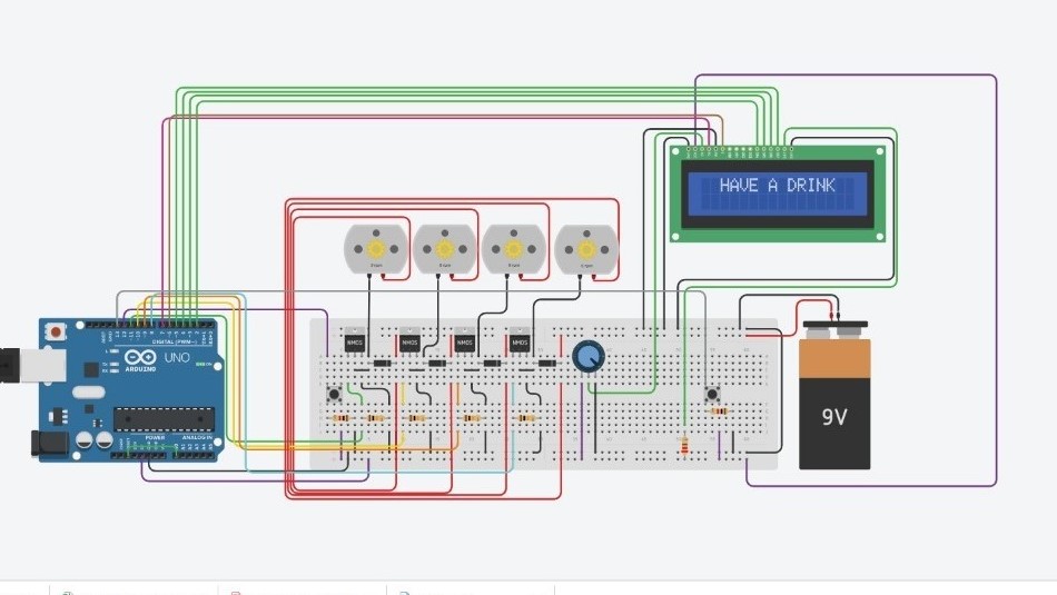
3. The code was developed in two parts, one for the push button system elaborated in the previous reports and an Ultrasonic Sensor module, which was added during the final prototype generation.
4. The aim was to develop an assistant for out friendly bartender, since every superhero has an able sidekick. Batman has ALFRED, Ironman has JARVIS hence it was only apt Bartender has BARTENDERLY.
Basic Code
5. The code was developed in two parts, one for the push button system elaborated in the previous reports and an Ultrasonic Sensor module, which was added during the final prototype generation.
6. For assistance of the code development, TINKERCAD module of AUTODESK was utilised. The smooth functioning of the software was a great help in visualising the working of an Arduino virtually prior to final assembly.
Challenges
7. Though, there were multiple challenges including the need for learning basic electronics and building the confidence in using the equipment in MAKERSPACE, the joy of seeing the final product was beyond description. The main challenge in this project which we look back and feel is the time management, which could have been done in a better manner. A pert chart fir monitoring the progress is our main take away from this project.
Concept
8. Modelling of the different concepts for the envisaged Cocktail maker were undertaken using Rhinoceros Software version 6. It is easy to handle with a large library for design combination development. The basic design has been developed for positioning of 4 bottles in upside down position on top of the cocktail maker. In addition the feasibility of positioning 02 bottles beside the model is being worked upon. The maker is expected to have one LCD screen and two control switches to make the choice.
9. Post undertaking a market survey the model was modified according to the new requirements. The same modelling software was used for generation of the final prototype.
10. The final prototype involved surface cut using a laser cutter in MDF and Acrylic boards of 3mm thickness. The sequence of prototype making and assembly can be briefly put as follows:-
Project Working
11. The working of the final prototype is shown in the video below:-