Assignment 4
IoT - Arduino
Producing sounds of different frequencies from the Buzzer as the distance computed from a proximity sensor varies
Arduino uno, when connected with a sensor and coded with Arduino software, can be used to carry out multiple functions related to the sensor used. For example, in this project a proximity sensor, a buzzer and an arduino has been used to produce different frequency of sound by varying the distance of the obstacle from the proximity sensor. The steps to do the same has been shown as follows.
HC-SR04 Ultrasonic Sensor Module - Datasheet
The datasheet contains various specifications of the sensor like the accuracy, minimum and maximum current/voltage it needs to work, its basic connection, etc. By reading this datasheet, it becomes easier to understand the sensor and its working.
The ultrasonic sensor module, also known as proximity sensor, uses the ultrasonic wave which bursts from the sensor when triggered and is deflected back from the obstacle, giving the distance of the obstacle from the sensor. Combining a buzzer and an LED light with the sensor can be useful for various notifiations such as to get notified when the water tank is full, to get a signal when the water reaches above the danger line for a dam, to notify the municipality of the garbage bins which are filled, and so on. The datasheet of the ultrasonic sensor can be accessed from here .
Steps for conections
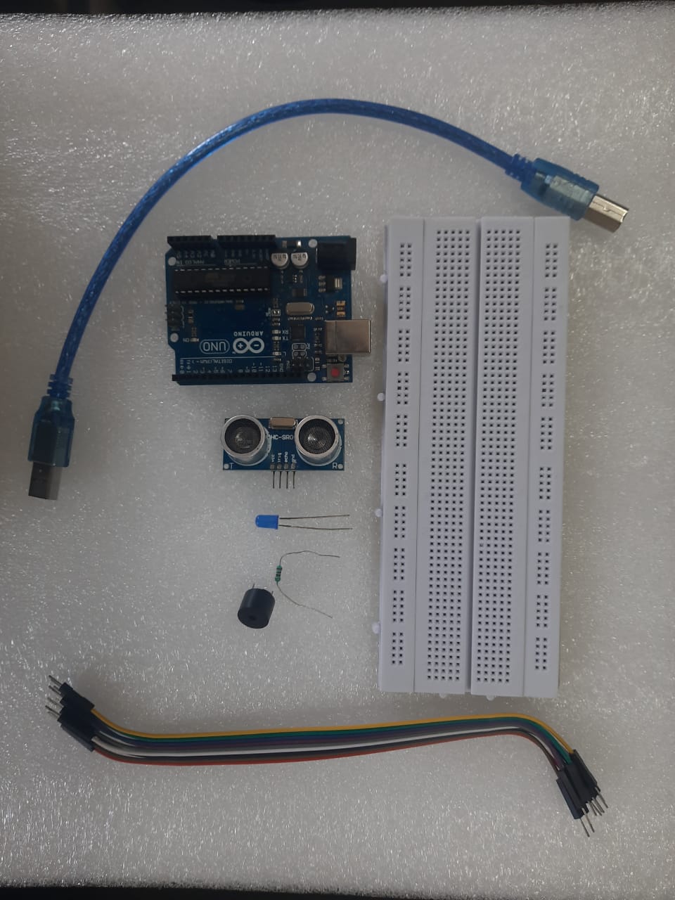
The components required for the project, as shown in the image, are USB cable, Arduino Uno, HC-SR04 Ultrasonic Sensor Module, LED, Resistor, Buzzer, Bread board and a set of connecting wires.
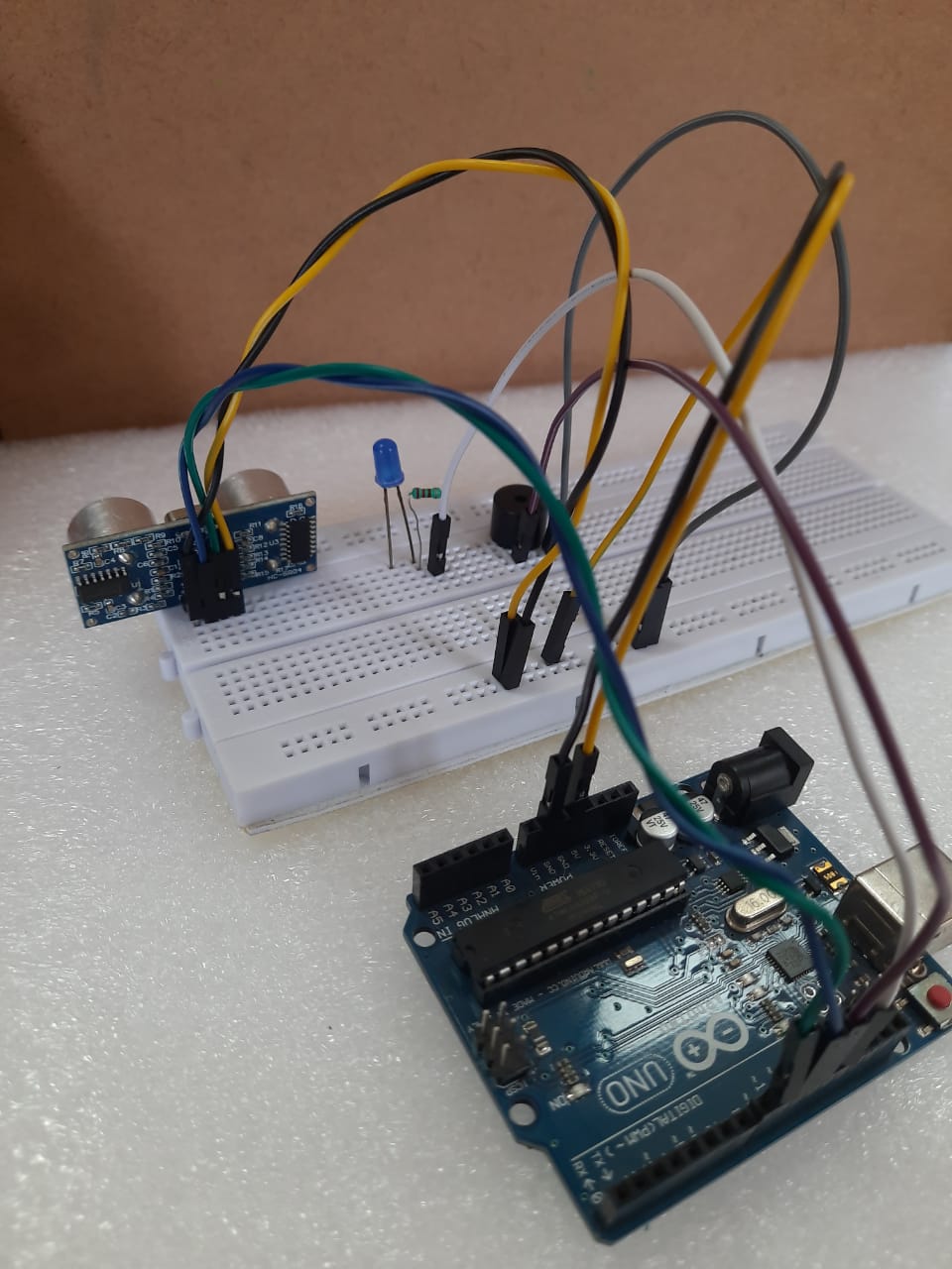
The following steps need to be followed to make the connects for the arduino, sensor, buzzer and LED :
- The sensor vcc is connected to the 5v in Arduino
- The sensor gnd is connected to the Arduino gnd
- The sensor trig is connected to the Arduino board digital I/O 9
- The sensor echo is connected to the Arduino board digital I/O 10
- Attach the buzzer to the bread board
- The buzzer’s longer leg (+) is connected to Arduino board digital 11
- The buzzer’s longer leg (-) is connected to Arduino board GND (connected to the bread board)
- Attaching the led to the bread board keeping the + on the right
- Connect the resistor to the led’s + leg
- The other leg of resistor is connected to Arduino boards digital 13
- The negative leg of led is connect to gnd on bread board
Programming the Arduino
After the connections are made, a program is written in Arduino IDE to produce different sounds at different proximity.The steps are as follows:
#define NOTE_B0 31
#define NOTE_C1 33
#define NOTE_CS1 35
#define NOTE_D1 37
#define NOTE_DS1 39
#define NOTE_E1 41
#define NOTE_F1 44
#define NOTE_FS1 46
#define NOTE_G1 49
#define NOTE_GS1 52
#define NOTE_A1 55
#define NOTE_AS1 58
#define NOTE_B1 62
#define NOTE_C2 65
#define NOTE_CS2 69
#define NOTE_D2 73
#define NOTE_DS2 78
#define NOTE_E2 82
#define NOTE_F2 87
#define NOTE_FS2 93
#define NOTE_G2 98
#define NOTE_GS2 104
#define NOTE_A2 110
#define NOTE_AS2 117
#define NOTE_B2 123
#define NOTE_C3 131
#define NOTE_CS3 139
#define NOTE_D3 147
#define NOTE_DS3 156
#define NOTE_E3 165
#define NOTE_F3 175
#define NOTE_FS3 185
#define NOTE_G3 196
#define NOTE_GS3 208
#define NOTE_A3 220
#define NOTE_AS3 233
#define NOTE_B3 247
#define NOTE_C4 262
#define NOTE_CS4 277
#define NOTE_D4 294
#define NOTE_DS4 311
#define NOTE_E4 330
#define NOTE_F4 349
#define NOTE_FS4 370
#define NOTE_G4 392
#define NOTE_GS4 415
#define NOTE_A4 440
#define NOTE_AS4 466
#define NOTE_B4 494
#define NOTE_C5 523
#define NOTE_CS5 554
#define NOTE_D5 587
#define NOTE_DS5 622
#define NOTE_E5 659
#define NOTE_F5 698
#define NOTE_FS5 740
#define NOTE_G5 784
#define NOTE_GS5 831
#define NOTE_A5 880
#define NOTE_AS5 932
#define NOTE_B5 988
#define NOTE_C6 1047
#define NOTE_CS6 1109
#define NOTE_D6 1175
#define NOTE_DS6 1245
#define NOTE_E6 1319
#define NOTE_F6 1397
#define NOTE_FS6 1480
#define NOTE_G6 1568
#define NOTE_GS6 1661
#define NOTE_A6 1760
#define NOTE_AS6 1865
#define NOTE_B6 1976
#define NOTE_C7 2093
#define NOTE_CS7 2217
#define NOTE_D7 2349
#define NOTE_DS7 2489
#define NOTE_E7 2637
#define NOTE_F7 2794
#define NOTE_FS7 2960
#define NOTE_G7 3136
#define NOTE_GS7 3322
#define NOTE_A7 3520
#define NOTE_AS7 3729
#define NOTE_B7 3951
#define NOTE_C8 4186
#define NOTE_CS8 4435
#define NOTE_D8 4699
#define NOTE_DS8 4978
// constants won't change
const int TRIG_PIN = 9; // Arduino pin connected to Ultrasonic Sensor's TRIG pin
const int ECHO_PIN = 10; // Arduino pin connected to Ultrasonic Sensor's ECHO pin
const int BUZZER_PIN = 8; // Arduino pin connected to Piezo Buzzer's pin
const int DISTANCE_THRESHOLD = 50; // centimeters
// variables will change:
float duration_us, distance_cm;
// notes in the melody:
int melody[] = {
NOTE_E5, NOTE_E5, NOTE_E5,
NOTE_E5, NOTE_E5, NOTE_E5,
NOTE_E5, NOTE_G5, NOTE_C5, NOTE_D5,
NOTE_E5,
NOTE_F5, NOTE_F5, NOTE_F5, NOTE_F5,
NOTE_F5, NOTE_E5, NOTE_E5, NOTE_E5, NOTE_E5,
NOTE_E5, NOTE_D5, NOTE_D5, NOTE_E5,
NOTE_D5, NOTE_G5
};
// note durations: 4 = quarter note, 8 = eighth note, etc, also called tempo:
int noteDurations[] = {
8, 8, 4,
8, 8, 4,
8, 8, 8, 8,
2,
8, 8, 8, 8,
8, 8, 8, 16, 16,
8, 8, 8, 8,
4, 4
};
void setup() {
pinMode(TRIG_PIN, OUTPUT); // set arduino pin to output mode
pinMode(ECHO_PIN, INPUT); // set arduino pin to input mode
}
void loop() {
// generate 10-microsecond pulse to TRIG pin
digitalWrite(TRIG_PIN, HIGH);
delayMicroseconds(10);
digitalWrite(TRIG_PIN, LOW);
// measure duration of pulse from ECHO pin
duration_us = pulseIn(ECHO_PIN, HIGH);
// calculate the distance
distance_cm = 0.017 * duration_us;
if(distance_cm < DISTANCE_THRESHOLD)
buzzer(); // play a song
delay(500);
}
void buzzer() {
// iterate over the notes of the melody:
int size = sizeof(noteDurations) / sizeof(int);
for (int thisNote = 0; thisNote < size; thisNote++) {
// to calculate the note duration, take one second divided by the note type.
//e.g. quarter note = 1000 / 4, eighth note = 1000/8, etc.
int noteDuration = 1000 / noteDurations[thisNote];
tone(BUZZER_PIN, melody[thisNote], noteDuration);
// to distinguish the notes, set a minimum time between them.
// the note's duration + 30% seems to work well:
int pauseBetweenNotes = noteDuration * 1.30;
delay(pauseBetweenNotes);
// stop the tone playing:
noTone(BUZZER_PIN);
}
}
Conclusion
This assignment helped us understand the basic functioning of an Arduino Uno and how it can be coupled with various sensors to produce a desired function .