Assignment 11
CNC Router ( Big )
Introduction
A computer numerical control (CNC) router is a computer-controlled cutting machine related to the hand-held router used for cutting various hard materials, such as wood, composites, aluminium, steel, plastics, glass, and foams. CNC routers can perform the tasks of many carpentry shop machines such as the panel saw, the spindle moulder, and the boring machine. A CNC router typically produces consistent and high-quality work and improves factory productivity. Unlike a jig router, the CNC router can produce a one-off as effectively as repeated identical production. Automation and precision are the key benefits of CNC router tables.A CNC router can reduce waste, the frequency of errors, and the time the finished product takes to get to market.

Process
Steps to be followed :
1. Aspire is the software used for CNC Router. Part to be cut is to be modelled in any 2D CAD software or in Aspire itself.

2. Here, we have imported the model from solidworks, saved as '.dxf' file.

3. Origin has to be set in the drawing for the orientation of CNC.
4. Disjoint parts in the drawing has to be joined. Select Edit Objects -> Open vectors -> Join.
5. In toolpath, XY datum has to be selected.
6. Select 17mm as thickness ( of the sheet ) in material setup.
7. Select the sketch and then go to Toolpath Operation -> Profile Toolpath. Give the dimensions as : Start Depth – 0mm, Cut Depth – 17mm.
8. In machine vector, choose where will the drill make the cut- inside, on the line or outside.
9. 'Tabs' are added with a thickness of 2mm and length 6 mm. Tabs are given to prevent the cut piece from moving away during the cutting process. Adding tabs will leave uncut areas with the thickness provided which can be later removed by chisel.
10. After the required dimensions are given, Click on 'Calculate'.

11. Order of the tasks can be arranged as engraving is generally done first and profiling, later.
12. Select Post Processor- WINCNC GCode (mm) (*.tap) and save the toolpath. Copy the files to pendrive and connect to the Controller.


13. Click Run/Pause on the controller, Udisk file --> Select file. Keep the default values.
14. Set the X, Y, Z axis of the machine as zero, by changing the values in the controller.
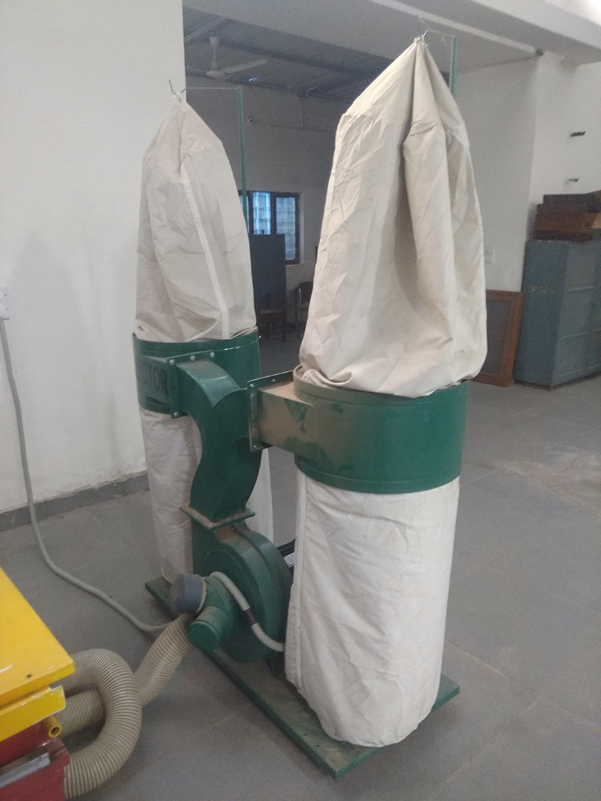

15. Click Run/Pause on the controller, Udisk file --> Select file. Keep the default values.
16. Run CNC Router with +Z value ( in air ) for testing and to get an understanding about the cutting area.. If it is found to be succesful, run again with the actual values.
Result
This is the result of CNC process.
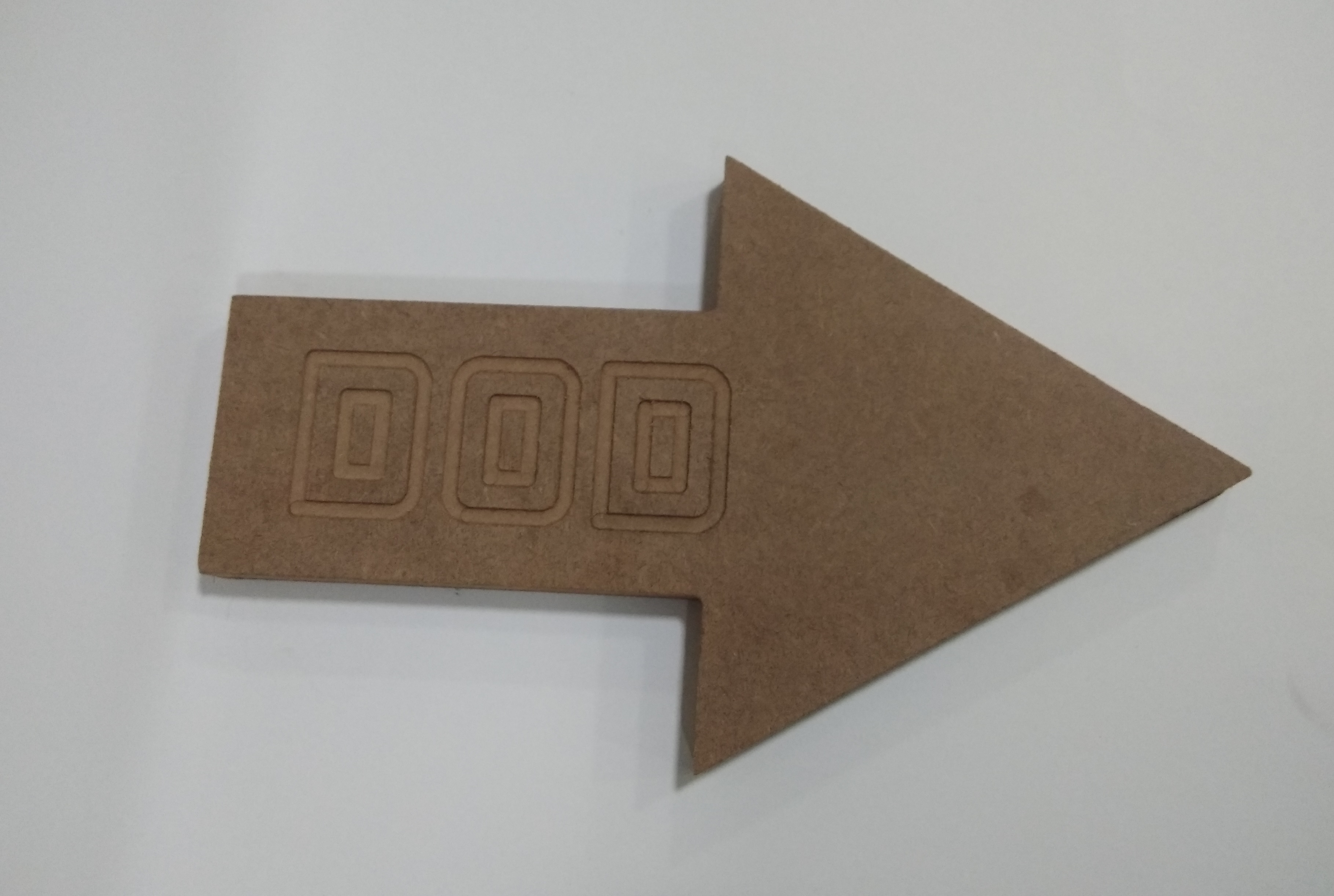
CNC Router testing Video