Assignment 4
Input/Output Devices
A.Sensors used in smartphone
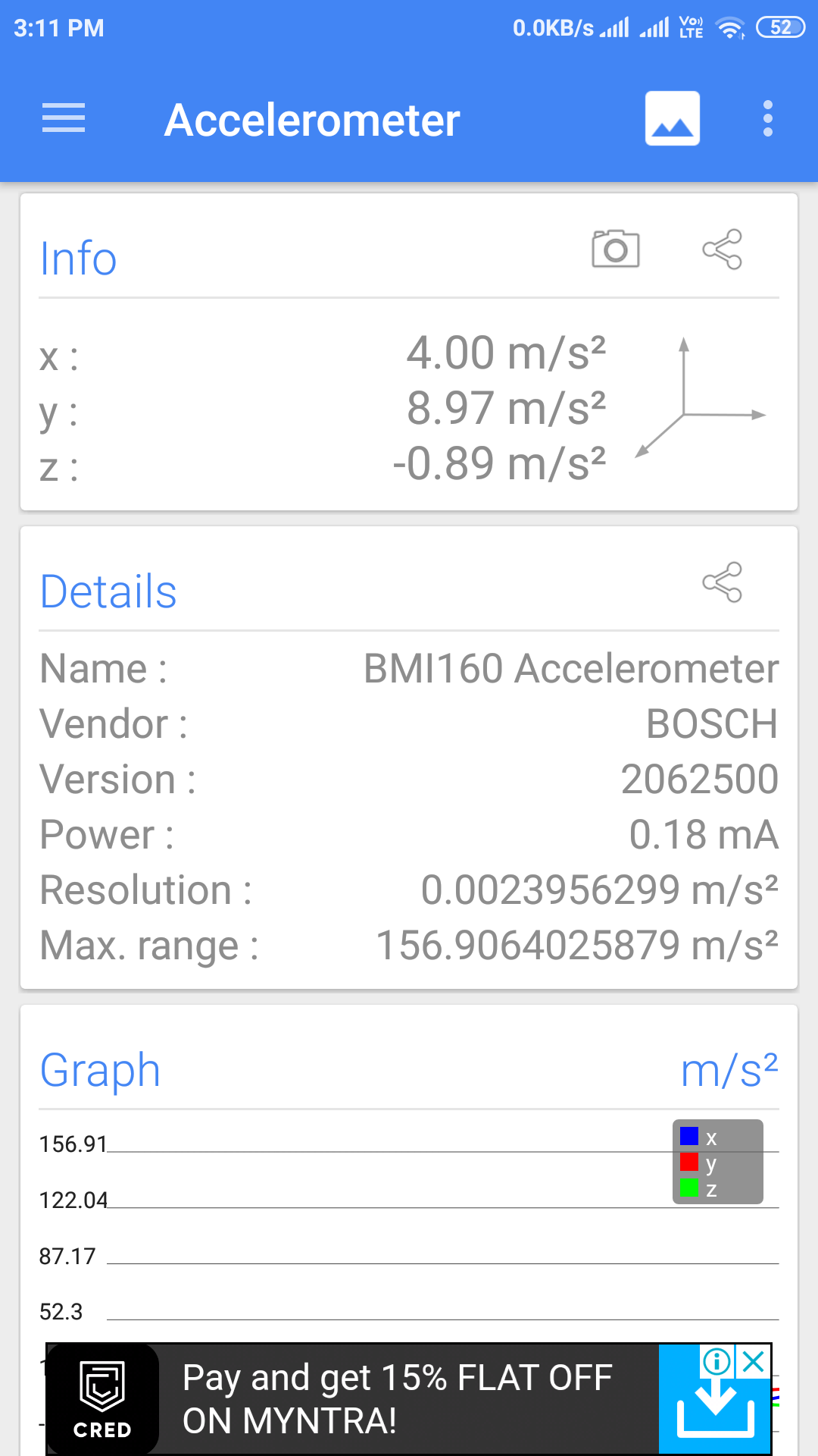
1. Accelerometer
An accelerometer detects acceleration, vibration, and tilt to determine movement and exact orientation along the three axes. Apps use this smartphone sensor to determine whether your phone is in portrait or landscape orientation.It can also tell if your phone screen is facing upward or downward. The accelerometer can also detect how fast your phone is moving in any linear direction.
2. Gyroscope
Gyroscope also provides orientation details and direction like up/down and left/right but with greater precision like how much the device is tilted. This is where it differs from accelerometer — gyroscope can measure rotation too but the former cannot.

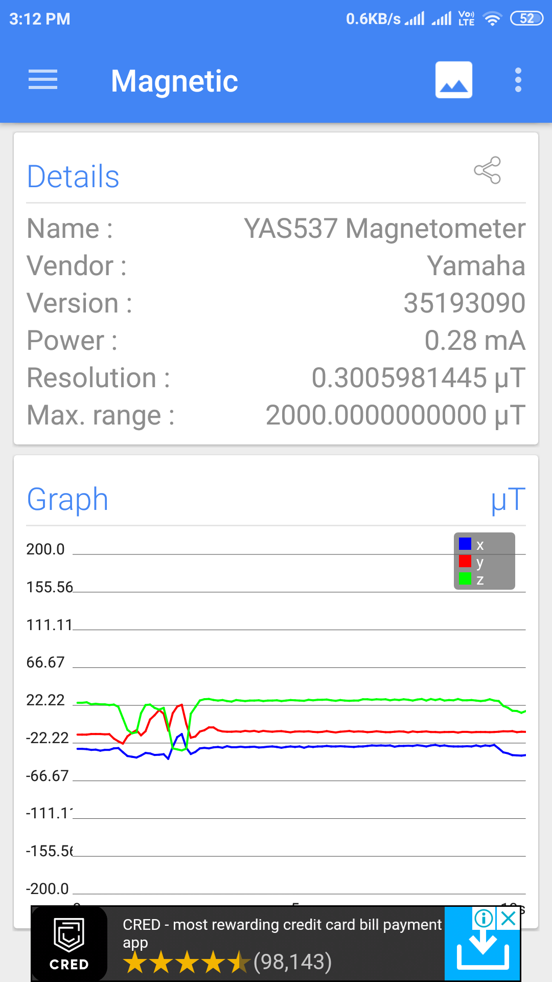
3. Magnetometer
Our smartphones are equipped with magnetometer which we commonly recognize as a compass. It can detect magnetic fields, so the compass app in phones uses this smartphone sensor to point at the planet’s north pole.
4. GPS
Global Positioning System (GPS) units in smartphone communicate with the satellites to determine our precise location on Earth. The GPS technology doesn’t actually use internet data this is why we can find our location on maps even after losing the signals, but the map itself is blurry as it requires internet to load the details — this is how offline map works. GPS is used in all location-based apps like Uber and Google Maps.
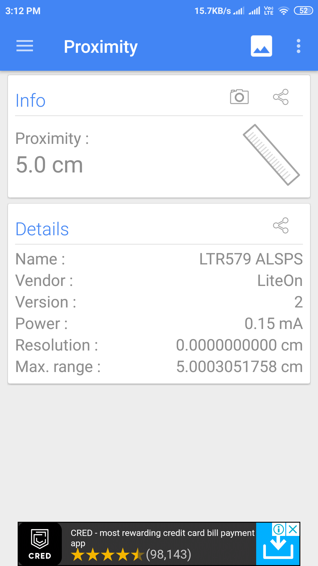
5. Proximity Sensor
A proximity sensor makes use of an infrared LED and IR light detector to find out how close the phone is to an outside object. It used while making calls and when the phone is held to the face to make or receive a call, the sensor detects it and disables the touchscreen display to avoid unintended input through the skin.
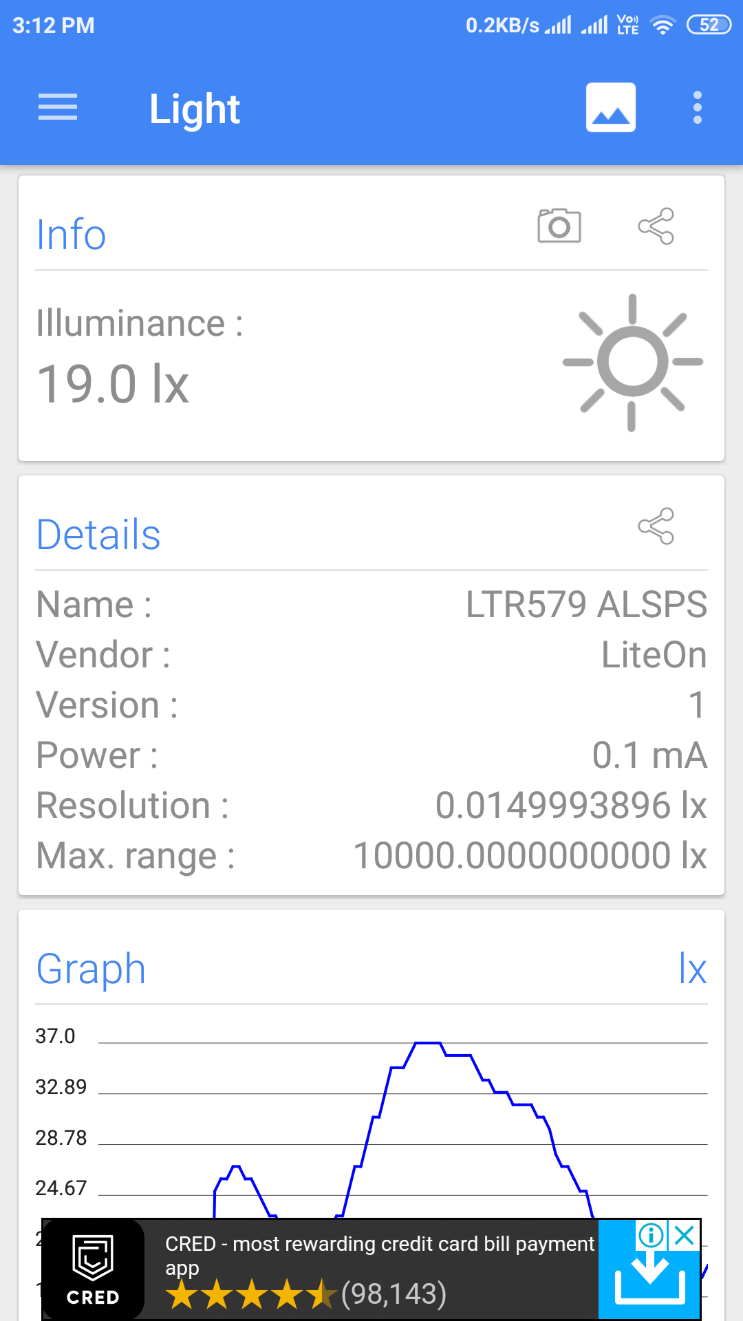
6. Ambient Light Sensor
The light sensor detects the lighting levels in the vicinity to adjust the display brightness accordingly. It is used in Automatic Brightness Adjuster to decrease or increase the brightness of the smartphone screen based on the availability of light.
6. Fingerprint Sensor
Gone are the days of memorizing passwords and patterns to unlock your phone as many users prefer using the fingerprint scanner these days. Fingerprint sensor enables biometric verification to secure many smartphones today. It is a capacitive scanner that records your fingerprint electrically.
B.Sensor with Arduino
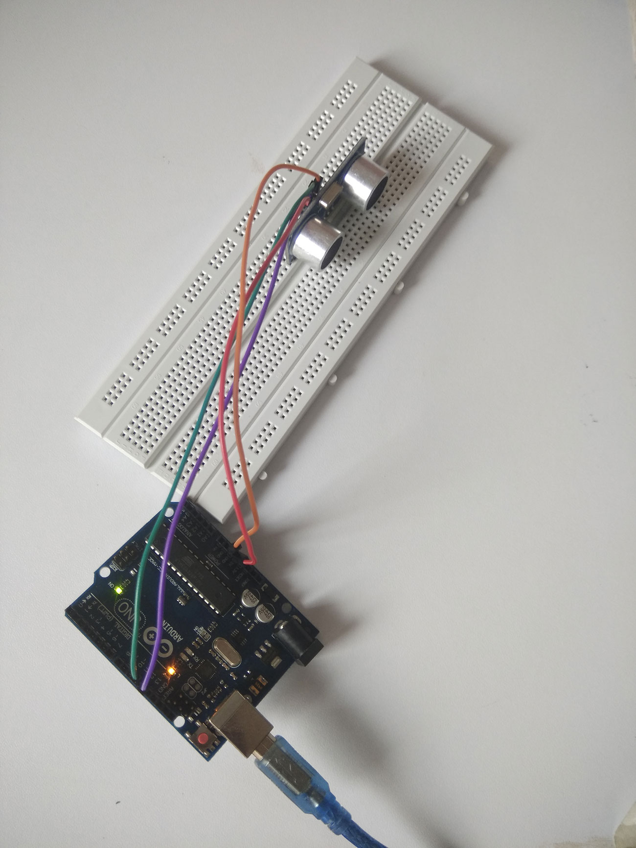
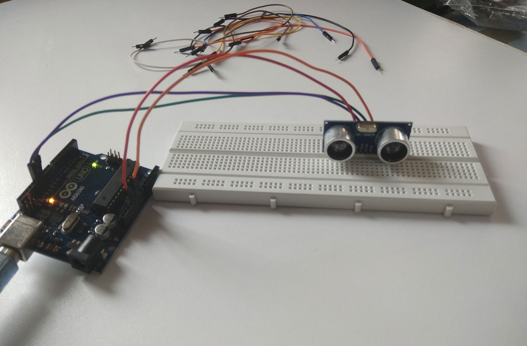
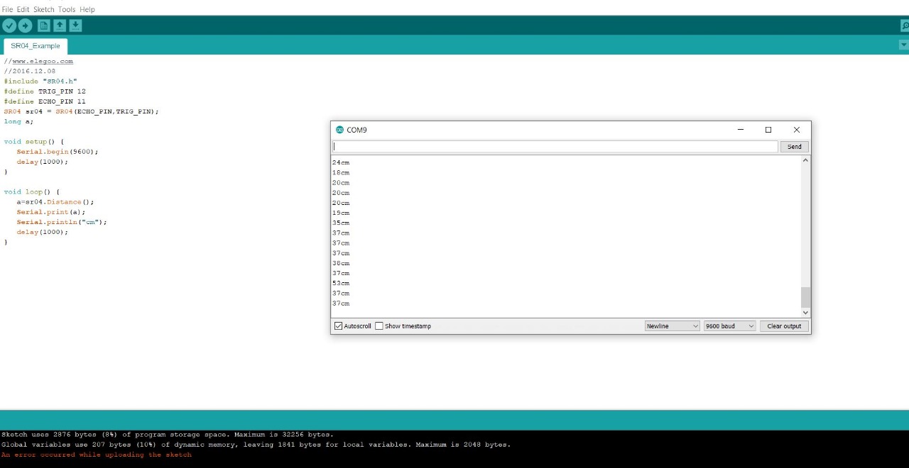
Ultrasonic sensor HC-SR04 is used with arduino uno module to measure the distance.
Initially, HC-SR04 library is included for the program to run.
#include "SR04.h"
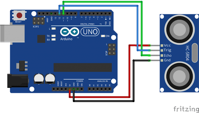
For arduino coding, program from elegoo kit is used. Trigger pin and Echo pin of Ultrasonic sensor were connected to pin 12 and 11 accordingly and mentioned in the program.
#define TRIG_PIN 12
#define ECHO_PIN 11
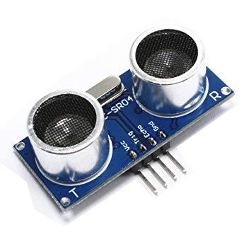
Ultrasonic sensor module HC-SR04 provides 2cm-400cm non-contact measurement function, the ranging accuracy can reach to 3mm. The modules includes ultrasonic transmitters, receiver and control circuit.
Wiring Diagram
Output
Here is the arduino code used for the program:
Real World Application
This sensor is used in car parking system where car entry is controlled through barrier system, the barrier must not be lowered when there is beneath a vehicle. This whole process is controlled through ultrasonic sensor.
Inference From Datasheet
Ultrasonic sensor will send a signal outward with a timer till it encounters an object. If it detects an object, wave will be reflected and received by the US receiver and timer will be stopped. Velocity of US wave is 340m/s. Based on these values, distance can be calculated.
Pin connections of the Ultrasonic Sensor is as shown below.
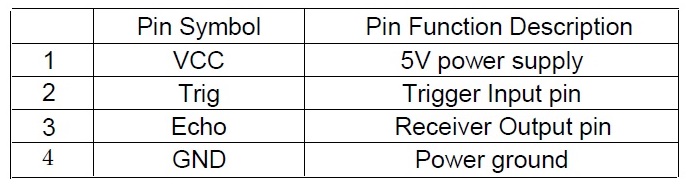
Operating voltage of this sensor is 5V DC and operating current is 15mA at a frequency of 50KHz. Range of this sensor is 2cm to 4m.
C. LCD Programming
LCD 1602 Module is used for Display with Arduino programming.
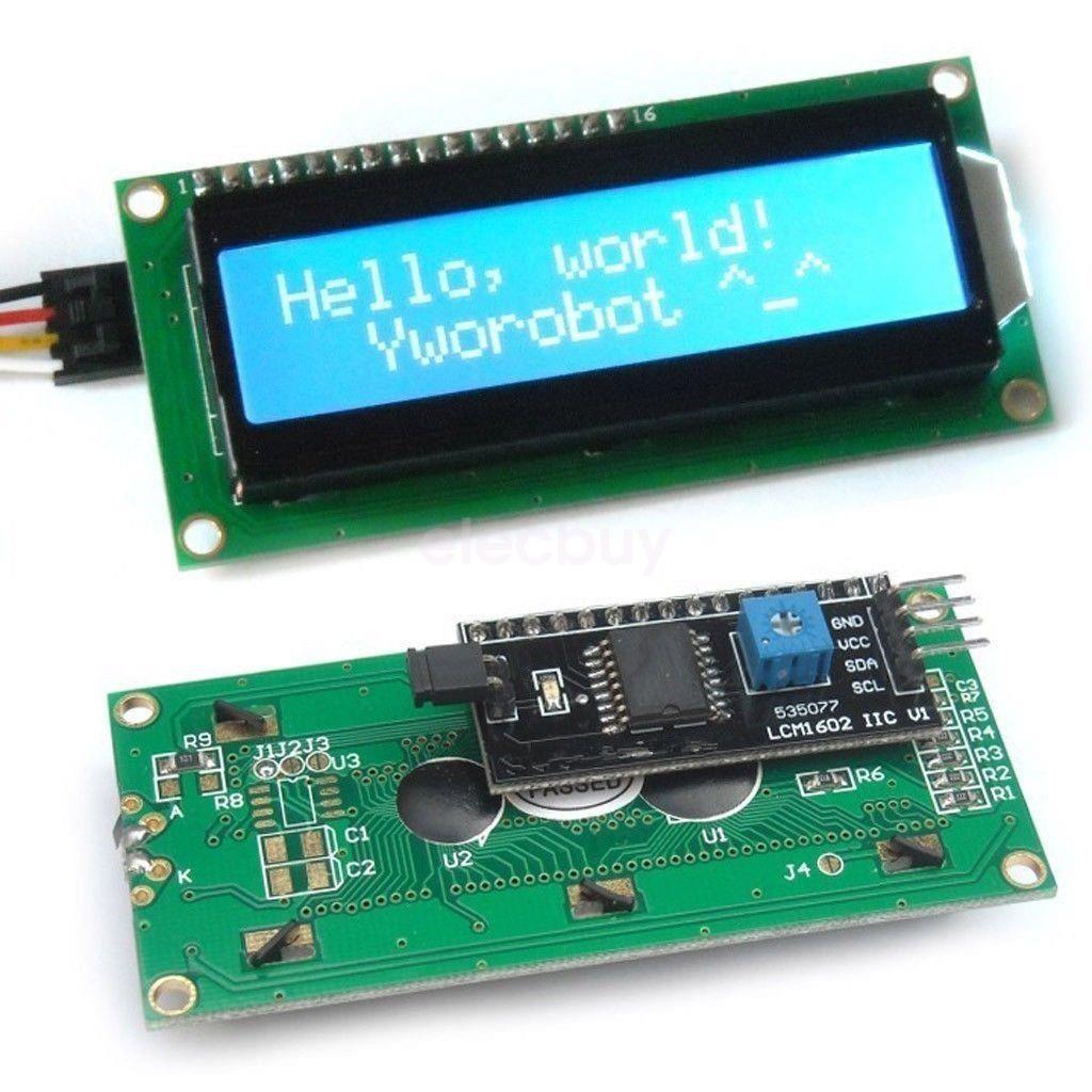
Arduino is connected to LCD (LCM1602) via I2C module. By using this way, Arduino will only use 2 GPIO pins which act as I2C SDA and SCL pins. I2C Module will be responsible for converting I2C data to LCD data and control signals. Contrast of LCD is adjusted with the help of a screw driver.
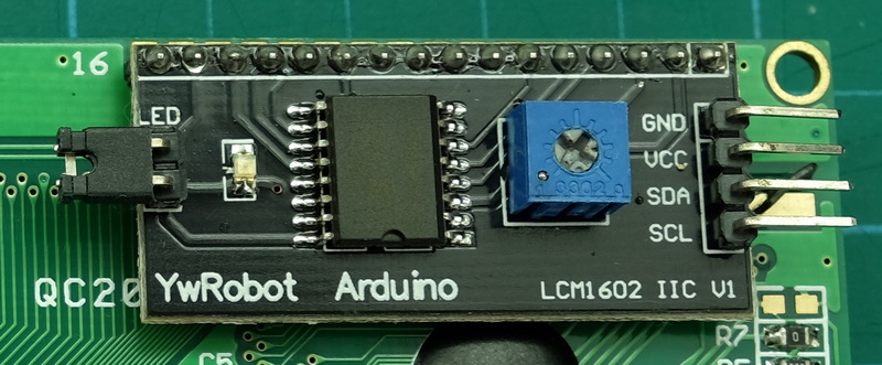
Connections has to be made in this manner:
SDA pin to A4 (Uno)
SCL pin to A5 (Uno)
VCC and GND to respective pins in Uno
These are the libraries required to be added for the program to run:
#include <Wire.h>
#include <LiquidCrystal_I2C.h>
Output
Here is the arduino code used for the program:
Inference From Datasheet
LCM1602A
It's a 2-line x16 characters display with 5V power supply. 80.0x36.0 mm is the dimension of the module with a viewing area of 64.5x13.8 mm. Size of the character displayed in LCD is 2.95x5.05 mm. Input Voltage range of this LCD is from 4.7-5.5V(max) and the typical current value is 1.mA
D. Input + Output Device
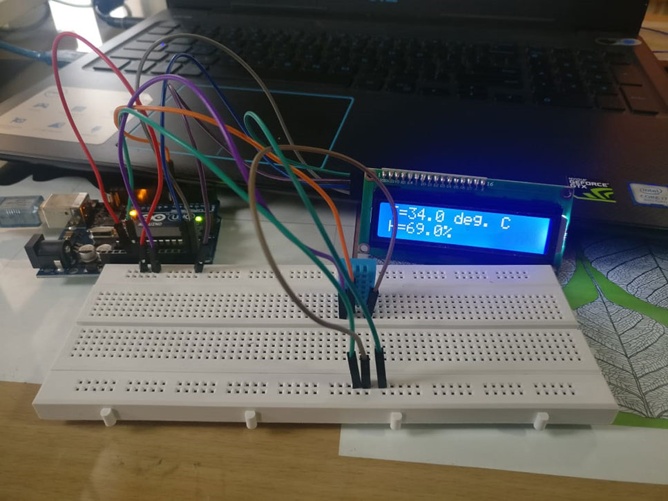
DHT11 Temperature and Humidity Sensor is used with LCD to display the values using Arduino programming. Here the input and output devices are combined to work together with the help of Arduino Uno.
DHT11 digital temperature and humidity sensor is a composite Sensor which contains a calibrated digital signal output of the temperature and humidity.
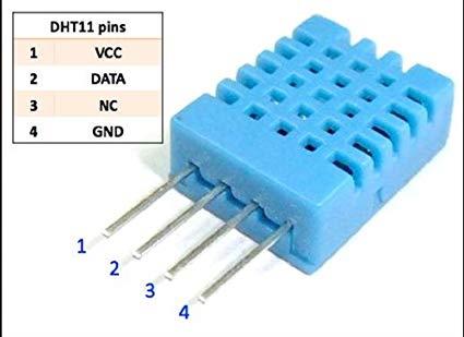
Pins of DHT11 are connected to Arduino Uno as:
1 to VCC (Uno)
2 to Any data pin (Uno)
3 - No Connection
4 to GROUND (Uno)
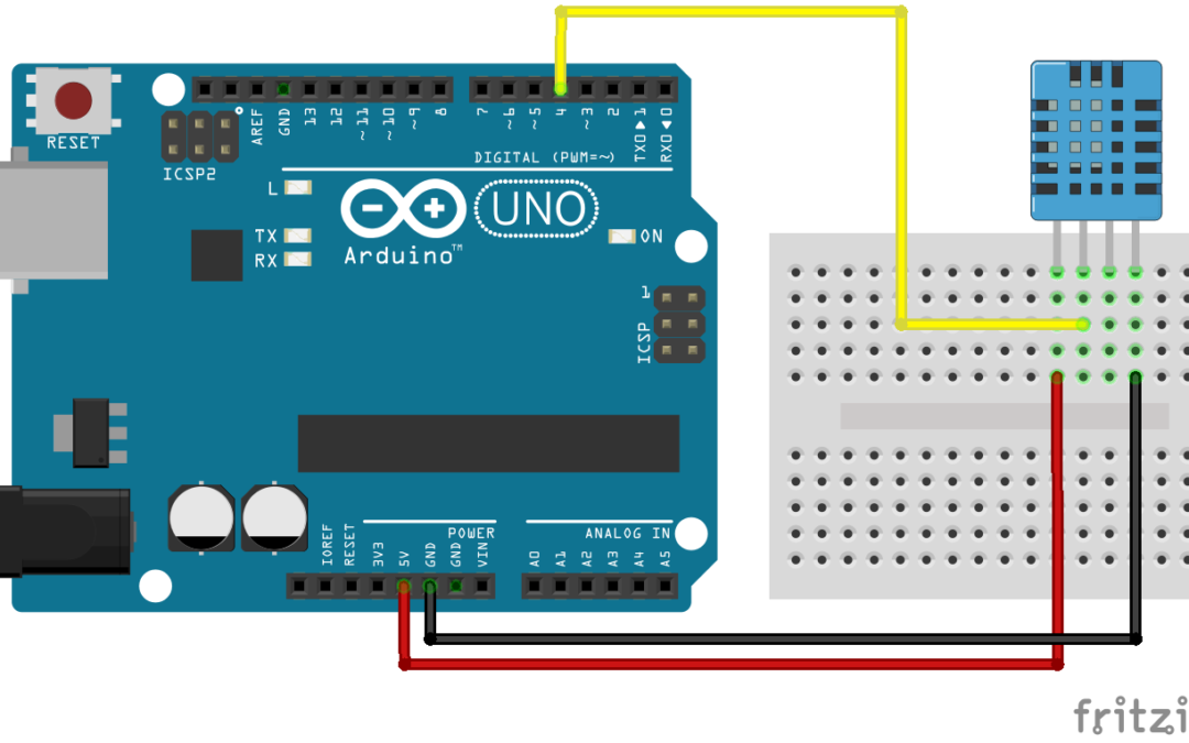
DHT11 Schematic Diagram
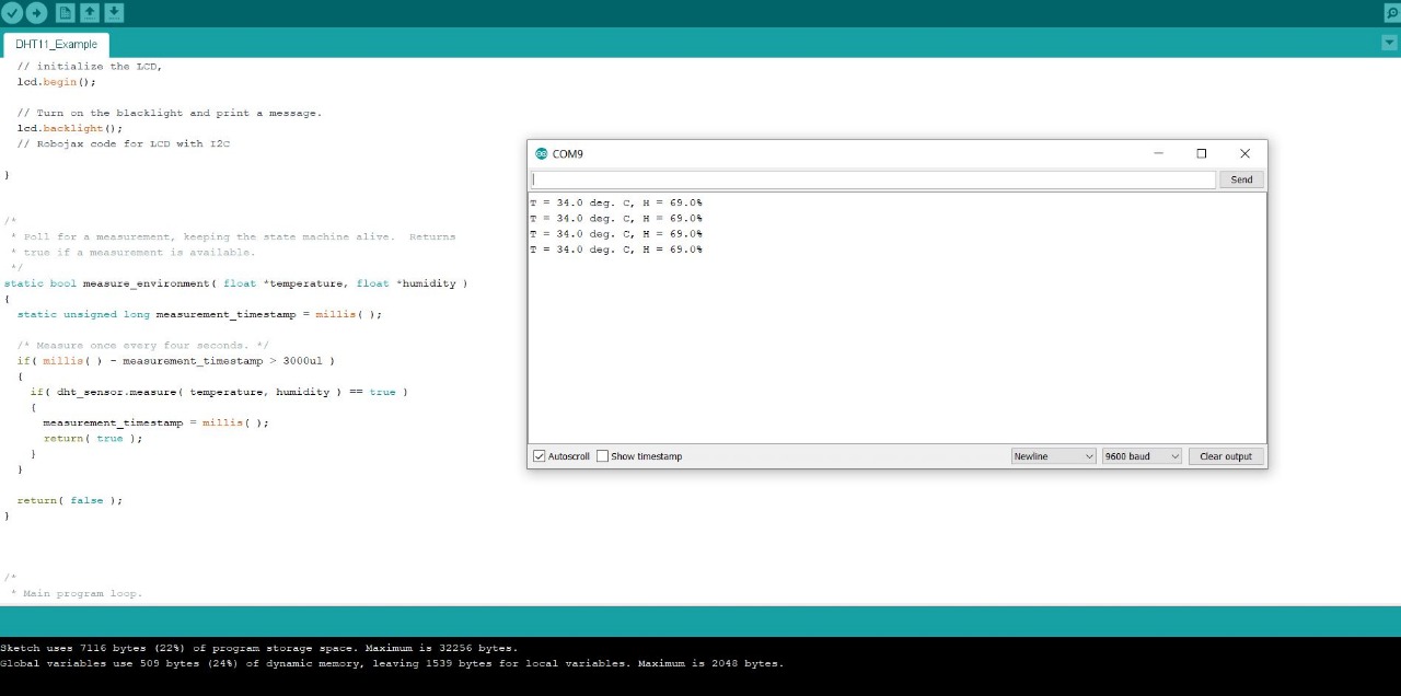
Output
Output in Serial Monitor
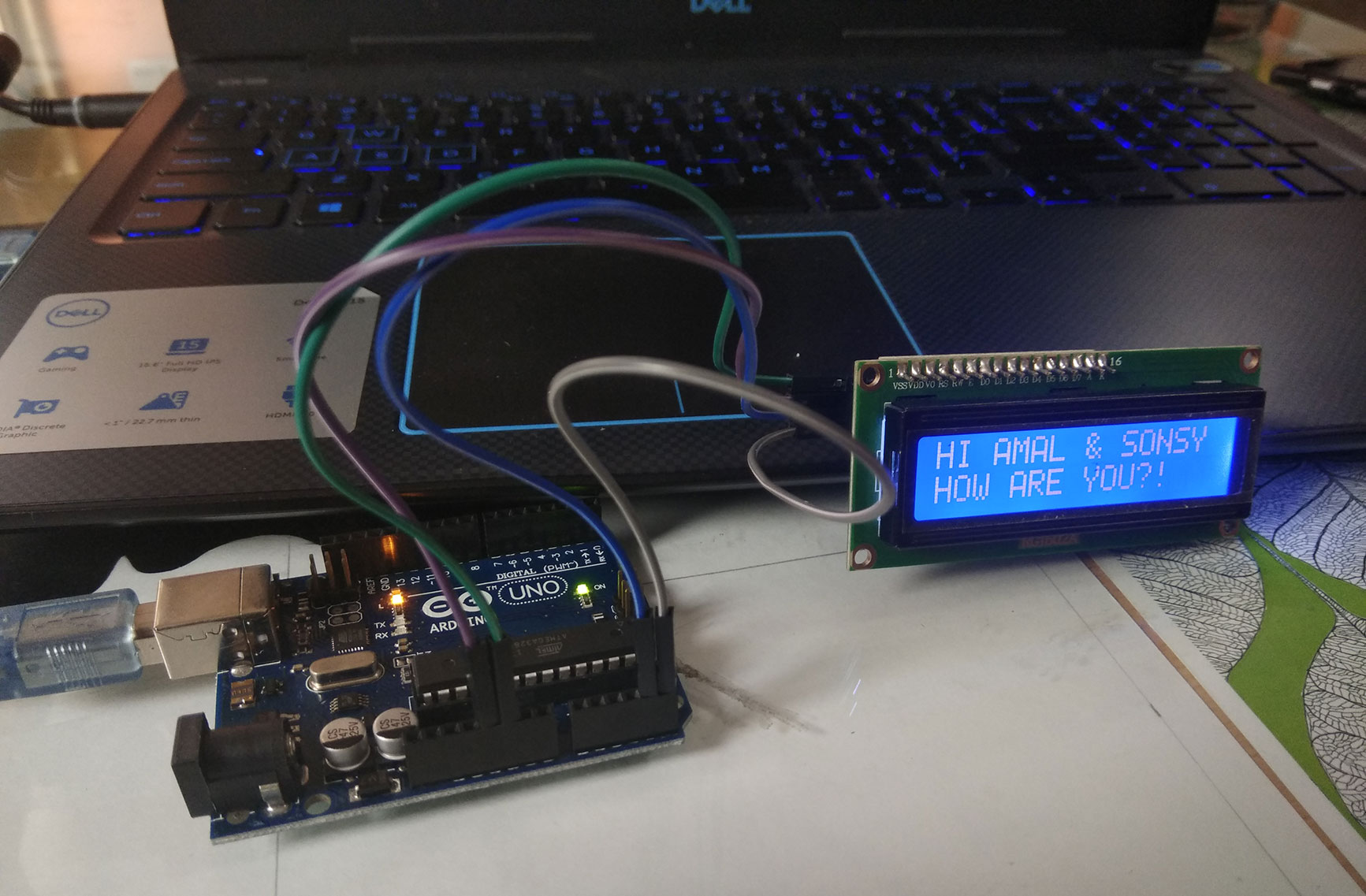
Output Displayed in LCD
Here is the arduino code used for the program: