Assignment 6
2D and 3D CAD Modelling
CAD
Computer-aided design (CAD) is the use of computers (or workstations) to aid in the creation, modification, analysis, or optimization of a design CAD software is used to increase the productivity of the designer, improve the quality of design, improve communications through documentation, and to create a database for manufacturing. CAD output is often in the form of electronic files for print, machining, or other manufacturing operations.
Raster and Vector Images
There are two main type of image files: Raster and Vector. Raster images are created with pixel-based programs or captured with a camera or scanner. They are more common in general such as jpg, gif, png, and are widely used on the web. Vector graphics are created with vector software and are common for images that will be applied onto a physical product. Also used in CAD, engineering, and 3D graphics which we do not provide information nor services for.

Softwares used for Raster and Vector image processing are :
Poplar softwares used for 2D and 3D CAD modelling are :
2D CAD Modelling
1.Adobe Photoshop
2.Adobe Illustrator
3.Corel Draw
4.GIMP
5.Inkspace
3D CAD Modelling
1.AutoCAD
2.Fusion 360
3.Inventor LT
4.Solidworks
5.Cinema 4D
6.Rhino
2D Modelling
The process of designing a logo is designed using vector software Adobe Illustrator.
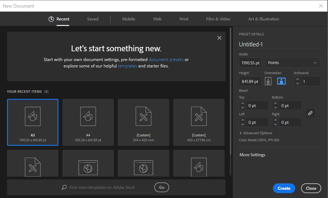
1. Open Illustrator and click on File -> New to create a new document.
2. Different tools used in illustrator is explained in the below image.

3. Using polygon shape tool a triangle is created ( Give the number of sides as 3.

4. Click on the shape and it will show a quick transform box. Scaling can be done by dragging on the corners of the box. Color fill can be given from the fill box as shown in the image.

5. Select both the shapes and click on the shape builder tool on the left toolbar. By pressing 'Alt' key + drawing over the shape, substraction of the shape can be done.

6. Similarly all the other shapes were made using the shape tool.

7. Text is added using the 'Text' tool (T icon) from the tool bar. Fonts can be changed from the top tool bar.

8. Final logo in black and white is as shown below.

9. Different color options were tried to make it more interesting.

10. This is the final logo selected out of the options available.

3D Modelling Process
Autodesk Fusion 360 is the software I have used for 3D Modelling. A storage box with projections which can be inserted in the corresponding slots is designed which is required for my course project.
The process starts with creating a sketch on a required plane. So here, a basic rectangle is drawn in XY plane. Dimesions can be changed using 'Sketch Dimension' tool during sketching phase or using 'Press Pull' tool at a later stage.
.JPG)
Select the sketch drawn and Click on the Extrude icon ( second from left in the tool bar ). This will create a solid block.
.JPG)
On the bottom plane of the cube, the surface is selected and a new sketch is drawn ( for projection).
.JPG)
The same process is repeated for all the 4 projections at the bottom of the cube.
.JPG)
.JPG)
Using 'Shell' tool ( third in Modify section ), the hollow surface can be created.
save the file using different formats using .obj, .stl etc.
.stl is the preferred extension for 3D printing.
Output
.JPG)