Assignment 6
2D vector.
For doing this part of assignment I have used Adobe Illustrator 2017.Unlike raster graphics, which are comprised of colored pixels arranged to display an image, vector graphics are made up of paths, each with a mathematical formula (vector) that tells the path how it is shaped and what color it is bordered with or filled by. Since mathematical formulas dictate how the image is rendered, vector images retain their appearance regardless of size. They can be scaled infinitely. Vector images can be created and edited in programs such as Illustrator, CorelDraw, and InkScape (don’t worry, these visual editors do the math for you).
Vector project-I have designed logo using adobe illustrator. Steps are explained below.
Step 1-Open Adobe Illustrator goto File >> New >> select Print tab >> Select paper size >> Select Units >> Click on Create.
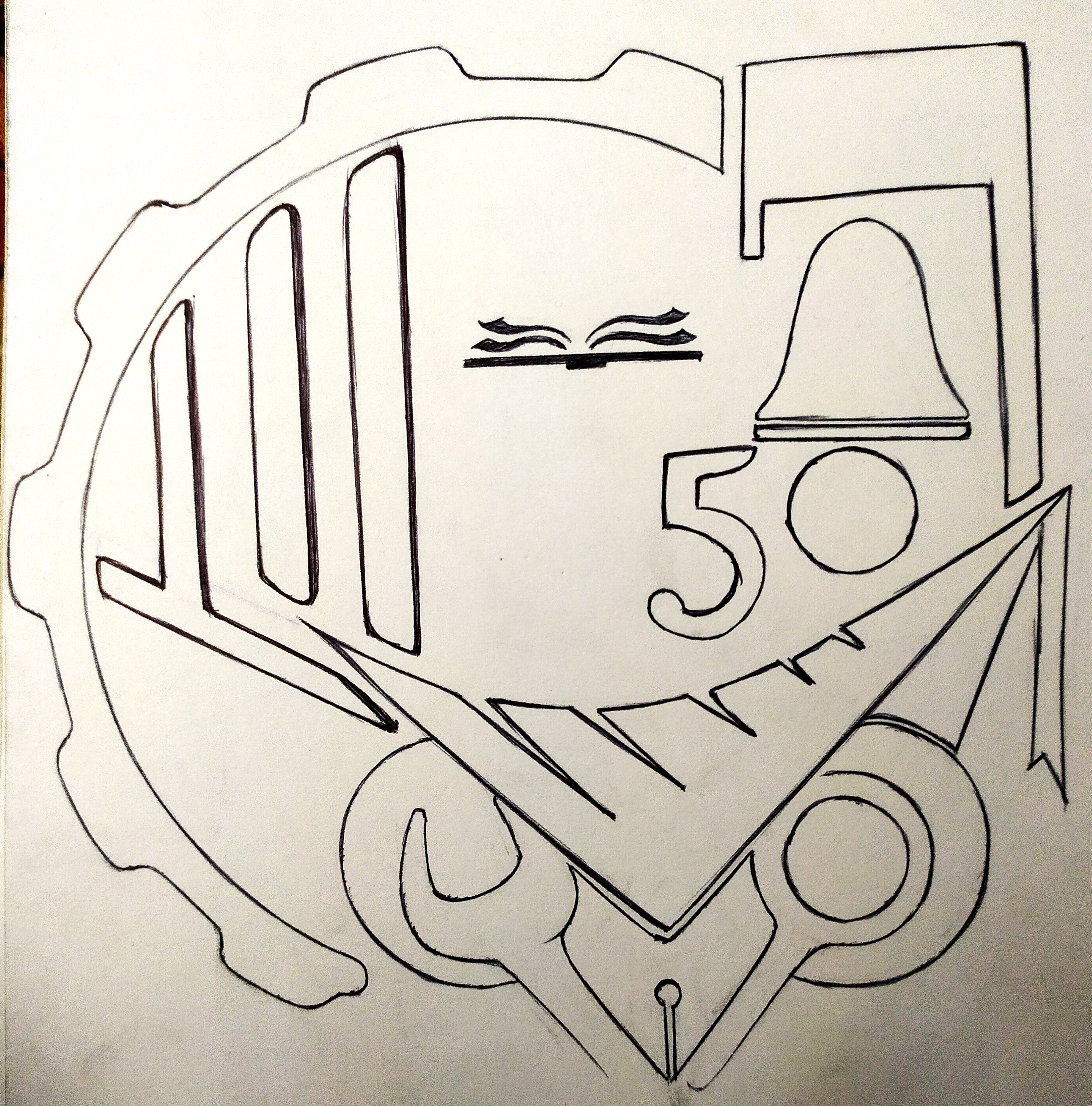
NOTE:For creating logo in vector for I sketched it on paper and then traced it in Adobe illustrator. sketch shown below.
Step 2-Importing sketch in Adobe illustrator. Goto File>> click on "Place" >> Select file to be imported >> Select 'open'. >> Position your image wherever you want.
Step 3-Intro duction to tools I used during this assignment. See Below Image
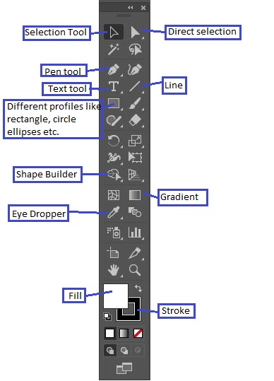
Selection tool: To select image or anything , say profile and can be scaled or change position.
Direct Selection tool: Using this tool we can manipulate anchor point and handle individually.
Pen tool: To trace image shown above.
Line segment tool: To draw straight line wher needed.
Different profiles: Can make geometrical shapes easily.
Shap builder tool: To combine two or more profiles or to create profile in which coluor can be filled out of closed loop.
Eye Dropper tool: To pick and drop colour from anywhere into selected profile.
Fill tool: To change color of profile.
Stroke tool: To change color of border of any selected profile.
Step 4-Trace imported image and filled colors to it.
Result-Finished work.

3D CAD.
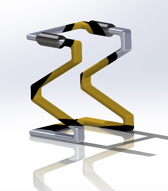
Software I used to create my CAD model is SolidWorks I have used part module for creating this model of a walker.
Step 1- I have opened Solidworks .
Step 2- Selected part module.
Step 3- Then sketched a trajectory (path on which a profile can be sweeped).
Step 4- Drew a rectangular crossection of walker and used sweep command. also used extrude command to make some of the part.
Result- Please check below image.
Keyshot Rendering.
I haven't done keyshot rendering of above walker but will show another example. please watch below video. Keyshot8.1.
2D Raster.
For rastering I have used Adobe Photoshop cs6.Raster images, also known as bitmaps, are comprised of individual pixels of color. Each color pixel contributes to the overall image. Raster images might be compared to pointillist paintings, which are composed with a series of individually-colored dots of paint. Each paint dot in a pointillist painting might represent a single pixel in a raster image. When viewed as an individual dot, it’s just a color; but when viewed as a whole, the colored dots make up a vivid and detailed painting. The pixels in a raster image work in the same manner, which provides for rich details and pixel-by-pixel editing.
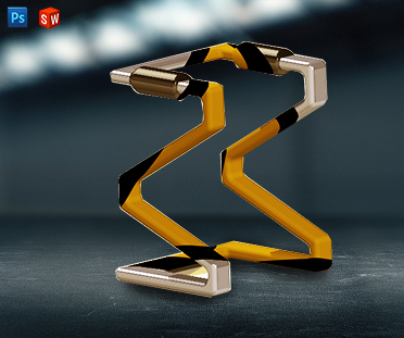
I have used this software to give final finish to my rendered model. Tools are almost same as Adobe illustrator
Step 1- Imported JPEG (output from Keyshot. It can be done by simply drag and drop the file in photoshop window.
Step 2- Adjusted color, brightness and contrast of image.
Result- Please check below image.
Possibilities with CAD.
1) Parametric Modeling Parametric is a term used to describe a dimension's ability to change the shape of model geometry as soon as the dimension value is modified. ... Parametric modelling uses the computer to design objects or systems that model component attributes with real world behaviour
The Parametric Modelling Process Parametric models are built from a set of mathematical equations. For parametric models to have any legitimacy, they must be based on real project information. It is the modernity of the information examination techniques and the breadth of the hidden undertaking information which decides the viability of a modelling solution.There are two popular parametric representation models:
Constructive Solid Geometry (CSG)CSG defines a model in terms of combining basic (primitive) and generated (using extrusion and sweeping operation) solid shapes. It uses Boolean operations to construct a model. CSG is a combination of 3D solid primitves (for example a cylinder, cone, prism, rectangle or sphere) that are then manipulated using simple Boolean operations.
Boundary Representation (BR)In BR, a solid model is formed by defining the surfaces that form its spatial boundaries (points, edges, etc.) The object is then made by joining these spatial points. Many Finite Element Method (FEM) programs use this method, as it allows the interior meshing of the volume to be more easily controlled.
Advantages These are the benefits offered by 3D parametric modelling over traditional 2D drawings: 1) Capability to produce flexible designs 2) 3D solid models offer a vast range of ways to view the model 3) Better product visualization, as you can begin with simple objects with minimal details 4) Better integration with downstream applications and reduced engineering cycle time 5) Existing design data can be reused to create new designs 6) Quick design turnaround, increasing efficiency2) Computer Aided Manufacturing Computer Aided Manufacturing (CAM) is the use of software and computer-controlled machinery to automate a manufacturing process.
Based on that definition, you need three components for a CAM system to function:
a) Software that tells a machine how to make a product by generating toolpaths. b) Machinery that can turn raw material into a finished product. c) Post Processing that converts toolpaths into a language machines can understand.These three components are glued together with tons of human labor and skill. As an industry we’ve spent years building and refining the best manufacturing machinery around. Today, there’s no design too tough for any capable machinist shop to handle.
CAD to CAM Process
Without CAM, there is no CAD. CAD focuses on the design of a product or part. How it looks, how it functions. CAM focuses on how to make it. You can design the most elegant part in your CAD tool, but if you can’t efficiently make it with a CAM system then you’re better off kicking rocks.
The start of every engineering process begins in the world of CAD. Engineers will make either a 2D or 3D drawing, whether that’s a crankshaft for an automobile, the inner skeleton of a kitchen faucet, or the hidden electronics in a circuit board. In the world of CAD, any design is called a model and contains a set of physical properties that will be used by a CAM system.
3) Computer Aided Engineering CAE or Computer-Aided Engineering is a term used to describe the procedure of the entire product engineering process, from design and virtual testing with sophisticated analytical algorithms to the planning of manufacturing. Computer-aided engineering is standard in almost any industry that uses some sort of design software to develop products. CAE is the next step in not only designing a product, but also supporting the engineering process, as it allows to perform tests and simulations of the product’s physical properties without needing a physical prototype. In the context of CAE, the most commonly used simulation analysis types include Finite Element Analysis, Computational Fluid Dynamics, Thermal Analysis, Multibody Dynamics and Optimizations.
Fields of application:
CAE can be used in almost any industry and company that designs a product exposed to different environments. Industries using computer-aided engineering in their product development process include but are not limited to: automotive, aerospace, plant engineering, electronics, energy, consumer goods and HVAC. The products that can be simulated range from extremely small parts of products to very big and complex structures such as race cars, bridges or even power plants. Testing the structural integrity of a crane that carries a specific load to a rooftop is a possible application as well as assessing the acoustic design of a concert hall or the convective flow inside a light bulb; all these are examples of applications where simulation can make a huge, sometimes life-saving difference . As you see, the field of applications of computer-aided engineering or engineering simulation is unlimited and can help engineers and designers in any industry to develop products better and faster.
-------------------------------------End of Assignment---------------------------------------