Assignment 6 - 2D and 3D CAD
2D Model
A 2d design professional draws 2-dimensional, or flat, images used in mechanical drawings, electrical engineering projects, video games, animation, clothing construction and architecture.
Softwares: Rastor-GIMP & Vector - Inkscape, Coral draw, Adove Illustrator-Photoshop
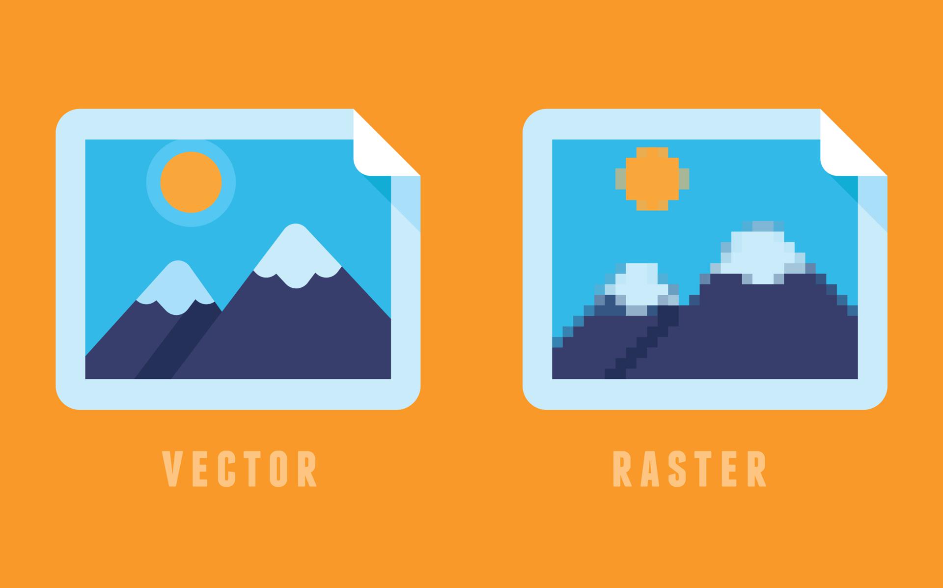
Raster and Vector Images : There are two main type of image files: Raster and Vector. Raster images are created with pixel-based programs or captured with a camera or scanner. They are more common in general such as jpg, gif, png, and are widely used on the web. Vector graphics are created with vector software and are common for images that will be applied onto a physical product. Also used in CAD, engineering, and 3D graphics which we do not provide information nor services for.
2D model:
Process
Step 1: Use 2D render software
Step 2: Select plane to work on from top / front/right
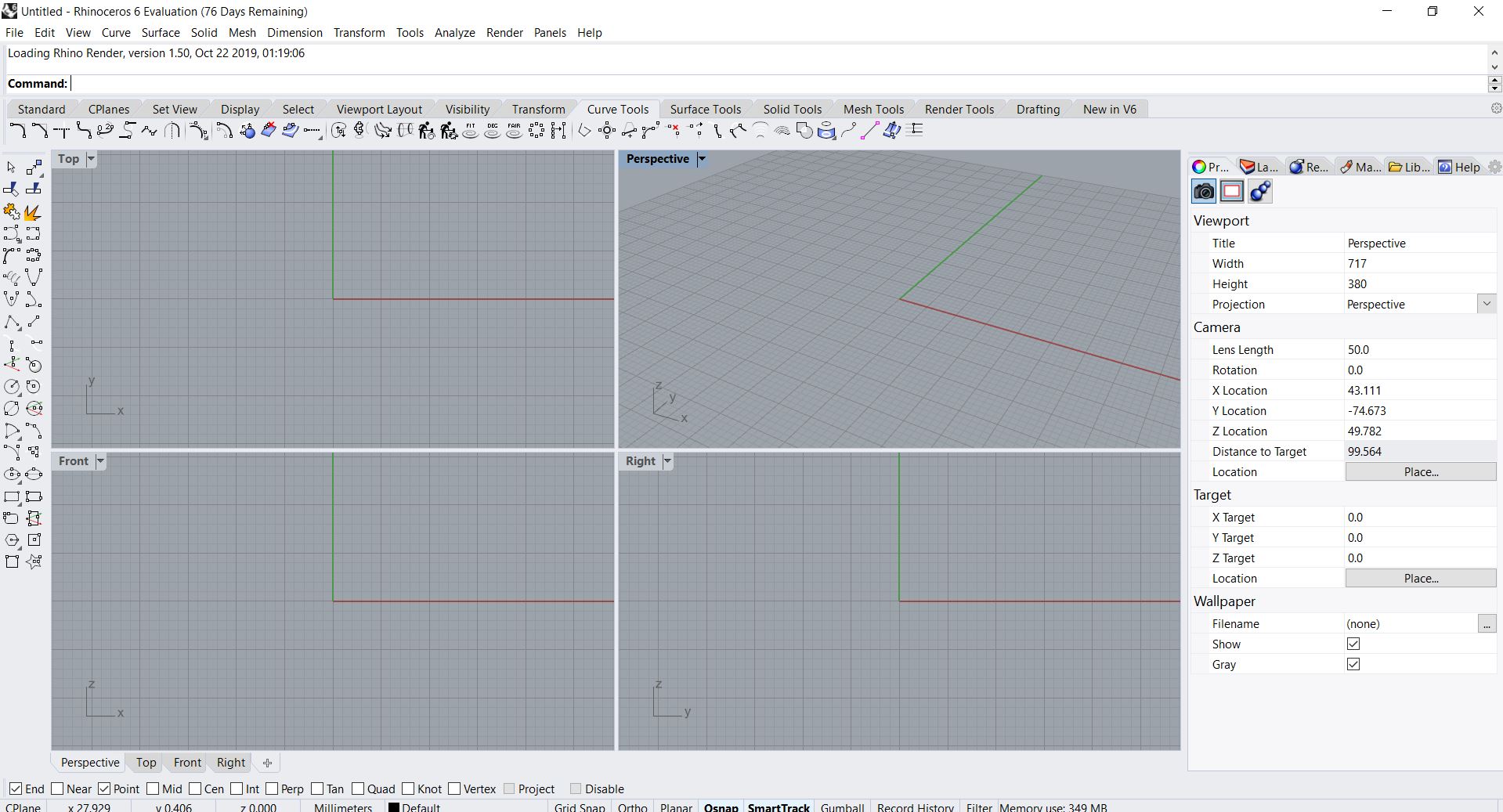
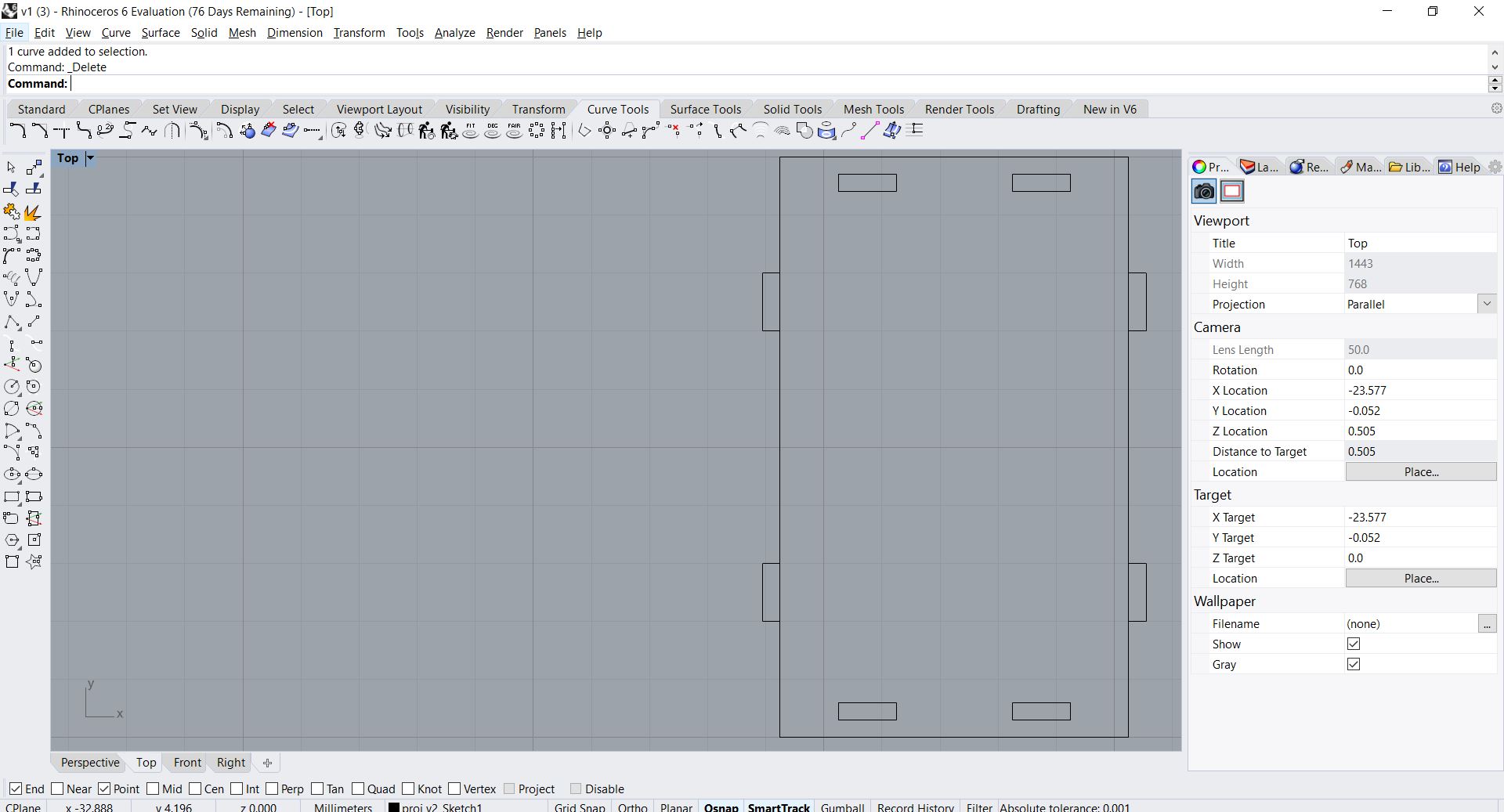
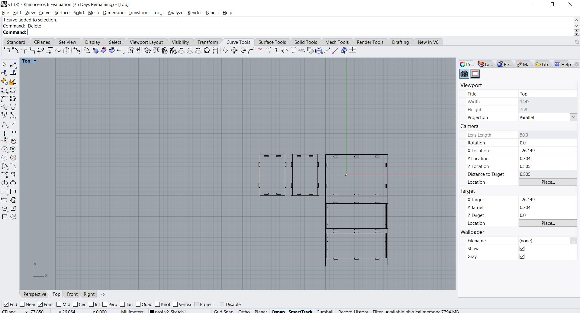
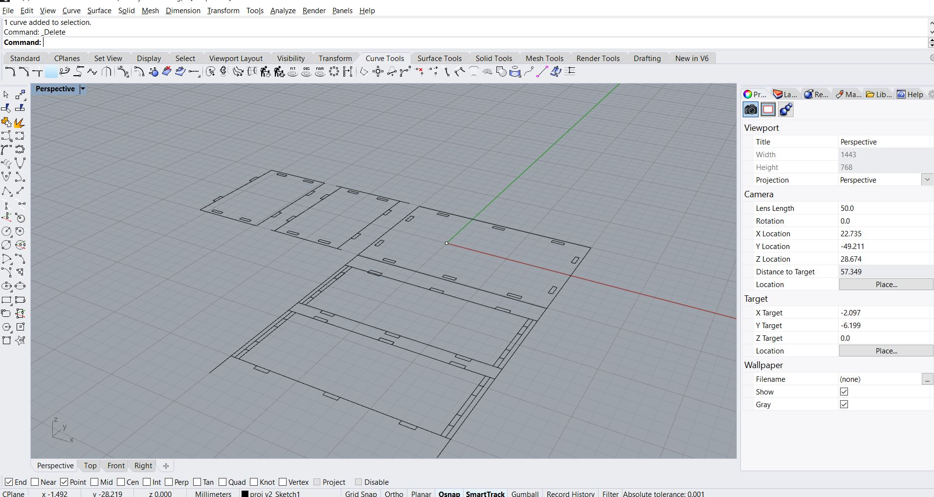
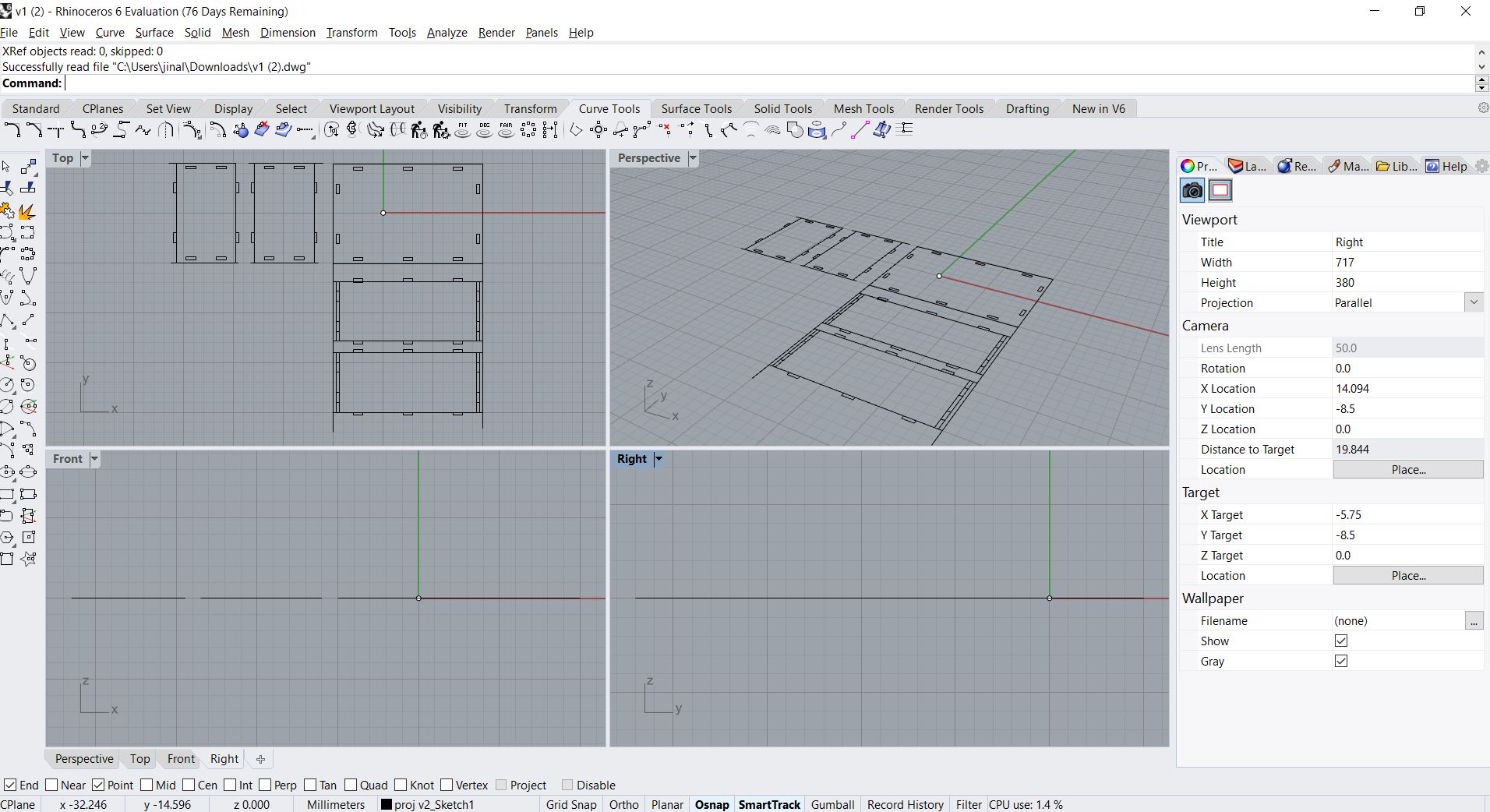
Step 3: start making render
3D Model
Computer-aided design, or more commonly referred to as CAD, 3D models. 3D models are typically either used for digital applications such as animation or for manufacturing/prototyping processes like 3D printing.
Software: AutoCAD, Fusion 360, InventorLT, Solidworks, Cinema 4D, Rhino
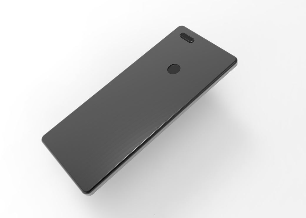
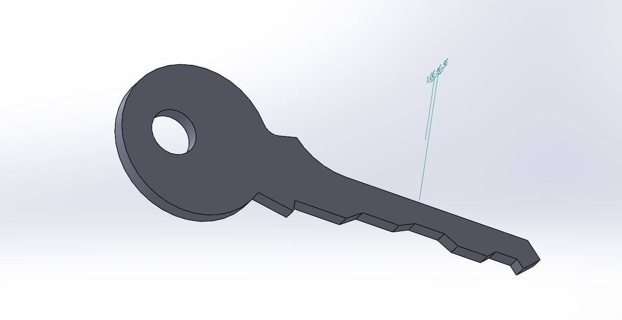
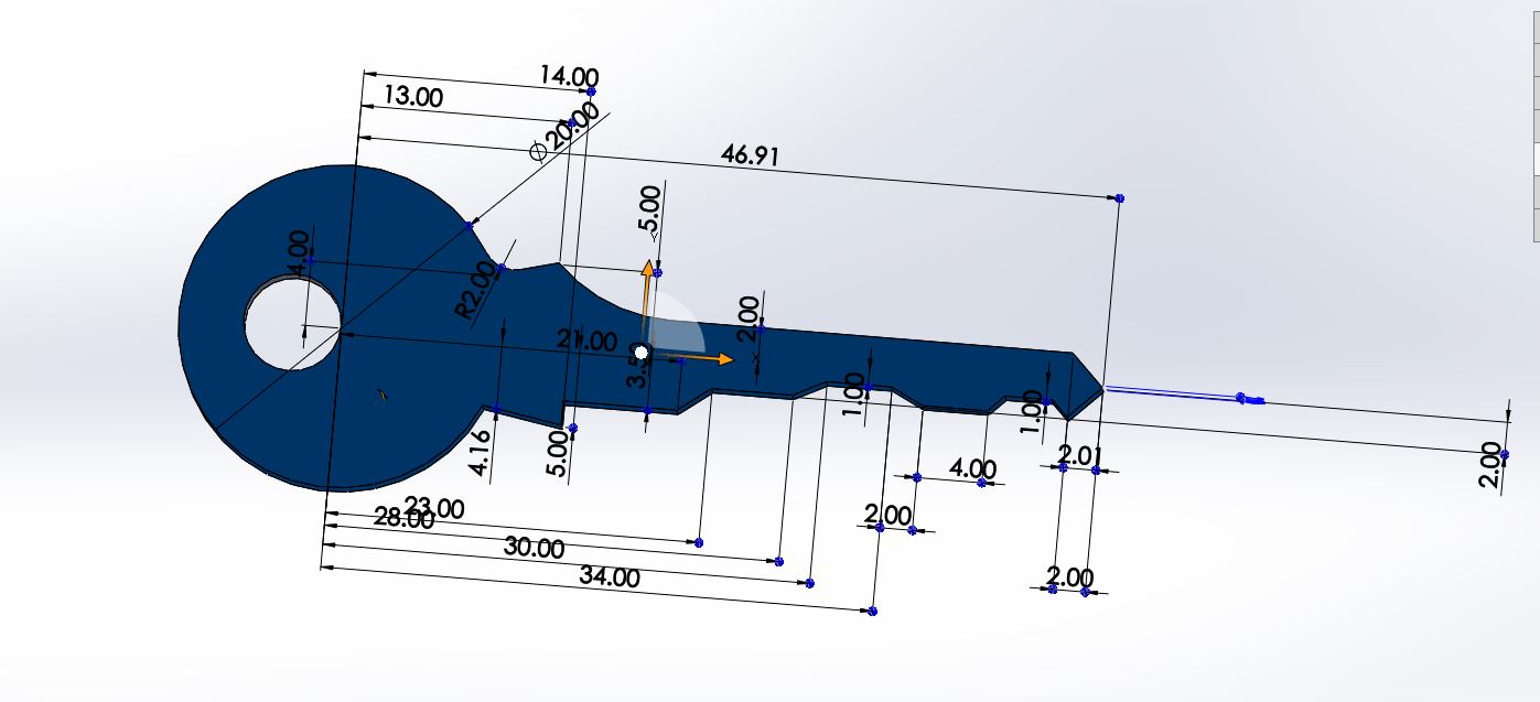
3D model
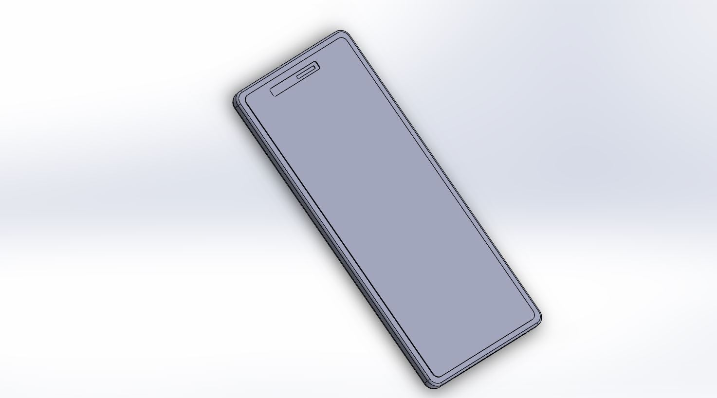
Rendered version of the 3D-model
Process in Modelling
Parametric modeling allows the operator to use what is referred to as "design intent". The objects and features created are modifiable. Any future modifications can be made by changing how the original part was created. If a feature was intended to be located from the center of the part, the operator should locate it from the center of the model. The feature could be located using any geometric object already available in the part, but this random placement would defeat the design intent. If the operator designs the part as it functions the parametric modeler is able to make changes to the part while maintaining geometric and functional relationships.
Direct or explicit modeling provide the ability to edit geometry without a history tree. With direct modeling, once a sketch is used to create geometry the sketch is incorporated into the new geometry and the designer just modifies the geometry without needing the original sketch. As with parametric modeling, direct modeling has the ability to include relationships between selected geometry (e.g., tangency, concentricity).
CAD Possibilities
Parametric Modelling
Those are built on mathematical equations.
1. Constructive Solid Geometry: A model in term of basic and generated solid shapes. it uses boolean operations
2. Boundary Representation: It is formed by defining surface that form sptial boundary.
Computer aided engineering
It describes product engineering process. It is standard in almost any industry that uses sort of design software to develop products