Assignment 4
A. Different sensors in our phone and what they do. Measuring and analyzing the data for a sensor in a log and reporting our findings.
1. Proximity Sensor
Detects when an object is near to the phone and is most commonly used to sense when a phone is near the user's ear to turn off the display thus saving both battery life and preventing accidental screen touches.
2. Accelerometer and gyroscope
Accelerometers in mobile phones are used to detect the orientation of the phone. The gyroscope, or gyro for short, adds an additional dimension to the information supplied by the accelerometer by tracking rotation or twist.
An accelerometer measures the linear acceleration of movement, while a gyro, on the other hand, measures the angular rotational velocity. Both sensors measure the rate of change but they just measure the rate of change for different things.
Accelerometers are also used to provide 'steps' information for a vendors 'health' application.
3. Digital compass
The digital compass that's usually based on a sensor called the magnetometer and provides mobile phones with a simple orientation in relation to the Earth's magnetic field. As a result, your phone always knows which way is North so it can auto rotate your digital maps depending on your physical orientation.
4. Barometer
The barometer assists the GPS chip inside the device to get a faster lock by instantly delivering altitude data. Additionally,
the barometer can be utilized to provide 'floors climbed' information to a phones 'health' app.
With the advent of more accurate indoor navigation, the barometer can assist in determining what floor a user is on within an airport for example.
5. Biometrics
Biometric related sensors provide levels of enhanced security by capturing and validating human-related metrics. Including FingerPrint recognition, IRIS (eye) scanning and full facial recognition.
Biometric sensors provide a more secure but more convenient way to unlock phones and pay for purchases.
Additionally, biometric sensors can also be used to collect a users heart rate.
The log for the accelerometer can be found HEREB. Using an Ultrasonic sensor with ARDUINO board and measuring the distance between the sensor and an object.
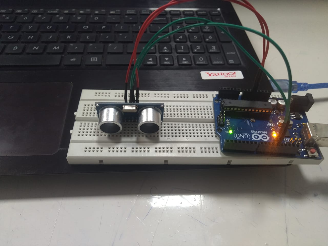
In this experiment, I along with Amit worked on learning how to connect an input device to an Arduino and measure the readings. We used an ultrasonic sensor to measure the distance between the sensor and an object.
Components needed:
- ARDUINO UNO
- Ultrasonic sensor HC-SR04
- Jumper wires
- Bread board
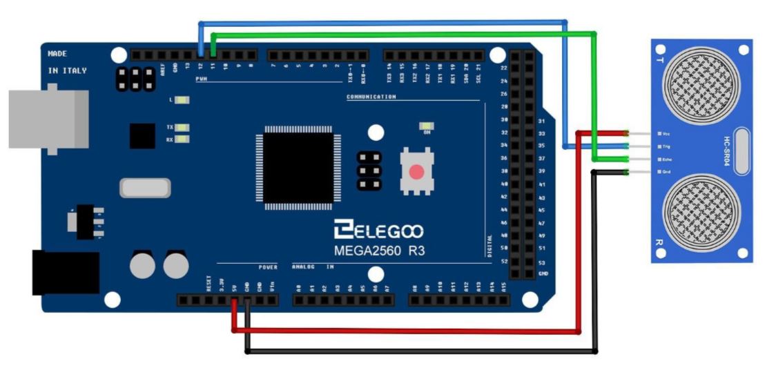
Circuit Diagram
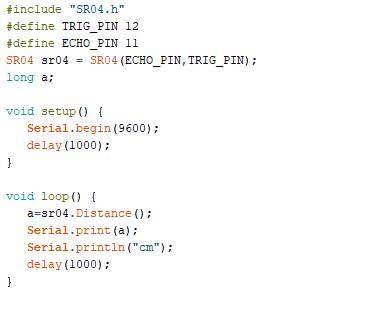
Code
Step 1:
Build the circuit according to the circuit diagram.
Step 2:
Import the library HC-SR04
Step 3:
Input the code in Arduino.
Step 4:
Measure the distance of the sensor from an object. The output will be shown in the serial monitor.
The images and the video of the experiment can be found below
Real-world uses:
- Liquid level sensing
- TRash level monitoring
- Production lines
- Vehicle detection in car washes
Inference from Datasheet
HC-SR04 Specifications
- Working Voltage: DC 5V
- Working Current: 15mA
- Working Frequency: 40Hz
- Max Range: 4m
- Min Range: 2cm
- Measuring Angle: 15 degree
- Trigger Input Signal: 10µS TTL pulse
- Echo Output Signal Input TTL lever signal and the range in proportion
- Dimension 45 * 20 * 15mm
C. Using an LCD display with ARDUINO board
In this experiment I along with Amit worked on learning how to use an LCD display along with an I2C module
Components needed:
- ARDUINO UNO
- LCD RG1602A
- Jumper wires
- I2C module
- Bread board
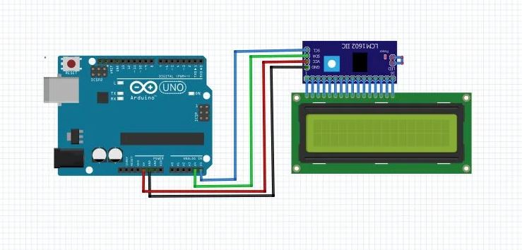
Circuit Diagram
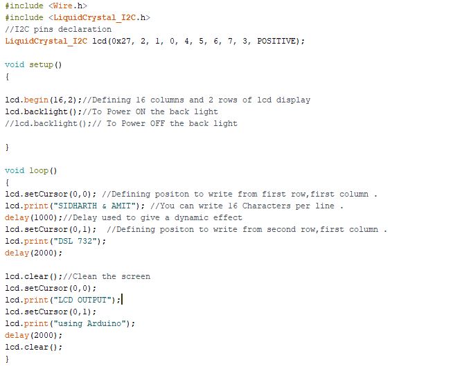
Code
Step1
Build the circuit according to the circuit diagram. Connect the VCC to +5 v and Ground terminal to the ground in Arduino. Connect SDA to A4 and SCL to A5.
Step 2
We must include the two libraries for the code to work.
"Wire.h"
"LiquidCrystal_I2C.h>"
Basic functions we use in code
lcd.begin(16,2); //Defining 16 columns and 2 rows of lcd display
lcd.backlight(); //To Power ON /OFF the back light
lcd.setCursor(0,0); //Defining positon to write from first row,first column .
lcd.setCursor(0,1); //Defining positon to write from second row,first column .
lcd.print(" write here to print"); //You can write 16 Characters per line within quotations.
lcd.clear(); //Clean the screen
Step 3
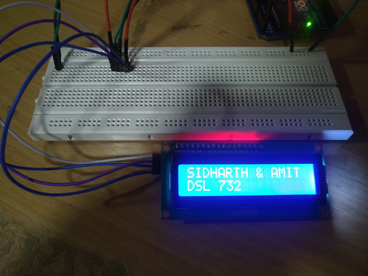
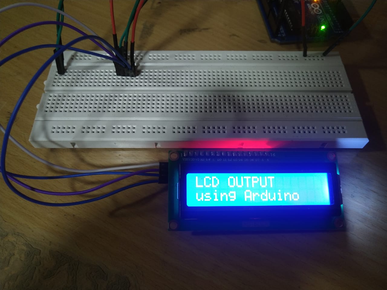
Upload the code to arduino board and check the output
The images and the video of the experiment can be found below
Inference from datasheet
LCD RG1602A Specifications:
Operating Voltage: 5.0 V or 3.0 V
Module size: 80*36*12.5
View area: 64.5*14.6
| PIN NO | SYMBOL | LEVEL | DESCRIPTION |
| 1 | VSS | --- | GROUND FOR LOGIC |
| 2 | VDD | --- | POWER SUPPLY FOR LOGIC |
| 3 | V0 | --- | POWE SUPPLY FOR LCD DRIVE |
| 4 | RS | H/L | REGISTER SELECTION |
| 5 | R/W | H/L | READ/WRITE SELECTION |
| 6 | E | H/L | ENABLE SIGNAL FOR LCM |
| 7-14 | DB0-DB7 | H/L | DATA BUS LINES |
| 15 | LEDA | --- | POWER SUPPLY FOR BACKLIGHT+ |
| 16 | LEDK | --- | POWER SUPPLY FOR BACKLIGHT- |
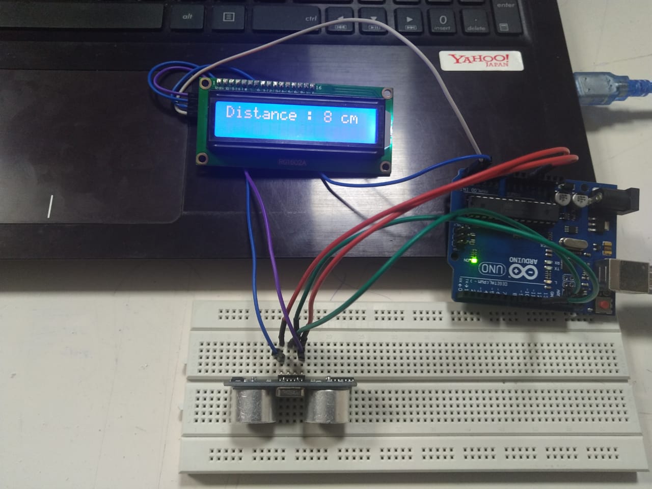
D.Combining input and output devices together using ARDUINO
In this experiment, we tried using an input device and an output device together. We used an ultrasonic sensor to measure the distance between it and an object and an LCD display to show us the distance calculated.
Components needed:
- ARDUINO UNO
- LCD RG1602A
- Ultrasonic sensor HC-SR04
- Jumper wires
- I2C module
- Bread board
Circuit diagram
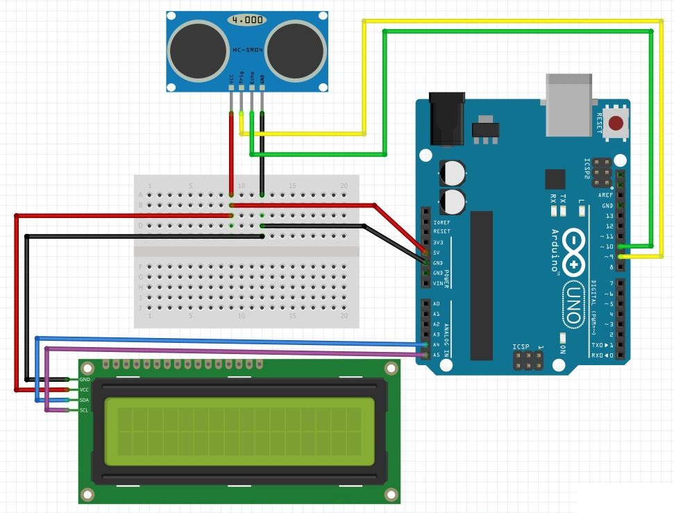
Image credits : https://surtrtech.files.wordpress.com/2018/01/09782-3.png
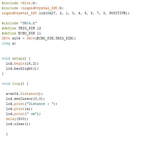
Code
Step1
Build the circuit according to the circuit diagram. Connect the VCC to +5 v and Ground terminal to the ground in Arduino. Connect SDA to A4 and SCL to A5.
Connect the TRIG PIN to 12 and the ECHO to 11
Step 2
Upload the code to the Arduino board and check the output
The images and the video of the experiment can be found below