Assignment 11
CNC Large
CNC Large is used in machining of large fabrications and large castings
Method
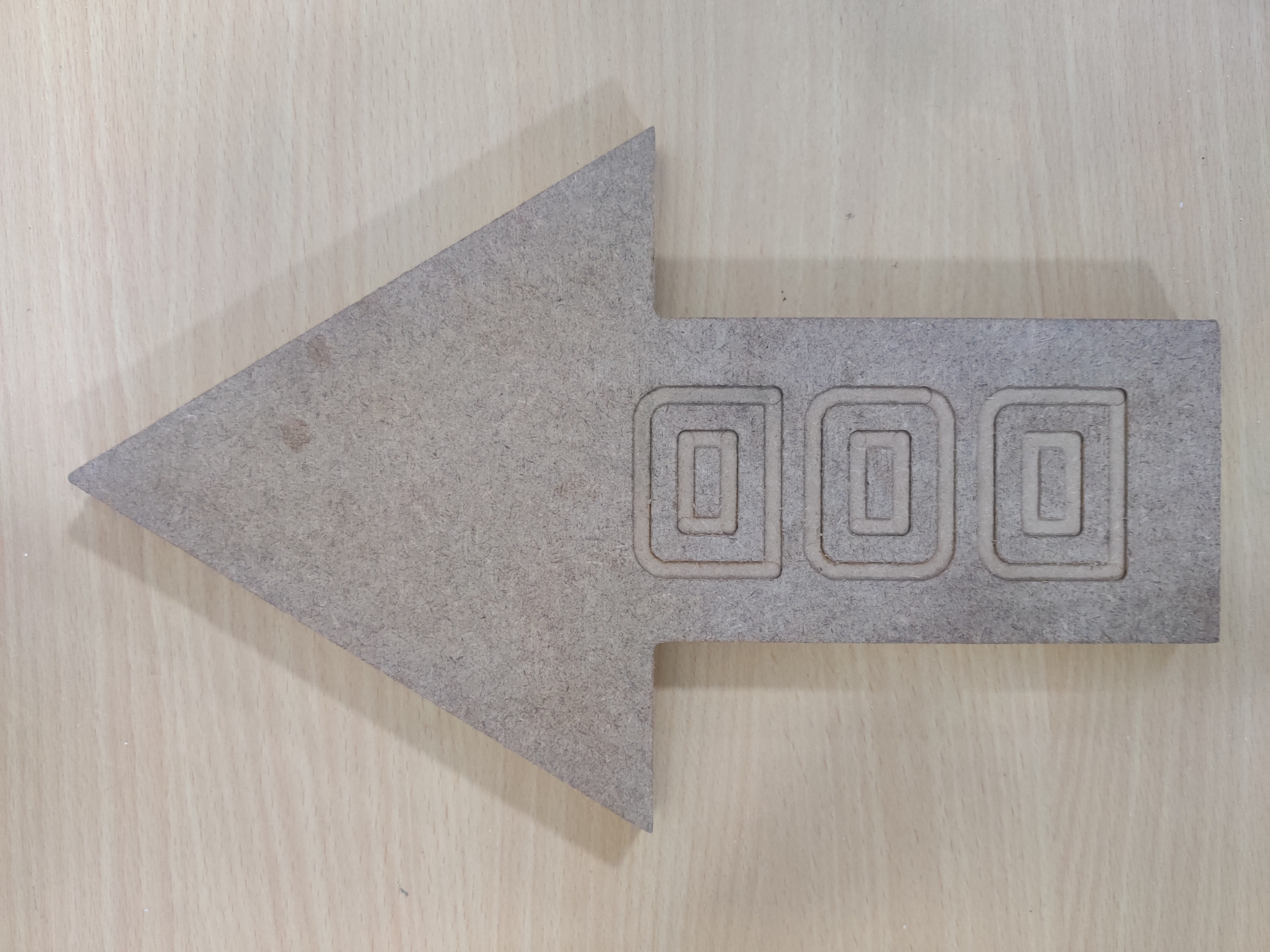
First create the profile of the sketch using CAD software. Install Aspire and open the dxf file in the software. After deciding the point on the board where the CNC will orient to begin the cut, set the origin corner in the drawing accordingly as the CNC will begin cutting in the same orientation. If there is any disjoint in the drawing, check in Edit Objects > Open vectors in the right. Go to join option- to join the missing links In the Toolpath Option at the right- select XY Datum Go to Material Setup and set the following settings Thickness- 17mm XY Datum Corner – (select the corner) Z – Zero – Material Surface Model Position in material – (Gap Above Model- 0mm) Rapid Z gaps over material- Clearance (z) – 5mm Plunge (ZZ) – 5mm Home/ Start Position- X:00, Y:00, Z Gap above the material- 20Select the sketch and then go to Toolpath Operation- Profile Toolpath Start Depth – 0mm Cut Depth – 17mm Tool End Mill > Tool Database > Metric Tools > End Mills > End Mill 6mm (Keep default settings) Machine Vector (where will the drill make the cut- inside, on the line or outside) Select Outside Add tabs to Toolpath The safe tab length is the default value of 12mm, to make it easier to remove we have changed the length to 6mm and thickness 2mm. Add 2 tabs This is provided to prevent the object from moving away due to freedom to motion while the cut is being executed. On adding tabs the machine leaves certain areas uncut to hold the object in place. It can be later removed by chisel after the job is done. Keep the rest of the settings same Safe Z – it is the position when the tool doesn’t have to cut what is the distance in Z place that it moves above the surface (shouldn’t go below 5mm) Go to Calculate Quick Engrave T- quick engraving path Keep the tools same- d software Dia -6 mm, Path Depth- 3 Stepover- 2.4mm (40%) Spindle speed- 12000r.p.m. Purge rate- 20 mm/sec Total Number- 1) Change the option to -Outline Select Calculate option at the bottom- on doing this it will create the tool path and show the arrows in the direction of cut. Then clock on the Close option at the lower bottom Now decide if you will carry out both the actions together or separately. If you are doing it together, decide the order. Engraving should be done first, then profile cut should be carried out. So go to Toolpaths in the right bottom and arrange the order of task. Place Quick Engrave on top. On preview selected toolpath you can see the final cut profile in model Then Save toolpath (marked by a floppy disk icon) present above the Toolpath icon. Check the option- output all toolpaths to one file For saving the file in the correct format- Make the >Post Processor selection Post Processor- WINCNC GCode (mm) (*.tap) Then select Save Toolpath Transfer the file to a pendrive and insert it in the CNC
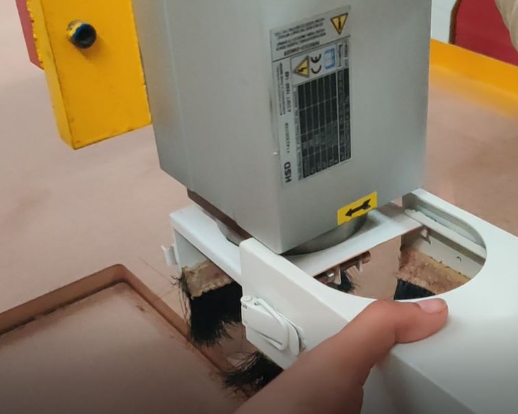
Set the CNC Drill position via the controlls Make one trial off the surface at a higher Z level to check if the path is correct. Then do the actual cut. After orienting the drill at the required origin point on the surface Set X:0 Y:0 Z:0 (XY:0 and YZ:0 in the controller) For trial Run Click Run and Pause, it will display all the options (Udisk file, internal file, recent file) Go to U disk File > Select File> OK Keep the settings for work speed, fast speed, fall down setting the same Press OK
Repeat the above steps. Press OK it will start.