
Assignment 4
Part A: Sensors in the phone List of sensors in the phone- Acclerometer- its the sensor for testing the accleration along a given axis. Acclerometers are built on the principle of measuring the force exerted on a test of unknown mass along a given axis. This also tells the phones software which way the handset is pointing
- Proximity Sensor- detects when a user is holding the phone near their face during a call and turns off the display to prevent keypad presses and battery consumption from the display
- Barometer-measures air pressure. If the barometer goes up it means the weather is going to be fair. If it goes down it measn its going to rain or snow
- Light Sensor- photodetectir that senses the amount of ambient light
- Gyroscope- measures rotational velocity along the Roll, Pitch and Yaw axes.
- Magnetic sensor- used for detecting the orientation of deise with respect to magnertic north. It recieves messages in the form of varying magnetic field produced by nearby electronics
- Heart Rate Monitor (HRM)- measures the heart rate in beats per minute using an optical LED light source and an LED light sensor the light shines through the skin and the sensor measures the amount of light that reflects back. The variations in the light reflections are interpreted as heartbeats
- Fingerprint sensor- once the fingerprint is scanned, the sensor compares the new picture against the pre-stored print to determine if they match
- Acclerometer: The accelerometer detects the orientation of phone and measures its linear acceleration of movement. 3 different colours in the graph shows the movement in 3 different directions. After opening the sensor I moved the phone around to see the movement in the graph
- Light sensor To test this sensor the I exposed the phone to different levels of brightness - first next the window (with max lux levels) that read as level 4 along with a higher lux count,in the next scenario I moved it below the indoor ceiling light (that read as level 3) and the thrid scenario was below a table (that read as level 2)
Position sensor
Part B: Measuring the distance using Ultrasonic Sensors
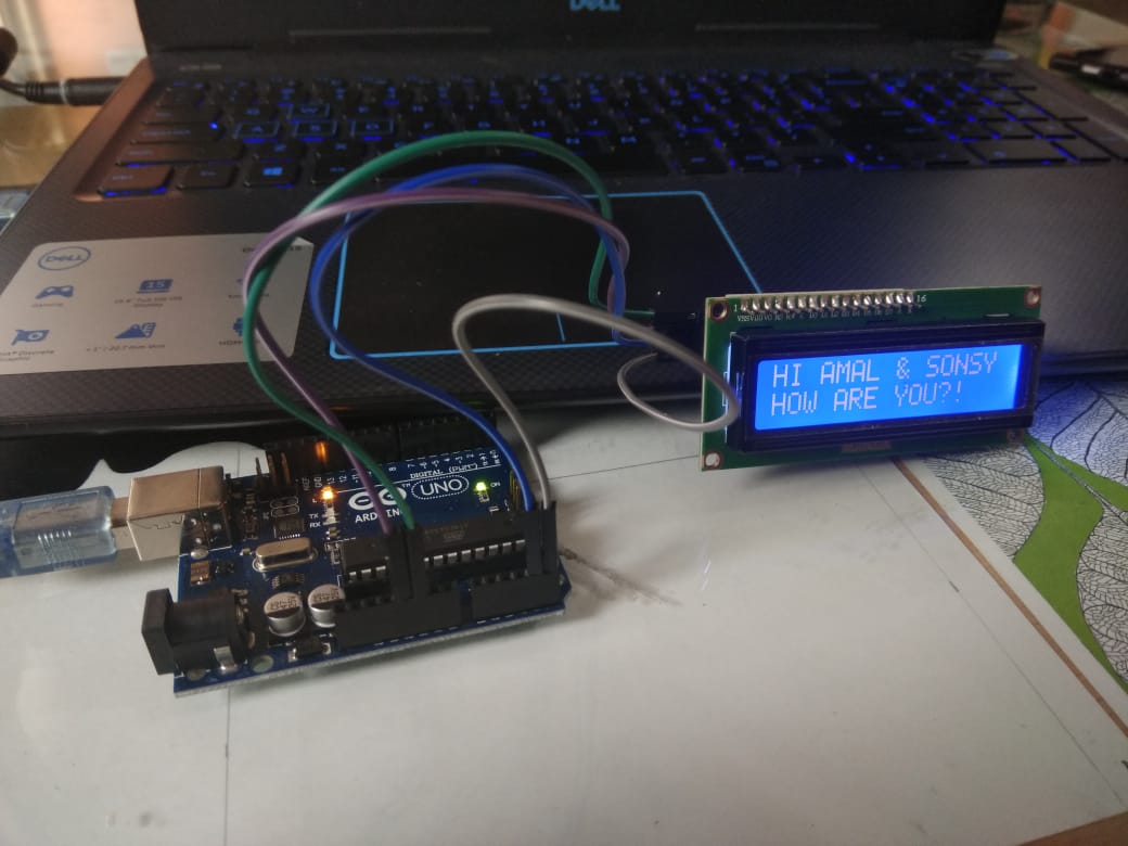
Part C: Output device LCD DisplayStep 1: Wiring the devise
Ultrasonic sensors are used to measure distance by using ultrasonic waves. The sensor head emits an ultrasonic wave and receives the wave reflected back from the target. Ultrasonic Sensors also measure the distance to the target by measuring the time between the emission and reception. The trig pin acts in sending the signal and the echo pin recieves the signal and the time in between is used to find the location of the object Wiring the ultrasonic sensor with the arduino For measuring the distance the ultrasonic sensor was connected to the breadboard and the following connections were made Vcc - 5v Trig - pin 12 (input) Echo - pin 11 (output) GND - GND The data connection was made through the trig pin and the echo pin connection Power and ground connection was made through the Vcc and ground point.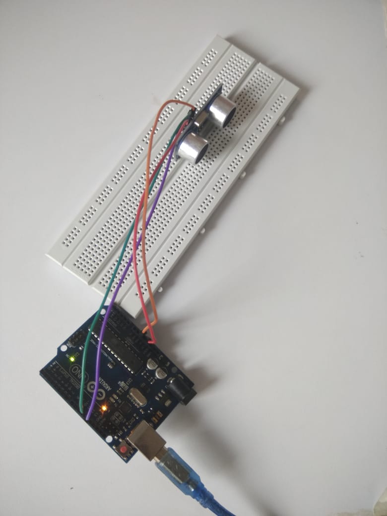
Step 2: Writing the code
Arduino IDE was used to write the code. The code used for this used specified the data pin (trig and echo). The trig pin acts in sending the signal and the echo pin recieves the signal and the time in between is used to find the location of the object Since Both sides of the serial connection (i.e. the Arduino and your computer) need to be set to use the same speed serial connection in order to get any sort of intelligible data -Serial.begin command was used to set the same transmission rate between the computer and the ARDUINO (9600 is the default value used)Library file was attatched to the existing code to make the program shorter. The library was included at the beginning of the code and simple commands were used to control the behaviour of the sensor Sketch> include library> .ZIP library (library attatchment made at the beginning of the code)
For printing the display in the monitor void loop was set up with distance, unit and delay was provided There was an error in running the program- the port for ARDUINO connection was wrongly selected. So we opened Tools> Port: (and selected the correct port) After fixing the error, then to read the data the serial monitor was opened- Tools> Serial Monitor The screen displayed the changing distance of obstacles in front of the sensor

use could be mounted to cycles to create smart cycles
Part D: Combining a temperature and humidity sensor with an LCD monitorStep 1: Wiring the devise
The LCD used was an LED backlight with two rows of display with up to 16 characters on each row. Its is used to show letters and characters. 1602 means it displays 2 lines of 16 characters. Each position can display one character. The four connection was used in this case. The LCD used was an LED backlight with two rows of display with up to 16 characters on each row. GND - GND VCC - 5V SDA - A4 SCL - A5 The data connection was made through the SDA and the SLC pin connection Power and ground connection was made through the Vcc and ground point.Step 2: Writing the code
LiquidCrystal library was included at the beginning of the code to make it shorter. In the void setup, lcd.begin() was used to initialize the interface of the LCD screen lcd.backlight was used to turn on the backlight for the display syntax used- lcd.clear -was used to position the cursor at the upper left corner (clearing the old display) lcd.print -the information that we want to be displayed on the monitor lcd.setCursor -set the location at which subsequent text written to the LCD will be displayed. Here this was used to specify the position of the second line of text. Position used was (0,1) to begin in the second line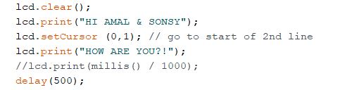
Input device - DTH 11 temperature and humidity sensor Output device - LCD monitor
Step 1: Wiring the devise
The LCD used was an LED backlight with two rows of display with up to 16 characters on each row. Its is used to show letters and characters. 1602 means it displays 2 lines of 16 characters . For the DTH 11 GND - GND VDD - 5V NC - Empty pin DATA - PIN 7 The DTH 11 sensor contains a callibrated digital signal output of temperature and humidity. The sensor includes a resistive sense of wet components and a NTC temperature measurement device For the LCD Display GND - GND VCC - 5V SDA - A4 SCL - A5 For the LCD display The code was edited to clear the previos text,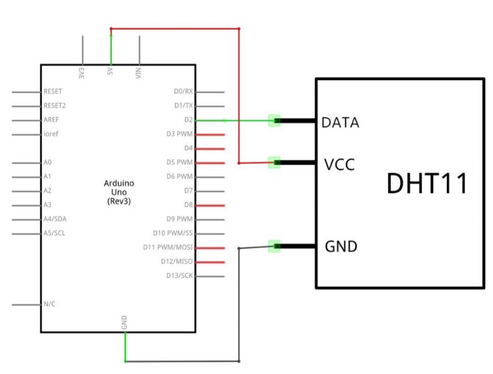
Step 2: Writing the code
Included both the libraries for the operation in the same process as mentioned above syntax float var = val var = variable name val = value assigned to the variable