Assignment 6
2D CAD modeling

models are flat, two-dimensional drawings that provide overall dimensions, layouts, and information needed to reproduce or build the subject. Examples of these
types of drawings are found in a variety of industries including aerospace, architecture, automotive, cartography, civil engineering, interior design,
landscaping, and even fashion.

2D Graphic could be Vector or Raster graphics
The difference between vector and raster graphics is that raster graphics are composed of pixels, while vector graphics are composed of paths. A raster graphic,
such as a gif or jpeg, is an array of pixels of various colors, which together form an image.
A vector graphic, such as an .eps file or Adobe Illustrator file, is composed of paths, or lines, that are either straight or curved. The data file for a vector image contains
the points where the paths start and end, how much the paths curve, and the colors that either border or fill the paths. Because vector graphics are not made of pixels,
the images can be scaled to be very large without losing quality. Raster graphics, on the other hand, become "blocky," since each pixel increases in size as the image is made larger.


Examples of 2D software- Photoshop, Autocad, GIMP, Indesign, Illustrator

3D CAD modeling

In 3D computer graphics, 3D modeling is the process of developing a mathematical representation of any surface of an object (either inanimate or living) in three
dimensions via specialized software. The product is called a 3D model. Someone who works with 3D models may be referred to as a 3D artist. It can be displayed as a
two-dimensional image through a process called 3D rendering or used in a computer simulation of physical phenomena. The model can also be physically created using
3D printing devices.

Examples of 2D software- Fusion 360, Rhino, Revit, Inventor LT, Solid Works, Cinema 4D, Autocad 3D GIMP, Indesign, Illustrator
The 3D printing process builds a three-dimensional object from a computer-aided design (CAD) model, usually by successively adding material layer by layer,
which is why it is also called additive manufacturing.
It covers a variety of processes in which material is joined or solidified under computer control to create a three-dimensional object,
with material being added together (such as liquid molecules or powder grains being fused together), typically layer by layer.
2D Graphics- Drawing a profile
For 2D drawing I used Autocad. Using the software, I prepared the outline of the cuts for the Acrylic sheet. For my project which is a mirror clock, I needed to laser cut the Acrylic sheets into circles of required dimension and a radial grid around for diffused acrylic sheets slots.First I calculated the required radius to get a circumference of 1m. I set the standard dimensions in Autocad to mm and in decimals (by using the unit command). Then I used the circle command in Autocad to draw the dimensioned profile of the circle by entering the value for the radius.
After the basic outline I drew a radial construction grid of lines with an angle of 6 degrees between them. I drew a second circle of 109 mm radius. Separately I prepared a grid of 8.5mm by 50mm (60 pieces) that would be the dimension for cutting my acrylic rod.
With the ortho snap on I copied and then pasted one rod on the circle with radial grid. Then I made a polar array of the rod using the polar array command (with the center of circle as base point and 6-degree angle between). I saved the file in .dwg format
Importing the file to Illustrator I imported the file into Illustrated to convert it to vector path and saved the file in .ai format.
3D Modeling Lamp
After saving the file in a pendrive I connected the it to the printed and opened the model file and selected it to print. Print will set position and temperature(Nozzle Temp - 216 Deg Cel & Bed Temp - 60 Deg Cel) according to instructions set in file. For 3D model I prepared a lamp shade using Fusion 360. From the sketch menu I selected create sketch, then I selected the plane for sketching. Then I selected the line tool and started at the origin and drew a vertical line of required dimension(110mm in this case). Then used line tool to draw two lines 23.4mm at top and 45mm at bottom. Then I connected the bottom left to the top left using spline tool. Then I used the control point to change its curvature, view the form from the home menu and finish the sketch. From the create menu I selected the revolve option. Profile- the sketch I created and axis is the vertical line.Then I split the body at top and bottom. From construction menu I selected offset plane. I selected plane at the top that I wanted to offset, then I offset it by entering the value. Under modify menu I selected split the body – selected the body to split and then selected the plane. Body 1, Body 2 were created then I hid the plane, then I hid the bottom portion. Then to create a hole (for fitting the holder). Then I selected create sketch and selected the top face. Then I selected sketch, center diameter circle (leaving 1mm gap around).
(Parametric) Then I stop the sketch and extrude it – changed the distance, and for the surface I wanted to extrude I selected the bottom surface. If I change the position of construction plane then the extrusion also changes. From modify drop down menu I choose shell and selected the faces that I would like to remove. I selected the top face and using control I also select the bottom face and I enter in the wall thickness (1.6mm). Then I offset the bottom face using the same process. Now I have 3 bodies- body 1,2 and 3. Now I create the pattern in the middle shape. I hide the top and the bottom part. Then I create a new sketch. Next I want to project the sketch in the existing geometry, under sketch menu I will choose project and in selection filter I will change it to bodies and I will select the body. Then using line tool I create two diagonal lines. I add a parallel constraint to make sure the two lines are parallel. Then using sketch dimension, I fix the dimension between the two lines.
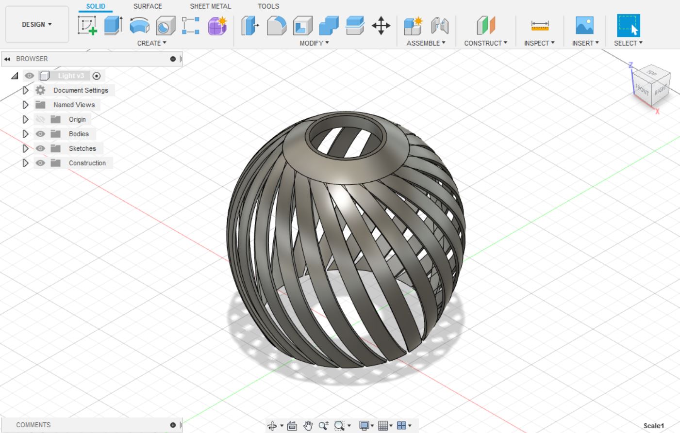
From create menu I choose extrude and drag the profile I created all the way through and change the one way to symmetric to make sure the extrusion is created on both sides of the solids. Instead of a cut I changed the property to intersect. This created two symmetric strips that can be patterned around in a circle.
From create menu I select pattern, circular pattern, changed the pattern type to bodies. For the body I select one strip and for the axis I select the Z axis. Then I specify the quantity – 22 and press ok. (I created a grid only on one direction as my final print model was going to be small, a pattern can be created on the other side as well using the same process). For making changes in previous steps I went to the timeline and edited the steps by right clicking on it and choosing edit feature. Everything in the model changes accordingly. Finally I export the model as .stl file