A microcontroller is a compact integrated circuit designed to govern a specific operation in an embedded system
where a typical microcontroller includes a processor, memory and input/output (I/O) peripherals on a single chip.
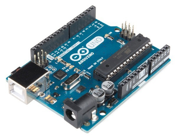
As an instance, Arduino is a microcontroller based platform (ATMEGA 328 for the UNO) and as per the assignment brief,
we need to perform the following tasks using this micro-controller:
1. Write your first name by switching 9 LEDs ON/OFF with the help of push button such that with press of one push
button, the letters of the name blink with a delay of 1000 ms.
2. With press of another push button, all LEDs blink ON and then OFF with a delay of 1000 ms five times.
3. Extra credit: Blink the LEDs ON/OFF as per the letter typed on the Serial Monitor using those 9 LEDs.
This assignment had to be done in a group of two and hence, I paired up with Atul Kumar who has an Architect
background.
Process:
1. Tools and Components Used
Electrical Components - The Electrical Components that were used to
perform the assignment includes the following:
1. LED (x9)
2. Push Buttons (x2)
3. Resistors (x9)
4. Jumper wires
5. Breadboard
6. USB cable (type A to type B)
Arduino UNO R3 Board - The Arduino UNO R3 is a microcontroller board
based on a removable, dual-inline-package (DIP) ATmega328 AVR microcontroller. It has 20 digital input/output pins
(of which 6 can be used as PWM Outputs and 6 can be used as Analog Inputs).
Arduino IDE Software - The Arduino IDE is an open-source software that
makes it easy to write code and upload it to the board. The environment is written in Java and based on Processing
and other open-source software and can run on Windows, Mac OS X, and Linux.
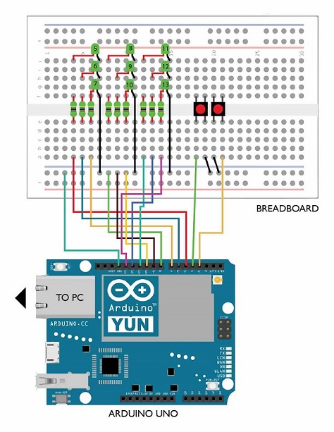
2. Circuit Diagram and Arrangements
After understanding the basic site structure and acquiring knowledge about
Arduino UNO, we started working on the Circuit Diagram and the associated Arrangements. The circuit was arranged on
the basis of the following concept:
1. LEDs have ends with fixed polarity. The anode has to be connected individually to seperate pins (as per the program)
and the cathode can be common grounded (as per the program).
2. Push Buttons have no fixed ends as such. Thus, one end has to be connected with an assigned pin and other end can be
common grounded.
3. Since the LEDs operate at low voltages, there should be a resistor provided with each LED to avoid it from burning.
We tried putting a common resistor at the common cathode end and that worked as well but the issue was, as the number
of LEDs increased gradually, their brightness fluctuated. So, we provided each LED with its own resistor.
4. Arduino was connected to the PC using a USB cable for constant power supply.
5. Each of the LEDs was given a number during the rough work so to avoid any confusion further.
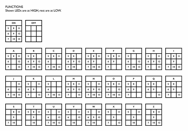
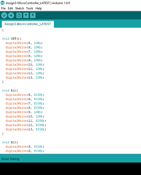
3. Alphabet Configurations
After working with the circuit diagram on paper and on the Arduino UNO R3 Board, we followed the layout of those 9 LEDs to conclude the configuration of all the alphabets. We coded the methods for each of the alphabets such that (as per the image), each number shown represents the corresponding pin to be at 'HIGH' and the missing one to be at 'LOW'.
4. Code Walkthroughs
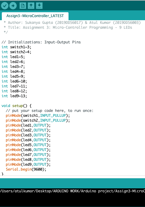
1. Initialization/Setup Code - Here, LEDs and Push buttons are being
assigned to the Arduino UNO R3 Board pins and as you can notice, each of the LEDs have also been renamed as 'led1',
'led2', and so on and are declared global for easy reference. However, this naming was not used later so as to
avoid confusion between the LED numbers and the Board pin numbers.
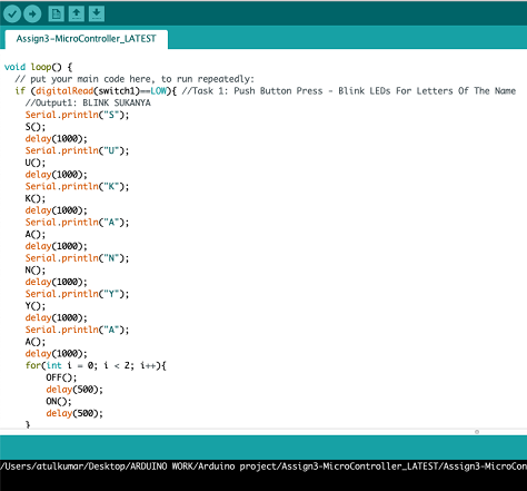
2. Task 1 Execution - The task of blinking the names of both the group members has been
addressed using this code snippet. To distinguish between the two names (while blinking the LEDs), a buffer
double-print pattern between the two names have been put up.
3. Task 2 Execution - The task of blinking the LEDs ON/OFF with a delay of every 1000ms
5 times in a row can be addressed in this code snippet.
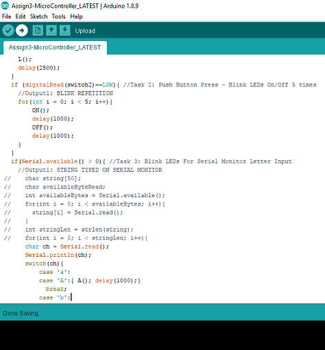
4. Task 3 Execution - The task of blinking the letter typed in the Serial Monitor has been
addressed using this code snippet. We have kept the inputs to be not case-sensitive and hence both uppercase and
lowercase alphabets will be considered as valid inputs. However, we tried writing a program which could take inputs
consisting of multiple characters i.e. a complete string along with spaces but due to time constraints, we couldn't
get through it but have achieved till about 90%. The code written for this purpose can be seen in the comments.
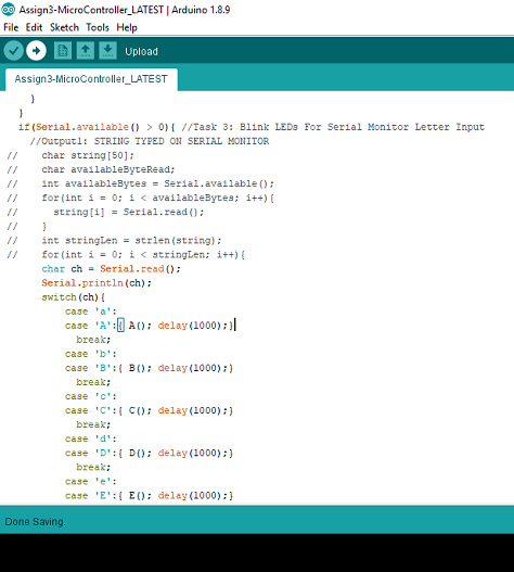
5. Alphabet/Method Definitions - Here, the method definitions for each alphabet can be seen according to the Configurations discussed before.
Result:
The assignment has given me relatively good insights on Arduino Programming
since I come from a Computer Science background and hence microcontroller interfacing and programming came out to be
a really exciting task during the entire course of the assignment duration.
It has a huge scope of betterment and corrections although.
1. The circuit can be made in a more cleaner way on the breadboard.
2. The work still has to be done on the input print code. We want to make it work for multiple character input
involving alphabets and numbers also. The program has already been written but has a few bugs in it.
3. I need to work a lot on my circuit designing and interfacing, thereby enhancing my coding skills on a new interface
and develop electrical knowledge throughout the course.