A microcontroller is a compact integrated circuit designed to govern a specific operation in an embedded system
where a typical microcontroller includes a processor, memory and input/output (I/O) peripherals on a single chip.
As an instance, Arduino is a microcontroller based platform (ATMEGA 328 for the UNO) and as per the assignment brief,
we need to perform the following tasks using this micro-controller:
1. What are the different sensors in your phone and what do they do? Conduct an experiment to measure and analyze
the data for a sensor in a log and report your findings.
2. Add an input device to a microcontroller board and read it. Document the process. Find an application
for it in the real world around you. Please write in your own words what did you infer from the datasheet of the
input device that you used?
3. Add an output device to a microcontroller board and program it to do something. Please write in your own words
what did you infer from the datasheet of the output device that you used?
3. Extra credit: Combine the input and output device to work together.
This assignment had to be done in a group of two and hence, I paired up with Atul Kumar who has an Architect
background.For this assignment, we wanted to create something which could be of some use in practical world. So
we decided to build a prototype of a reverse parking assistance system that could guide users while parking there vehicles.
Task Walkthroughs:
1. Task 1 Execution
Nowadays, smart phones have evolved to perform a number of tasks. All these tasks are performed
by a complex combination and arrangement of input and output devices that capture and analyze data according to the use.
Sensors are one of these techs that are incorporated in the smart phones to analyze their surroundings and capture
specific data for further analysis and processing.
The phone models analyzed in this task are as follows:
1. Xiaomi MI A2 - Atul's Handset
2. OonePlus 6T - Sukanya's Handset

The tool used to analyze these sensors is an Android Application called 'Sensors'.The following
are the types of the sensors that were found in these phones:
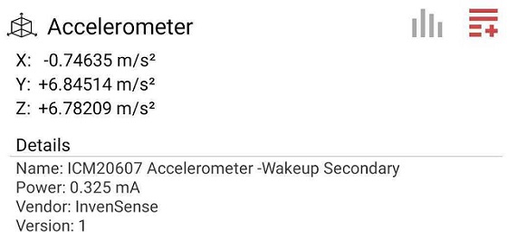
Accelerometer
PRESENT IN: MI A2 | OnePlus 6T
USAGE: Measures acceleration forces and detect motions - in Navigation, VR,
Gaming, etc.
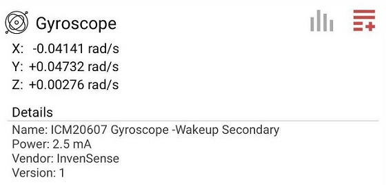
Gyroscope
PRESENT IN: MI A2 | OnePlus 6T
USAGE: Measures and maintains orientation and angular velocity - in VR, Gaming, etc.
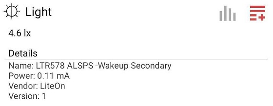
Ambient Light Sensor
PRESENT IN: MI A2 | OnePlus 6T
USAGE: Detects the intensity of light, used in automatic brightness control of display.
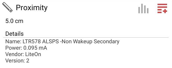
Proximity Sensor
PRESENT IN: MI A2 | OnePlus 6T
USAGE: Detects the distance of an object, used in turning the screen off when the phone
is brought near the ears.
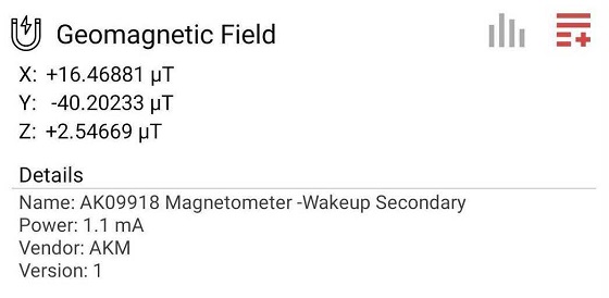
Hall Sensor
PRESENT IN: MI A2 | OnePlus 6T
USAGE: Measures the magnitude of a magnetic field.
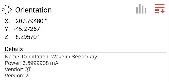
E-Compass
PRESENT IN: MI A2 | OnePlus 6T
USAGE: Detects the orientation of the phone, used in Navigation, etc.
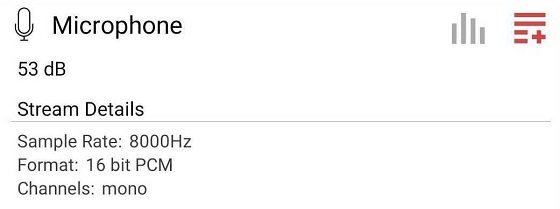
Microphone
PRESENT IN: MI A2 | OnePlus 6T
USAGE: Detects and inputs audio signals, used for audio capturing during calls,
audio recording, video capturing, etc.
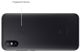
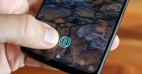
Finger Print Sensor
PRESENT IN: MI A2 | OnePlus 6T
USAGE: Scans the fingerprint of the users, - in MI A2, the fingerpfint sensor found was
the regular one while OnePlus 6T had an optical finger print sensor.
2. Task 2,3, Extra Credit Execution
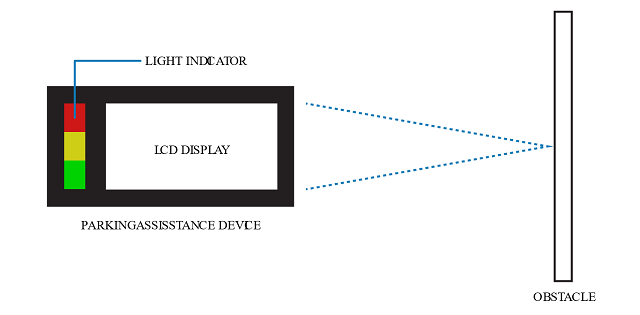
In order to complete Tasks 2, 3, and Extra Credit, we thought of building a reverse parking
assisstance system. The system will work in a manner such that it will be easier for the users to get a sense of
favourable gap between the car and the obstacle.
Tools and Components Used - The Electrical Components that were used to
perform the assignment includes the following:
1. Arduino UNO R3 Board
2. 3 LEDs (Green, Yellow and Red)
3. Ultrasonic Sensor (HC-R04)
4. LCD Display (RG1602A)
5. LCD Interface (1602 I2C)
6. Misc. Components (Breadboard, jumper wires, etc.)
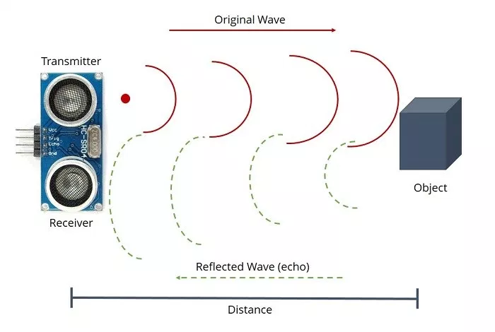
Input Device - Ultrasonic Sensor HC-SR04
As per the DATASHEET - The HC-SR04 is an Ultrasonic sensor that allows the user to measure distance of an object
from the sensor itself. It works on the simple principle of SONAR.
SPECIFICATIONS
Purpose: To determine distance of an object from the sensor.
Range: 2cm to 400 cm
Resolution: 3mm
Power Supply: +5V DC
Quiescent Current: <2mA
Working Currnt: 15mA
Effectual Angle: <15 degrees
Measuring angle: 30 degrees
Trigger input Pulse width: 10uS
Dimension: 45mmx20mmx15mm
The device needs to have "Ultrasonic.h" library included in the code to function.
The datasheet mentions various aspects of the device related to its functioning, uses, interface, assembly, etc.
Before using the sensor for the first time, going through the its datasheet is recommneded.
LINK TO DATASHEET: DOWNLOAD HERE
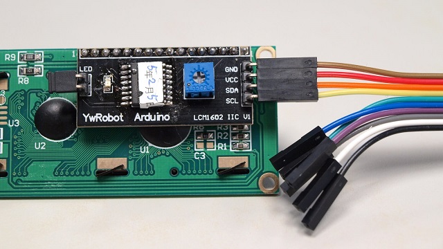
Output Device - LCD Display RG1602 (with LCM 1602 I2C module)
As per the DATASHEET - This device is a 16x2 LCD display i.e. it has the ability to display 2 lines of text with
16 characters in each lines. Since, the output for the LCD has 16 pins, its difficult to connect the LCD module directly
to the Arduino due to lack of pins available on Arduino. The LCM 1602 I2C module helps in reducing the pins to 4 which
makes it easy for the user to connect the LCD to Arduino.
SPECIFICATIONS
Purpose: To print characters as intended
Display format: 16 characters x 2 lines
Display font: 5x8 dots
Power Supply: +5V DC
The device needs to have "LiquidCrystal_I2C.h" and "Wire.h" libraries included in the code, in order to function.
The data sheet also mentions the functioning, requirements, specifications and other aspects in detail.
LINK TO DATASHEET: DOWNLOAD HERE
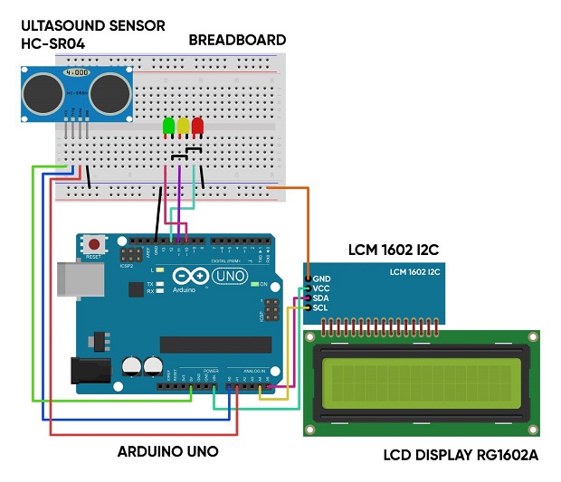
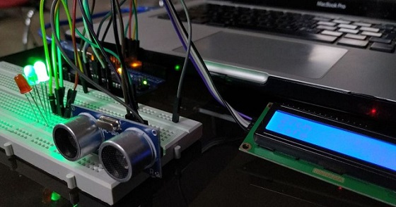
Circuit Diagram and Arrangements
The Ultrasonic Sensor is measuring the distance, thus satisfying the criteria for Task 2.
The LCD display and the LEDs are being used to output the distance, thus satisfying the criteria for Task3.
The final assembly as following is satisfying the critera for the Extra Credit Task.
Code Walkthroughs
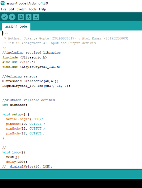
1. Initialization/Setup Code - The Input and Output Devices need to
access their respective libraries in order to process. The libraries for the devices are as follows:
-"Ultrasonic.h" for the Ultrasonic sensor
-"LiquidCrystal_I2C.h" for the LCD display
-"Wire.h" for the LCM 1602 I2c module
These libraries can be downloaded easily via web and can be installed easily in Arduino IDE through
"Sketch > Include library > Add .ZIP library"
2. Core Code - The Ultrasound Sensor measures the distance and the
distance measured is taken in an integer variable as "distance". This distance is compared to certain sets of instructions
(using if and else statement) and on the basis of those instructional comparisons, a few self-written functions are
executed.
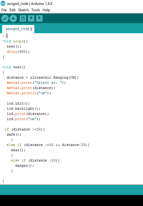
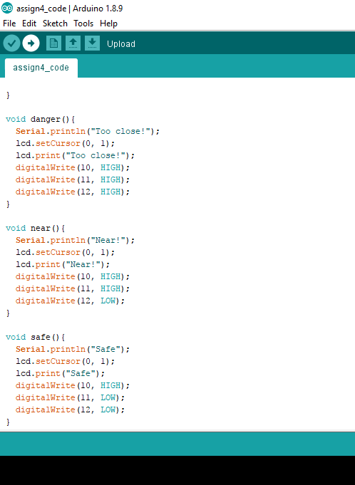
The following information is printed in the serial monitor:
Object at: x cm (where x is the distance)
The distance will be shown on the first line of LCD display as well.
If the distance is more than 20cm,
The serial monitor will show Safe.
The second line of LCD will show Safe.
The GREEN LED will light up.
If the distance is between 10 and 20cm,
The serial monitor will show Near!.
The second line of LCD will show Near!.
The GREEN and YELLOW LEDs will light up.
If the distance is less than 10cm,
The serial monitor will show Too close!.
The second line of LCD will show Too close!.
The GREEN, YELLOW and RED LEDs will light up.
Result:
The assignment has given me relatively good insights on Arduino Programming
since I come from a Computer Science background and hence microcontroller input and output device interfacing came out
to be a really exciting task.
The whole setup was working fine considering the Ultrasonic Sensor and the LCD Display separately and as a whole.
It has a huge scope of betterment and corrections although.
1. Working upon the latency between the information displayed upon the Serial monitor and the LCD monitor.
2. More LEDs can be introduced to create a line of LEDs which will make the concept clearer.
3. Assembly can be done in a neat way.
4. A battery based setup can be introduced.