Computer-aided design is the use of computers to aid in the creation, modification, analysis, or optimization of a design. CAD software is used to increase the productivity of the designer, improve the quality of design, improve communications through documentation, and to create a database for manufacturing.
1. 2D CAD
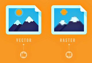
In 2D CAD, there are mainly two image concepts: Raster Image and Vector
Image.
Raster Images are mainly composed of pixels whereas Vector Images are composed of lines and curves
known as paths, that are rooted in mathematical theory. Raster Images when zoomed beyond an extent gets pixelated
whereas Vector Images remains the same.
An image representing the difference between Raster and Vector Images is shown below:
The different softwares for 2D CAD Modelling include:
1. Raster Images - Adobe Photoshop, GIMP
2. Vector Images - Adobe Illustrator, InkScape, CorelDraw
1.1. 2D CAD-Raster Modelling:
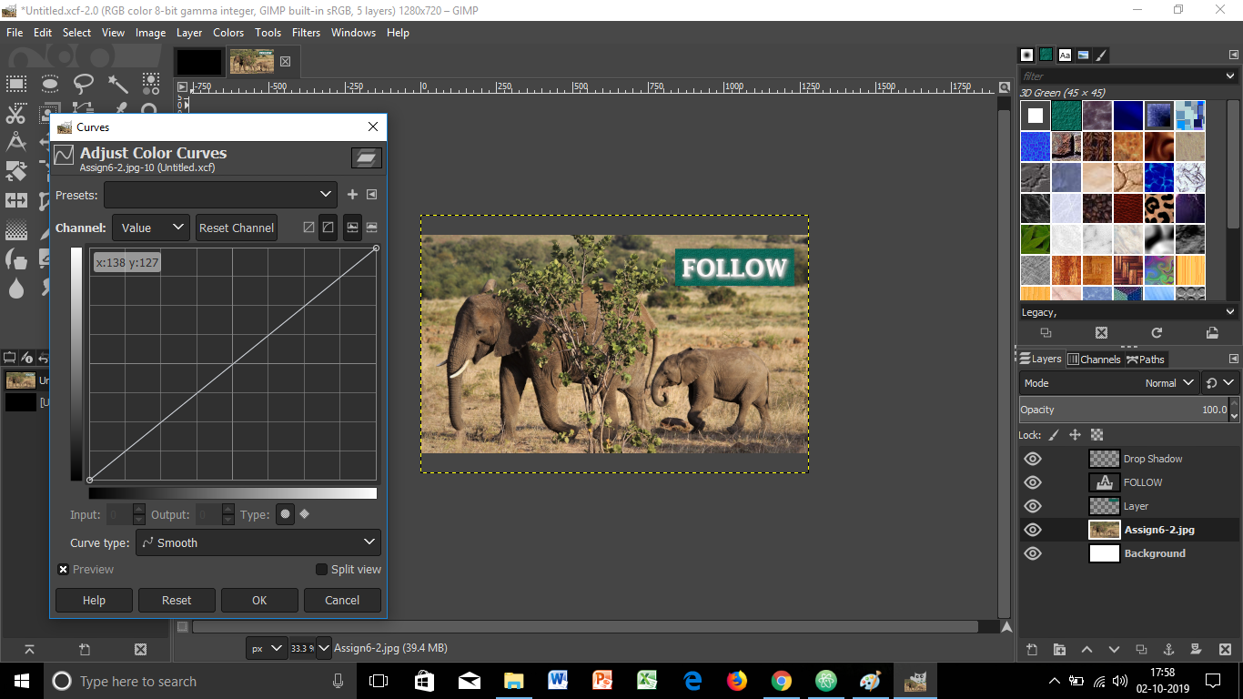
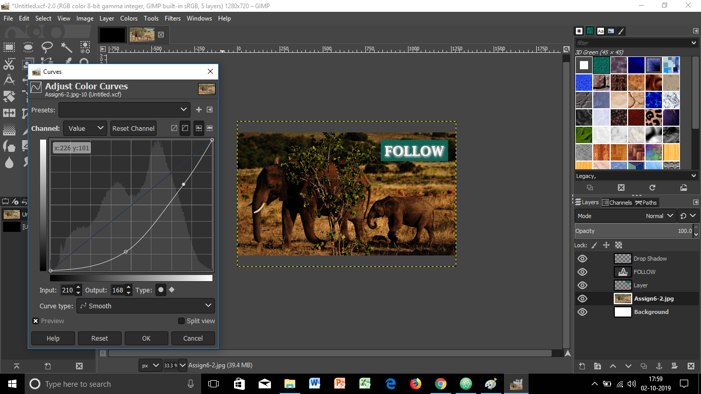
GIMP is a free and open-source raster graphics editor used for image retouching and editing, free-form drawing, converting between different image formats, and more specialized tasks. GIMP is released under GPLv3+ licenses and is available for Linux, macOS, and Microsoft Windows.
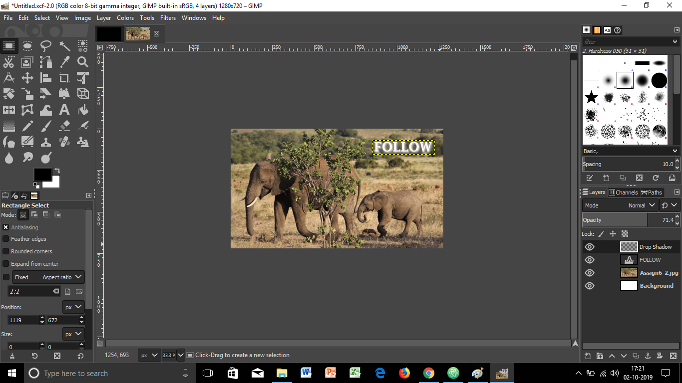
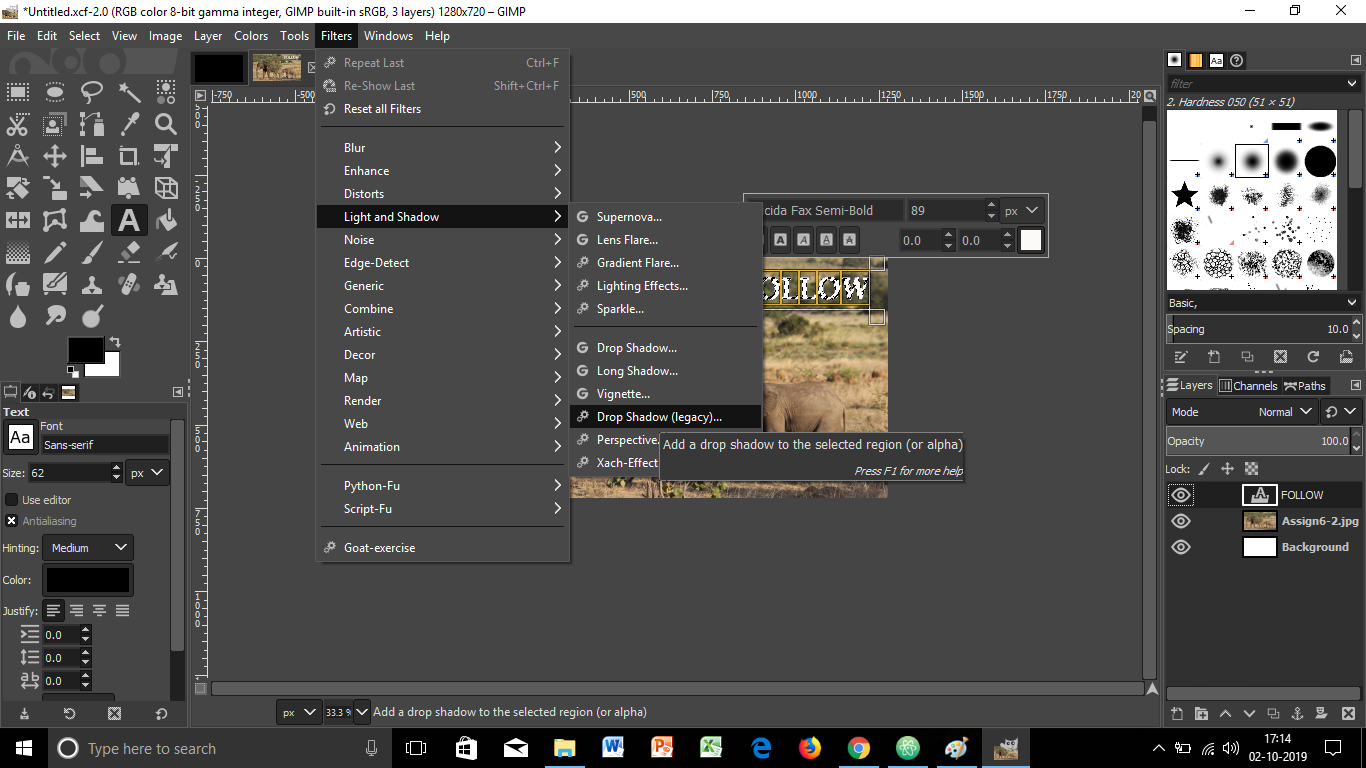
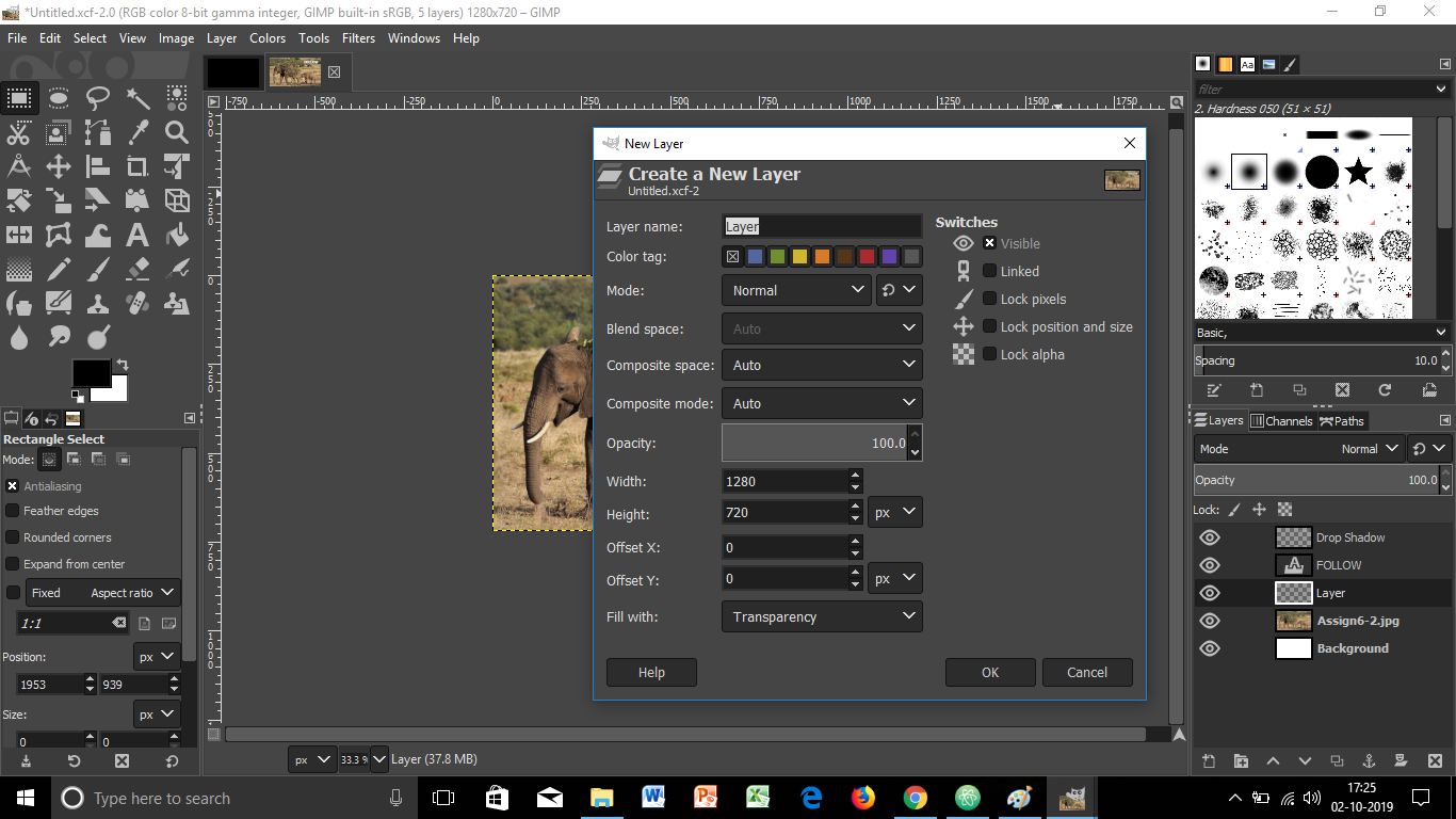
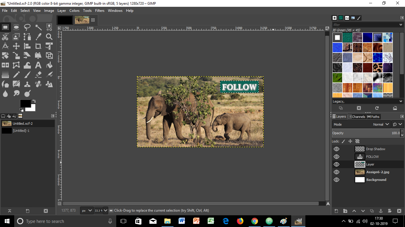
I referred some of the best tutorials for learning the GIMP tool, through which I managed to manipulate an image shown below. I tried hands-on with scaling the image, adding text to the image, applying light and shadow filters, adding new layers, adjusting color curves, and more, thereby coming out with a new image in itself.


The steps followed for all the manipulations with the image can be shown below:
1. Scaling the image
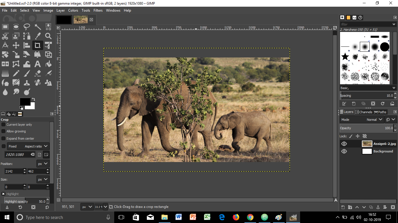

2. Adding Text to the image
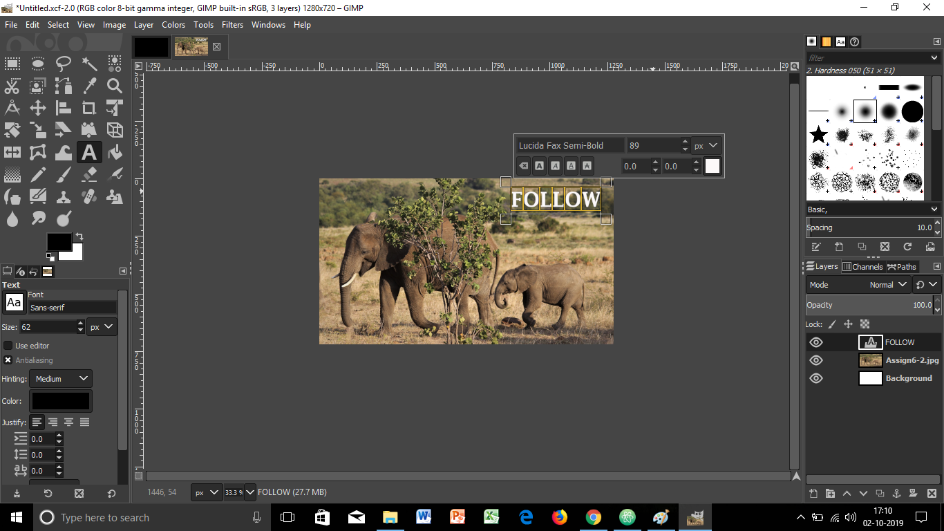
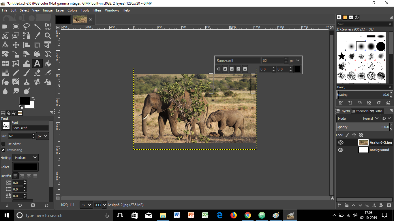
3. Applying Filters to the image
4. Adding New Layers to the image
5. Ajusting Color Curves to the image
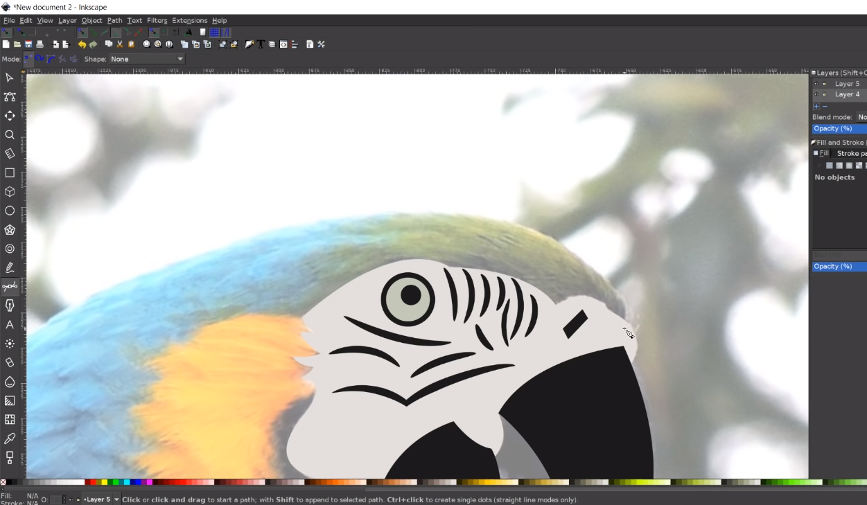
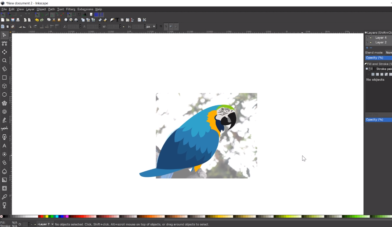
1.2. 2D CAD-Vector Modelling:
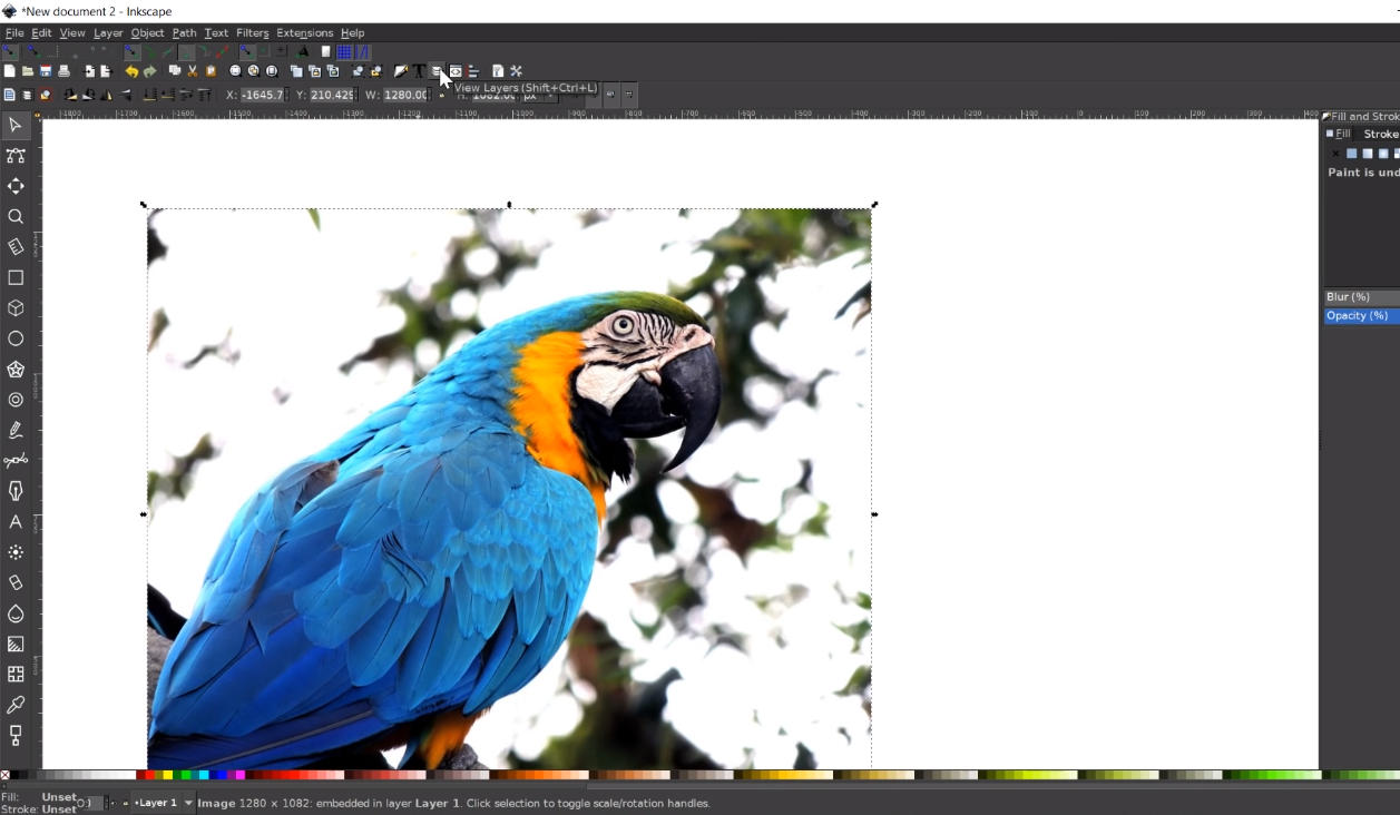
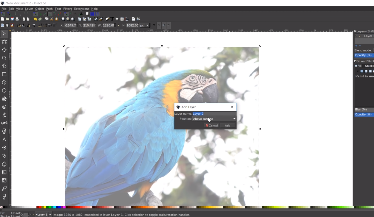
Inkscape is a free and open-source vector graphics editor. This software can be used to create or edit vector graphics such as illustrations, diagrams, line arts, charts, logos and complex paintings.
I also referred some tutorials for learning the Inkscape tool, through which I managed to manipulate an image shown below, and transform it to a vector image. I tried hands-on with scaling the image, adding new layers, applying curves and colors to the new image, and transforming it into a vector image that can also be used as a logo.


The steps followed for all the manipulations with the image can be shown below:
1. Scaling the image & Adding Layers to the Image
2. Applying Curves & Colors to the Image
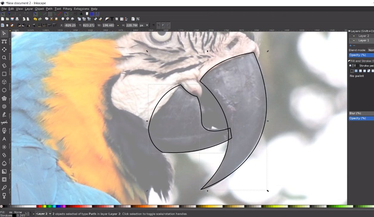
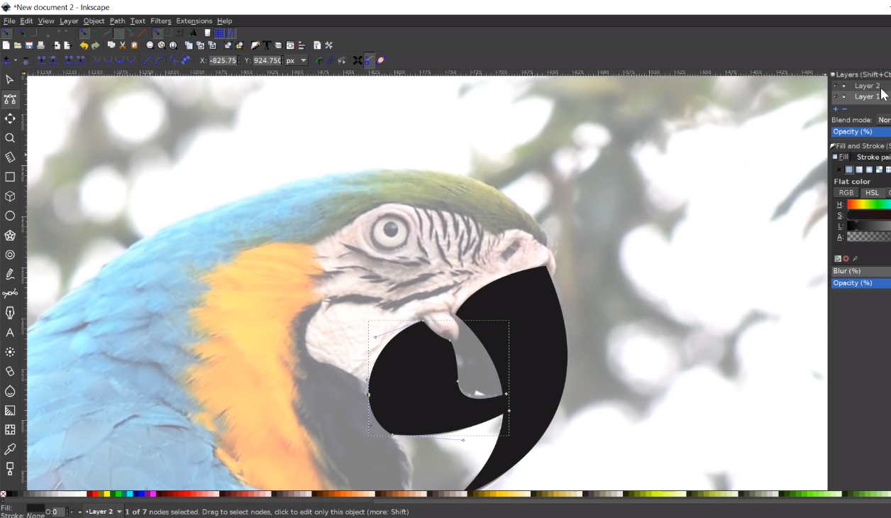
3. Transforming image into a vector logo
2. 3D CAD
3D CAD, or three-dimensional computer-aided design, is technology for design and technical documentation, which replaces manual drafting with an automated process.
I, along with Girish Yadav, tried Solidworks for our project parts modelling.
SolidWorks is a solid modeling computer-aided design and computer-aided engineering computer program that
runs primarily on Microsoft Windows. We worked on modelling the platforms that would support the 3 servos and ended
up in making a complete model for the self-stabilizing platform.
The demonstration for the 3D CAD Modelling can be shown below:
3. Extra Credit: Possibilities with CAD
1. Parametric Modelling
Parametric is a term used to describe a dimension's ability to change the shape
of model geometry as soon as the dimension value is modified. Parametric modelling uses the computer to design objects
or systems that model component attributes with real world behaviour.
The Parametric Modelling Process - Parametric models are built from a set of mathematical equations. For
parametric models to have any legitimacy, they must be based on real project information. It is the modernity of the
information examination techniques and the breadth of the hidden undertaking information which decides the viability
of a modelling solution.
There are two popular parametric representation models:
1. Constructive Solid Geometry (CSG): CSG defines a model in terms of combining basic (primitive) and generated
(using extrusion and sweeping operation) solid shapes. It uses Boolean operations to construct a model. CSG is a
combination of 3D solid primitves (for example a cylinder, cone, prism, rectangle or sphere) that are then
manipulated using simple Boolean operations.
2. Boundary Representation (BR): In BR, a solid model is formed by defining the surfaces that form its spatial
boundaries (points, edges, etc.) The object is then made by joining these spatial points. Many Finite Element
Method (FEM) programs use this method, as it allows the interior meshing of the volume to be more easily
controlled.
2. Physics Simulations and Analysis
CAD models can also be a great way to analyze various effects of physical forces on desired subjects in a virtual envirnoment.
3. Computer-Aided Engineering
CAE or Computer-Aided Engineering is a term used to describe the procedure of
the entire product engineering process, from design and virtual testing with sophisticated analytical algorithms to
the planning of manufacturing. Computer-aided engineering is standard in almost any industry that uses some sort of
design software to develop products.
CAE is the next step in not only designing a product, but also supporting the engineering process, as it allows to
perform tests and simulations of the product’s physical properties without needing a physical prototype. In the
context of CAE, the most commonly used simulation analysis types include Finite Element Analysis, Computational
Fluid Dynamics, Thermal Analysis, Multibody Dynamics and Optimizations.
4. Animation and VFX
Application of CAD models in to animations and VFX is also possible and is quite popular in the multimedia community. CAD models can be made to create scenes and effects which are not practically possible to create.
Result:
The assignment has given me relatively good insights on 2D/3D CAD Modelling.
The whole task gave me enough knowledge about all the tools and processes that are mandatory for making
products.