Assignment 4
Micro Controller Input & Output Device
In this 4th assignment we will use a microcontroller which is a compact integrated circuit designed to govern a specific operation in an embedded system where a typical microcontroller includes a processor, memory and input/output (I/O) peripherals on a single chip.we need to perform the following tasks using this micro-controller:
1. What are the different sensors in your phone and what do they do? Conduct an experiment to measure and analyze the data for a sensor in a log and report your findings.
2. Add an input device to a microcontroller board and read it. Document the process. Find an application for it in the real world around you. Please write in your own words what did you infer from the datasheet of the input device that you used?
3. Add an output device to a microcontroller board and program it to do something. Please write in your own words what did you infer from the datasheet of the output device that you used?
Input Device with Arduino - DHT11 Temperature and Humidity Sensor
The Sensor is accurate enough for most projects that need to keep track of humidity and temperature readings. Again we will be using a Library specifically designed for these sensors that will make our code short and easy to write.
DHT11 digital temperature and humidity sensor is a composite Sensor which contains a calibrated digital signal output of the temperature and humidity. The dedicated digital modules collection technology and the temperature and humidity sensing technology are applied to ensure that the product has high reliability and excellent long-term stability. The sensor includes a resistive sense of wet components and a NTC temperature measurement devices, and connects with a high-performance 8-bit microcontroller.
Applications: HVAC, dehumidifier, testing and inspection equipment, consumer goods, automotive, automatic control, data loggers, weather stations, home appliances, humidity regulator, medical and other humidity measurement and control.

Circuit
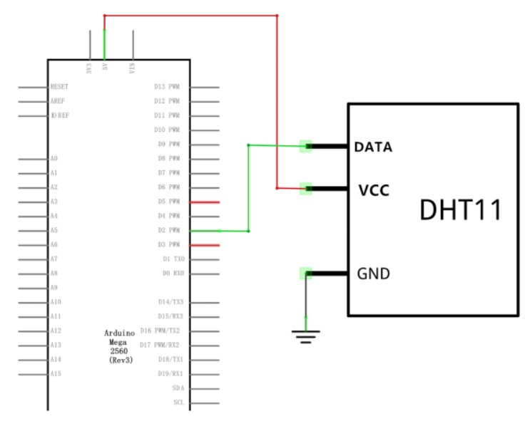
Wiring diagram

Code Used

Connections were made according to the above diagram and tested by uploading the code from arduino IDE.

Output Device with Arduino-LCD Screen
The display has an LED backlight and can display two rows with up to 16 characters on each row. You can see the rectangles for each character on the display and the pixels that make up each character. The display is just white on blue and is intended for showing text.1602 means it displays 2 lines of 16 characters.Each position can display 1 character.
- GND- Ground
- VCC- 5V
- SDA- A4
- SCL- A5
Circuit

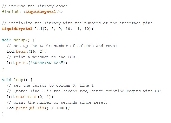
Code used
Circuit Image

Combining both Input and Output Device with Arduino
In this exercise we use the data received from the temperture humidity sensor and display on the LCD screen.
Code used for the exercise

NOTE:- The Serial.begin(9600)runs the data rate at bits per second.
Final Image

Final Video
Sensors in my phone
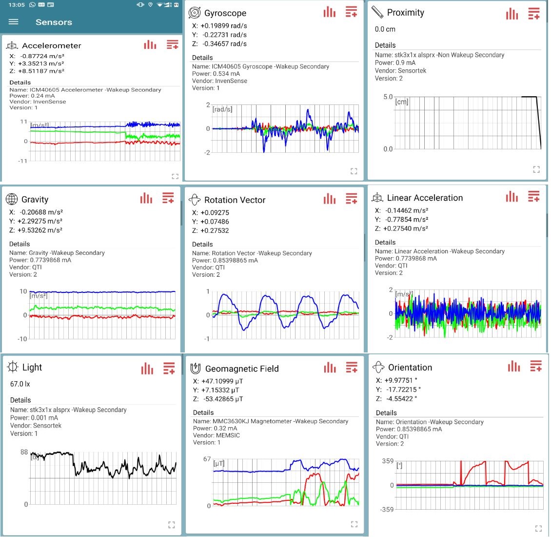
To learn more about the in-built sensors I used mu Nokia 6.1+ handset as a testing device.There are several apps for testing,I have used Sensoduino and Sensors app. Click here for Sensor Log
| Sr no. | Name | Description |
|---|---|---|
| 1 | Accelerometer | For testing temperature along given axis.Accelerators are built on the principle of measuring the force exerted on a test of unknown mass along given axis. |
| 2 | Proximity Sensor | Detects when a user is holding the phone near their ear during a call and it turns off the display to unecessary avoid keypresses and battery consumption. |
| 3 | Light Sensor | Photodetector that senses the amount of ambient light. |
| 4 | Gyroscope | Measures rotational velocity along Roll,Yaw and Pitch axis. |
| 5 | Magnetic Sensor | Detecting the orientation of device with respect to magnetic north.Generally Compass relies on this sensor. |
| 6 | Fingerprint Sensor | Once the fingerprint is scanned the device compares the new picture against the pre-stored picture if they match or not. |