Assignment6
A. Add an output device to a microcontroller board and program it to do something. Upload the arduino code. Please write in your own words what did you infer from the datasheet of the output device that you used?
B. Combine the input and output device to work together and collect data for an activity connected to you. Upload the arduino code. Analyze that data and make sense of it. E.g. – finding the thermal comfort in your room.
MAX7219 LED Dot Matrix Module
Overview
Component Introduction
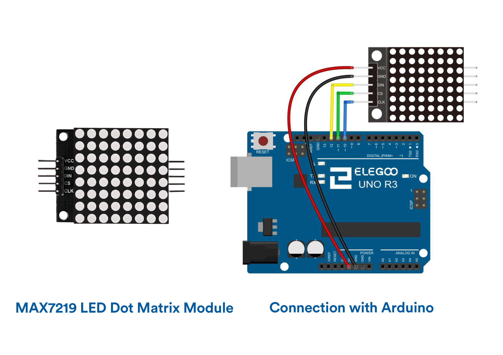
The MAX7219 IC is a serial input/output common-cathode display driver
that interfaces microprocessors to a 7-segment numeric LED displays of up to 8 digits,bar-graph displays, or 64 individual LEDs.Here is an 8×8 LED matrix,integrated with a MAX7219 IC setup, available as a pre-wired module is used. Typical specification of this LED Matrix Module is shown below:
Operating Voltage: DC 4.7V – 5.3V
Typical Voltage: 5V
Operating Current: 320mA
Max Operating Current: 2A
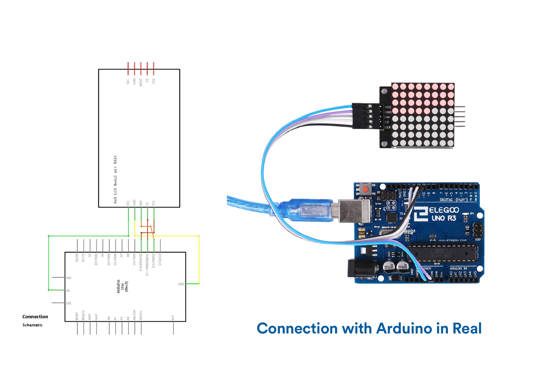
VCC and Ground are connected to the Arduino. Pin 12 is connected to DIN, Pin 11 is connected to CS and Pin 10 is connected to CLK.
LED MAX7219 Code
                                //www.elegoo.com
        //2016.12.9

        //We always have to include the library
        #include "LedControl.h"

        /*
         Now we need a LedControl to work with.
         ***** These pin numbers will probably not work with your hardware *****
         pin 12 is connected to the DataIn
         pin 11 is connected to LOAD(CS)
         pin 10 is connected to the CLK
         We have only a single MAX72XX.
         */
        LedControl lc=LedControl(12,10,11,1);

        /* we always wait a bit between updates of the display */
        unsigned long delaytime1=500;
        unsigned long delaytime2=50;
        void setup() {
          /*
           The MAX72XX is in power-saving mode on startup,
           we have to do a wakeup call
           */
          lc.shutdown(0,false);
          /* Set the brightness to a medium values */
          lc.setIntensity(0,8);
          /* and clear the display */
          lc.clearDisplay(0);
        }

        /*
         This method will display the characters for the
         word "Arduino" one after the other on the matrix.
         (you need at least 5x7 leds to see the whole chars)
         */
        void writeArduinoOnMatrix() {
          /* here is the data for the characters */
          byte a[5]={B01111110,B10001000,B10001000,B10001000,B01111110};
          byte r[5]={B00010000,B00100000,B00100000,B00010000,B00111110};
          byte d[5]={B11111110,B00010010,B00100010,B00100010,B00011100};
          byte u[5]={B00111110,B00000100,B00000010,B00000010,B00111100};
          byte i[5]={B00000000,B00000010,B10111110,B00100010,B00000000};
          byte n[5]={B00011110,B00100000,B00100000,B00010000,B00111110};
          byte o[5]={B00011100,B00100010,B00100010,B00100010,B00011100};

          /* now display them one by one with a small delay */
          lc.setRow(0,0,a[0]);
          lc.setRow(0,1,a[1]);
          lc.setRow(0,2,a[2]);
          lc.setRow(0,3,a[3]);
          lc.setRow(0,4,a[4]);
          delay(delaytime1);
          lc.setRow(0,0,r[0]);
          lc.setRow(0,1,r[1]);
          lc.setRow(0,2,r[2]);
          lc.setRow(0,3,r[3]);
          lc.setRow(0,4,r[4]);
          delay(delaytime1);
          lc.setRow(0,0,d[0]);
          lc.setRow(0,1,d[1]);
          lc.setRow(0,2,d[2]);
          lc.setRow(0,3,d[3]);
          lc.setRow(0,4,d[4]);
          delay(delaytime1);
          lc.setRow(0,0,u[0]);
          lc.setRow(0,1,u[1]);
          lc.setRow(0,2,u[2]);
          lc.setRow(0,3,u[3]);
          lc.setRow(0,4,u[4]);
          delay(delaytime1);
          lc.setRow(0,0,i[0]);
          lc.setRow(0,1,i[1]);
          lc.setRow(0,2,i[2]);
          lc.setRow(0,3,i[3]);
          lc.setRow(0,4,i[4]);
          delay(delaytime1);
          lc.setRow(0,0,n[0]);
          lc.setRow(0,1,n[1]);
          lc.setRow(0,2,n[2]);
          lc.setRow(0,3,n[3]);
          lc.setRow(0,4,n[4]);
          delay(delaytime1);
          lc.setRow(0,0,o[0]);
          lc.setRow(0,1,o[1]);
          lc.setRow(0,2,o[2]);
          lc.setRow(0,3,o[3]);
          lc.setRow(0,4,o[4]);
          delay(delaytime1);
          lc.setRow(0,0,0);
          lc.setRow(0,1,0);
          lc.setRow(0,2,0);
          lc.setRow(0,3,0);
          lc.setRow(0,4,0);
          delay(delaytime1);
        }

        /*
          This function lights up a some Leds in a row.
         The pattern will be repeated on every row.
         The pattern will blink along with the row-number.
         row number 4 (index==3) will blink 4 times etc.
         */
        void rows() {
          for(int row=0;row<8;row++) {
            delay(delaytime2);
            lc.setRow(0,row,B10100000);
            delay(delaytime2);
            lc.setRow(0,row,(byte)0);
            for(int i=0;i < row;i++) {
              delay(delaytime2);
              lc.setRow(0,row,B10100000);
              delay(delaytime2);
              lc.setRow(0,row,(byte)0);
            }
          }
        }

        /*
          This function lights up a some Leds in a column.
         The pattern will be repeated on every column.
         The pattern will blink along with the column-number.
         column number 4 (index==3) will blink 4 times etc.
         */
        void columns() {
          for(int col=0;col<8;col++) {
            delay(delaytime2);
            lc.setColumn(0,col,B10100000);
            delay(delaytime2);
            lc.setColumn(0,col,(byte)0);
            for(int i=0;i < col;i++) {
              delay(delaytime2);
              lc.setColumn(0,col,B10100000);
              delay(delaytime2);
              lc.setColumn(0,col,(byte)0);
            }
          }
      }
LED MAX 7219 Video
UltraSonic Sensor Module
Overview
The MAX7219 IC is a serial input/output common-cathode display driver
that interfaces microprocessors to a 7-segment numeric LED displays of up to 8 digits,bar-graph displays, or 64 individual LEDs.Here is an 8×8 LED matrix,integrated with a MAX7219 IC setup, available as a pre-wired module is used. Typical specification of this LED Matrix Module is shown below:
Operating Voltage: DC 4.7V – 5.3V
Typical Voltage: 5V
Operating Current: 320mA
Max Operating Current: 2A
VCC and Ground are connected to the Arduino. Pin 12 is connected to DIN, Pin 11 is connected to CS and Pin 10 is connected to CLK.
LED MAX7219 Code
//www.elegoo.com
//2016.12.9
//We always have to include the library
#include "LedControl.h"
/*
Now we need a LedControl to work with.
***** These pin numbers will probably not work with your hardware *****
pin 12 is connected to the DataIn
pin 11 is connected to LOAD(CS)
pin 10 is connected to the CLK
We have only a single MAX72XX.
*/
LedControl lc=LedControl(12,10,11,1);
/* we always wait a bit between updates of the display */
unsigned long delaytime1=500;
unsigned long delaytime2=50;
void setup() {
/*
The MAX72XX is in power-saving mode on startup,
we have to do a wakeup call
*/
lc.shutdown(0,false);
/* Set the brightness to a medium values */
lc.setIntensity(0,8);
/* and clear the display */
lc.clearDisplay(0);
}
/*
This method will display the characters for the
word "Arduino" one after the other on the matrix.
(you need at least 5x7 leds to see the whole chars)
*/
void writeArduinoOnMatrix() {
/* here is the data for the characters */
byte a[5]={B01111110,B10001000,B10001000,B10001000,B01111110};
byte r[5]={B00010000,B00100000,B00100000,B00010000,B00111110};
byte d[5]={B11111110,B00010010,B00100010,B00100010,B00011100};
byte u[5]={B00111110,B00000100,B00000010,B00000010,B00111100};
byte i[5]={B00000000,B00000010,B10111110,B00100010,B00000000};
byte n[5]={B00011110,B00100000,B00100000,B00010000,B00111110};
byte o[5]={B00011100,B00100010,B00100010,B00100010,B00011100};
/* now display them one by one with a small delay */
lc.setRow(0,0,a[0]);
lc.setRow(0,1,a[1]);
lc.setRow(0,2,a[2]);
lc.setRow(0,3,a[3]);
lc.setRow(0,4,a[4]);
delay(delaytime1);
lc.setRow(0,0,r[0]);
lc.setRow(0,1,r[1]);
lc.setRow(0,2,r[2]);
lc.setRow(0,3,r[3]);
lc.setRow(0,4,r[4]);
delay(delaytime1);
lc.setRow(0,0,d[0]);
lc.setRow(0,1,d[1]);
lc.setRow(0,2,d[2]);
lc.setRow(0,3,d[3]);
lc.setRow(0,4,d[4]);
delay(delaytime1);
lc.setRow(0,0,u[0]);
lc.setRow(0,1,u[1]);
lc.setRow(0,2,u[2]);
lc.setRow(0,3,u[3]);
lc.setRow(0,4,u[4]);
delay(delaytime1);
lc.setRow(0,0,i[0]);
lc.setRow(0,1,i[1]);
lc.setRow(0,2,i[2]);
lc.setRow(0,3,i[3]);
lc.setRow(0,4,i[4]);
delay(delaytime1);
lc.setRow(0,0,n[0]);
lc.setRow(0,1,n[1]);
lc.setRow(0,2,n[2]);
lc.setRow(0,3,n[3]);
lc.setRow(0,4,n[4]);
delay(delaytime1);
lc.setRow(0,0,o[0]);
lc.setRow(0,1,o[1]);
lc.setRow(0,2,o[2]);
lc.setRow(0,3,o[3]);
lc.setRow(0,4,o[4]);
delay(delaytime1);
lc.setRow(0,0,0);
lc.setRow(0,1,0);
lc.setRow(0,2,0);
lc.setRow(0,3,0);
lc.setRow(0,4,0);
delay(delaytime1);
}
/*
This function lights up a some Leds in a row.
The pattern will be repeated on every row.
The pattern will blink along with the row-number.
row number 4 (index==3) will blink 4 times etc.
*/
void rows() {
for(int row=0;row<8;row++) {
delay(delaytime2);
lc.setRow(0,row,B10100000);
delay(delaytime2);
lc.setRow(0,row,(byte)0);
for(int i=0;i < row;i++) {
delay(delaytime2);
lc.setRow(0,row,B10100000);
delay(delaytime2);
lc.setRow(0,row,(byte)0);
}
}
}
/*
This function lights up a some Leds in a column.
The pattern will be repeated on every column.
The pattern will blink along with the column-number.
column number 4 (index==3) will blink 4 times etc.
*/
void columns() {
for(int col=0;col<8;col++) {
delay(delaytime2);
lc.setColumn(0,col,B10100000);
delay(delaytime2);
lc.setColumn(0,col,(byte)0);
for(int i=0;i < col;i++) {
delay(delaytime2);
lc.setColumn(0,col,B10100000);
delay(delaytime2);
lc.setColumn(0,col,(byte)0);
}
}
}
LED MAX 7219 Video
UltraSonic Sensor Module
Overview
LED MAX7219 Code
//www.elegoo.com
//2016.12.9
//We always have to include the library
#include "LedControl.h"
/*
Now we need a LedControl to work with.
***** These pin numbers will probably not work with your hardware *****
pin 12 is connected to the DataIn
pin 11 is connected to LOAD(CS)
pin 10 is connected to the CLK
We have only a single MAX72XX.
*/
LedControl lc=LedControl(12,10,11,1);
/* we always wait a bit between updates of the display */
unsigned long delaytime1=500;
unsigned long delaytime2=50;
void setup() {
/*
The MAX72XX is in power-saving mode on startup,
we have to do a wakeup call
*/
lc.shutdown(0,false);
/* Set the brightness to a medium values */
lc.setIntensity(0,8);
/* and clear the display */
lc.clearDisplay(0);
}
/*
This method will display the characters for the
word "Arduino" one after the other on the matrix.
(you need at least 5x7 leds to see the whole chars)
*/
void writeArduinoOnMatrix() {
/* here is the data for the characters */
byte a[5]={B01111110,B10001000,B10001000,B10001000,B01111110};
byte r[5]={B00010000,B00100000,B00100000,B00010000,B00111110};
byte d[5]={B11111110,B00010010,B00100010,B00100010,B00011100};
byte u[5]={B00111110,B00000100,B00000010,B00000010,B00111100};
byte i[5]={B00000000,B00000010,B10111110,B00100010,B00000000};
byte n[5]={B00011110,B00100000,B00100000,B00010000,B00111110};
byte o[5]={B00011100,B00100010,B00100010,B00100010,B00011100};
/* now display them one by one with a small delay */
lc.setRow(0,0,a[0]);
lc.setRow(0,1,a[1]);
lc.setRow(0,2,a[2]);
lc.setRow(0,3,a[3]);
lc.setRow(0,4,a[4]);
delay(delaytime1);
lc.setRow(0,0,r[0]);
lc.setRow(0,1,r[1]);
lc.setRow(0,2,r[2]);
lc.setRow(0,3,r[3]);
lc.setRow(0,4,r[4]);
delay(delaytime1);
lc.setRow(0,0,d[0]);
lc.setRow(0,1,d[1]);
lc.setRow(0,2,d[2]);
lc.setRow(0,3,d[3]);
lc.setRow(0,4,d[4]);
delay(delaytime1);
lc.setRow(0,0,u[0]);
lc.setRow(0,1,u[1]);
lc.setRow(0,2,u[2]);
lc.setRow(0,3,u[3]);
lc.setRow(0,4,u[4]);
delay(delaytime1);
lc.setRow(0,0,i[0]);
lc.setRow(0,1,i[1]);
lc.setRow(0,2,i[2]);
lc.setRow(0,3,i[3]);
lc.setRow(0,4,i[4]);
delay(delaytime1);
lc.setRow(0,0,n[0]);
lc.setRow(0,1,n[1]);
lc.setRow(0,2,n[2]);
lc.setRow(0,3,n[3]);
lc.setRow(0,4,n[4]);
delay(delaytime1);
lc.setRow(0,0,o[0]);
lc.setRow(0,1,o[1]);
lc.setRow(0,2,o[2]);
lc.setRow(0,3,o[3]);
lc.setRow(0,4,o[4]);
delay(delaytime1);
lc.setRow(0,0,0);
lc.setRow(0,1,0);
lc.setRow(0,2,0);
lc.setRow(0,3,0);
lc.setRow(0,4,0);
delay(delaytime1);
}
/*
This function lights up a some Leds in a row.
The pattern will be repeated on every row.
The pattern will blink along with the row-number.
row number 4 (index==3) will blink 4 times etc.
*/
void rows() {
for(int row=0;row<8;row++) {
delay(delaytime2);
lc.setRow(0,row,B10100000);
delay(delaytime2);
lc.setRow(0,row,(byte)0);
for(int i=0;i < row;i++) {
delay(delaytime2);
lc.setRow(0,row,B10100000);
delay(delaytime2);
lc.setRow(0,row,(byte)0);
}
}
}
/*
This function lights up a some Leds in a column.
The pattern will be repeated on every column.
The pattern will blink along with the column-number.
column number 4 (index==3) will blink 4 times etc.
*/
void columns() {
for(int col=0;col<8;col++) {
delay(delaytime2);
lc.setColumn(0,col,B10100000);
delay(delaytime2);
lc.setColumn(0,col,(byte)0);
for(int i=0;i < col;i++) {
delay(delaytime2);
lc.setColumn(0,col,B10100000);
delay(delaytime2);
lc.setColumn(0,col,(byte)0);
}
}
}
LED MAX 7219 Video
UltraSonic Sensor Module
Overview
Component Introduction
Ultrasonic sensor is great for all kind of projects that need distance measurements,
avoiding obstacles as examples.The HC-SR04 is inexpensive and easy to use since we will be using a Libraryspecifically designed for these sensor.
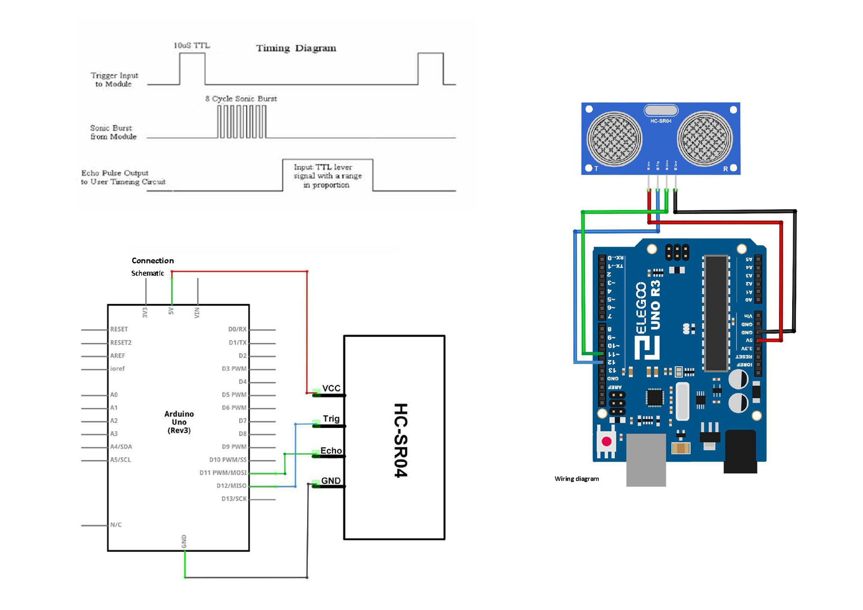
Ultrasonic sensor module HC-SR04 provides 2cm-400cm non-contact measurement function, the ranging accuracy can reach to 3mm. The modules includes ultrasonic transmitters, receiver and control circuit. The basic principle of work:
(1) Using IO trigger for at least 10us high level signal,
(2) The Module automatically sends eight 40 kHz and detect whether there is a pulse signal back.
(3) IF the signal back, through high level , time of high output IO duration is the time from sending ultrasonic tore turning.
Test distance = (high level time × velocity of sound (340m/s) /2
The Timing diagram is shown below. You only need to supply a short 10us pulse to
the trigger input to start the ranging, and then the module will send out an 8 cycle
burst of ultrasound at 40 kHz and raise its echo. The Echo is a distance object that is
pulse width and the range in proportion .You can calculate the range through the
time interval between sending trigger signal and receiving echo signal.
Formula: us/ 58 = centimeters or us / 148 =inch; or: the range = high level time * velocity(340M/S) / 2;
we suggest to use over 60ms measurement cycle, in order to prevent
trigger signal to the echo signal.
Ultrasonic Sensor Code
  #include "SR04.h"
  #define TRIG_PIN 3
  #define ECHO_PIN 2
  SR04 sr04 = SR04(ECHO_PIN,TRIG_PIN);
  long a;

  void setup() {
     Serial.begin(9600);
     delay(1000);
  }

  void loop() {
     a=sr04.Distance();
     Serial.print(a);
     Serial.println("cm");
     delay(1000);
  }
Fusion of LED MAX7219 and Ultrasonic Sensor
Fusion Code
#include Arduino.h>
#include LedControl.h>
#include "pitches.h"

const int LED_DIN = 12;
const int LED_CLK = 11;
const int LED_CS = 10;

const int TRIG = 9;
const int ECHO = 8;

LedControl lc = LedControl(LED_DIN, LED_CLK, LED_CS, 1);

int duration = 0;
int distance = 0;
const int STEP = 30;
const int THRESHOLD = 30;

byte levels[8][8] = {
  {B00000000, B00000000, B00000000, B00000000, B00000000, B00000000, B00000000, B00000000},
  {B00000000, B00000000, B00000000, B00011000, B00011000, B00000000, B00000000, B00000000},
  {B00000000, B00000000, B00011000, B00111100, B00111100, B00011000, B00000000, B00000000},
  {B00000000, B00011000, B00111100, B01111110, B01111110, B00111100, B00011000, B00000000},
  {B00011000, B00111100, B01111110, B11111111, B11111111, B01111110, B00111100, B00011000},
  {B00111100, B01111110, B11111111, B11111111, B11111111, B11111111, B01111110, B00111100},
  {B01111110, B11111111, B11111111, B11111111, B11111111, B11111111, B11111111, B01111110},
  {B11111111, B11111111, B11111111, B11111111, B11111111, B11111111, B11111111, B11111111}
};

void setup() {
  Serial.begin(9600);

  lc.shutdown(0, false);
  lc.setIntensity(0, 8);
  lc.clearDisplay(0);

  pinMode(TRIG, OUTPUT);
  pinMode(ECHO, INPUT);

  // power on animation
  for (int i=0; i<8; i++) {
    for (int j=0; j<8; j++) {
      lc.setRow(0, j, levels[i][j]);
    }
    delay(100);
  }
Fusion Video
THANK YOU! :)
Ultrasonic sensor is great for all kind of projects that need distance measurements,
avoiding obstacles as examples.The HC-SR04 is inexpensive and easy to use since we will be using a Libraryspecifically designed for these sensor.
Ultrasonic sensor module HC-SR04 provides 2cm-400cm non-contact measurement function, the ranging accuracy can reach to 3mm. The modules includes ultrasonic transmitters, receiver and control circuit. The basic principle of work:
(1) Using IO trigger for at least 10us high level signal,
(2) The Module automatically sends eight 40 kHz and detect whether there is a pulse signal back.
(3) IF the signal back, through high level , time of high output IO duration is the time from sending ultrasonic tore turning.
Test distance = (high level time × velocity of sound (340m/s) /2
The Timing diagram is shown below. You only need to supply a short 10us pulse to
the trigger input to start the ranging, and then the module will send out an 8 cycle
burst of ultrasound at 40 kHz and raise its echo. The Echo is a distance object that is
pulse width and the range in proportion .You can calculate the range through the
time interval between sending trigger signal and receiving echo signal.
Formula: us/ 58 = centimeters or us / 148 =inch; or: the range = high level time * velocity(340M/S) / 2;
we suggest to use over 60ms measurement cycle, in order to prevent
trigger signal to the echo signal.
Ultrasonic Sensor Code
#include "SR04.h"
#define TRIG_PIN 3
#define ECHO_PIN 2
SR04 sr04 = SR04(ECHO_PIN,TRIG_PIN);
long a;
void setup() {
Serial.begin(9600);
delay(1000);
}
void loop() {
a=sr04.Distance();
Serial.print(a);
Serial.println("cm");
delay(1000);
}
#include "SR04.h"
#define TRIG_PIN 3
#define ECHO_PIN 2
SR04 sr04 = SR04(ECHO_PIN,TRIG_PIN);
long a;
void setup() {
Serial.begin(9600);
delay(1000);
}
void loop() {
a=sr04.Distance();
Serial.print(a);
Serial.println("cm");
delay(1000);
}
Fusion of LED MAX7219 and Ultrasonic Sensor
Fusion Code
#include Arduino.h>
#include LedControl.h>
#include "pitches.h"
const int LED_DIN = 12;
const int LED_CLK = 11;
const int LED_CS = 10;
const int TRIG = 9;
const int ECHO = 8;
LedControl lc = LedControl(LED_DIN, LED_CLK, LED_CS, 1);
int duration = 0;
int distance = 0;
const int STEP = 30;
const int THRESHOLD = 30;
byte levels[8][8] = {
{B00000000, B00000000, B00000000, B00000000, B00000000, B00000000, B00000000, B00000000},
{B00000000, B00000000, B00000000, B00011000, B00011000, B00000000, B00000000, B00000000},
{B00000000, B00000000, B00011000, B00111100, B00111100, B00011000, B00000000, B00000000},
{B00000000, B00011000, B00111100, B01111110, B01111110, B00111100, B00011000, B00000000},
{B00011000, B00111100, B01111110, B11111111, B11111111, B01111110, B00111100, B00011000},
{B00111100, B01111110, B11111111, B11111111, B11111111, B11111111, B01111110, B00111100},
{B01111110, B11111111, B11111111, B11111111, B11111111, B11111111, B11111111, B01111110},
{B11111111, B11111111, B11111111, B11111111, B11111111, B11111111, B11111111, B11111111}
};
void setup() {
Serial.begin(9600);
lc.shutdown(0, false);
lc.setIntensity(0, 8);
lc.clearDisplay(0);
pinMode(TRIG, OUTPUT);
pinMode(ECHO, INPUT);
// power on animation
for (int i=0; i<8; i++) {
for (int j=0; j<8; j++) {
lc.setRow(0, j, levels[i][j]);
}
delay(100);
}