1. The aim of this project is to understand the methodology of undertaking Laser Cutting. It involves different procedures such as cutting of material into complex shapes and also undertaking engraving. Laser cutting can be undertaken on a variety of materials such as wood, acrylic, MDF boadrs, foam boards and glass
2. Laser cutting involves development of a 2D CAD drawing of the design required and exporting the job to a Laser cutter similar to a printer.
LASER CUTTING
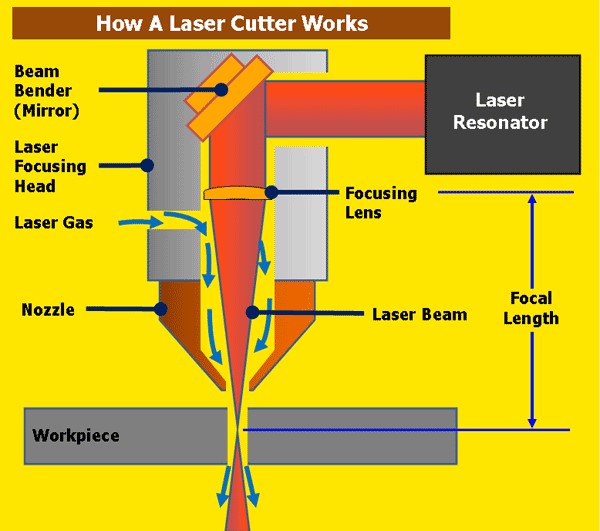
3. The laser beam is a column of very high intensity light, of a single wavelength, or color. In the case of a typical CO2 laser, that wavelength is in the Infra-Red part of the light spectrum, so it is invisible to the human eye. The beam is only about 3/4 of an inch in diameter as it travels from the laser resonator, which creates the beam, through the machine’s beam path. It may be bounced in different directions by a number of mirrors, or “beam benders”, before it is finally focused onto the plate. The focused laser beam goes through the bore of a nozzle right before it hits the plate. Also flowing through that nozzle bore is a compressed gas, such as Oxygen or Nitrogen.
4. Focusing the laser beam can be done by a special lens, or by a curved mirror, and this takes place in the laser cutting head. The beam has to be precisely focused so that the shape of the focus spot and the density of the energy in that spot are perfectly round and consistent, and centered in the nozzle. By focusing the large beam down to a single pinpoint, the heat density at that spot is extreme. Think about using a magnifying glass to focus the sun’s rays onto a leaf, and how that can start a fire. Now think about focusing 6 KWatts of energy into a single spot, and you can imagine how hot that spot will get.
5. The high power density results in rapid heating, melting and partial or complete vaporizing of the material. When cutting mild steel, the heat of the laser beam is enough to start a typical “oxy-fuel” burning process, and the laser cutting gas will be pure oxygen, just like an oxy-fuel torch. When cutting stainless steel or aluminum, the laser beam simply melts the material, and high pressure nitrogen is used to blow the molten metal out of the kerf.
6. The basic working of any Laser Cutter is as shown in the link below.
PRESS FIT MODELS
7. An INTERFERENCE FIT, also known as a PRESS FIT or FRICTION FIT is a fastening between two parts which is achieved by friction after the parts are pushed together, rather than by any other means of fastening.The tightness of fit is controlled by amount of interference; the allowance (planned difference from nominal size). Formulas exist to compute allowance that will result in various strengths of fit such as loose fit, light interference fit, and interference fit. The value of the allowance depends on which material is being used, how big the parts are, and what degree of tightness is desired. Such values have already been worked out in the past for many standard applications, and they are available to engineers in the form of tables, obviating the need for re-derivation.
8. The thickness of the material decides the thickness of the locking pins at the edge of the side shell extensions In order to ensure the locking pins just protrude out and lock themselves on the other side of the rectangular slots.
Methodology
9. As explained in the video, for the purpose of this exercise a simple 2D drawing of a Pen Stand available in PDF format on the web was taken. It was imported to CORALDRAW software, the text required was added. The final drawing is saved in CDR format and forwarded for Laser Cutter using the print command.
10. The dimensions of the side shell extension slots and the slots for undertaking the press fit in the bottom and top lock plate. In this exercise a 2.3mm thick MDF board was used to develop the model, hence the margin for the laser cut was kept at 0.1mm based on open source data available. To explain further, the dimension of the rectangular slots in the base on top plate of the pen stand where the side structure is supposed to be locked in place was made 0.1mm smaller thn the dimension of the extension slots in the side structure
11. The drawing is placed within the boundary of the laser cutting machine slot dimensions (In our case the available area is 812mm x 508mm. The document is in the fourth quadrant, hence the nudge values set based on the edge smoothness of the material used. Here, we used a nudge value of 3mm in the positive direction for x axis and in the negative direction on y axis. The edges which need to be cut and indicated as HAIRLINE and the areas which need to be engraved are indicated as None, to ensure RASTERING is undertaken.
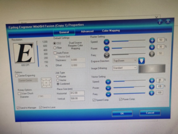
12. In the preferences for the settings, combined Laser Cutting procedure for undertaking both vector cutting and rastering together is selected. The power settings for Rastering are, Speed-50% and Power-30% while that for Vector cutting were set at Speed-35%, Power-65% and Frequency-100%. The settings are appled and the job is uploaded onto the laser cutter.
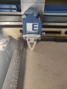
13. The base plate of the laser cutter is moved vertically post placement of the material to be cut or engraved in order to focus the laser on the surface of the material.
14. Once the job is uploaded the laser cutter starts with undertaking Rastering followed by Vector Cutting.