Assignment 4
Input and Output Devices
This week we were required to understand the working of input and output devices for microcontroller programming.
Input Devices
Input devices are those that can collect some input for any proccess. All sensors are input devices . There are many sensors out there in different devices that we use. Let's take a look at the sesnors present in one of the most commonly used devices - Smartphones.
Sensors in our phones
This is a brief overview of the number of sesors present in my phone:
I use a Motorola Moto G5s Plus phone.
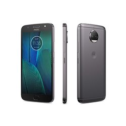
I installed an app called SensoDuino from the Google Playstore to see the various sensors in my phone and to log the data that these sensors receive. I found that my phone has the following sesnors in it:
- Accelerometer
- Gyroscope
- Light sensor
- Proximity Sensor
- Gravity Sensor or g-Force Sensor
- Linear Acceleration Sensor
- Step Counter
- Location Sensor
- Touchscreen (for touch input)
- Microphone
- Front and rear Cameras
From the above sensors, I was able to obtain and log the following data using SensoDuino: Sensor Log.
We see that a phone has so many sensors and certain phones have even more of them. Each sensor is designed to collect a certain type of data for us. A Microcontroller uses the obtained data to perform various functions and to give a desired output. But how do we get an output? for that we use Output Devices.
Output Devices
Output Devices are those that give us output based on the input or the procees carried out.
Outputs can be Audio, Visual, Haptic or a combination of these.
All smartphones have output devices in them such as:
Using Input and Output Devices
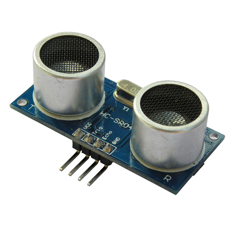
We were given 2 input and 2 output devices each to work with. For the inputs, we were given HC-SR04 Ultrasonic Sensor and a DHT11 Temperature & Humidity sensor
For the output we were given an RGB LED and an I2C LCD Display
We used the HC SR04 Ultrasonic sensor first to check how the distance of an object changes as we move it closer and farther from the sensor.
The code for which can be found here: Ultrasonic Sensor.
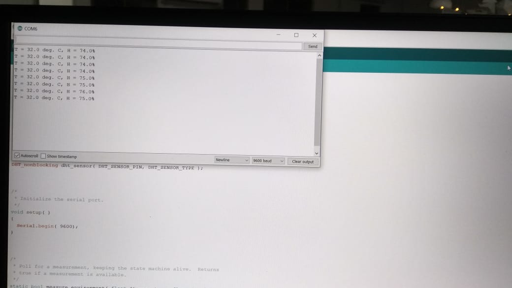
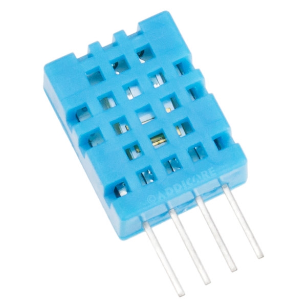
We then used the DHT11 Temperature and humidity Sensor to check how the temperature and humidity changes as we bring warm and moist objects near the sensor.
The code for the same can be found here:
DHT11 Temp&Humidity
The datasheet of the DHT11 showed me that the sensor has a range of 0°C-50°C temperature with an accuracy of + 2°C, 20%-90% relative humidity with an accuracy of + 5%.
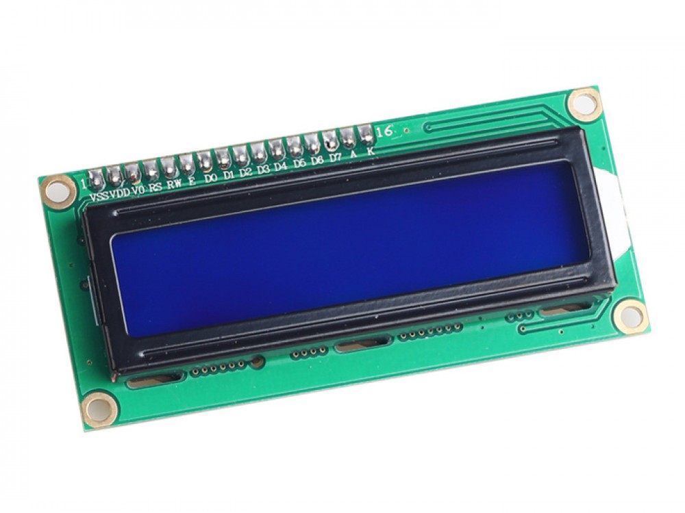
After that, we used the I2C LCD to display custom messages on it.
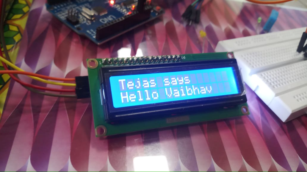
The code for which can be found here: LCD Display.
The datasheet of the I2C LCD revealed that the display runs on 5V DC, the contrast of the display can be set using the potentiometer on the I2C interface. The size of the display is 80mm x 36mm x 20 mm and the viewable area is 66mm x 16mm. The LCD is a 2 lines by 16 character display and is backlit by white light.
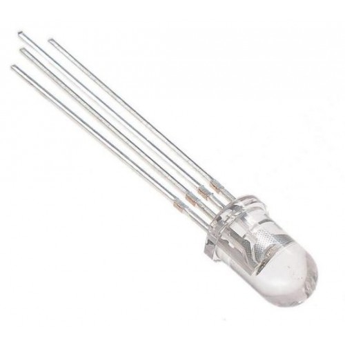
Finally, we used the RGB LED to display changing colors.
The code for which can be found here: RGB LED.
An important thing to be noted here is to make sure to include all the library files associated with the sensors and actuators to the Arduino IDE when using them in the code. Once added there is no need to add again. But first time operation requires the addition of library files.
Real world Application of an Ultrasonic Sensor
One application of such a set up can be for automatic lighting in rooms. As someone approaches or leaves a particlar area, the lighting can be brightened or dimmed accordingly. The Ultrasonic Sensors can be used to sense the presence of people.Real world Application of DHT11 sensor
DHT11 can be used to sense the temperature and moisture level of soil for agricultural purposes where optimum soil mositure and temperature can result in better yield.
Real world Application of LCD display
To display various messages, information, warnings or any kind of text/graphics, we can use LCD displays.
Real world Application of RGB LEDs
RGB LEDs can be used to make colored displays by arranging them in a matrix.
Combining both Input and Output Devices
This exercise was so much fun as we could see in realtime what the input and output devices are capable of. We were required to combine one input device and one output device such that the data from the input device could be used to reflect in the output device.
And like I said, this exercise was so interesting that we ended up using many combinations to get different results. I am going to share with you all the arrangements we had done and all their respective codes below:
-
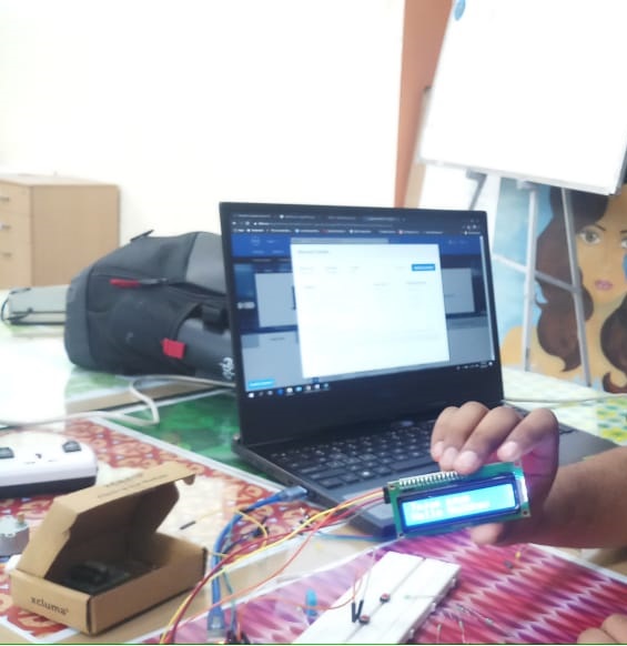
Ultrasonic Sensor + LCD
We combined the Ultrasonic Sensor and LCD to collect the distance of an object and display it's distance as it changes. The code for this activity can be found here: Ultrasonic + LCD
-
Ultrasonic Sensor + RGB LED + LCD
We combined the Ultrasonic Sensor with I2C LCD and RGB LED to show the distance of an object on LCD and change the color of the LED based on the change in position of the object. The code for this activity can be found here: Ultrasonic+LCD+LED
-
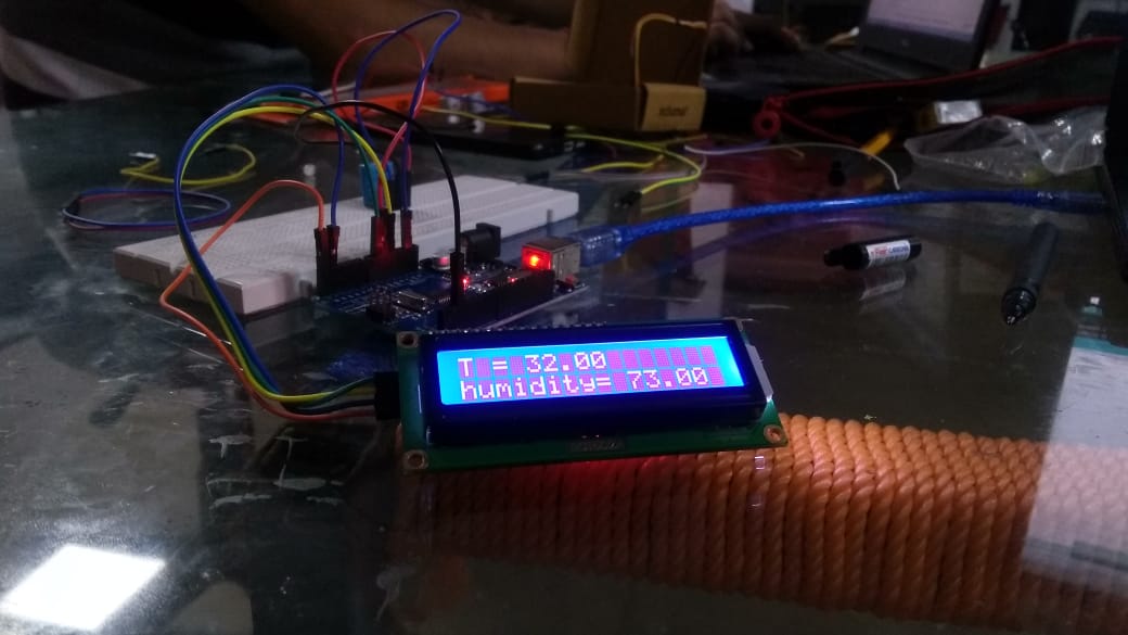
Temperature and Humidity sensor + LCD
We combined the DHT11 sensor and LCD to collect temperature of the environment and display it in the LCD. The code for this activity can be found here: DHT11+LCD