|
Repositioning
Tool for FE-Human Body Model
Does your
product development still follow a sequential path? Then it’s time to
think!! Can you cascade your product development activities by introducing
“Virtual Validation” (through
finite element analysis) at concept stage of your product. Simple math will
show increased benefits in the product development time through this
cascading and offloading of these virtual validation activities.
Computational advancements have facilitated virtual validation of not only
the automobile structure but also human body models.
FE-HBM (Finite Element – Human Body
Models)
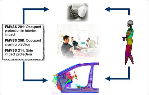
Human computational models are used to investigate
failures that may occur to human body under impact loads. Standard posture
models that are available commercially can predict the loading in these
postures. Any deviation from the standard posture is termed out-of-position
(OOP) posture and is of significance in injury prediction. Some of the OOP
conditions of interest are leaning or bending forward, could involve a non
standard inclination of the seat back or the head positioned next to pillar
and so on. Injury levels of the human body may change significantly with
change in posture of the occupant. Hence it is important to evaluate the
injuries to the occupant in different postures. However commercially available
FE-HBMs are in a few standard postures. Repositioned models are needed to
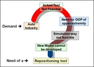
be obtained for OOP simulations. Thus, with an increasing demand
for repositioned models a need to develop a repositioning tool for existing
FE-HBM exist.
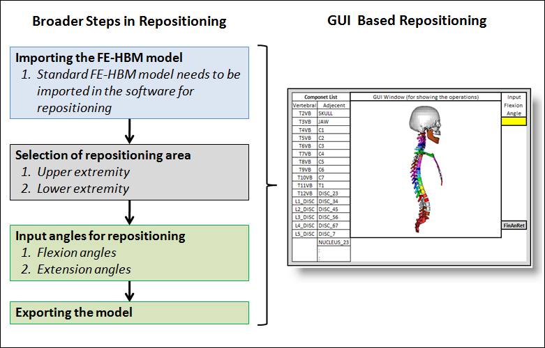
Steps in Repositioning
Steps in
repositioning go through rigorous research and are later incorporated in a
GUI based environment. The various steps in software based FE-HBM
repositioning are shown. Computer graphics based methods like spines,
Delaunay etc are used in repositioning techniques
Lower Extremity
Repositioning
Repositioning software takes
as an input FE mesh of standard human body model as shown in figure and the
desired knee angle post repositioning.
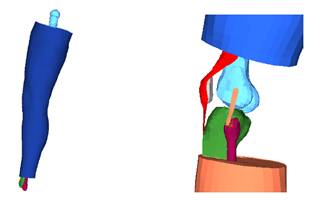 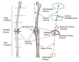
(Left to Right) GM / UVA model in initial
configuration. Detailed view of the knee joint region of GM / UVA model.
Axis definitions.
Output
from the software for various knee angles is shown in figure.
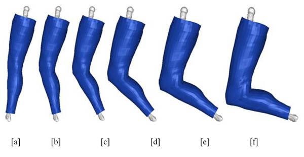
Lower
extremity model (a) Initial configuration (≈ 9O flexion) and
flexed at: (b) 30O (c) 45O (d) 60O (e) 75O (f) 90O
Repositioning Upper
Extremity
Upper
extremity repositioning is divided into three basic categories. Primary
steps in repositioning are shown in figure below. All the steps are
included in the software and with minimal inputs from the user
repositioning can be done.
|
|
YGlY8fZZu4m2zmxvVp4DzWe4IkTuIIZO275ad/YQOuCe+gaBNVtHTCXt0JJLVWH52HCIq2pWBa1f
QT8AgEZE/uIYPynHIZEEIvDn4l0DjxxGrj2LXhSB5fzsTTKA+gyERYKQNWjMbcICbaHrxrMPIeIo
liJfG25vR8nxuhQpdKMTHSvCZ1Kzk95kpid3LVGXsvOvDV0tT/fqABhBNC8W7q9rv01oPreauerV
7riX5ZiIBNs9C9Z0GofPfdY3wDOr8EiKJ/D017vA6VnP7yBt/wlXj03KUAbv40+qMv8IhgUr80M/
9WMIAEACN0F5rCV5tQYCICAHKGUBm6d639E1IGZyeSN+YZF6YXEKK/ACFgZzFzYtryZL4rJ7N8Zz
j6N73oIjPKcTNmV7ohQdL/AuxWd83kF0bAFUxTVM0eZ0OURMUldt3YBtqxBdXNZUYYF9YbZ9U3hu
4lUn4TUyZqdiFUEbhxIc7ZU8YBhGgAZ31XMzMmN3DpUsnFQQoXJP9QRHOIF/5KF//bMdACggh4cg
gzAIC4YgsWJpWpNYC9iAtvEdIGB57GMBpxcljQQ0HahAGmVQFZZpCEUSJtgdoNRzRWJzNkYuLth7
LkEtPwJL6vKJvtZQ7aJbQ9cVUcL/FV4RFk9CXE4WTMqXXEh4F1PGQ3tBdVm2TNeWdVo3GVxHhd8V
dmfSfcj4Md33JuwGAI4gAgYEb+g1jXbjZ261bzfTCtZzHe9kh0qTPnVYYPa3d+JBADZxjkOjd9+Y
KVJiCIilH3w4gPMBULLSH431ADrAI7ewaZZ3UhcIAgAAArKwEP4IABkYJU7gBCPXgRoFhhVmCpgG
WSXoeo91eqdAAQFwazNhW9bSEzYmik5Re6qEWzpCgjMlJTehDuuwkljBki0Jk8T3FdwBJcB1OWth
hNzBXEelF9HXF9MHXTbRhNYnjJGRfcVojMd4VcmoGeT1O80YFsUzIrWxSWCIfvWG/3e/8XZ9Jh3C
0n8PgUcpKZZyKEfsWH/raGAHliTv6CoAMAjd8QDr1h+FJCCWlo86gAD8GHmrdVJyYAETCACyYAEW
YJAZmAyHiZiHCQDJ4ASOJHrM0lFcBJEneAoqklCaZhOplwEWkJE6UkEpklrdAUGyRHu4R3u0pBOD
c5JCEkvtkiRXwZKxCZMvSZst+ZI8mBVjGSXSRkzOp4s6dG3YwIRVB30A4AxbFk7ZZZRSWBldh5Ru
opSbwZSfITJYWCeOwR2WoAF+4hEjQo1X2U4VhXfTM19+NldL0zbmgynJUo58tx6ikh2ignBYt3D0
cRMI0HnloiJysIreQSu20p+TsP9pFWh5REAEtbZxG3cTiZmYi6mYC1FKGJVRD3kKElmZFnl6IWgB
qhcTq+eh06Kf5TIt3wGSTQFTPqZbocRzwLeDMfmStgmjMalssmiT9LIWbREwotObRwWc2FZ10xec
0XWcNmFdtXOURvqcS2SdGTOdnVGdXbVVjxEWIqCdxnMJywISKmeNZ9hOlwQRclee7qROgid/88d/
gJVXREMAAYaW/Jd/9ck+i4YAIlou/Emn+jmiq9c1ArpoEAgJnWcTBmkTDIqYDpoMNnEBchCNkRiJ
lGgKlomZmbmZqBcWPHGnIQqiIXqpIroYhXOiNRgunhgA0XFLQyebMfqip3qbw0f/fEZGLy60dDh6
i7/pfKmTbcTJi8eJDUOadcN4pL6apFW1pNzXpJPxJuOlVZBxE7LhCK7hnVUZCSujLFvJlWQIV2Ql
puz4lWnanmVJcEqTlus4n+G4cLZip5zaN+eqW5iKpzahW0zwEwHQSDchC5NYoSiooINKqId6qJFH
YgsRKCa2LBV6iRWqWokYFqKQqXiqqevasKv4sP0JAAfAmjT3EqhJJJx4hMH3JC9ZozLJqj/1qjbK
FtE2ZSfbmzvJXGuRZcOJdbtKdby6GNTEnEgarN5VrE0ZnVB0hVGkZpOxrFQahnVGep81d+3nTnFF
hsYRNJ7SNoemV91aT+nxRnbU/3+comggelm0FhZygABS4gKcehNMwATyeplJkASyIAuTCZHcsa82
0QgBEIGiJwcXYWqY0CMqaBMb54+WF5EAMAoKq6ndIbGZehOFu7CZGposAUK210FjFkveMGRS0bEy
tFPBNaNFV6MthHRYorICk4ueO3VNGETSpatDal3KqSK/upw3W2bDWoVX9aS+EzI44RpYWn4ZYREc
MWdI26XhqbScNCFkKk9sCofj0w3lYypLM38JkbXpKqf6iZ8NC6Jh+6E28QQAsARLcFC1EJiycK8R
WaHii4L6mphAEYFz24ElIAdxI6Fc2499K6iA664S67ARS72YWlPUe7jA1omScf8TSNKiTCKbH5u5
xtdCI3sON0qEoSswulirwHkTWyakvchUNtEY4kZVzum6GwO7Ypezx9pVxmonXWM8WSqJVvl2w0F3
9LV+kZJfTlu87nm87glYaKp3gRce6sM+X5uu+um11Bu2L2C91qtQAJC9SyAHp1AL3luv4gvFNxFZ
DRoAt+GANrG+mACwr/ECqXawBolSCTUK+0tr+Yu/C6u/ZHy/8OstwhbAwfeiX8GSuoS5B/yKCvyq
JevAuQi6ERx1wSl9QcoJMEukM6vBUdjB2vfByKiUIvyUvCMBxOOsE3G7KCyGzqtvXOm7YnoTZ3qm
9zdw37Om3yo04/hvp6JoB2D/p5kaxIAaJWs8tl1zUAsRWfdaiZHaHZS3l495EyUQQJjAxgAgvhSW
YZhWkf3LrsFsuDW1eskstvU7uNxBJLw1wFqhqi5pzdiMm1uRLzV6ozdEVDtKMDgJfXzRhL04XdNl
XRR7yM2ZyEiZs2d2jI5srD0rAZGcdVnKMpBpEW+Tlc+BTu2HMwPxVyBHIelJytrhd+Gx0DssNA29
w3fUhuB6KYmWygdApzyyEIgbFmHrAjcxxO8KrzYxy0scWSSNibh8kJMneaz1mGpnu64BCRIJkcaM
0po2xmmMzBCbp/trE8XWv2jcrhC7qcHsLtWcFbU5m6hqx3dMx0ZGTAu8fDjp/5t6gVzBiSwUrKvB
ecE8EVWI/M7FuMjSyZSiARpP2Rh32TUL1EALNK3XmMnsN1/Y+jajEhGdnFmg7NDhM6rjAdFH46bf
WEfMiyr8IbbpGsTNrMwQi59hocSz3MQVmdIYCglzaxNWPEmDwh+WoCJ+kqDCPJk3jVADkNNcW8aE
G81BbRMtANTQ7Mz9ucbtyhOTG8e1KZtKDZPbrBVLgscLbENwgUOlE7pV1qNUN8hBitxFuXVgHdbP
OdY666QjjNb/sG46YMJ1Zn7VSG8v7M+R4hwtvH6aktch9hBQ+4Y1HFi66R2fsmivOaK65bWNnYeG
BNJGbL1eixPb+1jeK9mtZ/9htbbSuuzSt0sRdStaffO1fHthUHxhA2CRY0zGO/3MIMpjibvaPS3U
DyvhunUA6QC/W8GS6u2DSnYVmysXJZtcamE6a0FtVCJ9FJzOW63c7kzjzd3Bz+0mlWHWI5yFjunj
fZLCGtG71VpRAM2VfWUQb9TJ3Bq1UmvFQAHYAScleIqfqdUPpMFH7nMTobnRYwuvrUcD+v3fYx6p
lSd5LwOwXFg8c4phChq+f/tYA4DMh4vhMlIjkBs5JHHYh53h9+vTY3nN2Ayj8PGKsViTwHVkVkE6
xfTANkFUelF12XDc6Qyz0zXjwGqzNv7O8VxuIbPjno4TKfBIorVJ+rx2zXL/PfMlHC4MvHyG5OjZ
byIeJbdxjjhR6wKn1+n95xp9APIhHzLgcDYhD8MuDyUV33k60mCuvWRukf5dvpu2aHJAB+sVG5Yw
pyqSiAwOAA4uxlq7zC32SQniODX4I69FglpL1O0q4RmOExwro0p920u9zbKum01HhGthzhQcpE2Y
uuBW45re3Dguz9y045ChjyM3cp5GjWhnTl9Fd3C1tFzKPwXGvAhNw01+8Xillq/5AjwRl/KhEuxD
WP8x7LUiNTzx0XF60xlGqadg0pfp7M2OodHORcVTEZZXLmHcthVJ2v2bWj7hYoujUrIFkrANv5vK
zBouFaUKm4OOzbhdm7qd/xVjYbmXO0xSnaMPbLIBw4tZdtzBeZzOYBNgttyZDvCaLvA6nqw8TicA
oAMHn/Ce1m5VaSJG+8/f3d2+i0Z6B+vpY96eMsroTTTdwOQBVniKWx8oAfJ9tEevMpfysBCyUlIu
AKiaBgkZOMswH/OaH1lEkARp3izVvrc4j+3FbLCQwO2q/ZErwTe+vnu65w+zVSOmncZK79pc6y5J
Ahap+vSCDu9N3RWbC9VSrRaio6Mm65ssm9XnbMHYpZyY3rpnL/1QurNgd51sj52jbgQITwbC0dYZ
IVZoyI1o+M9whSja+neFf95E09cJrfEbn6eH8D6+DjWQ5viK9WBcU7gJhf+QCMUfAHFK4MBTAAgK
NEgQwBI5cmQBwBQREwAAlyxJomgKEiRTACAhePEC0gpTBSEZBDAKwAuK/ly+9Afyhb9+LwHAdPnP
n84DB3L+9LdiRU+hIUNSpGjU6EqWK5NSTBeV4jkA6qxexapu3blz6rh6PbfOatWsZbFS5crVXNpz
5twCMAdO7ly6cgHU/UYXADa+fCn25YQNQLZsSAH8Q5xY8QvFjRk3hhxZ8mTKlS1fxpxZM+SGmznL
+Qc69GjEFFOkMGIEADwyKZBawgQbgCWIEieuwp2bYm7eqwCswoSbYvDewlutytZK+XLlq44nB8Bc
+nTl0alPt379enbt3Vv/IV23juIh8gBq9jvfz/y8fnLYzwMgT557+P3euzdMsWAGiskSFmzooP8G
GlCgJRgyRZaH8kNKko422ggBSEISCoAHUVLpJphqcgkBmmg6T0OcXvJpphFX8MenoJhiaamkjlLK
RQDWkQoAqszSKkevwAJLLPFwxBEtttZKay0b6YoLnLiSvAucvOjKa6++pJRSMMIKQ2qyxyLb0jMv
vwQzTDEpa0i0L8skTTTTAKihBgBSICOAFOQYDjbaILIzEqSA4+233Ijzs08/ifOtleSSuy4b575j
rhvvGH0U0kiX425S6cAT7xA50DMPPU/7CcA++zbt54F55JAPgHlWPXVV/wYB4A8AZPxDaCA5CDyo
VlvpXMJCUzr69deMgvWIo42KFYnCY5HaECYEEDjPpfMC2Klaa/+5KSSdqtUwJJcA6IlFGcVVCioa
pyLLLLGs+qorrtZNF8izbGSr3reSTLIuu/By0i6+CpuSL2cGw/ISiiTr0rExF2a4YYfJ7OxMNP95
4IE3XWsTntMCaA2piGQDIBJMNtFTuOJ267M4k1M+zjvkJJ20Uu1kfpRmS7+jKDwADqHJvA9DFFVU
9x5AdR55AmCVPvhcYzCZWVE66NaCch3wVjkO9FXYYIHduliNLNzoqApb8nlEE2+KtiYRt4XpMJdM
/Pbtf+A+gNxynYoRqv90xLMxXqx8ZJfHr8TyW16v6CWyrSLRmgtfuZjM68m6BvMrYMGwIYwigw+D
LOHFHgY9dNHDnNiziWcAQLXTAJDDNXjeDAAiPCeiPbZABxVUt+JUEW7Q6JxbdLlDga+uu2+mI2DS
5G+GmfnqchbP004/Vc9T9kZVVT55TG1vVfsuRioIWZ32r8BTaqkFgFqoXj/AJBLKmmutuw722I00
amqmEHHqB260f/aHiF6iE50IcCbbAslLtBVApMSoRUdpILj2lg504WhdF8wR4NRROHkJqV5FMgdc
9KWvJs0lcv3aS5UGVphsYG4whumclkY3QxrWEGJeAo0cZjCD1LzpTa3/e9VEZBOR4QTKNyrzTXB+
wzs+9WY30UEUcxSlHGy0zGbdkdnxsDMdLSqni8tZnvMoBT2fgSo90kPPe9rDOqPBZx5Esw+rwAeA
IIiPfMgw3/nUtz6FoM9qcngfQuhHrPhxzVjFCtsL+qfIAH7obW2T1s/WNqKbENAf3ooJUC7ZyG+9
6EV5A9cBanQjC1plXToC3I8Md5Wu0EstQ2Kckh4nSybJRXImBMdfAuMXFmYOSwf7HMJsOExi2rB0
mGkIAHSQBzi0yYdH6IkLXACAac5GdpgQ2URw5xs/8Q5QKGvin3QDxeAxh3iZc94VL5VOMTIHPHRC
o6dAtB6hwWc+8hAE/wBMxSr2XIxpdRzfrPBINYFIzUCsKyiuBEmsQTIUQicxFkdWQpMXCAUmcFMb
ANXGIbZti1pmYwnbqlVRTTbQgRBcxwso2DcgaRCDGOQgkDwIy3uNcHL86lcusbFLbAyMclb6pcKE
WUyiFjV0xySTMnWwzDa55g2sO4A0qUknIs6OiCozYsqQ6ETDLOdlVSSeOrcTM0u9igBIOStFwrgd
isghehsFERrZ0xBOGY1OguAeP/3pGoDekVYC2pWBlpBQhRakofLTCLDuB1EIZUt/KzARIzuZn2hN
8ieV1CRLNOkSi1rrWw8EZVSaQsqywOtVp13ljlyZuFfayHGO21dOJf+HlL709HIt7GVFOIcYzyWm
t0YFbnAlZibJsE6ZqskD6+jEOmlWsym2i83H9iTOrPauurxRojuRMlbmBWBS3vVO7Kwj1ued1jA6
Axr1qjeIQagRKYCYAU1iF8d5yOk0fBWfQJ1WIPMlsxYBKmxHhuUrw2xNsRH1yNc+xEim2ERE0xOv
ejzbNpE+MoEDzEmDf3K2ULqIRis1r2FSWxW+xZRdM/0gV0po0xDaci5I8VdtgdrLwhjMtzIUbo51
DCakJoYiOoBDapb5rDLJwblHAZmdbnNEJ55sZLhjYp+ecymKHKp4zFtrd7I8Roqss51cRgoaQTTP
fgyCQfAIBHxnEKL/9eyVjnbU74D6ewo5oI+gBBJWgQVs4AdBqM8niZZSLtkSSKJnngyi1rYwqxPG
xGRuGI7bJh8pwLqdliomTu1YdLRBpJSllR8kEpHuAtt85fLFFHGxTp1h2yrT+IWc++3cdjxrWm8m
Yj6mSGqWy9xpqqAhLhBKNa85nJIBJ6va/NPtikMosXaVvFuMFHfSCl7qbDmdZDT09NSmXFXJER7w
kMPr/CEHSe4VvwHdb2ELeqteGVQhAinJsOa3ZwMneLEJ/l9NIAsAD2GSQ9rONkwKmJ+XoCjSjR6g
huaGyUR7tssA2FvfMJ3pGeFIxKqF5QdXrK+43AXVso3xlAhGMBYe/yzWsa51ylWOmIkhRTXJlKaR
AaACXzdkBdQUNmy0acTr3m4TfAKnE6VoqOZEEWf5SWvS1cogpbfii4zabs2+zOXwhKp6PaOIIQzB
T2/f4Ns+29SHTLO6N6N7oLoi7CkOROc7IyR+WUMKnxHZ2JP8rEIv8NDb4NbIM6qnwjZhoEUVLTeY
fFSBBcQJo6MzIwpeOtPyqvgpzYIUFIfY8ne5pYv3surLvfBKI18Jjlc+etIrpkzKrMEBat5cOSBA
mi1o/Q0agoBKW8L2ts9qz1f281VsoroTidSinu1l6YiXQTcbPhZnpLPyqIeehuj2e+YB/XC/7jxh
3+iayu5X+AW2oP//cffUThHvt9db7vX7GqABIBTpSVrv36JezwReLWzthMM3abi3CmjJmYTEQ9ti
tAD6jg/rtFVylwPkEbLAoBRTMQZxiwe8FwiUwI7jl1uiEk7gBM/Lhm4AgG7gwN1yDJQrvRHcsR/L
g9RTAQT4NX67gRZ4vdZzwWSajdu7k9/4JtxgNt/4uZ8bmSQSurJip2hjnuSbmeUbj0OgCFE5Feij
L1cxBNawvg/BPlXhFIoAKP0aqIQAsISqGqnhr/I7LIbSCIkKsxX4lG7Zu5nolLiSsBGJG4RTNEJ7
JE7aJAQyG3/wLog7F4pIrXZxlx2hipcCixTboLZwC8VZi0MUIbf/UBJGfEBTw6ko8QsMbLXC8MAs
iSES1MSVy48DaIgWYB2a8zWaayvXoybjsgSRSUU/yb2T8RPe472gGz7oCEKpuxlq+zIySsJNmStS
ib44SrNvgw8AkgMkTMJ+KrtXSQK2C6w8AqT/IL9GOCx5qx+waSzzUKQzjCT9cYkDMMMIy6j524nO
Aor6y5JMMrhLYpueQLhGA48amTjBAcR2IbFNy7ivQBxDPERFbMS4OId+rCVcwqUUwkDBILkO/EAQ
5K1NZMiUM4yhGADYKxNRjAMVcIEX8ERqagqKsD3b0R0cPKIo06YdBMmVKRQgHEKyQr6bebrn0ZlO
cY/2UEKkSRo6/wGEr2MPADLGY3iVIOCBn+QBpEgCdzOoPDqF9ykJAjmJaSwkiTKWr1kJ6umni+pG
b9y36aFDnDC4v3Obb0GAfxC8vfsHFWEM/9EbEOtDBETAissgr2AtetRHRHxAqlgSR6Slf9y4nPIX
AMDADPw8beDADxSqhiTMHHtIUKQIUHSB0wtFFWgrqQIAMuBI3GuO72iylPkNkuRBH5zF5hHCSMHF
6/giImSrl1SbhlAjN5qrVQmArysjAKqYY5BNnjQvGQSABACkZRS/XDkfPhq/VIAVMCSkeqOIjSAK
M1SvNkQKoZBNioCFikoPASIgzeqoDIM0k/oJxHu/nXjHlSKtIP8BxHk8nLYUC1BLi6pIxLhMxFFz
RAmMrVTTPL7cJYrQBm0AAMC8T2BayMLkT+BaTgBAzBVogZuLuSKTA8d8AZlbja+LBNwjniXTHUDp
PQAgyZKMOpVcyUixNi2bOpfkG05BTVFZj1OJo9UguLSpGGOYTRWlTcPYtbZKgBhFCt5EiP9SCP4w
v+GUO4r4A2/8lOs5rQ9YgWd5BVgo0qLglAnbJAGCJDfUMEgKwPuLCr75TrPwQ8FppU0rT0K8EQnU
RyOpy/Z8xLy0QPnMQMGwz/q8T/vcLRHszzcNHYogxfUD0BZQzLZqkdlDANSLTI2pk985DpNUIlbc
wd2o0E34uWf/myLSbIXQnJmUnLq0eslDYC/04EX1WBWlMYwWoQifyD7ogwIWnc22elHjCjHAYsaO
wFGm7Bqk6IkeCLEW7cQDeAEjrbR+8Il0HCnuzE5r6UpLyqSQ8In9k7S5GZsprSDDUct5rEcdWZx6
cS1ENERDZM8wrUtIhE8U6ksr6cA19VZYg9NwHab/rNP1G9CkiDmKKNA8yIMjWI0UYA2OBFStwszN
9L0d1MyussUM3VfmaElK4SJ/9Q5MGQ8zqydMVRr4eJ2lENa6qR5QRYpjYFHWgQVYQArbvLwZXbf9
yA9gydhKqJse2ICIpYgPyA9RPYYDKFKMpNVQEgqR8h83JFaB/8O7agkXQtu7FYG4UYrHK22XDboK
wLnHT0vEfUzPRXxE9yRTu9Alv8QSNa1PNpU1caXa0ZHT5TzXCGou1nE9F9CBH2oIMvi2FIgd2mgZ
4HGO6kIZWMxM3EhU4ekyLKrFgYXUXNTF6rmP79GD9zC+cgElF0UCJLjYXdiFit0FADhciniFxWXc
V0AKYYDcyBUGw6Cz4IQ7eTOMStDczT2AShAvSmCQ5pRYFSVdALBYcUnCBns0RQNWtrEsNbQWE+mJ
ZwFABmI88XC8x5u8oDUl3l2XT5vWCQwhCARIcPhHbE21JpHP3EJIkisMN63a6PWSq705O1VXF3BB
nKMmFaQIdv89DXArk9eZrpYJVCZLGc3Uwd6bUOWIorgdOs/sV7m9xQ4lWPOgp1HpBz3YW/jYVBe5
m5cEAMEtgiJYrsKFBcIlXFgoBsNg3IxFCDmIlRwVMAAwBoqoBE+oBJbNj9mUWNFd0eY0qXJxPkzi
lhFh3YvSzpHiicnqpO+IuNzV3awgi7BoS1RiF8RJzxxG2vbsxyaZrRLaC6e1RA68ksyR3iNumPxw
TIogUDsVNmnyRCCak44JtyMIBHbtMuLBjUCFCEFBX9+j0PX1KvbtMis7juz4on9Vjg1FHuRDK6QQ
r5gh1dRVwjIzM6RARhnZSEwJj/CQAx2ogc1tK8I13Yq1WAX/RgqTvbwfgBU5KIBCgmRjkOTZ3VMA
kM0K7mDSlVgK3uT+DeGj8IkSwchIq91I21VOYhujcLjtYgqJo7gQ693efSkVU4e5tOWaYsR/VFq9
wLwXo8TPu8Qi1k8kJubpRYolrlPrRczrdYGeSCZ4BSJwA4BAAIA8oJOzPduPVKIj4kGSzEwoYqvf
ANi6pduBTSv4VQ7jEy+lMy9MVUIz0zo5auVW/tvlW4eGaIL8KOBCrlh+hoUAUOSTahFGhhUKoBMJ
FhZJnmQOnthL5mBLZhCGhSAW6Yme4IlKk9kASmXrzCy4AcCMtTwgqYrzsmFnRU/1PFri1WW7BGKB
zCUhpojA/xRmhSzmmr4Mw3DM6s3albjIUxy7sD0NLL7J10mVbTqZjwzj3CjUk2RfojO6uH220QxY
aJsO4yO+diJY9LA6irhj/Z2HuuHUvAGldXiAHbpYxpUDxzUMQ/ZnAAjok2IRiuCPhghDAEiFST6A
DxZdUTUG49uAkRXrwL6bFFmBsayb2HHdwythzzLsA8Kw7izAGMYKv7m4s0ALW/7SFuNhHva4vNzL
z9NA0Lbp0cYMckVmvDGKanKN+2odP9WBNAu3+CjqreodH9TBL66yyiRf7HBflOxXADhn7rLbPkYb
eqpUitADdswfwV4Ksp4BAC6Txm1g021r0LUbGJloAKCAAv+Qg8MCTmHVZIe2ZBAGgJH960+SaIEW
l+Mc1k5CvAAEPJyYCVHGCaSYoMiWbE2zuALM0qLdR8WpVuHtOM/WC8wpOecNKtJW8MlQYgSV6Jtd
ndVpCGpejeor1esqSW5KNvXdhODo8N6umfxQZxE3jNhJK4ow8eVY52djVCoDYPUwBIwNidb75IlW
ChV0qz4OjxmoARwAACWQ7uk25H5Gb79V3ODE0e6et19ZAUke7w4eVaT46/PmSbiucexGb0+SwxRx
v5kNwPr78slC1pHO76uIR06jvBAC6RCTpbpgkvv0pUrMHJpe8DrHFiaeOXV9gZ7uVMmM8I2ZkyMA
hNXwOmn/lm15AKfgiDJ6FQ7e4xPf+w5EMbr3ZdRmu1AMxWojtF8AMIRnYVh+kwPshiBOTYrW0/Ed
5/Efz1i2LvJxcVz+WFUljx+hcHKUDbGRzfKnsPH03khRh6DY6QklVThJMyBuyZkaAdoyT/Y+RHOj
1UfXStoJhETYOjVfojHRtvNsLw08p1MZEds4+XPxBV8AOAJBeCpAYFftma4tLt9xCqfMdPTx0u1J
J7rocBTfLmdLcdRb1EVnhiw9nnFSj2ujkMFTp5NtGG85KIaFB4CFd3iHd84rb4pKOHK5zhqHyJoX
SGhLXmDFDfJXYPjyynKxRu16FmgIam+NnsP6oz9vQQpv/zgXGLZStfzDKj2xr5gXtSjaaRUhutBl
WkJeJDG1kbN20KZzbbfph1y/m0OK19GYr/tzihBbcEsu2kuzai7q6dqEbAY6I1KifB3n6xC+uZVf
S2HjaOt3ORgbXVeK5XKglWiI7G6rdUD4J1f4h194Y8h7hq9xw/AEj5frCE6QhzAFjZ9gpCiGxTXS
xS9Ste7ft1fvVocRT46Rm+UkhMtKBUI1PXTlDqJ5d+EgtjiLQvRvW4aLW/JH41X9JqF25XW1IsYS
pM92iqjkPO9TOOnT17kvw3j6IzgCFXRBX1NB5X4i3mj3IzLqtoX0ercOer+ymzl7dyJnLxLYItR0
OQDrwP9mYrX/dwq5uVAvFz92q4jlYDk4XL3H+47fVJA+hQzAUfM6CcNI/MZ33MWliOasDvU+ead4
/OvOboB4IfAFAAAr/B3wp/CfPwAM/T38R7AVgHXpAKgrqG4jx47n1H0MCRLkOYwdN55L+ZHjRwAp
zZk7F3OmOZfgbn6DCRPcTnAAeN4M6tPcTQDZjB5Fmm1pwX9On0KNKnUq1apWr2LNqnUr165eqxZE
YLAgAHhl4QWAl0ItgBQpCrotSwYAAgRy7LpQoeKunAMCya4CsGpVK8KDBwPYtEnw4VWLNzkGUDhb
q8qSK2OmbBkz586eL3v+HHr0ZtKmLRdctw5AX79/yZL/FbhihZwVAw3KkQNg4N91clQDB3BsOPFd
uwAUM1YMNvHhsD8AoCQdgKtKAGDBgm1qO6QkSXbz6AGJrDFj2Qu+gvUqwCvhxC/v5v06tvz4vAsS
hG2/Pn6Csw8kpFBDDwnYUH7pWETWSSeF1OBILS0IUkwroVTSSzTBJBMARAVFlE48nePTTRwS9VOJ
Ry2VVIpH+fSViy/CGKOMM9JI1mwAkAAAGWqZtdZbcbVFxlsFudACAAfcoNeNcrzAZH4FBdZYY5gA
gEmUjq1ipWCLeXbUaF6eJlqYFJn2jZhjhpaaarvpdxt/B7RWV21s4ldXGWUAtyZx9xD3AHPNvefc
BgVV/0KJda94cp16AGQAwHamyCGLLABAchssYiWnnDH6NQeafbD9dZt+9MlX35P7PXlfAAf8A4CA
DDHkakHp0KpghCg9KBJHJt26YEnq6CTTTBpyCNSHH5oo1E9BGaVUQSs2RaO001JbrbVgjXrWWmeZ
BVdZQwLQQgsuHAnnXiuw1mR++UHGWJaNMVYlZPBymSZompGJJmagnUaAvqX9y5masaF6an8A9pXb
bPXlRlaeAgA63ANQQBFxoO8BYJ1+7aXHqKO5mTIpJCNX+gICsCxXnspkAZptwQW7aXB/pRJUs6kz
A0hWgQU1VBGCGvHqK0kPdhR0r7i6JCyGGiq9k04eiv/Y4bIcPosNis5Ge63WW3PdNbZjmfAjWzzC
9WMKARg57rj4McnkbnzZDCWVjamCmGOLSYkYv5kRJlk2hAGs796kDd7vv2YKXJFuAMo8M2+z5Rbz
QLpVtCanzXkiAAAVN8fnMe4dY0zo6B36SnuwZZCbHI9S2ggkjRS0MCwrqFze550HsC/MNN/HO310
Oh7qff3FN2rPCF6EkdEe5TrSrkczmNGFwiptk9MfhljiiFEX+yxTKDLVotfjk1/+jGORRYLYZrHV
llsBFGRkkeTO3HZY9r92mLuDPab/vFYi5jR7K1wrEFcZA+YrTLnjDALTFLDEwQZOwbPZfWijLuEJ
xEn/lcvTatzjOQAkCgpy8FygRBeo5RTEFaZrDyxUt7pHmYJSrxvP7GAhG9qp7HOg+9y+eEfBUu1u
d6kyFX9g5rKMLI8lQ0tJ0aDHIAtRL0Mzsd7TPESUEC0rah3yCVK6yJSsmS+MYhwjVWIHABO0RUc+
IovZyCIuOmGwSXZBQAZbAxvHzO0weFMMJuY2rywVpDOa0cxl/kZA0/hrTIccDb/MBAD4EYAs8JOk
fizXpJcNZEmGIIse9NMwl/3pGJ4YwKDcI4fmDKA5otuhDovhiVfcQA5NaIKjYCjDkSEHO4rizcoA
YEJQ2ghdwCSV5IA4H/4UcT+7OQBFEjTMbJ0kiU9U/4n0moahDfHkitl8mohqApRv+mQp2AAANpzR
RTCSMZ3qJF/63kKCtAApLuAS1xuV+Zo5OqlJfbnNu65ktz5uYm4A1N9lAFcZgwYygYJD0yI7A0rB
DSyDL7PRJw0xj3noQQ/zAIAgLHrRjQLgox8tSCqdkygAQGw4dHAOoFYZuvcsx4W0rOV2CjJDGuoS
O9h5gTEEsqlNOQciCuFZgfxxEFcV1R/9aMhSXeY7In7qU6Ji0wtyZpHkucSJGwFlr1TCRJcMK1gx
ASs3nQaUn2Rxi94bpzPGmRTxrTOucr0WG8/4lrmUbUhvXNsE64cwtuUTSlgSjJYgA5k+MuaPkuHX
3/8ys5mGhmaBB2QgZxJJmkgCwLKQZWTlDkY5lz3AT/q5aG4eIFKQnnYekxyOAKDDpubI4AGqZKkJ
N+WE3Bzjs8/MZU51+gLaCeQVK3AOgYgqoBf0rGe7hc2NyFIX3zkOVEU8UK0KQiGtPm+rtmKJV6H4
NJkIC5tWBEf2kDU1cKKVKdhYb7PQOdf3wvdFZCkBjt4SgBSQ4b7zNFL8yDU8VPUlXRmcKpauRNg+
3o0xAIQPvjBjUIqApoGEY2hkyeLAB0LYkuUShCDk4WEPs0YO8/hwSOfRD9LO4wHyGPFIRXpikPLp
d80J7Ut/SRwT5sEJuT1lQYrhY+T4eDnJ+bFOe4v/nYUZBF2fE2pDiorcJidVqa5aKpWV2uSDJBWO
vQseMWvmsJ8pD7vRjBBsSEJNsIK3ijVR2ja3WaJiqTWcR2nrONsb3zvjmSsFQSMazdbGcPHVBYKO
W/HuA6cB04Zy7MJjYKiEiYBaCbEFDsy+SEPIbEGSksCUrMAsM8mGclpfmLUcAE7cDxGzeMW6+TCL
SzwPEevGoxddsatHKhxSgc6UnXpp6HCLW+f4UjlC/nGQie3j7BQ5O8ZAwApeMZCdCagfT+4HUpdq
5X5Q+9raRoA/ngztbteMcVGN2e/+0szk/UrM2e1VmVtyoZosd1RCIVHUurjeOnOCEw7JM7/7LZV2
/7JRnmPhLwAGfUxyL/PQTYJcYLdE0EhHGjEDlcwqKOO3ziD0gYXTNGz+tdnPDCykpn71iOWRm42u
2MMjDmluXrzJFYtU5Bc9sXRvw1LiyMGlL/X1KTsV7B8LO2VBvs6xkV1kBBgDyeCO1XG/XdSmapvK
ruJ2lhcCboRwua8Eo0itSiJN6H19QaBMc03Ge6ynYVMoRTnrUdbbVgDoe9/+nnu/65pGt7ylLmQR
NLlcMMT/uimfurlgfrDEx8QgGBOqMKy7Bmiaj3dakRrHsMNWY2pTh1jEIE55ykObWtPO+qK1Fn1f
b3fj3NKy1z2Xbct+KmwgG3voRTe6Tp1LR4b8tv/pTi9QPwJQ5d8HwNtWHiqTBxKrgjCumG6CjUU6
GHZ2q9tCwCK7Tky0k/KaNYskSmuz7j3OuNM9/HjGkbfC5j64iGUggt77D9dlKsoN/oKAGcyjydJH
BM8rXgclpCArHbCPQ57//V9nydzI5QaryUNIqZw8hNaLvdgDoFqLfdSLad3pEUcT3FbP5YYMRIwv
/ZyQvV6xLQfK1F6R6cxDCIRR2ca0EZ+1WdtQ/d7w7cYLOp23IRdS/cMBSBW5iQrybJe6PZ/YvVtY
ld2xkJexwERard03NQudFUS+yZ34SWFcFUSO7Bl9gQv7+d0jqR+htd+TOAnl2IWKFYRh/VMAABD/
QFFJu3RJ4YDJv1iWAD1QHEKU5YzcqelGh3EeAHzYAY7eRWVU6G3UzNkaEM2W6mlgzrESbflS7KFQ
0AmZTo2gCSZV7vGGgCBVUmVb1KlglEEZ7sGKChKIck1U8fgMuiWRgzDRupnZdTUIFKUZm4lXFbmZ
NxlLNzELOd0bbExhL1JhFf6I3a1NquyG323hzKBK/UjUGCYglCiGPyVGlkBaYNQLZ/TNIAngQo0J
HUpeaCAQAlVeQWCbiYkYtRmCHCwgyqFjq02g6GlUzLkYSBmi6JjQr+2YjXVgeTSicjSiI0ZiCVKi
UD3EbBRICpZalGVbDPYDlkUbJuqegBzEC0QE/yYaEZtwHSpGCBNpJIUEjVd5RIMkTdOk2YaU1fXw
hBJqX1GQ09vVWRT64kuWD/nVl0ymgA7OD5EIhH8dnOTgB5sggCCQhR6iIx+WIWIoRrswmpUsxiEV
VGW8oTaGSQAGDpqMmuU9AB6OHB+uI4hpnsr9Icux2CCeVunhHBSY0in13A59UOj8lOz52Ka8peyZ
IAlmxygqBHKlIEQy5PA1GbZpG0E0JLRJBJMx3dW9iqyUSzIliNfdikjoSkZ85CoqUUokjVhlyFAc
YUlW3/Yki7Lo4mfqG0yKZkymTxohn03yV07OR8G1X83lx09yGACco6oRZTTu0WDdn1JSmmNNRv++
AI5UKtTjTd4AVsQj9QMEmlhyUturpVzDpJpYjiXJiZ4DgtTLqJ4xmGVu0WNumV7LvFQ/guCPwR6R
JZuinMdEdttxedsKZpkLXhtgRlkmCl+TEYhEOuRD6CBVvcbPMKbQbGQTscSERA9lvkQUTZFJ0mIS
MovaUc0uspdLjmaE0hX5odEZ9Ve4FBxrSpffUZBr5syHmZyKvVpGraMzOhzjvUtAVSMjRR5pSFio
TRhlYYaEtQKMRiUBNqBymhgfmpw8cFgCgujKwZwEat5XvsxtvQeSqhLrdeB3HsNbjuewDZmUGlkm
QmRgpiCWPVtTKSR8+qULIhW3hWKrEObVken/qwzVpxzAVf0gdgUhNXmXFCELUGBfZiroSd4is7AX
FLqXhPqptADc3gVaC+QHh8aHMWqZlxHEAZjFc6qYh3WSH0ajbRYYGkojlTQUvwDnZXxjZ9ioHE6W
IhHgUgWAcnoS5dBayo3WSKnaSFFn8MiBEzTBzmFgbfXJSpHQzekj7AEZeYgg0RUDQDqE1REk7ylE
sR6X3sHGUuUHRepHXVDd7hVIXVhdteoHgFQXZAKhE71iZUbRS5BkNonrsSyLEp4VaOpbaP7pugKq
FVohkfAVX9mHfx2j1pWFPKDFHm4lA5rcZ1Gj4SnllmhJcDrWGwInN4YGwiLSqNxoiPHMqGAb/7XJ
AbZN7KioanXCRmiRxWktB4DYRYAdAwb2nAXezsju2sqgEGzwY5QOmyReh5UeFTCtZj/QUcT2nsxU
GfHdYLYIJJPREZPtzEMsVnNp69FAE/SA5Ls1zVBoE/bQKVptD2fWxPfxKbta7fnIZPygi/xg6Pq9
QL3iZGveKzwA6QJqpcpBoG6ImGBQquE1WkDBR2hUXGlsajf2i4UNUEF8WiR9WsjJis0q1alNmRwE
Lh+iHIillgL6KFBmC5zcRc4AgBPskAk56TGs1K59J5DxY7H1GCQSnQmmbJKJIw1iW6lhm0BYG7eZ
jFiwSUJqW5MJn9AeXyYyhOqiKdPN7joI0/9yjVmZ+UrSTk9Yhev1WFESph04DQU5wR02gN/VOu9X
NCNzrQB/FQmRrB/77Yd/lUtZjG3ZXqw8ZFRBwBpGkYUZmm+UUEk2tkJjVdrg0GiLgqpnfJpDEafO
YCKVYaXpnlrE8iitlRjMJWDJvVpI0QM90BIgAEIZ6AcTMIHpUS4+DofJuscqjafmopAIEpsJgkqa
umCVZeJSHUQ/5Ke0oS66cGJTzadD7gxRuYpEzKeVVpJ1bWvRtClKVKacHmiI1Cm5qp2ynCTc5Vvz
Pu8Qa0VtupEw3STfWW/MGCry4WsCki3Z9i/iJqAeBDCshS+lmuGjBUZCbUaDzS1qFARmeXH/qKpv
jIoxUw6g5exMxE6slOEv4S6n2SqgBHrY2hZEEwgCIACAAhNEbjBBQZwe5XanSl3Mrk6plF5wIvNW
7QHAKRjMCZtu4P7HAXzpDR2kQu5GfKKp1dkvRDxZYR4frTifZDrR1/kuSITkd1VfTIwrvOnHN22f
SuYb8/YpEePyvzHXwIUL/axf3xljzdAPWTyxWRSz965cQZgcUJKWHGQx/wDQHw0W/QrnZ/Sty3za
JEWS7mTWZgVgOFqpP8xAPxzCIdis71Es/+5hraUqWegGApMEAPBxbghDPRfEMAwHIQNVxKRlPn8O
JcAeXA5Z5/5qss2OMO0qbFgZUtmvCPtF/8S+QFMRZAz+rEK4ZwsXCIEEACkiBJYN61CNAwBkaxAC
KNjBhtfFW0EUr7kuIRc5AyfYMoTm8kw/BXPxVwvsLtf6XQAY3KiwTzHzYRQjc0GkGlDCnDOzhjMa
3jMa1opSRBg75RlHpQBZmMd5XGoQ1QvOwAzobVNN8qlJWcoJacwp84jJAR3I81chcF3Ucz0PgyDz
2s0dQ67qhq1GRwVzbpTyI11mxwqcgjHQg0JLnWAHrlJZMrhFdOmuAAn/HtW5TCd7crUCCEFitD+E
tEhfBBJdl9Gqmyrf8LduCPYVL57Sm/aUSBAHsUzT9EzbdJLJj9r0MsEVBPucBZAKdff2L/8xs5ps
fhT4apSfzIsZuq1TJxD7TqXdxi+F1WEHFdUN6C+1ucxWw4ZXCiKP+iE8nwMC78YKqAAAtHVbs4xc
W4wTCAI9bgpABx1yCNumWLB46tJsnIJFwzEn6u/wJSQJN5d0EUw4JxfQFtcoCi2yQkRBgAOYZZVW
GY2DkJmaGWho0wTZaUgP46JPvHRMr/aF1/Quh4swyau8wsOHsw+I/3QUBzW+1ubm7eE5flQnmZbc
NLXbdrFDPRj8KrcCBcynchYbCwjh8gz+QrfN9sM4Gy5sjOUnhVRa0wEfb3cuLJfFfFATbOddB9nm
Dh3LsndBnEIIL3QmaxtDZ4uyLiRguuf/bXgif1trtRLmClDrUHmDz9Qw9H2k8wghEaKd0hgo9aSV
9uQiat8yhg+xjcQPL792ueQMiM82iNu2iR+zMpPYAl5x6CV1+fJPik6z460v4FjcA+E4NUOljDoU
VmdiLN0v4N63Uk2sn7AaxjZMAgqDO+sGO7BDSsNGSvkcd+ojQL9CesclQScHWfzBHwBI1PW4PyhD
ttizYEd04DIOJy6MfC/07RZVZRcVmf7WCoxyB6XbKfvnrTi4WIGXg1tTFJ0X96gk88J0n/u588bO
1t4ITsMruTAqPDBqUBuzoQt1vU832aK4qtImbMiBbBeY+S7WmdA4clezqEFUcSIV4ZJi/9/yL+Be
peHCHMvplnc/wROo7W79wsZz/MbDxgAAAMjfTnnQwSpRQntMaZT2WOMCyGF7tX4oQ6sXBC3QAgdw
wC/IvKskNpUlhLT9pZYqq/FUa6tYaSgO1UDCRtdpBIIPKLtJkUgW4dPjcEnQG/f5hLmje7pbLaAb
BH9Nb8Hxlb2LOLfUO4mVtfciM4i589aKL0HA7XBHxnEX0m/OIVX+n6gRYG7kp/LpR+BiG1f3Qx9m
1JCSBRPkQi7U8+G7zHdnyy8UBB5AfuRziiJOh66vd+Nv/AtwPGw4PgDQgufHwszHAi2Mvncfu7QB
ueumoLS1CRGdigobvdO5cGoYuJt2dv+3S/2a0TloS+1OlGtqq7bWXy1sGAm6GL/1cu9ZkH2Ifzi9
N+MegijagxROi4uiqUsZruFwewrBE+xUG3yncjpVd9biuEbvANEwA8BWD+IBdtJYMjAAIL4wAEMu
VLx+4Px3HzsA2AEe7P/+Qz5AAABgbCAdAJQoCRRYrBiAhgoB/JI48dcLiQJpQfxFK1ZGALQ8KpQo
TGG/F/38oezXD4A/iC9gvgAQkybMmTVlKvS3k+e/nT4B+OTpshWAdekUqlO6lClTAE2hQgVgzty5
qlSpWp2K9WrXrADAhd0Kzhw4sGaxcRL4j21bt2/hxpU7l25du3fx5tW7l69dACv+Agb/0EJwi8EA
4MFDnHgxPHmNGctTLFBeZXnzAFh2nLnyAIErDAM4IKemnAMHAGzCJHCV6tYAWsWGHZt20dqza+fW
bXu3bty9fQPPLfDBOoE4aR6vCcBFc+cu5ERXAXFedXnRL4sUJuzJEwDbIYYX9mv8L4V20OOxo94O
ADwAChkzpgOHK4cMITJsSFIYLYm0hFCII4/8CyA8gbYDDzyUDsjpwJtwgjA55JaDyB+heGrppwwP
OEqgc56KqqkQRYxqKquwsgpFAFT0CsUVwzKLq7MA4ESttfrKUccdeezRxx/Z+uuzv0JbAbQAyCBD
scSWZHIxySZD7DHL5pnSsikBGOAA/8FuOo00mkxLrbVVxHzttt1w+024M9eUrc3h3izKqAeUq/C4
BxVyLjo5VFChheYUik6hyiJSqLvvEkT0wfEUUo89R90rZCCCakjIGIYuvQ+/7wSSSCYhQoIoAPL4
S9BUTgU6DUIXYpLQJuUOdJBCmZJTCKgLhwLqNKRAJLFEdXz9damtWkzRnK2M7UrFqcwKi6pmzeIE
G7CCAtLaa7HNVlu3FOISMMAIE0jJAOBRsknGnOTMMnWrVJfQv1yos9UX5DASJjkQEEg11VLjl7Zs
eIMz4DgH/qY2g2kLgODYCBAoNoRpg5g441yt01VaY0IgugNUMO2A5rSMzrmZwuNIIP8mmEjUVP4g
ikWg9dKD2T083hOIEh100LShYi7FL0EEgFZIwZWHJlpeCPFUaELkkGaawlRzzbAoIxU6Rx2rTRRI
WKm8ukorr1189lixnCVbrBur3VbttdluG67PvoUbIngKIKOxJxlTSLErrVxXsseGZO7im+oVSGOB
MFkFk8X1VVNN2mDDDeJWJp+8FQLefBw4hWRTyEA816HzJqWXLj06BE7r8wbURJMjvBdYjb1lAJhA
tNSiSXIZgJgfnZnm9xLKWb+defZ5OwSIvn1l28F70MFVbaqJVYwjfDr6WVXV8CeF0uEyaa0h2lop
ZIv9iqtkqyJrKmZjNOsbsWrE0e3/+emvn8fABQMNAARSAEDJFMiFrnQxaW9XchcAqvQYLs3LTl+y
iesAsDjFMW42AHMTmgYWJ83pBnNralia2pQ069HkNNCBYHgOt7GRQSReAPjGNwolkBwgiHk19Iij
YKYe34WHEk1oQvGIpx9EvSB5zDuV85z2vedRbzmzut6sRheUnTwIRFcrEYmS8isWda1FJwLbi8py
rLGV7SzwA8A70mY/Na6RjW/Dn5BE07/EkAFJAhQIPAIYGb9Vpl2Ak9cTX3KvVrkuABJMnL9iY8EM
ummDwmkkm9DksNwobE0CWQfFLtZEhYxGDqEZzHM05jpVAao5sHvQRn6RgxkKDXch/3lUzNxDQwBU
YpYA+GHxBoKp/RCxiMuL1fXuxELYtSpPMGEVnp7oxD8y8FUQSYdxenUOrJlIKsFyirFQhBXycQWM
xypjjM7yvtQI5B1tNOc57Sc3qgGgfymQYwrONagmEcoxlSngupQ2ONIxkTQzGY2+DKkKSf7rN92A
3CN7Q8lKcnCgwRHO5yjGRDsdIF/SwVMoAYCvUgayheLUyBKWMIQhbAQivtwdzHKoHYEQJCGvkIMQ
h1cMqiWPZQrxAAc41cx9zkuESnxVMpvYzKAu5wCsAMAzq6ZFEWXxmly8yhbBCEb1nQ9a8MtEJtKI
Tq1uFVtvZGc739kkyjjmXI+pJ/+hqoSZfVZscKVJ1T8niAnVrKYVq1DkIjvnOb0KRKEXDOFB/+pI
oxgHqD8VyJ72N51iZhRfhiPNMYmpkBd+BFUCGQKejrg7HHrOPJWdpScc8tIgMmQFymve99ZaKyRG
L5CyQuIy9Tk6pqkqHUhhEYuuKCymbjObX9Pm98Q2RnBiNatcNe5xddQt0bAOrP7LG2KkJEDJSAmf
rQUkyYYqkxXUawX3ypch5coa2qzCr5AU7AdFtdfbAMBAGhSsUSwW2UCdsCQrUcgDRMec5jT2JpCl
FitLlQsB58KkJBEIpASiu18YiFE2oyXPXkqQ4r3gIaeNCEVGslOdLvF5CkGAP2T/kiE8nSZ7UWza
05ZJK4GAg1day634ILIs1G4RfWIkC1XCaRYAEBe5PfYxX4Z0gOa6MwDwbGdkyNoYeZCrunfSpGyf
PBMj1QsmhzOkvx6nOYRiEDifa+ibOtgbhUR0w/PthxxWwpI02xc7fpwJdPLVYbC8EBwwPGIuAJAL
YNA0aQNKWiUSop+X3ofCD+kUhv1zEZ9K6EApcXQ/8qW9obREJQdICetyIl8nyqpC3jCKbXG7VPE5
RSFZmRHYUI0iGT3Lhe0TSCbM8mNZz3ou4Rly/5R0R3RBCW+ZeV1hj2YnnIymVomT4Dj/1QqAPS7M
BNtyeTMnWDJnuoWMVfOZ7buS/0EAYBCD4BtnFCIIe8nXhQjyZXcyK8sE606lp0XIQhjiOpnyTN0T
8Q+qTmu9+tr30Y4O8U5QAnAAqOQFjnaJS5bL6ExGKL4Cqe2HfCVNK1pTRFYDkTQxjvGqeNHUNWZf
VWHYDVvRmuQlF8itv4okJC0mutNNl3WZqGETSxQmXnog4lwDADPV1bx4XSiYF+ZzOcE3adGZ4prR
PPB+dHvb376SIDK6QBfSGcCnOlTVExULl7kMJKNiVKJs5pDwrPMVNRSJucFjChPnc80pUXO/TyLp
SRPc4JJGjYpJlmK2qtio0HSxUixuNYpHRZosyvjhxagsxZ9j1Wars1lEronilv+c8sc9OTvZaYLm
IgaAu07yc6HMQCcLm5kT2rbSAfqaTZApN8sW2MKeLXQxA+eDZDZcKOeO9IGj2b5Op1Jm5PCuFXvU
iP1BELp7GRF2m4c85gF7QmChH1jAQiCvsD7WDcw8ZYRnzSZR+krczhKAp6Tg4udJwA9uEoMffEMu
Oc11Gc20KCL174DH2uAJb3hpVqVYNO64V2QEnFxN5OSn8gzQ8hTCBL5qAYsMj8yl5Vgu2FSr9DSM
5hSi21gCIo5tEzbBNu5qYGKvNprNkYKur4aD6MLD6IbCJbpvT9bMXfqmj4KPUIQP+yiLO56glxjF
ZUhKPJoH+qKPIajPE6yv7HD/R2USRRneDvxMYgm7j9L8DSUGbgWnCMRUAv20Ryj+AdMyTagWLjwe
7raYwuKAZdQE7/AQD6qSRUW+hvG+CfJG7gDlcKsub8j8BzHo6AHJys0qplaCClaqh/sG7rDsC3EU
BzbIi0zIazgMSvZmL9oWZgQRZsyWC2hmYAaGAgvX7AYGQQ+6jyXsiQYvY0rmIfgwYxTxyWjQDvmO
ECM2IgD2bMHCA7SmrxZTAQCKELSQ8IgSZSUC4BPjru1UAgrVTwqpUArVz+D4DUNwBeFmTqigqCj8
zvCuhgzxrynOMOP4b0W4SfFYrSyqCvJEDo3msBzRaQGbq8g4L57+ZjJMKcok/2qn2Or7CvH7XCcD
U4NxVmEfdc6hWsEEK4fLAutgCLLnDopiOEkOZOAYj+7M0GzbbuAJfS+BEOg6+iitAMekbIcVi08k
MqL5bgcXAaAWp28ki7CGVDFR3O4XCQ4Zwy/NoLD8UkJD0I8nTkIl6q4nVlCKLEa2/ghpPi0pJE7i
ytAMDW8bNe5Yyqe3nqosykicuoEAy8kcqXKNMg/z3Mm51vFupuvNICuySgfYmgkz6nEQ7+sB6nFx
6MquWM+hQhByciMgoW0g1wsAyuCwMmT8dlIPeI/N0mweQNGAruQUSzE7UDEjwQ7thEHP8KwjEzNB
nK95ioEkqc/6PMEXFNOIzP+NHqewCbMtzdyOBckPJ+VuKD6s34yxGXHlH7KwJ4GSmRyOYi7Oiu7P
DKsIDb2G47JJWWTkm0KOACevKoVzbdAR85BEjsqFKwUiduIFLIeqAhWiOtRKIF6QOtMs6ViikFZj
H+tqgyIn6OZyN0aQLg/KLuVOe2rSHzrxCbENJv9GFCnSMoIvMzAS7QSCDgzCVAaMwIymwEJyJEkS
AIjw+nxBeVCSU0gzzU5iJq/wBVFiQYdxBQPuBRAAJ0mTCjOEGRGOtV6zaYKmV6oxRK9xRNAwDRev
47SiWd5HLKKyAIfzRYkzK/sHKxXDyAJoRuPlOQKprQAxsqTzc64NIq4tzfD/y75WT+f2kR95Ttku
6C0Zxr3exMv4KgUFYiePcQZk4BOvrS9hkDMoEiPl4AEOU2juEz81ExgY81SWJzEVZcZaMVGcjzNX
ovw+kwlnEsRQEz1tUjQtlP18AkNYUydxRQJ/iphA7XvE5zY1ThsT7/96S8faRxwJEEYpNUbR8Z3Y
KTnzhpSOqQ8nEDY7rDrM0kE/sUgzcBNSo66ygbz60a7gcjzJs8tCaDayzEL0cgp5wuhmQEuVLiJ7
z+nqcxTnQUz5iA/x00zVFE3RdBeZtaZKSjPVNFovjDrdriVuUiV+8SWzreD6rTTxtDO7dQWZ0Vun
6DWh8UCAZZqKsv7yrxq1/1Hj1BBFswJSV1RSXbRS8fVHsBLlEgOAlvNP9CtHPZXTJkQgRBWBpHNI
SXUlAJMl6ItMVq+uWHVJCerZJscEN6fLGqpWdWLShuIG5CBD/hImr/NXz6pLE0ge9KAi20UhjhVZ
cQf5HHNNmRUlo1VlhPQFr7VahRElEEAmL/T88DT9UNNPo0aK/nRDWgJonNNBjKrFQm18SA3/9K9E
cexEuSkc7TU487VrcwQAFHBGNY/zMnUyXOBPBJY54rEL5/FgEYi9pJMeSfYJCREfVy9JJ1ZVASvo
Yk/LtMw3iG79tCdkc489SxYi/KY+MVIP9KBYBWIGAAA/7QBmjQjdis+0Mv/zZnGnI63TQmfiJfm0
+yrU0Q6kJrkVXC00AKImL6nwVqbID2slHcqBqaS2mqBCUflvGxNvN1tkRd4QAKJyUr12eHfk8jDP
BOwmK6PkkwBWv96xaWPOYA0WM6qjH+KWYbH3+0pC6XjPYRJRYtsy2cKjYWL1EWmDfHtjBMODCh/A
H1Sw7roPMM0SAFaWJdw2adaFcd8Fcl/WIBTTVFixWVmmZmm2WQXiDzozzQ5AGPHEQJ7nQt8KaKoQ
Qw9OQ29FCz3WNH8274ipHGZXDIfliiKuanFzi8jixtQnPCIVeIP3Xon3he+iDpsLHmZ0MAzjbFvo
OZozn55zOqWTeqtXVHn/dd+GNOmQNElXtS0XcS4/54NMMPY6iHNIcL0ohn1DNj1ZsGHx8fswEGHj
9jAfYzrptyIfN3InF2aLKICPcIA3F1o1lyQQeM2ApsSoE3V3IsT61Px2wtKcsUqpUEOSdlBbd4J3
0g8B4Glvy1dG1MVImA33z/9UOIxAbmu5FoYt2Y1OLmy/igxQowVuODRydKPii6hQ42ClM4y9WIhh
sr60uIgLMRGTOG8NMpLGd0o/6AT7VgQtSU9v4BC8Vc24T2FXwnV+WFQT6CJpkL7492Uvd2g4Mvk0
140NGIGntPwSONvgTvzyGD259U77uErJtYJXk3X/+P10qhxAzSlg7EMw/27GkCWMxCbHWBg4K/mS
7Zk1sRId4UFLbFhw0NZ5fzJCDsBt08qYEdZ6xVh7eVWLjbgDuTNJZ8NVHVEgAdfLhMNyfmN9d8Lo
fBmLifgzW1kOAiBhRRUVT5GPKlIQBOExIPeM0biAn5lmbXaNpRmOEdjtbvL7eBbu+DRc79hKhbZc
pagZXXd1RVNw/eHuDPWDq6h217lq9g9e00eSGe98vmmew+OetdqN2gkdt8SGQRlgAQW7Soc6ppdl
jRkw5ddgERqh5VZ+W9AQWOOhE1HnLCh8nQ1K9VpOqtgfbiCDBW4Q23puP1EO1PpHT7ldUpYz5nOZ
6WByL5d5GBMYIntzef/xjUPyD+K4CRn0JYnRCrU5T/cUsP/YGa0Ug0mbnJdLJooCaiVuRJ2iRDMu
AKkquKDlN+nZhbf6kusQbPtHSz5ZIP6keQHaTsDNYC8DiOOWoPthpLHXeuW2TtNMrhFxH5N4Vfsx
PH+ufDM2r6r0fQm5SpGxYRs2uq8ziAlzsYWVPuczaQp4OwQMTSvbQC9bgG0HAPwgjq9VYRkUJxf0
syN0aJG6/VQbadlPUA88tRskJ2Q3qZoaxqLakR/5WaoansvCDcGphbN6t3f7KrvaMMIFxJljuNV2
eoDygHxtua2DoNV64NTaeq2XJVv5+9TqhFQVb4tiiZ30H/e6TTAncub/KxOFmtKG8cXnlrzTjHF/
2ItHsSINs0pWNuZkArPhO777s2jM7spvFgD+AAEUAUJ7GpvJj3Tz+OBkEqijJlCTVidaArUnOOBS
c9KWC53B52pge1hkm/+aRZJr2ylZVMMBgAR0m8OJ9+S6+jA8WTDO9pPyxDnwrgbfNrlLOm75KmHt
d2She4jrK6MUgq4lFoT4Nk4wlgSB3HUomFqD2rlnXEvtaxAOG4ibXL2hXA+k/L5piiQG7L1n2rR4
vVS4XBEqdGHn1gpJt2jFr5vRXEPJtUo1lJAzuCZFgxU+VGsefGv0DymlmitQeEYyvEUFQtDjkNAt
WSDCVgH1R39G/IZH/7zEs6e6gnXFERa5rbPFYTyIFXY6y1ImGisR+T18dxxWzfevGu1WqXWbeZXV
7dewl3swvdRdHsCcYSIZNvPW+UONdz3L33toDuAPTuMK+5vM7zhBi/Zzgzo1AXUnVBeDhaJjA7k0
9dhjH8SprR03Z5tZguvCT5hGghc4wX3QxT1fyR3ziOQwwEXEcVi/RANLKIMyUFrSfdigYTzTo36t
67Eel+Nw+hETVlVVaRU8QxDgMWjgy/VODf7gtViLEUjh0xoV6TOMR/EBwuRA1hgJLT7dfN0Ge+k0
OP4TWZJkiT1Ct3lBMVR1B7nNxZX9OvbN5y6ov7nc2FWLItxqWeTG+v98bOaZAPun5+v55ynVeIte
uAFj0Udc9I9bXdjFSljcOt72xdWq3qF701OMVjymuvmdNx5HLuFSNyynvHYfl8HZtKvV2KMbrlkd
YelAxdl+sSlyNOiYUyieeWIay1npf2laGIwkjkPTCVlQ8AEfNU/z1McZQyRtXFXTj5cdQ1sCT0Yt
XRFvUW0enk8YK9zn8hViRsGd88cdAEqgW8IFNEQcIAC0cDEQAAB5CA3KO5hQ3jyE8wA8NDgv4sOK
FvtJ7DdPIwCOHg2KNPiiJICSKE2WlHPA4KpWq2K+BNCqFYGaOHPqxElzp89WPX/iDDDSoD9/Ro8q
RdrPX9OnTPtJnar/karVjfPkVJT40OHCiwu9AjhwgGVRAMLSql2Ldu2TJ2nbqpUrjK7ItXHx1gWw
4o/fj1OjTv34AmpTAE4TN32BQGnTxEcRL/X3L3JlpZUrS6asVORjyEiPfg6N1GC1oupSq16tGsC5
17BjvwYAzhy4c7XN6dZ9G5zBb928dTOYAkDxkf+SK1/OvLnz59CjS59Ovbr169izXzdoQmSLFgYJ
Chw/ELzCsAwRhu0a8fzXi1szgizaseXJlCrxj1whR2TMbC+tkg0AqwQl1E4GHpjgTgSchVhSoomm
kWKKAQbSYFN1dFVFegyyFUL2OVhUfyKtYZBebOGVCzAr0lUXXnLd/6WXi8L09Ycff4hEVFE7vjBS
Yh9R2M8Km00W2VGXLfWPZEke2eRlIhlZJJBOjXTaWayx5tpr5sDWJWwA7GYbb7yBY6ZB3aQ5nHFs
FqXdm3DGKeecdNbJXFFEGkTkdwbxWRA8IzWk3noJSeTVe/BRBFJ7GxlE1n34+YiSSJK+sAJ/BsEk
03+ZHujTTZ7WtKCoIwFVFFNGHmYYkFZhaJWGIQEwyEhk+QipQaywYpCJAJDo4Ix65bJiLi6eOBdb
NL641qUi5djTTJDmZ5KIfBEJ2mRFZtaZkkiSdlmSDxY55ZGHFXWOSOoYlGVqW8omG21iitnbmWqu
mUJx+CJn57789v/r77/O7UfkCn6C953BAMADqHsMwSMoRek5xBVG7cUaa0rRYkzppCnJgUCmMcEE
U6eh5jRqTt/UFACDIvGE3JGporqqhVJpSLNUIUYrR6Uc25prrgZFYJCvvx6LorAA5DJXLHalSKOx
tfqFY8sBkhRppFbrJ9IBkB3W7WRLcial2EpulpRkoyFW7mlXbqmuulrG9uU5c4dpG25klommmsTl
e5xBAAcu+OCERycwX+DlKRCfCS88aFiDipQQWBN5tZVIHTF6dcYjbZ4SAr5uGrJIoJZ8MoMut5x6
Upo55rraQm7UKmBbHyCpzjxLC8DPuo5EIq+/JpsWscLORUvTyKL/iBYAfxyA441/iTyTflfnrnFJ
j56N2dekcabtlOCCFqXrpJUr0rmusQtAunCnOzfd7tqdW29jimQO30WZ8Dfghffv//91AgAJ9NQn
87RgT+ZRWMLS47D0SE49EZsIRkZSH6tlTCWdkxbGNJYpAkmvQC4jSoMMIkIdJShlPqFJB1P4o22l
CnaGuVmGNoY1WrHEPjxzUBB2uEM54IBaI0FRXN6ytACkKHkzYp6NoAc9mgQIKJMCYueKsrnxGSls
ZNuWtjCDmCaVZmxSKc1pyoGu1axPfedyl9ykaBB6pclB92oTAABIxzraUTp4EsjA+OSCoijwcQc5
T8QM1RX6MKpW/z3joOdqSMMVCmgTQCmZTkh4lh0VRUEthNK1IrMqVVHlLIyUlAtcQBaWuMBWI0kG
tXb4w6LkwhawjKWM5gIAIsaFaTBCYlzwlCcmOstBPkpGMnCBiyBYsHonoWEUdxQAsm0mSa3bngux
9cVtQcU0bWxfa9RxDvZJ8VxmCqc4w2kOAODPYHnKF//uyM52ApCAfInn4vK0sMYBCpAOBKRYMPcQ
HC4SldZLJBXxg6mRBQiEkuSJJA2UDZw09FTOnMxTgjSzi2HwepM65Sh7NcqNTgsZyUCGQXBhEGIN
raS5uIVJR3ILg/wSAFEwFhEBgMsj7nJ5I4Glj2QpIh4G4QXG3P+hLUp6nwtqsJHR2po/mvkkJ4Et
NFvs3vjQhhRxYDNMZzRjN9vFJbnNRpy2MdOY3OidxZlHju5Mq1oFV622kueAjbPnHwt1EIeFxa4L
wVxeHWU7o6IyqchU5gWZ1RMCzSShCjXdThpKKitq0khL7aQyqTfZv4ZnZ6csKgBCGlKSOshXKlWp
sFLaLL/8IaZ3menxcoksAMQyli/gqUh2CADazsKYQL0tbW1B2mmRBJRaCyj2QpRFb2URfN17jGcS
Y1UAXMk3WW3NbNz1PnDWhpzjLGdwzkIwxf1treANL530pAJ5wnUF2TOIwtYbVwUqTFANSY8/E+lb
o3KussJFJVD/ZHI6ofTXZDlhbGMhtJTNfGZCiglRfrN2PbOah2hF4SwyQFoUH/SHBygdLdKYZ1rT
4lQYTKBpTfPClmCUFLawNIhPjVlb3RokBulN2i1amkHq2SqUwb0d17w3Ls4wlXs9Nsg1e3eldHWT
NefipmyU/NVxgpWs39CjHgcGgAEcR7xYzrJ1RDKwPSbuAGRQr1zrKY8Glhm+eW3Po7DmW/pyrMb2
5eBvDTogxNakdKECgIAFZKrxaSuaEg0SAAKQ3iomM8c+Ikh5euUgRkk4aRtmtCsj3eEOG4sJTKDF
iJVFy2CYVKcqvu1tgQhjYQoTALfwbI03GEXKMrjN2evMtwr8/1TjKiUAHgGSc3dtkNesZqvdDDY3
h73V6xo7rOE0J5cJdrgBDEAkWo62tJfjVnl2V8zsXa/CAnDmBuK1YXtltSJtPG5yyzmp/inQYRH7
XwAb6CyQ7V6EQgJQ3TEYsFobyQBuADGLREQXBgkppEcLACZEeiQY5nClc5SjKAgrFrGwJE6LEoyK
IwMBGBeRqU292WS8YOOqzEftbgxccedOsPU2SjOfGjYv/rhbaDPK7gxCRvRtE9jEZrKSaeNk7JbT
IN6Q8ne6XO1pG13L1c4Ts0ey3gCwVyEOu+d781ooNlsWmfVdsJyxbquRRbIbCW23QvW8OqP8mVzY
WjUG43zjcv+XxNmGMIRFAvBvg/hAJLnwtKcLTgekaRgAd1d4pZkXU2LJYdPG2qXFg4EAkHPc8ar0
uOMNkg+lzNftbbfvbxUJ7eI+kzNBppCVeJ2+dHFzSzoXdrHDyvpxiuhgh1vn0WefVvJaWyDZA1S2
4cHthUQdchCk1AVRbmhzn9vNPetUgRIEdgWFPZIDfpDn047fegc2xydJb1YoxhWOOIjgwpID8f7u
0oUL3iBLWELSbBoXZFQ8GCuAfMdNDVJVfpzjVuwMADCOyEq9uvptlm+2Ik1zBGRnJ2+doStXgg7q
kkamp3pKxmQ813NiJRJRJmWXQnSENUe014HtREAqQHTGcQD/8EAGgGKCupcwZdY4K4hPAlVZ9/Vq
GvRXVbRI/iEqAqZYCwV9Z4FFX2M2U1RD+TUtGDUtBxAfEqEV8zFBoXYW4UcsvSBaK7VwDOcsK1U8
RjMXweB+lyJ/kGd/EEU+SPEClrdq/+dXa8dIPwJotEaA8TZop0EO2fSA6wMbEfguPidWyXaBBnNW
Iqg4HhiIdkRAzMIsx4GC9qReZ1ZXLRhI99ZIbAZnniOJQpgS6RUZhXVJnoJnnqJC0QczWxQu9xZF
+BZct2KJLUEx3lcRWhEfSAgAs9BiQRCLBmELO7ADAzeFluaEAcA0sSAH7FcXFRdMXoh/fIUVRfIZ
iEGGUnJf/2/mV7eSNdF4KrPmg9R0LQAwDrz2c0ZmZBDoa2Cih+JYFN9wAAgkZW2lOBwoiOzYP/sB
TyIBDymgewuzXi0YdQpRVK1mfPg1fDLYdhilVOLiQQQiYKRDEyiUWIqlQpk0LmqXhlYnbsmUVFyD
FRPEEXLAERnBKCIli6I2VACAi+RXfs6SYiZFLMdDC8DIfgAQDC9gYl9YFB3QASzAAgdQMwgGWSfx
hpO1eURofDSYb4CDLVv0WKChjbtWZG7zjcEGJrghTiORbGNhH3B1QIkjguvYjloJMFxGiPGYMPO4
QGF2Ziv4e5B4OzZ4aGnpk5UoZ9eof9BXEznYZ51yQv5Fl/9W1EWlUX0AiG5F+CidoZEVoREY0YqE
2R6cJUW4mDS9QC0gaVIm9gs0VUtwQWJqgQAHYGIThgyqRi2FkTk5eWD+sAJiiImR0X8A+ZMzWIRC
qZfIhYAJKBJtwy5Mpka64RrQ1Wu9QTflFGUuoI6XYh5YuZXE+S8GEYJd2TdgWY9St4j4GIOraX3C
1ZNcZ1k6KYaeGCpgNxI7gjIIgpcFSBmiaHKZVz05VG5jEWgU44rb528R8Wh+p2G5cIsrRVQ5ZZ/E
IplMY0uclhaYmTMAgAuzMKAESky/BZoREW+X8oZG0hKYd4pYR53WqZdtGCH6Vw0B0Dbrkz5qlEZR
qYdkUhv/4SEeflKIegKIxZmidnKi8nSIuheW81gcUdecaqma9iaD0/iPODoSn4SdFoqJPQEgctmJ
1DJJeFlgOhqA0UmK+ziVPYYUg4kRdIeRW6GRmwVSFAYAIiWfUcALTjhwrjVUJ2liALBawjBTa0EW
9QmLBBqLBqqlLxARizIln8GMm8QkzlQr+thg5olue0qK2SKepbmXV7WhEugg5YRs8ZIbItFHiKM4
V1ltWamilKod8KSOAQCj9RiWZrkwumM9lLh1yEdyPEozTpGTkBFkLrETLzGXLoMgB+kgQLpgSVp8
AvUCO7YUyqiK7tkPWoGMEraZ9ikSvBAFUXBqSQNpyWoL/wEQn2VaU2iaFi8gDAdALJvZkQZBi1o6
YT4Cmgg2Gkdhp0R5RZaXQ9D5T6KqHztSoc0om98EJl2Cmz4nJmdhlei4gShaqfqKHSJRXuVlEGEW
lmQQAGEmj7q3iNJYnvsokf0YLek1O2HUo2NDPqrTCkKqEy9hsa9KpMCEfH0pqpqlMbqqk5kzQSX7
q1uBpZwlcPNnanLAcZ6FNHunrHsnDDU1LHIxrXvhfu/nfiJxrY+yKKjqGKQ5GsolTdBUGoh2O8R3
fTb2I+MSRqLoIF4FP2FyLmMiL3cTjwq0OHoUqeWVr/s6tnj0jglDBvgCKJlKj2OJjxHpfzUKqKP6
W45SFf+nOlF3+xQTAq6wQ2skAxMNxVgCxljZ+RMi8rbHFKH/l5oyB1lpw6sTs31ccaUSpkotu3Ev
O0x4Rywz6yCahhZ/Jww6uxeLt4UWt63IgKsLsSgJaiQLuklI4UXt6oyg+pAbdJb19aOiIWjU0qF0
c7W7kRu8wXQK9DdDx2X/+q9ku7yGA08+gi9rCwCIGKNOl1fmClgQurBu9rCgaapSYSF3GyQjG7WS
USo4kbHnO3aG27GROIpq6LTT4kKiWWAaaaVROg908AAdoaWVKxJfmAyZCwBAQLN+R1J5hxaxcDwn
8hYncVNa+n4Q3JHcKmSLsnJd4w9kwaDbc4Cuea6Gxnb/WaeG4xs7ZxE/v0s31xW8P7dAClOwx0Ew
iXOc8MS8NNwcx6mO8xiw6qWpKZh8R4VvwqeGjiKnCGq3V5G3VQKuocG3UXIW5+uqhVt22Yt5N/qn
6OmQ8eYYkeuKGqm/iImlqfS/L2sQAzx+JuaswnA8v+DAIqHALWm67hfHBpG6HemtPYarEqVFWdw6
4OLBDJuwbXm747O3FnoY0jAS8JNGicqb9cO19KhAZBBmXqmOslfDNMyix0G9x2Gw0iuPowihbCmd
/vgR3Su030sVpwq+eEuxSEpge/kO5jukDxWXrSBxb0tygYWjnBe/I5tc5NMUM3C/GuEhhSkrBuEE
WfoX/06AuXLQzFHgBM3sBE6gAzrQzNZszbd4i0yQA9eMaRhXEhmYgZFyKeAszihBziWxFJaSxaSJ
tEvRzhsMyE2broJcin8lM6JXwtOVqCkcKI1TsNNLBgWQApKMlZVsycsLj32zycvZ0FpzSkqqWcPH
tIqiIftbxFWBynuLyuLrtxAStbDsIOgbSaBiu/mBu0yquH6axbB5FNY8AzNwzc3cITItB3qgB9Jc
004QBde8cU7QK8jw0zoAAEMAkgahUiG5mEywxmscYrTwC0+9ArewAsKyAhBscSswCy+ADJeCoPDs
DwS1AtWDzmMt1vihf3ELUGgonScXyoAqWZeDyK5hN/8rrBATsXvuJaNou2xugtA1LBL4MrDUa4IN
7cl+SZ5qOcoTQ8pCKzuwosqnHLGc1MoGBjPYSNl1CZ7maSvfjBKdnXH30dkvUNOkDdM1fQMyLQMx
XdMFtp7+JpgB8KsdaWn/23EBHKZiSmNFIQxrzNuS+dRPjWpgmgsT9n4nsQue0b0/SoaVza7kSqGX
sdnSPd3kmZqUVbSKsQIYQcng5CBigdf4EtigwNf64tfMO2iSXIIpQLDKqTAyCgB9RIQnkVln+Meu
zdigOaWlrNEbHbG4tpeT/ZbUpMRTSyl0QNoITtoHnuA7g3EOjgAiOwMsrRQyMOFMcb8To5G/KhHn
F5P/LpuYrjUEqJZSnGtSadHbAPALUE1UGmZipruFx405c2okzA2uR9stUdXSYqMZ/WjdM7jW1E3W
lmLW5Cwi3Ed1xoHXYHm26tSD5p3QgJ2p90IU603YJngcGxXfb5Z8Z0gRrz2YWIGTsuMqEZvRZR4S
FkqnVJXmvXwx+3fN97GBiN3jAYhubfgYeH7nugul60l33AcANQAxtD15IDfGyCpjpLVhvM3bBgHc
eJeLD4zVjEJJLeQUzEinoBhvLec9xUUaZpjSSyqh1qfYFSEPKKF9kXsQE2FPMurJBL22Td7XTz62
JLTX95LJ0QsKCtRRifYCEE0Sv+5/GrOeW7yR89Eq/2b+SRNV6c5t2RPbyvgBOqRt1uSWuO/LagTm
NRb+pMpVsqsYEhFRA77iYZN3ucL0svVnuVFY4mvqhATnaUjDsxs45ggWJcwNWdE0axGl6aAXVRsz
ytOZ0opdnZZI7IkCEXvlXnmd5H7j5LO+r4ANKLcuvVV+ggvTUeGxj78OyoEUpYRZv8Z+0RAbGOZD
M6F32T4KpFZsKdbcKzsz2tdcEqBtz0qab1n8pOLzy61N7KkOD0M9QOS+ceYucAAs9JZrEPAO6f7b
knnH7ntXcWQB5kfsGKi05zp+azuO49NEgH2pywIIv9VuEqXOnhFxKL4Xj4QNo3EU65P68JQqEra+
yf/hzd595FHwnVmVQt9aA0EGb/CNbcpmXhQk/70XLG/KZbQqzzlh3fIwjx8xj7grX/UxY01Wf/WR
gRHgXrKAMgN5kAAK17JDH3lFf2ogNxImZkkbd8ZJL58YhwxHeNE2Mxp2OsiylvWcjvNig6dfw+PQ
aKPQ+I/UjTHE7hAfciiJSBQSH0euLkcH7fYpGvHrncmCffF1f/fwLUrzzZaPEjl9LsxhLvIWLfhk
LrECvvWzWp0bY83g3Mz/WVQyzRgODsjDZTaF/DpZjOe4zxVEER+CGREDBBB0APwhCCDZQYMHFSJc
KKdXr4QKCSALhgwAAGQZLSJTCCDXx48eg31csSL/GIB58wD0Y8kSgD+YMF/AfEnzYsyaMf/FpOlv
50+fPP0BAApzJ8+aFwG8YMp0aVOlL542her0ItWpUq9KpaoV5Tx5KlOCBRBWXlgA8OClSAvvotoU
AVKQAcCWrVKi//Tu5dvX71/AgQUPJlzY8GHEiRX3vSh37kW2awOQYevCsgsAlzEvdWH1ReenAA7I
K3uW9Lx+qMWOTYky9WvXeFe2pD2bdr+cSPvB3N1zaFSuXaECbypHDgA5L0oiMH6gKlXj0btOFS00
t1CcPHtb99fbO86vqsO3JkHiOF6GCzuqRwZR/cWKFTFS3LjQY66R90nmAhCg9e2Xenuht5Wsu8ko
/52CGgo7BI+6jqediFKQuKyGq9Cp6UITzivhZFMprLHKAos0tdyCqzG61qprRbwWc/FFGGOUccYY
lUohBbdurIsMudy67KIfn+qMqyGVMq20s8YTKzXxVHNJKSZxu82lKV2KybsH8epwQ+KEM445BBAo
LrkDnLPwqejkCPOiB4QikEHeFuwOTjkZVEq1EFNiUiUSAKhBtojeU+8gJ5w4SJmDCDgpGPnoq68j
/EC674X8vrLNyphm8i1OmySE01MFuVPwqKPqRDCqCzHcakOsVuVyOgvHQsssEskw0VYe75pLLhYv
ovFXYIMVdti/IEvLrsjYoiszzJptNjOrOLNKHv94kqw2ST1bY01bvFR6jclLUZOyyiyR0vLVaDXk
Ejk1jeuqOc8wfDe6Nj+d816k3OTUVJtoGgu31fAEoM8asMDiokHtSxiAKN47ib75GrUPJElfoBil
S3HjSdM6r0vqJlLlLHXUoUYONcIEseuS1a1SlfdC6paCNt0QzyKrRABAwVkypUzoNS9igxZ6aKL9
uqhPXXN0C4AWmGY2s6cxxOyzMt0yjbSrlRwPr9dQW8nJcQFkSVyv9QVU3nVdRTta5ZJL7oW3mzpA
Oqxa9S1NTh+8clN75zwQpxA9JA+ABARCOOFkAl0vGTokyijih+VTXL+PwhwJP4xrq6mfFQDFKzv/
BP0JILfrRkY59ARfKiqooxD4rUKY1WbZZbaZAm2zi2htS63dd5SLLrtaLHp44ouvcWDIJkOW6Raa
buHHH4nkSjRqkcT6yCjFuvOrsVP7uuvZxKVyygA7XTl22Z/rsiS3mXr7ojLdjzs01TftLU05TN0O
p+/M/m3foYgnXbLpkxymoLjFDSoijUvc4zLCKIxUxCLv+QgyKoeAj+THW09SSkk6CIDOWSYnoCJV
fxa0ulCBinX5otM/XiKm5wSnQ+mLHas4dDsR5o4sOOIdPGx1LCAaSynGI2IRjViso9XFLrlyS/Mu
8rzNBOkzUKlWtZBktSMF7iKs4Z6TvieeKW0Q/0CfW9nLKGTDMjolOcyRiprWBjc1IeBvLISTcWQw
g/zpi1/9O9D+/NWaDHnuOAtDXKDo8JD5zAcYFonPBCn4EYvxR1KeqwlmSnJJaGGGN3oDj8lMlhOT
wSQAJDsKU0rCMfO5TF11exXM4sUs3CmlRCbinY52FbwhHlGXuxyeUpCWLLw4kWnPEuHUQJO7Klov
LUe6U8BS4p9sAaxrYQOQuAD1ujfWDlaBpB1X2rUUNsqQKWEyDoRSqMeYzAAmeKOjyl5ynf1ZKm14
OY+gCqkeiGgEABJcFMQUCJJI6ucinRsoCMtkGQ8+sTOarFNRfvLO+jXohEIpoVC6ApMVrHBCZf+s
oThnmBWQAkmETiFNW1LUQ2DeJZe8ZGlLg+U0yNhlac5zWtOKGbUylWWZVswaM7elNfF5jWzeo401
uTa282XIhjI8Ixov0j73KWcFFhrKDNTpyQX58V7lWyfe1BnP8nHSX7hhmVeeyjCOJA5xah1U4xxI
kYfpE4EeeYEFQxISgq5ABQSVGaps54IybSqUHdNbblCYUaqkzIXYKeG5sqnNLb1yhpYJjufWYqIl
rkilLuVsZ2EkG1uypXnOaxosRTq1AySTWtXrKdaACqKAweZbXmuJ5zhIQ7bRrq+u/Ciaoio/voJK
neUMVZ38+CZ8xeSOxL0IS+akse1sx1Kygx3/AJ6AnrUSQCGIOogcFvm4+ADguxaZayRzYcH7eM6j
8sLMAXBiulORDGQ0QaFMpKqp+kb0k0aRzVJVhS4LdahZ0tPK0oCoIhXhEmieZXCDBQMAn8U0LU8s
rTCDpJmyJLOK10tS7k4DFm1xUU+wcZLXoFRbx66XQzEMJBqVira3ze88FJUTcdtpJ+zE0x/4ey6/
rKNFVlblfUoh5HY7Igd9ImORcXXgoDA4Sdyi62+lExVFb3KdrqCsvqdjrMgy9YKc+jdeLB5OV551
lSKVdsJvkalmV+pgOMfZhSq15UAr7LSbBmnDGa7etUiURS7CNrao8Q9uZIPi9K2Xui3uJv1g/1ec
4uDlEInQaMmMUs5S5UarYv3NbjydJo3tjSfQ9J6WHg23wxVZgclAxg0cyCiLjBeBL8BgLwCqYlVK
RSijLG5Q6pffAISpKajTW8g8tbrFfjkmB0gxmWWG6xU7KzigacEKSjsZY+nIZ5uVc7cbDOFsi3YF
o6OpTZ+2GVr2ebWlMVIWQfRhEH8PNs0Vj2NzXWbedqnRic6KVQGQiCv7o17mvE50YFKv4/oGrO+M
03fkYFUbbzVbKgGAClTwxCAnJ1BpZWsyuOvxAGREDrzgBV42IhuOJ+MFiRvJ5aC9LlHXJGQOGuw/
TLmCNfVaQjNv5359wpSRQfQ325whgLUiFf8XPA84zOucMGUZFwV7W+qdFUCEl+dEYVo4hztTC9ZU
y+6s/VTQ04USxdN475alzegDXCr9/DEDAEz6EAffcXG1HDo5tImTyN3NHLPaY+fKoKsGD6AWlaJm
GEulyNz9+HyQUfIInuQics3IQVaeOIrlQsXczNJgBeuPLPsjo772la9b6GUr2xfH/Xr25s0a5OEk
3VkyGy3znO5mbk9d97tE3s8ImvXS6rmHGl43kq74FbNojd79YPaq7v1R2K8YwPpuu68A8ICB51FC
eTwnVh+uzuSaq4958zTgfZymssNvAOplytwA0ItVGzlRGnl8yXkBa8cDY/KWn1gFXZZT2TD/n/8J
HVKZqsTqPnc6EKDYr1IpimFDHR8Ds05xsdqJHejZjNprHmsDIRaJut37QCPCi7touieqKTzDDFpK
wT9bmtbCFhFrDUAJs+hjsf4iurSbnSjjvPnKo3/Qvp3gvviCQJiQASAEKzrpifJLws0RP/wRC+dg
GmvjKzA7gF7gBXs6FPsIhmRYJPu7P0ZhMrXiiMtDiAzij5CSQDnJCenyO/sqCXOio5AxFwZ5KDph
ipShIwHxh8AaiqOLrFZJFaVwFtwhLazjKw8EQUQkHryIsLwyQeaBmuFLtz+bMNPAIhcEEUoiuscy
K5DaEleprjSKIQDkr4LjifzJPjlYnYg6/5m4yx8COZAlxLEkfC7SSYo9mYdBGATjwAsVQAANVIrj
OICOQKCOoD9cAIAd2AG42gh9EsYxTByB2i3RMCvQMRDROyWp6gkUokP4Mj0Xmi/TW6GdoLXFgi8u
kwmeKBP3gokwiZ9NPJ+kO61HhEInKokAMMQ3S0R9DBoRBKHS+r0KKy2csZV0MzDWOhI/C4+zUTRN
fL2160NWoj4Xgx85tLSgSEWj0DsF4b5zRJ1DeIm8e4ACaSc+msXyYzhNc42UGAQAIKc0kSNAkYOc
6jjGYwj6AwBcCIId+MJYa0ZhfA+PoKS+8go52Z+bW4GfyKhz9Dkh9DGlqEZl8wfXuUOFA/89TdkO
dQS9ZbsKtGsZ2WMWqbA24AOhzumci8u9fUxLYenHDdzAeXSiEjkpFdypkjqSsKtBZ/PEpvJD6fvD
h2y/5rMOXgvHmOC+/Em2dUqhLXsd7OM+5Aq/7iifWfybePqpYWoa+XEX6IBJYpy/jFgkAAiCIEAO
uHI8iyiJhFm/0VrNz0Af+3KKT1FAGpuok/GJX0uh0vs5O7RNiQqdnEClTIkJNzQQdyQzr0i64MOM
1YQpsuTA4FowtYzOGQGUhPo9R+ShFOwdPmPBJMka52vIkMpBWFm6FiurM3Gv+ZLN90KQw0xMmUvM
TOvN1zHFcnpMBoEuv2kuTQMcE7M94BD/NvxRE6UgAAAgAERpPPqzCNFEDvwbr2BYgZS7iAE4gNUU
S67sJhaKQ4gqvZAZTKoUqwi5id2MzzfcFI7ZDlTKqDmajeZbpQxRukG00NpzzueETum8URfxJQ6E
qYB8i+zcmdyhSw+7Hrw8tTNx0RkcM7Thyup7SmsExwbkF47MHxLiyCwZIeywsf3Ml74rkC51LgM5
N1Q5H3aJDgQokwFIU5DLv8RZ0GBAMiZDBq1ACNlYTqaavupYRfDYKO7YsvckGYyySr8bJT9VvX3Z
w364yk5rrjHKNZmBngysxyeqURyt1BeRjYtzmg2svcuqi0h8C9ZKpmVyLQBIh08cz2bb/zxQdKXv
/MPPmU0n7bWY4DVSAUIqHRkglJDG8E0A2jEqTTjwkEy/CT95fBYDHKCsWKM0SdP1M035cNM3lY/v
4kQddCqPGkVxZMOnNCzU8VAaI0udAJliy46Z0Co01ErteJ0qMTTqi6Kv9Ef/rDahtFR6TQzZKEvS
8k+C7B0fKkghNb5SXQd1OFVqNU5H3csyq5tXzdDXSc/aNDZcHRWrShmMtE1QqrIsfTg6gRLzG0mY
YDaky6F4dD6XeR+pUAH8ARTRHM34QDKMUDlkiJ/Wi75m4yitEJUFXBAOtROeKyU3jMP5BNSeAM6Y
cJ2aINouPbTxQTTnkz2aorCyxFdAqf9Xqi0MpchUmCLBpukRzKIlH+UpUZUNdVgHU42ZG5zBVeWt
VpmhN3SQhQ06CPS5owBCdbrYHcM+cKy0WNyfGRA8fIFFL+2xlYCfJ2zNp/nEbjoOp7C4MOmMG3jc
8/ABN6UIV8OIusqIwlU09FHYToyWjnwvoUuQz1W90cOqFkmZl0BarUSAPMQX6GrUjNEcq/jKGVW6
tqTUqs1dwLhavCCokeWRfcWZt+AzEgnbUr2IdFCHsvUrg9XLVtVEJh2OUAvRV33PKDUVc1zF9lwn
gEsh7OOb1cuxoWCuWjQ/QwskvuqcypIjF5uf5JwK49CBHCiCJWAYRrkuOdUnMVObeYT/FkfTXEAN
UXOBWwIEOosUXS/zu928l92Yid8EIGr6Fik5Kpcgjf+SigzsoKbZQKy1Ud3VXd4FSObpkWP5URVZ
LbcIACtSCrK9iHVYB/5F2yP9S/pRn8G9JhpDTLs7YFm92PbciY/slIukL41ykCP8DeKKrps4Sf5t
TrIkKKeASfOMGzUDjeHQAQCoXyZQiihYCsmL4W2q09HCnRfjJoKj1WBFPauEylC60nGsQ98gWppY
1whmVw9rPZmRUaeLWtn4YD/eC0yFV5iylci4FR9lCxQOUhZuYeZ9o/BE2CQ9nzIxtNowJwLuRuxV
LNqsu5hIhI/U0x37h4Hrm/4R4ojr/ztPO9sOakTn40yjmx8PmhqrSIYg8AHKwYtZsIWkCmMOmlAL
XdUw9pS8JT0TGscFvrvrPbYGmSo13Jg4FjW/aQnxGZ+hquAOi5kMtNDfe84//uN7PTyoKWFPnbDs
pJYVlo3khWHqgL2FVFvwpKEDoGMVIjaqpLkj/tPtvYhEoLTe1EhSgsqtGkBfdUWdXWet2GA1G95o
8QIvcOffsjOSpeXRzDwAsIVcngWbXVvbCJAWTbH/FaeFLa4NtUNVPD27xajgsqg5lgmtGgp5lufV
ShLbsYpNzWZK6mY//qAdJSge6VQyAAU2O5YUKT68INuB7Vy2c+iXs7fpqOPa6g2gvf+7uLVeidLh
f/C3nOBBisof8JtqdwKd3jiEQwhGM7GQKOQar3GLKQQAhm7ohoyq0NjAqjAIysmFW6joXH42tQ3E
2Wguwa1BUEwb+AIhm9M1lXGoc7I7B5bDRN0kdDQbaS6q8CGfq0kSdzxc5olHD5JX4cHp3NXppusc
HxJnBMMRTzWR6uFrAFDnTFKVXZZhbloXq3jqau471GnAceWbmhuhq2JPbk2n3raX0H1FJpRJs55R
JYACL1LrA/CZto4ZG4LlGqXrMuQPW7hujDboiIQaFAM8ADgGaQREMHbSCBnOb+RNNT6V60XXBwkT
0JHjOV7X2LUmP7seM8kMKKIw5Qz/7T727M/2HIJCKbdYFhMBAELOsEDMoehNWI9S6vB+xxOrDXmG
EyPO2fjCZAHk5I2M2yGu6jTGsebDii/JqRmFBVh4KqRas7tgaCSFlfkZsKm5iMyz7rxG6g6hZCrp
MfA+gGN4gWP4cfAe77MdMztJCqyqxlLRlGZGRycdPQaOzCqhrSi3Hg4rKadVzhL0IA/CWv/+74vj
K4FMlgJfkQI3sNPajKo4Jht36FSFyFaRbzqe3h6ezewwx6Cd262myks7Qso0l+KMFuaQSc4GABM3
NDkAH95RChZ3veCImyhy7ZYLCYvWZTBWWPKZzGMoEyAH7x+H5DYfIvn6G9MtLgOO/0BzGU6V8Yfa
jmDxQYnKHlUrfx6lm9GaMst87PJKvYiL2/WLSBHTVhFyNnBeMTBBBBLbGUojbfB2np0zYfWnluDa
4nAj3mGr3tMIKRWtPorgli/wC7rQ/dgFZ3AwkwMnuAgoAABjMHGKkwPxSHTnbuhGg461rawDmCSL
PrtAGqPn2od9uIh98HEg/+7v7nTRANmic958idVRKR1Ugid0DbWcUxk4j+zauBpL7E4gARIowvJJ
7Wxct9Terbi2IO24IPBgXxYRgtHWNvYGd9Vwn+veit3YfXZoDzUKP2mkyDS/0y8ghImJpZOft9iE
L3gafFSnKJMmcIJzNwZChwVDN/8q2Vh0CpT3ygKOnPriIX8sSrqXfufDfQj4YxiATQdygw9j6LW+
+hmdw1aQhgegtueYJY5vcoHpFuxOZrrMlCfB/v54kO/gXu9aYQ92Mm8MWYeaYoo2kF7It0bcCPc0
x8+YVp9wxCZMAuwJKA1C+MQ7cWwQAKjbK5WyVbqIsaeDpDfxe1AKlpQl4LkIt556SEt8U4uKInnI
cLnhGNx0AeD0Y1CGe9j0NodI8faY0suNEQVfdB3amGM4CbYmiq+tSrT7s7j4DsspS3Iet/QVvu97
QPl1054wZekP4FUopRumZ2Gv6Ql3QIT9xvfS24Dyie+eSpZV3hwsUC9RbYSJG4D/LyD8pKB32+AH
CAAvBr4QCODgsYQKjwFoIkcOgHsHBw2a1w8APHgHD3oRSPBjQZAEIRJ0UdDjSYIoB65kKRJAv5gx
YfrrV9PfwRcHDmwEIGBhQmUMcfrz57JlT5FHAfj715RogKJOXzwtStRqUao2r1LFunWjzLAww4qV
Z/YsgLNm05qFt/Ysz4MtVgCY26Lnv7x69/Lt6/cv4MCCBxMubPgw4sR+e6oAYAKjxhTwUgCQDIBM
AI0Ye7po4eKgi9CfBZoEIHrjx5UtWQrc2ZNsTZtjbdKWOVumxYtkxWJ96rQoU6tOAxx0Gryq8KZM
f/uTI9UqgES9q26cMSMRgpwh/0FqT33wItOE947hw7ex2MNBMB/0mwe5Z0el2+XL4a5aJXf53MWO
vfn9hTEBGgMAQwsJdQ9RKwwEHAA7KdVdaiodt9FvXWF13FYWAmfUTb3pBt5tY+UW0zzutfXWWW6x
hVaKKg4QVwt3NUahYjXaeCOOOep4Y090HWRZRgdlFAAZmxkp12dJhgbaC6U5aVqE3tnXoEUW9bfb
h2HFluVut5EFAHO9DYfTRtNFVVWYGz7lXHKHACCHU8wdRKY/MxyCQJSszXcSTUQxtZV5CR1UTDF6
DPLAPHK4dyRqL+lXUH1S4qdnnpWGGNNN4L3QT4AFEgjAAOMllOAK0/nDk6MQ7v/J55wI4ImmmlZ1
9RWHXkHXJUxeijWPWvKsiKJaK7qlETww0tVYdmDuuCyzzTr7LF899URGZJpNdllm0oJmmpKmccsa
t/fl5xpYI1b5J6a01YTulrJh2Z6IJPL2HHVz/hbnU8eJKZW+zeG74QPQgZmvR5HOp51qNNX2nX81
MQRAlf08JAd4QSaVn34F4yeuS5VOypJY6a4r0D6dHrTPMbGusHK/F0KIUnersXSAPwjQeWFvs26o
4Va3tocbiGGd26uvKRZ94tEnQkbsRsgWBy3UUUs9dV/aAhCAZEVuRtlmWm/kY2dJhhsaSyaV1uRR
4FL5s3vtRTzTu1zWBve7us7/K/ByV5n6T3D/9jbwb2zeG/ADD+jb6ECRGiQuw+r6x9Sc6n5n5ZsQ
WY3Uo/MpvifHHTuq9uUC4bPPTAyh7M8++yCgwsr+lGorg2R6hJRB+u1ks3IDX2WThjt3+HfcY4E1
E6/yuOXr8Sz2+qtGbRFrMQAzUj099dXjyJljkKVApEaYWXsQNwfRJdpoS54G2pIH91QixEBb+TP8
s20Zm8Ja9hOA0F/GDeLVyF11L710lxzqYIVNf5sBwWb3kQNYbjVlilymHlcb+mkLHhMDQB6k5bHP
Ja5jMNugzLYzm5YBgGXawsqCymSVnpFJcrV7iao816DfQA6FRekZzXp3w3XB/09euvrOr4AlRGAN
a2mQoZa2rKfEJTJxMdJ6jGWwxjSvHYQanFkStz7TJG+Rj0nrK1GJLhLG3LQtYrmRn/0U1i656Q9o
M2kZmvJmquOkKV8AhBO/DmIdVa1kJySxj8siSBuGdShXGEkBZTICkTxkUIOek09L/ngwSX0MYyOc
TglduDMLqXCOf3pcCBf3KHJ1UoenotnvLlS3/NkmiMJC0fEwsryMBAke8SgSPLSWnSbyspfU01Yi
uxaZbG2EG1YsYRazKDbzne8gYITYGOElr3NN0zawseY1eehGuo1oTnozld7wRcMw+e2bbPImmQy2
Me0w0DvT0U0E5wTBLP3oWv/waCQZGKkDHSAsczIzWOccCMmC2OZvWvFPqQaCuw3VsEOyUeMgEfex
RoUScgLxEE5M+ZXdnFFeZTla85ZHNFfS8nm13J7WfKnSlTpLWySozGZySSQjkQMA4Svh+Mp3vtOc
D4w+hWYYxcg2ErWvh/C03/3S1UZW0rNPGxInAff21H095UxOgUgeNSahlvixPt5kobsaFlFt2iYF
ZEgkIw/SSB2QJIQbfAFALcVBGBa0kAcFT+uKslB0otNP6nKhRB0Yw62e5HdM0RkmV1k35ckyWMZT
XrBoubRqHVFZLL0sZhXTEygKiTJAMtJNxTc203gGfVg8yFrA6LZ5BMCn7Bv/apXwNyK6KRVTXtqS
3VoJx2+KSY5p0lcdicI3psxguJ6TQ7JkNjvn7JZOH8qU8L50SCFZ0EiPeUjmVkWQFWyukoN90Hcu
Mp1NqSuvLmuoWMGzlb/i5CJ36Sd4lcuam7nudWAFDlk6iiUTPdZXQQwpZB872czUEomIvFpmE6zg
wWwWAC+9DDykiLWe1BSZ4wtXaZWERXkUzz0+hVeVfupRK72toEgNK1Lt1kmHxgqA0CHncwToYuMc
xzp5Qu4jt8oUrK7wb1+Fbni/JJlEVldrjxEIdjP2oJV51VICheRMDHvQgbxuhwIzFXGuxt5B+um9
L/wc4mgnuyrP0aO7YiXE/0b6qyAmbS0lnWxliHXgpy24znbuiWepe5mDYOaY4qML2Mw3Nhe45iy8
8vBq2afaMMLkbWXMHxpDJpN24Y8/0AHnVOlFQ3oFcDo0rGFO1JmU7noHnTz2pCDpl9+yck0jGSRS
lgumzkpGyavwpRTGXhJlFPaDIOK18g0bykLZ7VByRJFNjC6Wa7XFtyDALqRiu2Q0FK3ola80aYQl
m0s5G8nO3l5wg/f8Wc342cI5xaJnRtMgDq+oeEB1mxhd2z4zCtWNlZ60iUVGtx9vaNiXlipw/+ab
KzNoJBICSZNBdziI9IxWR80U/nL7IyExknuOhOusQzmS2V3uQQ96Y8421f8wcMrTkw8f5MPlkpPA
KtnjuxM4lrzUzZE6ls2ufOzzkBikIcPUst/++UrxXJntXWt7GzkmoJGZTNKqm8Ps47ChfRViRYcY
xEOVJr3blql05baF/tbX1zV9IRf75nB5u1oks7MqBq7uIDPql2xOTd/IYTPI/NFWAyHyEAclrj6u
GuhHJKk++ZZaWwoHO8Gdi98/zbOG7CUNwlY+0FDSrK/tJaMPF9tfWK6FLbF0HrbhXPSiwxToplep
0A98YM1I6y7vzSkXS9tuRUOd3Yumurzhd8asc2mN+BtZTyJo5Zb1bLeb5vSli1PwVSGA1APxY9tX
/DeK4RfmZP3QGUPXwIP/TOwACE/yXOEaUMLrmKKsklaPW4gzv+6QJo4XZEHUDTOJetBRrlF/e2O+
zYsQrc2dR22bqcibSZZkPM/Q9dzpJSATSYtnEQlKEYefAZoEclGSvMjRgBGwuJtrWd0YNRpseeDb
6Aoo1U9YkVz6rR9UZZqmlUlcyJUc8B2fFAQDLc7LTZ8cBAzsRNdSRZfVNNKbbITghQT40doAiBol
5Zq0rIyrLE7wBQdfwZ2fHBuQ5cqW0QWZhAR8hdnB5ViD+JX+7dcrgRRksZ7RiJ62edbOVcZjKCAb
Wg8D7tm1FJNc0MXrBdpoHIBZmIhPSV0eOt28/ZRrIRq9tZbu1cTv8Q8V/+Kbba1X+jUXbyWHHJ1X
g3ifJaHECwZWO6kQ4gkMDpocrgSZIfnIPfngxGwfrg2hagxAEdKacnGcDXhEqchGSsxXnzyQv7Hf
42lZBL3AyjzUC9GfstUfSJCSUWXJbIkRzYlUzaVFSNWS8chZhJ0VRkARZbShNVINnjUg11TY1/hI
0pHGFq2Z0wFi7eHeuVQd1ZnZD73GX4nXbrQXpmHIswWcnCQHcZzKd31Z4uCJfSSONdUgnRzEIcyj
rugX3BiECR3EDdwA903MDTyEPvbd36VGY8TVW53fQDBkUjDON1kerTQOdI1MpmgFeoVZK8JQxtjd
+3AU8xAR57XZRpQUgf8Fic5ZhmdxzTXmJNRkI7ZwjZ+53l2sQFCaFgA61qE9Ux8qWqJ52KK1VlDp
FzvehkPVT7vAEa3EI6YZB7/ghINUFHc0X6mdhMTYFm9NCAAcggE51w/t20wUBMvYgR0o5B69yULK
wUN+1xAWRGPAFStCEscdBBy8YsLJ0M1YFCb5CUhCzkMZhWzECoPUDh9pl1stjqQdI8Qkj5slY4Ah
T09kRE12j0aQwE3SmU6W5o442I/kmRyW0FCypmjJIE/0H1AdWlp0GO7B22wq5c9IyztCFG5hybpY
GQtB4b/BCkOxHEpu4ZskC2vUhnMcZOy031lKh+EAT90Ij0qwDB7AJUT/2MBc2qVG0t9JgF/0aBXm
5Boc3IANqKdGDqbnoBKxBWePBcdY5cpI2ow7wpGyxQyuzSIHNQgb7aZsJuPnKU1JWUstQSNMpQBn
maaD6ghqDl2sVZH4vB5OXahp4KEYptY40l6H5iZrjdG5sCNtzc2VFBtE1ZUJ3ldxYgWNkZ+efJBK
4Fhz1g/FNCa/4Q0OgpXMvVFbssRbbicevOIMyMB3bkQ6lMPFWKJXrcBeOp/6sMR62kBgqicA0IEc
0MGqoMROtGgq1aAvfpJWJIveFN9jSgnHiJLHuIbmIU1L2twsaRvrZQQaHqDq+dyD5iliROicAQA5
IF1duB4dzuFGbCaK/5QI1NVmsKiWNWlL8ABnivoHpPrbVWLlvwSjXC0Fd3DXErrLbNzoGzkV3jDF
QyaWUSUizLiAj9jBdspBXGqLDGxEOSRpktLfxLCOgrwgJW7VypCStmCprS2bTsRnmbGYeIFFLALf
HFmFzbgKDEbmJNEan6jjgNJc8niem9FSZjyjtNDphKXASz2Yno7rnm4E11TRTX2jqorWXMApzclb
UtreiNpdlNVWgNZrscGjUvHQl/Yb7HTkrVXiEbLGyhzCIYTMJ9EB3BDHcE6IVTynKrURhKjbdrKq
HbgqACzkXcbqQczqrNKqtuyECjyEgsDVrurJCmDpAQipxW7nm2BpDP/mmE7whL8y1NbF0020TmPe
jJkSBQL8xq4C43lK5rTOxLRlZn/dXGQNoJxqjUaYwGgeGblOLWHwJIW65usFpZe1pP9JHaK6W+0l
arkE6G3FxL1piW+i3DWdCUbJpwkeRABcZETyERPeKJCFReF8hUWR0MPaymy0jW3YB1xa7MXSAV2C
Z094rMemAwAw7uyoAOtUTiZGCJbSgeEObsW6LMxi6UaCV4sqZqrZBAL0msg1oWMGRw65qOSBVz8+
2bRiq6EGILaaFPKcIbct6GO8VDVSLe/+RfYcIPhUqMq1qwkBWGSpBa/MZqIemn/Fi0GGzPyUKG9s
mTvGRrA9W4s2bAz/eWWEzJ9KYAqoQmc/sAd7PE76bVTfWmeI0A7LVqzh1uVdIqni1mo61K9BsM6M
dNVfWq7lAgBcZi6rvmx9wCwTeq75Kt6WMQV+TmHxoVeX+s8V4pqabqGTFWXsKi2LyCkBKuiCUsaR
4Wnv9u5BHNm5sisdDiqGOmMZVuuH4p6Kdcm75F9tnahMnK3+9GsNGl74BWMWPl9c0IbdolzjUEx1
Wt761URattdtLIqErGr7XqxdIq6s0qrH9oTlQO5egs6S8K/h0kHLWuzLil9gYU6/ANGW1URCPR7w
rZc3eR/yfVqUyChhseLiONa0YavnJagGg2a1cE2elUDphbAg54W5//YcofpIstVFXdDFm7Ewi9jm
ovwh4J4ZWVTa1rljijlODe8r3Ahfz+6nx8VstIILQVSeDIevp+Jt8TGiwPWt3n6JCCkd4VbsxcLv
9iVpFSuk3pkid4TNZ2Rp/9IBAAcwdmWprSkQfzrbhRxiqvWiIL2fN6EufCLfyn1QmionDNUxMyqj
8sQS03qmFB1SZIzmS63hIAvyRgByEioyawLa1h6ou24eW/wUiNqw9HZyGnEyilnvUaEtDsuO64Zl
fkBrYVEHEM+NbsAEcdBBvbxTi4YnfsmE9zEhMsXlF+PB4S5k6NiAYDIkRLZAFqtEZ8geF1/p/7bs
m7xA5U40Kc8izP+0H7H91UHF08ndjBsjn+8ABwXH6JSAWaFqpktOVrbJaSLZZJ7l2TkP8kZ8MKEq
slAGqigOdZAgzRCxmx9Ck1PippmxUaRhEwxfMm3Nz+9JosbpmF/2tLPB2FgEMW1kWfpG57/urRwk
wsFqU1cuTrsCwBPHpS33BEbTwQwAAEdnrEdDBEgjRbq9V0mfdOYKBOeSi0CH2ZVFFOTcVUh+kuNw
Jc3AmFb2DjInZ/fKsdooY4EajywV0QDaZC4BrwcHclKL8MT1yAQi8lPvsfEKmGw60zMFIqJVpqQh
1SFOkPy0X225LSh7nBaCdv31S5j8CSqXyb2kZY4+Zm8YEHZu5Eb/zPL/ZnR4boQNxOp6Hu6VGu5d
9HKyQQT/jrd244EfVa4cNC9FFfDzVZ8mG8QZ2yf1uspC+U9w9A6I9Kd/ylBEnp9pu6lahB48TwYf
H2Dunutrh7C0PMPXaO3wxqS2wrNsYqbXLlqjhVhR/bakRS8JLgy+SWrMiWcrBjRqeO98lZOc9IPC
cplxhIl0+5gTApt1F3DoWA38evcr+njG2uV4y4V5qxswm/RJx+VO+KoFm18Mkks7GoWzgQVNh27N
RGc91krDrUueKBAdn6e0OFbyzKQeVwsugUKRqF5rm/OD826El2fWuuaLlDkzTjVQSx00JRqI/q1X
9/lStYu+VmWY/34X56yuwE4Kl8aFp7koThisP1QnChYFHh2nPPKWwTI5n/QpRDxkXQr59gm2YA/2
jmNOZyiktBiutFjHCuxRXL4FbTLx+f3lJ51K9foiAsOfj/2bRpHJswq4zKqpYAEgSe0xLgGJTXKW
YwgAILe5CDN1eTq1O6+bW5D5ZCEPVbOFbjPlanX4trtRvOTbMysiPgfbxWnXOnXOHAu0DOIE37wx
JAJAJ17qc0g3fZK1tFxiNRvPTHENQ3I6eG56T2jkDAw25w7ukGNOsvX7QqK6HlmHqq/6qyZqOTZa
5LGKhDhrXMyT+p2xKcUnYrmMTZys0IayKCP6T2crattunBU78P8CgDozu5s7e2OwDG0LiYB9swoH
y2zGG4cH4gvDsP4BeqguKcmrOwhtr2rwN6NjEgAg0Bvri3NAutVI6w9aePccUgC8qpD3BHfCJQDE
wUF4Z+Vcrtd7fcxkKE+A/UEEc5ZuBALYAKv0YbtJ3W5KXrlP1OWkGs/YeK3c0CIC2dELa4BvR2l0
K85DmLGPM0w9mLjCPLnGdhJaaLs+o2kPy5Bg+PLwdoeLmIj+/GxhNolT0N2be8IM+CMF7Or2Fb7I
WIwNjHXE4+Cc6eThHQBOe54Z/EFg7km7qtq/omAWfNnHJUQaxGccgEan99pzMR3AQbJYtaG1GwjC
iyjZfcCG9jz/zfRhZoWpPBx0aeo6Ub1/Mk5nYhtmFKA422lrv7zjP760vF275nVMGaiccmuKOFOe
q9a7meMzbdNafiIPA8QLgQNfACA40CAAhQQNHhTYcCHChw0LHjjgz9+/jBg5+lPYMSMAkHI0btRY
UqTCQ4lWrCjosKBCACtUrJCpUJAcePLgAUgBgAwgAHbsKCRKFA9SonKSArBhwykAOXTkDCU6FI/U
qlUVyqkaBwBVsWHplC1r5wWdsPMAyJvnVl7bt3Hn9at7N8DCmwf3OqQIoB8AixZBYuyHUaS/Fx4N
+zss8nBkx44DvJz4UKJlhggjunjhoqHnmwrhle5p2ie8nylY//v0SeLmP9mzade2fRt3bt27eff2
/Rt4cOG3R880bnNmC9KlAex03vy5aeby6M6zDsC6XesBrGe/rl074H7jyYsnPz5A4OIU+cL8O9o9
zJjsJ9IXXLJjSfwiNX7Uj1GOwjb6CAAEEJDDpff0qgk5mXoSBB455AmAjBQC+OmNoozCIyk7kvrQ
jqqKmgEqqaiyqqirvDJRq6puIKusrs4qKy216GALLrfk0nG8u8YDjC0FN+tLs5j8IYyjwzpKbDHE
EgtMsigni4gzvqjEzEq9PnvIhS5BUyiv01LoaUwyfzJhNdcUGo7NNt18E8444SxOBQDqBEC5FZST
TgDndmpLOv/oUMPOO+666w477RA99Dvy6oLyx+Lai68++DLzK0v6LhvIopsw+g8kjQJgLFSOAgRV
pAPYk2M+9mZCbr4/S5OnKgvJ6KmonwDo0EOl8CirKThKnErEqzzUClmvTpxqrK3MoqNGha6j7q0d
qQPSLrsSrauliLzN1L2PBExMscYYg2wyKX/sxyKGNJXpUolEuwk0L+v90kGfxtR3tTRhW1POgAUe
mOCCbVtPIeQalK4nnnhqGDWGCWXUUB/Z6i488BA9Tz1JNS2y0is//rhVKl3VklOUSC31U4/4a5kj
japactROCapKPngd5AlQnuVIs6gLN+y1w6aosgMOp6AiFsX/XYtaEWplTWy2KrNesCNGQtuidmt5
Xogr22y5s+uFeRqECF6/rizZXHSbBOkjdac0T1WJTOZs7SIV9BIAe0dT7czA9QXABIANPhzxxBUn
TqY6G7Rpz9Midhhi0wL4EztCs73urkO3XZRRwBB2NedWsZwU9UpLj2kzI2N28qSNPhWX3Pw4mmEG
mVzGciE5ELCyPtN4phwoOYIayrVynC66V6yYKqrEG048Cqtko5YKxhZFhNaszHGciy6vL94c0hfC
tpT1Se9uFTGOmlTSZcfQlVL0yH48HSK1Sd8yNNBiurdLeCoOa/rlmn8BYHEJVOAC43STOt2pBQuD
x+WE1xzi//mpJ3Lh3KG0xaiLYWw73glSX96lvxJiyoTr05/+QAWz2nGEXP1BoOxglrt/3I1KB6pP
ybYmK4ddKEJVeQMAKAQA5TGvebx6nkJeNL2rNMUrW3FWWKqmlihWLS1YU8vFdlSteXxtQhYjW9k2
l7mEJGQ+8XrJycRVLrh1JDDpmpJjzkNHNOINhUQSjWc+07cA+jGALVAOvlrTGjSpCYEMVOQiGYkb
OiUMOYESHsQcJqjqeM6Dmuvc5zinrTOmjndpG1m41rM6d43shfjBT/xElZhVroyGUmmXu9rjO87Y
hDnOiYufXJOCKAKgBkZUnq+ORTSiKeQp2KMeUqyHvWeFRf97vkPAM7mYo7h4jTpg21xBwmaX9Ghr
U6oDXpYw8jb5JQmG6FJIHe33o1lWqXV4S5tAANg3hQxSkHjKp2sOWbgSHLCRARUoAx+ZHEGVpk8V
1KXkGoYdt2ywc4FhVAdBqLO82WeeagwZkeKpPlFayWUzhBnM+sMYVbpwlTeRwwHweEodygSXkhte
dH4SIYXoQCHlOKIxnWZMORwrmShKERSl6Ew6hMhGV5TmUbM2QriwpWxwwVY/yoatR7ElW3pZ20VF
xrrJtA9+cEwJeejIMUixdEgo62hx/Ma3vuVTkMpRSGtKUDhdGW6gedWrwBpnHDvlS2Kz8uFzrnmt
Q4UvdCL//GB4SBifj6JQnKA8XZYg6x/ZvZCGA1qTgPYDO7Ta8luXMcgBVjoYQVlwsED5SYWwd4Qj
PECnPc2KVUDUK67Y4AZQOYpamhc1rjxLLdF8QRWDe5NsysNA1ALbF8koHotZVT3hzF9mQus6WBbm
MeIpKx0pcx4Vpm+tpwxgl/YpwPIOzq4A3et62eumvt7pTghlmEwpiTnlOhSTIpyYoibGUZBlFGSY
yegoK6szSonUdpZ9XfzaZ5JSEWiWByJdaC1SWklG54f7yosvAXAEAMB2aLTt1Yjx8NOsJPMoRfmQ
9bbXPStGcbgtntgI22Ig8AHGfFm9albJN0LRwpONp8Ts/1dd9hizRurIdxRyvFw1Xj+24F73VI5c
V1MCA+K1vVnWsm5g+te/XjhigSLe1uYyMR0dti4zvktj06pWjQJ4sho1XUfxZjsa3nDBK0NJKgd0
pMpshlXw3GFBBAGAQMwKtROsZGtcQ4YAyAEaRqxaU4xpzKyEKCtxKNFNXFxchTyrqDD+5VQIdWbr
dGtHK0DAc3ss0R55U3RvvmimzCUZwKRrndw1T5JPmMa1upW8+pzycfwKGxIcMJFbVvayZzO6g57m
YfBI6OQARWZTgy50iqKxGrdaYCVLVjPoS91oYiegdGr2zrPL7EdstsNAD/gvhQ7EoaH9pzE3p6Y/
qQo0dP8KLKxUumhD+alalvbL4tgoRlh72rJYpVTsYdIuK+Diq1ZNvm3x2EcSJeFW7aM33YEkjuoy
z65fXZ4BU/a/fPvSlPPpArk2iASrQTazaa5sZzOMgmFG9C7tPZcPPvSS3tEcgIUkWf8SWMj7w9TH
z92y2P3n469sGe1SouT8STiUa4ROc+Qw757VWyGOLqS+5KBT5W2FebW9dFJ+GhWx8DZGZakicU0E
tRgbvNQf/OIHq+rcHvk9zRlPs7aoWl2tV7Y+6VRXefJyZO/yt92tG3Bb/xhXfSbMrz+BzV1r3vn2
9lUmrMl5LsE8WJ75/GIPheiiDCz5OHucZKOED9JPae7/Bts+pKOyndSJuDsBv0eHAnZXmAOB2l3G
hYj5bg4ZXCOHasSWigBvnlJM/OlfdhrhcaciVXCmVFJLa1Hmmwd3ynadda45bIHvsXPF/x78WR3+
Y5VjO+W360eVp0eHUlXH5VkQykNZIUBDkEBDYUKvcGTC8xJwr95rrmpKoRgmoZCPOgjLmsxM74Tu
u8ArwIiE9uaMzrCkUwikjcLKSWQnpZbEwXbv6PhvuHwtJsCsKi6oOXxC7MRucMphBmLrQ55HKYoJ
REpMQ5RFxlyMWYLL+w7E+7jCOs6s/Mxmk8zvO1ht/chGovLC/SArnOpDbsajyNTDrC7wCYMkzvZm
vAJJ/64szyZQDQCMDQEV0A0DCvR6iaFyKdq27loo55rewouWcPWIjpbobNaW7rHATSYuYlzgqDBq
R4YSURHPDd5O6WbYCMyk4jmWQ2hUA9/UBHdia8RMjKfU7qeKQiyqBmtgJPuM8IpeAAm9D/yug4xe
oCX0C1HOL/2gC0rEzwuhatAELQvnIz3mD0q4C1LKw4MCz3O6iiHwxW8GUJ8IkNjWEBqx7A2nMYHW
o5AcUOeYo2uOjwK5hlGqwwr5z80so/UAEc46cD1ArgRtb7Pa6BBP0CPwJ9x4ZwVKKwQPavTaQieW
g0yYLwVssDXIQSGG6N/YrrYKshM1hEWwD+FUStSkyP/h8Auq9g4MxyY7pMXi0q8fYrGMEkUw6ga8
Pkn4Qml+5Mfx1glKRIii+GueKMJ/gM0Mz/BVukwh2DDZqBEnFccaC2iSns2CsunrEItrVG/b/isD
T6492IwQN0o9zAWdVgZ+9uOFbg1uZmhNcCh/cAgW69EirumgAIWSqgIebiUTVYNC0oQaFIIa3mCI
iCkUswKJastDZmsosE8muicVfeuKWlEXL1IWQ4cWx6dzVoB8oARbQJJ37KZK2GgyvkkY7QclAZOD
zK8tUGaPVC4AL8/lIIkmo1EacxI0B6avrnFwAsvetrGwuvEOVY8DAfEPzbHXPjAdoyTXzM0dnaTq
qnL/XFbwNbMwBrcGOnhOVkhDJ5hD9P5RaFqDG9JyLYfoBz2EKeryLNySQ6rzJlLEKISqRe4OIn9J
ot5CFSFuY/SL8AZvm6DrO7ZFZDBqnOTJPDyCnaQF/Ciqc7zoWiqTdFSu8lguT2YyDT3zJkNTQAPm
Js5ycFoj2iZoOhYUKIlHD4eyKKmr2xIznsZRztBmNORmjpzyq0QwhtYRhqqSq0DJZLoCOCdxQv6k
OJcvE8euONoSiUJkV8yiB+GSKayTeoziKo6KeryCO6OpKr5TICoO28AQq9LMe7LFfPxOxyAl1nhR
AwNsPsrq1vDvGAVTv3KkWkhoGQNJgPRErvyz2D5z/0DLtE1u4h+Pkycr6OsC4LiuSZesZUvXCOXe
JQNdUEpRyVOUJG7mr/7UETdZJkQ71FP2rz1dUEu6UiYkhKG+ErW4zsMKCSB/ghyoYTm5AQCowROL
JiuUhal8ZVdudLZSTDtT7Gm4Uy+DFDsE4gK/MzwiCrois/3E6Eih5AD6wUDaRSTptKXccxh/ZDIp
M5MetEFpzCDK0AylTIBm0jiU41/MFFrnxK8A50CxURvxEDWNLw+B0vAmlNsO9fXCbTT8NDJK0n5A
NKSaLs8Y7Fw8QlcXk7oSUzCqhTokBCwb9VFNAxACQflY6ycsFWAxVVNJzFg85FkCrjpvVEcL1lh4
9P9Uk1B7Ym3vOGm/wBDwOgYXbbFW2cIiyIOl/oJCyVHywAQy80/o1gxIUk+5VPY+AxCABPAMp+w/
zyY2otVmh0MhBmAAaBA5SRPR6o1nZuVadKmw5MFQJfS/elNcN5CUbqI8yPWcNBQ3X4hPcY9UCMT1
fk8xJ0KquuYBDM1yMujrTsu1UsMnrFAYAOBSR+Mtj+UHPTGJOGSJSlXhhIooUHXUoggBuqX81Mwi
N4i/vEOiuEn9dixWcyxShgReN0VByrUYjVQmHrTMskkPZ1BsvYTlvhRPZhZhbtZzgSNnzXJM/LFf
aqpntPUn71Bo2yIE21Mcv+3wXg+jnJb+qlSO/lT/SkJqBBnRBEWU407mUB1KArPpAeYtl+xQVsjS
tVzLVhRCGJ53dJ6H0gh2U3elOksMeRQuRXJUe9EiCX0LAYTBJubjL9cMhPROST2pHyyyjCwmJrwL
eJUWdp22PtUjoiiza+zzxiqJXupFTy5vWTmX3D6XgHdDJshyTNRUX/LigiinYbKJkpAvtJBya43S
6JiySsnqMci1XNPFCttmyNR16s4xNtMnBJEPR4CyODNIVqKjJ37GQrhitJ43baPgD274D/jAKDxx
eUhMeq03YaVie7f3qBbWDlrie6XIItI2ZDBmYqqKYu7vixLFk9Dzm+qCm4Yxc+RXbdzjACZKzUDn
/8x0RLmkClt3olMsL4IwrwDvpA0LGI4ZpzT2ZXSrVSGwFY8h+HS7arqYTOksdHZlQoO1S4ObUjLk
yGmx6/Y41KRwcwxhT3Ff4AAkuEGBMkIqR6YE5dGYD3saYomFIQoAAIf/AAB0GNNUjJg6pO2uN2Hb
Tnu102FX4Gm+VyBWiomTTjCranPQd0nFiIofZVuWFP9SEmSDrIIRwiIqpmLxgg9bVktXMzrueGfh
ap/6068GOI6zudlIg44J6EJWK0zOmHjetDI18Cg9sFdLKAS9sJDX5chMMnc9xWr7dDcpuLqmy1u6
cniLdpe87rTq0DilAgEqw5YegoZFuTigEyEt7f+oRPV6WYRUdwtFooX7lKogVoQFb8I6+jbbHkWX
azEwsWVWI4WKP7KPT1q65Ol8p+WpuOaO4aK+gJY0zGuNX44B31ibs9lBEnj5Cki1vi6msxWNrnAM
QZZE1eZWBTnkuJCpHbOd3HlulgRdiAx+3JFP80Zk7aaYGWKSV9Ord8nQBAFChidotdGXfkcVA61V
0nY9QoRgkUgtSoyVW4Rud/Ru4877YqyTjW4hvKmi7qL9CtMjPRKLxSY7cjFbEFOt+jir66Ni1qyM
zZiMyZhoE01y7mkz8+Q/H6hmc1qnoXGOL6RCLKRn6WumKum4HuvbMDSjvZWHOAY+TxIyNPicmO7/
jayWwSRlheT3ZO4ztVN7OQBAD+iQ9G4i+GoZAWTioEm5DUSZlLtC7UgMLuXaOrnPKoqYKIp4KK4G
L2Hs7iyKsUmSsK3jVnNsY8uT8L5Y/MzT5CwueLuNPSMX/J65i1DY+ID2NG4in/73GYvDs7W5JvEN
EwFHaFQLv4OysFqyW8/Z8MhRdJTarH6RqUuW16aaQ3f3KUMqfey0i3vzpSvzty2ZOfIgDxh06yLi
uNPaoKGXuZ17h4npExPWOpkmormXu0vxIfEOElFHoyfGIg774tQvqzr2qjQHWC3SD/k6KTljCckZ
fIB7nHWJQiLGnv63ANfjvz8bGtMUiBhN7DBR/5wrcbErFBl5kT3uESXZ2axIjmPIZX37lCqJLEkw
S0nqhoJZp+MmDCEoOVt55itLQyz5d6t8J2HkwDMOgMVb/IaRJywsTSmAWG6xl1hCkWE15GpMlbRQ
FXv0xtf09C4QwFFS8tUuLuII00emytXWSVpmaX7t1Kj34ouf6ueItdoGS+c4OYOsnI2xOcsLWCZg
ozT8dSxbFEHjdKFUO88nq+guZV7TvM1PkqnT5Ufih34UGQXhRldLqCWBjHFjIkiAcn+9EqBtSsxh
t6CRWJL3b9Gbe9GhkwfTDtKDuKIHrmGvwiC61w4qbC9XhNN7VcgMZNWONMghxUcIEyNr1Z2RFP9I
0ApttJrZV3u0VKXMuqMC9fiOeenCYOo/MY/Xe/1zA9yu1FRXBvwfwfK0D8B/Bi1+jTK8yVfVHe9X
4bfCt/C6drP+0ojD1SeSufbbi7VlSa9RBcGfjfohCrogVECGcRgAmpsPFr0PkoIq0k7FWFluR1GI
K10wTBUtpmnfvWIFnht2exGj1mXwTt191ZPsiTGrzs/Hjjm8f/chgo5yu6YSMf7W1WSNOb6zPf7j
f13AmQ8T8U358PA0WlfZzdzDraRj5FMjrTTJyAolGWPxqB0RCfXO4QxP59e3K3lLJ/ByHibnAEDo
Z20hjttOkF4hlL4NdPiG+8B5ELIpqJ5DqIj/1Ci90Y/CIhy2RlaRrvkWT5d2A5P0vC+ul/8OIx1/
4jwHXOc3JEVLInOE7lOUG//8eH9ijTd+7/n+Zv0e2Om4WkXbAfm3Xhre4SdsHNFm8buJis+Dvbtp
8am6Tw95gzNcdx2rwWXXPiRwG3fkpcuaoQAigDwAchAAeIEwIYCDCFfIWbECgAuJBP9Y/AOgTRsA
FwHgsYNHzkeQePB4LImyJEE5dOTIAWBHjh06MO3MfLHQpp0XNmnSabnSzgqMDIsyxJkQ4cKjCnEC
6NdvXoCoUOc9pfrCalWqAOZBhdqVa7+lXZcmRXp2YdqmaJUeBCBvnry5A+HJs2sXAN6l8PrC/9Ob
Al4KwAEWRoxIdum/xYwbO34MObLkyZQrW76MObPmzZWXkgDwuW/ghYIBkwH89+7dpS4moj2qVmnS
2LJnJyYb1avXsl97X+09dmE/f8OLE/f39DhU4mD9OXdOtm1aprXdUqftdOlAutvnwoXrHe9fv0sR
yJFutqFDFa3JyumokWPHjzJHqkyZEkDLli9tyrRT0045IaQTTSy95BJEREmX3VnWreUUWFGF9ZRX
WY2lG1fCSajbUx5atZBVtl3HVInUZbcQXeD1tZpqeekFDxnjkVcaAIMBgNhtnO3IY48+/ghkkIwt
9FmRAMg4WAopyGjjX0sOptoBE7U2EWxuzf+m0HVZ3tZhhVRp9Ztvvv0GgHJmjmXmcdBBlx6DDTpo
VHVqWbmUXOC1GOKddfWl113wHMDQQyuwBRtBCLRA1h/vWQQAHxtdxCiA9pmEX34uHfjffzXxpFZP
/vl06UGMEqXliXEyWOdYVR0wzwtcZTjhhB9W9aFVIM4zDwKEElrUdCVa1x2LqeG12owwlvZkADca
pqOQzj4LbbTSPoYjkQCYENqNgg22bQDb6nUAoBJVieVbWL52boWpUiUru7upuhVYSy33VXLGGTfV
mcMhh52csZ34Zm1WIqWdd9ylaKeKfhkbblIPtdmgC+ZRtJBFi/KRkXyQ5mTfSZWahCl//gH/aBOn
POnUE6guiYoRRg+aaO6IDjqllVfhZuhlh+wK5xWGXpKFgIht9bolhAOjSFdexOYlD5MzjsZnjcwm
Nm3VVl+NtWTVGvmZkgstiayTZKRQ2JTjYvfvdGxZB2JZXeEqVs4TajVmmF8Rd9WZeOs958wBV5cl
nOgtVGVXcelpuME0Rv1XzAhNDCeVLhwgRwuIaqwoo49CyihLIHlcqX4H/uRTTDTtZJN++tFRoMos
t0yiqQD3iyJVEPnWc89eyvulqri2bdSvJEL4t3XCwiXesXwea+OSyi41GGIqKJZ19dZfD6RnoIGm
LdlKkj02t6cRbnZ7V66N9pa44QpAAHB3/1jzznQL5yFw9C6k93D463+0bTOb6KZ+veU7cElY2w6m
mj01rn/mGdpBAlClcMmhSpx7T8Y41xGZLORjKsEUS0D1k4PsBCelY91MaLISlsmHNv07lcDOFaF5
rCA3scpQ/MASv5qxz20DVFu5+ueUtbSPaUtT3pGMVZoYLataAJjeQrAHxShKkTLaM1LzjjSawHiv
cZIbl2scRzAwAiBcPHzb74KzlXftjn3BmRdUppIv+5UJTffil5b8N7vzDW54BFTR4QYiF4Op5ljy
AJTREFIQf72ASjqoGAZfsjkMeuQlHOzgfj64FKBYp3St8wlHXjAqUtEOYugK3OBw4i65Sf+FXb7j
2VR+V5gdRsd/6AMcwdJFmiIubEaNU5KTSJOk2wBgisQsZhSrCBoSKCuJXlOijchXJSqlzZToYVWI
2qab320IZzdsY5iY46E5Fkd/5FTOLHkFxAfBkGgoAk+IDvfOxHWnRX9pmK8SMjETSVMHjcSgojK2
FM4thJKVJAh/WCI6FC5lZT4x4Qk9CcqAMmp5w7unEOEkN7n5rl65q1+XtGmWgbXQVFcykYsUyDjy
eE2LVxyME59ozJjK1GrW4lrztpgkJRUGUe2ZUgtcA7hfKeVW7yPq+675JY8mBl7MISe8gJOcOU5T
ZsRTpxBF6hbvgMeoVplLwsKzwP8xxSH//xrgUo5ghAf48w8PqAMA9sCHPdxmIyLhoEFd0hIA/UQn
K1kZggqEsnAhAAFucIPG+oQ8iCiyaD701avSGJZ69YarSO1bKYMYOxgGsSmkKdbC9IKkZzpppc9s
1kxPi9rsIfOZ32veeMY2tfb8NH0QGyA2fwfS3IAUVrYii+6e2tQ5xnGcURUqNYk3VVpyNqtabW5c
bOVHFbHwogmByEvQE8wjqNWfba3DHr4bV7juYSMEWUro8Dq61fH1kuUNUOoW4oYDFNawHRmkXeSB
GMEN7aq4fFfuNiohqJrxmr2lU2NfGECR6kV5vIzajVYaTNOmdsIUzoy1THAt1oKtSTYi/8NOI7JI
nJiNliZinzbP+FHcgqh36+uZqux1vwCP047IBeOIjGtVat4pRXl6blfjEqza6rg2BSkUhle6KEkS
pA51iKsw/fASuQLgDiXRqwf16tCVAOUlNSHLfFdgWMz1aVgvsAsC7HnczRq3xBl18VNzE06p1Oxt
vRJg+nIsG3bm8rN+yWkvc8raJlKvwoQudGRquj2dPummzwPA5VywyIXMdsjqk8uJVXyrL1nFfd7k
DVTfXJyo1o2k08Xo/9JlUcRpZ6u2CuSOR4kq2kAOJ4M5cvOSLNCFuNWRkPJDeeN6B7LMZHQvId16
D5RCXhMFIsrGyF7s8oK7IKCQWD0wnv+zw2JW2m3FtxowiMIoVCDe+ZYK8RaNAsMnli7YayZY1ksN
De94/2O1GhbMMg2zgsI4uj2O5qll8+w2XPkYkCiWihlBOi81altCTQ1wONeW5lPmcbNtIWNiDrbV
twnyjwOhHcUpzWUMHznCuO6IfEq+sfLuwdeMWiiyW5fQlSUGgxHFHCLGDJcy/+kAgxz3td3kFFY9
VrKfpl9le9ugo7EzzxAv1bNVmsU/X3EpTpS31StMb6+BYmzKGk21VmA2RFkOqIMzcatxe3C4leWo
CU8q3Yiet/vxq6qkBHg6i1cUauNkngUjuKst3fHkknu5bXlJMEsw8oEq+SIoN7kcwuz/h1HdFSgw
v6SBVsg5UIaSUYjYizyiXWaes8jOcuIvlm5WQ45+ul1mdB+dY7Z0UsYJZv5iMGAirOFnYhimV+89
apdiAgF87ZljKw2TVoAo5FNE7Jdresd/R3Afp93E4ZzXGl+8+g2FeuKC1yPEvZ+laWdHkH33OyCB
LOTzFeq4BPlMCbYH24olWQ0StZg/OdIoFHaEUfxxbwh/4lcvATuQonlE0RH3lRplFm1jth1oBn5r
tk6zIiZi0iV1whuyRHjsd2B1Zht91jyn8Uu5t0TD5HslKFNV9DwQFoKIwWwSIXYUwSvP52Nn91xv
Q0PYFBZgYkPYN4HI0UZAJ3tUVWM2/6YUcWEQyLMdPLZjA/dqpEZdOlZeu7csXpM5jKIG64A5Vbh/
f4AxczAHh9URlFd5yCaALWOGBWiAE7UXoEdPLaJ3jBU4fIRRrARqPyMrFphN39ZDP2RLbbJ+6tMX
y5QkyDJ87ZZhvGeCiThF2tNSOTWC/dZvl2M5JgVIrFaDKuZ3CNdmqrR2E+iHpqZf3YcimjV+fDF6
K4I40Gc456Rc7Gcu0EMCOpAHpTUYzOBIckB/66CLWaiFYkYHX7iFRNEfYwgUYHiGKccHROEiuqJz
dTFIB1N6VdWKWzKBYlFDV+FbZ1RGY3QA6CNATKdcDHEAo+VhweQ1gbZEiqiOUsSIGv/WdUvUgszH
fCUCIl5liV1ladpUgwGXUf3AaTiDRvUShCUlVjgGfoqkHd4yF6khXQlUQLL0bwRZLk0XaADQSLdh
ixYDAFe4i/5kQZL0hZgneQFCOqKDUCJpEYMlUCxHFmYWbZ7neRhHdx8Hjj+EjauHIRtVJ2h3Yl3R
jX24ZuFWG2REBlt3U1M3GJ+xe4i4jk2ZNYwIYU1CNhHRAogxjy5YKAUEZNuhYmkHTwH3YjbkUVtx
kz+IUT5Xd1kJhNaBMNvRONwxT1wJkevkjRnoFLW2UDUwfIOxDBxBf3Kgix3JOSWxXblGE5u3QigD
FPthEgMIKUOxMRjjbASEE3vBgHr/EniCA0CLtUd2UyFzpjMJ12qysht9uF+URpN7mYKAliSfMWhO
CZs0ZS3mCGjVUpWQ+IKT2E50AXjTZzhot3ZHlZNxY0Pzs3QH+RrHGUbS2E4/loQLhnEIBDyaWSo+
NEDsRhZ6uSzL0JcYoQaAGZi8uBCFKVAhZIbnqR/vVZIe0XKPCZkdwXLe0idO0XMugoQGM5BqI4c3
tjPWGFm1QiFdeRsRWJ3oMRsuEAAgCFtR2TXbQ4KxCaFVcxtRSTZLwWy3GRE+xWP2CHj2yJuHw5O9
9T4Y8kqvwjNRoW8jBYQ+h5yxs4pbmSJxyZCrATyzY6NXxY14+X5kkQcXyZd9uRC6/wieWChQjHd/
fPASLIeYC9EHAIJQRUqA5ylKS2EMbNk4xIKZTQhwpyZWZ7kh/+lfPrNbOVhg6YeatcUQZvM15aho
wYRhrhmhcSotidGgOjU+jsYsk9hTl/ObG/d3XtWTD2kr7gOQbeaPu/GNFCc7+pV0XMol0OVccZml
nziReGRKb3EASbKUiTGLwhSY4KlsWVhyC4GkaYief9AHMJEoKXcRBXhYAFAMCxGrxtNxzviW0eUd
H0dbTohLC/GP6iIWhApnZoQhNXqcsBeObqGhgNGIz/R+yyKn0eosAiB8DmqI53gYOPKCZzMRbxlI
f/St+ChwZpePvQVZG+Vf3QdrEv9pUbbENtmIj32XpdKVqIqqR3s4Jy2VGK8AAPzaXgDQl4EppIK5
eZCSZCuEpBiDkiu0qqxqEa5qcsUQq8WwAsXwArGKc501oxv3eax4WfZ6r/zJTXNjg7s1N8X6enck
Rh/rgoVzlKSllK8prTPLI9Vap1ekfMmXrf3WrTCilX/6rYIqorhFspCVQ2a5R6dWatMYa7hRFhz3
HQjkR4nhN7JHenZHWmTBr1v7r0EqsOsAmMbokaHUKHIgmavKsChphp8EpbIaqxBhsRg7RH3EkPfV
J5+nVWhakGdZkHboYgdHsmaXsm1DkaimT9salddaWjTLuD3ioImGe18HdnjqAnz/GiN8wh1fBWSt
9k6ttrlDS5xRYUj7JYr1GlKhmCc8U4920mO4+iLpsaigqH4LES6suUSewLX9Wl5kkA0AgIUCG7YF
+0hSWrZgOHNie566IklEUQywULEHAQsYWwzG0JLl1x3RJkgWZ3ftyrRmNSvcFKI7SWfdpoeVapCE
44KIslIih0yN676cgUy4l61WmaGmiLmBZGnypFXQR66XVrIvxo2Dx6J19zey8zM587S1qrl8l59q
RmKKuhQHsKC4x7X+6q9Hkhhfy2W8OLyRWYanipgbcxEIcH9LQbHPe7HSK7F0G7WChL3yJC5X+4cC
I27ts4M5o0MrNr47VGC9SlX7/yZpfMqa22Mk72vEmGEtkEsW82sYfLpgfcEkH+odgHcrMxh9Akch
ZPlt4JiosCu7a2NxqYvDqRu0SeNOBLycfAiFTlF8+roQW+sJupsYb/AG2NC7ZLEOZVAGzXZ/WogR
fFCqIVywaosTJXwQE/sC0avCsUoMT6xvdMFz2NsdvZmWi7qfjgU/IVqBZgeibmNPOFZnrXGVX5OU
yWQtR4zKlgGVN8LEeHqbuWR734p+6Ne//uu/GnKaEfmAlmo0ByAvPLM7PfazqubFX+yKyQk9znSO
SxHHriBMS/EG2SDN00wWJbFWwYhriifIgow5hXx/OIHIzTuxAGAMjKyQSjgX4f/ikLJciUI2Sjdq
NF+KYoTak/3rW3DRjRXlQLOVm6TsrNqTygGtNQ4aYfNLlYjxFyDYYOPRoUl4MCZ2iWeXsqVkpjS5
pe7qRt6Ueoi6drgaeOdrY5aFNkvBJFrUdcMHAJXQr1ubzwCACZjwNdmADTNtx9gAANJszdcspQfL
EYsiZsHomH+geRxcseLyvCs8sePccwS0AnDZlnYCnGKkYKYXVDsJZ0V1z+PKj5m5K4eLlZO4l4/7
GQJN1tSSxPBIFmDdPk3iNDLCJ/gLT1sJ1RJ9aWBiYAHErtMIM0bXj5vMleTnceCGS3CIIueWtcui
0v76yZuACZtwJHJgx3ecGHb/oNOiKsI+LcKDLB+RN9QYBBHh8rYREb2wCqtKzZA8BhHR6VXPF9V8
+8CXepbaSLRrR2ASTUBLizbl0wIBoNZEfCNjXdbBvRhJ7Jqt7Gg5AoLMs0t64WrnJ9eriMX5O5ds
GdJLe21G0Wk5qRu/WjBa+ZxE2KIjnZUgyFLdMj6IvdJoShZvsBDSbMc3zZ5rxcEHa38/LbybDUqR
p6QP6zIMscKkndTkDADEcNoDsYALqcDop3EQmVnW1qLZYWK6xY+/qXFlZBVkFI6Vm77oCz3P5JoP
KtxkTRY7iqc7ixjaMh7K7dapAalbBah0FtHG2k6FG88Y/aXad6hxY3TNzboD/0yEZtqSTiIYMQJa
D1Zar6DScQzBm8DYAEDHMo0N3PDevRsSfbxWPq149k22CxF5Qp3ZXt7fCTGxsGDC40wPBb6b3xG0
volwnDmK3OtABBa4BUbXPe6Thlu5E/FT/sanMfvhIS7cxP11TIQYHnaU48Ety+3ikBq05Pp6b66y
Pz5uYWx9q4eoXcKhecuo1j1dI81nQ85oFZnSIo1ZjQ3T0iwHMq3qNt3Ty6vT71GYXAbUEsURfpDf
f6DfbNtyhSK9pQ3gjZyrz1mrw7zgc93m+pmsITsiPEmoA1bhUU27P1koooy+vR3WcAroZe2gxX0b
OcItooVEn5U4zb3afveQfv8YHcKjWR6Hqb+MjWSiIfEST3kLMMWTxq4II26NGtxi5KVVCc7MQiXS
2O0N2ZIN3/b35ddMnv9UMWlbpJrX5S6zMehE2mU+4O504FGrHa6Wdk893aRYk4SdJcIanIJ6TSZP
Fnp3FFOi51Vi7dvzpiCe7QKdxFNjocmMRbwENW/t3LT83NL9zJwe6Stafdpn9MFhKxpCr8rpsQ8I
ez673KCuU2486qSbFAewCasA0wtxGtGw6ieX8NcMEwabtmr7Bwqi3xZh62KmPpj139Qbq3MxbQ49
7Ph7TQqOaWXEWbFrzK9hTXBjfrRtywhTIrqt5/VLEbbGlDOfyts+NTu7mk3/stBP7Edw7eIgukNY
mK813uBVHU5odJPvnsUdsrn5ad2Yhe+LEzXJTRaPWFZLR+lHEg3RIOXSDPbCK98fsTHZHPZD0eVd
7s2Mgk5OMVgVH/cvMPct/NEaL6DjalSnS2ldnFw3423+K/jGykL8NlsUMbmt76CMH9w1f/MR8WAy
IogKPXof+mON/qF4rPke6zibeXqA8sugL5C8M3TQhcZpWcDYQUYAAU+gQADwyBQEkAIhgIQJFb5i
+CKiRAAvLEq8SBETplUMAbTxCCAbgD8l7eAhWVLlSpUp/8hpiWelyz80Jar088fPi5IuK1r8CfSn
xxfFDkSUB0BeUqZLlSpN/wpgntR58qZSnZf1qtarEzMS/To0o9CgFxn20yrVqtquU912ZZgUqIsW
DOkCWMGwRd6QJAD4BfBP8GDChQ0fRpxY8WLGjR0/hhxZ8mTHf0Ne5pswgMOCKeB1Jgh1aVW1Vk0r
rbo0KoB160ICDfvVLOywB/r1Y+gPNwDcvW9fvv0b7TzcXTGOpYhcKHKwQA98HkgQlEF4AchYB4C9
YUSxYmdPBLBpE0MvbUCGVGmHJkuWNGECQAmz58yVN3OW5JkzJffjsMEDOOAAjJp6SrWn4vIoq7Wo
suqq4Ya7bKzmzPIqNgkpWistDaXi0C2oPgSALhf0GrGFulzIjCHAAqOsRf8XX4QxRhlnhMyjFfHC
kaEUFDoohQDg8UyhFAgczcCqUltrtMtemy25siryKqgAz8otJOF4243K4Lb6rcInvaOwv+T6Q6i6
6AoaaCGPfNyRyTHFrPCAVeYEwAsvAGCDPJdOYq/P9f5QryY87JivJZV4qqmknXQy9D/ZyKIISgSd
opTABDPEKiuGuNKUwyjDDLNCjLwki0FTPfXwqa3samHEEUOsC4C6UrSMRRpvxTVXXXdtsVYc88pL
IYewUwjI0OAx0LTUoDoSU9Zci7C7Jpd7FMDegPONNyzP6vLKLJWT9NE3Ry0rUnmQTepMMqBTUzth
xyTVyYwC7KjOOtnI887//Qjtsz32Bu2J3/VSQhSAnF647z6S6qQQzOWgJKvSD51CsEPUMNUKrU07
nfBhCR3mr2ENNW3QYrVCisrVVmGVlSFaAeM1ZplnplnGJX/V0SE2U7hux89US7bIqUwD2qPWXvtS
XIhlw3K3fvzRVjinrby2S6LKpfZjrEWNVKBz003zzM50DEBYaeEMqlyGNqn3TjnsrSkl+fpNtM8H
epKp0PkQ/QOBPxDNKfCryRR1aaQlboqpuFblamPiOn2cY6zHBfVjrUlTMEHNUYvLUhNjrcvEHFX0
qGbTT0c99X9uvswEIV8vlufOi05tWWVXOxqstNWG92Ors8z22qi3Jf7T/9jU7jhkoX5Gtswz2WXo
MzWjTLty2rgTr0634V74Jbr1Xunu9/CQjyaS+O6bUZzihhj5aXtHWfFkC7w0rUw9zGo4uJ7MutQL
P70M5DblKYolKWWh00usRrci1TXQgQ+MUa1oxZkdCalsALgOQYDGFCSRxkCSSt5xkjYtjzjNhNqC
2u+0NDyuDaV6/XMh0zxSna85L2wz3I70aPOmcPEubWLggvYAQAU26KslfOrXnwolB/GBbwUrWAkC
/KYoRi3sBfry4dJABZ4DyI9SJzvQhvKXlc1waitwEVPvtlitUkFuVYtjS0g+E7rQZSYzDIRgHvW4
R8SwLjOuo2CQ0MS8Iv9dTFme8p/hXjgqrVnNSroZ3tS0ta0sTa5jkWJOC6OXLqV4DWwEkV4oowdA
LcLJQkARAwC4YKch4oshM+GXn5Kokrt5bz1QxE+hFHaoO41rd/8z3JQI5MEFoUoqAWjcVB6EP8lZ
0pnuE9kZB1ixD2YnNKJrmcv6Yis+dtObDmRdSCpIwXUNEjobZFbRXAgecslwhxQJDre01JsUUmmF
jnwnJrVmOeRFT4MF+Rp00uTPUU7IeAb1WFjsdCcqXOEKXxjY3OgzS7x5r5b4IZihDHWwwbHzOyR8
UhcnlhRibqxDYzyp/fTXTGBm0qVkOQDjPHWgAjIvAKKL1QRL902e9rT/ZjfLiwkaAsgKXlCgzfta
sprFzoOiTWlTA17Uqpadbk01XjxcIwwjNanmERJZPzpWWJVnSpAZTygLZegVAPAFiM5EohplD03i
84e7ueQm6DMfo66oPITKq3IAOopThmbAmTrOQ8tMKYT2986DvpA/gM1OqqZpu+m1THQ6ZYhPNbtZ
XXlEBQz5rI5elxChAvSoP0PnBzFJPTAVbkqO5FbVerMZ3NSzW5cMYeE02bmnoKsgP0oXJxdyrKby
b4e59Qhah0gFAMiBlS15a91k6VZb5hIB6NMbSfzwxDtNyXLg4p93JnUxVTXzccfk1Mb057iZgref
3w2JZE92Gor1NoGj/1sSZ/W73xeF0y8KIaqwwpamDQ7tKv7RIqkc9gLbVFWqsi2hlYpXSsr1D1Jh
mZ38zmnac/kzlKLcnXi95NGGVUF7C11unZx7p/m8VYngSxRM3mbd6apvBaz0wlFaCk0RMpWwmNNU
kC2WMWae935L0trWviuREc0DmaiKCuJAPCucXYa/V8ZyZVgH4BJQ0Iad1GBSV5PQs2UtxBGGqreq
lC3e1LO1ZT2uYz3SFNQCtJNg/vBRCyouRpryfSExMVpZyVw7ORcAYIjxRGusUTnMmCc8USJNdoLj
vpo5oYwt0Fuosmm4FEexvEkvgzKHZD8j+KOviu8br2Kg5oUEWPjdaf+WZT1rwvgXwJxBkzl1jc4R
9vmX3yme1B4s4SxBsnhMuxBZ+zneoN25qx027YcHB0M5Z/Eygh609pwLBvfANa7fLomjCzbdg6EY
i2NtZ6+xuimSalpTn85Uh9Z7P2mikZ/IngsIZ7rqxN25TNrky6u5SWuCY/kyoR1ql9s04NOKZszW
cyzafhdPb1W1HwGA8CR53LAlN0w0BZIYUn82yuhsJjTXI9ySv8QQSwAgE+TB9hBPvOJDhxvG/mqP
R14CIPaRGwxXvBMr9Z1sygHweu2OY5DJGN/iHPktRzpjVDwUIKJDPETxnaaSetvVgnrk1XwpeNgN
viShkkBIDSnWacH/itSooPzXlt4qJSmecQAY+ywY17gP98nGUjkc5ERiXlxAOWDWojzlTfIIHd7W
8pdjO9sLXTG3VfKe7/3JJwwJ0M0L9QIw4PjcSMM0vtdJFqVjhdOMe3LkttKgTrFecvPQsamt7gIm
o8rAUQYu9FwN64GL3fc93TIAukyC0h4ESBlk+Mg/KsLD+4c4HJKaxq6E5tq2Oe/HZWycMczbotH5
QxvW9UDAZty/+mf7b5MDHQBwifWfWNAyD4l5nkvXiy7a29LF/0QPgEUUMyQX3HGTduox8jOp0ssf
qWg6xtGK1GucTCmZm/Gz1iIX2+Mcihm8gjgIbbqZ3+NAn2Kdsjs7/2PBQD0Tm1PSHfOjkE5Bi+hj
M0oiNusjJXfiOAyTn076omZbDTozE+KqnrfTpxBrtLdRvPZjP8djKFXagi0IovN4pQeoP3DDOW97
pW9jsAMgtP7ziFyIu0UqHAuBkiI7ParYDWU6LwM7kg5xvU0zJr1DQYpAtZnqtwuUnnDKrA60w246
uDURvlohCM9ouIEywRH6iSmJMOJgQResuEgKoY6zsDmbn+77uPrKNWQZPHZhPuYjP7IQjOZqtOZS
v/UrQsdjiCTkAiXUAi3IgizYAo+ILkVzRfybwvZ4Iiqggi44MRYBgHzQwlzgRSRTN6OriJhCw7dA
puIQsgQpMjdqwP+MQUCqoDqr+4o3XDXuc57K2sA7xMY9IjvLSIHSAo2EqEQzubrlKyX+EUbTW0Hf
cKQWfBoUCsCiGzHCoamQu0GJ2aTgAiVoKz8JfJJaazT1G0JQdD/lQsIkXEUAyILL8B6KesWBebEV
qAITUyUUE4x8qIj/48X/IzUUjKEYCpCnAzXTez6OUcAHhLoFMaMBygoBMTxfWhlOizLFmcTPMBtY
y8abhKCbObvSEpKjMr7QoL0RwUTtS0HH6Q1DxJLn85bNSCGrwj4yeUoEm7NI7Dfvw6FnYzizWjcR
KwxORL9PzIRQjLklgbz+0wKGbMiciyu84Iv3GwyJCIZbAIBehA//PECJE9Sn7IuUkeE0jRlJVROj
ZSSy/Zk2tzO/qSwgArlAz9q93sPJx6SZm/GL/8oZQUq+EKG9q1otjyPDd0PKiZskCPsW2bvEC2uY
+UEXL/IixLyzgBok6rEesjoMTlS/Tly/xhNFI/SCFdMXLXBCKEzLmRgYO7mxoFOutwSAYPi/W9BI
u3TOwnQqamEvt/BLTWO9IWOmknm6tKjO9jLBAYwVDwI5kptDAAitzwI7yFTPn2JMPeTJYimnATuK
oPxFpjmjtzjKRLyNzbC+6vOHo+AdRiyc1Uwc1TwQRxQ8fBQowxlK06SIPgpCT2SIsBxIodPN3RS6
LXibWIzF4GyJ/1fiNu0BOuNkpbfcxFzABYZgTgBwAue8y3jkyAF0C2QyQJAESZXUTjE8QHSUplMi
HAUirA9il7MzzyJNz/VEUl5ZEr8QKrNZOM/AIA2iunEssxELMsVSSqRsmv5ERMgSUDaMu+6rSoDK
wdnZJK9CiAtLsNKsw9n8x+byiEvATYKsULQytDvRUD1ZmEiLwp4AiZroPDsZUZi7E8F4gVrDBYy8
BSeoSxdtjh6KUe6gTjJsxjMkybYQTMGEt5JZPjcECgUqKUr5jHIiUoRr0yRFVVxhncmszNiBDihd
I/FCm6gjQ08zoduqLeGZNhITse+ISb8b0/n5uzPlMK2EUXJZDP+v5MQJFUtWAgdzqNOFYisUy1Ms
BE4Y+wiGsEVBJUiKPNSu1MgVbVQ7OAm85KFfYjowFCOUREaS0lEne9fX0xSoHApXubpXwcHxq8n8
StV+vZUltQzKXDgg+UbaK7WtPCmR9MwHCx4swTt6lcE+o8GJ8a3gshTW/KAaokTYNM0Rc8yuDEL0
Ywg5dT8AMAdojVZW+gKaq1ZK61DLyzkA6IJt9YIR1ZcS/YdvBVcCYE65dFH1IFf10Mz/cKH0wlLO
OcOETUYHSUlNC0DDcRVUqwtKKanKDCd/xVqbAS3SWZE2aZN1YRehVCQ+4y1TGRnRpDjbqqSqq7B+
2qACHdYoo8b/pQilDmu7s5HVEGsMrxRZlyNUAHhWcCDU99M2an0bz8MiRINZ4ZzZmeUu5Qq0wNDZ
rgQAucyFFbVLhlCPQUGJZ/xBX9vLlKrU7bQ9d+UUBkQpvvQQcXkVF7BXxBTPqCDS9vzYrLVdLbOR
gEW7YREkzLSLHrM6dVW6MfwNQ2xYqAkXB/WlBHPEiqVKEJHbemSKjWWqfbye2jUMvoVTvxWikz3Z
wTU3OxW6wyXROgnRxe0J8ugCL3Dc94vcyc3ey51LcfUIch0Uco09vEVXKilDdxOy/8UK6YtXrEjD
TUPB1m1dxAS87RCWFLndB56My2BVygywgnWVFxDbGBWmk8kc/w0h3kPcz0pi0OttSRAKmnqssy8a
qWGlRLmAuEA8VcbQ3vTj3jt5VnN41jqtUN5UpbehWRK1AoZwA0U738btgsfFQi9YARnWxcr9P849
iSiG4jX9sxSs0aSz0fs8qXlTEK1YDQPG29fFprXoKpqkQwhG4xrZpq5FO/i0i9adC0uLKcXJYvy5
uM+MJ7uTR3xrw4g5YQOVxPGsR8F71OZjLcmY4bd5OYY4WXA4hxyOOSOkOS6QA1u8RRSzAjfIq7gJ
UfZl3xX44UJlS8awyFsgAPkFAPuNYikmV479wd0RMu0kxgbktJSyn5REDcnxQpXRCzj6p5wBAG+M
4TQm5j5aY/899FqzSWBqEUoKKSClazcuUcemyZbl/dKP2SDUYrsVRhwiARF4YMm8ZVB+jYwZ7rKX
g1YcbmRofb8L3VAu4II8uWTPYwjF7Yn+M+Irollbgd/EmN+5BGgnWOX7JWih3aqhBMACzGIxtL22
WCnHkWWo4xDPjRK6QCAAmd4A6LCeYZ1i9mh/zt0bISpcc13fZTJGOrPBqmMdRUB1/BbdKUeyOk0y
PeGR+mLu82aKeUbmJcdYQ+SQhdMuA1zvJeqSvVAMvRMuaAN5RlwhOt/Bldk66YIXaFwhMtQakd/L
ZVRWLuhBQZpH/TVkNDCkVbrUo9EAXr3Gcb2RYclzLemWGYD/wDon7RBmn/7ou97EY1YIhSNS0RGR
n3gV2AiQXyUaspY3ZZKa5zNMxAM2YKNbh6uUQZ7HiaHsh6O2GRzmcl4SVVAFj1jnGxailMUxQ+sC
SraX5Aq6kLhZO7HFmZXZqV5f1y7UfpZhZKjcnk3loBVaoQUAOvjEg5ZYwrliD+ZRbbllrohmiTam
oXwVbBIdUb2MfcXr6R6MYw7mhBDYXn5dDIaTOWYLkqLaehvJ6HvavWvEDINbi6Wf6M1pmVxTdD3o
zC5noL4ZosZheznq0WbfHr5k1S7fhdrWbaXq2F7fzKLtZLVtJ5bLoL0MO/DtB//tV94irONOJxve
hi7dkUlD/+UescyUlYtuTWtUIOomcQl2T1wLnWXO4DAlLyWJ6GK0VSwRkGOltpV7W9EYORzE6cr+
YtlL3hOU7/mOUADg7M4OCdAGXyOcOYiCZx4OXxI1ztae2esi8AJ/IsoIicvVyPoNWt928AdP6PZB
aJX0X+pUQ/uhN7bwYlHrlLww2P9w7mxqngzc1yAncTTeptwdLcsCHfgpT5VucS3OHxjnDe+KIeCN
uL5LzcgeVpTh5tX8xZUTihnRXiIv8ku/tvweSLbq4SefZ3pm3ylv3FB3XBdxYgXPbd3+8gf/8o46
dHiZToYOTOMWtQxpWlxegQzuDtCRc+HaDru+c4/OXW4cqv9flxUExkyKaDWl4iA6Rsfi7ZLmC26D
anAAIATVYDsiYe+cznGwDi8yo5FKv3RM5+wkj2RBMzRKfvL/pud8lllSr1ns3du4/OfehnAIX3Xf
BkCU3l8AmWVjTMCjjbcuttQGKSbQc0Nkx6ZRvSCP8MZgp+48Z9XZ5YsTiQgPnxQD8qB680vpww1r
5jN4vDpyJQTIBlb6EWQC3VUSTuhR+Vf6Hncjz3TdjNYNRWqjRtzUblyqfm1Sl4j+6sUVlct7z3c6
WPXqBV1JCZDq1DSmp0BMPe4GdN3ttoioLZESmSFiuUaIx+thB4wUYNKQiBV7FVvpqRRishSlw09t
kdiY7sH/qtemV2HwGxdWwk5hyq5Sem0feY9g+t7sci/3o07Zw6U55Vp3bd15185nW4SRf17OoYdw
hjD6e//EaDEzSZnUMDxANzJdiSZ4eQgEALABG2CZVsmL5WhdXueLOZRurp9uX2GIJm0IXm+VE3mV
Z6Na8B6a8hJJjRnhROfHuxiRVtZcqPAt36KpRx9PV17e3cmVSrf0mLd00RZt8r1TT3+/xW9t9tVn
vt/bW5DLyrWFBdf3ol913hZAZePRs1bdWk7DtWaIQBj9qzsRbHrrl0SgWCnP67Zz139ggAAgkMTA
ggQFAlgh0MXCFggBwAMgD15EeRYBzLuIUZ7Ei/PmYfyI//AFyRcCS5pMWfIkyocC7cCMidAizY4C
Oda8qJOjxAMqUwJYydJkUKAA/iFNqnQp06ZKAciJKgdhJFVWr1oFoAqAl65evXL9KrbrVKhewnZF
ezatwC5uX7h1C6ALXC9djjrN6xRArlsAbtm65VcgncKF7dABYJiOnZEkixIV+hCkSJH9KlPOKJBy
SI4f5X0GYGP0DAClXS50QdQFQwAtHDoEQAZACtR49eLOrXs3796+fwMPLnx474IGaaNW2Jo1wgAV
4eHM6JmnZukALl8H+TNyS8hAhT5+HJOxTJo6Jd60udMmgAMHWBaNH35kUITE9UKNCsCRVq1YUY+V
VoBjyf/hVVlgfYUQWG/FdRddcd12318CBRYYYYsldthhDz0mX33zXYdRdiFlJtFHIG1W4oknijaa
DaaVthJrKS3HkAuvuWZbbfbd16OPPwIZpJBDMoXQQQeZgNAKCikEwI0CRSQRdBBNtFF0N0XnmUgf
yvdTl1+u9IJ745HZmHk4oSmlemlyOFR9HsJJJFL5TcUff1kJhNVWAao14FoFelGWQGudNWiCDzbY
xQpd2HUXkA8JZgtCiDWmGGOFvVQpl5HB96aKmJHI2YqbgTZPIAK96CKMkDmpmpOv2phja03aFqGc
t+Kaq6674gfAQb4C+5BDTbbQWpQTcQRdRBmBhJOJV17/pp2HLXm5XackHRCTttpKyRN6zu4Errfx
dVouubYKSed+AESCkJ5X9UmonwgGSlZYDwl4KFxcxLUko3I9+pdfgk2I0KWYKsatY22GiRB2H/VD
oomihpQiswAIoqpAM3Ac42rMwfoqbAIptKNLvKKcssorS4jar0oi9CSUVEakbEfUTTddxUNtx12Y
3X045rbkUWpmmuuhWRF6C2/KZbm6qmtnrXiOFS+fBtqboNZfwdVg13MB/Kg+t+AyIcEAOEHeQ9tq
2iF4RCGUmdwSz71ZSKe6mDeMHAMAg9NBMccaQ8XGhhxqLCOeuOKKGxdsQjAvBBFEFHVbuUaagZbm
lt2h/+Tzd+F12J62RLPNHpZrom6bUdeSu2vU6wo0yii2iWV11WIVaBa9+XrVdVxfQ4jucPwIbLZf
TgCgafJsw0TfSW/CHTd2pe4sN4oPC5SxDTds/+LeM/jNIY2pCYTj47Ytnr7668tppPtMPt6CQpRT
STOV4N68kf7zHBCASl3+D3Sf81KZYEK65KUnad9C07jWIT7HwA1EKMuPQCLRrtiJgna7m5e8utIG
rgCKdx30Vxf45TsHFSpd+SgbACx0NuYxZnnKq5Vt5gaqFQUgOxETTYv09qKO8e1ny2lVjgpXK/Yh
MYlK9I3jggU/YiGkZlOa4pQ88yz9WYR/73GbZDj3Nv8CMo9MMlQP6hiIkHU40E1/W13KKMgu/shu
drN7BABkhxbb3U4sbWhDvTaolhWchUENmguPgJSPFg5mYIORYelkQsM3uYRFIgGNxDZzmYilqnvc
A8AmOWaD03SJIS8AmczMh74lojKVqvyH+x6ZI8pRpGZVykmW8uetn+EylxFkFdvIQ7TlxfA86yEG
AIjRQJdEr02FnKB+3lhHO87xmYPCYx5rV6AQqsVQXnhBIE8IobsIr0cAOGQiy7bIRzbvke6JZD0A
UI92YoYz/bgkD2/APe6NpkXfQwgMkkkSGwnOSbQ62SoLatD0NfEgTyzf5ODhHCnKwzk8ydz+KMmT
hmH/NKOgg8/owtiYbS1QPcQk5kPSiBqTAgCND2GZGy1Yx9hF046F4uAGE3TNmoaFm2nxHb/kAk4i
HbJ4xptU0ZqnMJek8QAoRcg7K3aiAICEnpyspw/z+cnSvCh88JkPKWl40K+CVWUPeZmSWgOlZFEO
WQkMl/6gB6eGsWqjoQsj0RJTJgAQQlzFhAVSS2pSlZ7RpIiDyrraFdPDKoiaNc3XVLC5NZ16YVFu
6alclpmuvwQgkX6RFCNjCNKTPrIYAChGZiIW1XkYQjQ34OT2WrRavXWMh0TY6sdgZUSChjW3uiWS
K2MWm1hOzn45aVZ1OBJAXfaMO+RCmAGZlzzS2YEQ/yHlCDH4GtjrCsSBaQRsOHlF2AoKhI5xBIB4
Z6fYreWxsX7cpldImKjKdtdHxdvsZjnrko8e9a+hNQZUKxOSiBniRfYczWszqSq+vYgIs32Mq/5p
khsxZKCW3S2FKywcl6gAABmmFY4YMsu0yrIixe3Ie6DHxdB1DpljwtCFDoMYRja3UuASbV+z69cb
x9d1ggovTOcoXgCMAL1XG7IX9ggotRyAvUoG22QHmWNxuqS+fBFIFKIwQ6QuNaWoEe2WIjZPgWxy
wPa0J6rylqoeKtg90QuojYZ1OAvDOc5MrFWGXeIQm8HSOWqiJUbWOZ/jxpXBETyAYRCzmAsZFbqO
TP8TjUG7XZRqVyAIrVUcfVzHEZxXhLUDSxuO/BX39C4tlG1QCqF2NkTyJRe5QE06EahlG9uGxqad
tWtVe8/trbaHqkrVDGww21eUGHCwipVZVyrnYyM7L658jRGrRBGcPEdnF4PkiT23S2E/F0MaSszy
OjuebkuEmI3+K6S3++on6xi85H2mHR9R3tnRtINCBoAW6tUnQCo5kA3q6YTbp8gW8iUYucghAKys
PJjgobcPEa09aL3a144Z16/VdT5F02sbIAEAr3gFEUE2SofIzNjJHjnJWfmQOpdvcL+FpSzth7mL
DJBnMn+IqyxV6G2zGMZFGyN1axVpWGtZsOr7brv/3t3ud58Xj2rRQn5GCEjI2gUAo67s7LwrkIEF
fNXBiMJLXIKHdGbZNvawR4g4metbR3ziZvYeaV6U8YUYZZSBK7akS273Y9sG5eVzSGmcDaUpmhFF
5Drxh8Jj1hVn29A5zxRRZSLG0SrcpNFD4ncFksFKt5vd8J6X0jcdFXmlpGrvfWnVvXtqVeciGAAI
Buup7Mi2OQ817YzYmM0O5gFbNZO97rXFP+m988UMoK96892Lb+FHFushfKuS5EB8tKYFkFX0YQ6h
Dd3iFzf+rl2H7tKUSR/J95txOwaAKDB/2PH6qfOez13voJ6gUZMe3Y/arEAErvXWc/3r+le4S9o5
/1Wz157ZGZju/Z7enI9y2EhtEZ/xMWBuIR9sMMQnAcAR8IQsJQubcArhAQ1HHYxhuISGDM1nNV4M
qc4DOY0SCYTUaN54GZ1MEVk10Yt+dAU3mQSfDJIcld4EocaqIUPrtd7aJBzD9NaYEWFroQo+GRgP
tcjulVid0R0RDVQDSqED0lDytUavHcHSwNIF5k/MfdG5tNhiWF8YKpojHdDaPBKKdcgSpeC6mF/m
vWG8UJMcksVUzCA3WQ2T3QUO1l0bSUrqCUQPqh7rqd5LfB3sudINyMHZSZwRUpwS8p5p5M17NEmx
BQ7JiNwUauIq8Z9CxFaUgJgtMQ0Xbcr/dOClKP8eAHxd9vlSpRRQjLlS3BEFKrUhHMUhHVke5vXJ
HFbTVGgBSWjaguxhj8nfZanaIg1iD66e6kVBENLHajzEIi5i7RHhwxWYxgCRaUhiJJLPRgFfH25i
OKbSIykEjvheFAXXLDnL83yOmyiXzSkei9nBIWqKwsDQUdWKP4Xf0K2LLZrfuoVCBmmQNr0gWKAF
0+kUQR4KOCHdYD3EDxLiMnJd8qziSTyhQEyjPS2i7bHWNfJe25VGSJ7j3JkYQ2WiOKIk5QlEhtWZ
3m1MbDVfy2lEBr4jiNQHpmibhqjiPJYOUbXiUSVFCaoRJ/bjCo4XeYVCUiqlUk4TL94OQkzFOs3/
lOiRV0Mmzjj5Beut2uohwzKq3lZOZH2IElQ2lkYGINo9YsdI4FqOhmq0mdOYhBGl5FwmESaihvzk
yDneRMtVxC15yeD9j8GQ4M15ID3GmFH1kqYUCTKZmEkUFEI4gj/qIgCEwiMsZa1wUB4mSHsY5IA8
RKUVI1BNmcAN4up5ZaqFJTtGoyJipCKSWTVeo+7t3qr43ii9iRGZBPyAI13y5lViot4tSY6sSmmw
XHBFiVteiyzGh7ZlW6Etj/4hHLcYUCKc5FOgxrUZFFUYVhzaxj8qlmbOm+2Q3wqGZvuYZldCpMCt
HiCiBshgJEduZNq1louEpCfxTWy1ZWyYj03u/2Nv+qfrfCMN8d5pwFJwDV+s/BmYJAzONSemQOch
QmerAUAi5MZ1nstBaadR2pGGTqZCLpamZZMcjid5rg8AIMP9FaKJfuWqqZpw2uZ7TuNGglkjXmPv
2afFiWQybdU3/mePrkxC4CVwDosnIsSLFOeUxApgqlFQuEdO4uTBPGd0HiJ17maFPiPcfBVVSOZR
vqF3WqZCeqi8dRBBYhpogiblqZ4gLqNpph6LbqWT6GiugVlH3tMm5ZNazmY2voh+eh+t+OiftlGT
uKSEoQZF6FmUdJwGBhChieHNweNORqgzUuhveBVYZah3cqiZUiYualOY7mLtGIpAjABoslt5Qv8N
QgziD6raIL4pasjpexapmJ2Z7+HpPnlPbMyJ8zQJoPIqgEaYhsFMcD6EkUpR5CQfnO7od1yfkyaM
DH0dlZrqUvxNtC6OlmpeKQgEK2QqNLVbKEgTV3jqpiUIFYArd8pOBVQACgKAPnwlaaJqqk1ZzECl
RkYjQsTBDdwrDwERre6NBC7T8+BWrwps+7iAQtQZk0hYxalJlIxMApaiamqbocWjYkAqQkwqcZxS
WF3qeJVCK2hrl3Jrt5aqgsCgvLmEuY5Cui6RPpgoX6gpe6Kewrnm+HEkSN4oEJ1GkaxOlQ5sz8rX
mxBqkbpEgbpGbHgcKZ5Ek54ihoxhfwYHtar/pDONFyuwgsdmqlGOKLciRJAF4y6Snyhcni7+mCo9
xImuZ4oKRMy2aMy6RHz+30vu3jniLN/obH34qc/ibcAEqF3aBv2YZEDh0kgwaqOeomLyagW51NR6
bCtoaI+RqreGLJCFaslaHthi7dgSJSC6K9uubeemWqveHmtuI87CyFXRrbTCTIbl7eo+ClG05EME
gUDELjoWUWo4xNtA0rbFIx1Aa88S1gXZUdVabRyC7OwEJOlFrofuItiOguU273jJEdSKFcvWX8B9
JUKobee6KegqH63+0NyiyxGx7vi2TK3E7uwCwOxSTsO+SvRxis01qsXi7e8+xOJWLdYWr/FC/26p
Qi+YJgjYlh/zkt9R8iwqUW/AZd3nukT2sqh6zgLNXeHuYdXclgbqTh75YvBwEJFLoG+hMtRrtAbh
CeaC8q7TAiqsZqv9Mq4u5m/leiv/cqsGZJMXYBpCBLAAj1dQ6ta7tqj9wesCA+KqCsQDhwyq3CfO
SqB1LmAGM3FxXCRCdLDkCKcVBm59yEGGcNuEYrBilIUKV+3HQm/x1lEGBSTkRq4dyTC4psWoVm7z
BvAASy/7oKqbruj21graRs5RbMz3ZGNQPsSuNnEgM5EBGIAPAMADP3AH+/H5HO07cnHvNnHlAcAX
2y8Mi7EdiUJSoobWdufsWC4A3/BLIdsCK/9w9qpn6rXe2oLjS5ru6ZrcEgtyLOOGAQCADyCy7K6y
cFbiWPKnQFxsJKMGJd+veeUvDmKyGUfvZ1qyJ2fQDb9xDo4y9qZtKQsxIaLtXvBxBb8yLMtyNzeF
ASTAIafvhOXIChgtLyeTN5ucu7GzQFTytobxeGlyPFuy5n1tMzMvABewnGEvi/IFAfSwaZqwyQHR
AOQqN6tzQiNFOBNxOE0xQFnLPmdwVTICO7tb/cJzyMpz2BrzMksTKI8xADevROMdAfTzNA/0UhCA
Jw3AACQHSSu0N5M0Ji6Hz8D0+D6SRTtul3Ko43p0GN/zJ+ez5W5iwAIHALT0DJh07MV0Ux//NSO7
hrLeNOuGl7tVdDvrdAuDrE+bqUa/FCjj81DHMW+6dOxNtVOj9ZyYs5PEhmSM9Z9WdTtT2iVvdVef
MZeCdVjrsyCr5lmndVr7ligJRULbxiNcdVW2IAvTtVfHMzTl9dc+bwYFcqX+dWXrxQCUmMyEDmEL
REVf9WeTFyNcbTErs13zIQY9Nli/NV2qZktb9mtftrAKdkpTNQCItmFfdCf/YzF3NDGS6kfn9eWF
8mqjJNzVh0HDdnI3BUM9ySxydkU/RG7zGPGSdociL0LoYnDrtV/7KAAsdesod3gr8Y1g6XOLdq0E
IXVrNaluKEyRp3aPsXkRdziai3jbd64y/4lZKXRnc6qglAYepLdp1/VkmvZ7g21A6nMzc/d/WqRr
MMR9Q7hJ0nZtGzZUItB/JxwxG/N6s3djG/hjf+2C+ycEzzeEMzHwubZ5W3hjlAYcZPiG8vaGQ5M9
C3hQq7bllrgUbvCEm3hTKwlyq7h+NM8MwIEqjixvN+6G03il6TVI4zhOD5+I97hTS7nP8jdUFPmQ
/7c0aTRPE++SdzkzB/eIQnmOT/mZ9yqPlQUcaLmRazg89/RdN7aYI3iCVzma43meR/N5y8AYSaAz
xriMy7mS/yN887ieI3qiH59tA0CfE02Rb3lGzzk9F3ihG7qZK3qma/qkrQ23bHmgC/qgg/85aGp3
BjXGpqN6qlOY8iWMTGC4pIe6qHc4qR+4ap+6quN6rhOlNnaUNgI4AJwAknu5hys2rYP4ret6sis7
P/I6SP13H5xARo82sQs4Jh87pi97tms7bnR6Ua0KgL/4gKs3Y0+6mOvzR935tqv7uuMHBmSfq4MS
dg/7uJN7mI+0ao8Ru+t7yxCAugOAu8OY2pTGmMEBmQX7bs87tcM45m33i8jEvkM8pQJACIQAAXz3
sv97pjhXR3ZPtCN8wtd7mG83I2F7xG/6xFN8yqt8yvNfyZNvxgNTT9Ypme30tuLvnPc0jpO8yfN8
r7T8zwN90Av90BN90Rv90SN90iv90jP/fdM7fdL3fJAIRDOMQdVbPQA8Q9ZrPTUAQDqg0deDfdin
VNiTPdiPfdmjvdin/dp//dmzPdu7/dt7fTrMPd2ffd2vA97Tfdp3Pd37/d8DfjqUA90PvuDH/du3
PeKX/eErvtnnvdc3/uPnPeNH/tgH/uX7PdkDQDlwfud7/ud7vnZFvkpVQ+mb/umfPuVrvhiw/hiI
AQAsQ+zHvsuzOwA0gzRYfdVjPTVwwzPw/jP0veKr/uKPvtoXf+Ifv/ErPuDnvehLfub//dr3veBj
fvXbffIPv/Qnv9nvfeTv/fVvv+gDfuFjvuaD/vmDvvOPPgBMQzW0//u7f/xXQ/a3vRi4/z7rw77s
LwPtq3s7AABAjBE4RhpBANSecXuGkBqAdQ8hRpS4zuFEixTLXdQoseLGjR09egQZcl26kulQpgOZ
kqVJlBoBtExXDiXNmTVZ0qRI0uJInjsjvnTp8iRRiDFf/hwK9GfPpj3LRZU6lepUlU+PVptWTWvX
rV/L+bwIQEzZMc8ALFOrFsA/t2/hxpU7l25du3fx5tW7l29fv3//AmhHkPCYtAwToqX2UyxMk1gf
NmYMeaJkiylLnuzIMjPmxxNVyhSdk7Plj5RXFh3KOWlkozxLU45oOiSAqlVnUr0KGQDXrVyB/64W
licAgWXFpH22ti1g58+hR5c+nTpgAP/NBg48qDBxw6a0Z8tmilp85KesUW7ujP7i1ZQ2b74fPf47
ZeIP0QtVzfGz0swO+8MKvI9yk6rAAnUbsDLfvOrKwQEPMkuMAJZba5nmqstQww057PC56woK0bBn
uuNOQfpOE+9Ep8pbcbWXNvNsv7FGk8/G+FAsjrLd1iNKxgBDC9AjznKsTzyVbkvSwPue6k04B4WL
CryGxhCjyguXqfBCD7ns0ssvp2vHuIFCPGihM9GqZjLGMpJtRY7KM+88/XjsUajW+GsJvhpj482+
le70jMijsFqqTj9bVFLRImtj8LdHtWKUIwmxtBBDMDHNVNNMBRNRIABIVEhU79bUUcX/U+N0sSjN
IFptvcx6Es2mPeGDT9IUC1WvpVX1C29Oot6EM1FFo0Iwo2ApghRSBiGsErlKmdtU2mmppe667Aw6
k6GG2iRpRWTldDPOW0ETTdcXX8tzVllJwwxZcGOkM1BYCRVySFjBJVTFJYmd6t0GGWxQQbKsFAOt
CpcTrNqFGW64LgBELOjTxBJCyLZSvbUXY0RbPK+z/1plbcbKatyzRnJhIq/V/QTFE2WJiMw3XNT6
TfJfR3Hm6mXjCk7OwmXEdFjooasdMztpzCRR6d6MNFVcVDv+1Vf8VNN4thtNjg+nmV5mUcAhXQ0Q
wKZejClqN28z9jZ4oQy4KyZFoga5/zGwJJEtovHO20sA+O7b77/7btpplZ8+W6n+UrszYz5planr
yna0rGWYH7ezcsj3VVJtqS6PLOCvGoR7I3J4LqsZULOs8FK9WW8dOqOzA1XppQGv3fbb+XbN6toM
L/zw1gCdV6Sta+XTXd+bEr1cGYX9fSiZZcaoZgQ7p+jz4IBTHiYJk6vd9e/B9wt27WZfusnicE9f
/cB5TxWy1xJnnkDjb8QR3trWZ//jQfX1ryXoU1WzqlQPAMtSFleUlz++ZYmBqwvfAyH4FlBha0Tl
S5PgvNU7jiiQgx304AdBGEIRSkYsI8TdSVBoEgAOiyYClBJqqhFCmGQnOUpLnQMjmP9D141vYhZk
2sbah7yvuc9jzXPT1uKzrvqpUIhAHCLYTBhFKU4ROFW0IlcGNjeDya6BOvTi966FLdmVj1SDy6AG
z0fE9+nLRx+rjZ7oJ5/qzTF6FWmjUQLlmTqy0IU0YdsVATkwamTndMuxIQ6/mEiGhTF2FlQMBoNI
uCY+kWz8oRq9dneUrGktiY67nyRBCRqWpXCPmeujTW4GSCu+jEoFKyQDE6ZIWTpsgmJ0JFoyacQz
TtKJHHPeUej3RpkUb5jHC+VP7iOvV2nsREvp3zHbQy/z4IZfLeRcKlWZvYFViZsXstvSZhlOavGw
gghZmstwZUZfrpOXG8HT2HyULsf/KHE0m6SjbNzDspbZq5mYeSY7NcI/6Z2SgNm0ovbGws3jKMeQ
WxLnQzHFyIEcjIzfalK3oNnLNP7qM2bblUBjVc8l2q+dHiFOfl4kzX+GJF0rhI2QbHPKF8LQoAjM
4nGqxEVDIhKiPc2QRHtYvoNsVJ1EzSgkYUMvpNhJniEdKRz7BFCenFSfhuIn2VzmUpb6U5MyRai3
aqpNxhRMIN5MXSx9mlYN1dKWPszl1DRaVKMeNaBcRcpHueoYTmKtmPd8mqCqhkLIofMygp0ZXWvj
1a82Kqxq2qaVuIm6hipMrZWVDg+R5silxtVrJd0l1CrZUaqlNJd31RoxkWhMqerI/6rxJOxO8tqe
lqqRZsWq5oGmUtDGxpAxOBUDdnT6jKBZlrjWkeFnkbtauVISq48B0EdXNb84QpWJiD2NaAJL2LuS
RKBa5Y1iCViO3Z6IZwMx6zd5Wlz10oWcY5zdSDrI2eTO1brlwtf+Rjk/1DYOu59UmWvjqVJgvjYo
AvaugMCLrLDstmtjIqtysuS39U4YL0CtoFCfGF/PRhK0/nMufrBLYN3Rj7868S9kFsval8rowAj2
6h8be1PIAk47FLbxXK6DnUZqlr4iiYwHV8rcDV9GtHQKLIH2O90Ww6aOsSVygJf8HcXCOKzk9ZuV
jDbjG2/ZLWKiYCFnZzEhc/g7QP8ey7iQFTOm9kq6p+UrEg88xdwN763oqu6QP5JgmoZ1pusIS/oG
CVnDZGcZYnAolyksGApeh0TmJNGbLEpbkciZgyy9749GRqPppjY9PRGhnwVIm0rfq41zDLKUbZtq
a676WHsOJO7Em81WVqkZp8PpGE6HaBtb2L3m63E66wtsXlKa2Bys5wBjOmU1avjOeB6LV0timvwF
wG8BuKJtdhsWbhYsLQqlW3p1DdEc29LRvkaqj9H4a3W70592dJydBRWTrKG2XUjCjayQrdg+exaO
FCn2v0f4kd0OpzeNDYugTQdUcIc7nF5eNI/X3VlnnxnNO1Iqr6pGP9PSk7osSbb/VTq5uYG+uOKF
givH7ohfiTPmrVDJdsEbS5Ft49rBzbDSoRmeVkU/3IdjRne6z+3zrcLIcgCmZ7RJDFVUpg3fVBk5
yYF+r8N+7TNAWtnKmfynlw88hr6lOa2tlOucq7W91OCOuYOesqjLV7ZsDLA85RWkfW4aKcTcpLkM
VMya3ObpMi1lh5U73+UyNuYwD6vMyZocCuJ87OIk54XfK3S1r13w3E0KPPdJOfQsVWR2tlV6jKdE
eib7qSL/ONQBL/nBV57MjBm49Rhc3sje+lON7ymlsf7z1EdctkXOPJ5QivkUesZk8LnrvONIer3v
3emn97ukg03x3be+OFzHtsHL/wtZW9NNy7Z/aHsh/pFR5z7tbO+9eUjL5h51xrTpHynSbXR3/iof
+ZsLi773Hf3J65/87KZyTRfs5XzrQrrnb7wvnHit3B6t5U5ug8aP9cxvedyutXLJPTbNXOKInvbE
+U6J9G7rA/OP/zBn4vpP95qkimINga7N+rjNb74pwg5wlnhNszBq9cjvgygvmi5vmeTHnTaOeOIP
zkSv9GSCA4kFQYyQWGxn+iJw/wJP2Fxv4Awvm2rnkAxpsmIwkdiKfCjm0dTkBFXPVMxs6g4HZDLO
UFjquRiHT9qvZN4sCWvmuMLlAcmQ90zwCS8ixQSusWaiN9JnNizovG6oHbLQi//Ar+fCcASZcNIA
rhFBqOMgcYT0kPrEL3+aUPpI8CEmcSxU6YSKw27U4tHOKkuGqxAhKAHdCsESkRLL7xKdUJI+bRHr
qtlUpoVu4s8UKAfv0IkCrgQrA5YS5gXRyhQfaAZ9qAa9BRnfKFUY8BVF0Bch0AZ30Q6h0J1s0cQc
MRtrpwnJK3XOSrIOiRjDZwuDSqia0TWa5Bwx8RmhMRrdkRXfsRqp0RnncR2R6cTgsTIaKmG8cacI
URx36Mt6bQHPcbPYBPrwUBrjUR5bcRobMh8h0iFd8dQW8nHA8YaEsRQBMm/IEfIi7yk2UZfYsQFH
UiQTUiIrsh1RMiUVkR3NJvr/uvGb+PEKh3Ej8QaEpExA1FElGfIhWbIlS9LUhLIO6xEoV/Ey8HEl
OaIfH20fGc8maemWBhItjoIOFVIklPEolfIqe5Ir7bEoeZIefVIsIzIsyYscrjDC+rFvoJJojMOH
lMbR3kXDoocidtIkg5IowdIo95Ik+9Ivx/IrvRIvBfMiSEcYAefR2lJorGEgG2J2TOQkq9IqATMw
u3IwC9My+VIzCZMzKxMz9bIsKwdU/oaiZkfsFnNhAMAa4DL8NNPKKHMrf3IzPbMzBy+KJtI2Z5Mi
oWjiSMh2aNI0lQY1U3OcmqE1MUwyebOXcLDknFMWrxKErvEWc6MPK3F9njMo/5NyLD1RImLorEjE
I9GiOIum1hptaVwzN+uyLv1NG93zPW1nOqNCUuSTOv0IzSzxMmWTLPcTKP/wO4LTI5vhKcnzSxqz
fBRiKt9FOfmTtd4uhSCUTp5rmSAUZhAnQvkEQ9swQ2vENvaKXaZzoOzzFq2pOltIDe9SLDwJ93RT
NCXiPqRoI0JyHWLIh45TqKyhQDVlNTUrPUGTPdezqtyPtDzq92LLrtDlY/bkDH/wZNiwOpMu1TDC
REu0SknUOhGS6upTPtsTPvPzKGe0RssHzGanMXWUU3rUgtAhWBY0S3Uyj4S0qkwrTvsjr+YU3t7N
JequXWxR75bOzUJuSW7CLly3dERtKzeC1E1rMzQDKl9OhLeYLE1Pc+HOtDoUVLPIgUGHklEdFE5R
KrCKdF4UJyh2kKmqRifySO6CiQ37dA2rdEqtNFZHFEizU1NbtLC2UyMg1fIGciCJs7gCAgAh+QQA
BgAAACwAAAAAeAJcAocAAAAYAAgYGBgBBDIQIQAxBAMjBjAAAFAAAHkpCEI5GHshMXsAQgAAawAp
QgAAQnsAY2MAe3snUHtIAABKABhSAABXABhVJwB2AABzACRoMQB6KDlSAFJREnN2AHZ1KUJ4K3lG
agBjQgB1dQBYWFhWa3tnUlJ7Rnt7Y1JycnIAAJYAALAhDq4AANMAAOoAAP4AJdY5ENYASpQAV7Qx
QpQycbIAZ88Ad/M5UtY5Uu8mcc45Y/9YEolCEKVqGJt3AKlrIZx2IapSANZ7KdZORpJQUK9Dc5xN
eapzTohxQqlzZ7lQT8hQUv1Qc9pPcvN5RP97d9Zzcv8AiwAAlwAArAAAuAAAtTEAnFIAjHsAtVIA
sXsAyQAA2gAA6gAA/gAA1FIA/3tajABllwByrABjhHt7u3tr/wB77wB73Ht773t7/XsAhIQAkq0A
rK0AtbU5kLMAh9sAjOsAhP8AlO8Amv4AsdoAqP8AvecAtf8rhds4kuoAzMwA2dkA0P8A7OwA/v5S
j7Bjjb1Sk9VCl+9SpdZvlNJjpd5tr/BSzs570P9r5+d7//+WAACPAC6VLwC1AAC3ADipNAC1ISGU
EHOXLkqvM1WVSwCYZQC2WAClawCtcwC9YwC5eACQc1K9SnOtc1Kta3vPAADqAAD+AAD/ACn/MQDQ
AEP5AFL/MVLnMWvRRADQZgD+VADucgDGQkLTRGn7UXqSAJKKKYSEIbuxALGnKYyUKdScKeewL9Sx
LvqUa6WmY62UVP+lWv/nIbXLAMvWGPfUOP79AP3/MdbPe5T+WIr+Zpf/b6neQv/xQ//va++ZmgCM
jDmOrQC9hACsrACxvTmEhFKHzQCa6wCx1ACs/gC21Hu972vKhgDWjADelADOnCHOpQDpmQDvtQD6
qAD+ugDGnHPvnGv0p3PR0QDV/wD/ygD/2QDq6gDq/wD+6AD+/gDexlrU1HvK8Xv2+HqSkpK9jJyo
qKi5ubnehJzXla3YpbXtlLbvpb3QlPTpnP/vss33pf/R0dHr6+v///8I/wD/CRxIsKDBgwgTKlzI
sKHDhxAjSpxIsaLFhwAy/gHwp6NGjhr5fNzIcaPHjiQzqlSJ0mTLkiBFulnpEabNmiw3+gGwB2RK
jT8BXBxKtKjRo0iTKl3KtKnTp1CjQrWZc6VKkSaBgqRZ8qTVr2DB1hxL8mTWlT23drW6Uarbt3Dj
yp1Lt67du29h4lyrciZLtl1dmhX8UatXAH7DhkWpVyzNskLxSp5MubLly5gzR626d7FZvYxfhvY6
tjHbspDPgs46M6hLlZpjy55Nu7bt20UBLAJ8+PTawYIJj/aZNahixYNhztzZGTbu59CjS59O3elu
476Pfw3+GzX2rWlXA/99DVp71ero06tfz1763+ZqfwqXT/7vY+KIM7YR313ryL2QZdTegAQWaOCB
UyG3HV/idUaaaMWllFZy/b1HnkhfIajhhhx26OFA5oGY02HzcRfca3thqJaCKKa0EYYIqaHYhzTW
aOONeIVFhYAFicVYdyYGVh9VFnq3VYsA+KHkSgdlpEYXXYCF45RUVmnlUBlBqWWGAn2132JARvjj
eCAlBlx/KIIFQY8ZcQFlRl4A4MWcc0Z25Z145mklAFUAoOWbXHDB5D+e/WikaD4S5huEae7lR0oE
qRSoSnTGWWmcemaq6aYIHueFm1Zpo81ppbk4ZEvzZbTOfYw2lhJWTK7/FCiol8bJJae45qrrcyr9
GWeUAEz61aiJ+sfSTsy1at6yAIikYlizZilnnXJOS+2u2GarLWVWvdkFnZIKGmpG4JSrEhrxrbjg
T+u0y+poQ2YkUiZgzSpopZSCS62d2/br779N9QqsnN+CG6y4VoGzEjjoBjZiRnQA0O6qKq06McWG
wWsTHxx/NYVKW6yEr7UGT8svwCinrHJE+e6Lb5zCZkQsAOYCYI45VqWhrqruXizxxO8m59GzX4W8
hbiW1qn0yOCu7PTTULP5MrVL92orAN98o5LCOINzzjk6Z/T1OQDY8ZXP7gLGldo1r7RFyC1bau3c
JtcZ9d14A5wvyVTj/1vwwOa2PTbZg5f9c9pnY/yfdymhoTAA9ALwNtx823pp3CbnrfnmusJZba2W
Kw3nwFZ1bR7aQPvMGbwmNfy45G97zjTJce/L+e244wln0pdTTbfJ5D4+OOHnmEO22aj3DDSZjL72
ulUl0x467586l/v12NdIKe18766v3DS/PjYA4xueuMXLh+nwXlJIIfvSl1c+t6DZ12//hiK/P/X2
cpf8NVhk41n6FMQsrEnOe3UDnufkFyd03e+BEBxQ/jBXq919zn//K5wAlYc+xK3GRD/ZwsjoBjru
nSuCKMQNj1Iooiy9qXZJA97+VHKG83HwcBhj3fpIAj/qVUt+K2kY9v9WyELahGUUx4HgSv4EPemF
rnI1XBYHc3iiHc7NZdMDn7S20CcAoOFpzLrarYqIlwqoZBRoTCMS1YhEAKhxRrpLIpac1L0KKrCE
luveDz3zrqroK4F2ZKIQLxIiCZonfqCj3ghPRka3ZKQCFUCjG9m4RjZO8o2WtB6OMvKCTr6Ak50s
IBFj5L2+Tc2UPSwl/NrUBYQ97D4tKyUQmZiRL7JJlCvxhz9WMg9NTucriVTl9yoYzJI1MkEZoeQl
MWlJZSpTFKLISAFo1I+v6HKXAAhlNj/JSZVwcwXwkMcBwOKPJgFADaLj3h/rFj9mgQo4IAQkKqX1
wi6FpR/VXEE1Qen/TW56EgD+WIE259FLRt5GZKckJh4XqtARHjMpK6FkGpc5UYlSlKJIhGY0C1AA
gxYIAAHoR0F3qctsbtOkn0wpPwGwghUcYJz94GY/sDlKGV0whljMaQ+HWTJBncmKCNSfn6JEuoyQ
1KRfaek2Q+lJf4aypaHcZUE9qpn8MbShvSsmVhf5UIuYMZmSlGgl22ieZlpSFKEIRTQf8YhRsscq
BH0pQI+aUpXaFaXm+WdA5Rop6TkxejzdKcxamTGyfOavV/PCCzOygl2qdFn/XCoonfpJqQJgqrJB
aGA3K9h9LauzvPNlVxXyyEiadaJfOe0bl6XRaIaCraKlzkrkIY+M/8SVDHMF6Env+tiVuICpwF1J
Sw9A08jI0oTD1N9mDwas7yyIhDztp1L7uVTKhoWpuz3pLgNA0ADg1q130exWoxfGyu0UmAm13WgP
8lWMVjSiYbWofJm52pW89hGhAEBbp1kd2xaUoJcNcG4Vw82V8LbABu4tKGm6y3VWLbqyLKGbEMad
9e0tnUMdJ14TjGCr/PPDYOmwXC871djGxaZXDKZitHrV9K6SfyV00noJBQBIxre+YFUtfXd8Y0mK
YhQazQhb2/oIjlI1s7zs5X9LfM1dxjS4ks2uVYxhjIwcg8P9rCyMRWcwH/bNvAcL1gf/Y5PQmqwL
L9VmdcFyjCtf9//ASFUpcZ0M4DHmRSXo5Kx4XQxaRXLWz9B7mU27WsCKzteZiObxRdsKgPziVyX8
pc0+SWxbSqukl2QIwDWriU/g1jW4Ba4ymw3cTZR2EpuIZBqEcemfUlHQs91UcFjc7GZvnjTKkS0p
iecRAClFBcXKfTECWTxe0JrXz2aGYxHBelGxjlXHhoZ2s9H440bDNiP3BYCRkazbANf50gD27lx1
/eQ1f7jDGaFyldtc6zZPtsCR7d2wLZjV3oGquQ8b0/v2BoByZJnN7LZyrQHg7lprM7K5Jil3SwyA
FAxqKSvJM7LF2OI/T/zYGK/4KunHQtP2+NnSZrV2Po5E/L5WJW3/Pbm2McNLb8+Wtv4FQKZL6mQA
9GOcdX33V+JRZXUT3BgF/8rB0SvsEdabTlFSLFERChYsDttW/k7zSgJO8DYPoOruxsdX7sHhT1f2
qASdNFgOgJRAJ9TsGlekyAt49FOGOYU2jjbJJQmWuYP87mM9jslTzmhrazvSOaq0gJN82doqGQDw
wK2uVSLXnK+5trWNRzwA4HOsC9zdBMeyUOitasBefEucDyy/11kNf5dDw5mnujJUj3l84DMj9+C6
wT0dljrDYyUOB8BLJ7Lii4v32LD21J8zvtCmN/TtSkymyPGOd/di9PnKxDZs8dt3IoM3Lpe2dAHh
kQJN55bTAz8O/+Rv3w9jFMPKQL+8lau+4pumM7m45EIq5d0/z5bD3yrBPNVVIgCB+4PTryd24WdN
JCVVBYVbuWdnpCV8PgRDy7VnfHZxxMZne1RID7QSywNtcsdjcwd90pZWK0F91qdfJiYV2WcVF+NB
YdFkNdcPA6gd5Fd+6md57Ld+ANAKrNAKrYB2TlRHl5J0TJR0YhQW00M3ppd/7jYAVMcKqsAKBBcA
94BPACh2BVSANldnvZYR4vZwCXEc0iANFqRZwKdAiNV2wzeBesZiANACLXBkt/MV5OAuGmh3zndo
G3h3jYZWaCVk0zd9JOiGTKF7t3dpWZiChqg4KqFLVJh6V3ZlVP+WEQCIeJD4ejZ3DFqHdf1Hde6m
gzqYgzv4dCVjhkmzJTvyahj2PSpxDdcwdcegDCvRf0zICk64DzaniFYRgDa3T0GHeV/RXTKnEt/l
cLm3EBkxBivxhcgIhg4IZhDYZ8RXbBJYbLTThvdjFcuwDABADqqyTEdEh2S1dtyoTGmlVmplFUMW
gtcXMLo3Tt+2QYeoOtaUW43YiJRXZQFYTfAwiCohhVrHblcmAPunEgHAiToIALLogF5WQt9Ciinm
Zaq0EmJXDEpIABlBkAbZhBlBi70oUgHGafNQTZp4ZZw2YCDVfQ6XhQp4SwBgjMmIjO73MsAEfM7Y
TuDIdAxFdOn/qDkqEQZfgY0RVTGrkkllxYHNR3fagVbjqF/XRoJ9WIJllxGD6Ivb+I6HKDG5ZFS6
5g+Y54L2KIX4eHuJp4+v12b3QGttlolupgoCaZAGeZDFCJPs9IPTAiVxUgV9skr7MzJVEDIlBQsr
gYOcmINWwWAzRWf41EvV9JG9ZA+MOYn7ZIUEdYC/2H2ZxoV99RUt+YUviXYWF3wM+IxmGEbg0mHX
cxzaeBxAI1buhYd22IGUlF8qoYdKOYJ/iG359RQqUVuQiIEdRJWpozgFiE2FCVCU6JVf2XCJd1mT
5o9Y125aqArQiZFteZDNsEBGp5CKVZOfwyf7qBIF2YmcmBEa/5BLJDVT+yRS6HmFlMiY9jCJRjWc
iqmFlJkRwsiF/GaMGZGZyuhZM0mTwnSGaQeaeqZmTrky1pARYpCgCroSp0kNQ5loHFiHGliH1YZy
fUhkI8hogWgV+lgx6dCbvtlBiXhNkPh/7jmFr5ePiBeVkTl1zWmD3RaL0JkRB+mWD7ksb2KXGTEF
cgAAWtCjXvACXnAAn7RIVhGYrTCQBamFRjZu5WmiufiRiYmeSlZn5lmiJQVguimJ89lwAoJiI4Of
AKCfEDiGQyiKxoaGaSqNVtEBHWAVd5MR1qCgdLqgViEGCIqgCZpadyihROmBZwVkQFahSjmbFpqS
hASVGWF4Af+2KuqwDumAQyGKQ/uYlTOViyOJninaoVf4Xy7If/rnZpMGnUwondPphL2XVQvJJ1Qg
B666Iz86LY1HoH95g56YgwMpnhgAABpQADRHoreonh+pnud5eMVJogQFD1sobgFQnwloU9GDn/oJ
hhNIdGkXjdAooMKWEW76FW46C7Ngmf1yoABQp3j6FcYoBmGgruZKpw6qnTU5Xz+WRmtloRnKlPoF
eImqqACgm98GqZAqqVQpsFj5pJz2fyZqnCuKeAmYZPZQDzXYf1dJY2Ehiwe5pJypWJYCJW3QBmzA
BivhqtbSSYLJUi3VUuFJkOFJTotnVMSJsMI6pfHZorloc+P/RmL4KIn06aUNG0N7ZIwsmZnCZHx9
5ozwqp22sBJuurTd+hXgWqCbIqdgIQZjULVWW7Xlyq7ryq52Sg3U8AzP8LVHC6/UJqglt5QYKmR/
WGQdBYjEiHhbKg+3R7OQ+qgCO7BVmVuK6GReiamburA4+xUAGZKDcqoWi6qyqKSe+InCBIRysB8g
mxE70qMe9gI5yAoroIMnq4MDebmfGAmR0ISR4LIjSqIIe6lSOqyKyZGR+ZEh9ZjICmC4NYjilnu5
l1hxgqp4GrRnkIwL1IxF65lju3a2ULzhiqCgAAoqwbQ8kBE+8Lw+oGy5shJXW73Wi7XtKgbVCQBg
+wzc4L3U//C9w2seu2qOfTdJ1XaO1be2jAZb0QS1KqmsgxhOyqkqHzpFk/qOlXql+PR/KHqc3Odf
nlpiHGl5u2RPh5vABrmDgAmYAOAI5tWxX/AFcKOjACCyVNAnpdhJOHiDBNlJmdsKK5ARoAu6qjC6
pRucNFeYHpmeVKqcLdq/Trpr3hUAt1eZXorD3YOqWTumQvuQiQRo4zu2LCmm5XrEWSsGnbC8SwsA
PAC9UPy84popxUi113vF2Mu1KrEM4Ru2XvwMGfHFYgu/b8ssjMAIZ2So58iUaRubreVr5tSh8mDD
hldQH6oO9wuvaWOeJaWwmnqcoIBbC7dkBVUMJTa4ukWxNP+awDaqsjsIwSTjqvvxBRkRMqUosiph
wazAwUqqsie7ApGACaELAKALAPtAiyw4V8N5ulL1wlRapSKFmK9HorGMeLNbw5lmu8fFw+caFtPg
g3gkShtavWAhDVZ7xHYKAJ3QCcm7Es0bxdAcvW5LJciMxdbcw9lIDt3rxd8Lxtzwtd/7zd/7tWBM
xgbRpADACBigzmjMLBiKtufrvj8WTdEkqIT6SIqsj3KLeFXKM49KMSGaPPD4sgDov/+7sInXa2En
wBlBDy0KpTbbJbFjuF8BmIKplvvhqnIwhB+jEpicyV2EgxzsyCipCiCMwgB1DDT2D6bbZCXKv6sL
w1X60LP/HLu9BJYy16xZ2LDbw8PVbL1ALLxWkcFU0DDTTBQqMQbGPKZKLaZKrRLmCtUJmgzJsBLR
HMUGgCsrCbTWjMVWQQ7fDL7PcJre68XkXNbfzL1qbc4C0VEYUL7lO2Roq3dtXKhsBZsZAU2XVM8A
MM+QJIlgeXvjZ2l4HLBWGdC/mbe1KEo4rawtqpi8Rg/HYKUIG1LGNdFWcbhLCpgY3QaUqx0fDRaA
6UkYy9kqAVUvUE4tTcvAysrqGRYoCRbDWcvJidO5vLMmBNVcTcxkaBUNsBJ7aZch00VeJBf5ydTG
DIZiuqcAsLV0qqdi0MwqcdXPawBZzSk93NVAnY3Z/K5h/0EOX9vFYi22YPvNpwmnDaEYosBW75vX
b6yH1Zeh7dvX92xWK6GPgg2WjPozkXo4d6u/A1uTZDC3dQbZymnI70lzdpKntsrAjvwJHk25VbAj
oJcRM3rBPTqjM1qjBZm5KOu5ID4ORuVJutRYLt1k1bS3U3raQxzAXRpLdwq0VnzMKuE+GRHcwM1F
xD3FcKES1pDcQLsSzN2uVjEGeKqMCWAAV33dmpK1u33NGUEOYB2+Uy7l3HCa6KAO5x3G4By2ADDO
YJvNUj7m8EtR7d3Xgkrf0ASbSGm+astorQVkYPG+jb2wtUW/dkwxhY2/eIu370ZZ6Eafc1vArUti
xjBSV//KL1vs4J1MkJ/wCaGtHWoZ6RvuhJdrsphr0R186SLO0uX0Ai3l6b964ghLUyN8HE0F6J+k
sFqY0zx9NT6doE+OtTluwa1EWDXePjY+GeTqw9Ddy+f63OWKn0ZODdLgtelgAM6L1UyuJwhq5Ft9
vac55tRQ5eAN1lIOAOiQ5emw7emgDlm+LOgg5eNODuP+Fe/QhXHXRms0z2205iAoZK8Fm/LNaGZL
Ua6gEvgN2HeumxhTtwALon0O4H+uc2umqDQbdjON6FDKJg7s4JxIB3Iw4N6ZEadw8RifEZAMADVQ
AyqBkZUOAGppYCIM4h6st6kMVSXupE/K4nil2ueGcE3/NYkwW8CZ9l17w8O/DO1AHQKSUwUIYy+e
o+u7znLUS6dGnNQzfq5GTrVUmw79neRQ3Ox5MuxUG+1XG+VjfuVVbt7vau7bjsfcHvbfHqlgb+4S
gw5ffd4T8w4l2F6rRW16rdf2pXJvnrZnjuZ0l+91rqL5jYL//O2Jnb99vlIJZvDgRsiQGJ+1eKmM
5MEF2ckim4UWybhfAcFyoAM1MMorMfIfT6Mi/eEdPKIA5emebuKgPsJ7e1SMxU/chAAIMPORlWWf
9LpS6J4l6aW/qxK/fPXXaxVHEy1+In9iVFUAMA2/rIy9/NTHbOTO7/xJ7fxOn+zLbt1R+9xW+/XX
LuXV/17t3H/lAADu6AD14v/t3g7u6qDt477+EnO/ecybKRhbZ9RM84xy89538w6bdr/X36jv/g8Q
8ADACyCPoEAACQGkW8dQXTp16yQCkFjR4kWKFy1mVAjA34EDAF686ChyZMkD8/olVDmP5TyYCf31
m5nw302cAFq1YsUTgBxARwLo3Fm0VYCiJROaMGGkRgokAFRFAkBVaUJWrAD0ZPWi1YoVOrdq9ffP
oz+0/9B6VIt25Aq0YRPKFZkQ5EeTJEue9HcVAM1+K/+qBOBSYQoAXpROAzBGzJjGYyRLBhACABfM
XRQn9tJZjUKcoUWPJl3a9GnSCaetZs0YgDTYsV9Tnv9ce3JCx5Mfj0mX0IABAKiFDyde3Phx1ADE
LIesUBo5buSocZsOnRq5Z+TIJUTXHd3D7+m6g+8OoDs5dOgpPowYkeE6jgo3dhStcNR9/ABGJXz0
KFTC/wAI5REACSypv4REuU9B/RQS6MGBADBIQqXga48hDOHTCCO/MpqoIpnQOqCvkUgysSTDQFII
JpcCYNEwwPoKTjSkipJDjoQAMcqorXbqSSENHFkKgCM6TCiSSDDBKiuiumKFLibXKguttM6ici6w
6MoLABdcGFFFhcoKUcqzaPrrqn4IK8wwhbrYSqHVlOtoDGkosywhLhLyQrPOElIDOUADvamj1uBk
TJr/ZmJrjrLIbLutsd0ekzQd4GwS9FJMMz1OueWM9PTT9dABdaF11PFwvo602y6hd3JKaMGO+vMv
1gFDCdBW/wwcsKP7HIwwQnjIiHBCeTrC8KFSS2Xo1Ik6AlGjkubzJwAp11ppphNfmOeALjtSsyXD
0DJzRtFmuFGOVhLacccad2pSoRriLUIVVlQZaytV6FWIyay0yqoVr8C6F62h2ppSJrVKAqvEEu0a
Uca7Du6rLY88AuzMwC5OSDA1FcpTK9Vce6wx3CAL4c6ENHPTUk1bTu2111wLmTVpXqu5Q0ZHvcpl
nnvOFFIxmN0Qo6E37AidjSx67yqjU9XuHfrMUkiU//4CLNBWABMUBcBd+dNvlK1LgnBshCKEL6GI
GkL2PQ3PTmhooecDseJqLbZYRpJUbMEFpVhMUyaNRZNDhhl4crfddYkyHPGtiqxhLH+Z3BdyyP3l
6YUn702YLSrXMtJEhgEY0SyS/nm4LykTltLMazPmeMWYKMRKoWoYY2625iq7s0/QfPY5odhuBqC1
ODuqvZpqAEAeeThrJ56x5aOXnlzfq7f+NACsCbroouPmnlnvKfIwWvBLeoYa0PiTlcD9qK51alHi
D1u/+O1jMCEIgc0fIQ0pcggiDr2Ne22D2/jCVKYzzaQmhXlBShICOp2R60ZSS0okhLSuoxTlR4br
Sf8AjtAKOYDsKlzxSb8oR8KFZSUkEczLSfQSOrigjnNssdJZ/lIT1mksMGwyTLFmFzLcBI1OdbrZ
yZrRu+u1zDnGYx7MgAcb5U0DedBb3vCeVyjpZTF5SeRiF/9hDTkN0GhiJFoZk0bAADYtIc843zNK
EiCwhW1XsAIb2OBXR7HhD1h7/JUAF4KshswNjd8jpAGrJUMFFmZNYHrgSbSkEBtEMpI/mWBOepIu
CyLOXYbbJI+O8EEcndCEXIkcv/hluBV0BSTo2Y52OuTC0G3pgWBB3cRqWcsaWmslrtsYYVy0Ih+K
sHi3IyKddEcyL2IKeHTKXTmi90RpTKNmyZOiFJX/x7zjscZ5zrumFquYTHBW723egxsZz3jOD6Vz
jEIz4BqVsiA8fk1+HVHQ1upJPwCYQI97DJaD+PcstUFEPuocIDnbFp8OXcwlLXmgQhz5yI6ci3qD
cpcFqcKuHWnFR6345E7QtSRTpouDpYRcuriCAFYcIKWfYhjo9LIlGVHpLf+IIQv98q15DEV2wlSe
chwzGyImJGgAQF84kdORm2ETeeirGWykOc1uJq+KVyyUFL0p1YkaVauX8lQ5zUlQgp6KnPFB59za
CU/71DFs8rPjq/aTx7H5SoATYU+z2AZWr+YVobgcF4pi59AOyeVGJakPUgDgCKvwiIPuuuROPMgK
/3SJVJRM4mDlLNsTBIAEJC9VSAv25qmTuICzwRETALIkl4MljGKJDIzFdumtwvhQIelKiFST55ig
FVNOd2LMVoXjHChWw5nJG+7whhcbaQ6PmsulpjZXs00qPnNnvqWuoADwjgLqrHvQAmh3uSvIQaZz
rvCpQAXo91Y79kqebz3MPuP6q0GOc7xlzesYARqm1d1wJYaJHZsaViIEIOBcKySsqzApFcVpUqQa
BGGDfWJSU4b0R/0qpb+20sADBJiRgG1pC09kQxnhl0QviCEur1QTXY6LTYN5yZtqe02fCpGZNsMN
AMqR1eqaJXiq6eaND9VUaQYZxkq1rfNkZqTgSf/DHTjOcZNPAzWDfjeATCsjO7fLofqO17wAqOdb
u7yfXqk3IYjhp0KEJT5ozVfKhEzzfMW3MTKxNqc8jJ1oXXiuLqlIkpMkl0KEZK8MNslwPWpsCB0c
aAqPBcKDTnS/TDqWA1Qk0o38b+g6HKKOXIlialkYSday2ta59rWvXRGFRGjbkkUGNpCBYp1Y1mRo
Apkxw03ecZu64+cOuYkleeZTn+rUaN7MHU4mtnGibEYyjhfNa0Y2eJvttvmUN63xVBB73au/PqYR
r9tuc4XAGh9dnokla8op7Eoy2NC+gG8AsMEN+Owqv3AyKTsChU7Q1cEScuWylW20CXskEklTGpb/
oy1JiEF8y0yrpWEnZl1fMhaA/b6Why7u6a6dI5lb12zG1sjxkpNsxTgt78Y7DnZyl+eaJnrTmTYL
XpCV/Opix/y30WJzsqG97Gd791lu7h6zthw2OioFIfnro1j9eLYr9zzKPL/KUDxXmL+tKaKDtalS
TnF1dTG4R4aTA2Iiu8F8V5jQYTflVTR8AILr7MS2NEuIDe5QvtxQ7oCB0ULP9NeedlOoP22Mq2Wj
EDBWNyHuIHmhisvyjCe3mrXGqvRoHcWSQ1Ehw5Z55YfDqmZ9yuZmrW/ODzq+grKzQVvLT0nOLBDE
8A+h9LVv01zJ5vLJhG4U4xh/5yGPeQxiEBv7/0vG0KQSwZwjGx2BxNVPoZNLgt1G6UpBZDspdn+P
9LL+7tzDNEvgMb0dv6pFOA2r1XbUvYUuDvf9qKVe7hfr/bYjmw3LWV1jjms11jNjjfLQx2pEATnY
17QqEJHnzMfrkDuxPAIcDihTszMaqM4bq6RDNo5INj96s7RSCH0CgAA4MwBIPQmMm2MLr7Ohjte7
MvBxm++bu3GbB4kahNbamNbipRVTiOEDgAyABAAwPsUpCqRIPnQJgBQgoQzyCSPhpAojqY4AiQD7
iNORkc3JvuyzpUxLHYQ7pBU4iYLDGJfYL0WindrCJp/iu4xjNWMKPKN6MSiiqp6ShtySjY+bIv/m
YY0AmB6FOBk5lEOYK0A7NA0FbD1oYzYG7DydQ8DvUbYGEbqO0MA8ZLYFBABVsQ6DAj1UOTiH6z1/
MJcbiQnXITUW/Bvg6xiFyIBGqEEbrKyNarCfWJcc1KhR0jcSirCya8Iv+Ygrwa8QoRjSEpOYskXV
icIo7IfTejoWw8Koy7sqYp7c0J0wsBljehQms56oor/VoIbVOCLHuDVjKjn+a8OQE65ac6YjmkMH
cIAQuENxNDYE5EBl8zwP5DZzBMQ2m7KrQD1nKajNOxvrAEH0kcc/lD21UAuI670ZmIGEwL0rLD9e
8otgVIhGyABQxLqkaCwHC4B78xHFAZlUlJz/xaqcyJFF0bm+DEOA7UMkz7kl1AG/s2g7kzSxauFF
f5jCF2hBhdgvu0s/IoOUnwqBNPS7OsmdZIqq5roi4BmZIWq1p1Ku4wE5GGvGMaBDBxhHptyUc1Q6
nvNDnZtKAjrE7xI9uUIMaLBKPSwkRZQOsISO7aiIDMGQEUSVW5qBwKBEjOm93mvBHdqlFeyQ4fPE
hTw+xzIKyPKJD2osVHSX6aOtVYSwVHxCKkEAmaIlK3k7pyMtWSSYzoFEyWy4v3iLlQzGmKy42tG7
SNGdEFg1KKoNJLoenuyp1YgmargZjRuZj0Mu/ouT+tvCZwoBAiCAZWxK3MTDcTKns+xK1vNA/6zk
QGfLvCEhs63sQORMiHq0DumIjg2ksnxMy39Uy1FjE166xLf8GjEriQxQSOM7hRzMQY8qio6StxsE
KehbrCF0sc45zBfoHNSSmgk0OO4byRn6tLqhCYfbTys5LVJ7Qb1bPKWQwx3DuJxJotLExuKRDclI
w0SpmV9Trvp7Rp6sIgAggNzMUECJx0D8zXRMR+FUurIKTjLjSt8kTuVsTu24DugoCYdQlvZQM6Nj
i8GSSxkBDEzsiBX0PfzoUWuTwbsUi436OufDqMWRilHiCZBRT4xkT3G5kohxC6X4MtmLTMhEuFy0
RRMzk/2UoX5oGF5UimG0JqBqDjoUg9DMSf8IvS5xmp6pco0dkxT8GyKboaKqiq7o0SkN3dNAYccP
ccRui0pE/NBHtLJ2fMB5dBvz8A5RYc7r4AaFWAY3+p9ACqTeiC9UuREycUnf6z3gc0sdFQzt7NFB
TIjvTAjEcb6ITL4f/BF7abRBU0+xE7HIHJEAA6z8qLb9IMlNIxODIS1qqRtxsRsutRaoEwmBMR5d
Sx6NU8YQOEaYsQ3GgBrfqVC9U42PK8aPG8ottKbi0aLb5FNxxZ4+RFS5mVETDZ+vQjosSzNugxZR
UQhGZVRFnA70UQg2egZJJRX3uJCIMFd1ekKI26VIDIwb7VQXXDEDSZAwEzNSwLoe+YRPMDT/VpBY
eYvVS6qK6ZOcwWzS7NPPjvAAt3qBXBUxxyzBXCRJidFFuzkxFrvCDRsy2Oy7ZjAmaAWAm2UmRrmx
VnEZa32m4KGTI5JTxBOensqtNpRNCx1Xpt3QchSv4QwfplHXr1LEEMWyYzuaeZ1XAHDONWIjSZVU
N1ob90iWS/1DFPWLaUFYhP3U22MRrnmE+RlVACAFv/gEGwEAvB3FBUsKIek3jq2sJdEZkfUAD8AP
krW2KTGxJay6TAu1TZW4fsA+2qkmK5qNmoUMMYDWMIBW22CVcC0O2nk86QpK2ehMo21GND3KY5Su
pn3dPr2uc/K231zHPOxAEBGPhLgrdhUv/wBQB6Rps/LY2vTwjnsFAH0F2+RNXn59j7o6W7xSCjGR
S3FD1UuUS997kWJxCQKpFQPJj9IDAEoYX0pAVRxhMIkcxQAQko6wsH1hUvUhEAThFVIdhcS9D5Io
gGC1krbTqTGhm7XLpe6TXhkijCv0i5O7XDW12c7FWZS5jfebLtG1sSIrzeBJFM3NHfpTnpVbjs11
ommqNdgdYUA5wG9rQA9tJxPdEFNJD1NpPaMjB+JcB+9YVOKNV0Vc3uUV232VCPZ4DwDqzbQ1kpmg
3k/FzreNidixFSb+XjArvfKlhPgJpav4wUGzCn+jHIpTCFnpmlcZVfAl2Y54gQKYmIrJNP8b2jQL
VAj/rVJhhdyS+JtdYpNai6KebNbMxdnO5VySiQzjujFO6ZSo0U0OvjHhKk1k3DEgIp5r6uDlCIOb
OcabIWFKtq7bRWGq3LYNFCNFLN7fdVd2SgftKF70GN7zoFcAWIZU3mFW1lf/ASQAQhZDNSu44xJP
mUtPhcn+wjuFwJpXqTb9oGI5IFUASMiEVIp0YV/A5RW6pV/w9VH2Gq3RkpjGHWPOgiUC5k/KNLiI
qzEbC1DWQABmCioPFmROUYhOOTJQkc+EKAd3PmRE/rgNbo3NfCYPDoOgaeDQrWR+xkN0pNoTRaMV
Ng9Witem0QhTsdqCFpWtVYgRGIFVVl7/iRbbsVUbZbHUq22WZkm3bpmLFkhWcRNVlhDIlyBp+Zlb
ht2PYe6VlVavhLTLT1QcjQ1MJmnY+oVmMP7RF2CEMT44pWiplwJql6JCHeVPFOuLFRMMyADkN10N
j8zJPMbnchYqQRaDWSMZ1ZTnOIRWAARApQWeB021aoIeLALA5JFqc+5nte7TFMZkqrRdeC3osXRX
oymPRbVhNwKAh97rVQ7biQbb5rXUiCiDMgDo/rmKLlE3zmoBLlm3l8Rl/iJprYmj+FGvUcAR/DiB
ZjYSrbAKeqlIrbDpZ/bRr7EaRjjt0zatEvMHooY7COIwoLbmgXvcG/JSLBRTVCMezdLZ/5opZw+O
sUX55mpwKmx1tYQIg2dtZ+HyagquhqGlMVUDOcYgniJLnnIOg2/c57Xe7vqoXbfW5NDzI7lOj6cs
R4K+imfY64dG3n113Ad4gIEOWCPhmy5h7IRwgc/qG17GO3ui7AUZ5q+RA80m5mPuTru0y8NCMMD1
iSce7frtZdQGgNT2CC35sNgWuA8DlQt/yQLuh18SaV2LmWhaDc261U/BLWUNNsnDjWd91tZ9Z3em
YBjT3JKhjBHfzLG2reKaaubh7qaUgy4C1H/+btyV1/Em76VBlTRbRFBRbydf70XUjnNhcgYUK/hA
asN4JKLuEse279hqMYUQhmmLo8tOK/8AJ2aFbAQ1V/NiPuaE+FvQDm0wzmn2egTUnvC9OAAv3/AW
2ouRUJHVAXFKM4kntEKFuDGznpkzGCbHKJHlAIk5jHSU6ZDObfEwOCIbg/HainHmuRNHiSLYZGRt
ZJ5HPkYx9HGmPBcgF6dM7sOAxt3MO2VWSmjgZCcmdyXHVRV0uJFFJG8RgOhysnIUCYtbbW294BvP
UggteZGEEHMxV4qWVmnRVooD7wghgXMTElycJmYuGwWr+emTQDsAaIFKG3TZ3pKHYeO3FAxjj6UW
E9V0QHR4fh7japQx+POhYiHJQ25+B4Bm0MYYh3FDrgx7vw0scq6ocuR8zh5U19BzqVb/7DJsdATO
dYUPiEZeUvbksSqf3lhEe/XakliGh/71jKDE91bO9NiOEQiBERCBNaLrPy216mWYdevoccdv+6aL
tw3zZ8+PE4h2AG+Q0jsGoj+GqwgQbGfF0CZt9vLRL9sadxdqgcPwhgH0mBKMEBMMFWmYQdeLOW7n
3tBGZ7QiUue7AKNCOdXgolVkf8/05d705a41y3AUyBjr6Rb1RJ9q7W74HKuk0Xh4l4EaEK25QSVU
aHnovB7vVdl4i0hohYgOVamORVTljniIf5QItlGKlW/5ewzUOD4/lygRO1MIm/8siOqInv8aADiB
Ho12t3qroi96Lu4IC9oXIszp18eP/2oD5rqoZXeXpaEOnXS3oTjOenGvC6J+7TMRoZIIsrvvP4Vw
lJEwcaBKMiIKa4X49xgv5EQn+IKnjKqCLmvd3KHi+1T3+79Hf6eVj4wu/MGvWidfo4x/s57zLiNR
Uen4CWdJG8wvFYQCiGcjRAAAsO7gOoMJCzIsOG+ew4YHDryoCMBiQYsqVCBA0KJFQTh/GDIBUGTU
KJNyULJcWYThy4bHZh5zAqBAATk6d9aoofNTQwAdKxIt+mLFilGilKJcsXQFQ6MvLk6lOrUqUatZ
G67w5w+qV38F+41l2K/fgY5aq1oNyrBctXIAptEFUK3atGoF7wKQNuYv4DFCEVSVZv/YMDW3Bcsx
BsBYblzGcfUGDfxXml26dTVrtnsXrlwxYgr+K236NOrUqlezbu36NezYsmfT/ientM7WO2krNqgQ
4cHfwBEKH57Q+HHkyhOOWNZ8xLOC6MhN/81QecHkwNMh712QHLmGB9VxFx6d4Qjrw32PfQjxIYCH
B6hqzfhCxc78cODoZMKkSBE6AZhffgPKYeBOdMhBhxNN6PTIIxVUgAEGNQDACiuffNIKVRi6xVJT
UiGFlFQlmniiiCOGJRYAZ5HFUAATndVQVmxZxGE6ckkmV118ZXYXZoExNIZh3lHzGJJIvjVZYwCE
EEJfAFj2V1+a6cVZj3DdxZdopNX/9iWYYYo5Jpmq3Ybbmazl55oBDQkjTCxxXmdcccDVaWd3y2E3
Ap998skQOnXOuZ5beuJJnHd3IqpQcezpoUd+g+gxCKWDEHipThgB0IILAOzBB0PCAIDSSqMWtBKI
qaaEEgAYMMQIAI+E8ggAojDESisYpnAhKy+wEiuEpqqaUkOsgkORpvahaFFWXhXEIgBhFTXiChVR
m6K11UpVUI6ORTZXQ3iJK66UvT02X5LpurUjXAU9OVqRUwqGV2d00avXlpMBIAZlZfr7L8AB05ab
bail6dpuqAFgQJtxOvxwdok2qqeiiu7pXJ8Y/5ldd4ISKnGh2IGsGHELATDIPP08/zRIQZPGB9Fg
FXWUVo1s7XHzHgyRSuyoqA67KksFMUKrYpFc2EorcuyKYa/FsjqszqxOFFXNmp747LPQrrhiV125
iNSL/ry4gsoqQ2UUQ92CNnJD6TY5tcSgNbaju09CKcY0UvolJJZzcYavvm4JPDjhhQd85sG2Jc5a
Ionk1vDDDnsAcXbccaedyWx7ZyidGfupcciLlsw5nXYmSnrmirm3ekMww1dfpxetxRCoBY2Cqu0+
Q52qqQDACuGsBakCQK5yeMg0faMG/bPyHCpbVPLMFjU1Rs5Gm7XYXvUjlljbb99iiy+C3574bTmm
mI5Myv2tuY855rbbejUJZUPxTv+pebhxARAGAIb7/z8AZZObxRGMNUFhmOTiNLkExoJb6lgHeYJD
sQnSiW3E6RMA0oM/jl1ng0ExFHs4hp0KOiRlD1HZy0wIs/hEZVMuiB30APCHkTDEZ6f62dNApDxW
FURWRAOAKlhBB1zxykMX8YAHdgg03pmKQyWSXX2uUpADQIstYbne1lYULe+9yEXiQ2FDZrSu97lv
fXRbDBnV5cFETSNIvckX4PJlFy1paX/881IA86jHABbQYIszDQB84APv/OJhC0zbOiz3QIthrnSO
5NwaIwkAOTTET34CwDPOQ7JGimc9joyPylinwhO2boUTAYl9CjLDGdLBDkFjBCP/KlEJ5qlKiaty
SwrkkCsOIc92FRlFUpbHxJSc43k2egHcsoaUhnjlBVnk3ta2J7YtijF7YiTfWLw4H2+oDUnyk9uS
2tUkxdiNflMMAVsiaTfPyBGOcdwSZu7IkD3Ss56E6+Np/hgUUb2pn7+QGAQDWh4KjjBPFCsIJjCx
CYUudBMLTehDMQGAhCZ0jZSUZOhM10lPJkQn7kHhCVf3nhW2aB7zyUgL/+CHP9jBdilhBCVnWcuZ
6pCJAMhlrgqCvKcdJZg51KGpipmsdFLRegXpirOg+QJpSrNF2otmtLIHPi9O1SHim9kBvOGYdKRx
buGSm1wimUwoMqQbZgUANrCR/421snWtToISHNnZTtDoDzMAkIIUtrCF/tmzr35F2B//0Th8CrZx
iShNQQY5yH4ytrGMjdhBFCnBglKWox2TKEUzq1DNVpSznsWEHFDgnRqwQYOJesZBylCG0m30YyFz
iEfnYYgUhvRloPxiyqZ4gNgBwA52mKGpYFoAW/5UmDXVYSV0AoAAKCaHRDlu0HpHtXRekZn+6AgC
riitLEY1i2QR24zIchbwWnUeCDjqCtRCPAB0q31JaohoRLMAzcHtANp4gVnzq18AZEOt/f2vWssV
V3fiS0t6CcMd8YpXLzDgrw5+MG4UpzCMOlZUp0tOBCdr0MoeilCWsARmP+vZif+KWLMoEC1EJcoQ
CwVlIH5KTEPkYNngiLCRGgXlPHQy21HCx4SlDCNaANApULV0JC+VwwSIq2SaBk2WuIPuT39pXGEB
wBzmMyr2rJtd7TZza93lrvbGGz7y3pYwR/Fi+bo6t7UVpEjxVcsCzPmMZjDkEna+yAHyOxH98rkb
2eBvNriR1v/+GQDNGDCiJ3PgchUErwzwQiQhLGl/IU5h/ACZIAOZ6d5U+E0cHE8iNfzIDc94IR/+
8EQjWuIQrzqzqW4oQyXKYsW4GADgAc8DHiDCO31QZKV8yANi6+PVle8sK7zmHe5Qu5RQkmhQNi60
KzFJ3e3Qlkp8bg6VVxArVwX/y9W93pedOc0Vibup2ZumW7gYvrN0rVq5BXJQ4Fe/w+wvIwuY714u
UWd9R0W/3+gGALTR5/y6la3YEPR/GXLod25JrgcWDAC84IUuSEyOQdHLpDNOJsSl6dLJQMbHP44M
ZHhnsZ3u9KfTkY4HirrULtdwQU59ahJT9KGqpijNbV5iEq8CEz2PtRFq4FCJ3Ro8ysXfCLPJ3Pg8
4CHCLikpfWwW8fbDELNVdu0uCoBjVHt3vEuVk5Uo9q+z5AWjMPvTtF3MrLHdukkNN5e3J+63MyTM
WzRLAMbbjxGlDKTha0g335uoMKTTO/rF77+78W+tasMbZm08wf9MaLVS/s/R/+ELgeeoL/4JpgsS
l7jnK+5Ovmq89LU5WAEBwI9ksJ71IAc5AHJxi1zs8+SOVQ93HjhQDo+6ZDE/NSYigQlL0PyzsAaA
zjUL64e+OrM//7kcGrqJiRKdHG8ABHhsPZ3thyejEizvNV2kE0qJ9Lbv/vskWQgARACADh9a4rOL
e7tSQdnaqULA2aPbO2hFte5ffvtT+YO4/V9XuN25cY/3VBHYZJMJMRdVbZVc5Mg4BUXe3FHhAQAn
NMQ3AIDimRXi9RkA/JvAPR6fAdpaHVzC3dnlJRpfIFi5gN7EwSAAmIEEah6TVMM7kJ7p7aAAGUxp
XFpBtB7IiVzs3cLsAYDtof9cyUTQyu1e7z2hqX3Y8Mkc8qUYJmRCRGWCq2kWFnLhFi6UKjxfioWh
HEBU8VVUbwBConCI8/TacZBPboGRbVmKHIRSAJgQGImX1ZUQ+9GB+22dMcyES5EdIZIKJf3U2BUi
YeRfolhPdTFVdWWRMzmVsyDFFUkTVCVgVngNCpVNF7kIt5QDV4lib6ydYlgCv2HgN6ziv3FgN+BX
B/5b4gHc4znewJlgf1UeAFjCCiJaHfEPZnheDA5jF5gBe6UPZQSFO/AgM/ZgPp2JYowc7M0eMCBh
EjZWjRlE7iWSOlQMCA0HN/zeh0WCzFlCALQaztmcFq4aicFaQvWcKsTaO1b/4WZFVEQFBdLkoz6y
YT4WCnuUTW713fm5h6ScjLF1ohdR0nuozGxJ2zEEojEQl/wVl3JBWyJCW0p4wNmZndt1FyZiUTRB
07lR0Ul1l7gV1TN1BVF8D7pN1bCt23qpjVucA00WEzjcJE42hDewoiwmHgfKYn4lniy6oll5g8AZ
pVlJ3gkGGuUBwCUQ3zOw4P4IhmDAIDFKHEN8Rm80I1f6kQ+mhnKF3BD2BjBcIzYKh0FEUARZDCOh
ZcBJoRSS4/DtIjp21md1oWbx3DtqlhguVKr5HGD+nEMpFPFkwz4eJvEgpuocJI55YlBMCqQ4ZkKS
xerIwWwBgEMKotcV4koc/2JxXSS0JRHaTQWYgdn/cRmLTMREhAUmIlNRQeJXVEsCflcCmgUewmSi
1KQ60CQAgMM3+CZOgoNW9SRPKt5PmpVQdmA3OB4HChzk6VfB5WIuBtgl0Fk7fcaiQZwwbicMUlzb
hJrKJURXjqdp9FFgAUDrpad6FoRZYuN6KNLlsKVruQXwnZrwUaGq2eNmbdYZiphfDuZe7mVE/RwA
9NzP8SVgJmY+GmYrGCaD/hnSMKg+dlBJlU2FAiQAyIOGykNDCMLRid+MqJAcQAQlOGQgLtlmduYS
geYgyt+oLCJSndv/mVtUNVVQbM0LbBlrNpOOCmBFJNVsbpE1/Rgo4ghXFf8TkurmOexmbwbnb95k
CPKklLpicgYlcgKALY5gUQocB7YVU/6ZJjwl+hwY50WcVXLnxGljIlmOypUHeb5pwZSnaqAnpuwE
Ru0ay5EHeVgHyKzCKrSCn3JIOQ4qiJFj8eHlFeblFd6ciFXhgT4qYO4liYVhYFKUKvjlPv4p0qwC
gyoopzZoP0ZMYy7kbW7ohmaoINRQHfbDqlKm08FHiW6dZsbfT6ko/A2itrWo/OHf2ZFIAFLiU4Fb
R64IJiIAJm5NdhGFl81m91iTWLgHvBkpACDptC4pTe6mTT4pcPrmBq6i4knpBiKnlSrnWfGZlp5V
W1WeJuzinXGCu95pQwz/BdrAaVfWKaZMknquZ2L+aaDy66b2I84VyspFVub4qcEe7CoUKKD6aTYk
bH3CZTn2p/FlQn+6o0KtYxUOKEWtQjwG6F8yas9haoQe5oSSbIRS6EFCRMqShalqaIaa6qnIwaSE
aI7ZoSwBItehAq0Cja3a3/uh6HEh1dyJ5LedplQdYFj0qPb0lHch4JA66/eMEgIsoDZOq9XW5LXy
pjngpLZya5R6K9gC3CyOrbiG65aCYLoeXIBpAqpdgia8LVHmV0P82cDtlza2aSJNxInQq//YK6Z4
5eIERb4WRKACquHyK+IizRm6hWRxlQZoQIEirMFGbsMu7CoEwDjapyXI/+XM1SWreeGILVTIYgKl
bqyAAlFfli5/guqfOiio9iOgSqimtmFw3CYe+ljLvizM5hhE0KF7jCisSlsgHgMqdJ3X2eqtsijQ
5pAlCqB23Sj3UOKxGu11OZPc/ehXWG805d250eaQhpR5kU3aHOnVZq21gkMIBidwruLXgmsrJmeV
+qQt6tcIKmXlpdW6oqK+vS3cdoOWMgRbBZz/DvC5ckvmHEBrLMsL8K1u+G1gCRA+oWfr9cbh+mu/
Hm5/ThTxiccDFcDjEp/kTq7lLuwuytwUDl9CgVjkOhQnOJQLc8IqTB9DbEIMu/DOWWGk1qPpDs9+
HuhD9ZyCHubs/mkQz/9ug87JJFmoJ+KuhsIDh26oEwNA0wEvfOzER2EmJcjqQ2obDmEm8iZv/S1v
2n2FVxzAMhktSIZkjf6qsmrRdXnXGs8I1KZQRSwkt5BvkmbtbnYj124rcLbvt/bkcfobIcftLeJi
AF/CCKAa/6KV3WaguyqlufovB96xyulgbZgIAz+jAxMQbCSOBOdrMhTE4ZayBRvu4oKYKgMA5BYE
AQTA4+5iCPupwhosoGKuKm/uoKJhn05fwn6s8tWcXkJqpaZjDkeqYBax7EpoYkro6yquqOoEZQLk
jORu7s5D082DPLxOfsDHzT6kZkokq8jS7RSirlabRCpZtCDFahbgM/X/X925sSS28QEmK9IKqbkl
oLPMwwtAKxhdMrWar7Xypvo+6ZP+JNhOaSyWrb8Zst0CXG/oLwC8bSZggyuOIAZCcsENHJeyV5ty
1Zfs7SafXievRuqJ8iiT8ilbsL9mMAqjcEM8bizPMi3/6SaQsOZCrDk2BA27sE+7cA0XKA3PcKPi
cIDmsIG2414eaEXpY+WSLIQ2qKY+tWFSaMrMLB6yrBOfassGmzazji45TycAwhHEKk1wHfylik6U
sznDShgzGQ+lRJeJTfP+g1fYdVAQn5eRG/ZGy9COm/OyplMF6Wzu3Qpc8T/jcbUqqbU2adc6afuy
4rfSIiEvdCsuZwGj/6uXrpU2FISYNnJ+cSknYEMGBnB+tcK5QvRHYzJqiPRI31MBdTIliTJDmHIF
/2vCJirOobAqw7RMXwDk0jR/9SsR5/IUbjCJEV9P1/BPO5Sf+jIN82dBPBReDnOkguExF2iAxmPI
huH0keyn/is/miw0s0fKsMyIYqg1N7GGZvNXV7HhdkInHMG04WxEijNb57eLujVGprNNSRP2VguW
iaNe17OZ7fVSlebcfQ+zDnYzHXYowceLAHT5WuseE3Qf/+aTGmcgg2s3BAC5hvhyUvZZESUis1Vn
6xsqTnQmrOt+jfa7nmBz0m+5ejRIu/Zr69FtEFY+4ca0EUhDSK4p2//0oQKAFvY2iBHEb4tAcM9y
LXOqwwIfT+flc8ewlS/3ciPflVf5dPNn8pmuYErqDxs1YS6oEZt5G+KjeKNsbhnCIVAKCq33Vu/Y
NkOrHhCPv24qAJRACdRATUQNiACI8ujOfoNmWk/kaWbXfLhmbZewJYRDuOVoSCZVjKJmUZmFswpp
RUQtYt/x1S72kiqGH6tvTiY0cYbgQjP0lZZraAOcNrw6rMO6kRcExcLt/7qru1q0u3a2WplVKzxe
Z+stUeT4pHGcmiBWb8hwkAs5Easa8VlCJiC5RFkCcMu0UPspd08uwgpqQ+zclmP5ll97T4P7DCPf
mDP1ZlHq9CFzgMb/cFOfOQUHcXnjD8s0xFbrrjxQkiCszjY/yrKjMp/XwBE0SFCwREzod3/Tijmr
Mw8ZLQLU1z7ickGEg4/OnbEWLXr1hrAny9MmOIOLEtvQ5Dqcw8j3hobf5G9G6WTzpCHDb35pFVH+
b6zPvJFnAsVOdAaWIGnjOgYWnHOW+LSWJGsTe1+hHmuURDAkvdIHA+HS8MG6BQYr6gm/NCvL9Ew7
OeIGRV2a+7d3vZaD+3JLN7wS7l4OT5rXNporLnmHam8UhU6cUlBoqB7kQXzUeZ1nMwCIAHKv10tL
lE7gQIwVBIDQkg7BSii8dS2pUqJMRD6+wIRSDUr6g9A/z1rUDI0o/8uzGPYcg+9yNURAD7Q6PFBj
Y21NKka3srxbMNfSGR4JDnDAzbysO4PN23xBuLjcZjRpW7RpQ3RGW+3aEP3GUdozzikTBEMuJP3x
M71QO73BVi4td7urSbsKy7QIVHvkPr1i2CU6TlTXg33Cen/Yl/na66OmyrueK0Y+hvczw67JMrOo
JkuMDUBBoBIq3TltOZ1776Le6z1DUH1CAUQNHHIAEAQAoMhBAKMYMjzY0CGjUAsbUqwIcZRCjRo0
Hmz18cCLj61evFBY0iSAAwcOrjSJsmTHkzJhxjyIEgGCFf768fQZYF7QoArTpQNw7igAdeeWnmN6
bh3Uo02dVrWKVP/mN3BbzYEDsBVsWLEAtHUzW7abNrLa2JZlywlAJrlyO5YFIAIAJ716AWTze3Av
X6TlCAP4dxhxYsWLGTd2/BhyZMmO5VS2fPmyZDmKKysGEOxzrmCicx3ctOr0ptSrMK1WDWCTwtiY
MFmibdsSAA0XdmvwLfMgbUwAhAsn3pr2JuHKk89G/dw19FWwpUdfdR3Ax1XZrnPn3mp7+FbZso80
f75VefSrtI8kjx6+wnU3Y9Z8saLyi5UHEchpAVwPPQAISp55AMjNEks0sASvA4crrqAaarBEDhNM
AM6iihh5RKOMHMJQAxFC5Eij+FpB4CP6UlKxJprqs+8lGFFSUSP/nw7qJygciTIKK3V8/DGqH506
6imqmqLqKHC6WtKcrr4SC8qtAPgmLbPSUqutLNmKa65MuIxrIwCw0QsbbDQKbC9NAKimnGoMmwwx
GV+Ak8467bzzMMz0zIyzzf7BUKPVpINOtelOo00j3GobzjcSFSoO0gchPS7SSJ2LDlPqMB2UOvBG
Yg+8bLQTlb2+Qv1I1PPKEzVV9FpVDz7z5ANgRvtWWOGFykIqCAGFXGjhVxcE1GioAxlMMEHiKMWE
ICMKouNCQBVy6BFGLOrww+HYCwAAbj1KMdXtUjwxpxdrnVEjGWmFcV372k3pRYV4OkgoAwEoKiml
flxqX36J5Pep/4CrOorJJpv0KkqwutrqGwCstHJLLbPkci4w51JTob2cOcjMNJ3RxBm4NHJMTjxN
PhllOztDbE/LdtjBsmCQyWXmKA6qjtDnUAMAtddUGy44BB81rlJEI1226OY0xdk1npnmFFRSv/vO
U0/fA7W98bSGNWqtwx03VlUPmu9cmN6VI1cX1PbVhQPkcOEgLuSWNlHa5Hjw7uEkkKOAGg6ihJJK
KHkoImsxyjA4nluJzcTzVlkBABYkj9HsdMtuUV05312xRXoH1PFeHg/qt1+n1Jkq4CNNH/IcJQ1W
EqyvFuZKLCertDKbbtaSWK0uvaSrYr4AExOAkPMa8+OPASCsHP9cZUwZ+uil1ywxPxcDYAeZc6mM
jsqYkGnQ1E7jObUHf0ZUIdtUYw5pCI9OGlLliHu66U2tg+1Ucdn7Tv/0ql5vJNlpVdawlipYhS09
Y6PbSUqSH7Wt7SBy6JVCuLCFCnIhaAlalG0iaLS8AaAEBZADDnSAIWoZDiIZyoi2sGMeA57qILeS
HAvSsyJaschs7pKWDS3Hrs3x0F74Sgrp9hUkpAAsdVdBSsEM5iSF1S4sDtNGK6rUlt1piWIV+13w
OGGm4m1sTHnhxMdEtq5bTQ+NaVQjY1b2D+sl5jOjkZkcgwEa5sgPQ/Ir33DuyL7iMEdSRWvfce6Y
HOQYRzn0gw7/+RQ5vvGAij37i+Qjx9OXrlHNPbDCpAtBdcCwzWpdPwzlSuSAHwCoYAVqI2Ww4Aao
BymKWQcpQUGE4yUSCeMJuXxCLkojDIVYC4UOOdx0ruM/VHWyFZBjQUk4IiIcXs4mwDEX5tSFwxu+
C5sHEeIRiegjqEhldUUK55CayCTXye6Js4sdxM6iO95tyXcA0MTv5hmXkMFlL32Rp0YuMRg2vWmN
ARVo9Fb2xj8tEBOsKZpyYtORhBKHoQyFDXNYs7OkUeqO7VvocRpJTPtVh2dS09r+qkYqU/0PVVXL
Dtbcg1JjIjCACmyXKEvitlsVRA4qOMgA3gYsYMVNbkHVyKJq/3M3S3ipBH/UzUFwqUtg9FIYvjxI
MIWZQqe9NKYyZEGjlqq5aNLnh9PMYeZeEkp03bBz29SXN0v3o3+tTnVNAUBXWte6cj4JSgtbmMMe
9rArTsx3XorNPOkyRnyGUSGZuMRigTNQxz7WZJaBYx1pVtmZjaY0y6loQpGjUBY2VDbLmR9tPKtR
o7UmE6fdRGqTw9pD8rGjsflo0z5FSUnatlSxYilWqbZbsME0RTKtlUxuJYeQxAhtuWKJTLjQhebO
DQAXgE1tCqKRTgyNUUyNalR5+QQmfG8CEwAAhw43zBYe81ZfvYujeAivsFKucx0R61jPqsNsqpUp
3dwX6pKYxP/THcycrXuSXhM2pdtB7K+A7ZI81RQ8kOETwgBYLGOXx6ZyABSyGcZTyzjc4Zb9aTQz
EzHNLnuzSnmWNbK9jqSm86jRkpaPxckEQwNpnAXeGFCxDen/Ikkqr1WyOykdVYpICh9WBRC4MQXA
fFw0I/zsh3K6Om7lKAhd0BLkOiUgQyeigR1l3XK7wngqAL7LhBOcAABU9VAKrzOdVJVkBRvcYJPd
lTkM2ResdI5mncsauoNwU7/7VV1/5VrOAOM1LAQGR8POQkUE4/ggDa6YJsaoEeNN+BIHaVObACon
T6NEw6H+sMow073uyeHUqO7IoVCsCuM8R1uQanFwOBtjGkv/FLRDhR9tUuu0Nv8a2NhpcZs3NR1P
9fi2yU7PJn3rSa9BEslJTk9umAxNk0jwrAqpDADSiy4vfLsjKZLDdDrRiXG3OVQdCfN2D0KiyoR3
AinESEawgxI5E/Wh2XnvuULZQ/pSk12c61w1/TzEQO83nIM+EsGaCA67mmPAtIuSFNuZloOcBYvY
0MTGN64RjjP4IIWFC6ZxmF7J1CTUKX/MnjQDaRrLRDgpZqT5lCpzF7cGULeeza5fHWyfC9vL18FU
eoKcKpFCUlSKO5V5xLXsIbtUVtIOLgN5qG0E0NcglYGct78NbvVgeTpdBjZ41B1mjTQIABOwTHlT
WC4HEZWD/9TlGdWzLfB/V13PAHcvleGrTaMY/OA+Qp3CwwlxczzcdUpCNOwYPzu++lV3GM+SmTje
8Y4rBGOSFqOEFZLpjqzgMShX+ejrNGrEAMAJyUgGMlS/etYjAxlDU+gmXJ3vjsB6upOKOWk1kuKX
NwfnyzHka3v+c2D7us2mwZnSj43J/hmbpV2L9kjPQ7WkSz2BS+7IPHCEo0EMAnQn6U+tKjNBhXQd
3B+RQ4qiUe42Y2PWPYZ0tXB65jUzxCQKSBytF6UsWUnz09QLAPyBAAeQAA9QPw7AHz4PckTpmajO
7/5sKgLvdASG8J6CYFzndQSM8Z6oAx9Pd/hKLa4EiyrP8v/U5PI27ncyzYsmTNOYpxwOQDFEj/Rq
EHowYwecQA5ajwdXLxlkDzkACcbQZ9Vqbghno/ZgzGc4S36KhrWE0NdU4dek8Ph+TvlOA/rypz30
x8f6YpPiY4CeTmykBT1mRQ4MwRCAovv6YRAAoB+6j/v4I7liZPwE0CPW7yPKDQC6rPfCo4U64gKk
SwMcAS9ygxGsRSYyQiP0z3xyg9a+JaY+LZtu6AArcQEJ8B8I8AUIUAEtcScWkO7QCnM6Qq365cbE
qb/OwfBUEcCWBGEkrsDOguLMQookhsEqD+Q+buMyjS4O4hIUy/NgMAanbE5s0BjTiB8AoPVa5gd3
IPciZbP/YGzmYMM0JGr3XG26CqU4puO1uLG1dg35dMbnwvH4fM3ZhKxxWsr6sMq3sk8hYGqB+kEO
HuANuU8OhgIOAeAB5uEe/U3rIAf9vAAAjuA8DGKl+KeYVqpUgEMEAsARJwIi0AwBREEUJuJAjuNA
Nusdo27fbCInEKASr64SDdAA/6EkDvBPKjETN7ETF9AlNsessg1QDk4pNAKJBi1JmMiJOtAVPzDy
+qoWbdEEc1EXUTDS5MkFD6AcYAIB3uEYn5JO2ugxAIAfetAq5eBlsOvEMEEVVCw1RusRPQvXuJKz
FGq6pNCP/ghSZqz4fC6hks/4km/umO5rnu6Fms5xkg4v/6cOEn9L2kCJ+/YRR+SgHt2Q+/phQPax
XuQrVwAS/Y6AIEdi/W4GPNCtVCZpIX9jQTTCWkIhIgFAFK5OFNKn/yCkL/3HAWuEAEHyAEFyE32i
ADUREw/QAC1xJTLxAJfLviqnFClQ8HwkKphMIaiCdRrudV5RnSbu8aiEFkmwBIfyBFEw8/ZpE34x
01aCearhHRAAKrtzMqSSMZTRKnkQAHipNDCkswzJaQ7lxYZt9x5q+GKOkESL59oS2N5yFaiQHK0Q
0sLNcdwDmdxRgGpr+v5SpnTEEN6QMOMQDvtBDwYhR+wlHw/CENqgDbpODgRSMoGmMi0zCz1lpdJn
EEnk/v8qYzQrEs6oq/8SibMOSN8SUF5GshI3sScM8DUPML0s0R9Sckd7NBNZs0cL8AFn4l5OB/Ao
UF++SXU6AinsyuE0UEogDse6gUqYkxbf6RaL8ha3VDrjwvOWZ9MKwzvHNDIk63r6U9ds7FH06Dk0
CuaMRqGikWeUMBst5Wh8jgqDzdfgbxX4FNhiAy8LiED5EseKbOlUBfumTfvcsB8MAafysUEHASjq
xUC4z1IdFQDaAAC8IEM1tBUmU1sQkjsUZ5JIdSEPokHWrDIygiJDQRTuI84CaVka6v9aQkdp0xJf
cwB74iQJ8BN9FFdvVSRRcgH3zFxmpQLXyjeV4puiIhX/IQ2KOlBKrMRK3Yl3svQEuRTzjPJLMYRM
Vc5M7yRcKaMxtk0rTdM0ECk/WRRp0JRu1qc1fgZQ2ww/rfA6/NT4zvELtwYdAbRAk+wcEUimLPUB
KgNSLbUfhQJHDOQN6/ENB8RcNRQPdYMjiimSyqNUKxNEQXRaRmFVWdVVD8ISrg4TDkBRKKXFAig2
dbQn5oUAW9YfNvFXNTEmZlMlaxM3MzEAYjZn/WFmFzAn7ispmtQ3l2Kt8quIlLQCD49pVdEpIA4W
o9VhrLRKE8yKNq6MMAR4jJLzMAxlivFbUQY8S29sq8cxAAAd6qZSFMKijrB9nGMIkYOjkmOixAdo
pCU//+OSmIDNT/H1gMIwUMel6fbyX4ErYD9pUeuRHvnxHhFzDftxYYXCMC0VMSFWHrMuRX4jHEn1
2FZqY0t1ODxWDhyiIimSOBAAE2rqAFTBNiQlNnIjRealZWFWRg+wZW+Fdk+yNm32Enm3d2/0Vnw3
ZmfqXvKlaKHidPQLab2J4QyGFQ8PrwgsOfmqSv3qWs+EL6LzSzKBWzNNesA2bFOmbKPSoFjmbNGB
HBJHkBBFtlyNotyUs5IwP2NNPt/yUOA1ouTHy27GXvs02PDV2I4pa6qvcAd4VBPV2b5BYBWI+xz1
cRETYYdCYeOQci0VANqw+yojRXhjqSwWYzv32MgOM/8jyFyBI/hQIlbj7kEURzVvdWUtcQBfs1fv
I0hxc0d3dzYNQxNNsnd71h9W4qYUqEeK1miJmOGctkmcdvESBmGolFqp9K8OgjzQZLCkU/O4t/MO
InrAN3xvcHy/c2zL9zDQFn1Flv9ejQgp6rR0T43pU05bA9bSU/jIsffwMxwB+F4DeD0A94U+ZYAC
VOoOF3G1Tx4dtYIJwh7rsVIXk3K77/vsBacmU7rYVoSPLbci6TJDOJLXGKL8yDZgFRMigX0zUt96
wnFfFpUvcXaD9SRhNniJNTYz0YYvETc3MRNxOBM7cSeEeHSIOHmPt3kNDSkaT+IWhtGYs3p35yDY
Yor/NWETKA0uorPB4gJjOG+Lu3iNvhiM30iMD4oc0tZYznhZlGWo6hZC2rjWXgxRwkfo9DQuey+k
/PD98jiA15GTos7HCNgvATZRp47JEtQw4fD7FnRhJzco1JByEdlhHTUFyKAACgAAoipEQ/iSNXkL
CwIFUIBoNnqjLSG9WhcjgcYnENOFe1dHd2ITbzQ2bflmLRE3azOlY9lma/MA0kN0lLVocZomWRGJ
kXiuDoaJvcKJhzrypNgvjlqM9sJLtLcXu9Zr76QksFmgtBmMzfdM0RecNejtxhnu7lYI6bfW4NPV
NDKh7Gd9dkZv5dJpuMN/xzEv4XGPn06QyxC4FHgM//8Zgh0WMQeBoCU4QgdEYQkzoPkRUwGge9iN
mCg6sUvVYtlj2zR6jWtMUmzDeV5glKkLNnf1Vt2wEm/3V1XaRnm3JG92JXt0Ewdwlld2P26aApf3
l5eVaZO4iZYo8Yh5r/rKiZdZG44aqZ0Zmrv04+gi0zwvZbhYqrOZqst0XOEIbb85fcNZWdyndU9r
TVH2PZ+Rfcv6aYRuP1kjT+GSbYGNE9hajwGIkvhV+tLxL8/DruHxIMrgRhi2QS+4cSXXUu07kSt1
MB9WIZrqCTwCM8lOOzI2kirD/ShlnNt1g1YidTmoRkx5d1cZhzWxNnnVRjCxV2/YpVczZnMVSIO0
d/+z4wDmY4h9WaeV94idl2llJzmhxMCql9HWgrf/ghMojdKW2orBhPMc8WuPW8OSW7nFWCHQgchF
Vu4c6jaoy/fuFsVoAy07uUWTg36+Egsr6p09mGP41s1+zHDpUgyxKskIoJ+DC74/Z7C9D/wMVkci
lIL5sfvUsL4rN6p0CcA12WJBdJLWjyA6wRsju11hKSRSNyVG+sJduMJj9rR1VFdzNVh9WCRluUe5
E5ZDvBX2o8S7ybV/M/C+6aebdrYNT9EUzcDMomGkSMZnPC+cWS+AWwXBxBGfuk6M28cdC8ghg09O
rx0A4Bm+WWSTJcnTBzcCQI5zLbTYd37X2X4ViRz/v/vXTBXLLSk81GOSqE+A30NrYuX6DJduvKVb
FIJbCAA41rxBFXoeFheCF1Me89EQ+hoAaCGit4uX1m+Eq8aDPWXcUmCtuXqjf+82LMElMAF3CZ2k
DX1GgzV39aOGO5xHbbMlGd53SdJdb2zTieTTVdErgDqop1Z3voHjG2bGkTobVr3GjbKpL0+LTUbW
Z/2xlrv08sR6cp0aDoLXHRJB+s8SIuHmyFLmrtuh2JW0Zsui0voyLZat2Zp/t1y3wtCYsCZQs70M
S6SAqci9mexhD9MeNYIeGxewCzrOEdMQGrnd3527skPePxfaSFXP8f1iz9nG4lV+Wtc2DoA2LBtX
/wSes2GzZW2URl+4RhViP3a3ZoGVJSE9SBVQpVdW35gM0EzcrWyydJr0aZ93xWFHej+w1DmeSjne
Cz9enjZh1VHQS6gZ5E4eT1Je5TOs1g2KmztjBp7hGZbhIJ7BjCEEWY78q6lj92SO2JcG6LvbyuES
ITH5YmXCX40MzP9zXJIO6s2jG/Y5kBc1DjVC67tPHx+AWObh+xw2MBvWgt193RTHwK9Lsf2nMlZB
3kl1PjHKdYkG7onDo1egH/a+RktaAX8VUCpxJYSU23+WNXGZAAEigL9/L/wNNAgAIYB16QAAOPdQ
ncSJFCtSBGBRosONEiGeO2cupDmQIMEBCAkupf/KlRsBdOv2LaZMANlq2qwJgNMmTZwyaWqZyScA
TT8d/juKNKnSpS+WOn0KNarUqVSrWo0qR85UrUq5Jp0xA8CzZcueAUDn0BIATJYwrbXUti2ATS03
YsKkatXdvW7v6r27cdUmwYQxER5M1/CqxYwbC24FwDHjVo0pR26Fua7mzZw5Y/4MGjSA0J+zlcZs
2nTmhevq9pvXT85rALBrx6Y9z6Eeh69fy3kwz3ZuWgCEGTd+eVWrTqOVL6YMeZUc5XKgR16craXb
un4Nq43Lti+mFf76vSjYz19Cg+wNHjiwYsVG9uvbsz/gr+BB9vEdIvj/jz8C7UefQfoVqN5CDT3/
hFFGDl704EWdTchZSi59AxNMM910U048cULUUJkAEFRRG12lVFMorshii1t55WJXMDo14z81HrUR
WXVtAhhckcClFiY86qWXQ3wZhuRcey12XUuHPUmXZFIqlxx0q2TznHOQkYYlaa10OZqXpIUpppdh
poYadF8qp+aXG7XWG22x1RZAP73VBlxwcuSW20ZyANDbbLQQd9xxza0CQCfTWWnZEdRZGRmWRgK2
1l4O8cjXXOABINd55aGnnkIAxPeeQemx10997AX4T0IEtRdgQufpV5d96gWYH66hJphOawxGGGGD
wHb00EcjiXSsRyqZkxKzLMkELUwAfMMhTpyA/8iJQ9ldQqJQIQLQoopRiRtjuebKeG5SWd14VI3s
tqTjhHCt9dddia2F6ZL06itZYIgRNhdjqigm5XVXTuaYZdCp9tmVX2LGJk1lijaxmaCxOTHDb/KW
25xxCmfnA+vKkxvJem4UqEOEFipMmIl20sqiz8lxhBExU0ZllpMClq+RemH6Vnh9JWTep//Nlx55
/uBnanuq2rfeq7qu5ymu682H0H5NZc3rghAN66Cww370kEgkhQRS2Ss1C46z08akIbQ0VTvXtXNv
261D37JI7lN9pwt4jFkF3i67Mw7+FLyBGcbpvNohiSilQyaJJONSIuavYAZLmddzh+KMs3JdIv96
sZcYZ1bxZ2SmjvrDpbHZ5ZqlbSwnALLBNlugtgGgx57B4eZ7XX2uXGhzYVK3aAqRZcVoc5Zxau+I
lipZuXib0tXP0bIqbZ5+qbJXQH31sWpQq+0d+A9++h34dEv20ZqfQ7065BHYGYkd4TnqFHsssmk7
y7a1meMbb4PWhqqVnWx1iFtB0dtP+DaVvxFugitaF+EQ15UMRsUhOtIXkOYlJO1UCjDV2xdgpvQv
uizucv3CEmM2QRkXPic6qqkhaTAmsdStjnWXSVPFcOgQX81GNncCFMjmoQc9zCN4SwxOnzRDPEMh
KkvQyQoAUlAdLVEJUkGyVKZGaCnwyAVRdcr/D3rikx+oOaQAFLiardozIFwdqFQH8dTT6DOfABUE
AHtUEP3wZz+NjG0dZANJsvo3EgCsrW0BJKCGHhmTu3FIW5NkoGZQJMEUUXCT5sJguiyoLg1C5U8O
aUzjWjKYLx5pUpHj15QK1pl+hc5KlXFODzGGMYahZodl4mWZurEl1LAJdqcDTXaCyLEH3MlORtTd
n5y4J97Nw2QAOIU1rdkSlrXseIwywhGYR0UmmVIDYKwUjy71s02oc4RycUh53vmCfsRHaQeoCyTu
6UZYHcR8uiLIeRBQvlWhEVUISpBDPMUrX30tkBUBpIPIpg5Dmg1t5lAkIy+6tgIakIA20QwC/wHA
LU7lJFvgskomk3JSTqq0Kp78JIwOh5VWzWWddmlnZJCkwiMNjUiWckznprQ5x3DmYNjRos6KCbGG
uS6YOmSdaHQpJtEtlXaxUaZw5GQb2dDGZHJIYnBIVs1rivUUnqFiVo5gO3A2j6gAIGemVtkdIfVF
jLx5Z3peQB5S1dMh92wEPrmmK6e98Z+B5c8bb0Ug9bwgIfLzmkPt99iMeOSQiITIIgMIDgJGS24b
yQY2PosNSXY0pGohaUkjmNKjpHalrJUKKAGHwZey6yiJ4IzQKjXCyIGRUnwpkmMIVrBX9gtRyZGS
C1eHptddzJcWE9M3mqum5C41qZBBJm3+tP/MedTpTrfDjZ686sSNmGKsZIVEZ1pRgyNUcb1ach6T
3Gov8fDWLwNzS1vY4pA/EO1TeJUPAP6DzXtCogDh49qqAhq1OhpEafuJ1YHeuasDv6c/AJgfg/TH
0IlEtiIfmexEKWrRiwJQJYrcKAG1hQ3Pgla01kpLTk4UQaqstrU0xspsW2RB2UKlthtBB1ro6pdJ
4fZIKrzpOV/5U8ZsbhNJfmF0nude0OUsqVK9mMagKibm9lKXuAwNUq2r1WWmKqu12WoTeec7sJqi
JdcEgIA5g9bRZLGKMotyW3dLve3U65xr2cgf/sxY7a3gFD/4gTXP4+Y1Cvaw5jsffxgsWIT/IkhX
BcGPfxnyxwxDCFjnIGREy2bIsyVyxMtSCQEza8C3ASDFKVYxi7NB0nllSy0xlnGNb43jG+caXU/R
ygO0c73K9dmLb91On185GKEKV9ladEjonEO6MsVOdU5lqlPPxCXYGfNh1p3NEY14Oztpl2TRnKbv
+vSBRqi7JX41hXnN66d4O1tL1SlBUNvq1k1kQr6Sk6uxNxMfAJP10GKVDx0LGtCDuMpAuDJfQRrO
tQN973yxUoiFI6JpQYINw2WjqP8qWmqMWiglMyngqkHb6lcfUy0tqbXLcQ3zq7zWpaGEygNkaqRN
VYpIaSE2Cb94nSYHVzJMHm44q3sd61S5/6nXrnbrHDbdpKoGiOtoDWwCYJs4eSxlS6Smnn73AQA0
QuzqXveb75kEIvxJ3aTcTMyUF0MqaYCcI8yzXYgLgAzoPQN1wetYw3qKF5AVACxYAdMgnGBbRe3B
u2K8ek7FPvI92NkVXtCGwXb5Tmse1BSVqGWZNeIRm/wbmc3sqj2r4tByKOUjuOS4qjLjmMt+KS0t
17q0UvtQ2nZnvL1v3VfJpKA2RhXJFv4rRwNDRtmyh86T+unQpOXQRF/65zXm6U7nkDKUwYiAyi7v
stsPkTmRT+QWBABIsJGy+3XsiQYBCOSATwusne+dIaXn5j6X3bdk73U5xQoET15hdVCD5v9OjPc0
5NN4B7YrUqNw5wM/aeQ0o8FHvnJ5FtEZG9dxHtc/IbYSpKZIDrFRLvFZWPJZr+ZidfF6tjZ7K4gi
uYdjheOCNoIjkxIXIoVTPUdseGZKlyJ04iQYPWhKLqR8kBIZ2GZlVNY6qUMAofFcqkMAG5GEolF9
GgMA2scx3WcbgzAIuHMneTJN5BcchnB+FLIRsvBmcmABG0F/nGFF7wVfPrcdpzBebHZN8UFeg1cX
aEQ17MNoApIrCqgqknZHe5RGgUV567BYDmGBE2KBGtESFtFpnyZqoZZIHXhZJqFRpYchNIFyKSZJ
oRVaIdVyfgN7LLhSulZBqMhSSDFzogT/bKfEKbolNEMDfP1yHcA1Ra+EF0o2Q1oUd6vhGVnWdFLo
EAHQXLHDMF9GIYYwZr2hhXLyGrXxTF/IJ04kDw+gA/91C24mYAImfyAAAO6XFd0IAGlIIU7gBMqD
f+W0SuNlCms2VoIHeG3mEBlwChQQAAWwYJCGHoeXWGakT4DFHg9XH6fiD/HxcGpEhguhDuvQkA/p
kBHZkPrjUJoxER7RYRnZYSZREiSmGahmYpyoYp41N6F1ciI1ik4Re7FnioKjijIXg1YhW4aDFJph
CSIAQkN2X9tRi4xBMKXEbD45JdFxdNBmHb20kHXxhNU3MbwEda7zlEC0EA5xCB0DGwAw/wib8QC/
5l19Qo3zgI06gADbyI2Q4FeQgIbuBwCyYAEZIGBrRn/JgAzJQJd1CQDJ4ARXhG9GgimJYSnuOHCH
BoCAp4Z7RwEWMCAL9mAv8B51EQD+gQDuk3DgooCESFCKGZAtkQ6WJ5GE5JmRKBGeOREOuT+Yl5Sd
AUCkV2KaqIknl3rZ4Ymf5QyhmJJMUYpQwZIt+SIvKZO82WusaCO1ByOagZOOwHJxEQDhwXI9CVRA
mYvDB1S+6ItH6SW6hIzTR21ONxrTFhrcKTvA6CtLtBEI0Hazch5ykIicwSd+kp6TwI3wJ2BEQASJ
BgnuBm93OZd1SZd3uZ9ZET545m9u4f+OYQWA2FSYepd3fOcefcegfGSes8JHnaGAA/ECAGUri1WI
EQgZmKaIpNmZDwminUmRGVYsGpmRJuEspEZiIBmCKbYKraZ6JwdazuAQIUWKKnijuhk4rWh7vkl7
wIl7MJUUdYGTOJlz/MZ7xgdLz7lsNFGUQ5hDpdMmroOdUchD20ZdUkp9UwkotuMQcoAAEDor6Cmm
5hmhfUdK7vmlfYWW9vRmDqGf+smfybBGdABfmXBO7UhWpnAeYrV/e7eGDvEeZfqgDvqghAqhJ3JY
FmqQ8WMgASVTkHFxoekgHkoRpFmaDFWiJMGp/5OimGUSrEl6o+qarHZM2TCbqWqSLKf/kreZozo6
QTzqIrJKFV4RWy+1FBsBF8Y5bPgVHn2GW8smVIHRpNI5hFvkdNbWlMm6OsSkXFyCdBT4pWSaqBVK
rYtVqGZ6UADABAAQAAFgRWVYTYDpEO62EXFql3SaaOSUFfnCb24hh3YohxtBjnUhCoZqpoeKrfqa
iPyangBwAAh4cI9aH4L4gRzKkJb6oQq7aYFUoiNhoiiqoiwBkixKQCOIDS/qELLZiSioSTjaqrB6
ij7qWiSrY6w4ODeyEUX6FkEzZHkadAIjXE1SF4vxk8ZqrFE6jExXbdvpZVH3MLpEO4iWFYhWF2BK
IS6QqBvBBEwArthkCkmQBLIgC+/o/47vqBnoqq5jx374Jger5K7/QYDl2o3diLWicK+Huhn/aqgb
wbb4aqiN6U7qM5AGRqGiAg6b+SaUaqkTKZEQqXH2g5EZCbHGchKfKnImMaqj2pojuLEyOpvYMJsg
BWOqtZIpKLKsRassEpM0AqS0l3stESSWkJx3ESTltGQvJDDJxqQ7GBhRhrNWeqWz61TdwE1A66zR
NbTk+aVhOivkqa8OqrQN6hBPAABLsATWVAtrKQtyaE2AOV54OKd1+Zjs17X4VwJf+3N3YbRlWbb1
CgCjcFD/uq/+GryF2hL8mr6CeKE41yuWF5qg2beYiqkjqqkmqpEoeokXVWIbZXobsf9iHMuxlGsU
qmVSmJu5NLa5Ldi5NSeDNyKcJ2i60DNf06OkQ7cYAwNLsCtloFOlFONUS6idPpSs0eonkWmt5gmm
wau0LzC83esQLWO8SyAHp1ALyysL42q18+oQBiqn31oX7Ie9mCAHdOAWmPIC/8ZXZcuNAii+bouo
Uay2/qoZ+aqt7pRw8dNYFPi388u3oYmpFXgRnAqxhVtRIsE2HiiqqEZJKCejbkzAJcWSKZWbCbyj
DcxSL2mrMkgjniQBp3RbpiseQBN8wtq6x4d0x9pezNqzjFw6yPid2mbCB0CmhrrCbUch2NrCTEtK
1pQVBuq8dEiPnFF2Ymde6+gQJWD/b5gAwwDwjnhormtGmOObra3ctunbd7W8tLSMvrWixQxBgSFK
qcLst6OZqYK7qRF7uPvLLG9jsR9oqtiQLRzLCaBIwAE7xwhsxzGHx7WqinsMwYXzDwvwxyh5W75X
Tq6bwbg4RezcGIMhMVQSZW3ywdlJu033lFqqzxszqIi2WOSJnknrAi6wES28WE27EZ5cwwbaw3c4
y2pIdlx7yuTEI0Wmq2pRn+Mqh7Lc0G0mvr0MxUaLrVWciP41vviKvv0qxXWxmfBLzAwLuB4qxheZ
zBoJcgCEuCMXE6UHgibxWVcSwEF9zQHrqiG7zSy4wL2pa1yBe795FGFJSnIhyEMm/2RL2hi7eMFJ
5l7yzMH1LLut0ITSx4SgEdb2LExiAlWm8SZ/srTWusK5bMv9yrstQcOefMPzGIB/52ZdW4wixBd/
YgnnIRfutmbQ29Eefcv+vLZqu74b0QImjdKI6raRbbTvcXEfSswQCZoPiXEYqD8dVrjn0DYnAarL
Mi2tSXoWwmpuLJsy6rEga5tHraNJnccx9cBO/Ws68CcBUINTLV/H1pxGZ7Oqa0pQZ5TzZh1YtqxO
ZYxNeZqeIbRfKq0jDaZz3UxVPLwOajuRuRHIK1bLi9d+GoDwxncZsG5+ZYN7IQd0ARcVGpn2uaev
LMt++sQhHdJXPL77wcuOfaa8bP++941oB5AO3YupnP3cm/FQhFTThTvaoh1yAGRyBaTaqVeCFR65
ry0VdCzbCUzbLzJK7cLHGqSXI/6rt4W6QmmLxQ2dBbMwouPiUKisPKuE1PeYzibW2pnJEEqejdkP
YHFEqbIRclu0TNutf0cD3p3Xf+enDmF2Y9dKWdEjQBKm3AiP8m0KASBWA2Df2/qv/TFY9BErCNm9
V1y+utzYSRnTxSyigGSRNP3Z+DtqIZdRmHhZF2sT1bxqb2ySlavNH7vhdtzNNhbOt017LZECWBQ0
XSQX+zY9Kz6sPiiszWEaw6R8B84ZS+mtDoHpmiHjJYx0UDyecnAAdmInM/BtACD/D6kuD/VU3Wfa
rXgNADRwvEku3rXeEviUVtqLCbwt5bPyZhs9rwOA2CLdvXa1AkCuTwRRcbjyf9qt0viN0pTdEggb
iTBtzBURkRVo6ae5EoyrmhmbenmuqrRZwH2OUn++4R1eshrE1E6RjcqjPHF2zpRSd8RF3LZ4wRkM
z7Lj4g+jJTFeMfXs1QCP46zhtu+xlXZSHv0ArrrzGgGQ6n2yJ+9B0F7a0eaFoKew0NhE622m19Oa
KUDiFgLm6+ZFroRZ3+fRmAmSHkWTHndkIBWqT+nZ1v68y2WurcC8EdUOol+8sKHZ2WOz4KBdUQ5u
iYzEganNEiiH53ruEKb1cn6O/+7pHui9hqt8PCMAoAPvHu/y7nu+Kh4G45zHl++8mCZaNOnJPcI7
y/ae/iatMSuU3PIKnyqxIWZbJQ9Z4UT15AKY3GaQQH+ezPEdH5j0SARJAOXTAyRke0+zEsvzCgnC
joeV7TR3hXgJF1gAVVjETubBC+CJ2NKKyJA+P8zGLNMkir+EqzaJS2JKn9qpreegOO4vxudGHdtT
j/vqbvXtjvVDiuhGAO/KUykgRLq/OvbPuYtEIk5AmfzA5V5dkhpaotaO3On37PZBBPdU2X2kzkyw
EW5XmerlNn4BTYd5l9CeHN6F7/F+SsNykMPxlXOSwPhrBgm+CwkrgLXmRVakcP+mb+S7ANHPn8B+
APwdRHjwn78DBxImXLGiYcQXFV8AwAjAokWNFzVi9LguXTqM5wCoW4dSncqVKVWmXHfOpToA51be
xJlTnclzPX2eM9cTnElz4IweLQouKYCj35oaBYANW7ZsnDBKxQqAakYA/7x+BfsC7FixY82eRZtW
7Vq2bd2+hWtWjpy4cunS/Xf3K8YUKYwYAQCPTIqMmCxhwgQgsWHEiVc9howR8uRVACZLphy51aps
rTyv2uy5M+dWADyfRp36NAHVrUu7hv069uzSGNetw3hIN4B+BAcW7Devnxzh8wDMk0fc+LzixLli
PAUgA8ZkAE5dBzD3+nbr27H/e7++ZIkcU7JkPecqyRQASO0hIYBUMaJ19vRHYXwo8CCCgf0FGlTI
n4UEZOifFwIccAWGDlqho4s4AqkiBzfKaCTcajrpJpc2ZAmmllDKUCcRe6rJp6B+MsecmpA6qkVw
AHDKqBjBcUqrbKSKChsAOMGRqmy4Squss4Ssq0gjj0QySbXmwstIJvPyCi++AKihBgBSICOAFOTA
yLDDujzsS8wuy6yyzMbULBvQ1uxMzc1A88w02lCTk7Y65/SMNTxdy+g2AA6RozfefusNuOaCeyA5
eZYLbh7l0JMOI2Sq++46ObgDr1JLuVwCAFM+9fTT9UIFFRJT2luvvRdMka89/64eSggBBHzzzaAB
YTWooocA1NUfABqaUMKMNqIQAJFIwvClDzeUCaVmPQxRRJ14+qnaoABIqsWiklLRRRmhulHHrLLa
CoBLMEKLSLKUZLddd99dcq4jmcTrgQeuJKxKMkDJsq+MwkxMMcQsscxMytA0+MyDQRtttM3afFi2
bvC8MzY995QN49T6xM2QgXgrlCCQixuunwfkWFSe45hTzjjC0EtmUvrAuzS6TLuz9BQ5xCN1PVF9
/tlT99hT9aL5AAigoIT08+dAX/3rD0CEBlzI1qYJfPpqpxkKttgHiz22pAxhalbZD3PCTVppqT2x
p7ZVPEcpub198dsZoZpKXP8cnRG33HO7MkvdsOAlvHDDkXyyyMRnAAAwf+UgjAwAslRMsS8JZqzg
hC/TXHNMDu48NIZH/yy0jClGXeOKNa7NWNwKNag3QkfuTTgu5Un5AeboYC44fDMKAoBJZcZ5u1pq
AaCWm5XXLonueob+Z6BPhURoVUHqL2umt44dat4WuhUhqa9GSIUDF6qo6mGJdZCriw6wUGyyPXTW
Q/tVqkntaUtE0UQVs9WWUYrCFG85pUZWwYqOfuQjrQBpXek6XAQlOMF4KS4vM5jBX650Jcgh7TmJ
+RJiuqS5ynxOYQZTRZkqYxmttMJhpiONm1ZnJzwFoDXfQA0O6cS6jdnmdR//CxnsgjNER2UHd8s5
WaOY8zsABCF4MYtZ8YyXPOV5h4qXmovzsBO0oPVseq5yT3xe0A9dKS0hYxTfQWglNaoRyGrocxp/
sHY1qa0vQuz71QFEIrZl9XEnLinbhqKlv51Qq1pu40kAvcWUGN2tRjnimwKjspUfZeSBQ6JgJjVJ
wcS9ZS4A0EEe4FClDR6hIS5wAQBSCQDMsTJzJFxhmTKiQtC5cE22xOUtZ+gZHfJyNanD2C731Ccu
CfE3v+ENyQIFgOTMQxAA0B1zpKklfzUxeMOL4s1ytp1O1axmNtuiqKInquqZamjUM5VGBvKCiJxx
V1D7D9NwFb6DSOgh6FPQ/67uSCyPpOMFyDJJTGbCofvRLyX5I+RKSHRI/2FLgIocYIsaeZSo8Cgr
WulRJQH3FcFxdJMfBanhOrkWLunApHnQFwDykJ0DoFKVXBKhwMIEy8fQtKaZUYUJOZeR0DTMhaER
Jmxm2MvTBDU1BIAURpCakYvxCSNywA0ygyioIc5FOMxMDgAMobtG+a4v/nIiAKAoM21uKjxL2Kam
xgkq6fnMnNVDJ2/KuAI0bs1X6KkV1sB3EAC1sWldmSODVrBX8X0Nj+lYh0cCqqGz0SSpkCKkTGzC
vxNVNpEsWiSN6JaRBPJtklOxkbk2aqAghdS0p3XXSM+SHVACZqVzCUB2UP+5So8YRqYxpalNM7IJ
FZrwTlwp3Q41ZsM5NdU1sZWTUeP0WK74CXbHFOIgBjHEgmAkEDP4TzKX+FXChBWbyJCiFHXGpVpo
B1PXGVWo1JsR6VkPVURbjxrR2BE14oevhUKuGQOUxoSgzx8IsCvV6Bsgp2GkIRAKG3O5otCdMNgm
OzGWYweZExIVkqEkwuzcoCLRF2EEb1jxLAMZeC6PQhC1J0bxvOS1WlDm4S8mlRW9aCshMQ3MMZu7
aU4js4pN2JRMnemhnICsXNUQ+XR04qlweVjU54hsqsAZBHrgAQhAYBCZK8MXWJ+IzeKJF4vHu5kp
uAMqrpC5reyJ69B8s5H/vwJIP4OSXUGQCySFWK2eC+HP1m7FK4QcaHwHeKxJQvTgByf0JhF2yYL3
1z9EYphuc2Nkh2Gk2RdhI5I6Cq2I0UVaE6fY05/2ZJO8kpG/cOmpLlXBXFwQkVVWjmAC69yZSAiA
TfDWxzVFjZtwCVwjK7kVRN0YapZK3Nb0Wqg+BBlw/BPbT0rTOPCAhxzgYZAb6KcfsR3MV60pvLHi
TIra6WamwClmjHDRzO0N46mE1j2B0BUAeT4Q05IdMsAmBD0IyefTDHTPvlpEQG8Un2kAMBIMIdTQ
0jpJSgq9EkUv9MI+ISC3HrphD3+Lop3FCCUpia6OeqXjoAZ5yL+SOFJn/4dLqJRDKlWQ6rk0yKUY
mSmaAJDChdWUt7b2ca+TulQPYmTOkCL2DpM8G2M71XWxS3ZGDmEIZ0szMNKetkDkkD2kaXvb3/W2
d74pHp2VFTtrZW97qUe9+vhnPi+QY9PsCufZEdbed23ngGx1PoQE4CEF7m89BY7Ygh9cf2P7u9iq
pWAFW1yzNcKGRaPSQBFX8uMfF3nkQ84kUNYgxilHOQJc0AIXyOEATEIAoFlpCdJHApa6venNV3Hj
VdC8MqKBEy5lf+Q5zZCpzwnmkpF8G9zsprpDNMRxujqP4EtbcgQJVNSMs8Ftj5VS4BzvdrgkffDg
bFTmFueZyQlG3gAgIv/PtWuv5i278RGoagI6X0b8Yfd6Ou0fdhZLRfgTPrGYJgCIRdaE/X5ogyrL
Q4J+jhQRwBTBlgE0QAIsIBfJkR2xigXKhm4AgG6AwNEKC8iTvAv8NIzIAx2ogQNQAQRQtXdLOc7r
PATgvE8aPdJ7tVlTjIWhNR6DwR7jLRh8vdOIPT5hHSMrOuPiIWT7k0PAiNoZjuBrOuMQBGiLuv5I
PuAQFIzwrm4DJ/PKmeIxL+tIBTGLjrViK+0bO67ohxWgt/Zzp9ghCEGBFTciH3tDlz7jKwKxKzna
Kz8rjZHIv/0bkQh7ibKpH4WrCQEEij8MCriRmxQZikKMKEp7ikrTEU7/sAob+REJtKTAwcBJvMDn
GIC5aIHsWLlUW7mnOoCLSCUuIT0vKZjTaz3OUT3Vk7nY0LXOKDraw8HcOw1go5ijC8JAsR3iKIje
kaZACARoUxk1Ggg5AMIgvKomAoKkSoKuk75LES+d0SIrQrPsEycvSid0qh65CiKpISNhPAAwzIjn
uifB2i/wMQj1+wf+yDe6+4cDY8O7Mha+wwg7FBFj0UOCahaHC8QD7BYDVIptOcSnmJHFY0RMYyBI
3LTBocSFDDmuaIEBOIAWoJdNlAMVQCUQVCWPgDlMiASC2TEyAZ0YpMGEaSEgY5hYxJigiw2VpCGM
oUUf7A1c1MWrcrZP/wIEaBO+7OmHYjwGSAkCHgBKHsiIJPgmZoQ+8NAiLIyORtDCcvuZdDInddOI
ILoqd2KIb3Q3MswaehqsM8wavlLHrrSrAtEaN8II/MsIeqQwROuQQFIJnkgRQJTLAiTEuPFHAqIb
xGPABtwKbYDACbwkhhRMFOOKFchEjHA5ytNEFTi1VZq2FJy1mouMHhNJVay1igGy4JIh1uFBlMwh
odI9JvMTkAmAuRDC5bAd5ggAnGQ737CXY4DNnnwsFASABJCDJFjGowQPMNuO9ZgO7Du3aiSaiQDD
JwOQjIgI2MQIWGCnQvlKAmMjveqrgKOvNpKa9OEr2yC4ZFFL/mMss/8BJEMaQKCIS6bwx7rcMIGk
NIwoSEzTBm0AAL+Mz4TktMG0z9NCTgA4TMPMRJSjl4p8KcdMgWlTQVMESZurDN76nJvDOTm5wRv0
NWCajc6cRdVgyRy0xY+xqiHSLlx8tueAJ3sxBtgcUeV8DlPLCDlIgBXNCHHDjvKyot8ETqdsL4z4
g28MGeGoLvT4gBWQlVeABSClCDOElfrzynozP1/plbdDP/KpkD3izu40iQ45m4GCMPIExH00iX/8
xwEsRLx8NPZkxMWDz/eMT/jcKAu8zzU9HIzoRO/TzxZwuVPTiLmQlcqbHNYkvQA4ocgoxZvDDNWD
QcyMvTaBk1fUQY3/odBfKy4fPATpCg5c3EVHcbph+YhfiZqCCD4oiM0SfSoUfSoFq75t8k0vgp5T
NbAD6AHmkk30ODBYgAXR64cD+EIEaZrz0yv+oid4O4ABsbt9q6ejSTCekFLc4JD6oVJ9JM/x/B/0
dNa64bDD20tJgkAzNVPAUVM21dZ3yc849b4WOEwXeIHOwwj/zIM8eAMtgYcBjS2PPBOduqkXBNQY
ZFDgaklZvFcJdQ1aRDJbfFThcxTfoVSnmzaOqAhgAY5NzYjY7Ek5gNUUBVXCgw4x045IKTNPkdhK
ALQe2ICFxQhKeI5jKNFjOIAgfYEDy6N2ssrnnJr1G0e0GxBgsS92//SHBhk4KJ1StZSshHNLKuVD
LA3EZd1SQvRSAYTWiYKKqxjTcrHWa63PbYXaNgUAxkRMOeWKVJqt7NA8F9ABDpoLaBtQmCMhncot
y0hFeR3U06gk0TAdtq0YouLXRMXXJeOYIEy2gJ2HANCD4pgzCsEjrpADJECCFN2FXYDVXQAAxMWI
V2Dcxn2FjBCGyJVcYeAKnbFY4RROAKiEzeXcA/CEjADZkDUGABDZ0h1RAICFfcKPjvAvudsrwrIz
/2Kj82kIWdGneCQJQetOhToJmzjWPIwJ8fTDuGzWorDLu9QwioIKRoTPcoFEH/mRbI3a6TUSN4VT
wyxXcMVarMVIlf/SgXVNgRtgEsmZpcdwvZtamFRM0Bg0jZOsDRvMTFicUH3N1x6EyWSqqn7Qg71d
vvURFrC5EAAY3CIoAlMzXFgo3MKFhWLgisaVWOyQg+kwVeEcXQDwhErwhJMVvYU1XeUsXRJt1a7p
vgFDwyOdowKjv4PoVXhUnznEDd3V2YNiMIFiibOBy6A1wKEFSC4lRDB9JIpa2q14XuilQOo1YiV5
DqrVT/3cvFZDpc/roC3pi9JMAV/MAz1AGMmsKbQFVLOtQRtcrtQADUTFk0UtNq6ILZ6rRZOzW+rS
XyzOiGOEkEttLt67DTmoAR3g3KcqXNSF1dRdYNCV2B+QDjkogAn/DhpjUOTaRQCMIFHSHdGRHd3Y
fA5hCRZMdYiDbcNcxVWFSL+WVTs9g0eBkxAYTigF8yOCKqTe3Ucc7pbj9dK4gdakPbwX4RFHjEAI
JOIiPuJerovCRE45zcTDLNcnhuLAIIMOijYACASV4hJaQt94rUweM1shA+Pl+q0cBCZ+LQ3kkt9W
mDPkWiqeg5Rd7KooMwSmW6KOiJBL5ph1mIsmOFGMQNw/BuQ/BoAP2Ce/JWTpKAAuEbtEVmRjOIAS
jeSe/GBKDuE7ap87aoiGWAiZ9cr3wxruuZUBwc7bldikUpuTWDBVfss+HF7i1WHj7dIvVd5F4stK
+std9uWXrt6M/2BMxtw8Yh5XUMyIvpgLLEkBPVipm5w23MliyfzTaaa1OoFQiMGIONHmz6xQz7jQ
VlDjCMXQo6Oq6ooyANjfeQC0B7lkPFqHB8CgFG1cOXhcrsBnewaA0OUnCYGQ6ZgL4FyPVFjkAwDh
R2ZYkeWKDehY9uEnETaIb7xKn8Oa6wyQ8lPhTwTl99POOjS0hcOJQZOw/Ck0h8vSZS1eoyXaiKq4
RXLASvrscoHp0YaLblXij9iIVSKMr4KcdVUpKpM2rFIZEtqE842lzlFfnItfkyyypaYNoorqIutX
YXrFHuI9pCuOQdCD6tKDA/OIv/7rsJ6B0TQ5s3Zcxl1OP35Yff/uGre2ZACggH8GzlToCLvuVEr2
VIzoWL7eZ8Nq6wkhToeQu+P05Ld73QPJ5LF8UsfWWZqgsEPLCMm6YeLFYbo86ePtsEe7uI1zxHLh
ZdKG8LFI4ga56a+RWX95HDlo5qeDtoj1MXgdE8rMbd9+IbV139sDgGFLceYi5zljMp8rrtCsDeou
CEAB1YqQg0Zub/9Fu7mw49uYARywEiW4bgfW7odtb7de3Ej5TfLYQlFZAUWG5LyuYPXm647tyffm
cYN9bgix5ADpVff7t7vjK4zeqwrZzpztTv3TiecgkY1mLgVPWk1r8EqK8DtPC5meWtU1sGnDcAyX
gyMAhMC4gQ7/xwjcmW2c6lNqrsweOx3S8Ez6DbKiK+7du5DqMgRZMVgR9O7/peMXyPEfXwcM6lol
kFh8TnKNBIDHnQ4ZdfKeiQgpP2/m6lg+R22N9Ns57vTvbohxZD//0rd6ok6RuBD/3t0Jg+ybeHNs
uWwC1OzN5tKIe6ht6TCNq3M7x/NsB4tupfBxzQgycO0/f8xo45IjyIMjAABAOFdEL19oxogZTD32
ZWrVKFQXIuPaU53QRK7RbAg5oCtdx3GvZmiLQMEf55JtIN1jkINiMAYGbviHZ3gGRt0tF5ZKWHKM
kFFTkIPzEJVVWY/RbfiMAFLGDVIgLQYGxmbV9etb/9vuhhCH/0ij1mXZ9MkIb9gjU1ZLNh8RmkCk
A0ykokXPugGgFmGKTAttjdL2pAdmFbBZjMgScAf336mmAY22Z5KVQBj0PBBqroDmWAJxkWyh14jf
tp33uY0NSg/Nuv0Vf296lsfxHQd1Ofjup1oHhE94hT/5vNf7vK9yd8YIi1/1s84ACf4U8/AUj0eP
Yij5xTdy93nvtsb1x3f8YJFZik5DX/GrNvOGgcvdeTz2/RtwHAaKFYHlA59liYNWxtM4BnrwpB9t
jNBxOM1TcA+AffHzasKIdYUHc/88VEo1EHRuySgYeMWEFDpqeKdmVVRbEk+Nzcx3fE/JtPdBzxNh
YVkBtt+I+f+Qewq5Y6ji4NiUA8Td+4hHD1VnrlMYfIxNqmzMiGK47sB35J6ME8h3eYH33/p3fOtf
kDN/WYHbI4BYBwCAuoIGDyJMqI6gQoXnzgF4eM7cRHMWLQIwB06jxY0dOwIAt1EkyZAaAWRDmVJl
tpYD/8GMKXMmzZo2b+LMqXMnz54+fwK9ORABgBUDAcADAIoMUngpkqZIMTAqUqYIEMg5IKeFChVy
sB548eLoKgCrzqJFC2BT2bRs167aBKBVq1XZ6M612+ouXbx9/wIOPDcw4QCEAX/7S+AwY8BH1wnM
Glbs0cpiV6yQs0Ls2MxyAHCmvE4O5NIAjqFOvWsXgGLGilX/To268gcAlChVAlDpFQBYsCqbCg4p
SRLQPHpAOmrM2O+BsF795i17MOjQlC1brx564NjK2rNz77ziwAF/5v0B+OdP/XnQA9elS3e0IX2D
5xbWt7/ufsSLE/9T1N9FF4FzjkfghETSSAkimFJLKz2YEoJBUVihhRdimKGGR2EGgAkAkAFPiCA6
BQBVID51lAstAKCVCpgZJccLMnY3kFxpuWWWXGxholZcg/W1SitA1vUXkY0phmRfRyp5ZGJ9PcnY
e5C5h91Y4GlF3lWaVQnaVWWUURqVsqX2QGxkzjZbbbrhBsArvD33WwYABGeKHLLIAgAknPVGlGvL
GePddEvy/3kUZYV6F5512dX4XY3btYjeeeapBwB6AMQn0ED55ccQp+o8RBCA/mHEUUcGfnTSSAuu
ihJLA0X4koaz0lqrrbcKlWgATy21KzxJTRUAGVIN1IILLrToIpcyysjdQD/i6GNZbOG41lx8GUkk
X0w2qSRdi3m7ZLhRZkuls4smKhZ5Wcmh2WbbtfuYaajdI9sDUECBZmqn7atborxBB8CcdsphSp6Q
ILznCwjAAhugyw0UAJmJKsrnohY3aujFVzrKsXbkHcXepZdmuqmnn95n0MmcQlQRRS9bBBFFBw5I
IIMiMXgSStg4+KqsuAIdtNBD51qUh1KJmJSIoEwlVQpkBP/A4oorcsfslV81e91b0e4ILbVqaSsk
XSmNLTa3SJ4tWLjiri0YAKMlm7HG1mHWLsacffa2uWem5slA+erL7zHGDD7QK7m9yVtlGbRbcHB6
NgJJIwNh9gIsKyz35zGCH3OPYXh1vPF2G2vcZceOln5dZZfCpylEnza0cn2hSlRzRRmZOqBHqnKU
oEY4v+qgSxMSXbzxx2do9FEpfPgU1COaSFUAAEht7NzMDoX9dT22VS1bb3GfVl5/YTukY23T9Xm3
bafdpHdaVXxodpnNeHf9Y4lp2gD0zuY3FHTwL02oIdzmjgEbwyWuN41zXJ30lLDerAAWl8EcoDbH
OSCFTn7/F8tgBh/FKPCEjmIE2RTsECK7/LTsZaMKUEVolioEleR3rVIJAHhGw58hL4c63KFNKOch
EyHlKcTalYmYUiwWdUeDM8IKAsTSLpCRBVpowQRcMGFFHa2CewMJ0l/MVrb2HQaMbIMS2gIzvYgd
5YwAIIB3zDWj03GmQ3IwxFH04J14iZBvnhjABgaCGjnIRgCpISC/CNma3bSrCU2gU51MATmE9cY3
kQwNoAZiyDwWxSiYnJv9PsjJJEKqYqA5wJDgs0kRmrCEoGqZy2A2EdztrkC7UxUMFVSSlmCjhs64
YXp46Mtf5nB5HyJBEIlFlRScsQXKZNF3qpM9rOAtK3zK/6IUz4JFTNzoe2Dr4tiWRB30tQJc6/NW
otgoRm/qrTqfQReH8GiIecxDD3qYBwAMIQh4wnMg+MTnQATZv6OkBoAFHNwAN0fA2cBmgYtk5OMc
CMliSNI3vnmBMcQSqEDNZj3mGcikzLMCSXXUH/1Az0hFSDpPFupuhhrlATAVn6OkjFN5ROF+FgKg
irgMd7rbKQwzIpLf6QyXNczlSogHzKMiFVdH+VAJpGLE6BFLmdRDVvxAOaN1VY1G3dGmWX7EIytS
MS7iM99euLktsrIvXOI8jDnVd07CTCk88MvjA8zkHXi26wH7pCcA9jqPM6rJWbKRwQMCN8jNNaFd
x8jbKf8HAtGISvQFmBPLK1YwG5FxdFIvGFljE9Who1yFdKL85KPekw5NRUSVKlPZfBoSKlDFLLYs
HEnuYjkQW5akQSnBhjOIGrKkAje4yZsKAEqAAgDsCmonoh4zqXclRFknKwDQqlbJokVrirVHPVrL
16gjtvIVaUhvNRIZyztGxRwFruAEnRuTJQhByGMe8pjvdOUgX/rCsx94nYde5cvPfeqXr7MJjz9R
U1eCEvQ0Bz1GE/SwWEA6thiwkbBrWkPhSEoUw5fbTCZPYymNfnik/tgsSEPaD0uNVMQittRHQ1ol
RsXvk106rXwickKZKqQyCWGlbGMrIAKlinc/HXJIaMj/21y6qpfCXTKTeTKQ5gExKk6LqvUA4IIX
XNmZztyOVpwoWTx25yzfAwAVwQrWaY3VL+HNhtjQac43DwTOmCwMXtSIpLWuTV5H0W8/7Htf+X5m
vvGNb1/3+xlDxBeehParHwWgKMHxC5ADVHBqFKvYAWduwq9pzWsqTOHfSFSSxkDACl7BGY2WeMTm
OfGqW90PVqdYpLJGgKo7+uFDkee5VtXylscypJfaWLUFuTFrN0W7nHY2UatalTkSZGRsIJkTnFBy
k6ttbZks9UNNQ6ZUjNLcY0EXY9xZlxPrVl24jJnM1LTiW7rbzfGR77zh4tac87xePfeVz/Ow73zb
Rc9B/w+6r/6GJx0ZPY8A69dKlBHg4CTNOUtLul+ZtrCEOV1x3zxWw7BAgDEqZymxbPQ8JA65iSUV
6xRbitYuZs8/QN5S1FXVMnPBlEAgQuz63NyEIlQhgkw1y5rdTEEmaZAuoQ2AaVP72kpv8vKIK2UA
XMVQx+I1O7UDGupevVDa3AQVuX5mMXe1LGVDK5vPh763jrcv6mNfXPWd8MbdFwAAl29dD55f/ipa
0YXeJ2k9LBvCycEJCm4X4Qo7sYt22sKb7vTFHwubUDcH6k1Uj2RFbuuQijQAJ5f1iUcua5KbhzOV
GkiuO3moysCnxjmPnSpZOaoW+vRUtDWV71pFkmbvFv/auUT60nvPZAAQM8pTngpRODP1gWQZPOh6
43TVqTqx/uhZZx6zNdUGmLOib+2NSbuaz57OfLu9XYOWr9z/XPe9PsDP/8VngGNeSDI1wQmXziua
AIB4T1+Ywo3PcKiPgmqQVw6JrdjniVjIbV5Jed6kWArlWV56mEdL2U+vdUfqtZZqrZ4JPYRsAUhE
xNLMAJ0tNduyuUpvRdu0+d4JAtdABB/wlQAQeceVYVl4wKCW6Rqi0EjeYMUDyIONiNWNtMVXXdGP
xBvZiY3YnZ1agRO3kAu5sJemhN9nwJeg7eB9id/e7ZM8+Vc+MdrpoAngzZ8cYFT9FU7iSdimKV7F
MQf//z3Wb4RU5YVGe2CeSKEY54kUZpxHAabaC4iMHVLKpbifltHYQLyOBbZeRGRgK/HOC71Q7eGM
LQ2E7iEZDqHgJPLQUZTAhxwXcU1VlzzXDD6a8nnZG+XgDvLg1rTbum3CjphF+dyFWVhfWpFTEiZh
XOXbwclBwgkCv8WdPMjB+O1d+81TFhYawsUcgv1RxF3aQB3eReWfa0yY/rVG/0HeAqKaP/Bh6G1W
iLnYAVpjHEoKA/bhCrRcR43eBrnHr7nOBdoHfsDOsQ3If7xS7nCELF1EzsAQUCFI0dXQb1FiPwZT
8JEAU01FS02NoiCLWFAV6qSUeyCAIBxFFPai3D3L/yluzdfJBZG0GVndRSvKYiyiD555izlRiT88
QJ/ZF5/JXS/GnUrOFz0ZnPq5pN3lExcOkBxAweCBISCFYQAp2P0FCjQ6ozNGUsb1XzWux2aBnIhd
4x2SFB2O1Fi0WlTeGqpVCjaqB3tYCulNBqK8jXzYXEzBjjoWBI+93kns1FmGYG7h1iPmktGZoD/C
pfFUhlRoW7JYGTNhGVcmXyg1E9S9l0MagkoGWiliUSqaxfQZYTfVBUe2GfehVRkhCRM65mMMRD+k
n92h5L61ZLy05KLdnRaqnxXyFRcaA+Hd5GLJBoQZ1hheGONF2IVBHqhBVGaJzMiBnEfdpgI6pUhB
Jf/mUWMCUmPo9WFwvpyuDcRL2ZywiSWoGCKp+FiQyeNGxB4j/s5QtSWSxWV2Eo0K/pALTp3UWFmj
5GUMcmVogIwUyoEO8qI8qeREFqY1UQtYDUbZvSLZfOS8dSTbmUtd8Zm+yR0vyoM9TSHA7WCirV97
st9Moov8TRqDEs6DGp4YQowBbRqFVWhQ/qSEQRYbdlSLadZmtdipbdQB9uarfR5IqRzLfVgf3uaK
otqjHUDrVGAJiUo7NmdZ9lwH0mM95hY+4oxbIl3SaeeQ0spRkACxFAvV3GV3zOB4eozFuMcBJIV/
zZdezZcdVaGOvOcpYhMVYSR4EYljah9bBQYTvqL/mYbR95UUZt5R3tBXS97VgeJTAOxV/MhB/BFQ
4DXBYRkYANXLdBBUoFCchR2F/jXeGkYSNarHNeIhZqjYiEVdZTxlZvlhZVyFyummyJzHVVzleWBl
ZZCHKY0QIbYjjzlnPM4jkNGjsw3ZDAHp0QkpkcqqhQAfd6pIlSlpdeyleIKQPMBDgQYcS8qDDuKR
tfRgDx7mdj1mX9AnBuUnXaAp96lReiHJGeFRpVbmqwXALfbZiXkHnI5mZdTVUXxmoGjJE52GEzDo
3+0Lakpo4RxQZVSc/ZXhxUnUbLIhe3zUJqkOAPRDE72atspNrIVcNqaR//XhVTZRHDogegzJZ7Ej
/84lSgmZ6uvdY83MknTW0lpCxO5JmyTOashSiK1SjlEgC3i2gHFaCcz56q+WH5wCaHyl32fYl1ls
qViRGdd9E3iVFVk5JkjSmfts0ZEcBRupkTnhW1aKVMCK1Gc0LcotGn4lWtTKw3uJkFZ8BRQJHoIt
2EAJVLsOjqB2WoaaoaE+ozRWxmeZ6B2eWIolpT8gQD8sDFG4B6zRoaQkYKWMnovCrap1qt5u1HFq
Umelko7NjiG6DE6FoIGgCnQ229D5aJHtHjbwnshablCQYtq2gCYd37EkJGgc5JUln13u4K+6rBT+
WzzZ0XTtWzwdxdYda1c5K11k5NjMXJn+hZmiHf9bRYzZ5Zl3KKCJmmTbvhq3ntif6VOd/tlnzAM9
0MMiAQIglIF3MAETKONBEc7DAWqCUZymzauF5l//WYYc+uuqCW8AuNpH9cPLjZhY9INR7CYCMqyn
+uF63BpwemobCSJYdorOkRBCmCrMvIwhzp6ODt1aFshASNvHxurlOrBQZG7JJqnUdO54wlyL+Grp
ZvB/7uIO6sEU2pccyFMpHmu6hWm8ZWRlIC0YvdVa2VkYeZ+5BG/xBiyKjRS3cjB9FVqi9ZWg1exA
NIEgAAIATO9YtAsTWBKfgm1ALbHYBmX3vqZQrqEkAcApZMyJDmCsYQZ5BKzcSpZRcGPn4WHIaWr/
e3AUe2wWVmJWV6LWQ9DoQYCl4R6b4uaUANejsoFgLSkwJ1AuyD7wH9eEd3gb9VgZVU0dsoAbeX6u
3JkuUmQwsAoaucqBQ+KVCK9uCWMy0ZZVRmKfY0zrtKowGpkTOm3ROJETLUblDPTDIRwC5/krDcsh
wCUv32XuZ0SvRADAELeLMPDyQAxDQRUU51RamlQSJUBxvToW4+1fw2yYHwmqpMrhq/nfSOWa28qh
HW7ewk7KANJvp2al/x1Ai63oPwDAOLiUIC7nBXqHzSXbQHwgbS1IdQKAMyywHwPyPcNEZWyuBBeL
lRVyIWeZdyRFBrus6Z4unAaAFDpkoolw86Eb/yaPme/qBXkd4fZR69qMqUW/DaWexwzMwJ5569J2
64l1ZoEK40AMmhzQQS7jcvReBS/z8jA488Skxp/+EecEijEjMzSeoVBO4wqcQvbumawB7+YdwKtx
Rg1/lPtynsqJUBnn76T8A3nYYcP6gzmf81eGpWp9pR0PsAfSzO4EnVoiyAJT7lvic1rHRNp62wpU
D9UYS3MNhNI0xUCbrgYfdOZ2Jj29k6JhoZlAdOy+Ihctq0eackjqp6Z01A28sjSLkEdXBg/XaXxV
YfSCSvSCRofANEwDVPbqS2o4wZ4Ws8V5b4V177xKEmacAh2Wr1PO4cnZ8ASlS2nx7cj0YTUGZ//+
LiU5A4A3iGpE1FT/qpJOkUodx8xNbWCrauyCUG4fN7BaP7B3MNNnHd8mzvWvKA1247WvMjJ3k+Kb
diYA5CI+2ZFeTWRgX6RjCAnPiil+wuK8fd/nycHIdLG3Cm8/qHIPV0YW0lOx0hMgnAMdDHFm50Jn
fXa9AEATHJRtnDYU97RpD8QpqC9Rl+/mla8IRer7jsXm8ck2wyFUY2XCduhVtIc30BxMbfVw31Rx
Z0Ti1kzM2GOOAs8CVy50pzWH+NAgIzKLkMcAtBR2X/evbLcjN/J/gnfcta7eMdZDw65cLCtGypth
Q6a9wfdGr2i7tAfTolyK0bCZjF+4ciYACMP/Uag0ALADO7RzZfiTTfsRGBaOMb+CM5LtAQVlvP7B
H5CHa8+hMlBML6+O3HJ5ru1m5UQl6GmUpqJvSF3lx2HG6AHbIOIY/+IcIrZSi2ugCgWIIzriPPNx
jdv4PUvw5rLIZxkLskgpPEgpI8NDAGC30hA0I0e2FBo5+eHVHcl1YN+uY7D3szZGRm/f71q5ecw3
tkqqNAsvSZJ0S7pksQ6EMDzBE9BsY/3CtFP7tA/EAByFoxnUcri5bfAGUPJ0vIIqeRw1hXuHMoz5
QNACLXAAB/xCun+clpeH3NJh5UEq3SaKor/EbWeqNaKeVxobjlGspdNxgLzjwcN4q9ZekdXz/3N/
usjieIcVBQUzE5C3enZ796/qcA//23wNtKCRH5kP8nSNhc5C9DeZ3UYWtpIALWG0PLQONtp8H7pa
HXicUX1/dD+ktDwZ6FEwQS7kAi8DvQhtNsX8wkDYAR4kvR3YgXcYAx3ktDGPLWk/c2VQ+wtQu9Wr
OwDQQiyoeyysu9dztr++gJbbbVJmzPL1a4jTL1W66HUE4v8KN422EiISfGzR8c0IiB53uj0/PMQf
BYsIvvJYD7D8Sl0ffqur+ndHshQCa9xRj1u3QN54mY10XQnPLkVH+WFLCWLcWZVTyWeU3uigy+fK
QH7zYi/aUZ1WLwAEvTAAQy4seaK8+2b7Of8ALH3S48Hu+9FpfMZtyOuEeUe1X721c73Vdz0tDATY
D/+779lm1fc3i5LohJD/QXV7dOpG/ZrqpTiNYjqmy0yPvXgI0pKB8L2n/310G8VnsT8hj4jFCzni
u/pRgDwkg7c8YHvkk55WORHIbBdAANi0auAmAK0QHkS4sNXBbKsaMpT4jSHFhBIxLlSYkeNGjgsJ
AHiwDgCAFydRpiyZ8iQAFy9hupAzU0XJkvPmyZs3U548m7+ECXvyBEBQm0dLCgP665dNPHbsPIWK
BwDVQsaO1dBRCUAxr0e9FitalBZTWkJs0opFq2RZpDaDGjXqr9+BF29tskRpUi9fvSqP+vv/508w
YQCEEQ8GcGBdupLnAKiTPJny5MiVMVcGcM5c586cPQMwB3p0ac6nAYBTLbozuNSuOXGy+Y92bdu3
cefWvZt3b9+/gQcXPpy4bwArSiJvgRzA8hYAQJGBBwBederVp2O3XhKez546vcvr7h3AgAPM+R44
IIelnAMAMBFcBUC+QYYeNeb/2HH//f4YPbIIIQEbAmCdB1bqKy+8bIJpJjlUUKGFl2yaqaQAegKg
qZKGKiouD/FSyqaoSHyKKjwKAcAYYwDAgRIVwxLLmLCSKompu4RgCy+ghPEwrg97LEk9v15woSUF
+XrrrgT/IvIoxQYrrLDFGNuspMwwuwxL/8wg+6w0L7v8krQxX0vNM3PK5ASb1AAozs034YxTzjnp
pM0m9JDLkznrqpPuOj67K+m7DAcN77vkXGByrxfkWGGFk+RAoKRNMKkUPkzs8w/Aiyr6D79WCNTv
P41K8lQkkohcclGWiERgpgNUcO+Al8ybCSaTkFKrJCaYAPLHsWyKpaQSSbSjKjyoKokSrboqZsZm
nRUrLgSohavHH3/F9kMn92JQ0VRXvavJv5Y8ALFz/TnoOPTOaRdLm7Z89zTP5mUNtDHPLNMc1Vbj
FwDZSqpT4IEJLthg3JLLM7nnbCIDAIexu0686WyarlAAvssJ4wyTKynRviBlztWSKl0FU/+SAcim
FZUjykjdUTEiYFSZYQ6g1AJtshmvAxPMSyWQIY1UvQjdE1IOpIo0ssijhGXCRx+v/VBYAKaq+kRk
kQWAKxygFStGaYNCQNuotYU6SCWPQknpVNcmF9wjxSX3BfVslvIfm9JBz9srj4qXMtHwzddL0+gF
B03I+PXX338DPtjxxyGPPLeOj1sYAARSuC6FACLWjruIL854Y5/QC7dbANjb62j6Ko0Pk5tbgajl
TT/1dNTaJQppI9zvY9BtltRrwcK3Rn711rRL+uYbDW3KocZsP9TRxGKvTtYmSppoIloWo/0qqBfG
NntbJcfde8mV3o5b7vRXLQkxvCBz913/y66MdzN6wTz8THzPMZxN1fblGn4tryTvaJPkEJhABcrp
Th1jzgEylwLrSCc7FIMH50B3qNCljVWn80vq7rK6klWKUrUzYStoBjNO9Yd3NsFIAEy1DlSx70g2
WY8cGOaSmLjqaEOikJEo9JZflCUHzrMW2YShI6pJZXpVqZHWAPAi7dEoLM8SBvjChy28tA9XaVNa
Sxp0EiP5Tn1yU9W4PFiSdJAEMpE5x5a0RD8sxU9M+APcl/AImpIkbl+vWY0mCrhAQQ6SkLtJ2LpK
EsHMwUOC1AEFxTBWwQyNRzyj0wnykOQXIrHHJOspySpUMcKbqUxluIOdCmFou9ydUiK8/0OIzlBV
RlYJSVI0YRAPUYeAl5xPk6kh4E+WsIQhDGGIR9HisKZHop8E6RhRBMAr5OAV7nXPUeKTy1E44IGx
gJGDP/MWL8l3Rvb1MlVvWwwrDOSYx5xjHW/M0rvq9zfS1FF/+LvXvtB0pj4mriSZyMQBCxlQgSqQ
csxJgSKp08jtiKeS1WnooACQk3l0s5zgStXq1HM0TJHQUi7rCAB0BtKS6A6kreRIqFJZIFV+pCQy
TFKTuvggAESIg6iLVElcVST1IUV5AGDL2QAwBAb9qiRMNNaFNgRUSryiK9H0WoxWgESj7I2igNni
oiiKPvIpCm5W7apKhpQOdcYPjn6Dl/9k7ndPL9kLTXvD5z5V8w3X/BOgA7XrXQ3WwCEBAKHSyRx3
qDMxiVkMokj7GRhl6aQVNOpRjJLUCC11EIiQcnaaYiGDdBfS3gEghf3pLIBayiRyVmh1R+nHaW3y
AAR57CU35csY7+KaI3ooF7XNxTGBtcSjAmBqv7AZUK73ohk5tSszeoFYQPQTpiwXuFzl5XPBiVN/
3OV9DFLPXpMk2vU5V1x7dEwb2elOzfiNfiUJDVXvCCb/7at/aIqrbOmKV/nOt04dgyBfEQqP6Pwp
kg11aGA5tqAO9gxkeXFUo04ystYR5HURkd0KLatCV4bUlR5laWhHe76Z9EMOp+0HADz/jFqe+CQv
MpFUdJWnPNcQNRcAAMZtw8cgtSjxLZR4kTSj2azjItdGzB3icqn61bfQhcj9kNRh0JWufhD5AEt+
Txc9aMbzKcgbAFijTcT7TvJK5o1HwV9n0hu4L4nGcO7lJwAy4Rr6rpnNxEEKQg/6MAvCA2KC9RyJ
fSbLM351ysAD4ZJMVjKBeIRln6qwhVcKM1eGJJaITVRJNgxiDqP2tIMAwCAGETo8C8JRVt1jUo45
FKLChWlTW2Zyo8gVaB2tGCv4Sm6X65YgTTV9XZQ0aotMZOoiZsmGWXI/XtDrdKWLSk6i4emwms7H
xHG8W3bXZtoV7XaNhjV1vKf/+Ple/wB0YzZt9va3DclX/I47zheE2AW7k27+GtZ0eYabgPWS0Zas
LtDz2YRBWBbhyiqa3yrc92ZniJeZ+NrDHZY0pi2t6Z4IAnWl8yU4fhm+Dh3xV7EQlrBoQYsALOVp
yuoKUqr5TKgdJakfMkV2kRdiD4M418FmeZIPs+QXEHnYiHlPd22Nxm51F53fjaeWnQ1taUu7nvMU
k2tG0y9+cvuf4Hb60+8m7giaAKFyvk5/ARVSPmdXz+425wssLWmSCXogCpksRPBz6JjB7LOJbiWG
wUitgb9P5UebNGoVfkl5yCHAAEgxxYOiI6E8YWzX0pCpm8Lxbb0IFl5pPCxK8grJA//+bD9SBlJU
fpcQFxnJv575h9HVa5YHW9hIlhKVuup1mIKxMWfNDLO31C6hE12PeSRc0smsdIhvu9tQ9z2bj2IC
cv8VUNlhaCRV71UhO9eiJcH0h49CKXtv4t8oZEjb3c7S/oQK+wkxkMDlAPO6b3jlPRnP6DS2dw3i
mfI+LYqoyxaUpgirmEhZPAAe//hnSp6pcon/h5Thw06LLmROAAlwAEHv16ZryUwPXQ7j82iu5qTE
H54MsbhJz7ippcYK9tCKvMJLHWZvNIjujozungBHgJau935vBfEqkaQucyDG6qojcxgKkrjK2DpI
nArMtEAM0lBrUjoKIubjwURF7ST/IqVY6KT4o1NwhiTUg1pmYAbOpfRC7AaeT+UsKTw0Jif4bqLA
IydIrGxAbfCgZ1vKQuOUAqgiD/9goQ2LIRX2zxP6z/+I6kNOKwB+zcNc7gAPMOboAgJNT9gEMNhy
DfTQJUp8Js/crS8awueErtk8EDLUYeiiDRy6hH/wB+l0zzW6gdsMiAVB8a4AoAQiaNzEjZEqyGLU
zSUSa8oqilusCgtLouB68JMsZRVwkT4oa4UOLVSM0AgXAgl7B1VuSA5kIMnojsM6zNI6LMSy8Bm5
MP0KC7d8BP6k6mwyzkOA60OYqg29cf8mrwy35UMI8NYW0ABVLgGni/OQkTAIUQEZ/7AwogQRDaOX
aqicuqX1rkR+LGPLuGz2TiPa8mlwbo8zyMyP5GrbuA0A3iEUHTKg+AoFXjChEqqCFonEdOpjkM10
uo6bJuoHZ/EoVAskN0qyViEbzA4hSgnCQCX7llDCXKYkygDS3ocwBNEw9KAZRQwLzY9QvnBjuhBj
JCoMxwdqbGsMfaXyFG+qisEb2xAcfQEpzQbUbg0dSU/JPIwdC5DIGjACEcAmc60rz6VNqmsj96yX
rsxKsqwDnS1+BJLo8mle8Kg0kA4hOXEh6+oh9TKByE3cKFKCFolPWItCzDJcFvF8cGKibMIZZ7Hg
BBAI6SN25oM/gPH6bsffqs8mZv/SAdvRHwZBD7Bw0uYB7yAqY7yDC0+zJxRzW+iADqDmxWori0aN
DkvCKcWC/5jKF5Bo5AyPALES2FYuD51xK3/ND9HlBRAAHrnSbghDMZqzLHFu5zQJOSUFvNaSA+WF
Et+y2jCxNETDj1ajExtnL8kTgfiqBPwyvxTKT1xCh5YmEXdw+SIKJ3RGAKEvJFVuJD8sFwcCFx2M
CBWiMlnyI7ovZpCCwlDHfcaS1xBDBmYgHe1TJy2JsMAwolRTDh4APC7piVrTNbUoF2BTHMnGmNRw
qKTqaZqiR4YT2HyzKvtwAcHSEI9TyQpRAs/FOaPk9GDRAlkPvbCzMshq6EQQzAr/cn/6yC4VciHL
c0kjZyKpLgDIYJEUimJ+aIzwUflSD5xwohZXND8f4AcNgvpwMRdjZ2Xyo0C1b0CYUFQubECRgkFt
1B8GTgY8bDQp7e4+jJJ8skJVUx4ytLBsokM9FEhA9MWS8lANz/6mUkRBhClACgHx8B0p7QCLE0YV
sAF7beZYTjmRbDBy1DAmcCzt8QKji6z6EQR/NLxCUEjDZC6vbY+WTjzzkklpVWCkTvjibEr/yiUm
RIcSRSMNk/mWZEvnEyfsMzRPy04/rLTogz5w8SEcjCFKiXdCJRhr5iN0Rt9wRkFrstfm7je79AZI
szTBcKKGUg8sVGMCtTXtYFCR/wj+xCdexZE3GRWohNMkhBNcDxABIPBS4XTmhk054/EQQTUx5PEw
qMUsbQKdysFKmC2OXA9IN2MStZNIuxM0UDCuknQ8a7Vj6ws9/ypXpZRiJuSHPKYVCcyqiDWiQCox
qzI4ZRF1QFJMx7QhZOfBWOkydfbtEI1UUCUCTS/8qDAdq9LgbGL9+PQ79EAPyrUkZgAABHVQzUbU
rGkq6ZUOsTZeGxMBP4z0nJFSCTA5ufJNzwVgN7UQyTJU7yZUa9IwAGOW0qFhH+NvXg/23JJVDTJ/
Bgc1wPMuldRjAZeB0pPcyABKj+IletVXyyj5PPImzHU0XTZZJffWFlPSmvGTJP9TCCdTWreVsw7t
F1cpTUnFJpLsAeQ0/BxQcpO1FgEAXT9sZb1FolpXDzb0aemgXVuT8oLCGhHV8A51URkVAP5gUz3M
XLgWQZFnMZdTSA6AWgoWGcWSHg22ObsyYaEMjMphA+kWnijjbqdtBDnDcMT3SI8icZanE2U1cNX3
TVyQ6kZRSnWmBZ7DBRI3Jj4G3gxTMYv1cSH3I4nWJpT11ozWP581F3dxQENKZwjECGnGhfYj7b4v
EAnjAVA3AsH1Pm/t+fbXC4fSC48CXTnGdm83dwuvR3gXa6/pd4EXUYVX0uiCWrALP5WTugT25Siw
HkkX5ubRYA8jR3NULNPlbdX/pWHbaHvh6DIAkhLrqa1sYnwFSK7CU1ZndX2puDeOIlfxiwzeo1fp
12MUVxH7YkiINTF9gn+3lDG3Nlx/8CQJGO0Ywo1NZaRyZo4h2AiRUHdIAl3k4BAkmO4w71hpMTET
E0PIlVCYVYQ71Jr8zxqrdjfrlVGHN23uFAFfzvNolFPLlteQbMhM71PjNDH62DDUw4PEKmJ/9G/W
SfbQS5/0CTw3VgWrOJbDrRTdV4LMoznmtzmqdEm+qOsOYGV1wmXnIQCMFXYptx+UFbWUdYAzd0x1
UVtdMiEozN86i2xP1x/4GHrT+E6T+Wj6F5mFEjzC2QvlQRAEwSdkAGpx1121/yguGPn/rvYaV7hH
/mB49ZAuiHdSFTDY8LBGTY8Q27bXRA+kphdH5XFBYY4CjS1ul+1UPRApvlcgT/CtWqO9njiK8ZJj
ZXmjbcMF4ew8cJlh6PdXH60VM1Axt5SM+RecZ/Gb/bdOAZnDDOGTCLhMnZVN+y2aX7JAftYfbgCh
bVKGkRlm01EOBDmlcUI1LclC+Q4AEJmE/y8oauvFGtmRx1FER7SeJe3zABmf4fHzOi8sEQNg2xZ6
ia0r09aswfJ5UQ8AGNZho+2UNUM7pU0TWbk1QsNf0PctOLqvO1rqxs085pdhJiRxWTGxjhbPJIqD
I1d/wXmoh/qlu9TDZtokH/9Cc5+5+pJwZ3f2Tb8VVBnQD192kou6mBmbT2VXJ5raW9r5R16MqmUz
npFSnj9Eq4HTw/qZkhUQRv0QHpGMrBF6h0FVMdK6U5/T1xL6XOxiSRh6HyUx6CJaBCVafNtLn8TX
7zCar/3ar/kKVwFA+JTjOcSbV7sYiJbmdAqrjJGajAEYckEMciMbD4m2TiHNhcb0vjcCJTFTszcl
I6o1ItSFtKYQh2NuAF92NG8tmftBDwZBkItVqcEwNdF1ce8Cq6UaRGGsDJ+mDltbw/8AARThHS8Y
HWH0ksUaAmlORg+xAaPuMHpYrRlULJk3e5ety/wRBOlaBJHOM8qMx/Pab/H/kgQ0erurOJFKsTnW
hbDF+9F8FbYEhf1YNpiRekMd104jKrKH+r1V948TtFSEMHYeYnf224797WXqe62rK/S8WsEPfOUa
vH/nU5x/EjyWlsI3vPAAwLY63KpR+BqjRngVITmHs8isUivRdh3N2lMn8MUd0LgXXa2FLV0OgBWq
xTrlWp4iWkjJ7K553I9eGQCEHJaJfH1LAlczZzlwuSTkN5fL20j26lBuQs6T+nEdtzHdW3Lh+2UX
E4NDSFIKGL9VUkCr77+BUWaGrNGJN8VHO6adcSccPKnXLzX9dJRRAhmosoSv5YRlm8Ox2kMO4A/U
Iw+9etBZtFJrGLg5ExnX/7agzxrSgXpBdwYEbzyJh27H8anH2QsFkzTIn2TUY7nU/VJ+K2ewkXyk
TSJRDoA8BOXJ9c7Bq5xl4dtcVVcxQRIkWWVkIlNzw3xA/0MY9wNNTerY69Gr/RlCBVDBlbnDhLmD
wzld/bRo3qLPfUXbR20saE1e4089wF3lLpkBiROfazSI11rYAuC4f5htDYO4i3vAadSC3+KX5h1v
pdu9fPxMyoxN0HchMyfUh9zfAdcFK2cFCDu8PaawEzuxDUUaV3axy1jLWTriMdjix0VWnLWNW0ZA
gbEy39TFFRTXSn7imX3lcMKopxy1G94n1iOGbb6Eoeadk5JEZ7vPi8JR7P/5XkOzX4FeYL+yMxn9
Rln8YHl4k9sRiPn+LdYSjt5SO8msuqsezM53r8E+1L2+yEHdJpzjOASesA1+dBb+UMq1jEnsko56
Pt2+pTGY3b6OUZ5MMpk/QDET5C0rVAQEL+ox0uOxhk2+zSlt8Atf7zRIYzLqyUgUz7EFXvd85CJf
a1egniu/HLkWxET8+ltu8yO9bYV72Dw56WFuFtHcRkUPIPz5A0CwGsGD6hIqXJjwHIBzECOaiwgR
gDlw5jJizKjxIkFv3UISTAGA5EEA/1KqXMmypcuXMGPKnEmzps2bOHPeJGji4IoWBFsAHQqghQug
BOXJA7BUqVOm8uYpPRj/dem8q1HnAdDab17Xfie39jtA8IXZsy8AoDV7coWcg61WZVu1Ki6AVQBa
6d3Lt+/evH4DAw6sN+zBgQAEKhbYb2C/xpD9gX1MmTIAyl4rg706aNBVqGQNi357cA1BYahTqwag
WliuXMBysV7derawg61R20694s8fP39EAwhwMu3hxpclK++3IvHixsqdLxb4b6Di6oqlY8d+eLr0
xYnBHjRomCHDhxQpTnS4kWPHi+DAEQwpsqT9sDrz69/Pv7///yyF1VxQRSElVFEuAADPSVPJA89T
UkWVVIRWYfWZWF5pRZBXBB1A1lpnqcVWWSKu4BZBdMVF11wE9fUNXy/6/wVYjDDyNVhfYbVimHXT
KRdAZJFdlllll2lG5EF6nOShcSECwAorBJkGAGmi5bYbarHFduVpqe3GZW2tmXhQcHnVpaOIIaIl
HEFiQtfjQNv5g51AKC1WXXUBUNdjYgQpx6Ob1iEXlkMEqVOoeQ5BtN56FFmk0TkYtRcpAPR1MxJJ
mJ4E4Kacdurppy+11VwLPxVYIFHwLJhUg041paGrSml11awazkMcQeKVlSaIxunKFlpyIIAiXXVt
gteNhMmYbF8B+HXrYGHJyaOf0TG2nGOVZVZkZaH5+oIcaa0lIkFPPklQBARRWWWXuaH2GgC5dBmL
l7RdedtsS/oGHFxxnf/JK4jeNtnhnm9Kq5130905bZ/TKgZWdAAYRB56hR66EHrppQdApO9pFN98
9F1qn0kEgWryySinHJOopg4IwApHEZTqqk8p9eBSG1rllFRMSXUhrl0dxCuaIwb861kIUClXinUB
QMBwy+IY9V9/nWTjSeAV/DCQkm2rWZEHLakW0eASHS5brLRi7kmkSVmlvanJ9lpqAcxL22pwswbA
HwcA95tvd9XVtLj/mt2kWR5255zCeuapp7RwQq7nd4glhzDEBxF6TkIVW4wxo+cw6qh7F3F0kDkh
eWOYCSSXrPLrsMf+HwAksMmmgUDFrOCCC7ba1FQ0wxrhVj8LGdrRhBf/h7yaasJVpop4VU3Qs8Q9
PT2yyRJwpo6CYW3wc4yFx7XX2Qo9tJJyJD62wCcF4b77cuCw5knt6vbEE/IGcHeXee/d299+88Pz
6IKm+YWlV0ZDYI+4I7msFYxydJIOdMLTtYgBoByZU4hDFEKQRKUHdAYkyMdCZpgUZMp1skuhClcI
EwG9DCg/GVVYZuagmq0KKqyKVVh41qEDME9cCTQcAguYlzIJDntTO8itrDccwywrWnOy3HMoCKRt
ceiAQFyfC1zgofS5YIgASMaa3Ce/sOTCFmhMI27wdj95bQlveGPZ3v5GJtGkJRnJwAUugqArIYbL
fGqi3uXiVJ06SUth/4bMGsPoZC3EkMccFuOgOioSQvbE55KYnBQJhzKgE6KEhaAMZQpt97KiBKVU
CjpIqnrXKprh8EE9w9mGrnK8oQnsbABjn+FOZJcVRW9qUgPmjbKhF2JmI1p2gmDXrgWZHynvj81T
0xe3OKUtUnNEyUCGGAGAC4LIJl3ezMUtvnmSWxCkjgCIApfaCIBY6G9/99LbSdCYFjUK531BeAEf
3WcLgphzeT8s2uEEdoB/KJORD7wOdaSjuCCJoyAEgaR5KJaxim4sPvDJ6CUpZSkCCcVlJBOlSEd6
spc1R0ylJBVQZvagVeKQKjVrJUyV5EM/PhOXWSTaLgdUmBQhMWo/Vf9WsvAjue+4iYqY+9cfjWYY
F4Dri+MKozaR0c3RHGSc43yNOMfkmz+oEzfstBs845nGNL7AngdxHwDUOgs+6jMIbeWjLbZatLFh
MZp+VF+d4pQYxmHHcUXdU58g81ALbiySnJskehYlkYpk8rEY4ahhfoKU+3ySpJjNLH/YpIJSFmVU
et2dSx20OwXVECqw1Nk8arkr9tmyeUEsHIruwiJg9kV7wuSLMe3ivWQ6zGHJgUy3cBpNgI1NKAea
0pqmmk1khMUHb+FBOLX6rjl2FXD3EgYTAEALseqmNsHwplnRSBB88nGt7psFQWIQ2lvgwpw33RVT
5/srABzgcnZi5Jz/FvqmwXYNSob14EIqUlGNYfTAkdKkpVRXKlKdFAADMIlmJ0xhm/jEpC+E4QHI
IDPRziwpqb0ZDnGGs8TlsletZd4zhajT4gAmcIDphm25Z1vACK4wmlIoQvckKL2eb33FTctRjAIU
dR1EQ1LFI7yqq1wzMvm61+USE5gQC+/epjYACMY36VnetrZ1fuzFo5JzUdX4Li9gdjWc0DxEHGk5
br8Gze+OwSOeCVpwYhBpyDo2B4BJTnJzGbvoJTW60Y5+trIYHsAADlLhRjt6JRgmZQw77NJVkraG
sLzZ72DpLTUz1bgs/nGnD0LAps24MDMu4tV6O6c4T0dQaW4tIHHq/+mTDIA0siIeAHRBkGwuWasA
YAKTTwKEc0IZcMGJwmtiQYuwxPMkwYg2MhBAbeGIWcxhTMYLri3GfIStpmme9Zlhq+I+8qmBDISz
Mp0jnoEAGIOEkmRF/uznPPv5ovCBLCQ/8sJDYxill320wDUbac+iUpUs/TBTWrpwEUPl00MsXF2J
m2IzHw1F3AsqYTQuNQAQE8c5Jhi1Kvfp2DKJ3GhRtCEMIasAaIXXAPDBQXKhZZoHmw7voi4ApGtd
KO9NnbKRg5W/dC9pBwMB3MZ20sWo7aQTJB+KYS3KB8piEpG7O/udVhQVxkDo5OrOGTTUnvsMaEDX
m8+Y1Gi+hfNROf8GfOBwFyVnDV4U9fEu4Qs3bWplavUsBtTvf4etr2w6on61aC8yBmqqaXymwxys
kN6xOIqViuZxvUCv85ADrYgXNMMA+zVykJvOje3zKANgCUuA11gBgIxoB2MFS8+207eN7e6ABwDU
XtLFzSZuwF/98X31rci9oyMMAgAdHfTgQ+idZwMTOpMH+UZQYFgqMQE87tiXeylVcNJOHgAeZLg7
7xbeFIb7bvCuJZzgX5t+IL4WLk37uG2bVWMdEXNHicwO5vqOV6WefETNcwCfISualyHEg2Rw5Xm5
gHO/9mTHNkfeNHPxwi6rEQytZyKxt3RiNESvlh0vEHU3VXn+Z1f/oNZbB4NQfPVAFkQOHfQQZEd2
zFd2jvVYGgUA0ldKB9d9pPR22deDsGM71tccJhF+vBN+MnNaLdUUTDFrK5ZLTeiEgFR1a6FXEQRy
/KIXNNIKMcJxNkJjyHSCcRaCt5Rih1NAaJE4tDKAmdcVsjKABKFecPVlBGELO7ADS8YL8NVz6HQQ
4TUvsSAHqxdtd5SBtddDGCJBWfOBguV+9UV4AoU8ooFuwXc5gAIA42BY+5YohhIRZ/dnM/h8YfEN
B8BJ/fZvmuKDqPiDF+ZZqpQCdyczLdU7DLeEkKhmvhd4k8eIxRU2DYNxyJIjfoFbfpGFqFZEJph1
FkeCJxZQysgW//eFIRnicpk3K4dIEM61Vl42C7PQTwBgh6NHenPYT98kG81GC4AIT1n2AuGlgWHR
AR3AAixwAI/BIQUzEIooWCJIRMvYfrr0OFoHOYgoEJcIdi6oWGbHiRoDKZh0EhtlX6FxIA72by6T
ihSJMqv4YJTmiqkki0joIKpihtB0Yvynfi4mWyWIX1UIGLu1aofHhVQTiXLCUE1kUwl0Zi12FomT
HWxIjRmieUFzIdm0TWtih0u2Jtz4TeH1C+0EAG30XaqBAAfgXMgwlWW2Ji/wFfQIPpKxAr91e3Si
ewAYZBQ3UCUoHW+GkuABYIbVZ5voiRUFSZByEqFDOjYIAC7gMv8vNCA6iEIV2ZecQhDct4olQRKp
YhLwQJiYRn6VZ3mghou5CFCy1lsORC2qZiZAFRbCuHGNx2j6x4SM6Ee41GIFdF9TlCEGOCsFKCRa
EZTOlXPUlQt1SE4ROE+zKRtKOS9NeWVPGVrcpI2+OQt6RCIZEjSNpBgmklDT8SFjKGuU95hngx+U
U0iAcnsYNDEAsA4YY1H7FlEH1jEE8UUnBUOkYnAT6ZfmCSBsgpEmoZGHyTsamZinRWu8x4+12Hv/
p0tE0pV/cnvD1Aryt3GGcSu3tZnfYZ9RpVMjOHjjkpNaeYA86RWpSY2suU3h9ZpRwAue92sAQF5I
+U3NhhrspBr/HiKbAPCb6hWcrPcCXGGA9XiP0xl8fCU2ADWS6veIvId1AKmVsAZRLVh2wuEQ+SYp
pvOd01dZ1FdwPHieSooTkhYWKcBh4EcQ4UcSiakqkEhcT7h+ZAiAYTEZlCEZD9OV60YQH3djKykj
2HMQTLQjBkWjy+mYj2mGpPlAs8KGDkoHshI0rDmV10iivBAFUaBk8FKUsiGOsqFl3CVWIYoaLyAM
ByAbfHqNb3gQfJoWw7k1WnmPaNkjNUWWj7iP9FlXk4mPw2GdotEoofMQmcQRkyIgEKmXLlOeSzqr
TAqYANBZUhoArhgA45cCoHB3pIV+fSSW9SmFONktRlIkYPoY/+vWoIfXF2ZiJv/5rEMlHLhonzY5
rPe5SCOXHabJIaapebrGXMzVa9wmB9hWVe+CqIQaXsIgVsCWGo16L63neq1HqXyaOFgZpl3JlVpp
HYSUTDdabp2WoCJ5GIDlJsxKcoZRYEAKSaTDqhmBcKoynsiFYZ0lq7S6sTLhQgBABqDAYU8KiwoS
frwanzX6nECmpWNJIh0yGcu6TJUBphSUNS+KGP6ZLHKRsxn3RHaUstpqS+LWjMbRMH5yVGnYhl2h
edKYZOUqe+eKR2WWc+ElHN3FGrHxLsIwr0Vnga4nbaw3lZe3FFipFW9ynN1qtDpGcp+ZU6C5VCAp
qm+yNfPjsP9ACikSO6RSOjMcdjuxiqu4yrGCuzKklBYkQQa6Cg+Je7iHaVr855lxG5aBp1f76jU0
+6WWMZ3I0SNhajW6Ba3+qWrdYxgS55klaJJNon9pq5NXYadpKAcP8BkTKqkamAzoKkbFtq45102I
+q7Ndhr3oxa6Qalf23pTaY3IYByV+68egpx+JXyIcYs5xX4IJGrWghzj07CKQmAQi7eloxGqJFof
W7HVZ6ueNbjo2xKAiZfgd0LtmbjjJ182+UNCU2ths6KVCxn5ObMwizAv6ng5Iq3KkqZ3VXWhNnEt
q6DDpzUHaKc72Q8P0HlPa64aiK4EkbtZZnO6yxrN9gvDGxb/v5tlXlu81vgC17i8PXJ5HThnCaO6
3HGjB1y9kHmfaeI9mDo+0iCXEfEQ3UuXFOthg3lhGHmK6VvE6XkfrpgCAYC440uYRoigIDmSpgtb
XxE0+8qs/NsPP/IYy2FUcyaZlfMOntsvOSu6erGmoOqmCPx39TsiKxyQXicQM5C0AaAHrZt5AJAk
AOAEvgaBfCxmchDIchAFThDITuAEOqADgrzIclCHdcgEObDIU0ZtZmEilrwCIGIilWzJaKHJZuEw
L+Cv0+kP/hqwxolu0bt7CHq6ULjKoopUkHGqqZqqpRNZVLE7UAp+oFASiEsGJrGXjFbERsyKl2KY
8KsgGglE/1/0qQfqhAg0nNoyj1VMPjI7s1LUmYvEbg4jxqLRcVbYnLlYa83JhNy6wIsRyDcwAzPA
yHKgB4PAzp2xA4XMyE4QBYt8bU4wJclghzoAAEPAjf5kTnVIEEzgwR68XbTwCwm9AriwAq+xAiNs
vCswCyZsItDsrwKxFp6cyZisVBt9FgZDo21MeWh2daLGNWAhIYPigno7IUsBD78KxFHavj6Bl0kq
zLR6EJiCuEmcuE1cElbqqVj6nCVIjfsKrle8Lcuq1BNUibY3QQllZ55rjJI3IpSMNAhgFtUmIlf9
LezMzurMzjfAyDKwzuwMHnWqhpsnrtsUZbWbbbc7h/8ML/95SD+oYdDcpdBKaU7A9rXRpha7cBBV
bLaN9IEHpbbDtx3+t9iMfa2gOTZcGRmkPCs2zR6iURXiu0o8vdkfCXB8idMcOxx9S9N9y567ymEJ
wqUvAFUiGJkO+hlHvRn5m8Xi86XJ0VAEM8pezEh29NW+/dvADS7UNtxZnbozUI+LIQPILRDSeMfQ
eBXiuhU9B7XXJntyoE3bRF5Ydajf9AsGfRve/bu5EADUFV4RDdhHNs0p7Bj/ujiQw1dxooKxZXJb
2tid3NGbnN/CsXkkhsvih8wAELKehB+gLbgnocQmpMQlscQL4oqqQk2pXcPytZi6dsdInRkcMthe
+jVZnCv/v0U5/FqcB+ViSSPIJeIygZeMY9hiDhTHI6fNR0snFt6GrUsQNbAh002IgMx0QrndRak/
HnwvCR3CoreuX7sCSCYci6GIu/2PC6RMAdtXYvipY+mcRBS5dYUVx3pkDhpLsMhSRqiRT4rgwlHg
Bi7amGJCw4EpDR6l1iRkqw2AywxkLZaGr620p5nUmNs1sQzGLEwnmotQRxUwJc7O+M2MjMnKEy6m
y/3n3pHWK8rlNUAlXUXd27R0t1t7vLBVNWdAOldzh3qBLuNy+Vk5/mDY9Zh/h6R/8Z0wEGQ+4hzD
sK7oKYuTWTGAWQEVPFRav9rgCN64A/7ZZq6kOu3rh3u4/7v8Ydb0nQM151G8hBZO6s6N4V2xxZdK
Pswq2JbRoMWJ2Asz651s4oFsFoys1cJSsNIrMKlej0e13Hc+S58BD/1cO5XObZauZLZb3UKZwRUK
bAchRlqGqFqFqNHmITVexfzaGL3S7TuWdSzcai686m1ak85JcdhKw8xpqRbS5VUxFR/pUmLuyyND
4MOe01Ka5sMBfkvMYahtlwny8lB1NqwNRE7R3D9p53eMxdC84V2KuSGuuo0UkBE0tBrtFoGsFuMO
LIJMvUGr7v9aLTHuv410VGyYKxa+IDOQBwlgXVB77zye6dQNbWGBR9rU7xpMXdSGDAII29pCLfdo
e6yuUP/wLTlw5u0h7Yjo3pj2TXm3Liu5HitTQYThe5iEmSmtc9Ml35fFTuaDmbjEAeEub5fhktoJ
srKJ00o4b5qyjZUYMo89j8XJ2oHNGnmPPYZLH8qBDJXKOSWL/ALEjX5brrqBHiha4+jeWis0To21
Qwdcr3Q6bru9gKFipgxiVK/Ie7zYLUavCS81ZyLhBdulrhhMHj7Z7O7InW6Ps19SXtK3hPd5P3kw
vPH8TSGZrSpTqqs8bVnCnvh+OT0mVNror6skYU0wT01q4exxvqC/MxVl++6tCxD95vUDMBDAwYP9
FC5UCIDhQgD+/PWTKNGhRIoWKSIE8OJFR48hQ3IU+UL/jhwAcl6sWIHg5IGRJU/OLAny44GKFnPu
rBiR506fPy0WnDdwXgCjRQGQIIGSY7JkAKBOnSqVarJeUpVVBRDMKzIAyMSCRUYVQK5guXKdVZtr
xVqH8xwyDOrvRca6QyP+k8jXn1++AfoO9vvX396ffPMijFny40HHH2uCtCmS8WSEcufJK6qZszwA
8MjACz36YAAyoVMAMAFgNcd/sWXPpl3b9m3cuXXv5t3b92/gwWsjTJGCdHEApo0DcNH8YHMXkF+4
8NiR+mMA8rRn1w66s1KBSQsqNIhQoMC5D9Or/5n38GXLkeE7PukSAYKQJ18cgDny8kw57jvogZ3w
qigj/6AOxEhBnzJyMLOkNOsMPRIAqIGjg66qSsNknHDiKgLICoasscIyqy21zgrmhRSJWo+gBV/o
qUC9BstJMcOEOmwnvgo7DDDDGKssPukis6xI+Wryj6iiQOtOLniiLE1K0lxLbbXXDhJuSy679PJL
ML88KAXUsCSzONSei27NNW1i7LqDugMNnu6ICo9JowriSK7zBiLooYYADTTBnkhKsrrLhvSvPv1E
egnRxhydiUCh6nJwRh11AsonPPWMUK4Ka8ACiww5hMqqqwCIItVguhoxrBLLqgrFtDpCK0U+6cpJ
Rp02IhQhG3esCMggib1xRx9tnM9I6RRtTFE3O6psT/+lPptTSlCiXA0eMolzDbYwwxV3XHLLHW6p
b8tMrtsWAmiBuTadm8466/gjrbt76/xOQqXMM+rPf3M9L9CF/MxrIwyrMxI7aDFbSSWVTCrpAJri
809TABcUVkcYNUaw46GAKoogDDtDNwE6EDI1Kg6toiOZrUIk8dURwTJxVhTvQ1HPgg+qaAUMMcS0
MAAE6wuxHAk9NkgeeULgn2WhRXLhqR32iDrmOLI2tChT6zoA5JbDElxzyzb7bLTPrfBbbgMQDYAW
4oYbOnijkwzrm+TJdzs57VRKroP47XOuf18kmL1CDY10SWcVxk4kliD2KOKD+Js8YskeyzGojACU
Q1j/BJXWMaKEeEJKKUSDRleOKVBN1VRU5ThVLFiRabVmsFLNBZm2dL4VqfQwZAkhoIF2zsBhjyad
JyChJqy9YA3DEb9IG1/W8SOpLrJuhD5LLkrSwC/NtSyzBCBt9NNX30uEKgwbSzLcfXfu6Li3biQ6
6eSOb337DdzkkfUJKX36E0MMQp6eceQ9zqIMfBr3OPmoxCUfCRD2Licg9zhPRyeRwQw+pzFM0Shk
ImRSADATNJS0DHZUoUMvspIMEgHjdiXSEFtywaK1tEV1PvNHdFjyQ+bMa2hL81mPmoaspinGiDby
CEt4FSTFKSlzFnOMtKoIKTbVjyPwyFb4pJSC+ImN/zVkW18ZzXjG2bSPfGCrUgDgNr8WxKtN08GO
3vS2PyfVyY0u2tfpBhaXwQ2MLhARWqLkU7UpMm5hkgkQSl4wwUQ+0iWfM6KPDraTGUgkYxPRCAhD
dpFKoeeQGHLK61ZIlazEynatAgYNdcc7HNrwIECbJQBWwJ/mDO8gccSappKXE9IhzZJHDKFESiKR
FQTLL1G0IKQiaTULIoRu1QEN10gzGniAbVtjIyMavflNtMGNOKshw2vedU5xOodNHeFPaEJjR+7o
r054khBnNENAQJ7HcCQzDyGH9M8HTtGBi0SI5Ca3khUs6TAzyGSlOEnCnXjOHw0F5lw29tCeoC5J
pP9UlaxcZ0qYTUUOqmxlV0r00ajcUC28Y4stZ6kCWkpLSFfbD0425qMeBYWHyRPmL1fwD5EQMVnD
StjijvTAaDXzMc3JnOq09T3yfStL4KRqVcuFoeIUoJxvfJcL5kc37u0HnnbcWx6zQ0+0jixPCDxg
Q4Lm1us1FTJIhSAVjwqSiGHuJDFFWiZPIr0Qhg6YGM1JB//6nkuBDIQuqhpAn/CUlRGAQzcYy8wA
0EraodRWO2tRwhh4NQDY9EdL04klz1fMnTQxockbZo6WqFNmbvRQS6rimu6GqCq5Jnxk2io3z2dV
4AaXS2Mc09jkt8uvOqdu0cnfnMY6T+4UxJ7eaZL/hAIZMI4gsKhKreszU0e1yUQqryNxCvT+cdjB
uOdS7kmQ5yjyXvZmFD1I+qfEGKbCqWxlKylBRklX2arKSkVWU0GAWnoBF0RaD1HFTJYGAfue0fao
JDiK3tGSlqAleqSdi/SPFMMrkjZBBk7zc+dBuKVbqSJEuCtmMW++VVywzRKO6ZRj/cianfzhmH/b
2Vd2JuS3hpQnu3BV8Ift+riANrC+B50cRw5xiEr60h/olTL0PFao904EQDC6FDC/41kplvKUNYQh
ZUVku8u6kiqPTEtabuhdBS/Gtcq6cNIOcp+QBAtpc9YUsShszCceILaRtOJnL8OmzGFtBXIz8ZjU
/4WCF/+2xZOmdGyIa6Y37lKcXYVX1twZpTvmL1/d0w5pqsuvv2E3IXlSXJEh1bDuJhmRiWQoAA7h
s4hQikeI4ctMJEIpwXKyQRVdHiez3A85MJTKeFEryVSggl1SUSWuG7BVthLSqIhFDrzgBUcAjKEB
J+MFKUURnJnlnvhKxGjRU62Afjnad1dEMDgdmkfsDOGpWe+zHWZOHBMVt3PyFcW+rXTBWyyA1kh1
NS0AGqMZDVbxgc+5dzRr33q8GQACzl/bPfKzKDPK2TIuyQuega2f/Osp8/mihpEDgSzFk7qUDlPH
xkhDJXqYL2OIxNibNn5bNpZuu8pmtTuIWKAybv9yt8W7Jxy2RfzMtBxN2B/JTNzmomfEuuDUJ/aG
eaEO01Tt0beK/V7nRxh+ToBzZGxTNXjbgYuuSLs003OHOJVyfOP94ZEo9kRrQgQi6O0x69zTguYV
v2tUzEDtAZQ6rxJTbiMNLlGTDPXkQxVIo4vQ3FcRnQmEDjIAwG+XYgDoBZmhcu2YVZbbAOCFVwAs
FmAU/egn2t1ajNROoS0wmPFG5jHvbazL07snxjJMnqPnnv3oBbyHlxrdlJt2gDfcNW4kuNutD061
13LG6Owqc63JNYrrT+92pC7Gfaxxjmy449GMbVKXzrCQi7yIU/bLB/fyQdEFSwb4h3m6e2VsY2v/
Or3wHM2ACbhZtJiqqV7gBZAiM8zqNm4bkVcZC5YpC6Q7lZ2ZFnbSFPZSsWNRrcIIQWERvhG6sD/7
JXuTPNSyC3/gD4t4jPjrriWxLS1CO7lhOG9hu+vbQTPiiISjJemDI06jEtMAtfCZk/0pK+kyGdXx
MO5iGMJTErG7q5HTMMBbprzAv8bTtZNonp4iqkP4IISJiI4Jtv/TvJjjlPAQCD3Qg5PgCBVAgLiJ
KZQ4AK7Ir9ODigCoLFwAgB3Ygf+qHbCwwwuMClmSqcphmMDyuh9Srb/Iuq4jrUd8xJ1apucxJgRY
OcBquidqQReUiPuwnCeMGq9Sk+hwuLOzpeLx/xYt4UFXVJ/sW7RasiUhLBps+j6J6x4ltDj/MSQn
JLS4eqbGOrwnVJjKIZrTOq36ywmXKwz+Q6J3u7UpWzx0y4kuyzwA9JViwwg8GQQAuA/PQQDVkYN2
Yplre50Aw4Ug2AHXAwvMGkQ7TJWw2CGZwo6LygjV+ilkmhF6wxEVtESemr+8ACpeyUTiuyh7Cx3+
wIlAmyvBgyCyg5t5AbhaHB6ggTYdfEWNNBuOKAFa/Mi5kxvw8SIvCjV4yjt80RNmWjIiGaiQiyuY
vD3A25R7G5YPOq8+SzmiiTfFGJAHeEZNtEYyzEYI8yS/AZy4sRuTqJj8EMdSwUOokJn+Aosg8P8B
/vIKQVRFDhkArqLIeRm7rRuJxAAWERwsEoTGTUEa4/OHeWMeX+rEingilug/UUQ8afK3TptDdJql
VRS4jfzLsgkaXaIl7jMx4yBJ8IuTHENJ6DIqloQ/w7siX6Sth0yd0IKwnmyaPeM/OXAwTdrEeAOW
ipgJBBlKwpqIoRxDxSpNJnwjLfIIPPOcAMEQyUqVyqLKIEiJr0izsVgBeTyAAaDItKvHhRmsdwum
nUovHQmMJKo6jxDBoFDBoHgiBOnEZErOuQi9UZwbT+tKrqolXeomwBxPMTmICoE2cfI0RrM7xKyS
IxS/OtmOVvvFonI1I8Mehwy75PwknyC+6KT/P5ZDol4zy5xwoxU8LMXqOoTJMr/rv057zZVMCQBB
AP4YAAuFGTeCPdqpyrCQA6wcC2B4DBgKGoq0Iu6KFpzozxuZv/d4rTkDDBVtsKmzC81RzqGaRBr1
JBekCF5ZUL+ji1mTljXxNxdYNBuUOxzEEPJcUjARHk27QZFcDtFAzMTEOzpxkoNYhymMCY4bxROS
TDdhuv1Exj3TzGThzJWjpNISzWXqMk36HPUiNqI0zUJxvqxJKPlzlEcCEAvlSkHc0Nz0CjOrHSgU
U+2JJNw7ThWtkUWNRMjribmEIikDPhb8ieQzJsz7UfWIInqBF7yURegTOPFkUlL1DQyBNhwE/9UV
iI5bjLgivFLwq5J5Sod1SIcp5DhYA9PAu0/JuDzj7EmyvKkHy0mdNAzKAywt5CHJ80yMOolMctMF
0rzDUEghfb6dcyb6MEYV8JygqcrctB1k8FBYeQFksBwTjY/rgEzKbMmaPJZgEj5/rDO7YAljgRot
qbAd6VEFycStoxF+GrIC8qftaQ5/I7G0G54kHdVSXdjcQAj0TM8gNMz2dM/8cZuTxBB1WActjZZm
iUzHbL+xG7vE0ItKBKYbddHB4L9MgsSWe4D9dNSfONaKGgppdYjKMcB56TT6CihH+ohnuw/quAGh
vYGDCAKjdZVgoKywIFexwFlhlBrC21Ky5P+1wdo9zUwMe6O6ShFNOoPLuPSHTMRUwiLDTdXUTUUU
rzpFVDxAVQwahn1bFzuIh03PUvw0KT2xRrsxvDsIWwWAdFCHvp0pu9TVMPXY/ESUjlGMPSqiGP2l
//yJtvzMHJGDRFhUAFi80rpEKbvGw8LO1AxAgJI7l2oqcQQvzKHbKToJHciBIlgCAHgCr4iCpS0R
DoNBy2C0IFKypx3Ze1U3ZSRWvuC603rRi+pdQBMhGWkQfT2QF/GTPwFYggANY5zIGySehrtIhYVb
7bVXlwLCrnqXEztMXDwxvRE/8cvSvtXYfOs4jk2wQ9nVhFCd0Vmawli3BwPIAM2RQzAaNrX/Pxmt
sv5DUOb93KgBSSCiDKd8SMzZOaV8DB0AANeV3YN4LHJdScPTOYB7zewByzKdPywknWThOs8cKqpt
0Uo9TV7p1/YQpEEq2ziR3o+jxXcxUuJp2+zd3rc9VZCcn1b1IhNrG7yrJvTd2MMlNCosXI9d1+rg
D5LRFcB6rRu1sCiW4tHMiUS4tcelP12TUfbCC59ZtmlFzY9LncF0IKfcNyb7iOFp4Azh0Aw8iFmw
hai5YLgCPRoO3SVT1pcl2bh8TuU0QXWrM75IqPhKYbG1Ro0QlALyE+fVMQf6zhKFI7/EYUq2NI6I
KeljIywJn097m73liHXI2F1lP0PJVfpM/7ADUOQEddz7JdDmYTA1fY8rLkt/cDnWAgpotdop+ytt
LFxNk8UtUjIv8AJTZjIZ256wOFoUWQtbsIVZmIXrAaiPgIiJCD1OZb674jMcuQwSlsQTLIzw5MRO
qlTBMhyDUWU8kl6aQi7vTFglrWRKrmEkbbRWfQ0wUo17WUyOoFV12NJCLWZzU9d/ClhAyeLWercT
dMs9qzXEAMoApairpUlNyYgnq8P+WBIEzC6DII2aAoBhJuZfPCjKkEUuTTq1uAUAiGNo7tXIlKa5
KB0Grc/CUyh3TabqOBbn+cfM9ZHknVkW3Dyv1QhGbmHnhYhSqxNR7DeEKFGEnWR43l55Lv8e8A2j
E6vqu92W8/W0wKUOOFFXpQLoQWuW4BmYos5i6WnUYXo6G10onkCJYZUIhlqiZFkeHvJiYnsUMh5O
JYCCwuHoA2iNj3a/yDjdcFYZG6qVW4hjOUZij4sOQspGADgGREyw9bVHSKU6e+VAYtLE4AXg+8CU
5bU8dAYUg5GTPOoPT62fpGRbd5a0p4bbHeLh3eLkT9Ot1bgjUyQJaW4msC7UpYPewynozYa3JPI/
PgbQyXXLZXTLGoEewLOM+min4YQFWDgIOSCPRnuxYR5jwTtd2+pVtnAzZnZmf66JJh6ULJPsAziG
FzgG95bsyp5MbJVOTlG5YoE8Q/aY5OX/IaoTLII2oH1CD9PWO7Ir2F8uHuxtxdeGbQCAtod9FzbC
5+QYk+RIk9wyxfqJCazx52IOawYK8ABvCEHmR3z93SgLVsm1SXldRhUMGTe9WcyYpANIWOommRsY
HClBiO1+v8zBnPrp6oOglZSO4zmWwoKmucjmj/eWbPd2SUUCy+exV/s9vgvzY03sRL4MJUVuXojY
DPIj8LQtWNwNuAZXsQVncAcv8wofDaxuNE6m7awBq+uwmyJOJDyW7w1mGIIu64JBHM1NaNeKr52K
zlj2C4oiYYj2uuR8bqkRCYpxgoOAAgAwBuoGnOve6CoBbGKuwjSGQaUMrVs5iGaOyaMC//DU3Id9
OIh9aO/3juzIbvLQErRD2ijsXKB6HUgst1RMcTcFmdY+Rw8DUo8Bxxcs9bS0LcWYcuczZ/BagrYo
YaPwiZ/UiLHjKLGCjRc6eg7ePmJzg1qz/e9GRucpFlArA1ae8pHOxCSIjrK4Vp6qjfXFmSs44Y8m
cAJJNwYAqHHrxu6g2fHl01O5ko52QrCODWkoBJaMSHWCeIF9aPVjEIAlf29Zv2AnBJbefdnfPeF7
NKbStAu77onR3vJhv9I8ks+54aVMIzEzX/aFVXOOMA02fzHahvO0jfN1kg68kT807jCRewhj++8W
FpT/lOuBDPSipNT8Rda37omVRbd9K//4x4h4Oqh36r4HhPBGhHib1wDpf88PUhaS+dj56lCPf02/
JYf4V1eGiB8024WzkvXAuuC6RdT4iPBaXJsIoUdnYi/5HYPVWL/TGVZ2lm/5uS0aKV0Od+Itet6l
mqefrKmOdEVEO5ct+WthvF8I1CTtQBlqhpjyCxteB5VXq6viY+E/YgEAmc0pyhY7hIj4Jm+CN6SH
gxiEQcB0juD6GGyykNhwnjfikH4Ri/Li/ThjABgA976H41f7YpveuxI8ZdUJo+nsdv1a0CahVUOg
Rf71d+qbYe9+eQg9UMVd1x78JYXDMVIOKtmWErvwxoeODMcasIrCE2UnawYUvA8Ahrj//OAm+y33
ZmEFCH8BAADw56+gQX//FCY0GIDhQjkLGR5MZHBiwn8EAcyYkQgBwRcvAIgsOZKkyZMA+hH0d+zY
vWP48A0EUEyOnEEA5j2YxxIevI0AvKBMOdKoSTkpQ5YsWlTkU6RQ+1FludJfP6wE+70w5tUYgGNh
Xx5T9vLgvxUiDRI8cAAp06VNER5sufDFxYR0s/rD27AgXr58tVLdWJXl4cPzAMhr3JixY3jyIEue
HFkyALcEV7QAoELov9CiR5Mubfo06tSqV7Nu7fo17Nilha4gGCBFUHhkCILanQJAUOBCW7gAUNwF
coIumr44btxk1LhQ2/r0WZAqVuyF/7Nn1Y44cdWV4AtjxMjwodC8CwGYV8+2oZyGBg8BiJ+xLv4Z
hxBAh07yqWFs9RPAYPeMRVAxxQwyyAP9yLGYcEJFBZVUUCnlX3/TyWUUgIeJ111dL/TzFQAGijUA
Wccc5M8KK8hn0AET/hfdUukhwF9DE9FlkF9Yrdjjix+Gt5KQ/fhU2DyOPaakZUxCJo9kucUIQAu1
fQYSe7JpuSWXXXr5JZcSbqTbbcHhJtxuYh63pnHPLbfRmxn2p5lhRxppZJHcHTQeVQQmduSHdob3
oo4tUWQeXRO1h9BE8S30aEEPMGSoQkxdeJSGmE4HYlaGbucPWDvdiZMcVgElIYcVYv966X9yakph
qk15iJ2PIe1DIgD7qLiiQi3W9qJe0jnllFSZ/YNAXYjK12OnfRk0mI97UiWoYXdO+2RjQUXWpJLY
YgZlbhtdSRCY5Zp7LrrpziYmAL0FF65wwW1UG5XEtZnccnEiV1xzFKIk1AHV4WmkwIV1B95V2mUn
7XhCCspSXnUxuuOhvOaoXqL+2NeQpA88wKjESfkL4HQ+corfQAoTVB1BOLEr3atwlXRhq8zZfPOG
Kr1s6z6FHROArv7ss48KCLTIYkKCsVXQRrDOFbNJbiG7tI7RiigfYMAKyKd41bKUZLdMTlZZZd4C
By5wpxL0WZbquv023HGTJlRxJqT/TUaZAKQQQJp7A/DMZsbtq9yaxRHO77AbzbOYtQKvdCSgiZn8
XcPjRc6nVRvdx2t7CT30qNYFNRrxejNc1PSrB8iBun9MJ2yyVq9nxy48pAKgA6o4yzwzrMTqDnXv
g2LdIrsNraV56K+HNKFKu490wKQWOysf9H4NJph4gjKe2Fbecrukk0zmdipQZMi7kdzpq79+lxIK
YPeZwO0G70bc0J2c4Pw6t6/hbyq+OAAf1zgBFixhkoPYwbiTvco1bEfleQ/porc50EnvHxuTWEdg
9hS3rI5DO9oK7ApznWgRSX6/Acrq8oC73AHPVS/ooNMARKPdfYhiB1kBiAwFmB4h/w9aS4Md6+QC
s5TQCXnTox70tMYw7lXlYQQJX7bA5xjKTBEo5IvH/NIEEvZxsYteNI2Y7BYUvMFjb3j7Tf2oEbjB
8e9ehTPcyha3k8VZS4AE+07BKLcwgx1mj0Vq4gJFCEGtaYQiQTIkoURnEPsA4CGVqk+qUKc6/7wI
YkB0nclqqLcyAicPBIFHHlS4QqcVCymscpWMSlnDpB3kat0BgItEMrX3ME0+nXrdK4MYQ6Yw7yQh
YqVWgBStrTEQYVLElhSh9L2xWTFt5Dshub4ozWmmT0y/wZtvwhUccgDAfrCsDf72dRI24g+A5pwj
HRdTMJZBblZcOxgTMadJaCkSIv96uZg966mov1BkdYVCyaWaFzXVKYVSthwhAmNHGA/h5oShJMgK
ddDBXrpQJKfEWSqLtcq/uLIuRzPILCllUKad7JZBlNEQ5zIjrE0PWnwp0uUUU5gpPqYyNLUpMpk5
vlOdqXxtoyZQg1ouocDvk3vjKQDSxM15Ce5e9sofHCGDzjuiM4B3Etg8CNTO7e2xVn3UjsO4Z9Bn
Se9i9YxYBeWznh+ajpczwxLz/hWfvWDtKghdaJEIkgI0ojCpeq1PQEuJlBXQDJUUrVHXyMoj2H30
Ly2h63WsorQcsqQzboVLSv+FSYM0Flh/5OPDFqNMKD1RSdoK27acuVP5gUJvaBT/KmxjuyWiAsBu
8tskcGoCgKXWBpxNtdcbnwi2rJpTjne06joJWEfMIbCYHvKUYiG4z7yAbHPsUet97OKPjshJDvwB
XnpWZ0vH4jJ2nzVh2lYXHBKEBCeqimuLCmrYWMHlU3oJTF9e4CJg/jBItimpVlZEpab1UrO+m4vE
cBjdl8o0PA3+mthKm8wJq1a1fMtN/H4q2w1zGIwb+Q1fj/pXNc6rt4dzo+A0o6QkTTWAxR0YVhGz
zu90VY8JzCtdbMhPJaJlc6dzT7AETJKACuWFpJwOpcSbvBDO7k/hiV9QPOlX1LmXvhsq6GUzlbOl
2BcrIiqJJYcZYIT4sIdAXFGn/1pg2cwiNq7L43EgHdwwsTXpSU/61mh3qlPgnCkFvolmhwMtaKGw
16/m82twSBw44rWxXnAM2GSSBDZ5BMCcBHscAL82rU2LKsafxYqfGNgSeiqxkKDbpw0xkmqRFoVV
UZEvko14ECWTek8hJBLX9PbJh6qNdVX+ndNguDPnQUeE0FpLrZT4WP52r6S4rtWAZ0QywaZKeoOJ
bDwfxpIIhy2nyGRMM8uXm/mBAsSAFjS6ZSsUEO+tp0LxZm06Q6/BGeepjJH0vRuD7+oAsNLFVedV
76RcgSdwVjWWbCXJHN1B4lOf2aWIoTQCM+/WrCSqQwDb2Lajlyq5v/hx51YQxv+u1bUMsG6ZmVJu
RG2LTlugW9ZZ7orH7Bx/0JKjHjOTSWI4JLew4kuB3lg/ax3wWGdbpI3iZKjYJKDodKcYTpu5f5Pu
qcd23a69+vmYallwOoc4htO3i51kaTlilewB356nD/jKIW2EQAtj6XgZ3rnrhi5ZSzsyAgo7UO9q
XMdsucE9h4lQIdkxcyOXEKnekpRfvxyGpGRz64p8lJ0BE4SBJ+nC7Grrk40kqirNaCo1gx+2tFPO
CLMpTZ20kWSSz4oBaCZugtJnc2uY6rbvooRAfOEIeROWVOqtb/F1gAE0yZyWkbQ8AG7pqg494DB2
vgHFGvKqoLnuykYr6DJ2as3/TQmVLzw5zzMz0VoOk+NykJQPpfXHGhqMXVKuz0YcTyHGH3kARMaQ
8yTUohtJW3MIYfV41dJdZU5CgUhtWMXk/QvP7ZLuZIaAvdOmARK3QRFpSRhQBAC4wMPrhRuIcRKI
2c3theAX5Z6u7ZVQkJgLmNg3nVhm6Fu+Lc737BvB9Nu/LRDk2JGdiIfEdE8IYcdVRMu1KVatEUpZ
BUtbKF6GxIUcTAmATBLy+F1dSEryNND0lRC9gNL7kQrJ8VKr3V9TDID9NSBmTYcNoMR+tVJcPNZL
qaFnbd4llZd+7ReBLeDnbciEFJFzcQ/Y4JTRfVvS1RTaWBGGaSBu8A271Z4I/yYi3Kyb7uFNN+kf
vchbSNBb2NQgDEqaOmWa8p1TOi0X9+gWrXjVAf1gG8KZj3nOobRE98nMq30X/pWKwfDKtbnOIQhh
XcjTrPwH8WzEDdxAy5DKDbgM1OCEykHHZ1wUsMGcSPhikU0b+XmcYrnOydjazXEFzi3NsIxhjVSI
11yO9uTUMi1dMo1JuIUbNpGJCdzGaykiO8YNIwoHGilaZ6gZLEmim0jYFAFQ8snRimVicXXapWmi
nKVHcynMgHiHh2hNp/hQEN4HBeXYQZxcgUVH3rWOL8GigMFdXRzCBY1aWHUNH+libdiBHRCEDWQQ
APRiMAZjSr1QYHnGkImhNv8KxQ2UIazF0OhtFj+5zuChWUtcjeaRVwIKkZUJEeFxzaSl3mgt07ed
jyDKjwYemgmWwDq2o1WmCwAUmgmiEUGQGGf43gr63vPECJ3txD7yIyaSHb/hyb9VGqcJBQP1oJD4
kS0GXvoV4V9InLBoY6bUB5ZsSlXER/v90CweQi1+DNbwCYQURlMQjx3ggR2szknOAEGsJAvNxa/B
pEUdWUa9ABzUJBzYADPepNMkkcQ8C13JokLVUne8ALIgkI5J3knYjLAUWFMcAOXI1J2lHh9G0W6q
1ru0Hp/Jnt6ggK5dJXKeS1bqFVfWz2ZYlrzJ27wdwIRFWlqKFtipJSemkxz/waXpeceH3Bp3JOT1
meJ0rQfkPc2BjYR3zUVBYqRO1hUASOFB5RpjQgXxQOZjlmFHoOQWlkM6SF4XjsQKfIaRxUw2jkRN
iiaDAgAdyAEdIKjFmSYUQhCnEKSz9AOWWExDnpTPEYsGEVGMRGB4lOUEolYVRUnakGMHJpXdUOVx
JqeMeslyXh1BkAPg+B49Eg+9fKWEKR2e6WOkiR0dOZiY4CL1+eBkieLk2Bp/cejC2ZBsbhmIRgdh
8V/7YQcsihApQltL4ISYhRVidE1TpCBBPGZklqSYyMBGAKib6hKpqECLfB8SIlmLFJGYPCiWvRzQ
GdT1lNdCGoaLdEdNlKI//yDLjYDfbCYhRnnQ+hmdOPImhT3lUwoFUESd3djWjG7qbH3YCcJbtNHj
gBHPiTqGaBmfWSJfJuKJ18jZeCLGq8biyXzWQqZfs8TdikBKltmhDHlQixgmWDEMLJaQ4EHkIoUp
woiQScARSeqnHJSkSq4OmxKEm6ZDOgComLiFCuCEWnzfNq7Agx4AmkImHkBmfTyoy91hjDDcirgd
gP3g0dwqdEFQQcwSEupSiB5ZAtYQ6imTt0FR2QiitsCebnwSAKDAb8CopnIqw77GO3blc4JllYQl
PpYNtxkfdiafC9ZJbg5Kktaqd1Qfp8Cqwjjpk1YoT1aUv2wjhsSfyIGIx/+s4Wlq5AWBbG5GBwA0
K5pCaH2s5BYCwLVe65sG6L+ogJyaHGmSBB08aEnqJ5qSpIMqxYM2I2ahZtKwJpNpKFcApf8xHEJU
Tyr6HP6pJ30ZBjjuJoWZVoVR6qFxUgn+RlE1rNyyRm0xp3PWY+BM7MQKh4mu2JDCYPJBBouFXAEV
03him8GBSJN9FV7qhdKQV2eyLHMk6EgE5uTgWj80SIPkUiUx3AVtjR1pEACQ69PSQUr6rFAEbbUC
rbX+h5yyDQcJW8ssrenSgc4+Jh6cq1K4l7RVbZCN3rse6q2N1DO6BVrdnZbNiORi1Oot5dki3dnc
VOsR7HD+1VSiz9xmr4f/2VZz+t5X0uPWXWFulCpNXeccodN5Java6SA8DWCfwFPiMpt86hJnemjv
iASddMeWKmnIaYw/IOa87phBAB5ZYe6QzAW9PO3OysFKMiO1qi62xt/aGG3iEIS90G7tjiuanusL
TWmIUkyzZW0szap5Yc/XCpMh7aWm4GzLaQg+ou33UJHTjW/b8pTbmtuLIqL2Zq+nNudXRmIkruBT
5ll1Psk5xZFVxRP3TA6hgsfiAiGNgafiHtIOApuB3YwMFQXQbV6pHO5BVgV9Qmk0DkZH5hWmBM7o
ajBJMjDqtunqVubquAz91ltyYLCD6iceR+0LoSvqKG/vCJ67MlmLOFv1/+kQjEDPdE2KH0+enCQo
Ss1IOFpGb6oopVpRFlWvCZoADuvwDsvtRhQabYAlZ8QbvXySIGIgwHYLJgbuHFFVHvJRsu6R8MDT
5vXRCAGT4RUlHU7uDPkSxAXmx5JUyziWKfrIFm6NT7xF/41kzpJu7jIwG++MDdikL7pMCxgodBDH
U9mx7T6tuUothCrzAmbZB50mp+DXhUoLCZ2wKfLQ07QsYsWKUCBd2vqmIDZd9ZaR7EXdcnayP4fG
RtjWvEAn3qqZZU3vaUGviXandtJRoHwnHzVpxzYZE8OynnTpDtpmHfLlOCPSeziInnDp6PyumDVL
/BkmalKFRM7I3pLuBv/3IjQLRe7SAWVO8+kCFpVgc5mqmeFA6NLmrBrnrktmxiqOcxoGWS4xTUdR
lsKFIlFjV9UIkwKiVCStp85AL+rdGWUgdD73ho3y8z/7s6cOR2/Z4yg7U9qgTd+qXlW55T86EYl2
bOLacpKmNC3DahXr68hYtZbdL8U8JFXsb+bkSBknD8XYx3f0n87crn72bDRLiA2wqWg6toOabmcs
hTbDH+1WNh6jqVs8qJ4mnYD2Lv5uza2NRNZinuJSxY1MDQVBkDBlTl8vKhaLLczVc7asLaWeifmc
EdzWVglgb1hrr4TkKN7u4jySI2kJbPSGTVaP3aq6mPoyUY2xrxcb5BL/Ud+U6vUcWyTlksvxZsRK
CGaArYd5dGSx/l90bczytPfOSAhMO7BNb4RNW+ZPU8lSuIC9bfbSajBR4+kLX1bT0AmTQYXEkPDI
+sjUjBWvWA8rsUQjP148J+E831SKliP5eLU+H+whshcIDvcOFzdM9mh0EjVmVPKpmBaFRbeL/WMT
mV5MTXdd/2D7mhT9Mq9tn7EzTiiDJzIAoDRi7tijoLeZsathArhKmGDJ+WwwxjFkA8A0l+F708hT
OTBBmK6EdMQKZFBJgg+LQUiscWE1At2FDsQtMpmX1ZUEoTC0KaoC9mVV62uFN6XrCeJu9PbrzZ6u
1a3UgThxC/TaWPBx/9fGAVByIFpRJEsV+o4dps3g+lWOLIMaQkZ0Up8UN7oceA0R6zgg01CQeRSK
FE7XjkhEsKTfey8hgZ3Nbey5LzI5A8MfLxLEDNj01JJkSfIsjeh3Sp7uDWC5rHeEDMxAi8yAmuKb
vgUuq7rwpgNAojIhZAUy5xn2YonZ0mRFneJrXKmUPDdvTUWJ0+X5IF6dkteon/+5/q1gj34dJTMd
cDZ32VTV1/BbQy+OW0Zg+o4i/M6OmHA3ZmX7hI8taqcwsCAKRxASyMRHkLPL78D6J5FWi6rpqwvF
GkNtHJgkZeKE6dp6My+7CwxAjGzhT282QSAAHFy1xubbYzjO8ihj2f++TIE/KTYe0UVfaAvPNlVn
iP9YKorL3obH3tXZjVaeW7lz6l+JiY+WdVqf+Ckzd4T9G4sbib+5crI6UUVHscK/3OOtPLHtqtaD
t3Ul8iMZREcAGcNJ4Y3vtVCQHLhMxp9p/JnaOuk+a8VDOd1D6Opo/DeTXOdlRhxU831XNgbDAZbw
47G/oHKBeXvvq17vK0LFtgCzeQFm0sj0RxrGOVQsR+/ofLv7PG74xiEGd6EN/dyKicZNrI/ybZTg
M9NP0U50Gr8xH4sb14vLdZ4YnqXrsuIno2ZR+G2a5vFKnFndh6NAdUEMRCIcwpy62WYUqIQIghxE
yarDwxsA9dvrLB7/P2tJ2nQZ6ilQlyTUuswWukzF0y7PYjDtvkDtnurJa2yknV1N6Eyb5R9LuIXx
UjtsV9/swA4QrfCbn3HLAwSAFy9cEBRY8AUAhQvhNYQHgExDACkkprA4cSKJhQD+dfT4EWRIkSNJ
ljR5EmVKlStZthS5UeEKACoAtFDYQiYAhwDkNezJc2fPoPIAzDM6r+jRef2S9jPqNOlSowD6VbXK
9KrVAExhKhz49atAsAPFJoQ5lixasl7HLmx74J8/f3Hlzq0rlyNeAHblxpVTl25dhf4AIEAgZ0XC
sG4BrFCRkyEAQfDkyAtAJgXGN3YW2sFjx3Poz3jkAOA8w4ZCOXRK/4Pm7BmAnNKrY8sGcCM2Hd2q
dfd+sZsOUnnD5xGVVxxpValVqSIt6zasWbaKF/s7cOBudsJyXwjei9dfv/DjxZefvrbteepgN1Iv
CMBFfBcw4QWgSEYnxYmZL/Jf6BLAAAUckMACCeyKJpoaa0wmhx7qCUKdhHrIwYeiWqoppS48asPk
ssIKqq7aUmu9rs4ra0T2oEsPrOs2yi4wvv7Z6zvt5PorsLj2OgBFOaRDsTEFpYOHKCIpm+iyhzjL
DIDRQntSN9jgSC231kAzDY/atJSNttV0my0333ZLqqjhjDOTKKfURGq5FXJCb7211JPzLvHC+66f
7sbbjiry/LSKqv/rVERrRRTTMmij+eRTdL6NHrLoURT4MwEjShUyENNMNd2U05dMXLAmhhwEKkIj
KXQwAKU4fIrVopySqrlXp1KOORPjjC699nBNkdCzDpUzTrjA2yvGGPWKC1kZ/SntrktdBKs0EhlT
yEhSH5LjUdMAsE8hJ0WDjTU74ADAhtRWs/I1zmxbl0sAWOtNyyh/G3Mq5IhC7oU0l1LT1XlemAcy
sXTNNdfBmq1Lz+wUKu9PvcLrh8fopntuxbAQKlEh+eDTeCH7LiqBv5Ax4qjTkk0+GeWRNpJJwVAb
PFUiU4sclUiF2JTqqQ5v1lApqLiyddcRdTX0V/YKlhbOQw3uS67/AL4r1h+nwbORrhlmWIgwgdGT
AwEWh/TpwWrJkCOFN7TNrBzTvh0NSzlgo/IG1tR+LUt2Z6PDXXd347I03ebFm02ezBTO33vXBPEF
Wn01i9CkBcZ6O/ES9u7OhsWjiqqq7vxVa4KjK2i+geITKOONR7dpo8tSQGGiEjDS6NKUZZ+d9gMX
oiknN0UVoEJrZ65W8HpxrvdVn1kVnkNfiV6+4qKDXmxgooHNla4c7aoxsKePZZr7q7OWuKzDgIUp
ACOLLDUF28zmNu3PnvysSdBIu/I2d9GNv7bZ9N8Sb77dfcEO8AqcvYyTL8ssRyoDQSDmSEc66TzP
gdCr0eQuV5fL/zHMPOTJSgSnZ7QffeU9IDRdxjTWAps0aj8AMIHILEWy2r0QhjH01EYUtALU0cx8
EqqWQ+6lqg6lSlU7yxmsGsgrXA1NLdL7lPRu9cBe2chGl9qe9WqkMDkIalBG49piXmYtHWYrfbap
AQDK0b730e2MCilXbOaGJXXtrzV0CGDe+MY1BPQGcEUJ3nCKYsDkLCchh/sjU5L2Qa+p6DsJq6B2
BnO5zF3lYXfC4mKM+KPzMEpRN6mJC2xiQtSJTCMkYJILZVhKU8oOQTGxSe8cZJwcBmVDF3pVc4ZH
y+Q1cHlHq6ScRNS4JPLSeYOBXLKSxRcaQVEwMtrIFaGXK/EtpP+LOYQQhTJzJADkQSFljJ9o3Cga
t2VpjXNLV93gqDd4sYZvhokS3vSoEOIQJV/FSZOa/hWrfQ3SK82bU8WKaKep+dOCNNLcQDdYlQMI
LZ++5CUJRxcf1HGykyZcCMgAIMqKbuSUGdUop243E4W0DGYNKR+RfmK+B5XpXsdB3lGYoqqWtgqJ
jYOOEhFJU4V6zoNmAcxciIVMvfTULtXjqcMO+oItsoViijnAFa/Do52ATYcTIYPH2HiEIzxAm05S
yBndVxpy3SA1rkHjlmxjTrnlTzZGNc2YNnKc4RjGrfoaiPFoNUgMPe6IHkRqdaYGRUd+iKCP5ErQ
9plT6TSUkyj/jOhGLkIpi8Zuo5GVbICg6VHLxsxUMHNlhHgizwsdp0P9UgoQnaMeQ+nzl/z8pULb
Y1PtKey1QR2MjmDESBph8TBAYhx1rsNUHBKpfKXCj9PSB4AjAACrW4Wfk5jrmW+SK6xy5Azb7LbW
c6LVqH3bjYYWMg+4upUqiduXPfklyJlycK/NlKCN/LmwqA30YVwBLAclSFj2NNR0J0SdRD+ZQtfB
brIBFnBKOqogmvwWs0/lLDzkeTOV6iwqsoop+BK6y+Y5D8OGfB6d+KKs7ez0w83Ky13oEgDrBGBE
PqKkeiUDgED4xIvVsghxIRIAOUCDjH2DzbfSaAc5ZCkOVNrI/znZuZDe+JisPmoXbYwC2qPoDqUr
QMACEQiVe4aIkBi+8GmxZicM9sk8gu3HVgBbK9aa9r6j21hEO7kgmeQklLCD7IDpXOeOLFEnUK0Q
70b1k5/I08k865kQf/acQ2q5mUy0qSWRJsER+3RGJnZYMekSW2dFDFgq5udzBOHiF1OoVJzVyVQx
w0ZolFG6anPfquVnGrfhLTXo9CpM8EZkdcktrXVko6ABFjgGIeBwWFmOsNXU0qGZ9rRxelGdIven
vTDnQ/uq1Yk8d1qNNaqTnIQP6iCTAkqtDqN2FveA8cxKU+UZxmE7E3KSotIeqgqIP+PVlnuF5psu
1LBGgxzlgv/a7+wtrbYOy9qM0JuW3CrNgdSikBwCEQgdblYhIkuBx+RQxrTNprnMdaPbyFUbuQWw
1nL7kjmrNJvsyqbITd5ZPY1ST/Kyqa79UpyVd6vbwiK8Ru7FIKAWVmZoc+hZKeLnokZYE/5yG1SU
cl0Lx930yVZ2IReZUEhDutmaDY5NKkXeLEt7q87lUr33TstZFo1In1aRahj18E4J/r2xU0x8Y1fR
U+Hh8GkCRSGXyc+oMSKHamjTft5itRvnl6UqhRzxZs0bOuV2cv/Z7CipEq/kb7kc8o65yjDPE4ZW
nFTPQ48wGPxTrXwOIlXxKNn1NR0m92v0+eRuIY+ds9Npb8r/Ake8mg7iMw6J4rs98vEoTtb6XQ2d
RS0XarX13SVvUU8jg3lZxGsP8fTZ/lMu88pHhUI3zErzSp2kMAVTFVk5ZqBN+bltbWgMzY8Vwni9
ceacXmJnHblG/7KqvI9PxhmZyDRsDw07c+pJ3goJgrjs2UavVu5EsMbLpYQnvXZlIa7tdPZLot4M
MkLpP2pPA0upoyJuIqjui+CBzwTni4zDXkKLu1KPAK9v+XCpc1pQIbAjinyK+rLGtoqJcjYNkaAF
SBQuwWIDePJM7+CBP7IFAKzG/EYD/QZP8NCv5EgOjxQPrXzkMOwP8kBLvF7ATVgK5kqrrugKVvxF
OWwmy5xo/8XOkJcsR8xABFCCaFZSMN/gIwJLqAXmw4Rez80UAgNnbwP7EJW6oj9yj+52QnD4yKRQ
CviQQ3icxt4q7IgcsQBvrpJMJDvsBOBuMGrQTmFg5DtesOCoozGYykV8sD76rDIUDj9mTD9EhhsU
wmy6iTSYMP04jjesS/HYCrvs5vEUUSD85Q1XhbvMq9iWwk0OZ2GQIugmZrcUo/i6jDwyx9kyx5aK
Z0MKbVdCh2PosPWgDFQuCsD8EBz/ECYCcftAkKQM8e7cit1UrrResIMMMN+YcaaST69ggivkAqAO
Zk9A7BI1ceAGThn3KiC1cAWYyji+CChA7UieCj+IcO8yg/8aFIIa3sBseOzHduyMnsQzDO8W2Qpe
+Ca7pvD+OESBrGz/imcqjpE5qmwFqkyP1ATTlEZiKKkHD/DZfK7nZMU5uDAleaLC3oPoGsUO9Ssm
IOMCwy0ck7JkOqrUyDGz8uwg0eRMqkUqg6cniy+YjC8Sxa6JKJFhsiYfvewSs8b5YmQsyRLZtHIZ
1epM0A3dDlInsKUiHiUVU4gbIpIbKDJ+WI3j0s+b8AAwAXMjXmOrxCl/HE8kMafJXmDKgNExOYSu
yCuQXLKlQkQt07KmBIvMnrGdRosn64WP2sloJBDb2MzN3mxB5IyUlJI1MSV1mlJkeKgUw+ZB0ERw
rs5eCGf/YHBu3rISPRRttbzScpoNioTJYP7NgqhvN1fwkBaiNAxxEH2yZm6gIqpJ4kzEbFhNCQlP
fkKjSX4sMNtoq65Euq4k15ZM115qIICNpTKElmaJX16SngZpTVxFGstwLfNTiXruTgpKQ1JFtDRE
HUNzpoLydEIFJ1CHQfLwolazNR90QBiLCCVOECXCWgKgKoXiz6oy4aqt3jZMtbiyKzhzOO9ROxzJ
H40JtrAG9Q5N+5TqAHovNkoqwSxkh+TguFZx4kSGHKjhLluRGr5pbWqDq2AjFgXTMMVKnNTF8XSx
NFpKgWKplnzIGPtFvF7O9AKlHwxDUIpI7sJuobAivmSp//K4EBGJgwTbA7Em8CZkgttgzya+EULn
VEA+CvcotBzd6ZXQJLhIqrPA6wH1cxIPLcMo5kVEzzwQdU8a6af4rcMc9ZgAoEtpMq9AMSEOoDgE
5xQnxC0TEt0AARCqKRX9gxuewUepISKDNCP3kseWCzDBs/1cI0nLMzaaVBcx519Ybv986Hgyx/K8
ggGFEVauwyoOqhk5p2geJydDb3gwBFZIq91OMK5kdGNWz+gyppNQM2CQkk67lSUUYgAGYD8c0in9
7OHUjY+m6UzkoUUf0esuk1Jh0B6Zo0RNTFG94xItkQY7kUb0Cnxmci0A1UwewMUconwWQkPzDD+s
aj/sg/8RhQEAThUmhHS5upNiryQwL3I85wg05GhJ7cBWdREBdOdfhOhmXiVVdDJDoNRXfXVNUhZW
Eofn9C1eaw56zMMNXyoFAQ1N4ypTi2QOtQ0nELQmtPVTvBVpVwJc4SEVmRb8LkLdzlVCzOThjGMU
m1Po6EseQbRgdC6SwKxhGPUrYQIfowh7bEufToQFycKzClEeHqDhYibPospgreoIAiEz8AMAhIFv
l+giMZIvV61JApM0tEVJlVRtpCtk7QYBhEEmpAMlScskd5VV8iRE6DNY98UsrkJtCVVrN0JWZilD
iMidpPWdzsdC5nDbslWT8nBbHTRpYzckFiIiPlAVRSb/IVE3QtAEXWMqRAHW61TwEUEXzCCJKUq0
2X4mOc/SUY1py8BuxUax94SDauXSRnV3bslm4mbtBQ6AbyE2Cv5AfP9gD7ZKSLlTCTdycDM2NtIF
b1yDncTKTeyPXa4DYheKZ5xCVyNP2vwlVn6GMunpPleyBy1MiTB1St0wWv/0TxtMahvCRTypaGMC
VFCTW2UXg0FC4VaRae1jVPU01KjSTKKW2txR2XTrN++tK6yiPwlqPLx25zomHw8G+hTm30yYvlRL
LGIUYdOVainjdxTSLclGNdjCfoUhCgBgfP8AAPjA1SqW1dZvugj3VftSVpW0PFfgjexvIK7ofjNz
5eYh/962LnFkDkPMK4E8BESaw9BqkmbfgkdWZU3CkIC6C01+Nh2phUeObhspuCsyGJA1WCEi4lEs
ImQuw2lMSt2uzjbhqXOzcjnNMJdGUb4iiXPLY74aBi0r0bbObjeTqkQQjiyuIzSp1jbrzuGgMiFP
pe8QQCC2iCy+V4m7wrlgkccCCDypODdm9UpcY17sh/4SoqzmrbvEsAvfsCoEcIFU8v+udLzIkCmS
sVJBESs7plmnYkABtYEX2eqoBUGHFunstGVgN5BjlyEoQlR3lElKDUL87Nw4lBnRcG2h9/gO4Geg
jYUHSrA0CEReuIoAroYFrmzJMjj1rY3ZI0Z9WKGBNv8QBGEyYoZGH+IyYDnufgRiTcTHmuuM8OZI
w7NdAqiXrxg0flnWuCQkvcqAe9FkY+VfiC1Ye85VWhrznvlwYtIR3RGni7lVptWzwKtnD3GaWHmT
2kx3WMay+LCczfmiJlSq+kP8TiVhzWddZVQmUXg5DdWIVrig4otzb9J4nS9FU3SgG6mXcGoFe7CU
TZlqFe6aJOLuLFQhKtqoXFkhZJmJ20CJmVg1ilRwX5VwgTlJO3arAOgjTfrkpsWEqfkYacmeZdpV
6hOyMVW8fKarjdFF0ez6uusKBxQRnQN1a+YQU/dabYiCXxepkxpp9TDP9IOp15m101Gq0xSrTxgr
387/NxcGdLOihTF5TC2Z5w6wOMUaX22WUPUTraNSraHzIfJADyBaqMVCruNub/v2rvO6W5awO7mJ
cHMZsLFYVk0DgEDuMHVNbaF3I3aGWKUi3vhlgdJ7DJ8C2voFtQxYaBZD5Ro5mz17h6L6qeSQtGHP
RFAbkGMPIm5XP5AEnaU2qFvLvjooeA1rFBeC58psDfWZM20yOfdEXwMaYnDJsCAxnoHXJ93JbV2J
FPPsOYPwtLgmJlTMeyFWfAEAr2OcM2IDMIt0ff1af8IFpOeGncJbrJaqSdlI2ZxoP5uCPcsr5r6w
GC1vg+5KvrDoc5mnGd0CU322THjWxK/uKRuidr+v/zFsAva2VcAHXLXhARRKjWlFdT8a8q3vLr0w
O1nBtETsOScLar7ga4NsMIZpsAYl1VhzCfngBK/ksfeoFtBI0JUwK8Wp9VZgeX67F/VifMaZ2Lmk
K+NynH3fRTYO97sJO8iXyn9so8jpnJcMY8oqc2Uxtx9WgCvouA3jszmKqtC3lnNyWCBcJLnreIQR
9txwCJosuBszsMxlV7U1Ivx2lAxAIeKoiZtJ5QBCZ3oKOJgCVU52ssLx+UPuXHOcUfRqcKBt8HsY
o1d8yeZUBLTc9k9l9Ad3QhAabtDJApYTQgVmbXxlvIljvA8+YzWy21WpGA8YbzZE2mMPQKxG+o5G
Xf82VkCvtZY5VeTnTC/ilyIhYMUpyAxQ6hPyug54LfUykSrrpnVdYQwhf6suJ9iPL7jYvXUjSMA+
1lx1qAVqM0NdKeRq57yQqL3aC02PpK3YJB7PFTBRh/P5mA1fqc3UzTDEwyJT1f2d3MmHRcrdU1mm
BKKiZ6LeFeLe28CJxbcP2mabtArgBRPl7iakXeM6xGpeqlB/SoNklR5jjq8LzVjmyvhX/9elqcJp
NMRz31UZGad03wmPhyNs6JZpYUYnuGVohZ3YVz61jz0/6sM6nzb3hKJ0pL2Ec/iBUg+3JbzY8N4q
1HjbJdxPxNbZkCmS5TGxu/K0Dt3pm77XBxFDY8P/lct9IApSdzJJDpZYxiudidN3NARz7OuG010t
pOXILDo2vENOf+yA4eO8tuFeHsewrsiM4tU4DDnXyc97vuFVJmnydGcmqnuCEXGItUeJ8VXe8eeU
wDUizR0yhYjQ2UlFRkfH45dR54P3U1xS9DOeVgCiXz8ABPv5M4jwoD8ACREiBOBP4UKCAF5UfIEx
o8WLGjlu9LixI0UA8kjKO2mypEqU8FrCA+CSIgI5FkVyXLFCjgoXLkbK+QMUQJs2AIAGxWNHjh2k
S/EAwAM1KlQAcujIuQrATlKtWbVutINRqx06VK1SlYPzD8GaNjVmpOj2YsGB8wYKBFB33ot+8/Dm
/707l67Avn3pUuzbVmRHxXFHnlQJT17kl5IrE3T50mUKmJsBdF4xcuS/0aRLmz6NOrXq1axbu34N
O7bs2a0JkgBw+zY8MmQCkEkBb/Nvz8MnH+jJsydHuR6Xg3QeGi/fwHkZMhSI3S72wBAbKhz4PfzC
iCPfuv14nu1atiGXf0R5MjJJgn0fl4zZUvKBi2hXmGdPkBwIKEfQHz8FxQdRRgVlB1VITSVVhABY
VdVVWilFllcNVqQVHReSRaEcFQWl1nrmgaSeXI1JJ908B/SzV13X8TWdjNbRWBhDhAXgFwL/uRcS
exjB9SNBK012X2XyZUYGTMExmYJvAPAIAGih0f+GZZZabslll16WVqVtuJEQQHA8AhclmpxldsB+
APBkYk0VNTdknT/O0xd9gw1WUF003ujndhRhd5Bd4SUUgHcCkRennegJ+VacKto5J33wPWbkPCvd
h99LbWqEFpFDrjfTmxQBdSAfQhW1YIlKaeVUhFKVdRWFFzaoIYdidQjiVSK+QCJzc7b1XKOj2lVX
mzj6taeOgP2Fl455EoQAYgA6+uiP/31k0mQkIZlZSzA5GZyTnI1kpWhfrstuu+6+e1qYueHmWWcp
3PvSvZ6VaypyyjFW7LYfTZsnnssK5idhMwK2cHYLLapod+GtheKoz51n7LCRmmqkPPVhat+34nb/
SrFGpWKc3AsDyNFCCwUadeCqrQZV1VJPyTpVhVXRAWJSGb7AFYge8johVsAGuyLGFWd8GF84Qbun
jIEO5KyMfOFZXrZyNhbXxkrDZBm45IpLbr2bdeZZmACoQBG8br8Nd9yqUTQvCfbmW66a+hIEp7/M
LTYq4NwOinWLfCJLo2GA2cVQoYUCdqhCBEkOJNcYK4Zio5WWhBd804YcH6fwUCnwTADOqVybLL8M
s1oKzqyWUgThnLPOPJ81FodD9izW7WeNqFZQldMZJKWCz7XCX4ThiPhdhVW3bLQUB7yYidSfCDbY
k4VLRrjm5s0vQVayTZDc5p+P/pd0A2ACvcQF/3CvcOX+xmNy/va0NfZCAtCm9PThabA+HcxwVgsN
dhK1sMd1R2IJERW22pOev2HLge3h3EkIoxKSaOpIooPHfrrGFgE5ai3J0QHrFiSi183sKSKi3VSs
QiHfFU1YQuPV7cjyh6OxKjRfA2FzJhW46+QlUQkTzHZsxJcAALBg06KgpLRVPcBRBFwdDJe9UtCb
KNUrbdFJnxe/CEbWrC83usEi/MoVnCg16U1wYuO/9lc5ixyAiU1bop4SdqPoBQZiEJkSoRaVqId9
J2tFiqPXjjdCx3Bug4dRCSND9y3+HaCHGCnVD5MDAB2YEHYpHEmrAnQz2hWtQmTZWWiwwjsbTv9o
RKcKimScmLmMQWojf0HYnxKnnQJeLU9XKw+Q4ihLCEZKSVXcF37UqK+8rU1dYWymM70opvbNK37w
ox++COKyvr2pBfib4PGYaDBwAvB/A5zOSLTzOO10JzuGWiAQDyk4i0WweJPqWMfEqcFLcYqCgctI
TtYzPYocwQgPgN0fHlAHAOyBD3uIDlHk4EJa2WpCQ2uQr0SE0bHsSittQgAC3OAGVqlFXJLBSSIT
w5gV3VJ50tlOdngZQL/kST0nLRbx+lmny7wSM+FS5tnuBT8uXumZRC3q20ZSAvf9dDO7QeZn+NYT
bj7RgZUi2BJtpLx58CicNaKIEu+CTj6C1SH/B2ncE1MKwiAt7WLMwVTnMoU10LnVkBrDCE5+1RwU
pO0IBYUdQuuwh8AydKF7IApVKCKrs9SqKhQdWtHMIqKuiIUibjgASENqFLAlSR5Wuty1qke8PlUN
rIFqGDinNM6Z5tRyUIxlkXo6MszApEm++alQmWnU3Oq2S2KaZr26t6/gBqAFoHmBCyyCnB9O0C8y
leku/wdAqkXtnLjMIzsX6BBBXSyI6eFWPLWG05QYabwe01Q+P8a5m1rPTgJyjl71lYIDrZAqdagD
Q6MDAD+IqKEAuANUGgTDiVbUohQ6bFdGctkVhFSkagmbPF4QGQR8Cq1qRWSkjCi17CysgNF6/x5z
c2rT48kSiJdxyU5bstQzpelsaSMfAHYL4xjTprf0Amr8OMNiALjsTcbFZjfpaZPOpTachbtqwfpB
Jfo0DMngaYg6+cjPSgksUvOE4iFTkt75aAprW95UlCElqpNZpH1J/al8P0mQhJ4QKH44bGDvMJKx
+MosPKvoYzEaWQaLz0qflExmHhxheXzQeKyF58ZYWt2p0bHDUisZVUdYaPc0p0z46R4oMoPFKTVJ
XyZAm4tlDOpQr4Yi7WvfmeoFPmymC5M6zmbJsCfOLfulvObcZeEIx7ipXWfJgrSOIYsnsFf7sHL9
C03ITEKYRz4yvRF0LXsJ0r7NlCDHZ84sq/+qvSBQ7qHNwgsQDCV7w8VGZ2bAOiEitBcAQAv6AN46
q6GnPKoXQa+07GScr5urMPQM74F1vWlOOyWue2XxJVvcG0HIJ+qEK/wfFEnqbQgCXzP95qkrcLXL
WvbjH3IZg3Y0ssL0aLjpaMelTM6uvdMKXhD/GrxyEfScvNyxkgDQY8jOMr/BTFOMiGgzpY52Z7DN
OmxbWw4L9kOwSCmi3gmtVocl0YKOFrzMIiJsLwD0ASrDOcvRFdg1UZbV6H1dQT1PYYXL+Q+3K+xH
Qacl3Rud3ihiW563beF0B/X6IJ62iTM1SjhptakuvuNgLxJPMr+qTMPZYQOONkdhly6Uqwz/0GZ7
lsKjQsCDKXIpzGNq5jV/dD+dQ+W3yOE2LDa4gYyihlaiCnZFye8cWLfDAu8q3IzFSvAYDHXYIwkm
VYfwt1657kLvL9gXbinJ/VS10Gh1edM6UaSfn79RyRaL+fLNqeE71LprX7djTJuNlaljVfPt4qYq
0iLLy+Xy0jwvdlQy9ELOeA0v6t6zZDlKRVzXjngMAUaSjwVjrkGE1znM1jVsxVqg1D5CpS+nFxRq
sA4MxoCZBRSqMgevJ4FBYRazt3QYtUNOB3Ulklm7B2FVRxnechKDJk+YwzWxhEsjR1rIonyHN1NS
Blr8tl44xS0tAT82Nhz2skUJ+GLbJ4RG/3V38JVioVFxrbZjLfND64dshJdsHbdEVDMX78c8ZCd/
VAhvxpIiD2Qx/vYeU5QfHUMZ8SFTK0FIlCcpwwJ3JKBJXLQZzPAycpB662CHEBiBekYHFuh0rgJu
tEcWItWBOZRtAMAHJYIkPkKCSeJ/mAJpKEd5H4EdhZGFHsYwzMJloTFhp4N2YAYk7PZb1rdieDcv
czeEp9hMd+d9K7ZG4hd+LQN4zWFBNHdBqaV+G1cw7tcsz5M4vqZhTkRlawWGXFdTRlImZnhsIdN+
cBEwBrhcOWZC0SGHqAIADniHnBR12fZ6g3h7kjUWG/gyDOZRn8RtjgEPPqIkv1eGboVyNP8YRQU4
Fw0zIyzyJ6glhWQ3STYoYlJkJ21yRk61RWkTbbiFigWZPkUYd+UCGn33ikuYcZayQY60ZVHIeUpG
j84icou3awzTbO6WctBRf8KSKZARc/okkTa3LcMjaSIhdwFSA3i3GctQFKknB3Z4ja0CFX2FZjiU
jTukdCJCIX3QetkIFCvwSaoyUvMxJ+22e/ZBgO8YXqEHR1VIWh72fneEif/zTtGnXCfFkt5XcKUH
hEFokGV5PutTej/FI6BBXH5Hfkw4OI/RZYe3frfoftEVLcyTl4hGNV7IhRKUOVwXS4cxgEq5jpwT
GZ6ThiBWgFq3EdhHES+JNssgk2qhBjX/aZN4SBA6+Um305OZNVmNNTvCsyBpkW3lyCkbYRnac5gZ
pDmS14wrsjDOspEFxGV0sYxpCJLv6G9vElRNFZY15j5mSZxnGRpG6BlJ1ndtCRrIsWMrwXFymRJD
tnEdVk5QI0BNFGz5Z2jOBokjYV7JuCnAt3k8pDSSB1qSJHcPRxF5kAd4R5kUYYeY+YCf1DorxAci
wm19SBF9YFEiYp9PR5T4VQxfSHBKkm6QNFeMOXnCNzjOA6EtwmhUw3zLZ576mEhdmVwQl0XImVTS
VD7FKaJHNRKkt0WtuGNseXHO2UjL5jEosUFQKD0d11KNppcZBoxA5qAguTRfqJUvOovj/4llKIlz
sfl5cmRb+PWe+GWTmHlCEFhtBJGfIMiffyCUG7JmrJN71lYMBNGlFiMf89FucoUSwDZVgYl254Sj
yIeb49QiHmaeztiVKcKiAAAKmxZ3AFBmpjiifcouAiAAYsI+SeoyC0l+bGQqBxqR9RGjEimFdsmL
GamX5uSXgcldlOSFAwOecfU5JglzrxmVQAZQlQKZFPEKAHCqBgYAMmmT83mTfYhCF2iIcqAq3LhD
noRmRrGlwlMMXVoMK1CgXfp7U0SeIPMY3sWPUgl6y5WdiGOd7TdkOsJcoJp/GtMcLiBVcIecm3Eb
QOin3/qnYpKWAbCcVbKQ49cT3vOiyv92QY5UXoxmeLwoNV9VHTeYgvC4hZa6MYPCaCYxH2Tqmvx0
rwMrqhCXY6aKqgmbZwTRqq4qiAbFgDuUn0iJq7fKjVFXFB+IsQAAC12KE8E6EpShU7+nT1WXZXN6
fwT7hdVRS4fXVVKTbIRpr2a6WpGCrRyzraUXouDKs1ziPjV2sGGCE1G1TVPUdlhmXo1aeBApg5nI
VYDSD4MmaVuJg5w4S8IyLb0kXkoGsARHJN6JVqOqnsFJEZVwqql6qiJCBtkAAA/YqjV5sTPzE3qW
nw8bGp95gX/gIytUIr2qAl/asV4qrJehecZqsitRbCqXNOcJjwUhRH9CZNPKIpmYeNX/mnM26Jwu
A18gSmM967lb0n0He65W0pYEIltAumxzeYacKoUE5Guf0m9gKLCeZxP1uCwYNJJYtrWgeqSh544j
cQA9eLBnm7DFCwCtyLBvq3oQG6V1m7cPC6sihQCsRxG/CqwV0auC26UWJLKYEhkmm08uB0teSSl0
1azLZ0fP1a9uqjChtYZyka1MCHG+AaJ1Q5afi7+xIaikhzZCqzZJOEVOAlxyeUFDCl2PGq0DtJKC
mYJg6yjFZpFVk4vhq7soIbBywlZzOj2/kS/Di6qVYLwU8QZvgA1sOxLrUAZlsGasF4FqwQdTWqXR
C6sWQb3YCwDBWgywILjGAADEMC7p//UYV3e44WteUeZaRqpSyBe50WVVs0Z2BDFhvZlTPBGL2iqQ
D3cb+avFsoGQ4uO/r5gusRUTSstxzAWFsoaLSsSLwvY3Dqxclso/lyhyyJd47YoXiRmn6Blp1upV
HJykFOEJIRwdJJwNhVzIIwEVENuHZxYgz5ttsvp0eBgUFtGlsPACOeyrN9ylPvxKSnmCV2esEek/
dMI0elxIMDtE8WrGbsq1k3Q9ziFVb2mwacOeWbzFt1wbSsVFbGmuOmYlL9EkYjwySvuvL7rK1Zla
WlhPHvmXOlq7ciyvVOiu6EWknmjNEmSgWQRce9MZIOwJZ+vKAIAJmABxhYwN55wN2P8AAIWcyIrM
YPJVIDHzyDIsUjoEO8DqJtebvb6aye2mlCvglCO5fqwMR0WCr9t5wMmmtXfphNHylDR1SdlUxQIp
VLaMyxedGneXVBSRLn5HEGeyG0wyxu16fqDDqGX8rqqVP3DMnVV7do7brMmXKRX80OkpRbuZzZgG
mWgDwqkaxZuACZtwvHJQwiYcGnbgzq3CyBE7zwPKKkZnz62CE23isaARuF1qDFidPRZcEjghnowk
ZLeGqb1L1htzNW36sgccgBGskh2RXDcrv6S40RaN0XUNJu6jV/6bLm1JEMFcNjwFE4zEqOsaswIY
raLCQyFmgyxNhY6LaDZiT3bMbBX/Q4xag9h9fby7AQrHCxxwWLaomqovTRBvQBDmzLZsiwcQK8nw
vHp6lrdO5wfAYnT7CRTlxhbZe8O5vc89jIYlUXXdYkExesAnu7iR2MyHUaE7MqMD3b5K1j8pVbTY
uoQjsZ58atd2jVQc/cVWshll4tcAJy5JC6P2gcy4GB2Ds52eFXkqRYUaBi1Zy7QFTLuXen/QYS6g
ABy74d0+2Bmu0NO/K85ADQBH8AbpjA3cUMLrzEIsbFAx08iuLasEYXSEmLc6xB6+qsOCm9vEUIYk
EZfFXMRnHIVfK5XImrL2PYXry7Xpl2Uuwo/b5C+yLK4/e901Phr7q9deDIedjWlj/0M27TrYorxx
Mpd1WZOmV+tuEMyvjYdENlLAxhxMzlywIiFbbHeEBwvC1toeQC3UhSwHpp3gRQF0inx6OhlZr91K
RRHbfzDbbJ6x1uYcwsrPus3Jvu2a/6e6V1V4BL2C0K2sK4J4hV1kuNhEkpRIVMw3Hk3dejqcNn7d
7vNwHe3FPJJFaRNbPm4pZCrYzH3ZzAiVBX05cdzYi/OCd2RO4VnNKYvBezxbbLcvPO6DXGS2l90R
Ar7ORG3UCr56TQ2xnGkgp2Kx9nk0E64WH/hL1TsSWd3D/vrbGQTEbnXG/4N+ixmSSC6MqcVc037M
he5y7OE38btjJQoAekXXjl7Xgv+q49oNccDM4yjWU2+1rnUp3NiOXzNLrS0tiQZE6vZGiU5OcyQu
m6YsTCWG6U9SLyomVCB8LR5xAFxOEU0SDemcztfG66qN1DBjsXGbFm3O5jScWfvaHridySdhec6O
51BueE07yvrjoFWrHnMkLVEoc4y2tAXj22/x1rHsaqbSkvdr7hgN6Tp+rlOilvktwCMDNuINpDVH
i4XzgNMzbJ7YmzAtXRu5a3qSfKq7XVIuTGZaYrB1RuOy6PjVwBqh5McbDdFw4Am+60Sp2kiRbUv9
2n9glBM+4R4/yeVbKR6V27n9YCVfzCebQdEegP9O0Brs0mWfEW0y4tNeZP1K9kP/0kbxq+ikuLM/
f+4/q92gYS/bHBy90XaNaNJ2TMzy+fSL2W9q+AL9wzBVLyiknmF4kqAX/GVUFSf9A9hI3xtea1up
qlZTvwqbsAoUYVilLVI2Q+aLnFmpjeaRbBSzHdXFvlzyVAxu0uwmb/J3OejanptjXWHFHSnsN2vj
736SO16Sv2Nw7Yrd5/OYj8uaj4RwR/RMJcz3ZMxAev8kbfpGHrZWFm8A0c8fAAACCfYrWLAfQoIH
F84rOG8hAIgEXwB4kVHjRYwbNVr02HAjgAPyAMBDifJkCpQByLgEABNACpEdMdocyTEjgE2bCHpp
06YhwT9F7QAomlTpUqRJ5fwB/4AHwNOiTasqvfjHT9IXW6FWvXkxJ0iCBw6INSkvLQC1awmaJDhP
3ryKdO3GpduP7tCOH0GO/AvYo1i8FPfehZiY4uK5bOG6aOGCYGQALVpUvjyURMN/nT1/Bh1a9GjS
pU2fRp1a9WrWrV2rbri54QoAtAmmoEkGwEuWuE/Cc+xYrVzHcuWaNM53aE6dfQn37Wv24PSGExFO
rK5Qb4CIDJ1/xykY/M6PwM2n/E3GPN8UAXyL3AldsMYDq1b59OIFAJufVu3gWSrAq5Y6Cio87Bgw
wRcG9GNBrbRCiqzv/LrJoobSwjA4tYZCzLC56pLorsX+gm68wJ5jjsPGkhtRMf+2XoQRMskyc8G2
y2yLjaDXduSxRx9/BDLI1gCQrTYjaaNppvZoogkeUFgiCJ62KBqusbaMc2uddZQTi7CP5vvyogOu
48s6MrFbiCHrEjqRvMBKHMs5jgKQUsrfVMLzpIZkSlInP8lrbiOzVunPCzb4068pABAUkKkAD6yK
UasGdBCArRb06ioAvKAQUL+85EjDDDd8K67F7FIMVRArgk+8kMKLr8v4DEvMysNahKtUACSTEbPK
CMKRINmEJLZYY49FtkfljrxNSSahTEE94aacqy3krG2MIC2XGy9MUL/U7qCBrhtXzaHWxK6mwf4E
TE52Z61TnvPwVA+43exlEr7/sGT9U06CNiF006kEhqopqhr9SsAHqgIwwa8c/AOBPzAtais/1C3R
3y653bBj4WAktda9aNVrHu5CHLnNd2Md7MSGDkuZ1YpCvpYgyDK7zDIjc9QxWZ9/BjroH5fly4Rn
nV1Jt2k3xJK4aonTdkt9P43T0/jS9e66M6fT2qHlrA60XX/3jc+kOl9MKU979WS7VRKpDtPC+zbV
Tw6CI/zj4EYnTWrhp6KialKkII64YsMLDmtsb/2s8K21qGXsZVRjQhWhxFTlK8WxXe431MJaxDWu
DHfNebLMdiaSM6FXZ7111/9JHfWGfMMtX94AiAc4taTEsMpr4fJcY1jZzVhN/+MTKje7hLZu0yb5
WAb0Tc/NkxfttNtej21P37YwJFkBEIMLugGggo1Ek1q0YQH5Rr8oOfx2eIUVlEJA4gcfjPCFRIUn
m2WySnoR5LIFF7ogxzAlw4te9PK57s2nWxPamOQ+x6qOkSpKv9KZzoDFMwC8zoMfBOHQloUj2i0J
N7pBD7Zq9TQDOq97zvNW/0KVrnMZhHnmUgibVNaqTr3KXQ1RidnkVb3r2cuIBFEauPoHQehdRAwA
4EJ+yHcooqCPUevbW9/cl7CkzK8olTqcVfRXIea8i4w2kc6oIDIlU52KVqma3OVYtUN3hepV7RpZ
Hl/2FqhFyV4aPF2wNhNCQv8W0pClIdpQcGMCJd0LHnRCD++ohS3gec5NxGMcYNLkteV1DYfLy+HU
2tUyl8lwKHUKgBDPdj0/XpAgAQCTCzXHL47kRz9UuMIVvsC3qWAxiwzL2x8WxpWmQExwD7IjGflF
Njh9BIAVZMsaCQjHvCymZHQ52TXnyD9SdnNWB6iLG3UFtepVL4MbJNoh1blOQi5LBQBg5NFQQDs9
XY+SVGKRm563RCayiUxcyyFCBhIANDGvn8/LZBMbV6oh6mmIdpKXEVXymwZabV/gQWgtbUm+KwDg
C7tUSi8DxD6HSeUpCxPj4EK60ksl6nvSCxv0SHKA4KyRODflC8pOlRdqInD/mxbdZ1AJIx1xtlGA
fMnZjRLJTqY2lXUNeScAotrIFJSgkXe6k+6wFU3g1SRj2/OXdGjokDMJFKBd0yEpuTlKH2roJOV8
a1yPSFHtRW+ZMeTcUGx5SypMRYro05vDHBXSp/ztixEjXIKQ4gf56Uc6d1yX9MLDUK6+SESSgyMC
KaJNvLiojjy0owNfFoA5Os1puTKb6WTHF6e21rXHSuRm5JmklEAyiEO0UiXPCDdQyWlMBe1kWZUX
E7RWtIm8nVVbrYU2Ib71bFilq716KMvp+rAKdNsoFfrqBTn89SuBJalgkVLYYhZupIbbygqk6AWa
es+4nQvtTXJLJVoZ5lSk/41Ih3halw9tc3M/hOxFJJMq0TkuOHZim1LfGayevdbBD95RImliAqvS
c17O1Wpb1haryS4Tocr5p9ZuuLyBBJQsVHsg3FwYQGjaycUR9eOF62rRjZXRwwS57l6luF3u6gcM
313pL4MsB7tNzMgk5Zv+9LM/G78tph5Oy+Xse6s92sVypMXcG7OVubsqEVwvkExOwwmyDSF4Nkaa
6lAgvGY2w4ZoJKCJbGk7Lzov7U3ygZVkQxnQsnoHlJz0h3fG4r27lvJCzM3Qi50bY4mqS6FB5R9f
dLxjunUXDJM6WHi52D73DQ6M50XmRvf33t3ylnv0hdmUJbIYLN+Ks2/Mo/9nf7jE70nGczIz8JQm
mj3a2KbXDW5zsIX9Gb5MdcJyTg9W7cnGbm3vkn7B2ibRVdBxEbQgJRY0mHqIXM8JsMXNPWJK4DJR
uzZTxWKzBAAy8ZNJkw+73fXxFjcN6pA2JG8kQZwv/QAGJY9voYQ2I56jhxyRqXqbC5Tjqi/3oWmG
EyJmAbipd8Uho5LzraltG0EWvLNhd3zYy2IknAFQ4ZlQtIgoGV25JR63GmrHk6EkqJ8NKjwfEjpj
jvPYJNmiO3tF1LbnIdGJa6zQWcmBDgBI97onTWlbwvvSTpn3YIOMOLMIltMvAMN6R80toA46gi5M
9V0Q7vCEoGxVIjLOZSn/0l59attmAm6RTeGiyoxvkMEd9Hje10w0mlhV5LtRdiRTKPAam5swCufz
qteUnYVYeyIlFvrQ7froC/XucS3e+VsE3xKV2Bi+/CSI3YwOgEuQHrs6dvdQguLdBwxTyFN3WHib
coD9bZQgt7DQ19r+9TIWJuyHsRzo4uihWNtly5mDYJ6fE/doBsfk5lHaalWnd+q7lmjxZCQjUdIk
adWWlbEUOj9HpkARF3fxBxFAcb28/uS263E7zznmS1Un6s31y5QH61RGT2TTl37pt4SiLdgC8REK
e2s9hIm6eRMcJJsYs+AxKRqKXAieD9MYFLsIaooIVWOIxPCpaNKvtJMy/9ChuWfjiDBrIxYzG6Bb
m0TCu+pzQaYqttmBp5K7l5WoM/RotjsDFKKaDokwEzPpJOTZGsiLuOMKuGlBwcvTqqEop83Tk6HD
CSaalc7QP7uhA7shPf9bOoIQQC4YQC3QgizIgi1oiMCSOtjbtCpiCvnRri7ALrwDgHyQwFygQy5p
ts4JC3A6lRXhwPoqLZNJOALqLxBBOMuZB4hbuY8wwRGZu7VQQRYEtheUxENSDkayqhJgJD9qj3rJ
qickPFr7Ej2sL/LbLBoqrkD7s1KquU/JmEYclfgbnUXbHRk7N+X7DmIjMtE7uiw8vb0iCC8UQDIE
gCzgi2B6PfFiivBagf8quC4o2qjOyAeMwD06zIVl8ToYgiGzkCPDaLUMXKA2Wrji+5DOEhFDPIvJ
Ix7KmLJGhBE8AY4kQafpm8R5bCfliDMazI15QaGJcgEwuyjJuzNCvA4fdDkT6wfu6JpxiTzl+544
OTSd87ZccSiec8KMOrXoaUEqJLKjGz1108J2U46msz0tOEZkrLeRqg3bQD3PuIhgqMZcwL2owAOp
ECUeSr7OUrVuTLW4u5UsU5VvtMMUKbxQkaZcS0G60rihsA16ZMoQWpZ8ycQlgYcmwRMYc4GrhKnk
urmE6w7zC7EgzDYUQcfQohDIkSREY7ELoZPM4536CzrkmpCM9Iwq1D//gsgEpdvC/+sxCNSCAzxD
TgNMsGCK/FCvJfNFlgQAlwQAmCSImXRMR+s6//HD/MpAmOnJKSO+zEIMKWOVALuoySiwy7ugiUpK
qeK4pkRN1xmKNNuMqGwSKBE8mupHWzO1sSDEA+pKsDxIgkBFhfQHmqpAbTMj0bQ8FISRytO8tFgl
4BjKb7FJuZzLjQSAK7TLj/TFXtQxeONCLLQKNURDXiKKS6MbJTNMKWJJKswFXCAIxnQCx6RJHXy2
z6QI/NrMzZrMyxIZakK7vfjGvXA7vzid+WKj9cgX09w46EzNBE0W5ZAtGmykqQQOToQHiEscEgzI
hOtGUgwXVHw5hHgs/+HMKwrBuVe8PNTCuShpwjxpP2YCSATVSP7bRdLDy+vEzr3qLoHZAiw8H+8M
TAUUCqjIuvwgT3bTj854AWLDhWq8hVxwApl0T7cJm3+0EA6EiLHzQ5nBUrQrmQXCsg7EJ8IrwZ04
ndPSkAh9RxpMMxdV0DUlljeLnaNRj9dkTv+BQg87O9xUILIyl5fjuoSCQjxjx91RQuOcu49ZtHhx
skdTItOgS/7zyF4EAHAwhxq1pY/aqBx9Qx6NOl4qQDcU0ut8xiMFjcVcz5h0zP84ioU0t9yLC4TD
Tf3KFiw1IJ/Upj+EiIa0CV6ZuDCDyKOEx2Vh02BdUL7YjGItOdxwD/96Yc5+lMJT26lXVbg+Ixch
BICBwNWqIcGyFBVYdL6HNNSG4p23bD/iiUTRqELRI4hLmFH9MIdJpVQp+gLtxFRRs7ceVUCC6AJP
5RRQLdJ/ENVRncYlddIDWRQ7SNVmpS5yBMRUW5FYxUw56k9VgSMui09eMcHL6BgybZZfZS1h9dg2
LU1jvY2jgdDdCABb+8wmc77NpFLdVDzhAi3FKcLKW66a/ZhCdasBhSspnTxmKldzzUV0VTcijVRz
AAciRb1Ku1S70br9+TH2Ac98zdfG8sUc66B/HVVS7YVbwL2ZJIijQNWZqi4pNRVDXFiDc5EC2in9
2tJtvMwyCjOsXMT/KHu/Y43Bn/3YvHUNYk2dBiVZKNmVuI0giTOgcUSM/vxBT7I2ZSJLRb05QS1R
UdGVUbnZ54rCWsRI2AjagRna8WnXdkVaUbNRCGTa8twU8YTaetuULvCCqUU9q8Xa0FjMgK3GoTiQ
AzFYtrvcfmmcKv29+yQwzEm4wxjEWL1VUIlbGnnIUTlTNFUzvYVeHuFbY2WSeMoNUHgJufXH5sSI
NDK4Lx0/gkyTafWzf8RIdGycSco5iKJcycWQ86ie/1QxeTyNc63LdRMYSTXaSc3L7NwoLrAbfS1P
KyAIN5g61JXaLqBa29uUFahfOZzdqDBY3L3dsG3IxSmR+iReztxJ/7vAr7Y9u3GUIO7VVV9pPhdr
3nSK3hXeW82IHbtFVmkJ3LcTMJl6gZJYoz10280ircTds5eKS68rS/WNXAtiKMrdEDrJlfvjXQoZ
ks0dPfwFgHYFh3OQVOykVO0EYDd8w42yAjc4poIRz9Zt3RUQ4CJNydOIxoBtTFSlYFRN1fmFoavB
QJhpNSx1I4lVWP5KmQeakTDLjMYIIhmcwedl4UN2sxwpkqN5j4mbOJahzbKZGcusr1IMl/FVCFiC
T7gcm3sSVPd9xTJNS7Y4xw5roIXCW0aFYqtat0nd3/2FVL3krl/kAv7oYq0jiKetCttLYP3R1xaM
XdKI4GkEACeYYP84fmNW5Vll/j0ODj5a4Y7N4qnOMlzhFVuZ6pXMeKZHqp7bAVZEBuf6VeShMJpj
TRK5RVlmdc7ltSm3DRFL9kFB0xdaC+JZEaJP7lWJNMqchQtE9Nn7M+QnzsWBsaqi/dzPPb13zQ8t
bgNbbtrxQV2kBQBP7YIXkNrxMdLVAIBeUFImleA3duOD/TeZAjtbab76DD7LzKNBzMxqPkfeVcfL
GACaIiJ54JNvDuecHo3pLbkKK1Cd6ZWMCDPyMIu5k6aMfdgFkrZNUrm4Yb8KIeIKir/JReK6vcOg
cx5lUQ5VUIWGoOJX9jdZXrIb7QIAFpiGWC+9IlI3zNeJrmjWbev/Ig3m+g0GAFhSri1Yg03Vg6WD
XbSkb3mp393MDK3SSi4gxBjEMbvVywVknMFY5WSPjtXpyc5aYYkd2YonGryMEgazZcJhrrLpavFA
34tWEdM9WnpOH9oqmw3Xuk004oTMf/63VNbcgV6WgzZagRHr9eouNzRrekVr07Ulit4Ui4Zr1tWR
uWbUup5d3NNrvrCDvpZuv46vZsqpUfRdaeZJnmTZtMOnORKtc9I8tFGO06Hs8yY2F24W67WZyohb
jEDZWTliaWpnaCZI8e2Hs9hk/Bvimt0dQnULaJrqqTkxCYlCNdXozQUAru7qodDf4Bbrd9slLgBg
0RVu0WXrfEUA/4tu3XzVD/l5jaG462j+Wr3u6+iWbmX2ksutMg7m4FbN0uRIu2o2vg3qR8Yx4dKJ
K6VBAZxGb8pWb4LI7PdIqsnIpIyTu8oyXirt4et4rDnGRqeWb8c4y4jki1AecLfDqPgIEvtdcAYH
c0nb7V78KCiCtwsvT8NcXQ2X2g6fWuld0gDg2mrU6zqXbhTva4yZYxyfTATy84fNzOHdC4YTkRWI
7yjEmV+RK0Km3x/XaZ7x2xn8VUO3GYvlCASjFtNaC7dVaux4KSFuXOU4CkJYbQEvVIjMWbeRLA7b
CSHxcjAPc64O3f4dXTO3cDQfn16eaDfnFARHjcRk4+mc7mE/8f883y3GZVU9VLgdnubiy08aVztH
q/Rp16AIdQ9ybnRHz2n13gySg0flHWpmZefiiDLStpyJWDVyndnNkQyDJQQ7s9kAd1+3OuXzZVXC
aFMFh/UGF3O9zOKf0E5fvHWBkVqLdms3vwhlCQY2xr1hj248n+4Cj8/n0MZttNIOwUyFpeaRuUrO
ns3A/WNFPwmY4Fja1vZDhvTbaE2lbO/NvomewxBNX1lOL2znLLT7CzPaCLPnhtwMA5lcW8L2tVBc
TRxf31sF32pZl/UI10umDXgLT2i3zlfjlvq3Nvr6FVjcw+s730Wup4PotsY9z73LMUT7fOdYm9XD
/u65CAQAsAH/GyAd96aNWEle0LSNteHYk//xFxZyu030XsHKt1LijI35APredzbffUJfAXN5g22I
o9iqcP15Ux9lw7uzEjEWL//yff9yhVbo0r1RgW9aKerluGZdqh8avAYAW9j6PCf26T5YsSy0g+BP
F3/YVOkvWKuIQHj7idtsDQr8mMYgV2J0vUfvlO9blnfkwL8gGJsSFjktgqvkq/awtirxOqdZaAJw
ySXlax3XAr/6o7dtAIiEfVf6d1XohQ69NE9oCJR6427rt0ZuILFrJbWF+28Irz8K2IdSkqY4gJg3
D4DAAAIHCiSYkCDDgwrnyUtoY+IMABUBYMwIwMULFxhdeATQ/6KFSIxkAKTQmPEfy5YuX8KMKXMm
zZo2b+LMqXMnz54+dWIkkVGo0JQqV2z8GBIjPADy4MlzCjGqvKgEo0JEOLDfwBcAXoD1+jWsWLJf
x5b1ChaAnbZ02rZ1WrWq07p16eKlavXAAYxr/6pVm1Ewxp82AchJDMARgEgAVEGGrBKAl8qWK1O+
rNmyHM4YLWfG/Blzly4vSpcGYBo1AMMvAdzCiMvWrdhs6eDGDQC3Hd4a1449G/hsQwBcjSdMHnEg
xuQIl0ucaMNixbAbO24MCXLjyJIBVBot7Ho8+fLmz6NPj3NoUIzhVyBFKjJkU7lNn2KlCxEj3v0O
hQcH2HCABf/4F19wvYWgHfblJZdT9+nl4G9+/UUhcRW2ph5LiCnGmGOSYRSZZJt5ERqJoHnRWYoa
lSiaiSWuhlppK3ThRY0ZlqdRbbbtptttuWEUl18AXlhWcwZppdVDCC3ZXFaBYDSddNShlZ1Hgnnk
EUkhyTeZeBqCGaaYY5LJU3vtCaURSfK5QBIA9eH35lNSUcVQRBFy1VWAaAlmXWDAAfrCAXARSqhc
Vt11l1510jWYWME5+tujYnIoBwAaNJaRiCK+2OKJmmWmoqUuZvaiaqdxgRp8MuJIHka32AIAbbBp
lFtvGCUopIWDVfloQnk+JBWTSgqbkCBTYjSDstWVtV1SWZb/5CZS4WlUprXXYpstel6mqVGXzr75
JlRyQmjVfndepZCjAgbqp1lDCjqogr0p6GCDeNmXaKQA9rlvq2BWulimXoK4WackhiaqiQtrdpqM
Dqt247b63JKLrLDFCoATcGlU6IK7WgdpRkkG6xDJzSkEpXQrU6csADAQaaXMLbSZEbUraZuzzjvz
3NKZAHTb5bfhwjMuVPeN22hEhzq40LtkpVWhu48OmiuhVkvIX4T3IqoSYSBDWmbAjDGG0SijeAnq
p5e92BlibMN9mcOoQczav67xA0AuscU6qxNsdeyxro8S9mhGwJrMXJLMHcfcsTbcAPl0Lc8As6Rf
aRdSdwB0/6lSz5+DHjrAPwsVH+ecIzWnnOQ+yCjT/kXVT18D/llgr72uJbjHgCc6l6JMZ7TO5RQS
Tti1HGIUiWNmi5I2ims/b1kblKmIWdyVrdpFqnN3EfGX5gGQT8a4xFZbkB6/xZauXrLfkHPqHjTP
d1z1EyUA0kUuJeXMBqZddtG273uiGyABC3gToGkkTaaTT5eacrQHta4uA0HXuSDCF0i9i0/Ei1qV
rkavDy6IY/i6F/AAsA7hEQ9evJrU8RTTGMacDW1oewQAzhaagyFsM21oQ4qu5ynswShGrOmeAMmT
jwDMilbmw5Xu1Pex9hluZO9b2n8IQr/73S9/EwFA5CxiA/+XWcg6INGOm1zQOc8ZMI1qXOM/2BPA
pBRNXA402r3OtTRETY1delxh7nRnKLcsaIQQAgAxCNk1FPLKS4bTFvJeWEMbzvCRn8FhDg3Wmeot
LDQvgBH3hljEHOWDVrAp3xvP98YLamQe9ABAPeoBv+QY54rTiZwWb3C/6SzrIi+LIliyNMaNnBFn
bBwmMXuGQDcuECMkKdocyRWAcdFJKtG0ip9uZ5Y/DSc4hbLaB50Yl61RpZCF1AgiVVLOE1aLkS5U
Xg3NFkkbloiSakPYJaNnPS9sEjNzS1VqiKihUMIGF7IZZUYAyTFDTQaFByhnRlr5SvltZR714yJF
J5K/W+L/0mXTsVwYseQ/9hUzpCLNVgK9tIKliEuOEVTUoiRkJAxVE3e2Ox8Ia6q+XAGAEIyKCjFg
YU5yIhKdwUOkzhAjMMe8M6kZ+eHaDhaqt93znvn0Ao1Kw8/UCFM9r9Lbq/hGU3p584nkDGAxAGCM
JBkEOYbIIhch11YpTWlZWCRCR5XyLDd5aaR63WuYSqlM+hTtmQ6ck++oeEc9sYtPekwLpHxkUIN6
M0GE+B1PfTrUy2JEeCgU6t2wZdTkYYSGMQSAaNEmz3karDKWwiTcppo9Gdmts+cBAPloNStbZEwl
C8JaZoNHVmNYcVgSBYAhZik542J0ixoFABHouhaOjAW6/23ySDBly9frYtdMGlEBALj7LZKQhC7M
hOBT7mNHqfSlSFErXsgGcyDe+Cg3OJ0Xx3pn2bH2FrOZRaExLaURGj5yhqIFwAh8mNpKemGHKjLR
AfBZmXxGzKqssi74VMK3WFkMAFGIglgTylATTqasC6lfPybaxRvQEsW2TO4W4WqD5vLFcL/M0pom
k90b41i7XuKuSpY5pzjWKWn9ccoFpWa7qV3HvfJdMq4SdJsm/q6sXtLsfsfKX2OyL4YCruEITmtP
1AKgDQu+DF8sA+GryiieYluirGKTi2BkOHAFzS+IvSRlhJB4IBbNIoolt+KVtfh+M3gxAF6RXsw9
C1oozf9qjhvtaJi8sU14TWnRogLkccGOmvt6WgabFST4yrc3dDDlNt2iPv4UUsp1NuE5N7tq0H12
eaW14SNm7WWm+hAAWujhi1bwYNDAlp+M7mv5vPrmOHNYrG3Bg18zUlZ81G+4trQl5GhZbSwCenJf
nAgSCv2K/0EXc1ua9Ccfbe5Gq4THf50Pf+KYtME2pYJR6VO71quScC/ZVvp2bBNFSEj2UZnOAaew
Z/3rmFnT2tbQw7UPtcAhpsLHwZbpHpqxijZrZcTYcAZAMKIQJJXgQUgf9pI97GEcjKAY5dXuc8pd
jCyKTOcEGYGuWMboSxufO+eP3nGPSVKRHzPl3UzDI2P/rfmXpRwohKAWtY9M+WlT1wsAqg4gIhcp
us9ipHlapnWA0QY9SpoqRW4z81cMBtvuyZDg22LzsS0WjLdjJNkfeyLh2HePk6uYiyu2dovhOuhB
CxpZ3b33zRddbp0jfq8B3FyUfl6fZsYJX/0aUJV4tZ0DyLfJQCpoqZ8YwkLZZUITqvqw+6sSUWw9
qaP9FNhTm5gfguVEqrlqOy9+PK/q7c0AQAbcPR7y3zdbI3enqN7zrneXJzcjf58cA8Fdc8OrPfHS
Z+Piwevz6Rzh8awT8pCEw8EMWsgtTK6VrTyIUM6DVZHDMx4BMUI2d26dtF2HJ4IPHDfF/NorCGOV
DG1//7zJBAPHwR3cdQyzTUgUeYmKKaBbRYkWYRQWsVh6sclkbEfnTN8F8lUA1YybfNER2IW7ycMz
tRS91Y5MkR980cuoMVH5CQ5NpU/HBBBwVJ4BuZ/ApB7X3WCnyJMOqtao4NMmORX/SVL0pcfF5EKG
8V4Avl0ABknI0V0p3YAc7N3KpVyUsIy2advy9cUEzhy0nE7pYWAYqlGzIcXfhUtK/Ri+gAxj0Zs2
gVq+AUDIod8HvaAfOVkMFsnhYdn73WAkZV38oVb9RZWlaEHsMRxpoB38EWER6k3FZIQS8p4AaliH
FY5GJEYU5t0CthWLJYtcVcSgbVEXztQZiWEpFlMAIf9FdyjL5BDNIKkhv2AQTIlFvjGdbtiBE3pe
fT0WN70RL4EhrAkMDOUgDYVC8zjPaMgewoSGw0EYDnmP/I1WUWkEAS6hAHocW8ihX0Cf3kkhJuod
yrXcFX4R4OHStoHblewKuZniOq5RRnAXj6mb8o0jU6DhIF1ILIYRr+jGvsFXHN7i7nCe1eDUl6hf
Ci2iNPJhDgJAKDxCKDjkQzrkJO1gDmWEpVxQPO0fadkaz4SP220cxyGDAAZghv3NkHgh8nRjN05h
nyVXRYwj4GnUoHUEjRGJV0waO+IkDX5hz5XEKmKEYFFa1gjIGorMjzRZLY7aP9LX57VgEU1G4azF
MGX/hCMIY+phBERGpPOwXv1hRIOJhuxlhJYdpHqEUmzAmRJynEjqTTCU5ApZYhWiWDcW37WJ40tS
iXRgh+ZMiOnoYU76JUlhBFLEI3x84RdZBKXBA1DWB0eERKDk4VqE2qjRIjYqZWUyZSKkU0wUJHEQ
U0awUx9mWfydllMFIjKCitaJ5edgBFpS48bBWZxpRLhhhKVUoRTOZd5JxyfmUka55AzUjEi4CYZk
5l8S584Epl+RY7u14kcw55VMHuW9BRy+oT/+4+9VpkYkwmF4jcicYvIglUL2oVgulSB+WSYZDAAY
Y/yFzlqq5WqO5EhaTBktBW1i4orxmZ894PL5pFxN/wQC7okFFmeA5gzntIBgesualGFGTIe7Ddaz
EGXlfQVfLJmo7ZatUKZ1Lhtm9iWk8dEvFpBnVqV4hqd4NqRpYqT92ZNpdplYpubVeaQSsuYRsudH
IKB9UhTLqRhcedGyGGYuYZGbTNqjdImAEikjyUc87iT7uNsZOt/3DQjmRWdkJiWQLFuVGiAAZKeO
4VxIeeZ3iuf85SDaMCSLfCWK4tp4YsQIiKgNtd8jtudZ5l772CjWtZW1YRGPrqJuLldJZIjoyUeR
Aur/UdfgHSdhasSCIg1z0gyN5mO/9IiUAoluYKiGjiWkfU2lqmbyhGgpYAQrgGn8jVaJ2hBlmGhU
mf9qiVABqYLnKFRABXwoAOjDSCKD7q1mnMLmfHpjRWZEHOBm4OWpbs5jVnXfcAZqsfaVGRFqfJxR
KAYlAGXJc6pQlCIlhe6GP15plrpGXulVl3YdAJRCK3jqiHarqI5qqZ4pqGjEqrqqAelDWs7qrM7o
a/oVJvqXRlThS+Lr/jjlpWKqsfprTnRfddmPRiwpcNpV5clgvOTbG26eh/pEvw4QiAYYALACK4Dr
p0JS/KVn/2VEgZ3qmaKnKKCmWA5YO2YEvMKpRhyhxcjoyk6GbU6bRuTpOPKmj1rqWQzpv+osIyZp
RghsSmWEfDpnCUZolBptZDpsTnqnl1IsuLbCp8L/n3iGgiSNVpeViplmnciCKTRC7P9FIpy6rK22
LMvKqErwahR2Ip7WrFxx6HFy187CbRGKBTxqRBBghN1mRH2Al1KQRMgIJ6RGJ6X+q1Etjw05bbha
pbgWY+1lrGnxINuILOppHepBUjudYrvW6rFxFUa4bOeOLWyqxLZ5Yi65TNuiUdyirqu0jw8AAN62
btA5a1JQnpH8CBxiBLb6K+FqhMU67daOqJhObf8JbzuFHWhIbuTKEOUS6xoBlCSCLa1mhOey7MbN
QmyGxMxSjl2+BnFsaOp67wGBS0awrpIqE3A2JgdlxD4GbtIW6Wzu7uE+LaiKa8hO7cSO1tlgCtxY
/23WSi7aKK/PKB7nii3ZTobLpmz1Omjj6SnptgpIfe8D/0RStI/r0iOfLipHDOVZyIFkqiCWfu9u
+Bf8WiziNi5ojkLzFGPwNq4kYQqpYoaa/iHyciyOPSLZ2nDuga6b3lthJMv+sO2GeEv3QvAQa6YB
GADrVm/1UrDPHOf/IOyj0IEcCO4Q0+kIH679/q4kiUJWpivHeokNaS3yRq7lopvK4vAZH+HGvRnc
OWKGuUTaMjATbykR03FOGAAA+EAS3+33lO8XbgflqQTuQrCXWLHFEu/vCq//qnDapSsWg/HkHq/W
de0YYgQBZNj0YjKMEmC5JQsb2GwbOXAdi/JNGP9AAgCAEg9bSayAfHrf6YpyaNVarWHEFWOs/I5W
RN7vCufyIzdP5IrsCQtxBq4my3KV7rnd8momdXzRAADxHI/yM8+EKSOwbFmwL2ET+6KuRsZyLGtE
/CLy1i7uLjsyx/oyep7wCWvtJHdn9F4yMteEMg/AAEzGn0JzPdNEXx6ndqAvNAfQNketCa+qLosz
L4exLwNzKbpyTwBAPOvSsNrzQ0ewH4uEo6pz+5IWIzwCRnOzP2dxeEZtt+5y2vlyL0dy8wyxPCcS
NkP0Sr/xKnOHQQYz3MIyN4emR4sriw70aNXQSJP0L5s0EatQTLP0UM/cor5LPXtJRssyN990U5f/
8Dgn70ibs09XtF+2z1BjNU4MQHr9pgwiNUZotEbXGiNcdC3Xsk6bDUjncljydE9rLVADSDxn9Vzb
xAAYqnOqdNyCtTYD2GQAdEeXa0iHpf+29VSjnlATqTaeBTPTdWPPRPnWjFjYM1iTdUbIsmVDLSIn
suMy7mCPVlv3tGk9sNdItmObdtu2CQvxMwAwQmV7iQGG6TeLZrlSrViKbDGWMzrndWIj2m6f9kMX
6lJMNmu7dr1WBB7ANk4D9po+tcYWdi8jdnHaVc38dnW/MZ/69s5Stq4uyHEzm2mVsFPrtHJvdsjy
dNZGN3Fab1VbNx3vpFx/NUZz92HCwXePqmZv/3bakff8mfd5p7P3OnF2t/dwcw5jf3VGI09czAAc
xOHEnnVI369ahzdJ4/YY/3c2S3B6D/hKa/jgEjdiMLiCH3dtP3h+67dgWyVoQzd7h6GAb/iLjzZr
fxYciHiDg7eJkzdOQzV/qzh6djiMA3mQm9teA4AMOBEAwMGI/7N453RzO/dtj7GLC/mUUzl2hVaR
74ZbMLiS4zeOj7OEfzZoS3mVk3mZS6VuGcqId7mXoziEE7RUL4iZy/mc35jMPpmCx6F9y/Zfg/mS
9zecszidC/qgj4nyhVV35zkAnIBmY2yf23KYQ3k6xzmhU3qlt+lh7o53y9yex7aTuzlhSzXgWP/6
qJO6caIfTrkMcvfBg5v1o4M5pI9xCP14qdN6rR8GBswhx4BRF3d64rp6jp+NWxsjx9h6secIABBA
rQMArkeWrnMRHOSoovf6o3v6jWuZW2MRsRv7tis0AIRACBAAAYx5ey/7V4FenVbbplP7ur86mGK7
NwU6txO6t397vdt7vQcfjJf7TT2WykX7P5+170J4o6czvMv7wWtn8Cn8wjN8wzv8w0N8xEv8xFN8
xVv8xWN8xlM8wjNiM4zBx4M8ADzDyJM8NQBAOpxQyqv8yrPayrt8yrf8y8u8ysf8zM98zdu8zeN8
zr/8zvM8y6dD0Av90BN9OpRD0B/90fs8zy//fc43/c8LD8oH/TpMvdRbPdVLPdVT/dMzPdTrfDmA
fdiL/diLvWZ5PcxXQ9qr/dqvPdejkxjA/RiIAQAsQ93XfbwfPAA0gzSA/MeLPDVwwzMA/jOcPMr/
vNvD/Nm7POLLPOPrvOL3POQvftFTfuUHvePTvOSbveajE9ZjPdF/vtUP/eZrPub3PNmjPtmT/tkD
QDVMg+u/fuy7ftojPgCIgdzDPd0vwzPcPcebRzsAQN/zvTQAADU8Q+Abv8mzvtcDQDlw/uorvulH
/vNDP+QXvtAfPfYjfeVX/+GXPvVHfdVnveh7/vh3//I/f/On/vorfenPftrLvuyXQ+3D/e0T/77d
977vjwcAtMMYDD9AjBkD4Bm1gs+4PQNAbV1Dhw8hAoA4MWI6ihcnSsS40aFGjh89fsQYUuTEdBLT
pVS5kmW6civXkSwZc2bEmhcBWIS5U2dLizJv0gz6EEA5o0eRJkV6cmjMatWmPY0KVWq1ckApAhAz
ZqsYAMuWPQML4F9Zs2fRplW7lm1bt2/hxpU7l25du3YBNBO4d+AzvwkNYsVZU7DIwoabEk2sePFJ
iy9VQmYpWaXQoIcxXl3cMGfKdT0/fwatMzTKxZg55lS6OinToQCqTpX9VLNhalzFeBULduxd37+B
Bxc+nDjeZtLGIEe+EDDCgqg7zoQ+cvN06v+bLTdF6TMl5ZWQsxNu6jqxY9Etz6evHP7y5pOs4b+s
fRN2VPtVqVpFTQ0AV67Lvgqrt+IILNDAAxH8rZ3+9lKOIIOoAQw26Qgr57QLsbPuusQ6+4477tgr
SUOH5uOwIc9I46kniz4b0abq4oMvRMOomi2/ambMKLetAORtwASBDFLIIYMDoJ3kkOzLub8UEo9C
DLXDLkcnOfyQMsi8m3IjF1vM8MQVQ2NJtPS4jA7GGFfTciQbZ5sKugC6yq1HH8ki0s478cQzL76S
W+igCPmzUET6oIzSy0Or7O7DRdUczFAMUVwxxTE9azS1M+UzyiVNj9rUKC5hy4/Np6bTyj//hcDa
zcg8WW3VVeHykka5vQhCyCC/inpSRBYf7dVERLVryTvvFP3p1/aqGw3F88SstEwzOUSTNVBHFRVH
6LTa0Ssfl1nw1W/BDZctBvn0069zJ9QVsUJfk/JZaINdVFgxywTVS0mZDTNMFHOqDlNpkarX2oFL
3PK2rgA8V6w6xW3YYVYBiFjiiSmWmMpB2UXW341Pk2xYeY31dSbyTEzRZHxZeldlgJWyNCP8Ri0Y
I/5wEyPhsFR9WOedgySXr1oVVqjioYkuOmLOKm03Y6U5TnReDyOrrN6mZL6JKfRUpLS0prVjGSmX
I4JZ7Kpxys0/onlOW23ifKY1aFwJNczo/7npthgkd/FOFmRGp06tbrtFMvbkfSndSeUMvT4KbKLa
jO0p/TL6myCcFVrb8svpIohPJYNOF2N1mc5K8tFJL93001FPXTCgVDd6NNEOx9TT2TsNWLtqUB/J
v9yAFpBhzIEP/qy2BQJaYc/XBV1jkUM/Ntpio4baJamdj/tCXh3iVafWue/e+8fBD59U6fzjClWx
cBVe/eD3LPdtavi7OPnql6e/+df2JpZ65j93nrQTv6Qez7xrcRlJnKYEJj4FlupgXGnG5PwSlt+t
j4I7a9/P3qYQhijvUkuzngc/GK/J7G2A9utflFiUQgDmqzIpIeDKDujC2ylQfJaiWVceGP9BdFWQ
hzrTnPsy2C8Obolr9TNhCPEXPStFr4DwugnZCCMpnuwLTLEz0QEtBCoaig+KGdndGBSCPvRNsIdl
bBXxBnKr4yXtbvK7HxL5B0f6LHF6H2oiZ8rzwhYSbidaI9kb6YPFO4Zqi4/rYkTKxzv04YyMZnQk
kS64lzAqDH4asqSgjnjCOMoxiiNcFGXuGMpDIqaFPmGWpKwYLSwmsJCQE5FAusK5CDbykbVMUCSL
14y3LYSTjsqkJgFpxMtAjzv6C1kwP/LHdoHJZPraYyq7tkoOtdKQpUpkGAWUPltu85bP2Jws0YW9
Nrqxl8AUJjJ35ROPqbOEmxyn0wYXqVL/yrCIgawdp/CZqVGOhJpPcVl/tnI2MS6sHdw0aIHQaLxw
irODQyRnOc0JUZCQkG+/bGjJWMhMPirznNLBYhZn2E9rfnEg2XyGtw6a0iINjQB1i6gvLXpRED60
k3W8EtRA2Td3GoaZKMPaMXeamo8Oshz9xB1hygfGWmWTlip1KlwSGsSIjM6hVZ3fTK3KU4qCSKfo
TGfhmjm4UOKxY4Lk0lWM+s9Y8o5yE3vqW+eCS3AGRmOkw+pVY/pOEXpSiUzsalD2eakpNquPYzVs
TD7KSmpaM6ADoRit4BpZt+RFLxiUKk2vYzonevWlWZ0oMbcKzZpwdI7KCisVgcpZoUoz/6SLJczE
uGKq8jVVsnBd0OZyeBB0dXRDlyldb/Oq1yQW05OUEa33jpYaecazWWQN7kjuqU/aKU6L/fwUieh2
sIASD0C19a5ZjLS5vFwWs1nJm9yQKzmJKvem0uMO61K3DpZhZnRSZGG+DgvDAw6ykHMr6hZp5p9l
jAFOsBzDA7/7XbkqFG7rZcxdhRvH9E54dCxD7EcDS0TOUHWzvDWMIEnbEdOJryhGvcoXtyWQAYuh
cgmOLGWBuEsPm7eeDpZpybZquBwrsSgYvnBigXURU1KYyK3bklH1Y2LZBvSBSR2Ii22bUDXu1sbO
hfCNg0rKHa+kQ+1Vond6PNQws7bGgf+zsmo1PMyuKRnJMUlkkxtrM9pC+ZHh5YteGNykKh82v1Li
c7+2zK9AcxnDWSx0hoFr5gdnOc1W49JJ2IxkBsWyyXeeM53NGFUZzzgjQWZ0o/MYPSwVa9Qt7BAx
P+ahMe931Qd8oac5DeryHtmQ4Pvv45ySVoDOFpbL2EqLMc1NNIKzwbPuNKz3DNPrDbpFIDOmSlrt
tR8DucyexbKxlU2YNhOSmm7+omxnG2yD1i0A6j02tq+N7nSPFtA5Ni6qP5myQk+bzM9NdLJfFOus
IBl3t27lVdZ64K809sni3qamOwcSDtP4yutWN0Yc87RSZ8mFWzbuoaPttVcj29qyDlz/iEGCZLQq
eS+5afLQDF7LBQeRoREW8cLximaHlyTioCXhqetIapu7EOPRna50j0LAPjf83p2ltVG5vdiuUEyH
C0t5nStrWd0qBJMd7/CG7Up0jwflajuWDM4D3eOfjz1gqxya1hlu73Pr+2WSFmnFdLhUMV766Zb7
IV8IELSEIE9EOML3i357dbZvxDzSWydowZ5zdhYr4wDLHbRgfmaZZ3vw2J1mP10Cm7kR5VxtHSiA
Clr3CiL8eJP/M4eKnHrU8fXZLkwdoinvt79ZPfYPt3xrwVduoknn89gUI0pFr76V77LqIip+zCuf
drTX/mLxXX6+fyWf6V0l8smHPhxN/6d7rFhShxIUo++Cv77hd+74ICm/cjPU8r9fX+3K/7T7rb/o
wEn/JTFR/f3PbnT5p6b3EDxe+NnHm2JsyoQoiubovNqP+WwP/uJP8hpQ8GiPARdQvv5q5iKi+yZp
kRQi9ADQ7r6pVhJioUorkDhuAiVw/SAwAtnvAR0QBYfO9FJw7UCCcsbo+06K7jrwW+6OVqaMymoC
9lrQBflsCE+vBJHPBPePBTcOf57LOiCIqWwQ2HKQZ06nQtTMCPXvCFmwCJ8vBrVQBZPw70DOAr2Q
82zwK5oOB6cQYjIoA0sP62ZvC3MFC7PwC+tw65CQC7uwDPHQ5exwBUeCHDoPV9IwYv/W0ILAqHPI
iz6yTugKMAFPMA/5sA/vUAH/0A/BMAwv0RI1kSLIwf8kiOmk8BDDxRoUKjAWMQIDjxMxUQiH0BHp
kAwpsRIjcRNl0Ma4j+kYDMFIUVwAwBoUZu/a0EWI8bWqrxUlMQiT8QVFR3UycRJZcRaFbAylUROL
ZqDc0C94sRfBZbwUcdOSDxab8RhhMBqrERlfjnTob/rYsTDI0QWXsAGdsGgoAnfeBpy6ixt1sBl0
6RsTzvrEMUPwbyAJsmjW0ShiQicOkh0XEgjHcfPOsehM8FlkAiJ5jwbBqRnyUR9ZxRSDKBVVUOhO
b1JI0plMUiQTctCgrZTUwySXhefjGDImG3LaZDJTpk/6AvIh0GPCbjH+aqN7NgLR7LFz+vF4rIEj
IQYYd+lcuOFWirEce1LNCGuelmt7/CwlVbLmBMi+pkg1ZLImpw+xFMUmD/Igc7JkGpIh7a8gzU3f
hHIXGcwUkTJP8izPPrEcz7JKMqoqT+k8UBLsWu+9mkueqChfimJTbhIxGzKLEpNTvpL+8hIqO5EW
T4Qia+KoaK4u32Yb5xKSPnKXyAEGRXI0X3KwlIVM/Gw79GfidC7i+pIqXwcmybIxFzIhF1MxGfIl
RhMB368WhSyUrAMzP47B4FKyAgIAIfkEAAYAAAAsAAAAAHgCXAKHAAAAGAAIGBgYAQQyECEAMQQD
IwYwAABQAAB5KQhCORh7ITF7AEIAAGsAKUIAAEJ7AGNjAHt7J1B7SAAASgAYUgAAVwAYVScAdgAA
cwAkaDEAeig5UgBSURJzdgB2dSlCeCt5RmoAY0IAdXUAWFhYVmt7Z1JSe0Z7e2NScnJyAACWAACw
IQ6uAADTAADqAAD+ACXWORDWAEqUAFe0MUKUMnGyAGfPAHfzOVLWOVLvJnHOOWP/WBKJQhClahib
dwCpayGcdiGqUgDWeynWTkaSUFCvQ3OcTXmqc06IcUKpc2e5UE/IUFL9UHPaT3LzeUT/e3fWc3L/
AIsAAJcAAKwAALgAALUxAJxSAIx7ALVSALF7AMkAANoAAOoAAP4AANRSAP97WowAZZcAcqwAY4R7
e7t7a/8Ae+8Ae9x7e+97e/17AISEAJKtAKytALW1OZCzAIfbAIzrAIT/AJTvAJr+ALHaAKj/AL3n
ALX/K4XbOJLqAMzMANnZAND/AOzsAP7+Uo+wY429UpPVQpfvUqXWb5TSY6Xeba/wUs7Oe9D/a+fn
e///lgAAjwAulS8AtQAAtwA4qTQAtSEhlBBzly5KrzNVlUsAmGUAtlgApWsArXMAvWMAuXgAkHNS
vUpzrXNSrWt7zwAA6gAA/gAA/wAp/zEA0ABD+QBS/zFS5zFr0UQA0GYA/lQA7nIAxkJC00Rp+1F6
kgCSiimEhCG7sQCxpymMlCnUnCnnsC/UsS76lGulpmOtlFT/pVr/5yG1ywDL1hj31Dj+/QD9/zHW
z3uU/liK/maX/2+p3kL/8UP/72vvmZoAjIw5jq0AvYQArKwAsb05hIRSh80AmusAsdQArP4AttR7
ve9ryoYA1owA3pQAzpwhzqUA6ZkA77UA+qgA/roAxpxz75xr9Kdz0dEA1f8A/8oA/9kA6uoA6v8A
/ugA/v4A3sZa1NR7yvF79vh6kpKSvYycqKioubm53oSc15Wt2KW17ZS276W90JT06Zz/77LN96X/
0dHR6+vr////CP8A/wkcSLCgwYMIEypcyLChw4cQI0qcSLGixYcAMv4B8KejRo4a+XzcyHGjx44k
M6pUidJky5IgRbpZ6RGmzZosN/oBsAdkSo0/AVwcSrSo0aNIkypdyrSp06dQo0K1mXOlSpEmgYKk
WfKk1a9gwdYcS/Jk1pU9t3a1ulGq27dw48qdS7eu3btvYeJcq3ImS7ZdXZoV/FGrVwB+w4ZFqVcs
zbJC8UqeTLmy5cuYM0etunexWb2MX4b2OrYx27KQz4LOOjOoS5WaY8ueTbu27dtFASwCfPj02sGC
CY/2mTWoYsWDYc7c2Rk27ufQo0ufTt3pbuO+j38N/hs19q1pVwP/fQ1ae9Xq6NOrX89e+t/man8K
l0/+72PiiDO2Ed9d68i9kGXU3oAEFmjggVMhtx1f4nVGmmjFpZRWcv29R55IXyGo4YYcdujhQOaB
mNNh83EX3Gt7YaiWgiimtBGGCKmh2Ic01mjjjXiFRYWABYnFWHcmBlYfVRZ6t1WLAPih5EoHZaRG
F12AheOUVFZp5VAZQallhgJ9td9iQEb443ggJQZcfyiCBUGPGXEBZUZeAODFnHNGduWdeOZpJQBV
AKDlm1xwweQ/nv1opGg+EuYbhGnu5UdKBKkUqEp0xllpnHpmqummCB7nhZtWaaPNaaW5OGRL82W0
zn2MNpYSVkyu/xQoqJfGySWnuOaq63Mq/RlnlABM+tWoifrH0k7MtWresgCIpGJYs2YpZ51yTkvt
rthmqy1lVr3ZBZ2SChpqRuCUqxIa8a244E/rtMvqaENmJFImYM0qaKWUgkutndv26++/TfUKrJzf
ghusuFaBsxI46AY2YkZ0ANDuqiqtOjHFhsFrEx8cfzWFSlushK+1Bk/LL8Aop6xyRPnui2+cwmZE
LADmAmCOOValoa6q7l4s8cTvJufRs1+FvIW4ltap9Mjgruz001Cz+TK1S/dqKwDffKOSwjiDc845
Omf09TkA2PGVz+4CxpXaNa+0RcgtW2rt3CbXGfXdeAOcL8lU4/9b8MDmtj022YOX/XPaZ2P8n3cp
oaEwAPQC8DbcfNt6adwm56355rrCWW2tlisN58BWdW0e2kD7zBm8JjX8uORve840yXHvy/ntuOMJ
Z9KXU023yeQ+Pjjh55hDttmo9ww0mYy+9rpVJdMeOu+fOpf79djXSCntfO+ur9w0vz42AOMbnrjF
y4fp8F5SSCH70pdXPreg2ddv/4Yivz/19nKX/DVYZONZ+hTELKxJznt1A57n5BcndN3vgRAcUP4w
V6vdfc5//yucAJWHPsStxkQ/2cLI6AY67p0rgijEDY9SKKIsval2SQPe/lRyhvNx8HAYY936SAI/
6lVLfitpGPb/VshC2oRlFMeB4Er+BD3pha5yNVwWB3N4oh3OzWXTA5+0ttAnAKDhacy62q2KiJcK
qGQUaEwjEtWIRACocUa6SyKWnNS9CiqwhJbr3g89866q6CuBdmSiEC8SIgmaJ36go94IT0ZGt2Sk
AhVAoxvZuEY2TvKNlrQejjLygk6+gJOdLCARY+S9vk3NlD0sJfza1AWEPew+LSslEJmYkS+ySZQr
8Yc/VjIPTU7nK4lU5fcqGMySNTJBGaHkJTFpSWUqUxSiyEgBaNSPr+hylwAIZTY/yUmVcHMF8JDH
AcDijyYBQA2i494f6xY/ZoEKOCAEJCql9cIuhaUf1VxBNUHp/01uehIA/liBNufRS0beRmSnJCYe
F6rQER4zKSuhZBqXOVGJUpSiSIRmNAtQAIMWCAAB6EdBd6nLbG7TpJ9MKT8BsIIVHGCc/eBmP7A5
ShldMIZYzGkPh1kyQZ3JigjUn5+iRLqMkNSkX2npNkPpSX+GsqWh3GVBPaqZ/DG0ob0rJlYX+VCL
mDGZkpRoJdtonmZaUhShCEU0H/GIUbLHKgR9KUCPmlKV2hWl5vlnQOUaKek5MXo83SnMWpkxsnzm
r1fzwgszsoJdqnRZ/1wqKJ36SakCYKqyQWhgNyvYfS2rs7zzZVcV8shImnWiXzntG5el0WiGgq2i
pc5K5CGPjP/ElQxzBehJ7/rYlbiAqcBdSUsPQNPIyNKEw9TfZg8GrO8siIQ87adS+7lUyoaFqbs9
6S4DQNAA4Natd9HsVqMXxsrtFJgJtd1oD/JVjFY0omG1qHyZudqVvPYRoQBAW6dZHdsWlKCXDXBu
FcPNlfC2wAbuLShpust1Vi26siyhmxDGnfXtLZ1DHSdeE4xgq/zzw2DpsFwvO9XYxsWmVwymYrR6
1fSukn8ldNJ6CQUASMa3vmBVLX13fGNJimIUGs0IW9v6CI5SNbO87OV/S3zNXcY0uJLNrlWMYYyM
HIPD/awsjEVnMB/2zbwHC9YH/2OT0JqsCy/VZnXBcowrX/f/wEhVKXGdDOAx5kUl6OSseF0MWkVy
1s/Qe5lNu1rAis7XmYjm8UXbCoD84lcl/KXNPklsW0qrpJdkCMA1q4lP4NY1uAWuMpsN3E2UdhKb
iGQahHHpn1JR0LPdVHBY3Oxmb540ypEtKYnnEQApRQXFyn0xAlk8XtCa189mhmMRwXpRsY5Vx4aG
drPR+ONGwzYj9wWAkZGs2wDX+dIA9u5cdf3kNX+4wxmhcpXbXOs2T7bAke3dsC2Y1d6BqrkPG9P7
9gaAcmSZzey2cq0B4O5aazOyuSYpd0sMgBQMaikryTOyxdjiP0/82Biv+Crpx0LT9vjZ0ma1dj6O
RPy+ViVt/z25tjHDS2/Plrb+BUCmS+pkAPRjnHV991fiUWV1E9wYBf/KwdEr7BHWm05RUixREQoW
LA7bVv5O80oCTvA2D6Dq7sbHV+7B4U9X9qgEnTRYDoCUQCfU7BpXpMgLePRThjmFNo42ySUJlrmD
/O5jPY7JU85oa2s70jmqtICTfNnaKhkA8MCtrlUi15yvuba1jUc8AOBzrAvc3QTHslDorWrAXnxL
nA8sv9dZDX+XQ8OZp7oyVI95fOAzI/fgusE9HZY6w2MlDgfASyey4ouL99iw9tSfM77Qpjf07UpM
psjxjnf3YvT5ysQ2bPHbdyKDNy6XtnQB4ZECTeeW0wM/Dv/kb98PYxTDykC/vJWrvuKbpjO5uORC
KuXdP8+Ww98qwTzVVSIAgfuD068nduFnTSQlVQWFW7lnZ6QlfD4EQ8u1Z3x2ccTGZ3tUSA+0EssD
bXLHY3MHfdKWVitBfdanXyYmFdlnFRfjQWHRZDXXDwOoHeRXfupneey3fgDQCqzQCq2Adk5UR5eS
dEyUdGIUFtNDN6aXf+42AFTHCqrACgQXAPeATwAodgVUgDZXZ72WEeL2cAlxHNIgDRakWcCnQIjV
dsM3gXrGYgDQAi1wZLfzFeTgLhpod853aBt4d42GVmglZNM3fSTohkyhe7d3aVmYgoaoOCqhS1SY
eld2ZVT/lhEAiHiQ+Ho2dwxah3X9R3XupoM6mIM7+HQlY4ZJsyU78moY9j0qcQ3XMHXHoAwr0X9M
yApOuA82p4hWEYA2t09Bh3lf0V0ypxLf5XC5txAZMQYr8YXICIYOCGYQ2GfEV2wSWGy004b3YxXL
sAwAQA6qskxHRIdktXbcqExppVZqZRVDFoLXFzC6N07ftkGHqDrWlFuN2IiUV2UBWE3wMIgqIYVa
x25XJgD7pxIBwIk6CACy6IBeVkLfQoop5mWqtBJiVwxKSAAZQZAG2YQZQYu9KFIBxmnzUE2aeGWc
NmAg1X0Ol4UKeEsAYIzJiIzu9zLABHzO2E7gyHQMRXTp/6g5KhEGX4GNEVUxq5JJZcWBzUd32oFW
46hf10aCfViCZZcRg+iL2/iOhygxuWRUuuYPmOeC9iiF+Hh7iaePr9dm90BrbZaJbqYKAmmQBnmQ
xQiT7PSD0wIlcVIFfbJK+zMyVRAyJQULK4GDnJiDVsFgM0Vn+NRL1fSRvWQPjDmJ+2SFBHWAv9h9
mcaFffUVLfmFL4l2Fhd8DPiMZhhG4NJh13Mc2ngcQCNW7oWHdtiBlJRfKqGHSjmCf4ht+fUUKlFb
kIiBHUSVqaM4BYhNhQlQlOiVX9lwiXdZk+aPWNduWqgK0ImRbXmQzbBARqeQilWTn8Mn+6gSBdmJ
nJgRGv+QSyQ1U/skUuh5hZTImPYwiUY1nIqphZSZEcLIhfxmjBmRmcroWTNJk8J0hmkHmnqmZk65
MtaQEWKQoAq6EqdJDUOZaBxYhxpYh9WGcn1IZCPIaIFoFfpYMenQm77ZQYl4TZD4f+45ha+Xj4gX
lZE5dc1pg90Wi9CZEQfplg+5LG9ilxkxBXIAAFrQo17wAl5wAJ+0SFYRmK0wkAWphUY2buVporn4
kYmJnkpWZ+ZZoiUFYLopifPZcAKCYiODnwCgnxA4hkMoisaGhmkqjVbRAR1gFXeTEdagoHS6oFYh
BgiKoAmaWncooUTpgWcFZEBWoUo5mxaakoQElRlheAH/tirqsA7pgEMhikP7mJUzlYsjiZ4p2qFX
+F8uyH/652aTBp1MKJ3T6YS9l1ULySdUIAeuuiM/Oi2NR6B/eYOemIMDKZ4YAAAaUAA0R6K3qJ4f
qZ7neXjFSaIEBQ9bKG4BUJ8JaFPRg5/6CYYTSHRpF43QKKDClhFu+hVuOguzYJn9cqAAUKd4+hXG
KAZhoK7mSqcOqp01OV8/lkZrZaEZypT6BXiJqqgAoJvfBqmQKqlUKbBY+aSc9n8mapwringJmGT2
UA812H9XSWNhIYsHuaScqViWAiVt0AZswAYr4arW0kmCyVIt1VLhSZDhSU6LZ1TEibDCOqXx2aK5
aHPj/0Zi+CiJ9OmlDRtDe2SMLJmZwmR8feaM8KqdtrASbrq03foV4FqgmyKnYCEGY1C1Vlu15cqu
68qudkoN1PAMz/C1Rwuv1CaoJbeUGCpkf1hkHQWIxIh4WyoPt0ezkPqoAjuwVZlbiuhkXompm7qw
OPsVABmSg3KqFouqsqiknviJwgSEcrAfIJsRO9KjHvYCOcgKK6CDJ6uDA3m5nxgJkdCEkeCyI0qi
CHupUjqsismRkfmRIfWYyApguDWI4pZ7uZdYcYKqeBq0Z5CMC9SMReuZY7t2tlC84YqgoAAKKsG0
PJARPvC8PqBsubISV1u91ou17SoG1QkAYPsM3OC91P/wvcNrHrtqjn03SdV2jtW3towGW9EEtSqp
rIMYTsqpKh86RZP6jpV6pfj0fyh6nNznX55aYhxpebtkT4ebwAa5g4AJmADgCObVsV/wBXCjowAg
slTQJ6XYSTh4gwTZSZnbCiuQEaALuqowuqUbnDRXmB6ZnlSqnC3av066a94VALdXmV6Kw92Dqlk7
pkL7kIkEaOM7tiwppuV6xFkrBp2wvEsLADwAvVD8vOKaKcVItdd7xdjLtSqxDOEbtl78DBnxxWIL
v2/LLIzACGdkqOfIlGkbm63la+bUofJgw4ZXUB+qDvcLr2ljniWlsJp6nKCAWwu3ZAVVDCU2uLpF
sTT/msA2qrI7CMEk46r78QUZETKlKLIqYcGswMFKqrInuwKRgAmhCwCgCwD7QIssOFfDebpS9cJU
WqUihZivR6KxjHizW8OZZrvHxcPnGhbT4IN4JEobWr1gIQ1We8R2CgCd0AnJuxLNG8XQHL1uSyXI
jMXW3MPZSA7d68XfC8bc8LXf+83f+7VgTMYG0aQAwAgYoM5ozCwYirbn674/Fk3RJKiE+kiKrI9y
i3hVyjOPSjEhmjzw+LIA6L//u7CJ12thJ8AZQQ8tCqU22yWxY7hfAZiCqZb74apyMIQfoxKYnMld
hIMc7MgoqQogjMIAdQw09g+m22Qlyr+rC8NV+tCz/xy7vQSWMtesWdiw28PD1Wy9QCy8VpHBVNAw
00wUKjEGxjymSi2mSq0S5grVCZoMybAS0RzFBoArKwm01ozFVkEO3wy+z3Ca3uvF5FzW38y9am3O
AtFRGFC+5TtkaKt3bVyobAWbGQFNl1TPADDPkCSJYHl742dpeBywVhnQv5m3tShKOK2sLaqYvEYP
x2ClCBtSxjXRVnG4SwqYGN0GlKsdHw0WgOlJGMvZKgFVL1BOLU3LwMrK6hkWKAkWw1nLyYnTubyz
JgTVXE3MZGgVDbASe2mXIdNFXiQX+cnUxgyGYrqnALC1dKqnYtDMKnHVz2sAWc0pPdzVQJ2N2fyu
Yf9BDl/bxWIttmD7zacJpw2hGKLAVu+b12+sh9WXoe3b1/dsViuhj4INloz6M5F6OHervwNbk2Qw
t3UG2cppyO9Jc3aSp7bKwI78CR5NuVWwI6CXETN6wT06ozNaowWZuSjruSA+DkblSbrUWC7dZNW0
t1N62kMcwF0aS3cKtFZ8zCrhPhkR3MDNRcQ9xXChEtaQ3EC7EszdrlYxBniqjAlgAFd93ZqStbt9
zRlBDmAdvlMu5dxwmuigDucdxuActgAwzmCbzVI+5vBLUe3d14JK39AEm0hpvmrLaK0FZGDxvo29
sLVFv3ZMMYWNv3iLt+9GWehGn3NbwK1LYsYwUlf/yi9b7OCdTJCf8AmhrR1qGekb7oSXa7KYa9Ed
fOkiztLl9AIt5em/euIIS1MjfBxNBeifpLBamNM8fTU+naBPjrU5bsGtRFg13j42Phnk6sPQ3cvn
+tzlip9GTg3S4LXpYADOi9VMricIauRbfb2nOebUUOXgDdZSDgDokOXpsO3poA5ZvizoIOXjTg7j
/hXv0IVx10ZrNM9ttOYgKGSvBZvyzWhmS1GuoBL4Ddh3rpsYU7cAC6J9DuB/rnNrpqg0G3YzjehQ
yiYO7OCcSAdyMODemRGncPEYnxGQDAA1UAMqgZGVDgBqaWAiDOIerLepDFUl7qRPyuJ4pdrnhnBN
/zWJMFvAmfZde8PDvwztQB0CklMFCGMvnqPru85y1EunRpzUM36uRk61VJsO/Z3kUNzseTLsVBvt
VxvlY37lVW7e72ru247H3B723x6pYG/uEoMOX33eE/MOJdheq0Vteq3X9qVyb562Z47mdJfvda6i
+Y2C//ztiZ2/fb5SCWbw4EbIkBiftXipjOTBBdnJIpuFFsm4XwHBcqADNTDKKzHyH0+jIv3hHTyi
AOXpnm7ioD7Ce3tUjMVP3IQACDDzkZVln/S6UuieJemlv6sSv3z112sVRxMtfiJ/YlRVADANv6yM
vfzUx2zkzu/8Se38Tp/sy27dUfvcVvv11y7l1f9e7dx/5QAA7ugA9eL/7d4O7uqg7eO+/hJzv3nM
mykYW2fUTPOMcvPed/MOm3a/19+o7/4PEPAAwAsgj6BAAAkBpFvHUF06deskApBY0eJFihctZlQI
wN+BAwBevOgocmTJA/P6JVQ5j+U8mAn99ZuZ8N9NnABatWLFE4AcQEcC6NxZtFWAoiUTmjBhpEYK
JABURQJAVWlCVqwA9GT1otWKFTq3avX3z6M/tP/QelSLduQKtGETyhWZEORHkyRLnvR3FQDNfiv/
qgTgUmEKAF6UTgMwRsyYxmMkSwYQAgAXzF0UJ/bSWY1CnKFFjyZd2vRp0gmnrWbNGIA02LFfU57/
XHtyQseTH49Jl9CAAQCohQ8nXtz4cdQAxCyHrFAaOW7kqHGbDp0auWfkyCVE1x3dw+/puoPvDqA7
OXToKT6MGJHhOo4KN3YUrXDUffwARiV89ChUwv8ACOURAAksqb+ERLlPQf0UEujBgQAwSEKl4GuP
IQzh0wgjvzKaqCKZ0Dqgr5FIMrEkw0BSCCaXAmDRMMD6Ck40pIqSQ46EADHKqK126kkhDRxZCoAj
OkwokkgwwSororpihS4m1yoLrbTOonIusOjKCwAXXBhRRYXKClHKs2j666p+CCvMMIW62Eqh1ZTr
aAxpKLMsIS4S8kKzzhJSAzlAA72po9bgZEya/2Zia46yyGy7rbHdHpM0HeBsEvRSTDM9TrnljPT0
0/XQAXWhddTxcL6OtNsuoXdySmjBjvrzL9YBQwnQVv8MHLCj+xyMMEJ4yIhwQnk6wvChUktl6NSJ
OgJRo5Lm8ycAKddaaaYTX5jngC47UrMlw9Ayc0bRZrhRjlYS2nHHGndqUqEa4i1CFVZUGWsrVehV
iMmstMqqFa/AuhetodqaUia1SgKrxBLtGlHGuw7uqy2PPALszMAuTkgwNRXKUyvVXHusMdwgC+HO
hDRz01JNW07ttddcC5k1aV6ruUNGR73KZZ57zhRSMZjdEKOhN+wInY0seu8qo1PV7h36zFJIlP/+
AizQVgATFAXAXfnTb5StS4JwbIQihC+hiBpC9j0Nz05oaKHnA7Hiai22WEaSVGzBBaVYTFMmjUWT
Q4YZeHK33XWJMhzxrYqsYSx/mdwXcsj95emFJ+9NmC0q1zLSRIYBGNEskv55uC8pE5bSzGsz5njF
mCjESqFqGGNutuYqu7NP0Hz2OaHYbgagtTg7qr2aagBAHnk4ayeeseWjl55c36u3/jQArAm66KLj
5p5Z7ynyMFrwS3qGGtD4k5XA/aiudWpR4g9bv/jtYzAhCIHNHyENKXIIIg69jXttg9v4wlSmM82k
JoV5QUoSAjqdketGUktKJIS0rqMU5UeG60n/AI7QCjmA7Cpc8Um/KEfChWUlJBHMy0n0Ejq4oI5z
bLHSWf5SE9ZpLDBsMkyxZhcy3ASNTnW62cma0bvrtcw5xmMezIAHG+VNA3nQW97wnlco6WUxeUnk
Yhf/YQ05DdBoYiRaGZNGwAA2LSHPON8zShIgsIVtV7ACG9jgV0ex4Q9Ye/yVABeCrIbMDY3fI6QB
qyVDBRZmTWB64Em0pBAbRDKSP5lgTnqSLgsizl2G2ySPjvBBHJ3QhFyJHL/4ZbgVdAUk6NmOdjrk
wtBt6YFgQd3EalnLGlprJa7bGGFctCIfirB4tyMinXRHMi9iCnh0yl05ovdEaUyjZsmTohSV/8e8
47HGec67pharmExwVu9t3oMbGc94zg+lc4xCM+AalbIgPH5Nfh1R0NbqST8AmECPewyWg/j3LLVB
RD7qHCA52xafDl3MJS15oEIc+ciOnIt6g3KXBanCrh1pxUet+ORO0LUkU6aLg6WEXLq4ggBWHCCl
n2IY6PSyJRlR6S3/iCEL/fKteQxFdsJUnnIcMxsiJiRoAEBfOJHTkZthE3noqxlspDnNbiavilcs
lBS9KdWJGlWrl/JUOc1JUIKeipzxQefc2glP+9QxbPKz46v2k8ex+UqAE2FPs9gGVq/mFaG4HBeK
YufQDsnlRiWpD1IA4Air8IiD7rrkTjzICv90iVSUTOJg5SzbEwSABCQvVUgL9uapk7iAs8EREwCy
JJeDJYxiiQyMxXbprcL4UCHpSohUk+eYoBVTTndizFaF4xwoVsOZyRvu8IYXG2kOj5rLpaY2V7NN
Kj5zZ76lrqAA8I4C6qx70AJod7kryEGmc67wqUAF6PdWO/ZKnm89zD7j+qtBjnO8Zc3rGAEaptXd
cCWGiR2bGlYiBCDgXCskrKswKRXFaVKkGgRhg31iUlOG9Ef9KqW/ttLAAwSYkYBtaQtPZEMZ4ZdE
L4ghLq9UE12Oi02DecmbantNnwqRmTbDDQDKkdXqmiV4qunmjQ/VVGkGGcZKta3zZGak4En/wx04
znGTTwM1g343gEwrIzu3y6H6jte8AKjnW7u8n16pNyGI4adChCU+aM1XyoRM83zFtzEysTanPIyd
aF14ri6pSJKTJJdChGSvDDbJcD1qbAgdHGgKjwXCg050v0w6lgNUJNKN/G/oOhyijlyJYmpZGEnW
strWufa1r10RhURo25JFBjaQgWKdWNZkaAKZMcNN3nGbuuPnDrmJJXnmU5/q1GjezB1OJrZxomxG
Mo4XzWtGNnib7bb5lDet8VQQe92rvz6mEa/bbnOFwBofXZ6JJWvKKexKMtjQvoBvALDBDfjsKr9w
Mik7AoVO0NXBEnLlspVttAl7JBJJUxqW/6MtSYhBfMtMq6VhJ2ZdXzIWgP2+locu7umunSOZW9ds
xtbI8ZKTbMU4Le/GOw52cpfnmiZ605k2C16QlfzqYsf8t9Fic7Khvexne/dZbu4es7YcNjoqBSH5
66NY/Xi2K/c8yjy/ylA8V5i/rSmig7WpUk5xdXUxuEeGkwNiIrvBfFeY0GE35VU0fACC6+zEtjRL
iA3uUL7cUO6AgdFCz/TXnnZTqD9tjKtloxAwVjch7iB5oYrL8ownt5q1xqr0aB3FkkNRIcOWeeWH
w6pmfcrmZq1vzg86voKys0Fby09JziwQxPAPofS1b9NcyebyyYRuFOMYf+chj3kMYhAb+/9LxtCk
EsGcIxsdgcTVT6GTS4LdRulKQWQ7KXZ/j/Sy/u7cwzRL4DG9Hb+qRTgNq9V21L2FLg73/ailXu4X
6/22I5sNy1ldY45rNdYzY43y0MdqRAE52Ne0KhCR58zH65A7sTwCHA4oU7MzGqjOG6ukQzaOSDY/
erO0Ugh9AoAAODMASD0JjJtjC6+zoY7XuzLwcZvvm7txmweJGoTW2pjW4qUVU4jhA4AMgAQAMD7F
KQqkSD50CYAUIKEM8gkj4aQKI6mOAIkA+4jTkZHNyb7ss6VMSx2EO6QVOImCwxiX2C9Fop3awiaf
4ruMYzVjCjyjejEooqqekobcko2PmyL/5mGNAJgehTgZOZRDmCtAOzQNBWw9aGM2Buw8nUPA71G2
BhG6jtDAPGS2BQQAVbEOgwI9VDk4h+s9fzCXG4kJ1yE1Fvwb4OsYhciARqhBG6ysjWqwn1iXHNSo
UdI3EoqwsmvCL/mIK8GvEKEY0hKTmLJF1YnCKOyH03o6FsPCqMu7KmKe3NCdMLAZY3oUJrOeqKK/
1aCG1Tgix7g1Yyo5/mvDkBOuWnOmI5pDB3CAELhDcTQ2BORAZfM8D+Q2cwTENpuyq0A9ZymozTsb
6wBB9JHHP5Q9tVALiOu9GZiBhMC9Kyw/XvKLYFSIRsgAUMS6pGgsBwuAe/MRxQGZVJSc/8WqnMiR
RdG5vgxDgO1DJM+5JdQBv7NoO5M0sWrhRX+YwhdoQYXYL7tLPyKDlJ8KgTT0uzrJnWSKqua6IuAZ
mSFqtadSruMBORhrxjGgQwcYR6bclHNUOp7zQ52bSgI6xO8SPblCDGiwSj0sJEWUDrCEju2oiAzB
kBFElVuagcCgRIzpvd5rwR3apRXskOHzxIU8PscyCsjyiQ9qLFR0l+mjrVWEsFR8QipBAJmiJSt5
O6cjLVkkmM6BRMlsuL94i5UMxpisuNrRu0jRnRBYNSiqDSS6Hp7sqdWIJmq4GY0bmY9DLv6Lk/rb
wmcKAQIggGVsStzEw3Eyp7PsStbzQP+s5EBny7whIbOt7EDkTIh6tA7piI4NpLJ8TMt/VMtRYxNe
usS3/BoxK4kMUEjjO4UczEGPKoqOkrcbBCnoW6whdLHOOcwX6BzUkpoJNDjuG8kZ+rS6oQmH208r
OS1Se0G9WzylkMMdw7icSaLSxMbikQ3JSMNEqZlfU676e0aerCIAIIDczFBAicdA/M10TEfhVLqy
Ck4y40rfJE7lbE7tuA7oKAmHUJb2UDOjY4vBkksZAQxM7IgV9D386FFrk8G7FIuN+jrnw6jFkYpR
4gmQUU+MZE9xuZKIcQul+DLZi0zIRLhctEUTM5P9lKF+aBheVIphtCagag46FIPQzEn/CL0ucZqe
qXKNHZMU/Bsim6Giqoqu6NEpDd3TQGHHD3HEbotKRPzQR7SydnzAeXQb8/AOUWHO6+AGhVgGN/qf
QAqk3ogvVLkRMnFJ3+s94HNLHRUM7ezRQUyI70wIxHG+iEy+H/wRe2m0QVNPsROxyByRAAOs/Ki2
/SDJTSMTgyEtaqkbcbEbLrUWqBMJgTEeXUsejVPGEDhGmLENxoAa36lQvVONjyvGjxvKLbSm4tGi
2+RTccWePkRUuZlREw2fr0I6LEszboMWUVEIRmVURZwO9FEINnoGSSUV97iQiDBXdXpCiNulSAyM
G+1UF1wxA0mQMBMzUsC6HvmETzA0/1aQWHmL1UuqiumTnMFs0uzTz47wALd6gVwVMccswVwkSYnR
Rbs5MRa7wg0bMtjsu2YwJmgFgJtlJka5sVZxGWt9puChkyOSU8QTnp7KrTaUTQsdV6bd0HIUr+EM
H6ZR169SxBDFsmM7mnmdVwBwzjViI0mVVDdaG/dIlkv9QxT1i2lBWIT91NtjEa55hPkZVQAgBb/4
BBsBALwdxQVLCiHpN46trCXRGZH1AA/AD5K1tikxsSWsukwLtU2VuH7APtqpJiuajZqFDDGA1jCA
VttglXAtDtp5POkKStnoTKNtRjQ9ymOUrqZ93T69rnPytt9cxzzsQBARj4S4K3YVL/8AUAekabPy
2Nr08I57BQB9BdvkTV5+fY+6Olu8UgoxkUtxQ9VLlEvfe5FicQkCqRUDyY/SAwBKGF9KQFUcYTCJ
HMUAEJKOsLB9YVL1IRAE4RVSHYXEvQ+SKIBgtZK206kxoZu1y6Xuk14ZIowr9IuTu1w1tdnOxVmU
uY33my7RtbEiK83gSRTNzR36U56VW47NdaJpqjXYHWFAOcBva0APbScT3RBTSQ9TaT2jIwfiXAfv
WFTijVdFXN7lFdt9lQj2eA8A6s20NZKZoN5Pxc63jYnYsRUm/l4wK73ypYT4CaWr+MFBswp/oxyK
UwhZ6ZpXGVXwJdmOeIECmJiKyTT/G9o0C1QI/61SYYXckvibXWKTWouinmzWzMXZzuVckokM47ox
TumUqNFNDr4x4SpNZNwxICKea+rg5QiDmznGmyFhSrau20Vhqty2DRQjRSze33VXdkoH7She9Bje
86BXAFiGVN5hVtZX/wEkAEIWQzUruOMST5lLT4XJ/sI7hcCaV6k2/aBiOSBVAEjIhFSKdGFfwOUV
uqVf8PVR9hqt0ZKYxh1jzoIlAuZPyjS4iKsxGwtQ1kAAZgoqDxZkTlGITjkyUJHPhCgHdz5kRP64
DW6NzXwmDw6DoGng0K1kfsZDdKTaE0WjFTYPVorXptEIU7HaghaVrVWIERiBVVZe/4kW27FVG2Wx
1KttlmZJt26ZixZIVnETVZYQyJcgafmZW4bdj2HulZVWr4S0y09UHI0NTCZp2PqFZjD+0RdghDE+
OKVoqZcCapeiQh3lTxTrixUTDMgA5DddDY/MyTzG53IWKkEWg1kjGdWU5ziEVgAEQKUFngdNtWqC
HiwCwOSRanPuZ7Xu0xTGZKq0XXgt6LF0V6Mpj0W1YTcCgIfe61UO24kG2+a11IgogzIA6P65ii5R
N85qAS5Zt5fEZf4iaa2Jo/hRr1HAEfw4gWY2Eq2wCnqpSK2w6Wf20a+xGkY47dM2rRLzB6KGOwji
MKC25oF73BvyUiwUU1QjHs3S2f+aKWcPjrFF+eZqcCpsdbWECINnbWfh8moKroahpTFVAznGIJ4i
S55yDoNv3Oe13u76qF231uTQ8yO5To+nLEeCvopn2OuHRt59ddwHeICBDlgj4ZsuYeyEcIHP6hte
xjt7ouwFGeavkQPNJuZj7k67tMvDQjDA9YknHu367WXUBoDU9ggt+bDYFrgPA5ULf8kC7odfEmld
i5loWg3NutVPwS1lDTbJw41nfdbWfWd3pmAY09ySoYwR38yxtq3immrm4e6mlIMuAtR//m7cldfx
Ju+lQZU0W0RQUW8nX+9F1I5zYXIGFCv4QGrDeCSi7hLHtu/YajGFEIZpi6PLTiv/ACdmhWwENVfz
Yj7mhPhb0A5tMM5p9noE1J7wvTgAL9/wFtqLkVCR1QFxSjOJJ7RChbgxs56ZMxgmxyiR5QCJOYx0
lOmQzm3xMDgiG4Px2opx5rkTR4ki2GRkbWSeRz5GMfRxpjwXIBenTO7DgMbdzDtlVkpo4GQnJncl
x1UVdLiRRSRvEYDocrJyFAmLW21tveAbz1IILXmRhBBzMVeKllZp0VaKA+8IIYFzExJcnCZmLhsF
q/npk0A7AGiBSht02d6Sh2HjtxQMY4+lFhPVdEB0eH4e42qUMfjzoWIhyUNufgeAZtDGGIdxQ64M
e78NLHKuqHLkfM4eVNfQc6lW/+wybHQEznWFD4hGXlL25LEqn95YRHv12pJYhof+9YygxPdWzvTY
jhEIgREQgTWi6z8tteplmHXr6HHHb/umi7cN82fPjxOIdgBvkNI7BqI/hqsIEGxnxdAmbfby0S/b
GncXaoHD8IYB9JgSjBATDBVpmEHXizlu597QRme0IlLnuwCjQjnV4KJVZH/P9OXe9OWuNctwFMgY
6+kW9USfau1u+ByrpNF4eJeBGhCtuUElVGh56Lwe71XZeItIaIWIDlWpjkVU5Y54iH+UCLZRipVv
+XsM1Dg+P5coETtTCJv/LIjqiJ7/GgA4gR6Ndrd6q6Ivei7uCAvaFyLM6dfHj/9qA+a6qGV3l6Wh
Dp10t6E4znpxrwuifu0zEaGSCLK77z+FcJSRMHGgSjIiCmuF+PcYL+REJ/iCp4yqgi5r3dyh4vtU
9/u/R3+nlY+MLvzBr1onX6OMf7Oe8y4jUVHp+AlnSRvMLxWEAohnI0QAALDu4DqDCQsyLDhvnsOG
Bw68qAjAYkGLKlQgQNCiRUE4fxgyAVBk1CiTclCyXFmE4cuGx2YecwKgQAE5OnfWqKHzU0MAHSsS
LfpixYpRopSiXLF0BUOjLy5OpTq1KlGrWRuu8OcPqld/BfuNZdiv34GOWqtaDcqwXLVyAKbRBVCt
2rRqBe8CkDbmL+AxQhFUlWb/2DA1twXLMQbAWG5cxnH1Bg38V5pdunU1a7Z7F65cMWIK/itt+jTq
1KpXs27t+jXs2LJn0/4np7TO1jtpKzaoEOHB38ARCh+e0Phx5MoTjljWfMSzgujITf/NUHnB5MDT
Ie9dkBy5hgfVcRceneEI68N9j30I8SGAhweoas34QsXO/HDg6GTCpEgROgGYX34DymHgTnTIQYcT
Tej0yCMVVIABBjUAwAorn3zSClUYusVSU1IhhZRUJZp4oogjhiUWAGeRxVAAE53VUFZsWcRhOnJJ
JlddfGV2F2aBMTSGYd5R8xiSSL41WWMAhBBCXwBY9ldfmunFWY9w3cWXaKTV//YlmGGKOSaZqt2G
25ms5eeaAQ0JI0wscV5nXHHA1Wlnd8thNwKfffLJEDp1zrmeW3riSZx3dyKqUHHs6aFHfoPoMQil
gxB4qU4YAdCCCwDswQdDwgCA0kqjFrQSiKmmhBIAGDDECACPhPIIAKIwxEorGKZwISsvsBIrhKaq
mlJDrIJDkab2oWhRVl4VxCIAYRU14goVUZuitdVKVVCOjkU2V0N4iSuulL09Nl+S6bq1I1wFPTla
kVMKhldndNGr15aTASAGZWX6+y/AAdOWm22openabqgBYECbcTr8cHaJNqqnooru6VyfGP+ZXXeC
EipxodiBrBhxCwEwyDz9PP80SEGTxgfRYBV1lFaNbO1x8x4MkUrsqKgOuypLBTFCq2KRXNhKK3Ls
imGvxbI6rM6sThRVzZqe+Oyz0K64YldduYjUi/68uILKKkNlFEPdgjZyQ+k2ObXEoDW2o7tPQinG
NFL6JSSWc3GGr75uCTw44YUHfObBtiXOWiKJ5Nbwww57AHF23HGnnclse2conRn7qXHIi5bMOZ12
Jkp65oq5t3pDMMNXX6cXrcUQqAWNgqrtPkOdqqkAwArhrAWpAkCucnjINH2jBv2z8hwqW1TyzBY1
NUbORpu12F71I5ZY22/fYosvgt+e+G05ppiOTMr9rbmPOea223o1CWVD8U7/qXm4cQEQBgCG+/8/
AGWTm8URjDVBYZjk4jS5BMaCW+pYB3mCQ7EJ0oltxOkTANKDP45dZ4NBMRR7OIadCjokZQ9R2ctM
CLP4RGVTLogd9ADwh5EwxGen+tnTQKQ8VhVEVkQDgCpYQQdc8cpDF/GAB3YINN6ZikMlkl19rlKQ
A0CLLWG53tZWFC3vvchF4kNhQ2a0rve5b310WwwZ1eXBRE0jSL3JF+DyZRctaWl//PNSAPOoxwAW
0GCLMw0AfOAD7/ziYQtM2zos90CLYa50juTcGiMJADk0xE9+AsAzzkOyRopnPY6Mj8pYp8ITtm6F
EwGJfQoywxnSwQ5BYwQj/ypRCeapSomrcksK5JArDiHPdhUZRVKWx8SUnON5NnoB3LKGlIZ45QVZ
5N7Wtie2LYoxe2Ik31i8OB9vqA1J8pPbktrVJMXYjX5TDAFbImk3z8gRjnHcEmbuyJA90rOehOvj
af4YFFG9qZ+/kBgEA1oeCo4wTxQrCCYwsQmFLnQTC03oQzEBgIQmdI2UlGToTNdJTyZEJ+5B4QlX
954Vtmge88lIC//ghz/YwXYpYQQlZ1nLmeqQiQDIZa4KgrynHSWYOdShqYqZrHRS0XoF6YqzoPkC
aUqzRdqLZrSyBz4vTtUh4pvZAbzhmHSkcW7hkptcIplMKDKkG2YFADawkf+NtbJ1rU6CEhzZ2U7Q
6A8zAJCCFLawhf7Zs69+Rdgf/9E4fAq2cYkoTUEGOch+MraxjI3YQRQpwYJSlqMdkyhFM6tQzVaU
s57FhBxQ4J0asEGDiXrGQcpQhtJt9GMhc4hH52GIFIb0ZaD8YsqmeIDYAcAOdpihqWBaAFv+VJg1
1WEldAKAACgmh0Q5btB6R7V0XpGZ/ugIAq4orSxGNYtkEduMyHIW8Fp1Hgg46grUQjwAdKt9SWqI
aESzAM3B7QDaeIFZ86tfAGRDrf39r1rLFVd34ktLegnDHfGKVy8w4K8OfjBuFKcwjDpWVKdLTgQn
a9DKHopQlrAEZj/r2Yn/ilizKBAtRCXKEAsFZSB+SkxD5GDZ4IiwkRoF5Tx0MttRwseEpQwjWgDQ
KVC1dCQvlcMEiKtkmgZNlriD7k9/aVxhAcAc5jMq9qybXe02c2vd5a72xhs+8t6WMEfxYvm6Ore1
FaRI8VXLAsz5jGYw5BJ2vsgB8jsR/fK5G9ngbza4kdb//hkAzRgwoidz4HIVBK8M8EIkISxpfyFO
YfwAmSADmeneVPhNHBxPIjX8yA3PeCEf/vBEI1riEK86s6luKEMlymLFuBgA4AHPAx4gwjt9UGSl
fMgDYuvj1ZXvLCu85h3uULuUUJJoUDYutCsxSd3t0JZKfG4OlVcQK1cF/8vVvd6XnTnNFYm7qdmb
plu4GL6zdK1auQVyUOBXv8PsLyMLmO9eLlFnfUdFv9/oBgC00ef8upWt2BD0fxly6HduSa4HFgwA
vOCFLkhMjkHRy6QzTibEpenSyUDGxz+ODGR4Z7Gd7vSn05GOB4q61C7XcEFOfWoSU/ShqqYozW1e
YhKvAhM9j7URauBQid0aPMrF3wizydz4POAhwi4pKX1sFvH2wxCzVXbtLgqAY1R7d7xLlZOVKPav
s+QFozD707RdzKyx3bpJDTeXtyfutzMkzFs0SwDG248RpQyk4WtIN9+bqDCk0zv6xe+/u/FvrWrD
G2ZtPMH/TGi1Uv7P0f/hC4HnqC/+CaYLEpe45yvuTr5qvPS1OVgBAcCPZLCe9SAHOQBycYtc7PPk
jlUPdx44UA6PumQxPzUmIoEJS9D8s7AGgM41C+uHvjqzP/+5HBq6iYkSnRxvAAR4bD2d7YcnoxIs
7zVdpBNKifS27/77JFkIAEQAgA4fWuKzi3u7UkHZ2qlCwNmj2ztoRbXuX377U/mDuP1fV7jduXGP
91QR2GSTCTEXVW2VXOTIOAVF3txR4QEAJzTENwCA4pkV4vUZAPybwD0enwHaWh1cwt3Z5SUaXyBY
uYDexMEgAJiBBGoek1TDO5Ce6e2gABlMaVxaQbQeyIlc7N3C7AGA7aH/XMlE0MrtXu89oal92PDJ
HPKlGCZkQkRlgqtpFhZy4RYulCo8X4qFoRxAVPFVVG8AQqJwiPP02nGQT26BkW1ZihyEUgCYEBiJ
l9WVEPvRgfttnTHMhEuRHSGSCiX91NgVImHkX6JYT3UxVXVlkTM5lbMgxRVJE1QlYFZ4DQqVTRe5
CLeUA1eJYm+snWJYAr9h4Des4r9xYDfgVwf+W+IB3OM53sCZYH9VHgBYwgoiWh3xD2Z4XgwOYxeY
AXulD2UEhTvwIDP2YD6diWKMHOzNHjAgYRI2Vo0ZRO4lkjpUDAgNBzf83odFgsxZQgC0Gs7ZnBau
GonBWkL1nCrE2jtW/+FmRVREBQXS5KM+smE+Fgp7lE1u9d35uYeknIyxdaIXUdJ7qMxsSdsxBKIx
EJf8FZdyQVsiQltKeMDZmZ3bdRcmYlE0QdO5UdFJdZe4FdUzdQVRfA+6TdWwrdt6qY1bnANNFhM4
3CRONoQ3sKIsJh4HymJ+JZ4suqJZeYPAGaVZSd4JBhrlAcAlEN8zsOD+CIZgwCAxShxDfEZvNCNX
+pEPpoZyhdwQ9gYwXCM2CodBRFAEWQwjoWXASaEUkuPw7SI6dtZndaFm8dw7apYYLlSq+Rxg/pxD
KRTxZMM+HibxIKbqHCSOeWJQTAqkOGZCksXqyMFsAYBDCqLXFeJKHP9icV0ktCUR2k0FmIHZ/3EZ
i0zERIQFJiJTUUHiV1RLAn5XApoFHsJkotSkOtAkAIDDN/gmToKDVvUkTyreT5qVUHZgNzgeBwoc
5OlXweViLgbYJdBZO33GokGcMG4nDFJc24SayiVEV46nafRRYAFA66WnehaEWWLjeijS5bCla7kF
8J2a8FGhqtnjZm3WGYqYXw7mXu5lRP0cAPTcz/ElYCZmPhpmKxgmg/4Z0jCoPnZQSZVNhQIkAMiD
hspDQwjC0YnfjKiQHEAEJThkIC7ZZnbmEoHmIMrfqCwiUp3b/5lbVDVVUGzNC2wZazaTjgpgRSTV
bG6RNf0YKOIIVxX/E5Lq5jnsZm8G52/eZAjypJS6YnIGJXICgC2OYFEKHAe2FVP+mSY8JfocGOdF
nFVy58RpYyJZjsqVB3m+acGUp2qgJ6bsBEbtGsuRB3lYB8iswiq0gp9ySDkOKoiRY/Hh5RXm5RXe
nIhV4YE+KmDuJYmFYWBSlCr45T7+KdKsAoMqKKc2aD9GTGMu5G1u6IZmqCDUUB32w6pSptPBR4lu
nWbG30+pKPwNora1qPzh39mRSABS4lOBW0euCCYiACZuTXYRhZfNZvdYk1i4B7wZKQAg6bQuKU3u
pk0+KXD65gauouJJ6QYip5Uq51nxmZaeVVtVnibs4p1xgrveaUMM/wXawGlX1immTJJ6rmdi/mmg
8uum9iPOFcrKRVbm+KnBHuwqFCig+mk2JGx9wmU59qfxZUJ/uqNCrWMVDihFrUI8BuhfMmrPYWqE
HuaEkmyEUuhBQkTKkoWpamiGmuqpyMGkhGiO2aEsASLXoQKtAo2t2t/7oehxIdXcieS3naZUHWBY
9Kj29JR3IeCQOuv3jBICLKA2TqvV1uS18qY54KS2cmuUeivYAtwsjq24huuWgmC6HlyAaQKqXYIm
vC1R5ldD/NnA7Zc2tmkiTcSJ0Kv/2CumeOXiBEW+FkSgAqrh8iviIs0ZuoVkcZUGaECBIqzBRm7D
LuwqBMA42qclyP/lzNUlq3nhiC1UyGICpW6sgAJRX5Yuf4LqnzooqPYjoEqoprZhcNwmHvpYy74s
zOYYRNChe4worEpbIB4DKnSd19nqrbIo0OaQJQqgdt0o91DisRrtdTmT3P3oV1hvNOXdudHmkIaU
eZFN2hzp1WattYJDCAYncK7i14JrKyZnlfqkLerXCCpl5aXVuqKivr0t3HaDljIEWwWc/w7wuXJL
5hxAayzLC/CtbvhtYAkQPqFn6/XG4fprvx5uf04U8YnHAxXA4xKf5E6u5S7sLsrcFA5fQoFY5DoU
JziUC3PCKkwfQ2xCDLvwzllhpNaj6Q7Pfh7oQ/Wcgh7m7P5pEM//boPOySRZqCfirobCA4duqBMD
QNMBL3zsxEdhJiXI6kNqGw5hJvImb/0tb9p9hVccwDIZLUiGZI3+qrJq0XV51xrPCNSmUEUsJLeQ
b5Jm7W52I9duK3C277f25HH6GyHH7S3iYgBfwgigGv+ild1moLsqpbn6LwfescrpYG2YCAM/owMT
EGwkjgTnazIUxOGWsgUb7uKCmCoDAOQWBAEEwOPuYgj7qcIaLKBiripv7qCiYZ9OX8J+rPLVnF5C
aqWmYw5HqmAWsexKaGJK6OsqrqjqBGUC5Izkbu7OQ9PNgzy8Tn7Ax80+pGZKJKvI0u0Uoq5Wm0Qq
WbQgxWoW4DP1/1/dubEktvEBJivSCqm5JaCzzMMLQCsYXTK1mq+18qb6PumT/iTYTmkslq2/GbLd
Alxv6C8AvG0mYIMrjiAGQnLBDRyXslebctWX7O0mn14nr0bqifIok/IpW7C/ZjAKo3BDPG4szzIt
/+kmkLDmQqw5NgQNu7BPu3ANFygNz3Cj4nCA5rCBtuNeHmhF6WPlkiyENqimPrVhUmjKzCwesqwT
n2rLBps2s44uOU8nAMIRxCpNcB38pYpOlLM5w0oYMxkPpUSXiU3z/oNX2HVQEJ+XkRv2RsvQjpvz
sqZTBels7t0KXPE/43G1Kqm1NmnXOmn7suK30iIhL3QrLmcBo/+rl66VNhSEmDZyfnEpJ2BDBgZw
frXCuUL0R2Myaoj0SN9TAXUyJYkyQ5hyBf9rwiYqzqGwKsO0TF8A5NI0f/UrEefyFG4wiRFfT9fw
TzuUn/oyDfNnQTwUXg5zpILhMRdogMZjyIbh9JHsp/4rP5osNLNHyrDMiGKoNTexhmbzV1ex4XZC
JxzBtOFsRIozW+e3i7o1RqazTUkT9lYLlomjXtezme31UpXm3H0Psw52Mx12KMHHiwB0+VrrHhN0
H//mkxpnIINrNwQAuYb4clL2WRElIrNVZ+sbKk50Jqzrfo32u55gc9JvuXo0SLv2a+vRbRBWPuHG
tBFIQ0iuKdv/9KECgBb2NogRxG+LQHDPci1zqsMCH0/n5XPHsJUv93Ij35VX+XTzZ/KZrmBK6g8b
NWEuqBGbeRvio3ijbG4ZwiFQCgqt91bv2DZDqx4Qj79uKgCUQAnUQE1EDYgAiPLozn6DZlpP5Glm
13y4Zm2XsCWEQ7jlaEgmVYyiZlGZhbMKaUVELWLf8dUu9pIqhh+rb04mNHGG4EIz9JWWa2gDnDa8
OqzDupEXBMXC7f+6q7tatLt2tlqZVSs8XmfrLVHk+KRxnJogVm/IcJALORGrGvFZQiYguURZAnDL
tFD7KXdPLsIKakPs3JZj+ZZfe0+D+wwj35gz9WZR6vQhc4DG/3BTnzkFB3F54w/LNMRW6648UJIg
rM42P8qyozKf18ARNEhQsERM6Hd/04o5qzMPGS0C1Nc+4nJBhIOPzp2xFi169YawJ8vTJjiDixLb
0OQ6nMPI94aG3+RvRulk86Qhw29+aRVR/m+sz7yRZwLFTnQGliBp4zoGFpxzlvi0liRrE3tfoR5r
lEQwJL3SBwPh0vDBugUGK+oJvzQry/RMOzniBkVdmvu3d72Wg/tySze8Eu5eDk+a1zaaKy55h2pv
FIVOnFJQaKge5EF81HmdZzMAiAByr9dLS5RO4ECMFQSA0JIOwUoovHUtqVKiTEQ+vsCEUg1K+oPQ
P89a1AyNKP/Lsxj2HIPvcjVEQA+0OjxQY2NtTSpGt7K8WzDX0hkeCQ5wwM28rDuDzdt8Qbi43GY0
aVu0aUN0Rlvt2hD9xlHaM84pEwRDLiT98TO9UDu9wVYuLXe7q0m7Csu0CFR75D69YtglOk5U14N9
wnp/2Jf52uujpsq7nitGPob3M8OuyTKzqCZLjA1AQaASKt05bTmde++i3us9Q1B9QgFEDRxyABAE
AKDIQQCjGDI82NAho1ALG1KsCHGUQo0aNB5s9fHAi4+tXrxQWNIkgAMHDq40ibJkx5MyYcY8iBIB
ghX++vH0GWBe0KAK06UDcO4oAHXnlp5jem4d1KNNnVa1ilT/5jdwW82BA7AVbFixALR1M1u2mzay
2tiWZcsJQCa5cjuWBSACACe9egFk83twL1+k5QgD+HcYcWLFixk3dvwYcmTJjuVUtnz5smQ5iisr
BhDsc65gonMd3LTq9KbUqzCtVg1gk8LYmDBZom3bEgANF3Zr8C3zIG1MAIQLJ96a9ibhypPPRv3c
NfRVsKVHX3UdwMdV2a5z595qe/hW2bKPNH++VXn0q7SPJI8evsJ1N2PWfLGi8ouVBxHIaQFcDz0A
CEqeeQDIzRJLNLAErwOHK66gGmqwRA4TTADOoooYeUSjjBzCUAMRQuRIo/haQeAj+lJSsSaa6rPv
JRhRUlEj/58O6icoHIkyCit1fPwxqh+dOuopqpqi6ihwulrSnK6+EgvKrQD4Ji2z0lKrrSzZimuu
TLiMayMAsNELG2w0CmwvTQCoppxqDJsMMRlfgJPOOu288zDM9MyMs83+wVCj1aSDTrXpTqNNI9xq
G843EhUqDtIHIT0u0kidiw5T6jAdlDrwRmIPvGy0E5W9vkL9SNTzyhM1VfRaVQ8+8+QDYEb7Vljh
hcpCKggBhVxo4VcXBNRoqAMZTDBB4ijFhCAjCqLjQkAVcugRRizq8MPh2AsAAG49SjHV7VI8MacX
a51RIxlphXFd+9pN6UWFeDpIKAMBKCoppX5cal9+ieT3qf+AqzqKySab9CpKsLra6hsArLRySy2z
5HIuMOdSU6G9nDnIzDSd0cQZuDRyTE48TT4ZZTs7Q2xPy3bYwbJgkMll5igOqo7Q51ADALXXVBsu
OAQfNa5SRCNdtujmNMXZNZ6Z5hRUUr/7zlNP3wO1vfG0hjVqrcMdN1ZVD5rvXJjelSNXF9T21YUD
5HDhIC7kljZR2uR48O7hJJCjgBoOooSSSih5KCJrMcowOJ5bic3E81ZZAQAWJI/R7HTLblFdOd9d
sUV6B9TxXh4P6rdfp9SZKuAjTR/yHCUNVhKsrxbmSiwnq7Qym27WklitLr2kq2K+ABMTgJDzGvPj
jwEgrBz/XGVMGfropdcsMT8XA2AHmXOpjI7KmJBp0NRO4zm1B39GVCHbVGMOaQiPThpS5Yh7uulN
rYPtVHHZ+07/9KpebyTZaVXWsJYqWIUtPWOj20lKkh+1re0gcuiVQriwhQpyIWgJWpRtImi0vAGg
BAWQAw50gCFqGQ4iGcqItrBjHgOe6iC3khwL0rMiWrHIbO6Slg0tx67N8dBe+EoK6fYVJKQALHVX
QUrBDOYkhdUuLA7TRiuq1JbdaYliFftd8DhhpuJtbEx54cTHRLauW00PjWlUI2NW9g/rJeYzo5GZ
HIMBGubID0PyK99w7si+4jBHUkVr33HumBzkGEc59IMO//kUOb7xgIo9+4vkI8fTl65RzT2wwqQL
QXXAsM1qXT8M5UrkgB8AqGAFaiNlsOAGqAcpilkHKUFBhOMlEgnjCbl8Qi5KIwyFWAuFDjncdK7j
P1R1shWQY0FJOCIiHF7OJsAxF+bUhcMbvgubBxHiEYnoI6hIZXVFCueQmsgk18nuibOLHcTOojve
bcl3ANDE7+YZl5DBZS99kadGLjEYNr1pjQEVaPRW9sY/LRATrCmacmLTkYQSh6EMhQ1zWLOzpFHq
ju1b6HEaSUz7VYdnUtPa/qpGKlP9D1VVyw7W3INSYyIwgApslyhL4rZbFUQOKjjIAN4GLGDFTW5B
1ciiav9zN0t4qQR/1M1BcKlLYPRSGL48SDCFmUKnvTSmMmRBo5aquWjS54fTzGHmXhJKdN2wc9vU
lzdL96N/rU51TQFAV1rXunI+CUoLW5jDHvawK07Md16KzTzpMkZ8hlEhmbjEYoEzUMc+1mSWgWMd
aVbZmY2mNMupaEKRo1AWNlQ2y5kfbTyrUaO1JhOn3URqk8PaQ/Kxo7H5aNM+RUlJ2rZUsWIpVqm2
W7DBNEUyrZVMbiWHkMQIbbliiUy40IXmzg0AF4BNbQqikU4MjVFMjWpUefkEJnxvAhMAAIcON8wW
HvNWX72Lo3gIr7BSrnMdEetYz6rDbKqVKd3cF+qSmMT/0x3MnK17kl4TNqXbQeyvgO2SPNUUPJDh
E8IAWCxjl8emcgAUshnGU8s43OGW/Wk0MxMxzS57s0p5ljWyvY6kpvOo0ZKWj8XJBEMDaZwF3hhQ
sQ3p/yJJKq9VsjspHVWKSAofVgUQuDEFwHxcNCP87Idyujpu5SgIXdAS5DolIEMnooEdZd1yu8J4
KgC+y4QTnAAAVPVQCq8znVSVZAUb3GCT3ZU5DNkXrHSOZp3LGrqDcFO/+1Vdf+VazgDjNSwEBkfD
zkJFBOP4IA2umCbGqBHjTfgSB2lTmwAqJ0+jRMOh/rDKMNO97snh1KjuyKFQrArjPEdbkGpxcDgb
YxpL/xS0Q4UfbVLrtDb/GtjYaXGbNzUdT/X4tslOzyZ960mvQRLJSU5PbpgMTZNI8KwKqQwA0osu
L3y7IymSw3Q60YlxtzlUHQnzdg9CosqEdwIpxEhGsIMSORP1odl577lC2UP6UpNdnOtcNf08xEDv
N5yDPhLBmggOu5pjwLSLkhTbmZaDnAWL2NDExjeuEY4z+CCFhQumcZheydQk1Cl/zJ40A2kay0Q4
KWak+ZQqcxe3BlC3ns2uXx1snwvby9fBVHqCnCqRQlJUijuVecS17CG7VFbSDi4DeahtBNDXIJWB
nLe/DW71YHk6XQY2eNQdZo00CAATsEx5U1guBxGVg//U5RnVsy3wf1ddzwB3L5Xhq02jGPzgPkKd
wsMJcXM83HVKQjTsGD87vvpVdxjPkpk43vGOKwRjkhajhBWS6Y6s4DEoV/no6zRqxADACclIBjJU
v3rWIwMZQ1PoJlyd747AerqTijlpNZLilzcH58sx5Gt7/nNg+7rNpsGZ0o+Nyf4Zm6Vdi/ZIz0O1
pEs9gUvuyDxwhKNBDAJ0J+lPrSozQYV0HdwfkUOKolHuNmNj1j2GdLVweuY1M8QkCkgcrRelLFlJ
89PUCwD8gQAHkAAPUD8OwB8+D3JE6Zmozu/+bCoC73QEhvCegmBc53UEjPGeqAMfT3f4Si2uBIsq
z/L/1OTyNu53Ms2LJkzTmKccDkAxRI/0ahB6MGMHnEAOWo8HVy8ZZA85AAnG0GfVam4IZ6P2YMxn
OEt+ioa1hNDXVOHXpPD4fk75TgP68qc99MfH+mKT4mOAnk5spAU9ZkUODMEQgKL7+mEQAKAfuo/7
+CO5YmT8BNAj1u8jyg0Auqz3wqOFOuICpEsDHAEvcoMRrEUmMkIj9M98coPWviWmPi2bbugAK3EB
CfAfCPAFCFABLXEnFpDu0ApzOkKt+uXGxKm/zsHwVBHAlgRhJK7AzoLizEKKJIbBKg/kPm7jMo0u
DuISFMvzYDAGp2xObNAY04gfAKD1WuYHdyD3ImWz/2Bs5mDDNCRq91xtugqlOKbjtbixtXYN+XTG
58Lx+HzN2YSscVrK+rDKt7JPIWBqgfpBDh7gDblPDoYCDgHgAebhHv1N6yAH/bwAAI7gPAxipfin
mFaqVIBDBALAEScCItAMAURBFCbiQI7jQDbrHaNu32wiJxCgEq+uEg3QAP+hJA7wTyoxEzexExfQ
JTbHrLINUA5OKTQCiQYtSZjIiTrQFT8w8vqqFm3RBHNRF1Ew0uTJBQ+gHGACAd7hGJ+STtroMQCA
H3rQKuXgZbDrxDBBFVQsNUbrET0L17iSsxRquqTQj/4IUmas+HwuoZLP+JJv7pjua57uhZrOcZIO
L/+nDhJ/S9pAifv2EUfkoB7dkPv6YUD2sV7kK1cAEv2OgCBHYv1uBjzQrVQmaSF/Y0E0wlpCISIB
QBSuThTSp/8gpC/9xwFrhABB8gBBchN9ogA1ERMP0AAtcSUy8QCXy74qpxQpUPB8JCqYTCGognUa
7nVeUZ0m7vGohBZJsASH8gRRMPP2aRN+MdNWgnmq4R0QACq7czKkkjGU0Sp5EAB4qTQwpLMMyWkO
5cWGbfceavhijpBEi+faEtjechWokBytENLCzXHcA5ncUYBqa/r+UqZ0xBDekDDjEA77QQ8GIUfs
JR8PwhDaoA26Tg4EUjKBpjItMws9ZaXSZxBJ5P7/KmM0KxLOqKv/EomzDkjfElBeRrISN7EnDPA1
DzC9LNEfUnJHezQTWbNHC/ABZ+JeTgfwKFBfvkl1OgIp7MrhNFBKIA7HuoFKmJMW3+kWi/IWt1Q6
48LzlmfTCsM7xzQyJOt6+lPXbOxR9Og5NArmjEahopFnlDAbLeVofI4Kg83X4G8V+BTYYgMvC4hA
+RLHimzpVAX7pk373LAfDAGn8rFBBwEo6sVAuM9SHRUA2gAAvCBDNbQVJlNbEJI7FGeSSHUhD6JB
1qwyMoIiQ0EU7iPOAmlZGur/WkJHadMSX3MAe+IkCfATfRRXb1UkUXIB98xcZqUC18o3leKboiIV
/yENijpQSqzESt2Jd7L0BLkU84zySzGETFXOTO8kXCmjMbZNK03TNBApP1kUadCUbtanNX4GUNsM
P63wOvzU+M7xC7cGHQG0QJPsHBFIpiz1ASoDUi21H4UCRwzkDevxDQfEXDUUD3WDI4opksqjVCsT
REF0WkZhVVnVVQ/CEq4OEw5AUSilxQIoNnW0J+aFAFvWHzbxVzUxJmZTJWsTNzMxAGI2Z/1hZhcw
J+4rKZrUN5dirfKriJS0Ag+PaVXRKSAOFqPVYay0ShPMijaujDAEeIyS8zAMZYrxW1EGPEtvbKvH
MQAAHeqmUhTCoo6wfZxjCJGDo5JjosQHaKQlP//jkpiAzU/x9YDCMFDHpen28l+BK2A/aVHrkR75
8R4Rcw37cWGFwjAtFTEhVh6zLkV+IxxJ9dhWamNLdTg8Vg4coiIpkjgQABNq6gBUwTYkJTZyI0Xm
pWVhVkYPsGVvhXZPsjZt9hJ5t3dv9FZ8N2Zn6l7ypWih4nT0C2m9ieEMhhUPD68ILDn5qkr96lrP
hC+i80sygVszTXrANmxTpmyj0qBY5mzRgRwSR5AQRbZcjaLclLOSMD9jTT7f8lDgNaLkx8tuxl77
NNjw1diOKWuqr3AHeFQT1dm+QWAViPsc9XERE2GHQmHjkHItFQDasPsqI0V4Y6ksFmM799jIDjP/
I8hcgSP4UCJW4+5BFEc1b3VlLXEAX7NX7yNIcXNHd3c2DUMTTbJ3e9YfVuKmFKhHitZoiZjhnLZJ
nHbxEgZhqJRaqfSvDoI80GSwpFPzuLfzDiJ6wDd8b3B8v3Nsy/cw0BZ9RZb/Xo0IKeq0dE+N6VNO
WwPW0lP4yLH38DMcAfheA3g9APeFPmWAAlTqDhdxtU8eHbWCCcIe67FSF5Nyu+/77AWnJlO62FaE
jy23IukyQziS1xii/Mg2YBUTIoF9M1LfesJxXxaVL3F2g/UkYTZ4iTU2M9GGLxE3NzETcTgTO3En
hHh0iDh5j7d5DQ0pGk/iFobRmLN6d+cg2GKK/zVhEygNLqKzweICYzhvi7t4jb4YjN9IjA+KHNLW
WM54WZRlqOoWQtq41l4MUcJH6PQ0LnsvpPzw/fI4gNeRk6LOxwjYLwE2UaeOyRLUMOHw+xZ0YSc3
KNSQchHZYR01BcigAAoAAKIqREP4kjV5CwsCBVCAaDZ6oy0hvVoXI4HGJxDThXtXR3diE280Nm35
Zi0RN2szpWPZZmvzANJDdJS1aHGaJlkRiZF4rg6Gib3CiYc68qTYL45ajPbCS7S3F7vWa++kJLBZ
oLQZjM33TNEXnDXo7cYZ7u5WCOm31uDT1TQyoexnfXZGb+XSabjDf8cxL+Fxj59OkMsQuBR4DP//
GYIdFjEHgaAlOEIHRGEJM6D5EVMBoHvYjZgoOrFL1WLZY9s0eo1rTFJsw3leYJSpCzZ39VbdsBJv
91dV2kZ5tyRvdiV7dBMHcJZXdj9umgKX95eXlWmTuImWKPGIea/6yomXWRuOGqmdGZq79OPoItM8
L2W4WKqzmarLdFzhCG2/OX3DWVncp3VPa01R9j2fkX3L+mmEbj9ZI0/hkm2BjRPYWo8BiJL4VfrS
8S/Pw67h8SDK4EYYtkEvuHEl11LtO5ErdTAfViGa6gk8AjPJTjsyNpIqw/0oZZzbdYNWInU5qEZM
eXdXGYc1sTZ51UYwsVdv2KVXM2ZzFUiDtHf/s+MA5mOIfVmnlfeInZdpZSc5ocTAqpfR1oK3/4IT
KI3SltqKwYTzHPFrj1vDklu5xVgh0IHIRVbuHOo2qMv37hbFaAMtO7lFk4N+vhILK+qdPZhj+NbN
fsxw6VIMsSrJCKCfgwu+P2ewvQ/8DFZHIpSC+bH71LC+KzeqdAnANdliQXSS1o8gOsEbI7tdYSkk
UjclRvrCXbjCY/a0dVRXczVYfVgkZblHuROWQ7wV9qPEu8m1fzPwvumnm3a2DU/RFM3AzKJhpEjG
ZzwvnFkvgFsFwcQRn7pOjNvHHQvIIYNPTq8dAOAZvllkkyXJ0wc3AkCOcy202Hd+19l+FYkc/7/7
10wVyy0pPNRjkqhPgN9Da2Ll+gyXbrylWxSCWwgAONa8QRV6HhYXghdTHvPREPoaAGghoreLl9Zv
hKvGgz1l3FJgrbl6o3/vNizBJTABdwmdpA19RoM1d/WjhjucR22zJRned0nSXW9s04nk01XRK4A6
qKdWd76B4xtmxpE6G1a9xo2yqS9Pi01G1mf9sZa79PLEenKdGg6C1x0SQfrPEiLh5shS5q7bodiV
tGbLotL6Mi2Wrdmaf7dct8LQmLAmULO9DEukgKnIvZnsYQ/THjWCHhsXsAs6zhHTEBq53d+du7JD
3j8X2khVz/H9Ys/ZxuJVflrXNg6ANiwbV/8EnrNhs2VtlEZfuEYVYj92t2aBlSUhPUgVUKVXVt+Y
DNBM3K1ssnSa9Gmfd8VhR3o/sNQ5nko53gs/Xp42YdVR0EuoGeROHk9SXuUzrNYNips7Ywae4RmW
4SCewYwhBFmO/KupY/dkjtiXBui728rhEiEx+WJlwl+NDMz/c1ySDurNoxv2OZAXNQ41Quu7Tx8f
gFjm4fscNjAb1oLdfd0Ux8CvS7H9pzJWQd5JdT4xynWJBu6Jw6NXoB/2vkZLWgF/FVAqcSWElNt/
ljVxmQABIoC/fy/8DTQIACGAdekAADj3UJ3EiRQrUgRgUaLDjRIhnjtnLqQ5kCDBAQgJLqX/ypUb
AXTr9i2mTADZatqsCYDTJk2cMmlqmcknAE0/Hf47ijSp0qUvljp9CjWq1KlUq1qNKkfOVK1KuSad
MQPAs2XLngFA59ASAEyWMK211LYtgE0tN2LCpGrV3b1u7+q9u3HVJsGEMREeTNfwqsWMGwtuBcAx
41aNKUduhbmu5s2cOWP+DBo0gNCfs5XGbNp05oXr6vab10/OawCwa8emPc+hHoevX8t5MM92bloA
hBk3fnlVq06jlS+mDHmVHOVyoEdenK2l27p+DauNy7YvphX++r0o2M9fQoPsDR44sGLFRvbr27M/
4K/gQfbxHSL4/48/Au1Hn0H6FajeQg09/4RRRg5e9OBFnU3IWUoufQMTTDPddFNOPHFC1FCZABBU
URtdpVRTKK7IYotbeeViVzA6NeM/NR61EVl1bQIYXJHApRYmPOqll0N8GYbkXHstdl1Lhz1Jl2RS
KpccdKtk85xzkJGGJWmtdDmal6SFKaaXYaaGGnRfKqfmlxu11httsdUWQD+91QZccHLklttGcgDQ
22y0EHfccc2tAkAn01lp2RHUWRkZlkYCttZeDvHI11zgASDXeeWhp55CAMT3nkHpsddPfewF+E9C
BLUXYELn6VeXfeoFmB+uoSaYTmsMRhhhg8B29NBHI4l0rEcqmZMSsyzJBC1MAHzDIU6cgP/IiUPZ
XUKiUCEC0KKKUYkbY7nmynhuUlndeFSN7Lak44RwrfXXXYmthemS9OorWWCIETYXY6ooJuV1V07m
mGXQqfbZlV9ixiZNZYo2sZmgsTkxw2/yltuccQpn5wPrypMbyXpuFKhDhBYqTJiJdtLKos/JcYQR
MVNGZZaTApavkXph+lZ4fSVk3qf/zZceef7gZ2p7qtq33qu6rucpruvNh9B+TWXN64IQDeugsMN+
9JBIJIUEUtkrNQuOs9PGpCG0NFU717Vzb9utQ9+ySO5TfacLeIxZBd4uuzMO/hS8gRnG6bzaIYko
pUMmiSTjUiLmr2AGS5nXc4fijLNyXSL/erGXGGdW8Wdkpo76w6Wx2eWapW0sJwCywTZboLYBoMee
weHme119rlxoc2FSt2gKkWXFaHOWcWrviJYqWbl4m9LVz9GyKm2efqmyV0B99bFqUKvtHfgPfvod
+HRL9tGan0O9OuQR2BmJHeE56hR7LLJpO8u2tZnjG2+D1oaqlZ1sdYhbQdHbT/g2lb8RboIrWhfh
ENeVDEbFITrSF5DmJSTtVAow1dsXYKb0L7os7nL9whJjNkEZFz4nOqqpIWkwJrHUrY51l0lTxXDo
EF/NRjZ3AhTI5qEHPcwjeEsMTp80QzxDISpL0MkKAFJQHS1RCVJBslSmRmgp8MgFUXXK/w964pMf
qDmkABS4mq3aMyBcHahUB/HU0+gznwAVBAB7VBD98Gc/jYxtHWQDSbL6NxIArK1tASSghh4Zk7tx
SFuTZKBmUCTBFFFwk+bCYLosqC4NQuVPDmlM41oymC8eaVKR49eUCtaZfoXOSpVxTg8xhjGGoWaH
ZeJlmbqxJdSwCXanA012gsixB9zJTkbU3Z+cuCfezcNkADiFNa3ZEpa17HiMMsIRmEdFJplSA2Cs
FI8u9bNNqHOEcnFIed75gn7ER2kHqAsk7ulGWB3EfLoiyHkQUL5VoRFVCEqQQzzFK199LZAVAaSD
yKYOQ5oNbeZQJCMvurYCGpCANtEMAv8BwC1O5SRb4LJKJpNyUk6qtCqe/CSMDoeVVs1lnXZpZ2SQ
pMIjDY1IlnJM56a0Ocdw5mDY0aLOigmxhrkumDpknWh0KSbRLZV2sVGmcORkG9nQxmRySGJwSFbN
a4r1FJ6hYlaOYDtwNo+oACBnplbZHSH1RYy8eWd6XkAeUtXTIfdsBD65piunvfGfgeXPG29FIPW8
ICHy85pD7ffYjHjkkIiEyCIDCA4CRktuG8kGNj6LDUl2NKRqIWlJI5jSo6R2payVCigBh8GXsuso
ieCM0Co1wsiBkVJ8KZJjCFawV/YLUcmRkgtXh6bXXcyXFhPTN5qrpuQuNamQQSZt/rT/zHnU6U63
w42evOrEjZhirGSFRGdaUYMjVHG9WnIek9xqL/Hw1i8Dc0tb2OKQPxDtU3iVDwD+g817QqIA4ePa
qgIatToaRGn7idWB3rmrA7+nPwCYH4P0x9CJRLYiH5nsRClq0YsCUCWK3CgBtYUNz4JWtNZKS05O
FEGqrLa1NMbKbFtkQdlCpbYbQQda6OqXSeH2SCq86Tlf+VPGbG4TSX5hdJ7nXtDlLKlSvZjGoCom
5vZSl7gMDVKtq9VlpiqrtdlqE3nnO7CaoiXXBICAOYPW0WSxijKLclt3S73t1Ouca9nIH/7MWO2t
4BQ/+IE1z+PmNQr2sOY7H38YLFiE/yJIVwXBj38Z8scMQwhY5yBkRMtmyLMlcsTLUgkBM2vAtwEg
xSlWMYuzQdJ5ZUstMZZxjW+N4xvnGl1P0coDtHO9yvXZi2/dTp9fORihClfZWnRI6JxDujLFTnVO
ZapTz8Ql2BnzYdadzRGNeDs7aZdk0Zym7/r0gUaouyV+NYV5zeuneDtbS9UpQVDb6tZNZEK+kpOr
sTcTHwCT9dBilQ8dCxrQg7jKQLgyX0EazrUDfe98sVKIhSOiaUGCDcNlo6j/KlpqjFooJTMp4KpB
2+pXH1MtLam1y3EN86u81qWhhMoDZGqkTVWKSGkhNgm/eJ0mB1cyTB5uOKt7HetUuf+p16526xw2
3aSqBojraA1sAmCbOHksZUukpp5+9wEANELs6l73m++ZBCL8Sd2k3EzMlBdDKmmAnCPMs12IC4AM
6D0DdcHrWMN6iheQFQAsWAHTIJxgW0XtwbtivHpOxT7yPdjZFV7QhsF2+U5rHtQUlahlmTXiEZv8
G5nN7Ko9q+LQcijlI7jkuKoy45jLfiktLde6tFL7UNp2Z7y9b91XyaSgNkYVyRb+K0cDQ0bZsofO
k/rp0KTl0ERf+uc15ulO55AylMGIgMou77LbD5E5kU/kFgQASLCRsvt17IkGAQjkgE8LrJ3vnSGl
5+Y+l923ZO91OcUKBE9eYXVQg+b/Toz3NOTTeAe2K1KjcOcDP2nkNKPBR75yeRbRGRvXcR7XPyG2
EqSmSA6xUS7xWVjyWa/mYnXxerY2eyuIIrmHY4XjgjaCI5MSFyKFUz1HbHhmSpcidOIkGD1oSi6k
fJASGdhmZVTWOqlDAKHxXKpDABuRhKJRfRoDANrHMd1nG4MwCLhzJ3kyTeQXHIZwfhSyEbLwZnJg
ARtBf5xhRe8FXz63HacwXmx2TfFBXoNXF2hENezDaAKSKwqoKpJ2R3uURoFFeeuwWA5hgRNigRrR
EhbRaZ8maqGWSB14WSahUaWHITSBcikmSaEVWiHVcn4Deyy4UrpWQajIUkgxc6IE/2ynxCm6JTRD
A3z9ch3ANUWvhBdKNkNaFHer4RlZ1nRS6BAB0FyxwzBfRiGGMGa9oYVy8hq18UxfyCdOJA8PoAP/
dQtuJmACJn8gAADulxXdCABpSCFO4ATKg3/ltErjZQprNlaCB3ht5hAZcAoUEAAFsGCQhh6Hl1hm
pE+AxR4PVx+n4g/x8XBqRIYLoQ7r0JAP6ZAR2ZD641CaMREe0WEZ2WEmURIkphmoZmKcqGKeNTeh
dXIiNYpOEXuxZ4qCo4oyF4NWIVuGgxSaYQkiAEJDdl/bUYuMQTClxGw+OSXRcXTQZh29tJB18YTV
NzG8BHWu85RAtBAOcQgdAxsAMP8Im/EAv+ZdfUKN84CNOoAA28iNkOBXkICG7gcAsmABGSBga0Z/
yYAMyUCXdQkAyeAEV4RvRoIpiWEp7jhwhwaAgKeGe0cBFjAgC/ZgL/AedREA/oEA7pNw4KKAhEhQ
ihmQLZEOlieRhOSZkSgRnjkRDrk/mJeUnQFApFdimqiJJ5d62eGJn+UMoZiSTFGKUMGSLfkiLymT
vNlrrGgjtQcjmoGTjsBycREA4cFyPQlUQJmLwwdUvuiLR+kluoSM00dtTjca0xYa3Ck7wOgrS7QR
CNB2s3IecpCInMEnfpKek8CN8CdgREAEiQYJ7gZvdzmXdUmXd7mfWRE+eOZvbuH/jmEFgNhUmHqX
d3znHn3HoHxknrPCR52hgAPxAgBlK4tViBEIGZimiKTZmQ8Jop1JkRlWLBqZkSbhLKRGYiAZgim2
Cq2meicHWs7gECFFiip4o7oZOK1oe75Je8CJezCVFHWBkziZc/zGe8YHS8+5bDRRlEOYQ6XTJq6D
nVHIQ9tGXVJKfVMJKLbjEHKAABA6K+gppuYZoX1HSu75pX2Flvb0Zg6hn/rJn8mwRnQAX5lwTu1I
VqZwHmK1f3u3hg7xHmX6oA76oIQKoSdyWBZqkPFjIAElU5BxcaHpIB5KEaRZmgxVoiTBqf+Tophl
EqxJeqPqmqx2TNkwm6lqkiyn/5K3maM6OkE86iKyShVeEVsvtRQbARfGOWz4FR59hlvLJlSB0aTS
OYRb5HTW1pTJujrEpFxcgnQU+KVkmqgVSq2LVahmelAAwAQAEAABYEVlWE2A6RDuthFxapd0mmjk
lBX5wm9uIYd2KIcbQY51IQqGaqaHiq36moj8mp4AcAAIeHCPWh+C+IEcypCW+qEKu2mBVKIjYaIo
qqIsAZIsSkAjiA0v6hCy2YkoqEk42qqweoo+6lokq2OsODg3shFF+hZBM2R5GnQCI1xNUheL8ZPG
aqxROoxMV23b6WVR9zC6RDuIlhWIVhdgSiEukKgbwQRMAK7YZApJkASyIAvv6P+O76gZ6KquY8d+
+CYHq+Su/0GA5dqN3Yi1onCvh7oZ/2qoG8G2+GqojelO6jOQBkahogIOm/kmlGqpEymREKlx9oOR
GQmxxnISnypyJjGqo9qaI7ixMjqb2DCbIAVjqrWSKSiyrEWrLBKTNAKktJd7LREklpCcdxEk5bRk
LyQwycakOxgYUYazVnqls+tU3cBNQOus0TW05PmlYTor5KmvDqq0DeoQTwAAS7AE1lQLaykLcmhN
gDleeDindfmY7Ne1+FcCX/tzd2G0ZVm29QoAo3BQ/7qv/hq8hdoS/Jq+gnihONcrlheaoNm3mIqp
I6qpJqqRKHqJF1ViG2V6G7H/YhzLsZRrFKplUpibuTS2uS3YuTUngzcinCdoutAzX9OjpEO3GAMD
S7ArZaBTpRTjVEuonT6UrNHqJ5FpreYJpsGrtC8wvN3rEC1jvEsgB6dQC8srC+NqtfPqEAYqp99a
F+yHvZggB3TgFpjyAv/GV2XLjQIovm6LqFGstv6qGfmqre6UcPHTWBT4t/PLt6GJqRV4EZwKsYVb
USLBNh4oqqhGSSgno25MwCXFkimVmwm8ow3MUi9pqzJII54kAad0W6YrHkATfMLauseHdMfaXsza
s4xcOsj4ndpmwgdApoa6wm1HIdjawkxLStaUFQbqvHRIj5xRdmJnXuvoECVg/2+YAMMA8I54aK5r
Rpjjm62t3Lbp23e1vLS0jL61osUMQYEhSqnC7LejmamCu6kRe7j7yyxvY7EfaKrYkC0cywmgSMAB
O8cIbMcxh8e1qop7DMGF8w8L8McoeVu+V06um8G4OEXs3BiDITFUEmVt8sHZSbtN95Raqs8bM6iI
tljkiZ5J6wIusBEtvFhNuxGeXMMG2sN3OMtqSHZce8rkxCNFpqtqUZ/jKoey3NBtJr69DMVGi61V
nIj+Nb74ir79KsV1sZnwS8wMC7geKsYXmcwaCXIAhLgjFxOlB4Im8VlXEsBBfc0B66ohu80suMC9
qWtcgXu/eRRhSUpyIchDJv9kS9oYu3jBSeZe8szB9Sy7rdCE0seEoBHW9ixMYgJVpvEmf7K01rrC
uWzL/cq7LUHDnnzD8xiAf+dmXVuMIsQXf2IJ5yEX7rZm0NvRHn3L/ry2aru+G9ECJo3SiOq2kW20
73FxH0rMEAmaD4lxGKg/HVa459A2JwGqyzItrUl6FsJqbiybMuqxIGubR62jSZ3HMfXATv1rOvAn
AVCDUy1fx9acRmezqmtKUGeU82YdWLasTmWMTXmaniG0XyqtIw2mc91MVTy8Dmo7kbkRyCtWy4vX
fhqA8MZ3GbBufmWDeyEHdAEXFRqZ9rmnryzLfvrEIR3SVzy++8HLjn2mvGz/vveNaAeQDt2LqZz9
3JvxUIRU04U72qIdcgBkcgWk2qlXghUeua8tFXQs2wlM2y8ySu3CxxqklyP+q7eFukJpi8UNnQWz
MKLj4lCorDyrhNT3mM4m1tqZyRBKno3ZD2BxRKmyEXJbtEzbrX9HA96d13/npw5hdmPXSlnRI0AS
ptwIj/JtCgEgVgNg39v6r/0xWPQRKwjZvVdcvrrc2EkZ08UsooBkkTT92fg7aiGXUZh4WRdrE9W8
am9skpWrzR+74XbczTYWzrdNey2RAlgUNF0kF/s2PSs+rD4orM1hGsOkfAfOGUvprQ6B6Zoh4yWM
dFA8nnJwAHZiJzPwbQAg/w+pLg/1VN1n2q14DQA0cLxJLt613hL4lFbaiwm8LeWz8mYbPa8DgNgi
3b12tQJArk8EUXG48n/ardL4jdKU3RIIG4kwbcwVEZEVaOmnuRKMq5oZm3p5rqq0WcB9jlJ/vuEd
XrIaxNROkY3Kozxxds6UUnfERdy2eMEZDM+y4+IPoyUxXjH17NUAj+Os4bbvsZV2Uh79AK668xoB
kOp9sifvQdBe2tHmhaCnsNDYROttptfTmilA4hYC5uvmRa6EWd/n0ZgJkh5Fkx53ZCAVqk/p2db+
vMtlrq3AvBHVDqJfvLCh2dljs+CgXVEObomMxIGpzRIoh+d67hCm9XJ+jv/u6R7ovYarfDwjAKAD
7x7v8u57vioeBuOcx5fvvJgmWjTpyT3CO8v2nv4mrTErlNzyCp8qsSFmWyUPWeFE9eQCmNxmkEB/
nszxHR+Y9EgESQDl0wMkZHtPsxLL8woJwo6Hle00d4V4CRdYAFVYxE7mwQvgidjSisiQPj/MxizT
JIq/hKs2iUtiSp/aqa3noDjuL8bnRh3bU4/76m717Y71Q4roRgDvylMpIES6vzr2z7mLRCJOQJn8
wOVeXZIaWqLWjtzp9+z2QQT3VNl9pM5MsBFuV5nq5TZ+AU2HeZfQnhzehe/xfkrDcpDD8ZVzksD4
awYJvgsJK4C15kVWpHD/pm/kuwDRz5/AfgD8HUR48J+/AwcSJlyxomHEFxVfAMAIwKJFjRc1YvS4
Ll06jOcAqFuHUp3KlSlVplx3zqU6AOdW3sSZU53Jcz19njPXE5xJc+CMHi0KLimAo9+aGgWADVu2
bJwwSsUKgGpGAP+8fgX7AuxYsWPNnkWbVu1atm3dvoVrVo6cuHLp0v139yvGFCmMGAEAj0yKjJgs
YcIEILFhxIlXPYaMEfLkVQAmS6YcudWqbK08r9rsuTPnVgA8n0ad+jQB1a1Lu4b9Ovbs0hjXrcN4
SDeAfgQHFuw3r58c4fMAzJNH3Pi84sS5YjwFIAPGZABOXQcw9/p269ux/3u/vmSJHFOyZD3nKskU
AEjtISGAVDGidfb0R2F8KPAggoH9BRpUyJ+FBGTonxcCHHAFhg5aoaOLOAKpIgc3ymgk3Go66SaX
NmQJppZQylAnEXuqyaegfjLHnJqQOqpFcABwyqgYwXFKq2ykigobADjBkapsuEqrrLOErKtII49E
Mkm15sLLSCbz8govvgCooQYAUiAjgBTkwMiww7o87EvMLsussszG1Cwb0NbsTM3NQPPMNNpQk5O2
Ouf0jDU8XcvoNgAOkaM33n7rDbjmgnsgOXmWC24e5dCTDiNkqvvuOjm4A69SS7lcAgBTPvX00/VC
BRUSU9pbr70XTJGvPf+uHkoIAQR8882gAWE1qKKHANTVHwAamlDCjDaiEACRSMLwpQ83lAmlZj0M
UUSdePqp2qAASKrFopJS0UUZobpRx6yy2gqASzBCi0iylGS3XXffXXKuI5nE64EHriSsSjJAybKv
jMJMTDHELLHMTMrQNPjMg0EbbbTN2nxYtm7wvDM2PfeUDePU+sTNkIF4K5QgkIsbrp8H5FhUnuOY
U844wtBLZlL6wLs0uky7s/QUOcQjdT1Rff7ZU/fYU/Wi+QAIoKCE9PPnQF/96w9AhAZcyNamCXz6
aqcZCrbYB4s9tqQMYWpW2Q9zwk1aaak9sae2VTxHKbm9ffHbGaGaSlz/HJ0Rt9xzuzJL3bDgJbxw
w5F8ssjEZwAAMH/lIIwMALJUTLEvCWas4IQv01xzTA7uPDSGR/8stIwpRl3jijWuzVjcCjWoN0JH
7k04LuVJ+QHm6GAuOHwzCgKASWXGebtaagGglpuV1y6J7nqG/megT4VEaFVB6i9rpreOHWreFroV
IamvRkiFAxeqqOphiXWQq4sOsFBssj101kP7VapJ7WlLRNFEFbPVllGKwhRvOaVGVsGKjn7kI60A
aV3pOlwEJTjBeCkuLzOYwV+udCXIIe05ifkSYrqkucp8TmEGU0WZKmMZrbTCYaYjjZtWZyc8BaA1
30ANDunEuo3Z5nUf/wsZ7IIzREdlB3fLOVmjmPM7AAQheDGLWfGMlzzleYeKl5qL87ATtKD1bHqu
ck98XtAPXSktIWMU30FoJTWqEchq6HMaf7B2NamtL0Ls+9UBRCK2ZfVxJy4p24aipb+dUKtabuNJ
AL3FlBjdrUY54psCo7KVH2XkgUOiYCY1ScHEvWUuANBBHuBQpQ0eoSEucAEAUgkAzLEycyRcYZky
okLQuXBNtsTlLWfoGR3ycjWpw9gu99QnLgnxN7/hDckCBYDkzEMQANAdc6SpJX81MXjDi+LNcrad
TtWsZjbboqiiJ6rqmWpo1DOVRgbygoiccVdQ+w/TcBW+g0joIehT0P+u7kgsj6TjBcgySUxmwqH7
0S8l+SPkSkh0SP9hS4CKHGCLGnmUqPAoK1rpUSUB9xXBcXSTHwWp4Tq5Fi7pwKR50BcA8pCdA6BS
lVwSocDCBMvH0LSmmVGFCTmXkdA0zIWhESZsZtjL0wQ1NQSAFEaQmpGL8QkjcsANMoMoqCHORTjM
TA4ADKG7RvmuL/5yIgCgKDNtbio8S9impsYJKun5zJzVQydvyrgCNG7NV+ipFdbAdxAAtbFpXZkj
g1awV/F9DY/pWIdHAqqhs9EkqZAipExswr8TVTaRLFokjeiWkQTybZJTsZG5NmqgIIXUtKd110jP
kh1QAmalcwlAdlD/uUqPGEamMaWpTTOyCRWa8E5cKd0ONWbDOTXVNbGVk1Hj9Fiu+Al2xxTiIAYx
xIJgJBAz+E8yl/hVwoQVm8iQohR1xqVaaAdT1xlVqNSbEelZD1VEW48a0dgRNeKHr4VCrhkDlMaE
oM8fCLAr1egbIKdhpCEQChtzuaLQnTDYJjsxlmMHmRMSFZKhJMLs3KAi0RdhBG9Y8SwDGXguj0IQ
tSdG8bzktVpQ5uEvJpUVvWgrITENzDGbu2lOI7OKTdiUTJ3poZyArFzVEPl0dOKpcHlY1OeIbKrA
GQR64AEIQGAQmSvDF1ifiM3iiReLx7uZKbgDKq6Qua3sievQfLOR/78CSD+Dkl1BkAskhVitngvh
z9ZuxSuEHGh8B3isSUL04Acn9CYRdsmC99c/RGKYbnNjZIdhpNkXYSOSOgqtiNFFWhOn2NOf9mST
vJKRv3DpqS5VwVxcEJFVVo5gAuvcmUgIgE3w1sc1RY2bcAlcIyu5FUTdGGqWStzW9FqoPgQZcPwT
209K0zjwgIcc4GGQG+inH7EdzFetKbyx4kyK2ulmpsApZoxw0cztDeOphNY9gdAVAHk+ENOSHTLA
JgQ9CMnn0wx0z75aREBvFJ9pADASDCHU0NI6SUoKvRJFL/TCPiEgtx66YQ9/i6KdxQglKYmujnql
46AGeci/kjhSZ/+HS6iUQypVkOq5NMilGJkpmgCQwoXVlLe29nGvk7pUD2JkzpAi9g6TPBtjO9V1
sUt2Rg5hCGdLMzDSnrZA5JA9pGl729/1tne+KR6dlRU7a2Vve6lHvfr4Zz4vkGPT7Arn2RHW3ndt
54BsdT6EBOAhBe5vPQWO2IIfXH9j+7vYqqVgBVtcszXChkWj0kARV/LjHxd55EPOJFDWIMYpRzkC
XNACF8jhAExCAKBZaQnSRwKWur3pzVdx41XQvDKigRMuZX/kOc2Qqc8J5pKRfBvc7Ka6QzTEcbo6
j+BLW3IECVTUjLPBbY+VUuAc73a4JH3w4GxU5hbnmckJRt4AICL/z7Vrr+Ytu/ERqGoCOl9G/GH3
ejrtH3YWS0X4Ez6xmCYAiEXWhP1+aIMqy0OCfo4UEcAUwZYBNEACLCAXyZEdsYoFyoZuAIBugMDR
CgvIk7wL/DSMyAMdqIEDUAEEULV3SznO6zwE4LxPGj3Se7VZU4yFoTUeg8Ee4y0YfL3TiD0+YR0j
Kzrj4iFk+5NDwIjaGY7gazrjEARoi7r+SD7gEBSM8K5uAyfzypniMS/rSAUxi461YivtGzuu6IcV
oLf2c6fYIQhBgRU3Ih97Q5c+4ysCsSs52is/K42RyL/9G5EIe4myqR+FqwkBBIo/DAq4kZsUGYpC
jChKe4pK0xFO/7AKG/kRCbSkwMHASbzA5xiAuWiB7Fi5VFu5pzqAi0glLiE9LymY02s9zlE91ZO5
2NC1zig62sPB3DsNYKOYowvCQLEd4iiI3pGmQAgEaFMZNRoIOQDCILyqJgKCpEqCrpO+SxEvndEi
K0Kz7BMnL0ondKoeuQoiqSEjYTwAMMyI57onwdov8DEI9fsH/sg3uvuHA2PDuzIWvsMIOxQRY9FD
gmoWhwvEA+wWA1SKbTnEp5iRxWNETGMgSNy0waHEhQw5rmiBATiAFqCXTZQDFUAlEFQlj4A5TIgE
gtkxMgGdGKTBhGkhIGOYWMSYoIsNlaQhjKFFH+wNXNTFq3K2T/8CBGgTvuzph2I8BkgJAh4ASh7I
iCT4JmaEPvDQIiyMjkbQwnL7mXQyJ3XTiCC6KndiiG90NzLMGnoarDPMGr5Sx660qwLRGjfCCPzL
CHqkMETrkEBSCZ5IEUCUywIkxLjxRwKiG8RjwAbcCm2AwAm8JIYUTBTjihXIRIxwOcrTRBU4tVWa
thSctZqLjB4TSVWstYoBsuCSIdbhQZTMIaHSPSbzE5AJgLkQwuWwHeYIAJxkO9+wl2OAzZ58LBQE
gASQgyRYxqMEDzDbjvWYDuw7t2okmokAwycDkIyICNjECFhgp0L5SgJjI73qq4CjrzaSmvThK9sg
uGRRS/5jLLP/ASRDGkCgiEum8Me63DCBpDSMKEhM0wZtAAC/jM+E5LTBtM/TQk4AOEzDzESUo5eK
fCnHTIFpU0FTBEmbqwze+pybwzk5ucEb9DVgmo3OnEXVYMkctMWPsaoh0i5cfLbngCd7MQbYHFHl
fA5Tywg5SIAVzQhxw47ysqLfBE6nbC+M+INvDBnhqC70+IAVkJVXgAUgpQgzhJX688p6Mz9f6ZW3
Qz/yqZA94s7uNIkOOZuBgjDyBMR9NIl//McBLES8fDT2ZMTFg8/3jE/43CgLvM81PRyM6ETv088W
cLlT04i5kJXKmxzWJL0AOKHIKMWbwwzVg0HMjL02gZNX1EGN/6HQXysuHzwE6QoOXNxFR3G6YfmI
X4maggg+KIjNEn0qFH0qBau+bfJNL4KeUzWwA+gB5pJN9DgwWIAF0euHA/hCBGma89Mr/qIneDuA
AbG7fauno0kwnpBS3OCQ+qFSfSTP8fwf9HTWuuGww9tLSYJAMzVTwFFTNtXWd8nPOPW+FjhMF3iB
zsMI/8yDPHgDLYGHAY0tjzwTnbqpFwTUGGRQ4GpJWbxXCXUNWkQyW3xU4XMU36FUp5s2jqgIYAGO
Tc2I2OxJOYDVFAVVwoMOMdOOSCkzT5HYSgC0HtiAhcUISniOYyjRYziAIH2BA8ujdrLK55ya9RtH
tBsQYLEvdv/0hwYZOCidUrWUrIRzSyrlQywNxGXdUkL0UgGE1omCiqsY03Kx1mutz22F2jYFAMZE
TDnlilSarezQPBfQAQ6aC2gbUJgjIZ3KLctIRXkd1NOoJNEwHbatGKLi10TF1yXjmCBMtoCdhwDQ
g+KYMwrBI66QAyRAghTdhV2A1V0AAMTFiFdg3MZ9hYwQhsiVXGHgCp2xWOEUTgCohM3l3APwhIwA
2ZA1BgAQ2dIdUQCAhX3Cj47wL7nbK8KyM/9io/NpCFnRp3gkCUHrToU6CZs41jyMCfH0w7hs1qKw
y7vUMIqCCkaEz3KBRB/5kWyN2uk1EjeFU8MsV3DFWqzFSJX/0oF1TYEbYBLJmaXHcL2bWphUTNAY
NI2TrA0bzExYnFB9zdcehMlkqqp+0IO9Xb71ERawuRAAGNwiKAJTM1xYKNzChYVi4IrGlVjskIPp
MFXhHF0A8IRK8ISTFb2FNV3lLF0SbdWu6b4BQ8MjnaMCo7+D6FV4VJ85xA3d1dmDYjCBYomzgcug
NcChBUguJUQwfSSKWtqteF7opUDqNWIleQ6q1U/93LxWQ6XP66At6YvSTAFfzAM9QBjJrCm0BVSz
rUEbXK7UAA1ExZNFLTauiC2eq0WTs1vq0l8szohjhJBLbS7euw05qAEd4NynKlzUhdXUXWDQldgf
kA45KIAJ/w4aY1Dk2kUAjCBR0h3RkR3d2HwOYQkWTHWIg23DXMVVhUi/llU7PYNHgZMQGE4oBfMj
giqk3t1HHO6W4/XSuIHWpD28F+ERR4xACCTiIj7iXq6LwkROOc3EwyzXJ4biwCCDDoo2AAgEleIS
WkLfeK1MHjNbIQPj5fqtHAQmfi0N5JLfVpgz5FoqnoOUXeyqKDMEpluijoiQS+aYdZiLJjhRjEDc
PwbkPwaAD9gnvyVk6SgALhG7RFZkYziAEo3knvxgSg7hO2qfO2qIhlgImfXK98Ma7rmVAcHO25XY
pFKbk1gwVX7LPhxe4tVh4+3SL1XeReLLSvrLXfbll67ejP9gTMbcPGIeV1DMiL6YCyxJAT1YqZuc
NtzJYsn802mmtTqBUIjBiDjR5s+sUM+40FZQ4wjF0KOjquqKMgDY33kAtAe5ZDxahwfAoBRtXDl4
XK7AZ3sGgNDlJwmBkOmYC+Bcj1RY5AMA4UdmWJHlig3oWPbhJxE2iG+8Sp/DmusMkPJT4U8E5ffT
zjo0tIXDiUGTsPwpNIfL0mUtXqMl2oiquEVywEr67HKB6dGGi25V4o/YiFUijK+CnHVVKSqTNqxS
GRLahPONpc5RX5yLX5MssqWmDaKK6iLrV2F6xR7iPaQrjkHQg+rSgwPziL/+67CegdE0ObN2XMZd
Tj9+WH3/7hq3tmQAoIB/Bs5U6Ai77lRK9lSM6Fi+3mfDausJIU6HkLvj9OS3e90DyeSxfFLH1lma
oLBDywjJumHixWG6POnj7bBHu7iNc8Ry4WXShvCxSOIGuemvkVl/eRw5aOang7aI9TF4HRPKzG3f
fiG1dd/bA4BhS3HmIuc5YzKfK67QrA3qLghAAdWKkINGbm//Rbu5sOPbmAEcsBIluG4H1u6HbW+3
XtxI+U3y2EJRWQFFhuS8rmD15uuO7cn35nGDfW4IseQA6VX3+7e74yuM3qsK2c6c7U7904nnIJGN
Zi4FT1pNa/BKivA7TwuZnlrVNbBpw3AMl4MjAITAuIEO/8cI3JltnOpTaq7MHjsd0vBM+g2yoivu
3buQ6jIEWTFYEfTu/6XjF8jxH18HDOpaJZBYfE5yjQSAx50OGXXynokIKT9v5upYPkdtjfTbOe70
726IcWQ//9K3eqJOkbgQ/97dCYPsm3hzbLlsAtTszebSiHuobekwjatzO8fzbAeLbqXwcc0IMnDt
P3/MaOOSI8iDIwAAQDhXRC9faMaIGUw99mVq1ShUFyLj2lOd0ESu0WwIOaArXcdxr2Zoi0DBH+eS
bSDdY5CDYjAGBm74h2d4BkbdLReWSlhyjJBRU5CD8xCVVVmP0W34jABSxg1SIC0GBsZm1fXrW//b
7oYQh/9Io9Zl2fTJCG/YI1NWSzYfEZpApANMpKJFz7oBoBZhikwLbY3S9qQHZhWwWYzIEnAH99+p
pgGNtmeSlUAY9DwQaq6A5lgCcZFsodeI37ad97mNDUoPzbr9FX9vepbH8R0HdTn47qdaB4RPeIU/
+bzX+7yvcnfGCItf9bPOAAn+FPPwFI9Hj2Io+cU3cvd577bG9cd3/GCRWYpOQ1/xqzbzhoHL3Xk8
9v0bcBwGihWB5QOfZYmDVsbTOAZ68KQfbYzQcTjNU3APgH3x82rCiHWFB3P/PFRKNRB0bskoGHjF
hBQ6aninZlVUWxJPjc3Md3xPybT3Qc8TYWFZAbbfiPn/kHsKuWOo4uDYlAPE3fuIRw9VZ65TGHyM
TapszIhiuO7Ad+SejBPId3mB99/6d3zrX5Azf1mB2yOAWAcAgLqCBg8iTKiOoEKF584BeHjO3ERz
Fi0CMAdOo8WNHTsCALdRJMmQGgFkQ5lSZbaWA//BjClzJs2aNm/izKlzJ8+ePn8CvTkQAYAVAwHA
AwCKDFJ4KZKmSDEwKlKmCBDIOSCnhQoVcrAeePHi6CoAq86iRQtgU9m0bNeu2gSgVatV2ejOtdvq
Ll28ff8CDjw3MOEAhAF/+0vgMGPAR9cJzBpW7NHKYleskLNC7NjMcgBwprxODuTSAI6hTr1rF4Bi
xopV/06NuvIHAJQoVQJQ6RUAWLAqmwoOKUkS0Dx6QDpqzNjvgbBe/eYtezDo0JQtW68eeuDYytqz
c++84sABf+b9AfjnT/150APXpUt3tCF9g+cW1re/7n7EixP/U9TfRReBc45H4IRE0kgJIphSSys9
mBKCQVFYoYUXYpihhkdhBoAJAJABT4ggOgUAVSA+dZQLLQCglQqYGSXHCzJ2N5BcabllllxsYaJW
XIP1tUorQNb1F5GNKYZkX0cqeWRifT3J2HuQuYfdWOBpRd5VmlUJ2lVllFEalbKl9kBsZM42W226
4QbAK7w991sGAARnihyyyAIAJJz1RpRryxnj3XRL8v95FGWFeheeddnV+F2N27WI3nnmqQcAegDE
J9BA+eXHEKfqPEQQgP5hxFFHBn500kgLrooSSwNF+JKGs9Jaq623CpVoAE8ttSs8SU0VABlSDdSC
Cy606CKXMsrI3UA/4uhjWWzhuNZcfBlJJF9MNqkkXYt5u2S4UWZLpbOLJioWeVnJodlm27X7mGmo
3SPbA1BAgWZqp+2rW6K8QQfAnHbKYUqekCC85wsIwAIboMsNFACZiSrK56IWN2roxVc6yrF25B3F
3qWXZrqpp5/eZ9DJnEJUEUUvWwQRRQcOSCCDIjF4EkrYOPiqrLgCHbTQQ+dalIdSiZiUiKBMJVUK
ZAT/wOKKK3LH7JVfNXvdW9HuCC21amkrJF0pjS02t0ieLVi44q4tGACjJZuxxtZh1i7GnH32trln
pubJQPnqy+8xxgw+0Cu5vclbZRm0W3BwejYCSSMDYfYCLCss9+cxgh9zj2F4dbzxdhtr3GXHjpZ+
XWWXwqcpRJ82tHJ9oUpUc0UZmTqgR6pylKBGOL/qoEsTEl288cdnaPRRKXz4FNQjmkhVAABIbezc
zA6F/XU9tlUtW29xn1Zef2E7pGNt0/V5t22n3aR3WlV8aHaZzXh3/WOJadoA9M7mNxR08C9NqCHc
5o4BG8MlrjeNc1yd9JSw3qwAFpfBHKA2xzkghU5+/xfLYAYfxSjwhI5iBNkU7BAiu/y07GWjClBF
aJYqBJXkd61SCQB4RsOfIS+HOtyhTSjnIRMh5SnE2pWJmFIsFnVHgzPCCgLE0i6QkQVaaMEEXDBh
RR2tgnsDCdJfzFa29h0GjGyDEtoCM72IHeWMACCAd8w1o9NxpkNyMMRR9OCdeImQb54YwAYGgho5
yEYAqSEgvwjZmt20qwlNoFOdTAE5hPXGN5EMDaAGYsg8FsUomJyb/T7IySRCqmKgOcCQ4LNJEZqw
hKBqmctgNhHc7a5Au1MVDBVUkpZgo4bOuGF6eOjLX+ZweR8iQRCJRZUUnLEFymTRd6qTPazgLSt8
yv+iFM+CRUzc6Htg6+LYlkQd9LUCXOvzVqLYKEZv6q06n0EXh/BoiHnMQw96mAcADCEIeMJzIPjE
50AE2b+jpAaABRzcADdHwNnAZoGLZOTjHAjJYkjSN755gTHEEqhAzWY95hnIpMyzAkl11B/9QM9I
RUg6TxbqboYa5QEwFZ+jpIxTeUThfhYCoIq4DHe62ykMMyKS3+kMlzXM5UqIB8yjIhVXR/lQCaRi
xOgRS5nUQ1b8QDmjdVWNRt3Rpll+xCMrUjEu4jPfXri5LbKyL1ziPIw51XdOwkwpPPDL4wPM5B14
tusB+6QnAPY6jzOqyVmykcEDAjfIzTWhXcfI2yn/BwLRiEr0BZgTyytWMBuRcXRSLxhZYxPVoaNc
hXSi/OSj3pMOTUVElSpT2XwaEipQxSy2LBxJ7mI5EFuWpEEpwYYziBqypAI3uMmbCgBKgAIA7Apq
J6IeM6l3JURZJysA0KpWyaJFa4q1Rz1ay9eoI7byFWlIbzUSGcs7RsUcBa7gBJ0bkyUIQchjHvKY
73TlIF/6wrMfeJ2HXuXLz33ql6+zCY8/UVNXghL0NAc9RhP0sFhAOrYYsJGwa1pD4UhKFMOX20wm
T2MpjX54pP7YLEhD2g9LjVTEIrbUR0NaJUbF75NdOq18InJCmSqkMglhpWxjKyACpYp3Px1ySGjI
/9tcuqqXwl0yk3kykOYBMSpOi6r1AOCCF1zZmc7cjlacKFk8ducs3wMAFcEK1mmN1S/hzYbY0GnO
Nw8EzpgsDF7UiKS1rk1eR9FvP+x7X/l+Zr7xjW9f9/sZQ8QXnoT2qx8FoCjB8QuQA1RwahSr2AFn
bsKvac1rKkzh30hUksZAwApewRmNlnjE5jnxqlvdD1anWKSyRoCqO/rhQ5HnuVbV8pbHMqSX2li1
BbkxazdFu5x2NlGrWpU5EmRkbCCZE5xQcpOrbW2ZLPVDTUOmVIzS3GNBF2PcWZcT61ZduIyZzNS0
4lu6283xke+84eLWnPO8Xj33lc/zsO9820XPQf8Puq/+hicdGT2PAOvXSpQR4OAkzTlLS7pfmbaw
hDldcd88VsOwQIAxKmcpsWz0PCQOuYklFesUW4rWLmbPP0DeUtRV1TJzwZRAIELs+tzchCJUIYJM
Ncua3UxBJmmQLqENgGlT+9pKb/LyiCtlAFzFUMfiNTu1AxrqXr1Q2twEFbl+ZjF3tSxlQyubz4e+
t463L+pjX1z1nfDG3RcAAJdvXQ+eX/4qWtGF3idpPSwbwsnBCQpuF+EKO7GLdtrCm+70xR8Lm1A3
B+pNVI9kRW7rkIo0ACeX9YlHLmuSm4czlRpIrjt5qMrAp8Y5j50qWTmqFvr0VLQ1le9aRZJm7xb/
2rlE+tJ7z2QAEDPKU54KUTgz9YFkGTzoeuN01ak6sf7oWWceszXVBpizom/tjUm7ms+ezny7vV2D
lq/c/1z3vT7Az//FZ4BjXkgyNcEJl84rmgCAeE9fmMKNz3Coj4JqkFcOia3Y54lYyG1eSXnepFgK
5VleephHS9lPr3VH6rWWaq2eCT2EbAFIRMTSzACdLTXbsrlKb0XbtPneCQLXQAQf8JUAEHnHlWFZ
eMCglukaotBI3mDFA8iDjYjVjbTFV13Rj8Qb2YmN2J2dWoETt5ALubCXpoTfZ8CXoO3gfYnf3u2T
PPlXPjHa6aAJ4M2fHGBU/RVO4knYpilexTEH//891m+EVOWFRntgnkihGOeJFGacRwGm2guIjB1S
yqW4n5bR2EC8jgW2XkRkYCvxzgu9UO3hjC0NhO4hGQ6h4CTy0FGUwIccF3FNVZc81ww+mvJ52Rvl
4A7y4Na027ptwo6YRfnchVlYX1qRUxImYVzl28HJQcIJAr/FnTzIwfjtXfvNUxYWGsLFHIL9UcRd
2kAd3kXln2tMmP61Rv9B3gKimj/wYehtVoi52AFaYxxKCgP24Qq0XEeN3ga5x6+5zgXaB37AzrEN
yH+8Uu5whCxdRM7AEFAhSNHV0G9RYj8GU/CRAFNNRUtNjaIgi1hQFeqklHsggCAcRRT2otw9y/8p
bs3XyQWRtBlZ3UUrymIsog+eeYs5UYk/PECf2RefyV0vxp1Kzhc9GZz6uaTd5RMXDpAcQMHggSEg
hWEAKdj9BQo0OqMzRlLG9V81rsdmgZyIXeMdkhQdjtRYtFpU3hqqVQo2qgd7WArpTQaivI182FxM
wY46FgSPvd5J7NRZhmBu4dYj5pLRmaA/wqXxVIZUaFuyWBkzYRlXJl8oNRPUvZdDGoJKBlopYlEq
msX0GWE31QVHthn3oVUZIQkTOuZjDEQ/pJ/doeS+tWS8tOSi3Z0Wqp8V8hUXGgPh3eRiyQaEGdYY
XhjjRdiFQR6oQVRmiczIgZxH3aYCOqVIQSX/5lFjAlJj6PVhcL6crg3ES9mcsIklqBgiqfhYkMnj
RsQeI/7OULUlksVldhKNCv6QC06d1FhZo+RlDHJlaICMFMqBDvKiPKnkRBamNVELWA1G2b0i2Xzk
vHUk25lLXfGZvskdL8qDPU0hwO1goq1fe7LfTKKL/E0agxLOgxqeGEKMAW0ahVVoUP6khEEWG3ZU
i2nWZrXYqW3UAfbmq30eSKkcy31YH97miqLaox1A61RgCYlKOzZnWfZcB9JjPeYWPuKMWyJd0mnn
kNLKUZAAsRQL1dxld8zgeHqMxbjHASSFf82XXs2XHVWhjrznKWITFWEkeBGJY2ofWwUGE76i/5mG
0feVFGbeUd7QV0ve1YHiUwDsVfzIQfwRUOA1wWEZGADVy3QQVKBQnIUdhf413hpGEjWqxzXiIWao
2IhFXWU8ZWb5YWVchcrppsicx1Vc5XlgZWWQhymNECG2I485ZzzOI5DRo7MN2QwB6dEJKZHKqoUA
H3eqSJUpaXXspXiCkDzAQ4EGHEvKgw7ikbX0YA8e5nY9Zl/QJwblJ12gKfepUXohyRnhUaVW5qsF
wC322Yl5B5yOZmXU1VF8ZqBoyROdhhMw6N/tC2pKaOEcUGVUnP2V4cVJ1GyyIXt81CapDgD0QxO9
mrbKTayFXDamkf/14VU2URw6IHoMyWexI//OJUoJmerr3WPNzJJ01tJaQsTuSZskzmrIUoitUo5R
IAt4toBxWgnM+eqvlh+cAmh8pd9n2JdZbKlYkRnXfRN4lRVZOSZI0pn7bNGRHAUbqZE54VtWilTA
itRnNC3KLRp+JVrUysN7iZBWfAUUCR6CLdhACVS7Do6gdlqGmqGhPqM0VsZnmegdnliKJaU/IEA/
LAxRuAes0aGkJGCljJ6Lwq2qdarebtRxalJnpZKOzY4hugxOhaCBoAp0NtvQ+WiR7R428J7IWm5Q
kGLatoAmHd+xJCRoHOSVJZ9d7uCvuqwU/ls82dF07Vs8HcXWHWtXOStdZOTYzFyZ/oWZoh3/W0WM
2eWZdyigiZpk274at57Yn+lTnf7ZZ8wDPdDDIgECIJSBdzABEyjjQRHOwwFqglGcps2rheZf/1mG
HPrrqglvALjaR/XDy42YWPSDUewmAjKsp/rhetwacHpqGwkiWHaKzpEQQpgqzLyMIc6ejg7dWhbI
QEjbx8bq5TqwUGRuySap1HTueMJci/hq6Wbwf+7iDurBFNqXHMhTKR5ruoVpvGVkZSAtGL3VWtlZ
GHmfuQRv8QYsio0Ut3IwfRVaovWVoNXsQDSBIAACAEzvWLQLE1gSn4JtQC2x2AZl976mUK6hJAHA
KWTMiQ5grGEGeQSs3EqWUXBj5+FhyGlq/3twFHtsFlZiVlei1kPQ6EGApeEem+LmlADXo7KBYC0p
MCdQLsg+8B/XhHd4G/VYGVVNHbKAG3l+rtyZLlJkMLAKGrnKgUPilQivbgljMtGWVUZin2NM67Sq
MBqZEzpt0TiREy1G5Qz0wyEcAuf5Kw3LIcAlL99l7mdEr0QAwBC3izDw8kAMQ0EVFOdUWppUEiVA
cb06FuPtX8NsmB8JqqTK4av530jlmtvKoR1u3sJOygDSb6dmpf8dQIut6D8AwDi4lCAu5wV6h80l
20B8IG0tSHUCgDMssB8D8j3DRGVsrgQXi5UVciFnmXckRQa7rOmeLpwGgBQ6ZKKJcPOhG/8mj5nv
6gV5HeH2UevajKlFvw2lnscMzMCeeevSduuJdWaBCuNADJoc0EEu43L0XgUv8/IwOPPEpMaf/hHn
BIoxIzM0nqFQTuMKnEL27pmsAe/mHcCrcUYNf5T7cp7KiVAZ5++k/AN52GHD+oM5n/NXhqVqfaUd
D7AH0szuBJ1aIsgCU+5b4nNax0TaetsKVA/VGEtzDYTSNMVAm64GH3TmdiY9vZOiYaGZQHTsviIX
LatHmnJI6qemdNQNvLI0i5BHVwYP12l8VWH0gkr0gkaHwDRMA1T26ktqOMGeFrPFeW+Fde+8ShJm
nAIdlq9TzuHJ2fAEpUtp8e3I9GE1Bmf//i4lOQOAN4hqRNRU/6qSTpFKHcfMTW1gq2rsglBuHzew
Wj+wdzDTZx3fJs71rygNduO1rzIyd5Pim3YmAOQiPtmRXk1kYF+kYwgJz4opfsLivH3f58nByHSx
twpvP6hyD1dGFtJTsdITIJwDHQxxZudCZ312vQBAExyUbZw2FPe0aQ/EKagvUZfv5pWvCEXq+47F
5vHJNsMhVGNlwnboVbSHN9AcTG31cN9UcWdE4tZMzNhjjgLPAlcudKc1h/jQICMyi5DHALQUdl/3
r2y3Izfyf4J33LWu3jHWQ8OuXCwrRsqbYUOmvcH3Rq9ou7QH06JcitGwmYxfuHImAAjD/1GoNACw
Azu0c2X4k037ERgWjjG/gjOS7QEFZbz+wR+Qh2vPoTJQTC+vjtxyea7tZuVEJehplKaib0hd5cdh
xugB2yDiGP/iHCK2UotroAoFiCM64jzzcY3b+D1L8OayyGcZC7JIKTxIKSPDQwBgt9IQNCNHthQa
Ofnh1R3JdWDfrmOw97M2RkZv3+9auXnMN7ZKqjQLL0mSdEu6ZLEOhDA8wRPQbGP9wrRT+7QPxAAc
haMZ1HK4uW3wBlDydLyCKnkcNYV7hzKM+UDQAi1wAAf8Qrp/nJaXh9zSYeVBKt0miqK/xG1nqjWi
nlcaG45RrKXTcYC848HDeKvWXpHV8/9zf7rI4niHFQUFMxOQt3p2e/ev6nAP/9t8DbSgkR+ZD/J0
jYXOQvQ3md1GFraSAC1htDy0DjbafB+6Wh14nFF9f3Q/pLQ8GehRMEEu5AIvA70IbTbF/MJA2AEe
JL0d2IF3GAMd5LQxjy1pP3NlUPsLULvVqzsA0EIsqHssrLvXc7a/voCW221SZszy9WuI0y9Vuuh1
BOL/CjeNthIiEnxs0fHNCIged7o9PzzEHwWLCL7yWA+w/EpdH36rq/p3R7IUAmvcUY9bt0DeeJmN
dF0Jzy5FR/lhSwli3FmVU8lnlN7ooMvnykB+82Iv2lGdVi8ABL0wAEMuLHmivPtm+zn/ACx90uPB
7vvRaXzGbcjrhHlHtV+9tXO91Xc9LQwE2A//u+/ZZtX3N4uS6ISQ/0F1e3TqRv2a6qU4jWI6pstM
j714CNKSgfC9p/99dBvFZ7E/IY+IxQs54rv6UYA8JIO3PGB75JOeVjkRyGwXQADYtGrgJgCtEB5E
uLDVwWyrGjKU+I0hxYQSMS5UmJHjRo4LCQB4sA4AgBcnUaYsmfIkABcvYbqQM1NFyZLz5smbN1Oe
PJu/hAl78gRAUJtHSwoD+uuXTTx27DyFigcA1ULGjtXQUQlAMa9HvRYrWpQWU1pCbNKKRatkWaQ2
gxo16q/fgRdvbbJEaVIvX70qj/r7/+dPMGEAhBEPBnBgXbqS5wCokzyZ8uTIlTFXBnDOXOfOnD0D
MAd6dGnOpwGAUy26M7jUrjlxsvmPdm3bt3Hn1r2bd2/fv4EHFz6cuG8AK0oib4EcwPIWAECRgQcA
XnXq1adjt14Sns+eOr3L6+4dwIADzPkeOCCHpZwDADARXAVAvkGGHjXm/9hx//3+GD2yCCEBGwJg
nQdW6isvvGyCaSY5VFChhZdsmqmkAHoCoKmShioqLg/xUsqmqEh8iio8CgHAGGMAwIESFcMSy5iw
kiqJqbuEYAsvoITxMK4PeyxJPb9ecKElBfl6664E/yLyKMUGK6ywxRjbrKTMMLsMS//MIPusNC+7
/JK0MV9LzTNzyuQEm9QAKM7NN+GMU8456aTNJvSQy5M566qT7jo+uyvpuwwHDe+75Fxgcq8X5Fhh
hZPkQKCkTTCpFD5M7PMPwIsq+g+/VgjU7z+NSvJUJJKIXHJRlohEYKYDVHDvgJfMmwkmk5BSqyQm
mADyx7FsiqWkEkm0oyo8qCqJEq26KmbGZp0VKy4EqIWrxx9/xfZDJ/diUNFUV72ryb+WPACxc/05
6Dj0zmkXS5u2fPc0z+ZlDbQxzyzTHNVW4xcA2UqqU+CBCS7YYNySyzO552wiAwCHsbtOvOlsmq5Q
AL7LCeMMkysp0b4gZc7VkipdBVP/kgHIphWVI8pI3VExImBUmWEOoNQCbbIZrwMTzEslkCGNVL0I
3RNSDqSKNLLIo4Rlwkcfr/1QWACmqvpEZJEFgCscoBUrRmmDQkDbqLWFOkglj0JJ6VTXJhfcI8Ul
9wX1bJbyH5vSQc/bK4+KlzLR8M3XS9PoBQdNyPj1199/Az7Y8cchjzy3jo9bGAAEUrguhQAi1o67
iC/OeGOf0Au3WwDY2+to+iqND5ObW4Go5U0/9XTU2iUKaSPc72PQbZbUa8HCt0Z+9da0S/rmGw1t
yqHGbD/U0cRir07WJkqaaCJaFqP9KqgXxjZ7WyXH3XvJld6OW+70Vy0JMbwgc/dd/8uujHczesE8
/Ex8zzGcTdX25Rp+La8k72iT5BCYQAXK6U4dY84BMpcC60gnOxSDB+dAd6jQpY1Vp/NL6u6yupJV
ilK1M2EraAYzTvWHdzbBSABMtQ5Use9INlmPHBjmkpi46mhDopCRKPSWX5QlB86zFtmEoSOqSWV6
VamR1gDwIu3RKCzPEgb4woctvLQPV2lTWksadBIj+U59clPVuDxYknSQBDKROceWtEQ/LMVPTPgD
3JfwCJqSJG5fr1mNJgq4QEEOkpC7Sdi6ShLBzMFDgtQBBcUwVsEMjUc8o9MJ8pDkFyKxxyTrKckq
VDHCm6lMZbiDnQphaLvcnVIivP9DiM5QVUZWCUlSNGEQD1GHgJecT5OpIeBPlrCEIQxhiEfR4rCm
R6KfBOkYUQTAK+TgFe51z1Hik8tROOCBsYCRgz/zFi/Jd0b29TJVb1sMKwzkmMecYx1vzNK76vc3
0tRRf/i7177QdKY+Jq4kmcjEAQsZUIEqkHLMSYEiqdPI7YinktVp6KAAkJN5dLOc4ErV6tRzNEyR
0FIu6wgAdAbSkugOpK3kSKhSWSBVfqQkMkxSk7r4IABEiIOoi1RJXFUk9SFFeQBgy9kAMAQG/aok
TDTWhTYEVEq8oivR9FqMVoBEo+yNooDZ4qIoij7yKQpuVu2qSoaUDnXGD45+g5f/ZO53Ty/ZC017
w+c+VfMN1/wToAO1610N1sAhAQCh0skcd6gzMYlZDKJI+xkYZemkFTTqUYyS1AgtdRCIkHJ2mmIh
g3QX0t4BIIX96SyAWsokclZodUfpx2lt8gAEeewlN+XLGO/imiN6KBe1zcUxgbXEowJgar+wGVCu
96IZObUrM3qBWED0E6YsF7hc5eVzwYlTf9zlfQxSz16TJNr1OVdce3RMG9npTs34jX4lCQ1V7wgm
/+2rf2iKq2zpilf5zrdOHYMgXxEKj+j8KZINdWhgObagDvYMZHlxVKNOMrLWEeR1EZHdCi2rQleG
1JUeZWloR3u+mfRDDqftBwA8/4xanvgkLzKRVHSVpzzXEDUXAADGbcPHILUo8S2UeJE0o9ms4yLX
Rswd4nKp+tW30IXI/ZDUYdCVrn4Q+QBLfk8XPWjG8ynIGwBYo03E+07ySuaNR8FfZ9IbuC+JxnDu
5ScAMuEa+q6ZzcRBCkIP+jALwgNigvUciX0myzN+dcrAA+GSTFYygXiEZZ+qsIVXCjNXhiSWiE1U
STYMYg6j9rSDAMAgBhE6PAvCUVbdY1KOORSiwoVpU1tmcqPIFWgdrRgr+Epul+uWIE01fV2UNGqL
TGTqImbJhllyP17Q63Sli0pOouHpsJrOx8RxvFt212baFe12jYY1dbyn//j5Xv8AdGM2bfb2tw3J
V/yOO84XhNgFu5Nu/hrWdHmGm4D1ktGWrC7Q89mEQVgW4coqmt8q3PdmZ4iXmfjawx2WNKYtreme
CAJ1pfMlOH4Zvg4d8VexEJawaEGLACzlacrqClKq+UyoHSWpHzJFdpEXYg+DONfBZnmSD7PkFxB5
2Ih5T3dtjcZudRed342nlp0NbWlLu57zFJNrRtMvfnL7n+B2+tPvJu4ImgChcr5OfwEVUj5nV8/u
NucLLC1pkgl6IAqZLETwc+iYweyziW4lhsFIrYG/T+VHmzRqFX5JecghwABIMcWDoiOhPGFs19KQ
qZvC8W29CBZeaTwsSvIKyQP//mw/UgZSVH6XEBcZyb+e+YfR1WuWB1vYSJYSlbrqdZiCsTFnzQyz
t9QuoRNdj3kkXNLJrHSIb7vbUPc9m49iAnL/FVDZYWgkVe9VITvXoiXB9IePQil7b+LfKGRI293O
0v6ECvsJMZDA5QDzum945T0Zz+g0tncN4pnyPi2KqMsWlKYIq5hIWTwAHv/4Z0qeqXKJ/4eU4cNO
iy5kTgAJcABB79ema8lMD10O4/NoruakxB+eDLG4Sc+4qaXGCvbQirzCSx1mbzSI7o6M7p4AR4CW
rvd+bwXxKpGkLnMgxuqqI3MYCpK4ytg6SJwKzLRADNJQa1I6CiLm48FERe0k/yKlWOik+KNTcIYk
1INaZmAGzqX0QuwGnk/lLCk8NCYn+G6iwCMnSKxsQG3woGdbykLjlAKoIg//YKENiyEV9s8T+s//
iOpDTisAfs3DXO4ADzDm6AICTU/YBDDYcg300CVKfCbP3K0vGsLnhK7ZPBAy1GHoog0cuoR/8Afp
dM81uoHbDIgFQfGuAKAEImjcxI2RKshi1M0lEmvKKopbrAoLS6LgevCTLGUVcJE+KGuFDi1UjNAI
FwIJewdVbkgOZCDJ6I7DOszSOizEsvAZuTD9Cgu3fAT+pOpsMs5DgOtDmKoNvXH/Jq8Mt+VDCPDW
FtAAVS4Bp4vzkJEwCFEBGf+wMKIEEQ2jl2qonLql9a5Efixjy7hs9k4j2vJpcG6PM8jMj+Rq27gN
AN4hFB0yoPgKBV4woRKqghaJxHTqY5DNdLqOmybqB2fxKFQLJDdKslYhG8wOIUoJwkAl+5ZQwlym
JMoA0t6HMATRMPSgGUUMC82PUL5wY7oQYyQqDMcHamxrDH2l8hRvqorBG9sQHH0BKc0G1G4NHUlP
yTyMHQuQyBowAhHAJnOtK8+lTaprI/esl67MSrKsA50tfgSS6PJpXvCoNJAOITlxIevqIfUygchN
3ChSghaJT1iLQswyXBbxfHBiomzCGWex4AQQCOkjduaDP4Dx+m7H36rPJmb/0gHb0R8GQQ+wcNLm
Ae8gKmO8gwtPsycUc1vogA6g5sVqK4tGjQ5LwinFgv+YyheQaOQMjwCxEthWLg+dcSt/zQ/R5QUQ
AB650m4IQzGasyxxbuc0CTklBbzWkgPlhRLfstowsTREw49WoxMbZy/JE4H4qgT8Mr8Uyk9cQoeW
JhF3cPkiCid0RgChLyRVbiQ/LBcHAhcdjAgVojJZ8iO6L2aQgsJQx33GktcQQwZmIB3tUyctibDA
MKJUUw4eADwu6Yla0zW1KBdgUxzJxpjUcKik6mmaokeGE9h8syr7cAHB0hCPU8kKUQLPxTmj5PRg
0QJZD72wszLIauhEEMwK/3J/+sguFXIhy3NJI2ciqS4AyGCRFIpifmiM8FH5Ug+ccKIWVzQ/H+AH
DYL6cDEXY2dl8qNAtW9AmFBULmxAkYJBbdQfBk4GPGw0Ke3uPoySfLJCVVMeMrSwbKJDPRRIQPTF
kvJQDc/+plJEQYQpQAoB8fAdKe0AixNGFbABe23mWE45kWwwctQwJnAs7fECo4us+hEEfzS8QlBI
w2Qur22Plk4885JJaVVgpE744mxK/8olJkSHEkUjDZP5lmRL5xMn7DM0T8tOP6y06IM+cPEhHIwh
Sol3QiUYa+YjdEbfcEZBa7LX5u43u/QGSLM0wXCihlIPLFRjArU17WBQkf8I/sQnXsWRNxkVqITT
JIQTXA8QASDwUuF05oZNOePxEEE1MeTxMKjFLG0CncrBSpgtjlwPSDdjErWTSLsTNFAwrpJ0PGu1
Y+sLPf8qV6WUYibkhzymFQnMqog1okAqMasyOGURdUBSTMe0IWTnwVjpMnX27RCNVFAlAk0v/Kgw
HavS4Gxi/fj0O/RAD8q1JGYAAAR1UM1G1KxpKumVDrE2XhsTAT+M9JyRUgkwObnyTc8FYDe1EMky
VO8mVGvSMABjltKhYR/jb14P9tySVQ0yfwYHNcDzLpXUYwGXgdKT3MgASo/iJXrVV8so+TzyJsx1
NF02WSX31hZT0prxkyT/UwgnU1q3lbMO7RdXKU1JxSaS7AHkNPwcUHKTtRYBAF0/bGW9RaJaVw82
9GnpoF1bk/KCwhoR1fAOdVEZFQD+YFM9zFy4FkGRZzGXU0gOgFoKFhnFkh4Ntjm7MmGhDIzKYQPp
Fp4o426nbQQ5w3DE90iPInGWpxNlNXDV901ckOpGUUp1pgWewwUSNyY+Bt4MUzGL9XEh9yOJ1iaU
9daM1j+fNRd3cUBDSmcIxAhpxoX2I+2+LxAJ4wFQNwLB9T5v7fn21wuH0guPAl05xnZvN3cLr0d4
F2uv6XeBF1GFV9LoglqwCz+Vk7oE9uUosB5JF+bm0WAPI0dzVCzT5W3V/6Vh22h74egyAJIS66mt
bGJ8BUiuwlNWZ3V9qbg3jiJX8YsM3qNX6ddjFFcR+2JIiDUxfYJ/t5QxtzZcf/AkCRjtGMKNTWWk
cmaOIdgIkVB3SAJd5OAQJJjuMO9YaTExExNDyJVQmFWEO9Sa/M8aq3Y365VRhzdt7hQBX87zaJRT
y5bXkGzITO9T4zQx+tgw1MODxCpif/Rv1kn20Euf9Ak8N1YFqziWw60U3VeCzKM55rc5qnRJvqjr
DmBldcJl5yEAjBV2KbcflBW1lHWAM3dMdVFbXTIhKMzfOotsT9cf+Bh60/hOk/lo+heZhRI8wtkL
5UEQBMEnZABqcdddtf8oLhj5/672Gle4R/5gePWQLoh3UhUw2PCwRk2PENu210QPpKYXR+VxQWGO
Ao0tbpftVD0QKb5XIE/wrVqjvZ44ivGSY2V5o23DBeHsPHCZYej3Vx+tFTNQMbeUjPkXnGfxm/23
TgGZwwzhkwi4TJ2VTfstml+yQH7WH24AoW1ShpEZZtNRDgQ5pXFCNS3JQvkOABCZhP8vKGrrxRrZ
kcdRREe0niXt8wAZn+Hx8zovLBEDYNsWeomtK9PWrMHyeVEPABjWYaPtlDVDO6VNE1m5NULDX9D3
LTi6rzta6sbNPOaXYSYkcVkxsY4WzySKgyNXf8F5qIf6pbvUw2baJB//QnOfufqScGd39k2/FVQZ
0A9fdpKLupgZm09lVyea2lva+UdejKplM56RUp4/RKuB08P6mZIVEEb9EB6RjKwReodBVTHSulOf
09cS+lzsYkkYeh8lMegiWgQlWnzbS5/E1+8wmq/92q/5ClcBQPiU4znEm1e7GIiW5nQKq4yRmowB
GHJBDHIjGw+Jtk4hzYXG9L43AiUxU7M3JSOqNSLUhbSmEIdjbgBfdjRvLZn7QQ8GQZCLVanBMDXR
dXHvAqulGkRhrAyfpg5bW8P/AAEU4R0vGB1h9JLFGgJpTkYPsQGj7jB6WK0ZVCyZN3uXrcv8EQTp
WgSRzjPKjMfz2m/x/5IENHq7qziRSrE51oWwxfvRfBW2BIX9WDaYkXpDHddOIyqyh/q9VfePE7RU
hDB2HmJ39tuO/e1l6nutqyv0vFrBD3zlGrx/51OcfxI8lpbCN7zwAMC2OtyqUfgao0Z4FSE5h7PI
rFIr0XYdzdpTJ/DFHdC4F12thS1dDoAVqsU65VqeIlpIyeyuedyPXhkAhByWiXx9SwJXM2c5cLkk
5DeXy9tI9upQbkLOk/pxHbcx3Vty4ftlFxODQ0hSChi/VVJAq++/gVFmhqzRiTfFRzumnXEnHDyp
1y81/XSUUQIZqLKEr+WEZZvDsdpDDuAP1CMPvXrQWbRSaxi4ORMZ1/+2oM8a0oF6QXcGBG88iYdu
x/Gpx9kLBZM0yJ9k1GO51P1SfitnsJF8pE0iUQ6APATlyfXOwaucZeHbXFVXMUESJFllZCJTc8N8
QP9DGPcDTU3q2OvRq/0ZQgVQwZW5w4S5g8M5Xf20aN6iz31F20dtLGhNXuNPPcBd5S6ZAYkTn2s0
iNda2ALguH+YbQ2DuIt7wGnUgt/il+Ydb6XbvXz8TMqMTdB3ITMn1Ifc3wHXBStnBQg7vD2msBM7
sQ1FGld2sctYy1k64jHY4sdFVpy1jVtGQIGxMt/UxRUU10p+4pl95XDCqKcctRveJ9Yjhm2+hKHm
nZOSRGe7z4vCUez/+V5Ds1+BXmC/sjMZ/UZZ/GB5eJPbEYj5/i3WEo7eUjvJrLqrHszOd6/BPtS9
vshB3Sac4zgEnrANfnQW/lDKtYxJ7JKOej7dvqUxmN2+jlGeTDKZP0AxE+QtK1QEBC/qMdLjsYZN
vs0pbfALX+80SGMy6slIFM+xBV73fOQiX2tXoJ4rvxy5FsRE/PpbbvMjvW2Fe9g8OelhbhbR3EZF
DyD8+QNAsBrBg+oSKlyY8ByAcxAjmosIEYA5cOYyYsyo8SJBb91CEkwBgORBAP9SqlzJsqXLlzBj
ypxJs6bNmzhz3iRo4uCKFgRbAB0KoIULoATlyQOwVKlTpvLmKT0Y/3XpvKtR5wHQ2m9e134nt/Y7
QPCF2bMvAKA1e3KFnIOtVmVbtSougFUAWundy7fv3rx+AwMOrDfswYEABCoW2G9gv8aQ/YF9TJky
AMpeK4O9OmjQVahkDYt+e3ANQWGoU6sGoFpYrlzAcrFe3Xq2sIOtUdtOveLPHz9/RAMIcDLt4caX
JSvvtyLx4sbKnS8W+G+g4uqKpWPHfni69MWJwR40aJghw4cUKU50uJFjx4vgwBEMKbKk/bA68+vf
z7+///8shdVcUEUhJVRRLgAAz0lTyQPPU1JFlVSEVmH1mVheaUWQVwQdQNZaZ6nFVlkiruAWQXTF
RddcBPX1DV8v+v8FWIww8jVYX2G1Yph10ykXQGSRXZZZZZdpRuRBepzkoXEhAsAKKwSZBgBpouW2
G2qxxXblaantxmVtrZl4UHB51aWjiCGiJRxBYkLX40Db+YOdQCgtVl11AVDXY2IEKcejm9YhF5ZD
BKlTqHkOQbTeehRZpNE5GLUXKQD0dTMSSZieBOCmnHbq6acvtdVcCz8VWCBR8CyYVINONaWhq0pp
ddWsGs5DHEHilZUmiMbpyhZaciCAIl11bYLXjYTJmGxfAfh162Bhycmjn9ExtpxjlWVWZGWh+fqC
HGmtJSJBTz5JUAQEUVlll7mh9hoAuXQZi5e0XXnbbEv6BhxccZ3/ySuI3jbZ4Z5vSqudd9PdOW2f
0yoGVnQAGEQeeoUeuhB66aUHQKTvaRTffPRdap9JBIFq8skopxyTqKYOCMAKRxGU6qpPKfXgUhta
5ZRUTEl1Ia5dHcQrmiMG/OtZCFApV4p1AUDAcMviGPVff51k40ngFfwwkJJtq1mRBy2pFtHgEh0u
W6y0Yu5JpElZpb2pyfZaagHMS9tqcLMGwB8HAPebb3fV1bS4/5rdpFkeduecwnrmqae0cEKu53eI
JYcwxAcRek5CFVuMMaPnMOqoexdxdJA5IXljmAkkl6zy67DH/h8AJLDJpoFAxazgggu22tRUNMMa
4VY/Cxna0YQX/4e8mmrCVaaKeFVN0LPEPT09sskScKaOgmFt8HOMhce119kKPbSSciQ+tsAnBeG+
+3LgsOZJ7er2xBPyBnB3l3nv3dvffvPD8+iCpvmFpVdGQ2CPuCO5rBWMcnSSDnTC07WIAaAcmVOI
QxRCkESlB3QGJMjHQmaYFGTKdbJLoQpXCBMBvQwoPxlVWGbmoJqtCiqsilVYeNahAzBPXAk0HAIL
mJcyCQ57UzvIraw3HMMsK1pzstxzKAikbXHogEBcnwtc4KH0uWCIAEjGmtwnv7DkwhZoTCNu8HY/
eW0Jb3hj2d7+RibRpCUZycAFLoKgKyGGy3xqot7l4lSdOklLYf+GzBrD6GQtxJDHHBbjoDoqEkL2
xOeSmJwUCYcyoBOihIWgDGUKbfeyogSlVAo6SKp61yqa4fBBPcPZhq5yvKEJ7GwAY5/hTmSXFUVv
alID5o2yoRdiZiNadoJg164FmR8p74/NU9MXtzilLVJzRMlAhhgBgAuCyCZd3szFLb55klsQpI4A
iAKX2giAWOhvf/fS20nQmBY1Cud9QXgBH91nC4KYc3k/LNrhBHaAfyiTkQ+8DnWko7ggiaMgBIGk
eSiWsYpuLD7wyeglKWUpAgnFZSQTpUhHerKXNUdMpSQVUGb2oFXikCo1ayVMleRDPz4Tl1kk2i4H
VJgUITFqP1X/VrLwI7nvuImKmPvXH41mGBeA64vjCqM2kdHN0RxknON8jTjH5Js/qBM37LQbPOOZ
xjS+wJ4HcR8A1DoLPuozCG3loy22WrSxYTGaflRfneKUGMZhx3FF3VOfIPNQC24skpybJHoWJZGK
ZPKxGOGoYX6ClPt8kqSYzSx/2KSCUhZlVHrdnUsdtDsF1RAqsNTZPGq5K/bZsnlBLByK7sIiYPZF
e8LkizHt4r1kOsxhyYFMt3AaTYCNTSgHmtKapppNZITFB2/hQTi1+q45dhVw9xIGEwBAC7HqpjbB
8KZZ0UgQfPJxre6bBUFiENpb4MKcN90VU+f7KwAc4HJ2YuSc/xb6psF2DUqG9eBCKlJRjWH0wJHS
pKVUVypSnRQAAzCJZidMYZv4xKQvhOEByCAz0c4sKam9GQ5xhrPE5bJXrWXeM4Wo0+IAJnCA6YZt
uWdbwAiuMJpSKEL3JCi9nm99xU3LUYwCFHUdRENSxSO8qqtcMzL5utflEhOYEAvv3qY2AAjGN+lZ
3ra2dX7sxaOSc1HV+C4vYHY1nNA8RBxpOW6/Bs3vjsEjnglacGIQacg6NgeASU5ycxm76CU1utGO
frayGB7AAA5S4UY7eiUYJmUMO+zSVZK2hrC82e9g6S01M9W4LP5xpw9CwKbNuDAzLuLVejunOE9H
UGluLSBx6v/pkwyANLIiHgB0QZBsLlmrAGACk08ChHNCGXDBicJrYkGLsMTzJMGINjIQQG3hiFnM
YUzGC64txnyEraZpnvWZYaviPvKpgQyEszKdI56BABiDhJJkRf7s5zz7+aLwgSwkP/LCQ2MYpZd9
tMA1G2nPolKVLP0wU1q6cBFD5dNDLFxdiZtiMx8NRdwLKmE0LjUAEBPHOSYYtSr36dgyidxoUbQh
DCGrAGiF1wDwwUFyoWWaB5sO76IuAKRrXSjvTZ2ykYOVv3QvaQcDAdzGdtLFqO2kEyQfimEtygfK
YhKRuzv7nVYUFcZA6OTqzhk01J77DGhA15vPmNRovoXzUTn/BnzgcBclZw1eFPXxLuELN21qZWr1
LAbU73+Hra9sOqJ+tWgvMgZqqml8psMcrJDesTiKlYrmcb1Ar/OQA62IFzTDAPs1cpCbzo3t8ygD
YAlLgNdYAYCMaAdjBUvPttO3je3ugAcA1F7Sxc0mbsBf/fF99a3IvaMjDAIAHR304EPonWcDEzqT
B/lGUGBYKjEBPO7Yl3spVXDSTh4AHmS4O+8W3hSG+27wriWc4F+bfiC+Fi5N+7htm1VjHRFzR4nM
Dub6jlelnnxEzXMAnyErmpchxINkcOV5uYBzv/ZkxzZH3jRz8cIuqxEMrWcisbd0YjREr5YdLxB1
N1V5/mdX/6DWWweDUHz1QBZEDh30EGRHdsxXdo71WBoFANJXSgfXfaT0dtnXg7BjO9bXHCYRfrwT
fjJzWi3VFEwxayuWS03ohIBUdWuhVxEEcvyiFzTSCjHCcTZCY8h0gnEWgreUYodTQGiROLQygJnX
FbIygAShXnD1ZQRhCzuwA0vGC/DVc+h0EOE1L7EgB6sXbXeUgbXXQxgiQVnzgYLlfvVFeAKFPKKB
bsF3OYACAONgWPuWKIYSEWf3ZzP4fGHxDQfASf32b5rig6j4gxfmWaqUAncnMy3VOwy3hJCoZr4X
eJPHiMUVNg2DcciSI36BW36RhahWRCaYdRZHgicWUMrIFv/3hSEZ4nKZNyuHSBDOtVZeNguz0E8A
YIejR3pz2E/fJBvNRguACE9Z9gLhpYFh0QEdwAIscACPwSEFMxCKKFgiSETL2H669DhaBzmIKBCX
CHYuqFhmx4kaAymYdBIbZV+hcSAO9m8uk4oUiTKr+GCU5oqpJItI6CCqYobQdGL8p34uJlsliF9V
CBi7tWqHx4VUE4lywlBNZFMJdGYtdhaJkx1sSI0ZonlBcyHZtE1rYodLtibc+E3h9QvtBABt9F2q
gQAH4FzIMJVltiYv8BX0CD6SsQK/dXt0onsAGGQUN1AlKB1vhpLgAWCG1Web6IkVBUmQchKhQzo2
CAAu4DL/LzQgOohCFdmXnEIQ3LeKJUESqWIS8ECYmEZ+lWd5oIaLuQhQstZbDkQtqmYmQBUWwrhx
jcdo+seEjOhHuNRiBXRfU5QhBjgrBSgkWhGUzpVz1JULdUhOEThPsykbSjkvTXllTxla3KSNvjkL
ekQiGRI0jaQYJpJQ0/EhYyhrlPeYZ4MflFNIgHJ7GDQxALAOGGNR+xZRB9YxBPFFJwVDpGJwE+mX
5gkgbIKRJqGRh8k7GpmYp0VrvMePtdh7/6dLRNKVf3J7w9QK8rdxhnErt7WZ32GfUaVTIzh445KT
WnmAPOkVqUmNrLlN4fWaUcALnvdrAEBeSPlNzYYa7KQa/x4imwDwm+oVnKz3AlxhgPV4j9MZfHwl
NgA1kur3iLyHdQCplbAGUS1YdsLhEPkmKabzndNXWdRXcDx4nkqKE5IWFinAYeBHEOFHEompKpBI
XE+4fmQIgGExGZQhGQ/TletGEB93YyspI9hzEEy0IwZFo8vpmI9phqT5QLPChg5KB7ISNKw5lddI
orwQBVGgZPBSlLIhjrKhZdwlViGKGi8gDAcgG3x6jW94EHyaFsO5NVp5j2jZIzVFlo+4j/RZV5OJ
j8NhnaLRKKHzEJnEEZMiIBCply5Tnks6q0wKmADQWVIaAK4YAOOXAqBwd6SFfn0klvUphTjZLUZS
JGD6GP/r1qCH1xdmYib/+axDJRy4aJ82Oaz3uUgjlx2mySGmqXm6xlzM1WvcJgfYVlXvgqiEGl7C
IFbAlhqNei+t53qtR6l8mjhYGaZdyZVaaR2ElEw3Wm6dlqAieRiA5SbMSnKGUWBACkmkw6oZgXCq
Mp7IhWGdJau0urEy4UIAQAagwGFPCosKEn68Gp81+pxApqVjSSIdMhnLukyVAaYUlDUvihj+mSxy
kbMZ90R2lLLaakvi1ozG0TB+clRp2IZdoXnSmGTlKnvnikdllnPhJRzdxRqx8S7CMK9FZ4GuJ22s
N5WXtxRYqRVvcpzdarQ6RnKfmVOguVQgKapvsjXz47D/QAopEjukUjozHHY7sYqruMqxgrsypJQW
JEEGugoPiXu4h2la/OeZcRuWgadX++o1NPulljGdyNEjYWo1ugWt/qlq3WMYEueZJWiSTaJ/aauT
V2GnaSgHD/AZEyqpGpgM6CpGxbauOddNiPquzXYa96MWukGpX9t6U2mNyGAclfuvHoKcfiV8iHGL
OcV+CCRq1oIc49OwikJgEIu3paMRqiRaH1ux1WernjW46NsSgImX4HdC7Zm44ydfNvlDQlNrYbOi
lQsZ+TmzMIswL+p4OSKtypKmd1V1oTZxLaugw6c1B2inO9kPD9B5T2uuGoiuBJG7WWZzussazfYL
wxsW/7+bZV5bvNb4Ate4vD1yeR04ZwmjutxxowdcvZB5n2niPZg6PtIglxHxEN1LlxTrYYN5YRh5
iulbxOl5H66YAgGAuONLmEaIoCA5kqYLW18RNPvKrPzbDz/yGMthVHMmmZXzDp7bLzkrunqxpqDq
pgj8d/U7IisckF4nEDOQtAGgB62beQCQJADgBL4GgXwsZnIQyHIQBU4QyE7gBDqgA4K8yHJQh3XI
BDmwyFNGbWZhIpa8AiBiIpVsyWihyWbhMC/gr9PpD/4asMaJbtG7ewh6ulC4yqKKVJBxqqmaqqUT
WVSxO1AKfqBQEohLBiaxl4xWxEbMipdimPCrIBoJRP9f9KkH6oQINJzaMo9VTD4yO7NS1JmLxG4O
I8ai0XFW2Jy5WGvNyYTcusCLEcg3MAMzwMhyoAeDwM6dsQOFzMhOEAWLfG1OMCXJYIc6AABDwI3+
ZE51SBBM4MEevF208AsJvQK4sAKvsQIjbLwrMAsmbCLQ7K8CsRaenMmYrFQbfRYGQ6NtTHlodnWi
xjVgISGD4oJ6OyFLAQ+/CsRR2r4+gZdJKsy0ehCYgrhJnLhNXBJW6qlY+pwlSI37Cq5XvC3LqtQT
VIm2N0EJZWeea4ySNyKUjDQIYBbVJiJX/S3szM7qzM43wMgysM7sDB51qoabJ67bFGW1m223O4f/
DC//eUg/qGHQ3KXQSmlOwPa10aYWu3AQVWy2jfSBB6W2w7cd/rfYjH2toDk2XBkZpDwrNs0eolEV
4rtKPL3ZHwlwfInTHDscfUvTfcueu8phCcKlLwBVIhiZDvoZR70Z+ZvF4vOlydFQBDPKXsxIdvTV
vv3bwA0u1DbcWZ26M1CPiyEDyC0Q0njH0HgV4roVPQe11yZ7cqBN20ReWHWo3/QLBn0b3v27uRAA
1BVeEQ3YRzbNKewY/7o4kMNXcaKCsWVyW9rYndzRm5zfwrF5JIbL4ofMABCynoQfoC24J6HEJqTE
JbHEC+KKqkJNqV3D8rWYunbHSJ0ZHDLYXvo1WZwr/79FOfxanAflYkkjyCXiMoGXjGPYYg4UxyOn
zUdLJxbehq1LEDWwIdNNiIDMdEK53UWpPx58LwkdwqK3rl+7AkgmHIuhiLv9jwukTAHbV2L4qWPp
nEQUuXWFFcd6ZA4aS7DIUkaokU+K4MJR4AYu2phiQsOBKQ0epdYkZKsNgMsMZC2Whq+ttKeZ1Jjb
NbEMxixMJ5qLUEcVMCXOzvjNjIzJyhMupsv9596R1ivK5TVAJV1F3du0dLdbe7ywVTVnQDpXc4d6
gS7jcvlZOf5g2PWYf4ekf/GdMBBkPuIcw7Cu6CmLk1kxgFkBFTxUWr/a4AjeuAP+2WaupDrt64d7
uP+7/GHW9J0DNedRvIQWTurOjeFdscWXSj7MKtiW0aDFidgLM+udbOKBbBaMrNXCUrDSKzCpXo9H
tdx3PkufAQ/9XDuVzm2WrmS2W91CmcEVCmwHIUZahqhahajR5iE1XsX82hi90u07lnUs3GouvOpt
WpPOSXHYSsPMaakW0uVVMRUf6VJi7ssjQ+DDntNSmubDAX5LzGGobZcJ8vJQdTasDURO0dw/aed3
jMXQvOFdirkhrrqNFJARNLQa7RaBrBbjDiyCTL1Bq+7/Wi0x7r+NdFRsmCsWviAzkAcJYF1Qe+88
nunUDW1hgUfa1O8aTF3UhgwCCNvaQi33aHusrlD/8C05cObtIe2I6N6Y9k15ty4ruR4rU0GE4XuY
hJkprXPTJd+XxU7mg5m4xAHhLm+X4ZLaCbKyidNKOG+aso2VGDKPPY/FydqBzRp5jz2GSx/KgQyV
yjkli/wCxI1+W666gR4oWuPo3lorNE6NtUMHXK90Om67vYChYqYMYlSvyHu82C1GrwkvNWci4QXb
pa4YTB4+2ezuyJ1uj7NfUl7St4T3eT95MLzx/E0hma0qU6qrPG1Zwp74fjk9JlTa6K+rJGFNME9N
auHscb6gvzMVZfvurQsQ/eb1AzAQwMGD/RQuVAiA4UIA/vz1kyjRoUSKFikiBPDiRUePIUNyFPlC
/44cAHJerFiB4OSBkSVPziwJ8uOBihZz7qwYkedOnz8tFpw3cF4Ao0UBkCCBkmOyZACgTp0qlWqy
XlKVVQUQzCsyAMjEgkVGFUCuYLlynVWba8Vah/McMgzq70XGukMj/pPI159fvgH6Dvb719/en3zz
IoxZ8uNBxx9rgrQpkvFkhHLnySuqmbM8APDIwAs9+mAAMqFTADABYDXHf7Flz6Zd2/Zt3Ll17+bd
2/dv4MFrI0yRgnRxAKaNA3DR/GBzF5BfuPDYkfpjAPK0Z9cOurNSgUkLKjSIUKDAuQ/Tq/+Z9/Bl
y5HhOz7pEgGCkCdfHIA58vJMOe476IGd8KooI/+gDsRIQZ8ycjCzpDTrDD0SAKiBo4OuqkrDZJxw
4ioCyAqGrLHCMqsttc4K5oUUiVqPoAVf6KlAvQbLSTHDhDpsJ74KOwwwwxirLD7pIrOsSPlq8o+o
okDrTi54oixNStJcS2211w4Sbksuu/TySzC/PCgF1LAkszjUnotuzTVtYuy6g7oDDZ7uiAqPSaMK
4kiu8wYi6KGGAA00wZ5ISrK6y4b0rz79RHoJ0cYcnYlAoepycEYddQLKJzz1jFCuCmvAAosMOYTK
qqsAiCLVYLoaMawSy6oKxbQ6QitFPunKSUadNiIUIRt3rAjIIIm9cUcfbZzPSOkUbUxRNzuqbE//
pT6bU0pQolwNHjKJcw22MMMVd1xyyx1uqW/LTK7bFgJogbk2nZvOOuv4I627e+v8TkKlzDPqz39z
PS/QhfzMayMMqzMSO2gxW0kllUwq6QCa4vNPUwAXFFZHGDVGsOOhgCqKIAw7QzcBOhAyNSoOraIj
ma1CJPHVEcEycVYU70NRz4IPqmgFDDHEtDAABOsLsRwJPTZIHnlC4J9loUVy4akd9og65jiyNrQo
U+s6AOSWwxJcc8s2+2y0z63wW24DEA2AFuKGGzp4o5MM65vkyXc7Oe1USq6D+O1zrn9fJJi9Qg2N
dElnFcZOJJYg9ijig/ibPGLJHssxqIwAlENY/wSV1jGihHhCSilEg0ZXjilQTdVUVOU4VSxYkWm1
ZrBSzQWZtnS+Fan0MGQJIaCBds7AYY8mnScgoSasvWANwxG/SBtf1vEjqS6yboQ+Sy5K0sAvzbUs
swQgbfTTV99LhCoMG0sy3H137ui4t24kOunkjm99+w3c5JH1CSl9+hNDDEKennHkPc6iDHwa9zj5
qMQlHwkQ9i4nIPc4T0cnkcEMPqcxTNEoZCJkUgAwEzSUtAx2VKFDL7KSDBIB43Yl0hBbcsGitbRF
dT7zR3RY8kPmzGtoS/NZj5qGrKYpxog28ghLeBUkxSkpcxZzjLSqCCk21Y8j8MhW+KSUgviJjf81
ZFtfGc14xtm0j3xgq1IA4Da/FsSrTdPBjt70tj8n1cmNLtrX6QYWl8ENjC4QEVqi5FO1KTJuYZIJ
EEpeMMFEPtIlnzOijw62kxlIJGMT0QgIQ3aRSqHnkBhyyutWSJWsxMp2rQIGDXXHOxza8CBAmyUA
VsCf5gzvIHHEmqaSlxPSIc2SRwyhREoikRUEyy9RtCCkImk1CyKEbtUBDddIMxp4gG1bYyMjGr35
TbTBjTirIcNr3nVOcTqHTR3hT2hCY0fu6K9OeJIQZzRDQECex3AkMw8hh/TPB07RgYtEiOQmt5IV
LOkwM8hkpThJwp14zh8NBeZcNvbQnqAuSaT/VJWsXGdKmE1FDqpsZVdK9NGo3FAtvGOLLWepAlpK
S0hX2w9ONuajHgWFh8kT5i9X8A+REDFZw0rY4o70wGg18zHNyZzqtPU98n0rS+CkalXLhaHiFKCc
b3yXC+ZHN+7tB5523Fses0NPtI4sTwg8YEOC5tbrNRUySIUgFY8Kkohh7iQxRVomTyK9EIYOmBjN
SQf/+p5LgQyELqoaQJ/wlJURgEM3GMvMANBK2qHUVjtrUcIYeDUA2PRHS9OJJc9XzJ00MaHJG2aO
lqhTZm70UEuq4pruhqgquSZ8ZNoqN89nVeAGl0tjHNPY5LfLrzqnbtHJ35zGOk/uFMSe3mmS/4QC
GTCOILCoSq3rM1NHtclEKq8jcQr0/nHYwbjnUu5JkOco8l72ZhQ9SPqnxBimwqlsZSspQUZJV9mq
ykpFVlNBgFp6ARdEWg9RxUyWBgH7ntH2qCQ4it7RkpagJXqknYv0jxTDK5I2QQZO83PnQbilW6ki
RLgrZjFvvlVcsM0SjumUY/3Imp384Zh/29lXdibkt4aUJ7twVfCH7fq4gDawvgedHEcOcYhK+tIf
6JUy9DxWqPdOBEAwuhQwv+NZKZbylDWEIWVFZLvLupIqj0xLWm7oXQUvxrXKunDSDnKfkAQLaXPW
FLEobMwnHiC2kbTiZy/DpsxhbQVyM/GY1P+Fghf/tsWTpnRsiGumN+5SnF2FV9bcGaU75i9f3dMO
aarLr79hNyF5UlyRIdWw7iYZkYlkKAAO4bOIUIpHiOHLTCRCKcFyskEVXR4ns9wPOTCUynhRK8lU
oIJdUlElrhuwVbYS0qiIRQ684AVHAIyhASfjBSlFEZyZ5Z74SsRo0VOtgH452ndXRDA4HZpH7Azh
qVnvsx1mThwTFbdz8hXFvq10wVssgNZIdTUtABqjGQ1W8YHPuXc0a996vBkAAs5f2z3ysygzytky
LskLnoGtn/zrKfP5ooaRA4EsxZO6lA5Tx8ZIQyV6mC9jiMTYmzZ+WzaWbrvKZrU7iFigMm7/crfF
uycctkX8zLQcTdgfyUzc5qJnxLrg1Cf2hnmhDtNU7dG3iv1e50cYfk6Ac2RsUzV424GLrki7NNNz
hziVcnzj/eGRKPZEa0IEIujtMevc04LmFb9rVMxA7QGUOq8SU24jDS5Rkwz15EMVSKOL0NxXEZ0J
hA4yAMBvl2IA6AWZoXLtmFWW2wDghVcALBZgFP3oJ9rdWozUTqEtMJjxRuYx722sy9O7J8YyTJ6j
55796AW8h5ca3ZSbdoA33DVuJLjbrQ9OtddyxujsKnOtyTWK60/vdqQuxn2scY5suOPRjG1Sl86w
kIu8iFP2ywf38kHRBUsG+Id5untlbGNr/zq98BzNgAm4WbSYqqle4AWQIjPM6jZuG5FXGQuWKQuk
O5WdmRZ20hT2UrFjUa3CCEFhEb4RurA/+yV7kzzUsgt/4A+LeIz4664lsS0tQju5YThvYbvr20Ez
4oiEoyXpgyNOoxLTALXwmZP9KSvpMhnV8TDuYhjCUxKxu6uR0zDAW6a8wL/G07WTaJ6eIqpD+CCE
iYiOCbb/07yY45TwEAg90IOT4AgVQIC4iSmUOACuyK/Tg4oAqCxcAIAd2IH/qh2wsMMLjApZkqnK
YZjA8rofUq2/yLquI61HfMSdWqbnMSYEWDnAaronakEXlIj7sJwnjBqvUpPocLizs6Xi8f8WLeFB
V1Sf7Fu0WrIlISwabPo+ieseJbQ4/zEkJyS0uHqmxjq8J1SYyiGa0zqt+ssJlysM/kOid7u1KVs8
dMuJLss8APSVYsMIPBkEALgPz0EA1ZGDdmKZa3udAMOFINgB1wMLzBpEO0yVsNghmcKOi8oI1fop
ZJoResMRFbREnpq/vAAqXslE4rsoewsd/sCJQJsrwYMgsoObeQG4WhweoIE2HXxFjTQbjigBWvzI
uZMb8PEiLwo1eMo7fNETZloyIhmokIsrmLw9wNuUexuWDzqvPks5ook3xRiQB3hGTbRGMsxGCPMk
vwGcuLEbk6iY/BDHUsFDqJCZ/gKLIPD/Af7yCkFURQ4ZAK6iyHkZu60bicQAFhEcLBKExk1BGuPz
h3ljHl/qxIp4IpboP1FEPGnyt06bQ3SapVUUuI38y7IJGl2iJe4zMeMgSfCLkxxDSegyKpaEP8O7
Il+krYdMndCCsJ5smj3jPzlwME3axHgDloqYCQQZSsKaiKEcQ8UqTSZ8Iy3yCDzznADBEMlKlcqi
yiBIia9Is7FYAXk8gAGgyLSrx4UZrHcLpp1KLx0JjCSqOo8QwaBQwaB4IgTpxGRKzrkIvVGcG0/r
Sq6qJV3qJsAcTzE5iAqBNnHyNEazO8SskiMUvzrZjlb7xaJyNSPDHocMu+T8JJ8gvuik/z+WQ6Je
M8uccKMVPCzF6jqEyTK/679Oe82VTAkAQQD+GAALhRk3gj3aqcqwkAOsHAtgeAwYChqKtCLuihac
6M8bmb/3eK05AwwVbbCpswvNUc6hmkQa9SQXpAheWVC/o4tZk5Y18TcXWDQblDscxBDyXFIwER5N
u0GRXA7RQMzExDs6cZKDWIcpjAmOG8UTkkw3Ybr9RMY908xk4cyVo6TSEs1l6jJN+hz1IjaiNM1C
cb6sSSj5c5RHAhAL5UpB3NDc9Aozqx0oFFPtiSTcO04VrZFFjUTI64m5hCIpAz4W/InkMybM+1H1
iCJ6gRe8lEXoEzjxZFJS9Q0MgTYcBP/VFYiOW4y4IrxS8KuSeUqHdUiHKeQ4WAPTwLtPybg84+xJ
srypB8tJnTQMygMsLeQhyfNMjDqJTHLTBdK8w1BIIX2+nXMm+jBGFfCcoKnK3LQdZPBQWHkBZLAc
E42P64BMymzJmjyWYBI+f6wzu2AJY4EaLamwHelRBcnEraMRfhqyAvKn7WkOfyOxtBueJB3VUl3Y
3EAI9EzPIDTM9nTP/HGbk8QQdVgHLY2WZolMx2y/sRu7xNCLSgSmG3XRweC/TILElnuA/XTUnzjW
ihoKaXWIyjHAeek0+gooR/qIZ7sP6rgBob2BgwgCo3WVYKCssCBXscBZYZQawttSsuT/tcHaPc1M
DHujukoRTTqDy7j0h0zEVMIiw03V1E1FFK86RVQ8QFUMGoZ9Wxc7iIdNz1L8NCk9sUa7Mbw7CFsF
gHRQh76dKbvU1TD12PxElI5RjD0qohj9pf/8ibb8zByRg0RYVABYvNK6RCm7xsPCztQMQICSO5dq
KnEEL8yh2yk6CR3IgSJYAgB4Aq+IgqUtEQ6DQctgtCBSsqcd2XtVN2UkVr7gutN60YvqXUATIRlp
EH09kBfxkz8BWIIADWOcyBsknoa7SIWFW+21V5cCwq56lxM7TFw8Mb0RP/HL0r7V2HzrOI5NsEPZ
1YRQndFZmsJYtwcDyADNkUMwGja1/z8ZrbL+Q1Dm/dyoAUkgogynfEjM2TmlfAwdAADXld2DeCxy
XUnD0zmAe83sAcsynT8sJJ1k4TrPHCqqbdFKPU1e6df2EKRBKts4kd6Po8V3MVLiadvs3d63PVWQ
nJ9W9SITaxu8qyb03djDJTQqLFyPXdfq4A+S0RXAeq0btbAoluLRzIlEuLXHpT9dk1H2wgufWbZp
Rc2PS53BdCCn3Dcm+4jhaeAM4dAMPIhZsIWouWC4Aj0aDt0lU9aXJdm4fE7lNEF1qzO+SKj4SmGx
tUaNEJQC8hPn1TEH+s4ShSO/xGFKtjSOiCnpYyMsCZ9Pe5u95Yh1yNhdZT9DyVX6TP+wA1DkBHXc
+yXQ5mEwNX2PKy5Lf3A51gIKaLXaKfsrbSxcTZPFLVIyL/ACU2YyGduesDhaFFkLW7CFWZiF6wGo
j4CIiQg9TmW+u+IzHLkMEpbEEyyM8OTETqpUwTIcg1FlPJJemkIu70xYJa1kSq5hJG20Vn0NMFKN
e1lMjqBVddjSQi1mc1PXfwpYQMni1nq3E3TLPas1xADKAKWoq6VJTcmIJ6vD/lgSBMwugyCNmgKA
YSbmXzwoypBFLk06tbgFAIhjaO7VyJSmuSgdBq3PwlMod02m6jgW5/nHzPWR5J1ZFtw8r9UIRm5h
54WIUqsTUew3hChRhJ1keN5eeS7/HvANoxOr6rvdlvP1tMClDjhRV6UC6EFrluAZmKLOYulp1GF6
OhtdKJ5AiWGVCIZaomRZHh7yYmJ7FDIeTiWAgsLh6ANojY92v8g43XBWGRuqlVuIYzlGYo+LDkLK
RgA4BkRMsPW1R0ilOnvlQGLSxOAF4PvAlOW1PHQGFIORkzzqD0+tn6RkW3eWtKeG2x3i4d3i5E/T
rdW4I1MkCWluJrAu1KWD3sMp6M2GtyTyPz4G0Ml1y2V0yxqBHsCzjPpop+GEBVg4CDkgj0Z7sWEe
Y8E7XdvqVbZwM2Z2Zn+uiSYelCyT7AM4hhc4BveW7MqeTGyVTk5RuWKBPEP2mOTl/yGqEyyCNqB9
Qg/T1juyK9hfLh7sbcXXhm0AgLaHfRc2wufkGJPkSJPcMsX6iQms8ediDmsGCvAAbwhB5kd8/d0o
C1bJtUl5XUYVDBk3vVnMmKQDSFjqJpkbGBwpQYjtfr/MwZz66eqDoJWUjuM5lsKCprnI5o/3lmz3
dklFAsvnsVf7Pb4L82NN7ES+DCVFbl6I2AzyI/C0LVjcDbgGV7EFZ3AHL/MKHw2sbjROpu2sAavr
sJsiTiQ8lu8NZhiCLuuCQRzNTWjXiq+dis5Y9guKImGI9rrkfG6pEQmKcYKDgAIAMAbqBpzr3ugq
AWxirsI0hkGlDK1bOYhmjsmjAv/w1NyHfTiIfWjv947syG7y0BK0Q9oo7Fygeh1ILLdUTHE3BZnW
PkcPA1KPAccXLPW0tC3FmHLnM2fwWoK2KGGj8Imf1Iix4yixgo0XOnoO3j5ic4Nas/3vRkbnKRZQ
KwNWnvKRzsQkiI6yuFaeqo31xZkrOOGPJnACSTcGAKhx68buoNnx5dNTuZKOdkKwjg1pKASWjEh1
gniBfWj1YxCAJX9vWb9gJwSW3n3Z3z3hezSm0rQLu+6J0d7yYb/SPJLPueGlTCMxM1/2hVVzjjAN
Nn8x2obztI3zdZIOvJE/NO4wkXsIY/vvFhaU/5TrgQz0oqTU/EXWt+6JlUW3fSv/+MeIeDqod+q+
B4TwRoR4m9cA6X/PD1IWkvnY+epQj39NvyWH+FdXhogfNNuFs5L1wLrgukXU+IjwWlybCKFHZ2Iv
+R2D1Vi/0xlWdpZv+bktGildDnfiLXrepZqnn6ypjnRFRDuXLflrYbxfCNQk7UAZaoaY8gsbXgeV
V6ur4mPhP2IBAJnNKcoWO4SI+CZvgjekh4MYhEHAdI7g+hhsspDYcJ434pB+EYvy4v04YwAYAPe+
h+NX+2Kb3rsSPGXVCaPp7Hb9WtAmoVVDoEX+9Xfqm2HvfnkIPVDFXdce/CWFwzFSDirZlhK78MaH
jgzHGrCKwhNlJ2sGFLwPAIa4//zgJvst92ZhBQh/AQAA8OevoEF//xQmNBiA4UI5CxkeTGRwYsJ/
BAHMmJEIAcEXLwCILDmSpMmTAPoR9Hfs2L1j+PANBFBMjpxBAOY9mMcSHryNALygTDnSqEk5KUOW
LFpU5FOkUPtRZbnSXz+sBPu9MObVGIBjYV8eU/by4L8VIg0SPHAAKdOlTREebLnwxcWEdLP6w9uw
IF6+fLVS3ViV5eHD8wDIa9yYsWN48iBLnhxZMgC3BFe0AKBC6L/QokeTLm36NOrUqlezbu36NezY
pYWuIBggRVB4ZAiC2p0CQFDgQlu4AFDcBXKCLpq+OG7cZNS4UNv69FmQKlbshf+zZ9WOOHHVleAL
Y8TI8KHQvAsBmFfPtqGchgYPAYifsS7+GYcQQIdO8qlhbPUTwGD3jEVQMcUMMsgD/cixmHBCRQWV
VFAp5V9/08llFICHidddXS/08xUABoo1AFnHHOTPCivIZ9ABE/4X3VLpIcBfQxPRZZBfWK3Y44sf
hreSkP34VNg8jj2mpGVMQiaPZLnFCEALtX0GEnuyabkll116+SWXEm6k223B4SbcbmIet6Zxzy23
0ZsZ9qeZYUcaaWSR3B00HlUEJnbkh3aG96KOLVFkHl0TtYfQRPEt9GhBDzBkqEJMXXiUhphOB2JW
hm7nD1g73YmTHFYBJSGHFWL/eul/cmpKYapNeYidjyHtQyIA+6i4okIt1vaiXtI55ZRUmf2DQF2I
ytdjp30ZNJiPe1IlqGF3TvtkY0FF1qSS2GIGZW4bXUkQmOWaey666c4mJgC9BReucMFtVBuVxLWZ
3HJxIldccxSiJNQB1eFppMCFdQfeVdplJ+14QgrKUl51MbrjobzmqF6i/tjXkKQPPMCoxEn5C+B0
PnKK30AKE1QdQTixK92rcJV0YavM2Xzzhiq9bOs+hR0TgK7+7LOPCgi0yGJCgrFV0EawzhWzSW4h
u7SO0YooH2DACsineNWylGS3TE5WWWXeAgcucKcS9FmW6rr9NtxxkyZUcSak/01GmQCkEECaewPw
zGbG7avcmsURzu+wG82zmLUCr3QkoImZ/F3D40XOp1Ub3cdrewk99KjWBTUa8XozXNT0qwfIgbp/
TCdsslavZ8cuPKQCoAOqOMs8M6zE6g5174Ni3SK7Da2leeivhzShSruPdMCkFjsrH/R+DSaYeIIy
nthW3nK7pJNM5nYqUGTIu5Hc6au/fpcSCmD3mcDtBu9G3NCdnOD8Orev4W8qvjgAH9c4ARYsYZKD
2MG4k73KNWxH5XkP6aK3OdBJ7x8bk1hHYPYUt6yOQzvaCuwKc51oEUl+vwHK6vKAu9wBz1Uv6KDT
AESj3X2IYgdZAYgMBZgeIf8PWkuDHevkArOU0Al506Me9LTGMO5V5WEECV+2wOcYykwRKOSLx/zS
BBL2cbGLXjSNmOwWFLzBY294+039qBG4wfHvXoUz3MoWt5PFWUuABPtOwSi3MIMdZo9FauICRQhB
rWmEIkEyJKFEZxD7AOAhlapPqlCnOv+8CGJAdJ3Jaqi3MgInDwSBRx5UuEKnFQsprHKVjEpZw6Qd
5GrdAYCLRDK19zBNPp163SuDGEOmMO8kIWKlVoAUra0xEGFSxJYUofS9sVkxbeQ7Ibm+KM1ppk9M
v8Gbb8IVHHIAwH6wrA3+9nUSNuIPgOacIx0XUzCWQW5WXDsYEzGnSWgpEiL/ermYPeupqL9QZHWF
Qsmlmhc11SmFUrYcIQJjRxgP4eaEoSTICnXQwV66UCSnxFkqi7XKv7iyLkczyCwpZVCmneyWQZTR
EOcyI6xND1p8KdLlFFOYKT6mMjS1KTKZOb5Tnal8baMmUINaLqHA75N74ykA0sTNeQnuXvbKHxwh
g847ojOAdxLYPAjUzu3tsVZ91I7DuGfQZ0nvYvWMWAXls54fmo6XM8MS8/4Vn71g7SoIXWiRCJIC
NKIwqXqtT0BLiZQV0AyVFK1R18jKI9h99C8toet1rKK0HLKkM26FS0r/hUmDNBZYf+TjwxajTCg9
UUnaCtu2nLlT+YFCb2gU/ypsY7slogLAbvLbJHBqAoCl1gacTbXXG58ItqyaU453tOo6CVhHzCGw
mB7ylGIhuM+8gGxz7FHrfezij47ISQ78AV56VmdLx+Iydp81YdpWFxwShAQnqopriwpq2FjB5VN6
CUxfXuAiYP4wSLYpqVZWRKWm9VKzvpuLxHAY3ZfKNDwN/prYSpvMCatWtXzLTfx+KtsNcxiMG/kN
X4/6VzXOq7eHc6PgNKOkJE01gMUdGFYRs87vdFWPCcwrXWzITyWiZXOnc0+wBEySgArlhaScDqXE
m7wQzu5P4YlfUDzpV9S5l74bKuhlM5WzpdgXKyIqiSWHGWCE+LCHQFxRp/9aYNnMIjauy+NxIB3c
MLE16UlP+tZod6pT4JwpBb6JZocDLWihsNev5vNrcEgcOOK1sV5wDNhkkgQ2eQTAnAR7HAC/Nq1N
iyrGn8WKnxjYEnoqsZCg26cNMZJqkRaFVVGRL5KNeBAlk3pPISQS1/T2yYeqjXVV/p3TYLgz50FH
hNBaS62U+Fj+dq+kuK7VgGdEMsGmSnqDiWw8H8aSCIctp8hkTDPLl5v5gQLEgBY0umUrFBDvradC
8WZtOkOvwRnnqYyR9L0bg+/qALDSxVXnVe+kXIEncFY1lmwlyRzdQeJTn9mliKE0AjPv1qwkqkMA
29i2o5cqub/4cedWEMb/rtW1DLBumZlSbkRti05boFvWWe6Kx+wcf9CSox4zk0liOCS3sOJLgd5Y
P2sd8FhnW6SN4mSo2CSg6HSnGE6buX+T7qnHdt2uvfr5mGpZcDqHOIbTt4udZGk5YpXsAd+epw/4
yiFthEALY+l4Gd6564YuWUs7MgIKO1DvalzHbLnBPYeJUCHZMXMjlxCp3pKUX78chqRkc+uKfJSd
AROEgSfpwuxq65ONJKoqzWgqNYMftrRTzgizKU2dtJFkks+KAWgmboLSZ3NrmOq276KEQHzhCHkT
llTqrW/xdYABNMmclpG0PABu6aoOPeAwdr4BxRryqqC57spGK+gydmrN/00JlS88Oc8zM9FaDpPj
cpCUD6X1xxoajF1Srs9GHE8hxh95AETGkPMk1KIbSVtzCGH1eNXSXWVOQoFIbVjF5P0Lz+2S7mSG
gL3TpgESt0ERaUkYUAQAuMDD64UbiHESiNnN7YXgF+Weru2VUJCYC5jYN51YZuhbvi3O9+wbwfTb
vy0Q5NiRnYiHxHRPCGHHVUTLtSlWrRFKWQVLWyhehsSFHEwJgEwS8vhdXUhK8jTQ9JUQvYDS+5EK
yfFSq91fUwyA/TUgZk2HDaDEfrVSXDzWS6mhZ23eJZWXfu0XgS3g523IhBSRc3EP2OCU0X1b0tUU
2lgRhmkgbvANu9WeCP8mItysm+7hTTfpH73IW0jQW9jUIAxKmjplmvKdUzotF/foFq141QH9YBvC
mY95zqG0RPfJzKt9F/6VisHwyrW5ziEIYV3I06z8B/FsxA3cQMuQyg24DNTghMpBx2dcFLDBnEj4
YpFNG/l5nGK5zsnY2s1xBc4tzbCMYY1UiNdcjvbk1DItXTKNSbiFGzaRiQncxmspIjvGDSMKBxop
WmeoGSxJoptI2BQBUPLJ0YplYnF12qVpopylR3MpzIB4h4doTaf4UBDeBwXl2EGcXIFFR961ji/B
ooDBXV0cwgWNWlh1DR/pYm3YgR0QhA1kEAD0YjAGY0q9UGB5xpCJoTb/CsUNlCGsxdDobRY/uc7g
oVlLXI3mkVcCCpGVCRHhcc2kpd5oLdO3nY8gyo8GHpoJlsA6tqNVpgsAFJoJohFBkBhn+N4K+t7z
xAid7cQ+8iMmkh2/4cm/VRqnCQUD9aCQ+JEtBl76FeFfSJywaGOm1AeWbEpVxEf7/dAsHkItfgzW
8AmEFEZTEI8d4IEdrM5JzgBBrCQLzcWvwaRFHVlGvQAc1CQc2AAz3qTTJJHEPAtdyaJC1VJ3vACy
IJCOSd5J2IywFFhTHADlyNSdpR4fRtFuqta7tB6fyZ7eoICuXSVynktW6hVX1s9mWJa8ydu8HcCE
RVpaihbYqSUnppMc/8Gl6XnHh9wadyTk9ZnidK0H5D3NgY2Ed81FQWKkTtYVAEjhQeUaY0IF8UDm
Y5ZhR6DkFpZDOkheF47ECnyGkcVMNo5ETYomgwIAHcgBHSCoxZkmFEIQpxCks/QDllhMQ56UzxGL
BhFRjERgeJTlBKJWFUVJ2pBjByaV3VDlcSanjHrJcl4dQZAD4PgePRIPvXylhCkdnuljpIkdHTmY
mOAi9fngZIni5Ngaf3HowtmQbG4ZiEYHYfFf+2EHLIoQKUJbS+CEmIUVYnRNU6QgQTxmZJakmMjA
RgCom+oSqahAi3wfEiJZixSRmDwolr0c0BnU9ZTXQhqGi3RHTZSiP/8gy42A32wmIUZ50PoZnTjy
JoU95VMKBVBEnd3Y1oxu6mx92AnCW7TR44ARz4k6hmgZn1kiXybiidfI2XgixqvG4sl81kKmX7PE
3YpASpbZoQx5UIsYJlgxDCyWkOBB5CKFKcKIkEnAEUnqpxyUpEquDpsShJumQzoAqJi4hQrghFp8
3zauwIMeAJpCJh5AZn08qMvdYYww3Iq4HYD94NHcKnRBUEHMEhLqUogeWQLWEOopk7dBUdkIorbA
nm58EgCgwG/AqKZyKsO+xjt25XOCZZWEJT6WDbcZH3YmnwvWSW4OSpLWqndUH6fAqsI46ZNWKE9W
lL9sI4bEn8iBiMf/rOFpauQFgWxuRgcANCuaQmh9rOQWAsC1XuubBui/qICcmhxpkgQdPGhJ6iea
kqSDKsWDNiNmoWbSsCaTaShXAKX/MRxCVE8q+hz+qSd9GQY47iaFmVaFUeqhcVIJ/kZRNazcskZt
Madz1mPgTOzECoeJrtiQwmDyQQaLhVwBFdN4YpvBgUiTfRVe6oXSkFdnsixzJOhIBObk4Fo/NEiD
5FIlMdwFbY0daRAAkOvT0kFK+qxQBG21Aq21/oecsg0HCVvLLK3p0oHOPiYenKtSuJe0VW2Qjd67
HuqtjdQzugVa3Z2WzYjkYtTqLeXZIt3Z3FTrEexw/tVUos/cZq+H/9lWc/reV9Lj1l1hbpQqTV3n
HKHTeSWr2ukgPA1gn8BT4jKbfOoSZ3po74gEnXTHlippyGmMPyDmvO6YQQAeWWHukMwFvTztzsrB
SjIjtaoutsbf2hht4hCEvdBu7Y4rmp7rC01piFJMs2VtLM2qeWHP1wqTIe2lpuBsy2kIPqLt91CR
041v2/KU25rbiyKi9mavpzbnV0ZiJK7gU+ZZdT7JOcWRVcUT90wOoYLH4gIhjYGn4h7SDgKbgd2M
DBUF0G1eqRzuQVYFfUJpNA5GR+YVpgTO6GowSTIw6rbp6lbm6rgM/dZbcmCwg+onHkftC6Er6ihv
7wieuzJZizhb9f/pEIxAz3RNih9PnpwkKErNSDhaRm+qKKVaURZVrwmaAA7r8A7L7UYUGm2AJWfE
G718kiBiIMB2CyYG7hxRVR7yUbLukfDA0+b10QgBk+EVJR1O7gz5EsQF5seSVMs4lin6yBZujU+8
Rf+NZM6Sbu4yMBvvjA3YpC+6TAsYKHQQx1PZse0+rblKLYQq8wJm2QedJqfg14VKCwmdsCny0NO0
LGLFilAgXdr6piA2XfWWkexF3XJ2sj+HxkbY1rxAJ96qmWVN72lBr4l2p3bSUaB8Jx81acc2GRPD
sp506Q7aZh3y5Tgj0ns4iJ5w6ej8rpg1S/wZJmpShUTOyN6S7gb/9yI0C0Xu0gFlTvPpAhaVYHOZ
qpnhQOjS5qwa565LZsYqjnMaBlkuMU1HUZbChSJRY1fVCJMColQkrafOQC/q3RllIHQ+94aN8vM/
+7OnDkdv2eMoO1PaoE3fql5VueU/OhGJdmzi2nKSpjQtw2oV6+vIWLWW3S/FPCRV7G/m5EgZJw/F
2Md39J/O3K5+9mw0S4gNsKloOraDmm5nLIU2wx/tVjYeo6lbPKieJp2A9i7+bs2tjUTWYp7iUsWN
TA0FQZAwZU5fLyoWiy3M1XO2rC2lnon5nBHc1lYJYG9Ya6+E5Cje7uI8kiNpCWz0hk1Wj92qupj6
MlGNsa8XG+QS/1HflOr1HFsk5ZLL8WbESghmgK2HeXRksf5fdG3M8rT3zkgITDuwTW+ETVvmT1PJ
UriAvW320mowUePpC19W09AJk0GFxJDwyPrI1IwVr1gPK7FEIz9ePCfhPN9UipYj+Xi1Ph/sIbIX
CA73Dhc3TPZodBI1ZlTyqZgWhUW3i/1jE5leTE13Xf9g+5oU/TKvbZ+xM04ogycyAKA0Yu7Yo6C3
mbGrYQK4SphgyflsMMYxZAPANJfhe9PIUzkwQZiuhHTECmRQSYIPi0FIrHFhNQLdhQ7ELTKZl9WV
BKEwtCmqAvZlVetrhTel6wnibvT2682ertWt1IE4cQv02ljwcf/XxgFQciBaUSRLFfqOHabN4PpV
jiyDGkJGdFKfFDe6HHgNEes4INNQkHkUihRO145IRLCk33svIYGdzW3suS8yOQPDHy8SxAzY9NSS
ZEnyLI3od0qe7g1guax3hAzMQIvMgJrim74FLqu68KYDQKIyIWQFMucZ9mKJ2dJkRZ3ia1yplDw3
b01FidPl+SBenZLXqJ//uf6tYI9+HSUzHXA2d9lU1dfwW0MvjltGYPqOIvzOjphwN2Zl+4SPLWqn
MLAgCkcQEsjER5Czy+/A+ieRVouq6asLxRpDbRyYJGXihOnaejMvuwsMQIxs4U9vNkEgABxctcbm
22M4zvIoY9n/vkyBPyk2HtFFX2gLzzZVZ4j/WCqKy96Gx97V2Y1Wnlu5c+pfiYmPlnVan/gpM3eE
/RuLG4m/uXKyOlFFR7HCv9zjrTyx7arWg7d1JfIjGURHABnDSeGN77VQkBy4TMafafyZ2jrpPmvF
QzndQ+jqaPw3k1znZUYcVPN9VzYGwwGW8OOxv6BygXl776te7ytCxbYAs3kBZtLI9EcaxjlULEfv
6Hy7+zxu+MYhBnehDf3cionGTayP8m2U4DPTT9FOdBq/MR+LG9eLy3WeGJ6l67LiJ6NmUfhtmubx
SpxZ3YejQHVBDEQiHMKcutlmFKiECIIcRMmqw8MbAPXb6ywe/z9rSdp0GeopUJck1LrMFrpMxdMu
z2Iw7b5A7Z7qyWtspJ1dTehMm+UfS7iF8VI7bFff7MAOEK3wm59xywMEgBcvXBAUWPAFAIUL4TWE
B4BMQwApJKawOHEiiYUA/nX0+BFkSJEjSZY0eRJlSpUrWbYUuVHhCgAqALRQ2EImAIcA5DXsyXNn
z6DyAMwzOq/o0Xn9kvYz6jTpUqMA+lW1yvSq1QBMYSoc+PWrQLADxSaEOZYsWrJexy5se+CfP39x
5c6tK5cjXgB25caVU5duXYX+ACBAIGdFwrBuAaxQkZMhAEHw5MgLQCYFxjd2FtrBY8dz6M945ADg
PMOGQjl0Sv+D5uwZgJzSq2PLBnAjNh3dqnX3frGbDlJ5w+cRlVccaVWpVakiLes2rFm2ihf7O3Dg
bnbCcl8I3ovXX7/w48WXn7627XnqYDdSLwjARXwXMOEFoEhGJ8WJmS/yX+gSwAAFHJDAAgnsiiaa
GmtMJoce6glCnYR6yMGHolqqKaUuPGrD5LLCCqqu2lJrva7OK2tE9qBLD6zrNsouML7+2es77eT6
K7C49joARTmkQ7ExBaWDhygiKZvosoc4ywyA0UJ7UjfY4Egtt9ZAMw2P2rSUjbbVdJstN992S6qo
4Ywzkyin1ERquRVyQm+9tdST8y7xwvuun+7G244q8vy0iqr/61REa0UU0zJoo/nkU3S+jR6y6FEU
+DMBI0oVMhDTTDXdlNOXTFywJoYcBCpCIyl0MAClOHyK1aKckqq5V6dSjjkT44wuvfZwTZHQsw6V
M064wNsrxhj1igtZGf0p7a5LXQSrNBIZU8hIUh+S41HTALBPISdFg401O+AAwIbUVrPyNc5sW5dL
AFjrTcsofxtzKuSIQu6FNJdS09V5XpgHMrF0zTXXwZqtS8/sFCrvT73C64fH6KZ7bsWwECpRIfng
03gh+y4qgb+QMeKo05JNPhnlkTaSScFQGzxVIlOLHJVIhdiU6qkOb9ZQKai4snXXEXU19Ff2CpYW
zkMN7kuu/wC+K9Yfp8Gzka4ZZliIMIHRkwMBFof06cFqyZAjhTe0zawc074dDUs5YKPyBtbUfi1L
dmejw113d+OyNN3mxZtNnswUzt971wTxBVp9NYvQpAXGejvxEvbuzobFo4qqqu78VWuCoytovoHi
EyjjjUe3aaPLUkBhohIw0ujSlGWfnfYDF6IpJzdFFaBCa2euVvB6ca73VZ9ZFZ5DX4levuKig15s
YKKBzZWuHO2qMbCnj2Wa+6uzlrisw4CFKQAjiyw1BdvM5jbtz578rEnQSLvyNnfRjb+22fTfEm++
3X3BDvAKnL2Mky/LLEcqA0Eg5khHOuk8z4HQq9HkLleXy/8xzDzkyUoEp2e0H33lPSA0XcY01gKb
NGo/ADCByCxFstq9EIYx9NRGFLQC1NHMfBKqlkPupaoOpUpVO8sZrBrIK1wNTS3S+5T0bvXAXtnI
RpfanvVqpDA5CGpQRuPaYl5mLR1mK322qQEAytG+99HtjAopV2zmhiV17a81dAhg3vjGNQT0BnBF
Cd5wimLA5CwnIYf7I1OS9kGvqeg7CaugdgZzucxd5WF3wuJijPij8zBKUTepiQtsYkLUiUwjJGCS
C2VYSlPKDkExsUnvHGScHAZlQxd6VXOGR8vkNXB5R6uknETUuCTy0nmDgVyyksUXGkFRMDLayBWh
lyvxLaT/izmEEIUycyQA5EEhZYyfaNwoGrdlaY1zS1fd4Kg3eLGGb4aJEt70qBDiECVfxUmTmv4V
q30N0ivNm1PFiminqfnTgjTS3EA3WJUDCC2fvuQlCUcXH9RxspMmXAjIACDKim7klBnVKKduNxOF
tAxmDSkfkX5ivgeV6V7HQd5RmKKqlrYKiY2DjhIRSVOFes6DZgHMXIiFTL301C7V46nDDvqCLbKF
Yoo5wBWvw6OdgE2HEyGDx9h4hCM8QJtOUsgZ3Vcact0gNa5B45ZsY0655U82RjXNmDZynOEYxq36
GojxaDVIDD3uiB5EanWmBkVHfoigj+RK0PaZU+k0lJMo/4zoRi5CKYvGbqORlWyAoOlRy8bMVDBz
ZYR4Is8LHadD/VIKEJ2jHkPp85f8/KVC22NT7SnstUEdjI5gxEgaYfEwQGIcda7DVBwSqXylwo/T
0geAIwAAq1uFn5OY65lvkiuscuQM2+y21nOi1ah9242GFjIPuLqVKonblz35JciZcnCvzZSgjfy5
sKgN9GFcASwHJUhY9jTUdCdEnUQ/mULXwW6yARZwSjqqIJr8FrNP5Sw85HkzleosKrKKKfgSusvm
OQ/DhnwenfiirO3s9MPNystd6BIA6wRgRD6ipHolA4BA+MSL1bIIcSESADlAg4x9g8230mgHOWQp
DlTayP852bmQ3viYrD5qF22MAtqj6A6lK0DAAhEIlXuGiJAYvvBpsWYnDPbJPILtx1YAWyvWmva+
o9tYRDu5IJnkJJSwg+yA6VznjixRJ1CtEO9G9ZOfyNPJPOuZEH/2nENquZlMtKklkSbBEft0RiZ2
WDHpEltnRQxYKubncwTh4hdTqFSc1clUMcNGaJRRumpz36rlZxq34S016PQqTPBGZHXJLa11ZKOg
ARY4BiHgcFhZjrDV1NKhmfa0cXpRnSL3p70w50P7qtWJPHdajTWqk5yED+ogkwJKrQ6jdhb3gPHM
SlPlGcZhOxNykqLSHqoKiD/j1ZZ7heabLtSwRoMc5YL/2u/sLa22DsvajNCbltwqzYHUopAcAhEI
HW5WISJLgcfkUMa0zaa5zHWj28hVG7kFsNZy+5I5qzSb7MqmyE3eWT2NUk/ysqmu/VKclXer28Ii
vEbuxSCgFlZmaHPoWSni56JGWBP+chtUlHJdC8fd9MlWdiEXmVBIQ7rZmg2OTSpF3ixLe6vO5VK9
907LWRaNSJ9WkWoY9fBOCf69sVNMfGNX0VPh4fBpAkUhl8nPqDEih2po037eYrUb55elKoUc8WbN
GzrldnL/2ewoqRKv5G+5HPKOucowzxOGVpxUz0OPMBj8U618DiJV8SjZ9TUdJvdr9PnkbiGPnbPT
aW/K/wJHvJoO4jMOieK7PfLxKE7W+l0NnUUtF2q19d0lb1FPI4N5WcRrD/H02f5TLvPKR4VCN8xK
80qdpDAFUxVZOWagTfm5bW1oDM2PFcJ4vXHmnF5iZx25Rv+yqryPT8YZmcg0bA8NO3PqSd4KCYK4
7NlGr1buRLDGy6WEJ712ZSGu7XT2S6LeDDJC6T9qTwNLqaMibiKo7ovggc8E54uMw15Ci7tSjwCv
b/lwqXNaUCGwI4p8ivqyxraKiXI2DZGgBUgULsFiA3jyTO/ggT+yBQCsxvxGA/0GT/DQr+RIDo8U
D6185DDsD/JAS7xewE1YCuZKq67oClb8RTlsJsucaP/FzpCXLEfMQARQgmhWUjDf4CMCS6gF5sOE
Xs/NFAIDZ28D+xCVuqI/co/udkJw+MikUAr4kEN4nMbeKuyIHLEAb66STCQ77ATgbjBq0E5hYOQ7
XrDgqKMxmMpFfLA++qwyFA4/Zkw/RIYbFMJsuok0mDD9OI43rEvx2Aq77ObxFFEg/OUNV4W7zKvY
lsJNDmdhkCLoJma3FKP4uow8MsfZMseWimdDCm1XQodj6LD1oAxULgrA/BAc/xAmAnH7QJCkDPHu
3IrdVK60XrCDDDDfmHGmkk+vYIIr5AKgDmZPQOwSNXHgBk4Z9yogtXAFmMo4vggoQO1Ingo/iHDv
MoP/GhSCGt7AbHjsx3bsjJ7EMwzvFtkKXvgmu6bw/jhEgaxs/4pnKo6ROapsBapMj9QE05RGYiip
Bw/w2Xyu52TFObgwJXmiwt6D6BrFDvUrJiDjAsMtHJOyZDqq1Mgxs/LsINHkTKpFKoOnJ4svmIwv
EsWuiSiRYbImH73sErPG+WJkLMkS2bRyGdXqTNAN3Q5SJ7ClIh4lFVOIGyKSGygyfliN49LPm/AA
MAFzI15jq8QpfxxPJDGnyV5gyoDRMTmErsgrkFyypUJELdOypgSLzJ6xnUaLJ+uFj9rJaCQQ29jM
zd5sQeSMlJSSNTEldZpSZHioFMPmQdBEcK7OXghn/2Bwbt6yEj0UbbW80nKaDYqEyWD+zYKobzdX
8JAWojQMcRB9smZuoCKqSeJMxGxYTQkJT35Co0l+LDDbaKuuRLquJNeWTNdeaiCAjaUyhJZmiV9e
kp4GaU1cRRrLcC3zU4l67k4KSkNSRbQ0RB1Dc6aC8nRCBSdQh0Hy8KJWszUfdEAYiwglThAlwloC
oCqF4s+qMuGqrd42TLW4sis4czjvUTscyR+NCbawBvUOTfuU6gB6LzZKKsEsZIfk4LhWceJEhhyo
4S5bkRq+aW1qg6tgIxYF0zDFSpzUxfF0sTRaSoFiqZZ8yBj7RbxezvQCpR8MQ1CKSO7CbqGwIr5k
qf/yuBARiYME2wOxJvAmZILbYM8mvhFC51RAPgr3KLQc3emV0CS4SKqzwOsB9XMSDy3DKOZFRM88
EHVPGumn+K3DHPWYAKBLaTKvQDEhDqA4BOcUJ8QtExLdAAEQqikV/YMbnsFHqSEigzQj95LHlgsw
wbP9XCNJyzM2mlQXMedfWG7/fOh4MsfyvIIBhRFWrsMqDqoZOadoHicnQ294MARWSKvdTjCuZHRj
Vs/oMqaTUDNgkJJOu5UlFGIABmA/HNIp/ezh1I2PpulM5KFFH9HrLpNSYdAemaNETUxRveMSLZEG
O5FG9Ap8ZnItANVMHsDFHKJ8FkJD8ww/rGo/7IP/EYUBAE4VJoR0ubqTYq8kMC9yPOcINORoSe3A
VnURAXTnX4ToZl4lVXQyQ6DUV311TVIWVhKH5/QtXmsOeszDDV8qBQENTeMqU4tkDrUNJxC0JrT1
U7wVaVcCXOEhFZkW/C5C3c5VQszk4YxjFJtT6OhLHkG0YHQuksCsYRj1K2ECH6MIe2xLn06EBcnC
swpRHh6g4WImz6LKYK3qCAIhM/ADAISBb5foIjGSL1etSQKTNLRFSZVUbaQrZO0GAYRBJqQDJUnL
JHeVVfIkROgzWPfFLK5CbQlVazdCVmYpQ4jInaT1nc7HQuZw27JVk/JwWx00aWM3JBYiIj5QFUUm
/yFRN0LQBF1jKkQB1utU8BFBF8wgiSlKtNl+JjnP0lGNacvAbsVGsfeEg2rl0kZ1d27JZuJm7QUO
gG8hNgr+QHz/YA+2Ski5Uwk3cnAzNjbSBW9cg53Eyk3sj12uA2IXimecQlcjT9r8JVZ+hjLp6T5X
sgctTIkwdUrdMFr/9E8bTGobwkU8qWhjAlRQk1tlF4NBQuFWkWntY1T1NNSo0kyiltrcUdl06zfv
rSusoj8Jajy8duc6Jh8PBvoU5t9MmL5USyxiFGHTlWop43cU0i3JRjXYwn6FIQoAYHz/AAD4wNUq
ltXWb7oI91X7UlaVtDxX4I3sbyCu6H4zc+XmIf/eti5xZA5DzCuBPAREmsPQapJm34JHVmVNwpCA
ugtNfjYdqYVHjm4bKbgrMhiQNVghIuJRLCJkLsNpTErdrs424alzs3I5zTCXRlG+Iolzy2O+GgYt
K9G2zm43k6pEEI4sriM0qdY2687hoDIhT6XvEEAgtogsvleJu8K5YJHHAgg8qTg3ZvVKXGNe7If+
EqKs5q27xLAL37AqBHCBVPL/rnS8yJApkrFSQRErO6ZZp2JAAbWBF9nqqAVBhxbp7LRlYDeQY5ch
KEJUd5RJSg1C/OzcOJQZ0XBtoff4DuBnoI2FB0qwNAhEXriKAK6GBa5syTI49a2N2SNGfVihgTb/
EARhMmKGRh/iMmA57n4EYk3Ex5rrjPDmSMOzXQKol68YNH5Z1rgkJL3KgHvRZGPlX4gtWHvOVVoa
8575cGLSEd0Rp4u5VabVs8CrZw9xmlh5k9pMd1jGsviwnM35oiZUqvpD/E4lYc1nXWVUJlF4OQ3V
iFa4oOKLc2/SeJ0vRVN0oBupl3BqBXuwlE2ZahXumiTi7ixUISraqFxZIWSZidtAiZlYNYpUcF+V
cIE5STt2qwDoI0365KbFhKn5GGnJnmXaVeoTsjFVvHymq43RRdHs+rrrCgcUEZ0DdWvmEFP3Wm2I
gl8XqZMaafUwz/SDqdeZtdNRqtMUq08YK9/O/zcXBnSzooUxeUwtmecOsDjFGl9tllD1E62jUq2h
8yHyQA8gWqjFQq7jbm/79q7zuluWsDu5iXBzGbCxWFZNA4BA7jB1TW2hdyN2hlilIt74ZYHSewyf
Atr6BbUMWGgWQ+UaOZs9e4ei+qnkkLRhz0RQG5BjDyJuVz+QBJ2lNqhby746KHgNaxQXgufKbA31
mTNtMjn3RF8DGmJwybAgMZ6B1yfdyW1diRTz7DmD8LS4JiZUzHshVnwBAK9jnDNiAzCLdH39Wn/C
BaTnhp3CW6yWqknZSNmcaD+bgj3LK+a+sBgtb4PuSr6w6HOZpxndAlN9tkx41sSv7ikbona/r/8x
bAL2tlXAB1y14QEUSo1pRXU/GvKt7y69MDtZwbRE7DknC2q+4GuDbDCGabAGJdVYcwn54ASv5LH3
qBbQSNCVMCvFqfVWYHl+uxf1YnzGmdi5pCvjcpx930U2Dve7CTvIl8p/bKPI6ZyXDGPKKnNlMbcf
VoAr6LgN47M5iqrQt5ZzclggXCS563iEEfbccAiaLLgbM7DMZVe1NSL8dpQMQCHiqImbSeUAQmd6
CjiYAlVOdrLC8flD7lxznFH0anCgbfB7GKNXfMnmVAS03PZPZfQHd0IQGm7QyQKWE0IFZm18ZbyJ
Y7wPPmM1sttVqRgPGG82RNpjD0CsRvqORl3/NlZAr7WWOVXk50wv4pciIWDFKcgMUOoT8roOeC31
MpEq66Z1XWEMIX+rLifYjy+42L11I0jAPtZcdagFajNDXSnkaue8kKi92gtNj6St2CQezxUwUYfz
+ZgNX6nN1M0wxMMiU9X9ndzJh0XK3VNZpgSiomei3hXi3tvAicW3D9pmm7QK4AUT5e4mpF3jOsRq
XqpQf0qDZJUeY46vC81Y5sr4V//XpanCaTTEc99VGRmndN8Jj4cjbOiWaWFGJ7hlaIWd2Fc+tY89
P+rDOp8294SidKS9hHP4gVIPtyW82PDeKtR42yXcT8TW2ZApkuUxsbvytA7d6Zu+1wcRQ2PD/5XL
fSAKUncySQ6WWMYrnYnTdzQEc+zrhtNdLaTlyCw6NrxDTn/sgOHjvLbhXh7HsK7IjOLVOAw518nP
e77hVSZp8nRnJqp7ghFxiLVHifFV3vHnlMA1Is0dMoWI0NlJRUZHx+OXUeeD91NcUvQznlYAol8/
AAT7+TOI8KA/AAkRIgTgT+FCggBeVHyBMaPFixo5bvS4sSNFAPJIyjtpsqRKlPBawgPgkiICORZF
clyxQo4KFy5GyvkDFECbNgCABsVjR44dpEvxAMADNSpUAHLoyLkKwE5SrVm1brSDUasdOlStUpWD
8w/BmjY1ZqTo9mLBgfMGCgRQd96LfvPw5v+9O5euwL596VLs21ZkR8VxR55UCU9e5JeSKxN0+dJl
CpibAXReMXLkv9GkS5s+jTq16tWsW7t+DTu27NmtCZIAcPs2PDJkApBJAW/zb8/DJx/oybMnR7ke
l4N0Hhov38B5GTIUiN0u9sAQGyoc+D38wogj37r9eJ7tWrYhl39EeTIySYJ9H5eM2VLygYtoV5hn
T5AcCChH0B8/BcUHUUYFZQdVSE0lVYQAWFXVVVopRZZXDVakFR0XkkWhHBUFpdZ65oGknlyNSSfd
PAf0s1dd1/E1nYzW0VgYQ4QF4BcC/7kXEnsYwfUjQStNdl9l8mVGBkzBMZmCbwDwCABoodH/hmWW
Wm7JZZdellalbbiREEBwPAIXJZqcZXbAfgDwZGJNFTU3ZJ0/ztMXfYMNVlBdNN7o53YUYXeQXeEl
FIB3ApEXp53oCflWnCraOSd98D1m5Dwr3YffS21qhBaRQ64305sUAXUgH0IVtWCJSmnlVIRSlXUV
hRc2qCGHYnUI4lUivkAic3O29Vyjo9pVV5s4+rWnjoD9hZeOeRKEAGIAOvroj/99ZNJkJCGZWUsw
ORmck5yNZKVoX67LbrvuvntamLnh5llnKdz70r2elWsqcsoxVuy2H02bJ57LCuYnYTMCtnB2Cy2q
aHfhrYXiqM+dZ+ywkZpqpDz1YWrft+J2/0qxRqVinNwLA8jRQgsFGnXgqq0GVdVST8k6VYVV0QFi
Uhm+wBWIHvI6IVbABrsixhVnfBhfOEG7p4yBDuSsjHzhWV62cjYW18ZKw2QZuOSKS269m3XmWZgA
qEARvG6/DXfcqlE0Lwn25luumvoSBKe/zC02KuDcDop1i3wiS6NhgNnFUKGFAnaoQgRJDiTXGCuG
YqOVloQXfNOGHB+n8FAp8EwAzqlcmyy/DLNaCs6sllIE4ZyzzjyfNRaHQ/Ys1u1njahWUJXTGSSl
gs+1wl+E4Yj4XYVVt2y0FAe8mInUnwg22JOFS0a45ubNL0FWsk2Q3Oafj/6XdANgAr3EBf9wr3Dl
/sZjcv72tDX2QgLQpvT04WmwPh3McFYLDXYStbDHdUdiCREVttqTnr9hy4Ht4dxJCKMSkmjqSKKD
x366xhYBOWotydEB6xYkotfN7Ckiot1UrEIh3xVNWELj1e3I8oejsSo0XwNhcyYVuOvkJVEJE8x2
bMSXAACwYNOioKS0VT3AUQRcHQyXvVLQmyjVK23RSZ8XvwhG1qwvN7rBIvzKFZwoNelNcGLjv/ZX
OYscgIlNW6KeEnaj6AUGYhCZEqEWlaiHfSdrRYqj1443QsdwboOHUQkjQ/ct/h2ghxgp1Q+TAwAd
mBB2KRxJqwJ0M9oVrUJk2VlosMI7G07/aESnCopknJi5jEFqI39B2J8Sp50CXi1PVysPkOIoSwhG
SklV3Bd+1KivvK1NXWFspjO9KKb2zSt+8KMfvgjisr69qQX4m+DxmGgwcALwfwOczki08zjtdCc7
hlogEA8pOItFsHiT6ljHxKnBS3GKgoHLSE7WMz2KHMEID4DdHx5QBwDsgQ97iA5R5OBCWtlqQkNr
kK9EhNGx7EorbUIAAtzgBlapRVySwUkiE8OYFd1SedLZTnZ4GUC/5Ek9Jy0W8fpZp8u8EjPhUubZ
7gU/Ll7pmUQt6ttGUgL3/XQzu0HmZ/jWE24+0YGVItgSbaS8efAonDWiiBLvgk4+gtUh/wdp3BNT
CsIgLe1izMFU5zKFNdC51ZAawwhOftUcFKTtCAWFHULrsIfAMnSheyAKVSgiq7PUqioUHVrRzCKi
roiFIm44AEhDahSwJUkeVrrctapHvD5VDayBahg4pzTOmebUclCMZZF6OjLMwKRJvvmpUJlp1Nzq
tktimma9urev4AagBaB5gQssgpwfTtAvMpXpLv8HQKpF7Zy4zCM7F+gQQV0siOnhVjy1htOUGGm8
HtNUPj/GuZtaz04Cco5e9ZWCA62QKnWoA0OjAwA/iKihALgDVBoEw4lW1KIUOmxXRnLZFYRUpGoJ
mzxeEBkEfAqtakVkpIwotewsrIDRev8ec3Nq0+PJEoiXcclOW7LUM6XpbGkjHwB2C+MY06a39AJq
/DjDYgC47E3GxWY36WmTzqU2nIW7asH6QSX6NAzJ4GmIOvnIz0oJLFLzhOIhU5Le+WgKa1veVJQh
JaqTWaR9Sf2pfD9JkISeECh+OGxg7zCSsfjKLDyr6GMxGlkGi89Kn5RMZh4cYXl80HishefGWFrd
qdGxw1IrGVVHWGj3NKdM+OkeKDKDxSk1SV8mQJuLZQzqUK+GIu1r35nqBT5spguTOs5mybAnzi37
pbzm3GXhCMe4qV1nyYK0jiGLJ7BX+7By/QtNyExCmEc+Mr0RdC17CdK+zZQgx2fOLKv/qr0gUO6h
zcILEAwle8PFRmdmwDohIrQXAEAL+gDeOquhpzyqF0GvtOxknK+bqzD0DO+Bdb1pTjslrntl8SVb
3BtByCfqhCv8HxRJ6m0IAl8z/eapK3C1y1r24x9yGYN2NLLC9Gi46WjHpUzOrr3TCl4Q/xq8chH0
nLzcsZIA0GPIzjK/wUxTjIhoM6WOdmewzTpsW1sOC/ZDsEgpot4JrVaHJdGCjha8zCIibC8A9AEq
wznL0RXYNVGW1eh9XUE9T2GFy/kPtyvsR0GnJd0bnd4oYluet23hdAf1+iCetokzNUo4abWpLr7j
YC8STzK/qkzD2WEDjjZHYZculKsM/9Bme5bCo0LAgylyKcxjauY1f3Q/nUPlt8jhNiw2uIGMooZW
ogp2RcnvHFi3wwLvKtyMxUrwGAx12CMJJlWH8Ldeue5C7y/YF24pyf1UtdBodXnTOlGkn5+/UckW
i/nyzanhO9S6a1+3Y0ybjZWpY1Xz7eKmKtIiy8vl8tI8L3ZUMvRCzngNL+res2Q5SkVc1454DAFG
ko8FY65BhNc5zNY1bMVaoNQ+QqUvpxcUarAODMaAmQUUqjIHryeBQWEWs7d0GLVDTgd1JZJZuwdh
VUcZ3nISgyZPmMM1sYRLI0dayKJ8hzdTUgZa/LZeOMUtLQE/NjYc9rJFCfhi2yeERv91d/CVYqFR
ca22Yy3zQ+uHbISXbB23RFQzF+/HPGQnf1QIb8aSIg9kMf72HlOUHx1DGfEhUytBSJQnKcMCdySg
SVy0GczwMnKQeutghxAYgXpGBxbodK4CbrRHFiLVgTmUbQDAByWCJD5Cgknif5gCaShHeR+BHYWR
hR7GMMzCZaExYaeDdmAGJOz2W9a3Yng3L3M3hKfYTHfnfSu2RuIXfi0DeM1hQTR3QamlfhtXMO7X
LM+TOL6mYU5EZWsFhlxXU0ZSJmZ4bCHTfnARMAa4XDlmQtEhh6gCAA54h5wUddn2eoN4e5I1Fhv4
MgzmUZ/EbY4BDz6iJL9Xhm6FcjT/GEUFOBcNMyMs8ieoJYVkN0k2KGJSZCdtckZOtUVpE224hYoF
mT5FGHflAhp994pLmHGWskGOtGVRyHlKRo/OInKLt2sM02zulnLQUX/CkimQEXP6JJE2ty3DI2ki
IXcBUgN4txnLUBSpJwd2eI2tAhV9hWY4lI07pHQiQiF90HrZCBQr8EmqMlLzMSfttnv2QYDvGF6h
B0dVSFoe9n53hIn/807Rp1wnxZLeV3ClB4RBaJBleT7rU3o/xSOgQVx+R35MODiP0WWHt3636H7R
FS3Mk5eIRjVeyIUSlDlcF0uHMYBKuY6cExmek4YgVoBatxHYRxEviTbLIJNqoQY1/2mTeEgQOvlJ
t9OTmTVZjTU7wrMgaZFt5cgpG2EZ2nOYGaQ5kteMK7IwzrKRBcRldLGMaQiS7+hvbxJUTRWWNeY+
ZkmcZxkaRugZSdZ3bQkayLFjK8FxcpkSQ7ZxHVZOUCNATRRs+WdozgaJI2FeybgpwLd5PKQ0kgda
kiR3D0cReZAHeEeZFGGHmPmAn9Q6K8QHIsJtfUgRfWBRImKfT0eU+FUMX0hwSpJukDRXjDl5wjc4
zgOhLcJoVMN8y2ee+phIXZlcEJdFyJlU0lQ+xSmiRzUSpLdFrbhjbHlxztlIy+YxKLFBUCg9HddS
jaaXGQaMQOagILk0X6iVLzqL4/+JZSiJc7H5eXJkW/j1nvhlk5h5QhBYbQSRnyDIn38glBuyZqyT
e9ZWDATRpRYjH/PRbnKFEsA2VYGJdueEo8iHm+PUIh5mns7YlSnCogAACpsWdwBQZqY4on3KLgIg
AGLCPknqMgtJfmxkKgcakfURoxIphXbJixmpl+bkl4HJXZTkhQMDnnH1OSYJc68ZlUAGUJUCmRTx
CgBwqgYGADJpk/N5k32IQhdoiHKgKty4Q56EZkaxpcJTDF1aDCtQoF36e1NEniDzGN7Fj1IJesuV
nYhjne03ZDrCXKCafxrTHC4gVXCHnJtxG0Dop9/6p2KSlgGwnFWykOPXE97zosr/dkGOVF6MZni8
KDVfVR03mILwuIWWujGDwmgmMR9k6pr8dK8DK6oQl2OmiqoJm2cE0aquKogGxYA7lJ9Iiau3yo1R
VxQfiLEAAAtdihPBOhKUoVO/p09Vl2Vzen8E+4XVUUuH11VSk2yEaa9mulqRgq0cs62lF6LgyrNc
4j41drBhghNRtU1T1HZYZl6NWngQKYOZyFWA0g+DJmlbiYOcOEvCMi29JF5KBrAERyTeiVajqp7B
SRGVcKqpeqoiQgbZAAAP2Ko1ebEz8xN6lp8PGxqfeYF/4CMrVCK9qgJf2rFeKqyXoXnGarIrUWwq
lzTnCY8FIUR/QmTTyiKZmHjV/5pzNuicLgNfIEpjPeu5W9J9B3uuVtKWBCJbQLpsc3mGnCqFBORr
n9JvYCiwnmcT9bgsGDSSWLa1oHqkoeeOI3EAPXiwZ5uwxQsArciwb6t6EBuldZu3DwurIoUArEcR
vwqsFdGrgtulFiSymBIZJptPLgdLXkkpdNWsy2dHz9WvbqowobWGcpGtTAhxvgGidUOWn4u/sSGo
pIc2Qqs2SThFTgJccnlBQwpdjxqtA7SSgpmCYOsoxWaRVZOL4au7KCGwcsJWczo9v5Evw4uqlWC8
FPEGb4ANbDsS61AGZbBmrBeBasEHU1ql0QurFkG92AsAwVoMsCC4xgAAxDAu6f/1GFd3uOFrXlHm
WkaqUsgXudFlVbNGdgQxYb2ZUzwRi9oqkA93G/mrxbKBkOLjv6+YLrEVE0rLccwFhbKGi0rEi8L2
Nw6sXJbKP5cocsiXeO2KF4kZp+gZadbqVRycpBThCSEcHSScDYVcyCMBFRDbh2cWIM+bbbL6dHgY
FBbRpbDwAjnsqzfcpT78Skp5gldnrBHpP3TCNHpcSDA7RPFqxm7KtZN0Pc4hVW9psGnDnlm8xbdc
G0rFRWxprjpmJS/RJGI8Mkr7ry+6ytWZWlpYTx75lzpau3Isr1ToruhFpJ5ozRJkoFkEXHvTGSDs
CWfrygCACZgAcYWMDeecDdj/AACFnMiKzGDyVSAx88gyLFI6BDvA6ibXm72+msntppQr4JQjuX6s
DEdFgq/becDJprV36YTR8pQ0dUnZVMUCKVS2jMsXnRp3l1QUkS5+RxBnshtMMsbten6gw6hl/K6q
lT9wzJ1Ve3aO26zJlykV/NDpKUW7mc2YBploA8KpGsWbgAmbcLxyUMImHBp24M6twsgRO88DyipG
Z8+tghNt4rGgEbhdagxYnT0WXBI4IZ6MJGS3hqm9S9YbczVt+rIHHIARrJIdkVw3K7+kuNEWjdF1
DSbuo1f+my5tSRDBXDY8BROMxKjrGrMCGK2iwkMhZoMsTYWOi2g2Yk92zGwV/0OMWoPYfX28uwEK
xwsccFi2qJqqL00Qb0AQ5sy2bIsHECvJ8Lx6epa3TucHwGJ0+wkU5cYW2XvDub3PPYyGJVF13WJB
MXrAJ7u4kdjMh1GhOzKjA92+StY/KVW02LqEI7GefGrXdo1UHP3FVrIZZeLXACcuSQuj9oHMuBgd
g7OdnhV5KkWFGgYtWcu0BUy7l3p/0GEuoAAcu+HdPtgZrtDTvyvOQA0AR/AG6YwN3FDC68xCLGxQ
MdPIri2rBGF0hJi3OsQevqrDgpvbxFCGJBGXxVzEZxyFXyuVyJqy9j2F68u16ZdlLsKP2+Qvsiyu
P3vdNT4a+6vXXgyHnY1pY/9DNu062KK8cTKXdVmTplfrbhDMr42HRDZSwMYcTM5csCIhW2x3hAcL
wtbaHkAt1IUsB6ad4EUBdIp8ejoZWa/dSkUR238w22yesdbmHMLKz7rNyb7tmv+nuldVeAS9gtCt
rCuCeIVdZLjYRJKUSFTMNx5N3Xo6nDZ+3e7zcB3txTySRWkTWz5uKWQq2Mx92cwIlQV9OXHc2Ivz
gndkTuFZzSmLwXs8W2y3Lzzug1xktpfdEQK+zkRt1Aq+ek0NsZxpIKdisfZ5NBOuFh/4S9U7Elnd
w/762xkExG51xv+DfosZkkgujKnFXNN+zIXucuzhN/G7YyUKAHpF145e14L/quPaDXHAzOMo1lNv
ta51KdzYjl8zS60tLYkGROr2RolOTnMkLpumLEwlhulPUi8qJlQgfC0ecQBcThFNEg3pnM7Xxuuq
jdQwY7FxmxZtzuY0nFn72h64ncknYXnOjudQbnhNO8r646BVqx5zJC1RKHOMtrQF49tv8dax7Gqm
0pL3a+4YDek6fq5Topb5LcAjAzbiDaQ1R4uF84DTM2ye2JswLV0buWt6knyqu11SLkxmWmKwdUbj
suj41cAaoeTHGw3RcOAJvutEqdpIkW1L/dp/YJQTPuEeP8nlWykeldu5/WAlX8wnm0HRHoD/TtAa
7NJlnxFtMuLTXmT9SvZD/9JG8avopLizP3/uP6vdoGEv2xwcvdF2jWjSdkzM8vn0i9lvavgC/cMw
VS8opJ5heJKgF/xlVBUn/QPYSN8bXmtbqapWU78Km7AKFGFYpS1SNkPmi5xZqY3mkWwUsx3Vxb5c
8lQMbtLsJm/ydzno2p6bY11hxR0p7Ddr4+9+kjtekr9jcO2K3efzmI/Lmo+EcEf0TCXM92TMQHr/
JG36Rh62VhZvANHPHwAAAgn2K1iwH0KCBxfOKzhvIQCIBF8AeJFR40WMGzVa9NhwI4AD8gDAQ4ny
ZAqUAci4BAATQAqRHTHaHMkxI4BNmwh6adOmIcE/Re0AKJpU6VKkSeX8Af+AB8DTok2rKr34x0/S
F1uhVr15MSdIggcOiDUpLy0AtWsJmiQ4T968inTtxqXbj+7Qjh9BjvwL2KNYvBT33oWYmOLiuWzh
umjhgmBkAC1aVL48lETDf509fwYdWvRo0qVNn0adWvVq1q1dq264ueEKALQJpqBJBsBLlrhPwnPs
WK1cx3LlmjTOd2hOnX0J9+1r9uD0hhMRTqyuUG+AiAydf8cpGPzOj8DNp/xNxjzfFAF8i9wJXbDG
A6tW+fTiBQCbn1bt4FkqwKuWOgoqPOwYMMEXBvRjQa20Qoqs7/y6yaKG0sIwOLWGQsywueqS6K7F
/oJuvMCeY47DxpIbUTH/tl6EETLJMnPBtstsi42g13bksUcffwQyyNYAkK02I2mjaab2aKIJHlBY
IgietigarrG2jHNrnXWUE4uwj+b78qIDruPLOjKxW4gh6xI6kbzAShzLOY4CkFLK31TC86SGZEpS
Jz/Ja24js1bpzws2+NOvKQAQFJCpAA+silGrBnQQgK0W9OoqALygEFC/vORIwww3fCuuxexSDFUQ
K4JPvJDCi6/L+AxLzMrDWoSrVAAkkxGzygjCkSDZhCS2WGOPRbZH5Y68TUkmoUxBPeGmnKst5Kxt
jCAtlxsvTFC/1O6gga4bV82h1sSupsH+BExOdmetU57z8FQPuN3sZRK+/7Bk/VNOgjYhdNOpBIaq
Kaoa/UrAB6oCMMGvHPwDgT8wLWorP9Qt0d8uud2wY+FgJLXWvWjVax7uQhy5zXdjHezEhg5LmdWK
Qr6WIMgyu8wyI3PUMVmffwY66B+X5cuEZ51dSbdpN8SSuGqJ03ZLfT+N09P40vXuujOn09qh5awO
tF1/943PpDpfTClPe/Vku1USqQ7Twvs21U8OgiP84+BGJ01q4aeiompSpCCOuGLDCw5rbG/9rPCt
tahl7GVUY0IVocRU5SvFsV3uN9TCWsQ1rgx3zXmyzHYmkjOhV2e9ddf/SR31hnzDLV/eAIgHOLWk
xLDKa+HyXGNY2c1YTf/jEyo3u4S2btMm+VgG9E3PzZMX7bTbXo9tT9+2MCRZARCDC7oBoIKNRJNa
tGEB+Ua/KDn8dniFFZRCQOIHH4zwhUSFJ5tlskp6EeSyBRe6IMcwJcOLXvTyue7Np1sT2pjkPseq
jpEqSr/Smc6AxTMAvM6DHwTh0JaFI9otCTe6QQ+2avU0Azqve87zVv9Cla5zGYR55lIIm1TWqk69
yl0NUYnZ5FW969nLiARRGrj6B0HoXUQMAOBCfsh3KKKgj1Hr21vf3JewpMyvKJU6nFX0VyHmvIuM
NpHOqCAyJVOdilapmtzlWLVDd4XqVe0aWR5f9haoRcleGjxdsDYTQkL/FtKQpSHaUHBjAiXdCx50
Qg/vqIUt4HnOTcRjHGDS5LXldQ2Hy8vh1NrVMpfJcCh1CoAQz3Y9P16QIAEAkws1xy+O5Ec/VLjC
Fb7At6lgMYsMy9sfFsaVpkBMcA+yIxn5RTY4fQSAFWTLGgkIx7wspmR0Odk158g/UnZzVgeoixt1
BbXqVS+DGyTaIdW5TkIuSwUAYOTRUEA7PV2PklRikZuet0QmsolMXMshQgYSADQxr5/Py2QTG1eq
IeppiHaSlxFV8psGWm1f4EFoLW1JvisA4Au7VEovA8Q+h0nlKQsT4+BCutJLJep70gsb9EhygOCs
kTg35QvKTpUXaiJw/5sW3WdQCSMdcbZRgHzJ2Y0SyU6mNpV1DXknAKLayBSUoJF3upPusBVN4NUk
Y9vzl3Ro6JAzCRSgXdMhKbk5Sh9q6CTlfGtcj0hR7UVvmTHk3FBseUsqTEWK6NObwxwV0qf87YsR
I1yCkOIH+elHOndcl/TCw1CuvkhEkoMjAimiTby4qI48tKMDXxaAOTrNabkym+lkxxentta1x0rk
ZuSZpJRAMohDtFIlzwg3UMlpTAXtZFmVFxO0VrSJvJ1VW62FNiG+9WxYpau9eijL6fqwCnTbKBX6
6gU5/PUrgSWpYJFS2GIWbqSG28oKpOgFmnrPuJ0L7U1ySyVaGeZUpP+NSId4WpcPbXNzP4TsRSST
KtE5Ljh2YptS3xmsnr3WwQ/eUSJpYgKr0nNeztVqW9YWq8kuE6HK+afWbri8gQSULFR7INxcGEBo
2snFEfXjhetq0Y2V0cMEue5epbhd7uoHDN9d6S+DLAe7TczIJOWb/vSzPxu/LaYeTsvl7HurPdrF
cqTF3Buzlbm7KhFcL5BMTsMJsg0heDZGmupQILxmNsOGaCSgiWxpOy86L+1N8oGVZEMZ0LJ6B5Sc
9Id3xuK9u5byQszN0IudG2OJqkuhQeUfX3S8Y7p1FwyTOlh4udg+9w0OjOdF5kb3997d8pZ79IXZ
lCWyGCzfirNvzKP/Z3+4xO9JxnMyM/CUJpo92tim1w1uc7CF/Rm+THXCck4PVu3Jxm5t75J+wdom
0VXQcRG0ICUWNJh6iFzPCbDFzT1iSuAyUbs2U8ViswQAMvGTSZMPu9318RY3DeqQNiRvJEGcL/0A
BiWPb6GENiOeo4cckal6mwuU46ov96FphhMiZgG4qXfFIaOS862pbRtBFryzYXd82MtiJJwBUOGZ
ULSIKBlduSUetxpqx5OhJKifDSo8HxI6Y47z2CTZojt7RdS25yHRiWus0FnJgQ4ASPe6J01pW8L7
0k6Z92CDjDizCJbTLwDDekfNLaAOOoIuTPVdEO7whKBsVSIyzmUp/9JefWrbZgJukU3hosqMb5DB
HfR43tdMNJpYVeS7UXYkUyjwGpubMArn86rXlJ2FWHsiJRb60O366Av17nEt3vlbBN8SldgYvvwk
iN2MDoBLkB67Onb3UILi3QcMU8hTd1h4m3KA/W2UILew0Nfa/vUyFibsh7Ec6OLooVjbZcuZg2Ce
nxP3aAbH5OZR2mpVp3fqu5Zo8WQkI1HSJGnVlpWxFDo/R6ZAERd38QcRQHG9vP7ktutxO8855ktV
J+rN9cuUB+tURk9k05d+6beEoi3YAvERCntrPYSJunkTHCSbGLPgMSkailwIng/TGBS7CGqKCFVj
iMTwqWjSr7STMv/Qobln44gwayMWMxugW5tEwrvqc0GmKrbZgaeSu5eVqDP0aLY7AxSimg6JMBMz
6STk2RrIi7jjCrhpQcHL06qhKKfN05OhwwkmmpXO0D+7oQO7IT3/WzqCEEAuGEAt0IIsyIItaIjA
kjrY27QqYgr50a4uwC68A4B8kMBcoEMuabbOCQtwOpUV4cD6Ki2TSTgC6i8QQTjLmQeIW7mPMMER
mbu1UEEWBLYXlMRDUg5GsqoSYCQ/ao96yaonJDxa+xI9rC/y2ywaKq5A+7NSqrlPyZhGHJX4G51F
2x0ZOzfl+w5iIzLRO7osPL29IggvFEAyBIAs4Itgej3xYorwWoH/KrguKNqozsgHjMA9OsyFZfE6
GIIhs5Ajw2i1DFygNlq44vuQzhIRQzyLySMeypiyRoQRPAGOJEGn6ZvEeWwn5YgzGsyNeUGhiXIB
MLsoybszQrwOH3Q5E+sH7uiacYk85fueODk0nfO2XHEonnPCjDq16GlBKiSyoxs9ddPCdlOOprM9
LThGZKy3kaoN20A9z7iIYKjGXMC9qMADqRAlHkq+zlK1bky1uLuVLFOVb7TDFCm8UJGmXEtButK4
obANemTKEFqWfMnEJYGHJsETGHOBq4Sp5Lq5hOsO8wuxIMw2FEHH0KIQyJEkRGOxC6GTzOOd+gs6
5JqQjPSMKtQ//4LIBKXbwv/rMQjUggM8Q04DTLBgivxQryXzRZYEAJcEAJgkiJl0TEfrOv/xw/zK
QJjpySkjvsxCDCljlQC7qMkosMu7oIlKSqniuKZETdcZijTbjKhsEigRPJrqR1sztbEgxAPqSrA8
SIJARYX0B5qqQG0zI9G0PBSEkcrTvLRYJeAYym+xSbmcy40EgCu0y4/0xV7UMXjjQiy0CjVEQ14i
ikujGyUzTCliSSrMBVwgCMZ0AsekSR18ts+kCPzazM2azMsSGWpCu734xr1wO784nflio/XIF9Pc
OOhMzQRNFuWQLRpspKkEDk6EB4hLHBIMyITrRlIMF1R8OYR4LP/hzCsKwblXvDzUwrkoacI8aT9m
AkgE1Uj+20XSw8vrxM696i6B2QIsPB/vDEwFFAqoyLr8IE9204/OeAFiw4VqvIVccAKZdE+3CZt/
tBAOhIix80OZwVK0K5kFwrIOxCfCK8GdOJ3T0pAIfUcaTDMXVdA1JZY3i52jUY/XZE7/gUIPOzvc
VCCyMpeX47qEgkI8Y8fdUULjnLuPWbR4cbJHUyLToEv+88heBABwMIcataWP2qgcfUMejTpeKkA3
FNLrfMYjBY3FXM+YdMz/OIqFNLfciwuEw039yhYsNSCf1KY/hIiGtAlembgwg8ijhMdlYdNgXVC+
2IxiLTnccA//emHOfpTCU9upV1W4PiMXIQSAgcDVqiHBshQVWHS+hzTUhuKdt2w/4olE0ahC0SOI
S5hR/TCHSaVUKfoC7cRUUbO3HlVAgugCT+UUUC3SfxDVUZ3GJXXSA1kUO0jVZqUucgTEVFuRWMVM
OepPVYEjLotPXjHBy+gYMm2WX2UtYfXYNi1NY72No4HQ3QgAW/vMJnO+zaRS3VQ84QItxSnCyluu
mv2YQnWrAYUrKZ08ZipXc81FdFU3Io1UcwAHIkW9SrtUu9G6/fkx9gHPfM3XxvLFHOugfx1VUu2F
W8C9mSSIo0DVmaouKTUVQ1xYg3ORAtop/drSbbzMMgozrFzE/yh7v2ONwZ/92Lx1DWJNnQYlWSjZ
lbiNIIkzoHFEjP78QU+yNmUiS0W9OUEtUVHRlVG52eeKwlrESNgI2oEZ2vFp13ZFWlGzUQhk2vLc
FPGE2nrblC7wgqlFPavF2tBYzICtxqE4kAMxWLa73H5pnCr9vfskMMxJuMMYxFi9VVCJWxp5yFE5
UzRVM72FXh7hW2NlknjKDVB4Cbn1x+bEiDQyuC8dP4JMk2n1s3/ESHRsnEnKOYiiXMnFkPOonv9U
MXk8jXOty3UTGEk12knNy+zcKC6wG30tTysgCDeYOtSV2i6gWtvblBWoXzmc3agwWNy93bBtyMUp
kfokXs7cSf+7wK+2PbtxlCDu1VVfaT4Xa950it4V3lvNiB27RVZpCdy3EzCZeoGSWKM9dNvNIq3E
3bOXikuvK0v1jVwLYijK3RA6yZX7410KGZLNHT38BYB2BYdzkFTspFTtBGA3fMONsgI3OKaCEc/W
bd0VEOAiTcnTiMaAbUxUpWBUTdX5haGrwUCYaTUsdSOJVVj+SpkHmpEwy4zGCCIZnMHnZeFDdrMc
KZKjeY+JmziWoc2ymRnLrK9SDJfxVQhYgk+4HJt7ElT3fcUyTUu2OMcOa6CFwltGhWKrWrdJ3d/9
hVS95K5f5AL+6GKtI4inrQrbS2D90dcWjF3SiOBpBAAnmGD/OH5jVuVZZf49Dg4+WuGOzeKpzjJc
4RVbmeqVzHimR6qe2wFWRAbn+lXkoTCaY00SuUVZZnXO5bUptw0RS/ZBQdMXWgviWRGiT+5ViTTK
nIULRPTZ+zPkJ87FgbGqov3czz29d80PLW4DW27a8UFdpAUAT+2CF5Da8THS1QCAXlBSJpXgN3bj
g/03mQI7W2m++gw+y8yjQczMaj5H3lXHyxgAmiIieeCTbw7nnB6N6S25CitQnemVjAgz8jCLuZOm
jH3YBZK2TVK5uGG/CiHiCoq/yUXiur3DoHMeZVEOVVCFhqDiV/Y3WV6yG+0CABaYhlgvvSJSN8zX
ia5o1m3r/yIN5voNBgBYUq4tWINN1YOlg120pG95qd/dzAyt0kouIMQYxDG71csFZJzBWOVkj47V
6cnOWmGJHdmKJxq8jBIGs2XCYa6y6WrxQN+LVhHTPVp6Th/aKpsN17pNNOKEzH/+t1TW3IFeloM2
WoER6/XqLjc0a3pFa9O1JYreFIuGa9bVkblm1LqeXdzTa76wg76Wbr+Or2bKqVH0XWnmSZ5k2bTD
pzkSrXPSPLRRjtOh7PMmNhduFuu1mcqIW4xA2Vk5YmlqZ2gmSPHth7PYZPwb4prdHUJ1C2ia6qk5
MQmJQjXV6M0FAK7u6qHQ3+AW63fbJS4AYNEVbtFl63xFAP+Lbt181Q/5eY2huOto/lq97uvolm5l
9pLLrTIO5uBWzdLkSLtqNr4N6kfGMeHSiSulQQGcRm/KVm+CyOz3SKrJyKSMk7vKMl4q7eHreKw5
xkanlm/HOMuI5ItQHnC3w6j4CBL7XXAGB3NJ2+1e/CgogrcLL0/DXF0Nl9oOn1rpXdIA4Npq1Os6
l24U72uMmWMcn0wE8vOHzczh3QuGE5EViO8oxJlfkStCpt8f12me8dsZ/FVDtxmL5QgEoxbTWgu3
VWrseCkhblzlOApCWG0BL1SIzFm3kSwO2wkh8XIwD3OuDt3+HV0zt3A0H59enmg35xQER43EZOPp
nO5hP/H/PN8txmVVPVS4HZ7m4stPGlc7R6v0adegCHUPcm50R89p9d4MkoNH5R1qZmXn4ogy0rac
iVg1cp3ZzZEMgyUEO7PZAHdftzrl82VVwmhTBYf1Bhdzvczin9BOX7x1gZFai3ZrN78IZQkGNsa9
YY9uPJ/uAo/P59DGbbTSDsFMhaXmkblKzp7NwP1jRT8JmOBY2tb2Q4b022hNpWzvzb6JnsMQTV9Z
Ti9s5yy0+wsz2giz54bcDAOZXFvC9rVQXE0cX99bBd9qWZf1CNdLpg14C09ot85X45b6tzb6+hVY
3MPrO99FrqeD6LbGPc+9yzFE+3znWJvVw/7uuQgEALAB/xsgHfemjVhJXtC0jbXh2JP/8RcWcrtN
9F7ByrdS4oyN+QD63nc2331CXwFzeYNtiKPYqnD9eVMfZcO7sxIxFi//8n3/coVW6NK9UYFvWinq
5bhmXaofGrwGAFvY+jwn9uk+WLEstIPgTxd/2FTpL1iriEB4+4nbbA0K/JjGIFdidL1H75TvW5Z3
5MC/IBibEhY5LYKr5Kv2sLYq8TqnWWgCcMkl5Wsd1wK/+qO3bQCIhH1X+ndV6IUOvTRPaAiUeuNu
67dGbiCxayW1hftvCK8/CtiHUpKmOICYNw+AwAACBwokmJAgw4MK58lLaGPiDAAVAWDMCMDFCxcY
XXgE0P+ihUiMZACk0JjxH8uWLl/CjClzJs2aNm/izKlzJ8+ePnViJJFRqNCUKlds/BgSIzwA8uDJ
cwoxqryoBKNCRDiw38AXAF6A9fo1rFiyX8eW9QoWgJ22dNq2dVq1qtO6denipWr1wAGMa/+qVZtR
MMafNgHISQzAEYBIAFRBhqwSgJfKlitTvqzZshzOGC1nxvwZc5cuL0qXBmAaNQDDLwHcwojL1q3Y
bOngxg0Atx3eGteOPRv4bEMAXI0nTB5xIMbkCJdLnGjDYsWwGztuDAly48iSAVQaLex6PPny5s+j
T49zaFCM4VcgRSoyZFO5TZ9ipQsRI979DoUHB9hwgAX/+BdfcL2FoB325SWXU/fp5eBvfv1FIXEV
tqYeS4gpxphjkmEUmWSbeREaiaB50VmKGpUomoklroZaaSt04UWNGZanUW227abbbblhFJdfAF5Y
VnMGaaXVQwgt2VxWgWA0nXTUoZWdR4J55BFJIck3mXgaghmmmGOSyVN77QmlEUnyuUASAPXh9+ZT
UlHFUEQRctVVgGgJZl1gwAH6wgFwEUqoXFbddZdeddI1mFjBOfrbo2JyKAcAGjSWkYgivtjiiZpl
pqKlLmb2omqncYEafDLiSB5Gt9gCAG2waZRbbxglKKSFg1X5aEJ5PiQVk0oKm5AgU2I0g7LVlbVd
UlmW/+QmUuFpVKa112KbLXpepqlRl86++SZUckJo1X53XqWQowIG6qdZQwo6qIK9Kehgg3jZl2ik
APa5b6tgVrpYpl6CuFmnJIYmqokLa3aajA6rduO2+tySi6ywxQqAE3BpVOiCu1oHaUZJBusQyc0p
BKV0K1OnLAAwEGmlzC20mRG1K2mbs84789zSmQB02+W34cIzLlT3jdtoRIc6uNC7ZKVVobuPDpor
oVZLyF+E9yKqEmEgQ1pmwIwxhtEoo3gJ6qeXvdgZYmzDfZnDqEHM2r+u8QNALrHFOqsTbHXssa6P
EvZoRsCazFySzB3H3LE23AD5dC3PALOkX2kXUncAdP+pUs+fgx46wD8LFR/nnCM1p5zkPsgo0/5F
1U9fA/5ZYK+9riW4x4AnOpeiTGe0zuUUEk7YtRxiFIljZouSNoprP29ZG5SpiFncla3aRapzdxHx
l+YBkE/GuMRWW5Aev8WWrl6y35Bz6h40z3dc9RMlANJFLiXlzAamXXbRtu97ohsgAQt4E6BpJE2m
k0+XmnK0B7WuLgNB17kgwhdIvYtPxItala5Grw8uiGP4uhfwALAO4REPXrya1PEU0xjGnA1taHsE
AM4WmoMhbDNtaEOKrucp7MEoRqzpngDJk48AzIpW5sOV7tT3sfYZbmTvW9p/CEK/+90vfxMBQOQs
YgP/l1nIOiDRjptc0DnPGTCNalzjP9gTwKQUTVwONNq9zrU0RE2NXXpcYe50Zyi3LGiEEAIAMQjZ
NRTyykuG0xbyXlhDG87wkZ/BYQ4N1pnqLSw0L4AR94ZYxBzlg1awKd8bz/fGC2pkHvQAQD3qAb/k
GOeK04mcFm9wv+ks6yIviyJYsjTGjZwRZ2wcJjF7hkA3LhAjJCnaHMkVgHHRSSrRtIqfbmeWPw0n
OIWy2gedGJetUaWQhdQIIlVSzhNWi5EuVF4NzRZJG5aIkmpD2CWjZz0vbBIzc0tVaoiooVDCBhey
GWVGAMkxQ00GhQcoZ0Za+Ur5bWUe9eMiRSeSv1vi/9Jl07FcGLHkP/YVM6QizVYCvbSCpYhLjhFU
1KIkZCQMVRN3tjsfCGuqvlwBgBCMigoxYGFOciISncFDpM4QIzDHvDOpGfnh2g4Wqrfd85759AKN
SsPP1AhTPa/S26v4RlN6efOJ5AxgMQBgjCQZBDmGyCIXIddWKU1pWVgkQkeV8iw3eWmket1rmEqp
TPoU7ZkOnJPvqHhHPbGLT3pMC6R8ZFCDejNBhPgdT3061MtiRHgoFOrdsGXU5GGEhjEEgGjRJs95
GqwylsIk3KaaPRnZrbPnAQD5aDUrW2RMJQvCWmaDR1ZjWHFYEgWAIWYpOeNidIsaBQAR6LoWjowF
uv9t8kgwZcvX62LXTBpRAQC4+y2SkIQuzITgU+5jR6n0pUhRK17IBnMg3vgoNzidF8d6Z9mx9haz
mUWhMS2lERo+coaiBcAIfJjaSnphhyoy0QHwWZl8RsyqrLIu+FTCt1hZDABRiIJYE8pQE06mrAup
Xz8m2sUb0BLFtkzuFuFqg+byxXC/zNKaJpPdG+NYu17irkqWOac41ilp/XHKBaVmu6ldx73yXTKu
EnSbJv6urF7S7H7Hyl9jsi+GAq7hCE5rT9QCoA0LvgxfLAPhq8oonmJboqxik4tgZDhwBc0viL0k
ZYSQeCAWzSKKJbfilbX4fjN4MQBekV7MPQtaKM3/ao4b7WiYvLFNeE1p0aIC5HHBjpr7eloGmxUk
+Mq3N3Qw5Tbdoj7+FFLKdTbhOTe7atB9dnmlteEjZu1lpvoQAFro4YtW8GDQwJafjO5r+bz65jhz
WKxtwYNfM1JWfNRvuLa0JeRoWW0sAnpyX5wIEgr9iv9BF3NbmvQnH23uRquEx3+dD3/imLTBNqWC
UelTu9arknAv2Vb6dmwTRUhI9lGZzgGnsGf965hZ09rW0MO1D7XAIabCx8GW6R6asYo2a2XE2HAG
QDCiECSV4EFIH/aSPexhHIygGOXV7nPKXYwsikznBBmBrljG6Esbnzvnj95xj0lSkR8z5d1MwyNj
/635l6UcKISgFrWPTPlpU9cLAKoOICIXKbrPYqR5WqZ1gNEGPUqaKkVuM/NXDAbb7smQ4Nti87Et
Foy3YyTZH3si4dh3j5OrmIsrtnaL4TroQQsaWd29980XXW6dI36vAdxclH5en2bGCV/9GlCVeLWd
A8i3yUAqaKmfGMJC2WVCE6r6sPurElFsPamj/RTYU5uYH4LlRKq5ajsvfjyv6u3NAEAG3D0e8t83
WyN3p6je8653lyc3I3+fHAPBXXPDqz3x0mfj4sHr8+kc4fGsE/KQhMPBDFrILUyula08iFDOg1WR
wzMeATFCNndunbRdhyeCDxw3xfzaKwhjlQxtf/+8yQQDx8Ed3HUMs01IFHmJiimgW0WJFmEUFrFY
erHJZGxH50zfBfJVANWMm3zREdiFu8nDM7UUvdWOTJEffNHLqDFR+QkOTaVPxwQQcFSeAbmfwKQe
191gp8iTDqrWqODTJjkV/0lS9KXHxeRChvFeAL5dAAZJyNFdKd2AHOzdyqVclLCMtmnb8vXFBM4c
tJxO6WFgGKpRsyHF34VLSv0YvoAMY9GbNoFavgFAyKHfB72gHzlZDBbJ4WHZ+91gJGVd/KFW/UWV
pWhB7DEcaaAd/BFhEepNxWSEEvKeAGpYhxWORiRGFObdArYViyWLXFXEoG1RF87UGYlhKRZTACH/
RXcoy+QQzSCpIb9gEEyJRb4xnW7YgRN6Xn09Fje9ES+BIawJDAzlIA2FQvM4z2jIHsKEhsNBGA55
j/yNVlFpBAEuoQB6HFvIoV9An95JISbqHcq13BV+EeDh0raB25XsCrmZ4jquUUZwF4+pm/KNI1Og
4SBdSCyGEa/oxr7BVxze4u5wntXg1JeoXwotojTyYQ4CQCg8Qig45EM65CTtYA5lhKVcUDztH2nZ
Gs+Ej9ttHMchgwAGYIb9zZB4IfJ0YzdOYZ8lV0WMI+Bp1KB1BI0RiVdMGjviJA1+Yc+VxCpihGBR
WtYIyBqKzI80WS2O2j/S1+e1YBFNRuGsxTBl/4QjCGPqYQRERqTzsF79YUSDiYbsZYSWHaR6hFJs
wJkScpxI6k0wlOQKWWIVolg3Ft+1ieNLUol0YIfmTIjp6GFO+iVJYQRSxCN8fOEXWQSlwQNQ1gdH
hESg5OFahNqo0SI2KmVlMmUipFNMFCRxEFNGsFMfZln8nZZTBSIygorWieXnYARaUuPGwVmcaUS4
YYSlVKEUzmXeSccn5lJGueQM1IxIuAmGZOZfEufOBKZfkWO7teJHMOeVTB7lvQUcvqE//uPvVaZG
JMJheI3InGLyIJVC9qFYLpUgflkmGQwAGGP8hc5aquVqjuRIWkwZLQVtYuKK8ZmfPeDy+aRcTf8E
Au6JBRZngOYM57SAYHrLmpRhRkyHuw3WsxBl5X0FXyyZqO2WrVCmdS4bZvYlpPHRLxaQZ1aleIan
eDakaWKk/dmTaXaZWKbm1XmkErLmEbLnRyCgfVIUy6kYXHnRshhmLmGRm0zao3SJgBIpI8lHPO4k
+7jbGTrf9w0I5kVnZCYlkCxblRogAGSnjuFcSHnmd4rn/OUg2jAki3wliuLaeGLECIioDbXfI7bn
WeZe+9go1rWVtWERj66ibi5XSWSI6MlHkQLq/1HX4B0nYWrEgiINc9IMjeZjv/SIlAKJbmCoho4l
pH1Npapm8oRoKWAEK4Bp/I1WidoQZZhoVJn/aolQAamC5yhUQAV8KADow0gig+6tZpzC5nx6Y0Vm
RBzgZuDlqW7OY1Z133AGarH2lRkRanycUSgGJQBlyXOqUJQiJYXuhj9eaZa6Rl7pVZd2HQCUQit4
6oh2q6iOaqmeKahoxKq6qgHpQ1rO6qzO6Gv6FSb6l0ZU4Uvi6/445aViqrH6a050X3XZj0YsKXDa
VeXJYLzk2xtunof6RL8OEIgGGACwAiuA66dCUvylZ/9lRIGd6pmipyigplgOWDtmBLzCqUYcocXI
6MpOhm1Om0bk6Tjypo9a6lkM6b/qLCMmaUYIbEplhHw6ZwlGaJQabWQ6bE56p5dSLLi2wqfC/594
hoIkjVaXlYqZZp3Igik0Quz/RSKcuqyttizLyqhK8GoUdiKe1qxccehxctfOwm0RigU8akQQYITd
ZkR9gJdSkETICCekRiel/qtRLY8NOW24WqW4FmPtZaxp8SDbiCzqaR3qQVI7nWK71uqxcRVGuGzn
ji1sqsS2eWIuuUzbolHcoq6rtI8PAADetm7QOWtSUJ6R/AgcYgS2+ivhaoTFOu3WjqiYTm3/CW87
hR1oSG7kyhDlEusaAZQkgi2tZoTnsuzGzUJshsTMUo5dvgZxbGjqeu8BgUtGsK6SKhNwNiYHZcQ+
Bm7SFuls7u7hPi2oimvITu3EjtbZYArcWP9t1kou2iivzyge54ot2U6Gy6Zs9Tpo4+kp6bYKSH3v
A/9EUrSP69Ijny4qRwzlWciBZKogln7vbvgX/Fos4jYuaI5C8xRj8DauJGEKqWKGmv4h8nIsjj0i
2dpw7oGum95bYSTL/rDthnhL90LwEGumARgA61Zv9VKwzxzn/yDso9CBHAjuENPpCB+u/f6uJIlC
VqYrx3qJDWkt8kau5aKbyuLwGR/hxr0Z3DlihrlE2jIwE28pEdNxThgAAPhAEt/t95TvF24H5akE
7kKwl1ixxRLv7wqv/6pw2qUrFoPx5B6v1nXtGGIEAWTY9GIyjBJguSULG9hsGzlwHYvyTRj/QAIA
gBIPW0msgHx63+mKcmjVWq1hxBVjrPyOVkTe7wrn8iM3T+SK7AkLcQauJstyle653fJqJnV80QAA
8RyP8jPPhCkjsGxZsC9hE/uirkbGcixrRPwi8tYu7i47Msf6Mnqe8Alr7SR3Z/ReMjLXhDIPwABM
xp9Ccz3TRF8ep3agLzQH0DZHrQmvqi6LMy+HsS8Dcym6ck8AQDzr0rDa80NHsB+LhKOqc/uSFiM8
AkZzsz9ncXhGbbfuctr5ci9HcvMMsTwnEjZD9Eq/8Spzh0EGM9zCMjeHpkeLK4sO9GjV0EiT9C+b
NBGrUEyz9FDP3KK+Sz17SUbLMjffdFOX//A4J+9Im7NPV7Rfts9QYzVODEB6/aYMIjVGaLRG1xoj
XHQt17JOmw1I53JY8nRPay1QA0g8Z/Vc28QAGKpzqnTcgrU2A9hkAHRHl2tIh6X/tvVUo55QE6k2
ngUz03Vjz0T51oxY2DNYk3VGyLJlQy0iJ7LjMu5gj1Zb97RpPbDXSLZjm3bbtgkL8TMAMEJle4kB
huk3i2a5Uq1YimwxljM653ViI9pun/ZDF+pSTDZru3a9VgQewDZOA/aaPrXGFnYvI3Zx2lXN/HZ1
vzGf+vbOUrauLshxM5tplbBT67Ryb3bI8nTWRjdxWm9VWzcd76RcfzVGc/dhwsF3j6pmb/922pH3
/Jn3eaez9zpxdrf3cHMOY391RiNPXMwAHMThxJ51SN+vWoc3SeP2GP93Nktweg/4Smv44BI3YjC4
gh93bT94fuu3YFslaEM3e4ehgG/4i482a38WHIh4g4O3iZM3TkM1f6s4enY4jAN5kJvbXgOADDgR
AMDBiP+zeOd0czv3bY+xiwv5lFM5doVWke+GWzC4kuM3jo+zhH82aEt5lZN5mUulbhnKiHe5l6M4
hBO0VC+Imcv5nN+YzD6Zgsehfcv2X4P5kvc3nLM4nQv6oI+J8oVVd+c5AJyAZmNsn9tymEN5Osc5
oVN6pbfpYe6Od8vcnse2k7s5YUs14Fj/+qiTunGiH065DHL3wYOb9aODOaSPcQj9eKnTeq0fBgbM
IceAURd3euK6eo6fjVsbI8fYerHnCAAQQK0DAK5Hlq5zERzkqKL3+qN7+o1rmVtjEbEb+7YrNACE
QAgQAAGMeXsv+1eBXp1W26ZT+7q/OphiuzcFOrcTurd/e73be70HH4yX+009lspF+z+fte9CeKOn
M7zL+8FrZ/Ap/MIzfMM7/MNDfMRL/MRTfMVb/MVjfMZTPMIzYjOMwceDPAA8w8iTPDUAQDqcUMqr
/Mqz2sq7fMq3/MvLvMrH/MzPfM3bvM3jfM6//M7zPMunQ9AL/dATfTqUQ9Af/dH7PM8v/33ON/3P
Cw/KB/06TL3UWz3VSz3VU/3TMz3U63w5gH3Yi/3Yi71meT3MV0Paq/3arz3Xo5MYwP0YiAEALEPd
1328HzwANIM0gPzHizw1cMMzAP4znDzK/7zbw/zZuzziyzzj67zi9zzkL37RU37lB73j07zkm73m
oxPWYz3Rf77VD/3maz7m9zzZoz7Zk/7ZA0A1TIPrv37su37aIz4AiIHcwz3dL8Mz3D3Hm0c7AEDf
8700AAA1PEPgG7/Js77XA0A5cP7qK77pR/7zQz/kF77QHz32I33lV//hlz71R33VZ73oe/74d//y
P3/zp/76K33pz37ay77sl0Ptw/3tE/++3fe+748HALTDGAw/QIwZA+AZtYLPuD0DQG1dQ4cPIQKA
ODFiOooXJ0rEuNGhRo4fPX7EGFLkxHQS06VUuZJlunIr15EsGXNmxJoXAViEuVNnS4syb9IM+hBA
OaNHkSZFenJozGrVpj2NClVqtXJAKQIQM2arGADLlj0DC+BfWbNn0aZVu5ZtW7dv4caVO5duXbt2
ATQTuHfgM78JDWLFWVOwyMKGmxJNrHjxSYsvVUJmKVml0KCHMV5d3DBnynU9P38GrTM0ysWYOeZU
ujop06EAqk6V/VSzYWpcxXgVC3bsXd+/gQcXPpw43mbSxiBHvhAwwoKoO86EPnLzdOr/my03Rekz
JeWVkLMTbuo6sWPRLc+nrxz+8uaTrOG/rH0TdlT7ValaRU0NAFeuy74Kq7fiCCzQwAMR/K2d/vZS
jiCDqAEMNukIK+e0C7Gz7rrEOvuOO+7YK0lDh+bjsCHPSOOpJ4s+G9Gm6uKDL0TDqJotv2pmzCi3
rQDkbcAEgQxSyCGDA6Cd5JDsy7m/FBKPQgy1wy5HJzn8kDLIvJtyIxdbzPDEFUNjSbT0uIwOxhhX
03IkG2ebCroAusqtRx/JItLOO/HEMy++klvooAj5s1BE+qCM0stDq+zuw0XVHMxQDFFcMcUxPWs0
tTPlM8olTY/a1CguYcuPzaem08o//4XA2s3IPFlt1VXh8pJGub0IQsggv4p6UkQWH+3VRES1a8k7
7xT96df2qhsNxfPErLRMMzlEkzVQRxUVR+i02tErH5dZ8NVvwQ2XLQb59NOvcyfUFbFCX5PyWWiD
XVRYMcsE1UtJmQ0zTBRzqg5TaZGq19qBS9zytq4APFesOsVt2GFWAYhY4okplpjKQdlF1t+NT5Ns
WHmN9XUm8kxM0WR8WXpXZYCVsjQj/EYtGCP+cBMj4bBUfVjnnYMkl69aFVao4qGJLjpiziptN2Ol
OU50Xg8jq6zepmS+iSn0VKS0tKa1YxkplyOCWeyqccrNP6J5Tltt4nymNWhcCTXM6P+56bYYJHfx
ThZkRqdOrW67RTL25H0p3UnlDL0+Cmyi2oztKf0y+psgnBVa2/LL6SKITyWDThdjdZnOSvLRSS/d
9NNRT10woFQ3ejTRDsfU09k7DVi7alAfyb/cgBaQYcyBD/6stgUCWmHP1wVdY5FDPzbaYqOG2iWp
nY/7Ql4d4lWn1rnv3vvHwQ+fVOn84wpVsXAVXv3g9yz3bWr4uzj56penv/nX9iaWeuY/d560E7+k
Hs+8a3EZSZymBCY+BZbqYFxpxuT8EpbfrY+CO2vfz96mEIYo71JLs54HPxivyextgPbrX5RYlEIA
5qsyKSHgyg7owtspUHyWollXHhj/QXRVkIc605z7MtgvDm6Ja/UzYQjxFz0rRa+A8LoJ2QgjKZ7s
C0yxM9EBLQQqGooPihnZ3RgUgj70TbCHZWwV8QZyq+Ml7W7yux8S+QdH+ixxeh9qImfK88IWEm4n
WiPZG+mDxTuGaouP62JEysc79OGMjGZ0JJEuuJcwKgx+GrKkoI54wjjKMYojXBRl7hjKQyKmhT5h
lqSsGC0sJrCQkBORQLrCuQg28pG1TFAki9eMty2Ek47KpCYBacTLQI87+gtZMD/yx3aByWT62mMq
u7ZKDrXSkKVKZBgFlD5bbvOWz9icLNGFvTa6sZfAFCYyd+UTj6mzhJscp9MGF6lS/8qwiIGsHafw
malRjoSaT3FZf7ZyNjEurB3cNGiB0Gi8cIqzg0MkZznNCVGQkJBvv2xoyVjITD4q85zSwWIWZ9hP
a35xINl8hrcOmtIiDY0AdYuoLy16URA+tJN1vBLUQNk3dxqGmSjD2jF3mpqPDrIc/cQdYcoHxlpl
k5YqdSpcEhrEiIzOoVWd30ytylOKgkin6Exn4Zo5uFDisWOC5NJVjPrPWPKOchN76lvngktwBkZj
pMPqVWP6ThF6UolM7GpQ9nmpKTarj2M1bEw+ykpqWjOgA6EYreAaWbfkRS8YlCpNr2M6J3r1pVmd
KDG3Cs2acHSOygorFYHKWaFKM/+kiyXMxLhiqvI1VbJwXdDmcngQdHV0Q5cpXW/zqtckFtOTlBGt
946WGnnGs1lkDe5I7qlP2ilOi/38FInodrCAEg9AtfWuWYy0ubxcFrNZyZvckCs5iSr3ptLjDutS
tw6WYWZ0UmRhvg4LwwMOspBzK+oWaeafZYwBTrAcwwO/+125KhRu62XMXYUbx/ROeHQsQ+xHA0tE
zlB1s7w1jCBJ2xHTia8oRr3KF7clkAGLoXIJjixlgbhLD5u3ng6Wacm2argcK7EoGL5wYoF1EVNS
mMit25JR9WNi2Qb0gUkdiIttm1A17tbGzoXwjYNKyh2vpEPtVaJ3ejzUMLO2xoH/s7JqNTzMrikZ
yTFJZJMbazPaQvmR4eWLXhjcpCofNr9S4nO/tsyvQHMZw1ksdIaBa+YHZznNVuPSSdiMZAbFssl3
njOdzRhVGc84I0FmdKPzGD0sFWvULewQMT/moTHvd9UHfKGnOQ3q8h7ZkOD77+OcklaAzhaWy9hK
izHNTTSCs8Gz7jSs9wzT6w26RSAzpkpa7bUfA7nMnsWysZVNmDYTkppu/qJsZxtsg9YtAOo9Nrav
je50jxbQOTYuqj+ZskJPm8zPTXSyXxTrrCAZd7du5VXWeuCvNPbJ4t6mpjsHEg7T+MrrVjdGHPO0
UmfJhVs27qGj7bVXI9vasg5c/4hBgmS0KnkvuWny0AxeywUHkaERFvHC8Ypmh5ck4qAl4anrSGqb
uxDj0Z2udI9CwD43/N6dpbVRub3YrlBMhwtLeZ0ra1ndKgSTHe/whu1KdI8H5Wo7lgzOA93jn489
YKscmtYZbu9z6/tlkhZpxXS4VDFe+umW+yFfCBC0hCBPRDjC94t+e3W2b8Q80lsnaMGec3YWK+MA
yx20YH5mmWd78NidZj9dApu5EeVcbR0ogApa9woi/HiT/zOHipx61PH12S5MHaIp77e/WT32D7d8
a8FXbqJJ5/PYFCNKRa++le+y6iIqfswrn3a01/5i8V1+vn8ln+ldJfLJhz4cTf+ne6xYUocSFKPv
gr++4Xfu+CApv3Iz1PK/X1/tyv+0+62/6MBJ/yUxUf39z250+aem9xA8XvjZx5tibMqEKIrm6Lza
j/lsD/7iT/IaUPBojwEXUL7+auYiovsmaZEUIvQA0O6+qVYSYqFKK5A4bgIlcP0gMALZ7wEdEAWH
zvRScO1AgnLG6PtOiu468FvujlamjMpqAvZa0AX5bAhPrwSRzwT3jwU3Dn+eyzogiKlsENhykGdO
p0LUzAj17whZsAifLwa1UAWT8O9AzgK9kPNs8CuaDgenEGIyKANLD+tmbwtzBQuz8AvrcOuQkAu7
sAzx0OXscAVHghw6D1fSMGL/1tCCwKhzyIs+sk7oCjABTzAP+bAP71AB/9APwTAML9ESNZEiyMH/
JIjppPAQw8UaFCowFjECA48TMVEIh9AR6ZAMKbESI3ETZdDGuI/pGAzBSFFcAMAaFGbv2tBFiPG1
qq8VJTEIk/EFRUd1MnESWXEWhWwMpVETi2ag3NAveLEXwWW8FHHTkg8Wm/EYYTAaqxEZX4506G/6
2LEwyNEFl7ABnbBoKAJ33gacuosbdbAZdOkbE876xDFD8G8gCbJo1tEoYkInDpIdFxIIx3HzzrHo
TPBZZAIieY8GwakZ8lEfWcUUgygVVVDoTm9SSNKZTFIkE3LQoK2U1MMkl4Xn4xgyJhty2mQyU6ZP
+gLyIdBjwm4x/mqjezYC0eyxc/rxeKyBIyEGGHfpXLjhVoqxHHtSzQhrnpZre/wsJVWy5gTIvqZI
NWSyJqcPsRTFJg/yIHOyZBqSIe2vIM1N34RyFxnMFJEyT/Iszz6xHM+ySjKqKk/pPFAS7FrvvZpL
nqgoX4piU24SMRsyixKTU76S/vISKjuRFk+EImviqGiuLt9mG+cSkj5yl8gBBkVyNF9ysJSFTPxs
O/Rn4nQu4vqSKl8HJsmyMRcyIRdTMRnyJUYTAd+vFoUslKwDMz+OweBSsgICACH5BAAGAAAALAAA
AAB4AlwChwAAABgACBgYGAEEMhAhADEEAyMGMAAAUAAAeSkIQjkYeyExewBCAABrAClCAABCewBj
YwB7eydQe0gAAEoAGFIAAFcAGFUnAHYAAHMAJGgxAHooOVIAUlESc3YAdnUpQngreUZqAGNCAHV1
AFhYWFZre2dSUntGe3tjUnJycgAAlgAAsCEOrgAA0wAA6gAA/gAl1jkQ1gBKlABXtDFClDJxsgBn
zwB38zlS1jlS7yZxzjlj/1gSiUIQpWoYm3cAqWshnHYhqlIA1nsp1k5GklBQr0NznE15qnNOiHFC
qXNnuVBPyFBS/VBz2k9y83lE/3t31nNy/wCLAACXAACsAAC4AAC1MQCcUgCMewC1UgCxewDJAADa
AADqAAD+AADUUgD/e1qMAGWXAHKsAGOEe3u7e2v/AHvvAHvce3vve3v9ewCEhACSrQCsrQC1tTmQ
swCH2wCM6wCE/wCU7wCa/gCx2gCo/wC95wC1/yuF2ziS6gDMzADZ2QDQ/wDs7AD+/lKPsGONvVKT
1UKX71Kl1m+U0mOl3m2v8FLOznvQ/2vn53v//5YAAI8ALpUvALUAALcAOKk0ALUhIZQQc5cuSq8z
VZVLAJhlALZYAKVrAK1zAL1jALl4AJBzUr1Kc61zUq1re88AAOoAAP4AAP8AKf8xANAAQ/kAUv8x
Uucxa9FEANBmAP5UAO5yAMZCQtNEaftRepIAkoophIQhu7EAsacpjJQp1Jwp57Av1LEu+pRrpaZj
rZRU/6Va/+chtcsAy9YY99Q4/v0A/f8x1s97lP5Yiv5ml/9vqd5C//FD/+9r75maAIyMOY6tAL2E
AKysALG9OYSEUofNAJrrALHUAKz+ALbUe73va8qGANaMAN6UAM6cIc6lAOmZAO+1APqoAP66AMac
c++ca/Snc9HRANX/AP/KAP/ZAOrqAOr/AP7oAP7+AN7GWtTUe8rxe/b4epKSkr2MnKioqLm5ud6E
nNeVrdilte2Utu+lvdCU9Omc/++yzfel/9HR0evr6////wj/AP8JHEiwoMGDCBMqXMiwocOHECNK
nEixosWHADL+AfCno0aOGvl83Mhxo8eOJDOqVInSZMuSIEW6WekRps2aLDf6AbAHZEqNPwFcHEq0
qNGjSJMqXcq0qdOnUKNCtZlzpUqRJoGCpFnypNWvYMHWHEvyZNaVPbd2tbpRqtu3cOPKnUu3rt27
b2HiXKtyJku2XV2aFfxRq1cAfsOGRalXLM2yQvFKnky5suXLmDNHrbp3sVm9jF+G9jq2MduykM+C
zjozqEuVmmPLnk27tu3bRQEsAnz49NrBggmP9pk1qGLFg2HO3NkZNu7n0KNLn07d6W7jvo9/Df4b
NfataVcD/30NWnvV6ujTq1/PXvrf5mp/CpdP/u9j4ogzthHfXevIvZBl1N6ABBZo4IFTIbcdX+J1
RppoxaWUVnL9vUeeSF8hqOGGHHbo4UDmgZjTYfNxF9xre2GoloIoprQRhgipodiHNNZo4414hUWF
gAWJxVh3JgZWH1UWerdViwD4oeRKB2WkRhddgIXjlFRWaeVQGUGpZYYCfbXfYkBG+ON4ICUGXH8o
ggVBjxlxAWVGXgDgxZxzRnblnXjmaSUAVQCg5ZtccMHkP579aKRoPhLmG4Rp7uVHSgSpFKhKdMZZ
aZx6Zqrppgge54WbVmmjzWmluThkS/NltM59jDaWElZMrv8UKKiXxsklp7jmqutzKv0ZZ5QATPrV
qIn6x9JOzLVq3rIAiKRiWLNmKWedck5L7a7YZqstZVa92QWdkgoaakbglKsSGvGtuOBP67TL6mhD
ZiRSJmDNKmillIJLrZ3b9uvvv031Cqyc34IbrLhWgbMSOOgGNmJGdADQ7qoqrToxxYbBaxMfHH81
hUpbrISvtQZPyy/AKKesckT57otvnMJmRCwA5gJgjjlWpaGuqu5eLPHE7ybn0bNfhbyFuJbWqfTI
4K7s9NNQs/kytUv3aisA33yjksI4g3POOTpn9PU5ANjxlc/uAsaV2jWvtEXILVtq7dwm1xn13XgD
nC/JVOP/W/DA5rY9NtmDl/1z2mdj/J93KaGhMAD0AvA23HzbemncJuet+ea6wlltrZYrDefAVnVt
HtpA+8wZvCY1/Ljkb3vONMlx78v57bjjCWfSl1NNt8nkPj444eeYQ7bZqPcMNJmMvva6VSXTHjrv
nzqX+/XY10gp7Xzvrq/cNL8+NgDjG564xcuH6fBeUkgh+9KXVz63oNnXb/+GIr8/9fZyl/w1WGTj
WfoUxCysSc57dQOe5+QXJ3Td74EQHFD+MFer3X3Of/8rnACVhz7ErcZEP9nCyOgGOu6dK4IoxA2P
UiiiLL2pdkkD3v5UcobzcfBwGGPd+kgCP+pVS34raRj2/1bIQtqEZRTHgeBK/gQ96YWucjVcFgdz
eKIdzs1l0wOftLbQJwCg4WnMutqtioiXCqhkFGhMIxLViEQAqHFGuksilpzUvQoqsISW694PPfOu
qugrgXZkohAvEiIJmid+oKPeCE9GRrdkpAIVQKMb2bhGNk7yjZa0Ho4y8oJOvoCTnSwgEWPkvb5N
zZQ9LCX82tQFhD3sPi0rJRCZmJEvskmUK/GHP1YyD01O5yuJVOX3KhjMkjUyQRmh5CUxaUllKlMU
oshIAWjUj6/ocpcACGU2P8lJlXBzBfCQxwHA4o8mAUANouPeH+sWP2aBCjggBCQqpfXCLoWlH9Vc
QTVB6f9NbnoSAP5YgTbn0UtG3kZkpyQmHheq0BEeMykroWQalzlRiVKUokiEZjQLUACDFggAAehH
QXepy2xu06SfTCk/AbCCFRxgnP3gZj+wOUoZXTCGWMxpD4dZMkGdyYoI1J+fokS6jJDUpF9p6TZD
6Ul/hrKlodxlQT2qmfwxtKG9KyZWF/lQi5gxmZKUaCXbaJ5mWlIUoQhFNB/xiFGyxyoEfSlAj5pS
ldoVpeb5Z0DlGinpOTF6PN0pzFqZMbJ85q9X88ILM7KCXap0Wf9cKiid+kmpAmCqskFoYDcr2H0t
q7O882VXFfLISJp1ol857RuXpdFohoKtoqXOSuQhj4z/xJUMcwXoSe/62JW4gKnAXUlLD0DTyMjS
hMPU32YPBqzvLIiEPO2nUvu5VMqGham7PekuA0DQAODWrXfR7FajF8bK7RSYCbXdaA/yVYxWNKJh
tah8mbnalbz2EaEAQFunWR3bFpSglw1wbhXDzZXwtsAG7i0oabrLdVYturIsoZsQxp317S2dQx0n
XhOMYKv888Ng6bBcLzvV2MbFplcMpmK0etX0rpJ/JXTSegkFAEjGt75gVS19d3xjSYpiFBrNCFvb
+giOUjWzvOzlf0t8zV3GNLiSza5VjGGMjByDw/2sLIxFZzAf9s28BwvWB/9jk9CarAsv1WZ1wXKM
K1/3/8BIVSlxnQzgMeZFJejkrHhdDFpFctbP0HuZTbtawIrO15mI5vFF2wqA/OJXJfylzT5JbFtK
q6SXZAjANauJT+DWNbgFrjKbDdxNlHYSm4hkGoRx6Z9SUdCz3VRwWNzsZm+eNMqRLSmJ5xEAKUUF
xcp9MQJZPF7QmtfPZoZjEcF6UbGOVceGhnaz0fjjRsM2I/cFgJGRrNsA1/nSAPbuXHX95DV/uMMZ
oXKV21zrNk+2wJHt3bAtmNXegaq5DxvT+/YGgHJkmc3stnKtAeDuWmszsrkmKXdLDIAUDGopK8kz
ssXY4j9P/NgYr/gq6cdC0/b42dJmtXY+jkT8vlYlbf89ubYxw0tvz5a2/gVApkvqZAD0Y5x1ffdX
4lFldRPcGAX/ysHRK+wR1ptOUVIsUREKFiwO21b+TvNKAk7wNg+g6u7Gx1fuweFPV/aoBJ00WA6A
lEAn1OwaV6TIC3j0U4Y5hTaONsklCZa5g/zuYz2OyVPOaGtrO9I5qrSAk3zZ2ioZAPDAra5VItec
r7m2tY1HPADgc6wL3N0Ex7JQ6K1qwF58S5wPLL/XWQ1/l0PDmae6MlSPeXzgMyP34LrBPR2WOsNj
JQ4HwEsnsuKLi/fYsPbUnzO+0KY39O1KTKbI8Y5392L0+crENmzx23cigzcul7Z0AeGRAk3nltMD
Pw7/5G/fD2MUw8pAv7yVq77im6YzubjkQirl3T/PlsPfKsE81VUiAIH7g9OvJ3bhZ00kJVUFhVu5
Z2ekJXw+BEPLtWd8dnHExmd7VEgPtBLLA21yx2NzB33SllYrQX3Wp18mJhXZZxUX40Fh0WQ11w8D
qB3kV37qZ3nst34A0Aqs0AqtgHZOVEeXknRMlHRiFBbTQzeml3/uNgBUxwqqwAoEFwD3gE8AKHYF
VIA2V2e9lhHi9nAJcRzSIA0WpFnAp0CI1XbDN4F6xmIA0AItcGS38xXk4C4aaHfOd2gbeHeNhlZo
JWTTN30k6IZMoXu3d2lZmIKGqDgqoUtUmHpXdmVU/5YRAIh4kPh6NncMWod1/Ud17qaDOpiDO/h0
JWOGSbMlO/JqGPY9KnEN1zB1x6AMK9F/TMgKTrgPNqeIVhGANrdPQYd5X9FdMqcS3+VwubcQGTEG
K/GFyAiGDghmENhnxFdsElhstNOG92MVy7AMAEAOqrJMR0SHZLV23KhMaaVWamUVQxaC1xcwujdO
37ZBh6g61pRbjdiIlFdlAVhN8DCIKiGFWsduVyYA+6cSAcCJOggAsuiAXlZC30KKKeZlqrQSYlcM
SkgAGUGQBtmEGUGLvShSAcZp81BNmnhlnDZgINV9DpeFCnhLAGCMyYiM7vcywAR8zthO4Mh0DEV0
6f+oOSoRBl+BjRFVMauSSWXFgc1Hd9qBVuOoX9dGgn1YgmWXEYPoi9v4jocoMblkVLrmD5jngvYo
hfh4e4mnj6/XZvdAa22WiW6mCgJpkAZ5kMUIk+z0g9MCJXFSBX2ySvszMlUQMiUFCyuBg5yYg1bB
YDNFZ/jUS9X0kb1kD4w5iftkhQR1gL/YfZnGhX31FS35hS+JdhYXfAz4jGYYRuDSYddzHNp4HEAj
Vu6Fh3bYgZSUXyqhh0o5gn+Ibfn1FCpRW5CIgR1ElamjOAWITYUJUJTolV/ZcIl3WZPmj1jXblqo
CtCJkW15kM2wQEankIpVk5/DJ/uoEgXZiZyYERr/kEskNVP7JFLoeYWUyJj2MIlGNZyKqYWUmRHC
yIX8ZowZkZnK6FkzSZPCdIZpB5p6pmZOuTLWkBFikKAKuhKnSQ1DmWgcWIcaWIfVhnJ9SGQjyGiB
aBX6WDHp0Ju+2UGJeE2Q+H/uOYWvl4+IF5WROXXNaYPdFovQmREH6ZYPuSxvYpcZMQVyAABa0KNe
8AJecACftEhWEZitMJAFqYVGNm7laaK5+JGJiZ5KVmfmWaIlBWC6KYnz2XACgmIjg58AoJ8QOIZD
KIrGhoZpKo1W0QEdYBV3kxHWoKB0uqBWIQYIiqAJmlp3KKFE6YFnBWRAVqFKOZsWmpKEBJUZYXgB
/7Yq6rAO6YBDIYpD+5iVM5WLI4meKdqhV/hfLsh/+udmkwadTCid0+mEvZdVC8knVCAHrrojPzot
jUegf3mDnpiDAymeGAAAGlAANEeit6ieH6me53l4xUmiBAUPWyhuAVCfCWhT0YOf+gmGE0h0aReN
0CigwpYRbvoVbjoLs2CZ/XKgAFCnePoVxigGYaCu5kqnDqqdNTlfP5ZGa2WhGcqU+gV4iaqoAKCb
3wapkCqpVCmwWPmknPZ/JmqcK4p4CZhk9lAPNdh/V0ljYSGLB7mknKlYlgIlbdAGbMAGK+Gq1tJJ
gslSLdVS4UmQ4UlOi2dUxImwwjql8dmiuWhz4/9GYvgoifTppQ0bQ3tkjCyZmcJkfH3mjPCqnbaw
Em66tN36FeBaoJsip2AhBmNQtVZbteXKruvKrnZKDdTwDM/wtUcLr9QmqCW3lBgqZH9YZB0FiMSI
eFsqD7dHs5D6qAI7sFWZW4roZF6JqZu6sDj7FQAZkoNyqhaLqrKopJ74icIEhHKwHyCbETvSox72
AjnICiuggyergwN5uZ8YCZHQhJHgsiNKogh7qVI6rIrJkZH5kSH1mMgKYLg1iOKWe7mXWHGCqnga
tGeQjAvUjEXrmWO7drZQvOGKoKAACirBtDyQET7wvD6gbLmyEldbvdaLte0qBtUJAGD7DNzgvdT/
8L3Dax67ao59N0nVdo7Vt7aMBlvRBLUqqayDGE7KqSofOkWT+o6VeqX49H8oepzc51+eWmIcaXm7
ZE+Hm8AGuYOACZgA4Ajm1bFf8AVwo6MAILJU0Cel2Ek4eIME2UmZ2workBGgC7qqMLqlG5w0V5ge
mZ5Uqpwt2r9OumveFQC3V5leisPdg6pZO6ZC+5CJBGjjO7YsKablesRZKwadsLxLCwA8AL1Q/Lzi
minFSLXXe8XYy7UqsQzhG7Ze/AwZ8cViC79vyyyMwAhnZKjnyJRpG5ut5Wvm1KHyYMOGV1Afqg73
C69pY54lpbCaepyggFsLt2QFVQwlNri6RbE0/5rANqqyOwjBJOOq+/EFGREypSiyKmHBrMDBSqqy
J7sCkYAJoQsAoAsA+0CLLDhXw3m6UvXCVFqlIoWYr0eisYx4s1vDmWa7x8XD5xoW0+CDeCRKG1q9
YCENVnvEdgoAndAJybsSzRvF0By9bkslyIzF1tzD2UgO3evF3wvG3PC13/vN3/u1YEzGBtGkAMAI
GKDOaMwsGIq25+u+PxZN0SSohPpIiqyPcot4Vcozj0oxIZo88PiyAOi//7uwiddrYSfAGUEPLQql
NtslsWO4XwGYgqmW++GqcjCEH6MSmJzJXYSDHOzIKKkKIIzCAHUMNPYPpttkJcq/qwvDVfrQs/8c
u70EljLXrFnYsNvDw9VsvUAsvFaRwVTQMNNMFCoxBsY8pkotpkqtEuYK1QmaDMmwEtEcxQaAKysJ
tNaMxVZBDt8Mvs9wmt7rxeRc1t/MvWptzgLRURhQvuU7ZGird21cqGwFmxkBTZdUzwAwz5AkiWB5
e+NnaXgcsFYZ0L+Zt7UoSjitrC2qmLxGD8dgpQgbUsY10VZxuEsKmBjdBpSrHR8NFoDpSRjL2SoB
VS9QTi1Ny8DKyuoZFigJFsNZy8mJ07m8syYE1VxNzGRoFQ2wEntplyHTRV4kF/nJ1MYMhmK6pwCw
tXSqp2LQzCpx1c9rAFnNKT3c1UCdjdn8rmH/QQ5f28ViLbZg+82nCacNoRiiwFbvm9dvrIfVl6Ht
29f3bFYroY+CDZaM+jORejh3q78DW5NkMLd1BtnKacjvSXN2kqe2ysCO/AkeTblVsCOglxEzesE9
OqMzWqMFmbko67kgPg5G5Um61Fgu3WTVtLdTetpDHMBdGkt3CrRWfMwq4T4ZEdzAzUXEPcVwoRLW
kNxAuxLM3a5WMQZ4qowJYABXfd2akrW7fc0ZQQ5gHb5TLuXccJrooA7nHcbgHLYAMM5gm81SPubw
S1Ht3deCSt/QBJtIab5qy2itBWRg8b6NvbC1Rb92TDGFjb94i7fvRlnoRp9zW8CtS2LGMFJX/8ov
W+zgnUyQn/AJoa0dahnpG+6El2uymGvRHXzpIs7S5fQCLeXpv3riCEtTI3wcTQXon6SwWpjTPH01
Pp2gT461OW7BrURYNd4+Nj4Z5OrD0N3L5/rc5YqfRk4N0uC16WAAzovVTK4nCGrkW329pznm1FDl
4A3WUg4A6JDl6bDt6aAOWb4s6CDl404O4/4V79CFcddGazTPbbTmIChkrwWb8s1oZktRrqAS+A3Y
d66bGFO3AAuifQ7gf65za6aoNBt2M43oUMomDuzgnEgHcjDg3pkRp3DxGJ8RkAwANVADKoGRlQ4A
amlgIgziHqy3qQxVJe6kT8rieKXa54ZwTf81iTBbwJn2XXvDw78M7UAdApJTBQhjL56j67vOctRL
p0ac1DN+rkZOtVSbDv2d5FDc7Hky7FQb7Vcb5WN+5VVu3u9q7tuOx9we9t8eqWBv7hKDDl993hPz
DiXYXqtFbXqt1/alcm+etmeO5nSX73WuovmNgv/87Ymdv32+Uglm8OBGyJAYn7V4qYzkwQXZySKb
hRbJuF8BwXKgAzUwyisx8h9PoyL94R08ogDl6Z5u4qA+wnt7VIzFT9yEAAgw85GVZZ/0ulLoniXp
pb+rEr989ddrFUcTLX4if2JUVQAwDb+sjL381Mds5M7v/Ent/E6f7Mtu3VH73Fb79dcu5dX/Xu3c
f+UAAO7oAPXi/+3eDu7qoO3jvv4Sc795zJspGFtn1EzzjHLz3nfzDpt2v9ffqO/+DxDwAMALII+g
QAAJAaRbx1BdOnXrJAKQWNHiRYoXLWZUCMDfgQMAXrzoKHJkyQPz+iVUOY/lPJgJ/fWbmfDfTZwA
WrVixROAHEBHAujcWbRVgKIlE5owYaRGCiQAVEUCQFVpQlasAPRk9aLVihU6t2r198+jP7T/0HpU
i3bkCrRhE8oVmRDkR5MkS570dxUAzX4r/6oE4FJhCgBelE4DMEbMmMZjJEsGEAIAF8xdFCf20lmN
QpyhRY8mXdr0adIJp61mzRiANNixX1Oe/1x7ckLHkx+PSZfQgAEAqIUPJ17c+HHUAMQsh6xQGjlu
5Khxmw6dGrln5MglRNcd3cPv6bqD7w6gOzl06Ck+jBiR4TqOCjd2FK1w1H38AEYlfPQoVML/AAjl
EQAJLKm/hES5T0H9FBLowYEAMEhCpeBrjyEM4dMII78ymqgimdA6oK+RSDKxJMNAUggmlwJg0TDA
+gpONKSKkkOOhAAxyqitdupJIQ0cWQqAIzpMKJJIMMEqK6K6YoUuJtcqC620zqJyLrDoygsAF1wY
UUWFygpRyrNo+uuqfggrzDCFuthKodWU62gMaSizLCEuEvJCs84SUgM5QAO9qaPW4GRMmv9mYmuO
sshsu62x3R6TNB3gbBL0UkwzPU655Yz09NP10AF1oXXU8XC+jrTbLqF3ckpowY768y/WAUMJ0Fb/
DBywo/scjDBCeMiIcEJ5OsLwoVJLZejUiToCUaOS5vMnACnXWmmmE1+Y54AuO1KzJcPQMnNG0Wa4
UY5WEtpxxxp3alKhGuItQhVWVBlrK1XoVYjJrLTKqhWvwLoXraHamlImtUoCq8QS7RpRxrsO7qst
jzwC7MzALk5IMDUVylMr1Vx7rDHcIAvhzoQ0c9NSTVtO7bXXXAuZNWleq7lDRke9ymWee84UUjGY
3RCjoTfsCJ2NLHrvKqNT1e4d+sxSSJT//gIs0FYAExQFwF3502+UrUuCcGyEIoQvoYgaQvY9Dc9O
aGih5wOx4mottlhGklRswQWlWExTJo1Fk0OGGXhyt911iTIc8a2KrGEsf5ncF3LI/eXphSfvTZgt
Ktcy0kSGARjRLJL+ebgvKROW0sxrM+Z4xZgoxEqhahhjbrbmKruzT9B89jmh2G4GoLU4O6q9mmoA
QB55OGsnnrHlo5eeXN+rt/40AKwJuuii4+aeWe8p8jBa8Et6hhrQ+JOVwP2ornVqUeIPW7/47WMw
IQiBzR8hDSlyCCIOvY17bYPb+MJUpjPNpCaFeUFKEgI6nZHrRlJLSiSEtK6jFOVHhutJ/wCO0Ao5
gOwqXPFJvyhHwoVlJSQRzMtJ9BI6uKCOc2yx0ln+UhPWaSwwbDJMsWYXMtwEjU51utnJmtG767XM
OcZjHsyABxvlTQN50Fve8J5XKOllMXlJ5GIX/2ENOQ3QaGIkWhmTRsAANi0hzzjfM0oSILCFbVew
AhvY4FdHseEPWHv8lQAXgqyGzA2N3yOkAaslQwUWZk1geuBJtKQQG0Qykj+ZYE56ki4LIs5dhtsk
j47wQRyd0IRciRy/+GW4FXQFJOjZjnY65MLQbemBYEHdxGpZyxpaayWu2xhhXLQiH4qweLcjIp10
RzIvYgp4dMpdOaL3RGlMo2bJk6IUlf/HvOOxxnnOu6YWq5hMcFbvbd6DGxnPeM4PpXOMQjPgGpWy
IDx+TX4dUdDW6kk/AJhAj3sMloP49yy1QUQ+6hwgOdsWnw5dzCUteaBCHPnIjpyLeoNylwWpwq4d
acVHrfjkTtC1JFOmi4OlhFy6uIIAVhwgpZ9iGOj0siUZUekt/4ghC/3yrXkMRXbCVJ5yHDMbIiYk
aABAXziR05GbYRN56KsZbKQ5zW4mr4pXLJQUvSnViRpVq5fyVDnNSVCCnoqc8UHn3NoJT/vUMWzy
s+Or9pPHsflKgBNhT7PYBlav5hWhuBwXimLn0A7J5UYlqQ9SAOAIq/CIg+665E48yAr/dIlUlEzi
YOUs2xMEgAQkL1VIC/bmqZO4gLPBERMAsiSXgyWMYokMjMV26a3C+FAh6UqIVJPnmKAVU053YsxW
heMcKFbDmckb7vCGFxtpDo+ay6WmNlezTSo+c2e+pa6gAPCOAuqse9ACaHe5K8hBpnOu8KlABej3
Vjv2Sp5vPcw+4/qrQY5zvGXN6xgBGqbV3XAlhokdmxpWIgQg4FwrJKyrMCkVxWlSpBoEYYN9YlJT
hvRH/Sqlv7bSwAMEmJGAbWkLT2RDGeGXRC+IIS6vVBNdjotNg3nJm2p7TZ8KkZk2ww0AypHV6pol
eKrp5o0P1VRpBhnGSrWt82RmpOBJ/8MdOM5xk08DNYN+N4BMKyM7t8uh+o7XvACo51u7vJ9eqTch
iOGnQoQlPmjNV8qETPN8xbcxMrE2pzyMnWhdeK4uqUiSkySXQoRkrww2yXA9amwIHRxoCo8FwoNO
dL9MOpYDVCTSjfxv6Docoo5ciWJqWRhJ1rLa1rn2ta9dEYVEaNuSRQY2kIFinVjWZGgCmTHDTd5x
m7rj5w65iSV55lOf6tRo3swdTia2caJsRjKOF81rRjZ4m+22+ZQ3rfFUEHvdq78+phGv225zhcAa
H12eiSVryinsSjLY0L6AbwCwwQ347Cq/cDIpOwKFTtDVwRJy5bKVbbQJeyQSSVMalv+jLUmIQXzL
TKulYSdmXV8yFoD9vpaHLu7prp0jmVvXbMbWyPGSk2zFOC3vxjsOdnKX55ometOZNgtekJX86mLH
/LfRYnOyob3sZ3v3WW7uHrO2HDY6KgUh+eujWP14tiv3PMo8v8pQPFeYv60pooO1qVJOcXV1MbhH
hpMDYiK7wXxXmNBhN+VVNHwAguvsxLY0S4gN7lC+3FDugIHRQs/01552U6g/bYyrZaMQMFY3Ie4g
eaGKy/KMJ7eatcaq9GgdxZJDUSHDlnnlh8OqZn3K5matb84POr6CsrNBW8tPSc4sEMTwD6H0tW/T
XMnm8smEbhTjGH/nIY95DGIQG/v/S8bQpBLBnCMbHYHE1U+hk0uC3UbpSkFkOyl2f4/0sv7u3MM0
S+AxvR2/qkU4DavVdtS9hS4O9/2opV7uF+v9tiObDctZXWOOazXWM2ON8tDHakQBOdjXtCoQkefM
x+uQO7E8AhwOKFOzMxqozhurpEM2jkg2P3qztFIIfQKAADgzAEg9CYybYwuvs6GO17sy8HGb75u7
cZsHiRqE1tqY1uKlFVOI4QOADIAEADA+xSkKpEg+dAmAFCChDPIJI+GkCiOpjgCJAPuI05GRzcm+
7LOlTEsdhDukFTiJgsMYl9gvRaKd2sImn+K7jGM1Ywo8o3oxKKKqnpKG3JKNj5si/+ZhjQCYHoU4
GTmUQ5grQDs0DQVsPWhjNgbsPJ1DwO9RtgYRuo7QwDxktgUEAFWxDoMCPVQ5OIfrPX8wlxuJCdch
NRb8G+DrGIXIgEaoQRusrI1qsJ9YlxzUqFHSNxKKsLJrwi/5iCvBrxChGNISk5iyRdWJwijsh9N6
OhbDwqjLuypintzQnTCwGWN6FCaznqiiv9WghtU4Ise4NWMqOf5rw5ATrlpzpiOaQwdwgBC4Q3E0
NgTkQGXzPA/kNnMExDabsqtAPWcpqM07G+sAQfSRxz+UPbVQC4jrvRmYgYTAvSssP17yi2BUiEbI
AFDEuqRoLAcLgHvzEcUBmVSUnP/FqpzIkUXRub4MQ4DtQyTPuSXUAb+zaDuTNLFq4UV/mMIXaEGF
2C+7Sz8ig5SfCoE09Ls6yZ1kiqrmuiLgGZkharWnUq7jATkYa8YxoEMHGEem3JRzVDqe80Odm0oC
OsTvEj25QgxosEo9LCRFlA6whI7tqIgMwZARRJVbmoHAoESM6b3ea8Ed2qUV7JDh88SFPD7HMgrI
8okPaixUdJfpo61VhLBUfEIqQQCZoiUreTunIy1ZJJjOgUTJbLi/eIuVDMaYrLja0btI0Z0QWDUo
qg0kuh6e7KnViCZquBmNG5mPQy7+i5P628JnCgECIIBlbErcxMNxMqez7ErW80D/rORAZ8u8ISGz
rexA5EyIerQO6YiODaSyfEzLf1TLUWMTXrrEt/waMSuJDFBI4zuFHMxBjyqKjpK3GwQp6FusIXSx
zjnMF+gc1JKaCTQ47hvJGfq0uqEJh9tPKzktUntBvVs8pZDDHcO4nEmi0sTG4pENyUjDRKmZX1Ou
+ntGnqwiACCA3MxQQInHQPzNdExH4VS6sgpOMuNK3yRO5WxO7bgO6CgJh1CW9lAzo2OLwZJLGQEM
TOyIFfQ9/OhRa5PBuxSLjfo658OoxZGKUeIJkFFPjGRPcbmSiHELpfgy2YtMyES4XLRFEzOT/ZSh
fmgYXlSKYbQmoGoOOhSD0MxJ/wi9LnGanqlyjR2TFPwbIpuhoqqKrujRKQ3d00Bhxw9xxG6LSkT8
0Ee0snZ8wHl0G/PwDlFhzuvgBoVYBjf6n0AKpN6IL1S5ETJxSd/rPeBzSx0VDO3s0UFMiO9MCMRx
vohMvh/8EXtptEFTT7ETscgckQADrPyotv0gyU0jE4MhLWqpG3GxGy61FqgTCYExHl1LHo1TxhA4
RpixDcaAGt+pUL1TjY8rxo8byi20puLRotvkU3HFnj5EVLmZURMNn69COixLM26DFlFRCEZlVEWc
DvRRCDZ6BkklFfe4kIgwV3V6QojbpUgMjBvtVBdcMQNJkDATM1LAuh75hE8wNP9WkFh5i9VLqorp
k5zBbNLs08+O8AC3eoFcFTHHLMFcJEmJ0UW7OTEWu8INGzLY7LtmMCZoBYCbZSZGubFWcRlrfabg
oZMjklPEE56eyq02lE0LHVem3dByFK/hDB+mUdevUsQQxbJjO5p5nVcAcM41YiNJlVQ3Whv3SJZL
/UMU9YtpQViE/dTbYxGueYT5GVUAIAW/+AQbAQC8HcUFSwoh6TeOrawl0RmR9QAPwA+StbYpMbEl
rLpMC7VNlbh+wD7aqSYrmo2ahQwxgNYwgFbbYJVwLQ7aeTzpCkrZ6EyjbUY0PcpjlK6mfd0+va5z
8rbfXMc87EAQEY+EuCt2FS//AFAHpGmz8tja9PCOewUAfQXb5E1efn2PujpbvFIKMZFLcUPVS5RL
33uRYnEJAqkVA8mP0gMAShhfSkBVHGEwiRzFABCSjrCwfWFS9SEQBOEVUh2FxL0PkiiAYLWSttOp
MaGbtcul7pNeGSKMK/SLk7tcNbXZzsVZlLmN95su0bWxIivN4EkUzc0d+lOelVuOzXWiaao12B1h
QDnAb2tAD20nE90QU0kPU2k9oyMH4lwH71hU4o1XRVze5RXbfZUI9ngPAOrNtDWSmaDeT8XOt42J
2LEVJv5eMCu98qWE+Amlq/jBQbMKf6McilMIWemaVxlV8CXZjniBApiYisk0/xvaNAtUCP+tUmGF
3JL4m11ik1qLop5s1szF2c7lXJKJDOO6MU7plKjRTQ6+MeEqTWTcMSAinmvq4OUIg5s5xpshYUq2
rttFYarctg0UI0Us3t91V3ZKB+0oXvQY3vOgVwBYhlTeYVbWV/8BJABCFkM1K7jjEk+ZS0+Fyf7C
O4XAmlepNv2gYjkgVQBIyIRUinRhX8DlFbqlX/D1UfYardGSmMYdY86CJQLmT8o0uIirMRsLUNZA
AGYKKg8WZE5RiE45MlCRz4QoB3c+ZET+uA1ujc18Jg8Og6Bp4NCtZH7GQ3Sk2hNFoxU2D1aK16bR
CFOx2oIWla1ViBEYgVVWXv+JFtuxVRtlsdSrbZZmSbdumYsWSFZxE1WWEMiXIGn5mVuG3Y9h7pWV
Vq+EtMtPVByNDUwmadj6hWYw/tEXYIQxPjilaKmXAmqXokId5U8U64sVEwzIAOQ3XQ2PzMk8xudy
FipBFoNZIxnVlOc4hFYABEClBZ4HTbVqgh4sAsDkkWpz7me17tMUxmSqtF14LeixdFejKY9FtWE3
AoCH3utVDtuJBtvmtdSIKIMyAOj+uYouUTfOagEuWbeXxGX+ImmtiaP4Ua9RwBH8OIFmNhKtsAp6
qUitsOln9tGvsRpGOO3TNq0S8weihjsI4jCgtuaBe9wb8lIsFFNUIx7N0tn/milnD46xRfnmanAq
bHW1hAiDZ21n4fJqCq6GoaUxVQM5xiCeIkuecg6Db9zntd7u+qhdt9bk0PMjuU6PpyxHgr6KZ9jr
h0befXXcB3iAgQ5YI+GbLmHshHCBz+obXsY7e6LsBRnmr5EDzSbmY+5Ou7TLw0IwwPWJJx7t+u1l
1AaA1PYILfmw2Ba4DwOVC3/JAu6HXxJpXYuZaFoNzbrVT8EtZQ02ycONZ33W1n1nd6ZgGNPckqGM
Ed/Msbat4ppq5uHuppSDLgLUf/5u3JXX8SbvpUGVNFtEUFFvJ1/vRdSOc2FyBhQr+EBqw3gkou4S
x7bv2GoxhRCGaYujy04r/wAnZoVsBDVX82I+5oT4W9AObTDOafZ6BNSe8L04AC/f8Bbai5FQkdUB
cUoziSe0QoW4MbOemTMYJscokeUAiTmMdJTpkM5t8TA4IhuD8dqKcea5E0eJIthkZG1knkc+RjH0
caY8FyAXp0zuw4DG3cw7ZVZKaOBkJyZ3JcdVFXS4kUUkbxGA6HKychQJi1ttbb3gG89SCC15kYQQ
czFXipZWadFWigPvCCGBcxMSXJwmZi4bBav56ZNAOwBogUobdNnekodh47cUDGOPpRYT1XRAdHh+
HuNqlDH486FiIclDbn4HgGbQxhiHcUOuDHu/DSxyrqhy5HzOHlTX0HOpVv/sMmx0BM51hQ+IRl5S
9uSxKp/eWER79dqSWIaH/vWMoMT3Vs702I4RCIEREIE1ous/LbXqZZh16+hxx2/7pou3DfNnz48T
iHYAb5DSOwaiP4arCBBsZ8XQJm328tEv2xp3F2qBw/CGAfSYEowQEwwVaZhB14s5bufe0EZntCJS
57sAo0I51eCiVWR/z/Tl3vTlrjXLcBTIGOvpFvVEn2rtbvgcq6TReHiXgRoQrblBJVRoeei8Hu9V
2XiLSGiFiA5VqY5FVOWOeIh/lAi2UYqVb/l7DNQ4Pj+XKBE7Uwib/yyI6oie/xoAOIEejXa3equi
L3ou7ggL2hcizOnXx4//agPmuqhld5eloQ6ddLehOM56ca8Lon7tMxGhkgiyu+8/hXCUkTBxoEoy
Igprhfj3GC/kRCf4gqeMqoIua93coeL7VPf7v0d/p5WPjC78wa9aJ1+jjH+znvMuI1FR6fgJZ0kb
zC8VhAKIZyNEAACw7uA6gwkLMiw4b57DhgcOvKgIwGJBiypUIEDQokVBOH8YMgFQZNQok3JQslxZ
hOHLhsdmHnMCoEABOTp31qih81NDAB0rEi36YsWKUaKUolyxdAVDoy8uTqU6tSpRq1kbrvDnD6pX
fwX7jWXYr9+BjlqrWg3KsFy1cgCm0QVQrdq0agXvApA25i/gMUIRVJVm/9gwNbcFyzEGwFhuXMZx
9QYN/FeaXbp1NWu2exeuXDFiCv4rbfo06tSqV7Nu7fo17NiyZ9P+J6e0ztY7aSs2qBDhwd/AEQof
ntD4ceTKE45Y1nzEs4LoyE3/zVB5weTA0yHvXZAcuYYH1XEXHp3hCOvDfY99CPEhgIcHqGrN+ELF
zvxw4OhkwqRIEToBmF9+A8ph4E50yEGHE03o9MgjFVSAAQY1AMAKK5980gpVGLrFUlNSIYWUVCWa
eKKII4YlFgBnkcVQABOd1VBWbFnEYTpySSZXXXxldhdmgTE0hmHeUfMYkki+NVljAIQQQl8AWPZX
X5rpxVmPcN3Fl2ik1f/2JZhhijkmmardhtuZrOXnmgENCSNMLHFeZ1xxwNVpZ3fLYTcCn33yyRA6
dc65nlt64kmcd3ciqlBx7OmhR36D6DEIpYMQeKlOGAHQggsA7MEHQ8IAgNJKoxa0EoippoQSABgw
xAgAj4TyCACiMMRKKximcCErL7ASK4SmqppSQ6yCQ5Gm9qFoUVZeFcQiAGEVNeIKFVGborXVSlVQ
jo5FNldDeIkrrpS9PTZfkum6tSNcBT05WpFTCoZXZ3TRq9eWkwEgBmVl+vsvwAHTlpttqKXp2m6o
AWBAm3E6/HB2iTaqp6KK7ulcnxj/mV13ghIqcaHYgawYcQsBMMg8/Tz/NEhBk8YH0WAVdZRWjWzt
cfMeDJFK7KioDrsqSwUxQqtikVzYSity7Iphr8WyOqzOrE4UVc2anvjss9CuuGJXXbmI1Iv+vLiC
yipDZRRD3YI2ckPpNjm1xKA1tqO7T0IpxjRS+iUklnNxhq++bgk8OOGFB3zmwbYlzloiieTW8MMO
ewBxdtxxp53JbHtnKJ0Z+6lxyIuWzDmddiZKeuaKubd6QzDDV1+nF63FEKgFjYKq7T5DnaqpAMAK
4awFqQJArnJ4yDR9owb9s/IcKltU8swWNTVGzkabtdhe9SOWWNtv32KLL4LfnvhtOaaYjkzK/a25
jznmttt6NQllQ/FO/6l5uHEBEAYAhvv/PwBlk5vFEYw1QWGY5OI0uQTGglvqWAd5gkOxCdKJbcTp
EwDSgz+OXWeDQTEUeziGnQo6JGUPUdnLTAiz+ERlUy6IHfQA8IeRMMRnp/rZ00CkPFYVRFZEA4Aq
WEEHXPHKQxfxgAd2CDTemYpDJZJdfa5SkANAiy1hud7WVhQt773IReJDYUNmtK73uW99dFsMGdXl
wURNI0i9yRfg8mUXLWlpf/zzUgDzqMcAFtBgizMNAHzgA+/84mELTNs6LPdAi2GudI7k3BojCQA5
NMRPfgLAM85DskaKZz2OjI/KWKfCE7ZuhRMBiX0KMsMZ0sEOQWMEI/8qUQnmqUqJq3JLCuSQKw4h
z3YVGUVSlsfElJzjeTZ6AdyyhpSGeOUFWeTe1rYnti2KMXtiJN9YvDgfb6gNSfKT25La1STF2I1+
UwwBWyJpN8/IEY5x3BJm7siQPdKznoTr42n+GBRRvamfv5AYBANaHgqOME8UKwgmMLEJhS50EwtN
6EMxAYCEJnSNlJRk6EzXSU8mRCfuQeEJV/eeFbZoHvPJSAv/4Ic/2MF2KWEEJWdZy5nqkIkAyGWu
CoK8px0lmDnUoamKmax0UtF6BemKs6D5AmlKs0Xai2a0sgc+L07VIeKb2QG84Zh0pHFu4ZKbXCKZ
TCgypBtmBQA2sJH/jbWyda1OghIc2dlO0OgPMwCQghS2sIX+2bOvfkXYH//ROHwKtnGJKE1BBjnI
fjK2sYyN2EEUKcGCUpajHZMoRTOrUM1WlLOexYQcUOCdGrBBg4l6xkHKUIbSbfRjIXOIR+dhiBSG
9GWg/GLKpniA2AHADnaYoalgWgBb/lSYNdVhJXQCgAAoJodEOW7Qeke1dF6Rmf7oCAKuKK0sRjWL
ZBHbjMhyFvBadR4IOOoK1EI8AHSrfUlqiGhEswDNwe0A2niBWfOrXwBkQ639/a9ayxVXd+JLS3oJ
wx3xilcvMOCvDn4wbhSnMIw6VlSnS04EJ2vQyh6KUJawBGY/69mJ/4pYsygQLUQlyhALBWUgfkpM
Q+Rg2eCIsJEaBeU8dDLbUcLHhKUMI1oA0ClQtXQkL5XDBIirZJoGTZa4g+5Pf2lcYQHAHOYzKvas
m13tNnNr3eWu9sYbPvLeljBH8WL5ujq3tRWkSPFVywLM+YxmMOQSdr7IAfI7Ef3yuRvZ4G82uJHW
//4ZAM0YMKInc+ByFQSvDPBCJCEsaX8hTmH8AJkgA5np3lT4TRwcTyI1/MgNz3ghH/7wRCNa4hCv
OrOpbihDJcpixbgYAOABzwMeIMI7fVBkpXzIA2Lr49WV7ywrvOYd7lC7lFCSaFA2LrQrMUnd7dCW
SnxuDpVXECtXBf/L1b3el505zRWJu6nZm6ZbuBi+s3StWrkFclDgV7/D7C8jC5jvXi5RZ31HRb/f
6AYAtNHn/LqVrdgQ9H8Zcuh3bkmuBxYMALzghS5ITI5B0cukM04mxKXp0slAxsc/jgxkeGexne70
p9ORjgeKutQu13BBTn1qElP0oaqmKM1tXmISrwITPY+1EWrgUIndGjzKxd8Is8nc+DzgIcIuKSl9
bBbx9sMQs1V27S4KgGNUe3e8S5WTlSj2r7PkBaMw+9O0Xcyssd26SQ03l7cn7rczJMxbNEsAxtuP
EaUMpOFrSDffm6gwpNM7+sXvv7vxb61qwxtmbTzB/0xotVL+z9H/4QuB56gv/gmmCxKXuOcr7k6+
arz0tTlYAQHAj2SwnvUgBzkAcnGLXOzz5I5VD3ceOFAOj7pkMT81JiKBCUvQ/LOwBoDONQvrh746
sz//uRwauomJEp0cbwAEeGw9ne2HJ6MSLO81XaQTSon0tu/++yRZCABEAIAOH1ris4t7u1JB2dqp
QsDZo9s7aEW17l9++1P5g7j9X1e43blxj/dUEdhkkwkxF1VtlVzkyDgFRd7cUeEBACc0xDcAgOKZ
FeL1GQD8m8A9Hp8B2lodXMLd2eUlGl8gWLmA3sTBIACYgQRqHpNUwzuQnuntoAAZTGlcWkG0HsiJ
XOzdwuwBgO2h/1zJRNDK7V7vPaGpfdjwyRzypRgmZEJEZYKraRYWcuEWLpQqPF+KhaEcQFTxVVRv
AEKicIjz9NpxkE9ugZFtWYochFIAmBAYiZfVlRD70YH7bZ0xzIRLkR0hkgol/dTYFSJh5F+iWE91
MVV1ZZEzOZWzIMUVSRNUJWBWeA0KlU0XuQi3lANXiWJvrJ1iWAK/YeA3rOK/cWA34FcH/lviAdzj
Od7AmWB/VR4AWMIKIlod8Q9meF4MDmMXmAF7pQ9lBIU78CAz9mA+nYlijBzszR4wIGESNlaNGUTu
JZI6VAwIDQc3/N6HRYLMWUIAtBrO2ZwWrhqJwVpC9ZwqxNo7Vv/hZkVURAUF0uSjPrJhPhYKe5RN
bvXd+bmHpJyMsXWiF1HSe6jMbEnbMQSiMRCX/BWXckFbIkJbSnjA2Zmd23UXJmJRNEHTuVHRSXWX
uBXVM3UFUXwPuk3VsK3beqmNW5wDTRYTONwkTjaEN7CiLCYeB8pifiWeLLqiWXmDwBmlWUneCQYa
5QHAJRDfM7Dg/giGYMAgMUocQ3xGbzQjV/qRD6aGcoXcEPYGMFwjNgqHQURQBFkMI6FlwEmhFJLj
8O0iOnbWZ3WhZvHcO2qWGC5UqvkcYP6cQykU8WTDPh4m8SCm6hwkjnliUEwKpDhmQpLF6sjBbAGA
Qwqi1xXiShz/YnFdJLQlEdpNBZiB2f9xGYtMxESEBSYiU1FB4ldUSwJ+VwKaBR7CZKLUpDrQJACA
wzf4Jk6Cg1b1JE8q3k+alVB2YDc4HgcKHOTpV8HlYi4G2CXQWTt9xqJBnDBuJwxSXNuEmsolRFeO
p2n0UWABQOulp3oWhFli43oo0uWwpWu5BfCdmvBRoarZ42Zt1hmKmF8O5l7uZUT9HAD03M/xJWAm
Zj4aZisYJoP+GdIwqD52UEmVTYUCJADIg4bKQ0MIwtGJ34yokBxABCU4ZCAu2WZ25hKB5iDK36gs
IlKd2/+ZW1Q1VVBszQtsGWs2k44KYEUk1WxukTX9GCjiCFcV/xOS6uY57GZvBudv3mQI8qSUumJy
BiVyAoAtjmBRChwHthVT/pkmPCX6HBjnRZxVcufEaWMiWY7KlQd5vmnBlKdqoCem7ARG7RrLkQd5
WAfIrMIqtIKfckg5DiqIkWPx4eUV5uUV3pyIVeGBPipg7iWJhWFgUpQq+OU+/inSrAKDKiinNmg/
RkxjLuRtbuiGZqgg1FAd9sOqUqbTwUeJbp1mxt9PqSj8DaK2taj84d/ZkUgAUuJTgVtHrggmIgAm
bk12EYWXzWb3WJNYuAe8GSkAIOm0LilN7qZNPilw+uYGrqLiSekGIqeVKudZ8ZmWnlVbVZ4m7OKd
cYK73mlDDP8F2sBpV9YppkySeq5nYv5poPLrpvYjzhXKykVW5vipwR7sKhQooPppNiRsfcJlOfan
8WVCf7qjQq1jFQ4oRa1CPAboXzJqz2FqhB7mhJJshFLoQUJEypKFqWpohprqqcjBpIRojtmhLAEi
16ECrQKNrdrf+6HocSHV3Inkt52mVB1gWPSo9vSUdyHgkDrr94wSAiygNk6r1dbktfKmOeCktnJr
lHor2ALcLI6tuIbrloJguh5cgGkCql2CJrwtUeZXQ/zZwO2XNrZpIk3EidCr/9grpnjl4gRFvhZE
oAKq4fIr4iLNGbqFZHGVBmhAgSKswUZuwy7sKgTAONqnJcj/5czVJat54YgtVMhiAqVurIACUV+W
Ln+C6p86KKj2I6BKqKa2YXDcJh76WMu+LMzmGETQoXuMKKxKWyAeAyp0ndfZ6q2yKNDmkCUKoHbd
KPdQ4rEa7XU5k9z96FdYbzTl3bnR5pCGlHmRTdoc6dVmrbWCQwgGJ3Cu4teCaysmZ5X6pC3q1wgq
ZeWl1bqior69Ldx2g5YyBFsFnP8O8LlyS+YcQGssywvwrW74bWAJED6hZ+v1xuH6a78ebn9OFPGJ
xwMVwOMSn+ROruUu7C7K3BQOX0KBWOQ6FCc4lAtzwipMH0NsQgy78M5ZYaTWo+kOz34e6EP1nIIe
5uz+aRDP/26DzskkWagn4q6GwgOHbqgTA0DTAS987MRHYSYlyOpDahsOYSbyJm/9LW/afYVXHMAy
GS1IhmSN/qqyatF1edcazwjUplBFLCS3kG+SZu1udiPXbitwtu+39uRx+hshx+0t4mIAX8IIoBr/
opXdZqC7KqW5+i8H3rHK6WBtmAgDP6MDExBsJI4E52syFMThlrIFG+7igpgqAwDkFgQBBMDj7mII
+6nCGiygYq4qb+6gomGfTl/Cfqzy1ZxeQmqlpmMOR6pgFrHsSmhiSujrKq6o6gRlAuSM5G7uzkPT
zYM8vE5+wMfNPqRmSiSryNLtFKKuVptEKlm0IMVqFuAz9f9f3bmxJLbxASYr0gqpuSWgs8zDC0Ar
GF0ytZqvtfKm+j7pk/4k2E5pLJatvxmy3QJcb+gvALxtJmCDK44gBkJywQ0cl7JXm3LVl+ztJp9e
J69G6onyKJPyKVuwv2YwCqNwQzxuLM8yLf/pJpCw5kKsOTYEDbuwT7twDRcoDc9wo+JwgOawgbbj
Xh5oRelj5ZIshDaopj61YVJoyswsHrKsE59qywabNrOOLjlPJwDCEcQqTXAd/KWKTpSzOcNKGDMZ
D6VEl4lN8/6DV9h1UBCfl5Eb9kbL0I6b87KmUwXpbO7dClzxP+NxtSqptTZp1zpp+7Lit9IiIS90
Ky5nAaP/q5eulTYUhJg2cn5xKSdgQwYGcH61wrlC9EdjMmqI9EjfUwF1MiWJMkOYcgX/a8ImKs6h
sCrDtExfAOTSNH/1KxHn8hRuMIkRX0/X8E87lJ/6Mg3zZ0E8FF4Oc6SC4TEXaIDGY8iG4fSR7Kf+
Kz+aLDSzR8qwzIhiqDU3sYZm81dXseF2QiccwbThbESKM1vnt4u6NUams01JE/ZWC5aJo17Xs5nt
9VKV5tx9D7MOdjMddijBx4sAdPla6x4TdB//5pMaZyCDazcEALmG+HJS9lkRJSKzVWfrGypOdCas
636N9rueYHPSb7l6NEi79mvr0W0QVj7hxrQRSENIrinb//ShAoAW9jaIEcRvi0Bwz3Itc6rDAh9P
5+Vzx7CVL/dyI9+VV/l082fyma5gSuoPGzVhLqgRm3kb4qN4o2xuGcIhUAoKrfdW79g2Q6seEI+/
bioAlEAJ1EBNRA2IAIjy6M5+g2ZaT+RpZtd8uGZtl7AlhEO45WhIJlWMomZRmYWzCmlFRC1i3/HV
LvaSKoYfq29OJjRxhuBCM/SVlmtoA5w2vDqsw7qRFwTFwu3/uqu7WrS7drZamVUrPF5n6y1R5Pik
cZyaIFZvyHCQCzkRqxrxWUImILlEWQJwy7RQ+yl3Ty7CCmpD7NyWY/mWX3tPg/sMI9+YM/VmUer0
IXOAxv9wU585BQdxeeMPyzTEVuuuPFCSIKzONj/KsqMyn9fAETRIULBETOh3f9OKOaszDxktAtTX
PuJyQYSDj86dsRYtevWGsCfL0yY4g4sS29DkOpzDyPeGht/kb0bpZPOkIcNvfmkVUf5vrM+8kWcC
xU50BpYgaeM6Bhacc5b4tJYkaxN7X6Eea5REMCS90gcD4dLwwboFBivqCb80K8v0TDs54gZFXZr7
t3e9loP7cks3vBLuXg5Pmtc2misueYdqbxSFTpxSUGioHuRBfNR5nWczAIgAcq/XS0uUTuBAjBUE
gNCSDsFKKLx1LalSokxEPr7AhFINSvqD0D/PWtQMjSj/y7MY9hyD73I1REAPtDo8UGNjbU0qRrey
vFsw19IZHgkOcMDNvKw7g83bfEG4uNxmNGlbtGlDdEZb7doQ/cZR2jPOKRMEQy4k/fEzvVA7vcFW
Li13u6tJuwrLtAhUe+Q+vWLYJTpOVNeDfcJ6f9iX+drro6bKu54rRj6G9zPDrskys6gmS4wNQEGg
EirdOW05nXvvot7rPUNQfUIBRA0ccgAQBACgyEEAoxgyPNjQIaNQCxtSrAhxlEKNGjQebPXxwIuP
rV68UFjSJIADBw6uNImyZMeTMmHGPIgSAYIV/vrx9BlgXtCgCtOlA3DuKAB155aeY3puHdSjTZ1W
tYpU/+Y3cFvNgQOwFWxYsQC0dTNbtps2strYlmXLCUAmuXI7lgUgAgAnvXoBZPN7cC9fpOUIA/h3
GHFixYsZN3b8GHJkyY7lVLZ8+bJkOYorKwYQ7HOuYKJzHdy06vSm1KswrVYNYJPC2JgwWaJt2xIA
DRd2a/At8yBtTACECyfemvYm4cqTz0b93DX0VbClR191HcDHVdmuc+feanv4VtmyjzR/vlV59Ku0
jySPHr7CdTdj1nyxovKLlQcRyGkBXA89AAhKnnkAyM0SSzSwBK8DhyuuoBpqsEQOE0wAzqKKGHlE
o4wcwlADEULkSKP4WkHgI/pSUrEmmuqz7yUYUVJRI/+fDuonKByJMgordXz8MaofnTrqKaqaouoo
cLpa0pyuvhILyq0A+CYts9JSq60s2Yprrky4jGsjALDRCxtsNApsL00AqKacagybDDEZX4CTzjrt
vPMwzPTMjLPN/sFQo9Wkg0616U6jTSPcahvONxIVKg7SByE9LtJInYsOU+owHZQ68EZiD7xstBOV
vb5C/UjU88oTNVX0WlUPPvPkA2BG+1ZY4YXKQioIAYVcaOFXFwTUaKgDGUwwQeIoxYQgIwqi40JA
FXLoEUYs6vDD4dgLAABuPUox1e1SPDGnF2udUSMZaYVxXfvaTelFhXg6SCgDASgqKaV+XGpffonk
96n/gKs6iskmm/QqSrC62uobAKy0cksts+RyLjDnUlOhvZw5yMw0ndHEGbg0ckxOPE0+GWU7O0Ns
T8t22MGyYJDJZeYoDqqO0OdQAwC111QbLjgEHzWuUkQjXbbo5jTF2TWemeYUVFK/+85TT98Dtb3x
tIY1aq3DHTdWVQ+a71yY3pUjVxfU9tWFA+Rw4SAu5JY2UdrkePDu4SSQo4AaDqKEkkooeSgiazHK
MDieW4nNxPNWWQEAFiSP0ex0y25RXTnfXbFFegfU8V4eD+q3X6fUmSrgI00f8hwlDVYSrK8W5kos
J6u0Mptu1pJYrS69pKtivgATE4CQ8xrz448BIKwc/1xlTBn66KXXLDE/FwNgB5lzqYyOypiQadDU
TuM5tQd/RlQh21RjDmkIj04aUuWIe7rpTa2D7VRx2ftO//SqXm8k2WlV1rCWKliFLT1jo9tJSpIf
ta3tIHLolUK4sIUKciFoCVqUbSJotLwBoAQFkAMOdIAhahkOIhnKiLawYx4Dnuogt5IcC9KzIlqx
yGzukpYNLceuzfHQXvhKCun2FSSkACx1V0FKwQzmJIXVLiwO00YrqtSW3WmJYhX7XfA4YabibWxM
eeHEx0S2rltND41pVCNjVvYP6yXmM6ORmRyDARrmyA9D8ivfcO7IvuIwR1JFa99x7pgc5BhHOfSD
Dv/5FDm+8YCKPfuL5CPH05euUc09sMKkC0F1wLDNal0/DOVK5IAfAKhgBWojZbDgBqgHKYpZBylB
QYTjJRIJ4wm5fEIuSiMMhVgLhQ453HSu4z9UdbIVkGNBSTgiIhxezibAMRfm1IXDG74LmwcR4hGJ
6COoSGV1RQrnkJrIJNfJ7omzix3EzqI73m3JdwDQxO/mGZeQwWUvfZGnRi4xGDa9aY0BFWj0VvbG
Py0QE6wpmnJi05GEEoehDIUNc1izs6RR6o7tW+hxGklM+1WHZ1LT2v6qRipT/Q9VVcsO1tyDUmMi
MIAKbJcoS+K2WxVEDio4yADeBixgxU1uQdXIomr/czdLeKkEf9TNQXCpS2D0Uhi+PEgwhZlCp700
pjJkQaOWqrlo0ueH08xh5l4SSnTdsHPb1Jc3S/ejf61OdU0BQFda17pyPglKC1uYwx72sCtOzHde
is086TJGfIZRIZm4xGKBM1DHPtZkloFjHWlW2ZmNpjTLqWhCkaNQFjZUNsuZH208q1GjtSYTp91E
apPD2kPysaOx+WjTPkVJSdq2VLFiKVaptluwwTRFMq2VTG4lh5DECG25YolMuNCF5s4NABeATW0K
opFODI1RTI1qVHn5BCZ8bwITAACHDjfMFh7zVl+9i6N4CK+wUq5zHRHrWM+qw2yqlSnd3BfqkpjE
/9MdzJyte5JeEzal20Hsr4DtkjzVFDyQ4RPCAFgsY5fHpnIAFLIZxlPLONzhlv1pNDMTMc0ue7NK
eZY1sr2OpKbzqNGSlo/FyQRDA2mcBd4YULEN6f8iSSqvVbI7KR1VikgKH1YFELgxBcB8XDQj/OyH
cro6buUoCF3QEuQ6JSBDJ6KBHWXdcrvCeCoAvsuEE5wAAFT1UAqvM51UlWQFG9xgk92VOQzZF6x0
jmadyxq6g3BTv/tVXX/lWs4A4zUsBAZHw85CRQTj+CANrpgmxqgR4034EgdpU5sAKidPo0TDof6w
yjDTve7J4dSo7sihUKwK4zxHW5BqcXA4G2MaS/8UtEOFH21S67Q2/xrY2Glxmzc1HU/1+LbJTs8m
fetJr0ESyUlOT26YDE2TSPCsCqkMANKLLi98uyMpksN0OtGJcbc5VB0J83YPQqLKhHcCKcRIRrCD
EjkT9aHZee+5QtlD+lKTXZzrXDX9PMRA7zecgz4SwZoIDruaY8C0i5IU25mWg5wFi9jQxMY3rhGO
M/gghYULpnGYXsnUJNQpf8yeNANpGstEOClmpPmUKnMXtwZQt57Nrl8dbJ8L28vXwVR6gpwqkUJS
VIo7lXnEtewhu1RW0g4uA3mobQTQ1yCVgZy3vw1u9WB5Ol0GNnjUHWaNNAgAE7BMeVNYLgcRlYP/
1OUZ1bMt8H9XXc8Ady+V4atNoxj84D5CncLDCXFzPNx1SkI07Bg/O776VXcYz5KZON7xjisEY5IW
o4QVkumOrOAxKFf56Os0asQAwAnJSAYyVL961iMDGUNT6CZcne+OwHq6k4o5aTWS4pc3B+fLMeRr
e/5zYPu6zabBmdKPjcn+GZulXYv2SM9DtaRLPYFL7sg8cISjQQwCdCfpT60qM0GFdB3cH5FDiqJR
7jZjY9Y9hnS1cHrmNTPEJApIHK0XpSxZSfPT1AsA/IEAB5AAD1A/DsAfPg9yROmZqM7v/mwqAu90
BIbwnoJgXOd1BIzxnqgDH093+EotrgSLKs/y/9Tk8jbudzLNiyZM05inHA5AMUSP9GoQejBjB5xA
DlqPB1cvGWQPOQAJxtBn1WpuCGej9mDMZzhLfoqGtYTQ11Th16Tw+H5O+U4D+vKnPfTHx/pik+Jj
gJ5ObKQFPWZFDgzBEICi+/phEACgH7qP+/gjuWJk/ATQI9bvI8oNALqs98KjhTriAqRLAxwBL3KD
EaxFJjJCI/TPfHKD1r4lpj4tm27oACtxAQnwHwjwBQhQAS1xJxaQ7tAKczpCrfrlxsSpv87B8FQR
wJYEYSSuwM6C4sxCiiSGwSoP5D5u4zKNLg7iEhTL82AwBqdsTmzQGNOIHwCg9VrmB3cg9yJls/9g
bOZgwzQkavdcbboKpTim47W4sbV2Dfl0xufC8fh8zdmErHFayvqwyreyTyFgaoH6QQ4e4A25Tw6G
Ag4B4AHm4R79TesgB/28AACO4DwMYqX4p5hWqlSAQwQCwBEnAiLQDAFEQRQm4kCO40A26x2jbt9s
IicQoBKvrhIN0AD/oSQO8E8qMRM3sRMX0CU2x6yyDVAOTik0AokGLUmYyIk60BU/MPL6qhZt0QRz
URdRMNLkyQUPoBxgAgHe4Rifkk7a6DEAgB960Crl4GWw68QwQRVULDVG6xE9C9e4krMUarqk0I/+
CFJmrPh8LqGSz/iSb+6Y7mue7oWaznGSDi//pw4Sf0vaQIn79hFH5KAe3ZD7+mFA9rFe5CtXABL9
joAgR2L9bgY80K1UJmkhf2NBNMJaQiEiAUAUrk4U0qf/IKQv/ccBa4QAQfIAQXITfaIANRETD9AA
LXElMvEAl8u+KqcUKVDwfCQqmEwhqIJ1Gu51XlGdJu7xqIQWSbAEh/IEUTDz9mkTfjHTVoJ5quEd
EAAqu3MypJIxlNEqeRAAeKk0MKSzDMlpDuXFhm33Hmr4Yo6QRIvn2hLY3nIVqJAcrRDSws1x3AOZ
3FGAamv6/lKmdMQQ3pAw4xAO+0EPBiFH7CUfD8IQ2qANuk4OBFIygaYyLTMLPWWl0mcQSeT+/ypj
NCsSzqir/xKJsw5I3xJQXkayEjexJwzwNQ8wvSzRH1JyR3s0E1mzRwvwAWfiXk4H8ChQX75JdToC
KezK4TRQSiAOx7qBSpiTFt/pFovyFrdUOuPC85Zn0wrDO8c0MiTrevpT12zsUfToOTQK5oxGoaKR
Z5QwGy3laHyOCoPN1+BvFfgU2GIDLwuIQPkSx4ps6VQF+6ZN+9ywHwwBp/KxQQcBKOrFQLjPUh0V
ANoAALwgQzW0FSZTWxCSOxRnkkh1IQ+iQdasMjKCIkNBFO4jzgJpWRrq/1pCR2nTEl9zAHviJAnw
E30UV29VJFFyAffMXGalAtfKN5Xim6IiFf8hDYo6UEqsxErdiXey9AS5FPOM8ksxhExVzkzvJFwp
ozG2TStN0zQQKT9ZFGnQlG7WpzV+BlDbDD+t8Dr81PjO8Qu3Bh0BtECT7BwRSKYs9QEqA1IttR+F
AkcM5A3r8Q0HxFw1FA91gyOKKZLKo1QrE0RBdFpGYVVZ1VUPwhKuDhMOQFEopcUCKDZ1tCfmhQBb
1h828Vc1MSZmUyVrEzczMQBiNmf9YWYXMCfuKyma1DeXYq3yq4iUtAIPj2lV0SkgDhaj1WGstEoT
zIo2rowwBHiMkvMwDGWK8VtRBjxLb2yrxzEAAB3qplIUwqKOsH2cYwiRg6OSY6LEB2ikJT//45KY
gM1P8fWAwjBQx6Xp9vJfgStgP2lR65Ee+fEeEXMN+3FhhcIwLRUxIVYesy5FfiMcSfXYVmpjS3U4
PFYOHKIiKZI4EAATauoAVME2JCU2ciNF5qVlYVZGD7Blb4V2T7I2bfYSebd3b/RWfDdmZ+pe8qVo
oeJ09AtpvYnhDIYVDw+vCCw5+apK/epaz4QvovNLMoFbM016wDZsU6Zso9KgWOZs0YEcEkeQEEW2
XI2i3JSzkjA/Y00+3/JQ4DWi5MfLbsZe+zTY8NXYjilrqq9wB3hUE9XZvkFgFYj7HPVxERNhh0Jh
45ByLRUA2rD7KiNFeGOpLBZjO/fYyA4z/yPIXIEj+FAiVuPuQRRHNW91ZS1xAF+zV+8jSHFzR3d3
Ng1DE02yd3vWH1biphSoR4rWaImY4Zy2SZx28RIGYaiUWqn0rw6CPNBksKRT87i38w4iesA3fG9w
fL9zbMv3MNAWfUWW/16NCCnqtHRPjelTTlsD1tJT+Mix9/AzHAH4XgN4PQD3hT5lgAJU6g4XcbVP
Hh21ggnCHuuxUheTcrvv++wFpyZTuthWhI8ttyLpMkM4ktcYovzINmAVEyKBfTNS33rCcV8WlS9x
doP1JGE2eIk1NjPRhi8RNzcxE3E4EztxJ4R4dIg4eY+3eQ0NKRpP4haG0ZizenfnINhiiv81YRMo
DS6is8HiAmM4b4u7eI2+GIzfSIwPihzS1ljOeFmUZajqFkLauNZeDFHCR+j0NC57L6T88P3yOIDX
kZOizscI2C8BNlGnjskS1DDh8PsWdGEnNyjUkHIR2WEdNQXIoAAKAACiKkRD+JI1eQsLAgVQgGg2
eqMtIb1aFyOBxicQ04V7V0d3YhNvNDZt+WYtETdrM6Vj2WZr8wDSQ3SUtWhxmiZZEYmReK4Ohom9
womHOvKk2C+OWoz2wku0txe71mvvpCSwWaC0GYzN90zRF5w16O3GGe7uVgjpt9bg09U0MqHsZ312
Rm/l0mm4w3/HMS/hcY+fTpDLELgUeAz//xmCHRYxB4GgJThCB0RhCTOg+RFTAaB72I2YKDqxS9Vi
2WPbNHqNa0xSbMN5XmCUqQs2d/VW3bASb/dXVdpGebckb3Yle3QTB3CWV3Y/bpoCl/eXl5Vpk7iJ
lijxiHmv+sqJl1kbjhqpnRmau/Tj6CLTPC9luFiqs5mqy3Rc4Qhtvzl9w1lZ3Kd1T2tNUfY9n5F9
y/pphG4/WSNP4ZJtgY0T2FqPAYiS+FX60vEvz8Ou4fEgyuBGGLZBL7hxJddS7TuRK3UwH1YhmuoJ
PAIzyU47MjaSKsP9KGWc23WDViJ1OahGTHl3VxmHNbE2edVGMLFXb9ilVzNmcxVIg7R3/7PjAOZj
iH1Zp5X3iJ2XaWUnOaHEwKqX0daCt/+CEyiN0pbaisGE8xzxa49bw5JbucVYIdCByEVW7hzqNqjL
9+4WxWgDLTu5RZODfr4SCyvqnT2YY/jWzX7McOlSDLEqyQign4MLvj9nsL0P/AxWRyKUgvmx+9Sw
vis3qnQJwDXZYkF0ktaPIDrBGyO7XWEpJFI3JUb6wl24wmP2tHVUV3M1WH1YJGW5R7kTlkO8Ffaj
xLvJtX8z8L7pp5t2tg1P0RTNwMyiYaRIxmc8L5xZL4BbBcHEEZ+6Tozbxx0LyCGDT06vHQDgGb5Z
ZJMlydMHNwJAjnMttNh3ftfZfhWJHP+/+9dMFcstKTzUY5KoT4DfQ2ti5foMl268pVsUglsIADjW
vEEVeh4WF4IXUx7z0RD6GgBoIaK3i5fWb4SrxoM9ZdxSYK25eqN/7zYswSUwAXcJnaQNfUaDNXf1
o4Y7nEdtsyUZ3ndJ0l1vbNOJ5NNV0SuAOqinVne+geMbZsaROhtWvcaNsqkvT4tNRtZn/bGWu/Ty
xHpynRoOgtcdEkH6zxIi4ebIUuau26HYlbRmy6LS+jItlq3Zmn+3XLfC0JiwJlCzvQxLpICpyL2Z
7GEP0x41gh4bF7ALOs4R0xAaud3fnbuyQ94/F9pIVc/x/WLP2cbiVX5a1zYOgDYsG1f/BJ6zYbNl
bZRGX7hGFWI/drdmgZUlIT1IFVClV1bfmAzQTNytbLJ0mvRpn3fFYUd6P7DUOZ5KOd4LP16eNmHV
UdBLqBnkTh5PUl7lM6zWDYqbO2MGnuEZluEgnsGMIQRZjvyrqWP3ZI7Ylwbou9vK4RIhMfliZcJf
jQzM/3Nckg7qzaMb9jmQFzUONULru08fH4BY5uH7HDYwG9aC3X3dFMfAr0ux/acyVkHeSXU+Mcp1
iQbuicOjV6Af9r5GS1oBfxVQKnElhJTbf5Y1cZkAASKAv38v/A00CAAhgHXpAAA491CdxIkUK1IE
YFGiw40SIZ47Zy6kOZAgwQEICS6l/8qVGwF06/YtpkwA2WrarAmA0yZNnDJpapnJJwBNPx3+O4o0
qdKlL5Y6fQo1qtSpVKtajSpHzlStSrkmnTEDwLNly54BQOfQEgBMljCttdS2LYBNLTdiwqRq1d29
bu/qvbtx1SbBhDERHkzX8KrFjBsLbgXAMeNWjSlHboW5rubNnDlj/gwaNIDQn7OVxmzadOaF6+r2
m9dPzmsAsGvHpj3PoR6Hr1/LeTDPdm5aAIQZN355VatOo5Uvpgx5lRzlcqBHXpytpdu6fg2rjcu2
L6YV/vq9KNjPX0KD7A0eOLBixUb269uzP+Cv4EH28R0i+P+PPwLtR59B+hWo3kINPf+EUUYOXvTg
RZ1NyFlKLn0DE0wz3XRTTjxxQtRQmQAQVFEbXaVUUyiuyGKLW3nlYlcwOjXjPzUetRFZdW0CGFyR
wKUWJjzqpZdDfBmG5Fx7LXZdS4c9SZdkUiqXHHSrZPOcc5CRhiVprXQ5mpekhSmml2Gmhhp0Xyqn
5pcbtdYbbbHVFkA/vdUGXHBy5JbbRnIA0NtstBB33HHNrQJAJ9NZadkR1FkZGZZGArbWXg7xyNdc
4AEg13nloaeeQgDE955B6bHXT33sBfhPQgS1F2BC5+lXl33qBZgfrqEmmE5rDEYYYYPAdvTQRyOJ
dKxHKpmTErMsyQQtTAB8wyFOnID/yIlD2V1ColAhAtCiilGJG2O55sp4blJZ3XhUjey2pOOEcK31
112JrYXpkvTqK1lgiBE2F2OqKCbldVdO5phl0Kn22ZVfYsYmTWWKNrGZoLE5McNv8pbbnHEKZ+cD
68qTG8l6bhSoQ4QWKkyYiXbSyqLPyXGEETFTRmWWkwKWr5F6YfpWeH0lZN6n/82XHnn+4Gdqe6ra
t96ruq7nKa7rzYfQfk1lzeuCEA3roLDDfvSQSCSFBFLZKzULjrPTxqQhtDRVO9e1c2/brUPfskju
U32nC3iMWQXeLrszDv4UvIEZxum82iGJKKVDJokk41Ii5q9gBkuZ13OH4oyzcl0i/3qxlxhnVvFn
ZKaO+sOlsdnlmqVtLCcAssE2W6C2AaDHnsHh5ntdfa5caHNhUrdoCpFlxWhzlnFq74iWKlm5eJvS
1c/Rsiptnn6psldAffWxalCr7R34D376Hfh0S/bRmp9DvTrkEdgZiR3hOeoUeyyyaTvLtrWZ4xtv
g9aGqpWdbHWIW0HR20/4NpW/EW6CK1oX4RDXlQxGxSE60heQ5iUk7VQKMNXbF2Cm9C+6LO5y/cIS
YzZBGRc+JzqqqSFpMCax1K2OdZdJU8Vw6BBfzUY2dwIUyOahBz3MI3hLDE6fNEM8QyEqS9DJCgBS
UB0tUQlSQbJUpkZoKfDIBVF1yv8PeuKTH6g5pAAUuJqt2jMgXB2oVAfx1NPoM58AFQQAe1QQ/fBn
P42MbR1kA0my+jcSAKytbQEkoIYeGZO7cUhbk2SgZlAkwRRRcJPmwmC6LKguDULlTw5pTONaMpgv
HmlSkePXlArWmX6FzkqVcU4PMYYxhqFmh2XiZZm6sSXUsAl2pwNNdoLIsQfcyU5G1N2fnLgn3s3D
ZAA4hTWt2RKWtex4jDLCEZhHRSaZUgNgrBSPLvWzTahzhHJxSHne+YJ+xEdpB6gLJO7pRlgdxHy6
Ish5EFC+VaERVQhKkEM8xStffS2QFQGkg8imDkOaDW3mUCQjL7q2AhqQgDbRDAL/AcAtTuUkW+Cy
SiaTclJOqrQqnvwkjA6HlVbNZZ12aWdkkKTCIw2NSJZyTOemtDnHcOZg2NGizooJsYa5Lpg6ZJ1o
dCkm0S2VdrFRpnDkZBvZ0MZkckhicEhWzWuK9RSeoWJWjmA7cDaPqAAgZ6ZW2R0h9UWMvHlnel5A
HlLV0yH3bAQ+uaYrp73xn4HlzxtvRSD1vCAh8vOaQ+332Ix45JCIhMgiAwgOAkZLbhvJBjY+iw1J
djSkaiFpSSOY0qOkdqWslQooAYfBl7LrKIngjNAqNcLIgZFSfCmSYwhWsFf2C1HJkZILV4em113M
lxYT0zeaq6bkLjWpkEEmbf60/8x51OlOt8ONnrzqxI2YYqxkhURnWlGDI1RxvVpyHpPcai/x8NYv
A3NLW9jikD8Q7VN4lQ8A/oPNe0KiAOHj2qoCGrU6GkRp+4nVgd65qwO/pz8AmB+D9MfQiUS2Ih+Z
7EQpatGLAlAlitwoAbWFDc+CVrTWSktOThRBqqy2tTTGymxbZEHZQqW2G0EHWujql0nh9kgqvOk5
X/lTxmxuE0l+YXSe517Q5SypUr2YxqAqJub2Upe4DA1SravVZaYqq7XZahN55zuwmqIl1wSAgDmD
1tFksYoyi3Jbd0u97dTrnGvZyB/+zFjtreAUP/iBNc/j5jUK9rDmOx9/GCxYhP8iSFcFwY9/GfLH
DEMIWOcgZETLZsizJXLEy1IJATNrwLcBIMUpVjGLs0HSeWVLLTGWcY1vjeMb5xpdT9HKA7Rzvcr1
2Ytv3U6fXzkYoQpX2Vp0SOicQ7oyxU51TmWqU8/EJdgZ82HWnc0RjXg7O2mXZNGcpu/69IFGqLsl
fjWFec3rp3g7W0vVKUFQ2+rWTWRCvpKTq7E3Ex8Ak/XQYpUPHQsa0IO4ykC4Ml9BGs61A33vfLFS
iIUjomlBgg3DZaOo/ypaaoxaKCUzKeCqQdvqVx9TLS2ptctxDfOrvNaloYTKA2RqpE1VikhpITYJ
v3idJgdXMkwebjirex3rVLn/qdeuduscNt2kqgaI62gNbAJgmzh5LGVLpKaefvcBADRC7Ope95vv
mQQi/EndpNxMzJQXQyppgJwjzLNdiAuADOg9A3XB61jDeooXkBUALFgB0yCcYFtF7cG7Yrx6TsU+
8j3Y2RVe0IbBdvlOax7UFJWoZZk14hGb/BuZzeyqPavi0HIo5SO45LiqMuOYy34pLS3XurRS+1Da
dme8vW/dV8mkoDZGFckW/itHA0NG2bKHzpP66dCk5dBEX/rnNebpTueQMpTBiIDKLu+y2w+ROZFP
5BYEAEiwkbL7deyJBgEI5IBPC6yd750hpefmPpfdt2TvdTnFCgRPXmF1UIPm/06M9zTk03gHtitS
o3DnAz9p5DSjwUe+cnkW0Rkb13Ee1z8hthKkpkgOsVEu8VlY8lmv5mJ18Xq2NnsriCK5h2OF44I2
giOTEhcihVM9R2x4ZkqXInTiJBg9aEoupHyQEhnYZmVU1jqpQwCh8VyqQwAbkYSiUX0aAwDaxzHd
ZxuDMAi4cyd5Mk3kFxyGcH4UshGy8GZyYAEbQX+cYUXvBV8+tx2nMF5sdk3xQV6DVxdoRDXsw2gC
kisKqCqSdkd7lEaBRXnrsFgOYYETYoEa0RIW0WmfJmqhlkgdeFkmoVGlhyE0gXIpJkmhFVoh1XJ+
A3ssuFK6VkGoyFJIMXOiBP9sp8QpuiU0QwN8/XIdwDVFr4QXSjZDWhR3q+EZWdZ0UugQAdBcscMw
X0YhhjBmvaGFcvIatfFMX8gnTiQPD6AD/3ULbiZgAiZ/IAAA7pcV3QgAaUghTuAEyoN/5bRK42UK
azZWggd4beYQGXAKFBAABbBgkIYeh5dYZqRPgMUeD1cfp+IP8fFwakSGC6EO69CQD+mQEdmQ+uNQ
mjERHtFhGdlhJlESJKYZqGZinKhinjU3oXVyIjWKThF7sWeKgqOKMheDViFbhoMUmmEJIgBCQ3Zf
21GLjEEwpcRsPjkl0XF00GYdvbSQdfGE1TcxvAR1rvOUQLQQDnEIHQMbADD/CJvxAL/mXX1CjfOA
jTqAANvIjZDgV5CAhu4HALJgARkgYGtGf8mADMlAl3UJAMngBFeEb0aCKYlhKe44cIcGgICnhntH
ARYwIAv2YC/wHnURAP6BAO6TcOCigIRIUIoZkC2RDpYnkYTkmZEoEZ45EQ65P5iXlJ0BQKRXYpqo
iSeXetnhiZ/lDKGYkkxRilDBki35Ii8pk7zZa6xoI7UHI5qBk47AcnERAOHBcj0JVECZi8MHVL7o
i0fpJbqEjNNHbU43GtMWGtwpO8DoK0u0EQjQdrNyHnKQiJzBJ36SnpPAjfAnYERABIkGCe4Gb3c5
l3VJl3e5n1kRPnjmb27h/45hBYDYVJh6l3d85x59x6B8ZJ6zwkedoYAD8QIAZSuLVYgRCBmYpoik
2ZkPCaKdSZEZViwamZEm4SykRmIgGYIptgqtpnonB1rO4BAhRYoqeKO6GTitaHu+SXvAiXswlRR1
gZM4mXP8xnvGB0vPuWw0UZRDmEOl0yaug51RyEPbRl1SSn1TCSi24xBygAAQOivoKabmGaF9R0ru
+aV9hZb29GYOoZ/6yZ/JsEZ0AF+ZcE7tSFamcB5itX97t4YO8R5l+qAO+qCECqEnclgWapDxYyAB
JVOQcXGh6SAeShGkWZoMVaIkwan/k6KYZRKsSXqj6pqsdkzZMJupapIsp/+St5mjOjpBPOoiskoV
XhFbL7UUGwEXxjls+BUefYZbyyZUgdGk0jmEW+R01taUybo6xKRcXIJ0FPilZJqoFUqti1WoZnpQ
AMAEABAAAWBFZVhNgOkQ7rYRcWqXdJpo5JQV+cJvbiGHdiiHG0GOdSEKhmqmh4qt+pqI/JqeAHAA
CHhwj1ofgviBHMqQlvqhCrtpgVSiI2GiKKqiLAGSLEpAI4gNL+oQstmJKKhJONqqsHqKPupaJKtj
rDg4N7IRRfoWQTNkeRp0AiNcTVIXi/GTxmqsUTqMTFdt2+llUfcwukQ7iJYViFYXYEohLpCoG8EE
TACu2GQKSZAEsiAL7+j/ju+oGeiqrmPHfvgmB6vkrv9BgOXajd2ItaJwr4e6Gf9qqBvBtvhqqI3p
TuozkAZGoaICDpv5JpRqqRMpkRCpcfaDkRkJscZyEp8qciYxqqPamiO4sTI6m9gwmyAFY6q1kiko
sqxFqywSkzQCpLSXey0RJJaQnHcRJOW0ZC8kMMnGpDsYGFGGs1Z6pbPrVN3ATUDrrNE1tOT5pWE6
K+Sprw6qtA3qEE8AAEuwBNZUC2spC3JoTYA5Xng4p3X5mOzXtfhXAl/7c3dhtGVZtvUKAKNwUP+6
r/4avIXaEvyavoJ4oTjXK5YXmqDZt5iKqSOqqSaqkSh6iRdVYhtlehux/2Icy7GUaxSqZVKYm7k0
trkt2Lk1J4M3IpwnaLrQM1/To6RDtxgDA0uwK2WgU6UU41RLqJ0+lKzR6ieRaa3mCabBq7QvMLzd
6xAtY7xLIAenUAvLKwvjarXz6hAGKqffWhfsh72YIAd04BaY8gL/xldly40CKL5ui6hRrLb+qhn5
qq3ulHDx01gU+Lfzy7ehiakVeBGcCrGFW1EiwTYeKKqoRkkoJ6NuTMAlxZIplZsJvKMNzFIvaasy
SCOeJAGndFumKx5AE3zC2rrHh3TH2l7M2rOMXDrI+J3aZsIHQKaGusJtRyHY2sJMS0rWlBUG6rx0
SI+cUXZiZ17r6BAlYP9vmADDAPCOeGiua0aY45utrdy26dt3tby0tIy+taLFDEGBIUqpwuy3o5mp
grupEXu4+8ssb2OxH2iq2JAtHMsJoEjAATvHCGzHMYfHtaqKewzBhfMPC/DHKHlbvldOrpvBuDhF
7NwYgyExVBJlbfLB2Um7TfeUWqrPGzOoiLZY5ImeSesCLrARLbxYTbsRnlzDBtrDdzjLakh2XHvK
5MQjRaaralGf4yqHstzQbSa+vQzFRoutVZyI/jW++Iq+/SrFdbGZ8EvMDAu4HirGF5nMGglyAIS4
IxcTpQeCJvFZVxLAQX3NAeuqIbvNLLjAvalrXIF7v3kUYUlKciHIQyb/ZEvaGLt4wUnmXvLMwfUs
u63QhNLHhKAR1vYsTGICVabxJn+ytNa6wrlsy/3Kuy1Bw558w/MYgH/nZl1bjCLEF39iCechF+62
ZtDb0R59y/68tmq7vhvRAiaN0ojqtpFttO9xcR9KzBAJmg+JcRioPx1WuOfQNicBqssyLa1JehbC
am4smzLqsSBrm0eto0mdxzH1wE79azrwJwFQg1MtX8fWnEZns6prSlBnlPNmHVi2rE5ljE15mp4h
tF8qrSMNpnPdTFU8vA5qO5G5EcgrVsuL134agPDGdxmwbn5lg3shB3QBFxUamfa5p68sy376xCEd
0lc8vvvBy459prxs/773jWgHkA7di6mc/dyb8VCEVNOFO9qiHXIAZHIFpNqpV4IVHrmvLRV0LNsJ
TNsvMkrtwscapJcj/qu3hbpCaYvFDZ0FszCi4+JQqKw8q4TU95jOJtbamckQSp6N2Q9gcUSpshFy
W7RM261/RwPendd/56cOYXZj10pZ0SNAEqbcCI/ybQoBIFYDYN/b+q/9MVj0ESsI2b1XXL663NhJ
GdPFLKKAZJE0/dn4O2ohl1GYeFkXaxPVvGpvbJKVq80fu+F23M02Fs63TXstkQJYFDRdJBf7Nj0r
Pqw+KKzNYRrDpHwHzhlL6a0OgemaIeMljHRQPJ5ycAB2Yicz8G0AIP8PqS4P9VTdZ9qteA0ANHC8
SS7etd4S+JRW2osJvC3ls/JmGz2vA4DYIt29drUCQK5PBFFxuPJ/2q3S+I3SlN0SCBuJMG3MFRGR
FWjpp7kSjKuaGZt6ea6qtFnAfY5Sf77hHV6yGsTUTpGNyqM8cXbOlFJ3xEXctnjBGQzPsuPiD6Ml
MV4x9ezVAI/jrOG277GVdlIe/QCuuvMaAZDqfbIn70HQXtrR5oWgp7DQ2ETrbabX05opQOIWAubr
5kWuhFnf59GYCZIeRZMed2QgFapP6dnW/rzLZa6twLwR1Q6iX7ywodnZY7PgoF1RDm6JjMSBqc0S
KIfneu4QpvVyfo7/7uke6L2Gq3w8IwCgA+8e7/Lue74qHgbjnMeX77yYJlo06ck9wjvL9p7+Jq0x
K5Tc8gqfKrEhZlslD1nhRPXkApjcZpBAf57M8R0fmPRIBEkA5dMDJGR7T7MSy/MKCcKOh5XtNHeF
eAkXWABVWMRO5sEL4InY0orIkD4/zMYs0ySKv4SrNolLYkqf2qmt56A47i/G50Yd21OP++pu9e2O
9UOK6EYA78pTKSBEur869s+5i0QiTkCZ/MDlXl2SGlqi1o7c6ffs9kEE91TZfaTOTLARbleZ6uU2
fgFNh3mX0J4c3oXv8X5Kw3KQw/GVc5LA+GsGCb4LCSuAteZFVqRw/6Zv5LsA0c+fwH4A/B1EePCf
vwMHEiZcsaJhxBcVXwDACMCiRY0XNWL0uC5dOoznAKhbh1KdypUpVaZcd86lOgDnVt7EmVOdyXM9
fZ4z1xOcSXPgjB4tCi4pgKPfmhoFgA1btmycMErFCoBqRgD/vH4F+wLsWLFjzZ5Fm1btWrZt3b6F
a1aOnLhy6dL9d/crxhQpjBgBAI9MioyYLGHCBCCxYcSJVz2GjBHy5FUAJkumHLnVqmytPK/a7Lkz
51YAPJ9Gnfo0AdWtS7uG/Tr27NIY163DeEg3gH4EBxbsN6+fHOHzAMyTR9z4vOLEuWI8BSADxmQA
Tl0HMPf6duvbsf97v75kiRxTsmQ95yrJFABI7SEhgFQxonX29EdhfCjwIIKB/QUaVMifhQRk6J8X
AhxwBYYOWqGjizgCqSIHN8poJNxqOukmlzZkCaaWUMpQJxF7qsmnoH4yx5yakDqqRXAAcMqoGMFx
SqtspIoKGwA4wZGqbLhKq6yzhKyrSCOPRDJJtebCy0gm8/IKL74AqKEGAFIgI4AU5MDIsMO6POxL
zC7LrLLMxtQsG9DW7EzNzUDzzDTaUJOTtjrn9Iw1PF3L6DYADpGjN95+6w245oJ7IDl5lgtuHuXQ
kw4jZKr77jo5uAOvUku5XAIAUz719NP1QgUVElPaW6+9F0yRrz3/rh5KCAEEfPPNoAFhNaiihwDU
1R8AGppQwow2ohAAkUjC8KUPN5QJpWY9DFFEnXj6qdqgAEiqxaKSUtFFGaG6UcesstoKgEswQotI
spRkt113311yriOZxOuBB64krEoyQMmyr4zCTEwxxCyxzEzK0DT4zINBG220zdp8WLZu8LwzNj33
lA3j1PrEzZCBeCuUIJCLG66fB+RYVJ7jmFPOOMLQS2ZS+sC7NLpMu7P0FDnEI3U9UX3+2VP32FP1
ovkACKCghPTz50Bf/esPQIQGXMjWpgl8+mqnGQq22AeLPbakDGFqVtkPc8JNWmmpPbGntlU8Rym5
vX3x2xmhmkpc/xydEbfcc7syS92w4CW8cMORfLLIxGcAADB/5SCMDACyVEyxLwlmrOCEL9Ncc0wO
7jw0hkf/LLSMKUZd44o1rs1Y3Ao1qDdCR+5NOC7lSfkB5uhgLjh8MwoCgEllxnm7WmoBoJabldcu
ie56hv5noE+FRGhVQeova6a3jh1q3ha6FSGpr0ZIhQMXqqjqYYl1kKuLDrBQbLI9dNZD+1WqSe1p
S0TRRBWz1ZZRisIUbzmlRlbBio5+5COtAGld6TpcBCU4wXgpLi8zmMFfrnQlyCHtOYn5EmK6pLnK
fE5hBlNFmSpjGa20wmGmI42bVmcnPAWgNd9ADQ7pxLqN2eZ1H/8LGeyCM0RHZQd3yzlZo5jzOwAE
IXgxi1nxjJc85XmHipeai/OwE7Sg9Wx6rnJPfF7QD10pLSFjFN9BaCU1qhHIauhzGn+wdjWprS9C
7PvVAUQitmX1cScuKduGoqW/nVCrWm7jSQC9xZQY3a1GOeKbAqOylR9l5IFDomAmNUnBxL1lLgDQ
QR7gUKUNHqEhLnABAFIJAMyxMnMkXGGZMqJC0LlwTbbE5S1n6Bkd8nI1qcPYLvfUJy4J8Te/4Q3J
AgWA5MxDEADQHXOkqSV/NTF4w4vizXK2nU7VrGY226Kooieq6plqaNQzlUYG8oKInHFXUPsP03AV
voNI6CHoU9D/ru5ILI+k4wXIMklMZsKh+9EvJfkj5EpIdEj/YUuAihxgixp5lKjwKCta6VElAfcV
wXF0kx8FqeE6uRYu6cCkedAXAPKQnQOgUpVcEqHAwgTLx9C0pplRhQk5l5HQNMyFoREmbGbYy9ME
NTUEgBRGkJqRi/EJI3LADTKDKKghzkU4zEwOAAyhu0b5ri/+ciIAoCgzbW4qPEvYpqbGCSrp+cyc
1UMnb8q4AjRuzVfoqRXWwHcQALWxaV2ZI4NWsFfxfQ2P6ViHRwKqobPRJKmQIqRMbMK/E1U2kSxa
JI3olpEE8m2SU7GRuTZqoCCF1LSndddIz5IdUAJmpXMJQHZQ/7lKjxhGpjGlqU0zsgkVmvBOXCnd
DjVmwzk11TWxlZNR4/RYrvgJdscU4iAGMcSCYCQQM/hPMpf4VcKEFZvIkKIUdcalWmgHU9cZVajU
mxHpWQ9VRFuPGtHYETXih6+FQq4ZA5TGhKDPHwiwK9XoGyCnYaQhEAobc7mi0J0w2CY7MZZjB5kT
EhWSoSTC7NygItEXYQRvWPEsAxl4Lo9CELUnRvG85LVaUObhLyaVFb1oKyExDcwxm7tpTiOzik3Y
lEyd6aGcgKxc1RD5dHTiqXB5WNTniGyqwBkEeuABCEBgEJkrwxdYn4jN4okXi8e7mSm4AyqukLmt
7Inr0Hyzkf+/Akg/g5JdQZALJIVYrZ4L4c/WbsUrhBxofAd4rElC9OAHJ/QmEXbJgvfXP0RimG5z
Y2SHYaTZF2EjkjoKrYjRRVoTp9jTn/Zkk7ySkb9w6akuVcFcXBCRVVaOYALr3JlICIBN8NbHNUWN
m3AJXCMruRVE3Rhqlkrc1vRaqD4EGXD8E9tPStM48ICHHOBhkBvopx+xHcxXrSm8seJMitrpZqbA
KWaMcNHM7Q3jqYTWPYHQFQB5PhDTkh0ywCYEPQjJ59MMdM++WkRAbxSfaQAwEgwh1NDSOklKCr0S
RS/0wj4hILceumEPf4uincUIJSmJro56peOgBnnIv5I4Umf/h0uolEMqVZDquTTIpRiZKZoAkMKF
1ZS3tvZxr5O6VA9iZM6QIvYOkzwbYzvVdbFLdkYOYQhnSzMw0p62QOSQPaRpe9vf9bZ3vikenZUV
O2tlb3upR736+Gc+L5Bj0+wK59kR1t53beeAbHU+hATgIQXubz0FjtiCH1x/Y/u72KqlYAVbXLM1
woZFo9JAEVfy4x8XeeRDziRQ1iDGKUc5AlzQAhfI4QBMQgCgWWkJ0kcClrq96c1XceNV0LwyooET
LmV/5DnNkKnPCeaSkXwb3OymukM0xHG6Oo/gS1tyBAlU1IyzwW2PlVLgHO92uCR98OBsVOYW55nJ
CUbeACAi/8+1a6/mLbvxEahqAjpfRvxh93o67R92FktF+BM+sZgmAIhF1oT9fmiDKstDgn6OFBHA
FMGWATRAAiwgF8mRHbGKBcqGbgCAboDA0QoLyJO8C/w0jMgDHaiBA1ABBFC1d0s5zus8BOC8Txo9
0nu1WVOMhaE1HoPBHuMtGHy904g9PmEdIys64+IhZPuTQ8CI2hmO4Gs64xAEaIu6/kg+4BAUjPCu
bgMn88qZ4jEv60gFMYuOtWIr7Rs7ruiHFaC39nOn2CEIQYEVNyIfe0OXPuMrArErOdorPyuNkci/
/RuRCHuJsqkfhasJAQSKPwwKuJGbFBmKQowoSnuKStMRTv+wChv5EQm0pMDBwEm8wOcYgLlogexY
uVRbuac6gItIJS4hPS8pmNNrPc5RPdWTudjQtc4oOtrDwdw7DWCjmKMLwkCxHeIoiN6RpkAIBGhT
GTUaCDkAwiC8qiYCgqRKgq6TvksRL53RIitCs+wTJy9KJ3SqHrkKIqkhI2E8ADDMiOe6J8HaL/Ax
CPX7B/7IN7r7hwNjw7syFr7DCDsUEWPRQ4JqFocLxAPsFgNUim05xKeYkcVjRExjIEjctMGhxIUM
Oa5ogQE4gBagl02UAxVAJRBUJY+AOUyIBILZMTIBnRikwYRpISBjmFjEmKCLDZWkIYyhRR/sDVzU
xatytk//AgRoE77s6YdiPAZICQIeAEoeyIgk+CZmhD7w0CIsjI5G0MJy+5l0Mid104gguip3Yohv
dDcyzBp6GqwzzBq+UseutKsC0Ro3wgj8ywh6pDBE65BAUgmeSBFAlMsCJMS48UcCohvEY8AG3Apt
gMAJvCSGFEwU44oVyESMcDnK00QVOLVVmrYUnLWai4weE0lVrLWKAbLgkiHW4UGUzCGh0j0m8xOQ
CYC5EMLlsB3mCACcZDvfsJdjgM2efCwUBIAEkIMkWMajBA8w2471mA7sO7dqJJqJAMMnA5CMiAjY
xAhYYKdC+UoCYyO96quAo682kpr04SvbILhkUUv+Yyyz/wEkQxpAoIhLpvDHutwwgaQ0jChITNMG
bQAAv4zPhOS0wbTP00JOADhMw8xElKOXinwpx0yBaVNBUwRJm6sM3vqcm8M5ObnBG/Q1YJqNzpxF
1WDJHLTFj7GqIdIuXHy254AnezEG2BxR5XwOU8sIOUiAFc0IccOO8rKi3wROp2wvjPiDbwwZ4agu
9PiAFZCVV4AFIKUIM4SV+vPKejM/X+mVt0M/8qmQPeLO7jSJDjmbgYIw8gTEfTSJf/zHASxEvHw0
9mTExYPP94xP+NwoC7zPNT0cjOhE79PPFnC5U9OIuZCVypsc1iS9ADihyCjFm8MM1YNBzIy9NoGT
V9RBjf+h0F8rLh88BOkKDlzcRUdxumH5iF+JmoIIPiiIzRJ9KhR9KgWrvm3yTS+CnlM1sAPoAeaS
TfQ4MFiABdHrhwP4QgRpmvPTK/6iJ3g7gAGxu32rp6NJMJ6QUtzgkPqhUn0kz/H8H/R01rrhsMPb
S0mCQDM1U8BRUzbV1nfJzzj1vhY4TBd4gc7DCP/Mgzx4Ay2BhwGNLY88E526qRcE1BhkUOBqSVm8
Vwl1DVpEMlt8VOFzFN+hVKebNo6oCGABjk3NiNjsSTmA1RQFVcKDDjHTjkgpM0+R2EoAtB7YgIXF
CEp4jmMo0WM4gCB9gQPLo3ayyuecmvUbR7QbEGCxL3b/9IcGGTgonVK1lKyEc0sq5UMsDcRl3VJC
9FIBhNaJgoqrGNNysdZrrc9thdo2BQDGREw55YpUmq3s0DwX0AEOmgtoG1CYIyGdyi3LSEV5HdTT
qCTRMB22rRii4tdExdcl45ggTLaAnYcA0IPimDMKwSOukAMkQIIU3YVdgNVdAADExYhXYNzGfYWM
EIbIlVxh4AqdsVjhFE4AqITN5dwD8ISMANmQNQYAENnSHVEAgIV9wo+O8C+52yvCsjP/YqPzaQhZ
0ad4JAlB606FOgmbONY8jAnx9MO4bNaisMu71DCKggpGhM9ygUQf+ZFsjdrpNRI3hVPDLFdwxVqs
xUiV/9KBdU2BG2ASyZmlx3C9m1qYVEzQGDSNk6wNG8xMWJxQfc3XHoTJZKqqftCDvV2+9REWsLkQ
ABjcIigCUzNcWCjcwoWFYuCKxpVY7JCD6TBV4RxdAPCESvCEkxW9hTVd5SxdEm3Vrum+AUPDI52j
AqO/g+hVeFSfOcQN3dXZg2IwgWKJs4HLoDXAoQVILiVEMH0kilrarXhe6KVA6jViJXkOqtVP/dy8
VkOlz+ugLemL0kwBX8wDPUAYyawptAVUs61BG1yu1AANRMWTRS02rogtnqtFk7Nb6tJfLM6IY4SQ
S20u3rsNOagBHeDcpypc1IXV1F1g0JXYH5AOOSiACf8OGmNQ5NpFAIwgUdId0ZEd3dh8DmEJFkx1
iINtw1zFVYVIv5ZVOz2DR4GTEBhOKAXzI4IqpN7dRxzuluP10riB1qQ9vBfhEUeMQAgk4iI+4l6u
i8JETjnNxMMs1yeG4sAggw6KNgAIBJXiElpC33itTB4zWyED4+X6rRwEJn4tDeSS31aYM+RaKp6D
lF3sqigzBKZboo6IkEvmmHWYiyY4UYxA3D8G5D8GgA/YJ78lZOkoAC4Ru0RWZGM4gBKN5J78YEoO
4TtqnztqiIZYCJn1yvfDGu65lQHBztuV2KRSm5NYMFV+yz4cXuLVYePt0i9V3kXiy0r6y1325Zeu
3oz/YEzG3DxiHldQzIi+mAssSQE9WKmbnDbcyWLJ/NNpprU6gVCIwYg40ebPrFDPuNBWUOMIxdCj
o6rqijIA2N95ALQHuWQ8WocHwKAUbVw5eFyuwGd7BoDQ5ScJgZDpmAvgXI9UWOQDAOFHZliR5YoN
6Fj24ScRNohvvEqfw5rrDJDyU+FPBOX30846NLSFw4lBk7D8KTSHy9JlLV6jJdqIqrhFcsBK+uxy
genRhotuVeKP2IhVIoyvgpx1VSkqkzasUhkS2oTzjaXOUV+ci1+TLLKlpg2iiuoi61dhesUe4j2k
K45B0IPq0oMD84i//uuwnoHRNDmzdlzGXU4/flh9/+4at7ZkAKCAfwbOVOgIu+5USvZUjOhYvt5n
w2rrCSFOh5C74/Tkt3vdA8nksXxSx9ZZmqCwQ8sIybph4sVhujzp4+2wR7u4jXPEcuFl0obwsUji
Brnpr5FZf3kcOWjmp4O2iPUxeB0Tysxt334htXXf2wOAYUtx5iLnOWMynyuu0KwN6i4IQAHVipCD
Rm5v/0W7ubDj25gBHLASJbhuB9buh21vt17cSPlN8thCUVkBRYbkvK5g9ebrju3J9+Zxg31uCLHk
AOlV9/u3u+MrjN6rCtnOnO1O/dOJ5yCRjWYuBU9aTWvwSorwO08LmZ5a1TWwacNwDJeDIwCEwLiB
Dv/HCNyZbZzqU2quzB47HdLwTPoNsqIr7t27kOoyBFkxWBH07v+l4xfI8R9fBwzqWiWQWHxOco0E
gMedDhl18p6JCCk/b+bqWD5HbY302znu9O9uiHFkP//St3qiTpG4EP/e3QmD7Jt4c2y5bALU7M3m
0oh7qG3pMI2rczvH82wHi26l8HHNCDJw7T9/zGjjkiPIgyMAAEA4V0QvX2jGiBlMPfZlatUoVBci
49pTndBErtFsCDmgK13Hca9maItAwR/nkm0g3WOQg2IwBgZu+IdneAZG3S0XlkpYcoyQUVOQg/MQ
lVVZj9Ft+IwAUsYNUiAtBgbGZtX161v/2+6GEIf/SKPWZdn0yQhv2CNTVks2HxGaQKQDTKSiRc+6
AaAWYYpMC22N0vakB2YVsFmMyBJwB/ffqaYBjbZnkpVAGPQ8EGqugOZYAnGRbKHXiN+2nfe5jQ1K
D826/RV/b3qWx/EdB3U5+O6nWgeET3iFP/m81/u8r3J3xgiLX/WzzgAJ/hTz8BSPR49iKPnFN3L3
ee+2xvXHd/xgkVmKTkNf8as284aBy915PPb9G3AcBooVgeUDn2WJg1bG0zgGevCkH22M0HE4zVNw
D4B98fNqwoh1hQdz/zxUSjUQdG7JKBh4xYQUOmp4p2ZVVFsST43NzHd8T8m090HPE2FhWQG234j5
/5B7CrljqOLg2JQDxN37iEcPVWeuUxh8jE2qbMyIYrjuwHfknowTyHd5gfff+nd861+QM39Zgdsj
gFgHAIC6ggYPIkyojqBChefOAXh4ztxEcxYtAjAHTqPFjR07AgC3USTJkBoBZEOZUmW2lgP/wYwp
cybNmjZv4sypcyfPnj5/Ar05EAGAFQMBwAMAigxSeCmSpkgxMCpSpggQyDkgp4UKFXKwHnjx4ugq
AKvOokULYFPZtGzXrtoEoFWrVdnozrXb6i5dvH3/Ag48NzDhAIQBf/tL4DBjwEfXCcwaVuzRymJX
rJCzQuzYzHIAcKa8Tg7k0gCOoU69axeAYsaKVf9OjbryBwCUKFUCUOkVAFiwKpsKDilJEtA8ekA6
aszY74GwXv3mLXsw6NCULVuvHnrg2Mras3PvvOLAAX/m/QH450/9edAD16VLd7QhfYPnFta3v+5+
xIsT/1PU30UXgXOOR+CERNJICSKYUksrPZgSgkFRWKGFF2KYoYZHYQaACQCQAU+IIDoFAFUgPnWU
Cy0AoJUKmBklxwsydjeQXGm5ZZZcbGGiVlyD9bVKK0DW9ReRjSmGZF9HKnlkYn09ydh7kLmH3Vjg
aUXeVZpVCdpVZZRRGpWypfZAbGTONlttuuEGwCu8PfdbBgAEZ4ocssgCACSc9UaUa8sZ4910S/L/
eRRlhXoXnnXZ1fhdjdu1iN555qkHAHoAxCfQQPnlxxCn6jxEEID+YcRRRwZ+dNJIC66KEksDRfiS
hrPSWquttwqVaABPLbUrPElNFQAZUg3UggsutOgilzLKyN1AP+LoY1ls4bjWXHwZSSRfTDapJF2L
ebtkuFFmS6WziyYqFnlZyaHZZtu1+5hpqN0j2wNQQIFmaqftq1uivEEHwJx2ymFKnpAgvOcLCMAC
G6DLDRQAmYkqyueiFjdq6MVXOsqxduQdxd6ll2a6qaef3mfQyZxCVBFFL1sEEUUHDkgggyIxeBJK
2Dj4qqy4Ah200EPnWpSHUomYlIigTCVVCmQE/8Diiityx+yVXzV73VvR7ggttWppKyRdKY0tNrdI
ni1YuOKuLRgAoyWbscbWYdYuxpx99ra5Z6bmyUD56svvMcYMPtArub3JW2UZtFtwcHo2AkkjA2H2
AiwrLPfnMYIfc49heHW88XYba9xlx46Wfl1ll8KnKUSfNrRyfaFKVHNFGZk6oEeqcpSgRji/6qBL
ExJdvPHHZ2j0USl8+BTUI5pIVQAASG3s3MwOhf11PbZVLVtvcZ9WXn9hO6RjbdP1ebdtp92kd1pV
fGh2mc14d/1jiWnaAPTO5jcUdPAvTagh3OaOARvDJa43jXNcnfSUsN6sABaXwRygNsc5IIVOfv8X
y2AGH8Uo8ISOYgTZFOwQIrv8tOxlowpQRWiWKgSV5HetUgkAeEbDnyEvhzrcoU0o5yETIeUpxNqV
iZhSLBZ1R4MzwgoCxNIukJEFWmjBBFwwYUUdrYJ7AwnSX8xWtvYdBoxsgxLaAjO9iB3ljAAggHfM
NaPTcaZDcjDEUfTgnXiJkG+eGMAGBoIaOchGAKkhIL8I2ZrdtKsJTaBTnUwBOYT1xjeRDA2gBmLI
PBbFKJicm/0+yMkkQqpioDnAkOCzSRGasISgapnLYDYR3O2uQLtTFQwVVJKWYKOGzrhhenjoy1/m
cHkfIkEQiUWVFJyxBcpk0Xeqkz2s4C0rfMr/ohTPgkVM3Oh7YOvi2JZEHfS1Alzr81ai2ChGb+qt
Op9BF4fwaIh5zEMPepgHAAwhCHjCcyD4xOdABNm/o6QGgAUc3AA3R8DZwGaBi2Tk4xwIyWJI0je+
eYExxBKoQM1mPeYZyKTMswJJddQf/UDPSEVIOk8W6m6GGuUBMBWfo6SMU3lE4X4WAqCKuAx3utsp
DDMikt/pDJc1zOVKiAfMoyIVV0f5UAmkYsToEUuZ1ENW/EA5o3VVjUbd0aZZfsQjK1IxLuIz3164
uS2ysi9c4jyMOdV3TsJMKTzwy+MDzOQdeLbrAfukJwD2Oo8zqslZspHBAwI3yM01oV3HyNsp/wcC
0YhK9AWYE8srVjAbkXF0Ui8YWWMT1aGjXIV0ovzko96TDk1FRJUqU9l8GhIqUMUstiwcSe5iORBb
lqRBKcGGM4gasqQCN7jJmwoASoACAOwKaieiHjOpdyVEWScrANCqVsmiRWuKtUc9WsvXqCO28hVp
SG81EhnLO0bFHAWu4ASdG5MlCEHIYx7ymO905SBf+sKzH3idh17ly8996pevswmPP1FTV4IS9DQH
PUYT9LBYQDq2GLCRsGtaQ+FIShTDl9tMJk9jKY1+eKT+2CxIQ9oPS41UxCK21EdDWiVGxe+TXTqt
fCJyQpkqpDIJYaVsYysgAqWKdz8dckhoyP/bXLqql8JdMpN5MpDmATEqTouq9QDgghdc2ZnO3I5W
nChZPHbnLN8DABXBCtZpjdUv4c2G2NBpzjcPBM6YLAxe1Iikta5NXkfRbz/se1/5fma+8Y1vX/f7
GUPEF56E9qsfBaAowfELkANUcGoUq9gBZ27Cr2nNaypM4d9IVJLGQMAKXsEZjZZ4xOY58apb3Q9W
p1ikskaAqjv64UOR57lW1fKWxzKkl9pYtQW5MWs3RbucdjZRq1qVORJkZGwgmROcUHKTq21tmSz1
Q01DplSM0txjQRdj3FmXE+tWXbiMmczUtOJbutvN8ZHvvOHi1pzzvF4995XP87DvfNtFz0H/D7qv
/oYnHRk9jwDr10qUEeDgJM05S0u6X5m2sIQ5XXHfPFbDsECAMSpnKbFs9DwkDrmJJRXrFFuK1i5m
zz9A3lLUVdUyc8GUQCBC7Prc3IQiVCGCTDXLmt1MQSZpkC6hDYBpU/vaSm/y8ogrZQBcxVDH4jU7
tQMa6l69UNrcBBW5fmYxd7UsZUMrm8+HvreOty/qY19c9Z3wxt0XAACXb10Pnl/+KlrRhd4naT0s
G8LJwQkKbhfhCjuxi3bawpvu9MUfC5tQNwfqTVSPZEVu65CKNAAnl/WJRy5rkpuHM5UaSK47eajK
wKfGOY+dKlk5qhb69FS0NZXvWkWSZu8W/9q5RPrSe89kABAzylOeClE4M/WBZBk86HrjdNWpOrH+
6FlnHrM11QaYs6Jv7Y1Ju5rPns58u71dg5av3P9c970+wM//xWeAY15IMjXBCZfOK5oAgHhPX5jC
jc9wqI+CapBXDomt2OeJWMhtXkl53qRYCuVZXnqYR0vZT691R+q1lmqtngk9hGwBSETE0swAnS01
27K5Sm9F27T53gkC10AEH/CVABB5x5VhWXjAoJbpGqLQSN5gxQPIg42I1Y20xVdd0Y/EG9mJjdid
nVqBE7eQC7mwl6aE32fAl6Dt4H2J397tkzz5Vz4x2umgCeDNnxxgVP0VTuJJ2KYpXsUxB///PdZv
hFTlhUZ7YJ5IoRjniRRmnEcBptoLiIwdUsqluJ+W0dhAvI4Ftl5EZGAr8c4LvVDt4YwtDYTuIRkO
oeAk8tBRlMCHHBdxTVWXPNcMPpryedkb5eAO8uDWtNu6bcKOmEX53IVZWF9akVMSJmFc5dvByUHC
CQK/xZ08yMH47V37zVMWFhrCxRyC/VHEXdpAHd5F5Z9rTJj+tUb/Qd4Copo/8GHobVaIudgBWmMc
SgoD9uEKtFxHjd4Gucevuc4F2gd+wM6xDch/vFLucIQsXUTOwBBQIUjR1dBvUWI/BlPwkQBTTUVL
TY2iIItYUBXqpJR7IIAgHEUU9qLcPcv/KW7N18kFkbQZWd1FK8piLKIPnnmLOVGJPzxAn9kXn8ld
L8adSs4XPRmc+rmk3eUTFw6QHEDB4IEhIIVhACnY/QUKNDqjM0ZSxvVfNa7HZoGciF3jHZIUHY7U
WLRaVN4aqlUKNqoHe1gK6U0GoryNfNhcTMGOOhYEj73eSezUWYZgbuHWI+aS0ZmgP8Kl8VSGVGhb
slgZM2EZVyZfKDUT1L2XQxqCSgZaKWJRKprF9BlhN9UFR7YZ96FVGSEJEzrmYwxEP6Sf3aHkvrVk
vLTkot2dFqqfFfIVFxoD4d3kYskGhBnWGF4Y40XYhUEeqEFUZonMyIGcR92mAjqlSEEl/+ZRYwJS
Y+j1YXC+nK4NxEvZnLCJJagYIqn4WJDJ40bEHiP+zlC1JZLFZXYSjQr+kAtOndRYWaPkZQxyZWiA
jBTKgQ7yojyp5EQWpjVRC1gNRtm9Itl85Lx1JNuZS13xmb7JHS/Kgz1NIcDtYKKtX3uy30yii/xN
GoMSzoManhhCjAFtGoVVaFD+pIRBFht2VItp1ma12Klt1AH25qt9HkipHMt9WB/e5oqi2qMdQOtU
YAmJSjs2Z1n2XAfSYz3mFj7ijFsiXdJp55DSylGQALEUC9XcZXfM4Hh6jMW4xwEkhX/Nl17Nlx1V
oY685yliExVhJHgRiWNqH1sFBhO+ov+ZhtH3lRRm3lHe0FdL3tWB4lMA7FX8yEH8EVDgNcFhGRgA
1ct0EFSgUJyFHYX+Nd4aRhI1qsc14iFmqNiIRV1lPGVm+WFlXIXK6abInMdVXOV5YGVlkIcpjRAh
tiOPOWc8ziOQ0aOzDdkMAenRCSmRyqqFAB93qkiVKWl17KV4gpA8wEOBBhxLyoMO4pG19GAPHuZ2
PWZf0CcG5SddoCn3qVF6IckZ4VGlVuarBcAt9tmJeQecjmZl1NVRfGagaMkTnYYTMOjf7QtqSmjh
HFBlVJz9leHFSdRssiF7fNQmqQ4A9EMTvZq2yk2shVw2ppH/9eFVNlEcOiB6DMlnsSP/ziVKCZnq
691jzcySdNbSWkLE7kmbJM5qyFKIrVKOUSALeLaAcVoJzPnqr5YfnAJofKXfZ9iXWWypWJEZ130T
eJUVWTkmSNKZ+2zRkRwFG6mROeFbVopUwIrUZzQtyi0afiVa1MrDe4mQVnwFFAkegi3YQAlUuw6O
oHZahpqhoT6jNFbGZ5noHZ5YiiWlPyBAPywMUbgHrNGhpCRgpYyei8KtqnWq3m7UcWpSZ6WSjs2O
IboMToWggaAKdDbb0Ploke0eNvCeyFpuUJBi2raAJh3fsSQkaBzklSWfXe7gr7qsFP5bPNnRdO1b
PB3F1h1rVzkrXWTk2Mxcmf6FmaId/1tFjNnlmXcooImaZNu+Gree2J/pU53+2WfMAz3QwyIBAiCU
gXcwARMo40ERzsMBaoJRnKbNq4XmX/9Zhhz666oJbwC42kf1w8uNmFj0g1HsJgIyrKf64XrcGnB6
ahsJIlh2is6REEKYKsy8jCHOno4O3VoWyEBI28fG6uU6sFBkbskmqdR07njCXIv4aulm8H/u4g7q
wRTalxzIUykea7qFabxlZGUgLRi91VrZWRh5n7kEb/EGLIqNFLdyMH0VWqL1laDV7EA0gSAAAgBM
71i0CxNYEp+CbUAtsdgGZfe+plCuoSQBwClkzIkOYKxhBnkErNxKllFwY+fhYchpav97cBR7bBZW
YlZXotZD0OhBgKXhHpvi5pQA16OygWAtKTAnUC7IPvAf14R3eBv1WBlVTR2ygBt5fq7cmS5SZDCw
Chq5yoFD4pUIr24JYzLRllVGYp9jTOu0qjAamRM6bdE4kRMtRuUM9MMhHALn+SsNyyHAJS/fZe5n
RK9EAMAQt4sw8PJADENBFRTnVFqaVBIlQHG9Ohbj7V/DbJgfCaqkyuGr+d9I5ZrbyqEdbt7CTsoA
0m+nZqX/HUCLreg/AMA4uJQgLucFeofNJdtAfCBtLUh1AoAzLLAfA/I9w0RlbK4EF4uVFXIhZ5l3
JEUGu6zpni6cBoAUOmSiiXDzoRv/Jo+Z7+oFeR3h9lHr2oypRb8NpZ7HDMzAnnnr0nbriXVmgQrj
QAyaHNBBLuNy9F4FL/PyMDjzxKTGn/4R5wSKMSMzNJ6hUE7jCpxC9u6ZrAHv5h3Aq3FGDX+U+3Ke
yolQGefvpPwDedhhw/qDOZ/zV4alan2lHQ+wB9LM7gSdWiLIAlPuW+JzWsdE2nrbClQP1RhLcw2E
0jTFQJuuBh905nYmPb2TomGhmUB07L4iFy2rR5pySOqnpnTUDbyyNIuQR1cGD9dpfFVh9IJK9IJG
h8A0TANU9upLajjBnhazxXlvhXXvvEoSZpwCHZavU87hydnwBKVLafHtyPRhNQZn//4uJTkDgDeI
akTUVP+qkk6RSh3HzE1tYKtq7IJQbh83sFo/sHcw02cd3ybO9a8oDXbjta8yMneT4pt2JgDkIj7Z
kV5NZGBfpGMICc+KKX7C4rx93+fJwch0sbcKbz+ocg9XRhbSU7HSEyCcAx0McWbnQmd9dr0AQBMc
lG2cNhT3tGkPxCmoL1GX7+aVrwhF6vuOxebxyTbDIVRjZcJ26FW0hzfQHExt9XDfVHFnROLWTMzY
Y44CzwJXLnSnNYf40CAjMouQxwC0FHZf969styM38n+Cd9y1rt4x1kPDrlwsK0bKm2FDpr3B90av
aLu0B9OiXIrRsJmMX7hyJgAIw/9RqDQAsAM7tHNl+JNN+xEYFo4xv4Izku0BBWW8/sEfkIdrz6Ey
UEwvr47ccnmu7WblRCXoaZSmom9IXeXHYcboAdsg4hj/4hwitlKLa6AKBYgjOuI883GN2/g9S/Dm
sshnGQuySCk8SCkjw0MAYLfSEDQjR7YUGjn54dUdyXVg365jsPezNkZGb9/vWrl5zDe2Sqo0Cy9J
knRLumSxDoQwPMET0Gxj/cK0U/u0D8QAHIWjGdRyuLlt8AZQ8nS8gip5HDWFe4cyjPlA0AItcAAH
/EK6f5yWl4fc0mHlQSrdJoqiv8RtZ6o1op5XGhuOUayl03GAvOPBw3ir1l6R1fP/c3+6yOJ4hxUF
BTMTkLd6dnv3r+pwD//bfA20oJEfmQ/ydI2FzkL0N5ndRha2kgAtYbQ8tA422nwfulodeJxRfX90
P6S0PBnoUTBBLuQCLwO9CG02xfzCQNgBHiS9HdiBdxgDHeS0MY8taT9zZVD7C1C71as7ANBCLKh7
LKy713O2v76AltttUmbM8vVriNMvVbrodQTi/wo3jbYSIhJ8bNHxzQiIHne6PT88xB8Fiwi+8lgP
sPxKXR9+q6v6d0eyFAJr3FGPW7dA3niZjXRdCc8uRUf5YUsJYtxZlVPJZ5Te6KDL58pAfvNiL9pR
nVYvAAS9MABDLix5orz7Zvs5/wAsfdLjwe770Wl8xm3I64R5R7VfvbVzvdV3PS0MBNgP/7vv2WbV
9zeLkuiEkP9BdXt06kb9muqlOI1iOqbLTI+9eAjSkoHwvaf/fXQbxWexPyGPiMULOeK7+lGAPCSD
tzxge+STnlY5EchsF0AA2LRq4CYArRAeRLiw1cFsqxoylPiNIcWEEjEuVJiR40aOCwkAeLAOAIAX
J1GmLJnyJAAXL2G6kDNTRcmS8+bJmzdTnjybv4QJe/IEQFCbR0sKA/rrl008duw8hYoHANVCxo7V
0FEJQDGvR70WK1qUFlNaQmzSikWrZFmkNoMaNeqv34EXb22yRGlSL1+9Ko/6+//nTzBhAIQRDwZw
YF26kucAqJM8mfLkyJUxVwZwzlznzpw9AzAHenRpzqcBgFMtujO41K45cbL5j3Zt27dx59a9m3dv
37+BBxc+nLhvACtKIm+BHMDyFgBAkYEHAF516tWnY7deEp7Pnjq9y+vuHcCAA8z5Hjggh6WcAwAw
EVwFQL5Bhh415v/Ycf/9/hg9sgghARsCYJ0HVuorL7xsgmkmOVRQoYWXbJqppAB6AqCpkoYqKi4P
8VLKpqhIfIoqPAoBwBhjAMCBEhXDEsuYsJIqiam7hGALL6CE8TCuD3ssST2/XnChJQX5euuuBP8i
8ijFBiussMUY26ykzDC7DEv/zCD7rDQvu/yStDFfS80zc8rkBJvUACjOzTfhjFPOOemkzSb0kMuT
Oeuqk+46Prsr6bsMBw3vu+RcYHKvF+RYYYWT5ECgpE0wqRQ+TOzzD8CLKvoPv1YI1O8/jUryVCSS
iFxyUZaIRGCmA1Rw74CXzJsJJpOQUqskJpgA8sexbIqlpBJJtKMqPKgqiRKtuipmxmadFSsuBKiF
q8cff8X2Qyf3YlDRVFe9q8m/ljwAsXP9Oeg49M5pF0ubtnz3NM/mZQ20Mc8s0xzVVuMXANlKqlPg
gQku2GDcksszuedsIgMAh7G7TrzpbJquUAC+ywnjDJMrKdG+IGXO1ZIqXQVT/5IByKYVlSPKSN1R
MSJgVJlhDqDUAm2yGa8DE8xLJZAhjVS9CN0TUg6kijSyyKOEZcJHH6/9UFgApqr6RGSRBYArHKAV
K0Zpg0JA26i1hTpIJY9CSelU1yYX3CPFJfcF9WyW8h+b0kHP2yuPipcy0fDN10vT6AUHTcj49dff
fwM+2PHHIY88t46PWxgABFK4LoUAItaOu4gvznhjn9ALt1sA2NvraPoqjQ+Tm1uBqOVNP/V01Nol
Cmkj3O9j0G2W1GvBwrdGfvXWtEv65hsNbcqhxmw/1NHEYq9O1iZKmmgiWhaj/SqoF8Y2e1slx917
yZXejlvu9FctCTG8IHP3Xf/Lrox3M3rBPPxMfM8xnE3V9uUafi2vJO9ok+QQmEAFyulOHWPOATKX
AutIJzsUgwfnQHeo0KWNVafzS+rusrqSVYpStTNhK2gGM071h3c2wUgATLUOVLHvSDZZjxwY5pKY
uOpoQ6KQkSj0ll+UJQfOsxbZhKEjqkllelWpkdYA8CLt0SgszxIG+MKHLby0D1dpU1pLGnQSI/lO
fXJT1bg8WJJ0kAQykTnHlrREPyzFT0z4A9yX8AiakiRuX69ZjSYKuEBBDpKQu0nYukoSwczBQ4LU
AQXFMFbBDI1HPKPTCfKQ5Bciscck6ynJKlQxwpupTGW4g50KYWi73J1SIrz/Q4jOUFVGVglJUjRh
EA9Rh4CXnE+TqSHgT5awhCEMYYhH0eKwpkeinwTpGFEEwCvk4BXudc9R4pPLUTjggbGAkYM/8xYv
yXdG9vUyVW9bDCsM5JjHnGMdb8zSu+r3N9LUUX/4u9e+0HSmPiauJJnIxAELGVCBKpByzEmBIqnT
yO2Ip5LVaeigAJCTeXSznOBK1erUczRMkdBSLusIAHQG0pLoDqSt5EioUlkgVX6kJDJMUpO6+CAA
RIiDqItUSVxVJPUhRXkAYMvZADAEBv2qJEw01oU2BFRKvKIr0fRajFaARKPsjaKA2eKiKIo+8ikK
blbtqkqGlA51xg+OfoOX/2Tud08v2QtNe8PnPlXzDdf8E6ADtetdDdbAIQEAodLJHHeoMzGJWQyi
SPsZGGXppBU06lGMktQILXUQiJBydppiIYN0F9LeASCF/eksgFrKJHJWaHVH6cdpbfIABHnsJTfl
yxjv4pojeigXtc3FMYG1xKMCYGq/sBlQrveiGTm1KzN6gVhA9BOmLBe4XOXlc8GJU3/c5X0MUs9e
kyTa9TlXXHt0TBvZ6U7N+I1+JQkNVe8IJv/tq39oiqts6YpX+c63Th2DIF8RCo/o/CmSDXVoYDm2
oA72DGR5cVSjTjKy1hHkdRGR3Qotq0JXhtSVHmVpaEd7vpn0Qw6n7QcAPP+MWp74JC8ykVR0lac8
1xA1FwAAxm3DxyC1KPEtlHiRNKPZrOMi10bMHeJyqfrVt9CFyP2Q1GHQla5+EPkAS35PFz1oxvMp
yBsAWKNNxPtO8krmjUfBX2fSG7gvicZw7uUnADLhGvqumc3EQQpCD/owC8IDYoL1HIl9JsszfnXK
wAPhkkxWMoF4hGWfqrCFVwozV4YklohNVEk2DGIOo/a0gwDAIAYROjwLwlFW3WNSjjkUosKFaVNb
ZnKjyBVoHa0YK/hKbpfrliBNNX1dlDRqi0xk6iJmyYZZcj9e0Ot0pYtKTqLh6bCazsfEcbxbdtdm
2hXtdo2GNXW8p//4+V7/AHRjNm329rcNyVf8jjvOF4TYBbuTbv4a1nR5hpuA9ZLRlqwu0PPZhEFY
FuHKKprfKtz3ZmeIl5n42sMdljSmLa3pnggCdaXzJTh+Gb4OHfFXsRCWsGhBiwAs5WnK6gpSqvlM
qB0lqR8yRXaRF2IPgzjXwWZ5kg+z5BcQediIeU93bY3GbnUXnd+Np5adDW1pS7ue8xSTa0bTL35y
+5/gdvrT7ybuCJoAoXK+Tn8BFVI+Z1fP7jbnCywtaZIJeiAKmSxE8HPomMHss4luJYbBSK2Bv0/l
R5s0ahV+SXnIIcAASDHFg6IjoTxhbNfSkKmbwvFtvQgWXmk8LEryCskD//5sP1IGUlR+lxAXGcm/
nvmH0dVrlgdb2EiWEpW66nWYgrExZ80Ms7fULqETXY95JFzSyax0iG+721D3PZuPYgJy/xVQ2WFo
JFXvVSE716IlwfSHj0Ipe2/i3yhkSNvdztL+hAr7CTGQwOUA87pveOU9Gc/oNLZ3DeKZ8j4tiqjL
FpSmCKuYSFk8AB7/+GdKnqlyif+HlOHDTosuZE4ACXAAQe/XpmvJTA9dDuPzaK7mpMQfngyxuEnP
uKmlxgr20Iq8wksdZm80iO6OjO6eAEeAlq73fm8F8SqRpC5zIMbqqiNzGAqSuMrYOkicCsy0QAzS
UGtSOgoi5uPBREXtJP8ipVjopPijU3CGJNSDWmZgBs6l9ELsBp5P5SwpPDQmJ/huosAjJ0isbEBt
8KBnW8pC45QCqCIP/2ChDYshFfbPE/rP/4jqQ04rAH7Nw1zuAA8w5ugCAk1P2AQw2HIN9NAlSnwm
z9ytLxrC54Su2TwQMtRh6KINHLqEf/AH6XTPNbqB2wyIBUHxrgCgBCJo3MSNkSrIYtTNJRJryiqK
W6wKC0ui4HrwkyxlFXCRPihrhQ4tVIzQCBcCCXsHVW5IDmQgyeiOwzrM0josxLLwGbkw/QoLt3wE
/qTqbDLOQ4DrQ5iqDb1x/yavDLflQwjw1hbQAFUuAaeL85CRMAhRARn/sDCiBBENo5dqqJy6pfWu
RH4sY8u4bPZOI9ryaXBujzPIzI/katu4DQDeIRQdMqD4CgVeMKESqoIWicR06mOQzXS6jpsm6gdn
8ShUCyQ3SrJWIRvMDiFKCcJAJfuWUMJcpiTKANLehzAE0TD0oBlFDAvNj1C+cGO6EGMkKgzHB2ps
awx9pfIUb6qKwRvbEBx9ASnNBtRuDR1JT8k8jB0LkMgaMAIRwCZzrSvPpU2qayP3rJeuzEqyrAOd
LX4EkujyaV7wqDSQDiE5cSHr6iH1MoHITdwoUoIWiU9Yi0LMMlwW8XxwYqJswhlnseAEEAjpI3bm
gz+A8fpux9+qzyZm/9IB29EfBkEPsHDS5gHvICpjvIMLT7MnFHNb6IAOoObFaiuLRo0OS8IpxYL/
mMoXkGjkDI8AsRLYVi4PnXErf80P0eUFEAAeudJuCEMxmrMscW7nNAk5JQW81pID5YUS37LaMLE0
RMOPVqMTG2cvyROB+KoE/DK/FMpPXEKHliYRd3D5IgondEYAoS8kVW4kPywXBwIXHYwIFaIyWfIj
ui9mkILCUMd9xpLXEEMGZiAd7VMnLYmwwDCiVFMOHgA8LumJWtM1tSgXYFMcycaY1HCopOppmqJH
hhPYfLMq+3ABwdIQj1PJClECz8U5o+T0YNECWQ+9sLMyyGroRBDMCv9yf/rILhVyIctzSSNnIqku
AMhgkRSKYn5ojPBR+VIPnHCiFlc0Px/gBw2C+nAxF2NnZfKjQLVvQJhQVC5sQJGCQW3UHwZOBjxs
NCnt7j6MknyyQlVTHjK0sGyiQz0USED0xZLyUA3P/qZSREGEKUAKAfHwHSntAIsTRhWwAXtt5lhO
OZFsMHLUMCZwLO3xAqOLrPoRBH80vEJQSMNkLq9tj5ZOPPOSSWlVYKRO+OJsSv/KJSZEhxJFIw2T
+ZZkS+cTJ+wzNE/LTj+stOiDPnDxIRyMIUqJd0IlGGvmI3RG33BGQWuy1+buN7v0BkizNMFwooZS
DyxUYwK1Ne1gUJH/CP7EJ17FkTcZFaiE0ySEE1wPEAEg8FLhdOaGTTnj8RBBNTHk8TCoxSxtAp3K
wUqYLY5cD0g3YxK1k0i7EzRQMK6SdDxrtWPrCz3/KlellGIm5Ic8phUJzKqINaJAKjGrMjhlEXVA
UkzHtCFk58FY6TJ19u0QjVRQJQJNL/yoMB2r0uBsYv349Dv0QA/KtSRmAAAEdVDNRtSsaSrplQ6x
Nl4bEwE/jPSckVIJMDm58k3PBWA3tRDJMlTvJlRr0jAAY5bSoWEf429eD/bcklUNMn8GBzXA8y6V
1GMBl4HSk9zIAEqP4iV61VfLKPk88ibMdTRdNlkl99YWU9Ka8ZMk/1MIJ1Nat5WzDu0XVylNScUm
kuwB5DT8HFByk7UWAQBdP2xlvUWiWlcPNvRp6aBdW5PygsIaEdXwDnVRGRUA/mBTPcxcuBZBkWcx
l1NIDoBaChYZxZIeDbY5uzJhoQyMymED6RaeKONup20EOcNwxPdIjyJxlqcTZTVw1fdNXJDqRlFK
daYFnsMFEjcmPgbeDFMxi/VxIfcjidYmlPXWjNY/nzUXd3FAQ0pnCMQIacaF9iPtvi8QCeMBUDcC
wfU+b+359tcLh9ILjwJdOcZ2bzd3C69HeBdrr+l3gRdRhVfS6IJasAs/lZO6BPblKLAeSRfm5tFg
DyNHc1Qs0+Vt1f+lYdtoe+HoMgCSEuuprWxifAVIrsJTVmd1fam4N44iV/GLDN6jV+nXYxRXEfti
SIg1MX2Cf7eUMbc2XH/wJAkY7RjCjU1lpHJmjiHYCJFQd0gCXeTgECSY7jDvWGkxMRMTQ8iVUJhV
hDvUmvzPGqt2N+uVUYc3be4UAV/O82iUU8uW15BsyEzvU+M0MfrYMNTDg8QqYn/0b9ZJ9tBLn/QJ
PDdWBas4lsOtFN1XgsyjOea3Oap0Sb6o6w5gZXXCZechAIwVdim3H5QVtZR1gDN3THVRW10yISjM
3zqLbE/XH/gYetP4TpP5aPoXmYUSPMLZC+VBEATBJ2QAanHXXbX/KC4Y+f+u9hpXuEf+YHj1kC6I
d1IVMNjwsEZNjxDbttdED6SmF0flcUFhjgKNLW6X7VQ9ECm+VyBP8K1ao72eOIrxkmNleaNtwwXh
7DxwmWHo91cfrRUzUDG3lIz5F5xn8Zv9t04BmcMM4ZMIuEydlU37LZpfskB+1h9uAKFtUoaRGWbT
UQ4EOaVxQjUtyUL5DgAQmYT/Lyhq68Ua2ZHHUURHtJ4l7fMAGZ/h8fM6LywRA2DbFnqJrSvT1qzB
8nlRDwAY1mGj7ZQ1QzulTRNZuTVCw1/Q9y04uq87WurGzTzml2EmJHFZMbGOFs8kioMjV3/BeaiH
+qW71MNm2iQf/0Jzn7n6knBnd/ZNvxVUGdAPX3aSi7qYGZtPZVcnmtpb2vlHXoyqZTOekVKeP0Sr
gdPD+pmSFRBG/RAekYysEXqHQVUx0rpTn9PXEvpc7GJJGHofJTHoIloEJVp820ufxNfvMJqv/dqv
+QpXAUD4lOM5xJtXuxiIluZ0CquMkZqMARhyQQxyIxsPibZOIc2FxvS+NwIlMVOzNyUjqjUi1IW0
phCHY24AX3Y0by2Z+0EPBkGQi1WpwTA10XVx7wKrpRpEYawMn6YOW1vD/wABFOEdLxgdYfSSxRoC
aU5GD7EBo+4welitGVQsmTd7l63L/BEE6VoEkc4zyozH89pv8f+SBDR6u6s4kUqxOdaFsMX70XwV
tgSF/Vg2mJF6Qx3XTiMqsof6vVX3jxO0VIQwdh5id/bbjv3tZep7rasr9LxawQ985Rq8f+dTnH8S
PJaWwje88ADAtjrcqlH4GqNGeBUhOYezyKxSK9F2Hc3aUyfwxR3QuBddrYUtXQ6AFarFOuVaniJa
SMnsrnncj14ZAIQclol8fUsCVzNnOXC5JOQ3l8vbSPbqUG5CzpP6cR23Md1bcuH7ZRcTg0NIUgoY
v1VSQKvvv4FRZoas0Yk3xUc7pp1xJxw8qdcvNf10lFECGaiyhK/lhGWbw7HaQw7gD9QjD7160Fm0
UmsYuDkTGdf/tqDPGtKBekF3BgRvPImHbsfxqcfZCwWTNMifZNRjudT9Un4rZ7CRfKRNIlEOgDwE
5cn1zsGrnGXh21xVVzFBEiRZZWQiU3PDfED/Qxj3A01N6tjr0av9GUIFUMGVucOEuYPDOV39tGje
os99RdtHbSxoTV7jTz3AXeUumQGJE59rNIjXWtgC4Lh/mG0Ng7iLe8Bp1ILf4pfmHW+l2718/EzK
jE3QdyEzJ9SH3N8B1wUrZwUIO7w9prATO7ENRRpXdrHLWMtZOuIx2OLHRVactY1bRkCBsTLf1MUV
FNdKfuKZfeVwwqinHLUb3ifWI4ZtvoSh5p2TkkRnu8+LwlHs//leQ7NfgV5gv7IzGf1GWfxgeXiT
2xGI+f4t1hKO3lI7yay6qx7MznevwT7Uvb7IQd0mnOM4BJ6wDX50Fv5QyrWMSeySjno+3b6lMZjd
vo5RnkwymT9AMRPkLStUBAQv6jHS47GGTb7NKW3wC1/vNEhjMurJSBTPsQVe93zkIl9rV6CeK78c
uRbERPz6W27zI71thXvYPDnpYW4W0dxGRQ8g/PkDQLAawYPqEipcmPAcgHMQI5qLCBGAOXDmMmLM
qPEiQW/dQhJMAYDkQQD/UqpcybKly5cwY8qcSbOmzZs4c94kaOLgihYEWwAdCqCFC6AE5ckDsFSp
U6by5ik9GP916byrUecB0NpvXtd+J7f2O0DwhdmzLwCgNXtyhZyDrVZlW7UqLoBVAFrp3cu37968
fgMDDqw37MGBAAQqFthvYL/GkP2BfUyZMgDKXiuDvTpo0FWoZA2LfntwDUFhqFOrBqBaWK5cwHKx
Xt16trCDrVHbTr3izx8/f0QDCHAy7eHGlyUr77ci8eLGyp0vFvhvoOLqiqVjx354uvTFicEeNGiY
IcOHFClOdLiRY8eL4MARDCmypP2wOvPr38+/v///LIXVXFBFISVUUS4AAM9JU8kDz1NSRZVUhFZh
9ZlYXmlFkFcEHUDWWmepxVZZIq7gFkF0xUXXXAT19Q1fL/r/BViMMPI1WF9htWKYddMpF0BkkV2W
WWWXaUbkQXqc5KFxIQLACisEmQYAaaLlthtqscV25Wmp7cZlba2ZeFBwedWlo4ghoiUcQWJC1+NA
2/mDnUAoLVZddQFQ12NiBCnHo5vWIReWQwSpU6h5DkG03noUWaTRORi1FykA9HUzEkmYngTgppx2
6umnL7XVXAs/FVggUfAsmFSDTjWloatKaXXVrBrOQxxB4pWVJojG6coWWnIggCJddW2C142EyZhs
XwH4detgYcnJo5/RMbacY5VlVmRlofn6ghxprSUiQU8+SVAEBFFZZZe5ofYaALl0GYuXtF1522xL
+gYcXHGd/8kriN422eGeb0qrnXfT3Tltn9MqBlZ0ABhEHnqFHroQeumlB0Ck72kU33z0XWqfSQSB
avLJKKcck6imDgjACkcRlOqqTyn14FIbWuWUVExJdSGuXR3EK5ojBvzrWQhQKVeKdQFAwHDL4hj1
X3+dZONJ4BX8MJCSbatZkQctqRbR4BIdLlustGLuSaRJWaW9qcn2WmoBzEvbanCzBsAfBwD3m293
1dW0uP+a3aRZHnbnnMJ65qmntHBCrud3iCWHMMQHEXpOQhVbjDGj5zDqqHsXcXSQOSF5Y5gJJJes
8uuwx/4fACSwyaaBQMWs4IILttrUVDTDGuFWPwsZ2tGEF/+HvJpqwlWminhVTdCzxD09PbLJEnCm
joJhbfBzjIXHtdfZCj20knIkPrbAJwXhvvty4LDmSe3q9sQT8gZwd5d5793b337zw/Pogqb5haVX
RkNgj7gjuawVjHJ0kg50wtO1iAGgHJlTiEMUQpBEpQd0BiTIx0JmmBRkynWyS6EKVwgTAb0MKD8Z
VVhm5qCarQoqrIpVWHjWoQMwT1wJNBwCC5iXMgkOe1M7yK2sNxzDLCtac7LccygIpG1x6IBAXJ8L
XOCh9LlgiABIxprcJ7+w5MIWaEwjbvB2P3ltCW94Y9ne/kYm0aQlGcnABS6CoCshhst8aqLe5eJU
nTpJS2H/hswaw+hkLcSQxxwW46A6KhJC9sTnkpicFAmHMqATooSFoAxlCm33sqIEpVQKOkiqetcq
muHwQT3D2YaucryhCexsAGOf4U5klxVFb2pSA+aNsqEXYmYjWnaCYNeuBZkfKe+PzVPTF7c4pS1S
c0TJQIYYAYALgsgmXd7MxS2+eZJbEKSOAIgCl9oIgFjob3/30ttJ0JgWNQrnfUF4AR/dZwuCmHN5
Pyza4QR2gH8ok5EPvA51pKO4IImjIASBpHkolrGKbiw+8MnoJSllKQIJxWUkE6VIR3qylzVHTKUk
FVBm9qBV4pAqNWslTJXkQz8+E5dZJNouB1SYFCExaj9V/1ay8CO577iJipj71x+NZhgXgOuL4wqj
NpHRzdEcZJzjfI04x+SbP6gTN+y0GzzjmcY0vsCeB3EfANQ6Cz7qMwht5aMttlq0sWExmn5UX53i
lBjGYcdxRd1TnyDzUAtuLJKcmyR6FiWRimTysRjhqGF+gpT7fJKkmM0sf9ikglIWZVR63Z1LHbQ7
BdUQKrDU2TxquSv22bJ5QSwciu7CImD2RXvC5Isx7eK9ZDrMYcmBTLdwGk2AjU0oB5rSmqaaTWSE
xQdv4UE4tfquOXYVcPcSBhMAQAux6qY2wfCmWdFIEHzyca3umwVBYhDaW+DCnDfdFVPn+ysAHOBy
dmLknP8W+qbBdg1KhvXgQipSUY1h9MCR0qSlVFcqUp0UAAMwiWYnTGGb+MSkL4ThAcggM9HOLCmp
vRkOcYazxOWyV61l3jOFqNPiACZwgOmGbblnW8AIrjCaUihC9yQovZ5vfcVNy1GMAhR1HURDUsUj
vKqrXDMy+brX5RITmBAL796mNgAIxjfpWd62tnV+7MWjknNR1fguL2B2NZzQPEQcaTluvwbN747B
I54JWnBiEGnIOjYHgElOcnMZu+glNbrRjn62shgewAAOUuFGO3olGCZlDDvs0lWStoawvNnvYOkt
NTPVuCz+cacPQsCmzbgwMy7i1Xo7pzhPR1Bpbi0gcer/6ZMMgDSyIh4AdEGQbC5ZqwBgApNPAoRz
QhlwwYnCa2JBi7DE8yTBiDYyEEBt4YhZzGFMxguuLcZ8hK2maZ71mWGr4j7yqYEMhLMynSOegQAY
g4SSZEX+7Oc8+/mi8IEsJD/ywkNjGKWXfbTANRtpz6JSlSz9MFNaunARQ+XTQyxcXYmbYjMfDUXc
CyphNC41ABATxzkmGLUq9+nYMoncaFG0IQwhqwBohdcA8MFBcqFlmgebDu+iLgCka10o702dspGD
lb90L2kHAwHcxnbSxajtpBMkH4phLcoHymISkbs7+51WFBXGQOjk6s4ZNNSe+wxoQNebz5jUaL6F
81E5/wZ84HAXJWcNXhT18S7hCzdtamVq9SwG1O9/h62vbDqifrVoLzIGaqppfKbDHKyQ3rE4ipWK
5nG9QK/zkAOtiBc0wwD7NXKQm86N7fMoA2AJS4DXWAGAjGgHYwVLz7bTt43t7oAHANRe0sXNJm7A
X/3xffWtyL2jIwwCAB0d9OBD6J1nAxM6kwf5RlBgWCoxATzu2Jd7KVVw0k4eAB5kuDvvFt4Uhvtu
8K4lnOBfm34gvhYuTfu4bZtVYx0Rc0eJzA7m+o5XpZ58RM1zAJ8hK5qXIcSDZHDlebmAc7/2ZMc2
R940c/HCLqsRDK1nIrG3dGI0RK+WHS8QdTdVef5nV/+g1lsHg1B89UAWRA4d9BBkR3bMV3aO9Vga
BQDSV0oH132k9HbZ14OwYzvW1xwmEX68E34yc1ot1RRMMWsrlktN6ISAVHVroVcRBHL8ohc00gox
wnE2QmPIdIJxFoK3lGKHU0BokTi0MoCZ1xWyMoAEoV5w9WUEYQs7sANLxgvw1XPodBDhNS+xIAer
F213lIG110MYIkFZ84GC5X71RXgChTyigW7BdzmAAgDjYFj7liiGEhFn92cz+Hxh8Q0HwEn99m+a
4oOo+IMX5lmqlAJ3JzMt1TsMt4SQqGa+F3iTx4jFFTYNg3HIkiN+gVt+kYWoVkQmmHUWR4InFlDK
yBb/94UhGeJymTcrh0gQzrVWXjYLs9BPAGCHo0d6c9hP3yQbzUYLgAhPWfYC4aWBYdEBHcACLHAA
j8EhBTMQiihYIkhEy9h+uvQ4Wgc5iCgQlwh2LqhYZseJGgMpmHQSG2VfoXEgDvZvLpOKFIkyq/hg
lOaKqSSLSOggqmKG0HRi/Kd+LiZbJYhfVQgYu7Vqh8eFVBOJcsJQTWRTCXRmLXYWiZMdbEiNGaJ5
QXMh2bRNa2KHS7Ym3PhN4fUL7QQAbfRdqoEAB+BcyDCVZbYmL/AV9Ag+krECv3V7dKJ7ABhkFDdQ
JSgdb4aS4AFghtVnm+iJFQVJkHISoUM6NggALuAy/y80IDqIQhXZl5xCENy3iiVBEqliEvBAmJhG
fpVneaCGi7kIULLWWw5ELapmJkAVFsK4cY3HaPrHhIzoR7jUYgV0X1OUIQY4KwUoJFoRlM6Vc9SV
C3VIThE4T7MpG0o5L015ZU8ZWtykjb45C3pEIhkSNI2kGCaSUNPxIWMoa5T3mGeDH5RTSIByexg0
MQCwDhhjUfsWUQfWMQTxRScFQ6RicBPpl+YJIGyCkSahkYfJOxqZmKdFa7zHj7XYe/+nS0TSlX9y
e8PUCvK3cYZxK7e1md9hn1GlUyM4eOOSk1p5gDzpFalJjay5TeH1mlHAC573awBAXkj5Tc2GGuyk
Gv8eIpsA8JvqFZys9wJcYYD1eI/TGXx8JTYANZLq94i8h3UAqZWwBlEtWHbC4RD5Jimm853TV1nU
V3A8eJ5KihOSFhYpwGHgRxDhRxKJqSqQSFxPuH5kCIBhMRmUIRkP05XrRhAfd2MrKSPYcxBMtCMG
RaPL6ZiPaYak+UCzwoYOSgeyEjSsOZXXSKK8EAVRoGTwUpSyIY6yoWXcJVYhihovIAwHIBt8eo1v
eBB8mhbDuTVaeY9o2SM1RZaPuI/0WVeTiY/DYZ2i0Sih8xCZxBGTIiAQqZcuU55LOqtMCpgA0FlS
GgCuGADjlwKgcHekhX59JJb1KYU42S1GUiRg+hj/69agh9cXZmIm//msQyUcuGifNjms97lII5cd
pskhpql5usZczNVr3CYH2FZV74KohBpewiBWwJYajXovred6rUepfJo4WBmmXcmVWmkdhJRMN1pu
nZagInkYgOUmzEpyhlFgQApJpMOqGYFwqjKeyIVhnSWrtLqxMuFCAEAGoMBhTwqLChJ+vBqfNfqc
QKalY0kiHTIZy7pMlQGmFJQ1L4oY/pkscpGzGfdEdpSy2mpL4taMxtEwfnJUadiGXaF50phk5Sp7
54pHZZZz4SUc3cUasfEuwjCvRWeBridtrDeVl7cUWKkVb3Kc3Wq0OkZyn5lToLlUICmqb7I18+Ow
/0AKKRI7pFI6Mxx2O7GKq7jKsYK7MqSUFiRBBroKD4l7uIdpWvznmXEbloGnV/vqNTT7pZYxncjR
I2FqNboFrf6pat1jGBLnmSVokk2if2mrk1dhp2koBw/wGRMqqRqYDOgqRsW2rjnXTYj6rs12Gvej
FrpBqV/belNpjchgHJX7rx6CnH4lfIhxiznFfggkataCHOPTsIpCYBCLt6WjEaokWh9bsdVnq541
uOjbEoCJl+B3Qu2ZuOMnXzb5Q0JTa2GzopULGfk5szCLMC/qeDkircqSpndVdaE2cS2roMOnNQdo
pzvZDw/QeU9rrhqIrgSRu1lmc7rLGs32C8MbFv+/m2VeW7zW+ALXuLw9cnkdOGcJo7rccaMHXL2Q
eZ9p4j2YOj7SIJcR8RDdS5cU62GDeWEYeYrpW8TpeR+umAIBgLjjS5hGiKAgOZKmC1tfETT7yqz8
2w8/8hjLYVRzJpmV8w6e2y85K7p6saag6qYI/Hf1OyIrHJBeJxAzkLQBoAetm3kAkCQA4AS+BoF8
LGZyEMhyEAVOEMhO4AQ6oAOCvMhyUId1yAQ5sMhTRm1mYSKWvAIgYiKVbMlooclm4TAv4K/T6Q/+
GrDGiW7Ru3sIerpQuMqiilSQcaqpmqqlE1lUsTtQCn6gUBKISwYmsZeMVsRGzIqXYpjwqyAaCUT/
X/SpB+qECDSc2jKPVUw+MjuzUtSZi8RuDiPGotFxVticuVhrzcmE3LrAixHINzADM8DIcqAHg8DO
nbEDhczIThAFi3xtTjAlyWCHOgAAQ8CN/mROdUgQTODBHrxdtPALCb0CuLACr7ECI2y8KzALJmwi
0OyvArEWnpzJmKxUG30WBkOjbUx5aHZ1osY1YCEhg+KCejshSwEPvwrEUdq+PoGXSSrMtHoQmIK4
SZy4TVwSVuqpWPqcJUiN+wquV7wty6rUE1SJtjdBCWVnnmuMkjcilIw0CGAW1SYiV/0t7MzO6szO
N8DIMrDO7AwedaqGmyeu2xRltZtttzuH/wwv/3lIP6hh0Nyl0EppTsD2tdGmFrtwEFVsto30gQel
tsO3Hf632Ix9raA5NlwZGaQ8KzbNHqJRFeK7Sjy92R8JcHyJ0xw7HH1L033LnrvKYQnCpS8AVSIY
mQ76GUe9GfmbxeLzpcnRUAQzyl7MSHb01b7928ANLtQ23FmdujNQj4shA8gtENJ4x9B4FeK6FT0H
tdcme3KgTdtEXlh1qN/0CwZ9G979u7kQANQVXhEN2Ec2zSnsGP+6OJDDV3GigrFlclva2J3c0Zuc
38KxeSSGy+KHzAAQsp6EH6AtuCehxCakxCWxxAviiqpCTaldw/K1mLp2x0idGRwy2F76NVmcK/+/
RTn8WpwH5WJJI8gl4jKBl4xj2GIOFMcjp81HSycW3oatSxA1sCHTTYiAzHRCud1FqT8efC8JHcKi
t65fuwJIJhyLoYi7/Y8LpEwB21di+Klj6ZxEFLl1hRXHemQOGkuwyFJGqJFPiuDCUeAGLtqYYkLD
gSkNHqXWJGSrDYDLDGQtloavrbSnmdSY2zWxDMYsTCeai1BHFTAlzs74zYyMycoTLqbL/efekdYr
yuU1QCVdRd3btHS3W3u8sFU1Z0A6V3OHeoEu43L5WTn+YNj1mH+HpH/xnTAQZD7iHMOwrugpi5NZ
MYBZARU8VFq/2uAI3rgD/tlmrqQ67euHe7j/u/xh1vSdAzXnUbyEFk7qzo3hXbHFl0o+zCrYltGg
xYnYCzPrnWzigWwWjKzVwlKw0iswqV6PR7Xcdz5LnwEP/Vw7lc5tlq5ktlvdQpnBFQpsByFGWoao
WoWo0eYhNV7F/NoYvdLtO5Z1LNxqLrzqbVqTzklx2ErDzGmpFtLlVTEVH+lSYu7LI0Pgw57TUprm
wwF+S8xhqG2XCfLyUHU2rA1ETtHcP2nnd4zF0LzhXYq5Ia66jRSQETS0Gu0WgawW4w4sgky9Qavu
/1otMe6/jXRUbJgrFr4gM5AHCWBdUHvvPJ7p1A1tYYFH2tTvGkxd1IYMAgjb2kIt92h7rK5Q//At
OXDm7SHtiOjemPZNebcuK7keK1NBhOF7mISZKa1z0yXfl8VO5oOZuMQB4S5vl+GS2gmysonTSjhv
mrKNlRgyjz2Pxcnagc0aeY89hksfyoEMlco5JYv8AsSNfluuuoEeKFrj6N5aKzROjbVDB1yvdDpu
u72AoWKmDGJUr8h7vNgtRq8JLzVnIuEF26WuGEwePtns7sidbo+zX1Je0reE93k/eTC88fxNIZmt
KlOqqzxtWcKe+H45PSZU2uivqyRhTTBPTWrh7HG+oL8zFWX77q0LEP3m9QMwEMDBg/0ULlQIgOFC
AP789ZMo0aFEihYpIgTw4kVHjyFDchT5Qv+OHAByXqxYgeDkgZElT84sCfLjgYoWc+6sGJHnTp8/
LRacN3BeAKNFAZAggZJjsmQAoE6dKpVqsl5SlVUFEMwrMgDIxIJFRhVArmC5cp1Vm2vFWofzHDIM
6u9FxrpDI/6TyNefX74B+g72+9ff3p988yKMWfLjQccfa4K0KZLxZIRy58krqpmzPADwyMALPfpg
ADKhUwAwAWA1x3+xZc+mXdv2bdy5de/m3dv3b+DBayNMkYJ0cQCmjQNw0fxgcxeQX7jw2JH6YwDy
tGfXDrqzUoFJCyo0iFCgwLkP06v/mffwZcuR4Ts+6RIBgpAnXxyAOfLyTDnuO+iBnfCqKCP/oA7E
SEGfMnIws6Q06ww9EgCogaODrqpKw2SccOIqAsgKhqyxwjKrLbXOCuaFFIlaj6AFX+ipQL0Gy0kx
w4Q6bCe+CjsMMMMYqyw+6SKzrEj5avKPqKJA604ueKIsTUrSXEtttdcOEm5LLrv08kswvzwoBdSw
JLM41J6Lbs01bWLsuoO6Aw2e7ogKj0mjCuJIrvMGIuihhgANNMGeSEqyusuG9K8+/UR6CdHGHJ2J
QKHqcnBGHXUCyic89YxQrgprwAKLDDmEyqqrAIgi1WC6GjGsEsuqCsW0OkIrRT7pyklGnTYiFCEb
d6wIyCCJvXFHH22cz0jpFG1MUTc7qmxP/6U+m1NKUKJcDR4yiXMNtjDDFXdccssdbqlvy0yu2xYC
aIG5Np2bzjrr+COtu3vr/E5Cpcwz6s9/cz0v0IX8zGsjDKszEjtoMVtJJZVMKukAmuLzT1MAFxRW
Rxg1RrDjoYAqiiAMO0M3AToQMjUqDq2iI5mtQiTx1RHBMnFWFO9DUc+CD6poBQwxxLQwAATrC7Ec
CT02SB55QuCfZaFFcuGpHfaIOuY4sja0KFPrOgDklsMSXHPLNvtstM+t8FtuAxANgBbihhs6eKOT
DOub5Ml3OzntVEqug/jtc65/XySYvUINjXRJZxXGTiSWIPYo4oP4mzxiyR7LMaiMAJRDWP8EldYx
ooR4QkopRINGV44pUE3VVFTlOFUsWJFptWawUs0FmbZ0vhWp9DBkCSGggXbOwGGPJp0nIKEmrL1g
DcMRv0gbX9bxI6kusm6EPksuStLAL821LLMEIG3001ffS4QqDBtLMtx9d+7ouLduJDrp5I5vffsN
3OSR9QkpffoTQwxCnp5x5D3Oogx8Gvc4+ajEJR8JEPYuJyD3OE9HJ5HBDD6nMUzRKGQiZFIAMBM0
lLQMdlShQy+ykgwSAeN2JdIQW3LBorW0RXU+80d0WPJD5sxraEvzWY+ahqymKcaINvIIS3gVJMUp
KXMWc4y0qggpNtWPI/DIVviklIL4iY3/NWRbXxnNeMbZtI98YKtSAOA2vxbEq03TwY7e9LY/J9XJ
jS7a1+kGFpfBDYwuEBFaouRTtSkybmGSCRBKXjDBRD7SJZ8zoo8OtpMZSCRjE9EICEN2kUqh55AY
csrrVkiVrMTKdq0CBg11xzsc2vAgQJslAFbAn+YM7yBxxJqmkpcT0iHNkkcMoURKIpEVBMsvUbQg
pCJpNQsihG7VAQ3XSDMaeIBtW2MjIxq9+U20wY04qyHDa951TnE6h00d4U9oQmNH7uivTniSEGc0
Q0BAnsdwJDMPIYf0zwdO0YGLRIjkJreSFSzpMDPIZKU4ScKdeM4fDQXmXDb20J6gLkmk/1SVrFxn
SphNRQ6qbGVXSvTRqNxQLbxjiy1nqQJaSktIV9sPTjbmox4FhYfJE+YvV/APkRAxWcNK2OKO9MBo
NfMxzcmc6rT1PfJ9K0vgpGpVy4Wh4hSgnG98lwvmRzfu7QeedtxbHrNDT7SOLE8IPGBDgubW6zUV
MkiFIBWPCpKIYe4kMUVaJk8ivRCGDpgYzUkH//qeS4EMhC6qGkCf8JSVEYBDNxjLzADQStqh1FY7
a1HCGHg1ANj0R0vTiSXPV8ydNDGhyRtmjpaoU2Zu9FBLquKa7oaoKrkmfGTaKjfPZ1XgBpdLYxzT
2OS3y686p27Ryd+cxjpP7hTEnt5pkv+EAhkwjiCwqEqt6zNTR7XJRCqvI3EK9P5x2MG451LuSZDn
KPJe9mYUPUj6p8QYpsKpbGUrKUFGSVfZqspKRVZTQYBaegEXRFoPUcVMlgYB+57R9qgkOIre0ZKW
oCV6pJ2L9I8UwyuSNkEGTvNz50G4pVupIkS4K2Yxb75VXLDNEo7plGP9yJqd/OGYf9vZV3Ym5LeG
lCe7cFXwh+36uIA2sL4HnRxHDnGISvrSH+iVMvQ8Vqj3TgRAMLoUML/jWSmW8pQ1hCFlRWS7y7qS
Ko9MS1pu6F0FL8a1yrpw0g5yn5AEC2lz1hSxKGzMJx4gtpG04mcvw6bMYW0FcjPxmNT/hYIX/7bF
k6Z0bIhrpjfuUpxdhVfW3BmlO+YvX93TDmmqy6+/YTcheVJckSHVsO4mGZGJZCgADuGziFCKR4jh
y0wkQinBcrJBFV0eJ7PcDzkwlMp4USvJVKCCXVJRJa4bsFW2EtKoiEUOvOAFRwCMoQEn4wUpRRGc
meWe+ErEaNFTrYB+Odp3V0QwOB2aR+wM4alZ77MdZk4cExW3c/IVxb6tdMFbLIDWSHU1LQAaoxkN
VvGBz7l3NGvferwZAALOX9s98rMoM8rZMi7JC56BrZ/86ynz+aKGkQOBLMWTupQOU8fGSEMlepgv
Y4jE2Js2fls2lm67yma1O4hYoDJu/3K3xbsnHLZF/My0HE3YH8lM3OaiZ8S64NQn9oZ5oQ7TVO3R
t4r9XudHGH5OgHNkbFM1eNuBi65IuzTTc4c4lXJ84/3hkSj2RGtCBCLo7THr3NOC5hW/a1TMQO0B
lDqvElNuIw0uUZMM9eRDFUiji9DcVxGdCYQOMgDAb5diAOgFmaFy7ZhVltsA4IVXACwWYBT96Cfa
3VqM1E6hLTCY8UbmMe9trMvTuyfGMkyeo+ee/egFvIeXGt2Um3aAN9w1biS4260PTrXXcsbo7Cpz
rck1iutP73akLsZ9rHGObLjj0YxtUpfOsJCLvIhT9ssH9/JB0QVLBviHebp7ZWxja/86vfAczYAJ
uFm0mKqpXuAFkCIzzOo2bhuRVxkLlikLpDuVnZkWdtIU9lKxY1GtwghBYRG+EbqwP/sle5M81LIL
f+APi3iM+OuuJbEtLUI7uWE4b2G769tBM+KIhKMl6YMjTqMS0wC18JmT/Skr6TIZ1fEw7mIYwlMS
sburkdMwwFumvMC/xtO1k2ieniKqQ/gghImIjgm2/9O8mOOU8BAIPdCDk+AIFUCAuIkplDgArsiv
04OKAKgsXACAHdiB/6odsLDDC4wKWZKpymGYwPK6H1Ktv8i6riOtR3zEnVqm5zEmBFg5wGq6J2pB
F5SI+7CcJ4war1KT6HC4s7Ol4vH/Fi3hQVdUn+xbtFqyJSEsGmz6PonrHiW0OP8xJCcktLh6psY6
vCdUmMohmtM6rfrLCZcrDP5Done7tSlbPHTLiS7LPAD0lWLDCDwZBAC4D89BANWRg3ZimWt7nQDD
hSDYAdcDC8waRDtMlbDYIZnCjovKCNX6KWSaEXrDERW0RJ6av7wAKl7JROK7KHsLHf7AiUCbK8GD
ILKDm3kBuFocHqCBNh18RY00G44oAVr8yLmTG/DxIi8KNXjKO3zRE2ZaMiIZqJCLK5i8PcDblHsb
lg86rz5LOaKJN8UYkAd4Rk20RjLMRgjzJL8BnLixG5OomPwQx1LBQ6iQmf4CiyDw/wH+8gpBVEUO
GQCuosh5GbutG4nEABYRHCwShMZNQRrj84d5Yx5f6sSKeCKW6D9RRDxp8rdOm0N0mqVVFLiN/Muy
CRpdoiXuMzHjIEnwi5McQ0noMiqWhD/DuyJfpK2HTJ3QgrCebJo94z85cDBN2sR4A5aKmAkEGUrC
moihHEPFKk0mfCMt8gg885wAwRDJSpXKosogSImvSLOxWAF5PIABoMi0q8eFGax3C6adSi8dCYwk
qjqPEMGgUMGgeCIE6cRkSs65CL1RnBtP60quqiVd6ibAHE8xOYgKgTZx8jRGszvErJIjFL862Y5W
+8WicjUjwx6HDLvk/CSfIL7opP8/lkOiXjPLnHCjFTwsxeo6hMkyv+u/TnvNlUwJAEEA/hgAC4UZ
N4I92qnKsJADrBwLYHgMGAoairQi7ooWnOjPG5m/93itOQMMFW2wqbMLzVHOoZpEGvUkF6QIXllQ
v6OLWZOWNfE3F1g0G5Q7HMQQ8lxSMBEeTbtBkVwO0UDMxMQ7OnGSg1iHKYwJjhvFE5JMN2G6/UTG
PdPMZOHMlaOk0hLNZeoyTfoc9SI2ojTNQnG+rEko+XOURwIQC+VKQdzQ3PQKM6sdKBRT7Ykk3DtO
Fa2RRY1EyOuJuYQiKQM+FvyJ5DMmzPtR9YgieoEXvJRF6BM48WRSUvUNDIE2HAT/1RWIjluMuCK8
UvCrknlKh3VIhynkOFgD08C7T8m4POPsSbK8qQfLSZ00DMoDLC3kIcnzTIw6iUxy0wXSvMNQSCF9
vp1zJvowRhXwnKCpyty0HWTwUFh5AWSwHBONj+uATMpsyZo8lmASPn+sM7tgCWOBGi2psB3pUQXJ
xK2jEX4asgLyp+1pDn8jsbQbniQd1VJd2NxACPRMzyA0zPZ0z/xxm5PEEHVYBy2NlmaJTMdsv7Eb
u8TQi0oEpht10cHgv0yCxJZ7gP101J841ooaCml1iMoxwHnpNPoKKEf6iGe7D+q4AaG9gYMIAqN1
lWCgrLAgV7HAWWGUGsLbUrLk/7XB2j3NTAx7o7pKEU06g8u49IdMxFTCIsNN1dRNRRSvOkVUPEBV
DBqGfVsXO4iHTc9S/DQpPbFGuzG8OwhbBYB0UIe+nSm71NUw9dj8RJSOUYw9KqIY/aX//Im2/Mwc
kYNEWFQAWLzSukQpu8bDws7UDECAkjuXaipxBC/ModspOgkdyIEiWAIAeAKviIKlLREOg0HLYLQg
UrKnHdl7VTdlJFa+4LrTetGL6l1AEyEZaRB9PZAX8ZM/AViCAA1jnMgbJJ6Gu0iFhVvttVeXAsKu
epcTO0xcPDG9ET/xy9K+1dh86ziOTbBD2dWEUJ3RWZrCWLcHA8gAzZFDMBo2tf8/Ga2y/kNQ5v3c
qAFJIKIMp3xIzNk5pXwMHQAA15Xdg3gscl1Jw9M5gHvN7AHLMp0/LCSdZOE6zxwqqm3RSj1NXunX
9hCkQSrbOJHej6PFdzFS4mnb7N3etz1VkJyfVvUiE2sbvKsm9N3YwyU0Kixcj13X6uAPktEVwHqt
G7WwKJbi0cyJRLi1x6U/XZNR9sILn1m2aUXNj0udwXQgp9w3JvuI4WngDOHQDDyIWbCFqLlguAI9
Gg7dJVPWlyXZuHxO5TRBdaszvkio+EphsbVGjRCUAvIT59UxB/rOEoUjv8RhSrY0jogp6WMjLAmf
T3ubveWIdcjYXWU/Q8lV+kz/sANQ5AR13Psl0OZhMDV9jysuS39wOdYCCmi12in7K20sXE2TxS1S
Mi/wAlNmMhnbnrA4WhRZC1uwhVmYhesBqI+AiIkIPU5lvrviMxy5DBKWxBMsjPDkxE6qVMEyHINR
ZTySXppCLu9MWCWtZEquYSRttFZ9DTBSjXtZTI6gVXXY0kItZnNT138KWEDJ4tZ6txN0yz2rNcQA
ygClqKulSU3JiCerw/5YEgTMLoMgjZoCgGEm5l88KMqQRS5NOrW4BQCIY2ju1ciUprkoHQatz8JT
KHdNpuo4Fuf5x8z1keSdWRbcPK/VCEZuYeeFiFKrE1HsN4QoUYSdZHjeXnku/x7wDaMTq+q73Zbz
9bTApQ44UVelAuhBa5bgGZiizmLpadRhejobXSieQIlhlQiGWqJkWR4e8mJiexQyHk4lgILC4egD
aI2Pdr/ION1wVhkbqpVbiGM5RmKPiw5CykYAOAZETLD1tUdIpTp75UBi0sTgBeD7wJTltTx0BhSD
kZM86g9PrZ+kZFt3lrSnhtsd4uHd4uRP063VuCNTJAlpbiawLtSlg97DKejNhrck8j8+BtDJdctl
dMsagR7As4z6aKfhhAVYOAg5II9Ge7FhHmPBO13b6lW2cDNmdmZ/rokmHpQsk+wDOIYXOAb3luzK
nkxslU5OUbligTxD9pjk5f8hqhMsgjagfUIP09Y7sivYXy4e7G3F14ZtAIC2h30XNsLn5BiT5EiT
3DLF+okJrPHnYg5rBgrwAG8IQeZHfP3dKAtWybVJeV1GFQwZN71ZzJikA0hY6iaZGxgcKUGI7X6/
zMGc+unqg6CVlI7jOZbCgqa5yOaP95Zs93ZJRQLL57FX+z2+C/NjTexEvgwlRW5eiNgM8iPwtC1Y
3A24BlexBWdwBy/zCh8NrG40TqbtrAGr67CbIk4kPJbvDWYYgi7rgkEczU1o14qvnYrOWPYLiiJh
iPa65HxuqREJinGCg4ACADAG6gac697oKgFsYq7CNIZBpQytWzmIZo7JowL/8NTch304iH1o7/eO
7Mhu8tAStEPaKOxcoHodSCy3VExxNwWZ1j5HDwNSjwHHFyz1tLQtxZhy5zNn8FqCtihho/CJn9SI
seMosYKNFzp6Dt4+YnODWrP970ZG5ykWUCsDVp7ykc7EJIiOsrhWnqqN9cWZKzjhjyZwAkk3BgCo
cevG7qDZ8eXTU7mSjnZCsI4NaSgEloxIdYJ4gX1o9WMQgCV/b1m/YCcElt592d894Xs0ptK0C7vu
idHe8mG/0jySz7nhpUwjMTNf9oVVc44wDTZ/MdqG87SN83WSDryRPzTuMJF7CGP77xYWlP+U64EM
9KKk1PxF1rfuiZVFt30r//jHiHg6qHfqvgeE8EaEeJvXAOl/zw9SFpL52PnqUI9/Tb8lh/hXV4aI
HzTbhbOS9cC64LpF1PiI8FpcmwihR2diL/kdg9VYv9MZVnaWb/m5LRopXQ534i163qWap5+sqY50
RUQ7ly35a2G8XwjUJO1AGWqGmPILG14HlVerq+Jj4T9iAQCZzSnKFjuEiPgmb4I3pIeDGIRBwHSO
4PoYbLKQ2HCeN+KQfhGL8uL9OGMAGAD3vofjV/tim967Ejxl1Qmj6ex2/VrQJqFVQ6BF/vV36pth
7355CD1QxV3XHvwlhcMxUg4q2ZYSu/DGh44MxxqwisITZSdrBhS8DwCGuP/84Cb7LfdmYQUIfwEA
APDnr6BBf/8UJjQYgOFCOQsZHkxkcGLCfwQBzJiRCAHBFy8AiCw5kqTJkwD6EfR37Ni9Y/jwDQRQ
TI6cQQDmPZjHEh68jQC8oEw50qhJOSlDlixaVORTpFD7UWW50l8/rAT7vTDm1RiAY2FfHlP28uC/
FSINEjxwACnTpU0RHmy58MXFhHSz+sPbsCBevny1Ut1YleXhw/MAyGvcmLFjePIgS54cWTIAtwRX
tACgQui/0KJHky5t+jTq1KpXs27t+jXs2KWFriAYIEVQeGQIgtqdAkBQ4EJbuABQ3AVygi6avjhu
3GTUuFDb+vRZkCpW7IX/s2fVjjhx1ZXgC2PEyPCh0LwLAZhXz7ahnIYGDwGIn7Eu/hmHEECHTvKp
YWz1E8Bg94xFUDHFDDLIA/3IsZhwQkUFlVRQKeVff9PJZRSAh4nXXV0v9PMVAAaKNQBZxxzkzwor
yGfQARP+F91S6SHAX0MT0WWQX1it2OOLH4a3kpD9+FTYPI49pqRlTEImj2S5xQhAC7V9BhJ7smm5
JZddevkllxJupNttweEm3G5iHremcc8tt9GbGfanmWFHGmlkkdwdNB5VBCZ25Id2hveiji1RZB5d
E7WH0ETxLfRoQQ8wZKhCTF14lIaYTgdiVoZu5w9YO92JkxxWASUhhxVi/3rpf3JqSmGqTXmInY8h
7UMiAPuouKJCLdb2ol7SOeWUVJn9g0BdiMrXY6d9GTSYj3tSJahhd077ZGNBRdakkthiBmVuG11J
EJjlmnsuuunOJiYAvQUXrnDBbVQblcS1mdxycSJXXHMUoiTUAdXhaaTAhXUH3lXaZSfteEIKylJe
dTG646G85qheov7Y15CkDzzAqMRJ+QvgdD5yit9AChNUHUE4sSvdq3CVdGGrzNl884YqvWzrPoUd
E4Cu/uyzjwoItMhiQoKxVdBGsM4Vs0luIbu0jtGKKB9gwArIp3jVspRkt0xOVlll3gIHLnCnEvRZ
luq6/TbccZMmVHEmpP9NRpkApBBAmnsD8Mxmxu2r3JrFEc7vsBvNs5i1Aq90JKCJmfxdw+NFzqdV
G93Ha3sJPfSo1gU1GvF6M1zU9KsHyIG6f0wnbLJWr2fHLjykAqADqjjLPDOsxOoOde+DYt0iuw2t
pXnor4c0oUq7j3TApBY7Kx/0fg0mmHiCMp7YVt5yu6STTOZ2KlBkyLuR3Omrv36XEgpg95nA7Qbv
RtzQnZzg/Dq3r+FvKr44AB/XOAEWLGGSg9jBuJO9yjVsR+V5D+mitznQSe8fG5NYR2D2FLesjkM7
2grsCnOdaBFJfr8ByurygLvcAc9VL+ig0wBEo919iGIHWQGIDAWYHiH/D1pLgx3r5AKzlNAJedOj
HvS0xjDuVeVhBAlftsDnGMpMESjki8f80gQS9nGxi140jZjsFhS8wWNvePtN/agRuMHx716FM9zK
FreTxVlLgAT7TsEotzCDHWaPRWriAkUIQa1phCJBMiShRGcQ+wDgIZWqT6pQpzr/vAhiQHSdyWqo
tzICJw8EgUceVLhCpxULKaxylYxKWcOkHeRq3QGAi0QytfcwTT6det0rgxhDpjDvJCFipVaAFK2t
MRBhUsSWFKH0vbFZMW3kOyG5vijNaaZPTL/Bm2/CFRxyAMB+sKwN/vZ1EjbiD4DmnCMdF1MwlkFu
Vlw7GBMxp0loKRIi/3q5mD3rqai/UGR1hULJpZoXNdUphVK2HCECY0cYD+HmhKEkyAp10MFeulAk
p8RZKou1yr+4si5HM8gsKWVQpp3slkGU0RDnMiOsTQ9afCnS5RRTmCk+pjI0tSkymTm+U52pfG2j
JlCDWi6hwO+Te+MpANLEzXkJ7l72yh8cIYPOO6IzgHcS2DwI1M7t7bFWfdSOw7hn0GdJ72L1jFgF
5bOeH5qOlzPDEvP+FZ+9YO0qCF1okQiSAjSiMKl6rU9AS4mUFdAMlRStUdfIyiPYffQvLaHrdayi
tByypDNuhUtK/4VJgzQWWH/k48MWo0woPVFJ2grbtpy5U/mBQm9oFP8qbGO7JaICwG7y2yRwagKA
pdYGnE211xufCLasmlOOd7TqOglYR8whsJge8pRiIbjPvIBsc+xR633s4o+OyEkO/AFeelZnS8fi
MnafNWHaVhccEoQEJ6qKa4sKathYweVTeglMX17gImD+MEi2KalWVkSlpvVSs76bi8RwGN2XyjQ8
Df6a2EqbzAmrVrV8y038firbDXMYjBv5DV+P+lc1zqu3h3Oj4DSjpCRNNYDFHRhWEbPO73RVjwnM
K11syE8lomVzp3NPsARMkoAK5YWknA6lxJu8EM7uT+GJX1A86VfUuZe+GyroZTOVs6XYFysiKokl
hxlghPiwh0BcUaf/WmDZzCI2rsvjcSAd3DCxNelJT/rWaHeqU+CcKQW+iWaHAy1oobDXr+bza3BI
HDjitbFecAzYZJIENnkEwJwEexwAvzatTYsqxp/Fip8Y2BJ6KrGQoNunDTGSapEWhVVRkS+SjXgQ
JZN6TyEkEtf09smHqo11Vf6d02C4M+dBR4TQWkutlPhY/navpLiu1YBnRDLBpkp6g4lsPB/GkgiH
LafIZEwzy5eb+YECxIAWNLplKxQQ762nQvFmbTpDr8EZ56mMkfS9G4Pv6gCw0sVV51XvpFyBJ3BW
NZZsJckc3UHiU5/ZpYihNAIz79asJKpDANvYtqOXKrm/+HHnVhDG/67VtQywbpmZUm5EbYtOW6Bb
1lnuisfsHH/QkqMeM5NJYjgkt7DiS4HeWD9rHfBYZ1ukjeJkqNgkoOh0pxhOm7l/k+6px3bdrr36
+ZhqWXA6hziG07eLnWRpOWKV7AHfnqcP+MohbYRAC2PpeBneueuGLllLOzICCjtQ72pcx2y5wT2H
iVAh2TFzI5cQqd6SlF+/HIakZHPrinyUnQEThIEn6cLsauuTjSSqKs1oKjWDH7a0U84IsylNnbSR
ZJLPigFoJm6C0mdza5jqtu+ihEB84Qh5E5ZU6q1v8XWAATTJnJaRtDwAbumqDj3gMHa+AcUa8qqg
ue7KRivoMnZqzf9NCZUvPDnPMzPRWg6T43KQlA+l9ccaGoxdUq7PRhxPIcYfeQBExpDzJNSiG0lb
cwhh9XjV0l1lTkKBSG1YxeT9C8/tku5khoC906YBErdBEWlJGFAEALjAw+uFG4hxEojZze2F4Bfl
nq7tlVCQmAuY2DedWGboW74tzvfsG8H0278tEOTYkZ2Ih8R0Twhhx1VEy7UpVq0RSlkFS1soXobE
hRxMCYBMEvL4XV1ISvI00PSVEL2A0vuRCsnxUqvdX1MMgP01IGZNhw2gxH61Ulw81kupoWdt3iWV
l37tF4Et4OdtyIQUkXNxD9jglNF9W9LVFNpYEYZpIG7wDbvVngj/JiLcrJvu4U036R+9yFtI0FvY
1CAMSpo6ZZrynVM6LRf36BateNUB/WAbwpmPec6htET3ycyrfRf+lYrB8Mq1uc4hCGFdyNOs/Afx
bMQN3EDLkMoNuAzU4ITKQcdnXBSwwZxI+GKRTRv5eZxiuc7J2NrNcQXOLc2wjGGNVIjXXI725NQy
LV0yjUm4hRs2kYkJ3MZrKSI7xg0jCgcaKVpnqBksSaKbSNgUAVDyydGKZWJxddqlaaKcpUdzKcyA
eIeHaE2n+FAQ3gcF5dhBnFyBRUfetY4vwaKAwV1dHMIFjVpYdQ0f6WJt2IEdEIQNZBAA9GIwBmNK
vVBgecaQiaE2/wrFDZQhrMXQ6G0WP7nO4KFZS1yN5pFXAgqRlQkR4XHNpKXeaC3Tt52PIMqPBh6a
CZbAOrajVaYLABSaCaIRQZAYZ/jeCvre88QIne3EPvIjJpIdv+HJv1UapwkFA/WgkPiRLQZe+hXh
X0icsGhjptQHlmxKVcRH+/3QLB5CLX4M1vAJhBRGUxCPHeCBHazOSc4AQawkC83Fr8GkRR1ZRr0A
HNQkHNgAM96k0ySRxDwLXcmiQtVSd7wAsiCQjkneSdiMsBRYUxwA5cjUnaUeH0bRbqrWu7Qen8me
3qCArl0lcp5LVuoVV9bPZliWvMnbvB3AhEVaWooW2KklJ6aTHP/Bpel5x4fcGnck5PWZ4nStB+Q9
zYGNhHfNRUFipE7WFQBI4UHlGmNCBfFA5mOWYUeg5BaWQzpIXheOxAp8hpHFTDaORE2KJoMCAB3I
AR0gqMWZJhRCEKcQpLP0A5ZYTEOelM8RiwYRUYxEYHiU5QSiVhVFSdqQYwcmld1Q5XEmp4x6yXJe
HUGQA+D4Hj0SD718pYQpHZ7pY6SJHR05mJjgIvX54GSJ4uTYGn9x6MLZkGxuGYhGB2HxX/thByyK
EClCW0vghJiFFWJ0TVOkIEE8ZmSWpJjIwEYAqJvqEqmoQIt8HxIiWYsUkZg8KJa9HNAZ1PWU10Ia
hot0R02Uoj//IMuNgN9sJiFGedD6GZ048iaFPeVTCgVQRJ3d2NaMbupsfdgJwlu00eOAEc+JOoZo
GZ9ZIl8m4onXyNl4IsarxuLJfNZCpl+zxN2KQEqW2aEMeVCLGCZYMQwslpDgQeQihSnCiJBJwBFJ
6qcclKRKrg6bEoSbpkM6AKiYuIUK4IRafN82rsCDHgCaQiYeQGZ9PKjL3WGMMNyKuB2A/eDR3Cp0
QVBBzBIS6lKIHlkC1hDqKZO3QVHZCKK2wJ5ufBIAoMBvwKimcirDvsY7duVzgmWVhCU+lg23GR92
Jp8L1kluDkqS1qp3VB+nwKrCOOmTVihPVpS/bCOGxJ/IgYjH/6zhaWrkBYFsbkYHADQrmkJofazk
FgLAtV7rmwbov6iAnJocaZIEHTxoSeonmpKkgyrFgzYjZqFm0rAmk2koVwCl/zEcQlRPKvoc/qkn
fRkGOO4mhZlWhVHqoXFSCf5GUTWs3LJGbTGnc9Zj4EzsxAqHia7YkMJg8kEGi4VcARXTeGKbwYFI
k30VXuqF0pBXZ7IscyToSATm5OBaPzRIg+RSJTHcBW2NHWkQAJDr09JBSvqsUARttQKttf6HnLIN
Bwlbyyyt6dKBzj4mHpyrUriXtFVtkI3eux7qrY3UM7oFWt2dls2I5GLU6i3l2SLd2dxU6xHscP7V
VKLP3Gavh//ZVnP63lfS49ZdYW6UKk1d5xyh03klq9rpIDwNYJ/AU+Iym3zqEmd6aO+IBJ10x5Yq
achpjD8g5rzumEEAHllh7pDMBb087c7KwUoyI7WqLrbG39oYbeIQhL3Qbu2OK5qe6wtNaYhSTLNl
bSzNqnlhz9cKkyHtpabgbMtpCD6i7fdQkdONb9vylNua24siovZmr6c251dGYiSu4FPmWXU+yTnF
kVXFE/dMDqGCx+ICIY2Bp+Ie0g4Cm4HdjAwVBdBtXqkc7kFWBX1CaTQORkfmFaYEzuhqMEkyMOq2
6epW5uq4DP3WW3JgsIPqJx5H7QuhK+oob+8InrsyWYs4W/X/6RCMQM90TYofT56cJChKzUg4WkZv
qiilWlEWVa8JmgAO6/AOy+1GFBptgCVnxBu9fJIgYiDAdgsmBu4cUVUe8lGy7pHwwNPm9dEIAZPh
FSUdTu4M+RLEBebHklTLOJYp+sgWbo1PvEX/jWTOkm7uMjAb74wN2KQvukwLGCh0EMdT2bHtPq25
Si2EKvMCZtkHnSan4NeFSgsJnbAp8tDTtCxixYpQIF3a+qYgNl31lpHsRd1ydrI/h8ZG2Na8QCfe
qpllTe9pQa+Jdqd20lGgfCcfNWnHNhkTw7KedOkO2mYd8uU4I9J7OIiecOno/K6YNUv8GSZqUoVE
zsjeku4G//ciNAtF7tIBZU7z6QIWlWBzmaqZ4UDo0uasGueuS2bGKo5zGgZZLjFNR1GWwoUiUWNX
1QiTAqJUJK2nzkAv6t0ZZSB0PveGjfLzP/uzpw5Hb9njKDtT2qBN36peVbnlPzoRiXZs4tpykqY0
LcNqFevryFi1lt0vxTwkVexv5uRIGScPxdjHd/SfztyufvZsNEuIDbCpaDq2g5puZyyFNsMf7VY2
HqOpWzyoniadgPYu/m7NrY1E1mKe4lLFjUwNBUGQMGVOXy8qFostzNVztqwtpZ6J+ZwR3NZWCWBv
WGuvhOQo3u7iPJIjaQls9IZNVo/dqrqY+jJRjbGvFxvkEv9R35Tq9RxbJOWSy/FmxEoIZoCth3l0
ZLH+X3RtzPK0985ICEw7sE1vhE1b5k9TyVK4gL1t9tJqMFHj6QtfVtPQCZNBhcSQ8Mj6yNSMFa9Y
DyuxRCM/Xjwn4TzfVIqWI/l4tT4f7CGyFwgO9w4XN0z2aHQSNWZU8qmYFoVFt4v9YxOZXkxNd13/
YPuaFP0yr22fsTNOKIMnMgCgNGLu2KOgt5mxq2ECuEqYYMn5bDDGMWQDwDSX4XvTyFM5MEGYroR0
xApkUEmCD4tBSKxxYTUC3YUOxC0ymZfVlQShMLQpqgL2ZVXra4U3pesJ4m709uvNnq7VrdSBOHEL
9NpY8HH/18YBUHIgWlEkSxX6jh2mzeD6VY4sgxpCRnRSnxQ3uhx4DRHrOCDTUJB5FIoUTteOSESw
pN97LyGBnc1t7LkvMjkDwx8vEsQM2PTUkmRJ8iyN6HdKnu4NYLmsd4QMzECLzICa4pu+BS6ruvCm
A0CiMiFkBTLnGfZiidnSZEWd4mtcqZQ8N29NRYnT5fkgXp2S16if/7n+rWCPfh0lMx1wNnfZVNXX
8FtDL45bRmD6jiL8zo6YcDdmZfuEjy1qpzCwIApHEBLIxEeQs8vvwPonkVaLqumrC8UaQ20cmCRl
4oTp2nozL7sLDECMbOFPbzZBIAAcXLXG5ttjOM7yKGPZ/75MgT8pNh7RRV9oC882VWeI/1gqisve
hsfe1dmNVp5buXPqX4mJj5Z1Wp/4KTN3hP0bixuJv7lysjpRRUexwr/c4608se2q1oO3dSXyIxlE
RwAZw0nhje+1UJAcuEzGn2n8mdo66T5rxUM53UPo6mj8N5Nc52VGHFTzfVc2BsMBlvDjsb+gcoF5
e++rXu8rQsW2ALN5AWbSyPRHGsY5VCxH7+h8u/s8bvjGIQZ3oQ393IqJxk2sj/JtlOAz00/RTnQa
vzEfixvXi8t1nhiepeuy4iejZlH4bZrm8UqcWd2Ho0B1QQxEIhzCnLrZZhSohAiCHETJqsPDGwD1
2+ssHv8/a0nadBnqKVCXJNS6zBa6TMXTLs9iMO2+QO2e6slrbKSdXU3oTJvlH0u4hfFSO2xX3+zA
DhCt8JufccsDBIAXL1wQFFjwBQCFC+E1hAeATEMAKSSmsDhxIomFAP519PgRZEiRI0mWNHkSZUqV
K1m2FLlR4QoAKgC0UNhCJgCHAOQ17MlzZ8+g8gDMMzqv6NF5/ZL2M+o06VKjAPpVtcr0qtUATGEq
HPj1q0CwA8UmhDmWLFqyXscubHvgnz9/ceXOrSuXI14AduXGlVOXbl2F/gAgQCBnRcKwbgGsUJGT
IQBB8OTIC0AmBcY3dhbawWPHc+jPeOQA4DzDhkI5dEr/g+bsGYCc0qtjywZwIzYd3ap1936xmw5S
ecPnEZVXHGlVqVWpIi3rNqxZtooX+ztw4G52wnJfCN6L11+/8OPFl5++tu156mA3Ui8IwEV8FzDh
BaBIRifFiZkv8l/oEsAABRyQwAIJ7IommhprTCaHHuoJQp2EesjBh6JaqimlLjxqw+SywgqqrtpS
a72uzitrRPagSw+s6zbKLjC+/tnrO+3k+iuwuPY6AEU5pEOxMQWlg4coIimb6LKHOMsMgNFCe1I3
2OBILbfWQDMNj9q0lI221XSbLTffdkuqqOGMM5Mop9REarkVckJvvbXUk/Mu8cL7rp/uxtuOKvL8
tIqq/+tURGtFFNMyaKP55FN0vo0esuhRFPgzASNKFTIQ00w13ZTTl0xcsCaGHAQqQiMpdDAApTh8
itWinJKquVenUo45E+OMLr32cE2R0LMOlTNOuMDbK8YY9YoLWRn9Ke2uS10EqzQSGVPISFIfkuNR
0wCwTyEnRYONNTvgAMCG1Faz8jXObFuXSwBY603LKH8bcyrkiELuhTSXUtPVeV6YBzKxdM0118Ga
rUvP7BQq70+9wuuHx+ime27FsBAqUSH54NN4IfsuKoG/kDHiqNOSTT4Z5ZE2kknBUBs8VSJTixyV
SIXYlOqpDm/WUCmouLJ11xF1NfRX9gqWFs5DDe5Lrv8AvivWH6fBs5GuGWZYiDCB0ZMDARaH9OnB
asmQI4U3tM2sHNO+HQ1LOWCj8gbW1H4tS3Zno8Ndd3fjsjTd5sWbTZ7MFM7fe9cE8QVafTWL0KQF
xno78RL27s6GxaOKqqru/FVrgqMraL6B4hMo441Ht2mjy1JAYaISMNLo0pRln532AxeiKSc3RRWg
QmtnrlbwenGu91WfWRWeQ1+JXr7iooNebGCigc2VrhztqjGwp49lmvurs5a4rMOAhSkAI4ssNQXb
zOY27c+e/KxJ0Ei78jZ30Y2/ttn03xJvvt19wQ7wCpy9jJMvyyxHKgNBIOZIRzrpPM+B0KvR5C5X
l8v/Mcw85MlKBKdntB995T0gNF3GNNYCmzRqPwAwgcgsRbLavRCGMfTURhS0AtTRzHwSqpZD7qWq
DqVKVTvLGawayCtcDU0t0vuU9G71wF7ZyEaX2p71aqQwOQhqUEbj2mJeZi0dZit9tqkBAMrRvvfR
7YwKKVds5oYlde2vNXQIYN74xjUE9AZwRQnecIpiwOQsJyGH+yNTkvZBr6noOwmroHYGc7nMXeVh
d8LiYoz4o/MwSlE3qYkLbGJC1IlMIyRgkgtlWEpTyg5BMbFJ7xxknBwGZUMXelVzhkfL5DVweUer
pJxE1Lgk8tJ5g4FcspLFFxpBUTAy2sgVoZcr8S2k/4s5hBCFMnMkAORBIWWMn2jcKBq3ZWmNc0tX
3eCoN3ixhm+GiRLe9KgQ4hAlX8VJk5r+Fat9DdIrzZtTxYpop6n504I00txAN1iVAwgtn77kJQlH
Fx/UcbKTJlwIyAAgyopu5JQZ1SinbjcThbQMZg0pH5F+Yr4Hlelex0HeUZiiqpa2ComNg44SEUlT
hXrOg2YBzFyIhUy99NQu1eOpww76gi2yhWKKOcAVr8OjnYBNhxMhg8fYeIQjPECbTlLIGd1XGnLd
IDWuQeOWbGNOueVPNkY1zZg2cpzhGMat+hqI8Wg1SAw97ogeRGp1pgZFR36IoI/kStD2mVPpNJST
KP+M6EYuQimLxm6jkZVsgKDpUcvGzFQwc2WEeCLPCx2nQ/1SChCdox5D6fOX/PylQttjU+0p7LVB
HYyOYMRIGmHxMEBiHHWuw1QcEql8pcKP09IHgCMAAKtbhZ+TmOuZb5IrrHLkDNvsttZzotWofduN
hhYyD7i6lSqJ25c9+SXImXJwr82UoI38ubCoDfRhXAEsByVIWPY01HQnRJ1EP5lC18FusgEWcEo6
qiCa/BazT+UsPOR5M5XqLCqyiin4ErrL5jkPw4Z8Hp34oqzt7PTDzcrLXegSAOsEYEQ+oqR6JQOA
QPjEi9WyCHEhEgA5QIOMfYPNt9JoBzlkKQ5U2sj/Odm5kN74mKw+ahdtjALao+gOpStAwAIRCJV7
hoiQGL7wabFmJwz2yTyC7cdWAFsr1pr2vqPbWEQ7uSCZ5CSUsIPsgOlc544sUSdQrRDvRvWTn8jT
yTzrmRB/9pxDarmZTLSpJZEmwRH7dEYmdlgx6RJbZ0UMWCrm53ME4eIXU6hUnNXJVDHDRmiUUbpq
c9+q5Wcat+EtNej0KkzwRmR1yS2tdWSjoAEWOAYh4HBYWY6w1dTSoZn2tHF6UZ0i96e9MOdD+6rV
iTx3Wo01qpOchA/qIJMCSq0Oo3YW94DxzEpT5RnGYTsTcpKi0h6qCog/49WWe4Xmmy7UsEaDHOWC
/9rv7C2ttg7L2ozQm5bcKs2B1KKQHAIRCB1uViEiS4HH5FDGtM2mucx1o9vIVRu5BbDWcvuSOas0
m+zKpshN3lk9jVJP8rKprv1SnJV3q9vCIrxG7sUgoBZWZmhz6Fkp4ueiRlgT/nIbVJRyXQvH3fTJ
VnYhF5lQSEO62ZoNjk0qRd4sS3urzuVSvfdOy1kWjUifVpFqGPXwTgn+vbFTTHxjV9FT4eHwaQJF
IZfJz6gxIodqaNN+3mK1G+eXpSqFHPFmzRs65XZy/9nsKKkSr+RvuRzyjrnKMM8ThlacVM9DjzAY
/FOtfA4iVfEo2fU1HSb3a/T55G4hj52z02lvyv8CR7yaDuIzDoniuz3y8ShO1vpdDZ1FLRdqtfXd
JW9RTyODeVnEaw/x9Nn+Uy7zykeFQjfMSvNKnaQwBVMVWTlmoE35uW1taAzNjxXCeL1x5pxeYmcd
uUb/sqq8j0/GGZnINGwPDTtz6kneCgmCuOzZRq9W7kSwxsulhCe9dmUhru109kui3gwyQuk/ak8D
S6mjIm4iqO6L4IHPBOeLjMNeQou7Uo8Ar2/5cKlzWlAhsCOKfIr6ssa2iolyNg2RoAVIFC7BYgN4
8kzv4IE/sgUArMb8RgP9Bk/w0K/kSA6PFA+tfOQw7A/yQEu8XsBNWArmSquu6ApW/EU5bCbLnGj/
xc6QlyxHzEAEUIJoVlIw3+AjAkuoBebDhF7PzRQCA2dvA/sQlbqiP3KP7nZCcPjIpFAK+JBDeJzG
3irsiByxAG+ukkwkO+wE4G4watBOYWDkO16w4KijMZjKRXywPvqsMhQOP2ZMP0SGGxTCbLqJNJgw
/TiON6xL8dgKu+zm8RRRIPzlDVeFu8yr2JbCTQ5nYZAi6CZmtxSj+LqMPDLH2TLHlopnQwptV0KH
Y+iw9aAMVC4KwPwQHP8QJgJx+0CQpAzx7tyK3VSutF6wgwww35hxppJPr2CCK+QCoA5mT0DsEjVx
4AZOGfcqILVwBZjKOL4IKEDtSJ4KP4hw7zKD/xoUghrewGx47Md27IyexDMM7xbZCl74Jrum8P44
RIGsbP+KZyqOkTmqbAWqTI/UBNOURmIoqQcP8Nl8rudkxTm4MCV5osLeg+gaxQ71KyYg4wLDLRyT
smQ6qtTIMbPy7CDR5EyqRSqDpyeLL5iMLxLFrokokWGyJh+97BKzxvliZCzJEtm0chnV6kzQDd0O
UiewpSIeJRVTiBsikhsoMn5YjePSz5vwADABcyNeY6vEKX8cTyQxp8leYMqA0TE5hK7IK5BcsqVC
RC3TsqYEi8yesZ1GiyfrhY/ayWgkENvYzM3ebEHkjJSUkjUxJXWaUmR4qBTD5kHQRHCuzl4IZ/9g
cG7eshI9FG21vNJymg2KhMlg/s2CqG83V/CQFqI0DHEQfbJmbqAiqkniTMRsWE0JCU9+QqNJfiww
22irrkS6riTXlkzXXmoggI2lMoSWZolfXpKeBmlNXEUay3At81OJeu5OCkpDUkW0NEQdQ3OmgvJ0
QgUnUIdB8vCiVrM1H3RAGIsIJU4QJcJaAqAqheLPqjLhqq3eNky1uLIrOHM471E7HMkfjQm2sAb1
Dk37lOoAei82SirBLGSH5OC4VnHiRIYcqOEuW5EavmltaoOrYCMWBdMwxUqc1MXxdLE0WkqBYqmW
fMgY+0W8Xs70AqUfDENQikjuwm6hsCK+ZKn/8rgQEYmDBNsDsSbwJmSC22DPJr4RQudUQD4K9yi0
HN3pldAkuEiqs8DrAfVzEg8twyjmRUTPPBB1Txrpp/itwxz1mACgS2kyr0AxIQ6gOATnFCfELRMS
3QABEKopFf2DG57BR6khIoM0I/eSx5YLMMGz/VwjScszNppUFzHnX1hu/3zoeDLH8ryCAYURVq7D
Kg6qGTmnaB4nJ0NveDAEVkir3U4wrmR0Y1bP6DKmk1AzYJCSTruVJRRiAAZgPxzSKf3s4dSNj6bp
TOShRR/R6y6TUmHQHpmjRE1MUb3jEi2RBjuRRvQKfGZyLQDVTB7AxRyifBZCQ/MMP6xqP+yD/xGF
AQBOFSaEdLm6k2KvJDAvcjznCDTkaEntwFZ1EQF051+E6GZeJVV0MkOg1Fd9dU1SFlYSh+f0LV5r
DnrMww1fKgUBDU3jKlOLZA61DScQtCa09VO8FWlXAlzhIRWZFvwuQt3OVULM5OGMYxSbU+joSx5B
tGB0LpLArGEY9SthAh+jCHtsS59OhAXJwrMKUR4eoOFiJs+iymCt6ggCITPwAwCEgW+X6CIxki9X
rUkCkzS0RUmVVG2kK2TtBgGEQSakAyVJyyR3lVXyJEToM1j3xSyuQm0JVWs3QlZmKUOIyJ2k9Z3O
x0LmcNuyVZPycFsdNGljNyQWIiI+UBVFJv8hUTdC0ARdYypEAdbrVPARQRfMIIkpSrTZfiY5z9JR
jWnLwG7FRrH3hINq5dJGdXduyWbiZu0FDoBvITYK/kB8/2APtkpIuVMJN3JwMzY20gVvXIOdxMpN
7I9drgNiF4pnnEJXI0/a/CVWfoYy6ek+V7IHLUyJMHVK3TBa//RPG0xqG8JFPKloYwJUUJNbZReD
QULhVpFp7WNU9TTUqNJMopba3FHZdOs3760rrKI/CWo8vHbnOiYfDwb6FObfTJi+VEssYhRh05Vq
KeN3FNItyUY12MJ+hSEKAGB8/wAA+MDVKpbV1m+6CPdV+1JWlbQ8V+CN7G8gruh+M3Pl5iH/3rYu
cWQOQ8wrgTwERJrD0GqSZt+CR1ZlTcKQgLoLTX42HamFR45uGym4KzIYkDVYISLiUSwiZC7DaUxK
3a7ONuGpc7NyOc0wl0ZRviKJc8tjvhoGLSvRts5uN5OqRBCOLK4jNKnWNuvO4aAyIU+l7xBAILaI
LL5XibvCuWCRxwIIPKk4N2b1SlxjXuyH/hKirOatu8SwC9+wKgRwgVTy/650vMiQKZKxUkERKzum
WadiQAG1gRfZ6qgFQYcW6ey0ZWA3kGOXIShCVHeUSUoNQvzs3DiUGdFwbaH3+A7gZ6CNhQdKsDQI
RF64igCuhgWubMkyOPWtjdkjRn1YoYE2/xAEYTJihkYf4jJgOe5+BGJNxMea64zw5kjDs10CqJev
GDR+Wda4JCS9yoB70WRj5V+ILVh7zlVaGvOe+XBi0hHdEaeLuVWm1bPAq2cPcZpYeZPaTHdYxrL4
sJzN+aImVKr6Q/xOJWHNZ11lVCZReDkN1YhWuKDii3Nv0nidL0VTdKAbqZdwagV7sJRNmWoV7pok
4u4sVCEq2qhcWSFkmYnbQImZWDWKVHBflXCBOUk7dqsA6CNN+uSmxYSp+RhpyZ5l2lXqE7IxVbx8
pquN0UXR7Pq66woHFBGdA3Vr5hBT91ptiIJfF6mTGmn1MM/0g6nXmbXTUarTFKtPGCvfzv83FwZ0
s6KFMXlMLZnnDrA4xRpfbZZQ9ROto1KtofMh8kAPIFqoxUKu425v+/au87pblrA7uYlwcxmwsVhW
TQOAQO4wdU1toXcjdoZYpSLe+GWB0nsMnwLa+gW1DFhoFkPlGjmbPXuHovqp5JC0Yc9EUBuQYw8i
blc/kASdpTaoW8u+Oih4DWsUF4LnymwN9ZkzbTI590RfAxpicMmwIDGegdcn3cltXYkU8+w5g/C0
uCYmVMx7IVZ8AQCvY5wzYgMwi3R9/Vp/wgWk54adwluslqpJ2UjZnGg/m4I9yyvmvrAYLW+D7kq+
sOhzmacZ3QJTfbZMeNbEr+4pG6J2v6//MWwC9rZVwAdcteEBFEqNaUV1Pxryre8uvTA7WcG0ROw5
JwtqvuBrg2wwhmmwBiXVWHMJ+eAEr+Sx96gW0EjQlTArxan1VmB5frsX9WJ8xpnYuaQr43Kcfd9F
Ng73uwk7yJfKf2yjyOmclwxjyipzZTG3H1aAK+i4DeOzOYqq0LeWc3JYIFwkuet4hBH23HAImiy4
GzOwzGVXtTUi/HaUDEAh4qiJm0nlAEJnego4mAJVTnaywvH5Q+5cc5xR9GpwoG3wexijV3zJ5lQE
tNz2T2X0B3dCEBpu0MkClhNCBWZtfGW8iWO8Dz5jNbLbVakYDxhvNkTaYw9ArEb6jkZd/zZWQK+1
ljlV5OdML+KXIiFgxSnIDFDqE/K6Dngt9TKRKuumdV1hDCF/qy4n2I8vuNi9dSNIwD7WXHWoBWoz
Q10p5GrnvJCovdoLTY+krdgkHs8VMFGH8/mYDV+pzdTNMMTDIlPV/Z3cyYdFyt1TWaYEoqJnot4V
4t7bwInFtw/aZpu0CuAFE+XuJqRd4zrEal6qUH9Kg2SVHmOOrwvNWObK+Ff/16Wpwmk0xHPfVRkZ
p3TfCY+HI2zolmlhRie4ZWiFndhXPrWPPT/qwzqfNveEonSkvYRz+IFSD7clvNjw3irUeNsl3E/E
1tmQKZLlMbG78rQO3embvtcHEUNjw/+Vy30gClJ3MkkOlljGK52J03c0BHPs64bTXS2k5cgsOja8
Q05/7IDh47y24V4ex7CuyIzi1TgMOdfJz3u+4VUmafJ0Zyaqe4IRcYi1R4nxVd7x55TANSLNHTKF
iNDZSUVGR8fjl1Hng/dTXFL0M55WAKJfPwAE+/kziPCgPwAJESIE4E/hQoIAXlR8gTGjxYsaOW70
uLEjRQDySMo7abKkSpTwWsID4JIiAjkWRXJcsUKOChcuRsr5AxRAmzYAgAbFY0eOHaRL8QDAAzUq
VABy6Mi5CsBOUq1ZtW60g1GrHTpUrVKVg/MPwZo2NWak6PZiwYHzBgoEUHfei37z8Ob/vTuXrsC+
felS7NtWZEfFcUeeVAlPXuSXkisTdPnSZQqYmwF0XjFy5L/RpEubPo06terVrFu7fg07tuzZrQmS
AHD7NjwyZAKQSQFv82/Pwycf6MmzJ0e5HpeDdB4aL9/AeRkyFIjdLvbAEBsqHPg9/MKII9+6/Xie
7Vq2IZd/RHkyMkmCfR+XjNlS8oGLaFeYZ0+QHAgoR9AfPwXFB1FGBWUHVUhNJVWEAFhV1VVaKUWW
Vw1WpBUdF5JFoRwVBaXWeuaBpJ5cjUkn3TwH9LNXXdfxNZ2M1tFYGEOEBeAXAv+5FxJ7GMH1I0Er
TXZfZfJlRgZMwTGZgm8A8AgAaKHR/4ZlllpuyWWXXpZWpW24kRBAcDwCFyWanGV2wH4A8GRiTRU1
N2SdP87TF32DDVZQXTTe6Od2FGF3kF3hJRSAdwKRF6ed6An5Vpwq2jknffA9ZuQ8K92H30ttaoQW
kUOuN9ObFAF1IB9CFbVgiUpp5VSEUpV1FYUXNqghh2J1COJVIr5AInNztvVco6PaVVebOPq1p46A
/YWXjnkShABiADr66I//fWTSZCQhmVlLMDkZnJOcjWSlaF+uy2677r57Wpi54eZZZync+9K9npVr
KnLKMVbsth9NmyeeywrmJ2EzArZwdgstqmh34a2F4qjPnWfssJGaaqQ89WFq37fidv9KsUalYpzc
CwPI0UILBRp14KqtBlXVUk/JOlWFVdEBYlIZvsAViB7yOiFWwAa7IsYVZ3wYXzhBu6eMgQ7krIx8
4VletnI2FtfGSsNkGbjkiktuvZt15lmYAKhAEbxuvw133KpRNC8J9uZbrpr6EgSnv8wtNirg3A6K
dYt8IkujYYDZxVChhQJ2qEIESQ4k1xgrhmKjlZaEF3zThhwfp/BQKfBMAM6pXJssvwyzWgrOrJZS
BOGcs848nzUWh0P2LNbtZ42oVlCV0xkkpYLPtcJfhOGI+F2FVbdstBQHvJiJ1J8INtiThUtGuObm
zS9BVrJNkNzmn4/+l3QDYAK9xAX/cK9w5f7GY3L+9rQ19kIC0Kb09OFpsD4dzHBWCw12ErWwx3VH
YgkRFbbak56/YcuB7eHcSQijEpJo6kiig8d+usYWATlqLcnRAesWJKLXzewpIqLdVKxCId8VTVhC
49XtyPKHo7EqNF8DYXMmFbjr5CVRCRPMdmzElwAAsGDToqCktFU9wFEEXB0Ml71S0Jso1Stt0Umf
F78IRtasLze6wSL8yhWcKDXpTXBi47/2VzmLHICJTVuinhJ2o+gFBmIQmRKhFpWoh30na0WKo9eO
N0LHcG6Dh1EJI0P3Lf4doIcYKdUPkwMAHZgQdikcSasCdDPaFa1CZNlZaLDCOxtO/2hEpwqKZJyY
uYxBaiN/QdifEqedAl4tT1crD5DiKEsIRkpJVdwXftSor7ytTV1hbKYzvSim9s0rfvCjH74I4rK+
vakF+Jvg8ZhoMHAC8H8DnM5ItPM47XQnO4ZaIBAPKTiLRbB4k+pYx8SpwUtxioKBy0hO1jM9ihzB
CA+A3R8eUAcA7IEPe4gOUeTgQlrZakJDa5CvRITRsexKK21CAALc4AZWqUVcksFJIhPDmBXdUnnS
2U52eBlAv+RJPSctFvH6WafLvBIz4VLm2e4FPy5e6ZlELerbRlIC9/10M7tB5mf41hNuPtGBlSLY
Em2kvHnwKJw1oogS74JOPoLVIf8HadwTUwrCIC3tYszBVOcyhTXQudWQGsMITn7VHBSk7QgFhR1C
67CHwDJ0oXsgClUoIquz1KoqFB1a0cwioq6IhSJuOABIQ2oUsCVJHla63LWqR7w+VQ2sgWoYOKc0
zpnm1HJQjGWRejoyzMCkSb75qVCZadTc6rZLYppmvbq3r+AGoAWgeYELLIKcH07QLzKV6S7/B0Cq
Re2cuMwjOxfoEEFdLIjp4VY8tYbTlBhpvB7TVD4/xrmbWs9OAnKOXvWVggOtkCp1qANDowMAP4io
oQC4A1QaBMOJVtSiFDpsV0Zy2RWEVKRqCZs8XhAZBHwKrWpFZKSMKLXsLKyA0Xr/HnNzatPjyRKI
l3HJTluy1DOl6WxpIx8AdgvjGNOmt/QCavw4w2IAuOxNxsVmN+lpk86lNpyFu2rB+kEl+jQMyeBp
iDr5yM9KCSxS84TiIVOS3vloCmtb3lSUISWqk1mkfUn9qXw/SZCEnhAofjhsYO8wkrH4yiw8q+hj
MRpZBovPSp+UTGYeHGF5fNB4rIXnxlha3anRscNSKxlVR1ho9zSnTPjpHigyg8UpNUlfJkCbi2UM
6lCvhiLta9+Z6gU+bKYLkzrOZsmwJ84t+6W85txl4QjHuKldZ8mCtI4hiyewV/uwcv0LTchMQphH
PjK9EXQtewnSvs2UIMdnziyr/6q9IFDuoc3CCxAMJXvDxUZnZsA6ISK0FwBAC/oA3jqroac8qhdB
r7TsZJyvm6sw9AzvgXW9aU47Ja57ZfElW9wbQcgn6oQr/B8USeptCAJfM/3mqStwtcta9uMfchmD
djSywvRouOlox6VMzq690wpeEP8avHIR9Jy83LGSANBjyM4yv8FMU4yIaDOljnZnsM06bFtbDgv2
Q7BIKaLeCa1WhyXRgo4WvMwiImwvAPQBKsM5y9EV2DVRltXofV1BPU9hhcv5D7cr7EdBpyXdG53e
KGJbnrdt4XQH9fognraJMzVKOGm1qS6+42AvEk8yv6pMw9lhA442R2GXLpSrDP/QZnuWwqNCwIMp
cinMY2rmNX90P51D5bfI4TYsNriBjKKGVqIKdkXJ7xxYt8MC7yrcjMVK8BgMddgjCSZVh/C3Xrnu
Qu8v2BduKcn9VLXQaHV50zpRpJ+fv1HJFov58s2p4TvUumtft2NMm42VqWNV8+3ipirSIsvL5fLS
PC92VDL0Qs54DS/q3rNkOUpFXNeOeAwBRpKPBWOuQYTXOczWNWzFWqDUPkKlL6cXFGqwDgzGgJkF
FKoyB68ngUFhFrO3dBi1Q04HdSWSWbsHYVVHGd5yEoMmT5jDNbGESyNHWsiifIc3U1IGWvy2XjjF
LS0BPzY2HPayRQn4YtsnhEb/dXfwlWKhUXGttmMt80Prh2yEl2wdt0RUMxfvxzxkJ39UCG/GkiIP
ZDH+9h5TlB8dQxnxIVMrQUiUJynDAnckoElctBnM8DJykHrrYIcQGIF6RgcW6HSuAm60RxYi1YE5
lG0AwAclgiQ+QoJJ4n+YAmkoR3kfgR2FkYUexjDMwmWhMWGng3ZgBiTs9lvWt2J4Ny9zN4Sn2Ex3
530rtkbiF34tA3jNYUE0d0GppX4bVzDu1yzPkzi+pmFORGVrBYZcV1NGUiZmeGwh035wETAGuFw5
ZkLRIYeoAgAOeIecFHXZ9nqDeHuSNRYb+DIM5lGfxG2OAQ8+oiS/V4ZuhXI0/xhFBTgXDTMjLPIn
qCWFZDdJNihiUmQnbXJGTrVFaRNtuIWKBZk+RRh35QIaffeKS5hxlrJBjrRlUch5SkaPziJyi7dr
DNNs7pZy0FF/wpIpkBFz+iSRNrctwyNpIiF3AVIDeLcZy1AUqScHdniNrQIVfYVmOJSNO6R0IkIh
fdB62QgUK/BJqjJS8zEn7bZ79kGA7xheoQdHVUhaHvZ+d4SJ//NO0adcJ8WS3ldwpQeEQWiQZXk+
61N6P8UjoEFcfkd+TDg4j9Flh7d+t+h+0RUtzJOXiEY1XsiFEpQ5XBdLhzGASrmOnBMZnpOGIFaA
WrcR2EcRL4k2yyCTaqEGNf9pk3hIEDr5SbfTk5k1WY01O8KzIGmRbeXIKRthGdpzmBmkOZLXjCuy
MM6ykQXEZXSxjGkIku/ob28SVE0VljXmPmZJnGcZGkboGUnWd20JGsixYyvBcXKZEkO2cR1WTlAj
QE0UbPlnaM4GiSNhXsm4KcC3eTykNJIHWpIkdw9HEXmQB3hHmRRhh5j5gJ/UOivEByLCbX1IEX1g
USJin09HlPhVDF9IcEqSbpA0V4w5ecI3OM4DoS3CaFTDfMtnnvqYSF2ZXBCXRciZVNJUPsUpokc1
EqS3Ra24Y2x5cc7ZSMvmMSixQVAoPR3XUo2mlxkGjEDmoCC5NF+olS86i+P/iWUoiXOx+XlyZFv4
9Z74ZZOYeUIQWG0EkZ8gyJ9/IJQbsmask3vWVgwE0aUWIx/z0W5yhRLANlWBiXbnhKPIh5vj1CIe
Zp7O2JUpwqIAAAqbFncAUGamOKJ9yi4CIABiwj5J6jILSX5sZCoHGpH1EaMSKYV2yYsZqZfm5JeB
yV2U5IUDA55x9TkmCXOvGZVABlCVApkU8QoAcKoGBgAyaZPzeZN9iEIXaIhyoCrcuEOehGZGsaXC
UwxdWgwrUKBd+ntTRJ4g8xjexY9SCXrLlZ2IY53tN2Q6wlygmn8a0xwuIFVwh5ybcRtA6Kff+qdi
kpYBsJxVspDj1xPe86LK/3ZBjlRejGZ4vCg1X1UdN5iC8LiFlroxg8JoJjEfZOqa/HSvAyuqEJdj
poqqCZtnBNGqriqIBsWAO5SfSImrt8qNUVcUH4ixAAALXYoTwToSlKFTv6dPVZdlc3p/BPuF1VFL
h9dVUpNshGmvZrpakYKtHLOtpRei4MqzXOI+NXawYYITUbVNU9R2WGZejVp4ECmDmchVgNIPgyZp
W4mDnDhLwjItvSReSgawBEck3olWo6qewUkRlXCqqXqqIkIG2QAAD9iqNXmxM/MTepafDxsan3mB
f+AjK1QivaoCX9qxXiqsl6F5xmqyK1FsKpc05wmPBSFEf0Jk08oimZh41f+aczbonC4DXyBKYz3r
uVvSfQd7rlbSlgQiW0C6bHN5hpwqhQTka5/Sb2AosJ5nE/W4LBg0kli2taB6pKHnjiNxAD14sGeb
sMULAK3IsG+rehAbpXWbtw8LqyKFAKxHEb8KrBXRq4LbpRYkspgSGSabTy4HS15JKXTVrMtnR8/V
r26qMKG1hnKRrUwIcb4BonVDlp+Lv7EhqKSHNkKrNkk4RU4CXHJ5QUMKXY8arQO0koKZgmDrKMVm
kVWTi+GruyghsHLCVnM6Pb+RL8OLqpVgvBTxBm+ADWw7EutQBmWwZqwXgWrBB1NapdELqxZBvdgL
AMFaDLAguMYAAMQwLun/9RhXd7jha15R5lpGqlLIF7nRZVWzRnYEMWG9mVM8EYvaKpAPdxv5q8Wy
gZDi47+vmC6xFRNKy3HMBYWyhotKxIvC9jcOrFyWyj+XKHLIl3jtiheJGafoGWnW6lUcnKQU4Qkh
HB0knA2FXMgjARUQ24dnFiDPm22y+nR4GBQW0aWw8AI57Ks33KU+/EpKeYJXZ6wR6T90wjR6XEgw
O0TxasZuyrWTdD3OIVVvabBpw55ZvMW3XBtKxUVsaa46ZiUv0SRiPDJK+68vusrVmVpaWE8e+Zc6
WrtyLK9U6K7oRaSeaM0SZKBZBFx70xkg7Aln68oAgAmYAHGFjA3nnA3Y/wAAhZzIisxg8lUgMfPI
MixSOgQ7wOom15u9vprJ7aaUK+CUI7l+rAxHRYKv23nAyaa1d+mE0fKUNHVJ2VTFAilUtozLF50a
d5dUFJEufkcQZ7IbTDLG7Xp+oMOoZfyuqpU/cMydVXt2jtusyZcpFfzQ6SlFu5nNmAaZaAPCqRrF
m4AJm3C8clDCJhwaduDOrcLIETvPA8oqRmfPrYITbeKxoBG4XWoMWJ09FlwSOCGejCRkt4apvUvW
G3M1bfqyBxyAEaySHZFcNyu/pLjRFo3RdQ0m7qNX/psubUkQwVw2PAUTjMSo6xqzAhitosJDIWaD
LE2FjotoNmJPdsxsFf9DjFqD2H19vLsBCscLHHBYtqiaqi9NEG9AEObMtmyLBxAryfC8enqWt07n
B8BidPsJFOXGFtl7w7m9zz2MhiVRdd1iQTF6wCe7uJHYzIdRoTsyowPdvkrWPylVtNi6hCOxnnxq
13aNVBz9xVayGWXi1wAnLkkLo/aBzLgYHYOznZ4VeSpFhRoGLVnLtAVMu5d6f9BhLqAAHLvh3T7Y
Ga7Q078rzkANAEfwBumMDdxQwuvMQixsUDHTyK4tqwRhdISYtzrEHr6qw4Kb28RQhiQRl8VcxGcc
hV8rlciasvY9hevLtemXZS7Cj9vkL7Isrj973TU+Gvur114Mh52NaWP/QzbtOtiivHEyl3VZk6ZX
624QzK+Nh0Q2UsDGHEzOXLAiIVtsd4QHC8LW2h5ALdSFLAemneBFAXSKfHo6GVmv3UpFEdt/MNts
nrHW5hzCys+6zcm+7Zr/p7pXVXgEvYLQrawrgniFXWS42ESSlEhUzDceTd16Opw2ft3u83Ad7cU8
kkVpE1s+bilkKtjMfdnMCJUFfTlx3NiL84J3ZE7hWc0pi8F7PFtsty887oNcZLaX3RECvs5EbdQK
vnpNDbGcaSCnYrH2eTQTrhYf+EvVOxJZ3cP++tsZBMRudcb/g36LGZJILoypxVzTfsyF7nLs4Tfx
u2MlCgB6RdeOXteC/6rj2g1xwMzjKNZTb7WudSnc2I5fM0utLS2JBkTq9kaJTk5zJC6bpixMJYbp
T1IvKiZUIHwtHnEAXE4RTRIN6ZzO18brqo3UMGOxcZsWbc7mNJxZ+9oeuJ3JJ2F5zo7nUG54TTvK
+uOgVasecyQtUShzjLa0BePbb/HWsexqptKS92vuGA3pOn6uU6KW+S3AIwM24g2kNUeLhfOA0zNs
ntibMC1dG7lrepJ8qrtdUi5MZlpisHVG47Lo+NXAGqHkxxsN0XDgCb7rRKnaSJFtS/3af2CUEz7h
Hj/J5VspHpXbuf1gJV/MJ5tB0R6A/07QGuzSZZ8RbTLi015k/Ur2Q//SRvGr6KS4sz9/7j+r3aBh
L9scHL3Rdo1o0nZMzPL59IvZb2r4Av3DMFUvKKSeYXiSoBf8ZVQVJ/0D2EjfG15rW6mqVlO/Cpuw
ChRhWKUtUjZD5oucWamN5pFsFLMd1cW+XPJUDG7S7CZv8nc56Nqem2NdYcUdKew3a+PvfpI7XpK/
Y3Dtit3n85iPy5qPhHBH9EwlzPdkzEB6/yRt+kYetlYWbwDRzx8AAAIJ9itYsB9CggcXzis4byEA
iARfAHiRUeNFjBs1WvTYcCOAA/IAwEOJ8mQKlAHIuAQAE0AKkR0x2hzJMSOATZsIemnTpiHBP0Xt
ACiaVOlSpEnl/AH/gAfA06JNqyq9+MdP0hdboVa9eTEnSIIHDog1KS8tALVrCZokOE/evIp07cal
24/u0I4fQY78C9ijWLwU996FmJji4rls4bpo4YJgZAAtWlS+PJREw3+dPX8GHVr0aNKlTZ9GnVr1
atatXatuuLnhCgC0CaagSQbAS5a4T8Jz7FitXMdy5Zo0zndoTp19Cffta/bg9IYTEU6srlBvgIgM
nX/HKRj8zo/Azaf8TcY83xQBfIvcCV2wxgOrVvn04gUAm59W7eBZKsCrljoKKjzsGDDBFwb0Y0Gt
tEKKrO/8usmihtLCMDi1hkLMsLnqkuiuxf6CbrzAnmOOw8aSG1Ex/7ZehBEyyTJzwbbLbIuNoNd2
5LFHH38EMsjWAJCtNiNpo2mm9miiCR5QWCIInrYoGq6xtoxza511lBOLsI/m+/KiA67jyzoysVuI
IesSOpG8wEocyzmOApBSyt9UwvOkhmRKUic/yWtuI7NW6c8LNvjTrykAEBSQqQAPrIpRqwZ0EICt
FvTqKgC8oBBQv7zkSMMMN3wrrsXsUgxVECuCT7yQwouvy/gMS8zKw1qEq1QAJJMRs8oIwpEg2YQk
tlhjj0W2R+WOvE1JJqFMQT3hppyrLeSsbYwgLZcbL0xQv9TuoIGuG1fNodbErqbB/gRMTnZnrVOe
8/BUD7jd7GUSvv+wZP1TToI2IXTTqQSGqimqGv1KwAeqAjDBrxz8A4E/MC1qKz/ULdHfLrndsGPh
YCS11r1o1Wse7kIcuc13Yx3sxIYOS5nVikK+liDIMrvMMiNz1DFZn38GOugfl+XLhGedXUm3aTfE
krhqidN2S30/jdPT+NL17rozp9PaoeWsDrRdf/eNz6Q6X0wpT3v1ZLtVEqkO08L7NtVPDoIj/OPg
RidNauGnoqJqUqQgjrhiwwsOa2xv/azwrbWoZexlVGNCFaHEVOUrxbFd7jfUwlrENa4Md815ssx2
JpIzoVdnvXXX/0kd9YZ8wy1f3gCIBzi1pMSwymvh8lxjWNnNWE3/4xMqN7uEtm7TJvlYBvRNz82T
F+20216PbU/ftjAkWQEQgwu6AaCCjUSTWrRhAflGvyg5/HZ4hRWUQkDiBx+M8IVEhSebZbJKehHk
sgUXuiDHMCXDi1708rnuzadbE9qY5D7Hqo6RKkq/0pnOgMUzALzOgx8E4dCWhSPaLQk3ukEPtmr1
NAM6r3vO81b/QpWucxmEeeZSCJtU1qpOvcpdDVGJ2eRVvevZy4gEURq4+gdB6F1EDADgQn7Idyii
oI9R69tb39yXsKTMryiVOpxV9Fch5ryLjDaRzqggMiVTnYpWqZrc5Vi1Q3eF6lXtGlkeX/YWqEXJ
Xho8XbA2E0JC/xbSkKUh2lBwYwIl3QsedEIP76iFLeB5zk3EYxxg0uS15XUNh8vL4dTa1TKXyXAo
dQqAEM92PT9ekCABAJMLNccvjuRHP1S4whW+wLepYDGLDMvbHxbGlaZATHAPsiMZ+UU2OH0EgBVk
yxoJCMe8LKZkdDnZNefIP1J2c1YHqIsbdQW16lUvgxsk2iHVuU5CLksFAGDk0VBAOz1dj5JUYpGb
nrdEJrKJTFzLIUIGEgA0Ma+fz8tkExtXqiHqaYh2kpcRVfKbBlptX+BBaC1tSb4rAOALu1RKLwPE
PodJ5SkLE+PgQrrSSyXqe9ILG/RIcoDgrJE4N+ULyk6VF2oicP+bFt1nUAkjHXG2UYB8ydmNEslO
pjaVdQ15JwCi2sgUlKCRd7qT7rAVTeDVJGPb85d0aOiQMwkUoF3TISm5OUofaugk5XxrXI9IUe1F
b5kx5NxQbHlLKkxFiujTm8McFdKn/O2LESNcgpDiB/npRzp3XJf0wsNQrr5IRJKDIwIpok28uKiO
PLSjA18WgDk6zWm5MpvpZMcXp7bWtcdK5GbkmaSUQDKIQ7RSJc8IN1DJaUwF7WRZlRcTtFa0ibyd
VVuthTYhvvVsWKWrvXooy+n6sAp02ygV+uoFOfz1K4ElqWCRUthiFm6khtvKCqToBZp6z7idC+1N
ckslWhnmVKT/jUiHeFqXD21zcz+E7EUkkyrROS44dmKbUt8ZrJ691sEP3lEiaWICq9JzXs7ValvW
FqvJLhOhyvmn1m64vIEElCxUeyDcXBhAaNrJxRH144XratGNldHDBLnuXqW4Xe7qBwzfXekvgywH
u03MyCTlm/70sz8bvy2mHk7L5ex7qz3axXKkxdwbs5W5uyoRXC+QTE7DCbINIXg2RprqUCC8ZjbD
hmgkoIlsaTsvOi/tTfKBlWRDGdCyegeUnPSHd8bivbuW8kLMzdCLnRtjiapLoUHlH190vGO6dRcM
kzpYeLnYPvcNDoznReZG9/fe3fKWe/SF2ZQlshgs34qzb8yj/2d/uMTvScZzMjPwlCaaPdrYptcN
bnOwhf0Zvkx1wnJOD1btycZube+SfsHaJtFV0HERtCAlFjSYeohczwmwxc09YkrgMlG7NlPFYrME
ADLxk0mTD7vd9fEWNw3qkDYkbyRBnC/9AAYlj2+hhDYjnqOHHJGpepsLlOOqL/ehaYYTImYBuKl3
xSGjkvOtqW0bQRa8s2F3fNjLYiScAVDhmVC0iCgZXbklHrcaaseToSSonw0qPB8SOmOO89gk2aI7
e0XUtuch0YlrrNBZyYEOAEj3uidNaVvC+9JOmfdgg4w4swiW0y8Aw3pHzS2gDjqCLkz1XRDu8ISg
bFUiMs5lKf/SXn1q22YCbpFN4aLKjG+QwR30eN7XTDSaWFXku1F2JFMo8BqbmzAK5/Oq15SdhVh7
IiUW+tDt+ugL9e5xLd75WwTfEpXYGL78JIjdjA6AS5Aeuzp291CC4t0HDFPIU3dYeJtygP1tlCC3
sNDX2v71MhYm7IexHOji6KFY22XLmYNgnp8T92gGx+TmUdpqVad36ruWaPFkJCNR0iRp1ZaVsRQ6
P0emQBEXd/EHEUBxvbz+5LbrcTvPOeZLVSfqzfXLlAfrVEZPZNOXfum3hKIt2ALxEQp7az2Eibp5
Exwkmxiz4DEpGopcCJ4P0xgUuwhqighVY4jE8Klo0q+0kzL/0KG5Z+OIMGsjFjMboFubRMK76nNB
piq22YGnkruXlagz9Gi2OwMUopoOiTATM+kk5NkayIu44wq4aUHBy9OqoSinzdOTocMJJpqVztA/
u6EDuyE9/1s6ghBALhhALdCCLMiCLWiIwJI62Nu0KmIK+dGuLsAuvAOAfJDAXKBDLmm2zgkLcDqV
FeHA+iotk0k4AuovEEE4y5kHiFu5jzDBEZm7tVBBFgS2F5TEQ1IORrKqEmAkP2qPesmqJyQ8WvsS
Pawv8tssGiquQPuzUqq5T8mYRhyV+BudRdsdGTs35fsOYiMy0Tu6LDy9vSIILxRAMgSALOCLYHo9
8WKK8FqB/yq4LijaqM7IB4zAPTrMhWXxOhiCIbOQI8NotQxcoDZauOL7kM4SEUM8i8kjHsqYskaE
ETwBjiRBp+mbxHlsJ+WIMxrMjXlBoYlyATC7KMm7M0K8Dh90ORPrB+7omnGJPOX7njg5NJ3ztlxx
KJ5zwow6tehpQSoksqMbPXXTwnZTjqazPS04RmSst5GqDdtAPc+4iGCoxlzAvajAA6kQJR5Kvs5S
tW5Mtbi7lSxTlW+0wxQpvFCRplxLQbrSuKGwDXpkyhBalnzJxCWBhybBExhzgauEqeS6uYTrDvML
sSDMNhRBx9CiEMiRJERjsQuhk8zjnfoLOuSakIz0jCrUP/+CyASl28L/6zEI1IIDPENOA0ywYIr8
UK8l80WWBACXBACYJIiZdExH6zr/8cP8ykCY6ckpI77MQgwpY5UAu6jJKLDLu6CJSkqp4rimRE3X
GYo024yobBIoETya6kdbM7WxIMQD6kqwPEiCQEWF9AeaqkBtMyPRtDwUhJHK07y0WCXgGMpvsUm5
nMuNBIArtMuP9MVe1DF440IstAo1RENeIopLoxslM0wpYkkqzAVcIAjGdALHpEkdfLbPpAj82szN
mszLEhlqQru9+Ma9cDu/OJ35YqP1yBfT3DjoTM0ETRblkC0abKSpBA5OhAeISxwSDMiE60ZSDBdU
fDmEeCz/4cwrCsG5V7w81MK5KGnCPGk/ZgJIBNVI/ttF0sPL68TOveougdkCLDwf7wxMBRQKqMi6
/CBPdtOPzngBYsOFaryFXHACmXRPtwmbf7QQDoSIsfNDmcFStCuZBcKyDsQnwivBnTid09KQCH1H
GkwzF1XQNSWWN4udo1GP12RO/4FCDzs73FQgsjKXl+O6hIJCPGPH3VFC45y7j1m0eHGyR1Mi06BL
/vPIXgQAcDCHGrWlj9qoHH1DHo06XipANxTS63zGIwWNxVzPmHTM/ziKhTS33IsLhMNN/coWLDUg
n9SmP4SIhrQJXpm4MIPIo4THZWHTYF1QvtiMYi053HAP/3phzn6UwlPbqVdVuD4jFyEEgIHA1aoh
wbIUFVh0voc01IbinbdsP+KJRNGoQtEjiEuYUf0wh0mlVCn6Au3EVFGztx5VQILoAk/lFFAt0n8Q
1VGdxiV10gNZFDtI1WalLnIExFRbkVjFTDnqT1WBIy6LT14xwcvoGDJtll9lLWH12DYtTWO9jaOB
0N0IAFv7zCZzvs2kUt1UPOECLcUpwspbrpr9mEJ1qwGFKymdPGYqV3PNRXRVNyKNVHMAByJFvUq7
VLvRuv35MfYBz3zN18byxRzroH8dVVLthVvAvZkkiKNA1ZmqLik1FUNcWINzkQLaKf3a0m28zDIK
M6xcxP8oe79jjcGf/di8dQ1iTZ0GJVko2ZW4jSCJM6BxRIz+/EFPsjZlIktFvTlBLVFR0ZVRudnn
isJaxEjYCNqBGdrxadd2RVpRs1EIZNry3BTxhNp625Qu8IKpRT2rxdrQWMyArcahOJADMVi2u9x+
aZwq/b37JDDMSbjDGMRYvVVQiVsaechROVM0VTO9hV4e4VtjZZJ4yg1QeAm59cfmxIg0MrgvHT+C
TJNp9bN/xEh0bJxJyjmIolzJxZDzqJ7/VDF5PI1zrct1ExhJNdpJzcvs3CgusBt9LU8rIAg3mDrU
ldouoFrb25QVqF85nN2oMFjcvd2wbcjFKZH6JF7O3En/u8Cvtj27cZQg7tVVX2k+F2vedIreFd5b
zYgdu0VWaQnctxMwmXqBklijPXTbzSKtxN2zl4pLrytL9Y1cC2Ioyt0QOsmV++NdChmSzR09/AWA
dgWHc5BU7KRU7QRgN3zDjbICNzimghHP1m3dFRDgIk3J04jGgG1MVKVgVE3V+YWhq8FAmGk1LHUj
iVVY/kqZB5qRMMuMxggiGZzB52XhQ3azHCmSo3mPiZs4lqHNspkZy6yvUgyX8VUIWIJPuBybexJU
933FMk1LtjjHDmughcJbRoViq1q3Sd3f/YVUveSuX+QC/uhirSOIp60K20tg/dHXFoxd0ojgaQQA
J5hg/zh+Y1blWWX+PQ4OPlrhjs3iqc4yXOEVW5nqlcx4pkeqntsBVkQG5/pV5KEwmmNNErlFWWZ1
zuW1KbcNEUv2QUHTF1oL4lkRok/uVYk0ypyFC0T02fsz5CfOxYGxqqL93M89vXfNDy1uA1tu2vFB
XaQFAE/tgheQ2vEx0tUAgF5QUiaV4Dd244P9N5kCO1tpvvoMPsvMo0HMzGo+R95Vx8sYAJoiInng
k28O55wejektuQorUJ3plYwIM/Iwi7mTpox92AWStk1Subhhvwoh4gqKv8lF4rq9w6BzHmVRDlVQ
hYag4lf2N1leshvtAgAWmIZYL70iUjfM14muaNZt6/8iDeb6DQYAWFKuLViDTdWDpYNdtKRveanf
3cwMrdJKLiDEGMQxu9XLBWScwVjlZI+O1enJzlphiR3ZiicavIwSBrNlwmGusulq8UDfi1YR0z1a
ek4f2iqbDde6TTTihMx//rdU1tyBXpaDNlqBEev16i43NGt6RWvTtSWK3hSLhmvW1ZG5ZtS6nl3c
02u+sIO+lm6/jq9myqlR9F1p5kmeZNm0w6c5Eq1z0jy0UY7ToezzJjYXbhbrtZnKiFuMQNlZOWJp
amdoJkjx7Yez2GT8G+Ka3R1CdQtomuqpOTEJiUI11ejNBQCu7uqh0N/gFut32yUuAGDRFW7RZet8
RQD/i27dfNUP+XmNobjraP5ave7r6JZuZfaSy60yDubgVs3S5Ei7aja+DepHxjHh0okrpUEBnEZv
ylZvgsjs90iqycikjJO7yjJeKu3h63isOcZGp5ZvxzjLiOSLUB5wt8Oo+AgS+11wBgdzSdvtXvwo
KIK3Cy9Pw1xdDZfaDp9a6V3SAODaatTrOpduFO9rjJljHJ9MBPLzh83M4d0LhhORFYjvKMSZX5Er
QqbfH9dpnvHbGfxVQ7cZi+UIBKMW01oLt1Vq7HgpIW5c5TgKQlhtAS9UiMxZt5EsDtsJIfFyMA9z
rg7d/h1dM7dwNB+fXp5oN+cUBEeNxGTj6ZzuYT/x/zzfLcZlVT1UuB2e5uLLTxpXO0er9GnXoAh1
D3JudEfPafXeDJKDR+UdamZl5+KIMtK2nIlYNXKd2c2RDIMlBDuz2QB3X7c65fNlVcJoUwWH9QYX
c73M4p/QTl+8dYGRWot2aze/CGUJBjbGvWGPbjyf7gKPz+fQxm200g7BTIWl5pG5Ss6ezcD9Y0U/
CZjgWNrW9kOG9NtoTaVs782+iZ7DEE1fWU4vbOcstPsLM9oIs+eG3AwDmVxbwva1UFxNHF/fWwXf
almX9QjXS6YNeAtPaLfOV+OW+rc2+voVWNzD6zvfRa6ng+i2xj3PvcsxRPt851ib1cP+7rkIBACw
Af8bIB33po1YSV7QtI214diT//EXFnK7TfRewcq3UuKMjfkA+t53Nt99Ql8Bc3mDbYij2Kpw/XlT
H2XDu7MSMRYv//J9/3KFVujSvVGBb1op6uW4Zl2qHxq8BgBb2Po8J/bpPlixLLSD4E8Xf9hU6S9Y
q4hAePuJ22wNCvyYxiBXYnS9R++U71uWd+TAvyAYmxIWOS2Cq+Sr9rC2KvE6p1loAnDJJeVrHdcC
v/qjt20AiIR9V/p3VeiFDr00T2gIlHrjbuu3Rm4gsWsltYX7bwivPwrYh1KSpjiAmDcPgMAAAgcK
JJiQIMODCufJS2hj4gwAFQFgzAjAxQsXGF14BND/ooVIjGQApNCY8R/Lli5fwowpcybNmjZv4syp
cyfPnj51YiSRUajQlCpXbPwYEiM8APLgyXMKMaq8qASjQkQ4sN/AFwBegPX6NaxYsl/HlvUKFoCd
tnTatnVatarTunXp4qVq9cABjGv/qlWbUTDGnzYByEkMwBGASABUQYasEoCXypYrU76s2bIczhgt
Z8b8GXOXLi9KlwZgGjUAwy8B3MKIy9at2Gzp4MYNALcd3hrXjj0b+GxDAFyNJ0wecSDG5AiXS5xo
w2LFsBs7bgwJcuPIkgFUGi3sejz58ubPo0+Pc2hQjOFXIEUqMmRTuU2fYqULESPe/Q6FBwfYcIAF
//gXX3C9haAd9uUll1P36eXgb379RSFxFbamHkuIKcaYY5JhFJlkm3kRGomgedFZihqVKJqJJa6G
WmkrdOFFjRmWp1Fttu2m2225YRSXXwBeWFZzBmml1UMILdlcVoFgNJ101KGVnUeCeeQRSSHJN5l4
GoIZpphjkslTe+0JpRFJ8rlAEgD14ffmU1JRxVBEEXLVVYBoCWZdYMAB+sIBcBFKqFxW3XWXXnXS
NZhYwTn626NicigHABo0lpGIIr7Y4omaZaaipS5m9qJqp3GBGnwy4kgeRrfYAgBtsGmUW28YJSik
hYNV+WhCeT4kFZNKCpuQIFNiNIOy1ZW1XVJZlv/kJlLhaVSmtddimy16XqapUZfOvvkmVHJCaNV+
d16lkKMCBuqnWUMKOqiCvSnoYIN42ZdopAD2uW+rYFa6WKZegrhZpySGJqqJC2t2mowOq3bjtvrc
koussMUKgBNwaVTogrtaB2lGSQbrEMnNKQSldCtTpywAMBBppcwttJkRtStpm7POO/Pc0pkAdNvl
t+HCMy5U943baESHOrjQu2SlVaG7jw6aK6FWS8hfhPciqhJhIENaZsCMMYbRKKN4Ceqnl73YGWJs
w32Zw6hBzNq/rvEDQC6xxTqrE2x17LGujxL2aEbAmsxckswdx9yxNtwA+XQtzwCzpF9pF1J3AHT/
qVLPn4MeOsA/CxUf55wjNaec5D7IKNP+RdVPXwP+WWCvva4luMeAJzqXokxntM7lFBJO2LUcYhSJ
Y2aLkjaKaz9vWRuUqYhZ3JWt2kWqc3cR8ZfmAZBPxrjEVluQHr/Flq5est+Qc+oeNM93XPUTJQDS
RS4l5cwGpl120bbve6IbIAELeBOgaSRNppNPl5pytAe1ri4DQde5IMIXSL2LT8SLWpWuRq8PLohj
+LoX8ACwDuERD168mtTxFNMYxpwNbWh7BADOFpqDIWwzbWhDiq7nKezBKEas6Z4AyZOPAMyKVubD
le7U97H2GW5k71vafwhCv/vdL38TAUDkLGID/5dZyDog0Y6bXNA5zxkwjWpc4z/YE8CkFE1cDjTa
vc61NERNjV16XGHudGcotyxohBACADEI2TUU8spLhtMW8l5YQxvO8JGfwWEODdaZ6i0sNC+AEfeG
WMQc5YNWsCnfG8/3xgtqZB70AEA96gG/5BjnitOJnBZvcL/pLOsiL4siWLI0xo2cEWdsHCYxe4ZA
Ny4QIyQp2hzJFYBx0Ukq0bSKn25nlj8NJziFstoHnRiXrVGlkIXUCCJVUs4TVouRLlReDc0WSRuW
iJJqQ9glo2c9L2wSM3NLVWqIqKFQwgYXshllRgDJMUNNBoUHKGdGWvlK+W1lHvXjIkUnkr9b4v/S
ZdOxXBix5D/2FTOkIs1WAr20gqWIS44RVNSiJGQkDFUTd7Y7Hwhrqr5cAYAQjIoKMWBhTnIiEp3B
Q6TOECMwx7wzqRn54doOFqq33fOe+fQCjUrDz9QIUz2v0tur+EZTennzieQMYDEAYIwkGQQ5hsgi
FyHXVilNaVlYJEJHlfIsN3lppHrda5hKqUz6FO2ZDpyT76h4Rz2xi096TAukfGRQg3ozQYT4HU99
OtTLYkR4KBTq3bBl1ORhhIYxBIBo0SbPeRqsMpbCJNymmj0Z2a2z5wEA+Wg1K1tkTCULwlpmg0dW
Y1hxWBIFgCFmKTnjYnSLGgUAEei6Fo6MBbr/bfJIMGXL1+ti10waUQEAuPstkpCELsyE4FPuY0ep
9KVIUSteyAZzIN74KDc4nRfHemfZsfYWs5lFoTEtpREaPnKGogXACHyY2kp6YYcqMtEB8FmZfEbM
qqyyLvhUwrdYWQwAUYiCWBPKUBNOpqwLqV8/JtrFG9ASxbZM7hbhaoPm8sVwv8zSmiaT3RvjWLte
4q5KljmnONYpaf1xygWlZrupXce98l0yrhJ0myb+rqxe0ux+x8pfY7IvhgKu4QhOa0/UAqANC74M
XywD4avKKJ5iW6KsYpOLYGQ4cAXNL4i9JGWEkHggFs0iiiW34pW1+H4zeDEAXpFezD0LWijN/2qO
G+1omLyxTXhNadGiAuRxwY6a+3paBpsVJPjKtzd0MOU23aI+/hRSynU24Tk3u2rQfXZ5pbXhI2bt
Zab6EABa6OGLVvBg0MCWn4zua/m8+uY4c1isbcGDXzNSVnzUb7i2tCXkaFltLAJ6cl+cCBIK/Yr/
QRdzW5r0Jx9t7karhMd/nQ9/4pi0wTalglHpU7vWq5JwL9lW+nZsE0VISPZRmc4Bp7Bn/euYWdPa
1tDDtQ+1wCGmwsfBlukemrGKNmtlxNhwBkAwohAkleBBSB/2kj3sYRyMoBjl1e5zyl2MLIpM5wQZ
ga5YxuhLG58754/ecY9JUpEfM+XdTMMjY/+t+ZelHCiEoBa1j0z5aVPXCwCqDiAiFym6z2KkeVqm
dYDRBj1KmipFbjPzVwwG2+7JkODbYvOxLRaMt2Mk2R97IuHYd4+Tq5iLK7Z2i+E66EELGlndvffN
F11unSN+rwHcXJR+Xp9mxglf/RpQlXi1nQPIt8lAKmipnxjCQtllQhOq+rD7qxJRbD2po/0U2FOb
mB+C5USquWo7L348r+rtzQBABtw9HvLfN1sjd6eo3vOud5cnNyN/nxwDwV1zw6s98dJn4+LB6/Pp
HOHxrBPykITDwQxayC1MrpWtPIhQzoNVkcMzHgExQjZ3bp20XYcngg8cN8X82isIY5UMbX//vMkE
A8fBHdx1DLNNSBR5iYopoFtFiRZhFBaxWHqxyWRsR+dM3wXyVQDVjJt80RHYhbvJwzO1FL3VjkyR
H3zRy6gxUfkJDk2lT8cEEHBUngG5n8CkHtfdYKfIkw6q1qjg0yY5Ff9JUvSlx8XkQobxXgC+XQAG
ScjRXSndgBzs3cqlXJSwjLZp2/L1xQTOHLScTulhYBiqUbMhxd+FS0r9GL6ADGPRmzaBWr4BQMih
3we9oB85WQwWyeFh2fvdYCRlXfyhVv1FlaVoQewxHGmgHfwRYRHqTcVkhBLyngBqWIcVjkYkRhTm
3QK2FYsli1xVxKBtURfO1BmJYSkWUwAh/0V3KMvkEM0gqSG/YBBMiUW+MZ1u2IETel59PRY3vREv
gSGsCQwM5SANhULzOM9oyB7ChIbDQRgOeY/8jVZRaQQBLqEAehxbyKFfQJ/eSSEm6h3KtdwVfhHg
4dK2gduV7Aq5meI6rlFGcBePqZvyjSNToOEgXUgshhGv6Ma+wVcc3uLucJ7V4NSXqF8KLaI08mEO
AkAoPEIoOORDOuQk7WAOZYSlXFA87R9p2RrPhI/bbRzHIYMABmCG/c2QeCHydGM3TmGfJVdFjCPg
adSgdQSNEYlXTBo74iQNfmHPlcQqYoRgUVrWCMgaisyPNFktjto/0tfntWARTUbhrMUwZf+EIwhj
6mEEREak87Be/WFEg4mG7GWElh2keoRSbMCZEnKcSOpNMJTkClliFaJYNxbftYnjS1KJdGCH5kyI
6ehhTvolSWEEUsQjfHzhF1kEpcEDUNYHR4REoOThWoTaqNEiNiplZTJlIqRTTBQkcRBTRrBTH2ZZ
/J2WUwUiMoKK1onl52AEWlLjxsFZnGlEuGGEpVShFM5l3knHJ+ZSRrnkDNSMSLgJhmTmXxLnzgSm
X5Fju7XiRzDnlUwe5b0FHL6hP/7j71WmRiTCYXiNyJxi8iCVQvahWC6VIH5ZJhkMABhj/IXOWqrl
ao7kSFpMGS0FbWLiivGZnz3g8vmkXE3/BALuiQUWZ4DmDOe0gGB6y5qUYUZMh7sN1rMQZeV9BV8s
majtlq1QpnUuG2b2JaTx0S8WkGdWpXiGp3g2pGlipP3Zk2l2mVim5tV5pBKy5hGy50cgoH1SFMup
GFx50bIYZi5hkZtM2qN0iYASKSPJRzzuJPu42xk63/cNCOZFZ2QmJZAsW5UaIABkp47hXEh55neK
5/zlINowJIt8JYri2nhixAiIqA213yO251nmXvvYKNa1lbVhEY+uom4uV0lkiOjJR5EC6v9R1+Ad
J2FqxIIiDXPSDI3mY7/0iJQCiW5gqIaOJaR9TaWqZvKEaClgBCuAafyNVonaEGWYaFSZ/2qJUAGp
gucoVEAFfCgA6MNIIoPurWacwuZ8emNFZkQc4Gbg5aluzmNWdd9wBmqx9pUZEWp8nFEoBiUAZclz
qlCUIiWF7oY/XmmWukZe6VWXdh0AlEIreOqIdquojmqpnimoaMSquqoB6UNazuqszuhr+hUm+pdG
VOFL4uv+OOWlYqqx+mtOdF912Y9GLClw2lXlyWC85Nsbbp6H+kS/DhCIBhgAsAIrgOunQlL8pWf/
ZUSBneqZoqcooKZYDlg7ZgS8wqlGHKHFyOjKToZtTptG5Ok48qaPWupZDOm/6iwjJmlGCGxKZYR8
OmcJRmiUGm1kOmxOeqeXUiy4tsKnwv+feIaCJI1Wl5WKmWadyIIpNELs/0UinLqsrbYsy8qoSvBq
FHYintasXHHocXLXzsJtEYoFPGpEEGCE3WZEfYCXUpBEyAgnpEYnpf6rUS2PDTltuFqluBZj7WWs
afEg24gs6mkd6kFSO51iu9bqsXEVRrhs544tbKrEtnliLrlM26JR3KKuq7SPDwAA3rZu0DlrUlCe
kfwIHGIEtvor4WqExTrt1o6omE5t/wlvO4UdaEhu5MoQ5RLrGgGUJIItrWaE57Lsxs1CbIbEzFKO
Xb4GcWxo6nrvAYFLRrCukioTcDYmB2XEPgZu0hbpbO7u4T4tqIpryE7txI7W2WAK3Fj/bdZKLtoo
r88oHueKLdlOhsumbPU6aOPpKem2Ckh97wP/RFK0j+vSI58uKkcM5VnIgWSqIJZ+7274F/xaLOI2
LmiOQvMUY/A2riRhCqlihpr+IfJyLI49ItnacO6BrpveW2Eky/6w7YZ4S/dC8BBrpgEYAOtWb/VS
sM8c5/8g7KPQgRwI7hDT6Qgfrv3+riSJQlamK8d6iQ1pLfJGruWim8ri8Bkf4ca9Gdw5Yoa5RNoy
MBNvKRHTcU4YAAD4QBLf7feU7xduB+WpBO5CsJdYscUS7+8Kr/+qcNqlKxaD8eQer9Z17RhiBAFk
2PRiMowSYLklCxvYbBs5cB2L8k0Y/0ACAIASD1tJrIB8et/pinJo1VqtYcQVY6z8jlZE3u8K5/Ij
N0/kiuwJC3EGribLcpXuud3yaiZ1fNEAAPEcj/Izz4QpI7BsWbAvYRP7oq5GxnIsa0T8IvLWLu4u
OzLH+jJ6nvAJa+0kd2f0XjIy14QyD8AATMafQnM900RfHqd2oC80B9A2R60Jr6ouizMvh7EvA3Mp
unJPAEA869Kw2vNDR7Afi4SjqnP7khYjPAJGc7M/Z3F4Rm237nLa+XIvR3LzDLE8JxI2Q/RKv/Eq
c4dBBjPcwjI3h6ZHiyuLDvRo1dBIk/QvmzQRq1BMs/RQz9yivks9e0lGyzI333RTl//wOCfvSJuz
T1e0X7bPUGM1TgxAev2mDCI1Rmi0RtcaI1x0LdeyTpsNSOdyWPJ0T2stUANIPGf1XNvEABiqc6p0
3IK1NgPYZAB0R5drSIel/7b1VKOeUBOpNp4FM9N1Y89E+daMWNgzWJN1RsiyZUMtIiey4zLuYI9W
W/e0aT2w10i2Y5t227YJC/EzADBCZXuJAYbpN4tmuVKtWIpsMZYzOud1YiPabp/2QxfqUkw2a7t2
vVYEHsA2TgP2mj61xhZ2LyN2cdpVzfx2db8xn/r2zlK2ri7IcTObaZWwU+u0cm92yPJ01kY3cVpv
VVs3He+kXH81RnP3YcLBd4+qZm//dtqR9/yZ93mns/c6cXa393BzDmN/dUYjT1zMABzE4cSedUjf
r1qHN0nj9hj/dzZLcHoP+Epr+OASN2IwuIIfd20/eH7rt2BbJWhDN3uHoYBv+IuPNmt/FhyIeIOD
t4mTN05DNX+rOHp2OIwDeZCb214DgAw4EQDAwYj/s3jndHM7922PsYsL+ZRTOXaFVpHvhlswuJLj
N46Ps4R/NmhLeZWTeZlLpW4Zyoh3uZejOIQTtFQviJnL+ZzfmMw+mYLHoX3L9l+D+ZL3N5yzOJ0L
+qCPifKFVXfnOQCcgGZjbJ/bcphDeTrHOaFTeqW36WHujnfL3J7HtpO7OWFLNeBY//qok7pxoh9O
uQxy98GDm/Wjgzmkj3EI/Xip03qtHwYGzCHHgFEXd3riunqOn41bGyPH2Hqx5wgAEECtAwCuR5au
cxEc5Kii9/qje/qNa5lbYxGxG/u2KzQAhEAIEAABjHl7L/tXgV6dVtumU/u6vzqYYrs3BTq3E7q3
f3u923u9Bx+Ml/tNPZbKRfs/n7XvQnijpzO8y/vBa2fwKfzCM3zDO/zDQ3zES/zEU3zFW/zFY3zG
UzzCM2IzjMHHgzwAPMPIkzw1AEA6nFDKq/zKs9rKu3zKt/zLy7zKx/zMz3zN27zN43zOv/zO8zzL
p0PQC/3QE306lEPQH/3R+zzPL/99zjf9zwsPygf9Oky91Fs91Us91VP90zM91Ot8OYB92Iv92Iu9
Znk9zFdD2qv92q8916OTGMD9GIgBACxD3dd9vB88ADSDNID8x4s8NXDDMwD+M5w8yv+828P82bs8
4ss84+u84vc85C9+0VN+5Qe949O85Ju95qMT1mM90X++1Q/95ms+5vc82aM+2ZP+2QNANUyD679+
7Lt+2iM+AIiB3MM93S/DM9w9x5tHOwBA3/O9NAAANTxD4Bu/ybO+1wNAOXD+6iu+6Uf+80M/5Be+
0B899iN95Vf/4Zc+9Ud91We96Hv++Hf/8j9/86f++it96c9+2su+7JdD7cP97RP/vt33vu+PBwC0
wxgMP0CMGQPgGbWCz7g9A0BtXUOHDyECgDgxYjqKFydKxLjRoUaOHz1+xBhS5MR0EtOlVLmSZbpy
K9eRLBlzZsSaFwFYhLlTZ0uLMm/SDPoQQDmjR5EmRXpyaMxq1aY9jQpVarVyQCkCEDNmqxgAy5Y9
AwvgX1mzZ9GmVbuWbVu3b+HGlTuXbl27dgE0E7h34DO/CQ1ixVlTsMjChpsSTax48UmLL1VCZilZ
pdCghzFeXdwwZ8p1PT9/Bq0zNMrFmDnmVLo6KdOhAKpOlf1Us2FqXMV4FQt27F3fv4EHFz6cON5m
0sYgR74QMMKCqDvOhD5y83Tq/5stN0XpMyXllZCzE27qOrFj0S3Pp68c/vLmk6zhv6x9E3ZU+1Wp
WkVNDQBXrsu+Cqu34ggs0MADEfytnf72Uo4gg6gBDDbpCCvntAuxs+66xDr7jjvu2CtJQ4fm47Ah
z0jjqSeLPhvRpurigy9Ew6iaLb9qZswot60A5G3ABIEMUsghgwOgneSQ7Mu5vxQSj0IMtcMuRyc5
/JAyyLybciMXW8zwxBVDY0m09LiMDsYYV9NyJBtnmwq6ALrKrUcfySLSzjvxxDMvvpJb6KAI+bNQ
RPqgjNLLQ6vs7sNF1RzMUAxRXDHFMT1rNLUz5TPKJU2P2tQoLmHLj82nptPKP/+FwNrNyDxZbdVV
4fKSRrm9CELIIL+KelJEFh/t1UREtWvJO+8U/enX9qobDcXzxKy0TDM5RJM1UEcVFUfotNrRKx+X
WfDVb8ENly0G+fTTr3Mn1BWxQl+T8llog11UWDHLBNVLSZkNM0wUc6oOU2mRqtfagUvc8rauADxX
rDrFbdhhVgGIWOKJKZaYykHZRdbfjU+TbFh5jfV1JvJMTNFkfFl6V2WAlbI0I/xGLRgj/nATI+Gw
VH1Y552DJJevWhVWqOKhiS46Ys4qbTdjpTlOdF4PI6us3qZkvokp9FSktLSmtWMZKZcjglnsqnHK
zT+ieU5bbeJ8pjVoXAk1zOj/uem2GCR38U4WZEanTq1uu0Uy9uR9Kd1J5Qy9PgpsotqM7Sn9Mvqb
IJwVWtvyy+kiiE8lg04XY3WZzkry0Ukv3fTTUU9dMKBUN3o00Q7H1NPZOw1Yu2pQH8m/3IAWkGHM
gQ/+rLYFAlphz9cFXWORQz822mKjhtolqZ2P+0JeHeJVp9a57977x8EPn1Tp/OMKVbFwFV794Pcs
921q+Ls4+eqXp7/51/YmlnrmP3eetBO/pB7PvGtxGUmcpgQmPgWW6mBcacbk/BKW362Pgjtr38/e
phCGKO9SS7OeBz8Yr8nsbYD261+UWJRCAOarMikh4MoO6MLbKVB8lqJZVx4Y/0F0VZCHOtOc+zLY
Lw5uiWv1M2EI8Rc9K0WvgPC6CdkIIyme7AtMsTPRAS0EKhqKD4oZ2d0YFII+9E2wh2VsFfEGcqvj
Je1u8rsfEvkHR/oscXofaiJnyvPCFhJuJ1oj2Rvpg8U7hmqLj+tiRMrHO/ThjIxmdCSRLriXMCoM
fhqypKCOeMI4yjGKI1wUZe4YykMipoU+YZakrBgtLCawkJATkUC6wrkINvKRtUxQJIvXjLcthJOO
yqQmAWnEy0CPO/oLWTA/8sd2gclk+tpjKru2Sg610pClSmQYBZQ+W27zls/YnCzRhb02urGXwBQm
MnflE4+ps4SbHKfTBhepUv/KsIiBrB2n8JmpUY6Emk9xWX+2cjYxLqwd3DRogdBovHCKs4NDJGc5
zQlRkJCQb79saMlYyEw+KvOc0sFiFmfYT2t+cSDZfIa3DprSIg2NAHWLqC8telEQPrSTdbwS1EDZ
N3cahpkow9oxd5qajw6yHP3EHWHKB8ZaZZOWKnUqXBIaxIiMzqFVnd9MrcpTioJIp+hMZ+GaObhQ
4rFjguTSVYz6z1jyjnITe+pb54JLcAZGY6TD6lVj+k4RelKJTOxqUPZ5qSk2q49jNWxMPspKaloz
oAOhGK3gGlm35EUvGJQqTa9jOid69aVZnSgxtwrNmnB0jsoKKxWBylmhSjP/pIslzMS4YqryNVWy
cF3Q5nJ4EHR1dEOXKV1v86rXJBbTk5QRrfeOlhp5xrNZZA3uSO6pT9opTov9/BSJ6HawgBIPQLX1
rlmMtLm8XBazWcmb3JArOYkq96bS4w7rUrcOlmFmdFJkYb4OC8MDDrKQcyvqFmnmn2WMAU6wHMMD
v/tduSoUbutlzF2FG8f0Tnh0LEPsRwNLRM5QdbO8NYwgSdsR04mvKEa9yhe3JZABi6FyCY4sZYG4
Sw+bt54OlmnJtmq4HCuxKBi+cGKBdRFTUpjIrduSUfVjYtkG9IFJHYiLbZtQNe7Wxs6F8I2DSsod
r6RD7VWid3o81DCztsaB/7OyajU8zK4pGckxSWSTG2sz2kL5keHli14Y3KQqHza/UuJzv7bMr0Bz
GcNZLHSGgWvmB2c5zVbj0knYjGQGxbLJd54znc0YVRnPOCNBZnSj8xg9LBVr1C3sEDE/5qEx73fV
B3yhpzkN6vIe2ZDg++/jnJJWgM4WlsvYSosxzU00grPBs+40rPcM0+sNukUgM6ZKWu21HwO5zJ7F
srGVTZg2E5Kabv6ibGcbbIPWLQDqPTa2r43udI8W0Dk2Lqo/mbJCT5vMz010sl8U66wgGXe3buVV
1nrgrzT2yeLepqY7BxIO0/jK61Y3RhzztFJnyYVbNu6ho+21VyPb2rIOXP+IQYJktCp5L7lp8tAM
XssFB5GhERbxwvGKZoeXJOKgJeGp60hqm7sQ49GdrnSPQsA+N/zenaW1Ubm92K5QTIcLS3mdK2tZ
3SoEkx3v8IbtSnSPB+VqO5YMzgPd45+PPWCrHJrWGW7vc+v7ZZIWacV0uFQxXvrplvshXwgQtIQg
T0Q4wveLfnt1tm/EPNJbJ2jBnnN2FivjAMsdtGB+Zplne/DYnWY/XQKbuRHlXG0dKIAKWvcKIvx4
k/8zh4qcetTx9dkuTB2iKe+3v1k99g+3fGvBV26iSefz2BQjSkWvvpXvsuoiKn7MK592tNf+YvFd
fr5/JZ/pXSXyyYc+HE3/p3usWFKHEhSj74K/vuF37vggKb9yM9Tyv19f7cr/tPutv+jASf8lMVH9
/c9udPmnpvcQPF742cebYmzKhCiK5ui82o/5bA/+4k/yGlDwaI8BF1C+/mrmIqL7JmmRFCL0ANDu
vqlWEmKhSiuQOG4CJXD9IDAC2e8BHRAFh870UnDtQIJyxuj7ToruOvBb7o5WpozKagL2WtAF+WwI
T68Ekc8E948FNw5/nss6IIipbBDYcpBnTqdC1MwI9e8IWbAIny8GtVAFk/DvQM4CvZDzbPArmg4H
pxBiMigDSw/rZm8LcwULs/AL63DrkJALu7AM8dDl7HAFR4IcOg9X0jBi/9bQgsCoc8iLPrJO6Aow
AU8wD/mwD+9QAf/QD8EwDC/REjWRIsjB/ySI6aTwEMPFGhQqMBYxAgOPEzFRCIfQEemQDCmxEiNx
E2XQxriP6RgMwUhRXADAGhRm79rQRYjxtaqvFSUxCJPxBUVHdTJxEllxFoVsDKVRE4tmoNzQL3ix
F8FlvBRx05IPFpvxGGEwGqsRGV+OdOhv+tixMMjRBZewAZ2waCgCd94GnLqLG3WwGXTpGxPO+sQx
Q/BvIAmyaNbRKGJCJw6SHRcSCMdx886x6EzwWWQCInmPBsGpGfJRH1nFFIMoFVVQ6E5vUkjSmUxS
JBNy0KCtlNTDJJeF5+MYMiYbctpkMlOmT/oC8iHQY8JuMf5qo3s2AtHssXP68XisgSMhBhh36Vy4
4VaKsRx7Us0Ia56Wa3v8LCVVsuYEyL6mSDVksianD7EUxSYP8iBzsmQakiHtryDNTd+EchcZzBSR
Mk/yLM8+sRzPskoyqipP6TxQEuxa772aS56oKF+KYlNuEjEbMosSk1O+kv7yEio7kRZPhCJr4qho
ri7fZhvnEpI+cpfIAQZFcjRfcrCUhUz8bDv0Z+J0LuL6kipfBybJsjEXMiEXUzEZ8iVGEwHfrxaF
LJSsAzM/jsHgUrICAgAh+QQABgAAACwAAAAAeAJcAocAAAAYAAgYGBgAADQQIQA0BAYlCDEAAFAA
AHgAIUUAOHUpCEI5AGsAbgAxewAAQnshUntMAAZSGClKJABvAAB0ACZ0LQBmITJCAEJMDG9KIXtz
AHt7KUJ1KXtFaAB1TQB4eABXV1dLT3dQaHtjWlJ7QntzY1Jzc3MAAJQAAK8pAIwxCL0AANMAAP4A
Md4AMe0xEMYAQ4gAU64AY70xWoQvbrEAatUAde85UuwkeNIuY/JQDopjGIx7AK1rIZx4IapCEN57
KdZNQppSU6xCa5RNeKt2TZV3QqtxZ7dPS81PUvtNcNRQcPd4Rf17c85zaf0AigAAmgAApwAAtwAA
nFIAnHsAvVIAunsxjHsAyQAA2gAA7QAA/gAAzlMA1HcA/3tYigBkmgB0sABWmHtrjHt4vHtKzgB4
yQB75wBw2Ht763t7/nsAhoYAlK8Auro5lK0Aj9kAh/4AsNkArv4th902j+gAxsYA2NgA2v8A7u4A
/v5UirRzhJxjj7hOkNFCmO9Kpc5rnP9tsPF71v97//+QAACSADCVLQKtAACvADavNACtISGYL0u9
AEKyNleMSQCXYwC4WACtcQCTWFCVcVK1SnOrb1K5Z3vSAADWGCnSKQDWKSn9AAD/ACn8MQD3OSHL
AELWKVreKXv+AFP/MUrvMXvLRADZagD0UADtcgD3cynRRWfxTXb3a0qTAJOMKYSEIbu1ALWtKYyS
KNOYKeevMc60LPmEUpyUWqW1c4StZ7WUU/+nWv/QJpzeIaXvGK33Ia3UANTOEPfQOP78APz/KcbT
UoTGc4T+VoX+ZZj/cq7eQv/3Rf+ZmgCOrgCIsTm9hACztACMhlKMtUq1jEKnvXuIzwCY5wCqzAC1
/gC61nvSjADZrgDsmgD/hDnsqgDrtQD8qAD+twDGkG/SuXvnlGPxr3XMzADT/gD/ywD/1gDn5wDq
/wD/6AD+/gDS0k/Pz3vM8nv89XuQkJCzs7PWhJzWjKfslLXnpbXOhO/znPvxp8j3pf/T09Pr6+v/
//8I/wD/CRxIsKDBgwgTKlzIsKHDhxAjSpxIsaLFiwsBaNyoR89GjR4BdAzZUaTIkihLflx5MuXI
lCdjeryzkaZJly1jbsTIs6fPn0CDCh1KtKjRo0iTKhUKMmTTj05lckS50qXHqCyzaq0JwObVr19B
cgSwtKzZs2jTql3Ltq3bpWJVNo0a9ilUsHhzjrwZF6zUmVsDiyRE9q3hw4gTK17MuLHSuDrHVp0r
02pLv3thVt6ch+tUnVfFaiTkuLTp06hTq179c7JmliTDZp5tGWfszSttCtbKurfv38CDCy+7W6XT
0MUvKzdufCtVjbpxzy48vLr169izBxetNapXunrp1v+FClv2c+hV607Xzr69+/fw4U5O/vJzfaww
X2L2y7c8aJjxBSjggAQWmFBW/zh33137ZXZZg3dttMV8zlEn0BpbGajhhhx2mFhgAwWm31P3OTji
XgxmNeFYzCEXokZrcMEFgh7WaOONOLamkRZbaMHjRwmGE85HdtiR1XG0hXbiVOdJCMCKle23kowy
ajTjFlysmOOWXHbppUBWAuAjj1oAMMUUKw2ZHootLtcdTh9NCKV9tnkExZMzbkTlhFk+aeGXgAYq
qHtharUFmgCoKY6aAKhBFXJ9rUlbZHM6SWJtGm2BZZ5UVsnSoKCGKupvemqUxalZiGnqRow2uiZl
NdH/RJN+ebG0YqW7SZjljFVSCUCvno4q7LDEIvZRnk+m6quqGi26UTrQSsZiriZp5I47mfoZJ515
eYQln8v+6muwxZZr7rlJldqnlVSWKcVH4USrUTrqqDOXU3lEde21LO2L7Upyphdek51y2ulK6Cas
8MIXHXuwuJ6yBG06GqlD70dqaJTxR/5i6y8AH2sLMLdu/goxrydzqhHDLLfs8kFhHuwpsB9R/GzF
ANS7scbibPUxv5biape0Jo3LLq8qV/ny0kwrHDOw4fp65rzzXlxxvQCII046PVsbcr//blUpm3LJ
XPDRKDet9trDFor0w+JuhCgANlOMdWAdg7yv3kBb/2ppbVQh+7bgy7Jt+OGBZmqw2ZxiWSga9uZc
r8U5b83xz3t/HbDIl9qGNspxd4oh4qSXfqPJoY/7cJYBo0H1RpRzvVvmfWs754qAh1bw4lADsIbp
wAdvoMOp+6pptn56OvlKNnudeVb/Vir0bhGbvLvJwmevPXxmTh2xzJoe7zjEsNct+0Z5Y157wLd2
jpmeZ5O/0/b0t/fn4Syx7rDRUIOukesrSR/tgAal27lPL9a73qdGtZHf1a9L1EJcnDTlv6OhLoFU
AmCu+BWyzSHvgA6i2UfetbItUWtGGFrgAzUUgY1w4oUwBAAmZogJGdYQYSbMkEUkBK7+GexzvSoe
/P8Es7nNyYUkn/HUmOY3EcGY5oSr250PI+bAFXIPABGIACcAAMMuchETnKjhDDVCQyZ6aCMtSGML
AJDGXDkEfkE827Lk+D06Fg9ZnBubeFiyxBImiFpa6Uc/aGSsKUkRiKo7pCJTeD8rVqeFXPRiF2MI
xjHSUIxjREQjBeSPj9BDI/4I5QHYqJE1khIALADACU7AkgMoxIK9QxrqpghIOEIJj7mLSarKtJVB
AqAfoywlGtvIxjb2IwXEnIcf2WLIRF5PilN0pjSX6UhSaSSLk3xhJCdpwzDa0JKZ1OTwQOlLAHRS
lKNcoylNiUoAIAABGmFBKgFwgGA2Ul00i2MdGSf/zerhqVS4k03JNtLJcrKTjfUsZhvVuM42pgCZ
ayynWqaEyMHRUZEYvWi4NllNx7hQm9kE6RYFU8YyIkKTHMXOSgTZj09+MpRkIaU6hdnOwLQglcA0
Ixxn1k84piyaJxPReBYk01PmiphqLCVSjakRZS6FkT+1aD+n6s/AANVTVezoYj6SzW1qcyXc5OZW
TkrN66x0kGgdJD1ees5iKhWVa5xnPOdq1HoS04+fsyDa4rbTaL7NcbvCZXLu6laFKnWhLJkpYpka
AKce5SMxgqZUqwpIaKasmVBLoVYTA0mvhnWk2/SsSCkJzjFuhAIp7U0wWyBIjbQ2rQD45EoSuhW5
/8pVI/VM5UGTCkpYypKnl92rZflppuLepEVYaehBP2JXdSI1K8vVyCeHAlWqbjR/w83uM7d7rOA2
arPMxKIWtxhSsH72vNq8pAwRUUP2Amk49Axma+mB1l+WE5Sh7CQ9DrDQhtZUrshgBQCQYU/eErOT
Q4yaglXHrqgOLqgRioyDeMsSZShjI8oo8GIVK8yIStexPFlJZPkJNwdP1q8OjupPd/qrjIE3LS4E
K0tGi94YcvOSASipaVELHNwe4LW/tO9KY6vM/CaIHsg8rGFvuxJkJAMAT07obgmrwPgRt5ZTghJ/
wGNUrVh4K/51blF9OQ/Z7rBUJpYfi7W73YyS+P+qOnzxYyLpWY2ElLzlzbMkS+peTLi3EGZMjTB/
DFtP2re1ZTanOTv5UOUu+basQMaAP5KMZKTzrlSWIywbrFGNxo2CuPuMhLsMAAt/udQfMfWFUV3U
xZKyvsosa0b6amI8SjbFt851m99sUXFNSM7p8mqd74xnL2J5xt+8YaAdE0wEAPm+v6TvJ1lK5Jea
848bdu5BLzFgATtZ0k9mtZSXuzgIm7vTJDbZtyqFxwZTWhnhNrVGVO1lNLpVzEFWa6xT+4/qujkr
kqWqd49NvXTLSEvAJspHbSzJ8maFxhAftrI/Auhlfyi+v3R2kDdCbUFOOysIhq5hKQwAbkcayk7/
hjK8551hhZoyVQkMrgLJp+tl4ap/5p53MlZNb3q7NtWlXnVhCTvIRFv8jzA6cbvjh1nKbgXdV+Uu
dnt1PH4nvIlcpPOxIc51iTM8vaYFQMU96tr6cjytrY02wXPFynpI+tsqD3fQffzyQhlylgxe+5Mo
yGlnMqvUO2f5qeXN8Y0DPZBC3vef+vrgpl8XANng69PczOsTq1iRILq6jgLoMdGK9usNB71IwVhn
9eLw4vku/KFXf1+PdSxseq+Ht1Ne6XhvpNL8XVWYUsF73hNvmmweV/jKLTZW7zzehN+IIlJheED2
IwCCbKzikc67ClZ+JWAAw/78avngT/XyZkO4/+Yx0lmNnOMczgNAKmoc+vYXO+JhraTY5291s0gX
2tQWclZ86frX540lTyZpZbcR9CBp/UB7gRd0q1ZpKqJ+vfeAaPZgNZducxNU4cJzKzd3LKEIp/AR
/uBL9HVhx6cRDLgS9DAPAbB9elVRKYYKAHANG6F9KzaB1+d9k3VZxzMAAzB+EKEVWaQR0RAN6AcA
57AO1sJ8MfRwogdSW0dJYbRFiFBxsjZR0lV20PYR9WV2HOR/XAh7ySCAQsZKZwduGShvTyZ3mTIn
AfCAvudulXeD31IlaJJIaraA8BZyGgGBHGhOgwRTsdVSLEeC4VZomHVB3Cd5LAGDMJh9Mxh8ev8H
cOA3MjvIg28EANl3iVm3EtEAAJuoEUbIeXWWK6I3bKCVFYUghVNof9IlW/mXemkHZOnXhVwIMqrH
UoMkhqsYd4IHZWiYhiuCCi6oESmYCgFgCt11R1DHK9/ye7GkgSvBhryXguT0gR+4impFD/Xwc76E
aLK1grw2dSW2iNo3c7kicJTndPtjVJRYiYJRhBuELcTmeTUWSWD0fngmfxqBim1RhVV4X6+Yha03
QLKoPtpIbbjYjSPoc2eoEVHQXcD4kKjAfABgCsbojY6oFTCXK6eWh8QIjb11Tv1AjdEGiGWWjX9o
hUSmFVLnU7fGfDCoEeMIjskIfrv2jWdjSuv/2BAAEAY82ZNhsBE/+RFDKIp65n6kOIovVI/rpUJm
UU6s2I3bGJIDKGT8J5ADKZBn11q4OA9cuRL01osNCTcQ+ZATWZZqBkVXEj4AcCoAUAVt0AYAYAW/
ggAzYkoJxYZrGI0E1VbUGJLXuFYp+XGHVnT5M3A2GDGKaInj+IY0OZM2mHP1x4M76ZNhIAZiUJmY
KQZbEZQ+qRVIaZTzOElixF4odXRG0VuyBZhT+Y9RiT7qc5VWaYVp11SxVg3zIHRfVoIAEAVhGUQA
MJZkOZEVKZPfxzozkgVl4pZxaQVUAk+ldADQ2JGBUVAfGJL+EADSFlsu9YfTNl+KZz3dFXAr/7YS
iRkGi2mO54hij4mOqSiZk3mZPHmZLKGZAACflHmfPekMjwhISfmEAECaExeZPOGUBLgR2Llx+cea
zmOVsMk3e2Nf9KUVJemMJMiQvSlLgkGRAJeee7cFcKkFcVAFO/KWnpJGvNdcDyiNvbVobeWX1Rlt
EXqCAKBMUVl03ViI4rmheeKCkVef54li+7mftPARGRBnlKgRPCmMH5GZlekMlomk+HmfGuEMQlil
QUotAFqapqkjapWLgtlaL8p6aed/Dgqb/RcyBkmbH5GNhIeGUnCh5AOcZKmhwJgKwJhmz6QRbxkH
WyCieroRvWei0Ml7afROvHcILMqi+cWHof/0WmvlUoDZUmg3o8Q5cBXlKS4Ig5r5o1faqbTwqZ+q
EeMwDitRpADAAzxASMCmDR/hDE76qpZ5BpYpBk5qmU6qEfZJmfpJhFV6Dr0qhEFKAYWgpRoRhcXq
Xh+BUgpXhd0ImJHaca81m675emXaoF34c8oUAjOagkbXVIIYbmE5PXY6rhEZkYBqp+aKpzKSkXHA
pwGDJu3qgA+YRtDZgSmoCGqUAvmFYI0KUy4qlWsFiCcoo9FqozJ5sOIZlInJiJ1KcNlwDdkQedcw
sS+ZggFgDRhrDYKBqhz7Xi8GAKyKq2IgqyNLq7Qqq2fgDCQbq0BJmQBApb4as0FopTLrq7D/Rx0r
gYobcVKlGYXEmqzE2hME2KyxtYrTVo0JWk6tda0NCzSyRQKUOqNdmQu5QGm9uHegA3Njia7MV652
eqlZ265VtxJxAAB5yYYtkFCmcAiH8AiKoBGN5of76q99qV8t5VKJJqlCJqMUxXjJKCMyKJEvyZQV
sREUe7gTuxUQu7iJqxEYO5mKqRHswA4fwbGoCgC20J4PpBGN+6opW7K2OqsqO6sjC6XmJ7NVKoS+
yom+mro124kaUQAFcIpid4rCunaapElldE0RwRLbyaxrhZ3dWbAIqn9kuqDWOossoa2xNrAAsAp8
e18+YiVj+xFeG5Eq+psQmVcr0QbxqhWp/9CuzAeNKZhGbPu2sgtTocRb/YpWdXuN+vasq6dMUJuO
AddrWZGpG+EBAtqDGxEPhwt5i/uwD2u4E1vAQTmZMsiwAGAO5lC5lpu5/Ws6jjuxZyCyTvq5sjq6
s7rBLKuJrkuzv4q6Mmt+0VAAH3G7/+mzxQpIuXtDfvaDR8dV/Fi0kCq82vlS0deK0Yq8rlmtAwnE
1KoRUBtrZaZM8wC99+dLPcI5u/GQbViuu/GWghG+0QiB2osKLfBOsbuoippG+yqVfUlwfGu/h7Qb
U2O4LwgA/GsU8fARMEjAA5y4g/uwMPiTPSmDMajHzMAMG2G5sAALmps9nGsN12DIL2kNof/7uba6
siOLDRtxfue3GyFMwpvYujFLixshu1qqXjxLVhuhbH4mRjL0TZ6ZhLlow5C6yqyXlVr4oAJkpmfK
tBthxDJKD6sQax63I7y0m7ypEQ7gAOqXl/LqkeqXKdPbBV0AAHFQBEWgEXdKluPKzHFwxWabxQ8p
qPklxtQYSnG7qL60Tp3abiwhBXNzJmmsERbwEZGnfdUwZxohxwT8ghT7ETKYpPRpzwwMAJQLAAZg
AKj6Az8wyMHDuYdMsRoLuiPLwSd7qy8ryTEL0ZIMAOuwDu7wiR8xwpz4q/xs0RVd0eWHSZnkZyvB
sysxyv9ZUt4UWgVqtNr50o+6egPYcV7/M62vmbyyqMkrwZXKhMu6HKEs8cvTK6/EHJG8Z9S9pxVd
ULYA8MzBqH7RbKftatR5CJzam7ajtK/4ZZ366g9qhIenFF2HtVRtFNMb0QBo/RHpPAVsedYNoM7H
DHkaUQ0TjBErIccCfMCDC7l4bInYt5MagQ3YwA4GsBE/EMgEXTqGi8iIPKUmu8i1SoQSrboRDawe
fdEX7dEYPTuXXdH/0s9ZNEM9O3F9htLJStJPSHqelJowzcqPCn0cF6G2CDazKMtbmNP8kkzYiYI8
nYJ6KyZagCpZAYEdCY0umL0AkARJULZva73Q/LWpYAmW8L3XjM1f64Je3QJdXY2Kqr4w/6VGLCDO
MsVQY61tpvSov2sm5owop9LLE5LWhZGHKdijbXwWWoG4jQu59bnHemy6SOqquwoAiF3Xa1PIB13P
AKDBGUyfEE3ZlD3Rmp3ZmP3RmW2EnW3ROr0RFs437FB+oKwVKM1eyuZeqV2grB3TzkoPAmDWVCnb
rUiLuG3bQow5hYXEn3TErgXUqsJLJCSMbGi25CqRxcx8cZAEK6EIbxucHxEA06180LwRSr6+D7Wo
59SvioZG4Z1UmGZghMVb6F20GtHjZwJzPLKMFvIR6KARF0zgPhGD7HzAK0GfYvC4ft3fnQkA1uCq
k7sREuxIBn3QjV2fswrJDS7RklylRv94LRbdMYve2SDz0RiuvDb9oCsMyqZdyjq2Fb+b4q0NqQKQ
wzmcViH3L0Fs27NMpntzUDKK4yNJUwBAQomQCOdK3B8RneLbhhqB5Enugoj6EXEgAithjNP8m/jl
zcjkxVr9EeE9TEnlDylgWCuxRmCd46mpTPXU3r44PgYBAOss1z3K5kCxEXRtwCuBsYdM55ZZmYDt
slAKBuwQ4IktQX+OyI1Ln84Q0ec3whBNhP5y2f1O4Y8+4TPuepdD6SWNSaHsXiJuaKq5nWUGqaBO
gHqbnS8+8Ax6vHhDkCZo4z8dzncV67IO5D9+ttB461icK/E6AkiuEcZYrk/d3fraAnL/uxKpNE9c
zkYP9RGK1UYFNV++e+P2VObIghDcrhFpTt/gDhTjLhgZq7F5Xp+Yac/szpOuKthbWtAGfuB73bAc
g+GbnfGnzhJFOMkfMZoBurtg7qUQj+L0kIIxKrB323wWf9O1s6BATNvYEl2rrnaDlEYqoBEgH/JD
ToyD367STfLFLZErD4wtPwnUPJzGSKfby6JSqa/6yhLyxOzrVE/+4JwP5Zc/lqj+6lLCSw/nPVtQ
shCyG9eRt6uo9xGz+hFNj6vzmcC74ecbwdiJa+qu5++KjtkXHUCLfttfU/DFT4TrcA6wJ9oIb4In
vp1sn/ZsD6n1FTYyXvcxntN84+q0/0mwZqcROwAAgW+gEGgBJH/r1DDk6m+9LogKk+D4TO2CGmoK
7Y+uxQ5TD5XzG2FbLidTBwAQ/vwh8AfAX4oWLQ4c8NfPYMF+Bek5pAegHz2MADRqpDcPwEIA/0SO
JEmyAABUGrMBOKOx5EuYMWXOpClyo0YxOTVa48lzoxhnYgBYc4Yzp7MzQnsuDVnT6VOoUaVOpVrV
6cZr1q5lBeDO61ewYb92FVsWLNmwaNOqvanRHdu20dhtxAQAESZEGytWBLDXb1+/fCtedNjPsMWJ
fDe+NVv2ZmOxas12RQugBQCPLFhoDNBW42VDhgAYSlQaQCaNqVSbAmABgOo4cVSrDv8we3bt27bb
FgEQByWqlKaEA2CNKhVwzxs3W778OeHlhM41FgxZ0LphBAlTCGQIkSLFjH03etz49OZKAEWbWmX/
VBsAnRq3ytcYRuMZa0OvsQQq5kxSALISUKv82jPwQAQTVBAmrOaDbLIHHZMwMsYac8uxm9ZZJznF
APMwsA8zwmivixALbyzJMKQswrQiXHGs5jRrSwYabwpNtNISOQ0A3FIBQBELAojNNh+JLNK2Hn38
DYAiivANOOSGG864lAA4J7nmontOS+Yuo04ggR6yaKCGUkhhIYEK8/AiwcQbrzyabkIHAPTWWzBB
ALTJSagAt8oPjDDsYyk/n/w7Ayn/pIZaikA773T0UUgdvamZC1n0KkUXKdQU07HeShGu5N75MMRR
ORpsIosI60vUziqzcLFOLa3wQbIqE1U5AJZLbjQcc/zxNdUmKCA2YHMjMknaVEupSFR8K6JKKFFS
hLUpq9x1Sy2jc85L6v4R6B8xqbtpIW1B2pUv8shzaaabwKHzpkjb82y/rfYDIFAwdlKUJaT8808/
ArPyKV6CCzZYqvR2fQxCWWeNFcWHJ/T0rMncutVU8TKaJzwQ2ezrMFRvpXgtTjllmNZYL85VYRt7
NU0RHlOJzbeYZysWSSJRyi2lZpF4FtooqWXtuLY0Y6E5yzZCOluDbgIzuYYaMqi7/4QOKAzEmzxS
lzx2DwGAG5X0PRjhQVvqM0CNALXPvvzO2M/Qfltiqq2x67a77oVVZLktCzW9tMW+z6qVYVg3eucv
wUTsWNUOAffUVb9ZNHnkvz0lT0ajWc5RxxFqqIHmjZZNBdlkj8XZEgAssYS3aKMVTmiUFIZuyy65
tE5MHh/ytumIHLIOzIVSmEj48NpSzKMTGiWptdfCRvvuq6zBT735+AzUvqIITe+//HZN6l/owxf/
UVhlLVlhvz+FDNPyHb+ULJX1CpFEvxxqX/BKK40804rvr/VyzG1GRgCQwQxmoJHNAUAENdhVbW5m
MyO9xjiqeY3qUtek3/AsaMQxhf+1lIat2tUOadVpVXV+d7ve3Q54/TCTmUbkJnRpRF3regkAvMYZ
9HRvfAyaXn6EUq+EhQFQ8NFXW7QCn5x8Lz47ZGIT5TU5iUlOf4Pbn/vWEkUUgQowIEJVYhwyMZIJ
bn0N2xvlOgWAd8wQVwIEwAxkoJEO+CARxGrLKEYBgDs+0Fg446OzkNO6P06Lg4vZ1nNC+BmnOc0f
4ArT0zYStaalKVWpaqHwhCfDN2kkecoDl2ucF6ACOfEf8SibD/u0n3wFanv6qpdW3pbEPZFSlLOk
pXn4hjLzvW9FJRsjhPTnsMhMUS+Kq1/eHve3+2HxVcCsWItEpca9wTEOOsKjHa3/ecc7ku5IOZtg
smTTJEBqMDhSimZblqZIRjYynY9kmZqGh5EW7oVHM0zeJmt4QyWthCucDB8A4oGUluhkPmBIJfbM
thM/vU2JN9FGLR36UAZlMZqWkkwyI1bFh+VPiiQ71dXy175f4vJVANDQhvhX0beoK3HGm0cd6iAE
ISCwmtfE5h2NpE3SBeAEsulDBjOoQQ7CzpGeAVNBFHIABCT1hAXx1u+mg0JIFsZ+GwEPX7RjpnmU
UF32XF5qOpNDGu5QPvhBYnwAQNCz2gdAP0yowiD6VrjahJmbCqkV53pRu17ULVDEX+U4QhFC/hJy
FH1VSc+hIb4OFpke2mJjY1OH/434iqZ2rGZOjTQ6ZdnsBKrB4K5cR052FvVL4urOPwhikKaiVlwm
hKrvUvUd47mpGi3U2kY2mbySbCSfReSn3dBG1j3x6az5GuKhiOjKjXhAucrtbVyd20SLus+YeJ1c
dQN3xYYdU6LTVWYv8WfYdRzWpCIF5jA7BJgbxKEjfEngZGsKgE/w8aZEahZsaAOlZQENJVJKSZh0
51+XTK07AzFTUcOVzkVaxCC9491hPDrVjG3rIwewbaOYt5E5DUXDzTWYfOwVXKEQ91758hcR57Of
5Sr3uSuGK3crF0y2YBSvZszr4/iKXYnOWMcn85SGDiteH4/Xuy9+3ws3VhE6yv+wIqbRiHux+Yke
EeCyPppgN2UjMwr69I9Leh0AThFNA/vjAC1YJEFSoNrQ+iMAT5Mag73jTqlCWDAeUQg0l3fDd+nL
JxyOl3yyUb3gpo24+UqUWY+YYhYnOq4bkQeNYRxS615XxpWJbosEe+O7+lIjQS5peD2dab0GU3F1
oANGPNKRyFLzJp24Jh5BUSxtYpZIcajNlUf3Uy0HjTUPGW2CmeprgxCEqWZ65O58ndrreOe1Ci6R
g29SEa0FLwUnOLOdbJiasBFKh+GjMBDhcz0AeGC44/4Xn5hCAAIoWt1xlUfhclljIsv4ruyrtGLf
R14XbdrTnv5xp8dbTiti7LH/jR0RewHACYRzohM3qSlu9Liz48Cm1jYTJ66RM61dp5a1kVQnAkyL
AI1w4sx5QbN1UluYqAbAMHD+mILlGQCtzeMA82jhZZbnGgcCYE7ahpPdFrKVP2s4DHwSN1rt0x8T
MwoA6V530xddaRzHG96Z5uX6/CfGqE/dxpThNJD3fSUXY53GGiH1/DDTEfLoKOFrR/hGbPrw0nXT
gkVAkjgr/tld+xdMjFTtai2DCZBbBhGc4HW4GplsZju72WqqrQxhjhnbHsBMI6GwZ7KhvbMCoBp4
W8if93NEog9XxEA56J757HTUOxHqi92xZ+RddSnuNZizr+Itz9L1fd8kGleS/xwz4QLZ8/plYwhU
NdvbXpdsTlnWs4kD6orQB910UMvHAepwXNKtod6k7RtBACYIjwikfSuS3lJTVONskQCgytkRxiTk
TxC8f1SNwjfcz0p4rvnT4+kj9fp89+xTdCH6CaH4oZ7Iv9Q7QCaqq4ySOkLCH6iDPTKCQIihGNsr
iw3Zt/C6iXPYwN2LhhujIsrhiMaaB5UaPgAwDVCoC7o4Pt1SvtqoMtkQkmNBBekLp+rLO79rC8LT
voRrAU5AgLwgs5LjtdaCiAVTk8VzORjCJOTpOdMitrbov7QxwANJmj/LBjQApcxjLoIKvdIjJSpE
QDEUH4uKMUqLsf5xvXnLrv8swhAYszHzKSkN3L1zoMMN5D3+8T1dGkESTI5EMIS64ARM8D4V1Ii7
UMFWSZIHurLeyJkOGppwip1BKqeQOzjjQ4AdjL+m2YgSosTEmySHODX2gzxNoiEEsIAz86CdMKV8
6bCNuMJ92UJx+4lwYwn5yI94GENddC6NaDS9ogz2kTQHBCk29Ct6G5lNw7Q95MA7bMY63MAPdLRd
4sN0UZc/ZDJCzEYAGMSbKMTcmQ3VOYHNsrXbOAXpawsP8qC7IDnPYDtLXLvPGAiNKLBG2jiIaDOp
UpjDEI/aIo96iiZ6WUUiCkCCecWVCLojSqWNMC4Um0V/CsNdjEjoabcL+RT/k7nIIVPD7ELD9Lk9
D8g3jWBGkexAkUys2gNGI+tDzEi7E8TGQRxEQawLmSxEbuQMzkCdieOmc4wWn9IIvMCLdnxHeEw4
zxA2g0CIRcrBXTk/2JIzGGo8ANgkTyyU/8sXiLQlMbCPoLO/hKwP+GiJhnRIf5JIsnw69RFGR0tL
xgg7LKor2ROc8DoHGGsGEKAUZ7RDZ7xDk9yfikzJatQI0QgNhUE4FeRGmqyLCqiA3jCECjCEOIgA
TqQN4eCZ6YudHdwI4xNKomwLNjuAf6i8pLkJbZGwEdKIB1MTTJKnxvvHXQGbdykUMUAAMPAAq7xK
mfiJ/MgG3cyhPfuPr8yP/7AMq7IcTog6Sx6bOglkS6kDo6xzhw2xkmhAkWagy+mEzmdsRjrMTjzE
t1/0lIqAOZVUSdEAzMbUTM+4i22cyY2ogDhQzN4ogPG8jUeMHfzCtbYzPsLDT6jZnYUgFxFaGmyZ
ndGkKiSEsNo6gQN9xZvwGrCpEw3LCZCbzXyZRQPBiaFjm93kzftoif/InoYUTuIM0VpCKbTcsTVM
w+5azjLciOmsy7qkSyu5y+vEzu1sDN+4rlrBGMdbScDcFfwkSpnMC6AEgAigmSJNjtGZzz9aUuTw
hPzMTHjUCAoYUiwxJC5JmgAdIdoZ0PXjGGgjxY14Bt28sChEmz0Jntk8AP/mAtGruJesfFM6yVCB
lB6WYMhrEAoKFVE9dagpGjLkPE4UXc4JjBW3BAEWdVFKIUlPBLjAOUMZ2hp1CY3EdM+D08yEK0z1
rIAiTcxhAYDEbMnQkb4apL4M8oSQ08/LLAQKUFXR/CAQKqQrVZprMaSbCMVRTB6VBIBniFMyzbP5
KCsxkLwzAU26adMLfVOtlFP72wkO9c35CANx21MRjYNZYlGOTFFQw0jzWT2HgYtgqkOWAQFxHVdy
HVcr4TdPi40f04jo9KVhBFOFEQ2S00/MFFJE4IDe2AjQ0cHQIQ4atLhooVe7WFUKAICCZYFqYw4R
gtUBpR3cKRFzugxd0VH/aEtQlRjTa9OIucDYQIMPMHiOFEix5YomEIPTDD3Iz6vTOgXL+chTaSXO
maHWfgpJsNOoEjVRCaQoBZxAi/xWDwTXRQ3JuDyHmfmxwwIAD7xIUEnYR9WISWVM7fNRwkzPbXwF
fPVUx9TBHSS8f6VBu7PPKB1EdvQMEBrNWO0StEWttlAVjdCVzFEyjtiaqDRI9PAaH5mLawi6QAsx
ggIDM0mqXREuozCKPUlW9NhNgXQG6WFZe7HNl3W6mB2bvWLR6sRZP60xZTwLcd2IdlWRZkqLDSFJ
RfUMD/iA0gVGGnmABxDadS3dWezcQbUxKORRlrnPH92+bTxSjdhXFcxP/40ojkf82vq8zJd8SUEU
zQB11SzJUm3RO79rtgnTlRaYWFHUGtbk1WtjDXbY2Fdiq+5BKwBIqoS4nqG7if7wF+ESg9wc0ysM
ukFZ2VNaOqZ7XLKMDZmYmUjxjOnc3/0FQWzNVkCVHHIFO6tbpq94zjmsQ9GFxscogzKQAZK5CRAo
XQ/UG8+YXXi9ibyw3ds9vjiggGRIht4Q4Urc2pvw2nPUiIoLueItXsKzUoc9JAEtW70Dl01UML3o
h8obIDYSQQR1v7lti12bi7YQKP6rD/INg4QA3D0JCiXak5uwBvZtX/uTG990m/mYX/qtX/u9X/zV
v67g3+pMDgC+WUHN3P+xKNfNdUvtor1LKYPt0r1n9MAxGIONWAfC0YgJFqw9vGAU8AxWYAXMRLgh
0IghML5CvgnQoZlEjoCC3YhE7o2ZaZLYQB2NkLZKMhPmnZ0PUli0zdKjtLleMxP7YaGFYNujcVuN
GIAvvd5dZR48A4CNXQmBOiK0SWJBSd8kalyDvIwpzls+AZCg+Jcj3mKYFYkunonIZQ8AoJRdIQZi
cAVpdoW3/N8yljdaUWNzJVFdcsO3gGNaURgE7tNhHDvlWA6mBYBAXgVBtsQ4GAJ4HoKYjQ14nud5
rmd7fmd5jgMUZhLjUB3fOIBTSAGEM5NBJOgX3mSFXmhNztJKuiqr+av/c3bbAxiAqPQIMpjbVybT
u53lpPs8bwM39f2XeTlZ3WwB9MhbxFWKZi2KI3ZcY14xmf2HZKaJL46KtoDmaJ5mnp5mYMzZP7Vm
CxFXutRmmw2jCFbOiCmj/ok3fc3n2IADOFgCql6CmYnSQWa7OCDkQ75Mu6DazVRhSIy4SZgEU8gO
rHZV5HVY5rWM4PkSpdm7eiSMilhou96ShtaA5tneOE1pDxsQXj6PbPBlk8ZYukWPfAGuQwFOIIrp
iKzpmabpqFjmmtCInr7sy2ZXR90VbAZqAS7XoiZX5eTjpGZUC6bEM0oqpEKA1dYIONAIqs7q7bvd
rW67rt7BQtgbr9WZ/+PwjUk4hezwQdz16k/e0v8sl4PYDnFZJDL7FhSaCDmzH1PjC6Oh3hlKAfTQ
a41lhzkx7L0p7GhS1rytxXvJj7jRD3hx7Mee6ciuaacYBEG46RrCbPr2ac1OpooKWvQpRgAAbW0W
1311y4rk73etwJFKjgFq2wRX51WQbYO1VISrbcKTcNytC0S48PSsi+GIuGbh5+HAhBZA6Ps87rSF
4ecACbguMI4js6ZCIeiV7mdTl4XYDKb9R/RQhBvi6/Poa/BODsQt7JPNM0q8BllSby5G5pJwb3Yp
D/kGl/p+cnat4ABWyzNeVM1dY0PV77wJLC0HyZ21yJuAwgVXZwcv2P8fre2Do3BLJLkAQE9CXJIJ
IpZ/TU9Nxl1QXl4rHRe4fojt4Dh/aO65Vr+PUYziAQwKo/Ea1znmgZmNmOUfN+mw6XEtL0CmaKWx
NPKytN/IRuZNZ5BaAIBa+PSnjo1BUJgnR51oSFozFtQzjkAt3xVnpkTQ+W9DTfX97targzHyGIAd
3gw7+HUyf0eDhUz8RHNOUHN39GqYTA0q8Y0uo1oQb4ENUF6zlT9FWm4iFAhAV62E8JbUSgzxMIzj
8dLiIbaEzbAUOIQD6Oi+RoeDhMWLPcjkWNNwU650Tg6fqHQBgWlMF6VOT3Ilp+l/HwmNEPWCF3WR
KHWdXnhi2BVpBoD/SahgbV11z+6fSDgFjMf4i7/4jO94AIgEkAf5V+8NWx95F9PIYdwYi74JYA92
oqSARza+rXZnooTSqW0L5nsSn5TJ/JT2Tv75S86+cOG1iND2wwMTQIcIQQf3qUK1YQpzAMBgMwGJ
7Z1ld5f3AGlfSgyAAPAATdYIaAh7AIAESSB7SVjFfEeufj/AJn+JgKfpB4gJjfgBAOABu08Ohs/7
vOdc3pt4a674tYgEL9t4kD+FjTf8kA/5j098xmd83tgVAJ+osIgDCgk7hbmjOHApAKgDjxiAlQd2
PqjXBz/VhJv5CB9K1N/MsE6ync/wg6PVQyo8zmyVMBOtfmhu1fIW/xZ/M/VTFcB6+oyh7lSODhzf
biK2PN381bPqT5Yxk7BvgbCPfgCQBOove7QnlPlYewSk1rfn9IFfXUq0ex7YCL1veJaxdbmMtL+f
8ixSfMPX+FOQhMOXhPdH/I9HfMRvfJCvAd5IfM8AiDgAAIAoaLDgwIQA3LmLw/DhwofuEkqMKJGh
QgB1Ng6kN0Ahn4EUAHACgGhgSU4qOcVJqbKlSpIrY85MKbNkHIEkMZXE5BPAT5UtALQoOnSgP38K
/f1TmrAp06RJAfSTKrWFUqtJsU7t14/eV6pgqQKgZ7ajWXoD55mdB4DF0YwZ0WWjSxdAtmwJrQ08
cADSX0gDIREWDP9gWwoECKAxbiwJgCRIkiYDsGb5WmVrmOVyfvrvM+jQokeTLm36NOrUqlezbu26
dJzPsU3HzkkaAL/OA3nw1p2RGPDgwgFEixbR4kWMySEur9gcuURuAyNRrw4g0ilJp7Bz135qu/ZI
16uT525+u/jy5AfWkGsQwLr48Qc+eACgjPLlGZ+vRZvTrGIAtJHQSCXdhJJKJdwEk0s13USTTIwA
kJOBPGEC1IU+XVjSUEMdMJVCTSWUFQBSQcVUiVJVtVVWTTWlmF8JeaXWV/2UVdZZauFIDwoDGQXA
AB8BYAEAhyjEDgDo2HXXQGI4mVBghhVm2DbbtFAlAI1pCQ1kk0n/BkAzfFlmRkaW5ZVXRpi9tiab
bbr5JpytzWYbbLLNBlpuACyzJ5/LyMVbb8IJOmhwxFkE3UWIMtdcfskpOhA36om3HaWSYPcddZhu
dx16kko6HnqdUldEDafoJh+q65ThW2f6nROAW24l9J9aAw7o20sAlLASgw/S5CBNjDjSKyc8YZjh
Tz4WFSOKS0kVgFInnpiVVluV6OyHYslYllc35nhjWQgUpZBHCikCQCoAsINkXe3qxVkLMXJWpZX0
bpPlltA8JplkzVRWGWZk6nYNwQQDECfCCSu8MMN30jmaw3eCBgAzffYJACyw/EYox8ABcM6hjE7E
qKLOPfeQdON5/8opd9+BF0l44anccnWnmCKqqZ7WHEkcmU7amXxllDFfqqh+I5ejCaXlX04DyaGQ
MlFHPRApLM1EbE0NriQTAMMKNBPXGh6rUIxYITBiiS62mKJVImq1IgAppFCtP1gdAFZYVNWoFj1s
lZUCPfEeAABbsraV0CHnqrtuknV1BpiUXyZE75X2crlNvlxOFtljzhg8BegAoIEOkgWbHs/BDKu+
Ouutiybxw6HBLvE/AARgMZ8YZ6xxx70PdM6iJwtPMvETARApeaKynF3ymlKannqi+pye9NNT1zN3
LFvHWRzrwKfbN6YijVFChROellpxwDGQ1O0rAwApE9YEk6+/gv+9EiOMWH2gSsgiS3bdAIAAqVyr
bSSCyrSUArcR+WNudPNLjbolo7H0LW4paIFZBrcjpelIEUZaHJKY9JjHACAdfRkcYQYiCXodpnLQ
sNe9MLelfW3OX5gB3RSkgIYkAcBgcomH64IoxCG2iXaxk83r7sSZi+0OAL3r2EBMNjxHiWxk/JmZ
px6DnfC47Hk0o57OpDezUOmMOlisnly6qEZTdXE/5PIb+mLVhz4IxH1TSwaDXmI/YPHxJY7Q34N2
cqz/TYUpWMFK7aiVQEWayClIqZYDV3SVFMwoLGFBgI2Mwrdv9YdwCjmEkdLFOL1wKSHpOCUAuqHK
hHSjSi/Ekiv/LYelzGmOcyTEIQ576MOMELGXvuzlEZH4OohBbDZ6ulhnnsgx6JSsUVQUWcmmE8b1
fHGL1szOd1RGxvIor4zJo6Y3J/WdVIyznORk4zldxhm2qIWdOerDQHISB/cBAI/z2+PWstagpjli
j4IUm9jcVre6YeVgbEMgtRzpLH+saEVys4ok5VZJvYFFXOeD41nKIiuN6ggAitPNKUOaSlWS9DCy
NCkMMXevzI2QcwDAZS4TQjolKSl1v7wpTlUXTNr9I3Y8lc0gADCMZQxjqEYlKgB0wDtlDoqZ0Cye
fnwTzp1h8TyZep72TPHN6IGqZjeznnWsOj30AKCcZk2nqdKJ/9aBqGItFUQf4QqnlqjlRGoTSsaC
8JnPrMmkJV/ba096AtCSFNKQSXko2wiYkahYJbFaIUpSJGmjfmBwRhcsigRxtMFNkmsgKTCSKRYH
gHaMtoQhFSlJS9pKGKJUljGUoWOyJBkSvhSXSWLHTNeFJHnktLe+jZNPYeOw0gR1GPI8bk50oANW
MTdkUCVfc9eYM26OVT1V9RQ2u2oesJpxqjuDXjjLatY1krOsaj1FeQHQ1o1ylB6w6pus2lfXu+a1
foC9n19jwrWtAUWwhPQHtK7Sgn84cCABMDABF1lISTZ2oG+jSgsoK1GvUNiTHPSWW/iWELmJzx1I
Ii1pTymOdP+M2ISpLek2VsvClKr0tfSSBJegwS/a6sYoLZCHTX+r4x2z5mE/RS6Q5akABTThCUUl
qlGLOhDpkhe92YxEaPcDVS49QrxMZuNZpztVsop1mzS7bvQypV0vozHMzUOXk83p5PJ2Ea3ii+tG
lzaPOevIjk1bQtf2p0+9xqQEFIJQRlLivwylLW1JaYrc5HYAtUVFoGqDCtsaSi2uRFRulaURhW0E
V6Vx1K1EGcgHdVta054WlaoMR2pbu2IWb0N8jtnGCGEWGRU+Rl+MGYiScNshGw+Yx77ecZCDLU/Z
1aY0CSEqkpFt3jUz283ZFCNF9EM+aFQ5zeQ8Z3mx7bJ0mZn/zODFrs9yVr3qVScA04RypzblZetZ
ebxrXLaa30y4E8T1jRUEgJ2VwYQlOKKfLbEvn0uyq17xT7/FGtuFCKjQBs7NL4xtMN0SWq0UceWw
cgNLZSnaLblq1sBwLEtcPujhD5e2xCU28YlbqWpYwhAap3BllrYRCVhzabaSm0wAYAzjUoZINLw2
yq+DnjBhD7tOPUVNsUVzTD915spM5jZVzaiQRA3kEVb/QLvRymY1lte766EUky+lkK2SPXvcLfu3
ualVM2677dd2MprdLW8y0HvOdl/LnNnnvnniGwBO+Hc/9QlwTgxhCHlE0K9IongNXUguWvkHVyrO
WLchFNJv/yssZY3SFYxPNtM2YmeG2dmRA8zj4glRnDgYB+ISnhyV4jh1N1C9SlWyltUqPcwLGUNC
L7UUMi7Xlzpui44cn4bXQj9+EYledNDY5qfEpt3ScecnNb/d2c8uDxalDICrW73aWm8js598dupA
wrrNtfLYwfrVsH6X3J3SLnXNeF7pbv286Z1I3u2e/05CbZ7vS4YTTMgN9NueAZxADAGwFBxN+I/i
Ud7D1U1TFEVjMZABSVxkTYWNNVYlRZjeVBjHwZVa+EUK+A2oAYA4LATJhVhIlVg4jFRqyd7KuRir
xdwL0ZhCjJCW4BpuEV9pGB/y/aCbLB/zKZ8QDiFoFBefCP8DMqWZ06lRVV1XRjyCBUih1WUdE6aL
m3Vd/EFbQqjRpbQM2GHZm6EdGIGbepgbznyKtjVbmsEbE3YYAOxBDsDZCcTKnB1Y36VCuhRBQrSC
HzABSsTBDeQRnxWe1YDNhtzX4olNihhaI8VNVsjNdKALUixSIlWLBF4FQ23eV2BWBGma+bQFPSja
3WhUCYpSCppW66Gc7MneKrGYSeVeSsUcrNGal3RJlkxGLS7E8JHGzwEhMALX0amGTxHdDQTVMigh
7lhZ9bFhG1kVmJnRFHYfFbrheC2bWmmT+SVEzVjZF7rMpYAfOIoHN0Kj2pGbz1zXNlnhlTFjlkUR
ALxBDuT/gP7BWd7lYSoUQRHoYSsMBJ7ND9ZkzRDIj4MEhT8dXLIcTGFNiwUNRCqkAJFcR7oc1AOW
SFVonsRhRVVwy95EWKbhCEaZxQjSgwZl1Lmki4eVlgqaHGq9IEnJ4Cu11ivRy+XUEgDMGC4exgrB
mPcgCeT5YDAGJcLUhvMVE9L1lCBMiDzdAFPegEJYH/1pGftJimB03xROozueV7u1IXmUn0I4j9g1
oXRtJRN24VSWUTd9k83YjHW8ndsxG2e03ZvNQ0jEwd3Z3b29jz7qIV+mgk7UT04MpD7lF18Zy/3k
005gQgREgMJJhTkkRLqQYlEgwAc8JoA9YFRc1odA3IrE/0UlfQUEfWTfbFLggGRHgZriqF5phZQ6
mFBGxN6JwaCKrZprzRIuWsotjlCXrJCy9JpQ/ubCzElRPt9pxEZQGdixTZ+8OWT4WZs2gpelrAf3
WR1WZuG2YeMzkuOSgSU4iqFYegdZjqWBfdd2pVtYuZ95ZGU2xaW2+QYZEE5OzAOs1KNC7IFD8qVA
VJlCzIQh3tMhFmQi+tPiAQBjRoVBJYQ5TGTcpMIB8CVlAoA5MJIjSSIAyEuNxQVHHgBlRRBHzYNi
YFCGjSa4FMn5nVJrAkDwvWaqtRhtslgpbQ5kzBZkqFCX8BwPAieOvknEpAZRmoYCAIAtBKmQ2kIX
ttl6Zv9EdqZndUSndFKhk2LdW5aTG6aRF3Yn2IWn02FpO57f+W0jlbaZNb5hRuifQPSB3eEhe9RA
FQ4EH27fmsoFS8RBf/qVffVXgGoNlz5lX7aAHkKWQiUErxHFzymLQhzFuGgojXhkt7QFAqRF6L2V
rHyQuqgkiqZDa5aaCWHqvFRJN+QpjNqSYOzeTQIA1ulFjp7qUBJbcTJfaTzAkL7qdnIdeckF9pWR
m07jB1Sjm7HK1j0P2H3jlX4HF1mpE4qlE/YlsiZrX6JLskYCmkLmGzbjszXn242p/s3R3eVP/rTH
TVpdDahp1VWZfnaG4cHEXxXkwR2mflVdrnLGsiZrgAj/6rgEKpcOqo/Ii1coKsi1gIeKommCi+Kk
5OqZqKUW7ImSGKae1mt+Qzi0YMqRVAtuDg1JzozuS6neKKpmbE8RYREGE6vaidK96jAMaawaqzrJ
m1RGQvnBzPZNI3WO65dOChhih3iF469yp3e+nMt4h3dM6zaQ08++YRspK9G+a9HyZdzJpawmrdzB
o0IMgFvEAR3UgXzOSkJ0Xxw8giJAwrmI65p2HwBIiFI2TZ0y3n4qXkJYQERmhLIya5/2pr3CrbwG
6s/R67gAarfwa46Inr+S4ECopgombKauoDgU7gqaGKqFwzfEHgA07MOu0qfyXtUZxgdgHY6hxi9q
LHB6/yzH0snsTAxnjCyRmuy7OWE5Yh8VTmEX1mx3hiWwipuv3uzNaimTmReytlrtEi0bXlu6NBuy
olfcaZu0olO0wt1CbFgKBElCUG3YMoJA5M90PELWUuP2uWn1ZkQc5M9xJcT9GMuBIIhcIC3RBoCC
yu2P1O281u3c2tjc+oigEgVldZo7/avfHAXgVmpr5m/BZipLGq5INWziJm7jxiZsdsmXzNa+bB/l
DgQQ+ZyNaS4E7xRpFGOw4YAOHJctiO5Xkq44nuyRjocCb/D1aUo4yuzsxq7sAivtjiV66WELu7Cw
Du0L325f/iwW6qENu7ANA+8aXlnvGumuepZnpcBASP+BFAjIrRTBQIZtPCnEsz6CkVidpE5IE8fT
AW4NQAUShCSr2/YlAVwo+g4q+q7v+dptoPorXM2vWtjvRAzspRJswZJa4fqvwgYwAA8wxKaaxI4Q
vyTEAqfATz4wBA+yqsqOcBFTaCRVBgcpkMWlyW6lleHuctqsB5dwsM6sdwKrJk8r6R7GDLdw7eYw
X75wqyGr7eJwsvIwEDsjmjlbtSJvRhjxgJAt9laH1SkCdXit9VbxXyZEfwpaT2jx1nCxKSvw2obx
rtFrnhaqMisz3/BtKMbF/RosHJ/oyY3YNaOS426zw7riicXorEluRmCd3BCyOdOGj6HzMH0GkArp
yIr/rgZDMqtwsgezcDveLBhqD6aUFc2kMFiKV8/2LAuPcg7n7tH2ZQsfhgun8rUFr9AW61uuVUKw
AAtYEBFjb0JMgEbrRCQ8QnWsrHh4bZUpATEAQBM0QVOJAqlQAAVYSH8Jc0x4wrtqpwVMgEe3r/oC
KjOTcfrmNE4bqo1VNFo881lgkEMe78Ce1hubqCrOsYiJVDrEHgA3rAvCHgzC2qf28aj23Dl39QTP
SXHCTu1wKQcv50C0mpaGJ81usqaUlaVcsvP4M6WssD3frkEna9DyZV7f8ELz7igzq6w2Y+9a3ytz
BhETsRELRE5odBXnciRsLS4/9mAowiMoAUmbNEoL/4oosIc8/YRB7hEqdLEf1zQATIDcdkZP0636
hrG8wu3ddghFC7VCsNNQ6IgoUSo1U/PBqgM2Z7M2BzDjwl4eq5zE3uQtcoZXJ/dXD6M6f4YMtPM7
L/Ii00KRljU2fmk9l24/tww/e2F3+ypb02wT4i54jlNBw7Akp9Wa6a5e3/DLjXIq7DAWRmnpWpt9
r+dEtABcvIVCUIF/UwEvj6vUdQYJkECQWjahDAYIh+3X3Cmevq1CIACR/IhOs/YYy0Vqqzb72qtR
7HdsdwS/WlgqBEAq7i8ci1RrYvPhiljjotrr3fHjQm5xR0YKkapnKPfmdq6OB5sMyMAiRzeQAwB1
0/+1PXcwkqo1G1kyd6ehWS/zMoPy775bfLN32+J1lbtys4nX95kVPP5IbAs1gFPBEY9ttZ0eJIB3
NpEAkCqBEw2H7dw0AIQW9OaEYd6XgUACNT7CB4jLGCNzRsRF3DKXGbMvUVD0W1R0Revte1Fiiec2
NZcQbzt1wg4wN49U4gp3pxa3b4AGMgMdjh9fsB1yaowtEVJpQO8s+K3VGmnHBgv0d1MyGzWdYN83
OdFsX783EPepguqsdIHnQcs33N06Qp+TFUKlG2458P65oFZ0G7TBFmCvQFBCn5IweI9AQgSpE5WC
Q+pnFCdEhsQpIQaSJnRfJFian98thq92n6t7Mn//Wm+2NqAWBREPgIaNeIkvtf4yNcKyJMJqc+G6
OOM6bsq1IFa3FGUwc1H0YMJ/eo4H2cYWpZObLnark/BiKfp9Jac0uQh3cHybt8cfq1/jsM6K/A3/
LHO2IyofrSgr9CcjNPGucrVm2fy9mX5jKEUPiBbkvNVSgrSzWXdzURzQGxUT6UBoe/XC7EBsCOP9
mdZoQgA8glE8pGvDixgTurujNrsbavt+Gt26e/J+hFrcdlLnO8GeaKQbrm+3uDjYcYsPN+3d5nW4
FFc7sG8y/CALW2jIgPTxCXUHwSwEQcluqSNndwdL/HZud8YXa9A6WV6XU6vZ+nvD95rlsEO/2V1b
/3nIv5zb7jCwi6FbjiVUah0zJzoLIMBfboEWPHscmDbPx4ELT8eVAgAf+iWEd4ZHV1lE+kSxGMif
BZIGXMd9pnuGW71iDFBSONzE1Zi5Dz+g/xxcHIVs2ztu47uJD66Kr3g6tGA4rL1Ud6orfr+MVyyM
zn0g2z2OC+fD97g8SR8A1MLfz8JWpncTlhWVyn9av67zWDx6/Wwpfwf/A8SpU6kERjoFIFXCbQNT
LWzIMGEqhA0fDjwIQKDAhRgjduzosONEjx4PWsxokWDKiwBYtnRpciXLFi0AzEQQh6YWl3EmTABA
KVWcgSxPRWp56k2RhHESTmRpwQKAR1MBRKLKkv8TJq2YAHBy2dWlBpaRItacefas2bQu//lzi8Bf
2wP+ZsZ16xbAXb00+6VQS5Pm35ou0bKg6belRHYA2jEGkE4d5HRfv4oTl+5yOs2b04UDEA50aNCf
u5UOVxp1NwCSVq+GJIk1239n/9W2fRt3bt27eff2/Rt4cOHDiROPcztOHEEAljVvnhy6Dh3JZ80i
ehI79oUnOWbEeJR7du/iDY7PjjFj+ZPqsaNPSdBkSociRxIEf5Ciwo4QEzKcyBCiU7axLz6YYipJ
JZVi+mqellBAIQ4UBuOCwjhY8imi5MhIjCChlrIvJMoekeoQSFrCJKuuOFlxRZYQ4WpE+v5Cayb/
ytxqK68bEYDLn7zaakGvf3K0q668+unxgAMAq9GsGQGTiSYWEKOMSnWsvPJKyjjj7DPQuvHSs9NS
M600lmBjTZLXTGxppuLcfBPOOOWcE7nj3rTTtkGYc47P5gDQoTroXpJEO/G2Q88iRFcSCIDtBCKU
UfEkUQ9RSEsqz6BMCyqK0/IatcihUAUiaMDu3mMIJKLo++g9/STi7yGSuvPupYxeFa/Ai0YBYJ5e
AYDwwQm34MJCADDs6IT/gkqJqVcTfMqnqCjTKkUWV7QQk5lMNCokGgNrKUi9hiQSx7taaAsvdOkS
98gjD4ByLSfVcklKhABYrLHGsNx3XwAik8yl/y0B+FK0LwcWU0zUzITNNYZbohPiiCWe+M7k3MRT
yD41BsA6Khe87hRLw4OvpPNAPk/S8LAzKr1NXXbZoO4GRGlUAVNCaEBWSfqYyp7zs3mkkl2CL8Gh
aFaw5ovcAYCeBgOYJ455AkgSgAq3uFDZgyAAQKllE6JEmlUlsm8sqqYaUROtVGQxuRcPQSAFSB45
oNuvxPUxXADaUnfdudCtq0dz7YrLSH/aZRMtwmr0dugA8HWM38jVeexfzf51afLQCB5NtZ4XRhO2
NVmimPTSTYcT49ygS903Oz2n0jYLlyZKZMrau/0kS203D7vaVz4I0001DZ5T9wZaSFSSx1YoQP/m
+0MQ1v08er1nmEjGHTuk4Wsp6nnoibrped4FYIs4KDR2olK3LuKNZQeKgxKcUXI2IaNcUuQRRcCy
lpPkMHkRAYpIQQqSFICy6E0vdynXjcQVLrckaXBuAVIA6AKkBAKgXYYLXD/gtSQ2zahJinGMviTH
L39JBoWSmRz1xkQm1ZwJTa+Jjd5OV0Mb3hA30GmdxYDDutilLnUAmN3JXrY73qGMO9RTIvVwFSmb
2QpUsBJbffqzvPqAKiJDoaKsDKQ8mpnKQNZrSR/6EAd6KMB7vRIA0+hQtaux5D0uOUGzTrGHIoht
GyLR4gFb4hVrJQcAiDgES6gykxQ0ZVx7Gxz/3hQYOL7ZBQEWtMtsaqJIdAlJg+3iYAafRCPFeTAV
jhuhv6xkOchE7jGauYxlIlO5yYRDHLCUpTgO9iVbKgyGDROdb86FQ1/+EnU+zCEPeyPM2hDzHxgT
IjuGOJaWaYpRIFPU7UTmxJDhappHbM8SB5S8+kyRIhDJGTjz0yorbpFASVOnrbKpPVqxpA9Qe0Cv
wse0OrRxaIhsyQmCwpQ3mKos+jHaARVhvz9a6EUAGKTZWjBAiTAygXhp5F1ypEhIrmsvgIto4TKI
wUx2MnFMWpy9HkfCUloOla20DGY400oAxFKWshxYC02zmjMBQIaio+FueglMn/60h8jcjQ55/2PM
Y9pJme5Q6uy4YT9O/Q49qiqUNbGXsmxStWhN7E6tlBcSc1Yxi01B50hmRs7p0QytCgJjF9nZEqjR
gw50CB89AAC+pnGoJcQgRrNSUYQ7di2LYlPWQ4uiU0C65BFRYSiT1HVJu1CQbwuMqCMtOJvAAcmx
Pcrg4TJpuBYggIMASNKSPIkQUeaLlK08JSols0pxqPZyoIEpTGd6y4S98KZpwunDeNNToP4WuKoT
qm6IqrrfrM42QlyqO7hRlZhhBJoxS+JVFeWokjWxZNU0HnZvl6A8uiRnCjFrOc85Vv2Mtz+Iul52
brVOL0ZzFE+LGgDkmsa6No0edIUjS4gBAP+9xsEhf+1aqsAqkZk1xSiKgIRRRjACC51NKma7SpMi
uNGJEm5wjh0SkDCbI0naxaOb5ei6QNsPE4+PcTQRIWqvZErJTQYyK81M5SY3W9lybkwIsynDYshb
3fg2uEEW8nCJW9xjBoeHLFmuUscSCadqKpvf+cp1c0dlbF55rOzlyBa/C8fy9ie8XkUnFgNq3lt5
MauzgqJ7WaKKunqPV937Hn7121+J6BUATWiCnb12Cr6ODWjnLJVEnGyVGuTAflbR31QUO6KDjFaS
mcVkhQM3WUdWsIGzwaxEN6tZDbbgxAcw8agRtzi6nRZypaTxakt5QteqFoWfsfFowNTCHcf/Jk27
5KmQed1rIxeTmEYdppKXy8wmO9mZwOvUpVxWq6pmxHcZcRRApVdFdqIKQGSNiavQadYwQwS96Vzn
SdLpTrQyyhtvvuv3emXGNNK1v/7Fs57tzBSQNIs+8xkJR5wbhxzUoNA4HRGEISxautQkgepKJIgn
2XAPx2XT45LkiI8UYiC5qx8XJ3Vom0S1x6UWti5uMeVkvCXLdSmWMA3TbU/zDdymKYYm+sBOcwPk
Xt/8t78uqsWEXaeWLJnJTi6IVNmDKEzlkVDOrtSVxQPQ5s2suyQhb6L0CdboNcrM+wm3s6x3bjWH
cc1uraf3bmAhOjeov3olBr3xzDWSJKXA/2LNNs4AYII4RGIEVXmEUQieWKlYIEZxiWRdIgtRilL6
LW0yF5D8RiTCdXqTdOmoiUG9cVIn5gAfx1IKVYilVL5ahQCLacpPQxoX4tJhuZbK6GqOc9fzWudD
JfJQAXCOaBB7ubQrXs+IR6gAaLcl1m36lcMLEqmPitrhBdDxEAJuL3/TvPMbdPSnuV6UqLdmWU1U
S/DLq6aZ0ftwVrte9SxvrhUBVncE8PScJ9ZUmMAEkYhD3iNR0EgEwGyAjzBL7gIXDjNQogBQshrL
H3hkoiAogYCE4jTr4jQIgyjPcDZp1EwMAAyIahoD5DbjX1qpxSZHHUqO8zInpkSjllJDTP9sqjVy
Tddww+ZezwV/avaKLAZjBwCiwfZwj8kAoKkCbnjshygwZbuma8qmzVF0J3vGLerCTOqmL2f8g0PS
i8uqKMy2DoyIZvuWiHp6pUHIbh7qgGnuavxsQQyFwb/0jCSmLzlUQmzwo6/qLv6MIhIWTCqsIsIG
bkQYzrI0CpMiq9IIkCYaToHgwrE0rbOOZIAKUQIzjgIn0MQQAAsfkZRQSLVoCTNmCZZM75ZwCQCg
ARpYAxI+0cduowVfkBR/KfaMK5lmsAZt7waVS6maq9DgsCgyxbkWhcrUquk8Bnfe69xuhj+ah7zw
KCJKhSUGTQl1BqzCzcqi6T6uirtcQgv/eQVq5iGuvAfe1M4WhEEMy7AJYiWgIMLekm8i4sCv6o4O
reIcRwTwZq5EjCIAK8iy3pFvxqVHmARcIiiSHkmCNMlwUqAQDcdIKE8C6WHUHHHFWKKESii1MKel
KNEybuwSTfCWWmMbJAEacAoUZ671SpEjgQu5iqpOhKn2bJAkcbDJqqJTWOOahG7Krqe9tIoZpQrs
1otktqxVAk3MyOybvoIijlEKv4yKtiox1mwZuWtBtDAA3I2uzOgayW/P+qsJtnHfpIcpfiIY52hZ
MGLB4JAO8ccOoyIO8YaROGyCIohKAuAQ35FK/GEuKgzh2gXUQiyTHnDUPosR41IilgYD/xNSckDu
cjCHlixj1mgpExWGJTqxEwPgE2WO5mpjFDsSMnFoBlnn11YxGkiyFZdqLFCSUoaneGLS2YRPm0Bz
zWgS+UaF26zO/YLmVMrsoSCRJQggNmfTY3hxe4zSZHZFarjHvujhBppy7Z4yz7QxfbTI+JaCEoCi
VQCADLzGBzezJSSMKtxxgf4G4mwERxTJH9EFgShNtA5gRx6GAf/P00TMxCKwH0pMIPvBgO7FMfyS
L63EL0MvMmDTJcoEGk6BE3EqDtdkIyMTQEOyhnTuOISpuFyCFUtyHTSTZdIDumIR2Y4wmp4Ry16z
+gzEJq+I/XBSPoZxNTUU+sxrVmxzNP+NkiV2RRq70K2YBmoAQAzZDs+UAM9yMosGja9yJinoiJAK
6tgI6SsBICoOT0hYYkf8MS3nUYI+zB8oKOEw7EcoClz64jzl8nAYsRHXk4Py8j03j/NYLUtcCzNY
qV8Ek0wJk6bwkxMlIY8+cYZE0TEDFE5/qOdQJxUxpkCB7bBa4jJtbx1wDwsjVEKlrHe0aSNQM7Du
I2nIKWemMMs29CbDaipFtOuQ0Bmx60QBQAC0sBobxPsA4AayEUaJQQlklM+AsszSsEO4BtxMJH9Y
FdkAAH+k4gOuokdcAgAHKAXiUZHyItLw0DsVSKPyAgAGCNQ2KAIBctTQM5IyjiCz1D3/95JLYQuV
wHSVTKhMyXRgtqE0tFVbVSMSKrIiMXIFZ+NN49Rc65R08ISo7vS48lRPW3FBFYVlJmUWKWO9EIWI
qMo7WjPshjJSsu5DxwxEygloONRUp5Io0awoTXR22i1FObUlyk/eRlXeZpQNC3bQwDErAesgBo4H
9cco5KYOwWXSmtQf6eJk6xEBMuvwHIge6QJHMs5wijQFIC/EJhCDKo8CQ0nzOjCF+pJaxdTzrlUw
s3VMtHUT0/QiP9EHycE2eukxzxUyZ/BOhikVhUNQWML2SLJPQSbpCgJC8XUop4mIMEK7DNU0tyef
ADZDPwJVXJNts+7reJGqLMVuz2Np/56mRbWwQRYgBFhCz47gCFpCCSrWztqWRt8nIfwqP/RO7+Bw
K/cP8Gj10iosLQdIJgBgZR1o0ggQgSxKAYs1g6ZkLq2Ug0BNZ0lqS1vMxVBqTF2rWl+XaAcmFbqh
W20XtypyaVWPHGgIaqUWeI9qTrFWuKgWOY6qJbb29si20D7GZJZOQBSFut7DJ4PydaAIRI4xekAE
QJQvKOWW3HLFJCrVUt2qe1IUAELgb/OsCQDgCEZhFOIARXmSYNXQQ5kCkJSzKaZz70bEyWIV2SYM
wyYKRwYDfmdCBXblwiRKH18W4hqwo4rVETGILo9VZyvPtHpW1bakL7Hk1ax1dsekdv8VZiE6cU1b
wkTKNWqDF0BPsTgM1HiPbEjz9BykiTIo5SJMJhcLFYkEVnqcrop8xhunbhibj6xSMyEMyMyMWDzu
FTeflyXONxol4G+LxX2TA36zeH4htXFbpVmYIjnBDcICbu/Ckg4TK/DS5W4+iSZ2QIHDRbIcLsMW
z2YzDi4qjiWsVGcVkSXYQYM3kD5NyINZaloFE5YsQzVwV5FtdxPV1CJZAhRTmFwnmYUr2YWx1oc+
snWIdFh/JUIoYzGWjRa16TuwKV9LxtpUszWbD7uuZ20DxHtxptq2iApdshf1lbsgZSeiMRqrGAM2
wBW4RxZkQYsBwBDo94D0gyn8bGz/UFUipoLv0NG59m7/qIKBhLUl4PcrZqIHAGAHVmDT3BIQ74JJ
96IeCzFHFDECXSLUTKxZA8PYoHWDOTilrOSDZfdaa0uRa9dsO9FHTQQUe2qFKzlOL7mHigxdeaOu
WEJCGlpC7mVB16FPOWVSPCWJvOO5TPlTThNWio81WdkKFcR+q+6IV9P4tjchCAB8kdCJoe2JL7V7
GoQMfGUB6goDdgIAZCGbd8UQjhkAghmvOuKLVxPfzgZyuZKa7WdEuNMl5hcAsngm4Leb+U9JGY5z
8eZHYrYuqvTT1vk8d0TU6DLj+viP6dNLPe9KZKyQQ1hbRxiXdBeSI9lEBJqg67pO/+Ikk9WVyDTX
iv2CajwmupZRJqWLPYTmKLaMQ2E5iHeGveCWpCN1i65Obt0JzcjXpbcJRXk5GuegJVwBA+IgEUIb
tBPBJXq6tCvgK8jgBE6AcS8ii6rSBKA5wurPuZBtkL7CqZ9amw9Yi3cgA9JS8RRujltWglpWnTko
kzIO1AKgLikwjy/Pj1c3PgV5ul/qIctUn7eVkTnxIrfhIh8BoCEhSZ7WrstbeKtWuIYJT7jnV9r7
AHxFouPbbIcn2bYpeNDDCLfp+eYnstfwaMRsJxPkYJF4wEMifIkSly/blHdFb7dQCy0EqAHgs1nC
EBIhDio8tCncmD2HD1jijviNP//igARiO39iRA7RMUZuG7V3Wot3ZRRaIItZYgPcYjuL+5ojijsd
jzs5yS0ij5MCMnVDy7nd4Y+nO0uMvMaIljC5NTUaJY+8e2nD+wDc1Lyr3KCJC6HTWwZYYgDiYAAG
gCWicYlWorBz+KnIdvgeitsK1tpWBVcA3HplWVGpSIlFFGm6znNeeqEd3MFvwCWSYKEpPBGEQAg6
oAMq3KdN+5hXHAAe4AFYwtH1gDLGaQQK7jk9Z7db/IBh3FYp6sMI79IeCYGUVEg4qeL+sWYV0fL6
4a9boMgT0nPi07oNuWhbqFsPcxtyXSrCm/UGusqD98qPF8t1QwZkwEK+3MvD3Ff/GqQCTPsHOwW6
ypbZJjRSzhb5nm+WA7YX4bzbnjBuIyIcaDn7rh08pqnLdDGaLITPpdGKWQLQqaQDStuYm90l8GAO
9EDS4wDf7dUpHCwOTARkpRnZjKLFdbvFv4X/5PhcBseC6HFX18WiyvNI4hIRifU8F3HUxocdaEKe
5TPW0drjEXKt87l221q7NxHKoxwje/3Xg2x45SSGZRgVcYN7AKlYNDvPYwYdEy1SGhTKEpyJ5wNk
vBc/xj1hBzYKQ0SIQ9TO30lRbhO7HOXcXYKuorEI5gvf9WAOONslEqERvj4Ovr4RWkLRI0ACdqEl
0P519ncqagAA8m7BeBQd9afg/1ucBRiAJUi7OzNND2ei8Sw3ZYOE4j4L1Wt2j8Ua4T++ulEJc+RT
yS/R5coEvKABylfjA9ZkqSm55XMu2PE6hg00N1wiSZLDD/zgrvgWYnlvwSL3OzwFzanrieCjm4IP
Uv/jwNWpwCF7375CNr8iAFri9wGg942oFy3bUofIVwAgB5KfJbjetElb7BshOaJ/ww0hAuJgF3bh
CZ4g+5lhGZgB/JkBAEBhFEDBXqZCEWqgBvKujJO60AYgi+E/xlPg7hlA7xupgF0iPFuCahzoZAHi
nz9/AgcC6OcPoUIEChMmTNEvYouI/QAk7DcRAAB27AC006gupMiRJEsCKElSo//KlSxZdnvZDcA2
Sdu2QZMEANIHjY8A/PvX4qfQoUSLGj2KNKnSpUybOnUaJ+rTqT+jxlF61WhWoSpRaCQBwOo8AHXm
mQUwj57KMi0jRVIUCZJbjafqzj0VCe8punVPbasLoG8qv4MLn0qlMpXivYPrGnYs+DAAxZQrVz6s
eLLlzZsDcOYcuPHjvof39pVEGjXpU6r7AnDXMg6AAWNp0ZINwJAhAIlAqWyUqFGjG8GFaxQSp8Ku
XUoAMGO27Pmy6QBAjfKtcdGj7QAeyTbhNlL3SI/Ebxo1CkD6AQBYRCigoqV8jS3q268PoIV8/QUH
+vdnUUMIHXDARA71w5BC9UX/dBBGFW3U0UcnoURhShWSJA4A6YjDYYccAgBTiDFBA01NJQLwASQa
7fRTUFS9CGOMMs7IlFVb0aiVVEfdONSNLYFlVlR00EHPWWaZxdZrsKlEnlvlqQhAXq7pBRhfjoUG
2WF/lbZNZhohNlqWpV35WWVdUqZZmaCpWRmWkYUZ2GpyzgnYkvqxwIJsAxwAgC23aZRIbhphBwpw
mTSCm0pCSBABALs84dxzkjKj0nXVLQJAANtp+ogJJsA1V5ObqLdSCyuwUEB6KuB33335tepqq/Rp
RFCtAgkU4IH+HJBQCw61kGBEvVbk4IPudLTkhcpOqKw6GW7oYYcgdsONiDLd/2QTNDntBElPLeII
brjijluUVeT2qCNR6fb400pgaXRkH30EGQcdABRZpAB++KHSkhqFd1dgeeUVJ8GsWRknYWdS9ldj
rqn0ZmRjpskmmhVvRrGak0m8WmMJ08kanaUCcEAcLLTHwgFKNNEEbwBUICh68sUBSs00RxDBcss4
Fx0zvWjUiMtB19wdT9uZQEIccSkSZXg9JWJIIiggUKp9r8J6NdZZy6oSr/8dpCuxw/pKLEURpZDC
RAxC+JpG7bzdTrMWyq0OANGKE86HIlYbk0012YSiijr5BNS5hh+OeFPmHr6uUDxW9Q9LJowQQLxh
HTlkHGmNtS9aLIkHCahR7v9VMOkHk0bXxqJZpqWWHg8mn8OlZXwx7RV7VvuYpYWJGMi+V7lSHHyi
rHIQLau0G3oy18w8KDTT3MgRRzg6TKQ7A/Az0CrVzGmU24EVidJyRSm6bi1AnZ7W862Pn0qy2kcg
S2ED2BDZ/gQgrNlpK6QRRx65DTe6iYRZzbLb3fQmopds41p+Q5FGQOCt+iRughSs4D9sZLjFOU4r
LBmBCdBypMudhR7yigq84sCvz/2rJ3oRTwtN87EqZWlhjenS7iTDMcmwhDGWCQdnCAOmVJxpiIqh
YWYu1rscQgZ2fflLa1qTmoelx4R4OhnJ4kALWyDPN8pLz3Wa5zzmJSEJAPj/xc6AgTyXBec3RHsE
p7bTk/DF4YNNIk8KNrCB3VyNJbBiVR+tFiv3/XElB+DfgRZEP7ONbW3HaptHAijAugnQgAecFt9e
Ui0AkMhvC+zJB1gkQQuKcpTk0uC4NPi4sADAg6sEYVpAqDkQ9kElYuEXPdSikvG5UEqmoRJdoEg6
umxGdwpjDGlkpzuVEACJR2SmYpZZu9GECTC/851G0mcyAKTgZHk6AC1qQYuVWEd5hGLe83xDxl+s
BI0wY0kjsFOdom2HPD0BlafIFwm0bSA9fIwV1v4IUFdVzY8tiJ9KEGKgjJiNImTLCNskBLe4RZKA
y+JQ3qIFgEtesm80KZG2/wQXQReRcqQknZEpxWUuHmlkjqs8QeVCeKQ63EsjRQIhPaxyy1uqxBTi
EZhdTCMlF8pJdXwhIhApw0MkauZL0XRmECu2sRw+JoZ02lITSTdFVWpkAAOIA9WyqJFGdVF5GnnF
K6a30jh0kVQqgZludrNGPaoEjvNUyQhGEKX2XTN9fXzV+tg3SIEKUmv6IRlG1HaRfhCIof1rZNsi
ORKKXoiSd5sWtaxVogZ2R0XeSltJPwvaF2GwlOvSyAi+Y9MRmmVI9zJL5Yp0lqjcQKdMCszoBkY6
XlqJmo5ZoEZsiBnW2a5MFNMI7ohbpuBaZrgY4xgycVjNkK3mmsHTZlcRgP+AANgmrOoZq8wA8AoA
HAE9USErWVfyVt40Yjcwg5mm6NmT8vR0JT0ha18Hip8U/JU+heVvQPGbNYOqDaGKlciDONKR/0F2
gJM8oLQS+BJNZlYmgSsa2kQa2gxrGCuNA5dUZKARIhAhBzlw5VjOQtMbbK61mwvATW8ahzrINEoC
S1hQfWrbhEXVhrALTJdo6JfQKBU0AIAmxtRkRMUcVzE+XJPuRHNDqq4GmKhTJYHqI5tEAQCsxvXu
KKanVuWFWa3dXWs792s0NwJsLo/ATw/sazX+5mc+rTLolfWDZ/0O9n169a8/NdIPiBTYV/Q5Fp8+
suCQSLZClMWbhyx52Qj/T7gmOYESCF614UxrekcdNqkMZFCDGhABAHS4gYlVoto41HRzY8mpqtVS
h0Thpac/BYzBZBgnh4kmMZd56mI0prEiL9epvtaYxByG5vUNVZX0GF5YcKPncBo3AN4VbxfDTF4v
syS9UdtN1LoDx6a5xYQWaHMPytzP/m5N3V37j7NbwILC6hfP9CYo1/5ZH7QNqJAHLiifYJOSZM+H
0Q5GYDe2Ua1vjEhbf8tJTxwYyk1LfOKjpRFuSEziG2huHgGAF0zTYq+04Ote+LLXLf0ACOG90Kd6
gZhuE/bjwQCXdDLPjHKROkzmtilNS0aikdmkOuDttpd9gcZppru+kZM6/1Eno0XHX1bmL6tSzGsd
BbZltlaNwDURgeI6ALSj5vDEAa+P+ACmGoGAFozi3ILFj0FX8h//3IpAA4ncnfec7vdVbWvuWxua
JxpwlUS24BmCcN9k0nBJ7CQnByjcxB//+JNSJSwkBgCJ6WDCE8MUtnQoy+bUklN6yFgt2I3fwAiG
25bXOpiPKUzDgPcXmWwmyV3S+XIFrhECtOTpvM+9spc4seiKTCW3BDnmNRJtqMNsrWjNtnmd78Wq
8xNQXcfUI1Qk9rGDGwCHQHt92F5YgXrta7Uq/0B8Nf6B8IlVe2a3P+PsZ/j3jx1LAniiJclo3P/1
b9voBk6g9AEEAnkDCP95kscUKiFiAFADJ6ARfWBCdBBCsFUkAaA5OhV6M2UyeDJnAhMJqMEXUgIx
vmQ6NrQlNUcYvFZzl0FDtrcmTsWCNpclz8VbwiddpAMb+EIPRbAHAOAH8xADegZ1eyULqrQz0Bd1
VicbsjBWUTcf4jFuSiMe4eZ1o5B24edvtGIRcWcQWggUAxEA5VcQ2pQ28Gdv6hZY69Y+9Fd/i0Y3
bIgSjeZohWd4iMd/RZMT+UGAeRh5BmgUXwEAo1YDGnECe7AHQpIDEbhiRaJqJ0ZyuJQnJ6NXP3Vr
qGc6gNEwwtQ6hmEYKFgYvdZMzPSCRxZNMXhDhREnVFZNGnGDaSEbe8D/LzEwFkBYKaMgC0NYKdh2
hMpTi9J3XlwXKEHjhCYUheUmNACAAHzldnUHIP+BEFt4K+dXKxbRH/0xhnw2SO3nV3uUhvSnim5Y
QA0Wh48WIuEAE+FAhw0HgHioh+tIcZ02FHb1QQCwg3tgFn1QiPMgJBC4eQrgWiQ3KyVzYRv4Ly2E
Yz+VOk2EGD7meioYGl8SXMolGU71c0OmVDQoZVZlVcu2inUQciemagqgEc+xV7zgHI4CALsYfdVm
dbyIdQAgHEHTCBVgFXOxfboRT6TSKsq4jAPRjFv4H75CflxoEfUGSPG3R+1Hb9nIEWt4f/gnN3D4
YN1AjuXYN/2HjhoB/yXsqJXt2GEa8UF4JY9FYI/1+GxnEWsV2FoxEAMPgBZqwSoEEgdpI2dA1XK2
xUtVwmNXkjCsgxgNk5DB5Ze154LE1nPAVoqHSXS/k5FVcoP00JEcZxYPMBYAEB3XFAe8wAuUshwn
mZJLSHVYV3UuaRyIIpPzkV7wlIW+ApT+kYVxl4UC4SvPGDnK2B+pOVhHqY2E9U/9sw5MeX/emBIF
Z1lSGSLn2H92WDRbqZxc2S6B2EoAcAIMiI9Ggo+aw49FImMbVyQPED9xlm+4cR8HAFS4RRepV4kk
CDs8dhlCVkS/1YKU0WTINZgX4xkWKSeoOCfdOJ0glFq48RwkGQeSAv+gRZiLoClm06OS6fGSzxM0
vpgbNpleKqGMQVEf0Rh3CNGasema5ld30ugPQDkr6oOGGxhIqsiNj/Wb4FhJLzGV5WicnZRLhLOc
M6ppURGI7/JB8yCd+3kkUQGLq3UvOPUAwvN+aCMb4XkATrhypUNN7pmJ7mkmWHJ7oshMhQlVFQl8
mrg7UlYXVAZF3fhqIPRamyMb/5mZApqZ1+NlBqo8COqZCmoj79SgXsdtctWa56eahOYQrtmF/xGG
fsqaclehAIKGfcZn/rWBS9mNTQmcg+chFyWHU9miAVATB1cT3NASNKqpmSYAlEcHJRadmkeI8mgW
hIiPStejcdACcQn/hICUAqoKfzgRGKpBYx8jZFE1Jgm5GIL5Q7p6gvPpTFbqZDI4VNGFit34AKt2
YrDFcTXwHAE6KZBCHWvamWQ1Xm9qdREQBzA5ml4HNd6mRwZREAUBlC2QAlo4EGknd3yqkx1qfkHh
D9iFAHdmb4gqUHg2fwmGaCnahh0CqQaXQC8KoyqxqQULWgLQqRqRA5kjGydQqmFJlpoTS22pEdhl
FWNIoub6qlY4kAWJF3zBnsLUMDaEibKHc7c3GaFoMakQnyyrJhPJZM2VpYgZJ4sZXciqeamlFoEY
FZPCDHEAKdBRoNVqrVdXZsmxrUPzkrxBpxC6G+Iad0DhK2jjHz2J/wAc+ox3an6v6R++crXqV6hk
yDXu4z/Jwq9PKZwsqrZSiXiWepxQohEGK7cjpREhAJ0Oe7eZMw8hFxXL+gAyxoNyZh+vakJ8t7Gu
Yhc1Vmu2tTtCNBmvVxe1Z1uzt6s751TCCmy5Q6zFSoNIhxtqYSQSCAA0AABMwASTcgMiOa0Jyrq4
iIRSt7RL+60PCq4AoAw7aSv+QXeDqn7p1x/OiLVaC5uraRDxN7Z6txEt4A4HICGMqqKVRZwBy38N
t3hxO7fXS0EqARbRiRbcC4FxsLAbJxvzIJkyxS8laqSrGhVxlr565RYwFFQy1Iny+3pCRHNqolzK
VJgt+4mgiKWHqf+JAmdNWgW6Hgdbo0u6TJC6zyqSQqttaxp1YRYW5DU9sbu03/ZW3pYMFqG1uksg
w1Ouu/K744q77cq1XZsfWoiU9Wav80cgzZt/f1dABRcTVDmVlFqplOZwBIu9PWw4uGS3DsuAeHsk
J0aImcODCPCqCACr7XMfTPwqVoFdWOZvuAQAqEFr5pkYRpQmhKGXjduJvVZcuVcmMLsZ/BuK9Ums
IcilD/NXS2LFD1JToRaS0LrAlAIdlIKtrEte5bWS0zeaQQM0QaMbgWIIvjGbJJwptaKuH4o2vHLC
5EfC7vq7ekq89LMrBfJ+TryBx+Iv+7UsiiZ4BHdA5hgOLQoT03L/nCCyWSvhw68sLjO1vdJJxDAl
j/YSFX6gxEsMq/EHxXG2vlh2ALj0IHUZQw35a2iiGVmSY47BMJhxJsOlEj2nspSBucsVMcE0XdN0
sy1ht/1ADxUxFqAWkj8LrQ3swM/3wGNlQn/MT4L8GzBpyKfJwaxJK/9xtarpDynwdnD3p+h6p32a
mnu6jIr1oVa4my1htokmWaMcnP7qryByygEbEzIRYXBrvbCs0TECnQAQAmDBBy51AmSgeSgWQvlh
I+vLqkeJZWm3R1bBbAeBSx9LMKPTS0F0JrPjxYDhMRuTZP37Gb5XbBfzc/zbJhMTgpw7s7r2ZN34
FWBBEfTwADRA/wN2Gyk9KymUmc5suscrOUZGK5qBHCi8Aa7eloXGBYbuetBde67rmqm5ez+2ApSz
iaesSWC9EraJsRGwsdAL5oYOXTcOFhMTHSIKpxEKdHAV7cobzdiTx4CzPBbcayTwMlC9bCPzRpS/
bDXY9WyqJtMVQYlCF1xMVURe8np7yUPQPNrOtBK9V2TGBdt/BbM51sZTQkwdIyc9BhtjgVfhHM79
wJYQYNXMsMB3bD3oRq0RHGZk5M4uGdbyTH20q0dPx4WBGsIDgTYjHKj+XMLEe6cg+qENcdDGmx+e
sdeO5LzLAhKUpX85nNhzldGNLd9KAQBgQQJDHNlEzJ/2ah9eFf/FNjLFgNTE/RV6VhERajEOBUOe
Pg3UK2tMyOYmmJFUFMnaQe17SZ2Kx4SYWsqYngPVv21LHq0Rpysp0KrVlUm0vIhtZOZ8alQcLlko
vuGtUHPPHvq7jMyTH7qFgzqNWiuh0jjXPtmM6IcRumIfD4Kv+IEYx5JgkiRRJZEOUZ4OJqEOUm7l
Ux54KnHKWw4AW+7lbJvYVqnYWTnfZX4UADA5rSTE0EkGDLjfh2qMR7qqWNbZ/UXFxBd6t6RqVpHg
PoVbPYVzTJW/jBsxHyNEQ80m1xzU/3uzt61ES6Sf9f3ZcSAIFFu6JF7i80GtoLniBkpm3hq7REPj
3xquuPuM5/f/tV2rp2v9H1/IoYSKXTfewf4mIMWiNoNl3gjmNsA55VgeWVW+IVEuDlH+hl7uaKfc
5eSo7MQJImK+yncoo2Yu7f+gFmCR5twrxE8Xom3X31XoVa+KNoTrVfIqU6CX53p+4Cb0QlicssI1
vzL3Wzf0MGFczYgOdIyeikwtTTTLVgwIzv0QB+BMcvg4H3GwAC2x6eLlx398hGQE6sBRHTHOtA8q
oSX8k7jbk2jztV34p9PIyJxNm63ZkxVaPw1y0GsTP0vuPyfhERXS677OYMJ+5TCvaKd87Hhjylsu
lVye2NxglTEa39M+3/eCVx8UqoLo5u+HlFAc50Ya7lhmFaPX/4h5rmp+d1t6gRM2d+iO+7iBbujM
nCb1Xu+poOho8jtf6ujdzE9Q3Q838O9teVM8sANyb7sasQC4wQM8sBIQfK1GOFZj5KCFYhw1A/Hz
XOonDJs+yRLKkAKpvtZ0feP/kOoV38HhbSBF3iAMRSzNluuOVTdvQyHETvN1M/PDPvp1kzc27+XJ
vvPKbo5i/t5AL/RmLoj1jd9ujo2CtG5pZaRXhDYroecxNvUX+Lm01YEEuRikvbJtAia5bTETTp/E
Foq1rdS5Kib56Q7TBwB/kKxvXyQptBLKIP7KULr7hR5ktOJGW21xQOPCsUYvCZNalysYGneQvBLG
IP6MwAgSoP8MAjihAJEihT+CBP8VHHiwIACGBPs5bAHgYQt//ShKfNhPY4sU9PrRo8eQnTt3DNsB
UNdO3Up16Vq6hMmSJcp06cTVvOlS5koA4sKF8wn0J4CfP7sVDQeg27alS7kxZCiJ4T+qVa1exZpV
61auXb1+BRtW7FiyXRmeABAiBAC0aAGwaMECQAu6UOnenVvXLt04KQDEOXCgL1SQhevUiROn8MeQ
AAIB+viRYaRTkk6dApAq1TbNmU9p7rz5cyrPDFNdPg36NFTVrV2Hfh0btmzQAC7fxp37su3TuHt/
Bp4aOAB3o6D++fNAo0cA9G74gQpV2fTpTJZE5xEdapIko7z/x/Ee3rh47wAMxUlkCACoRu0BtHff
iGHGiv4A+PsHAAGCwNOhGmPEEUYAkECZA/yhqCCCUjhIIfz8EcigBwmCSsGI6qMrI4wy6kcgjxob
iR2TUNqpppdi2ommmlY0cSd1evopqKCIKuqocI4CgCkdl4pOKgDKAjJIIYckskgjqWKLhLSUjI4F
J+XaKy+8IpIyLwBSAEwwBB54gJ55mgNpHpD+oiexPw4DoMsyQZKMoVMoiyQz1TADbTg5SfvNtuDm
JO1O2mr78zUCAu1MN8t028034FBD9DbijEMgjug+EoTML7VjCBnqlInDP0z/io5LAPgIjyHyjEsk
kTjUAyWR//jg+/TT/QQc0JhPHWkIwRYaXHAgC+1TsKD8KAzsQGA3oqifDTVS1qIW6DkAgJFKKgkl
lViCKVudZFLxppzEcfHFGMcdqkakknJqR+0g+fFId9+FN155qzoLgBGYfPItKqWs6659/f1XIMAi
FVMxMAsDSTGQ6gCgjuQiU0wyZd+kLMfROOtzM9V488zO0er8LDMABiWUZNrCac1P2vRstDLc9Pxt
0eBmXq24vxCIaF8A/PByTO1sZWi6TpUBAFeoEmNIjznm0EMPPjA91bxUJY1OPvmgciRro6cbcC5G
uv5vU6KNnjDBgwai6yCKDvpRQgoVLHY+BCtqodmKmFXWo//ApB1JWoZSkinblgZPkUWbVgwXRqGC
SgopG3HckSmlomN3Xssvxzzzq84aoUkn95ULYJ3n4vffnHf2UrF54lAA4cLIjKE5yQBJbM2QNLIt
EqlkU7lPz34j7baY72Rt5dZQ/jMAQoNvWbeOGRW+ZYbcOeKvfltAActom7s0ulW+XwUqJJwo2mgj
jPgegDniaFqPPPQAoH3tyksvPUkbaRUq9hjKmqEBvw7MfoJGNLFRJzrBosvb1Da3twWLbQVJkH2K
lRGB4I1ZsmuMOPpWrXB1MEUlwkniFlcUn9DoRudSirp4BJXKac6FL4QhkOrFECe9pYb6Cp1eGCI6
K/WQStD/UVgcxNQ6MfWsMcphU0j88JHEIC06uzHeNi6GJ+jthmWp6d3IQIM80ChveYAilG2keJkx
Ngpm0QMezTBDnOrFIS471N4B1oEpZNSRIeBbBRIAQL5V4CoORrij+tw3SPi1r2mmol+qEgEq+MgH
FOwBhf+0Y6ACAqCARGsIAAKQqwXeB4JrAxavFjIRBd0nbguqm0buhsGe8A0AJyGRBz0Yy5XkZFvc
kpFQylWjb5wwR01JYTcAwK5htiuGx0RmMulFw7ekQC5QeiZcojMlgO1FhwAQEzaFuCbUIYwhHlGY
xJIIgD80sR9/sE3v5pRF3qCRTotSZ8ZcE0/jhbF5ZYyV/5uihyiGgAcAKIjDAA4QkTjgDADrQOgc
M1VHZAAAj9+7xS3+ElFcOSIx28vn/KRmiEWepxGJyB8k92dJ6gz0kgPYFAJ2qEP8VMgfB2AQQXal
K2AF620RfMh9IgiVfhyAQ3mTDGnqAktZziSf2Aqhi4jiE8aV0FxGEUcwUyg5YrZQmVfF6uVo6Ewb
QjOa1qSmdqqJzZ59KWEF29kNfBaSwkSMrY0hJ8MkEgfkmOY1GOvTx0QmM3jCjJ598uJsvmiyP7HM
ZbmBSqKg57uMaicFAB3AXAoKlYQqlKH5vAXVbuFHRwTmeqKLSDKSAZVUcRQArorDDWAlUpJOpz+X
ZEhkPf+7UpayLTAC+YfZZNq2CT0wghT6LbEGijdWNjajieMJQ1gkwnExzoQ2Msovgyk5Fhozq9fF
LpGgki/PgS6HeAErlaj0JTHNw7xkXZ2XDkMPBQCADmP6UD/UxNPFMIxZgjnAn0aTo9CssYrDgWKg
tIgn2XBxY8szrKMS+zK+9sbBapzeduPAgkjpRaFQqWP4jMYKVqyiw6yQFC4YMgQ9OiJ8n+WhaAHQ
UKl1dJEd6EB8Hom/1qLgpGL110p7eCC25cVYBomQgtiGU4LgzCEO2RBHcvo60riDHSJ6JS2Lyq0U
QSVxTCVX485lo8kthSnc2AblrJtdMpcZLP+8ElSc+dX/ucAFStMsnQ7NS97yhqTOSKND6+rwXrYy
JgYPUABQP0QPNAGgWNGSDV6DR0XFNrh4YRzwF1MR2MK+TJ8zC9k+Nc1P4tDQSYnBWV3W4Q6EloTF
GoYKhxPDClzgAglIGMIQymcl0FIpGQ21I2nrB4AOxEHGj0SpMrBnwMgCoBKVoDUPaduCvTWELoFx
ENpmupDg+gMBNlXW3TrklwB8SHnEefLfXjllpc7SyjzJpS6fay6GbIMbTaHuMK1qZnrXe3NotmFX
37Lvzy0bxdGZczbLSt6e9dN2tptUmQCBQZBsz405ltMpMPax1ODpd1Bc1PAkzVgCMGSTUPl4xzEl
cpLb/1Xk+oyZb9r5YEUJZzWdtmGkJJXjUis0QA4lKQBejYQPs2IJS9CjQ3GFYr009NYAOHooXGza
9tygA+uBZCP4g0kADOACHLDkDqcJ2q1PyS6+ail+ErigYG1bQRpi1t0E8k1l8Q3KJyF3uaccnaEY
VztehrcwGUJMe/fd3vi+0jO56ul975vr0RlTwOlccC99M2HOaSthkhgIMGlyti14uM5Uw5mP6bVj
vTGsyzUp6b/GpvS+a5nLG+3OlDMqwjacLNXqQupRA+BrRQuff4IenesEPQBDzxl4V8xioyMjFKc9
bf2sBgoYrwd/oEBBs/PZr/BWKUr+WvsBZQohXz2E7P8SOfuymNURuErLyeK+Vtx5ov4XMWSEWjaK
45TiFGBWd8x+xz9WtcPd7cZFvG+8C+njHi9ZvPMqK7hyHTKhmoZhuw9ZwGriCx27NIrbvLwCnnZC
LHkSsI2bNARrOb5yFEZpPRGEJ5JgiApjtoejLFKrFodiBZKKgweIAYaqozhgKBtkseu5o/ABgBck
PjtSj/pJj/doD0kRgkdqgUjqo1UwBmMwEH/jl+s7vDijvqkQCLDbvpoqiJzSNtzxEBA5v/ZLvxMx
nHIzHMRRqvcDChM6l6HIu3iTt/vLvzk8JjRDgTRjiDXTNxu6pgMQuCIKE2yaM/TqHiN6nTKxnhZY
L8b/OBquo5LMMw2U0wxFqw0MtCKauRPCkg1KQzAPBEHVW42YAUUzMsGbeTbBGJ2DwhROMaAaxMEb
zDWdCZ/w8UEWGz4W46jSWiQirJ5GSEL50Bpb8SwemsJaOx0c45cISYG6gaC38T4k0za1o4dnEZlw
I6oSGRwUoTKc4MZbmgldwjI2bMNfUiEWmjc6RMcXYog79It8YwGugpLg25swCcQDpLNBPC/uISt6
tAs3UsEzoa1EFD6+EL5M0wwKPMgJFI4E85PTO7156kRFkZ5N0w3RI46SyLzgU8FRuzAAEIG/GBr/
0IWRpEE7ug67y5RP0UVEgDo4wxpbpMLgm8Kui0m9/4C4ucjCbDu7bLOgvJnGzAgAazSJwHmJEzHD
wynDFHk/p2rDopguYVqhYpLDdKRKefkUZ/KLd4zHGzK0S6FHtiqiPywvqJgzsIQrmfRHKvkDCHQj
u+AXFUwsAuMdzGiwdwqZlNHElOFATpxLUfxAu1Qj4UCsi0zErWtL2mtBERCBAhpJANCFXGMIJmCC
TWGIC5g18LlFSSKtXASATHgkUBCC6mkB9Qgbf0vF0omzWIFA8fKhsdPCI8OIaDwYkXEyKHsRojQR
bZwJMkRK5gJH+GtKcuQRqiqmqjROzFGz7aqhN3Mzhgg49KrHsLSzxvsm82K8aMkxf4mUlcrIRqQm
uv/AEh0LQdRojXe6ouBgGXWiJ77cwDBKI4qky/9ClIWEuevrp4jgyJKYAVApoE6Jjv70D08pmgFZ
BVEYvhcMn64RQqh7pDgQAvMwBPA0IKHSmX/7FEcUvq7TIYA5EE96RvvoSZ+ElsCozREJnDP0xtvk
RlsSISybkaZ0SnibP70rzuO0UXiJjjtkR+YMHed0TgM8QDCpM2yqTui8lGH0uhNEmrtoS9qCRL0Q
mB5Cjd/BK85op+dBz7t8DfaUyy96yEVbrDAFUxJUPUurltWMQIZYh5OogRoYIOoYmta6JEmhzFhh
BWRIUNvbKAZNjEgSAkNQD45IAQE1zZr0IRxzRCj/pC3pK6X7SDvcQZhiOb8ow8aYSFEAOMOcYK6m
As5xBKZuAFUaPccbJVUhgQp2vENmGjxBvEeCC0voRMBBJECtU7bSSYzsU0F/KSjTAc++aMc8Kc9C
Gc/UGKNHm6cs4sC8NL3WYznQy7jmQU9QQU3wkoFSjAOse1NWxKRLMqCQ9JTbS59YaY8HBYUmeiQI
XbFkGMbw+k5irLXGGiuZBCtMCdGDoYdNYocDeDtaEhw03MZu9NdvzCWmhFGpAtV4G9VSVVixyFE8
fMfC+9FWNauv3EeyrLPuqRKIk8m72I++YNKN3c44E5hljIg84Y2NiZ7zdLDS08S8NDADE6yVcaf5
/4zPDyxTK6o+gJGBanUHSeEAbBWaOM1WsYFByqS6JexBDnNBhvDTPj1XQFWPOjoATWnX7HxXYzRU
RVW2KZTNQYOKvbnGlehXwqEyW+rNNNQloRBHFJIcpqg/qFjYuCULTLlDJ2nHE0CL55yzE3DVQLRY
QjzL7LQm1JwLVGRSldqLXR1Iw3WThWSUMMM0DOQ8DVxWMJI0LoXIT8Q0uqRPuytF42qiVQzJlOTW
YBOaADWgTKHFDuvB8GmiOPjMAADURbpTXCOa/bgmlBQIDMXQwf2/DbVannK8MSGNcEPJv6GyuEsH
GHHRTkUhqHTbMNMOuaXer1jHPIyVeUALMsDH5/8sK4vFR+pU1NQEXmYz3BbYToCpMLAKDBV0Hr3K
jeCRogcDysLyIszlHU8kwfiNlRFMWcJk1Ut5TpDMx6NJ3djaFH1A3U2hU6MFGoZQWg+TFNg910gi
zfCxI01pG38JFk+yKRBtxwvlXZvU2H/b2H1BmG87Pw6au08hN0zl1F0qWOgN1emt3hveCu3QUbbA
27MggwAGYvG1M8XbuigknWKEwDjii1Dr1d0dK0hUPeLZ3IjjvDCL2dcQGQ70k5c9MM19opqVmVG0
olIk4kGsgz7og9UBgD6Yi0gpqeCT0wWmTG8loDrtp9AFOe3AYB/0JE/iYArJKAE6XiQV3JtMTSr/
lDyR6BvkZT8SiY5ZIiFwXFukYIim4BEanUocvuGGhQq+bQvtBWK+LWAjYlXxFdyAHKuYzEPtoQsU
jIiR3doFDD06YZ5nXTktTQVlTZkvbQ1dThkSjA7BHFP5BGaYk9gAMC86oIM1Ni80liwEcK2BygvT
nQ5qNqDTvebURYbXtaMA8DAETZ/0scUHasa6+GDgqg/60MlSKgiMgsBDRmIdhIonq5aSYL/brDJG
5om0DUcYdcMdgcro0OSBtgpOHoDIAmVPZtW8zceyPK8525utXU0pvEld7RfZq4uM1KF+iAPc2d90
ImY94byGFDCGELlNOumRMelY2SQsfrkJ5N9n/51ZM/VR65wHNl6dhzYvIVpfAwmrTbHmbNZWOQUi
G7TBzOQwcMYVpHUpD5YpiriL+pBqBFBnqXbqYAky+3DLq9XQDbU+89vXe5ayfN7nGTneYALV+QOA
D5gKgiboTxkAvCWDtuhhva1pm54HZHZO7LymeA4rHQOYJhXIR9zoDenoiVEUhRRBmLFi1fDlK3bP
1vi4j/tiMpUZSxRMy46w7r3pPhAizga1iEBSK/EUbo1j/9wU6+AUHMxMF9SwcA6f0VqII/ukp7YQ
qk5nqz47BYmpCUGQ6hvfWrWS4hWRsI27sU4cTAEKcYgqG0mFp4JKS1aKpGDrTHZrhdXhTtbeAP/w
5FaNWEEkwMZAgHnoaws1zfIlOiXGPPDiEuW4ILy5gbZjuTXKbGANsAPbRA7swA3c34oE45QbQcKc
M2Te6by2aUFsIia22gOoY9jqzweA0zhggr8gmsu6rA9zqPQxMbJpoN32LNv+7dx+Rg89uwtxoIvQ
6nhN5SjUoUkTSuSWJRi/ssVh7qiC7vhD6xkFgEdo6+veZMBjCx6m60/uHr3NJos1KPL13VTm3VUG
jI/lqX4ItPfGm45OsNWIT7/MDCsVlPzVYnvy78x+pzR6MPo0QVnN6VZF5s925QVncNPmVgjX1j9Y
Av+w8Dp6wQ577Vl0qWOxKWOJoARy1HT2vqv/hqD7EKUE8eDg/izAxosmK259fmH164mmYm6igC7o
apwaDlVhSlgfX1ioQFwAUBJPDgDuJa8fBWIBzmtsYk0mR1OKPmXsS4xHxB1mOewN8QiNuAGUC8Fa
5is9iacttlzSc081it9Mk0iKfL05U+bPngcBmLM+CABo35km59YG3xQIT4zTzblby2A7SmqHqoRZ
TJ8HceoRr22oTgFVoo8Of0YUR6AOB+Rl62pEBjcoiyUURS4UvdQat4kax/T4u5G0PtjovpEaBfXq
/ZRPpmtW1+kCHkvfLWLhRtMSxj4scStJiQxeb5aepJrEntLzHI4ulewt1W/8rY1GEXPOfVa//3y5
anH2ADbwzi6veQAid40IOL+kB+iUJmrw0brzo/Mw3DOxDF/0cx50EN9dQqeQD2Ug3lqgmoL6FFdx
qwWvJ7NNErHUovygbtTUFAH4Grfxx6mR6Eb7tO7xhZdbTCGBzsHbvNXuiAe4WQ2Aq//Ors57tyxc
jJqrjvYI5LAgjmeWXfeDSrllS8RSBasn/N64h7y4m11IAF/2MXYvbXroWS1wIF5vrI9jOYZTOV9t
Ob5FXMvgosfMo4f3LXxNi5gb3M6Q+rhqUrrqnTpnENUPJiYdFqc+SBc3pCLDozTbFpkJ5g54gT+h
5Od0gwfVhF97tsfu6IB7EuBuUGaLLxHlVP8XROe8V3s/bw3F9/H1qV2XiDLJdcToeI7fddzppwkk
+cif0uTpZf2G/NR7XzEv8+EwQTrIAWvXW4CIM29egIEDAbRoESdhQoQNlUGMCCBixDhxlD1QZhHi
xYkUASALCTIkMgCsWAFwtGolgFUA/PkD0A8mTZovabbAiWDmzIQzb9bMGZPmP39Ch9b0N3Moz4YO
WwBw+DRhgFQA3LGLqg6AOnXpvH4N23Xs1nRmz4ozS7YrAHFp3cIFEG5uuG5068rdBqAb375RAfwL
LHgw4cKGDyNOrHgx48aOH0OG/DcqCQCVyZyYF3VeZgAGNW8++LehU9JORzNkOHVy6hYHDkT/7deP
nuzZMmlb7CezX5za/er8kf1XOG8AJ06lOgUgFfPkyQGcih79+fLm1ptXZ579OvfrVbtfX458fHLp
5JWbn26+fPSo7twBoEMHwJ6Dn+P06TNQgMEADheqphpFynhU0UUYbURRHBl9RFJJJJnEikuVrOII
SC/9AxRMSyHVz1Ex9XNACjz5g0AKKWxI0wEw3VRUTkV1mCKLJM504muqRdUaQgCwk1U7Wq0VJFlc
kZWWWmu1BZeSe81lV5N44dUXX5NFVqWVV2KZpZZZTgZACMaB6ZlnnXW2mWeg6ZgjjmqapiNUbL7Z
0AG20VanbnbSY9Fu/dxQGwB/xOabTP6c/wAdctupFxV7yqXyHXiNYveopARIil165y1q1Xmbnufe
X3TsUd9f/AkEgH6afaYmgFClViCBClLE4IAYDfiXSCJFdVJKq1B4YVRJ2YSTTVG9dmILM+2UglAA
IIDAa10aFSywNtGoFIqwtTrVm1gB8CORQgr5bVfpGBlkkkq6JdddddElF5N84RXVlvPSW6+99xb2
15dfjhBVZ5yJdmZoB7CKY7battklwlA9S4/D9NwmG2170sYbcLUpMFxvvvUTgFIxQWfVdesZ6txy
23VXHcqVRmpdOCk7N96l4ylsqHSLKgdAGVFB/KfA88RR85nJXJhQHAgU/BBEBSaokROufv/kxEe+
2lqShCitZKExQit84l8g1/TsX80ee+zHQL0JbVK6fUyjQ/04S3DaBkPlLbhjKbzWWUfijW5c7ALe
ZFRSTvkXvocjnrjihv1FQmX+/lvmmaABcKNUUpmmrcKttubUnHjuZmfEdQYNKAAK9OOHILtt7Gfb
hqIsc3s3n8zyco6ybN3KKV8aM3XQ2Xwo13/tXGcdddz3GX+aCTBZSVEhELTCS3N0IEcESj0r9tZH
5eBIz+uqUiVEf83hUjehyOGvIK+YEFNGmc22sNIOJ221g+7kD7aXv9nj8F0OaSt/UYeRvjIkv/3t
Lk6aS1TqYpfCyWtxEpwgBa/0lxGY4C//mSkU5VAlmoOB8DSoWVicxAaxh81mYhKTWMRmo5ugtY43
D6jNxpQyKJ6cjFOdKo/KbLedlzUHiMwRoshsV56Y5Swqicoddv4iOvkAbXIEMQgAjnEMbyhsDlz7
Q9M0ciCoSaQiS3MJhCAUoZZkbTLTGsqHQPa1mgDgRE2BH9zmJ61hsUgp92uK2eDUpaxwhUhnAYta
1CIuAR6SLW5ZFwOdtEDBOdAv3TBcBStpyUsS5oL+Mo7kQEPF1WgOlAsL5V8OgEIA1KlOqMSTblw4
HAD0Jg59ks0MaegntylqPbrMWRFTQalK1cw/lcLdo8TTnr/sklFM9NQqUxgfgWiGHvYJ/xgAsCgO
AAgDAHPAwxz04M2/MMEPA+Ke9qh3PQKhxEEE8J6EWtKrNy7lfGZj0a80ZJMR5SR+RkGAHd8nI3i2
DUQpShubTuY/u3kFLAkt5FbANZm+LVIc4ZDoNR8Zji6xC157AUA6AIPJj4JUcV6KSgZN0K9C/UU0
aOLfU3LEv6RxjqA8S6EqU2kbF65wMi6EGG9kszEACIInPWUbiWBTMtllipcte9QvufMX/0QFqpMh
QFQBQFWramcyMkPidLKDKUwx06bAUeknnxWXrQSDGADQQxy8qcUuevEj5XyVGE1CxltBSFcVqtBL
1AaT1xj1Jn2V0U9e4iF9hkhuH7PhGv/pWb+fCNVaKZiTbizHo6wIsB1726xCE2muv1z0f6CFpJT2
Mkl5eDSkql3tlqLyJX9lcJPGodyaAlRQmIpyMg874U4ntls62Uk3o7sln3yqG0HEsDeDIpZRe3ez
9KCsqeDZHTCBicwj6pI94smdp3ibpzrA0pNUHAhs4gKAtAZjrWzVwxy6qYe/aGRqc6VrRez6vQch
IxlYw5pL1jesyr1msfRc4688RMeXrAghzaonTcyXRxzWs1r9mCxsZBPYHgGyLAtdqFg861B1SXSi
E1WXRS/6wCk5MCryYC2LWxwZ11omxv7yZKHclK00pcmJtuHZblFJ0zsFl6fC4VkLWWj/y+IYlyfS
21GXfDedlKEsO0TUDhN1t8yZ4ew5zdlGcrh8Ci532Srv6dIDHvCXUk0uzeYlRlrVa5H3etObOMBB
VCQCRrkOaAlLuCteRYKSlvTVnjgRtHCT0rUUQA8BzBWK+wIs4BTd8HUFDuhrJrwbgwLyRwodJEMF
OUiHinguIQZxqNvVJLuYlpIuXjWrD/MXk07mBJgRU0H9KMqDodBhPN7tCR3mzFRWTCax8e0Kg12x
4raSlmaGpUtBmZ5iEhNS4Im2EbnrZPUsirpOvQqRYUlTZvNsvJox72TY+ua1wjIOdEY3fOcLRgAs
oZ3qZKd/DSujN3HIsX6NTfo+1uik/7imsUQNKGRj07YVyVHYVvFft7jC0L0l9FtiATVFRX3RimN8
kqc27SQj2OqPt3oyGJwMZ6BKGjW9FHOsaljPXClsXtMjAHhSoa8nNmxXFps4HAMOc1EQNNfE4UY5
3i5yYLYy6mr7UdSG2bObXsSiW4c8VuF2nR6Q6xeqNDRaV2tU9NT1qKz7fwSYVZ1rtYo4uIQVZTQj
hvKYFBQJjRhsVquAdXMigqsJWAhBkYwYK2GBgg2yssnJZA4albBAHPEN5fDd5BLiijueLo+/aCSZ
FJVHpBbkmmdxrAHQL8jliAVxunFtPddjVM601z2+uned2EJiB5diwgWUQg6AAhQwN//onVMieqDu
VOZEm9pJn+6VucrV9kTdOcwB89Thg8o4xMCmEAMaqrrkQQAQowlNWPKZcaCEWIA//KI1p9lZEYd0
rh1Xba/ZieTOdQCEPxbpFbRM+g3hfMo0jsr60KQj20pJE9XgFZ6PHN6GJd7iMRTFWdyIiVjFTZTG
NRIEbd4Ect5IaRAnHUAAtIDo7UjpceBTmNDq1Zyu/VavpdBNBcqd7BRxHJsKBRarHA1rkMaqiNAx
YZt1fMfurIx0MREPFlPTZZcyfdnybRt8NEscIFrl2BQAFMEeaB2tnZkt2IL7cZ1F0EIwtZcWZeEW
To9ErIKELMF9iSH4TYbcpdeJxB///MUfGcYCUMiTHn2MUY1egJTGstzQ/RAcyHBMQyxcpnEUZyGe
xClUuITa5EWe5ImYXEyJX3gcBToiJlHGZMTWs8QJCzBZ5nRgQphSuD2Mj4kgr62S6NwcsRXbcPWM
2DhF9HROwQCIS0GFedhMeCxVc/jg8MGMtSGV7EjH7mxD0QkPfFiEsQDAAAQWxPhBH+xBQUwTAPiB
H0jPFLqf19ECLQRDNVpj12nhFnJhnRWIXa2CnjnPOgmN+AVDCqSh+E1GG9If4ZWS3KwiTKXJ3/3f
/RRYbVTFZUWFpolF4kncxJnLAj4eqYWYqZnYIjbiIyLkBAlNZdDNB4YQq/AY6q0e/02p3kT2jLCt
YLLFHk654gdmIg0mTQog4f5JBSxu1ywenXdU2SxKijHp4qZUhy+OTPOtBgvY5E2WUtD0xzzMR35o
hjoCgBIogfvBn/RYYzVqU9BsYRxwody5SktcDbwtgfrhSi+kIfylwPwpDBXCn9DM4TuC5TsSC97l
YbIFCvsYHkcR0j52FFn4I5IUoqgJpMVJlOU9EADoReYl5F4mTpdUxudxoCV6JOnhyCd24sx54unx
WCtVjCrhlGP+hehZImq0CQ0y2YkgYeZcSpRZhw9KG5VxBxFN2dI5VS5mmXJ4WXeAGbcJzU1aYgqw
wAFwX1TIh6lQThMkgRJgn1OCX/8SNMFfzB9TJmUWMmV77Wa7eeOfTWWfIUMvsB+ipZVaUSFXtuEq
klL+uSKc0KHYBNrf7YlwCddrEOAfclgh9WNChQvGJWJclpq7+MU26AVfyqdIvZaMJeHlIIQllkZL
7do89Jp/VuSvPYxUnSDNPeZwDZl+yqCNGQ3SUKbRJMxmhowysSRo9lKV2aJ2JBOn/AURSt3U7cxq
iFBkwhIC2KTXCUxU+CYZ/oX8zVkbAuUcKCVxEudxOmVUfOEXAlocpF9JEKXctcB07uZ0ct2I5l9M
7V7ptcnBtA2JfKcN/YU4vIa3IN7DAcndDEmpJeLkFeJGlRZ86uV8ium8dJ7+5ef/m4jeadiWZ/SM
YZrg6umYd3XiY7IgC0WFQ8IjHUJF9GRiaywEf86MoQTfLXpmpRTq7+UiySjK1A1PiCLpneJk5VhE
HLhmSqHoVbYhDqSX/LWhcMqoNhqnU3KlhLiEjvJoSKyT94hqkAqpkG4Ogyapde6eylln//kdx0TF
NbFDYA1PR10plkaeIcYl5E3SXXYDmI5pspJpl9znJebng77JQOgagErTKgFoYu5YKJJggTJmTuEU
r/qRWFLmn65iDHbJzCTR73XHPa6khVbXLv0O8klKEtla1wAAC4hk0A3AZEiDNAjl/BEDUHZJLMQB
jLahjA5nezHlb9ooUeIoAZAq/wAgQY8CQDFgH6u26oI+K2twzZIiaY6FJZPNSV9xzJD9BSC1JVsa
Elt4GN4M68UtYKgNznvmpbLaLJYwK6Lh652eBgeuCSpJK9AepkU6kcz9Fraq0Ar6GIBNpqwezML8
XOfwabagK4VaWcqQZjGFJu9s1TEh0UkWXS9mFXxAZJfgq00moUU4SxwMgE3+hTQEZXrN31EiZVQQ
7Hl1ajYW5188QcM6ZY7aFUo4wammakhY7MVyJcd65dOe6c/KIAmJkNO6Bq/6n7DhI5Vy2kKJywAR
YqnVJXtSVANpFLLebOm+2GQkYRIajGSS3PRRq7ZW5EUmpif+GrfSbrbOzSgRlP+e+inS7K5C+K4m
Vu2iXkehZqhK4uIuKhHOIEoqMN/UjQLXTGbltC2lTiafWuIbBA1SEqU1yt9RMlsQHOyMahH2Haf5
Jq6Okmo6naoYIsT7me+Crmmz1cyROq5YKqm4CteeWK7/ZNi4bFZbfhZcquc1veyolRZfxKfpMjBj
oG5UpK6zrol/HoQ0UTCbDq2uIS2Qic4ICpnLyS/CQKvHMgSfIowqMsRrzIxeUNvSRcVVwTAAQBUP
Hm/JLG8QZsfzYofzPTCk2qRsWu+9soAJF8EbRIV0OuzwBIH4alP5/sWNwi8VUlWproS8IQOPFm5I
YGfCLO6I1hp+Pi7kgtAoBUr/bCgcPgbSuBhgy3LuIcpsIgrNl3ZcA9NxYjyw18Bm6EEFMdKaQUyf
NEmTzAFoNLlerm1rKiGt5XaJ5MYJCZGSbOLvqqhwoF5ohVbydFXVX1wVVAlTE/EeezBvd9AMa3bJ
9J3Z0UzvDw8Aij4xV86dGU7nbHalOiLx+/1oruQon8UBEnwPVPRC3XrxF7/GgrkdTHhNzQAWr84N
CdONjb3SbUQFwzVU4gkwliLSiHGN546YJG3DJNXxNzMOs0Iwz07mAexkQVSrtPon7O6anLoSsAGZ
M3Wxm1CmIy+yJkJyrEpPgkWHJMCiL4FHLbbrJeuOVBnfc/EQphBhl/gBIPwn/33UQNCggIkKMbHE
QTfEQTe3sqtGJ3rNXRzAr922YUgPz9UALkk4Qaq2ADL4glfm1vqsCBzVBN8Vs/78FcqBcchqJyn1
L2ZpheJ9Rct+1iHWZQFbnCIWq0aD81ILxjhHcBxN7zRVcNAC8joPcjur3gkmss3dMzN/JQmPsGmA
ZNr4gwy4UfDMDkGvTNYSH3dtaCjrcNFx253Eweo4zB/UQRz8iw8rBBlEBdz69RETqWAnblRo31+4
Qpe0WRK3KI7maDuBBCs4AS8jQwKQj7i+kbQIxfnAxD+0UYvwH/vIoZo6rXbunm0sXCB5GiGpZQC7
ZVAjkAEz0l2kGnzWLFODs/8443ESpkqaUbAHATI6ExkoSl8oyvOrwurvOvMI4S+EQktUyIBZIxN0
TUcLy2K7srWlgLJpKpPYOu/Yvhw9+MHzAQpmcBDlwJIlkkG/+jUtEylJD2n2NcGN2q3cLrZawWhX
/sX6kpHCoCJ2NtZLtBFSGEVRGDja+MOBh40EfzVu9enT9mE+tnaHPRx6qnFHxba6zHZBTpJtHyRu
MzD73SuxDMBnKONUWzUFX2QGH3JN7dSr6m4d5ukyfyznvEaZ/Rc9xQE9fdkuDiHSdeZAE/QQRYp6
AKG8QtlwO4xF6NoGncl8oCg1TMmSvTfXVbn76aZabYDd7mZ6EWV+A0BiPzb/nyGD2qWEI1jIY51N
TcSTTX/IT8DEgN+EnBsadyqpCJs2fqYlUHcUn+tNWWT4hjeSiYFpmIK46QIA7iHabsfRCWTgeFnw
mVSrBfcMtcautt6UBkOr7oYryDLymsS0P5SZwtDEjvNedHBZyXimdB3vdb/rV2Gb1TKHXMMHY+ZJ
HPQYZzw5HVARNUyGcMZ3El+53AnljQos+uJ3YgPlY7dEmTv7mae5vblNYzlavgFGgXc2THhMtBh4
TavIS8l4knZ6//j0H0IceRaSAQEwRwW6oKdaOBT6oX+zOA8jbJwASgVtqlT1Kik5ILOzB6Oe/PIu
aT8qyjX3c5+1IKyOf9HE/w0sPFqHzJBnR6sHue1UbSjPOvPpFADkNa7DUifee6Hwum8fBAxp0XT+
ZqheOQBIoTBMYVQEQxvWbc2wGY6in7Mjg0ugefySiEzDoWzEeYAPeEx49rS4IRwBGI3POH/uXoQ3
3BpX6SCuO7lEVAJteG3Hu7w3cKKL8wCg1HlLNXB3UDq7Ke1yNa3GFMfK6k7PamY71n9JT9/5w+rE
BHXLdVtn9y2+67XBpO/JdaAAx4DmybSeQBzQQQ5IdZoxZdAIaROo/GBjX8u//KbKPPeqVXSeV3q1
k9pxfknw1Y1G1h0FVLQQmFB0OxsleLYTuKHNBLbU4YPDYz07vT7uTWsTkv/e9Dm6TJRsX/1Febgk
GLrWJ+tk4F4ccdImmbg6s+lUs/ibxtwpPSgZa06tSu4z61ugub0CPMAabb+Z/bMv7o6j2OJoXseU
URmWbSaURa+erB6uQwwd6DXJe5BmKCzLyx3DZmGwiyoVah8SAydAEAsGgFhBgsQABAsWwBcAZA9Z
sVoFwJEjABcR+gPgr58/jx83cuzYsUVIj/88dkRw8qNHAC38oWypsWVHlyM1HjjQouRFnj95vgQa
VGjJA+zYHWh3MV06dU7TAXjaFKo6q1abAkgnjmtXcQDChRU7NhyAbgC2pb34j21bt2/hxpU7l25d
u3fx5tW7l++/i39T/D3/cQLAYADz6M2bd1jx4sR/6SV+jBgxPQCRMV/+63No0c1FgYLePPTn5n6n
+22e+XemxwcPbKZ0/UAjgFO3bZ/alioVAN6/f/vuDZx48eDGi9tOdWr58tvMofdmnmrbdNOpMVuO
HIdeDjqDFzdmzHjxHPO2bBlsAiCO+YMFDcKH32S9fIQXB8JPWDBAsIYQkXEIgFUsUi01kWSjSTaS
TJqphZVYiikmmD5CCaUGOQIpw44O8Okv0koi7SWhANBJp6W0ouoprZ6aqqmr1BEnqnTC8YorsMgi
66Ju1IIGgL6ADFLIIYkskq/PAiPhIsIMayw88Z68rDLtsrsss4tY+FBE/y2DApFEz7YEALXUVHOJ
tYs+im2jONIESQYZLnrOt+l4Ey654ZDL08486+Ttuej+/ExQMU+zMjIr4+CuMMUWfdJRANyLYz33
zJvjvfjsU68J+Q7aDNNBB71PTI1wOs2l1mDC8KOSIlw1JJk0zLCmUUfqiLOeQOyMKN8AYAfUzaiq
CsavbPQKxxzFuiitbQCQ5EcjoY1W2mmpBQCFz5RkcrAAnDwsscXIs5IybzO78i8WQuwMtNK8vLXL
0ggV8y/UPotNwdZCYrM2NP2RIY44T8kNOAKQ8y0A48Lhk2A+j2vuz9t6U0655q7DDrMA6ElUUfAO
O2ExMhgVz7xEAXiC0v/23sMoU4SIoU8/+wj6DKFgBBoolmBiAeDmTkelNSVbZfWHQlWF9ieAmWRi
tcJYZwK6VI645IzE0EL7y1epWIQKa6ledAqrGb2q8UZkx0JLLUmcpVbttdluO67PBhhgycKaHFc8
8hyrbB6MI0NMMwACcNczD72s2l12e6L3ojHLTPDAoIEGQIEHFGD6zdzm9LNP4wjYk+GGPxfuOYoB
Zm7iOhcvNLs/2MPsX449DvnRStmjnXZMV77U5Uvvezk+mhNSKPiBhNloJOMRvNcjCu+16QAFLVye
JlhZMim21J52WrR03133IqQAQBGqrLTOelgAZCz2K7KTTeustN2OX/7/+YX861oSBhihMLoJc1IA
cMPzLXEdakqWAUBg1hUiwRUuau0iFJkWdx1+4QtfrPFI5U4lEzjZRmDEOZhxPPe5VHwwdL+R05yg
Y7roROyBhqJHHf6QnX8taTGxCxejKjUySrmHZSvr4Xzqw6kfpkwgAgnAzXKGs/tsCHk4CQlJZNUg
BCBAJxM8SapYQj2i0SR72CMTvETEvZ6AT3wvSlHXmHKVrKhvbGNJRdnMxiz40Y+OdbQjXD6jLf7h
7SKN+Z94JOO3K2XpcEQJo+ESCJoqxit180IQmX4WRZDwC0P6apBfOEid5OwmORfpHOBKKELRBSw3
o4PYnuZFr+0oyoAB/3jNAwwoKNmVJ4c7tBTvhGgf9AAgPS8jokH2YzOc9Wcgi8uQz2wFGASCqmik
2kwKUuAS6rXkibPKHkcCwLgR4apqQDlAb8CHNayYT0UXaRGxtmKjsoSjGzr6y7KaRY5n3ZGe9Yxf
HunGvz8uZp+OCqBk/nYuMfYkgenSUkE9c4BCpU4kqRvT4xa0LzSpKUH+YNNGZHLROCGHhMAJ4V8C
B4CFgY5hwtkooEaXORYyLmOHukh26BEDxVimW5+hZaVQ1h5L+fCH8rEFL3v5Kd+xDHg4w1nwjPkr
7HEkmrVqEPMeiJplWpFpNnHaho75UMF57ydVDKc6uAbWYI0vKylCX/9XxNbGs/yFnWfhkRwBQA57
zpWu0/pLtvI5mP7NQwB4o2lj+DauAy7QkAPdla5EVEXFRXWhInFqmiBovVm1ph9xoE1LZthB4oQQ
TyX15GYC98nAbbZ0D4OY6Zqz0tPA8DUvdWFk6lAHu83yMBep5Rz+dTsf4pJlLvPdL3+HECQGL2fG
PNDTxNQC5MoGqqY6jXILlUzVEG2p2SOUYw83NXWJw1dg5dqMWjS+8F6EK1v51bHa2Y2znG0tdXXv
e4N01/0ZRq9/8WfeGAXQwWaXm+867CETqzgy1QpqjC2URI/ZGg3ZyzUyweRfNGnC34z0Nx0VYWeT
88mLaA5QznFO5lL/eRrWwZQAMLUMHWb7KBzetj0o2+2LfSvUoQaTuAMRXqmamGDoMnFVakINR2AS
3TaZSVVOQ+6Po7tVL32lu+Z0yhnHOtbPFAtH6RVLO83WrDnCl8tdpotg9mcCbe31SQLsViylpq5D
phnAi4xgIx+quCiaBqsKsirTEsQeC+4LOJyk2GYv7NELo9C0piSl6VJ3A1ZWCTP9OFTGZhklkdUy
UTzMFG97urtcDrGINt7ZjRnn3AxB885Ak16ajNcP6ArZVNSsjaxsdU0DP1AnCkwkOK+2lCdHObwt
OmuxamQW9Q6b2Fn+i5eRnWy3yJcwJGCSfRXDLSdJm1HWIixBw7S9/2wrdKGMpVWoBXVVAm+RVBUE
wCAEISE+E8fPnuNsSQfNYYc5BzpxmhflVDml1x6KO+GxIW0HldlL81R3m7oUcIk6s08PpFasFklT
sfo45oFkJKtm9Z1NYsHjRvzbB0ZNh9jcpe/l2qy8DtaK2EgsYqdXvVn20TyVHXMu/0V/euzYDf3n
x9FQTYFbKpzhtBliej20wBPNqqwpeyoib2QjMvAIyDfDJ7RMONAVjrfDTEtve1+kDnFwtMUYbeLD
xMFvUJIdAPSQdrWnPQ564B2mewqff216iDQTpvAYjuQc92Ml1vVHNB03qh2bKseupqa8Ig41onvx
eIOrWgp8JT6xNv9FRioa36+pLA71srOtWD6bPGAuc9HTldl5pS1lzh7y/3IVoQS9TGRbOGutsma5
sr7zJPe8mTfVeleZm451BF11DEvdT6akd705CIA/1OHr2ingvunBrX7zkbZrV3vbD87TuBdk7pvO
flE/PWusPuiRGyI1vkgS58IveDXIPLpW1a/tkqQCmuFzMpS7ZnnMp1XlK988WprlIuRh9AiQ9C4C
rwjjMEAG56Ckr3iusPxL9VpgkU6DHiILNSyQ8TLQi1LJuJjompRn6T4C5PwrDhDJN/yMOXbDTixM
lAZtNwzttD5MtTKQSvrGBqsEMciO+h7F+tTuAQBgU7aP7nwKPYL/CuEOQph2xrgcTtXcr+IUjFQs
7nhwYkGuK888MNYarh+yCf54z6BAZUYo7+QuL+WEjeU6DwCgIQCcJfQK8A3pCACUJAT2Z3/mwWPI
o5/AhatwZXuuzSiwA4IczaGGLv6uq7FqL/FCokw24wvFyAR7b8N4w886a08S5jcusTgojPiwLoVM
yTRqUHVgCvqcbwf/LfUE5QH0oD7gDndgxhaE4Qj/gmVmEfyOihA9rmj2LkMmjppUbQuri8GQZzWI
zImQLBijqx86BHH+Ihs+I8rI6slS7iv8b/PW6uXcEA61sW0ugg7zqn/w0OwoYye851ZEI5EIqgLn
pQYNzDJm74Gw/8tnekbW9gzqcmWg4gABbE0SQWhzqs5zMhHQjs/DPBEUv24QMaMySJEx4sAPeHA8
fmWGtG8I4yPGVGYW78PudMaoUqmhgIzwNqTitugl4uw0jqYKU2JUKMi5Jkr24I9e9hEVAMAZgWUq
Kq9rUA6tbETY2qon16oNtzEo5ecv6JC+VCzSau0cEYtLqsYCLXAzQjEQN1BMnjKCShL2aMXoIIgm
/oL3Csq/SgIBMsv1UotOhqMFPwct+xHrjg/RIigUn1LsTCwyuCUxHLJbAO4i2GAv2eAiuo/gANMi
gQsjbLFihCzIqmtDlKZVSPIYNw4lfUaSOI4JtTDUGKcPN4Mmo/8CyqbCRTCPyqpx2C4CKIWyNNeG
5uqQvsJxlnaie7aJarQLXl5vHbvwIN0xFOUlqgxsXxQRwZSRKREn224lH2XTTsySV4Rv+PSk+B6G
hUgpGXHzBh8tMhwtMyijDlBsDweFLwdFCZQAMMGzZQwu+2hRP5DoCQQlAJISVJ4nBSBqJtwTGB8z
JFWSghQMFw8xGYOu99BBK5iCKUzuM7lCbMyC86zxJ9vLNBVUWuRrvmpoNfPmAAagBdClgWQzOF8K
gnCz+b6OKjvUoTLQwAYMq+iMTJIyV86RcEhDLKsGTziJk/iRTwLy3d4o+GSQlOakA6MS+hZyM+gA
S4AUAExBUPj/si8vQgkwEma07z00DQlpZmaEBz09pzWDcwIPoP4GhdSci3ESryO6MGiUDv0mivFC
bQO/iKA08y/KKry0ZhrPkNjYaTQTdEHplEj+wgS+sVFuaBkpVIyUEjZfL5YwUHVsE3sEVUQRlZGS
aueq9AQRS0SIkyiUM2KScxOX8xNLJ8Q81CkHSDJw8ABCCgBYgJDiYFQDY1SFVCbPyy89ZahyJ1OQ
ND9mDJh2Ju34UTdS4FF19QS3NDFxrGmU7vZij0wLMdTW8yL6c2vMCv9+jf+o8UDTsA2zsU6pVS/y
SI84RjyqCF36CwwHKkMNiEo49PUO8jqesgItU+9oT6LusRwL/6lRS0MsBUU6Ugt1RCrQaFQgcVRg
cFSVCnUhDehERRVVU6BUswRVUUFV9VJQMuAikgAHYAEWZCY84cM7ZdUV9wNU/AyadhVewRKkmvAD
7zMKvW1MG6okxQTqLsIZN5N8nixrBLQr3rTY5HRaq/Vm7QIA6BABIZQ8DiBL2CVFg7OKqpJTB3UQ
0XUdxzXO3LHbjI4EwVJXGPUr/XTnILEn6iQFmSU4LiK0uvZrASdGkSNgcDQGNbVQcVAh3/UzxFJC
UdUUUGFIV/UidOBXKFY9hMdVaWztYvRbjeIApuhXsC3burTIQjBWridwXvIgGQ8AZLI/k3XyxNC7
tMIMQaXljv8NZzUXLw5QDucLHO+wtnTiYEuiQh+wew4glpxyOtE1EDOUUMx01gyzK6k0anvv5xzo
2q52wz4qOXnlLzRsUAjytIQOdsvVUz/D5w4oMKYoDlT2In4AAJhBUGZhM3RAB2ZhFmChetHO7VRG
P3ApCOPgYntKUNTuLwL3V5jhAJiBGSJ2bQcXUHNMshA3zwgs1gCnWMtVm/qTZQG0KsxoVUPzfeZ0
cw1YLjajKPPpDkMXS0w3NoFzRFwqUJ0ym5xSHReHUy/4XJ2WEBkVwHbuK931XR9RHyVRdPzxHxlm
BU8LU73tgtWRHqD2NSGwJAIDmg7gX0oiYQEgetu3fT9jFmj/gRbo9i+q11Zt9S+k9NIU4i/Lt3qz
l3ufaXovImKtuIpbIGKrN3pxN35T9HlGkmRFrTLjBWUZpxwAAHL/M0DHMH22Iiq64RuGTY7jOABt
9oAPuBs9V48YGFz6lJD6dERikyjClSobTTuSNoOTdgOrMkM7GExQFDgNS+SYUoTjVYdPuN2S00V/
jzgChiC1LnVCFF2r0hGLU10uAof/hZBk0od/GIg3Q4hn4XqH+CKQeO2k9Hv5o4k5TT9kOXv/woqh
SWKt+H0jNouvOHpHI3m7qaAocMhUUhg5jiVFOV37AY3TeCb9M6zIqnLTKZ1uRL3oWJwRFI/NGY/m
RjU7pkNI/9d0ufXaPqNcNphKIAOR97f5UikDobZjP3hXmRnAULkoTBDCKnGTOYuT6q3Q+lWrLrif
wSiMlnczMktQXvmHP8M7Zbl7u9cHW3VmBAJJ6Q4AgBkAihkWAqOkjRkIACB9exh+DUuSKZkYgdVX
SWX2HqppQ7Q31Ng/qeKMvLm8ysutQjNzz7moHwxb+2d0Q6RCX4Kpl9Klwm51NbShqdNoq5IDL6KK
UPR2bTdoLbSL/xkoMqth8nU5JQyEblS1XnKZlVfNggJL9ayP5FqZK3p6JfYv4qAWiPiWfdB7OUUh
gsE7kbCKSxquQQUIXrmlt7qG99Gtc4/BboJEgVHoyNRxtf85TX3NZdUHjtWLGzobcwvYqPM4nW0O
XSr0tJuahndFdRmt+cK1OquTXIdOkSM4d7v4lAE6oOVvKPKRH5GzUv0kBZcDBvn1hB5oKmu7hiG5
OAerD+Q6oJQZAGoBiI0ZFjKLrzmaiIXBIOxuIJAUI1ZVJ6aorqf3h1sgsZM3rPvrT0WuNMB4yBRP
ssdE8QZMPxdKjVtWytr4jWVkZmkW9ES7qFFTnUU1kIEWaAv8HAv5tSj4LauTOq3kQz0UpgdHRXE3
hBebuTN8KFjUt7dBLTmxzzy5lJAPFyGIgdDxWwenD/rgX7jluX/gB2ChFi7CrolZYuNAYrHb+gKA
FooHPxT/QiAAwDuBCXzrmn3JW3rb97zRe22zS7UPa3sWCb73DlEt09t0WpuxppspL328fGY9G7QH
MMDxuHNtbrD+2CecOgIXHAfp2ZApGCEF7DJm2LZPN6Bz26v/8M6t9CIu5zjKei3NUsJIyWHmRTdh
ulths5l3RTF20Pmol3u1l6SJ+V/crq/1IBAughZsgYiDSXiCED3iTsl/OAXImxkI4IfZlx80zC/+
LgW+8Evc2oGUt0FoGhk1UBAZ9yLAIZvX4T+nIkWA+svJeeXU8I7JvE7NPJ9ENTACuakptMAfWFDk
uVwMOS6l2kpo2xErnIRHmGoTKdEteVfe2+l8O9DvhDo6/8yEyBY3WnKh4NXCZ517NiNvMmY8LGN6
s/euP8OYLX2j+RYANB0AiHgYfipjg2E9YtEVU73UTT3JBWCKqogf1C0kokllu4nPvVpq07HccKxX
oypEva3XnfHXt2aNqKJYOHvYwnytkt2cL6LmAEDMDghVmdq0uYep4znsYjvCNRi2tcND9xm3PVaQ
91x+JVDjPyNCfsSiJNEtRcpOAnJGPUdrVWg5HEmSHc92D1bWiQIvv4XsLGMYlLyK933Sq5jSUcZ7
BWUZNsPgEyJmhMe3Du6VW6Dh27dzNAwmoidWerE2HFvRIzDkPCQL6duaZxt2eQW/1VQMwZm/4ViO
w/wvuP8B2V9+QZc9AeuPkA68J0Y1EgVJ366Ebx7cYmD7dU/0Qm/bobua9SeZ3s+kVS7kI2YIRkmr
awumrHHD3XtGhJObahC8auoSMaQtMaYPAIaBGdyepLW3+fedsGEBD/4CiIeB7AFg+S8CPYgpPwaC
7u2j4QkqeHumF2Wi6fm+4mt76+MdyuvlA18ydosVWdMYs6Oi8oY9nc7wL1qu8i9/tJUEIEYAAJCC
IIuBLFocVAjgYMIWAwfSm0ePHgCKFS1WBLCxHz2PHzWC9BgRQIuTEE8OVImyZUqIK1+6ZKkyIs2Z
Ml2W9MeTJ4B/PYMC8Af0X5yBqVIBSMq0qdKIAZgiTXX/alvSqkxPnVpacqXJmTFxfoXJomzYgf3S
cpzHdu28Pn38AGC2bBkzZl3zDoQF6ygAHwBoDRw2cFlEHiWDASAWrPHiJk2ILSZGeWCKgnn99eOZ
gqhnof5aBO05UDOAAwdQhq2pGifMsS1NojW9OS3ttLg/AsCNtis6AOkGplMHQFw6ccaRHxcHoFvE
btChD/xHvbr169iza9/Ovbv37+DDix9PnnvJEyQsE0SoMOXXhjAtcpyokb78+fVD6q4IcrXq1bDF
5l+AAvqXk07/7cRTUT59VtRQo021lFMUStVVhU1ttRWAOsnm2ksNmRUTWrj1s9ZEJ/YBgFx3tYiX
YLTY/0JLjDTaEpFfgQlGGACGGQYAD4ABoFhjjD0W2WSUSZbCD0ziNVRt/VwWFIM/hbYgabVp5k9q
CXZ4YGwwIbjTbiWqVaZaH/HmGwDEAQcccnAuF9xA0dUZUXl45qnnnnz26ec/AIQwUHrrFbRQQgeF
CFGi1Qw0z4kXZZQfiiGNxBFJHnqJYIEE5pTXhwSi1lWEo5E2ZYOfEYXUhBhiqNeEp1y1oYHvwdap
e2UtZBJqZ5rIFoq/PloHj3fZZddAMia7Y1dx2BjYYIQtsywPiEkWDGOKEWOLLcLYmCQxBf3gpIlZ
9iPalaCJBlRPgGpW7oisgXnrWDZ5GtGZZKZpZm5qDf/0WzbCDaRcciUxV6edP/2p8MIMN+ywdQMJ
JNB6BBXUXkwJdaURpBlFhNFGkvbHka3/fSlbvV++NiCoNQ10gD8Qlgozg55Vua6p6PoEQFStuspq
rE+VNKtYtBIdInsul6jvRRQ9OlFbdNDhYosDCVbSMC4O1KyzAAzjNY/TIrYYkdcC0O22SF5WUj8E
lBvazesCNdS5qe6m5bscFigWWLQOFECJZHrEW68R/fbbqwInF9zB4UiX8MOQRy755NcNZAIAl6/H
QgoOLQrfAAdEVNGjTlMU6Xz4gSw4fyizdFaHndrauqYoiRpRqTFvpiXMo8ndu6qp1jxVzxQOZBVV
qRz/f1VXfLsmu2xmnZRxr4A/bVHTFsVRLF3cDzT19wBApkREXkdLWAbkC0l2ttoKEz5lLUiWD2G8
Z0l38HPHbarb79LuHsq3ChOnekO4tOjLRIgTmJySY7DoNM5xj6OcBCdIwTxFLCJq4xxm4GMSFhzg
UY4CGaQkArKP7YY/uoldgOiVKbC8pjXOq9VpNhMzUskMQjdDVQ55d6W8EK9CU1Ee8oLWQpvM64UJ
KstrlIYv+pCuaVrb3l28972pDaQJT3hWArsWkcY4hjLdasJi4ic/wpDrbur63dzUyL+7wWxALUxQ
AE8GQ5UdcF9lukhXrNGcxC1Hcc2p0wOnU8FCGvKQ/9mJCAkOUBDMaLCDDEmURDiGvflgJHX18Ujo
DjS7/4GJUy4UYMtmk6Xc8YSGMuMhu3yyw3a9sTQNiggBfmghClWlJK3JG+yaV5PBCc6AvGELWwLg
xBtxzzB6mEsVrTiMo8QIAMnqGmFgURLGWFMxA6HMUYhxAMlw0URuhMip1mUSdJHTjbapjd1MhBoB
gaqTLIQjidJkEX6pRZgRmUZX4lScBj7QOXdCpEAHOsGIDGAAjqRYezLmqElCkT4ekxQmR3YaLrHw
Ji0LZb1UeLJ7PQmdqrSh7nSHw1VWqW7TWWW7BuIOWf5wIECz0AqLNkpOrmR6gOtVmk70RBRF0Ul6
SP/mMq2oNVrUAppoK99AfkBN9V2LfSWx3Tc/uhlx7nBm98NZG1GZpU12KZRINNkKVebLPOJzHvoE
AB8B8I3iHMetgYRgBAlK17oyrCRqo1jnGKpHjWBkHsQELKUy4jT7zI6OdfQK31Y2wHVqybGl7Inu
cIa74KHqlSldJaoi4o6WRqRVAfgZLks2L8YKsKKBKyv1IsUWAdCBLcMCABOOEtSgynaozAjEYeLA
W97qgAk60IFvg0tc3ipBCb3tbRIq1pLLzMS5H0IJzTqzVX+kIJ13SwEMW0eg0cKOXv85ALnsybQn
tmWtfvRnSezK3vb+KVCWaaShDMWQkpjOife5pH3/JmUgUeaSZKyJ3f9u10aq3q2Gp6xfgilLpVeC
xrKuJE1JPDtLp0gIXv6dKUdZKN7V0hNfTYtDHerA2zrQgQnITW4cmDBb3s4hDi9+8YpbHAce4Ei2
OpAmAHKQ4xw3ZnxJupZkkuCKFHxtN9TVjGg68zuY0c0l0HVNlFEy5V3O0bSKbYnt7lje8oIwYP1c
HEDn6t4ymxk8EUEBxRxZEKmScLD3/WukOrYxm3a3aK9bbOBgtlXIPjYok0WwZEuKWf357lQ8pJnv
9FLhiLTzPwhAQEsiXZNIU9pLKpaBDFSc6U0n9wZxuMEf/tDbnn4ZAHOorVCHqkyqASAOy7Ua4sp2
/01ixAIArnAFNIfhozNuBgHgZBA500iq6oKzwJ2MrrJ5KabA0SMFwpwHtNky7bzMiZBnzra2zaOe
QlnmIAfYGNMgekme0iMAHxP3TfJMkztvapSEAylX0flRkdrQwbzb4VBotiBBU9aIeTkApwdO8N6C
mtMtiPRAZEC9EjG8V38Y9zwEEKyBJPPFtSUAq6s4kCTEekZIDQza2PctAMTi1ttC227WKRoEpNLJ
Km1QdQ3MP++C8t0ZXfaHoMtz7Y6yK9sOutAhpp68GsS+egxW6fpqQsLeZ7ubYrfNf67ax/a5wKVC
JaB1BsuaIToAwTunsIXXX6319tJ21iiG74XHdP/mFJh5fJp5LQ6AoMbBtlUkQKuzdhcmVA3kKQ85
kspmcsXMAqk2wqzR932lfxA7h35+l7F5Z3PZfXKXiX3Pd89Kbbb8nFBDD/22AaBm+XqbDCMbHbpZ
yxF01weK6XY35v9bx17i60x8BinNTfNyu2G265DP4aHhdlmh9Pc/BAcRhvXGqTxCye1th7uJnLh6
PSbT7kHVuBWX2WoW/x3x4EfcLA4f+NlYd7Ndt9IN5f3nrXJVncuXo/NybnkNM41pVX4N6EXPf/cO
RM3xRTEg5ESC1TQDaDrY4zQU9TzM5k5gYjvjBSV89ny5Vy6+5kYQMlJcl34h1UOa1YE3UyXMkzL/
8cJbLcBbl5Fcl5dzBVIi7hKBq2VPvFFMXWZx2Ld3zKB936ODLaI9V2MLvBB+XAQLQUBN40d+QahK
58J4XJcC+vMZVCWBZnI3NWcbB5Zs8YJzYfVV8tIS0nYS8wCGAJAeJ4Bt/XeGBIVXa6ZHZSgp5iUf
lTQ6IqR57eZOGsY34SY4qaVathF5CvYuEqYg68dvTAiF/BaI3bVYL9FbJxEHmNGIvXVRGkY9t/F8
b6dT9+dlEVFbd6eDesd94KM9rhYRQQgtX3OEAICKzmIbS6hZ65JXmuWHNDR5GVhzx9dRteeA8hIg
DEVt0IYSbUEoZoiGxFhI/+dtFHMRJ1A6g7Ux/053Ik/nOuAlSheVE6LyS/QwgbhRidvoh5E3Kg+2
OyRVKhEmFPqGheumS2eXArwlaS6hggnnjks0Xi+YU/VYj84GdxeBbqTjU3UXVHOABwDACzk4VDxI
Ncwgik5yZEqlVLUwC0GQiuOnRT3RipYlTlwnc+y3e5K3kZiFc1nmQroUGyIChowUhvcnEPtXjCxJ
QWqIjI+yjHN2X2thbjxlWizIhe4BEeKVL76Ej+7yghy5TmuDYOOYSjETgoamSqMVQCqzNxDRjo6Y
Aghggg6ogmyHR0HJh7e3Wm6hiXnBC0FokBzXg3hhGLbwNQ3pNTYCCxM5frLGE3SDYOvSAor2Sv/G
xpFWx37HhkDsVjJg5V8FokQwgRrOdX9lODEtuZiU0xUJZV8yKYdwSClyphFelZOCmZlrsx+rA4Nc
WYFBOSqRtWDF92DC529TR4LoiEQmGAcqwY43BhbJ5YJ7uI30WECE42UUh095cRTfow93cZAIeRc+
iBdruSNKhYoQeTtyeVk0g5EfSGD0tpVUyHt9Rm+pWVO5mIWfFD0vMXdjOIyMOZ4Lk2akR3oWAwBl
OA8yWUnQyFobwRGiAnUBZoec8mGX8kt7SBv3+CSj8o2TFSEa2BNglzOJNoJQqZ2lBRuu2aAmoTa8
NYm4MZue6XzQN4PARCJfaYCvopA7WJYu4pv/0qSWJEoYQQCRhzeRELKEJzUaECE3JZWBpQGIM1ej
bnSFAsadRkM0SvQQSdcWAKCY5Dmk5almAFgxXcGePZV0o2NJ/liHUCoT09gV2DhelbJnXLkTNIqB
krVg/pZvp4KgVwZPmBcgKMiOYQGbLQCBtZkWvKVpUtiHuFdWJHJP9/FBgBUFEQEFepqQeTc1wFmQ
WRMHx3KcI0oYyjmR6jcUSQlwXhGOOnNKNOc2sgiaUrhyI4mZ20UvubIoo4RPwkikotonJVF666Ey
80AGgAVCbVFJHwNCuriFiEV19dSZl7I0BeQ3vSFvALp+pHlZr6KFT8kyW3ggDVoQrkll2sVb/x2m
FltZJp7GW/hSj85XmzV5ElIVBdoaEcwwB+ADilakPWhZooShVG55eCd6eIuaGV5xGZhBJYe4MxdY
hdWpTtWljatZrPaiEojCEC3QSF2WOWQ2qgQbHnlxpIqkjK1KbhDlVwAyU/7TMhlBLvhZpXu4Nrb5
jbwqM+C0Owm2Xltyi1zolFhoK1V5giaRrC3TD3FwiS7YdhT6cC/bLzJ4rd/FrX7aIsI5nFmzDHEQ
hGwJtCUaGLPglhLZUQAwAD2RQf/qrutBWTekl/NWc+zHK2lRO6GToxmmiD56EKanRxMzsAU7ttx2
pAAoSY6iqjtTcX8lHxYhpVJaRHEkOqtTT/8VW7FrU4HdSLVVOKAhlRlv1E4Lmoh6Fl24eLJH0Yi2
56Zx4C7rNLNt+qYzcKFZCXfn9igxhLPdOkUbt313sQu7MKKi6zXLQAsEULToengqAzqX4bXa1brq
QU5PKBQIVGAzx5dbghIlkrWEC5iG+xDSE4ARIbBiS7bGS3RGuh6ko55BmnQ3WUIbdVrUuG4Six/9
0ZkUq4d1+pkaS6lICY6BKKzoyIAY1YCNeLIQAae3ybItW6GAc4+8oWnSKgMA8AcksVoTZ7g4y2LC
GaiCynfEaRjHWa6nqJwM5a6LpzJISqAvx5R+Ria8aoGT1nAImjIi6zq54rUNMSjrdbwejB3/XYGw
mViG96d0TGd5vpuTJcEfxDQSIrE6+UlAtlmhlsqfkkdDYxIznwJW0Tt/ZFq4MxEHkuYXMvs3ZxKh
MwwlENwrMqtpo6Yb0ocmXyYWZqF3t9W5nmsXR5GWQ5ucqJuKaFvBJFka7fKER/mxRJlglFobLZEl
wDbDt9GUmRuYi5IrEbE5efHBelwdenEAA9BlJHxW1pN6l5lhY1UgEysSKOST94sWUHx7z9q9oSmI
PcG7h9xswqqptdfDM1GVChADE1pW9Qin1PqZZlKn9MBbf1AHZaIbv6JXJOkQieKhAOwix8I9dHEU
vECuoquiquk8BQG1+rZ1OPy46GQuKKF7/0kcfWK8qdNYMmZRehsUUHv8wWqIAieAp20RyIIMpPQw
n2FSK3GrfI4MEoocEvm5UyfElTTcvUXpWI7GJQmqk7loRIaro7FTlW46odaZxJ4GfdyYset8QBFH
oVJ8xxuFx5tzEN7KDP7Lud8qRUcxwL08fuW7nTXRYFfFQ5MlgTOKRsl8nTFIuXS4gv7VtQhBeg5x
ntRczcdbqvbFm+bVj6YDL+B10zidei4sAIlst5iyzno4s0ZsoThqYDtMghgVkp9UefqrtSrjD0ch
CCwbyu5rJtI6rW4nw53ZERMaia8lHxq0QWax0HNBy/9ry8pkF3fxBFk0GFxkiogKCxc91/8wAbX4
08DAZl0+dxn2upFz6mtlQpVvnKn1fDEQAbAI69LWfB4RoaqtOtMnXI3cKU+sox8kYdm1KhHTZ6sF
FMn9Uhqz0cx03W7PzHx0rMDEmrebIQi70bhU/bhZvc/4CDiplVqVkr0lQgckdmMVgxmyfBA5W8ue
i8sDoQRMsCwM+TUnStfPQ8asZFk+EaAB6o7XZRntV6/a2J+90rQ0i0DMDWAHbJ4AqNgeXBIsUIbr
yXmauKoPm8IPO1E9fUL6cS87JX21qY1q8tF+SdijXax3mNrc9U734kbq2777DMozG4FXDX/baya3
HdRM5DEm1o4IoBd4TJwusrN4cUxUQwv/v8XLyTnaSLpvYwKCXrd1KJHXlEpKETzSbNwCbUci4Kx2
nhq8AHuMxUveQ4rjg7KeHvPYrFpEIAKlSJs6m73ImL1yMPxh7hs4HqUX8zfPP5eg8aeIUv7UkZcW
9OumL/gAVY3fV125cbfVFSo680AHABBpyWXHG6yDDb3hIGosUyQYOuA1QkvAXtMCs2Bn1s2BrzS7
OOMSPaHiuqeXUajEJXIS9tqVqXF8/9Gvr5FX463jZHseZEjCMrmM6K1Hr6N5Ny1HICNRSW4pBFTf
t92mULHfl5zJPwdgmLydor3JH6XfpRLVU72Ntl7KnhkD7evlz+pLTM7ICOSe7JFcB1Dh/6cxAGyd
RRoO52ptGCDXTCA+DAiQALMgGArsMv7gcplFJZTMGT5HzL5HrwOO6NTjcshsodInaU7u6ixYKAA4
6ZROsHmB3pejpArrvChsyAki6hN7q+iMKSKknxYLOKE1gk5t0rEuVr0b4CwjnTNqzF3K2vtcIhSf
4ETp5SwLym2KJpbb5BWHOCoWOgHQ1qD47HM+CzYSB9OOAG7GPKjB7dDddavBZB7bfrZ7hY7717sh
aTPc8f2A7IGjr+QME4uX4/Pekgh9Apue7+zpMQOwEJmni6Lj73SGQvdxpdnr00sD5Zl8RN5FsvYJ
xKz+GleoxDeaYOp76xOq8fAr5uzbcP9b/9PktRahc7Y7p2JXnDVzgfJEWws6wvJ4PgwEMAxGhlDu
qpnAtyCd4RKA4uendJv0hmypRa2KTrln8hFWSy7XdbU4afTJKJ5JP555MTHr2Z6cjhpSL72fHh/w
PbEtzDort8hWitspRNhOfdQmHXWlTfSyfjsRv3t+djdbDtXQh+D4ssSWyFu/jtsamvzzICq+/RXA
exIosEEzdgNEJUUvQgvXLk0/e6gVc1BHn4jM2bR2WTcOJt1/SJ2V6jczfPm9MtQHBOPNGiWdD+ML
SBPAy9I4DhD/BA4kWNDgQYQJFS5k2NDhQ4gRJTIEUBEAiYsATpzQOG+eRY4AWIwE0KL/RUmUJk9W
NGkRAD16L2HClDnzZb+YL3XSwxmz302eAH7idKlSZUmjJ5O2LNpy6dGnR1kaRbrSadSVFv3987fV
n0t//cKOFSt0bFeycQQJ7Ren31u4D96G/cmWLVy8PwXlhSu0Is+gb3n2BZACAAqkU6UqrhjnwIE4
cW4oYVKR2TJml5kBoDWrFi1aAIbFsSV62GkEIw1bdapYaVKtaNEC+NpVK+2fZHXnFtub7N3C/VKk
eDwXL927cE0OFdzi7fCfM2m6Zlr4sMWJ2bVv597d+/eBLkdoBECG44l5IT+yEEnyteuqK6XXnBlg
ZvS/gWUSZR40Z0V33InvKqqqs+ip/wELhK0p2Fgj0ECtuJLNtorQ8s033GTzba253DLuAbcsMq6f
APhCTpDI+PoLrqCSq2u4AyFMsCXIHkMAAQCUiOwGzTb7rDPQTItjGdOGwZFBAqlbkDavKOxKLCd5
2y2sDHvDEK/hUnjrgOPwcrEf5966CUycnstPuv+qssgwxCoC700445RzToMsIiGkjjj6yCKSRmJP
TaoSs2imj9CMaT6giDq0J78AqwvAAAVcSk2XBpxxxtaQvDRBAB7DriuuKqTQpVCfvPC3CX0L8S0P
6dKLLC9HdJW5FMUcylH+BEPJsNWgwsopyIZ7r9Md4+AMyM8AsOU0Y08bJqtKYwyUU/8aZRN1Qq1O
7a3K3e5aTkyz+GIOrzDHLZdMnc6kzyVeo6XzXXjjlfcgi0bAyASNNqpoz5FOIgnQxJQaFIB55kOz
pop6sik6wPyKFoBIA4wvWl8bnBRBaS9ecNJOm0QrVFJBxfbJKYfSkC5/4iiRVcLW8tBKW8Udty1j
bXW0xboglOrX1x6LI4XXTvK0scjiAG2W0pg1rYVhAuY5UwVbGLq2CW37qkJtqzyVtm9dFXHWmckc
jK1zw1x3UEOtY5PUedt2++3tXMKIPPROCIBPFlr4UySnY0T7UIOlEyAnwMukx75EH4Y0UoqDrjhq
BSt90OKdJ8aNyavBKvXjqsNNlUr/K3VzS663ZMD6q34e0O3JlV2lq0TQa2XrZpbylrwl9n4d0Nir
KAVgFtCKbtaWJ3Y5YJjjkXe896l8X54pC5/0a66EUdU2LKDLdXXluuBCXblzyRZMbPps+ruiAwaw
qE034Xb/ffjrrLciffHs88+8/338TMALPhTh/AClYT5Jk0UkBrEDKolaGpMRgrBCKV8l7GEe+xht
JMQ528DsZJ47lepKJIMZnEoBKQtdWUwEroTBJTJCGcyj9GYgqOQOY5O6QZJwV5EfAQ8AxqqI8R7z
Q51VxXYKVFJWNEQb2G3LLBzUDXRk5qIUemt8tjoXugwFuOnoZB4D+BNi2hQ/MIbR/22VOk9IyNAe
9qRRJHpjjKDyU7Dy7YRwMhEgf3bikogB6ECXYiC0GISp50GFOtHSDeZE1iTMSeiC/8iQhrZVMn/I
oC5hiUMhxeKWbnkvLynMyx/+gBOBvZBiQysiIHeIowiyB3igqcUslLWs0lQEAT4IWLgKYxikDPFi
g2TKAajErbLQholigZEm8ZLEvNxNOWXqi9iWyTA02Sdt6WnPdb4oRmxmM05kvAie0FgR2/WplvLB
4qH897+/yHE/NimgARknrQUu5o8OjMqmSgnJn3BFkdi6YNVQdxaSbUtb/QChlDD5yLbsJmzdY8us
/gCAByiglreTGhcsyoV4XiwOqP9MUgA8A5rQDAOWywKAD3zAUZRsKwWzKQovs/IgUmZtkhcyiT+0
lBevyYowN1LRW8LEE7NJh1FXJBi/9nZNbSZVqdnh5gnGw7d/5Y9PL80KO2FSKELJ8X80IWCLWgop
JD2vcXzso8UoGh9P/fN6ZpmQIpmkz0NSrYRjAWaFRjeWG2ztkhfiDfX8qqLCRKYFN7pOUR5zUYta
SnctSIFjDpCkYwEvALagrEhdaVKoGjFnE9qHRYb2OKouqVuoqx50QPdEmQ1lsDhiUT8QQKZnltOq
MGEUNavZrvYtVbe7VUhTOZICNaaxT3qTIVMCx1VEIQxwO3kUPCFG0YqFNZCBtGf/EYPWqStB0iyL
tFbV+glMWNnSc3LJ0EFBR0lYMdRF3LvaSVAAtMigoE3z4GFFEYtRyGlsOI5RHACSBUuRNm0WtPQT
SjJUEpLZprPKUMYBWooxxWr2ar6pqZZqo1PmgE1M4bOLa5kJWxZGk6jp4VdhEINLAPBWxSsOT0VC
QB58iQSX4kSJ/ox71f4hd09YVGc74dMUTsGzrKBlnt90l9YLAfNK/eTcW+NqtesF83S9cUsSSWi9
KxMmOcjph4PVtLcBxIEOAFAAPcZskfvi10H0VMlG+1XL0IxUpCWlJRr3tq0WTEgZANgzg1vA4D2j
77GRa96SsPYtCcIsmRqcixOn/2iR15KrL4aS5sE8cp6KpOC9lWJxp3drkRd78374cw/f5BPHg82R
x8v9T04clzHfZXRyoIXuzjDGpZINk66c464F/QnlKX3tVJgMVyUxlBavYW2Tj5kWSQYwgDrUocx1
ODMA0pySxSYFAXEQ5WIoK2c+2bl6YjmJniviZ0Dzmc8NntiS6okUKElZ0c1M7U3FVZJI+3RsRAXM
fNDzEfPcErcp9nTBtQlq8lgnuGkUZTX/Asdz1gSOAeyfOv/i4OUp0EGyFuvDZg05sMg12Pg0pD8T
ScFhjhu8CTVokqkspgCc9i13G+Q3AZAMAKziI0VD832tS+SWbLR3QguwaIxe4P8CM0ksCIgegyuk
jD87vc/pZsmmHtgx6olIp18ipr0/DFRwwRaa9ykfTAIwDzJ8pH7rQ7HB3S5GhP92xmq0edILBkd6
+I9g5mO1ctMlaMhm3KX59WOhd/nu2HQ3ykredVtFFnPHz+Y33Fq5sXGzV5SV13OXA1R1/lURnK+C
cCu0ts95Zkr+MkZqDm4a3tyTdADciOmy2fNX0N3ndQPa6RmDWtSG1r2FhgtmzvF6Xn664Umnjajo
KSoZAhDww7T97dN/H8IzbZikMxyqf8r7VdfFTjnuOO9/56XqmSJWQ9ca6K4hZck7F2W1jhyDiGTy
IR2W6+sRG0rmnXBjyOLlBmn/nvS5uWTAudBziRVqA9N7oMXiNj8qPH/xE+E6id5AsYdRhhRIt6nT
PdKCtXq6NSWKFb54rbtoIZ4oDkn7m+OaD49QO7VjvkzDDuqbwTFysTUBp/sxNbqTCb2LOOTSKnVR
v/LrvAJ5MMrZmPTrmO6KnrPQNYSaEqp5MtuAq+8at2DLPxOiMtcZtxDxFHfDnQMoQDG8uXSCozhw
AzdYQDajJwdsHiJcI6R7M+EwjM7hMxhxCd1jMCr5HiOclnrylL4QAJMxPg+TGakxvhbKj6GaJuYj
MYJZO7ahQUmEF4TDraiau6wolLvDoomjo4oDIKextUA5wtCaNUyZivaDEpNL/7DOQRm9Ijnv8oqS
Czmly7WSsby0gJJs8QfImJyaA4B7EMMCJMN5uACd8AOiuShTYsA2Q4Dr2h8/YaN+4ZJyA6gKSYao
w7192Id70MPccBEvfDc2w67M6RLn+J4P6zIuGZ/wmY7ZUhiCSbt8yRc9gcHcmkR83CYbxCXsg6rt
swiP2LvuE0hV2yp3TJPAs5R4qrohw7ZpIccsPJnG+zUpyRpY/LWuiLnEkzyFsp4L0b+xCJHL+Qpm
4zbnqY6cuAdmIkMAuIBDQUZjsajISKw17KNte8bzcwoJbI/VuxaW8gdsTAZlwDkA6Cxg/I2+govH
4j2BiTCTaD9vMRu+ALt1XP+mfTOfSmNB5tsIFywjb8pHsISTSuGVuQMn7IORFtTE8Ru/O+IqHuyv
powuh5QnIuMjqFw8JhyZs1DFQXRFuoI/99OnT5HChlqr/NtDLVSipOAdw0PBsPMPoqQJMyw9mdwo
ZyS8/GosG0qS/EG6pmTChPkzoSzKA9u1LUM03oOgj8OuofA6rnOOEhS7seM7Fry0jsiXrnw+GQxL
3oybh4GROOyij0jLl9C7Vds7IDQgv4kwIszJ9bMc9HlFi8TIKPwcJ4w/45jIzGESX/u1lfvL3Tgo
h7E8BeIdQToAXPGJ/qiLTtwhyqxMzMxMzXxDlWA4zyw8sACTsAi0fbCSRIv/SsJoLlqby6N4DEE0
rZkZDKlUjhaazeUaHMlsxIBLj/OgJkzrTQxlKgB4MfYpy8JgAcMIyKIKyO4jHO/jMToCkHUQkKoL
snYTpABMwpixyLViwnjDnHhTPFu8ntrYSFA5ue+KHukUnV8KC0EQBGEJMgeEltbyKtpxiRergRrw
OG4TlmxTEPN8taOQQBliOvdbEwu8vCYkx2+xFeDYoxnqIy5JtClCF0nzEko7mH0xjwrFzY7ACEwj
uAzdU4ewwRNrl4XbF4KJRxLVO4LUInfEIxZNCY4TlI6DEJlhrySzRep0P2uBv770T1HZpwuyVI7U
LlihpAoRphv5metSjDYE/53BGJsUahgbzAgAwAIsCANanYrIyB5mxFKcfDUuxbfcwBbaWCkK6Z7J
Y7YRAT4tK6U1c5yY4osFBbvkS7VpCsiNqEevpJt75FNtRQiX+NMPrSYWOAD1GM4WLM67Mcjk1CMW
XVRfhLC61LpmckVbCSjElD+AWkKJvLAdnbxP9a7u3Ce5MsxukYFfarPeiw8ZIFiBWsnAKBM6CoEX
ezEAyIGKoNUwCBjB+kAGEroH+bKdzAq4shp/yLMo0defWC2+KJEvEcLFWE14JZ83XUTaKhxEsdCt
bMStTDg93VaeLYho4UcclCU9Kdd/A8K+Mx8Eei4PrA6OOcKX3SScGpdMgv9CQ8rRf7pX6eErpCxS
VUyxQwpSjGQ8v6IroUhY6uChF00YheWywGgYMZmPuamIHMiBiwWAi3WQjCVFArnJ6NpS4hqiawGZ
kf3J7GoJmPOS2ExW+GhaB2oUsWMh2bwVaZ0PeVS7Ca2fgMPT3exZzmWkn7UOcB3XgCzX7/PEFEWg
RRWyoRvFjeGku3BFrvtVGlUoTxXZzxE5VWQpS/3VWPwKKsQWTBWmcLlJS1nSTCkvDJmeVWWhddmT
jEBb6cpb6lrMqJkYCTQi++sKkiXKqjFc4VuihRoKA9vVL4wgltCVZ2LYya3NMnrBM6obbM3WzuXZ
ivCib1U4lxja0RU/4xT/yHRyJyDLm7hMSI5ZWdSaN137zkbCWrZaxdAZFeqszl6LvAwiuQOLPZNk
WuP1I2QjjPSsCzT5iFCbmxtojJ/LWLIyiiV90QgU4MGUPJK9GoCqqad9lFuBWnCSnBQ2v8Uwl01S
PkYc3Y0IAPit1vjd2fmlX2u6pW+VL5AY0eEc1FQDRaU9K1HsvaD5vXs7oX4QRBXRLrysGl3MS8nz
DRm2XauV4FZkMsHMNWHKmTbLmMayUvFSFV2E3JWUuCxCQMmIAxsAJJOIjMvU2x0yX6rol39pMqYj
2UnS3hh+Y2N6Wv0Qk89S1lF00djSlTi1NKIlDwrNk0E9gblJ4vn9XBk7/4w9oSa0E9FyLVFEzYl3
KgoXds4rtgrWHJcGLUwRPFaxFdPQqcVWTLCu/aVZjOCS2ydDYjJfnrCCXUxL2S9cKqQqqSSHMRyi
IEikhVXo/bnB2mBT3ObxxR3iqpAgnT2RrSnJ8wuwqWYcxosD2JtStLoCvpEGhSaZhUcKHc6QKGIL
1VlS7lxTxiU+eEFy3V+3POj/iGWHHCfWnZae2uItBpvvuUL8u93qrMOwzcthxsiY66dOtRDx4hS+
FSQekim6eplWZRg9TpOnugHJcGmXZjaNkd5NaUNRzKW98bimMGcu47y/7LBmWtnbQdM0LcKVgFMg
Zl993ucKxTR9kd9/3v/T2BvLHBZUfSnXsyvOHlPOKjY8qoIgTjngNiWRqA1fJ1Tg3GVFzJmgSvWn
jeY1ka2/Hl2iUHSKkfYj80peEyIhE7pK/iE/i4BpmHaMNUThSWGPFQatz9NpN+TpHrUk0gpQoE5E
1S1FGK3ecSk7za6b/XU+ACDifMGXPEXiqJbqqZ5q4KKfigi4RpyHrDan10anBFpaxcgd1XOj1lrJ
sc4wqEVgUK1RrN3OqrXdVWRFfH0yr50/Zl7cnNyhTUMfviEoN/Yc8VQUvkundkLbl3YszBTkQb4h
zdTS+sxpihlZaDnjHt2a6dmk9cZhFjawN2xOESm7SsPnVc6T8zgjCgX/bVHe3NI27fVh4qumJug7
uyh2S0N1hxVtnNZ4NYU86lzBi7ER61nZMnqj3bkSE90VFRwN5t8lbr4kbgzqzp9kyrpuDBSIqs8m
KEnyS2HbK3BJG7+rFMEObP6i5cXc4JIA0fms3iGqwgCkmttYK05i1YTJ5Q1rI4VcIBdNapu4NH2m
VtvCVjz5byWulD+pn9beF7wrKinGo3UAMtbNJSLC44Z96LF2ES5TtNfdmmALuQ3C2rIwZjr/2k/1
XApBvEBhgThQcZyIuQdQnewCJvKU8R90iT+egRtY9EW3CHQgUCxtwzdrAZs2XwAo4RJmyveIQmFD
Sk4K6uRoWLOR6WXF/3FTQs+ZLbuYWOV6tNCuJA8SkFjStvLeLCyX+JNXj+JyHc5V5+rU7dg1eo9Q
kopVHZ/Z6e0vFhfuWbTsRKhKGWPvbGs7BzYy9tRQkRDhhfR2bQ/oHZ8YSJ3s0vCPVFmiuqOTwBE4
qAhFv/QbsIFGf3Trco0VKrBAFm8/avR2bQkht0KX07oOc12fyguMG+DLBjqhQXWzSxvOzhPXNmJI
HA+JpXVtPe38nUeupB/X1sRzjeLnSt3Og7VCK4nfuxmHncoZ/TA1n1HYTbJKoVqKjMIQdzLHG+4E
czJl1pSibh4QtczxGRtjOa9whyjSIZFypwmmmAOkN2F2r4hHRwd2AP+8Wqb0/HkNjj1eRl/04biB
QfM9q6melEPc9maO4cg3JXKuCNLbYcGi2oLyEa3TIq6IuJX4ie9Wi3e+i/dyTXw4AIYubGNh1uCS
hjXBt82LfYvoLll2sOd38LIauYZ5vfQKZa5zkQEZjbtkzrwlQUDGYg8KHho5ZXuZrLQqQUF60jeW
GHD0R2cHp3d6ABQrPu9zGdqoibn6RTeJFLABUq+YxxhWMH40EaFsLSF75tD0XQ1nuVw+R1x4tCsj
ABgBTBtluefTaGHqjijoQWXljxCQ2XZwuXwhJl1eawb/dAzfmCkkYobzYI52t67di87el/9S6bJ3
kF+9h+p5FgGAFmf/bzVH6Smmh0EDCAAA5szBQ3BOHIEC0aEDwJAdOogQBR440OLiRQAsWrCIEwcB
xoQYWygUmBGADZMjM6484E+hv34xZ/brB6AmTps2BebsR/JmzZg6awJ4CWCkSoxHSSptihTAAXpS
5wmYZ/XEPADzTnAFgNXrVq8nAJBQ+O8s2rRq17Jt6/Yt3Lhy59Kta/fu3JIKx37tqtWqVgD0sgoW
6E7v0qU/kS4+mvgmvX6RIwOVXDPy0J5ELXPWOROxv5mfQ5MuXbS0TNKnRatOHdr16n+kZYc+ndp1
7dCykypmvPjkSpNQ+/2pw9My5X4yZLzeibMyzjg1A0iVKpgeVIsZ/w8aRAhgxgyHDh9GLM8OQJwD
JUmyaM8CgUenSudcJAjgRkrHvXu3qFjUs0w6QdcTUAJF1sJmOd0U038MPrUSU77xR1FU2F0FGFYY
dtWVCWOZMIJZeIk4IoklmngiimkphIBAG/IVQFYxakUdYQCsA8BhCkkYIXAcOeYfZ5glJ+RlmWk2
4HMKBcjgkkG99BqUubH22mqlqRalaVbSdqWVVq7nW3A8ssQYT5jFQc8DkDkXWUKCHJdTAEFFJxNk
2FW330F5xgGeeAyZZx56CSmmEUccsRDoASJhVBF3KNlgw0868qdUgA0WmJOQA6aQwk2dVhbnZjO1
YBRTE04oZqkkWf9IRl9bhdUqX2OVBYAJAKR4K6656rprWyu2yBcZLcoo42ACrXOjXk8lptR+R0Vl
E5GT6SSttEgmqGCnTX7WJJ1dQlmll6zB5q1qW3Zpm5V0JgXmg8wOmliRkSngnJqWuRmgnNfOCe11
1iFlUHcG7RleQ35KVJ5CHq3n3kaHZqcoRQUdhBJ+LH0JIU8MdvqSZs9xhiCnx3FcGVAxjRqUSryh
uu67Al34F6xiATACXyAKxCvOOeu8M1yIufjXsIG9o9CxOoq5n8URKlSdnZ1NBhRmnFmb2ZsL4gYg
TRynK+WUXJ9L2m1c02ZuleoajbGySCvNbJD9SIddvZQt13Gl+br/7aaBd+o3UJ727SneweclPIdA
CSncXqFHK8SpxBPbcEOkyqLtUqUBcKwZdjkhKGDVBUJ5ct0VjblsuysfGparffH1Kl9k3cwz7LHL
nmJJh27oMmBBAzD0scjKx/LaiTFtXbRFqkmtYHQrmdOTVzeftU1Ycgn2t6KFDW5plpdm7pNGqQxh
qd/zlrJAHBN55lCUASVDyZqB2hPew0vaeOPoEeyQ4IUn5F3CgmqE+IQ2xTjuEO5RJzHaxZhSkdu8
6Ug42dyl6FU3k2XtONr5zZiU5pjgtCcwrsoKVsbCKpmRYCwACIGtZqfCFbIwLgpBoV/GYpWgZYUd
hyka0oRTOgoV/2Z4mZOW1JCDk+QUSTLL64nWqIe1SpGrW13rHrnAlZrTcI82Z2OXu9B2qv64xDTx
etu0rBaauSkvXwB4wAP68YCnhS9P3SHcDPyXsMINBD0l8UhCGnaolRwqBYciYAEflwLFPWaDShFK
SYqYOZ9sLnMDOo7VQLctnGwqg8BpFlIa5rIMrQ4ssfLKCV/XwlGSkoUvlFlXZjijGrnjhgrZSI94
xDKo3MmHTRMiEYFoRGzpCydJpF6DmlS2cEWRXN3DjZRkY8Urhsldk4pl5KCyteRZBowAiBNNlKO1
fDHpiGm8zt4A8MY8fUdQN4CDQG5AR8MhRiAAxBgLGDfOQG6Kmf+SuuKCjEIUnmQLQZjJFoF2Iiro
QQdk0DwoAvUoLBn+rEMyC2UpIypRnp3yZzTEEY5y1EF2LatZ8rNlneI1LVxyLqB2i54vr6StY6Zr
NWHLzUud6K3VnO2ZFvue5JxSPtR4ETM3UF8wZyKdGHTsiL6Mg5vgphG+ESRgcJyBOr8THoXFwT4I
IZxeYBnAFBxgAH0zyH1scAAb7AQxo6spkwjEkxQUtYgKQoA/ECCntNZkc/3wDwbzOij2uMcxGApW
CGWGwlmlcKKGPSztBALDX3kwMIbB6P/2GLks/iZvH/Vh3IwXtag1EE7KgxIDuQXFmXprisYcZm2Y
iSrKcpR0vDH/ZmvMdCno+eMB23SOTQRw0qS2s7fguUFU9be/4QpKAbWbFAA2NQCn2gcACECAf6Bm
GfL9RLKRcutO6mnSIXosrnKlyYDselcwGVJxhYrsJkE4FprRCkQ2Qyx84zuiU4IylY197Cs3SjpL
CocotqROdYxIJORIV31G8mVlhIKyKaE0a6NFJvamZ71jqidZ4DNVeSWUw4tEl3pRmmJNFDCv0WhL
OnpRq2ZSIEeFABe4j8NPcBMyA/b1tsbWzUg9e4tOQZBkl0Ty1E0ddsAD9OQiSeJnGX2yz0lKppFE
Ed3ooqyUQ3VQofVVnetqVRb5crnLLlRsi2QmI2NBlq+GxKS7/6qF2eEJWIjTnS41M6NgOSuIwdtk
TT49jK4pYU8vUJZPmBL4THsmxSVFibCXPCMdRGrLbUoSisbauamEmDCdL26xXgQlg6kOl3D2SQmo
15URhwlEBjGIgaljkJIWCOKfbSOZfqprtOg+d3n/zKzHlHxkzREoMhfU64Q2kl8fCSQAJwBsrU4A
okp7udnOVlEoLepYG+X3f+IT9fH8Kxmm9YvbUnFzWduKxAN392vcQi2VSptaC9t00KIG9EExWBEv
7RlsuPXHok2Lr5fIoKxfwjAAiiAQ+9xgxX3zDp8UNrFPo8RRAnlBqUIWKIXQWHRDzPaBo7tBUqMt
UifuySLFu//PB3K3MvT4s6kYo0lN+lEvJ0h2KLf87Jl7uSTSLonvqKzX4J2kbU37tnW2HeDrcBe3
DpwzTt6Hr+jxmbZML+YUzdrxqUcTfPzNsA5J0kUsoXtB/8k3Ij9TlOW02+MKKUIR9odVpja17fwL
j3cWXsCG2yA8LxBOpvG4PCJXi7s/zIl6Ro1AnJKpgUDZnIILdCAFUWu8B2zKXoVNZSpzSuKfLAsK
aa55+dr8kzWqnY/Yg+bGgFOR9IjTmpm2SwIDVNxLvxzSI7zE0XzYe4K2etnxaXUN6nSvUgRmlDJG
lJjEgaAoPYCKK5k2BKCgJCNETxrS9NWDE0TG6PG0VZv7KIf/Q3XgVTUcHhUmmRQgD4h/x1Z08+rx
jh/xJiI3EnSNB+6TB17KG/eRsN1ZeYnPrFahLOzmBaBEgdnPkJk7EYrDbBQ0Lc22YRzxXNZlGd1Q
KBijuR6BSM/zLMmTtNNqWRJ5SV0zXRi2jSBsTY9LbUvxaSA/VcSkDVI0oQCLlERYDNwDpAHfzBP9
2JH3MRUPhlrd5YdHXBVWhV9C9MOmlJybQYer3VU4aRHhJdL7wd8CpY8iMWHp/IawGUoCakTlJReY
ZZ4AhmFECURZFCC1HSCx9VXSPEaAUYbquaEPAdjwBEBn9VKuLR2dcFMensuScCDVfaAfwhu8WdgV
epyHbc0G/+ohg+BbH9LJSnyEO3VQDAoEYHEFHdogO6idG+Vg9SXA9fGg49wHSszA9h1EVUVVwemd
T2Sbya3edtnEWQFaAgGHL6EMr42c+REYdmCRO+Ef/klcF9IXAIohMc4OKJVh6xANAi7V5O1RR0XK
ZEQjdSQhSEWjUtFNP4AKBWYj89yhSQWf1NnUaoGgBwriAekesxxNbuzUhJkGujQaemhMWTELfCAO
qSkE6gRLHaUBRGxi3whEd8SBJ8Zd9s3d9tVdeDCV4ahT+LkfNQ1JXVGhN+5EZanWZN3UK+raThTP
dN0Ja+1Nw7AHp8STQHBK85GhKBWjSsJORSVj7XTQUTTj+P9URNC1IRwOkZ1YY05STcdcjgUqiGas
W2+FIPvV1IXhXnBYZCyyhH+YIGz9hxjBY0KQSvC0ByTiHavECh0ux8GwnRt5Jf9oYg+GlcNZVVU5
XEO2wN+5YZMREaYgCemlYzMh13EoHT3Y1aUUT7ftou9dRP7FZHL1UTCaZEmspGFSlELQTKW90jIa
irU1C9+1GdDRgwAA3WXkpLd11n/g4WZy5jbuIYKF41FizCyWYwea3V6J4Ai6hDKdS4OoRpVEZQUV
n+8lhlWChF7MAxkY2wzKQOAMRBww1w22naCI5cTgR8OR4vURzlk+Skro3U/8mGWoJbQ4EGYYWadc
0kW+CyH/Fdk/qVln1Am3jd4ekRpJtlzlNZ/EHSZ75gwoiYUJnQNjpmGVLRVGOEwcTqZkbhu0xOFP
AmVQTg10ECIWnVXK7J67DeVo5lRSkgv3uFRnIpJs8lMcXOHifAQCDMAAiAUI1chyAIoQLhwOIoQn
guKnpQRyqpMp1pFzBkqFAtQS6lorXgte7tMCZpj6HVGNopiAgVTKbdRf6p8XDulJtqeR6kqYcUV8
mgSVMSN9kg+b3STQKaGUIllnHFji4WGoHAm7Lagz/WHaEGiBGuh+HZBRjM1pwQRoVQ8TJczjyeWk
ZegJGNsnKQQ7+CbCVJ/EsB1zCeTAyR1ZIud9VJXjtCge//VYgSUPdd4SgFLntdxTUpJmsxxegkQN
nO2l3uwi5DHFyt2jF0pckR6pqJ7IXtBKSchnXwHmk5bKA34Uf37b8TwN3ADoN3ZjgtFqpdxeUWbd
H4qpaZ6mai1FU+qG1/gD96SWEhlf+SQGfLgWdVEaALAKCNGhQqBDHICong4n9Q1ESpDTiTqcVwqK
cz6nxwERZPiTkWAGW4nXIm0G3jHo2mgQkdkhnNlSq9pmGp4XScJkMAJA840qwJZIqY7FPXZqk05e
f0mFHJbfq67l0yCJgCZZN1JNadIltiGlrhJlaynljxDrbJzp9sAmsoqWLfIGfGxqqvxEHDCUV+ij
QEjEtf9OROMEpz92B98kpNwRjjoJqp5qn6H2mL8VhpJ9J6YYIVv1GrZQF+9N6kgs0IBwFhxCoL/E
5OP1kdUOab8GrNbihUKU4VIxYwI+6df2i481LNENHfKUSRFJF63O2fu4rb+VYyHhqGlyrJeG6Zj+
hLeYyz9QkcgCX7Iua7tcJXf+BFesbCeVRHnEgcw2V4genEKWqEJcFbgWDjmB2ri2QBEaSUmy1dNo
BtByFsi562NEqsa+ifmdbZkorI+GJKFEIuV96kmGyNbWrlzMjOscINhGIuweIHJEY/K0YX/+br+o
iRJWKq6aUVFdbFJuUQj+G1JSna96oF4QK9+64/RAGLr/8JPKLAUktgtjrSwIIcbBMC7fiJMpAozb
oe8cJAD4rVj/dFogOYoBbe4j0YPEVed1kpu1AFTpwis+NdCQWCM4+SiTUu0W+lEfCcRJ/qvtPnDP
eC0XWpsz5l+qBkY08ufZNqBOllTfORAIn1T7VCy8miMJ3+05qs3kVBi9Xe/HrlsTqZTXRRmzQswG
XVnACVwNfB7+LG4ZTG7fEKq35qDeUS5VFXEgYe6j3F0EPYeTNRAEFd2MDkWBiM612V/PvZl+qg/T
zMNUWEiNuG4CpqcXNp8DQzAaqwVKlgVMtvHB4t0MZYU1+phlriUHC2//Ft109GSBHOhclukgvps5
hs/0/3agQmydsXos9mzJbjzaE4ns+Dxjs8oSDp9AEQRADrRT4KDDD2trQLYdWLpop7koKZ+oErcA
E28GZzmq+jxXFIcwrVZG/fFqytbyT+hvBlsHphKPFxNGoVytQqBAF65nGhfzWQiEzXxqYKLXY3pQ
HG8w8fwuWxqYyX3ulUbsxKJjCSco4fFiaRqysnhPIodsaqFplkiYuGyg8+bVRzDLhgBWsGRySZzH
n9ypDNBPEFsVDhIhKR8xVdEv5raADRBOL6HrZBBZrSHvZTwtFcpV+iGU6TJLLgNvqw5GjAxGsWSF
f7RH5S1wCjRwShozBIfZpy4weqWqKln0PADYq/Yntf/k5PE8JKzq8fH2UrBGtDcPGsYaJQqb3UzZ
yji/sPYQKzv+Lb15T2shRTsb7id9BQDkgDy/7EIcDDrcs9s5lSZKjM02pN51dSqix7iihEAPdATt
L5FMYbiBsKUOiEMThVwmdZo17A/pci3FMYzMkHp0kB+BasiEqkijMUrWE0nu7mPGcYyk9GTWpNCl
taupHrnlUizTcgb5sYYBMvV+c9mF6ce2pteYM8gWddOBzWk4a+mWtqCoFyjNoAlFdY2NAfWRE6Hi
oA6CH3N6h8JYmnMiAOQ8CkEbSY8RiVyFJ9uSm28bXUf1ZdKc1WSi3kf9BUZTxQzR4QAg3zLXkxnT
7l//P7BehAx6vnHeaIVFg7dVzLUu1rGBiFSsqjIsH1lqFl6B2tNRXkxmO2H1gvYL27cix+YJIuuy
Ind5/XdCxEhTk/R3ZHI0RAMAHLiCA8AYLCdzgZUQvhFYBaFwibL+qNO42gACOGdvF5R0XURwAyXb
xhnRauSAdq9OSVl09qhLP+B4X7QqkUGFoSeoYnd21247DXbLNTNGA81KP/MWnx7xQqRmme3ozugs
ptzp6nTz9vQ4gkbI3ozHoqmUj42aFsWW/J5R+MOv/ffozdHPmNAJoJBC1ICCI3iCo7nljugNCrHc
EWpJMOfk6l2GpwCHl7WSnasrvplxi9sTDwjKMe2b/54EZhpwL/v4j4exR/d1SN+41v7f4hB2/mE0
GKsSkE80OIln8EqNTrZrZN901T0v3VLyqAOrM5UEOY8zfmc5DH9sxhTrsv7Zzr01PlIay9ZXSdTA
GaWJXiz449rsOMV2QZ4lcA4OcCrMuG7KndPoZqBrveiLlYquRrqrq3X5Oj95LXHboeNOeIdQVgTL
ojNwozs6wEZ6yJxn71K6Fzv3YYd3wxpRSEH2QguvkF9p0Mot8ARae7v3ILdb9YaLC1+JZxurmr5w
9h5a94zgR2rQX0C158Gc65RFNLxBmi+4rwt7QepJziKEoBhxc9G5cwq0o3Q4yfWDMAfRWnOpZhCZ
k//x5FAo33+b11NExV6K97ojulaQQdDUU78OI7mP6uIM844zY9708ukZNs6bbfBmcIGpMtNLsTZf
pCC+G4aB6dWheqo3clBb75bD5k71LVBzPbJu+aF5ebzGmtmpUg7IEAktZpq/AcUf+DkceJxHOPY5
lcAURLjWtuGEJYWHPOZ2+OLVBPkR2JEMGG5hBlp74/Kw1ZmpONZx0cIKxgxZCNzkzlWARaSrp43/
PNCXJOjvtRfipxx7cY9PBeYDxmRCxtlSNC6lt6eDOmUH8oLOvgmjplEbPBQNvO0dazIV05Zf0H6Z
/UkQhiqhHQDoOirpBTEoRDQkBN0LhB7kwUDggRD/a+u2HpzCUa4Rf5+jjDWokbySZUSQHG8ev0nL
u6KB4SVynz3WXcddPzfQXL7Oy9BWtE6Odb7nH2mkL84WAgQAAPPo0QNQkGDCgfTmzTvYkOBBev0O
9pso0WJBiwD6dZx4UeNEihcFtmgBwGRKgShVpmxpsiRLlydXupRpc+bKlf549uwJgOc/n0L9/RPo
s6fRo0eDFm3KlChRnjoPHFBZ8mpWlQ65NgRQBAAdgSdOACgLIIRAYsR0xlmZBy5cAHPmxKE7Z+5d
PHT30o1j9y5dAG4BExb89y8AGzZaLLahGG9Hjv1MSvYoWWRHipc1T95MWXPoiqJBd7Z5E6vWqwsT
/84LkJChwIYnuNI2uzKFTgD/ePf2/Rt4cOHDiRc3fhx5cuXLmTfnLTB3bugAcrMQyBDhQ4QGGUIc
CNHh9YIfOYYsWN5i548fKdaEuXrmyfgoU9+Eaf/9/Kq6gQL12Q8p/5pCyh+gooLKKYGkGrBAAXsK
AKgD8LMvNfla2E+27xwia7CyPKxhJevWYkuPEh/gTyC+7AKgr8ACw2MuwASryzC3/BoMscEacwwA
BfBaqZ8UDvCooolOCs2y0AzSbKIUcmOyMyTpOQAB0Sq8ksL4TurOK+y8+rKseWjz8CwAUNDJuTTV
XJPNNt18szfdohOIBekW8pI7grDTsCEBwBMovf+QimSPu8suyqi9CuXDasL5Gr3PwpwcPaBBBxtE
CsCfBIzqKZ0I9Mm/BZ0qUCihVtrvNNQsdO+A8L7ckMw4OCwLRABYEJFEEwWLS4+86vK1r2DvyktG
XwebEbAY47gBJccW85G+FpysyjKOWvgsPWzVCy0FbaPMjNoq27uoJZmiVe09APw0CLzYvBuINljH
MhNNOO29F9989Q0ORelu1QlPdhFSyMvvuBs0I+7WSw89kRTWyVGcJL1P0XTN1ZIlDCv91B8ALSXQ
Uqk8bYpToiBMCiml3MtvVUhZerkqV7vycN4awErrgDhgwhWAPAS6wy2deh0WsBZdxCuwZG+80a7/
FRHT2dnF5lpZt34OoOdaz6LMVttrDQKUSCRLSxQ9AFBtOVL6LqaJtT0hss2sWWkW6Mzd9r0b77z1
Lg5F6my1biCJ8GRNoYa6C3xPRNnDKKTP2IOwvtMmTnXtnLJ01OyNL+0p05865jzAUTXn6WSOOyV5
qpXLvZh1lVrtqqvb4g7AZrBIqCoO6wAHgMQ7BHJLLoFgjPFFvoz31S+kafwLWbyYhzrqqfFjm9ol
sdU6ybEnAxt70ERayWGrW09XYnNlK/xPMlwjk0y6Fdwb/vjlt9fvOf3+V8yutsuzuzwhCgA7sVkP
eQb4PfaQrXznSqACX8K2R5kEQyP7j386xxOP/30MVP0xEOpINaBSDYUpEooJxiiEGpnE7HywWwmH
yHCCoJVEZ7ZSSzAAcIde9SwOcrlhivBgF6MFBnl3KQzzmPYrxDgpalJjoMXYliTrZWsyXvMWRyYj
kiMhaTQXqQq6FMVA+lyNT2IyixjhFTf+zA+NaVQjcupXv+rIJl53IpjhvhSb68BGcIpr2OIYpjq2
NRA+gGQiy3AiEEpJ8FMY/FyBFtnIlYgKZZeCpKjMJiFB0sRykktJqwLnHa+cgAwBIEsAyPC7l+nM
OrlZSw17hkMdrkSIR2tREOlyAyDackV1QdpfUoCX6KltPqnSVvesJZrwtSc0WePMuBhmNYldUv9V
KIkZeGB3FrmdcY3Z1OYadXMmJ62kNg7Z33nGo6eDSEScAWTceoqkR/eYcHJ/jCeknglBESYKVBbU
p+caGboMCihUo6JkQEXHn3qOkIurAqeGvmPGa+ZMJQgIGs961Su4rOiGytPlXn5Iy1365WnHMmIL
EuOYF1BHOvSM1Gousz2POIkz3UNmabBXHkBdx2pW8WIJX7YoszVEfWNsoTXjdhYSvG+bSVVq3vr2
zTKqT4wDy46e9hRAceLRPATMKtVcNjFGBZNiDzzJIXXjz/9oCnQBQiRRmEKgDzJSrfIsZOQwuTb6
yKyh4XHoGA0JUZNINJUrqahF4YKXEs1leLr/1Muwjqa8YunyWE4jqVt49AIbpHQ1E9JJkjyDArFV
kTTFRM/WyJYenbLMi+Rj2wBetyHvcMiMI6jXUmlbWzhNRydCGsAYw3nV7WgnIm3zbXYUt5FAfS0A
aVNuJqHJVUn1DSid61xbzwrXtI5OdAlyCqdAuJsCQa6nzH0J68yXQobe5pongFBK4oAAmrCgvXYa
bM/yoAfDHpaxMgJiY4mXLOYRy3kkdd5iGhM0LWHymZv1zBWZREzNIKBKWgOJccFGknJlBZ4tYQEn
82cbsrTPBAAIsd1sW2ITN2c6c0rBAFzr4ahalX8LkSM9XqPOAWYEIxDTJCH9WEKwZrasHusI/4E8
1s98/vMnC6Ikg5ism8npuJA7dmBevdLQ9qlOovSBLwL8NljC5oEuJTpsX/IiLI9q9L/LIx5KEMMs
xizGwD/+6mk+o0yuecaANHXwoc7ZUikjWLXUk9DbiopeAMj2kSdW9KL51kaninE237ENHbPjLnLq
ybcRyepGnNtjel6uJg+86WY7BqALlrqC1r1uWVOGINS19a3+AO+BgUlIldpaJ550VftgWyGIsmCs
QfNyReMyGDEP7aP75W/ynNY0HBmRRik4qRIpZmu5srRbm9Gag68VNiyG7abaVlU8X1YSYBtSfR6e
1bxGTGJGvxve/Hl0OMMUx+1o+jUEs/H+1v/JaROGN5C4vhLm+FMgU3/O1ExJNVwreMGQmZVjH3sn
rS9X7YDXJHZVVrcZK4e7FlgnZwIZ9peNLWYWfZTMjXVeLJsGWV2e5IjShkwXK3btRaXAs9omTWY2
04LMgM8yE6bi11RHc0Cy5NxVieOsTEAzRMMb6vHu5gF2mz94gSmqmGYXbDLNv8SRx9MJFmvFeOqp
g0cX4Z87SqbYrurREdSDGxRogohiyXo6EKxzbtnuOlnlwG38LOWDOZcBIFEFjNyievCZHuJwbBYB
eEbL1mXLm1YjmOvMl1LzWTC7+GmbDImKDVZSkLKdPZceajPcgZBF3Bvo8MLz3Av9cKEFclT/d0cd
97ZFEYvH6OJ6d6lgNIZIVfunndjgGKE2rzWoAb46/hzc1O1Je8I5EvHRTTeSajVdg7b45MoFHG2L
ApwKqVzGwItXormh0uEBcOzDFrtEjS8RjFQ0B/qr3FeUf/axWhDgHGl++TKJp2ZiP65HbILk274H
UA7liXQiwparvArp3GIPXnhtXm4v9zIwqXTiTFiAK66OTyTNtx5CuATGnLSO6OxK4O6u6ByltDZj
+lIH+tSOujIFkbQPZThlgw5kiTJrnsgOS8ApdvLqmvxopQZDOhiv/dyP5OLP/fJPo1wE8oSovw5g
DkgKd2hEMWAkD1IA/NAFDIHE27JFipoJ/4vCp2ESJaEybGcADeTk5qhsL9E0kA43UDc25Op+L0xa
iCsUxgTnqKrwaOC+r/PAMG1QJPqQCeGob8igrz80ZSd2YuFkbftUja7Ey/tWSuCEsKEYSoxgq4Go
ZjD85neYkNgWzwlNjljOLAoVa5f+oiqucA5yJjEUYy6cBLXGbeCO8D6yRzO6jTSwqJ1A65wmTsrO
BSWAzTo+DiaULrbkEKnqUBrViAO5zOpmw7V6C3Faw2CAb9/m4bSOsasSSBN9imxkSvpmsB9ORh01
aCfySUBSzUB2sFMKEcNoDdD+7TSk438y5FXKopR0sVz+JQ5EaC5Mkb5QMRV7xQ4AQA5sBP//mI0K
V8ItLkSEcmRquhCzLKfizCcXwUYzqOXboEgybIqPqGgArm0XtYwZsYLvZo8EykIOp5Em08h9UCBM
Im3prtHeuO4h8MgnCQJD/sy5Ls4FR80Xow9Q0q5jJBHhWG2RisxBKmgpGMQIFer7vrDcPlIg8u18
PPEDNes0/mUwRCjMmDAhhUb+bkgOfkflWpEKb8SQmOV5gsZnUiAFOXIAMbEXK+JariamRpLPWqpI
div5FMgjz+3jtAxwZs8EZGsma1Iy4cd9OKTDRDAPy6gPh49wLG1PomUrK47HRI2KSjM0DC4RO4Id
F7FSqG/UFEmDTOcRUye5pscI9/K55ur/K6vMXcDELETox+5Dd0xpCdfS5BTPd+xAOQWiLfmj5YAI
8loOCgHgBmyALp8GDlYCAR7mNnOTL5uo22pq9GqqSIZuM87m9bpIGZPxvciyLEYgxE7A9iaTPvVm
OlrofCZt0q5RnErwqtDnt3pKFwsx+VYHmcAG1ZKyM9BuBguuMwwukWbTyAKgUrIS0DKxHC8Uk6zj
Vc5n61yrkngsbQCHLIWN8dCyvmpIOZVTDh5yJZZzaqRwConmlm6ALrUQALKzBbZTcL6GhPJR8MYL
JYJuW3ZuQV1qeybCKi7s6N4L6U7iX3bnMQGABJ6uPq9UXwxpt8IkMyPtMg2mG+uoNQQg/0BZMPws
rhyRUueQpNSWshFLskGd8uAYiYL2iU4jLuz+aHrwTpBuE38+EELcxjcHND+S8W9Wwh3cQsyM06IA
YEUbEpZWwg3coP0abyX2IkWSJvKShzofAyPbD6XEYzwKQkPTFOD07kK8RVW3zaZGoiK2Bz3FC+lc
UoaWcSXgU8TmEEt39U0MST9VaEzC6Y4IIt8KZviATxRllSj18gDRcabe9FLOMVFm8E6JjE7RDmIa
ZRe/8xA1MUTOq0s6VK8iRpNkCFETdQlP1PH449jCTCAoNf7ab3j6K5aIRzBslFlQpAu/ZlRJ9Tzo
Siy9055GY2u+57PM8FVBwu4G8T1iD//YoJREAWdKEQ0DedVinWOF2Kf3shFcubF/NK01XgOhdkov
cc0iSxMdq08zSq1BDvAcWZYiGAn6YratqDJ1itIQ9dE2UStVOLTKXoX8unMsdYfv3MFojdM409UU
4/VdK/UBVBGWlK1YbPQx0lXk9MDnRHU8fG48CtTHyJXOSDIYHQZIgAQkHqaueJY9ZWgxo5QsBcIE
IvNi5zZNAECUSkmUIM33PvBVLI2OfvIztWJ8+tRyQM8zQMtKXNZuV7Yk3TTtQm/6/MNSbBDKRnNn
L9Q2V1JtvvI7aqwhvBJVMRdKbWUxBcJoj/bY5E+wlnZRJXUJn/aw8MteoRAv8FVpRQ7/JfxwVLm2
a0Xt1hbluQ6X5xzsQPuMAUf2CNd2MSGWTl6y3egWelFsLEQJAPhQ0kLwT4qPjsQ0PBKsULVykyTk
WUlLGBn3SBsXZdsxZht0KkCm5hSqucTK5saqVewkcMwLfbpXSL+3bUsXAE7XaEvuRP/XHZR2aR/g
AX5kCc9yCTNVaYrFOqt2XbGWnEY1ufp1SqZkScE3F1EL9MYTSsqmbCWCcdzjmyRnApc3SmtVIHA1
GqMXhhutKz0E0qwujrIXNoq1cOzoYbEkyrx1k8b3zpZpQc1X3By3P6i1NJlSch2uB9HUcvHR83Ki
fnODb8FyCLMkmq7ibQE4gJH2dA0Y/y3nDwDYoIHnIHYPy1hiqXat82rVmIILpWt5dzyqYkr0UWCZ
dGAP1pg2giRo7GyR7yTwMpqWcT0PtW13h2JjmJFlWCBaSJRmxTdhh5KF66rCETG/Fog3y3GkxFlB
En0ZVO3WdxGjS5RjtlLubn59qvko56D6CgT7TkwFYCDsbp7kQzF1w4sLOBUROIBZN40H+IyDmZWa
Z1hs93ZzV3f9FYOd5F95lluBcCTD5njPcYAAyKDa0Nz+pT2JFkUaGZz5ZV7EJJTGBAT5tviM1Se7
b86WaNwya5r5mOckQwBKskJVlmWpiCnXV2VdUzRD93c163J9isNUyJPsKETx2OLW9v9cAbg4e+Vo
eZl1DfiFhsZSTc53MlWxOtVGAQBe1Zhre5SZ2QkvR9UeA02PLQb1fg4zRsJVFYZh/pWE21B3diZi
SdRcXzicd1onZg+U9PCcD9pwANchXnk0xW58DTZbfi5lR+0pT/la2XcdabBAw4oFyS6QdjbXvmQs
gBZMt/VU0+WQGzqMF9Vo2SEOJBotxVgJHbVSvYyVfOdoOrUt3aAhxewA9ADCtLYgtrNf6VimBdAj
OzhtPjgBW9WlvyZhhrEgtoihazWRbaU67HenKztOpndMIrneZAOquhG4CCdENlREgXe8DlRxXTZR
hpeToxJISjmJXRuBMrTmyq2Vfer/lqfMk+CoksMSc344H1diHQjYoW8orU9XUcd4ad0io+MVo32n
OXOJOpkFDuzgo/XAjpErJHb0rzH4YOR3HFO6AFka9RI29cqGna7DklIYcNq2VnUnBXbHsi27pwvN
hjtpP3UtIryiNsXv1owxrLZtmUhi9KolSsp2Zg1OlJuSlCl3W/WUhERzlctuMxdK1wKycpurJUMN
uIXbof/3f4sbXZGbdR+gDa42DmC3V+7Ad/Igo3+kaj2auj8aJezBHq5DPHJjPbbkmk2avDDmRzny
W8rjYciJ0+SYxvhDvZv3UCUbt3Q6vmN4vn0atsjCIaAq38L1cAyCfIDpnZO3nZS6/1nnuVo4Wdti
8LUbEcH9mRdFN5rv0cenrGt/1qD9jhCD0CSGkz/OIbh3uYADOFGN24DZ2v0eAA5KXMxQvIZWPKOF
plcmlbqXkCZqXHBQaneXeZmrOngzvVDDjSQbJ48AWVBSsKhJd3S9mYUp+8nDWTdouN4gpLOxEXs/
s9zWMxS12Ma5pmA/C8+OVGsUHJ8TTmYft0JRWmgdnOBUuYnAJ7/ngZaBNiztUQWrbXMFYh30nMO9
WLhBfC3feKL1AA6yc4HR2KJ8R8Ub2GphfFLbrwWSIRnAZ2vFI2tF2tJ7rPlQtd5xioCO68sX0I9J
OLjW86bphMntJNVVvafrjUtZXf+odDhMB5thy04jRisYiTj0eH1VWxZmTfNxGzzC2fzPNrF4BUgI
g/Yqi84lR3fagXvP+bzPIxp1EQ8hxazQI7X9fGbRR86jPdqu4XXd273d4f2cQhqATJq7nezjSVsr
K2wkRjWxyYmE/dDJJpBo8bxOSLFiC55utXNeZo9vb/i+YWe9+NuHt9zduzYzmFpsBlMM1zQYTzkA
isyJmc/aSjUCdxZDpvVr/G7O9aq2gfDOnYw/oAEadILlsz2ABQOYj9PkjluYcTeYD4tSqTvGc4Pd
AcDn6cGpsAZ8Pl3e0dauAjZVEsiPA6XfWnXoDuYDIRano9SpdBXrYZg/NNaGIU3/fa78c8NjOEt9
sC1m8/tVwvpY10GZwBMx3B4XfYm9wS98kObekOB0caZqzi/c4e8xJqALALZB8Al/lzk8rVMk8R+f
uReygRUf8inV0b/J530eGTBfy3vX94d+sXdX+reSzescYYQ83/nV3/Me90296gECAAsAKQgCAPAv
ocKFDBs6fAgxosSJFCtavIgxo0aIBwEgOBjiBIATIkfOmwfgJMp5J1bOo7cSQIsWB1uwoGkTp0yZ
M2l2BECPHlCgQYMC6Ic0aT96/Y4uVXoQqVOmUps6ReqvqT8AWbtaDcBz5k6xNXuKJdszrNmya3se
OPDT6lGqQmEefOky5U+zaX22/2Vbc6DPED8Z/TwILXFHd4zdAWjsLk4ZAA8e6LmMOfNlAJo3x8EM
4LMezptBX74DwI6b1G7cpCiYDEDsZLSTtaCXQihQAgeL6vZtNGi/Fkv38mWbdmxynGujCgf6tO5S
ph2Dn+x9kMVA7du3HyxYEOHG8eTLmz+PPr3En4RFkjzY0j1LlGSuq0R5k2Z+/TYBJ+9d1FC+WaUU
VFBF5dRVSSVYYFNWddURc2dFKOF/xzWHXF80HSBVdQ4+NVRv9l1HoVpoHafWToeFQNhhAECzDTQA
xBiji49BNtllonVWGo8HiRZaj6OZNtodqgHghmopjDabbLS1kMxrAdYVQHBETf8Z1G1WUjihiX6h
eGF1dRXVFJm6VSnUS4fhJ9BAAhXkZngHqUdnnXbeiSdGLr6XkksoxZdSS32eBBdabt4kmIbVXWkl
cEIhRdWCciX16IeRMlhgghEqR1aKYPLVpYYoTtURpHMVd9egfRp31nIVKhdYRyQAwOJeAEQSya01
whijjInJeNgbpO3oI4+bzTGHZz2SVhqSqq3mRgtujOakk7bR5BtYRP3kaABLEWfUXOF+eSJzJqoo
KgAcnhrcdL/dZVdMJGonUHZuAoBCR3nuy2+//o7nEUgj3cVSoCsJOl9K9Lw1Vr38IXdYXYxK7KiC
l1J6IIEGNuVtP1nJlWJYGUr/WJaX5Lb631EegsgUdUChBFNMXP7l6ZclHjSCCSMAMKtxt0piY9A/
FfEGZsRmxqyPACQ7GpBEDolkkqvZIS21tDmpE5YA/uabc+CWGZ1uJnNq8198MSwcdWmL+TLMKB1G
L70p3JvvnP/ejXfe/nbUYkgAkIFw4AXbV1OsgrnZKsMiUpyto0ZlqnJVmUouKeWHYVg4qD7V3OnY
ih9WXHSndqRSAKVvqvnIXG76kwmz9rx6ri9uQ/tBtNcO468vSiON0cUaa9pnnAn/9GhSt4Zk1Qdd
/SSUV1a5LXbQGYUAPVpy3TI92mY4c7mu/pX99GKHq6ZKP73N3Zs26s1+++6b/ydwe3cJbnD9Iucn
003ZMXfA+DAxXhQ0VYwqp/qQgy52wMqBzFaXE9XmQMUT/6BoXaUiYMs6hJ3/KYxV5yLbA1v1E/fs
rGeGAcytcpW7XeVudiuURpB0pJmkAe9HQyIekQ7SGtWopgWqoZZssHa1KTFKAIzrDQJEFzarhKtk
3/sghtriE7VNZ2tDcduqXtamehmkbuJ5nxe/CEaH8E1gJqHfSeRTsggKpD+IUtcB3iaglwAwOI4r
1eQoR50OHchnN4PgibzUvZCBLiogohSAmoIXvXTPXCJzFbo2d4LXva6B6DohACRxCmhIYhss5OTt
avdCPRBLhsZiVhwOgqwhbf/mIHrIg7Na4wYEJMlq6opSCpg3piuFaEvgcln2pNgyVinqeyKLYHPS
hr0NxqxP28uOQbSorzBKc5ruG2OLRJKwbCKMDGnszxrHMpD+wauKGsSe9uposQVhSoEK4mPhPOjE
Cp1MUSqzI9jy6DLRLROOJptnPE04kvecYGcNJNcJc8VJ23XEk5vUnShhKCTgqdJoqITaQfKQh1ZG
bYeynNbykvGWW+JyW1MsYk3Cl7aSIrOg3usUBAHJKAC1TUSm4yeb5vbMaFJzpzzl10FmRRjCkGBn
2vwT4Q7ll0Nt53P/i0lQ1ETHqGpMQRjT1MYc5CKdrO5TUPTL2BBUT3WaalL/4lKYmiRoIT+aLYQk
cA/sHkk2S74okzDaZEcSc7vh+Y6UpdTMKS8zB1ZSq5WuvIPUaOKGO6AmZMwjSplyaSUpBZNdj/tl
mTj4yK42J0zeGlOa4kWwt+WFBXKSUxd7itrUpmdgk3RdnwTVkoPh53A40V9f3igmOQqonJ49p3Qk
FamrFlBTB3GMjS6EFphCDHNgdVBWhju6C17xXMTcrBo7JdCdjaAkfEQZWTjZUNrhFViHgehfJVo8
z3AGWcwCAEbzgBpY8hAAi83cD5sUVaAQMUAEGdNjyXTIYE5WmCTLLCNRlkGjnOSzq0rTT0jbETmp
dsIUJs8YezbQ+p2xjAeI/xtZ9NdGvZBowVB9mV3aFS5IXfUp7NzjY9hhXPu+tJGb9SPDMNhcPSqR
ZQFCCVg0F88DuxS7bhWJaznYVXWdIhKnsNEZggbRh6I3oqURzXmp9V5nSQtaDYPVAWJjD8/uNiiv
iV5vonNPd4nLZarjngdnJibIlk+058vpQfJV4TzrmSI4o1VHTmAC+chnJQcYgDN1Ipgsku4kYMHL
iU2syyWq+FJUJaBYD8OYx/iMqwg25gT1SMjIVQVBhWzZ9rzb0iauDj6ADigAdLZpTqHrLUwGABe4
0JEnQxmGoZQoKYelo6S5N6OskZYdkMRErzIszNuiY5lyY+bpoMpMaeZvIP+/mrpRWQfSiszLdUxr
tz2Le9wKkRV8RrKz2J4gAPUpyaFilT83ipbEAIKqo8VMKhZXFWOVY3OMs9ppef7TLDcmEKm1QlzK
PVYumk12WkHok4Jll7sm6OOr1rLkJt/61gDQgq0PsoWPY6YyUkbvr0cuysAiDaNISsHxDvKW5djX
t80Oylv6Rw8ieiifF8SetEMkQe6dLLMqgvSjCZaqt4Gb3Ewf9095NjCSDLp+cfNwbdVFZ5XYhShQ
barEzozPBhlwuCDLtKaNSzKDchrBFBykWDVGIF8uUqtJbiTETBJQ91S8z7Cye1ybfBBcd/zjWyj8
x0lD8pL3tTPMesBn8CD/7Pe+JoeracEWDsBcNeY8qjfvmvTCBRznSPtRS7y2dz095IjTcVumU2Sq
thjupst+wn1Ot1tnpU24vFvRLFBc6e4Ds8WZWLdjLbW+88jOxfxbxi0tpsDjYnAGcQWrkwqd3OHp
zyDfPaDcFCiGS6ST6jYH8FrYAq5xXfiQ43qwVjb570aDLJWbBqOTfxZNQg5FY6ooqre5klwGPHpK
lD2Wok4j40+LFDKf9Ta64W3nZlqzB4G0NzCsNhKzEh8oMQCGVi/vtlTzdh0xYx910XUlhmbGF1wG
tEBB40BvpnbNUYCkhik20iFsxjleNSpgokYH4x4CdW5bVWD5dxAZ13Hn/4d+5nd4nKFXihdD73cs
7LVyeeByh1VQxcQ6B7FfMiFml8VmZgJ2k0UXICJMqPdw4ScWblJipFNTrpdTEciGqPV0FNhWhLFh
WlR18CZi9zEo9mZ0MFNZaFYpJzh2LuIYjnFxDtd8yQEyBLIVHiNqMig5COg91wVCVBgoAfUn3DWB
fdcXcSUhB3AKS0aERah+ggV/UcZ4TFhDp8Q0o4FRCGBYrbE51xUyZIhz/dc10sEto7NmqFKCuWQr
NZZ2kwhNCrYoI3IYddOGyUhNb7iDtBJJV7R7IKY/BGM6INg25SOC5vSHKmZAX4hVaXQ5s5guLBgV
/rAVcRGDiwh9oVZP/f/UZh0kSPIicXyCiRPygwHnFp74cRsHAOl3eJjhhEpIZemlV5CXGQjgigiw
Q0dyd2ajEzFXWeckPhUUPWGjG5O2Y6WXOm52LvTSG9WIHca4PspIkmDUZ804UBY4D4YWjRvYbYRj
PsCnTGOGJX5YQMH1i5o2jtSFVmThMSk4dt8YVlPlg2OYejY4E743D/VRRq4WdSa0icH4ZvvIj1xg
eBz3BZnRfku4eEgjSlemB69hPFvmSsoljMcEHWk5RdVXQQAGHaIjPqXHkx2EIvQyAFZEIquCPjpV
kn3ZPiHUjEMlEgMAF3TIgecTk9aIFyEYaQPylmjGLgVoM0GHakLXOef/OFVa8SF2REhEyTlolWxB
90YxAVsSd27cRUyoV5QdEYpFSIRfkDRb6ZWo2CNxQCwpwHI81BqLdXFkWC47IWCORTHUF5kBpkcp
9XXg50h/1CmFBnovqYax55fTeTfmtoMB0FY9U4dVZ4Z+MiInIQDA13q3yIU9p2JTwXB9RIU76Ufl
6IjTJ32Rw5lOUSgzZp/A2CnyaB+wBRZ8on/BeI/2aGutKYoDipXKonh8NZCqZJsKgBk0kQdb1kOS
GKBkuH9qGRxVYioIEpxf6F8oJZfY5pA0ER6lZ4zu8RPUqaJ4c5Lu0X3a6UyGiZh5mIfzUFPm0y0D
QnoYWSms80Cyhlxi/+iT58gV7vmIoFYq7OhGZrl2cLZoIlaJc4iiUGkuBTaVA2qg/OiPG8cFsImg
ozRDixcHlnEZOGE8DNkl2wdxDQM9z1Ec0gU2AiJAYOguUWVt10ZdaSEnDtZ6UAo4fLmigZonT/ce
TPlgznSY3kmjMrlgNGmnKBYpNBh+NBZkQ5cy7KiZR7GICMeIzqWklGqIVap2pKOXfpJ3roaiDaea
dRd4BHp+V8mluJaVUuY0Yfp+qdQCegChUbMaYkiZzueTZaU953lZ7agUoDeAW3OnDJQuteUTpoWX
p5migkqtePJTKOqfdJhFHqmf3lmN5kNFAxR65slwyPVw60kzjHgQ5v8IAN6yiJvajgnnmfkXpHY3
KvIIpftJgagZicNEY1hKlbHaj0YYq10KbFKmoBP1Oyo3E1Azob6KlENXSWkpRXF6aRfEMQOoje+i
kWGSFtsRi1snL1MqndVqsuhxms24rd3RJt05KNzEqI06MROzeeUJhpiVp5sopO5Zjj+pqT/7jaOG
qVaxkfepaqEFk4r6Z1Nqj0LGnMnBjwHLpQMLqwJrXgmrsIzHSmrkXvS1GlvgTXVnrg2DLbnEMgkk
Ngm0W2DYLbq0S26kWUl1PmJzHe4RACVxsnmrHvBhgZW4rYiqRXiIh/XxnXF0i3XKKNZHtFJplMvV
Oe7pFVvxrlaVcJT/22ZGG7FJh6+FW4n+WV2y9q+tynGiK7DmV7VTm4RgeYpd+RObAV/IBrZZJY50
J4uRs6Nq+aZxmkFq5n/I6nljgnlNayh15mPX0Z/TqrfJa2FCBQDbdagtWarfqahiJq7k6XnL9a+n
N5ejBiE/Ca/P1RHPBa+ZCpoQC6CbE5Obaz8C9Sc16B9xBQDdAA6H4apaapUhx5pRCwBeoIqrSJsE
CRosNxqx+B3Yi48kU2oMgnz1ND68WzE0KzSMqx8x2m16ka3Ki8Eb0REV11Yd0ZLcWrixJb0KMyVy
1FsBFHpu9kQIJk9K6r2amRXuWqQ/S6TwSVz0Sk8rTBaMqpd6WRIs/yESf0ql2ktP29ANAAAO7aAO
P1GwWmqEWQDFWeAiXhAaFdWVTBh5DMReAAesAZekUgFM1McyXdimvztAcaobHjvB93KHFjyBGQzH
GYEzJMuydYh0gpu+JFIUXYcl1is2TQqPKPM5DOIVmsqI4Eu+0reZMPVSgLyoDZiXl9i+sFKhKfIW
3dANRgwA6qDEnZylpRtyUSzK+HsQUtwGAples1k8pBEh8Rd/x0WpZdNlt5vA4QNWc7SxviUdFxlz
K+iR0yXETxfHw1wRUNe3KxujA2GqeCjCPVwxJvyhQXGFq+opszshFPSTHwIhhXyO4ruujRivazdP
nkaqS2mM+KoqS/+pSKlJzpZMO5l8xJwsz0vcxBwXylMAxYcRclIAAFPQBqeMylmrykIybJvRAq6M
0IEVhkykiQcXXQlUrM9xwu2qo1vzpkOxFMHrmxR8x25cssQM0gvhZ2+FU8l8EHygqHg8YidmwozC
x9amszGddh1UfZLSvd7LmZgpxqfWmzVDoSqSx+r7Z/PYfe67whEkI/CsyfLsyfUsePRbsKU8BQDQ
Bkvjv1Bjq08zbLD5Ggmd0KHZtEE3OtYnLpdF1hatrCn2SxFsr9B0FzCrFz0T0nP9ECDRIuEBvQnT
zDEZW6GVjY/aW07KaXCFOQqnzTAcvjbMqYtczaEblRiSvj2cl/P/MzjrVhKpqaovEr9GvNSdLM+f
PLVOLbAAIMVu0AbyBxpYK0PtRWxfkAKB5dUJ/aOY7VVz8Za4O5xLFBRo4qgWnU/CqsJsnHTYJMx0
bdzlxrzauoH3QrjpnMfwkki+wYfkmTlN1MI+baya6bMe481A+xPerBWF2ciAfK/qSzh3DFt8UqX/
GYkvktRKDQCe3dRNTLqizcSndErtlbAnt0oDetBWHdvIctAK3ZCTGosHZNsldU/aQ0VjNm0r5Vhp
2Ru9XGByIi+HcdwZDnURxnsxOh9GVbcx2WBaR8J01NKhCbqChCGT8jFU5RSI3N3grY6Kc4P4Karl
HNkX/qR6/TZh/33jjGQ7MrIN3ADP8T3PSgzaB5EOoB3VR8gF+D26g3XFCruPMsFeAT4HA77F7ytk
6yg5pFfWu6TbZgxga/3gCxPWdjY4yJvhxg03Jj0/r5XSI9aojsZ1fTwu4pe9nQgXm7li7/ogPhs5
6gi+yimqEDeq0Zu00TlisOW4RPy4eLXZnL3J8k3PG4cGAJAO6pDpoh2KAAAFAxoHT35+HZHVEcWa
Wg7bXq3qr1zdLahV09Ns/1VEQjlFkRnNcslfZ7F7w13cbe7mLZJTu7dhZ7TMdB7diWnnMO1AEvuv
2KxwhlwVkmvIkyu5CMeJ2GuvKJLj6IzjJjHJXTzEPmGbQR6/mP+syZbeDlkKAGigDkuOBvY92rc2
6qNuoKa+uqsceK0O4K7c6q7+6N10ZmM9kYENdmIePgHoP2JjQnHyZ1D60cA+zH7mksisYQiT42bl
EuXU0kZxltbNkzomOc9lIITkrp0Kn+p6gOMN8khbqhB/RXwNR+vt48Vkm6f0Dweh1Jyk7pee6Zue
Dkvu1PX91FnQBm7w5Pfucfgu0O0leF3tyv0u4FiOWQKqVWhMvTElgP6DRJaV1kCXHPpj4Woo8Rpe
wHgdo+1GH0XlgcNXU7y168LL3sLrEwa3Yh2jR9vss9b+Tiquw74ZcZLt7UhXqvzad+xddKFR7jm/
2UWuxEzNyVj/igZAL/T0PfRL3wZJz49a4HFd0AWty5Wj8fRe3e//DvBbbPWTuShLoaFzpDLSUcb8
RW0n3MfXNRDQ6nplf9werNzKbDDYBCh9rdIfWOdPlcYriOKJA+0o2E6CHrnVrjKFnvwsDKBA7Z2Q
TLxtXDCzK44/cQM3oPgdYQo6T+mQ78k//+5Bf+kCa98HcQVe8ORXgKWc33Ee5wZUHPqiXxOxbdWm
r9AAMUcggIEAWhg8iPBgC4YGATykRw9ARIkRJ/ajJ6AiRogA+nmk9xEkRooTKVIU8NCkw4MsALhU
CWAegBMq/93EmVPnTp49ff4EGlToUKJFjR5FmlSoSpgPXbqc/3di5ryoU6nKvIr1KlV6V7t6tbgw
oUKxDBOaXQjggMh+bT9ibOuxn7+3D/15pEsXQN6Pd++yRPsQbVqyKgc/pDpV6lasMafKRMxYcEOx
gA3HvJEZQJyYikwB6LaNWzcA6tqZRq0STbp06lqnA8BF9uzYs23bBhDlYRwuV2oD0KIFuHAAXrw8
1JMcgPLfLQQ+h05wjvPoD6HPkY69sNnJgh8GqBje5EaTIkFWhEiR4/iT42MihNkU8cOaSu3fx59f
/37+/J2+/I8FmKqSSSqaCLRKK6vmkYhBBydCyLKGADsrMLk8kosjt95y6yG3AphrLrxC9CgAh8iq
0MLByppQQf8FH8uqMRljpKwyGyNUaQYAMrthMwBMATKm0Eo7rUh11FHpNdZgu+2h257k4iHi2nCj
jdqiFE6LLZyUzQ0AvtCjOACkaO666wyqzsznstOuxbTeNGgt8UriKKKPJBpPJDtDwvMkPtlDT6IW
njoIhZhqeqg/RRdltFFHHw3wpRReGtDAqhSLKrIF5wmAK6u6EpQ7URWKkMX34toww77iyvCuEF3N
a69SSS11VBVJvYqMxBqTbD4YF5xsQu5oHRYAG2zYsccbOPMMyCBBA8DIIosEgDXXXLsySiifjE04
MgFwo0rahNuCONu+iMkLMmVDU02BDtKOTTXl9e7EE1s84AD/k8CzqN86QdJIJY34lIik9s4raaVB
/3tvpkQfhThiiSeeGMBJAZh00kwRlKomqshwMbFPqQIvq2EDs5DUhELCENUOU0V1RFhFfFXfFCms
TOVg1dJ3V5F5hVElxhw2+WRRjX4v6YecZfqzh6Q9Esmol2SS3W2bpE03LjjjzGqVtG0SgCmkmGIK
wdwVKAXt0DaT3pjK0lmtjTJiGa6L3Lvzoj79DM9PCFcCEONDaQKAYsMPRzzxopS+WFcAdLW0Y8g2
DdnBmQSd1c2jh2VV1ZHiCqkul2mONcR8gxX2MBRRZ+gAkTFNMEbIZnTYO1s1v6zwf4xFVrMeYwKy
2ZhQM7K0/yNfQzLKbK9enss4eIsJbOmjlIJMsr+lTs0UJsWO7TPbrhdHYXleqc5+C2YZon8BpcdE
vtPD0ymYMp7vYcXvxz9/id+btKmNJaeKx4BmqV19JX6pk9BZEHI6lWioLXV7Gava4qoJygwv90LZ
6jRYGE057me9GhrRHDaqWeHIhDjhXbJ2tLRnqcRZilDJNlJzvCUhaXnM41ZtrMQb6f0GN9Ub09ja
daZ8Za973lsT+OwFp7F0hGXpwwiI+gU/PflpYFb0G54E9J+LxUR/XwRjGPFzohS45GIBxNSBMrUY
YP0MVFfZnKlU1oIDWER9quKQy1o2ulXp5W05q1GFxJczgv+ocSs+q11kJrfI1R1GRRPKibGM5bsf
/ahpn2EaALahEqkdD1s33BYouVQlHl7JlLQB4vWGGBOBHOB7SBzIvN7WnRKCpHzn89DdzGOwvWXR
b5QKXBfpozsxFtOYx+xJ0iZVkxMA8H9EI+AhpXmAAKQuRXIE3AP5KJe6XehlpYsVi675ptsVa00i
85jPHEO7+nHwkWOBZCR1xKMVBumSmHQWC5XGpavRhnm14ZrVptetMVlvbFLo4nWMmMTrxMFd8irI
ZY52GfSdx5YasmOgIpKS9/ErYUmbX9KQOVKSFpN/iGFmAAsUtI5RTmSdKqLtyHnNmIDnInaDSx7Z
MjrPxYr/dawb50+tMwc8YOd1K03krxQpUQWSEJ4O0UkK6clCfApvn8Cz5Gf66c9/zuZ5Au0hlqpn
0O1BdDrzMpNDHfpKJY6PMIS5U93m9NGS9K09J2EQfF6SkJACwFD2K2lgBXu4k9KkmZ2KXKYOhFSs
eHBXm9uZ7U4XP4ziNII7dRkFRfQXnNWKMtvhIL0A8UFelTYrRZspBg3z2Z0AYAa900xWYfiefDYt
q/bU6lanB6UrUQl6XGVXQYE4tnwd8TkLjQ501PrQh9qOlk1MT1z/RhL3sQd+CcPral0yqKfsc7Df
BW/ECuvMxGKlvB98bCC3w506VvFPodOpN2+ax710aLU2/1KvUz/rHYEUFQBvCNnsFJmg2TkSZe8E
LApfm6zfZfK2mYSwKZqFSVBibaumbMNvgfuQsVqvBVxwpXGRy9blorW5TCWk3i56HumKBwAePR+D
7DipN20xcO8Jb4513J+YLLNAzGwmgckAQAOxUUYIJNawxAOXgtktdAXz5mVVZaIVCdWdKVNJf48Y
YKGZVsC0urJbE4zCY6mQMxC+7YRv++BKXli3yovNFa5QSn9uicNjHVMKopREtXnPrMwVyHLfg8CF
qeSJTqxrev7WNwBc0Y43ZpwZBTfmHVfa0kQBwA9U0swCkSEAQUYUp4PM2J8Bc5AsAbOHwlMnbc43
Q577UP/nNFjl0GbQXgMpqlEXs87YfRm/4luivXziWti6UHimQMWDneZCfOazwmDtpyl3o2E4b2FL
HUaontm0PVj+uW3Pcah1nidR557qoumzq6GnGBEZa3HQNZq0MC89b3oLZQEGUAkfTvDpUUOOPgT0
WDRnIiC4GW0sfcKpej736le3uoLmgZtnUwtvlhQ3oudUZwiX+lyDw5MwPyG2CteMbNwy26ostGoo
37zbzcTBN3AGgLWjlIUOt0AKe34OAhDQbVjGMsvPm0O4c7ewQkPofC2mK3YPBiAW0G+iwrRJvaU+
9ZwsQGgnAFlUOH1aURPImQ7bIgsaInY5apQkenvLe3P/Cd+Gdy6DB96ZHGsUYqJKxzGy07iM5thx
ClE6kmWOrYSDhApTnKKFE35hC9/D25XfMDYu52fMrZ0F4UrB5jg/69r83O2hrhXonInJdlMcxfcy
GiJXvG78mIIxGltGcPKmeuzrDQAf+AAARui35Jh5oHT2fioH6O52UZ0zRhsMPAmXIAQdyKG/qI7W
zr9VCwYQYv9qeSBJZedjaLl9wlT8AEuxwTwbnE9UEL78AOCE0pz9nvRza+Usj9Kcw2rta481Xzhf
qLcZWh1WSud5/w86oasXBXqPjCo+i1q7RwucvjIh1ns9YpK9CLS0hzACfuu6C+Q981opnjkLmCC0
lbgr/yejk9BBO1jTI9TBGY/THIpTi+SCDv8imskRIQFzh2BbrXuJkO8Dv2Jbs/JDtpjghCC8KpUQ
Qgt7M8eLP2pzEmsTLps7APz7NrYpJFYyMbVarnEbQHuBn/HwKKOzmwuJn6ZjGElJmoa4mC6SwDSs
tIf4AU2rCiCbiWbqujjcCgOxsS2CLMC5q/bIKVtqsibjKZGAN8jKr0FcCIurvlwjqjXxMgJ7CHeo
wcgCs2LBtAULPNwyPyAMQiFMmvRLP37aLTfDmsfrGtnYEvprwm8hiBGLlyFEIs4IwKALQEEbQkNz
D4sImLPzEFljiqdoCg/MGfmAQDUkxsHKNE0zrI0hHP+vKzICARlT6y5yiomIgLGRQJ/0AUMn4ylJ
tLW3K5a5U8TsUERGHBoZVAlIjMRJdKuDMApJoicI88Fk+8RNFEJMmEd7RL9PBK4jZLwo+araYMIt
4IJrszlVZMVCkkKe+78rVCtIu6q6mpP1YDi/Cj2G2S7RixAxRMNi5EhjJBzD4rTFGrKU6j35EYz4
AJC0cIk9fCKIZDW5CkRWeac4sqYWEQyLW5Nx1DI8GDDIuIQvg8RZAoB0zB2/AznY6pFMikd5zEdO
FEJPtEdP1Mdn60cjJMVsAcgxKcizAZ9YSkgk2gxZ/DwrrEV1AwB7MBE92SX7mjT5CLvuKrczNMqO
pMv/MDqUT1MsOcRLIAu4gSOUizxJk7QuiJQrhIMg5buQuHMn0II7h6C76nvB6giamfjJR3wPogzK
cyRKpHAtkRO8z4jHh5DKh4jKfMxHfOREUNQtUfKnccONgSRIPEMuenmOXBtH/RsIK4zFsSxLCLEH
ENSQiewxSSs0sdsnuLyYulTOkaKJEdg0AdK989KXOySUvYKuwXRJ9Fg+9OEQKMuc/ZqoOaoVcfTK
RTwTngyaVYiJzHzEdETH9YxEpUgA8VsazwAA8/tB9NNPTIhKqASA/jTNr2k8lWvNUmQXa9uesUIA
eGFEcEsinXRBtAnLsdzNoOvNZACAeki7XGJLjHmK//4RJhubpeL0ouU0UTECABOoCRJ4sd1rqccR
tZqYPpSES+Ezzi2CsS48mPdCvonsOHEaJwJsCPOMpXG0TbtLT810z8ysQSYdyrkEigRIAB4kv9B0
Sv58yqe0R0wI0PeDtn3UFtekDfpLAQUdqiNaqwi1vv2TUN0cy4ZUiXV4iHNImmSoh1tKTKagH4ah
DGE0zrHb0xMV1C+iD+dk0cdZIzlcLMmhTmiUH5g4gAEAAD8gTPJAGGscCR+tyZ8SJ9WCKIIw0v0D
AECADFa4TPd80va0zMy0D9f6naWxpB8xP3lMv9LUzyDkUk4ozSL00gprHtngjCuos4OonsuzDtwk
z/81RVaxrND/u9Df7KbERAEE+NBIAbOLcQTGeYhJGdRuxZ9/A4BDTcYN1LqPbNS3fA+XOIAbCASL
uivg5M7urIuCE09rArbwYSsTKypSLdV9alJVjcSgjM9WVYkyG7z7JDla/c9alUotzdL2ez9fdT/I
w40tIFbLu7ksC7SNTVPjAjTmclOgiwnQiwk6fY/f3KOHiAEAiAFDiY9fxBFhytZeHENvtdnEoQ8W
ZVE6rImRHFcxZDrB9EXM0AyWdB/SO7sHKsHhU8eafCocadDusU3z5Eki1Q5TPUf4XNKAHcoazI8U
QpasQthMNM1cbdiH5VIAHVACfc2tyZYDsNgtSND/b0FTB3VQNplayJRQZhU6Z42DV92ne5AvlVjZ
ld1WDFoIYQSAbM3WsKvZm4Xcitk9wuFLfpuJIXOK/kHJBYTL3aEnlFC6uKqstPuIgqNJK6MlWfoz
vV3Eh8Bay9TMrOXaJ9WPSaonwZNVZKPVT9xVelxY1PRdfqzKtv2q2bg/ua0e3aDChspXE1MTrpnF
3QjAlgPcwK0LGZABlWVZDxUcjOQrm1jc8L2xLTKUyDVf8TIsAOADXmlGRNlTdBUQt3wYFaJUXMLU
pP0TiTS4vqO4QkuIM9HYeIlCIk0azFSJA0hHOkrH/ZCqNXuITNxE0Txbh51giMUhtm1bt+2C2UgB
/4sVLjYRt429W6XhWIK4QlkMy5+LxR35W9C7TgC4B8F9COzN3u1t2S6iOHkL35ml2ag73x9ulGHq
uh9LX+5dwCMWUQjcEUDQUaOrKwfqJkEyxPvqwHphxDNV3SJVItjVQjrSl5v8Yv8AvJFDhQD4wQg2
TXqk4KYM3gseXuLtgg3mgu3x4OqBs40NYM/rnnCD0978OStsyGWJrVrEXgDI3sJl2b8Kz/9AIcY1
yS1KTiCWZEWhDxOpw3FFFI3c3OBritbqEaPlk+ODSZmSkL2zSS0M4J57j9qsO6WxSQTKF0ouM5S7
Tx8kQqdk4wjW1YdVY4l1YyMUFy44CARgQjJZBv9mYAYq9D9wM+Hp5dhYOuGG/Lzd5JoWBj3FnWEa
1t6VVYAHgBtJ8+EdFl/54NZJNmf/uDo1GtcyslZNNjVK25ErQr09wRts5LtyasCIwk3+A+Asy9qh
e+WD0EEeQxZkUUrdTTY2lmA1ztUtzWU0dr9fBubaYAgEGMgxAYBjPubOE+CCYEhZFEvp1eNxm8Vp
5gxBHmRwdi0d0ebtVYkH4KBOjiQeHjSZPuebHiMACIHFQhD5yZimuBigfYgBGIBh00PCzFQ7QUGd
YcGEwEnjSuWuBEsuHtHu8GJGccceTFj2W+he9l3S7GXVpMqxlo04FuYPizksAQBkTuaNtrspfI//
kP08kQZAPuZbh+qRv10Wkp20ldaRGcjeQ+ZmAFAAUoG9RlaJmR27hMDpxr6Ph9hpjtlW5MyYoN7W
iylqkDO6er7GvCnlQYyb1jnPfubnqR5CNzmRgZbl2x280EyFVGA/NX7Y/0SET9yn4BLFUIqNLogN
hogSJhQOts7oZSDuEIbm3Wg57CBLC/1o6DVprkHpv129hwBswDbk6y7cwb5OnlAJ9RTf7nPs8E4K
yNbAXvzpYCJDkdLsfVFqiuAX/Z24vbuXp/bYLTZtYhLKLm4RR5EklMOkWQWA1xbwrvZqAEAE/sSE
A0dwlTjw2FDNiFY5J7EXVFxrZliGjEbmC7/w/7cWabHUzRSmZuamZj7OjBZ+1T2dgRRn6UNm2ZWF
aRzj7mxVT/VkBFQW7xs/Cp1erEeeH0mz7Btbils8OvdYrzy0lRZ8JQhlUyVKpnf7I3aElLCFR/wM
gFRAhQF/aDTmTwVPGkSgbQGVaCOEM6uxsw1va+JO5mFYhmH44xCH3gmFRQpNbpPeDJT2EYc05BVn
8QcwXIYxagCYcScfRhwndKPeaUTZK8vWSPph9EEfNqTmUSqOrCOvDLRS8jQRiEEo0T93ZfIRLymv
Ut0NcCsX8ACQ7a+ObVT38k8EgTDPYLCKDSYk7g0/ZgsHADUvbpV4Ajn35zlvZpENWeYu8WUZwv8X
CGwZQOQYMNxIdXQUeohAr3FUa/ZCp/ZI2mmn6D6gBWeom/bWmudV+xvQpnTQNiu8tb7bVIlBGIp9
ogzVjnKq+m/zq3IBf+0sd8pTD2uzBYEH/1Ixn7+HsHBbB3gNJ242H4ZheAKlgdO5HllnlmsWLvEV
UokucoFsLuTsfgh35+5A9+4SqvaPH7adHpSFEUOgLavDnZTyXRxI54gbwedJtLsBvnRNh1KeYKD7
qnkGnuXgAU0AJ3VSN/VTJ3B8t+2m1E+sDEUwRfqMZnpbz/XhLu6DP/i4TppWvPOGp1CuqXO+vjHu
oOFkf/GgAPSx7/jwAfmzb61rL847JEN2hvH/lcelRzuwOArt7KCXUG3lh1D3pPji3DGcFNKnWf1B
eq93oYdtovfd9CsEo09N3JboU3oPC79wyU/m4WbzNV/zW596ldB6qj9Wzg/xq2fhMWzAi2fZsAcK
sh/7oux2tC90NuwOoJbLLirndvSH88GTm4m427m1CC33nF+K7mv9RWlge/L5175yK3/oUbf3xL/3
hj36pFd62phffkDz4UbmW38Ig1/zy5/6zX+IJ1jhkfUR5f7w3/nbdX1h0i9kBXB/H9541fcu16f/
m8i0k/RFcAbav0qKu7AIgOhHjx6Agi1aAEB4MOFChQ4NJgQwZyLFOQUtUsRTEMC/jh4/ggwp//Lf
xo0jT6JMGRKADRsAbgAwhQoAKpkyaabKqRMAp549Aez0KdRnQaEbfxL9uZEL06ZMATh92pQnx3/8
Ci5jBmAZAGZcl2XdOGzZMADDzpZFC+BJSQBx3sZpezHOHLpxX96Ic+DAQrl+AcgAoCCGAgUFUQJY
lXhxW4QqH0OOLHky5cqWL2POrHlzwR8FYQBgETpFQdEpSJu8DGAgwYEBDCJk2FA27NgRK+K2KDH1
5pW9MbN0CTNmzJqoZupEpTOAUZ2eeA5NGr0oJ+jVkWJaGhXq9qkRIoAsCVYrWLJmxatNf9aW3Lp0
C951+x5vXNuhRZfmTVIwYcNVRS6mmFy2/f9WoIEHIpigggtKthFoLEBYEgukofafagOtRpBsDh3E
oYcbIZQbRSUxWCJkwb3kFk3F3aRcTi5CV5CLqQDgSXRI3XiUdTtmh0l2BU3VnXcjYeXVVuVtNVZZ
BZ1llnppqdXeW3XVpaKE+G2EJYCFEXYYkYoJ2JiXJpJZpplnoglcQT4UtAJCEJqGWm8A+INhRAxF
1GFtsekJwF65DaJfmmiyhFeKNMmEnE6LMgfUizkxN511OVIlXXU9XvqBdk5xx4Wg4QFw1ZFfkVWW
eUw+CWWTUf5VGpb5fRreYIYZBiCYrY45qK678tqrgSWtkB+csVrmT4aw5flQQ8oadABuGw3/4iuh
csUVQKI4paIcjAAEsGhOk+J4I1GIUHfdTz32CMAHUwDJ6VS5iiTqqKOqumRJaNXrZJOzNGZfaCRG
JhitFnrEGAAUSkiwtAsz3LDDbUVILHCs0dahQrRteOdEADtcZqE3wATyRjU56m0q3Trq4kxDgZtj
deXyeF12QinSqadcgCAxgG2dxdVY5rEqFr5mkcWVLbMEUVILryp84sAh4VOQYhW21bHVV2N9JsQc
F7gaiHzqafGHVWftsXB/odLto9l+O2NQSolr1E/kxkiUjzzN7JMiNUPVNwA5WyYW0Erqm2+rtQyo
c8ACEwxA1Lg2Xbbkk1O+uFwJ0plnshf3/9knvJUrWBK5oyNCd8omq832yuHGbW515L5MHQB3H8Wy
6bBHbvlGg5tXtKmElwcWAOzZYm/XhQ0A6kakoUA26M9DH33BbCp+mbGaz7Ysnn1Jz+BfpZdeUOpr
Y8t23a1b+nJScqX/ekHhVzfn7udtpa/PQwfPVfWBPwBA8h0ZrELN21/3CmjAXXHtQMiyWG02l8AD
zgl8EhRd+AqiCUahznXoA1e5zLUjSwEgfBPMnWo2oo8moeo8wtMfAYFTKwAWhGrOgyANa4jAz/2q
L2FjIANxaEPVSHCCFQSfJsRHI7XNqIOta5n6wnU+14WQdHRbkD7kMhYmzdBEguHI8mIIgP8B+vCH
YhwjgkgoP7A5MGNmJOOJWjXCIP7lNehrH1E+6ETpRFGKa/zVA7XGxQohrI9sHCQhsbbA7W0vNoUs
YXaCOETwvQ9yTJxO3GAGQjwWQoThWySRSkK1i3EylKJcWAPDVrE9jvIjBbkbHN34RkjOcZLps+Ok
3gdJSKZSlV4EUURy6ctfkgkiGRMbKn+5SkyYzpaPXKYmYbfEWMrtjuNCRCbzWEwxdvFglwMmN7uZ
w2Q50JspWSUi0uVIZuZxiLLUYCVld8nYUfOW5DKmJ/O0F3HiM5+VaWDFHKPPlczubrQbYQjlAsmS
VHKOOKqdBmUHxwrmsp7bO8A/K2rRkyz/UE/3vGjBkClQH8Uuna0syHBcIq51RrOOdWNoI+MZxTAO
UptYeghHa8pR7HWIojYliY8+2tPvVZCkMNGNyxTKzqIg1FyYqE4mDwpTMkKsL0/dKVVzeYABsOAh
1wTm7MqJLk4slSrxkQvIRLaxlqGUjpaEW1jBV815plJpfJpqVesqygNAiEBUDahPf1QduLyFpEI1
q0UaatSjQrGORGmqCLcKQb/oya6S9eY29+pRvoL1NXEBbMh2U9ahagRuaVWrNGUG1ii+1bEHlEuF
Jutabgryol1F108xsdnAGmpjZZVIYemYUEomFoStHKUwW/ja47KRrvmc7ezAetq/vscG/4S1yG43
5tvfsqy0SkUtNZVbQ+MiN7zi/W5tQTozK81gBika0W7xQNTR+raWswwrY6c43vviN7++Cii5lvrT
EhTEBjPobEXwApP5wDe+KZXv3FyqWv1COMISPpFHMeVfAAC4JcIZKntBhhElQrOo2m1udhjr3Qmj
OMUqBmCF+RrWwG6Ytx02a4Kvy8FZNtilK94xj3vM08s690e4la6MZwwT99Z4kmjFcVtx6eMnQzm/
5LTwzHCblyLrtrrWNaqSgWvYuWXyO1EeM5lfO7sz9/S5VnZLbgwM2i1vELs4TkpLEQGeMuM5zzbt
6irBeje4wAfLG4uDlkcUZzm/EztdLf/Eg/Xs6EdD9ad4Oy1gLyKiuOzWL888KadZB52WNhrSotZV
SQgw6stEoJz95at8cCuiLAdHwxruMqLnrGhExO/Uur5aQTzgawAQgAC99sCuVfKd2oa00oJmb6xl
3RIQszO7nW5oW3Nd7Gv3qiS+9gAAtu3tb2O7o6om8Y82cpdXU7fZLtkIUVM6bS8zuKDhnvegJGnv
e+M73/reN7/77e9/AzzgAh84wQtu8IP7hd6UK0gYxNDwMIQBAM2IBsWjcQ4AXCPjGt+4xgGwjo+D
POQgB0A23GHyk6M85SgHgMpb3nKWuzzmKoe5zGtucprb3OXswLnO2eFzl/M85zdHBzv/0GH0ohs9
6UpXujuCLnOnPz3lPp/61N1Bdauzo+lU3zrXu950ob8c7C/PBtnLbvazQx3oZ7DG2tt+8XPAPe5w
D7XCPQaAhztcDACoOMUBcA6OAz7jHhc54deR9pofPupiD/viZ954le/c5ldnfOMBsHSiJx3pR2d6
4lPeec9L3eqiv/rWb97103P9649X/epJfvbXl/3zJweAM9buDGvc/gx+P4fFeT/3upeN9njXezMm
bnySB57jgy98yAGQ9cfL3vGrn/30qV991lc/+p7P/OW5r/Ssa1/7X0f9z7NeftFrnfzqF//Ksw/7
94ffGvI/Q9utsfvex53uwPee8B3e//C9G180YNzfJV/HMZ/IOR/0td713RwDsp/0Xd8DNl33YR4F
Gh325Vz4jZ75bWD5lV76dR3RFZ3PiaAIRt7jgd/0ud77nR0GPh3uwaDtvR3cWVzv6d/+YQ4AiEHe
RVw0BGAzeBzgZQM2XMMQXkMAHGDzlZwCMmEEOuATQmHlbV4Fft8UXqD4aV82OF/VlV4Xot8WjmAY
qp/PSaDVleEKsmDZoUP4tZ3tWQM23J/cXRwOdszd7eDDSZwP6iHGFWEBXsPyJaHlLWATZl8UqiAD
uqDQWd7laR4jXuHiad8amt/5USLWVR0IjuHpSeAaqmAant0JKmIMst0ZwKEc2iAdNv8Mw/EgAOoh
EBLgNRChEfbhESYhyHEiIUKiIR6iE/Ii9FkgFV5eIqJDzGnfznHhGKLf+IXg1JmgCabgIEIfO3ii
2bEh28WgM/hdDcqdAKIiKUUDDxJfKwrgOvih4NXixwkiLopdGVpfL+5iIbbeFDai92leIj4f5eVc
5JHe6PHj5GFiJm7dGU7fGk5j7K2jKLIdNtjfNuZfN0qLHT4cNv5gEG5cNgQeIB5gAqqjIiIiO7bj
O4IkJFrgPC5dIioe2IFhB6JeMm5hCY6hCbLjGRYk2Znky52DNdYe7s2g79HgDTpkZqgiHjrDRHIc
EQIeRjLfFm4kR+oiNIbkUmZgBZL/pOY1Yk0CHSROIhf2oyXeIxhunUuKIdXFZCfOpFWmnBbipDXq
Hv7h3xz+JKkVxCqKI0VmnEXWZSzC4Tka3jBCpc15ZAM25eKB4lOiZPeRZBXeIkounha23Ere4z8C
ZFcSpiLOZMmFX+7hpO7JIQ265VtOi8PZ22sI3GRmYEcGZuWdZlRSIFV2HxYuXmKGHgd+YPo1YyZ+
ZC62XmUyJkq64dqx3dtpY0N6JqE4A95JZCvSpR8iZeEhHOQApjuSptCB32P2JeJJ5S9WoWuCHRk2
ptdxoOmRX22O4G2uI1nOZDWmpTOUoin+3nCaCe2tojPMJTmW43IyZ3QSY3PKhWJW/98zwqMvOqL3
ASP7HR6+ySZX/tzsMWNkkid/5mZZRh/t4V79qWccVpZ7lkhcQhxo/uDFlWMR2icC/idqpmbT6eeJ
omiKOt2KHtxsluFgQmJlmqXn2ds2+iSGqoTE3eEOSlwA+p0QYoNdmuM5CiR+MiV0OmWSriNiWiEF
EihuNmYGcp0zTp2KWqm9yR9mnkHt7R5nCieOKgg8QOT/TRxyCqkschwS6mWRKml1HqmRlmY8AmOA
UuWTit1uhp6Uoh6VXuJzCqZMVmY1Uqj8xWHcWdyNgimAwAPeRdwPBsA1vGJdHuWargOcXqVpluib
WurLLR3SHebS2SnYwSbKUSfQUf8dn35lgvopVj7oea5jTuZe23UpT84doiaqKu1g3u0d33noh6op
kZaqg5IokrYplI6oSAqogHqq0YWq0N1iZAbkS5Ifm0rhTI6qX6pllloDcDJkZ97qb/QfHpbpxP2o
kCZfiDafqhrrsB7rphIjpkYjdlpgs+YjzMnmJG5lVnrlgp6qJrqr1KFhGjLrQd4eZorBTralt34r
ZzSDXI6rAG5ckN5lEWLDGq4pX7rpSbZrxvolvEphp1rhPBYdvcZp6nng6UEmqvIrd67etaKkjAoq
/cVgofqeANrqrUIkaOphxfFhfZ7Dmm6spv7rpRIruyLrnBqm0pFsx/ZjVlbiJO7/ayaa4IzqHKC6
Kkpq6yiyXZcmrMIubAltRHHmYfGN44f+4ZoGq9CWp8cOLT627dABI2s26TAurcwxpsnea+pFbb+G
5dVRa4wG6jq6IQzqZDYaak9+LcMWHzbKBRCaLbqm69uuquS2X6aqrSLKqwVSLeiJHSfmrcluICaq
7Er+7TrqJhbW3yg6w05u5okl7koUX+wCoewC4UaIpsGta+5yLNMWre5irrImq6dubuWC3d3u4+f2
6d7yqTMS3fBCYOXppvMCgBvm5NZyZnBy4+sGDu32qOz2rHLqpeHNXL8ZLeUSb9D6blQeZiOSpPNO
LtM6rRdmJXhKbemV7svCrOBa/2MMauZm5t/NDqeYkm3x7SrFASF91qdeui/n3hz59m76lmfaCuvR
zu0vLnDdSqdXUuno/tz9Uqa1ht9N8m/h8mRwuq72kgQ8cC/fOe7jAi36xqm/NejuxhyMFqtqgiyT
VuAFly9WQqv9Sm7ApqENy9wayixmru6seqnXovA4cW+Z9l2kAh4aDCmRwnCcqiC/aawKSvAELynS
zmlVNusajmYNs1yq8i0J+m0QV6bLPp1v1t/a7R7jJlwTn0js+uDY9p2QUvE19PHGQS46PjDvWu7K
XWlbQLB16nAFP6Ih65vRZQM6RPIkS7Ikm6WBrqwap7EHZ2AbuzHQXaP9yYVCyv+fNZ5w4nYvAdNu
CyfwC1PuX74vDb8r0B0ywU3jGlZyJFfyLutyL3skzOWbWLKxtX7yvZXyxc1fMssfHAKwQ/aoD86u
90rxxv1xIAuy+cLyAhPtFWPu6WXuIlLhp2YeGZ5dLpszJRMkJJ/zOn/y5fZcLaPoy5XyPPsmAMyz
MjOzHTux9w5wM/QqNU+qK9+wOyeyF8sy0KnsN4NxOFth01FyQdKtOvcyL0u0Ns9wBr8tERNjF8/c
Pd+zPe/vPF9cM9NhKkdz7P5o4P3x2Qr0QZ/vIBt0D0uhN1/ndYIzI68mGq7zQ9Ok5T20RJuzJY/l
9Gk0Fv9p56Jn6r4hSO+vb4r/sj5j1EbkMfeaLUvX4i/DdEzLdEGrryaToLyC8zy6Q8iCKk+bnSSf
tWWi80+zM1YH8eoVdWOGsEeXMkg7dSnrHknv391BXMT5BUD78VFmQ0tvNUGvLdsOdGF6M/t6302X
5Egya1rnMtlNNtn59E5T9CS7NQpqs3+KHcvmXDur3Bo2dSkrJFMr87aeMo6KaV+HARC6NjPDc0Fs
s0u7LTcbtQpu8FfjtPMhZtYBb9KRXGWntRpG8mVPNDtrdlbHnGg39yZmYfzRNaGS8l0Tql4rHAAs
al8LH3cb5RQDcvh6HEo6cG3jdm6b79DRdNIyK07/4s4Z9zmbtRZSdFCztUXH/7JWEzJXnxyehmIy
OzUc0rNpPzVUF0wzuLbEJXhVW7PhcTTiZWB51/AXSudWvnR6T2DmLqtws7fcUuFwsyBaG7dDK7d9
0y1zm2rrPbh5Q/hBWndC2jVdr7Z76mCC+x/E9Wwfr7Tg/Sywrvgsh+R3anGFs7htb997r6YkuneA
gvhOU/Yk9/RE//RE+0Vi11xcyxyWb3GLY21pLzNTw7EogxeGKjh3Izh3IzD4skMtOrd1oniUAqaE
4/eFy2kOi3N7I3kFCzGUP7lx71s74hsDo6AEajmQhzYWTjcR/sX/GjhJuHbEPfr3grdVXzXGWjmX
k2oyXnl+xyY/zvZs13SAtv/3n0sgFt5bvcI1J8s1JOK1mG+E/zI6VLc2dxcnd/Oxxu14g2tkqr85
pvd6kRc2Icu5Yb8r5v04nZuovZ33bW+5vsmhErcudhebdid4reM4g6Ptsb+ctjP7pRM7ens7sIP7
uO93sCPepwecX8L63K37SEM1X3N3gqd5xq00Feu6pRv5RZv7t5M7f4t7vxv6YYf7v2+5fnc7MbZ7
l64D3C18rUr7qcE7jj/ctbswYe97wQ+8r2P4nG+2vwv6xQe8wIO8+0L7syf8w49aSYBmgrNDAVaz
eOO7FP56yG98Ng/125b6zCvoW4sqFsZdw8tdyTf8jKNij/r1laZ3Ns/5x2P/eMfbds4v+6pnPLJX
LSRuZsMbXru7u/Z271R7LzoQqXg78pBvPKd7PMaf/fM+/dQz/WerusZnuc8nPMP7L9HvtfdCMwFn
Q48HothH4L+ZfdrTfL7rO8CXO78fvOHH/StvZ6Gv3Nxffax/rUmncl5S6jkuPcf/OdoTfuAjPsHD
veKDPucfvsGTvtqr+8/WvRwCfa2+7jOrMko7w+VbcSGHPi1vvuAnvsiP/O4PfrKT/e1LHn6/Peoj
XuSrPrRf6K0KMEr3s+XR/lXb/unzfgPnvs4bf/VrP6k+MnamXaAPZPFT/8m1+eP//LPLhdwV+Ldq
Nz+jNMOHvcXrPtV3/uyh//v9B1zRPXSG/6Iu7zJAoAPgjmBBgwcREgSwkGHDhgkLDoQ40aBEihMt
XiTILqNGdwDOhTznECRIkSdDLvy3kmVLly9hxpQ5k2ZNmzdx5tS50yaAZj+j+fz5E8A6duzWJVW6
dF1Rpk+TdvSYUOrUih6PZtWaNeJWrla7ehU7VisAdhrJcgWAjm1bt27ZoYs7l+1auXfpwsWLd202
dH4B/xUc2C+6j20LJ37rNtvHjV+tVj1IknJlkggle8wMUaJlzyZPYgO5DqVIlTxRp1a9mnVr1yyF
EgVKFCpUp7WXbp6qezdWd2eB//591nFw4MTBfky7fKtZtMKNDz+8mDrdufBx7VqXG7et9qx9BYdX
PP5jYepsFbd1nHwy+/a7P8eXHx8s6NKiS5MOae30a///AQxQQNiGkm0okJDCLSoFmeJNIwcvgpA5
hYbzyj2zmMvQwQmzY4u7Dz3ci7sOtdOrRPAGS3G8vzh6Kz3zFoMQI/euco8jGt0RCKxsZFQoJP1+
3A80IEMSDYABkUxSySVhEiqaZnx6kqhsGFywyqbWwTEiLSn0LbrjKPwSufq02s7Mo8687qjfnLvo
S+jOsuu8t7wTqDsR7wpROwACEw89FT20C0bqzCusR6q4PLSgoxTdsr7k7CuNv9JEwkY0JjH1LyAA
IfkEAAYAAAAsAAAAAHgCXAKHAAAAGAAIGBgYAAA0ECEANAQGJQgxAABQAAB4ACFFADh1KQhCOQBr
AG4AMXsAAEJ7IVJ7TAAGUhgpSiQAbwAAdAAmdC0AZiEyQgBCTAxvSiF7cwB7eylCdSl7RWgAdU0A
eHgAV1dXS093UGh7Y1pSe0J7c2NSc3NzAACUAACvKQCMMQi9AADTAAD+ADHeADHtMRDGAEOIAFOu
AGO9MVqEL26xAGrVAHXvOVLsJHjSLmPyUA6KYxiMewCtayGceCGqQhDeeynWTUKaUlOsQmuUTXir
dk2Vd0KrcWe3T0vNT1L7TXDUUHD3eEX9e3POc2n9AIoAAJoAAKcAALcAAJxSAJx7AL1SALp7MYx7
AMkAANoAAO0AAP4AAM5TANR3AP97WIoAZJoAdLAAVph7a4x7eLx7Ss4AeMkAe+cAcNh7e+t7e/57
AIaGAJSvALq6OZStAI/ZAIf+ALDZAK7+LYfdNo/oAMbGANjYANr/AO7uAP7+VIq0c4ScY4+4TpDR
QpjvSqXOa5z/bbDxe9b/e///kAAAkgAwlS0CrQAArwA2rzQArSEhmC9LvQBCsjZXjEkAl2MAuFgA
rXEAk1hQlXFStUpzq29SuWd70gAA1hgp0ikA1ikp/QAA/wAp/DEA9zkhywBC1ila3il7/gBT/zFK
7zF7y0QA2WoA9FAA7XIA93Mp0UVn8U1292tKkwCTjCmEhCG7tQC1rSmMkijTmCnnrzHOtCz5hFKc
lFqltXOErWe1lFP/p1r/0Cac3iGl7xit9yGt1ADUzhD30Dj+/AD8/ynG01KExnOE/laF/mWY/3Ku
3kL/90X/mZoAjq4AiLE5vYQAs7MAjIZSjLVKtYxCp717iM8AmOcAqswAtf4AutZ70owA2a4A7JoA
/4Q57KoA67UA/KgA/rYAxpBv0rl755Rj8a91zMwA0/4A/8wA/9YA5+cA6f8A/+gA/v4A0tJPz897
zPJ7/PV7j4+Ps7Oz1oSc1oyn7JS156W1zoTv85z78afI96X/09PT6+vr////CP8A/wkcSLCgwYMI
EypcyLChw4cQI0qcSLGixYsLAWjcqEfPRo0eAXQM2VGkyJIoS35ceTLlyJQnY3q8s5GmSZctY27E
yLOnz59AgwodSrSo0aNIkyoVCjJk049OZXJEudKlx6gss2qtCcDm1a9fQXIEsLSs2bNo06pdy7at
26ViVTaNGvYpVLB4c468GRes1JlbA4skRPat4cOIEytezLix0rg6x1adK9NqS797YVbenIfrVJ1X
xWok5Li06dOoU6te/XOyZpYkw2aebRln7M0rbQrWyrq379/Agwsvu1ul09DFLys3bnwrVY26cc8u
PLy69evYswcXrTWqV7p66db/hQpb9nPoVetO186+vfv38OFOTv7yc32sMF9i9su3PGiY8QUo4IAE
FphQVv84d99d+2V2WYN3bbTFfM5RJ9AaWxmo4YYcdphYYAMFpt9T9zk44l4MZjXhWMwhF6JGa3DB
BYIe1mjjjTi2ppEWW2jB40cJhhPOR3bYkdVxtIV24lTnSQjAipXtt5KMMmo04xZcrJjjllx26aVA
VgLgI49aADDFFCsNmR6KLS7XHU4fTQilfbZ5BMWTM25E5YRZPmnhl4AGKqh7YWq1BZoAqCmOmgCo
QRVyfa1JW2RzOklibRptgWWeVFbJ0qCghirqb3pqlMWpWYhp6kaMNromZTXR/0STfnmxtGKlu0mY
5YxVUglAr56OKuywxCL2UZ5PpuqrqhotulE60ErGYq4maeSOO5n6GSedeXmEJZ/L/uprsMWWa+65
SZXap5VUlinFR+FEq1E66qgzl1N5RHXttSzti+1KcqYXXpOdctrpSugmrPDCFx17sLiespSOOOnM
W+9HamiU8Uf+YusvAB9rCzC3bv4KMa8nc6oRwyy37PJBYR7sKbAfVfysRvbWu7HG4mz1Mb+W4mqX
tCaNyy6vKlf58tJMKxwzsOH6OkWqANgMrb04XywOxT1bG3K//25VKZtyyVzw0Sg3rfbawxaK9MPi
boRo1fMCcHFgHYO8r95AW/9qaW1UIfu24MuybfjhgWZqsNmcalooGjbXW2/F6lDM8c97fx2wyJfa
hjbKcXeKIeKkl36jyaGP+/C3fqJR90bqUN413vzuHfS2UWKW8uJQA7CG6cAHb6DDqfvquLZIZ431
RrPzXXtW/1Yq9G4Rm1xw2sJnr/17Zp4ZN9q/atonlkfDbvXEl2euft9+br4i4JBeX/5O29ff3p+H
s5TlnGcnL/NHrltJ3jAHNCjN6X3dCtzukAWkUW3kd/brErUQFyfxoU5PvVJXpwKYq9rZbnPZ4pbu
aPaRd61sS9SaEYY+FcENRWAjnIihDAGAiRpigoY3RBgKM2QRCYELajPjndH/escuwbhPW3IhyWc8
NSb6TUQwpknhw66nurPBqIUB0kgEIsAJAMjwi17EBCduWEON2NCJHtpIC9bYAgCsMVcOwWAG+xfE
KspRdcVj4AEF9pmVNPGECaKWVvrRDxoZa0pU/Bzj5JdILqwQf1iszgu9CMYvzlCMZbQhGcuICEgK
yB8foYdG/EHKA7hRI208JQBYAIATnIAlB1BI+XrnvyLKT5BHgxID4ReTVJVpK4UEQD9MiUo1vtGN
b+xHCo45D0CyBZFVZCQVB0fHapIrktvRIhct2UVudrGGY8RhJjnZyeGNMpgAAGUpTdnGVKZylQBA
AAI0wgJWAuAAxISkBv2H/7KoWROI4VJcqRD4Fwd9BJTofKcb8YnMN7LRnW9MwTLbiE61TEmRAF3k
P6PJUQZikzUwjCEluUnJ3ZzxjIjopCezsxJC9kOUoiQlWU7ZzmLCMzAtYOUw0XhH3u1OjgsMKtyO
NJ4F0VSVuTomG1Gp1GRqpJlLeaRQGznNBVZPMBlNnu8+6piPkNSSLAErWLeSUmdip6WFTGsh6RFT
dSKTqatsoz3pSVek4vOYgPzc/E72PUVaFWLk29Uuk4PXtzaUqQ5lSU0T69QAQPUoH4nRNKkZUFz+
1Yo9hdgKuZqYSY70q13UyAy9+dlvjrOMG6HASn1DzBYQUiOvVSsARLkShv9uZa5z1Qg+WanQpY5y
lvy0Jdw0Gk2+oglR/KnPRyCq0I/ctZ1KzUpzNSLKoUi1o5jNymStStms9tV6cFMDZ58JgC2KlLRe
FStoL3lSRNzQvQ0Uzj2J+Vp6pFWY6BwlKUFJjwM4FKI3nSsyWAEAZOTTt8cEJQYhdsfMBvGyxY1Q
ZBzkW5YoQxkbUcaBGbvYYlKUuo/lyUokS9zqbffEVJXmRhvMhYyNNy0wXElo01va0a5XpJoMwElR
q1rg6PYAsRUmfls622buN0H0WCZiD5vblSAjGQCAMkN7W9hbWnGRlp0SlJJLHqRq5cJbATB0jxrM
edC2h6XiLoMdltXutrn/u1PtHw9f/JiSjtWb3SStnivZXjLCtxBoTE0xgSzbUOL3tWZOZzpBKVHm
Mjm3rEBGgT+SjGSwE69VljODDZYyNZvtSayr1n/G0twLgxkAGM6wqTWS6sV2+MOFbKZZGcLmNzMQ
xSrO9UbhnGJgTYjO6fpsaWtsYzBmWcbizGGgHUNMBAQ5v8K0ryhdWuSYpjOQHIauQi9RYAI/WdJQ
RvWPDZvmCPNVr7jO4LcqxcAiUloZ4V41quVtYTW+dcxCXqusV3uhWmNZf5Ntc6ePnat/iktLwCZK
SIt9XvSGNc+VjPholf0RQC/7Q/MVprOFvBFqE3LaWVGwdA9bYQBwO9JR/35ylOHNag03NJVU4+ey
brnpqloRV0A8d4aTkWpTY9jnHf/Iz1Nt2MLGmrazBtMD3dzu7Pa03VgtMa+lqd1xHS/hTPFiSbPc
cPVK/Lxi7LpplW3xrsL2vh1X62ujTfDdvLIekv72ysM97x/DvFCIRN2n264p8uWRr79ENc9bfmp6
57vegxwy0v/0dJ0//aoAyMZ3mQ5hXWNXqCDCuo4E6LEaE1vsDIe4jcU4bE2yEOOHh+3Z1c5xaznP
dm0HQD28rfJKx3sjlfbvqsKUit73nngcrbzM+r64wEwo1TyPt+EBoIhUtF6Q/QgAovc9U7f9j8WJ
/AgYwOBvT/da6nHW6P/Bk675iXhWI+c4h9ewlQqv3zj0w3Z/NzEJAECX/ZD2RWsw186SYHqsYwAY
NpQ2aWe3EfQgaf1Qe4M3b8hHd9viexDofG7DV+kWfHNDgRHTcyxXdyyhCKdwUMFkXxiWfBpRaSxB
D/MQALW2V8J3MKgAANewEdz3UxWIXW4WfsHnOAMwAOUHEVqxRRoRDdGgfgBwDutgLc43Q1nxdaPF
dZc0Rl2ECBZHfjBGXasHTIfnf/8XgFxIaZJWgK+UduC2gasGZQ4Iah8RABEogd8jdXD2LVWCJnYU
LsgHbyKnERDIfB/oD4UkU7P1Ui1XguFWaNAEOnlER1sRgzG4fTRoc0P/FXtPg4jbwoM9GEcAsH2Y
qHUrEQ0AwIkacYScN2y5An/qFRiFMIVUSBzURVvUpnqFFmTr93pc+DNBd2iFFIarOHeEF2VnCGor
ggovqBEqmAoBYArHIlzfZ3XrgoybxoErsYbEuBF8OI0hmH9sVQ+uWICJBlTgk33+Vj2LyH00V3AC
l4xQB3Az8k6VaImCYYQdhC14JnqgF39QKI+URH8agYptYYVWmF9r92z5RUCzOEBAo3a3aIC4x3JA
F2UMCQBRcIzAGJGoIIGmYIx7VYFbQTW5cmp4SIxr+Fvq1A/TGG2AaGbY+IdXiIJaQXVspmbOF4Ma
IY7oaHne5Yg02Wmp/7SODQEAYdCTPhkGGwGUH0GEo7hnTEiPpFiPNKRS8WUW6MSKSLd/IlmAQ6aF
HjSQAOg8afdauDgPXrkSQHeGDwk3EhmRAGCMFllZ1FMlfTchpwIAVdAGbQAAVvArCJCO4xaBath7
KqhfikaNfDhbbAVTzQRytggA1BeJJmaOEaOIlyiOboiDNtiCOdeUOgkzP9mTYiAGYcCZnrkVQvmT
WpGUpDmPluRnmMCUqahwikZbbJV2VNmK/EeQWEmbBelS+fWVAFAN80B0YGaCGhEFY5lBAFCWZnmW
FjmTJRY+5JMFZRKXdGkFVDJPqHQA0KiGgYFQfCiS/hAA0iaYs/WH0/9WX4lpiOBlk2rpmGEAmZOJ
nuDnniQ0Z5epdJrpk5zJEmKgEZyZmfz5k84AidQSQ5gUhalJcfwGFE+JkMJomLIplVa5PrUJobeZ
fyuhgibpjCUYnMOpVYFRkVV3k303l1oQB1WwI3LpKWvUe88FgX35W4vmViIZo2nFVvqGmBxHbds4
k9x1jmv2gpIHAGLAngIHoLFHCx+RAfLZgxrRk8L4EZ35pGLgDJu5pP3JnxrhDEOYpUSaK+7VpadX
FKrnmjB1o334j7G1dgEoi7WpplcYhrqpEdgobw4oBRvKYMZplh4KjKkAjN53fXIZB1tQohoxlx2Z
Cilqnb23RvLUe4f/8KIvul/pxJ2xNZiCOW35h6PKSU2Z+jAvGIP5KaRbSqS0MKqjqhHjMA4rgaQA
wAM8YEjApg0f4QxSOqubeQabGaW3KqX6WaX/WYRZeg5CCKzACqAUUAiqqRFSiKzw9REqxZrhiXSv
+Zq4eWjUynlZGaG2mTdC1kwhgJgWuniyZnvBGT5asafmOpETuRG9p6cYBTUaGQeAGjBoAq8AsIZr
ZJ0fqIKKwEYpsF8KRkrcKUyAKZiAiIIqeaZHp5wKG3A8qRGOyYihmmXZcA3ZIHnXcLEwqYIBYA0c
aw2Cwaoga5lcBQCwqp9iYKsni6vOYKtnsLK3erJBmZkA4AzAmqU2/zuswpqlAkgdK4GKG5FSTCmF
x8qsx9oTBgit4VmpAst6Q1aAsxixQENbJGCjiPmVuZALlNaLFpQnVFOWe5qu6Lqn7UqcWQCvx7MS
cQAAexmBLcBQpnAIh/AIiqARjeaH/ipTMTqS0kaYlipbKnlRj+eGXDCDEgiTX1oRG4GxinuxiTix
E8u4GsGxPAmUEOsO7PARIMuqAGALq2k/DguTs9qyKbuZUkq6KFurVIp+v7q6w3qzwfq6RAkABVAA
p1h/p1isBNdJnXRGWhQRJ5i0z8pW3jmeCHujTZum64etaso+G9GtsmawALAKf5tfPmIlZ/sRYTuR
LVqcEqlXK9EG9P9arvDqfGuogmsEt3M7uzJFSr4FsIGZtzFKsIKZaMWbgt3akgGnqVnRqRvhAQdK
ER8RD4obeRRbwBObuBd7wEI5uTMIsQBgDuaAuZnLuf+bPZF7sWdgslIqurbqsrfawai7iTWbs+q3
uqz7ukEYDQXwEbgLACllrMgqSLqbQ6kJhBcXSKLFj88qmMOrtNspffx3pskbNlepvBHavAIga14p
SvMgvdS1dj3CObsRkb9XnGIrGHIpGKkQB3yZh9yLCi0gTxpRAJD6qGvkr1NJjcf2t/jrjYHhPYkL
gwDgv0YRDx8Rg45rwIxruI/bsD45gzIIyMzADBuRubAAC50rPA7/aw3XwMgwaQ2ke7KlG6Wne7LY
sBHpl367ccKs66s5CzIfMbuqaXpAW1YboWwFSkOqzLsPJ1JHa4XRGsvE23rT+qBDvLxPe8QfocQq
OQ+sIGsftyOBJ5wPCQAO4AD1upf1Co0SKIE9UiZd0AUAEAdFUAQawadmaa7TzMUeqbZfHJGHul9p
PI2kVLeQGkzutKU8uhFSMDdnAscaYQEfIXncVw11phF57LgwiLHal7r5uRKZuBH/YgAGwKo/8AOJ
DDyf68iNDKSn27Knu7K6OrOZXNEWrX7r4A4ZzRKu24mwCwAZvQ4hvQ7nt0mclJorAbQrkcrulUnh
NFKGtoowNdNK/9uKVQmLfZOm2CqhOs0SSZxo82AMwEyhKyGcYvJLvqfME7muEagVXZC2AGDNwViv
2Lyn8LrUeGic3Nu2puSv+sWd/eoPbHSHqjRdiNVUb0SpG9EAbP0R8Dw1GgkAbQ0A8iyBP1oNFbx5
+FzABJzAhju5fnyJAN2wAIAN2MAOBrARP3DICU06ievIjnyluBrJopufF33CwzrSGh3SGi1IGr3Z
m+165RUBNRS0FAdfpW2gXgqFpBdKrgmeslyp0tdxl2rTAp3LO72FuG1YzQTU00uhPoIqWZGHHrmG
L7i9AJAESZC2c4u91yy2qWAJlhC+3vzNYvuCYt0CYR2Yj7q+Mv/FRiyQzjT1UGetbak0mGOqEVPQ
zohyKoE3IXOtdNH4o3R8FlqxuJAL2EAayICcuksqq70KAIyd1xQEg4zM0DDJwRv8zxU9hBedySAj
0qAt0pzN2QDQDpp9hDsLyhq+L+dnylrB0qjlwjfE2gj52pQay9EWlTNqkByDy7p9xGvKL8zkWIW5
jS+FTmXySyYkjE2thmGrrnkYB0mwEoowt8eZhtO9Ec091UnOvhIFqerkvoqmRuG9VJiGYIXlW+gN
vD1+JlTDI6FGEB+BDhqRwQSedYK9EY/7oxvxz2IguYLd3+vJpABgDbJquRtBwZH0uY385zD5spfc
4IQurMDa4QP/qdkg/dkb3YXp8zWlbEbLusrjtBXpreKxTaEpTqP4JXL/gpUwrtOgvjcKhYI/DZXo
zM4akQiJIOTE/RHQOL5VrBFHjuQv2KgfEQcisBLGqM3FqV/lvExl7NUfEd7GtFT+kAKHtRJtRNaw
9ZpFNl/unSnEN2t0jc+Rd8NmsRF4jcAr0bEda7Kd6ceiuaRgEAbsEOCNnT9+juD6eaWGnn4Onsnz
DtIZzej4PuEaLuEiDeN68+gbjqybdMrw1dKGBu1jamY0rdZPbI2AaNuhXsRPKxi0yRJfiYJDjc54
xeqtrrYfubZrKOtenCv0OgJHrhHGiK5T3d392gJ2uxKsZE9a/+5GErVc493sf7hWJ8jE+STmyIIQ
1w4AZk7faV4U3S4YB+6xeM6T++mkMju5smrY2q7Ii3yxDB2x0NPvAQ89Er/hRqjJH4GaKz3ii4fp
M03TsF2wL2WYty3jWWmtMc68WjldiWapQrZGKrDqHO/qSb3MEAiv0g3yxS2BJw+MKT8J25ycaJny
3fuiU9mv/coS9XTs7oRP/kCdEhWjQOaoeAtTw0sP511bULIQs1uv2N6rqPcRt/oR4P7uK3GfE4RF
rG/1jJvbV3nvXAiKAo37cR/wyIvJ63AOApjaOLTzsDymmz5bfcnpm35fRLzT/w7w2Yq8ttNcGN9M
sKgROwAAHP/f8R7ve3QN8rJODX7/e02NvS+ICpOA+FD9gh5qCun/tcAuUxJV8xuBWy9HUwdASgig
ThMFEAcO+OsHwJ8/gwj7FaQHoB89iAAkSqQ3D4BAAP80buTIsQAAVBKzATgjseNJlClVrmSpcaJE
MTElWqNJc6IYZ2IAWHMmMUzMMzl31qyZseVRpEmVLmXa1OnRidesXZMKwN1VrFm1YrW61WvWrlrD
ih37UqK7smajoZWICQAiTIgmNmwIgO5du3frNnxYsK9Deg/Nov3q9WXhrWO/Wg0LoAUAiyxYTAxg
1jEAQ4YwJ+IMIJPEVKFNAbAAIHScOKFDB1CtmrXr1maLAIj/AxJVSFO5AYxGleq25YmTHT+W2ML4
Y+PFiSPMiND5QgTGUxwcqJAhw4h2J1qciPTlSAA9jT4lj1QbAJkSqar3OdPazmskcZ4JWnLqfanx
y+/n39//f5SiWg+xxQg07MDECCvsLMNeOmcd4OqiCC+98sqrwoX8gqgurhRrkDEDxTIQRK6Ik8ws
GVJ8KTPNOEvEMwBeSwUARSwIALXWZsxRx9ZknNE2AIooorbbftNNt95CAuAc4IhL7rgnh3uMuYMO
SsghfxAgKIUUBDrILwsf2ku77bpj6SV0AABvPAD9A0CbmHQCgKqqwAgjDInOeM+mM8To88+hiKqq
TUILNfTQ/39eaobBEK/ycMQEI32UK7YidRQ4AN6xkEIK5+IrMMAEo0fTyhpbcCKwGnU0xK4a0zQ4
AFLAVKLMAHDxRUVMC22CAlDTFbYcfVwttJB0RKW2IpQsEiRFRkNSSUyhfDI55aZk7p+DErWSuZcE
ohYjTOvijjuTVnoJHDVfQpQ8y+Kj06c7ZyLpvfqcqW9O/O57b11++/UXKvFmnVRBVT1UjNGBCWaU
YLKsenVC7SKaJ7sKNwzVroJeTbXhAgtmlVJ3HgZAOIExa9FFGmNMBbXaVFbt1x5zBAm2kI5FIlll
jXR2NN/MkowF4i4rbqJpDXqpSuAIIsig6ow7QMMLzbKIXP/uzD0EAG5EkvdfpfK0pqQ53fXJTgDw
3JNeP//UiSjLuHb77X4PW6xkyxa0lGG8RQSr1Y5RZSvTTqOOKDB6AuiLIblB/lvxjRtNmPFWIZPo
xJ8FvhWAEWqooeWJik1F2GGDjdkSACyxZLZll81tZ5BmRQ5KKaN07soYE9oWy4Kcq1KgFALrPTuz
JLToBDY7Is00recsHu4Av+ZJvfjkvBPPnvYMr8/3MO1TJua79x5Avz3+EDhLDUbs0fD17vAqkefa
dHBRQU1/b4QHflz9xBJfFS3uKqdcOBnMYAYSuZwIaoAp1sDsZTsyTW9CYxrTlU5ItqmZznZjCmgR
TVqxi13/0JpTqoRo63ZKyx2W/PE0LnHJYmOSXAvNdBIAXE0iAQBP9r4HQz054z06eVdP7IQnOWXv
JVNBD1DiJKcbJlGJTlnYxwq2ML7dTYp7QxDHOjShitElQ4wxGBQTdj/6YapxlMoUuV4yGTQCYAYy
kEgHfJAIX5llFKMAAB0VCKyY5RFZv0kdH5t1QVRV6zgcHNpEuBXCK/kDW0frx+yQthCH9COFveud
ROZRKnIRb3mJKk3y8LXJ7sVjXnpCT9jiA4ayUQ9s76HTu+K0PTGcZ4mzpKV3BkMgMIIskHnbX8cO
1MQvehGLecFOQdLnNy7eL5dnASMwQ+ZCuk2kA3F4UR3n/3hNOtIRdDySmQOHlRoh9bGCuDlSNF8S
NA8iDVu6o53RZgUm30EkhQ0Z10uIp0kYyvBHI6kKKOEGgHjYqyQyWQ8YUBkve70kP0T0U5xeoo1a
RlSiAboi3RxnxSpmVH0IY9XBKEJMjNXPi6riJf3WcVJl9nJVLtyLhCgyjzrQYQhCIKA1sZlNOu5o
m6ALwAlS0wcKUrCCF2Qd0pKGtBYIBAFL1d0is2WQRCUSdwqJZPCiNpx5viST5drIRD6Xrp1w9Xvq
IeURJ2JQAJCtT6WkylTig6mJxlWuLinpxuY3xS+ez25UzOXiFCQRUQXSmSqF1NxOuo4HQaiweOMi
xQYXEf/U1GEiKLvpHK3J0x19jlgvO0FoJogp1ZXTkLazUjur8w8tkdZ2R0OaQpZmnetYdS8pnNpE
NEk844EmeUJMovJsYlaJoFWtPVnbeiTiAeQi159zZW5vm5hR/TGOsPibonQvRdJLpaVuuCRpFwFw
2AclNqXS9ZRL83KDOFSkLperLE4B8Ik86jRHxzrNaopUrJyB5EghKW22SmsSplUnS1xap7ZECFUr
5a6RJdwi1Iz50boMElwAwC1HjjeRNIXVht6DHkzMikoQo7KhbBVbcpHbXBTLNbrWze4Yp+ti6sI4
u329bhhZfGNfsuWk4T0sYhXLXRcPc2INiaMlG9IZibT/N5ufkBEBMjsjB3ozNSt7YFD5CKTVAeAU
dKuScw7QAkVqSVZGNdq2nKpgqja4qlt0n10sklQzijWGE1nT2cTqNpG4ErhoDQMqE5oe+ADAxCkm
9FwnIg8Zh9F8e81xjHu54l969KIem8iOe+zjB9WVvPl7bEwtNrHJVvMlncBmHUHxq21qNkdxYM2U
v3pfK+tsNKu1nbaaY+ssbYtLhjxIABSpWtf6BbYOAcyatQqZAMyDdyk4gazYNGfkpcvOy13XAUwJ
k+kJOq0hRs9A3WMTAhCg0OOeqzyQKb5EvxjHk0LfXRXXRSA7TiKWxrSPexy5klEXYpGFzGNBbSsA
cELg/5zoxEtw+po70sw3p2n1y8YpVCA1a9brNElrVxtm1CJAIpyQlVya40iKBzvNkIwtqBDXEAFM
TdnzSOFjLFyaBAIgTdOmtqEEko1r4Dys6fHAttOKHqHw8D4SETe5jW5odzfI0TiuK7txOb+05I/R
cwskve1tbyZBmor6BkBM30dPiHDnRQMnu8AnktOEh86bESxCj8b58NDOur9PdQ7Fz4kJjTsGEZy4
uAhda5BGElvNgiG55KiWbBee4AAE1oi1LZMN6/28Gly7yAHeZRM8adugIL6enAJ956OHfqJJTxVH
qX5X+zX6fLski9TxuuIlgZfeL4kGkz626EtJ1rx0Gf8yAUVddrO7RZtPVrVq4kC6IvQhNhi0sm+G
qpuKV/y/LzH7RBCACb4jImiKnN0607y0wDc4ACYHU8TKJDnFL/4fTrO2DOMzkmlXo+b/kcgBcJ7z
obSn53ZCJUyICx+bED0BbK7napwooh+G2S7VU7enW0BnuqUFqTcImYhzqMDai4Zmmq7GiBiJIZew
8z0AAAW3mAjs47sRTLthibLUuJFgQQXmE6fnk7tDsgy+o76BawFOQAC5ALOPKzOLIyHDiSQwITx4
IhNxQb8XQq1dM4v4sImf+5fLwLlsQINAwxPlMig56TmwmRNRmr8B/MIbcreyUBgoOhXyKSkaQ0DX
Q0D/rTOMw3KQc7jACpzDDNTAGfu0eYgzAjIEt+AETMC+E3yLP5yhGYqNVXsgV3sgDOIZcWodQDKn
gAs44EOAGvSHKYFETPELTSQ2ujA/S7ItrkIAC5CVDHKPUkKluKEz/OsnVFKum9C2VXqPeABDWmQu
iUA08uIijUq0M2RAICvAMtQxGnOQ2rPAOTRG21usvAERIctDSyKXRDAEJANEagSAQSTBl6gM1TCd
E+isRFyNU2A+s8igDIILj6NBspPEdHSMLJEILqE7BJudBVuzB7MMSDI8fKQwfSwZsck/negzL2SX
PAub/DuoiQgK5XFFgArIWmzI7jE3BoG3BfRF7SI9/726MVPhinXwgBGZiGJERpAsxvGCMWaKmjwc
F7GzlWn8wz/0Q7d4yRO8xtqJEdJpuG4Sx2UJqrYwRxpUx3QcOMvQEm1JATCbPoHRRHgqPwh7qcTD
RH+0wv4rFJ/QiWwYCfgjov4DopKIj+R6iVl0SLBUsefKq4lUt2TqK0mTOo9CrHPIHwBoBrhckmL8
yI+MQzpUxlx0FDycBwGADO7QjFrBFIEbwUGMSbeogAqgDUOoAEOIgwigjNXIjZppvtapwYkAPp8E
SrNQp4FwPKHRoHOKErNwMKXsRHpqoXualayRth0SAwQAAw/oP4ZsiZt4j6qsym/Lk4EiJa50xbD8
Tf9brK51u0gpasMXA0YPmcA47JBmAIHmXJRjjE6QrMA6LM7GeimUpJWJWEzNKDvLgAtrhMmJqIA4
SEzaKADNQLVFbB1YgzWzAz6+g8+kWSSB8JYOQidpeR1qeYnCu8dPbIgTqC1NAiuJuJqsWZOdc820
ik1tm80AKRsx+ImduM0ayh5Suhci8k3g3NC4OhjiFE6zNEP0mborGh+4dM7nBAG5tEu7nMs5rL37
qQ1GwzfgyU7MEEz4DD5rlIu4kIgIaJkfBY7PWU8+KtLf8IT4xMx1BAAK6NFoGSTR1E/Y0aCimYjC
czOmrK2XeAbc7CQmVJ444R3YPACFbIqp/AkJpdD/t7KJryGJtaIKKwQ9Dp1TJQrGsiRLELUxivTQ
SkkMFZUI50TRJaFDpxSYi9zA7aAacmFMxDTPSMxRwhTPCvhRxOwVAEBMlewc5ntB56MgT9g4+bTM
QqCAUT0nKp3S+/zMQrIMVAUs8xMev5yIZ1CTkfBSsDKuI1q8LvFMs7AlNI3QCKXV25S2mSgJPdnK
+AiDnqNTDo2DWZqIRUm3pvvQpTs9ZYw6sohDgQEBbu1Wb+3W2OOxB0GN8JKItSiQivzEktEMj5PP
y+RRROAA2pgIzjELy8QNF4Q498RMiUAEUqUAJh0ZZxuODhKkQTpViSgtwTCL5CAZI/soZxweOsNN
/2gDAHagVQ9LDzEAg+NIARPrypI5ophIUwrFWHoxVvq4tp5zUGYlN5ZxVuahwKwzvbLUNKfDLr86
FQ3sIm2NBgws1PCqQJYJWgj5WZ29ooF9Rolg1MWkPhz1w/C0xleQ10ttTHutQb7LVxd8O4jzzvA8
R1aFnf0UzWqRkoSNKiuVn5EJjhOJkX+riDIZ0GGdsxm52JyLHofSic0DAy5ZKkzxPA/L2JFVE/yb
E4rlE/pA1rdi2ZYNvZeFwrOEy2ilSGpdujR0FG71SDOcm8SAkBb1WZ8FDg/4ABDoObZIkQd4AIkQ
V0EjXXNdw7+JlYF1RoF5zxytPmsMUomo1xGMT/+J4I1F5Fr3JEGWbMlAzE/8pBbkPdi5G81OFAiS
AZpjO815SE2RAI+rGQ12uFidc6i2GhuJWCrjmB4JvYmcaCjPEwPbxM3bLNwLRch3CbfG/U3UUAmW
ORTLkFz9nVw83UVexFm08NasW72jvYoJpD1jlEMYPYwyKAMZaJiXAIEP8AAMHB/LWEJ1/U5JzMwc
tcY4oIBkSAbaEOGNi0QTloitFUcU1smAK97i5TsoRdUplVKx7a+o4pZ6DAzHawHhSKNPDFAkHNCJ
mLWLNQuCaiV4IV/j8Ns4yYntgaUhYt+cG1YdGiWSiN/5Bc77td8t7g9U2d9FIZ/+zdObxS4A+Nb/
zAXGnG09riiDilKLFgWAMRiDSusbQP2AwRIYDJ4IVliFyxS4IZCIIQC+QH4JzmmZQo4AgJ2IQqYN
lhES1CCd+tPVSeKS5X0d0FTeadkgfyDK5kjYg+ASY5IkgfiLkZHeyam/0ySDfQSAWT0eGZII7h0J
giIi5SHfeCmljD2DxZ3Yx2Df25STtQqKI16PLNZijahflnhcdglj4CAGYnAFaXYFZiJRMq7Z80Fj
cOXTFnM9AHDjp8OUA7bTGRvDMGrbpAUAVlhnVgDVOBgCeB6Cl0UNeJ7nea5ne35neY6DFA6S3jCd
2jiAU0gBgeOSPyRoGL5khV5oS0beSZKOLjEm/7WtnMk5gAGgMIklnle+MOTZXowVuibMjyRGD2vw
E+CYYgrNhhYAjynGv7XZTcV9q2NG5mSG2Zbo4qQwC2iO5mnu6WlOJmweY6bL5kDVZppVQ0WzSMgx
VKojLHrNZ9SAAzhYAqpeApZZUlAtuzgA5EG2zLeIWs1EYUZcuEmYBFOIDqwu21PV5Px0DN6hEqKp
kpALlYZYaLuGkobWgI6eZZaGHjqx5cdTaWFNaQQd7PYoq6BgpXeZ6YZU5mTmCJs+CmamTQDwacu2
bHNF1Fm5Zv9llW9tTjQ2zsFKaos6PUgko6VK7dSWCDiQiCRYgj/WzNvdarPr6hoshJLZ2pnxjf/a
mIRTiA4cxF2vNtsNouGDHYh35BZFKkruM5qFUNuQcrPs+BmHpV13BA+9lmV2SBOKpRvCLmzgKFkp
bNAwMNYRA2zGZey5cuzIdmykGARBwGnjuWz6/unMRj0ILlQINGNt5lbQ7tZ6Rc4D7C7SNs439hmH
pWiJ6OPY5juAzVHa5rsIx123QAQLD0+30I2FOxZ+1g1MaAGEfs/71M+ylRaMgOt39EEw8z7nNjli
IxOmnOTHSNrUBA9FkCGP/o7BJmxMGdbvTmkCjaZrECX1Dktljux/cO8z6Q75ruz6rm9zreCgrtxy
Lm3MTeM/1W+Ril2n7EjS866JWMK25eMGD1j/CH/PCZdEjwsA8AREIHEgX8nX8LRk3EVeoSnuboHr
hJgOH7RE/2pxxDFlC/EUa5uMPSaeNCmNXJkIvgbmqpxirfluLQ+UQFHsqvjKIgfL+kXyJOd0GKoF
AKgFUH9q1BiEWXly0gnd1KNyjOyuSQcOZ44mzulvFVX1XqxIRzu/AbjoUwYAO/h1dc5qJn1M+KTt
gEtz7/TqlgSNJKmNLIvaD2+BDVjr5J0wWuvzKmFuBDOOLrMOvogkCVEvLJKQXRvYDEuBQziAuuVr
dLDK8b5eqxTdlRU05Epn4GDTomgr/ch00fN0yFbymjaXUH8JUS8XU99phCcGTJFmAJiECl51/2v+
3ycCgEg4BYu/eIyveIyn+Ejo+EiY9Diw9VdvN0iTGnrg9YkA9mBXRyZdZODbakmMcA5Wx0AEjdMg
krZ4yfiUdtDs+fojM1Du80Y6iKIMIaJn8cBIyk50W5cCnliR3ZfgEozYXrSoynaPd1qF9GgKgADw
AEuWCGgIewCQBEiQBLP/trMxZn7vd4DviLZP8gdICYn4AQDgAbt/5oTP+4T3SNuD+M5u9Y76+FOo
eI+XhMH3eML3eI5HfMZH/NnAFG4N8F7EijhIEK2bFTqKAzqgg66ziF2XCGDng3cN2KwWOJg3/Z9M
fdnG3SLLeQwPuIMlpGs3pFJh8W4niKLvsv/1e6q+MLmk58SXoJhBlwweTo5DWPTtLeLArkoqDK76
1OMUCPsWCHvqH3uzL/tvC+l9X/t+7/SVkO+NUF1zsnsemAi9V3iBCd22FOqhLmOqU3zCt/j41/j5
//jEP/zG7/gamA3Et4yWAQgQAgcKBGDwoDt3cRIyBMAwIcKGDx8eNFjnokF6AyryMUgBACcAiAyG
5GSSU5ySJlOaBHmy5cuSLkPGiUMSU0hMOgHsNNkCQIugPw3681fR3z+jB4syZQqgKdMWRpE2lVoU
AL1+/bJi3YoVKz16GcOKBTtPLIuhFdcCQIcu29tsALLJNWjN4IEDkPRCMgjpb18A21IgQAD/7TBi
SQAkSYLEGIC1yHcjX2NrueK/zJo3c+7s+TPo0KJHky5t+jRq0HEyr1b9r6ZnAPwuG+Rhm/ZaYrp3
8wYQLZpDd8EnSiQO0ThF5MMncjMY6Tl0AKciTT8lqTr169SfA4Du/fn07eK7f48OoAbbgQDWsWdv
8MEDAGWOG1+r3OC8jPNqhi0MoM1BH4U0E0kmlTATSyrFNBNMLjECQE0D4oQJTxTqRGFIP/10wFWY
KfUUAP88lRSJVxXVD1RSPVVUUoXlddBW/QCglYwykvUVWPQgYJBQAAywEQAWAHBIRezM9ZZbdQEg
BpMH8RUYYIFts00LUwKAGJbQLOaYYwA0/3PXNdaYsVZkdNG1VmWpqbkmm226+eZprcH2mZytaTYb
AMvouecybNl2G2+BCrqbb8MtR9yhySFHH6L1AcCNd5JwZx12lG5n6SndhVcep5GQF96mzxVRQ6aX
tXfqOmXgdll963xVlkH8ieXGf6uuBEAJJyXIIEwLwsSII7tyglOFFu7EY1AvIrVWUyBCRdVUTKFY
1E8frshhAFwZVCNXYoX1akYIBFWRRhUpAkAqALBjZJJxXdbCi5ZNSeW821yZJTSKOcZYM5BBVtmY
tF0z8MAhwnkwwgkrrLCdc3bWsJ2aAcAMn3wCAAssuQ26sW4AnGPoosItmuhEJDPaHHnQSf8aXaWX
ioddyi6DZ0qomXYK3nNx4CydqeyVUYZ7qJ76DVuIHkTPWWPVZBMAcFSkDNRQG0QKSi8JG5OCJ7kE
QLA2vbT1hcVW9KJUOxK1Iokrhshis9I2m0IKz/oj1QExlmW3jGflR08K9MB7AAB66wfrIeequ25b
cF22F5RdHjRvlfVquQ2+WjLGJQDOFDwF5wCggY6RBIsej8ELm3466qlvFrHDq68esYgBVLznxRhn
zDHuBp1TnHIjhyxy78I9erOnklanHabZTRczdKHi7OnzzX+nc3TlXRaHq65e9k2p9kF09Ldn3RiH
0wBEfb4yAJACYUws8drr1ycxwkjVBJr/ZKyxY88NAAJOifiss5qSFBN1iCj+iJvc8pKVGJFLK4ET
C9xaEBbAYSVp+CnLIYh0OHbVRUtaAkA68AK4vxhEEvMSTOTqZSXKZUkxjOEXACrDuSlIAQ1tiWFl
2BIP1fGwhz5kE+xaxxrOOMwyFrMdAHDHMYMoKnj1+Z3JhMe8lUXqU8jD2XSuqKmbOY95zuOUzcTD
KbacooxmPKN0zGgfciWNLEgLXB/6YBP0SS0ZCVoJ/Hylx5U4gn4MAgn+8meif0hFKv8bEduogkio
HOVZCJxWVFIQI69sJQAIkJFQvPUtWJUFVkM6V7oQJ5cPGiQdpgRAN1L5OBXai5WUs1Ll/yy3L8UA
gIYznAIOc7iWH/Kyl7wU4hCJ+LCHtSZPFruMEjd2qCgC74khM5lznkNFaX7nU1i8IqiYJ0bpsew7
zgNV9Z73xTSeMRVlNOcpzJlGdJbRMmHJj/g22YdY1QR9ALBj+/KoNawpqCZcyyMgxRa2pKyokCqK
FrQG6Y8AsMVt/pgW3BxaFLhNckYxEtcD2/itBxokAOI7iOFoY0pxnDKVJu2GYFiZUmjM6xQnrJy+
GqOYW86wIm65KTpK58ud8nRhwITda1hHp0EAYBjLGIZRk3pUAOjgdskU1DKf6bv70IZ4Y3RZy1oW
s2+WJ4xg7JQ2vTkpc5LVjOhUZzrNqv9GAKjignt7Z+D0Jhao1VNqcUgGgvS5T6y5JCVe22tOchI2
YhGQkBON2yKLwtBGDpCAcgPKY/vRAq1kJQVCceBYcvQqT5YlBUQyhUOM1A4AjHakpkyHOFB5UpR2
Q6WufOWVWJiYK8n0IDRtCztAty7EyaOnvv0tnFoHVNY07DNEHcbSklsTHehgVc4F2VQb8lxyojFS
1r0u9C6FzesgTzrNoxnxtgpe74xTjF+c1BnPmd5MqTet7WRr4Mh1I6S90XxRqyeE8KqrrO0xfn5t
yda0xhPBCnKhTCGkVFJAUGYRNKFtg2TbrPLQE2Flsi2gKI0cmB/wbfYrGwYA3ErFDuH/jLa0pi3p
alHqypRK7oQqPMxiLkdL3AilBfLQKXBzrOPSOGy4yv3x0hSggCY8AalHTSpSDbLeJadVndzxnhO1
9AjqLnmd7Q1reSDhHe9mFZvZwTJ5dxY9b5pCnGDeVKbKWlb1qpOd5ezePE7w4fnOo84GoaM/l/DP
lLwPsAsqQYQatJaSBJInI0rsAeGWAg5Bq7ErooqjHYqigjoyglkRC2Ud6EZyVbCT+RmKBt2BuNGC
kKSnRfFqWVyvlba4VNs4Rb5gvaXLlVAx0ID1B3GqoRq3YMe+3jGQg720173mMwc56pGRbWU1N3m9
2qxI8AwCjSm7d81orXY7IzHNaV41/zvKMy94rMnN8wagq2L9TrnHHInxUvnN6pUOs9dqEDnHtSJy
vTP64qAMPyzBEY6oHz/12pJc7cp+AB6WQB8NoqVENC8OJmhjE/loAFILkorWigRrlOGMatLe3qrw
QUI9YtKS3LSmRmU4Upny1rKYpSt8LYyxJGsuPSbGi8kXjHfJGV4L5dc+R5iwh02nYLoGqMbs02Xc
y2S12ixU5IHy9wDwiKl/gLpuRqubs90pLWu7mtU5I3XSWxFzhzfMVg1jzaJHznhfecnotDc862zn
uG4Yz+lLnxP4/G9+9tkkQxjCHQvUK5AQ/kIUaugAk2IVCTsYbRRvyrRWJFmhXCVGk/+16MbFt7eP
YuUA84AbrAwnjlGX/NSnXLnKVY5K17541bLNV6279BhJHAbW6jhcTkvD65/zHohBF7pmYDPc18Hu
6LPr05uZveZ0bjW75omI1B/xgalTO+vsXHtaycPtTq1suuQcOxfDvc1xW8+qLLM+ttPc7Hc7BAD0
lrudN/zhgyhD3+lLhhMgdAN/B7zvNhmCrxgcTOAP4S2L3BgWgjXLUrBNiUzciVxFjTXLpUmWjWQe
feXIx+VFCljQkABAao1ciXkgao0gaqkW6pmUqr1U66kgS83YWrhQrOVabuHYZ+xe791gmwBf8P2e
Du6gZhzXngjDMa3f0r0bN4XVWkj/3yNYwNRZ3fqhi9JpnXdwnfVUhBlhFVa1k7yNW5lxx1eRnVdt
EzhBIZul19ut1/W13x7QAd2RQdx9WPqkQroUwUG0whLoGUjEwQ3ckcD9XdV8DYb4WeGFjdo0mlMg
VqI5B7oQRcQ5hdwERVU84IxcWlBkmKZdoBvBjQJVkEEQSSiRWOmZXmqZ1MqVYgq+3GvZi8vR0gvN
nq1hCRPlXmfwHA7WYnAVG2kIV9DdAFEtgxDODhmqlfK517OpjPVMHRMu4fTBm9uxV7M5GadIylo0
T7sVoTNeIfiJUfOZH/Sknde1l7u1U7yVFRMBwB7kQA7AH93NXRymQhEUgRy2gkHo/1n7XA3WDAH7
LEhPABTCHcvaIBS0gFgKGEQqpMAElFC6TFzimQiKUF60NKRT0AglTlLeYCJ9bSA9UNBGgdLhkFxp
mZqpnV6KpVIrsR7MCYYHZcpfuKK00R7tuYqRIFiN2SJNJsxqABOdDF/wvYYgQMjS3ABQ3oAVLl8R
ipvzGWMkTBnVUV8TCqPSMaPYIaUVllHYUUe7hR1VOltRKhl0lNsXYYd5hdUpjBd3LN84ds9UopFB
8EF+xIHcxRXSzANDpc87yqFdpgLTvE9N4CM//RdfEUv87BMgYUIERIAjDpA5HES6aOIBBAUCWEBi
/k8jTlSyMFKKHA1F5oUlPpAm+f9Np83fJzGRaIXiKa1F6nVDKbLWvLjcKarQldicjPWFC8XYrSFL
r9UkbvoUceUiTu4kUXXUsSEfWhLkMzZbulEjNVUT9TEhc05Z1rGZE0Lj2F1hVqqRNVbZdaLluVnV
p5AleIWHE74XGZUTbpBB4NTEG87dQdAhutilTUxZRbyEH+bTH+pjIAJU4QFAASTewhmEOSQkiKXC
AdglAlSdOSBUUiwW3IjQqowLjGRF3UwWjXxmYUiQWNwb4UzXad3e7ZmmSZWka7qcy62mvcSYC+3L
YpTQzZESDeami7oJxIzGTeqkAgCALdwojtrCQTCZZVQXeWnfGCEjUzZlGRJjs43/J1ZeytdZZXZS
yjU2aUUsFltIqZQm3XN0IW24GxSaZfbBXZ3ZRB/InQBURA3UACTA53kYBPVdBkrEwXz6VZ8N2H1m
jfdVxF2mQgvIIWRZy0HwGlDwHLJUxFCMS91gmoRe4jwgAFm8VdJYUEiNpomlgzqYXghRqrxMCcpM
1wvNWmOkaIr2RdXJxYuO6sGwjk7iIqpyxgPkKKsqWRk+53B6VzhhV/Qp4xI2pZutihZWZ1XyanW0
2zZgpVY2qTjeqbEea3umk116ChlxKTtdG9Op5UHA3zzEUVwCwPzMD3pI3ZmWKXw2IZpaBuCxxF/p
I8IFJoAZxAcsI1vcZXvepX/8/+m4+Kn3ASqPxAvGTajftECivpO3fBQGGQQIktykntqkTioIkSCl
hlBFbEPKhYNqjSRKtSIA0NxBzCYkhGqLkirHBhUPClFvoqoQ2WiODkOOuiqxaqEVgpnUTV8yNmHS
/eqSWufM1qywUtd1WGM1FuWx9qy7+uzPRuHVqRHbkWP7VcQAtCUd0MH85eXUKUIcPEJSnkvVrWmt
Yis9+VOcGl58Et5BWICQtKuxviuA8lyP9GmPmO2uqe2gqgVQeAW/bhLAfhQHhpZHJqykWqooKqxI
hsM3oCbE+m2KrZyJxhiKcqu6Vh3piAYtdmxu4uTHzompSoxlmKyOpiwaid1BjP9RMrIrzyjpzKZR
r3ajzfoqk6ZsGt1adibrNphT67ou7LqUnspu68quXTLfsxbpu6GhWpWjQcDNjxxEHeTH/NjE/PjF
I0StIpypUkaf1LFFHBTv0hxE/BALgRSI2KZLz6JLldaYvMoroKot+Hqv9wLFn75tC3jUG9HXvyKN
+ppvR4ZgweYt/VZqSJ5WSAJAOOxvyn3D/uovKaaajHFqxSIuAFQdAOzQzs2k4zruT3mGLgYbDuhA
ctmC5aYl5lLZ922up0gtBpOTkobdFlUnl/Vq6e7q0uVsGdlLBsvh6wKtXZKtst6uHKpfFDolexWt
vA2kQBqEFEjBfwAIAAwBez7/CITQBrjCbKwsMT0NsdYM1h81yNgea5WuBdua7fimLRbbK6Bumhdj
IvySXqTOb8HeHgmSFBqbFsrxb8oB8OCiVL7Q2gD7hbqCmEz2XAPnMbG5DgQDVfHpgAXf6I/1KJSK
XZVNp1aacFaKblZ6ygmPrsyibnqpLqxVGVkZ6wzfqWAArbIGI9vtrhm+WUUsaEX8MIBo7VpQz5kq
gtRGwrkcglKiKdPk5UHMJ6HlRBRrzRS7K7cepG1usb3WqaDS6/h2FDzNFyaqxcCOFhnr7cKaHir5
L+D+L2qeJgoOsMWuRdXBjR53s2r02DcLU2aQ7I2arOVesAbr6pOi8LAumSOb//B3agoJg52vft0i
Z3ALv3CTve4+pxkNp9Or3S4ZPufybanQyhsAsAALCCQPV0ReTgBEM81zKAJ0SG1fKCUrA4ASEAMA
NEETQJUojAoFUMCEDFgut4Qn/CyzBskEaBn4ZrHbxvTa+inbou28tq1QLPRYXOgFShBBtl8IbqhQ
FyzeguQZgxAbP2zErlYbbwPFvhCU6Jw3T3UfE11V72SdZvB47uw6L7IJJyl7mfAIP/LX7awKVzLN
WqPqku0LwzC6tPWddnIN627v8u6RXsZADuQP20RNQDQTc10rQ4fhUJ8SbHRHf3SgiIJB1MDS7MQ+
5hEqkO3F+rUvl69l3HT4Av+zZv+yg2qIQuu0fM3DT5RFKN1tMzsz396v/j4s/5qgNbPcU2OOZVA1
bVf1qQaVZsgAyZpzIAcyLewo5uYw861FOw/rV09HANgsIx93pSzPGZ01j7bwDAN0DadC6wa0nla3
dd+lsj7p0JLjqx6ycLRAWiR0RVABelMBE0ft5oYrW5AACdxoYQ8KHT8ZI3jNnNKpnq5FgX5vn8I0
ZhPzMAP4TAd4ZwdFeX92Rvg0aQcAKI7xUJ9S/aZ2CLG24EKsxKpSK54oCR3wQdT2i0auiAubDMhA
IPM2igPAb3N1UbYzcVejVTL3rtJMWQuzjWPwdSZrz2ayXGPyFCsdrNpwKBv/7XgnuIIDgHpTARD7
JHt3T1JmVaaQgI0qQRL1BgAEgAcDAGgdb00App8NyCMwLzKKi/hesRXb9Nk+F73ymk6T90IrtHnH
LUely4MDwGlDM/6e2v1W+P5Osxun5jVvKm5oxhXjMYj/XLDlJGkwOQ+O5+o+IY8CtyGXriNbaSPX
c1VKx6ttukt1Oqe37iIaxKvprAv/M9BuKXa/7qgLd3spH/YRJULzyJ8udBu0wRaksk1Qwuxe+qWM
wEHcaBKVAkF+6/MahIW0KR/+kSY8LSREkJk7KFuUubRn9trC7/emubwO5AB8HJ3frVCb0sHmLd6O
YEiisf6KAxujJsq9sWBs/6qk1Bya12BQHLqLCpvHgoaNa66jZ+6ku/jK/ipuYKc9n/CvDqO1nRMU
vhrKlhF0vytc83PtbjfZajd3W9kNZy6sMptNV4RCA4gWfPxB5Lquo1UJV0ccnMAS66hBCPvzureh
DcuFBFrWaAKWC0VBcvZlUzu0u220a/agvrT50jT8pkDw0kMAlLb8frve7vmee2A4iMM0B+7DVvOH
wqaJuuDGGjq957G95/bx7clvB8EsBMHCr1fO0oaapdGqs7O0cuWld7UWQjKl5zCnW3enb7fsvjU6
lejO6v0MR/z2lnpczzVUJl+TRefFC2p5kzcC5OUWaMGtx8FBUgIlxEEMb/9RJJQoHeLlfiNxUgaJ
sU/IgATaH2lAdxAkgKI5gR9EYSDAADkcANHGhVmWFhOz2abFUIB2twc1uEc4ws6vUZNg4KI74KLU
CaaY1c/xh2+G1m/9VNeJx5b40hwfANTC2M8Ci+tsrE4y2/O7Im9H35N1czvjwecu7tbwqKtTu8Eb
xXM3DWvvdMP1OsO6eGap0fbpQjtmHPyEFji0XwMEpVRxTqUCACDSqYMAThUpkmogRAASAUywAOBR
RoQaD3LC9BETAE4LO5LUcDASRIMtWLZsCcBlC5IA/NX0h8DfP38H/LHMadMfTaA1ZfZLAfOlTKQs
YZJ0yULm0YUG3QFoZxX/gLp06bTOnCluK9itYbeGAxAObVq0Z8N1c9u2rVsAkubOlQSJLsl//1ru
9fsXcGDBgwkXNnwYcWLFixk3jvM3ThxBAJZVrhwZsw4dkWfNOngKNGhooUeTNq0wNGiGC1OjTi0p
NMPWs2WnjiQ74ancu0Hn1o061baC21KdEh48uHGDEAuqJE4RgHCFKqk3f45c5cTmzZkzZ1gcfGqD
U7/PLuh14byFKFDEQdGUS/w4BydMhBiZzFTiccDzn57dq0cwekSRhTDxSCROFFTwIERCguQg6paK
iamZfgpKJ50QwCmon1qwSSehdOrpQ5r6CeqAA2R6CakJmVKKKRakQs8r/3VsvPFGr8baSqt02IIL
rrPc6iauIbs5SJIk58Irr4NYagzKKKWcksoqIXssSiz9GoQyy7ysDAAdOsOMJPPMjC0811T7TE3a
zozNPIR6m/O3OnmLrqDQ0swTPPuesw6i5z6zr7jrugMPOUKpW7S42mIrszjVQAsv0jwfHQWAeehR
rz324NuCi/kqsq+5E0iN6D6J+KTIgvou8uojBBdUcD5MWIIQQgkpnGnEEX8SqiadPuyQKKCA7cnY
E088wEmXFtqVxYNSOMogdrC6CsdsswWAx61I2tFHItUiEgAjh4wLSSXvUnIhK919F954s4wMSi3/
6fJLLwHwDD2FvHqzzf+A13S0NYLjbC0h3OjkzU5JC0VOOeIiXo47lSqOlMaMScJO4uQg/m7jSVsz
yFLxTD6oKk0PoicO9VIEQL4t6FPUIAgAeAjVbSihhOblxttIwIwE1OSjBBeMDBFEFEEgBUgUOYC6
AJRa6MKDhrJJRKBa+IcnDz+8N9ivf/VHWbKfdfbsFWPaOICqrsJW27i53bFHHxfyMS1x1zpS4yTp
WhfCduUdnPDCsywMM3sPw1Jjr/yaryo2U/t38jQNfrRMOAEmOGGGPV9YoeNAE924kn0+tDrmVDP0
YUYBbHwmSyvlU1KRI00T44NanmeeODbdlFkAtogjvlGHq/nmhwi6j+f/5zpW9DaSMipwpFk5iewj
RBBAZNqXAewVxJoAyPCnEIM9f6eute7Qp6EAKPtEE5t9cWq1k5KJqmuziltursbqEYCwI9JbzGUX
da1LcIZT4AIZeCXFBQYziXng4xSnOABE7jOfi17mNHewycEOhBl7k2wKxSfplFAigXLOdpyTQost
aji065nrXDM72lWuZCLT08D60AffKYB3m1oZHWAmswi9DgBk4E9wHDLDiTzPYjOp3tHmg4hDHEQj
LEkBRa52IWJdbXxd/AcCxDaiFYVvbPDrx/vI1pOmrC1tLcrf2/bHv235D49085Y4wsFHP5rFXAQ8
kt/+hsCDGGZrDVTk/yKlRC/DRPCRiLOXvS7oDgyyyTcJ8Q1rahen0hQMYALrpA79BbvuTIpSyiHU
xbDDnSemznXZiSWjarOnHTbqliYTGUn60LsHbEpT6qEHHeowE0GRhAwD4U8RTtUc7XRHUQdRRPRm
FRkAOAgAV9QIJFowrfGcz1fBylrVwucrnAzLa1vroonaGD/4rchFLWpRCwJQLf3ZUVtz02PdutJH
tPCxj+WKS5G68Q0D0oVJgTskYRLJSIc+FDGQlOQEH/dILFHSkpY8CDeiN6dMumZQrfnk5UQJSg+S
0oagbNRCJCYc0RHnmalj3ekApcLuEGcbM2QUcEZ2Q4f1tFK5W5nv6P9Ah2Cqx3eaosdUfkYMYiwv
FU3E2XX8JEtXMgQSGwSANaV3kUd8ACMsCic4v+g+L4KIJnyxSYmQVT7xtbON7FRWCxCwRgCkyH5o
myNW8HlHrfwVXGM5yx/9Wa5AFumgSwKAQgvTUIg+FrIQdOREB0NRB2qpkhnlBkISJic6tYmTJj3p
mUhaHlKaCZcxXClrROez48HSmRXjzmsXpVMY1jKHtsOtDYPqL0z1Tj11CKJ6bkCP35EHAMRI7lPB
w0yHtJBiEjrUahSRVQCMYATzEdqAgsaRFl1orBhyq/nAh7W1qlW86MQa/MwG1w/VtR/xDR60JnLB
e/b1Rj4KLGD/Otj/f/7zSAM9l1wIWZe7JDAwjo3sghk82YlWUIKMy2xGURKJjkoiNwzxDWr+RTDY
jPIUH56cmRyVUhKzsras8dmfUIedqsISUVSdZW1t6VOe9nZ2uVPFVlXWu98lVYjJXY1TAdCEJig3
VfuJok2XY6j6WtjCNchB9CKhkYx4VUAKwat60Qe2dQIFfGklkbGIUka5xrVsLZDvAeLb5rStCGr2
pSN+85uVbtUNXGwBKECFNMACQsNvSIIEYwejYAYfGrIStaiWLCtZlGWUwpzt7G8U1rmGcXDEmwON
iEGcytngklKttFhOmUrDF8ZUOaZ25oyjmEuTpfa0KFXNjoGcqd0B/9m4Ql6uco2M5CU2Z4mrTNSo
SWaQKschBzWAMgAU0V1nH4QnKyKf+3zVKzGDsVjo9bKw1gvXNc61jWz+UJu/fba7MstaV6kjnfW7
X//1d8/+NAtaBowuv+FlSRACK0MR3e9DK5qyjQYMVydMYQvrpqMazvRnZVMm4ZB04aI1Me0wxigW
q86FUzneTHXaMdfZtra5rfEzc3m7D2YKmCi35u+EqFynEqPXRL4ZoorzXNb9R7oGMUEcIjGCjdzm
EZDorlctIKC0krF94AVWOI8FPqT7yic8gfpb2WsiNaO5H2p2M7k3dgC3HYTOdQZgHvP8X3kHOJBD
MqCgIWR0wRja3/9xhyjACUP3ugPgHNF4NKQzSGkaaTI0sJlLwUJL2tSM9NU2ttR3rsOdxj+cxRon
Nsk8bvEYn27GNcytDHfY01uS5LjB9B3KVfZypxp5ucljMjN/LcvK28cEJohEHHxeZQszW0AW+EB3
rVaTc7bVWGMl79XGiEadpGgoamUj/GgybqxnnWzfJvca6/kydYfdRt4CF395BADCAnTeAxTwIP+W
b0IDBu5yV79DHbxogf9jPtHI+941CgCOLvvgy2bNwUtaytiFGMQ6aOJs6TteCJYEheaQCDsw75Q8
JnVATkJEjk9CCHZ4Rz005QbmoZiMSz1MzxY+UBiSy8igq1GKIzL/lozmcgoimCn2qkzSMMJpBgTL
xEwoPuRJxoasyop8ZKKLcgInpm3MvG1a2Ev6si6+3mf6EIACKTD7AisdxMH70kHe+KjP0g4AoOEK
AW2xBg3B/CL91g8MFcnuIGgvxnAvAED+0pD+wEHSbiP/dEPhOAniBi80Hq5fRMt2JDC1bg6GXAg5
OO4zMG+mSJABY0nzhEpyII600oN3VG4eiEmpdo0YbEEYPlAEm6DFaCbYPm4/mkj23PARIqFAhI67
YPA2xCdDfAKdwgjbfEWe2sWLyAiNiiW+2igFiHCNos8IkZAe2kwJ92rdwq6OSIL7fEQc4s2PDMvP
7O0KTwELB03f/8YH/cKQGiMrcRDHgQYD79Jw/iYsgzxLkxgCNvRPxThvc+yQNcrDxEZuUSqPdV6M
hRrPK6jDUFgoOCAwOzDHtCIulAbmIIKIx1TGd5bK9GKuyCzxAQMF2AxCICJPiSICq6aJs4LGBR+h
6DZCRI7FBtnqfAAgALxiWswrRLxiJ5IvKK7uRNTszI5w+uiqJdcIGLEvR7TFbu4GCsFiCveGoOTi
IAANGp6RC/dtGquRKB+r/QZOsiwo76KBG/Uus1CCs0LM0mBjHEHqDkcoTiBF8TjPdRoPUU6lD2nJ
mZZwIT7SIw/CLCknxxavHwlvFAJAPRaiZYRoHopLEg2yCSrxlf8koh73Y2cuBgBOAFW0CiGkJ2iK
TkAgIQDM63y+ZmpgUbxqIgU6sgdR5AA2hGrYR83GzUSYrxZ9kdy0rr7SDexkUh2Ccb/IkiTkwhkl
AQvvggul8S++sCir0Qzdhe4eg6IkiiTyzjf1bh0MjmA0DMqWrfMeRdMOBjp2K4cK0B5jKaZaLAXx
8eNYTVVwJ9b6bxExJVN4h4j+EQCMaz4+MOaITAmIDJqYTJaWCDscgj2xKBRRIj4HpBQFRJxyYiE2
ZDJDEttIZNrEDHzARlhGhCTIZjLdyduQMAnjS+tgsm2wIhiFURiPkUIpVBmt8CclYRsQCt8Wai8S
iTZrkxpvk0r/dNPBdPPBZoIp824d9i6Ebm8tcekzOK2DMq06/M/zCrAemcN5XAu6vNIPrTPnWA23
gKpG2/IguBOYiqoRUQ4AboASy5MYlOA8kcyFZkuWlAnYZq45AuARvDQ+9c/KdM/ogqJAgWJaUkCt
wGcxueyt0Icxy2y9AGBarm752qkzdZGM6KFB6+vrIpTOAFVuKpRQo6MbtsEtEBVRGeInIyGnoBHB
QFREJzUpB4fRHAlFF4fgFkINASA4HcUN848wtWPhJEc0RAnVTM4fK6UAL089GfDiFrAQrZM6Kabk
3KQtJydyeGc+LDAuFwL1lotKJdE+aMaVaI4/+GPmAgUjMMIU/27PBYHuS7er95bOrSazJ7D1Xuiq
vDLkWC5kMadNnZqPbPTzFhN0+liyQWFSzkrTNAU1nwi1Qi/0z1zTGbewScjBCz+UUvt14N7PMf4V
/gC2DAluKVmUk6QDNzTp9vQRxEwVVVFJdSjOH1sVxqZL1MISAYV0SIm0xlxNEUmrKuCyd7qzEUMA
Aw7CyI7gCBZCCYi12FJNhV5pIbfBIaiqun6uDcEUABDT7SLzavhzWpwEABAgvN602nSwWGCCvWYE
T9N1jTbTzezp+kzzNCdUXo+xXBA1FQ7VaxnVJ7eQC8lBGiXVX8+WgghWgpJSbS9KVLZR/iB2Lg6O
ck6uN6QDtP9Oo4ZklUg1Jk4SsAFPjWM7dsZKjGL5EUnTY3dMFgBCQAIIoMiaAACOYBRGIQ64cybU
8zgYMFnnQyCcKeh+TkBEkRRvz7veFLzEpykqlyVUAFPK6T7DixWHwieq7uqU8H2QMPrIpkFFMxUe
tGrfFfu8L2vp9c9GwzUXayEghF/5Am2fN21xs7KOsrLOcKve1in1cf8kBWL9JSsDkGRQzABDzjxW
K3MnjwTPY3BVop6ElORQ60gTVy4bkXf4gAAWIAS2aiGOIDIq138xNyyvNFVOgT92RkK2i3TbECPJ
tPf8YTGNZSacZQdetwetlUDdymuIsPlwIn4OIl3VrBd3EQD/2OFPrfZqsVZej8RrEXWFs3A0sHAL
lbd5QxR6RZREI2qCrnFxDkIJj6JTvKJFfwPw1GQ4S6rw4OSFVAtL+8TkBnBV6XF8Z9Vj3TdGbczD
Ag+LTy4gL7ARMYAA4gADXMEV5FIWZOF/AcAQzhdAVGiJlFWZvAOBswoUK5L3KBMtAaByI7gFegAA
VGAHhiVAOyS8vAxESsT5lGX5UNKuPLgfUqQlD4IdSBNe+2qScYR4i9dculYufBKGhQ5XIKShaLiG
J/WGI0myBrbR9BcA3oOV38NTg5MdWhTwAM9REnHSsrKIZbYrb4u38nDxjknYoKtWqYMAOJaEzoRV
c/WDMGV3/7hYPfIXjEliPmRhIfLYENIYAMaYqVp1eTYxVQwiFK0sWm2vMJuVQEkCc/GYdVugcvnY
asTGrFIXaYslKLIOJeu5jcZN+m4CAdhMQbMOkkvYhCs5R7JWaxPVSBZ1Q38Si7iQC0N5lCP6SqYk
hy91gor2bY/iZfrFwqrSDQnPNRJGN/DWKgclBbHUK9UXfmmDlo4IdYY5S1UiHKhjplPoVoMqZLfz
H+nXAlU5mzEgDhJBqIM6EUjimo26AmaCDE7gBJ7LX7pDWUlAaLx0mkL19q5oJtJZnTGFdf93BzJg
WoQFkO9TjDTyPlMSzdrJJxRUNBn5CEdYoK2WoG3kkuXVUP+HhIWPBBq2AQsZ2qEhIUX2VaIHG5UP
55Sz0Xr1l5XvqhHXYR3OwbHBEQBR4nvnxGAuW/KYjJVU2tN0qOKgU1Fgan2DtHA37zhzmsTw2CN7
eh7IgFezeSGA+iCuOagNQahnG40zJj9u5og0kQRIoLpylrMwgpyz6SCSupr/N49HgZ3zGAA2QDLX
J/hyUJB7whXVOq52NyU7s0/t6q0jGUJN+IQD1aChsBu6loUVGgv5GgtDd9AOYDYJW74LmzEqWjDo
RQYOYgDiYAAGYKd/tXFKyVFBepMKhqRrx6UB93hU+tNMRzX6llRgGiLal1ZxTHb8z5j6UXcyhXFf
eyGSwKf/bVsIhKADOsC2sfmo0xibAeABHuAgYuAB9GAeYWoEgs7ojK5xllu51zmdjWWsb9CBZ/FN
3VSu7JQIb9EIEbnNNroFJHl4aQS/6rpQvXZINLkntwHLYzg2m3e+57uUK+q+B0MGZGA++pu/V5t+
0fioKZuW4bCIFe6WUfUrExxIBVgC9QQCgVnCpVgsc+v/MJtGPqhXSZaL3/YgQBw9OsCo0bgCVhwA
8GAO9EDG40DS57FYsysOppW4oXV0t1rHlfsxs8Z8uGxchQ8/tY2c0gyfleVE6nT6/jl43EEmgpeu
M2ZbcmQh+EfK5xWve/0K2bu9P3mhRLnLDUdtKbptqzcw/+TSmkQFIJuUoxUiq6zLszSMcxquNR6u
DkeHkxLwPMrXwUtwfWcCcs9ylmqVVP2Pt0L2k2DYK5aqp/2gZQBA0vVgDuZgJhKhEfY9Dva9ERYi
xSMgAnZhIQheYyRCaGogAGrPwgqkOD2dq/+XBXbgIIp6dkUSyElEfcaKP8fqTlOyroTwFhX5n0Md
yiU0n4iRrsHCoC/UmPbaOObiAwJHQLi82OfuyxuJeskwzAGDJFIkMvzAD3i6pzWm4eU4pDpriFfD
gyBmdH6GxTj7zvF8tG2r3K+e3M9S69Mydiy8dj7JTDZMNTCoSWsA2gEA39UcAIra3xshMto+tw0h
AuJgF/92oQmeoO6ZYRn0fu8BABRGARTqK+FroPZC0bqqOhIGwH8V33/pNAUYgAEsHna9AjMX4mVy
EFtNUq6UhYPhCsmTPBcZ1K5I2L7mWtcpWTWNJDp+MkMBYPewqGxv/t92/l1IdDd9/iBcmQSut2UC
QLh4RwCgvQy8wvYsjNpDw9L8Tjlvh3TQUbqM1JclfM/R3cbWPVcPvPSlmbEBgBZoQVRse+0D/yDa
vt/9/SCEIA4qoO6fgDKYQe/d3/39HvAXYhHCGSPm4xNHkZw3YbkBwL8BgoWEAioAGDyIMGGLhQwX
AmiR0CBEf//8UbzoD0A/fxs7HjjQgqNIBP06LiypsV//i34G2bkD0M6gupk0a9q8CeCmTnXiAIj7
CRQogG5EixIFAG0btKTQAED6YBDqv38tplq9ijWr1q1cu3r9Cjas2LFT45iNQ5bsWa5otbadGpEE
gHnzzNL5Q3ceAHrz+JYx6O7lwUiPIimKBCmSwVOnIjEGwNjxqYOMK0M+tS0VY82ZOZ9KlYoyAM2k
K382vXk06NWsW4NW7Tr26gCyXV8+rXnz6ceoK0vq3RuAYIgsWMQBMOAAAFu0jgNIBMCQQVAGG1m3
7vygkAoRAOx6AoDZMmbixR8ENQoAqEUGHz0C4N4ECcSRFBOOtAlA+oMtUqwokJ4KDjXU0EMEFkig
RAZh/2RRgwCI1JE/B3C0EoUklYThShqtxBIA7LADk0w7jUhTTiTSlA4A6QQV1FBGFQWAUtvICAAI
kDj13lRVpcVjjz7+CKRaZgXZ1VpZDXkkXAfJZVBeffRBl1l/zMWXXn74cZBgBtWXmCKQASCZY7cp
9thtl+WWSma7kbbNaQihlhtubtYmG2x0tmYnnaP1FqdutwEHqGX8AXBAHCwAwEIKCCjRRBDPAVBB
dPrtl1AcoFxqaQQF7LLLMOGRx0wv1T3aiHrUvQdffCTEYZh99dUXnSGJoIAAQggeCBGuDhmIK0IT
VkSRRhByJKxK/oTEEoYc9ZNCChx26A6IMZl44k7UVv/rE4tCEcVNUd3GmNQpSzkF1Qc36khkuuqu
yy5bSLZb1ltXyWsVWgmdEIIATgIQR1510BEHX/QAcOVcCSl2WGJgTnaZmJdB9hvDoW3WpmdqVoyZ
m59FtCdqed4JGm0g4zlyaKXFWZplqEHTW8TBVVoroikcwGgTCEk3Ss7pZXJpz5ZaCsoQR3i3THjj
GSSqQdBNR50i7xH2iFyRxFHY04UploghLcia3oEcf20rRPzd2sJHCQ27kbAUivQghh05u2xLLwlW
7YjXnpittj15a9Q2SC2VFABQCZ7jQvAejnjiQr7LrpH1upUQCXLRxRe/ec31pFlNxoHlwVuS6Rjo
kX3/eYokcS4mJ8acoTlnZX1GZHLJq30Mssgg/6mbaaThHihwBqWneaKHAoBAHLTUcpAh1OmcHig8
9wwK0KAkkQQAvxQNTPKPJlIq09Td6F74YJplApitPpLCBhtIx6tCverKEK+5jt3rQQd01PZGJ2Xk
doYqoeShl0yrbtYioDrypi0XvegoSZnRuG70FABQZUeKq6AFL1gvxq3LcfT6B78AYIIRAOAEc7lc
lPTClz4c5CzzwBI9BnYQhb0nMo8JXZl8dxDVZexkFfPbbnSDsjIBwHYjI4DsZlcyyKRMTqbhXaAi
1iaGpcc4h0pBFeOAgFrQghYIQQ/zvBe9MAKgetk7/0j2IpWQRlBnOvAJgHugZr5ImKB8r2rWBihF
vwF5DX583FUeeWW2g+hvkCnpSEk4pCEPgYhuBrTJ3UiEQBYpsBvb6BYDMbMUv0EFEoWjIAY/CUp4
Oa5xQ6KXQeIgFxLwoYR0CQDl6LCXJg2Mcmd54QsHY4rFhGkylRGT71KzJx1mBmN+O6JqDJLEI76m
ZAGAkzM148TSMYZlgPrdB7MzgAFgEQC0sIVBusM8nRnkFa8Y2inj8EU8RsoQ7HwOdNh3kPA9QhE3
MsgIRBgJP05KfrcCG9jgJz/3ee0hBrnfSfr3EZMAxiUGiUkja/JIu+ntJy6ypFHA1UCDQAJ8EnRW
KP8/CtINjlJdozTIqgAwub60Mi90gKVK90I5vZjlBrccDOl2iTqHeawybTrI6kyDsRh9hjVDtQ1r
DGJEPSkzFURU6g+XqDLGuKx3TdQPQo6TAm0ioFbM+eakwrmfVwDgCDkzizjFebN2ck86kUJj1dwD
H1gl5D3irF8eIZICf0pEbHvlY9j0uJBAVuiQ/bjf/+QGIuFEtG6L1UkkJcmtyHbjbzOKEXw42ixP
hnSznOXRSNM1JBkYhAhEoMMNWKkXuhyEHjegXAmrtJeAmaUOddgSZMjUGBrelpeomwxp2MSw03RG
uLQDjeoyQzufxqapRXRNOGLzpz4xMZpULdNxPrL/kONkh5veNEgAwDqKoaFTZ+NF51fFiUa9tsc9
AXjVq+DjkB7UNX57JSjHCBRI7M6vP39NEH3vqkeDMIsjBu1QCz6kHIc+dCaNxclEKbpABla2so+o
J1QM19kMa3gsnwVSHGQggxrUgAgAyAEdXHm5JqWWHgFDoWttGbCB1SE7odOlbmt4w9sIkzKYKY0S
e/xboi6zNkglmXOVOrIfA1GI6o3Iy45DD+Wc0yB55eZBAvDdcI6VeeMtK3gTwk7psBM6WXOj+Nyr
OQs8ogU9+KpA+6tP+2FEyg9hgdjymqs8AzZB/NRzs0qSUGiVLcF3azLYJPrgoVgURuOakSbreSMM
/2940pR2lwZ95JwcaPoGAKOLAFSs2iq5VGADsyU9YPlCPwgiDgfIrS9z2xjKSCa4qUsdMhmD3KIa
lzWdGfKdkAmapBqTmShLiOt4WV0mR0RgBgHYQQ5FiwAYJFLME+9Xu5yeUWA722iVVCK+7U4AHKIw
cZyaCB/xAfY0AgEtGEWbC1TfQCKkQfQG1kccpN8/wjl+fDUQP/mTtiY3stAIgeiD97ZAbljW0X6T
BKQPQJVKS3ziR7o0Wfil6RLfIAeaS60JVUpblVaO1LQd2FbNVp/GiM6GDROUUHkoJ59OpmJCDrKv
bxcRAnj3IDoHgM6lzfOdDxGpYDv263haGWpSFf8hL+xLS51TZS629bxj/Z220+nlnJ2X2wgBdyLY
A9dXmUWEH3jPIta9kHeLDd4TondGMAIsi1TlVw1SzoDuKlA969OuCxXMSxZcIkgaWq8M34YknBKV
j1B88Yz/R4e/chDSAqAGJARAHzRHBxMKTKZ9KbUtY2mo4tj3N5LprRBpyNvRtCmKnkkTNIENGl3z
emNLLS6Sb8enZ1K3uoChUl/2sAeCzeMBVYbUQXImiw8WLevcJu9xZKHlL3LMVWaBlfgMUapRsHvt
g17Qg9xuke8zKCRvbxCwAJDZ/+6537oiaPsD6PcG482Aj91WhCfLcEoiXnAPabz/KX4WHbQVJgX/
ACRWAwZxAsBnF5mnWirlYi0WS5+HKIbibzaWcuaDY70FGT21J2nyGcTkJsCmJq4ne7ZXJ0sVO7i3
RFCFbFSldErXe513HHuAJQowMMV3fKMgC8l3fF22dTqzg1iHVt8GHdRhH5qjGBZQdqRCPF0TP20X
fvS2ERYRAG5HFRfxIHEXd86yRwCFd7vCb2LzIfEHeAxGf4l2f+EQI4W3f5H2f28IgBZ3FUtSecEH
JfOggHURB3RQByJXQjHQSnsBQxBRKJllXxY4GTXWS4txJhuzgWuiGz4UGiZ4cyPDXLcjOx2TO0bX
goAyVR6jWC/UUiU0F/3yAAZBHlbHC+HhHQAQ/4TNF33YtnVWdR0A0AgVcBZyBVfttEZOyBDmV34i
4SBwR34NUoUWoYUPond392//1Wf+tivRQoZlKH8GN1GT9CJryHBtaBBw6I0TF4BZgYAoZRBFUAR9
sAd0oUJmoVoAA4F8AQExcIq3NCAfEQfOUl8rF1y7JSg9hmuT6I8kiFyuN4kjSILBpkyUuFyZuIks
ODHJhkMv0Re1pXkPoBcAcDT6EQe8wAvM4B274IqwKIQ+GH22aB3qEQe4+DVhph7zdiwvSW/iF5P0
Rn4VURESBH7lx1dhuJPrB4Z71BIMpVhleEBneI3dEA5IqZREEQAzQkkUFkMS9I1TKXFGMnkECP8A
fEBCddGAejh8KvV0DhgDZkNfC5ECztEQrbZbpcePbClcPpYbOqREsTeJJ7gaz3WX0FV7xJY70nU6
pvGJSxeKAUOKDugc5LGKcQAqiemRInlWXDY0YLVP1xEHjWAp7vRO7cSSB0GTxxISN+l2aYOMNTmT
yIgROAmTCjJQfYUgrHmILjGNgFeNJYKGEaaGhec39YR4VMmbVRkHB8gkcnECW8mVrGQWFskXJ6aH
/aIArEY2zXIcaXkA9uFqwTVrqQeJALk6PUVzRxVMu6NMl/hrSQQcK8gbpvGCgvkSNOVxvscXx4GY
HbmYvLAMRfODj1ltPziZAdgzmBkrYgZPWTj/miGxEG83hTNZFfUWfnFnmqg5QeHXZ87oX9w3Px6y
DrG5YLPJYLVJFEkJI9vwlI4WEb1JopP2aXtIBzmQlSfgccAHAOmIh+nYL30hS3rYAvdYfPx2lvAG
AIe3ML5kenP5nTtkEFFEe6tBc8hlJwrZGsImO+JpG3Lil00EkdJUVS/xAPSwSg24eZNHHooJKswA
HkcDXlr3ZWQVfWUVAZWpHifZCFnzHJrJPlHodgnaHznpD+ymoMMIjHzaIOS3VQigX3vWVwHlfn3X
UBrqWEapNy7ioR2Kf472lPvXjSVqqZslAJ/WbCnacXQRfMCnjvzCYhdZOcRTPGbBhfZlljta/18P
k1sNgzpnop0BKTGYMZdCNlQ+xaRHtVROqie5xzq7U6Uv8xI2WJgOeJVmEabMEAdjunxfVqZjJYvk
hYsnCQq1SIT/GStZ+H02KXch0SwNcqAIYJrl6kEMcpoXYZMhQa4WYXd+xZpxdmDSIiKyyagJVBSP
ipTauI2oUqmXCrCgZBAhMELDWbBh6VLsSCUKMIqdA1hnqTn/tqMFonIPY0O8VVQ95YGtJzFK1Guy
Nzu7ikQJmUxLFii7J5jOMUsuViUBQAMAwARMEKZg+in3eZ/NR5JmNTS1iK2yoq3tlAxvx6B1NyEF
SrTl6nYyyaDHWKfFCKERqn6t6SEHdgCMZP+vBFR/EPYiHrqGIZqbCBGwYXtBB0Gw83ACAUAGWgkA
mYeiM3ocX1lbWCK10HmjZkFfdOtHpEc6qLcYvfZ6xLSxi0GXSBp7vYYQvmqXw5ZkP8SJr6de05R0
guIcqWUQVVI5NPCyTHADoEKz9Wmz0cplWldeO+umteizYyZmyvAg4gcsFfERgiV3EmKFDYquWAh3
cvcQ4AdgelaoYugOHzFAdiNw2PJgk5WU+nqbkuo3l3UQYuu8iANDBDucesGiqDUXwPd0BIMAZ1k8
8NYQxWMgZ7FV2TVoMLRbWwJrQlRzsDFdt7GxsVFMITtEtQGlRFayJnt6nYhD/iQY8wB0HUL/oyKG
imC6uakIKrNYpiJ5Fll3EKXbwKXCksqzuki7IBahp8fSLBMioEMroOq6oHX6dk7LPxICEmQDhvYl
jYY2fwd0EJA0UcYbYS4CogYxWZwEts+Lw+oSSyEQAAY7vdarF3sAS2bhB9vLvXHwkwwBvvRlt9l1
ADDUIa9qY7wxMauRq6rnj76FOrxmc8U1dACAlwgZnqwRxqlQxkpWVbjTgRlTpRxDsPSAEnohwJ+i
rAdMHs9qpqAbTppzdVpni2kEHW/6n9JBHf7AtJxpmuRKoP4wM3QGtrabk91KEeT3fcjiIBtRtBTq
XxxjtRmKE/VqjdqihuFwvNk4WTGif7r5/685zMo9MkIAEAIEywdk0MNdqVqsJBEBaLc42j7hy27t
cxYfNDD9AEOxdkNU7FsEOTvTFYJW3BpHqie62hplTM2VaL8uF01KxoKQGIJacgJyQczE/ACYS7Cf
cgNgasDmIYSSucejQD2yaJKluzRwGsHfx5mty6dGi8G6ezb4fK5/iozip89tM1jLyKOhwVCd/FCN
1cK0qTejrK8wMhQgStEj2soXnRavLJxkQEIG24BN8ldIDBEBiGd6t8Txs1X8YhbDDMcL86MMI7iv
wb4hG1Q/FCNcPLJJJHQ7/cVfA3Tziycwvc1R9UyMe2wxSI4lAcf9cIoQUM7MSh4F7JF37P9mCXxe
ZuXOGilOpXIdXL00jQCg7fTIsxvCsWsRzYLPM+mSQmvWdGrWyhghnhmv84PQcwPKC40tMoFAgzfR
lOTXUSmVGC3YkJdKHZ1a1duevcsQ25RdATi+/CbSfmRqZxHOADAOa1mxqmdcqjFcy2SrQWR6RSWy
1oyJ0MXTbWyy0rWJZSKRrxzO/eBCsGwQMgsqBYyR9dmYN5vHfXx1kzJe28M9XH0ppeJ1Yu3W3kpv
7ao/UajPGFGFcceZlcyg3zeFIWFQw8IQBuZ+EMFULpFYRdkOnoy1CUHK4kDKYEzKpIyUSYnKFK1/
GrXKgy3fWAFCIlQ+w9nRakuKzSg2Jy3/0tplt2ODxKtlai8UB/1wFpf90iyXJ7Dnnb51bOf5jymY
TGO8uKgNKKxjskhNsOF8A4JAJbOtBMu6XQiRwHncZb9NXunhdTx7KdFBZlkzp8GooC3Qrn8aEpVM
msGIz9K2VX0qk3J3bxHyP0VOP6OhSIkVE+Et3lhr3uFg3k8O0ceb3mro1+4N2POt5VcxMIU9QtTL
0T+93VGbXduHRWfZLBCLRYFaW55X4Cy21OcMMSonTUg+uMncnbTWJ68XZKPNVHt54RCpiRruTFW1
HyQUzgfueXXxNXGwABFx4tKa4rudM9XT4tZ6rdQBbmJtz+YauzI5hc1CrhXhtKgJfoHa/8HBeKD7
o1Al4ZkAZDZMlcI5kRNMPnADV965bt7oTeXr3d5+rXDwHd9bLth7QULCabZDZLABReZK7BzFA51p
3tizVQduXuCK3iHoa0NkEjuGqxpDpaQRvhuw5+eICzLmDl3Dqs19ybg+ZlWyXRLYTiUsxgM7UO8A
oLoAsADOwQM8YOJnGrqU7s5JkK1dbSqCnJkzzrSmSclPaxDKoCjmZzhsjdz/MOoZ0Y00Xt0vudyF
RFgaEWVI7t2Jauu3foZQjvLpzevp7euU1C0VneXELt/jGAIkpJWVh3dj84wqDZ2EwssEPluC+OYf
JPSLQXqxFrK/Bc1ItO5H/RixUcZGpv+4uIfhGc6JluEOePQHWVrZfNE5CKEMYa+6TKBXlc4vzrfO
ogtuBs/2BiEdEMIS+KzBCGEMYc8IjCABynBvcdcfKYCn/+D3SVvBNCksFaIhynJIKQDHLS0cQgne
Tc5YKR/l583yVW7lFA3zBuGjMj/YNC+9PWwQxXEozc679HOP/GKPxVfgtLXSBW4QguAH4VzMLLdr
FP4aBrknpiddypWJgE71gi6lT5V7k5H1B/EHf6AASs0SrPX1ByH2Yc8ES4AQ/h4R1LPiafpFhhAH
cMr2PCtgw2LPJ3cAYX8QxsAIjsAIAJD3RQt+gZ/W4ZrWGK82x1IsRpssrl4Sf1ZTsEn/8leLtQAR
Lpw4gQMFAigosJtCANu6OYQIQCIASRL/XcSYUeNGjh09fgQZUuRIkiVNngQJ4AQJACFCTJTIgkUL
FgEmtmgBAOdOnRJ54gSQIs6BA3EQKHhAbx4Aek2dAohDL06cP1UBJJXqlN7EU5G6AkiV6lTYVGBT
bRNb1mxZsadOgR3rNm5biWTt3rW7Fu/esAH44m0oV7BcSYIBxB2M2G1axADcjQKAIA7MfvQEQVUK
EyYyZZ2VxemseeLkiQ8eAOAzSrVE1a0hJzIUJxGARrUb0bYtWndkBIwYOQJgTDdwAP/84TRu3F+K
FP6cO2/hD8Bzf8qlOwdA9AD2fv76/+Hs1w9AePLiv7egd8CxO3aOJaprp07+fPr15wOwn/8+Qf4G
wyFUKKFuAOiGG4i6GRAmSIpDqUEHH4QwQgknlOgEAEh4SSeZBJDppp1y+tBDnnxibijJ5smKKaW0
iqqpPwCo6oHK+omqsvEO86oiu05Bq66w0CqrR8beOkyxxcACgIC/7vJryb30IiscwBI7BRrBrHSr
yMUUG1IwsRyDzCgQYfJjxa00E06izkBTBgDiJJpKojzwmEMPPfgQzbXVEoGNtIluu20iRwYlrjNG
fPINTc9CI4666Kpb7h/kjoO0OOqMm+457STqroVOzfOuPKb6IQoAdtxxxz0A4tOvVf918HO1PoQI
8u+ghMJZ6KADHWpIQQYnBDZYYYcllqMKWZpIpg590unDnGACMUSfxixznqisVUCrppaKKgYVxfNj
KqlsDO+wwsAC8q61xlILLrm+bGuut8iaCC8pyVLSrnuXhPIvLalM7LAujdySLseOgIqmZlNAYSiJ
MtNsFYlXmQgJJ9wkzohbJAZgjjjszEOPPACwUw/NVjMEtkQmawST2SQCBRSJBpXoUN+IQgABNdtc
dFGYnFMOJ+yeiy46TC99LlNKsdOuu36YK488Fc8Uh532UoU11vyy1vpVg2ilFUBcBSTwwIYSlGjB
Ytdmu223PaowWRYAUDamDkecNkT/oJplFgA/oEIxDhSzNbMpiWSkp7Kt/Khsqjhh8kpgtNhNq1+2
CJZoMLbUbfJJvvbFK18nywIY4H+5lPddIt1BOI6ZSBzqgHVEQ6Z2iSZeBQkALl4FuDiMuL1jkYc3
uWQ7WdtTZahwqw2AmBuRGYBDYVLmgJ55vn4i6SZSTtLrIBV6aOuSho666TZ1LgVPnS53RgDEMbW9
dt7r2j6utRb7a1sFLOhsXiNaEADU9jYCFtCAEUoW3To0N7rRTWEiapa0IvgsiaCIKS26weK09bCs
NMU8HtzKHxzXjzocZl1kSRdczjKWzKmOLkOynFo8Nzp10ZB0VzLdbgRGpXjBCTJC/znAAHIiJgCs
w4izk0jtbIc7id3iFlC5hRGA44ipqEeHeQJAyviURdnkJmZf3FlnDtCC62GvMzqLoPa2l6kDpCBo
0ImOpYAGtOk8qjvXedQaSRW1UW2lLEDBWteuWL/3DQRs+xubQL4xIARtg0AGGlAAB3hASlbSkhuR
SAoWuKxNiugnFMzb3lY0j6UoRXBS8VsGz7SVGcVBceM5E4xeNB6qzBIvlGOhXpBkJIMdiV8A6Nzm
bNgXG54uYC0sEgyvqBsUNGwAOjHKRI6IRCXq8BakuYXvHEEUoDgrRMlIxkT4lDIA8CkON/BibWS2
KKKUsU0AeOYBEPAsCSaNKMyhVP/3ckId8y0taXm05xjZN7VlLnNr8plIrAopEFohMkC6GtCufHVJ
ila0gHJLgWZkQsHXOQta0nrWUlBEyq2Q9Fp1qAM9FAAAOhgucU1Jingepjh6vIg8RTlAWs5il3Rt
bl5E2lJQ4RJDdZklmMXUl7+oBJPBuMtLBUOMwbBGN9dJZm9InEjtKEYcVqyiq12dDC4kMgTd0ayb
3gRKMpABgLVmcYvk7EAHmge95wHAMygo4zOfGUp6RksiB1DOtLYzR3wmp1IA7c48n+O08YSnBSlo
X+KQxJ5Arqp+9LkfTLbGUP39pyC5UiSBHmm2iUzSoqdFLbAAgIIG2m1unKQJA6H/NUG8kVKkowzA
SKUymTpkqw4t3YpT+mGapMDypTWdpXbUExZc/oi5m3PXDeNlMKICxkdLAp0w97Kvf3FFc1mCKsFQ
JxGsKWsq8wTkEVPV1q1OhBWsmAorcIELJCBhCEMAQO/4htZngZOtbZXIOGfTAXTeBhR0HUBnWoDX
0Oy1EpXYrzc9WSqJHKcFRKFOc8L3T+9QBwH89M54QsUcTjXFL6Ziz3vuR8hWaRahh/RP/hYyY4ns
6iGlNW1qdbzjkkiEtXTLqCZf28DY8jVae6ugbUuqFAvqFk4d7KBEbNKUOPwNhOmBk0f1QjmdhgVJ
MIyq6qr7JIkQQMpnBiZMzDwR/5uguc1eZmpiputU1YVZqKqSiWQmEyJ3rKPPNQMOxUJTXyS8971L
WILuMBZhaa3Vv8gIZyhmkzJy1iYOHXDeF0GBAOtNZAAcuIBd+2ZkJNO2JyTqXqbC94/m8BOfHXaO
eaJG4lGR12oSmR+rLvsqQU7kIAXVzEMeQloBWoTHx0Y23H4MZCDLdoHMQqtmDDdSUgJAt6VcytSi
okpUzvSll7FRdsYITbw1BIU8dW5dxPzUIx3VSWOe4S8DE1TUfSm8dR4vnlkQTdKk18/SO5QjBN0m
RcNkCQAoOMXOimTbsfW/oShnOVU2m9rElTZfRAGFddhNTx75oxOktRq99+oMf/9vsY1l39MMNxHK
qnjX99n1RPqDSND2T9jELvavkr1zZGtUkxqlSV/nthONM4Xa1rbtPHLL5FhuMCp+KqFxG9fxZvWb
gl7SKZczF6+fTnde13WSu0cHby8TzOtyMebAzr4eiVj1wnFAshH/fDtW2PUzplFi7eKgxL239ay3
oxgA6t7Wak6aT7DBDShuAAAhxKwFMhO4I4xhjOrxdYIeoi3e+Hvq6TCn1Xd8lNKcdh0+MmflVmvP
qyz78hW7qpANJUj+bvWfAwlbQTnmee5Ru1reO3uTDNwoKA9gwcIpJbe2RTrEjL5BVMK9BSg97mii
/SznPwuoXD43nFO3dcOQpUn/oMsu2ZlUTHaHmS6puzfX34IqOKGXKHAXzVQn8hnP/HcqeUdG30ed
X/4PHsDVlDgtepnaAB5QeDzI6x3h4CYJizZS4zjNWLjHag71ibWlUZqTCxX2SQF6QA8kOZVVwbWX
47XLApD+iL3ZS4iG4Iab65W0wT3dg0FL8rGgiImMkgkbhLYLU49RcqlrQ7qRsrYzIT4UWZGbgDvn
k6W8SRgJwonq4wrS+RF2waUWeiotgRd6GR3RGSbxUyF8U7/TUT9eWp1Uqb5oQcI+wyoAEAGoYJPQ
0IU3xL+1YgJgyyrdmDhDyLTZEhQAy7wI1DII9EMtY8LyCTF+KpcMlJqmyIlU/wiAFFM9ERxBQvIP
sJG9Wykb20OQ0jK2GOTEStINIQuKZSmyv8q2bckMrUCR40O+CirCp8jBFjjCZ6kDj4JFCjqyWgSl
LNkLyjGhLoEXX8oLscPCYfIy8gsqtdNF8xPDuCAvMiy1JswJPzOiiRABEbieNwQAXWg4iVgCJvAZ
AAg1mpmY/2qr6QkwLcq0mBEChGkBPJwIyjMy3aDFPwTET8rBvCEfWCvE8MhAgioL1MO11lOomOOs
/qjEFLw5R7qxBXnBTnTItpmIZWOBn3O2ByIlMsA2p8hIIgxCpXsYaisl9dCbnZCMaSlD6fsknBCK
aUkmK+wpRwIvqLqheQEMf/8hRmKiITornZgsHV9cHUA8NfiTu9mpgeW5HtCgnp5hE7sTlENZBVH4
r7qjmOmZuHQEhTgQgiwyBJWsvz8CpQjcjekrN6rjq+24wKSJmu6YGu1oORAUQYHUj9criBNEQYji
lUbSxIfUy7eBiYxirWUJxVPLNuTjweDiQWv7yB+EmAX8iYnQswiCv7xxwr0pEb7REivcqWJkoe+C
whgSRmHkF2M8O5nsQsZQP64jL8v7ED/5txwoSrvzjKV0pzWBzXfSDVZAhqmUngBMx6mQGSEwBDyU
wND4qJEUy/3rwwf8Q6KzogvklLQMAK1gy/ZwS9aLORijy7q8RAJBELRpyL3/BE8JicigWDYbzKgk
EynCJMImM5OJoLbotKCekDC+mgpaQ8LVnCdPEgpaa4y7YJfuaosV2gYiISqwK8ab1MLQLL+BMaan
4rovWR5TGxEZYD+o4ID5i03inM02aUPiTBSO2Y3ayMqr9E2ZCU62SoYF7LiUZMDNuyJBTKNQEg3y
6Efhkgh2OACsmZ+3JEj9yU4U9B/u5JW00bnwNFIEGs8fezb3rLakKyUeXLpYojblSyOQyryciQP1
gcYJKsnMKxEt3SGgUhehKpgecpIEFb+8ID+fdKG3kBdkDFACVc0PkQEKdYfJ4IALtbupIM7a7Jk9
9Rnb7B2K+SrBC7zbEIIS/zXRE62dA+AMFjXOFhXLBjS1zCO1ieDHctGKiSiV+YHLFrtOzjKIg+yf
u3SITISJI1VVJO3LZqsQMvjB9EQ+3aLSJnUy1YQgQSwK/PwoMdG8XbW+7huLHuGSHRrQ/xwzvUjQ
VMiumszJ08S3ZEQ7OqzQgnIc0aA/4lwrd0qwDDUj28xNwXuv/Ko7x4mDLwqA4MRD3FwrzuCNUqND
5pjUFs1VGZ1TTOUgwymLFKND+oG5+kmHEhRVUj2IiDpVR9KMVVVYlJhB3tONebCQpLO2EyDMIkTP
amOy4kQyes2b9yPJPfsQq5owYN2h8/tPekumyRGSZeWcA/2LZhW7ZrVCL//MJdH4rmOqUImNVTgR
nGwbjfrzNM/Qh/o7Sj+1qzShu/xahck415hxniwKHttxVzjasKEBMe44T3mc174aERaVT2mJTqc4
sRQLJPzRDUFKh8760dnrFWFDVe5Z2LglCc3wS5U4AQux252VWOUrqaSLJUajpz5cUZ0AojGCRfRS
ySzVUmlxQs1ZCzDsOrcYULOAty+7Sb1oVixEnSzxrmR60zaF0JxNOlUMADrogz6wFgDoA52QDM8Y
N6C4nm790w79Vttkw8dJs4j5L4erDlXbiaS5opzpV3GbvssbXMHlIFubKh5VPX+1H1E1yLr8NbdV
yFSV2+tNifGUshMgAwv/odiIndVVVJEm09nLs0U/XFHKBCKccLuc+NL5hEWmQs2yY9AB1am1YNmW
vUntUqo7U7d3aVB6aypVua3wpQM6UF1SOl1oQgAxet2c+NMyAlSiBdr8c5yGMzSlpRiOATCrLR+g
uFrssKMOU0sQU5rmpEVLRV7zBSWrwZpUsU5ZSSjMMkHOItj/uLlMRJsixd4exgiY+LEBeCaMVAmI
1dtqi1XyTQ+RFMR5xLz5nKD7tLohgmIaKZe1c9ObTVmadFl/KTM3Q7M1WzM0s5yhekLOLFn0M81c
whpZnYfVtRZbjWORrR57XBTZjeA1CY1F+Zv72ztyFNcN1i+JeZNMOUuh//ndO7ojBMhUfTzLDGu1
NfpaBtTYjY1Rx7i16iRB16OfWfm1fnVbRhqQR9hEHzblf9CNAbhbI75b8G3SCurIjB1MJv5KKOZY
wK1FlNwbJOQUlHMl8YhTzl3jLSlZKMnfYbxcvGizMfauOGVQgAnDaU0V21LF0z0lUlLF88oJxuQb
DZVgpfxWJliCz9A/AMxggdsqigmnwKpAonmUqm2BDxs9fjS5dl6OOSIasqxUFWbJf5Qf5xWkXtMM
Q4KfRDLoheDO7uROACBlHj5ludWMZeNe74VYN0ZPxYxPBJiHZwTL9D1fSC1caNwb4hKV8rgBmfou
KsS3w5hcZ+WLNLUL0P/MC/TjITddY2eWF7azLQEwqXngaWomJcdB3JHstNn007uLzTiYQ6Sspmp6
L0EONBDNR+roDm6CI+iYjnnOxzvKZ3w2jjjaniaWIBauF0wGwU89KEIyQXFga4TIlbe2uVNN6Jx7
aFNuWIkggQD43iKmaJ8dXfFFuvy01I/m50nNpPXd0udUgJIuD1dKY/DqwpyunL04ZphGZn5x0M/d
TDkrnWb8QaTrWVUUqZ5tX6JuYHc66s54AD1Whj8Y5zZp6tqRyq4CgErgmMBTmqwGscHKI6HRbfbx
YH3cJ34KPeBdzoVjyQ85sQ/01BgWpENi64J+qABxax3GlVF26LpeWMf/nAiW4IO71WsjHkyLXgr4
rKDAPW7jfGJKBrmpoD5yCY9fRrnECY/FA0OBCWCbjiHP3F/+femBgeY0ftA3Tc0fPOCeldU+EAAE
DwA/MGyjLqPV5lP6Y0q1klrbeer8EjgNp5hKoeqpRuTjgCytDm6iuY7usUB+0thKRl72oE60th8S
jO4Zh58ZCxCFbiRRzsTv1G5V1Q0TsLbuLeLxlmO/ptLGXO+xnkex3okScaXEmYwZqW9ZixrS2L5p
1WzLpex4I0ay+5ebVowGjWbObWNSQmCQ/OnTpbY+ltTUrl3PeADQcBwzCqfYxnCpHFSlze0Q1u2r
Xg4KBG7pUGRCnA7r/yhufTRuJkdfTKbOSAxotabxtjbozxJlhexOtOnxHhYNEvBe8IbVi/1sJoUY
Rfc4j77kU9NBypiKGamK8kCl8KDvxAkEQFDpyJ3JAQ7NuzjmJZFpzQVwx/1cnJYqlrK2nj1iwdlZ
XEzJ1E7tOFjtNZHN+ss7QM7wPN9wD+bqEl6sovEHRraw0XtkSjlkdjZE7nhX5Vz2RTRr/IBxzJLx
SJfusbFxHU9oXIHbTI9bzWCJleDrCuprkUoyAPhpT0rfFafUfT4AKYclcREPEWpslJMaOFE3e2uq
YfZvXa8he3m3nOTsYc7im01p9jtwoN7pOFY6iRVp5M6eowQNCWcTpP/8Uztfq3FdBdveYEPmahV3
FKLx9k7xlHomdHzOo3AfGqfZm669RXX/QHaPuXePdAKZ7ute6Et/W3yHaJh4iREYcn+36Ite7+SG
13mtZAqT8peCJRpx7PiG9X5odZlqLFpSCbT7XMg1UJe++Cx8VppOac2WyTFkKQTeA1s1JTX3aZIy
SfXO46RW7QmPzWeXdjs3VDwHDuHo3XK32u8wH1KBrA5DgFdT5MG6QIDKlJznDhL+c27G1RRr7k2G
9Kd/KBv3LB2393u3+lXVdwAAcrx15SJ2T6SzPHuV0eK1V6A4AMMpe/GIdbT3ZamZJT7qDgs5Eh76
X13s9c7p9f8eO87/VOO0E6+flAg62IPAh4k4TuCuT/nLC1RvVW13cvw+rR0C2Eavqm2JgbAOvlql
Gfq/aiP1SaynCT2AQIDgwAEAAAIY9Nfinz9/ABo27BexIQCJFv31S+GvYIuOLQx67GiQHTsA7Qyq
S6lyJUt1AFrCTAlAHM2aNAF0C6dzZ7icAMLh7NltqEEA/44iTap0KdOmTp9CjSp1KtWqVq8WDQFA
6wiDJ+YBmPf1RNF5YMPOO/AxJEiPRUO6dVu0LVwABAHQy9uvIr1+fff28ys4zp8/gfspKNovzuHD
DyUaPJUKgOTKqU5hPkX58mUAk1OBDi36M+nRo8OZ9mw6NWfMlzNn/+481+Dr2JYNljFIz+AftGHj
zC5LjxUAZAA6xkGw1q2y5gCaK4sTB3ocJ8+hYwfgJHvx2ciMswoPYJWjVQCMIQwePEWKog4fQrxb
VGCLfvUxOoT4MTjE/o/xW3RcfQOptZ+A+4l00ksxyTQbgy3NZFNNP+mUU087GTSUhkAVdZWHH4IY
oogjkpgVCQYFcMJXaJFlkFln2aWWgG3NKFJds7EFl0h29dXjbof1iJdgfgHXGwAK9COIIBUt1the
AFKmGWyWVRalZJ6ptlpoWIKGmparBfClaFHW5lqVkZGJmXrB5eYXPYW9OE8ccQZgVnDEGYQAcME5
15x02E2nHXbZOf8xnXPFfWdcogaxYt4q5CUzF34T5eePRhJRBJ9BByjUQn4SdRRgf55CpGlCpU50
UUX+ICARRzMeN5I7a6q30ktzPRihhDdZaGGFHA4lVDdzkVissccimyxTRZHQIgB8rOgsWC/SZSBb
dAVno44IyrdbXnrlFUCPgf34V18AAMfYYTcgGZi6GK0amENStjalmlWCluWXBOgr5mj9aukZbJzN
ZSbAYs4FLgB00CEnWvPsRu0xx3gT3By0/vEndYZeN6gyHXNs3qKLAtDoeI+a515/qJJaqqT+sWeR
p6EioN/K8OF36n8XPQnqfdXOVtKt7aRTtNFFq5NO0i6xVBRMEYb/I85OUlPI068/aUjUsAYp27XX
X4O9rEEnAmACACrCeBa1ByJ47bVsx/X2pj7y5eZe4/5Vt2Lo9nNDHH/F0Ji6gEEZ2cBUylZamP7O
lh4B/j4umpf/GlyUbZkdLJpk+QIwq5DfLjznPAJQu7ZBFYsDgDAAzIHHHHrAXhQTSwxq6MceQwey
cyKPvKjJ5KV8KqaYHjepezjDbJ9CF7VQc0MtV7ryeztDCaBCOIo0GUkmoaS090kfLVNMuMpEU9Tn
U/2rTrNdmNOww6ZjVNjz01//h1t5BcAIJ/Ixl51hgQRWy0GQAAeYIwMVBVzfEoCP/CIkcgVmLoL5
kbrUBQBByKtJ/08CUEEEVi97qUlfmdtSwFBkQn41bjb84pzlDmem0iBuc6DRTOcMYrc3/eF/cdpU
QSbkkmAQAwB6iAPsLqaxjWUHd32izsdM1rvvlIw4wDPP9E7VEIJ0UFOVGt57MBIqDhZoUhvE1KSq
GC+H8MxSKThABAmyn+25xCTeO9r3lLagXBWFQ7SaC09wkrWgAEAe8rMfIQtpSKQYRCsGGYHZXOQi
GMnlQLGSpAHZpp5veQtcDlSgtya4FyaZCzAaZMwFB9ekVfHQcIdrzWtKA5rIfWlx/voX44rSysqY
CTYeXI1ktsG5WZWLHnGoA7rURg87maWHNwEAEIMhxCHqYQ6v0/9DUaLDHSUukTol4913CJAo46yC
OJUI3s14yClKWbGcXuzUkzh1HIEkBHkQId5EjpfGjNwlMFkkidBcYrSl0dGOD2raTHQitfNRyFcY
2onWiBLIQ0I0omFLJABO1MiztUgscNsoR2+UQAfqBpN1Ax3eIkiuvQ0pb+tyF5MG5489TbJgHwTh
ZPo1QlfOMl85nczlcIlLV/oyqKlxh+eK8oAYFGVOj5yWnSYEAGIA8ZnSoSbsYIcDHBgkdx3D3Vab
s4QlcFNRvjMIFdM5KnlmqpxzYU+eEMBDUnVkI+csY84sYlf32BUjBMnIY7C0Pe6BD3xI+94dB+oS
g6IPKIk96Pr/3NfQDkk0spI1VlFM0JWyqAiA2AKaJTn7OTeFFJOZHBdfvmVSG27SkxH8iwaZ1I8Y
PMAge2rbjl4YwxCaRpas2SkJcyqwXP4Uc5yZYWh8uTmDeG436KLbnupUOrA4dS5DnKoQ0RUHrFa3
mti83aAAsAQn9i4Z4LEifLi4H7quyWUZsV5c5/o8NvaHjD2zHmQ+eZGNZCQFgAkTAP56EjoKFmlM
M2z5zjc1Ch1UagdN6Pt6AtnJQjjCVZkLCS7rFUiyYJLaotGGW3CXvITWhngRrbh8BGJNKvez5YKg
KCFYGB6iADgejoMbPWolmmoGpzoGjW532uMv/bY2ZXKNvmRI/9xfjrgfD2jgbkTnIgH4xjdBlC1M
94TdPWa1u1392CriYB5WPNE46USrRtZEDKgGsYx7YQ992yK942hEeoS7Z7wSYlJQfXIkJVFQYOcI
0AETuGqJ/UmCEatYDWHNII8YpIQb7eilzMVsF82sJDsaSbkcQKQV0c0mRatiB4JWN6B0DIvP5STe
AIAFNEYBCnhIYx3RJse3vRKPTQPLMfG2t7O8sU8/SBlfaq64SMZLHJZ8w99MazbzcO5Tm9AEmCYV
B0qIBbWrvSYUXmfLTewycb7pTZIZJVOzYc+ZpwyAasfCmWityKUKNzMEGoQ9cXUZffETAJ7FszEI
3J6CAhpQQP8bltCLLWihF1whP26N0Y9euKMpWpSufIUjLFhLpTvrkW6JlJOjJSmKN+3aB5K2pIDJ
4lqSM5e4xMHGIbTXa1RzMIDdNGA79WCvD6evbRh5hsgFgEDi0B4e2Q0AftjDIx05lzjYwhblnrJ0
aJFC1kkT6tKcOp9y1yhWLAFRUPzmuWMxlzM7kz3o7jq6ve71eVLEUxncSAA3Kpd527De81WVawOT
vf4K7b9/rmNhB0pwA0dN4AY2uNYczDWGI77RDjdII++CoAy3LdUEvLhyj/mtErtptJn/nF4UQ9oh
CeaBoY8RjXieclgjZ0cU1+VMSwOwH9/axzOf0i3LpBojG3f/SzWUjrwBMIAs7sYPfdgD6ZAJFj/4
YU9KL7d0DEILWgQj+tKX7cWmbv2oZ7Vj21zFV+eiqDVZOxgpGLu15+L1dXtqLjXelgFvJHc01lsx
GImg9vIOAH//s++5GryBBa7g/jeW1hxe4hFgZK3JiXREhh3HxCng28RFSOHFiJ1Y5m3c5YEOlAFG
KI1U6EGQQUDexL2FgJxe3LRACvhcCmyYLllJy4nGj9lUrumUb9XLkN2GaeTcNuwcW7DADvJgURwA
cLxIndABAPRBH4DF+QGAEihBuZ3bnkhf9LEOcExdHFzfUwVRdjyKeHwVFBkEF/bC2J1bCqhbcCzd
ua0JbbFf/xqy36ak0RmpSgR9nF24w54ZxGDtXfwQmEwkFkL9n6GtTwAOCw4qXAESIiHNxom0iI3A
isVdS8blBcR0ko+UmKcdRJKBHAemFGAUBQOeHAmOIMUBAHv4XApOSZq4Uuy9UgvCYCqgYsAAF5Xo
0uYAm7B1RlEFBw9mWAqwwA8GB8MQIYw0QRIogRUGEbUlQRMUhbpRIbpYHxVG3Zlp13g0SsosQZj1
gnqwFRAF0dKVoddtC0fFFI5oGOp5WBZ9ktzFi33xEB3eH/4Vjf4xiKD9H4It1h8GRSDiYCHqoyHh
zyLF21so4AIKUMV5WkGK1salxwZmYEp91uhBXifWRUgkh/+1SKS2fIS9qNIL7taOMc7MlckHtYYt
DdfmXAkA5IYl7ci4oQsC7GDzFZ1BHCO1mV8wXJXZFcUcSKE0UaEzAgc0QiNZXd14oEuYEaMVtgA3
EiNSLmLbQWT7keBbkODb3BMaNUYVpQNB8FkdARRK5CHBMRZQ9GGh4QTC4eMg7uNZek2kxVt7tAAI
Sl5KPmBYVB4kSuCJ4Y23fFQFdpIniUsHemDkraFb6EmsbEvKVRoIRcnrgUkMSk5j0pJvweIriiSW
mSTQyAUubop0xAFmuohLkt35ed20MZNMLqMzXt/F+GS5EUA4fZl5xEGifNui+ORRIqVSYs8BfWNg
3ohFwlr/3L2hk3xS6rBDFu1RHMEjhBQc1RTa4I0lonXDNuQjWkpnWs5GQGqY5EGlXJjFiUFiJtEl
kyWQaX3aQqpUjxCnZX5jdhpmYbrVbIAQDcGczMXcYkIm7WGO4dyeaQDbbcJbUbRHS9LYAMyFNEiD
EqobMSDhbMRCHJhdLARA1E2hTiKjFSZlUbQmcSABURbDU9FmbUKkQJ4crfAmbnqUGk4SGz0Ek8wf
HBaF0MSPO+JhHPmdoRkc/yEUwgEFdA7gdPIoZa1Ve7DVW27iACUMxICFQZIUSEUgBWpe5wEJqO0F
QTQgOUYS3CCHlTaPjMnFe+aYrQVMK3ZklzjmlkRmTVFJ/78A23HVECiuFQvoogJKxwHoyQHsYFFI
QxI6k7o9IRQaxIKOZhQyI9UZxBNQaBmypjSaR6F00zdtKIeWYYieodwsoKRCJZZWaW52hHygVgZ5
HL91z94lTWE5zdMUXOCVqoIZhLAAgI72aKv6qH/+Y6UlIAJBDFpY3oh9p6Zx2gR+nondDeiFYADl
5oey30QiEHIox8VxKW1s5GPmGpjmlk+1kO2BRu79CwCMAq0E5AEMgKrVqemlGgC8AXBAIRNKX7o9
IboAQBB4HU5KnUFs45TF60+azNWJzGuKFRce5dfxpyIGq3r0p6TqJkWmoYhtaqeWRD8F2NHAI1eq
hP/1Ef9iLWfq/NFQRKerYuz9wGq4hiLHZtjEGch2Hul2RoxIdWdIZd7dGOQE1Y2SZqdTvmxUhsRg
WqmehARBvOdBrEbmmBAA8Et6OI6zMg6RpcnlAIxlTIYtxmqq8eAPbubHsgDNFsEbwGuFYlkQsCsz
zsZPmpvVSpG9IsprxuZ39GeNpGS2VGl2ViraVkvBCmtv9tWm7UX9ocRLaOU7xiNXyiOqLtiaaAgO
bsPWZOzgYgWsspUuYstdGBMyWd6RPiJeipoCpVavKkyeNWVUvi2VpuQPBuYI4ixi7tiPceS1VmJR
AK0Jjcm0BhcLcgbOpa7SihqMSAdLbiILDMAAeGZR1Kb/NqIZ70Jbn5rhUxUlvPokUGah1sUBEmjd
R/QCn57th/IQPFFEfwRpcGARcRKspaJh3OwNX+hZ3aZEQB0nQRXUHv1fgvkRUDznxRJu+0bFesRq
W+7HAZSOXC6byJYs6NSlBAYdeE5QiqEt6qntGt4mQXxi3OyJO4Fu5qDifDZraiTkK9Jgl47Gfs6F
HwCCdwLAHtQAcAgE1GbmNsRB4OouN8or74IdMcRB1/ap17HwHrHmNGqdE3xbCyDDNQJsZ72Me0WP
pfhHf5xTB6nesbqt28nNJ8FR92jl+EJIqvZhQQFe/znnc5ql+1pxUvzjz2nxz/nGDjUuXhjpxoUW
r/bv/7GBWAA75RCTKFxi6gEbiD/IQBVlBjSoiS+9XG6togN/Rk/ZFmnMogzV0N3EQSCMWGHEwQn0
z1nwYAvEARkYxJ06MvEqpQnPhbMVhSvMRlQxoYIySgynDDKwghMoLzIkQKRY6mzczPOgU0P8Q8sw
BHy0MkT8Q4qSXsXpZtvCmgNpz60siPgalvfoioQImtUE4KrqaBVfsRWr5OH+3A45F1Mdk63Waq1G
IJKClmmdMRrL7OVuWKUOrGFKikHIQBy3UCz6Uiv2mB7jGmTWnk8JF9ISTCCPGCAQGzGJBVn8j2xl
GBkQqCOfnwn/5NaWm7MF9LnlqSYXoxkmqCd3x2zIx//zmtUPQ8/0Pg9DoIoqX/QVXacaYy5hwq1f
2Z8d4u1AGU0w28QwW036GrMgJnNLYzH8/hxB0MmLVAMYR3PjphjHJakk/m/pchiVYkt6Wukpl+MD
PIDLmEocZEopHpfMhQa0ionosgaXnql+slA154V0gBgi4/M8DKFnUgNRwBRAyytZn9kwBtEGAC+a
FaVNAgAms2Y4aR0oG4cj2LUEWQ/ycBGnQA9kYDQr+0MA+EMsDzYry1Mt2/KIEiz3Ihc7+hsThy/T
7MpNEHMf+cT67qhLJzMAtBqQ/ieQnkBBHNO0jLZNjyw1P24F1mWnWa4RRyR6OiCmetRcKUBsoXJD
KLX/KmEGDhLMatyaOq/z0LJSZN5Ltf7LrGSgMP3N5ZFBV+dAw9gJNRzdxSTlJle3CSvhTyao8EJj
LGAyEsbweNA1mAGAXTsCXrWZ9MTHOZFRfsSyRb/yX2c0EBcQR782Su5IEtvtn0F2+N7fZKdOZWMI
UYTDMWu2Zquk7wkopb1I8TGunRwTQnjLyZJYxwEwlg41Lic2UcNbfsyFkqjMPMXBkui2lNDazupa
rjnwb3Fpb4cGSUoQANSBVgfAcu/GCTR3ADTMw/B4uqDm0iHjM5o1ACSdMCidQQSD1/GpekAVUGod
mCGDedz1lE1leaGdQqh32qn3QywEYMc3pWSKG70s/4a/XV3QLff4Mkm/KICjtGXjI0sf+Ga32lr5
Xot0tfEZXzQfhJHWpWr7aieS+bGSedtmeIiLG1LvCV35w5LMC+s1NYqnglRDzmpMTr70MXF7xiym
gh2jVh38AUktd1icQBwwDJ73uLsiZRMIOSU/VZEfuTPJ5PT5ZFRBoROFB12Px3n/JDpmOZbLV6l4
CkPAN5dveZavCkcMsUdvM7acud7NEWSXdDqwuYDbI3TioCQgc5y76lzMeXtQWldHs8jWya1ikuOS
u8KI55gLdUT2pmx3r7jF08s0RG1n+VHHViwCMn26UqVXenAjzATbZ37qXrY2X8aFeg4cMo8/F1jo
JP+Rn9mEUh1AVzdBUyiSNzkTQmP0BYAvIAqYmcxdV+2nWE/0kNFH9LrzvBmpwDdFX/kZxQgbs/tu
isQBkMQB9FuA9fc7pkPUCDO1N9ZKZ7a2E26CYxRGPfPoeDGMjDaIdaef9yuRcnMlxWyVNoa8H7r0
PIACrAymGPV7vPNTOzVUa4mkj8mlz1SRXfVqcdzfMAzaKDxTMbw0JR00IqMzXvd1W7JtOhPGCwMx
BEAwcPx3kDc4nbekzN389TB+mPyVKwQCCDtgD/ZEW7SVp/JFCPHUw+xyxAhW1qEd9rc4rPmutHkf
4YSOQkO2C32PqiTZkEVm7dDrd/G3mLtdZnNACjX/frN7UHtU1ct7OOMMGT2EUre3Q4xzRrrGpnMk
l8CgHt/ee8rGHjkGJpUYjX8FWFT/28c9ugR59a16alIyQWN816YmZVZt3KWj8YB5+oH588iTRZv8
yrN8fM0Z4m+WGnazX1HmHAmYSqQOgAc4QIQTOJAgAADbEAaQBOBfQ4cPIUaUOJFiRYsXMWbUuJFj
x38AUBgUSQLAiZInTM6jN28eAJUsDbJsuZImAJr06NnEKdIgixYAWgQValBoUaBFg4pEejQpgH79
nIp8CpVnP39X/QHAujXr1ThXeV6VEcfgqVMAUp1KmyoVWrZv2aJ1C5cu23Bw59alO1dt37Rn0Z5V
//u26lOdO+nFUZwTZct5JxzDlAlgzhzFAJ5UphxnDgBinw1+Fi3ac5MmpEcT88xzdTBiwYIBiBUs
luzYoLVC9WeVt1WtW1uA5Xo1+O9/XH9yPd51uO/dz3krbZqU+lCjItkZTAdAXTrv27cDSNedvLru
4MWlV58eAEH3Ag8iBCBpoUf79/Hn17+/I+sBAwwyCaWUZBJgMgNZygknlXJiEDEAApCuup+IYsqo
64hC6qemppKqQ5G2smq330R8TisAHlDggat0E0sGAMyCcTDC9GorrxrrCgDHvdgyy0fAYFwrMLa2
8RAqnHD6A4A4kCSrMZcgi8wlmCrrjDPNqvRMtf/URtPyM9O27NLLMV9TDbZYAoAtttigyw065p4L
TrjndjuAueX8+ae4PIdjrkSweHszNwuBInTCptjJrh3tzlNHvO60884888QBQJx01lOvvfcKQqjI
+vgLVdRRSS31I4NCIuEAkgRECUHJYnrVsQXpCcDBnEDK8EJdN9SwUF0tHMqgDw3KysNi+/xtq7Cu
UgArrZZ7US6z6iKgRh131MvabOPqkdqy/vJxyLSMPIyeP/5AMjGRIJsyMimrrOxKyjQLk0t7v2zC
S9DsJdO12GarDTbV3NQtUOewCk5EZf1BAIEDDkAWzz35PG45ZUs0+E3DDGOKV+oIBSBRABYV7zv/
k79z9FHzvLM0U005HcigbuQD1dSbcc5Z54ZYa/UkAlWKSTKZAqApaCR7kvA6X5dS+lCIh6XKKWOd
6s1YFp969llkGfbnKzjzNKjIVLYhkka9eIpw2x1vvAttb8vqi1q1xjXyyMSYtEmkB/jGlbUp3aU3
3s6y3Dc1w4mxxRYAbOmyX9IA+Dfy2SKPbVgTD6YagBRS+DssOaMSifPjul62T6gy5y2Aqaja8GNe
D2hrZO64g7TR78I7r9JLX640nG4GAp4nT+cjh6GdkU9eeY96PulnW2FyaaVZYTJaQdZ8Ctbp6qQL
dkIADug4tw9Z75CrrFljcc4Sv4LWK6rXmrHb/7puTCVCAAgwCNuzuXULXB/DRbe12KhqhknMTgyi
LnrEYDIyaQlrWjI4zmymM/fiF5cWpzjHPY5frpkcbWxzOc8Na3wpgE6LiPOs8vWjc8ziipteuDHM
sY5XrxMK1GbnKJahjDzjaZnJXNa7TXWDJ78jIvEWQo7lLZGJTXzISErivAFNSQDuYgn0qsegB7bw
QtPpVdO0p6GfQI1YrBtRAXuDMamRSH1z4kocnLUVssQNLtsQIP24RcD76U8k99uLQQIoN7/kxUh1
+APfEmgunNShDi/BYuAeODjLCA5xqOFSaU5jSTKhxoMBq5zlpqaxQDlFYaNUn5yyUr4WmE9zxf9i
mIhQJ0PU9aZ1XfSeQcSRHZWdhzu48yWkXIapERokeHc54jYUYhAnLpOZO4Oiz1BCBpHMA4tDyyKu
WhjGGmJIjN5LSvg6RpUVFmucmjNRn4QDS6w8wGKtTEvZqoXHPOIFR/jjibfiN7dvCWlY9HiKkhSo
yJw0ciWQHJrg4qWYet2rklsCkyY3uKVOqqlyoRyRDEm5MWWhsitZ68cqOUanhSErRKnE6FR2g7oa
etNSIqNd7cDTwx6mjDUvG+Lvihmf+dismT316X7YFUUStApoU5oeggrqtwxp75ZeZOkNIyaVY5Uv
pZfzTVVSes7mgG1Zc1SWSOAyozu+ZW3zbMv/PN0iSH32BVweWowiddIPpCUmaA4E3GQkqdAKXtKC
+wLTvjYp0dd8sKLlq9qbOIfRhKnPYB/16GEPphuSYu6khp0KxFx3S9llh2RA9OUvW9Y7TXWDtKU1
rU5F8lPVrpZ5BgmBUAU0TWvOFlXbbMotlcZSkYBTapZNaYfWKMLUdbSN61uWQQQxiKuQDlxvgef8
+GfW+tUorX4B4I/KIpUUdegmClJgTuJAW2uO0Kt87eto/hpRwEqONmtik289asLU/YajF90NSIGr
WLAgS5RtomVj+xHVoxjKILNb1Hge5cOZ8lK0uzOtEYUnH2gok7UVtnBFnuk8l0izgdNrEEuq/+i0
AX9RWN0EIw0LQ8MVrlFQsuSq6fbrSn/I4CoCBivZekTP6M5zf9lCix1/JEh+AukPcZDr3dQl0AYx
6V0GBYAeoBxlKMdBD4ZrKL5EQ5aIPs6D7V1TAVMagI0hYLhaMSGdRmQV/KLPxWw0Vn+jQ9VZfqjE
wkqBoiKV4M/iLog2FQdpIQy8Y85HHse78KERnWGUQKnJDpwHgroHxkO5zsQ88SdryGdZlGL1YAVr
cXFbaSKRyEAGmL1tkJxLpLz0GK2tjl+4ApldAKDLn5furncDOg8mW/GuMJFylKkMWAteMDVaVm+X
2Eu52JQzUC1AgCxZeOYXqtmjhmkzVkpEzv+s+mbFkO1YF3+SCs519lE8VPC5+5wpS5U20OE4yHwM
Ig9Ez/vCInmtSUjCaIM2EELgphC4l4oUqFXt0nbj2FP8efBjsTE610YzswIc8KDEAUOADCv/pput
srLNWz+CdYwIeGSEm+to35VeeHk93l9HWQEAyOSVsSwaxWmQ2MIebHtrEzXzNduiHvUHR7Pt2HEO
d5bnk4qgqh1SFZu6V8OM6Z753GAAmJbdpAXAhBdiaHpv/acAeO29Y1ISayI1emH8N4ENNZTw2aS3
uEp4wtFIrN+KU6MOZxZPmE5iip8akPKD7sbzmHF5Wnet5BLJ248sUCUrSNeNPqjnHqAHfcX//HB9
tYUwGoeb0KwmNBMFIYSSHsriEF1hwyFl0mNpNef8aU5H5zZK5wzciFuHQgDIBmtSdu4eplvdgBY0
u8WWWq4Pv5muDZDPGjjbeRyAxLWnvRd31c+2J77bCBffCq+GPm5jFEQ13t7zJ46AzFqcSDPyn1l3
XM+OF15cHqq1Abu7+CnFwQ8pl9Iw5zhsYvP1oQTTPG6S7fPiLjdKz9PUrGsWZs0eq80yRmsea1Bg
L/YOzjDGDxVsD/fOA+q2o8EqxfeojojgTeuIbwSXyN6chwQco12IJkGWj/lCZiluq5vYruASyLAS
TvZ6K+6IxfW0TWq6YreYr/n8DQAQwKtq/+8gqOus6sJt7IIuWE39/uLjvkWqRK7WFO+7cMJWVqL+
7Gq8RIINwJANDMLYhu3KMAlyLMn/uoxy9Mew7ivONiY5kmWV5s7ayixr2ojhzkgHV0fTOuTseOL2
xINRdM+HeG89pq7qfs8gso4EHbEEDYJVju8kHG/5aK9CYHDEMIQG5cop3m8njswKxQkHH7DnLios
Iu5jJk1YeEIo4kD8Tu0t1AKe5AL9oMvH1i9cRAIwOOb9OhFJGMRc5CoLX6IO6KDsPCcMPUcJlKAM
9c9L/srmVuMz1mQ2AoE1IgSzhil8TMjNWCQFVkzp6o713OiFBjD0xmmpRAIdBvGlNPAQR//r904r
BB+xHpMHiqJo0R7jXRDkAAagBbIHWLjpe9jO/Q4O8QiuE3WOFMlHUHgQfFxQjEisFb2pCK9DCenn
CbllbZgwFTpSCYUMrICkF61PyeSPJ+ggaQCABQzCAlkjDMXQIJRAJBjqGUUjvQKrX9oLAK7xx94i
CMEPYsbNczjHjB6L6GAohpIFKlYnzYbuBmtJJAQxPMqtl2YKHtnjwXyPESnMHr3yZoJq0U6AD8Su
0SImKLJnCLVpBqXCFz3R+o4kB6fi7XSwHyLkqkSoFf2t4szOV15RWM7KjsyG/KQLrcoGu+JmJEkS
7miFVszlAPaIBVhySSSTJSUTAEzBJYf/aQx5YsvMazRm8jbS0DMsh3KgjDDFDQZNTAYNDs4oq41a
hPUK6C7rUgedQhvXUTtE4od8CSsTUR5LKwRF8CuJkz96xiTIoFWaDGp84t8usVCaxgr1BiesLyeq
c41ErjaNksXw0psmTS9X01eK8G8wEi8MAvCgsH8IYxfZSufYrjoXr2iyMSJX8jJT4AYuUzIDIDN5
IiZ5IgMMIglwABZggTVsMjWYUTT3T0tGCC44RzWZJjyPUOkyZ2pMr6TSSe6qTTtt7AJzBzwQLMF8
UyuFhyuHszhRFD+8bkWVc98OgCXREjpZ8fmgpuBEES6tE+6k7wbj7tJ2cHyiCvwyUUK8/3Mi9XLv
KKRbZhG6RCJ/IMSenvSesqVIgMS6DK+A3pIugRFpVPEIiTAO/PEyM1MzNxMAdGCYnPFwmgA2crJy
VEPKLM6Omq9QIMZhhsn5fAVE5ut8ynFZAoVFFnLOeLRDLJAd2XEQJQVldpN3GJU9RsjqhC9FJfU+
jA/s9BEyUgIiYbTp9nLADsBvag0xEA91cKUT55L6oBLTiCXvhPAIJRSMbKsFkBSQ0ir91LNMeSLI
EBONEpIxuXR7KmTcHAZM/+YHAIAZ/mYWeEIHdAAWZuFZDeI0Q0NMLqkJ4kBB8eVvokwk7HSYmOEA
mIEZCLRLf6WpXM++LlSd0imrUgn0Jv8wO1GMHW8vPHKvUXD1A4OzESd1X1vL+JAvSkTCJ2B0Jb9I
xH4CgYSxVkIx8aLGRz8RS1VVfIrUYyLtVVlDIi3kLy0uL87CFm+xLg4zSOaGn9BIQarwSIKU0uos
KTqHcw6ALFgSFSzQWMM1XFljFmiBFgziTA1CWU9TWg3iCaYV2YKBDLNVWZ9VWVkjBZDVIAj0aZ22
BaDWWCWUSDFk7bAN20oHUDRK9rSzQ8oBAAzVIBzFh3oTUzCFd9D2N6mOG66uK/k1bjGiUvMxJQCW
YAPSOiROWNwuS63QLaWP+kQOO3/UYyTSVSF0SGMVQr/0V+LiuQSP4+jiuXpERnRVMWX/7/0MglVP
DVZdliwoZGaPtWZtlidwlhaYNWejtcp+TWhpcjTSpGg5CDRoIWmVFgCelnMK9GnHlUCldmov9mKX
xpsGbikx1KRGqRTh8l3DVmw9NFIkJVHVIT3Slno7sBu4gbSyF1InTG699yLC8l8jxjIB8ieaczIB
ztJENRRN9vBMVnMfNlBTNnE7F2Nh1TvxV0Io7sbmInKhkHLpQjBejW4W0kcZtkudMxOHkjNHiHRr
ljWY8Vl19mdXrspe10xeYya3DABw1mmf9gc6h3ehFhaAgAgRQCQK9KmE8PsyKw+zVmsrNB3Lxzqz
sy3GlnYM8WTQ1noxhYjwFVJP9HuF/5hnAkSKUsLU8LYnANKGDtbt5kqBpCZU47IkdZSGgRB/67dV
QcZq7ZcVu9SrzsZ/kzDV3kkWLXdXu40GZXR4m2YoFtirHqgljHV0SRd3eSIOVJeCK3hozQQ2mLFN
PZh3F3iEgKCOqTY8bUjEBoykSmf12qQOe0vFCPUCp1JEW8Y7GDVtt6O0tjc4I3WIQZmI61bDBBZG
BxZkwAhUk+wTqQKK35f6pM9g85RcWVOFazntNOQVya8WPZYvakSArcsgd5BxcZmpRAcA+iAmIoSa
DGKOAaAWbLZ3YcGr9HjlAEBnhQE0/iU2ZnLzNrNOEcCBbbZmW6COgxc8oe8F9VbtwP8GlkwRzLwW
Sw3LedmRXs92PTT5ek1re+MtiENZbp/JZ/CW0k7ZSPsWrqjT7YqGfV95+r6PYjGxixEXi/lSopHC
Inc5FdDTxwB4MDz6jGPESHT0qVRRE1fWIPqgD8jCQCDkgX7gB2ChFgwCWaV5SQq0mn8tAGhBGERC
TQaLGXEDcsQZXMUZWcnZgdF5RtlY0gyleNPVv4bOaw3Lhi8QhzPQZDKZetmW6kRC3v4ZlCNxlA2i
c8p3MgWWKNIyKQ4a10S1BnM0VFdHR1EnZXWLiWs5QpkGnSm6KAaO1Pq3PGvkI+dCMMkYMAaJhFAM
gRXbSJtOaFBuJh7IdJV2FnZ3d8n/gnUruCdpwRZ0NnJeg01dToOszIGZtqgJoGbBlR+clCHMLAWY
bpHbGGNL+ldCxBTnrKpOVZipAhycdx10U4d3uFHZtpOJqHu/GqwBQBIXbSU756yB4qwFdvzUl61r
5X1BEUl+0e06Me8gerEr2qKzmH6fb7e6gsbEJi7EWJ7qKIAFI6QhsJZWeI1jmyDDjibiAEFYGlkp
+3Z5oncv+8msmScNQmeHYXE8O3L0BfP277RrlnOKGlkFwGGgRh/w5DdMyMaWZi+jLxNrj2s7rQ5L
NpxoiLdvz7fdcQMxOas3eZ89+bhDOax9JgUuc4nrc4mLYjJZI6ACyhMTegaHMSou/2u27Tr6Fldx
9xav+VIp58g8+cgjfcyXZTHHRPbogPWkNcQyYbspunB6wisnhuFYl6FnnXXMUZiDp7kzLPhvwlwk
CjxyWiM2HgqwSLcFGDxc82e1g6OdtObnTI+pthiR97ZCrAqqj3LoGlYuxpYqEew7svpSfpOfDcJt
XRysB0C5xxrLoTMgJZPvjsZBDuPw2BfJpHMntHEgkRxxTz28NZy+TwQrloN0lmOOaPGPzpO6kDDK
w6q9qTx/h5w6CropDKQmXoKuHmgYSnfM95vMcZdAO2OmkXUYvhwA1twgFCd2bwPOXy41GLz2VluE
6mu5oCXPl0tzOBz6VjGivXh8nP9SklMVBw3CUCs5tFI8nysF0hMRACR90oW4iF9rczanhc7axrv7
JqTniXXiMIYxLkM1Sm3JpFWzYgH9yMX71JQST9zoH5YcsGk9QtaTjHFMMAXjb1oVgQu2PtGXQwzj
Jd4lpf0gAJhhGZahdMuUQOfIB67ZIKJ92nmAJ66dTYkhvSBnkPX0KkyondpJK779arLitf18FWMw
r93E2yRQcMWJNeqZbDdQPeh96kSCq/1Z31OUJ06g31sWrQV+iQPSiVVCC38VSQRAihEj4cm1yJVa
SCsu1cc7fVwd3JWjKyx+Y82q26E81+WiyNE9Qk2+ewZw2G1CJZK5/kg35m9+syn/n7M5WyS8SnVz
XtoNggds3s0H5jaAnjRS4KV/oGlPKLGShThePUOfAyjxtMQmNoG32JWqb5xS1erb0VHU1nodfWY+
8JPBnl9XNLnH2t+bu3x7Ii0Nohrqu66AEaET2tYUMr5PPakPReTBuwUGrvv23OI/gk/En2EuhpfR
r0EJv8ppH4sTf0MgpttUXnpgog6k/eXN2fJzNtpZIw4MvLOhHSAALBsGoCAPHgCIAQhGLFiwhLZs
CbOVkJjFFAB+MCvYD0A/fx/7tfBH8l9JkgD+jSTpz6Q/ACBjfizYogWAmjRr4rSpsydPnDlv6izI
sV/IjkbpGTXqcanSjgXRAchW/zBdQXHpxGEVRxQA125gw4It+K+s2bNo06pdy7at27dw48qdS7eu
24IkAOQFgJEvxhYsbN4MzKIrAHqHD8+jJ2Ax4oKO6SFWKplyQcQ9hQr+mVlwTs6Zu/rU7PNn1wMv
WapGqdolzJarU65GWTCV7du4c9+ufQq3YQCniJb2XJr00IIsCgMIXPDA0n5POy5eDGDedAB16DDb
vmz7RgC0AAQgOsz79zgRyQ8jOJDowYINGTIEMDG9RWIp+nIMEDLmSJcsmQTTf7HJZKBwQ432WWcK
GifYeM81Bd1SEkYYFQBS/dZVVhwCIJZYZNkl4ogklmjiiSj+gxcAJxSEEQspFP/GnIwtHHAAUfRQ
N49iiFEn2WGV7UjZkAgm+JlxRTII1IIK+mRjV7O9RtJHLL0GYGqttSSlSVwSpduXudV22za39Rac
aE0OR5pwyxVWE3PPxcmUdTnyuGMczHTH3XYFmecnn0008YR67BGUAXkLORRfRRIB0IRFLSiUD0Gp
9beSSwAOCNtJMBllYH9IrumZZg4e1yBRSMnZVHRQaUjUVlpplZWHYIVTazdEpajrrrz26itaK7r4
YoxEMQfYATte5iOPOP5YmbNDQqUmkqaWylOR1m7mmXNYRrkalVJuquJJqslWZVcBgKluKgWRmUpv
7tomGqk0WXtTksUyV9RTrHb/lGOddCaLZ57e9fmnnwU1oQR4rnZFUEEOOVTRRE0kFKmkBCEl00qr
CegPx+V++mmSmzmIppractZVv6nGWZ1h1gCwzVUcwsqVrR/imtKvPPfs889pEXXCARj1FeOLgNmk
3GXVOTvdZM8C+a9HlN0IGnGjpXz1yQlqbVh/rE0p9mtUVkmu2QB6/BJRZhNFwLphAqBbbyffK2px
TKZcVMtxKtW0dXYSNXB3AOgBwMF/AjBMHOBRZAstFK0HACxdNWT5Q/ARwzgxByikuEdkg2QTpuTe
RLprIoMaEwA2hjbckiYfx2RXSSUlYXTVAV7QNIaFkxVXs4ZlazhdAW388cib/0jUAES7yBdNhHmW
LD0BXOcYUU9DXVlirB+wE1Dfy17ckuGHZjeqHn0602xhe0uu2rEVFGBJMBXkjttwsyv3u7vNnje9
9WpQ0irEN1UFTDHUKcjACqIHwyEOYQqkRS0AEJHISS4jlEuUfCpymhsVJGNN8Y+5CtSCK7GmPygE
SadiYjXxjY985QNfZ2jHFDlJB3Dz4B0AYgaAb3hlVlih1VhylbwiGvGIbOlKfpy3nOUMEDKJ+VeO
AkCPaihGatC63uy8Vi28bdF8qDpQ6sKlmo6whErr2xTaXjIe8YgrZGsDgDvu5yUwiUle+LrX60hG
L5w8SVVOqR2F/rWjOiyGDv8FYQLjGthAADDhgcwIhHviQElK6oAJOtCBJTPJSUoqQQmVrGQS/NKT
/JTGlK/ribhSkLqYpCCFH0lB1/DlxVLV7TjOqdBTcrcj6wDuGl2R1VeGGCIkGvOYRQRACITll+Ug
bWmQ6ZEUsee07UXNlrFbUB9teS3ajRGWlRJb+9wnrvrJD3VZ0lL8iELHt8WNTAgSijYFWEtc2rCG
9/SXdeKQHUrSgQ5MUGQo4xBQSs4hDgedw0EJKtA48IBxRMGk4giSAx0AwKIOWdh9GKKQJLgiBRfs
BytD0gKRdox+HPMJKl+3Up20VIDZ4mMXe/Kkw7jMl9Xz5YauEsRuEK+YyAz/qlB5RhQUPO+oS6xp
s+okGR81dTKRiaIezefF8R1pWnsLZwpXiEIymi0mBdoUlM5mritZSY2p0VC69Ne90CAAAT15K1De
KtcmDVQGMhjoXWVwgzj01a9+/cMfKtmj6xBlDox04AMPZx4FjjI8DVuIQi5HjFgAwBWuoKAtlsER
riIAS1yq0qUKBE5PpQ+FMyFZKlebyrx18zko8OU8UkAn2iZrp0Qcqm53qyuiGA2phTnAZCBDJ6hN
72lYHK48TVW+5aapa7Cz4WlHNsYzwtG63WJbaq40rnR2N51SYtNvDqDX8pr3vJRswVsLIoN8LqW9
NvxD7piq08IB4KCMJMBi/w9WkCQ8lhbhSQ/kKPKQ+9wHALGwrC2GkR7Q+ccfCDAhbG4yP9eUVoWt
DAnXZBc7qrJ2tagMsSxhZxjemvjEJPJtM5Gjn8T0kpBNiyJyHZNAUsVQnjaGXS0lVKHVtXK6qvtW
t8Aaxy0NGZ0ShkloM6VawYSyrlv7HwxxzGM5gYRCgXRZjnCYQMM1MA6NPBgBGIuw7TChIAAOcHoa
vFHPxeIhlKugOZmp3SsRyFsXBjIs53w3GcYQhuELyql06kvbkngvKE60ouECAKMWrWhNJIOLfzSP
nArpijSmXmQw81wXGinHx5HulSMETiD7mMhVApdh5ke/Nx5ZrLNRkWuPY/9e0wianhx2mafuadPn
4I6Q1YOil/UAZsU2FnFkDiia1ey4BrtqFrPQLEU4QhJWYilXsLlzpmAJqgvPpKu3BuMep+y6UBE3
dy/1DKIXze52l6UgRmVmX4675b/lSADMeupwH7Om/2EzazXl25UJuD7UvqTU7CsyGb06ziqFNjYC
QlNMhZJeSuYnlEoCtOyeM2qCj7pl/QocL4nCSDCTeTv6FfOf8OQwW/BC2oiCRRAoB+1op6dbKzlr
HK0d606V1tRb3XOT/ZxxrHl4hj2ZbU3msXS9sAio7o66iZWI1Je1KEjS1N00n9bLcDsXfObGm3Mm
RHAz7rqGIgO6xhTO8LD/ka6snPJukV9IVYqntwVx6EtNQrnNBt0TJPw5CiCzbDvdTee2JddDyr+D
7MQNjE9defkH10OQmgPA8tP2VM4lXO2+PPzgP84whn8+6/NBt9M7YZK+rJMfpi99RyMontRnv1t4
P++3kCGDkK7XVBlPbZpXvaremEuaP1IGn2f3OFdlAvRVg1VKaGy49EFLv6EHep57pyQCUqD90mBc
vXBdEtp57d4CTkg6OeVlGxk5BzwAgBfMWPyf5F8wZjx+8pMnCOUBUItZBAEAQTALlANZLJFzFUYS
o0MbrxEAogd0VzZ61bVh/XY1n1Z0OJEcOTEPRMN0ueN0JgB1tBeCSER1/7dXEC0yD1cHY1DTNL33
VF/kaTCoR6wDcuNHah+nMUGnQmzTdm3XLaGlZLABPxK3Whv2PQCgfXmXAghwd8yFcaiCZUtxgxLy
gKTGMlCxZZZ2W5H3cg9Ef3ziHSzHWQumf5JDeRQBC9B2ebMwba9RUihhQiYxWufigBpmcN2WZxqG
LXiDMszlRckBFDZiSh0Ye8u0MyJ4iEZkGLiHPbrHI3WSb8A2GS2kcVpDdNHlN8eHfFGofDKRh2xz
FAwoThjGPkAYVuvUYVXVWjlRcTjBfRD1P6Gkax/3gGUHharCS72EU7/BOH+iDyjXeNvBchuxf/s3
UZWXhmkoPwg4TgBiE/8nFXEOuHx7lmGmZhh7REt7+EIY+D25mCwfaIiIGI7GU1SN1mh/8XTWkYIJ
hFxSND1PMkszBXZgxC9IkYkhRGpnZ3arJo2gh139WDY+eBIMCI2zBhpDiFU9EQd4h3c3sUSUZG7P
EYvm9xyBN2odJ0hF0RgAU28a8njzx19+wovGSIYkqYZoODnR1oa0gVZxqGTKeEJrcxQQiHB2qFUj
41p9RIQ42SZJYxPdGCziGJRAU47xtmJCg4LqJyS/h1y3lmOg5pS0Y4+CNJGnRSGfyHzTmHA8iFYK
KHxYJWUeZhwWx32f4Yo14kET2Q+UhFeCd5H5xGMV0oHNAThRQBRQAAX/h+OR3kF/vhh/CBMHhEOM
Zbh/Ahht0EY5H8Ma4SJe9cIpZhVe3gZ6pYaH2Hh0WaM3yTEjsKNTewGOQvmZu9IVjvY8o3ICgPMY
G6kjLjiBMeg1KzMZtQOb50dAKtQq8hONexZ9X4VqoCUev3GZ4tZalCiWeIcRCulSskRJY8cUVBgn
eVVJHNcPgZePNbQqS6GRQqFUUbCdRGF/zNCXXwiSf0k4YziSxgiAaEgAlpeYbGdONpEffQFHj2l2
VMh81OhtcJktlGiQ8hQ9bgJpOtUiIAiaBFoiv1GURPGB6fhip8l7ijEerhOhfSg7kgEdVDObE7JL
LvOEmziNWVlGQyZO/2PlQeMGaPo5dGuyhAy5kBsXB/gYJwMXkdDZD/A1i0xRdle0YwbjkV5Yf2UW
By+3HrxQkvtnC5YngOcDAAPAEkskS/BZGBgxYaQTP/iZZ61kI0uhEzXFh1wkQIGhNLc3b8qUWwVa
pilWjraXpOo3X7s3NYmhMiozVSVjPtGCGIFkpxmKFDR0j6bloSMDNmajamPVHN5jL6qFTQXZTTeh
ooyzd0Aho1h2gzEqJ2sJXxtqnb72MtdYEIu3QPtVZt2xC7twnoI5DLRAADJnmNE2KgMwAPkBpbIE
I7+1m6S4NuqjVTnIbf7gPTXxHB6EipaoJl/6JnRmgrJnpshaF7ZnVP9G1XUtkhddN2MrKGjU6pSz
xDR1iqn1aDt7Y4sdSl1bxZtst07ACYPlqoeq6H0qahNsWUCUpImqcoMUglfvKgMA8AcW6muDdKLd
yQwB5YXg6YVkBpgTZUGDeYxIOgv68qQtNirNhDpTOiXhVY14KJNx9ZZc829cei+ZCaVH1Zmemawi
2xaKaBi6I6DWkVP1Jk2saYl5xBGYOCR2enwzCxUFNHoc13z1SZ/7OLFFGKdfZ1VgeSrDEQdwBVGW
6nOj9pBR2LQt05w0+l4y8Ad1AK8Uoju2hIFj5kiQdHI+2h2MMwxDSqSSU5iGCU3WqCbx2V2cFy6p
pWHUOCU90R8IEJ3/dWibf7afSNKxvoW2ITuygAss4zUAI4eyOLRl+zaJrlmuniGzNlWh1JOnenqh
PaaJMQquzDdWYvOr1CK0jGuuGRdPr7OECvAAS+GiVgsS7Up+8jq5TkFJdVC1WfY3AtAXw6o0MqIc
eumj5kE4vRu2m2WehDkLY0aBefue5tKDQwYq1FZaqiSTqSKvBJS2L4SupoKBw/Ibgbu9aiGajXYC
AyBbT4eLf5MsGthCATSn8jgqlUF22UqPj3F+VCmpOmubNjuHrVOilnl6xHGiLqsmS2gUqKuWRjGd
cvKc+VibVmazmagU8gVYA6xPxRJPMOJMhTEH2wGe4Ykw3aEn9keq/6V6eQF4vIZaLksGR2Ujk/KD
Qs9rID5mt09rIX8WKj3xpU3URCjwImg6oNwLuN6LPfXVjQzKb6lnJBWYetiaobAJudaJKvSIo9K1
azq4wqtDvf4bjwySsTrJTRzmD4wjCAQswDWoa+86eLQIOndqOzL6kHSQQEejHxgII4XhnX7So5zl
J8vwBIPyQZ+Tf8dIwtc4YQk3fSxRt/4gYqsDvbT4d3y6FEpYt9LCv/w7GNcCaQjaw5gsa0IDxFyG
i8GmOxOqTeZWoY9LypDrLDabKsdXuTh4FE0BJdRGvZ+bxaC2v5Isy5cJJSEhCB6BuiCBulOYfGL8
cXEZl4K0yiwTu/8PqURL1ESZmZeJg2zL0MGQ9wRM8DATlX9qCMgctpiuFqj+CGE18UouArc/B8MT
2QL5caM3SsKiYsNHRZQ8nMnI2hUs8IEnSGhC/DKIEQASKsp0GjWQa6F12kYZ+rjemtC2mbmVOcvm
GnbCOSoW2M0p1K4R7KIxQJ0FfLoDPMUEd6GSeztWWR3KbLQIoCEVHIzm0aMb0bt8QguYdLAlOQvH
+56eV2T+wIAjND8MpxOGDDatUqUazae9yjdF8Y58GEBf6rH6EW/0zL1pihcnyMkjp6k25lxY7bDP
Uo/tCyTQ4Teq7C8YaUPTiT4aor+fi8vXV9NGl9Y7qKv2KsZLYbr/tSidkBrUrXuhT3yLioFIbxVK
z9xEi4fBGwyqBJMnDMME5Ul5BEB5w9ACNG1uLmKrPK2MEQt6PlHIt5paobfABlzUVGkUhaqf2gLP
K+bUTx24XXECLcLakNHaSMkHLxN8RVzb7Ks90HLQRJLEYJ2ntLnQuGwvqqjFnnvLP3t6VNy8IvPF
akmFcRAAYAy9Y/wAqJvRb5nGfOM3bGrPeFdJ68U6A6DHg8LSLX3YnAVgFBQHMj1RCHAAsxAeDtsc
ECZrZ6PJL8mkIwaiOJh2qaVndQ3JoK3AWQZXcFl02PJoaZraPmwYrQ2tplkdjShpyfLPLbtUuC3W
Xa3dYA3SIN3b/zf6m8Yr3GAUU6moJA0ttKcVyxnGy3K9FCy+wDxm3XFgugasaw0s1lpmWK4yUDcS
AHvceHqiJ+Cxhkc4pMI7DO3NudZoI581QkzGEhDqUv7Ypz8Gbncr3R4BV4Mnv0Zx0nvT1tdqNzlc
YgoushN8AnmBsg/+4JAxAG4CXQC9JM+C20tsGZdhGSCn1yOt1lyM4rVMd+pLtIDud1WMla20uhGs
lqY71FklwL4cxU/crTeaIzcSbz2pE1+KAgPFtRB02IhNC+89QYuzYMILUq4Kn5XoGfXNSpmtXbPx
bVWedpIeJ0XdnLWIpTX0SkZRiaGCEQj6t2UOmr8hoC1CBnxQaf9T3T1vri1yOlXYKtAZvtsz6ywI
3eF4e8tcGt/ZXr1/bn38uYPps8JdlTofIQOBFwfNad35WBStW8aCF9ZF0Wu7VB1PYumUrFL6wVA3
0OnUvBG1kGYTpd7mmR+t2sxFeD4IaEqnM2cAmcibzY+mJe5XBtpyUuNZ2g/LKVK6XlLc41zDGs9o
GuzJ2hV5sUyubZq3lSzPXMQABDvQYk0CbaGgs8R6etD1ePCDTmKSvPMPTXxbbNlzqLTjrsgfEQcv
nuj9sOhWudEwSiHRDUgwa7VQ4es4JuhOZiOUdANKcGaH48HnDeqgrjgC79gIkBzneNV9Jju1+ho7
OJOYm5tM8Ur/+YHreS0nvXo7JaXx/nJNJuM8RSny9UwUaV4drc3mO5K7blL1yI1FyUU9GX4Z+erV
dsrhtjlHwGqEam28M/yzdmPgv1HfWqKMP7fiEpLoEOCiYaTQAycI7r70NAv5Vmnw3Wwv5MXkJy1Q
+y7k7y1B6L0eY78eXi5TwWo+n3ffK0mffirF3+bI64zxdivgWbpLT1FST9EXc/4j2OL3ZAr4wi7V
QvPgWhjHGFjLQbFUSgnt2P/VBF3KaDzv9jNH90N3IL7zJC7LGpsZShU/1TeoYjOZqQMQcfwB6Ncv
Tj9/BRMCEJSw4MOBCBU+LEjQ4MGK/QjSe8jRYj96AFoASEFS/2QLlCdRrmQ5ssWBOClSuBwJAGac
G3EA0KpFaxYtWgBsDbOlc9jRmgCULl3aMqnTkzb9TR0IgCrCqUsTbp04kOtXjQ5RPlQqkWJGivRa
kH24tq3GkErpzQUwl+7SkiWZAvjX1+9fwIEFDyZc2PBhxIkVL2bc2PDSESQAnJhMhjIAMkpZtGAB
gEVnlSKjulwa0i7d06bvcpwLkmBd1nX3LnVXu7bKpE1TOqXZEvdKprx3+/5d84C/f1OTI6+qlepz
rxLBRpyOUKdDjBoZAhDokOLHs2EfxtGJlnXF11GDpyzuG+UBmDNDw19KnvzPWrYAHJ2zf1iLYUYT
zj2lWFKJPv+rrIIuq+aqs0o6CK0ayyztCPIOrbfY6setgtyC7S65UgspLwBQYMoxFFNUcUUWW3Tx
H6Ykm2yyeS7T7DPQPBNQt9JQo2ceH+0SIC7TQLKrrgBYi2s2AGy7ba/hDOStPfV4HPC3AnFTaiGq
ZlNOQeaWW+7B6sRziKuDHnhIhi0RIkhNrKQD70yN2CIvI45Ack2kzaBMqbMBe0NJp+FCUwo/+4wa
5okmDhjG0UcFLbTA3pqiUkGsFqrTTQslehDCrWbi0LuPylIIvAld67AgjtZSLTWmjrRpgKVMXOpF
XHPVdVde/4pRqRMos/Ezz2rajNjQDKwLyFdR+7DHD/WUzaP/2Z60bT0p3YNKWWyznRK4ZGuqkCno
lhvI3AWjm45LUCV6ICIZZAD13YPA+jQ8pijKqS49K9yMPUpdAnTK4gC4IcqoQAPqp6B0UmoX+CI+
AOAsV+ozYHAvBZPLAMyqys3qEpIpPLIuNPUjV7/b8Ky1PjzN5dIAmGcA0Ey0tVecc9Z558D2ElbG
EwLAUcfOjg2Y0liPtAvIaYmEjV8lZYOLKSeVcsfSb7WlGNv2otwW49za3ErB5NBNjmzl0qbO44k6
BUuGqhISSE7r2gWPoo/D++MPkEjjLGyREATba9/iQCBcHXlSfBahbBlqKQR8GI1MkvRC6eKvsWTv
OO3sTrDd/35kmhOiuz1FGd+V+/VQRHqSFFFmyoi1WSmea7f99hV9nsxGz5Dtk9iBRaspyJCYdVau
pjc6L0kmm7xWN0klZRK4rKvnlsp2xy4XOrS3dzt7MiGMt065I5QbLPLbfo3tfv4AIAYFJvfzJS7q
56LgK1swPNyafAKqFqEQxXEB8oEPDrebTpGkS8EBW5W8JrjppAdUKPFHCkimIZIpBQEIYJWGOJQ6
lxkphHSZxzxuVCva4U6FK2Rhz5jyM830TjOcaUqOAKa0HzXLNM9SzbRECCXaXA16hAMcEaN3xElB
Dzf0UZfd0iWmjZXtOZhyEKi2dBAIbGVuXLFQvcxyt1JlkP8k5GnBBksEJfjYr36ay18K4gAfhO2k
J4wb4FAYV0CiJYVTLYDOPpaCIOpxi2Dfi0gAPlZBC2qKQp6aCIU6VsbDnYWDKVsZ8XB4mnkEgA+Z
kSGJUthCUIZyZ3uRTLBkWLTeFc1oysphs2DDrB7t0FkgUmKT5hfI3GzLeri8Xtfm88WQhUVt3EPX
gsIXQdNJR02f2iLI6kanspjKIR0ji2hQMBPyoMBW83AY/dR4P29lTSZvbN5OgkIUAQZoFpIbmrgW
wsepYAUAflSGMg7AwEFqaymmOxMFE3mvC1HzgiL5jkUIwkGKeMhIp3EdrOhxAhPqKAUm0gtfRHlR
jOZqKSH/mNFlfIdK0SALXA6dC9Nk9arkLSkA3fJTwZSoS5hmq6WBssk97RXMjaVtTFQRE3OaGEGt
eEwgbvMiuwxisrJcqE4HWClwcjSAONABAA+gh1SX8k1w1oSmLTHcZ2gimnM6bij6wWMqczQ2eGJF
GQBYaz1bUM+1KgWOMkUacfbpjwlFc5EqgwhERtYR9AAAoRmCC0lbM5cAzIMMJrzMRCv6yYxGVrKN
2eiM8KJK0KxSR8OT2cuMt8NpdVaWoJWN8DLmrW4R0Zd2HZxWCca5rxiVTlzy6XOSY8h0dSl7FeqK
ROrVqWaa6ajVLJ1G5gowYg1gAHSogwLoUQerAgCrps1f/0sQEIe/Gapx6HxcDHEEGq6MBDpxdStc
2cpWe2rJrsKhVJyas1dFKrUgFhxoGTvYgjyNUIckhOjuSiS6ik5WwAM+TGUbS7RTciazOcrhK3UI
LZT2sCz3lB7+jhZT1U4PiV4j1089Rkg5bc+nfBlml7jCT2eCZW5kKuraVmzITXGqqcoaGgCSAYBV
hMQ+V/1ma8NpIMMVaiSOcpxQ9pNKJIcPAeONqz+U8dZ6nheucaWusq4klVPts68Ywttf+3Vf9KSu
sIb1bI1gh5laBZjAa2ZzXwxcuRMuWM4hYprxHIy8Wc6SKXM1VIXZ+GPACYhA7O3wFOOJzJDl1Jhm
416ckv/qqeqsGE1fAa7bqHlh5ObIxgBwBJHIo5TpBmrD3DnchekToKV8l0/IEuwGtzKVtQ6kvG1F
75SpbOE/I6hzMdaQUtdC3w4StiIccpldXLfQkPR3sUEz5X9v1WZoC7iyShFdjYs2ElXKBUgmvWRo
S0rn0g6RNPyrmNa2llpegoslglN0oxMdMq/w1KdnK7G5EnRMRk7nt77typaU0sx7ag5pB6BVMgy+
6VUw5dNt6PFW84fdsBXRrKoUL0IeOxtlpMC8bbV1WFjK3td6SqARwVs/OFjcgsAn2C0LUWoaWmY+
yIyxZqb2s6N9c4xO2yRIBh6fdKQUZtUZh09D6bNuyR7/AvGPevg0t5VZK1fuPce9Hj4xiOUpYhOX
+L2Jzt6+tRgh4A6EPuv90wEMfvZNy4ZpcXADw9XYtQ3TBOJII/exgGe00JXEmGwVHVNsrQw3bYrp
gpwSfaqZvoSaHLAJPQDLCkrmIynWhDVibH95Z1GcZx6UlfWk7/RSY5k5+FVMC1HTIiorQSOdOE0X
N/4I9p6AJzW3VEwXiLW3W2GK2JD2XqmCPuWgSLPrfIF1CEwI10Cl3OPsB78xPSQgGz/8Ow72g3v1
WRJkchvouxQ/jni5Z5VkQJnW+9jHPerJpbuNndDVw7KWE8/rDqpcdf16GtSiFfkS+jdYlY8oZDX/
/9vh/7yaQyUCTIr8K6kfES2nyTMiWRJBKzd10xoITDe/Ya3GGxuFuIpDa7dMwbczsT2QeSIGuZWo
2y3Z8i3hO6o2SRA4wi7tAhcCiIt76KC0kwDTiD6dqB/yWKNdMrfrqpQIFBgF652XCDgNjJvwSwZl
uLF5Uop9CDGL8I6JEbdxMzd2Qxk+2pQ8eYvGe7+KeJmW8yzLO4HMgChhoTn/A0A11Jm9yIvPy6yS
YIGJkrn8C7okOb2UMrrpEQ1yqzKKoUAqKcK92K2NyZSsmzpNma0QI0Ss0wpGYxAIMZ928bpn2qPr
48PhkD9qkZZ+QAZt6yzukC77IY8NarqmcyOEwaViUf+1PqmJvduQJVwrP3IIyoG/vGq9IKSSLuwY
YIO/VQEPtfgO1gnD4qG83QkAM6QRYbG5NWzGXmmeaiOWFEAWFJi8EsqkbRut0VI7WhIi9dCndGug
18sYm7AiRswtBskt4bqp3vrAKSLBdpsiE1xH68DAf1uIwQlFKSnH8xC88yi9+hDFUYQ4I/qxcQLC
KLm2ofmXcnqQLIyrfeCi1yC5DSG29MA0ddPFe8o7WjyLVvnCDMmv11kNuoAoa6SMGhEWy5sRZ2xJ
XlEKjrKVnfO8zsg/OjShVmo5nHwlgGySdfBG1yI8DpMeP9Oyj2DHCJK6Q4s36OhAEwRBr3AOdLEK
KYr/ukMzx+m4AXxMCEEQBJmInn8jxy+jlo34ocqqgRqYHuz6SofLFkIZyj9RNZRYMkXDi4trl5Xq
wlSpk1LBGqgIxJVoPL0Kj5bxwi+0C9c4jQopIVNqzGBJLFMyActyScrEFZg8IwBDMGSZvJuEGQVs
GqcJIqxxPboCyyoxlfAYOUlEytlDRBN7SvDZktrqqXhMR65TMX/TiA2KiUoJmLnTlH5cko5YEo4C
gOLEAiwIA+WkFPIQlepyS4QUlIkTiZPbuwpaoLiRk5paC2gCI3SrwnASnLRYlTrJE/wiC9Z5uSNZ
Nsw4AT5ARjMLlmW8jMqsTxZhCorKi2xLAQS4jDos/6GYI71tLDqrsSUDTb0jeinWOoujVJmrTEFK
S5cOlFBIBB8rApPa9Aopmsp4slB7gRvtWIm5cy3cGB8M1JOQUBXWcB0AIAGOKs4cUArlDIPRICOQ
g6kgg0tsk0tHTBsFgadDSp+BgCTUKZ2j600EpZj3Q5W0KLb9iov4tDzLUMaOYkb7vNLFmA29eEMN
QslrxIwSSiweIjrREk1vVC+A+Utzcz/U2bIG5aLsYUpDtE0JxTe6wccMZMqe2inbMrQyaaKyiBew
cRg03RIQ7UhVkRaPeJniVIocyAEaBQAaDUobNcXe+EFVdKrvyo3vwyvsXMSUwNPDC7bAGiKXArn1
2f+Q/BK2MXsZJSEhzkxJ+DzD+bRSLL3Vx9DSmSwa//zSL/2QncyzIDpTjETQfORDDIImkqE6Z3Ki
pjzEpUxH6fi+eMxQGNG6rJjH9NiKH8QSgkQgafKizilLPIGZ/uMoQkW3Sk1QrkIt7TuWpAiTdIQn
JlyQlOC1jomI4noNrVI6oUwiYnuLPFlUyINVlTQhy6DVKk1DXG1YwVCK2ZnGAXyhzrRJhyrTcHOe
9UiWYvVDPWLQ8EgIalIqD6RHWnw1pWTKaG2iDpRNdASTnpoK3Jo33ToxSqMcwXLBNP3WsDkTcZWL
DqKW1DAhjjoBGbmBf/Mx/RlRDNMfXgoNHAEYefP/CiB12amgIC0jlcEE2RgaPNTy130qyw8aMyNR
T4PNJPkMAMuovFplWId9Wzc7o/wkic7QpqXw0joMvaXRRqrRMJoAjaTDJV3LoAvyRSGNkDgtRKuc
vdhyWTBBREWjzdqSt5LVK4whVJZwI7ZMoPDZorI4D6HdWybBCZxAWlEjxR7kjkDCGCJEFu5ZsrRy
WQoaQTECxowwKEBqLSzxWPcb2/1yUpnrL4RFxjFkrMmQEbhNXhdiii2t24gys2uMKD5IQFc1uucJ
DoZUPafLyC6MsS2MMZMpuRTDSrZR2SOkPZR9EOe4ugWZ0MnNupiFRImUp+J4S+AYJ70AO+k4CAka
/1jt+CxakpF0Vdoy4lnVGmBM/JMhpMoR84clyzoKurpUbZtdUxnwOAAbMtVxtKsNWjzlURpkSzbJ
OzMqTcZldFvlbVhd3bkotcb/pF4yBZHrpa7JWT27alPU8Y6TJVzgAx0LWVnz7VTGRcfckzd6WxA+
TTEqzFkCcRj3Gl/uGBuLIFiXIT2lEOCcyOI3mhhdWtdLYdqgPAlW20PdeOCrmMh+WKl4StWPSFEj
bakJ3N6lExf0HMnUEIBrRMlmi8/49C8UTuFbFaw27NrQM6UvFVNhXRIhItY4ekDe9UiQJFX460iS
7Ssuuk0KxVAvwTrqQFk/fSIGLqaotJC6khJM3f+aZprf6MgOcq0/O3PApbgBLc4JLjY3Gy2YziBI
fx3j2XiKmliyCf0e9Y2xwZxi4urDQPyzCQbe1zHD/7QRlZTME8Y8QIZbDbpmibUsPpa5xMLjO9Rb
0HKHdejl1RVj8KxALfteLuMrHGbQB803Z11KTlnfDUTHIDbEnJLclyVlNCXROLgmyNGRfpAXoIrC
owJOz1zA2SDULL6B4zoiUkQA3+gMVJROluBlKMErTnVceszNJp1gC+5nPuzDp40mETHb4jFhWeUD
hYWhP65m+9yLuW1MM5tSAZC50DMpjBVnYlWvKkM+cfGIwiVXvqpkOqmI24znQQziT47fH05Zpjb/
sZj1t3zkMO5AAd8xVIIGu3xFQfR4nTHdC1neF6Wg5W8UjnUVmIMU6YuZSoGLN62oXFPZwnz5XoMK
Y+RzPZdiZlhhTBdm27tdWGqGaYdlEtCgaS8FOp1OwJ2kjXG2kgjssxsGXWOmv6EWX4pkZye6UOcw
Jk9e46mlXHvOvao84qzwPV9iXc+Ig6xWlQd4l0XEt98CXqKDZRsAABsYa1leCnTw2EC6Za8SCTD+
qrI2mO+MCqa8K/NBTbZgbqEGoePS3T+DigNQTNhANplZrJmTUrWNTOOUkcEmbFw9o70ADf7L6cTK
W3qohtAr0ANNvRnCNr/REn7x4IFavHXGIJBt/0fxWOp4m1OVnVOYnVzaE/Dcorfbag4kErjPSNct
jIF+UIBLhmctSpBhDK2ROBw4UIoZQNrcHmsA6G0fu1ydaCenFWmm2O3jAw64fjR74S3Bq2CLGFsK
O2cEstQhq+5LMjZn7syEhUzLGgHjfGnxpkxB1h2afl7O/JGVOsACZWSAPS2/0TXQ5cTxzO+M0OEs
byTykWJyAZV7htbFFbEMjbf49YfeY90NRho5NJzB+sfyiI5FHIjXrmNYeRr2mAM9T1qDue0QBwB2
EPGHHhzWzq5BkeilK2vdlgmHhqnjGOXAe3Hi4jWLkInBMp1aWl1LVY/9wmO/VsaZI94TBu8it/9m
/NS/88ZpnDy9/vtJcr5xi47AxlvUYFvV713VL8PySS5VYV6XMKdTQ9w9bFU0fH5fGFni1XtAik4B
QYi+4NQIJ35x1GTlEO4h9sADPddznYgB3u5tdGCHQGeHgFMtFiAPYjl0LdFtWUaJFLCBh44S+Dht
2Pyyuq4mC7p0wRvxTBXHlEBp2Mk/k0TJKR3DGUHeUn/b2biMJKfDnH7ekLgacfbajr2c3OiXFPVf
K29nkH01Z0rzzvbsTP5s2hriPj1i1zTfY6fCWPdlpIMP96l1VgEAEGVQ5i4IjBiIi6UHLlaKbM/2
dEUHb/92oQ90uaplBS73HNUf+uYR3Nbdljj/jqBCHyOF8bZATUT1OPoGx1RUFh3nr006SZWkUhOg
jEY9eFNH8spT7CXPpPbu6TjaR+FRD4vHExTNeHVu46IeFxeHNAD/79oDYnWJ1gEH+WelU4wsTe1F
unLcG6D9x4GGG1r8iJEdj8P0ke1MiTnAdmyfA52YgRn4c6Af+qHnjtgLKRy5Ll32jTlAiT3P7Szp
Z9gbZjhFuXz/SPhLoA+U4xWvMPggIe3WY+gl+BGgDBKwEbNH+GvWv2WMVb1t9feWKekUY9EwPP+N
DVK1/is33HGJUDB/3KXMKfclecLXOvCn1ume4x9DVj2JA3rg9sPjCJ0QBOZWJIjACOVpKC3p/3k9
x4M48HzQBwh06NgNLMgOQJw4AAC0aAiARQuILFggjHNAYcOGBw7gmTMHD4AbNmy0WGiyZMaUJfv5
6wegpT8A/VzOrElvpsya/VKkkOkzZ78ANWXCbOGSIVKVC5WiTJkUAD0A88jkmid13gmsALJu5XrC
BAASC8X+K2v2LNq0ateybev2Ldy4cufSrRvXJIKFJ05stdpXKmCr86ICWLfO5MmMiRk6ZNy4xYGb
Mm/2oyy5MubMQGdShsoZp0+Wolu6hDn6pb/UqlWjVs0ydevXr1G/hgn732rcrFPXXp2YqcqSjoU7
XrryJmUFR2la7icIKOmaQnX2i4MzKr3sUf+ddvToPc6MGQDQjRdI8Dz5hQkRR5woceFGjMIPePcY
0sYNh8SHOyW6/OVm1E02k1E9LSQdTTjN1FILphlnHEr8QdjUflhNJVVWVu3Fl1Yk8LWXSXaJOCKJ
JZp4IoppIabXhxzOI5hUAVj1jkmGLeYUjhE2ZZJ22GVm2YCYIecZdQkup6BtrI12Wm+20bYaTK1B
GdOUu6WmG5RSwsZecBTulyNjxQVZmXWEIYcZADLIsCB1LflXUxzPLdTjUiZ5190cCIlHHnoHmRRH
nghV9JBE+ilmUk8edQfSSMT1xx9KBzgIIHWd6WQUTSYNRdSTDTK5kaFhKlWcUhS9iKGFf23/2BUA
IwAQwkIpyjorrbXayhZiPYHI11UwwggAjYYdRupjiu24Y4/ZeXbmmQM2R2SRmupEZZOlLcnSk7zB
VqWVtc2mbZKt6YYllTH9Bql+5xbrKHExMVudZJQdKUOAOtXr3Jx01vnRnfaBN954fqqn0BwK/Wkw
oRBJyFOi9eUpUmOL/RbpAafdex2BCiZ4IFD+eRplTgccmuOOSTk10VaoakgGhy0CYAKvsN46M801
2/yWSbCCmPKLvgLmjjuFDYtjnf0duhFUUCU7JpCf/QiUvNJOS5NrUS7pJrfbJhll1uVOiRq5vk1o
bHATpwvcRlk6fQOalfmXmpo1RacxaQA8/xBDPw9o9xQADnsHwAwI/6le34IerJBEFKlEUQoULWrf
SDek4KXEJjsE8oE6RUUgppsHmPlLBJJmdU08GTrycBM+FNFCFmrlFewpwwrAzbXbfjutObMKYs+B
1Rj0sKuvK2Z/kSmb7PE/cpZTcxqD5vy0RFVtrWluVmvl1jF561uTVo7rTwBmk/xll6rXKelq2ApZ
HZpCmdaPDNqzKVqm4deEdwDK7vc4v4AbDAccFnIDwhFsRSaZiJccwoKG9es+PDHbSbh0uecdJTQy
wZSC6vWTolTPSP0o0LpG9igFvgdVGGpZWPgCs4XIDHcufCEM4aK7XXHId1YJGtAWgrLxif8qdUrb
G/Jckh3lMWd9l8ncUOY3lNFxr4Ne601ppvQtKE0xe61RV5ciBCFITSxMWuoN89hXwav5wzp4ixYS
oxOnpOmwb36zT3gGCDjxrAdQeSqY4HR4Oofw5AADUFR9AICfA9iggisK1bnUpzlNpcBpGpPXUBDg
DwSwyXo1wSDShGM0skUocQ/B0FbIEIBVncBVYnFVrGKoylXGcIYssqFJcKjDHbIrYsXKV7Lylywh
fqZZjpTMxaBjLybu5mpaylL2ilklKdVGgpwcFRc36UXFdM16yFEIkujHkgeAz17TSWNNnkMYA5Iz
jnIcGMHSGSgFIEZxSuHJH/sVKAQgAGn/y0LTNNt4qM10BgAPdFqAosYSei4pQBjsh8g4aTkfuoch
KOsLh8jwMr6MACxioR0rM6rRm+kuZbzz3UKCdsAdiuqZdXIb8rCjHZQS0UfNCk2R5BdT6TmIjF6z
Yvpcc0yupeYABsyihIpWthCazJ5VOypsZqIAboomdLZh34qiY64ipSCPArwBVrOK1cHNgF7k/Ko+
nfLArwZQEMeBWgZ7+EkvAqBil8IgYjxor4wdhXSVMQqQQBWqvSpGcRQplF66IlEQiUUsLdwoYhMr
q4667FeFAYBIS0LSPZoPWj8EYo/c1kvNbEqgSgyK3OSWEyo6dUFJpaLWkFquZiJGr88k/1oXyze2
30gKQDn9mrXiUNPRsQRhaCQnTxTCq6tmFT8rMpgMxHMDhQCKYHmyQUgEOTbJIkYGMYiBdWMA3RYI
wlLM6hhSwksR49iTnlJ7XvM0dtDzHpSXCSWqhB5KKNaZRCsrLGXKUqnY/fJXRCzcXQ398thZEmqL
tnSKEe+J2aUNsXnnTWKR5JrE276tqbfF3jJ/msDXHniooyqbY9ImNinyBonWcVAH02SuQyYQMXtY
iH2WuyK/KSQ8CLmjfSAn3ZEs5AURMtCgFuJVUNmEaQGyZ1LGG839xLVSOcFg3YBy0M1RxrVBzZHC
Gtq4Fe3qVV7uL5jDfBeT0BAwiBlWlv81aaweNqZ5VM5lEO+pmYtNJ7QzqfPcdlphC5NYe6zRMHA8
bEt0UdZymgwT+o5K0ya678SyceqB1ETo8K6oCEVw7p/wxD+DiadgbsTxjgUpnhfU6bgJ8S1C1+cs
BUHSpwqsHIe1uJknR0u9nj3Te9VFqiw79CE9AbIK+QKrw4q52MYuC2LKLGAu/fWTmzy00oI0xMsu
mE7fhWmE3yTaz97UN068KWtZvMfxwTZ1WSwZ2Qz8RWQ66U2h0y39tBe6A1TVdI8CAAJQgBiWhS8O
aXjAp+XpsBoP6m9/EyR0eWyDAPatuRU5NTbpkYIzFdFSaLSnmve5ZKldsNY1qedcKV7/mUzyNclp
RhTjgLwVVM7u2C4v9n/LvJDg/ZW+tMw4cRocxspkR5fIUWlmiYTEBPE2mwKKMNWSRLV4U4mcGx63
QgFN7hFS/VDVTG1srOZokLlkI8GdnKMAgIK8IOZCMH5AGgDAP4Eb7saffnvCAWcD8YSkufZ5+Hp2
0kghEWlI8rK4q52ZLgNr/IN29mA93SrtzCDUh5vMckP96WvJG2jYGH055vk7FgDX6IAFThibvbjS
44mc2qRf2tAh3KaLET16OG2q1GNNIbAGuvZMBjE0sw6uR8vUmGXcLX/iQPaGkn0hg+UKANKODuc6
DE93xMMNEtDwt/9tgAMcCY/rs566/5/6gtJetZE8ixNEmlR8S8n2pTbVUp4njdx6rLlkgfxrxMzu
8pm/v0ZTJpYudx6Bn/zrZOmIpjRYvDTYdSDPZOxN6ulEnR3d/FiSEjmV2LAYoW1Y7E0aUIkb5Rga
agDITmWJ9FwNTsDbQqzYoSBAHCCQki3EKInSzuRJGhBEfThfR8CYR8SB9K2HwekYj83A3KnHDYbE
AEGc91FckBjFvXxOeEUMusRW5tSNTXxQPxlRke3NPq3ZUrzHli3QQvSEvv2X/eGfGLZSzH2IAZUQ
60Te0RjPshDgqp3ezymNkQTTZxndXLWJITnd1KUbFtneawkemJAK0mBPtrBbaTmRoP+Yy14RivBF
EACwjAueQPioCXoEHCDhGJ4YDI5tYnSJBMK5kRspBI8RYQtsDmcRyGU4WZFAmwiBCYjlhEElEZVt
FrUtVFMoTBZO3gONlxcixhj+IhmOxc60E+g1FH0VD98Jid9RHBweT+rhGZsIE/3UC9ZEj4Y1oWyJ
z9NNmrhx42y1lWqEjbk81TiWmBM1lW6RyoNMhPAxmVZghUSlSZ80nPNtIr94mqDs4HNB1wD54I2B
GvY9XHj10oDgVd9B2E00RKY8BqVF3QbG4iMVUdsgoOM1hF+hnC76k759YRgCo0dyFK+sCgCcg+cd
I8o0W0aMFwEK0UruXHYIQEolIdL/SRjdzM+sAeI2MiHUxRpYYSA0yVZuZI2UhE5oHQhvlSBCPBtx
VBU9DcAAdIXLCJkMGETDOUzf1OMNSh/1xVjCWd+nFVBAntpKfB9mlCJNShmEPYjjXdmjXJLqTWEz
KuCH7RAuHtD8SZ7Y6ddH7mXNBJZIkmSvUVcJPVSb8RzP0QNMMsss/lxiKktoQNLSFQk0qp6AUGD5
vOKSZWPsyR5bldQ+mQu5iOOKMVP1vM1PJGUtqVlwIcAAfIiGLBs7yEAl3qCiWOLj4KAN5thzXR90
hQRt7uMoJsRYGuFdDYXIJch6bcoSKmWHEQdd3QswmZ5jbseaocR7yFcX4mVediRf/3bnYvklYpBk
5NElgUUI6RkmPeTPYQ6JMqIUADSgTD6gHTbVb6nOZX6JT2ocNt7nK3rYIIZjuYQmCLqGCDadTzgE
CpaUxLSAcD2iV6zI8lHld2DiJRocdAUS5Fhfb05ooGAfdMXBfjxNcaai5jQSBpFopixncypoY7hV
gkASMKVUz1mhZNlcREjWXxnIXeald/ZorZBZyqzgdabh/43XcTDHz7HUz82iYS4gWlHmHUbYdIxm
ZmqcHw6efQpa7Wkg0SRa2JSgP4gjmJZggeKEIiIoiJ6NjghHHEgi7wwXALCDnMZBQaidotiR33SH
G22obj6XIMkRnt6dhyYlLMZVx//5HVVN3NFFzYKimw8Nx0bQpMZcFvstjXXaUo4WmI5qp492aoqY
xP6tFQC+H4Gt1Q8pqRuupEs55phAT5TGmzSqD5dsXATxZ9VdqTdmKYgFJYCG6TGBqbdNzzhWZCNu
kRftRZtG4ooQxPLJ6dtV5dptIm4iRsHsI2LYEaDsmIcyKCzaiz8pqmY5zUo4YK2p5YfZXuY0RwE6
5mFK5/vV6Cz1BBf+Gkfqpafeq12Ehb62UZGW6ngqGHsmabwk2LR1RnpBC5QyYLbNVn/uoZg8CFDZ
Kpf+IWKEKa+SS/hgj2xsiU6dZnUyaF5IE6vEAVaMkgENBEHQ6VUGXKACkp3OQQL/MNf2GVD3BZLC
YR+3uqpMABkvueWT8lMGjR/OpWYXDd3AfldcjlNgDqavMc5CfKG+4avU+leoTt5JOtt4RR5gEGDB
oifQrdRPGGB8QtJm5Fk0mt+t8iTa2qp+7iHFACvHWuyU4AZumMTVhQ7eLiKa5lNJuIylAUANLFuc
GkQclIGd3CMe2BGeWGKe1Gy21pHjIlzCYR+pdatm4JXbbAamaJAjbQxOgArhQeyxCMdnJOCSHkWP
DAY9DMZVHNCNiirj6FsvRu3U1u6YFdbnPdTVZm3r9I4BwmGTGtFito0jPamZTs3GiG4g7mRQVSAG
6qGW7lOi8aq4XAkIAuv1bMlR/1yhjiTo7HnUhxQB4JKTQQiE4TLub9ZgheJdVQpkzQKn5LZA5eps
54AGPW1u58ankbjaoRHNxzYGLwls5sooVAyGX9xopiLK/AGZ7TawWwRWdv4aAGatkgnGi6xuAgav
wLrUf7SnKZIrCIuWrnKv2vYhuuLkfkbMilkv3YYj3ALoUKKWtzFsK4LsoYAIyzhoAOTAsg4ueqjJ
JWqaHblRPUKczMos+4piQDaKDeQJ9NAD5iJHxZiXq4YrQH0GJWFcCLVYUG1wpX7tqRgwBlsF0kyE
vPZiCkCtvTowGyNbq0Sw0xbjQ/WMAPSMVaBnpeKxSt1T301bFDoP2VZmlQ7tuP9p4/OasMNWLJT8
wwsv8ku0cDmOmKJ5oLnVMEIgQGPQUAsuRA7wsEn4SZ+ggwy8kfYxrp4SYfd133LV0aCSxEg4sUQa
XnNEKmggLKuFcBYLLSFXZMQs6TJOZ89d8KlUQ8/41JY1DpChgIF8YRs3s1ls3hYayKh+nh1b8Klw
LUqdrtSk4kpJqv7WaqApLx96pvuhcMTeG9jIrbd9D7mM6brxlJUoqLnmk8FoiBlqhckCgCf35BgE
8T02LuIGksHIbONCrkmIBPYhQH68suUSCPhREkDtnIR9MBQfiUsM3v/aonAg7Xpih1Ss7urOQx1j
cFsNAOOknORxpDM784ro6En//x+PRIUBC0ZIA50GX9sQJWOS9izjGa8ERdMIN2dO/vQ5DxU5RbLF
fs8Lfw9Sw+1seOCZrqktFodCCIbLhKRJzAAPR0M0AABXfzUAjME/5ukdtWz/JESgpHL3CaSH2gAC
YB8say7UNAREz9XnZBtlwJW3qmO68RXpnmcthrQBF3DvkIFP+RNKP22IrHQbA5dLl2oByzQd2zHA
oqqPuCRLLk2RfLBySsi5ljPbpiZnYqbd9mojq3OsXK+vstvXvMR7rSnOGaug7Mpg6UX9Ae5Xd7VX
6zYQ/nP/TOjjhOLdwVjhwFj3tXUKwLXlJiRzGCTjJS/xPgtdUVBNWNmjkvBG/0unAkZ2r7yIjAgY
yvzaMq8xY0+tl+VKv65OvgzGd/cOZXstSx3I3hDRG/qIgPTT2oIzyQhVOPP3lX6vAfWq3DJyOlOv
r2bsgGLYsLpWbD9bfQkXCr1Mfi1EDdgNwK0IWFfr+l5iy35lWgfK9OGREo8ETyi38+CvWYYf9HCM
x2FuBlnKa9Mwh8n312LHqfSue2eFKEmU0yqzYnNneeMrouDlvM4SRYD0YM90e19zR6Ou2K5PNqOn
8eYh1MUWUxDelVdy9Ornr6oz9QronxU4Uz+JbXUgW9aSydTXPHTyVZuhvsJKNLzBboN1hivuDjof
oKjvd2hiHeHjcePs5Ma1W//2gzJrBmT+bL1UTHt1jMbY21QzJ3zU+FWAdO+GtIzwgSjByAPtKJAH
eacqMOVtWRupJEgrSzWPdO8kGMBys6HjsQZZuVBb4CCvrZYGeK9iCZhCstjgemlHspiauYF+7+gu
54r0Tg64KSh5CIbHuZznNm/baaC+rDwN8cCVNUCntcMBOsLFNXPPBLgO7KuqX2bQ8qtKSyOluV9z
IGQcgM+l50zbeO9eRS5IlNlRHqd6uu0OueQtkNNutFUg+eompnv3jIzE4bpytKrh8YtWkIeJcyGn
sMMzL5Nd0QfqxjHpui+ysMU+MoDiOsfm2ukslJj4Re/8bYXvzooQg0lEg0L/RANgAkAe5IFw92mF
6uOeV2U6HbESt8ASg4R6fdCRoiiKLo9FnyjRl27HgUZGk58PBXNNW/Dqhs88YHrLvM63rgi+53t2
grqpqu4Pqe6/E7wdqxSSBoUvK2npHma43sitZqZ/WylP5t5pa42uW2zGCqjdpja3zP2WwEeumY8l
+8qpiK8fvFLMLAQxqPzgLETMNz6012bN36NZN25VcmJz7fwSCzrQYwzx2svBQlh7VXHS63Jsn3kv
C/M8FPxg9wUfWLWG6PtiZ73URvCQx3Gph312sK5gizTqC0C+tOvvMukyqlof0joWzngKOwWS5b0M
K7iXd1sj57r1bjztTH/G//IvaJMNklnzyJrhCZz8JyW+yusB+V+4AX0HSNS881V+jung43oaKvN8
QCoAiO+sW5liQv6sx2HGP/0x0ALEAQT9CPYDcLBFwhYIFTJsqBAigHn0Js6TSHGexYwST3DceKLj
QRQHD/4zeRJlSpUrWbZ0+RJmTJkzada0efMfyYMpAPDsyYLkRIpDLwrViFFjRosA+tFz2tRg06f0
mjKlCtWgU6o6IS5cCCAh2K5iI5J9GBas2bNlD/gj6Q8u3INx4fajWzLuP7h6/eXUubdvYLl0CQ/e
S/LAAbMkI3r9KvbA0o0fO4KMAxJAxxoHWQAlRgyAHtEP5swJnSePHgB4Sv/HAVAaduzSrF/PiQO7
tmvbpnebjvP7Blgbw4crMO01RYrEBJkCoNciakHmWKdLTxH1akGrBZcPNOjc4EOyacuO/bpxaEWJ
GwOQmXfCIubMAEaSxHkff379+/n3P6mTJJ8602koopyqyKn1KFLQOfCo0ooeByGM7qqtqmJsrMW6
cuwxtcL6aq3GWkhsrrcK88cuAE68qzC+dOKLL8L0wksvGOXiai2xdCTPMQASkyypyg7SrAgAQvAx
jrA8Ay2Pg+5wTSfVcLtttirnYI032KjM7bXbALjNSzCTJO6G4V7DsEOmDugHOqaoc7OgCKWD7js4
o5tTO5Kg8lGxD3sUbzz/tJzLCKP15iGDjCHhy0xIkUryD9JIJZ2UUpYADBCAASVyLr0FtapIAEIn
GzTCqaCS88FTHdwTzcXU8hBHDssTMUMf3ZrrVrrsYnFXFAlTMUYTb8wLsGJxpcsvhwAVj9mwIksq
qfkYBaCGIookIbE4gALqIND0uOMg11AjybQusZQtttq0zPI3MHkL87c5WiCOuDM9fCwxC++0czqq
WrjKzYP6xRPggyrsp88PA9WQQ5IwilCpyeJjtLKQ6qsU44w13himnjz2iacB3zvq01KF8jRiAQq0
6EEIJVSVoIKV3VFWPxmDtSE0QyQRwMIMqouwFFVcMde5bHRRMGR/BVYx/4TuVRbEnBX68SClDCWJ
jMrmgRKhJDPtNhgA7lANgDziGJfsg66k8kor8VA3Nirj3c01ML/8LTl66+WxMacF3jdm7Qii887p
+F1IOuYO5lPqxptV+ACII9Y6pKynBZDjzDXfPNKPPw65aviOQpBU9dQzuEBOT62q5ey2i1XQEGOX
3SuHnv6qrb+IHtrnwXrtVdgYjQXARqUD4zPQDJV3fESNrp6sYmldCytJoHj6TOyyyz5btbTXRRc3
8G/Q8u7SvjS/3RRc09vvDV1tTjp+oyKcwjzxhLPgVNWk1U/+yfsxYvMIwKHeA4AAYEY+L+LcAhnY
wJgAaCTJCYpHSHUgk/+5rFQoOxCnWsa61iUIQ64yT85wtjzZ8axOLPLVCg3Tq18tjXfEMx6xjiWY
GQHIf3yLmsIEtSmrUWZaBTxAksKCACgtKTRJRI2XyJal3WDpXE5Ml2zipZvdfKkFvwEAcV7QE5+g
hXZ62lN16JGcxMkvQm76V+GwIzCDIewAtZsVCXl4kGdtxD1kyEVIKhYSEzzKgYEUZAMvtROfFDAj
i0IQURA0kdJdcCIBmIr+TAXC5DlthAwpYYfcF5Hc9UyFuorLsVx4I2EJpobFuovwbvWYTrYKjJdc
CJDWsylFzUc+2VKIEa1Hku6pBjV5MI1oXvO2LqGLNuA739zuVrcrJsn/NgAokw0A8AIbfJGEsNJJ
deB0ncBh54zzq1916uSgOOrocX/akY8GoJQDjuxymCGBAgdZT3tqbCcAUs4AAMAH93iEZYvklFCq
ZsEKLkgqWsmKVOrUMIeasGac7B+gCslC4PFOlG4J2ihTKbycBIaVMMJVAHCkzUwuq4c/3MimEFgZ
kiokDgj4Cgti6pMkEjOYwyRm+G4DRfMp83vLPKZvsuiaac4LShsCI6226abnOFVwcboTAgYiPwc1
B3+2a5gOZ9YCFkTGI4sCSfT+OAJA3hOtae1PPnnS1gGQ4Z1iLeDKNHiRiwxlgKlbnVauqrMdysqv
r9pkD3uWIoL0TkWl/xwlDBfrURUWT3g4ZKpf5cg8AEmMltHTmRHTQlMEeOyXwERNaURDTCzBLXzK
dFeYrnjFos4hODaYlw2Cc7ulCjY6bUocG3PLHKuOEX57muNSeSgoEo0sPgiczx/to1bnPhcnbPVi
1TSiyB/SdVB3feR2J8kqrbpSRJrMJCZH+JVb6QlFdhFaekuJUaCZMpV9wZVjc7UikkINpRGFmmCp
Gy2OTCuBZhmiVxcyxIOE9pfjikNppfQuK6E2te4qX93s1q44pKCLZlrnRGdXFqZ4M7hVSZyc6AdV
EbPOjXLqanl7hBAW4M49YlXufMx6VujeGMeW0uchOzKyjrgHPQUq1f8ATWdQCzqyu2l8H4d1xl/+
EfYvTPGVelGEK8UOzYVCcy8reUdfGYpUvErdr4fJHLtorbSALf3uiAYMFAPflMFlU3Cck8k2KU5x
XavVzW0WAqbkZLhctRLzmL1ouPh9U5wyE5yFSoXVJgs2RGB5cYEjI+PMmEBIzM3xpjmNkkuh4AD8
hGci4wPPTiUlPSojnZAtwlDY1Ww8g8Uvf7c55cRO2Vdz2dWuNXqXYw3NsTNKWtI+CpeEye7VLe4f
OrlVtas5O82NCm+fPwsAIyoAwThF24JLu5pi9vTOPKWbbcS0zD4naX1matIrX3VbT0YFqvIzY1Sj
8zpufqcpMi3unwD/K5Zm+7ClIQHAPInXaYPjuJDtzEwiKQifRa2sQQ9zpFEglroH3YyOfUNneDeu
8Uupl8rfwbV6BbYiFQkLeMQqjNFMzrjyrjnjNhMPt6BF3YX/NyTuI4sReUJVbIeGwaJtkmi4rYe3
BRV8P20N3c7nG3kRtV1bpOa6wyw1J0OERICjTj+u47r4CYzRryNJVR8aaw1laiEvDoqaQ0Lwg7/9
uToZCQv4APDqSuzhnqr4qtMzUKLAkt+WFXQYHR2wkNtayoc/5a50d6IaFq/XIG3lvSSKbG2+z+Zo
rq5mZx2RCx/YNUHX9i+LvlPyJR3C4r7BAeQVh2zZzQZvy0MKYj5c/+Y95tDSec5uTbzQMarKdmcf
LtpndoCWzvNI9IT78u0JoPYAIFGkXrgiHW7XDYpqMkY2aFeTR9yJdh7Kf7PfyG912JCfnKNveYti
3cJKyQfA17T762T1W6vMA6m6/+1+q77ksXCJXuiATg9KT22UTrXGrTW65DcS4+mGSIu26DWSY9kY
ZsUo0PASZ41y7+soaU+UrOO8j0ckzatE0M2Mb1pCQOBsjPlWkJBIAgVG4odEZz16TAYDCiMkSVQk
CeKG4pwgimbaDURwxo22qSDYS9dG7gjP77xSCf3ea7Haz/ECS3koLy26D7zQ4pAyQgCgLUiejwJn
Dihcj1wAUM6Grv+0ig4A7AAA5MCKgApdvIQkpodnou5MZg+bBi9HGsfsTGw5pMpO5ATfwAneDGIA
rvCv0Ant1C4RdWKsBq4jCK7gWFASGchRUIBySq3H4El0bLDIRIW76IFnbA/wYk6b8O1v5KfKbu38
kjAVUQ5omtAJi8aGzkvMOuxpxixq9hAAQoWWVEpadK4sNEUMa4MMUSNtQgMN1zBcks7BeuOn4NBH
gqOKoKRJUsAD7Q8Pb+8remtNwsnrLg4Qt8JB+Im8KmurCAwRNaURScCsIHES35FzHAUzfMxQ7i7/
RqcTC4XiMOkHWazfOgktTNFO3KIIv+7wtIzk9OSUWCS+FiuGyrH/zJ6MssyxdoIiWvLqeSqjaQAy
Z7YlXA5sAEVPzsDFDkryIOSgkNwlXVIvmpxRmm5AGi0MDsYug5Kt3UyqVtiEjMiJ3nwLuESMRGTO
ENNuBF+MWzqDWx6xI0ygxuDRKTMnnwpoBjFxKm+OHohM4gYFVERlQRCR44AQIhUGqwIxcQhyt0Tu
IJdQ15iDIKMw8torWazQ++gvoubPxWoJzRbEFxPj+xrmKLkFSohOJMflDkqyJOWADUnCDtxAbVBL
bVYrtXCDtqSR3A5iJlsAATIIhAZth77wLBCCJwUxNB0mKy4wjtLp7LhqQJrtBI7kBNzuKWMTYw5i
ABSjxwBq4eyR/7r2Th8biYOWQiIDzxZ1LhCDi73sB+QOq+So7C8OT6OwzAlhEYaA0JWosMmyUUmA
YjK2UCszsgI3TtIypdncIfQEM86axDDVkFxIwg0YMyRJgjZYcqi8BCabyZemi4MgZP70q+OqbkTY
CBDjxE7ADn6sAjyQh8mS5yiL8msegwQesblkU0I7BwAGgPrubvowlBdRZtWwj1P4z4RESCLFKJzM
zyCTMxVbcQgTb4WkMy5SpL6WsP5WDKJyRIceQzs1ryjwkrL2S0f+zR3IUwBL7xh9qbRI6yDccwBD
w5jmc+kcs0xq61JmL40gxCn+Rck+ExjNQ8AUA9H4pffgJGC2gv9ME4b7/IRbGkJTNIUpBy5CJxRO
94MkAs5QMjETgUQf0wMfGy0E/9HDPtArso5ES7QgheYsyymxSE6jFC9GXSixJIs/ObI6a/GhBCVH
LYLInmelejRDVhNIg7T0CBAAg45r3DMOHqDbdCJu1MVuYLK2UlU0/gV19NNluKpG53IbNVBfvq5B
UGehPjQIl80rBmRYxVM8/+1B3zROl/U+hkQyEAh6RiX7kIwri6JQYk1YqTNB10T8tuOMBOBQ/8YI
0UvxfibkfibyplNbJ5Jm5O86g9Aibe5ABGhTE7RvtmUEDyJIQZXBuM1IR5Xo2BPoUJWYdqrpnC5d
JlMAyUY1ZNX/Sq/USsFP2fqGS8WUUBdNYEgKVVCFvLhqPIjVWMOTJEbAHZnVZKNrSOYja6gSuepR
QfARPQiFRsGz9jhEUH/rLMUvOcUoypbT1swV14YGOltRqSaWPwdrKCltHmzKlp5HL7XQAoUSX8dz
X93hS85QNYJ0YUf1AUjDSEnrlwpwS9blJalpYQ8MS/MzPB42cvgyIoXV3ZzlTgDmm/pqCBME+MRC
gspjNbPTIz0SAEygZE+WcGcCQE7ggKzLuqAloGS2kUYn+IZPOG2WLLeu97QjAKQjvQrP/NCvXFmx
14QW4wZtXfFrAjmswJaWJ5yn5qymK2+SYtFCUwCgarU2VPd1/2tFUjTehg2A7jUKlpjUZajMx1VB
Mnj1AEt1kK+wFELy5diS9kYpkkSyYzQBRhw5dpKcxhrPbmpnalu+d06VtXDHV8fmlCplUJFe1lqt
lVp70Bx9FNk6ZCf98FAr9zvui/xO7iAf9VxFl2HelqJQt4dyCHngyYeuS4Ak4nnDCB3TpHat1jy7
VmsBFnjf03fnoIKzxwCvKEqNl2zS9mGZF0KSYzMrVRv3U2cD9MQ4FlETCt4glfj8DXCRMmQxh3xv
uHxpkHIoyCL4gMhUikMLJdTi9kb/t4cutkSp17dSEVFH7mdUMddgdBVxMW5r9PIotSLBCrOu5u8Y
Z8kyTgR14v+BgW7BaJc8IRhgt5ZrpKSMuw1cxBY3YJK2AEBJPzhBJuk58LgnIlZbKXLfxHJgtINM
663RsteSEuRD1M4oY5iGv+bfcBiSV4IRZYwGo9VQIGlPNWTS/HNmx1Kq5vaM5Me3sArx8hffgrbK
EjIsKw/WJDaEalEnfshZW7de87DsiPLfzLhqh3Rf4wCNRTJ3lzQNkTG0sgdcqOglZ3IxBfAA9ICq
ZlUrMtNKRdiSphBbT7dhuJX3TuxAH0RjO7ADQfGcFpkzJA18WSBkHjmS19kkwvc9dFj/CGgeeHFa
eZMkFNF//lhHTFGJQ9N1wC5PSBTxoFjkWHSJS4ozAfKVK9b/HwlLlqEPszQiVGbtTIlLJ9ZBl3GX
bHy5l4M5mAP2jQPWjY95Gc9kjuFgmUsrX5RMP6VZK6j5jiW2PGB3arxUA7s5K7DXgw65T9QOHY31
b7clBZqNndmZERmlh08gUW5z1DzRqdNIjq55djBvQEfMJ606xBwtKoDGsAw6laFYRiNtlYfy6vwx
lneUC2sOUp8MRBTRbw4Cox/YammXdjlaSHWXgh+gDUDyVEdabJrEXqR0Md1ADYmpBezBHgwGdXhC
oRbiYfNTq0z3FnXOqQxUKnC6r1ClKe5LJxQ5Xz2VM7iFaYt6nY+6EUFiKVC7nzLihxtXL9OxCgGL
gFNl0XJ2/+sMhwjhLX8XNWi3upxk+xC39OWi12YIJEF0VKWWAuYezd++5lLWIa7HWGvPGFS39qMZ
7AHgYK9Li2BV4w7A5bsvhZgWM6WR9yASm4O8iFZ1MKHyE6opTywZuribg7ZfplRcTaH41NmAAh2D
upx7SXxJu3APl1HgSj5kMMagZe8SeEc22UYrtkFuG0CRM5R19qv3ty2VEKG/eLKIG3Zu0dEYKY0i
ummpU5ZipwpJYh3OIbrlWpftOhkpuGDhYCaBDmzLBrzN0HiTtD3dswWSIRkc5qVRR1bd+yofG379
1DMFBSvueyo46EJUpSYdKYwX9Ciny6YEHJIPF3FBwsAPiP+HHw6BF6Qjg7uIhVwQvU73BMdbm4r3
yi+9vpqg37Vm45vwsJjJh3DiLFKtk80QMUSR31onWDyja/fFe7mCKVgAtXs9TyN7Dsy6GZO8fRzI
ASDIiVySwAKEIvZhPRDSXgk79cR6W0eS2rsmNRNAFtlTZ7itAlzLTXbsUnasBsjugsRlrcYr09Rx
yMO4+aqf0yhcX9hiB7LeRg7+fHutJ3ayh9vD2WxFLwRqD7jPARWFm5srLgUaoEGMXbyXtdZ8ZDzR
+w9ro8R3g46O6Xiw7YAnKj3Ik6GMfOKpFJvTHxuRLwkn33ZHWMfVXPjIB/FDIWZT0m5NgRqdbfjV
yfdS+qj/4RAJPrCStYGzs3hd8ABEM/E2XLPjn3XW0ELZt6M4rD3WiP08tt3VR3ySkp5WU1/tmrE1
tgtJJ6BhG7SdJLi929UG3LNtSbEWeAXwbNszDdtTgtq93ZGhjCKEeQ2Ij+l9yAOrXStQrFXnjhlq
Y+W94gxopUA7UwTEcyLx4Af8IKoNBS8nxmYwN29dZDe5M6L6T//dvU1MzTl+nF74zef8OjdsvEie
I3nm2Ssku3Z0VNjVzLGVvw8i+Q6CEbA922ced6s2DsoAALoW3D0aDf212yr/W9CdjoF+3S3d0oE8
Gf5le3sVymf1sl/6QigaGEWIv/Abv/UHdbqzV1cdqKWL/+u7nnB1wjUvx2o2USLcg54t4iHQPl9t
FJojTqE0XpADut62uR8yd2fRkhZTk9qlMJsoteTLSV/I1GG2eKFtL/Bxv/BfPuYBIObH/1Jq1/HN
c1Q/+v9Ug/IzmJgKkzEJ2w1SQDXavfM/PxlIOKaPvFQAQgC9gQMFDmxBEAA9AAwBtHjYwiFDiBAn
UozokKJEhv0WDuy4EORAhgFG0pvXkCFKFgBYsGyZAkBMAChS/ruJM6fOnTx7+vwJNKjQoUSLGj2K
9GdKhidOMEV5Yp7TeVIBRJ1Kld4Bhy9bdGURUePDhh4JelRoNmS/tfTW9gPwliNbuG/dtq2L1y3e
lGEzjv+1OPYiYMEYK178S3eh3JBtFQNASRUyyoZiK2b02/ev14YkAIQIwRdApEiit0EDAG2b6dPQ
Wi8F8AaAHj1xZtu+rUc2btsA5syZDaB2buC3ZQNwY8eNGwB2WrjJDSBZsujSx5oVwHAk2bQK+7Xo
GFfkxMGALxMuX/EA44/dEypUSfW9ZIYuW9J/SbNh0v38+/v/D2CAQgGAAEOgOWVVfFJBpSAZfARA
1QFbsdQXS2CRl9JZaZWElll06bVWdyCGJ5dbdMnlT4iUWcYiYZqFddhgMFrGEVlsvdVYXCcppCBf
MRZmGJArNnQCCU6B5qNokrzG5GtFvGGbcLvpthtwvQH/JxyVWuamXHLHOQeddNT1lZB27nGHFkId
oSWejIFhZhGcMz4kYXtrfuSYSTvGt1R99aWAX00MCUhooYYeiuhRDSEZAlZTRfXYVZFCON5lFmJ0
IZ1bZTePhh6mlZBdJIZ4I6l5mZrXUhqFdhhGctKIWXqbLrUmeIzF9Vinuc4TAGWxvriqX76mRAJo
SK4YEWmoqbYNQ8w2m1prrEkjTZRVUlklcbXJti1vxSEH7pd2hDlddS1MRxCH2r3XIT0CIOAdSNmB
tKaPNMb4q5sS4QlXY9up5BFVvWZ3n4X42ZRowgovzPB+Bnpm1VOQQbrgY2RMZlimF7YEo3rb6VpW
uqCO/2SiXiJ+aGq/Jav4mqvIzvlyYEDO+dcBuKqMI3g3L9QpZI4JK5hEQQPt8pFHMsQIsgyNBsAp
ppmGWrTLSi1NcNYWly1uDHXbrbfQKQd2c8pBF92YYpbZ7nvumolAY/SU5LaOP8s8s6v4vprdeoqh
jdKek+3oJ0MxCQpAw4Yfjvjhiz6cIMVVUfVonFzRt5lXEUk4mdqdelrmyA2N+GFiKaPcssvABhnn
3S4illJ44H24d1s88mwv6kQLKSRDJjhlJACdJVmYaKRtI8kpqU3d7LPNWj2blMNl7TVtDPn2PNl6
5HFccskhgFyYAByQTAopiJlMWe2xa9JEbnNE0J221v8us7C3p24ZvbHzzLOCmTfE0kwHF564AApw
gP5ZHJKcIqmKKRBjubsQhVjiMbTI5yRnaRfc0KSzu7gOZaky2ZCGRTO7BalFLqrR50KUI5Wxb009
ewz8SHgvEhKpdyYYQelmJjzSnIYhOwRAs4wnrWbRpnnRgx62pHcl4zAkD3m43nHA1gLuPYch0pHQ
+MhnPrSZT33+yhF72rcuGelrjPhanwRbyCMB8Ekl9gGUTJZCwDjKcY4+YUhnjOW7zkQmQQyCjH04
RrmJUKhOANNV3ygowU+x50Qjep2KbhS6m43HdHQ7Hd0meTcShS4xcPlcv/C3xhEiplWxElpKmoLA
Y23/5E0aYZoPgfi0hrRGNacZIhGPmLUjxkE3c2CIla6HvTuAKyJuuMMdMEQ+NiUyizJJwfs6JC88
yetmLNIXKUuJET25q4WK2aML48OCmbxRP3QspzkJGLE7WqUzV5nYxMjQkgfCSJ4tOcBkIERBT4Es
ZG8zickaiSrSsQwA7mjS6jAZrFexzoR1SRHOViiit4WyMjhcFYwkZxXeIRBBSTLPqljTGqdJq4cp
IaL0oIc1re1SD77REhPzcMxh2gEAx/RVRMpVNm0qxCDaSUHIVLZIt8nOPfCTX90u49FsXvAxfssV
hCjFP3GK85xUrarhDMiUR7kzUvM4gJ/+4sDNfHMy/z3bUcD0lDagrkyDd4mkiRrijriyKl/oseiP
6jTQTm5SRSn00GQE0CoR2i6GrjqBCTJqLFXebkbfO0UkTsGkMzTJpLZEafW8JZyVWumlT3TOcpbT
F6Fdbjr2+Ck/xSdBAPRKqB6xX878FTPBaqaUGOrQMvOHnf2hRJwMqYlVfwtcQzEFYkzpnQIpNoBN
UciUEdkYfLpJwb4x9ZBbRJkGSwSivS5FrgUdUtAOmlTL2EyTpIpkjRzZmIGF15IwVFpWNwqAGgJP
tKFtgYQcCwAucKEhkp3sLZ2XyymZVLPAYSKXxDbT5Xh0PHUq7TKXSg+fppZNsqOwnkTyM9pek5RD
M/9J3zrVK7LmasS8HVRwT4xi/iwuYk3ho6PoA+PJTQ5z8PEmQXiVz30qZi700otaSlWXtjKku0wa
IUIJOye8kvdE/jiRXEi3SIXiLliV2UhVWnyCRnHmg5WEk2Mhq1/9AkAL+WXIFspsmwc8oLJGFPBs
1hyHXhaHicdJQZcULKFqmrKfWRyIhNRTQaDOy23YsZW/qBk/bJKnog3hpnThw8bJlDjFlK40UR52
IKvsjqucdqNL6LkZe0Y6ugAz6+ZAdkLZieqfpGrrzeRK0FjTd5WVrNslbcakVDn5ra9j16/qa2Sg
YQhSqMwokTCJniM3rSH7HXOZtwDtMutGzZTNFi7/q/eA2uABWwBoYh7EBzbQbuEACZUcYzr0Zw8R
rF+DrjAYh1rhooZ33uXBZ58BoEYXNlpw+QGgpf8N8JzYkcWp7AwfLpagCcW4PvXc1B4jE5+97XNz
arlVkIF8qk0Omcg2NSpFj8y6Rz55L3VJtQrZFUJbj9KuiGkKVBD4O46y0uM0Ywhkx7yF/e4X2mfe
L3RsCWA3a403vpGzt5goPu25ISJnrvLMl+mdtUUZtp+ELZ5UfZd4/3qM+VoVKNk4Vn07hbcBL3vA
B57VdQagnd8bAIxfYqF6ogRCkVEjxJmKFp+h+kYptFWpSNcke8lJ0YvFyFs92eQQOfQ1fEV0l+m7
//Jq/mViG0XgcJV2Sbwt7RSQ1YLOd55zaRsH6AEWOnCKzm2kh9tl8wtNhhaCENviaMKGbne9SqV1
vKnOMMJ6iVlTMg+765vfJja78Sl9eWOTYASHrdgf/QR3V0nmJHo35Flvi7O+A5STryloQWE2ZRgy
Vq8MTXzJ81oiJ3f9qMBCKqyufGWORgzZwga/Xw7A+Uh8XufRbjbRqz10pjcccbBLv1FgeYAAwpQc
lKRszGVfB8FParMztgVUFeZ38KYqcDI/tvNHiUQWI7ZGvVV8x0eCwIV28JVlhwUpzxdIYIEf+vNw
WYE/s5M3ZZJBtaJBOkN+C9WAHwd5odUP/tBkrf/DSOfXOhu0gxs2NEtII34kFXyQUQgifzMnQzB0
X2UWZgDAc9JmGy0FgMRxLUOnbdiCAAkoRS3gJRgiFubxPeSmU0G2Lh1REuFxdfOigxc0N7uHZM31
EpSiK/IxH0xSgoNogixmbEWCQF3FgvYRd2SlIHbHKxDnM2rTLiSTI6/jRR40SbEWbIQnShiRIkNI
hClScqKIhAP1ibH1MghFSJHxKPBliDTngBdVc1iYhVsoZl9wG5klgCmFNQSILeKDPUuXHDW1e0il
gYwBN+0hEJ+TJ/azQlbnRaqyhhpmUSwxADgWiCAYY/5GiN9oTqeEgr1zAG73fHDXgbtSfcEniXj/
1zmfwncoBGQgJFgL9l0+yBBDuEEkhyuP5I+rWIUv4n7xY09O+E4BAE+xKItJhXmIsX+g93lfgC28
GIC9+DwEeBsp0EQOATbYA3lsyHL7UitV9x7ldXFmknV0KFS+Rj8C6ZL4UY5mAlU9AkfgaJN0tGXw
ZSRIAn3xFE8vAYNBuSu/p0h4MocpiYMsI0II1ZCy9SYAsHi08hYOpXjndUJysRXXRFfW2IRjBX+W
Z2ypM2vBtoYRIWZhdpb9l4W6mBsUCYZh6GYEqAC2ERF54Bzakxvt1160SDBDJYev1Y+yF1EoJFQ4
EkZuYmuzNhNhpD8AAE/yd5ORKUcDdwKPCYVF/7JwC3cwQpkVAtOOoNIu7oOUOQNCHZeK8YMvURke
5leEJsRQuFIneih+q9hoTgiCVbF28+dxIDlKtJVfDylmuBhmEokl1XZtbxmAcbBmsxEWw6gcYkmb
9mhKamOJdtJJqtZJrlWDmIgm8oZNFSFOtKNvTshRkmmeA0SZCASFKYGO7emVkhGU8NmMoIKHlpiJ
czOL8kNX+NgQi9dkVLkXrLkX6td6tbZgwhZp87FHxYZlEUNR4adQKXGWaAl6PUehAMCWFHmcyOmL
1NMCelCX2aNgj4c641c/KpQXIaFX/TiNFnY/RJWBG8gVGMFbHyZ2uumN56mjDGMgltdi/PN2Bv8T
aepIpJFxEgPzjknqTympikw4foSnmkNIlf/ZDwFwMyyzeEpZolVWf8FikN80YivYoOURoawUP2Jm
ixcKbcDJBcRJepdVkXApZw8xHE8EHV0WPO21SnkjQZj4WueVdbb3omYyYV3Xe4BEFmTlh2A5gjvq
qAkzXIaVIPfhk9AHlPCJqXo3qJXIT+5TL4InRuexXhwhiqEYhHBBpdk5clfpZEpIZSwnfXenoN6U
dghipgPpkpaRhWmKlvklnBc6YBsKp1rjS8gYTMuxBWLlgweVGX1acYwkZCV5J0fpbhtCgXvThg9a
GJvpGPHxmAHwO48qrgpjR5ZHBggSOIz4R7L/GoMwqDnweB1mkZQtyZBiFKFLMaVBOJWoumvqN6C4
gi+yyZRhN6u7Uqsyp5ezRjTMtqu/SaE7xwVqeaHc0jzCuqFa0hAFFlNayHofiaAXtRHn5mq30h0l
WyNgVINngkH9Qm5mqhmbOZ6Zs56NOq41GyAQY0O9A6TouK6YWqR7ZFrcAZqgCZALS6LVaJIOZapQ
OaD5WBdWuq9aaqLgx1he2pgKymkZFQB8YHkPmmww40PisBRseotbyLBoCgBeUIAGaG2lFz3dVqcd
OxNlObWM5UikyWMl52u1x6nYQbRFZrTNFWMz6UI/SrM2i7gqNnA6u4hCarDtKpT5dFbaVJTr/3KP
kdel9dOPS7u0p6qP/3mETguQVFtbq9KOWNuYkfKYCUlzYGs73dAs4NAO6iChDxuc0ZYFuZsFr+EF
wTE9bguXyNltrtdSpdO6RuVJWPdQJ4k+WqRunuNPKEe36rpvfOBHYJm42QsgusOoQtqTkMauQtkh
Oka5A4GHMWOvTHh/s8JInKuvTFsjqmmEKhKwl2tJtXm1XzpcUnECa9crfLmXsqIasAsAs6sOs9sO
DvuwvgoAuuvAZ9YQu9sGbBanFcxtVuIQRYd6LbNYYgmEKOqXgrZus2etIwM3hrljeSZKPglpKiF/
naG9MaxiNpRplcqzLAGfP3u1nDo75St19P9qf7DaF7iGqqTivkorulLaSVkqb/W7pfvGrmDKJw/n
FAkpQ/RDHgcAu1sMAAfsxbRru2fZwLq7FGcmBQAwBW0wwRRcRBbMG96Wlxosx71UO94lWpWyF23l
l0M1aNSpss/bPteJFi2bGWC1FD2CEr+TozLMyAOCRw3hRpkZKTrss9PVw/zkw5iXbAxZi/34T6HI
tKBMqlC5qqhIuk7HaI/7cNzYaFjWYijhta96GaexDd3AxV6MwAo8sWO7wA08BQDQBr3BtsRxsRXZ
bXkgkeIzx3OMxbe6sCDcL9Rakue2nSlrgS0KuLwnuMBnm+HayN98aZ7Bk5J8qT4LuTU2uen/HIFq
CKu0poEjx2r5inhxAbqjM3jPrM1WW7DbCB/EBhVkGsCIcRpbXMtdjMBerMu9Gsa9vLtu0AZGxxsW
a8wb+QUp0EvLPMd2s5CzVbJ3i6LtkSd8phD1ac3YCh4comH/U7hQOBkwDM4vDRQQgyT+E6T4q8ru
Ol1mNRDki1Yeuzqng1SezLTvq6+gC7+iyK+luClOPJu+ichfmjkKQmwrCMCFfFRRAwBbzA3NctC5
HMYMsdC7nF+7tEsYC7xvybAtcNEYXXRqTcfszFxEiIPns6RvU4N9aRarJU0QtS5aQcjyI062iTAw
Tdg74TspERMMx7ML4rNR8dQ8khWVeMmO/5FoT/qqiLG5qGIqWeq5o9xQnURITnq/ifae3OhHtWkx
D/Kjt0qLhZwSrlHLsW3QuAzGE5sOCd3LzTbWwYGmP9e2vpgbOpfBa43Rbl28XzuQGYK3yksvzRvS
8lKJKFyd6ObMNQpP+1PY2W3Y7CnJk7wgWIHTRprTOV2+7Nzarb2+2ZlxepF4/vm+S7yvUQnEp5zK
8UmwhzwZV5GbUqaBsDI1WR3b3VDAtJ3AaIkGAJAO6nDgYb1/AAAFvxkHXBDhonfW3AbWxk3ccozh
G6ywRuYqJoKBn9KnvuYeF2gnMEqBgcGzkYYgLq3dL05c47SIx2W9N43OH2Z9FEeBUnbVC/9LxCtj
xCWTeKE8lfG9rx/Jfl8bNDFo2vtDsAjHulesp8DoQ7RM0LN90AoMAGiQDreNBmGty2At4WPusBkr
gBaeXxsuzBqO0XXcIpWyxyO9PuusQoNapVf3qShuGS8hTlMxfC8O6MSV2JTKcJBjMebshNSX09Sl
0wfa39oqEf642evt2aCcqqdKa9qamE7N5IiM2gbr2Dbl2lWNEQS4S//AELYs212N0Pp14Ane5biN
pr3cwG3gBhJe5mRm5sOqJc2mzBq85m3N1m+9m82aTYn0pxGoI3k+jXg+qM1IphcS2MO3yIBO2EBK
038UFQiXC+dayUDbQp2JP+6Rz6Ru1Yb/d15AXuSPZOlEndSV8s6i7bGoq7+fLtWZ48y8uRFbA4yo
DuBcfNC4/Jtb3uXqcNtfvdDOBsy4noVaQGZd0AUlZcy+vszBvuHAPj10TIW584F3kj4izkwoC9LR
BL0j8bIyDqaHa+0vvbOZ6U5a1UeUHDDWh0j8jcUeJSGus95A3ium2t6dLd8H6uFV+5T27elQTLC2
GpAC2RA3cAPBUdYAYArOoupYLvCvbvCwjtuyjrZX4AUSfgUD7/BjRmZu0LtxKm0X31K+ofZ0jHrF
C7Ie7owdYhDtYaUnV3KwZWg+/DMmLxFxB3y6ufIw3o3qukAU48+O6Jl3R2oJAbI8vmjf/6PzF4cX
VJmPRay07j6EtSiqlz15Rj9iSK/4w5fPdwzvAOD0Tx/1Uj/1WyzgBE67DMHlWR/rC8zg+xUFW8MF
YS9mYz/2adu7WwIdYtb2a63mGf/2cE+WwXOyfXZu0P1Jzh1U77bjFrHiYOcUg0/4gO+484Bwhw/V
MXikPYNqrJ2n98tIAqXuKIL5mH/km87UBlpjmRp2LTzF+I7eVZ0SNoD6Tu+7AGFKIACCALptA9BO
nUKG6gqmgwjRIReKFAlWxJiRoBaCbdy0AVARAEctWy5SdAPgix4AXgBICckFQIs5NW3enIkTwE2e
O20SbNGioFCiM422OECPHgClTJv2W/+qdGk/gkqhEoSalV4Ap1Kbeo3KdCYLACyEoigIYF7Bf23d
voUbV+5cunXt3sWbV+9evn39/s1LkOzgFGXJAjgx74TaxIvnKV6r9rHkxwEe01s7D7PmmUGJBj0K
WnRn0Gn7Uc2K+jRVf6exrgbQr7W/2LMB0B7tGejn3LpDC538OHjmzGmLE6e8u7Rv5qUBzLAB4MYN
6XEAKBKYnSDChd0btgOQTp3EdDEtZkR/niNMAG4+iuS4haN5Ll/SeoFpkSbPm0LnFOSvp56MIpBA
5w44wKmuFMxKLHqoWqogryAEK0KrpKpqqRYOO8w4tgADMUQRRySxRBNNLAuAwlRkUTH/xohL7EXK
iAtus6UuU0453oTKkccHY4tNNddO+3HI2mS7TTbUZkuQR9127KzHHBFMTjjkglOrICwjm4w0J59s
Li0x08quTFMK+q47ANQZL6LyREoPPfMAiCIk66w7ryCZ5ARgCimmmAKoAG1K4T+fBhVQp6FIY5TH
pAJ4cKuroIpqKwwhZOqqrqSiECyxFEwxVIIWW+xEU09FNVVVV21rzFDJoNExyLKksVamNNPMstB2
1dFLHl17bcjVhIwtAGGHtE1JKn3VcTnPvnz2ACttHc5DyQjqEqhGGd1tUQBatSG66aQT0xTsBirI
OzYdYlM8d0M6KU44MTopjjhk0nNO/3qlgOlP9vYLMIXC/kOUv0N/0rbbKI2i8sevipzqx6omzdCr
ijFcsCAWDitsxcUIYjVkkUcmmVUxO9bSscQyi1HWGV+2cqgvd12us2WxmmrYIIsEFrbVaJuNNaqg
7a0537zUMmali8P2OC4je7LbmRX+FlxxqaMOAO3I3BqAbdRst83y6JN3T41iAules82m76V+/czJ
YAQBJrhgnAxO+Ci906o0NgujuupviSesFCxILY5wY4JQFrNkxx+HPHK7CEyBLI9nbezFtVamcUYB
cMWsUTCd/SypCDPd+VjVgFQySdeCFlO0mcN0duGdZqQ2sqRp5Z3ZZ6Hk9i0AorNhXP/qzjRzoDK9
TnfNNseLt+y16Y3pI7X1Pc8ifl+CG+C0ajogUbtrOhhhb2vnEfWnIK7KbwFOp7Spwz2tULDBFhez
VMn357//kMcsjMpcJBzJfOwxshpOApsErV49S0JUSZ2QJMg6Yv3sSLhhlu+QtqP0/UQ4fCADzDzU
JRLKjHQMVBhchicd42kNeQI51wvRhS5XSW9e6akXAK6XPfW4jXt/WlH56PaT8RERb4sC06IA57e+
OawpDspY/TZ1OjFxaEz+w2IWtQiik42KVJgbYJYak7vHfG5u2ipar/iWqQbpLDXBCpKQgIakZjWL
aHcEEB7INw9YJVB3vCPhHz+DxtH/FKgoKgwXC7PmQhnS0FUFkSHZ4iRJ6lXEXjzU10j4BRM/Cax8
NRki+YooygDJDI0GIlClIIQawD1xQYVDnFQ4E5TB8IhjBEELyLa4S172UoVpuRwCNde0YS5tMqPL
ERobVpBJRUo1PIOgG09jrNPQBoK/GaQDoQS88gEAEEq71pWuNc6oRc12UYvL8GagSIJkRxFj0o6Z
GKm8M9lwejisiEfuhT2LuG17/EJQ3WwSSiMW8ZPkO+XC0sdMh2EqUxba1MWe6KndkGVD93OVLzW6
0SxWcVQuGqOMQjorY64FmdrUTVIgOCE2TtBID3qd6tKSxJMW0pxGmYMe/wMIEf5x/0tcquPvMugb
uQzvallb3nWSd6YYzlN5lNSIDefUhn3SSyT+5GQLuBA+gRL0bgZFVOxEx7dmOohSCupbhs4qxcIU
5aKCyShH5TrXxwETMYg5wQkCkNcYdSmvAxxgH8k5NaP5iEGRSp3fjCRTn7UGgr/DoxqFKqavilBL
4exdMpG22aJULZ3QYaEO56m1eTZ1eTB8qvSgeraQXOEKOzyPSQiyyX6lQCZELJTdDjqog8VhDtaZ
6ew6hNaqzC8sxHXQRGWpsUcuznIs0iVdpTtdVQHgBwXp6wn4sNfM4RWvLANslxSnULdyi6FMjFiD
YFpBnwkruIU9oQk7mz49AkCnL/+7rDgFGSXZJXRvnv3s1QpiWlQ49Uxcc2r05GTPORHkkg0GwBZM
QlspCOy2hMqtbkepw5r4liC/Be7eOmsavym2fRarWHIx88ThjnVFQQQwdWU8YxEtwADY3dwJyLAY
WH2sMZYZYF8JaBaLyg6Fn+KUU9q45GhOisnGQiL6ytnfmiGFq4Y6VE+dRkxTcvZohayLUUM7WlOg
whSncCEkk9pO1Cr4hqrViL2uAK+CSFgmWaBtC6Rw4ZogAAFg3TCWQfxbLBuoyMwsMYYephQBXEyi
zGUBypII4w/R2NKX7ssCsKtj7gLWiyHsMXiTM5aygMYswIvK+yi1yoYWCStxZO//NbW5QQYCT3ZX
/k99k+bTLY9TdIX9TXTnos4xn9bMNEStudYsJnwyeMFxmPOcJLyFLGBVz3zez4c1PD4AEXrQIYar
qRe6PgrNT0JRRHFaLNdWXjFO2JiGd7yL6gMfAOAWmdNxXu+qMgFSxjEHuJ9F9TZIFSu5lazsGTTZ
S5uhTtbhDjzKALha35vU16fj3FKXqTZioiAIL88R8GhRMfKRA4ATrupaWk6+YHveE16vXVtIpo1V
BF14iLv9qqIA5BN79XzQM01Yi0G16PeZGAAC6JS64Qpd26kIZYWRd9SlLjx7f1evkOG3SIO8FgRx
6DDoQ+ulrBJRrSg2veyVLzbT/wdxWhfkADolGNz3iC1aPS1LBHGHIYOLStAcIDCgHReZzVzggnDC
8M0t/Mqt2nJJvryq/eSChP2p5wPY3GAapmwpCe1bzoP4fAVKsaKfYvDXfKosK+pQpMcEmhdXeuqv
xzRBfgALxCiGVPoO6cqSo/vxbujXGXJ0pMjNSiDBFNZxBBJ/eTPWmvI3oD+Ru07xQMzj+BoA7si7
Zr/sHL2IOfDxHPyBCWJ48rvq5CeP3mqbbVU74YkiJpn5JvUMIK8ivtsFs863fW6vQiO+cENXMmYC
lioajNSTGltqHNhTwEuzLtqzOjHCqy+SQKbxvRQROIIDPospO2cSwIeKNRNKO/+iwSZTCoqJE6hS
wqxeuz7sA8FkGiS+eA52Oq0yKzn0I7/D4wRMGD9MOD/0ezOpajYdejzJ24LIewk9Y4+4uTycO8Gw
+rYntA6hcxXRQytNQT5csqtQsahDMzV3W8AvpLFR8aIYqb3aIxVYkRHDEAwEvMAUiaVFi5ivYLKc
yZnHgi8OiqyheL77qgk9kj6EyrhLuDu8y76EKURvebePOyqRG7kyMzmTKz9IfMQcxEEfVD+Wi6rz
sJe2eb8j3B4l1AlSckJu47zO6zkPsz/gsweuaDIBHMDW05gCFJXOgkUwtEXqSousYwwJ3EUZUZyN
2UKg8LqLMbdYWin1YrIgAUH/W9ugtmOYnpC7Aam+tRBEvBOTQ2TBgsjGRFTEYjsXABg8wutBguDB
cTQ8HpREPWm5e8IkLthEq5I8KUBCmAilbrKJPyyosOK//ds8cHskSAEAe1Cf0YMNAHquCjSLR8Ko
FbnFhqQrxCCBTQuAEMoc2/sutRgANSS1X3QOCRG9h6GYp2gjaEq+NKq1k1S+Q+FDnpC+26m+VUiL
bVxBbZTJbASMBAg57QjHAzs/AMCEcjw/HQTKdHQzeYEqTnxHkZAwgdkkBPAPhLEJ3xKlaMw53ipF
ELtKVLS/ZACAekgrYikIT/pFGEtIsULItHDItNwo7woBANirfbNIfFuMroMr/4FLEaFISMUxrvcB
SQsJnJFcJVk7ITy0o4QBjZy6G3yEvv94SZosROzLvrzLRsnkxrxIAJwcs29sxBq0wZ+sxKDMwXRc
Rx5aPDhJSouYthRoSm2rG6msSsR8zVIyRf37rZgkiHMYE2WoB0ghvgF0Lqb7OrxssYTsQuhSy+Pk
pVGJyLbsxb+6PV8cxvHyusM4gIz0g4+0lAgpuzdKRheEL7UzEB4xGKrswyzjqXkIAFa4xse8Ppq0
RpsEDDGDpDQrMxqUxHIcP0jUQUocx9FkR9I0G+u4AjjZAqHgl2v7MCYUKLiDOwXluX0sxU1MRWQQ
SFdTRgBAAQSQRQvUrMNwBP9XaT3kFFEt8iIAYE6Ryi5SsZ8V/cXhBIADiAM/4EtYSq6HMrvEGppt
oSmU1DvWFEXYXEk94qksUU9XocyZjMwjDZG0KJ40K7DwK7DDQ0d0vEGTw8/yG82jfLY5o5cCdRsE
ZU2p7Lx8vEcy7QnXhNBC80cAwE0xEUgKIogYAIAHQIthDDcegbEPjcWli7ER9dPIGZURMFExAqlC
XQzV41CN3FCCmA7qeEOc6ZRnUqzHGjjngLjJCk/W1DaVvDy5I4gitUbHFNX2ZMEREbPoYCRwrE9x
PLn97MHyIz+hxFJnmySWcz+KOIAC3QKmZI/WjMqb8LCKu7yC4bD9c7BNjIP/RXqke1DGawIAOX2A
sAyVJxG6D/3QX+TTP9VWydk3uru9b0WMEDo9RV06bP0WRZqfGZ0YS1krn/mR5UOp79y7gyoIqlzJ
e/xU23TP9wzVvCOR4aGO6FA25Ak/SES/K61SHqTSKqVVTFy8S6qImttVfqmT7+EP1/zRPoxNnDBF
B/O8nkvFe0ANAJABGYjTOR3XC+ysDvkHALBWPlUctNjWma0r73IZMPoYxmlRwxiuw2iVcbnOhwk+
iCkr73QrKnOSr/PRQjOf8dRYhNLXUH3RQkSKQiwR7xstgiA5gx2/V4VVhGXYslktSjIP6+iCikgB
L92kg/kwMQXW/ru/YJ1N/2TFMlO0jhtI1qxZqIK4B2YliJI12Wd9VhQIov5iunN9WXUbLppl3JIh
CIr8ouaMjMopVy3USGGTDhlVNKZQtQfhTToc2dnJprVjDqXNsvtDQZ/YrWtExJm4GSurzL/A2oFV
Va2J0sOTxBvEQbAN21r1XVvtgrPlAoFR2z3rNq38VULbCQ/jvFQck/3rvOrAW+ctWZIVXDmNgVxK
IuZyC5f1XjVUHIZs3PE1GcTgiuDgxY9RPcq13EVNJ0f9yABMsgahGf76tY4EPdQ1qO/5w0fqyNrx
uBORz1QNx8SzQYOtUv5E4N7NxN9t4PfgAqFAgHgEgGVgBmawWJ6LyuX1PP9va97NA+H8s9uPxdvp
FRUxAdzAxV4AUIAHWL7nqjTvTdzhgjryteHqwjEz1GHphC7Kpdzx4kZyid/44UuEa8F4DbaOhFoF
VZQB2TmpDc+F6rtTWaHj0clV7Vrc1d1ztNLQ3GLcddgwLs2UoIigQAAjhAlmWAYL1jbkRai5BWFD
GdNSFELavNtkTVbmCqIZWCfAPdmCiFaIY1nh0dPVG+QbRmRTIYi2FLLNsZ+O6RDUg7EBGAC6yJBG
M0YbHTsvO9pzIojnE0X9HZD9bc/Vy1QrQ5UqFjkaJLzCy2LdReCCAErcJRv1s2WKCN4I1qoIkwmO
uGAMZmPVvZ3nxcpiBq7/Ed5EY6bjvM1jaSUIPl6nGTBZk30AaGVhRoExFSpkPfW9skzkbxbgQSWp
ycWo9UW9xVmRSg4zKIrfJIuQbEpJeN0NXMs1J25ibrM/SyUQv0tlcdEazdxMAEiFVBCTL35Vn0QE
9HskyBNbsQ2JLgiJoJAJyeMIC8ZgNV7jtiWiYy7WYhXh5T3F2szK5i1hPF6kDoHmabbeaI2BaFWA
/O3TliUImPzeEQPnm/5XcXaRWOwYxikMRE1AS85AkLxRqdFRIzMQUM5YJ2ZitGwVRJRi7kuVFWIz
5SnggcbqV4blk0OEn8SErvbqguhqOoMzo8QXmUifmQOAC16GClZjYN7U/4KY26sUwjruWDu+k+lg
ZmldEWnmY5Kl5meN1mgNam0GAJiESUbIX5xmbBER549RQ/b1YeiyotgVnnRt5yeKV6TW0RcdVvJc
akUZttiJaqEwGVQ1tvALgFRAhaxe4Cr1ya/+yTFBBIRWR7PG7X6KCZkjiLZe6wq24LYehmUYBgCJ
0G9b3mL9jzS9EzuW3ukFLqGTgT6uXuyVU+aK6ac+7O2e18b2btkdVMg2i3Ne3+d6uuwuqo/8XL/h
Ck6Wkk7WPNCGypoYBKcWav990QT5H9SGIXC8aqxm7deG7YKGZYKobfQDgdxev3aUvDX27eAG5jUu
7oJ4Arv9nraVWzq24//lLmETfqQXmObqZWnCrk70luntTuyE+u4V74tBXcMCQVQYpjQT/yUqRKx3
hudyYr6lzVh8bNCCGITAcBXR4Of9rmqCHbzVbu2sNmgbbPJIdFUQKMr//EF9ka239u21bmsHL+5h
GIYncBXPs2sx2UePRu5GzWNlDSIX+NsYqG7B/uS7QHHutl8aZ/E7F5623JBuJozfxJ/CkNm96Ap1
HbscTyPzespP8gn5rm/LnoubSaaRkc/l2cwCA/DWDgCD1uomVzkcTD8qdzn223ItB+6CcHDh9vIJ
l+vnJfMxwWvRwmOPypEURtkYuG45R2w6zxs853U5Z06EZN91G9fCDgz/GxdMI0P2bcGpjD2Y/gVy
wEgQoLNzAU4kNrNd1WZtABdwgRbwLX7EQuBaWmZoB445fDF1NV7rt+5t4q7g4e5yL79wuA0xpmVu
cikIEx6ujnzzlnb0ls11ms6bae/1O5e9bonkWwqiGoZBf1g0wzz0KSsQ8Vl00TbVERN4FEkkK1bV
JAfwgb7dKh3obk9gLf7MR4SXhi7NDwEAflhjYMZoAJjw4iZudifud0+LChfzVb8TM995HboBGN1b
pSuI6m3hl7bsOQf4Kxr4pR+2eiu1AoRhRM2lv6CNhjdqpB7dU0LBBXU9UyV2Sc94J2VlcPR4Jgf5
kH/yV068cFdoLW3g/0dsC34gCHRva7oPZpiH91R/9+IG87SI3uftWBaKg7kJ+uYyWQUo+qP/d1Nm
+sZPJ+siCBiwwHP2pK6HQdFr7/haPkRnwgTt9/jkH6wlLSgV6I5PhUwvP6z2BJHf9tytRCu97R+M
uQiIgF/qbXRnBneH+bSo+b3He3gnc+UVrWM95uldKCA+ZJlu4RgwekvOdVP+fMdn8YKQfGAEJi9c
UkbT7NFJdrZ7ytS9+DAMe+tAclNQ8rInaNzNdoL2BE3X9PyEVSmN7duuZXqp/aJy6y138HZnd4LI
e4AYJhCAwGEECwJIqBDAnDgNHwKIsxAACxYTLSb8p3HjPwAxYjxQkP+RI0cAq0xOTNhiJMmWLl/C
jClzJs2aNm/izKlzJ8+eNxX6SAjDYkWLKTD63AjAHz16KlWujNpiJYCpU6FSPXBgDteugxQmDSu2
JgAbAG7cOJsQFVtTAFLBjQs3AKe3cFHN5aR3b10AfP/2rbvXr14AmAzXxfRBIZfGjgE8ZukyIb+E
yy4DuDxsWWaDCQsaBH1wIMKUFzEqRA1AJgAFrluvbonypGmwY2/jzq17N+/eOBfCSEi0ou2w/QA0
hVq1qlTmzq9SbbG16xyFg3xj32laIgC2qLrfTYU3VcIAcuES5pse8GBECQcPPszp8OEPUxI6bgxZ
v2SXlS1jplloywz/NJFoByI0y0RXLaTaT6+JNBltAKRAYYOxZZehhhty2KFYpy2UG3LJWcUcdCZi
FVVCXIXooYuTmYXWWWklZMp358Vlnl3jfffXeuwJphB8hWGSmHx7KbKfflyAUBxNKRHIWUFSFrgQ
aANuBoAtswSxUAuqYfibSBGShE9CJ1Vo2otrstmmm7td1CJuyCnEoFVSlXhnSm+6qRaNKZliXnji
oTeeXOm9B+SQALhHGKKYyHekXookCZmlADSpnWUDEZglglWaVktKVIXJU0KvkQSAmbU5yaerr8IK
a21w+rOcinmimGt/sXa4kHu/ItKooIbmGBdePRamqHrt+bUQkYcJ/+ljo4w26xOUoSEkWqcGXdat
llp6Vqq1rg2Q6kIVojARr+uy2y6HAPAgJ2612vrcc80x6K6LtQUbbHnnjQdeeI4qu+xgiPblbLLq
NepvXR8qxBlnmRHU6WgEZtbtxLt+qIAA5WqEUkJpApBuq/qinLLKv518m3J6ooinvCv7xmi//frq
b0KayCVoz4IVvPDBBiMstM026yyiQvpUiTG33KpbM5kdjcwqzVdjnXVJHLtsJ3R6wiyu1nPefPPR
SGvyLwDDxpVo0D8WVjTQch+Ns9hj6QPlxOFyzRtsVFtoocl9j1244Xze7fJy9pZoIlWHw8mq2Ujr
nFIAcAOJeWBGD/85d7CFIJ145C1vmFHgFpJMOOSrs776y4w3J3rrOSV0WNk6Tz4tq0EDzZ7bdC+K
M86z2zRR6ioSn7zyhWMVs/PLJ1W77ZPzmzvObxe8XtHaM1qIv8NDH5NCxy8Xvvnnt/uU446vhL6m
iGCiO+UJWS+8w8pqbjDnQtdlNvjuK6VqpyMdAAtowOzU60QlOuBPDAMpw1CufsCym3vwx7toAS9h
iPDeBo/GQOPZSisMHCEJe9O8mLWvhKxh1AMfOD/6pcRu0fId7+b2O/U4qmxnM+C5XnYAFQIxiNG7
11VEKMSXGAZ+9IFUwiJIPbWoJXM1/BEGE7aX6XlvhwW0EGqac8T/L4LxSbeyyg/DmCpItRCN0Iph
5WbEELfpD3s4bOLCihTBmZnvIgxSnRn7GMQDDIAFsfOjUiAFPwfOJ0jcMQ1aZMQiuOXPR4C5YdwS
CQAOZtE9PKxTdPhIyE+O8AAVIRUoO6LEJbqwLnFY5SoTQqNGpoVFvZtl9iRJN0TpUJMANM0CS+lL
Ie6plElE5XwuJxFWxiEtsZyRI/HgqGbVkJZz65xfioTFX8mOeCkh2S+7GUQ8+tGBqGzhMVvpRhY1
kiHViWMtJ7m/ZNlRh9lsnfoI6M17bvKXDnSPNefTrFVWxwaOROdA5XZBGvZOe+3ZYAfnyTp74jOi
EkUfC4kpn4gk/2QGM1BLV5gJADxUB5rRxJxC+VfNS05uoipdKUvZNUzEoBEAJUiIDWagTHUSNC0O
meEUEfpOwcSToZ5sKVGLalSXqRGRdpzpDGwQo1h2tJHVCWk0+RdHgyKKg406Kle76tWw7JM+83lg
K5UJ1aimc51VlaZVserPfmXxq3KdK11hElaY9sWcAsUpWmUE0ki606fU1N/86mrYw361dodMKifM
eQOJUCenZwUsOzs3WGoyNAIRQCxnO8tSCIrVmn5xbEQiWx1YMgSkam2nYE26rOkhYrOenS1tu5nE
2o31MKxMCGRNG5G0dsWZrG3tT08aP9DVNrnK7aM4pedPZK7ItP8N8ahpLChFn5Z0eg5dLnd5tRAC
dNcnEYAfP6up293yNbJudCp72au5SL73qm99WHjrq6+EeCC/ACAAAfDrAfvWRLMxdSFv0StddJal
ve2Fo2UDi131xJO+AJ6wqxaSXw8A4MIa3jCFz0hevE6EOwc+bYLdqxCqVlaS151lDrfb4Rf7jVUy
njGNa2zjG+M4xzreMY977OMfAznIQh4ykYscTBinLCFhEMOSwxAGADSjGdGI8jkAcI0rYznLWAbA
Orrs5S97GQDZcAeZy2zmM5sZAGhe85rVzOY3o9nNcJ4zmeVM5zfb+c5t1nOc0cEOdAD6z4AeNKEJ
7Y48zxnRieb/c5vZ4ehHQzrSkmbHoRl9ZkXzWczZ2DSnO91pTLMZAGewxqhLXeVzoDrVqHYxktmk
ZCbDGspTnjIAzqHlW1+Zy2De9TpAvWhL1xnYcRb2pYltZnb4Ws/JxnOh/TxoQQfa0MtOs6WnDWcA
TDrbkq40sa0dak+D+9OMBoAzRu0Ma5z7DLU+RzRQ3e4qtxpl5G4ykwEwayk3Q8xYxsY1+L3va+ia
11/GdrcLbuxgH5zbB/f2tbv97GY//OEKvzPDJy5sbGs7446uOLWNrelwg5vhALAGyc9gcpLX+t2q
ZnW8PZQQZ9D7yfeOBgCwkQ1/azkbWxY4mAkObI4jPOFAL7bQ/xMe9GpDPNpJR4fF6SxyoWtc40M/
erVBHu6m4xndWjf3qd3N7lW33KUAEAOsn+yMmXM5yzq/dcB53usxX9zgRZ/7wo2OdYorXdDQjjig
745nRmdj6oeOesanjo6pf9zqnD78uEtN8nNjY90qB3vYvQtzWIvB3viOhjNqjuu159rtYWZ63EtP
d48bXfBlHjoAls53ZzO94gxnvMcJr22/zxnZHle8p3WfaXOT2uSRV/XX4V15WQEg5rLefK2vvHac
+zsAou8y7X+O+tNfv+7YH3ezob33QuN+z3z2fcFtP+nwN9zhvBd3ph9Paq2nvPjuZvnxa9aMsmd+
5vlGx+ez3P92nree3Fnf9ple9hlgtemd68Fe38keo5Fft0GanzmaBP7Zo1Hgxh2gAyYe74lc8JEc
umGDNayb11Fe/b1J8pVd521evq1Dltkcrv2fwCGeAGZgAdKgDXIfxHlfof0Z+hFdpkGd+Uma4CHe
+nGaD9bZObxfuZFa100ezZngCaJgky3frFkZrmlZDPIaxuEgEKae3akeEqbfxS3g971e7FVbGi6c
EA6h9l2cEW6aGAae1i2huqna5NFfFM5JQpQdud1b2uGc2vVb4E3f292gFxLgALphDSrb0u1gszUg
4BEhG7bhISobHI6ZyDkeE9phu6lcu+WhHkLMktFYfynE5fT/GCNSHBh+YSsuItKdoRnCXiTyWfVd
XASanztQ2gx2GyYGXuOl29Z1nfwZnyi63OUtWeehXQtiof8VopHRGNVZohoe3ANOo9MpXTYS2vfR
4p1hYO1lGwWKY6Tx4htioiYuYcnRHPEVXygaY0/MW6w5wwqmXTPymxZuoSpeGzSaBiIS2y664s8p
YPcNGsf52o2NGyVS2jd2YaZhohiOXDCW2vB93ZG9Y4bwIb1B2ebR3JXx29qBXuhNXwBe468lYp3x
Y0qq5EpOhPhdmpFlGxHuHhyK4aHV2B2640XSzv31IdrZmgs6X1DiY8+RniI2JDW+YkmuosPxXQIu
YEEa5VKC/2PUsWRV3lg6ppsdphoe6mR2wMMUkuIK0pzOveCt3WMh9po+Oh0rBqRSSqVAPqUs5p1B
WtovTiUbSmA5/pwvomNWklrnkaDX5WRXPgk8KB/alaWWBeJQDtw6qOUYnuS4taVbhtpAyiVdMpot
/hwusqFeVt05jtv7AR+pjSAxDhVhagfZUeHZ4VuV9d81rB1jDhylUaZLJmVt/t1kZtrrOaU2YmYt
TqJCPppnch8caqbT0WEwntoTliBqzokYIGPm0eM58FsgBiLAPSNtHuVbPqay6WZUJuQ2Wiag/aae
WaP1haMFxmR3shmyGedxXpvjlZozDOPkFaNzusz9UaH+Xf8hloWkRx7eMxYleErmdyIle5okXCqg
LJandxobsi0kZ1KlscHnJdJkXwLfqEneVrLbaeInWSifWFoZ6OEc6LXeM96mgxpogUamP8JiGWZj
bzYod26m+V0gQArbeTokaLZfyW2dVhJjc36otSwEzGmeFTJjM4qk6Pncdq4lW7aoiqYo3j3lQPpZ
TUrjnNklBAonjjrptfFl46FbqXFd/JEgFA4pWEVZM3ReSuSbku5cdiKobU4pi9api+ZgxD1is2Ep
llaosnWplxKohcKh7I3a1qHbMLKjh6bpZKzpmm4kpK7kgVLql0rpnOYmGZ4hDypdn1bclnJpBQph
n67eTF7/aGgi6vttqCfOX6PC46PmG6y+KZxiJ4q+5I4Naq5Wqq7i6W7KpVwyIK/SaY1K2jiqp6OR
apYSqhHWpKidQbplZWku6mDi51dG2ZTFKr6xIK3Wqugl69GlYpReKm5mqoLqqXhuo6cK66J1abL+
qdNh4rvGmRL6aJkWH6tWGbU6JwDAA6xGapT1562hgTOOpLjmZrh+6w/e6bjuppXynbruKhC269Dp
6LLyXsWy2eExYTDSp7TKn76i5r/mG7YCLP9p2cBmIVrK5MImGq6WK+ppJ7mmGex9n1PuHcSS2eEF
GZzp3gXeaMa5axEap6G+n2iKIKq1qZq46m9cK8A2bb79/ycWymaXqd7KQinFWWVKRCw2EuRAWtyO
AVo2oIPYku3Yjm343VjU/SzGPqk5GiF5omq5nZtphOAHaijI6qTIiizUWsOVoazfxmnBsuzLYirh
HmXWFtn6HZ7Ziq3ZOm7jQm7VoqSNQRpx7ujbYqyNfWCVOZ6PWkPk4e076i3J5ltiCuySMungGq6l
0ijrJprDJl3rbWrNBtqheRrj4m7ZHh7k5m7vymvbmifismSbfWDxHurIee4Hgu7SksWa0hqsuubp
EqzgFq7Cqm6CVm+fwS4kVmmVmqHtMq7iHlrYPm75Mm7CCh7bYq+dYiOqJu/nIq/dlly+Mu9M6K2/
/iScTv8t1RpsqNmdsq4r8Hpc3hEwzUab7Hpv1xZkp/Vu2R5h6zkw+Ubw2VqtzJZqjjKc+l5a0Rbt
GURe5xavCIauHi6E02prwF7D36aw8+2v5F7v+lrwsKXe9nIvpy4oeTrw4t3upsWe7k7wBLtwDCer
BpvZ787soYawCIYwEotw/YqPkzlZbXArwGWDrWbvBa/o1vbqZhawzUac7P6qNgbax4VvDo8tp0Fw
A5cv2QaxEAOdoOYew1VZByuvEjPxodKvE7fEV0JxGHReH9Oc8C6E/77w6rouZA4wDRMatilwI4vZ
GeswA+twGvOu77Jx/66ZEWfy0GkymYEqcibxB9ac/H7/IMCN8PHxax/PGxSTG+BimQp3K5M6prLx
GCIXMiFncSMmMLouIALHZSzicA4L8xmPbRqvsQQ7LvpisvWyr5bKHh0fauQtMcmFIKOGbDOoMjaz
MrcSohW7JcIy7CHbsqYCMy8jmxjzMiSSbSSvMyRTsBpbcsIqsxtrcZyFMjUjLxOr6imH3dipMsxt
88myXRWPJLJeMQDbZI55oy4ytAznMsXRbjoXmi9LdG+6pxnzMDtnIjJHcORqrTifGRGvmUgP6zhf
GylHc/x6btTocUdocxS/9JMlKa6h7P52cmUSYMzmHsLVcsctM7OhsyOSZwE77CPvsCRntI5hMUL6
ND3j/+ZNHxoHK68pp0SqWXPe9vGTZTUKwzLquh1JHnTT6TTPNvXPCfJZo+ueCpqYKTXrVZuNeSPF
Wu6bkXSdyW9Vs6NV8zOS8TErA3QUh6QK/+3+pmU1tvFPG3IzC/HE9XQ947IlMrVTj2uOEZ/HVvZe
v1gq+7UqRy0MouhYJyRiP7ZoM/NiV7Bity5q0/JZA5nT5bVVE986rBxmd1jyqbIqz3QzEjZYLzZC
O3ZqB7AA/3ZiE3dxw7BqC/cWG3eavfaqNXe+0jaA2TYrN1kUC/QKY/duP7RJg/RyJ3d3Y3EMu3VY
z3U4j7ZrP/e6yfa0OvFC1BtuZ1lXezUADigZkrZDb//3dwd3SSM3dx+3ckP0Fc+e7KXaeq9cXq/3
VZNwlD0Z4oa1PJf1LfP3cJ83hUe4eWM4cOv3hqNZXR9abKOabHNZekd3eEXq8z7qicqyN/vYfeO3
i4c3eYv2eB+0h194hoc0gae3qhn4qpV4d/2r5kHqOaDDSKps6rU4hN84eL94bx82gP+3htOZjcf4
cDOksu04ibvq/a5p5KlsIUI4ESq1f++3d0e5lHO4mZd2f595m6u5jvc4bJ9DnCf4jyvXRmJrkFvD
Mx55fpt5Y7M5jgs6mad5hU+uyxY6oav5khs6niG4nM82OBGmtULq09Yan3tzbyt5lR86jv1vGPp2
ohf/N7Lh2ECCWmQLG1Qzuqi7A1SPYJxD90KoWhMPKb+meIoDGqZT74ODOqd3G2sDu5D9mQOPb9I1
rvmq+q3OmKIvuq+3p477uKxbtl6n6Ynr7Zdnuqb3eqhnWqA+2qZTtCKH+/aCb0fD80aTb7qru7RF
6ZA1OZTLMI+xI0Wud48reMsFuaVj+65r+qb7++B5uy426cIp8kQX/KCBr/nybgQX+7obe7BKuLPH
WbAnxLjxeIFT5GvT+r76K67rOr8zucSXeaJ5+3B+ehej/Cwa8Mp78VCrsQ+T7zk77qBV8szDbcRz
e6PT2U1/MnprvGXL9vLiJ57HKsmK2cd/9SzjfM4PLTqgljyEguHBO9u4b69Rp/vC567Mb2/jPrmF
l9mVWziBwzqqHe1rY0PkhVFAAAAh+QQABgAAACwAAAAAeAJcAocAAAAYAAgYGBgAADQQIQA0BAYl
CDEAAFAAAHgAIUUAOHUpCEI5AGsAbgAxewAAQnshUntMAAZSGClKJABvAAB0ACZ0LQBmITJCAEJM
DG9KIXtzAHt7KUJ1KXtFaAB1TQB4eABXV1dLT3dQaHtjWlJ7QntzY1Jzc3MAAJQAAK8pAIwxCL0A
ANMAAP4AMd4AMe0xEMYAQ4gAU64AY70xWoQvbrEAatUAde85UuwkeNIuY/JQDopjGIx7AK1rIZx4
IapCEN57KdZNQppSU6xCa5RNeKt2TZV3QqtxZ7dPS81PUvtNcNRQcPd4Rf17c85zaf0AigAAmgAA
pwAAtwAAnFIAnHsAvVIAunsxjHsAyQAA2gAA7QAA/gAAzlMA1HcA/3tYigBkmgB0sABWmHtrjHt4
vHtKzgB4yQB75wBw2Ht763t7/nsAhoYAlK8Auro5lK0Aj9kAh/4AsNkArv4th902j+gAxsYA2NgA
2v8A7u4A/v5UirRzhJxjj7hOkNFCmO9Kpc5rnP9tsPF71v97//+QAACSADCVLQKtAACvADavNACt
ISGYL0u9AEKyNleMSQCXYwC4WACtcQCTWFCVcVK1SnOrb1K5Z3vSAADWGCnSKQDWKSn9AAD/ACn8
MQD3OSHLAELWKVreKXv+AFP/MUrvMXvLRADZagD0UADtcgD3cynRRWfxTXb3a0qTAJOMKYSEIbu1
ALWtKYySKNOYKeevMc60LPmEUpyUWqW1c4StZ7WUU/+nWv/QJpzeIaXvGK33Ia3UANTOEPfQOP78
APz/KcbTUoTGc4T+VoX+ZZj/cq7eQv/3Rf+ZmgCOrgCIsTm9hACzswCMhlKMtUq1jEKnvXuIzwCY
5wCqzAC1/gC61nvSjADZrgDsmgD/hDnsqgDrtQD8qAD+tgDGkG/SuXvnlGPxr3XMzADT/gD/zAD/
1gDn5wDp/wD/6AD+/gDS0k/Pz3vM8nv89XuPj4+zs7PWhJzWjKfslLXnpbXOhO/znPvxp8j3pf/T
09Pr6+v///8I/wD/CRxIsKDBgwgTKlzIsKHDhxAjSpxIsaLFiwsBaNyoR89GjR4BdAzZUaTIkihL
flx5MuXIlCdjeryzkaZJly1jbsTIs6fPn0CDCh1KtKjRo0iTKhUKMmTTj05lckS50qXHqCyzaq0J
wObVr19BcgSwtKzZs2jTql3Ltq3bpWJVNo0a9ilUsHhzjrwZF6zUmVsDiyRE9q3hw4gTK17MuLHS
uDrHVp0r02pLv3thVt6ch+tUnVfFaiTkuLTp06hTq179c7JmliTDZp5tGWfszSttCtbKurfv38CD
Cy+7W6XT0MUvKzdufCtVjbpxzy48vLr169izBxetNapXunrp1v+FClv2c+hV607Xzr69+/fw4U5O
/vJzfawwX2L2y7c8aJjxBSjggAQWmFBW/zh33137ZXZZg3dttMV8zlEn0BpbGajhhhx2mFhgAwWm
31P3OTjiXgxmNeFYzCEXokZrcMEFgh7WaOONOLamkRZbaMHjRwmGE85HdtiR1XG0hXbiVOdJCMCK
le23kowyajTjFlysmOOWXHbppUBWAuAjj1oAMMUUKw2ZHootLtcdTh9NCKV9tnkExZMzbkTlhFk+
aeGXgAYqqHtharUFmgCoKY6aAKhBFXJ9rUlbZHM6SWJtGm2BZZ5UVsnSoKCGKupvemqUxalZiGnq
Row2uiZlNdH/RJN+ebG0YqW7SZjljFVSCUCvno4q7LDEIvZRnk+m6quqGi26UTrQSsZiriZp5I47
mfoZJ515eYQln8v+6muwxZZr7rlJldqnlVSWKcVH4USrUTrqqDOXU3lEde21LO2L7Upyphdek51y
2ulK6Cas8MIXHXuwuJ6ylI446cxb70dqaJTxR/5i6y8AH2sLMLdu/goxrydzqhHDLLfs8kFhHuwp
sB9V/KxG9ta7scbibPUxv5biape0Jo3LLq8qV/ny0kwrHDOw4fo6RaoA2AytvThfLA7FPVsbcr//
blUpm3LJXPDRKDet9trDFor0w+JuhGjV8wJwcWAdg7yv3kBb/2ppbVQh+7bgy7Jt+OGBZmqw2Zxq
WigaNtdbb8XqUMzxz3t/HbDIl9qGNspxd4oh4qSXfqPJoY/78Ld+olH3RupQ3jXe/O4d9LZRYpby
4lADsIbpwAdvoMOp++q4tkhnjfVGs/Nde1b/Vir0bhGbXHDawmev/Xtmnhk32r9q2ieWR8Nu9cSX
Z65+335uviLgkF5f/k7b19/en4ezlOWcZycv80euW0neMAc0KM3pfd0K3O6QBaRRbeR39usStRAX
J/GhTk+9UlenApir2tluc9nilu5o9pF3rWxL1JoRhj4VwQ1FYCOciKEMAYCJGmKChjdEGAozZBEJ
gQtqM+Od0f96xy7BuE9bciHJZzw1JvpNRDCmSeHDrqe6s8GohQHSSAQiwAkAyPCLXsQEJ25YQ43Y
0Ike2kgL1tgCAKwxVw7BYAb7F8QqylF1xWPgAQX2mZU08YQJopZW+tEPGhlrSlT8HOPkl0gurBB/
WKzOC70Ixi/OUIxltCEZy4gISArIHx+hh0b8QcoDuFEjbTwlAFgAgBOcgCUHUEj5eue/IspPkEeD
EgPhF5NUlWkrhQRAP0yJSjW+0Y1v7EcKjjkPQLIFkVVkJBUHR8dqkiuS29EiFy3ZRW52sYZjxGEm
OdnJ4Y0ymAAAZSlN2cZUpnKVAEAAAjTCAlYC4ADEhKQG/Yf/sqhZE4jhUlypEPgXB30ElOh8pxvx
icw3stGdb0zBMtuITrVMSZEAXeQ/o8lRBmKTNTCMISW5ScndnPGMiOikJ7OzEkL2Q5SiJCVZTtnO
YsIzMC1g5TDReEfe7U6OCwwq3I40ngXRVJW5OiYbUanUZGqkmUt5pFAbOc0FVk8wGU2e7z7qmI+Q
1JIsAStYt5JSZ2KnpYVMayHpEVN1IpOpq2yjPelJV6Ti85iA/Nz8TvY9RVoVYuTb1S6Tg9e3NpSp
DmVJTRPr1ABA9SgfidE0qRlQXP7Vij2F2Aq5mphJjvSrXdTIDL352W+Os4wbocBKfUPMFhBSI69V
KwBEuRKG/25lrnPVCD5ZqdCljnKW/LQl3DQaTb6iCVH8qc9HIKrQj9y1nUrNSnM1IsqhSLWjmM3K
ZK1K2az21XpwUwNnnwmALYqUtF4VK2gveVJE3NC9DRTOPYn5WnqkVZjoHCUpQUmPAzgUojedKzJY
AQBk5NO3xwQlBiF2x8wG8bLFjVBkHORblihDGRtRxoEZu9hiUpS6j+XJSiRL3Opt98RUleZGG8yF
jI03LTBcSWjTW9rRrlekmgzASVGrWuDo9gCxFSZ+WzrbZu43QfRYJmIPm9uVICMZAIAyQ3tb2Fta
cZGWnRKUkksepGrlwlsBMHSPGsx50LaHpeIugx2W1e62uf+7U+0fD1/8mJKO1ZvdJK2eK9leMsK3
EGhMTTGBLNtQ4ve1Zk5nOkEpUeYyObesQEaBP5KMZLATr1WWM4MNljI1m+1JrKvWf8bS3AuDGQAY
zrCpNZLqxXb4w4VsplkZwuY3MxDFKs71RuGcYmBNiM7p+mxpa2xjMGZZxuLMYaAdQ0wEBDm/wrSv
KF1a5JimM5Achq5CL1FgAj9Z0lBG9Y8Nm+YI81WvuM7gtyrFwCJSWhnhXjWq5W1hNb51zEJeq6xX
e6FaY1l/k21zp4+dq3+KS0vAJkpIi31e9IY1z5WM+GiV/RFAL/tD8xWms4W8EWoTctpZUbB0D1th
AHA70lH/fnKU4c1qDTc0lVTj57JuuemqWhFXQDx3hpORalNj2Ocd/8jPU23YwsaatrMG0wPd3O7s
9rTdWC0xr6Wp3XEdL+FM8WJJs9xw9Ur8vGLsummVbfGuwva+HVfra6NN8N28sh6S/vbKwz3vH8O8
UIhE3afbriny5ZGvv0Q1z1t+anrnu96DHDLS//R0nT/9qgDIxneZDmFdY1eoIMK6jgTosRoTW+wM
h7iNxThsTbIQ44eH7dnVznFrOc92bQdAPbyt8krHeyOV9u+qwpSK3veeeBytvMz6vrjATCjVPI+3
4QGgiFS0XpD9CACi9z1Tt/2PxYn8CBjA4G9P91rqcdbo/8GTrvmJeFYj5ziH17CVCq/fOPTDdn83
MQkAQJf9kPZFazDXzpJgeqxjABg2lDZpZ7cR9CBp/VB7gzdvyEd32+J7EOh8bsNX6RZ8c0OBEdNz
LFd3LKEIp3BQwWRfGJZ8GlFpLEEP8xAAtbZXwncwqAAA17AR3PdTFYhdbhZ+wec4AzAA5QcRWrFF
GhEN0aB+AHAO62AtzjdDWfF1o8V1lzRGXYQIFkd+MEZdqwdMh+d//xeAXEhpklaAr5R24LaBqwZl
DghqHxEAESiB3yN1cPYtVYImdhQuyAdvIqcREMh8H+gPhSRTs/VSLVeC4VZo0AQ6eURHWxGDMbh9
NGhzQ/8Ve0+DiNvCgz0YRwCwfZiodSsRDQDAiRpxhJw3bLkCf+oVGIUwhVRIHNRFW9SmeoUWZOv3
elz4M0F3aIUUhqs4d4QXZWcIaiuCCi+oESqYCgFgCsciXN9ndeuCjJvGgSuxhsS4EXw4jSGYf2xV
D65YgIkGVOCTff5WPYvIfTRXcAKXjFAHcDPyTpVoiYJhhB2ELXgmeqAXf1Aoj5REfxqBim1hhVaY
X2v3bPlFQLM4QECjdrdogLjHckAXZQwJAFFwjMAYkagggaZgjHtVgVtBNblyanhIjGv4W+rUD9MY
bYBoZtj4h1eIglpBdWymZs4Xgxohjuhoed7liDTZaan/tI4NAQBh0JM+GQYbAZQfQYSjuGdMSI+k
WI80pFLxZRboxIpIt38iWYBDpoUeNJAA6Dxp91q4OA9euRJAd4YPCTcSGZEAYIwWWVnUUyV9NyGn
AgBV0AZtAABW8CsIkI7jFoFq2HsqqF+KRo18OFtsBVPNBHK2CADUF4kmZo4Ro4iXKI5uiIM22II5
15Q6CTM/2ZNiIAZhwJmeuRVC+ZNakZSkOY+W5GeYwJSpqHCKRltslXZU2Yr8R5BYSZsF6VL59ZUA
UA3zQHRgZoIaEQVjmUEAUJZmeZYWOZMlFj7kkwVlEpd0aQVUMk+odADQqIaBgVB8KJL+EADSJpiz
9YfT/1ZfiWmI4GWTaumYYQCZk4me4OeeJDRnl6l0mumTnMkSYqARnJmZ/PmTzgCJ1BJDmBSFqUlx
/AYUT4mQwmiYsimVVrk+tQmht5l/K6GCJumMJRicw6lVgVGRVXeTfTeXWhAHVbAjcukpa9R7zwWB
fflbi+ZWIhmjacVW+oaYHEdt2ziT3HWOa/aCkgcAYsCeAgegsUcLH5EB8tmDGtGTwvgRnfmkYuAM
m7mk/cmfGuEMQ5ilRJor7tWlp1cUqueaMHWjffiPsbV2ASiLtammVxiGuqkR2ChvDigFG8pgxmmW
HgqMqQCM3nd9chkHW1CiGjGXHZkKKWqdvbdG8tR7h//woi+6X+nEnbE1mII5bfmHo8pJTZn6MC8Y
g/kppFtKpLQwqqOqEeMwDiuBpADAAzxgSMCmDR/hDFI6q5t5BpsZpbcqpfpZpf9ZhFl6DkIIrMAK
oBRQCKqpEVKIrPD1ESrFmuGJdK/5mrh5aNTKeVkZobaZN0LWTCGAmBa6eLJme8EZPlqxp+Y6kRO5
Eb2npxgFNRoZB4AaMGgCrwCwhmtknR+ogorARimwXwpGStwpTIApmICIgip5pkennAobcDypEY7J
iKGaZdlwDdkgeddwsTCpggFgDRxrDYLBqiBrmVwFALCqn2JgqyeLq85gq2ewsrd6skGZmQDgDMCa
pTb/O6zCmqUCSB0rgYobkVJMKYXHyqzH2hMGCK3hWakCy3pDVoCzGLFAQ1skYKOI+ZW5kAuU1osW
lCdUU5Z7mq7ouqftSpxZAK/HsxJxAAB7GYEtwFCmcAiH8AiKoBGN5of+KlMxOpLSRpiWKlsqeVGP
54ZcMIMSCJNfWhEbgbGKe7GJOLETy7gawbE8CZQQ6w7s8BEgy6oAYAuraT8OC5Oz2rIpu5lSSroo
W6tUin6/urrDerPB+rpECQAFUACnWH+nWKwE10mddEZaFBEnmLTPylbeOZ4Ie6NNm6brh61qyj4b
0a2yZrAAsAp/m18+YiVn+xFhO5EtWpwSqVcr0Qb0/1qu8Op8a6iCawS3czu7MkVKvgWwgZm3MUqw
gploxZuC3dqSAaepWdGpG+EBB0oRHxEPiht5FFvAE5u4F3vAQjm5MwixAGAO5oC5mcu5/5s9kXux
Z2CyUiq6tuqyt9rBqLuJNZuz6re6rPu6QRgNBfARuAsAKWWsyCpIuptDqQmEFxdIosWPzyqYw6u0
2yl9/HemyRs2V6m8Edq8AiBrXilK8yC91LV2PcI5uxGRv1ecYisYcikYqRAHfJmH3IsKLSBPGlEA
kPqoa+SvU0mNx/a3+OuNgeE9iQuDAOC/RhEPHxGDjmvAjGu4j9uwPjmDMgjIzMAMG5G5sAALnSs8
Dv9rDdfAyDBpDaR7sqUbpad7stiwEemXfrtxwqzrqzkLMh8xu6ppekBbVhuhbAVKQ6rMuw8nUkdr
hdEay8TbetP6oEO8vE97xB+hxCo5D6wgax+3I4EnnA8JAA7gAPW6l/UKjRIogT1SJl3QBQAQB0VQ
BBrBp2ZprtPMxR6ptl8ckYe6X2k8jaRUt5AaTO60pTy6EVIwN2cCxxphAR8hedxXDXWmEXnsuDCI
sdqXuvm5Epm4Ef9iAAbAqj/wA4kMPJ/ryI0MpKfbsqe7sro6s5lc0RatfuvgDhnNEq7bibALABm9
DiG9Due3SZyUmisBtCuRyu6VSeE0Uoa2ijA100r/24pVCYt9k6bYKqE6zRJJnGjzYAzATKErIZxi
8ku+p8wTua4RqBVdkLYAYM3BWK/YvKfwutR4aJzc27am5K/6xZ396g9sdIeqNF2I1VRvRKkb0QBs
/RHwPDUaCQBtDQDyLIE/Wg0VvHn4XMAEnMCGO7l+fIkA3bAAgA3YwA4GsBE/cMgJTTqJ68iOfKW4
Gsmim58XfcLDOtIaHdIaLUgavdmb7XrlFQE1FLQUB1+lbaBeCoWkF0quCZ6yXKnS13GXatMCncs7
vYW4bVjNBNTTS6E+gipZkYceuYYvuL0AkARJkLZzi73XLLapYAmWEL7e/M1i+4Ji3QJhHZiPur4y
/8VGLJDONPVQZ61tqTSYY6oRU9DOiHIqgTchc6100fijdHwWWrG4kAvYQBrIgJy6SyqrvQoAjJ3X
FASDjMzQMMnBG/zPFT2EF53JICPSoC3SnM3ZANAOmn2EOwvKGr4v52fKWsHSqOXCN8TaCPnalBrL
0RaVM2qQHIPLun3Ea8ovzORYhbmNL4VOZfJLJiSMTa2GYauueRgHSbASijC3x5mG070RzT3VSc6+
EgWp6uS+iqZG4b1UmIZgheVb6A28PX4mVMMjoUYQH4EOGpHBBJ51gr0Rj/ujG/HPYiC5gt3f68mk
AGANsmq5G0HBkfS5jfznMPmyl9zghC6swNrhA/+p2SD92RvdhenzNaVsRsu6yuO0Femt4rFNoSlO
o/glcv+ClTCu06C+NwqFgj8NlejMzhqRCIkg5MT9EdA4vlWsEUeO5C/YqB8RByKwEsaozcWpX+W8
TGXs1R8R3sa0VP6QAoe1Em1E1rD1mkU2X+6dKcQ3a3SNz5F3w2axEXiNwCvRsR1rsp3px6K5pGAQ
BuwQ4I2dP36O4Pp5pYaefg6eyfMO0hnN6Pg+4Rou4SIN43rz6BuOrJt0yvDV0oYG7WNqZjSt1k9s
jYBo26FexE8rGLTJEl+JgkONznjF6q2uth+5tmso616cK/Q6AkeuEcaIrlPd3f3aAna7EqxkT1r/
7kYStVzj3ex/uFYnyMT5JObIghDXDgBmTt9pXhTdLhgH7rF4zpP76aQyO7myatjarsiLfLEMHbHQ
0+8BDz0Sv+FGqMkfgZorPeKLh+kzTdOwXbAvZZi3LeNZaa0xzrxaOV2JZqlCtkYqsOoc7+pJvcwQ
CK/SDfLFLYEnD4wpPwnbnJxomfLd+6JT2a/9yhL1dOzuhE/+QJ0SFaNA5qh4C1PDSw/nXVtQshCz
W6/Y3quo9xG3+hHg/u4rcZ8ThEWsb/WMm9tXee9cCIoCjftxH/DIi8nrcA4CmNo4tPOwPKabPlt9
yembfl9EvNP/DvDZiry201wY30ywqBE7AAAc/9/xHu97dA3ysk4Nfv97TY29L4gKk4D4UP2CHmoK
6f+1wC5TElXzG4FbL0dTB0BKCKBOEwUQBw746wfAnz+DCPsVpAegHz2IACRKpDcPgEAA/zRu5Mix
AABUErMBOCOx40mUKVWuZKlxokQxMSVao0lzohhnYgBYcyYxTMwzOXfWrJmx5VGkSZUuZdrU6dGJ
16xdkwrA3VWsWbVitbrVa9auWsOKHftSoruyZqOhlYgJACJMiCY2bAiA7l27d+s2fFiwr0N6D82i
/er1ZeGtY79aDQugBQCLLFhMDGDWMQBDhjAn4gwgk8RUoU0BsAAgdJw4oUMHUK2atevWZosAiP8D
ElVIU7kBjEaV6rbliZMdP5bYwvhj48WJI8yI0PlCBMZTHByokCHDiHYnWpyI9OVIAD2NPiWPVBsA
mRKpqvc509rOayRxnglacup9qfHL7+ff3/9/lKJaD7HFCDTswMQIK+wsw146Zx3g6qIIL73yyqvC
hfyCqC6uFGuQMQPFMhBEroiTzCwZUnwpM804S8QzAF5LBQBFLAgAtdZmzFHH1mSc0TYAiiiittt+
00233kIC4BzgiEvuuCeHe4y5gw5KyCF/ECAohRQEOsgvCx/aS7vtumPpJXQAAG88AP0DQJuYdAKA
qqrACCMMic54z6YzxOjzz6GIqqpNQgs19ND/f15qhsEQr/JwxAQjfZQrtiJ1FDgA3rGQQgrn4isw
wASjR9PKGltwIrAadTTErhrTNDgAUsBUoswAcPFFRUwLbYICUNMVthx9XC20kHREpbYilCwSJEVG
Q1JJTKF8MjnlpmTun4MStZK5lwSiFiNM6+KOO5NWegkcNV9ClDzL4qPTpztnIum9+pypb0787ntv
XX779Rcq8WadVEFVPVSM0YEJZpRgsqx6dULtIponuwo3DNWugl5NteECC2aVUnceBkA4gTFr0UUa
Y0wFtdpUVu3XHnMECbaQjkUiWWWNdHY038ySjAXiLituomkNeqlK4AgiyKDqjDtAwwvNsohc/+7M
PQQAbkSS91+l8rSmpDnd9clOAPDck14//9SJKMu4dvvtfg9brGTLFrSUYbxFBKvVjlFlK9NOo44o
MHoC6IshuUH+W/GNG02Y8VYhk+jEnwW+FYARaqih5YmKTUXYYYON2RIALLFktmWXzW1nkGZFDkop
o3TuyhgT2hbLgpyrUqAUAus9O7MktOgENjsizTSt5ywe7gC/5km9+OS8E8+e9gyvz/cw7VMm5rv3
HkC/Pf4QOEsNRuzR8PXu8CqR59p0cFFBTX9vhAd+XP3EEl8VLe4qp1w4GcxgBhK5nAhqgCnWwOxl
OzJNb0JjGtOVTki2qZnOdmMKaBFNWrGLXf/QmlOqhGjrdkrLHZb88TQuccliY5JcC810EgBcTSIB
AE/2vgdDPTnjPTp5V0/shCc5Ze8lU0EPUOIkpxsmUYlOWdjHCrYwvt1NintDEMc6NKGK0SVDjDEY
FBN2P/phqnGUyhS5XjIZNAJgBjKQSAd8kAhfmWUUowAAHRUIrJjlEVm/SR0fm3VBVFXrOBwc2kS4
FcIr+QNbR+vH7JC2EIf0I4W9651E5lEqchFveYkqTfLwtcnuxWNeekJP2OIDhrJRD2zvodO74rQ9
MZxnibOkpXcGQyAwgiyQedtfxw7UxC96EYt5wU5B0uc3Lt4vl2cBIzBD5kK6TaQDcXhRHef/eE06
0hF0PJKZA4eVGiH1sYK4OVI0XxI0DyINW7qjndFmBSbfQSSFDRnXS4inSRjK8EcjqQoo4QaAeNir
JDJZDxhQGS97vSQ/RPRTnF6ijVpGVKIBuiLdHGfFKmZUfQhj1cEoQkyM1c+LquIl/dZxUmX2clUu
3IuEKDKPOtBhCEIgoDWxmU067miboAvACVLTBwpSsIIXZB3Skoa0FggEAUvV3SKzZZBEJRJ3Colk
8KI2nHm+JJPl2shEPpeunXD1e+oh5REnYlAAkK1PpaTKVOKDqYnGVa4uKenG5jfFL57PblTM5eIU
JBFRBdKZKoXU3E66jgdBqLB44yLFBhcR/9TUYSIou+kcrcnTHX2OWC87QWgmiCnVldOQtrNSO6vz
Dy2R1nZHQ5pClmad61h1Lymc2kQ0STzjgSZ5Qkyi8mxiVomgVa09Wdt6JOIB5CLXn3Nlbm+bmFH9
MY6w+JuidC9F0kulpW64JGkXAXDYByU2pdL1lEvzcoM4VKQul6ssTgHwiTzqNEfHOs1qilSsnIHk
SCEpbbZKaxKmVSdLXFqntkQIVSvlrpEl3CLUjPnRugwSXADALUeON5E0hdWG3oMeTMyKShCjsqFs
FVtykdtcFMs1utbN7hin62Lqwji7fb1uGFl8Y1+y5aThPSxiFctdFw9zYg2JoyUb0hmJtP83m5+Q
EQEyOyMHejM1K3tgUPkIpNUB4BR0q5JzDtACRWpJVkY12racqmCqNriqW3SfXSySVDOKNYYTWdPZ
xOo2kbgSuGgNAyoTmh74AMDEKSb0XCciDxmH0Xx7zXGMe7niX3r0oh6byI577OMH1ZW8+XtsTC02
sclW8yWdwGYdQfGrbWo2R3FgzZS/el8r62w0q7Wdtppj6yxti0uGPEgAFKla1/oFtg4BzJq1CpkA
zIN3KTiBrNg0Z+Sly87LXdcBTAmT6Qk6rSFGz0DdYxMCEKDQ456rPJApvkS/GMeTQt9dFddFIDtO
IpbGtI97HLmSURdikYXMY0FtKwBwQuD/nOjES3D6mjvSzDenafXLxilUIDVr1us0SWtXG2bUIkAi
nJCVXJrjSIoHO82QjC2oENcQAUxN2fNI4WMsXJoEAiBN06a2oQSSjWvgPKzp8cC204oeofDwPhIR
N7mNbmh3N8jROK4ru3E5v7Tkj9FzCyS97W1vJkGaivoGQEzfR0+IcOdFAye7wCeS04SHzpsRLEKP
xvnw0M66v091DsXPiQmNOwYRnLi4CF1rkEYSW82CIbnkqJZsF57gAATWiLUtkw3r/bwaXLvIAd5l
Ezxp26Agvp6cAn3no4d+oklPFUepflf7Nfp8uySL1PG64iWBl94viQaTPrboS0nWvHQZ/zIBRV12
s7tFm09WtWriQLoi9CE2GLSyb4aqm4pX/L8vMftEEIAJviMiaIqc3TrTvLTANzgAJgdTxMokOcUv
/h9Os7YM4zOSaVej5v+RyAFwnvOhtKfndkIlTIgLH5sQPQFsrudqnCiiH4bZLtVTt6dbQGe6pQWp
NwiZiHOowNqLhmaarsaIGIkhl7DzPQAABbeYCOzjuxFMu2GJstS4kWBBBeYTp+eTu0OyDL6jvoFr
AU5AALkAs48rM4sjIcOJJDAhPHgiE3FBvxdCrV0zi/iwiZ/7l8vAuWxAg0DDE+UyKDnpObCZE1Ga
vwH8whtyt7JQGCg6FfIpKRpDQNdDQP+tM4zDcpBzuMAKnMMM1MAZ+7R5iDMCMgS34ARMwL4TfIs/
nKEZio1VeyBXeyAM4hlxah1AMqeACzjgQ4Aa9IcpgURM8QtNJDa6MD9Lsi2uQgALkJUMco9SQqW4
oTP86ydUUq6b0LZVeo94AENaZC6JQDTy4iKNSrQzZEAgK8Ay1DEac5Das8A5NEbbW6y8AREhy0NL
IpdEMAQkA0RqBIBBJMGXqAzVMJ0T6KxEXI1TYD6zyKAMgguPo0Gyk8R0dIwskQguoTsEm50FW7MH
swxIMjx8pDB9LBmxyT+d6DMvZJc8C5v8O6iJCArlcUWACshabMjuMTcGgbcF9EXtIj3/vboxU+GK
dfCAEZmIYkRGkCzG8YIxZoqaPBwXsbOVafzDP/RDt3jJE7zG2okR0mm4bhLHZQmqtjBHGlTHdBw4
y9ASbUkBMJs+gdFEeCo/CHupxMNEf7TC/isUn9CJbBgJ+COi/gOikoiP5HqJWXRIsFSx58qriVS3
ZOorSZM6j0Ksc8gfAGgGuFySYvzIj4xDOlTGXHQUPJwHAYAM7tCMWsEUgRvBQYxJt6iACqANQ6gA
Q4iDCKCM1ciNmmm+1qnBiQA+nwRKs1CngXA8odGgc4oSs3AwpexEemqhe5qVrJG2HRIDBAADD+g/
hmyJm3iPqqzKb8uTgSIlrnTFsPxN/1usrnW7SClqwxcDRg+ZwDjskGYAgeZclGOMTpCswDoszsZ6
KZSklYlYTM0oO8uAC2uEyYmogDhITNooAM1AtUVsHViDNbMDPr6Dz6RZJIHwlg5CJ2l5HWp5icK7
x09siBOoLU0CK4m4mqxZk51zzbSKTW2bzQApGzH4iZ24zRrKHlK6FyLyTeDc0Lg6GOIUTrM0Q/SZ
uisaH7h0zucEAbm0S7ucyzmsvfupDUbDN+DJTswQTPgMPmuUi7iQiAhomR8Fjs9ZTz4q0t/whPjE
zHUEAAro0WgZJNHUT9jRoKKZiMJzM6asrZd4BtzsJCZUnjjhHdg8AIVsiqn8CQml0P+3somvIYm1
ogorBD0OnVMlCsayJEsQtTGK9NBKSQwVlQjnRNEloUOnFJiL3MDtoBpyYUzENM9IzFHCFM8K+FHE
7BUAQEyV7Bzme0HnoyBP2Dj5tMxCoIBRPScqndL7/MxCsgxUBSzzEx6/nIhnUJOR8FKwMq4jWrwu
8UyzsCU0jdAIpdXblLaZKAk92cr4CIOeo1MOjYNZmohFSbem+9ClOz1ljDqyiEOBAQFu7VZv7dbY
47EHQY3wkoi1KJCK/MSS0QyPk8/L5FFE4ADamAjOMQvLxA0XhDj3xEyJQARSpQAmHRlnG44OEqRB
OlWJKC3BMIvkIBkj+yhnHB46w03/aAMAdqBVD0sPMQCD40gBE+vKkjmimEhTCsVYejFW+ri2nnNQ
ZiU3lnFW5qHArDO9stQ0p8MuvzoVDewibY0GDCzU8KpAlglaCPlZnb2igX1GiWDUxaQ+HPXD8LTG
V5DXS21Me61BvstXF3w7iPPO8DxHVoWd/RTNapGShI0qK5WfkQmOE4mRf6uIMhnQYZ2zGbnYnIse
h9KJzQMDLlkqTPE8D8vYkVUT/JsTiuUT+kDWt2LZlg29l4XCs4TLaKVIal26NHQUbvVIM5ybxICQ
FvVZnwUOD/gAEOg5tkiRB3gAiRBXQSNdc13Dv4mVgXVGgXnPHK0+awxSiajXEYxP/4ngjUXkWvck
QZZsyUDMT/ykFuQ92LkbzU4UCJIBmmM7zXlITZEAj6sZDXa4WJ1zqLYaG4lYKuOYHgm9iZxoKM8T
A9vEzdss3AtFyHcJt8b9TdRQCZY5FMuQXP2dXDzdRV7EWbTw1qxbvaO9igmkPWOUQxg9jDIoAxlo
mJcAgQ/wAAwcH8tYQnX9TknMzBy1xjiggGRIBtoQ4Y2LRBOWiK0VRxTWyYAr3uLlOyhF1SmVUrHt
r6jilnoMDMdrAeFIo08MUCQc0ImYtYs1C4JqJXghX+Pw2zjJie2BpSFi35wbVh0aJZKI3/kFzvu1
3y3uD1TZ30Uhn/7N05vFLgD41v/MBcacbT2uKIOKUosWBYAxGINK6xtA/YDBEhgMnghWWIXLFLgh
kIghAL5AfgnOaZlCjgCAnYhCpg2WERLUIJ3609VJ4pLlfR3QVN5p2SB/IMrmSNiD4BJjkiSB+IuR
kd7Jqb/TJIN9BIBZPR4ZkgjuHQmCIiLlId94KaWMPYPFndjHYN/blJO1CoojXo8s1mKNqF+WeFx2
CWPgIAZicAVpdgVmIlEyrtnzQWNw5dMWcz0AcOOnw5QDttMZG8MwatukBQBWWGdWANU4GAJ4HoKX
RQ14nud5rmd7fmd5joMUDpLeMJ3aOIBTSAGB45I/JGgYvmSFXmhLRt5Jko4uMSb/ta2cyTmAAaAw
iSWeV74w5NlejBW6JsyPJEYPa/AT4JhiCs2GFgCPKca/tdlNxX2rY0bmZIbZlujipDALaI7mae7p
aU4mbB5jpsvmQNVmmlVDRbNIyDFUqiMses1n1IADOFgCql4ClllSUC27OADkQbbMt4hazURhRly4
SZgEU4gOrC7bU9Xk/HQM3qESoqmSkAuVhlhou4aShtaAjp5lloYeOrHlx1NpYU1pBB3s9iiroGCl
d5nphlTmZOYImz4KZqZNAPBpy7Zsc0XUWblm/2WVb21ONDbOwUpqizo9SCSjpUrt1JYIOJCIJFiC
P9bM291qs+vqGiyEktnamfGN/9qYhFOIDhzEXa822w2i4YMdiHfkFkUqSu4zmoVQ25Bys+z4GYel
XXcED72WZXZIE4qlG8IubOAoWSls0DAw1hEDbMZl7Lly7Mh2bKQYBEHAaeO5bPr+6cxGPQguVAg0
Y23mVtDu1npFzgPsLtI2zjf2GYelaIno49jmO4DNUdrmuwjHXbdABAsPT7fQjYU7Fn7WDUxoAYR+
z/vUz7KVFoyA63f0QTDzPuc2OWIjE6ac5MdI2tQED0WQIY/+jsEmbEwZ1u9OaQKNpmsQJfUOS2WO
7H9w7zPpDvmu7Pqub3Ot4KCu3HIubcxN4z/Vb5GKXafsSNLzrolYwrbl4wYPWP8If88Jl0SPCwDw
BEQgcSBfydfwtGTcRV6hKe5ugeuEmA4ftET/anHEMWUL8RRrm4w9Jp40KY1cmQi+BuaqnGKt+W4t
D5RAUeyq+MoiB8v6RfIk53QYqgUAqAVQf2rUGIRZeXLSCd3Uo3KM7K5JBw5njibO6W8VVfVerEhH
O78BuOhTBgA7+HV1zmomfUz4pO2AS3Pv9OqWBI0kqY0si9oPb4ENWOvknTBa6/MqYW4EM44usw6+
iCQJUS8skpBdG9gMS4FDOIC65Wt0sMrxvl6rFN2VFTTkSmfgYNOiaCv9yHTR83TIVvKaNpdQfwlR
LxdT32mEJwZMkWYAmIQKXnX/a/7fJwKASDgFi794jK94jKf4SOj4SJj0OLD1V283SJMaeuD1iQD2
YFdHJl1k4NtqSYxwDlbHQASN0yCStnjJ+JR20Oz5+iMzUO7zRjqIogwhomfxwEjKTnRblwKeWJHd
l+ASjNhetKjKdo93WoX0aAqAAPAAS5YIaAh7AJAESJAEs/+2szFmfu93gO+Itk/yB0gJifgBAOAB
u3/mhM/7hPdI24P4zm71jvr4U6h4j5eEwfd4wvd4jkd8xkf82cAUbg3wXsSKOEgQrZsVOooDOqCD
rrOIXZcIYOeDdw3YrBY4mDf9n0x92cbdIst5DA+4gyWkazekUmHxbieIou+y//V7qr4wuaTnxJeg
mEGXDB5OjkNY9O0t4sCuSioMrvrU4xQI+xYIe+ofe7Mv+28L6X1f+37v9JWQ741QXXOyex6YCL1X
eIEJ3bYU6qEuY6pTfMK3+PjX+Pn/+MQ//Mbv+BqYDcS3jJYBCBACBwoEYPCgO3dxEjIEwDAhwoYP
Hx40WOeiQXoDKvIxSAEAJwCIDIbkZJJTnJImU5oEebLly5IuQ8aJQxJTSEw6Aew02QJAi6A/Dfrz
V9HfP6MHizJlCqAp0xZGkTaVWhQAvX79smLdihUrPXoZw4oFO08si6EV1wJAhy7b22wAssk1aM3g
gQOQ9EIyCOlvXwDbUiBAAP/tMGJJACRJgsQYgLXIdyNfY2u54r/Mmjdz7uz5M+jQokeTLm36NGrQ
cTKvVv2vpmcA/C4b5GGb9lpiunfzBhAtmkN3wSdKJA7ROEXkwydyMxjpOXQApyJNPyWpOvXr1J8D
gO79+fTt4rt/jw6gBtuBANaxZ2/wwQMAZY4bX6vc4LyM82qGLQygzUEfhTQTSSaVMBNLKsU0E0wu
MQJATQPihAlPFOpEYUg//XTAVZgp9RQA/zyVFIlXFdUPVFI9VVRSheV10Fb9AKCVjDKS9RVY9CBg
kFAADLARABYAcEhF7Mz1llt1ASAGkwfxFRhggW2zTQtTAoAYltAs5phjADT/c9c11pixVmR00bVW
ZampuSabbbr55mmtwfaZnK1pNhsAy+i55zJs2XYbb4EKuptvwy1H3KHJIUcfovUBwI13knBnHXaU
bmfpKd2FVx6nkZAX3qbPFVFDppe1d+o6ZeB2WX3rfFWWQfyJ5cZ/q64EQAknJcggTAvCxIgju3KC
U4UW7sRjUC8itVZTIEJF1VRMoVjUTx+uyGEAXBlUI1dihfVqRggEVZFGFSkCQCoAsGNkknFd1sKL
lk1J5bzbXJklNIo5xlgzkEFW2Zi0XTPwwCHCeTDCCSussJ1zdtawnZoBwAyffAIACyy5DbqxbgCc
Y+iiwi2a6EQkM9ocedBJ/xpdpZeKh13KLoNnSqiZdgrec3HgLJ2p7JVRhnuonvoNW4geRM9ZY9Vk
EwBwVKQM1FAbRApKLwkbk4InuQRAsDa9tPWFxVb0olQ7ErUiiSuGyGKz0jabQgrP+iPVATGWZbeM
Z+VHTwr0wHsAAHrrB+sh56q7bltwXbYXlF0eNG+V9Wq5Db5aMsYlAM4UPAXnAKCBjpEEix6PwQub
fjrqqW8WscOrrx6xiAFUvOfFGGfMMe4GnVOcciOHLHLvwj16s6eSVqcdptlNFzN0oeLs6fPNf6dz
dOVdFoerrl72Tan2QXT0t2fdGIfTAER9vjIAkAJhTCzx2uvXJzHCSNUEmv9krLFjzw0AAk6J+Kyz
mpIUE3WIKP6Im9zykpUYkUsrgRML3FoQFsBhJWn4KcshiHQ4dtVFS1oCQDrwAri/GEQS8xJM5Opl
JcplSTGM4RcAKsO5KUgBDW2JYWXYEg/V8bCHPmQT7FrHGs44zDIWsx0AcMcxgygqePX5ncmEx7yV
RepTyMPZdK6oqZs5j3nO45TNxMMptpyijGY8o3TMaB9yJY0sSAtcH/pgE/RJLRkJWgn8fKXHlTiC
fgwCCf7yZ6J/SEUq/xsR26iCSKgc5VkInFZUUhAjr2wlAAiQkVC89S1YlQVWQzpXuhAnlw8aJB2m
BEA3Uvk4FdqLlZSzUuX/LLcvxQCAhjOcAg5zuJYf8rKXvBTiEIn4sIe1Jk8Wu4wSN3aoKALviSEz
mXOeQ0VpfudTWLwiqJgnRumx7DvOA1X1nvfFNJ4xFWU05ynMmUZ0ltEyYcmP+DbZh1jVBH0AsGP7
8qg1rCmoJlzLIyDFFrakrKiQKooWtAbpjwCwxW3+mBbcHFoUuE1yRjES1wPb+K0HGiQA4juI4Whj
SnGcMpUm7YZgWJlSaMzrFCesnL4ao5hbzrAibrkpOkrny53ydGHAhN1rWEenQQBgGMsYhlGTelQA
6OB2yRTUMp/pu/vQhnhjdFnLWhazb5YnjGDslDa9OSlzktWM6FRnOs2q/0YAqOKCe3tn4PQmFqjV
U2pxSAaC9LlPrLkkJV7ba05yEjZiEZCQE43bIovC0EYOkIByA8pj+9ECrWQlBUJx4Fhy9CpPliUF
RDKFQ4zUDgCMdqSmTIc4UHlSlHZDpa585ZVYmJgryfQgNG0LO0C3LsTJo6e+/S2cWgdU1jTsM0Qd
xtKSWxMd6GBVzgXZVBvyXHKiMVLWvS70LoXN6yBPOs2jGfG2Cl7vjFOMX5zUGc+Z3kypN63tZGvg
yHUjpL3RfFGrJ4Twqqus7TF+fm3J1rTGE8EKcqFMIaRUUkBQZhE0oW2DZNus8tATYWWyLaAojRyY
H/Bt9isbBgDcSsUO4f+MtrSmLelqUerKlEruhCo8zGIuR0vcCKUF8tApcHOs49I4bLjK/fHSFKCA
JjwBqUdNKlINst4lp1Wd3PGeE7X0COoueZ3tDWt5IOEd72YVm9nBMnl3Fj1vmkKcYN5UpspaVvWq
k53l7N48TvDh+c6jzgahoz+X8M+UvA+wCypBhBq0lpIEkicjSuwB4ZYCDkGrsSuiiqMdiqKCOjKC
WRELZR3oRnJVsJP5GYoG3YG40YKQpKdF8WpZXK+VtrhU2zhFvmC9pcuVUDHQgPUHcaqhGrdgx77e
MZCDvbTXveYzBznqkZFtZTU3eb3arEjwDAKNKbt3zWitdjsjMc1pXjX/O8ozL3isyc3zBqCrYv1O
ucccifFS+c3qlQ6z12oQOce1InK9M/rioAw/LMERjqgfP/Xaklztyn4AHpZAHw2ipUQ0Lw4maGMT
+WgAUguSitaKBGuU4Yxq0t7eqvBBQj1i0pLctKZGZThSmfLWspilK3wtjLEkay49JsaLyReMd8kZ
Xgvl1z5HmLCHTadgugaoxuzTZdzLZLXaLFTkgfL3APCIqX+Aum5Gq5uz3Skta7ua1TkjddJbEXOH
N8xWDWPNokfOeF95yei0NzzrbOe4bhjP6UufE/j8b3722SRDGMIdC9QrkBD+QhRq6ACTYhUJOxht
FG/KtFYkWaFcJUaT/7XoxsW3t49i5QDzgBusDCeOUZf81KdcucpVjkrXvnjVss1Xrbv0GEkcBtbq
OFxOS8Prn/MeiEEXumZgM9zXwe7os+vTm5m95nRuNbvmiYjUH/GBqVM76+xce1rJw+1OrWy65Bw7
F8O9zXFbz6ossz6209zsdzsEAPSWu503/OGDKEPf6UuGEyB0A38HvO82GYKvGBxM4A/hLYvcGBaC
NctSsE2JTNyJXEWNNculSZaNZB595cjH5UUKWNCQAEBqjVyJeSBqjSBqqRbqmZSqvVTrqSBLzdha
uFCs5Vpu4dhn7F7v3WCbAF/w/Z4O7qBmHNeeCMMxrd/SvRs3hdVaSP/fI1jA1Fnd+qGL0mmdd3Cd
9VSEGWEVVrWTvI1bmXHHV5GdV20TOEEhm6XX263X9bXfHtAB3ZFB3H1Y+qRCuhTBQbTCEugZSMTB
DdyRwP1d1XwNhvhZ4YWN2jSaUyBWojkHuhBFxDmF3ARFVTzgjFxaUGSYpl2gG8GNAlWQQRBJKJFY
6ZleapnUypViCr7ca9mLy9HSC82erWEJE+VeZ/AcDtZicBUbaQhX0N0AUS2DEM4OGaqV8rnXs6mM
9UwdEy7h9MGb27FXszkZp0jKWjRPuxWhM14h+IlR85kf9KSd17WXu7VTvJUVEwHAHuRADsAf3c1d
HKZCERSBHLaCQej/WftcDdYMAfssSE8AFMIdy9ogFLSAWAoYRCqkwASUULpMXOKZCIpQXrQ0pFPQ
CCVOUt5gIn1tID1Q0EaB0uGQXGmZmqmdXoqlUiuxHswJhgdlyl+4orTRHu25ipEgWI3ZIk0mzGoA
E50MX/C9hiBAyNLcAFDegBUuXxGKm/MZYyRMGdVRXxMKo9Ixo9ghpRWWUdhRR7uFHVU6W1EqGXSU
2xdhh3mF1SmMF3cs3zh2z1SikUHwQX7EgdzFFdLMA0OlzzvKoV2mAtO8T03gIz/9F18RS/zsEyBh
QgREgCMOkDkcRLpo4gEEBQJYQGL+TyNOVLIwUoocDUXmhSU+kCb5/02nzd8nMZFoheIprUXqdUMp
sta8uNwpqtCV2JyM9YULxditIUuv1SRu+hRx5SJO7iRRddSxIR9aEuQzNlu6USM1VRP1MSFzTlnW
sZkTQuPYXWFWqpE1Vtl1ouW5WdWnkCV4hYcTvhcZlRNukEHg1MQbzt1B0CG62KVNTFlFvIQf5tMf
6mMgAlThAUABJN7CGYQ5JCSIpcIB2CUCVJ05IFRSLBbciNCqjAuMZEXdTBaNfGZhSJBY3BvhTNdp
3d7tmaZJlaRrupzLraa9xJgL7ctilNDNkRIN5qaLugnEjMZN6qQCAIAt3CiO2sJBMJllVBd5ad8Y
ISNTNmUZEmOzjf8nVl7K11lldlLKNTZpRSwWW0iplCbdc3QhbbgbFJpl9sFdndlEH8idAFREDdQA
JMDneRgE9V0GSsTBfPpVnw3YfWaN91XEXaZCC8ghZFnLQfAaUPAcslTEUIxL3WCahF7iPCAAWbxV
0lhQSI2miaWDOpheCFGqvEwJykzXC81aY6RoivZF1cnFi47qwbCOTuIiqnLGA+QoqypZGT7ncHpX
OGFX9CnjEjalm62KFlZnVfJqdbTbNmClVjapON6psR5re6aTXXoKGXEpO10b06nlQcDfPMRRXALA
/MwPekjdmZYpfDYhmloG4LHEX+kjwgUmgBnEBywjW9xle96lf/z/6bj4qfcBKo/EC8ZNqN+0QKK+
k7d8FAYZBAiS3KSe2qROKgiRIKWGUEVsQ8qFg2qNJEq1IgDQ3EHMJiSEaouSKscGFQ8KUW+iqhDZ
aI4OQ466KrFqoRWCmdRNXzI2YdL96pJa58zWrLBS13VYYzUW5bH2rLv67M9G4dWpEduRY/tVxAC0
JR3Qwfzl5dQpQhw8QlKeS9Wtaa1iKz35U5waXnwS3kFYgJC0q7G+K4DyXI/0aY+Y7a6p7aCqBVB4
Bb9uEsB+FAeGlkcmrKRaqigqrEiGwzegJsT6bYqtnInGGIpyq7pWHemIBi12bG7i5MfOialKjGWY
rI6mLBqJ3UGM/1EysivPKOnMplGvdqPN+iqTpmwa3Vp2Jus2mFPrui7supSeym7ryq5dMt+zFum7
oaFalaNBwM2PHEQd5Mf82MT8+MUjRK0inKlSRp/UsUUcFO/SHET8EAuBFIjYpkvPokuV1pi8yiug
qi34eq/3AsWfvm0LeNQb0de/Io36mm9HhmDB5i39VmpInlZIAkA47G/KfcP+6i8pppqMcWrFIi4A
VB0A7NDOzaTjOu5PeYYuBhsO6EBy2YLlpiXmUtn3ba6nSC0Gk5OSht0WVSeX9Wrp7urS5WwZ2UsG
y+HrAq1dkq2y3q4cql8UOiV7Fa28DaRAGoQUSMF/AAgADAF7Pv8IhNAGuMJsrCwxPQ2x1gzWHzXI
2B5rla4F25rt+KYtFtsroG6aF2Mi/JJepM5vwd4eCZIUGpsWyvFvygHw4KJUvtDaAPuFuoKYTPZc
A+cxsbkOBANV8emABd/oj/UolIpdlU2nVppwVopuVnrKCY+uzKJueqkurFUZWRnrDN+pYACtsgYj
2+2uGb5ZRSxoRfwwgGjtWlDPmSqC1EbCuRyCUqIp0+TlQcwnoeVEFGvNFLsrtx6kbW6xvdapoNLr
+HYUPM0XJqrFwI4WGevtwpoeKvkv4P4vap4mCg6wxa5F1cGNHnezavTYNwtTZpDsjZqs5V6wBuvq
k6LwsC6ZI5v/8HdqCgmDna9+3SJncAu/cJO97j6nGQ2n06vdLhk+5/JtqdDKGwCwAAsIJA9XRF5O
AEQzzXMoAnRIbV8oJSsDgBIQAwA0QRNAlSiMCgVQwIQMWC63hCf8LLMGyQRoGfhmsdvG9Nr6Kdui
7by2rVAs9Fhc6AVKEEG2XwhuqFAXLN6C5BmDEBs/bMSuVhtvA8W+EJTonDdPdR8TXVXvZJ1m8Hju
7DovsgknKXuZ8Ag/8tftrApXMs1ao+qS7QvDMLq09Z12cg3rbu/y7pFexkAO5A/bRE1ANBNzXStD
h+FQnxJsdEd/dKCIgkHUwNLsxD7mESqQ7cX6tS+Xr2XcdPgC/7Nm/7KDaohC67R8zcNPlEUo3W0z
OzPf3q/+Piz/mqA1s9xTY45lUDVtV/WpBpVmyADJmnMgBzIt7Cjm5jDzrUU7D+tXT0cA2CwjH3el
LM8ZnTWPtvAMA3QNp0LrBrSeVrd136WyPunQkuOrHrJwtEBaJHRFUAF6UwETR+3mhitbkAAJ3Ghh
DwodPxkjeM2c0qmerkWBfm+fwjRmE/MwA/hMB3hnB0V5f3ZG+DRpBwAojvFQn1L9pnYIsbbgQqzE
qlIrnigJHfBB1PaLRq6IC5sMyEAg8zaKA8Bvc3VRtjNxV6NVMveu0kxZC7ONY/B1JmvPZrJcY/IU
Kx2s2nAoG//teCe4ggOAelMBEPske3dPUmZVppCAjSpBEvUGAASABwMAaB1vTQCmnw3IIzAvMoqL
+F6xFdv02T4XvfKaTpP3Qiu0ecctR6XLgwPAaUMz/p7a/Vb4/k6zG6fmNW8qbmjGFeMxiP9csOUk
aTA5D47n6j4hjwK3IZeuI1tpI9dzVUrHq226S3U6p7fuIhrEq+msC/8z0G4pdr/uqAt3eykf9hEl
QvPIny50G7TBFqSyTVDC7F76pYzAQdxoEpUCQX7r8xqEhbQpH/6RJjwtJESQmTsoW5S5tGf22sLv
96a5vA7kAHwcnd+tUJvSweYt3o5gSKKx/ooDG6Mmyr2xYGz/qqTUHJrXYFAcuosKm8eCho1rrqNn
7qS7+Mr+Km5gpz2f8K8Oo7WdExS+GsqWEXS/K1zzc+1uN9lqN3db2Q1nLqwym01XhEIDiBZ8/EHk
uq6jVQlXRxycwBLrqEEI+/O6t6ENy4UEWtZoApYLRUFy9mVTO7S7bbRr9qC+tPnSNPymQPDSQwCU
tvx+u97u+Z57YDiIwzQH7sNW84fCpom64MYaOr3nsb3n9vHtyW8HwSwEwcKvV87Shpql0aqzs7Ry
5aV3tRZCMqXnMKdbd6dvt+y+NTqV6M7q/QxH/PaWelzPNVQmX5NF58ULanmTNwLk5RZowa3HwUFS
AiXEQQxv/1EklCgd4uV+I3FSBomxT8iABNofaUB3ECSAojmBH0RhIMAAORwA0caFWZYWE7PZpsVQ
gHa3BzW4RzjCzq9Rk2DgojvgotQJppjVz/GHb4bWb/1U14nHlvjSHB8A1MLYzwKL62ysTjLb87si
b0ffk3VzO+PB5y7u1vCoq1O7wRvFczcNa+90w/U6w7p4ZqnR9ulCO2Yc/IQWOLRfAwSlVHFOpQIA
INKpgwBOFSmSaiBEABIBTLAA4FFGhBoPcsL0ERMATgs7ktRwMBJEgy1YtmwJwGULkgD81fSHwN8/
fwf8scxp0x9NoDVl9ksB86VMpCxhknTJQubRhQbdAWhnFf+AunTptM6cKW4r2K1ht4YDEA5tWrRn
w3Vz27atWwCS5s6VBIkuyX//Wu71+xdwYMGDCRc2fBhxYsWLGTeO8zdOHEEAllWuHBmzDh2RZ806
eAo0aGihR5M2rTA0aIYLU6NOLSk0w9azZaeOJDvhqdy7QefWjTrVtoLbUp0SHjy4cYMQC6okThGA
cIUqqTd/jlzlxObNmTNnWBx8aoNTv88u6HXhvIUoUMRB0ZRL/DgHJ0yEGJnMVOJxwPOfnt2rRzB6
RJGFMPFIJE4UVPAgREKC5CDqloqJqZl+CkonnRDAKaifWrBJJ6F06ulDmvoJ6oADZHoJqQmZUoop
FqRCzyv/dWy88UavxtpKq3TYgguus9zqJq4huzlIkiTnwiuvg1hqDMoopZySyioheyxKLP0ahDLL
vKwMAB06w4wk88yMLTzXVPtMTdrOjM08hHqb87c6eYuuoNDSzBM8+56zDqLnPrOvuOu6Aw85Qqlb
tLjaYiuzONVACy/SPB8dBYB56FGvPfbg24KL+Sqyr7kTSI3oPon4pMiC+i7y6iMEF1RwPkxYghBC
CSmcacQRfxKqJp0+7JAooIDtydgTTzzASZcW2pXFg1I4yiB2sLoKx2yzBYDHrUja0Uci1SISACOH
jAtJJe9SciEr3X0X3nizjAxKLf/p8ksvAfAMPYW8erPN/4DXdLQ1guNsLSHc6OTNTkkLRU454iJe
jjuVKo6UxoxJwk7i5CD+buNJWzPIUvFMPqgqTQ+iJw71UgRAvi3oU9QgCAB4CNVtKKGE5uXG20jA
jATU5KMEF4wMEUQUQSAFSBQ5gLoAlFrowoOGsklEoFr4hycPP7w32K9/9UdZsp919uwVY9o4gKqu
wlbbuLndsUcfF/IxLXHXOlLjJOlaF8J25R2c8MKzLAwzew/DUmOv/JqvKjZT+3fyNA1+tEw4ASY4
YYY9X1ih40AT3biSfT60OuZUM/RhRgFsfCZLK+VTUpEjTRPjg1qeZ544Nt2UWQC2iCO+UYer+eaH
CLqP5//nOlb0NpIyKnCkWTmJ7CNEEEBk2pcB7BXEmgDI8KcQgz1/p6617tCnoQAo+0QTm31xarWT
komqa7OKW26uxuoRgLAj0lvMZRd1rUtwhlPgAhl4JcUFBjOJeeDjFKc4AETuM5+LXuY0d7DJwQ6E
GXuTbArFJ+mUUCKBcs52nJNCiy1qOLTrmetcMzvaVa5kItPTwPrQB98pgHebWhkdYCazCL0OAGTg
T3AcMsOJPM9iM6ne0eaDiEMcRCMsSQFFrnYhYl1tfF38BwLENqIVhW9s8OvH+8jWk6asLW0tyt/b
9se/bfkPj3TzljjCwUc/msVcBDyS3/6GwIMYZmsNVOT/IqVEL8NE8JGIs5e9LugODLLJNwnxDWtq
F6fSFAxgAuukDv0Fu+5MilLKIdTFsMOdJ6bOddmJJaNqs6cdNuqWJhMZSfrQuwdsSlPqoQcd6jAT
QZGEDAPhTxFO1RztdEdRB1FE9GYVGQA4CABX1AgkWjCt8ZzPV8HKWtXC5yucDMtrW+uiidoYP/it
yEUtalELAlAt/dlRW3PTY9260ke08LGP5YpLkbrxDQPShUmBOyRhEslIhz4UMZCU5AQf90gsUdKS
ljwIN6I3p0y6ZlCt+eTlRAlKD5LShqBs1EIkJhzREeeZqWPd6QClwu4QZxszZBRwRnZDh/W0Urlb
me/o/0CHYKrHd5qix1R+RgxiLC8VTcTZdfwkS1cyBBIbBIA1pXeRR3wAIywKJzi/6D4vgogmfLFJ
iZBVPvG1s43sVFYLELBGAKTIfmibI1bweUet/BVcYznLH/1ZrkAW6aBLAoBCC9NQiD4WshB05EQH
Q1EHaqmSGeUGQhImJzq1iZMmPemZSFoeUpoJlzFcKWtE57PjwdKZFePOaxelUxjWMoe2w60Ng+ov
TPVOPXUIonpuQI/fkQcAxEjuU8HDTIe0kGISOtRqFJFVAIxgBPMR2oCCxpEWXWisGHKr+cCHtbWq
VbzoxBr8zAbXD9W1H/ENHrQmcsF79vVGPgosYP862P9//vNIAz2XXAhZl7skMDCOjeyCGTzZiVZQ
gozLbEZREomOSiI3DPENav5FMNiM8hQfnpyZHJVSErOytqzx2Z9Qh52qwhJRVJ1lbW3pU572dna5
U8VWVda73yVViMldjVMB0IQmKDdV+4miTZdjqPpa2MI1yEH0IqGRjHhVQArBq3rRB7Z1AgV8aSWR
sYhSRrnGtWwtkO8B4tvmtK0IavalI37zm5Vu1Q1cbAEoQIU0wAJCw29IggRjB6NgBh8ashK1qJYs
K1mUZZTCnO3sbxTWuYZxcMSbA42IQZzK2eCSUq20WE6ZSsMXxlQ5pnbmjKOYS5Ol9rQoVc2OgZyp
3QH/2bhCXq5yjYzkJTZniatM1KhJZpAqxyEHNYAyABTRXWcfhCcrIp/7fNUrMYOxWOj1srDWC9c1
zrWNbP5Qm799trsyy1pXqSOd9btf//V3z/40C1oGjC6/4WVJEAIrQxHd70MrmrKNBgxXJ0xhC+um
oxrO9GdlUybhkHThojUx7TDGKBarzoVTOd5Mddox19m2trmt8TNzebsPZgqYKLfm74SoXKcSo9dE
vhmiivNc1v1HugYxQRwiMYKN3OYRkOiuVy0goLSSsX3gBVY4jwU+pPvKJzyB+lvZayI1o7kfanYz
uTd2ALcdhM51BmAe8/xfeQc4kEMyoKAhZHTBGNrf/3GHKMAJQ/e6A+Ac0Xg0pDNIaRppMjSwmUvB
Qkva1Iz01Ta21Heuw53GP5zFGic2yTxu8RifbsY1zK0Md9jTW5LkuMH0HcpV9nKnGnm5yWMyM38t
y8rbxwQmiEQcfF5lCzNbQBb4QHetVpNzttVYYyXv1caIRp2kaChqZSP8aDJurGedbN8m9xrr+TJ1
h91G3gIXf3kEAMICdN4DFPAg/5ZvQgMG7nJXv0MdvGiB/2M+0cj73jUKAI4u++DLZs3BS1rK2IUY
xDpo4mzpO14IlgSF5pAIOzDvlDwmdUBOQkSOT0IIdnhHPTTlBuahmIxLPUzPFj5QGJLLyKCrUYoj
Mv+WjOZyCiKYKfaqTNIwwmkGBMvETCg+5EnGhqzKinxkootyAiembcy8bVrYS/qyLr7eZ/oQgAIp
MPsCKx3EwfvSQd74qM/SDgCg4QoBbbEGDcH8Iv3WDwwVye4gaC/GcC8AQP7SkP7AQdJuI/90Q+E4
CeIGLzQerl9Ey3YkMLVuDoZcCDk47jMwb6ZIkAFjSfOESnIgjrTSg3dUbh6ISal2jRhsQRg+UASb
oMVoJtg+bj+aSPbc8BEioUCEjrtg8DbEJ0N8Ap3CCNt8RZ7axYvICI2KJb7aKAWIcI2izwiRkB7a
TAn3at3Cro5Igvt8RBzizY8My8/s7QpPAQsHTd//xgf9wpAaIytxEMeBBgPv0nD+JiyDPEuTGAI2
9E/FOG9z7JA1ysPERm5RKo91XoyFGs8rqMNQWCg4IDA7MMe0Ii6UBuYggojHVMZ3lsr0Yq7ILPEB
AwXYDEIgIk+JIgKrpomzgsYFH6HoNkJEjsUG2ep8ACAAvGJazCtEvGInki8oru5E1OzMjnD66Kol
1wgYsS9HtMVu7gYKwWIK94ag5OIgAA0anpEL920aq5EoH6v9Bk6yLCjvooEb9S6zUIKzQszSYGMc
QeoORyhOIEXxOM91Gg9RTqUPacmZlnAhPtIjD8IsKSfHFq8fCW8UAkA9FqJlhGgeiksSDbIJKvGV
/ySiHvdjZy4GAE4AVbQKIaQnaIpOQCAhAMzrfL5mamBRvGoiBTqyB1HkADaEathHzcbNRJivFn2R
3LSuvtIN7GRSHYJxv8iSJOTCGSUBC++CC6XxL76wKKvRDN2F7h6DoiSKJPLON/VuHQyOYDQMypat
8x5F0w4GOnYrhwrQHmMpplosBfHx41hNVXAn1vpvETElU3iHiP4RAIxrPj4w5ohMCYgMmphMlpYI
OxyCPbEoFFEiPgekFAVEnHJiITZkMkMS20hk2sQMfMBGWEaEJMhmMt3J25AwCeNL62CybbAiGIVR
GI+RQilUGa3wJyVhGxAK3xZqLxKJNmuTGm+TSv9008F088Fmginzbh32LoRuby1x6TM4rYMyrTr8
z/MKsB6Zw3lcC7q80g+tM+dYDbeAqkbb8iC4E5iKqhFRDgBugBLLkxiU4DyRzIVmS5aUCdhmrjkC
4BG8ND71z8p0z+iCokCBYlpSQK3AZzG57K3QhzHLbL0AYFqubvnaqTN1kYzooUHr6+silM4AVW4q
lFCjoxu2wS0QFVEZ4icjIaegEcFAVEQnNSkHh9EcCUUXh+AWQg0BIDgdxQ3zjzC1Y+EkRzRECdVM
zh8rpQAvTz0Z8OIWsBCtkzoppuTcpC0nJ3J4Zz4sMC4XAvWWi0ol0T5oxpVojj/4Y+YCBSMwwhT/
bs8Fge5Lt6v3ls6tJrMnsPVe6Kq8MuRYLmQxp02dmo9s9PMWE3T6WLJBYVLOStM0BTWfCLVCL/TP
XNMZt7BJyMELP5RS+3Xg3s8x/hX+ALYMCW4pWZSTpAM3NOn29BHETBVVUUl1KM4fWxXGpkvUwhIB
hXRIibTGXE0RSasq4LJ3urMRQwADDsLIjuAIFkIJiLXYUk2FXmkht8EhqKq6fq4NwRQAENPtIvNq
+HNanAQAECC83rTadLBYYIK9ZgRP03WNNtPN7On6TPM0J1Rej7FcEDUVDtVrGdUnt5ALyUEaJdVf
z5aCCFaCklJtL0pUtlH+IHYuDo5yTq43pAO0/06jhmSVSDUmThKwAU+NYzt2xkqMYvkRSdNjd0wW
AEJAAgigyJoAAI5gFEYhDrhzJtTzOBgwWedDIJwp6H5OQESRFG/Pu94UvMSnKSqXJVQAU8rpPsOL
FYfCJ6ru6pTwfZAw+simQUUzFR60at8V+7wva+n1z0bDNRdrISCEX/kCbZ83bXGzso6yss5wq97W
KfVx/yQFYv0lKwOQZFDMAEPOPFYrcyePBM9jcFWinoSU5FDrSBNXLhuRd/iAABYgBLZqIY4gMirX
fzE3LK80VU6BP3ZGQraLdNsQI8m09/xhMY1lJpxlB163B62VQN3Ka4iw+XAifg4iXdWsF3cRAP/Y
4U+t9mqxVl6PxGsRdYWzcDSwcAuVt3lDFHpFlEQjaoKucXEOQgmPolO8okV/A/DUZDhLqvDg5IVU
C0v7xOQGcFXpcXxn1WPdN0ZtzMMCD4tPLiAvsBExgADiAANcwRXkUhZk4X8BwBDOF0BUaImUVZm8
A4GzChQrkvcoEy0BoHIjuAV6AABUYAeGJUA7JLy8DERKxPmUZflQ0q48uB9SpCUPgh1IE177apJx
hHiL11y6Vi58EoaFDlcgpKFouIYn9YYjSbIGttH0FwDeg5Xfw1ODkx1aFPAAz1EScdKysohltitv
i7fycPGOSdigq1apgwA4loTOhFVz9YMwZXf/uFg98heMSWI+ZGEh8tgQ0hgAxpipWnV5NjFVDCIU
rSxaba8wm5VASQJz8Zh1W6By+dhqxMasUhdpiyUosg4l67mNxk36bgIB2ExBsw6SS9iEKzlHslZr
E9VIFnVDfxKLuJALQ3mUI/pKpiSHL3WCivZtj+Jl+sXCqtINCc81EkY38NYqByUFsdQr1Rd+aYOW
jgh1hjlLVSIcqGOmU+hWgypkt/Mf6dcCVTmbMSAOEkGogzoRSOKajboCZoIMTuAEnstfukNZSUBo
vHSaQvX2rmgm0lmdMYV1/3cHMmBahAWQ71OMNPI+UxLN2sknFFQ0GfkIR1igrZagbeSS5dVQ/4eE
hY8EGrYBCxnaoSEhRfZVogcblQ/nlLPRevWXle+qEddhHc7BscERAFHie+fEYC5b8piMlVTa03So
4qBTUWBqfYO0cDfvOHOaxPDYI3t6HsiAV7N5IYD6IK45qA1BqGcbjTMmP27miDSRBEigunKWszCC
nLPpIJK6mv83j0eBnfMYADZAMtcn+HJQkHvCFdU6rnY3JTuzT+3qrSMZQk34hAPVoKGwG7qWhRUa
C/kaC0N30A5gNglbvgubMSpaMOhFBg5iAOJgAAZgp3+1cUrJUUF6kwqGpGvHpQH3eFT600xHNfqW
VGAaItqXVnFMdvzPmPpRdzKFcV97IZLAp/9tWwiEoAM6wLax+ajTGJsB4AEe4CBi4AH0YB5hagSC
zuiMrnGWW7nXOZ2NZaxv0IFn8U3dVK7slAhv0QgRuc02ugUkeXhpBL/qulC9dkg0uSe3ActjODab
d77nu5Qr6r4HQwZkYD76m79Xm37R+Kgpm5bhsIgV7pZR9SsTHEgFWAL1BAKBWcKlWCxz6/8wm0Y+
qFdJlovf9iBAHD06wKjRuAJWHADwYA70QMbjQNLnsVizKw6mlbihdXS3WseV+zGzxny4bFyFDz+1
jZzSDJ+V5UTqdPr+OXjcQSaCl64zZltyZCH4R8rnFa97/QrZu70/eaFEucsNR20pum2rNzD/5NKa
RAUgm5SjFSKrrMuzNIxzGq41Hq4OR4eTEvA8ytfBS3B9ZwJyz3KWapVU/Y+3QvaTYNgrlqqn/aBl
AEDS9WAO5mAmEqER9j0O9r0RFiLFIyACdmEhCF5jJEJoaiAAas/CCqQ4PZ2r/5cFduAginp2RRLI
SUR9xoo/x+pOU7KuhPAWFfmfQx3KJTSfiJGuwcKgL9SY9to45uIDAkdAuLzY5+7LG4l6yTDMAYMk
UiQy/MAPeLqnNabh5TikOmuIV8ODIGZ0fobFOPvO8Xy0bavcr57cz1Lr0zJ2LLx2PslMNkw1MKhJ
awDaAQDf1RwAitrfGyEy2j63DSEC4mAX/3ahCZ6g7plhGfR+7wEAFEYBFOor4Wug9kLRuqo6EgbA
fxXff+k0BRiAASwedr0CMxfiZXIQW01SrpSFg+EKyZM8FxnUrkjYvuZa1ylZNY0kOn4yQwFg97Co
bG/+33b+XUh0N33+IFyZBK63ZQJAuHhHAKC9DLzC9iyM2kPD0vxOOW+HdNBRuozUlyV8z9HdxtY9
Vw+89KWZsQGAFmhBVGx77QP/INq+3/39IIQgDiqg7p+AMphB793f/f0e8BdiEcIZI+bjE0eRnDdh
uQHAvwGChYQCKgAYPIgwYYuFDBcCaJHQIER///xRvOgPQD9/GzseONCCo0gE/TouLKmxX/+LfgbZ
uQPQzqC6mTRr2rwJ4KZOdeIAiPsJFCiAbkSLEgUAbRu0pNAAQPpgEOq/fy2mWr2KNavWrVy7ev0K
NqzYsVPjmI1DluxZrmi1tp0akQSAefPM0vlDdx4AevP4ljHo7uXBSI8iKYoEKZLBU6ciMQbA2PGp
g4wrQz61LRVjzZk5n0qVijIAzaQrfza9eTTo1axbg1btOvbqALJdXz6tefPpx6grS+rdG4BgiCxY
xAEw4AAAW7SOA0gEwJBBUAYbWbfu/KCQChEA7HoCgNkyZuLFHwQ1CgCoRQYfPQLg3gQJxJEUE460
CUD6gy1SrCiQngoONdTQQwQWSKBEBmH/ZFGDAIjUkT8HcLQShSSVhOFKGq3EEgDssAOTTDuNSFNO
JNKUDgDpBBXUUEYVBYBS28gIAAiQOPXeVFWlxWOPPv4IpFpmBdnVWlkNeSRcB8llUF599EGXWX/M
xZdefvhxkGAG1ZeYIpABIJljtyn22G2X5ZZKZruRts1pCKGWG25u1iYbbHS2Ziedo/UWp263AQeo
ZfwBcEAcLADAQgoIKNFEEM8BUEF0+u2XUBygXGppBAXssssw4ZHHTC/VPdqIetS9B198JMRhmH31
1RedIYmggABCCB4IEa4OGYgrQhNWRJFGEHIkrEr+hMQShhz1k0IKHHboDogxmXjiTtRW/+sTi0IR
xU1R3caY1ClLOQXVBzfqSGS66q7LLltItlvWW1fJaxVaCZ0QggBOAhBHXnXQEQdf9ABw5VwJKXZY
YmBOdpmYl0H2G8OhbdamZ2pWjJmbn0W0J2p53gkabSDjOXJopcVZmmWoQdNbxMFVWiuiKRzAaBMI
STdKzullcmnPlloKyhBHeLdMeOMZJKpB0E1HnSLvEfaIXJHEUdjThSmWiCEtyJregRx/bStE/N3a
wkcJDbuRsBSK9CCGHTm7bEsvCVbtiNeemK22PXlr1DZILZUUAFAJnuNC8B6OeOJCvsuukfW6lRAJ
ctHFF795zfWkWU3GgeXBW5LpGOiRff95iiRxLiYnxpyhOWdlfUZkcsmrfQyyyCD/qZtppOEeKHAG
pad5oocCgEActNRykCHU6ZweKDz3DArQoCSRBAC/FA1M8o8mUirT1N3oXvhgmmUCmK0+ksIGG0jH
q0K96soQr7mO3etBB3TU9kYnZeR2hiqh5KGXTKtu1iKgOvKmLRe96ChJmdG4bvQUAFBlR4qroAUv
WC/Grctx9PoHvwBgghEA4ARzuVyU9MKXPhzkLPPAEj0GdhCFvScyjwldmXx3ENVl7GQV89tudIOy
MgHAdiMjgOxmVzLIpExOpuFdoCLWJoalxziHSkEV44CAWtCCFghBD/O8F70wAqB62Tv/SPYilZBG
UGc68AmAe6BmvkiYoHyvatYGKEW/AXkNfnzcVR55ZbaD6G+QKelISTikIQ+BiG4GtMndSIRAFimw
G9voFgMxsxS/QQUShaMgBj8JSng5rnFDopdB4iAXEvChhHQJAOXosJcmDYxyZ3nhCwdjisWEaTKV
EZPvUrMnHWYGY347omoMksQjvqZkAYCTMzXjxNIxhmWA+t0HszOAAWARALSwhUG6wzydGeQVrxja
KePwRTxGyhDsfA502HeQ8D1CETcyyAhEGAk/Tkp+twIb2OAnP/d57SEGud9J+vcRkwDGJQaJSSNr
8ki76e0nLrKkUcDVQINAAnwSdFYo/z8K0g2OUl2jNMiqADC5vrQyL3SApUr3Qjm9mOUGtxwM6XaJ
Ood5rDJtOsjqTIOxGH2GNUO1DWsMYkQ9KTMVRFTqD5eoMsa4rHdN1A9CjpMCbSKgVsz55qTCuZ9X
AOAIOTOLOMV5s3ZyTzqRQmPV3AMfWCXkPeKsXx4hkgJ/SkRse+Vj2PS4kEBW6JD9uN//5AYi4US0
bovVSSQlya3IduNvM4oRfDjaLE+GdLOc5dFI0zUkGRiECESgww1YqRe6HIQeN6BcCau0l4CZpQ51
2BJkyNQYGt6Wl6ibDGnYxLDTdEa4tAON6jJDO5/GpqlFdE04YvOnPjExmlQt03E+sv+Q42SHm940
SADAOoqhoVNn40XnV8WJRr22xz0BeNWr4OOQHtQ1fnslKMcIFEjszq8/f00Qfe+qR4MwiyMG7VAL
PqQchz50Jo3FyUQpukAGVrayj6gnVAzX2QxreCyfBVIcZCCDGtSACADIAR1cebkmpZYeAUOha20Z
sIHVITuh06Vua3jD2wiTMpgpjRJ7/FuiLrM2SCWZc5U6sh8DUYjqjcjLjkMP5ZzTIHnl5kEC8N1w
jpV54y0reBPCTumwEzpZc6P43Ks5CzyiBT34qkD7q0/7YUTKD2GB2PKaqzwDNkH81HOzSpJQaJUt
wXdrMtgk+uChWBRG45qRJut5Iwz/b3jSlHaXBn3knBxo+gYAo4sAVKzaKrlUYAOzJT1g+UI/CCIO
B8itL3PbGMpIJripSx0yGYPcohqXNZ0Z8p2QCZqkGpOZKEuI63hZXSZHRGAGAdhBDkWLABgkUswT
71e7nJ5RYDvbaJVUIr7tTgAcojBxnJoIH/EB9jQCAS0YRZsLVN9AIqRB9AbWRxyk3z/COX58NRA/
+ZO2Jjey0AiB6IP3tkBuWNbRfpMEpA9AlUpLfOJHujRZ+KXpEt8gB5pLrQlVSluVVo7UtB3YVs1W
n8aIzoYNE5RQeSgnn06mYkIOsq9vFxECePcgOgeAzqXN850PEalgO/breFoZalIV/yEv7EtLnVNl
Lrb1vGP9nbbT6eWcnZfbCAF3ItgD11eZRYQfeM8i1r2Qd4sN3hOid0YwAiyLVOVXDVLOgO4qUD3r
064LFcxLFlwiSBparwzfhiScEpWPUHzxjP9Hh79yENICoAYkBEAfNEcHEwpMpn0ptS1jaaji2Pc3
kumtEGnI29G0KYqeSRM0gQ0aXfN6Y0stLpJvx6dnUre6gKFSX/awB4LN4wFVhtRBciaLDxYt69wm
73FkoeUvcsxVZoGV+AxRqlGwe+2DXtCD3G6R7zMoJG9vELAAkNn/7rnfuiJo+wPo9wbjzYCP3VaE
J8twSiJecA9pvP8pfhYdtBUmBf8AJFYDBnECwGcXmadaKuViLRZLn4cohuJvNpZy5oNjvQUZPbUn
afIZxOQmwKYmrid7tlcnSxU7uLdEUIVsVKV0Std7nXcce4AlCjAwxXd8oyALyXd8XbZ1OrODWIdW
3wYd1GEfmqMYFlB2pEI8XRM/bRd+9LYRFhEAbkcVF/EgcRd3zrJHAIV3u8JvYvMh8Qd4DEZ/iXZ/
4RAjhbd/kfZ/bwiAFncVS1J5wQcl86CAdREHdFAHIldCMdBKewFDEFEomWVfFjgZNdZLi3EmG7OB
a6IbPhQaJnhzI8NctyM7HZM7RteCgDJVHqNYL9RSJTQX/fIABkEeVscL4eEdABD/hM0Xfdi2dVZ1
HQDQCBVwFnIFV+20Rk7IEOZXfiLhIHBHfg1ShRahhQ+id3f3b//VZ/62K9FChmUofwY3UZP0ImvI
cG1oEHDojRMXgFmBgChlEEVQBH2wB3ShQmahWgADgXwBATFwirc0IB8RB85SXysXXLslKD2Ga5Po
jySIXK43iSNIgsGmTJS4XJm4iSw4McmGQy/RF7WleQ+gFwBwNPoRB7zAC8zgHbvgirAohD4YfbZo
HeoRB7j4NWGmHvN2LC9Jb+IXk/RGfhVRERIEfuXHV2G4k+sHhnvUEgylWGV4QGd4jd0QDkiplEQR
ADNCSRQWQxL0jVMpcUYyeQQI/wB8QEJ10YB6OHwq9XQOGANmQ18LkQLO0RCttlulx49sKVw+lhs6
pESxN4knuBrPdZfQVXvEljvSdTqm8YlLF4oBQ4oO6BzksYpxACqJ6ZEieVZcNjRgtU/XEQeNYCnu
9E7txJIHQZPHEhI36XZpg4w1OZPIiBE4CZMKMlB9hSCseYguMY2AV40lgoYRpoaF5zf1hHhUyZtV
GQcHyCRycQJbyZWsZBYWyRcnpof9ogCsRjbNchxpeQD24WrBNWupB4kAuTo9RXNHFUy7o0yX+GtJ
BBwryBum8YKC+RI05XG+xxfHgZgduZi8sAxF84OPWW0/OJkB2DOYGStiBk9ZOP+aIbEQbzeFM1kV
9RZ+cWeaqDlB4ddnzuhf3Dc/HrIOsblgs8lgtUkUSQkj2/CUjhYRvUmik/Zpe0gHOZCVJ+BxwAcA
6YiH6dgvfSFLetgC91h8/HaW8AYAh7cwvmR6c/mdO2QQUUR7q0FzyGUnCtkawiY74mkbcuKXTQSR
0lRVL/EA9LBKDbh5k0ceigkqzAAeRwNeWvdlZBV9ZRUBlakeJ9kIWfMcmsk+Ueh2CdofOekP7Kag
wwiMfNog5LdVCKBfe9ZXAeV+fddQGupYRqk3LuKhHYp/jvaU+9eNJWqpmyUAn9ZsKdpxdBF8wKeO
/MJiF1k5xFM8ZsGF9mWWO1r/Xw+TWw2DOmeinQEpMZgxl0I2VD7FpEe1VE6qJ7nHOrtTpS/zEjZY
mA54lWYRpswQB2O6fF9WpmMli+SFiycJCrVIhP8ZK1n4fTYpdyHRLA1yoAhgmuXqQQxymhdhkyFB
rhZhd37FmnF2YNIiIrLJqAlUFI+KlNq4jahSqZcKsKBkECEwQsNZsGHpUuxIJQowip0DWGepOf+2
owWicg9jQ7xVVD3lga0nMUrUa7I3O7uKRAmZTEsWKLsnmM4xSy5WJQFAAwDABEwQpmD6Kfd5n81H
kmY1NLWIrbKire2UDG/HoHU3IQVKtOXqdjLJoMdYp8UIoRGqfq3pIQd2AIxk/68EVH8Q9iIeuoYh
mpsIEbBhe0EHQbDzcAIBQAZaCQCZh6IzehxfWVtYIrXQeaNmQV9060ekRzqotxi99nrEtLGLQZdI
Gnu9hhC+apfDlmQ/xImvp17TlHSC4hypZRBVUjk08LJMcAOgQrP1abPRymVaV14766a16LNjJmbK
8CDiBywV8RGCJXcSYoUNiq5YCHdy9xDgB2B6Vqhi6A4fMUB2I3DY8mCTlZT6epuS6jeXdRBi67yI
A0MEO5x6waKoNRfA93QEgwBnWTzw1hDFYyBnsVXZNWgwtFtbAmtCVHOwMV23sbGxUUwhO0S1AaVE
VrIme3qdiEP+JBjzAHQdQv+jIoaKYLq5qQgqs1imInkWWXcQpdvApcKSyrO6SLsgFqGnx9IsEyKg
Qyug6rqgdfp2Tss/EgISZAOG9iWNhjZ/B3QQkDRRxhthLgKiBjFZnAS2z4vD6hJLIRAABju91qsX
ewBLZuEH28u9cfCTDAG+9GW32XUAMNQhr2pjvDExq5GrquePvoU6vGZzxTV0AICXCBmerBHGqVDG
SlZVuNOBGVOlHEOw9IASeiHAn6KsB0wez2qmoBtOmnN1WmeLaQQdb/qf0kEd/sC0nGma5Eqg/jAz
dAa2tpuT3UoR5Pd9yOIgG1G0FOpfHGO1GYoT9WqN2qKG4XC82ThZMaJ/uvn/rznMyj0yQgAQAgTL
B2TQw12pWqwkEQFotzjaPuHLbu1zFh80MP0AQ7F2Q1TsWwQ5O9MVglbcGkeqJ7raGmVMzZVovy4X
TUrGgpAYglpyAnJBzMT8AJhLsJ9yA2BqwOYhhJK5x6NAPbJokqW7NHAawd/Hma3Lp0aLwbp7Nvh8
rn+KjOKnz20zWMvIo6HBUJ38UI3VwrSpN6OsrzAyFCBK0SPayhedFq8snGRAQgbbgE3yV0gMEQGI
Z3q3xPGzVfxiFsMMxwvzowwjuK/BviEbVD8UI1w8skkkdDv9xV8DdPOLJzC9zVH1TIx7bDFIjiUB
x/1wihBQzsxKHgXskXfs/2YJfF5m5c4aKU6lch1cvTSNAKDt9MizG8KxaxHNgs8z6ZJCa9Z0atbK
GCGeGa/zg9BzA8oLjS0ygUCDN9GU5NdRKZUYLdiQl0odnVrV2569yxDblF0BOL78JtJ+ZGpnEc4A
MA5rWbGqZ1yqMVzLZKtBZHpFJbLWjInQxdNtbLLStYllIpGvHM794EKwbBAyCyoFjJH12Zg3m8d9
fHWTMl7bwz1cfSml4nVi7dbeSm/tqj9RqM8YUYVxx5mVzKDfN4UhYVDDwhAG5n4QwVQukVhF2Q6e
jLUJQcriQMpgTMqkjJRJicoUrX8atcqDLd9YAUIiVD7D2dFqS4rNKDYnLf/S2mW3Y4PEq2VqLxQH
/XAWl/3SLJcnsOedvnVs5/mPKZhMY7y4qA0orGOySE2w4XwDgkAls60Ey7pdCJHAedxlv01e6eF1
PHsp0UFmWTOnwaigLdCufxoSlUyawYjP0rZVfSqTcndvEfI/RU4/o6FIiRUT4S3eWGve4WDeTw7R
x5veaujX7g3Y863lVzEwhT1C1MvRP73dUZtd24dFZ9ksEItFgVpbnlfgLLbU5wwxKidNSD64ydyd
tNYnrxdko81Ue3nhEKmJGu5MVbUfJBTOB+55dfE1cbAAEXHi0priu50z1dPi1nqt1AFuYm3P5hq7
MjmFzUKuFeG0qAl+gdr/wcF4oPujUCXhmQBkNkyVwjmRE0w+cANX3rlu3uhN5evd3n6tcPAd31su
2HtBQsJptkNksAFF5krsHMUDnWne2LNVB25e4IreIehrQ2QSO4arGkOlpBG+G7Dn54gLMuYOXcOq
zX3JuD5mVbJdEthOJSzGAztQ7wCgugCwAM7BAzxg4mcaupTuzkmQrV1tKoKcmTPOtKZJyU9rEMqg
KOZnOGyN3P8w6hnRjTRe3S+53IVEWBoRZUju3Ylq67d+hlCO8unN6+nt65TULRWd5cQu3+MYAiSk
lZWHd2PzjCoNnYTCywQ+W4L45h8k9ItBerEWsr8FzUi07kf9GLFRxkam/7i4h+EZzomW4Q549AdZ
Wtl80TkIoQxhr7pMoFeVzi/Ot86iC24Gz/YGIR0QwhL4rMEIYQxhzwiMIAHKcG9x1x8pgKf/4PdJ
W8E0KSwVoiHKckgpAMctLRxCCd5NzlgpH+XnzfJVbuUUDfMG4aMyP9g0L709bBDFcSjNzrv0c4/8
Yo/FV+C0tdIFbhCC4AfhXMwst2sU/hoGuSemJ13KlYmATvWCLqVPlXuTkfUH8Qd/oABKzRKs9fUH
IfZhzwRLgBD+HhHUs+Jp+kWGEAdwyvY8K2DDYs8ndwBhfxDGwAiOwAgAkPdFC36Bn9bhmtYYrzbH
UixGmyyuXhJ/VlOwSf/yV4u1ABEunDiBAwUCKCiwm0IA27o5hAhAIgBJEv9dxJhR40aOHT1+BBlS
5EiSJU2eBAngBAkAIUJMlMiCRQsWASa2aAEA506dEnniBJAizoEDcRAoeEBvHgB6TZ0CiEMvTpw/
VQEkleqU3sRTkboCSJXqVNhUYFNtE1vWbFmxp06BHes2bluJZO3etbsW796wAfjibShXsFxJggHE
HYzYbVrEANyNAoAgDsx+9ARBVQoTJjJlnZXF6ax54uSJDx4A4DNKtUTVrSEnMhQnEYBGtRvRti1a
d2QEjBg5AmBMN3AA//zhNG7cX4oU/pw7b+EPwHN/yqU7B0D0APZ+/vr/4ezXD0B48uK/t6B3wLE7
do4lqmunTv58+vXnA7Cf/z5B/gbDIVQooW4A6IYbiLoZECZIikOpQQcfhDBCCSeU6AQASHhJJ5kE
kOmmnXL60EOefGJuKMnmyYoppbSKqqk/AKjqgcr6iaqy8Q7zqiK7TkGrrrDQKqtHxt46TLHFwAKA
gL/u8mvJvfQiKxzAEjsFGsGsdKvIxRQbUjCxHIPMKBBh8mPFrTQTTqLOQFMGAOIkmkqiPPCYQw89
+BDNtdUSgY20iW67bSJHBiWuM0Z88g1Nz0IjjrroqlvuH+SOg7Q46oyb7jntJOquhU7N8648pvoh
CgB23HHHPQDi069V/3Xwc7U+hAjy76CEwlnooAMdakhBBicENlhhhyWWowpZmkimDn3S6cOcYAIx
RJ/GLHOeqKxVQKumlooqBhXF82MqqWwM77DCwALyrrXGUgsuub5sa663yJoILynJUtKue5eE8i8t
qUzssC6N3JIux46AiqZmU0BhKIky02wViVeZCAkn3CTOiFskBmCOOOzMQ488ALBTD81WMwS2RCZr
BJPZJAIFFIkGlehQ34hCAAE121x0UZicUw4n7J6LLjpML30uU0qx0667fpgrjzwVzxSHnfZShTXW
/LLW+lWDaKUVQFwFJPDAhhKUaMFi12a7bbc9qjBZFgBQNqYOR5w2RP+gmmUWAD+gQjEOFLM1symJ
ZKSnsq38qGyqOGHySmC02E2rX7YIlmgwttRt8km+9sUrXyfLAhjgf7mU910i3UE4jplIHOqAdURD
pnaJJl4FCQAuXgW4OIy4vWORhze5ZDtZ21NlqHCrDYCYG5EZgENhUuaAnnm+fiLpJlJO0usgFXpo
65KGjrrpNnUuBU+dLndGAMQxtb123uvaPq61FvtrWwUs6GxeI1oQANT2NgIW0IARShbdOjQ3utFN
YSJqlrQi+CyJoIgpLbrB4rT1sKw0xTwe3MofHNePOhxmXWRJF1zOMpbMqY4uQ7KcWjw3OnXRkHRX
Mt1uBEaleMEJMkL/OcAAciImAKzDiLOTSO1shzuJ3eIWULmFEYDjiKmoR4d5AkDK+JRF2eQmZl/c
WWcO0ILrYa8zOoug9raXqQOkIGjQiY6lgAa06TyqO9d51BpJFbVRbaUsQMFa165Yv/cNBGz7G5tA
vjEgBG2DQAYaUAAHeEBKVtKSG5FICha4rE2K6CcUzNveVjSPpShFcFLxWwbPtJUZxUFx4zkTjF40
HqrMEi+UY6FekGQkgx2JXwDo3OZs2Bcbni5gLSwSDK+oGxQ0bAA6McpEjohEJerwFqS5he8cQRSg
OCtEyUjGRPiUMgDwKQ438GJtZLYoopSxTQB45gEQ8CwJJo0ozKFU//dyQh3zLS1pebTnGNk3tWUu
c2vymUisCikQWiEyQLoa0K58dUmKVrSAckuBZmRCwdc5C1rSetZSUETKrZD0WnWoAz0UAAA6GC5x
TUmKeB6mOHq8iDxFOUBazmKXdG1uXkTaUlDhEkN1mSWYxdSXv6gEk8G4y0sFQ4zBsEY310lmb0ic
SO0oRhxWrKKrXZ0MLiQyBN3RrJveBEoykAGAtWZxi+TsQAeaB73nAcAzKCjjM58ZSnpGSyIHUM60
tjNHfCanUgDtzjyf47TxhKcFKWhf4pDEnkCuqn70uR9MtsZQ/f2nILlSJIEeabaJTNKip0UtsACA
ggbabW6cpAkDof81QbyRUqSjDMBIpTKZOmSrDi3dilP6YZqkwPKlNZ2ldtQTFlz+iLmbc9cN42Uw
ogLGR0sCnTD3sq9/cUVzWYIqwVAnEawpayrzBOQRU9XWrU6EFayYCitwgQskIGEIQwBA7/iG1meB
k61tlcg4Z9MBdN4GFHQdQGdagNfQ7LUSldivNz1ZKokcpwVEoU5zwvdP71AHAfz0znhCxRxONcUv
pmLPe+5HyFZpFqGH9E/+FjJjiezqIaU1bWp1vOOSSIS1dMuoJl/bwNjyNVp7q6BtS6oUC+oWTh3s
oERs0pQ4/A2E6YGTR/VCOZ2GBUkwjKrqqvskiRBAymcGJkzMPBH/m6C5zV5mamKm61TVhVmoqpKJ
ZCYTIneso881Aw7FQlNfJLz3vUtYgu4wFmFprdW/yAhnKGaTMnLWJg4dcN4XQYEA601kABy4gF37
ZmQk07YnJOpepsL3j+bwE58ddo55okbiUZHXahKZH6su+ypBTuQgBdXMQx5CWgFahMfHRjbcfgxk
IMt2gcxCq2YMN1JSAkC3pVzK1KKiSlTO9KWXsVF2xghNvDUEhTx1bl3E/NQjHdVJY57hLwMTVNR9
Kbx1Hi+eWRBN0qTXz9I7lCME3SZFw2QJACg4xc6KZNux9b+hKGc5VTab2sSVNl9EAYV12E1PHvmj
E6S1Gr336gx//2+xjWXf0ww3EcqqeNf32fVE+oNI0PZP2MQu9q+SvXNka1STGqVJX+e2E40zhdrW
tu08csvkWG4wKn4qoXEb1/Fm9ZuCXtIplzMXr59Od17XdZK7RwdvLxPM63Ix5sDOvh6JWPXCcUCy
Ef98O1bY9TOmUWLt4qDEvbf1rLejGADq3tZqTppPsMENKG4AACHErAUyE7gjjGGM6vF1gh6iLd74
e+rpMKfVd3yU0px2HT4yZ+VWa8+rLPvyFbuqkA0lSP5u9Z8DCVtBOeZ57lG7Wt47e5MM3CgoD2DB
wiklt7ZFOsSMvkFUwr0FKD3uaKL9LOc/C6hcPjecU7d1w5ClSf+gyy7ZmVRMdoeZLqm7N9ffgio4
oZcocBfNVCfyGc/8dyp5R0bfR51f/g8ewNWUOC16mdoAHlB4PMjrHeHgJgmLNlLjOM1YuMdqDvWJ
taVRmpMLFfZJAXpADyQ5lVXBtZfjtcsCkP6IvdlLiIbghpvrlbTBPd2DQUvysaCIiYySCRuEtgtT
j1FyqWtDupGytjMhPhRZkZuAO+eTpbxJGAnCierjCtL5EXbBpRZ6Ki2BF3oZHdEZJvFTIXxTv9NR
P15anVSpvmhBwj7DKgAQAahgk9DQhTfEv7ViAmDLKt2YOEPItNkSFADLvAjUMgj0Qy1jwvIJMX4q
lwyUmqbIiVT/CIAUUz0RHEFC8g+wkb1bKRvbQ5DSMrYY5MRK0g0hC4plKbK/yrZtyQytQJHjQ74K
KsKnyMEWOMJnqQOPgkUKOrJaBKUs2QvKMaEugRdfyguxw8Jh8jLyCyq100XzE8O4IC8yLLUmzAk/
M6KJEAERuJ43BABdaDiJWAIm8BkACDWamZj/aqvpCTAtyrSYEQKEaQE8nAjKMzLdoMU/BMRPysG8
IR9YK8TwyECCKgvUw7XWU6iY46z+qMQUvDlHurEFecFOdMi2mYhlY4Gfc7YHIiUywDanyEgiDEKl
exhqKyX10JudkIxpKUPp+yScEIppSSYr7ClHAi+ouqF5AQx//yFGYqIhOiudmCwdX1wdQDw1+JO7
2amB5bke0KCenmETuxOUQ1kFUfivuqOY6Zm4dASFOBCCLDIElay/PwKlCNyN6Ss3quOr7bjApIma
7pga7Wg5EBRBgdSP1yuIE0RBiOKVRtLEh9TLt4GJjGKtZQnFU8s25OPB4OJBa/vIH4SYBfyJidCz
CIK/vHHCvSkRvtESK9ypYmSh74LCGBJGYeQXYzw7mexCxlA/riMvy/sQP/m3HChKu/OMpXSnNYHN
d9INVkCGqZSeAEzHqZAZITAEPJTA0PiokRTL/evDB/xDorOiC+SUtAwArWDL9nBL1os5GKPLurxE
AkEQtGnIvf8ETwmJyKBYNhvMqCQTKcIkwiYzk4mgtui0oJ6QML6aClpDwtWcJ08SClprjLtgl+5q
ixXaBiIhKrArxpvUwtAsv4Expqfiui9ZHlMbERlgP6jggPmLTeKczTZpQ+JMFI7ZjdrIyqv0TZkJ
TrZKhgXsuJRkwM27IkFMo1ASDfLoR+GSCHY4AKyZn7ckSP3JThT0H+7klbTRufA0UgQazx97Nves
tqQrJR5culiiNuVLI5DKvJyJA/WBxgkqycwrES3dIaBSF6EqmB5ykgQVv7wgP590obeQF2QMUAJV
zQ+RAQp1h8nggAu1u6kgztrsmT31GdvsHYr5KsELvNsQghL/NdETrZ0D4AwWNc4WFcsGNLXMI7WJ
4Mdy0YqJKJX5gcsWu07OMoiD7J+7dIhMhIkjVVUk7ctmqxAy+MH0RD7dotImdTLVhCBBLAr8/Cgx
0bxdtb7uG4se4ZIdGtD/HDO9SNBUyK6azMnTxLdkRDs6rNCCchzRoD/iXCt3SrAMNSPbzE3Be6/8
qjvHiYMvCoDgxEPcXCvO4I1So0PmmNQWzVUZnVNM5SDDKYsUo0P6gbn6SYcSFFVSPYiIOlVH0oxV
VViUmEHe0415sJCks7YTIMwiRM9qY7LiRDJ6zZv3I8k9+xCrmjBg3aHz+096S6bJEZJl5ZwD/Ytm
FbtmtUIv/8wl0fiuY6pQiY1VOBGcbBuN+vM0z9CH+jtKP7WrNKG7/FqFyTjXmHGeLAoe23FXONqw
oQEx7jhPeZzXvhoRFpVPaYlOpzixFAsk/NENQUqHzvrR2esVYUNV7lnYuCUJzfBLlTgBC7HbnZVY
5SuppIslRqOnPlxRnQCiMYJF9FLJLNVSaXFCzVkLMOw6txhQs4C3L7tJvWhWLESdLPGuZHrTNoXQ
nE06VQwAOuiDPrAWAOgDnZAMzxg3oLiebv3TDv1W22TDx0mziPkvh6sOVduJpLminOlXcZu+yxtc
weUgW5sqHlU9f7UfUTXIuvw1t1XIVJXb602J8ZSyEyADC/+h2Iid1VVUkSbT2cuzRT9cUcoEIpxw
u5z40vmERaZCzbJj0AHVqbVg2Za9Se1SqjtTt3dpUHprKlW5rfClAzpQXVI6XWhCADF63Zz40zIC
VKIF2vxznIYzNKWlGI4BMKstH6C4Wuywow5TSxBTmuakRUtFXvMFJavBmlSxTllJKMwyQc4i2P+4
uUxEmyLF3h7GCJj4sQF4JoxUCYjV22qLVfJND5EUxHnEvPmcoPu0uiGCYhopl7Vz05tNWZp0WX8p
MzdDszVbMzSznKF6Qs4sWfQzzVzCGlmdh9W1FluNY5GtHntcFNmN4DUJjUX5m/vbO3IU1w3WL4l5
k0w5S6H/+d07uiMEyFR9PMsMa7U1+loG1NiNjVHHuLXqJEHXo59Z+bV+dVtGGpBH2EQfNuV/0I0B
uFsjvlvwbdIK6siMHUwm/koo5ljArUWU3Bsk5BSUcyXxiFPOXeMtKVkoyd9hvFy8aLMx9q44ZVCA
CcNpTRXbUsXTPSVSUsXzygnG5BsNlWCl/FYmWILP0D8AzGCB2yqKCafAqkCieZSqbYEPGz1+NLl2
Xo45IhqyrFQVZsl/lB/nFaRe0wxDgp9EMuiF4M7u5E4AIGUePmW51Yxl417vhVg3Rk/FjE8EmIdn
BMv0PV9ILVxo3BviEpXyuAGZ+i4qxLfDmFxn5Ys0tQvQ/8wL9OMhN11jZ5YXtrMtATCpeeBpaiYl
x0Hckey02fTTu4vNOJhDpKymanovQQ40EM1H6ugOboIj6JiOec7HO8pnfDaOONqeJpYgFq4XTAbB
Tz0oQjJBcWBrhMiVt7a5U03onHtoU25YiSCBAPjeIqZonx1d8UW6/LTUj+bnSc2k9d3S51SAki4P
V0pj8OrCnK6cvThmmEZmfnHQz91MOSudZvxBpOtZVRSpnm1fom5gdzrqzngAPVaGPxjnNmnq2pHK
rgKASuCYwFOarAaxwcojodFt9vFgfdwnfgo94F3OhWPJDzmxD/TUGBakQ2Lrgn6oAHFrHcaVUXbo
ul5Yx/+cCJbgg7vVayMeTIteCvisoMA9buN8YkoGuamgPnIJj19GucQJj8UDQ4EJYJuOIc/cX/59
6YGB5jR+0DdNzR884J6V1T4QAAQPAD8wbKMuo9XmU/pjSrWSWtt56vwSOA2nmEqh6qlG5OOALK0O
bqK5ju6xQH7S2EpGXvagTrS2HxKM7hmHnxkLEIVuJFHOxO/UblXVDROwtu4t4vGWY7+m0sZc77Ge
R7HeiRJxpcSZjBmpb1mLGtLYvmnVbMul7HgjRrL7l5tWjAaNZs5tY1JCYJD86dOltj6W1NSuXc94
ANBwHDMKp9jGcKkcVKXN7RDW7ateDgoEbulQZEKcDuv/KG59NG4mR19Mps5IDGi1pvG2NujPEmWF
7E606fEeFg0S8F7whtWL/WwmhRhF9ziPvuRT00HKmIoZqYryQKXwoO/ECQRAUOnInckBDs27OOYl
kWnNBXDH/VycliqWsraePWLB2VlcTMnUTu04WO01kc36yztAzvA833AP5uoSXqyi8QdGtrDRe2RK
OWR2NkTueFflXPZFNGv8gHHMkvFIl+6xsXEdT2hcgdtMj1vNYImV4OsK6muRSjIA+GlPSt8Vp9R9
PgAphyVxEQ8RamyUkxo4UTd7a6ph9m9dryF7ebec5OxhzuKbTWn2O3Cg3uk4VjqJFWnkzp6jBA0J
ZxOk//xTO1+rcV0F295gQ+ZqFXcUovH2TvGUeiZ0fM6jcB8ap9mbrr1Fdf9Ado+5d490Apnu617o
S39bfIdomHiJERhyf7foi17v5IbXea1kCpPyl4IlGnHs+Ib1fmh1mWosWlIJtPtcyDVQl774LHxW
mk5pzZbJMWQpBN4DWzUlNfdpkjJJ9c7jpFbtCY/NZ5d2OzdUPAcO4ejdcrfa7zAfUoGsDkOAV1Pk
wbpAgMqUnOcOEv5zbsbVFGvuTYb0p38oG/csHbf3e7f6VdV3AAByvHXlInZPpLM8e5XR4rVXoDgA
wyl78Yh1tPdlqZklPuoOCzkSHvpfXez1zun1/x47zv9U47QTr5+UCDrYg8CHiThO4K5P+csLVG9V
bXdy/D6tHQLYRq+qbYmBsA6+WqUZ+r9qI/VJrKcJPYBAgODAAQAAAhj01+KfP38AGjbsF7EhAIkW
/fVL4a9gi44tDHrsaJAdOwDtDKpLqXIlS3UAWsJMCUAczZo0AXQLp3NnuJwAwuHs2W2oQQD/jiJN
qnQp06ZOn0KNKnUq1apWrxYNAUDrCIMn5gGY9/VE0Xlgw8478DEkSI9FQ7p1W7QtXAAEAdDL268i
vX599/bzKzjOnz+B+yko2i/O4cMPJRo8lQqA5MqpTmE+RfnyZQCTU4EOLfoz6dGjw5n2bDo1Z8yX
M2f/7jzX4OvYlg2WMUjP4B+0YePMLkuPFQBkADrGQbDWrbLmAJorixMHehwnz6FjB+Ake/HZyIyz
Cg9glaNVAIwhDB48RYqiDh9CvFtUYIt+9TE6hPgxOMT+j/FbdFx9A6m1n4D7iXTSSzHJNBuDLc1k
U00/6ZRTTzsZNJSGQBV1lYcfghiiiCOSmBUJBgVwwldokWWQWWfZpZaAbc0oUl2zsQWXSHb11eNu
h/WIl2B+AdcbAAr0I4ggFS3W2F4AUqYZbJZVFqVknqm2WmhYgoaalqsF8KVoUdbmWpWRkYmZesHl
5hc9hb04TxxxBmBWcMQZhABwwTnXnHTYTacddtk5/zGdc8V9Z1yiBrFi3irkJTMXfhPl549GElEE
n0EHKNRCfhJ1FGB/nkKkaUKlTnRRRf4gIBFHMx43kjtrqrfSS3M9GKGEN1loYYUcDiVUN3ORWKyx
xyKbLFNFkdAiAHys6CxYL9JlIFt0BWejjgjKt1teeuUVQI+B/fhXXwAAx9hhNyAZmLoYrRqYQ1K2
NqWaVYKW5ZcE6CvmaP1q6RlsnM1lJsBizgUuAHTQISda8+xG7THHeBPcHLT+8Sd1hl43qDIdc2ze
oosC0Oh4j5rnXn+oklqqpP6xZ5GnoSKg38rw4Xfqfxc9Cep91c5W0q3tpFO00UWrk07SLrFUFEwR
hv8jzk5SU8jTrz9pSNSwBinbtddfg72sQScCYAIAKsJ4FrUHInjttWzH9famPvLl5l7j/lW3Yuj2
c0Mcf8XQmLqAQRnZwFTKVlqY/s6WHgH+Pi6al/8aXJRtmR0smmT5AjCrkN8uPOc8AlC7tkEViwOA
MADMgcccesBeFBNLDGroxx5DB7JzIo+8qMnkpXwqppgeN6l7OMNsn0IXtVBzQy1XuvJ7O0MJoEI4
ijQZSSahpLT3SR8tU0y4ykRT1OdT/atOs12Y07DDpmNU2PPTX/+HW3kFwAgn8jGXnWGBBFbLQZAA
B5gjAxUFXN8SgI/8IiRyBWYugvmRutQFAEHIq0n/TwJQQQRWL3upSV+Z21LAUGRCfjVuNvzinOUO
Z6bSIG5zoNFM5wxitzf94X9x2lRBJuSSYBADAHqIA+wuprGNZQd3faLOx0zWu++UjDjAM8/0TtUQ
gnRQU5Ua3nswEioOFmhSG8TUpKoYL4fwzFIpOEAECbKf7bnEJN472veUtqBcFYVDtJoLT3CStaAA
QB7ysx8hC2lIpBhEKwYZgdlc5CIYyeVAsZKkAdmmnm95C1wOVKC3JrgXJpkLMBpkzAUH16RV8dBw
h2vNa0oDmsh9aXH++hfjitLKypgJNh5cjWS2wblZlYsecagDutRGDzuZpYc3AQAQgyHEIephDq/T
/0NRosMdJS6ROiXj3XcIkCjjrII4lQjezXjIKUpZsZxe7NSTOHUcgSQEeRAh3kSOl8aM3CUwWSSJ
0FxitKXR0Y4PatpMdCK181HIVxjaidaIEshDQjSiYUskAE7UyLO1SCxw2yhHb5RAB+oGk3UDHd4i
SK69DSlv63IXkwbnjz1NsmAfBOFk+jVCV84yXzmdzOVwiUtX+jKoqXGH54rygBgUZU6PnJadJgQA
YgDxmdKhJuxghwMcGCR3HcPdVpuzhCVwU1G+MwgV0zkqeWaqnHNhT54QwENSdWQj5yxjzixiV/fY
FSMEychjsLQ97oEPfEj73h0H6hKDog8oiT3o+v/c19AOSTSykjVWUUzQlbKoCIDYApolOfs5N4UU
k5kcF1++ZVIbbtKTEfyLBpnUjxg8wCB7atuOXhjDEJpGlqzZKQlzKrBc/hRznJlhaHy5OYN4bjfo
otue6lQ6sDh1LkOcqhDRFQesVrea2LzdoACwBCf2LhngsSJ8uLgfuq7JZRmxXlzn+jw29oeMPbMe
ZD55kY1kJAWACRMA/noSOgoWaUwzbPnONzUKHVRqB03o+3oC2clCOMJVmQsJLusVSLJgktqi0YZb
cJe8hNaGeBGtuHwEYk0q97PlgqAoIVgYHqIAOB6Ogxs9aiWaaganOgaNbnfa4y/9tjZlco2+ZEj/
3F+OuB8PaOBuROciAfjGN0GULUz3hN09ZrW7Xf3YKuJgHlY80TjpRKtG1kQMqAaxjHthD33bIr3j
aER6hLtnvBJiUlB9ciQlUVBg5wjQARO4aon9SYIRq1gNYc0gjxikhBvt6KXMxWwXzawkOxpJuRxA
pBXRzSZFq2IHglY3oHQMi8/lJN4AgAU0RgEKeEhjHdEmx7e9Eo9NA8sx8ba3s7yxTz9IGV9qrrhI
xksclnzD30xrNvNw7lOb0ASYJhUHSogFtau9JhReZ8tN7DJxvulNkhklU7Nhz5mnDIBqx8KZaK3I
pQo3MwQahD1xdRl98RMAnsWzMQjcnoICGlBA/xuW0IstaKEXXCE/bo3Rj164oylalK58hSMsWEul
O+uRbomUk6MlKYo37doHkrakgMniWpIzl7jEwcYhtNdrVHMwgN00YDv1YK8Pp69tGHmGyAWAQOLQ
Hh7ZDQB+2MMjHTmXONjCFuWesnRokULWSRPq0pw6n3LXKFYsAVFQ/Oa5YzGXMzuTPejuOrq97vV5
UsRTGdxIADcql3nbsN7zVZVrA5O9/grtv3+uY2EHSnADR03gBja41hzMNYYjvtEON0gj74KgDLct
1QS8uHKP+a0Su2m0mf+cXhRD2iEJ5oGhjxGNeJ5yWCNnRxTX5UxLA7Af39rHM5/SLcukGiMbd/9L
NZSOvAEwgCzuxg992APpkAkWP/hhT0ovt3QMQgtaBCP60pftxaZu/ahntWPbXMVX56KoNVk7GCkY
u7Xn4vV1e2ouNd6WAW8kdzTWWzEYiaD28g4Af/+z77kavIEFruD+N5bWHF7iEWBkrcmJdESGHcfE
KeDbxEVI4cWInVjmbdzlgQ6UAUYojVToQZBBQN7EvYWAnF7ctEAK+FwKbJguWUnLicaP2VSu6ZRv
1cuQ3YZp5Nw27BxbsMAO8mBRHABwvEid0AEA9EEfgMX5AYASKEG5ndueSF/0sQ5wTF0cXN9TBVF2
PIp4fBUUGQQX9sLYnVsKqFtwLN25rQltsV//GrLfpqTRGalKBH2cXbjDnhnEYO1d/BCYTCQWQv2f
oa1PAA4LDipcARIiIc3GibSIjcCKxV1LxuUFxHSSj5SYpx1EkoEcB6YUYBQFA54cCY4gxQEAe/hc
Ck5JmrhS7L1SC8JgKqBiwAAXlejS5gCbsHVGUQUHD2ZYCrDADwYHwxAhjDRBEiiBFQYRtSVBExSF
ulEhulgfFUbdmWnXeDRKyixBmPWCerAVEAXR0pWh120LR8UUjmgY6nlYFn2S3MWLffEQHd4f/hWN
/jGIoP0fgi3WHwZFIOJgIeqjIeHPIsXbWyjgAgpQxXlaQYrWxqXHBmZgSn3W6EFeJ9ZFSCSH/7VI
pLZ8hL2o0gvu1o4xzsyVyQe1hi0N1+ZcCQDkhiXtyLihCwLsYPMVnUEcI7WZXzBcldkVxRxIoTRR
oTMCBzRCI1ld3XigS5gRoxW2ADcSI1IuYttBZPuR4FuQ4NvcExo1RhWlA0HwWR0BFErkIcExFlD0
YaHhBMLh4yDu41l6TaTFW3u0AAhKXko+YFhUHiRK4Inhjbd8VAV2kieJSwd6YOStoVvoSaxsS8pV
GghFyeuBSQxKTmPSkm/B4iuKJJaZJNDIBS5uinTEAWa6iEuS3fl53bQxk0wuozNe38X4ZLkRQDh9
mXnEQaJ826L45FEipVJizwF9Y2DeiEXCWv/cvaGTfFLqsEMW7VEcwSOEFBzVFNrgjSWidcM25CNa
SmdazkZAapjkQaVcmMWJQWIm0SWTJZBpfdpCqlSPEKdlfmN2GmZhutVsgBANwZzMxdxiQibtYY7h
3J5pANttwltRtEdL0tgAzIU0SIMSqhsxIOFsxEIcmF0sBEDUTaFOIqMVJmVRtCZxIAFRFsNT0WZt
QqRAnhyt8CZuepQaThIbPQSTzB8cFoXQxI874mEc+Z2hGRz/IRTCAQV0DuB08ihlrVV7sNVbbuIA
JQzEgIVBkhRIRSAFal7nAQmo7QVBNCA5RhLcIIeVNo+MycV75pitBUwrdmSXOOaWRGZNUUn/vwDb
cdUQKK4VC+iiAkrHAejJAexgUUhDEjqTuj0hFBrEgo5mFDIj1RnEE1BoGbKmNJpHoXTTN20oh5Zh
iJ6h3CygpEIlllZpbnaEfKBWBnkcv3XP3iVNYTnN0xRc4JWqghmEsACAjvZoq/qof/5jpSUgAkEM
WljeiH2npnHaBH6eid0N6IVgAOXmh7LfRCIQcijHxXEpbWzkY+YamOaWT7WQ7YFG7v0LAIwCrQTk
AQyAqtWp6aUaALwBcEAhE0pfuj0hugBAEHgdTkqdQWzjlMXrT5rM1YnMa4oVFx7l1/GnIgarevSn
pOomRaahiG1qp5ZEPwXY0cAjV6qE//UR/2ItZ+r80VBEp6ti7P3AariGIsdm2MQZyHYe6XZGjEh1
Z0hl3t0Y5ATVjZJmp1O+bFSGxGBaqZ6EBEG850GsRuaYEADwS3o4jrMyDpGlyeUAjGVMhi3Gaqrx
4A9u5seyAM0WwRvAa4ViWRCwKzPOxk+am9VKkb0iymvG5nf0Z42kZLZUaXZWKtpWS8EKa2/21abt
Rf2hxEto5TvGI1fKI6ou2JpoCA5uw9Zk7OBiBayylS5iy10YEzJZ3pE+Il6KmgKlVq8qTJ41ZVS+
LZWm5A8G5gjiLGLu2I9x5LVWYlEArQmNybQGFwtyBs6lrtKKGoxIB0tuIgsMwAB4ZlHUpv82ohnv
QlufmuFTFSW8+iRQZqHWxQESaN1H9AKfnu2H8hA8UUR/BGlwYBFxEqylomHc7A1f6FndpkRAHSdB
FdQe/V+C+RFQPOfFEm77RsV6xGpb7scBlI5cLpvIlizo1KUEBh14TlCKoS3qqe0a3iZBfGLc7Ik7
gW7moOJ8NmtqJOQr0mCXjsZ+zoUfAIJ3AsAe1ABwCATUZuY2xEHg6i43yivvgh0xxEHX9qnXsfAe
seY0ap0TfFsLIMM1AmxnvYx7RY+l+Ed/nFMHqd6xuq3byc0nwVH3aOX4Qkiq9mFBAV7/OedzmqX7
WnFS/OPPafHP+cYONS5eGOnGhRav9u//sYFYADvlEJMoXGLqARuIP8hAFWUGNKiJL71cbq2iA39G
T9kWacyiDNXQ3cRBIIxYYcTBCfTPWfBgC8QBGRjEnToy8SqlCc+FsxWFK8xGVDGhgjJKDKcMMrCC
EygvMiRApFjqbNzM86BTQ/xDyzAEfLQyRPxDipJexelm28KaA2nPrSyI+BqW9+iKhAia1QTgqupo
FV+xFavk4f7cDjkXUx2TrdZqrUYgkoKWaZ0xGsvs5W5YpQ6sYUqKQchAHLdQLPpSK/aYHuMaZNae
TwkX0hJMII8YIBAbMYkFWfyPbGUYGRCoI5+fCf/k1pabswX0ueWpJhejGSaoJ3fHbMjH//Oa1Q9D
z/Q+D0Ogiipf9BVdpxpjLmHCrV/Znx3i7UAZTTDbxDBbTfoasyAmc0tjMfz+HEHQyYtUAxhHc+Om
GMclqST+b+lyGJViS3pa6SmX4wM8gMuYShxkSikel8yFBrSKieiyBpeeqX6yUDXnhXSAGCLj8zwM
oWdSA1HAFEDLK1mf2TAG0QYAL5oVpU0CACazZjhpHSgbhyPYtQRZD/JwEadAD2RgNCv7QwD4QywP
NivLUy3b8ogSLPciFzv6GxOHL9Psyk0Qcx/5xPruqEsnMwC0GpD+J5CeQEEc07SMtk2PLDU/bgXW
ZadZrhFHJHo6IKZ61FwpQGyhckMotf8qYQYOEsxq3Jo6r/PQslJk3ku1/susZKAw/c3lkUFX50DD
2Ak1HN3FJOUmV7cJK+FPJqjwQmMsYDISxvB40DWYAYBdOwJetZn0xMc5kVF+xLJFv/JfZzQQFxBH
vzZK7kgS2+2fQXb43t9kp05lYwhRhMMxa7Zmq6TvCSilvUjxMa6dHBNCeMvJkljHATCWDjUuJzZR
w1t+zIWSqMw8xcGS6LaU0NrO6lquOfBvcWlvhwZJShAA1IFWB8By78YJNHcANMzD8Hi6oObSIeMz
mjUAJJ0wKJ1BBIPX8al6QBVQah2YIYN53PWUTWV5oZ1CqHfaqfdDLARgxzelZIobvSz/hr9dXdAt
9/gySb8ogKO0ZeMjSx/4ZrfaWvlei3S18RlfNB+EkdalavtqJ5L5sZJ522Z4iIsbUu8JXfnDkswL
6zU1iqeCVEPOakxOvvQxcXvGLKaCHaNWHfwBSS13WJxAHDAMnve4uyJlEwg5JT9VkR+5M8nk9Plk
VEGhE4UHXY/Hef8kOmY5lstXqXgKQ8A3l295lq8KRwyxR28ztpy53s0RZJd0OrC5gNsjdOKgJCBz
nLvqXMx5e1BaV0ezyNbJrWKS45K7wojnmAt1RPambHevuMXTyzREbWf5UcdWLAIyfbpSpVd6cCPM
BNtnfupetjZfxoV6Dhwyjz8XWOgk/5Gf2YRSHUBXN0FTKJI3ORNCY/QFgC8gCpiZzF1X7adYT/SQ
0Uf0uvO8GanAN0Vf+RnFCBuz+26KxAGQxAH0W4D19zumQ9QIM7U31kpntrYTboJjFEY98+h4MYyM
Noh1p5/3K5FycyXFbJU2hrwfuvQ8gAKsDKYY9Xu881M7NVRriaSPyaXPVJFd9Wpx3N8wDNooPFMx
vDQlHTQiozNe93Vbsm06E8YLAzEEQDBw/HeQNzidt6TM3fz1MH6Y/JUrBAIIO2AP9kRbtJWn8kUI
8dTD7HLECFbWoR32tzis+a60eR/hhI5CQ7YLfY+qJNmQRWbt0Ot38beYu11mc0AKNf9+s3tQe1TV
y3s44wwZPYRSt7dDjHNGusamcySXwKAe3957ysYeOQYmlRiNfwVYVP/bxz26BHn1rXpqUjJBY3zX
piZlVm3cpaPxgHn6gfnzyJNFm/zKs3x8zRnib5YadrNfUeYcCZhKpA6ABzhAhBM4kCAAANsQBpAE
4F9Dhw8hRpQ4kWJFixcxZtS4kWPHfwBQGBRJAsCJkidMzqM3bx4AlSwNsmy5kiYAmvTo2cQp0iCL
FgBaBBVqUGhRoEWDikR6NCmAfv2cinwKlWc/f1f9AcC6NevVOFd5XpURx+CpUwBSnUqbKhVatm/Z
onULly7bcHDn1qU7V23ftGfRnlX/+7bqU5076cVRnBNly3knHMOUCWDOHMUAnlSmHGcOAGKfDX4W
LdpzkyakRxPzzHN1MGLBggGIFSyW7NigtUL1Z5W3Va1bW4DlejX4739cf3I93nW4793PeSttmpT6
UKMi2RlMB0BdOu/btwNI1528uu7gxaVXnx4AQfcCDyIEIGmhR/v38efXv78j6wEDDDIJpZRkEmAy
A1nKCSeVcmIQMQACkK66n4hiyqjriELqp6amkqpDkbayarffRHxOKwAeUOCBq3QTSwYAzIJxMML0
aiuvGusKAMe92DLLR8BgXCswtrbxECqccPoDgDiQJKsxlyCLzCWYKuuMM82q9Ey1/9RG0/Iz07bs
0ssxX1MNtlgCgC222KDLDTrmngtOuOd2O4C55fz5p7g8h2OuRLB4ezM3C4EidMKm2MmuHe3OU0e8
7rTzzjzzxAFAnHTWU6+99wpCqMj6+AtV1FFJLfUjg0Ii4QCSBEQJQclietWxBekJwMGcQMrwQl03
1LBQXS0cyqAPDcrKw2L7/G2rsK5SACutlntRLrPqIqBGHXfUy9ps4+qR2rL+8nHItIw8jJ4//kAy
MZEgmzIyKaus7ErKNAuTS3u/bMJL0Owl07XYZqsNNtXc1C1Q57AKTkRl/UEAgQMOQBbPPfk8bjll
SzT4TcMMY4pX6ggFIFEAFhXvO/+Tv3P0UfO8szRTTTkdyKBu5APV1Jtxzlnnhlhr9SQCVYpJMpkC
oCloJHuS8Dpfl1L6UIiHpcopY53qzVgWn3r2WWQZ9ucrOPM0qMhUtiGSRr14inDbHW+8C21vy+qL
WrXGNfLIxJi0SaQH+MaVtSndpTfezrLcNzXDibHFFgBs6bJf0gD4N/LZIo9tWBMPphqAFFL4Oyw5
oxKJ8+O6XrZPqDLnLYCpqNrwY14PaGtk7riDtNHvwjuv0ktfrjScbgYCnidP5yOHoZ2RT155j3o+
6WdbYXJppVlhMlpB1nwK1unqpAt2QgAO6Di3D1nvkKusWWNxzhK/gtYrqteasdv/um5MJUIACDAI
27O5dQtcH8NFt7XYqGqGScxODKIuesRgMjJpCWtaMjjObKYz9+IXlxanOMc9jl+umRxtbHM5zw1r
fCmATouI86zy9aNzzOKKm164McyxjlevEwrUZucolqGMPONpmclc1rtNdYMnvyMi8RZCjuUtkYlN
fMhISuK8AU1JAO5iCfSqx6AHtvBC0+lV07SnoZ9AjVisG1EBe4MxqZFIfXPiShyctRWyxA0u2xAg
/bhFwPvpTyT324tBAig3v+TFSHX4A98SaC6c1KEOL8Fi4B44OMsIDnGo4VJpTmNJMqHGgwGrnOWm
prFAOUVho1SfnLJSvhaYT3PF/2KYiFAnQ9T1pnVd9J5BxJEdlZ2HO7jzJaRchqkRGiR4dzniNhRi
ECcuk5k7g6LPUEIGkcwDi0PLIq5aGMYaYkiM3ktK+DpGlRUWa5yaM1GfhANLrDzAYq1MS9mqhcc8
4gVH+OOJt+I3t28JaVj0eIqSFKjInDRyJZAcmuDipZh63auSWwKTJje4pU6qqXKhHJEMSbkxZaGy
K1nrxyo5RqeFIStEqcToVHaDuhp601Iio13twNPDHqaMNS8b4u+KGZ/52KyZPfXpftgVRRK0CmhT
mh6CCuq3DGnvll5k6Q0jJpVjlS+ll/NNVVJ6zuaAbVlzVJZI4DKjO75lbfNsy/883SJIffYFXB5a
jCJ10g+kJSZoDgTcZCSp0Ape0oL7AtO+NinR13ywouWr2ps4h9GEqc9gH/XoYQ+mG5Ji7qSGnQrE
XHdL2WWHZED05S9b1jtNdYO0pTWtTkXyU9WulnkGCYFQBTRNa84WVdtsyi2VxlKRgFNqlk1ph9Yo
wtR1tI3rW5ZBBDGIq5AOXG+B5/z4Z9b61SitfgHgj8oilRR16CYKUmBO4kBba47Qq3zt62j+GlHA
So42a2KTbz1qwtT9hqMX3Q1IgatYsCBLlG2iZWP7EdWjGMogs1vUeB7lw5nyUrS7M60RhScfaCiT
tRW2cEWe6TyXSLOB02sQS6r/6LQBf1FY3QQjDQtDwxWuUVCy5Krp9utKf8jgKgIGK9l6RM/oznN/
2UKLHX8kSH4C6Q9xkOvd1CXQBjHpXQYFgB6gHGUox0EPhmsovkRDlog+zoPtXVMBUxqAjSFguFox
IZ1GZBX8os/FbDRWf6ND1Vl+qMTCSoGiIpXgz+IuiDYVB2khDLxjzkcex7vwoRGdYZRAqckOnAeC
ugfGQ7nOxDzxJ2vIZ1mUYvVgBWtxcVtpIpHIQAaYvW2QnEukvPQYra2OX7gCmV0AoMufl+6udwM6
DyZb8a4wkXKUqQxYC14wNVpWb5fYS7nYlDNQLUCALFl45heq2aOGaTNWSkTO/6z6ZsWQ7VgXf5IK
znX2UTxU8Ln7nClLlTbQ4TjIfAwiD0TP+8Iiea1JSMJogzYQQuCmELiXihSoVe3SduPYU/x58GOx
MTrXRjOzAhzwoMQBQ4AMK/+mm62yss1bP4J1jAh4ZISb62jflV54eT3eX0dZAQDI5JWxLBrFaZDY
wh5se2sTNfM126Ie9QdHs+3YcQ53lueTiqCqHVIVm7pXw4zpnvncYACYlt2kBcCEF2Joem/9pwB4
7b1jUhJrIjV6Yfw3gQ01lPDZpLe4SnjC0Uis34pTow5nFk+YTmKKnxqQ8oPuxvOYcXlad63kEsnb
jyxQJStI140+qOceoAd9xf/8cH21hTAah5vQrCY0EwUhhJIeyuIQXWHDIWXSY2k15/xpTkfnNkrn
DNyIW4dCAMgGa1J27h6mW92AFjS7xZZarg+/ma4NkM8aONt5HIDEtae9F3fVz7YnvtsIF98Kr4Y+
bmMURDXe3vMnjoDMWpxIM/KfWXdcz44XXlweqrUBu7v4KcXBDymX0jDnOGxi8/WhBNM8bpLt8+Iu
N0rP09SsaxZmzR6rzTJGax5rUGAv9g7OMMYPFWwP984D6rajwSrF96iOiOBN64hvBJfI3pyHBByj
XYgmQZaP+UJmKW6rm9iu4BLIsBJO9nor7ojF9bRNarpit5iv+fwNABDAq2r/7yCo66zqwm3sgi5Y
Tf3+4uO+RapErtYU77twwlZWov7sarxEgg3AkA0MwtiG7cowCXIsyf+6jHL0x7DuK842JjmSZZXm
ztrKLGvaiOHOSAdXR9M65Ox44vbEg1F0z4d4bz2mrup+zyCyjgQdsQQNglWO7yQcb/lor0JgcMQw
hAblyinebyeOzArFCQcfsOcuKiwi7mMmTVh4QijiQPxO7S3UAp7kAv2gy8fWL1xEAjA45v06EUkY
xFzkKgtfog7ooOw8Jww9RwmUoAz1z0v+yuZW4zPWZDYCgTUiBLOGKXxMyM1YJAVWTOnqjvXc6IUG
MPTGaalEAh0G8aU08BBH/+v3TisEH7EekweKomjRHuNdEOQABqAFsgdYuOl72M79Dg7xCK4TdY4U
yUdQeBB8XFCMSKwVvakIr0MJ6ecJuWVtmDAVOlIJhQysgKQXrU/J5I8n6CBpAIAFDMICWSMMxdAg
lEAkGOoZRSO9Aqtf2gsArvHH3iIIwQ9ixs1zOMeMHovoYCiGkgUqVifNhu4Ga0kkBDE8yq2XZgoe
2ePBfI8RKcwevfJmgmrRToAPxK7RIiYosmcItWkGpcIXPdH6jiQHp+LtdLAfIuSqRKgV/a3izM5X
XlFYzsqOzIb8pAutyga74mYkSRLuaIVWzOUA9ogFWHJJJJMlJRMATMElh/9pDHliy8xrNGbyNtLQ
MyyHcqCMMMUNBk1MBg0OziirjVqE9QroLutSB51CG9dRO0Tih3wJKxNRHksrBEXwK4mTP3rGJMig
VZoManzi3y6xUJrGCvUGJ6wvJ6pzjUSuNo2SxfDSmyZNL1fTV4rwbzASLwwC8KCwfwhjF9lK59iu
OhevaLIxIlfyMlPgBi5TMgMgM3kiJnkiAwwiCXAAFmCBNWwyNZhRNPdPS0YILjhHNZkmPI9Q6TJn
akyvpNJJ7qpNO23sAnMHPBAswXxTK4WHK4ezOFEUP7xuRZVz3w6AJdESOlnx+aCm4EQRLq0T7qTv
BuPu0nZwfKIK/DJRQrz/cyL1cu8opFtmEbpEIn8gxJ6e9J6ypUiAxLoMr4Deki6BEWlU8QiJMA78
8TIzUzM3EwB0YJic8XCaADZysnJUQ8oszo6ar1AgxmGGyfl8BUTm63zKcVkChUUWcs54tEMskB3Z
cRAlBWV2k3cYlT1GyOqEL0Ul9T6MD+z0ETJSAiJhtOn2csAOwG9qDTEQD3VwpRPnkvqgEtOIJe+E
8AglFIxsqwWQFJDSKv3Us0x5IsgQE40SkjG5dHsqZNwcBkz/5gcAgBn+ZhZ4Qgd0ABZm4VkN4jRD
Q0wuqQniQEHx5W+iTCTsdJiY4QCYgRkItEt/palcz74uVJ3SKatSCfQm/zA7UYwdby88cq9RcPUD
g7MRJ3VfW8v4kC9KRMInYHQlv0jEfgKBhLFWQjHxosZHPxFLVVV8itRjIu1VWUMiLeQvLS4vzsIW
b7EuDjNI5oaf0EhBqvBIgpTS6iwpOodzDoAsWBIVLNBYwzVcWWMWaIEWDOJMDUJZT1NaDeIJphXZ
goEMs1VZn1VZWSMFkNUgCPRpnbYFoNZYJZRIMWTtsA3bSgdQNEr2tLNDygEADNUgHMWHehNTMIV3
0PY3qY4brq4r+TVuMaJS8zElAJZgA9I6JE5Y3C5LrdAtpY/6RA47f9RjJNJVIXRIYxVCv/RX4uK5
BI/j6OK5ekRGdFUxZf/v/QyCVU8NVl2WLChkZo+1Zm2WJ3CWFpg1Z6O1yn5NaGlyNNKkaDkINGgh
aZUWAJ6Wcwr0aceVQKV2ai/2YpfGmwZuKTHUpEapFOHyXcNWbD00UiQlUdUhPdKWejuwG7iBtLIX
UidMbr33IsLyXyPGMgHyJ5pzMgHO0kQ1FE328ExWcx82UFM2cTsXY2HVO/FXQijuxuYicqGQculC
MF6NbhbSRxm2S50zE4eSM0eIdGuWNZjxWXX2Z1euyl7XTF5jJrcMAHDWaZ/2BzqHd6EWFoCACBFA
JAr0qYTw+zIrD7NWays0HcvHOrOzLcaWdgzxZNDWejGFiPAVUk/0e4X/mGcCRIpSwtTwticA0oYO
1u3mSoGkJlTjsiR1lIaBEH/rt1VBxmrtlxW71KvOxn+TMNXeSRYtd1e7jQZldHibZigW2KseqCWM
dXRJF3d5Ig5Ul4IreGjNBDaYsU09mHcXeISAoI6pNjxtSMQGjKRKZ/XapA57S8UI9QKnUkRbxjsY
NW23o7S2NzgjdYhBmYjrVsMEFkYHFmTACFST7BOpAorfl/qkz2DzlFxZU4VrOe005BXJrxY9li9q
RICtyyB3kHFxmalEBwD6ICYihJoMYo4BoBZstndhwav0eOUAQGeFATT+JTZmcvM2s04RwIFttmZb
oI6DFzyh7wX1Vu3A/waWTBHMvBZLDct52ZFez3Y9NPl6TWt74y2IQ1lun8ln8JbSTtlI+xauqNPt
ioZ9X3n6vo9iMbGLEReL+VKikcIidzkV0NPHAHgwPPqMY8RIdPSpVFETV9Yg+qAPyMJAIOSBfuAH
YKEWDAJZpXlJCrSafy0AaEEYREJNBosZcQNyxBlcxRlZydmB0XlG2VjSDKV409W/hs5rDcuGLxCH
M9BkMpl62ZbqRELe/hmUI3GUDaJzyncyBZYo0jIpDhrXRLUGczRUV0dHUSdldYuJazlCmQadKboo
Bo7U+rc8a+Qj50IwyRgwBomEUAyBFdtIm05oUG4mHsh0lXYWdnd3yf+CdSu4J2nBFnQ2cl6DTV1O
g6zMgZm2qAmgZsGVH5yUIcwsBZhukdsYY0v6V0LEFOesqk5VmKkCHJx3HXRTh3e4Udm2k4moe78a
rAFAEhdtJTvnrIHirAV2/NSXrWvlfUERSX7R7Tox7yB6sSvaorOYfp9vt7qCxsQmLsRYnuoogAUj
pCGwllZ4jWObIMOOJuIAQVgaWSn7dnmidy/7yayZJw1CZ4dhcTw7cvQF8/bvtGuWc4oaWQXAYaBG
H/DkN0zIxpZmL6MvE2uPazutDks2nGiIt2/Pt91xAzE5qzd5nz35uEM5rH0mBS5zietziYtiMlkj
oALKExN6BocxKi7/a7btOvoWV3H3Fq/5UinnyDz5yCN9zJdlMcdE9uiA9aQ1xDJhuym6cHrCKyeG
4ViXoWeddcxRmIOnuTMs+G/CXCQKPHJaIzYeCrBItwUYPFzzZ7WDo5205udMj6m2GJH3tkKsCqqP
cugaVi7GlioR7Duy+lJ+k58Nwm1dHKwHQLnHGsuhMyAlk++OxkEO4/DYF8mkcye0cSCRHHFPPbw1
nL5PBCuWg3SWY45o8Y/Ok7qQMMrDqr2pPH+HnDoKuikMpCZegq4eaBhKd8z3m8xxl0A7Y6aRdRi+
HADW3CAUJ3ZvA85fLjUYvPZWW4Tqa7mgJc+XS3M4HPpWMaK9eHyc/1KSUxUHDcJQKzm0UjyfKwXS
ExEAJH3ShbiIX2tzNqeFztrGu/smpOeJdeIwhjEuQzVKbcmkVbNiAf3IxfvUlBJP3OgflhywaT1C
1pOMcUwwBeNvWhWBC7Y+0ZdDDOMl3iWl/SAAmGEZlqF0y5RA58gHrtkgon3aeYAnrp1NiSG9IGeQ
9fQqTKid2kkrvv1qsuK1/XwVYzCv3cTbJFBwxYk16plsN1A96H3qRIKr/VnfU5QnTqDfWxatBX6J
A9KJVUILfxVJBECKESPhybXIlVpIKy7Vxzt9XB3claMrLH5jzarboTzX5aLI0T1CTb57BnDYbUIl
krn+SDfmb36zKf+fszlbJLxKdXNe2g2CB2zezQfmNoCeNFLgpX+gaU8osZKFOF49Q58DKPG0xCY2
gbfYlapvnFLV6tvRUdTWeh19Zj7wk8GeX1c0ucfa35u7fHsiLQ2iGuq7roARoRPa1hQyvk89qQ9F
5MG7BQau+/bc4j+CT8SfYS6Gl9GvQQm/ymkfixN/QyCm21ReemCiDqT95c3Z8nM22lkjDgy8s6Ed
IAAsGwagIA8eAIgBCEYsWLCEtmwJs5WQmMUUAH4wK9gPQD9/H/u18EfyX0mSAP6NJOnPpD8AIGN+
LNiiBYCaNGvitKmzJ0+cOW/qLMixX8iORukZNepxqdKOBdEByFb/MF1BcenEYRVHFADXbmDDgi34
r6zZs2jTql3Ltq3bt3Djyp1Lt67bgiQA5AWAkS/GFixs3gzMoisAeocPz6MnYDHigo7pIVYqmXJB
xD2FCv6ZWXBOzpm7+tTs82fXAy9Zqkap2iXMlqtTrkZZMJXt27hz3659CrdhAKeIlvZcmvTQgiwK
Awhc8MDSfk87Ll4MYN50AHXoMNu+bPtGALQABCA6zPv3OBHJDyM4kOjBgg0ZMgQwMb1FYin6cgwQ
MuZIlyyZBNN/sclkoHBDjfZZZwoaJ9h4zzUF3VISRhgVAFL91lVWHAIgllhk2SXiiCSWaOKJKP6D
FwAnFIQRCykU/8acjC0ccABR9FA3j2KIUSfZYZXtSNmQCCb4mXFFMgjUggr6ZGNXs71G0kcsvQZg
aq21JKVJXBKl25e51XbbNrf1FpxoTQ5HmnDLFVYTc8/FyZR1OfK4YxzMdMfddgWZ5yefTTTxhHrs
EZQBeQs5FF9FEgHQhEUtKJQPQan1t5JLAA4I20kwGWVgf0iu6ZlmDh7XIFFIydlUdFBpSNRWWmmV
lYdghVNrN0SlqOuuvPbqK1oruvhijEQxB9gBO17mI484/liZs0NCpSaSppbKU5HWbuaZc1hGuRqV
Um6q4kmqyVZlVwGAqW4qBZGZSm/u2iYaqTRZe1OSxTJX1FOsdv+UY510Jotnnt71+aefBTWhBHiu
dkVQQQ45VNFETSQUqaQEISXTSqsJ6A/H5X76aZKbOYimmtpy1lW/qcZZnWHWALDNVRzCypWtH+Ka
0q889+zzz2kRdcIBGPUV44uA2aTcZdU5O91kzwL5r0eU3QgacaOlfPXJCWptWH+sTSn2a1RWSa7Z
AHr8ElFmE0XAumECoFtvJ98ranFMplxUy3Eq1bR1dhI1cHcA6AHAwX8CMEwc4FFkCy0UrQcALF01
ZPlD8BHDODEHKKS4R2SDZBOm5N5EumsigxoTADaGNtySJh/HZFdJJSVhdNUBXtA0hoWTFVezhmVr
OF0BbfzxyJv/SNQARLvIF02EeZYsPQFc5xhRT0NdWWKsH7ATUN/LXtyS4YdmN6oefTrTbGF7S67a
sRUUYEkwFeSO23CzK/e7u82eN731alDSKsQ3VQVMMdQpyMAKogfDIQ5hCqRFLQAQkchJLiOUS5R8
KnKaGxUkY03xj7kK1IIrsaY/KARJp2JiNfGNj3zlA19naMcUOUkHcPPgHQBiBoBveGVWWKHVWHKV
vCIa8Yhs6Up+nLec5QwQMon5V44CQI9qKEZq0Lre7LxWLbxt0XyoOlDqwqWajrCESuvbFNpeMh7x
iCtkawOAO+7nJTCJSV74utfrSEYvnDxJVU6pHYX+taM6LIYO/wVhAuMa2EAAMOGBzAiEe+JASUrq
gAk60IElM8lJSipBCZWsZBL80pP8lMaUr+uJuFKQupikIIUfSUHX8OXFUtXtOM6p0FNytyPrAO4a
XZHVV4YYIiQa85hFBEAIhOWX5SBtaZDpkRSx57TtRc2WsVtQH215LdqNEZaVElv73Ceu+skPdVnS
UvyIQse3xY1MCBKKNgVYS1zasIb39Jd14pAdStKBDkxQZCjjEFBKziEOB53DQQkq0DjwgHFEwaTi
CJIDHQDAog5Z2H0YopAkuCIFF+wHK0PSApF2jH4c8wkqX7dSnbRUgNniYxd78qTDuMyX1fPlhq4S
xG4Qr5jIDP+qUHlGFBQ876hLrGmz6iQZHzV1MpGJoh7N58XxHWlaewtnCleIQjKaLSYF2hSUzmau
K1lJjanRULr0173QIAABPXkrUN4q1yYNVAYyGOhdZXCDOPTVr379wx8q2aPrEGUOjHTgAw9nHgWO
MjwNW4hCLkeMWADAFa6goC2WwRGuIgBLXKrSpQoETk+lD4UzIVkqV5vKvHXzOSjw5TxSQCfaJmun
RByqbnerK6IYDamFOcBkIEMnqE3vaVgcrjxNVb7lpqlrsLPhaUc2xjPC0brdYltqrjSudHY3nVJi
028OoNfymve8lGzBWwsig3wupb02/EPumKrTwgHgoIwkwGL/D1aQJDyWFuFJD+Qo8pD73AcAsbCs
LYaRHtD5xx8IMCFsbjI/15RWha0MCddkFzuqsna1qAyxLGFnGN6a+MQk8m0zkaOfxPSSkE2LInId
k0BSxVCeNoZdLSVUodW1crqq+1a3wBrHLQ0ZnRKGSWgzpVrBhLKuW/sfDHHMYzmBhEKBdFmOcJhA
wzUwDo08GAEYi7DtMKEgAA5wehq8Uc/F4iGUq6A5mandKxHIWxcGMiznfDcZxhCG4QvKqXTqS9uS
eC8oTrSi4QIAoxataE0kg4t/NI+cCumKNKZeZDDzXBcaKcfHke6VIwROIPuYyFUCl2HmR783Hlms
s1GRa49j/17TCJqeHHaZp+5p0+fgjpDVg6KX9QBmxTYWcWQOKJrV7LgGu2oWs9AsRThCElZiKVew
uXOmYAmqC8+kq7cG4x6n7LpQETd3L/UMohfN7naXpSBGZWZfjrvlv+VIAMx66nAfs6b/YTNrNeXb
lQm4PtS+pNTsKzIZvTrOKoU2NgJCU0yFkl5K5ieUSgK07J4zaoKPumX9ChwvicJIMJN5O/oV85/w
5DBb8ELaiIJFECgH7Winp1srOWscrR3rTpXW1Fvdc5P9nHGseXiGPZltTeaxdL2wCKjujrqJlYjU
l7UoSNLU3TSf1stwOxd85sabcyZEcDPuuoYiA7rGFM7wsP+Rrqyc8m6RX0hViqe3BXHoS01Cuc0G
3RMk/DkKILNsO91N57Yl10PKv4PsxA2MT115+QfXQ5CaA8Dy0/ZUziVc7b48/OA/zjCGfz7r80G3
0zthkr6skx+mL31HIyie1Ge/W3g/77eQIYOQrtdUGU9tmle9qt6YS5o/UgafZ/c4V2UC9FWDVUpo
bLj0QUu/oQd6nnunJAJSoP3SYFy9cF0S2nnt3gJOSDo55WUbGTkHPACAF8xY/J/kXzBmPH7ykycI
5QFQi1kEAQBBMAuUA1kskXMVRhKjQxuvEQCiB3RXNnrVtWH9djWfVnQ4kRw5MQ9Ew3S543QmAHW0
F4JIRHX/t1cQLTIPVwdjUNM0vfdUX+RpMKhHrANy40dqH6cxQadCbNN2bdctoaVksAE/ErdaG/Y9
AKB9eZcCCHB3zIVxqIJlS3GDEvKApMYyULFllnZbkfdyD0R/fOIdLMdZC6Z/kkN5FAEL0HZ5szBt
r1FSKGFCJjFa5+KAGmZw3ZZnGoYteIMyzOVFyQEUNmJKHRh7y7QzIniIRmQYuIc9uscjdZJvwDYZ
LaRxWkN00eU3x4d8Uah8MpGHbHMUDChOGMY+QBhW69RhVdVaOVFxOMF9EPU/oaRrH/eAZQeFqsJL
vYRTv8E4f6IPKNd428FyG7F/+zdRlZeGaSg/CDhOAGIT/ycVcQ64fHuWYaZmGHtES3v4Qhj4PbmY
LB9oiIgYjsZTVI3WaH/xdNaRggmEXFI0PU8ySzMFdmDEL0iRiSFEamdndqsmjaCHXf1YNj54EgwI
jbMGGkOIVT0RB3iHdzexRJRkbs8Ri+b3HIE3ah0nSEXRGABTbxryePPHX37Ci8ZIhiSphmg4OdHW
hrSBVnGoZMp4QmtzFBCIcHaoVSPjWn1EhDjZJkljE90YLOIYlEBTjvG2YkKDguonJL+HXLeWY6Dm
lLRjj4I0kadFIZ/IfNOYcDyIVgoofFglZR5mHBbHfZ/hijXiQRPZD5SEV4J3kfnEYxXSgc0BOFFA
FFAABf+H45HeQX++GH8IEweEQ4xluH8CGG3QRjkfwxrhIl71wilmFV7eBnqlhofYeHRZozfJMSOw
o1N7AY5C+Zm70hWO9jyjcgKA8xgbqSMuOIEx6DUrMxm1A5vnR0Aq1CryE417Fn1fhWqgJR6/cZni
1lqUKJZ4hxEK6VKyREljxxRUGCd5VUkc1w+Bl481tCpLoZFCoVRRsJ1EYX/M0JdfCJJ/SThjOJLG
CIBoSACWl5hsZ042kR99AUePaXZUyHzU6G1wmS2UaJDyFD1uAmk61SIgCJoEWiK/UZRE8YHp+GKn
yXuKMR6uE6F9KDuSAR1UM5sTsksu84SbOI1ZWUZDJk7/Y+VB4wZo+jl0a7KEDLmQGxcH+BgnAxeR
0NkP8DWLTFF2V7RjBuORXlh/ZRYHL7cevFCS+2cLlieA5wMAA8ASSyRL8FkYGDFhpBM/+JlnrWQj
S6ETNcWHXCRAgaE0tzdvypRbBVqmKVaOtpek6jdfuzc1iaEyKjNVJWM+0YIYgWSnGYoUNHSPpuWh
IwM2ZqNqY9Uc3mMvqoVNBdlNN6GijLN3QCGjWHaDMSonawlfG2qdvvYy11gQi7dA+1Vm3bELu3Ce
gjkMtEAAMmeY0TYqAzAA+QGlsgQjv7WbpLg26qNVOcht/uA9NfEcHoSKlqgmX/omdGaCsmemyFoX
tmdU/0bVdS2SF103YysoaNTqlLPENHWKqfVoO3tjix1KXVvFm2y3TsAJg+Wqh6rofSpqE2xZQJSk
iapygxSCV+8qAwDwBxbqa4N0ot3JDAHlheDphWQGmBNlQYN5jEg6C/rypC02Ks2EOlM6JeFVjXgo
k3H1llzzb1x6L5kJpUfVmZ6ZrCLbFopoGLojoNaRU/UmTaxpiXnEEZg4JHZ6fDMLFQU0ehzXfPVJ
n/s4sUUYp19nVWB5KsMRB3AFUZbqc6P2kFHYtC3TnDT6XjLwB3UArxSiO7aEgWPmSJB0cj7aHYwz
DENKpJJTmIYJTdaoJvHZXZwXLqmlYdQ4JT3RHwgQnf91aJt/tp9I0rG+hbYhO7KACyzjNQAjh7I4
tGX7NomuWa6eIbM2VaHUk6d6eqE9pokxCq7MN1Zi86vUIrSMa64ZF0+vs4QK8ABL4aJWCxLtSn7y
OrlOQUl1ULVZ9jcC0BfDqjQyohx66aPmQTi9G7abZZ6EOQtjRoF5+57m0oNDBirUVlqqJJOpIq8E
lLYvhK6mgoHD8huBu71qIZqNdgIDIFtPh4t/kywa2EIBNKfyOCqVQXbZSo+PcX5UKak6a5s2O4et
U6KWeXrEcaIuqyZLaBSoq5ZGMZ1y8pz5WJtWZrOZqBTyBVgDrE/FEk8w4kyFMQfbAZ7hiTDdoSf2
R6r/pXp5AXi8hlouSwZHZSOT8oNCz2sgPma3T2shfxYqPfGlTdREKPAiaDqg3Au43os99dWNDMpv
qWckFZh62JqhsAm51okq9Iij0rVrOrjCq0O9/huPDJKxOslNHOYPjCMIBCzANahr7zp4tAg6d2o7
MvqQdJBAR6MfGAgjheGdftKjnOUny/AEg/JBn5N/x0jC1zhhCTd9LFG3/iBiqwO9tPh3fLoUSli3
0sK//DsY1wJpCNrDmCxrQgPEXIaLwaY7E6pN5lahj0vKkOssNpsqx1e5OHgUTQEl1Ea9n5vFoLa/
kizLlwklISEIHoG6IIG6U5h8YvxxcRmXgrTKLBO7/w+pREvURJmZl4mDbMvQwZD3BEzwMBOVf2oI
yBy2mK4WqP4IYTXxSi4Ctz8HwxPZAvlxozdKwqJiw0dFlDycycjaFSzwgSdIaEL8MogRABIqynQa
NZBroXXaRhn6uN6a0LaZuZU5y+YadsI5KhbYzSnUrhHsojFAnQV8ugM8xQR3oZJ7O1ZZHcpstAig
IRUcjObRoxvRu3xCC5h0sCU5C8f7np5XZP7AgCM0PwynE4YMNq1SpRrNp73KN0XxjnwYQF/qsfoR
b/TMvWmKFyfIySOnqTbmXFjtsM9Sj+0LJNDhN6rsLxhpQ9OJPhqiv5+Ly9dX00aX1juoq/Yqxkth
uv+1KJ2QGtSte6FPfIuKgUhvFUrP3ESLh8EbDKoEkycMwwTlSXkEQHnD0AI0bW4uYqs8rYwRC3o+
Uci3mlqht8AGXNRUaRSFqp/aAs8r5tRPHbhdcQItwtqQ0dpIyQcvE3xFXNvsqz3QctBEksRgnae0
udC4bC+qqMWee8s/e3pU3Lwi88VqSYVxEABgDL1j/ACom9FvmcZ84zdsas94V0nrxToDoMeDwtIt
fdicBWAUFAcyPVEIcACzEB4O2xwQJmtno8kvyaQjBqI4mHappWd1DcmgrcBZBldwWXTY8mhpmto+
bBitDa2mWR2NKGnJ8s8tu1S4LdZdrd1gDdIg3dv/N/qbxivcYBRTqagkDS20pxXLGcbLcr0ULL7A
PGbdcWC6BqxrDSzWWmZYrjJQNxIAe9x4eqIn4LGGRzikwjsM7c251mgjnzVCTMYSEOpS/tinPwZu
dyvdHgFXgye/RnHSe9PW12o3OVxiCi6yE3wCeYGyD/7gkDEAbgJdAL0kz4LbS2wZl2EZIKfXI63W
XIzitUx36ku0gO53VYyVrbS6EayWpjvUWSXAvhzFT9ytN5ojNxJvPakTX4oCA8W1EHTYiE0L7z1B
i7NgwgtSrgqflegZ9c1Kma1ds/FtVZ52kh4nRd2ctYilNfRKRlGJoYIRCPq3ZQ6avyGgLUIGfFBp
/1PdPW+uLXI6Vdgq0Bm+2zPrLAjd4Xh7y1wa39levX9uffy5g+mzwl2VOh8hA4EXB81p3flYFK1b
xoIX1kXRa7tUHU9i6ZSsUvrBUDfQ6dS8EbWQZhOl3uaZH63azEV4PghoSqczZwCZyJvNj6Yl7lcG
2nJS41naD8spUrpeUtzjXMMaz2ga7MnaFXmxTK5tmreVLM9cxAAEO9BiTQJtoaCzxHp60PV48INO
YpK88w9NfFts2XOotOOuyB8RBy+e6P2w6Fa50TBKIdENSDBrtVDh6zgm6E5mI5R0A0pwZofjwecN
6qCuOALv2AiQHOd41X0mO7X6Gjs4k5ibm0zxSv/5get5LSe9ejslpfH+ck0m4zxFKfL1TBRpXh2t
zeY7krtuUvXIjUXJRT0Zfhn56tV2yuG2OUfAaoRqbbwz/LN2Y+C/Ud9aoow/t+ISkugQ4KJhpNAD
JwjuvvQ0C/lWafDdbC/kxeQnLVD7LuTvLUHovR5jvx5eLlPBaj6fd98rSZ9+KsXf5sjrjPF2K+BZ
uktPUVJP0Rdz/iPY4vdkCvjCLtVC8+BaGMcYWMtBsVRKCe3Y/9UEXcpoPO/2M0f3Q3cgvvMkLssa
mxlKFT/VN6hiM5mpAxBx/AHo1y9OP38FEwIQlLDgw4EIFT4sSNDgwYr9CNJ7yNFiP3oAWgBIQVL/
ZAuUJ1GuZDmyxYE4KVK4HAkAZpwbcQDQqkVrFi1aAGwNs6Vz2NGaAJQuXdoyqdOTNv1NHQiAKsKp
SxNunTiQ61eNDlE+VCqRYkaK9FqQfbi2rcaQSunNBTCX7tKSJZkC+NfX71/AgQUPJlzY8GHEiRUv
ZtzY8NIRJACcmEyGMgAySlm0YAGARWeVIqO6XBrSLt3Tpu9ynAuSYF3WdfcudVe7tsqkTVM6pdkS
90qmvHf7/l3zgL9/U5Mjr6qV6nOvEsFGnI5Qp0OMGhkCEOiQ4sezYR/G0YmWdcXXUYOnLO4b5QGY
M0PDX0qe/M9atgAcnbN/WIthRhPOPaVYUok+/6usgi6r5qqzSjoIrRrLLO0I8g6tt9jqx62C3ILt
LrlSCykvAFBgyjEUU1RxRRZbdPEfpiSbbLJ5LtPsM9A8E1C30lCjZx4f7RIgLtNAsquuAFiLazYA
bLttr+EM5K099Xgc8LcCcVNqIapmU05B5pZb7sHqxHOIq4MeeEiGLREiSE2spAPvTI3YIi8jjkBy
TaTNoEypswF7Q0mn4UJTCj/7jBrmiSYOGMbRRwUttMDemqJSQawWqtNNCyV6EMKtZuLQu4/KUgi8
CV3rsCCO1lItNaaOtGmApUxc6kVcc9V1V17/ilGpEyiz8TPPatqM2NAMrAvIV1H7sMcP9ZTNo//Z
nrRtPSndg0pZbLOdErhka6qQKeiWG8jcBaObjktQJXogIhlkAPXdg8D6NDymKMqpLj0r3Iw9Sl0C
dMriALghyqhAA+qnoHRSahf4Ij4A4CxX6jNgcC8Fk8sAzKrKzeoSkik8si409SNXv9vwrLU+PM3l
0gCYZwDQTLS1V5xz1nnnwPYSVsYTAsBRx86ODZjSWI+0C8hpiYSNXyVlg4spJ5Vyx9JvtaUY2/ai
3Bbj3NrcSsHk0E2ObOXSps7jiToFS4aqEhJITuvaBY+ij8P74w+QSOMsbJEQBNtr3+JAIFwdeVJ8
FqFsGWopBHwYjUyS9ELp4q+xZO847exOsN3/fmSaE6K7PUUZ35X79VBEepIUUWbKiLVZKZ5rt/32
FX2ezEbPkO2T2IFFqynIkJh1Vq6mNzovSSabvFY3SSVlErisq+eWynbHLhc6tLd3O3syIYy3Trkj
lBss8tt+je1+/gAgBgUm9/MlLurnouArWzA83Jp8AqoWoRDFcQHygQ8Ot5tOkaRLwQFblbwmuOmk
B1Qo8UcKSKYhkikFAQhglYY4lDqXGSmEdJnHPG5UK9rhToUrZGHPmPIzzfROM5xpSo4AprQfNcs0
z1LNtEQIJdpcDXqEAxwRo3fESUEPN/RRl93SJaaNle05mHIQqLZ0EAhsZW5csVC9zHK3UmWQ/yTk
acEGSwQl+NivfprLXwriAB+E7aQnjBvgUBhXQKIlhVMtgM4+loIg6nGLYN+LSAA+VkELaopCnpoI
hTpWxsOdhYMpWxnxcHiaeQSAD5mRIYlS2EJQhnJne5FMsGRYtN4VzWjKymGzYMOsHu3QWSBSYpPm
F8jcbMt6uLxe1+bzxZCFRW3cQ9eCwhdB00lHTZ/aIsjqRqeymMohHSOLaFAwE/KgwFbzcBj91Hg/
b2VNJm9s3k6CQhQBBmgWkhuauBbCx6lgBQB+VIYyDsDAQWprKaY7EwUTea8LUfOCIvmORQjCQYp4
yEincR2s6HECE+ooBSbSC19EeVGM5mopIf+Y0WV8h0rRIAtcDp0L02T1quQtKQDd8lPBlKhLmGar
pYGyyT3tFcyNpW1MVBETc5oYQa14TCBu8yK7DGKyslyoTgdYKXByNIA40AEAD6CHVJfyTXDWhKYt
MdxnaCKaczpuKPrBYypzNDZ4YkUZAFhrPVtQz7UqBY4yRRpx9umPCUVzkSqDCERG1hH0AAChGYIL
SVszlwDMgwwmvMxEK/rJjEZWso3Z6IzwokrQrFJHw5PZy4y3w2l1VpaglY3wMuatbhHRl3YdnFYJ
xrmvGJVOXPLpc5JjyHR1KXsV6opE6tWpZprpqNUsnUbmCjBiDWAAdKiDAuhRB6sCAKumzV//SxAQ
h78ZqnHofFwMcQQarowEOnF1K1zZylZ7asmuwqFUnJqzV0UqtSAWHGgZO9iCPI1QhySE6O5KJLqK
TlbAAz5MZRtLtFNyJrM5yuErdQgtlPawLPeUHv6OFlPVTg+JXiPXTz1GSDltz6d8GWaXuMJPZ4Jl
bmQq6tpWbMhNcaqpyhoaAJIBgFWExD5X/WZrw2kgwxVqJI5ynFD2k0okhw8B442rP5Tx1nqeF65x
pa6yriSVU+2zrxjC21/7dV/0pK6whvVsjWCHmVoFmMBrZnNfDFy5Ey5YziFimvEcjLxZzpIpczVU
hdn4Y8AJiEDs7fAU44nMkOXUmGbjXpyS/+qp6qwYTV8BrtuoeWHk5sjGAHAEkcijlOkGasPcOdyF
6ROgpXyXT8gS7Aa3MpW1DqS8bUXvlKls4T8jqHMx1pBS10LfDhK2IhxymV1ct9CQ9HexQTPlf2/V
ZmgLuLJKEV2NizYSVcoFSCa9ZGhLSufSDpE0/KuY1raWWl6CiyWCU3SjEx0yr/DUp2crsbkSdExG
Tue3vu3KlpTSzHtqDmkHoFUyDL7pVTDl023o8Vbzh92wFdGsqhQvQh47G2WkwLxttXVYWMre13pK
oBHBWz84WNyCwCfYLQtRahpaZj7IjLFmpvazo31zjE7bJEgGHp90pBRm1RmHT0Pps27JHv8C8Y96
+DS3lVkrV+49x70ePjGI5SliE5f4vYnO3r61GCHgDoQ+6/3TAQx+9k3LhmlxcAPD1di1DdME4kgj
97GAZ7TQlcSYbBUdU2ytDDdtiumCnBJ9qpm+hJocsAk9AMsKSuYjKdaENWJsf3lnUZxnHpSV9aTv
9FJjmTn4VUwLUdMiKitBI504TRc3/gj2noAnNbdUTBeItbdbYYrYkPZeqYI+5aBIs+t8gXUITAjX
QKXc4+wHvzE9JCAbP/w7DvaDe/VZEmRyG+i7FD+OeLlnlWRAmdb72Mc96smlu42d0NXDspYTz+sO
qlx1/Xoa1KIV+RL6N1iVjyhkNf//2+H/vJpDJQJMivwrqR8RLafJMyJZEkErN3XTGghMN79hrcYb
G4W4ikNrt0zBtzOxPZB5Iga5lajbLdnyLeE7qjZJEDjCLu0CFwKIi3vooLSTANOIPp2oH/JYo10y
t+uqlAgUGAXrnZcIOA2Mm/BLBmW4sXlSin0IMYvwjokRt3EzN3ZDGT7alDx5i8Z7v4p4mZbzLMs7
gcyAKGGhOf8DQDXUmb3Ii8/LrJJggYmSufwLuiQ5vZQyuukRDXKrMoqhQCopwr3YrY3JlKybOk2Z
rRAjRKzTCkZjEAgxn3bxumfao+vjw+GQP2qRln5ABm3rLO6QLvshjw1quqZzI4TBpWJR/7U+qYm9
25AlXCs/cgjKgb+8ar0gpJIu7Bhgg79VAQ+1+A7WCcPiobzdCQAzpBFhsbk1bMZeaZ5qI5YUQBYU
mLwSyqRtG63RUjtaEiL10Kd0a6DXyxibsCJGzC0GyS3huqne+sApIsF2myITXEfrwMB/W4jBCUUp
KcfzELzzKL36EMVRhDgj+rFxAsIoubah+ZdyepAsjKt94KLXILkNIbb0wDR108V7yjtaPItW+cIM
ya/XWQ26gChrpIwaERbLmxFnbEleUQqOspWd87zOyD86NKFWajmcfCWAbJJ18EbXIjwOkx4/07KP
YMcIkrpDizfo6EATBEGvcA50sQopiv+6QzPH6bgBfEwIQRAEmYiefyPHL6OWjfihyqqBGpge7PpK
h8sWQhnKP1E1lFgyRcOLi2uXlerCVKmTUsEaqAjElWg8vQqPlvHCL7QL1ziNCikhU2rMYEksUzIB
y3JJysQVmDwjAEMwZJm8m4QZBWwapwkirHE9ugLLKjGV8Bg5SUTK2UNEE3tK8NmS2uqpeExHrlMx
f9OIDYqJSgmYudOUflySjlgSjgKA4sQCLAgD5aQU8hCV6nJLhBSUiROJk9u7ClqguJGTmloLaAIj
dKvCcBKctFiVOskT/CIL1nm5I1k2zDgBPkBGMwuWZbyMyqxPFmEKisqLbEsBBLiMOiz/oZgjvW0s
OquxJQNNvSN6KdY6i6NUmatMQUpLlw6UUEgEHysCk9r0CimayniyUHuBG+1YiblzLdwYHwzUk5BQ
FdZwHQAgAY4qzhxQCuUMg9EgI5CDqSCDS2yTS0dMGwWBp0NKn4GAJNQpnaPrTQSlmPdDlbQotv2K
i/i0PMtQxo5iRvu80sWYDb14Qw1CyWvEjBJKLB4iOtESTW9UL4D5S3NzP9TZsgblouxhSkO0TQnF
N7rBxwxkyp7aKdsytDJporKIF7BxGDTdEhDtSFWRFo94meJUihzIARoFABoNShs1xd74QVV0qu/K
je/DK+xcxJTA08MLtsAaIpcCufXZ/5D8ErYxexklISHOTEn4PMP5tFIsvdXH0NKZLBr//NIv/ZCd
zLMgOlOMRNB85EMMgiaSoTpncqKmPMSlTEfp+L54zFAY0bqsmMf02IofxBKCRCBp8qLOKUs8gZn+
4yhCRbdKTVCuQi3tO5akCJN0hCcmXJCU4LWOiYjieg2tUjqhTCJie4s8WVTIg1WVNCHLoNUqTUNc
bVjBUIrZmcYBfKHOtEmHKtNwc571SJZi9UM9YtDwSAhqUioPpEdafDWlZMpobaIOlE10BJOemgrc
mjfdOjFKoxzBcsE0/dawORNxlYsOopbUMCGOOgEZuYF/8zH9GVEM0x9eCg0cARh58/8KIHXZqaAg
LSOVwQTZGBo81PLXfSrLDxozI1FPg80k+QwAy6i8WmVYh31bNzuj/CSJztCmpfDSOgy9pdFGqtEw
mgCNpMMlXcugC/JFIY2QOC1Eq5y92HJZMEFERaPN2pK3ktUrjCFUlnAjtkyg8NmisjgPod1bJsEJ
nEBaUSPFHuSOQMIYIkQW7lmytHJZChpBMQLGjDAoQGotLPFY9xvb/XJSmesvhEXGMWSsyZARuE1e
F2KKLa3biDKza4woPkhAVzW65wkOhlQ9p8vILoyxLYwxkym5FMNKtlHZI6Q9lH0Q57i6BZnQyc26
mIVEiZSn4nhL4BgnvQA76TgICRr/WO34LFqSkXRV2jLiWdUaYEz8kyGkyhHzhyXLOgq6ulRtm11T
GfA4ABsy1XG0qw1aPOVRGmRLNsk7MypNxmV0W+VtWF3duSi1xv+kXjIFkeulrslZPbtqU9TxjpMl
XOADHQtZWfPtVMZFx9yTN3pbED5NMSrMWQJxGPcaX+4YG4sgWJchPaUQ4JzI4jeaGF1a10th2qA8
CVbbQ9144KuYyH5YqXhK1Y9IUSNtqQnc3qUTF/QcydQQgGtEyWaLz/j0LxRO4VsVrDbs2tAzpS8V
U2FdEiEi1jh6QN71SJAkVfjrSJLtKy66TQrFUC/BOupAWT99IgYupqi0kLqSEkzd/5pmmt/oyA5y
rT87c8CluAEtzgkuNjcbLZjOIEh/HePZeIqaWLIJ/R71jbHBnGLi6sNA/LMJBt7XMcP/tBGVlMwT
xjxAhlsNumaJtSw+lrnEwuM71FvQcod16OXVFWPwrEAt+14u4yscZtAHzTdnXUpOWd8NRMcgNsSc
ktyXJWU0JdE4uCbI0ZF+kBegisKjAk7PXMDZINQsvoHjOiJSRADf6AxUlE6W4GUowStOdVx6zM0m
nWAL7mc+7MOnjSYRMdviMWFZ5QOFhaE/rmb73Iu5bUwzm1IBkLnQMymMFWdiVa8qQz5x8YjCJVe+
qmQ6qYjbjOdBDOJPjt8fTlmmNv+xmPW3fOQw7kAB3zFUgga7fEVB9HidMd0LWd4XpaDlbxSOdRWY
gxTpi5lKgYs3rahcU9nCfPlegwpj5HM9l2JmWGFMF2bbu11YaoZph2US0KBpLwU6nU7AnaSNcbaS
COyzGwZdY6a/oRZfimRnJ7pQ5zAmT17jqaVce869qjzirPA9X2Jdz4iDrFaVB3iXRcS33wJeooNl
GwAAGxhrWV4KdPDYQLplrxIJMP6qsjaY74wKprwr80FNtmBuoQah49LdP4OKA1BM2EA2mVmsmZNS
tY1M45SRwSZsXD2jvQAN/svpxMpbeqiG0CvQA029GcI2v9ESfvHggVq8dcYgkG3/R/FY6nibU5Wd
U5idXNoT8Nyit9tqDiQSuM9I1y2MgX5QgEuGZy1KkGEMrZE4HDhQihlA2tweawDobR+7XJ1oJ6cV
aabY7eMDDrh+NHvhLcGrYIsYWwo7ZwSy1CGr7ksyNmfuzISFTMsaAeN8afGmTEHWHZp+Xs78kZU6
wAJlZIA9Lb/RNdDlxPHM74zQ4SxvJPKRYnIBlXuG1sUVsQyNt/j1h95j3Q1GGjk0nMH6x/KIjkUc
iNeuY1h5GvaYAz1PWoO57RAHAHYQ8YceHNbOrkGR6KUra92WCYeGqeMY5cB7ceLiNYuQicEynVpa
XUtVj/3CY79Wxpkj3hMG7yK3/2b81L/zxmmcPL3++0lyvnGLjsDGW9RgW9XvXdUvw/JJLlVhXpcw
p1ND3D1sVTR8fl8YWeLVe0CKTgFBiL7g1AgnfnHUZOUQ7iH2wAM913OdiAHe7m10YIdAZ4eAUy0W
IA9iOXQt0W1ZRokUsIGHjhL4OG3Y/LK6riYLunTBG/FMFceUQGnYyT+TRMkpHcMZQd5Sf9vZuIwk
p8Ocft6QuBpx9tqOvZzc6JcU9V8rb2eQfTVnSvPO9uxM/mzaGuI+PWLXNN9jp8JY92Wkgw/3qXVW
AQAQZVDmLgiMGIiLpQcuVopsz/Z0RQdv/3ahD3S5qmUFLvcc1R/65hHc1t2WOP+OoEIfI4XxtkBN
RPU4+gbHVFQWHeevTTpJlaRSE6CMRj14U0fyylPsJc+k9u7pONpH4VEPi8cTFM14dW7joh4XF4c0
AP/v2gNidYnWAQf5Z6VTjCxN7UW6ctwboP3HgYYbWvyIkR2Pw/SR7UyJOcB2bJ8DnZiBGfhzoB/6
oeeO2AspHLkuXfaNOUCJPc/tLOln2BtmOEW5fP9I+EugD5TjFa8w+CAh7dZj6CX4EaAMErARs0f4
a9a/ZYxVvW3195Yp6RRj0TA8/40NUrX+KzfccYlQMH/cpcwp9yV5wtc68KfW6Z7jH0NWPYkDeuD2
w+MInRAE5lYkiMAI5WkoLen/eT3HgzjwfNAHCHTo2A0syA5AnDgAALRoCIBFC4gsWCCMc0Bhw4YH
DuCZMwcPgBs2bLRYaLJkxpQl+/nrB6ClPwD9XM6sSW+mzJr9UqSQ6TNnvwA1ZcJs4ZIhUpULlaJM
mRQAPQDzyOSaJ3XeCawAsm7lesIEABILxf4ra/Ys2rRq17Jt6/Yt3Lhy59KtG9ckgoUnTmy12lcq
YKvzogJYt87kyYyJGTpk3LjFgZsyb/ajLLky5sxAZ1KGyhmnT5aiW7qEOfqlv9SqVaNWzTJ169ev
Ub+GCfvfatysU9denZipypKOhTteuvImZQVHaVruJwgo6ZpCdfaLgzMqvexR/5129Og9zowZANCN
F0jwPPmFCRFHnChx4UaMwg949xjSxg2HxIc7Jbr85WbUTTaTUT0tJB1NOM3UUgumGWccSvxB2NR+
WE0lVVZW7cWXViTwtZdJdok4IoklmngiimkhpteHHM4jmFQBWPWOSYYt5hSOETZlknbYZWbZgJgh
5xl1CS6noG2sjXZab7bRthpMrUEZ05S7paYblFLCxl5wFO6XI2PFBVmZdYQhhxkAMsiwIHUt+VdT
HM8t1ONSJnnX3RwIiUceegeZFEeeCFX0kET6KWZSTx51B9JIxPXHH0oHOAggdZ3pZBRNJg1F1JMN
MrmRoWEqVZxSFL2IoYV/bf/YFQAjABDCQinKOiuttdrKFmI9gcjXVTDCCACNhh1G6mOK7bhjj9l5
duaZAzZHZJGa6kRlk6UtydKTvMFWpZW1zaZtkq3phiWVMf0GqX7nFusocTExW51klB0pQ4A61evc
nHTW+dGd9oE33nh+qqfQHAr9aTChEEnIU6L15SlSY4v9FukBp917HYEKJnggUP55GmVOBxya445J
OTXRVqhqSAaHLQJgAq+w3jozzTXb/JZJsIKY8ou+AuaOO4UNi2Od/R26EVRQJTsmkJ/9CJS80k5L
k2tRLukmt9smGWXW5U6JGrm+TWhscBOnC9xGWTp9A5qV+ZeamjVFpzFpADz/EEM/D2j3FAAOewfA
DAj/qV7fgh6skEQUqURRChQtat9IN6TgpcQmOwTygTpFRSCmmweY+UsEkmZ1TTwZOvJwEz4U0UIW
auUV7CnDCsDNtdt+O605swpiz4HVGPSwq68rZn+RKZvs8T9yllNzGoPm/LREVW2taW5Wa+XWMXnr
W5NWjutPAGaT/GWXqtcp6WrYClkdmkKZ1o8M2rMpWqbh14R3AMru9zi/gBsMBxwWcgPCEWxFJpmI
lxzCgob16z48MdtJuHS55x0lNDLBlILq9ZOiVM9I/SjQukb2KAW+B1UYallY+AKzhcgMdy58IQzh
ortdcch3Vgka0BaCsvGJ/yp1Stsb8lySHeUxZ32XydxQ5jeU0XGvg17rTWmm9C0oTTF7rVFXlyIE
IUhNLExa6g3z2FfBq/nDOniLFhKjE6ek6bBvfrNPeAYIOPGsB1B5KpjgdHg6h/DkAANQVH0AgJ8D
2KCCKwrVudSnOU2lwGkak9dQEOAPBLDJejXBINKEYzSyRShxD8HQVsgQgFWdwFVicVWsYqjKVcZw
hiyyoUlwqMMdsitixcpXsvKXLCF+plmOlMzFoGMvJu7malrKUvaKWSUp1UaCnBwVFzfpRcV0zXrI
UQiS6MeSB4DPXtNJY02eQxgDkjOOchwYwdIZKAUgRnFK4ckf+xUoBCAAaf/LQtM023iozXQGAA90
WoCixhJ6LilAGOyHyDhpOR+6hyEo6wuHyPAyvowALGKhHSszqtGb6S5lvPPdQoJ2wB2K6pl1chvy
sKMdlBLRR80KTZHkF1PpOYiMXrNi+lxzTK6l5gAGzKKEila2EJrMnlU7KmxmogBuiiZ0tmHfiqJj
riKlII8CvAFWs4rVwc2AXuT8qj6d8sCvBlAQx4FaBnv4SS8CoGKXwiBiPGivjB2FdJUxCpBAFaq9
KkZxFCmUXroiURCJRSwt3ChiEyurjrrsV4UBgEhLQtI9mg9aPwRij9zWS81sSqBKDIrc5JYTKjp1
QUmlotaQWq5mIkavzyT/WhfLN7bfSApAOf2ateJQ09GxBGFoJCdPFMKrq2YVPysymAzEcwOFAIpg
ebJBSAQ5NskiRgYxiIF1YwDdFgjCUszqGFLCSxHj2JOeUnte8zR20PMelJcJJaqEHkoo1plEKyss
ZcpSqdj98ldELNxdDf3y2FkSaou2dIoR74nZpQ2xeedNYpHkmsTbvq2pt8XeMn+awNceeKijKptj
0iY2KfIGidZxUAfTZK5DJhAxe1iIfZa7Ir8pJDwIuaN9ICfdkSzkBREy0KAW4lVQ2YRpAbJnUsYb
zf3EtVI5wWDdgHLQzVHGtUHNkcIa2rgV7epVXu4vmMN8F5PQEDCIGVaW/zVprB42pnlUzmUQ76mZ
i00ntDOp89x2WmELk1h7rNEwcDxsS3RR1nKaDBP6jkrTJrrvxLJx6oHUROjwrqgIRXDun/DEP4OJ
p2BuxPGOBSmeF9TpuAnxLULX5ywFQdKnCqwch7W4mSdHS72ePdN71UWqLDv0IT0Bsgr5AqvDirnY
xi4LYsosYC799ZObPLTSgjTEyy6YTt+FaYTfJNrP3tQ3Trwpa1m8x/HBNnVZLBnZDPxFZDrpTaHT
Lf20F7oDVNV0jwIAAlCAGJaFLw5peMCn5emwGg/qb38TJHR5bIMA9q25FTk1NumRgjMV0VJotKea
97lkqV2w1jWp51wpXv+ZTPI1yWlGFOOAvBVUzu7YLi/2f8u8kOD9lb60zDhxGhzGymRHl8hRaWaJ
hMQE8TabAoow1ZJEtXhTiZwbHrdCAU3uEVL9UNVMbWys5miQuWQjwZ2cowCAgrwg5kIwfkAaAMA/
gRvuxp9+e8IBZwPxhKS59nn4enbSSCERaUjysrirnZkuA2v8g3b2YD3dKu3MINSHm8xyQ/3pa8kb
aNgYfTnm+TsWANfogAVOGJu9uNLjiZzapF/a0CHcposRPXo4barUY00hsAa69kwGMTSzDq5Hy9SY
Zdwtf+JA9oaSfSGD5QoA0o4O5zoMT3fEww0S0PC3/22AAxwJj+uznrr/n/qC0l61kTyLE0SaVHxL
yfalNtVSnieN3HqsuWSB/GvEzO7ymb+/RlMmli53HoGf/Otk6YimNFi8NNh1IM9k7E3q6USdHd38
WJISOZXYsBihbVjsTRpQiRvlGBpqAMhOZYn0XA1OwNtCrNihIEAcIJCSLcQoidLO5EkaEER9OF9H
wJhHxIH0rYfB6RiPzcDcqccNhsQAQZz3UVyQGMW9fE54RQy6xFbm1I1NfFA/GVGR7c0+rdlSvMeW
LdBC9IS+/Zf94Z8YtlLMfYgBlRDrRN7RGM+yEOCqnd7PKY2RBNNnGd1ctYkhOd3UpRsW2d5rCR6Y
kArSYE+2sFtpOZGg/5jLXhGK8EUQALCMC55A+KgJegQcIOEYnhgMjm1idIkEwrmRGykEjxFhC2wO
ZxHIZThZkUCbCIEJiOWEQSURlW0WtS1UUyhMFk7eA42XFyLGGP4iGY7FzrQT6DUUfRUP3wmJ31Ec
HB5P6uEZmwgT/dQL1kSPhjWhbInP002auHHjbLWVaoSNuTzVOJaYEzWVbpHKg0yE8DGZVmCFRKVJ
nzSc820iv3iaoOzgc0HXAPngjYEa9j1cePXSgOBV30HYTTREpjwGpUXdBsbiIxVR2yCg4zWEX6Gc
LvqTvn1hGAKjR3IUr6wKAJyD5x0jyjRbRowXAQrRSu5cdghASiUh0v9JGN3Mz6wB4jYyIdTFGlhh
IDTJVm5kjZSETmgdCG+VIEI8G3FUFT0NwAB0hcsImQwYRMM5TN/U4w1KH/XFWMJZ36cVUECe2kp8
H2aUIk1KGYQ9iONd2aNckupNYTMq4IftEC4e0PxJntjp10fuZc0ElkiSZK9RVwk9VJvxHM/RA0wy
yyz+XGIqS2hA0tIVCTSqnoBQYPm84pJlY+zJHluV1D6ZC7mI44oxU/W8zU8kZS2pWXAhwAB8iIYs
GzvIQCXeoKJY4uPgoA3m2HNdH3SFBG3u4ygmxFga4V0NhcglyHptyhIqZYcRB13dCzCZnmNux5qh
xHvIVxfiZV52JF//dudi+SVikGTk0SWBRQjpGSY95M9hDokyohQANKBMPqAdNtVvqc5lfolPahw2
3ucretgghmO5hCYIuoYINp1POAQKlpTEtIBwPaJXrMjyUeV3YOIlGhx0BRLkWF9vTmigYB90xcF+
PE1xpqLmNBIGkWimLGdzKmhjuFWCQBIwpVTPWaFk2VxESNZfGchd5qV39mitkFnKrOB1puH/jddx
MMfPsdTPzaJhLiBaUeYdRth0jGZmapwfDp59ClrtaSDRJFrYlKA/iCOYlmCB4oQiIiiIno2OCEcc
SCLvDBcAsIOcxkFBqJ2i2JHfdIcbbahuPpcgyRGe3p2HJiUsxlXH//kdVU3c0UXNgqKbDw3HRtCk
xlwW+y2NddpSjhaYjmqnj3ZqipjE/q0VAL4fga3VDympG66kSznmmEBPlMabNKoPl2xcBPFn1V2p
N2YpiAUlgIbpMYGpt03POFZkI26RF+1Fm0biihDE8snp21Xl2m0ibiJGwewjYtgRoOyYhzIoLNqL
PymqZjnNSjhgranlh9le5jRHATrmYUrn+9XoLPUEF/4aR+qlp96rXYSFvrZRkZbqeCoYeyZpvCTY
tHVGekELlDJgts1Wf+6hmDwIUNkql/4hYoQpr5JL+GCPbGyJTp1mdTJoXkgTq8QBVoySAQ0EQdDp
VQZcoAKSnc5BAv8w1/YZUPcFksJhH7e6qkwAGS+55ZPyUwaNH86lZhcN3cB+V1yOU2AOpq8xzkJ8
ob7hq9T6V6hO3kk623hFHmAQYMGiJ9Ct1E8YYHxC0mbkWTSa363yJNraqn7uIcUAK8da7JTgBm6Y
xNWFDt4uIprmU0m4jKUBQA0sW5waRByUgZ3cIx7YEZ5YYp7UbLbWkeMiXMJhH6l1q2bgldtsBqZo
kCNtDE6ACuFB7LEIx2ck4JIeRY8MBj0MxlUc0I2KKuPoWy9G7dTW7pgV1uc91NVmbev0jgHCYZMa
0WK2jSM9qZlOzcaIbiDuZFBVIAbqoZbuU6LxqrhcCQgC6/VsyVH/XKGOJOjsedSHFAHgkpNBCITh
Mu5v1mCF4l1VCmTNAqfktkDl6mzngAY9bW7nxqeRuNqhEc3HNgYvCWzmyihUDIZf3GimIsr8AZnt
NrBbBFZ2/hoAZq2SCcaLrG4CBq/AutR/tKcpkisIi5aucq/a9iG64uR+RsyKWS/dhiPcAuhQopa3
MWwrguyhgAjLOGgA5MCyDi56qMklapoduVE9QpzMyiz7imJANooN5An00APmIkfFmJerhitAfQYl
YVwItVhQbXClfu2pGDAGWwXSTIS89mIKQK29OjAbI1urRLDTFuND9YwA9IxVoGel4rFK3VPfTVsU
Og/ZVmaVDu24/2nj85qww1YslPzDCy/yS7RwOY6YonmgudUwQiBAY9BQCy5EDvCwSfhJn6CDDLyR
9jGunhJh93XfctXRoJLESDixRBpec0QqaCAsq4VwFgstIVdkxCzpMk5nz13wqVRDz/jUljUOkKGA
gXxhGzezWWzeFhrIqH6eHVvwqXAtSp2u1KTiSkmq/tZqoCkvH3qm+6FwxN4b2Mitt30PuYzpuvGU
lSioueaTwWiIGWqFyQKAJ/fkGATxPTYu4gaSwchs40KuSYgE9iFAfryy5RII+FESQO2chH0wFB+J
Swze/9qicCDtemKHVKzu6s5DHWNwWw0A46Sc5HGkMzvziujoSf//H49EhQELRkgDnQZf2xAlY5L2
LOMZrwRF0wg3Z07+9DkPFTlFssV+zwt/D1LD7Wx44JmuqS0Wh0IIhsuEpEnMAA9HQzQAAFd/NQCM
wT/m6R21bP8kRKCkcvcJpIfaAAJgHyxrLtQ0BETP1edkG2XAlbeqY7rxFemeZy2GtAEXcO+QgU/5
E0o/bYisdBsDl0uXagHLNB3bMcCiqo+4JEsuTZF8sHJKyLmWM9umJmdipt32aiOrc6xcr6+y29e8
xHutKc4Zq6DsymDpRf0B7ld3tVfrNhD+c/9M6OOE4t3BWOHAWPe1dQrAteUmJHMYJOMlL/E+C11R
UE1Y2aOS8Eb/S6cCRnavvIiMCBjK/NoyrzFjT62X5Uq/rk6+DMZ39w5ley1LHcjeENEb+oiA9NPa
gjPJCFU48/eVfq8B9arcMnI6U6+vZuyAYtiwulZsP1t9CRcKvUx+LUQN2A3ArQhYV+v6XmLLfmVa
B8r04ZESjwRPKLfz4K9Zhh/0cIzHYW4GWcpr0zCHyffXYsep9K57Z4UoSZTTKrNic2d54yui4OW8
zhJFgPRgz3R7X3NHo67Yrk82o6fx5iHUxRZTEN6VV3L06uevqjP1CuifFThTP4ltdSBb1pLJ1Nc8
dPJVm6G+wko0vMFug3WGK+4OOh+gqO93aGId4eNx4+zkxrVb//aDMmsGZP5svVRMe3WMxtjbVDMn
fNT4VYB074a0jPCBKMHIA+0okAd5pyow5W1ZG6kkSCtLNY907yQYwHKzoeOxBlm5UFvgIK+tlgZ4
r2IJmEKy2OB6aUeymJq5gX7v6C7nivRODrgpKHkIhse5nOc2b9tpoL6sPA3xwJU1QKe1wwE6wsU1
c88EuA7sq6pfZtDyq0pLI6W5X3MgZByAz6XnTNt4715FLkiU2VEep3q67Q655C2Q0260VSD56iam
e/eMjMThunK0quHxi1aQh4lzIaewwzMvk13RB+rGMem6L7KwxT4ygOI6x+ba6SyUmPhF7/xthe/O
ihCDSUSDQv9EA2ACQB7kgXD3aYXq455XZTodsRK3wBKDhHp90JGiKIouj0WfKNGXbseBRkaTnw8F
c01b8OqGzzxgesu8zreuCL7ne3aCuqmq7g+p7r8TvB2rFJIGhS8raekeZrjeyK1mpn9bKU/m3mlr
ja5bbMYKqN2mNrfM/ZbAR66ZjyX7yqmIrx+8UswsBDGo/OAsRMw3PrTXZs3fo1k3blVyYnPt/BIL
OtBjDPHay8FCWHtVcdLrcmyfeS8L8zwU/GD3BR9YtYbo+2JnvdRG8JDHcamHfXawrmCLNOoLQL60
6+8y6TKqWh/SOhbOeAo7BZLlvQwruJd3WyPnuvVuPO1Mf8b/8i9okw2SWfPImuEJnPwnJb7K6wH5
X7gBfQdI1LzzVX6O6eDjehoq83xAKgCI76xbmWJC/qzHYcY//THQAsQBBP0I9gNwsEXCFggVMmyo
ECKAefQmzpNIcZ7FjBJPcNx4ouNBFAcP/jN5EmVKlStZtnT5EmZMmTNp1rR58x/JgykA8OzJguRE
ikMvCtWIUWNGiwD60XPa1GDTp/SaMqUK1aBTqjohLlwIICHYrmIjkn0YFqzZs2UP+CPpDy7cg3Hh
9qNbMu4/uHr95dS5t29guXQJD95L8sABsyQjev0q9sDSjR87gowDEkDHGgdZACVGDIAe0Q/mzAmd
J48eAHhK/8cBUBp27NKsX8+JA7u2a9umd5uO8/sGWBvDhysw7TVFisQEmQKg1yJqQeZYp0tPEfVq
QasFlw806NzgQ7Jpy479unFoRYkbA5CZd8Ii5swARpLEeR9/fv37+fc/qZMknzrTaSiinKrIqfUo
UtA58KjSih4HIYzuqq2qYmysxbpy7DG1wvpqrcZaSGyutwrzxy4ATryrML504osvwvTCSy8Y5eJq
LbF0JM8xABKTLKnKDtKsCABC8DGOsDwDLY+D7nBNJ9Vwu222KudgjTfYqMzttdsAuM1LMJMk7obh
XsOwQ6YO6Ac6pqhzs6AIpYPuOzijm1M7kqDyUbEPexRvPP+0nMsIo/XmIYOMIeHLTEiRSvIP0kgl
nZRSlgAMEIABJXIuvQW1qkgAQicbNMKpoJLzwVMd3BPNxdTyEEcOyxMxQx/dmutWuuxicVcUCVMx
RhNvzAuwYnGlyy+HABWP2bAiSyqp+RgFoIYiiiQhsTiAAuog0PS44yDXUCPJtC6xlC222rTM8jcw
eQvztzlaII64Mz18LDEL77RzOqpauMrNg/rFE+CDKuynzw8D1ZBDkjCKUKnJ4mO0spDqqxTjjDXe
GKaePPaJpwHfO+rTUoXyNGIBCrToQQglVJWggpXdUVY/GYO1ITRDJBHAwgyqi7AUVVwx17lsdFEw
ZH8FVjH/hO5VFsScFfrxIKUMJYmMyuaBEqEkM+02GADuUA2APOIYl+yDrqTySivxUDc2KuPdzTUw
v/wtOXrr5bExpwXeN2btCKLzzun4XUg65g7mU+rGm1X4AIgj1jqkrKcFkOPMNd880o8/Drlq+I5C
kFT11DO4QE5Prarl7LaLVdAQY5fdK4ee/qqtv4ge2ufBeu1V2BiNBcBGpQPjM9AMlXd8RI2unqxi
aV0LK0mgePpM7LLLPlu1tNdFFzfwb9Dy7tK+NL/dFFzT2+8NXW1OOn6jIpzCPPGEs+BU1aTVT/7J
+zFi8wjAod4DgABgRj4v4twCGdjAmABoJMkJikdIdSCT/7msVCg7EKdaxrrWJQhDrjJPznC2PNnx
rE4s8tUKDdOrXy2Nd8QzHrGOJZgZAch/fIuawgS1KatRZloFPECSwoIAKC0pNElEjZfIlqXdYOlc
TkyXbOKlm918qQW/AQBxXtATn6CFdnraU3XokZzEyS9CbvpX4bAjMIMh7AC1mxUJeXiQZ23EPWTI
RUgqFhITPMqBgRRkAy+1E58UMCOLQhBREDSR0l1wIgGYiv5MBcLkOW2EDClhh9wXkdz1TIW6isux
XHgjYQmmhsW6i/Bu9ZhOtgqMl1wIkNazKUXNRz7ZUogRrUeS7qkGNXkwjWhe87YuoYs24Dvf3O5W
tysmyf82ACiTDQDwAht8kYSw0kl14HSdwGHnjPOrX3Xq5KA46uhxf9qRjwaglAOO7HKYIYECB1lP
e2psJwBSzgAAwAf3eIRli+SUUKpmwQouSCpayYpU6tQwh5qwZpzsH6AKyULg8U6UbgnaKFMpvJwE
hpUwwlUAcKTNTC6rhz/cyKYQWBmSKiQOCPgKC2LqkyQSM5jDJGb4bgNF8ynze8s8pm+y6JppzgtK
GwIjrbbppuc4VXBxuhMCBiI/BzUHf7ZrmA5n1gIWRMYjiwJJ9P44AkDeE61p7U8+edLWAZDhnWIt
4Mo0eJGLDGWAqVudVq6qsx3Kyq+v2mQPe5YigvRORaX/HCUMF+tRFRZPeDhkql/lyDwASYyW0dOZ
EdNCUwR47JfARE1pRENMLMEtfMp0V5iueMWiziE4NpiXDYJzu6UKNjptShwbc8scq44Rfnua41J5
KCgSjSw+CJzPH+2jVuc+Fyds9WLVNKLIH9J1UHd95HYnySqtulJEmswkJkf4lVvpCUV2EVp6S4lR
oJkylX3BlWNztSKSQg2lEYWaYKkbLY5MK4FmGaJXFzLEg4T2l+OKQ2ml9C4roTa17ipf3ezWrjik
oItmWudEZ1cWpngzuFVJnJzoB1URs86NcupqeXuEEBbgzj1iVe58zHpW6N4Yx5bS5yE7MrKOuAc9
BSrV/wBNZ1ALOrK7aXwfh3XGX/4R9i9M8ZV6UYQrxQ7NhUJzLyt5R18ZilS8St2vh8kcu2ittIAt
/e6IBgwUA9+UwWVTcJyTyTYpTnFdq9XNbRYCpuRkuFy1EvOYvWi4+H1TnDITnIVKhdUmCzZEYHlx
gSMj48yYQEjMzfGmOY2SS6HgAPyEZyLjA89OJSU9KiOdkC3CUNjVbDyDxS9/tznlxE7ZV3PZ1a41
epdjDc2xM0pa0j4Kl4TJ7tUt7h86uVW1qzk7zY0Kb58/CwAjKgDBOEXbgku7mmL29M48pZttxLTM
PidpfWZq0itfdVtPRgWq8jNjVKPzOm5+pykyLe6fAP8rlmb7sKUhAcA8iddpg+O4kO3MTCIpCJ9F
raxBD3OkUSCWugfdjI59Q2d4N67xS6mXyt/BtXoFtiIVCQt4xCqM0UzOuPKuOeM2Ew+3oEXdhf83
JO4jixF5QlVsh4bBom2SaLith7cFFXw/bQ3dzucbeRG1XVuk5rrDLDUnQ4REgKNOP67juvgJjNGv
I0lVHxprDWVqIS8OippDQvCDv/25OhkJC/gA8OpK7OGeqviq0zNQosCS35YVdBgdHbCQ21rKhz/l
rnR3ohoWr9cgbeW9JIpsbb7P5miurmZnHZELH9g1Qdf2L4u+U/IlHcLivsEB5BWHbNnNBm/LQwpi
Plz/5j3m0NJ5zm5NvNAxqsp2Zx8u2md2gJbO80j0hPvy7Qmg9gAgUaReuCIdbtcNimoyRjZoV5NH
3Il2Hsp/s9/Ib3XYkJ+co295i2LdwkrJB8DXtPvrZPVbq8wDqbr/7X6rvuSxcIle6IBOD0pPbZRO
tcatNbrkNxLj6YZIi7boNZJj2RhmxSjQ8BJnjXLv6yhpT5Ss47yPRyTNq0TQzYxvWkJA4GyM+VaQ
kEgCBUbih0RnPXpMBgMKIyRJVCQJ4obinCCKZtoNRHDGjbapINhL10buCM/vvFIJ/d5rsdrP8QJL
eSgvLboPvNDikDJCAKAtSJ6PAmcOKFyPXABQzoau/7SKDgDsAADkwIqACl28hCSmh2ei7kxmD5sG
L0cax+xMbDmkyk7kBN/ACd4MYgCu8K/QCe3ULhF1YqwGriMIruBYUBIZyFFQgHJKrcfgSXRssMhE
hbvogWdsD/BiTpvw7W/kp8pu7fySMBVRDmia0AmLxobOS8w67GnGLGr2EABChZZUSlp0riw0RQxr
gwxRI21CAw3XMFySzsF646fg0EeCo4qgpElSwAPtDw9v7yt6a03CyesuDhC3wkH4ibwqa6sIDBE1
pRFJwKwgcRLfkXMcBTN8zFDuLv9GpxMLheIw6QdZrN86CS1M0U7cogi/7vC0jOT05JRYJL4WK4bK
sf/MnoyyzLF2giJa8up5KqNpADJntiVcDmwARU/OwMUOSvIg5KCQ3CVdUi+anFGabkAaLQwOxi6D
kq3dTKpW2ISMyInefAu4RIxEZM4Q024EX4xbOoNbHrEjTKDG4NEpMyefCmgGMXEqb44eiEziBgVU
RGVBEJHjgBAiFQarAjFxCHK3RO4gl1DXmIMgozDy2itZrND76C+i5s/FagnNFsQXE+P7GuYouQVK
iE4kx+UOSrIk5YANScIO3EBtUEttViu1cIO2pJHcDmImWwABMgiEBm2HvvAsEIInBTE0HSYrLjCO
0unsuGpAmu0EjuQE3O4pYxNjDmIAFKPHAGrh7JH/uvZOHxuJg5ZCIgPPFnUuEIOLvewH5A6r5Kjs
Lw5Po7DMCWERhoDQlaiwybJRSYBiMrZQKzOyAjdO0jKl2dwh9AQzzprEMNWQXEjCDRgzJEmCNlhy
qLwEJpvJl6aLgyBk/vSr46puRNgIEOPETsAOfqwCPJCHyZLnKIvyax6DBB6xuWRTQjsHAAaA+u5u
+jCUF1Fm1bCPU/jPhERIIsUonMzPIJMzFVtxCBNvhaQzLlKkvpaw/lYMonJEhx5DOzWvKPCSsvZL
R/7NHchTAEvvGH2ptEjrINxzAEPDmOZz6RyzTGrrUmYvjSDEKf5FyT4TGM1DwBQD0fil9+AkYLaC
/0wThvv8hFsaQlM0hSkHLkInFE73gyQCzlAyMROBRB/TAx8bLQT/0cM+0CuyjkRLtCCF5izLKbFI
TqMUL0ZdKLEkiz85sjpr8aEEJUctgsieZ6V6NENWE0iDtPQIEACDjmvcMw4eoNt0Im7UxW5gsrZS
VTT+BXX002W4qkbnchs1UF++rkFQZ6E+NAiXzSsGZFjFUzz/7UHfNE6X9T6GRDIQCHpGJfuQjCuL
olBiTVipM0HXRPy244wE4FD/xgjRS/F+JuR+JvKmU1snkmbk7zqD0CJt7kAEaFMTtG+2ZQQPIkhB
lcG4zUhHlejYE+hQlZh2qumcLl0mUwDJRjVk1f9Kr9RKwU/Z+oZLxZRQF01gSApVUIW8uGo8iNVY
w5MkRsAdmdVko2tI5iNrqBK56lFB8BE9CIVGwbP2OERQf+ssxS85xSjKltPWzBXXhgY6W1GpJpY/
B2soKW0ebMqWnkcvtdAChRJfx3Nf3eFLzlA1gnRhR/UBSMNISeuXCnBL1uUlqWlhDwxL8zM8HjZy
+DIihdXdnOVOAOab+moIEwT4xEKCymM1s9MjPRIATKBkT5ZwZwJATuCArMu6oCWgZLaRRif4hk84
bZYst673tCMApCO9Cs/80K9cWbHXhBbjBm1d8WsCOazAlpYnnKfmrKYrb5Ji0UJTAKBqtTZU93X/
a0VSNN6GDYDuNQqWmNRlqMzHVUEyePUAS3WQr7AUQvLl2JL2RimSRLJjNAFGHDl2kpzGGs9uamdq
W753TpW1cMdXx+aUKmVQkV7WWq2VWnvQHH0U2TpkJ/3wUCv3O+6L/E7uIB/1XEWXYd6WolC3h3II
eeDJh65LgCTiecMIHdOkdq3WPLtWawEWeN/Td+eggrPHAK8oSo2XbNL2YZkXQpJjMytVG/dTZwP0
xDgWURMK3iCV+PwNcJEyZDGHfG+4fGmQcijIIviAyFSKQwsl1OL2Rv+3hy62RKnXt1IRUUfuZ1Qx
12B0FXExbmv08ii1IsEKs67m7xhnyTJOBHXi/4GBbsFolzwhGGC3lmukpIy7DVzEFjdgkrYAQEk/
OEEm6TnwuCciVlspct/EcmC0g0zrrdGy15IS5EPUzihjmIa/5t9wGJJXghFljAaj1VAgaU81ZNL8
c2bHUqrm9ozkx7ewCvHyF9+CtsoSMiwrD9YkNoRqUSd+yFlbt17zsOyI8t/MuGqHdF/jAI1FMneX
NA2RMbSyB1yo6CVncjEF8AD0gKpmVSsy00pF2JKmEFtPt2G4lfdO7EAfRGM7sANB8ZwWmTMkDXxZ
IGQeOZLX2STC9z10WP8IaB54cVp5kyQU0X/+WEdMUYlD03XALk9IFPGgWORYdIlLijMB8pUr1v8f
CUuWoQ+zNCJUZu1MiUsn1kGXcZdsfLmXgzmYA/aNA9aNj3kZz2SO4WCZSytflEw/pVkrqPmOJbY8
YHdqvFQDuzkrsNeDDrlP1A4djfVvtyUFmo2d2ZkRGaWHTyBRbnPUPNGp00iOrnl2MG9AR8wnrTrE
HC0qgMawDDqVoVhGI22Vh/Lq/DGWd5QLaw5SnwxEFNFvDgKjH9hqaZd2OVpIdZeCH6ANQPJUR1ps
msRepHQx3UANiakF7MEeDAZ1eEKhFuJh81OrTPcWdc6pDFQqcLqvUKUp7ksnFDlfPZUzuIVpi3qd
j7oRQWIpULufMuKHG1cv07EKAYuAU2XRcnb/6wyHCOEtfxc1aLe6nGT7ELf05aLXZggkQXRUpZYC
5h7N377mUtYhrsdYa88YVLf2oxnsAeBgr0uLYFXjDsDluy+FmBYzpZH3IBKbg7yIVnUwofITqilP
LBm6uJuDtl+mVFxNofjU2YACHYO6nHtJfEm7cA+XUeBKPmQwxqBl7xJ4RzbZRiu2QW4bQJEzlHX2
q/e3LZUQob94sogbdm7R0RgpjSK6aalTlmKnCkliHc4huuVal+06GSm4YOFgJoEObMsGvM3QeJO0
Pd2zBZIhGRzmpVFHVt37Kh8bfv3UMwUFK+57KjjoQlSlJh0pjBf0KKfLpgQckg8XcUHCwA+I/4cf
DoEXpCODu4iFXBC9TvcEx1ubivfKL72+mqDftWbjm/CwmMmHcOIsUq2TzRAxRJHfWidYPKNr98V7
uYIpWAC1ez1PI3sOzLoZk7x9HMgBIMiJXJLAAoQi9mE9ENJeCTv1xHpbR5LauyY1E0AW2VNnuK0C
XMtNduxSdqwGyO6CxGWtxivT1HHIw7j5qp/TKFxf2GIHst5GDv58e60ndrKH28PZbEUvBGoPuM8B
FYWbmysuBRqgQYxdvJe11nxkPNH7D2ujxHeDjo7peLDtgCcqPciToYx84qkUm9MfG5EvCSffdkdY
x9Vc+MgH8UMhZlPSbk2BGp1t+NXJ91L6qP/hEAk+sJK1gbOzeF3wAEQz8TZcs+OfddbQQtm3ozis
PdaI/Ty23dVHfJKSnlZTX+2asTW2C0knoGEbtJ0kuL3b1Qbcs21JsRZ4BfBs2zMN21OC2r3dkaGM
IoR5DYiP6X3IA6tdK1CsVeeOGWpj5b3iDGilQDtTBMRzIvHgB/wgqg0FLyfGZjA3b11kN7kzovpP
/929TUzNOX6cXvjN5/w6N2y8SJ4jeebZKyS7dnRU2NXMsZW/DyL5DoIRsD3bZx53qzYOygAAuhbc
PRoN/bXbKv9b0J2OgX7dLd3SgTwZ/mV7exXKZ/WyX/pCKBoYRYi/8Bu/9Qd1urNXVx2opYv/67ue
cHXCNS/HajZRItyDni3iIdA+X20UmiNOoTRekAO63ra5HzJ3Z9GSFlOT2qUwmyi15MtJX8jUYbZ4
oW0v8HG/8F8+5gEg5sf/UmrX8c1zVD/6/1SD8jOYmAqTMQnbDVJANdq98z8/GUg4po+8VABCAL2B
AwUObEEQAD0ADAG0eNjCIUOIECdSjOiQokSG/RYO7LgQ5ECGAUbSm9eQIUoWAFiwbJkCQEwAKFL+
u4kzp86dPHv6/Ak0qNChRIsaPYr0Z0qGJ04wRXlintN5UgFEnUqV3gGHL1t0ZRFR48OGHgl6VGg2
ZL+19Nb2A/CWI1u4b922rYvXLd6UYTOO/7U49iJgwRgrXvxLd6HckG0VA0BJFTLKhmIrZvTb96/X
hiQAhAjBF0CkSKK3QQMAbZvp09BaLwXwBoAePXFm276tRzZu2wDmzJkNoHZu4LdlA3Bjx40bAHZa
uMkNIFmy6NLHmhXAcCTZtAr7tegYV+TEwYAvEy5f8QDjj90TKlRJ9b1khi5b0n9Js2HS/fz7+/8P
YIBCAYAAQ6A5ZVV8UkGlIBl8BEDVAVux1BdLYJGX0llplYSWWXTptVZ3IIYnl1t0yeVPiJRZxiJh
moV12GAwWsYRWWy91VhcJymkIF8xFmYYkCs2dAIJToHmo2iSvMbka0W8YZtwu+m2G3C9Af8nHJVa
5qZccsc5B5101PWVkHbucYcWQh2hJZ6MgWFmEZwzPiRhe2t+5JhJO8a3VH31pYBfTQwJSGihhh6K
6FENIRkCVlNF9dhVkUI43mUWYnQhnVtlN4+GHqaVkF0khngjqXmZmtdSGoV2GEZy0ohZepsutSZ4
jMX1WKe5zhMAZbG+uKpfvqZEAmhIrhgRaaiptg1DzDabWmusSSNNlFVSWSVxtcm2LW/FIQful3aE
OV11LUxHEIfavdchPQIg4B1I2YG0po80xvirmxLhCVdj26nkEVW9ZnefhfjZlGjCCi/M8H4GembV
U5BBuuBjZExmWKYXtgSjetvpWla6oI7/ZKJeIn5oar8lq/iaq8jO+XJgQM751wG4qowjeDcv1Clk
jgkrmERBA+3ykUcyxAiyDI0GwCmmmYZatMtKLU1w1haXLW4Mddutt9ApB3ZzykEX3Zhiltnue+6a
iUBj9JTkto4/yzyzq/i+mt16iqGN0p6T7egnQzEJCkDDhh+O+OGLPpwgxVVR9WicXNG3mVcRSTiZ
2p16WubIDY34YWIpo9yyy8AGGefdLiKWUnjgfbh3WzzybC/qRAspJEMmOGUkAJ0lWZhopG0jySmp
Td3ss81aPZuUw2XtNW0M+fY82XrkcVxyySGAXJgAHJBMCimImUxZ7bFr0kRuc0TQnbbW/y6zsLen
bhm9sfPMs4KZN8TSTAcXnrgACnCA/lkckpwiqYopEGO5uxCFWOIxtMjnJGdpF9zQpLO7uA5lqTLZ
kIZFM7sFqUUuqtHnQpQjlbFvTT17DPxIeC8SEql3JhhB6WYmPNKchiE7BECzjCetZtGmedGDHrak
dyXjMCQPebjeccDWAu49hyHSkdD4yGc+tJlPff7KEXvaty4Z6WuM+FqfBFvIIwHwSSX2AZRMlkLA
OMpxjj5hSGeM5bvORCZBDIKMfThGuYlQqE4A01XfKCjBT7HnRCN6nYpuFLqbjcd0dDsd3SZ5NxKF
LjFw+Vy/8LfGESKmVbESWkqagsBjbf/kTRphmg+B+LSGtEY1pxkiEY+YtSPGQTdzYIiVroe9O4Ar
Im64wx0wRD42JTKLMknB+zokLzzJ62Ys0hcpS4kRPbmrhYrZowvjw4KZvFE/dCynOQkYsTtapTNX
mdjEyNCSB8JIni05wGQgREFPgSxkbzOJyRqJKtKxDADuaNLqMBmsV7HOhHVJEc5WKKK3hbIyOFwV
jCRnFd4hEEFJMs+qWNMap0mrhykhovSghzWt7VIPvtESE/NwzGHaAQDH9FVEylU2bSrEINpJQchU
tki3yc498JNf3S7j0Wxe8DF+yxWEKMU/cYrznFStquEMyJRHuTNS8ziAn/7iwM18czL/PdtRwPSU
NqCuTIN3iaSJGuKOuLIqX+ix6I/qNNBOblJFKfTQZATQKhHaLoauOoEJMmosVd5uRt87RSROwaQz
NMmktkRp9bwlnJVa6aVPdM5yltMXoV1uOvb4KT/FJ0EA9EqoHrFfzvwVM8FqppQY6tAy84ed/aFE
nAypiVV/C1xDMQViTOmdAik2gE1RyJQR2Rh8uknBvjH1kFtEmQZLBKK9LkWuBR1S0A6aVMvYTJOk
imSNHNmYgYXXkjBUWlY3CoAaAk+0oW2BhBwLAC5woSGSnewtnZfLKZlUs8BhIpfENtPleHQ8dSrt
MpdKD5+mlk2yo7CeRPIz2l6TlEMz/0nfOtUrsuZqxLwdVHBPjGL+LC5iTeGjo+gD48lNDnPw8SZB
eJXPfSpmLvTSi1pKVZe2MqS7TBohQgk7J7yS90T+OJFcSLdIheIuWJXZSFVafIJGceaDlYSTYyGr
X/0CQAv5ZcgWymybBzygskYU8GzWHIdeFoeJx0lBlxQsoWqasp9ZHIiE1FNBoM7Lbdixlb+oGT9s
kqeiDeGmdOHDxsmUOMWUrjRRHnYgq+yOq5x2o0vouRl7Rjq6ADPr5kB2QtmJ6p+kauvN5ErQWNN3
lZWs2yVtxqRUOfmtr2PXr+prZKBhCFKozCiRMImeIzetIfsdc5m3AO0y60bNlM0WLv+r94Da4AFb
AGhiHsQHNtBu4QAJlRxjOvRnDxGsX4OuMBiHWuGihnfe5cFnnwGgRhc2WnD5AaCl/w3wnNiRxans
DB8ulqAJxbg+9dzUHiMTn73tc3NquVWQgXyqTQ6ZyDY1KkWPzLpHPnkvdUm1CtkVQluP0q6IaQpU
EPg7jrLS4zRjCGTHvIX97hfaZ94vdGwJYDdrjTe+kbO3mCg+7bkhImeu8syX6Z21RRm2n4QtnlR9
l3j/eoz5WhUo2ThWfTuFtwEve8AHntV1BqCd3xsAjF9ioXqiBEKRUSPEmYoWn6H6Rim0ValI1yR7
yUnRi8XIWz3Z5BA59DV8RXSX6bv/8mr+ZWIbReBwlXZJvC3tFJDVgs53nnNpGwfoARY6cIrObaSH
22XzC02GFoIQ2+JowoZud71KpXW8qc4wwnqJWVMyD7vrm98mNrvxKX15Y5NgBIet2B/9BHdXSeYk
ejfkWW+Ls74DlJOvKWhBYTZlGDJWrwxNfMnzWiInd/2owEIqrK58ZY5GDNnCBr9fDsD5SHxe59Fu
NtGrPXSmNxxxsEu/UWB5gADClByUpGzMZV8HwU9qszO2BVQV5nfwpipwMj+280eJRBYjtka9VXzH
R4LAhXbwlWWHBSnPF0hggR/683BZgT+zkzdlkkG1okE6Q34L1YAfB3mh1Q/+0GSt/8NI59c6G7SD
GzY0S0gjfiQVfJBRCCJ/MydDMHRfZRZmAMBz0mYbLQWAxHEtQ6dt2IIACShFLeAlGCIW5vE95KZT
QbYuHVES4XF186KDFzQ3u4dkzfUSlKIr8jEfTFKCg2iCLGZsRYJAXcWC9hF3ZKUgdscrEOczatMu
JJMjr+NFHjRJsRZshCdKGJEiQ0iEKVJyooiEA/WJsfUyCEVIkfEo8GWINOeAF1VzWJiFWyhmX3Ab
mSWAKYU1BIgt4oM9S5ccNbV7SKWBjAE37SEQn5Mn9rNCVudFqrKGGmZRLDEAOBaIIBhj/kaI32hO
p4SCvXMAbvd8cNeBu1J9wSeJeP/XOZ/CdygEZCAkWAv2XT7IEEO4QSSHK4/kj6tYhS/ifvFjT074
TgEAT7Eoi0mFeYixf6D3eV+ALbwYgL34PAR4GynQRA4BNtgDeWzIcvtSK1X3HuV1cWaSdXQoVL5G
PwLpkvhRjmYCVT0CR+Bok3S0ZfBlJEgCffEUTy8Bg0G5K7+nSHgyhymJgywjQgjVkLL1JgCweLTy
Fg6leOd1QnKxFddEV9bYhGMFf5ZnbKkza8G2hhEhZmF2lv2XhbqYGxQJhmHoZgSoALYREXngHNqT
G+3XXrRIMEMlh6/Vj7IXUSgkVDgSRm5ia7M2E2GkPwAAT/J3k5EpRwN3Ao8JhUX/snALdzBCmRUC
046g0i7ug5Q5A0Idl4rxgy9RGR7mV4QmxFC4Uid6KH6r2GhOCIJVsXbz53EgOUq0lV8PKWa4GGYS
iSXVdm1vGYBxsGazERbDqBxiSZv2aEpqY4l20kmq1kmuVYOYiCbyhk0VIU60o29OyFGSaZ4DRJkI
BIUpgY7t6ZWSEZTw2YyggoeWmIlzM4vyQ1f42BCL12RUuResuRfq13q1tmDCFmnzsUfFhmURQ1Hh
p1ApcZZoCXo9R6EAwJYUeZzI6YvU0wJ6UJfZo2CPhzrjVz8qlBchoVf9OI0Wdj9ElYEbyBUYwVsf
Jna66Y3nqaMMYyCW12L883YG/xNp6kikkXESA/OOSepPKamKTDh+hKeaQ0iV/9kPAXAzLLN4Slmi
VVZ/wWKQ3zRiK9ig5RGhrBQ/YmaLFwptwMkFxEl6l1WRcClnDzEcTwQdXRY87bVKeSNBmPha55V1
tveiZjJhXdd7gEQWZOWHYDmCO+qoCTNchpUg9+GT0AeU8ImpejeolchP7lMvgidG57FeHCGKoRiE
cEGl2TlyV+lkSkhlLCd9d6eg3pR2CGKmA+mSlpGFaYqW+SWcFzpgGwqnWuNLyBhMy7EFYuWDB5UZ
fVpxjCRkJXknR+luG0KBe9OGD1oYm+kY8fGYAfA7jyquCmNHlkcGCBI4jPhHsv8agzCoOfB4HWaR
lC3JkGIUoUsxpUE4lai6a+o3oLiCL7LJlGE3q7tSqzKnl7NGNMy2q79JoTvHBWp5odzSPMK6oVrS
EAUWU1rIeh+JoBe1EefmarfSHSVbI2BUg2eCQf1CbmaqGZs5npmzno06rjUbIBBjQ70DpOi4rpha
pHtkWtwBmqAJkAtLotVokg5lqlA5oPlYF1a6r1pqouDHWF7amArKaRkVAHxgeQ+abDDjQ+KwFGx6
i1vIsGgKAF5QgAZobaUXPd1Wpx07E2U5tYzlSKTJYyXna7XHqdhBtEVmtM0VYzPpQj9KszaLuCo2
cDq7iEJqsO0qlPl0VtpUlOv/co+R16X1049Lu7Snqo//eYROC5BUW1ur0o5Y25iR8pgJSXNgazvd
0Czg0A7qIKEPG5zRlgW5mwWv4QXBMT1uC5fI2W2u11Kl07pG5UlY91AniT5apG6e408oR7fqum98
4EdgmbjZCyC6w6hC2pOQxq5C2SE6RrkDgYcxY69MeH+zwkicq69MWyOqaYQqErCXa0m1ebVfOlxS
cQJr1yt8uZeyohqwCwCzqw6z2w4O+7C+CgC668Bn1hC72wZsFqcVzG1W4hBFh3ots1hiCYQo6peC
tm6zZ60jAzeGuWN5Jko+CWkqIX+dob0xrGI2lGmVyrMsAZ8/e7WcOjvlK3X0/2p/sNoXuIaqpOK+
Siu6UtpJWSpv9bul+8auYMonD+cUCSlD9EMeBwC7WwwAB+zFtGu7Z9nAursUZyYFADAFbTDBFFxE
Fswb3paXGizHvVQ73iValbIXbeWXQzVo1Kmyz9s+14kWLZsZYLUUPYISv5OjMszIA4JHDeFGmRkp
Ouyz09XD/OTDmJdsDFmL/fhPoci0oEyqULmqqEi6Tsdoj/tw3NhoWNZiKOG1r3oZp7EN3cDFXozA
CjyxY7vADTwFANAGvcG2xHGxFdlteSCR4jPHc4zFt7qwINwv1FqS57adKWuBLQq4vCe4wGeb4drI
33xpnsGTknypPgu5NTa56f8cgWoIq7SmgSPHavmKeHEBuqMzeM+szVZbsNsIH8QGFWQawIhxGltc
y12MwF6sy70axr28u27QBkbHGxZrzBv5BSnQS8s8x3azkLNVsneLou2RJ3ymEPVpzdgKHhyiYf9T
uFA4GTAMzi8NFBCDJP4TpPiryu46XWY1EOSLVh67OqeDVJ7MtO+rr6ALv6LIr6W4KU48m76JyF+a
OQpCbCsIwIV8VFEDAFvMDc1y0Lkcxgyx0LucX7u0SxgLvG/JsC1w0RhddGpNx+zMXESIg+ezpG9T
g31pFqslTRC1LlpByPIjTraJMDBN2DvhOykREwzHswvis1Hx1DySFZV4yY7/kWhP+qqIsbmoYipZ
6rmj3FCdREhOer+J9p7c6Ee1aTEP8qO3SouFnBKuUcuxbdC4DMYTmw4J3cvNNtbBgaY/17a+mBs6
l8FrjdFuXbxfO5AZgrfKSy/NG9LyUokoXJ3o5sw1Ck/7U9jZbdjsKcmTvCBYgdNGmtM5Xb7s3Nqt
vb7ZmXF6kXj++b5LvK9RCcSnnMrxSbCHPBlXkZtSpoGwMjVZHdvdUMC0ncBoiQYAkA7qcOBhvX8A
AAW/GQdcEOGid9bcBtbGTdxyjOEbrLBG5iomgoGf0qe+5h4XaCcwSoGBwbORhiAurd0vTlzjtIjH
Zb03jc4fZn0UR4FSdtUL/0vEK2PEJZN4oTyV8b2vH8l+Xxs0MWja+0OwCMe6V6ynwOhDtEzQs33Q
CgwAaJAOt40GYa3LYC3hY+6wGSuAFp5fGy7MGo7RddwilbLHI70+66xCg1qlV/epKG4ZLyFOUzF8
Lw7oxJXYlMpwkGMx5uyE1JfT1KXTB9rf2ioR/rjZ6+3ZoJyqp0pr2pqYTs3kiIzaBuvYNuXaVY0R
BLhL/8AQtizbXY3Q+nXgCd7luI2mvdzAbeAGEl7mZGbmw6olzabMGrzmbc3Wb72bzZpNifSnEagj
eT6NeD6ozUimFxLYw7fIgE7YQErTfxQVCJcL51rJQNtCnYk/7pHPpG7Vhv93XkBe5I9k6USd1JXy
zqLtsairv58u1ZnjzLy5EVsDjKgO4Fx80Lj8m1ve5epw21+90M4GzLiehVpAZl3QBSVlzL6+zMG+
4cA+PXRMhbnzgXeSPiLOTCgL0tEEvSPxsjIOpodr7S+9s5npTlrVR5QcMNaHSPyNxR4lIa6z3kDe
K6ba3p0t3wfq4VX7lPbt6VBMsLYakALZEDdwA8FR1gBgCs6i6lgu8K9u8LCO27KOtlfgBRJ+BQPv
8GNGZm7Qu3EqbRffUr6h9nSMesULsh7ujB1iEO1hpSdXcrBlaD78MyYvEXEHfLq58jDejeq6QBTj
z47omXdHagkBsjy+aN//o/MXhxdUmY9FrLTuPoS1KKqXPXlGP2JIr/jDl893DO8A4PRPH/VSP/Vb
LOAETrsMweVZH+sLzOD7FQVbwwVhL2ZjP/Zp27tbAh1i1vZrreYZ//ZwT5bBc7J9dm7Q/UnOHVTv
tuMWseJg5xSDT/iA77jzgHCHD9UxeKQ9g2qsnaf3y0gCpe4ogvmYf+SbztQGWmOZGnYtPMX4jt5V
nRI2gPpO77sAYUogAIIAum0D0E6dQobqCqaDCNEhF4oUCVbEmJGgFoJt3LQBUBEARy1bLlJ0A+CL
HgBeAEgJyQVAizk1bd6ciRPATZ47bRJs0aKgUKIzjbY4QI8eAKVMm/Zb/6p0aT+CSqEShJqVXgCn
Upt6jcp0JgsALISiKAhgXsF/bd2+hRtX7ly6de3exZtX716+ff3+zUuQ7OAUZckCODHvhNrEi+cp
Xqv2seTHAR7TWzsPs+aZQYkGPQpadGfQaftRzYr6NFV/p7GuBtCvtb/YswHQHu0Z6OfcukMLnfw4
eObMaYsTp7y7tG/mpQHMsAHgxg3pcQAoEpidIMKF3Ru2A5BOncR0MS1mRH+eI0wAbj6K5LiFo3ku
X9J6gWmRJs+bQucU5K+nnowikEDnDjjAqa4UzEoseqhaqiCvIAQrQqukqmqpFg47zDi2AAMxRBFH
JLFEE00sC4DCVGRRMf/GiEvsRcqIC26zpS5TTjnehMqRxwdji0011077ccjaZLtNNtRmS5BH3Xbs
rMccEUxOOOSCU6sgLCObjDQnn2wuLTHTyq5MUwr6rjsA1BkvovJESg898wCIIiTrrDuvIJnkBGAK
KaaYAqgAbUrhP58GFVCnoUhjlMekAnhwq6ugimorDCFk6qqupKIQLLEUTDFUghZb7ERTT0U1VVVX
bWvMUMmg0THIsqSxVqY008yy0HbV0UseXXttyNWEjC0AYYe0TUkqfdVxOc++fPYAK20dzkPJCOoS
qEYZ3W1RAFq1IbrppBPTFOwGKsg7Nh1iUzx3QzopTjgxOimOOGTSc07/eqWA6U/29gswhcL+Q5S/
Q3/SttsojaLyx6+KnOrHqibN0KuKMVywIBYOK2zFxQhiNWSRRyaZVTE71tKxxDKLUdYZX7ZyqC93
Xa6zZbGaatggiwQWttVom401qqDtrTnfvNQyZqWLw/Y4LiN7stuZFf4WXHGpow4A7cjcGoBt1Gy3
zfLok3dPjWIC6V6zzabvpX79zMlgBAEmuGCcDE74KL3TqjQ2C6O66m+JJ6wULEgtjnBjglAWs2TH
H4c8crsITIEsj2dt7MW1VqZxRgFwxaxRMJ39LKkIM935WNWAVDJJ14IWU7SZw3R24Z1mpDaypGnl
ndlnoeT2LQCis2Fc/+rONHOgMr1Od802x4u37LXpjekjtfU9zyJ+X4Ib4LRqOiBRu2s6GGFva+cR
9acgrspvAU6ntKnDPa1QsMEWF7NUyffnv/+QxyyMylwkHMl87DGyGk4CmwStXj1LQlRJnZAkyDpi
/exIuGGW75C2o/T9RDh8IAPMPNQlEsqMdAxUGFyGJx3jaQ15AjnXC9GFLldJb17pqRcArpc99biN
e39aUfno9pPxERFviwLTogDnt745rCkOylj9NnU6MXFoTP7DYha1CKKTjYpUmBtglhqTu8d8bm7a
Klqv+JapBuksNcEKkpCAhqRmNYtodwQQHsg3D1glUHe8I+EfP4PG0f8UqCgqDBcLs+ZCGdLQVQWR
IdniJEnqVcRePNTXSPgFEz8JrHw1GSL5iijKAMkMjQYiUKUghBrAPXFBhUOcVDgTlMHwiGMEQQvI
trhLXvZShWm5HAI117RhLm0yo8sRGhtWkElFSjU8g6AbT2Os09AGgr8ZpAOhBLzyAQAQSrvWla41
zqhFzXZRi8vwZqBIgmRHEWPSjpkYqbwz2XB6OKyIR+6FPYu4bXv8QlDdbBJKIxbxk+Q75cLSx0yH
YSpTFtrUxZ7oqd2QZUP3c5UvNbrRLFZxVC4ao4xCOitjrgWZ2tRNUiA4ITZO0EgPep3q0pLEkxbS
nEaZgx7/AwgR/nH/S1yq4+8y6Bu5DO9qWVvedZJ3phjOU3mU1IgN59SGfdJLJP7kZAu4ED6BEvRu
BkVU7ETHt2Y6iFIK6luGzirFwhTlooLJKEflOtfHARMxiDnBCQKQ1xh1Ka8DHGAfyTk1o/mIQZFK
nd+MJFOftQaCv8OjGoUqpq+KUEvh7F0ykbbZolQtndBhoQ7nqbV5NnV5MHyq9KB6tpBc4Qo7PI9J
CLLJfqVAJkQslN0OOqiDxWEO1pnp7DqE1qrMLyzEddBEZamxRy7OcizSJV2lO11VAeAHBenrCfiw
18zhFa8sA2yXFKdQt3KLoUyMWINgWkGfCSu4hT2hCTubPj0CQKcv/7usOAUZJdkldG+e/ezVCmJa
VDj1TFxzavTkZM85EeSSDQbAFkxCWykI7LaEyq1uR6nDmviWIL8F7t46axq/KbZ9FqtYcjHzxOGO
dUVBBDB1ZTxjES3AANjd3AnIsBhYfawxlhlgXwloFovKDoWf4pRT2rjkaE6KycZCIvrK2d+aIYWr
hjpUT51GTFNy9miFrItRQztaU6DCFKdwISST2k7UKviGqtWIva4Ar4JIWCZZoG0LpHDhmiAAAWDd
MJZB/FssG6jIzCwxhh6mFAFcTKLMZQHKkgjjD9HY0pfuywKwq2PuAtaLIewxeJMzlrKAxizAi8r7
KLXKhhYJK3Fk7/81tblBBgJPdlf+T32T5tMtj1N0hf1NdOeizjGf1sw0RK251iwmfDJ4wXGY85wk
vIUsYFXPfN7PhzU8PgARetAhhqupF7o+Cs1PQlFEcVos11ZeMU7YmIZ3vIvqAx8A4BaZ03Fe76oy
AVLGMQe4n0X1NkgVK7mVrOwZNNlLm6FO1uEOPMoAuFrfm9TXp+PcUpepNmKiIAgvzxHwaFEx8pED
gBOu6lpaTr5ge94TXq9dW0imjVUEXXiIu/2qogDkE3v1fNAzTViLQbXo95kYAALolLrhCl3bqQhl
hZF31KUuPHt/V6+Q4bdIg7wWBHHoMOhD66WsElGtKDa97JUvNtP/B3FaF+QAOiUY3PeILVo9LUsE
cYchg4tK0BwgMKAdF5nNXOCCcMLwzS38yq3ackm+vKr95IKE/annA9jcYBqmbCkJ7VvOg/h8BUqx
op9i8Nd8qiwr6lCkxwSaF1d66q/HNEF+AAvEKIZU+g7pypKj+/Fu6NcZcnSkyM1KIMEU1nEEEn95
M9aa8jegP5G7TvFAzOP4GgDuyLtmv+wcvYg58PEc/IEJYnjyu+rkJ4/eapttVTvhiSImmfkm9Qwg
ryK+2wWzzrd9bq9CI75wQ1cyZgKWKhqM1JMaW2oc2FPAS7Mu2rM6McKrL5JApvG9FBE4ggM+iyk7
ZxLAh4o1E0o7/6LBJlMKiokTqFLCrF67PuwDwWQaJL54DnY6rTIrOfQjv8PjBEwYP0w4P/R7M6lq
Nh16PMnbgsh7CT1jj7i5PJw7wbD6tie0DqFzFdFDK01BPlyyq1CxqEMzNXdbwC+ksVHxohipvdoj
FViREcMQDAS8wBSJpUWLmK9gspzJmceCLw6KrKF4vvuqCT2SPoTKuEu4O7zLvoQpRG95t487KpEb
uTIzOZMrP0h8xBzEQR9UP5aLqvOwl7Z5vyPcHiXUCVJyQm7jvM7rOQ+zP+CzB65oMgEcwNbTmAIU
lc6CRTC0RepKi6xjDAncRRlRnI3ZQqDwuosxt1haKfVisiABQf9b26C2Y5iekLsBqb61EES8E5ND
ZMGCyMZEVMRiOxcAGDzC60GC4MFxNDwelEQ9abl7wiQu2ESrkjwpQEKYCKVusok/LKiw4r/92zxw
eyRIAQB7UJ/Rgw0Aeq4KNItHwqgVucWGpCvEIIFNC4AQyhzb+y61GAA1JLVfdA4JEb2HoZinaCNo
Sr40qrWTVL5D4UOekL7bqb5VSIttXEFtlMlsBIwECDntCMcDOz8AwIRyPD8dBMp0dDN5gSpOfEeR
kDCB2SQE8A+EsQnfEqVozDneKkUQu0pUtL9kAIB6SCtiKQhP+kUYS0ixQsi0cMi03CjvCgEA2Kt9
s0h8W4yugyv/gUsRoUhIxTGu9wFJCwmckVwlWTshPLSjhAGNnLobfIS+/3hJmixE7Mu+vMtGyeTG
vEgAnByzb2zEGrTBn6zEoMzBdFxHHlo8OElKi5i2FGhKbasbqaxKxHzNUjJF/futmCSIcxgTZagH
SCG+AXQupvs6vGyxhOxC6FLL4+SlUYnItuzFv7o9XxzG8fK6wziAjPSDj7SUCCm7N0pGF4QvtTMQ
HjEYquzDLOOpeQgAVrjGx7w+mrRGmwQMMYOkNCszGpTEchw/SNRBShzH0WRH0jQb67gCONkCoeCX
a/swJhQouIM7BeW5fSzFTUxFZBBIV1NGAEABBJBFC9Ssw3AE/1dpPeQUUS3yIgBgTpHKLlKxnxX9
xeEEgAOIAz/gS1hKrocyu8Qamm2hKZTUO9YURdhcST3iqSxRT1ehzJmMzCMNkbQonjQrsPArsMND
R3S8QZPDz/IbzaN8tjmjlwJ1GwRlTansvHy8RzLtCdeE0ELzRwDATTERSAoiiBgAgAdAi2EMNx6B
sQ+NxaWLsRH108gZlREwUTECqUJdDNXjUI3cUIKYDup4Q5zplGdSrMcaOOeAuMkKT9bUNpW8PLkj
iCK1RscU1fZkwRERs+hgJHCsT3E8uf3swfIjP6HEUmebJJZzP4o4gALdAqZkj9aMypvwsIq7vILh
sP1zsE2Mg/9FeqR7UMZrAgA5fYCwDJUnEboP/dBf5NM/1VbJ2Te6u71vRYwQOj1FXTps/RZFmp8Z
nRhLWSuf+ZHlQ6nv3LuDKgiqXMl7/FTbdM/3DNW8I5HhoY7oUDbkCT9IRL8rrVIepNIqpVVMXLxL
qoia21V+qZPv4Q/X/NE+jE2cMEUH87yeS8V7QA0AkAEZiNM5HdcL7KwO+QcAsFY+VRy02NaZrSvv
chkw+hjGaVHDGK7DaJVxuc6HCT6IKSvvdCsqc5Kv89FCM5/x1FiE0tdQfdFCRIpCLBHvGy2CIDmD
Hb9XhVWEZdiyWS1KMg/r6IKKSAEv3aSD+TAxBdb+u79gnU3/ZMUyU7SOG0jWrFmogrgHZiWIkjXZ
Z31WFAii/mK6c31ZdRsummXckiEIivyi5oyMyilXLdRIYZMOGVU0plC1B+FNOhzZ2cmmtWMOpc2y
+0NBn9ita0TEmbgZK6vMv8DagVVVrYnSw5PEG8RBsA3bWvVdW+2Cs+UCgVHbPes2rfxVQtsJD+O8
VByT/eu86sBb5y1ZkhVcOY2BXEoi5nILl/VeNVQchmzc8TUZxOCK4ODFj1E9yrXcRU0nR/3IAEyy
BqEZ/vq1jgQ91DWo7/nDR+rI2vG4E5HPVA3HxLNBg61S/kTg3s3E323g9+ACoUCAeASAZWAGZrBY
novK5fU8/29r3s0D4fyz24/F2+kVFTEB3MDFXgBQgAdYvueqNO9N3OGCOvK14erCMTPUYemELsql
3PHiRnKJ3/jhS4RrwXgNto6EWgVVlAHZOakNz4Xqu1NZoePRyVXtWtzV3XO00tDcYtx12DAuzZSg
iKBAACOECWZYBgvWNuRFqLkFYUMZ01IUQtq822RNVuYKohlYJ8A92YKIVohjWeHR09Ub5BtGZFMh
iLYUss2xn47pENSDsQEYALrIkEYzRhsdOy872nMiiOcTRf0dkP1tz9XLVCtDlSoWORokvMLLYt1F
4IIAStwlG/WzZYoI3gjWqgiTCY64YAxmY9W9nefFymIGrv8R3kRjpuO8zWNpJQg+XqcZMFmTfQBo
ZWFGgTEVKmQ99b2yTORvFuBBJanJxaj1Rb3FWZFKDjMoit8ki5BsSkl43Q1cyzUnbmJusz9LJRC/
S2Vx0RrN3EwASIVUEJMvflWfRAT0eyTIE1uxDYkuCImgkAnJ4wgLxmA1XuO2JaJjLtZiFeHlPcXa
zMrmLWE8XqQOgeZptt5ojYFoVYD87dOWJQiY/N4RA+eb/ldxdpFY7BjGKQxETUBLzkCQvFGp0VEj
MxBQzlgnZmK0bBVElGLuS5UVYjPlKeCBxupXhuWTQ4SfxISu9uqC6Go6gzOjxBeZSJ+ZA4ALXoYK
VmNg3tT/gpjbqxTCOu5YO76T6WBmaV0RaeZjkqXmZ43WaA1qbQYAmIRJRshfnGZsERHnj1FD9vVh
6LKi2BWedG3nJ4pXpNbRFx1W8lxqRRm22IlqoTAZVDW28AuAVECFrF7gKvXJr/7JMUEEhFZHs8bt
fooJmSOItl7rCrbgth6GZRgGAInQb1veYv2PNL0TO5be6QUuoZOBPq5e7JVT5orppz7s7Z7XxvZu
2R1UyDaLc17f53q67C6qj/xcv+EKTpaSTtY80IbKmhgEpxZq/33RBPkf1IYhcLxqrGbt14btgoZl
gqht9AOB3F6/dpS8Nfbt4AbmNS7ugngCu/2etpVbOrbj/+UuYRN+pBeY5uplacKuTvSW6e1O7IT6
7hXvi0FdwwJBVBimNBP/JSpErHeG53JivqXNWHxs0IIYhMBwFdHg5/2uaoIdvNVu7aw2aBts8kh0
VRAoyv/8QX2Rrbf27bVuawcv7mEYhidwFc+zazHZR49G7kbNY2UNIhf42xiobsH+5LtAce62Xxpn
8TsXnrbckG4mjN/En8KQ2b3oCnUduxxPI/N6yk/yCfmub8uei5tJppGRz+XZzAID8NYOAIPW6iZX
ORxMPyp3Ofbbci0H7oJwcOH28gmX6+cl8zHBa9HCY4/KkRRG2Ri4bjlHbDrPGzzndTlnToRk33Ub
18IODP8bF0wjQ/ZtwamMPZj+BXLASBCgs3MBTiQ2s13VZm0AF3CBFvAtfsRC4FpaZmgHjjl8MXU1
Xuu37m3iruDh7nIvv3C4DTGmZW5yKQgTHq6OfPOWdvSWzXWazptp7/U7l71uieRbCqIahkF/WDTD
PPQpKxDxWXTRNtURE3gUSSQrVtUkB/CBvt0qHehuT2At/sxHhJeGLs0PAQB+WGNgxmgAmPDiJm52
J+53T4sKF/NVvxMz33kdugEY3VulK4jqbeGXtuw5B/grGvilH7Z6K7UChGFEzaW/oI2GN2qkHt1T
QsEFdT1TJXZJz3gnZWVw9HgmB/mQf/JXTrxwV2gtbeD/R2wLfiAIdG9rug9mmIf3VH/34gbztIje
5+1YFoqDuQn65jJZBSj6o/93U2b6xk8n6yIIGLDAc/akrodB0Wvv+Fo+RGfCBO33+OQfrCUtKBXo
jk+FTC8/rPYEkd/23K1EK73tH4y5CIiAX+ptdGcGd4f5tKj5vcd7eCdz5RWtYz3m6V0oID5kmW7h
GDB6S851U/58x2fxgpB8YAQmL1xSRtPs0Ul2tnvK1L34MAx760ByU1Dysido3M12gvYETdf0/IRV
KY3t265leqn9onLrLXfwdmd3gsh7gBgmEIDAYQQLAkioEMCcOA0fAoizEAALFhMtJvynceM/ADFi
PFCQ/5EjRwCrTE5M2GIkyZYuX8KMKXMmzZo2b+LMqXMnz543FfpICMNiRYspMPrcCMAfPXoqVa6M
2mIlgKlToVI9cGAO166DFCYNK7YmABsAbtw4mxAVW1MAUsGNCzcAp7dwUc3lpHdvXQB8//atu9ev
XgCYDNfF9EEhl8aOATxm6TIhv4TLLgO4PGxZZoMJCxoEfXAgwpQXMSpEDUAmAAWuW69uifKkabBj
b+POrXs37944F8JISLSi7bD9ADSFWrWqVObOr1JtsbXrHIWDfGPfaVoiALaout9NhTdVwgBy4RLm
mx7wYEQJBw8+zOnw4Q9TEjpuDFm/ZJeVLWOmWWjLDP80kWgHIjTLRFctpNpPr4k0GW0ApEBhg7Fl
l6GGG3LYoVinLZQbcslZxRx0JmIVVUJcheihi5OZhdZZaSVkynfnxWWeXeN999d67AmmEHyFYZKY
fHspsp9+XIBQHE0pEchZQVIWuBBoA24GgC2zBLFQC6ph+JtIEZKET0InVWjai2uy2aabu13UIm7I
KcSgVVKVeGdKb7qpFo0pmWJeeOKhN55c6b0H5JAAuEcYopjId6ReiiQJmaUANKmdZQMRmCWCVZpW
S0pUhclTQq+RBICZtTnJp6uvwgprbXD6s5yKeaKYa3+xdriQe78i0qighuYYF149Fqaoeu35tRCR
hwn/6WOjjDbrE5ShISRapwZd1q2WWnpWqrWuDZDqQhWiMBGv67LbLocA8CAnbrXa+txzzTHorou1
BRtseeeNB154jiq77GCI9uVssuo16m9dHyrEGWeZEdTpaARm1u3Eu36ogADlaoRSQmkCkG6r+qKc
ssq/nXybcnqiiKe8K/vGaL/9+upvQprIJWjPghW88MEGIyy0zTbrLKJC+lSJMbfcqlszmR2NzCrN
V2OddUkcu2wndHrCLK7Wc95889FIa/IvAMPGlWjQPxZWNNByH42z2GPpA+XE4XLNG2xUW2ihyX2P
XbjhfN7t8nL2lmgiVYfDyarZSOucUgBwA4l5YEYP/zl3sIUgnXjkLW+YUeAWkkw45KuzvvrLjDcn
eus5JXRY2TpPPi2rQQPNntt0L4ozzrPbNFHqKhKfvPKFYxWz88snVbvtk/ObO85vF7xe0dozWoi/
w0Mfk0LHLxe++ee3+5Tjjq+EvqaIYKI75QlZL7zDympuMOdC12U2+O4rpWqnIx0AC2jA7NTrRCU6
4E8MAynDUK5+wLKbe/DHu2gBL2GI8N4Gj8ZA49lKKwwcIQl707yYta+ErGHUAx84P/qlxG7R8h3v
5vY79TiqbGcz4LledgAVAjGI0bvXVUQoxJcYBn70gVTCIkg9taglczX8EQYTtpfpeW+HBbQQappz
xP8vgvFJt7LKD8OYKki1EI3QimHlZsQQt+kPezhs4sKKFMGZme8iDFKdGfsYxAMMgAWx86NSIAU/
B84nSNwxDVpkxCK45c9HgLlh3BIJAA5m0T08rFN0+EjIT47wABUhFSg7osQlurAucVjlKhNCo0am
hUW9m2X2JEk3ROlQkwA0zQJL6Ush7qmUSUTlfC4nEVbGIS2xnJEj8eCoZtWQlnPrnF+KhMVfyY54
KSHZL7sZRDz60YGobOExW+lGFjWSIdWJYy0nub9k2VGH2Wyd+gjozXtu8pcOdI8159OsVVbHBo5E
50DldkEa9k577dlgB+fJOnviM6ISRR8LiSmfiCT/ZAYzUEtXmAkAPFQHmtHEnEL5V81LTm6iKl0p
S9k1TMSgEQAlSIgNZqBMdRI0LQ6Z4RQR+k7BxJOhnmwpUYtqVJepEZF2nOkMbBCjWHa0kdUJaTT5
F0eDIoqDjToqV7vq1bDskz7zeWArlQnVqKZznVWVplWx6s9+ZfGrcp0rXWESVpj2xZwCxSlaZQTS
SLrTp9TU3/zqatjDfrV2h0wqJ8x5A4lQJ6dnBSw7OzdYajI0AhFALGc7y1IIitWafnFsRCJbHVgy
BKRqbadgTbqs6SFis56dLW27mcTajfUwrEwIZE0bkbR2xZmsbe1PTxo/0NU2ucrtozil509krsi0
/w3xqGksKEWflnR6Dl0ud3m1EAJ01ycRgB8/q6nb3fI1sm50KnvZq7lIvveqb31YeOurr4R4IL8A
IAAB8OsB+9ZEszF1IW/RK110lqW97YWjZQOLXfXEk74AnrCrFpJfDwDgwhreMIXPSF68ToQ7Bz5t
gt2rEKpWVpLXnWUOt9vhF/uNVTKeMY1rbOMb4zjHOt4xj3vs4x8DOchCHjKRixxMGKcsIWEQw5LD
EAYANKMZ0YjyOQBwjStjOctYBsA6uuzlL3sZANlwB5nLbOYzmxkAaF7zmtXM5jej2c1wnjOZ5Uzn
N9v5zm3Wc5zRwQ50APrPgB40oQntjjzPGdGJ5v9zm9nh6EdDOtKSZsehGX1mRfNZzNnYNKc73WlM
sxkAZ7DGqEtd5XOgOtWodjGS2aRkJsMaylOeMgDOoeVbX5nLYN71OkC9aEvXGdhxFvaliW1mdvha
z8nGc6H9PGhBB9rQy06zpacNZwBMOtuSrjSxrR1qT4P704wGgDNG7QxrnPsMtT5HNFDd7iq3GmXk
bjKTATBrKTdDzFjGxjX4ve9r6JrXX8Z2twtu7GAfnNsH9/a1u/3sZj/84Qq/M8MnLmxsazvjjq44
tY2t6XCDm+EAsAbJz2Byktf63apmdbw9lBBn0PvJ944GALCRDX9rORtbFjiYCQ5sjiM84UAvttD/
Ex70akM82klHh8XpLHKha1zjQz96tUEe7qbjGd1aN/ep3c3uVbfcpQAQA6yf7IyZcznLOr91wHne
6zFf3OBFn/vCjY51iitd0NCOOKDvjmdGZ2Pqh456xqeOjql/3OqcPvy4S03yc2Nj3SoHe9i9C3NY
i8He+I6GM2qO67Xn2u1hZnrcS093jxtd8GUeOgCWzndnM73iDGe8xwmvbb/PGdkeV7yndZ9pc5Pa
5JFX9dfhXXlZASDmst58ra+8dpz7OwCi7zLtf47601+/7tgfd7OhvfdC437PfPZ9wW0/6fA33OG8
F3emH09qrae8+O5m+fFr1oyyZ37m+UbH57Pc/3aet57cWd/2mV72GWC16Z3rwV7fyR6jkV+3QZqf
OZoE/tmjUeDGHaADJh7viVzwkRy6YYM1rJvXUV79vUnylV3nbV6+rUOW2Ryu/Z/AIZ4AZmAB0qAN
ch/EeV+h/Rn6EV2mQZ35SZrgId76cZoP1tk5vF+5kVrXTR7NmeAJomCTLd+sWRmuaVkM8hrG4SAQ
pp7dqR4Spt/FLeD3vV7sVVsaLpwQDqH2XZwRbpoYBp7WLaG6qdrk0V8UzklClB253Vva4Zza9Vvg
Td/b3aAXEuAAumENKtvS7WCzNSDgESEbtuEhKhscjpnIOR4T2mG7qVy75aEeQsyS0Vh/KcTl9P8Y
I1IcGH5hKy4i0p2hGcJeJPJZ9V1cBJqfO1DaDHYbJgZe46Xb1nWd/BmfKLrc5S1Z56FdC2Kh/xWi
kdEY1VmiGh7cA06j0yldNhLa99HinWFg7WUbBYpjpPHiG2KiJi5hydEc8RVfKBpjT8xbrDnDCqZd
M/KbFm6hKl4bNJoGIhLbLrrizylg9w0ax/najY0bJVLaN3ZhpmGiGI5cMJba8H3dkb1jhvAhvUHZ
5tHclfHb2oFe6E1fAF7jryVinfFjSqrkSk6E+F2akWUbEe4eHIrhodXYHbrjRdLO/fUh2tmaCzpf
UOJjz5GeIjYkNb5iSa6iw/FdAi5gQRrlUoL/Y9SxZFXeWDqmmx2mGh7qZHbAwxSS4grSnM694K3d
YyH2mj46HSsGpFJKpUA+pSzmnUFa2i9OJRtKYDn+nC+iY1aSWueRoNflZFc+CTwoH9qVpZYF4lAO
3Dqo5Rie5Li1pVuG2kDKJV0ymi3+HC6yoV5W3TmO2/sBH6mNIDEOFWFqB9lR4dnhW5X13zWsHWMO
HKVRpksmZW3+3WRm2us5pTZiZi1OokI+mmdyHxxqptPRYTCe2hOWIGrOiRggY+bR4znwWyAGIsA9
I20e5Vs+prLpZlQm5DZaJqD9pp5Zo/WFowXGZHeyGbIZ53Fem+OVmjMM4+QVo3O6zP1Rof5d/yGW
haRHHt4zFiV4SuZ3IiV7miRcKqAslqd3GhuyLSRnUqWxwecl0mRfAt+oSd5Wsttp4idZKJ9YWhno
4Rzotd4z3qaDGmiBRqY/wmIZZmNvNih3bqb5XSBACtt5OiRotl/JbZ1WEmNzfqi1LATMaZ4VMmMz
iqTo+dx2riVbtqiKpijePeVA+llNSuOc2SUECieOOum18WXjoVupcV38kSAUDilYRVkzdF5K5JuS
7lx2IqhtTimL1qmL5mDEPWKzYSmWVqiydamXEqiFwqHsjdrWodswsqOHpulkrOmabiSkruSBUuqX
Sumc5iYZniEPKl2fVtyWcmkFCmGfrt5MXv9oaCLq+22oJ85fo8Ljo+YbrL4pnGInir7kjg1qrlaq
ruLpbsqlXDIgr9JpjUraOKqno5FqlhKqEdakqJ1BumVlaS7qYOLnV0bZlMUqvrEgrdaq6CXr0aVi
lF4qbmaqguqpeG6jpwrronVpsv6p02Hiu8aZEvpomRYfq1YZtTonAMADrEZqlPXnraGBM46kuOZm
uH7rD97puO6mlfKduu4qELbr0OnosvJexbLZ4TFhMNKntMqfvqLmv+YbtgIs/2nZwGYhWsrkwiYa
rpYr6mknuaYZ7H2fU+4dxJLZ4QUZnOneBd5oxrlrERqnob6faIogqrWpmrjqb1wrwDZtvv3/JxbK
Zpep3spCKcVZZUpELDYS5EBa3I4BWjagg9iS7diObfjdWNT9LMY+qTkaIXmiarmdm2mE4AdqKMjq
pMiKLNRaw5WhrN/GacGy7MtiKuEeZdYW2fodntmKrdk6buNCbtWipI1BGnHu6NtirI19YJU5no9a
Q+Th7TvqLcnmW2IK7JIy6eAarqXSKOsmmsMmXettas0G2qF5GuPibtkeHuTmbu/Ka9uaJ+KyZJt9
YPEe6sh57geC7tKSxZrSGqy65ukSrOAWrsKqboJWb5/BLiRWaZWaoe0yruIeWtg+bvkybsIKHtti
r51iI6om7+cir92WXL4y70zorb/+JJxO/y3VGmyo2Z2yrivwelzeETDNRpvsem/XFmSn9W7ZHmHr
OTD5RvDZWq3MlmqOMpz6XlrRFu0ZRF7nFq8Ihq4eLoTTamvAXsPfprDz7a/kXu/6WvCwpd72ci+n
Lih5OvDi3e6mxZ7uTvAEu3AMJ6sGm9nvzuyhhrAIhjASi3D9io+TOVltcCvAZYOtZu8Fr+jW9upm
FrDNRpzs/qo2BtrHhW8Ojy2nQXADly/ZBrEQA52g5h7DVVkHK68SM/Gh0q8Tt8RXQnEYdF4f05zw
LoT/vvDqui5kDjANExq2KXAji9kZ6zAD63Aa867vsnH/rpkRZ/LQaTKZgSpyJvEH1pz8fv8gwI3w
8fFrH88bFJMb4GKZCncrkzqmsvEYIhcyIWdxIyYwui4gAsdlLOJwDgvzGY9tGq+xBDsu+mKy9bKv
lsoeHR9q5C0xyYUgo4ZsM6gyNrMytxKiFbslwjLsIduypgIzLyObGPMyJJJtJK8zJFOwGltywiqz
G2txnIUyNSMvE6vqKYfd2KkyzG3zybJdFY8ksl4xANtkjnmjLjK0DOcyxdFuOheaL0t0b7qnGfMw
O2ciMkdw5GqtOJ8ZEa+ZSA/rOF8bKUdz/Hpu1OhxR2hzFL/0kyUprqHs/nZyZRJgzOYewtVyxy0z
s6GzI5JnATvsI++wJGe0jmExQvo0PeP/5k0fGgcrrymnRKpZc9728ZNlNQrDMuq6HUkedNPpNM82
9c8J8lmj654KmpgpNetVm415I8Va7puRdJ3Jb1Wzo1XzM5LxMSsDdBSHpAr/7f6mZTW28U8bcjML
8cT1dD3jsiUytVOPa44Rn8dW9l6/WCr7tSpHLQyi6FgnJGI/tmgz82JXsGK3LmrT8lkDmdPltVUT
3zqsHGZ3WPKpsirPdDMSNlgvNkI7dmoHsAD/dmITd3HDsGoL9xYbd5q99qo1d77SNoDZNis3WRQL
9Apj924/tEmD9HInd3djcQy7dVjPdTiPtms/97rJ9rQ68ULUG25nWVd7NQAOKBmStkNv//d3B3dJ
Izd3H7dyQ/QVz57spdp6r1xer/dVk3CUPRnihrU8l/Ut8/dwnzeFR7h5Yzhw6/eGo1ldH1pso5ps
c1l6R3d4RerzPuqJyrI3+9h947eLhzd5i/Z4H7SHX3iGhzSBp7eqGfiqlXh3/avmQeo5oMNIqmzq
tTiE3zh4v3hvHzaA/7eG05mNx/hwM6Sy7TiJu+r9rmnkqWwhQjgRKrV/77d3R7mUc7iZl3Z/n3mb
q7mO9zhsn0OcJ/iPK9dGYmuQW8MzHnl+m3ljszmOCzqZp3mFT67LFjqhq/mSGzqeIbiczzY4Eaa1
QurT1hqfe3NvK3mVHzqO/W8Y+naiF/83suHYQIJaZAsbVDO6qLsDVI9gnEP3QqhaEw8pv6Z4igMa
plPvg4M6p3cbawO7kP2ZA49v0jWu+ar6rc6Yoi+6r7enjvu4rFu2Xqfpievtl2e6pvd6qGdaoD7a
plO0Iof79oJvR8PzRpNvuqu7tEXpkDU5lMswj7EjRa53jyt4ywW5pWP7rmv6pvv74Hm7Ljbpwiny
RBf8oIGv+fJuBBf7uht7sEq4s8dZsCfEuPF4gVPka9P6vvorrus6vzO5xJd5onn7cH56F6P8LBrw
ynvxUKuxD5PvOTvuoFXyzMNtxHN7o9PZTX8yemu8Zcv28uInnscqyYrZx3/1LON8zg8tOqCWPISC
4cE727hvr1Gn+8Lnrsxvb+M+uYWX2ZVbOIHDOqod7WtjQ+SFUUAAACH5BAAGAAAALAAAAAB4AlwC
hwAAABgACBgYGAAANBAhADQEBiUIMQAAUAAAeAAhRQA4dSkIQjkAawBuADF7AABCeyFSe0wABlIY
KUokAG8AAHQAJnQtAGYhMkIAQkwMb0ohe3MAe3spQnUpe0VoAHVNAHh4AFdXV0tPd1Boe2NaUntC
e3NjUnNzcwAAlAAArykAjDEIvQAA0wAA/gAx3gAx7TEQxgBDiABTrgBjvTFahC9usQBq1QB17zlS
7CR40i5j8lAOimMYjHsArWshnHghqkIQ3nsp1k1CmlJTrEJrlE14q3ZNlXdCq3Fnt09LzU9S+01w
1FBw93hF/XtzznNp/QCKAACaAACnAAC3AACcUgCcewC9UgC6ezGMewDJAADaAADtAAD+AADOUwDU
dwD/e1iKAGSaAHSwAFaYe2uMe3i8e0rOAHjJAHvnAHDYe3vre3v+ewCGhgCUrwC6ujmUrQCP2QCH
/gCw2QCu/i2H3TaP6ADGxgDY2ADa/wDu7gD+/lSKtHOEnGOPuE6Q0UKY70qlzmuc/22w8XvW/3v/
/5AAAJIAMJUtAq0AAK8ANq80AK0hIZgvS70AQrI2V4xJAJdjALhYAK1xAJNYUJVxUrVKc6tvUrln
e9IAANYYKdIpANYpKf0AAP8AKfwxAPc5IcsAQtYpWt4pe/4AU/8xSu8xe8tEANlqAPRQAO1yAPdz
KdFFZ/FNdvdrSpMAk4wphIQhu7UAta0pjJIo05gp568xzrQs+YRSnJRapbVzhK1ntZRT/6da/9Am
nN4hpe8YrfchrdQA1M4Q99A4/vwA/P8pxtNShMZzhP5Whf5lmP9yrt5C//dF/5maAI6uAIixOb2E
ALOzAIyGUoy1SrWMQqe9e4jPAJjnAKrMALX+ALrWe9KMANmuAOyaAP+EOeyqAOu1APyoAP62AMaQ
b9K5e+eUY/GvdczMANP+AP/MAP/WAOfnAOn/AP/oAP7+ANLST8/Pe8zye/z1e4+Pj7Ozs9aEnNaM
p+yUteeltc6E7/Oc+/GnyPel/9PT0+vr6////wj/AP8JHEiwoMGDCBMqXMiwocOHECNKnEixosWL
CwFo3KhHz0aNHgF0DNlRpMiSKEt+XHky5ciUJ2N6vLORpkmXLWNuxMizp8+fQIMKHUq0qNGjSJMq
FQoyZNOPTmVyRLnSpceoLLNqrQnA5tWvX0FyBLC0rNmzaNOqXcu2rdulYlU2jRr2KVSweHOOvBkX
rNSZWwOLJET2reHDiBMrXsy4sdK4OsdWnSvTaku/e2FW3pyH61SdV8VqJOS4tOnTqFOrXv1zsmaW
JMNmnm0ZZ+zNK20K1sq6t+/fwIMLL7tbpdPQxS8rN258K1WNunHPLjy8uvXr2LMHF601qle6eunW
/4UKW/Zz6FXrTtfOvr379/DhTk7+8nN9rDBfYvbLtzxomPEFKOCABBaYUFb/OHffXftldlmDd220
xXzOUSfQGlsZqOGGHHaYWGADBabfU/c5OOJeDGY14VjMIReiRmtwwQWCHtZo4404tqaRFltoweNH
CYYTzkd22JHVcbSFduJU50kIwIqV7beSjDJqNOMWXKyY45ZcdumlQFYC4COPWgAwxRQrDZkeii0u
1x1OH00IpX22eQTFkzNuROWEWT5p4ZeABiqoe2FqtQWaAKgpjpoAqEEVcn2tSVtkczpJYm0abYFl
nlRWydKgoIYq6m96apTFqVmIaepGjDa6JmU10f9Ek355sbRipbtJmOWMVVIJQK+ejirssMQi9lGe
T6bqq6oaLbpROtBKxmKuJmnkjjuZ+hknnXl5hCWfy/7qa7DFlmvuuUmV2qeVVJYpxUfhRKtROuqo
M5dTeUR17bUs7YvtSnKmF16TnXLa6UroJqzwwhcde7C4nrKUjjjpzFvvR2polPFH/mLrLwAfawsw
t27+CjGvJ3OqEcMst+zyQWEe7CmwH1X8rEb21ruxxuJs9TG/luJql7QmjcsurypX+fLSTCscM7Dh
+jpFqgDYDK29OF8sDsU9Wxtyv/9uVSmbcslc8NEoN6322sMWivTD4m6EaNXzAnBxYB2DvK/eQFv/
amltVCH7tuDLsm344YFmarDZnGpaKBo211tvxepQzPHPe38dsMiX2oY2ynF3iiHipJd+o8mhj/vw
t36iUfdG6lDeNd787h30tlFilvLiUAOwhunAB2+gw6n76ri2SGeN9Uaz8117Vv9WKvRuEZtccNrC
Z6/9e2aeGTfav2raJ5ZHw271xJdnrn7ffm6+IuCQXl/+TtvX396fh7OU5ZxnJy/zR65bSd4wBzQo
zel93Qrc7pAFpFFt5Hf26xK1EBcn8aFOT71SV6cCmKva2W5z2eKW7mj2kXetbEvUmhGGPhXBDUVg
I5yIoQwBgIkaYoKGN0QYCjNkEQmBC2oz453R/3rHLsG4T1tyIclnPDUm+k1EMKZJ4cOup7qzwaiF
AdJIBCLACQDI8ItexAQnblhDjdjQiR7aSAvW2AIArDFXDsFgBvsXxCrKUXXFY+ABBfaZlTTxhAmi
llb60Q8aGWtKVPwc4+SXSC6sEH9YrM4LvQjGL85QjGW0IRnLiAhICsgfH6GHRvxBygO4USNtPCUA
WACAE5yAJQdQSPl6578iyk+QR4MSA+EXk1SVaSuFBEA/TIlKNb7RjW/sRwqOOQ9AsgWRVWQkFQdH
x2qSK5Lb0SIXLdlFbnaxhmPEYSY52cnhjTKYAABlKU3ZxlSmcpUAQAACNMICVgLgAMSEpAb9h/+y
qFkTiOFSXKkQ+BcHfQSU6HynG/GJzDey0Z1vTMEy24hOtUxJkQBd5D+jyVEGYpM1MIwhJblJyd2c
8YyI6KQns7MSQvZDlKIkJVlO2c5iwjMwLWDlMNF4R97tTo4LDCrcjjSeBdFUlbk6JhtRqdRkaqSZ
S3mkUBs5zQVWTzAZTZ7vPuqYj5DUkiwBK1i3klJnYqelhUxrIekRU3Uik6mrbKM96UlXpOLzmID8
3PxO9j1FWhVi5NvVLpOD17c2lKkOZUlNE+vUAED1KB+J0TSpGVBc/tWKPYXYCrmamEmO9Ktd1MgM
vfnZb46zjBuhwEp9Q8wWEFIjr1UrAES5Eob/bmWuc9UIPlmp0KWOcpb8tCXcNBpNvqIJUfypz0cg
qtCP3LWdSs1KczUiyqFItaOYzcpkrUrZrPbVenBTA2efCYAtipS0XhUraC95UkTc0L0NFM49ifla
eqRVmOgcJSlBSY8DOBSiN50rMlgBAGTk07fHBCUGIXbHzAbxssWNUGQc5FuWKEMZG1HGgRm72GJS
lLqP5clKJEvc6m33xFSV5kYbzIWMjTctMFxJaNNb2tGuV6SaDMBJUata4Oj2ALEVJn5bOttm7jdB
9FgmYg+b25UgIxkAgDJDe1vYW1pxkZadEpSSSx6kauXCWwEwdI8azHnQtoel4i6DHZbV7ra5/7tT
7R8PX/yYko7Vm90krZ4r2V4ywrcQaExNMYEs21Di97VmTmc6QSlR5jI5t6xARoE/koxksBOvVZYz
gw2WMjWb7Umsq9Z/xtLcC4MZABjOsKk1kurFdvjDhWymWRnC5jczEMUqzvVG4ZxiYE2Izun6bGlr
bGMwZlnG4sxhoB1DTAQEOb/CtK8oXVrkmKYzkByGrkIvUWACP1nSUEb1jw2b5gjzVa+4zuC3KsXA
IlJaGeFeNarlbWE1vnXMQl6rrFd7oVpjWX+TbXOnj52rf4pLS8AmSkiLfV70hjXPlYz4aJX9EUAv
+0PzFaazhbwRahNy2llRsHQPW2EAcDvSUf9+cpThzWoNNzSVVOPnsm656apaEVdAPHeGk5FqU2PY
5x3/yM9TbdjCxpq2swbTA93c7uz2tN1YLTGvpandcR0v4UzxYkmz3HD1Svy8Yuy6aZVt8a7C9r4d
V+tro03w3byyHpL+9srDPe8fw7xQiETdp9uuKfLlka+/RDXPW35qeue73oMcMtL/9HSdP/2qAMjG
d5kOYV1jV6ggwrqOBOixGhNb7AyHuI3FOGxNshDjh4ft2dXOcWs5z3ZtB0A9vK3ySsd7I5X276rC
lIre9554HK28zPq+uMBMKNU8j7fhAaCIVLRekP0IAKL3PVO3/Y/FifwIGMDgb0/3Wupx1uj/wZOu
+Yl4ViPnOIfXsJUKr9849MN2fzcxCQBAl/2Q9kVrMNfOkmB6rGMAGDaUNmlntxH0IGn9UHuDN2/I
R3fb4nsQ6Hxuw1fpFnxzQ4ER03MsV3csoQincFDBZF8YlnwaUWksQQ/zEAC1tlfCdzCoAADXsBHc
91MViF1uFn7B5zgDMADlBxFasUUaEQ3RoH4AcA7rYC3ON0NZ8XWjxXWXNEZdhAgWR34wRl2rB0yH
53//F4BcSGmSVoCvlHbgtoGrBmUOCGofEQARKIHfI3Vw9i1VgiZ2FC7IB28ipxEQyHwf6A+FJFOz
9VItV4LhVmjQBDp5REdbEYMxuH00aHND/xV7T4OI28KDPRhHALB9mKh1KxENAMCJGnGEnDdsuQJ/
6hUYhTCFVEgc1EVb1KZ6hRZk6/d6XPgzQXdohRSGqzh3hBdlZwhqK4IKL6gRKpgKAWAKxyJc32d1
64KMm8aBK7GGxLgRfDiNIZh/bFUPrliAiQZU4JN9/lY9i8h9NFdwApeMUAdwM/JOlWiJgmGEHYQt
eCZ6oBd/UCiPlER/GoGKbWGFVphfa/ds+UVAszhAQKN2t2iAuMdyQBdlDAkAUXCMwBiRqCCBpmCM
e1WBW0E1uXJqeEiMa/hb6tQP0xhtgGhm2PiHV4iCWkF1bKZmzheDGiGO6Gh53uWINNlpqf+0jg0B
AGHQkz4ZBhsBlB9BhKO4Z0xIj6RYjzSkUvFlFujEiki3fyJZgEOmhR40kADoPGn3Wrg4D165EkB3
hg8JNxIZkQBgjBZZWdRTJX03IacCAFXQBm0AAFbwKwiQjuMWgWrYeyqoX4pGjXw4W2wFU80EcrYI
ANQXiSZmjhGjiJcojm6IgzbYgjnXlDoJMz/Zk2IgBmHAmZ65FUL5k1qRlKQ5j5bkZ5jAlKmocIpG
W2yVdlTZivxHkFhJmwXpUvn1lQBQDfNAdGBmghoRBWOZQQBQlmZ5lhY5kyUWPuSTBWUSl3RpBVQy
T6h0ANCohoGBUHwokv4QANImmLP1h9P/Vl+JaYjgZZNq6ZhhAJmTiZ7g554kNGeXqXSa6ZOcyRJi
oBGcmZn8+ZPOAInUEkOYFIWpSXH8BhRPiZDCaJiyKZVWuT61CaG3mX8roYIm6YwlGJzDqVWBUZFV
d5N9N5daEAdVsCNy6Slr1HvPBYF9+VuL5lYiGaNpxVb6hpgcR23bOJPcdY5r9oKSBwBiwJ4CB6Cx
RwsfkQHy2YMa0ZPC+BGd+aRi4AybuaT9yZ8a4QxDmKVEmivu1aWnVxSq55owdaN9+I+xtXYBKIu1
qaZXGIa6qRHYKG8OKAUbymDGaZYeCoypAIzed31yGQdbUKIaMZcdmQopap29t0by1HuH//CiL7pf
6cSdsTWYgjlt+YejyklNmfowLxiD+SmkW0qktDCqo6oR4zAOK4GkAMADPGBIwKYNH+EMUjqrm3kG
mxmltyql+lml/1mEWXoOQgiswAqgFFAIqqkRUois8PURKsWa4Yl0r/mauHlo1Mp5WRmhtpk3QtZM
IYCYFrp4smZ7wRk+WrGn5jqRE7kRvaenGAU1GhkHgBowaAKvALCGa2SdH6iCisBGKbBfCkZK3ClM
gCmYgIiCKnmmR6ecChtwPKkRjsmIoZpl2XAN2SB513CxMKmCAWANHGsNgsGqIGuZXAUAsKqfYmCr
J4urzmCrZ7Cyt3qyQZmZAOAMwJqlNv87rMKapQJIHSuBihuRUkwphcfKrMfaEwYIreFZqQLLekNW
gLMYsUBDWyRgo4j5lbmQC5TWixaUJ1RTlnuarui6p+1KnFkAr8ezEnEAAHsZgS3AUKZwCIfwCIqg
EY3mh/4qUzE6ktJGmJYqWyp5UY/nhlwwgxIIk19aERuBsYp7sYk4sRPLuBrBsTwJlBDrDuzwESDL
qgBgC6tpPw4Lk7Pasim7mVJKuihbq1SKfr+6usN6s8H6ukQJAAVQAKdYf6dYrATXSZ10RloUESeY
tM/KVt45ngh7o02bpuuHrWrKPhvRrbJmsACwCn+bXz5iJWf7EWE7kS1anBKpVyvRBvT/Wq7w6nxr
qIJrBLdzO7syRUq+BbCBmbcxSrCCmWjFm4Ld2pIBp6lZ0akb4QEHShEfEQ+KG3kUW8ATm7gXe8BC
ObkzCLEAYA7mgLmZy7n/mz2Re7FnYLJSKrq26rK32sGou4k1m7Pqt7qs+7pBGA0F8BG4CwApZazI
Kki6m0OpCYQXF0iixY/PKpjDq7TbKX38d6bJGzZXqbwR2rwCIGteKUrzIL3UtXY9wjm7EZG/V5xi
KxhyKRipEAd8mYfciwotIE8aUQCQ+qhr5K9TSY3H9rf4642B4T2JC4MA4L9GEQ8fEYOOa8CMa7iP
27A+OYMyCMjMwAwbkbmwAAudKzwO/2sN18DIMGkNpHuypRulp3uy2LAR6Zd+u3HCrOurOQsyHzG7
qml6QFtWG6FsBUpDqsy7DydSR2uF0RrLxNt60/qgQ7y8T3vEH6HEKjkPrCBrH7cjgSecDwkADuAA
9bqX9QqNEiiBPVImXdAFABAHRVAEGsGnZmmu08zFHqm2XxyRh7pfaTyNpFS3kBpM7rSlPLoRUjA3
ZwLHGmEBHyF53FcNdaYReey4MIix2pe6+bkSmbgR/2IABsCqP/ADiQw8n+vIjQykp9uyp7uyujqz
mVzRFq1+6+AOGc0SrtuJsAsAGb0OIb0O57dJnJSaKwG0K5HK7pVJ4TRShraKMDXTSv/bilUJi32T
ptgqoTrNEkmcaPNgDMBMoSshnGLyS76nzBO5rhGoFV2QtgBgzcFYr9i8p/C61HhonNzbtqbkr/rF
nf3qD2x0h6o0XYjVVG9EqRvRAGz9EfA8NRoJAG0NAPIsgT9aDRW8efhcwAScwIY7uX58iQDdsACA
DdjADgawET9wyAlNOonryI58pbgayaKbnxd9wsM60hod0hotSBq92ZvteuUVATUUtBQHX6VtoF4K
haQXSq4JnrJcqdLXcZdq0wKdyzu9hbhtWM0E1NNLoT6CKlmRhx65hi+4vQCQBEmQtnOLvdcstqlg
CZYQvt78zWL7gmLdAmEdmI+6vjL/xUYskM409VBnrW2pNJhjqhFT0M6IciqBNyFzrXTR+KN0fBZa
sbiQC9hAGsiAnLpLKqu9CgCMndcUBIOMzNAwycEb/M8VPYQXnckgI9KgLdKczdkA0A6afYQ7C8oa
vi/nZ8pawdKo5cI3xNoI+dqUGsvRFpUzapAcg8u6fcRryi/M5FiFuY0vhU5l8ksmJIxNrYZhq655
GAdJsBKKMLfHmYbTvRHNPdVJzr4SBanq5L6KpkbhvVSYhmCF5VvoDbw9fiZUwyOhRhAfgQ4akcEE
nnWCvRGP+6Mb8c9iILmC3d/ryaQAYA2yarkbQcGR9LmN/Ocw+bKX3OCELqzA2uED/6nZIP3ZG92F
6fM1pWxGy7rK47QV6a3isU2hKU6j+CVy/4KVMK7ToL43CoWCPw2V6MzOGpEIiSDkxP0R0Di+VawR
R47kL9ioHxEHIrASxqjNxalf5bxMZezVHxHexrRU/pACh7USbUTWsPWaRTZf7p0pxDdrdI3PkXfD
ZrEReI3AK9GxHWuynenHormkYBAG7BDgjZ0/fo7g+nmlhp5+Dp7J8w7SGc3o+D7hGi7hIg3jevPo
G46sm3TK8NXShgbtY2pmNK3WT2yNgGjboV7ETysYtMkSX4mCQ43OeMXqra62H7m2ayjrXpwr9DoC
R64RxoiuU93d/doCdrsSrGRPWv/uRhK1XOPd7H+4VifIxPkk5siCENcOAGZO32leFN0uGAfusXjO
k/vppDI7ubJq2NquyIt8sQwdsdDT7wEPPRK/4UaoyR+Bmis94ouH6TNN07BdsC9lmLct41lprTHO
vFo5XYlmqUK2Riqw6hzv6km9zBAIr9IN8sUtgScPjCk/CducnGiZ8t37olPZr/3KEvV07O6ET/5A
nRIVo0DmqHgLU8NLD+ddW1CyELNbr9jeq6j3Ebf6EeD+7itxnxOERaxv9Yyb21d571wIigKN+3Ef
8MiLyetwDgKY2ji087A8pps+W33J6Zt+X0S80/8O8NmKvLbTXBjfTLCoETsAABz/3/Ee73t0DfKy
Tg1+/3tNjb0viAqTgPhQ/YIeagrp/7XALlMSVfMbgVsvR1MHQEoIoE4TBRAHDvjrB8CfP4MI+xWk
B6AfPYgAJEqkNw+AQAD/NG7kyLEAAFQSswE4I7HjSZQpVa5kqXGiRDExJVqjSXOiGGdiAFhzJjFM
zDM5d9asmbHlUaRJlS5l2tTp0YnXrF2TCsDdVaxZtWK1utVr1q5aw4od+1Kiu7Jmo6GViAkAIkyI
JjZsCIDuXbt36zZ8WLCvQ3oPzaL96vVl4a1jv1oNC6AFAIssWEwMYNYxAEOGMCfiDCCTxFShTQGw
ACB0nDihQwdQrZq169ZmiwCI/wMSVUhTuQGMRpXqtuWJkx0/ltjC+GPjxYkjzIjQ+UIExlMcHKiQ
IcOIdidanIj05UgAPY0+JY9UGwCZEqmq9znT2s5rJHGeCVpy6n2p8cvv59/f/3+UoloPscUINOzA
xAgr7CzDXjpnHeDqoggvvfLKq8KF/IKoLq4Ua5AxA8UyEESuiJPMLBlSfCkzzThLxDMAXksFAEUs
CAC11mbMUcfWZJzRNgCKKKK2237TTbfeQgLgHOCIS+64J4d7jLmDDkrIIX8QICiFFAQ6yC8LH9pL
u+26Y+kldAAAbzwA/QNAm5h0AoCqqsAIIwyJznjPpjPE6PPPoYiqqk1CCzX00P9/XmqGwRCv8nDE
BCN9lCu2InUUOADesZBCCufiKzDABKNH08oaW3AisBp1NMSuGtM0OABSwFSizABw8UVFTAttggJQ
0xW2HH1cLbSQdESltiKULBIkRUZDUklMoXwyOeWmZO6fgxK1krmXBKIWI0zr4o47k1Z6CRw1X0KU
PMvio9OnO2ci6b36nKlvTvzue29dfvv1FyrxZp1UQVU9VIzRgQlmlGCyrHp1Qu0imie7CjcM1a6C
Xk214QILZpVSdx4GQDiBMWvRRRpjTAW12lRW7dcecwQJtpCORSJZZY10djTfzJKMBeIuK26iaQ16
qUrgCCLIoOqMO0DDC82yiFz/7sw9BABuRJL3X6XytKakOd31yU4A8NyTXj//1Ikoy7h2++1+D1us
ZMsWtJRhvEUEq9WOUWUr006jjigwegLoiyG5Qf5b8Y0bTZjxViGT6MSfBb4VgBFqqKHliYpNRdhh
g43ZEgAssWS2ZZfNbWeQZkUOSimjdO7KGBPaFsuCnKtSoBQC6z07syS06AQ2OyLNNK3nLB7uAL/m
Sb345LwTz572DK/P9zDtUybmu/ceQL89/hA4Sw1G7NHw9e7wKpHn2nRwUUFNf2+EB35c/cQSXxUt
7iqnXDgZzGAGErmcCGqAKdbA7GU7Mk1vQmMa05VOSLapmc52YwpoEU1asYtd/9CaU6qEaOt2Sssd
lvzxNC5xyWJjklwLzXQSAFxNIgEAT/a+B0M9OeM9OnlXT+yEJzll7yVTQQ9Q4iSnGyZRiU5Z2McK
tjC+3U2Ke0MQxzo0oYrRJUOMMRgUE3Y/+mGqcZTKFLleMhk0AmAGMpBIB3yQCF+ZZRSjAAAdFQis
mOURWb9JHR+bdUFUVes4HBzaRLgVwiv5A1tH68fskLYQh/Qjhb3rnUTmUSpyEW95iSpN8vC1ye7F
Y156Qk/Y4gOGslEPbO+h07vitD0xnGeJs6SldwZDIDCCLJB521/HDtTEL3oRi3nBTkHS5zcu3i+X
ZwEjMEPmQrpNpANxeFEd5/94TTrSEXQ8kpkDh5UaIfWxgrg5UjRfEjQPIg1buqOd0WYFJt9BJIUN
GddLiKdJGMrwRyOpCijhBoB42KskMlkPGFAZL3u9JD9E9FOcXqKNWkZUogG6It0cZ8UqZlR9CGPV
wShCTIzVz4uq4iX91nFSZfZyVS7ci4QoMo860GEIQiCgNbGZTTruaJugC8AJUtMHClKwghdkHdKS
hrQWCAQBS9XdIrNlkEQlEncKiWTwojaceb4kk+XayEQ+l66dcPV76iHlESdiUACQrU+lpMpU4oOp
icZVri4p6cbmN8Uvns9uVMzl4hQkEVEF0pkqhdTcTrqOB0GosHjjIsUGFxH/1NRhIii76RytydMd
fY5YLztBaCaIKdWV05C2s1I7q/MPLZHWdkdDmkKWZp3rWHUvKZzaRDRJPOOBJnlCTKLybGJWiaBV
rT1Z23ok4gHkItefc2Vub5uYUf0xjrD4m6J0L0XSS6WlbrgkaRcBcNgHJTal0vWUS/NygzhUpC6X
qyxOAfCJPOo0R8c6zWqKVKycgeRIISlttkprEqZVJ0tcWqe2RAhVK+WukSXcItSM+dG6DBJcAMAt
R443kTSF1Ybegx5MzIpKEKOyoWwVW3KR21wUyzW61s3uGKfrYurCOLt9vW4YWXxjX7LlpOE9LGIV
y10XD3NiDYmjJRvSGYm0/zebn5ARATI7Iwd6MzUre2BQ+Qik1QHgFHSrknMO0AJFaklWRjXatpyq
YKo2uKpbdJ9dLJJUM4o1hhNZ09nE6jaRuBK4aA0DKhOaHvgAwMQpJvRcJyIPGYfRfHvNcYx7ueJf
evSiHpvIjnvs4wfVlbz5e2xMLTaxyVbzJZ3AZh1B8attajZHcWDNlL96XyvrbDSrtZ22mmPrLG2L
S4Y8SAAUqVrX+gW2DgHMmrUKmQDMg3cpOIGs2DRn5KXLzstd1wFMCZPpCTqtIUbPQN1jEwIQoNDj
nqs8kCm+RL8Yx5NC310V10UgO04ilsa0j3scuZJRF2KRhcxjQW0rAHBC4P+c6MRLcPqaO9LMN6dp
9cvGKVQgNWvW6zRJa1cbZtQiQCKckJVcmuNIigc7zZCMLagQ1xABTE3Z80jhYyxcmgQCIE3Tprah
BJKNa+A8rOnxwLbTih6h8PA+EhE3uY1uaHc3yNE4riu7cTm/tOSP0XMLJL3tbW8mQZqK+gZATN9H
T4hw50UDJ7vAJ5LThIfOmxEsQo/G+fDQzrq/T3UOxc+JCY07BhGcuLgIXWuQRhJbzYIhueSolmwX
nuAABNaItS2TDev9vBpcu8gB3mUTPGnboCC+npwCfeejh36iSU8VR6l+V/s1+ny7JIvU8briJYGX
3i+JBpM+tuhLSda8dBn/MgFFXXazu0WbT1a1auJAuiL0ITYYtLJvhqqbilf8vy8x+0QQgAm+IyJo
ipzdOtO8tMA3OAAmB1PEyiQ5xS/+H06ztgzjM5JpV6Pm/5HIAXCe86G0p+d2QiVMiAsfmxA9AWyu
52qcKKIfhtku1VO3p1tAZ7qlBak3CJmIc6jA2ouGZpquxogYiSGXsPM9AAAFt5gI7OO7EUy7YYmy
1LiRYEEF5hOn55O7Q7IMvqO+gWsBTkAAuQCzjysziyMhw4kkMCE8eCITcUG/F0KtXTOL+LCJn/uX
y8C5bECDQMMT5TIoOek5sJkTUZq/AfzCG3K3slAYKDoV8ikpGkNA10NA/60zjMNykHO4wAqcwwzU
wBn7tHmIMwIyBLfgBEzAvhN8iz+coRmKjVV7IFd7IAziGXFqHUAyp4ALOOBDgBr0hymBREzxC00k
NrowP0uyLa5CAAuQlQxyj1JCpbihM/zrJ1RSrpvQtlV6j3gAQ1pkLolANPLiIo1KtDNkQCArwDLU
MRpzkNqzwDk0RttbrLwBESHLQ0sil0QwBCQDRGoEgEEkwZeoDNUwnRPorERcjVNgPrPIoAyCC4+j
QbKTxHR0jCyRCC6hOwSbnQVbswezDEgyPHykMH0sGbHJP53oMy9klzwLm/w7qIkICuVxRYAKyFps
yO4xNwaBtwX0Re0iPf+9ujFT4Yp18IARmYhiREaQLMbxgjFmipo8HBexs5Vp/MM/9EO3eMkTvMba
iRHSabhuEsdlCaq2MEcaVMd0HDjL0BJtSQEwmz6B0UR4Kj8Ie6nEw0R/tML+KxSf0IlsGAn4I6L+
A6KSiI/keolZdEiwVLHnyquJVLdk6itJkzqPQqxzyB8AaAa4XJJi/MiPjEM6VMZcdBQ8nAcBgAzu
0IxawRSBG8FBjEm3qIAKoA1DqABDiIMIoIzVyI2aab7WqcGJAD6fBEqzUKeBcDyh0aBzihKzcDCl
7ER6aqF7mpWskbYdEgMEAAMP6D+GbImbeI+qrMpvy5OBIiWudMWw/E3/W6yudbtIKWrDFwNGD5nA
OOyQZgCB5lyUY4xOkKzAOizOxnoplKSViVhMzSg7y4ALa4TJiaiAOEhM2igAzUC1RWwdWIM1swM+
voPPpFkkgfCWDkInaXkdanmJwrvHT2yIE6gtTQIribiarFmTnXPNtIpNbZvNACkbMfiJnbjNGsoe
UroXIvJN4NzQuDoY4hROszRD9Jm6KxofuHTO5wQBubRLu5zLOay9+6kNRsM34MlOzBBM+Aw+a5SL
uJCICGiZHwWOz1lPPirS3/CE+MTMdQQACujRaBkk0dRP2NGgopmIwnMzpqytl3gG3OwkJlSeOOEd
2DwAhWyKqfwJCaXQ/7eyia8hibWiCisEPQ6dUyUKxrIkSxC1MYr00EpJDBWVCOdE0SWhQ6cUmIvc
wO2gGnJhTMQ0z0jMUcIUzwr4UcTsFQBATJXsHOZ7QeejIE/YOPm0zEKggFE9Jyqd0vv8zEKyDFQF
LPMTHr+ciGdQk5HwUrAyriNavC7xTLOwJTSN0Ail1duUtpkoCT3ZyvgIg56jUw6Ng1maiEVJt6b7
0KU7PWWMOrKIQ4EBAW7tVm/t1tjjsQdBjfCSiLUokIr8xJLRDI+Tz8vkUUTgANqYCM4xC8vEDReE
OPfETIlABFKlACYdGWcbjg4SpEE6VYkoLcEwi+QgGSP7KGccHjrDTf9oAwB2oFUPSw8xAIPjSAET
68qSOaKYSFMKxVh6MVb6uLaec1BmJTeWcVbmocCsM72y1DSnwy6/OhUN7CJtjQYMLNTwqkCWCVoI
+VmdvaKBfUaJYNTFpD4c9cPwtMZXkNdLbUx7rUG+y1cXfDuI887wPEdWhZ39FM1qkZKEjSorlZ+R
CY4TiZF/q4gyGdBhnbMZudicix6H0onNAwMuWSpM8TwPy9iRVRP8mxOK5RP6QNa3YtmWDb2XhcKz
hMtopUhqXbo0dBRu9UgznJvEgJAW9VmfBQ4P+AAQ6Dm2SJEHeACJEFdBI11zXcO/iZWBdUaBec8c
rT5rDFKJqNcRjE//ieCNReRa9yRBlmzJQMxP/KQW5D3YuRvNThQIkgGaYzvNeUhNkQCPqxkNdrhY
nXOothobiVgq45geCb2JnGgozxMD28TN2yzcC0XIdwm3xv1N1FAJljkUy5Bc/Z1cPN1FXsRZtPDW
rFu9o72KCaQ9Y5RDGD2MMigDGWiYlwCBD/AADBwfy1hCdf1OSczMHLXGOKCAZEgG2hDhjYtEE5aI
rRVHFNbJgCve4uU7KEXVKZVSse2vqOKWegwMx2sB4UijTwxQJBzQiZi1izULgmoleCFf4/DbOMmJ
7YGlIWLfnBtWHRolkojf+QXO+7XfLe4PVNnfRSGf/s3Tm8UuAPjW/8wFxpxtPa4og4pSixYFgDEY
g0rrG0D9gMESGAyeCFZYhcsUuCGQiCEAvkB+Cc5pmUKOAICdiEKmDZYREtQgnfrT1UnikuV9HdBU
3mnZIH8gyuZI2IPgEmOSJIH4i5GR3smpv9Mkg30EgFk9HhmSCO4dCYIiIuUh33gppYw9g8Wd2Mdg
39uUk7UKiiNejyzWYo2oX5Z4XHYJY+AgBmJwBWl2BWYiUTKu2fNBY3Dl0xZzPQBw46fDlAO20xkb
wzBq26QFAFZYZ1YA1TgYAngegpdFDXie53muZ3t+Z3mOgxQOkt4wndo4gFNIAYHjkj8kaBi+ZIVe
aEtG3kmSji4xJv+1rZzJOYABoDCJJZ5XvjDk2V6MFbomzI8kRg9r8BPgmGIKzYYWAI8pxr+12U3F
fatjRuZkhtmW6OKkMAtojuZp7ulpTiZsHmOmy+ZA1WaaVUNFs0jIMVSqIyx6zWfUgAM4WAKqXgKW
WVJQLbs4AORBtsy3iFrNRGFGXLhJmARTiA6sLttT1eT8dAzeoRKiqZKQC5WGWGi7hpKG1oCOnmWW
hh46seXHU2lhTWkEHez2KKugYKV3memGVOZk5gibPgpmpk0A8GnLtmxzRdRZuWb/ZZVvbU40Ns7B
SmqLOj1IJKOlSu3Ulgg4kIgkWII/1szb3Wqz6+oaLISS2dqZ8Y3/2piEU4gOHMRdrzbbDaLhgx2I
d+QWRSpK7jOahVDbkHKz7PgZh6VddwQPvZZldkgTiqUbwi5s4ChZKWzQMDDWEQNsxmXsuXLsyHZs
pBgEQcBp47ls+v7pzEY9CC5UCDRjbeZW0O7WekXOA+wu0jbON/YZh6Voiejj2OY7gM1R2ua7CMdd
t0AECw9Pt9CNhTsWftYNTGgBhH7P+9TPspUWjIDrd/RBMPM+5zY5YiMTppzkx0ja1AQPRZAhj/6O
wSZsTBnW705pAo2maxAl9Q5LZY7sf3DvM+kO+a7s+q5vc63goK7cci5tzE3jP9VvkYpdp+xI0vOu
iVjCtuXjBg9Y/wh/zwmXRI8LAPAERCBxIF/J1/C0ZNxFXqEp7m6B64SYDh+0RP9qccQxZQvxFGub
jD0mnjQpjVyZCL4G5qqcYq35bi0PlEBR7Kr4yiIHy/pF8iTndBiqBQCoBVB/atQYhFl5ctIJ3dSj
cozsrkkHDmeOJs7pbxVV9V6sSEc7vwG46FMGADv4dXXOaiZ9TPik7YBLc+/06pYEjSSpjSyL2g9v
gQ1Y6+SdMFrr8yphbgQzji6zDr6IJAlRLyySkF0b2AxLgUM4gLrla3SwyvG+XqsU3ZUVNORKZ+Bg
06JoK/3IdNHzdMhW8po2l1B/CVEvF1PfaYQnBkyRZgCYhApedf9r/t8nAoBIOAWLv3iMr3iMp/hI
6PhImPQ4sPVXbzdIkxp64PWJAPZgV0cmXWTg22pJjHAOVsdABI3TIJK2eMn4lHbQ7Pn6IzNQ7vNG
OoiiDCGiZ/HASMpOdFuXAp5Ykd2X4BKM2F60qMp2j3dahfRoCoAA8ABLlghoCHsAkARIkASz/7az
MWZ+73eA74i2T/IHSAmJ+AEA4AG7f+aEz/uE90jbg/jObvWO+vhTqHiPl4TB93jC93iOR3zGR/zZ
wBRuDfBexIo4SBCtmxU6igM6oIOus4hdlwhg54N3DdisFjiYN/2fTH3Zxt0iy3kMD7iDJaRrN6RS
YfFuJ4ii77L/9XuqvjC5pOfEl6CYQZcMHk6OQ1j07S3iwK5KKgyu+tTjFAj7Fgh76h97sy/7bwvp
fV/7fu/0lZDvjVBdc7J7HpgIvVd4gQndthTqoS5jqlN8wrf4+Nf4+f/4xD/8xu/4GpgNxLeMlgEI
EAIHCgRg8KA7d3ESMgTAMCHChg8fHjRY56JBegMq8jFIAQAnAIgMhuRkklOckiZTmgR5suXLki5D
xolDElNITDoB7DTZAkCLoD8N+vNX0d8/oweLMmUKoCnTFkaRNpVaFAC9fv2yYt2KFSs9ehnDigU7
TyyLoRXXAkCHLtvbbACyyTVozeCBA5D0QjII6W9fANtSIEAA/+0wYkkAJEmCxBiAtch3I19ja7ni
v8yaN3Pu7Pkz6NCiR5Mubfo0atBxMq9W/a+mZwD8LhvkYZv2WmK6d/MGEC2aQ3fBJ0okDtE4ReTD
J3IzGOk5dACnIk0/Jak69evUnwOA7v359O3iu3+PDqAG24EA1rFnb/DBAwBljhtfq9zgvIzzaoYt
DKDNQR+FNBNJJpUwE0sqxTQTTC4xAkBNA+KECU8U6kRhSD/9dMBVmCn1FAD/PJUUiVcV1Q9UUj1V
VFKF5XXQVv0AoJWMMpL1FVj0IGCQUAAMsBEAFgBwSEXszPWWW3UBIAaTB/EVGGCBbbNNC1MCgBiW
0CzmmGMANP9z1zXWmLFWZHTRtVZlqam5Jpttuvnmaa3B9pmcrWk2GwDL6LnnMmzZdhtvgQq6m2/D
LUfcockhRx+i9QHAjXeScGcddpRuZ+kp3YVXHqeRkBfeps8VUUOml7V36jpl4HZZfet8VZZB/Inl
xn+rrgRACSclyCBMC8LEiCO7coJThRbuxGNQLyK1VlMgQkXVVEyhWNRPH67IYQBcGVQjV2KF9WpG
CARVkUYVKQJAKgCwY2SScV3WwouWTUnlvNtcmSU0ijnGWDOQQVbZmLRdM/DAIcJ5MMIJK6ywnXN2
1rCdmgHADJ98AgALLLkNurFuAJxj6KLCLZroRCQz2hx50En/Gl2ll4qHXcoug2dKqJl2Ct5zceAs
nanslVGGe6ie+g1biB5Ez1lj1WQTAHBUpAzUUBtECkovCRuTgie5BECwNr209YXFVvSiVDsStSKJ
K4bIYrPSNptCCs/6I9UBMZZlt4xn5UdPCvTAewAAeusH6yHnqrtuW3BdtheUXR40b5X1arkNvloy
xiUAzhQ8BecAoIGOkQSLHo/BC5t+Ouqpbxaxw6uvHrGIAVS858UYZ8wx7gadU5xyI4cscu/CPXqz
p5JWpx2m2U0XM3Sh4uzp881/p3N05V0Wh6uuXvZNqfZBdPS3Z90Yh9MARH2+MgCQAmFMLPHa69cn
McJI1QSa/2SssWPPDQACTon4rLOakhQTdYgo/oib3PKSlRiRSyuBEwvcWhAWwGElafgpyyGIdDh2
1UVLWgJAOvACuL8YRBLzEkzk6mUlymVJMYzhFwAqw7kpSAENbYlhZdgSD9XxsIc+ZBPsWscazjjM
MhazHQBwxzGDKCp49fmdyYTHvJVF6lPIw9l0rqipmzmPec7jlM3Ewym2nKKMZjyjdMxoH3IljSxI
C1wf+mAT9EktGQlaCfx8pceVOIJ+DAIJ/vJnon9IRSr/GxHbqIJIqBzlWQicVlRSECOvbCUACJCR
ULz1LViVBVZDOle6ECeXDxokHaYEQDdS+TgV2ouVlLNS5f8sty/FAICGM5wCDnO4lh/yspe8FOIQ
ifiwh7UmTxa7jBI3dqgoAu+JITOZc55DRWl+51NYvCKomCdG6bHsO84DVfWe98U0njEVZTTnKcyZ
RnSW0TJhyY/4NtmHWNUEfQCwY/vyqDWsKagmXMsjIMUWtqSsqJAqiha0BumPALDFbf6YFtwcWhS4
TXJGMRLXA9v4rQcaJADiO4jhaGNKcZwylSbthmBYmVJozOsUJ6ycvhqjmFvOsCJuuSk6SufLnfJ0
YcCE3WtYR6dBAGAYyxiGUZN6VADo4HbJFNQyn+m7+9CGeGN0WctaFrNvlieMYOyUNr05KXOS1Yzo
VGc6zar/RgCo4oJ7e2fg9CYWqNVTanFIBoL0uU+suSQlXttrTnISNmIRkJATjdsii8LQRg6QgHID
ymP70QKtZCUFQnHgWHL0Kk+WJQVEMoVDjNQOAIx2pKZMhzhQeVKUdkOlrnzllViYmCvJ9CA0bQs7
QLcuxMmjp779LZxaB1TWNOwzRB3G0pJbEx3oYFXOBdlUG/JccqIxUta9LvQuhc3rIE86zaMZ8bYK
Xu+MU4xfnNQZz5neTKk3re1ka+DIdSOkvdF8UasnhPCqq6ztMX5+bcnWtMYTwQpyoUwhpFRSQFBm
ETShbYNk26zy0BNhZbItoCiNHJgf8G32KxsGANxKxQ7h/4y2tKYt6WpR6sqUSu6EKjzMYi5HS9wI
pQXy0Clwc6zj0jhsuMr98dIUoIAmPAGpR00qUg2y3iWnVZ3c8Z4TtfQI6i55ne0Na3kg4R3vZhWb
2cEyeXcWPW+aQpxg3lSmylpW9aqTneXs3jxO8OH5zqPOBqGjP5fwz5S8D7ALKkGEGrSWkgSSJyNK
7AHhlgIOQauxK6KKox2KooI6MoJZEQtlHehGclWwk/kZigbdgbjRgpCkp0Xxallcr5W2uFTbOEW+
YL2ly5VQMdCA9QdxqqEat2DHvt4xkIO9tNe95jMHOeqRkW1lNTd5vdqsSPAMAo0pu3fNaK12OyMx
zWleNf87yjMveKzJzfMGoKti/U65xxyJ8VL5zeqVDrPXahA5x7Uicr0z+uKgDD8swRGOqB8/9dqS
XO3KfgAelkAfDaKlRDQvDiZoYxP5aABSC5KK1ooEa5ThjGrS3t6q8EFCPWLSkty0pkZlOFKZ8tay
mKUrfC2MsSRrLj0mxovJF4x3yRleC+XXPkeYsIdNp2C6BqjG7NNl3MtktdosVOSB8vcA8Iipf4C6
bkarm7PdKS1ru5rVOSN10lsRc4c3zFYNY82iR854X3nJ6LQ3POts57huGM/pS58T+PxvfvbZJEMY
wh0L1CuQEP5CFGroAJNiFQk7GG0Ub8q0ViRZoVwlRpP/tejGxbe3j2LlAPOAG6wMJ45Rl/zUp1y5
ylWOSte+eNWyzVetu/QYSRwG1uo4XE5Lw+uf8x6IQRe6ZmAz3NfB7uiz69Obmb3mdG41u+aJiNQf
8YGpUzvr7Fx7WsnD7U6tbLrkHDsXw73NcVvPqiyzPrbT3Ox3OwQA9Ja7nTf84YMoQ9/pS4YTIHQD
fwe87zYZgq8YHEzgD+Eti9wYFoI1y1KwTYlM3IlcRY01y6VJlo1kHn3lyMflRQpY0JAAQGqNXIl5
IGqNIGqpFuqZlKq9VOupIEvN2Fq4UKzlWm7h2GfsXu/dYJsAX/D9ng7uoGYc154IwzGt39K9GzeF
1VpI/98jWMDUWd36oYvSaZ13cJ31VIQZYRVWtZO8jVuZccdXkZ1XbRM4QSGbpdfbrdf1td8e0AHd
kUHcfVj6pEK6FMFBtMIS6BlIxMEN3JHA/V3VfA2G+FnhhY3aNJpTIFaiOQe6EEXEOYXcBEVVPOCM
XFpQZJimXaAbwY0CVZBBEEkokVjpmV5qmdTKlWIKvtxr2YvL0dILzZ6tYQkT5V5n8BwO1mJwFRtp
CFfQ3QBRLYMQzg4ZqpXyudezqYz1TB0TLuH0wZvbsVezORmnSMpaNE+7FaEzXiH4iVHzmR/0pJ3X
tZe7tVO8lRUTAcAe5EAOwB/dzV0cpkIRFIEctoJB6P9Z+1wN1gwB+yxITwAUwh3L2iAUtIBYChhE
KqTABJRQukxc4pkIilBetDSkU9AIJU5S3mAifW0gPVDQRoHS4ZBcaZmaqZ1eiqVSK7EezAmGB2XK
X7iitNEe7bmKkSBYjdkiTSbMagATnQxf8L2GIEDI0twAUN6AFS5fEYqb8xljJEwZ1VFfEwqj0jGj
2CGlFZZR2FFHu4UdVTpbUSoZdJTbF2GHeYXVKYwXdyzfOHbPVKKRQfBBfsSB3MUV0swDQ6XPO8qh
XaYC07xPTeAjP/0XXxFL/OwTIGFCBESAIw6QORxEumjiAQQFAlhAYv5PI05UsjBSihwNReaFJT6Q
Jvn/TafN3ycxkWiF4imtRep1Qymy1ry43Cmq0JXYnIz1hQvF2K0hS6/VJG76FHHlIk7uJFF11LEh
H1oS5DM2W7pRIzVVE/UxIXNOWdaxmRNC49hdYVaqkTVW2XWi5blZ1aeQJXiFhxO+FxmVE26QQeDU
xBvO3UHQIbrYpU1MWUW8hB/m0x/qYyACVOEBQAEk3sIZhDkkJIilwgHYJQJUnTkgVFIsFtyI0KqM
C4xkRd1MFo18ZmFIkFjcG+FM12nd3u2ZpkmVpGu6nMutpr3EmAvty2KU0M2REg3mpou6CcSMxk3q
pAIAgC3cKI7awkEwmWVUF3lp3xghI1M2ZRkSY7ON/ydWXsrXWWV2Uso1NmlFLBZbSKmUJt1zdCFt
uBsUmmX2wV2d2UQfyJ0AVEQN1AAkwOd5GAT1XQZKxMF8+lWfDdh9Zo33VcRdpkILyCFkWctB8BpQ
8ByyVMRQjEvdYJqEXuI8IABZvFXSWFBIjaaJpYM6mF4IUaq8TAnKTNcLzVpjpGiK9kXVycWLjurB
sI5O4iKqcsYD5CirKlkZPudwelc4YVf0KeMSNqWbrYoWVmdV8mp1tNs2YKVWNqk43qmxHmt7ppNd
egoZcSk7XRvTqeVBwN88xFFcAsD8zA96SN2Zlil8NiGaWgbgscRf6SPCBSaAGcQHLCNb3GV73qV/
/P/puPip9wEqj8QLxk2o37RAor6Tt3wUBhkECJLcpJ7apE4qCJEgpYZQRWxDyoWDao0kSrUiANDc
QcwmJIRqi5IqxwYVDwpRb6KqENlojg5DjroqsWqhFYKZ1E1fMjZh0v3qklrnzNassFLXdVhjNRbl
sfasu/rsz0bh1akR25Fj+1XEALQlHdDB/OXl1ClCHDxCUp5L1a1prWIrPflTnBpefBLeQViAkLSr
sb4rgPJcj/Rpj5jtrqntoKoFUHgFv24SwH4UB4aWRyaspFqqKCqsSIbDN6AmxPptiq2cicYYinKr
ulYd6YgGLXZsbuLkx86JqUqMZZisjqYsGondQYz/UTKyK88o6cymUa92o836KpOmbBrdWnYm6zaY
U+u6Luy6lJ7KbuvKrl0y37MW6buhoVqVo0HAzY8cRB3kx/zYxPz4xSNErSKcqVJGn9SxRRwU79Ic
RPwQC4EUiNimS8+iS5XWmLzKK6CqLfh6r/cCxZ++bQt41BvR178ijfqab0eGYMHmLf1WakieVkgC
QDjsb8p9w/7qLymmmoxxasUiLgBUHQDs0M7NpOM67k95hi4GGw7oQHLZguWmJeZS2fdtrqdILQaT
k5KG3RZVJ5f1aunu6tLlbBnZSwbL4esCrV2SrbLerhyqXxQ6JXsVrbwNpEAahBRIwX8ACAAMAXs+
/wiE0Aa4wmysLDE9DbHWDNYfNcjYHmuVrgXbmu34pi0W2yugbpoXYyL8kl6kzm/B3h4JkhQamxbK
8W/KAfDgolS+0NoA+4W6gphM9lwD5zGxuQ4EA1Xx6YAF3+iP9SiUil2VTadWmnBWim5WesoJj67M
om56qS6sVRlZGesM36lgAK2yBiPb7a4ZvllFLGhF/DCAaO1aUM+ZKoLURsK5HIJSoinT5OVBzCeh
5UQUa80Uuyu3HqRtbrG91qmg0uv4dhQ8zRcmqsXAjhYZ6+3Cmh4q+S/g/i9qniYKDrDFrkXVwY0e
d7Nq9Ng3C1NmkOyNmqzlXrAG6+qTovCwLpkjm//wd2oKCYOdr37dImdwC79wk73uPqcZDafTq90u
GT7n8m2p0MobALAACwgkD1dEXk4ARDPNcygCdEhtXyglKwOAEhADADRBE0CVKIwKBVDAhAxYLreE
J/wsswbJBGgZ+Gax28b02vop26LtvLatUCz0WFzoBUoQQbZfCG6oUBcs3oLkGYMQGz9sxK5WG28D
xb4QlOicN091HxNdVe9knWbweO7sOi+yCScpe5nwCD/y1+2sClcyzVqj6pLtC8MwurT1nXZyDetu
7/LukV7GQA7kD9tETUA0E3NdK0OH4VCfEmx0R390oIiCQdTA0uzEPuYRKpDtxfq1L5evZdx0+AL/
s2b/soNqiELrtHzNw0+URSjdbTM7M9/er/4+LP+aoDWz3FNjjmVQNW1X9akGlWbIAMmacyAHMi3s
KObmMPOtRTsP61dPRwDYLCMfd6UszxmdNY+28AwDdA2nQusGtJ5Wt3XfpbI+6dCS46sesnC0QFok
dEVQAXpTARNH7eaGK1uQAAncaGEPCh0/GSN4zZzSqZ6uRYF+b5/CNGYT8zAD+EwHeGcHRXl/dkb4
NGkHACiO8VCfUv2mdgixtuBCrMSqUiueKAkd8EHU9otGrogLmwzIQCDzNooDwG9zdVG2M3FXo1Uy
967STFkLs41j8HUma89mslxj8hQrHazacCgb/+14J7iCA4B6UwEQ+yR7d09SZlWmkICNKkES9QYA
BIAHAwBoHW9NAKafDcgjMC8yiov4XrEV2/TZPhe98ppOk/dCK7R5xy1HpcuDA8BpQzP+ntr9Vvj+
TrMbp+Y1bypuaMYV4zGI/1yw5SRpMDkPjufqPiGPArchl64jW2kj13NVSserbbpLdTqnt+4iGsSr
6awL/zPQbil2v+6oC3d7KR/2ESVC88ifLnQbtMEWpLJNUMLsXvqljMBB3GgSlQJBfuvzGoSFtCkf
/pEmPC0kRJCZOyhblLm0Z/bawu/3prm8DuQAfByd361Qm9LB5i3ejmBIorH+igMboybKvbFgbP+q
pNQcmtdgUBy6iwqbx4KGjWuuo2fupLv4yv4qbmCnPZ/wrw6jtZ0TFL4aypYRdL8rXPNz7W432Wo3
d1vZDWcurDKbTVeEQgOIFnz8QeS6rqNVCVdHHJzAEuuoQQj787q3oQ3LhQRa1mgClgtFQXL2ZVM7
tLtttGv2oL60+dI0/KZA8NJDAJS2/H673u75nntgOIjDNAfuw1bzh8Kmibrgxho6veexvef28e3J
bwfBLATBwq9XztKGmqXRqrOztHLlpXe1FkIypecwp1t3p2+37L41OpXozur9DEf89pZ6XM81VCZf
k0XnxQtqeZM3AuTlFmjBrcfBQVICJcRBDG//USSUKB3i5X4jcVIGibFPyIAE2h9pQHcQJICiOYEf
RGEgwAA5HADRxoVZlhYTs9mmxVCAdrcHNbhHOMLOr1GTYOCiO+Ci1AmmmNXP8YdvhtZv/VTXiceW
+NIcHwDUwtjPAovrbKxOMtvzuyJvR9+TdXM748HnLu7W8KirU7vBG8VzNw1r73TD9TrDunhmqdH2
6UI7Zhz8hBY4tF8DBKVUcU6lAgAg0qmDAE4VKZJqIEQAEgFMsADgUUaEGg9ywvQREwBOCzuS1HAw
EkSDLVi2bAnAZQuSAPzV9IfA3z9/B/yxzGnTH02gNWX2SwHzpUykLGGSdMlC5tGFBt0BaGcV/4C6
dOm0zpwpbivYrWG3hgMQDm1atGfDdXPbtq1bAJLmzpUEiS7Jf/9a7vX7F3BgwYMJFzZ8GHFixYsZ
N47zN04cQQCWVa4cGbMOHZFnzTp4CjRoaKFHkzatMDRohgtTo04tKTTD1rNlp44kO+Gp3LtB59aN
OtW2gttSnRIePLhxgxALqiROEYBwhSqpN3+OXOXE5s2ZM2dYHHxqg1O/zy7odeG8hShQxEHRlEv8
OAcnTIQYmcxU4nHA85+e3atHMHpEkYUw8UgkThRU8CBEQoLkIOqWiompmX4KSiedEMApqJ9asEkn
oXTq6UOa+gnqgANkegmpCZlSiikWpELPK/91bLzxRq/G2kqrdNiCC66z3OomriG7OUiSJOfCK6+D
WGoMyiilnJLKKiF7LEos/RqEMsu8rAwAHTrDjCTzzIwtPNdU+0xN2s6MzTyEepvztzp5i66g0NLM
Ezz7nrMOouc+s6+467oDDzlCqVu0uNpiK7M41UALL9I8Hx0FgHnoUa899uDbgov5KrKvuRNIjeg+
ifikyIL6LvLqIwQXVHA+TFiCEEIJKZxpxBF/EqomnT7skCiggO3J2BNPPMBJlxbalcWDUjjKIHaw
ugrHbLMFgMetSNrRRyLVIhIAI4eMC0kl71JyISvdfRfeeLOMDEot/+nySy8B8Aw9hbx6s83/gNd0
tDWC42wtIdzo5M1OSQtFTjniIl6OO5UqjpTGjEnCTuLkIP5u40lbM8hS8Uw+qCpND6InDvVSBEC+
LehT1CAIAHgI1W0ooYTm5cbbSMCMBNTkowQXjAwRRBRBIAVIFDmAugCUWujCg4aySUSgWviHJw8/
vDfYr3/1R1myn3X27BVj2jiAqq7CVtu4ud2xRx8X8jEtcdc6UuMk6VoXwnblHZzwwrMsDDN7D8NS
Y6/8mq8qNlP7d/I0DX60TDgBJjhhhj1fWKHjQBPduJJ9PrQ65lQz9GFGAWx8Jksr5VNSkSNNE+OD
Wp5nnjg23ZRZALaII75Rh6v55ocIuo/n/+c6VvQ2kjIqcKRZOYnsI0QQQGTalwHsFcSaAMjwpxCD
PX+nrrXu0KehACj7RBObfXFqtZOSiaprs4pbbq7G6hGAsCPSW8xlF3WtS3CGU+ACGXglxQUGM4l5
4OMUpzgARO4zn4te5jR3sMnBDoQZe5NsCsUn6ZRQIoFyznack0KLLWo4tOuZ61wzO9pVrmQi09PA
+tAH3ymAd5taGR1gJrMIvQ4AZOBPcBwyw4k8z2Izqd7R5oOIQxxEIyxJAUWudiFiXW18XfwHAsQ2
ohWFb2zw68f7yNaTpqwtbS3K39v2x79t+Q+PdPOWOMLBRz+axVwEPJLf/obAgxhmaw1U5P8ipUQv
w0TwkYizl70u6A4Mssk3CfENa2oXp9IUDGAC66QO/QW77kyKUsoh1MWww50nps512Yklo2qzpx02
6pYmExlJ+tC7B2xKU+qhBx3qMBNBkYQMA+FPEU7VHO10R1EHUUT0ZhUZADgIAFfUCCRaMK3xnM9X
wcpa1cLnK5wMy2tb66KJ2hg/+K3IRS1qUQsCUC392VFbc9Nj3brSR7TwsY/likuRuvENA9KFSYE7
JGESyUiHPhQxkJTkBB/3SCxR0pKWPAg3ojenTLpmUK355OVECUoPktKGoGzUQiQmHNER55mpY93p
AKXC7hBnGzNkFHBGdkOH9bRSuVuZ7+j/QIdgqsd3mqLHVH5GDGIsLxVNxNl1/CRLVzIEEhsEgDWl
d5FHfAAjLAonOL/oPi+CiCZ8sUmJkFU+8bWzjexUVgsQsEYApMh+aJsjVvB5R638FVxjOcsf/Vmu
QBbpoEsCgEIL01CIPhayEHTkRAdDUQdqqZIZ5QZCEiYnOrWJkyY96ZlIWh5SmgmXMVwpa0Tns+PB
0pkV485rF6VTGNYyh7bDrQ2D6i9M9U49dQiiem5Aj9+RBwDESO5TwcNMh7SQYhI61GoUkVUAjGAE
8xHagILGkRZdaKwYcqv5wIe1tapVvOjEGvzMBtcP1bUf8Q0etCZywXv29UY+Cixg/zrY/3/+80gD
PZdcCFmXuyQwMI6N7IIZPNmJVlCCjMtsRlESiY5KIjcM8Q1q/kUw2IzyFB+enJkclVISs7K2rPHZ
n1CHnarCElFUnWVtbelTnvZ2drlTxVZV1rvfJVWIyV2NUwHQhCYoN1X7iaJNl2Oo+lrYwjXIQfQi
oZGMeFVACsGretEHtnUCBXxpJZGxiFJGuca1bC2Q7wHi2+a0rQhq9qUjfvOblW7VDVxsAShAhTTA
AkLDb0iCBGMHo2AGHxqyErWoliwrWZRllMKc7exvFNa5hnFwxJsDjYhBnMrZ4JJSrbRYTplKwxfG
VDmmduaMo5hLk6X2tChVzY6BnKndAf/ZuEJernKNjOQlNmeJq0zUqElmkCrHIQc1gDIAFNFdZx+E
Jysin/t81Ssxg7FY6PWysNYL1zXOtY1s/lCbv322uzLLWlepI531u1//9XfP/jQLWgaMLr/hZUkQ
AitDEd3vQyuaso0GDFcnTGEL66ajGs70Z2VTJuGQdOGiNTHtMMYoFqvOhVM53kx12jHX2ba2ua3x
M3N5uw9mCpgot+bvhKhcpxKj10S+GaKK81zW/Ue6BjFBHCIxgo3c5hGQ6K5XLSCgtJKxfeAFVjiP
BT6k+8onPIH6W9lrIjWjuR9qdjO5N3YAtx2EznUGYB7z/F95BziQQzKgoCFkdMEY2t//cYcowAlD
97oD4BzReDSkM0hpGmkyNLCZS8FCS9rUjPTVNrbUd67DncY/nMUaJzbJPG7xGJ9uxjXMrQx32NNb
kuS4wfQdylX2cqcaebnJYzIzfy3LytvHBCaIRBx8XmULM1tAFvhAd61Wk3O21VhjJe/VxohGnaRo
KGplI/xoMm6sZ51s3yb3Guv5MnWH3UbeAhd/eQQAwgJ03gMU8CD/lm9CAwbucle/Qx28aIH/Yz7R
yPveNQoAji774MtmzcFLWsrYhRjEOmjibOk7XgiWBIXmkAg7MO+UPCZ1QE5CRI5PQgh2eEc9NOUG
5qGYjEs9TM8WPlAYksvIoKtRiiMy/5aM5nIKIpgp9qpM0jDCaQYEy8RMKD7kScaGrMqKfGSii3IC
J6ZtzLxtWthL+rIuvt5n+hCAAikw+wIrHcTB+9JB3vioz9IOAKDhCgFtsQYNwfwi/dYPDBXJ7iBo
L8ZwLwBA/tKQ/sBB0m4j/3RD4TgJ4gYvNB6uX0TLdiQwtW4OhlwIOTjuMzBvpkiQAWNJ84RKciCO
tNKDd1RuHohJqXaNGGxBGD5QBJugxWgm2D5uP5pI9tzwESKhQISOu2DwNsQnQ3wCncII23xFntrF
i8gIjYolvtooBYhwjaLPCJGQHtpMCfdq3cKujkiC+3xEHOLNjwzLz+ztCk8BCwdN3//GB/3CkBoj
K3EQx4EGA+/ScP4mLIM8S5MYAjb0T8U4b3PskDXKw8RGblEqj3VejIUazyuow1BYKDggMDswx7Qi
LpQG5iCCiMdUxneWyvRirsgs8QEDBdgMQiAiT4kiAqumibOCxgUfoeg2QkSOxQbZ6nwAIAC8YlrM
K0S8YieSLyiu7kTU7MyOcProqiXXCBixL0e0xW7uBgrBYgr3hqDk4iAADRqekQv3bRqrkSgfq/0G
TrIsKO+igRv1LrNQgrNCzNJgYxxB6g5HKE4gRfE4z3UaD1FOpQ9pyZmWcCE+0iMPwiwpJ8cWrx8J
bxQCQD0WomWEaB6KSxINsgkq8ZX/JKIe92NnLgYATgBVtAohpCdoik5AICEAzOt8vmZqYFG8aiIF
OrIHUeQANoRq2EfNxs1EmK8WfZHctK6+0g3sZFIdgnG/yJIk5MIZJQEL74ILpfEvvrAoq9EM3YXu
HoOiJIok8s439W4dDI5gNAzKlq3zHkXTDgY6diuHCtAeYymmWiwF8fHjWE1VcCfW+m8RMSVTeIeI
/hEAjGs+PjDmiEwJiAyamEyWlgg7HII9sSgUUSI+B6QUBUSccmIhNmQyQxLbSGTaxAx8wEZYRoQk
yGYy3cnbkDAJ40vrYLJtsCIYhVEYj5FCKVQZrfAnJWEbEArfFmovEok2a5Mab5NK/3TTwXTzwWaC
KfNuHfYuhG5vLXHpMzitgzKtOvzP8wqwHpnDeVwLurzSD60z51gNt4CqRtvyILgTmIqqEVEOAG6A
EsuTGJTgPJHMhWZLlpQJ2GauOQLgEbw0PvXPynTP6IKiQIFiWlJArcBnMbnsrdCHMctsvQBgWq5u
+dqpM3WRjOihQevr6yKUzgBVbiqUUKOjG7bBLRAVURniJyMhp6ARwUBURCc1KQeH0RwJRReH4BZC
DQEgOB3FDfOPMLVj4SRHNEQJ1UzOHyulAC9PPRnw4hawEK2TOimm5NykLScncnhnPiwwLhcC9ZaL
SiXRPmjGlWiOP/hj5gIFIzDCFP9uzwWB7ku3q/eWzq0msyew9V7oqrwy5FguZDGnTZ2aj2z08xYT
dPpYskFhUs5K0zQFNZ8ItUIv9M9c0xm3sEnIwQs/lFL7deDezzH+Ff4AtgwJbilZlJOkAzc06fb0
EcRMFVVRSXUozh9bFcamS9TCEgGFdEiJtMZcTRFJqyrgsne6sxFDAAMOwsiO4AgWQgmItdhSTYVe
aSG3wSGoqrp+rg3BFAAQ0+0i82r4c1qcBAAQILzetNp0sFhggr1mBE/TdY02083s6fpM8zQnVF6P
sVwQNRUO1WsZ1Se3kAvJQRol1V/PloIIVoKSUm0vSlS2Uf4gdi4OjnJOrjekA7T/TqOGZJVINSZO
ErABT41jO3bGSoxi+RFJ02N3TBYAQkACCKDImgAAjmAURiEOuHMm1PM4GDBZ50MgnCnofk5ARJEU
b8+73hS8xKcpKpclVABTyuk+w4sVh8Inqu7qlPB9kDD6yKZBRTMVHrRq3xX7vC9r6fXPRsM1F2sh
IIRf+QJtnzdtcbOyjrKyznCr3tYp9XH/JAVi/SUrA5BkUMwAQ848VitzJ48Ez2NwVaKehJTkUOtI
E1cuG5F3+IAAFiAEtmohjiAyKtd/MTcsrzRVToE/dkZCtot02xAjybT3/GExjWUmnGUHXrcHrZVA
3cpriLD5cCJ+DiJd1awXdxEA/9jhT632arFWXo/EaxF1hbNwNLBwC5W3eUMUekWURCNqgq5xcQ5C
CY+iU7yiRX8D8NRkOEuq8ODkhVQLS/vE5AZwVelxfGfVY903Rm3MwwIPi08uIC+wETGAAOIAA1zB
FeRSFmThfwHAEM4XQFRoiZRVmbwDgbMKFCuS9ygTLQGgciO4BXoAAFRgB4YlQDskvLwMRErE+ZRl
+VDSrjy4H1KkJQ+CHUgTXvtqknGEeIvXXLpWLnwShoUOVyCkoWi4hif1hiNJsga20fQXAN6Dld/D
U4OTHVoU8ADPURJx0rKyiGW2K2+Lt/Jw8Y5J2KCrVqmDADiWhM6EVXP1gzBld/+4WD3yF4xJYj5k
YSHy2BDSGADGmKladXk2MVUMIhStLFptrzCblUBJAnPxmHVboHL52GrExqxSF2mLJSiyDiXruY3G
TfpuAgHYTEGzDpJL2IQrOUeyVmsT1UgWdUN/Eou4kAtDeZQj+kqmJIcvdYKK9m2P4mX6xcKq0g0J
zzUSRjfw1ioHJQWx1CvVF35pg5aOCHWGOUtVIhyoY6ZT6FaDKmS38x/p1wJVOZsxIA4SQaiDOhFI
4pqNugJmggxO4ASey1+6Q1lJQGi8dJpC9fauaCbSWZ0xhXX/dwcyYFqEBZDvU4w08j5TEs3ayScU
VDQZ+QhHWKCtlqBt5JLl1VD/h4SFjwQatgELGdqhISFF9lWiBxuVD+eUs9F69ZeV76oR12EdzsGx
wREAUeJ758RgLlvymIyVVNrTdKjioFNRYGp9g7RwN+84c5rE8Ngje3oeyIBXs3khgPogrjmoDUGo
ZxuNMyY/buaINJEESKC6cpazMIKcs+kgkrqa/zePR4Gd8xgANkAy1yf4clCQe8IV1TqudjclO7NP
7eqtIxlCTfiEA9WgobAbupaFFRoL+RoLQ3fQDmA2CVu+C5sxKlow6EUGDmIA4mAABmCnf7VxSslR
QXqTCoaka8elAfd4VPrTTEc1+pZUYBoi2pdWcUx2/M+Y+lF3MoVxX3shksCn/21bCISgAzrAtrH5
qNMYmwHgAR7gIGLgAfRgHmFqBILO6IyucZZbudc5nY1lrG/QgWfxTd1UruyUCG/RCBG5zTa6BSR5
eGkEv+q6UL12SDS5J7cBy2M4Npt3vue7lCvqvgdDBmRgPvqbv1ebftH4qCmbluGwiBXullH1KxMc
SAVYAvUEAoFZwqVYLHPr/zCbRj6oV0mWi9/2IEAcPTrAqNG4AlYcAPBgDvRAxuNA0uexWLMrDqaV
uKF1dLdax5X7MbPGfLhsXIUPP7WNnNIMn5XlROp0+v45eNxBJoKXrjNmW3JkIfhHyucVr3v9Ctm7
vT95oUS5yw1HbSm6bas3MP/k0ppEBSCblKMVIqusy7M0jHMarjUerg5Hh5MS8DzK18FLcH1nAnLP
cpZqlVT9j7dC9pNg2CuWqqf9oGUAQNL1YA7mYCYSoRH2PQ72vREWIsUjIAJ2YSEIXmMkQmhqIABq
z8IKpDg9nav/lwV24CCKenZFEshJRH3Gij/H6k5Tsq6E8BYV+Z9DHcolNJ+Ika7BwqAv1Jj22jjm
4gMCR0C4vNjn7ssbiXrJMMwBgyRSJDL8wA94uqc1puHlOKQ6a4hXw4MgZnR+hsU4+87xfLRtq9yv
ntzPUuvTMnYsvHY+yUw2TDUwqElrANoBAN/VHACK2t8bITLaPrcNIQLiYBf/dqEJnqDumWEZ9H7v
AQAURgEU6ivha6D2QtG6qjoSBsB/Fd9/6TQFGIABLB52vQIzF+JlchBbTVKulIWD4QrJkzwXGdSu
SNi+5lrXKVk1jSQ6fjJDAWD3sKhsb/7fdv5dSHQ3ff4gXJkErrdlAkC4eEcAoL0MvML2LIzaQ8PS
/E45b4d00FG6jNSXJXzP0d3G1j1XD7z0pZmxAYAWaEFUbHvtA/8g2r7f/f0ghCAOKqDun4AymEHv
3d/9/R7wF2IRwhkj5uMTR5GcN2G5AcC/AYKFhAIqABg8iDBhi4UMFwJokdAgRH///FG86A9AP38b
Ox440IKjSAT9Oi4sqbFf/4t+Btm5A9DOoLqZNGvavAngpk514gCI+wkUKIBuRIsSBQBtG7Sk0ABA
+mAQ6r9/LaZavYo1q9atXLt6/Qo2rNixU+OYjUOW7FmuaLW2nRqRBIB588zS+UN3HgB68/iWMeju
5cFIjyIpigQpksFTpyIxBsDY8amDjCtDPrUtFWPNmTmfSpWKMgDNpCt/Nr15NOjVrFuDVu069uoA
sl1fPq158+nHqCtL6t0bgGCILFjEATDgAABbtI4DSATAkEFQBhtZt+78oJAKEQDsegKA2TJm4sUf
BDUKAKhFBh89AuDeBAnEkRQTjrQJQPqDLVKsKJCeCg411NBDBBZIoEQGYf9kUYMAiNSRPwdwtBKF
JJWE4UoarcQSAOywA5NMO41IU04k0pQOAOkEFdRQRhUFgFLbyAgACJA49d5UVaXFY48+/gikWmYF
2dVaWQ15JFwHyWVQXn30QZdZf8zFl15++HGQYAbVl5gikAEgmWO3KfbYbZfllkpmu5G2zWkIoZYb
bm7WJhtsdLZmJ52j9RanbrcBB6hl/AFwQBwsAMBCCggo0UQQzwFQQXT67ZdQHKBcamkEBeyyyzDh
kcdML9U92oh61L0HX3wkxGGYffXVF50hiaCAAEIIHggRrg4ZiCtCE1ZEkUYQciSsSv6ExBKGHPWT
QgocdugOiDGZeOJO1Fb/6xOLQhHFTVHdxpjUKUs5BdUHN+pIZLrqrssuW0i2W9ZbV8lrFVoJnRCC
AE4CEEdeddARB1/0AHDlXAkpdlhiYE52mZiXQfYbw6Ft1qZnalaMmZufRbQnanneCRptIOM5cmil
xVmaZahB01vEwVVaK6IpHMBoEwhJN0rO6WVyac+WWgrKEEd4t0x44xkkqkHQTUedIu8R9ohckcRR
2NOFKZaIIS3Imt6BHH9tK0T83drCRwkNu5GwFIr0IIYdObtsSy8JVu2I156YrbY9eWvUNkgtlRQA
UAme40LwHo544kK+y66R9bqVEAly0cUXv3nN9aRZTcaB5cFbkukY6JF9/3mKJHEuJifGnKE5Z2V9
RmRyyat9DLLIIP+pm2mk4R4ocAalp3mihwKAQBy01HKQIdTpnB4oPPcMCtCgJJEEAL8UDUzyjyZS
KtPU3ehe+GCaZQKYrT6SwgYbSMerQr3qyhCvuY7d60EHdNT2Ridl5HaGKqHkoZdMq27WIqA68qYt
F73oKEmZ0bhu9BQAUGVHiqugBS9YL8aty3H0+ge/AGCCEQDgBHO5XJT0wpc+HOQs88ASPQZ2EIW9
JzKPCV2ZfHcQ1WXsZBXz2250g7IyAcB2IyOA7GZXMsikTE6m4V2gItYmhqXHOIdKQRXjgIBa0IIW
CEEP87wXvTACoHrZO/9I9iKVkEZQZzrwCYB7oGa+SJigfK9q1gYoRb8BeQ1+fNxVHnlltoPob5Ap
6UhJOKQhD4GIbga0yd1IhEAWKbAb2+gWAzGzFL9BBRKFoyAGPwlKeDmucUOil0HiIBcS8KGEdAkA
5eiwlyYNjHJneeELB2OKxYRpMpURk+9SsycdZgZjfjuiagySxCO+pmQBgJMzNePE0jGGZYD63Qez
M4ABYBEAtLCFQbrDPJ0Z5BWvGNop4/BFPEbKEOx8DnTYd5DwPUIRNzLICEQYCT9OSn63AhvY4Cc/
93ntIQa530n69xGTAMYlBolJI2vySLvp7ScusqRRwNVAg0ACfBJ0Vij/PwrSDY5SXaM0yKoAMLm+
tDIvdIClSvdCOb2Y5Qa3HAzpdok6h3msMm06yOpMg7EYfYY1Q7UNawxiRD0pMxVEVOoPl6gyxris
d03UD0KOkwJtIqBWzPnmpMK5n1cA4Ag5M4s4xXmzdnJPOpFCY9XcAx9YJeQ94qxfHiGSAn9KRGx7
5WPY9LiQQFbokP243//kBiLhRLRui9VJJCXJrch2428zihF8ONosT4Z0s5zl0UjTNSQZGIQIRKDD
DVipF7ochB43oFwJq7SXgJmlDnXYEmTI1Bga3paXqJsMadjEsNN0Rri0A43qMkM7n8amqUV0TThi
86c+MTGaVC3TcT6y/5DjZIeb3jRIAMA6iqGhU2fjRedXxYlGvbbHPQF41avg45Ae1DV+eyUoxwgU
SOzOrz9/TRB976pHgzCLIwbtUAs+pByHPnQmjcXJRCm6QAZWtrKPqCdUDNfZDGt4LJ8FUhxkIIMa
1IAIAMgBHVx5uSallh4BQ6FrbRmwgdUhO6HTpW5reMPbCJMymCmNEnv8W6IuszZIJZlzlTqyHwNR
iOqNyMuOQw/lnNMgeeXmQQLw3XCOlXnjLSt4E8JO6bATOllzo/jcqzkLPKIFPfiqQPurT/thRMoP
YYHY8pqrPAM2QfzUc7NKklBolS3Bd2sy2CT64KFYFEbjmpEm63kjDP9veNKUdpcGfeScHGj6BgCj
iwBUrNoquVRgA7MlPWD5Qj8IIg4HyK0vc9sYykgmuKlLHTIZg9yiGpc1nRnynZAJmqQak5koS4jr
eFldJkdEYAYB2EEORYsAGCRSzBPvV7ucnlFgO9tolVQivu1OAByiMHGcmggf8QH2NAIBLRhFmwtU
30AipEH0BtZHHKTfP8I5fnw1ED/5k7YmN7LQCIHog/e2QG5Y1tF+kwSkD0CVSkt84ke6NFn4pekS
3yAHmkutCVVKW5VWjtS0HdhWzVafxojOhg0TlFB5KCefTqZiQg6yr28XEQJ49yA6B4DOpc3znQ8R
qWA79ut4WhlqUhX/IS/sS0udU2UutvW8Y/2dttPp5Zydl9sIAXci2APXV5lFhB94zyLWvZB3iw3e
E6J3RjACLItU5VcNUs6A7ipQPevTrgsVzEsWXCJIGlqvDN+GJJwSlY9QfPGM/0eHv3IQ0gKgBiQE
QB80RwcTCkymfSm1LWNpqOLY9zeS6a0Qacjb0bQpip5JEzSBDRpd83pjSy0ukm/Hp2dSt7qAoVJf
9rAHgs3jAVWG1EFyJosPFi3r3CbvcWSh5S9yzFVmgZX4DFGqUbB77YNe0IPcbpHvMygkb28QsACQ
2f/uud+6Imj7A+j3BuPNgI/dVoQny3BKIl5wD2m8/yl+Fh20FSYF/wAkVgMGcQLAZxeZp1oq5WIt
FkufhyiG4m82lnLmg2O9BRk9tSdp8hnE5CbApiauJ3u2VydLFTu4t0RQhWxUpXRK13uddxx7gCUK
MDDFd3yjIAvJd3xdtnU6s4NYh1bfBh3UYR+aoxgWUHakQjxdEz9tF370thEWEQBuRxUX8SBxF3fO
skcAhXe7wm9i8yHxB3gMRn+Jdn/hECOFt3+R9n9vCIAWdxVLUnnBByXzoIB1EQd0UAciV0Ix0Ep7
AUMQUSiZZV8WOBk11kuLcSYbs4Frohs+FBomeHMjw1y3IzsdkztG14KAMlUeo1gv1FIlNBf98gAG
QR5Wxwvh4R0AEP+EzRd92LZ1VnUdANAIFXAWcgVX7bRGTsgQ5ld+IuEgcEd+DVKFFqGFD6J3d/dv
/9Vn/rYr0UKGZSh/BjdRk/Qia8hwbWgQcOiNExeAWYGAKGUQRVAEfbAHdKFCZqFaAAOBfAEBMXCK
tzQgHxEHzlJfKxdcuyUoPYZrk+iPJIhcrjeJI0iCwaZMlLhcmbiJLDgxyYZDL9EXtaV5D6AXAHA0
+hEHvMALzOAdu+CKsCiEPhh9tmgd6hEHuPg1YaYe83YsL0lv4heT9EZ+FVEREgR+5cdXYbiT6weG
e9QSDKVYZXhAZ3iN3RAOSKmURBEAM0JJFBZDEvSNUylxRjJ5BAj/AHxAQnXRgHo4fCr1dA4YA2ZD
XwuRAs7REK22W6XHj2wpXD6WGzqkRLE3iSe4Gs91l9BVe8SWO9J1OqbxiUsXigFDig7oHOSxinEA
KonpkSJ5Vlw2NGC1T9cRB41gKe70Tu3EkgdBk8cSEjfpdmmDjDU5k8iIETgJkwoyUH2FIKx5iC4x
jYBXjSWChhGmhoXnN/WEeFTJm1UZBwfIJHJxAlvJlaxkFhbJFyemh/2iAKxGNs1yHGl5APbhasE1
a6kHiQC5Oj1Fc0cVTLujTJf4a0kEHCvIG6bxgoL5EjTlcb7HF8eBmB25mLywDEXzg49ZbT84mQHY
M5gZK2IGT1k4/5ohsRBvN4UzWRX1Fn5xZ5qoOUHh12fO6F/cNz8esg6xuWCzyWC1SRRJCSPb8JSO
FhG9SaKT9ml7SAc5kJUn4HHABwDpiIfp2C99IUt62AL3WHz8dpbwBgCHtzC+ZHpz+Z07ZBBRRHur
QXPIZScK2RrCJjviaRty4pdNBJHSVFUv8QD0sEoNuHmTRx6KCSrMAB5HA15a92VkFX1lFQGVqR4n
2QhZ8xyayT5R6HYJ2h856Q/spqDDCIx82iDkt1UIoF971lcB5X5911Aa6lhGqTcu4qEdin+O9pT7
140laqmbJQCf1mwp2nF0EXzAp478wmIXWTnEUzxmwYX2ZZY7Wv9fD5NbDYM6Z6KdASkxmDGXQjZU
PsWkR7VUTqonucc6u1OlL/MSNliYDniVZhGmzBAHY7p8X1amYyWL5IWLJwkKtUiE/xkrWfh9Nil3
IdEsDXKgCGCa5epBDHKaF2GTIUGuFmF3fsWacXZg0iIissmoCVQUj4qU2riNqFKplwqwoGQQITBC
w1mwYelS7EglCjCKnQNYZ6k5/7ajBaJyD2NDvFVUPeWBrScxStRrsjc7u4pECZlMSxYouyeYzjFL
LlYlAUADAMAETBCmYPop93mfzUeSZjU0tYitsqKt7ZQMb8egdTchBUq05ep2Msmgx1inxQihEap+
rekhB3YAjGT/rwRUfxD2Ih66hiGamwgRsGF7QQdBsPNwAgFABloJAJmHojN6HF9ZW1gitdB5o2ZB
X3TrR6RHOqi3GL32esS0sYtBl0gae72GEL5ql8OWZD/Eia+nXtOUdILiHKllEFVSOTTwskxwA6BC
s/Vps9HKZVpXXjvrprXos2MmZsrwIOIHLBXxEYIldxJihQ2KrlgId3L3EOAHYHpWqGLoDh8xQHYj
cNjyYJOVlPp6m5LqN5d1EGLrvIgDQwQ7nHrBoqg1F8D3dASDAGdZPPDWEMVjIGexVdk1aDC0W1sC
a0JUc7AxXbexsbFRTCE7RLUBpURWsiZ7ep2IQ/4kGPMAdB1C/6MihopgurmpCCqzWKYieRZZdxCl
28ClwpLKs7pIuyAWoafH0iwTIqBDK6DquqB1+nZOyz8SAhJkA4b2JY2GNn8HdBCQNFHGG2EuAqIG
MVmcBLbPi8PqEkshEAAGO73Wqxd7AEtm4Qfby71x8JMMAb70ZbfZdQAw1CGvamO8MTGrkauq54++
hTq8ZnPFNXQAgJcIGZ6sEcapUMZKVlW404EZU6UcQ7D0gBJ6IcCfoqwHTB7PaqagG06ac3VaZ4tp
BB1v+p/SQR3+wLScaZrkSqD+MDN0Bra2m5PdShHk933I4iAbUbQU6l8cY7UZihP1ao3aoobhcLzZ
OFkxon+6+f+vOczKPTJCABACBMsHZNDDXalarCQRAWi3ONo+4ctu7XMWHzQw/QBDsXZDVOxbBDk7
0xWCVtwaR6onutoaZUzNlWi/LhdNSsaCkBiCWnICckHMxPwAmEuwn3IDYGrA5iGEkrnHo0A9smiS
pbs0cBrB38eZrcunRovBuns2+Hyuf4qM4qfPbTNYy8ijocFQnfxQjdXCtKk3o6yvMDIUIErRI9rK
F50WryycZEBCBtuATfJXSAwRAYhnerfE8bNV/GIWwwzHC/OjDCO4r8G+IRtUPxQjXDyySSR0O/3F
XwN084snML3NUfVMjHtsMUiOJQHH/XCKEFDOzEoeBeyRd+z/Zgl8XmblzhopTqVyHVy9NI0AoO30
yLMbwrFrEc2CzzPpkkJr1nRq1soYIZ4Zr/OD0HMDyguNLTKBQIM30ZTk11EplRgt2JCXSh2dWtXb
nr3LENuUXQE4vvwm0n5kamcRzgAwDmtZsapnXKoxXMtkq0FkekUlstaMidDF021sstK1iWUika8c
zv3gQrBsEDILKgWMkfXZmDebx318dZMyXtvDPVx9KaXidWLt1t5Kb+2qP1GozxhRhXHHmZXMoN83
hSFhUMPCEAbmfhDBVC6RWEXZDp6MtQlByuJAymBMyqSMlEmJyhStfxq1yoMt31gBQiJUPsPZ0WpL
is0oNict/9LaZbdjg8SrZWovFAf9cBaX/dIslyew552+dWzn+Y8pmExjvLioDSisY7JITbDhfAOC
QCWzrQTLul0IkcB53GW/TV7p4XU8eynRQWZZM6fBqKAt0K5/GhKVTJrBiM/StlV9KpNyd28R8j9F
Tj+joUiJFRPhLd5Ya97hYN5PDtHHm95q6NfuDdjzreVXMTCFPULUy9E/vd1Rm13bh0Vn2SwQi0WB
WlueV+AsttTnDDEqJ01IPrjJ3J201ievF2SjzVR7eeEQqYka7kxVtR8kFM4H7nl18TVxsAARceLS
muK7nTPV0+LWeq3UAW5ibc/mGrsyOYXNQq4V4bSoCX6B2v/BwXig+6NQJeGZAGQ2TJXCOZETTD5w
A1feuW7e6E3l693efq1w8B3fWy7Ye0FCwmm2Q2SwAUXmSuwcxQOdad7Ys1UHbl7git4h6GtDZBI7
hqsaQ6WkEb4bsOfniAsy5g5dw6rNfcm4PmZVsl0S2E4lLMYDO1DvAKC6ALAAzsEDPGDiZxq6lO7O
SZCtXW0qgpyZM860pknJT2sQyqAo5mc4bI3c/zDqGdGNNF7dL7nchURYGhFlSO7diWrrt36GUI7y
6c3r6e3rlNQtFZ3lxC7f4xgCJKSVlYd3Y/OMKg2dhMLLBD5bgvjmHyT0i0F6sRayvwXNSLTuR/0Y
sVHGRqb/uLiH4RnOiZbhDnj0B1la2XzROQihDGGvukygV5XOL863zqILbgbP9gYhHRDCEviswQhh
DGHPCIwgAcpwb3HXHymAp//g90lbwTQpLBWiIcpySCkAxy0tHEIJ3k3OWCkf5efN8lVu5RQN8wbh
ozI/2DQvvT1sEMVxKM3Ou/Rzj/xij8VX4LS10gVuEILgB+FczCy3axT+Gga5J6YnXcqViYBO9YIu
pU+Ve5OR9QfxB3+gAErNEqz19Qch9mHPBEuAEP4eEdSz4mn6RYYQB3DK9jwrYMNizyd3AGF/EMbA
CI7ACACQ90ULfoGf1uGa1hivNsdSLEabLK5eEn9WU7BJ//JXi7UAES6cOIEDBQIoKLCbQgDbujmE
CEAiAEkS/13EmFHjRo4dPX4EGVLkSJIlTZ4ECeAECQAhQkyUyIJFCxYBJrZoAQDnTp0SeeIEkCLO
gQNxECh4QG8eAHpNnQKIQy9OnD9VASSV6pTexFORugJIlepU2FRgU20TW9ZsWbGnToEd6zZuW4lk
7d61uxbv3rAB+OJtKFewXEmCAcQdjNhtWsQA3I0CgCAOzH70BEFVChMmMmWdlcXprHni5IkPHgDg
M0q1RNWtIScyFCcRgEa1G9G2LVp3ZASMGDkCYEw3cAD//OE0btxfihT+nDtv4Q/Ac3/KpTsHQPQA
9n7++v/h7NcPQHjy4r+3oHfAsTt2jiWqa6dO/nz69ecDsJ//PkH+BsMhVCihbgDohhuIuhkQJkiK
Q6lBBx+EMEIJJ5ToBABIeEknmQSQ6aadcvrQQ558Ym4oyebJiimltIqqqT8AqOqByvqJqrLxDvOq
IrtOQauusNAqq0fG3jpMscXAAoCAv+7ya8m99CIrHMASOwUawax0q8jFFBtSMLEcg8woEGHyY8Wt
NBNOos5AUwYA4iSaSqI88JhDDz34EM211RKBjbSJbrttIkcGJa4zRnzyDU3PQiOOuuiqW+4f5I6D
tDjqjJvuOe0k6q6FTs3zrjym+iEKAHbcccc9AOLTr1X/dfBztT6ECPLvoITCWeigAx1qSEEGJwQ2
WGGHJZajClmaSKYOfdLpw5xgAjFEn8Ysc56orFVAq6aWiioGFcXzYyqpbAzvsMLAAvKutcZSCy65
vmxrrrfImggvKclS0q57l4TyLy2pTOywLo3cki7HjoCKpmZTQGEoiTLTbBWJV5kICSfcJM6IWyQG
YI447MxDjzwAsFMPzVYzBLZEJmsEk9kkAgUUiQaV6FDfiEIAATXbXHRRmJxTDifsnosuOkwvfS5T
SrHTrrt+mCuPPBXPFIed9lKFNdb8stb6VYNopRVAXAUk8MCGEpRowWLXZrtttz2qMFkWAFA2pg5H
nDZE/6CaZRYAP6BCMQ4UszWzKYlkpKeyrfyobKo4YfJKYLTYTatftgiWaDC21G3ySb72xStfJ8sC
GOB/uZT3XSLdQTiOmUgc6oB1REOmdokmXgUJAC5eBbg4jLi9Y5GHN7lkO1nbU2WocKsNgJgbkRmA
Q2FS5oCeeb5+IukmUk7S6yAVemjrkoaOuuk2dS4FT50ud0YAxDG1vXbe69o+rrUW+2tbBSzobF4j
WhAA1PY2AhbQgBFKFt06NDe60U1hImqWtCL4LImgiCktusHitPWwrDTFPB7cyh8c1486HGZdZEkX
XM4ylsypji5DspxaPDc6ddGQdFcy3W4ERqV4wQkyQv85wAByIiYArMOIs5NI7WyHO4nd4hZQuYUR
gOOIqahHh3kCQMr4lEXZ5CZmX9xZZw7QguthrzM6i6D2tpepA6QgaNCJjqWABrTpPKo713nUGkkV
tVFtpSxAwVrXrli/9w0EbPsbm0C+MSAEbYNABhpQAAd4QEpW0pIbkUgKFrisTYroJxTM295WNI+l
KEVwUvFbBs+0lRnFQXHjOROMXjQeqswSL5RjoV6QZCSDHYlfAOjc5mzYFxueLmAtLBIMr6gbFDRs
ADoxykSOiEQl6vAWpLmF7xxBFKA4K0TJSMZE+JQyAPApDjfwYm1ktiiilLFNAHjmARDwLAkmjSjM
oVT/93JCHfMtLWl5tOcY2Te1ZS5za/KZSKwKKRBaITJAuhrQrnx1SYpWtIByS4FmZELB1zkLWtJ6
1lJQRMqtkPRadagDPRQAADoYLnFNSYp4HqY4eryIPEU5QFrOYpd0bW5eRNpSUOESQ3WZJZjF1Je/
qASTwbjLSwVDjMGwRjfXSWZvSJxI7ShGHFasoqtdnQwuJDIE3dGsm94ESjKQAYC1ZnGL5OxAB5oH
vecBwDMoKOMznxlKekZLIgdQzrS2M0d8JqdSAO3OPJ/jtPGEpwUpaF/ikMSeQK6qfvS5H0y2xlD9
/acguVIkgR5ptolM0qKnRS2wAICCBtptbpykCQOh/zVBvJFSpKMMwEilMpk6ZKsOLd2KU/phmqTA
8qU1naV21BMWXP6IuZtz1w3jZTCiAsZHSwKdMPeyr39xRXNZgirBUCcRrClrKvME5BFT1datToQV
rJgKK3CBCyQgYQhDAEDv+IbWZ4GTrW2VyDhn0wF03gYUdB1AZ1qA19DstRKV2K83PVkqiRynBUSh
TnPC90/vUAcB/PTOeELFHE41xS+mYs977kfIVmkWoYf0T/4WMmOJ7OohpTVtanW845JIhLV0y6gm
X9vA2PI1WnuroG1LqhQL6hZOHeygRGzSlDj8DYTpgZNH9UI5nYYFSTCMquqq+ySJEEDKZwYmTMw8
Ef+boLnNXmZqYqbrVNWFWaiqkolkJhMid6yjzzUDDsVCU18kvPe9S1iC7jAWYWmt1b/ICGcoZpMy
ctYmDh1w3hdBgQDrTWQAHLiAXftmZCTTtick6l6mwveP5vATnx12jnmiRuJRkddqEpkfqy77KkFO
5CAF1cxDHkJaAVqEx8dGNtx+DGQgy3aBzEKrZgw3UlICQLelXMrUoqJKVM70pZexUXbGCE28NQSF
PHVuXcT81CMd1UljnuEvAxNU1H0pvHUeL55ZEE3SpNfP0juUIwTdJkXDZAkAKDjFzopk27H1v6Eo
ZzlVNpvaxJU2X0QBhXXYTU8e+aMTpLUavffqDH//b7GNZd/TDDcRyqp41/fZ9UT6g0jQ9k/YxC72
r5K9c2RrVJMapUlf57YTjTOF2ta27Txyy+RYbjAqfiqhcRvX8Wb1m4Je0imXMxevn053Xtd1krtH
B28vE8zrcjHmwM6+HolY9cJxQLIR/3w7Vtj1M6ZRYu3ioMS9t/Wst6MYAOre1mpOmk+wwQ0obgAA
IcSsBTITuCOMYYzq8XWCHqIt3vh76ukwp9V3fJTSnHYdPjJn5VZrz6ss+/IVu6qQDSVI/m71nwMJ
W0E55nnuUbta3jt7kwzcKCgPYMHCKSW3tkU6xIy+QVTCvQUoPe5oov0s5z8LqFw+N5xTt3XDkKVJ
/6DLLtmZVEx2h5kuqbs319+CKjihlyhwF81UJ/IZz/x3KnlHRt9HnV/+Dx7A1ZQ4LXqZ2gAeUHg8
yOsd4eAmCYs2UuM4zVi4x2oO9Ym1pVGakwsV9kkBekAPJDmVVcG1l+O1ywKQ/oi92UuIhuCGm+uV
tME93YNBS/KxoIiJjJIJG4S2C1OPUXKpa0O6kbK2MyE+FFmRm4A755OlvEkYCcKJ6uMK0vkRdsGl
FnoqLYEXehkd0Rkm8VMhfFO/01E/XlqdVKm+aEHCPsMqABABqGCT0NCFN8S/tWICYMsq3Zg4Q8i0
2RIUAMu8CNQyCPRDLWPC8gkxfiqXDJSapsiJVP8IgBRTPREcQULyD7CRvVspG9tDkNIythjkxErS
DSELimUpsr/Ktm3JDK1AkeNDvgoqwqfIwRY4wmepA4+CRQo6sloEpSzZC8oxoS6BF1/KC7HDwmHy
MvILKrXTRfMTw7ggLzIstSbMCT8zookQARG4njcEAF1oOIlYAibwGQAINZqZmP9qq+kJMC3KtJgR
AoRpATycCMozMt2gxT8ExE/KwbwhH1grxPDIQIIqC9TDtdZTqJjjrP6oxBS8OUe6sQV5wU50yLaZ
iGVjgZ9ztgciJTLANqfISCIMQqV7GGorJfXQm52QjGkpQ+n7JJwQimlJJivsKUcCL6i6oXkBDH//
IUZioiE6K52YLB1fXB1APDX4k7vZqYHluR7QoJ6eYRO7E5RDWQVR+K+6o5jpmbh0BIU4EIIsMgSV
rL8/AqUI3I3pKzeq46vtuMCkiZrumBrtaDkQFEGB1I/XK4gTREGI4pVG0sSH1Mu3gYmMYq1lCcVT
yzbk48Hg4kFr+8gfhJgF/ImJ0LMIgr+8ccK9KRG+0RIr3KliZKHvgsIYEkZh5BdjPDuZ7ELGUD+u
Iy/L+xA/+bccKEq784yldKc1gc130g1WQIaplJ4ATMepkBkhMAQ8lMDQ+KiRFMv968MH/EOis6IL
5JS0DACtYMv2cEvWizkYo8u6vEQCQRC0aci9/wRPCYnIoFg2G8yoJBMpwiTCJjOTiaC26LSgnpAw
vpoKWkPC1ZwnTxIKWmuMu2CX7mqLFdoGIiEqsCvGm9TC0Cy/gTGmp+K6L1keUxsRGWA/qOCA+YtN
4pzNNmlD4kwUjtmN2sjKq/RNmQlOtkqGBey4lGTAzbsiQUyjUBIN8uhH4ZIIdjgArJmftyRI/clO
FPQf7uSVtNG58DRSBBrPH3s296y2pCslHly6WKI25UsjkMq8nIkD9YHGCSrJzCsRLd0hoFIXoSqY
HnKSBBW/vCA/n3Sht5AXZAxQAlXND5EBCnWHyeCAC7W7qSDO2uyZPfUZ2+wdivkqwQu82xCCEv81
0ROtnQPgDBY1zhYVywY0tcwjtYngx3LRiokolfmByxa7Ts4yiIPsn7t0iEyEiSNVVSTty2arEDL4
wfREPt2i0iZ1MtWEIEEsCvz8KDHRvF21vu4bix7hkh0a0P8cM71I0FTIrprMydPEt2REOzqs0IJy
HNGgP+JcK3dKsAw1I9vMTcF7r/yqO8eJgy8KgODEQ9xcK87gjVKjQ+aY1BbNVRmdU0zlIMMpixSj
Q/qBufpJhxIUVVI9iIg6VUfSjFVVWJSYQd7TjXmwkKSzthMgzCJEz2pjsuJEMnrNm/cjyT37EKua
MGDdofP7T3pLpskRkmXlnAP9i2YVu2a1Qi//zCXR+K5jqlCJjVU4EZxsG4368zTP0If6O0o/tas0
obv8WoXJONeYcZ4sCh7bcVc42rChATHuOE95nNe+GhEWlU9piU6nOLEUCyT80Q1BSofO+tHZ6xVh
Q1XuWdi4JQnN8EuVOAELsdudlVjlK6mkiyVGo6c+XFGdAKIxgkX0Usks1VJpcULNWQsw7Dq3GFCz
gLcvu0m9aFYsRJ0s8a5ketM2hdCcTTpVDAA66IM+sBYA6AOdkAzPGDeguJ5u/dMO/VbbZMPHSbOI
+S+Hqw5V24mkuaKc6Vdxm77LG1zB5SBbmyoeVT1/tR9RNci6/DW3VchUldvrTYnxlLITIAML/6HY
iJ3VVVSRJtPZy7NFP1xRygQinHC7nPjS+YRFpkLNsmPQAdWptWDZlr1J7VKqO1O3d2lQemsqVbmt
8KUDOlBdUjpdaEIAMXrdnPjTMgJUogXa/HOchjM0paUYjgEwqy0foLha7LCjDlNLEFOa5qRFS0Ve
8wUlq8GaVLFOWUkozDJBziLY/7i5TESbIsXeHsYImPixAXgmjFQJiNXbaotV8k0PkRTEecS8+Zyg
+7S6IYJiGimXtXPTm01ZmnRZfykzN0OzNVszNLOcoXpCzixZ9DPNXMIaWZ2H1bUWW41jka0ee1wU
2Y3gNQmNRfmb+9s7chTXDdYviXmTTDlLof/53Tu6IwTIVH08ywxrtTX6WgbU2I2NUce4teokQdej
n1n5tX51W0YakEfYRB825X/QjQG4WyO+W/Bt0grqyIwdTCb+SijmWMCtRZTcGyTkFJRzJfGIU85d
4y0pWSjJ32G8XLxoszH2rjhlUIAJw2lNFdtSxdM9JVJSxfPKCcbkGw2VYKX8ViZYgs/QPwDMYIHb
KooJp8CqQKJ5lKptgQ8bPX40uXZejjkiGrKsVBVmyX+UH+cVpF7TDEOCn0Qy6IXgzu7kTgAgZR4+
ZbnVjGXjXu+FWDdGT8WMTwSYh2cEy/Q9X0gtXGjcG+ISlfK4AZn6LirEt8OYXGflizS1C9D/zAv0
4yE3XWNnlhe2sy0BMKl54GlqJiXHQdyR7LTZ9NO7i804mEOkrKZqei9BDjQQzUfq6A5ugiPomI55
zsc7ymd8No442p4mliAWrhdMBsFPPShCMkFxYGuEyJW3trlTTeice2hTbliJIIEA+N4ipmifHV3x
Rbr8tNSP5udJzaT13dLnVICSLg9XSmPw6sKcrpy9OGaYRmZ+cdDP3Uw5K51m/EGk61lVFKmebV+i
bmB3OurOeAA9VoY/GOc2aerakcquAoBK4JjAU5qsBrHByiOh0W328WB93Cd+Cj3gXc6FY8kPObEP
9NQYFqRDYuuCfqgAcWsdxpVRdui6XljH/5wIluCDu9VrIx5Mi14K+KygwD1u43xiSga5qaA+cgmP
X0a5xAmPxQNDgQlgm44hz9xf/n3pgYHmNH7QN03NHzzgnpXVPhAABA8APzBsoy6j1eZT+mNKtZJa
23nq/BI4DaeYSqHqqUbk44AsrQ5uormO7rFAftLYSkZe9qBOtLYfEozuGYefGQsQhW4kUc7E79Ru
VdUNE7C27i3i8ZZjv6bSxlzvsZ5Hsd6JEnGlxJmMGalvWYsa0ti+adVsy6XseCNGsvuXm1aMBo1m
zm1jUkJgkPzp06W2PpbU1K5dz3gA0HAcMwqn2MZwqRxUpc3tENbtq14OCgRu6VBkQpwO6/8obn00
biZHX0ymzkgMaLWm8bY26M8SZYXsTrTp8R4WDRLwXvCG1Yv9bCaFGEX3OI++5FPTQcqYihmpivJA
pfCg78QJBEBQ6cidyQEOzbs45iWRac0FcMf9XJyWKpaytp49YsHZWVxMydRO7ThY7TWRzfrLO0DO
8DzfcA/m6hJerKLxB0a2sNF7ZEo5ZHY2RO54V+Vc9kU0a/yAccyS8UiX7rGxcR1PaFyB20yPW81g
iZXg6wrqa5FKMgD4aU9K3xWn1H0+ACmHJXERDxFqbJSTGjhRN3trqmH2b12vIXt5t5zk7GHO4ptN
afY7cKDe6ThWOokVaeTOnqMEDQlnE6T//FM7X6txXQXb3mBD5moVdxSi8fZO8ZR6JnR8zqNwHxqn
2ZuuvUV1/0B2j7l3j3QCme7rXuhLf1t8h2iYeIkRGHJ/t+iLXu/khtd5rWQKk/KXgiUacez4hvV+
aHWZaixaUgm0+1zINVCXvvgsfFaaTmnNlskxZCkE3gNbNSU192mSMkn1zuOkVu0Jj81nl3Y7N1Q8
Bw7h6N1yt9rvMB9SgawOQ4BXU+TBukCAypSc5w4S/nNuxtUUa+5NhvSnfygb9ywdt/d7t/pV1XcA
AHK8deUidk+kszx7ldHitVegOADDKXvxiHW092WpmSU+6g4LORIe+l9d7PXO6fX/HjvO/1TjtBOv
n5QIOtiDwIeJOE7grk/5ywtUb1Vtd3L8Pq0dAthGr6ptiYGwDr5apRn6v2oj9Umspwk9gECA4MAB
AAACGPTX4p8/fwAaNuwXsSEAiRb99Uvhr2CLji0MeuxokB07AO0MqkupciVLdQBawkwJQBzNmjQB
dAunc2e4nADC4ezZbahBAP+OIk2qdCnTpk6fQo0qdSrVqlavFg0BQOsIgyfmAZj39UTReWDDzjvw
MSRIj0VDunVbtC1cAAQB0MvbryK9fn339vMrOM6fP4H7KSjaL87hww8lGjyVCoDkyqlOYT5F+fJl
AJNTgQ4t+jPp0aPDmfZsOjVnzJczZ//uPNfg69iWDZYxSM/gH7Rh48wuS48VAGQAOsZBsNatsuYA
miuLEwd6HCfPoWMH4CR78dnIjLMKD2CVo1UAjCEMHjxFiqIOH0K8W1Rgi371MTqE+DE4xP6P8Vt0
XH0DqbWfgPuJdNJLMck0G4MtzWRTTT/plFNPOxk0lIZAFXWVhx+CGKKII5KYFQkGBXDCV2iRZZBZ
Z9mlloBtzShSXbOxBZdIdvXV426H9YiXYH4B1xsACvQjiCAVLdbYXgBSphlsllUWpWSeqbZaaFiC
hpqWqwXwpWhR1uZalZGRiZl6weXmFz2FvThPHHEGYFZwxBmEAHDBOdecdNhNpx122Tn/MZ1zxX1n
XKIGsWLeKuQlMxd+E+Xnj0YSUQSfQQco1EJ+EnUUYH+eQqRpQqVOdFFF/iAgEUczHjeSO2uqt9JL
cz0YoYQ3WWhhhRwOJVQ3c5FYrLHHIpssU0WR0CIAfKzoLFgv0mUgW3QFZ6OOCMq3W1565RVAj4H9
+FdfAADH2GE3IBmYuhitGphDUrY2pZpVgpbllwToK+Zo/WrpGWyczWUmwGLOBS4AdNAhJ1rz7Ebt
Mcd4E9wctP7xJ3WGXjeoMh1zbN6iiwLQ6HiPmudef6iSWqqk/rFnkaehIqDfyvDhd+p/Fz0J6n3V
zlbSre2kU7TRRauTTtIusVQUTBGG/yPOTlJTyNOvP2lI1LAGKdu111+DvaxBJwJgAgAqwngWtQci
eO21bMf19qY+8uXmXuP+Vbdi6PZzQxx/xdCYuoBBGdnAVMpWWpj+zpYeAf4+LpqX/xpclG2ZHSya
ZPkCMKuQ3y485zwCULu2QRWLA4AwAMyBxxx6wF4UE0sMaujHHkMHsnMij7yoyeSlfCqmmB43qXs4
w2yfQhe1UHNDLVe68ns7QwmgQjiKNBlJJqGktPdJHy1TTLjKRFPU51P9q06zXZjTsMOmY1TY89Nf
/4dbeQXACCfyMZedYYEEVstBkAAHmCMDFQVc3xKAj/wiJHIFZi6C+ZG61AUAQcirSf9PAlBBBFYv
e6lJX5nbUsBQZEJ+NW42/OKc5Q5nptIgbnOg0UznDGK3N/3hf3HaVEEm5JJgEAMAeogD7C6msY1l
B3d9os7HTNa775SMOMAzz/RO1RCCdFBTlRreezASKg4WaFIbxNSkqhgvh/DMUik4QAQJsp/tucQk
3jva95S2oFwVhUO0mgtPcJK1oABAHvKzHyELaUikGEQrBhmB2VzkIhjJ5UCxkqQB2aaeb3kLXA5U
oLcmuBcmmQswGmTMBQfXpFXx0HCHa81rSgOayH1pcf76F+OK0srKmAk2HlyNZLbBuVmVix5xqAO6
1EYPO5mlhzcBABCDIcQh6mEOr9P/Q1Giwx0lLpE6JePddwiQKOOsgjiVCN7NeMgpSlmxnF7s1JM4
dRyBJAR5ECHeRI6XxozcJTBZJInQXGK0pdHRjg9q2kx0IrXzUchXGNqJ1ogSyENCNKJhSyQATtTI
s7VILHDbKEdvlEAH6gaTdQMd3iJIrr0NKW/rcheTBuePPU2yYB8E4WT6NUJXzjJfOZ3M5XCJS1f6
MqipcYfnivKAGBRlTo+clp0mBABiAPGZ0qEm7GCHAxwYJHcdw91Wm7OEJXBTUb4zCBXTOSp5Zqqc
c2FPnhDAQ1J1ZCPnLGPOLGJX99gVIwTJyGOwtD3ugQ98SPveHQfqEoOiDyiJPej6/9zX0A5JNLKS
NVZRTNCVsqgIgNgCmiU5+zk3hRSTmRwXX75lUhtu0pMR/IsGmdSPGDzAIHtq245eGMMQmkaWrNkp
CXMqsFz+FHOcmWFofLk5g3huN+ii257qVDqwOHUuQ5yqENEVB6xWt5rYvN2gALAEJ/YuGeCxIny4
uB+6rsllGbFeXOf6PDb2h4w9sx5kPnmRjWQkBYAJEwD+ehI6ChZpTDNs+c43NQodVGoHTej7egLZ
yUI4wlWZCwku6xVIsmCS2qLRhltwl7yE1oZ4Ea24fARiTSr3s+WCoCghWBgeogA4Ho6DGz1qJZpq
Bqc6Bo1ud9rjL/22NmVyjb5kSP/cX464Hw9o4G5E5yIB+MY3QZQtTPeE3T1mtbtd/dgq4mAeVjzR
OOlEq0bWRAyoBrGMe2EPfdsiveNoRHqEu2e8EmJSUH1yJCVRUGDnCNABE7hqif1JghGrWA1hzSCP
GKSEG+3opczFbBfNrCQ7Gkm5HECkFdHNJkWrYgeCVjegdAyLz+Uk3gCABTRGAQp4SGMd0SbHt70S
j00DyzHxtrezvLFPP0gZX2quuEjGSxyWfMPfTGs283DuU5vQBJgmFQdKiAW1q70mFF5ny03sMnG+
6U2SGSVTs2HPmacMgGrHwplorcilCjczBBqEPXF1GX3xEwCexbMxCNyeggIaUED/G5bQiy1ooRdc
IT9ujdGPXrijKVqUrnyFIyxYS6U765FuiZSToyUpijft2geStqSAyeJakjOXuMTBxiG012tUczCA
3TRgO/Vgrw+nr20YeYbIBYBA4tAeHtkNAH7YwyMdOZc42MIW5Z6ydGiRQtZJE+rSnDqfctcoViwB
UVD85rljMZczO5M96O46ur3u9XlSxFMZ3EgANyqXeduw3vNVlWsDk73+Cu2/f65jYQdKcANHTeAG
NrjWHMw1hiO+0Q43SCPvgqAMty3VBLy4co/5rRK7abSZ/5xeFEPaIQnmgaGPEY14nnJYI2dHFNfl
TEsDsB/f2sczn9Ity6QaIxt3/0s1lI68ATCALO7GD33YA+mQCRY/+GFPSi+3dAxCC1oEI/rSl+3F
pm79qGe1Y9tcxVfnoqg1WTsYKRi7tefi9XV7ai413pYBbyR3NNZbMRiJoPbyDgB//7PvuRq8gQWu
4P43ltYcXuIRYGStyYl0RIYdx8Qp4NvERUjhxYidWOZt3OWBDpQBRiiNVOhBkEFA3sS9hYCcXty0
QAr4XApsmC5ZScuJxo/ZVK7plG/Vy5Ddhmnk3DbsHFuwwA7yYFEcAHC8SJ3QAQD0QR+AxfkBgBIo
Qbmd255IX/SxDnBMXRxc31MFUXY8inh8FRQZBBf2wtidWwqoW3As3bmtCW2xX/8ast+mpNEZqUoE
fZxduMOeGcRg7V38EJhMJBZC/Z+hrU8ADgsOKlwBEiIhzcaJtIiNwIrFXUvG5QXEdJKPlJinHUSS
gRwHphRgFAUDnhwJjiDFAQB7+FwKTkmauFLsvVILwmAqoGLAABeV6NLmAJuwdUZRBQcPZlgKsMAP
BgfDECGMNEESKIEVBhG1JUETFIW6USG6WB8VRt2Zadd4NErKLEGY9YJ6sBUQBdHSlaHXbQtHxRSO
aBjqeVgWfZLcxYt98RAd3h/+FY3+MYig/R+CLdYfBkUg4mAh6qMh4c8ixdtbKOACClDFeVpBitbG
pccGZmBKfdboQV4n1kVIJIf/tUiktnyEvajSC+7WjjHOzJXJB7WGLQ3X5lwJAOSGJe3IuKELAuxg
8xWdQRwjtZlfMFyV2RXFHEihNFGhMwIHNEIjWV3deKBLmBGjFbYANxIjUi5i20Fk+5HgW5Dg29wT
GjVGFaUDQfBZHQEUSuQhwTEWUPRhoeEEwuHjIO7jWXpNpMVbe7QACEpeSj5gWFQeJErgieGNt3xU
BXaSJ4lLB3pg5K2hW+hJrGxLylUaCEXJ64FJDEpOY9KSb8HiK4oklpkk0MgFLm6KdMQBZrqIS5Ld
+XndtDGTTC6jM17fxfhkuRFAOH2ZecRBonzbovjkUSKlUmLPAX1jYN6IRcJa/9y9oZN8UuqwQxbt
URzBI4QUHNUU2uCNJaJ1wzbkI1pKZ1rORkBqmORBpVyYxYlBYibRJZMlkGl92kKqVI8Qp2V+Y3Ya
ZmG61WyAEA3BnMzF3GJCJu1hjuHcnmkA223CW1G0R0vS2ADMhTRIgxKqGzEg4WzEQhyYXSwEQNRN
oU4ioxUmZVG0JnEgAVEWw1PRZm1CpECeHK3wJm56lBpOEhs9BJPMHxwWhdDEjzviYRz5naEZHP8h
FMIBBXQO4HTyKGWtVXuw1Vtu4gAlDMSAhUGSFEhFIAVqXucBCajtBUE0IDlGEtwgh5U2j4zJxXvm
mK0FTCt2ZJc45pZEZk1RSf+/ANtx1RAorhUL6KICSscB6MkB7GBRSEMSOpO6PSEUGsSCjmYUMiPV
GcQTUGgZsqY0mkehdNM3bSiHlmGInqHcLKCkQiWWVmludoR8oFYGeRy/dc/eJU1hOc3TFFzglaqC
GYSwAICO9mir+qh//mOlJSACQQxaWN6IfaemcdoEfp6J3Q3ohWAA5eaHst9EIhByKMfFcSltbORj
5hqY5pZPtZDtgUbu/QsAjAKtBOQBDICq1anppRoAvAFwQCETSl+6PSG6AEAQeB1OSp1BbOOUxetP
mszVicxrihUXHuXX8aciBqt69Kek6iZFpqGIbWqnlkQ/BdjRwCNXqoT/9RH/Yi1n6vzRUESnq2Ls
/cBquIYix2bYxBnIdh7pdkaMSHVnSGXe3RjkBNWNkmanU75sVIbEYFqpnoQEQbznQaxG5pgQAPBL
ejiOszIOkaXJ5QCMZUyGLcZqqvHgD27mx7IAzRbBG8BrhWJZELArM87GT5qb1UqRvSLKa8bmd/Rn
jaRktlRpdlYq2lZLwQprb/bVpu1F/aHES2jlO8YjV8ojqi7YmmgIDm7D1mTs4GIFrLKVLmLLXRgT
MlnekT4iXoqaAqVWrypMnjVlVL4tlabkDwbmCOIsYu7Yj3HktVZiUQCtCY3JtAYXC3IGzqWu0ooa
jEgHS24iCwzAAHhmUdSm/zaiGe9CW5+a4VMVJbz6JFBmodbFARJo3Uf0Ap+e7YfyEDxRRH8EaXBg
EXESrKWiYdzsDV/oWd2mREAdJ0EV1B79X4L5EVA858USbvtGxXrEalvuxwGUjlwum8iWLOjUpQQG
HXhOUIqhLeqp7RreJkF8YtzsiTuBbuag4nw2a2ok5CvSYJeOxn7OhR8AgncCwB7UAHAIBNRm5jbE
QeDqLjfKK++CHTHEQdf2qdex8B6x5jRqnRN8WwsgwzUCbGe9jHtFj6X4R3+cUwep3rG6rdvJzSfB
Ufdo5fhCSKr2YUEBXv8553OapftacVL8489p8c/5xg41Ll4Y6caFFq/27/+xgVgAO+UQkyhcYuoB
G4g/yEAVZQY0qIkvvVxuraIDf0ZP2RZpzKIM1dDdxEEgjFhhxMEJ9M9Z8GALxAEZGMSdOjLxKqUJ
z4WzFYUrzEZUMaGCMkoMpwwysIITKC8yJECkWOps3MzzoFND/EPLMAR8tDJE/EOKkl7F6WbbwpoD
ac+tLIj4Gpb36IqECJrVBOCq6mgVX7EVq+Th/twOORdTHZOt1mqtRiCSgpZpnTEay+zlblilDqxh
SopByEAct1As+lIr9pge4xpk1p5PCRfSEkwgjxggEBsxiQVZ/I9sZRgZEKgjn58J/+TWlpuzBfS5
5akmF6MZJqgnd8dsyMf/85rVD0PP9D4PQ6CKKl/0FV2nGmMuYcKtX9mfHeLtQBlNMNvEMFtN+hqz
ICZzS2Mx/P4cQdDJi1QDGEdz46YYxyWpJP5v6XIYlWJLelrpKZfjAzyAy5hKHGRKKR6XzIUGtIqJ
6LIGl56pfrJQNeeFdIAYIuPzPAyhZ1IDUcAUQMsrWZ/ZMAbRBgAvmhWlTQIAJrNmOGkdKBuHI9i1
BFkP8nARp0APZGA0K/tDAPhDLA82K8tTLdvyiBIs9yIXO/obE4cv0+zKTRBzH/nE+u6oSyczALQa
kP4nkJ5AQRzTtIy2TY8sNT9uBdZlp1muEUckejogpnrUXClAbKFyQyi1/yphBg4SzGrcmjqv89Cy
UmTeS7X+y6xkoDD9zeWRQVfnQMPYCTUc3cUk5SZXtwkr4U8mqPBCYyxgMhLG8HjQNZgBgF07Al61
mfTExzmRUX7EskW/8l9nNBAXEEe/NkruSBLb7Z9Bdvje32SnTmVjCFGEwzFrtmarpO8JKKW9SPEx
rp0cE0J4y8mSWMcBMJYONS4nNlHDW37MhZKozDzFwZLotpTQ2s7qWq458G9xaW+HBklKEADUgVYH
wHLvxgk0dwA0zMPweLqg5tIh4zOaNQAknTAonUEEg9fxqXpAFVBqHZghg3nc9ZRNZXmhnUKod9qp
90MsBGDHN6Vkihu9LP+Gv11d0C33+DJJvyiAo7Rl4yNLH/hmt9pa+V6LdLXxGV80H4SR1qVq+2on
kvmxknnbZniIixtS7wld+cOSzAvrNTWKp4JUQ85qTE6+9DFxe8YspoIdo1Yd/AFJLXdYnEAcMAye
97i7ImUTCDklP1WRH7kzyeT0+WRUQaEThQddj8d5/yQ6ZjmWy1epeApDwDeXb3mWrwpHDLFHbzO2
nLnezRFkl3Q6sLmA2yN04qAkIHOcu+pczHl7UFpXR7PI1smtYpLjkrvCiOeYC3VE9qZsd6+4xdPL
NERtZ/lRx1YsAjJ9ulKlV3pwI8wE22d+6l62Nl/GhXoOHDKPPxdY6CT/kZ/ZhFIdQFc3QVMokjc5
E0Jj9AWALyAKmJnMXVftp1hP9JDRR/S687wZqcA3RV/5GcUIG7P7borEAZDEAfRbgPX3O6ZD1Agz
tTfWSme2thNugmMURj3z6HgxjIw2iHWnn/crkXJzJcVslTaGvB+69DyAAqwMphj1e7zzUzs1VGuJ
pI/Jpc9UkV31anHc3zAM2ig8UzG8NCUdNCKjM173dVuybToTxgsDMQRAMHD8d5A3OJ23pMzd/PUw
fpj8lSsEAgg7YA/2RFu0lafyRQjx1MPscsQIVtahHfa3OKz5rrR5H+GEjkJDtgt9j6ok2ZBFZu3Q
63fxt5i7XWZzQAo1/36ze1B7VNXLezjjDBk9hFK3t0OMc0a6xqZzJJfAoB7f3nvKxh45BiaVGI1/
BVhU/9vHPboEefWtempSMkFjfNemJmVWbdylo/GAefqB+fPIk0Wb/MqzfHzNGeJvlhp2s19R5hwJ
mEqkDoAHOECEEziQIAAA2xAGkATgX0OHDyFGlDiRYkWLFzFm1LiRY8d/AFAYFEkCwImSJ0zOozdv
HgCVLA2ybLmSJgCa9OjZxCnSIIsWAFoEFWpQaFGgRYOKRHo0KYB+/ZyKfAqVZz9/V/0BwLo169U4
V3lelRHH4KlTAFKdSpsqFVq2b9midQuXLttwcOfWpTtXbd+0Z9GeVf/7tupTnTvpxVGcE2XLeScc
w5QJYM4cxQCeVKYcZw4AYp8NfhYt2nOTJqRHE/PMc3UwYsGCAYgVLJbs2KC1QvVnlbdVrVtbgOV6
Nfjvf1x/cj3edbjv3c95K22alPpQoyLZGUwHQF0679u3A0jXnby67uDFpVefHgBB9wIPIgQgaaFH
+/fx59e/vyPrAQMMMgmllGQSYDIDWcoJJ5VyYhAxAAKQrrqfiGLKqOuIQuqnpqaSqkORtrJqt99E
fE4rAB5Q4IGrdBNLBgDMgnEwwvRqK68a6woAx73YMstHwGBcKzC2tvEQKpxw+gOAOJAkqzGXIIvM
JZgq64wzzar0TLX/1EbT8jPTtuzSyzFfUw22WAKALbbYoMsNOuaeC06453Y7gLnl/PmnuDyHY65E
sHh7MzcLgSJ0wqbYya4d7c5TR7zutPPOPPPEAUCcdNZTr733CkKoyPr4C1XUUUkt9SODQiLhAJIE
RAlByWJ61bEF6QnAwZxAyvBCXTfUsFBdLRzKoA8NysrDYvv8bauwrlIAK62We1Eus+oioEYdd9TL
2mzj6pHasv7ycci0jDyMnj/+QDIxkSCbMjIpq6zsSso0C5NLe79swkvQ7CXTtdhmqw021dzULVDn
sApORGX9QQCBAw5AFs89+TxuOWVLNPhNwwxjilfqCAUgUQAWFe87/5O/c/RR87yzNFNNOR3IoG7k
A9XUm3HOWeeGWGv1JAJVikkymQKgKWgke5LwOl+XUvpQiIelyiljnerNWBafevZZZBn25ys48zSo
yFS2IZJGvXiKcNsdb7wLbW/L6otatcY18sjEmLRJpAf4xpW1Kd2lN97Ostw3NcOJscUWAGzpsl/S
APg38tkij21YEw+mGoAUUvg7LDmjEonz47petk+oMuctgKmo2vBjXg9oa2TuuIO00e/CO6/SS1+u
NJxuBgKeJ0/nI4ehnZFPXnmPej7pZ1thcmmlWWEyWkHWfArW6eqkC3ZCAA7oOLcPWe+Qq6xZY3HO
Er+C1iuq15qx2/+6bkwlQgAIMAjbs7l1C1wfw0W3tdioaoZJzE4Moi56xGAyMmkJa1oyOM5spjP3
4heXFqc4xz2OX66ZHG1scznPDWt8KYBOi4jzrPL1o3PM4oqbXrgxzLGOV68TCtRm5yiWoYw842mZ
yVzWu011gye/IyLxFkKO5S2RiU18yEhK4rwBTUkA7mIJ9KrHoAe28ELT6VXTtKehn0CNWKwbUQF7
gzGpkUh9c+JKHJy1FbLEDS7bECD9uEXA++lPJPfbi0ECKDe/5MVIdfgD3xJoLpzUoQ4vwWLgHjg4
ywgOcajhUmlOY0kyocaDAauc5aamsUA5RWGjVJ+cslK+FphPc8X/YpiIUCdD1PWmdV30nkHEkR2V
nYc7uPMlpFyGqREaJHh3OeI2FGIQJy6TmTuDos9QQgaRzAOLQ8sirloYxhpiSIzeS0r4OkaVFRZr
nJozUZ+EA0usPMBirUxL2aqFxzziBUf444m34je3bwlpWPR4ipIUqMicNHIlkBya4OKlmHrdq5Jb
ApMmN7ilTqqpcqEckQxJuTFlobIrWevHKjlGp4UhK0SpxOhUdoO6GnrTUiKjXe3A08Mepow1Lxvi
74oZn/nYrJk99el+2BVFErQKaFOaHoIK6rcMae+WXmTpDSMmlWOVL6WX801VUnrO5oBtWXNUlkjg
MqM7vmVt82zL/zzdIkh99gVcHlqMInXSD6QlJmgOBNxkJKnQCl7SgvsC0742KdHXfLCi5avamziH
0YSpz2Af9ehhD6YbkmLupIadCsRcd0vZZYdkQPTlL1vWO011g7SlNa1ORfJT1a6WeQYJgVAFNE1r
zhZV22zKLZXGUpGAU2qWTWmH1ijC1HW0jetblkEEMYirkA5cb4Hn/Phn1vrVKK1+AeCPyiKVFHXo
JgpSYE7iQFtrjtCrfO3raP4aUcBKjjZrYpNvPWrC1P2GoxfdDUiBq1iwIEuUbaJlY/sR1aMYyiCz
W9R4HuXDmfJStLszrRGFJx9oKJO1FbZwRZ7pPJdIs4HTaxBLqv/otAF/UVjdBCMNC0PDFa5RULLk
qun260p/yOAqAgYr2XpEz+jOc3/ZQosdfyRIfgLpD3GQ693UJdAGMeldBgWAHqAcZSjHQQ+Gayi+
REOWiD7Og+1dUwFTGoCNIWC4WjEhnUZkFfyiz8VsNFZ/o0PVWX6oxMJKgaIileDP4i6INhUHaSEM
vGPORx7Hu/ChEZ1hlECpyQ6cB4K6B8ZDuc7EPPEna8hnWZRi9WAFa3FxW2kikchABpi9bZCcS6S8
9BitrY5fuAKZXQCgy5+X7q53AzoPJlvxrjCRcpSpDFgLXjA1WlZvl9hLudiUM1AtQIAsWXjmF6rZ
o4ZpM1ZKRM7/rPpmxZDtWBd/kgrOdfZRPFTwufucKUuVNtDhOMh8DCIPRM/7wiJ5rUlIwmiDNhBC
4KYQuJeKFKhV7dJ249hT/HnwY7ExOtdGM7MCHPCgxAFDgAwr/6abrbKyzVs/gnWMCHhkhJvraN+V
Xnh5Pd5fR1kBAMjklbEsGsVpkNjCHmx7axM18zXboh71B0ez7dhxDneW55OKoKodUhWbulfDjOme
+dxgAJiW3aQFwIQXYmh6b/2nAHjtvWNSEmsiNXph/DeBDTWU8Nmkt7hKeMLRSKzfilOjDmcWT5hO
YoqfGpDyg+7G85hxeVp3reQSyduPLFAlK0jXjT6o5x6gB33F//xwfbWFMBqHm9CsJjQTBSGEkh7K
4hBdYcMhZdJjaTXn/GlOR+c2SucM3Ihbh0IAyAZrUnbuHqZb3YAWNLvFllquD7+Zrg2Qzxo423kc
gMS1p70Xd9XPtie+2wgX3wqvhj5uYxRENd7e8yeOgMxanEgz8p9Zd1zPjhdeXB6qtQG7u/gpxcEP
KZfSMOc4bGLz9aEE0zxuku3z4i43Ss/T1KxrFmbNHqvNMkZrHmtQYC/2Ds4wxg8VbA/3zgPqtqPB
KsX3qI6I4E3riG8El8jenIcEHKNdiCZBlo/5QmYpbqub2K7gEsiwEk72eivuiMX1tE1qumK3mK/5
/A0AEMCrav/vIKjrrOrCbeyCLlhN/f7i475FqkSu1hTvu3DCVlai/uxqvESCDcCQDQzC2IbtyjAJ
cizJ/7qMcvTHsO4rzjYmOZJllebO2sosa9qI4c5IB1dH0zrk7Hji9sSDUXTPh3hvPaau6n7PILKO
BB2xBA2CVY7vJBxv+WivQmBwxDCEBuXKKd5vJ47MCsUJBx+w5y4qLCLuYyZNWHhCKOJA/E7tLdQC
nuQC/aDLx9YvXEQCMDjm/ToRSRjEXOQqC1+iDuig7DwnDD1HCZSgDPXPS/7K5lbjM9ZkNgKBNSIE
s4YpfEzIzVgkBVZM6eqO9dzohQYw9MZpqUQCHQbxpTTwEEf/6/dOKwQfsR6TB4qiaNEe410Q5AAG
oAWyB1i46XvYzv0ODvEIrhN1jhTJR1B4EHxcUIxIrBW9qQivQwnp5wm5ZW2YMBU6UgmFDKyApBet
T8nkjyfoIGkAgAUMwgJZIwzF0CCUQCQY6hlFI70Cq1/aCwCu8cfeIgjBD2LGzXM4x4wei+hgKIaS
BSpWJ82G7gZrSSQEMTzKrZdmCh7Z48F8jxEpzB698maCatFOgA/ErtEiJiiyZwi1aQalwhc90fqO
JAen4u10sB8i5KpEqBX9reLMzldeUVjOyo7MhvykC63KBrviZiRJEu5ohVbM5QD2iAVYckkkkyUl
EwBMwSWH/2kMeWLLzGs0ZvI20tAzLIdyoIwwxQ0GTUwGDQ7OKKuNWoT1Cugu61IHnUIb11E7ROKH
fAkrE1EeSysERfAriZM/esYkyKBVmgxqfOLfLrFQmsYK9QYnrC8nqnONRK42jZLF8NKbJk0vV9NX
ivBvMBIvDALwoLB/CGMX2Urn2K46F69osjEiV/IyU+AGLlMyAyAzeSImeSIDDCIJcAAWYIE1bDI1
mFE0909LRgguOEc1mSY8j1DpMmdqTK+k0knuqk07bewCcwc8ECzBfFMrhYcrh7M4URQ/vG5FlXPf
DoAl0RI6WfH5oKbgRBEurRPupO8G4+7SdnB8ogr8MlFCvP9zIvVy7yikW2YRukQifyDEnp70nrKl
SIDEugyvgN6SLoERaVTxCIkwDvzxMjNTMzcTAHRgmJzxcJoANnKyclRDyizOjpqvUCDGYYbJ+XwF
RObrfMpxWQKFRRZyzni0QyyQHdlxECUFZXaTdxiVPUbI6oQvRSX1PowP7PQRMlICImG06fZywA7A
b2oNMRAPdXClE+eS+qAS04gl74TwCCUUjGyrBZAUkNIq/dSzTHkiyBATjRKSMbl0eypk3BwGTP/m
BwCAGf5mFnhCB3QAFmbhWQ3iNENDTC6pCeJAQfHlb6JMJOx0mJjhAJiBGQi0S3+lqVzPvi5UndIp
q1IJ9Cb/MDtRjB1vLzxyr1Fw9QODsxEndV9by/iQL0pEwidgdCW/SMR+AoGEsVZCMfGixkc/EUtV
VXyK1GMi7VVZQyIt5C8tLi/OwhZvsS4OM0jmhp/QSEGq8EiClNLqLCk6h3MOgCxYEhUs0FjDNVxZ
YxZogRYM4kwNQllPU1oN4gmmFdmCgQyzVVmfVVlZIwWQ1SAI9GmdtgWg1lgllEgxZO2wDdtKB1A0
Sva0s0PKAQAM1SAcxYd6E1MwhXfQ9jepjhuuriv5NW4xolLzMSUAlmAD0jokTljcLkut0C2lj/pE
Djt/1GMk0lUhdEhjFUK/9Ffi4rkEj+Po4rl6REZ0VTFl/+/9DIJVTw1WXZYsKGRmj7VmbZYncJYW
mDVno7XKfk1oaXI00qRoOQg0aCFplRYAnpZzCvRpx5VApXZqL/Zil8abBm4pMdSkRqkU4fJdw1Zs
PTRSJCVR1SE90pZ6O7AbuIG0shdSJ0xuvfciwvJfI8YyAfInmnMyAc7SRDUUTfbwTFZzHzZQUzZx
OxdjYdU78VdCKO7G5iJyoZBy6UIwXo1uFtJHGbZLnTMTh5IzR4h0a5Y1mPFZdfZnV67KXtdMXmMm
twwAcNZpn/YHOod3oRYWgIAIEUAkCvSphPD7MisPs1ZrKzQdy8c6s7MtxpZ2DPFk0NZ6MYWI8BVS
T/R7hf+YZwJEilLC1PC2JwDShg7W7eZKgaQmVOOyJHWUhoEQf+u3VUHGau2XFbvUq87Gf5Mw1d5J
Fi13V7uNBmV0eJtmKBbYqx6oJYx1dEkXd3kiDlSXgit4aM0ENpixTT2Ydxd4hICgjqk2PG1IxAaM
pEpn9dqkDntLxQj1AqdSRFvGOxg1bbejtLY3OCN1iEGZiOtWwwQWRgcWZMAIVJPsE6kCit+X+qTP
YPOUXFlThWs57TTkFcmvFj2WL2pEgK3LIHeQcXGZqUQHAPogJiKEmgxijgGgFmy2d2HBq/R45QBA
Z4UBNP4lNmZy8zazThHAgW22ZlugjoMXPKHvBfVW7cD/BpZMEcy8FksNy3nZkV7Pdj00+XpNa3vj
LYhDWW6fyWfwltJO2Uj7Fq6o0+2Khn1fefq+j2IxsYsRF4v5UqKRwiJ3ORXQ08cAeDA8+oxjxEh0
9KlUURNX1iD6oA/IwkAg5IF+4AdgoRYMAlmleUkKtJp/LQBoQRhEQk0GixlxA3LEGVzFGVnJ2YHR
eUbZWNIMpXjT1b+GzmsNy4YvEIcz0GQymXrZlupEQt7+GZQjcZQNonPKdzIFlijSMikOGtdEtQZz
NFRXR0dRJ2V1i4lrOUKZBp0puigGjtT6tzxr5CPnQjDJGDAGiYRQDIEV20ibTmhQbiYeyHSVdhZ2
d3fJ/4J1K7gnacEWdDZyXoNNXU6DrMyBmbaoCaBmwZUfnJQhzCwFmG6R2xhjS/pXQsQU56yqTlWY
qQIcnHcddFOHd7hR2baTiah7vxqsAUASF20lO+esgeKsBXb81Jeta+V9QRFJftHtOjHvIHqxK9qi
s5h+n2+3uoLGxCYuxFie6iiABSOkIbCWVniNY5sgw44m4gBBWBpZKft2eaJ3L/vJrJknDUJnh2Fx
PDty9AXz9u+0a5ZzihpZBcBhoEYf8OQ3TMjGlmYvoy8Ta49rO60OSzacaIi3b8+33XEDMTmrN3mf
Pfm4QzmsfSYFLnOJ63OJi2IyWSOgAsoTE3oGhzEqLv9rtu06+hZXcfcWr/lSKefIPPnII33Ml2Ux
x0T26ID1pDXEMmG7KbpwesIrJ4bhWJehZ511zFGYg6e5Myz4b8JcJAo8clojNh4KsEi3BRg8XPNn
tYOjnbTm50yPqbYYkfe2QqwKqo9y6BpWLsaWKhHsO7L6Un6Tnw3CbV0crAdAuccay6EzICWT747G
QQ7j8NgXyaRzJ7RxIJEccU89vDWcvk8EK5aDdJZjjmjxj86TupAwysOqvak8f4ecOgq6KQykJl6C
rh5oGEp3zPebzHGXQDtjppF1GL4cANbcIBQndm8Dzl8uNRi89lZbhOpruaAlz5dLczgc+lYxor14
fJz/UpJTFQcNwlArObRSPJ8rBdITEQAkfdKFuIhfa3M2p4XO2sa7+yak54l14jCGMS5DNUptyaRV
s2IB/cjF+9SUEk/c6B+WHLBpPULWk4xxTDAF429aFYELtj7Rl0MM4yXeJaX9IACYYRmWoXTLlEDn
yAeu2SCifdp5gCeunU2JIb0gZ5D19CpMqJ3aSSu+/Wqy4rX9fBVjMK/dxNskUHDFiTXqmWw3UD3o
fepEgqv9Wd9TlCdOoN9bFq0FfokD0olVQgt/FUkEQIoRI+HJtciVWkgrLtXHO31cHdyVoyssfmPN
qtuhPNflosjRPUJNvnsGcNhtQiWSuf5IN+ZvfrMp/5+zOVskvEp1c17aDYIHbN7NB+Y2gJ40UuCl
f6BpTyixkoU4Xj1DnwMo8bTEJjaBt9iVqm+cUtXq29FR1NZ6HX1mPvCTwZ5fVzS5x9rfm7t8eyIt
DaIa6ruugBGhE9rWFDK+Tz2pD0XkwbsFBq779tziP4JPxJ9hLoaX0a9BCb/KaR+LE39DIKbbVF56
YKIOpP3lzdnyczbaWSMODLyzoR0gACwbBqAgDx4AiAEIRixYsIS2bAmzlZCYxRQAfjAr2A9AP38f
+7XwR/JfSZIA/o0k6c+kPwAgY34s2KIFgJo0a+K0qbMnT5w5b+osyLFfyI5G6Rk16nGp0o4F0QHI
Vv8wXUFx6cRhFUcUANduYMOCLfivrNmzaNOqXcu2rdu3cOPKnUu3rtuCJADkBYCRL8YWLGzeDMyi
KwB6hw/PoydgMeKCjukhViqZckHEPYUK/plZcE7Ombv61OzzZ9cDL1mqRqnaJcyWq1OuRlkwle3b
uHPfrn0Kt2EAp4iW9lya9NCCLAoDCFzwwNJ+TzsuXgxg3nQAdegw275s+0YAtAAEIDrM+/c4EckP
IziQ6MGCDRkyBDAxvUViKfpyDBAy5kiXLJkE03+xyWSgcEON9llnChon2HjPNQXdUhJGGBUAUv3W
VVYcAiCWWGTZJeKIJJZo4oko/oMXACcUhBELKRT/xpyMLRxwAFH0UDePYohRJ9lhle1I2ZAIJviZ
cUUyCNSCCvpkY1ezvUbSRyy9BmBqrbUkpUlcEqXbl7nVdts2t/UWnGhNDkeacMsVVhNzz8XJlHU5
8rhjHMx0x912BZnnJ59NNPGEeuwRlAF5CzkUX0USAdCERS0olA9BqfW3kksADgjbSTAZZWB/SK7p
mWYOHtcgUUjJ2VR0UGlI1FZaaZWVh2CFU2s3RKWo66689uorWiu6+GKMRDEH2AE7XuYjjzj+WJmz
Q0KlJpKmlspTkdZu5plzWEa5GpVSbqriSarJVmVXAYCpbioFkZlKb+7aJhqpNFl7U5LFMlfUU6x2
/5RjnXQmi2ee3vX5p58FNaEEeK52RVBBDjlU0URNJBSppAQhJdNKqwnoD8flfvppkps5iKaa2nLW
Vb+pxlmdYdYAsM1VHMLKla0f4prSrzz37PPPaRF1wgEY9RXji4DZpNxl1Tk73WTPAvmvR5TdCBpx
o6V89ckJam1Yf6xNKfZrVFZJrtkAevwSUWYTRcC6YQKgW28n3ytqcUymXFTLcSrVtHV2EjVwdwDo
AcDBfwIwTBzgUWQLLRStBwAsXTVk+UPwEcM4MQcopLhHZINkE6bk3kS6ayKDGhMANoY23JImH8dk
V0klJWF01QFe0DSGhZMVV7OGZWs4XQFt/PHIm/9I1ABEu8gXTYR5liw9AVznGFFPQ11ZYqwfsBNQ
38te3JLhh2Y3qh59OtNsYXtLrtqxFRRgSTAV5I7bcLMr97u7zZ43vfVqUNIqxDdVBUwx1CnIwAqi
B8MhDmEKpEUtABCRyEkuI5RLlHwqcpobFSRjTfGPuQrUgiuxpj8oBEmnYmI18Y2PfOUDX2doxxQ5
SQdw8+AdAGIGgG94ZVZYodVYcpW8IhrxiGzpSn6ct5zlDBAyiflXjgJAj2ooRmrQut7svFYtvG3R
fKg6UOrCpZqOsIRK69sU2l4yHvGIK2RrA4A77uclMIlJXvi61+tIRi+cPElVTqkdhf61ozoshg7/
BWEC4xrYQAAw4YHMCIR74kBJSuqACTrQgSUzyUlKKkEJlaxkEvzSk/yUxpSv64m4UpC6mKQghR9J
Qdfw5cVS1e04zqnQU3K3I+sA7hpdkdVXhhgiJBrzmEUEQAiE5ZflIG1pkOmRFLHntO1FzZaxW1Af
bXkt2o0RlpUSW/vcJ676yQ91WdJS/IhCx7fFjUwIEoo2BVhLXNqwhvf0l3XikB1K0oEOTFBkKOMQ
UErOIQ4HncNBCSrQOPCAcUTBpOIIkgMdAMCiDlnYfRiikCS4IgUX7AcrQ9ICkXaMfhzzCSpft1Kd
tFSA2eJjF3vypMO4zJfV8+WGrhLEbhCvmMgM/6pQeUYUFDzvqEusabPqJBkfNXUykYmiHs3nxfEd
aVp7C2cKV4hCMpotJgXaFJTOZq4rWUmNqdFQuvTXvdAgAAE9eStQ3irXJg1UBjIY6F1lcIM49NWv
fv3DHyrZo+sQZQ6MdOADD2ceBY4yPA1biEIuR4xYAMAVrqCgLZbBEa4iAEtcqtKlCgROT6UPhTMh
WSpXm8q8dfM5KPDlPFJAJ9oma6dEHKpud6srohgNqYU5wGQgQyeoTe9pWByuPE1VvuWmqWuws+Fp
RzbGM8LRut1iW2quNK50djedUmLTbw6g1/Ka97yUbMFbCyKDfC6lvTb8Q+6YqtPCAeCgjCTAYv8P
VpAkPJYW4UkP5CjykPvcBwCxsKwthpEe0PnHHwgwIWxuMj/XlFaFrQwJ12QXO6qydrWoDLEsYWcY
3pr4xCTybTORo5/E9JKQTYsich2TQFLFUJ42hl0tJVSh1bVyuqr7VrfAGsctDRmdEoZJaDOlWsGE
sq5b+x8MccxjOYGEQoF0WY5wmEDDNTAOjTwYARiLsO0woSAADnB6GrxRz8XiIZSroDmZqd0rEchb
FwYyLOd8NxnGEIbhC8qpdOpL25J4LyhOtKLhAgCjFq1oTSSDi380j5wK6Yo0pl5kMPNcFxopx8eR
7pUjBE4g+5jIVQKXYeZHvzceWayzUZFrj2P/XtMImp4cdpmn7mnT5+COkNWDopf1AGbFNhZxZA4o
mtXsuAa7ahaz0CxFOEISVmIpV7C5c6ZgCaoLz6SrtwbjHqfsulARN3cv9QyiF83udpelIEZlZl+O
u+W/5UgAzHrqcB+zpv9hM2s15duVCbg+1L6k1OwrMhm9Os4qhTY2AkJTTIWSXkrmJ5RKArTsnjNq
go+6Zf0KHC+Jwkgwk3k7+hXzn/DkMFvwQtqIgkUQKAftaKenWys5axytHetOldbUW91zk/2ccax5
eIY9mW1N5rF0vbAIqO6OuomViNSXtShI0tTdNJ/Wy3A7F3zmxptzJkRwM+66hiIDusYUzvCw/5Gu
rJzybpFfSFWKp7cFcehLTUK5zQbdEyT8OQogs2w73U3ntiXXQ8q/g+zEDYxPXXn5B9dDkJoDwPLT
9lTOJVztvjz84D/OMIZ/PuvzQbfTO2GSvqyTH6YvfUcjKJ7UZ79beD/vt5Ahg5Cu11QZT22aV72q
3phLmj9SBp9n9zhXZQL0VYNVSmhsuPRBS7+hB3qee6ckAlKg/dJgXL1wXRLaee3eAk5IOjnlZRsZ
OQc8AIAXzFj8n+RfMGY8fvKTJwjlAVCLWQQBAEEwC5QDWSyRcxVGEqNDG68RAKIHdFc2etW1Yf12
NZ9WdDiRHDkxD0TDdLnjdCYAdbQXgkhEdf+3VxAtMg9XB2NQ0zS991Rf5GkwqEesA3LjR2ofpzFB
p0Js03Zt1y2hpWSwAT8St1ob9j0AoH15lwIIcHfMhXGogmVLcYMS8oCkxjJQsWWWdluR93IPRH98
4h0sx1kLpn+SQ3kUAQvQdnmzMG2vUVIoYUImMVrn4oAaZnDdlmcahi14gzLM5UXJARQ2YkodGHvL
tDMieIhGZBi4hz26xyN1km/ANhktpHFaQ3TR5TfHh3xRqHwykYdscxQMKE4Yxj5AGFbr1GFV1Vo5
UXE4wX0Q9T+hpGsf94BlB4Wqwku9hFO/wTh/og8o13jbwXIbsX/7N1GVl4ZpKD8IOE4AYhP/JxVx
Drh8e5ZhpmYYe0RLe/hCGPg9uZgsH2iIiBiOxlNUjdZof/F01pGCCYRcUjQ9TzJLMwV2YMQvSJGJ
IURqZ2d2qyaNoIdd/Vg2PngSDAiNswYaQ4hVPREHeId3N7FElGRuzxGL5vccgTdqHSdIRdEYAFNv
GvJ488dffsKLxkiGJKmGaDg50daGtIFWcahkynhCa3MUEIhwdqhVI+NafUSEONkmSWMT3Rgs4hiU
QFOO8bZiQoOC6ickv4dct5ZjoOaUtGOPgjSRp0Uhn8h805hwPIhWCih8WCVlHmYcFsd9n+GKNeJB
E9kPlIRXgneR+cRjFdKBzQE4UUAUUAAF/4fjkd5Bf74YfwgTB4RDjGW4fwIYbdBGOR/DGuEiXvXC
KWYVXt4GeqWGh9h4dFmjN8kxI7CjU3sBjkL5mbvSFY72PKNyAoDzGBupIy44gTHoNSszGbUDm+dH
QCrUKvITjXsWfV+FaqAlHr9xmeLWWpQolniHEQrpUrJESWPHFFQYJ3lVSRzXD4GXjzW0KkuhkUKh
VFGwnURhf8zQl18Ikn9JOGM4ksYIgGhIAJaXmGxnTjaRH30BR49pdlTIfNTobXCZLZRokPIUPW4C
aTrVIiAImgRaIr9RlETxgen4YqfJe4oxHq4ToX0oO5IBHVQzmxOySy7zhJs4jVlZRkMmTv9j5UHj
Bmj6OXRrsoQMuZAbFwf4GCcDF5HQ2Q/wNYtMUXZXtGMG45FeWH9lFgcvtx68UJL7ZwuWJ4DnAwAD
wBJLJEvwWRgYMWGkEz/4mWetZCNLoRM1xYdcJECBoTS3N2/KlFsFWqYpVo62l6TqN1+7NzWJoTIq
M1UlYz7RghiBZKcZihQ0dI+m5aEjAzZmo2pj1RzeYy+qhU0F2U03oaKMs3dAIaNYdoMxKidrCV8b
ap2+9jLXWBCLt0D7VWbdsQu7cJ6COQy0QAAyZ5jRNioDMAD5AaWyBCO/tZukuDbqo1U5yG3+4D01
8RwehIqWqCZf+iZ0ZoKyZ6bIWhe2Z1T/RtV1LZIXXTdjKyho1OqUs8Q0dYqp9Wg7e2OLHUpdW8Wb
bLdOwAmD5aqHquh9KmoTbFlAlKSJqnKDFIJX7yoDAPAHFuprg3Si3ckMAeWF4OmFZAaYE2VBg3mM
SDoL+vKkLTYqzYQ6Uzol4VWNeCiTcfWWXPNvXHovmQmlR9WZnpmsItsWimgYuiOg1pFT9SZNrGmJ
ecQRmDgkdnp8MwsVBTR6HNd89Umf+zixRRinX2dVYHkqwxEHcAVRlupzo/aQUdi0LdOcNPpeMvAH
dQCvFKI7toSBY+ZIkHRyPtodjDMMQ0qkklOYhglN1qgm8dldnBcuqaVh1DglPdEfCBCd/3Vom3+2
n0jSsb6FtiE7soALLOM1ACOHsji0Zfs2ia5Zrp4hszZVodSTp3p6oT2miTEKrsw3VmLzq9QitIxr
rhkXT6+zhArwAEvholYLEu1KfvI6uU5BSXVQtVn2NwLQF8OqNDKiHHrpo+ZBOL0btptlnoQ5C2NG
gXn7nubSg0MGKtRWWqokk6kirwSUti+ErqaCgcPyG4G7vWohmo12AgMgW0+Hi3+TLBrYQgE0p/I4
KpVBdtlKj49xflQpqTprmzY7h61TopZ5esRxoi6rJktoFKirlkYxnXLynPlYm1Zms5moFPIFWAOs
T8USTzDiTIUxB9sBnuGJMN2hJ/ZHqv+lenkBeLyGWi5LBkdlI5Pyg0LPayA+ZrdPayF/Fio98aVN
1EQo8CJoOqDcC7jeiz311Y0Mym+pZyQVmHrYmqGwCbnWiSr0iKPStWs6uMKrQ73+G48MkrE6yU0c
5g+MIwgELMA1qGvvOni0CDp3ajsy+pB0kEBHox8YCCOF4Z1+0qOc5SfL8ASD8kGfk3/HSMLXOGEJ
N30sUbf+IGKrA720+Hd8uhRKWLfSwr/8OxjXAmkI2sOYLGtCA8RchovBpjsTqk3mVqGPS8qQ6yw2
myrHV7k4eBRNASXURr2fm8Wgtr+SLMuXCSUhIQgegboggbpTmHxi/HFxGZeCtMosE7v/D6lES9RE
mZmXiYNsy9DBkPcETPAwE5V/agjIHLaYrhao/ghhNfFKLgK3PwfDE9kC+XGjN0rComLDR0WUPJzJ
yNoVLPCBJ0hoQvwyiBEAEirKdBo1kGuhddpGGfq43prQtpm5lTnL5hp2wjkqFtjNKdSuEeyiMUCd
BXy6AzzFBHehkns7Vlkdymy0CKAhFRyM5tGjG9G7fEILmHSwJTkLx/uenldk/sCAIzQ/DKcThgw2
rVKlGs2nvco3RfGOfBhAX+qx+hFv9My9aYoXJ8jJI6epNuZcWO2wz1KP7Qsk0OE3quwvGGlD04k+
GqK/n4vL11fTRpfWO6ir9irGS2G6/7UonZAa1K17oU98i4qBSG8VSs/cRIuHwRsMqgSTJwzDBOVJ
eQRAecPQAjRtbi5iqzytjBELej5RyLeaWqG3wAZc1FRpFIWqn9oCzyvm1E8duF1xAi3C2pDR2kjJ
By8TfEVc2+yrPdBy0ESSxGCdp7S50LhsL6qoxZ57yz97elTcvCLzxWpJhXEQAGAMvWP8AKib0W+Z
xnzjN2xqz3hXSevFOgOgx4PC0i192JwFYBQUBzI9UQhwALMQHg7bHBAma2ejyS/JpCMGojiYdqml
Z3UNyaCtwFkGV3BZdNjyaGma2j5sGK0NraZZHY0oacnyzy27VLgt1l2t3WAN0iDd2/83+pvGK9xg
FFOpqCQNLbSnFcsZxstyvRQsvsA8Zt1xYLoGrGsNLNZaZliuMlA3EgB73Hh6oifgsYZHOKTCOwzt
zbnWaCOfNUJMxhIQ6lL+2Kc/Bm53K90eAVeDJ79GcdJ709bXajc5XGIKLrITfAJ5gbIP/uCQMQBu
Al0AvSTPgttLbBmXYRkgp9cjrdZcjOK1THfqS7SA7ndVjJWttLoRrJamO9RZJcC+HMVP3K03miM3
Em89qRNfigIDxbUQdNiITQvvPUGLs2DCC1KuCp+V6Bn1zUqZrV2z8W1VnnaSHidF3Zy1iKU19EpG
UYmhghEI+rdlDpq/IaAtQgZ8UGn/U909b64tcjpV2CrQGb7bM+ssCN3heHvLXBrf2V69f259/LmD
6bPCXZU6HyEDgRcHzWnd+VgUrVvGghfWRdFru1QdT2LplKxS+sFQN9Dp1LwRtZBmE6Xe5pkfrdrM
RXg+CGhKpzNnAJnIm82PpiXuVwbaclLjWdoPyylSul5S3ONcwxrPaBrsydoVebFMrm2at5Usz1zE
AAQ70GJNAm2hoLPEenrQ9Xjwg05ikrzzD018W2zZc6i0467IHxEHL57o/bDoVrnRMEoh0Q1IMGu1
UOHrOCboTmYjlHQDSnBmh+PB5w3qoK44Au/YCJAc53jVfSY7tfoaOziTmJubTPFK//mB63ktJ716
OyWl8f5yTSbjPEUp8vVMFGleHa3N5juSu25S9ciNRclFPRl+Gfnq1XbK4bY5R8BqhGptvDP8s3Zj
4L9R31qijD+34hKS6BDgomGk0AMnCO6+9DQL+VZp8N1sL+TF5CctUPsu5O8tQei9HmO/Hl4uU8Fq
Pp933ytJn34qxd/myOuM8XYr4Fm6S09RUk/RF3P+I9ji92QK+MIu1ULz4FoYxxhYy0GxVEoJ7dj/
1QRdymg87/YzR/dDdyC+8yQuyxqbGUoVP9U3qGIzmakDEHH8AejXL04/fwUTAhCUsODDgQgVPixI
0ODBiv0I0nvI0WI/egBaAEhBUv9kC5QnUa5kObLFgTgpUrgcCQBmnBtxANCqRWsWLVoAbA2zpXPY
0ZoAlC5d2jKp05M2/U0dCIAqwqlLE26dOJDrV40OUT5UKpFiRor0WpB9uLatxpBK6c0FMJfu0pIl
mQL419fvX8CBBQ8mXNjwYcSJFS9m3Njw0hEkAJyYTIYyADJKWbRgAYBFZ5Uio7pcGtIu3dOm73Kc
C5JgXdZ19y51V7u2yqRNUzql2RL3Sqa8d/v+XfOAv39TkyOvqpXqc68SwUacjlCnQ4waGQIQ6JDi
x7NhH8bRiZZ1xddRg6cs7hvlAZgzQ8NfSp78z1q2AByds39Yi2FGE849pVhSiT7/q6yCLqvmqrNK
OgitGsss7QjyDq232OrHrYLcgu0uuVILKS8AUGDKMRRTVHFFFlt08R+mJJtssnku0+wz0DwTULfS
UKNnHh/tEiAu00Cyq64AWItrNgBsu22v4QzkrT31eBzwtwJxU2ohqmZTTkHmllvuwerEc4irgx54
SIYtESJITaykA+9MjdgiLyOOQHJNpM2gTKmzAXtDSafhQlMKP/uMGuaJJg4YxtFHBS20wN6aolJB
rBaq000LJXoQwq1m4tC7j8pSCLwJXeuwII7WUi01po60aYClTFzqRVxz1XVXXv+KUakTKLPxM89q
2ozY0AysC8hXUfuwxw/1lM2j/9metG09Kd2DSllss50SuGRrqpAp6JYbyNwFo5uOS1AleiAiGWQA
9d2DwPo0PKYoyqkuPSvcjD1KXQJ0yuIAuCHKqEAD6qegdFJqF/giPgDgLFfqM2BwLwWTywDMqsrN
6hKSKTyyLjT1I1e/2/CstT48zeXSAJhnANBMtLVXnHPWeefA9hJWxhMCwFHHzo4NmNJYj7QLyGmJ
hI1fJWWDiyknlXLH0m+1pRjb9qLcFuPc2txKweTQTY5s5dKmzuOJOgVLhqoSEkhO69oFj6KPw/vj
D5BI4yxskRAE22vf4kAgXB15UnwWoWwZaikEfBiNTJL0Qunir7Fk7zjt7E6w3f9+ZJoTors9RRnf
lfv1UER6khRRZsqItVkpnmu3/fYVfZ7MRs+Q7ZPYgUWrKciQmHVWrqY3Oi9JJpu8VjdJJWUSuKyr
55bKdscuFzq0t3c7ezIhjLdOuSOUGyzy236N7X7+ACAGBSb38yUu6uei4CtbMDzcmnwCqhahEMVx
AfKBDw63m06RpEvBAVuVvCa46aQHVCjxRwpIpiGSKQUBCGCVhjiUOpcZKYR0mcc8blQr2uFOhStk
Yc+Y8jPN9E4znGlKjgCmtB81yzTPUs20RAgl2lwNeoQDHBGjd8RJQQ839FGX3dIlpo2V7TmYchCo
tnQQCGxlblyxUL3McrdSZZD/JORpwQZLBCX42K9+mstfCuIAH4TtpCeMG+BQGFdAoiWFUy2Azj6W
giDqcYtg34tIAD5WQQtqikKemgiFOlbGw52FgylbGfFweJp5BIAPmZEhiVLYQlCGcmd7kUywZFi0
3hXNaMrKYbNgw6we7dBZIFJik+YXyNxsy3q4vF7X5vPFkIVFbdxD14LCF0HTSUdNn9oiyOpGp7KY
yiEdI4toUDAT8qDAVvNwGP3UeD9vZU0mb2zeToJCFAEGaBaSG5q4FsLHqWAFAH5UhjIOwMBBamsp
pjsTBRN5rwtR84Ii+Y5FCMJBinjISKdxHazocQIT6igFJtILX0R5UYzmaikh/5jRZXyHStEgC1wO
nQvTZPWq5C0pAN3yU8GUqEuYZqulgbLJPe0VzI2lbUxUERNzmhhBrXhMIG7zIrsMYrKyXKhOB1gp
cHI0gDjQAQAPoIdUl/JNcNaEpi0x3GdoIppzOm4o+sFjKnM0NnhiRRkAWGs9W1DPtSoFjjJFGnH2
6Y8JRXORKoMIREbWEfQAAKEZggtJWzOXAMyDDCa8zEQr+smMRlayjdnojPCiStCsUkfDk9nLjLfD
aXVWlqCVjfAy5q1uEdGXdh2cVgnGua8YlU5c8ulzkmPIdHUpexXqikTq1almmumo1SydRuYKMGIN
YAB0qIMC6FEHqwIAq6bNX/9LEBCHvxmqceh8XAxxBBqujAQ6cXUrXNnKVntqya7CoVScmrNXRSq1
IBYcaBk72II8jVCHJITo7kokuopOVsADPkxlG0u0U3ImsznK4St1CC2U9rAs95Qe/o4WU9VOD4le
I9dPPUZIOW3Pp3wZZpe4wk9ngmVuZCrq2lZsyE1xqqnKGhoAkgGAVYTEPlf9ZmvDaSDDFWokjnKc
UPaTSiSHDwHjjas/lPHWep4XrnGlrrKuJJVT7bOvGMLbX/t1X/SkrrCG9WyNYIeZWgWYwGtmc18M
XLkTLljOIWKa8RyMvFnOkilzNVSF2fhjwAmIQOzt8BTjicyQ5dSYZuNenJL/6qnqrBhNXwGu26h5
YeTmyMYAcASRyKOU6QZqw9w53IXpE6ClfJdPyBLsBrcylbUOpLxtRe+UqWzhPyOoczHWkFLXQt8O
ErYiHHKZXVy30JD0d7FBM+V/b9VmaAu4skoRXY2LNhJVygVIJr1kaEtK59IOkTT8q5jWtpZaXoKL
JYJTdKMTHTKv8NSnZyuxuRJ0TEZO57e+7cqWlNLMe2oOaQegVTIMvulVMOXTbejxVvOH3bAV0ayq
FC9CHjsbZaTAvG21dVhYyt7XekqgEcFbPzhY3ILAJ9gtC1FqGlpmPsiMsWam9rOjfXOMTtskSAYe
n3SkFGbVGYdPQ+mzbske/wLxj3r4NLeVWStX7j3HvR4+MYjlKWITl/i9ic7evrUYIeAOhD7r/dMB
DH72TcuGaXFwA8PV2LUN0wTiSCP3sYBntNCVxJhsFR1TbK0MN22K6YKcEn2qmb6EmhywCT0AywpK
5iMp1oQ1Ymx/eWdRnGcelJX1pO/0UmOZOfhVTAtR0yIqK0EjnThNFzf+CPaegCc1t1RMF4i1t1th
itiQ9l6pgj7loEiz63yBdQhMCNdApdzj7Ae/MT0kIBs//DsO9oN79VkSZHIb6LsUP454uWeVZECZ
1vvYxz3qyaW7jZ3Q1cOylhPP6w6qXHX9ehrUohX5Evo3WJWPKGQ1///b4f+8mkMlAkyK/CupHxEt
p8kzIlkSQSs3ddMaCEw3v2GtxhsbhbiKQ2u3TMG3M7E9kHkiBrmVqNst2fIt4TuqNkkQOMIu7QIX
AoiLe+igtJMA04g+nagf8lijXTK366qUCBQYBeudlwg4DYyb8EsGZbixeVKKfQgxi/COiRG3cTM3
dkMZPtqUPHmLxnu/iniZlvMsyzuBzIAoYaE5/wNANdSZvciLz8uskmCBiZK5/Au6JDm9lDK66REN
cqsyiqFAKinCvditjcmUrJs6TZmtECNErNMKRmMQCDGfdvG6Z9qj6+PD4ZA/apGWfkAGbess7pAu
+yGPDWq6pnMjhMGlYlH/tT6pib3bkCVcKz9yCMqBv7xqvSCkki7sGGCDv1UBD7X4DtYJw+KhvN0J
ADOkEWGxuTVsxl5pnmojlhRAFhSYvBLKpG0brdFSO1oSIvXQp3RroNfLGJuwIkbMLQbJLeG6qd76
wCkiwXabIhNcR+vAwH9biMEJRSkpx/MQvPMovfoQxVGEOCP6sXECwii5tqH5l3J6kCyMq33gotcg
uQ0htvTANHXTxXvKO1o8i1b5wgzJr9dZDbqAKGukjBoRFsubEWdsSV5RCo6ylZ3zvM7IPzo0oVZq
OZx8JYBsknXwRtciPA6THj/Tso9gxwiSukOLN+joQBMEQa9wDnSxCimK/7pDM8fpuAF8TAhBEASZ
iJ5/I8cvo5aN+KHKqoEamB7s+kqHyxZCGco/UTWUWDJFw4uLa5eV6sJUqZNSwRqoCMSVaDy9Co+W
8cIvtAvXOI0KKSFTasxgSSxTMgHLcknKxBWYPCMAQzBkmbybhBkFbBqnCSKscT26AssqMZXwGDlJ
RMrZQ0QTe0rw2ZLa6ql4TEeuUzF/04gNiolKCZi505R+XJKOWBKOAoDixAIsCAPlpBTyEJXqckuE
FJSJE4mT27sKWqC4kZOaWgtoAiN0q8JwEpy0WJU6yRP8IgvWebkjWTbMOAE+QEYzC5ZlvIzKrE8W
YQqKyotsSwEEuIw6LP+hmCO9bSw6q7ElA029I3op1jqLo1SZq0xBSkuXDpRQSAQfKwKT2vQKKZrK
eLJQe4Eb7ViJuXMt3BgfDNSTkFAV1nAdACABjirOHFAK5QyD0SAjkIOpIINLbJNLR0wbBYGnQ0qf
gYAk1Cmdo+tNBKWY90OVtCi2/YqL+LQ8y1DGjmJG+7zSxZgNvXhDDULJa8SMEkosHiI60RJNb1Qv
gPlLc3M/1NmyBuWi7GFKQ7RNCcU3usHHDGTKntop2zK0MmmisogXsHEYNN0SEO1IVZEWj3iZ4lSK
HMgBGgUAGg1KGzXF3vhBVXSq78qN78Mr7FzElMDTwwu2wBoilwK59dn/kPwStjF7GSUhIc5MSfg8
w/m0Uiy91cfQ0pksGv/80i/9kJ3MsyA6U4xE0HzkQwyCJpKhOmdyoqY8xKVMR+n4vnjMUBjRuqyY
x/TYih/EEoJEIGnyos4pSzyBmf7jKEJFt0pNUK5CLe07lqQIk3SEJyZckJTgtY6JiOJ6Da1SOqFM
ImJ7izxZVMiDVZU0Icug1SpNQ1xtWMFQitmZxgF8oc60SYcq03BznvVIlmL1Qz1i0PBICGpSKg+k
R1p8NaVkymhtog6UTXQEk56aCtyaN906MUqjHMFywTT91rA5E3GViw6iltQwIY46ARm5gX/zMf0Z
UQzTH14KDRwBGHnz/wogddmpoCAtI5XBBNkYGjzU8td9KssPGjMjUU+DzST5DADLqLxaZViHfVs3
O6P8JInO0Kal8NI6DL2l0Uaq0TCaAI2kwyVdy6AL8kUhjZA4LUSrnL3YclkwQURFo83akreS1SuM
IVSWcCO2TKDw2aKyOA+h3VsmwQmcQFpRI8Ue5I5AwhgiRBbuWbK0clkKGkExAsaMMChAai0s8Vj3
G9v9clKZ6y+ERcYxZKzJkBG4TV4XYootrduIMrNrjCg+SEBXNbrnCQ6GVD2ny8gujLEtjDGTKbkU
w0q2UdkjpD2UfRDnuLoFmdDJzbqYhUSJlKfieEvgGCe9ADvpOAgJGv9Y7fgsWpKRdFXaMuJZ1Rpg
TPyTIaTKEfOHJcs6Crq6VG2bXVMZ8DgAGzLVcbSrDVo85VEaZEs2yTszKk3GZXRb5W1YXd25KLXG
/6ReMgWR66WuyVk9u2pT1PGOkyVc4AMdC1lZ8+1UxkXH3JM3elsQPk0xKsxZAnEY9xpf7hgbiyBY
lyE9pRDgnMjiN5oYXVrXS2HaoDwJVttD3Xjgq5jIflipeErVj0hRI22pCdzepRMX9BzJ1BCAa0TJ
ZovP+PQvFE7hWxWsNuza0DOlLxVTYV0SISLWOHpA3vVIkCRV+OtIku0rLrpNCsVQL8E66kBZP30i
Bi6mqLSQupISTN3/mmaa3+jIDnKtPztzwKW4AS3OCS42NxstmM4gSH8d49l4ippYsgn9HvWNscGc
YuLqw0D8swkG3tcxw/+0EZWUzBPGPECGWw26Zom1LD6WucTC4zvUW9Byh3Xo5dUVY/CsQC37Xi7j
Kxxm0AfNN2ddSk5Z3w1ExyA2xJyS3JclZTQl0Ti4JsjRkX6QF6CKwqMCTs9cwNkg1Cy+geM6IlJE
AN/oDFSUTpbgZSjBK051XHrMzSadYAvuZz7sw6eNJhEx2+IxYVnlA4WFoT+uZvvci7ltTDObUgGQ
udAzKYwVZ2JVrypDPnHxiMIlV76qZDqpiNuM50EM4k+O3x9OWaY2/7GY9bd85DDuQAHfMVSCBrt8
RUH0eJ0x3QtZ3heloOVvFI51FZiDFOmLmUqBizetqFxT2cJ8+V6DCmPkcz2XYmZYYUwXZtu7XVhq
hmmHZRLQoGkvBTqdTsCdpI1xtpII7LMbBl1jpr+hFl+KZGcnulDnMCZPXuOppVx7zr2qPOKs8D1f
Yl3PiIOsVpUHeJdFxLffAl6ig2UbAAAbGGtZXgp08NhAumWvEgkw/qqyNpjvjAqmvCvzQU22YG6h
BqHj0t0/g4oDUEzYQDaZWayZk1K1jUzjlJHBJmxcPaO9AA3+y+nEylt6qIbQK9ADTb0Zwja/0RJ+
8eCBWrx1xiCQbf9H8VjqeJtTlZ1TmJ1c2hPw3KK322oOJBK4z0jXLYyBflCAS4ZnLUqQYQytkTgc
OFCKGUDa3B5rAOhtH7tcnWgnpxVpptjt4wMOuH40e+EtwatgixhbCjtnBLLUIavuSzI2Z+7MhIVM
yxoB43xp8aZMQdYdmn5ezvyRlTrAAmVkgD0tv9E10OXE8czvjNDhLG8k8pFicgGVe4bWxRWxDI23
+PWH3mPdDUYaOTScwfrH8oiORRyI165jWHka9pgDPU9ag7ntEAcAdhDxhx4c1s6uQZHopStr3ZYJ
h4ap4xjlwHtx4uI1i5CJwTKdWlpdS1WP/cJjv1bGmSPeEwbvIrf/ZvzUv/PGaZw8vf77SXK+cYuO
wMZb1GBb1e9d1S/D8kkuVWFelzCnU0PcPWxVNHx+XxhZ4tV7QIpOAUGIvuDUCCd+cdRk5RDuIfbA
Az3Xc52IAd7ubXRgh0Bnh4BTLRYgD2I5dC3RbVlGiRSwgYeOEvg4bdj8srquJgu6dMEb8UwVx5RA
adjJP5NEySkdwxlB3lJ/29m4jCSnw5x+3pC4GnH22o69nNzolxT1XytvZ5B9NWdK88727Ez+bNoa
4j49Ytc032Onwlj3ZaSDD/epdVYBABBlUOYuCIwYiIulBy5WimzP9nRFB2//dqEPdLmqZQUu9xzV
H/rmEdzW3ZY4/46gQh8jhfG2QE1E9Tj6BsdUVBYd569NOkmVpFIToIxGPXhTR/LKU+wlz6T27uk4
2kfhUQ+LxxMUzXh1buOiHhcXhzQA/+/aA2J1idYBB/lnpVOMLE3tRbpy3Bug/ceBhhta/IiRHY/D
9JHtTIk5wHZsnwOdmIEZ+HOgH/qh547YCykcuS5d9o05QIk9z+0s6WfYG2Y4Rbl8/0j4S6APlOMV
rzD4ICHt1mPoJfgRoAwSsBGzR/hr1r9ljFW9bfX3linpFGPRMDz/jQ1Stf4rN9xxiVAwf9ylzCn3
JXnC1zrwp9bpnuMfQ1Y9iQN64PbD4widEATmViSIwAjlaSgt6f95PceDOPB80AcIdOjYDSzIDkCc
OAAAtGgIgEULiCxYIIxzQGHDhgcO4JkzBw+AGzZstFhosmTGlCX7+esHoKU/AP1czqxJb6bMmv1S
pJDpM2e/ADVlwmzhkiFSlQuVokyZFAA9APPI5Jondd4JrACybuV6wgQAEgvF/itr9izatGrXsm3r
9i3cuHLn0q0b1ySChSdObLXaVypgq/OiAli3zuTJjIkZOmTcuMWBmzJv9qMsuTLmzEBnUobKGadP
lqJbuoQ5+qW/1KpVo1bNMnXr169Rv4YJ+99q3KxT116dmKnKko6FO1668iZlBUdpWu4nCCjpmkJ1
9ouDMyq97FH/nXb06D3OjBkA0I0XSPA8+YUJEUecKHHhRozCD3j3GNLGDYfEhzsluvzlZtRNNpNR
PS0kHU04zdRSC6YZZxxK/EHY1H5YTSVVVlbtxZdWJPC1l0l2iTgiiSWaeCKKaSGm14ccziOYVAFY
9Y5Jhi3mFI4RNmWSdthlZtmAmCHnGXUJLqegbayNdlpvttG2GkytQRnTlLulphuUUsLGXnAU7pcj
Y8UFWZl1hCGHGQAyyLAgdS35V1Mczy3U41ImedfdHAiJRx56B5kUR54IVfSQRPopZlJPHnUH0kjE
9ccfSgc4CCB1nelkFE0mDUXUkw0yuZGhYSpVnFIUvYihhX9t/9gVACMAEMJCKco6K6212soWYj2B
yNdVMMIIAI2GHUbqY4rtuGOP2Xl25pkDNkdkkZrqRGWTpS3J0pO8wVallbXNpm2SremGJZUx/Qap
fucW6yhxMTFbnWSUHSlDgDrV69ycdNb50Z32gTfeeH6qp9AcCv1pMKEQSchTovXlKVJji/0W6QGn
3XsdgQomeCBQ/nkaZU4HHJrjjkk5NdFWqGpIBoctAmACr7DeOjPNNdv8lkmwgpjyi74C5o47hQ2L
Y539HboRVFAlOyaQn/0IlLzSTkuTa1Eu6Sa32yYZZdblTokaub5NaGxwE6cL3EZZOn0DmpX5l5qa
NUWnMWkAPP8QQz8PaPcUAA57B8AMCP+pXt+CHqyQRBSpRFEKFC1q30g3pOClxCY7BPKBOkVFIKab
B5j5SwSSZnVNPBk68nATPhTRQhZq5RXsKcMKwM212347rTmzCmLPgdUY9LCrrytmf5Epm+zxP3KW
U3Mag+b8tERVba1pblZr5dYxeetbk1aO608AZpP8ZZeq1ynpatgKWR2aQpnWjwzasylapuHXhHcA
yu73OL+AGwwHHBZyA8IRbEUmmYiXHMKChvXrPjwx20m4dLnnHSU0MsGUgur1k6JUz0j9KNC6RvYo
Bb4HVRhqWVj4ArOFyAx3LnwhDOGiu11xyHdWCRrQFoKy8Yn/KnVK2xvyXJId5TFnfZfJ3FDmN5TR
ca+DXutNaab0LShNMXutUVeXIgQhSE0sTFrqDfPYV8Gr+cM6eIsWEqMTp6TpsG9+s094Bgg48awH
UHkqmOB0eDqH8OQAA1BUfQCAnwPYoIIrCtW51Kc5TaXAaRqT11AQ4A8EsMl6NcEg0oRjNLJFKHEP
wdBWyBCAVZ3AVWJxVaxiqMpVxnCGLLKhSXCowx2yK2LFyley8pcsIX6mWY6UzMWgYy8m7uZqWspS
9opZJSnVRoKcHBUXN+lFxXTNeshRCJLox5IHgM9e00ljTZ5DGAOSM45yHBjB0hkoBSBGcUrhyR/7
FSgEIABp/8tC0zTbeKjNdAYAD3RagKLGEnouKUAY7IfIOGk5H7qHISjrC4fI8DK+jAAsYqEdKzOq
0ZvpLmW8891CgnbAHYrqmXVyG/Kwox2UEtFHzQpNkeQXU+k5iIxes2L6XHNMrqXmAAbMooSKVrYQ
msyeVTsqbGaiAG6KJnS2Yd+KomOuIqUgjwK8AVazitXBzYBe5PyqPp3ywK8GUBDHgVoGe/hJLwKg
YpfCIGI8aK+MHYV0lTEKkEAVqr0qRnEUKZReuiJREIlFLC3cKGITK6uOuuxXhQGASEtC0j2aD1o/
BGKP3NZLzWxKoEoMitzklhMqOnVBSaWi1pBarmYiRq/PJP9aF8s3tt9ICkA5/Zq14lDT0bEEYWgk
J08UwqurZhU/KzKYDMRzA4UAimB5skFIBDk2ySJGBjGIgXVjAN0WCMJSzOoYUsJLEePYk55Se17z
NHbQ8x6UlwklqoQeSijWmUQrKyxlylKp2P3yV0Qs3F0N/fLYWRJqi7Z0ihHvidmlDbF5501ikeSa
xNu+ram3xd4yf5rA1x54qKMqm2PSJjYp8gaJ1nFQB9NkrkMmEDF7WIh9lrsivykkPAi5o30gJ92R
LOQFETLQoBbiVVDZhGkBsmdSxhvN/cS1UjnBYN2ActDNUca1Qc2RwhrauBXt6lVe7i+Yw3wXk9AQ
MIgZVpb/NWmsHjameVTOZRDvqZmLTSe0M6nz3HZaYQuTWHus0TBwPGxLdFHWcpoME/qOStMmuu/E
snHqgdRE6PCuqAhFcO6f8MQ/g4mnYG7E8Y4FKZ4X1Om4CfEtQtfnLAVB0qcKrByHtbiZJ0dLvZ49
03vVRaosO/QhPQGyCvkCq8OKudjGLgtiyixgLv31k5s8tNKCNMTLLphO34VphN8k2s/e1DdOvClr
WbzH8cE2dVksGdkM/EVkOulNodMt/bQXugNU1XSPAgACUIAYloUvDml4wKfl6bAaD+pvfxMkdHls
gwD2rbkVOTU26ZGCMxXRUmi0p5r3uWSpXbDWNannXCle/5lM8jXJaUYU44C8FVTO7tguL/Z/y7yQ
4P2VvrTMOHEaHMbKZEeXyFFpZomExATxNpsCijDVkkS1eFOJnBset0IBTe4RUv1Q1UxtbKzmaJC5
ZCPBnZyjAICCvCDmQjB+QBoAwD+BG+7Gn357wgFnA/GEpLn2efh6dtJIIRFpSPKyuKudmS4Da/yD
dvZgPd0q7cwg1IebzHJD/elryRto2Bh9Oeb5OxYA1+iABU4Ym7240uOJnNqkX9rQIdymixE9ejht
qtRjTSGwBrr2TAYxNLMOrkfL1Jhl3C1/4kD2hpJ9IYPlCgDSjg7nOgxPd8TDDRLQ8Lf/bYADHAmP
67Oeuv+f+oLSXrWRPIsTRJpUfEvJ9qU21VKeJ43ceqy5ZIH8a8TM7vKZv79GUyaWLncegZ/862Tp
iKY0WLw02HUgz2TsTerpRJ0d3fxYkhI5ldiwGKFtWOxNGlCJG+UYGmoAyE5lifRcDU7A20Ks2KEg
QBwgkJItxCiJ0s7kSRoQRH04X0fAmEfEgfSth8HpGI/NwNypxw2GxABBnPdRXJAYxb18TnhFDLrE
VubUjU18UD8ZUZHtzT6t2VK8x5Yt0EL0hL79l/3hnxi2Usx9iAGVEOtE3tEYz7IQ4Kqd3s8pjZEE
02cZ3Vy1iSE53dSlGxbZ3msJHpiQCtJgT7awW2k5kaD/mMteEYrwRRAAsIwLnkD4qAl6BBwg4Rie
GAyObWJ0iQTCuZEbKQSPEWELbA5nEchlOFmRQJsIgQmI5YRBJRGVbRa1LVRTKEwWTt4DjZcXIsYY
/iIZjsXOtBPoNRR9FQ/fCYnfURwcHk/q4RmbCBP91AvWRI+GNaFsic/TTZq4ceNstZVqhI25PNU4
lpgTNZVukcqDTITwMZlWYIVEpUmfNJzzbSK/eJqg7OBzQdcA+eCNgRr2PVx49dKA4FXfQdhNNESm
PAalRd0GxuIjFVHbIKDjNYRfoZwu+pO+fWEYAqNHchSvrAoAnIPnHSPKNFtGjBcBCtFK7lx2CEBK
JSHS/0kY3czPrAHiNjIh1MUaWGEgNMlWbmSNlIROaB0Ib5UgQjwbcVQVPQ3AAHSFywiZDBhEwzlM
39TjDUof9cVYwlnfpxVQQJ7aSnwfZpQiTUoZhD2I413Zo1yS6k1hMyrgh+0QLh7Q/Eme2OnXR+5l
zQSWSJJkr1FXCT1Um/Ecz9EDTDLLLP5cYipLaEDS0hUJNKqegFBg+bzikmVj7MkeW5XUPpkLuYjj
ijFT9bzNTyRlLalZcCHAAHyIhiwbO8hAJd6golji4+CgDebYc10fdIUEbe7jKCbEWBrhXQ2FyCXI
em3KEiplhxEHXd0LMJmeY27HmqHEe8hXF+JlXnYkX/9252L5JWKQZOTRJYFFCOkZJj3kz2EOiTKi
FAA0oEw+oB021W+pzmV+iU9qHDbe5yt62CCGY7mEJgi6hgg2nU84BAqWlMS0gHA9olesyPJR5Xdg
4iUaHHQFEuRYX29OaKBgH3TFwX48TXGmouY0EgaRaKYsZ3MqaGO4VYJAEjClVM9ZoWTZXERI1l8Z
yF3mpXf2aK2QWcqs4HWm4f+N13Ewx8+x1M/NomEuIFpR5h1G2HSMZmZqnB8Onn0KWu1pINEkWtiU
oD+II5iWYIHihCIiKIiejY4IRxxIIu8MFwCwg5zGQUGonaLYkd90hxttqG4+lyDJEZ7enYcmJSzG
Vcf/+R1VTdzRRc2CopsPDcdG0KTGXBb7LY112lKOFpiOaqePdmqKmMT+rRUAvh+BrdUPKakbrqRL
OeaYQE+Uxps0qg+XbFwE8WfVXak3ZimIBSWAhukxgam3Tc84VmQjbpEX7UWbRuKKEMTyyenbVeXa
bSJuIkbB7CNi2BGg7JiHMigs2os/KapmOc1KOGCtqeWH2V7mNEcBOuZhSuf71egs9QQX/hpH6qWn
3qtdhIW+tlGRlup4Khh7Jmm8JNi0dUZ6QQuUMmC2zVZ/7qGYPAhQ2SqX/iFihCmvkkv4YI9sbIlO
nWZ1MmheSBOrxAFWjJIBDQRB0OlVBlygApKdzkEC/zDX9hlQ9wWSwmEft7qqTAAZL7nlk/JTBo0f
zqVmFw3dwH5XXI5TYA6mrzHOQnyhvuGr1PpXqE7eSTrbeEUeYBBgwaIn0K3UTxhgfELSZuRZNJrf
rfIk2tqqfu4hxQArx1rslOAGbpjE1YUO3i4imuZTSbiMpQFADSxbnBpEHJSBndwjHtgRnlhintRs
ttaR4yJcwmEfqXWrZuCV22wGpmiQI20MToAK4UHssQjHZyTgkh5FjwwGPQzGVRzQjYoq4+hbL0bt
1NbumBXW5z3U1WZt6/SOAcJhkxrRYraNIz2pmU7NxohuIO5kUFUgBuqhlu5TovGquFwJCALr9WzJ
Uf9coY4k6Ox51IcUAeCSk0EIhOEy7m/WYIXiXVUKZM0Cp+S2QOXqbOeABj1tbufGp5G42qERzcc2
Bi8JbObKKFQMhl/caKYiyvwBme02sFsEVnb+GgBmrZIJxousbgIGr8C61H+0pymSKwiLlq5yr9r2
Ibri5H5GzIpZL92GI9wC6FCilrcxbCuC7KGACMs4aADkwLIOLnqoySVqmh25UT1CnMzKLPuKYkA2
ig3kCfTQA+YiR8WYl6uGK0B9BiVhXAi1WFBtcKV+7akYMAZbBdJMhLz2YgpArb06MBsjW6tEsNMW
40P1jAD0jFWgZ6XisUrdU99NWxQ6D9lWZpUO7bj/aePzmrDDViyU/MMLL/JLtHA5jpiieaC51TBC
IEBj0FALLkQO8LBJ+EmfoIMMvJH2Ma6eEmH3dd9y1dGgksRIOLFEGl5zRCpoICyrhXAWCy0hV2TE
LOkyTmfPXfCpVEPP+NSWNQ6QoYCBfGEbN7NZbN4WGsiofp4dW/CpcC1Kna7UpOJKSar+1mqgKS8f
eqb7oXDE3hvYyK23fQ+5jOm68ZSVKKi55pPBaIgZaoXJAoAn9+QYBPE9Ni7iBpLByGzjQq5JiAT2
IUB+vLLlEgj4URJA7ZyEfTAUH4lLDN7/2qJwIO16YodUrO7qzkMdY3BbDQDjpJzkcaQzO/OK6OhJ
//8fj0SFAQtGSAOdBl/bECVjkvYs4xmvBEXTCDdnTv70OQ8VOUWyxX7PC38PUsPtbHjgma6pLRaH
QgiGy4SkScwAD0dDNAAAV381AIzBP+bpHbVs/yREoKRy9wmkh9oAAmAfLGsu1DQERM/V52QbZcCV
t6pjuvEV6Z5nLYa0ARdw75CBT/kTSj9tiKx0GwOXS5dqAcs0HdsxwKKqj7gkSy5NkXywckrIuZYz
26YmZ2Km3fZqI6tzrFyvr7Lb17zEe60pzhmroOzKYOlF/QHuV3e1V+s2EP5z/0zo44Ti3cFY4cBY
97V1CsC15SYkcxgk4yUv8T4LXVFQTVjZo5LwRv9LpwJGdq+8iIwIGMr82jKvMWNPrZflSr+uTr4M
xnf3DmV7LUsdyN4Q0Rv6iID009qCM8kIVTjz95V+rwH1qtwycjpTr69m7IBi2LC6Vmw/W30JFwq9
TH4tRA3YDcCtCFhX6/peYst+ZVoHyvThkRKPBE8ot/Pgr1mGH/RwjMdhbgZZymvTMIfJ99dix6n0
rntnhShJlNMqs2JzZ3njK6Lg5bzOEkWA9GDPdHtfc0ejrtiuTzajp/HmIdTFFlMQ3pVXcvTq56+q
M/UK6J8VOFM/iW11IFvWksnU1zx08lWbob7CSjS8wW6DdYYr7g46H6Co73doYh3h43Hj7OTGtVv/
9oMyawZk/my9VEx7dYzG2NtUMyd81PhVgHTvhrSM8IEowcgD7SiQB3mnKjDlbVkbqSRIK0s1j3Tv
JBjAcrOh47EGWblQW+Agr62WBnivYgmYQrLY4HppR7KYmrmBfu/oLueK9E4OuCkoeQiGx7mc5zZv
22mgvqw8DfHAlTVAp7XDATrCxTVzzwS4Duyrql9m0PKrSksjpblfcyBkHIDPpedM23jvXkUuSJTZ
UR6nerrtDrnkLZDTbrRVIPnqJqZ794yMxOG6crSq4fGLVpCHiXMhp7DDMy+TXdEH6sYx6bovsrDF
PjKA4jrH5trpLJSY+EXv/G2F786KEINJRINC/0QDYAJAHuSBcPdpherjnldlOh2xErfAEoOEen3Q
kaIoii6PRZ8o0Zdux4FGRpOfDwVzTVvw6obPPGB6y7zOt64Ivud7doK6qaruD6nuvxO8HasUkgaF
Lytp6R5muN7IrWamf1spT+beaWuNrltsxgqo3aY2t8z9lsBHrpmPJfvKqYivH7xSzCwEMaj84CxE
zDc+tNdmzd+jWTduVXJic+38Egs60GMM8drLwUJYe1Vx0utybJ95LwvzPBT8YPcFH1i1huj7Yme9
1EbwkMdxqYd9drCuYIs06gtAvrTr7zLpMqpaH9I6Fs54CjsFkuW9DCu4l3dbI+e69W487Ux/xv/y
L2iTDZJZ88ia4Qmc/CclvsrrAflfuAF9B0jUvPNVfo7p4ON6GirzfEAqAIjvrFuZYkL+rMdhxj/9
MdACxAEE/Qj2A3CwRcIWCBUybKgQIoB59CbOk0hxnsWMEk9w3Hii40EUBw/+M3kSZUqVK1m2dPkS
ZkyZM2nWtHnzH8mDKQDw7MmC5ESKQy8K1YhRY0aLAPrRc9rUYNOn9JoypQrVoFOqOiEuXAggIdiu
YiOSfRgWrNmzZQ/4I+kPLtyDceH2o1sy7j+4ev3l1Lm3b2C5dAkP3kvywAGzJCN6/Sr2wNKNHzuC
jAMSQMcaB1kAJUYMgB7RD+bMCZ0njx4AeEr/xwFQGnbs0qxfz4kDu7Zr26Z3m47z+wZYG8OHKzDt
NUWKxASZAqDXImpB5linS08R9WpBqwWXDzTo3OBDsmnLjv26cWhFiRsDkJl3wiLmzABGksR5H39+
/fv59z+pkySfOtNpKKKcqsip9ShS0DnwqNKKHgchjO6qrapibKzFunLsMbXC+mqtxlpIbK63CvPH
LgBOvKswvnTiiy/C9MJLLxjl4motsXQkzzEAEpMsqcoO0qwIAELwMY6wPAMtj4PucE0n1XC7bbYq
52CNN9iozO212wC4zUswkyTuhuFew7BDpg7oBzqmqHOzoAilg+47OKObUzuSoPJRsQ97FG88/7Sc
ywij9eYhg4wh4ctMSJFK8g/SSCWdlFKWAAwQgAElci69BbWqSABCJxs0wqmgkvPBUx3cE83F1PIQ
Rw7LEzFDH92a61a67GJxVxQJUzFGE2/MC7BicaXLL4cAFY/ZsCJLKqn5GAWghiKKJCGxOIAC6iDQ
9LjjINdQI8m0LrGULbbatMzyNzB5C/O3OVogjrgzPXwsMQvvtHM6qlq4ys2D+sUT4IMq7KfPDwPV
kEOSMIpQqcniY7SykOqrFOOMNd4Ypp489omnAd876tNShfI0YgEKtOhBCCVUlaCCld1RVj8Zg7Uh
NEMkEcDCDKqLsBRVXDHXuWx0UTBkfwVWMf+E7lUWxJwV+vEgpQwliYzK5oESoSQz7TYYAO5QDYA8
4hiX7IOupPJKK/FQNzYq493NNTC//C05euvlsTGnBd43Zu0IovPO6fhdSDrmDuZT6sabVfgAiCPW
OqSspwWQ48w13zzSjz8OuWr4jkKQVPXUM7hATk+tquXstotV0BBjl90rh57+qq2/iB7a58F67VXY
GI0FwEalA+Mz0AyVd3xEja6erGJpXQsrSaB4+kzssss+W7W010UXN/Bv0PLu0r40v90UXNPb7w1d
bU46fqMinMI88YSz4FTVpNVP/sn7MWLzCMCh3gOAAGBGPi/i3AIZ2MCYAGgkyQmKR0h1IJP/uaxU
KDsQp1rGutYlCEOuMk/OcLY82fGsTizy1QoN06tfLY13xDMesY4lmBkByH98i5rCBLUpq1FmWgU8
QJLCggAoLSk0SUSNl8iWpd1g6VxOTJds4qWb3XypBb8BAHFe0BOfoIV2etpTdeiRnMTJL0Ju+lfh
sCMwgyHsALWbFQl5eJBnbcQ9ZMhFSCoWEhM8yoGBFGQDL7UTnxQwI4tCEFEQNJHSXXAiAZiK/kwF
wuQ5bYQMKWGH3BeR3PVMhbqKy7FceCNhCaaGxbqL8G71mE62CoyXXAiQ1rMpRc1HPtlSiBGtR5Lu
qQY1eTCNaF7zti6hizbgO9/c7la3KybJ/zYAKJMNAPACG3yRhLDSSXXgdJ3AYeeM86tfderkoDjq
6HF/2pGPBqCUA47scpghgQIHWU97amwnAFLOAADAB/d4hGWL5JRQqmbBCi5IKlrJilTq1DCHmrBm
nOwfoArJQuDxTpRuCdooUym8nASGlTDCVQBwpM1MLquHP9zIphBYGZIqJA4I+AoLYuqTJBIzmMMk
ZvhuA0XzKfN7yzymb7LommnOC0obAiOttumm5zhVcHG6EwIGIj8HNQd/tmuYDmfWAhZExiOLAkn0
/jgCQN4TrWntTz550tYBkOGdYi3gyjR4kYsMZYCpW51WrqqzHcrKr6/aZA97liKC9E5Fpf8cJQwX
61EVFk94OGSqX+XIPABJjJbR05kR00JTBHjsl8BETWlEQ0wswS18ynRXmK54xaLOITg2mJcNgnO7
pQo2Om1KHBtzyxyrjhF+e5rjUnkoKBKNLD4InM8f7aNW5z4XJ2z1YtU0osgf0nVQd33kdifJKq26
UkSazCQmR/iVW+kJRXYRWnpLiVGgmTKVfcGVY3O1IpJCDaURhZpgqRstjkwrgWYZolcXMsSDhPaX
44pDaaX0LiuhNrXuKl/d7NauOKSgi2Za50RnVxameDO4VUmcnOgHVRGzzo1y6mp5e4QQFuDOPWJV
7nzMelbo3hjHltLnITsyso64Bz0FKtX/AE1nUAs6srtpfB+HdcZf/hH2L0zxlXpRhCvFDs2FQnMv
K3lHXxmKVLxK3a+HyRy7aK20gC397ogGDBQD35TBZVNwnJPJNilOcV2r1c1tFgKm5GS4XLUS85i9
aLj4fVOcMhOchUqF1SYLNkRgeXGBIyPjzJhASMzN8aY5jZJLoeAA/IRnIuMDz04lJT0qI52QLcJQ
2NVsPIPFL3+3OeXETtlXc9nVrjV6l2MNzbEzSlrSPgqXhMnu1S3uHzq5VbWrOTvNjQpvnz8LACMq
AME4RduCS7uaYvb0zjylm23EtMw+J2l9ZmrSK191W09GBaryM2NUo/M6bn6nKTIt7p8A/yuWZvuw
pSEBwDyJ12mD47iQ7cxMIikIn0WtrEEPc6RRIJa6B92Mjn1DZ3g3rvFLqZfK38G1egW2IhUJC3jE
KozRTM648q454zYTD7egRd2F/zck7iOLEXlCVWyHhsGibZJouK2HtwUVfD9tDd3O5xt5EbVdW6Tm
usMsNSdDhESAo04/ruO6+AmM0a8jSVUfGmsNZWohLw6KmkNC8IO//bk6GQkL+ADw6krs4Z6q+KrT
M1CiwJLflhV0GB0dsJDbWsqHP+WudHeiGhav1yBt5b0kimxtvs/maK6uZmcdkQsf2DVB1/Yvi75T
8iUdwuK+wQHkFYds2c0Gb8tDCmI+XP/mPebQ0nnObk280DGqynZnHy7aZ3aAls7zSPSE+/LtCaD2
ACBRpF64Ih1u1w2KajJGNmhXk0fciXYeyn+z38hvddiQn5yjb3mLYt3CSskHwNe0++tk9VurzAOp
uv/tfqu+5LFwiV7ogE4PSk9tlE61xq01uuQ3EuPphkiLtug1kmPZGGbFKNDwEmeNcu/rKGlPlKzj
vI9HJM2rRNDNjG9aQkDgbIz5VpCQSAIFRuKHRGc9ekwGAwojJElUJAnihuKcIIpm2g1EcMaNtqkg
2EvXRu4Iz++8Ugn93mux2s/xAkt5KC8tug+80OKQMkIAoC1Ino8CZw4oXI9cAFDOhq7/tIoOAOwA
AOTAioAKXbyEJKaHZ6LuTGYPmwYvRxrH7ExsOaTKTuQE38AJ3gxiAK7wr9AJ7dQuEXVirAauIwiu
4FhQEhnIUVCAckqtx+BJdGywyESFu+iBZ2wP8GJOm/Dtb+Snym7t/JIwFVEOaJrQCYvGhs5LzDrs
acYsavYQAEKFllRKWnSuLDRFDGuDDFEjbUIDDdcwXJLOwXrjp+DQR4KjiqCkSVLAA+0PD2/vK3pr
TcLJ6y4OELfCQfiJvCprqwgMETWlEUnArCBxEt+RcxwFM3zMUO4u/0anEwuF4jDpB1ms3zoJLUzR
TtyiCL/u8LSM5PTklFgkvhYrhsqx/8yejLLMsXaCIlry6nkqo2kAMme2JVwObABFT87AxQ5K8iDk
oJDcJV1SL5qcUZpuQBotDA7GLoOSrd1MqlbYhIzIid58C7hEjERkzhDTbgRfjFs6g1sesSNMoMbg
0SkzJ58KaAYxcSpvjh6ITOIGBVREZUEQkeOAECIVBqsCMXEIcrdE7iCXUNeYgyCjMPLaK1ms0Pvo
L6Lmz8VqCc0WxBcT4/sa5ii5BUqITiTH5Q5KsiTlgA1Jwg7cQG1QS21WK7Vwg7akkdwOYiZbAAEy
CIQGbYe+8CwQgicFMTQdJisuMI7S6ey4akCa7QSO5ATc7iljE2MOYgAUo8cAauHskf+69k4fG4mD
lkIiA88WdS4Qg4u97AfkDqvkqOwvDk+jsMwJYRGGgNCVqLDJslFJgGIytlArM7ICN07SMqXZ3CH0
BDPOmsQw1ZBcSMINGDMkSYI2WHKovAQmm8mXpouDIGT+9Kvjqm5E2AgQ48ROwA5+rAI8kIfJkuco
i/JrHoMEHrG5ZFNCOwcABoD67m76MJQXUWbVsI9T+M+EREgixSiczM8gkzMVW3EIE2+FpDMuUqS+
lrD+VgyickSHHkM7Na8o8JKy9ktH/s0dyFMAS+8Yfam0SOsg3HMAQ8OY5nPpHLNMautSZi+NIMQp
/kXJPhMYzUPAFAPR+KX34CRgtoL/TBOG+/yEWxpCUzSFKQcuQicUTveDJALOUDIxE4FEH9MDHxst
BP/Rwz7QK7KOREu0IIXmLMspsUhOoxQvRl0osSSLPzmyOmvxoQQlRy2CyJ5npXo0Q1YTSIO09AgQ
AIOOa9wzDh6g23QibtTFbmCytlJVNP4FdfTTZbiqRudyGzVQX76uQVBnoT40CJfNKwZkWMVTPP/t
Qd80Tpf1PoZEMhAIekYl+5CMK4uiUGJNWKkzQddE/LbjjATgUP/GCNFL8X4m5H4m8qZTWyeSZuTv
OoPQIm3uQARoUxO0b7ZlBA8iSEGVwbjNSEeV6NgT6FCVmHaq6ZwuXSZTAMlGNWTV/0qv1ErBT9n6
hkvFlFAXTWBIClVQhby4ajyI1VjDkyRGwB2Z1WSja0jmI2uoErnqUUHwET0IhUbBs/Y4RFB/6yzF
LznFKMqW09bMFdeGBjpbUakmlj8HaygpbR5sypaeRy+10AKFEl/Hc1/d4UvOUDWCdGFH9QFIw0hJ
65cKcEvW5SWpaWEPDEvzMzweNnL4MiKF1d2c5U4A5pv6aggTBPjEQoLKYzWz0yM9EgBMoGRPlnBn
AkBO4ICsy7qgJaBktpFGJ/iGTzhtliy3rve0IwCkI70Kz/zQr1xZsdeEFuMGbV3xawI5rMCWliec
p+aspitvkmLRQlMAoGq1NlT3df9rRVI03oYNgO41CpaY1GWozMdVQTJ49QBLdZCvsBRC8uXYkvZG
KZJEsmM0AUYcOXaSnMYaz25qZ2pbvndOlbVwx1fH5pQqZVCRXtZarZVae9AcfRTZOmQn/fBQK/c7
7ov8Tu4gH/VcRZdh3paiULeHcgh54MmHrkuAJOJ5wwgd06R2rdY8u1ZrARZ439N356CCs8cAryhK
jZds0vZhmRdCkmMzK1Ub91NnA/TEOBZREwreIJX4/A1wkTJkMYd8b7h8aZByKMgi+IDIVIpDCyXU
4vZG/7eHLrZEqde3UhFRR+5nVDHXYHQVcTFua/TyKLUiwQqzrubvGGfJMk4EdeL/gYFuwWiXPCEY
YLeWa6SkjLsNXMQWN2CStgBAST84QSbpOfC4JyJWWyly38RyYLSDTOut0bLXkhLkQ9TOKGOYhr/m
33AYkleCEWWMBqPVUCBpTzVk0vxzZsdSqub2jOTHt7AK8fIX34K2yhIyLCsP1iQ2hGpRJ37IWVu3
XvOw7Ijy38y4aod0X+MAjUUyd5c0DZExtLIHXKjoJWdyMQXwAPSAqmZVKzLTSkXYkqYQW0+3YbiV
907sQB9EYzuwA0HxnBaZMyQNfFkgZB45ktfZJML3PXRY/whoHnhxWnmTJBTRf/5YR0xRiUPTdcAu
T0gU8aBY5Fh0iUuKMwHylSvW/x8JS5ahD7M0IlRm7UyJSyfWQZdxl2x8uZeDOZgD9o0D1o2PeRnP
ZI7hYJlLK1+UTD+lWSuo+Y4ltjxgd2q8VAO7OSuw14MOuU/UDh2N9W+3JQWajZ3ZmREZpYdPIFFu
c9Q80anTSI6ueXYwb0BHzCetOsQcLSqAxrAMOpWhWEYjbZWH8ur8MZZ3lAtrDlKfDEQU0W8OAqMf
2Gppl3Y5Wkh1l4IfoA1A8lRHWmyaxF6kdDHdQA2JqQXswR4MBnV4QqEW4mHzU6tM9xZ1zqkMVCpw
uq9QpSnuSycUOV89lTO4hWmLep2PuhFBYilQu58y4ocbVy/TsQoBi4BTZdFydv/rDIcI4S1/FzVo
t7qcZPsQt/TlotdmCCRBdFSllgLmHs3fvuZS1iGux1hrzxhUt/ajGewB4GCvS4tgVeMOwOW7L4WY
FjOlkfcgEpuDvIhWdTCh8hOqKU8sGbq4m4O2X6ZUXE2h+NTZgAIdg7qce0l8SbtwD5dR4Eo+ZDDG
oGXvEnhHNtlGK7ZBbhtAkTOUdfar97ctlRChv3iyiBt2btHRGCmNIrppqVOWYqcKSWIdziG65VqX
7ToZKbhg4WAmgQ5sywa8zdB4k7Q93bMFkiEZHOalUUdW3fsqHxt+/dQzBQUr7nsqOOhCVKUmHSmM
F/Qop8umBBySDxdxQcLAD4j/hx8OgRekI4O7iIVcEL1O9wTHW5uK98ovvb6aoN+1ZuOb8LCYyYdw
4ixSrZPNEDFEkd9aJ1g8o2v3xXu5gilYALV7PU8jew7MuhmTvH0cyAEgyIlcksAChCL2YT0Q0l4J
O/XEeltHktq7JjUTQBbZU2e4rQJcy0127FJ2rAbI7oLEZa3GK9PUccjDuPmqn9MoXF/YYgey3kYO
/nx7rSd2sofbw9lsRS8Eag+4zwEVhZubKy4FGqBBjF28l7XWfGQ80fsPa6PEd4OOjul4sO2AJyo9
yJOhjHziqRSb0x8bkS8JJ992R1jH1Vz4yAfxQyFmU9JuTYEanW341cn3Uvqo/+EQCT6wkrWBs7N4
XfAARDPxNlyz45911tBC2bejOKw91oj9PLbd1Ud8kpKeVlNf7ZqxNbYLSSegYRu0nSS4vdvVBtyz
bUmxFngF8GzbMw3bU4Lavd2RoYwihHkNiI/pfcgDq10rUKxV544ZamPlveIMaKVAO1MExHMi8eAH
/CCqDQUvJ8ZmMDdvXWQ3uTOi+k//3b1NTM05fpxe+M3n/Do3bLxIniN55tkrJLt2dFTY1cyxlb8P
IvkOghGwPdtnHnerNg7KAAC6Ftw9Gg39tdsq/1vQnY6Bft0t3dKBPBn+ZXt7Fcpn9bJf+kIoGhhF
iL/wG7/1B3W6s1dXHaili//ru55wdcI1L8dqNlEi3IOeLeIh0D5fbRSaI06hNF6QA7retrkfMndn
0ZIWU5PapTCbKLXky0lfyNRhtnihbS/wcb/wXz7mASDmx/9SatfxzXNUP/r/VIPyM5iYCpMxCdsN
UkA12r3zPz8ZSDimj7xUAEIAvYEDBQ5sQRAAPQAMAbR42MIhQ4gQJ1KM6JCiRIb9Fg7suBDkQIYB
RtKb15AhShYAWLBsmQJATAAoUv67iTOnzp08e/r8CTSo0KFEixo9ivRnSoYnTjBFeWKe03lSAUSd
SpXeAYcvW3RlEVHjw4YeCXpUaDZkv7X01vYD8JYjW7hv3bati9ct3pRhM47/tTj2ImDBGCte/Et3
odyQbRUDQEkVMsqGYitm9Nv3r9eGJACECMEXQKRIordBAwBtm+nT0FovBfAGgB49cWbbvq1HNm7b
AObMmQ2gdm7gt2UDcGPHjRsAdlq4yQ0gWbLo0seaFcBwJNm0Cvu16BhX5MTBgC8TLl/xAOOP3RMq
VEn1vWSGLlvSf0mzYdL9/Pv7/w9ggEIBgABDoDllVXxSQaUgGXwEQNUBW7HUF0tgkZfSWWmVhJZZ
dOm1VncghieXW3TJ5U+IlFnGImGahXXYYDBaxhFZbL3VWFwnKaQgXzEWZhiQKzZ0AglOgeajaJK8
xuRrRbxhm3C76bYbcL0B/ycclVrmplxyxzkHnXTU9ZWQdu5xhxZCHaElnoyBYWYRnDM+JGF7a37k
mEk7xrdUffWlgF9NDAlIaKGGHoroUQ0hGQJWU0X12FWRQjjeZRZidCGdW2U3j4YeppWQXSSGeCOp
eZma11IahXYYRnLSiFl6my61JniMxfVYp7nOEwBlsb64ql++pkQCaEiuGBFpqKm2DUPMNptaa6xJ
I02UVVJZJXG1ybYtb8UhB+6XdoQ5XXUtTEcQh9q91yE9AiDgHUjZgbSmjzTG+KubEuEJV2PbqeQR
Vb1md5+F+NmUaMIKL8zwfgZ6ZtVTkEG64GNkTGZYphe2BKN62+laVrqgjv9kol4ifmhqvyWr+Jqr
yM75cmBAzvnXAbiqjCN4Ny/UKWSOCSuYREED7fKRRzLECLIMjQbAKaaZhlq0y0otTXDWFpctbgx1
26230CkHdnPKQRfdmGKW2e577pqJQGP0lOS2jj/LPLOr+L6a3XqKoY3SnpPt6CdDMQkKQMOGH474
4Ys+nCDFVVH1aJxc0beZVxFJOJnanXpa5sgNjfhhYimj3LLLwAYZ590uIpZSeOB9uHdbPPJsL+pE
CykkQyY4ZSQAnSVZmGikbSPJKalN3eyzzVo9m5TDZe01bQz59jzZeuRxXHLJIYBcmAAckEwKKYiZ
TFntsWvSRG5zRNCdttb/LrOwt6duGb2x88yzgpk3xNJMBxeeuAAKcID+WRySnCKpiikQY7m7EIVY
4jG0yOckZ2kX3NCks7u4DmWpMtmQhkUzuwWpRS6q0edClCOVsW9NPXsM/Eh4LxISqXcmGEHpZiY8
0pyGITsEQLOMJ61m0aZ50YMetqR3JeMwJA95uN5xwNYC7j2HIdKR0PjIZz60mU99/soRe9q3Lhnp
a4z4Wp8EW8gjAfBJJfYBlEyWQsA4ynGOPmFIZ4zlu85EJkEMgox9OEa5iVCoTgDTVd8oKMFPsedE
I3qdim4UupuNx3R0Ox3dJnk3EoUuMXD5XL/wt8YRIqZVsRJaSpqCwGNt/+RNGmGaD4H4tIa0RjWn
GSIRj5i1I8ZBN3NgiJWuh707gCsibrjDHTBEPjYlMosyScH7OiQvPMnrZizSFylLiRE9uauFitmj
C+PDgpm8UT90LKc5CRixO1qlM1eZ2MTI0JIHwkieLTnAZCBEQU+BLGRvM4nJGokq0rEMAO5o0uow
GaxXsc6EdUkRzlYooreFsjI4XBWMJGcV3iEQQUkyz6pY0xqnSauHKSGi9KCHNa3tUg++0RIT83DM
YdoBAMf0VUTKVTZtKsQg2klByFS2SLfJzj3wk1/dLuPRbF7wMX7LFYQoxT9xivOcVK2q4QzIlEe5
M1LzOICf/uLAzXxzMv8921HA9JQ2oK5Mg3eJpIka4o64sipf6LHoj+o00E5uUkUp9NBkBNAqEdou
hq46gQkyaixV3m5G3ztFJE7BpDM0yaS2RGn1vCWclVrppU90znKW0xehXW469vgpP8UnQQD0Sqge
sV/O/BUzwWqmlBjq0DLzh539oUScDKmJVX8LXEMxBWJM6Z0CKTaATVHIlBHZGHy6ScG+MfWQW0SZ
BksEor0uRa4FHVLQDppUy9hMk6SKZI0c2ZiBhdeSMFRaVjcKgBoCT7ShbYGEHAsALnChIZKd7C2d
l8spmVSzwGEil8Q20+V4dDx1Ku0yl0oPn6aWTbKjsJ5E8jPaXpOUQzP/Sd861Suy5mrEvB1UcE+M
Yv4sLmJN4aOj6APjyU0Oc/DxJkF4lc99KmYu9NKLWkpVl7YypLtMGiFCCTsnvJL3RP44kVxIt0iF
4i5YldlIVVp8gkZx5oOVhJNjIatf/QJAC/llyBbKbJsHPKCyRhTwbNYch14Wh4nHSUGXFCyhapqy
n1kciITUU0Ggzstt2LGVv6gZP2ySp6IN4aZ04cPGyZQ4xZSuNFEediCr7I6rnHajS+i5GXtGOroA
M+vmQHZC2Ynqn6Rq683kStBY03eVlazbJW3GpFQ5+a2vY9ev6mtkoGEIUqjMKJEwiZ4jN60h+x1z
mbcA7TLrRs2UzRYu/6v3gNrgAVsAaGIexAc20G7hAAmVHGM69GcPEaxfg64wGIda4aKGd97lwWef
AaBGFzZacPkBoKX/DfCc2JHFqewMHy6WoAnFuD713NQeIxOfve1zc2q5VZCBfKpNDpnINjUqRY/M
ukc+eS91SbUK2RVCW4/SrohpClQQ+DuOstLjNGMIZMe8hf3uF9pn3i90bAlgN2uNN76Rs7eYKD7t
uSEiZ67yzJfpnbVFGbafhC2eVH2XeP96jPlaFSjZOFZ9O4W3AS97wAee1XUGoJ3fGwCMX2KheqIE
QpFRI8SZihafofpGKbRVqUjXJHvJSdGLxchbPdnkEDn0NXxFdJfpu//yav5lYhtF4HCVdkm8Le0U
kNWCzneec2kbB+gBFjpwis5tpIfbZfMLTYYWghDb4mjChm53vUqldbypzjDCeolZUzIPu+ub3yY2
u/EpfXljk2AEh63YH/0Ed1dJ5iR6N+RZb4uzvgOUk68paEFhNmUYMlavDE18yfNaIid3/ajAQiqs
rnxljkYM2cIGv18OwPlIfF7n0W420as9dKY3HHGwS79RYHmAAMKUHJSkbMxlXwfBT2qzM7YFVBXm
d/CmKnAyP7bzR4lEFiO2Rr1VfMdHgsCFdvCVZYcFKc8XSGCBH/rzcFmBP7OTN2WSQbWiQTpDfgvV
gB8HeaHVD/7QZK3/w0jn1zobtIMbNjRLSCN+JBV8kFEIIn8zJ0MwdF9lFmYAwHPSZhstBYDEcS1D
p23YggAJKEUt4CUYIhbm8T3kplNBti4dURLhcXXzooMXNDe7h2TN9RKUoivyMR9MUoKDaIIsZmxF
gkBdxYL2EXdkpSB2xysQ5zNq0y4kkyOv40UeNEmxFmyEJ0oYkSJDSIQpUnKiiIQD9Ymx9TIIRUiR
8SjwZYg054AXVXNYmIVbKGZfcBuZJYAphTUEiC3igz1Llxw1tXtIpYGMATftIRCfkyf2s0JW50Wq
soYaZlEsMQA4FoggGGP+RojfaE6nhIK9cwBu93xw14G7Un3BJ4l4/9c5n8J3KARkICRYC/ZdPsgQ
Q7hBJIcrj+SPq1iFL+J+8WNPTvhOAQBPsSiLSYV5iLF/oPd5X4AtvBiAvfg8BHgbKdBEDgE22AN5
bMhy+1IrVfce5XVxZpJ1dChUvkY/AumS+FGOZgJVPQJH4GiTdLRl8GUkSAJ98RRPLwGDQbkrv6dI
eDKHKYmDLCNCCNWQsvUmALB4tPIWDqV453VCcrEV10RX1tiEYwV/lmdsqTNrwbaGESFmYXaW/ZeF
upgbFAmGYehmBKgAthEReeAc2pMb7ddetEgwQyWHr9WPshdRKCRUOBJGbmJrszYTYaQ/AABP8neT
kSlHA3cCjwmFRf+ycAt3MEKZFQLTjqDSLu6DlDkDQh2XivGDL1EZHuZXhCbEULhSJ3oofqvYaE4I
glWxdvPncSA5SrSVXw8pZrgYZhKJJdV2bW8ZgHGwZrMRFsOoHGJJm/ZoSmpjiXbSSarWSa5Vg5iI
JvKGTRUhTrSjb07IUZJpngNEmQgEhSmBju3plZIRlPDZjKCCh5aYiXMzi/JDV/jYEIvXZFS5F6y5
F+rXerW2YMIWafOxR8WGZRFDUeGnUClxlmgJej1HoQDAlhR5nMjpi9TTAnpQl9mjYI+HOuNXPyqU
FyGhV/04jRZ2P0SVgRvIFRjBWx8mdrrpjeepowxjIJbXYvzzdgb/E2nqSKSRcRID845J6k8pqYpM
OH6Ep5pDSJX/2Q8BcDMss3hKWaJVVn/BYpDfNGIr2KDlEaGsFD9iZosXCm3AyQXESXqXVZFwKWcP
MRxPBB1dFjzttUp5I0GY+FrnlXW296JmMmFd13uARBZk5YdgOYI76qgJM1yGlSD34ZPQB5Twial6
N6iVyE/uUy+CJ0bnsV4cIYqhGIRwQaXZOXJX6WRKSGUsJ313p6DelHYIYqYD6ZKWkYVpipb5JZwX
OmAbCqda40vIGEzLsQVi5YMHlRl9WnGMJGQleSdH6W4bQoF704YPWhib6Rjx8ZgB8DuPKq4KY0eW
RwYIEjiM+Eey/xqDMKg58HgdZpGULcmQYhShSzGlQTiVqLpr6jeguIIvssmUYTeru1KrMqeXs0Y0
zLarv0mhO8cFanmh3NI8wrqhWtIQBRZTWsh6H4mgF7UR5+Zqt9IdJVsjYFSDZ4JB/UJuZqoZmzme
mbOejTquNRsgEGNDvQOk6LiumFqke2Ra3AGaoAmQC0ui1WiSDmWqUDmg+VgXVrqvWmqi4MdYXtqY
CsppGRUAfGB5D5psMOND4rAUbHqLW8iwaAoAXlCABmhtpRc93VanHTsTZTm1jOVIpMljJedrtcep
2EG0RWa0zRVjM+lCP0qzNou4KjZwOruIQmqw7SqU+XRW2lSU6/9yj5HXpfXTj0u7tKeqj/95hE4L
kFRbW6vSjljbmJHymAlJc2BrO93QLODQDuogoQ8bnNGWBbmbBa/hBcExPW4Ll8jZba7XUqXTukbl
SVj3UCeJPlqkbp7jTyhHt+q6b3zgR2CZuNkLILrDqELak5DGrkLZITpGuQOBhzFjr0x4f7PCSJyr
r0xbI6pphCoSsJdrSbV5tV86XFJxAmvXK3y5l7KiGrALALOrDrPbDg77sL4KALrrwGfWELvbBmwW
pxXMbVbiEEWHei2zWGIJhCjql4K2brNnrSMDN4a5Y3kmSj4JaSohf52hvTGsYjaUaZXKsywBnz97
tZw6O+UrdfT/an+w2he4hqqk4r5KK7pS2klZKm/1u6X7xq5gyicP5xQJKUP0Qx4HALtbDAAH7MW0
a7tn2cC6uxRnJgUAMAVtMMEUXEQWzBvelpcaLMe9VDveJVqVshdt5ZdDNWjUqbLP2z7XiRYtmxlg
tRQ9ghK/k6MyzMgDgkcN4UaZGSk67LPT1cP85MOYl2wMWYv9+E+hyLSgTKpQuaqoSLpOx2iP+3Dc
2GhY1mIo4bWvehmnsQ3dwMVejMAKPLFju8ANPAUA0Aa9wbbEcbEV2W15IJHiM8dzjMW3urAg3C/U
WpLntp0pa4EtCri8J7jAZ5vh2sjffGmewZOSfKk+C7k1Nrnp/xyBagirtKaBI8dq+Yp4cQG6ozN4
z6zNVluw2wgfxAYVZBrAiHEaW1zLXYzAXqzLvRrGvby7btAGRscbFmvMG/kFKdBLyzzHdrOQs1Wy
d4ui7ZEnfKYQ9WnN2AoeHKJh/1O4UDgZMAzOLw0UEIMk/hOk+KvK7jpdZjUQ5ItWHrs6p4NUnsy0
76uvoAu/osivpbgpTjybvonIX5o5CkJsKwjAhXxUUQMAW8wNzXLQuRzGDLHQu5xfu7RLGAu8b8mw
LXDRGF10ak3H7MxcRIiD57Okb1ODfWkWqyVNELUuWkHI8iNOtokwME3YO+E7KRETDMezC+KzUfHU
PJIVlXjJjv+RaE/6qoixuahiKlnquaPcUJ1ESE56v4n2ntzoR7VpMQ/yo7dKi4WcEq5Ry7Ft0LgM
xhObDgndy8021sGBpj/Xtr6YGzqXwWuN0W5dvF87kBmCt8pLL80b0vJSiShcnejmzDUKT/tT2Nlt
2OwpyZO8IFiB00aa0zldvuzc2q29vtmZcXqReP75vku8r1EJxKecyvFJsIc8GVeRm1KmgbAyNVkd
291QwLSdwGiJBgCQDupw4GG9fwAABb8ZB1wQ4aJ31twG1sZN3HKM4RussEbmKiaCgZ/Sp77mHhdo
JzBKgYHBs5GGIC6t3S9OXOO0iMdlvTeNzh9mfRRHgVJ21Qv/S8QrY8Qlk3ihPJXxva8fyX5fGzQx
aNr7Q7AIx7pXrKfA6EO0TNCzfdAKDABokA63jQZhrctgLeFj7rAZK4AWnl8bLswajtF13CKVsscj
vT7rrEKDWqVX96kobhkvIU5TMXwvDujEldiUynCQYzHm7ITUl9PUpdMH2t/aKhH+uNnr7dmgnKqn
SmvamphOzeSIjNoG69g25dpVjREEuEv/wBC2LNtdjdD6deAJ3uW4jaa93MBt4AYSXuZkZubDqiXN
pswavOZtzdZvvZvNmk2J9KcRqCN5Po14PqjNSKYXEtjDt8iATthAStN/FBUIlwvnWslA20KdiT/u
kc+kbtWG/3deQF7kj2TpRJ3UlfLOou2xqKu/ny7VmePMvLkRWwOMqA7gXHzQuPybW97l6nDbX73Q
zgbMuJ6FWkBmXdAFJWXMvr7Mwb7hwD49dEyFufOBd5I+Is5MKAvS0QS9I/GyMg6mh2vtL72zmelO
WtVHlBww1odI/I3FHiUhrrPeQN4rptrenS3fB+rhVfuU9u3pUEywthqQAtkQN3ADwVHWAGAKzqLq
WC7wr27wsI7bso62V+AFEn4FA+/wY0ZmbtC7cSptF99SvqH2dIx6xQuyHu6MHWIQ7WGlJ1dysGVo
PvwzJi8RcQd8urnyMN6N6rpAFOPPjuiZd0dqCQGyPL5o3/+j8xeHF1SZj0WstO4+hLUoqpc9eUY/
Ykiv+MOXz3cM7wDg9E8f9VI/9Vss4AROuwzB5Vkf6wvM4PsVBVvDBWEvZmM/9mnbu1sCHWLW9mut
5hn/9nBPlsFzsn12btD9Sc4dVO+24xax4mDnFINP+IDvuPOAcIcP1TF4pD2Daqydp/fLSAKl7iiC
+Zh/5JvO1AZaY5kadi08xfiO3lWdEjaA+k7vuwBhSiAAggC6bQPQTp1ChuoKpoMI0SEXihQJVsSY
kaAWgm3ctAFQEQBHLVsuUnQD4IseAF4ASAnJBUCLOTVt3pyJE8BNnjttEmzRoqBQojONtjhAjx4A
pUyb9lv/qnRpP4JKoRKEmpVeAKdSm3qNynQmCwAshKIoCGBewX9t3b6FG1fuXLp17d7Fm1fvXr59
/f7NS5Ds4BRlyQI4Me+E2sSL5yleq/ax5McBHtNbOw+z5plBiQY9Clp0Z9Bp+1HNivo0VX+nsa4G
0K+1v9izAdAe7Rno59y6Qwud/Dh45sxpixOnvLu0b+alAcywAeDGDelxACgSmJ0gwoXdG7YDkE6d
xHQxLWZEf54jTABuPorkuIWjeS5f0nqBaZEmz5tC5xTkr6eejCKQQOcOOMCprhTMSix6qFqqIK8g
BCtCq6SqaqkWDjvMOLYAAzFEEUcksUQTTSwLgMJUZFEx/8aIS+xFyogLbrOlLlNOOd6EypHHB2OL
TTXXTvtxyNpku0021GZLkEfdduysxxwRTE445IJTqyAsI5uMNCefbC4tMdPKrkxTCvquOwDUGS+i
8kRKDz3zAIgiJOusO68gmeQEYAopppgCqABtSuE/nwYVUKehSGOUx6QCeHCrq6CKaisMIWTqqq6k
ohAssRRMMVSCFlvsRFNPRTVVVVdta8xQyaDRMciypLFWpjTTzLLQdtXRSx5de23I1YSMLQBhh7RN
SSp91XE5z7589gArbR3OQ8kI6hKoRhndbVEAWrUhuumkE9MU7AYqyDs2HWJTPHdDOilOODE6KY44
ZNJzTv96pYDpT/b2CzCFwv5DlL9Df9K22yiNovLHr4qc6seqJs3Qq4oxXLAgFg4rbMXFCGI1ZJFH
JplVMTvW0rHEMotR1hlftnKoL3ddrrNlsZpq2CCLBBa21WibjTWqoO2tOd+81DJmpYvD9jguI3uy
25kV/hZccamjDgDtyNwagG3UbLfN8uiTd0+NYgLpXrPNpu+lfv3MyWAEASa4YJwMTvgovdOqNDYL
o7rqb4knrBQsSC2OcGOCUBazZMcfhzxyuwhMgSyPZ23sxbVWpnFGAXDFrFEwnf0sqQgz3flY1YBU
MknXghZTtJnDdHbhnWakNrKkaeWd2Weh5PYtAKKzYVz/6s40c6AyvU53zTbHi7fstemN6SO19T3P
In5fghvgtGo6IFG7azoYYW9r5xH1pyCuym8BTqe0qcM9rVCwwRYXs1TJ9+e//5DHLIzKXCQcyXzs
MbIaTgKbBK1ePUtCVEmdkCTIOmL97Ei4YZbvkLaj9P1EOHwgA8w81CUSyox0DFQYXIYnHeNpDXkC
OdcL0YUuV0lvXumpFwCulz31uI17f1pR+ej2k/EREW+LAtOiAOe3vjmsKQ7KWP02dToxcWhM/sNi
FrUIopONilSYG2CWGpO7x3xubtoqWq/4lqkG6Sw1wQqSkICGpGY1i2h3BBAeyDcPWCVQd7wj4R8/
g8bR/xSoKCoMFwuz5kIZ0tBVBZEh2eIkSepVxF481NdI+AUTPwmsfDUZIvmKKMoAyQyNBiJQpSCE
GsA9cUGFQ5xUOBOUwfCIYwRBC8i2uEte9lKFabkcAjXXtGEubTKjyxEaG1aQSUVKNTyDoBtPY6zT
0AaCvxmkA6EEvPIBABBKu9aVrjXOqEXNdlGLy/BmoEiCZEcRY9KOmRipvDPZcHo4rIhH7oU9i7ht
e/xCUN1sEkojFvGT5DvlwtLHTIdhKlMW2tTFnuip3ZBlQ/dzlS81utEsVnFULhqjjEI6K2OuBZna
1E1SIDghNk7QSA96nerSksSTFtKcRpmDHv8DCBH+cf9LXKrj7zLoG7kM72pZW951knemGM5TeZTU
iA3n1IZ90ksk/uRkC7gQPoES9G4GRVTsRMe3ZjqIUgrqW4bOKsXCFOWigskoR+U618cBEzGIOcEJ
ApDXGHUprwMcYB/JOTWj+YhBkUqd34wkU5+1BoK/w6MahSqmr4pQS+HsXTKRttmiVC2d0GGhDuep
tXk2dXkwfKr0oHq2kFzhCjs8j0kIssl+pUAmRCyU3Q46qIPFYQ7WmensOoTWqswvLMR10ERlqbFH
Ls5yLNIlXaU7XVUB4AcF6esJ+LDXzOEVrywDbJcUp1C3couhTIxYg2BaQZ8JK7iFPaEJO5s+PQJA
py//u6w4BRkl2SV0b5797NUKYlpUOPVMXHNq9ORkzzkR5JINBsAWTEJbKQjstoTKrW5HqcOa+JYg
vwXu3jprGr8ptn0Wq1hyMfPE4Y51RUEEMHVlPGMRLcAA2N3cCciwGFh9rDGWGWBfCWgWi8oOhZ/i
lFPauORoTorJxkIi+srZ35ohhauGOlRPnUZMU3L2aIWsi1FDO1pToMIUp3AhJJPaTtQq+Iaq1Yi9
rgCvgkhYJlmgbQukcOGaIAABYN0wlkH8WywbqMjMLDGGHqYUAVxMosxlAcqSCOMP0djSl+7LArCr
Y+4C1osh7DF4kzOWsoDGLMCLyvsotcqGFgkrcWTv/zW1uUEGAk92V/5PfZPm0y2PU3SF/U1056LO
MZ/WzDRErbnWLCZ8MnjBcZjznCS8hSxgVc983s+HNTw+ABF60CGGq6kXuj4KzU9CUURxWizXVl4x
TtiYhne8i+oDHwDgFpnTcV7vqjIBUsYxB7ifRfU2SBUruZWs7Bk02UuboU7W4Q48ygC4Wt+b1Nen
49xSl6k2YqIgCC/PEfBoUTHykQOAE67qWlpOvmB73hNer11bSKaNVQRdeIi7/aqiAOQTe/V80DNN
WItBtej3mRgAAuiUuuEKXdupCGWFkXfUpS48e39Xr5Dht0iDvBYEcegw6EPrpawSUa0oNr3slS82
0/8HcVoX5AA6JRjc94gtWj0tSwRxhyGDi0rQHCAwoB0Xmc1c4IJwwvDNLfzKrdpySb68qv3kgoT9
qecD2NxgGqZsKQntW86D+HwFSrGin2Lw13yqLCvqUKTHBJoXV3rqr8c0QX4AC8QohlT6DunKkqP7
8W7o1xlydKTIzUogwRTWcQQSf3kz1pryN6A/kbtO8UDM4/gaAO7Iu2a/7By9iDnw8Rz8gQliePK7
6uQnj95qm21VO+GJIiaZ+Sb1DCCvIr7bBbPOt31ur0IjvnBDVzJmApYqGozUkxpbahzYU8BLsy7a
szoxwqsvkkCm8b0UETiCAz6LKTtnEsCHijUTSjv/osEmUwqKiROoUsKsXrs+7APBZBokvngOdjqt
Mis59CO/w+METBg/TDg/9HszqWo2HXo8yduCyHsJPWOPuLk8nDvBsPq2J7QOoXMV0UMrTUE+XLKr
ULGoQzM1d1vAL6SxUfGiGKm92iMVWJERwxAMBLzAFImlRYuYr2CynMmZx4IvDoqsoXi++6oJPZI+
hMq4S7g7vMu+hClEb3m3jzsqkRu5MjM5kys/SHzEHMRBH1Q/louq87CXtnm/I9weJdQJUnJCbuO8
zus5D7M/4LMHrmgyARzA1tOYAhSVzoJFMLRF6kqLrGMMCdxFGVGcjdlCoPC6izG3WFop9WKyIAFB
/1vboLZjmJ6QuwGpvrUQRLwTk0NkwYLIxkRUxGI7FwAYPMLrQYLgwXE0PB6URD1puXvCJC7YRKuS
PClAQpgIpW6yiT8sqLDiv/3bPHB7JEgBAHtQn9GDDQB6rgo0i0fCqBW5xYakK8QggU0LgBDKHNv7
LrUYADUktV90DgkRvYehmKdoI2hKvjSqtZNUvkPhQ56QvtupvlVIi21cQW2UyWwEjAQIOe0IxwM7
PwDAhHI8Px0EynR0M3mBKk58R5GQMIHZJATwD4SxCd8SpWjMOd4qRRC7SlS0v2QAgHpIK2IpCE/6
RRhLSLFCyLRwyLTcKO8KAQDYq32zSHxbjK6DK/+BSxGhSEjFMa73AUkLCZyRXCVZOyE8tKOEAY2c
uht8hL7/eEmaLETsy768y0bJ5Ma8SACcHLNvbMQatMGfrMSgzMF0XEceWjw4SUqLmLYUaEptqxup
rErEfM1SMkX9+62YJIhzGBNlqAdIIb4BdC6m+zq8bLGE7ELoUsvj5KVRici27MW/uj1fHMbx8rrD
OICM9IOPtJQIKbs3SkYXhC+1MxAeMRiq7MMs46l5CABWuMbHvD6atEabBAwxg6Q0KzMalMRyHD9I
1EFKHMfRZEfSNBvruAI42QKh4Jdr+zAmFCi4gzsF5bl9LMVNTEVkEEhXU0YAQAEEkEUL1KzDcAT/
V2k95BRRLfIiAGBOkcouUrGfFf3F4QSAA4gDP+BLWEquhzK7xBqabaEplNQ71hRF2FxJPeKpLFFP
V6HMmYzMIw2RtCieNCuw8Cuww0NHdLxBk8PP8hvNo3y2OaOXAnUbBGVNqey8fLxHMu0J14TQQvNH
AMBNMRFICiKIGACAB0CLYQw3HoGxD43FpYuxEfXTyBmVETBRMQKpQl0M1eNQjdxQgpgO6nhDnOmU
Z1Ksxxo454C4yQpP1tQ2lbw8uSOIIrVGxxTV9mTBERGz6GAkcKxPcTy5/ezB8iM/ocRSZ5sklnM/
ijiAAt0CpmSP1ozKm/Cwiru8guGw/XOwTYyD/0V6pHtQxmsCADl9gLAMlScRug/90F/k0z/VVsnZ
N7q7vW9FjBA6PUVdOmz9FkWanxmdGEtZK5/5keVDqe/cu4MqCKpcyXv8VNt0z/cM1bwjkeGhjuhQ
NuQJP0hEvyutUh6k0iqlVUxcvEuqiJrbVX6pk+/hD9f80T6MTZwwRQfzvJ5LxXtADQCQARmI0zkd
1wvsrA75BwCwVj5VHLTY1pmtK+9yGTD6GMZpUcMYrsNolXG5zocJPogpK+90Kypzkq/z0UIzn/HU
WITS11B90UJEikIsEe8bLYIgOYMdv1eFVYRl2LJZLUoyD+vogopIAS/dpIP5MDEF1v67v2CdTf9k
xTJTtI4bSNasWaiCuAdmJYiSNdlnfVYUCKL+YrpzfVl1Gy6aZdySIQiK/KLmjIzKKVct1Ehhkw4Z
VTSmULUH4U06HNnZyaa1Yw6lzbL7Q0Gf2K1rRMSZuBkrq8y/wNqBVVWtidLDk8QbxEGwDdta9V1b
7YKz5QKBUds96zat/FVC2wkP47xUHJP967zqwFvnLVmSFVw5jYFcSiLmcguX9V41VByGbNzxNRnE
4Irg4MWPUT3KtdxFTSdH/cgATLIGoRn++rWOBD3UNajv+cNH6sja8bgTkc9UDcfEs0GDrVL+RODe
zcTfbeD34AKhQIB4BIBlYAZmsFiei8rl9Tz/b2vezQPh/LPbj8Xb6RUVMQHcwMVeAFCAB1i+56o0
703c4YI68rXh6sIxM9Rh6YQuyqXc8eJGconf+OFLhGvBeA22joRaBVWUAdk5qQ3Pheq7U1mh49HJ
Ve1a3NXdc7TS0Nxi3HXYMC7NlKCIoEAAI4QJZlgGC9Y25EWouQVhQxnTUhRC2rzbZE1W5gqiGVgn
wD3ZgohWiGNZ4dHT1RvkG0ZkUyGIthSyzbGfjukQ1IOxARgAusiQRjNGGx07LzvacyKI5xNF/R2Q
/W3P1ctUK0OVKhY5GiS8wsti3UXgggBK3CUb9bNligjeCNaqCJMJjrhgDGZj1b2d58XKYgau/xHe
RGOm47zNY2klCD5epxkwWZN9AGhlYUaBMRUqZD31vbJM5G8W4EElqcnFqPVFvcVZkUoOMyiK3ySL
kGxKSXjdDVzLNSduYm6zP0slEL9LZXHRGs3cTABIhVQQky9+VZ9EBPR7JMgTW7ENiS4IiaCQCcnj
CAvGYDVe47YlomMu1mIV4eU9xdrMyuYtYTxepA6B5mm23miNgWhVgPzt05YlCJj83hED55v+V3F2
kVjsGMYpDERNQEvOQJC8UanRUSMzEFDOWCdmYrRsFUSUYu5LlRViM+Up4IHG6leG5ZNDhJ/EhK72
6oLoajqDM6PEF5lIn5kDgAtehgpWY2De1P+CmNurFMI67lg7vpPpYGZpXRFp5mOSpeZnjdZoDWpt
BgCYhElGyF+cZmwREeePUUP29WHosqLYFZ50becnilek1tEXHVbyXGpFGbbYiWqhMBlUNbbwC4BU
QIWsXuAq9cmv/skxQQSEVkezxu1+igmZI4i2XusKtuC2HoZlGAYAidBvW95i/Y80vRM7lt7pBS6h
k4E+rl7slVPmiumnPuztntfG9m7ZHVTINotzXt/nerrsLqqP/Fy/4QpOlpJO1jzQhsqaGASnFmr/
fdEE+R/UhiFwvGqsZu3Xhu2ChmWCqG30A4HcXr92lLw19u3gBuY1Lu6CeAK7/Z62lVs6tuP/5S5h
E36kF5jm6mVpwq5O9Jbp7U7shPruFe+LQV3DAkFUGKY0E/8lKkSsd4bncmK+pc1YfGzQghiEwHAV
0eDn/a5qgh281W7trDZoG2zySHRVECjK//xBfZGtt/bttW5rBy/uYRiGJ3AVz7NrMdlHj0buRs1j
ZQ0iF/jbGKhuwf7ku0Bx7rZfGmfxOxeettyQbiaM38SfwpDZvegKdR27HE8j83rKT/IJ+a5vy56L
m0mmkZHP5dnMAgPw1g4Ag9bqJlc5HEw/Knc59ttyLQfugnBw4fbyCZfr5yXzMcFr0cJjj8qRFEbZ
GLhuOUdsOs8bPOd1OWdOhGTfdRvXwg4M/xsXTCND9m3BqYw9mP4FcsBIEKCzcwFOJDazXdVmbQAX
cIEW8C1+xELgWlpmaAeOOXwxdTVe67fubeKu4OHuci+/cLgNMaZlbnIpCBMero5885Z29JbNdZrO
m2nv9TuXvW6J5FsKohqGQX9YNMM89CkrEPFZdNE21RETeBRJJCtW1SQH8IG+3Sod6G5PYC3+zEeE
l4YuzQ8BAH5YY2DGaACY8OImbnYn7ndPiwoX81W/EzPfeR26ARjdW6UriOpt4Ze27DkH+Csa+KUf
tnortQKEYUTNpb+gjYY3aqQe3VNCwQV1PVMldknPeCdlZXD0eCYH+ZB/8ldOvHBXaC1t4P9HbAt+
IAh0b2u6D2aYh/dUf/fiBvO0iN7n7VgWioO5CfrmMlkFKPqj/3dTZvrGTyfrIggYsMBz9qSuh0HR
a+/4Wj5EZ8IE7ff45B+sJS0oFeiOT4VMLz+s9gSR3/bcrUQrve0fjLkIiIBf6m10ZwZ3h/m0qPm9
x3t4J3PlFa1jPebpXSggPmSZbuEYMHpLznVT/nzHZ/GCkHxgBCYvXFJG0+zRSXa2e8rUvfgwDHvr
QHJTUPKyJ2jczXaC9gRN1/T8hFUpje3brmV6qf2icustd/B2Z3eCyHuAGCYQgMBhBAsCSKgQwJw4
DR8CiLMQAAsWEy0m/Kdx4z8AMWI8UJD/kSNHAKtMTkzYYiTJli5fwowpcybNmjZv4sypcyfPnjcV
+kgIw2JFiykw+twIwB89eipVrozaYiWAqVOhUj1wYA7XroMUJg0rtiYAGwBu3DibEBVbUwBSwY0L
NwCnt3BRzeWkd29dAHz/9q27169eAJgM18X0QSGXxo4BPGbpMiG/hMsuA7g8bFlmgwkLGgR9cCDC
lBcxKkQNQCYABa5br26J8qRpsGNv486tezfv3jgXwkhItKLtsP0ANIVatapU5s6vUm2xteschYN8
Y99pWiIAtqi6302FN1XCAHLhEuabHvBgRAkHDz7M6fDhD1MSOm4MWb9kl5UtY6ZZaMsM/zSRaAci
NMtEVy2k2k+viTQZbQCkQGGDsWWXoYYbctihWKctlBtyyVnFHHQmYhVVQlyF6KGLk5mF1llpJWTK
d+fFZZ5d433313rsCaYQfIVhkph8eymyn35cgFAcTSkRyFlBUha4EGgDbgaALbMEsVALqmH4m0gR
koRPQidVaNqLa7LZppu7XdQibsgpxKBVUpV4Z0pvuqkWjSmZYl544qE3nlzpvQfkkAC4RxiimMh3
pF6KJAmZpQA0qZ1lAxGYJYJVmlZLSlSFyVNCr5EEgJm1Ocmnq6/CCmttcPqznIp5ophrf7F2uJB7
vyLSqKCG5hgXXj0Wpqh67fm1EJGHCf/pY6OMNusTlKEhJFqnBl3WrZZaelaqta4NkOpCFaIwEa/r
stsuhwDwICdutdr63HPNMeiui7UFG2x5540HXniOKrvsYIj25Wyy6jXqb10fKsQZZ5kR1OloBGbW
7cS7fqiAAOVqhFJCaQKQbqv6opyyyr+dfJtyeqKIp7wr+8Zov/366m9CmsglaM+CFbzwwQYjLLTN
NussokL6VIkxt9yqWzOZHY3MKs1XY511SRy7bCd0esIsrtZz3nzz0Uhr8i8Aw8aVaNA/FlY00HIf
jbPYY+kD5cThcs0bbFRbaKHJfY9duOF83u3ycvaWaCJVh8PJqtlI65xSAHADiXlgRg//OXewhSCd
eOQtb5hR4BaSTDjkq7O++suMNyd66zkldFjZOk8+LatBA82e23QvijPOs9s0UeoqEp+88oVjFbPz
yydVu+2T85s7zm8XvF7R2jNaiL/DQx+TQscvF77557f7lOOOr4S+pohgojvlCVkvvMPKam4w50LX
ZTb47iulaqcjHQALaMDs1OtEJTrgTwwDKcNQrn7Aspt78Me7aAEvYYjw3gaPxkDj2UorDBwhCXvT
vJi1r4SsYdQDHzg/+qXEbtHyHe/m9jv1OKpsZzPguV52ABUCMYjRu9dVRCjElxgGfvSBVMIiSD21
qCVzNfwRBhO2l+l5b4cFtBBqmnPE/y+C8Um3ssoPw5gqSLUQjdCKYeVmxBC36Q97OGziwooUwZmZ
7yIMUp0Z+xjEAwyABbHzo1IgBT8HzidI3DENWmTEIrjlz0eAuWHcEgkADmbRPTysU3T4SMhPjvAA
FSEVKDuixCW6sC5xWOUqE0KjRqaFRb2bZfYkSTdE6VCTADTNAkvpSyHuqZRJROV8LicRVsYhLbGc
kSPx4Khm1ZCWc+ucX4qExV/JjngpIdkvuxlEPPrRgahs4TFb6UYWNZIh1YljLSe5v2TZUYfZbJ36
COjNe27ylw50jzXn06xVVscGjkTnQOV2QRr2Tnvt2WAH58k6e+IzohJFHwuJKZ+IJP9kBjNQS1eY
CQA8VAea0cScQvlXzUtObqIqXSlL2TVMxKARACVIiA1moEx1EjQtDpnhFBH6TsHEk6GebClRi2pU
l6kRkXac6QxsEKNYdrSR1QlpNPkXR4MiioONOipXu+rVsOyTPvN5YCuVCdWopnOdVZWmVbHqz35l
8atynStdYRJWmPbFnALFKVplBNJIutOn1NTf/Opq2MN+tXaHTConzHkDiVAnp2cFLDs7N1hqMjQC
EUAsZzvLUgiK1Zp+cWxEIlsdWDIEpGptp2BNuqzpIWKznp0tbbuZxNqN9TCsTAhkTRuRtHbFmaxt
7U9PGj/Q1Ta5yu2jOKXnT2SuyLT/DfGoaSwoRZ+WdHoOXS53ebUQAnTXJxGAHz+rqdvd8jWybnQq
e9mruUi+96pvfVh466uvhHggvwAgAAHw6wH71kSzMXUhb9ErXXSWpb3thaNlA4td9cSTvgCesKsW
kl8PAODCGt4whc9IXrxOhDsHPm2C3asQqlZWktedZQ632+EX+41VMp4xjWts4xvjOMc63jGPe+zj
HwM5yEIeMpGLHEwYpywhYRDDksMQBgA0oxnRiPI5AHCNK2M5y1gGwDq67OUvexkA2XAHmcts5jOb
GQBoXvOa1czmN6PZzXCeM5nlTOc32/nObdZznNHBDnQA+s+AHjShCe2OPM8Z0Ynm/3Ob2eHoR0M6
0pJmx6EZfWZF81nM2dg0pzvdaUyzGQBnsMaoS13lc6A61ah2MZLZpGQmwxrKU54yAM6h5Vtfmctg
3vU6QL1oS9cZ2HEW9qWJbWZ2+FrPycZzof08aEEH2tDLTrOlpw1nAEw625KuNLGtHWpPg/vTjAaA
M0btDGuc+wy1Pkc0UN3uKrcaZeRuMpMBMGspN0PMWMbGNfi972vomtdfxna3C27sYB+c2wf39rW7
/exmP/zhCr8zwycubGxrO+OOrji1ja3pcIOb4QCwBsnPYHKS1/rdqmZ1vD2UEGfQ+8n3jgYAsJEN
f2s5G1sWOJgJDmyOIzzhQC+20P8THvRqQzzaSUeHxekscqFrXONDP3q1QR7upuMZ3Vo396ndze5V
t9ylABADrJ/sjJlzOcs6v3XAed7rMV/c4EWf+8KNjnWKK13Q0I44oO+OZ0ZnY+qHjnrGp46OqX/c
6pw+/LhLTfJzY2PdKgd72L0Lc1iLwd74joYzao7rtefa7WFmetxLT3ePG13wZR46AJbOd2czveIM
Z7zHCa9tv88Z2R5XvKd1n2lzk9rkkVf11+FdeVkBIOay3nytr7x2nPs7AKLvMu1/jvrTX7/u2B93
s6G990Ljfs989n3BbT/p8Dfc4bwXd6YfT2qtp7z47mb58WvWjLJnfub5Rsfns9z/dp63ntxZ3/aZ
XvYZYLXpnevBXt/JHqORX7dBmp85mgT+2aNR4MYdoAMmHu+JXPCRHLphgzWsm9dRXv29SfKVXedt
Xr6tQ5bZHK79n8AhngBmYAHSoA1yH8R5X6H9GfoRXaZBnflJmuAh3vpxmg/W2Tm8X7mRWtdNHs2Z
4AmiYJMt36xZGa5pWQzyGsbhIBCmnt2pHhKm38Ut4Pe9XuxVWxounBAOofZdnBFumhgGntYtobqp
2uTRXxTOSUKUHbndW9rhnNr1W+BN39vdoBcS4AC6YQ0q29LtYLM1IOARIRu24SEqGxyOmcg5HhPa
YbupXLvloR5CzJLRWH8pxOX0/xgjUhwYfmErLiLSnaEZwl4k8ln1XVwEmp87UNoMdhsmBl7jpdvW
dZ38GZ8outzlLVnnoV0LYqH/FaKR0RjVWaIaHtwDTqPTKV02Etr30eKdYWDtZRsFimOk8eIbYqIm
LmHJ0RzxFV8oGmNPzFusOcMKpl0z8psWbqEqXhs0mgYiEtsuuuLPKWD3DRrH+dqNjRslUto3dmGm
YaIYjlwwltrwfd2RvWOG8CG9Qdnm0dyV8dvagV7oTV8AXuOvJWKd8WNKquRKToT4XZqRZRsR7h4c
iuGh1dgduuNF0s799SHa2ZoLOl9Q4mPPkZ4iNiQ1vmJJrqLD8V0CLmBBGuVSgv9j1LFkVd5YOqab
HaYaHupkdsDDFJLiCtKczr3grd1jIfaaPjodKwakUkqlQD6lLOadQVraL04lG0pgOf6cL6JjVpJa
55Gg1+VkVz4JPCgf2pWllgXiUA7cOqjlGJ7kuLWlW4baQMolXTKaLf4cLrKhXlbdOY7b+wEfqY0g
MQ4VYWoH2VHh2eFblfXfNawdYw4cpVGmSyZlbf7dZGba6zmlNmJmLU6iQj6aZ3IfHGqm09FhMJ7a
E5Ygas6JGCBj5tHjOfBbIAYiwD0jbR7lWz6msulmVCbkNlomoP2mnlmj9YWjBcZkd7IZshnncV6b
45WaMwzj5BWjc7rM/VGh/l3/IZaFpEce3jMWJXhK5nciJXuaJFwqoCyWp3caG7ItJGdSpbHB5yXS
ZF8C36hJ3lay22niJ1kon1haGejhHOi13jPepoMaaIFGpj/CYhlmY282KHdupvldIEAK23k6JGi2
X8ltnVYSY3N+qLUsBMxpnhUyYzOKpOj53HauJVu2qIqmKN495UD6WU1K45zZJQQKJ4466bXxZeOh
W6lxXfyRIBQOKVhFWTN0Xkrkm5LuXHYiqG1OKYvWqYvmYMQ9YrNhKZZWqLJ1qZcSqIXCoeyN2tah
2zCyo4em6WSs6ZpuJKSu5IFS6pdK6ZzmJhmeIQ8qXZ9W3JZyaQUKYZ+u3kxe/2hoIur7bagnzl+j
wuOj5husvimcYieKvuSODWquVqqu4uluyqVcMiCv0mmNSto4qqejkWqWEqoR1qSonUG6ZWVpLupg
4udXRtmUxSq+sSCt1qroJevRpWKUXipuZqqC6ql4bqOnCuuidWmy/qnTYeK7xpkS+miZFh+rVhm1
OicAwAOsRmqU9eetoYEzjqS45ma4fusP3um47qaV8p267ioQtuvQ6eiy8l7FstnhMWEw0qe0yp++
oua/5hu2Aiz/adnAZiFayuTCJhqulivqaSe5phnsfZ9T7h3EktnhBRmc6d4F3mjGuWsRGqehvp9o
iiCqtamauOpvXCvANm2+/f8nFspml6neykIpxVllSkQsNhLkQFrcjgFaNqCD2JLt2I5t+N1Y1P0s
xj6pORoheaJquZ2baYTgB2ooyOqkyIos1FrDlaGs38ZpwbLsy2Iq4R5l1hbZ+h2e2Yqt2Tpu40Ju
1aKkjUEace7o22KsjX1glTmej1pD5OHtO+otyeZbYgrskjLp4BqupdIo6yaawyZd621qzQbaoXka
4+Ju2R4e5OZu78pr25on4rJkm31g8R7qyHnuB4Lu0pLFmtIarLrm6RKs4BauwqpuglZvn8EuJFZp
lZqh7TKu4h5a2D5u+TJuwgoe22KvnWIjqibv5yKv3ZZcvjLvTOitv/4knE7/LdUabKjZnbKuK/B6
XN4RMM1Gm+x6b9cWZKf1btkeYes5MPlG8NlarcyWao4ynPpeWtEW7RlEXucWrwiGrh4uhNNqa8Be
w9+msPPtr+Re7/pa8LCl3vZyL6cuKHk68OLd7qbFnu5O8AS7cAwnqwab2e/O7KGGsAiGMBKLcP2K
j5M5WW1wK8Blg61m7wWv6Nb26mYWsM1GnOz+qjYG2seFbw6PLadBcAOXL9kGsRADnaDmHsNVWQcr
rxIz8aHSrxO3xFdCcRh0Xh/TnPAuhP++8Oq6LmQOMA0TGrYpcCOL2RnrMAPrcBrzru+ycf+umRFn
8tBpMpmBKnIm8QfWnPx+/yDAjfDx8WsfzxsUkxvgYpkKdyuTOqay8RgiFzIhZ3EjJjC6LiACx2Us
4nAOC/MZj20ar7EEOy76YrL1sq+Wyh4dH2rkLTHJhSCjhmwzqDI2szK3EqIVuyXCMuwh27KmAjMv
I5sY8zIkkm0krzMkU7AaW3LCKrMba3GchTI1Iy8Tq+oph93YqTLMbfPJsl0VjySyXjEA22SOeaMu
MrQM5zLF0W46F5ovS3RvuqcZ8zA7ZyIyR3Dkaq04nxkRr5lID+s4XxspR3P8em7U6HFHaHMUv/ST
JSmuoez+dnJlEmDM5h7C1XLHLTOzobMjkmcBO+wj77AkZ7SOYTFC+jQ94//mTR8aByuvKadEqllz
3vbxk2U1CsMy6rodSR500+k0zzb1zwnyWaPrngqamCk161WbjXkjxVrum5F0nclvVbOjVfMzkvEx
KwN0FIekCv/t/qZlNbbxTxtyMwvxxPV0PeOyJTK1U49rjhGfx1b2Xr9YKvu1KkctDKLoWCckYj+2
aDPzYlewYrcuatPyWQOZ0+W1VRPfOqwcZndY8qmyKs90MxI2WC82Qjt2agewAP92YhN3ccOwagv3
Fht3mr32qjV3vtI2gNk2KzdZFAv0CmP3bj+0SYP0cid3d2NxDLt1WM91OI+2az/3usn2tDrxQtQb
bmdZV3s1AA4oGZK2Q2//93cHd0kjN3cft3JD9BXPnuyl2nqvXF6v91WTcJQ9GeKGtTyX9S3z93Cf
N4VHuHljOHDr94ajWV0fWmyjmmxzWXpHd3hF6vM+6onKsjf72H3jt4uHN3mL9ngftIdfeIaHNIGn
t6oZ+KqVeHf9q+ZB6jmgw0iqbOq1OITfOHi/eG8fNoD/t4bTmY3H+HAzpLLtOIm76v2uaeSpbCFC
OBEqtX/vt3dHuZRzuJmXdn+feZuruY73OGyfQ5wn+I8r10Zia5BbwzMeeX6beWOzOY4LOpmneYVP
rssWOqGr+ZIbOp4huJzPNjgRprVC6tPWGp97c28reZUfOo79bxj6dqIX/zey4dhAglpkCxtUM7qo
uwNUj2CcQ/dCqFoTDym/pniKAxqmU++DgzqndxtrA7uQ/ZkDj2/SNa75qvqtzpiiL7qvt6eO+7is
W7Zep+mJ6+2XZ7qm93qoZ1qgPtqmU7Qih/v2gm9Hw/NGk2+6q7u0RemQNTmUyzCPsSNFrnePK3jL
BbmlY/uua/qm+/vgebsuNunCKfJEF/ygga/58m4EF/u6G3uwSrizx1mwJ8S48XiBU+Rr0/q++iuu
6zq/M7nEl3mieftwfnoXo/wsGvDKe/FQq7EPk+85O+6gVfLMw23Ec3uj09lNfzJ6a7xly/by4iee
xyrJitnHf/Us43zODy06oJY8hILhwTvbuG+vUaf7wueuzG9v4z65hZfZlVs4gcM6qh3ta2ND5IVR
QAAAIfkEAAYAAAAsAAAAAHgCXAKHAAAAGAAIGBgYAAA0ECEANAQGJQgxAABQAAB4ACFFADh1KQhC
OQBrAG4AMXsAAEJ7IVJ7TAAGUhgpSiQAbwAAdAAmdC0AZiEyQgBCTAxvSiF7cwB7eylCdSl7RWgA
dU0AeHgAV1dXS093UGh7Y1pSe0J7c2NSc3NzAACUAACvKQCMMQi9AADTAAD+ADHeADHtMRDGAEOI
AFOuAGO9MVqEL26xAGrVAHXvOVLsJHjSLmPyUA6KYxiMewCtayGceCGqQhDeeynWTUKaUlOsQmuU
TXirdk2Vd0KrcWe3T0vNT1L7TXDUUHD3eEX9e3POc2n9AIoAAJoAAKcAALcAAJxSAJx7AL1SALp7
MYx7AMkAANoAAO0AAP4AAM5TANR3AP97WIoAZJoAdLAAVph7a4x7eLx7Ss4AeMkAe+cAcNh7e+t7
e/57AIaGAJSvALq6OZStAI/ZAIf+ALDZAK7+LYfdNo/oAMbGANjYANr/AO7uAP7+VIq0c4ScY4+4
TpDRQpjvSqXOa5z/bbDxe9b/e///kAAAkgAwlS0CrQAArwA2rzQArSEhmC9LvQBCsjZXjEkAl2MA
uFgArXEAk1hQlXFStUpzq29SuWd70gAA1hgp0ikA1ikp/QAA/wAp/DEA9zkhywBC1ila3il7/gBT
/zFK7zF7y0QA2WoA9FAA7XIA93Mp0UVn8U1292tKkwCTjCmEhCG7tQC1rSmMkijTmCnnrzHOtCz5
hFKclFqltXOErWe1lFP/p1r/0Cac3iGl7xit9yGt1ADUzhD30Dj+/AD8/ynG01KExnOE/laF/mWY
/3Ku3kL/90X/mZoAjq4AiLE5vYQAs7MAjIZSjLVKtYxCp717iM8AmOcAqswAtf4AutZ70owA2a4A
7JoA/4Q57KoA67UA/KgA/rYAxpBv0rl755Rj8a91zMwA0/4A/8wA/9YA5+cA6f8A/+gA/v4A0tJP
z897zPJ7/PV7j4+Ps7Oz1oSc1oyn7JS156W1zoTv85z78afI96X/09PT6+vr////CP8A/wkcSLCg
wYMIEypcyLChw4cQI0qcSLGixYsLAWjcqEfPRo0eAXQM2VGkyJIoS35ceTLlyJQnY3q8s5GmSZct
Y27EyLOnz59AgwodSrSo0aNIkyoVCjJk049OZXJEudKlx6gss2qtCcDm1a9fQXIEsLSs2bNo06pd
y7at26ViVTaNGvYpVLB4c468GRes1JlbA4skRPat4cOIEytezLix0rg6x1adK9NqS797YVbenIfr
VJ1XxWok5Li06dOoU6te/XOyZpYkw2aebRln7M0rbQrWyrq379/Agwsvu1ul09DFLys3bnwrVY26
cc8uPLy69evYswcXrTWqV7p66db/hQpb9nPoVetO186+vfv38OFOTv7yc32sMF9i9su3PGiY8QUo
4IAEFphQVv84d99d+2V2WYN3bbTFfM5RJ9AaWxmo4YYcdphYYAMFpt9T9zk44l4MZjXhWMwhF6JG
a3DBBYIe1mjjjTi2ppEWW2jB40cJhhPOR3bYkdVxtIV24lTnSQjAipXtt5KMMmo04xZcrJjjllx2
6aVAVgLgI49aADDFFCsNmR6KLS7XHU4fTQilfbZ5BMWTM25E5YRZPmnhl4AGKqh7YWq1BZoAqCmO
mgCoQRVyfa1JW2RzOklibRptgWWeVFbJ0qCghirqb3pqlMWpWYhp6kaMNromZTXR/0STfnmxtGKl
u0mY5YxVUglAr56OKuywxCL2UZ5PpuqrqhotulE60ErGYq4maeSOO5n6GSedeXmEJZ/L/uprsMWW
a+65SZXap5VUlinFR+FEq1E66qgzl1N5RHXttSzti+1KcqYXXpOdctrpSugmrPDCFx17sLiespSO
OOnMW+9HamiU8Uf+YusvAB9rCzC3bv4KMa8nc6oRwyy37PJBYR7sKbAfVfysRvbWu7HG4mz1Mb+W
4mqXtCaNyy6vKlf58tJMKxwzsOH6OkWqANgMrb04XywOxT1bG3K//25VKZtyyVzw0Sg3rfbawxaK
9MPiboRo1fMCcHFgHYO8r95AW/9qaW1UIfu24MuybfjhgWZqsNmcalooGjbXW2/F6lDM8c97fx2w
yJfahjbKcXeKIeKkl36jyaGP+/C3fqJR90bqUN413vzuHfS2UWKW8uJQA7CG6cAHb6DDqfvquLZI
Z431RrPzXXtW/1Yq9G4Rm1xw2sJnr/17Zp4ZN9q/atonlkfDbvXEl2euft9+br4i4JBeX/5O29ff
3p+Hs5TlnGcnL/NHrltJ3jAHNCjN6X3dCtzukAWkUW3kd/brErUQFyfxoU5PvVJXpwKYq9rZbnPZ
4pbuaPaRd61sS9SaEYY+FcENRWAjnIihDAGAiRpigoY3RBgKM2QRCYELajPjndH/escuwbhPW3Ih
yWc8NSb6TUQwpknhw66nurPBqIUB0kgEIsAJAMjwi17EBCduWEON2NCJHtpIC9bYAgCsMVcOwWAG
+xfEKspRdcVj4AEF9pmVNPGECaKWVvrRDxoZa0pU/Bzj5JdILqwQf1iszgu9CMYvzlCMZbQhGcuI
CEgKyB8foYdG/EHKA7hRI208JQBYAIATnIAlB1BI+XrnvyLKT5BHgxID4ReTVJVpK4UEQD9MiUo1
vtGNb+xHCo45D0CyBZFVZCQVB0fHapIrktvRIhct2UVudrGGY8RhJjnZyeGNMpgAAGUpTdnGVKZy
lQBAAAI0wgJWAuAAxISkBv2H/7KoWROI4VJcqRD4Fwd9BJTofKcb8YnMN7LRnW9MwTLbiE61TEmR
AF3kP6PJUQZikzUwjCEluUnJ3ZzxjIjopCezsxJC9kOUoiQlWU7ZzmLCMzAtYOUw0XhH3u1OjgsM
KtyONJ4F0VSVuTomG1Gp1GRqpJlLeaRQGznNBVZPMBlNnu8+6piPkNSSLAErWLeSUmdip6WFTGsh
6RFTdSKTqatsoz3pSVek4vOYgPzc/E72PUVaFWLk29Uuk4PXtzaUqQ5lSU0T69QAQPUoH4nRNKkZ
UFz+1Yo9hdgKuZqYSY70q13UyAy9+dlvjrOMG6HASn1DzBYQUiOvVSsARLkShv9uZa5z1Qg+WanQ
pY5ylvy0Jdw0Gk2+oglR/KnPRyCq0I/ctZ1KzUpzNSLKoUi1o5jNymStStms9tV6cFMDZ58JgC2K
lLReFStoL3lSRNzQvQ0Uzj2J+Vp6pFWY6BwlKUFJjwM4FKI3nSsyWAEAZOTTt8cEJQYhdsfMBvGy
xY1QZBzkW5YoQxkbUcaBGbvYYlKUuo/lyUokS9zqbffEVJXmRhvMhYyNNy0wXElo01va0a5XpJoM
wElRq1rg6PYAsRUmfls622buN0H0WCZiD5vblSAjGQCAMkN7W9hbWnGRlp0SlJJLHqRq5cJbATB0
jxrMedC2h6XiLoMdltXutrn/u1PtHw9f/JiSjtWb3SStnivZXjLCtxBoTE0xgSzbUOL3tWZOZzpB
KVHmMjm3rEBGgT+SjGSwE69VljODDZYyNZvtSayr1n/G0twLgxkAGM6wqTWS6sV2+MOFbKZZGcLm
NzMQxSrO9UbhnGJgTYjO6fpsaWtsYzBmWcbizGGgHUNMBAQ5v8K0ryhdWuSYpjOQHIauQi9RYAI/
WdJQRvWPDZvmCPNVr7jO4LcqxcAiUloZ4V41quVtYTW+dcxCXqusV3uhWmNZf5Ntc6ePnat/iktL
wCZKSIt9XvSGNc+VjPholf0RQC/7Q/MVprOFvBFqE3LaWVGwdA9bYQBwO9JR/35ylOHNag03NJVU
4+eybrnpqloRV0A8d4aTkWpTY9jnHf/Iz1Nt2MLGmrazBtMD3dzu7Pa03VgtMa+lqd1xHS/hTPFi
SbPccPVK/Lxi7LpplW3xrsL2vh1X62ujTfDdvLIekv72ysM97x/DvFCIRN2n264p8uWRr79ENc9b
fmp657vegxwy0v/0dJ0//aoAyMZ3mQ5hXWNXqCDCuo4E6LEaE1vsDIe4jcU4bE2yEOOHh+3Z1c5x
aznPdm0HQD28rfJKx3sjlfbvqsKUit73nngcrbzM+r64wEwo1TyPt+EBoIhUtF6Q/QgAovc9U7f9
j8WJ/AgYwOBvT/da6nHW6P/Bk675iXhWI+c4h9ewlQqv3zj0w3Z/NzEJAECX/ZD2RWsw186SYHqs
YwAYNpQ2aWe3EfQgaf1Qe4M3b8hHd9viexDofG7DV+kWfHNDgRHTcyxXdyyhCKdwUMFkXxiWfBpR
aSxBD/MQALW2V8J3MKgAANewEdz3UxWIXW4WfsHnOAMwAOUHEVqxRRoRDdGgfgBwDutgLc43Q1nx
daPFdZc0Rl2ECBZHfjBGXasHTIfnf/8XgFxIaZJWgK+UduC2gasGZQ4Iah8RABEogd8jdXD2LVWC
JnYULsgHbyKnERDIfB/oD4UkU7P1Ui1XguFWaNAEOnlER1sRgzG4fTRoc0P/FXtPg4jbwoM9GEcA
sH2YqHUrEQ0AwIkacYScN2y5An/qFRiFMIVUSBzURVvUpnqFFmTr93pc+DNBd2iFFIarOHeEF2Vn
CGorggovqBEqmAoBYArHIlzfZ3XrgoybxoErsYbEuBF8OI0hmH9sVQ+uWICJBlTgk33+Vj2LyH00
V3ACl4xQB3Az8k6VaImCYYQdhC14JnqgF39QKI+URH8agYptYYVWmF9r92z5RUCzOEBAo3a3aIC4
x3JAF2UMCQBRcIzAGJGoIIGmYIx7VYFbQTW5cmp4SIxr+Fvq1A/TGG2AaGbY+IdXiIJaQXVspmbO
F4MaIY7oaHne5Yg02Wmp/7SODQEAYdCTPhkGGwGUH0GEo7hnTEiPpFiPNKRS8WUW6MSKSLd/IlmA
Q6aFHjSQAOg8afdauDgPXrkSQHeGDwk3EhmRAGCMFllZ1FMlfTchpwIAVdAGbQAAVvArCJCO4xaB
ath7KqhfikaNfDhbbAVTzQRytggA1BeJJmaOEaOIlyiOboiDNtiCOdeUOgkzP9mTYiAGYcCZnrkV
QvmTWpGUpDmPluRnmMCUqahwikZbbJV2VNmK/EeQWEmbBelS+fWVAFAN80B0YGaCGhEFY5lBAFCW
ZnmWFjmTJRY+5JMFZRKXdGkFVDJPqHQA0KiGgYFQfCiS/hAA0iaYs/WH0/9WX4lpiOBlk2rpmGEA
mZOJnuDnniQ0Z5epdJrpk5zJEmKgEZyZmfz5k84AidQSQ5gUhalJcfwGFE+JkMJomLIplVa5PrUJ
obeZfyuhgibpjCUYnMOpVYFRkVV3k303l1oQB1WwI3LpKWvUe88FgX35W4vmViIZo2nFVvqGmBxH
bds4k9x1jmv2gpIHAGLAngIHoLFHCx+RAfLZgxrRk8L4EZ35pGLgDJu5pP3JnxrhDEOYpUSaK+7V
padXFKrnmjB1o334j7G1dgEoi7WpplcYhrqpEdgobw4oBRvKYMZplh4KjKkAjN53fXIZB1tQohox
lx2ZCilqnb23RvLUe4f/8KIvul/pxJ2xNZiCOW35h6PKSU2Z+jAvGIP5KaRbSqS0MKqjqhHjMA4r
gaQAwAM8YEjApg0f4QxSOqubeQabGaW3KqX6WaX/WYRZeg5CCKzACqAUUAiqqRFSiKzw9REqxZrh
iXSv+Zq4eWjUynlZGaG2mTdC1kwhgJgWuniyZnvBGT5asafmOpETuRG9p6cYBTUaGQeAGjBoAq8A
sIZrZJ0fqIKKwEYpsF8KRkrcKUyAKZiAiIIqeaZHp5wKG3A8qRGOyYihmmXZcA3ZIHnXcLEwqYIB
YA0caw2Cwaoga5lcBQCwqp9iYKsni6vOYKtnsLK3erJBmZkA4AzAmqU2/zuswpqlAkgdK4GKG5FS
TCmFx8qsx9oTBgit4VmpAst6Q1aAsxixQENbJGCjiPmVuZALlNaLFpQnVFOWe5qu6Lqn7UqcWQCv
x7MScQAAexmBLcBQpnAIh/AIiqARjeaH/ipTMTqS0kaYlipbKnlRj+eGXDCDEgiTX1oRG4Gxinux
iTixE8u4GsGxPAmUEOsO7PARIMuqAGALq2k/DguTs9qyKbuZUkq6KFurVIp+v7q6w3qzwfq6RAkA
BVAAp1h/p1isBNdJnXRGWhQRJ5i0z8pW3jmeCHujTZum64etaso+G9GtsmawALAKf5tfPmIlZ/sR
YTuRLVqcEqlXK9EG9P9arvDqfGuogmsEt3M7uzJFSr4FsIGZtzFKsIKZaMWbgt3akgGnqVnRqRvh
AQdKER8RD4obeRRbwBObuBd7wEI5uTMIsQBgDuaAuZnLuf+bPZF7sWdgslIqurbqsrfawai7iTWb
s+q3uqz7ukEYDQXwEbgLACllrMgqSLqbQ6kJhBcXSKLFj88qmMOrtNspffx3pskbNlepvBHavAIg
a14pSvMgvdS1dj3CObsRkb9XnGIrGHIpGKkQB3yZh9yLCi0gTxpRAJD6qGvkr1NJjcf2t/jrjYHh
PYkLgwDgv0YRDx8Rg45rwIxruI/bsD45gzIIyMzADBuRubAAC50rPA7/aw3XwMgwaQ2ke7KlG6Wn
e7LYsBHpl367ccKs66s5CzIfMbuqaXpAW1YboWwFSkOqzLsPJ1JHa4XRGsvE23rT+qBDvLxPe8Qf
ocQqOQ+sIGsftyOBJ5wPCQAO4AD1upf1Co0SKIE9UiZd0AUAEAdFUAQawadmaa7TzMUeqbZfHJGH
ul9pPI2kVLeQGkzutKU8uhFSMDdnAscaYQEfIXncVw11phF57LgwiLHal7r5uRKZuBH/YgAGwKo/
8AOJDDyf68iNDKSn27Knu7K6OrOZXNEWrX7r4A4ZzRKu24mwCwAZvQ4hvQ7nt0mclJorAbQrkcru
lUnhNFKGtoowNdNK/9uKVQmLfZOm2CqhOs0SSZxo82AMwEyhKyGcYvJLvqfME7muEagVXZC2AGDN
wViv2Lyn8LrUeGic3Nu2puSv+sWd/eoPbHSHqjRdiNVUb0SpG9EAbP0R8Dw1GgkAbQ0A8iyBP1oN
Fbx5+FzABJzAhju5fnyJAN2wAIAN2MAOBrARP3DICU06ievIjnyluBrJopufF33CwzrSGh3SGi1I
Gr3Zm+165RUBNRS0FAdfpW2gXgqFpBdKrgmeslyp0tdxl2rTAp3LO72FuG1YzQTU00uhPoIqWZGH
HrmGL7i9AJAESZC2c4u91yy2qWAJlhC+3vzNYvuCYt0CYR2Yj7q+Mv/FRiyQzjT1UGetbak0mGOq
EVPQzohyKoE3IXOtdNH4o3R8FlqxuJAL2EAayICcuksqq70KAIyd1xQEg4zM0DDJwRv8zxU9hBed
ySAj0qAt0pzN2QDQDpp9hDsLyhq+L+dnylrB0qjlwjfE2gj52pQay9EWlTNqkByDy7p9xGvKL8zk
WIW5jS+FTmXySyYkjE2thmGrrnkYB0mwEoowt8eZhtO9Ec091UnOvhIFqerkvoqmRuG9VJiGYIXl
W+gNvD1+JlTDI6FGEB+BDhqRwQSedYK9EY/7oxvxz2IguYLd3+vJpABgDbJquRtBwZH0uY385zD5
spfc4IQurMDa4QP/qdkg/dkb3YXp8zWlbEbLusrjtBXpreKxTaEpTqP4JXL/gpUwrtOgvjcKhYI/
DZXozM4akQiJIOTE/RHQOL5VrBFHjuQv2KgfEQcisBLGqM3FqV/lvExl7NUfEd7GtFT+kAKHtRJt
RNaw9ZpFNl/unSnEN2t0jc+Rd8NmsRF4jcAr0bEda7Kd6ceiuaRgEAbsEOCNnT9+juD6eaWGnn4O
nsnzDtIZzej4PuEaLuEiDeN68+gbjqybdMrw1dKGBu1jamY0rdZPbI2AaNuhXsRPKxi0yRJfiYJD
jc54xeqtrrYfubZrKOtenCv0OgJHrhHGiK5T3d392gJ2uxKsZE9a/+5GErVc493sf7hWJ8jE+STm
yIIQ1w4AZk7faV4U3S4YB+6xeM6T++mkMju5smrY2q7Ii3yxDB2x0NPvAQ89Er/hRqjJH4GaKz3i
i4fpM03TsF2wL2WYty3jWWmtMc68WjldiWapQrZGKrDqHO/qSb3MEAiv0g3yxS2BJw+MKT8J25yc
aJny3fuiU9mv/coS9XTs7oRP/kCdEhWjQOaoeAtTw0sP511bULIQs1uv2N6rqPcRt/oR4P7uK3Gf
E4RFrG/1jJvbV3nvXAiKAo37cR/wyIvJ63AOApjaOLTzsDymmz5bfcnpm35fRLzT/w7w2Yq8ttNc
GN9MsKgROwAAHP/f8R7ve3QN8rJODX7/e02NvS+ICpOA+FD9gh5qCun/tcAuUxJV8xuBWy9HUwdA
SgigThMFEAcO+OsHwJ8/gwj7FaQHoB89iAAkSqQ3D4BAAP80buTIsQAAVBKzATgjseNJlClVrmSp
caJEMTElWqNJc6IYZ2IAWHMmMUzMMzl31qyZseVRpEmVLmXa1OnRidesXZMKwN1VrFm1YrW61WvW
rlrDih37UqK7smajoZWICQAiTIgmNmwIgO5du3frNnxYsK9Deg/Nov3q9WXhrWO/Wg0LoAUAiyxY
TAxg1jEAQ4YwJ+IMIJPEVKFNAbAAIHScOKFDB1CtmrXr1maLAIj/AxJVSFO5AYxGleq25YmTHT+W
2ML4Y+PFiSPMiND5QgTGUxwcqJAhw4h2J1qciPTlSAA9jT4lj1QbAJkSqar3OdPazmskcZ4JWnLq
fanxy+/n39//f5SiWg+xxQg07MDECCvsLMNeOmcd4OqiCC+98sqrwoX8gqgurhRrkDEDxTIQRK6I
k8wsGVJ8KTPNOEvEMwBeSwUARSwIALXWZsxRx9ZknNE2AIooorbbftNNt95CAuAc4IhL7rgnh3uM
uYMOSsghfxAgKIUUBDrILwsf2ku77bpj6SV0AABvPAD9A0CbmHQCgKqqwAgjDInOeM+mM8To88+h
iKqqTUILNfTQ/39eaobBEK/ycMQEI32UK7YidRQ4AN6xkEIK5+IrMMAEo0fTyhpbcCKwGnU0xK4a
0zQ4AFLAVKLMAHDxRUVMC22CAlDTFbYcfVwttJB0RKW2IpQsEiRFRkNSSUyhfDI55aZk7p+DErWS
uZcEohYjTOvijjuTVnoJHDVfQpQ8y+Kj06c7ZyLpvfqcqW9O/O57b11++/UXKvFmnVRBVT1UjNGB
CWaUYLKsenVC7SKaJ7sKNwzVroJeTbXhAgtmlVJ3HgZAOIExa9FFGmNMBbXaVFbt1x5zBAm2kI5F
IllljXR2NN/MkowF4i4rbqJpDXqpSuAIIsig6ow7QMMLzbKIXP/uzD0EAG5EkvdfpfK0pqQ53fXJ
TgDw3JNeP//UiSjLuHb77X4PW6xkyxa0lGG8RQSr1Y5RZSvTTqOOKDB6AuiLIblB/lvxjRtNmPFW
IZPoxJ8FvhWAEWqooeWJik1F2GGDjdkSACyxZLZll81tZ5BmRQ5KKaN07soYE9oWy4Kcq1KgFALr
PTuzJLToBDY7Is00recsHu4Av+ZJvfjkvBPPnvYMr8/3MO1TJua79x5Avz3+EDhLDUbs0fD17vAq
kefadHBRQU1/b4QHflz9xBJfFS3uKqdcOBnMYAYSuZwIaoAp1sDsZTsyTW9CYxrTlU5ItqmZznZj
CmgRTVqxi13/0JpTqoRo63ZKyx2W/PE0LnHJYmOSXAvNdBIAXE0iAQBP9r4HQz054z06eVdP7IQn
OWXvJVNBD1DiJKcbJlGJTlnYxwq2ML7dTYp7QxDHOjShitElQ4wxGBQTdj/6YapxlMoUuV4yGTQC
YAYykEgHfJAIX5llFKMAAB0VCKyY5RFZv0kdH5t1QVRV6zgcHNpEuBXCK/kDW0frx+yQthCH9COF
veudROZRKnIRb3mJKk3y8LXJ7sVjXnpCT9jiA4ayUQ9s76HTu+K0PTGcZ4mzpKV3BkMgMIIskHnb
X8cO1MQvehGLecFOQdLnNy7eL5dnASMwQ+ZCuk2kA3F4UR3n/3hNOtIRdDySmQOHlRoh9bGCuDlS
NF8SNA8iDVu6o53RZgUm30EkhQ0Z10uIp0kYyvBHI6kKKOEGgHjYqyQyWQ8YUBkve70kP0T0U5xe
oo1aRlSiAboi3RxnxSpmVH0IY9XBKEJMjNXPi6riJf3WcVJl9nJVLtyLhCgyjzrQYQhCIKA1sZlN
Ou5om6ALwAlS0wcKUrCCF2Qd0pKGtBYIBAFL1d0is2WQRCUSdwqJZPCiNpx5viST5drIRD6Xrp1w
9XvqIeURJ2JQAJCtT6WkylTig6mJxlWuLinpxuY3xS+ez25UzOXiFCQRUQXSmSqF1NxOuo4HQaiw
eOMixQYXEf/U1GEiKLvpHK3J0x19jlgvO0FoJogp1ZXTkLazUjur8w8tkdZ2R0OaQpZmnetYdS8p
nNpENEk844EmeUJMovJsYlaJoFWtPVnbeiTiAeQi159zZW5vm5hR/TGOsPibonQvRdJLpaVuuCRp
FwFw2AclNqXS9ZRL83KDOFSkLperLE4B8Ik86jRHxzrNaopUrJyB5EghKW22SmsSplUnS1xap7ZE
CFUr5a6RJdwi1Iz50boMElwAwC1HjjeRNIXVht6DHkzMikoQo7KhbBVbcpHbXBTLNbrWze4Yp+ti
6sI4u329bhhZfGNfsuWk4T0sYhXLXRcPc2INiaMlG9IZibT/N5ufkBEBMjsjB3ozNSt7YFD5CKTV
AeAUdKuScw7QAkVqSVZGNdq2nKpgqja4qlt0n10sklQzijWGE1nT2cTqNpG4ErhoDQMqE5oe+ADA
xCkm9FwnIg8Zh9F8e81xjHu54l969KIem8iOe+zjB9WVvPl7bEwtNrHJVvMlncBmHUHxq21qNkdx
YM2Uv3pfK+tsNKu1nbaaY+ssbYtLhjxIABSpWtf6BbYOAcyatQqZAMyDdyk4gazYNGfkpcvOy13X
AUwJk+kJOq0hRs9A3WMTAhCg0OOeqzyQKb5EvxjHk0LfXRXXRSA7TiKWxrSPexy5klEXYpGFzGNB
bSsAcELg/5zoxEtw+po70sw3p2n1y8YpVCA1a9brNElrVxtm1CJAIpyQlVya40iKBzvNkIwtqBDX
EAFMTdnzSOFjLFyaBAIgTdOmtqEEko1r4Dys6fHAttOKHqHw8D4SETe5jW5odzfI0TiuK7txOb+0
5I/Rcwskve1tbyZBmor6BkBM30dPiHDnRQMnu8AnktOEh86bESxCj8b58NDOur9PdQ7Fz4kJjTsG
EZy4uAhda5BGElvNgiG55KiWbBee4AAE1oi1LZMN6/28Gly7yAHeZRM8adugIL6enAJ956OHfqJJ
TxVHqX5X+zX6fLski9TxuuIlgZfeL4kGkz626EtJ1rx0Gf8yAUVddrO7RZtPVrVq4kC6IvQhNhi0
sm+GqpuKV/y/LzH7RBCACb4jImiKnN0607y0wDc4ACYHU8TKJDnFL/4fTrO2DOMzkmlXo+b/kcgB
cJ7zobSn53ZCJUyICx+bED0BbK7napwooh+G2S7VU7enW0BnuqUFqTcImYhzqMDai4Zmmq7GiBiJ
IZew8z0AAAW3mAjs47sRTLthibLUuJFgQQXmE6fnk7tDsgy+o76BawFOQAC5ALOPKzOLIyHDiSQw
ITx4IhNxQb8XQq1dM4v4sImf+5fLwLlsQINAwxPlMig56TmwmRNRmr8B/MIbcreyUBgoOhXyKSka
Q0DXQ0D/rTOMw3KQc7jACpzDDNTAGfu0eYgzAjIEt+AETMC+E3yLP5yhGYqNVXsgV3sgDOIZcWod
QDKngAs44EOAGvSHKYFETPELTSQ2ujA/S7ItrkIAC5CVDHKPUkKluKEz/OsnVFKum9C2VXqPeABD
WmQuiUA08uIijUq0M2RAICvAMtQxGnOQ2rPAOTRG21usvAERIctDSyKXRDAEJANEagSAQSTBl6gM
1TCdE+isRFyNU2A+s8igDIILj6NBspPEdHSMLJEILqE7BJudBVuzB7MMSDI8fKQwfSwZsck/negz
L2SXPAub/DuoiQgK5XFFgArIWmzI7jE3BoG3BfRF7SI9/726MVPhinXwgBGZiGJERpAsxvGCMWaK
mjwcF7GzlWn8wz/0Q7d4yRO8xtqJEdJpuG4Sx2UJqrYwRxpUx3QcOMvQEm1JATCbPoHRRHgqPwh7
qcTDRH+0wv4rFJ/QiWwYCfgjov4DopKIj+R6iVl0SLBUsefKq4lUt2TqK0mTOo9CrHPIHwBoBrhc
kmL8yI+MQzpUxlx0FDycBwGADO7QjFrBFIEbwUGMSbeogAqgDUOoAEOIgwigjNXIjZppvtapwYkA
Pp8ESrNQp4FwPKHRoHOKErNwMKXsRHpqoXualayRth0SAwQAAw/oP4ZsiZt4j6qsym/Lk4EiJa50
xbD8Tf9brK51u0gpasMXA0YPmcA47JBmAIHmXJRjjE6QrMA6LM7GeimUpJWJWEzNKDvLgAtrhMmJ
qIA4SEzaKADNQLVFbB1YgzWzAz6+g8+kWSSB8JYOQidpeR1qeYnCu8dPbIgTqC1NAiuJuJqsWZOd
c820ik1tm80AKRsx+ImduM0ayh5Suhci8k3g3NC4OhjiFE6zNEP0mborGh+4dM7nBAG5tEu7nMs5
rL37qQ1GwzfgyU7MEEz4DD5rlIu4kIgIaJkfBY7PWU8+KtLf8IT4xMx1BAAK6NFoGSTR1E/Y0aCi
mYjCczOmrK2XeAbc7CQmVJ444R3YPACFbIqp/AkJpdD/t7KJryGJtaIKKwQ9Dp1TJQrGsiRLELUx
ivTQSkkMFZUI50TRJaFDpxSYi9zA7aAacmFMxDTPSMxRwhTPCvhRxOwVAEBMlewc5ntB56MgT9g4
+bTMQqCAUT0nKp3S+/zMQrIMVAUs8xMev5yIZ1CTkfBSsDKuI1q8LvFMs7AlNI3QCKXV25S2mSgJ
PdnK+AiDnqNTDo2DWZqIRUm3pvvQpTs9ZYw6sohDgQEBbu1Wb+3W2OOxB0GN8JKItSiQivzEktEM
j5PPy+RRROAA2pgIzjELy8QNF4Q498RMiUAEUqUAJh0ZZxuODhKkQTpViSgtwTCL5CAZI/soZxwe
OsNN/2gDAHagVQ9LDzEAg+NIARPrypI5ophIUwrFWHoxVvq4tp5zUGYlN5ZxVuahwKwzvbLUNKfD
Lr86FQ3sIm2NBgws1PCqQJYJWgj5WZ29ooF9Rolg1MWkPhz1w/C0xleQ10ttTHutQb7LVxd8O4jz
zvA8R1aFnf0UzWqRkoSNKiuVn5EJjhOJkX+riDIZ0GGdsxm52JyLHofSic0DAy5ZKkzxPA/L2JFV
E/ybE4rlE/pA1rdi2ZYNvZeFwrOEy2ilSGpdujR0FG71SDOcm8SAkBb1WZ8FDg/4ABDoObZIkQd4
AIkQV0EjXXNdw7+JlYF1RoF5zxytPmsMUomo1xGMT/+J4I1F5Fr3JEGWbMlAzE/8pBbkPdi5G81O
FAiSAZpjO815SE2RAI+rGQ12uFidc6i2GhuJWCrjmB4JvYmcaCjPEwPbxM3bLNwLRch3CbfG/U3U
UAmWORTLkFz9nVw83UVexFm08NasW72jvYoJpD1jlEMYPYwyKAMZaJiXAIEP8AAMHB/LWEJ1/U5J
zMwctcY4oIBkSAbaEOGNi0QTloitFUcU1smAK97i5TsoRdUplVKx7a+o4pZ6DAzHawHhSKNPDFAk
HNCJmLWLNQuCaiV4IV/j8Ns4yYntgaUhYt+cG1YdGiWSiN/5Bc77td8t7g9U2d9FIZ/+zdObxS4A
+Nb/zAXGnG09riiDilKLFgWAMRiDSusbQP2AwRIYDJ4IVliFyxS4IZCIIQC+QH4JzmmZQo4AgJ2I
QqYNlhES1CCd+tPVSeKS5X0d0FTeadkgfyDK5kjYg+ASY5IkgfiLkZHeyam/0ySDfQSAWT0eGZII
7h0JgiIi5SHfeCmljD2DxZ3Yx2Df25STtQqKI16PLNZijahflnhcdglj4CAGYnAFaXYFZiJRMq7Z
80FjcOXTFnM9AHDjp8OUA7bTGRvDMGrbpAUAVlhnVgDVOBgCeB6Cl0UNeJ7nea5ne35neY6DFA6S
3jCd2jiAU0gBgeOSPyRoGL5khV5oS0beSZKOLjEm/7WtnMk5gAGgMIklnle+MOTZXowVuibMjyRG
D2vwE+CYYgrNhhYAjynGv7XZTcV9q2NG5mSG2Zbo4qQwC2iO5mnu6WlOJmweY6bL5kDVZppVQ0Wz
SMgxVKojLHrNZ9SAAzhYAqpeApZZUlAtuzgA5EG2zLeIWs1EYUZcuEmYBFOIDqwu21PV5Px0DN6h
EqKpkpALlYZYaLuGkobWgI6eZZaGHjqx5cdTaWFNaQQd7PYoq6BgpXeZ6YZU5mTmCJs+CmamTQDw
acu2bHNF1Fm5Zv9llW9tTjQ2zsFKaos6PUgko6VK7dSWCDiQiCRYgj/WzNvdarPr6hoshJLZ2pnx
jf/amIRTiA4cxF2vNtsNouGDHYh35BZFKkruM5qFUNuQcrPs+BmHpV13BA+9lmV2SBOKpRvCLmzg
KFkpbNAwMNYRA2zGZey5cuzIdmykGARBwGnjuWz6/unMRj0ILlQINGNt5lbQ7tZ6Rc4D7C7SNs43
9hmHpWiJ6OPY5juAzVHa5rsIx123QAQLD0+30I2FOxZ+1g1MaAGEfs/71M+ylRaMgOt39EEw8z7n
NjliIxOmnOTHSNrUBA9FkCGP/o7BJmxMGdbvTmkCjaZrECX1Dktljux/cO8z6Q75ruz6rm9zreCg
rtxyLm3MTeM/1W+Ril2n7EjS866JWMK25eMGD1j/CH/PCZdEjwsA8AREIHEgX8nX8LRk3EVeoSnu
boHrhJgOH7RE/2pxxDFlC/EUa5uMPSaeNCmNXJkIvgbmqpxirfluLQ+UQFHsqvjKIgfL+kXyJOd0
GKoFAKgFUH9q1BiEWXly0gnd1KNyjOyuSQcOZ44mzulvFVX1XqxIRzu/AbjoUwYAO/h1dc5qJn1M
+KTtgEtz7/TqlgSNJKmNLIvaD2+BDVjr5J0wWuvzKmFuBDOOLrMOvogkCVEvLJKQXRvYDEuBQziA
uuVrdLDK8b5eqxTdlRU05Epn4GDTomgr/ch00fN0yFbymjaXUH8JUS8XU99phCcGTJFmAJiECl51
/2v+3ycCgEg4BYu/eIyveIyn+Ejo+EiY9Diw9VdvN0iTGnrg9YkA9mBXRyZdZODbakmMcA5Wx0AE
jdMgkrZ4yfiUdtDs+fojM1Du80Y6iKIMIaJn8cBIyk50W5cCnliR3ZfgEozYXrSoynaPd1qF9GgK
gADwAEuWCGgIewCQBEiQBLP/trMxZn7vd4DviLZP8gdICYn4AQDgAbt/5oTP+4T3SNuD+M5u9Y76
+FOoeI+XhMH3eML3eI5HfMZH/NnAFG4N8F7EijhIEK2bFTqKAzqgg66ziF2XCGDng3cN2KwWOJg3
/Z9MfdnG3SLLeQwPuIMlpGs3pFJh8W4niKLvsv/1e6q+MLmk58SXoJhBlwweTo5DWPTtLeLArkoq
DK761OMUCPsWCHvqH3uzL/tvC+l9X/t+7/SVkO+NUF1zsnsemAi9V3iBCd22FOqhLmOqU3zCt/j4
1/j5//jEP/zG7/gamA3Et4yWAQgQAgcKBGDwoDt3cRIyBMAwIcKGDx8eNFjnokF6AyryMUgBACcA
iAyG5GSSU5ySJlOaBHmy5cuSLkPGiUMSU0hMOgHsNNkCQIugPw3681fR3z+jB4syZQqgKdMWRpE2
lVoUAL1+/bJi3YoVKz16GcOKBTtPLIuhFdcCQIcu29tsALLJNWjN4IEDkPRCMgjpb18A21IgQAD/
7TBiSQAkSYLEGIC1yHcjX2NrueK/zJo3c+7s+TPo0KJHky5t+jRq0HEyr1b9r6ZnAPwuG+Rhm/Za
Yrp38wYQLZpDd8EnSiQO0ThF5MMncjMY6Tl0AKciTT8lqTr169SfA4Du/fn07eK7f48OoAbbgQDW
sWdv8MEDAGWOG1+r3OC8jPNqhi0MoM1BH4U0E0kmlTATSyrFNBNMLjECQE0D4oQJTxTqRGFIP/10
wFWYKfUUAP88lRSJVxXVD1RSPVVUUoXlddBW/QCglYwykvUVWPQgYJBQAAywEQAWAHBIRezM9ZZb
dQEgBpMH8RUYYIFts00LUwKAGJbQLOaYYwA0/3PXNdaYsVZkdNG1VmWpqbkmm226+eZprcH2mZyt
aTYbAMvouecybNl2G2+BCrqbb8MtR9yhySFHH6L1AcCNd5JwZx12lG5n6SndhVcep5GQF96mzxVR
Q6aXtXfqOmXgdll963xVlkH8ieXGf6uuBEAJJyXIIEwLwsSII7tyglOFFu7EY1AvIrVWUyBCRdVU
TKFY1E8frshhAFwZVCNXYoX1akYIBFWRRhUpAkAqALBjZJJxXdbCi5ZNSeW821yZJTSKOcZYM5BB
VtmYtF0z8MAhwnkwwgkrrLCdc3bWsJ2aAcAMn3wCAAssuQ26sW4AnGPoosItmuhEJDPaHHnQSf8a
XaWXioddyi6DZ0qomXYK3nNx4CydqeyVUYZ7qJ76DVuIHkTPWWPVZBMAcFSkDNRQG0QKSi8JG5OC
J7kEQLA2vbT1hcVW9KJUOxK1Iokrhshis9I2m0IKz/oj1QExlmW3jGflR08K9MB7AAB66wfrIeeq
u25bcF22F5RdHjRvlfVquQ2+WjLGJQDOFDwF5wCggY6RBIsej8ELm3466qlvFrHDq68esYgBVLzn
xRhnzDHuBp1TnHIjhyxy78I9erOnklanHabZTRczdKHi7OnzzX+nc3TlXRaHq65e9k2p9kF09Ldn
3RiH0wBEfb4yAJACYUws8drr1ycxwkjVBJr/ZKyxY88NAAJOifiss5qSFBN1iCj+iJvc8pKVGJFL
K4ETC9xaEBbAYSVp+CnLIYh0OHbVRUtaAkA68AK4vxhEEvMSTOTqZSXKZUkxjOEXACrDuSlIAQ1t
iWFl2BIP1fGwhz5kE+xaxxrOOMwyFrMdAHDHMYMoKnj1+Z3JhMe8lUXqU8jD2XSuqKmbOY95zuOU
zcTDKbacooxmPKN0zGgfciWNLEgLXB/6YBP0SS0ZCVoJ/Hylx5U4gn4MAgn+8meif0hFKv8bEduo
gkioHOVZCJxWVFIQI69sJQAIkJFQvPUtWJUFVkM6V7oQJ5cPGiQdpgRAN1L5OBXai5WUs1Ll/yy3
L8UAgIYznAIOc7iWH/Kyl7wU4hCJ+LCHtSZPFruMEjd2qCgC74khM5lznkNFaX7nU1i8IqiYJ0bp
sew7zgNV9Z73xTSeMRVlNOcpzJlGdJbRMmHJj/g22YdY1QR9ALBj+/KoNawpqCZcyyMgxRa2pKyo
kCqKFrQG6Y8AsMVt/pgW3BxaFLhNckYxEtcD2/itBxokAOI7iOFoY0pxnDKVJu2GYFiZUmjM6xQn
rJy+GqOYW86wIm65KTpK58ud8nRhwITda1hHp0EAYBjLGIZRk3pUAOjgdskU1DKf6bv70IZ4Y3RZ
y1oWs2+WJ4xg7JQ2vTkpc5LVjOhUZzrNqv9GAKjignt7Z+D0Jhao1VNqcUgGgvS5T6y5JCVe22tO
chI2YhGQkBON2yKLwtBGDpCAcgPKY/vRAq1kJQVCceBYcvQqT5YlBUQyhUOM1A4AjHakpkyHOFB5
UpR2Q6WufOWVWJiYK8n0IDRtCztAty7EyaOnvv0tnFoHVNY07DNEHcbSklsTHehgVc4F2VQb8lxy
ojFS1r0u9C6FzesgTzrNoxnxtgpe74xTjF+c1BnPmd5MqTet7WRr4Mh1I6S90XxRqyeE8KqrrO0x
fn5tyda0xhPBCnKhTCGkVFJAUGYRNKFtg2TbrPLQE2Flsi2gKI0cmB/wbfYrGwYA3ErFDuH/jLa0
pi3palHqypRK7oQqPMxiLkdL3AilBfLQKXBzrOPSOGy4yv3x0hSggCY8AalHTSpSDbLeJadVndzx
nhO19AjqLnmd7Q1reSDhHe9mFZvZwTJ5dxY9b5pCnGDeVKbKWlb1qpOd5ezePE7w4fnOo84GoaM/
l/DPlLwPsAsqQYQatJaSBJInI0rsAeGWAg5Bq7ErooqjHYqigjoyglkRC2Ud6EZyVbCT+RmKBt2B
uNGCkKSnRfFqWVyvlba4VNs4Rb5gvaXLlVAx0ID1B3GqoRq3YMe+3jGQg720173mMwc56pGRbWU1
N3m92qxI8AwCjSm7d81orXY7IzHNaV41/zvKMy94rMnN8wagq2L9TrnHHInxUvnN6pUOs9dqEDnH
tSJyvTP64qAMPyzBEY6oHz/12pJc7cp+AB6WQB8NoqVENC8OJmhjE/loAFILkorWigRrlOGMatLe
3qrwQUI9YtKS3LSmRmU4Upny1rKYpSt8LYyxJGsuPSbGi8kXjHfJGV4L5dc+R5iwh02nYLoGqMbs
02Xcy2S12ixU5IHy9wDwiKl/gLpuRqubs90pLWu7mtU5I3XSWxFzhzfMVg1jzaJHznhfecnotDc8
62znuG4Yz+lLnxP4/G9+9tkkQxjCHQvUK5AQ/kIUaugAk2IVCTsYbRRvyrRWJFmhXCVGk/+16MbF
t7ePYuUA84AbrAwnjlGX/NSnXLnKVY5K17541bLNV6279BhJHAbW6jhcTkvD65/zHohBF7pmYDPc
18Hu6LPr05uZveZ0bjW75omI1B/xgalTO+vsXHtaycPtTq1suuQcOxfDvc1xW8+qLLM+ttPc7Hc7
BAD0lrudN/zhgyhD3+lLhhMgdAN/B7zvNhmCrxgcTOAP4S2L3BgWgjXLUrBNiUzciVxFjTXLpUmW
jWQefeXIx+VFCljQkABAao1ciXkgao0gaqkW6pmUqr1U66kgS83YWrhQrOVabuHYZ+xe791gmwBf
8P2eDu6gZhzXngjDMa3f0r0bN4XVWkj/3yNYwNRZ3fqhi9JpnXdwnfVUhBlhFVa1k7yNW5lxx1eR
nVdtEzhBIZul19ut1/W13x7QAd2RQdx9WPqkQroUwUG0whLoGUjEwQ3ckcD9XdV8DYb4WeGFjdo0
mlMgVqI5B7oQRcQ5hdwERVU84IxcWlBkmKZdoBvBjQJVkEEQSSiRWOmZXmqZ1MqVYgq+3GvZi8vR
0gvNnq1hCRPlXmfwHA7WYnAVG2kIV9DdAFEtgxDODhmqlfK517OpjPVMHRMu4fTBm9uxV7M5GadI
ylo0T7sVoTNeIfiJUfOZH/Sknde1l7u1U7yVFRMBwB7kQA7AH93NXRymQhEUgRy2gkHo/1n7XA3W
DAH7LEhPABTCHcvaIBS0gFgKGEQqpMAElFC6TFzimQiKUF60NKRT0AglTlLeYCJ9bSA9UNBGgdLh
kFxpmZqpnV6KpVIrsR7MCYYHZcpfuKK00R7tuYqRIFiN2SJNJsxqABOdDF/wvYYgQMjS3ABQ3oAV
Ll8RipvzGWMkTBnVUV8TCqPSMaPYIaUVllHYUUe7hR1VOltRKhl0lNsXYYd5hdUpjBd3LN84ds9U
opFB8EF+xIHcxRXSzANDpc87yqFdpgLTvE9N4CM//RdfEUv87BMgYUIERIAjDpA5HES6aOIBBAUC
WEBi/k8jTlSyMFKKHA1F5oUlPpAm+f9Np83fJzGRaIXiKa1F6nVDKbLWvLjcKarQldicjPWFC8XY
rSFLr9UkbvoUceUiTu4kUXXUsSEfWhLkMzZbulEjNVUT9TEhc05Z1rGZE0Lj2F1hVqqRNVbZdaLl
uVnVp5AleIWHE74XGZUTbpBB4NTEG87dQdAhutilTUxZRbyEH+bTH+pjIAJU4QFAASTewhmEOSQk
iKXCAdglAlSdOSBUUiwW3IjQqowLjGRF3UwWjXxmYUiQWNwb4UzXad3e7ZmmSZWka7qcy62mvcSY
C+3LYpTQzZESDeami7oJxIzGTeqkAgCALdwojtrCQTCZZVQXeWnfGCEjUzZlGRJjs43/J1ZeytdZ
ZXZSyjU2aUUsFltIqZQm3XN0IW24GxSaZfbBXZ3ZRB/InQBURA3UACTA53kYBPVdBkrEwXz6VZ8N
2H1mjfdVxF2mQgvIIWRZy0HwGlDwHLJUxFCMS91gmoRe4jwgAFm8VdJYUEiNpomlgzqYXghRqrxM
CcpM1wvNWmOkaIr2RdXJxYuO6sGwjk7iIqpyxgPkKKsqWRk+53B6VzhhV/Qp4xI2pZutihZWZ1Xy
anW02zZgpVY2qTjeqbEea3umk116ChlxKTtdG9Op5UHA3zzEUVwCwPzMD3pI3ZmWKXw2IZpaBuCx
xF/pI8IFJoAZxAcsI1vcZXvepX/8/+m4+Kn3ASqPxAvGTajftECivpO3fBQGGQQIktykntqkTioI
kSClhlBFbEPKhYNqjSRKtSIA0NxBzCYkhGqLkirHBhUPClFvoqoQ2WiODkOOuiqxaqEVgpnUTV8y
NmHS/eqSWufM1qywUtd1WGM1FuWx9qy7+uzPRuHVqRHbkWP7VcQAtCUd0MH85eXUKUIcPEJSnkvV
rWmtYis9+VOcGl58Et5BWICQtKuxviuA8lyP9GmPmO2uqe2gqgVQeAW/bhLAfhQHhpZHJqykWqoo
KqxIhsM3oCbE+m2KrZyJxhiKcqu6Vh3piAYtdmxu4uTHzompSoxlmKyOpiwaid1BjP9RMrIrzyjp
zKZRr3ajzfoqk6ZsGt1adibrNphT67ou7LqUnspu68quXTLfsxbpu6GhWpWjQcDNjxxEHeTH/NjE
/PjFI0StIpypUkaf1LFFHBTv0hxE/BALgRSI2KZLz6JLldaYvMoroKot+Hqv9wLFn75tC3jUG9HX
vyKN+ppvR4ZgweYt/VZqSJ5WSAJAOOxvyn3D/uovKaaajHFqxSIuAFQdAOzQzs2k4zruT3mGLgYb
DuhActmC5aYl5lLZ922up0gtBpOTkobdFlUnl/Vq6e7q0uVsGdlLBsvh6wKtXZKtst6uHKpfFDol
exWtvA2kQBqEFEjBfwAIAAwBez7/CITQBrjCbKwsMT0NsdYM1h81yNgea5WuBdua7fimLRbbK6Bu
mhdjIvySXqTOb8HeHgmSFBqbFsrxb8oB8OCiVL7Q2gD7hbqCmEz2XAPnMbG5DgQDVfHpgAXf6I/1
KJSKXZVNp1aacFaKblZ6ygmPrsyibnqpLqxVGVkZ6wzfqWAArbIGI9vtrhm+WUUsaEX8MIBo7VpQ
z5kqgtRGwrkcglKiKdPk5UHMJ6HlRBRrzRS7K7cepG1usb3WqaDS6/h2FDzNFyaqxcCOFhnr7cKa
Hir5L+D+L2qeJgoOsMWuRdXBjR53s2r02DcLU2aQ7I2arOVesAbr6pOi8LAumSOb//B3agoJg52v
ft0iZ3ALv3CTve4+pxkNp9Or3S4ZPufybanQyhsAsAALCCQPV0ReTgBEM81zKAJ0SG1fKCUrA4AS
EAMANEETQJUojAoFUMCEDFgut4Qn/CyzBskEaBn4ZrHbxvTa+inbou28tq1QLPRYXOgFShBBtl8I
bqhQFyzeguQZgxAbP2zErlYbbwPFvhCU6Jw3T3UfE11V72SdZvB47uw6L7IJJyl7mfAIP/LX7awK
VzLNWqPqku0LwzC6tPWddnIN627v8u6RXsZADuQP20RNQDQTc10rQ4fhUJ8SbHRHf3SgiIJB1MDS
7MQ+5hEqkO3F+rUvl69l3HT4Av+zZv+yg2qIQuu0fM3DT5RFKN1tMzsz396v/j4s/5qgNbPcU2OO
ZVA1bVf1qQaVZsgAyZpzIAcyLewo5uYw861FOw/rV09HANgsIx93pSzPGZ01j7bwDAN0DadC6wa0
nla3dd+lsj7p0JLjqx6ycLRAWiR0RVABelMBE0ft5oYrW5AACdxoYQ8KHT8ZI3jNnNKpnq5FgX5v
n8I0ZhPzMAP4TAd4ZwdFeX92Rvg0aQcAKI7xUJ9S/aZ2CLG24EKsxKpSK54oCR3wQdT2i0auiAub
DMhAIPM2igPAb3N1UbYzcVejVTL3rtJMWQuzjWPwdSZrz2ayXGPyFCsdrNpwKBv/7XgnuIIDgHpT
ARD7JHt3T1JmVaaQgI0qQRL1BgAEgAcDAGgdb00App8NyCMwLzKKi/hesRXb9Nk+F73ymk6T90Ir
tHnHLUely4MDwGlDM/6e2v1W+P5Osxun5jVvKm5oxhXjMYj/XLDlJGkwOQ+O5+o+IY8CtyGXriNb
aSPXc1VKx6ttukt1Oqe37iIaxKvprAv/M9BuKXa/7qgLd3spH/YRJULzyJ8udBu0wRaksk1Qwuxe
+qWMwEHcaBKVAkF+6/MahIW0KR/+kSY8LSREkJk7KFuUubRn9trC7/emubwO5AB8HJ3frVCb0sHm
Ld6OYEiisf6KAxujJsq9sWBs/6qk1Bya12BQHLqLCpvHgoaNa66jZ+6ku/jK/ipuYKc9n/CvDqO1
nRMUvhrKlhF0vytc83PtbjfZajd3W9kNZy6sMptNV4RCA4gWfPxB5Lquo1UJV0ccnMAS66hBCPvz
urehDcuFBFrWaAKWC0VBcvZlUzu0u220a/agvrT50jT8pkDw0kMAlLb8frve7vmee2A4iMM0B+7D
VvOHwqaJuuDGGjq957G95/bx7clvB8EsBMHCr1fO0oaapdGqs7O0cuWld7UWQjKl5zCnW3enb7fs
vjU6lejO6v0MR/z2lnpczzVUJl+TRefFC2p5kzcC5OUWaMGtx8FBUgIlxEEMb/9RJJQoHeLlfiNx
UgaJsU/IgATaH2lAdxAkgKI5gR9EYSDAADkcANHGhVmWFhOz2abFUIB2twc1uEc4ws6vUZNg4KI7
4KLUCaaY1c/xh2+G1m/9VNeJx5b40hwfANTC2M8Ci+tsrE4y2/O7Im9H35N1czvjwecu7tbwqKtT
u8EbxXM3DWvvdMP1OsO6eGap0fbpQjtmHPyEFji0XwMEpVRxTqUCACDSqYMAThUpkmogRAASAUyw
AOBRRoQaD3LC9BETAE4LO5LUcDASRIMtWLZsCcBlC5IA/NX0h8DfP38H/LHMadMfTaA1ZfZLAfOl
TKQsYZJ0yULm0YUG3QFoZxX/gLp06bTOnCluK9itYbeGAxAObVq0Z8N1c9u2rVsAkubOlQSJLsl/
/1ru9fsXcGDBgwkXNnwYcWLFixk3jvM3ThxBAJZVrhwZsw4dkWfNOngKNGhooUeTNq0wNGiGC1Oj
Ti0pNMPWs2WnjiQ74ancu0Hn1o061baC21KdEh48uHGDEAuqJE4RgHCFKqk3f45c5cTmzZkzZ1gc
fGqDU7/PLuh14byFKFDEQdGUS/w4BydMhBiZzFTiccDzn57dq0cwekSRhTDxSCROFFTwIERCguQg
6paKiamZfgpKJ50QwCmon1qwSSehdOrpQ5r6CeqAA2R6CakJmVKKKRakQs8r/3VsvPFGr8baSqt0
2IILrrPc6iauIbs5SJIk58Irr4NYagzKKKWcksoqIXssSiz9GoQyy7ysDAAdOsOMJPPMjC0811T7
TE3azozNPIR6m/O3OnmLrqDQ0swTPPuesw6i5z6zr7jrugMPOUKpW7S42mIrszjVQAsv0jwfHQWA
eehRrz324NuCi/kqsq+5E0iN6D6J+KTIgvou8uojBBdUcD5MWIIQQgkpnGnEEX8SqiadPuyQKKCA
7cnYE088wEmXFtqVxYNSOMogdrC6CsdsswWAx61I2tFHItUiEgAjh4wLSSXvUnIhK919F954s4wM
Si3/6fJLLwHwDD2FvHqzzf+A13S0NYLjbC0h3OjkzU5JC0VOOeIiXo47lSqOlMaMScJO4uQg/m7j
SVszyFLxTD6oKk0PoicO9VIEQL4t6FPUIAgAeAjVbSihhOblxttIwIwE1OSjBBeMDBFEFEEgBUgU
OYC6AJRa6MKDhrJJRKBa+IcnDz+8N9ivf/VHWbKfdfbsFWPaOICqrsJW27i53bFHHxfyMS1x1zpS
4yTpWhfCduUdnPDCsywMM3sPw1Jjr/yaryo2U/t38jQNfrRMOAEmOGGGPV9YoeNAE924kn0+tDrm
VDP0YUYBbHwmSyvlU1KRI00T44NanmeeODbdlFkAtogjvlGHq/nmhwi6j+f/5zpW9DaSMipwpFk5
iewjRBBAZNqXAewVxJoAyPCnEIM9f6eute7Qp6EAKPtEE5t9cWq1k5KJqmuziltursbqEYCwI9Jb
zGUXda1LcIZT4AIZeCXFBQYziXng4xSnOABE7jOfi17mNHewycEOhBl7k2wKxSfplFAigXLOdpyT
Qostaji065nrXDM72lWuZCLT08D60AffKYB3m1oZHWAmswi9DgBk4E9wHDLDiTzPYjOp3tHmg4hD
HEQjLEkBRa52IWJdbXxd/AcCxDaiFYVvbPDrx/vI1pOmrC1tLcrf2/bHv235D49085Y4wsFHP5rF
XAQ8kt/+hsCDGGZrDVTk/yKlRC/DRPCRiLOXvS7oDgyyyTcJ8Q1rahen0hQMYALrpA79BbvuTIpS
yiHUxbDDnSemznXZiSWjarOnHTbqliYTGUn60LsHbEpT6qEHHeowE0GRhAwD4U8RTtUc7XRHUQdR
RPRmFRkAOAgAV9QIJFowrfGcz1fBylrVwucrnAzLa1vroonaGD/4rchFLWpRCwJQLf3ZUVtz02Pd
utJHtPCxj+WKS5G68Q0D0oVJgTskYRLJSIc+FDGQlOQEH/dILFHSkpY8CDeiN6dMumZQrfnk5UQJ
Sg+S0oagbNRCJCYc0RHnmalj3ekApcLuEGcbM2QUcEZ2Q4f1tFK5W5nv6P9Ah2Cqx3eaosdUfkYM
YiwvFU3E2XX8JEtXMgQSGwSANaV3kUd8ACMsCic4v+g+L4KIJnyxSYmQVT7xtbON7FRWCxCwRgCk
yH5omyNW8HlHrfwVXGM5yx/9Wa5AFumgSwKAQgvTUIg+FrIQdOREB0NRB2qpkhnlBkISJic6tYmT
Jj3pmUhaHlKaCZcxXClrROez48HSmRXjzmsXpVMY1jKHtsOtDYPqL0z1Tj11CKJ6bkCP35EHAMRI
7lPBw0yHtJBiEjrUahSRVQCMYATzEdqAgsaRFl1orBhyq/nAh7W1qlW86MQa/MwG1w/VtR/xDR60
JnLBe/b1Rj4KLGD/Otj/f/7zSAM9l1wIWZe7JDAwjo3sghk82YlWUIKMy2xGURKJjkoiNwzxDWr+
RTDYjPIUH56cmRyVUhKzsras8dmfUIedqsISUVSdZW1t6VOe9nZ2uVPFVlXWu98lVYjJXY1TAdCE
Jig3VfuJok2XY6j6WtjCNchB9CKhkYx4VUAKwat60Qe2dQIFfGklkbGIUka5xrVsLZDvAeLb5rSt
CGr2pSN+85uVbtUNXGwBKECFNMACQsNvSIIEYwejYAYfGrIStaiWLCtZlGWUwpzt7G8U1rmGcXDE
mwONiEGcytngklKttFhOmUrDF8ZUOaZ25oyjmEuTpfa0KFXNjoGcqd0B/9m4Ql6uco2M5CU2Z4mr
TNSoSWaQKschBzWAMgAU0V1nH4QnKyKf+3zVKzGDsVjo9bKw1gvXNc61jWz+UJu/fba7MstaV6kj
nfW7X//1d8/+NAtaBowuv+FlSRACK0MR3e9DK5qyjQYMVydMYQvrpqMazvRnZVMm4ZB04aI1Me0w
xigWq86FUzneTHXaMdfZtra5rfEzc3m7D2YKmCi35u+EqFynEqPXRL4ZoorzXNb9R7oGMUEcIjGC
jdzmEZDorlctIKC0krF94AVWOI8FPqT7yic8gfpb2WsiNaO5H2p2M7k3dgC3HYTOdQZgHvP8X3kH
OJBDMqCgIWR0wRja3/9xhyjACUP3ugPgHNF4NKQzSGkaaTI0sJlLwUJL2tSM9NU2ttR3rsOdxj+c
xRonNsk8bvEYn27GNcytDHfY01uS5LjB9B3KVfZypxp5ucljMjN/LcvK28cEJohEHHxeZQszW0AW
+EB3rVaTc7bVWGMl79XGiEadpGgoamUj/GgybqxnnWzfJvca6/kydYfdRt4CF395BADCAnTeAxTw
IP+Wb0IDBu5yV79DHbxogf9jPtHI+941CgCOLvvgy2bNwUtaytiFGMQ6aOJs6TteCJYEheaQCDsw
75Q8JnVATkJEjk9CCHZ4Rz005QbmoZiMSz1MzxY+UBiSy8igq1GKIzL/lozmcgoimCn2qkzSMMJp
BgTLxEwoPuRJxoasyop8ZKKLcgInpm3MvG1a2Ev6si6+3mf6EIACKTD7AisdxMH70kHe+KjP0g4A
oOEKAW2xBg3B/CL91g8MFcnuIGgvxnAvAED+0pD+wEHSbiP/dEPhOAniBi80Hq5fRMt2JDC1bg6G
XAg5OO4zMG+mSJABY0nzhEpyII600oN3VG4eiEmpdo0YbEEYPlAEm6DFaCbYPm4/mkj23PARIqFA
hI67YPA2xCdDfAKdwgjbfEWe2sWLyAiNiiW+2igFiHCNos8IkZAe2kwJ92rdwq6OSIL7fEQc4s2P
DMvP7O0KTwELB03f/8YH/cKQGiMrcRDHgQYD79Jw/iYsgzxLkxgCNvRPxThvc+yQNcrDxEZuUSqP
dV6MhRrPK6jDUFgoOCAwOzDHtCIulAbmIIKIx1TGd5bK9GKuyCzxAQMF2AxCICJPiSICq6aJs4LG
BR+h6DZCRI7FBtnqfAAgALxiWswrRLxiJ5IvKK7uRNTszI5w+uiqJdcIGLEvR7TFbu4GCsFiCveG
oOTiIAANGp6RC/dtGquRKB+r/QZOsiwo76KBG/Uus1CCs0LM0mBjHEHqDkcoTiBF8TjPdRoPUU6l
D2nJmZZwIT7SIw/CLCknxxavHwlvFAJAPRaiZYRoHopLEg2yCSrxlf8koh73Y2cuBgBOAFW0CiGk
J2iKTkAgIQDM63y+ZmpgUbxqIgU6sgdR5AA2hGrYR83GzUSYrxZ9kdy0rr7SDexkUh2Ccb/IkiTk
whklAQvvggul8S++sCir0Qzdhe4eg6IkiiTyzjf1bh0MjmA0DMqWrfMeRdMOBjp2K4cK0B5jKaZa
LAXx8eNYTVVwJ9b6bxExJVN4h4j+EQCMaz4+MOaITAmIDJqYTJaWCDscgj2xKBRRIj4HpBQFRJxy
YiE2ZDJDEttIZNrEDHzARlhGhCTIZjLdyduQMAnjS+tgsm2wIhiFURiPkUIpVBmt8CclYRsQCt8W
ai8SiTZrkxpvk0r/dNPBdPPBZoIp824d9i6Ebm8tcekzOK2DMq06/M/zCrAemcN5XAu6vNIPrTPn
WA23gKpG2/IguBOYiqoRUQ4AboASy5MYlOA8kcyFZkuWlAnYZq45AuARvDQ+9c/KdM/ogqJAgWJa
UkCtwGcxueyt0Icxy2y9AGBarm752qkzdZGM6KFB6+vrIpTOAFVuKpRQo6MbtsEtEBVRGeInIyGn
oBHBQFREJzUpB4fRHAlFF4fgFkINASA4HcUN848wtWPhJEc0RAnVTM4fK6UAL089GfDiFrAQrZM6
Kabk3KQtJydyeGc+LDAuFwL1lotKJdE+aMaVaI4/+GPmAgUjMMIU/27PBYHuS7er95bOrSazJ7D1
XuiqvDLkWC5kMadNnZqPbPTzFhN0+liyQWFSzkrTNAU1nwi1Qi/0z1zTGbewScjBCz+UUvt14N7P
Mf4V/gC2DAluKVmUk6QDNzTp9vQRxEwVVVFJdSjOH1sVxqZL1MISAYV0SIm0xlxNEUmrKuCyd7qz
EUMAAw7CyI7gCBZCCYi12FJNhV5pIbfBIaiqun6uDcEUABDT7SLzavhzWpwEABAgvN602nSwWGCC
vWYET9N1jTbTzezp+kzzNCdUXo+xXBA1FQ7VaxnVJ7eQC8lBGiXVX8+WgghWgpJSbS9KVLZR/iB2
Lg6Ock6uN6QDtP9Oo4ZklUg1Jk4SsAFPjWM7dsZKjGL5EUnTY3dMFgBCQAIIoMiaAACOYBRGIQ64
cybU8zgYMFnnQyCcKeh+TkBEkRRvz7veFLzEpykqlyVUAFPK6T7DixWHwieq7uqU8H2QMPrIpkFF
MxUetGrfFfu8L2vp9c9GwzUXayEghF/5Am2fN21xs7KOsrLOcKve1in1cf8kBWL9JSsDkGRQzABD
zjxWK3MnjwTPY3BVop6ElORQ60gTVy4bkXf4gAAWIAS2aiGOIDIq138xNyyvNFVOgT92RkK2i3Tb
ECPJtPf8YTGNZSacZQdetwetlUDdymuIsPlwIn4OIl3VrBd3EQD/2OFPrfZqsVZej8RrEXWFs3A0
sHALlbd5QxR6RZREI2qCrnFxDkIJj6JTvKJFfwPw1GQ4S6rw4OSFVAtL+8TkBnBV6XF8Z9Vj3TdG
bczDAg+LTy4gL7ARMYAA4gADXMEV5FIWZOF/AcAQzhdAVGiJlFWZvAOBswoUK5L3KBMtAaByI7gF
egAAVGAHhiVAOyS8vAxESsT5lGX5UNKuPLgfUqQlD4IdSBNe+2qScYR4i9dculYufBKGhQ5XIKSh
aLiGJ/WGI0myBrbR9BcA3oOV38NTg5MdWhTwAM9REnHSsrKIZbYrb4u38nDxjknYoKtWqYMAOJaE
zoRVc/WDMGV3/7hYPfIXjEliPmRhIfLYENIYAMaYqVp1eTYxVQwiFK0sWm2vMJuVQEkCc/GYdVug
cvnYasTGrFIXaYslKLIOJeu5jcZN+m4CAdhMQbMOkkvYhCs5R7JWaxPVSBZ1Q38Si7iQC0N5lCP6
SqYkhy91gor2bY/iZfrFwqrSDQnPNRJGN/DWKgclBbHUK9UXfmmDlo4IdYY5S1UiHKhjplPoVoMq
ZLfzH+nXAlU5mzEgDhJBqIM6EUjimo26AmaCDE7gBJ7LX7pDWUlAaLx0mkL19q5oJtJZnTGFdf93
BzJgWoQFkO9TjDTyPlMSzdrJJxRUNBn5CEdYoK2WoG3kkuXVUP+HhIWPBBq2AQsZ2qEhIUX2VaIH
G5UP55Sz0Xr1l5XvqhHXYR3OwbHBEQBR4nvnxGAuW/KYjJVU2tN0qOKgU1Fgan2DtHA37zhzmsTw
2CN7eh7IgFezeSGA+iCuOagNQahnG40zJj9u5og0kQRIoLpylrMwgpyz6SCSupr/N49HgZ3zGAA2
QDLXJ/hyUJB7whXVOq52NyU7s0/t6q0jGUJN+IQD1aChsBu6loUVGgv5GgtDd9AOYDYJW74LmzEq
WjDoRQYOYgDiYAAGYKd/tXFKyVFBepMKhqRrx6UB93hU+tNMRzX6llRgGiLal1ZxTHb8z5j6UXcy
hXFfeyGSwKf/bVsIhKADOsC2sfmo0xibAeABHuAgYuAB9GAeYWoEgs7ojK5xllu51zmdjWWsb9CB
Z/FN3VSu7JQIb9EIEbnNNroFJHl4aQS/6rpQvXZINLkntwHLYzg2m3e+57uUK+q+B0MGZGA++pu/
V5t+0fioKZuW4bCIFe6WUfUrExxIBVgC9QQCgVnCpVgsc+v/MJtGPqhXSZaL3/YgQBw9OsCo0bgC
VhwA8GAO9EDG40DS57FYsysOppW4oXV0t1rHlfsxs8Z8uGxchQ8/tY2c0gyfleVE6nT6/jl43EEm
gpeuM2ZbcmQh+EfK5xWve/0K2bu9P3mhRLnLDUdtKbptqzcw/+TSmkQFIJuUoxUiq6zLszSMcxqu
NR6uDkeHkxLwPMrXwUtwfWcCcs9ylmqVVP2Pt0L2k2DYK5aqp/2gZQBA0vVgDuZgJhKhEfY9Dva9
ERYixSMgAnZhIQheYyRCaGogAGrPwgqkOD2dq/+XBXbgIIp6dkUSyElEfcaKP8fqTlOyroTwFhX5
n0MdyiU0n4iRrsHCoC/UmPbaOObiAwJHQLi82OfuyxuJeskwzAGDJFIkMvzAD3i6pzWm4eU4pDpr
iFfDgyBmdH6GxTj7zvF8tG2r3K+e3M9S69Mydiy8dj7JTDZMNTCoSWsA2gEA39UcAIra3xshMto+
tw0hAuJgF/92oQmeoO6ZYRn0fu8BABRGARTqK+FroPZC0bqqOhIGwH8V33/pNAUYgAEsHna9AjMX
4mVyEFtNUq6UhYPhCsmTPBcZ1K5I2L7mWtcpWTWNJDp+MkMBYPewqGxv/t92/l1IdDd9/iBcmQSu
t2UCQLh4RwCgvQy8wvYsjNpDw9L8Tjlvh3TQUbqM1JclfM/R3cbWPVcPvPSlmbEBgBZoQVRse+0D
/yDavt/9/SCEIA4qoO6fgDKYQe/d3/39HvAXYhHCGSPm4xNHkZw3YbkBwL8BgoWEAioAGDyIMGGL
hQwXAmiR0CBEf//8UbzoD0A/fxs7HjjQgqNIBP06LiypsV//i34G2bkD0M6gupk0a9q8CeCmTnXi
AIj7CRQogG5EixIFAG0btKTQAED6YBDqv38tplq9ijWr1q1cu3r9Cjas2LFT45iNQ5bsWa5otbad
GpEEgHnzzNL5Q3ceAHrz+JYx6O7lwUiPIimKBCmSwVOnIjEGwNjxqYOMK0M+tS0VY82ZOZ9KlYoy
AM2kK382vXk06NWsW4NW7Tr26gCyXV8+rXnz6ceoK0vq3RuAYIgsWMQBMOAAAFu0jgNIBMCQQVAG
G1m37vygkAoRAOx6AoDZMmbixR8ENQoAqEUGHz0C4N4ECcSRFBOOtAlA+oMtUqwokJ4KDjXU0EME
FkigRAZh/2RRgwCI1JE/B3C0EoUklYThShqtxBIA7LADk0w7jUhTTiTSlA4A6QQV1FBGFQWAUtvI
CAAIkDj13lRVpcVjjz7+CKRaZgXZ1VpZDXkkXAfJZVBeffRBl1l/zMWXXn74cZBgBtWXmCKQASCZ
Y7cp9thtl+WWSma7kbbNaQihlhtubtYmG2x0tmYnnaP1FqdutwEHqGX8AXBAHCwAwEIKCCjRRBDP
AVBBdPrtl1AcoFxqaQQF7LLLMOGRx0wv1T3aiHrUvQdffCTEYZh99dUXnSGJoIAAQggeCBGuDhmI
K0ITVkSRRhByJKxK/oTEEoYc9ZNCChx26A6IMZl44k7UVv/rE4tCEcVNUd3GmNQpSzkF1Qc36khk
uuquyy5bSLZb1ltXyWsVWgmdEIIATgIQR1510BEHX/QAcOVcCSl2WGJgTnaZmJdB9hvDoW3Wpmdq
VoyZm59FtCdqed4JGm0g4zlyaKXFWZplqEHTW8TBVVoroikcwGgTCEk3Ss7pZXJpz5ZaCsoQR3i3
THjjGSSqQdBNR50i7xH2iFyRxFHY04UploghLcia3oEcf20rRPzd2sJHCQ27kbAUivQghh05u2xL
LwlW7YjXnpittj15a9Q2SC2VFABQCZ7jQvAejnjiQr7LrpH1upUQCXLRxRe/ec31pFlNxoHlwVuS
6RjokX3/eYokcS4mJ8acoTlnZX1GZHLJq30Mssgg/6mbaaThHihwBqWneaKHAoBAHLTUcpAh1Omc
Hig89wwK0KAkkQQAvxQNTPKPJlIq09Td6F74YJplApitPpLCBhtIx6tCverKEK+5jt3rQQd01PZG
J2XkdoYqoeShl0yrbtYioDrypi0XvegoSZnRuG70FABQZUeKq6AFL1gvxq3LcfT6B78AYIIRAOAE
c7lclPTClz4c5CzzwBI9BnYQhb0nMo8JXZl8dxDVZexkFfPbbnSDsjIBwHYjI4DsZlcyyKRMTqbh
XaAi1iaGpcc4h0pBFeOAgFrQghYIQQ/zvBe9MAKgetk7/0j2IpWQRlBnOvAJgHugZr5ImKB8r2rW
BihFvwF5DX583FUeeWW2g+hvkCnpSEk4pCEPgYhuBrTJ3UiEQBYpsBvb6BYDMbMUv0EFEoWjIAY/
CUp4Oa5xQ6KXQeIgFxLwoYR0CQDl6LCXJg2Mcmd54QsHY4rFhGkylRGT71KzJx1mBmN+O6JqDJLE
I76mZAGAkzM148TSMYZlgPrdB7MzgAFgEQC0sIVBusM8nRnkFa8Y2inj8EU8RsoQ7HwOdNh3kPA9
QhE3MsgIRBgJP05KfrcCG9jgJz/3ee0hBrnfSfr3EZMAxiUGiUkja/JIu+ntJy6ypFHA1UCDQAJ8
EnRWKP8/CtINjlJdozTIqgAwub60Mi90gKVK90I5vZjlBrccDOl2iTqHeawybTrI6kyDsRh9hjVD
tQ1rDGJEPSkzFURU6g+XqDLGuKx3TdQPQo6TAm0ioFbM+eakwrmfVwDgCDkzizjFebN2ck86kUJj
1dwDH1gl5D3irF8eIZICf0pEbHvlY9j0uJBAVuiQ/bjf/+QGIuFEtG6L1UkkJcmtyHbjbzOKEXw4
2ixPhnSznOXRSNM1JBkYhAhEoMMNWKkXuhyEHjegXAmrtJeAmaUOddgSZMjUGBrelpeomwxp2MSw
03RGuLQDjeoyQzufxqapRXRNOGLzpz4xMZpULdNxPrL/kONkh5veNEgAwDqKoaFTZ+NF51fFiUa9
tsc9AXjVq+DjkB7UNX57JSjHCBRI7M6vP39NEH3vqkeDMIsjBu1QCz6kHIc+dCaNxclEKbpABla2
so+oJ1QM19kMa3gsnwVSHGQggxrUgAgAyAEdXHm5JqWWHgFDoWttGbCB1SE7odOlbmt4w9sIkzKY
KY0Se/xboi6zNkglmXOVOrIfA1GI6o3Iy45DD+Wc0yB55eZBAvDdcI6VeeMtK3gTwk7psBM6WXOj
+NyrOQs8ogU9+KpA+6tP+2FEyg9hgdjymqs8AzZB/NRzs0qSUGiVLcF3azLYJPrgoVgURuOakSbr
eSMM/2940pR2lwZ95JwcaPoGAKOLAFSs2iq5VGADsyU9YPlCPwgiDgfIrS9z2xjKSCa4qUsdMhmD
3KIalzWdGfKdkAmapBqTmShLiOt4WV0mR0RgBgHYQQ5FiwAYJFLME+9Xu5yeUWA722iVVCK+7U4A
HKIwcZyaCB/xAfY0AgEtGEWbC1TfQCKkQfQG1kccpN8/wjl+fDUQP/mTtiY3stAIgeiD97ZAbljW
0X6TBKQPQJVKS3ziR7o0Wfil6RLfIAeaS60JVUpblVaO1LQd2FbNVp/GiM6GDROUUHkoJ59OpmJC
DrKvbxcRAnj3IDoHgM6lzfOdDxGpYDv263haGWpSFf8hL+xLS51TZS629bxj/Z220+nlnJ2X2wgB
dyLYA9dXmUWEH3jPIta9kHeLDd4TondGMAIsi1TlVw1SzoDuKlA969OuCxXMSxZcIkgaWq8M34Yk
nBKVj1B88Yz/R4e/chDSAqAGJARAHzRHBxMKTKZ9KbUtY2mo4tj3N5LprRBpyNvRtCmKnkkTNIEN
Gl3zemNLLS6Sb8enZ1K3uoChUl/2sAeCzeMBVYbUQXImiw8WLevcJu9xZKHlL3LMVWaBlfgMUapR
sHvtg17Qg9xuke8zKCRvbxCwAJDZ/+6537oiaPsD6PcG482Aj91WhCfLcEoiXnAPabz/KX4WHbQV
JgX/ACRWAwZxAsBnF5mnWirlYi0WS5+HKIbibzaWcuaDY70FGT21J2nyGcTkJsCmJq4ne7ZXJ0sV
O7i3RFCFbFSldErXe513HHuAJQowMMV3fKMgC8l3fF22dTqzg1iHVt8GHdRhH5qjGBZQdqRCPF0T
P20XfvS2ERYRAG5HFRfxIHEXd86yRwCFd7vCb2LzIfEHeAxGf4l2f+EQI4W3f5H2f28IgBZ3FUtS
ecEHJfOggHURB3RQByJXQjHQSnsBQxBRKJllXxY4GTXWS4txJhuzgWuiGz4UGiZ4cyPDXLcjOx2T
O0bXgoAyVR6jWC/UUiU0F/3yAAZBHlbHC+HhHQAQ/4TNF33YtnVWdR0A0AgVcBZyBVfttEZOyBDm
V34i4SBwR34NUoUWoYUPond392//1Wf+tivRQoZlKH8GN1GT9CJryHBtaBBw6I0TF4BZgYAoZRBF
UAR9sAd0oUJmoVoAA4F8AQExcIq3NCAfEQfOUl8rF1y7JSg9hmuT6I8kiFyuN4kjSILBpkyUuFyZ
uIksODHJhkMv0Re1pXkPoBcAcDT6EQe8wAvM4B274IqwKIQ+GH22aB3qEQe4+DVhph7zdiwvSW/i
F5P0Rn4VURESBH7lx1dhuJPrB4Z71BIMpVhleEBneI3dEA5IqZREEQAzQkkUFkMS9I1TKXFGMnkE
CP8AfEBCddGAejh8KvV0DhgDZkNfC5ECztEQrbZbpcePbClcPpYbOqREsTeJJ7gaz3WX0FV7xJY7
0nU6pvGJSxeKAUOKDugc5LGKcQAqiemRInlWXDY0YLVP1xEHjWAp7vRO7cSSB0GTxxISN+l2aYOM
NTmTyIgROAmTCjJQfYUgrHmILjGNgFeNJYKGEaaGhec39YR4VMmbVRkHB8gkcnECW8mVrGQWFskX
J6aH/aIArEY2zXIcaXkA9uFqwTVrqQeJALk6PUVzRxVMu6NMl/hrSQQcK8gbpvGCgvkSNOVxvscX
x4GYHbmYvLAMRfODj1ltPziZAdgzmBkrYgZPWTj/miGxEG83hTNZFfUWfnFnmqg5QeHXZ87oX9w3
Px6yDrG5YLPJYLVJFEkJI9vwlI4WEb1JopP2aXtIBzmQlSfgccAHAOmIh+nYL30hS3rYAvdYfPx2
lvAGAIe3ML5kenP5nTtkEFFEe6tBc8hlJwrZGsImO+JpG3Lil00EkdJUVS/xAPSwSg24eZNHHooJ
KswAHkcDXlr3ZWQVfWUVAZWpHifZCFnzHJrJPlHodgnaHznpD+ymoMMIjHzaIOS3VQigX3vWVwHl
fn3XUBrqWEapNy7ioR2Kf472lPvXjSVqqZslAJ/WbCnacXQRfMCnjvzCYhdZOcRTPGbBhfZlljta
/18Pk1sNgzpnop0BKTGYMZdCNlQ+xaRHtVROqie5xzq7U6Uv8xI2WJgOeJVmEabMEAdjunxfVqZj
JYvkhYsnCQq1SIT/GStZ+H02KXch0SwNcqAIYJrl6kEMcpoXYZMhQa4WYXd+xZpxdmDSIiKyyagJ
VBSPipTauI2oUqmXCrCgZBAhMELDWbBh6VLsSCUKMIqdA1hnqTn/tqMFonIPY0O8VVQ95YGtJzFK
1GuyNzu7ikQJmUxLFii7J5jOMUsuViUBQAMAwARMEKZg+in3eZ/NR5JmNTS1iK2yoq3tlAxvx6B1
NyEFSrTl6nYyyaDHWKfFCKERqn6t6SEHdgCMZP+vBFR/EPYiHrqGIZqbCBGwYXtBB0Gw83ACAUAG
WgkAmYeiM3ocX1lbWCK10HmjZkFfdOtHpEc6qLcYvfZ6xLSxi0GXSBp7vYYQvmqXw5ZkP8SJr6de
05R0guIcqWUQVVI5NPCyTHADoEKz9Wmz0cplWldeO+umteizYyZmyvAg4gcsFfERgiV3EmKFDYqu
WAh3cvcQ4AdgelaoYugOHzFAdiNw2PJgk5WU+nqbkuo3l3UQYuu8iANDBDucesGiqDUXwPd0BIMA
Z1k88NYQxWMgZ7FV2TVoMLRbWwJrQlRzsDFdt7GxsVFMITtEtQGlRFayJnt6nYhD/iQY8wB0HUL/
oyKGimC6uakIKrNYpiJ5Fll3EKXbwKXCksqzuki7IBahp8fSLBMioEMroOq6oHX6dk7LPxICEmQD
hvYljYY2fwd0EJA0UcYbYS4CogYxWZwEts+Lw+oSSyEQAAY7vdarF3sAS2bhB9vLvXHwkwwBvvRl
t9l1ADDUIa9qY7wxMauRq6rnj76FOrxmc8U1dACAlwgZnqwRxqlQxkpWVbjTgRlTpRxDsPSAEnoh
wJ+irAdMHs9qpqAbTppzdVpni2kEHW/6n9JBHf7AtJxpmuRKoP4wM3QGtrabk91KEeT3fcjiIBtR
tBTqXxxjtRmKE/VqjdqihuFwvNk4WTGif7r5/685zMo9MkIAEAIEywdk0MNdqVqsJBEBaLc42j7h
y27tcxYfNDD9AEOxdkNU7FsEOTvTFYJW3BpHqie62hplTM2VaL8uF01KxoKQGIJacgJyQczE/ACY
S7CfcgNgasDmIYSSucejQD2yaJKluzRwGsHfx5mty6dGi8G6ezb4fK5/iozip89tM1jLyKOhwVCd
/FCN1cK0qTejrK8wMhQgStEj2soXnRavLJxkQEIG24BN8ldIDBEBiGd6t8Txs1X8YhbDDMcL86MM
I7ivwb4hG1Q/FCNcPLJJJHQ7/cVfA3Tziycwvc1R9UyMe2wxSI4lAcf9cIoQUM7MSh4F7JF37P9m
CXxeZuXOGilOpXIdXL00jQCg7fTIsxvCsWsRzYLPM+mSQmvWdGrWyhghnhmv84PQcwPKC40tMoFA
gzfRlOTXUSmVGC3YkJdKHZ1a1duevcsQ25RdATi+/CbSfmRqZxHOADAOa1mxqmdcqjFcy2SrQWR6
RSWy1oyJ0MXTbWyy0rWJZSKRrxzO/eBCsGwQMgsqBYyR9dmYN5vHfXx1kzJe28M9XH0ppeJ1Yu3W
3kpv7ao/UajPGFGFcceZlcyg3zeFIWFQw8IQBuZ+EMFULpFYRdkOnoy1CUHK4kDKYEzKpIyUSYnK
FK1/GrXKgy3fWAFCIlQ+w9nRakuKzSg2Jy3/0tplt2ODxKtlai8UB/1wFpf90iyXJ7Dnnb51bOf5
jymYTGO8uKgNKKxjskhNsOF8A4JAJbOtBMu6XQiRwHncZb9NXunhdTx7KdFBZlkzp8GooC3Qrn8a
EpVMmsGIz9K2VX0qk3J3bxHyP0VOP6OhSIkVE+Et3lhr3uFg3k8O0ceb3mro1+4N2POt5VcxMIU9
QtTL0T+93VGbXduHRWfZLBCLRYFaW55X4Cy21OcMMSonTUg+uMncnbTWJ68XZKPNVHt54RCpiRru
TFW1HyQUzgfueXXxNXGwABFx4tKa4rudM9XT4tZ6rdQBbmJtz+YauzI5hc1CrhXhtKgJfoHa/8HB
eKD7o1Al4ZkAZDZMlcI5kRNMPnADV965bt7oTeXr3d5+rXDwHd9bLth7QULCabZDZLABReZK7BzF
A51p3tizVQduXuCK3iHoa0NkEjuGqxpDpaQRvhuw5+eICzLmDl3Dqs19ybg+ZlWyXRLYTiUsxgM7
UO8AoLoAsADOwQM8YOJnGrqU7s5JkK1dbSqCnJkzzrSmSclPaxDKoCjmZzhsjdz/MOoZ0Y00Xt0v
udyFRFgaEWVI7t2Jauu3foZQjvLpzevp7euU1C0VneXELt/jGAIkpJWVh3dj84wqDZ2EwssEPluC
+OYfJPSLQXqxFrK/Bc1ItO5H/RixUcZGpv+4uIfhGc6JluEOePQHWVrZfNE5CKEMYa+6TKBXlc4v
zrfOogtuBs/2BiEdEMIS+KzBCGEMYc8IjCABynBvcdcfKYCn/+D3SVvBNCksFaIhynJIKQDHLS0c
QgneTc5YKR/l583yVW7lFA3zBuGjMj/YNC+9PWwQxXEozc679HOP/GKPxVfgtLXSBW4QguAH4VzM
LLdrFP4aBrknpiddypWJgE71gi6lT5V7k5H1B/EHf6AASs0SrPX1ByH2Yc8ES4AQ/h4R1LPiafpF
hhAHcMr2PCtgw2LPJ3cAYX8QxsAIjsAIAJD3RQt+gZ/W4ZrWGK82x1IsRpssrl4Sf1ZTsEn/8leL
tQARLpw4gQMFAigosJtCANu6OYQIQCIASRL/XcSYUeNGjh09fgQZUuRIkiVNngQJ4AQJACFCTJTI
gkULFgEmtmgBAOdOnRJ54gSQIs6BA3EQKHhAbx4Aek2dAohDL06cP1UBJJXqlN7EU5G6AkiV6lTY
VGBTbRNb1mxZsadOgR3rNm5biWTt3rW7Fu/esAH44m0oV7BcSYIBxB2M2G1axADcjQKAIA7MfvQE
QVUKEyYyZZ2VxemseeLkiQ8eAOAzSrVE1a0hJzIUJxGARrUb0bYtWndkBIwYOQJgTDdwAP/84TRu
3F+KFP6cO2/hD8Bzf8qlOwdA9AD2fv76/+Hs1w9AePLiv7egd8CxO3aOJaprp07+fPr15wOwn/8+
Qf4GwyFUKKFuAOiGG4i6GRAmSIpDqUEHH4QwQgknlOgEAEh4SSeZBJDppp1y+tBDnnxibijJ5smK
KaW0iqqpPwCo6oHK+omqsvEO86oiu05Bq66w0CqrR8beOkyxxcACgIC/7vJryb30IiscwBI7BRrB
rHSryMUUG1IwsRyDzCgQYfJjxa00E06izkBTBgDiJJpKojzwmEMPPfgQzbXVEoGNtIluu20iRwYl
rjNGfPINTc9CI4666Kpb7h/kjoO0OOqMm+457STqroVOzfOuPKb6IQoAdtxxxz0A4tOvVf918HO1
PoQI8u+ghMJZ6KADHWpIQQYnBDZYYYcllqMKWZpIpg590unDnGACMUSfxixznqisVUCrppaKKgYV
xfNjKqlsDO+wwsAC8q61xlILLrm+bGuut8iaCC8pyVLSrnuXhPIvLalM7LAujdySLseOgIqmZlNA
YSiJMtNsFYlXmQgJJ9wkzohbJAZgjjjszEOPPACwUw/NVjMEtkQmawST2SQCBRSJBpXoUN+IQgAB
NdtcdFGYnFMOJ+yeiy46TC99LlNKsdOuu36YK488Fc8Uh532UoU11vyy1vpVg2ilFUBcBSTwwIYS
lGjBYtdmu223PaowWRYAUDamDkecNkT/oJplFgA/oEIxDhSzNbMpiWSkp7Kt/Khsqjhh8kpgtNhN
q1+2CJZoMLbUbfJJvvbFK18nywIY4H+5lPddIt1BOI6ZSBzqgHVEQ6Z2iSZeBQkALl4FuDiMuL1j
kYc3uWQ7WdtTZahwqw2AmBuRGYBDYVLmgJ55vn4i6SZSTtLrIBV6aOuSho666TZ1LgVPnS53RgDE
MbW9dt7r2j6utRb7a1sFLOhsXiNaEADU9jYCFtCAEUoW3To0N7rRTWEiapa0IvgsiaCIKS26weK0
9bCsNMU8HtzKHxzXjzocZl1kSRdczjKWzKmOLkOynFo8Nzp10ZB0VzLdbgRGpXjBCTJC/znAAHIi
JgCsw4izk0jtbIc7id3iFlC5hRGA44ipqEeHeQJAyviURdnkJmZf3FlnDtCC62GvMzqLoPa2l6kD
pCBo0ImOpYAGtOk8qjvXedQaSRW1UW2lLEDBWteuWL/3DQRs+xubQL4xIARtg0AGGlAAB3hASlbS
khuRSAoWuKxNiugnFMzb3lY0j6UoRXBS8VsGz7SVGcVBceM5E4xeNB6qzBIvlGOhXpBkJIMdiV8A
6NzmbNgXG54uYC0sEgyvqBsUNGwAOjHKRI6IRCXq8BakuYXvHEEUoDgrRMlIxkT4lDIA8CkON/Bi
bWS2KKKUsU0AeOYBEPAsCSaNKMyhVP/3ckId8y0taXm05xjZN7VlLnNr8plIrAopEFohMkC6GtCu
fHVJila0gHJLgWZkQsHXOQta0nrWUlBEyq2Q9Fp1qAM9FAAAOhgucU1Jingepjh6vIg8RTlAWs5i
l3Rtbl5E2lJQ4RJDdZklmMXUl7+oBJPBuMtLBUOMwbBGN9dJZm9InEjtKEYcVqyiq12dDC4kMgTd
0ayb3gRKMpABgLVmcYvk7EAHmge95wHAMygo4zOfGUp6RksiB1DOtLYzR3wmp1IA7c48n+O08YSn
BSloX+KQxJ5Arqp+9LkfTLbGUP39pyC5UiSBHmm2iUzSoqdFLbAAgIIG2m1unKQJA6H/NUG8kVKk
owzASKUymTpkqw4t3YpT+mGapMDypTWdpXbUExZc/oi5m3PXDeNlMKICxkdLAp0w97Kvf3FFc1mC
KsFQJxGsKWsq8wTkEVPV1q1OhBWsmAorcIELJCBhCEMAQO/4htZngZOtbZXIOGfTAXTeBhR0HUBn
WoDX0Oy1EpXYrzc9WSqJHKcFRKFOc8L3T+9QBwH89M54QsUcTjXFL6Ziz3vuR8hWaRahh/RP/hYy
Y4ns6iGlNW1qdbzjkkiEtXTLqCZf28DY8jVae6ugbUuqFAvqFk4d7KBEbNKUOPwNhOmBk0f1Qjmd
hgVJMIyq6qr7JIkQQMpnBiZMzDwR/5uguc1eZmpiputU1YVZqKqSiWQmEyJ3rKPPNQMOxUJTXyS8
971LWILuMBZhaa3Vv8gIZyhmkzJy1iYOHXDeF0GBAOtNZAAcuIBd+2ZkJNO2JyTqXqbC94/m8BOf
HXaOeaJG4lGR12oSmR+rLvsqQU7kIAXVzEMeQloBWoTHx0Y23H4MZCDLdoHMQqtmDDdSUgJAt6Vc
ytSiokpUzvSll7FRdsYITbw1BIU8dW5dxPzUIx3VSWOe4S8DE1TUfSm8dR4vnlkQTdKk18/SO5Qj
BN0mRcNkCQAoOMXOimTbsfW/oShnOVU2m9rElTZfRAGFddhNTx75oxOktRq99+oMf/9vsY1l39MM
NxHKqnjX99n1RPqDSND2T9jELvavkr1zZGtUkxqlSV/nthONM4Xa1rbtPHLL5FhuMCp+KqFxG9fx
ZvWbgl7SKZczF6+fTnde13WSu0cHby8TzOtyMebAzr4eiVj1wnFAshH/fDtW2PUzplFi7eKgxL23
9ay3oxgA6t7Wak6aT7DBDShuAAAhxKwFMhO4I4xhjOrxdYIeoi3e+Hvq6TCn1Xd8lNKcdh0+Mmfl
VmvPqyz78hW7qpANJUj+bvWfAwlbQTnmee5Ru1reO3uTDNwoKA9gwcIpJbe2RTrEjL5BVMK9BSg9
7mii/SznPwuoXD43nFO3dcOQpUn/oMsu2ZlUTHaHmS6puzfX34IqOKGXKHAXzVQn8hnP/HcqeUdG
30edX/4PHsDVlDgtepnaAB5QeDzI6x3h4CYJizZS4zjNWLjHag71ibWlUZqTCxX2SQF6QA8kOZVV
wbWX47XLApD+iL3ZS4iG4Iab65W0wT3dg0FL8rGgiImMkgkbhLYLU49RcqlrQ7qRsrYzIT4UWZGb
gDvnk6W8SRgJwonq4wrS+RF2waUWeiotgRd6GR3RGSbxUyF8U7/TUT9eWp1Uqb5oQcI+wyoAEAGo
YJPQ0IU3xL+1YgJgyyrdmDhDyLTZEhQAy7wI1DII9EMtY8LyCTF+KpcMlJqmyIlU/wiAFFM9ERxB
QvIPsJG9Wykb20OQ0jK2GOTEStINIQuKZSmyv8q2bckMrUCR40O+CirCp8jBFjjCZ6kDj4JFCjqy
WgSlLNkLyjGhLoEXX8oLscPCYfIy8gsqtdNF8xPDuCAvMiy1JswJPzOiiRABEbieNwQAXWg4iVgC
JvAZAAg1mpmY/2qr6QkwLcq0mBEChGkBPJwIyjMy3aDFPwTET8rBvCEfWCvE8MhAgioL1MO11lOo
mOOs/qjEFLw5R7qxBXnBTnTItpmIZWOBn3O2ByIlMsA2p8hIIgxCpXsYaisl9dCbnZCMaSlD6fsk
nBCKaUkmK+wpRwIvqLqheQEMf/8hRmKiITornZgsHV9cHUA8NfiTu9mpgeW5HtCgnp5hE7sTlENZ
BVH4r7qjmOmZuHQEhTgQgiwyBJWsvz8CpQjcjekrN6rjq+24wKSJmu6YGu1oORAUQYHUj9criBNE
QYjilUbSxIfUy7eBiYxirWUJxVPLNuTjweDiQWv7yB+EmAX8iYnQswiCv7xxwr0pEb7REivcqWJk
oe+CwhgSRmHkF2M8O5nsQsZQP64jL8v7ED/5txwoSrvzjKV0pzWBzXfSDVZAhqmUngBMx6mQGSEw
BDyUwND4qJEUy/3rwwf8Q6KzogvklLQMAK1gy/ZwS9aLORijy7q8RAJBELRpyL3/BE8JicigWDYb
zKgkEynCJMImM5OJoLbotKCekDC+mgpaQ8LVnCdPEgpaa4y7YJfuaosV2gYiISqwK8ab1MLQLL+B
Maan4rovWR5TGxEZYD+o4ID5i03inM02aUPiTBSO2Y3ayMqr9E2ZCU62SoYF7LiUZMDNuyJBTKNQ
Eg3y6Efhkgh2OACsmZ+3JEj9yU4U9B/u5JW00bnwNFIEGs8fezb3rLakKyUeXLpYojblSyOQyryc
iQP1gcYJKsnMKxEt3SGgUhehKpgecpIEFb+8ID+fdKG3kBdkDFACVc0PkQEKdYfJ4IALtbupIM7a
7Jk99Rnb7B2K+SrBC7zbEIIS/zXRE62dA+AMFjXOFhXLBjS1zCO1ieDHctGKiSiV+YHLFrtOzjKI
g+yfu3SITISJI1VVJO3LZqsQMvjB9EQ+3aLSJnUy1YQgQSwK/PwoMdG8XbW+7huLHuGSHRrQ/xwz
vUjQVMiumszJ08S3ZEQ7OqzQgnIc0aA/4lwrd0qwDDUj28xNwXuv/Ko7x4mDLwqA4MRD3FwrzuCN
UqND5pjUFs1VGZ1TTOUgwymLFKND+oG5+kmHEhRVUj2IiDpVR9KMVVVYlJhB3tONebCQpLO2EyDM
IkTPamOy4kQyes2b9yPJPfsQq5owYN2h8/tPekumyRGSZeWcA/2LZhW7ZrVCL//MJdH4rmOqUImN
VTgRnGwbjfrzNM/Qh/o7Sj+1qzShu/xahck415hxniwKHttxVzjasKEBMe44T3mc174aERaVT2mJ
Tqc4sRQLJPzRDUFKh8760dnrFWFDVe5Z2LglCc3wS5U4AQux252VWOUrqaSLJUajpz5cUZ0AojGC
RfRSySzVUmlxQs1ZCzDsOrcYULOAty+7Sb1oVixEnSzxrmR60zaF0JxNOlUMADrogz6wFgDoA52Q
DM8YN6C4nm790w79Vttkw8dJs4j5L4erDlXbiaS5opzpV3GbvssbXMHlIFubKh5VPX+1H1E1yLr8
NbdVyFSV2+tNifGUshMgAwv/odiIndVVVJEm09nLs0U/XFHKBCKccLuc+NL5hEWmQs2yY9AB1am1
YNmWvUntUqo7U7d3aVB6aypVua3wpQM6UF1SOl1oQgAxet2c+NMyAlSiBdr8c5yGMzSlpRiOATCr
LR+guFrssKMOU0sQU5rmpEVLRV7zBSWrwZpUsU5ZSSjMMkHOItj/uLlMRJsixd4exgiY+LEBeCaM
VAmI1dtqi1XyTQ+RFMR5xLz5nKD7tLohgmIaKZe1c9ObTVmadFl/KTM3Q7M1WzM0s5yhekLOLFn0
M81cwhpZnYfVtRZbjWORrR57XBTZjeA1CY1F+Zv72ztyFNcN1i+JeZNMOUuh//ndO7ojBMhUfTzL
DGu1NfpaBtTYjY1Rx7i16iRB16OfWfm1fnVbRhqQR9hEHzblf9CNAbhbI75b8G3SCurIjB1MJv5K
KOZYwK1FlNwbJOQUlHMl8YhTzl3jLSlZKMnfYbxcvGizMfauOGVQgAnDaU0V21LF0z0lUlLF88oJ
xuQbDZVgpfxWJliCz9A/AMxggdsqigmnwKpAonmUqm2BDxs9fjS5dl6OOSIasqxUFWbJf5Qf5xWk
XtMMQ4KfRDLoheDO7uROACBlHj5ludWMZeNe74VYN0ZPxYxPBJiHZwTL9D1fSC1caNwb4hKV8rgB
mfouKsS3w5hcZ+WLNLUL0P/MC/TjITddY2eWF7azLQEwqXngaWomJcdB3JHstNn007uLzTiYQ6Ss
pmp6L0EONBDNR+roDm6CI+iYjnnOxzvKZ3w2jjjaniaWIBauF0wGwU89KEIyQXFga4TIlbe2uVNN
6Jx7aFNuWIkggQD43iKmaJ8dXfFFuvy01I/m50nNpPXd0udUgJIuD1dKY/DqwpyunL04ZphGZn5x
0M/dTDkrnWb8QaTrWVUUqZ5tX6JuYHc66s54AD1Whj8Y5zZp6tqRyq4CgErgmMBTmqwGscHKI6HR
bfbxYH3cJ34KPeBdzoVjyQ85sQ/01BgWpENi64J+qABxax3GlVF26LpeWMf/nAiW4IO71WsjHkyL
Xgr4rKDAPW7jfGJKBrmpoD5yCY9fRrnECY/FA0OBCWCbjiHP3F/+femBgeY0ftA3Tc0fPOCeldU+
EAAEDwA/MGyjLqPV5lP6Y0q1klrbeer8EjgNp5hKoeqpRuTjgCytDm6iuY7usUB+0thKRl72oE60
th8SjO4Zh58ZCxCFbiRRzsTv1G5V1Q0TsLbuLeLxlmO/ptLGXO+xnkex3okScaXEmYwZqW9ZixrS
2L5p1WzLpex4I0ay+5ebVowGjWbObWNSQmCQ/OnTpbY+ltTUrl3PeADQcBwzCqfYxnCpHFSlze0Q
1u2rXg4KBG7pUGRCnA7r/yhufTRuJkdfTKbOSAxotabxtjbozxJlhexOtOnxHhYNEvBe8IbVi/1s
JoUYRfc4j77kU9NBypiKGamK8kCl8KDvxAkEQFDpyJ3JAQ7NuzjmJZFpzQVwx/1cnJYqlrK2nj1i
wdlZXEzJ1E7tOFjtNZHN+ss7QM7wPN9wD+bqEl6sovEHRraw0XtkSjlkdjZE7nhX5Vz2RTRr/IBx
zJLxSJfusbFxHU9oXIHbTI9bzWCJleDrCuprkUoyAPhpT0rfFafUfT4AKYclcREPEWpslJMaOFE3
e2uqYfZvXa8he3m3nOTsYc7im01p9jtwoN7pOFY6iRVp5M6eowQNCWcTpP/8Uztfq3FdBdveYEPm
ahV3FKLx9k7xlHomdHzOo3AfGqfZm669RXX/QHaPuXePdAKZ7ute6Et/W3yHaJh4iREYcn+36Ite
7+SG13mtZAqT8peCJRpx7PiG9X5odZlqLFpSCbT7XMg1UJe++Cx8VppOac2WyTFkKQTeA1s1JTX3
aZIySfXO46RW7QmPzWeXdjs3VDwHDuHo3XK32u8wH1KBrA5DgFdT5MG6QIDKlJznDhL+c27G1RRr
7k2G9Kd/KBv3LB2393u3+lXVdwAAcrx15SJ2T6SzPHuV0eK1V6A4AMMpe/GIdbT3ZamZJT7qDgs5
Eh76X13s9c7p9f8eO87/VOO0E6+flAg62IPAh4k4TuCuT/nLC1RvVW13cvw+rR0C2Eavqm2JgbAO
vlqlGfq/aiP1SaynCT2AQIDgwAEAAAIY9Nfinz9/ABo27BexIQCJFv31S+GvYIuOLQx67GiQHTsA
7QyqS6lyJUt1AFrCTAlAHM2aNAF0C6dzZ7icAMLh7NltqEEA/44iTap0KdOmTp9CjSp1KtWqVq8W
DQFA6wiDJ+YBmPf1RNF5YMPOO/AxJEiPRUO6dVu0LVwABAHQy9uvIr1+fff28ys4zp8/gfspKNov
zuHDDyUaPJUKgOTKqU5hPkX58mUAk1OBDi36M+nRo8OZ9mw6NWfMlzNn/+481+Dr2JYNljFIz+Af
tGHjzC5LjxUAZAA6xkGw1q2y5gCaK4sTB3ocJ8+hYwfgJHvx2ciMswoPYJWjVQCMIQwePEWKog4f
QrxbVGCLfvUxOoT4MTjE/o/xW3RcfQOptZ+A+4l00ksxyTQbgy3NZFNNP+mUU087GTSUhkAVdZWH
H4IYoogjkpgVCQYFcMJXaJFlkFln2aWWgG3NKFJds7EFl0h29dXjbof1iJdgfgHXGwAK9COIIBUt
1theAFKmGWyWVRalZJ6ptlpoWIKGmparBfClaFHW5lqVkZGJmXrB5eYXPYW9OE8ccQZgVnDEGYQA
cME515x02E2nHXbZOf8xnXPFfWdcogaxYt4q5CUzF34T5eePRhJRBJ9BByjUQn4SdRRgf55CpGlC
pU50UUX+ICARRzMeN5I7a6q30ktzPRihhDdZaGGFHA4lVDdzkVissccimyxTRZHQIgB8rOgsWC/S
ZSBbdAVno44IyrdbXnrlFUCPgf34V18AAMfYYTcgGZi6GK0amENStjalmlWCluWXBOgr5mj9aukZ
bJzNZSbAYs4FLgB00CEnWvPsRu0xx3gT3By0/vEndYZeN6gyHXNs3qKLAtDoeI+a515/qJJaqqT+
sWeRp6EioN/K8OF36n8XPQnqfdXOVtKt7aRTtNFFq5NO0i6xVBRMEYb/I85OUlPI068/aUjUsAYp
27XXX4O9rEEnAmACACrCeBa1ByJ47bVsx/X2pj7y5eZe4/5Vt2Lo9nNDHH/F0Ji6gEEZ2cBUylZa
mP7Olh4B/j4umpf/GlyUbZkdLJpk+QIwq5DfLjznPAJQu7ZBFYsDgDAAzIHHHHrAXhQTSwxq6Mce
QweycyKPvKjJ5KV8KqaYHjepezjDbJ9CF7VQc0MtV7ryeztDCaBCOIo0GUkmoaS090kfLVNMuMpE
U9TnU/2rTrNdmNOww6ZjVNjz01//h1t5BcAIJ/Ixl51hgQRWy0GQAAeYIwMVBVzfEoCP/CIkcgVm
LoL5kbrUBQBByKtJ/08CUEEEVi97qUlfmdtSwFBkQn41bjb84pzlDmem0iBuc6DRTOcMYrc3/eF/
cdpUQSbkkmAQAwB6iAPsLqaxjWUHd32izsdM1rvvlIw4wDPP9E7VEIJ0UFOVGt57MBIqDhZoUhvE
1KSqGC+H8MxSKThABAmyn+25xCTeO9r3lLagXBWFQ7SaC09wkrWgAEAe8rMfIQtpSKQYRCsGGYHZ
XOQiGMnlQLGSpAHZpp5veQtcDlSgtya4FyaZCzAaZMwFB9ekVfHQcIdrzWtKA5rIfWlx/voX44rS
ysqYCTYeXI1ktsG5WZWLHnGoA7rURg87maWHNwEAEIMhxCHqYQ6v0/9DUaLDHSUukTol4913CJAo
46yCOJUI3s14yClKWbGcXuzUkzh1HIEkBHkQId5EjpfGjNwlMFkkidBcYrSl0dGOD2raTHQitfNR
yFcY2onWiBLIQ0I0omFLJABO1MiztUgscNsoR2+UQAfqBpN1Ax3eIkiuvQ0pb+tyF5MG5489TbJg
HwThZPo1QlfOMl85nczlcIlLV/oyqKlxh+eK8oAYFGVOj5yWnSYEAGIA8ZnSoSbsYIcDHBgkdx3D
3Vabs4QlcFNRvjMIFdM5KnlmqpxzYU+eEMBDUnVkI+csY84sYlf32BUjBMnIY7C0Pe6BD3xI+94d
B+oSg6IPKIk96Pr/3NfQDkk0spI1VlFM0JWyqAiA2AKaJTn7OTeFFJOZHBdfvmVSG27SkxH8iwaZ
1I8YPMAge2rbjl4YwxCaRpas2SkJcyqwXP4Uc5yZYWh8uTmDeG436KLbnupUOrA4dS5DnKoQ0RUH
rFa3mti83aAAsAQn9i4Z4LEifLi4H7quyWUZsV5c5/o8NvaHjD2zHmQ+eZGNZCQFgAkTAP56EjoK
FmlMM2z5zjc1Ch1UagdN6Pt6AtnJQjjCVZkLCS7rFUiyYJLaotGGW3CXvITWhngRrbh8BGJNKvez
5YKgKCFYGB6iADgejoMbPWolmmoGpzoGjW532uMv/bY2ZXKNvmRI/9xfjrgfD2jgbkTnIgH4xjdB
lC1M94TdPWa1u1392CriYB5WPNE46USrRtZEDKgGsYx7YQ992yK942hEeoS7Z7wSYlJQfXIkJVFQ
YOcI0AETuGqJ/UmCEatYDWHNII8YpIQb7eilzMVsF82sJDsaSbkcQKQV0c0mRatiB4JWN6B0DIvP
5STeAIAFNEYBCnhIYx3RJse3vRKPTQPLMfG2t7O8sU8/SBlfaq64SMZLHJZ8w99MazbzcO5Tm9AE
mCYVB0qIBbWrvSYUXmfLTewycb7pTZIZJVOzYc+ZpwyAasfCmWityKUKNzMEGoQ9cXUZffETAJ7F
szEI3J6CAhpQQP8bltCLLWihF1whP26N0Y9euKMpWpSufIUjLFhLpTvrkW6JlJOjJSmKN+3aB5K2
pIDJ4lqSM5e4xMHGIbTXa1RzMIDdNGA79WCvD6evbRh5hsgFgEDi0B4e2Q0AftjDIx05lzjYwhbl
nrJ0aJFC1kkT6tKcOp9y1yhWLAFRUPzmuWMxlzM7kz3o7jq6ve71eVLEUxncSAA3Kpd527De81WV
awOTvf4K7b9/rmNhB0pwA0dN4AY2uNYczDWGI77RDjdII++CoAy3LdUEvLhyj/mtErtptJn/nF4U
Q9ohCeaBoY8RjXieclgjZ0cU1+VMSwOwH9/axzOf0i3LpBojG3f/SzWUjrwBMIAs7sYPfdgD6ZAJ
Fj/4YU9KL7d0DEILWgQj+tKX7cWmbv2oZ7Vj21zFV+eiqDVZOxgpGLu15+L1dXtqLjXelgFvJHc0
1lsxGImg9vIOAH//s++5GryBBa7g/jeW1hxe4hFgZK3JiXREhh3HxCng28RFSOHFiJ1Y5m3c5YEO
lAFGKI1U6EGQQUDexL2FgJxe3LRACvhcCmyYLllJy4nGj9lUrumUb9XLkN2GaeTcNuwcW7DADvJg
URwAcLxIndABAPRBH4DF+QGAEihBuZ3bnkhf9LEOcExdHFzfUwVRdjyKeHwVFBkEF/bC2J1bCqhb
cCzdua0JbbFf/xqy36ak0RmpSgR9nF24w54ZxGDtXfwQmEwkFkL9n6GtTwAOCw4qXAESIiHNxom0
iI3AisVdS8blBcR0ko+UmKcdRJKBHAemFGAUBQOeHAmOIMUBAHv4XApOSZq4Uuy9UgvCYCqgYsAA
F5Xo0uYAm7B1RlEFBw9mWAqwwA8GB8MQIYw0QRIogRUGEbUlQRMUhbpRIbpYHxVG3Zlp13g0Ssos
QZj1gnqwFRAF0dKVoddtC0fFFI5oGOp5WBZ9ktzFi33xEB3eH/4Vjf4xiKD9H4It1h8GRSDiYCHq
oyHhzyLF21so4AIKUMV5WkGK1salxwZmYEp91uhBXifWRUgkh/+1SKS2fIS9qNIL7taOMc7MlckH
tYYtDdfmXAkA5IYl7ci4oQsC7GDzFZ1BHCO1mV8wXJXZFcUcSKE0UaEzAgc0QiNZXd14oEuYEaMV
tgA3EiNSLmLbQWT7keBbkODb3BMaNUYVpQNB8FkdARRK5CHBMRZQ9GGh4QTC4eMg7uNZek2kxVt7
tAAISl5KPmBYVB4kSuCJ4Y23fFQFdpIniUsHemDkraFb6EmsbEvKVRoIRcnrgUkMSk5j0pJvweIr
iiSWmSTQyAUubop0xAFmuohLkt35ed20MZNMLqMzXt/F+GS5EUA4fZl5xEGifNui+ORRIqVSYs8B
fWNg3ohFwlr/3L2hk3xS6rBDFu1RHMEjhBQc1RTa4I0lonXDNuQjWkpnWs5GQGqY5EGlXJjFiUFi
JtElkyWQaX3aQqpUjxCnZX5jdhpmYbrVbIAQDcGczMXcYkIm7WGO4dyeaQDbbcJbUbRHS9LYAMyF
NEiDEqobMSDhbMRCHJhdLARA1E2hTiKjFSZlUbQmcSABURbDU9FmbUKkQJ4crfAmbnqUGk4SGz0E
k8wfHBaF0MSPO+JhHPmdoRkc/yEUwgEFdA7gdPIoZa1Ve7DVW27iACUMxICFQZIUSEUgBWpe5wEJ
qO0FQTQgOUYS3CCHlTaPjMnFe+aYrQVMK3ZklzjmlkRmTVFJ/78A23HVECiuFQvoogJKxwHoyQHs
YFFIQxI6k7o9IRQaxIKOZhQyI9UZxBNQaBmypjSaR6F00zdtKIeWYYieodwsoKRCJZZWaW52hHyg
VgZ5HL91z94lTWE5zdMUXOCVqoIZhLAAgI72aKv6qH/+Y6UlIAJBDFpY3oh9p6Zx2gR+nondDeiF
YADl5oey30QiEHIox8VxKW1s5GPmGpjmlk+1kO2BRu79CwCMAq0E5AEMgKrVqemlGgC8AXBAIRNK
X7o9IboAQBB4HU5KnUFs45TF60+azNWJzGuKFRce5dfxpyIGq3r0p6TqJkWmoYhtaqeWRD8F2NHA
I1eqhP/1Ef9iLWfq/NFQRKerYuz9wGq4hiLHZtjEGch2Hul2RoxIdWdIZd7dGOQE1Y2SZqdTvmxU
hsRgWqmehARBvOdBrEbmmBAA8Et6OI6zMg6RpcnlAIxlTIYtxmqq8eAPbubHsgDNFsEbwGuFYlkQ
sCszzsZPmpvVSpG9IsprxuZ39GeNpGS2VGl2ViraVkvBCmtv9tWm7UX9ocRLaOU7xiNXyiOqLtia
aAgObsPWZOzgYgWsspUuYstdGBMyWd6RPiJeipoCpVavKkyeNWVUvi2VpuQPBuYI4ixi7tiPceS1
VmJRAK0Jjcm0BhcLcgbOpa7SihqMSAdLbiILDMAAeGZR1Kb/NqIZ70Jbn5rhUxUlvPokUGah1sUB
EmjdR/QCn57th/IQPFFEfwRpcGARcRKspaJh3OwNX+hZ3aZEQB0nQRXUHv1fgvkRUDznxRJu+0bF
esRqW+7HAZSOXC6byJYs6NSlBAYdeE5QiqEt6qntGt4mQXxi3OyJO4Fu5qDifDZraiTkK9Jgl47G
fs6FHwCCdwLAHtQAcAgE1GbmNsRB4OouN8or74IdMcRB1/ap17HwHrHmNGqdE3xbCyDDNQJsZ72M
e0WPpfhHf5xTB6nesbqt28nNJ8FR92jl+EJIqvZhQQFe/znnc5ql+1pxUvzjz2nxz/nGDjUuXhjp
xoUWr/bv/7GBWAA75RCTKFxi6gEbiD/IQBVlBjSoiS+9XG6togN/Rk/ZFmnMogzV0N3EQSCMWGHE
wQn0z1nwYAvEARkYxJ06MvEqpQnPhbMVhSvMRlQxoYIySgynDDKwghMoLzIkQKRY6mzczPOgU0P8
Q8swBHy0MkT8Q4qSXsXpZtvCmgNpz60siPgalvfoioQImtUE4KrqaBVfsRWr5OH+3A45F1Mdk63W
aq1GIJKClmmdMRrL7OVuWKUOrGFKikHIQBy3UCz6Uiv2mB7jGmTWnk8JF9ISTCCPGCAQGzGJBVn8
j2xlGBkQqCOfnwn/5NaWm7MF9LnlqSYXoxkmqCd3x2zIx//zmtUPQ8/0Pg9DoIoqX/QVXacaYy5h
wq1f2Z8d4u1AGU0w28QwW036GrMgJnNLYzH8/hxB0MmLVAMYR3PjphjHJakk/m/pchiVYkt6Wukp
l+MDPIDLmEocZEopHpfMhQa0ionosgaXnql+slA154V0gBgi4/M8DKFnUgNRwBRAyytZn9kwBtEG
AC+aFaVNAgAms2Y4aR0oG4cj2LUEWQ/ycBGnQA9kYDQr+0MA+EMsDzYry1Mt2/KIEiz3Ihc7+hsT
hy/T7MpNEHMf+cT67qhLJzMAtBqQ/ieQnkBBHNO0jLZNjyw1P24F1mWnWa4RRyR6OiCmetRcKUBs
oXJDKLX/KmEGDhLMatyaOq/z0LJSZN5Ltf7LrGSgMP3N5ZFBV+dAw9gJNRzdxSTlJle3CSvhTyao
8EJjLGAyEsbweNA1mAGAXTsCXrWZ9MTHOZFRfsSyRb/yX2c0EBcQR782Su5IEtvtn0F2+N7fZKdO
ZWMIUYTDMWu2Zquk7wkopb1I8TGunRwTQnjLyZJYxwEwlg41Lic2UcNbfsyFkqjMPMXBkui2lNDa
zuparjnwb3Fpb4cGSUoQANSBVgfAcu/GCTR3ADTMw/B4uqDm0iHjM5o1ACSdMCidQQSD1/GpekAV
UGodmCGDedz1lE1leaGdQqh32qn3QywEYMc3pWSKG70s/4a/XV3QLff4Mkm/KICjtGXjI0sf+Ga3
2lr5Xot0tfEZXzQfhJHWpWr7aieS+bGSedtmeIiLG1LvCV35w5LMC+s1NYqnglRDzmpMTr70MXF7
xiymgh2jVh38AUktd1icQBwwDJ73uLsiZRMIOSU/VZEfuTPJ5PT5ZFRBoROFB12Px3n/JDpmOZbL
V6l4CkPAN5dveZavCkcMsUdvM7acud7NEWSXdDqwuYDbI3TioCQgc5y76lzMeXtQWldHs8jWya1i
kuOSu8KI55gLdUT2pmx3r7jF08s0RG1n+VHHViwCMn26UqVXenAjzATbZ37qXrY2X8aFeg4cMo8/
F1joJP+Rn9mEUh1AVzdBUyiSNzkTQmP0BYAvIAqYmcxdV+2nWE/0kNFH9LrzvBmpwDdFX/kZxQgb
s/tuisQBkMQB9FuA9fc7pkPUCDO1N9ZKZ7a2E26CYxRGPfPoeDGMjDaIdaef9yuRcnMlxWyVNoa8
H7r0PIACrAymGPV7vPNTOzVUa4mkj8mlz1SRXfVqcdzfMAzaKDxTMbw0JR00IqMzXvd1W7JtOhPG
CwMxBEAwcPx3kDc4nbekzN389TB+mPyVKwQCCDtgD/ZEW7SVp/JFCPHUw+xyxAhW1qEd9rc4rPmu
tHkf4YSOQkO2C32PqiTZkEVm7dDrd/G3mLtdZnNACjX/frN7UHtU1ct7OOMMGT2EUre3Q4xzRrrG
pnMkl8CgHt/ee8rGHjkGJpUYjX8FWFT/28c9ugR59a16alIyQWN816YmZVZt3KWj8YB5+oH588iT
RZv8yrN8fM0Z4m+WGnazX1HmHAmYSqQOgAc4QIQTOJAgAADbEAaQBOBfQ4cPIUaUOJFiRYsXMWbU
uJFjx38AUBgUSQLAiZInTM6jN28eAJUsDbJsuZImAJr06NnEKdIgixYAWgQValBoUaBFg4pEejQp
gH79nIp8CpVnP39X/QHAujXr1ThXeV6VEcfgqVMAUp1KmyoVWrZv2aJ1C5cu23Bw59alO1dt37Rn
0Z5V//u26lOdO+nFUZwTZct5JxzDlAlgzhzFAJ5UphxnDgBinw1+Fi3ac5MmpEcT88xzdTBiwYIB
iBUsluzYoLVC9WeVt1WtW1uA5Xo1+O9/XH9yPd51uO/dz3krbZqU+lCjItkZTAdAXTrv27cDSNed
vLru4MWlV58eAEH3Ag8iBCBpoUf79/Hn17+/I+sBAwwyCaWUZBJgMgNZygknlXJiEDEAApCuup+I
Ysqo64hC6qemppKqQ5G2smq330R8TisAHlDggat0E0sGAMyCcTDC9GorrxrrCgDHvdgyy0fAYFwr
MLa28RAqnHD6A4A4kCSrMZcgi8wlmCrrjDPNqvRMtf/URtPyM9O27NLLMV9TDbZYAoAtttigyw06
5p4LTrjndjuAueX8+ae4PIdjrkSweHszNwuBInTCptjJrh3tzlNHvO60884888QBQJx01lOvvfcK
QqjI+vgLVdRRSS31I4NCIuEAkgRECUHJYnrVsQXpCcDBnEDK8EJdN9SwUF0tHMqgDw3KysNi+/xt
q7CuUgArrZZ7US6z6iKgRh131MvabOPqkdqy/vJxyLSMPIyeP/5AMjGRIJsyMimrrOxKyjQLk0t7
v2zCS9DsJdO12GarDTbV3NQtUOewCk5EZf1BAIEDDkAWzz35PG45ZUs0+E3DDGOKV+oIBSBRABYV
7zv/k79z9FHzvLM0U005HcigbuQD1dSbcc5Z54ZYa/UkAlWKSTKZAqApaCR7kvA6X5dS+lCIh6XK
KWOd6s1YFp969llkGfbnKzjzNKjIVLYhkka9eIpw2x1vvAttb8vqi1q1xjXyyMSYtEmkB/jGlbUp
3aU33s6y3Dc1w4mxxRYAbOmyX9IA+Dfy2SKPbVgTD6YagBRS+DssOaMSifPjul62T6gy5y2Aqaja
8GNeD2hrZO64g7TR78I7r9JLX640nG4GAp4nT+cjh6GdkU9eeY96PulnW2FyaaVZYTJaQdZ8Ctbp
6qQLdkIADug4tw9Z75CrrFljcc4Sv4LWK6rXmrHb/7puTCVCAAgwCNuzuXULXB/DRbe12KhqhknM
TgyiLnrEYDIyaQlrWjI4zmymM/fiF5cWpzjHPY5frpkcbWxzOc8Na3wpgE6LiPOs8vWjc8ziipte
uDHMsY5XrxMK1GbnKJahjDzjaZnJXNa7TXWDJ78jIvEWQo7lLZGJTXzISErivAFNSQDuYgn0qseg
B7bwQtPpVdO0p6GfQI1YrBtRAXuDMamRSH1z4kocnLUVssQNLtsQIP24RcD76U8k99uLQQIoN7/k
xUh1+APfEmgunNShDi/BYuAeODjLCA5xqOFSaU5jSTKhxoMBq5zlpqaxQDlFYaNUn5yyUr4WmE9z
xf9imIhQJ0PU9aZ1XfSeQcSRHZWdhzu48yWkXIapERokeHc54jYUYhAnLpOZO4Oiz1BCBpHMA4tD
yyKuWhjGGmJIjN5LSvg6RpUVFmucmjNRn4QDS6w8wGKtTEvZqoXHPOIFR/jjibfiN7dvCWlY9HiK
khSoyJw0ciWQHJrg4qWYet2rklsCkyY3uKVOqqlyoRyRDEm5MWWhsitZ68cqOUanhSErRKnE6FR2
g7oaetNSIqNd7cDTwx6mjDUvG+Lvihmf+dismT316X7YFUUStApoU5oeggrqtwxp75ZeZOkNIyaV
Y5UvpZfzTVVSes7mgG1Zc1SWSOAyozu+ZW3zbMv/PN0iSH32BVweWowiddIPpCUmaA4E3GQkqdAK
XtKC+wLTvjYp0dd8sKLlq9qbOIfRhKnPYB/16GEPphuSYu6khp0KxFx3S9llh2RA9OUvW9Y7TXWD
tKU1rU5F8lPVrpZ5BgmBUAU0TWvOFlXbbMotlcZSkYBTapZNaYfWKMLUdbSN61uWQQQxiKuQDlxv
gef8+GfW+tUorX4B4I/KIpUUdegmClJgTuJAW2uO0Kt87eto/hpRwEqONmtik289asLU/YajF90N
SIGrWLAgS5RtomVj+xHVoxjKILNb1Hge5cOZ8lK0uzOtEYUnH2gok7UVtnBFnuk8l0izgdNrEEuq
/+i0AX9RWN0EIw0LQ8MVrlFQsuSq6fbrSn/I4CoCBivZekTP6M5zf9lCix1/JEh+AukPcZDr3dQl
0AYx6V0GBYAeoBxlKMdBD4ZrKL5EQ5aIPs6D7V1TAVMagI0hYLhaMSGdRmQV/KLPxWw0Vn+jQ9VZ
fqjEwkqBoiKV4M/iLog2FQdpIQy8Y85HHse78KERnWGUQKnJDpwHgroHxkO5zsQ88SdryGdZlGL1
YAVrcXFbaSKRyEAGmL1tkJxLpLz0GK2tjl+4ApldAKDLn5furncDOg8mW/GuMJFylKkMWAteMDVa
Vm+X2Eu52JQzUC1AgCxZeOYXqtmjhmkzVkpEzv+s+mbFkO1YF3+SCs519lE8VPC5+5wpS5U20OE4
yHwMIg9Ez/vCInmtSUjCaIM2EELgphC4l4oUqFXt0nbj2FP8efBjsTE610YzswIc8KDEAUOADCv/
pputsrLNWz+CdYwIeGSEm+to35VeeHk93l9HWQEAyOSVsSwaxWmQ2MIebHtrEzXzNduiHvUHR7Pt
2HEOd5bnk4qgqh1SFZu6V8OM6Z753GAAmJbdpAXAhBdiaHpv/acAeO29Y1ISayI1emH8N4ENNZTw
2aS3uEp4wtFIrN+KU6MOZxZPmE5iip8akPKD7sbzmHF5Wnet5BLJ248sUCUrSNeNPqjnHqAHfcX/
/HB9tYUwGoeb0KwmNBMFIYSSHsriEF1hwyFl0mNpNef8aU5H5zZK5wzciFuHQgDIBmtSdu4eplvd
gBY0u8WWWq4Pv5muDZDPGjjbeRyAxLWnvRd31c+2J77bCBffCq+GPm5jFEQ13t7zJ46AzFqcSDPy
n1l3XM+OF15cHqq1Abu7+CnFwQ8pl9Iw5zhsYvP1oQTTPG6S7fPiLjdKz9PUrGsWZs0eq80yRmse
a1BgL/YOzjDGDxVsD/fOA+q2o8EqxfeojojgTeuIbwSXyN6chwQco12IJkGWj/lCZiluq5vYruAS
yLASTvZ6K+6IxfW0TWq6YreYr/n8DQAQwKtq/+8gqOus6sJt7IIuWE39/uLjvkWqRK7WFO+7cMJW
VqL+7Gq8RIINwJANDMLYhu3KMAlyLMn/uoxy9Mew7ivONiY5kmWV5s7ayixr2ojhzkgHV0fTOuTs
eOL2xINRdM+HeG89pq7qfs8gso4EHbEEDYJVju8kHG/5aK9CYHDEMIQG5cop3m8njswKxQkHH7Dn
LiosIu5jJk1YeEIo4kD8Tu0t1AKe5AL9oMvH1i9cRAIwOOb9OhFJGMRc5CoLX6IO6KDsPCcMPUcJ
lKAM9c9L/srmVuMz1mQ2AoE1IgSzhil8TMjNWCQFVkzp6o713OiFBjD0xmmpRAIdBvGlNPAQR//r
904rBB+xHpMHiqJo0R7jXRDkAAagBbIHWLjpe9jO/Q4O8QiuE3WOFMlHUHgQfFxQjEisFb2pCK9D
CennCbllbZgwFTpSCYUMrICkF61PyeSPJ+ggaQCABQzCAlkjDMXQIJRAJBjqGUUjvQKrX9oLAK7x
x94iCMEPYsbNczjHjB6L6GAohpIFKlYnzYbuBmtJJAQxPMqtl2YKHtnjwXyPESnMHr3yZoJq0U6A
D8Su0SImKLJnCLVpBqXCFz3R+o4kB6fi7XSwHyLkqkSoFf2t4szOV15RWM7KjsyG/KQLrcoGu+Jm
JEkS7miFVszlAPaIBVhySSSTJSUTAEzBJYf/aQx5YsvMazRm8jbS0DMsh3KgjDDFDQZNTAYNDs4o
q41ahPUK6C7rUgedQhvXUTtE4od8CSsTUR5LKwRF8CuJkz96xiTIoFWaDGp84t8usVCaxgr1Bies
Lyeqc41ErjaNksXw0psmTS9X01eK8G8wEi8MAvCgsH8IYxfZSufYrjoXr2iyMSJX8jJT4AYuUzID
IDN5IiZ5IgMMIglwABZggTVsMjWYUTT3T0tGCC44RzWZJjyPUOkyZ2pMr6TSSe6qTTtt7AJzBzwQ
LMF8UyuFhyuHszhRFD+8bkWVc98OgCXREjpZ8fmgpuBEES6tE+6k7wbj7tJ2cHyiCvwyUUK8/3Mi
9XLvKKRbZhG6RCJ/IMSenvSesqVIgMS6DK+A3pIugRFpVPEIiTAO/PEyM1MzNxMAdGCYnPFwmgA2
crJyVEPKLM6Omq9QIMZhhsn5fAVE5ut8ynFZAoVFFnLOeLRDLJAd2XEQJQVldpN3GJU9RsjqhC9F
JfU+jA/s9BEyUgIiYbTp9nLADsBvag0xEA91cKUT55L6oBLTiCXvhPAIJRSMbKsFkBSQ0ir91LNM
eSLIEBONEpIxuXR7KmTcHAZM/+YHAIAZ/mYWeEIHdAAWZuFZDeI0Q0NMLqkJ4kBB8eVvokwk7HSY
mOEAmIEZCLRLf6WpXM++LlSd0imrUgn0Jv8wO1GMHW8vPHKvUXD1A4OzESd1X1vL+JAvSkTCJ2B0
Jb9IxH4CgYSxVkIx8aLGRz8RS1VVfIrUYyLtVVlDIi3kLy0uL87CFm+xLg4zSOaGn9BIQarwSIKU
0uosKTqHcw6ALFgSFSzQWMM1XFljFmiBFgziTA1CWU9TWg3iCaYV2YKBDLNVWZ9VWVkjBZDVIAj0
aZ22BaDWWCWUSDFk7bAN20oHUDRK9rSzQ8oBAAzVIBzFh3oTUzCFd9D2N6mOG66uK/k1bjGiUvMx
JQCWYAPSOiROWNwuS63QLaWP+kQOO3/UYyTSVSF0SGMVQr/0V+LiuQSP4+jiuXpERnRVMWX/7/0M
glVPDVZdliwoZGaPtWZtlidwlhaYNWejtcp+TWhpcjTSpGg5CDRoIWmVFgCelnMK9GnHlUCldmov
9mKXxpsGbikx1KRGqRTh8l3DVmw9NFIkJVHVIT3Slno7sBu4gbSyF1InTG699yLC8l8jxjIB8iea
czIBztJENRRN9vBMVnMfNlBTNnE7F2Nh1TvxV0Io7sbmInKhkHLpQjBejW4W0kcZtkudMxOHkjNH
iHRrljWY8Vl19mdXrspe10xeYya3DABw1mmf9gc6h3ehFhaAgAgRQCQK9KmE8PsyKw+zVmsrNB3L
xzqzsy3GlnYM8WTQ1noxhYjwFVJP9HuF/5hnAkSKUsLU8LYnANKGDtbt5kqBpCZU47IkdZSGgRB/
67dVQcZq7ZcVu9SrzsZ/kzDV3kkWLXdXu40GZXR4m2YoFtirHqgljHV0SRd3eSIOVJeCK3hozQQ2
mLFNPZh3F3iEgKCOqTY8bUjEBoykSmf12qQOe0vFCPUCp1JEW8Y7GDVtt6O0tjc4I3WIQZmI61bD
BBZGBxZkwAhUk+wTqQKK35f6pM9g85RcWVOFazntNOQVya8WPZYvakSArcsgd5BxcZmpRAcA+iAm
IoSaDGKOAaAWbLZ3YcGr9HjlAEBnhQE0/iU2ZnLzNrNOEcCBbbZmW6COgxc8oe8F9VbtwP8GlkwR
zLwWSw3LedmRXs92PTT5ek1re+MtiENZbp/JZ/CW0k7ZSPsWrqjT7YqGfV95+r6PYjGxixEXi/lS
opHCInc5FdDTxwB4MDz6jGPESHT0qVRRE1fWIPqgD8jCQCDkgX7gB2ChFgwCWaV5SQq0mn8tAGhB
GERCTQaLGXEDcsQZXMUZWcnZgdF5RtlY0gyleNPVv4bOaw3Lhi8QhzPQZDKZetmW6kRC3v4ZlCNx
lA2ic8p3MgWWKNIyKQ4a10S1BnM0VFdHR1EnZXWLiWs5QpkGnSm6KAaO1Pq3PGvkI+dCMMkYMAaJ
hFAMgRXbSJtOaFBuJh7IdJV2FnZ3d8n/gnUruCdpwRZ0NnJeg01dToOszIGZtqgJoGbBlR+clCHM
LAWYbpHbGGNL+ldCxBTnrKpOVZipAhycdx10U4d3uFHZtpOJqHu/GqwBQBIXbSU756yB4qwFdvzU
l61r5X1BEUl+0e06Me8gerEr2qKzmH6fb7e6gsbEJi7EWJ7qKIAFI6QhsJZWeI1jmyDDjibiAEFY
Glkp+3Z5oncv+8msmScNQmeHYXE8O3L0BfP277RrlnOKGlkFwGGgRh/w5DdMyMaWZi+jLxNrj2s7
rQ5LNpxoiLdvz7fdcQMxOas3eZ89+bhDOax9JgUuc4nrc4mLYjJZI6ACyhMTegaHMSou/2u27Tr6
Fldx9xav+VIp58g8+cgjfcyXZTHHRPbogPWkNcQyYbspunB6wisnhuFYl6FnnXXMUZiDp7kzLPhv
wlwkCjxyWiM2HgqwSLcFGDxc82e1g6OdtObnTI+pthiR97ZCrAqqj3LoGlYuxpYqEew7svpSfpOf
DcJtXRysB0C5xxrLoTMgJZPvjsZBDuPw2BfJpHMntHEgkRxxTz28NZy+TwQrloN0lmOOaPGPzpO6
kDDKw6q9qTx/h5w6CropDKQmXoKuHmgYSnfM95vMcZdAO2OmkXUYvhwA1twgFCd2bwPOXy41GLz2
VluE6mu5oCXPl0tzOBz6VjGivXh8nP9SklMVBw3CUCs5tFI8nysF0hMRACR90oW4iF9rczanhc7a
xrv7JqTniXXiMIYxLkM1Sm3JpFWzYgH9yMX71JQST9zoH5YcsGk9QtaTjHFMMAXjb1oVgQu2PtGX
QwzjJd4lpf0gAJhhGZahdMuUQOfIB67ZIKJ92nmAJ66dTYkhvSBnkPX0KkyondpJK779arLitf18
FWMwr93E2yRQcMWJNeqZbDdQPeh96kSCq/1Z31OUJ06g31sWrQV+iQPSiVVCC38VSQRAihEj4cm1
yJVaSCsu1cc7fVwd3JWjKyx+Y82q26E81+WiyNE9Qk2+ewZw2G1CJZK5/kg35m9+syn/n7M5WyS8
SnVzXtoNggds3s0H5jaAnjRS4KV/oGlPKLGShThePUOfAyjxtMQmNoG32JWqb5xS1erb0VHU1nod
fWY+8JPBnl9XNLnH2t+bu3x7Ii0Nohrqu66AEaET2tYUMr5PPakPReTBuwUGrvv23OI/gk/En2Eu
hpfRr0EJv8ppH4sTf0MgpttUXnpgog6k/eXN2fJzNtpZIw4MvLOhHSAALBsGoCAPHgCIAQhGLFiw
hLZsCbOVkJjFFAB+MCvYD0A/fx/7tfBH8l9JkgD+jSTpz6Q/ACBjfizYogWAmjRr4rSpsydPnDlv
6izIsV/IjkbpGTXqcanSjgXRAchW/zBdQXHpxGEVRxQA125gw4It+K+s2bNo06pdy7at27dw48qd
S7eu24IkAOQFgJEvxhYsbN4MzKIrAHqHD8+jJ2Ax4oKO6SFWKplyQcQ9hQr+mVlwTs6Zu/rU7PNn
1wMvWapGqdolzJarU65GWTCV7du4c9+ufQq3YQCniJb2XJr00IIsCgMIXPDA0n5POy5eDGDedAB1
6DDbvmz7RgC0AAQgOsz79zgRyQ8jOJDowYINGTIEMDG9RWIp+nIMEDLmSJcsmQTTf7HJZKBwQ432
WWcKGifYeM81Bd1SEkYYFQBS/dZVVhwCIJZYZNkl4ogklmjiiSj+gxcAJxSEEQspFP/GnIwtHHAA
UfRQN49iiFEn2WGV7UjZkAgm+JlxRTII1IIK+mRjV7O9RtJHLL0GYGqttSSlSVwSpduXudV22za3
9RacaE0OR5pwyxVWE3PPxcmUdTnyuGMczHTH3XYFmecnn0008YR67BGUAXkLORRfRRIB0IRFLSiU
D0Gp9beSSwAOCNtJMBllYH9IrumZZg4e1yBRSMnZVHRQaUjUVlpplZWHYIVTazdEpajrrrz26ita
K7r4YoxEMQfYATte5iOPOP5YmbNDQqUmkqaWylOR1m7mmXNYRrkalVJuquJJqslWZVcBgKluKgWR
mUpv7tomGqk0WXtTksUyV9RTrHb/lGOddCaLZ57e9fmnnwU1oQR4rnZFUEEOOVTRRE0kFKmkBCEl
00qrCegPx+V++mmSmzmIppractZVv6nGWZ1h1gCwzVUcwsqVrR/imtKvPPfs889pEXXCARj1FeOL
gNmk3GXVOTvdZM8C+a9HlN0IGnGjpXz1yQlqbVh/rE0p9mtUVkmu2QB6/BJRZhNFwLphAqBbbyff
K2pxTKZcVMtxKtW0dXYSNXB3AOgBwMF/AjBMHOBRZAstFK0HACxdNWT5Q/ARwzgxByikuEdkg2QT
puTeRLprIoMaEwA2hjbckiYfx2RXSSUlYXTVAV7QNIaFkxVXs4ZlazhdAW388cib/0jUAES7yBdN
hHmWLD0BXOcYUU9DXVlirB+wE1Dfy17ckuGHZjeqHn0602xhe0uu2rEVFGBJMBXkjttwsyv3u7vN
nje99WpQ0irEN1UFTDHUKcjACqIHwyEOYQqkRS0AEJHISS4jlEuUfCpymhsVJGNN8Y+5CtSCK7Gm
PygESadiYjXxjY985QNfZ2jHFDlJB3Dz4B0AYgaAb3hlVlih1VhylbwiGvGIbOlKfpy3nOUMEDKJ
+VeOAkCPaihGatC63uy8Vi28bdF8qDpQ6sKlmo6whErr2xTaXjIe8YgrZGsDgDvu5yUwiUle+LrX
60hGL5w8SVVOqR2F/rWjOiyGDv8FYQLjGthAADDhgcwIhHviQElK6oAJOtCBJTPJSUoqQQmVrGQS
/NKT/JTGlK/ribhSkLqYpCCFH0lB1/DlxVLV7TjOqdBTcrcj6wDuGl2R1VeGGCIkGvOYRQRACITl
l+UgbWmQ6ZEUsee07UXNlrFbUB9teS3ajRGWlRJb+9wnrvrJD3VZ0lL8iELHt8WNTAgSijYFWEtc
2rCG9/SXdeKQHUrSgQ5MUGQo4xBQSs4hDgedw0EJKtA48IBxRMGk4giSAx0AwKIOWdh9GKKQJLgi
BRfsBytD0gKRdox+HPMJKl+3Up20VIDZ4mMXe/Kkw7jMl9Xz5YauEsRuEK+YyAz/qlB5RhQUPO+o
S6xps+okGR81dTKRiaIezefF8R1pWnsLZwpXiEIymi0mBdoUlM5mritZSY2p0VC69Ne90CAAAT15
K1DeKtcmDVQGMhjoXWVwgzj01a9+/cMfKtmj6xBlDox04AMPZx4FjjI8DVuIQi5HjFgAwBWuoKAt
lsERriIAS1yq0qUKBE5PpQ+FMyFZKlebyrx18zko8OU8UkAn2iZrp0Qcqm53qyuiGA2phTnAZCBD
J6hN72lYHK48TVW+5aapa7Cz4WlHNsYzwtG63WJbaq40rnR2N51SYtNvDqDX8pr3vJRswVsLIoN8
LqW9NvxD7piq08IB4KCMJMBi/w9WkCQ8lhbhSQ/kKPKQ+9wHALGwrC2GkR7Q+ccfCDAhbG4yP9eU
VoWtDAnXZBc7qrJ2tagMsSxhZxjemvjEJPJtM5Gjn8T0kpBNiyJyHZNAUsVQnjaGXS0lVKHVtXK6
qvtWt8Aaxy0NGZ0ShkloM6VawYSyrlv7HwxxzGM5gYRCgXRZjnCYQMM1MA6NPBgBGIuw7TChIAAO
cHoavFHPxeIhlKugOZmp3SsRyFsXBjIs53w3GcYQhuELyql06kvbkngvKE60ouECAKMWrWhNJIOL
fzSPnArpijSmXmQw81wXGinHx5HulSMETiD7mMhVApdh5ke/Nx5ZrLNRkWuPY/9e0wianhx2mafu
adPn4I6Q1YOil/UAZsU2FnFkDiia1ey4BrtqFrPQLEU4QhJWYilXsLlzpmAJqgvPpKu3BuMep+y6
UBE3dy/1DKIXze52l6UgRmVmX4675b/lSADMeupwH7Om/2EzazXl25UJuD7UvqTU7CsyGb06ziqF
NjYCQlNMhZJeSuYnlEoCtOyeM2qCj7pl/QocL4nCSDCTeTv6FfOf8OQwW/BC2oiCRRAoB+1op6db
KzlrHK0d606V1tRb3XOT/ZxxrHl4hj2ZbU3msXS9sAio7o66iZWI1Je1KEjS1N00n9bLcDsXfObG
m3MmRHAz7rqGIgO6xhTO8LD/ka6snPJukV9IVYqntwVx6EtNQrnNBt0TJPw5CiCzbDvdTee2JddD
yr+D7MQNjE9defkH10OQmgPA8tP2VM4lXO2+PPzgP84whn8+6/NBt9M7YZK+rJMfpi99RyMontRn
v1t4P++3kCGDkK7XVBlPbZpXvaremEuaP1IGn2f3OFdlAvRVg1VKaGy49EFLv6EHep57pyQCUqD9
0mBcvXBdEtp57d4CTkg6OeVlGxk5BzwAgBfMWPyf5F8wZjx+8pMnCOUBUItZBAEAQTALlANZLJFz
FUYSo0MbrxEAogd0VzZ61bVh/XY1n1Z0OJEcOTEPRMN0ueN0JgB1tBeCSER1/7dXEC0yD1cHY1DT
NL33VF/kaTCoR6wDcuNHah+nMUGnQmzTdm3XLaGlZLABPxK3Whv2PQCgfXmXAghwd8yFcaiCZUtx
gxLygKTGMlCxZZZ2W5H3cg9Ef3ziHSzHWQumf5JDeRQBC9B2ebMwba9RUihhQiYxWufigBpmcN2W
ZxqGLXiDMszlRckBFDZiSh0Ye8u0MyJ4iEZkGLiHPbrHI3WSb8A2GS2kcVpDdNHlN8eHfFGofDKR
h2xzFAwoThjGPkAYVuvUYVXVWjlRcTjBfRD1P6Gkax/3gGUHharCS72EU7/BOH+iDyjXeNvBchux
f/s3UZWXhmkoPwg4TgBiE/8nFXEOuHx7lmGmZhh7REt7+EIY+D25mCwfaIiIGI7GU1SN1mh/8XTW
kYIJhFxSND1PMkszBXZgxC9IkYkhRGpnZ3arJo2gh139WDY+eBIMCI2zBhpDiFU9EQd4h3c3sUSU
ZG7PEYvm9xyBN2odJ0hF0RgAU28a8njzx19+wovGSIYkqYZoODnR1oa0gVZxqGTKeEJrcxQQiHB2
qFUj41p9RIQ42SZJYxPdGCziGJRAU47xtmJCg4LqJyS/h1y3lmOg5pS0Y4+CNJGnRSGfyHzTmHA8
iFYKKHxYJWUeZhwWx32f4Yo14kET2Q+UhFeCd5H5xGMV0oHNAThRQBRQAAX/h+OR3kF/vhh/CBMH
hEOMZbh/Ahht0EY5H8Ma4SJe9cIpZhVe3gZ6pYaH2Hh0WaM3yTEjsKNTewGOQvmZu9IVjvY8o3IC
gPMYG6kjLjiBMeg1KzMZtQOb50dAKtQq8hONexZ9X4VqoCUev3GZ4tZalCiWeIcRCulSskRJY8cU
VBgneVVJHNcPgZePNbQqS6GRQqFUUbCdRGF/zNCXXwiSf0k4YziSxgiAaEgAlpeYbGdONpEffQFH
j2l2VMh81OhtcJktlGiQ8hQ9bgJpOtUiIAiaBFoiv1GURPGB6fhip8l7ijEerhOhfSg7kgEdVDOb
E7JLLvOEmziNWVlGQyZO/2PlQeMGaPo5dGuyhAy5kBsXB/gYJwMXkdDZD/A1i0xRdle0YwbjkV5Y
f2UWBy+3HrxQkvtnC5YngOcDAAPAEkskS/BZGBgxYaQTP/iZZ61kI0uhEzXFh1wkQIGhNLc3b8qU
WwVapilWjraXpOo3X7s3NYmhMiozVSVjPtGCGIFkpxmKFDR0j6bloSMDNmajamPVHN5jL6qFTQXZ
TTehooyzd0Aho1h2gzEqJ2sJXxtqnb72MtdYEIu3QPtVZt2xC7twnoI5DLRAADJnmNE2KgMwAPkB
pbIEI7+1m6S4NuqjVTnIbf7gPTXxHB6EipaoJl/6JnRmgrJnpshaF7ZnVP9G1XUtkhddN2MrKGjU
6pSzxDR1iqn1aDt7Y4sdSl1bxZtst07ACYPlqoeq6H0qahNsWUCUpImqcoMUglfvKgMA8AcW6muD
dKLdyQwB5YXg6YVkBpgTZUGDeYxIOgv68qQtNirNhDpTOiXhVY14KJNx9ZZc829cei+ZCaVH1Zme
mawi2xaKaBi6I6DWkVP1Jk2saYl5xBGYOCR2enwzCxUFNHoc13z1SZ/7OLFFGKdfZ1VgeSrDEQdw
BVGW6nOj9pBR2LQt05w0+l4y8Ad1AK8Uoju2hIFj5kiQdHI+2h2MMwxDSqSSU5iGCU3WqCbx2V2c
Fy6ppWHUOCU90R8IEJ3/dWibf7afSNKxvoW2ITuygAss4zUAI4eyOLRl+zaJrlmuniGzNlWh1JOn
enqhPaaJMQquzDdWYvOr1CK0jGuuGRdPr7OECvAAS+GiVgsS7Up+8jq5TkFJdVC1WfY3AtAXw6o0
MqIceumj5kE4vRu2m2WehDkLY0aBefue5tKDQwYq1FZaqiSTqSKvBJS2L4SupoKBw/Ibgbu9aiGa
jXYCAyBbT4eLf5MsGthCATSn8jgqlUF22UqPj3F+VCmpOmubNjuHrVOilnl6xHGiLqsmS2gUqKuW
RjGdcvKc+VibVmazmagU8gVYA6xPxRJPMOJMhTEH2wGe4Ykw3aEn9keq/6V6eQF4vIZaLksGR2Uj
k/KDQs9rID5mt09rIX8WKj3xpU3URCjwImg6oNwLuN6LPfXVjQzKb6lnJBWYetiaobAJudaJKvSI
o9K1azq4wqtDvf4bjwySsTrJTRzmD4wjCAQswDWoa+86eLQIOndqOzL6kHSQQEejHxgII4XhnX7S
o5zlJ8vwBIPyQZ+Tf8dIwtc4YQk3fSxRt/4gYqsDvbT4d3y6FEpYt9LCv/w7GNcCaQjaw5gsa0ID
xFyGi8GmOxOqTeZWoY9LypDrLDabKsdXuTh4FE0BJdRGvZ+bxaC2v5Isy5cJJSEhCB6BuiCBulOY
fGL8cXEZl4K0yiwTu/8PqURL1ESZmZeJg2zL0MGQ9wRM8DATlX9qCMgctpiuFqj+CGE18UouArc/
B8MT2QL5caM3SsKiYsNHRZQ8nMnI2hUs8IEnSGhC/DKIEQASKsp0GjWQa6F12kYZ+rjemtC2mbmV
OcvmGnbCOSoW2M0p1K4R7KIxQJ0FfLoDPMUEd6GSeztWWR3KbLQIoCEVHIzm0aMb0bt8QguYdLAl
OQvH+56eV2T+wIAjND8MpxOGDDatUqUazae9yjdF8Y58GEBf6rH6EW/0zL1pihcnyMkjp6k25lxY
7bDPUo/tCyTQ4Teq7C8YaUPTiT4aor+fi8vXV9NGl9Y7qKv2KsZLYbr/tSidkBrUrXuhT3yLioFI
bxVKz9xEi4fBGwyqBJMnDMME5Ul5BEB5w9ACNG1uLmKrPK2MEQt6PlHIt5paobfABlzUVGkUhaqf
2gLPK+bUTx24XXECLcLakNHaSMkHLxN8RVzb7Ks90HLQRJLEYJ2ntLnQuGwvqqjFnnvLP3t6VNy8
IvPFakmFcRAAYAy9Y/wAqJvRb5nGfOM3bGrPeFdJ68U6A6DHg8LSLX3YnAVgFBQHMj1RCHAAsxAe
DtscECZrZ6PJL8mkIwaiOJh2qaVndQ3JoK3AWQZXcFl02PJoaZraPmwYrQ2tplkdjShpyfLPLbtU
uC3WXa3dYA3SIN3b/zf6m8Yr3GAUU6moJA0ttKcVyxnGy3K9FCy+wDxm3XFgugasaw0s1lpmWK4y
UDcSAHvceHqiJ+Cxhkc4pMI7DO3NudZoI581QkzGEhDqUv7Ypz8Gbncr3R4BV4Mnv0Zx0nvT1tdq
NzlcYgoushN8AnmBsg/+4JAxAG4CXQC9JM+C20tsGZdhGSCn1yOt1lyM4rVMd+pLtIDud1WMla20
uhGslqY71FklwL4cxU/crTeaIzcSbz2pE1+KAgPFtRB02IhNC+89QYuzYMILUq4Kn5XoGfXNSpmt
XbPxbVWedpIeJ0XdnLWIpTX0SkZRiaGCEQj6t2UOmr8hoC1CBnxQaf9T3T1vri1yOlXYKtAZvtsz
6ywI3eF4e8tcGt/ZXr1/bn38uYPps8JdlTofIQOBFwfNad35WBStW8aCF9ZF0Wu7VB1PYumUrFL6
wVA30OnUvBG1kGYTpd7mmR+t2sxFeD4IaEqnM2cAmcibzY+mJe5XBtpyUuNZ2g/LKVK6XlLc41zD
Gs9oGuzJ2hV5sUyubZq3lSzPXMQABDvQYk0CbaGgs8R6etD1ePCDTmKSvPMPTXxbbNlzqLTjrsgf
EQcvnuj9sOhWudEwSiHRDUgwa7VQ4es4JuhOZiOUdANKcGaH48HnDeqgrjgC79gIkBzneNV9Jju1
+ho7OJOYm5tM8Ur/+YHreS0nvXo7JaXx/nJNJuM8RSny9UwUaV4drc3mO5K7blL1yI1FyUU9GX4Z
+erVdsrhtjlHwGqEam28M/yzdmPgv1HfWqKMP7fiEpLoEOCiYaTQAycI7r70NAv5Vmnw3Wwv5MXk
Jy1Q+y7k7y1B6L0eY78eXi5TwWo+n3ffK0mffirF3+bI64zxdivgWbpLT1FST9EXc/4j2OL3ZAr4
wi7VQvPgWhjHGFjLQbFUSgnt2P/VBF3KaDzv9jNH90N3IL7zJC7LGpsZShU/1TeoYjOZqQMQcfwB
6NcvTj9/BRMCEJSw4MOBCBU+LEjQ4MGK/QjSe8jRYj96AFoASEFS/2QLlCdRrmQ5ssWBOClSuBwJ
AGacG3EA0KpFaxYtWgBsDbOlc9jRmgCULl3aMqnTkzb9TR0IgCrCqUsTbp04kOtXjQ5RPlQqkWJG
ivRakH24tq3GkErpzQUwl+7SkiWZAvjX1+9fwIEFDyZc2PBhxIkVL2bc2PDSESQAnJhMhjIAMkpZ
tGABgEVnlSKjulwa0i7d06bvcpwLkmBd1nX3LnVXu7bKpE1TOqXZEvdKprx3+/5d84C/f1OTI6+q
lepzrxLBRpyOUKdDjBoZAhDokOLHs2EfxtGJlnXF11GDpyzuG+UBmDNDw19KnvzPWrYAHJ2zf1iL
YUYTzj2lWFKJPv+rrIIuq+aqs0o6CK0ayyztCPIOrbfY6setgtyC7S65UgspLwBQYMoxFFNUcUUW
W3TxH6Ykm2yyeS7T7DPQPBNQt9JQo2ceH+0SIC7TQLKrrgBYi2s2AGy7ba/hDOStPfV4HPC3AnFT
aiGqZlNOQeaWW+7B6sRziKuDHnhIhi0RIkhNrKQD70yN2CIvI45Ack2kzaBMqbMBe0NJp+FCUwo/
+4wa5okmDhjG0UcFLbTA3pqiUkGsFqrTTQslehDCrWbi0LuPylIIvAld67AgjtZSLTWmjrRpgKVM
XOpFXHPVdVde/4pRqRMos/Ezz2rajNjQDKwLyFdR+7DHD/WUzaP/2Z60bT0p3YNKWWyznRK4ZGuq
kCnolhvI3AWjm45LUCV6ICIZZAD13YPA+jQ8pijKqS49K9yMPUpdAnTK4gC4IcqoQAPqp6B0UmoX
+CI+AOAsV+ozYHAvBZPLAMyqys3qEpIpPLIuNPUjV7/b8Ky1PjzN5dIAmGcA0Ey0tVecc9Z558D2
ElbGEwLAUcfOjg2Y0liPtAvIaYmEjV8lZYOLKSeVcsfSb7WlGNv2otwW49za3ErB5NBNjmzl0qbO
44k6BUuGqhISSE7r2gWPoo/D++MPkEjjLGyREATba9/iQCBcHXlSfBahbBlqKQR8GI1MkvRC6eKv
sWTvOO3sTrDd/35kmhOiuz1FGd+V+/VQRHqSFFFmyoi1WSmea7f99hV9nsxGz5Dtk9iBRaspyJCY
dVaupjc6L0kmm7xWN0klZRK4rKvnlsp2xy4XOrS3dzt7MiGMt065I5QbLPLbfo3tfv4AIAYFJvfz
JS7q56LgK1swPNyafAKqFqEQxXEB8oEPDrebTpGkS8EBW5W8JrjppAdUKPFHCkimIZIpBQEIYJWG
OJQ6lxkphHSZxzxuVCva4U6FK2Rhz5jyM830TjOcaUqOAKa0HzXLNM9SzbRECCXaXA16hAMcEaN3
xElBDzf0UZfd0iWmjZXtOZhyEKi2dBAIbGVuXLFQvcxyt1JlkP8k5GnBBksEJfjYr36ay18K4gAf
hO2kJ4wb4FAYV0CiJYVTLYDOPpaCIOpxi2Dfi0gAPlZBC2qKQp6aCIU6VsbDnYWDKVsZ8XB4mnkE
gA+ZkSGJUthCUIZyZ3uRTLBkWLTeFc1oysphs2DDrB7t0FkgUmKT5hfI3GzLeri8Xtfm88WQhUVt
3EPXgsIXQdNJR02f2iLI6kanspjKIR0ji2hQMBPyoMBW83AY/dR4P29lTSZvbN5OgkIUAQZoFpIb
mrgWwsepYAUAflSGMg7AwEFqaymmOxMFE3mvC1HzgiL5jkUIwkGKeMhIp3EdrOhxAhPqKAUm0gtf
RHlRjOZqKSH/mNFlfIdK0SALXA6dC9Nk9arkLSkA3fJTwZSoS5hmq6WBssk97RXMjaVtTFQRE3Oa
GEGteEwgbvMiuwxisrJcqE4HWClwcjSAONABAA+gh1SX8k1w1oSmLTHcZ2gimnM6bij6wWMqczQ2
eGJFGQBYaz1bUM+1KgWOMkUacfbpjwlFc5EqgwhERtYR9AAAoRmCC0lbM5cAzIMMJrzMRCv6yYxG
VrKN2eiM8KJK0KxSR8OT2cuMt8NpdVaWoJWN8DLmrW4R0Zd2HZxWCca5rxiVTlzy6XOSY8h0dSl7
FeqKROrVqWaa6ajVLJ1G5gowYg1gAHSogwLoUQerAgCrps1f/0sQEIe/Gapx6HxcDHEEGq6MBDpx
dStc2cpWe2rJrsKhVJyas1dFKrUgFhxoGTvYgjyNUIckhOjuSiS6ik5WwAM+TGUbS7RTciazOcrh
K3UILZT2sCz3lB7+jhZT1U4PiV4j1089Rkg5bc+nfBlml7jCT2eCZW5kKuraVmzITXGqqcoaGgCS
AYBVhMQ+V/1ma8NpIMMVaiSOcpxQ9pNKJIcPAeONqz+U8dZ6nheucaWusq4klVPts68Ywttf+3Vf
9KSusIb1bI1gh5laBZjAa2ZzXwxcuRMuWM4hYprxHIy8Wc6SKXM1VIXZ+GPACYhA7O3wFOOJzJDl
1Jhm416ckv/qqeqsGE1fAa7bqHlh5ObIxgBwBJHIo5TpBmrD3DnchekToKV8l0/IEuwGtzKVtQ6k
vG1F75SpbOE/I6hzMdaQUtdC3w4StiIccpldXLfQkPR3sUEz5X9v1WZoC7iyShFdjYs2ElXKBUgm
vWRoS0rn0g6RNPyrmNa2llpegoslglN0oxMdMq/w1KdnK7G5EnRMRk7nt77typaU0sx7ag5pB6BV
Mgy+6VUw5dNt6PFW84fdsBXRrKoUL0IeOxtlpMC8bbV1WFjK3td6SqARwVs/OFjcgsAn2C0LUWoa
WmY+yIyxZqb2s6N9c4xO2yRIBh6fdKQUZtUZh09D6bNuyR7/AvGPevg0t5VZK1fuPce9Hj4xiOUp
YhOX+L2Jzt6+tRgh4A6EPuv90wEMfvZNy4ZpcXADw9XYtQ3TBOJII/exgGe00JXEmGwVHVNsrQw3
bYrpgpwSfaqZvoSaHLAJPQDLCkrmIynWhDVibH95Z1GcZx6UlfWk7/RSY5k5+FVMC1HTIiorQSOd
OE0XN/4I9p6AJzW3VEwXiLW3W2GK2JD2XqmCPuWgSLPrfIF1CEwI10Cl3OPsB78xPSQgGz/8Ow72
g3v1WRJkchvouxQ/jni5Z5VkQJnW+9jHPerJpbuNndDVw7KWE8/rDqpcdf16GtSiFfkS+jdYlY8o
ZDX//9vh/7yaQyUCTIr8K6kfES2nyTMiWRJBKzd10xoITDe/Ya3GGxuFuIpDa7dMwbczsT2QeSIG
uZWo2y3Z8i3hO6o2SRA4wi7tAhcCiIt76KC0kwDTiD6dqB/yWKNdMrfrqpQIFBgF652XCDgNjJvw
SwZluLF5Uop9CDGL8I6JEbdxMzd2Qxk+2pQ8eYvGe7+KeJmW8yzLO4HMgChhoTn/A0A11Jm9yIvP
y6ySYIGJkrn8C7okOb2UMrrpEQ1yqzKKoUAqKcK92K2NyZSsmzpNma0QI0Ss0wpGYxAIMZ928bpn
2qPr48PhkD9qkZZ+QAZt6yzukC77IY8NarqmcyOEwaViUf+1PqmJvduQJVwrP3IIyoG/vGq9IKSS
LuwYYIO/VQEPtfgO1gnD4qG83QkAM6QRYbG5NWzGXmmeaiOWFEAWFJi8EsqkbRut0VI7WhIi9dCn
dGug18sYm7AiRswtBskt4bqp3vrAKSLBdpsiE1xH68DAf1uIwQlFKSnH8xC88yi9+hDFUYQ4I/qx
cQLCKLm2ofmXcnqQLIyrfeCi1yC5DSG29MA0ddPFe8o7WjyLVvnCDMmv11kNuoAoa6SMGhEWy5sR
Z2xJXlEKjrKVnfO8zsg/OjShVmo5nHwlgGySdfBG1yI8DpMeP9Oyj2DHCJK6Q4s36OhAEwRBr3AO
dLEKKYr/ukMzx+m4AXxMCEEQBJmInn8jxy+jlo34ocqqgRqYHuz6SofLFkIZyj9RNZRYMkXDi4tr
l5XqwlSpk1LBGqgIxJVoPL0Kj5bxwi+0C9c4jQopIVNqzGBJLFMyActyScrEFZg8IwBDMGSZvJuE
GQVsGqcJIqxxPboCyyoxlfAYOUlEytlDRBN7SvDZktrqqXhMR65TMX/TiA2KiUoJmLnTlH5cko5Y
Eo4CgOLEAiwIA+WkFPIQlepyS4QUlIkTiZPbuwpaoLiRk5paC2gCI3SrwnASnLRYlTrJE/wiC9Z5
uSNZNsw4AT5ARjMLlmW8jMqsTxZhCorKi2xLAQS4jDos/6GYI71tLDqrsSUDTb0jeinWOoujVJmr
TEFKS5cOlFBIBB8rApPa9Aopmsp4slB7gRvtWIm5cy3cGB8M1JOQUBXWcB0AIAGOKs4cUArlDIPR
ICOQg6kgg0tsk0tHTBsFgadDSp+BgCTUKZ2j600EpZj3Q5W0KLb9iov4tDzLUMaOYkb7vNLFmA29
eEMNQslrxIwSSiweIjrREk1vVC+A+Utzcz/U2bIG5aLsYUpDtE0JxTe6wccMZMqe2inbMrQyaaKy
iBewcRg03RIQ7UhVkRaPeJniVIocyAEaBQAaDUobNcXe+EFVdKrvyo3vwyvsXMSUwNPDC7bAGiKX
Arn12f+Q/BK2MXsZJSEhzkxJ+DzD+bRSLL3Vx9DSmSwa//zSL/2QncyzIDpTjETQfORDDIImkqE6
Z3KipjzEpUxH6fi+eMxQGNG6rJjH9NiKH8QSgkQgafKizilLPIGZ/uMoQkW3Sk1QrkIt7TuWpAiT
dIQnJlyQlOC1jomI4noNrVI6oUwiYnuLPFlUyINVlTQhy6DVKk1DXG1YwVCK2ZnGAXyhzrRJhyrT
cHOe9UiWYvVDPWLQ8EgIalIqD6RHWnw1pWTKaG2iDpRNdASTnpoK3Jo33ToxSqMcwXLBNP3WsDkT
cZWLDqKW1DAhjjoBGbmBf/Mx/RlRDNMfXgoNHAEYefP/CiB12amgIC0jlcEE2RgaPNTy130qyw8a
MyNRT4PNJPkMAMuovFplWId9Wzc7o/wkic7QpqXw0joMvaXRRqrRMJoAjaTDJV3LoAvyRSGNkDgt
RKucvdhyWTBBREWjzdqSt5LVK4whVJZwI7ZMoPDZorI4D6HdWybBCZxAWlEjxR7kjkDCGCJEFu5Z
srRyWQoaQTECxowwKEBqLSzxWPcb2/1yUpnrL4RFxjFkrMmQEbhNXhdiii2t24gys2uMKD5IQFc1
uucJDoZUPafLyC6MsS2MMZMpuRTDSrZR2SOkPZR9EOe4ugWZ0MnNupiFRImUp+J4S+AYJ70AO+k4
CAka/1jt+CxakpF0Vdoy4lnVGmBM/JMhpMoR84clyzoKurpUbZtdUxnwOAAbMtVxtKsNWjzlURpk
SzbJOzMqTcZldFvlbVhd3bkotcb/pF4yBZHrpa7JWT27alPU8Y6TJVzgAx0LWVnz7VTGRcfckzd6
WxA+TTEqzFkCcRj3Gl/uGBuLIFiXIT2lEOCcyOI3mhhdWtdLYdqgPAlW20PdeOCrmMh+WKl4StWP
SFEjbakJ3N6lExf0HMnUEIBrRMlmi8/49C8UTuFbFaw27NrQM6UvFVNhXRIhItY4ekDe9UiQJFX4
60iS7Ssuuk0KxVAvwTrqQFk/fSIGLqaotJC6khJM3f+aZprf6MgOcq0/O3PApbgBLc4JLjY3Gy2Y
ziBIfx3j2XiKmliyCf0e9Y2xwZxi4urDQPyzCQbe1zHD/7QRlZTME8Y8QIZbDbpmibUsPpa5xMLj
O9Rb0HKHdejl1RVj8KxALfteLuMrHGbQB803Z11KTlnfDUTHIDbEnJLclyVlNCXROLgmyNGRfpAX
oIrCowJOz1zA2SDULL6B4zoiUkQA3+gMVJROluBlKMErTnVceszNJp1gC+5nPuzDp40mETHb4jFh
WeUDhYWhP65m+9yLuW1MM5tSAZC50DMpjBVnYlWvKkM+cfGIwiVXvqpkOqmI24znQQziT47fH05Z
pjb/sZj1t3zkMO5AAd8xVIIGu3xFQfR4nTHdC1neF6Wg5W8UjnUVmIMU6YuZSoGLN62oXFPZwnz5
XoMKY+RzPZdiZlhhTBdm27tdWGqGaYdlEtCgaS8FOp1OwJ2kjXG2kgjssxsGXWOmv6EWX4pkZye6
UOcwJk9e46mlXHvOvao84qzwPV9iXc+Ig6xWlQd4l0XEt98CXqKDZRsAABsYa1leCnTw2EC6Za8S
CTD+qrI2mO+MCqa8K/NBTbZgbqEGoePS3T+DigNQTNhANplZrJmTUrWNTOOUkcEmbFw9o70ADf7L
6cTKW3qohtAr0ANNvRnCNr/REn7x4IFavHXGIJBt/0fxWOp4m1OVnVOYnVzaE/Dcorfbag4kErjP
SNctjIF+UIBLhmctSpBhDK2ROBw4UIoZQNrcHmsA6G0fu1ydaCenFWmm2O3jAw64fjR74S3Bq2CL
GFsKO2cEstQhq+5LMjZn7syEhUzLGgHjfGnxpkxB1h2afl7O/JGVOsACZWSAPS2/0TXQ5cTxzO+M
0OEsbyTykWJyAZV7htbFFbEMjbf49YfeY90NRho5NJzB+sfyiI5FHIjXrmNYeRr2mAM9T1qDue0Q
BwB2EPGHHhzWzq5BkeilK2vdlgmHhqnjGOXAe3Hi4jWLkInBMp1aWl1LVY/9wmO/VsaZI94TBu8i
t/9m/NS/88ZpnDy9/vtJcr5xi47AxlvUYFvV713VL8PySS5VYV6XMKdTQ9w9bFU0fH5fGFni1XtA
ik4BQYi+4NQIJ35x1GTlEO4h9sADPddznYgB3u5tdGCHQGeHgFMtFiAPYjl0LdFtWUaJFLCBh44S
+Dht2Pyyuq4mC7p0wRvxTBXHlEBp2Mk/k0TJKR3DGUHeUn/b2biMJKfDnH7ekLgacfbajr2c3OiX
FPVfK29nkH01Z0rzzvbsTP5s2hriPj1i1zTfY6fCWPdlpIMP96l1VgEAEGVQ5i4IjBiIi6UHLlaK
bM/2dEUHb/92oQ90uaplBS73HNUf+uYR3Nbdljj/jqBCHyOF8bZATUT1OPoGx1RUFh3nr006SZWk
UhOgjEY9eFNH8spT7CXPpPbu6TjaR+FRD4vHExTNeHVu46IeFxeHNAD/79oDYnWJ1gEH+WelU4ws
Te1FunLcG6D9x4GGG1r8iJEdj8P0ke1MiTnAdmyfA52YgRn4c6Af+qHnjtgLKRy5Ll32jTlAiT3P
7SzpZ9gbZjhFuXz/SPhLoA+U4xWvMPggIe3WY+gl+BGgDBKwEbNH+GvWv2WMVb1t9feWKekUY9Ew
PP+NDVK1/is33HGJUDB/3KXMKfclecLXOvCn1ume4x9DVj2JA3rg9sPjCJ0QBOZWJIjACOVpKC3p
/3k9x4M48HzQBwh06NgNLMgOQJw4AAC0aAiARQuILFggjHNAYcOGBw7gmTMHD4AbNmy0WGiyZMaU
Jfv56wegpT8A/VzOrElvpsya/VKkkOkzZ78ANWXCbOGSIVKVC5WiTJkUAD0A88jkmid13gmsALJu
5XrCBAASC8X+K2v2LNq0ateybev2Ldy4cufSrRvXJIKFJ05stdpXKmCr86ICWLfO5MmMiRk6ZNy4
xYGbMm/2oyy5MubMQGdShsoZp0+Wolu6hDn6pb/UqlWjVs0ydevXr1G/hgn732rcrFPXXp2YqcqS
joU7XrryJmUFR2la7icIKOmaQnX2i4MzKr3sUf+ddvToPc6MGQDQjRdI8Dz5hQkRR5woceFGjMIP
ePcY0sYNh8SHOyW6/OVm1E02k1E9LSQdTTjN1FILphlnHEr8QdjUflhNJVVWVu3Fl1Yk8LWXSXaJ
OCKJJZp4IoppIabXhxzOI5hUAVj1jkmGLeYUjhE2ZZJ22GVm2YCYIecZdQkup6BtrI12Wm+20bYa
TK1BGdOUu6WmG5RSwsZecBTulyNjxQVZmXWEIYcZADLIsCB1LflXUxzPLdTjUiZ5190cCIlHHnoH
mRRHnghV9JBE+ilmUk8edQfSSMT1xx9KBzgIIHWd6WQUTSYNRdSTDTK5kaFhKlWcUhS9iKGFf23/
2BUAIwAQwkIpyjorrbXayhZiPYHI11UwwggAjYYdRupjiu24Y4/ZeXbmmQM2R2SRmupEZZOlLcnS
k7zBVqWVtc2mbZKt6YYllTH9Bql+5xbrKHExMVudZJQdKUOAOtXr3Jx01vnRnfaBN954fqqn0BwK
/WkwoRBJyFOi9eUpUmOL/RbpAafdex2BCiZ4IFD+eRplTgccmuOOSTk10VaoakgGhy0CYAKvsN46
M8012/yWSbCCmPKLvgLmjjuFDYtjnf0duhFUUCU7JpCf/QiUvNJOS5NrUS7pJrfbJhll1uVOiRq5
vk1obHATpwvcRlk6fQOalfmXmpo1RacxaQA8/xBDPw9o9xQADnsHwAwI/6le34IerJBEFKlEUQoU
LWrfSDek4KXEJjsE8oE6RUUgppsHmPlLBJJmdU08GTrycBM+FNFCFmrlFewpwwrAzbXbfjutObMK
Ys+B1Rj0sKuvK2Z/kSmb7PE/cpZTcxqD5vy0RFVtrWluVmvl1jF561uTVo7rTwBmk/xll6rXKelq
2ApZHZpCmdaPDNqzKVqm4deEdwDK7vc4v4AbDAccFnIDwhFsRSaZiJccwoKG9es+PDHbSbh0uecd
JTQywZSC6vWTolTPSP0o0LpG9igFvgdVGGpZWPgCs4XIDHcufCEM4aK7XXHId1YJGtAWgrLxif8q
dUrbG/Jckh3lMWd9l8ncUOY3lNFxr4Ne601ppvQtKE0xe61RV5ciBCFITSxMWuoN89hXwav5wzp4
ixYSoxOnpOmwb36zT3gGCDjxrAdQeSqY4HR4Oofw5AADUFR9AICfA9iggisK1bnUpzlNpcBpGpPX
UBDgDwSwyXo1wSDShGM0skUocQ/B0FbIEIBVncBVYnFVrGKoylXGcIYssqFJcKjDHbIrYsXKV7Ly
lywhfqZZjpTMxaBjLybu5mpaylL2ilklKdVGgpwcFRc36UXFdM16yFEIkujHkgeAz17TSWNNnkMY
A5IzjnIcGMHSGSgFIEZxSuHJH/sVKAQgAGn/y0LTNNt4qM10BgAPdFqAosYSei4pQBjsh8g4aTkf
uochKOsLh8jwMr6MACxioR0rM6rRm+kuZbzz3UKCdsAdiuqZdXIb8rCjHZQS0UfNCk2R5BdT6TmI
jF6zYvpcc0yupeYABsyihIpWthCazJ5VOypsZqIAboomdLZh34qiY64ipSCPArwBVrOK1cHNgF7k
/Ko+nfLArwZQEMeBWgZ7+EkvAqBil8IgYjxor4wdhXSVMQqQQBWqvSpGcRQplF66IlEQiUUsLdwo
YhMrq4667FeFAYBIS0LSPZoPWj8EYo/c1kvNbEqgSgyK3OSWEyo6dUFJpaLWkFquZiJGr88k/1oX
yze230gKQDn9mrXiUNPRsQRhaCQnTxTCq6tmFT8rMpgMxHMDhQCKYHmyQUgEOTbJIkYGMYiBdWMA
3RYIwlLM6hhSwksR49iTnlJ7XvM0dtDzHpSXCSWqhB5KKNaZRCsrLGXKUqnY/fJXRCzcXQ398thZ
EmqLtnSKEe+J2aUNsXnnTWKR5JrE276tqbfF3jJ/msDXHniooyqbY9ImNinyBonWcVAH02SuQyYQ
MXtYiH2WuyK/KSQ8CLmjfSAn3ZEs5AURMtCgFuJVUNmEaQGyZ1LGG839xLVSOcFg3YBy0M1RxrVB
zZHCGtq4Fe3qVV7uL5jDfBeT0BAwiBlWlv81aaweNqZ5VM5lEO+pmYtNJ7QzqfPcdlphC5NYe6zR
MHA8bEt0UdZymgwT+o5K0ya678SyceqB1ETo8K6oCEVw7p/wxD+DiadgbsTxjgUpnhfU6bgJ8S1C
1+csBUHSpwqsHIe1uJknR0u9nj3Te9VFqiw79CE9AbIK+QKrw4q52MYuC2LKLGAu/fWTmzy00oI0
xMsumE7fhWmE3yTaz97UN068KWtZvMfxwTZ1WSwZ2Qz8RWQ66U2h0y39tBe6A1TVdI8CAAJQgBiW
hS8OaXjAp+XpsBoP6m9/EyR0eWyDAPatuRU5NTbpkYIzFdFSaLSnmve5ZKldsNY1qedcKV7/mUzy
NclpRhTjgLwVVM7u2C4v9n/LvJDg/ZW+tMw4cRocxspkR5fIUWlmiYTEBPE2mwKKMNWSRLV4U4mc
Gx63QgFN7hFS/VDVTG1srOZokLlkI8GdnKMAgIK8IOZCMH5AGgDAP4Eb7saffnvCAWcD8YSkufZ5
+Hp20kghEWlI8rK4q52ZLgNr/IN29mA93SrtzCDUh5vMckP96WvJG2jYGH055vk7FgDX6IAFThib
vbjS44mc2qRf2tAh3KaLET16OG2q1GNNIbAGuvZMBjE0sw6uR8vUmGXcLX/iQPaGkn0hg+UKANKO
Duc6DE93xMMNEtDwt/9tgAMcCY/rs566/5/6gtJetZE8ixNEmlR8S8n2pTbVUp4njdx6rLlkgfxr
xMzu8pm/v0ZTJpYudx6Bn/zrZOmIpjRYvDTYdSDPZOxN6ulEnR3d/FiSEjmV2LAYoW1Y7E0aUIkb
5RgaagDITmWJ9FwNTsDbQqzYoSBAHCCQki3EKInSzuRJGhBEfThfR8CYR8SB9K2HwekYj83A3KnH
DYbEAEGc91FckBjFvXxOeEUMusRW5tSNTXxQPxlRke3NPq3ZUrzHli3QQvSEvv2X/eGfGLZSzH2I
AZUQ60Te0RjPshDgqp3ezymNkQTTZxndXLWJITnd1KUbFtneawkemJAK0mBPtrBbaTmRoP+Yy14R
ivBFEACwjAueQPioCXoEHCDhGJ4YDI5tYnSJBMK5kRspBI8RYQtsDmcRyGU4WZFAmwiBCYjlhEEl
EZVtFrUtVFMoTBZO3gONlxcixhj+IhmOxc60E+g1FH0VD98Jid9RHBweT+rhGZsIE/3UC9ZEj4Y1
oWyJz9NNmrhx42y1lWqEjbk81TiWmBM1lW6RyoNMhPAxmVZghUSlSZ80nPNtIr94mqDs4HNB1wD5
4I2BGvY9XHj10oDgVd9B2E00RKY8BqVF3QbG4iMVUdsgoOM1hF+hnC76k759YRgCo0dyFK+sCgCc
g+cdI8o0W0aMFwEK0UruXHYIQEolIdL/SRjdzM+sAeI2MiHUxRpYYSA0yVZuZI2UhE5oHQhvlSBC
PBtxVBU9DcAAdIXLCJkMGETDOUzf1OMNSh/1xVjCWd+nFVBAntpKfB9mlCJNShmEPYjjXdmjXJLq
TWEzKuCH7RAuHtD8SZ7Y6ddH7mXNBJZIkmSvUVcJPVSb8RzP0QNMMsss/lxiKktoQNLSFQk0qp6A
UGD5vOKSZWPsyR5bldQ+mQu5iOOKMVP1vM1PJGUtqVlwIcAAfIiGLBs7yEAl3qCiWOLj4KAN5thz
XR90hQRt7uMoJsRYGuFdDYXIJch6bcoSKmWHEQdd3QswmZ5jbseaocR7yFcX4mVediRf/3bnYvkl
YpBk5NElgUUI6RkmPeTPYQ6JMqIUADSgTD6gHTbVb6nOZX6JT2ocNt7nK3rYIIZjuYQmCLqGCDad
TzgECpaUxLSAcD2iV6zI8lHld2DiJRocdAUS5Fhfb05ooGAfdMXBfjxNcaai5jQSBpFopixncypo
Y7hVgkASMKVUz1mhZNlcREjWXxnIXeald/ZorZBZyqzgdabh/43XcTDHz7HUz82iYS4gWlHmHUbY
dIxmZmqcHw6efQpa7Wkg0SRa2JSgP4gjmJZggeKEIiIoiJ6NjghHHEgi7wwXALCDnMZBQaidotiR
33SHG22obj6XIMkRnt6dhyYlLMZVx//5HVVN3NFFzYKimw8Nx0bQpMZcFvstjXXaUo4WmI5qp492
aoqYxP6tFQC+H4Gt1Q8pqRuupEs55phAT5TGmzSqD5dsXATxZ9VdqTdmKYgFJYCG6TGBqbdNzzhW
ZCNukRftRZtG4ooQxPLJ6dtV5dptIm4iRsHsI2LYEaDsmIcyKCzaiz8pqmY5zUo4YK2p5YfZXuY0
RwE65mFK5/vV6Cz1BBf+Gkfqpafeq12Ehb62UZGW6ngqGHsmabwk2LR1RnpBC5QyYLbNVn/uoZg8
CFDZKpf+IWKEKa+SS/hgj2xsiU6dZnUyaF5IE6vEAVaMkgENBEHQ6VUGXKACkp3OQQL/MNf2GVD3
BZLCYR+3uqpMABkvueWT8lMGjR/OpWYXDd3AfldcjlNgDqavMc5CfKG+4avU+leoTt5JOtt4RR5g
EGDBoifQrdRPGGB8QtJm5Fk0mt+t8iTa2qp+7iHFACvHWuyU4AZumMTVhQ7eLiKa5lNJuIylAUAN
LFucGkQclIGd3CMe2BGeWGKe1Gy21pHjIlzCYR+pdatm4JXbbAamaJAjbQxOgArhQeyxCMdnJOCS
HkWPDAY9DMZVHNCNiirj6FsvRu3U1u6YFdbnPdTVZm3r9I4BwmGTGtFito0jPamZTs3GiG4g7mRQ
VSAG6qGW7lOi8aq4XAkIAuv1bMlR/1yhjiTo7HnUhxQB4JKTQQiE4TLub9ZgheJdVQpkzQKn5LZA
5eps54AGPW1u58ankbjaoRHNxzYGLwls5sooVAyGX9xopiLK/AGZ7TawWwRWdv4aAGatkgnGi6xu
AgavwLrUf7SnKZIrCIuWrnKv2vYhuuLkfkbMilkv3YYj3ALoUKKWtzFsK4LsoYAIyzhoAOTAsg4u
eqjJJWqaHblRPUKczMos+4piQDaKDeQJ9NAD5iJHxZiXq4YrQH0GJWFcCLVYUG1wpX7tqRgwBlsF
0kyEvPZiCkCtvTowGyNbq0Sw0xbjQ/WMAPSMVaBnpeKxSt1T301bFDoP2VZmlQ7tuP9p4/OasMNW
LJT8wwsv8ku0cDmOmKJ5oLnVMEIgQGPQUAsuRA7wsEn4SZ+ggwy8kfYxrp4SYfd133LV0aCSxEg4
sUQaXnNEKmggLKuFcBYLLSFXZMQs6TJOZ89d8KlUQ8/41JY1DpChgIF8YRs3s1ls3hYayKh+nh1b
8KlwLUqdrtSk4kpJqv7WaqApLx96pvuhcMTeG9jIrbd9D7mM6brxlJUoqLnmk8FoiBlqhckCgCf3
5BgE8T02LuIGksHIbONCrkmIBPYhQH68suUSCPhREkDtnIR9MBQfiUsM3v/aonAg7Xpih1Ss7urO
Qx1jcFsNAOOknORxpDM784ro6En//x+PRIUBC0ZIA50GX9sQJWOS9izjGa8ERdMIN2dO/vQ5DxU5
RbLFfs8Lfw9Sw+1seOCZrqktFodCCIbLhKRJzAAPR0M0AABXfzUAjME/5ukdtWz/JESgpHL3CaSH
2gACYB8say7UNAREz9XnZBtlwJW3qmO68RXpnmcthrQBF3DvkIFP+RNKP22IrHQbA5dLl2oByzQd
2zHAoqqPuCRLLk2RfLBySsi5ljPbpiZnYqbd9mojq3OsXK+vstvXvMR7rSnOGaug7Mpg6UX9Ae5X
d7VX6zYQ/nP/TOjjhOLdwVjhwFj3tXUKwLXlJiRzGCTjJS/xPgtdUVBNWNmjkvBG/0unAkZ2r7yI
jAgYyvzaMq8xY0+tl+VKv65OvgzGd/cOZXstSx3I3hDRG/qIgPTT2oIzyQhVOPP3lX6vAfWq3DJy
OlOvr2bsgGLYsLpWbD9bfQkXCr1Mfi1EDdgNwK0IWFfr+l5iy35lWgfK9OGREo8ETyi38+CvWYYf
9HCMx2FuBlnKa9Mwh8n312LHqfSue2eFKEmU0yqzYnNneeMrouDlvM4SRYD0YM90e19zR6Ou2K5P
NqOn8eYh1MUWUxDelVdy9Ornr6oz9QronxU4Uz+JbXUgW9aSydTXPHTyVZuhvsJKNLzBboN1hivu
DjofoKjvd2hiHeHjcePs5Ma1W//2gzJrBmT+bL1UTHt1jMbY21QzJ3zU+FWAdO+GtIzwgSjByAPt
KJAHeacqMOVtWRupJEgrSzWPdO8kGMBys6HjsQZZuVBb4CCvrZYGeK9iCZhCstjgemlHspiauYF+
7+gu54r0Tg64KSh5CIbHuZznNm/baaC+rDwN8cCVNUCntcMBOsLFNXPPBLgO7KuqX2bQ8qtKSyOl
uV9zIGQcgM+l50zbeO9eRS5IlNlRHqd6uu0OueQtkNNutFUg+eompnv3jIzE4bpytKrh8YtWkIeJ
cyGnsMMzL5Nd0QfqxjHpui+ysMU+MoDiOsfm2ukslJj4Re/8bYXvzooQg0lEg0L/RANgAkAe5IFw
92mF6uOeV2U6HbESt8ASg4R6fdCRoiiKLo9FnyjRl27HgUZGk58PBXNNW/Dqhs88YHrLvM63rgi+
53t2grqpqu4Pqe6/E7wdqxSSBoUvK2npHma43sitZqZ/WylP5t5pa42uW2zGCqjdpja3zP2WwEeu
mY8l+8qpiK8fvFLMLAQxqPzgLETMNz6012bN36NZN25VcmJz7fwSCzrQYwzx2svBQlh7VXHS63Js
n3kvC/M8FPxg9wUfWLWG6PtiZ73URvCQx3Gph312sK5gizTqC0C+tOvvMukyqlof0joWzngKOwWS
5b0MK7iXd1sj57r1bjztTH/G//IvaJMNklnzyJrhCZz8JyW+yusB+V+4AX0HSNS881V+jung43oa
KvN8QCoAiO+sW5liQv6sx2HGP/0x0ALEAQT9CPYDcLBFwhYIFTJsqBAigHn0Js6TSHGexYwST3Dc
eKLjQRQHD/4zeRJlSpUrWbZ0+RJmTJkzada0efMfyYMpAPDsyYLkRIpDLwrViFFjRosA+tFz2tRg
06f0mjKlCtWgU6o6IS5cCCAh2K5iI5J9GBas2bNlD/gj6Q8u3INx4fajWzLuP7h6/eXUubdvYLl0
CQ/eS/LAAbMkI3r9KvbA0o0fO4KMAxJAxxoHWQAlRgyAHtEP5swJnSePHgB4Sv/HAVAaduzSrF/P
iQO7tmvbpnebjvP7Blgbw4crMO01RYrEBJkCoNciakHmWKdLTxH1akGrBZcPNOjc4EOyacuO/bpx
aEWJGwOQmXfCIubMAEaSxHkff379+/n3P6mTJJ8602koopyqyKn1KFLQOfCo0ooeByGM7qqtqmJs
rMW6cuwxtcL6aq3GWkhsrrcK88cuAE68qzC+dOKLL8L0wksvGOXiai2xdCTPMQASkyypyg7SrAgA
QvAxjrA8Ay2Pg+5wTSfVcLtttirnYI032KjM7bXbALjNSzCTJO6G4V7DsEOmDugHOqaoc7OgCKWD
7js4o5tTO5Kg8lGxD3sUbzz/tJzLCKP15iGDjCHhy0xIkUryD9JIJZ2UUpYADBCAASVyLr0FtapI
AEInGzTCqaCS88FTHdwTzcXU8hBHDssTMUMf3ZrrVrrsYnFXFAlTMUYTb8wLsGJxpcsvhwAVj9mw
IksqqfkYBaCGIookIbE4gALqIND0uOMg11AjybQusZQtttq0zPI3MHkL87c5WiCOuDM9fCwxC++0
czqqWrjKzYP6xRPggyrsp88PA9WQQ5IwilCpyeJjtLKQ6qsU44w13himnjz2iacB3zvq01KF8jRi
AQq06EEIJVSVoIKV3VFWPxmDtSE0QyQRwMIMqouwFFVcMde5bHRRMGR/BVYx/4TuVRbEnBX68SCl
DCWJjMrmgRKhJDPtNhgA7lANgDziGJfsg66k8kor8VA3Nirj3c01ML/8LTl66+WxMacF3jdm7Qii
887p+F1IOuYO5lPqxptV+ACII9Y6pKynBZDjzDXfPNKPPw65aviOQpBU9dQzuEBOT62q5ey2i1XQ
EGOX3SuHnv6qrb+IHtrnwXrtVdgYjQXARqUD4zPQDJV3fESNrp6sYmldCytJoHj6TOyyyz5btbTX
RRc38G/Q8u7SvjS/3RRc09vvDV1tTjp+oyKcwjzxhLPgVNWk1U/+yfsxYvMIwKHeA4AAYEY+L+Lc
AhnYwJgAaCTJCYpHSHUgk/+5rFQoOxCnWsa61iUIQ64yT85wtjzZ8axOLPLVCg3Tq18tjXfEMx6x
jiWYGQHIf3yLmsIEtSmrUWZaBTxAksKCACgtKTRJRI2XyJal3WDpXE5Ml2zipZvdfKkFvwEAcV7Q
E5+ghXZ62lN16JGcxMkvQm76V+GwIzCDIewAtZsVCXl4kGdtxD1kyEVIKhYSEzzKgYEUZAMvtROf
FDAji0IQURA0kdJdcCIBmIr+TAXC5DlthAwpYYfcF5Hc9UyFuorLsVx4I2EJpobFuovwbvWYTrYK
jJdcCJDWsylFzUc+2VKIEa1Hku6pBjV5MI1oXvO2LqGLNuA739zuVrcrJsn/NgAokw0A8AIbfJGE
sNJJdeB0ncBh54zzq1916uSgOOrocX/akY8GoJQDjuxymCGBAgdZT3tqbCcAUs4AAMAH93iEZYvk
lFCqZsEKLkgqWsmKVOrUMIeasGac7B+gCslC4PFOlG4J2ihTKbycBIaVMMJVAHCkzUwuq4c/3Mim
EFgZkiokDgj4Cgti6pMkEjOYwyRm+G4DRfMp83vLPKZvsuiaac4LShsCI6226abnOFVwcboTAgYi
Pwc1B3+2a5gOZ9YCFkTGI4sCSfT+OAJA3hOtae1PPnnS1gGQ4Z1iLeDKNHiRiwxlgKlbnVauqrMd
ysqvr9pkD3uWIoL0TkWl/xwlDBfrURUWT3g4ZKpf5cg8AEmMltHTmRHTQlMEeOyXwERNaURDTCzB
LXzKdFeYrnjFos4hODaYlw2Cc7ulCjY6bUocG3PLHKuOEX57muNSeSgoEo0sPgiczx/to1bnPhcn
bPVi1TSiyB/SdVB3feR2J8kqrbpSRJrMJCZH+JVb6QlFdhFaekuJUaCZMpV9wZVjc7UikkINpRGF
mmCpGy2OTCuBZhmiVxcyxIOE9pfjikNppfQuK6E2te4qX93s1q44pKCLZlrnRGdXFqZ4M7hVSZyc
6AdVEbPOjXLqanl7hBAW4M49YlXufMx6VujeGMeW0uchOzKyjrgHPQUq1f8ATWdQCzqyu2l8H4d1
xl/+EfYvTPGVelGEK8UOzYVCcy8reUdfGYpUvErdr4fJHLtorbSALf3uiAYMFAPflMFlU3Cck8k2
KU5xXavVzW0WAqbkZLhctRLzmL1ouPh9U5wyE5yFSoXVJgs2RGB5cYEjI+PMmEBIzM3xpjmNkkuh
4AD8hGci4wPPTiUlPSojnZAtwlDY1Ww8g8Uvf7c55cRO2Vdz2dWuNXqXYw3NsTNKWtI+CpeEye7V
Le4fOrlVtas5O82NCm+fPwsAIyoAwThF24JLu5pi9vTOPKWbbcS0zD4naX1matIrX3VbT0YFqvIz
Y1Sj8zpufqcpMi3unwD/K5Zm+7ClIQHAPInXaYPjuJDtzEwiKQifRa2sQQ9zpFEglroH3YyOfUNn
eDeu8Uupl8rfwbV6BbYiFQkLeMQqjNFMzrjyrjnjNhMPt6BF3YX/NyTuI4sReUJVbIeGwaJtkmi4
rYe3BRV8P20N3c7nG3kRtV1bpOa6wyw1J0OERICjTj+u47r4CYzRryNJVR8aaw1laiEvDoqaQ0Lw
g7/9uToZCQv4APDqSuzhnqr4qtMzUKLAkt+WFXQYHR2wkNtayoc/5a50d6IaFq/XIG3lvSSKbG2+
z+Zorq5mZx2RCx/YNUHX9i+LvlPyJR3C4r7BAeQVh2zZzQZvy0MKYj5c/+Y95tDSec5uTbzQMarK
dmcfLtpndoCWzvNI9IT78u0JoPYAIFGkXrgiHW7XDYpqMkY2aFeTR9yJdh7Kf7PfyG912JCfnKNv
eYti3cJKyQfA17T762T1W6vMA6m6/+1+q77ksXCJXuiATg9KT22UTrXGrTW65DcS4+mGSIu26DWS
Y9kYZsUo0PASZ41y7+soaU+UrOO8j0ckzatE0M2Mb1pCQOBsjPlWkJBIAgVG4odEZz16TAYDCiMk
SVQkCeKG4pwgimbaDURwxo22qSDYS9dG7gjP77xSCf3ea7Haz/ECS3koLy26D7zQ4pAyQgCgLUie
jwJnDihcj1wAUM6Grv+0ig4A7AAA5MCKgApdvIQkpodnou5MZg+bBi9HGsfsTGw5pMpO5ATfwAne
DGIArvCv0Ant1C4RdWKsBq4jCK7gWFASGchRUIBySq3H4El0bLDIRIW76IFnbA/wYk6b8O1v5KfK
bu38kjAVUQ5omtAJi8aGzkvMOuxpxixq9hAAQoWWVEpadK4sNEUMa4MMUSNtQgMN1zBcks7BeuOn
4NBHgqOKoKRJUsAD7Q8Pb+8remtNwsnrLg4Qt8JB+Im8KmurCAwRNaURScCsIHES35FzHAUzfMxQ
7i7/RqcTC4XiMOkHWazfOgktTNFO3KIIv+7wtIzk9OSUWCS+FiuGyrH/zJ6MssyxdoIiWvLqeSqj
aQAyZ7YlXA5sAEVPzsDFDkryIOSgkNwlXVIvmpxRmm5AGi0MDsYug5Kt3UyqVtiEjMiJ3nwLuESM
RGTOENNuBF+MWzqDWx6xI0ygxuDRKTMnnwpoBjFxKm+OHohM4gYFVERlQRCR44AQIhUGqwIxcQhy
t0TuIJdQ15iDIKMw8torWazQ++gvoubPxWoJzRbEFxPj+xrmKLkFSohOJMflDkqyJOWADUnCDtxA
bVBLbVYrtXCDtqSR3A5iJlsAATIIhAZth77wLBCCJwUxNB0mKy4wjtLp7LhqQJrtBI7kBNzuKWMT
Yw5iABSjxwBq4eyR/7r2Th8biYOWQiIDzxZ1LhCDi73sB+QOq+So7C8OT6OwzAlhEYaA0JWosMmy
UUmAYjK2UCszsgI3TtIypdncIfQEM86axDDVkFxIwg0YMyRJgjZYcqi8BCabyZemi4MgZP70q+Oq
bkTYCBDjxE7ADn6sAjyQh8mS5yiL8msegwQesblkU0I7BwAGgPrubvowlBdRZtWwj1P4z4RESCLF
KJzMzyCTMxVbcQgTb4WkMy5SpL6WsP5WDKJyRIceQzs1ryjwkrL2S0f+zR3IUwBL7xh9qbRI6yDc
cwBDw5jmc+kcs0xq61JmL40gxCn+Rck+ExjNQ8AUA9H4pffgJGC2gv9ME4b7/IRbGkJTNIUpBy5C
JxRO94MkAs5QMjETgUQf0wMfGy0E/9HDPtArso5ES7QgheYsyymxSE6jFC9GXSixJIs/ObI6a/Gh
BCVHLYLInmelejRDVhNIg7T0CBAAg45r3DMOHqDbdCJu1MVuYLK2UlU0/gV19NNluKpG53IbNVBf
vq5BUGehPjQIl80rBmRYxVM8/+1B3zROl/U+hkQyEAh6RiX7kIwri6JQYk1YqTNB10T8tuOMBOBQ
/8YI0UvxfibkfibyplNbJ5Jm5O86g9Aibe5ABGhTE7RvtmUEDyJIQZXBuM1IR5Xo2BPoUJWYdqrp
nC5dJlMAyUY1ZNX/Sq/USsFP2fqGS8WUUBdNYEgKVVCFvLhqPIjVWMOTJEbAHZnVZKNrSOYja6gS
uepRQfARPQiFRsGz9jhEUH/rLMUvOcUoypbT1swV14YGOltRqSaWPwdrKCltHmzKlp5HL7XQAoUS
X8dzX93hS85QNYJ0YUf1AUjDSEnrlwpwS9blJalpYQ8MS/MzPB42cvgyIoXV3ZzlTgDmm/pqCBME
+MRCgspjNbPTIz0SAEygZE+WcGcCQE7ggKzLuqAloGS2kUYn+IZPOG2WLLeu97QjAKQjvQrP/NCv
XFmx14QW4wZtXfFrAjmswJaWJ5yn5qymK2+SYtFCUwCgarU2VPd1/2tFUjTehg2A7jUKlpjUZajM
x1VBMnj1AEt1kK+wFELy5diS9kYpkkSyYzQBRhw5dpKcxhrPbmpnalu+d06VtXDHV8fmlCplUJFe
1lqtlVp70Bx9FNk6ZCf98FAr9zvui/xO7iAf9VxFl2HelqJQt4dyCHngyYeuS4Ak4nnDCB3TpHat
1jy7VmsBFnjf03fnoIKzxwCvKEqNl2zS9mGZF0KSYzMrVRv3U2cD9MQ4FlETCt4glfj8DXCRMmQx
h3xvuHxpkHIoyCL4gMhUikMLJdTi9kb/t4cutkSp17dSEVFH7mdUMddgdBVxMW5r9PIotSLBCrOu
5u8YZ8kyTgR14v+BgW7BaJc8IRhgt5ZrpKSMuw1cxBY3YJK2AEBJPzhBJuk58LgnIlZbKXLfxHJg
tINM663RsteSEuRD1M4oY5iGv+bfcBiSV4IRZYwGo9VQIGlPNWTS/HNmx1Kq5vaM5Me3sArx8hff
grbKEjIsKw/WJDaEalEnfshZW7de87DsiPLfzLhqh3Rf4wCNRTJ3lzQNkTG0sgdcqOglZ3IxBfAA
9ICqZlUrMtNKRdiSphBbT7dhuJX3TuxAH0RjO7ADQfGcFpkzJA18WSBkHjmS19kkwvc9dFj/CGge
eHFaeZMkFNF//lhHTFGJQ9N1wC5PSBTxoFjkWHSJS4ozAfKVK9b/HwlLlqEPszQiVGbtTIlLJ9ZB
l3GXbHy5l4M5mAP2jQPWjY95Gc9kjuFgmUsrX5RMP6VZK6j5jiW2PGB3arxUA7s5K7DXgw65T9QO
HY31b7clBZqNndmZERmlh08gUW5z1DzRqdNIjq55djBvQEfMJ606xBwtKoDGsAw6laFYRiNtlYfy
6vwxlneUC2sOUp8MRBTRbw4Cox/YammXdjlaSHWXgh+gDUDyVEdabJrEXqR0Md1ADYmpBezBHgwG
dXhCoRbiYfNTq0z3FnXOqQxUKnC6r1ClKe5LJxQ5Xz2VM7iFaYt6nY+6EUFiKVC7nzLihxtXL9Ox
CgGLgFNl0XJ2/+sMhwjhLX8XNWi3upxk+xC39OWi12YIJEF0VKWWAuYezd++5lLWIa7HWGvPGFS3
9qMZ7AHgYK9Li2BV4w7A5bsvhZgWM6WR9yASm4O8iFZ1MKHyE6opTywZuribg7ZfplRcTaH41NmA
Ah2Dupx7SXxJu3APl1HgSj5kMMagZe8SeEc22UYrtkFuG0CRM5R19qv3ty2VEKG/eLKIG3Zu0dEY
KY0iummpU5ZipwpJYh3OIbrlWpftOhkpuGDhYCaBDmzLBrzN0HiTtD3dswWSIRkc5qVRR1bd+yof
G3791DMFBSvueyo46EJUpSYdKYwX9Ciny6YEHJIPF3FBwsAPiP+HHw6BF6Qjg7uIhVwQvU73BMdb
m4r3yi+9vpqg37Vm45vwsJjJh3DiLFKtk80QMUSR31onWDyja/fFe7mCKVgAtXs9TyN7Dsy6GZO8
fRzIASDIiVySwAKEIvZhPRDSXgk79cR6W0eS2rsmNRNAFtlTZ7itAlzLTXbsUnasBsjugsRlrcYr
09RxyMO4+aqf0yhcX9hiB7LeRg7+fHutJ3ayh9vD2WxFLwRqD7jPARWFm5srLgUaoEGMXbyXtdZ8
ZDzR+w9ro8R3g46O6Xiw7YAnKj3Ik6GMfOKpFJvTHxuRLwkn33ZHWMfVXPjIB/FDIWZT0m5NgRqd
bfjVyfdS+qj/4RAJPrCStYGzs3hd8ABEM/E2XLPjn3XW0ELZt6M4rD3WiP08tt3VR3ySkp5WU1/t
mrE1tgtJJ6BhG7SdJLi929UG3LNtSbEWeAXwbNszDdtTgtq93ZGhjCKEeQ2Ij+l9yAOrXStQrFXn
jhlqY+W94gxopUA7UwTEcyLx4Af8IKoNBS8nxmYwN29dZDe5M6L6T//dvU1MzTl+nF74zef8Ojds
vEieI3nm2Ssku3Z0VNjVzLGVvw8i+Q6CEbA922ced6s2DsoAALoW3D0aDf212yr/W9CdjoF+3S3d
0oE8Gf5le3sVymf1sl/6QigaGEWIv/Abv/UHdbqzV1cdqKWL/+u7nnB1wjUvx2o2USLcg54t4iHQ
Pl9tFJojTqE0XpADut62uR8yd2fRkhZTk9qlMJsoteTLSV/I1GG2eKFtL/Bxv/BfPuYBIObH/1Jq
1/HNc1Q/+v9Ug/IzmJgKkzEJ2w1SQDXavfM/PxlIOKaPvFQAQgC9gQMFDmxBEAA9AAwBtHjYwiFD
iBAnUozokKJEhv0WDuy4EORAhgFG0pvXkCFKFgBYsGyZAkBMAChS/ruJM6fOnTx7+vwJNKjQoUSL
Gj2K9GdKhidOMEV5Yp7TeVIBRJ1Kld4Bhy9bdGURUePDhh4JelRoNmS/tfTW9gPwliNbuG/dtq2L
1y3elGEzjv+1OPYiYMEYK178S3eh3JBtFQNASRUyyoZiK2b02/ev14YkAIQIwRdApEiit0EDAG2b
6dPQWi8F8AaAHj1xZtu+rUc2btsA5syZDaB2buC3ZQNwY8eNGwB2WrjJDSBZsujSx5oVwHAk2bQK
+7XoGFfkxMGALxMuX/EA44/dEypUSfW9ZIYuW9J/SbNh0v38+/v/D2CAQgGAAEOgOWVVfFJBpSAZ
fARA1QFbsdQXS2CRl9JZaZWElll06bVWdyCGJ5dbdMnlT4iUWcYiYZqFddhgMFrGEVlsvdVYXCcp
pCBfMRZmGJArNnQCCU6B5qNokrzG5GtFvGGbcLvpthtwvQH/JxyVWuamXHLHOQeddNT1lZB27nGH
FkIdoSWejIFhZhGcMz4kYXtrfuSYSTvGt1R99aWAX00MCUhooYYeiuhRDSEZAlZTRfXYVZFCON5l
FmJ0IZ1bZTePhh6mlZBdJIZ4I6l5mZrXUhqFdhhGctKIWXqbLrUmeIzF9Vinuc4TAGWxvriqX76m
RAJoSK4YEWmoqbYNQ8w2m1prrEkjTZRVUlklcbXJti1vxSEH7pd2hDlddS1MRxCH2r3XIT0CIOAd
SNmBtKaPNMb4q5sS4QlXY9up5BFVvWZ3n4X42ZRowgovzPB+Bnpm1VOQQbrgY2RMZlimF7YEo3rb
6VpWuqCO/2SiXiJ+aGq/Jav4mqvIzvlyYEDO+dcBuKqMI3g3L9QpZI4JK5hEQQPt8pFHMsQIsgyN
BsApppmGWrTLSi1NcNYWly1uDHXbrbfQKQd2c8pBF92YYpbZ7nvumolAY/SU5LaOP8s8s6v4vprd
eoqhjdKek+3oJ0MxCQpAw4Yfjvjhiz6cIMVVUfVonFzRt5lXEUk4mdqdelrmyA2N+GFiKaPcssvA
Bhnn3S4illJ44H24d1s88mwv6kQLKSRDJjhlJACdJVmYaKRtI8kpqU3d7LPNWj2blMNl7TVtDPn2
PNl65HFccskhgFyYAByQTAopiJlMWe2xa9JEbnNE0J221v8us7C3p24ZvbHzzLOCmTfE0kwHF564
AApwgP5ZHJKcIqmKKRBjubsQhVjiMbTI5yRnaRfc0KSzu7gOZaky2ZCGRTO7BalFLqrR50KUI5Wx
b009ewz8SHgvEhKpdyYYQelmJjzSnIYhOwRAs4wnrWbRpnnRgx62pHcl4zAkD3m43nHA1gLuPYch
0pHQ+MhnPrSZT33+yhF72rcuGelrjPhanwRbyCMB8Ekl9gGUTJZCwDjKcY4+YUhnjOW7zkQmQQyC
jH04RrmJUKhOANNV3ygowU+x50Qjep2KbhS6m43HdHQ7Hd0meTcShS4xcPlcv/C3xhEiplWxElpK
moLAY23/5E0aYZoPgfi0hrRGNacZIhGPmLUjxkE3c2CIla6HvTuAKyJuuMMdMEQ+NiUyizJJwfs6
JC88yetmLNIXKUuJET25q4WK2aML48OCmbxRP3QspzkJGLE7WqUzV5nYxMjQkgfCSJ4tOcBkIERB
T4EsZG8zickaiSrSsQwA7mjS6jAZrFexzoR1SRHOViiit4WyMjhcFYwkZxXeIRBBSTLPqljTGqdJ
q4cpIaL0oIc1re1SD77REhPzcMxh2gEAx/RVRMpVNm0qxCDaSUHIVLZIt8nOPfCTX90u49FsXvAx
fssVhCjFP3GK85xUrarhDMiUR7kzUvM4gJ/+4sDNfHMy/z3bUcD0lDagrkyDd4mkiRrijriyKl/o
seiP6jTQTm5SRSn00GQE0CoR2i6GrjqBCTJqLFXebkbfO0UkTsGkMzTJpLZEafW8JZyVWumlT3TO
cpbTF6Fdbjr2+Ck/xSdBAPRKqB6xX878FTPBaqaUGOrQMvOHnf2hRJwMqYlVfwtcQzEFYkzpnQIp
NoBNUciUEdkYfLpJwb4x9ZBbRJkGSwSivS5FrgUdUtAOmlTL2EyTpIpkjRzZmIGF15IwVFpWNwqA
GgJPtKFtgYQcCwAucKEhkp3sLZ2XyymZVLPAYSKXxDbT5Xh0PHUq7TKXSg+fppZNsqOwnkTyM9pe
k5RDM/9J3zrVK7LmasS8HVRwT4xi/iwuYk3ho6PoA+PJTQ5z8PEmQXiVz30qZi700otaSlWXtjKk
u0waIUIJOye8kvdE/jiRXEi3SIXiLliV2UhVWnyCRnHmg5WEk2Mhq1/9AkAL+WXIFspsmwc8oLJG
FPBs1hyHXhaHicdJQZcULKFqmrKfWRyIhNRTQaDOy23YsZW/qBk/bJKnog3hpnThw8bJlDjFlK40
UR52IKvsjqucdqNL6LkZe0Y6ugAz6+ZAdkLZieqfpGrrzeRK0FjTd5WVrNslbcakVDn5ra9j16/q
a2SgYQhSqMwokTCJniM3rSH7HXOZtwDtMutGzZTNFi7/q/eA2uABWwBoYh7EBzbQbuEACZUcYzr0
Zw8RrF+DrjAYh1rhooZ33uXBZ58BoEYXNlpw+QGgpf8N8JzYkcWp7AwfLpagCcW4PvXc1B4jE5+9
7XNzarlVkIF8qk0Omcg2NSpFj8y6Rz55L3VJtQrZFUJbj9KuiGkKVBD4O46y0uM0Ywhkx7yF/e4X
2mfeL3RsCWA3a403vpGzt5goPu25ISJnrvLMl+mdtUUZtp+ELZ5UfZd4/3qM+VoVKNk4Vn07hbcB
L3vAB57VdQagnd8bAIxfYqF6ogRCkVEjxJmKFp+h+kYptFWpSNcke8lJ0YvFyFs92eQQOfQ1fEV0
l+m7//Jq/mViG0XgcJV2Sbwt7RSQ1YLOd55zaRsH6AEWOnCKzm2kh9tl8wtNhhaCENviaMKGbne9
SqV1vKnOMMJ6iVlTMg+765vfJja78Sl9eWOTYASHrdgf/QR3V0nmJHo35Flvi7O+A5STryloQWE2
ZRgyVq8MTXzJ81oiJ3f9qMBCKqyufGWORgzZwga/Xw7A+Uh8XufRbjbRqz10pjcccbBLv1FgeYAA
wpQclKRszGVfB8FParMztgVUFeZ38KYqcDI/tvNHiUQWI7ZGvVV8x0eCwIV28JVlhwUpzxdIYIEf
+vNwWYE/s5M3ZZJBtaJBOkN+C9WAHwd5odUP/tBkrf/DSOfXOhu0gxs2NEtII34kFXyQUQgifzMn
QzB0X2UWZgDAc9JmGy0FgMRxLUOnbdiCAAkoRS3gJRgiFubxPeSmU0G2Lh1REuFxdfOigxc0N7uH
ZM31EpSiK/IxH0xSgoNogixmbEWCQF3FgvYRd2SlIHbHKxDnM2rTLiSTI6/jRR40SbEWbIQnShiR
IkNIhClScqKIhAP1ibH1MghFSJHxKPBliDTngBdVc1iYhVsoZl9wG5klgCmFNQSILeKDPUuXHDW1
e0ilgYwBN+0hEJ+TJ/azQlbnRaqyhhpmUSwxADgWiCAYY/5GiN9oTqeEgr1zAG73fHDXgbtSfcEn
iXj/1zmfwncoBGQgJFgL9l0+yBBDuEEkhyuP5I+rWIUv4n7xY09O+E4BAE+xKItJhXmIsX+g93lf
gC28GIC9+DwEeBsp0EQOATbYA3lsyHL7UitV9x7ldXFmknV0KFS+Rj8C6ZL4UY5mAlU9AkfgaJN0
tGXwZSRIAn3xFE8vAYNBuSu/p0h4MocpiYMsI0II1ZCy9SYAsHi08hYOpXjndUJysRXXRFfW2IRj
BX+WZ2ypM2vBtoYRIWZhdpb9l4W6mBsUCYZh6GYEqAC2ERF54Bzakxvt1160SDBDJYev1Y+yF1Eo
JFQ4EkZuYmuzNhNhpD8AAE/yd5ORKUcDdwKPCYVF/7JwC3cwQpkVAtOOoNIu7oOUOQNCHZeK8YMv
URke5leEJsRQuFIneih+q9hoTgiCVbF28+dxIDlKtJVfDylmuBhmEokl1XZtbxmAcbBmsxEWw6gc
Ykmb9mhKamOJdtJJqtZJrlWDmIgm8oZNFSFOtKNvTshRkmmeA0SZCASFKYGO7emVkhGU8NmMoIKH
lpiJczOL8kNX+NgQi9dkVLkXrLkX6td6tbZgwhZp87FHxYZlEUNR4adQKXGWaAl6PUehAMCWFHmc
yOmL1NMCelCX2aNgj4c641c/KpQXIaFX/TiNFnY/RJWBG8gVGMFbHyZ2uumN56mjDGMgltdi/PN2
Bv8TaepIpJFxEgPzjknqTympikw4foSnmkNIlf/ZDwFwMyyzeEpZolVWf8FikN80YivYoOURoawU
P2JmixcKbcDJBcRJepdVkXApZw8xHE8EHV0WPO21SnkjQZj4WueVdbb3omYyYV3Xe4BEFmTlh2A5
gjvqqAkzXIaVIPfhk9AHlPCJqXo3qJXIT+5TL4InRuexXhwhiqEYhHBBpdk5clfpZEpIZSwnfXen
oN6UdghipgPpkpaRhWmKlvklnBc6YBsKp1rjS8gYTMuxBWLlgweVGX1acYwkZCV5J0fpbhtCgXvT
hg9aGJvpGPHxmAHwO48qrgpjR5ZHBggSOIz4R7L/GoMwqDnweB1mkZQtyZBiFKFLMaVBOJWoumvq
N6C4gi+yyZRhN6u7Uqsyp5ezRjTMtqu/SaE7xwVqeaHc0jzCuqFa0hAFFlNayHofiaAXtRHn5mq3
0h0lWyNgVINngkH9Qm5mqhmbOZ6Zs56NOq41GyAQY0O9A6TouK6YWqR7ZFrcAZqgCZALS6LVaJIO
ZapQOaD5WBdWuq9aaqLgx1he2pgKymkZFQB8YHkPmmww40PisBRseotbyLBoCgBeUIAGaG2lFz3d
VqcdOxNlObWM5UikyWMl52u1x6nYQbRFZrTNFWMz6UI/SrM2i7gqNnA6u4hCarDtKpT5dFbaVJTr
/3KPkdel9dOPS7u0p6qP/3mETguQVFtbq9KOWNuYkfKYCUlzYGs73dAs4NAO6iChDxuc0ZYFuZsF
r+EFwTE9bguXyNltrtdSpdO6RuVJWPdQJ4k+WqRunuNPKEe36rpvfOBHYJm42QsgusOoQtqTkMau
QtkhOka5A4GHMWOvTHh/s8JInKuvTFsjqmmEKhKwl2tJtXm1XzpcUnECa9crfLmXsqIasAsAs6sO
s9sODvuwvgoAuuvAZ9YQu9sGbBanFcxtVuIQRYd6LbNYYgmEKOqXgrZus2etIwM3hrljeSZKPglp
KiF/naG9MaxiNpRplcqzLAGfP3u1nDo75St19P9qf7DaF7iGqqTivkorulLaSVkqb/W7pfvGrmDK
Jw/nFAkpQ/RDHgcAu1sMAAfsxbRru2fZwLq7FGcmBQAwBW0wwRRcRBbMG96Wlxosx71UO94lWpWy
F23ll0M1aNSpss/bPteJFi2bGWC1FD2CEr+TozLMyAOCRw3hRpkZKTrss9PVw/zkw5iXbAxZi/34
T6HItKBMqlC5qqhIuk7HaI/7cNzYaFjWYijhta96GaexDd3AxV6MwAo8sWO7wA08BQDQBr3BtsRx
sRXZbXkgkeIzx3OMxbe6sCDcL9Rakue2nSlrgS0KuLwnuMBnm+HayN98aZ7Bk5J8qT4LuTU2uen/
HIFqCKu0poEjx2r5inhxAbqjM3jPrM1WW7DbCB/EBhVkGsCIcRpbXMtdjMBerMu9Gsa9vLtu0AZG
xxsWa8wb+QUp0EvLPMd2s5CzVbJ3i6LtkSd8phD1ac3YCh4comH/U7hQOBkwDM4vDRQQgyT+E6T4
q8ruOl1mNRDki1Yeuzqng1SezLTvq6+gC7+iyK+luClOPJu+ichfmjkKQmwrCMCFfFRRAwBbzA3N
ctC5HMYMsdC7nF+7tEsYC7xvybAtcNEYXXRqTcfszFxEiIPns6RvU4N9aRarJU0QtS5aQcjyI062
iTAwTdg74TspERMMx7ML4rNR8dQ8khWVeMmO/5FoT/qqiLG5qGIqWeq5o9xQnURITnq/ifae3OhH
tWkxD/Kjt0qLhZwSrlHLsW3QuAzGE5sOCd3LzTbWwYGmP9e2vpgbOpfBa43Rbl28XzuQGYK3yksv
zRvS8lKJKFyd6ObMNQpP+1PY2W3Y7CnJk7wgWIHTRprTOV2+7Nzarb2+2ZlxepF4/vm+S7yvUQnE
p5zK8UmwhzwZV5GbUqaBsDI1WR3b3VDAtJ3AaIkGAJAO6nDgYb1/AAAFvxkHXBDhonfW3AbWxk3c
cozhG6ywRuYqJoKBn9KnvuYeF2gnMEqBgcGzkYYgLq3dL05c47SIx2W9N43OH2Z9FEeBUnbVC/9L
xCtjxCWTeKE8lfG9rx/Jfl8bNDFo2vtDsAjHulesp8DoQ7RM0LN90AoMAGiQDreNBmGty2At4WPu
sBkrgBaeXxsuzBqO0XXcIpWyxyO9PuusQoNapVf3qShuGS8hTlMxfC8O6MSV2JTKcJBjMebshNSX
09Sl0wfa39oqEf642evt2aCcqqdKa9qamE7N5IiM2gbr2Dbl2lWNEQS4S//AELYs212N0Pp14Ane
5biNpr3cwG3gBhJe5mRm5sOqJc2mzBq85m3N1m+9m82aTYn0pxGoI3k+jXg+qM1IphcS2MO3yIBO
2EBK038UFQiXC+dayUDbQp2JP+6Rz6Ru1Yb/d15AXuSPZOlEndSV8s6i7bGoq7+fLtWZ48y8uRFb
A4yoDuBcfNC4/Jtb3uXqcNtfvdDOBsy4noVaQGZd0AUlZcy+vszBvuHAPj10TIW584F3kj4izkwo
C9LRBL0j8bIyDqaHa+0vvbOZ6U5a1UeUHDDWh0j8jcUeJSGus95A3ium2t6dLd8H6uFV+5T27elQ
TLC2GpAC2RA3cAPBUdYAYArOoupYLvCvbvCwjtuyjrZX4AUSfgUD7/BjRmZu0LtxKm0X31K+ofZ0
jHrFC7Ie7owdYhDtYaUnV3KwZWg+/DMmLxFxB3y6ufIw3o3qukAU48+O6Jl3R2oJAbI8vmjf/6Pz
F4cXVJmPRay07j6EtSiqlz15Rj9iSK/4w5fPdwzvAOD0Tx/1Uj/1WyzgBE67DMHlWR/rC8zg+xUF
W8MFYS9mYz/2adu7WwIdYtb2a63mGf/2cE+WwXOyfXZu0P1Jzh1U77bjFrHiYOcUg0/4gO+484Bw
hw/VMXikPYNqrJ2n98tIAqXuKIL5mH/km87UBlpjmRp2LTzF+I7eVZ0SNoD6Tu+7AGFKIACCALpt
A9BOnUKG6gqmgwjRIReKFAlWxJiRoBaCbdy0AVARAEctWy5SdAPgix4AXgBICckFQIs5NW3enIkT
wE2eO20SbNGioFCiM422OECPHgClTJv2W/+qdGk/gkqhEoSalV4Ap1Kbeo3KdCYLACyEoigIYF7B
f23dvoUbV+5cunXt3sWbV+9evn39/s1LkOzgFGXJAjgx74TaxIvnKV6r9rHkxwEe01s7D7PmmUGJ
Bj0KWnRn0Gn7Uc2K+jRVf6exrgbQr7W/2LMB0B7tGejn3LpDC538OHjmzGmLE6e8u7Rv5qUBzLAB
4MYN6XEAKBKYnSDChd0btgOQTp3EdDEtZkR/niNMAG4+iuS4haN5Ll/SeoFpkSbPm0LnFOSvp56M
IpBA5w44wKmuFMxKLHqoWqogryAEK0KrpKpqqRYOO8w4tgADMUQRRySxRBNNLAuAwlRkUTH/xohL
7EXKiAtus6UuU0453oTKkccHY4tNNddO+3HI2mS7TTbUZkuQR9127KzHHBFMTjjkglOrICwjm4w0
J59sLi0x08quTFMK+q47ANQZL6LyREoPPfMAiCIk66w7ryCZ5ARgCimmmAKoAG1K4T+fBhVQp6FI
Y5THpAJ4cKuroIpqKwwhZOqqrqSiECyxFEwxVIIWW+xEU09FNVVVV21rzFDJoNExyLKksVamNNPM
stB21dFLHl17bcjVhIwtAGGHtE1JKn3VcTnPvnz2ACttHc5DyQjqEqhGGd1tUQBatSG66aQT0xTs
BirIOzYdYlM8d0M6KU44MTopjjhk0nNO/3qlgOlP9vYLMIXC/kOUv0N/0rbbKI2i8sevipzqx6om
zdCrijFcsCAWDitsxcUIYjVkkUcmmVUxO9bSscQyi1HWGV+2cqgvd12us2WxmmrYIIsEFrbVaJuN
Naqg7a0537zUMmali8P2OC4je7LbmRX+FlxxqaMOAO3I3BqAbdRst83y6JN3T41iAules82m76V+
/czJYAQBJrhgnAxO+Ci906o0NgujuupviSesFCxILY5wY4JQFrNkxx+HPHK7CEyBLI9nbezFtVam
cUYBcMWsUTCd/SypCDPd+VjVgFQySdeCFlO0mcN0duGdZqQ2sqRp5Z3ZZ6Hk9i0AorNhXP/qzjRz
oDK9TnfNNseLt+y16Y3pI7X1Pc8ifl+CG+C0ajogUbtrOhhhb2vnEfWnIK7KbwFOp7Spwz2tULDB
FhezVMn357//kMcsjMpcJBzJfOwxshpOApsErV49S0JUSZ2QJMg6Yv3sSLhhlu+QtqP0/UQ4fCAD
zDzUJRLKjHQMVBhchicd42kNeQI51wvRhS5XSW9e6akXAK6XPfW4jXt/WlH56PaT8RERb4sC06IA
57e+OawpDspY/TZ1OjFxaEz+w2IWtQiik42KVJgbYJYak7vHfG5u2ipar/iWqQbpLDXBCpKQgIak
ZjWLaHcEEB7INw9YJVB3vCPhHz+DxtH/FKgoKgwXC7PmQhnS0FUFkSHZ4iRJ6lXEXjzU10j4BRM/
Cax8NRki+YooygDJDI0GIlClIIQawD1xQYVDnFQ4E5TB8IhjBEELyLa4S172UoVpuRwCNde0YS5t
MqPLERobVpBJRUo1PIOgG09jrNPQBoK/GaQDoQS88gEAEEq71pWuNc6oRc12UYvL8GagSIJkRxFj
0o6ZGKm8M9lwejisiEfuhT2LuG17/EJQ3WwSSiMW8ZPkO+XC0sdMh2EqUxba1MWe6KndkGVD93OV
LzW60SxWcVQuGqOMQjorY64FmdrUTVIgOCE2TtBID3qd6tKSxJMW0pxGmYMe/wMIEf5x/0tcquPv
MugbuQzvallb3nWSd6YYzlN5lNSIDefUhn3SSyT+5GQLuBA+gRL0bgZFVOxEx7dmOohSCupbhs4q
xcIU5aKCyShH5TrXxwETMYg5wQkCkNcYdSmvAxxgH8k5NaP5iEGRSp3fjCRTn7UGgr/DoxqFKqav
ilBL4exdMpG22aJULZ3QYaEO56m1eTZ1eTB8qvSgeraQXOEKOzyPSQiyyX6lQCZELJTdDjqog8Vh
DtaZ6ew6hNaqzC8sxHXQRGWpsUcuznIs0iVdpTtdVQHgBwXp6wn4sNfM4RWvLANslxSnULdyi6FM
jFiDYFpBnwkruIU9oQk7mz49AkCnL/+7rDgFGSXZJXRvnv3s1QpiWlQ49Uxcc2r05GTPORHkkg0G
wBZMQlspCOy2hMqtbkepw5r4liC/Be7eOmsavym2fRarWHIx88ThjnVFQQQwdWU8YxEtwADY3dwJ
yLAYWH2sMZYZYF8JaBaLyg6Fn+KUU9q45GhOisnGQiL6ytnfmiGFq4Y6VE+dRkxTcvZohayLUUM7
WlOgwhSncCEkk9pO1Cr4hqrViL2uAK+CSFgmWaBtC6Rw4ZogAAFg3TCWQfxbLBuoyMwsMYYephQB
XEyizGUBypII4w/R2NKX7ssCsKtj7gLWiyHsMXiTM5aygMYswIvK+yi1yoYWCStxZO//NbW5QQYC
T3ZX/k99k+bTLY9TdIX9TXTnos4xn9bMNEStudYsJnwyeMFxmPOcJLyFLGBVz3zez4c1PD4AEXrQ
IYarqRe6PgrNT0JRRHFaLNdWXjFO2JiGd7yL6gMfAOAWmdNxXu+qMgFSxjEHuJ9F9TZIFSu5lazs
GTTZS5uhTtbhDjzKALha35vU16fj3FKXqTZioiAIL88R8GhRMfKRA4ATrupaWk6+YHveE16vXVtI
po1VBF14iLv9qqIA5BN79XzQM01Yi0G16PeZGAAC6JS64Qpd26kIZYWRd9SlLjx7f1evkOG3SIO8
FgRx6DDoQ+ulrBJRrSg2veyVLzbT/wdxWhfkADolGNz3iC1aPS1LBHGHIYOLStAcIDCgHReZzVzg
gnDC8M0t/Mqt2nJJvryq/eSChP2p5wPY3GAapmwpCe1bzoP4fAVKsaKfYvDXfKosK+pQpMcEmhdX
euqvxzRBfgALxCiGVPoO6cqSo/vxbujXGXJ0pMjNSiDBFNZxBBJ/eTPWmvI3oD+Ru07xQMzj+BoA
7si7Zr/sHL2IOfDxHPyBCWJ48rvq5CeP3mqbbVU74YkiJpn5JvUMIK8ivtsFs863fW6vQiO+cENX
MmYClioajNSTGltqHNhTwEuzLtqzOjHCqy+SQKbxvRQROIIDPospO2cSwIeKNRNKO/+iwSZTCoqJ
E6hSwqxeuz7sA8FkGiS+eA52Oq0yKzn0I7/D4wRMGD9MOD/0ezOpajYdejzJ24LIewk9Y4+4uTyc
O8Gw+rYntA6hcxXRQytNQT5csqtQsahDMzV3W8AvpLFR8aIYqb3aIxVYkRHDEAwEvMAUiaVFi5iv
YLKcyZnHgi8OiqyheL77qgk9kj6EyrhLuDu8y76EKURvebePOyqRG7kyMzmTKz9IfMQcxEEfVD+W
i6rzsJe2eb8j3B4l1AlSckJu47zO6zkPsz/gsweuaDIBHMDW05gCFJXOgkUwtEXqSousYwwJ3EUZ
UZyN2UKg8LqLMbdYWin1YrIgAUH/W9ugtmOYnpC7Aam+tRBEvBOTQ2TBgsjGRFTEYjsXABg8wutB
guDBcTQ8HpREPWm5e8IkLthEq5I8KUBCmAilbrKJPyyosOK//ds8cHskSAEAe1Cf0YMNAHquCjSL
R8KoFbnFhqQrxCCBTQuAEMoc2/sutRgANSS1X3QOCRG9h6GYp2gjaEq+NKq1k1S+Q+FDnpC+26m+
VUiLbVxBbZTJbASMBAg57QjHAzs/AMCEcjw/HQTKdHQzeYEqTnxHkZAwgdkkBPAPhLEJ3xKlaMw5
3ipFELtKVLS/ZACAekgrYikIT/pFGEtIsULItHDItNwo7woBANirfbNIfFuMroMr/4FLEaFISMUx
rvcBSQsJnJFcJVk7ITy0o4QBjZy6G3yEvv94SZosROzLvrzLRsnkxrxIAJwcs29sxBq0wZ+sxKDM
wXRcRx5aPDhJSouYthRoSm2rG6msSsR8zVIyRf37rZgkiHMYE2WoB0ghvgF0Lqb7OrxssYTsQuhS
y+PkpVGJyLbsxb+6PV8cxvHyusM4gIz0g4+0lAgpuzdKRheEL7UzEB4xGKrswyzjqXkIAFa4xse8
Ppq0RpsEDDGDpDQrMxqUxHIcP0jUQUocx9FkR9I0G+u4AjjZAqHgl2v7MCYUKLiDOwXluX0sxU1M
RWQQSFdTRgBAAQSQRQvUrMNwBP9XaT3kFFEt8iIAYE6Ryi5SsZ8V/cXhBIADiAM/4EtYSq6HMrvE
GpptoSmU1DvWFEXYXEk94qksUU9XocyZjMwjDZG0KJ40K7DwK7DDQ0d0vEGTw8/yG82jfLY5o5cC
dRsEZU2p7Lx8vEcy7QnXhNBC80cAwE0xEUgKIogYAIAHQIthDDcegbEPjcWli7ER9dPIGZURMFEx
AqlCXQzV41CN3FCCmA7qeEOc6ZRnUqzHGjjngLjJCk/W1DaVvDy5I4gitUbHFNX2ZMEREbPoYCRw
rE9xPLn97MHyIz+hxFJnmySWcz+KOIAC3QKmZI/WjMqb8LCKu7yC4bD9c7BNjIP/RXqke1DGawIA
OX2AsAyVJxG6D/3QX+TTP9VWydk3uru9b0WMEDo9RV06bP0WRZqfGZ0YS1krn/mR5UOp79y7gyoI
qlzJe/xU23TP9wzVvCOR4aGO6FA25Ak/SES/K61SHqTSKqVVTFy8S6qImttVfqmT7+EP1/zRPoxN
nDBFB/O8nkvFe0ANAJABGYjTOR3XC+ysDvkHALBWPlUctNjWma0r73IZMPoYxmlRwxiuw2iVcbnO
hwk+iCkr73QrKnOSr/PRQjOf8dRYhNLXUH3RQkSKQiwR7xstgiA5gx2/V4VVhGXYslktSjIP6+iC
ikgBL92kg/kwMQXW/ru/YJ1N/2TFMlO0jhtI1qxZqIK4B2YliJI12Wd9VhQIov5iunN9WXUbLppl
3JIhCIr8ouaMjMopVy3USGGTDhlVNKZQtQfhTToc2dnJprVjDqXNsvtDQZ/YrWtExJm4GSurzL/A
2oFVVa2J0sOTxBvEQbAN21r1XVvtgrPlAoFR2z3rNq38VULbCQ/jvFQck/3rvOrAW+ctWZIVXDmN
gVxKIuZyC5f1XjVUHIZs3PE1GcTgiuDgxY9RPcq13EVNJ0f9yABMsgahGf76tY4EPdQ1qO/5w0fq
yNrxuBORz1QNx8SzQYOtUv5E4N7NxN9t4PfgAqFAgHgEgGVgBmawWJ6LyuX1PP9va97NA+H8s9uP
xdvpFRUxAdzAxV4AUIAHWL7nqjTvTdzhgjryteHqwjEz1GHphC7Kpdzx4kZyid/44UuEa8F4DbaO
hFoFVZQB2TmpDc+F6rtTWaHj0clV7Vrc1d1ztNLQ3GLcddgwLs2UoIigQAAjhAlmWAYL1jbkRai5
BWFDGdNSFELavNtkTVbmCqIZWCfAPdmCiFaIY1nh0dPVG+QbRmRTIYi2FLLNsZ+O6RDUg7EBGAC6
yJBGM0YbHTsvO9pzIojnE0X9HZD9bc/Vy1QrQ5UqFjkaJLzCy2LdReCCAErcJRv1s2WKCN4I1qoI
kwmOuGAMZmPVvZ3nxcpiBq7/Ed5EY6bjvM1jaSUIPl6nGTBZk30AaGVhRoExFSpkPfW9skzkbxbg
QSWpycWo9UW9xVmRSg4zKIrfJIuQbEpJeN0NXMs1J25ibrM/SyUQv0tlcdEazdxMAEiFVBCTL35V
n0QE9HskyBNbsQ2JLgiJoJAJyeMIC8ZgNV7jtiWiYy7WYhXh5T3F2szK5i1hPF6kDoHmabbeaI2B
aFWA/O3TliUImPzeEQPnm/5XcXaRWOwYxikMRE1AS85AkLxRqdFRIzMQUM5YJ2ZitGwVRJRi7kuV
FWIz5SnggcbqV4blk0OEn8SErvbqguhqOoMzo8QXmUifmQOAC16GClZjYN7U/4KY26sUwjruWDu+
k+lgZmldEWnmY5Kl5meN1mgNam0GAJiESUbIX5xmbBER549RQ/b1YeiyotgVnnRt5yeKV6TW0Rcd
VvJcakUZttiJaqEwGVQ1tvALgFRAhaxe4Cr1ya/+yTFBBIRWR7PG7X6KCZkjiLZe6wq24LYehmUY
BgCJ0G9b3mL9jzS9EzuW3ukFLqGTgT6uXuyVU+aK6ac+7O2e18b2btkdVMg2i3Ne3+d6uuwuqo/8
XL/hCk6Wkk7WPNCGypoYBKcWav990QT5H9SGIXC8aqxm7deG7YKGZYKobfQDgdxev3aUvDX27eAG
5jUu7oJ4Arv9nraVWzq24//lLmETfqQXmObqZWnCrk70luntTuyE+u4V74tBXcMCQVQYpjQT/yUq
RKx3hudyYr6lzVh8bNCCGITAcBXR4Of9rmqCHbzVbu2sNmgbbPJIdFUQKMr//EF9ka239u21bmsH
L+5hGIYncBXPs2sx2UePRu5GzWNlDSIX+NsYqG7B/uS7QHHutl8aZ/E7F5623JBuJozfxJ/CkNm9
6Ap1HbscTyPzespP8gn5rm/LnoubSaaRkc/l2cwCA/DWDgCD1uomVzkcTD8qdzn223ItB+6CcHDh
9vIJl+vnJfMxwWvRwmOPypEURtkYuG45R2w6zxs853U5Z06EZN91G9fCDgz/GxdMI0P2bcGpjD2Y
/gVywEgQoLNzAU4kNrNd1WZtABdwgRbwLX7EQuBaWmZoB445fDF1NV7rt+5t4q7g4e5yL79wuA0x
pmVucikIEx6ujnzzlnb0ls11ms6bae/1O5e9bonkWwqiGoZBf1g0wzz0KSsQ8Vl00TbVERN4FEkk
K1bVJAfwgb7dKh3obk9gLf7MR4SXhi7NDwEAflhjYMZoAJjw4iZudifud0+LChfzVb8TM995HboB
GN1bpSuI6m3hl7bsOQf4Kxr4pR+2eiu1AoRhRM2lv6CNhjdqpB7dU0LBBXU9UyV2Sc94J2VlcPR4
Jgf5kH/yV068cFdoLW3g/0dsC34gCHRva7oPZpiH91R/9+IG87SI3uftWBaKg7kJ+uYyWQUo+qP/
d1Nm+sZPJ+siCBiwwHP2pK6HQdFr7/haPkRnwgTt9/jkH6wlLSgV6I5PhUwvP6z2BJHf9tytRCu9
7R+MuQiIgF/qbXRnBneH+bSo+b3He3gnc+UVrWM95uldKCA+ZJlu4RgwekvOdVP+fMdn8YKQfGAE
Ji9cUkbT7NFJdrZ7ytS9+DAMe+tAclNQ8rInaNzNdoL2BE3X9PyEVSmN7duuZXqp/aJy6y138HZn
d4LIe4AYJhCAwGEECwJIqBDAnDgNHwKIsxAACxYTLSb8p3HjPwAxYjxQkP+RI0cAq0xOTNhiJMmW
Ll/CjClzJs2aNm/izKlzJ8+eNxX6SAjDYkWLKTD63AjAHz16KlWujNpiJYCpU6FSPXBgDteugxQm
DSu2JgAbAG7cOJsQFVtTAFLBjQs3AKe3cFHN5aR3b10AfP/2rbvXr14AmAzXxfRBIZfGjgE8Zuky
Ib+Eyy4DuDxsWWaDCQsaBH1wIMKUFzEqRA1AJgAFrluvbonypGmwY2/jzq17N+/eOBfCSEi0ou2w
/QA0hVq1qlTmzq9SbbG16xyFg3xj32laIgC2qLrfTYU3VcIAcuES5pse8GBECQcPPszp8OEPUxI6
bgxZv2SXlS1jplloywz/NJFoByI0y0RXLaTaT6+JNBltAKRAYYOxZZehhhty2KFYpy2UG3LJWcUc
dCZiFVVCXIXooYuTmYXWWWklZMp358Vlnl3jfffXeuwJphB8hWGSmHx7KbKfflyAUBxNKRHIWUFS
FrgQaANuBoAtswSxUAuqYfibSBGShE9CJ1Vo2otrstmmm7td1CJuyCnEoFVSlXhnSm+6qRaNKZli
XnjioTeeXOm9B+SQALhHGKKYyHekXookCZmlADSpnWUDEZglglWaVktKVIXJU0KvkQSAmbU5yaer
r8IKa21w+rOcinmimGt/sXa4kHu/ItKooIbmGBdePRamqHrt+bUQkYcJ/+ljo4w26xOUoSEkWqcG
Xdatllp6Vqq1rg2Q6kIVojARr+uy2y6HAPAgJ2612vrcc80x6K6LtQUbbHnnjQdeeI4qu+xgiPbl
bLLqNepvXR8qxBlnmRHU6WgEZtbtxLt+qIAA5WqEUkJpApBuq/qinLLKv518m3J6ooinvCv7xmi/
/frqb0KayCVoz4IVvPDBBiMstM026yyiQvpUiTG33KpbM5kdjcwqzVdjnXVJHLtsJ3R6wiyu1nPe
fPPRSGvyLwDDxpVo0D8WVjTQch+Ns9hj6QPlxOFyzRtsVFtoocl9j1244Xze7fJy9pZoIlWHw8mq
2UjrnFIAcAOJeWBGD/85d7CFIJ145C1vmFHgFpJMOOSrs776y4w3J3rrOSV0WNk6Tz4tq0EDzZ7b
dC+KM86z2zRR6ioSn7zyhWMVs/PLJ1W77ZPzmzvObxe8XtHaM1qIv8NDH5NCxy8Xvvnnt/uU446v
hL6miGCiO+UJWS+8w8pqbjDnQtdlNvjuK6VqpyMdAAtowOzU60QlOuBPDAMpw1CufsCym3vwx7to
AS9hiPDeBo/GQOPZSisMHCEJe9O8mLWvhKxh1AMfOD/6pcRu0fId7+b2O/U4qmxnM+C5XnYAFQIx
iNG711VEKMSXGAZ+9IFUwiJIPbWoJXM1/BEGE7aX6XlvhwW0EGqac8T/L4LxSbeyyg/DmCpItRCN
0Iph5WbEELfpD3s4bOLCihTBmZnvIgxSnRn7GMQDDIAFsfOjUiAFPwfOJ0jcMQ1aZMQiuOXPR4C5
YdwSCQAOZtE9PKxTdPhIyE+O8AAVIRUoO6LEJbqwLnFY5SoTQqNGpoVFvZtl9iRJN0TpUJMANM0C
S+lLIe6plElE5XwuJxFWxiEtsZyRI/HgqGbVkJZz65xfioTFX8mOeCkh2S+7GUQ8+tGBqGzhMVvp
RhY1kiHViWMtJ7m/ZNlRh9lsnfoI6M17bvKXDnSPNefTrFVWxwaOROdA5XZBGvZOe+3ZYAfnyTp7
4jOiEkUfC4kpn4gk/2QGM1BLV5gJADxUB5rRxJxC+VfNS05uoipdKUvZNUzEoBEAJUiIDWagTHUS
NC0OmeEUEfpOwcSToZ5sKVGLalSXqRGRdpzpDGwQo1h2tJHVCWk0+RdHgyKKg406Kle76tWw7JM+
83lgK5UJ1aimc51VlaZVserPfmXxq3KdK11hElaY9sWcAsUpWmUE0ki606fU1N/86mrYw361dodM
KifMeQOJUCenZwUsOzs3WGoyNAIRQCxnO8tSCIrVmn5xbEQiWx1YMgSkam2nYE26rOkhYrOenS1t
u5nE2o31MKxMCGRNG5G0dsWZrG3tT08aP9DVNrnK7aM4pedPZK7ItP8N8ahpLChFn5Z0eg5dLnd5
tRACdNcnEYAfP6up293yNbJudCp72au5SL73qm99WHjrq6+EeCC/ACAAAfDrAfvWRLMxdSFv0Std
dJalve2Fo2UDi131xJO+AJ6wqxaSXw8A4MIa3jCFz0hevE6EOwc+bYLdqxCqVlaS151lDrfb4Rf7
jVUynjGNa2zjG+M4xzreMY977OMfAznIQh4ykYscTBinLCFhEMOSwxAGADSjGdGI8jkAcI0rYznL
WAbAOrrs5S97GQDZcAeZy2zmM5sZAGhe85rVzOY3o9nNcJ4zmeVM5zfb+c5t1nOc0cEOdAD6z4Ae
NKEJ7Y48zxnRieb/c5vZ4ehHQzrSkmbHoRl9ZkXzWczZ2DSnO91pTLMZAGewxqhLXeVzoDrVqHYx
ktmkZCbDGspTnjIAzqHlW1+Zy2De9TpAvWhL1xnYcRb2pYltZnb4Ws/JxnOh/TxoQQfa0MtOs6Wn
DWcATDrbkq40sa0dak+D+9OMBoAzRu0Ma5z7DLU+RzRQ3e4qtxpl5G4ykwEwayk3Q8xYxsY1+L3v
a+ia11/GdrcLbuxgH5zbB/f2tbv97GY//OEKvzPDJy5sbGs7446uOLWNrelwg5vhALAGyc9gcpLX
+t2qZnW8PZQQZ9D7yfeOBgCwkQ1/azkbWxY4mAkObI4jPOFAL7bQ/xMe9GpDPNpJR4fF6SxyoWtc
40M/erVBHu6m4xndWjf3qd3N7lW33KUAEAOsn+yMmXM5yzq/dcB53usxX9zgRZ/7wo2OdYorXdDQ
jjig745nRmdj6oeOesanjo6pf9zqnD78uEtN8nNjY90qB3vYvQtzWIvB3viOhjNqjuu159rtYWZ6
3EtPd48bXfBlHjoAls53ZzO94gxnvMcJr22/zxnZHle8p3WfaXOT2uSRV/XX4V15WQEg5rLefK2v
vHac+zsAou8y7X+O+tNfv+7YH3ezob33QuN+z3z2fcFtP+nwN9zhvBd3ph9Paq2nvPjuZvnxa9aM
smd+5vlGx+ez3P92nree3Fnf9ple9hlgtemd68Fe38keo5Fft0GanzmaBP7Zo1Hgxh2gAyYe74lc
8JEcumGDNayb11Fe/b1J8pVd521evq1Dltkcrv2fwCGeAGZgAdKgDXIfxHlfof0Z+hFdpkGd+Uma
4CHe+nGaD9bZObxfuZFa100ezZngCaJgky3frFkZrmlZDPIaxuEgEKae3akeEqbfxS3g971e7FVb
Gi6cEA6h9l2cEW6aGAae1i2huqna5NFfFM5JQpQdud1b2uGc2vVb4E3f292gFxLgALphDSrb0u1g
szUg4BEhG7bhISobHI6ZyDkeE9phu6lcu+WhHkLMktFYfynE5fT/GCNSHBh+YSsuItKdoRnCXiTy
WfVdXASanztQ2gx2GyYGXuOl29Z1nfwZnyi63OUtWeehXQtiof8VopHRGNVZohoe3ANOo9MpXTYS
2vfR4p1hYO1lGwWKY6Tx4htioiYuYcnRHPEVXygaY0/MW6w5wwqmXTPymxZuoSpeGzSaBiIS2y66
4s8pYPcNGsf52o2NGyVS2jd2YaZhohiOXDCW2vB93ZG9Y4bwIb1B2ebR3JXx29qBXuhNXwBe468l
Yp3xY0qq5EpOhPhdmpFlGxHuHhyK4aHV2B2640XSzv31IdrZmgs6X1DiY8+RniI2JDW+YkmuosPx
XQIuYEEa5VKC/2PUsWRV3lg6ppsdphoe6mR2wMMUkuIK0pzOveCt3WMh9po+Oh0rBqRSSqVAPqUs
5p1BWtovTiUbSmA5/pwvomNWklrnkaDX5WRXPgk8KB/alaWWBeJQDtw6qOUYnuS4taVbhtpAyiVd
Mpot/hwusqFeVt05jtv7AR+pjSAxDhVhagfZUeHZ4VuV9d81rB1jDhylUaZLJmVt/t1kZtrrOaU2
YmYtTqJCPppnch8caqbT0WEwntoTliBqzokYIGPm0eM58FsgBiLAPSNtHuVbPqay6WZUJuQ2Wiag
/aaeWaP1haMFxmR3shmyGedxXpvjlZozDOPkFaNzusz9UaH+Xf8hloWkRx7eMxYleErmdyIle5ok
XCqgLJandxobsi0kZ1KlscHnJdJkXwLfqEneVrLbaeInWSifWFoZ6OEc6LXeM96mgxpogUamP8Ji
GWZjbzYod26m+V0gQArbeTokaLZfyW2dVhJjc36otSwEzGmeFTJjM4qk6Pncdq4lW7aoiqYo3j3l
QPpZTUrjnNklBAonjjrptfFl46FbqXFd/JEgFA4pWEVZM3ReSuSbku5cdiKobU4pi9api+ZgxD1i
s2EpllaosnWplxKohcKh7I3a1qHbMLKjh6bpZKzpmm4kpK7kgVLql0rpnOYmGZ4hDypdn1bclnJp
BQphn67eTF7/aGgi6vttqCfOX6PC46PmG6y+KZxiJ4q+5I4Naq5Wqq7i6W7KpVwyIK/SaY1K2jiq
p6ORapYSqhHWpKidQbplZWku6mDi51dG2ZTFKr6xIK3Wqugl69GlYpReKm5mqoLqqXhuo6cK66J1
abL+qdNh4rvGmRL6aJkWH6tWGbU6JwDAA6xGapT1562hgTOOpLjmZrh+6w/e6bjuppXynbruKhC2
69Dp6LLyXsWy2eExYTDSp7TKn76i5r/mG7YCLP9p2cBmIVrK5MImGq6WK+ppJ7mmGex9n1PuHcSS
2eEFGZzp3gXeaMa5axEap6G+n2iKIKq1qZq46m9cK8A2bb79/ycWymaXqd7KQinFWWVKRCw2EuRA
WtyOAVo2oIPYku3Yjm343VjU/SzGPqk5GiF5omq5nZtphOAHaijI6qTIiizUWsOVoazfxmnBsuzL
YirhHmXWFtn6HZ7Ziq3ZOm7jQm7VoqSNQRpx7ujbYqyNfWCVOZ6PWkPk4e076i3J5ltiCuySMung
Gq6l0ijrJprDJl3rbWrNBtqheRrj4m7ZHh7k5m7vymvbmifismSbfWDxHurIee4Hgu7SksWa0hqs
uubpEqzgFq7Cqm6CVm+fwS4kVmmVmqHtMq7iHlrYPm75Mm7CCh7bYq+dYiOqJu/nIq/dlly+Mu9M
6K2//iScTv8t1RpsqNmdsq4r8Hpc3hEwzUab7Hpv1xZkp/Vu2R5h6zkw+Ubw2VqtzJZqjjKc+l5a
0RbtGURe5xavCIauHi6E02prwF7D36aw8+2v5F7v+lrwsKXe9nIvpy4oeTrw4t3upsWe7k7wBLtw
DCerBpvZ787soYawCIYwEotw/YqPkzlZbXArwGWDrWbvBa/o1vbqZhawzUac7P6qNgbax4VvDo8t
p0FwA5cv2QaxEAOdoOYew1VZByuvEjPxodKvE7fEV0JxGHReH9Oc8C6E/77w6rouZA4wDRMatilw
I4vZGeswA+twGvOu77Jx/66ZEWfy0GkymYEqcibxB9ac/H7/IMCN8PHxax/PGxSTG+BimQp3K5M6
prLxGCIXMiFncSMmMLouIALHZSzicA4L8xmPbRqvsQQ7LvpisvWyr5bKHh0fauQtMcmFIKOGbDOo
MjazMrcSohW7JcIy7CHbsqYCMy8jmxjzMiSSbSSvMyRTsBpbcsIqsxtrcZyFMjUjLxOr6imH3dip
Msxt88myXRWPJLJeMQDbZI55oy4ytAznMsXRbjoXmi9LdG+6pxnzMDtnIjJHcORqrTifGRGvmUgP
6zhfGylHc/x6btTocUdocxS/9JMlKa6h7P52cmUSYMzmHsLVcsctM7OhsyOSZwE77CPvsCRntI5h
MUL6ND3j/+ZNHxoHK68pp0SqWXPe9vGTZTUKwzLquh1JHnTT6TTPNvXPCfJZo+ueCpqYKTXrVZuN
eSPFWu6bkXSdyW9Vs6NV8zOS8TErA3QUh6QK/+3+pmU1tvFPG3IzC/HE9XQ947IlMrVTj2uOEZ/H
VvZev1gq+7UqRy0MouhYJyRiP7ZoM/NiV7Bity5q0/JZA5nT5bVVE986rBxmd1jyqbIqz3QzEjZY
LzZCO3ZqB7AA/3ZiE3dxw7BqC/cWG3eavfaqNXe+0jaA2TYrN1kUC/QKY/duP7RJg/RyJ3d3Y3EM
u3VYz3U4j7ZrP/e6yfa0OvFC1BtuZ1lXezUADigZkrZDb//3dwd3SSM3dx+3ckP0Fc+e7KXaeq9c
Xq/3VZNwlD0Z4oa1PJf1LfP3cJ83hUe4eWM4cOv3hqNZXR9abKOabHNZekd3eEXq8z7qicqyN/vY
feO3i4c3eYv2eB+0h194hoc0gae3qhn4qpV4d/2r5kHqOaDDSKps6rU4hN84eL94bx82gP+3htOZ
jcf4cDOksu04ibvq/a5p5KlsIUI4ESq1f++3d0e5lHO4mZd2f595m6u5jvc4bJ9DnCf4jyvXRmJr
kFvDMx55fpt5Y7M5jgs6mad5hU+uyxY6oav5khs6niG4nM82OBGmtULq09Yan3tzbyt5lR86jv1v
GPp2ohf/N7Lh2ECCWmQLG1Qzuqi7A1SPYJxD90KoWhMPKb+meIoDGqZT74ODOqd3G2sDu5D9mQOP
b9I1rvmq+q3OmKIvuq+3p477uKxbtl6n6Ynr7Zdnuqb3eqhnWqA+2qZTtCKH+/aCb0fD80aTb7qr
u7RF6ZA1OZTLMI+xI0Wud48reMsFuaVj+65r+qb7++B5uy426cIp8kQX/KCBr/nybgQX+7obe7BK
uLPHWbAnxLjxeIFT5GvT+r76K67rOr8zucSXeaJ5+3B+ehej/Cwa8Mp78VCrsQ+T7zk77qBV8szD
bcRze6PT2U1/MnprvGXL9vLiJ57HKsmK2cd/9SzjfM4PLTqgljyEguHBO9u4b69Rp/vC567Mb2/j
PrmFl9mVWziBwzqqHe1rY0PkhVFAAAAh+QQABgAAACwAAAAAeAJcAocAAAAYAAgWFhYAAzUQIQAs
CAIlCDUAAEYAAFIAAHkAIUIAMWMrCEQxAHshMXsAZgAAQnsAeHg5SlJRAA5SGClNJABqAAByACNs
LgBnITNMAExMFG9CIVJzAHRxKXtIbQBvVgBycgBXV1dKTm9PanljWlJ5RXt3Y1JoaGhnc3t7a3t3
d3cAAJUAAKwAALgxAK0AAMoAANoAAOsAAP4AR5MAVrEAa7kxQpQxQrU0cbAAQv8DbNEAd+45Uuck
ctIzY/haGIRkGI57AK1rIZx5Ia9aAN5CEOdQQpxQUqxCa5xMdqx1QqpzabdQUsZQU/xLbdZOdPB4
Q/17eNRvY/8AiwAAmAAAqgAAtgAAkHsAuVIAt3sxjHsAzQAA2gAA6gAA/gAA01IA829YiABnlgB1
sQBahFJKjHtSvXt3u3tS/wB71gB77wBjznt71nt753t7/3sAkZEAiq0AqasAt7czjrM1sLAAidkA
h/4Ar/4rhNw4kuoAzMwA3d0A6OgA/v5UjLNjjLVXmdpCle97vdZusfJ70v97//+KAACYAACQAC6W
LwCoAACwADmyNwCJKUaxNVW9OWOYSgCWZQCEYzm5WQC1bgCtaymOV1KUWmOYc1KtQkKscU6ta3vO
AADOISnsAAD+AADnACH5LgDNAEL9AFPxNnvTRADUaAD9VgDscgD3cynRRGbrSnPvUnv7UnuZAJmJ
KYSGIrqzALSpKYySKNCbKeexMdqxLfiYWKWtb7mUU/+lWv//OYT3Ib3TANPGEOfGOd7JOP7+AP7/
Od77If/WUoTWa4znWoz/WIn8Zpr/cq7eQv/2Rf/vc++NjQCJtACtrQC9nHOltXuO1wCb7gCu2gC2
/gC1znvQigDarADunADspQDvtQD+rAD+ugDOnHvOtXvrmG//tUr7sXnZ2QDH7wDN/gDZ/gD/ygD/
1wDs7ADn/gD+6gD+/gDOzlLNzXvK63vs7XSQkJCqqqq5ubnaqbnviqr7qb3nnP/xscn/pf/Kysra
2trp6en///8AAAAI/wD9CRxIsKDBgwgTKlzIsKHDhxAjSpxIsaLFixgPAtjIEYCfjR/9fAQZMqRH
jyJRokzZsaXIlC9jrpwJs2THj3s42qx5MqPPn0CDCh1KtKjRo0iTKl3KlKHOmyNPSlVpkqbLlVVb
at3KFepUkzBBigXQtKzZs2jTql3Ltq3bjE+jqrz68indujLx1r27kyfPjXy6cn1LuLDhw4gTK178
8+ZcujpH6qWpt2TNviQpY7Y7V7Ldj4xDix5NurTp0xABGOLY56RcjoEzU7WMtXZlq7dZatXdp7Xg
lqiDCx9OvLhxoKs/+hYrOWrY11wtS//KEnpcmzqXR5bK87j37+DDi/8Pvdv67seRsWfW7bq85sfq
XVbtPr6+/fv488P9fb557fVheXXZZe8xt9UXACA4m1X6NejggxA2yJE/W1kXk3q5TXZhgdttpGBX
5vUU4YgklmhiafzBVl510+WFFW1y7ZVgRwjWOKOBM2104o489uhjWRt5ESQXRG6EDjod8aFkhem1
+OJUlGn1hY00Asjgj1hmqeWWqQUpJJFFGtlSYBt2NiCUUE3XEpUe3mglXmRxKeecdPq4URcAePHh
Vt70yZEbz8GH3oswjsSmgjYmCuBOcdbp6KOQ3udlmwBYYWmeLXkDgBvyNSfXHAAseaGabibIZopd
RarqqqwGt6abV+T/6YWQAGhqZDropOPYU6DyB92UpnKkqKKzMapjq8gmqyxhG8Wa6Iez0poOrh2l
w46uOd7UzrbtAMBtR9veiGiwe1ZZLFUAcNHosuy26+5RVdY4pYKzAoAnANNii++0Wvlmjrffchvu
t6eOSyWbBAa47rsMN+ywRK/OK++d6XKkK78X54rkbwJ32228B0s5I4K6xTjhwyinrHJBr5Ir8UZc
xGoxv7ci2c3NAPwrMFfhfhgysKWW6pxcKxdtdMMcqUuuqS9XvBG2GHOl885U9+wmsOUSe26AR3ft
NbJrAi0x1ph2tIaRRx4JAM4cdQzwwOG2SeyplCZc1dd45+3oRlTQ/ygv1l8IeSkAZ7PDUdprc/Sv
VlV367Owjz+7KLp6V265lh3hOa/LgYsMQK6Cuf2b2HKjmurlqKdu4p1d3As003kWqe7rHHnTjeJv
w627lD+PTKXdI6ku/PAOctU6relyISSCs0/Mc+Me91xwqRMrCPyx42FP/PYQb8Vus7F24UXrM6qr
p9N/lxt69I5L7iHdAhK4MGmmD8b9/SxzBMr+oHi/uv9dCt/yAEc6ppHNd+4TzAGXdkD2QEkhp0NK
ippmwLFVkCNvwN/29Nc//u0PAIhABAhPBqGO9OOEG5kBABOiFT0962/vI2AMNwe4GUYMZEErWYhS
NJQDje2FP6wgDf8t+AbtabByHOQfADzYP0QsYoQifBACOLKPfWzkhP3giguAYxDeVQ9RB0tf/SC3
Od+BqFDQmYEaAaDGNbZRhUasSNjI9sMh1lGIBLRjHI9otI4w8YNMBKEIBzm/7AEAAQjgBz82YkUA
oBCOcGzJFufREYKIbIgjg50QN1nHrNFOctZDYwpV+MZRkrKNJJyIuTqZvpexEo+thGEq+ZiyJC4x
kB/siggLaZyt8KMfi2wkCrMISQDE4DcymBDFKmVDTVIQdkHspAFHFyx00WaUbFxjNiGpzRXw8iBF
9JsFpfnKV/Inj8z7Ji2XlUQlerAl7/yEPLnonZYocpEA+GUwrTj/zGyyMZlb1EpAAZBMjpBPnHm0
4SfHeUeGupJJgokkNrdJUQB40ykYZCU6aTjGGdpxTy8L0zrbBc8/dpCDt4znPAmpTtJMMZv4vGc+
82nFRqaoBRvB6Ua2eMyJelFcYbzgBcnpyoeWUWZgyRYqJfobjfjNo3dUIFGjSVVMtilMAGjDSFlV
0g4Gsp1eVeknoLhH+h3ypTJdpFqz2BF+otCfbExhTrcig54WM2yazOs4hQXLhO61I0oLlIzgikrC
SnQgCC1qVMno0Ko29qMJhZm62tDSrWKpo4DEZSA/AYqxhhAAhygrYzaCyF/OVK345Ag+q+jWR3IT
rh1hRUsiicq+/zEWjGVUrPo6Ok2ZuWaHcTVsXCPpTbmVs4yMhWVfldvQx9qLnpblklYy606TprS6
YhUkaEWLGI6oMJGotedG7rlIelTRkVj05ynjqtOWIAMZE10jFWw71BgCdajH1WMQkbod3ShjI//F
JimHyxFvQtaCidXtYxV8YE6GtEixii6XCtDVsFJXs0ocY2jJ413TqlUr5M2nPgFw3iy+1Y3qZSor
ZAsA+MJXrnyj7zSRS8EFMxiByG0ZX1uijGR4N7iFpYd9EZzgqTaWt6PbHBe6oK4IS/hHGykAhTfy
x+taOMPwBEAntrxlLXPZy1qepWEmqkhHdkSmJC6ziIFJYpt2Zf+pHIEEAFbc4o0gIxk+hut8jbtJ
oUIzv7lVn9hkmGMA0OO/ASZwJIVsYEEzeLH1i6WkOdkSMAHAyU/m0QipfFLMXtnLXw51lzsBgCdW
Fi2kTWQWUyvi8fKjkWhu63nRy9aP8YfO7+VInhF5QzHyrppIvq0zYVjGmvK4K0KWR5EfHbGGasUa
UJ20Y3eb6R1xLHpWtvI7A8llUne71N4m9SKeOOa48uOl4x0vm0XM6nSXmbW09lbudiaYF+cZGa5A
gArpiFtgpeLf/0boco2sR2BvxaYB/w09KMm5qSaYuRtRhBeZPe3kNfnU1bZPV8hh629huMrcFnW4
w13qRRQAKNz/bUgK99FuRbJ5xCB+tav3KWQU6q5jOLd1R/AMAFfg275mrCbAhx7wAxt9o87rSL2Q
m3AApAIADM+1z39tzmUj/XWKkPhGoI1fG1/Q0pjO+Hea6keOkAMa5CDHRtTR8W7lcrrY/SCpf9Pl
cUt5P2J+CBVhbVrBsDymH5YpvDcSsJwb/lsb4fkccbxboj+94TZGOrDrtXTaOR3gULfzi12xEXoI
mc9U1+jROZJ1jkCb6x1tpdMujXGx028aY9iIGGZPe05vHO1t20q43kn3kWt5Ed5eIUVuSeUJSGSK
xr5iamHOfMA7v9Vmht7hcS5vAIijxS82uJ+fgQpUcEXSR580/0coL6QBIkhIjoc6JY1hjI0w3NCf
t3pfidyV0pti62TEY5+3wuS8u95VAAB7YyAGqNIObKcOprN71tVtvidyoPZ7pGYR7QQAEzABGHdW
y3dmM+dqG5hmq6VmMzVv8zZ9VXN9LcZ5ODRjZAAA3deCLWh1sXROwII8XUF07sdw7adsmed5xgVo
z3RbB2R/LAgAp8d4khdEltZ6/8cY77ARY/CEAQgATziFsSeFK9gSCKgVVcgVC+iAXjhqwEduqkR8
2/ZBC4FuJOaBGwhMbIVmimRFbxheV2RzbkOChpc7HAFfivU+muSCLohkN7Y5QpIFWbARd/AFCNAC
ighw4zCH6v8HAPKggwzHg42mUdrnYH9Veo3AEdlAhACQBvrXXA+WcktIP004hVFIBmOgiqq4iq5I
Ble4FVtIhRyxhZzWP9/2hd4GfBDofyyUbWXYP4V0VsmXZqpVZs0XTGkFgujVjDk3gnbIPnGjUAu1
OX74gnMUeTFYRoRIiABwB4jUAqmgiAmQAAAwDuk1D/OgbOzIEZSoXBMnigjmfVm3iffXidAGiqE4
bXtSiscBAM4ghWoQgNMwDVJIhawoGFPIiq/oig5pi8EGbrx4CAEAERb4aRnmQcYnEGzFSKqlgTIF
TMioZml1ZmzojM8YjdT3jH+2QHk1QfIYiBshB9/4XEpwedr/VI6KiEVZtA/qCInK9pM82BXaaHQc
4X2RYH+UsHVFGJEbcQvQ5Y+mAZBSCABkMA3PYJAJ2RGsCIteSQbPUItUuJBkCQBnd5bQwFuh1RGH
cHdOUYEX1mnCWHwWeEXGmGaNNGtpdZLLuHzOZ2LQeHMqKY30hmPVtCfXiI2mgAr354M1FDZzQJMc
oQSAEHBrdEIt0A9qdEJW9JORGJTwB4T8SH9cQY9CeH+eaA2ohyq30JrB0Job8Q3fQA2rqYRS2RYt
UZAFyZVf2Ztg+ZuwGJYb4ZUPqYoAAA1oh5zJiZZbcQjOyRWIEFobhhB1eYsXZp1LpBWzlobJx3Ls
toEhxmpu/3iSgSmYKlme56QVidl9ALCYizlwzyQxWvCNd9ASK3AHUyZlm2liJ9RG/ZAA6wiUyiZk
jDZ/GzVGqbCJmggAm+h9TWl6qhmhRBihtQkAsqmatHk2AxmVt3kYGxGQAZiVWdkRz/CbJXqiXlmi
alCiXimWrfiEBLCcyHl2M5qWNJp2atcSuxRCh/BZRrQRcHlSZUhlwOiRNrWdHwiHHsaX6wZ96xZi
5TmNTgkuOgczXIGa67kR7gmfHHEptDOfHeF991kAGIABBdCfMzBMPDkDAOqZAxqaBgo/eocKWtcR
prCJE+qJgmEO1sCnfEqhHWENtAkA1KAG07ChHNqhzHKcBP+5mxK6EdRABmoQnJLKoiwqqV/poseZ
DTV6o7gnozJ6dlWqFQKhP9n5cdjJe+d1pN4JbywHh0/apMcIeGzFhos0fW0zmIXHkqhyf97nhy3B
mN4XRC1hBV2hBN6ECqmgrN4HAEqAAU6nbpqZpvzJk/o2A/PQApFoaNzaTPYDMYqgoBLXCJvYoHrK
lH2arrWpmn/6L4eKqABgqM+woocqfIqKm8eZlgQ5oRFqkMM5qV45qSjamyfKFZ5Ko8d5sMrpqRuR
dqMKjEN6qttGRWnInd75amoFb/e0aiRJq8p3WqZ1h4RHmOcZjcVaBSirpQBAAI8Xpi2ImqjZUf/2
B0pAACv/8G/NagpKcJMfiUWbSWsnxGsAoIiocgWDY5tdpHVZN64xG6hE+Kfpyqf8GqiqGa9qYKgb
cbXvWq/UYK/3qhb5ipwbYZAUCqgAgKKXSqkC65XV0LBph3tbQQAckZydSrdqB6rV50efllLZ1mZ+
66qruqoY+51uJpIfu1Yehk+iI4K6uqskuExDyKAboaypQAC/uqyY24IE0JiR27nKenmpcJN3cAfL
GrmbawqmMLrhwG6oxQ+bmZkdCWOFVT8SqLT2R64xew4AoLvqCrV9+rTqmpvPEJbEO68jqptRSKpf
uxZhq5zoWrZVO5wnuqJqa6JnG6rYq3bqsL0bIbdzK6Nm/9mpAHCAhQl31dVWFctI+5SxNdWqaPaq
+bRq8duxH/Y2ubqSjUuyIvtc0Cq5psCypft0zIq5y8qeHfF0WIoKlgu6lDl0WtoIpkAJqDu6ABAO
ISaSmkm0HfFaPlVKBHVM20qKvxhxmgjB5MoRuqu7HeGnVduuURu99Yq1Itq11LCbBQmvlbS8qLYR
yqmv/Aq90WuVAUupsGiWaPm2SHyW47u9TNzEWViA1JdlvGex3du+7bu+eFmMbSZzIdnFbFZrVHqH
+au/KVmaoFu5lzvAzRqtduq9kbsCgKAEAryy3dued3oJJ1CfqPV3jmRaAwZkd/VGgqxCMVBQkTgA
A4C0pf8KABK3tAx6pxA8hCkMAGIwgATotOxatlJ7tgM5r/H6DF07DTVMkCsqGDp8Fh3hvM8LxKgH
nCiasGh3lkccy0usDuzAxAboxE1cy9vbLU8MLmvHvaaahsHESIELh8fcZt7Zam/ITyNmq6zbEh/z
uGMcpVSjsoysdZSLsyubud1LwE/XsqirpWJ6k268ESeMzgBwCXrMuvVrSvCMYqU0u8Z0TOsoD4ms
yBEHAEk5rriLp7sb0B0xewMIkS9ctcIZop/cqI3qr9MQi157yvCSylS5EdXAyo9qlSxqxLEcqrKc
lrisywa4LQeIgGw30gjIqxzhxBroka/WvltMU1wMa3z/HJ6Ge8F9BzAjS835a82F1xELmn5PJ7eO
928BgHlaupRKUJ/8gZp3wAMxxccbDGduhEhupE2j1ALnhm7bqoPd08iOfKd32hG6+y8U0hIEfckd
MQ2/O68rWKlRSA1yzdBCXMQccckJHQ8SzRRb4Qxt+8MYPZzhO8tHjJYEINIiTdImTdLhctLPuL1u
zMR5a8XKTFOUDWvRHJ7PPGI5Pc0la7Ipgr/d0qyNfNQ2eMaOB8BIvRFIwLNbQa5a59TIuBXHpE2F
pUYIMK0bbEqKiAAB2hHFZZsknM3+HMl4WtbHwhWV7IT+uhHDSwYEcJWeLMpzvZsc0aIreMl/TQDx
4It7/91DHeEM4g2hGF2hvHXOWAjZv7w+vCzMbpt2HdHdVSRk8PvS43WxMz2SiftysevTdajSO22e
Unq/HaGgqP14RW3U4MyC/1af9nh/qJnOjKylo7vMLREDGO5dSzUDiNQPLRBJ803MahWOLqCtOpjD
DjHcjtye5Iqnzbo4XcQVY5m1zl2vVhnKzU3J123XpvzdfB3e473KgBqNjk3GAI7SHlPkA752ubze
ONrdsgbTxlxTfYm4iySS7+zfoi3NuHqe9htxm2jaq53gqo15qDC6a2zHLM4R9xfbFKwVhfxj84zb
Ho5TcOSqzIwA8pCtLuACJ47iGFV6pSe5KsuyAW3WI//cEbS4ggNZyisYygDwAQN9hQl5ybN3kLHn
46i8su8g3iB60WWr5dJnsqJdh3gIzCStFdBgaxmIsUoqc1XExXuZ0/LW02FM6qT+5ROO2gGwlEUt
5gAXAH9AugGc5iqLung6AvQ51Rp+1fCcmc2IQjDdupCYeaiEAMWld9k84RKHuuNM6JoC4xil6FX4
1pIKqRsh6XG1hdk90Jf+hMygyJruE01IAJ7+1z8s6o772aOObYd3v+XLqBTLWq17xYjLsbEbN16u
0z392Tq9z40g5i0h1ETXwMsKwDn7v98uwRM+Akw9W6ckz6W0k2pqsXy3D3IbiQSwrRyObineCINe
ehL/DMH3t4nckDMBHRFbEZaTquORru5OuIpC7POUTIBTGO/zDrYr6+kgWrUNr6vQOIL22+UBLo1c
EQ/I/G6Dq9kJr/D/DvBG/u/8/vD7HOwHPHTAngqAAAhq7HTKaujjbAoBoOaKUAFvvhEyMOe0hdu5
3eHU2oxuZjqFpXLhCta3G8EtgdzyzhE93+4foO5MJdh3/e5jwAmcIO9JHxRL7+n8IfZQX+qeHfan
vu+IBwBQvoEEn9mpJTq86vmfj+tws8+mzYLsCexlngp3ULMLzs0Bx5jtic6bWAAULAPE/2Yh3/eI
lNuRb2h6iWaUFMJTneKCHtY0r844L+7DZ5XRreOS/w75w1nEEH3py+3dmf/j9j7eHAfgne/6jsu4
7K/wgUn2UvqqrdvfUVz6DC/GjavljLvPAAAQpwCgIkgQAIBUqQKkQpXwzqZNAxsmREVgIsKEAEyZ
ImAKlUYAd0IePDgDwAyUJlOqNHmwH4B+CGTO6FfzJYB9Ofcd3MdvJ4B58oACEEryYIsWM/wtZdrU
HwBFig5GiqqRkilKjUh+PAegq1OwYZ0CIPPs4AcAaAGIQbAWwBgyZIy+nSvmoFi8efXu5dvX71/A
gQUPJlzY8EECzsgBaNfY8WPIjRlHnluZsuPJjzNHbrdZs2fMkElKNsrPdD9+RjnPxXyQc+jXsUGL
Hv8tuvNBU5URV0yY6s6dVBF7X5z4sbfGjcg1/iaZ8qTzlS1h3pSJoCbNmjzp5eRp+mBQoEUPrji6
FCVeqOmjSjXVaGNuqQe7dgVQmKwauWn1y1wr95nc/A6ySwwC6zPsQAQTVHBBBht0MCyjnJlNtthe
q00yDC+j0ELXbFutw9sAiCe1Cz/LrMQNK6RNN9VI83CuUWKM8aBUMAKut4UmYsgiijDKyCCPLglJ
pJKgk66ym6aLyToEUMoOJ+52Mu0nocBjkamUwCqgAPWqam8jreIjiT778DNLP7dOKjAuo8YYY60C
H5RzTjrrtPNO9FhUccINO0QRNgv79FC2zOJpsTX/1xLlczUVP8twz85sg1HGUQCo1Lcbd6RoOB8V
6o0h5VC5RMg7xGSRRZuUrK6mBBI4FQASwROPPKPAypKpCrpkD6vkTJ3vrsEA+E8NktRSU4w3y2pz
DLuAxfNZaKOVdlqwSnz1UEhNrHBRPk88sdEQVwQxxEUDjU2dcNFVp9zQPGMMAFJIsZRSWA7KtDeL
dGyIx4YW+jSVjnJTYmAkTCXJtNRIPMi705SEadWWdPqJHnqMmocojIWi1VmnzvOnharWA+CqucTs
yhyOAwMAv7PcQorAMdpS40wy7CKAAGpz1nlnnhP8k9FwtwXaXKI1bC1ScEmb7N2lv01aM0IBULcd
/3SRbnRpSeWldBRYYBHpU+P+DRtHseca2KhUX0oSVtRghZUftW1a9bqDtttpJ4orPnVjA8WaASmR
q8LNvYMMRjnlv4TNz1gxWiCQv5UPYlYMnHu2/HLMM2fqZ6hNnA20crlN0dGnETUd0NI/Z6xqqh1b
N2mnEdVaxiUs7RRgghjCN3dN/yUAOSVGAkCr6UpL+G2YUkv7piVtSgCBfeyue7vvLr54vLn2AgBw
kOP7kuT05APg8L4BW1muN5uDOYE3zzzrA83jl3/+aDnvdlzQhdZ/aHHZpe1/qz0Nfx2qWgFb578A
ugtetvvNEWz3qdsxhDfF8RQEP2IKJSBBJMQrTf/y1Ja8hCnvg3FrEqtkohPt6G0eF6vYxcjDt72A
DCkz8J57CAcVU5GPMGShi4BmUCD2AWAaZ/oA/Oh3RCQmkUEoYhdrBsU/o0ERdU4U2riCljqmra51
U1NHF6uGQHetqAlNAIVRQoGRHDWEgjza1O0QEpGBjcojLsnOSxiWMDvGjY4kWYRMsjMDFFaMekCx
3lCwRxLthSwBSOEVVkBiMq/QJVhwOggCxMA+9s3gTdOYBgBupkRQhlKUKqsNAgP4KCl2rmiqpIz9
jkY6AR5kao1hnbq8iK6mXSuKnblDEwAACmCC4oy/o9G/QKU7HfmrR6l4BByFhIrkFM+OcIMJCN3/
VplOdGIRnbAOTUqCQpxQrHoA0JtutEcVqCRAEUmZwZeUE59fIa4vAiKJTC45Bva9SQ2drNwo/flP
gI7lIPGAXRhHt8snsjJqm1EgAD9kGVpuMaJU6yIxOQdL1HVmRsHkaBkRokbd5QtsbExIvkSihOR4
JDfh+CDCrnUQRCCiE2jrh0n4ccKJiZOQQ3FhZfSCw/h4CSWmaEFytJKbNpXPL29pFgAQ4Ka3aHKT
nVRqQK161SQayn/vUqjnrHjKhGb0atgS62icWMrWTXRqRlEHORYDO7Ay1HYH6SgwPSk2AmyKInml
SEMGcgdAKAGauYFmOKpZGWqSBJgxnUsn7Hqd/9RAD5DkDOc4WQiAF9YqL0DlbCOuMsP2gCSS9Kkq
X3q4Fv6MQartoypWXftaJA40RbEznVypmEqwxvJDuxUaF6lmFLcG161SA1fTBnWQSn3iE0YBxSc8
OhBkQnc4NTImAe6AiusOZI7RbGllELFN5tZVSUjRCfTash0VXu96hyztWEImOKPMBKkf8WnioHoW
mbhptUJsLWz9+9/LafVznfMWQ7elG7GisnSR+uptVtRbpQFAuBN2a26jaFDkAkC5G34uSY7DV93p
7nYfue51L0jYaIYXEQBYMUkc+8u6drgfLahkdSqzQp5ibGOJLFxVGvHjHyNgI0eyBknSZ99iff/A
km+570H6C2AoR/lZAiZrGMmq4LCSi4kLVmWD8edgDh2EwmMO7lYTmsWDbNi5a14uSQKwlRAD7Hab
sC52DWIUpBpFpuHlKIz7TBKb1DSc+2gSOcv5naFkFpGbDWokQGJDpL6HRgchHwCkMc8mf8BVaBGD
XNRALCHKU8qjJjWCBirmMtPWRatE6BRvu2CDGs1bniNzrYdb3F0qSsPNVW4w2wyARczFogdRZkIg
QhATHwSays6zi/3cUT8DmnlGaQl/TKLT9R5yx4xWz/CGZ0OQJMciAChyOQ4ijfZWK31p0TSBmkWG
aRCLqukudb3trRetuhUa0NBllhP8byxj6NX/2cLo0dzFbwDsm9+2rrWZcx1hPj+3xdcCcYkLMhCN
LFulz372n1+KkpMUKeQkwbEhNVYZeIgFh4XTyo9TmpsUZ6O+Py0QPcXwAbvM7NP8ffK9ff5zCAHg
HeSAxnBJ4gykJ/2rojuov0F30X972TMIB8G+nbFwhlPY4ReeC7QrcwgAXOACXbcrAJRpcYMAadmD
jbZ4K8OSlTQnOiqJwVwKyd6DwCN7mxPcj79NspfnRuZFpkZJ6L2UNLnl5jnn5DPkzUlRA13yo853
0Yl+EIUDIOnQQDq/Ww1wCwc89OTCbYL/JOZ9SzjrE2aXSGZLrhivWTd+8AN5gglje1nExB+5/3jg
P2LXYAYb2HIHuXNEPvfmyKDuMag7SWi1sfzsc58lk0pUWg4mmGefJEWO3EEcsFlmkcQuOF/ZM+I9
fU72fPLrl/JBhl50kihc4YmR0KuZzuquir6VIGoihj2zGJJgvZcawIvCGtjrKOfqMNpbQMy6PY4S
CTvjvYLoiLVLDuBzMeFDPuIrvpZgiYOQAZKIARAEQR0jibIIEMc7v5X7tusjHEmbL5I4Ewd4DqVQ
N/FLE+kbop2DvE5iPx90kN/QGa0qutRLOPkrQpK4JVkCvdG7P387sAbjrQRSoPojiRC4QizMwixU
PQr7jVQTFNKIsWu5PcUCpkd4hOBJOwnivf+NCBj6OggLAIAG2ECQKxLj20CXOIpsqzsXwLu4+I/8
eAZBNIug8jsgy76UIol1AIByIBa1iBkEaIEi6sNTmZkhusROijez6MEf7MQF+Y0ghJaBIjoAlL+5
SD0vIoe2khpV+zz9szBT2j+He7q0ug0JQTgClDDLK7o7IMXhCoEo5CqI47NTKaMLBAWRQEMlAJWC
6L3AGz6SaAAOlLu348AO/CCkKDmSoETxIIsTnJmDEMTwUQRDbI/rS0T5qAZhMTKn+gAXQAoaE7+a
W7cczMRMJBZPzEcGAcU7oJPKA8CEO8UjTD1VVMJWzD/Q6xYuwwwsjEJtkULSGEhcPDoQQAv/cmEO
LuS3igSBhJPCMoyxMpqpg0gG3bArkUBGiZCIZmTDC1q2DLzDuLPDuOOP7GiBtZmBi5mBARiAbTyV
aogLUEuPluMgkniPFKuRdeiKTkILMiCWpnoZZHEVuIALMli3UIu3lcFHfdzKvwhFsQDFBiGJeIA/
gZRIU7wlVUSrpkNI0YtFytBCqLsih4I4+bs6zmMNdUADNLClyrhChHuoiBNDAEgGkqQr3DPJX4JA
3lvDO9Mu5aDBOoTM54DMlbAO5kEKi2mJeeBJAKDEeDyHRVwHdQxHxzsTqTBElzsI95A0hACARSyW
85ELd2sclMinuJjKqoQLkshExzs8rvxN/6YAy7zgxwMxFF+MP7NEQhYpSFbEpf0pPVhcSIbUwivE
PHMJxhNBA0SZC6IrQiKRsMfoIla0QivKJbpyOwBAgrmwgAmoDCK5A7sKnj8oiDv4AyX4jYigtrmL
DjukzCOxyRmjmxkzPBdYIRqTARLcnqQETQYlidFshKAaHnPEDaM0iqTsvrIISjdBFqOoyqacC2po
idL0TeAs0X70yuEUTvMROoBcDFPUDWEQBl/whVeoUakRzyR8Kyd0xeiUTgCgziwESK5Tnc7QTshg
HYCsjCRNqxvF0S9DFI8LJiTQIH6sUiv9jYEZGFBEhTREhWOjQTqUyf2cO3hkJ5SYoZQoU/8ERdAz
bYEFTUo4Hc0VPE1wi7RoqhHQDLX78Eb0sQuqtMp9ogZOEtRwHCISLVHg7Ed/QFG9IE7TwkWjm4sY
FYYarVRLtdQmXYxIJTjonBC31AwgBdInncvtjEureZVb8iLVkKs7mNIrhc8+KzsAyKZOmNIprYxm
VEmDyIFGSAr/FFMOlAmGkbZAm4EEeIl5qBicnAdXwZiD6EM2TVMzlVY0bdM2bZXWXIdFnD5iyVA2
qYwQ5TlBnTdLPFRE7URGVdRFVde+cFQIwUX4I4fbuFR6rddXIK51Ga60LFU9ecIeXcgfDVVRhbot
86qXOlJyGbZ+DREkAMlYJUOSUE/1nIv/ldRVVEiCHKjWuLPGmLSOhfnYQHMeZLUeY12vFRAKF3CB
BD2Kc8hToJIhl+tVoyyqPGtQ99ENahDUnD2VaSi83jxXoHUKFPVKdu3KOygEQmiKgCRLb6FXWajR
p32FqJ1aqdFUTXVSTzXYXIQogBVYgUWwh3pF/jmVsSpJhwU+r0vPRViEO7CAmRJJldRV8riDBNjP
/tRAEslbt0GYQPMjBCgkZjUKeaCVnZSPCzUKciwcCfU7o2w2pDSKwhvX9AtKJ4vcnk0/QjWLoN3c
phja4Cxa7TGK34AACEC9pQMAqbVXe2VFfcXR5+RRWNxahmpITwJG2QXbYZRdKAzGFTlb/2OENmC6
1ZBw27cNttzRVQBQAbrdWOQ7ErRZGNSIXg+SmyWhB+tJgHlwXqKQB8403JYliQgdHERkTUUEgJzd
2fSDPP7S2Xm7Es5936Ug2s4FXfSohVqYC1CsgRpoh/3tn7mw16dlXQkTzyZ83c9zSxZR2AFUOvy9
FjM4iBBwhiuU4AgGxswDW9sysN4FyY77XWASCRN4hIPQJmCbKQmUoJGAyZikoySZJrhBGIYJWZso
WZ7KXmYd3IOQBx22UJfFAMVVTQlFjpmND21dxPPlOSczi8IjiYosIueF30RtVEUtWkYNOgC4Bfu1
DP2tgTugjUn9YmFgERuVsBvd1x31V/+FxKKDOAU2PgVKcOM2buM3ZuORoQQ7poTbRQwz2OM8xt1S
3T8OFsNggk8ACGER1o2LI7HvnEyRexJpk6bTeOG2gRsZ7ocEsF4cWyHsrYwdHhP68OFuuyEhfg/M
REojPmInU9+54MjJhOJzVdGvPFGwqGKlvV8AqAVbAIAgAFsIAMXbAGNgBuO5aCvnDB0DRkhTkjkA
aONlfmNnhuM7rgQ2tuM6vmNrvmZKyIHKkASks90yUOBxUZcufhGp0w0TSE/gFa8HTMwL7ITl+jXR
FYkOQAnI6Qd/iMzDClkQQg0YZptKlokVsp55qI6NEQqDrgxQlgofBjKtEDKiGqpJa4f/15wLx5MQ
zJwLSUgKSYg8V0ZXWhZaWqZfxLMFLH4pCHgMIgnmGL2WLtrX0SvgtXzp1sgGO3bjkTmFSpjjnMbp
aXZjarbmnMbmO86BHMBjO95ooyiDMtgCM5Dgbq7CCxnnjLKWVjKBKX1YdR5kdjbGWf2EmWqztWUx
eQ45j9VP6ahk5Ynk6BUhSu7bZbWev5WJouhkzJqLXDEVSGsEmbho0ZoLa7AGaiiyM3GGFpAEwzZs
AMhojUbqjkZUWI7lsKBlAAgG+7WF+12Gg9WyylDplWZOJjxjZFYRZY5jN66EZpZmOO5pZw7qar7m
oBbq1rZmkkiCxH5qfMUlkjhp/bsy/8kwyTs450AeZGOEVdzzag1rs5n6jTi8C0Q6LHiMm5DFIxh+
YSVJlXr62xaqkhmQBwQgj05eAb5RTeKh00Yw1sZtNtc0YsDmvsQu7MNG7EqohBl4b45ubB88UZGe
38gu2snG4pKe7GUIhgAP8FPhbAOv2td5RdAObUKhaZ+eY4Ho6ddm452eZqO2Zkm45gy/5pF57Wsm
aqQmCQIwIFtqh9LdWsAEJuDOaq1GRgcEJgJw5+MWyTuYgOXeI0SqiRZ4R+i2Ce9Ya37+cZoyjb9t
FYFeIblmEb7xu/RICVNIAJWCpmXL1kVcb6Pga5KQBPlG6sOub/tevynO7/gNaXa9Zf/LvgUAiAUA
sIUADwY3J/DNNnCVvlENxr/Pxr/RnmbUluY3bubU5mkIX+1mpoQNv+NCt2PWFuprvgPZxmO2StU7
WBdinvSCTFIFQgbcewRYxeoP3moPDsmvVq7fADuXeIo9qgl/qClBq+Ts4NuGWZjppqZ9yN7qQXIE
SICDPmjMOgDxboFepbEXPG/RKmJyW2KjoG8AqARJmAFlN+0uN9cv9zl1/ej4Xdf9RryDyOJYyGUA
WIY2H3AAAAKjkPM5T3CxXfCoW5Fs8Gk5xmlnvumghuN4r3CBUHQNb3R7v2NG/2kOx19JXxcWoeOz
AgBMP4gzRMZN7zhCdnG0vb1sOu7/UZ8LVK8PJUn1lYhefX5hhflxSX7hnVgh6QjoW/fuuT6IA+D1
b9vxFgBlR9oIglApDiL2wovvZD/2xK6EVtFyLXd2xIb2aLc3dqX2MI9sAGCGW0BzkogFNZ8LAhf3
dyH3YC5PToVdTzXSNVZtPn/maT5tOebznmb32M53ft/wDfdwfM/3uSBttV9mgU+Ugq+rVu3gW9X0
F789r07uiSV1VK8jmEh1m7jnAK1ktFFrEJpuQqIHk1AvonieHT7oFWiLv6GxMPE2F3wPtqPygzBt
AJC5begGkohvLU92nVf2xO75n5e8j6ZivJh20C36o3/9g1DzW3BzN7cMAIB6YJb6/2O+89VAgzWu
6QrX6dXuc9X+851+451OdkNffti290O/4zoOarOH/jieY+unYwhve4LvYFC46o5Sz4Ove2D6hBjH
e/Vssb1/iVTve3u2iRlyZOPR+Bju+JGl9YA+CFxP8o2Zie1pufgAiEamAJgiYAqVqYSoADBs6LAh
tm7dtgGoBEBSJYwXM2aUdFGSR38iR5IsafIkypQqV7Js6fIlzJgyZ9JEeefOSZwkb9rcqVMkAGa3
hg4FQKvh0GC3lBYFgAaAsKhSp1KVyrAd1qwAsnLlurWrV7BdH5I9dYqSWbRpz1Y6a/YtALSU2rqV
m5buqbiU9vLtu1cSX71+BwPeK/94cKW+cd2+bWwWwFu1aBkiYwjqMmYAoG5ivgNKs+fMmEcD+HTz
E2rLAPz1a+0PQD/YrFv3C5AggYsWLWjTht2aH79+wfkBAA5cOHAA9ObR003vOT2G8hDMACCvxXUE
CFYAaMSwkffu4BkmPKhduyKG69Zvbd9Nm0QA2LDJx+ixon2LGRnW7O//P4ABCjigfzyV9NNIBh54
oE4ALENUUbHQctQtN1l44VNkabjhV1h1KNaHY3H40CmplHhiXmslxpZkZiW21ykWtajWimrVpVdh
g/klo1856ihYYT4GZhdjLULm2GMAVKYZaaNx5hloTY522ScA3FRalQ251tpqsTH/RAB/re2W22y9
/WZccsIhNxwA87g5TwvPMReddgDMoJtu0z0EXnh8AoAQeQiYgkB6AKy3TnvsACDRe93IRx9HGuXn
EUj8EXgppplquumlCoqEYIKg+oPghT/8cJOppt7UAwBOTAGhUg6ZeKKJtdKKomANZRPiWGDtCkAk
ANg67InCmjXrY3dFFhldNJ51pFxt2TjXWdQe9hdfPgKGo447UnJtt9/a2JgpjUHW4rNKWialk3cA
8Mhm7I72iJXuMpSlbFw6RFuZ/fiTQGszbMnlccMJB5txyMXm5nJxQgfACtflKd2e4n3nJ0GozJAQ
AemlYiiiiioqEXyOVjIffhyl/yzpfZy6/DLMMbvsqU4X2nyzpwD88KWpRtHCakNMJdXQrSjaSuvH
fv3Kq1YiZhNJsLNKfStkxKa4Flo1Yr1WiivGKNe0a4EbrmF9CZljjmMLuVhdW19drmPqVibalPE+
8khodE959x2oVYnvvr69xluZCczAmsC8FZewccUpzOabcMY55wwzrICndQxx91164SniZ0IzIJQQ
Qx+z1w4AisIHH0XzVaJffinvV+lqMtt+O+65M4jzhT3tVBJDRNUCps+xAKBUMA/dwtCtVh9tol7V
ivstQ9n02s6vUGtfddFSG0tsRW1LJi210V6NJJIPkf1juEIOSYn7iqkF9yn0J/9bZFoNzf1Z3Zch
gcS7eDAlJk3pf+76RCdKo0DB+Us2+ZoNa/yhnda4gDexUVPBYlOwhLVpOfMwXOWqIw95WEdimdvc
5wrVnUiApwWmEF15FvInAqgjZKkDwDYaFR9snIw+K1sZ7CyluyESsYiY4t3NfPI7kgDAFsJbns+O
t5SlBKOKDZla945FK3AdZmlNq572tqdFYkHPaMeCzIq0xhgXGWlEDjFXQ+Bntmy9b31+Gdtg2OYs
I3GNfg+5DAEL+C68cQaQ/QPgAVPjty6ZiUv84g0C/oUbFxyOYGhCzuIweDDmuAmEcoIYCUfYghMy
JIXewYB4GqEbhZQHAIU6nXv/GpXDR80HZSCRVKQ+IkQj8rKXvgyVS3hCKiT27jU/cAIyoaAzHwRt
ikJbXhajOavo1fGODgkjNoX1vDF+j2r4Yws4YZSXN6KvnKn4GFyIFi5uYatH2bqWj17EtnImK2zp
OqdD+geleF2GM4HsTGiw9LfUbCkA/opNBGkTgCtyAEz9SNwFh1MwhKGJHy1wU+XmoZwZPMc63ImY
PKqzp/QUCjzVYeVBBvJKRKFOUeho1OrkUwlonAx2+4mURVr2y53ydIgWCqanclKzUd3BVE6AAjJN
5YNTSRF5zjRW895CxhJxkWzAwmY2tRhVqIKPjd+kHtHgQk/0QQ+L4xwbHq2q/6O12QVdajlSObV5
Tnw2pDP8y1s//xmv0AxUM6gx6Ja65BtZpQIDGOAAB6rjL4ElZ4MHM9hwcjODNymHHpONzghLaCcS
Qqw73SnpDCIxkPKk1JXCMlRLAYAOAJRsIo5yXS0hBRKb7qchPb0tbmGGk6CmhLcmEWYNalCLWgQP
ALE4rvHqdbPNybVW5zSjFqlZtrnw5UXfwmojKLE9551Rq8iCFhyJhqxjfcy5JZqqrbiKoiRVpJru
ZJ8c10mktsqFLGDLixKUMNf9WuZ/TMKr/5AwpStRSaAGLtNgS1dYABhWVoZrTSQjuqbgLA44lWMI
w9xUWY5qNmIQy01nXZlCO/+BbnSk89hWbDiy+DiEh7U82UYqhVOL1C63Nr7xgGomKqG2hCfCHS5x
jYtcsjx1BXR9yHOl5r080vGOUGsENqEcLO9SbapXI9EYz1tlKqM3L2REFvQcMscxx3d669OjWzRU
LfY6RAkKnmt/1wXgzyChkJ5xF2kWucgGilkSDb7ifhPgjxlo58JuvLCh26Rh6MwglKDkznU0J2JF
KKI6oCOtSk87IkY5yiHQqGVFnKGR1znjdTTGMapTXZOf+Pa3OzZJIawE5KMwJLlAHi6S96trsgxL
umb+EdS0GwlhB7ubUyurVstizqhSNcvcLdY2sxxeN1Kbi2qe1jyJNM5I3CH/WFdksJX6K+ABAtQz
JiDgJz6jyEWWDty51vXHGBJCRM+7OvMmi0gRoNHlNMcF8oB0KC/nAs41Ygadg3LGWvmQdpyjPajj
dA4dxWmyvO4hxNulqjOucZsMkyU/VUmsa3EHXNOCCERgSC1okfKVA1mb53Vuks9oX/m997pY3a4Z
480hscZcqtBN7zaP7c3mffl+Y02fY8KsPvy1NUUwqtFkgEWJO0hi2N5miL0AAMBArgug56YSKAYq
dgajEtDnDAC8431veT8khA2pt0hlcAAEVPY5oyShh0Hags0VvBEHb4RBSEeQ6qz0hivmtMQlwo1u
LJ7FFdHP6zBy6o1TvvKf/yKmzXzS6tegHJkAMPnJb22LWQdZ1y9/edrLO/MyB+bmUBuRuegJV6HT
/oxWDrqXoctsdB49fc8WazibJS09Cv9ZVu821KoOgByUPdwactJmAFi3hvzt3fzd70Iv/nZ6w91O
cLf3QxCwHABgB+AetRN3DP45h4SHIAlBj3pUvCjEx4f+jKIlfVxc0xpbvv+3bTWoBBXmFRMA4BpD
gJ6G2ILKlR7MpV7qNdeRoVU2fVvvwZVWpUiXdRn3RNVUGZuW5dwpEMB69R4GEh2uLAuLiI3XfNNF
HJ92VV0OMB9D+IG7+AHzsNlmeIYB5dkCKVCWpJ2waJ+8fZ/3dd/32RuiAf9AnZAfdmhWZq3AhVHa
+vkdeZTHxhBK/N3Qw9nf/HFhD+VfTfEQxvkfGfqSb4nK5o3K5YWKqtyBD/SAD/jAzdSCLfDafp1e
ksXcc0FgeVGVOl3XWcWcBY4X8I1gCP6ctB2benGX9xQNBxaLIV5g3Ahd0aBROEXGXMAVjFBLujgE
CZBAQ8ggBtyBDdpg7DHEDt5VZoyd31RJ2l3cvR2hLBZhvdHiECLavznhCiTACuyi343HiFnhiZ2W
/Nlf4hnjo8xURegffZShM/LUxyUIj/kOUY2EzuDaDrDKrQ0XzqgZvKEef2kZPt2h0sURGVkglR1i
XDmbNEXX7mUR7zGi0Wz/YIlgQ2Okgj1+F+6doFut4Ll8zV1EnXbtxSeSQArEIEOMIpadDyIZUg6q
GyuiBgFg3/bVIhGKFNtRWy3eIgDchhPOAC/uosFR4ed4R+i0kneYjhZ2If2xJKN4w2u5WKjp3xg+
o00SEc1wHDWOCiEcDzDg2hAAwC3UwlAOBR22HACMg1ydV7XVCh+6HDmiE3ehI/pQJfDd3iOq1yNu
EQgiIlSRYLJQ4ncti7ZNRlmG11lY3SRMwid+SwXcQVQAQCk4hgjewSnYC/9gxv+s4rrhSwBUwC2u
3fZ5Hy3GIhEGpp14nwwAQAxIBwIkQC562Aaw3/q9EGm1W2odXksa4w65/84ymlpN3qRo5o6CvFo1
/hZJxJpDBGW1vcY47Bc2RGUeRmCLlddswtk+imAkFqLPXQ0WRdvUcA9wmpEHImIZmYg9SlVyvkVy
eqDV/CNAptFkaM2LpFkcDRslrOUnBksBwKUwlMIGMo9duku8kUadQUkn9GWWACaHIOFFGuF7DiFh
JmYMVId2QCbecQcQbAAQdM76zYAoXCYxriRnsiRMKp7JgNrr0CT/jaaDkqYwqQRv/YTOTMjOAEAU
FCVRbuhQ2pY2xaaugSi8iahtluObiahwEif6xOZb6OasLGeKPpsi/iY8NlvtnSOYLVt34d40uchX
GV35KAtkxMXV5QAAnP8A1gFmXCYJfinBXWpTXeVlvACACShS2OEL91nkYWKk271noq1dDMiADNzJ
AOQdChlcAqSQC2EaZhqeSyLem95fNtSURcDW5D0ons7MAO4pzrShUUUBh3KoQwDFXJFooZ4Tib6c
fOwanMmKVvZa0iFdb7JZtVUqta0XjUIiIR6dc46gJrZNjfwjjbRRQwxbDijBCZxACpDAHRQAVAjD
kDIPALiZXcoVAQXSHZybnqWGYXZfewomRmrI2s1bYwLAmLrAAAzACXGH3yWAd6jSmgqo6SBKLEnE
gR4oABwo/WkDLVUCASzo/jVono4rp/DOSpTmhJRc8CDTAAaXhjSgA+L/41PiI7zZ4VzlXs+Zl6ZZ
XHHe6BbF6wPqnOnl3FdqEYuaxXKWICJ2TfAVybk0CwrKKtjcAV9cyasyxHUxRAymQArYqik4pJP8
jyNgSdgBQAdkadt5qZYaoXyKVL01pgy4AAw0RC+WUqW1gCLcBmkFqGeBDENo5mYWqIt5RBjCmLiS
K9LqKRLtBARAAC3cwYR8XqWORA0A4YacF4nO670mWXMhGfdQWweKZToCHTje5vU1qh5606beY7Jl
YD2t0aheTdZsonWO015QbMVaLMYyRCR84vKZnShohl4BUhM4Ar34TQcMJny63YYEq5dWJNvFQH0C
wMw6RM1Smiq5wHiw/2nhpc4WciHiaWtMymQlOAMPVVzSpm7M7BYa3kRw2QwAMFMVze7sHsUQBGUh
AMVS3ubpjQijIurvfiOJWNkiauo77l5zIc3WatlTlg6VFSwJpiizHUmzNF1ecOK00AXzTE8MjpOb
pcId0ObyKQLFXt0f9c9nmECVGliWCqaWOJIFiVRs3MYSIqYtMoQMSK6xFivE8J0i5AYVYtpAZGHq
HJ7o1l83HPAOLehn9lBoqi4EC4iOoUQNpOvT3gEc2szsGgVrEgLn8WHqGer1veuh4hPSiGOMbhVw
HknQyeP3kGPZjuMDOi/Z1qNyVqWMAml02sXO8XC6UIKRQkZ+zVX4qv8eBsQgt7Xg8/WP4Aqrewar
b1gQQ1hQwERxPyBAb+wDR3JksOZvsQrAmSpCC8yASbIpAbPD53KI/S2eTJGu/llEBMdxprBazlgw
AAQl7c5uUUGB69YATvDAm2Et8NJrVDLv75pdWTkgCNcrCEplV/LoIofo2carglFV0ZnXHjbyCVYL
XoAVxv6IslmJrhVxiZBnKmRCZ2WddhEAe0apvADSCxThQyhOb0SxFfMGRAUMweyDFiemoXHf2y2m
pLnAFBKaAFcbOngDOiTzMi9KQ3BhbDUwjMkxNStRf9AMTnBIHs/uzjCABtQAUentm6VdDOPm9Smq
ggkLiIpjibKzok7/pTyKrToPsgi/M8AemW8+MlcOp9GxGUCmlWLEKimD764VcSZkQse6S/ORhZQ2
NCy/QLBSsZdI9AVRdC4/1AwQBy/zsv0aa5fOgDCzAEPoRik1gnaYQoAO8IB6brYmsze8NEwrcxc+
8/3NlAOfjOmibjXvdDHNRACCCkNs8wbbFufFYXvsq/URMojG5ofK8Gwicr2a7a5lJY8mIrQ5oAiX
6D2bqKW6bYqIWds8hh158qzuV/gy5TmFb36VNcaiUiSgkmGBySt/hr08FPxS8S3TskRPkAXpBi/T
Ay+P0v3ayWKC9JeWkis168aMVpsWcLbCtEu7tDe86UO8mA+RxU5n/3aomKaEulqDUJs1MgQzfcUb
5eGGBO84imjW2qEll/A6mzAIsjCXsWMiY/LWEnIqTORWc63YbpOlRs8Op9magc0menJ+vVwR22Yp
/8Gs5sA5efJbE8CfgWxmuAsuK5ZE53UjUTEWX3Q/tMBG74Nf9zK9BXOXAoBIU5p4JMALuV+7sVR7
MHM3SDYzGyickgUPScLpHq1mx3ESvcSrneEa6q4IMESBa0WsgqOhsra8pl5rY+1vR3hSA6FUK/Ju
n3OXbdk+opO0eM344JH0gJVCmvU4ot5NEPRxPsTrUTdd3wEVVw5Fa/ddB0cjXbSd7EPlaHF4V+Qv
h5ALDBxiV6adCP/ex2TmY7+0ZMP0orw0MsYWpIArHPd3fwtTGi7RNFr5HTQtABS4Q4yFH8IrHqqe
rbIz8EIg6kXyJEf1DFfqbb+2c6F5wL6jIs52eq0RY3iNr4Ey1snVHTB1VIZvcncT35Zq1zXxHdB4
/Hp3RWd3jNNGLgMAjnMURwM2RyMml/44AAD5Q5zkeydKS0O2MiP5ZDP5S96fkz9eqem0lE85lVc5
Z0ejGgJFDmQdAKAArzAENwQivJpzvGn1IJdXVtMHbrOzn9+2U1/4HjYqVKP2bneTJjulnDdb+Vjv
rxF3XYCVKWND+DY1Eaf1WYfnxyhCsJivQ7g4RfcDCP3GjKv7okv/8XW3huHw8gxw9EZTuuK6nZgO
HKYHI6cXuZvGNMAzebZy5uiCoalF+aqv+sfB+oKcK6s1bRDfAULaulhwAwv3+lJz7WozRFZDJW4r
N8BWzW17vAOSuchvPLfnNrKXOFaSLVaCV3CbZYibgl+ki70QMQSCaBEDuiOr3luPe0ICAGDexLmj
ewi5O6MnPS6j+z5Q+rwrR3hrMXPweHUIM6YntvttTHWoJOqgTqhH9tePugJbK/4ZfMXxd8LztIH0
tDR6XIPYi60nQRJknVigjgXe4DyO/Clc9huhOR+6eWs3oJmnbcBK8ps76sr3oVcf59hK+yXWBY/U
fB45nzYlt4mb/4hBZwLSQOkpvJ63YQABWOy5+waMbzfSs3u708Z4//Wd1HvT11102CIlMQSQq7dA
LDYC+LvIHHnAC/zYm3o0m9p+pz3xXx4dkwpQucvEA0ASOF/de0jCilfg4+aJJKe8Aho7y1VWw5mh
WnI5m55pAyw4NgTaXbjLGee/ov/1co0aXW9x94X07Dmsgi/qMeXOmwgq34TtPYbnv169AMQpAP36
8SNokOBAgjMYJiT48KFCiA4LPpzRrwUAevs47mvRouM+ehrp0Zs3cgYAAClhyJChUqWiRo1WmrKJ
AAGAdQDYqfSGzttPoULRdfMGwFs3pUaXHsX29CmASlOpAvB3Ff9rVq1buXb1+hVsWLFjyZY1exZt
2q132GJl2/aOWAAiAORgmwQAirx6yals9xcwYJ+nCJ9KpTLV4cTYEh82zNhwKsgAEsNEXDlx5MyL
M1NuzBgzaMmNOafS3Ngz6MiiN5v2DICAZ9KzMRM2fduwbd0AcufGfZs3pUqEKRUWfooSAErFlzd3
XlylMCdOVN5prPmPEsPWO5vmLvtwpEgAxEe6I0GCyokQJfa7eLE9+/URIV4kCJLjRgD7ZuQfKbIk
eloIECYXWpLBhZgUSWAGm0yhDIGd2vEpqAotDMoopJbacCkAnoImKqqwkUQltUw8EcUUVVyRRRPf
yurFr+ZSKQf/AO5IAi8U9AKAnB79CgwwbngrzDSBLDuSMt98o4y1w2CiDUrFoASPtNM+44zK2ZrE
jDQAAoBtNm1Q20w3JYt0DLfecBuSOeSKQ44w5Z5z083logOAOhuvNAyAPxK7A7QhvZOysvLIYwuA
9OKTrz732kOIooPoWwiij0Laj7/8SCrpI5MIhAnBBBVZ0MEHU8GJJwqBAoooobrRMCkOM4TqKQKo
mqrEFnXdlddefd01xqveikurGfM6FkdE8+CRHHV8BABIwYYsLE5qq4XJzCy7RPIyzTyL7DHZwJ3N
yjFXa+3KMaNUKQDaklQS3jXVhLda5IY7Djlu9T1SGGHw1HM2/4BP4U6g35SgkrzxSkBUEfIWjdQi
9+xb7+F+BmqIvUw32gfT/vZJIMAZRgrQJADkAVWGAWRKycF9Xeb2wlg9pFWqpyTBphKrft2Z5559
7jlGuNryx1i9jMbrDgDy8IGAHpt1+sdoCbBWIKqTdO3JgkkTU13QAuV2yihHS9dbsa2MjACxG/uS
ScXMnHfJ33TLrGriCoOpOTmXq/M5OwHwd7rSKuOOO9fSVEIJdyMpYeFIMHC44ocbmphbiifOWGOO
N54hAc1FPgmAk0oyWZ6TAUh5gBkatgkxnVJFKuYLVwUgQ5+YepXWEHHGVeefff8d+ODd+upFYv2B
wAcfkvYhL/+6jM6hRpV6dHb6ZwFQB0iVuCEMm2mxqVZuI58MW+3FKNO3Na9J27L70s6tUt3yK0OS
3vB5O3Puu4mzjLmq9p7zf9D5GwCiEAXEXQcAmSBcZ94GMNQMLBIkIIF4YPIQSFnMghZTCU4+ohJ+
IEQhSLpcxjbiMUyJhD8DEtnoSgK60p2sdAwZFQBYd74J9QR2qxoKqypEOwwdBSZJmRlUpAKNqvRO
eElU4hJXZLyuDOsqyKtO8oy2l+pIr3pZbFbU/iKkIk2tTPd7m5RgA7ZxjU00smHNkeR3Gm2tj3zy
U5f4XlZH+u3tFJVok9761rc7FRAAiatMJjLxJ2+VyXCFcw3/opA0n8oRBAH8aAE/GPJBilwwJY20
WEj6o5GQeGRAotvU6EpnMpXMoBGro+H5dtKTCXWjKLG0EKvQAaukWMiOMGHiLnn5s2CpxYlcIRYE
GKmjvCSPkQg4QAySZhktUq8v1wtM1n4zLappbV2XUVvbrkMoJ2lzm90c223I9kaxmXNdcsOfa4TT
znstR485C6CbTDHPP0aBMt9JhXUGhkAzSYktiUHcHShIwQoeCYOO/OAMDMLQDy4KPhPhx5HyY6mO
bKRTBGphyV5oso+kpGEAoMlhJlRSpPCQlhfyoYWYEhQAZAMbMIWpVCRRCRIhsZc51amufnmWoT3x
eEljSxWZ/1cdtiyTmUhqGjSppw4uTiiX00rbOedHzjN+K2DZHJ8470eu8rVLjnMM69XydyapFEeP
wtFjHqHTR77lbYCA/FM+G8NPt6XJm9Y5GEELCrlFRc4glGwoQ+Njn0dlTCUcaYHIOjIDFc4AdCQb
SUfl0YKTZXImrITWZoPCw1l21octFe1LcweAmtY0Zzjd6WpZ66Kf+pR4dKmRXRgJkxgAgJnDSkAC
9NW0LKoEexOal2OshqQ4OimdcPTmObdKqC2N5qphbcxUxanOIokRbq6xV/+2Kxy9vbU5brLMdChD
yEBaBxuKFNTcqPSW5BjKUPNJ6EQAENjdfpCSCWgUxOjbEf+Y7AMBjd2UyDRyEheW7iOl3EBKMktS
qE5Idq3qoVFuWSEK4y4bMjWtTW2aq9Z+GMRo6elYgomVudxhtpZ5SwxYjNsYIIC3b2HISpwJE6b6
RYzyumacUFPG16QLMerralal+01wvk9s1B1rkSvzNiWdla3xRGtbnVOnt6qEFP9SSSb6JMh9pnGM
7WWLneBLQUlNqiIJgQkpSHGRD+qXUoyi2MY4AgCc9KeTnqIHgUkGw8p2dMEiHak0cdzZ2Bm6lheu
cA+hMlMO19TDIZb0pMMyYrCUeEYiaOYdBjAAACQot3dIAAxuuxKGDOsODOmgStzhNGiC01zzM667
LtMkcKr/cTPolN/LkitdcQmuulVb55O3a69iJyeAfWQOlu/AZjbDpAl17RJe+UQavSohbwWlYDQo
9pBkwGQCpLjAuC9wZ4wsdoTz7W9+6syRGeBEcy3MqKdIh5NSqo5zg27HOVTSk6Hs8N9HUbRojwJT
bTwlGzTtMAhUS2mHP1xYr7208YxlVBsNwAWgjgEMErBiU5/a1G/JCADc4WNnOUubfKJfNZFL69S0
5jJv1DVtuMYlrc7a11F6DPzuOkaBTDmtUaZylZOdN1I029lsbkITrKPesla7rnfYK5m1HY2/Wubb
F5jABC4Ak0gKtgXu6XYGE0LndvcnwCrZqIBWSMoZyAMB/zFU3YIGvY6dcDbgn/3JSin8QwzHNCqn
zRnDIV54w0e8xECteIHugABOD4DFLXaxjBnieMvQY1gkg0k0jezU9cpNNohZzY+hJL70mS8xNc85
k1USm8aoXvWpoK5qoKQa7OIvN8pJ673W2s7vKptOV0z60bMsde2cT51Q3+fylTPmhI3HUNH4tkrC
zQhGdP1Izh6IQT4SZxDK94QbC3B/9gxgmLCw7SZ7O+lAShMg2PDu/v5sSif8w1teeIgwJYDgb3p4
/xfe0rSimY4EBgqw8ThN8kiNxXZrBt4CJwIhEDZKJebhLWBiAK9HHTKQmhooYEKvx5BM1rJEyViP
yQiFbf/KR1ueCziorZryKOjWKp5+Lrxm0I9sZBSOpNls5GDOZ1rWyTOarjKag6CeL2GsDgCmb+ss
Y/i0r6EkySIoJ83Yw+zoAd46Aic+pcBWaCVKSR5mDAAa5v0Ow+4KbVVgCZbmz5ZaqsIA4OAOrnsE
L7X+Tw4hLgCvSCU6yEA+7QAPYABgwMVuyws1IvM+ZSRUQg/0gC0CgVuiabhyL12QC6uWazRCzzIk
cfWKbASdBKzchee6iTWErX74pE3aiRSHQ07Ai+iSAwCsjxUZoZkmQKiOBA2eTDEW6DCco0bKbDyw
b82ebQnZjAUEa6Iux7DALyQ2onNQSCRARnQKsSSYMQH/uHD9vpAmUGXf+g12KsSzPOtV7K/CZgWm
AG//OCzS5tAcJe2XVCxpMqIA/TDj9tAPFfD8PoUC2WJ0JrAk9GA/6EERnQZqcgyRwGmNskQlrMRD
qqu5imzmYs+cCGATY626OvFdku/nYNAi88atik4VAWAUrK8j74ARRgEWVQIP8MAP/AAN6AcxgDAI
mwN6VELbxgMAfnEmkw4m+EG/HkrsIqZiLIbOOOeTPuZz6A0AQIYholHuSimV7EwM725CdEgb568b
1VANPcTgAo8cy/Ect/LD7qAGauBIWmAAHs9AEmSD7iC3EoAP1c5TQIckIPAt9IyF7tGM9MX0eO5J
hAzm/0pPMdjl9bYmSjJx11AQTGxOcERDM0AxfFxDyngPTrgFFf8HJjzSFS/A+u5gAlTCDyDgJJmg
Jj/zitQLnoRwX2iSzTxtAALLzQxCITBGYiQqIhqLY9hNJDQCZDRqJD7CsmKoo2YIQiIkJ+QvKqMS
Zu7PwqwS4boHZyBNK7nSOVerBoblIzqN0wpQJTJuAA6ALRzvAEpJsgrRLe0xLkdmI/QjEc4TPTeQ
2FLr5ciIq65GSmyNNNjmIZMsTAZTjipxnDox17JrSabM9/BGnuAKSZyDWzCzOjITADjzDvwAAJjA
F0eBFJZgCaqjS/yIr/pqPJbwoApCGAOrPYgR/Dan3f8+ySg16iQGJMG6sKNECjGAMyeeUij0BZeE
iEK+kQ0bLWeysuGe00dJ7FcsgwVsZDttBMY+DdTacVnuwHTWzhkDZB5sRHTY4hA1r/WudLM20DHe
xEgio220xQPxcl1cj6qYrD53bV+0pDuc7LqoBVuM7ef4pk7qCUmy7CNZESSRRBew7Nkk9OhsRJsI
4DnkJAd0cUNPEwAGICL4wQUQwEM9tLAiIt02KXMwZWPIkyEwlaNUrUVnyMhgRpa28Sh+gsIs45Y8
pA0PjqYs40db1acC8ETuEACG9CMcb1iQFABITSXyIA/koZkka1OaURANbCQQ8Q7Kcx8hEEn+ImuU
g07/4gT5ekxwWoecSEMwEwMVnEQwZ442rrVMETKqXsY47EYGmSMVJXMmV3EU7qAj17VdVSIYdEEX
KFT7SGFdi+/ZzmdQlwN6+IoIPa2C1KxWc0KTIgaDXDMhMsW/gpIkTiIlSmKFYMixdhMmaEIl1uHB
stHQ9M6lLMw47QhXCM9VR7YsoChFYGJIhzRB8PAtGhUnBsDPmDRp2pI8RSdKA+RY5xLz7kAf9wEC
VEIQLAOqoGVo84hali0SsWlsBDJ+UJBME+NM8VO6lEwzWAMxyQr36iWA7uUxMzIVVUIVqoMV19Uj
4XUZgmHptC9tR2EWZsEm9UYSkC1vJgj6KMgTuCUl/xhCb/cWb/vBUeMsITxmYyxVU9buozSPIeQh
AeytEqHF85xKwjaWOHmo71qKtA7O0WrKGUyrR0nWc70CVsdiVgFg5Fhg5JAUJ1zgLbrTz3zVRqCU
PDWvLXN2HwHkECGgIwQhaI9kaHlEJfDIaNmzA+Foq7w0rLL1MFzPW791ycoFXfxpndJkWtYKTtiq
apajnpQtb8K2+ELSFW/wSJZhGQCgCbIM2v7UbbXvd/MmrZKDBIawPO52b/X24+Z3xuZ3g/4WcFfi
k07Iv0gmRYkVJUpncU0HAB5HDDM2whCtRovC744TG9owgqWiKkjkcy+4ZEO3K1CWdEk3IzIi49xR
af/ygC14VSVO5i2ElWZjNx9HqRD34y044g44BgCS0EugKprYRH+cyzDJCDy4dUpgQjBjD2pJULlo
A1ymhtqWhFzhpJ3i5FzpZAZVYhYAABYscAI6MiTN9ooq9Ir/dPjSVU74yE4YpwSebzzst37xd435
toIQIOwCTBn/41I1pxnZjmR2Sxor64Dh73UATnIRDVao0qW2QYK1gYKdYfA6F4MbWZg0+CpGd3Q/
2INx1SwBQHlOhoSZNHR2VmclcO2qlIY1wn93li32YaKoLwC+pC+ggTcKcodbzkvDVOUSY3lREDVi
wyFhbbqMmDbUJ2DyZ1544wW5tGu1t4+oeBY8ABb/QhIz29X6AOBs0zVplgAWYCEHwzjLMNKPzDgA
DAUmMsllxDmc71dvOagFqnBh+9dwVUh09NjPVo2VJEQlzvDQPOsoHJilMORVJDjhbgUARNaRB5rE
JK5YhlSSR64FVNYsTedk/qBPSodXj7Ueb9ZmR+aOi5UkavOi/IsQThmVf1ZBpWdIYHnIvIkxkoSb
ZK0EmxZ5eywAdLmH5Wf2nheOhC35tOtNuEsyk02KzVWA/vQyKTMkwdcyXPEOrtkDOLImfXGb5TZu
s808clE8GAR/7Zdv3bic1TixBpc2XfgK9wxiScfPaMyPcQilWiWtR9U4Bw5VI3iCUcu0BJqg63ri
/wxaJRBaoTu4BfwQAFbAgP8AEP7gDyRaEG/1O4P1hXW3JDi6ozmGEPbhLXAXJnixL+6mIIUsEpsr
jVqvBIE4FVABJqKWecXJSlIakYYZTqj3TdaKjIEPrnLQmb3XqM0XABLB4q75ipvatn/3takOesrD
qrMaq82Zq2kMqynqojBarBHAUzKVrKM7JZoyS/Ous+wZtDz2G13qkLGBABQ5ZySBru2avIknRmqg
0yyjg073hMkahpj0ZPSsHu/gosnz/DY6Z/+DYTtihiW7to5kN/Bqpn+tO+YHrIiYE0nQs6W2Wr0K
NWivrIJjOOymTcr1p5WtOuz0DizAtjlUJZrgtv+ThhVf5jmieiMdphHIOVxPibjpd6tdfIPq7Ll1
lsAoq5SYElr4DYfmT+9YBXYUDUevUlWpgkQsuLyPXCy8MjpHl7c+OCNkYAVUIsoBmwt9dWYzehBf
OEDirSRmWL/r2H/726gusCCxBqu+Bkt4mSC5FbSb9kuWN0tEY0sK5ulyz4mtt/eut29OoZ6sTBW1
D0H9VJtJYeksbhUZwWW0V29EiG8vOZfytrhZ3LhRhSQgay7p18ZPpgRQZQx3HJ+t26X0meCECK7b
kIJ5h5GRXNWJZsxxgtL/mnSi/IX8DLCrVALhErG3fGRQiB56dr9RGdhF7eNaoALpQPRU+qQNZ0z/
tkrmYlptSFttttVLoIS6zka5FLM3mHgUrcW7zlXRQRPpTJPNcnDTXGbc8GZfl2MSJqECCiAQj+S4
WRwm2Du5tZqN3w1FLX1FozvKTwU4oSqtRVWHBnmfhai7E5k9V13hucIyDkA7W1bK/7p1J/5k9AB2
1TFKx/OTe10PeN2/+IEjUrnjvPCjZoAO/qCZFBNMfwzNb1mmu/Wzt2kEqcR5s8rnGLO1zXXFA4hP
beQXnZr4is8Ccfs8b1slcBvdKSGq+WjdUyAF2ljFA1aDJF1WyZl+jzurDyAnRiZTU/TtaP1F1wEn
cAi7V5yQj+KQ//mIUn3hyVuS3x6Tk8cHSod5/2bdveP7EOfhZ0NnHvqeLSAAZ+9AEPRREMqzNvv7
UoAdAehX1Lja8kQv96zJNqI114DYL5t2yQgTrMDDalvDzhdTfwh0fe0Emf0GB70k3Ac96Fc/QVeR
6LsuEc5dEQy0OdadLR5nJeRZ6h2pIOxs8TPp3tvY1LbaJV7iAARE81iUdU3nU0EVu1Vq4E0VKIYI
rhVuczm37bP/7Ye0ipaGSJdGHqjcZMQfdPQAAvq+k/ueAnG3sXsdAA4xZzm6v73a971w5Nn41YcL
q2a5wSsD2gEilcCBBAIIBDAwocKFCBc6TAUgosSJFCtavCiRkkZKpzZSAsBRY8eQIj1+BHAHZf8A
UixbkgLg8g5LmS5RTpCYCMCFnBEVgdT4UxKlSZPuYJjoot+MGf36RWwKNarTfvyqIgCwdGnErFkl
cv2KFYAMGTNkHEDQogW9tQDkyUOAwK28ievaAbALAJ03b3r57vXbVy+Av3oLe8MokYBESZIA+HsM
ObLkyZQrW76MObPmzZw7e/4MOrQ/iSwmogCwAsWKtqvl3Xk9N8+fP3Mjzrt9B8I8erd7v167dh8A
evvovb6jB8C+fSmV77vKNezSO1q9VpeY6lT27BG1a0+FbaJAbAchEnjoEDv6hwbXM3z4feEpAN63
19dO36TJjj/16x8p0RF33OQSSzDNZGATNc3/tARGOW30E1GvFaDYVFAt1RQCUkkFAFUe8pPADFhd
95WIE5Uo0VhkVcdbW/LMIFdEltxllzoRpfNXjn7puNdgfekoGDZCDglAJUZWAgBjjonGZJNOPgll
lFJuRlEJp522wmpZziWXa3nIJtFut/GmW28tGndHccUpB9xaeugBAQQoLQdXdFpllVJXYEnkXX3d
DdQQRIEGWpB7CSVmKEGJHjoQeQo5CilE2d1n33wdjUSSR/1hOhKmIQU44IEtiUoTKU0oOGpLDb7E
CCMAtApAIheA9BMAEmJQAFQd+tMPr0vBtWFUHVZFbALWdXUssmCRFdGKyLr4olsAzAhAXQDY/5iO
j4ABue1gewVGGADYaDOukEVKYmSSjU3JbrvuvgsvkxSJAMCVWUILbW1tIafHHb3dBkAgYgK81m9s
AbdmRMwdB0Ba1em51Wt3PkxRn5MidMp8jQoq6aGBrjdooNqg93Gi5ykUn0OW2jepn/t5BKCnlJji
H4QABDOgEwDMkmpLMjVYqoEtzUL0q7C6GqtEiqBwwoQENMVPUx1C5Q9TTEEVtYdTRc31DPwA8HWd
0Y2op4gmmm3n2G6dJW1E66xT7V3e8miYjtoS1s2P4g4Z3pGVOJPkkvEOTnjhhjs5Eb0o2MsalzEC
MI88kQOgxzzH+Rvwa2KyWbBwxNEjEejORf90XAtoK8sVdWGRbSJ9GG/HHQErKxRReoWCnFAAH49M
+6KAwj6eQN+lDBGllIIks37Il7QRpzbjPMUERAvts4FLFPjS0DvPYnT3OgHgEwBNA5CrVAH0GhVX
wW5dlVJVgW0V2ayjPX+zY0cXQ0RxwSjR23ADwI687OhHOTLM3MAVLr5lo0jOOFLgDgfBCEpwgqMB
AL0UVy/VNK4tE5GcByH3r3lAQHOW281w1EQPOQViOJ/z3HNSd5ylpGUrX2nBHcT2K7hcBSF/yph3
apeQ76iHISXL3UIUU0SBtMd3SYQPd4w3Ke78h3nzqRnMmhcRnAUDAKfKXvUQVCBRCe0ODWL/RE5a
hbQboOQOUNvQrprCK161QCnBGhZVvBa1YRFrK/NrHYpoaDYaiiUG+WuLsdz2tojYBUh521aO7sat
wwiJXOY6UmOURMFManKTTUpcBj+5pdrEyC2Rm8dwxrSbMl2OhW2CwAqL0yb9IYArCUgAdUp3uqyk
5YZdQUD8aqex472OUR1zyO0UcrL0LFFRvismeDb2zIHgJ4o+ZNmmrNifl/mHdMHYIhfFSAqaoAR7
4DxQGY/mqlmpkY3rmxqvopIWpVxNV1ThB1O4Br96fg2QYDlbV5g1sWYBgJADTcCLEPm/ANaNgITx
i7cME5i87Y085mpgujDJyYxqdKOSMU0J/+qFmnvJYzX5MuVtPhhCk/LGNwwTxJoC0ULR7QkrNnRY
DGfgsK0g4A5pqeUeJ4Kf101TPeQJGclK1kRAfSyp7GnmE1lmsSpmKlP8mVmn/IMpbnpznF/kahi/
OhMAHMFVrfIASgrQoPVN5Z3oGw0d36qrqHmtnnrkmlOEg8M//pF1ESFk/gqJ0IgEkEffKuwjCVvA
vZErG31zIEY5CtnITjAiGFxcSEnKwZNOzoMmFdNKQTiwNdLjTa/JXHP4ST+c1nQptSwd2eByBxfY
dZ/7xNh8bLvUQXkMPcdkKkF058yE8O49LINdfBxVPKhaLJvYxCrzSpLFbt4MJjQplVd7tv+glhyh
e4zwgAcKkJK0Yo2ecBRWUzCEIam5j1hfax97v0Yn+e11T86SyF8JWq1Eyg1cDDUsOrTF379MtFxF
+huSHivZBCv4XYm7EmpO07jWlLItkZMcaHtzyoGBLoUQ+NwaY4hDQEpnBtS5U8NuGhEd6OB9EWmv
U3qY3IYgt3ZFXCYRg+seIPoumeuJz8qiap9rzuy52Uye8m4m3VscSCY/uy52nxzOVgHBJkj43tTc
2NbyXvmtVzOde6lS1w+BbTm1LdH9ADoiGQAABjDoK0HrlNAD5q2RdRMwYhPIt8ZedF0L7rOfnySR
C34yIloaaQA4K49Dl3IuqGzRv87Epjv/sKWWJD7OLHPpz+n40WGVJgQhqhInu8KPxVEcIu2SeMz0
+PaIANAdj0kWzeDFmnZRPZ6nbo2YiFARKClJ8pLFeT3seTG7MemuByZwh+3OastSq4iWpXI11XKN
WGCeNj75sZxs93FiIlrR6rQCA8DmDwFvM5FCC9ijXBe2zgAY2ST7ZlF1Ce7P9K63ZgJtwUGPtHGM
5izkJEewEEIOcp9lpQuaU6LLlfhhXLFhXrXytePw4w7UBpuY6RNk+mRMeAdpoo6JaGPcKRW4DykZ
cqH5QyhWk7maqtVUP3URu3TTm0R7TdFQBdact6QJNjkCEpA2K109xULNnhqzEwCVFlB7/9p6FDOZ
94HtGeD10pgekfwiEu6/9k+/iOHLnA3Il4gQ9r9DomSBL/pAe6t97ZGhbERKQC+JjHIF+/Y3Zzvr
WVOCzkwUacHBF96VhTMslw1z+NhqG7XL7VGf+1zunxiVaiMaU4mL8rire6eyzGMcyD9sHlB0DSGP
0MyKn0fyFrfIM1Jwr4vkFDY4TdUEZEsEaROhmno5VBGkM8XvS2EvmBn/vmxDfR9Sj++I77cngsag
zRQJ4EMbCn0BB0Yi4BqwudDVwCKlne3crze+494aadGd7v+e8N0vHCYQFhxFdwiRV1CSgBlWWmIz
oDROeWq6ibzP98epQQ2+vE9Bxh06pv9bxlREg/Jq6WEoEQFcyeRjKCNNQmU8VQQgP3FVFuh5JDF6
/CFz0rVFqHIqQUNsI8gSQINGr4KCW8ZW51NHHJIWM8QPsiVmAOgU2IZtz4EAy0Ecy7Ft3PYsA9Vm
EJFIeLEjkbRuc/NIcwMA20BJ5HJ2SCJv3SeFfoZv+DZ+XDJ+5Wdh5wcwIGQbpnQiKGJL82NLPEVL
ZUh/u9QCLWaDLjZtFMcPNfAaP9VDm9dxzhR5v0VMeghrTJRrfwhULpMRySNVViQzcjNzN8N6XCRs
w0YKowBlZLRGJ3iCcWR7zEZe8NQUslV4ePQ1wAdfwyd1OSh8wmFmgQQW+EVjieR80Ef/QAwlQIVB
ZxLRDXuDGJXAZ1Ooi5AVERAGUpbVJajhFhL2QednGwXHT31EQ4BnIvTHcNPBMHDYhm5oV3dACPBz
HELHHVAlKEhVRKhQTEn0cXtYeQtxcrMWHtxoEYYIFBlIeh/RgVt0B0r2Ekzmeo0oRjJxKqMwCgNC
VrASFZaIibd3IboyT0oBFxY3W2O2HFLnHGpiigzHV/80FgPFQ+0AN0T4inTWUP9FN3YjEUSCDZUw
kuGBLvO2iympSRVhWacRjFeohaZkYQP3hWC4bVd3fM44IhKTLK3zYe/VXkDJD9c4dP2Qjd2xecuF
YyF3h0nFlKuGecQDPEGkcZViTe54/4gyQzPOA3MUcVpcJYKOSGw0wXP8iGyJ8I+uwlaZyCHQRk8H
qSFs6F7OYU83+JANOQNr4Uf91G0VmT9CCDetaFhG2COO1JGSxDdFUpIHlosq6ZgSxJKME4wjVXeL
FpO2YR03mSys43DQAY0BJRE8WBUL8xpQxw8QMFtfEyfr43/+J1Sw0xBFpBglx1SzKXk7Jh+5SR6n
IDvcuHLPtU1X9HItNxFSMBFBEzSv1zPV9RL8OAo2kZbuhD5XljWZWEtGd17z1HsSUU93ZU9k5hw7
uBRrMQ+q9XBZoSIWCREYKTeQZJhH+JEEZH3iQpLZh2CPiZ+EQxEOZll0Jy2USX6IFv8R/oZafNWT
oLlL0BExqjMROigcxMIcVXEcqIlPo8ZOUhGH/VADr7lxHTOOqcCUHLMex5SAOQZNJ0qVynWV2sQR
NLM8NXNVJyERd2CcM5qPTwaJqcKczemcyIZOjMCC09lOEVFLyqAM2FmQBcliYEZ8wyccwid1eckb
a+ECb1E/YmFfPMSKAPR86PYjgvGeiZVn9EmSlUAASoKS+amm7WIan4QC9DKZWSiTkwM5O4Ra1yFi
ZpYsOyVipaUwDsqD2TZxpikcd+B/0vg+hNCCUgNkznSACchDvkVjDzFcmPcoCXFyweSb+OGOysOO
RzajRmqkUFARd1A0ykkKsACWo+L/nM/Zj2mZK2x1ZRRRDMrwCDPwCLk6q+ljkHNVW00Kng6qFW0C
OjMwOQkJAC6grGWBHXdxDv+zSOj2kYcRnzsyn0ZSkkkChWvKrWwqEVcCrvkijP45oBMGACE2NndK
eAcKW6clIscBkQ7KkBL6U/83cXP4NYRwoebFqMWFVA5hY4ESoowysAooTU40HrZFTS7TPBuoKRlI
iDZDOgAgqsoABVBgpBPBPaiqeqmXnK1KVnfwjxNQABVEEUb6CBFRDLmKqym7q7xag3XZPlhhg4Ha
kMRHcLsBOi9SYQigrD/rAjLgV4HFpXUGUXYTpnhGJGU6kufSmN0KtfLSi78omcMY/2FcojsHShFl
w5fJSCIzekjLkRxpUopPSmagtg9yAj/Dd6/+Z5Rao17iUR9LCakCmxC2eVTN5IBBNJXCIzu7qaIY
6Fz5AaP7YaMScbEVm7EA4AdfKRGlAAuzkBLhVCAD0Kr8+CqhcoIUe6S56rkpm6szFBFHypbn1Q9K
J1f35JB/Gp5L4Tk6u7PlOZPJ6ncDFQMzUEj+o0hI6HUM1RcC5KWFNWALtJiM+bRRi7yd8a2/uBr9
GYzCGIY+eKCY5pPz9X4AYEsOKgiCUJotJJpsG2pBCaHYVgNGmY1FJyxz63ELgQonk4B5eCiKUaLE
haInqqmcBxHO9bBUxaIymhKrAP8ArECqACAAFRsRfuAHeIAHCOwHAMALEbGxlFsTl/ucAOCjKQgA
FEABuaoJLjsRLaC4LysVfmdtXuM14PmnUeo5sVRK/NM2LmC7t0u054ZAgwmmgwkk8+kMJWmS25q8
P8wZAgBSbnolKcBBbfN+KLKXmrm1yshHI5KQOki2gTpCZUuXbJgm9mqa7JVPI9R/brR5SfWhpkaO
tAOOItqHD3GO2ziBF9O/oSecwPl5dwAJAAwATHAHrMAKdgwAyXCkjIsSCMy5I6QMflyjE3y5EeFd
s4fBEiGqFDsDiku6BMkheOQhrvt0wrEVLcCD5NkinOV3wehX4TbDvBt91mrDjjT/nyNZpvKWpkAM
y5IhAEL8i0R8xNFbdQX6gz1odYLUywgAOtmGJmrSYaUpfGDDhqbpf+PLxREBAVTBRnEoh0LXHbzp
Hk/ZRPCLVPPbMYDbt8dVlfgruFdUVUamTRGxCnysBHvMzsWQDBPRwHfQwKIKAclgzzQKAAOAyK0K
AM/pAUewXScoyUdqpJFswCLclpZsT1ghqDwoImmxwrHEWS4AI0g8tFgxhBERYKfskTgspolZpiQZ
OEgSyyVNGcsbrlgShvXztTPltXpaoKETS6UoaWZ7HMQhEdM4mgBQA1tcW/kEFWwUEZ4WQ9e5GoZS
oh+qVMikaiHHzRwXRL3ZxhQY/8elRxH823J67Aqkw87snM6s4JUJAAHKYJz3bM8UGxG8QAqWy8/O
mblmJdCKmwDKgACiOgDcmYnVGbOqGzV1coOm2KQRMaVTqoVtUdFe2KwzEJhi11+CYRG9u24CNqZM
e2DbZ9ImjdKMg8vr+tJnc5O7fHytg0KwdEIQmSbhmSZxEqjMXBXLnNMsptdGSaQhAo13YMRQ2Wq9
w1TLxFQAwGMmJ2snmpSBO7i6xnKACACtsNWOKxF7bB22pAwQUNZ3YM/vbKQPHBGJ7NZlBdetMgCK
q0N2anRPMZBSUxW9ZxU3i20jcsysFLsWFjn8g2HIXRGDORgSEZ/XusMi3Rgkff/ZmF3L4dpXLH0i
Tpyn6aq1WJGQB0OswVy2KeFSAKDaaSK+Wwx1pFOzS1p0JEbbysKnTERMtRmbCzjiUG2OVDnVUsQ8
g8gRGscRPvTiIQHjEeEKyIASR6rHraDHery1qnUHRgoBuZALhWzdB93Wbj0KiZASYwUrRtoMs5TE
JqIhL4bXUPOJqVttUOe6Jsy2wxE6FLaFblFLJ1UbQngO7Smt/RV21qrRdjOmixke5/LK/x21U+tg
EzG0P8iXJOLSgqRXEgHMwHFCMRWegLq9D5kmp+3TFTFx79XjrFVix5KQBasQS2RUsEbpStVEUvlM
HGqV/ZERV4Q8lxLjMH4pMAH/AMiw3Eeq4zm+4zw+Ijb049ENALlgzwR90P2MuSBrNAHdKrScV/yE
rLNKnfCDR15zl/aEycPn3rZRjGKeABg2FxDxrFwai410mA6F7b/b5mSXmKzctAU253TOrfk2xHge
wyutxFH+LKeIkzLNQib0OTPd3soxJ8OX6NeIeD8loaY5ve/a4WVDxrzFQ5UOMlCp6fT9hwMIeh5R
CadQCR/x8DJO8aWO6jZO3X/86lqt1YV3Q1JgnAPsx0X+yABQCrueyK2i5ADgAbDCxFc6ERpCW/Z0
yQmQ4VmRyZyTMMU4OeUJMPQCmFw6WIT5SF+67RMR5xjBGP5N7shr7iLgiwN+/9F7zuegGdp9Pugs
1OwI42HaxiaBSrbYRnErpByj2YZlP3F+PlO2pMQmkgpPTTshV7C5XY7Bc1wmzh3YcB9+omudspUb
EfH0EfEQzxGDH/Exjuqr7sd/2JkR8QQrZOOFzLmPXAq6ruspz90nWHV6Pj/DTrPTlgCliDZPxzls
URsyKS23oRUfFRHPeuZyY5hHC6avyCMRAdKLeaYn2fTJ63YUMbSFlD9Yb+BpkxWeHxyx5MmEHVNs
EZql6BzbSwjxl+j2qtMnsnA4OTGAV+AFX/eWekQ49hBwz7fgT2vMc/gQzx8Z8+Lq70OmjuoAgLEj
H8CuwAr0/+q4gBIRcQxP8P8ErpASAJELGYCBygwaBKAMwKhRCxk+ZAiAUSJGdxhdnAEgIwCNGWd8
BLmRY0iQHQEg4MevHwIEM/jtczljH0yX+wDQw7mPnk158jj29Dlvnrx5LURwBLDu3DmO7AB4gxoV
XTd0UaM+lWq1alUA2LxWwgYA7FixlSQB8JdW7Vq2bd2+hRtX7ly6de3exZvXLsejSAHE+BsD8F8Z
gD/6Jdnx8MjEIk/SuwlAJ86dOG9Spnw5M1KdM3fOlMwPgB5CCVq0uLOvRo2UKRGHvHN4Y+OPd5B6
XJwqVQDdvX3/BsD7dyoCwoHrBkBg+HAAuk/5fq4bG/Pe0ZmfqkSpUnbslCj/dQfw/ZT37uO/c6cE
gBQAKFCSKXsPgNX8+a5Y2ceFi+MxAIEAuHIlF4GQOgghhBqCKEGOLpJoBkYYc4wk2RwbSTGWOEJg
Jpk2BOAlmGyqjDICgEIqKKGKcgEppdbhqB0AqvIGRhihkvGpGWO0CqquvPKqq+2wqQQASYJESy8j
j0QySSWXZHItAfpCygUYABsssCoVU2xCxrK8ULPKdLqpsxAvm4eeMiHbiTPLOpvJMwQgjK021myD
MMvabpPQJADixC034pYbjrfmlhvUt0JTOZTQ36xLhdHpEB3uOUkR9a6S8cbLLtP0ML1UPO0uxU69
PeEzKL776GOFCQAggAAp/zo5eoIjZAbyq1aHEoxolAdtzTPCCXuFUKR9+InJpmGHnaGFySoDgMSe
ODrRpxIyQlSpprCKkaqsrMIWx6y44rHHH8ES66wim0Q3XXXXZZctAQTwCwYAYEiRSsAKC/bXxbLU
CCkELJMMMzAxywlNgiHjaLLJJPPMppPezJLP1fakbV/bJNwXpDj1RAo54wAd9GPfRE5UOUAh/e3R
kwdlFLjsKi2PuyBBRe8Um2sW9Y5SSZXvPr+YKJDORwBY5YlYZ7U1aVwdYoShi/EsKbGk7dy339k+
MrbNfU5bFrKhfCIR2nkAKIGjaply6kUac8RxKnRs1IrtHcEKaywghSSyXf+99+a777cAgFJKeenl
SDAq/6KaYzuROjOzgpcNOETLcDoTqYPXfG2xkGqdITY+KYQtgc2h1jhzs3tL9DeTUWZu9dRT7231
lh+NLrpEVW4UUUu1e1k7mAHo1GZOv/OUozt0Tua9+AhU5viD2ktIoaFXYcU2pJNeZZVbH9r+Atsu
wDLpXkfvd/E6P0Lp2Jc0KrjZZ0kUiq++WLLWxW7XvjHGbm/capu5wwISkCoBDbEU0G8HRGACl1Qr
wvnFcIOJgQzMdz6RjA0AZWqcl9r3OGYB7DIBExOYqKY5PB2vI54TCcZmkIDYQI1fxkvcx1ZHnd6I
zFDIIdQMUecb3K0sFT3/xJ1YzuM77PQOeOXxFM3Gg5RkII9nQSuQMqAQPYT4xXoDcYRfIIGUpTWt
aXe4APhUiBvxqbB8WOpTRi4EGmN9JE3Oel/8OLKC5rSERWlrW462chVvrY1b2giXj74SpLMESYGH
RGQi/8aRFMFAXvNypJUIE8EzBqtLFzwRJgkGwi8ZrGsII5OZNAgx0pUkX1q6AwvvwBIzUqwxpEtl
ng4FO9bhEGS78eFxIuUc6fSSltURi3kwtTtMAU88w7NU8AjUROVx5CA6iyI0C4SURzzCB7YaGkcg
MTSI3MqE4BuhvsjHuWDdxiQeUZxmZkAPF/RkbPCLn0/oWK032Y9t+aPR//7i5o0dBVAsArxbkAyp
SIIW9IBRShFHBkc4wRTOcOVcDALGJhQzidJMjTOYwDLqMMthFE0OY+XVTGk1jN2GhbVpyThrQz6M
nTQxOkxOoGQKMh3+hmS96WEuczcp1PGOiETMjhDJAyriXcov77lDfDIQPWk+M4oGQooPYpU9AGwR
AI+w6q28+T2SltSMYyxlvsTKkcq0oJ3ve1YmfQIAOj4MAE5x0R6/tTa4bQtH/SRXAMlSrnMZ1K9/
bRIjAZBQwc1LSkihkgTLybhMYjKTFKUcZBQ2Jo5ixkuVO2WFSDfBjPApNgi4w2lcWLoKgTWVlzzd
DX1T0z/d8mTEKRRrVf9Gux2+Vned2l1uT3HEUE0NKeuJXjJaxZGlQuGpTT0IFRUCACkggWjaW8UW
q5lNBI3ieLbZ1dQSIDqRRu2rKZTNC/nlGHq0gCgIgB9RmsVWFTHFt7Xqhje60Q21+dGP/exRAJ1B
Lrz1FbD/BfBdGElYSDbykQ+VIL78YsGhPBaDZdKkZS9nuchODrOlzJhXwSub46EUtC0AlvG8W1IW
IqAfJz5xcGZqS10S6pe1BR4vcTqcRzXnUbirsaYwVan02Cp4MvuOqBLyHgggwbkZCIRxofhU5SpE
CgRw7nOrmlXqWheM4HuQa1qzZWKNlFfjM6XU0qgvjpyGJfB8J1vbeg7/a731KfOVb5zjayv+5Qiv
ABwXkYbk3wD32c9tEexgG9lIxD40MGJr7ImG4lhFa6ZyC+OMBil3E4iFeaRjZun4MATaGXA60ysV
p19OfAcUpxh2rnMtdV6Mw1XnTrUpMxTxNEUkY4YneJ8Clc2EDB+NtNA20Xyqgab5TL9ojyPVNJ4J
/dKa9wLgNGYmpb8QsF0Mo/PTmhudPNCb1kXLc55Jca9T4guVcZeb3E9BSh+3gt8g6TWg5vpzvOWd
Fr+4wN7zQgpDGwoAfLUAk0SZKMDjd6KKTnSTlhNTKDEb0jBvVpanvHTnWrJK0LawqxrTEkdQDAAU
k7rUKmZOc2xYw+UI/2fkwCkUbV29ctYxyjq25g5SYibE8tx6d0xUiMbotGQm95zY8yFaK469J6KH
hssd4jKz+eECfrQAJVpuzdNdkzkyjk6WJXF6Sps1cG83BwBsbhEA4mvuOJcdK1zhiJ1PEciv+HM7
HJl33AM8YEHnG5LyaujhuO3gRhP8sZOmcNdG2ZIRVltxI/YySeIUS1eKs3OiLnU/ON5xj0s+tSh/
bU1Xx1qUN9vzidrt2znyKe/4jrdJJL3NepyQiKWSishNrs+fN0Wgu0LoJowy0l+ye6Srj/cq+Ug/
gp+AfqRE+CpRie4lz8rwhbe0VfM3UlqgVnmiwOvruCNHxk5u7m//fv9TQQq4wvLePfNZ7udPJN3z
fVh6PRJxP3nWBQG+9QZPVNEDp/BGOwhKehCepeE0vIjDtONhoRNCPFchBEKIvBQrNZXwOI7gvNY6
mZsiuddqtepAjpbxrSHyKfAYoppTvZuDpc5JAKYKNoUItiZjj55hBQBoBds4ntxLOtGYQahLCZcg
lgRAvhkoPuTrkB4svkq7trAqszIDsXfqOo5YCgCwp+4ru3JTGxnxllrhEUEiF0koJPNDvy1EoFq5
t8I6LH7bN6Awkfm7P/vDIFGSNM2AHLIyExKCKC8LJ1/ZHFliCc86jC7ZMgBQwAWcvMi7A0LguMsz
lFWbpRZTFBmLjhv/Q0SVebncghnS25Rj8hSY2S3gUoyN+TX2OMEmE7bYo70WvIMX5IgsyqLWGJb1
SYlUZMUf3EEeZAliaY0e5Djju0HhswmGGys0cowSTJZnWYG2SorsA4B0GLeye0J+6iM94qdwabdx
KRcCGCgupMYEort7cyT3SxEFI0MTeSyAU69GY6wK85JaoQwBrEOHeziwsrpOQ6E7OYlZND4+rLyN
W8ATE8QUsyFU8LoIxCUWq8BEtK1eqiVY050P9J3zCJKi4g7sICpRwQ0+KbokS8GKjKKEaI/qgUGh
G5osMro9rEEatMUbRImPQD4f7EHgu0EPeRPnO6c+ES9ni75gbC83/0uHN3PCJzw7/OGWcMEzZwgo
gdLCaiRKdbnGe8u3SJIBBDgAsCFD+RMKb3ys/JM0NFETh8GJFEqcAKwax4sah4PBO4AAflgNeUTJ
fqhHyUMxlUAxVkEK1kK1kzGZUwOU1WFERVQtlYs139GthDyioioq1dstIbCaz+k12PvEi/S545mP
UWwFoQMAj0TF39s933NFW+yH0+BBk/RBzHSJzFQfjrq27kocBGirswk7sjtG+bqfe2rGQMozAHCG
shjKorTNBao7pGS/BmpKp1yBveM6irKgg7mJM4Gw/BMhdXwNAMQw5iy8ZOOHsSRLUhtJ0eg4tmTA
jdM4figEBYwpRP/0R68DlJGDnZaZsdSZjpfjwJfJlKD6QCRCD44Qgs5qDOeRPcXEz+tiTBd8TALR
PaWrQVdMyaWTReDDwVpcyaZTljZZn7ESswPsNIhBTTdLRjnTkbnyFq4ApCp0twLas9sEUaOsO4QC
DBdgSvhzSngyQzmCFsqonM2IjI/ajIdLnHGaw5hMo1rZsjvgh0DsEB49SbXsuI+DvI3rQ0JMFEIs
RJ2KHeigMYKEFPMEpu1AJku5OYcUzCzVNY1wqZBgIdSwyPs0CAhoHoNgTKB7TKGTzN1TxVRkU5vg
suLLzBbostbgQR2UUxxkidBkIzy5OGzjlxhwgY2YUKfIye4TO3z/6kke0QYrDCixmM0QlVQmCbQv
DMMDoKOn7EZGsyBEuyAX9aByvAzRfCFMq5rFaSUiRIpZFNAe5QdBTAkgPcshRYp7TDFCIDUkXY4I
fDGYYjkopaEf+lVKQQ/0II+FNA/i4cAtJUEJSaXTQC5PjL0oggBoslY07c81BUk2BUk53TI6zdMe
XCHj+0xY1Brem4kG1ZNfubgSHVSvAzsmxMlD5af4kkK56ooNrRu7IZLtmMZJBVi9iJLcRIrfzFQ4
+s2gUC/GEbhPrSiEyajjVE5epJAblZpS0sMto8WTdEBXLT4epUXtZJXsvMfJI7VWGZlUQ0SBLMic
qh2A5CHUgcSZ/w2qEHTIY1oiVeA0O7mYjGiPaQ3Tg5ACE3wmoKOPVT26kLxMlTAxHfxWpuUHBGA6
HMyIdD0WNvIQ0cwwbCsJe0uoYXQzseM+J6SvZZQbn/wnsNgvjqiEtQ3Yt82LwkkRpKTJhGUrOIKf
nxg44XRYy4kMjII4VUXVr6I6fkEJyUO+lERcju3R40E+6hSNWqVVWxXSfoAAyTOOXyqO1rGtuNwl
QtFL5tAxIPNA4UHImNNZ/4MNLAkEoLWHg3jd6Hnd4xnaMg2ansFdjki6WvTWyK2VIJw2OTVClmAJ
zbzBDtGadGWYrJWM8fo0QfvaJbQfczvGcRPbPMojANhQQPIRu/9h27eD2/CtC0ZyPzWjI4N1H3k4
2LC5P071C8sKpedDxw0DszJiV5Fg06XdWCD0wbJMieH6QzkdtcsVYOysXDppUgs8DkO0pZedLYJE
TxkLi+HhsWKqlSzFNQBYgpeE1pY8jDKVVqCFpiSDvaJDCsj8PI27TCNcti1z2i7bl8r0kNDQGoZ5
GPqtGqRkYTxKxjnzC0W9CrTlV4ESPfE1YrhISo6wPvQNRnkiEbuFFnAMuE6FsDQkq9ECL45xPPt1
voudQeVj1aQrPo6rAVYZSxNaQLYkYFsNYNtQDn4cyI8JGUBBBVYbyBbLqZ4apiFCivSIT9/a4FpB
DdQi2k50KoP/mKKDaIbk2hOjReHEtU6NpUEdbTqR5FZ+4K4CPQyOYlAabhOGmQkhlN8Ma44WYBHP
izOxS7s8ghHt9Qru5de6WdvaPGK4tZW6rVtgdBb4g8rG8tQ13ErOslEKuroIXVXdc9NI5l8a9NYx
1rjjKbUaoFw+nGbLOwkEvsDvLBRDHJQeso6X5a2dEh7bmbXd4ghQ4a1xVmdzthW39As/QAopOMEx
bR5p0hlpBYBkAACjacF+DuDK1c7tnEUd/M9VFEmqvUGZaND1Sd6sSRiHsbQDRAr3cpH5suiLvlC0
a038AqAObdu8qeWQpjclXuLzxWUnjr+nbN8LYjQ3lNiLLebE/9Mwq/OXpJ1MG1Rc3Vu2P4TmE1sN
NsbVBjQ1v7jD5vDHBV4t25oaYK0tm9kpGaO5Pn5PWwNMZSIHjvCDrMYDPMjqrvZqjpACxERBMj1k
fEaaJ+hnoIu8ABa1Vh3X3rPpkKDBD/nkhMlaEKlrFzofGTgMRFlCN7vowGZNe80njmhltP0KpPBX
pBBpkUYKFChp822W30zfEoEnxoniqCxOP7W0Um0+rySjqdmyVITrPexdWqxVVgXEjUtLe1zjqQEJ
0FJSC2SZggxWX0rhpEGOPp5Z1UvnddY14OpqPAAArzZujhgEKGjdKCLhZ5Im5VpkhUiGgWCCVkjr
FrQHe/znQf/cMpfokIIm7UpeyQzRkJpQV1DOmjS54nMqnxnga8UCt2sJbIxWxmy5kc+7m/0C6cau
5YK1PhQ4X/VVMyd2n/RdK71lMHGcoPEaLbG62Fq5WjhN5mFB5m1NydSGZOtswAfsUQF2bXdub5Io
6jt+Nd0Iz5VrmUXMwEmRFEmRuYREyCDDYC0Vsqy+A+I2buMeBI5QsuRKZDPFz4uclaG9A59hhVaw
h9/1Q94FPmc2aC2TyQ5xiT3NWqxZXodho+R1wz9NGunVvvmGM/paTSnUH2e0wkoggD37V/4W38eO
7GAM8AOHoxLpZURbq5huxzwf5lXkjHOF05ue69GO5KkbY8b/HeN7RGO0rEdzCq3oy1GOIfHdhmom
XRRCqR0W36lgEh5i4hRjAm7fRgo/uIOsLu7jLnWvJm4IGAQTOuRhY7LpHoj80I9WsL3J07glP8no
8zwchAnRwJrQTJasVVc2mZwPmsON8AZzCFtjBPP6lqscadS262hsgAY0f7s1Z3NbJmk1k+wUWKuE
jb8Cp7+FXViYHGWqm40J2t2HrsxjKWgATeZJ1l2la2bXODEDVnQiJac9AbH7HZ2jvqEkBZm7dNkd
cuqDb3FE+bHAlHHTPQVTyLVQF3VSJ/WkQXU8GAQABvKnEoACiW6CmJVYzw/+FDrLK1m/EC0nf3Ld
RejIJZaG/+aau+bkhQlVzi4Jbvg6eb1Ji5Yvnhe71cReAMgGIQ6gfTWgbG/zvgBwbofzgk1fYWTf
vjufOCTm8+kS0EBF3TWWu57hJ3f3L9bdel/aWRVqE0YNLQY1dNpKRLlA5ahtmIX7mOWhGMN0Fqfq
ZJK1YtJSdRYyE/YLYWi2G+dqeAaAKFBBFFSG6EYIWEeaIm9B20Phoa4VYRCGGfAFpJv30daIVaTT
yC3vypRymVAfG6b5zfDlzfHrcPv5+a5XVrazDvVJoYQ3pA9fvgAAyL59k/4Jyqbs9aps+uvUBx3N
EDcl8p7h7/7PK2feeFc60lbh6kw+eQxZfXcVjRAtDNsY5/9EjqMelNfRBl36ZoPMwKdm8ef4y1yL
eIgXzMCEoVeZfMoHfACQBVlwlRuvf8OvFYUYgBREBsaXD4C4wwpAqVatACBEKGyhMISyZBUp4ssX
gH78EPLbl5EfRwAzOLZokTDhvn0zNO4DUJLfjJMZVZZEmJIezXn0Es7LmbAlgFQAzp1D2A5At6JG
i3oD4K2bt6ZN0T1Nim3qVACVoFWianUrAH9ev4INK3Ys2bJmz6JNq3Yt27ZuwyIUAQAFCgArViSU
B0CePLx59e7lizAnAo8eee5sOWOkYsWJHcssiTIlxo0vJ69MqXHj5pQXK1/kaJGfxX4ARJNGXbEw
wsWJ7yT/aM2zcUsEd2DTbpwwFW+fvX/3JtC7ZypsvIn/Rs77VG/mwH0zPxV9eqpTACidwk6pUvbt
2a1L/x4+fMI7ABo2nEiRIcORt9/fbs++4Uhl9psFSIZsPzL9AFg98cR/Bjn0kIEAPOSLLC48dJpp
p3EUIQKuHeYYYodhJJlJJyFQEj373AQATSMCoBNO8wCAAGtAIcQOUUcZlZRTUDn1VDcATJVVJThS
ldVWO3b1lpBDElmkkUcOGZdddfmFQl92AaYXX1EKhqKKs8m2GGIWXqglZBqplFFmEHLUWZiYXbRZ
hJ9hVFpHo0VoUUVrRoiQio+NlMAdtFXIk4p65mYhQskJ//ecb8c9FwBwPRlnaHXLHRfdo5JK59Mp
lWAnXaaaWleJKeFlmilCt52HkHojzRdFFOYBAN95C70qnzAD2FcrAP3xt19CTwx0kKmyKEgRsA+1
4EJCdbKZ4oSBegnZYpmhpKKGNOFEbU4m0nPtikEN9SKMRSnFVFQ0QsXjVdhYhU1WVVkFJJLvwhuv
vPPCBYBcdCGE1wpPSrlXYFJOmSWFfAqsZcGGnUkZtJ5ZViZMkm0UZkcYkQmnaam5GZqbI8nGcbMz
7Mmla7qFnBvCzyk3XHKQIqpyb402aigAlFL66MzfaccdJTvvON6mnwJASkI9AKDeekVTVLSqwdxC
n6uyQv+NEDP2DZArfwixAiDWpnJs54TtecwswWK7hpJKE0pGLYgi3mRTTiEOlhCLLnq7VIzhQkVj
jVKti+5UWPnNFb2DE1644WMlhK9deDkJmF0ITQkwnobpVvDAJp+mIUkovRShmppxJhnHls2Jmpx0
lgZh2IzxSVvJCJsMcqAYzrxoocGtjPJwzj1nHMyR0lzddNdJh2nxm4KX6aficdxDD8GWaqovDS3d
NEJ4vBdrrLCyN4wAAChzK3/+6QqggKwUVDTUCLCHYeUIww9/7BfuI21LHopoU7XXlqj/oD8BoFvf
Qkq49kYuqajLb+vyEbrcdbgHQjCCQ0JRvvJ1l8clZF//kOuL47BUIfnN5nIVulNkKHMZMYmOThGj
00g8tyYHpaZOboJT1yjUp9a5LjaWC2HJIDMSmeVOZTFrGXJ456hITapmzJmZdjgVKkogBFScsg5C
RNKqWyjkVQCgRS18cYeJuKdV77lFMNDTvvlEbz/60RUbWXEHJvwna9pjyAza1zUAyCCPH9PNlkTm
Qw/dj20gCtG1UJQtFKEoFVdqkbeOgpClNIUpeuObVhKYQIRUwhkIkSAnO+lJsZQog0vyi7+gtEHA
zEAGfewSwW6IMASQaHNg4pzZOPPCZCFrTZshE8ZCs6YHJSZLN+TjhQA1TJHtKWyuedSiiJOyQw2x
JzgC/46kmqMyJVKKeMYL1aUSQsU7VpEFCalFLbhHH1p80WhRcMKosAcAppkRauZEiBrZWD5WwJEV
rpCjOetIH4TkEY+pzKMqZXDMj+3koLJczIisVaJs9e9tPUFAUMDZNUhilEY8ytFGtfKjIH0ypCI1
nL0suLi8+OVJjIlfKkfWLNYphoQNDZEtZ6mhmKiQTS7sSJlYaDoZpsZjjwnh7IYKsgSIDX499NJu
WDacQS0KOMaR5m+G6NTq1I46NWMid7KjsyiCZ4rkGYkmKKIqM2KRnF1jVavc6QQn0OeMcqXP1awW
R/PgQo69eJUVLbo6Zh1zh0yVSbE+9KH+xe1tJkJIRf9dNMBwPVJcejNXVSzpI66AdKSa3SySSnpS
xkEupX5piSoB2tKhwvSDKQrRYRFyExSKjpYnxGXmVEgmzl0ETqqZGO0U2krBAgpzAuthb6kZVZQZ
8TjPtGo0JyU8rTJRPFTEGfF8Jp0qAkATmgiAL1QVq1uk1WikKo87AcDOuJozarhChvhccU9W4AIX
+9xrFUVC0ICOhKDO+mtRD1a5FtCjJdSSB/8iClHGBoVuMTKKUpyCEHF5o1w5qqwlFbgVzmI4w0Ia
yQrqUsG94KUvhSnoTkorMKPasKEjocnaMrNCDb3kWKSjUy0bxtMZ8lZ+BzUYapMKm5AEMzev8yFv
rLr/xGcqxzno6klyiyMzrTr3uqBKiHe8ejOcFQ8hGgDSQsALgFuoCotI88VbjdbOLHp3jnNtyNXW
eLWsnS9rruitXxPamj7BFIcnrtxN6OGCFiCgkBR0GwV9kmCEpONbBRRXZJuCo7511Bk7qoQkNqnh
S2P6LEryi74WB5gDIMCgHXMpCPHsWhAN0rWGNWzmIOaZycjYtj29ZU55maw8K1SwOwaAnu7QAhy6
zoNNfVlynukTqyrXryxjchKFJzyrUBF5myLe8sZqFQ28QiFYBG+YxYwQdgYAnLDyrhm3F082szdX
bv5PgOI4ENi9b3KqFap/fdhfALiAHiqaB4FNJFFp/x46HY0EVyQhyZRHIrCyQBrJpDOb6Yc/XEkc
1pc8Roxf0o5MlS71oao77lqVrFptodMMZWACoc50rmFg6innTmPR2bVyj8TkeIWWOkwV1aAGCOlH
P/zR1OSi61DHdXLLWMa7Ov/Q2l7tDs+yc2UnYhIh2ZYFQqLwgx+0b3rpNFrSiqYQ70YBPeYee7r1
4+ZkAGCfbtRn1ng8EtPwnOd/0iGQlUXCjn2wqHp27YQKGcq/+2QdjR34jTBa8KUkZMkjyREDAVBp
iEM+4p4VLUIOcAA8ArS39vbhTPssE1aPCNU3gTGYZMIZW+fSxqi/9UoBy0qixg7XjSFu5RDAc53f
0f+aKzN2kotuqORmdasjEU+mdPadmyEPSEDK9iuobnWst8eL05u+MLqOtOhFAekcS/f4+DPnrLlx
nzN4d9zLv3N/yD3u+I677fvBGnjn+X1+VNY8WqIT/t3E0INXtMEPf3CEVBJVqEu7OJ7DRd4BapbE
cRpeEBRA4ZdHiFprGBSFUEv+HFjnjV7n1VZMmN5NnZxlMIwuhUbp3RGwxdz8/JbrzV5I2FBFvB1b
cQw28E6jOBMQHdfvFBmxYZU1aVVY6UxXaQp3RBenJMSOvMLU3QF4LcTS/EKZqcc/aRGqkFkUWtT0
IISbeR8yzFnauUIrIAArfGFFlJ/5ld8M9Fw/mCH/z/mDGaKfaaTEKu2Q+8hcRM1ASCjWSMzNgyEF
wfWfuBwcNmhDJS1Q4DweAhpiAsqFKJESfsXAxZmYQFGITcQStZCI6KWaJY4eB8aEq6WcrOFWjtUQ
zJ2gKNoQ7JlgS/jazgETz+1cq6jhg+yIDfIeM03VczRZ7ijRs4nVznAT8o0Hxxxhq1Bd0whDtzlB
uIWbQswHfTSIMLwVFSZEB6hP16zX1aRdQqjInYwhGfZcGvLcDLShN6KfyWnexhFVHJZIvwEYocnN
oRFeg0GY4eFINmhDID5aj2xFIR7iPnqSZ50UAMAADCSEQYnaBHbMnQDGiOjPTC1kyPXZTLncw4AO
/2bcVk+hHjj50cwFGWCh2K5dCAAQAiG8nc9tEs8FQD/cwRkCU8w4B3EEne6szC0yEzMRB3P4jpNJ
WVftzHfoDBSNx/FxzG1QHXt0mzIu4xlxDdjBCgBIozRKDxiJj125Vyu4QlUmBNxtIyuqIRv2gwu4
QNyB4ytuIN5tniuZjEHxj/2ZiKEBwDrooSNhFFP4YVIEYiBmQ0c13jsYID/yJUkl4knFgEDiESPi
V0EtBgIQGGBIorVki4oNkmHNhOjJ0odsoqtJjE/tkjLNXApu5uaR4m+p36hwTPn53Bmm5DgCgCb9
xhIFB7Idm8vQYlUdF5TJYFgVHzdhxxBeV1BqAP+2bU+YMaW5LaP2jET2LUQANKX0KETS1JM9VaVV
OoIYYuU2Smca+sNXdgVXqp+rUcYqjYwr4VlA3V/9zUCIGJo6MBKMEIX/OcWNAOJ7psu5NBwAgENf
2ucDgZNAxgAA7CfmRWAqkRBf8JuIsI0kso2KQSaJUGZkSGQK0VJF7hLreeQomuBGimLXwN1IoCYh
QEDcoV8bVkQbpmTPFWEOQofvwabQ2aJUQRNOPpelBKEUeccQAs31uBPzvUq3EY00HuVSolEwygIM
Kif0jMR+uBcXPuecrYJ0TucYimFYdmM/EAAakmY/BMDIXcSVmGO9cUkEFlJIIEDg7R9cxuXhAUD/
XQJiRw1gAd5nmxYOxwQkQsRAfzbgYBoGYqIIASQmIkFkTbDYga7aisUWZcaWZapJnSjThLKObxlV
rqliaJbkKhYCANCASoqlSvrDHaDmS6ZoKtxOTLboTDpKTT7KTUpZE2GH8RzfT1IRCmTP1OVoFGCR
8/DoUQonFEofAPxCehQN1fVq19VVkiopk2IlaTgpGoajVoZlG7qhi2lGYTgLj4kM5QzUYDTmPABa
YbAIADiW3cBjexrcmb6nNtzlIC6ZPrppur4LnAomDPRnIxakDFjeXvDboCVmACgkJS5mn4leiKCa
5kwLTlGkLoViRnIcCo7NZ76ddAJAMo7jKrZh/2lq6itqpYf2Qw30g0gOytFZ03IdCqP0Tg46h3VA
inHQzMzoZHfEqC9CkWjiAR4khPOFXUO8Bw7c6q2WW9GYx/R5HbB0XbbRU3s9JwCgHXVmJSt6I7Ka
RtKeYauhUKspi3fKYWMUVGkFGv/oBUWdAwIoGIOVKYTdSDaMq98I4Lnupbqi7VvAKX8CJNvSKeYd
gF7Ua5TU60P5KaBS4iQK0r+KyE2R3OmBom8drODaG6M+KjCdHyteZcSqH8+N6IeaBuTeXg1orGrS
oFV9qssoh2vOZnHY5HP5ovGoam5KkWgCwMvCLABk21mdrlDa7HD26Ni1ynlQBFT6quoWqRbO2f+c
Fa3RHq1HfChXAi+mXgzpwYSYQCu1vl4Ikdi+6UTWZmPXEtxcxiWO2GUqlCvg+Ai6pm33qm1CiERg
yimdykB/BsyepmPdNqaCXiu/fh7JeWDaFKrmIISx3JnrNaoK9phwmd8mhSjikugYRmxX9NyIQqqG
8hwElKjvsSYQFdFq6l4tuujJXopYaYpFeVhdvKyW3QGswAepoFHshjAZJURDAEuB4K7XgdPRNmkZ
ujDP/ZkAN2votNpKBJOptY5h4lGg3YReBJ5fxUgfimtdUha7cK/3IrFagC9CCCbb8mcERg7kDOie
6kW+PqSKqdqf/uuCEmpsRYxmBpaucWRgvQ//4iYuAFvqSUpu46rhbSTjlGYsIbxihwIgcsyi7tSO
obgmqZosTtrmpfDidPnkWNWFh73sHWCPBrQTIpNKB8vTmnEP05hHQyRjQzQf7vpqnMhQ3BlrxZYG
WJ7hGp7hV65xsxoqLXXntHpJafFEaclrYVCQ3KQnuNzIi+yNVKBpulgSQhxxEvsyWXCMFcUpf5ov
lUhJ3VJxgSroYp4aix2W38IvZKrE5eFbR8rfhB6s62mj4hIwai6upY4js75iab5gAKPfxLIiaqom
yTJTA6PM5oqqibJzH3+ulC1dqkaXT4oKQmRw66auGGHPeJkXO+GscP6mceYs1b2CU9pa6vxu/1Yu
xhlaZz+0ADg3bU1NJMR4zeuNWipRzgNK0zq4Jbd6S0kXnFyeqdjaY9ku3C+7tKYBgBWJhLuO7ynZ
NPomc0M1JGv1rTNrBmUuqN9WHjWL8f7CXGolVYqE5oMA0wBXadOOMzf/r2k26WlG7oOoporSJItq
NQTDZKlWSm364m6mKuken3kUso1ucEBjjzuZx3mJMOwyBLlxDwoD7c7FEGkQKxuHpmt8o4eGBMWq
H2zZ1IPSxLKYo8Fo3CrjF2CINEmXtCOt58F1w3vS4z1qRS+/9GZjlxXtp0BaXogJRhTj9NweqIGy
FuhpYBeTXGtV8/1y5Gdm8yleCDdL9TaW5v8aPyyInp8YivPFYizkjqgYJsQWUBXRdepTcQxyx+bT
tbMuVjBYNVFYncImAIAP5EEYoS5AuwqrwJWtgvcZndd6MCPu0odtaR9GfMRn/BkB4FtFT3UoH2/L
ofJMVKC0Ost9SeBHPrYA0bJ6MppKw6eOaBIvn+1mu/QSCzNoX1Bg/MsxExi9JqbdTuJjZqAl7u0z
UwZNC1N/qWApyhzsXeXbKe6DQC6zSucaj6ZKEnAonyHGxp2mCvSDmMFxEx0NAlE0LXdzMBuU2XMU
7eQ2WYeoWLcPzMV4bTdbM/LsvlVch7B4f3e5KbRfpcmsRShqfIRp0EMLPGZfTak41/D8jsn/3eKZ
oFStf/K3W6KnSSsaUVjvuPIIJu2IZiO4L4OvSBgLh9+FaAPMaCPz3OJrBWaxM/c0gnogEzdxhXa0
cA2Tb23zKjI1XzPrbh9wi6/xSf7uxPoDIUwqQhDChyKEcTPbVwdRPBdHeg8PkC/dlBGhXqxAHvDA
XCTEWt9GQJvHJBfjzD7yI58HCVtPe0y5y9kST9UalgdVeYZeeZIjQpzkmQAuKuPtnjFVA3p0K4d0
twzFfz+WuN5RJWSSA9V5nS9xQggkXhDABQXMvvh5hOe0tT7kY9r3qkUmBzIxbBMTl35kUnFk+434
VTqpOIOoN/s23P12OLs4qKMkMLGKHCuu/6gbF+4MnTz/Xo9PCsccjxMZz9P5y6v7QD/TOiO7daxC
8q73+i+Q0zwFuy+xEMpdOWms90WU5yCdRCbCmCyZzU29xPp6XuXwEUEGVCrtZ+DRDXpqu91ItvWK
7T3qiKWFO4KPhEhYUYOj+2if758XmJ9eMaEnqNrswwC8dodT6LTm3Ye3YInztZOmeCt+s+SmuIsz
KZiPSv8SwmkmRFaLqgT/RqHIpNH1ODahLJZVmW06+B0ogRIkgawDAB3AbK0z/ux2WTD8wq87OdSc
VTwhhFMSe8vllMZwRJbzw5+tWsw/TBerRIYILA3rNNtQjvIazECJWgvEgE+0w0g7FuGpZ/9dErG3
fzubNr3TK7hJ7QufP3j6ykMACGi1YH2h560zh8gAeL3lmNqu5e8YV4acHK4nO2mzj2aL43Z8m59u
+3umonghoORIFLgOlrrQzaCJ8niUJVHyXDyWRVdgmIcSAEASHH7ia1+X/QLT4CxACAMgjGBBgQWj
RPFFcCDDVwAA8OMXUWLFiPskYpQYsR+/GR0luqA3kt6MkfsA7FO5j97KlCoh8kO5UqVMAPTmkbw5
EuIMADN8Ag0KQMYMGTF8EpUBYN06AOwgdgPQjWpVqwCwacuWFVs2AJWwVYJWCSIAf2fRplW7lm1b
t2/hxpU7l25du3fXAmBRli+AFfL8rlj/AUBeYcKFAcubpxjAPIjzHJPMybPlSXopK/N0UTaoUKE/
kwIF7TnpaNKmRZet2K9vP9evXQOADbt1P3+2ZdvWffu27Nu7cb+GSEA2RN0I7iTg66LFHZ9m+KaS
Pj3VKekAqGOnXn27dGzVsZ+yLr76+FMAxJ+ilH49pUrn1acAcOcO4ME+fABAAdFP//4A/POvIWGc
GNCgggxE8MA7GEIQgIcookijiSqqCCOKZpCoIwQQqMwkmFRqiaaXZEIpppowQokknHbKqafPPltK
hhmNKovDdRKACoB0purGG6t+lEobrobE5quxwoIIryWZbNLJJ6F8sq8WANhMsMGuPMw+/8QaUwww
wiCDbCecKCOJpTFN5Ew00lIzDbUXUYOxtAhbs2g24VzjJza+gBPutztZc+3PPQMw7re+OEzAuaCa
m+EO6ABop53wpLMuu0tT+W47S6mDj7vxPoXvlEooWY9U8dZD7zwSuBQMgPz22y9AAAP0Y0AnnDjQ
oAQbXFBBh2KiMKONZCrWIo/0lCjDDlkyScSXQgQxxRRPHJHMMnVy87OfZixKLwAQwNGpHaOyylwA
hkzXyLDGqoQss6KMV9556a03L4j22gyivwYzDLHEuPTysTDFvJYylli6LGE1PXvzxYa3hZhNvirk
M1kNJwI00D1zy2223l7jTbdC//QHov9CzbINATXjdK6FFoCi72WI1IGou0yvm46A7TTtdLpTCABV
6PRUXQ/VoylRVUvDBqMjB4j2q0PAWm1F8JZbgtH1IF15vfqWWgZ8MNiLKq5wWAQ8AqmfDAkY6UOd
RBTxzJVKNDHFYseM7NqbOFwzNaCKiuHbvvgK0lyqANhK3a/cdRcaJe2NXPLJKWdr8L6ylAfLgAN+
rDGC9d57xTN5+inO0eCcODSJt42II4pZo+jijjyejU/aBNVNt5R1F9Q4PnuzEYHT2HT0DpiFOh6A
DyK1Geftds6Z0+l67hS98rA3D71TTzU11fOWTuzpp6Om1VaqGwLg6mBu4VrrrQ26Rf3/gejnSyPZ
Lxy2Qg5XSxszZxcmtxHVrUQpgciIJoOty+BkeH4znVG8RSVUAMAahDOc4RBHpKwAAElgeVflQBhC
EUKJLwc4wL7+Qph+aQ5ghumSYwjGopEk8CYIyxZoTsewzrSueDgM1kZi0hGQyA4kG7nTRIwDqNr5
Jja5yx3wXLMyHRKvh3fgEESac8VJcUM7P5uOdrrIHTF6p1KpCI/QQqWqo6nnPeKBSAuZNpgcPE0/
hLPjgBLiPq3xSiC4KkuDyCa7Y1loIxkSYoYm4rbMKCxaz7pbTQJ5kbwtkEw3gUzfVhcUb+1lghXs
CwbPpS6tMA4bzvjgCFGZSlW6BV/6/znAfjK3Jaa50EswBN2Y4Da6h+3wb6r7W5zalKzYqcZsGcPY
EGnzO40F6mSw8UcAQsan30EEk7ykYpvKYkWgvMyKEOGiGcdoKTA+72abup55QiWq9iANfJpTYavk
SL46Ek5ABsrjrt4Hv10BIFdbI+ZGNJK/CSlLkIZMibMsU0OaSItuMxnRY1bUIp6EaWWZ9MmMLgcR
T0qlR4eTiga90jh3QW6VJTWpCAkHS3em8F+HIQyYFGPLnOhtpgtEmA7d9EDVpY40VxxbsFgjTGFy
pH8U+mfGlGioPtXmNlIEpjVbh9OYeaY5EJGU826GnTA+7zuW8iqlyGMeN6LqPe5x4/++3PmvWern
Dne844Huqc8D8ZF+DPKnW+8oE58kywUX+0llAriSuJFoWoTFGy4tqRPIsAiHELvcOQAAWR6RyxuV
rYo3EidKI4kFLM4gzklBG9rI8SVWgfHLSrkEgAAwppYyLdiKKJkm4jEMmLt8EwIuRMwiErV/RFWb
bv2a1NpxDJq7o+bwnspLvkDVb44SysuSMilwkvGL4JxeOSt1xuxVSlTsAV+p3nnalvKlrXyJAByw
gFeEROFXe3TvfHolkPSc55pASYByyjKz5Y4utgu9CE0mslCbqEiBl7mlnFJDJb5AFh0QSQdmAYBB
dGlQG18Jy0jhJVoNb7hJpK2jq/j/9c7EQAYwiwnT52YqURku9zSna/GbgglE3v62f0O0iGpkgzE7
vUZPe+JYykzGYtZNTMjNvWYWnVqWmoGzetcJo1epZ71PTZloo1JP0tBDiU28c4XuxNde9lJevN4R
VwLhY3vbCwD2+iJs2a3vkF+cMEYKFkTFotYjYVI6Sqa4po7BpJv2AoAJQhay5PIRZq9C4c1iQxJJ
4vCjIV2XsuynBPtBLcDKUpjFdEnTKH5tRDnjsB62Car/xLGOMcbbof6TdkUUIlLvBMVhJteafSme
kRuW3yx2xqrj9KIZy4Jd6noKnWEV1bu4B4BMsNA+LAaAcsLciL5sYANlIUIsiACA/2zTip9/fB9d
ERQFBrXZOjAetS/bxBOEjWihFwLwhTIDEdh6GoYN3CHhCA2ABk/lRxDOoLq2wbh2kTTSBTd4Wiat
nxKYNsRvLLHATCymMMmQTI55mLZqa9sW35iQRAyujlWjtmRR5NVG/HES++FUBI+6yMnN6RQdVc1e
52yM0x1zX+ab8ypD5Mpl5fKXiNyTV92cnv3Bg7f1ONdd2TVs5aairvlihOXusjQ0cSSeU2LnPCfM
RJJpTMU/d8WhtGAz+sp3zSJs2cpGeCra2IbbK2zHg8/94AlHgaU3tzl/mRimEifYmFreyxyiOyYU
Mxaxijhy2oWc5GbL8TFrIxzVVv9z5bmmeuUtr3E2afMz0p0udbESZZxdFzxEB0CpuJc0FhY5NH3Z
wQ+IsG0A0IIWAGCGta+9baPjwVZIN7N7FTRuBxG9BcwwvhGQj/GXl8UldYPkuxMZ0cvshN5fn0dF
k0IlF5g9smjn0aF9xFE7uksSI6X7+SNtd1hiKdMB43trUbzib+10yELfadb/OVAKiXzxqt7/Mfev
L2At5Vivvpzt1pTL1s6tp6woyZbs82hO2MJJjXSuytyDVN7jjbCvuVBnAAYAAExhPsqC9mjP9ozv
9oruDo4uGFjwjyAC+IIPfiDC+IABIoCBFmIhB2NhBkiQ9nhQW0gtAXEr66YFJbT/TkVsCDMWyPpY
5O/catAiy8HS7tAQTRus8AoZp3EyDP24MLTsbuFc5bTE6+EWY7Uirvouh8hm6+KIzCZc5/D0p/Fk
zGyESA71xPCC67gwL/Nc7NYUcA/vTXg4TzQ8j1LMiFOgbFMqJWiMrTwscFRKBcsobyjc5ADMKATv
IAhmjxZqofYI4ARPcAT5ww9WkAWDAQCWgS+SrkGEjyF0sAYBIBhigfZmkQd1kBZ+UOhw6vKuqKEG
bFpswjIoafpiiAkdAwZiAAaqhDm0Kt8mC/x+BF2u0AoDrhJMyZS2sAu1UZWgpo5UqoWWpu9eyO9c
hGVaTA0NsC9qQlj0B/GQKEIA/9Ad77AsXO0dayvoLg/O5gQBn6rlfmJRgAIBtigCu6jJyIl6KLAC
4cM92sP+ztGx+qKtOBEiTnEGQdH4yqI/2soUTzEYluEjfY9X1KcWoiBsZnH2ZjEHac8FcJAWalC/
ZushLQ9tBqihCCyXFAsnyNHiygIGlDHQnBEi0MEb0KEqAODtprHCKqH8TmkbnRKVyqLSPqws/gKO
XmjEOk1MpApGRM2XDgjH1pFs2hEP7zDx6nAOkWgeecort9IP5wR1+JEPewg0AJJDvonmroc6qkdT
NKW7KvB7IHGkcE2nODAiKbIiS/ATL3IU54MjY/EjQdJARFJ9SnKfYsGO9AsAgP+h+G7v6ZYPYnxq
wJwvwACrhipjYGRosRxjP3xyM4AysgoNsywLcZLS7bBCC58yN0do0hZuP1yqKsOxlsaRJy8PLgOx
1JLCbphvQgSpYprzWF5tiIwj1WAu4/KRufZxAfERdfoxIOmjLDzP5nxGAv1ynYxmIVHPODOpsbZF
X3KADgBAF07x9mix9ijS+IgDQGLxDkzxMSHT9gCAGOSKISCiQOqnLC6SGXwCFGfgBIkjOzkwYmrt
gFAkGOXMNCljYD5HJ+dJGb8FCmNT33qk7ZLyK8oPG3UzRStn0kpr9YCzKsnw4WKqAClRTtQzqgzo
gAiIQgIqLR/v8J7T8PovLrH/CTsL0xzdUi7Rcaeu6A5iQ7q0AZy2qozECBETcr6MZntSJSYdK9es
RD7UTBdiEQVnsSVhEQX1Mxj40yP9EySZgRjoZ48Gwo/i1AQvcgYU0/gaFCNlsvXOMYfaDZdu8kxO
zMBU0xv5YmeiULKioiilohuSshpFKhtVtFLjBSJEAAAydTBOq8uC8/02bS25kkv9xqcIx90AjB2J
yQiL6f9ih3b0RIpwDUff7MXu0Q//kLmozlRnw0mbxxu+SDv4UtjGyrvOc6zMyt56Kdcg0rQA4Aeg
wE77ogfzM03VtAVR8T+NLxVFkhUrkyESdEFPsPiqVfmYNeiY9USCMd4Ay8A4/9T6xCRWfHNwzk5E
ixKzalMprbEpLbVfSUhTAdYvxGtgW8rERkzzzpWHHGsI7aduiLBEjEpCBqmYXOeHkIjyPrM7bZXW
cug68xFOqKmJ7qS87jICu2NYf+ZK2SnLKEHmCJN1fMhZn5UZlgEjSRBs7MhWWFDMsjUVa5ZmUVDp
tuZbCSJP9RRAieNlYKM07q1Wa9RG8U+X5k01Le5QVaC0Wgk2AQDtGmwohSRSGaf8KNVfyRYvMBVg
QSyt/KUw+oXvLA5wjKw651IddRSSRjMt25FV7waIohPm3tJpKbEtWU7I+tE6h2u4hMNXHxDYooP0
rAdL1whZ2RDXPHR1oAaWyv9iCkBxEzuxB+2TcO6AZiHCTYEWI8MGn4ShrRCEGJiBAF4mP1+DQ5ZW
8s7VdMzNci2vXU2TdIoRxQijtOYVREVU3x7VCiEVC5fSSMa2bJlXLgBAAgBg4VAoMGQpHA2WL4qC
K0W1OvviWaBFNKlFXSmWYokJSRVWO4s0SfFxLnEVR3NHZBC3idqqHaLHuoK1LDilL1V2jbbHdm/X
JypXNC7j7gQWIqYgdGsWADq3c3twBkd3Pm7v9kDyZ0VXMlFXdQkCTo2jBWbjIxDgNT4imTBOQuOW
6spC+hJqplLMUAGjtKS3GaNw34pSGpNSKpBteZs3h9siYAU2bT21YAUGo4z/YohN2Eb5MFAJS1oo
NOuG5X70536miDtnFcHMdwEVsHBxlR59p3fwBDZ6LDcIoXmko367A3yC7RCN9RRMYb5Ojz2p6Cf3
4jPiFXPtNHTRlOhSURfEVEz7QlvTR48KBEFYI4Rn12MImTVWwmWvafDirCUw1FBPTCsHWD/mtSwI
rdB4JOC24XiRl3EITodBeYfRFktIuXphtEsgolty6v6ouHujZSYgNreIEJYrxInJN4uBcG7/d2PR
F2b74jdEZmNEBmSUyDXCuBD1UvQ4Bed0bp10ETkBONBE48RWYP1QkWbt+PYW+GY/txZwVkx3QRdu
r9oAtC/i61f8yEEOeW02/8Y1Dhla9mEDTfhlowpqbeokNlTi3hWW5jXIziHfDK1HprEscDOUDbot
BIAq7UPvCLZzlEKI/bRPA/cr4ZmhCqsIA6wdiSWSdPVWaRV9pw4BocpUUU5kuZh3bEdjlqhm7tIg
b0ZU+EI9co625pIFAu2KqPbDBgMU7yCBOfFm+3h+shUKnGCcyRloAfScf6Wt2IsgEmCdP8KQbeeV
UWJN5tmKGwujBBVeI2PivLGfLTkK+QJSIbUs9JVfDzqtBSChSVkMBaN6xyuVVTmVB7NjKXQmXuJZ
tG457YyJjSW33nHlQs0tBZcPd9kzQ7adgQOl4Rc4iLmYOQbCfs1SeqZnsv/saJj5sLN2MxBAhRdL
p6+5ZnuaPvsCFFNRfnoWAKAABcn5gSPz2xBiQBLgTqIahGlDgFxics+3rrnFW+Rtog7Vs6kSrIVX
CsXvCqvxwnA4rXM44VIobcGRbUOtWwRniL2F1BxmOUGkoonwRGa5zlrVb21XH2k0uzm2eEgamHFj
mHGHi1ljUB471rRYBKe0jLNDIWW6OHNtKZZxYCbORQh4P7bV+ELXIhM0FMsCJO9AjwGg2k6x9i4z
aGGbIOxKGHyikGdXOKxuoRTZgUSVhP0XJXI6hiyOgD1nzGozC82PuZkbUUFsc0TMpXpCRvg7u33Z
ftbNgF45R9nNzjK6R5H/iB/7UPAIm6aJdE4+2GRCpr2X/DaKi72BjMl/zJlio62otC/L6bKN5jzF
mzP4e/vKgmpPLMCveVvL68AXEwAuky92gS+WofbsM4HPDAAWInUHYgYEAsPdearlpjTj+elslZV5
zb9X+O+w1jGCrCyoYRogosJqOAs/mcVB2RvZL8SeO7XKQpVpHDR8my2Zj7tnQm7qllqcD5Zlp6Ls
enBzuZ69sqeSTHeIGb4Dhb1jY1BM+n07RqlyI5j7Ah3KCcv9UjzWGPtsvFvKbjOakMQvQx742QS5
9Q4M4ASbQdrT/DKv5lmhoCJR8RTX/AW/zdsHAgHyfM/b+ZADrN2U+OWy/xixczeSwa6S9wMt+ILR
yQFdaNgKPTnSJb25W7St3zq8BqcoZOShY1aXl1ihHNm/KDSWH9bdKvbPErZjz+0A1xfJZ92Jav19
t/hOYn03mOhPboc2bD142oGLnMelr2PL0wNjibxGAAAGkJ1DPZvEvtoEGxwADAAP0Lza1efaf6Ai
gSAWbQEivHnOCYLNhCfDpVrDX1nUR8TyCA9OBD4psvei5E2mWARrM1UtyuJx4m4abfgrlnvfydbF
/Z2lvkRfuoW/NZ3XdPmh/CtElhjdKxom9NuiApGe0/fG/VdJnAilcX3Jo8mxd8e9mWjWOD44NJ5j
4uGqIAJYx+g71ChVOv9W0wUHAC4/sYBbNbPetFDQVjYgm41v2kcfP/viFmzhBxoTIuij9VsfVxIC
V3DF9en01qCreG5/BhaqBaiaSjycvOfZjcPc0Ocp3i0HHjio0fH9Xcae7Pt1X+oorVYgAKr5S5aD
KCDooWs8e5fvrrcux+2m+R7pxw9r3Su+rrHT/n5Z8Au/T5qoZLo41jQ+eOixN2jdNaBp5BE5HvrC
5LEDILClGpgKAKVTpwAAmLFwhkOFAGRIlAiRIgB6GOdhpAdA47yPHzmiQAFghUI/AFBuuHMHD8uX
MGPC/PEDJoObDGjRgugkShQnCp34EjYUqMJ+SJHOQNoi6dKk/Vrsm7r/z6HVFi2szsCqtavVhl4h
fn2oUCtEj/MAkCQJQAQAf3DjwoUHgBwAbQq14VUot6/fv4ADCx5MuLDhw4gTK16sdm1Jkysgr5A3
AGKMyxFlVJwY0aEMhmQhKqRKbyoAqlRH7yu9+jQ/1PtOn469EOzX2l4Z2jarG+zu2xChAkjqjzjS
4cWN+3trvN9y59CLFw+QPGlwpNWHQ42OHDv0fgBeT0UgujxBAKcQIHCYIAHZ9hNltEeQgL7CjDH1
6JGpn6UPH3gE6BJLANzBzIEIIkhAgswAYAsRov1Q3k467fSLMMIAQBSGGIq2XT9PaQeicFOxZmJs
q5GGYllh5eaii5+B/+YCSPRgxRZfgSFAjWh7Lebjj0AGKeSQRMqlEEkrkCSPSUs+NkBlAFwWg2YM
UcRZZzN8Vt5ossE2G2tdejnVa2QqxA+LoN02llm4hYXmmqEd9SF4331XXHfV0Wmndc1Bx5w/AfAF
XnLSDRqdcH3eaZp6D7FZHgIyRSppTBlhpEdHIH106UgA+ABAgCmhBAAzBjLYoKm2KAQhLTTdUgsA
O8WyE6y/aKjhhkMFJ6JSfI5IImypAQumbC2+maaabMboEFdbYeXCi12pt2WR1FZr7bXY/sWRWo91
GxkA8lgWpZRlWakQlVn2BlGwX7ZW4mgcpZiia14aW5u9ocFJ1rGOyv953Jx0Ekpcd8ppJ7BzBNfp
Ya919hPAh9MVKnB45LW470MsIfuVZpkBIC1GF22k0UaY0pNpWo6lFKpCpDJIwKimLtggAMDs1Cqs
sNISC84AyJKrMM1s6W+ITiXFz5klJu2uvKyZJhpvF/Ob70MxKDQllqKlLJhD0uKY7ddghy02YBdx
+22T31qN2ZRVZ2aRDFfHyVFpYKKImmyzmQbsbGQ67aaLYnXVUOBSX/fhrogKnJzBDT9c5+Lebamc
oXv+qfB2w0HEqJvGRtpZjOdahMBGII9caekhhcQtWyj5IeqBeCAIs6mzMwOMQja/qhMAss4qy5bN
IApee70+ZR2wdyP/r7fTLO5W1m+D18b2ZmSxxdZf0Y6t/fbcX3skko9BJhq5V1ctUZZuc9zR+veh
Fi/TqiXdrrvhjWevsRoLjn9D0h6NOMOYg0qemLOdO+WpOoEKDqHwxLAFzsmA4Hma1PKnlQTAZCsv
cQgLWDAl9W1kHxq5yMhMxxG0qM56KnMdy1rGDJnRjnbLUMgUphCFnEHkFgAIQg79hR3EqYtXv2La
0oQ4ROb9Jmr6skwHz+WZrHlNK3CZgT8c0r0qWvGKh/leSbwFERgAAAaYUZvbzrXEtEAkXhhJ3t3m
t7zkyYZRtvGNoyZIOP15jB/98B/AtINH4jysOoVi3MSkI7RCeUdP/94BVMMMZcg7SVBfvZkgQyx4
B4fcgVkvYYH6QkY6kHVyZJgy4Ra51TqUuPAOs2tGgmp3oFEtYxlTAEANy3MLHOpQh4z7F1RCJBbM
KS82Tdub0piXm3tBkiyXqRLWWHAkNMmlK1iMpjSluTpvmcRqMPBiGKVUNd1USQYIOIBoQJI3+ZnT
bqSZ37bOBLU3RQ9qUbNN1452tDyeaY/4PNhxDOmnhfkpT9+xXHb29BzhPLKYSHTeQlqQwRmwRD1a
uoN+AHCpQKSRdCEjYQlNyJFwkVJlK3xZqVxmqga98pUAuFktFWJLXBLsTrssnuHU+S4Vpeh9wSzN
QY/1PIstxHwcU/8fs/pCRSlKcZpITar2FJKkbokGjF4EY5QiErcxSgQBHu2IydKCvNm0z25NKycx
9ce5YtZRXR7L43DwWM97Gg2AiZuciCTXHJgeyk8Q09MAEZbAY85RcFNrViUrqZA7rEc0+tFDIEJ2
U0+a7LEmKxlIwmWSG63sVMyI3QsZBICTxrBBP1gpDgGwUpdWrlBLmQ4QI3gR5Z0mmGocZt4Ip1CL
6QaoE1nW9aJ4VKMeVanADS61Vgc+ADATm14U4/Q+t8lxklNpOo1fG2v6WtqUlaxmNStE6HkmtnL3
f7o8XJ9YKyg+NfJfAIWpxAImQAD01bb9Atz+HMqSBCz0Du3h5Eb/7iCI/ZAOmJ2MLEebiYJruu51
CBppK0va2ZPCrEA4rGWEd9ggPu0qtfvshwswp5oTlZNuy4MtWGlz1sAWriHnm9YU4+Jb4br4xUAi
LkSO64IvxiCq5GtbfJSpkHB5ZKtijR+I2dil5iErjm1iE7/Kw9Y8qrXJbAUvIvuYYYgkkHISExEg
2ctPxNkVUOV5EZLlaEfA0deCC2EBQ+8AYrpxRBD0eAnJRpiRUJoRZc0MlR9ceCAFs3LBnn3wHW4R
DNJO2KXSeZjlMKwdrOwqPEiLLWx0Ounppma+FztiZtAX5t+2GMagDjVhCLwlF9TYBW2Tkjan+hkt
iUYePj5Zu15b/91gNW1b+1jPWNyZ0MBGb7uQpueT7RllqFD5f+U5VEEPid4+EVCAjAxopyUZJ+gp
mdqFdWiB7Fs2/QSYsRhhyaUCXLoSRpZTQjNVqf7MjBh69rPthjAAgrFS3uHSwrvc0kOsQ0/aiIem
IZatvOR10NoWa3DHpSKLp/hbUTv84XCpJo1PfeqpgjGMcBujumAt2cg6LVhiKqdCNodEE5scrd91
cluDTWwpZ25hz4bKH6FdUMXptXLHERp84wSte8XxugTCLycpyuabAtjN/bnDj0tn55KQJE587jNm
YdhulC6j3Q0a9C5IW+id3Xs5CkkgAfYFAFPPoMaLO9o+6MmlX/+KFeQDNw3IjAytRu2aBWRZuFEh
zndR5xkipqa4cts2Lip5sMewDoAJzTi/vNXtS+Qx+LWx2y9Ir91/bWW7yovNYR72ar0ENGQuB8pP
hEFkcfizeyRVn1349tSSFoQABD4YMjZjtM0kizNL6qxVtHBLfwhAkCp3sYuSEuNUgT7Q1bMe4Xq7
9CgE/EyNFWJ2U4soANztt5CV1i4Tvd1dafRY5A8OJy0dViEiQMCKGd739sOYWwpxtPVdkFxUV+3+
4wrjGbclj3lwPHXrIibctyJwpCZIxnqvV23Zd3lrBWWQZk9qRV7a4XLpxV7txWyEZFDJxlqsF1+A
xTlHBBq0ZRX/+GV7tqdTpbF7dKNfqzE3jwUTdhZCT+cV6uFCBLALCiY7r1R1n7V8zMd1o/V8gGd/
8xd4Z3cUd0ImSrgiXSVienMiT9iC9KBrtpWA6TID5HFc6sFb7teFwfV38ldxp7ZN97dcc8N4sMZx
kRUyjrc0s0Usu0ZmvOZNjcJk3aV23+Vdmpd9hiM84nVXFhhIj5NzoiF6ZwU9qYeAaBKCmKYQl2KC
LahfReeCjXV0GwUBLOF7Mwg4mJWDrfRuMHN1KOUTQEFvLVV2FGd2MjB9YvE8x5F92vdx6WRTlIY8
NYIRVpEAJEZmk3cbzFRjCRBF6+eFxEhNENECABCG1DeGCnFx/+NSHp4ELgGQhmeRewJYa/fzN2VW
eXjoGv2GeW01bHhkJi6HFFTmHI5TMBjIXsmWMNP2gasXgiKIacChafdBD/2xGnfQgihCN7tniXO2
LSABAR8hZ/DHiLXDA5zlWfHmg7IzBUBBaEEoNM/DiK+4hJg3JrQRhcIEhbHhAlnhZgkQjUnWiwwx
faYWjHtXjCx5RaLhaI42hBVXhvjHcffBhmkBa2lBIx5nU/FziAqFiHZkJnz4jWyXeZi3XXr0VuEV
QOt1c/2kQJHzjoxIh361egiVaWb1QWxGUeEWfp20D2w2e0YXXZnSf3Z2B/+hEBt0P7OTgw22gz2I
dVc3b4NmaP+FtlNXOYGw6D9dhU4DOHDL0gIfRDKRiDc+NTimlmIgOYwt+ZhLZTXJiIzIiIqomFyY
4YzgEi7hcjpm5FE7aTq1dmmmoXpWODhK5hvABmV+aZR3qHIRFI5u9YfGtmzGMYF0ZR166VcldmIl
SX6QJBpSGGd6AGdf6UnDOXv6NWf+lym99xGd8hIJcGOLuEIHopCAdlINiSDLV2i3gEqmiBtVWUx0
cnlrx4Dn2TcbOXC1qBVTQZjDeXSHmYh1uJjHKIyQmZ9iI5nJSGOWSX/NSJ0xcACRh3jLuZO9p1WV
EibRtYhW+U52506icZSwGGzcFRt6qJQZik9zwkBgd3oa6F7/c5iVBmhmWEltJ2qaqgFuYskRRTeJ
AHZTKjgvZXMyPrZVawgABwAThAcRCTJScbmDrqR8yhdDAGAUo/Wb8CQ4d1ihGhlyYsUsPlmYrYF7
Z+GgbPIsNeZFLeCY+vml1iIuybiM/9mM9JdcWOVR1Hg6AklOIWGYsyZ5FFRHdkihxHaH6QmOStmA
Krcrx8aUuuQhcrIcCSSPKKqae5l6iJiIPlc/ayeJxxlnuVeYKTh3c9Z/biprCnEAA1AfMPAShMcg
BhKkQkqkWGdSR4pKpGWFS4pW4IGRGamR/5Ya7eEQLuCRwDScjlWYNVqHLWJ9YIQVYDqs3nMuolGE
KPlFMMAx/zaJeJ2JUZIVmguKTtn4V/kzcuRxoeCYeZbHh0fRZOFxp7MZQIcDooRIpz0nZod4XVn5
SAgZP2XSZmwGo5NYXbTnbSITg9D5Y3i2XBDxEn8GFO9Wlw65fPM2b9+JsHlpZvFXmeQormpHL+Lx
nlTBHvYFmOn0XyhYliUzAx4hfl6RXAvxLMRaskXClvE3pkVIfV4EoJrBmZzpfzcaQhulOtDJhl5V
kklGd3RoTHdUP0VJbI/alxoaZVAWgR2qm3zxcq1ook5bbU4bOPLYm0E5Gur5LqSzj5L6lVV6UXO3
HySEKZgamjfLFmwDN1NiHyyBnQcCBU4wsEO6fHUZDPRGWv+oJGFuGRxNEZULGKuyug9SSnC1Vjdu
toLk1hEOEZodQYUPkU0SYXYmG7kxhrJjiozWR32WSSVqmnhp+H8Ksa+PdbP6ha4O+nMS2j/b2jcW
ak9AeybkGK7exXKa16HBUaD0CI/aha4IhS9DKWZcQx6PKl1P2i4m6GYnOLplE25sFkInQ7bb0lT5
d7ahyhJOEEt3ALeninWFRrfbGwx3W7eRNFcJACKCqJSXhzR9M5ju40aONzdSWKVlCZIeC2T3YUZf
cWMcMwMDILn8qxjGNabHZbnLKHgRwXH9Z8AHDJpAlikCKULboo1zOmYec77oG7RF6borZ6HjqIdI
20dCszn/47lzaOW7rfeB7uq7d7SR6HueLNyPcdaCkyipAHaPu2p7Ozm2ZGtGlkWRogEULwGK3Ck7
3Bth3ouwSaqafDG+wtGkfDgVVkEVUnFrckeaLli4VbwRW7FVzilCHyGCMIA+DPEk/TvGhfG/lFuZ
qWiZM2CTndsRzarFaUG/ZjR3J2at8SR+Gjy0ePgaq+s/RHm+39qnD1hsFEmiuMsbVJmu9ShfmsbI
Y8I3yzOxtlapW5tGtkfDj5VRujcPBDlZn6s63AI3aIu2V8NqCvFKMAgFAFB8ctsg3Eu3hoZKUVC3
9ohhjrSALcAPWJEV4jGrf8l98PK+rUU3M6CLoRS669PF/yGUGd00fWT8zIHxvw6LxoJ3uQY8jW3c
YzsZugj6sSO4a2uCqOGLABiqhK1pwX4cHn38rd/VgOmsu4ccnLvZgSbMi8BBwnHiuv6GGpF2tXLH
tS+8X9sCWZClyfSgnPv6yfRrNaRMyjx8va8EBVCgC7pwqjH0yrAsYVEwBbTcrt3Bzkezy1hBFRML
cKPpfSx6xTOAEQmweJEVWR4LnfLAEFOSTV4EzTjdF/97XCmrjOGUVdSYwIqXqVvMxbxrZKUrwefp
jd2Ip3zMdpCmztylVoNM1VG2m42cu1j6tOyqiPRcj2vlZNtF0izsqE+aq5V8gvsge11L0Mu5yVu8
xTRNLv8S5KAWhABGugwvcSCl+MqEZmgSgrdWuWSAxw9agTR4I8nfh7GpEV3WSA8OEYkMvK8a4bFl
gxWwdpIwgHY53dkzZsaUWXEAMAA2ORkIfBbOCcqfzKo6K6fCWdJjkocaPKFHGdZQfacSCADtsNtZ
Xc/v2Krx/NsR+nOVN8j1RI4tXNbpyc+c1KKVeo9dqVE0G7omo3SYWr9rOMImuhB3HXk/egdQ8AMY
ndG30Cordc8hiBXeWtJeRYsjNnCji4IOQXupQyOIu9I32wJp2Buc3dk4fYzSPJmVqaZb1MYwK7aU
jSkn3IvVilb8XM57LNVlIuFlwsRWLdblsdsa3ts6F8//Xx2H8GzH1Qa7GJzbfvm3j/zg/+aP/jjM
W6vJoETQIKN0HxFrbfPhiHws+KUuomiXLIHRsYywhbPdlme1Sx2AsLXYKb05btYaHDUPCDAPMQ0S
ILmZyEiNb+HfOS0azESZEDEZEMFxpg2a/1fjjAfK8Ei6R/ba9FLWFUqU5FjBSeldVE2RGn7nVTui
Hi5Jwn1Miiq7V120sPl2syrJjyzQ26LWkvrWjuXAHZGJjDdVg41QrpaLhGXGrvzKL0HeOERvk/60
yM3clgYmIEZwGjuF7cOci6ce/DoP+h0ujtbGWr7lPD2m3uJRk8EkbEyNMpvQjAeCcXjPcZI8vWwa
eLiR/wG4It8o1S0nNO2gEHfO2/rG51wdzgsO6r/5unVuJuIorq+63L0Myeo5G/31WjD6lQZNsxl1
Z/NA45Y5zx3IIpASGsc13nQLsLWESi1AaONXVoj4t0XWeMJCicSsHrsaG/WtEe6xeFKehuqB5Vk+
68+8JZWZNuACLmBuwOAisz4GmusT70K5pPfCwpFG1lLNJaoxq0yNwcf9cq674bot7VRryCI/7SLc
TrzIw8K281WdocDyb4YOcl6J6AJ9oOWWEWRLIJdbmfKljepx6czEbfYOy6rasCCMkNpF0mGynrnK
NGiEiys9OjQaLzQCEi2NFiazxpktD2lqkxIPzWZc6/+R8TJogzabuZk6mcw3a+3ZPmbV9uAY2sLq
XD+h/sgWGryu6+x4rttPE8KtWshXieMp6nOySeIQqEfZ13LgrpFAu9y0IcOl4W0yulgyjsk2G3lV
j9X4XCAnudPzZu8KGwxAIS03X3BkIYs0ytjgB9krvfskw8VaPJInM4VpusZ47/ZvT8Zxv0XX9Bic
CebHj83N+uvCPtxtgtRWK7Egp7qv+3Hcb86Jj8GiEe3PHuKP3+HYpsi96yZIuXLEdvndtXl9CviR
vEbmTjqC0NwYQfoFfYZIDxDzACBA4AIAgDt3AHz5cnDGQ4gAIE58KFHiDIl3YBxkcRBAMJAhg30M
dsv/5JSB/Tw6rHgxYsSLLjF63FeTXk2aN2/aBLCP3gyf9OgBEKrT576D85TSmzcjwTymTJsikCdv
RlUA8lZgPejP61ewYcWOJVvW7Fm0adWuZdvW7Vt/ADp6XAFgxVa7eKvKy1p1Hl+/K2PClDlTpsWJ
NGvy68mv5uKePZEenLzPceXLk/ltdiy4H4KYANqNXkmxoumWpTGiXo26MEWLgl8mBsC4H7/buHUz
3nw7d24AuTkPD275sePOxw9eJkrvjtHnQYU+bz60aPXrLgweBNOdYUPYrFu7REiw49yQt0Z+NAnS
Yz/4ypQ59DjzNGyWsBE8xhmZv88WfpqhqJuIOuo6/6GSmucpAJRycAaBqrqqr708gutCDDPUcEMO
O/xKLsHyqusuwA4CrEKs+DrsvsNey28l43BaLMbaPOqMMv5wZK4xxmr0iKCWSKvvtdYMq880IosM
D0nVmEwNPt56G8632obj7LbafNMNuBmPQ+pG/hi76bmiFDrQJ4USjMq6qDzaDoDuwEDoDvBmY428
le4ATbCQAFDvz/WCg68f+Rwq1Egij3yJIMkqm6zRFgI8EzsCm4MqgQToeSqqppTK6qoTuQLAQ1JL
NfVUVMsK8a687OIKxcAAC6AwRUNTslbFLksuTP96rNG4GzPzNcT8CHvRNUXvWxLJO1M79s73BqVy
N/8tN8tyy92Cm/LKxmbMbDlgHyOKzKP00IPA6Q4SCiqmiDoAgBgAePMLOhtiSA7yxFMSIxjinUGh
jVzYyL2SAD1IpUHlmy9ShWeYr8nZjmxRsZuAxAhdNc9kUypMFXwwQlApxKurVEs2+WSUzwIRRFa1
cnXEvQLYS8WDZCiyWMMSs281mhjr0rIakXsUR/+U6zbY5YakFeeJk0y0Wdog1hlaaaW1VjgpsZTy
yqupzTYzo/8DtjkyhdLDQJ2GShNdAA5AIAYZQqR3oXvl2BnqxGDY6F94A/6IJIMPFpTQ+ZRpoeFC
AUgmmWSXTrTRmvbUuEB0fWpQqIc8JQqqptq1KsX/CklOeXTSSyd15YNYVb1EWP+q1b4WnTRW3BiN
61Wwb5EKF8f+kh4Mv6dfd2144GVTlnhngxu8aviqxJZbrn/jDeveJBOaaKHB7ik6nbhXU6FAonoX
3hjincujucH4bk59nQYgbhnuSKBfADby8xb2BlB+efkS6Mdh+ThMcYpbHOOGhCxmSWxjlRLKgYbC
OQg5qEFJiSBVQjYzmplOgxvk4FpWJgIAoGBEdTFRXWC1Ehmk8G62mhh+YrSr3NGEMkdzlLgaQ6yp
teR4qWEW8oylGveJxzPMWx4RhaMlrWFNOFVCImcaBa5deakzzikKmtDWE6EEgihtA035BEMzhniH
/yEXuQPekBS3g8ivfvZbSTAGoL9oxUcZBFGYMgTIuAIuznjhKVbTkGIUylUxQUqJYLuW0immEARF
W6HZqDr4SEhC0iMgXN3LQpWVrCBgNTbr4810eDPe0UhoQAOXfyCnmbHhsJN3AyViehi1EO3LTviZ
CKPiyLzm4XJQTNwN9J43Ler1Q3fgeiENlUNF6ZhLXQ1UZvni9UyPIGMldftOnRKyrFfORCFofB83
5YKolUQKAPI53MPymIzeJcuTO5xJgpbZHAdaB0JSEYhUIOSRz4VKVI6MZD/9mbJJtmpEWdGLqNwG
P57RRmcruthQapcc6w2TMmC6XqNuVJrHuYiVwf8Dog8VmsAfVa2IRtSlSralJW1xTTe8XCIxhaU7
b9mOig2kx9kceBA9wC1eB/EiMlyxEr40RA7VlEkZZ4nNNMatJXFjQVNjU8TgHA4A4hxgHiE6NJa0
EFkG4irG/hhBzjWIkJwTCKj0KZh/plWtpwooq1xF0Es6JIXvk4hSc/ZRwlTqZ7/Cqq5QacMZGQ9n
rCRMNnloWHZ+cga2PFhJRyrSQeEGslCyUteqBZyWaqtKYRIX2HLkvaGcSyiggd8dZPDMGAzgAMhA
hjHsIZiG1GuMFElIpIS40H/xLCZOxQjCpCWRfCDOI/awx+Jk9MRYIpY87qTpgSJFVk/ZU4IYAZ3/
VhrJz7VmV7twaesITVhQj6SQk+87Tb7umld2OXR3j6qMRVGJHKI1qY/0kd0rD4hYxcIyJbssaS77
W0TJ+hdbS1TpSn11RN680HbZGxsycWpTgpyWfArx4gCU0lq5IYSoqLlDC24bMb69RC4dmQkRZxBc
OyaOMcpY8CmxmkCkrgRj8nIQp8Q6oLBOyEShs9B2ffxjtbQ1dS3Ty0H2Nl4VbnQ8D2HUAhNUuy/5
iJTag9ywiOXKVerQaUqubw4981j/Ova//TWpSqfVSywtR3pc8lKOxCYu6tBUfuWLG9xYcIcDqPYA
AvHUPFgB2y/IYah10tk1DRuTFuhJkzxzgVMb/ystBCSAHwGcD+Pq8aXj2kTTsrEZi8xLG4emDaz0
vFwhF2TWHe8Tu0Bmdau9ElC7EBRmJFxjN+mqQqblayBDScq6nry7XGHGdrWh0UqEhCeNKiuj+M31
SkiKSzDzd8xi7mXWeGmjMisRN8SOqc8Y3Jk0BQUhCXCmR5qKZwvzWax/nuYX5iC1oh4aIpHS0ww4
aRBHh4gg/tuMAAFQj3z0Z5hii4xcPw27BFrHJwOip1QahGMHJWBmmMQKCEXnaowDubsigquR9VYf
pdL3sC1Rk5MduqMaCjxH3RraaIQEk2ZlWcsILJ6NrNWbZ/tG2mKGUs/DHODfei3oNpdSSquVYP/P
4uSlOCFEA0mLEC+Sb6eBcBBfqi4QAEjAI3jAAwD8QCvaGlWW+SpjTJh6PqvFhqpQhAxMjxI5BExl
T+rMr6fp4yCyxh2sUInUXkx43YtnXPDZFczqYOaRfm1EvGjENYtEvEzrcO7XvLHR0djeo3SK5tix
kWXdQXnU4+HOzNrSZbSjHWZoVw3ovLySStT8PNtYaYnhut7PGKNFCEAgwnEzLU8lfJAn3EGCYo1Q
iLr+9RzSdodgVwhM8i3SGQyqBa4XNnsfU6B9aFIpCGjBQQwyPJnHBrrbRwCnlNKCiU/c4oEffPv9
WXjvYhJeta4rJ+1t79cRRHNFgQqlJKOYXhH/uG8RjHYQDY8oQOGhJZDCph8KOjS7udLjOZ1bPTKL
ttgrOkFJqZNiKW55s7ZDOccwrRQyHzx7F26aDOFTt78ovoNAQACogRrIKn2RnwRgwIywGI5wKuaJ
lEE5MWKynoL7jxbQv+GTms8bu8s5JKLYu3kwiPSrClpjP/ebwkcSDBGSNY/woo1QPG5KsqWJO6xb
k5JjF2LjNspzM5YztmNDwAK0QVdSQNwiDF2angc0PQmMQNXbOeahw1uKvaPbtuipHtqznf7YkTuA
m7k6twOQsLdrEIWQhz6LEMCrgXMQuRkUu+V7iHprCR2smumDj+jLh4kCGp/5v52IlOw7JKyj/w+G
gjkmIT5PgTim6DtYUbVVo0Jc3KCNcyup46m9+R1FYRQJ4jP+c7JVVA7dgS+fSSeXc0HR2JNleZbC
ipjQuBbnMaICs8M7jCzUSz3HejRs9Bo6rKzNerMftIj46cL4SYBQepQUXEUeA4AdOAgeGIPBGh5M
1Kiy40Rw/J/B8UHncaKioQcXECekUMUJypnfAR4+6rVOqbF5UCTr6gu3Wr9cvEgO2sVYc6Z4cYEY
sJ/GIy+XiLuViEQGIsOkiSFe8RE11DdNAjumccU3dJatoUNsXDPb8Dn+kiyg8y087Mmf+61bCsc6
HLCVGkTMA5qIiJ9bS6EEMJOd2Ik0WkGs4/+xHZjHO+CBe3yla3qaEKsIR5OW3vqffBBFYtsMy/CV
mkDF7jtIJcS6hJpJarQTCjK/qXhCrIhCjNxL09k4xCMfI9sp8dqZkBOrpJAHQyrGzWGTABy4ijpA
Z9yjfRksW3FFmrwsQARKk5Keq9nG3+LGnAvNRzu9zRRHDewlF5OoPrqzuZqr3GvHyZgHCBi+iQMA
HtgBHshNANiCJEm+f8EUBGq+mdCO5ek+UGyegLy5g0BFy4kM6JqgiAQN3fIhdbIIvGtCSawuvli/
W+RL70SVgLpCIzMIaPrImpmrumqJt8S7y2GgXnOoiOIrZnS5FjTAmYydV4S5rGKia4yeLIH/Ntnb
Ns/8TM8MsMHpR58EUDOzLP9MJchAkhZgTbqSDDNpRKSYzTuAxFQDvN2kO9/UREwUMYVYCYOQFh48
zjJDS+WcgRZAQ4jcIgd5SdiRxg9VEKmgRe0EAO7szu/sUQ8RMhL6uFozCMXDCKUaL8P0GAnyNV5j
G7cTwJbbvPuiRrlcIV27FswqsOlR0KPbTNBMUJ3rRgr8RjBbHqAkPZUKyGpxHiCcL/IaUcm4CUHg
HeTKAz2AR1HBTdzUSg9NrIzgI02MjfNhxafarOGIlASQEct5lGGERaWxzC4zEqa4J7+jyLrgTh/N
VLY6CItjFYEhUvqpnzeZq/LyiGGExOhC/xD/eLKIaq/61Dz7pNHzupUqbYlqy1KjFJQz3RYIxENv
pDbkdLZpm0MstbZqE8gyXEh0tBk45Q9BmFMZ2QmcyAMWTBF5vM3chFPKhBpD4xlmRTalKVQo4gcW
5YdE7R2c6L96WlfN2U+8ErGpcQhPqUW+uNQe01R85RBYQzz7+ciA+bj7ixtFch1Hpcp6alLruCKY
2pEWlFKIwc94ZaGo2Zo1PVYnwiUG3RJt9FWrcT1hJdAw1UOdjBJevRZssZHsi9dSRQgc2Yk70KI4
3TTnQBFMMow95dPq9ChFmw3hDKfuExTDoDx+GEIEWEYasZzh4zOymiBpfCplm6UJwsvt1P9RKcxX
q3WLfd1CeekbjztP/Is7DU3CSFxBj6iiLTJbi1LDzUPAHrLEabTM5chMBEuiXCVWLc1JAO3YnRui
0wMwkN3D0kSw/oySg7CYJePE7jOTU4LZN1Ob0MGKmcBZrbQGc6DcykSsTWwN4RzLfvhZ4LTV2ogU
fihablu5dek/JVW3XGNIeI0aeqVai7xa2eUuTvU+vyHP+pm/IkUjgrU6UsM7k9uiA9ERtTU2tx25
pUGguFVRk1UiNfWl1BO6wTnT0vvYvw1Z0uxbbcMSlNIW6WTdmaCqO23ZmrgDR4nKyXiC9Fs7O4BB
PjUHc2DZPn2NRBO7uuowD1PIBBJdzGP/uZUbxnU1pINNXjdkElhhFRCK3dldYA9aiRgQGO/bDvOs
n3jhXVPV0OskvrJNmz/Cjhl6VTaULzhUtlolurS82KxZqS51Is1MTo3VW/8KkW6cLI69yQh8QMqr
koH43uRbzp81F82hHfM9pRkKhAylGXn4WT6tAd203DvAgxGFMYqwLaNyiQ6rCB4grNZogTPknc6Y
osuBTg0+WMwBsXdFwhxdAUxlYDZOC8HwSIP41L7ZwgmGRBVZQd891TAOpIQNiih1QWeMRrnkPMVi
rMoijru9QOn90sB9YZEaol+l3jz0SaCTrL4VRwNLQMWyiJ91EOETXgrFvkW9jjzIg1f5/1mu8wiF
gF8A4Lonbhyv/JedXUczvpP+DRfl0JzoIsYJCoqLwRXQY5p4OasEvtc2PuaxeOOdIs41ipd+MQiy
bRA7JsYiZE826WCaalj6lA2YPDjCyqqivTlgQY7qCURc5UwwU2Sck+HrpeHQdOdna2GcNMIVIeSS
VArh4zUs2gfzHRqb0AkA0IMKoSquS2WFsFwoTmht1eLX2MSnrGWoVcuYOkip0OekPdgBaY6YNK9B
3inr2s5irlpkPmaP6L443tot3A4YyDP5Aww8hkVidE/poAx9LsC1XbTJBLuRiwhGGQ5SPGQURrAo
CSa8nSwZ3lieFNkxleQBdcA081COdv+JuDmA8YGKdwwlPZhTyGObI97h3C1oVwYANpiThEaIst5W
00iIGtxcuqMVzPMsxmBPXW4Xmma4BooMw+0kZS23vkAB2DXmkQ7suOAIlN4OIs1dGEAAEiJbPKZm
U02vPgboLTJAQP6RRSPghRoMPAlncmbhtPzsm1vQFO3S5WFneD7tdk7tGVbtnfQVP92ZPpKBdCO+
Tw7DmpjTjAEkpJCHR5SHLmplsB5RNlDornti406uJHnoVlKuALwesmoXujbMn7AcgH4MHqbViCm3
YQ4hv1ZgwR7pcIpj4mRmGNiOBKiLxs4KxnZsMj7b64BMyoY3/ayvI7Eln+aMtHRhRP7/Q+59QI/t
xzL1uTGt4es1UEbWwzNtHJojYSUVK4UIK3cSrT/CmKHQIkCwiq8Ga5Y17rImbuCWQSFKCLY+rEQB
mv8QWwBWV4IMkLRRuBwpL0i1iPLZiKhLYO/+bpImbNsdzzXamxVgRzy2Ojt+7D5rT+GV7GaMpW4+
Kndlif1QOvy2EkMd59CGPZu0FuUhcJEtcC7fcqVGbeT0KCsFRoPls3dE3X0QhHMRN43ZBwu/cH45
CA1XCA5fCYUG7lTuPMLoWUKF6hsiRbEyv81pVxe45tzmj8NNKJjwohoHIb8WaRyfXXNzk601bDaK
tWmWB5kh2xnbmLP94wP05pjUshdR/wwTr6zP1m9E9m82BccA/1VYf2cvn/UZntIefhbEaLKrM/Ow
oumZwj62CWhTNgyw7ro5sXNjP+5i38pWautR/78Zuk6lhe55+NmMcbGKIQgZTXSeQq2dCmkejXRJ
X85KL/eTTh0VIAC/wGAN9V1VJcMOtk8p9bJt3c8WYbBkPOETjhJ9Z+GapBIERRh/gI+B37kB10kw
FSnNBFMDnzYFBylgPKyifSBpRwhPEThkQhBAwikM34hl3/BkD/mu+/hYrgh2nEanZRFRSsI2ketI
KTlRltZ9WKzty6+YKM+o01GLE/fAnnTD/vnU4bj0bvd6Wkz3ju5tDmQvY6cmD40nDf8soM7v+97v
rVmJhR+cgh/4jX3nhtfyGbZkqM7PqKHGHJEKVA1omwKsX5/w5uQ1PZiJYk92hShuOW/lV152w2Xy
kxd7jIKIJx+aDJY8caoU4RWbRA3jmONrL/rZRw93nr/acHIT8TYIw1PvITcR1/H0B3rvJK/PyVyh
sfckHcE0v0K6fYev0z/hgIxbLyWigu+H10/4XLr6kP1bCpTnMJVMQb7H2KEhfqB4vEt7mR+X4ZUx
Us4DOddwVW5l5v9wOl92PMDp5RvUnNbskXzyXjNVWGTRAG6TfT4KoHiK6dqo94m6xa9dSH98fJ30
8/lZZo61u0DvaZZmTreUo4fMzVv/Pp0ej/lSURkBCH77BgocCGAfv4QCFfIDoBAhQoX9AEyk2O/i
RYsYN2rcONEjR5AhRWYk+ZGkRQAqAcxoybIlTJgrX86g6VKlzJoHB/I0OG+evJ/yAAjquY/evp13
6DFdyZTp0X0IENy5g+fq1ZlVVVoFkHUmVjxebdq8CWDAvhYtks586XZlTAQNAfz86XQevRl45wF4
+tQp0n0zktal9zNBTpkxZMQA0LhxC5UiVPqrbPky5syaN3Pu7Pkz6NCiR5MubRr0ShYAVEeO7EKl
DJUrAMhbMRsoUJVBd/ft25RebwDtVLYrDjfxzZgudZqVqfLhwqTReQp0GDHhdYcM//vx477SZEeP
FP31I4+RYnfu50GmP4kSvMf2M5XXpK+zbP3kb11CjF6Qbl1ECXJQYDwddAdbSKmElF/0UNVWW1tV
JVZXEKqElVv0zaQAWi4YxVZy9eE0w1Qq7WXYSgkkEKBhTOEF3G+CGWTYT4YlQJNbjTHmWGMARDbT
aUEKOSSRRRp5pGhtsaaSC68BMNsKQ9lmG2188bVbbjC2OJNxws0X0374jYgTTlN11xB2Ru1EkIEM
XbeQdgypVNJ7F7VHp0jhrWcnSB3d6R6fdFqI33LOsUTooTjmp9OHPTVk10B3BLJmVCstxSBwvjG4
Eg87eOqpSjXUAMAdg65Ew6gA8P8wn5gzIVRTfwgdNCZztaqEQF184aqiiZpu+RSIwOVq2H05AbCj
Y8i2thKSzTr7LLTRnqaSaqv5CIALMLzmJJW11bZSblgOpWVTwhU3HKtg1rposYseKpec/hFkXazS
QYddQgflq92eeZoUQHl9wjcwRnc6JF5bGton4oiFKtdwiM+hGWtBBhE4ECF98RQYV1BlCmFjPPBw
R6dtjSphVl+pRAPLlh768EoF8QMrdUkZmKhOMsRWJgIzTVXjXX75dlReC+5VV018OTdDDD02DZmP
P0o7NdVVW00ktdZWywK3UEo5JV284RZUb1sSd+5x7ELsbnPOncldvhWzKZ1R1RH/xNCZFM0pMMF8
+y2eSYDmmbDD6tqXtuFLw0wivAppV7OsF0cKXE8qGXTHjTk+HeGFYXFVqlViqUwDACyPKtZxiVI6
0FT1Wgfny+6W9dZMDfLl1wy/DRtZXVO5pLPOyb62LGVXG3888sdnrVq12K4EJZVUVik2b1p6aS66
D7et7pgNfyfRQhPLbFC9EOn75r6B+zlSe+l1ZB6eBsc3UkYQLowomHARKrvaL8P75uMgYjObBQZB
A9QYWzAHph6tBCsTCktWJhQ6r6BuVKRr2QRZ1ZBYkWhuG/wQmXCmuoXdp0VaOkruYEQXGqkFNz9B
wE2CF5vGuOBHzEoeDnOowyLN/2RJ1ULBk6T0rdkMZWxXwk3ZzEWcLxmrcBHDWU0clxC4yQlysnJU
5fA2Fzz5q05d/BvgBkc45GhPYYhjF/cUZSsz4S0ia6pOxSiFoJVYrCZ3MFRbIIiH0HmOVHykIOpK
R7rTXSWDljvfQKLoqPNFZ1aFmh0a87MgcuXuKL4B0Dx+VheyHSs2nnTMtWwIgB2SspSm5Axtsmat
HwExetKTx1DEFYAijutsw8keGr23OF1KTIptjBvkJkYxe32vX18EY0jIAz/B7clCkSRj4ux3uPvN
DmIA+F/4qki+yg0EKUthS1KC15JSqSRzKlkAAfSox7FUZYIYWlnLSOVAsdjgkP/UGQwjt7nIOo7R
LGq8z4tSKCwX9YVELsxVJz2prNVI7ZQOfegOATAZramylUSMEm3IZkS6VGkl50LXPxGHoxG67V5x
2g6apmM+ud1MT8YMY8FeSr+/SVNh98NjP/dXzbWtyyxazKZ0VmdJnkDgkMeawc4SgDlzrmQBgAwL
H9N5FQI8EJArE2Tn9piVHYiFbgLBJ0tf1x9E+m4//bMmAp5SyRXmKmm5CgpfEtrJHhFvlBC9K16t
1kOKAgAFQBzibDIay7GlMje2XBsUyWIraz5Oi3GioqzGl8VYfadvyJTpeZQZsIqMcX+RdCY0Q+tP
XS5tpNp5zpsiAs6NcXMfECD/xKQ6qZMWqAhzM7EGAJyKFT6s03PtTBnqLhjPPtqgq5TCZ3+QK0Dy
VaxnqeNp2q6Z1koKq0Y/qQlcEQrLTsIGatcqXl7DK14kQYh5KvHrk6CUSljSEol8cYdHQVpNaHaP
OSWKG3TciDcqIrKR1NkbM9kXKC6G8U+cBW0Zp3mffyYuwf686boShd8JA/CKUemmxfahwGOtpEkw
IJVkuJJVPZYKglSVp+jEQjpB2mEsWi3dWBg5A2HKiG5sotdYW1XGDLmkKdb9yWus5MJYbpe73rXh
eJOs5CAN6oeT+VYQBTu9cKkEvteLXYgKF0JjNW7CbkITFeOFxQ0+B6bHNLP8//pUU50ejokNFu2C
Sashxh7sTNA5ab5a2xMFJWXD3G0SAD58hxKoxBrkvApvER1BPCT6KxOiIAAsCGM7dKUrpEMdm8AK
kRnvZHyd5ibDQu0wLB+yMPNQC40waSX2wiZ4obzhkmMta89ETZU/TC8Rt8teecwybPFloqIUyxws
6+TLcLxOdn6KXwFusU7pSfNG3Ne3fsKZdrSCMMwGhW1DzVmLYZ7Lf9hkNwwfcgZ39CRSV7IzclrD
0LhVZ+f4+JUXbxXGhBxdjDM9wETarGLjHl8ND1LWkfbvYT/Wi6p9vWu+HAABO1LLd+0664lT3B8q
gThf+0qbwLJ61+uNqxKtaf+r/L2Msb9ctrFPyt80sSVflp3pZev3JTZnG39t1raCbTpzkn/Ezm+b
4lwQeWMD1dHcsm31TM5whnYbWqphcbo6RdeVq7QYxqQL3QQvjdoav24wH/T3p3nSArs5l7E2vcnR
kkYjFM3S47Q5gKtrDd6K013JFxdl8yyqG113HEK4zJ/h9GdWiTX2zsoWn2PTp56GePHMaJY5JKeZ
MM/u9Jk0r7nCShTTOvtcTqsDu816Vh+lHhXpIa5DHdpNjRIrGuq8lTcBLsR6FUd6xFnR+vlm3G+u
M3v3bPLQvKqjZcRmCEBToRFCMwoUXXO3NUiuO/THW+vmrUQErXySlNl7pRD/utmJzw124Qsv5vDp
F+ief7bjoj3TP6HnmNR24oLPbkaR5tzB+qMmAuKzL/CpZ05eFTc4+Y5OkB5smEodUAPTQdBTwVsE
zV7tXZpWVUg8sQVL6JPXCd0AVYxaTMesbBmDZZmK4Ip1pRqRhUuRYRysRZ8K3tXFWUtboEBgdQvf
FZm15VLktctN/BSeqVZKaZG9wE1F9KCZDeHjrUd0KdjOyR8ebVu1uRmiuFSB+RLsQM5OENw4JcZt
AcDSqV5UhUWjFRIeSJXLZEU9qQqKfUU8KQQ+WY5gjJu4iVUbfh5qDZyD5dLRuJdGERmroeDcraAf
ntK1mNdKwCCuZR+r1deo/xGbB46UD+bZ4TUWAMVLd9RZzAUYZp2R5UFXziVh/ZHR+w1fZQVOEIIb
+giT5cxFlpGKfkgUAJiDOWjhHSCgoQFX1O2RVZEMOa1EPY2MV2QdjMXJYARVBW6Qv+3bzBiEvOye
6Jmd4qBdi7QXkQnWUITS8/2hNZrS8swEED0JIXZckUlS4GEhFMVZU+BLJPpH+OBZOlZEmLVfJa7P
S93f2XWfaNEj5c2ZE95PiYQHgKmPOpKfQ9ALDJXcfdhWnLUiALTbHageiHnhbmEFVfkW6GzFqojM
qmDIBfXSBRIEr/QXMvKbjWXRG5GJsRRfoYjgqmHJ3rFaYKHgNb4kKalSW/9ASTfy3f2JnGLRjnN4
DHAoW2T91E+iTy8tHpjlybMRYTPJWRq9GSjeIxKmSyfeR/5hxDJZ4nmgFr64CThJV+yMiVKNljng
lkLK4hnWIgX9kchMpKpU5KpYWkbqi+4NUDBSYGsdo93ISxXGkX40UWIc35TxhjRKSQv2IUwWpvJ8
GIRAT67F0gEsB0k2Y8TUxD7CCNHwGflJYn9IEQAFJBCCDxRaop64zxk9oRI6plLWYZyVZiLqzUlo
1maxo/7FSS+ZFCqGSGwg1W3eUVtYQ1gmpDWsXrv1IqM9JKIBkrz5EXKKjKrswEViFQ2IRULo3sR4
Hd3M4VcNHQjBCexApvf/kMVfMh8s0eRgSpxhlufVBJpMRk9NDgUCNGaEQeYjuQQCEI0lYYqCAKWX
ZZNsch56mJ93xBRmEdiBdSImfpYm3hThXF7NXQT8WJxFVGU8xkn5ZcdphRR3sUQuToYruqJvupvs
1WIYRp2qtBNFsuWqOCd0zkyevYr5cJPveBrFrE4HSpKweeJ3GmJfzcY2EqZ59mi0pMjz0ORiypba
DBvJdU+DkAumvE42pRQPwg6eecfP5U3fQFvqbCKP7Zg8KuEnKuhBUiWDXmWYVuXeBGRWepl2LGOx
wMVtAkAC5ICpmMzp8FGj8dYCalUgqWWnVOSpXBB0xuVOzGU+8YOK1A0G/xJjf/iOxSTWI9EKrvDG
rk0j2LSFj1Yq1bigbChmRrVaT8nZCLGhxjBIUtgnPfTgZf5j0E1p3pjfFH2mq9Lf/DElDsKfaZ5m
tX1pRphHgwaMxW0EhPZS4UVOSpUVjf5O6b1pLkIDNKiEsqqEM0BDDQwHiLrePPWiH5XKnqqEcrbM
czqEdFrHt35IAhDqcn1auH3IfFYOX5JafUwFpEZqevXVjpKnpdYreS2YK/0V3HEXunVqrbYO0SWp
plSm+PmSaskmSrkc/8VN43kHJraKmGRbVNLjM2XiTPhqeQCYa4opwujN4/xjy8FQKirOVABRLgIA
NDwrsy4rANABHZylQ//eqec4EDmBDqfsgCBpnYo6oqDGSuvMxUot1/8JRImQmwB6J+C1BK4EpmDq
6I7aK9Q6S/XF6woQYsN9kgw9pmMyTLpyk6gqCLCU45eVHymmH9DBDed5JoD2S5dym82NnPxdm2rK
DoSMqUc46N3y6kmE4nkY7P5JF3JY4TVtIzmxrKm8bNRB3XDSLBgip4itZc6OxYw5ThvOyz3xQ7oe
2xtZ2D2laxUKnCcmWIksH0vKBhBtY9SmrpHMBNhU7WwAD2ykG4PN3JoEBtg2SKjSZ8FiR8y0UdoC
Hb90HhR67Ac+WD366/zVKGqOlp6MB8bCD2W85lV+5iiaaYUmLa0kyrz/3gHLNivKzoSy8lEXEudu
CWcDSgi2rgrLaN3kyuV/bRpz3Uzv7V5B0MznDoRaRFiwGYrH2UYrTQbqqq4AC0mQQk/sKlS6Bd5j
zkqjzAh9KulfZKUbYWWTUuLZPpadDS9iSaxqHijJRWVT9qPekkf0LpNrOq/FBQCA9eOdpJSZNkSx
EqS1bW/KGm5bsKz4YgiISl2lkWhyqm/LiMXkfhCg8kQwft284BjnXicC0ZHYicjWQrFpLh83Bta8
DjAWlwbrDpHDXSjsHlVz7Ax/bJPtkrHQRMWSJp6pqjGrMp7PSal8PGzbvO32RJPcyirD8G0Je9HG
BszFNmzHOoToSXFX/+LI6c6EGZgBACiySvCBI/MBAEBys8pbijmkDlvFVhQS+morEHvFEEtHXBIx
nMwN+ZxiBvIbjmVKN+HTuoKju8BSAKxACsTrRGWxLSdJAQPA1XKYQh2KDMTQL4vxTvCZUXAMGhON
ryDzFPptBdsZUWJwq07iHdex5SkO/mxwadYtmJqHRmiWroow9HqsP4LHrYis/gbueUEIATDyI7ez
IzeQA1Frb2HdWaJv+mIVHnhdnh0xKGOnf7UoEute7VogiAwfX95H6wYWj94yQ18GKxZi0+xM3GVt
ycUdCF2YmjTIUNknBd6LvZzpT75x+10wrO7l8o6jgdKxOP5xN78mCf9vrK7Wj2YxS5iKMMLcNDYn
4k0c8kz4QYzF6YdSCPnObASy3rUmJ84G8dgpxHzq3mC0QFx+5GQlce4FX+UEaoKYlZZpiCxXMZA0
NFhnRohhFI8olET/sveg20Bf2DBjmAN7zMCWSylS7r20ameirfnZ48iedMSWFhMe5IMyaPSG6WbN
ya4SNpAQNkdQ78EMqGlZ81vwtErIgix0jh/4tDs/8oearyWnDCYLNYXYsxmuL8RFBMAKhloAoFi5
4X9gtRsSXQVOkklKcafGhgFPFL2GdUNP7Qp0satlLVqTRWyUiKhedKOEqtCIahXyYGaCbH5Gc9AR
GzXbXNseIZa2Rd7/FrZix3Rgjyl2g6neEpjBwGohQ7H2apxWqMRl38Fl+7SpFBJnM6AC4ilyttNo
s0ycpcVXcZrQCpUSb9C4JkCL6plfbgo48hipPQ8h4rZuN/jUtifW8vInndUB4MVaG3MZd1Pubooq
twl+6stlptTioa11wyf85eOcgbCFcEQff7Nig6lhc6wfH7Zi2zRnmVEUL5a8tsVrkNN6X3ZPA7l7
c/YdJNoXSl3j0rd9UyQBrC+NljZyMdKgbu64Feq+VQpSDEZaIXf2xqckNU2mPnRuN7gtT20wm94X
R7GJIFSB7JlQIbPAIhA31fVz867wjmZzUPeW0pd0e993b3NL7+re/3gzVRJvTHOz8263H6fENJ9z
KqbzvDZJD/QAAKy3eld6e/s0kFdyLUIyBM2eaGNyqNDADMReSXZQQM65qoebigaVW++DgAcjBCdF
MzLWYjyGZDA4mYN1W8Cur//6E90h5WS4A1/YpqDxrEAFRoP4mTKpULaqPYocPp40Dur5xaKwS/dj
VfZqdtO0ovsxYZvw9H6gtK/m9a0EDQEApf94pWN6e2O67eHpfMv7U02kvQNAPZG68u6jf1C5HNZY
hnGTgMvvpijv7Nx6sgBACUzGZOw6r+M2mB9Lj3xxMO/MmqsapBSzPqlJwF95FoH0GusnJ2YZn6s0
yZ+4NsvUMo3SZv8ROssr03eQcKK79EWoMHgjOp7XcXeaBXrNxI70eLv7AXtreqbDO+rgaeh8IczS
InyL9qoEXPGy4c1wYL0gBrOx4bHL+iVl2NFa4U3g+llMBqGNucOrboiphI7wMr/K1ZrbhanxxasH
bNxLvYEQO7OrsVACm18nL616J0/RrTZ788tvc0lA6LjP/HrQ+DfHdEXMqvGGiZFCelvoiJOUSnsP
vbsLuU/rsFnK29RB1VFTpI+QTvxpD2oxcJtAzrjWTAcaSCWRz8esyUDGZ+kxTQGexQE8dNnfcog5
zVnzck3E3VsJWWFQShkLFeW0daUctzlm5UlFzgbbak9ZrPQDtd3/Lvb1L7rdwjw462130zxsqoQK
Z+nJdyXdSra68YilADnmZzrRbz4Yxj/n07c6+bB9swTpJ22jkpl/TUcNAcS+ffwG7gMg0KDBGQgF
AqBn8OBBhAAAzJhRsaJFjDNixAAQQwYAFxRFUPR3EmVKlStZtnT5EmZMmTNp1rR5E2fOkxQphuwY
EoAMoEJDAp03D4C8o0sBzKO3FOlDhhMFSpUocWrCfVIfAuD3FezXgV6/8tRoES1FtGfXml178a3b
uHF51gXQD2+/u3n99euL199ewIP93v2rl2JeAH0PDw5smC/hwnLZXlRLN21GywBQcLb7saPdO34A
+PEzurRp06lX/+Nxfee1a9cAZOOBjQfA7dq579zh7XsGDRqa58LVyJMhP6wIWxBkuBziQqtb6VXn
KVXh8bRwgYIUSdKkTvHjyZc3fx49zbojhXr8GZQoT6hNjypFCvUoVq4NqzqsTs+hrRACMKuGxCLo
QOUo04wyttwizsHLIKwsMbvy8gvDADC8kDG9NiSsr7t4OoyxxBy70EMMG6vrre0kxGy7tDqb0TOe
4uPpNNJMQ0211XokTbbbdKPNtt1qC9I233q7AwEEaACusuMg5AnBhKocqSDnlqMngQSmOohAACMa
sy20ipLBve9EGqCE8NJ7E8445Zwzp8/goyi0oEAyaikA8UPKvv/5suqqoYeq20oi7LTaz6CwwmoQ
rsuMy2zKFhuccLPP9OqQQ8RU7BSyxhAzUbK8NPywQ39O5evBFjcrU8q2GKSRos4kFIqiFlIbbUcd
e2RNNdqILBI33YrM7cjXfvvNSd82slTSTPnDqoUWkuMPOy+9nO5QMacFMLPM0PwoJBdGOmAAN+lc
l9123R2PJ4/UTPNMiu57iil87aPvqKf8q+o5//77b0v+CiRrIAWjDRdW7SyVFdMp7UTRRE4n6/Qw
wSZbDLBQTwxsQ1ERe6xSiB82jsFIAVihxpZdhIGi1XjdEVhff6QISdyQhG3YZJft7VWUicvoxUyV
G2gG5ao0eMD/hbS6yrppAUCgq0jT8klPikYaSd13vf4abK/j1VpPn4qiryl+8eWXKfwIzCoiAQ1F
dNBFEVK6rKIpPVnvGPv2e+KPPY2MLw1FLVFDk0BM8cMLK/40xIUpJBralCWsCwVaF6YI5tRy69G3
m38MlljfiDXS2N16Q9ayKM+SeGiKBEpaqyrBRMjpaQd8G6KpqX4WI6Euek/NEcM+Hvnk0dMaZnnz
zDO/6J2ar755lGI7v7kBJHjg/xJi9HaAe5eUQcrpGrryhiEedS9SUQyRU04Fs5inxlEMgGPBN0WR
fVczVb91sqLUyjxDq0ldBAad89XMQver0ZGGNjxT0s50lizZ/zDrDjNwluQCKEBZzU4rz5nKRcQn
MAElikUzEJO4cBUfXZnLeMqT4Qxp+JL11OV58kIKffw0PenhB3u8A9OhAmSo6cDtYJJbkMmKE6sm
Hod9Ghtc/PACGcI9hlWJCRHkPrW/xv0lVK2ClqvKN6HYEbBWNZocDOTFGgbWrGarwZmzTndBC6qu
N03K4N+Ihr7YdWksWWLaQ0goIIgcKoQJedDQ9tQTAFTrkVxbTA0pWckZcg6TePpIUJKyQx/ep0+g
tI88mhKo/HzPiEX0nsH2k6iGKNGMDotlACPWpMDxr4pf7NheGhO5ujROivwDWchClsIYhStitGTi
ZlhWK1uR7/8iuKqLamaWIweOri64QVaRYGO6O86GIlBa0LP8hszMWOlurmyS+AwixP6083JtaSFQ
IFk8S94Tn1/LZOd6Ii+lkLJfAXVIv673Jx4yJVHe257cjojE3h3QaucDYNBcZxkEeMpEwXRcFx3n
MQzVhUQqAoDhuFhFK24IUkIz3xiPaT6eNJNlLLOVAHHFgpiBjpo3u2mwgKSz1Anrm8Va3WfmYsbN
xQ6dR8PdPhDwJeoghyoOkapaiHY2F+rKLvnU6lblpLWtPRI0MmiS9TxpUKj4q3rWU5tUFUqd7Sk0
aoa0ihiV6UEAKlFWUZSi+yimsVS575f1s59JNQpGD/kSok7/PKaUKlW0usSUgM9cy5mAstNemQYC
v5rDZj+zwCURC2cWvE0EZ2MDG9hlcstc7GZECEK7JfKtigwTNINiGaGMRFdYtekkudpb3+rEq2Qb
SWgQQNZOHtQpTcHXD6kXla50T25DNGIiJ+JH9GlnlmbJroi4i0uT8sO7XjychT71uFRtiqR/6RB3
oQmjJv6tg5l67MqaSc6hVNayl4UAagCwWf9Osy7OEpI278iz2PimBrJboVEn1d4yHoQgWFlIgKiC
HTG9ja2IcpE0ccW1FnDNpr8V8YhnwhOuSTIGTSLlitsGxFCKMl8Ci5oRucdQbvVnlrBKmURXuxmM
dje8GlXM/+JIxrHxnpQwIgopYTe3t4gt0a4awepLIevgaIK1v3HkVW76Owc+2EkOnrusN0N7xwjy
rAanHRhFJ7pSl3pFwoOErX9kFxFDUZUtQ/EIVqfcNRL/GdBqOjGeDmDcUu4roMk161Ku162nOvrO
cGWa3iAFZcWu1kKAFXIVwetdxbHPpCdSjBZRNapVqQq1Rb1ulFtKTvlSZAVV9qPwsEyROYyOvxsE
AB+wKebTlEbXPTsSkboJgARrz2kdxLN7X0cpgjgtfNh6pXXiJrCpaseq36knAEIMaG8H+sRfpcg/
d0hueQAUiE9Z7loXOjDpdk+V7mbqjlfqsDLRtdW/DDJeOv/d6VB7F3+CFenjRMo4jrJXLgx+4rJV
DTi7QDbWl5qBNO3ywF8D2+I8tdlotAkAOPDEZ70pkh0AoOZ27sNp2151ReMrO5QzjW5upYh13hog
Om/kTlfmM0V2+22fi5hzWxN3JwFa9PqwDa2J5lcRi/houUUX0tVp0jL9yNIeY0TgBucfXzuKy19a
rIrDFNViSIqxVC82pVjfMbMpZ5fORLyZB1QLxaf5wAZW84Exc6MfZhPmj1sQWcXmwbG3p0KBWOuh
Dat3ROHSpRsPcnszFxPTCXarO227zz/XPFdFMujilbKUgCIrKJvbp+twb2CI6h7B3PofBJQMcPk+
GcQ0aiL/f29036NuH6n+SuryTvGjKVXZ4u2N6c1N3e30TYqVK+IRSX48jqSxQWatafHSXD9Yo9kg
HP6uugOX/F9qca23YOdBeh/ntW+j+eQjj3pqH0cGEwcrJDO/efvfs/Nky//yiS56cqtN0dbtX4iI
xp7r6WjuhGxpb1QLZSrqjLhu1MJL6/pqRMprVbbu0wbDJHZPu/ynyQaIjJxoSlbg9TCnM0gp7lzk
ddqo7oKFIqYvp3rNR3zlcy6O+7pvNrgJN2ogwVSvIlxLkaKFg1yNnKCKKqqi5miOrfzDKSZvBpDi
Rh5Jt2Lo/qrwkgTt884tAMzt0Iwr0UhvoFRJ9bTnraDr/+ZeZ/Fgae1cRN8mEPf64fb+7fba8H0U
57xAhpeKqX+uDq+UjYw+UL5oBO7qy73K5fPgqB3aAQAigIGwSXTETPsAwO/g4Mtmo5tsg+QIzyCq
ZakSidJmj2HQoqkMKaHgqfKWEN7uoydkgJ+mbLd4ywpj8XjWQ+jqgpSSwty2kKzODemiYulWr51S
r+mmK+Haq3VyzAHpMJfgkN+6ztMEQ98oIr06Kn8oRlUIZw8VD74kjgEbDHMKiGXkIQVjZ+IsQ5IA
QBGBhSIScREb8ZociDU+xzcmEQD2AKguEQB4QM2ixloI6XsCBvYYr9k0wpZg7nuUi63WT92WLm0u
wgVyy/9OZFEiw0bQahGszu0+uHAXo0LpkGsYETCVWu/92swY2Uzusm7rJJBU4lBTqBFjPCQP12tk
oiixsO6u+jBotqtlZiSmUlBo4AJmBk0R01GOhlIRI4A2LmsGZdBHlEQSPc5zLhHNwu8gUg7m7qxa
iqN8yklo/tEHuYcJJc86ECo/sKzP/Gwi05JO8g+GYAjLzs3o/in0CirGQqkMTyj1QBJRihCiYI/4
1G73gmzTBocCraj3dKl+xovJWK7SGCaWhPAPX+ql3u7tjqocMSIGvood2ZE0EtEoQyun8utX4vHX
5hEqXbBYjE2VHCJ3IImdgrEFrE4FFxD9JmL9mPA2aY7/LHcIIs9SLX9zXfTvqzxs3OASF43L3ACl
hzhyPlbvdrzn5lxqchprDRmLJZsxJS9kDjUmsDZNsHrpO1HK0rArMlfOJGsS1tCIM2bk7Upw4fYP
HTeTJzwzPomSB6gp+kSnKQHADu7A7+BIWE5PInKnkBTFP1Ro6tAQFNHOlWRse5qwDNmqXz4DIner
54ATQ+EEAPhpOCGS6HgRI68nOWfOh5RremTs0WhsfGZTZVwHEI2GGSlGJb2TvShQcBYjJhVjmPRK
K0uy+FotsbyxONUzc1bGVpDProJrPj+zPo2SKK0J7/KONP2A5PwzzKRU8qDK8CyDIayCHgyPHl5P
7u6t/+rQsFCqI7nQVCEvDKHsggWmEC0zVE7FAwu/4yHBKhxDdC4z0tBc7Kwc1AC7ZZyirEwdLiLA
wuvyIg4JEwOFDCU7xosig7sCbiBDkUGD1JiezC54sSc9gxDJ9HVQbB030zNLtT5vajaqL+8gaAZx
g+TssdeuYy+9JNmi7UzBdIW0UvHI8zjUzV/grVvY1JPEhJR0xaZecU6TtTw2lC2/CqtWYMWM09xY
jMUGaiF9aP2gzt3A5a4eho/sQiAQY1H/DTsJCztb0utILWMqkESMqS+HkKIU7iaRA0B4UTJtZabY
ji1Dw1RLtV/ZMTVwQykdUY5wxDXs4FUBFClvTiC8BP8ISZGQFMpd4+vSWk7GcLMMlTC50OYWPZQK
lRVkayKThM4ilQ8u4zJ6eMhEW6w54Q0vIbOP5DWiwFUgnEM5tFNGn5EDXTJRpciw5ufsIoT4KFZI
a3IGbGmqCEYc05NlUiCFJMYigMItl5Q+/ZVUAVZHeCVKl9JmQI42+qAPFBYA6qEuZoeq2GnmVCiV
7mztoJZQL0I3Ue+E2vRE0/MzQhZvb6J4atFcuAZaWcZ6RHQX0a1t8OVXS1RNn2ovFZTxyJFMP8Nm
C8IgZlQwIVBExlVEiAl+Uu2oAnJiGTcZqcZb7sxeIUuygLSqDtFfm/RfOXNXYvAdNa40KugO+sBm
IAj/KeuBbLWiVgekUKQj0tyNG3+ScWNWTTPWT/zFXgAlPV8xTvMWelcCAPTBxCpyANIl1vJULndx
pOpjbRZtQoGxGN/2GM/HCJHDOWp2MDXG3+rHURl1yAhuMS0VXv2Qx9RHQBXMOm4R7j43XsuFQ+ui
dVfXVIFFa/UTgQMWD3gAAMA2HhcRAJKh2vqxSV7vOb4UWA8wVxmQCDUjJER3TVWvLI8OBXnOhGEx
elN4JajXToPLBQZgxWJNHggALtXKC3txZZPX9IJ1g/vyfosQfWtWkQTplRRVRqERGj3lOt1wA7Po
UtQuGT3X1dhwqupMUG9xaUmpMxyQLljRLioBACoB/4wF2GpHFUdwSlVvV+NocHXAlgYhWIK1oloq
2GDUQnvEsvJ6WCB/tCcI8vWydSzbtF7594RRWIUPOSUO4AAqkieWVoZjyjh/CABJj7lA6RRZlAiL
6tWyQmmgQ0vG9ccwkIkzt2dRq3NXLu3s7clOcQz3EtZkTRu9kZ94QozHuJbt5DPG+EfcUY2viTUg
oA98w4HDNgIWNoK1wks48YSYCoNl7gDFch5aVJWjBHh6VWDS9EQBCo0gC1kR2ZsTmRkqciT+ticj
LnBv8U9DyVpPdLnu46GkswF/VL7mSoi1hEqEeCwEE35zyXL3mSZVuX7hyyQfsHfcKhiJVfkak7Y2
if+hcZmWx9ihzxiNtyzjuhaz2tiBAQALFjYZ4vjlknnmGqJJJNY5rRWDKw0yG8w44s9BByp6rqd/
I/KbZ7rI8i+GITniTnZ5qWfd2tmSs4d8LIcNqblsAXIqIqxRrsUryrV9ljFn2XcZuXNiiUpT55WM
kHZ8FDIYxw1aCYhlMJUuOmKWKaKWwbisw/iWbxmtIRrXTCNVK5oGW8M2GtiBi5kiOnpAD0KZD6JJ
HM/p7titVIioaJOPKyL+NoN7JlQuYzqraJqmlRRE/5a+ljZw0wZ8syeglrMs8ddxp9PlDKlRIOxu
hjh9xwKJcY/rAvOpTRkwbdJF+xDf0gIBFGYAV/P/sTg14VQLT1iQlslajAEAG9L6lglAEn4bAIob
jNua7/JTp7p2rjPariPYo0kI8QpFdG0OUB3UMpTQzXQ7mtDwrRRNrbC4viTJsR97/4zzb1Ewe3HR
vdNN6eJ7bTp7UKm4zlzpnSSitOFMtNPJcps6ZyfQThRreLfxRT/jTA1wY6sjWqdalibubGBmrAEg
Eijhock6uH37t8XYGcw6uUcnB+H6jT3HNsL2KaNbgpNhH5TZaR6CjpVQew4JTW0JOp1QgNqWV+WD
KeSSkOvrY8/7kPXPvcWRU8Wxq3GRF/1UoPx02douQk7SCAvaQJOqIK5CkKgk95baGTVtkeKpqo0v
/wS5tKhXk9ouFref7Hykaaw1IhLMurdrGRvWeow7nK1BnEjgGkDnyDfmwO84GgCQYcUbIncquN3w
WISrA0EHcPJwsmJrq1cVe7zttrGBfKbTU6eJvJybSae9F7MLd3psHIgxOVK8BWAIRT+k5qgh7CrI
4maZmFyHjMlYhKoy9X4dDlPv+3xTaeYEpsG/tYtxZcIZRBI0/KHFmADW2k4eyDXSmGB9ZNfCyVnk
IMyMORnswR6kox+3pwXAMqTdjx62vduj5uwYrrCjVseJzr2ZVk0oHb3hTr2NnL5yuoYn2USTDqHo
d+FeDTp0x6mOZmn0G8K+Ag6hcYkFPNbT0SYtzf/ApbguFKbCugJMzFzhu/tO8IvcyVrOK+HYP4MA
rKCzsAkPBhaBnZ0PviwS5WAOIJgikOHaDw/xHIIT2XYvnwtCIQnSsnTRd3VMqaqydHHF0KiEf5zd
VfiVkRwXu5rIsfjckD6deXqHtrL4hLCKlZedCAS/MYwhBp4iwgIO8wa8gimj9oqMER6Kpd484bUg
aTuIFUwsr9l/l2gVeaJzSkIC6A0BKMHCcxmi6+ILvKALvMAL4gjjmH2NZ3DXTB41pp0nJBjbEc/m
CXA5Tg/RkffCHo0iEvTSLh4+LGO8f97Hn3fooTcp5B1EidxkozWSe/rTVbGa4RmIT68J6VWEPrv/
jr1ifJaaLLp+4GH9DTlwSQccPWeP3DNjtsE1wrBiTC429rdxjOIjgeqiJILad/CeJ77gC/j++h1a
Pw94VfXz8HmDNFLemMXvkRrCWmxbiKRLsJvwhEwI4h0CAZjNAePPKH7ekbfZkEOf6Nt76WP4/gFi
3jwA8goaJEhvXkIAAhsOBDAjIgCIEinOgEgxI72JADbS+7hwH4B9JOmRHCmSZEmUIif24/cSwEt+
MvnZtCmzXz+XOnXm3MkRQLugE4dalBjxIsakSYM2ZaoUAM2RE1NO3cevJdWP+zxunMj0KFixF2fI
IDpRBEezGZkioEQJwJegX+rOlSu3Ll4/fP0A/+jr5w5fwYD5/i182C8fPgDuCJ4YwSnVGftatPDa
tWPHlBO90kOAACTIzl27fv0KFmnZp6kvnmXrYqK8FQBoy6uNe6K/3bx7+/4NPLjw4cSLGz+OPLny
5cybEyewIjrBg7ML4m443eDthgsTog4LvqnYoB81K+RKVaXJlCLXn9R6c2ZNmjDr7+x5Hz9aoUaL
Og27lmriQbWaUlMRxV5LJ7HUUXnfEYiRRRlNCIAMZwGAAgBqARBDW0tFBBpHd33hxVxeTGSXXncZ
VhhhhAGWWF8xArBYY4QBEIFfEkJUmUkNbtTeehxlRs8MoXk3mmgmeaZZgBUVuFqFZ10oW2233f9G
G0fObclll15+CWaYYFppG3UrzMaQQPIMpN12Dg0k0FhPzlkWRiFyBNJAnimkmUorvVdaSzHNF1N9
E8U3VU8/AcVRO/0JlVprSkE44FFIHTpVpiLRpyCeDvoYoKWTQjWRhRZWGEOHGGoY1JQXCnhRJSiW
OFetedmFF0eFBTbYrjGyCGONjvk1x38RJoBZn34OSZJSSgK5pGmbLanZRpSSOp4LsV1JEEcZZihm
uOKOS2655dYWXZlXnnlbmmsOxK51AiXEZ6RR3tuWkagxJFq1SFK1mUqboXSoVPIhajBM8930035B
PRrepKJG+BS2OBGFE3sHVkVkZpKOByVHMrD/VWpQGZZcoZQSVgRAJZSckhdeKqaY61+/8voisIgh
Jqxge4QqJ7LTKrsgoBdxRa2SRIIkbWdkfdzaRLHJxi1a5l6NddZaa92RdAbZZhtB2GV3kEJjD0hn
1FFV2+B5/n40EKBCLngTfYbWh1PdNb3kk0+S+fcfaysDaClFdwaVqd1UZRVUSh51hYCodQ6Or8oT
fdtqya+tnNEpp8QV88y43nXYry7CuKtfvgprWKScI0AkS0CiZO1W0kabdGlJ7gtrvlFS2S2WuQGw
dfHGH488ciJFd2V1VLu5ZvPapfnQjnRCuXaSP/K50Xk+AiqwVIjuZFNMfCs8k93lM7oWUUPV/3lp
4ZVSCgACgyIulfhXaSW3ZiESOCrCicdU3lqVWlxTKldZTzwoqpXoVDQR1PXldDqTIM8WMywdoQ0s
IcqMwNqjEqV47DRK+hHSTNikiRUOIqdiQbcmkqWTJW+GNKzh1tClLumtiXrBaxOeInepe8EPLXny
iAm9YrZPEYwjNsGK3tKHKZyc73z0aR+FPMQy+lFOPBdDnOIyRpTyhG+LEsOWWdgyJZNhbiwf4hz2
GngrB45uLjubIK8qKKPUKYYxNxpc1NLzHpbsgzIcKxruRoK0pcENNQMhHMhOxRHhEcWGlKykJbsk
G69xa3oNkUcAsDS9iYBmVH/00Gnw5LbuLf/yiHxa0EjylpVYSjE+C4uiodACIPCECkLyYxn+DCa+
/DmRiaQBklZIlbb5KWVkBUTBGif0JGiqRkQPjKMcZwSY090MjzJaDB7wcKMAlrGQBCvJIMvJv34t
SZ1IKg8uyfI7AEzthTDUzSXvic98CgeHBClTduC0Qx2+sGIBHI+njJgnf6WynbPbVBP1Vzf6nG9v
6OuiZHypy4hFRYsMw5/68mdRTy0RgOLM4gCZiS4M0eZkS7FXlPx4K2vKlGZ5zCavtqk6PdKIj30B
YBvr50FEkgQ06mHW0EyoyITGKU6Sup7UqlRPLelzqlS9JAzP9DyGFOQh8wjodIgypzYWKCj/5+GT
98rjvYX+azPq41TdCqW3iAZzJ0N8aS7D41IAKcwlLlEYTQqVv8Y5zli8LCwDSabSla7KdS9Facga
KMc5SlYveBTMHXCKU8Mshg+EGatYIdJBQVImNGP8YDFv551Umo0hE3nIXZuireBNsqq0re0M+Um2
f4oNTtWTExbFehGupulT7TxidxLCHkxJZZg3cWLepmif/cSPoHISIEHXdiigkI98X6yKUZu2xbzC
DynAW+m31khd4L40jtaMrHvpuKs74KExOtVjNzkrmBn4oQUZlZh3V3KRZXFmJdPanWh46xCiNDKv
KMNNluxp2whL+GpXfZ51otfapRprgWMN/26aWOu9tq0yidoTpEOjCNEnRjSkBnXkdZ00zcAWrIoM
UxwTFfSer2gRrzuS0oWks6oVsJSx0xxvnagAxxRN9r3wLcx8c2ZB++40v5aJccXwdJIAlwaQnOnM
CZ/VWnp9hbeBu1QMyhvVCat5zeECgASoltuyfbh6aPMs4cymJxEb1zP/UkkssbJct4oPK85N2KDo
+qHJvdbKb+SrTPLHt0dHmnwzZlZyJddUp1KESimgjZCf+dmCLgWlAEBy6JTs3vZStkV39JV9WcSR
O0SOYmGNEEosk6D0rIeEQysiVxPMLziNeZRPSRVHPB0UNit72VuKJCit464M93aDWFQKgv/pxdp/
kdisoxGmn5ibsYtFFK7saykpD4steGK3Jgnzq0RlXMXAMm4yjVZhf4+NAk9nSMhOspd6MXIXJD8A
skqeKar3YtNWRzl1iakfAhgjIHOLrCotYFCCXJm0jpy1baul3kI4IhAEsMbYUZUhs0+OcuMIQADZ
ifOFX+jaupISNAmm17xArFZ1XjzQhD5JjR+64o3Bc+iwKulFQqTdnvyVlh9V7kdJcqAX9+6nLHOm
Sutp9QOmN4gT0kupATBwVC+ZLqOLoM1w5upX51SzEN+oNCtkpH0Q1YPscacSWUm9js+LqQ7LSIdU
tVgIp3zwhOdNAHLLLgB88uWsHa/akoL/gCQuFc9wCjYSVxmwrFxc8w5NHE0I3dFMN7XfygyL/fiK
H7vJh7szPtDFXInMj4nzY848b4UvB7StT44oAld1Na8A/CsQxVZnt2zapXzBfD2eI6AhbXLdc1o8
oXDvS7W5cOPkTgABfrGF737hcUOdl+8wcOrucd41zh09bbyExvSTW/3sVlk2nR9AtG6d0V2gwzUs
9QujNDE3xjAL4lP2tmiXY16eFkPt43hCVCfswA5B0XtipyJdMBHBB3x9F0FoV0fId18U4zu+hRE5
JkhvQ0IeoX415xBj1j1MVR5NkSrbJ3jeJ4PKBn7h1y7Q9kfU1hQniG2UV30j9imbByic/wdLdQNo
B/I/V1Z61xMlp7co+aETqhdvgAVSr1QwiWZS+Od4l2N1XZiARBZqE+KAYzgRESiBeNEFF0gXAGAF
p5YYxrdwx7dHtkYhihYhyWVOuhY7/EJCSeRxTMUdrOVlfschBUQ8M4iIywYAKdBP0kNP/fZbl4Id
1HdtZpWCCKVz7vdKUCcwTaQ3MEZrDGg9K/RokqYo+HEf5eN6exVMNhZevcNoSiEdVjc8uKd1IbNB
EjGGu/h1vkc6ZFdwp3YXYQCHZ/dqv0IjfQAaqtIhdnUvZwE+mOgg/gJyY0OJ6Ocd+6FjZzFPUpWI
3zhhGOKIjNctdSVN1iZmf7iCCXaJmP/RL3+mecvFiT4XSwVjWFr4gY6UE0/Ij/LBV5nSisE0erM3
e+PRaSq1bwmYISVAZKJ2KbvIi6YmgSMykXMUU2FAXzeydvUVLHyAAJelgMrnS99zEtASO902Zw9h
cwvxJtVTYnD3VMkGjjNpW7h3EF/VLiz0eBEnbdWHgqmlcXZXYNLCeYSGEkToilgoerxEFiFyIKeo
H6gobxtDaXkjY/d4fwWZLhhyMlmyUg8Wiec4EbuYDrzIBQRHM74YjNdkF5fVR2o3I3zQBxDhGPMF
VmW0OcyCiScJN50xNsMFiEDZID9iHghwAKfSjTSpmLWVUtQRSXD3GmmTET65WumHYJP/qCcGFi2b
6GdHCX/kF0251GIAggBPGZWnqSh7w0TiBmi4ZH9ZaGS4kW+1cTJdyZW5d24eAgAQyQ5l+YAAcJaq
BnZq6XUOJIxuaTOZtZFzOAPg5Bh3SXUlE0imgVBuUy31Yn3oZ427I20HoBSJuZjhqU/1lHiP6FgL
iBE354PCFoiSp5KiAULwyVY9J4/xOHrLB1MC4pR9ZTBQ6Z9JB1h+JZC7pIQFWkoIyIhAxoWBR111
xhG+yZu/SU11oQYcEXYVyV7GWRdgAAYAEAdBcYzJ5xggyQM8cFFlEZls5I7XCYh8p1Da+XEHpmBM
BQOFGIPiiaOUVGHQ1i4IxEzOmGE9/5haLEl9f1hM6yRUSOp+Q6gVvbRoG3VlpRlF23WKMNE3jKIo
mRKgUadLT+NGYSFkCBhVMPQtD1ZrDrqbEAqhDggA3TChc6EGA4dkGFpwbNmhcRAHWIAFVQCicjiH
4NQYJWqiIOlSbCR92tOXYYZ9gzlmlLc97sQvaFGjMpmjlWpDO5qTYHEh5+lZebeO7LiSPMQ9SOMj
z7IpPXeELcGTj3UthPOUqtifV5qa+xiVCXMos0aAT3qf0hEd+1Zhtidx6MkyawqRbeoNBNem3TBw
voiWxTkzHuqhcTCnX4CRGbicyRghglqiNrIWr+KBQ1KqhHmZJNiT74mS2ZlnMTCph/9oqe1KQzta
JRExJasqEew5iUOad+pJPUEin7hDkn92TNNlZaMpHnCVYrEKhQCasCBVRYcTe+nWX1GxlQpKnuiV
m7U2lgCQDmVJrA/YDd7gpl6XrMN5hhMJWTGDpx/Kp3WBkXvwM7oSLByhrYJqI5c1RMp3FuGqPXt3
qKghmNzhs9n5YdvnrkWbPPCKm+Z2dJE3eTzbkpaHHWCWSMT1ZZwHiqR4Zb5zEa5nPtFlpVfKEVKp
H/Nxl0CKV8mUUkDGb8eWUicjdRF3EW4aob3Jph97rHPRDW6atyR7cBgaU3qRsgCwsjSzB3zwM8kH
ADO7rSN6BwmQAIUqEVRigpV3c17/ti9McmC/loLSFpPsarSfmzWrggLt4q1h1YRvkq+q5LQdt2fG
FZ8n1JqJppS5Gj9a+nN3U6uyqrvZVWZQKji6mrazqba5YaZi+XYTAbK7ObcPCLLJCwDJm7dueqG4
QpxsCbh4Orhp6bIN5wcQl7iKW7Mz8JzQpKkp42WVh20mCKnnKqOU93EuKk83CrrzOy6a0atgqJOG
M2tdpSaA2bSYyUND6iC6E4SjoaoC+6VZaSCtZyhUxI/7959XeZ+0W1IwdJBr65UV629ct3sT8bFy
S5a8aLfH2rzJ6qYGV5GkIzqC+5xiFxTzpVmWcVmKO6h3IL4j6lvLFEbdM1zZhqgd/1dE5cpVPcgR
U0O/R1wuX7G2bfGj5xl5+Tp5QDmkQ3xzRVTAW+avUNOlWftYYTtLdwOrVsoTETy2HpiLSyi7ZIqA
yJa2w4OmGMsRx+qAHVu3zWu3eru3GZrCxikzelEFLXxwHPFNQXEHLTDD4AtOzcm4uYcyqnKC2VYv
TrMvIQY3eKadgJipSKzJ4hJkE2c5p5Kik/cu/0vKPUm1mnnKItdjwAtTAFljUDQThXIf/RjBoPhG
cFtQF7ECCcqrQ+ZgZYuLpDQRjUDMHDG3ZWms3qDMdmvC2gBH1cuWa1gFcgAA1ByMgkyojiG+3zuz
jXHDi7xLaQRyg/k2L9qzQozOsv/RW5vMzmNimymzTGlUJ2rCW++yQ9SnuhqHjZ+yfqbhQSYxSiIZ
RAp8hal4MBMVy6ZJy2ALY0zou0xogF+JW2xcvKwhmURBzI0QFHNrrHecvNoQvSgCzZH1txwhBydt
zdTbGHbJuDZ8yN38zeObuIyVOYyKuXyISkZkpME2NlUDAC7kue0s1M2xWDAwqa+yqZCEui15mSwJ
mHyYjQdWwJCKf7RGvm6Bq698u0X4XLt7mrb2sK95tfw0se/Mxr+7hbaW0QCQ0Rqt0ROBDby4zM2r
zM3cx3vcXsIIAF5wByfNXkTR0jfMzdoa0255ByZqohFCJZM6NQ6ikoRZgn75l0//qyYBMA+4GtRD
rdnJsSowoK46OTLzeiH2jJn8i32oa33Cpm3sxzQ6dl0EOXRSml1t5VeTxopfuyi5DZrnZrpFJhGD
nG8STbxsPJBvrBRvXcxsndyN4MwZS9fKDL3dANInvMcPJFkxw9fVfE0TIV81q83PKag6IKji65w1
u61/oxSAp0SOjVDkHJQqKXnqHCcHgABUstn3rRxFzREdAsrpqbn8q1WdxNM8vHeqJKOLRFwBG5sr
lG6rGMsUJVFWCUy4jZqMArERq2gMNMgTu8RRBZYFeFjDTMymwNamgNzJjYEYWN1M9qx64QV8fQcv
HjPc/WSMK9iKCxqHzd3gGyrG/xYbNeoVNk0evUVmPXmD/Jup9o3fS14cHBELE2HUAFCjPnp+nUTK
CNbDRUpi/Myd1SbQ1eVLrWgfS1c+ENVXsuzV7IOVEL1C3wTcvPpgYpolAxuaf9PWGOjWy43iDlPd
aqnXXeAYMq4XAweoNo7DMzsDPPCRiXvYJdro581GZ7GuTbLefFg9k23abILkJYNYTO7pxAEAsfDk
zBDlUwNJAd5VUJy6kFzaoxrEUq3FWSi7RhI5q8jVUhjhfcUwFV6Ks3vLTyMebv5NdVAbCTqbxAtD
IuegnVoRqIDRxTziIn7ieQ7tel69xPm3JkLNMX4iYDdwz+mcLg3ehC2zj66tjf9OFDCY05ROmNVo
iZYsNuMnrz4mv59u76H+5ADADIAX2kKs6fS8W+qJZ6pbxWWFVih5fwwuHrKtP8M0Rf034YYmUbsr
e8FcqJwDAMI+yHRAsVfHq8RWdCDT7ADg7G1NCdSO8so97dL+pi7c58/aBSfN7SfyAIRu2N897iWa
6N972ObO4xOxfY19SipoREWunRmGYZHS7/Vu758+EbVQC0AvMmdxg1t1z5nOuZfZtELK2tX1UyLP
QIN2sHgjhYzibrDkn5lWwY2Wbhq/4R2fwStQf5qGbhOBCs5+9wBAAG298o1g4hr99yTeCCef8nTa
5yLt4n0tB8FZ89w6ojHNzdv//NKOTsOZw43kwag8hHM+LDbqXBCcMBGPgIFNT/q+8fS0EPVRXiGf
xL+sP8pQTLmk/Kk/mEobHJu8jTE/B25lnj5SSFF7A4UNbXT36UhuP8gHGRSzSBsBnZtmLDF5f/fR
r/ImHhQpr/IiTuLK7ecv76wAAOjUDJzevtLhu8jjza2UP7OPDgA1UNNhRFYa1sPt7vkPAfqhQkCZ
Xfr3Xgu0AAC0cAAAcQDAQADz5BmcV/DgPIYFESJUCJHhPHoNK15MSE+jxnkIAMwAOeNjyJEgB4YU
OXAfQX789rUE0FJmzH78atLkR7AmTJs8+/0E0O+kSZIjS4okmvSjDAAwBuKB/wqVD1QCK6wCuIp1
4IqhKVF29UoUACqyY8meHdgobSNTagk2gqs2rluCBL/cxYsXQF6+fPfqHfgFgJc7d6wcBvAAwB08
iwvPKFwYAA8ekCPfmUxZ82YeAGzUqEvQBUF6AEpXTFjQIcWBFDUOPBgbAKTZBEnKYDrQ327evX3/
Bh5c+HDixY0fR55c+XLmzZ07H1iLFq0BMWAjlL0Q4uqE3ektXI2aO2vXABB4LJre5FGRLgHsWykT
5suXOeXbz3mz5s2eQlsCBcuor9YjKayUAMgNgKiiImAgFLjSCiuuIBzwq5JsW+8sVMzScMO15oIr
tNDoqquvu/4y0S+/9iJIMv/EFJPsscswSyCBGTG7g4ccKduxsxp+BC200VoY6LTXyKuoLtauO6iu
RwB48kLcdHuuSiuvxDJLLbfkcrnoaqkFAGZYaC02ieTRTh6HVhtvvNIogrO7oT46SUA7QTqvLvpi
cqlPPmfaz6aBdvrTPkJtAgol9SxUFCkLCYJqIAKoihTCCC3tis6ijKozTw057BAAUEAREQBK5BKl
VFA+YdWuvlBMUS8VB/NiMMmwuCKxxRrD4w7LcsQMMh2BxUxHzigj4LPPgiyVoIbWfNa001QCoEkA
Vrm2LmzpDK1Lb78FN1xxx00OAFrCrCUBMp01U81qtUttoSbl7Y4h8SaaKNP/C+d0FCkE4BvIJfji
k4/P+v4UCmGc/PuPzzoZZQ/D9Y5CENIFG2sWwgcJakfAAzm1E4EONyQrFVRMLmtUUUkdiGWCOnG5
WVhPjPVVFQXzotYv7sACACt0jdFXYk+6MWhjjQUAyGVlXjNJ0+Qs772XAnB3FWy3pY02gmKwDgBy
vwY7bLHHLo4gMMPUCgWsYostAHxTe7vefN9+02mKL1T07pXee69Pgme6z+GY+OTv0P0Gx7vffZNS
3Cs6L6Y00ku3GqgdyyUOUN+RSe4wlQZVHjX00EQXdeVWAfhk5plrXv0vWgEAAww5AMgVxsZkxGyx
X4nNcbIeebDDsx+XZVbm/4aidag0qfeu7WqCtF4KAK6pJLt666/HvsrozkV7BbXVbNegiKCF1yHw
JrrXtjuRAnlTqXMa2L2WDqYPJv/0a1gmhmHKPOJ+J2YU+yDHq6hIqC4bA4DlOna3fYFsZKD6lOhC
R7pPrEplokrdqFKXOlitjnU2+0KtcgY7OcwOaDiyjGMg45gZ6WgxmwHADohXg88krVniSZJ3UtM3
5j3JatnC2kmYkqDsFdGIR0SiP6Jji3cZUG0RkU29mjSR81HRTZlylKbYpxSnvA9gAgMYfOZXqIAB
znA+yQl7DLSoAj2qThebyqQWFCFMiOhytjnPAmeQRxFtDlQo25AEJ9iyQf+SaoKgYxnNanazvHSQ
ZpLRVaTu0AIiRWaFlxlWjGAIJBr+CAA0MF5riiQt5YERAKzAlg9ZURfoNaVbSYRlLGUJrui8C01Y
UZsIRFAt7MhtblT0pdzqsih9baprMRFjfOr3vvnwRGH6w8/9Hkagu/1vmlmUgUgGqKA50pFjlQPn
QBBwR/OQ0y1+LFk6CWnIC1qwkCsrZMwWCcJGNtILJyqMYGy3mBZcJoWRyaQmXdjJ4XkSlKAslStE
KS2CDGwgrFjlKmizLSgNpJWupN4sNbpRjpYLCO8yiDyodhUU7BI7qomI+Nr0kHpNE3OJm0GCADAa
HoZxYCupjzMdVrD+5Gf/Jlik2Bq51UZu5WmAcpQKHqpiUY7dUYELfGoCE7jAuECQcw+Mp+lWtTKu
HpKdJZqnrOgZwr3UqoRgaBEeKOnPyLCQWMPKjPBmaNBPJhQAxjCSnpgH0VX6MJUDiRJBnNLFjhbW
sIftDQA+astbrkAeapPALgtCtV/iy3zHY4i11jfUzeami5jxG/z8FL809gk/PQmKGfkXQDYSKG9a
RADkpsLNi0UoSgpsKlSnCs47huiqZdlcIEkHzwp2FZFZ9eAiPai6EJo1dnWZJFvbWpiASoYySVNa
DXYAGggcFKHQqEsyjMHQ0rzkoat0RV8nmi3aBNaVXfQaYuU731gShCto/wpptUiqS+5M8SFqwheA
o1UhA2FIsNKzTlsJcdOa4pR/gYMwagkVMQZCzI3ckm2kkkqVgVB0t7yVasdE/GEAVBW4aEnnyTw0
SAB0ooLHhSc8BQmAEIS1nmPVywi1cAfB7Cq6vdodjgA6o4Esa66fpMFBRYQMavENYKdcJUSx1cq/
Cqku9MVylouoX/ChqbHec9ZqqmjZt6GUKcRc3MQGkuDIEIKH7olf33bqp/8Iqs6Cy6IWG4dFx71x
gJGrLdPIiVsRj9gzJfZtWcZi1ZQNshOog3E84xmC5MZquSYajGB2jE+19lNovZoudW+EXU5uFzRJ
7q7MlFdKgvAVytfya/+2KiozLdfa1mIzzX3ZBj4IVfaX8kopQXCzxS1u1gU0HciMGnNTZbqnjM22
T05xkkZ+Vbi1fV5PhgEdldnWZdDf1u3lQDMCRFt1IBpCmecOSZBIS1qQKqtxWJM77xHyWDCFWavQ
Ro3JyHgkacsy9amTjFCEEoTJAEvYbqAc5b52OFtRQvZAaHprilccXCtxLEi/rJp8iRluD1mTsF1b
YDvBwCmjKdpikAlnh5IRwoe7szVf+6gLf+zPGt6w5Jrq7QWGOJwLDNIIEh0qP8qYZYdYJzvfvXRK
23jeKSqrY/DZAjzUiDH7FnVh8iQSTnbyk90luIjgHBTevBqis5aorEX/FHGLt93tWTKgl2/5tDfN
rXxlHsiU9A5Ta4bmMr3iFWboY17znpZgB+PpTTI3oMRxSqZP0XnOkQq5Bn3T2+gZ5scGEiQTE/3c
gDT60dcZetJ7lcbKtbSl77mYu1CyVzb6e6gBigA1E1TgA4cAAHJfFyYTJLGuPjsAFDpl91o5vm9H
fvKVs7b75pc7z8+s3XcY02wKEUHEztRokL3vSMUvPlLrG+AQnz9qN55xEktJF3Nzc4JMirbbFNF6
zqPmiSlx8+U+iyhQfOJGsxjpMTa9ADykpvsgTPugWrG3L+inGUgAUMO6YcmTTCEoJOuuVNs9EfkN
s1sl4buWKasNK5s4/+UTwREcDgnRtbUpiHvpOGAyszPLjWHLDbEQC5oagANQuEJoK8BjDGR6MoeS
icIDHNRKowLBm6Byo5S4OTyYCp0DADlawjgKp8XhlDxTImbpPKJDCwDwHNIDAKSzgNLxKqVbuuGC
utQzwywAA3uDDJEoGtnzt74DEgocuGYBjoU7pYcaviqLOLYjwT70w7KzCvAxQegjs45biiG6vkSk
mGxKCWQbAN4ohGTDDKi4upXbG79xOTrTn8UjMOzjFshLQqUCRSZ8isrpuU8stvUoOxtCNLV4oLMA
vdATvS+URTE8LhYLDEYywFjRmSxgvRn4ghnoFcdwwFCbv/85kNujAf+wK5XgMLs7ZIXh+8CZWruM
+sNrVL5BdKyrOIiLeD6UErnqk4EYQMQzc63Hc0YFuTrAAz8HsykgNCP0E6oskkER0TYoDEWoMASm
0ZRqOz774zxXfEV0O5nRuSAvTDp3A4VHgzQWUxldxDGbyZkSMomgSbk7oD2i0hdUG7iCu7LfuAfh
UygOdIU8nLXQmB7rwMaVHMFLCUQBc5odqotsQsS8I8chIsd+rD7t+8cMXMdKJLya4kGeOJiE0TOP
WR+xsI5uakKmHKAn1LlIVB8Dc6mevL8r/JTOKYtUSIVSQcgwvMWB+ASGHB2uEoyzNEPUM6v1mMTI
KEaMzMiPYRyR6Mj/VPPIniy7exjJkhTJDpxGZLMOp2DJwcxGrbCKwyQA7Ril6cONFxRHx4zB6nul
EtRBdnwfL2KmlaM2oiLCTlQf9pOUp5yjykusOnkYA0uJDLQhuIgEcyPIkyGAk+FKrqyLrwTLGFuE
3OyE3ORHFinADxqIWskTSGrDOQGLvlvG5KwrbnHGDeRLvvwhDzsw3yPM6nQ7ANiYbcw4OAmNAkmQ
xnTMilEcIrFG4VBHHRRKBhOY0xpC1ppLoBrFP3u/2iLNOow/x6k/1XwLRmM0kpnN/+xK2wzD0gGA
RdhNEVkE43IZ1GPQHkOALvC7q2urzPOfj+lIUKoBj6xD9OpL6JTO/4irGOsUUYtzELU5zIxzl44o
CcmkyehBkHFcM5z8yOMAABxEz8GzxPDDj8wDIGKqR23KRwKain1skLIZpu48EOEYgCIDAFPgzxST
zdgE0NnswioFy5hht3VTUAKNt138TcHoAi5QOSFzDB6dS80biAEYgAr8JNBITdVUqOc0yWaJqfIc
0TvFMuzMzm10F/OgPZChye+UUemZkhk9jkhkDMBbtj0Ro8zcTHpsHGLDz/hMwtAoBOQoFbGw091Q
gCWNoYEwBbLQP/5LMS2cUioVUNOrRYf8qlGhtEtr0BMR08BTuSPNmwujngGYwyRjzgyU0778IWok
EvJERDw11lozDf8UMNHD7B+QGCJBRUTryElDLRcb3cEF+yJG/SnG41Y0e5z5lM9NLRtsS9IStCEF
UIAnHRnPkc1TDYAsVdVVZdUtdZWzrDSxklUxzR3owsgzZRrf0L1lTBpQetPE+tWSlEZhpcNjZVj6
Ko0UQIEACEQKwU+aTInHzA2uOSZxNY5I1EE3w1GHOhg1ItlbrUecC1e8XL4jpU7iuD8FsD8I4hBA
6sp2ndK6GNBD+MIrlaAtvSBEcJVcTEtZhVC3eopjBJlmdEZezVBqVaKDHUmJGwjyzDuObdirnaUS
lRBcMBfM+RjwFDYEk6krqVGgFJiV45trktR5TNoCuhiptNpy+UT/lU3HIFE4ABiH/VMxtDjV/3zX
hGSZneVZpQNDRBoIoEWE/xPaMmwkLtAC82AMAGJE0cDAsvGuNbNKOY3TqJVaakQ2rAVdxNqKFNAK
XJiOamrMFxW2vYtb5EBUydFWgIlUj4FUO/lWlCWIS92SyqXR++ONceCQ/gyAvqVND5ExUAUAwb3N
4yVclQFaAECExK1XL81XANCCY0TThaVRDNVQg93cvkSwmeJJzKXb0DVfWNJac6GFrq1Y6su7ZyUi
LqlRBVkenGIemutMbwVSjIFbWoKOgdgBq8xbCEIZU+3bADDeUUmVJnXSR7tSWRw954Ve6AVaecIx
AOACMU3auY3A/+YYCBrIULvljZD81a2hXM9t2fNVYVkiiCfq2tNtoNUt1PK9Eo9dttF61JFrox22
OSbUXfRFKBvoSeD9o7MgAOItXuEilVQxBSct0Ntc3nc73Al+sZaZXtXJ4Jnc2IoxDytBMl79RwDQ
S/CtC+ugKRBd4TTOWoIgAiIYCCKIBeM8xGc9AIEYF3XkQb4psPcMKqOgKYyh4SO6P7o9NxXjyg1B
4uFNmVQpC1NQBMBlGZ4lpBgr0AnW0gymRSyG0OlZXaeFDhAG4Yzq0KhlCk4+4xRW41RGIjYGgDhu
ZVc2ChgUp6/hpuV51KPkTPbZ4MOazDqExZMZ3r5FhSNWNADQP/8GBoBHFkBJ3lLEBdyBOIQMFlO/
yOKBgK/WZY42Raiy+9UE4WQY0L4QVOVxXmU2dmVXdh9s1hI83hOTzV/Xmtv5IojikZkCKJmxQOLg
/ZQmtlKFHNDmJRWgTVAuHAgzIIGi1QsN9mT5TTLQ4OY4rdpSlh5qpOhAJueLxjU3HghXduOCrR76
bblrq1A1o69myU3e5E0AKAB7HmbibWlA2mcnZlVJbqevcmaCrgsNFgwxHRttPj6SnMmMPWF1xuii
Fpe6OGcDMACLJhf6zYnadc+jJOokIogEPeneHAgA1Yb/LOJG5mcAHNzmxdkJRh3UebELAoBlGIhg
CAZ8WOhxGQD/BQAlhePLMu4ak2sKPjTqvb4epI5jAyjnvZFUpDy/cpVnk07pgTjplCaAYAZQLdzb
mJZpW4TirHKZDdogXGSG0MAHJboeXY0vDuRiGEWQLuJkpubr1A4Xgohj9N2HuOzjqJ5q9FXsxR7o
2r7txQ4NrobSAm5iJ4bkf5Y0rsLsDEJrVM6eunraiDbhwJzo2Vbt6F5n5C4ipK0m9xQJZK3kRUAE
265k3Mbt225sLSRmmN6Q34bXsOZCw22VrRqurEUoUsZJoX5r6bbv1V5jGYTUkTsPW6ttmbnqAk1s
3SZrSeHHsB7DGetZVsmg1PlCjZpJ1UWQrplW6L7vC0c+qd5h/49BgFtTbK6CXgIP8arGahFRXKRD
cMqWYtAp7tJ58DUuFW+uSdTG8BrPxk4c7P72cN5ksdzsbgAP8O7+cehVXFVR78E1Lgwy6wxKXhr/
aEG1SaW18SlfyWrD7g73cAHHaQIP8JN+3ugd8i78v0NQ3CNHchhrlQrioBdf42d93y12ciqX84rT
oiIMCR3Pch5fN5ax7dweaC4X8dqUVxWP169i8BYjCDavrwjXZX/B8jmHdD+MbbF49DxP0GWu6iG/
7aoO8N6kaTOPZFI59BZLUEWn7dEOCzqp9EhndeXD3v5puw8Xblz0cu+ui01PNkBe1UFfOnYr6/82
dap2zGNy9P9WN/YRzEg982iK0/JZx0UEtWpchxTJwJjKBvV2IggO4s1gF+QIT9pVP/Zwj/XGi3PD
avY9/2ccYRq4cisCeuYUt8WWKa4LKvVyB5uwLUILF/d95ygKs/eO+u9l3vPbuYy60Ax118FJbAwx
5PUxhLSHL65K5nYjkpll5/eL9/CPSb6AR3fTMwEcKcbOOHh1LwxQq2Vsh/d4RyTjDtx/v+NChXOM
l3kS1Xdzr2RnJx0VyB0HTDbKGEYNK3mFZ154Jz01p9eJT24pn/mlZ/aW1POOL6RKBJbMcCECIniT
jxR//vThTnPSsQAWrnmmF3tjP3etNyR2zB0Y4oHbkaSfpN//BN96dzNrSv76sbf7uwf4p4d7UuH5
zLgDOyDTOZLQn7filKdso5t7r8f7xWf8ctb7WxwkSsQYGKpERSXGHKz2lIfgQ8LsGKv7xgf90Me1
gcZ50FnHurIBIVP4Ahp8oTd8FS89QyquRRD92rf91X58yAcd9Dy0y59PH6v8hdd8a9cgDBJ1UEjQ
21f+5ccSLU+6WvSxYUQyH9sVwQe1n48UEyD60leZeVcZ5gf/8F8+PZ/k21xHjOHVkq9+1r/+1TeB
hif00Csuoxcd8bf/+8/Aq8bFAeWmSpx+gACARyCeggYB3EmIJyHBgwBAQYwoEdTDiRErWqT46ROA
TxAn+Asp/3IkyZImT6JMqXIly5YuX8KMKXMmzZo2b+LMqXMnz54+f6IEsGgRRokAikJEeGchUwA0
aBwduNTgwYVL7xzNqjXjRa4UvXbcWHECSKBmz6JNq3Yt27ZqtR51K3cuT6FEMz48atTg1YFPASxo
SLWg0oEAbOxAbAPADoRIu3J9PLHj16R0L2POrHkzZ59wP4AGnRX0mDGdT2O2+7hoVooK+x6FGpjp
YKlYd+yokTs3XMmSk3pNupHjRdTGjyNPrtxl796hn0P/MBq6mGvXlmO3qdqib7hNnQIWPFjg4cSN
s/pVivQ38OAaiVvOLn8+/fqem+PPr38///7+/wMYoIADEv9YoIEHIpigggsyCJd9D0KI1jsAkFGh
hQBAk6GGAJAzjYcfgjgNh+SQWKKJ5ADQjjUrstiiiyum2I6MM9JY44wx2pijjjjq2OONPgL5Y5BB
8jgkjecUaaSQRgLwopMrtsOjOjJOWSWOVbaDpTpJDgmAOV+CGaaYYCKp5I3rmBlliCGOeKKJAIgB
wBghABChnXfqBMA7FlaIoYYbUuNhoGuK6GaJ6pDo5YrmWMOoo41Cyqg1XAJJqZKWXppmjphmqqmM
63BaqZlNPvlilFhmOeOUp1KpKo2h7vjlOWHOKiuZ5qxTppmgpgkAoR+iaGiJcNLpTJ14IpssTBTy
SYaffwL/UM00g05bbaAcInooOdmiqOKipbZoDqw1jttjuTt6auO55qbbjq7pnksquCxGmaqWqbK6
6r3qTOqpl7XaOmaY9ZrZb6+/ThOssCiKEaczdCobscQnMcvnsxtKGyi1g1KD7bYmIopoipBGWvKj
BvfarozrqqvykiqzPOO7/o46b4v16kujla6u2mrH/go8JsBfriuupr7+qrCwcDps7MRPT4whn2Nc
jHGg0k5bzaDltPkxt4meE+63kpKNcqcwuxxzy2mz3W68NreYYs6obtmqvfj+fHTQ5gx9K8t/I1zo
wgA84zCd70CdOLJSW/xnhtFmXO2H11YTMsgf/3uypCSX//1322i7TDDo8H7eJdwsApBzq/qmju/q
K/tbq+x7gyk6k0cH3rWbzwAQgsMTKh48hBM266zjKGosqPLXfqxttls6WTbJjcas9sukh2799SmP
bvrpBs/taoz32lv9OrSLWavtXeKOsO5uEguAM04LX/98elY4Rp+OQ4Mhx9NgbVBdsxyJRKaOR0lv
c5vzXOmw10Caue2BPpIX3FpHt7uN73Wrihmo0Mc3Ma0PSOvg1agQVo1qtAka8GtY7+hnvxcqh3DN
qlr/Tii55E0rdV67HIrWITYFfgtSDOyeAyOYPSIerWanM5qr8LXBC+rMbJcKWN8ENrMhMfFS5UCY
0gzFNP/5hcCFMBzjaWTYOMdF63/LExwPMXe+6WkuiNU7IhIhKMGzFZFI3yOaE+02JblpMFV565UH
BTZEI3EtdwtjmBhCQIAwHouMktQM4QSkRhTukIAiy9X3YJTEO44qdCG0IylLWalO5quPT/SjE6/I
pKANrW+jnGD7fvW+E30RkpPcZWqc8YzSlIaGSBNgg4pJxzp+EpTsQ+aOUJlB16XKgq7DUhZHVUXa
zWqW7DrYh9TAphOp8E0snF8keWnOtUxIf/rbHzSc0c7+3VBrHpLnLd/krU5Wr5gA2p4p+4lHfzbz
e6y6272eiaosqc1LtPKgNnUkRSIFrosrbBrEzmlRtOD/jwzqlB8aOyQ5a3loRJYbabc66UnuKbNS
+sTPP1Gax1MKtHXQzJlMscSfV16TdkVbF9IIpQaJ4lIMH3BYXC5q1J8QTp0afZY7a4hDagFQh1/D
ZdjwCdCWXhWrN1opV7s6oLsNcmUKquK6HlqpEEGVjUvTihiP6lacJFWj7Hwn5AQVOY1Fy3k7VKhJ
55jS2x2Tmcs0IpP6qsrXAbKPgqweLMHk1a6yMIxtfStlZRJX/WGoqY/r0MaUh0kCggx6JnUlkUSp
PdiZNrWEfekEfYhAk0UqseT7o+pUF9ZLnY+K6COhVieYvN9icpFffNhkK2tclsgvf0vVUFOHecPJ
6Q60/6kz6aTOkUzBAjawq71uVmsEKqvejZWAnC1CPQWqnH5wobzN7qWUF6IT1jNRDTOWLo9r35bI
Sa6YzVBzIzc5AOawgDv0GgB8aFjudnewf1Uwgl1qutdCuFE44xm+ZMrKDcKrkGMqK09B9NuEtYmk
5CBAw4pFzvuiOCUVw2xT+2vX/zHvRFMFQFXBG0rtsrbBCd7mdvUI29euqG7kwyB5o5nhhaY3YI5N
UzW79FRBUQNFUw1qseqb4iuLRCulMR4a5dnZkJKUW4giwD2/59cFlxbHOWbvjm/EuR9DasKBhF3P
FHvbV2o4vQ3dVK/KoUZqhTiTDKMaccuJ5RQ/qznuhP/cn6tVT25R0MxtpqWadWxpBl96U0GMsKQm
3LO5ZTB86rhzl2KZPoHteW1K4hrH7joNAgyYyoQu7qGP66fm8rd/+7Ghx0RMjihR98xopnSlMy0q
7KrrzXDGVU3Du8oiN3mKef4gT9FUwo8OKrh6FdkYxEDfhxm61rZGY67756aQobA/Ug72pHmMbDb3
+MbxnuCmxza9Mn1avIrNWbTxfGokL3lXPHW15EbcvMsxrWm0FrdbM/tOY71zswKeMqyFJbLH7qfd
6FJtsTHtYD0CcdnjPSzB9pWqfncpyf9eKId7RS3/UkPbvh4uuBHH8HFD60+LPvjEEyVoSHPSxvJ+
1YH/5m1seA+93aQqWwJRd+HVWTjf7WDHrBgLcNqlmkYoN9eHqwXfKQuYaXQKI/BuXtkJlfvWEu/5
8zxmKJFR16xpDiyCOp70j+Od3tKrd6PwzUonjnxfpCaSB6u4Xo9P0L3PFamgGUnRcJv9onpibv86
OmVI/zzscRe20blXIH5q/FXDXtmbm76ic/h933Ruouus3rdr1urwc29v1p5bcYsnXH4njvxb1V55
dzZ328MCO9DZfXTEH99cX3V38jd+KRYBsemedjZqt0SgCV5dp3n37UcL3mtB51IrvG84uaEl4HMH
y9eYq7Gkm0/sdyNd+RjPSm9jBX1lT892/aHGivjv/39qDJ5Y7YcVKVnAGckIdZi13JXSXN4XyQkL
jd9RqR3EPVx0DZgFWs7IGN/2cWD93d2axd/8DQgAkmAJAgAA9p//WQP/rQjXQJB/fAkCKokMXpsa
AZhUlQgBNAfVdBvV2FwEmhNH5Ry0PM/BGVCsvcnmhR6fcdzovd8Suhk+xZHp5coJluAVkmCT/N8K
/h//uWDziSCBnB/TUI0YdFvZASEvMdXv0VUbNc/7jJRodRJpzR781WHnfWAePt+ymQwFbQ7+MYoV
YuEVQo8KGuIKyt0ddom1MQkjphzPcUvHaIsRkuEDVlQa7lJ+bAgkagsOTtl09ZV1uR/z4aEHmuKx
uf9NELnIH8JI6dXbAg0iFoKKIW6hFybiEx7gudChjnDNJDaPiIjZJFYiMFENJk5SOgET7wRTc+jg
UWDO2xEY+50O59khLpZi/J2i3tlb9EnY0t3f3gViLGKhFqIgLXIhNQ6J7PnILu7IgHFLL3JionSb
tzHNwhmj4uAPMMlJaZghh9iSVjQjfszKBuphB2Yj8hkkKsKLsk0hlChKyUwP5whiOVIkAGohIpYj
F57UKKpjj3Skufjix5SDwoSZfNHjPELePQaP/ACTszgDMfaULXmU+4ShgJAiCCYkQuqkjzFkRFoD
sL2ivXWjOJZgIZrj/31hTtbILdoIUy6l22WS4BD/H5x02wPSo0rCkAzp40vqY+AUildG2jSaUq6Q
5TmUZRUWnUI64U0WZMrxHdM5JCDiX5QQJQluSRdipAomZVvqyNbliFOSS0jmoPCZJD2aYTFipf1Q
iD5CAzDFyUzaEtbYkjTCDTuyJQSZZWaepVkaiFIqIl/CVMhJX5OYHhz95EQO4goWIkZqpAomlNI5
IuE1D0nl1eXJIws1TJwkZv3IyS8tlTMcJtWAJYC5D2XaDI1BIbmIEmptyvKJUDugSWwyJ07ypOmd
DLCJplCeJglyYRdmYS2aI1x4Juj1iGXWSC8Sn8zNpkmWIQul5G4qS3KVhrHAJGQSSkzeZ5m133ha
/yMpRSd0ziBqXZ/oVaOmxRFDIuD98d3YoKY4+kd5RclNkaePfGSOmOeRDNAFgtbBkZgZxslRGMsP
wmfUbBnVaJQ+2uea4KeKKmFyKmcTriXR1SRXyeUf/keU/Ke1MaI6oEm59IcInUuF2giobGjY9dz5
MUxWzI8zoOGIRgwyBtMv8WO05I5kEgrXtOgoOp/dgSY2eulOqto+2Q00/YjJ0Q06/qiSoF65cCZh
Ko1+kNOS2qOTQkg+LhVMWul95imblEOWdimYfumffuZBbmmgtkz4ZImWNJvqZZ2qzSCSzGh+hKTu
xenu0Wl8EiMPoqgigSUrVhB1EqpaFmh/hqqjGv8qudTWNFXf3ylq6PFUrxDftkSLr2ULpVLqnF4q
ffRGpuKnN4GIP7rPlxCkoIrqNZ4qoF7msU4ouxzUBQkZQSkWOg5qoQbJlqgfOcCj8N2qreZqsuhe
O/mHZK4om8QdYJrqqCarljIhuhIosa6MqDmbbOkM1IXehbYrk6BfrSLhsMiprYpotz5IZi3pthpK
ukVqgMQotRorsqbrtCpsaUldtD4dmUorhb7qqKifyAhfrQ7skjYpwNoHpfYP8M3P7S3NIqGIKPLn
dNbdcp7WvSYszI7iHJkp1MFr+FQsqT4sSKIfiXQM2OVgvw4syEaIwBrL/IArygIVVbnqcgpgZ07/
Z8yeq7ou687ymNQdlEFR2B9pHA2G6vddINu9odAOLdHWx4Qs6cgOLMrGV6L8pLq+bNV2iXNa7cq+
6MLKLJE465jSlurVWd2MornK7asYIS5VTs+iSMeWrdnezzu0E8SRbNsubRIuYdxG7egNqN3mrbs2
quiRV0GJF8LqbMPeLb4WLrp5ojCSbVExrnzcKgHIqcl6EcqiEKhOLd4W67xlLu7ebu7S0t9mCaTy
R6lQioSmieBebqUIpsbqVQFtK4jiautyBkfF6ePqTjgNi6FgLwCUQ+U6bec6rOaqy8GSb35IY1iy
CAuyIPLKaH785cVeSjCKGVQiaeIq6eJKbwyR/y05sS044ZLt9q6Lbi4AEwnqGfABI3ACGzD4appJ
AaUz2QwLAuUhqm//MXDytq9NDu6NKC2H4EdAKm705i9mwC7wOZyx9C/bEvAAU+26cqk1KTDq8U0M
L/BpkSYfXucNcxpE0mX/+TAi+vADs2b60kvO6ghnEsljsa3ijoEIj/BcfOvRIq3kUvHb2q3lYvAK
j26vHPAMz0oXy3ACv+wNi00ZC5FPsqICfdcPVzAQT7CLqKAPv+bxngv7UnE1LPH8KNx7PnFm3C/s
giv2nqxwaXEWC/AGM2wBe/Eix/AHrWn2fGMkv5kOm+beIckQV3Ack8ohEjELzvF48hTtUvGS7gQx
7wUEACH5BAAGAAAALAAAAAB4AlwChwAAABgACBYWFgADNRAhACwIAiUINQAARgAAUgAAeQAhQgAx
YysIRDEAeyExewBmAABCewB4eDlKUlEADlIYKU0kAGoAAHIAI2wuAGchM0wATEwUb0IhUnMAdHEp
e0htAG9WAHJyAFdXV0pOb09qeWNaUnlFe3djUmhoaGdze3tre3d3dwAAlQAArAAAuDEArQAAygAA
2gAA6wAA/gBHkwBWsQBruTFClDFCtTRxsABC/wNs0QB37jlS5yRy0jNj+FoYhGQYjnsArWshnHkh
r1oA3kIQ51BCnFBSrEJrnEx2rHVCqnNpt1BSxlBT/Ett1k508HhD/Xt41G9j/wCLAACYAACqAAC2
AACQewC5UgC3ezGMewDNAADaAADqAAD+AADTUgDzb1iIAGeWAHWxAFqEUkqMe1K9e3e7e1L/AHvW
AHvvAGPOe3vWe3vne3v/ewCRkQCKrQCpqwC3tzOOszWwsACJ2QCH/gCv/iuE3DiS6gDMzADd3QDo
6AD+/lSMs2OMtVeZ2kKV73u91m6x8nvS/3v//4oAAJgAAJAALpYvAKgAALAAObI3AIkpRrE1Vb05
Y5hKAJZlAIRjOblZALVuAK1rKY5XUpRaY5hzUq1CQqxxTq1re84AAM4hKewAAP4AAOcAIfkuAM0A
Qv0AU/E2e9NEANRoAP1WAOxyAPdzKdFEZutKc+9Se/tSe5kAmYkphIYiurMAtKkpjJIo0Jsp57Ex
2rEt+JhYpa1vuZRT/6Va//85hPchvdMA08YQ58Y53sk4/v4A/v853vsh/9ZShNZrjOdajP9Yifxm
mv9yrt5C//ZF/+9z742NAIm0AK2tAL2cc6W1e47XAJvuAK7aALb+ALXOe9CKANqsAO6cAOylAO+1
AP6sAP66AM6ce861e+uYb/+1SvuxednZAMfvAM3+ANn+AP/KAP/XAOzsAOf+AP7qAP7+AM7OUs3N
e8rre+ztdJCQkKqqqrm5udqpue+Kqvupveec//Gxyf+l/8rKytra2unp6f///wAAAAj/AP0JHEiw
oMGDCBMqXMiwocOHECNKnEixosWLGA8C2MgRgJ+NH/18BBkypEePIlGiTNmxpciUL2OunAmzZMeP
ezjarHkyo8+fQIMKHUq0qNGjSJMqXcqUoc6bI09KVWmSpsuVVVtq3coV6lSTMEGKBdC0rNmzaNOq
Xcu2rduMT6OqvPryKd26MvHWvbuTJ8+NfLpyfUu4sOHDiBMrXvzz5ly6Okfqpam3ZM2+JCljtjtX
st2PjEOLHk26tOnTEAEY4tjnpFyOgTNTtYy1dmWrt1lq1d2nteCWqIMLH068uHGgqz/6Fis5atjX
XC1L/8oSelybOpdHlsrzuPfv4MOL/w+92/rux5GxZ9bturzmx+pdVu0+vr79+/jzw/19vnnt9WF5
ddll7zG31RcAIDibVfo16OCDEDbIkT9bWReTerlNdmGB222kYFfm9RThiCSWaGJp/MFWXnXT5YUV
bXLtlWBHCNY4o4EzbXTijjz26GNZG3kRJBdEboQOOh3xoWSF6bX44lSUafWFjTQCyOCPWGap5Zap
BSkkkUUa2VJgG3Y2IJRQTdcSlR7eaCVeZHEp55x0+rhRFwB48eFW3vTJkRvPwYfeizCOxKaCNiYK
4E5x1unoo5De52WbAFhhaZ4teQOAG/I1J9ccACx5oZpuJshmil1FquqqrAa3pptX5P/phZAAaGpk
Ouik49hToPIH3ZSmcqSoorMxqmOryCarLGEbxZroh7PSmg6uHaXDjq453tTOtu0AwG1H296IaLB7
VlksVQBw0eiy7Lbr7lFV1jilgrMCgCcA02KL77Ra+WaOt99yG+63p45LJZsEBrjuuww37LBEr84r
753pcqQrvxfniuRvAnfbbbwHSzkjgrrFOOHDKKesckGvkivxRlzEajG/tyLZzc0A/CswV+F+GDKw
pZbqnFwrF210wxypS66pL1e8EbYYc6XzzlT37Caw5RJ7boBHd+01smsCLTHWmHa0hpFHHgkAzhx1
DPDA4bZJ7KmUJlzV13jn7ehGVND/KC/WXwh5KQBns8NR2mtz9K9WVXfrs7CPP7sounpXbrmWHeE5
r8uBiwxAroK5/ZvYcqOa6uWop27inV3cCzTTeRap7uscedON4m/DrbuUP49Mpd0jqS788A5y1Tqt
6XIhJIKzT8xz4x73XHCpEysI/LHjYU/89hBvxW6zsXbhReszqqun03+XG3r0jkvuId0CErgwaaYP
xv39LHMEyv6geL+6/10K3/IARzqmkc137hPMAZd2QPZASSGnQ0qKmmbAsVWQI2/A3/b01z/+7Q8A
iEAECE8GoY7044QbmQEAE6IVPT3rb+8jYAw3B7gZRgxkQStZiFI0lAON7YU/rCAN/y34Bu1psHIc
5B8APNg/RCxihCJ8EAI4so99bOSE/eCKC4BjEN5VD1EHS1/9ILc534GoUNCZgRoBoMY1tlGFRqxI
2Mj2wyHWUYgEtGMcj2i0jjDxg0wEoQgHOb/sAQABCOAHPzZiRQCgEI5wbMkW59ERgohsiCODnRA3
Wces0U5y1kNjClX4xlGSso0knIi5Opm+l7ESj62EYSr5mLIkLjGQH+yKCAtpnK3wox+LbCQKswhJ
AMTgNzKYEMUqZUNNUhB2QeykAUcXLHTRZpRsXGM2IanNFfDyIEX0mwWl+cpX8iePzPsmLZeVRCV6
sCXv/IQ8ueidlihykQD4ZTCtOP/MbLIxmVvUSkABkEyOkE+cebThJ8d5R4a6kkmCiSQ2t0lRAHjT
KRhkJTppOMYZ2nFPLwvTOtsFzz92kIO3jOc8CalO0kwxm/i8Zz7zacVGpqgFG8HpRrZ4zIl6UVxh
vOAFyenKh5ZRZmDJFiol+huN+M2jd1QgUaNJVUy2KUwAaMNIWVXSDgaynV5V6SeguEf6HfKlMl2k
WrPYEX6i0J9sTGFOtyKDnhYzbJrM6ziFBcuE7rUjSguUjOCKSsJKdCAILWpUyejQqjb2owmFmbra
0NKtYqmjgMRlID8BirGGEACHKCtjNoLIX85UrfjkCD6r6NZHchOuHWFFSyKJyr7/MRaMZVSs+jo6
TZm5ZodxNWxcI+lNuZWzjIyFZV+V29DH2oueluWSVjLrTpOmtLpiFSRoRYsYjqgwkai150buuUh6
VNGRWPTnKeOq05YgAxkTXSMVbDvUGAJ1qMfVYxCRuh3dKGMj/8UmKYfLEW9C1oKJ1e1jFXxgToa0
SLGKLpcK0NWwUlezShxjaMnjXdOqVSvkzac+AXDeLL7VjeplKitkCwD4wleufKPvNJFLwQUzGIHI
bRlfW6KMZHg3uIWlh30RnOCpNpa3o9scF7qgrghL+EcbKQCFN/LH61o4w/AEQCe2vGUtc9nLWp6l
YSaqSEd2RKYkLrOIgUlim3Zl/6kcgQQAVtzijSAjGT6G63yNu0mhQjO/uVWf2GSYYwDQ478BJnAk
hWxgQTN4sfWLpaQ52RIwAcDJT+bRCKl8Usxe2ctfDnWXOwGAJ1YWLaRNZBZTK+Lx8qORaG7redHL
1o/xh87v5UieEXlDMfKumki+rTNhWMaa8rgrQpZHkR8dsYZqxRpQnbRjd5vpHXEsela28jsDyWVS
d7vU3ib1Ip445rjy46XjHS+bRczqdJeZtbT2Vu52JpgX5xkZrkCACumIW2Cl4t//RuhyjaxHYG/F
pgH/DT0oybmpJpi5G1GEF5k97eQ1+dTVtk9XyGHrb2G4ytwWdbjDXepFFAAo3P9tSAr30W5FsnnE
IH61q/cpZBTqrmM4t3VH8AwAV+DbvmasJsCHHvADG32jzutIvZCbcACkAgAMz7XPf23OZSP9dYqQ
+EagjV8bX9DSmM74d5rqR46QAxrkIMdG1NHxbuVyutj9IKl/0+VxS3k/Yn4IFWFtWsGwPKYflim8
NxKwnBv+Wxvh+RxxvFuiP73hNkY6sOu1dNo5HeBQt/OLXbERegiZz1TX6NE5knWOQJvrHW2l0y6N
cbHTbxpj2IgYZk97Tm8c7W3bSrjeSfeRa3kR3l4hRW5J5QlIZIrGvmJqYc58wDu/1WaG3uFxLm8A
iKPFLza4n5+BClRwRdJHnzT/RygvpAEiSEiOhzoljWGMjTDc0J+3el+J3JXSm2LrZMRjn7fC5Ly7
3lUAAHtjIAao0g5spw6ms3vW1W2+J3Kg9nukZhHtBAATMAEYd1bLd2Yz52obmGarpWYzNW/zNn1V
c30txnk4NGNkAADd14ItaHWxdE7AgjxdQXTux3Dtp2yZ53nGBWjPdFsHZH8sCACnx3iSF0SW1nr/
xxjvsBFj8IQBCABPOIWxJ4Ur2BIIqBVVyBUL6IBeOGrAR26qRHzb9kELgW4k5oEbCExshWaKZEVv
GF5XZHNuQ4KGlzscAV+K9T6a5IIuiGQ3tjlCkgVZsBF38AUI0AKKCHDjMIfq/wcA8qCDDMeDjaZR
2udgf1V6jcAR2UCEAJAG+tdcD5ZyS0g/TTiFUUgGY6CKqriKrkgGV7gVW0iFHLGFnNY/3/aF3gZ8
EOh/LJRtZdg/hXRWyZdmqlVmzRdMaQWC6NWMOTeCdsg+caNQC7U5fviCcxR5MVhGhEiIAHAHiNQC
qaCICZAAADAO6TUP86Bs7MgRlKhcEyeKCOZ9WbeJ99eJ0AaKoThte1KKxwEAziCFahCA0zANUkiF
rCgYU8iKr+iKDmmLwQZuvHgIAQARFvhpGeZBxicQbMVIqqWBMgVMyKhmaXVmbOiMzxiN1PeMf7ZA
eTVB8hiIGyEH3/hcSnB52v9UjoqIRVm0D+oIicr2kzzYFdpodBzhfZFgf5SwdUUYkRtxC9Dlj6YB
kFIIAGQwDc9gkAnZEawIi15JBs9Qi1S4kGQJAGd3ltDAW6HVEYdwd05RgRfWacJYfBZ4RcaYZo00
a2l1ksu4fM5nYtB4cyopjfSGY9W0J9eIjaaACvfngzUUNnNAkxyhBIAQcGt0Qi3QD2p0Qlb0k5EY
lPAHhPxIf1xBj0J4f55oDaiHKrfQmsHQmhvxDd9ADauphFLZFi1RkAXJlV/Zm2D5m7AYlhvhlQ+p
igAADWiHnMmJlltxCM7JFYgQWhuGEHV5ixdmnUukFbOWhsnHcuy2gSHGam7/eJKBKZgqWZ7npBWJ
2X0AsJiLOXDPJDFa8I130BIrcAdTJmWbaWIn1Eb9kADrCJTKJmSMNn8bNUapsImaCACb6H1NaXqq
GaFEGKG1CQCyqZq0eTYDGZW3eRgbEZABmJVZ2RHP8JsleqJeWaJqUKJeKZat+IQEsJzIeXYzmpY0
mnZq1xK7FEKH8FlGtBFweVJlSGXA6JE2tZ0fCIcexpfrBn3rFmLlOY1OCS46BzNcgZrruRHuCZ8c
cSm0M58d4X33WQAYgAEF0J8zMEw8OQMA6pkDGpoGCj96hwpa1xGmsIkT6omCYQ7WwKd8SqEdYQ20
CQDUoAbTsKEc2qHMcpwE/7mbEroR1EAGahCcksqiLCqpX+mix5kNNXqjuCejMnp2VaoVAqE/2flx
2Ml753Wk3glvLAeHT9qkxwh4bMWGizR9bTOYhceSqHJ/3ueHLcGY3hdELWEFXaEE3oQKqaCs3gcA
SoABTqdumpmm/MmT+jYD89ACkWho3NpM9gMxiqCgEtcIm9igesqUfZqutamaf/ovh4qoAGCoz7Ci
hyp8ioqbx5mWBDmhEWqQwzmpXjmpKNqbJ8oVnkqjx3mwyumpG5F2owqMQ3qq20ZFacid3vlqagVv
97RqJEmryndapnWHhEeY5xmNxVoFKKulAEAAjxemLYiaqNlR//YHSkAAK//wb81qCkpwkx+JRZtJ
ayfEawCgiKhyBYNjm12kdVk3rjEbqET4p+nKp/waqKoZr2pgqBtxte9ar9Rgr/eqFvmKnBthkBQK
qACAopdKqQLrldXQsGmHe1tBAByRnJ1Kt2oHqtXnR5+WUtnWZn7rqqu6qhj7nW4mkh+7Vh6GT6Ij
grq6qyS4TEPIoBuhrKlAAL+6rJjbggTQmJHbucp6ealwk3dwB8sauZtrCqYwuuHAbqjFD5uZmR0J
Y4VVPxKotPZHrjF7DgCgu+oKtX36tOqam88QlsQ7ryOqm1FIql+7FmGrnOhatlU7nCe6ompromcb
qtirduqwvRsht3Mro2b/2akAcICFCXfV1VYVy0j7lLE11apo9qr5tGrx27Ef9ja5upKNS7Ii+1zQ
KrmmwLKl+3TMirnLyp4d8XRYigqWC7qUOXRa2gimQAmoO7oAEA4hJpKaSbQd8Vo+VUoEdUzbSoq/
GHGaCMHkyhG6q7sd4adV265RG731irUi2rXUsJsFCa+VtLyothHKqa/8Cr3Ra5UBS6mwaJZo+bZI
fJbju71M3MRZWIDUl2W8Z7Hd277tu754WYxtJnMh2cVsVmtUeof5q78pWZqgW7mXO8DNGq126r2R
uwKAoAQCvLLd2553egknUJ+o9XeOZFoDBmR39UaCrEIxUFCROAADgLSl/woAEre0DHqnEDyEKQwA
YjCABOi07Fq2Unu2Azmv8foMXTsNNUyQKyoYOnwWHeG8zwvEqAecKJqwaHeWRxzLS6wO7MDEBujE
TVzL29stTwwua8e9ppqGwcRIgQuHx9xm3tlqb8hPI2arrNsSH/O4YxylVKOyjKx1lIuzK5u53UvA
T9eyqKulYnqTbrwRJ4zOAHAJesy69WtK8IxipTS7xnRM6ygPiazIEQcASTmuuIunuxvQHTF7AwiR
L1y1whmin9yojeqv0xCLXnvK8JLKVLkR1cDKj2qVLGrEsRyqspyWuKzLBrgtB4iAbDfSCMirHOHE
GuiRr9a+W0xTXAxrfP8cnoZ7wX0HMCNLzflrzYXXEQuafk8nt473bwGAeVq6lEpQn/yBmnfAAzHF
xxsMZ26ESG6kTaPUAueGbtuqg93TyI58p3faEbr7LxTSEgR9yR0xDb87rytYqVFIDXLN0EJcxBxx
yQkdDxLNFFvhDG37wxg9nOE7y0eMlgQg0iJN0iZN0uFy0s+4vW7MxHlrxcpMU5QNa9Ecns88Yjk9
zSVrsimCv93SrI181DZ4xo4HwEi9EUjAs1tBrlrn1Mi4FcekTYWlRggwrRtsSoqIAAHaEcVlmySc
zf4cyXha1sfCFZXshP66EcNLBgRwlZ4synO9mxzRoit4yX9NAPHgi3v/3UMd4QziDaEYXaG8dc5Y
CNm/vD68LMxum3Yd0d1VJGTw+9LjdbEzPZKJ+3Kx69N1qNI7bZ5Ser8doaCo/XhFbdTgzIL/Vp/2
eH+omc6MrKWju8wtEQMY7l1LNQOI1A8tEEnzTcxqFY4uoK06mMMOMdyO3J7kiqfNujhdxBVjmbXO
Xa9WGcrNTcnXbdem/N18Hd7jvcqAGo2OTcYAjtIeU+QDvna5vN442t2yBtPGXFN9ibiLJJLv7N+i
Lc24ep72G3GbaNqrneCqjXmoMLprbMcszhH3F9sUrBWF/GPzjNsejlNw5KrMjADykK0u4AInjuIY
VXqlJ7kqy7IBbdYj/9wRtLiCA1nKKxjKAPABA32FCXnJs3eQsefjqLyy7yDeIHrRZavl0meyol2H
eAjMJK0V0GBrGYixSipzVcTFe5nT8tbTYUzqpP7lE47aAbCURS3mABcAf0C6AZzmKou6eDoC9DnV
Gn7V8JyZzYhCMN26kJh5qIQAxaV32TzhEoe640zomgLjGKXoVfjWkgqpGyHpcbWF2T3Ql/6EzKDI
mu4TTUgAnv7XPyzqjvvZo45th3e/5cuoFMtarXvFiMuxsRs3Xq7TPf3ZOr3PjSDmLSHURNfAywrA
Ofu/3y7BEz4CTD1bpyTPpbSTamqxfLcPchuJBLCtHI5uKd4Ig156Ev8Mwfe3idyQMwEdEVsRlpOq
45Gu7k64ikLs85RMgFMY7/MOtivr6SBatQ2vq9A4gvbb5QEujVwRD8j8boOr2Qmv8P8O8Eb+7/z+
8Psc7Ac8dMCeCoAACGrsdMpq6ONsCgGg5opQAW++ETIw57SF27nd4dTajG5mOoWlcuEK1rcbwS2B
3PLOET3f7h+g7kwl2Hf97mPACZwg70kfFEvv6fwh9lBf6p4d9qe+74gHAFC+gQSf2aklOrzq+Z+P
63Czz6bNguwJ7GWeCndQswvOzQHHmO2JzptYABQsA8T/ZiHf94iU25FvaHqJZpQUwlOd4oIe1jSv
zjgv7sNnldGt45L/DvnDWcQQfenL7d2Z/+P2Pt4cB+Cd7/qOy7jsr/CBSfZS+qqt299RXPoML8aN
q+WMu88AABCnAKAiSBAAgFSpAqRClfDOpk0DGyZERWAiwoQATJkiYAqVRgB3Qh48OAPADJQmU6o0
ebAfgH4IZM7oV/MlgH059x3cx28ngHnygAIQSvJgixYz/C1l2tQfAEWKDkaKqpGSKUqNSH48B6Cr
U7BhnQIg8+zgBwBoAYhBsBbAGDJkjL6dK+agWLx59e7l29fvX8CBBQ8mXNjwQQLOyAFo19jxY8iN
GUeeW5my48mPM0dut1mzZ8yQSUo2ys90P35GOc/FfJBz6NexQYse/y2680FTlRFXTJjqzp1UEXtf
nPixt8aNyDX+JpnypPOVLWHelImgJs2aPOnl5Gn6YFCgRQ+uOLoUJV6o6aNKNdVoY26pB7t2BVCY
rBq5afXLXCv3mdz8DrJLDALrM+xABBNUcEEGG3QwLKOcmU222F6rTTIML6PQQtdsW63D2wCIJ7UL
P8usxA0rpE031UjzcK5RYozxoFQwAq63hSZiyCKKMMrIII8uCUmkkqCTrrKbpovJOgRQyg4n7nYy
7SehwGORqZTAKqAA9apqbyOt4iOJPvvwM0s/t04qMC6jxhhjrQIflHNOOuu08070WFRxwg07RBE2
C/v0ULbM4mmxNf/XEuVzNRU/y3DPzmyDUcZRAKjUtxt3pGg4HxXqjSHlULlEyDvEZJFFm5SsrqYE
EjgVABLBE488o8DKkqkKumQPq+RMne+uwQD4Tw2S1FJTjDfLanMMu4DF81loo5V2WrBKfPVQSE2s
cFE+Tzyx0RBXBDHERQONTZ1w0VWn3NA8YwwAUkixlFJYDsq0N4t0bIjHhhb6NJWOclNiYCRMJcm0
1Eg8yLvTlIRp1ZZ0+okeeoyahyiMhaLVWafO86eFqtYD4Kq5xOzKHI4DAwC/s9xCisAx2lLjTDLs
IoAAanPWeWeeE/yT0XC3BdpcojVsLVJwSZvs3aW/TVozQgFQtx3/dJFudGlJ5aV0FFhgEelT4/4N
G0ex5xrYqFRfShJW1GCFlR+1bVr1uoO222kniis+dWMDxZoBKZGrws29gwxGOeW/hM3PWDFaIJC/
lQ9iVgyce7b8cswzZ+pnqE2cDbRyuU3R0acRNR3Q0j9nrGqqHVs3aacR1VrGJSztFGCCGMI3d03/
JQA5JUYCQKvpSkv4bZhSS/umJW1KAIF97K57u+8uvni8ufYCAHCQ4/uS5PTkA+DwvgFbWa43m4M5
gTfPPOsDzeOXf/5oOe92XNCF1n9ocdml7X+rPQ1/HapaAVvnvwC6C162+80RbPep2zGEN8XxFAQ/
YgolIEEkxCtN//LUlryEKe+DcWsSq2SiE+3obR4Xq9jFyMO3vYAMKTPwnnsIBxVTkY8wZKGLgGZQ
IPYBYBpn+gD86HdEJCaRQShiF2sGxT+jQRF1ThTauIKWOqatrnVTU0cXq4ZAd62oCU0AhVFCgZEc
NYSCPNrU7RASkYGNyiMuyc5LGJYwO8aNjiRZhEyyMwMUVox6QLHeULBHEu2FLAFI4RVWQGIyr9Al
WHA6CALEwD72zeBN05gGAG6mRFCGUpQqqw0CA/goKXauaKqkjP2ORjoBHmRqjWGduryIrqZdK4qd
uUMTAAAKYILijL+j0b9ApTsd+atHqXgEHIWEiuQUz45wgwkI3f9WmU50YhGdsA5NSoJCnFCsegDQ
m260RxWoJEARSZnBl5QTn18hri8CIolMLjkG9r1JDZ2s3Cj9+U+AjuUg8YBdGEe3yyeyMmqbUSAA
P2QZWm4xolTrIjE5B0vUdWZGweRoGRGiRt3lC2xsTEi+RKKE5HgkN+H4IMKudRBEIKITaOuHSfhx
womJk5BDcWFl9ILD+HgJJaZoQXK0kps2lc8vb2kWABDgprdocpOdVGpArXrVJBrKf+9SqOeseMqE
ZvRq2BLraJxYytZNdGpGUQc5FgM7sDLUdgfpKDA9KTYCbIoieaVIQwZyB0AoAZq5gWY4qlkZapIE
mDGdSyfsep3/1EAPkOQM5zhZCIAX1iovQOVsI64yw/aAJJL0qSpfergW/oxBqu2jKlZd+1okDjRF
sTOdXKmYSrDG8kO7FRoXqWYUtwbXrVIDV9MGdZBKfeITRgHFJzw6EGRCdzg1MiYB7oCK6w5kjtFs
aWUQsU3m1lVJSNEJ9NqyHRVe73qHLO1YQiY4o8wEqR/xaeKgehaZuGm1QmwtbP3738tp9XOd8xZD
t6UbsaKydJH66m1W1FulAUC4E3ZrbqNoUOQCQLkbfi5JjsNX3enudh+57nUvSNhohhcRAFgxSRz7
y7p2uB8tqGR1KrNCnmJsY4ksXFUa8eMfI2AjR7IGSdJn32J9/8CSb7nvQfoLYChH+VkCJmsYyarg
sJKLiQtWZYPx52AOHYTCYw7uVhOaxYNs2LlrXi5JArCVEAPsdpuwLnYNYhSkGkWm4eUojPtMEpvU
NJz7aBI5y/mdoWQWkZsNaiRAYkOkvodGByEfAKQxzyZ/wFVoEYNc1EAsIcpTyqMmNYIGKuYy09ZF
q0ToFG+7YIMazVueI3Oth1vcXSpKw81VbjDbDIBFzMWiB1FmQiBCEBMfBJrKzrOL/dxRPwOaeUZp
CX9MotP1HnLHjFbP8IZnQ5AkxyIAKHI5DiKN9lYrfWnRNIGaRYZpEIuq6S51ve2tF626FRrQ0GWW
E/xvLGPo1f/ZwujR3MVvAOyb37autZlzHWE+P7fF1wJxiQsyEI0sW6XPfvafX4qSkxQp5CTBsSE1
Vhl4iAWHhdPKj1OamxRno74/LRA9xfABu8zs0/x98r19/nMIAeAd5IDGcEniDKQn/auiO6i/QXfR
f3vZMwgHwb6dsXCGU9jhF54LtCtzCABc4AJdtysAlGlxgwBp2YONtngrw5KVNCc6KonBXArJ3oPA
I3ubE9yPv02yl+dG5kWmRknovZQ0ueXmOefkM+TNSVEDXfKjznfRiX4QhQMg6dBAOr9bDXALBzz0
5MJtgv8k5n1LOOsTZpdIZkuuGK9ZN37wA3mCCWN7WcTEH7n/eOA/YtdgBhvYcge5c0Q+9+bIoO4x
qDtJaLWx/OxznyWTSlRaDiaYZ58kRY7cQRywWWaRxC44X9kz4j19TvZ88uuX8kGGXnSSKFzhiZHQ
q5nO6q6KvpUgaiKGPbMYkmC9lxrAi8Ia2Oso5+ow2ltAzLo9jhIJO+O9guiItUsO4HMx4UM+4iu+
lmCJg5ABkogBEARBHSOJsggQxzu/lfu26yMcSZsvkjgTB3gOpVA38UsT6RuinYO8TmI/H3SQ39AZ
rSq61Es4+StCkrglWQK90bs/fzuwBuOtBFKg+iOJELhCLMzCLFQ9CvuNVBMU0oixa7k9xQKmR3iE
4Ek7CeK9/40IGPo6CAsAgAbYQJArEuPbQJc4imyrOxfAu7j4j/x4BkE0i6DyOyDLvpQiiXUAgHIg
FrWIGQRogSLqw1OZmSG6xE6KN7PowR/sxAX5jSCEloEiOgCUv7lIPS8ih7aSGlX7PP2zMFPaP4d7
urS6DQlBOAKUMMsrujsgxeEKgSjkKojjs1MpowsEBZFAQyUAlYLovcAbPpJoAA6Uu7fjwA78IKQo
OZKgRPEgixOcmYMQxPBRBENsj+tLRPmoBmExMqf6ABdAChoTv5pbtxzMxEwkFk/MRwYBxTugk8oD
wIQ7xSNMPVVUwlbMP9DrFi7DDCyMQm2RQtIYSFw8OhBAC/9yYQ4u5LeKBIGEk8IyjLEymqmDSAbd
sCuRQEaJkIhmZMMLWrYMvMO4s8O444/saIG1mYGLmYEBGIBtPJVqiAtQS4+W4yCSeI8Uq5F16IpO
QgsyIJamehlkcRW4gAsyWLdQi7eVwUd93Mq/CEWxAMUGIYl4gD+BlEhTvCVVRKumQ0jRi0XK0EKo
uyKHgjj5uzrOYw11QAM0sKXKuEKEe6iIE0MASAaSpCvcM8lfgkDeW8M70y7loME6hMzngMyVsA7m
QQqLaYl54EkAoMR4PIdFXAd1DEfHOxOpMESXOwj3kDSEAIBFLJbzkQt3axyUyKe4mMqqhAuSyETH
Ozyu/E3/pgDLvODHAzEUX4w/s0RCFilIVsSl/Sk9WFxIhtTCK8Q8cwnGE0EDRJkLoitCIpGwx+gi
VrRCK8olunI7AECCubCACagMIrkDuwqePyiIO/gDJfiNiKC2uYsOO6TMI7HJGaObGTM8F1ghGpMB
EtyepARNBiWJ0WyEoBoec8QNozSKpOy+sghKN0EWo6jKppwLamiJ0vRN4CzRfvTK4RRO8xE6gFwM
U9QNYRAGX/CFV6hRqRHPJHwrJ3TF6JROAKDOLARIrlOdztBOyGAdgKyMJE2rG8XRL0MUjwsmJNAg
fqxSK/2NgRkYUESFNESFY6NBOpTJ/Zw7eGQnlJihlChT/wRF0DNtgQVNSjgdzRU8TXCLtGiqEdAM
tfvwRvSxC6q0yn2iBk4S1HAcIhItUeDsR39AUb0gTtPCRaObixgVhhqtVEu11CZdjEglOOicELfU
DCAF0iedy+2MS6t5lVvyItWQqzuY0iuFzz4rOwDIpk6Y0imtjGZUSYPIgUZICv8UUw6UCYaRtkCb
gQR4iXmoGJycB1fBmIPoQzZNUzOVVjRt0zZtldZch0WcPmLJUDapjBDlOUGdN0s8VETtREZV1EVV
175wVAjBRfgjh9u4VHqt11cgrnUZrrQsVT15wh5dyB8NVVGFui3zqpc6UnIZtn4NESQAyVglQ5JQ
T/Wci/+V1FVUSIIcqNa4s8aYtI6F+dhAcx5ktR5jXa8VEAoXcIEEPYpzyFOgkiGX61WjLKo8a1D3
0Q1qENScPZVpKLzePFegdQoU9Up27co7KARCaIqAJEtvoVdZqNGnfYWonVqp0VRNdVJPNdhchCiA
FViBRbCHekX+OZWxKkmHBT6vS89FWIQ7sICZEkmV1FXyuIME2M/+1EASyVu3QZhA8yMEKCRmNQp5
oJWdlI8LNQpyLBwJ9TujbDakNIrCG9f0C0oni9yeTT9CNYug3dymGNrgLFrtMYrfgAAIQL2lAwCp
tVd7ZUV9xdHn5FFY3FqGakhPAkbZBdthlF0oDMYVOVv/Y4Q2YLrVkHDbtw223NFVAFABut1Y5DsS
tFkY1IheD5KbJaEH60mAeXBeopAHzjTcliWJCB0cRGRNRQSAnN3Z9IM8/tLZebsSzn3fpSDazgVd
9KiFWpgLUKyBGmiH/e2fubDXp2VdCRPPJnzdz3NLFlHYAVQ6/L0WMziIEHCGK5TgCAbGzANb2zKw
3gXJjvtdYBIJE3iEg9AmYJspCZSgkYDJmKSjJJkmuEEYhglZmyhZnspeZh3cg5AHHbZQl8UAxVVN
CUWOmY0PbV3E8+U5JzOLwiOJiiwi54XfRG1URS1aRg06ALgF+7UM/a2BO6CNSf1iYWARG5WwG93X
HfVX/4XEooM4BTY+BUpw4zZu4zdm45GhBDumhNtFDDPY4zzG3VLdPw4Ww2CCTwAIYRHWjYsjse+c
TJF7EmmTptN44baBGxnuhwSwXhxbIeytjB0eE/rw4W67ISF+D8xESiM+YidT37ngyMmE4nNV0a88
UbCoYqW9XwCoBVsAgCAAWwgAxdsAY2AG47loK+cMHQNGSFOSOQBo42V+Y2eG4zuuBDa24zq+Y2u+
ZkrIgcqQBKSz3TJQ4HFRly5+EanTDRNIT+AVrwdMzAvshOX6NdEViQ5ACcjpB3+IzMMKWRBCDRhm
m0qWiRWynnmojo0RCoOuDFCWCh8GMq0QMqIaqklrh//XnAvHkxDMnAtJSApJiDxXRldaFlpapl/E
swUsfikIeAwiCeYYvZYu2tfRK+C1fOnWyAY7duOROYVKmOOcxulpdmNqtuacxuY7zoEcwGM73mij
KIMy2AIzkOBursILGeeMspZWMoEpfVh1HmR2NsZZ/YSZarO1ZTF5DjmP1U/pqGTlieToFSFK7ttl
tZ6/lYmi6GTMmotcMRVIawSZuGjRmgtrsAZqKLIzcYYWkATDNmwAyGiNRuqORlRYjuWwoGUACAb7
tYX7XYaD1bLKUOmVZk4mPGNkVhFljmM3roRmlmY47mlnDupqvuagFurWtmaSSILEfmp8xSWSOGn9
uzL/yTDJOzjnQB5kY4RV3PNqDWuzmfqNOLwLRDoseIybkMUjGH5hJUmVevrbFqqSGZAHBCCPTl4B
vlFN4qHTRjDWxm021zRiwOa+xC7sw0bsSqiEGXhvjm5sHzxRkZ7fyC7aycbikp7sZQiGAA/wU+Fs
A6/a13lF0A5tQqFpn55jgejp12bjnZ5mo7ZmSbjmDL/mkXntayZqpCYJAjAgW2qH0t1awAQm4M5q
rUZGBwQmAnDn4xbJO5iA5d4jRKqJFnhH6LYJ71hrfv5xmjKNv20VgV4huWYRvvG79EgJU0gAlYKm
ZcvWRVxvo+BrkpAE+Ubqw65v+16/Kc7v+A1pdr1l/8u+BQCIBQCwhQAPBjcn8M02cJW+UQ3Gv8/G
v9GeZtSW5jdu5tTmaQhf7WamhA2/40K3Y9YW6mu+A9nGY7ZK1TtYF2Ke9IJMUgVCBtx7BFjF6g/e
ag8Oya9Wrt8AO5d4ij2qCX+oKUGr5Ozg24ZZmOmmpn3I3upBcgRIgIM+aMw6APFugV6lsRc8b9Eq
YnJbYqOgbwCoBEmYAWU37S431y/3OXX96Phd1/1GvIPI4ljIZQBYhjYfcAAAAqOQ8zlPcLFd8Khb
kWzwaTnGaWe+6aCG43ivcIFQdA1vdHu/Y0b/aQ7HX0lfFxah47MCAEw/iDNExk3vOEJ2cbS9vWw6
7v9RnwtUrw8lSfWViF59fmGF+XFJfuGdWCHpCOhb9+65PogD4PVv2/EWAGVH2giCUCkOIvbCi+9k
P/bEroRW0XItd3bEhvZotzd2pfYwj2wAYIZbQHOSiAU1nwsCF/d3IfdgLk9OhV1PNdI1Vm0+f+Zp
Pm055vOeZvfYznd+3/AN93B8z/e5IG21X2aBT5SCr6tW7eBb1fQXvz2vTu6JJXVUryOYSHWbuOcA
rWS0UWsQmm5CogeTUC+ieJ4dPugVaIu/obEw8TYXfA+2o/KDMG0AkLlt6AaSiG8tT3adV/bE7vmf
l7yPpmK8mHbQLfqjf/2DUPNbcHM3twwAgHpglvr/Y77z1UCDNa7pCtfp1e5z1f7znX7jnU52Q19+
2Lb3Q7/jOg5qs4f+OJ5j66djCG97gu9gULjqjlLPg697YPqEGMd79WyxvX+JVO97e7aJGXJk49H4
GO74kaX1gD4IXE/yjZmJ7Wm5+ACIRqYAmCJgCpWphKgAMGzosCG2bt22AagEQFIljBczZpR0UZJH
fyJHkixp8iTKlCpXsmzp8iXMmDJn0kR5585JnCRv2typUyQAZreGDgVAq+HQYLeUFgWABoCwqFKn
UpXKsB3WrACycuW6tatXsF0fkj11ipJZtGnPVjpr9i0AtJTaupWblu6puJT28u27VxJfvX4HA94r
/3hwpb5x3b5tbBbAW7VoGSJjCOoyZgCgbmK+A0qz58yYRwP4dPMTassA/PVr7Q9AP9isW/cLkCCB
ixYtaNOG3Zofv37B+QEADlw4cAD05tHTTe85PYbyEMwAIK/FdQQIVgBoxLCR9+7gGSY8qF27Iobr
1m9t302bRADYsMnH6LGifYsZGdbs7/8/gAEKOKB/PJX000gGHnigTgAsQ1RRsdBy1C03WXjhU2Rp
uOFXWHUo1odjcfjQKamUeGJeayXGlmRmJbbXKRa1qNaKatWlV2GD+SWjXznqKFhhPgZmF2MtQubY
YwBUphlpo3HmGWhNjnbZJwDcVFqVDbnW2mqxMf9EAH+t7ZbbbL39ZlxywiE3HADzuDlPC88xF512
AMygm27TPQReeHwCgBB5CJiCQHoArLdOe+wAINF73chHH0ca5ecRSPwReCmmmWq66aUKioRggqD6
g+CFP/xwk6mm3tQDAE5MAaFSDpl4oom10oqiYA1lE+JYYO0KQCQA2DrsicKaNetjd0UWGV00nnWk
XG3ZONdZ1B72F18+AoajjjtScm2339rYmCmNQdbis0paJqWTdwDwyGbsjvaIle4ylKVsXDpEW5n9
+JNAazNsyeVxwwkHm3HIxebmcnFCB8AK1+Up3Z7ifecnQajMkBAB6aViKKKKKioRfI5WMh9+HKX/
LOl9nLr8Mswxu+ypThfafLOnAPzwpalG0cJqQ0wl1dCtKNpK68d+/cqrViJmE0mws0p9K2TEprgW
WjVivVaKK8Yo17RrgRuuYX0JmWOOYwu5WF1bX12uY+pWJtqU8T7ySGh0T3n3HahVie++vr3GW5kJ
zMCawLwVl7BxxSnM5ptwxjnnDDOsgKd1DHH3XXrhKeJnQjMglBBDH7PXDgCKwgcfRfNVol9+Ke9X
6Woy23477rkziPOFPe1UEkNE1QKmz7EAoFQwD93C0K1WH22iXtWK+y1D2fTazq9Qa1910VIbS2xF
bUsmLbXRXo0kkg+R/WO4Qg5JifuKqQX3KfQn/1tkWg3N/VndlyGBxLt4MCUmTel/7vpEJ0qjQMH5
Szb5mg1r/KGd1riAN7FRU8FiU7CEtWk58zBc5aojD3lYR2KZ29znCtWdSICnBaYQXXkW8icCqCNk
qQPANhoVH2ycjD4rWxnsLKW7IRKxiJji3c188juSAMAWwluez463lKUEo4oNmVr3jkUrcB1maU2r
nva2p0ViQc9ox4LMirTGGBcZaUQOMVdD4Ge2bL1vfX4Z22DY5iwjcY1+D7kMAQv4LrxxBpD9A+AB
U+O3LpmJS/ziDQL+hRsXHI5gaELO4jB4MOa4CYRyghgJR9iCEzIkhd7BgHgaoRuFlAcAhTqde/8a
lcNHzQdlIJFUpD4iRCPyspe+DJVLeEIqJPbuNT9wAjKhoDMfBG2KQlteFqM5q+jV8Y4OCSM2hfW8
MX6PavhjCzhhlJc3oq+cqfgYXIgWLm5hq0fZupaPXsS2ciYrbOk6p0P6B6V4XYYzgexMaLD0t9Rs
KQD+ik0EaROAK3IATP1I3AWHUzCEoYkfLXBT5eahnBk8xzrciZg8qrOn9BQKPNVh5UEG8kpEoU5R
6GjU6uRTCWicDHb7iZRFWvbLnfJ0iBYKpqdyUrNR3cFUToACMk3lg1NJEXnONFbz3kLGEnGRbMDC
Zja1GFWogo+N36Qe0eBCT/RBD4vjHBserar/o7XZBV1qOVI5tXlOfDakM/zLWz//Ga/QDFQzqDHo
lrrkG1mlAgMY4AAHquMvgSVngwcz2HByM4M3KYcek43OCEtoJxJCrDvdKekMIjGQ8qTUlcIyVEsB
gA4AlGwijnJdLSEFEpvupyE9vS1uYYaToKaEtyYRZg1qUItaBA8AsTiu8ep1s83JtVbnNKMWqVm2
ufDlRd/CaiMosT3nnVGryIIWHImGrGN9zLklmqqtuIqiJFWkmu5knxzXSaS2yoUsYMuLEpQw1/1a
5n9Mwqv/kDClK1FJoAYu02BLV1gAGFZWhmtNJCO6puAsDjiVYwjD3FRZjmo2YhDLTWddmUI7/4Fu
dKTz2FZsOLL4OISHtTzZRiqFU4vULrc2vvGAaiYqobaEJ8IdLnGNi1yyPHUFdH3Ic6XmvTzS8Y5Q
awQ2oRws71Jtqlcj0RjPW2UqozcvZEQW9BwyxzHHd3rr06NbNFQt9jpECQqea3/XBeDPIKGQnnEX
aRa5yAaKWRINvuJ+E+CPGWjnwm68sKHbpGHozCCUoOTOdTQnYkUoojqgI61KTzsiRjnKIdCoZUWc
oZHXOeN1NMYxqlNdk5/49rc7NkkhrATkozAkuUAeLpL3q2uyDEu6Zv4R1LQbCWEHu5tTK6tWy2LO
qFI1y9wt1jazHF43UpuLap7WPIk0zkjcIf9YV2Swlfor4AEC1DMmIOAnPqPIRZYO3LnW9ccYEkJE
z7s68yaLSBGg0eU0xwXygHQoL+cCzjViBp2DcsZa+ZB2nKM9qON0Dh3FabK87iHE26WqM65xmwyT
JT9VSaxrcQdc04IIRGBILWiR8pUDWZvndW6Sz2hf+b33uljdrhnjzSGxxlyq0E3vNo/tzeZ9+X5j
TZ9jwqw+/LU1RTCq0WSARYk7SGLY3maIvQAAwECuC6DnphIoBip2BqMS0OcMALzjfW95PySEDam3
SGVwAARU9jmjJKGHQdqCzRW8EQdvhEFIR5DqrPSGK+a0xCXCjW4snsUV0c/rMHLqjVO+8p//IqbN
fNLq16AcmQAw+clvbYtZB1nXL3952ss78zIH5uZQG5G56AlXodP+jFYOupehy2x0Hj19zxZrOJsl
LT0K/1lW7zbUqg6AHJQ93Bpy0mYAWLeG/O3d/N3vQi/+dnrD3U5wt/dDELAcAGAH4B61E3cM/jmH
hIcgCUGPelS8KMTHh/6MoiV9XFzTGlu+/7dtNagEFeYVEwDgGkOAnobYgsqVHsylXuo115GhVTZ9
W+/BlValSJd1GfdE1VQZm5bl3CkQwHr1HgYSHa4sC4uIjdd800Ucn3ZVXQ4wH0P4gbv4AfOw2WZ4
hgHl2QIpUJaknbBon7x9n/d13/fZG6IB/0CdkB92aFZmrcCFUdr6+R15lMfGEEr83dDD2d/8cWEP
5V9N8RDG+R8Z+pJvicrmjcrlhYqq3IEP9IAP+MDN1IIt8Np+nV6SxdxzQWB5UZU6XddZxZwFjhfw
jWAI/py0HZt6cZf3FA0HFoshXmDcCF3RoFE4RcZcwBWMUEu6OAQJkEBDyCAG3IEN2mDsMcQO3lVm
jJ3fVEnaXdy9HaEsFmG90eIQItq/OeEKJMAK7KLfjceIWeGJnZb82V/iGeOjzFRF6B99lKEz8tTH
JQiP+Q5RjYTO4NoOsMqtDRfOqBm8oR5/aRk+3aHSxREZWSCVHWJcOZs0RdfuZRHvMaLRbP9giWBD
Y6SCPX4X7p2gW63guXzNXUSddu3FJ5JACsQgQ4wilp0PIhlSDqobK6IGAWDf9tUiEYoU21FbLd4i
ANyGE84AL+6iwVHh53hH6LSSd5iOFnYh/bEko3jDa7lYqOnfGD6jTRIRzXAcNY4KIRwPMODaEADA
LdTCUA4FHbYcAIyDXJ1XtdUKH7ocOaITd6Ej+lAl8N3eI6rXI24RCCIiVJFgslDidy2Ltk1GWYbX
WVjdJEzCJ35LBdxBVABAKTiGCN7BKdgL/2DG/6ziuuFLAFTALa7d9nkfLcYiEQamnXifDABADEgH
AiRALnrYBrDf+r0QabVbah1eSxrjDrn/zjKaWk3epGjmjoK8WjX+FknEmkMEZbW9xjjsFzZEZR5G
YIuV12zC2T6KYCQWos9dDRZF29RwD3CakQciYhmZiD1KVXK+RXJ6oNX8I0Cm0WRozYukWRwNGyWs
5ScGSwHApTCUwgYyj126S7yRRp1BSSf0ZZYAJocg4UUa4XsOIWEmZgxUh3ZAJt5xBxBsABB0zvrN
gChcJjGuJGeyJEwqnsmA2uvQJP+NpoOSpjCpBG/9hM5MyM4AQBQUJVFu6FDaljbFpq6BKLyJqG2W
45uJqHASJ/rE5lvo5qwsZ4o+myL+Jjw2W+2dI5gtW3fh3jS5yFcZXfkoC2TExdXlAACc/wDWAWZc
Jgl+KcFdalNd5WW8AIAJKFLY4Qv3WeRhYqTbvWeirV0MyIAM3MkA5B0KGVwCpJALYRpmGp5LIt6b
3l821JRFwNbkPSiezswA7inOtKFRRQGHcqhDAMVckWihnhOJvpx87BqcyYpW9lrSIV1vslm1VSq1
rReNQiIhHp1zjqAmtk2N/CONtFFDDFsOKMEJnEAKkMAdFABUCMOQMg8AuJldyhUBBdIdnJuepYZh
dl97CiZGasjazVtjAsCYusAADMAJcYffJYB3qNKaCqjpIEosScSBHigAHCj9aQMtVQIBLOj+NWie
jiun8M5KlOaElFzwINMABpeGNKAD4v/jU+IjvNnhXOVez5mXpllccd7oFsXrA+qc6eXcV2oRi5rF
cpYgInZN8BXJuTQLCsoq2NwBX1zJqzLEdTFEDKZACtiqKTikk/yPI2BJ2AFAB2Rp23mplhqhfIpU
vTWmDLgADDREL5ZSpbWAItwGaQWoZ4EMQ2jmZhaoi3lEGMKYuJIr0uopEu0EBEAALdzBhHxepY5E
DQDhhpwXic7rvSZZcyEZ91BbB4plOgIdON7m9TWqHnrTpt5jsmVgPa3RqF5N1myidY7TXlBsxVos
xjJEJHzi8pmdKGiGXgFSEzgCvfhNBwwmfLrdhgSrl1Yk28VAfQLAzDpEzVKaKrnAeLD/aeGlzhZy
IeJpa0zKZCU4Aw9VXNKmbszsFhreRHDZDAAwUxXN7uwexRAEZSEAxVLe5umNCKMi6u9+I4lY2SJq
6jvuXnMhzdZq2VOWDpUVLAmmKLMdSbM0XV5w4rTQBfNMTwyOk5ulwh3Q5vIpAsVe3R/1z2eYQJUa
WJYKppY4kgWJVGzcxhIipi0yhAxIrrEWK8TwnSLkBhVi2kBkYeocnujWXzcc8A4t6Gf2UGiqLgQL
iI6hRA2k69PeARzazOwaBWsSAufxYeoZ6vW966HiE9KIY4xuFXAeSdDJ4/eQY9mO4wM6L9nWo3JW
pYwCaXTaxc7xcLpQgpFCRn7NVfiq/x4GxCC3teDz9Y/gCqt7BqtvWBBDWFDARHE/IEBv7ANHcmSw
5m+xCsCZKkILzIBJsikBs8Pncoj9LZ5Mka7+WUQEx3GmsFrOWDAABCXtzm5RQYHr1gBO8MCbYS3w
0mtUMu/vml1ZOSAI1ysISmVX8ugih+jZxquCUVXRmdceNvIJVgtegBXG/oiyWYmuFXGJkGcqZEJn
ZZ12EQB7Rqm8ANILFOFDKE5vRLEV8wZEBQzB7IMWJ6ahcd/bLaakucAUEpoAVxs6eAM6JPMyL0pD
cGFsNTCMyTE1K1F/0AxOcEgez+7OMIAG1ABR6e2bpV0M4+b1KaqCCQuIimOJsrOiTv+lPIqtOg+y
CL8zwB6Zbz4yVw6n0bEZQKaVYsQqKYPvrhVxJmRCx7pL85GFlDY0LL9AsFKxl0j0BVF0Lj/UDBAH
L/Oy/Rprl86AMLMAQ+hGKTWCdphCgA7wgHputiazN7w0TCtzFz7z/c2UA5+M6aJuNe90Mc1EAIIK
Q2zzBtsW58Vhe+yr9REyiMbmh8rwbCJyvZrtrmUljyYitDmgCJfoPZuopbptiohZ2zyGHXnyrO5X
+DLlOYVvfpU1xqJSJKCSYYHJK3+GvTwU/FLxLdOyRE+QBekGL9MDL4/S/drJYoL0l5aSKzXrxoxW
mxZwtsK0S7u0N7zpQ7yYD5HFTmf/dqiYpoS6WoNQmzUyBDN9xRvl4YYE7ziKaNbaoSWX8DqbMAiy
MJexYyJj8tYScipM5FZzrdhuk6VGzw6n2ZqBzSZ6cn69XBHbZin/wazmwDl58lsTwJ+BbGa4Cy4r
lkTndSNRMRZfdD+0wEbvg1/3Mr0Fc5cCgEhTmngkwAu5X7uxVHswczdINjMbKJySBQ9JwukerWbH
cRK9xKud4RrqrggwRIFrRayCo6GytrymXmtj7W9HeFIDoVQr8m6fc5dt2T6ik7R4zfjgkfSAlUKa
9Tii3k0Q9HE+xOtRN13fARVXDkVr910HRyNdtJ3sQ+VocXhX5C+HkAsMHGJXpp0I/97HZOZjv7Rk
w/SivDQyxhakgCsc93d/C1MaLtE0WvkdNC0AFLhDjIUfwiseqp6tsjPwQiDqRfIkR/UMV+ptv7Zz
oXnAvqMiznZ6rRFjeI2vgTLWydUdMHVUhm9ydxPflmrXNfEd0Hj8endFZ3eM00YuAwCOcxRHAzZH
IyaX/jgAAPlDnOR7J0pLQ7YyI/lkM/lL3p+TP16p6bSUTzmVVzlnR6MaAkUOZB0AoACvMAQ3BCK8
mnO8afUgl1dW0wdus7Of37ZTX/geNipUo/Zud5MmO6WcN1v5WO+vEXddgJUpY0P4NjURp/VZh+fH
KEKwmK9DuDhF9wMI/caMq/uiS//xdbeG4fDyDHD0RlO64rqdmA4cpgcjpxe5m8Y0wDN5tnLm6IKh
qUX5qq/6x8H6gpwrqzVtEN8BQtq6WHADC/f6UnPtajNEVkMlbis3wFbNbXu8A5K5yG88t+c2spc4
VpItVoJXcJtliJuCX6SLvRAxBIJoEQO6I6veW497QgIAYN7EuaN7CLk7oyc9LqP7PlD6vCtHeGsx
c/B4dQgzpie2+21Mdagk6qBOqEf214+6Alsr/hl8xfF3wvO0gfS0NHpcg9iLrSdBEmSdWKCOBd7g
PI78KVz2G6E5H7p5azegmadtwErymzvqyvehVx/n2Er7JdYFj9R8HjmfNiW3iZv/iEFnAtJA6Sm8
nrdhAAFY7Ln7BoxvN9Kze7vTxnj/9Z3Ue9PXXXTYIiUxBJCrt0AsNgL4u8gcecAL/NibejSb2n6n
PfFfHh2TClC5y8QDQBI4X917SMKKV+Dj5okkp7wCGjvLVVbDmaFacjmbnmkDLDg2BNpduMsZ57+i
//VyjRpdb3H3hfTsOayCL+ox5c6bCCrfhO09hue/Xr0AxCkA/frxI2iQ4ECCMxgmJPjwoUKIDgs+
nNGvBQB6+zjua9Gi4z56GunRmzdyBgAAKWHIkKFSpaJGjVaasokAAYB1ANip9IbO20+hQtF18wbA
WzelRpcexfb0KYBKU6kC8HcV/2tWrVu5dvX6FWxYsWPJljV7Fm3arXfYYmXb9o5YACIA5GCbBACK
vHrJqWz3FzBgn6cIn0qlMtXhxNgSHzbM2HAqyAASw0RcOXHkzIszU27MGDNoyY05p9Lc2DPoyKI3
m/YMgIBn0rMxEzZ927Bt3QBy58Z9mzelSoQpFRZ+ihIASsWXN3deXKUwJ05U3mms+Y8Sw9Y7m+Yu
+3CkSADER7ojQYLKiRAl9rt4sT379REhXiQIkuNGAPtm5B8psiR6WggQJhdaksGFmBRJYAabTKEM
gZ3a8SmoCi0MyiikltpwKQCegiYqqrCRRCW1TDwRxRRVXJFFE9/K6sWv5lIpB/8A7kgCLxT0AoCc
Hv0KDDBueCvMNIEsO5Iy33yjjLXDYKINSsWgBI+00z7jjMrZmsSMNAACgG02bVDbTDcli3QMt95w
G5I55IpDjjDlnnPTzeWiA4A6G680DIA/ErsDtCG9k7Ky8shjC4D04pOvPvfaQ4iig+hbCKKPQtqP
v/xIKukjkwiECcEEFVnQwQdTwYknCoECiiihutEwKQ4zhOopAqiaqsQWdd2V11593TXGq96KS6sZ
8zoWR0Tz4JEcdXwEAEjBhiwsTmqrhcnMLLtE8jLNPIvsMdnAnc3KMVdr7coxo1QpANqSVBLeNdWE
t1rkhjsOOW71PVIYYfDUczb/gE/hTqDflKCSvPFKQFQR8haN1CL37Fvv4X4Gaoi9TDfaB9P+9kkg
wBlGCtAkAOQBVYYBZErJwX1d5vbCWD2kVaqnJMGmEqt+3Znnnn3uOUa42vLHWL2MxusOAPLwgYAe
m3X6x2gJsFYgqpN07cmCSRNTXdAC5XbKKEdL11uxrYyMALEb+5JJxcycd8nfdMusauIKg6k5OZer
8zk7AfB3utIq444719JUQgl3Iylh4UgwcLjihxuamFuKJ85YY443niEBzUU+CYCTSjJZnpMBSHmA
GRq2CTGdUkUq5gtXBSBDn5h6ldYQccZV5599/x344N366kVi/YHABx+S9iEv/7qMzqFGlXp0dvpn
AVAHSJW4IQybabGpVm4jnwxb7cUo07c1r0nbsvvSzq1S3fIrQ5Le8Hk7c+67ibOMuar2nvN/0Pkb
AKIQBcRdBwCZIFxn3gYw1AwsEiQggXhg8hBIWcyCFlMJTj6iEn4gRCFIulzGNuIxTImEPwMS2ehK
ArrSnax0DBkVAFh3vgn1BHarGgqrKkQ7DB0FJkmZGVSkAo2q9E54SVTiEldkvK4M6yrIq07yjLaX
6kivellsVtT+IqQiTa1M93ublGADtnGNTTSyYc2R5Hcaba2PfPJTl/heVkf67e0UlWiT3vrWtzsV
EACJq0wmMvEnb5XJcIVzDf+ikDSfyhEEAfxoAT8Y8kGKXDAljbRYSPqjkZB4ZECi29ToSmcylcyg
Eauj4fl20pMJdaMosbQQq9ABq6RYyI4wYeIuefmzYKnFiVwhFgQYqaO8JI+RCDhADJJmGS1Sry/X
C0zWfjMtqmltXZdRW9uuQygnaXOb3Rzbbcj2RrGZc11yw59rhNPOey1HjzkLoJtMMc8/RoEy30mF
dQaGQDNJiS2JQdwdKEjBCh4Jg4784AwMwtAPLgo+E+HHkfJjqY5spFMEamHJXmiyj6SkYQCgyWEm
VFKk8JCWF/KhhZgSFABkAxswhalUJFEJEiGxlznVqa5+eZahPfF4SWNLFZn/Vx22LJOZSGoaNKmn
Di5OKJfTSts550fOM34rYNkcnzjvR67ytUuOcwzr1fJ3JqkUR4/C0WMeodNHvuVtgID8Uz4bw0+3
pcmb1jkYQQsKuUVFziCUbChD42OfR2VMJRxpgcg6MgMVzgB0JBtJR+XRgpNlciashNZmg8LDWXbW
hy0V7UtzB4Ca1jRnON3palnrop/6lHh0qZFdGAmTGACAmcNKQAL01bQsqgR7E5qXY6yGpDg6KZ1w
9OY5t0qoLY3mqmFtzFTFqc4iiRFurrFX/7YrHL29tTlussx0KEPIQFoHG4oU1Nyo9JbkGMpQ80no
RAAQ2N1+kJIJaBTE6NsR/5jsAwGN3ZTINHISF5buI6XcQEoyS1KoTkh2reqhUW5ZIQrjLhsyNa1N
bZqr1n4YxGjp6ViCiZW53GG2lnlLDFiM2xgggLdvYchKnAkTpvpFjPK6ZpxQU8bXpAsx6utqVqX7
TXC+T2zUHWuRK/M2JZ2VrfFEa1udU6e3qoQU/1JJJvokyH2mcYztZYud4EtBSU2qIgmBCSlIcZEP
6pdSjKLYxjgCAJz0p5OeogeBSQbDynZ0wSIdqTRx3NnYGbqWF65wD6EyUw7X1MMhlvSkwzJisJR4
RiJo5h0GMAAAJCi3d0gADG67EoYM6w4M6aBK3OE0aILTXPMzrrsu0yRwqv9xM+iU38uSK11xCa66
VVvnk7drr2InJ4B9ZA6W78BmNsOkCXXtEl75RBq9KiFvBaVgNCj2kGTAZAKkuMC4L3BnjCx2hPPt
b37qzJEZ4ERzLcyop0iHk1KqjnODbsc5VNKToezw30dRtGiPAlNtPCUbNO0wCFRLaYc/XFivvbTx
jGVUGw3ABaCOAQwSsGJTn9rUb8kIANzhY2c5S5t8ol81kUvr1LTmMm/UNW24xiWtztrXUXoM/O46
RoFMOa1RpnKVk503UjTb2WxuQhOso96yVruud9grmbUdjb9a5tsXmMAELgCTSAq2Be7pdgYTQud2
9yfAKtmogFZIyhnIAwH/MVTdgga9jp1wNuCf/clKKfxDDMc0KqfNGcMhXnjDR7zEQK14ge6AAE4P
gMUtdrGMGeJ4y9BjWCSDSTSN7NT1yk02iFnNj6EkvvSZLzE1zzmTVRKbxqhe9amgrmqgpBrs4i83
yknrvdbazu8qm05XTPrRsyx17ZxPnVDf5/KVM+aEjcdQ0fi2SsLNCEZ0/UjOHohBPhJnEMr3hBsL
cH/2DGCYsLDtJns76UBKEyDY8O7+/mxKJ/zDW154iDAlgOBvenj/F97StKKZjgQGCrDxOE3ySI3F
dmsG3gInAiEQNkol5uEtYGIAr0cdMpCaGihgQq/HkEzWskTJWI/JCIVt/8pHW54LOKitmvIo6NYq
nn4uvGbQj2xkFI6k2WzkYM5nWtbJM5quMpqDoJ4vYawOAKZv6yxj+LSvoSTJIignzdjD7OgB3joC
Jz6lwFZoJUpJHmYMABrm/Q7D7gptVWAJlubPllqqwgDg4A6uewQvtf5PDiEuAK9IJTrIQD7tAA9g
AGDAxW7LCzUi8z5lJFRCD/SALQKBW6JpuHIvXZALq5ZrNELPMiRx9YpsBJ0ErNyF57qJNYStfvik
TdqJFIdDTsCL6JIDAKyPFRmhmSZAqI4EDZ5MMRboMJyjRspsPLBvzZ5tCdmMBQRroi7HsMAvJDai
c1BIJEBGdAqxJJgxAf+4cP2+kCZQZd/6DXYqxLM861Xsr8JmBaYAb/84LNLm0Bwl7ZdULGkyogD9
MOP20A8V8Pw+hQLZYnQmsCT0YD/oQRGdBmpyDJHAaY2yRCWsxEOqq7mKbOZiz5wIYBNjrbo68V2S
7+dg0CLzxq2KThUBYBSsryPvgBFGARZVAg/wwA/8AA3oBzGAMAibA3pUQtvGAwB+cSaTDib4Qb8e
SuwipmIshs4455M+5nPoDQBAhiGiUe5KKZXsTAzvbkJ0SBvnrxvVUA09xOACjxzL8Ry38sPuoAZq
4EhaYAAez0ASZIPuILcSgA/VzlNAhyQg8C30jIXu0Yz0xfR47kmEDOb/Sk8x2OX1tiZKMnHXUBBM
bE5wREMzQDF8XEPKeA9OuAUV/wcmPNIVL8D67mACVMIPIOAkmaAmP/OK1AuehHBfaJLNPG0AAsvN
DEIhMEZiJCoiGotj2E0kNAJkNGokPsKyYqijZghCIiQn5C8qoxJm7s/CrBLhugdnIE0rudI5V6sG
huUjOo3TClAlMm4ADoAtHO8ASkmyCtEt7TEuR2Yj9CMRzhM9N5DYUuvlyIirrkZKbI002OYhkyxM
BlOOKnGcOjHXsmtJpsz38Eae4ApJnINbMLM6MhMAOPMO/AAAmMAXR4EUlmAJqqNL/Iiv+mo8lvCg
CkIYA6s9iBH8Nqfd/z7JKDXqJAYkwbqwo0QKMYAzJ55SKPQFl4SIQr6RDRstZ7Ky4Z7TR0nsVyyD
BWxkO20Exj4N1NpxWe7AdNbOGQNkHmxEdNjiEDWv9a50szbQMd7ESCKjbbTFA/FyXVyPqpisPndt
X7SkO5zsuqgFW4zt5/imTuoJSbLsI1kRJJFEF7Ds2ST06GxEmwjgOeQkB3RxQ08TAAYgIvjBBRDA
Qz20sCIi3TYpczBlY8iTITCVo1StRWfIyGBGlrbxKH6CwizjljykDQ+OpizjR1vVpwLwRO4QAIb0
IxxvWJAUAEhNJfIgD+ShmSRrU5pREA1sJBDxDspzHyEQSf4ia5SDTv/iBPl6THBah5xIQzATAxWc
RDBnjjautUwRMqpexjjsRgaZIxUlcyZXcRTuoCPXtV1VIhh0QRcoVPtIYV2L79nOZ1CXA3r4igg9
rYLUrFZzQpMiBoNcMyEyxb+CkiROIiVKYoVgyLF2EyZoQiXW4cGy0dD0zqUszDjtCFcIz1VHtiyg
KEVgYkiHNEHw8C0aFScGwM+YNGnakjxFJ0oD5FjnEvPuQB/3AQJUQhAsA6qgZWjziFqWLRKxaWwE
Mn5QkEwT40zxU7qUTDNYAzHJCvfqJYDu5TEzMhVVQhWqgxXX1SPhdRmCYem0L21HYRZmwSb1RhKQ
LW8mCPooyBO4JSX/GEJv9xZv+8FR4ywhPGZjLFVT1u6jNI8h5CEB7K0SocXznErCNpY4eajvWoq0
Ds7RasoZTKtHSdZzvQJWx2JWAWDkWGDkkBQnXOAtutPPfNVGoJQ8Na8tc3YfAeQQIaAjBCFoj2Ro
eUQl8Mho2bMD4WirvDSssvUwXM9bv3XJygVd/Gmd0mRa1gpO2KpqlqOelC1vwrb4QtIVb/BIlmEZ
AKAJsgza/tRtte938yatkoMEhrA87nZv9fbj5nfG5neD/hZwV+KTTsi/SCZFiRUlSmdxTQcAHkcM
MzbCEK1Gi8LvjhMb2jCCpaIqSORzL7hkQ7crUJZ0STcjMiLj3FFp//KALXhVJU7mLYSVZmM3H0ep
EPfjLTjiDjgGAJLQS6AqmthEf5zLMMkIPLh1SmBCMGMPaklQuWgDXKaG2paEXOGkneLkXOlkBlVi
FgAAFixwAjoyJM32iir0iv90+NJVTvjIThinBJ5vPOy3fvF3jfm2ghAg7AJMGf/jUjWnGdmOZHZL
GivrgOHvdQBOchENVqjSpbZBgrWBgp1h8DoXgxtZmDT4KkZ3dD/Yg3HVLAFAeU6GhJk0dHZWZyVw
7aqUhjXCf3eWLfZhoqgvAL6kL6CBNwpyh1vOS8NU5RJjeVEQNWLDIWFtuoyYNtQnYPJnXnjjBbm0
a7W3j6h4FjwAFv9CEjPb1foA4GzTNWmWABZgIQfDOMsw0o/MOAAMBSYyyWXEOZzvV285qAWqcGH7
13BVSHT02M9WjZUkRCXO8NA86ygcmKUw5FUkOOFuBQBE1pEHmsQkrliGVJJHrgVU1ixN52T+oE9K
h1ePtR5v1mZH5o6LlSRq86L8ixBOGZV/VkGlZ0hgeci8iTGShJtkrQSbFnl7LAB0uYflZ/aeF46E
Lfm06024SzKTTYrNVYD+9DIpMyTB1zJc8Q6u2QM4siZ9cZvlNm6zzTxyUTwYBH/tl2/duJzVOLEG
lzZd+Ar3DGJJx89ozI9xCKVaJa1H1TgHDlUjeIJRy7QEmqDreuL/DFolEFqhO7gF/BAAVsCA/wAQ
/uAPJFoQb/U7g/WFdbckOLqjOYYQ9uEtcBcmeLEv7qYghSwSmyuNWq8EgTgVUAEmopZ5xclKUhqR
hhlOqPdN1oqMgQ+uctCZvdeozRcAEsHirvmKm9q2f/e1qQ56ysOqsxqrzZmraQyrKeqiMFqsEcBT
MpWsozslmjJL866z7Bm0PPYbXeqQsYEAFDlnJIGu7Zq8iSdGaqDTLKODTveEyRqGmPRk9Kwe7+Ci
yfP8Njpn/4NhO2KGJbu2jmQ38Gqmf6075gesiJgTSdCzpbZavQo1aK+sgmM47KZNyvWnla067PQO
LMC2OVQlmuC2/5OGFV/mOaJ6Ix2mEcg5XE+JuOl3q118g+rsuXWWwCirlJgSWvgNh+ZP71gFdhQN
R69SVamCRCy4vI9cLLwyOkeXtz44I2RgBVQiygGbC311ZjN6EF84QOKtJGZYv+vYf/vbqC6wILEG
q74GS3iZILkVtJv2S5Y3S0RjSwrm6XLPia239663b06hnqxMFbUPQf1Um0lh6SxuFRnBZbRXb0SI
by85l/K2uFncuFGFJCBrLunXxk+mBFBlDHccn63bpfSZ4IQIrtuQgnmHkZFc1YlmzHGC0v+adKL8
hfwMsKtUAuESsbd8ZFCIHnp2v1EZ2EXt41qgAulA9FT6pA1nTP+2SuZiWm1IW2221UughLrORrkU
szeYeBStxbvOVdFBE+lMk81ycNNcZtzwZl+XYxImoQIKIBCP5LhZHCbYO7m1mo3fDUUtfUWjO8pP
BTihKq1FVYcGeZ+FqLsTmT1XXeG5wjIOQDtbVsr/unUn/mT0AHbVMUrH85N7XQ943b/4gSNSueO8
8KNmgA7+oJkUE0x/DM1vWaa79bO3aQSpxHmzyucYs7XNdcUDiE9t5BedmviKzwJx+zxvWyVwG90p
Iar5aN1TIAXaWMUDVoMkXVbJmX6PO6sPICdGJlNT9O1o/UXXASdwCLtXnJCP4pD/+YhSfeHJW5Lf
HpOTxwdKh3n/Zt294/sQ5+FnQ2ce+p4tIABn70AQ9FEQyrM2+/tSgB0B6FfUuNryRC/3rMk2ojXX
gNgvm3bJCBOswMNqW8POF1N/CHR97QSZ/QYHvSTcBz3oVz9BV5Houy4Rzl0RDLQ51p0tHmcl5Fnq
Hakg7GzxM+ne29jUttolXuIABETzWJR1TedTQRW7VWrgTRUohgiuFW5zObfts//th7SKloZIl0Ye
qNxkxB909AAC+r6T+54Ccbexex0ADjFnObq/vdr3vXDk2fjVhwurZrnBKwPaASKVwIEEAggEMDCh
woUIFzpMBSCixIkUK1q8KJGSRkqnNlICwFFjx5AiPX4EcAdl/wBSLFuSAuDyDkuZLlFOkJgIwIWc
ERWB1PhTEqVJk+5gmOii34wZ/fpFbAo1qtN+/KoiALB0acSsWSVy/YoVgAwZM2QcQNCiBb21AOTJ
Q4DArbyJ69oBsAsAnTdvevnu9dtXL4C/egt7wyiRgERJkgD4eww5suTJlCtbvow5s+bNnDt7/gw6
tD+JLCaiALACxYq2q+XdeT03z58/cyPOu30Hwjx6t3u/Xrt2HwB6++i9vqMHwL59KZXvu8o17NI7
Wr1Wl5jqVPbsEbVrT4VtokBsByESeOgQO/qHBtczfPh94SkA3rfX107fpMmOP/XrHynREXfc5BJL
MM1kYBM1zf+0BEY5bfQTUa8VoNhUUC3VFAJSSQUAVR7yk8AMWF33lYgTlSjRWGRVx1tb8swgV0SW
3GWXOhGl81eOfum412B96SgYNkIOCUAlRlYCAGOOicZkk04+CWWUUm5GUQmnnbbCalnOJZdrecgm
0W638aZbby0ad0dxxSkH3Fp66AEBBCgtB1d0WmWVUldgSeRdfd0N1BBEgQZakHsJJWYoQYkeOhB5
CjkKKUTZ3WfffB2NRJJH/WE6EqYhBTjggS2JShMpTSg4aksNvsQIIwC0CkAiF4D0EwASYlAAVB36
0w+vS8G1YVQdVkVsAtZ1dSyyYJEV0YrIuviiWwDMCEBdANj/mI6PgAG57WB7BUYYANhoM66QRUpi
ZJKNTcluu+6+Cy+TFIkAwJVZQgttbW0hp8cdvd0GQCBiArzWb2wBt2ZEzB0HQFrV6bnVa3c+TFGf
kyJ0ynyNCirpoYGuN2ig2qD3caLnKRSfQ5baN6mf+3kEoKeUmOIfhAAEM6ATAMySaksyNViqgS3N
QvSrsLoaq0SKoHDChAQ0xU9THULlD1NMQRW1h1NFzfUM/ADwdZ3RjainiCaabefYbp0lbUTrrFPt
Xd7yaJiO2hLWzY/iDhnekZU4k+SS8Q5OeOGGOzkRvSjYyxqXMQIwjzyRA6DHPMf5G/BrYrJZsHDE
0SMR6M5F/3RcC2gryxV1YZFtIn0Yb8cdASsrFFF6hYKcUAAfj0z7ooDCPp5A36UMEaWUgiSzfsiX
tBGnNuM8xQREC+2zgUsU+NLQO89idPc6AeATAE0DkKtUAfQaFVfBbl2VUlWBbRXZrKM9f7NjRxdD
RHHBKNHbcAPAjrzs6Ec5MszcwBUuvmWjSM44UuAOB8EISnCCowEAvRRXL9U0ri0TkZwHIfeveUBA
c5bbzXDURA85BWI4n/Pcc1J3nKWkZStfacEdxPYruFwFIX/KmHdql5DvqIchJcvdQhRTRIG0x3dJ
hA93jDcp7vyHefOpGcyaFxGcBQMAp8pe9RBUIFEJ7Q4NYv9ETlqFtBug5A5Q29CumsIrXrVAKcEa
FlW8FrVhEWsr82sdimhoNhqKJQb5a4ux3Pa2iNgFSHnbVo7uxq3DCIlc5jpSY5REwUxqcpNNSlwG
P7ml2sTILZGbx3DGtJsyXY6FbYLACovTJv0hgCsJSAB1Sne6rKTlhl1BQPxqp7HjvY5RHXPI7RRy
svQsUVG+KyZ4NvbMgeAnij5k2aas2J+X+Yd0wdgiF8VICpqgBHvgPFAZj+aqWamRjeubGq+ikhal
XE1XVOEHU7gGv3p+DZBgOVtXmDWxZgGAkANNwIsQ+b8A1o2AhPGLtwwTmLztjTzmamC6MMnJjGp0
o5IxTQn/6oWae8ljNfky5W0+GEKT8sY3DBPEmgLRQtHtCSs2dFgMZ+CwrSDgDmmp5R4ngp/XTVM9
5AkZyUrWREB9LKnsaeYTWWaxKmYqU/yZWaf8gyluenOcX+RqGL86EwAcwVWt8gBKCtCg9U3lnegb
DR3fqquoea2eeuSaU4SDwz/+kXURIWT+ConQiASQR98q7CMJW8C9kSsbfXMgRjkK2chOMCIYXFxI
ScrBk07OgyYV00pBOLA10uNNr8lcc/hJP5zWdCm1LB3Z4HIHF9h1n/vE2Hxsu9RBeQw9x2QqQXTn
zITw7j0sg118HFU8qFosm9jEKvNKksVu3gwmNCmVV3u2/6CWHKF7jPCABwqQkrRijZ5wFFZTMIQh
qbmPWF9rH3u/Rif57XVPzpLIXwlarUTKDVwMNSw6tMXfv0y0XEX6G5IeK9kEK/hdibsSak7TuNaU
si2Rkxxoe3PKgYEuhRD43BpjiENASmcG1LlTw24aER3o4H0Raa9TepjchiC3dkVcJhGD6x4g+i6Z
64nPyqJqn2vO7LnZTJ7ybibdWxxIJj+7LnafHM5WAcEmSPje1NzY1vJe+a1XM517qVLXD4FtObUt
0f0AOiIZAAAGMOgrQeuU0APmrZF1EzBiE8i3xl50XQvus5+fJJELfjIiWhppADgrj0OXci6obNG/
zsSmO/+wpZYkPs4sc+nP6fjRYZUmBCGqEie7wo/FURwi7ZJ4zPT49ogA0B2PSRbN4MWadlE9nqdu
jZiIUBEoKUnyksV5Pex5Mbsx6a4HJnCH7c5qy1KriJalcjXVco1YYJ42PvmxnGz3cWIiWtHqtAID
wOYPAW8zkUIL2KNcF7bOABjZJPtmUXUJ7s/0rrdmAm3BQY+0cYzmLOQkR7AQQg5yn2WlC5pTosuV
+GFcsWFetfK14/DjDtQGm5jpE2T6ZEx4B2mijoloY9wpFbgPKRlyoflDKFaTuZqq1VQ/dRG7dNOb
RHtN0VAF1py3pAk2OQISkDYrXT3FQs2eGrMTAJUWUHv/2noUM5n3ge0Z4PXSmB6R/CIS7r/2T7+I
4cucDciXiBD2v0OiZIEv+kB7q33tkaFsREpAL4mMcgX79jdnO+tZU4LOTBRpwcEX3pWFMyyXDXP4
2GobtcvtUZ/7XO6fGJVqIxpTiYvyuKt7p7LMYxzIP2weUHQNIY/QzIqfR/IWt8gzUnCvi+QUNjhN
1QRkSwRpE6GaejlUEaQzxe9LYS+YGf++bEN9H1KP74jvtyeCxqDNFAngQxsKfQEHRiLgGrC50NXA
IqWd7dyvN77j3hpp0Z3u/57w3S8cJhAWHEV3CJFXUJKAGVZaYjOgNE55arqJvM/3x6lBDb68T0HG
HTqm/1vGVESD8mrpYSgRAVzJ5GMoI01CZTxVBCA/cVUW6HkkMXr8IXPStUWocipBQ2wjyBJAg0av
goJbxlbnU0cckhYzxA+yJWYA6BTYhm3PgQDLQRzLsW3c9iwD1WYQkUh4sSORtG5z80hzAwDbQEnk
cnZIIm/dJ4V+hm/4Nn5cMn7lZ2HnBzAgZBumdCIoYkvzY0s8RUtlSH+71AItZoMuNm0Uxw818Bo/
1UOb13HOFHm/RUx6CGtMlGt/CFQukxHJI1VWJDNyM3M3w3pcJGzDRgqjAGVktEYneIJxZHvMRl7w
1BSyVXh49DXAB1/DJ3U5KHzCYWaBBBb4RWOJ5HzQR/9ADCVAhUFnEtENe4MYlcBnU6iLkBUREAZS
ltUlqOEWEvZB52cbBcdPfURDgGci9Mdw08EwcNiGbmhXd0AI8HMcQscdUCUoSFVEqFBMSfRxe1h5
C3FysxYe3GgRhggUGUh6H9GBW3QHSvYSTOZ6jShGMnEqozAKA0JWsBIVloiJt3chujJPSgEXFjdb
Y7YcUuccamKKDMdX/zQWA8VD7QA3RPiKdNZQ/0U3diMRRIINlTCS4YEu87aLKalJFWFZpxGMV6iF
pmRhA/eFYLhtV3d8zjgiEpMsrfNh79VeQMkP1zh0/ZCN3bF5y4VjIXeHScWUq4Z5xAM8QaRxlWJN
7nj/iDJDM84DcxRxWlwlgo5IbDTBc/yIbInwj67CVpnIIdBGTwepIWzoXs5hTzf4kA05A2vhR/3U
bRWZP0IIN61oWEbYI47UkZLEN0VSkgeWiyrpmBLEkowTjCNVd4sWk7ZhHTeZLKzjcNABjQElETxY
FQvzGlDHDxAwW18TJ+vjf/4nVLDTEEWkGCXHVLMpeTsmH7lJHqcgO9y4cs+1TVf0ci03EVIwEUET
NK/XM9X1Evw4CjaRlu6EPleWNZlYS0Z3XvPUexJRT3dlT2TmHDu4FGsxD6r1cFmhIhYJERgpN5Bk
mEf4kQRkfeJCktmHYI+Jn4RDEQ5mWXQnLZRJfogW/xH+hlp81ZOguUvQETGqMxE6KBzEwhxVcRyo
iU+jxk5SEYf9UAOvuXEdM46pwJQcsx7HlIA5Bk0nSpXKdZXaxBE0szw1c1UnIRF3YJwzmo9PBomp
wpzN6ZzIhk6MwILT2U4RUUvKoAzYWZAFyWJgRnzDJxzCJ3V5yRtr4QJvUT9iYV88xIoA9Hzo9iOC
8Z6JlWf0SZKVQABKgpL5qabtYhqfhAL0MplZKJOTAzk7hFrXIWJmliw7JWKlpTAOyoPZNnGmKRx3
4H/S+D6E0IJSA2TOdIAJyEO+RWMPMVyY9ygJcXLB5Jv44Y7Kw45HNqNGaqRQUBF3UDTKSQqwAJaj
4v+cz9mPaZkrbHVlFFEMyvAIM/AIuTqr6WOQc1VbTQqeDqoVbQI6MzA5CQkALqCsZYEdd3EO/7NI
6PaRhxGfOzKfRlKSSQKFa8qtbCoRVwKu+SKM/jmgEwYAITY2d0p4BwpbpyUixwGRDsqQEvpT/zdx
c/g1hHCh5sWoxYVUDmFjgRKijDKwCihNTjQetkVNLtM8G6gpGUiINkM6ACCqygAFUGCkE8E9qKp6
qZecrUpWd/CPE1AAFUQRRvoIEVEMuYqrKburvFqDddk+WGGDgdqQxEdwuwE6L1JhCKCsP+sCMuBX
gcWldQZRdhOmeEYkZTqS59KY3Qq18tKLvyiZwxj/YVyiOwdKEWXDl8lIIjN6SMuRHGlSik9KZqC2
D3ICP8N3r/5nlFqjXuJRH0sJqQKbELZ5VM3kgEE0lcIjO7upohjoXPkBo/thoxJxsRWbsQDgB18p
EaUAC7OQEuFUIAPQqvz4KqFyghR7pLnquSmbqzMUEUfKlufVD0onV/fkkH8ankvhOTq7s+U5k8nq
dwMVAzNQSP6jSEjodQzVFwLkpYU1YAu0mIz5tFGLvJ3xrb+4Gv0ZjMIYhj54oJjmk/P1fgBgSw4q
CIJQmi0kmmwbakEJodhWA0aZjUUnLHPrcQuBCieTgHl4KIpRosSFoieqqZwHEc71sFTFojKaEqsA
/wCsQKoAIAAVGxF+4Ad4gAcI7AcAwAsRsbGUWxOX+5wA4KMpCAAUQAG5qgkuOxEtoLgvKxV+Z21e
4zXg+adR6jmxVEr80zYuYLu3S7TnhkCDCaaDCSTz6QwlaZLbmrw/zBkCAFJueiUpwEFt834ospea
ubXKyEcjkpA6SLaBOkJlS5dsmCb2aprslU8j1H9utHlJ9aGmRo60A44i2ocPcY7bOIEX07+hJ5zA
+Xl3AAkADABMcAeswAp2DADJcKSMixIIzLkjpAx+XKMTfLkR4V2zh8ESIaoUOwOKS7oEySF45CGu
+3TCsRUtwIPk2SKc5XfB6FfhNsO8G33WasOONP+fI1mm8pamQAzLkiEAQvyLRHzE0Vt1BfqDPWh1
gtTLCAA62YYmatJhpSl8YMOGpul/48vFEQEBVMFGcSiHQtcdvOkeT9lE8ItU89sxgNu3x1WV+Cu4
V1RVRqZNEbEKfKwEe8zOxZAME9HAd9DAogoByWDPNAoAA4DIrQoAz+kBR7BdJyjJR2qkkWzAItyW
lmxPWCGoPCgiabHCscRZLgAjSDy0WDGEERFgp+yROCymiVmmJBk4SBLLJU0ZyxuuWBKG9fO1M+W1
elqgoRNLpShpZnscxCER0ziaAFADW1xb+QQVbBQRnhZD17kahlKiH6pUyKRqIcfNHBdEvdnGFBj/
x6VHEfzbcnrsCqTDzuyczqzglQkAAcpgnPdszxQbEbxACpbLz86ZuWYl0IqbAMqAAKI6ANyZidUZ
s6obNXVyg6bYpBExpVOqhW1R0V7YrDMQmGLXX4JhEb27bgI2pkx7YNtn0iaN0oyDy+v60mdzk7t8
fK2DQrB0QhCZJuGZJnESqMxcFcuc0yym10ZJpCECjXdgxFDZar3DVMvEVADAYyYnayealIE7uLrG
coAIAK2w1Y4rEXtsHbakDBBQ1ndgz+9spA8cEYns1mUF160yAIqrQ3ZqdE8xkFJTFb1nFTeLbSNy
zKwUuxYWOfyDYchdEYM5GBIRn9e6wyLdGCR9/9mYXcvh2lcsfSJOnKfpqrVYkZAHQ6zBXLYp4VIA
oNppIr5bDHWkU7NLWnQkRtvKwqdMREy1GZsLOOJQbY5UOdVSxDyDyBEaxxE+9OIhAeMR4QrIgBJH
qsetoMd6vLWqdQdGCgG5kAuFbN0H3dZuPQqJkBJjBStG2gyzlMQmoiEvhtdQ84mpW21Q57omzLbD
EToUtoVuUUsnVRtCeA7tKa39FXbWqtF2M6aLGR7n8sr/HbVT62ATMbQ/yJck4tKCpFcSAczAcUIx
FZ6Aur0PmSan7dMVMXHv1eOsVWLHkpAFqxBLZFSwRulK1URS+UwcapX9kRFXhDyXEuMwfikwAf8A
yLDcR6rjOb7jPD4iNvTj0Q0AuWDPBH3Q/Yy5IGs0Ad0qtJxX/ISss0qd8INHXnOX9oTJw+fetlGM
Yp4AGDYXEPGsXBqLjXSYDoXtv9vmZJeYrNy0BTbndM6t+TbEeB7DK63EUf4sp4iTMs1CJvQ5M93e
yjEnw5fo14h4PyWhpjm979rhZUPGvMVDlQ4yUKnp9P2HAwh6HlEJp1AJH/HwMk7xpY7qNk7df/zq
Wq3VhXdDUmCcA+zHRf7IAFAKu57IraLkAOABsMLEVzoRGkJb9nTJCZDhWZHJnJMwxTg55Qkw9AKY
XDpYhPlIX7rtExHnGMEY/k3uyGvuIuCLA37/0XvO56AZ2n0+6CzU7AjjYdrGJoFKtthGcSukHKPZ
hmU/cX4+U7akxCaSCk9NOyFXsLldjsFzXCbOHdhwH36ia52ylRsR8fQR8RDPEYMf8TGO6qvux3/Y
mRHxBCtk44XMuY9cCrqu6ynP3SdYdXo+P8NOs9OWAKWINk/HOWxRGzIpLbehFR8VEc965nJjmEcL
pq/IIxEB0ot5pifZ9MnrdhQxtIWUP1hv4GmTFZ4fHLHkyYQdU2wRmqXoHNtLCPGX6Paq0yeycDg5
MYBX4AVf95Z6RDj2EHDPt+BPa8xz+BDPHxnz4urvQ6aO6gCAsSMfwK7ACvT/6riAEhFxDE/w/wSu
kBIAkQsZgIHKDBoEoAzAqFELGT5kCIBRIkZ3GF2cASAjAI0ZZ3wEuZFjSJAdASDgx68fAgQz+O1z
OWMfTJf7ANDDuY+eTXnyOPb0OW+evHktRHAEsO7cOY7sAHiDGhVdN3RRoz6VarVqVQDYvFbCBgDs
WLGVJAHwl1btWrZt3b6FG1fuXLp17d7Fm9cux6NIAcT4GwPwXxmAP/ol2fHwyMQiT9K7CUAnzp04
b1KmfDkzUp0zd86UzA+AHkIJWrS4s69GjZQpEYe8c3hj4493kHpcnCpVAN29ff8GwPt3KgLCgesG
QGD4cAC6T/l+rhsb897RmZ+qRKlSduyUKP91B/D9lPfu479zpwSAFAAoUJIpew+A1fz5rljZx4WL
4zEAgQC4ciUXgZA6CCGEGoIoQY4ukmgGRhhzjCTZHBtJMZY4QmAmmTYE4CWYbKqMMgKAQioooYpy
ASml1uGoHQCq8gZGGKGS8akZY7QKqq688qqr7bCpBABJgkRLLyOPRDJJJZdkci0B+kLKBRgAGyyw
KhVTbELGsrxQs8p0uqmzEC+bh54yIduJM8s6m8kzBCCMrTbWbIMwy9puk9AkAOLELTfilhuOt+aW
G9S3QlM5lNDfrEuF0ekQHe45SRH1rpLxxssu0/QwvVQ87S7FTr094TMovvvoY4UJACCAACn/Ojl6
giNkBvKrVocSjGiUB23NM8IJe4VQpH34icmmYYedoYXJKgOAxJ44OtGnEjJCVKmmsIqRqqyswhbH
rLjisccfwRLrrCKbRDdddddlly0BBPALBgBgSJFKwAoL9tfFstQIKQQskwwzMDHLCU2CIeNosskk
88ymk97Mks/V9qRtX9sk3BekOPVECjnjAB30Y99ETlQ5QCH97dGTB2UUuOwqLY+7IEFF7xSbaxb1
jlJJle8+v5gokM5HAFjliVhntTVpXB1ihKGL8SwpsaTt3Lff2T4yts19TlsWsqF8IhHaeQAogaNq
mXLqRRpzxHEqdGzUiu0dwQprLCCFJLJd/7335rvvtwCAUkp56eVIMCr/oppjO5E6M7OClw04RMtw
OhOpg9d8bbGQap0hNj4phC2BzaHWOHOze0v0N5NRZm711FPvbfWWH40uukRVbhRRS7V7WTuYAejU
Zk6/85SjO3RO5r34CFTm+IPaS0ihoVdhxTakk15llVsf2v4C2y7AMuleR+938To/QunYlzQquNln
SRSKr75YstbFbte+McZub9xqm7nDAhKQKgENsRTQbwdEYAKXVCvC+cVwg4mBDMx3PpGMDQBlapyX
2vc4ZgHsMgETE5iopjk8Ha8jnhMJxmaQgNhAjV/GS9zHVked3ojMUMgh1AxR5xvcrSwVPf/EnVjO
4zvs9A545fEUzcaDlGQgj2dBK5AyoBA9hPjFegNxhF8ggZSlNa1pd7gA+FSIG/GpsHxY6lNGLgQa
Y30kTc56X/w4soLmtIRFaWtbjrZyFW+tjVvaCJePvhKkswRJgYdEZCL/xpEUwUBe83KklQgTwTMG
q0sXPBEmCQbCLxmsawgjk5k0CDHSlSRfWroDC+/AEjNSrDGkS2WeDgU71uEQZLvx4XEi5Rzp9JKW
1RGLeTC1O0wBTzzDs1TwCNRE5XHkIDqLIjQLhJRHPMIHthoaRyAxNIjcyoTgG6G+yMe5YN3GJB5R
nGZmQA8X9GRs8IufT+hYrTfZj235o9H//uLmjR0FUCwCvFuQDKlIghb0gFFKEUcGRzjBFM5w5VwM
AsYmFDOJ0kyNM5jAMuowy2EUTQ5j5dVMaTWM3YaFtWnJOGtDPoydNDE6TE6gZAoyHf6GZL3pYS5z
NynU8Y6IRMyOEMkDKuJdyi/vuUN8MhA9aT4zigZCig9ilT0AbBEAj7Dqrbz5PZKW1IxjLGW+xMqR
yrSgne97ViZ9AgA6PgwATnHRHr+1NrhtC0f9JFcAyVKucxnUr39tEiMBkFDBzUtKSKGSBMvJuExi
MpMUpRxkFDYmjmLGS5U7ZYVIN8GM8Ck2CLjDaVxYugqBNZWXPN0NfVPTP93yZMQpFGtV/0a7Hb5W
d53aXW5PccRQTQ0p64leMlrFkaVC4alNPQgVFQIAKSCBaNpbxRarmU0EjeJ4ttnV1BIgOpFG7asp
lM0L+eUYerSAKAiAH1GaxVYVMcW3teqGN7rRDbX50Y/97FEAnUEuvPUVsP8F8F0YSVhINvKRD5Ug
vvxiwaE8FoNl0qRlL2e5yE4Os6XMmFfBK5vjoRS0LQCW8bxbUhYioB8nPnFwZmpLXRLql7UFHi9x
OpxHNedRuKuxpjBVqfTYKngy+46oEvIeCCDBuRkIhHGh+FTlKkQKBHDuc6uaVepaF4zge5BrWrNl
Yo2UV+MzpdTSqC+OnIYl8HwnW9t6Dv9rvfUp85VvnONrK/7lCK8AHBeRhuTfAPfZz20R7GAb2UjE
PjQwYmvsiYbiWEVrpnIL44wGKXcTiIV5pGNm6fgwBNoZcDrTKxWnX058BxSnGHaucy11XozDVedO
tSkzFPE0RSRjhid4nwKVzYQMH4200DbRfKqBpvlMv2iPI9U0ngn90pr3AuA0ZialvxCwXQyj89Oa
G5080JvWRctznklxr1PiC5Vxl5vcT0FKH7eC3yDpNaDm+nO85Z0Wv7jA3vNCCkMbCgB8tQCTRJko
wON3oopOdJOWE1MoMRvSMG9Wlqe8dOdaskrQtrCrGtMSR1AMABSTutQqZk5zbFjD5Qj/Z+TAKRRt
Xb1y1jHKOrbmDlJiJsTy3Hp3TFSIxui0ZCb3nNjzIVorjr0nooeGyx3iMrP54QJ+tAAlWm7N012T
OTKOTpYlcXpKmzVwbzcHAGxuEQDia+44lx0rXOGInU8RyK/4czscmXfcAzxgQecbkvJq6OG47eBG
E/yxk6Zw10bZkhFWW3Ej9jJJ4hRLV4qzc6IudT843nGPSz61KH9tTVfHWpQ32/OJ2u3bOfIp7/iO
t0kkvc16nJCIpZKKyE2uz583RaC7QugmjDLSX7J7pKuP9yr5SD+Cn4B+pET4KlGJ7iXPyvCFt7RV
8zdSWqBWeaLA6+u4I0fGTm7ub/9+/1NBCrjC8t4981nu508k3fN9WHo9EnE/edYFAb71Bk9U0QOn
8EY7CEp6EJ6l4TS8iMO042GhE0I8VyEEQoi8FCs1lfA4juC81jqZmyK512q16kCOlvGtIfIp8Bii
mlO9m4OlzkkApgo2hQi2JmOPnmEFAGgF2zie3Es60ZhBqEsJlyCWBEC+GSg+5OuQHiy+Sru2sCqz
MgOxd+o6jlgKALCn7iu7clMbGfGWWuERQSIXSSgk80O/LUSgWrm3wjosfts3oDCR+bs/+8MgUZI0
zYAcsjITEoIoLwsnX9kcWWIJzzqMLtkyAFDABZy8yLsDQuC4yzOUVZulFlMUGYuOG/9DRJV5udyC
GdLblGPyFJjZLeBSjI35NfY4wSYTttijvRa8gxfkiCzKotYYlvVJiVRkxR/cQR5kCWJpjR7kOOO7
QeGzCYYbKzRyjBJMlmdZgbZKiuwDgHQYt7J7Qn7qIz3ip3Bpt3EpFwIYKC6kxgSiu3tzJPdLEQUj
QxN5LIBTr0ZjrArzklqhDAGsQ4d7OLCyuk5DoTs5iVk0Pj6svI1bwBMTxBSzIVTwugjEJRarwES0
rV6qJVjTnQ/0nfMIkqLiDuwgKlHBDT4puiRLwYqMooRoj+qBQaEbmiwyuj2sQRq0xRtEiY9APh/s
QeC7QQ95E+c7pz4RL2eLvmBsLzf/S4c3c8InPDv84ZZwwTNnCCiB0sJqJEp1ucZ7y7dIkgEEOACw
IUP5EwpvfKz8kzQ0UROHwYkUSpwArBrHixqHg8E7gAB+WA15RMl+qEfJQzGVQDFWQQrWQrWTMZlT
A5TVYURFVC2VizXf0a2EPKKiKirV2y0hsJrP6TXY+8SL9LnjmY9RbAWhAwCPRMXf2z3fc0Vb7IfT
4EGT9EHMdInMVB+OurbuShwEaKuzCTuyO0b5up97asZAyjMAcIayGMqitM0FqjukZL8GakqnXIG9
4zqKsqCDuYkzgbD8EyF1fA0AxDDmLLxk44exJEtSG0nR6Di2ZMCN0zh+KAQFjClE//RHrwOUkYOd
lpmx1JmOl+PAl8mUoPpAJEIPjhCCzmoM55E9xcTP62JMF3xMAtE9patBV0zJpZNF4MPBWlzJplOW
NlmfsRKzA+w0iEFNN0tGOdORufIWrgCkKnS3Atqz2wRRo6w7hAIMF2BK+HNKeDJDOYIWyqiczYiM
j9qMh0uccZrDmEyjWtmyO+CHQOwQHj1Jtey4j4O8jetDQkwUQixEnYod6KAxgoQU8wSm7UAmS7k5
hxTMLNU1jXCpkGAh1LDI+zQICGgeg2BMoHtMoZPM3VPFVGRTm+Cy4svMFuiy1uBBHZRTHGSJ0GQj
PLk4bOOXGHCBjZhQp8jJ7hM7fP/qSR7RBisMKLGYzRCVVCYJtC8MwwOgo6fsRkazIES7IBf1oHK8
DNF8IUyrmsVpJSJEilkU0B7lB0FMCSA9yyFFintMMUIgNSRdjgh8MZhiOSiloR/6VUpBD/Qgj4U0
D+LhwC0lQQlJpdNALk+MvSiCAGiyVjTtzzUFSTYFSTndMjrN0x5cIeP7TFjUGt6biQbVk1+5uBId
VK8DOybEyUPlp/iSQrnqig2tG7shku2YxkkFWL2IktxEit/MVDj6zaBQL8YRuE+tKITJqONUTl6k
kBuVmlLSwy2jxZN0QFctPh6lRe1kley8x8kjtVYZmVRDRIEsyJyqHYDkIdSBxJn/DaoQdMhjWiJV
4DQ7uZiMaI9pDdODkAITfCago49VPbqQvEyVMDEd/Fam5QcEYDoczIh0PRY28hDRzDBsKwl7S6hh
dDOx4z4npK9llBuf/Cew2C+OqIS1Ddi3zYvCSRGkpMmEZSs4gp+fGDjhdFjLiQyMgjhVRdWvojp+
QQnJQ76URFyO7dHjQT7qFI1apVVbFdJ+gADJM45fKo7Wsa243CVC0Uvm0DEg80DhQciY01n/gw0s
CQSgtYeDeN3oed3jGdoyDZqewV2OSLpa9NbIrZUgnDY5NUKWYAnNvMEO0Zp0ZZislYzx+jRB+9ol
tB9zO8ZxE9s8yiMA2FBA8hG7/2Hbt4Pb8K0LRnI/NaMjg3UfeTjYsLk/TvULywql50PHDQOzMmJX
kWDTpd1YIPTBskyJ4fpDOR21yxVg7KxcOmlSCzwOQ7Sll50tgkRPGQuL4eGxYqqVLMU1AFiCl4TW
ljyMMpVWoIWmJIO9okMKyPw8jbtMI1y2LXPaLtuXyvSQ0NAahnkY+q0apGRhPErGOfMLRb0KtOVX
gRI98TViuEhKjrA+9A1GeSIRu4UWcAy4ToWwNCSr0QIvjnE8+3W+i51B5WPVpCs+jqsBVhlLE1pA
tiRgWw1g21AOfhzIjwkZQEEFVhvIFsupnhqmIUKK9IhP39rgWkEN1CLaTnQqg/+YooNohuTaE6NF
4cS1To2lQR1tOpHkVn7grgI9DI5iUBpuE4aZCSGU3wxrjhZgEc+LM7FLuzyCEe31Cu7l17pZ29o8
Yri1lbqtW2B0FviDysby1DXcSs6yUQq6ughdVd1z00jmXxr01jHWuOMptRqgXD6cZss7CQS+wO8s
FEMclB6yjpflrZ0SHtuZtd3iCFDhrXFWZ3O2Fbf0Cz9ACik4wTFtHmnSGWkFgGQAAKNpwX4O4MrV
zu2cRR38z1UUSaq9QZlo0PVJ3qxJGIextANECvdykfmy6Iu+ULRrTfwCoA5t27yp5ZCmNyVe4vPF
ZSeOv6ds3wtiNDeU2Ist5sT/0zCr85eknUwbVFzdW7Y/hOYTWw02xtUGNDW/uMPm8McFXi3bmhpg
rS2b2SkZo7k+fk9bA0xlIgeO8IOsxgM8yOqu9mqOkALEREEyPWR8Rpon6Gegi7wAFrVWHdfes+mQ
oMEP+eSEyVoQqWsXOh8ZOAxEWUI3u+jAZk17zSeOaGW0/Qqk8FekEGmRRgoUKGnzbZbfTN8SgSfG
ieKoLE4/tbRSbT6vJKOp2bJUhOs97F1arFVWBcSNS0t7XOOpAQnQUlILZJmCDFZfSuGkQY4+nlnV
S+d11jXg6mo8AACvNm6OGAQoaN0oIuFnkiblWmSFSIaBYIJWSOsWtAd7/OdB/9wyl+iQgibtSl7J
DNGQmlBXUM6aNLnicyqfGeBrxQK3awlsjFbGbLmRz7ub/QLpxq7lgrU+FDhf9VUzJ3af9F0rvWUw
cZyg8RotsbrYWrlaOE3mYUHmbU3J1IZk62zAB+xRAXZtd25vkijqO3413QjPlWuZRczASZEUSZG5
hETIIMNgLRWyrL4D4jZu4x4EjlCy5EpkM8XPi5yVob0Dn2GFVrCH3/VD3gU+ZzZoLZPJDnGJPc1a
rFleh2Gj5HXDP00a6dW++YYz+lpNKdQfZ7TCSiCAPftX/hbfx47sYAzwA4ejEullRFurmG7HPB/m
VeSMc4XTm57r0Y7kqRtjxv8d43tEY7SsR3MKrejLUY4h8d2GaiZdFEKpHRbfqWASHmLiFGMCbt9G
Cj+4g6wu7uMuda8mbggYBBM65GFjsukeiPzQj1awvcnTuCU/yejzPByECdHAmtBMlqxVVzaZnA+a
w43wBnMIW2ME8/qWqxxp1LbraGyABjR/uzVnc1smaTWT7BRYq4SNvwKnv4VdWJgcZaqbjQna3Yeu
zGMpaABN5knWXaVrZtc4MQNWdCIlpz0BsfsdnaO+oSQFmbt02R1y6oNvcUT5scCUcdM9BVPItVAX
dVIn9aRBdTwYBAAG8qcSgAKJboKYlVjPD/4UOssrWb8QLSd/ct1F6Mgllob/5pq75uSFCVXOLglu
+Dp5vUmLli+eF7vVxF4AyAYhDqB9NaBsb/O+AHBuh/OCTV9hZN++O584JObz6RLQQEXdNZa7nuEn
d/cv1t16X9pZFWoTRg0tBjV02kpEuUDlqG2YhfuY5aEYw3QWp+pkkrVi0lJ1FjIT9gthaLYb52p4
BoAoUEEUVIboRghYR5oib0HbQ+GhrhVhEIYZ8AWkm/fR1ohVpNPILe/KlHKZUB8bpvnN8OXN8etw
+/n5rldWtrMO9UmhhDekD1++AADIvn2T/gnKpuz1qmz669QHHc0QNyXynuHv/s8rZ954VzrSVuHq
TD55DFl9dxWNEC0M2xjn/0SOox6U19EGXfpmg8zAp2bx5/jLXIt4iBfMwIShV5l8ygd8AJAFWXCV
G69/w68VhRiAFEQGxpcPgLjDCkCpVq0AIEQobKEwhLJkFSniyxeAfvwQ8tuXkR9HADM4tmiRMOG+
fTM07gNQkt+MkxlVlkSYkh7NefQSzsuZsCWAVADOnUPYDkC3okaLegPgrZu3pk3RPU2KbepUAJWg
VaJqdSsAf16/gg0rdizZsmbPok2rdi3btm7DIhQBAAUKACtWJJQHQJ48vHn17uWLMCcCjx557mw5
Y6RixYkdyyyJMiXGjS8nr0ypcePmlBcrX+RokZ/FfgBEk0ZdsTDCxYnvJP9ozbNxSwR3YNNunDAV
b5+9f/cm0LtnKmy8if9GzvtUb+bAfTM/FX16qlMAKJ3CTqlS9u3ZrUv/Hj58wjsAGjacSJEhw5G3
399uz77hSGX2mwVIhmw/Mv0AWD3xxH8GOfSQgQA85IssLjx0mmmncRQhAq4d5hhih2EkmUknIVAS
PfvcBABNIwKgE07zAIAAa0AhxA5RRxmVlFNQOfVUNwBMlVUlOFKV1VY7dvWWkEMSWaSRRw4Zl111
+YVCX3YBphdfUQqGooqzybYYYhZeqCVkGqmUUWYQctRZmJhdtFmEn2FUWkejRWhRRWtGiJCKj42U
wB20VciTinrmZiFCyQn/95xvxz0XAHA9GWdodcsdF92jkkrn0ymVYCddpppaV4kp4WWaKUK3nYeQ
eiPNF0UU5gEA33kLvSqfMAPYVysA/fG3X0JPDHSQqbIoSBGwD7XgQkJ1spnihIF6CdlimaGkooY0
4URtTibSc+2KQQ31IoxFKcVUVDRCxeNV2FiFTVZVWQUkku/CG6+888IFgFx0IYTXCk9KuVdgUk6Z
JYV8CqxlwYadSRm0nllWJkySbRRmRxiRCadpqbkZmpsjycZxszPsyaVruoWcG8LPKTdccpAiqnJv
jTZqKACUUvrozN9pxx0lO+843qafAkBKQj0AoN56RVNUtKrB3EKfq7JC/40QM/YNkCt/CLECINam
cmznhO15zCzBYruGkkoTSkYtiCLeZFNOIQ6WEIsuertUjOFCRWONUq2L7lRY+c0VvYMTXrjhYyWE
r114OQmYXQhNCTCehulW8MAmn6YhSSi9FKGamnEmGceWzYmanHSWBmHYjPFJW8kImwxyoBjOvGih
wa2M8nDOPWcczJHSXN1010mHafGbgpfpp+Jx3EMPwZZqqi8NLd00Qni8F2ussLI3jAAAKHMrf/7p
CqCArBRUNNQIsIdh5QjDD3/sF+4jbUseimhTtdeWqP+gPwGgW99CSrj2Ri6pqMtv6/IRutx1uAdC
MIJDQlG+8nWXxyVkX/+Q64vjsFQh+c3mchW6U2QocxkxiY5OEaPTSDy3Jgelpk5uglPXKNSn1rku
NpYLYckgMxKZ5U5lMWsZcnjnqEhNqmbMmZl2OBUqSiAEVJyyDkJE0qpbKORVAKBFLXxxh4m4p1Xv
uUUw0NO++URvP/rRFRtZcQcm/Cdr2mPIDNrXNQDIII8f082WROZDD92PbSAK0bVQlC0UoSgVV2qR
t46CkKU0hSl645tWEphAhFTCGQiRICc76UmxlCiDS/KLv6C0QcDMQAZ97BLBbogwBJBoc2DinNk4
88JkIWtNmyETxkKzpgclJks35OOFADVMke0pbK551KKIk7JDDbEnOAL/jqSaozIlUop4xgvVpRJC
xTtWkQUJqUUtuEcfWnzRaFFwwqiwBwCmmRFq5kSIGtlYPlbAkRWukKM560gfhOQRj6nMoyplcMyP
7eSgslzMiKxVomz17209QUBQwNk1SGKURjzK0Ua18qMgfTKkIjWcvSy4uLz45UmMiV8qR9Ys1imG
hA0NkS1nqaGYqJBNLuxImVhoOhmmxmOPCeHshgqyBIgNfj300m5YNpxBLQo4xpHmb4bo1OrUjjo1
YyJ3sqOzKIJniuQZiSYooiozYpGcXWNVq9zpBCfQ54xypc/VrBZH8+BCjr14lRUtujpmHXOHTJVJ
sT70of7F7W0mQkhF/100wHA9Ulx6M1dVLOkjroB0pJrdLJJKelLGQS6lfmmJKgHa0qHC9IMpCtFh
EXITFIqOlifEZeZUSCbOXQROqpkY7RTaSsECCnMC62FvqRlVlBnxOM+0ajQnJTytMlE8VMQZ8Xwm
nSoCQBOaCIAvVBWrW6TVaKQqjzsBwM64mjNquEKG+FxxT1bgAhf73GsVRULQgI6EoM76a1EPVrkW
0KMl1JIH/yIKUcYGhW4xMopSnIIQcXmjXDmqrCUVuBXOYjjDQhrJCupSwb3gpS+FKehOSiswo9qw
oSOhydoys0INveRYpKNTLRvG0xnyVn4HNRhqkwqbkAQzN6/zIW+suv/EZyrHOejqSXKLIzOtOve6
oEqId7x6M5wVDyEaANJCwAuAW6gKi0jzxVuN1s4seneOc23I1dZ4taydL2uu6K1fE9qaPsEUhyeu
3E3o4YIWIKCQFHQbBX2SYISk41sFFFdkm4KjvnXUGTuqhCQ2qeFLY/osSvKLvhYHmAMgwKAdcykI
8exaEA3StYY1bOYg5pnJyNi2Pb1lTnmZrDwrVLA7BoCe7tACHLrOg019WXKe6ROrKtevLGNyEoUn
PKtQEXmbIt7yxmoVDbxCIVgEb5jFjBB2BgCcsPKuGbcXTzazN1du/k+A4jgQ2L1vcqoVqn992F8A
uIAeKpoHgU0kUWn/HjodjQRXJCHJlEcisLJAGsmkM5vphz9cSRzWlzxGjF/SjkyVLvWhqjvuWpWs
Wm2h0wxlYAKhznSuYWDqKedOY9HZtXKPxOR4hZY6TBXVoAYI6Uc//NHU5KLrUMd1cstYxrs6/9Da
Xu0Oz7JzZSdiEiHZlgVCovCDH7Rveuk0WtKKphDvRgE95h57uvXj5mQAYJ9u1GfWeDwS0/Cc53/S
IZCVRcKOfbCoenbthAoZyr/7ZB2NHfiNMFrwpSRkySPJEQMBUGmIQz7inhUtQg5wADwCtLf29uFM
+ywTVo8I1TeBMZhkwhlb59LGqL/1SgHLSqLGDteNIW7lEMBznd/R/5orM3aSi26o5GZ1qyMRT6Z0
9p2bIQ9IQMr2K6huday3x4vTm74wuo606EUB6RxL9/j4M+esuXGfM3h33Mu/c3/IPe74jrvt+8Ea
eOf5fX5U1jxaohP+3cTQg1e0wQ9/cIRUElWoS7s4nsNF3gFqlsRxGl4QFEDhl0eIWmsYFIVQS/4c
WOeNXufVVkyY3k2dnGUwjC6FRundEbDF3Pz8luvNXkjYUEW8HVtxDDbwTqM4ExAd1+8UGbFhlTVp
VVjpTFdpCndEF6ckxI68wtTdAXgtxNL8Qpmpxz9pEaqQWRRa1PQghJt5HzLMWdq5QisgACt8YUWU
n/mV3wz0XD+YIf/P+YMZop9ppMQq7ZD7yFxEzUBIKNZIzM2DIQXB9Z+4HBw2aEMlLVDgPB4CGmIC
yoUokRJ+xcDFmZhAUYhNxBK1kIjopZoljh4HxoSrpZys4VaO1RDMnaAo2hDsmWBL+NrOARPP7Vyr
qOGD7IgN8h4zTdVzNFnuKNGzidXOcBPyjQfHHGGrUF3TCEO3OUG4hZtCzAd9NIgwvBUVJkQHqE/X
rNfVpF1CqMidjCEZ9lwa8twMtKE3op/Jad7GEVUclki/ARihyc2hEV6DQZjh4Ug2aEMgPlqPbEUh
HuI+epJnnRQAwAAMJIRBidoEdsydAMaI6M9MLWTI9dlMudzDgA7/ZtxWT6EeOPnRzAUZYKHYrl0I
ABACIbydz20SzwVAP9zBGQJTzDgHcQSd7qzMLTITMxEHc/iOk0lZV+3Md+gMFI3H8XHMbVAde3Sb
Mi7jGXEN2MEKAEijNEoPGImPXblXK7hCVSYE3G0jK6ohG/aDC7hA3IHjK24g3m2eK5mMQfGP/ZmI
oQHAOuihI2EUU/hhUgRiIGZDRzXeOxggP/IlSSXiScWAQOIRI+JXQS0GAhAYYEiitWSLig2SYc2E
6MnSh2yiq0mMT+2SMs1cCm7m5pHib6nfqHBM+fncGabkOAKAJv3GEgUHsh2by9BiVR0XlMlgWBUf
N2HHEF5XUGoA/7ZtT5gxpbkto/aMRPYtRAA0pfQoRNLUkz1VpVU6ghhi5TZKZxr6w1d2BVeqn6tR
xiqNjCvhWUDdX/3NQIgYmjowEowQhf85xY0A4numy7k0HACAQ1/a5wOBk0DGAADsJ+ZFYCqREF/w
m4iwjSSyjYpBJolQZmRIZArRUkXuEut55Cia4EaKYtfA3UigJiFAQNyhXxtWRBumZM8VYQ5Ch+/B
ptDZolRBE04+l6UEoRR5xxACzfW4E/O9SrcRjTQe5VKiUTDKAgwqJ/SMxH64Fxc+55ytgnRO5xiK
YVh2Yz8QABqSZj8EwMhdxJWYY71xSQQWUkggQODtH1zG5eEBQP9dAmJHDWAB3mebFg7HBCRCxEB/
NuBgGgZioggBJCYiQWRNsNiBrtqKxRZlxpZlqkmdKNOEso5vGVWuqWJoluQqFgIA0IBKiqVK+sMd
oOZLpmgq3E5MtuhMOkpNPspNSlkTYYfxHN9PUhEKZM/U5WgUYJHz8OhRCicUSh8A/EJ6FA3V9WrX
1VWSKimTYiVpOCkahqNWhmUbuqGLaUZhOAuPiQzlDNRgNOY8AFphsAgAOJbdwGN7GtyZvqc23OUg
Lpk+umm6vgucCiYM9GcjFqQMWN5e8NugJWYAKCQlLmafiV6IoJrmTAtOUaQuhWJGchwKjs1nvp10
AkAyjuMqtmH/aWrqK2qlh/ZDDfSDSA7K0VnTch0Ko/RODjqHdUCKcdDMzOhkd8SoL0KRaOIBHiSE
84VdQ7wHDtzqrZZb0ZjH9HkdsHRdttFTez0nAKAddWYlK3ojsppG0p5hq6FQqymLd8phYxRUaQUa
/+gFRZ0DAigYg5UphN1INoyr3wjgue6luqLtW8ApfwIk29Ip5h2AXtRrlNTrQ/kpoFLiJArSv4rI
TZHc6YGibx2s4Noboz4qMJ0fK15lxKofz43oh5oG5N5eDWisatKgVX2qyyiHa85mcdjkc/mi8ahq
bkqRaALAy8IsAGTbWZ2uUNrscPbo2LXKeVAEVPqq6hapFs7Z/5wVrdEerUd8KFcCL6ZeDOnBhJhA
K7W+XgiR2L7pRNZmY9cS3FzGJY7YZSqUK+D4CLqmbfeqbUKIRGDKKZ3KQH8GzJ6mY902poJeK79+
Hsl5YNoUquYghLHcmes1qgr2mHCZ3yaFKOKS6BhGbFf03IhCqobyHASUqO+xJhAV0WrqXi266Mle
ilhpikV5WF28rJbdAazAB6mgUeyGMBklREMAS4HgrteB09E2aRm6MM/9mQA3a+i02koEk6m1jmHi
UaDdhF4Enl/FSB+Ka11SFrtwr/cisVqAL0IIJtvyZwRGDuQM6J7qRb4+pIqp2p/+64ISamxFjGYG
lq5xZGC9D//iJi4AW+pJSm7jquFtJOOUZiwhvGKHAiByzKLu1I6huCapmixO2ual8OJ0+eRY1YWH
vewdYI8GtBMik0oHy9OacQ/TmEdDJGNDNB/u+mqcyFDcGWvFlgZYnuEanuFXrnGzGiotdee0eklp
8URpyWthUJDcpCe43MiL7I1UoGm6WBJCHHES+zJZcIwVxSl/mi+VSEndUnGBKuhinhqLHZbfwi9k
qsTl4VtHyt+EHqzraaPiEjBqLq6ljiOzvmJpvmAAo9/EsiJqqibJMlMDo8zmiqqJsnMff66ULV2q
RpdPigpCZHDrpq4YYc94mRc74axw/qZx5izVvYJT2lrq/G7/Vi7GGVpnP7QAODdtTU0kxHjN641a
KlHOA0rTOrglt3pLSRecXJ6p2Npj2S7cL7u0pgGAFYmEu47vKdk0+iZzQzUka/WtM2sGZS6o31Ye
NYvx/sJcaiVVioTmgwDTAFdp044zN/+vaTbpaUbug6imitIki2o1BMNkqVZKbfribqYq6R6feRSy
jW5wQGOPO5nHeYkw7DIEuXEPCgPtzsUQaRArG4ema3yjh4YExaofbNnUg9LEspijwWjcKuMXYIg0
SZe0I63nwXXDe9LjPWpFL7/0ZmOXFe2nQFpeiAlGFOP03B6ogbIW6GlgF5Nca1Xz/XLkZ2bzKV4I
N0v1Npbm/xo/LIienxiK88ViLOSOqBgmxBZQFdF16lNxDHLH5tO1sy5WMFg1UVidwiYAgA/kQRih
LkC7CqvAla2C9xmd13owI+7Sh21pH0Z8xGf8GQHgW0VPdSgfb8uh8kxUoLQ6y31J4Ec+tgDRsnoy
mkrDp45oEi+f7Wa79BILM2hfUGD8yzETGL0mpt1O4mNmoCXu7TNTBk0LU3+pYCnKHOxd5dsp7oNA
LrNK5xqPpkoScCifIcbGnaYK9IOYwXETHQ0CUTQtd3MwG5TZcxTt5DZZh6hYtw/MxXhtN1sz8uy+
VVyHsHh/d7kptF+lyaxFKGp8hGnQQws8Zl9NqTjX8PyOyf/d4pmgVK1/8rdboqdJKxpRWO+48ggm
7YhmI7gvg69IGAuH34VoA8xoI/Pc4msFZrEz9zSCeiATN3GFdrRwDZNvbfMqMjVfM+tuH3CLr/FJ
/u7E+gMhTCpCEMKHIoRxM9tXB1E8F0d6Dw+QL92UEaFerEAe8MBcJMRa30ZAm8ckF+PMPvIjnwcJ
W097TLnL2RJP1RqWB1V5hl55kiNCnOSZAC4q4+2eMVUDenQrh3S3DMV/P5a43lElZJID1XmdL3FC
CCReEMAFBcy++HmE57S1PuRj2veqRSYHMjFsExOXfmRScWT7jfhVOqk4g6g3+zbc/XY4uziooyQw
sYocK67/qBsX7gydPP9ej08KxxyPExnP0/nLq/tAP9M6I7t1rELyrvf6L5DTPAW7L7EQyl05aaz3
RZTnIJ1EJsKYLJnNTb3E+npe5fARQQZUKu1n4NENemq73Ui29YrtPeqIpYU7go+ESFhRg6P7aJ/v
nxeYn14xoSeo2uzDALx2h1PotObdh7dgifO1k6Z4K36z5Ka4izMpmI9K/xLCaSZEVouqBP9Gocik
0fU4NqEsllWZbTr4HSiBEiSBrAMAHcBsrTP+7HZZMPzCrzs51JxVPCGEUxJ7y+WUxnBElvPDn61a
zD9MF6tEhggsDes021CO8hrMQIlaC8SAT7TDSDsW4aln/10Ssbd/O5s2vdMruEntC58/ePrKQwAI
aLVgfaHnrTOHyAB4veWY2q7l7xhXhpwcric7abOPZovjdnybn277e6aieCGg5EgUuA6WutDNoIny
eJQlUfJcPJZFV2CYhxIAQBIcfuJrX5f9AtPgLEAIAyCMYEGBBaNE8UVwIMNXAADw4xdRYsWI+yRi
lBixH78ZHSW6oDeS3oyR+wDsU7mP3sqUKiHyQ7lSpUwA9OaRvDkS4gwAM3wCDQpAxgwZMXwSlQFg
3ToA7CB2A9CNalWrALBpy5YVWzYAlbBVglYJIgB/Z9GmVbuWbVu3b+HGlTuXbl27d9cCYFGWL4AV
8vyuWP8BQF5hwoUBy5unGMA8iPMck8zJs+VJeikr83RRNqhQoT+TAgXtOelo0qZFl63Yr28/169d
A4ANu3U/f7Zl29Z9+7bs27txv4ZIQDZE3QjuJODrosUdn2b4ppI+PdUp6QCoY6defbt0bNWxn7Iu
vvr4UwDEn6KUfj2lSufVpwBw5w7gwT58AEAB0U///gD8868hYZwY0KCCDETwwDsYQhCAhyiiSKOJ
KqoII4pmkKgjBBCozCSYVGqJppdkQimmmjBCiSScdsqpp88+W0qGGY0qi8N1EoAKgHSm6sYbq36U
ShuuhsTmq7HCggivJZls0sknoXyyrxYA2Eywwa48zD7/xBpTDDDCIINsJ5woI4mlMU3kTDTSUjMN
tRdRg7G0CFuzaDbhXOMnNr6AE+63O1lz7c89AzDut744TMC5oJqb4Q7oAGinnfCksy67S1P5bjtL
qYOPu/E+he+USihZj1Tx1kPvPBK4FAyA/PbbL0AAA/RjQCecONCgBBtcUEGHYqIwo41kKtYij/SU
KMMOWTJJxJdCBDHFFE8ckcwydXLzs59mLEovABDA0akdo7LKXACGTNfIsMaqhCyzooxX3nnprTcv
iPbaDKK/BjMMscS49PKxMMW8ljKWWLosYTU9e/PFhreFmE2+KuQzWQ0nAjTQPXPLbbbeXuNNt0L/
9Aei/0LNsg0BNeN0roUWgKLvZYjUgai7TK+bjoDtNO10ulMIAFXo9FRdD9WjKVFVS8MGoyMHiPar
Q8BabUXwlluC0fUgXXm9+pZaBnww2IsqrnBYBDwCqZ8MCRjpQ51EFPHMlUo0McVix4zs2ps4XDM1
oIqK4du++ArSXKoA2Erdr9x1Fxol7Y1c8skpZ2vwvrKUB8uAA36sMYL13nvFM3n6Kc7R4Jw4NIm3
jYgjilmj6OKOPJ6NT9oE1U23lHUX1Dg+e7MRgdPYdPQOmIU6HoAPIrUZ5+12zpnT6XruFL3ysDcP
vVNPNTXV85ZO7Omno6bVVqobAuDqYG7hWuutDbpF/f+B6OdLI9kvHLZCDldLGzNnFya3EdWtRCmB
yIgmg63L4GR4fjOdUbxFJVQAwBqEM5zhEEekrAAASWB5V+VAGEIRQokvBzjAvv5CmH5pDmCG6ZJj
CMaikSTwJgjLFmhOx7DOtK54OAzWRmLSEZDIDiQbudNEjAOo2vkmNrnLHfBcszIdEq+Hd+AQRJpz
xUlxQzs/m452usgdMXqnUqkIj9BCpaqjqec94oFIC5k2mBw8TT+Es+OAEuI+rfFKILgqS4PIJrtj
WWgjGRJihibitswoLFrPultNAnmRvC2QTDeBTN9WFxRv7WWCFewLBs+lLq0wDhvO+OAIUZlKVboF
X/r/OcB+MrclprnQSzAE3ZjgNrqH7fBvqvtbnNqUrNipxmwZw9gQafM7jQXqZLDxRwBCxqffQQST
vKRim8piRaC8zIoQ4aIZx2gpMD7vZpu6nnlCJar2IA18mlNhq+RIvjoSTkAGyuOu3ge/XQEgV1sj
5kY0kr8JKUuQhkyJsyxTQ5pIi24zGdFjVtQinoRpZZn0yYwuBxFPSqVHh5OKBr3SOHdBbpUlNakI
CQdLd6bwX4chDJgUY8uc6G2mC0SYDt30QNWljjRXHFuwWCNMYXKkfxT6Z8aUaKg+1eY2UgSmNVuH
05h5pjkQkZTzboadMD7vO5byKqXIYx43ouo97nHj/77c+a9Z6ucOd7zjge6pzwPxkX4M8qdb7ygT
nyTLBRf7SWUCuJK4kWhahMUbLi2pE8iwCIcQu9w5AABZHpHLG5WtijcSJ0ojiQUsziDOSUEb2sjx
JVaB8ctKuQSAADCmljIt2IoomSbiMQyYu3wTAi5EzCIStX9EVZtu/ZrU2nEMmruj5vCeyku+QNVv
jhLKy5IyKXCS8YvgnF45K3XG7FVKVOwBX6needqW8qWtfIkAHLCAV4RE4Vd7dO98eiWQ9JznmkBJ
gHLKMrPlji62C70ITSayUJuoSIGXuaWcUkMlvkAWHRBJB2YBgEF0aVAbXwnLSOElWg1vuEmkraOr
+P/1zsRABjCLCdPnZipRGS73NKdr8ZuCCUTe/rZ/Q7SIamSDMTu9Rk974ljKTMZi1k1MyM29Zhad
WpaagbN61wmjV6lnvU9NmWijUk/S0EOJTbxzhe7E1172Ul683hFXAuFje9sLAPb6ImzZre+QX5ww
RgoWRMWi1iNhUjpKprimjsGkm/YCgAlCFrLk8hFmr0LhzWJDEkni8KMhXZey7KcE+0EtwMpSmMV0
SdMofm1EOeOwHrYJqv/EsY4xxtuh/pN2RRQiUu8ExWEm15p9KZ6RG5bfLHbGquP0ohnLgl3qegqd
YRXVu7gHgEyw0D4sBoBywtyIvmxgA2UhQiyIAID/bNOKn398H10RFAUGtdk6MB61L9vEE4SNaKEX
AvCFMgMR2Hoahg3cIeEIDYAGT+VHEM6gurbBuHaRNNIFN3haJq2fEpg2xG8sscBMLKYwyZBMjnmY
tmpr2xbfmJBEDK6OVaO2ZFHk1Ub8cRL74VQEj7rIyc3pFB1VzV7nbIzTHXNf5pvzKkPkymXl8peI
3JNX3Zye/cGDt/U4113ZNWzlpqKu+WKE5e6yNDRxJJ5TYuc8J8xEkmlMxT93xaG0YDP6ynfNImzZ
ykZ4KtrYhtsrbMeDz/3gCUeBpTe3OX+ZGKYSJ9iYWt7LHKI7JhQzFrGKOHLahZzkZsvxMWsjHNVW
/3PluaZ65S2vcTZp8zPSnS51sRJlnF0XPEQHQKm4lzQWFjk0fdnBD4iwbQDQghYAYIa1r71to+PB
Vkg3s3sVNG4HEb0FzDC+EZCP8ZeXxSV1g+S7ExnRy+yE3l+fR0WTQiUXmD2yaOfRoX3EUTu6SxIj
pfv5I213WGIp0wHje2tRvOJv7XTIQt9p1v85UAqJfPGq3v8x968vYC3lWK++nO3WlMvWzq2nrCjJ
luzzaE7YwkmNdK7K3INU3uONsK+5UGcABgAATGE+yoL2aM/2jO/2iu4Oji4YWPCPIAL4gg9+IML4
gAEigIEWYiEHY2EGSJD2eFBbSC0BcSvrpgUltP9ORWwIMxbI+ljk79xq0CLLwdLu0BBNG6zwChmn
cTIM/bgwtOxu4VzltMTr4RZjtSKu+i6HyGbr4ojMJlzn8PSn8WTMbIRIDvXE8ILruDAv81zs1hRw
D+9NeDhPNDyPUsyIU6BsUyolaIytPCxwVEoFyyhvKNzkAMwoBO8gCGaPFmqh9gjgBE9wBPnDD1aQ
BYMBAJaBL5KuQYSPIXSwBgEgGGKB9maRB3WQFn5Q6HDq8q6ooQZsWmzCMihp+mKICR0DBmIABqqE
ObQq3yYL/H4EXa7QCgOuEkzJlLawC7VRlaCmjlSqhZam717I71yEZVpMDQ2wL2pCWPQH8ZAoQgD/
0B3vsCxc7R1rK+guD87mBAGfquV+YlGAAgG2KAK7qMnIiXoosALhwz3aw/7O0bH6oq04ESJOcQZB
0fjKoj/ayhRPMRiW4SN9j1fUpxaiIGxmcfZmMQdpzwVwkBZqUL9m6yEtD20GqKEILJcUCyfI0eLK
AgaUMdCcESLQwRvQoSoA4O2mscIqofxOaRudEpXKotI+rCz+Ao5eaMQ6TUykCkZEzZcOCMfWkWza
EQ/vMPHqcA6RaB55yiu30g/nBHX4kQ97CDQAkkO+ieauhzqqR1M0pbsq8HsgcaRwTac4MCIpsiJL
8BMvchTngyNj8SNB0kBEUn1Kcp9iwY70CwCA/6H4bu/plg9ifGrAnC/AAKuGKmNgZGixHGM/fHIz
gDKyCg2zLAtxktLtsEILnzI3R2jSFm4/XKoqw7GWxpEnLw8uA7HUksJumG9CBKlimvNYXm2IjCPV
YC7j8pG59nEB8RF1+jEg6aMsPM/mfEYC/XKdjGYhUc84M6mxtkVfcoAOAEAXTvH2aLH2KNL4iANA
YvEOTPExIdP2AIAY5IohIKJA6qcsLpIZfAIUZ+AEiSM7OTBiau2AUCQY5cw0KWNgPkcn50kZvwUK
Y1PfeqTtkvIryg8bdTNFK2fSSmv1gLMqyfDhYqoAKVFO1DOqDOiACIhCAiotH+/wntPw+i8usf8J
OwvTHN1SLtFxp67oDmJDurQBnLaqjMQIERNyvoxme1IlJh0r16xEPtRMF2IRBWexJWERBfUzGPjT
I/0TJJmBGOhnjwbCj+LUBC9yBhTT+BoUI2Wy9c4xh9oNl27yTE7MwFTTG/liZ6JQsqKiKKWiG5Ky
GkUqG1W0UuMFIkQAADJ1ME6ry4Lz/TZtLbmSS/3GpwjH3QCMHYnJCIvp/2KHdvREinANR9/sxe7R
D/+QuajOVGfDSZvHG75IO/hS2MbKu85zrMzK3nop1yDStADgB6DATvuiB/MzTdW0BVHxP40vFUWS
FSuTIRJ0QU+w+KpV+Zg16Jj1RIIx3gDLwDj/1PrEJFZ8c3DOTkSLErNqUymtsSkttV9JSFMB1i/E
a2BbysRGTPPOlYccawjtp26IsESMSkIGqZhc54eQiPI+szttldZy6DrzEU6oqYnupLzuMgK7Y1h/
5krZKcsoQeYIk3V8yFmflRmWASNJEGzsyFZYUMyyNRVrlmZRUOm25lsJIk/1FECJ42VgozTurVZr
1EbxT5fmTTUt7lBVoLRaCTYBAO0abCiFJFIZp/wo1V/JFi8wFWBBLK38pTD6he8sDnCMrDrnUh11
FJJGMy3bkVXvBoiiE+be0mkpsS1ZTsj60TqHa7iEw1cfENiig/SsB0vXCFnZENc8dHWgBpbK/2IK
QHETO7EH7ZNw7oBmIcJNgRYjwwafhKGtEIQYmIEAXiY/X4NDllbyztV0zM1yLa9dTZN0ihHFCKO0
5hVERVTfHtUKIRULl9JIxrZsmVcuAEACAGDhUCgwZCkcDZYvioIrRbU6++JZoEU0qUVdKZZiiQlJ
FVY7izRJ8XEucRVHc0dkELeJ2qodose6grUsOKUvVXaNtsd2b9cnKlc0LuPuBBYipiB0axYAOrdz
e3AGR3c+bu/2QPJnRVcyUVd1CQJOjaMFZuMjEOA1PiKZME5C45bqykL6EmqmUsxQAaO0pLcZo3Df
ilIak1IqkG15mzeH2yJgBTZtPbVgBQajjP9iiE3YRvkwUAlLWig064blfvTnfqaIO2cVwcx3ARWw
cHGVHn2nd/AENnosNwiheaSjfrsDfILtEI31FExhvk6PPanoJ/fiM+IVc+00dNGU6FJRF8RUTPtC
W9NHjwoEQVgjhGfXYwiZNVbCZa9p8OKsJTDUUE9MKwdYP+a1LAit0Hgk4LbheJGXcQhOh0F5h9EW
S0i5emG0SyCiW3Lq/qi4e6NlJiA2t4gQlivEick3i4Fwbv93Y9EXZvviN0RmY0QGZJTINcK4EPVS
9DgF53RunXQROQE40ETjxFZg/VCRZu349hb4Zj+3FnBWTHdBF26v2gC0L+LrV/zIQQ55bTb/xjUO
GVr2YQNN+GWjCmpt6iQ2VOLeFZbmNcjOId8MrUemsSxwM5QNui0EgCrtQ+8ItnOUQoj9tE8D9yvh
maEKqwgDrB2JJZJ09VZpFX2nDgGhylRRTmS5mHdsR2OWqGbu0iBvRlT4Qj1yjrbmkgUC7Yqo9sMG
AxTvIIE58Wb7eH6yFQqcYJzJGWgB9Jx/pa3YiyASYJ0/wpBt55VRYk3m2YobC6MEFV4jY+K8sZ8t
OQr5AlIhtSz0lV8POq0FIKFJWQwFo3rHK5VVOZUHs2MpdCZe4lm0bjntjImNJbfeceVCzS0Flw93
2TNDtp2BA6XhFziIuZg5BsJ+zVJ6pmey/+xomPmws3YzEECFF0unr7lme5o++wIUU1F+ehYAoAAF
yfmBI/PbEGJAEuBOohqEaUOAXGJyz7euucVb5G2iDtWzqRKshVcKxe8Kq/HCcDitczjhUihtwZFt
Q61bBGeIvYXUHGY5QaSiifBEZrnOWtVvbVcfaTS7ObZ4SBqYcWOYcYeLWWNQHjvWtFgEp7SMs0Mh
Zbo4c20plnFgJs5FCHg/ttX4QtciEzQUywIk70CPAaDaTrH2LjNoYZsg7EoYfKKQZ1c4rG6hFNmB
RJWE/RclcjqGLI6APWfMajMLzY+5mRtRQWxzRMylekJG+Du7fdl+1s2AXjlH2c3OMrpHkf+IH/tQ
8Aibpol0Tj7YZEKmvZf8NoqLvYGMyX/MmWKjrai0L8vpso3mPMWbM/h7+8qCak8swK95W8vrwBcT
AC6TL3aBL5ah9uwzgc8MABYidQdiBgQCw915quWmNOP56WyVlXnNv1f477DWMYKsLKhhGiCiwmo4
Cz+ZxUHZG9kvxJ47tcpClWkcNHybLZmPu2dCbuqWWpwPlmWnoux6cHO5nr2yp5JMd4gZvgOFvWNj
UEz6fTtGqXIjmPsCHcoJy/1SPNYY+2y8W8puM5qQxC9DHvjZBLn1DgzgBJtB2tP8Mq/mWaGgIlHx
FNf8Bb/N2wcCAfJ8z9v5kAOs3ZT45bL/GLFzN5LBrpL3Ay34gtHJAV1o2Ao9OdIlvblbtK3fOrwG
pyhk5KFjVpeXWKEc2b8oNJYf1t0q9s8StmPP7QDXF8ln3Ylq/X23+E5ifTeY6E9uhzZsPXjagYuc
x6WvY8vTA2OJvEYAAAaQnUM9m8S+2gQbHAAMAA/QvNrV59p/oCKBIBZtASK8ec4Jgs2EJ8OlWsNf
WdRHxPIID04EPimy96LkTaZYBGszVS3K4nHibhpt+CuWe9/J1sX9naW+RF+6hb81ndd0+aH8K0SW
GN0rGib026ICkZ7T98b9V0mcCKVxfcmjybF3x72ZaNY4Pjg0nmPi4aogAljH6DvUKFU6/1bTBQcA
Lj+xgFs1s960UNBWNiCbjW/aRx8/++IWbOEHGhMi6KP1Wx9XEgJXcMX16fTWoKt4bn8GFqoFqJpK
PJy859mNw9zQ5yneLQceOKjR8f1dxp7s+3Vf6iitViAAqvlLloMoIOihazx7l++uty7H7ab5HunH
D2vdK76usdP+flnwC79PmqhkujjWND546LE3aN01oGnkETke+sLksQMgsKUamAoApVOnAACYsXCG
Q4UAZEiUCJEiAHoY52GkB0DjvI8fOaJAAWCFQj8AUG64cwcPy5cwY8L88QMmg5sMaNGC6CRKFCcK
nfgSNhSown5Ikc5A2iLp0qT9Wuybuv/PodUWLazOwKq1q9WGXiF+fahQK0SP8wCQJAlABAB/cOPC
hQeAHABtCrXhVSi3r9+/gAMLHky4sOHDiBMrXqx2bUmTKyCvkDcAYozLEWVUnBjRoQyGZCEqpEpv
KgCqVEfvK736ND/U+06fjr0Q7NfaXhnaNqsb7O7bEKECSOqPONLhxY37e2u833Ln0IsXD5A8aXCk
1YdDjY4cO/R+AF5PRSC6PEEApxAgcJggAdn2E2W0R5CAvsKMMfXokamfpQ8feAToEksA3MHMgQgi
SECCzABgCxGi/VDeTjrt9IswwgBAFIYYirZdP09pB6JwU7FmYmyrkYZiWWHl5qKLn4H/5gJI9GDF
Fl+BIUCNaHst5uOPQAYp5JBEyqUQSSuQJI9JSz42QGUAXBaDZgxRxFlnM3xW3miywTYba116OdVr
ZCrED4ug3TaWWbiFheaaoR31IXjffVdcd9XRaad1zUHHnD8B8AVectINGp1wfd5pmnoPsVkeAjJF
KmlMGWGkR0cgfXTpSAD4AECAKaEEADMGMtigqbYoBCEtNN1SCwA7xbITrL9oqOGGQwUnolJ8jkgi
bKkBC6ZsLb6ZpppsxugQV1th5cKLXam3ZZHUVmvttdj+xZFaj3UbGQDyWBallGVZqRCVWfYGUbBf
tlbiaBylmKJrXhpbm72hwUnWsY7K/3ncnHQSSlx3ymknsHME1+lhr3X2E8CH0xUqcHjktbjvQywh
+5VmmQEgLUYXbaTRRpjSk2lajqUUqkKkMkjAqKYu2CAAwOzUKqyw0hILzgDIkqswzWzpb4hOJcXP
mSUm7a68rJkmGm8X85vvQzEoNCWWoqUsmEPS4pjt12CHLTZgF3H7bZPfWo3ZlFVnZpEMV8fJUWlg
ooiabLOZBuxsZDrtpotiddVQ4FJf9+GuiAqcnMENP1zn4t5tqZyhe/6p8HbDQcSom8ZG2lmM51qE
wEYgj1xp6SGFxC1bKPkh6oF4IAizqbMzA4xCNr+qEwCyzirLls0gCl57vT5lHbB3I/+vt9Ms7lbW
b4PXxvZmZLHF1l/Rjq399txfeySSj0EmGrlXVy1Rlm5z3NH696EWL9OqJd2uu+GNZ6+xGguOf0PS
Ho04w5iDSp6Ys5075ak6gQoOofDEsAXOyYDgeZrU8qeVBMBkKy9xCAtYMCX1bWQfGrnIyEzHEbSo
znoqcx3LWsYMmdGOdstQyBSmEIWcQeQWAAhCDv2FHcSpi1e/YtrShDhE5v0mavqyTAfP5ZmseU0r
cJmBPxzSvSpa8YqH+V5JvAURGAAABphRm9vOtcS0QCReGEne3ea3vOTJhlG28Y2jJkg4/XmMH/3w
H8C0g0fiPKw6hWLcxKQjtEJ5R0//3gFUwwxlyDtJUF+9mSBDLHgHh9yBWS9hgfpCRjqQdXJkmDLh
FrnVOpS48A6za0aCanegUS1jGVMAQA3Lcwsc6lCHjPsXVEIkFswpLzZN25vSmJebe0GSLJepEtZY
cCQ0yaUrWIymNKW5Om+ZxGow8GIYpVQ13VRJBgg4gGhAkjf5mdNupJnfts4EtTdFD2pRs03Xjna0
PJ5pj/g82HEM6aeF+SlP37Fcdvb0HOE8sphIdN5CWpDBGbBEPVq6g34AcKlApJF0ISNhCU3IkXCR
UmUrfFmpXGaqBr3ylQC4WS0VYktcEuxOuyye4dT5LhWl6H3BLM1Bj/U8iy3EfBxT/x+z+kJFKUpx
mkhNqvYUkqRuiQaMXgRjlCIStzFKBAEe7YjJ0oK82bTPbk0rJzH1x7li1lFdHsvjcPBYz3saDYCJ
m5yIJNccmB7KTxDT0wARlsBjzlFwU2tWJSupkDusRzT60UMgQnZTT5rssSYrGUjCZZIbrexUzIjd
CxkEgJPGsEE/WCkOAbBSl1auUEuZDhAjeBHlnSaYahxm3ginUIvpBqgTWdb1onhUox5VqcANLrVW
Bz4AMBObXhTj9D63yXGSU2k6jV8ba/pa2pSVrGY1K0ToeSa2cvd/ujxcn1grKD418l8AhanEAiZA
APTVtv0C3P4cypIELPQO7eHkRv/uIIj9kA6YnYwsR5uJgmu67nUIGmkrS9rZk8KsQDisZYR32CA+
7Sq1++yHCzCnmhOVk27Lgy1YaXPWwBauIeeb1hTj4lvhuvjFQCIuRI7rgi/GIKrka1t8lKmQcHlk
q2KNH4jZ2KXmISuObWITv8rD1jyqtclsBS8i+5hhiCSQchITESDZy0/E2RVQ5XkRkuVoR8DR14IL
YQFD7wBiunFEEPR4CclGmJFQmhFlzQyVH1x4IAWzcsGeffAdbhEM0k7YpdJ5mOUwrB2s7Co8SIst
bHQ66emmZr4XO2Jm0Bfm37YYxqAONWEIvCUX1NgFbZOSNqf6GS2JRh4+Plm7Xlv/3WA1bVv7WM9Y
3JnQwEZvu5Cm55PtGWWoUPl/5TlUQQ+J3j4RUICMDGinJRkn6CmZ2oV1aIHsWzb9BJixGGHJpQJc
uhJGllNCM1Wp/syMGHr2s+2GMACCsVLe4dLCu9zSQ6xDT9qIh6Yhlq285HXQ2hZrcMelIoun+FtR
O/zhcKkmjU996qmCMYxwG6O6YC3ZyDotWGIqp0I2h0QTmxyt33VyW4NNbClnbmHPhsofoV1Qxem1
cscRGnzjBK17xfG6BMIvJynK5psC2M39ucOPS2fnkpAkTnzuM2Zh2G6ULqPdDRr0Lkhb6J3dezkK
SSAB9gUAU8+gxos72j7oyaVf/4oV5AM3DciMDK1G7ZoFZFm4USHOd1HnGSKmprhy2zYuKnmwx7AO
gAnNOL+81e1L5DH4tbHbL0iv3X9tZbvKi81hHvZqvQQ0ZC4Hyk+EQWRx+LN7JFWfXfj21JIWhAAE
PhgyNmO0zSSLM0vqrFW0cEt/CECQKnexi5IS41SBPtDVsx7herv0KAT8TI0VYnZTiygA3O23kJXW
LhO93V1p9FjkDw4nLR1WISJAwIoZ3vf2w5hbCnG09V2QXFRX7f7jCuMZtyWPeXA8desiJty3InCk
JkjGeq9Xbdl3eWsFZZBmT2pFXtrhcunFXu3FbIRkUMnGWqwXX4DFOUcEGrRlFf/4ZXu2p1OlsXt0
o1+rMTePBRN2FkJP5xXq4UIEsAsKJjuvVHWftXzMx3Wj9XyAZ3/zF3hndxR3QiZKuCJdJWJ6cyJP
2IL0oGu2lYDpMgPkcVzqwVvu14XB9XfyV3Gntk33t1xzw3iwxnGRFTKOtzSzRSy7Rma85k2NwmTd
pXbf5V2al32GIzzidVcWGEiPk3OiIXpnBT2ph4BoEoKYphCXYoItqF9F54KNdXQbBQEs4XszCDiY
lYOt9G4wc3Uo5RNAQW8tVXYUZ3YyMH1i8TzHkX3a93HpZFOUhjw1ghFWkQAkRmaTdxvMVGMJEEXr
54XESE0Q0QIAEIbUN4YKcXH/41IengQuAZCGZ5F7Alhr9/M3ZVZ5eOga/YZ5bTVseGQmLocUVOYc
jlMwGMheyZYw0/aBqxeCIohpwKFp90EP/bEad9CCKEI3u2eJc7YtIAEBHyFn8MeItcMDnOVZ8eaD
sjMFQEFoQSg0z8OIr7iEmDcmtBGFwgSFseECWeFmCRCNSdaLDDF9phaMe1eMLHlFouFojjaEFVeG
+Mdx98GGaQFraUEjHmdT8XOICoWIdmQmfPiNbJd5mLddevRW4RVA63Vz/aRAkfOOjEiHfrV6CJVp
ZvVBbEZR4RZ+nbQPbDZ7RhddmdJ/dnYH/6EQG3Q/s5ODDbaDPYh1Vzdvg2Zo/4W2U1c5gbDoP12F
TgM4cMvSAh9EMpGINz41OKaWYiA5jC35mEtlNcmIjMiIiqiYXJjhjOASLuFyOmbkUTtpOrV2aaah
elY4OErmG8AGZX5plHeochEUjm71h8a2bMYxgXRlHXrpVyV2YiVJfpAkGlIYZ3oAZ1/pScM5e/o1
Z/6XKb33EZ3yEglwY4u4QgeikIB2Ug2JIMtXaLeASqaIG1VZTHRyeWvHgOfZNxs5cLWoFVNBmMN5
dIeZiHW4mMcojJCZn2IjmclIY5ZJf81InTFwAJGHeMu5k72nVZUSJtG1iFb5TnbnTqJxlLAYbNwV
G3qolBmKT3PCQGB3ehroXv9zmJUGaGZYSW0napqqAW5iyRFFN4kAdlMqOC9lczI+tlVrCAAHABOE
BxEJMlJxuYOupHzKF0MAYBSj9ZvwJDh3WKEaGXJixSw+WZitgXtn4aBs8iw15kUt4Jj6+aXWIi7J
uIz/2Yz0l1xY5VHUeDoCSU4hYZizJnkUVEd2SKHEdofpCY5K2YAqtyvHxpS65CFyshwJJI8oqpp7
mXqImIg+Vz9rJ4nHGWe5V5gpOHdz1n9uKmsKcQADUB8w8BKExyAGEqRCSqRYZ1JHikqkZYVLilbg
gZEZqZH/lhrt4RAu4JHANJyOVZg1WoctYn1ghBVgOqzecy6iUYQo+UUwwDH/Nol4nYlRkhWaC4pO
2fhX+TNy5HGh4Jh5lseHR9Fk4XGnsxlAhwOihEinPSdmh3hdWflICBk/ZdJmbAajk1hdtOdtIhOD
0PljeLZcEPESfwYU71aXDrl88zZv34mweWlm8VeZ5Ciuakcv4vGeVMEe9gWY6fRfKFiWJTMDHiF+
XpFcC/EsxFqyRcKW8TemRUh9XgSgmsGZnOl/NxpCG6U60MmGXlWSSUZ3dGhMd1Q/RUlsj9qXGhpl
UBaBHaqbfPFyrWiiTlttThs48tibQTka6vkupLOPkvqVVXpRc7cfJIQpmBqaN8sWbAM3U2IfLIGd
BwIFTjCwQ7p8dRkM9EZa/6gkYW4ZHE0RlQsYq7K6D1JKcLVWN262guTWEQ4Rmh1BhQ+RTRJhdiYb
uTGGsmOKjNZHfZZJJWqaeGn4fwqxr491s/qFrg76cxLaP9vaNxZqT0B7JuQYrt7FcprXocFRoPQI
j9qFrgiFL0MpZlxDHo8qXU/aLiboZic4umUTbmwWQidDttvSVPl3tqHKEk4QS3cAt6eKdYVGt9sb
DHdbt5E0VwkAIoKolJeHNH0zmO7jRo43N1JYpWUJkh4LZPdhRl9xYxwzAwMgufyrGMY1psdlucso
eBHBcf1nwAcMmkCWKQIpQtuijXM6Zh5zvugbtEXpuitnoeOoh0jbR0KzOf/juXNo5but94Hu6rt3
tJHoe54s3I9x1oKTKKkAdo+7ans7ObZka0aWRZGiARQvAYrcKTvcG2Hei7BJqpp8Mb7C0aR8OBVW
QRVScWtyR5ouWLhVvBFbsVXOKUIfIYIwgD4M8ST9O8aF8b+UW5mpaJkzYJOd2xHNqsVpQb9mNHcn
Zq3xJH4aPLR4+Bqr6z9Eeb7f2qcPWGwUSaK4yxtUma71KF+axshjwjfLM7G2Vqlbm0a2R8OPlVG6
Nw8EOVmfqzrcAjdoi7ZXw2oK8UowCAUAUHxy2yDcS7eGhkpRULf2iGGOtIAtwA9YkRXiMat/yX3w
8r6tRTczoIuhFLrr08X/IZQZ3TR9ZPzMgfG/DovGgne5BjyNbdxjOxm6CPqxI7hra4Ko4YsAGKqE
rWnBfhweffyt39WA6ay7hxycu9mBJsyLwEHCceK6/oYakXa1cse1L7xf2wJZkKXJ9KCc+/rJ9Gs1
pEzKPHy9rwQFUKALunCqMfTKsCxhUTAFtNyu3cHOR7PLWEEVEwtwo+l9LHrFM4ARCbB4kRVZHgud
8sAQU5JNXgTNON0X/3tcKauM4ZRV1JjAipepW8zFvGtkpSvB5+mN3YinfMx2kKbO3KVWg0zVUbab
jZy7WPq07KqI9FyPa+Vk20XSLOyoT5qrlXyC+yB7XUvQy7nJW7zFNE0u/xLkoBaEAEa6DC9xIKX4
yoRmaBKCt1a5ZIDHD1qBNHgjyd+HsakRXdZIDw4RiQy8rxrhsWWDFbB2kjCAdjnd2TNmxpRZcQAw
ADY5GQh8Fs4Jyp/Mqjorp8JZ0mOShxo8oUcZ1lB9pxIIAO2w21ldz+/YqvH82xH6c5U3yPVEji1c
1unJz5zUopV6j12pUTQbuiajdJhav2s4wia6EHcdeT96B1DwAxid0bfQKit1zyGIFd5a0l5FiyM2
cKOLgg5Be6lDI4i70jfbAmnYG5zd2Th9jNI8mZWpplvUxjArtpSNKSfci9WKVvxcznss1WUi4WXC
xFYt1uWx2xre2zoXz/9fHYfwbMfVBrsYnNt++beP/OD/5o/+OMxbq8mgRNAgo3QfEWtt8+GIfCz4
pS6iaJcsgdGxjLCFs92WZ7VLHYCwtdgpvTlu1hocNQ8IMA8xDRIguZnISI1v4d85LRrMRJkQMRkQ
wXGmDZr/V+OMB8rwSLpH9tr0UtYVSpTkWMFJ6V1UTZEafudVO6IeLknCfUyKKrtXXbSw+XazKsmP
LNDbotaS+taO5cAdkYmMN1WDjVCulouEZcau/MovQd44RG+T/rTIzdyWBiYgRnAaO4Xtw5yLpx78
Og/6HS6O1sZavuU8Pabe4lGTwSRsTI0ym9CMB4JxeM9xkjy9bBp4uJH/Abgi3yjVLSc07aAQd87b
+sbnXB3OCw7qv/m6dW4m4iiur7rcvQzJ6jkb/fVaMPqVBk2zGXVn80DjljnPHcgikBIaxzXedAuw
tYRKLUBo41dWiPi3RdZ4wkKJxKweuxob9a0R7rF4Up6G6oHlWT7rz7wllZk24AIuYG7A4CKzPgaa
6xPvQrmk98LCkUbWUs0lqjGrTI3Bx/1yrrvhui3tVGvIIj/tItxOvMjDwrbzVZ2hwPJvhg5yXono
An2g5ZYRZEsgl1uZ8qWN6nHpzMRt9g7LqtqwIIyQ2kXSYbKeuco0aISLKz06NBovNAISLY0WJrPG
mS0PaWqTEg/NZlzr/5HxMmiDNpu5mTqZzDdr7dk+ZtX24BjawupcP6H+yBYavK7r7Hiu208Twq1a
yFeJ4ynqc7JJ4hCoR9nXcuCukUC73LQhw6XhbTK6WDKOyTYbeVWP1fhcICe50/Nm7wobDEAhLTdf
cGQhizTK2OAH2Su9+yTDxVo8kiczhWm6xnjv9m9PxnG/Rdf0GJwJ5sePzc3668I+3G2C1FYrsSCn
uq/7cdxvzomPwaIR7c8e4o/f4dimyL3rJki5csR2+d21eX0K+JG8RuZOOoLQ3BhB+gV9hkgPEPMA
IEDgAgCAO3cAfPlycMZDiAAgTnwoUeIMiXdgHGRxEEAwkCGDfQx2y//klIH9PDqseDFixIsuMXrc
V5NeTZo3b9oEsI/eDJ/06AEQqtPnvoPzlNKbNyPBPKZMmyKQJ29GVQDyVmA96M/rV7BhxY4lW9bs
WbRp1a5l29btW38AOnpcAWDFVrt4q8rLWnUeX78rY8KUOVOmxYk0a/Lrya/m4p49kR6cvM9x5cuT
+W12LLgfgpgA2o1eSbGi6ZalMaJejbowRYuCXyYGwLgfv9u4dTPefDt3bgC5OQ8Pbvmx487HD14m
Su+O0edBhT5vPrRo9esuDB4E051hQ9isW7tESLDj3JC3Rn40CdJjP/jKlDn0OPM0bJawETzGGZm/
zxZ+mqGom4g66jr/oZKa5ykAlHJwBoGquqqvvTyC60IMM9RwQw47/EouwfKq6y7ADgKsQqz4Ouy+
w17LbyXjcFosxto86owy/nBkrjHGavSIoJZIq++11gyrzzQiiwwPSdWYTA0+3nobzrfahuPsttp8
0w24GY9D6kb+GLvpuaIUOtAnhRKMyrqoPNoOgO7AQOgO8GZjjbyV7gBNsJAAUO/P9YKDrx/5HCrU
SCKPfIkgySqbrNEWAjwTOwKbgyqBBOh5KqqmlMrqqhO5AsBDUks19VRUywrxrrzs4grFwAALoDBF
Q1OyVsUuSy5M/3qs0bgbM/M1xPwIe9E1Re9bEsk7Uzv2zvcGpXI3/y03y3LL3YKb8srGZsxsOWAf
I4rMo/TQg8DpDhIKKqaIOgCAGAB48ws6G2JIDvLEUxIjGOKdQaGNXNjIvZIAPUilQeWbL1KFZ5iv
ydmObFGxm4DECF01z2RTKkwVfDBCUCnEq6tUSzb5ZJTPAhFEVrVydcS9AthLxYNkKLJYwxKzbzWa
GOvSshqRexRH/5TrNtjlhqQV54mTTLRZ2iDWGVpppbVWOCmxlPLKq6nNNjOj/wO2OTKF0sNAnYZK
E10ADkAgBhlCpHehe+XYGerEYNjoX3gD/ogkgw8WlND5lGmh4UIBSCaZZJdOtNGa9tS4QHR9alCo
hzwlCqqm2rUqxf8KSU55dNJLJ3Xlg1hVvURY/6rVvhadNFbcGI3rVbBvkQoXx/6SHgy/p193bXjg
ZVOWeGeDG7xq+KrElluuf+MN694kE5poocHuKTqduFdToUCiehfeGOKdy6O5wfhuTn2dBiBuGe5I
oF8ANvLzFvYGUH55+RLox2H5OExxilsc44aELGZJbGOVEsqBhsI5CDmoQUmJIFVCNjOamU6DG+Tg
WlYmAgCgYER1MVFdYLUSGaTwbraaGH5itKvc0YQyR3OUuBpDrKm15HipYRbyjKUa94nHM8xbHhGF
oyWtYU04VUIiZxoFrl15qTPOKQqa0NYToQSCKG0DTfkEQzOGeIf/IRe5A96QFLeDyK9+9ltJMAag
v2jFRxkEUZgyBMi4Ai7OeOEpVtOQYhTKVTFBSolgu5bSKaYQBEVbodmoOvhISELSIyBc3ctClZWs
IGA1NuvjzXR4M97RSGhAA5d/IKeZseGwk3cDJWJ6GLUQ7ctO+JkIo+LIvObhclBM3A30njct6vVD
d+B6IQ2VQ0XpmEtdDVRm+eL1TI8gYyV1+06dErKsV85EIWh8HzflgqiVRAoA8jncw/KYjN4ly5M7
nEmCltkcB1oHQlIRiFQg5JHPhUpUjoxkP/2Zskm2akRZ0Yuo3AY/ntFGZyu62FBqlxzrDZMyYLpe
o25Umse5iJXB/wOiDxWawB9VrYhG1KVKtqUlbXFNN7xcIjGFpTtv2Y6KDaTH2Rx4ED3ALV4H8SIy
XLESvjREDtWUSRlnic00xq0lcWNBU2NTxOAcDgDiHGAeITo0lrQQWQbiKsb+GEHONYiQnBMIqPQp
mH+mVa2nCiirXEXQSzokhe+TiFJz9lHCVOpnv8KqrlBpwxkZD2esJEw2eWhYdn5yBrY8WElHKtJB
4QayULJS16oFnJZqq0phEhfYcuS9oZxLKKCB3x1k8MwYDOAAyECGMewhmIbUa4wUSUikhLjQf/Es
Jk7FCMKkJZF8IM4j9rDH4mT0xFgiljzupOmBIkVWT9lTghgBnf9WGsnPtWZXu3Bp6whNWFCPpJCT
7ztNvu6aV3Y5dHePqoxFUYkcojWpj/SR3SsPiFjFwjIluyxpLvtbRMn6F1tLVOlKfXVE3rzQdtkb
GzJxalOCnJZ8CvHiAJTSWrkhhKiouUMLbhsxvr1ELh2ZCRFnEFw7Jo4xyljwKbGaQKSuBGPychCn
xDqgsE7IRKGz0HZ9/GO1tDV1LdPLQfY2XhVudDwPYdQCE1S7L/mIlNqD3LCI5cpV6tBpSq5vDj3z
WP869r/9NalKp9VLLC1HelzyUo7EJi7q0FR+5Ysb3FhwhwOo9gAC8dQ8WAHbL8hhqHXS2TUNG5MW
6EmTPHOBUxv/Ky0EJIAfAZwP4+rxpePaRNOysRmLzEsbh6YNrPS8XCEXZNYd7xO7QGZ1q70SULsQ
FGYkXGM36apCpuVrIENJyrqevLtcYcZ2taHRSoSEJ40qK6P4zfVKSIpLMPN3zGLuZdZ4aaMyKxE3
xI6pzxjcmTQFBSEJcKZHmopnC/NZrH+e5hfmILWiHhoikdLTDDhpEEeHiCD+24wAAVCPfPRnmGKL
jFw/DbsEWscnA6KnVBqEYwclYGaYxAoIRedqjAO5uyKCq5H1Vh+l0vewLVGTkx26oxoKPEfdGtpo
hASTZmVZywgsno2s1Ztn+0baYoZSz8Mc4N96Leg2l1JKq5Vg/8/i5KU4IUQDSYsQL5Jvp4FwEF+q
LhAASMAjeMADAPxAK9oaVZb5KmNMmHo+q8WGqlCEDEyPEjkETGVP6syvp+njILLGHaxQidReTHjd
i2dc8NkVzOpg5pF+bUS8aMQ1i0S8TOtw7te8sdHR2N6jdIrm2LGRZd1BedTj4c7M2tJltKMdZmhX
Dei8vJJK1Pw821hpieG63s8Yo0UIQCDCcTMtTyV8kCfcQYJijVCIuv71HNJ2h2BXCEzyLdIZDKoF
rhc2ex9ToH1oUikIaMFBDDI8mccGuttHAKeU0oKJT9zigR98+/1ZeO9iEl61risn7W3v1xFEc0WB
CqUko5heEf+4bxGMdhANjyhA4aElkMKmHwo6NLu50uM5nVs9Mou22Cs6QUmpk2IpbnmztkM5xzCt
FDIfPHsXbpoM4VO3vyi+g0BAAKiBGsgqfZGfBGDAjLAYjnAq5omUQTkxYrKegvuPFtC/4ZOazxu7
yzkkoti7eTCI9KsKWmM/95vCRxIMEZI1j/CijVA8bkqypYk7rFuTkmMXYuM2ynMzljO2Y0PAArRB
V1JA3CIMXZqeBzQ9CYxA1ds55qHDW4q9o9u26Kke2rOd/tiRO4CbuTq3A5Cwt2sQhZCHPosQwKuB
cxC5GRS75XuIemsJHaya6YOP6MuHiQIan/m/nYiU7DskrKP/D4aCOSYhPk+BOKboO1hRtVWjQlzc
oI1zK6njqb35HUVhFAniM/5zslVUDt2BL59JJ5dzQdHYk2V5lsKKmNC4FucxogKzwzuMLNRLPcd6
NGz0GjqsrM16sx+0iPjpwvhJgFB6lBRcRR4DgB04CB4Yg8EaHkzUqLLjRHD8n8HxQedxoqKhBxcQ
J6RQxQnKmd8BHj7qtU6psXlQJOvqC7dav1y8SA7axVhzpnhxgRiwn8YjL5eIu5WIRAYiw6SJIV7x
ETXUN00CO6ZxxTd0lq2hQ2xcM9vwOf6SLKDzLTzsyZ/7rVsKxzocsJUaRMwDmoiIn1tLoQQwk53Y
iTRaQazj/7EdmMc74IF7fKVrepoQqwhHk5be+p98EEVi2wzL8JWaQMXuO0glxLqEmklqtBMKMr+p
eEKsiEKM3EvT2TjEIx8j2ynx2pmQE6ukkAdDKsbNYZMAHLiKOkBn3KN9GSxbcUWavCxABEqTkp6r
2cbf4sacC81HO73NFEcN7CUXk6g+urO5mqvca8fJmAcIGL6JAwAe2AEeyE0A2IIkSb5/wRQEar6Z
0I7l6T5QbJ6AvLmDQEXLiQzomqCIBA3d8iF1sgi8a0JJrC6+WL9b5EvvRJWAukIjMwho+siamau6
aom3xLvLYaBec6iI4itmdLkWNMCZjJ1XhLmsYqJrjJ4sgf822ds2z/xMzwywwelHnwRQM7Ms/0wl
yECSFmBNupIMM2lEpJjNO4DEVAO83aQ739RETBQxhVgJg5AWHjzOMkNL5ZyBFkBDiNwiB3lJ2JHG
D1UQqaBF7QQA7uzO7+xRDxEyEvq4WjMIxcMIpRovw/QYCfI1XmMbtxPAltu8+6JGuVwhXbsWzCqw
6VHQo9tM0ExQnetGCvxGMFseoCQ9lQrIanEeIJwv8hpRybgJQeAd5MoDPYBHUcFN3NRKD02sjOAj
TYyN82HFp9qs4YiUBJARy3mUYYRFpbHMLjMSprgnv6PIuuBOH81UtjoIi2MVgSFS+qmfN5mr8vKI
YYTE6EL/EP94sohqr/rUPPuk0fO6lSptiWrLUqMUlDPdFgjEQ2+kNuR0tmmbQyy1tmoTyDJcSHS0
GTjlD0GYUxnZCZzIAxZMEXm8zdyEU8qEGkPjGWZFNqUpVCjiBxblh0TtHZzov3paV83ZT7wSsalx
CE+pRb641B7TVHzlEFhDPPv5yID5uPuLG0VyHUelynpqUuu4IpjakRaUUojBz3hloajZmjU9VifC
JQbdEm30VatxPWEl0DDVQ52MEl69FmyxkeyL11JFCBzZiTvQojjdNOdAEUwyjD3l0+r0KEWbDeEM
p+4TFMOgPH4YQgRYRhqxnOHjM7KaIGl8KmWbpQnCy+3U/1EpzFerdYt93UJ56RuPO0/8izsNTcJI
XEGPqKItMluLUsPNQ8AessRptMzlyEwES6JcJVYtzUkA7didG6LTAzCQ3cPSRLD+jJKDsJgl48Tu
M5NTgtk3U5vQwYqZwFmttAZzoNzKRKxNbA3hHMt++FngtNXaiBR+KFpuW7l16T8lVbdcY0h4jRp6
pVqLvFrZ5S5O9T6/Ic/6mb8iRSOCtTpSwzuT26ID0RG1NTa3HbmlQaC4VVGTVSI19aXUE7rBOdPS
+9i/DVnS7FttwxKU0hbpZN2ZoKo7bdmauANHicrJeIL0Wzs7gEE+NQdzYNk+fY1EE7u66jAPU8gE
El3MY/+5lRvGdTWkg01eN2QSWGEVEIrd2V1gD1qJGBAY79sO86yfeOFdU9XQ6yS+sk2bP8KOGXpV
NpQvOFS2WiW6tLzYrFmpLnUizUxOjdVb/wqRbpwsjr3JCHxAyquSgfje5FvOnzUXzaEd8z2lGQqE
DKUZefhZPq0B3bTcO8CDEYUxirAto3KJDqsIHiCs1miBM+Sdzpiiy4FODT5YzAGxd0XCHF0BTGVg
Nk4LwfBIg/jUvtnCCYZEFVlB3z3VMA6khA2KKHVBZ4xGueQ8xWKsyiKOu71A6f3SwH1hkRqiX6Xe
PPRJoJOsvhVHA0tAxbKIn3UQ4RNeCsW+Rb2OPMiDV/n/Wa7zCIWAXwDguiduHK/8l51dRzO+k/4N
F+XQnOgixgkKiovBFdBjmng5qwS+1zY+5rF4450izjWKl34xCLJtEDsmxiJkTzbpYJpqWPqUDZg8
OMLKqqK9OWBBjuoJRFzlTDBTZJyT4eul4dB052drYZw0whUh5JJUCuHjNSzaB/MdGpvQCQDQgwqh
Kq5LZYWwXChOaG3V4tfYxKesZahVy5g6SKnQ56Q92AFpjpg0r0HeKevazmKuWmQ+Zo/ovjje2i3c
DhjIM/kDDDyGRWJ0T+mgDH0uwLVdtMkEu5GLCEYZDlI8ZBRGsCgJJrydLBneWJ4U2TGV5AF1wDTz
UI52/4m4OYDxgYp3DCU9mFPIY5sj3uHcLWhXBgA2mJOERoiy3lbTSIga3Fy6oxXM8yzGYE9dbhea
ZrgGigzD7SRlLbe+QAHYNeaRDuy44AiU3g4izV0YQAASIls8pmZTTa8+BugtMkBA/pFFI+CFGgw8
CWdyZuG0/OybW9AU7dLlYWd4Pu12Tu0ZVu2d9BU/3Zk+koF0I75PDsOamNOMASSkkIdHlIcuamWw
HlE2UOiue2LjTq4keehWUq4AvB6yahe6NsyfsByAfgweptWIKbdhDiG/VmDBHulwimPiZGYY2I4E
qIvGzgrGdmwyPtvrgEzKhjf9rK8jsSWf5oy0dGFE/v9D7n1Aj+3HMvW5Ma3h6zVQRtbDM20cmiNh
JRUrhQgrdxKtP8KYodAiQLCKrwZrljXusiZu4JZBIUoItj6sRAGa/xBbAFZXggyQtFG4HCkvSLWI
8tmIqEtg7/5ukiZs2x3PNdqbFWBHPLY6O37sPmtP4ZXsZoylbj4qd2WJ/VA6/LYSQx3n0IY9m7QW
5SFwkS1wLt9ypUZt5PQoKwVGg+Wzd0TdfRCEcxE3jdkHC79wfjkIDVcIDl8JhQbuVO48wuhZQoXq
GyJFsTK/zWlXF7jm3OaPw00omPCiGgchvxZpHJ9dc3OTrTVsNoq1aZYHmSHbGduYs/3jA/TmmNSy
F1H/DBOvrM/Wb0T2bzYFxwD/VVh/Zy+f9Rme0h5+FsRosqsz87Ci6ZnCPrYJaFM2DLDuujmxc2M/
7mLfylZq61H/vxm6TqWF7nn42YxxsYohCBlNdJ5CrZ0KaR6NdElfzkov95NOHRUgAL/AYA31XVUl
ww62Tyn1sm3dzxZhsGQ84ROOEn1n4ZqkEgRFGH+Aj4HfuQHXSTAVKc0EUwOfNgUHKWA8rKJ9IGlH
CE8ROGRCEEDCKQzfiGXf8GQP+a77+FiuCHacRqdlEVFKwjaR60gpOVGW1n1YrO3Lr5goz6jTUYsT
98CedMP++dThuPRu93paTPeO7m0OZC9jpyYPjScN/yygzu/73u+tWYmFH5yCH/iNfeeG1/IZtmSo
zs+oocYckQpUDWibAqxfn/Dm5DU9mIliT3aFKG45b+VXXnbDZfKTF3uMgognH5oMljxxqhThFZtE
DeOY42sv+tlHD3eev9pwchPxNgjDU+8hNxHX8fQHeu8kr8/JXKGx9yQdwTS/Qrp9h6/TP+GAjFsv
JaKC74fXT/hcuvqQ/VsKlOcwlUxBvsfYoSF+oHi8S3uZH5fhlTFSzgM513BVbmXm/3A6X3Y8wOnl
G9Sc1uyRfPJeM1VYZNEAbpN9PgqgeIrp2qj3ibrFr11If3x8nfTz+VlmjrW7QO9plmZOt5Sjh8zN
W/8+nR6P+VJRGQEIfvsGChwIYB+/hAIV8gOgECFChf0ATKTY7+JFixg3atw40SNHkCFFZiT5kaRF
ACoBzGjJsiVMmCtfzqDpUqXMmgcH8jQ4b568n/IACOq5j96+nXfoMV3JlOnRfQgQ3LmD5+rVmVVV
WgWQdSZWPF5t2rwJYMC+Fi2SznzpdmVMBA0B/PzpdB69GXjnAXj61CnSfTOS1qX3M0FOmTFkxADQ
uHELlSJU+qts+TLmzJo3c+7s+TPo0KJHky5tGvRKFgBUR47sQqUMlSsAyFsxGyhQlUF39+3blF5v
AO1UtisON/HNmC51mpWp8uHCpNF5CnQYMeF1hwz/+/HjvtJkR48U/fUjj5Fid+7nQaY/iRK8x/Yz
ldekr7Ns/eRvXUKMXpBuXUQJclBgPB10B1tIqYSUX/RQ1VZbW1UlVlcQqoSVW/TNpABaLhjFVnL1
4TTDVCrtZdhKCSQQoGFM4QXcb4IZZNhPhiVAk1uNMeZYYwBENtNpQQo5JJFFGnmkaG2xppILrwEw
2wpD2WYbbXzxtVtuMLY4k3HCzRfTfviNiBNOU3XXEHZG7USQgQxdt5B2DKlU0nsXtUenSOGtZydI
Hd3pHp90Wojfcs6xROihOOan04c9NWTXQHcEsmZUKy3FIHC+MbgSDzt46qlKNdQAwB2DrkTDqADw
/zCfmDMhVFN/CB00JnO1qoRAXXzhqqKJmm75FIjA5WrYfTkBsKNjyLa2EpLNOvsstNGeppJqq/kI
gAswvOYklbXVtlJuWA6lZVPCFTccq2DWumixix4ql5z+EWRdrNJBh11CB+Wr3Z55mhRAeX3CNzBG
dzokXlsa2ifiiIUq13CIz6EZa0EGETgQIX3xFBhXUGUKYWM88HBHp22NKmFWX6lEA8uWHvrwSgXx
Ayt1SRmYqE4yxFYmAjNNVeNdfvl2VF4L7lVXTXw5N0MMPTYNmY8/Sjs11VVbTSS11lbLArdQSjkl
XbzhFlRvWxJ37nHsQuxuc86dyV2+FbMpnVHVEf/E0JkUzSkwwXz7LZ5JgOaZsMPq2pe24UvDTCK8
CmlXs6wXRwpcTyoZdMeNOT4d4YVhcVWqVWKpTAMALI8q1nGJUjrQVPVaB+fL7pb11kwN8uXXDL8N
G1ldU7mks87JvrYsZVcbfzzyx2etWrXYrgQllVRWKTZvWnppLroPt63umA1/J9FCE8tsUL0Q6fvm
voH7OVJ76XVkHp4GxzdSRhAujCiYcBEqu9ovw/vm4yBiM5sFBkED1BhbMAemHq0EKxMKS1YmFDqv
oG5UpGvZBFnVkFiRaG4b/BCZcKa6hd2nRVo6Su5gRBcaqQU3P0HATYIXm8a44EfMSh4Oc6jDIs3/
ZEnVQsGTpPSt2QxlbFfCTdnMRZwvGatwEcNZTRyXELjJCXKyclTl8DYXPPmrTl38G+AGRzjkaE9h
iGMX9xRlKzPhLSJrqk7FKIWglVisJncwVFsgiIfQeY5UfKQg6kpHutNdJYOWO99Aouio80VnVoWa
HRrzsyBy5e4ovgHQPH5WF7IdKzaedMy1bAiAHZKylKbkDG2yZq0fATF60pPHUMQVgCKO62zDyR4a
vbc4XUpMim2MG+QmRjF7fa9fXwRjSMgDP8HtyUKRJGPi7He4+80OYgD4X/iqSL7KDQQpS2FLUoLX
klKpJHMqWQAB9KjHsVRlghhaWctI5UCx2OCQ/9QZDCO3ucg6jtEsarzPi1IoLBf1hUQuzFUnPams
1UjtlA596A4BMBmtqbKVRIwSbchmRLpUaSXnQtc/EYejEbrtXnHaDpqmYz653UxPxgxjwV5Kv79J
U2H3w2M/91fNta3LLFrMpnRWZ0meQOCQx5rBzhKAOXOuZAGADAsf03kVAjwQkCsTZOf2mJUdiIVu
AsEnS1/XH0T6bj/9syYCnlLJFeYqabkKCl8S2skeEW+UEL0rXq3WQ4oCAAVAHOJsMhrLsaUyN7Zc
GxTJYitrPk6LcaKirMaXxVh9p2/IlOl5lBmwioxxf5F0JjRD609dLm2k2nnOmyICzo1xcx8QIP/E
pDqpkxaoCHMzsQYAnIoVPqzTc+1MGeouGM8+2qCrlMJnf5ArQPJVrGep42narpnWSgqrRj+pCVwR
CstOwgZq1ypeXsMrXiRBiHkq8euToJRKWNISiXxxh0dBWk1odo85JYobdNyINyoispHU2Rsz2Rco
LobxT5wFbRmneZ9/Ji7B/rzpuhKF3wkD8IpR6abF9qHAY62kSTAglWS4klU9lgqCVJWn6MRCOkHa
YSxaLd1YGDkDYcqIbmyi11hbVcYMuaQp1v3Ja6zkwlhul7veteF4k6zkIA3qh5P5VhAFO71wqQS+
14tdiAoXQmM1bsJuQhMV44XFDT4Hpsc0s/z/+lRTnR6OiQ0W7YJJqyHGHuxM0DlpvlrbEwUlZcPc
bRIAPnyHEqjEGuS8Cm8RHUE8JPorE6IgACwIYzt0pSukQx2bwAqRGe9kfJ3mJsNC7TAsH7Iw81AL
jTBpJfbCJnihvOGSYy1rz0RNlT9MLxG3y155zDJs8WWiohTLHCzr5MtwvE52fopfAW6xTulJ80bc
17d+wpl2tIIwzAaFbUPNWYthnst/2GQ3DB9yBnf0JFJXsjNyWsPQuFVn5/j4lRdvFcaEHF2MMz3A
RNqsYuMeXw0PUtaR9u9hP9aLqn29a74cAAE7Ust37TrriVPcHyqBOF/7SpvAsnrX642rEq1p/6v8
vYyxv1y2sU/K3zSxJV+Wnell6/clNmcbf23WtoJtOnOSf8TOb5viXBB5YwPV0dyybfVMznCGdhta
qmFxujpF15WrtBjGpAvdBC+N2hq/bjAf9PenedICuzmXsTa9ydGSRiMUzdLjtDmAq2sN3orTXckX
F2XzLKobXXccQrjMn+H0Z1aJNfbOyhafY9OnnoZ48cxoljkkp5kwz+70mTSvucJKFNM6+1xOqwO7
zXpWH6UeFekhrkMd2k2NEisa6ryVNwEuxHoVR3rEWdH6+Wbcb64ze/ds8tC8qqNlxGYIQFOhEUIz
ChRdc7c1SK479Mdb6+atRAStfJKU2XulEP+62YnPDXbhCy/m8OkX6J5/tuOiPdM/oeeY1Hbigs9u
RpHm3MH6oyYC4rMv8KlnTl4VNzj5jk6QHmyYSh1QA9NB0FPBWwTNXu1dmlZVSDyxBUvok9cJ3QBV
jFpMx6xsGYNlmYrginWlGpGFS5FhHKxFnwre1cVZS1ugQGB1C98VmbXlUuS1y038FJ6pVkppkb3A
TUX0oJkN4eOtR3Qp2M7JHx5tW7W5GaK4VIH5EuxAzk4Q3Dglxm0BwNKpXlSFRaMVEh5IlctkRT2p
Cop9RTwpBD5ZjmCMm7iJVRt+HmoNnIPl0tG4l0YRGauh4NytoB+e0rWY10rAIK5lH6vV16j/EZsH
jpQP5tnhNRYAxUt31FnMBRhmnZHlQVfOJWH9kdH7DV9lBU4Qghv6CJPlzEWWkYp+SBQAmIM5aOEd
IKChAVfU7ZFVkQw5rUQ9jYxXZB2MxclgBFUFbpC/7dvMGIS87J7omZ3ioF2LtBeRCdZQhNLz/aE1
mtLyzAQQPQkhdlyRSVLgYSEUxVlT4Esk+kf44Fk6VkSYtV8lrs9L3d/ZdZ9o0SPlzZkT3k+JhAeA
qY86kp9D0AsMldx92FactSIAtNsdqB6IeeFuYQVV+RbobMWqiMyqYMgF9dIFEgSv9Bcy8puNZdEb
kYmxFF+hiOCqYcnesVpgoeA1viQpqVJb/0BJN/Ld/YmcYtGOc3gMcChbZP3UT6JPLy0emOXJsxFh
M8lZGr0ZKN4jEqZLJ95H/mHEMlnieaAWvrgJOElX7IyJUo2WOeCWQsriGdYiBf2RyEykqlTkqlha
RuqL7g1QMFJgax2j3chLFcaRfjRRYhzflPGGNEpJC/YhTBam8nwYhEBPrsXSASwHSTZjxNTEPsII
0fAZ+Ulif0gRAAUkEIIPFFqinrjPGT2hEjqmUtZhnJVmIurNSWjWZrGj/sVJL5kUKoZIbCDVbd5R
W1hDWCakNaxeu/Uioz0kogGSvPkRcoqMquzARWIVDYhFQujexHgd3czhVw0dCMEJ7ECm9/+QxV8y
HyzR5GBKnGGW59UEmkxGT00OBQI0ZoRB5iO5BAIQjSVhioIApZdlk2xyHnqYn3fEFGYR2IF1IiZ+
libeFOFcXs1dBPxYnEVUZTzGSfllx2mFFHexRC5Ohiu6om+6m+zVYhhGnaq0E0Wy5ao4J3TOTJ69
ivlwk+94GsWsTgdKkrB54ncaYl/NxjYSpnn2aLSkyPPQ5GLKltoMG8l1T4OQC6a8TjalFA/CDp55
x8/lTd9AW+psIo/tmDwq4Scq6EFSJYNeZZhW5d4EZFZ6mXYsY7HAxW0CQALkgKmYzOnwUaPx1gJq
VSCpZadU5KlcEHTG5U7MZT7xg4rUDQb/EmN/+I7FJNYj0Qqu8MauTSPYtIWPVirVuKBsKGZGtVpP
ydkIsaHGMEhS2Cc99OBl/mPQTWnemN8Ufaar0t/8MSUOwp9pnma1fWlGmEeDBozFbQSE9lLhRU5K
lRWN/k7pvWkuQgM0qISyqoQzQEMNDAeIut489aIflcqeqoRytsxzOoR0Wse3fkgCEOpyfVq4fch8
Vg5fklp9TAWkRmp69dWOkqel1it5LZgr/RXccRe6dWqttg7RJammVKb4+ZJqySZKuRz/xU3jeQcm
toqYZFtU0uMzZeJM+Gp5AJhriinC6M3j/GPLwVAqKs5UAFEuAgA0PCuzLisA0AEdnKVD/96p5zgQ
OYEOp+yAIGmdijqioMZK68zFSi3X/wlEiZCbAHon4LUErgSmYOrojtor1DpL9cXrChBiw32SDD2m
YzJMunKTqCoIsJTjl5UfKaYf0MEN53kmgPZLl3KbzY2c/F2basoOhIypRzjo3fLqSYTieRjs/kkX
cljhNW0jObGsqbxs1EHdcNIsGCKniK1lzo7FjDlOG87LPfFDuh7bG1nYPaVrFQqcJyZYiSwfS8oG
EG1j1KaukcwE2FTtbAAPbKQbg83cmgQG2DZIqNJnwWJHzLRR2gIdv3QeFHrsBz5YPfrr/NUoao6W
nowHxsIPZbzmVX7mKJpphSYtrSTKvP/eAcs2K8rOhLLyURcS524JZwNKCLauCsto3eTK5X9tGnPd
TO/tXkHQzOcOhFpEWLAZisfZRitNBuqqrgALSZBCT+wqVLoF3mPOSqPMCH0q6V9kpRthZZNS4tk+
lp0NL2JJrGoeKMlFZVP2o96SR/Quk2s6r8UFAID1452klJk2RLESpLVtb8oabluwrPhiCIhKXaWR
aHKqb8uIxeR+EKDyRDB+3bzgGOdeJwLRkdiJyNZCsWkuHzcG1rwOMBaXBusOkcNdKOweVXPsDH9s
k+2SsdBExZImnqmqMasyns9JqXw8bNu87fZEk9zKKsPwbQl70cYGzMU2bMc6hOhJcVf/4sjpzoQZ
mAEAKLJK8IEj8wEAQHKzyluKOaQOW8VWFBL6aisQe8UQS0dcEjGczA35nGIG8huOZUo34dO6gqO7
wFIArEAKxOtEZbEtJ0kBA8DVcphCHYoMxNAvi/FO8JlRcAwaE42vIPMU+m0F2xlRYnCrTuId17Hl
KQ7+bHBp1i2YmodGaJauijD0eqw/gsetiKz+Bu55QQgBMPIjt7MjN5ADUWtvYd1Zom/6YhUeeF2e
HTEoY6d/tSgS617tWiCIDB9f3kfrBhaP3jJDXwYrFmLT7EzcZW3JxR0IXZiaNMhQ2ScF3ou9nOlP
vnH7XTCs7uXyjqOB0rE4/nE3vyYJ/2+srtaPZjFLmIowwtw0NifiTRzyTPhBjMXph1II+c5sBLLe
tSYnzgbx2CnEfOreYLRAXH7kZCVx7gVf5QRqgpiVlmmILFcxkDQ0WGdGiGEUjyiURP+y96DbQF/Y
MGOYA3vMwJZLKVLuvbRqZ6Kt+dnjyJ50xJYWEx7kgzJo9IbpZs3JrhI2kBA2R1DvwQyoaVnzW/C0
SsiCLHSOH/i0Oz/yh5qvJacMJgs1hdizGa4vxEUEwAqGWgCgWLnhf2C1GxJdBU6SSUpxp8aGAU8U
vYZ1Q0/tCnSxq2UtWpNFbJSIqF50o4Sq0IhqFfJgZoJsfkZz0BEbNdtc2x4hlrZF3v8WtmLHdGCP
KXaDqd4SmMHAaiFDsfZqnFaoxGXfwWX7tKkUEmczoALiKXK202izTJylxVdxmtAKlRJv0LgmQIvq
mV9uCjjyGKk9DyHitm43+NS2J9by8ied1QHgxVobcxl3U+5uiiq3CX7qy2Wm1OKhrXXDJ/zl45yB
sIVwRB9/s2KDqWFzrB8ftmLbNGeZURQvlry2xWuQ03pfdk8DuXtz9h0k2hdKXePSt31TJAGsL42W
NnIx0qBu7rgV6r5VClIMRlohd/bGpyQ1TaY+dG43uC1PbTCb3hdHsYkgVIHsmVAhs8AiEDfV9XPz
rvCOZnNQ95bSl3R733dvc0vv6t7/eDNVEm9Mc7Pzbrcfp8Q0n3MqpvO8NkkP9AAArLd6V3p7+zSQ
V3ItQjIEzZ5oY3Ko0MAMxF5JdlBAzrmqh5uKBpVb74OAByMEJ0UzMtZiPIZkMDiZg3VbwK6v//oT
3SHlZLgDX9imoPGsQAVGg/iZMqlQtqo9ihw+njQO6vnForBL92NV9mp207Si+zFhm/D0fqC0r+b1
rQQNAQCl/3ilY3p7Y7rt4el8y/tTTaS9A0A9kbry7qN/ULkc1liGcZOAy++mKO/s3HqyAEAJTMZk
7Dqv4zaYH0uPfHEw78yaqxqkFLM+qUnAX3kWgfQa6ycnZhmfqzTJn7g2y9QyjdJm/xE6yyvTd5Bw
orv0RagweCM6ntdxd5oFes3EjvR4u/sBe2t6psM76uBp6HwhzNIifIv2qgRc8bLhzXBgvSAGs7Hh
scv6JWXY0VrhTeD6WUwGoY25w6tuiKmEjvAyv8rVmtuFqfHFqwds3Eu9gRA7s6uxUAKbXycvrXon
T9GtNnvzy29zSUDouM/8etD4N8d0Rcyq8YaJkUJ6W+iIk5RKew+9uwu5T+uwWcrb1EHVUVOkj5BO
/GkPajFwm0DOuNZMBxpIJZHPx6zJQMZn6TFNAZ7FATx02d9yiDnNWfNyTcTdWwlZYVBKGQsV5bR1
pRy3OWblSUXOBttqT1ms9AO13f8u9vUvut3CPDjrbXfTPGyqhApn6cl3Jd1KtrrxiKUAOeZnOtFv
PhjGP+fTtzr5sH2zBOknbaOSmX9NRw0BxL59/AbuAyDQoMEZCAUCoGfw4EGEAADMmFGxokWMM2LE
ABBDBgAXFEVQ9HcSZUqVK1m2dPkSZkyZM2nWtHkTZ86TFCmG7BgSgAygQkMCnTcPgLyjSwHMo7cU
6UOGEwVKlShxasJ9Uh8C4PcV7NeBXr/y1GgRLUW0Z9eaXXvxrdu4cXnWBdAPb7+7ef3164vX317A
g/3e/auXYl4AfQ8PDmyYL+HCctleVEs3bUbLAFBwtvuxo907fgD48TO6tGnTqVf/43F957Vr1wBk
44GNB8Dt2rnv3OHtewYNGprnwtXIkyE/rAhbEGS4HOJCq1vpVecpVeHxtHCBghRJ0qRO8ePJlzd/
Hj3NuiOFevwZlChPqE2PKkUK9ShWrg2rOqxOz6GtEAIwq4bEIuhA5SjTjDK23CLOwcsgrCwxu/Ly
C8MAMLyQMb02JKyvu3g6jLHEHLvQQwwbq+ut7STEbLu0OpvRM57i4+k00kxDTbXVeiRNttt0o822
3WoL0jbfersDAQRoAK6y4yDkCcGEqhypIOeWoyeBBKY6iEAAIxqzLbSKksG970QaoITw0nsTzjjl
nDOnz+CjKLSgQDJqKQDxQ8q+//my6qqhh6rbSiLstNrPoLDCahCuy4zLbMoWG5xws8/06pBDxFTs
FLLGEDNRsrw0/LBDf07l68EWNytTyrYYpJGiziQUiqIWUhttRx17ZE012ogsEjfdisztyNd++81J
3zayVNJM+cOqhRaS4w87L72c7lAxpwUws8zQ/CgkF0Y6YAA36VyX3XbdHY8nj9RM80yK7nuKKXzt
o++op/yr6jn//vtvS/4KJGsgBaMNF1btLJUV0yntRNFETifr9DDBJlsMsFBPDGxDURF7rFKIHzaO
wUgBWKHGll2EgaLVeN0RWF9/pAhJ3JCEbdhkl+3tVZSJy+jFTJUbaAblqjR4wP+FtLrKumkBQKCr
SNPySU+KRhpJ3Xe9/hpsr+PVWk+fiqKvKX7x5Zcp/AjMKiIBDUV00EURUrqsoik9We8Y+/Z74o89
jYwvDUUtUUOTQEzxwwsr/jTEhSkkGtqUJawLBVoXpgjm1HLr0bebfwyWWN+INdLY3XpD1rIoz5J4
aIoESlqrKsFEyOlpB3wboqmpfhYjoS56T80Rwz4e+eTR0xpmefPMM7/onZqvvnmUYju/uQEkeOD/
EmL0doB7l5RByukauvKGIR51L1JRDJFTTgWzmKfGUQyAY8E3RZF9VzNVv3WyotTKPEOrSV0EBp3z
1cxC96vRkYY2PFPSznSWLNn/MOsOM3CW5AIoQFnNTivPmcpFxCcwASWKRTMQk7hwFR9dmct4ypPh
DGn4kvXU5XnyQgp9/DQ96eEHe7wD06ECZKjpwO1gkluQyYoTqyYeh30aG1z88AIZwj2GVYkJEeQ+
tb/G/SVUrYKWq8o3odgRsFY1mhwM5MUaBtasZqvBmbNOd0ELqq43Tcrg34iGvth1aSxZYtpDSCgg
iBwqhAl50ND21BMAVOuRXFtMDSlZyRlyDpN4+khQkrJDH96nT6C0jzyaEqj8fM+IRfSewfaTqIYo
0YwOi2UAI9akwPGvil/s2F4aE7m6NE6K/ANZyEKWwhiFK2K0ZOJmWFYrW5Hv/yK4qotqZpYjB46u
LrhBVpFgY7o7zoYiUFrQs/yGzMxY6W6ubJL4DCLE/rTzcm1pIVAgWTxL3hOfX8tk53oiL6WQsl8B
dUi/rvcnHjIlUd7bntyOiMTeHdBq5wNg0FxnGQR4ykTBdFwXHecxDNWFRCoCgOG4WEUrbghSQjPf
GI9pPp40k2Uss5UAccWCmIGOmje7abCApLPUCeubxVrdZ+Zixs3FDp1Hw90+EPAl6iCHKg6RqlqI
djYX6sou+dTqVuWkta09EjQyaJL1PGlQqPiretZTm1QVSp3tKTRqhrSKGJXpQQAqUVZRlKL7KKax
VLnvl/Wzn0k1CkYP+RKiTv88ppQqVbS6xJSAz1zLmYCy016ZBgK/msNmP7PAJRELZxa8TQRnYwMb
2GVyy1zsZkQIQrsl8q2KDBM0g2IZoYxEV1i16SS52lvf6sSrZBtJaBBA1k4e1ClNwdcPqReVrnRP
bkM0YiIn4kf0aWeWZsmuiLiLS5Pyw7tePJyFPvW4VG2KpH/pEHehCaMm/q2DmXrsyppJzqFU1rKX
hQBqALBZ/06zLs4SkjbvyLPY+KYGsluhUSfV3jIehCBYWUiAqIIdMb2NrYhykTRxxbUWcM2mvxXx
iGfCE65JMgZNIuWK2wbEUIoyXwKLmhG5x1Bu9WeWsEqZRFe7GYx2N7waVcz/4kjGsfGelDAiCilh
N7e3iC3RrhrB6ksh6+BogrW/ceRVbvo7Bz7YSQ6eu6w3Q3vHCPKsBqcdGEUnulKXekXCg4Stf2QX
EUNRlS1D8QhWp9w1Ev8Z0Go6MZ4OYNxS7iugyTXrUq7Xrac6+s5wZZreIAVlxa7WQoAVchXB613F
sc+kJ1KMFlE1qlWpCrVFvW6UW0pO+VJkBVX2o/CwTJE5jI6/GwQAH7Ap5tOURtc9OxKRugmABGvP
aR3Es3tfRymCOC182HqldeImsKlqx6rfqScAQgxobwf6xF+lyD93SG55ABSIT1nuWhc6MOl2T5Xu
ZuqOV+qwMtG11b8MMl46/93pUHsXf4IV6eNEyjiOslcuDH7islUNOLtANtaXmoE07fLAXwPb4jy1
2Wi0CQA48MRnvSmSHQCg5nbuw2nbXnVF4ys7lDONbm6liHXeGiA6b+ROV+YzRXb7bZ+LmHNbE3cn
AVr0+rANrYnmVxGL+Gi5RRfS1WnSMv3I0h5jROAG5x9fO4rLX1qsisMU1WJIirFULzalWN8xsyln
l85EvJkHVAvFp/nABlbzgTFzox9mE+aPWxBZxebBsbenQoFY66ENq3dE4dKlGw9yezMXE9MJdqs7
bbvPP9c8V0Uy6OKVspSAIisom9un63BvYIjqHsHc+h8ElAxw+T4ZxDRqIv9/b3Tfo24fqf5K6vJO
8aMpVdni7Y3pzU3d7fRNipUr4hFJfjyOpLFBZq1p8dJcP1ij2SAc/q66A5f8X2pxrbdg50F6H+e1
b6P55COPemofRwYTByskM795+9+z82TL//KJLnpyq03R1u1fiIjGnuvpaO6EbGlvVAtlKuqMuG7U
wkvr+mpEymtVtu7TBsMkdk+7/KfJBoiMnGhKVuD1MKczSCnuXOR12qjugoUipi+nes1HfOVzLo77
um82uAk3aiDBVK8iXEuRooWDXI2coIoqqqLmaI6t/MMpJm8GkOJGHkm3Yuj+qvCSBO3zzi0AzO3Q
jCvRSG+gVEn1tOetoOv/5l5n8WBp7VxE3yYQ9/rh9v7t9trwfRTnvECGl4qpf64Or5SNjD5QvmgE
7urLvcrl8+CoHdoBACKAgbBJdMRM+wDA7+Dgy2ajm2yD5AjPIKplqRKJ0maPYdCiqQwpoeCp8pYQ
3u6jJ2SAn6Zst3jLCmPxeNZD6OqClJLC3LaQrM4N6aJi6VavnVKv6aYr4dqrdXLMAekwl+CQ37rO
0wRD3ygivToqfyhGVQhnDxUPviSOARsMcwqIZeQhBWNn4ixDkgBAEYGFIhJxERvxmhyINT7HNyYR
APYAqC4RAHhAzaLGWgjpewIG9hiv2TTClmDue5SLrdZP3ZYubS7CBXLL/05kUSLDRtBqEazO7T64
cBejQumQaxgRMJVa7/3azBjZTO6ybuskkFTiUFOoEWM8JA/Xa2SiKLGw7q76MGi2q2VmJKZSUGjg
AmYGTRHTUY6GUhEjgDYuawZl0EeURBI9znMuEc3C7yBSDuburFqKo3zKSWj+0Qe5hwklzzoQKj+w
rM/8bCLTkk7yD4ZgCMvOzej+KfQKKsZCqQxPKPVAElGKEKJgj/jUbveCbNMGhwKtqPd0qX7Gi8lY
rtIYJpaE8A9f6qXe7u2OqhwxIga+ih3ZkTQS0ShDK6fy61fi8dfmESpdsFiMTZUcIncgiZ2CsQWs
TgUXEP0mYv2Y8DZpjv8sdwgiz1Itf3Nd9O+rPGzc4BIXjcvcAKWHOHI+Vu92vOfmXGpyGmsNGYsl
mzElL2QONSawNk2weuk7UcrSsCsyV84kaxLW0IgzZuTtSnDh9g8dN5MnPDM+iZIHqCn6RKcpAcAO
7sDv4EhYTk8icqeQFMU/VGjq0BAU0c6VZGx7mrAM2apfPgMid6vngBND4QQA+Gk4IZLoeBEjryc5
Z86HlGt6ZOzRaGx8ZlNlXAcQjYYZKUYlvZO9KFBwFiMmFWOY9EorS7L4Wi2xvLE41TNzVsZWkM+u
gms+P7M+jZIorQnv8o40/YDk/DPMpFTyoMrwLIMhrIIeDI8eXk/u7q3/6tCwUKojudBUIS8MoeyC
BaYQLTNUTsUDC7/jIcEqHEN0LjPS0FzsrBzUALtlnKKsTB0uIsDC6/IiDgkTA4UMJTvGiyKDuwJu
IEORQYPUmJ7MLnixJz2DEMn0dVBsHTfTM0u1Pm9qNqov7yBoBnGD5Oyx165jL70k2aLtTMF0hbRS
8cjzONTNX+CtW9jUk8SElHTFpl5xTpO1PDaULb8Kq1ZgxYzT3FiMxQZqIX1o/aDO3cDlrh6Gj+xC
IBBjUf8NOwkLO1vS60gtYyqQRIypL4eQohTuJpEDQHhRMm1lptiOLUPDVEu1X9kxNXBDKR1RjnDE
NezgVQEUKW9OILwE/whJkZAUyl3j69JaTsZwswyVMLnQ5hY9lAqVFWRrIpOEziKVDy7jMnp4yERb
rDnhDS8hs4/kNaLAVSCcQzm0U0afkQNdMlGlyLDm5+wihPgoVkhrcgZsaaoIRhzTk2VSIIUkxiKA
wi2XlD79lVQBVkd4JUqX0mZAjjb6oA8UFgDqoS5mh6rYaeZUKJXubO2gllAvQjdR74Ta9ETT8zNC
Fm9vonhq0Vy4BlpZxnpEdBfRrW3w5VdLVE2fai8VlPHIkUw/w2YLwiBmVDAhUETGVUSICX5S7agC
cmIZNxmpxlvuzF4hS7KAtKoO0V+b9F85c1di8B01rjQq6A76wGYgCP8p64FstaJWB6RQpCPS3I0b
f5JxY1ZNM9ZP/MVeACU9XzFO8xZ6VwIA9MHEKnIA0iXW8lQud3Gk6mNtFm1CgbEY3/YYz8cIkcM5
anYwNcbf6sdRGXXICG4xLRVe/ZDH1EdAFcw6bhHuPjdey4VD66J1V9dUgUVr9ROBAxYPeAAAwDYe
FxEAkqHa+rFJXu85vhRYDzBXGZAINSMkRHdNVa8sjw4Fec6EYTF6U3glqNdOg8sFBmDFYk0eCAAu
1coLe3Flk9f0gnWD+/J+ixB9a1aRBOmVFFVGoREaPeU63XADs+hS1C4ZPdfV2HCq6kxQb3FpSakz
HJAuWNEuKgEAKgH/jAXYakcVR3BKVW9X42hwdcCWBiFYgrWiWirYYNRCe8Sy8npYIH+0Jwjy9bJ1
LNu0Xvn3hFFYhQ85JQ7gACqSJ5ZWhmPKOH8IAEmPuUDpFFmUCIvq1bJCaaBDS8b1xzCQiTO3Z1Gr
c1cu7eztyU5xDPcS1mRNG72Rn3hCjMe4lu3kM8b4R9xRja+JNSCgD3zDgcM2AhY2grXCSzjxhJgK
g2XuAMVyHlpUlaMEeHpVYNL0RAEKjSALWRHZmxOZGSpyJP62JyMucG/xT0PJWk90ue7joaSzAX9U
vuZKiLWESoR4LAQTfnPJcveZJlW5fuHLJB+wd9wqGIlV+RqTtjaJ/6FxmZbH2KHPGI23LOO6FrPa
2IEBAAsWNhni+OWSeeYaokkk1jmtFYMrDTIbzDjiz0EHKnqup38j8ptnusjyL4YhOeJOdnmpZ93a
2ZKzh3wshw2puWwBcioirFGuxSvKtX2WMWfZdxm5c2KJSlPnlYyQdnwUMhjHDVoJiGUwlS46YpYp
opbBuKzD+JZvGa0hGtdMI1UrmgZbwzYa2IGLmSI6ekAPQpkPokkcz+nu2K1UiKhok48rIv42g3sm
VC5jOqtomqaVFET/lr6WNnDTBnyzJ6CWsyzx13Gn0+UMqVEg7G6GOH3HAolxj+sC86lNGTBt0kX7
EN/SAgEUZgBX8/+xODXhVAtPWJCWyVqMAQAb0vqWCUASfhsAihuM25rv8lOnunauM9quI9ijSQjx
CkV0bQ5QHdQylNDNdDua0PCtFE2tsLi+JMmxH3v/jPNvUTB7cdG9003p4nttOntQqbjOXOmdJKK0
4Uy008lymzpnJ9BOFGt4t/FFP+NMDXBjqyNap1qWJu5sYGasASASKOGhyTq4ffu3xdgZzDq5RycH
4fqNPcc2wvYpo1uCk2EflNlpHoKOlVB7DglNbQk6nVCA2pZX5YMp5JKQ6+tjz/uQ9c+9xZFTxbGr
cZEX/VSg/HTZ2i5CTtIIC9pAk6ogrkKQqCT3ltoZNW2R4qmqjS//BLm0qFeT2i4Wt5/sfKRprDUi
Esy6t2sZG9Z6jDucrUGcSOAaQOfIN+bA7zgaAJBhxRsidyq43fBYhKsDQQdw8nCyYmurVxV7vO22
sYF8ptNTp4m8nJtJp70Xswt3emwciDE5UrwFYAhFP6TmqCHsKsjiZpmYXIeMyViEqjL1fh0OU+/7
fFNp5gSmwb+1i3FlwhlEEjT8ocWYANbaTh7INdKYYH1k18LJWeQgzIw5GezBHqSjH7enBcAypN2P
Hra926Pm7BiusKNWx4nOvZlWTSgdveFOvY2cvnK6hifZRJMOoeh34V4NOnTHqY5mafQbwr4CDqFx
iQU81tPRJi3N/8CluC4UpsK6AkzMXOG7+07wi9zJWs4r4dg/gwCsoLOwCQ8GFoGdnQ++LBLlYA4g
mCKQ4doPD/EcghPZdi+fC0IhCdKydNF3dUypqrJ0ccXQqIR/nN1V+JWRHBe7msix+NyQPp15eoe2
sviEsIqVl50IBL8xjCEGniLCAg7zBryCKaP2iowRHoql3jzhtSBpO4gVTCyv2X+XaBV5onNKQgLo
DQEowcJzGaLr4gu8oAu8wAviCOOYfY1ncNdMHjWmnSckGNsRz+YJcDlOD9GR98IejSIS9NIuHj4s
Y7x/3sefd+ihNynkHUSJ3GSjNZJ7+tNVsZrhGYhPrwnpVYQ+u/+OvWJ8lposun7gYf0NOXBJBxw9
Z4/cM2O2wTXCsGJMLjb2t3GM4iOB6qIkgtp38J4nvuAL+P76HVo/D3hV9fPweYM0Ut6Yxe+RGsJa
bFuIpEuwm/CETAjiHQIBmM0B488oft6Rt9mQQ5/o23vpY/j+AWLePADyChokSG9eQgACGw4EMCMi
AIgSKc6ASDEjvYkANtL7uHAfgH0k6ZEcKZJkSZQiJ/bj9xLAS34y+dm0KbNfP5c6debcyRFAu6AT
h1qUGPEixqRJgzZlqhQAzZETU07dx68l1Y/7PG6cyPQoWLEXZ8ggOlEER7MZmSKgRAnAl6Bf6s6V
K7cuXj98/QD/6OvnDl/BgPn+LXzYLx8+AO4InhjBKdUZ+1q08Nq1Y8eUE73SQ4AAJMjOXbt+/QoW
admnqS+eZetiorwVAGjLq417or/dvHv7/g08uPDhxIsbP448ufLlzJsTJ7AiOsGDswvibjjd4O2G
CxOiDgu+qdigHzUr5EpVpcmUItef1HpzZk2aMOvv7HkfP1qhRos6DbuWauJBtZpSUxHFXksnsdRR
ed8RiJFFGU0IgAxnAYACAGoBEENbS0UEGkd3feHFXF5MZJdedxlWGGGEAZZYXzECsFhjhAEQgV8S
QlSZSQ1u1N56HGVGzwyheTeaaCZ5plmAFRW4WoVnXShbbbfd/0YbR85tyWWXXn4JZphgWmkbdSvM
xpBA8gyk3XYODSTQWE/OWRZGIXIE0kCeKaSZSiu9V1pLMc0XU30TxTdVTz8BxVE7/QmVWmtKQTjg
UUgdOlWmItGnIJ4O+higpZNCNZGFFlYYQ4cYahjUlBcKeFElKJY4V6152YUXR4UFNtiuMbIIY42O
+TXHfxEmgFmffg5JklJKArmkaZstqdlGlJI6nguxXUkQRxlmKGa44o5Lbrnl1hZdmVeeeVuaaw7E
rnUCJcRnpFHe25aRqDEkWrVIUrWZSpuhdKhU8iFqMEzz3fTTfkE9Gt6kokb4FLY4EYUTewdWRWRm
ko4HJUcysP9ValAZllyhlBJWBEAllJySF14qppjrX7/y+iKwiCEmrGB7hConstMquyCgF3FFrZJE
giRtZ2R93NpEscnGLVrmXo111lpr3ZF0BtlmG0HYZXeQQmMPSGfUUVXb4Hn+fjQQoEIueBN9htaH
U901veSTT5L59x9rKwNoKUV3BpWp3VRlFVRKHnWFgKh1Do6vyhN922rJr62c0SmnxBXzzLjeddiv
LsK4q1++CmtYpJwjQCRLQKJk7VbSRpt0aUnuC2u+UVLZLZa5AbB18cYfjzxyIkV3ZXVUu7lm89ql
+dCOdEK5dpI/8rnReT4CKrBUiO5kU0x8KzyT3eUzuhZRQ9X/eWnhlVIKAAKDIi6V+FdpJbdmIRI4
KsKJx1TeWpVaXFMqV1lPPCiqlehUNBHU9eV0OpMgzxYzLB2hDSwhyozA2qMSpXjsNEr6EdJM2KSJ
FQ4ip2JBtyaSpZMlb4Y0rOHW0KUu6a2JesFrE54id6l7wQ8tefKICb1itk8RjCM2wYre0ocpnJzv
fPRpH4U8xDL6UU48F0Oc4jJGlPKEb4sSw5ZZ2DIlk2FuLB/iHPYaeCsHjm4uO5sgryooo9QphjE3
GlzU0vMeluyDMhwrGu5GgrSlwQ01AyEcyE7FEeERxYaUrKQluyQbr3Freg2RRwCwNL2JgGZUf/TQ
afDktu4t//KIfFrQSPKWlVhKMT4Li6Kh0AIg8IQKQvJjGf4MJr78OZGJpAGSVkiVtvkpZWQFRMEa
J/QkaKpGRA+MoxxnBJjT3QyPMloMHvBwowCWsZAEK8kgy8m/fi1JnUgqDy7J8jsATO2FMNTNJe+J
z3wKB4cEKVN24LRDHb6wYgEcj6eMmCd/pbKds9tUE/VXN/qcb2/o66JkfKnLiEVFiwzDn/ryZ1FP
LRGA4sziAJmJLgzR5mRLsVeU/Hgra8qUZnnMJq+2qTo90oiPfQFgG+vnQUSSBDTqYdbQTKjIhMYp
TpK6ntSqVE8t6XOqVL0kDM/0PIYU5CHzCOh0iDKnNhYoKP/n4ZP3yuO9hf5rM+rjVN0KpbeIBnMn
Q3xpLsPjUgApzCUuURhNCpW/xjnOWLwsLANJptKVrsp1L0VpyBooxzlKVi94FMwdcIpTwyyGD4QZ
q1gh0kFBUiY0Y/xgMW/nnVSajSETechdm6Kt4E2yqrSt7Qz5SbZ/ig1O1ZMTFsV6Ea6m6VPtPGJ3
EsIeTEllmDdxYt6maJ/9xI+gchIgQdd2KKCQj3xfrIpRm7bFvMIPKcBb6bfWSF3gvjSO1oyse+m4
qzvgoTE61WM3OSuYGfihBRmVmHdXcpFlcWYl09qdaHjrEKI0Mq8ow02W7GnbCEv4ald9nnWi19ql
GmuBYw3/bppY6722rTKJ2hOkQ6MI0SdGNKQGdeR1nTTNwBasigxTHBMV9J6vaBGvO5LShaSzqhWw
lLHTHG+dqADHFE32vfAtzHxzZkH77jS/lolxxfB0kgCXBpCc6cwJn9Vaen2Ft4G7VAzKG9UJq3nN
4QKABKiW27J9uHpo8yzhzKYnERvXM/9SSSyxsly3ig8rzk3YoOj6ocm91spv5KtM8se3R0eafDNm
VnIl11SnUoRKKaCNkJ/52YIuBaUAQHLolOze9lK2RXf0lX1ZxJE7RI5iYY0QSiyToPSsh4RDKyJX
E8wvOI15lE9JFUc8HRQ2K3vZW4okKK3jrgz3doNYVAqC/+nF2n+R2KyjEaafmJuxi0UUruxrKSkP
iy14YrcmCfOrRGVcxcAybjKNVmF/j40CT2dIyE6yl3oxchckPwCySp4pqvdi01ZHOXWJqR8CGCMg
c4usKi1gUIJcmbSOnLVtq6XeQjgiEASwxthRlSGzT45y4whAANmJ84Vf6Nq6khI0CabXvECsVnVe
PNCEPkmNH7rijcFz6LAq6UVCpN2e/JWWH1XuR0lyoBf37qcsc6ZK62n1A6Y3iBPSS6kBMHBUL5ku
o4ugzXDm6lfnVLMQ36g0K2SkfRDVg+xxpxJZSb2Oz4upDstIh1S1WAinfPCE500AcssuAHzy5awd
r9qSgv+AJC4Vz3AKNhJXGbCsXFzzDk0cTQjd0Uw3td/KDIv9+Iofu8mHuzM+0MVcicyPifNjzjxv
hS8HtK1PjigCV3U1rwD8KxDFVme3bNqlfMF8PZ4joCFtct1zWjyhcO9Ltblw4+ROAAF+sYXvfuFx
Q52X7zBw6u5x3jXOHT1tvITG9JNb/exWWTadH0C0bp3RXaDDNSz1C6M0MTfGMAviU/a2aJdjXp4W
Q+3jeEJUJ+zADkHRe2KnIl0wEcEHfH0XQWhXR8h3XxTjO76FETkmSG9DQh6hfjXnEGPWPUxVHk2R
KtsneN4ng8oGfuHXLtD2R9TWFCeIbZRXfSP2KZsHKJz/B0t1A2gH8j9XVnrXEyWntyj5oROqF2+A
BVKvVDCJZlL453iXY3VdmIBEFmoT4oBjOBERKIF40QUXSBcAYAWnlhjGt3DHt0e2RiGKFiHJZU66
Fjv8QkJJ5HFMxR2s5WV+xyEFRDwziIjLBgAp0E/SQ0/99luXgh3Ud21mlYIIpXPu90pQJzBNpDcw
RmsMaD0r9GiSpij4cR/l43p7FUw2Fl69w2hKIR1WNzy4p3Uhs0ESMYa7+HW+RzpkV3CndhdhAIdn
92q/QiN9ABqq0iF2dS9nAT6Y6CD+AnJjQ4no5x37oWNnMU9SlYjfOGEY4oiM1y11JU3WJmZ/uIIJ
domY/9Evf6Z5y8WJPhdLBWNYWviBjpQTT8iP8sFXmdKKwTR6szd749FpKrVvCZghJUBkonYpu8iL
piaBIzKRcxRTYUBfN7J29RUsfIAAl6WAyudL33MS0BI73TZnD2FzC/Em1VNicPdUyQaOM2lbuHcQ
X9UuLPR4ESdt1YeCqaVxdldg0sJ5hIYSROiKWCh6vEQWIXIgp6gfqChvG0NpeSNj93h/BZkuGHIy
WbJSDxaJ5zgRu5gOvMgFBEczvhiM12QXl9VHajcjfNAHEOEY8wVWZbQ5zIKJJwk3nTE2wwWIQNkg
P2IeCHAAp9KNNKmYtZVS1BFJcPcaaZMRPrla6Ydgk/+oJwYWLZvoZ0cJf+QXTbnUYgCCAE8Zlaep
KHvDROIGaLhkf1loZLiRb7VxMl3Jlbl3bh4CABDJDmX5gABwlqoGdmrpdQ4kjG5pM5m1kXM4A+Dk
GHdJdSUTSKaBUG5TLfVifehnjbsjbQegFIm5mOGpT/WUeI/oWAuIETfng8IWiJKnkqIBQvDJVj0n
j/E4essHUwLilH1lMFDpn0kHWH4lkLukhAVaSgjIiEDGhYFHXXXGEb7Jm79JTXWhBhwRdhXJXsZZ
F2AABgAQB0FxjMnnGCDJAzxwUWURmWzkjtcJiHynUNr5cQemYEwFA4UYg+KJo5RUYdDWLgjETM6Y
YT3/mFosSX1/WEzrJFRI6n5DqBW9tGgbdWWlGUXbdYow0TeMoiiZEqBRp0tP40ZhIWQIGFUw9C0P
VmsOupsQCqEOCADdMKFzoQYDh2QYWnBs2aFxEAdYgAVVAKJyOIfg1BglaqIg6VJsJH3a05dhhn2D
OWaUtz3uxC9oUaMymaOVakM7mpNgcSHn6Vl5t47suJI8xD1I4yPPsik9d4QtwZOPdS2E85Sq2J9X
mpr7GJUJcyizRoBPep/SER37VmG2J3HoyTJrCpFt6g0E16bdMHC+iJbFOTMe6qFxMKdfgJEZuJzJ
GCGCWqI2shav4oFDUqqEeZkk2JPviZLZmWcxMKmH/2ip7UpDO1olETElqyoR7DmJQ5p36kk9QSKf
uEOSf3ZM02VloykecJVisQqFAJqwIFVFhxN76dZfUbGVCkqe6JWbtTaWAJAOZUmsD9gN3uCmXpes
w3mGEwlZMYOnH8qndYGRe/AzuhIsHKGtgmojlzVEyncW4ao9e3eoqCGY3OGz2flh2+euRZs88Iqb
5nZ0kTd5PNuSlocdYJZIxPVlnAeKpHhlvnMRrmc+0WWlV8oRUqkf83GXQIpXyZRSQMZvx5ZSJyN1
EXcRbhqhvcmmH3usc9ENbpq3JHtwGBpTepGyALCyNLMHfPAzyQcAM7utI3oHCZAAhSoRVGKClXdz
Xv+2L0xyYL+WgtIWk+xqtJ+bNauCAu3irWHVhG+Sr6rktB23Z8YVnyfUmommlLkaP1r6c3dTq7Kq
u9lVZlAqOLqatrOptrlhpmL5dhMBsrs5tw8IsskLAMmbt256obhCnGwJuHg6uGnpsg3nBxCXuIpb
szPwnNCkqSnjZZWHbSYIqecqo5T3cS4qTzcKuvM7LprRq2Cok4Yza12lJoDZtJjJQ0PqILoThKOh
qgL7pVlpIK1nKFTEj/v3n1d5n7RbUjB0kGvrlRXrb1y3exPxsXJLlrxot8favMnqpgZXkaQjOoL7
nGIXFPOlWZZxWYo7qHcgviPqW8sURt0zXNmGqB3/V0TlylU9yBFTQ79HXC5fsbZt8aPnGXn5OnlA
OaRDfHNFVMBb5q9Q06VZ+1hhO0t3A6tWyhMRPLYemItLKLtkioDIlrbDg6YYyxHH6oAdW7fNa7d6
u7cZmsLGKTN6UQUtfHAc8U1BcQctMMPgC07Nybi5hzKqcoLZVi9Osy8hBjd4pp2AmKlIrMniEmQT
ZzmnkqKT9y7/S8o9SbWaecoi12PAC1MAWWNQNBOFch/9GMGg+EZwW1AXsQIJyqtD5mBli4ukNBGN
QMwcMbdlaazeoMx2a8LaAEfVy5ZrWAVyAADUHIyCTKiOIb7fO7ONccOLvEtpBHKD+TYv2rNCjM6y
/9Fbm8zOY2KbKbNMaVQnasJb77JD1Ke6GoeNn7J+puFBJjFKIhlECnyFqXgwExXLpknLYAtjTOi7
TGiAX4lbbFy8rCGZREHMjRAUc2usd5y82hC9KALNkfW3HCEHJ23N1NsYdsm4NnzI3fzN45u4jJU5
jIq5fIhKRmSkwTY2VQMALuS57SzUzbFYMDCpr7KpkIS6LXmZLAmYfJiNB1bAkIp/tEa+boGrr3y7
Rfhcu3uatvawr3m1/DSx78zGv7uFtpbRAJDRGq3RE4ENvLjMzavMzdzHe9xewggAXnAHJ81eRNHS
N8zN2hrTbnkHJmqiEUIlkzo1DqKShFmCfvmXT/+rJgEwD7ga1EOt2cmxKjCgrjo5MvN6IfaMmfyL
fahrfcKmbezHNDp2XQQ5dFKaXW3lV5PGil+7KLkNmudmukUmEYOcbxJNvGw8kG+sFG9dzGyd3I3g
zBlL18oMvd0A0ie8xw8kWTHD19V8TRMhXzWrzc8pqDogqOLrnDW7rX+jFICnRI6NUOQclCopeeoc
JweAAFSy2fetHEXNER0CyumpufyrVZ3E0zy8d6oko4tEXAEbmyuUbqsYyxQlUVYJTLiNmowCsRGr
aAw0yBO7xFEFlgV4WMNMzKbA1qaA3MmNgRhY3Uz2rHrhBXx9By8eM9z9ZIwr2IoLGofN3eAbKsb/
Fhs16hU2TR69RWY9eYP8m6n2jd9LXhwcEQsTYdQAUKM+en6dRMoI1sNFSmL8zJ3VJtDV5UutaB9L
Vz4Q1Vey7NXsg5UQvULfBNy8+mBimiUDG5p/09YY6NbLjeIOU91qqddd4BgyrhcDB6g2jsMzOwM8
8JGJe9gl2ujnzUZnsa5Nst58WD2TbdpsguQlg1hM7unEAQCx8OTMEOVTA0kB3lVQnLqQXNqjGsRS
rcVZKLtGEjmryNVSGOF9xTAVXoqze8tPIx5u/k11UBsJOpvEC0Mi56CdWhGogNHFPOIifuJ5Du16
Xr3E+bcmQs0xfiJgN3DP6ZwuDd6ELbOPrq2N/04UMJjTlE6Y1WiJliw24yevPia/n27vof7kAMAM
gBfaQqzp9Lxb6olnqlvFZYVWKHl/DC4esq0/wzRF/TfhhiZRuyt7wVyonAMAwj7IdECxV8erxFZ0
INPsAODsbU0J1I7yyj3t0v6mLtznz9oFJ83tJ/IAhG7Y3z3uJZro33vY5s7jE7F9jX1KKmhERa6d
GYZhkdLv9W7vnz4RtVALQC8yZ3GDW3XPmc65l9m0Qsra1fVTIs9Ag3aweCOFjOJusOSfmVbBjZZu
Gr/hHZ/BK1B/moZuE4EKzn73AEAAbb3yjWDiGv33JN4IJ5/ydNrnIu3ifS0HwVnz3DqiMc3N2//8
0o5Ow5nDjeTBqDyEcz4sNupcEJwwEY+AgU1P+r7x9LQQ9VFeIZ/Ev6w/ylBMuaT8qT+YShscm7yN
MT8HbmWePlJIUXsDhQ1tdPfpSG4/yAcZFLNIGwGdm2YsMXl/99Gv8iYeFCmv8iJO4srt5y/vrAAA
6NQMnN6+0uG7yOPNrZQ/s48OADVQ02FEVhrWw+3u+Q8B+qFCQJld+vdeC7QAALRwAABxAMBAAPPk
GZxX8OA8hgURIlQIkeE8eg0rXkxIT6PGeQgAzAA542PIkSAHhhQ5cB9Bfvz2tQTQUmbMfvxq0uRH
sCZMmzz7/QTQ76RJkiNLiiSa9KMMADAG4oH/CpUPVAIrrAK4inXgiqEpUXb1ShQAKrJjyZ4d2Cht
I1NqCTaCqzauW4IEv9zFixdAXr589+od+AWAlzt3rBwG8ADAHTyLC88oXBgADx6QI9+ZTFnzZh4A
bNSoS9AFQXoASldMWNAhxYEUNQ48GBsApNkEScpgOtDfbt69ff8GHlz4cOLFjR9Hnlz5cubNnTsf
WIsWrQExYCOUvRDi6oTd6S1cjZo7a9cAEHgsmt7kUZEuAexbKRPmy5c55dvPebPmzZ5CWwIFy6iv
1iMprJQAyA2AqKIiYCAUuNIKK64gHPCrkmxb7yxUzNJww7Xmgiu00Oiqq6+7/jLRL7/2Ikgy/8QU
k+yxyzBLIIEZMbuDhxwp27GzGn4ELbTRWhjotNfIq6gu1q47qK5HAHjyQtx0e65KK6/EMkstt+Ry
uehqqQUAZlhoLTaJ5NFOHodWG2+80iiCs7uhPjpJQDtBOq8u+mJyqU8+Z9rPpoF2+tM+Qm0CCiX1
LFQUKQsJgmogAqiKFMIILe2KzqKMqjNPDTnsEABQQBERAErkEqVUUD5h1a6+UExRLxUH82IwybC4
IrHFGsPjDstyxAwyHYHFTEfOKCPgs8+CLJWghtZ81rTTVAKgSQBWubYubOkMrUtvvwU3XHHHTQ4A
WsKsJQEynTVTzWq1S22hJuXtjiHxJpoo0/8L53QUKQTgG8gl+OKTj8/6/hQKYZz8+4/POhllD8P1
jkIQ0gUbaxbCBwlqR8ADObUTgQ43JCsVVEwua1RRSR2IZYI6cblZWE+M9VUVBfOi1i/uwAIAK3SN
0VdiT7oxaGONBQDIZWVeM0nT5CzvvZcCcHcVbLeljTaCYrAOAHK/BjtssccujiAww9QKBaxiiy0A
fFN7u958337TaYovVPTuld57r0+CZ7rP4Zj45O/Q/QbHu999k1LcKzovpjTSS7caqB3LJQ5Q35FJ
7jCVBlUeNfTQRBd15VYB+GTmmWte/S9aAQADDDkAyBXGxmTEbLFfic1xsh55sMOzH5dlVub/hqJ1
qDSp967taoK0XgoArqkku3rrr8e+yujORXsFtdVs16CIoIXXIfAmute2O5ECeVOpcxrYvZYOpg8m
//RrWCaGYco84n4nZhT7IMerqEioLhsDgOU6drd9gWxkoPqU6EJHuk+sSmWiSt2oUpc6WK2OdTb7
Qq1yBjs5zA5oOLKMYyDjmBnpaDGbAcAOiFeDzyStWeJJkndS0zfmPclq2cLaSZiSoOwV0YhHRKI/
omOLdxlQbRGRTb2aNJHzUdFNmXKUptinFKe8D2ACAxh85leogAHOcD7JCXsMtKgCPapOF5vKpBYU
IUyI6HK2Oc8CZ5BHEW0OVCjbkAQn2LJB/5JqgqBjGc1qdrO8dJBmktFVpO7QAiJFZoWXGVaMYAgk
Gv4IADQwXmuKJC3lgREArMCWD1lRF+g1pVtJhGUsZQmu6LwLTVhRmwhEUC3syG1uVPSl3OqyKH1t
qmsxEWN86ve++fBEYfrDz/0eRqC7/W+aWZSBSAaooDnSkWOVA+dAEHBH85DTLX4sWToJacgLWrCQ
KytkzBYJwkY20gsnKoxgbLeYFlwmhZHJpCZd2MnheRKUoCyVK0QpLYIMbCCsWOUqaLMtKA2kla6k
3iw1ulGOlgsI7zKIPKh2FRTsEjuqiYj42vSQek0Tc4mbQYIAMBoehnFgK6mPMx1WsP7kZ/8mWKTY
GrnVRm7laYBylAoeqmJRjt1RgQt8agITuMC4QJBzD4yn6Va1Mq4ekp0lmqes6BnCvdSqhGBoER4o
6c/IsJBYw8qM8GZo0E8mFADGMJKemAfRVfowlQOJEkGc0sWOFtawh+0NAD5qy1uuQB5qk8AuC0K1
X+LLfMdjiLXWN9TN5qaLmPEb/PwUvzT2CT89CYoZ+RdANhIob1pEAOSmws2LRShKCmwqVKcKzjuG
6Kpl2VwgSQfPCnYVkVn14CI9qLoQmjV2dZkkW9tamIBKhjJJU1oNdgAaCBwUodCoSzKMwdDSvOSh
q3RFXyeaLdoE1pVd9Bpi5TvfWBKEK2j/Cmm1SKpL7kzxIWrCF4CjVSEDYUiw0rNOWwlx05rilH+B
gzBqCRUxBkLMjdySbaSSSpWBUHS3vJVqx0T8YQBUFbhoSefJPDRIAHSigseFJzwFCYAQhLWeY9XL
CLVwB8HsKrq92h2OADqjgSxrrp+kwUFFhAxq8Q1gp1wlRLHVyr8KqS70xXKWi6hf8KGpsd5z1mqq
aNm3oZQpxFzcxAaS4MgQgofuiV/fduqn/wiqzoLLohYbh0XHvXGAkast08iJWxGP2DMl9m1ZxmLV
lA2yE6iDcTzjGYLkxmq5JhqMYHaMT7X2U2i9mi51b4RdTm4XNEnursyUV0qC8BXK1/Jr/7YqKjMt
19rWYjPNfdkGPghV9pfySilBcLPFLW7WBTQdyIwac1NluqeMzbZPTnGSRn5VuLV9Xk+GAR2V2dZl
0N/W7eVAMwJEW3UgGkKZ5w5JkEhLWpAqq3FYkzvvEfJYMIVZq9BGjcnIeCRpyzL1qZOMUIQShMkA
S9huoBzlvnY4W1FC9kBoemuKVxxcK3EsSL+smnyJGW4PWZOwXVtgO8HAKaMp2mKQCWeHkhHCh7uz
NV/7qAt/7M8a3rDkmurtBYY4nAsM0ggSHSo/yphlh1gnO9+9dErbeN4pKqtj8NkCPNSIMfsWdWHy
JBJOdvKT3SW4iOAcFN68GqKzlqisRf8UcYu33e1ZMqCXb/m0N82tfGUeyJT0DlNrhuYyveIVZuhj
XvOelmAH4+lNMjegxHFKpk/Rec6RCrkGfdPb6BnmxwYSJBMT/dyANPrR1xl60nuVxsq1tKXvuZi7
ULJXNvp7qAGKADUTVOADhwAAcl8XJhMksa4+OwAUOmX3Wjm+b0d+8pWztvvmlzvPz6zddxjTbAoR
QcTO1GiQve9IxS8+Uusb4BCfP2o3nnESS0kXc3NzgkyKttsU0XrOo+aJKXHz5T6LKFB84kazGOkx
Nr0APKSm+yBM+6Basbcv6KcZSABQw7phyZNMISgk665U2z0R+Q2zWyXhu5Ypqw0rmzj/5RPBERwO
CdG1tSmIe+k4YDKzM8uNYcsNsRALmhqAA1C4QmgrwGMMZHoyh5KJwgMc1EqjAsGboHKjlLg5PJgK
nQMAOVrCOAqnxeGUPFMiZuk8okMLAPAc0gMApLOA0vEqpVu64YK61DPDLAADe4MMkSga2fO3vgMS
Chy4ZgGOhTulhxq+Kos4tiPBPvTDsrMK8DFB6COzjluKIbq+RKSYbEoJZBsA3iiEZMMMqLi6ldsb
v3E5OtOfxSMw7OMWyEtCpQJFJnyKyum5Tyy29Sg7G0I0tXigswC90BO9L5RFMTwuFgsMRjLAWNGZ
LGC9GfiCGegVx3DAUJu//zmQ26MB/7ArleAwuztkheH7wJlau4z6w2tUvkF0rKs4iIt4PpQSueqT
gRhAxDNzrcdzRgW5OsADPwezKSA0I/QTqiySQRHRNigMRagwBKbRlGo7PvvjPFd8RXQ7mdG5IC9M
OncDhUeDNBZTGV3EMZvJmRIyiaBJuTugPaLSF1QbuIK7st+4B+FTKA50hTyctdCYHuvAxpUcwUsJ
RAFzmh2qi2xCxLwjxyEix36sPu37xwxcx0okvJriQZ44mITRM49ZH7Gwjm5qQqYcoCfUuUhUHwNz
qZ68vyv8lM4pi1RIhVJByDC8xYH4BIYcHa4SjLM0Q9Qzq/WYxMgoRozMyI9hHJHoyP9U88ieLLt7
GMmSFMkOnEZksw6nYMnBzEatsIrDJADtGKXpw40XFEfHjMHqe6US1EF2fB8vYqaVozaiIsJOVB/2
k5SnnKPKS6w6eRgDS4kMtCG4iARzI8iTIYCT4UqurIuvBMsYW4Tc7ITc5EcWKcAPGohayRNIasM5
AYu+W8bkrCtuccYN5Eu+/CEPOzDfI8zqdDsA2JhtzDg4CY0CSZDGdMyKURwisUbhUEcdFEoGE5jT
GkLWmkugGsU/e7/aIs06jD/HqT/VfAtGYzSSmc3/7ErbDMPSAYBF2E0RWQTjchnUY9AeQ4Au8Lur
a6vM85+P6UhQqgGPrEP06kvolM7/iKsY6xRRi3MQtTnMjHOXjigJyaTJ6EGQcVwznPzI4wAAHETP
wbPE8MOPzAMgYqpHbcpHApqKfWyQshmm7jwQ4RiAIgMAU+DPFJPN2ATQ2ezCKgXLmGG3dVNQAo23
XfxNwegCLlA5IXMMHp1LzRuIARiACvwk0EhN1VSo5zTJZomp8hzRO8Uy7MzObXQX86A9kKHJ75RR
6ZmSGT2OSGQMwFu2PRGjzNxMemwcYsPP+EzC0CgE5CgVsbDT3VCAJY2hgTAFstA//ksxLZxSKhVQ
06tFh/yqUaG0S2vQExHTwFO5I82bC6OeAZjDJGPODJTTvvwhaiQS8kREPDXWWjMN/xQw0cPsH5AY
IkFFROvISUMtFxvdwQX7Ikb9KcbjVjR7nPmUz00tG2xL0hK0IQVQgCcdGc+RzVMNgCxV1VVl1S11
lbOsNLGSVTHNHejCyDNlGt/QvWVMGlB608T61ZKURmGlw2NlWPoqjRRAgQAIRArBT5pMicfMDa45
JnE1jkjUQTfDUYc6GDUi2VutR5wLV7xcviOlTuK4PwWwPwjiEEDqynad0roY0EP4wiuVoC29IERw
lVxMS1mFULd6imMEmWZ0Rl7NUGpVooMdSYkbCPLMO45t2KudpRKVEFwwF8z5GPAUNgSTqSupUaAU
mJXjm2uS1HlM2gK6GKm02nL5RP+VTccgUTgAGIf9UzG0ONX/fNeEZJmd5VmlA0NEGgigRYT/E9oy
bCQu0ALzYAwAYkTRwMCy8a41s0o5jdOolVpqRDasBV3E2ooU0ApcmI5qaswXFba9i1vkQFTJ0VaA
iVSPgVQ7+VaUJYhL3ZLKpdH7441x4JD+DIC+pU0PkTFQBQDBvc3jJVyVAVoAQITErVcvzVcA0IJj
RNOFpVEM1VCD3dy+RLCZ4knMpdvQNV9Y0lpzoYWurVjqy7tnJSIuqVEFWR6cYh6a60xvBVKMgVta
go6B2AGrzFsIQhlT7dsAMN5RSZUmddJHu1JZHD3nhV7oBVp5wjEA4AIxTdq5jcD/5hgIGshQu+WN
kPzVraFcz23Z81VhWSKIJ+ra022g1S3U8r0Sj1220XrUkWujHbY5JtRd9EUoG+hJ4P2jsyAA4i1e
4SKVVDEFJy3Q21zedzvcCX6xlple1cngmdzYijEPK0EyXv1HANBL8K0L66ApEF3hNM5agiACIhgI
IogF4zzEZz0AgRgXdeRBvimw9wwqo6ApjKHhI7o/uj03FePKDUHi4U2ZVCkLU1AEwGUZniWkGCvQ
CdbSDKZFLIbQ6Vldp4UOEAbhjOrQqGUKTj7jFFbjVEYiNgaAOG5lVzYKGBSnr+Gm5XnUo+RM9tng
w5rMOoTFkxnevkWFI1Y0ANA//wYGgEcWQEneUsQF3IE4hAwWU7/I4oGAr9ZljjZFqLL71QThZBjQ
vhBU5XFeZTZ2ZVd2H2zWEjzeE5PNX9ea2/kiiOKRmQIombFA4uD9lCa2UoUc0OYlFaBNUC4cCDMg
gaLVCw32ZPlNMtDg5jit2lKWHmqk6EAm54vGNTceCFd244KtHvptuWurUDWjr2bJTd7kTQAoAHse
ZuJtaUDaZydmVUlup69yZoKuCw0WDDEdG20+PpKcyYw9YXXG6KIWl7o4ZwMwAIsmF/rNidp1z6Mk
6iQiiAQ96d4cCADVhv8s4kbmZwAc3ObF2QlGHdR5sQsCgGUYiGAIBnxY6HEZAP8FACWF48sy7hqT
awo+NOq9vh6kjmMDKOe9kVSkPL9ylWeTTumBOOmUJoBgBlAt3NuYlmlbhOKscpkN2iBcZIbQwAcl
uh5djS8O5GIYRZAu4mSm5uvUDheCiGP03Ye47OOonmr0VezFHujavu3FDg2uhtICbmInhuR/ljSu
wuwMQmtUzp66etqINuHAnOjZVu3oXmfkLiKkrSb3FAlkreRFQATbrmTcxu3bbmwtJGaY3pDfhtew
5kLDbZWtGq6sRShSxkmhfmvptu/VXmMZhNSROw9bq22ZueoCTWzdJmtJ4cewHsMZ61lWyaDU+UKN
mknVRZCumVbovu8LRz6p3mH/j0GAW1NsroJeAg/xqsZqEVFcpENwypZi0Cnu0nnwNS4Vb65J1Mbw
Gs/GThzs/vZw3mSx3OxuAA/w7v5x6FVcVVHvwTUuDDLrDEpeGv9oQbVJpbXxKV/JasPuDvdwAcdp
Ag/wk37e6B3yLvy/Q1DcI0dyGGuVCuKgF1/jZ33fLXZyKpfzitOiIgwJHc9yHl83lrHt3B5oLhfx
2pRXFY/Xr2LwFiMINq+vCNdlf8HyOYd0P4xtsXj0PE/QZa7qIb/tqg7w3qRpM49kUjn0FktQRaft
0Q4LOqn0SGd15cPe/mm7DxduXPRy766LTU82QF7VQV86divr/zZ1qnbMY3L0/1Y39hHMSD3zaIrT
8lnHRQS1alyHFMnAmMoG9XYiCA7izWAX5AhP2lU/9nCP9caLc8Nq9j3/ZxxhGrhyKwJ65hS3xZYp
rgsq9XIHm7AtQgsX933nKAqz947672Xe89u5jLrQDHXXwUlsDDHk9TGEtIcvrkrmdiOSmWXn94v3
8I9JvoBHd9MzARwpxs44eHUvDFCrZWyH93hHJOMO3H+/40KFc4yXeRLVd3OvZGcnHRXIHQdMNsoY
Rg0reYVnXngnPTWn14lPbimf+aVn9pbU844vpEoElsxwIQIieJOPFH/+9OFOc9KxABaueaYXe2M/
d603JHbMHRjigduRpJ+k3/8E33p3M2tK/vqxt/u7B/inh3tS4fnMuAM7INM5ktCft+KUp2yjm3uv
x/vFZ/xy1vtbHCRKxBgYqkRFJcYcrPaUh+BDwuwYq/vGB/3Qx7WBxnnQWce6sgEhU/gCGnyhN3wV
Lz1DKq5FEP3at/3VfnzIBx30PLTLn08fq/yF13xr1yAMEnVQSNDbV/7lxxItT7pa9LFhRDIf2xXB
B7WfjxQTIPrSV5l5VxnmB//wXz49n+TbXEeM4dWSr37Wv/7VN4GGJ/TQKy6jFx3xt//7z8CrxsUB
5aZKnH6AAIBHIJ6CBgHcSYgnIcGDAEBBjCgR1MOJEStapPjpE4BPECf4Cyn/ciTJkiZPokypciXL
li5fwowpcybNmjZv4sypcyfPnj5/ogSwaBFGiQCKQkR4ZyFTADRoHB241ODBhUvvHM2qNeNFrhS9
dtxYcQJIoGbPok2rdi3btmq1HnUrdy5PoUQzPjxq1ODVgU8BLGhItaDSgQBs7EBsA8AOhEi7cn08
sePXpHQvY86seTNnn3A/gAadFfSYMZ1PY7b7uGhWigr7HoUamOlgqVh37KiROzdcyZKTek26keNF
1MaPI0+u3GXv3qGfQ/8wGrqYa9eWY7ep2qJvuE2dAhY8WODhxI2z+lWK9Dfw4BqJW84ufz79+p6b
48+vfz///v7/AxiggAMS/1iggQcimKCCCzIIl30PQojWOwCQUaGFAECToYYAkDONhx+COA2H5JBY
oonkANCONSuy2KKLK6bYjowz0ljjjDHamKOOOOrY440+AvljkEHyOCSN5xRppJBGAvCikyu2w6M6
Mk5ZJY5VtoOlOkkOCYA5X4IZpphgIqnkjeuYGWWIIY54ookAiAHAGCEAEKGdd+oEwDsWVoihhhtS
42Gga4roZonqkOjliuZYw6ijjULKqDVcAkmpkpZemmaOmGaqqYzrcFqpmU0++WKUWGY545SnUqkq
jaHu+OU5Yc4qK5nmrFOmmaCmCQChH6JoaIlw0ulMnXgimyxMFPJJhp9/Av9QzTSDTlttoBwieig5
2aKo4qKltmgOrDWO22O5O3pq47nmptuOrumeSyq4LEaZqpapsrrqvepM6qmXtdo6Zpj1mtlvr79O
E6ywKIoRpzN0KhuxxCcxy+ezG0obKLWDUoPttiYiimiKkEZa8qMG99qujOuqq/KSKrM847v+jjpv
i/XqS6OVrq7aasf+CjwmwF+uK66mvv6qsLBwOmzsxE9PjCGfY1yMcaDSTlvNoOW0+TG3iZ4T7reS
ko1ypzC7HHPLabPdbrw2t5hizqhu2aq9+P58dNDmDH0ry38jXOjCADzjMJ3vQJ04slJb/GeG0WZc
7YfXVhMyyB//e7KkJJf//XfbaLtMMOjwft4l3CwCkHOr+qaO7+or+1ur7HuDKTqTRwfetZvPABCC
wxMqHjyEEzbrrOMoaiyo8td+rG22WzpZNsmNxqz2y6SHbv31KY9u+ukGz+1qjPfaW/06tItZq+1d
4o6w7m4SC4AzTgtf/3x6VjhGn45DgyHH02BtUF2zHIlEpo5HSW9zm/Nc6bDXQJq57YE+khfcWke3
u43vdauKGajQxzcxrQ9I6+DVqBBWjWq0CRrwa1jv6Ge/FyqHcM2qWv9OKLnkTSt1XrscitYhNgV+
C1IM7J4DI5g9Ih6tZqczmqvwtcEL6sxslwpY3wQ2syEx8VLlQJjSDMU0//mFwIUwHONpZNg4x0Xr
f8sTHA8xd77paS6I1TsiEiEowbMVkUjfI5oT7TYluWkwVXnrlQcFNkQjcS13C2OYGEJAgDAei4yS
1AzhBKRGFO6QgCLL1fdglMQ7jip0IbQjKUtZqU7mq49P9KMTr8ikoA2tb6OcYPt+9b4TfRGSk9xl
apzxjNKUhoZIE2CDiknHOn4SlOxD5o5QmUHXpcqCrsNSFkdVRdrNapbsOtiH1MCmE6nwTSycXyR5
ac61TEh/+tsfNJzRzv7dUGsekuct3+StTlavmADanin7iUd/NvN7rLrbvZ6JqiypzUu08qA2dSRF
IgWuiytsGsTOaVG04P+PDOqUHxo7JDlreWhElhtptzrpSe4ps1L6xM8/UZrHUwq0ddDMmUyxxJ9X
XpN2RVsX0gilBoniUgwfcFhcLmrUnxBOnRp9ljtriENqAVCHX8Nl2PAJ0JZeFas3WilXuzqguw1y
ZQqq4roeWqkQQZWNS9OKGI/qVpwkVaPsfCfkBBU5jUXLeTtUqEnnmNLbHZOZyzQik/qqytcBso+C
rB4sweTVrrIwjG19K2VlElf9Yaipj+vQxpSHSQKCDHomdSWRRKk92Jk2tYR96QR9iECTRSqx5Puj
6lQX1kudj4roI6FWJ5i832JykV982GQra1yWyC9/S9VQU4d5w8npDrT/qTPppM6RTMECNrCrvW5W
awQqq96NlYCcLUI9BaqcfnChvM3upZQXohPWM1ENM5Yuj2vflshJrpjNUHMjNzkA5rCAO/QaAHxo
WO52d7B/VTCCXWq610K4UTjjGb5kysoNwquQYyorT0H024S1iaTkIEDDikXO+6I4JRXDbFP7a9f/
Me9EUwVAVcEbSu2ytsEJ3uZ29Qjb166obuTDIHmjmeGFpjdgjk1TNbv0VEFRA0VTDWqx6pviK4tE
K6UxHhrl2dmQkpRbiCLAPb/n1wWXFsc5Zu+Ob8S5H0NqwoGEXc8Ue9tXaji9Dd1Ur8qhRmqFOJMM
oxpxy4nlFD+rOe6E/9yfq1VPblHQzG2mpZp1bGkGX3pTQYywpCbcs7llMHzquHOXYpk+ge15bUri
GsfuOg0CDJjKhC7uoY/rp+byt3/7saHHREyOKFH3zGimdKUzLSrsquvNcMZVTcO7yiI3eYp5/iBP
0VTCjw4quHoV2RjEQN+HGbrWtkZjrvvnppChsD9SDvakeYxsNvf4xvGe4KbHNr0yfVq8is1ZtPF8
aiQveVc8dbXkRty8yzGtabQWt1sz+05jvXOzAp4yrIUlssfup93oUm2xMe1gPQJx2eM9LMH2lap+
dynJ/14oh3tFLf9SQ9u+Hi64EcfwcUPrT4s++MQTJWhIc9LG8n7Vgf/mbWx4D73dpCpbAlF34dVZ
ON/tYMesGAtw2qWaRig314erBd8pC5hpdAoj8G5e2QmV+9YS7/nzPGYokVHXrGkOLII6nvSP453e
0qt3o/DNSieOfF+kJpIHq7hej0/Qvc8VqaAZSdFwm/2iemJu/zo6ZUj/POxxF7bRuVcgfmr8VcNe
2ZubvqJz+H3fdG6i66zet2vW6vBzb2/WnltxiydcfieO/FvVXnl3NnfbwwI70Nl9dMQf31xfdXfy
N34pFgGx6Z52Nmq3RKAJXl2nefftRwvea0HnUiu8bzi5oSXgcwfL15irsaSbT+x3I135GM9Kb2MF
fWVPz3b9ocaK+O//f2oMnljthxUpWcAZyQh1mLXcldJc3hfJCQuN31GpHcQ9XHQNmAVazsgY3/Zx
YP3d3ZrF3/wNCACSYAkCAAD2n/9ZA/+tCNdAkH98CQIqiQxemxoBmFSVCAE0B9V0G9XYXASaE0fl
HLQ8z8EZUKy9yeaFHp9x3Oi93xK6GT7FkenlygmW4BWSYJP83wr+H/+5YPOJIIGcH9NQjRh0W9kB
IS8x1e/RVRs1z/uMlGh1EmnNHvzVYed9YB4+37KZDAVtDv4xihVi4RVCjwoa4grK3R12ibUxCSOm
HM9xS8doixGS4QNWVBruUn5sCCRqCw5O2XT1lXW5H/PhoQea4rG5/00Qucgfwkjp1dsCDSIWgooh
bqEXJuITHuC50KGOcM0kNo+IiNkkViIwUQ0mTlI6ARPvBFNz6OBRYM7bERj7nQ7n2SEulmL8naLe
2Vv0SdjS3d/eBWIsYqEWoiAtciE1Dons+cgu7siAcUsvcmKidJu3Mc3CGaPi4A8wyUlpmCGH2JJW
NCN+zMoG6mEHZiPyGSQqwouyTSGUKErJTA/nCGI5UiQAaiEiliMXntQoqmOPdKS5+OLHlIPChJl8
0eM8Qt49Bo/8AJOzOAMx9pQteZT7hKGAkCIIJiRC6qSPMWREWgOwvaK9daM4lmAhmuP/fWFO1sgt
2ghTLqXbZZLgEP8fnHTbA9KjSsKQDOnjS+pj4BSKV0baNJpSrpDlOZRlFRadQjrhTRZkyvEd0zkk
IOJflBAlCW5JF2KkCiZlW+rI1uWIU5JLSOag8JkkPZphMWKl/VCIPkIDMMXJTNoS1tiSNMINO7Il
BJllZp6lWRqIUioiX8JUyElfk5geHP3kRA7iChYiRmqkCiaU0jki4TUPSeXV5ckjCzVMnCRm/cjJ
Ly2VMxwm1YAlgLkPZdoMjUEhuYgSam3K8olQO6BJbDInTvKk6Z0MsImmUJ4mCXJhF2ZhLZojXHgm
6PWIZdZILxKfzM2mSZYhC6XkbipLcpWGscAkZBJKTN5nmbXfeFr/IylFJ3TOIGpdn+hVo6bFEUMi
4P3x3digpjj6R3lFyU2Rp498ZI6Y55EM0AWC1sGRmBnGyVEYyw/CZ9RsGdVolD7a55rgp4oqYXIq
ZxOuJdHVJFfJ5R/+R5T8p7UxojqgSbn0hwidS4XaCKhsaNj13PkxTFbMjzOg4YhGDDIG0y/xY7Tk
jmQSCte06Cg6n92BJjZ66U6q2j7ZDTT9iMnRDTr+qJKgXrlwJmEqjX6Q05Lao5NCSD4uFUxa6X3m
KZuUQ5Z2KZh+6Z9+5kFuaaC2TPhkiZY0m+plnarNIJLMaH6EpO7F6e7RaXwSIw+iqCKBJStWEHUS
qloWaH+GqqMa/yq51NY0Vd/fKWro8VSvEN+2RIuvZQulUuqcXip99Eam4qc3gYg/us+XEKSgiuo1
niqgXuaxTii7HNQFCRlBKRY6DmqhBsmWqB85wKPw3aqt5mqy6F47+YdkriibxB1gmuqoJquWMiG6
EiixroyoOZts6QzUhd6FtiuToF+tIuGwyKmtimi3PkhmLem2Gkq6RWqAxCi1Giuypuu0KmxpSV20
Ph2ZSiuFvuqoqJ/ICF+tDuySNinA2gel9g/wzc/tLc0ioYgo8ud01t1ynta9JizMjuIcmSnUwWv4
VCypPixIoh+JdAzY5WC/DizIRojAGsv8gCvKAhVVuepyCmBnTv9nzJ6rui7rzvKY1B2UQVHYH2kc
DYbq910g272h0A4t0dbHhCzpyA4sysZXovykur5s1XaJc1rtyr7owsoskTjrmNKW6tVZ3Yyiucrt
qxghLlVOz6JIx5at2d7PO7QTxJFs2y5tEi5h3Ebt6A2o3eatuzaq6JFXQYkXwupsw94tvhYuunmi
MJJtUTGufNwqAcipyXoRyqIQqE4t3hbrvGUu7t5u7tLS32YJpPJHqVCKhKaJ4F5upQimxupVAW0r
iOJq63IGR8Xp4+pOOA2LoWAvAJRD5Tpt5zqs5qrLwZJvfkhjWLIIC7Ig8spofvzlxV5KMIoZVCJp
4irp4kpvDJH/LTmxLTjhku32rotuLgATCeoZ8AEjcAIbMPhqmkkBpTPZDAsC5SGqb/8xcPK2r00O
7o0oLYfgR0AqbvTmL2bALvA5nLH0L9sS8ABT7bpyqTUpMOrxTQwv8GmRJh9e5w1zGkTSZf/5MCL6
8AOzZvrSS87qCGcSyWOxreKOgQiP8Fx869EireRS8dvareVi8AqPbq8c8AzPShfLcAK/7A2LTRkL
kU+yogJ91w9XMBBPsIuooA+/5vGeC/tScTUs8fwo3Hs+cWbcL+yCK/aerHBpcRYL8AYzbAF78SLH
8AetafZ8YyS/mQ6b5t4hyRBXcByTyiESMQvO8XjyFO1S8ZLuBDHvBQQAIfkEAAYAAAAsAAAAAHgC
XAKHAAAAGAAIFhYWAAM1ECEALAgCJQg1AABGAABSAAB5ACFCADFjKwhEMQB7ITF7AGYAAEJ7AHh4
OUpSUQAOUhgpTSQAagAAcgAjbC4AZyEzTABMTBRvQiFScwB0cSl7SG0Ab1YAcnIAV1dXSk5vT2p5
Y1pSeUV7d2NSaGhoZ3N7e2t7d3d3AACVAACsAAC4MQCtAADKAADaAADrAAD+AEeTAFaxAGu5MUKU
MUK1NHGwAEL/A2zRAHfuOVLnJHLSM2P4WhiEZBiOewCtayGceSGvWgDeQhDnUEKcUFKsQmucTHas
dUKqc2m3UFLGUFP8S23WTnTweEP9e3jUb2P/AIsAAJgAAKoAALYAAJB7ALlSALd7MYx7AM0AANoA
AOoAAP4AANNSAPNvWIgAZ5YAdbEAWoRSSox7Ur17d7t7Uv8Ae9YAe+8AY857e9Z7e+d7e/97AJGR
AIqtAKmrALe3M46zNbCwAInZAIf+AK/+K4TcOJLqAMzMAN3dAOjoAP7+VIyzY4y1V5naQpXve73W
brHye9L/e///igAAmAAAkAAuli8AqAAAsAA5sjcAiSlGsTVVvTljmEoAlmUAhGM5uVkAtW4ArWsp
jldSlFpjmHNSrUJCrHFOrWt7zgAAziEp7AAA/gAA5wAh+S4AzQBC/QBT8TZ700QA1GgA/VYA7HIA
93Mp0URm60pz71J7+1J7mQCZiSmEhiK6swC0qSmMkijQmynnsTHasS34mFilrW+5lFP/pVr//zmE
9yG90wDTxhDnxjneyTj+/gD+/zne+yH/1lKE1muM51qM/1iJ/Gaa/3Ku3kL/9kX/73PvjY0AibQA
ra0AvZxzpbV7jtcAm+4ArtoAtv4Atc570IoA2qwA7pwA7KUA77UA/qwA/roAzpx7zrV765hv/7VK
+7F52dkAx+8Azf4A2f4A/8oA/9cA7OwA5/4A/uoA/v4Azs5Szc17yut77O10kJCQqqqqubm52qm5
74qq+6m955z/8bHJ/6X/ysrK2tra6enp////AAAACP8A/QkcSLCgwYMIEypcyLChw4cQI0qcSLGi
xYsYDwLYyBGAn40f/XwEGTKkR48iUaJM2bGlyJQvY66cCbNkx497ONqseTKjz59AgwodSrSo0aNI
kypdypShzpsjT0pVaZKmy5VVW2rdyhXqVJMwQYoF0LSs2bNo06pdy7at24xPo6q8+vIp3boy8da9
u5Mnz418unJ9S7iw4cOIEyte/PPmXLo6R+qlqbdkzb4kKWO2O1ey3Y+MQ4seTbq06dMQARji2Oek
XI6BM1O1jLV2Zau3WWrV3ae14JaogwsfTry4caCrP/oWKzlq2NdcLUv/yhJ6XJs6l0eWyvO49+/g
w4v/D73b+u7HkbFn1u26vObH6l1W7T6+vv37+PPD/X2+ee31YXl12WXvMbfVFwAgOJtV+jXo4IMQ
NsiRP1tZF5N6uU12YYHbbaRgV+b1FOGIJJZoYmn8wVZeddPlhRVtcu2VYEcI1jijgTNtdOKOPPbo
Y1kbeREkF0RuhA46HfGhZIXptfjiVJRp9YWNNALI4I9YZqnllqkFKSSRRRrZUmAbdjYglFBN1xKV
Ht5oJV5kcSnnnHT6uFEXAHjx4Vbe9MmRG8/Bh96LMI7EpoI2JgrgTnHW6eijkN7nZZsAWGFpni15
A4Ab8jUn1xwALHmhmm4myGaKXUWq6qqsBremm1fk/+mFkABoamQ66KTj2FOg8gfdlKZypKiiszGq
Y6vIJqssYRvFmuiHs9KaDq4dpcOOrjne1M627QDAbUfb3ohosHtWWSxVAHDR6LLstuvuUVXWOKWC
swKAJwDTYovvtFr5Zo6333Ib7renjkslmwQGuO67DDfssESvzivvnelypCu/F+eK5G8Cd9ttvAdL
OSOCusU44cMop6xyQa+SK/FGXMRqMb+3ItnNzQD8KzBX4X4YMrClluqcXCsXbXTDHKlLrqkvV7wR
thhzpfPOVPfsJrDlEntugEd37TWyawItMdaYdrSGkUceCQDOHHUM8MDhtknsqZQmXNXXeOft6EZU
0P8oL9ZfCHkpAGezw1Haa3P0r1ZVd+uzsI8/uyi6elduuZYd4Tmvy4GLDECugrn9m9hyo5rq5ain
buKdXdwLNNN5Fqnu6xx5043ib8Otu5Q/j0yl3SOpLvzwDnLVOq3pciEkgrNPzHPjHvdccKkTKwj8
seNhT/z2EG/FbrOxduFF6zOqq6fTf5cbevSOS+4h3QISuDBppg/G/f0scwTK/qB4v7r/XQrf8gBH
OqaRzXfuE8wBl3ZA9kBJIadDSoqaZsCxVZAjb8Df9vTXP/7tDwCIQAQITwahjvTjhBuZAQATohU9
Petv7yNgDDcHuBlGDGRBK1mIUjSUA43thT+sIA3/LfgG7WmwchzkHwA82D9ELGKEInwQAjiyj31s
5IT94IoLgGMQ3lUPUQdLX/0gtznfgahQ0JmBGgGgxjW2UYVGrEjYyPbDIdZRiAS0YxyPaLSOMPGD
TAShCAc5v+wBAAEI4Ac/NmJFAKAQjnBsyRbn0RGCiGyII4OdEDdZx6zRTnLWQ2MKVfjGUZKyjSSc
iLk6mb6XsRKPrYRhKvmYsiQuMZAf7IoIC2mcrfCjH4tsJAqzCEkAxOA3MpgQxSplQ01SEHZB7KQB
RxcsdNFmlGxcYzYhqc0V8PIgRfSbBaX5ylfyJ4/M+yYtl5VEJXqwJe/8hDy56J2WKHKRAPhlMK04
/8xssjGZW9RKQAGQTI6QT5x5tOEnx3lHhrqSSYKJJDa3SVEAeNMpGGQlOmk4xhnacU8vC9M62wXP
P3aQg7eM5zwJqU7STDGb+LxnPvNpxUamqAUbwelGtnjMiXpRXGG84AXJ6cqHllFmYMkWKiX6G434
zaN3VCBRo0lVTLYpTABow0hZVdIOBrKdXlXpJ6C4R/od8qUyXaRas9gRfqLQn2xMYU63IoOeFjNs
mszrOIUFy4TutSNKC5SM4IpKwkp0IAgtalTJ6NCqNvajCYWZutrQ0q1iqaOAxGUgPwGKsYYQAIco
K2M2gshfzlSt+OQIPqvo1kdyE64dYUVLIonKvv8xFoxlVKz6OjpNmblmh3E1bFwj6U25lbOMjIVl
X5Xb0Mfai56W5ZJWMutOk6a0umIVJGhFixiOqDCRqLXnRu65SHpU0ZFY9Ocp46rTliADGRNdIxVs
O9QYAnWox9VjEJG6Hd0oYyP/xSYph8sRb0LWgonV7WMVfGBOhrRIsYoulwrQ1bBSV7NKHGNoyeNd
06pVK+TNpz4BcN4svtWN6mUqK2QLAPjCV658o+80kUvBBTMYgchtGV9booxkeDe4haWHfRGc4Kk2
lrej2xwXuqCuCEv4RxspAIU38sfrWjjD8ARAJ7a8ZS1z2ctanqVhJqpIR3ZEpiQus4iBSWKbdmX/
qRyBBABW3OKNICMZPobrfI27SaFCM7+5VZ/YZJhjANDjvwEmcCSFbGBBM3ix9YulpDnZEjABwMlP
5tEIqXxSzF7Zy18OdZc7AYAnVhYtpE1kFlMr4vHyo5Fobut50cvWj/GHzu/lSJ4ReUMx8q6aSL6t
M2FYxpryuCtClkeRHx2xhmrFGlCdtGN3m+kdcSx6VrbyOwPJZVJ3u9TeJvUinjjmuPLjpeMdL5tF
zOp0l5m1tPZW7nYmmBfnGRmuQIAK6YhbYKXi3/9G6HKNrEdgb8WmAf8NPSjJuakmmLkbUYQXmT3t
5DX51NW2T1fIYetvYbjK3BZ1uMNd6kUUACjc/21ICvfRbkWyecQgfrWr9ylkFOquYzi3dUfwDABX
4Nu+ZqwmwIce8AMbfaPO60i9kJtwAKQCAAzPtc9/bc5lI/11ipD4RqCNXxtf0NKYzvh3mupHjpAD
GuQgx0bU0fFu5XK62P0gqX/T5XFLeT9ifggVYW1awbA8ph+WKbw3ErCcG/5bG+H5HHG8W6I/veE2
Rjqw67V02jkd4FC384tdsRF6CJnPVNfo0TmSdY5Am+sdbaXTLo1xsdNvGmPYiBhmT3tObxztbdtK
uN5J95FreRHeXiFFbknlCUhkisa+YmphznzAO7/VZobe4XEubwCIo8UvNrifn4EKVHBF0kefNP9H
KC+kASJISI6HOiWNYYyNMNzQn7d6X4ncldKbYutkxGOft8LkvLveVQAAe2MgBqjSDmynDqaze9bV
bb4ncqD2e6RmEe0EABMwARh3Vst3ZjPnahuYZqulZjM1b/M2fVVzfS3GeTg0Y2QAAN3Xgi1odbF0
TsCCPF1BdO7HcO2nbJnnecYFaM90WwdkfywIAKfHeJIXRJbWev/HGO+wEWPwhAEIAE84hbEnhSvY
EgioFVXIFQvogF44asBHbqpEfNv2QQuBbiTmgRsITGyFZopkRW8YXldkc25DgoaXOxwBX4r1Pprk
gi6IZDe2OUKSBVmwEXfwBQjQAooIcOMwh+r/BwDyoIMMx4ONplHa52B/VXqNwBHZQIQAkAb611wP
lnJLSD9NOIVRSAZjoIqquIquSAZXuBVbSIUcsYWc1j/f9oXeBnwQ6H8slG1l2D+FdFbJl2aqVWbN
F0xpBYLo1Yw5N4J2yD5xo1ALtTl++IJzFHkxWEaESIgAcAeI1AKpoIgJkAAAMA7pNQ/zoGzsyBGU
qFwTJ4oI5n1Zt4n314nQBoqhOG17UorHAQDOIIVqEIDTMA1SSIWsKBhTyIqv6IoOaYvBBm68eAgB
ABEW+GkZ5kHGJxBsxUiqpYEyBUzIqGZpdWZs6IzPGI3U94x/tkB5NUHyGIgbIQff+FxKcHna/1SO
iohFWbQP6giJyvaTPNgV2mh0HOF9kWB/lLB1RRiRG3EL0OWPpgGQUggAZDANz2CQCdkRrAiLXkkG
z1CLVLiQZAkAZ3eW0MBbodURh3B3TlGBF9Zpwlh8FnhFxphmjTRraXWSy7h8zmdi0HhzKimN9IZj
1bQn14iNpoAK9+eDNRQ2c0CTHKEEgBBwa3RCLdAPanRCVvSTkRiU8AeE/Eh/XEGPQnh/nmgNqIcq
t9CawdCaG/EN30ANq6mEUtkWLVGQBcmVX9mbYPmbsBiWG+GVD6mKAAANaIecyYmWW3EIzskViBBa
G4YQdXmLF2adS6QVs5aGycdy7LaBIcZqbv94koEpmCpZnuekFYnZfQCwmIs5cM8kMVrwjXfQEitw
B1MmZZtpYifURv2QAOsIlMomZIw2fxs1RqmwiZoIAJvofU1peqoZoUQYobUJALKpmrR5NgMZlbd5
GBsRkAGYlVnZEc/wmyV6ol5ZompQol4plq34hASwnMh5djOaljSadmrXErsUQofwWUa0EXB5UmVI
ZcDokTa1nR8Ihx7Gl+sGfesWYuU5jU4JLjoHM1yBmuu5Ee4JnxxxKbQznx3hffdZABiAAQXQnzMw
TDw5AwDqmQMamgYKP3qHClrXEaawiRPqiYJhDtbAp3xKoR1hDbQJANSgBtOwoRzaocxynAT/uZsS
uhHUQAZqEJySyqIsKqlf6aLHmQ01eqO4J6MyenZVqhUCoT/Z+XHYyXvndaTeCW8sB4dP2qTHCHhs
xYaLNH1tM5iFx5Kocn/e54ctwZjeF0QtYQVdoQTehAqpoKzeBwBKgAFOp26amab8yZP6NgPz0AKR
aGjc2kz2AzGKoKAS1wib2KB6ypR9mq61qZp/+i+HiqgAYKjPsKKHKnyKipvHmZYEOaERapDDOale
Oako2psnyhWeSqPHebDK6akbkXajCoxDeqrbRkVpyJ3e+WpqBW/3tGokSavKd1qmdYeER5jnGY3F
WgUoq6UAQACPF6YtiJqo2VH/9gdKQAAr//BvzWoKSnCTH4lFm0lrJ8RrAKCIqHIFg2ObXaR1WTeu
MRuoRPin6cqn/BqoqhmvamCoG3G171qv1GCv96oW+YqcG2GQFAqoAICil0qpAuuV1dCwaYd7W0EA
HJGcnUq3ageq1edHn5ZS2dZmfuuqq7qqGPudbiaSH7tWHoZPoiOCurqrJLhMQ8igG6GsqUAAv7qs
mNuCBNCYkdu5ynp5qXCTd3AHyxq5m2sKpjC64cBuqMUPm5mZHQljhVU/Eqi09keuMXsOAKC76gq1
ffq06pqbzxCWxDuvI6qbUUiqX7sWYauc6Fq2VTucJ7qiamuiZxuq2Kt26rC9GyG3cyujZv/ZqQBw
gIUJd9XVVhXLSPuUsTXVqmj2qvm0avHbsR/2Nrm6ko1LsiL7XNAquabAsqX7dMyKucvKnh3xdFiK
CpYLupQ5dFraCKZACag7ugAQDiEmkppJtB3xWj5VSgR1TNtKir8YcZoIweTKEbqrux3hp1XbrlEb
vfWKtSLatdSwmwUJr5W0vKi2Ecqpr/wKvdFrlQFLqbBolmj5tkh8luO7vUzcxFlYgNSXZbxnsd3b
vu27vnhZjG0mcyHZxWxWa1R6h/mrvylZmqBbuZc7wM0arXbqvZG7AoCgBAK8st3bnnd6CSdQn6j1
d45kWgMGZHf1RoKsQjFQUJE4AAOAtKX/CgASt7QMeqcQPIQpDABiMIAE6LTsWrZSe7YDOa/x+gxd
Ow01TJArKhg6fBYd4bzPC8SoB5womrBod5ZHHMtLrA7swMQG6MRNXMvb2y1PDC5rx72mmobBxEiB
C4fH3Gbe2WpvyE8jZqus2xIf87hjHKVUo7KMrHWUi7Mrm7ndS8BP17Koq6ViepNuvBEnjM4AcAl6
zLr1a0rwjGKlNLvGdEzrKA+JrMgRBwBJOa64i6e7G9AdMXsDCJEvXLXCGaKf3KiN6q/TEItee8rw
kspUuRHVwMqPapUsasSxHKqynJa4rMsGuC0HiIBsN9IIyKsc4cQa6JGv1r5bTFNcDGt8/xyehnvB
fQcwI0vN+WvNhdcRC5p+Tye3jvdvAYB5WrqUSlCf/IGad8ADMcXHGwxnboRIbqRNo9QC54Zu26qD
3dPIjnynd9oRuvsvFNISBH3JHTENvzuvK1ipUUgNcs3QQlzEHHHJCR0PEs0UW+EMbfvDGD2c4TvL
R4yWBCDSIk3SJk3S4XLSz7i9bszEeWvFykxTlA1r0RyezzxiOT3NJWuyKYK/3dKsjXzUNnjGjgfA
SL0RSMCzW0GuWufUyLgVx6RNhaVGCDCtG2xKiogAAdoRxWWbJJzN/hzJeFrWx8IVleyE/roRw0sG
BHCVnizKc72bHNGiK3jJf00A8eCLe//dQx3hDOINoRhdobx1zlgI2b+8PrwszG6bdh3R3VUkZPD7
0uN1sTM9kon7crHr03Wo0jttnlJ6vx2hoKj9eEVt1ODMgv9Wn/Z4f6iZzoyspaO7zC0RAxjuXUs1
A4jUDy0QSfNNzGoVji6grTqYww4x3I7cnuSKp826OF3EFWOZtc5dr1YZys1Nyddt16b83Xwd3uO9
yoAajY5NxgCO0h5T5AO+drm83jja3bIG08ZcU32JuIskku/s36Itzbh6nvYbcZto2qud4KqNeagw
umtsxyzOEfcX2xSsFYX8Y/OM2x6OU3DkqsyMAPKQrS7gAieO4hhVeqUnuSrLsgFt1iP/3BG0uIID
WcorGMoA8AEDfYUJecmzd5Cx5+OovLLvIN4getFlq+XSZ7KiXYd4CMwkrRXQYGsZiLFKKnNVxMV7
mdPy1tNhTOqk/uUTjtoBsJRFLeYAFwB/QLoBnOYqi7p4OgL0OdUaftXwnJnNiEIw3bqQmHmohADF
pXfZPOESh7rjTOiaAuMYpehV+NaSCqkbIelxtYXZPdCX/oTMoMia7hNNSACe/tc/LOqO+9mjjm2H
d7/ly6gUy1qte8WIy7GxGzdertM9/dk6vc+NIOYtIdRE18DLCsA5+7/fLsETPgJMPVunJM+ltJNq
arF8tw9yG4kEsK0cjm4p3giDXnoS/wzB97eJ3JAzAR0RWxGWk6rjka7uTriKQuzzlEyAUxjv8w62
K+vpIFq1Da+r0DiC9tvlAS6NXBEPyPxug6vZCa/w/w7wRv7v/P7w+xzsBzx0wJ4KgAAIaux0ymro
42wKAaDmilABb74RMjDntIXbud3h1NqMbmY6haVy4QrWtxvBLYHc8s4RPd/uH6DuTCXYd/3uY8AJ
nCDvSR8US+/p/CH2UF/qnh32p77viAcAUL6BBJ/ZqSU6vOr5n4/rcLPPps2C7AnsZZ4Kd1CzC87N
AceY7YnOm1gAFCwDxP9mId/3iJTbkW9oeolmlBTCU53igh7WNK/OOC/uw2eV0a3jkv8O+cNZxBB9
6cvt3Zn/4/Y+3hwH4J3v+o7LuOyv8IFJ9lL6qq3b31Fc+gwvxo2r5Yy7zwAAEKcAoCJIEACAVKkC
pEKV8M6mTQMbJkRFYCLChABMmSJgCpVGAHdCHjw4A8AMlCZTqjR5sB+AfghkzuhX8yWAfTn3HdzH
byeAefKAAhBK8mCLFjP8LWXa1B8ARYoORoqqkZIpSo1IfjwHoKtTsGGdAiDz7OAHAGgBiEGwFsAY
MmSMvp0r5qBYvHn17uXb1+9fwIEFDyZc2PBBAs7IAWjX2PFjyI0ZR55bmbLjyY8zR263WbNnzJBJ
SjbKz3Q/fkY5z8V8kHPo17FBix7/LbrzQVOVEVdMmOrOnVQRe1+c+LG3xo3INf4mmfKk85UtYd6U
iaAmzZo86eXkafpgUKBFD644uhQlXqjpo0o11WhjbqkHu3YFUJisGrlp9ctcK/eZ3PwOsksMAusz
7EAEE1RwQQYbdDAso5yZTbbYXqtNMgwvo9BC12xbrcPbAIgntQs/y6zEDSukTTfVSPNwrlFijPGg
VDACrreFJmLIIoowysggjy4JSaSSoJOuspumi8k6BFDKDifudjLtJ6HAY5GplMAqoAD1qmpvI63i
I4k++/AzSz+3TiowLqPGGGOtAh+Uc04667TzTvRYVHHCDTtEETYL+/RQtsziabE1/9cS5XM1FT/L
cM/ObINRxlEAqNS3G3ekaDgfFeqNIeVQuUTIO8RkkUWblKyupgQSOBUAEsETjzyjwMqSqQq6ZA+r
5Eyd767BAPhPDZLUUlOMN8tqcwy7gMXzWWijlXZasEp89VBITaxwUT5PPLHREFcEMcRFA41NnXDR
Vafc0DxjDABSSLGUUlgOyrQ3i3RsiMeGFvo0lY5yU2JgJEwlybTUSDzIu9OUhGnVlnT6iR56jJqH
KIyFotVZp87zp4Wq1gPgqrnE7MocjgMDAL+z3EKKwDHaUuNMMuwigABqc9Z5Z54T/JPRcLcF2lyi
NWwtUnBJm+zdpb9NWjNCAVC3Hf90kW50aUnlpXQUWGAR6VPj/g0bR7HnGtioVF9KElbUYIWVH7Vt
WvW6g7bbaSeKKz51YwPFmgEpkavCzb2DDEY55b+Ezc9YMVogkL+VD2JWDJx7tvxyzDNn6meoTZwN
tHK5TdHRpxE1HdDSP2esaqodWzdppxHVWsYlLO0UYIIYwjd3Tf8lADklRgJAq+lKS/htmFJL+6Yl
bUoAgX3srnu77y6+eLy59gIAcJDj+5Lk9OQD4PC+AVtZrjebgzmBN8886wPN45d//mg573Zc0IXW
f2hx2aXtf6s9DX8dqloBW+e/ALoLXrb7zRFs96nbMYQ3xfEUBD9iCiUgQSTEK03/8tSWvIQp74Nx
axKrZKIT7ehtHher2MXIw7e9gAwpM/CeewgHFVORjzBkoYuAZlAg9gFgGmf6APzod0QkJpFBKGIX
awbFP6NBEXVOFNq4gpY6pq2udVNTRxerhkB3ragJTQCFUUKBkRw1hII82tTtEBKRgY3KIy7JzksY
ljA7xo2OJFmETLIzAxRWjHpAsd5QsEcS7YUsAUjhFVZAYjKv0CVYcDoIAsTAPvbN4E3TmAYAbqZE
UIZSlCqrDQID+Cgpdq5oqqSM/Y5GOgEeZGqNYZ26vIiupl0rip25QxMAAApgguKMv6PRv0ClOx35
q0epeAQchYSK5BTPjnCDCQjd/1aZTnRiEZ2wDk1KgkKcUKx6ANCbbrRHFagkQBFJmcGXlBOfXyGu
LwIiiUwuOQb2vUkNnazcKP35T4CO5SDxgF0YR7fLJ7IyaptRIAA/ZBlabjGiVOsiMTkHS9R1ZkbB
5GgZEaJG3eULbGxMSL5EooTkeCQ34fggwq51EEQgohNo64dJ+HHCiYmTkENxYWX0gsP4eAklpmhB
crSSmzaVzy9vaRYAEOCmt2hyk51UakCtetUkGsp/71Ko56x4yoRm9GrYEutonFjK1k10akZRBzkW
AzuwMtR2B+koMD0pNgJsiiJ5pUhDBnIHQCgBmrmBZjiqWRlqkgSYMZ1LJ+x6nf/UQA+Q5AznOFkI
gBfWKi9A5WwjrjLD9oAkkvSpKl96uBb+jEGq7aMqVl37WiQONEWxM51cqZhKsMbyQ7sVGhepZhS3
BtetUgNX0wZ1kEp94hNGAcUnPDoQZEJ3ODUyJgHugIrrDmSO0WxpZRCxTebWVUlI0Qn02rIdFV7v
eocs7VhCJjijzASpH/Fp4qB6Fpm4abVCbC1s/fvfy2n1c53zFkO3pRuxorJ0kfrqbVbUW6UBQLgT
dmtuo2hQ5AJAuRt+LkmOw1fd6e52H7nudS9I2GiGFxEAWDFJHPvLuna4Hy2oZHUqs0KeYmxjiSxc
VRrx4x8jYCNHsgZJ0mffYn3/wJJvue9B+gtgKEf5WQImaxjJquCwkouJC1Zlg/HnYA4dhMJjDu5W
E5rFg2zYuWteLkkCsJUQA+x2m7Audg1iFKQaRabh5SiM+0wSm9Q0nPtoEjnL+Z2hZBaRmw1qJEBi
Q6S+h0YHIR8ApDHPJn/AVWgRg1zUQCwhylPKoyY1ggYq5jLT1kWrROgUb7tggxrNW54jc62HW9xd
KkrDzVVuMNsMgEXMxaIHUWZCIEIQEx8EmsrOs4v93FE/A5p5RmkJf0yi0/UecseMVs/whmdDkCTH
IgAocjkOIo32Vit9adE0gZpFhmkQi6rpLnW97a0XrboVGtDQZZYT/G8sY+jV/9nC6NHcxW8A7Jvf
tq61mXMdYT4/t8XXAnGJCzIQjSxbpc9+9p9fipKTFCnkJMGxITVWGXiIBYeF08qPU5qbFGejvj8t
ED3F8AG7zOzT/H3yvX3+cwgB4B3kgMZwSeIMpCf9q6I7qL9Bd9F/e9kzCAfBvp2xcIZT2OEXngu0
K3MIAFzgAl23KwCUaXGDAGnZg422eCvDkpU0JzoqicFcCsneg8Aje5sT3I+/TbKX50bmRaZGSei9
lDS55eY55+Qz5M1JUQNd8qPOd9GJfhCFAyDp0EA6v1sNcAsHPPTkwm2C/yTmfUs46xNml0hmS64Y
r1k3fvADeYIJY3tZxMQfuf944D9i12AGG9hyB7lzRD735sig7jGoO0lotbH87HOfJZNKVFoOJphn
nyRFjtxBHLBZZpHELjhf2TPiPX1O9nzy65fyQYZedJIoXOGJkdCrmc7qroq+lSBqIoY9sxiSYL2X
GsCLwhrY6yjn6jDaW0DMuj2OEgk7472C6Ii1Sw7gczHhQz7iK76WYImDkAGSiAEQBEEdI4myCBDH
O7+V+7brIxxJmy+SOBMHeA6lUDfxSxPpG6Kdg7xOYj8fdJDf0BmtKrrUSzj5K0KSuCVZAr3Ruz9/
O7AG460EUqD6I4kQuEIszMIsVD0K+41UExTSiLFruT3FAqZHeITgSTsJ4r3/jQgY+joICwCABthA
kCsS49tAlziKbKs7F8C7uPiP/HgGQTSLoPI7IMu+lCKJdQCAciAWtYgZBGiBIurDU5mZIbrEToo3
s+jBH+zEBfmNIISWgSI6AJS/uUg9LyKHtpIaVfs8/bMwU9o/h3u6tLoNCUE4ApQwyyu6OyDF4QqB
KOQqiOOzUymjCwQFkUBDJQCVgui9wBs+kmgADpS7t+PADvwgpCg5kqBE8SCLE5yZgxDE8FEEQ2yP
60tE+agGYTEyp/oAF0AKGhO/mlu3HMzETCQWT8xHBgHFO6CTygPAhDvFI0w9VVTCVsw/0OsWLsMM
LIxCbZFC0hhIXDw6EEAL/3JhDi7kt4oEgYSTwjKMsTKaqYNIBt2wK5FARomQiGZkwwtatgy8w7iz
w7jjj+xogbWZgYuZgQEYgG08lWqIC1BLj5bjIJJ4jxSrkXXoik5CCzIglqZ6GWRxFbiACzJYt1CL
t5XBR33cyr8IRbEAxQYhiXiAP4GUSFO8JVVEq6ZDSNGLRcrQQqi7IoeCOPm7Os5jDXVAAzSwpcq4
QoR7qIgTQwBIBpKkK9wzyV+CQN5bwzvTLuWgwTqEzOeAzJWwDuZBCotpiXngSQCgxHg8h0VcB3UM
R8c7E6kwRJc7CPeQNIQAgEUslvORC3drHJTIp7iYyqqEC5LIRMc7PK78Tf+mAMu84McDMRRfjD+z
REIWKUhWxKX9KT1YXEiG1MIrxDxzCcYTQQNEmQuiK0IikbDH6CJWtEIryiW6cjsAQIK5sIAJqAwi
uQO7Cp4/KIg7+AMl+I2IoLa5iw47pMwjsckZo5sZMzwXWCEakwES3J6kBE0GJYnRbISgGh5zxA2j
NIqk7L6yCEo3QRajqMqmnAtqaInS9E3gLNF+9MrhFE7zETqAXAxT1A1hEAZf8IVXqFGpEc8kfCsn
dMXolE4AoM4sBEiuU53O0E7IYB2ArIwkTasbxdEvQxSPCyYk0CB+rFIr/Y2BGRhQRIU0RIVjo0E6
lMn9nDt4ZCeUmKGUKFP/BEXQM22BBU1KOB3NFTxNcIu0aKoR0Ay1+/BG9LELqrTKfaIGThLUcBwi
Ei1R4OxHf0BRvSBO08JFo5uLGBWGGq1US7XUJl2MSCU46JwQt9QMIAXSJ53L7YxLq3mVW/Ii1ZCr
O5jSK4XPPis7AMimTpjSKa2MZlRJg8iBRkgK/xRTDpQJhpG2QJuBBHiJeagYnJwHV8GYg+hDNk1T
M5VWNG3TNm2V1lyHRZw+YslQNqmMEOU5QZ03SzxURO1ERlXURVXXvnBUCMFF+COH27hUeq3XVyCu
dRmutCxVPXnCHl3IHw1VUYW6LfOqlzpSchm2fg0RJADJWCVDklBP9ZyL/5XUVVRIghyo1rizxpi0
joX52EBzHmS1HmNdrxUQChdwgQQ9inPIU6CSIZfrVaMsqjxrUPfRDWoQ1Jw9lWkovN48V6B1ChT1
SnbtyjsoBEJoioAkS2+hV1mo0ad9haidWqnRVE11Uk812FyEKIAVWIFFsId6Rf45lbEqSYcFPq9L
z0VYhDuwgJkSSZXUVfK4gwTYz/7UQBLJW7dBmEDzIwQoJGY1CnmglZ2Ujws1CnIsHAn1O6NsNqQ0
isIb1/QLSieL3J5NP0I1i6Dd3KYY2uAsWu0xit+AAAhAvaUDAKm1V3tlRX3F0efkUVjcWoZqSE8C
RtkF22GUXSgMxhU5W/9jhDZgutWQcNu3Dbbc0VUAUAG63VjkOxK0WRjUiF4PkpsloQfrSYB5cF6i
kAfONNyWJYkIHRxEZE1FBICc3dn0gzz+0tl5uxLOfd+lINrOBV30qIVamAtQrIEaaIf97Z+5sNen
ZV0JE88mfN3Pc0sWUdgBVDr8vRYzOIgQcIYrlOAIBsbMA1vbMrDeBcmO+11gEgkTeISD0CZgmykJ
lKCRgMmYpKMkmSa4QRiGCVmbKFmeyl5mHdyDkAcdtlCXxQDFVU0JRY6ZjQ9tXcTz5TknM4vCI4mK
LCLnhd9EbVRFLVpGDToAuAX7tQz9rYE7oI1J/WJhYBEblbAb3dcd9Vf/hcSigzgFNj4FSnDjNm7j
N2bjkaEEO6aE20UMM9jjPMbdUt0/DhbDYIJPAAhhEdaNiyOx75xMkXsSaZOm03jhtoEbGe6HBLBe
HFsh7K2MHR4T+vDhbrshIX4PzERKIz5iJ1PfueDIyYTic1XRrzxRsKhipb1fAKgFWwCAIABbCADF
2wBjYAbjuWgr5wwdA0ZIU5I5AGjjZX5jZ4bjO64ENrbjOr5ja75mSsiBypAEpLPdMlDgcVGXLn4R
qdMNE0hP4BWvB0zMC+yE5fo10RWJDkAJyOkHf4jMwwpZEEINGGabSpaJFbKeeaiOjREKg64MUJYK
HwYyrRAyohqqSWuH/9ecC8eTEMycC0lICkmIPFdGV1oWWlqmX8SzBSx+KQh4DCIJ5hi9li7a19Er
4LV86dbIBjt245E5hUqY45zG6Wl2Y2q25pzG5jvOgRzAYzveaKMogzLYAjOQ4G6uwgsZ54yyllYy
gSl9WHUeZHY2xln9hJlqs7VlMXkOOY/VT+moZOWJ5OgVIUru22W1nr+ViaLoZMyai1wxFUhrBJm4
aNGaC2uwBmoosjNxhhaQBMM2bADIaI1G6o5GVFiO5bCgZQAIBvu1hftdhoPVsspQ6ZVmTiY8Y2RW
EWWOYzeuhGaWZjjuaWcO6mq+5qAW6ta2ZpJIgsR+anzFJZI4af27Mv/JMMk7OOdAHmRjhFXc82oN
a7OZ+o04vAtEOix4jJuQxSMYfmElSZV6+tsWqpIZkAcEII9OXgG+UU3iodNGMNbGbTbXNGLA5r7E
LuzDRuxKqIQZeG+ObmwfPFGRnt/ILtrJxuKSnuxlCIYAD/BT4WwDr9rXeUXQDm1CoWmfnmOB6OnX
ZuOdnmajtmZJuOYMv+aRee1rJmqkJgkCMCBbaofS3VrABCbgzmqtRkYHBCYCcOfjFsk7mIDl3iNE
qokWeEfotgnvWGt+/nGaMo2/bRWBXiG5ZhG+8bv0SAlTSACVgqZly9ZFXG+j4GuSkAT5RurDrm/7
Xr8pzu/4DWl2vWX/y74FAIgFALCFAA8GNyfwzTZwlb5RDca/z8a/0Z5m1JbmN27m1OZpCF/tZqaE
Db/jQrdj1hbqa74D2cZjtkrVO1gXYp70gkxSBUIG3HsEWMXqD95qDw7Jr1au3wA7l3iKPaoJf6gp
Qavk7ODbhlmY6aamfcje6kFyBEiAgz5ozDoA8W6BXqWxFzxv0Spicltio6BvAKgESZgBZTftLjfX
L/c5df3o+F3X/Ua8g8jiWMhlAFiGNh9wAAACo5DzOU9wsV3wqFuRbPBpOcZpZ77poIbjeK9wgVB0
DW90e79jRv9pDsdfSV8XFqHjswIATD+IM0TGTe84QnZxtL29bDru/1GfC1SvDyVJ9ZWIXn1+YYX5
cUl+4Z1YIekI6Fv37rk+iAPg9W/b8RYAZUfaCIJQKQ4i9sKL72Q/9sSuhFbRci13dsSG9mi3N3al
9jCPbABghltAc5KIBTWfCwIX93ch92AuT06FXU810jVWbT5/5mk+bTnm855m99jOd37f8A33cHzP
97kgbbVfZoFPlIKvq1bt4FvV9Be/Pa9O7okldVSvI5hIdZu45wCtZLRRaxCabkKiB5NQL6J4nh0+
6BVoi7+hsTDxNhd8D7aj8oMwbQCQuW3oBpKIby1Pdp1X9sTu+Z+XvI+mYryYdtAt+qN//YNQ81tw
cze3DACAemCW+v9jvvPVQIM1rukK1+nV7nPV/vOdfuOdTnZDX37YtvdDv+M6Dmqzh/44nmPrp2MI
b3uC72BQuOqOUs+Dr3tg+oQYx3v1bLG9f4lU73t7tokZcmTj0fgY7viRpfWAPghcT/KNmYntabn4
AIhGpgCYImAKlamEqAAwbOiwIbZu3bYBqARAUiWMFzNmlHRRkkd/IkeSLGnyJMqUKleybOnyJcyY
MmfSRHnnzkmcJG/a3KlTJABmt4YOBUCr4dBgt5QWBYAGgLCoUqdSlcqwHdasALJy5bq1q1ewXR+S
PXWKklm0ac9WOmv2LQC0lNq6lZuW7qm4lPby7btXEl+9fgcD3iv/eHClvnHdvm1sFsBbtWgZImMI
6jJmAKBuYr4DSrPnzJhHA/h08xNqywD89WvtD0A/2Kxb9wuQIIGLFi1o04bdmh+/fsH5AQAOXDhw
APTm0dNN7zk9hvIQzAAgr8V1BAhWAGjEsJH37uAZJjyoXbsihuvWb23fTZtEANiwycfosaJ9ixkZ
1uzv/z+AAQo4oH88lfTTSAYeeKBOACxDVFGx0HLULTdZeOFTZGm44VdYdSjWh2Nx+NApqZR4Yl5r
JcaWZGYlttcpFrWo1opq1aVXYYP5JaNfOeooWGE+BmYXYy1C5thjAFSmGWmjceYZaE2OdtknANxU
WpUNudbaarEx/0QAf63tlttsvf1mXHLCITccAPO4OU8LzzEXnXYAzKCbbtM9BF54fAKAEHkImIJA
egCst0577AAg0XvdyEcfRxrl5xFI/BF4KaaZarrppQqKhGCCoPqD4IU//HCTqabe1AMATkwBoVIO
mXiiibXSiqJgDWUT4lhg7QpAJADYOuyJwpo162N3RRYZXTSedaRcbdk411nUHvYXXz4ChqOOO1Jy
bbff2tiYKY1B1uKzSlompZN3APDIZuyO9oiV7jKUpWxcOkRbmf34k0BrM2zJ5XHDCQebccjF5uZy
cUIHwArX5SndnuJ95ydBqMyQEAHppWIooooqKhF8jlYyH34cpf8s6X2cuvwyzDG77KlOF9p8s6cA
/PClqUbRwmpDTCXV0K0o2krrx379yqtWImYTSbCzSn0rZMSmuBZaNWK9VoorxijXtGuBG65hfQmZ
Y45jC7lYXVtfXa5j6lYm2pTxPvJIaHRPefcdqFWJ776+vcZbmQnMwJrAvBWXsHHFKczmm3DGOecM
M6yAp3UMcfddeuEp4mdCMyCUEEMfs9cOAIrCBx9F81WiX34p71fpajLbfjvuuTOI84U97VQSQ0TV
AqbPsQCgVDAP3cLQrVYfbaJe1Yr7LUPZ9NrOr1BrX3XRUhtLbEVtSyYttdFejSSSD5H9Y7hCDkmJ
+4qpBfcp9Cf/W2RaDc39Wd2XIYHEu3gwJSZN6X/u+kQnSqNAwflLNvmaDWv8oZ3WuIA3sVFTwWJT
sIS1aTnzMFzlqiMPeVhHYpnb3OcK1Z1IgKcFphBdeRbyJwKoI2SpA8A2GhUfbJyMPitbGewspbsh
ErGImOLdzXzyO5IAwBbCW57PjreUpQSjig2ZWveORStwHWZpTaue9ranRWJBz2jHgsyKtMYYFxlp
RA4xV0PgZ7ZsvW99fhnbYNjmLCNxjX4PuQwBC/guvHEGkP0D4AFT47cumYlL/OINAv6FGxccjmBo
Qs7iMHgw5rgJhHKCGAlH2IITMiSF3sGAeBqhG4WUBwCFOp17/xqVw0fNB2UgkVSkPiJEI/Kyl74M
lUt4Qiok9u41P3ACMqGgMx8EbYpCW14Wozmr6NXxjg4JIzaF9bwxfo9q+GMLOGGUlzeir5yp+Bhc
iBYubmGrR9m6lo9exLZyJits6TqnQ/oHpXhdhjOB7ExosPS31GwpAP6KTQRpE4ArcgBM/UjcBYdT
MIShiR8tcFPl5qGcGTzHOtyJmDyqs6f0FAo81WHlQQbySkShTlHoaNTq5FMJaJwMdvuJlEVa9sud
8nSIFgqmp3JSs1HdwVROgAIyTeWDU0kRec40VvPeQsYScZFswMJmNrUYVaiCj43fpB7R4EJP9EEP
i+McGx6tqv+jtdkFXWo5Ujm1eU58NqQz/MtbP/8Zr9AMVDOoMeiWuuQbWaUCAxjgAAeq4y+BJWeD
BzPYcHIzgzcphx6Tjc4IS2gnEkKsO90p6QwiMZDypNSVwjJUSwGADgCUbCKOcl0tIQUSm+6nIT29
LW5hhpOgpoS3JhFmDWpQi1oEDwCxOK7x6nWzzcm1Vuc0oxapWba58OVF38JqIyixPeedUavIghYc
iYasY33MuSWaqq24iqIkVaSa7mSfHNdJpLbKhSxgy4sSlDDX/Vrmf0zCq/+QMKUrUUmgBi7TYEtX
WAAYVlaGa00kI7qm4CwOOJVjCMPcVFmOajZiEMtNZ12ZQjv/gW50pPPYVmw4svg4hIe1PNlGKoVT
i9Qutza+8YBqJiqhtoQnwh0ucY2LXLI8dQV0fchzpea9PNLxjlBrBDahHCzvUm2qVyPRGM9bZSqj
Ny9kRBb0HDLHMcd3euvTo1s0VC32OkQJCp5rf9cF4M8goZCecRdpFrnIBopZEg2+4n4T4I8ZaOfC
brywodukYejMIJSg5M51NCdiRSiiOqAjrUpPOyJGOcoh0KhlRZyhkdc543U0xjGqU12Tn/j2tzs2
SSGsBOSjMCS5QB4ukvera7IMS7pm/hHUtBsJYQe7m1Mrq1bLYs6oUjXL3C3WNrMcXjdSm4tqntY8
iTTOSNwh/1hXZLCV+ivgAQLUMyYg4Cc+o8hFlg7cudb1xxgSQkTPuzrzJotIEaDR5TTHBfKAdCgv
5wLONWIGnYNyxlr5kHacoz2o43QOHcVpsrzuIcTbpaozrnGbDJMlP1VJrGtxB1zTgghEYEgtaJHy
lQNZm+d1bpLPaF/5vfe6WN2uGePNIbHGXKrQTe82j+3N5n35fmNNn2PCrD78tTVFMKrRZIBFiTtI
YtjeZoi9AADAQK4LoOemEigGKnYGoxLQ5wwAvON9b3k/JIQNqbdIZXAABFT2OaMkoYdB2oLNFbwR
B2+EQUhHkOqs9IYr5rTEJcKNbiyexRXRz+swcuqNU77yn/8ips180urXoByZADD5yW9ti1kHWdcv
f3nayzvzMgfm5lAbkbnoCVeh0/6MVg66l6HLbHQePX3PFms4myUtPQr/WVbvNtSqDoAclD3cGnLS
ZgBYt4b87d383e9CL/52esPdTnC390MQsBwAYAfgHrUTdwz+OYeEhyAJQY96VLwoxMeH/oyiJX1c
XNMaW77/t201qAQV5hUTAOAaQ4CehtiCypUezKVe6jXXkaFVNn1b78GVVqVIl3UZ90TVVBmbluXc
KRDAevUeBhIdriwLi4iN13zTRRyfdlVdDjAfQ/iBu/gB87DZZniGAeXZAilQlqSdsGifvH2f93Xf
99kbogH/QJ2QH3ZoVmatwIVR2vr5HXmUx8YQSvzd0MPZ3/xxYQ/lX03xEMb5Hxn6km+JyuaNyuWF
iqrcgQ/0gA/4wM3Ugi3w2n6dXpLF3HNBYHlRlTpd11nFnAWOF/CNYAj+nLQdm3pxl/cUDQcWiyFe
YNwIXdGgUThFxlzAFYxQS7o4BAmQQEPIIAbcgQ3aYOwxxA7eVWaMnd9USdpd3L0doSwWYb3R4hAi
2r854QokwArsot+Nx4hZ4YmdlvzZX+IZ46PMVEXoH32UoTPy1MclCI/5DlGNhM7g2g6wyq0NF86o
GbyhHn9pGT7dodLFERlZIJUdYlw5mzRF1+5lEe8xotFs/2CJYENjpII9fhfunaBbreC5fM1dRJ12
7cUnkkAKxCBDjCKWnQ8iGVIOqhsrogYBYN/21SIRihTbUVst3iIA3IYTzgAv7qLBUeHneEfotJJ3
mI4WdiH9sSSjeMNruVio6d8YPqNNEhHNcBw1jgohHA8w4NoQAMAt1MJQDgUdthwAjINcnVe11Qof
uhw5ohN3oSP6UCXw3d4jqtcjbhEIIiJUkWCyUOJ3LYu2TUZZhtdZWN0kTMInfksF3EFUAEApOIYI
3sEp2Av/YMb/rOK64UsAVMAtrt32eR8txiIRBqadeJ8MAEAMSAcCJEAuetgGsN/6vRBptVtqHV5L
GuMOuf/OMppaTd6kaOaOgrxaNf4WScSaQwRltb3GOOwXNkRlHkZgi5XXbMLZPopgJBaiz10NFkXb
1HAPcJqRByJiGZmIPUpVcr5Fcnqg1fwjQKbRZGjNi6RZHA0bJazlJwZLAcClMJTCBjKPXbpLvJFG
nUFJJ/RllgAmhyDhRRrhew4hYSZmDFSHdkAm3nEHEGwAEHTO+s2AKFwmMa4kZ7IkTCqeyYDa69Ak
/42mg5KmMKkEb/2EzkzIzgBAFBQlUW7oUNqWNsWmroEovImobZbjm4mocBIn+sTmW+jmrCxnij6b
Iv4mPDZb7Z0jmC1bd+HeNLnIVxld+SgLZMTF1eUAAJz/ANYBZlwmCX4pwV1qU13lZbwAgAkoUtjh
C/dZ5GFipNu9Z6KtXQzIgAzcyQDkHQoZXAKkkAthGmYanksi3pveXzbUlEXA1uQ9KJ7OzADuKc60
oVFFAYdyqEMAxVyRaKGeE4m+nHzsGpzJilb2WtIhXW+yWbVVKrWtF41CIiEenXOOoCa2TY38I420
UUMMWw4owQmcQAqQwB0UAFQIw5AyDwC4mV3KFQEF0h2cm56lhmF2X3sKJkZqyNrNW2MCwJi6wAAM
wAlxh98lgHeo0poKqOkgSixJxIEeKAAcKP1pAy1VAgEs6P41aJ6OK6fwzkqU5oSUXPAg0wAGl4Y0
oAPi/+NT4iO82eFc5V7PmZemWVxx3ugWxesD6pzp5dxXahGLmsVyliAidk3wFcm5NAsKyirY3AFf
XMmrMsR1MUQMpkAK2KopOKST/I8jYEnYAUAHZGnbeamWGqF8ilS9NaYMuAAMNEQvllKltYAi3AZp
BahngQxDaOZmFqiLeUQYwpi4kivS6ikS7QQEQAAt3MGEfF6ljkQNAOGGnBeJzuu9JllzIRn3UFsH
imU6Ah043ub1NaoeetOm3mOyZWA9rdGoXk3WbKJ1jtNeUGzFWizGMkQkfOLymZ0oaIZeAVITOAK9
+E0HDCZ8ut2GBKuXViTbxUB9AsDMOkTNUpoqucB4sP9p4aXOFnIh4mlrTMpkJTgDD1Vc0qZuzOwW
Gt5EcNkMADBTFc3u7B7FEARlIQDFUt7m6Y0IoyLq734jiVjZImrqO+5ecyHN1mrZU5YOlRUsCaYo
sx1JszRdXnDitNAF80xPDI6Tm6XCHdDm8ikCxV7dH/XPZ5hAlRpYlgqmljiSBYlUbNzGEiKmLTKE
DEiusRYrxPCdIuQGFWLaQGRh6hye6NZfNxzwDi3oZ/ZQaKouBAuIjqFEDaTr094BHNrM7BoFaxIC
5/Fh6hnq9b3roeIT0ohjjG4VcB5J0Mnj95Bj2Y7jAzov2dajclaljAJpdNrFzvFwulCCkUJGfs1V
+Kr/HgbEILe14PP1j+AKq3sGq29YEENYUMBEcT8gQG/sA0dyZLDmb7EKwJkqQgvMgEmyKQGzw+dy
iP0tnkyRrv5ZRATHcaawWs5YMAAEJe3OblFBgevWAE7wwJthLfDSa1Qy7++aXVk5IAjXKwhKZVfy
6CKH6NnGq4JRVdGZ1x428glWC16AFcb+iLJZia4VcYmQZypkQmdlnXYRAHtGqbwA0gsU4UMoTm9E
sRXzBkQFDMHsgxYnpqFx39stpqS5wBQSmgBXGzp4Azok8zIvSkNwYWw1MIzJMTUrUX/QDE5wSB7P
7s4wgAbUAFHp7ZulXQzj5vUpqoIJC4iKY4mys6JO/6U8iq06D7IIvzPAHplvPjJXDqfRsRlAppVi
xCopg++uFXEmZELHukvzkYWUNjQsv0CwUrGXSPQFUXQuP9QMEAcv87L9GmuXzoAwswBD6EYpNYJ2
mEKADvCAem62JrM3vDRMK3MXPvP9zZQDn4zpom4173QxzUQAggpDbPMG2xbnxWF77Kv1ETKIxuaH
yvBsInK9mu2uZSWPJiK0OaAIl+g9m6ilum2KiFnbPIYdefKs7lf4MuU5hW9+lTXGolIkoJJhgckr
f4a9PBT8UvEt07JET5AF6QYv0wMvj9L92sligvSXlpIrNevGjFabFnC2wrRLu7Q3vOlDvJgPkcVO
Z/92qJimhLpag1CbNTIEM33FG+XhhgTvOIpo1tqhJZfwOpswCLIwl7FjImPy1hJyKkzkVnOt2G6T
pUbPDqfZmoHNJnpyfr1cEdtmKf/BrObAOXnyWxPAn4FsZrgLLiuWROd1I1ExFl90P7TARu+DX/cy
vQVzlwKASFOaeCTAC7lfu7FUezBzN0g2MxsonJIFD0nC6R6tZsdxEr3Eq53hGuquCDBEgWtFrIKj
obK2vKZea2Ptb0d4UgOhVCvybp9zl23ZPqKTtHjN+OCR9ICVQpr1OKLeTRD0cT7E61E3Xd8BFVcO
RWv3XQdHI120nexD5WhxeFfkL4eQCwwcYlemnQj/3sdk5mO/tGTD9KK8NDLGFqSAKxz3d38LUxou
0TRa+R00LQAUuEOMhR/CKx6qnq2yM/BCIOpF8iRH9QxX6m2/tnOhecC+oyLOdnqtEWN4ja+BMtbJ
1R0wdVSGb3J3E9+Watc18R3QePx6d0Vnd4zTRi4DAI5zFEcDNkcjJpf+OAAA+UOc5HsnSktDtjIj
+WQz+Uven5M/XqnptJRPOZVXOWdHoxoCRQ5kHQCgAK8wBDcEIryac7xp9SCXV1bTB26zs5/ftlNf
+B42KlSj9m53kyY7pZw3W/lY768Rd12AlSljQ/g2NRGn9VmH58coQrCYr0O4OEX3Awj9xoyr+6JL
//F1t4bh8PIMcPRGU7riup2YDhymByOnF7mbxjTAM3m2cubogqGpRfmqr/rHwfqCnCurNW0Q3wFC
2rpYcAML9/pSc+1qM0RWQyVuKzfAVs1te7wDkrnIbzy35zaylzhWki1Wgldwm2WIm4JfpIu9EDEE
gmgRA7ojq95bj3tCAgBg3sS5o3sIuTujJz0uo/s+UPq8K0d4azFz8Hh1CDOmJ7b7bUx1qCTqoE6o
R/bXj7oCWyv+GXzF8XfC87SB9LQ0elyD2IutJ0ESZJ1YoI4F3uA8jvwpXPYboTkfunlrN6CZp23A
SvKbO+rK96FXH+fYSvsl1gWP1HweOZ82JbeJm/+IQWcC0kDpKbyet2EAAVjsufsGjG830rN7u9PG
eP/1ndR709dddNgiJTEEkKu3QCw2Avi7yBx5wAv82Jt6NJvafqc98V8eHZMKULnLxANAEjhf3XtI
wopX4OPmiSSnvAIaO8tVVsOZoVpyOZueaQMsODYE2l24yxnnv6L/9XKNGl1vcfeF9Ow5rIIv6jHl
zpsIKt+E7T2G579evQDEKQD9+vEjaJDgQIIzGCYk+PChQogOCz6c0a8FAHr7OO5r0aLjPnoa6dGb
N3IGAAApYciQoVKlokaNVpqyiQABgHUA2Kn0hs7bT6FC0XXzBsBbN6VGlx7F9vQpgEpTqQLwdxX/
a1atW7l29foVbFixY8mWNXsWbdqtd9hiZdv2jlgAIgDkYJsEAIq8esmpbPcXMGCfpwifSqUy1eHE
2BIfNszYcCrIABLDRFw5ceTMizNTbswYM2jJjTmn0tzYM+jIojeb9gyAgGfSszETNn3bsG3dAHLn
xn2bN6VKhCkVFn6KEgBKxZc3d15cpTAnTlTeaaz5jxLD1jub5i77cKRIAMRHuiNBgsqJECX2u3ix
Pfv1ESFeJAiS40YA+2bkHymyJHpaCBAmF1qSwYWYFElgBptMoQyBndrxKagKLQzKKKSW2nApAJ6C
JiqqsJFEJbVMPBHFFFVckUUT38rqxa/mUikH/wDuSAIvFPQCgJwe/QoMMG54K8w0gSw7kjLffKOM
tcNgog1KxaAEj7TTPuOMytmaxIw0AAKAbTZtUNtMNyWLdAy33nAbkjnkikOOMOWec9PN5aIDgDob
rzQMgD8SuwO0Ib2TsrLyyGMLgPTik68+99pDiKKD6FsIoo9C2o+//Egq6SOTCIQJwQQVWdDBB1PB
iScKgQKKKKG60TApDjOE6ikCqJqqxBZ13ZXXXn3dNcar3opLqxnzOhZHRPPgkRx1fAQASMGGLCxO
aquFycwsu0TyMs08i+wx2cCdzcoxV2vtyjGjVCkA2pJUEt411YS3WuSGOw45bvU9Uhhh8NRzNv+A
T+FOoN+UoJK88UpAVBHyFo3UIvfsW+/hfgZqiL1MN9oH0/72SSDAGUYK0CQA5AFVhgFkSsnBfV3m
9sJYPaRVqqckwaYSq37dmeeefe45Rrja8sdYvYzG6w4A8vCBgB6bdfrHaAmwViCqk3TtyYJJE1Nd
0ALldsooR0vXW7GtjIwAsRv7kknFzJx3yd90y6xq4gqDqTk5l6vzOTsB8He60irjjjvX0lRCCXcj
KWHhSDBwuOKHG5qYW4onzlhjjjeeIQHNRT4JgJNKMlmekwFIeYAZGrYJMZ1SRSrmC1cFIEOfmHqV
1hBxxlXnn33/Hfjg3frqRWL9gcAHH5L2IS//uozOoUaVenR2+mcBUAdIlbghDJtpsalWbiOfDFvt
xSjTtzWvSduy+9LOrVLd8itDkt7weTtz7ruJs4y5qvae83/Q+RsAohAFxF0HAJkgXGfeBjDUDCwS
JCCBeGDyEEhZzIIWUwlOPqISfiBEIUi6XMY24jFMiYQ/AxLZ6EoCutKdrHQMGRUAWHe+CfUEdqsa
CqsqRDsMHQUmSZkZVKQCjar0TnhJVOISV2S8rgzrKsirTvKMtpfqSK96WWxW1P4ipCJNrUz3e5uU
YAO2cY1NNLJhzZHkdxptrY988lOX+F5WR/rt7RSVaJPe+ta3OxUQAImrTCYy8SdvlclwhXMN/6KQ
NJ/KEQQB/GgBPxjyQYpcMCWNtFhI+qORkHhkQKLb1OhKZzKVzKARq6Ph+XbSkwl1oyixtBCr0AGr
pFjIjjBh4i55+bNgqcWJXCEWBBipo7wkj5EIOEAMkmYZLVKvL9cLTNZ+My2qaW1dl1Fb265DKCdp
c5vdHNttyPZGsZlzXXLDn2uE0857LUePOQugm0wxzz9GgTLfSYV1BoZAM0mJLYlB3B0oSMEKHgmD
jvzgDAzC0A8uCj4T4ceR8mOpjmykUwRqYcleaLKPpKRhAKDJYSZUUqTwkJYX8qGFmBIUAGQDGzCF
qVQkUQkSIbGXOdWprn55lqE98XhJY0sVmf9XHbYsk5lIaho0qacOLk4ol9NK2znnR84zfitg2Ryf
OO9HrvK1S45zDOvV8ncmqRRHj8LRYx6h00e+5W2AgPxTPhvDT7elyZvWORhBCwq5RUXOIJRsKEPj
Y59HZUwlHGmByDoyAxXOAHQkG0lH5dGCk2VyJqyE1maDwsNZdtaHLRXtS3MHgJrWNGc43elqWeui
n/qUeHSpkV0YCZMYAICZw0pAAvTVtCyqBHsTmpdjrIakODopnXD05jm3SqgtjeaqYW3MVMWpziKJ
EW6usVf/tiscvb21OW6yzHQoQ8hAWgcbihTU3Kj0luQYylDzSehEABDY3X6QkgloFMTo2xH/mOwD
AY3dlMg0chIXlu4jpdxASjJLUqhOSHat6qFRblkhCuMuGzI1rU1tmqvWfhjEaOnpWIKJlbncYbaW
eUsMWIzbGCCAt29hyEqcCROm+kWM8rpmnFBTxtekCzHq62pWpftNcL5PbNQda5Er8zYlnZWt8URr
W51Tp7eqhBT/Ukkm+iTIfaZxjO1li53gS0FJTaoiCYEJKUhxkQ/ql1KMotjGOAIAnPSnk56iB4FJ
BsPKdnTBIh2pNHHc2dgZupYXrnAPoTJTDtfUwyGW9KTDMmKwlHhGImjmHQYwAAAkKLd3SAAMbrsS
hgzrDgzpoErc4TRogtNc8zOuuy7TJHCq/3Ez6JTfy5IrXXEJrrpVW+eTt2uvYicngH1kDpbvwGY2
w6QJde0SXvlEGr0qIW8FpWA0KPaQZMBkAqS4wLgvcGeMLHaE8+1vfurMkRngRHMtzKinSIeTUqqO
c4NuxzlU0pOh7PDfR1G0aI8CU208JRs07TAIVEtphz9cWK+9tPGMZVQbDcAFoI4BDBKwYlOf2tRv
yQgA3OFjZzlLm3yiXzWRS+vUtOYyb9Q1bbjGJa3O2tdRegz87jpGgUw5rVGmcpWTnTdSNNvZbG5C
E6yj3rJWu6532CuZtR2Nv1rm2xeYwAQuAJNICrYF7ul2BhNC53b3J8Aq2aiAVkjKGcgDAf8xVN2C
Br2OnXA24J/9yUop/EMMxzQqp80ZwyFeeMNHvMRArXiB7oAATg+AxS12sYwZ4njL0GNYJINJNI3s
1PXKTTaIWc2PoSS+9JkvMTXPOZNVEpvGqF71qaCuaqCkGuziLzfKSeu91trO7yqbTldM+tGzLHXt
nE+dUN/n8pUz5oSNx1DR+LZKws0IRnT9SM4eiEE+EmcQyveEGwtwf/YMYJiwsO0mezvpQEoTINjw
7v7+bEon/MNbXniIMCWA4G96eP8X3tK0opmOBAYKsPE4TfJIjcV2awbeAicCIRA2SiXm4S1gYgCv
Rx0ykJoaKGBCr8eQTNayRMlYj8kIhW3/ykdbngs4qK2a8ijo1iqefi68ZtCPbGQUjqTZbORgzmda
1skzmq4ymoOgni9hrA4Apm/rLGP4tK+hJMkiKCfN2MPs6AHeOgInPqXAVmglSkkeZgwAGub9DsPu
Cm1VYAmW5s+WWqrCAODgDq57BC+1/k8OIS4Ar0glOshAPu0AD2AAYMDFbssLNSLzPmUkVEIP9IAt
AoFbomm4ci9dkAurlms0Qs8yJHH1imwEnQSs3IXnuok1hK1++KRN2okUh0NOwIvokgMArI8VGaGZ
JkCojgQNnkwxFugwnKNGymw8sG/Nnm0J2YwFBGuiLsewwC8kNqJzUEgkQEZ0CrEkmDEB/7hw/b6Q
JlBl3/oNdirEszzrVeyvwmYFpgBv/zgs0ubQHCXtl1QsaTKiAP0w4/bQDxXw/D6FAtlidCawJPRg
P+hBEZ0GanIMkcBpjbJEJazEQ6qruYps5mLPnAhgE2OtujrxXZLv52DQIvPGrYpOFQFgFKyvI++A
EUYBFlUCD/DAD/wADegHMYAwCJsDelRC28YDAH5xJpMOJvhBvx5K7CKmYiyGzjjnkz7mc+gNAECG
IaJR7koplexMDO9uQnRIG+evG9VQDT3E4AKPHMvxHLfyw+6gBmrgSFpgAB7PQBJkg+4gtxKAD9XO
U0CHJCDwLfSMhe7RjPTF9HjuSYQM5v9KTzHY5fW2JkoycddQEExsTnBEQzNAMXxcQ8p4D064BRX/
ByY80hUvwPruYAJUwg8g4CSZoCY/84rUC56EcF9oks08bQACy80MQiEwRmIkKiIai2PYTSQ0AmQ0
aiQ+wrJiqKNmCEIiJCfkLyqjEmbuz8KsEuG6B2cgTSu50jlXqwaG5SM6jdMKUCUybgAOgC0c7wBK
SbIK0S3tMS5HZiP0IxHOEz03kNhS6+XIiKuuRkpsjTTY5iGTLEwGU44qcZw6Mdeya0mmzPfwRp7g
Ckmcg1swszoyEwA48w78AACYwBdHgRSWYAmqo0v8iK/6ajyW8KAKQhgDqz2IEfw2p93/PskoNeok
BiTBurCjRAoxgDMnnlIo9AWXhIhCvpENGy1nsrLhntNHSexXLIMFbGQ7bQTGPg3U2nFZ7sB01s4Z
A2QebER02OIQNa/1rnSzNtAx3sRIIqNttMUD8XJdXI+qmKw+d21ftKQ7nOy6qAVbjO3n+KZO6glJ
suwjWREkkUQXsOzZJPTobESbCOA55CQHdHFDTxMABiAi+MEFEMBDPbSwIiLdNilzMGVjyJMhMJWj
VK1FZ8jIYEaWtvEofoLCLOOWPKQND46mLONHW9WnAvBE7hAAhvQjHG9YkBQASE0l8iAP5KGZJGtT
mlEQDWwkEPEOynMfIRBJ/iJrlINO/+IE+XpMcFqHnEhDMBMDFZxEMGeONq61TBEyql7GOOxGBpkj
FSVzJldxFO6gI9e1XVUiGHRBFyhU+0hhXYvv2c5nUJcDeviKCD2tgtSsVnNCkyIGg1wzITLFv4KS
JE4iJUpihWDIsXYTJmhCJdbhwbLR0PTOpSzMOO0IVwjPVUe2LKAoRWBiSIc0QfDwLRoVJwbAz5g0
adqSPEUnSgPkWOcS8+5AH/cBAlRCECwDqqBlaPOIWpYtErFpbAQyflCQTBPjTPFTupRMM1gDMckK
9+olgO7lMTMyFVVCFaqDFdfVI+F1GYJh6bQvbUdhFmbBJvVGEpAtbyYI+ijIE7glJf8YQm/3Fm/7
wVHjLCE8ZmMsVVPW7qM0jyHkIQHsrRKhxfOcSsI2ljh5qO9airQOztFqyhlMq0dJ1nO9AlbHYlYB
YORYYOSQFCdc4C2608981UaglDw1ry1zdh8B5BAhoCMEIWiPZGh5RCXwyGjZswPhaKu8NKyy9TBc
z1u/dcnKBV38aZ3SZFrWCk7YqmqWo56ULW/CtvhC0hVv8EiWYRkAoAmyDNr+1G2173fzJq2SgwSG
sDzudm/19uPmd8bmd4P+FnBX4pNOyL9IJkWJFSVKZ3FNBwAeRwwzNsIQrUaLwu+OExvaMIKloipI
5HMvuGRDtytQlnRJNyMyIuPcUWn/8oAteFUlTuYthJVmYzcfR6kQ9+MtOOIOOAYAktBLoCqa2ER/
nMswyQg8uHVKYEIwYw9qSVC5aANcpobaloRc4aSd4uRc6WQGVWIWAAAWLHACOjIkzfaKKvSK/3T4
0lVO+MhOGKcEnm887Ld+8XeN+baCECDsAkwZ/+NSNacZ2Y5kdksaK+uA4e91AE5yEQ1WqNKltkGC
tYGCnWHwOheDG1mYNPgqRnd0P9iDcdUsAUB5ToaEmTR0dlZnJXDtqpSGNcJ/d5Yt9mGiqC8AvqQv
oIE3CnKHW85Lw1TlEmN5URA1YsMhYW26jJg21Cdg8mdeeOMFubRrtbePqHgWPAAW/0ISM9vV+gDg
bNM1aZYAFmAhB8M4yzDSj8w4AAwFJjLJZcQ5nO9XbzmoBapwYfvXcFVIdPTYz1aNlSREJc7w0Dzr
KByYpTDkVSQ44W4FAETWkQeaxCSuWIZUkkeuBVTWLE3nZP6gT0qHV4+1Hm/WZkfmjouVJGrzovyL
EE4ZlX9WQaVnSGB5yLyJMZKEm2StBJsWeXssAHS5h+Vn9p4XjoQt+bTrTbhLMpNNis1VgP70Mikz
JMHXMlzxDq7ZAziyJn1xm+U2brPNPHJRPBgEf+2Xb924nNU4sQaXNl34CvcMYknHz2jMj3EIpVol
rUfVOAcOVSN4glHLtASaoOt64v8MWiUQWqE7uAX8EABWwID/ABD+4A8kWhBv9TuD9YV1tyQ4uqM5
hhD24S1wFyZ4sS/upiCFLBKbK41arwSBOBVQASailnnFyUpSGpGGGU6o903WioyBD65y0Jm916jN
FwASweKu+Yqb2rZ/97WpDnrKw6qzGqvNmatpDKsp6qIwWqwRwFMylayjOyWaMkvzrrPsGbQ89htd
6pCxgQAUOWckga7tmryJJ0ZqoNMso4NO94TJGoaY9GT0rB7v4KLJ8/w2Omf/g2E7YoYlu7aOZDfw
aqZ/rTvmB6yImBNJ0LOltlq9CjVor6yCYzjspk3K9aeVrTrs9A4swLY5VCWa4Lb/k4YVX+Y5onoj
HaYRyDlcT4m46XerXXyD6uy5dZbAKKuUmBJa+A2H5k/vWAV2FA1Hr1JVqYJELLi8j1wsvDI6R5e3
PjgjZGAFVCLKAZsLfXVmM3oQXzhA4q0kZli/69h/+9uoLrAgsQarvgZLeJkguRW0m/ZLljdLRGNL
Cubpcs+Jrbf3rrdvTqGerEwVtQ9B/VSbSWHpLG4VGcFltFdvRIhvLzmX8ra4Wdy4UYUkIGsu6dfG
T6YEUGUMdxyfrdul9JnghAiu25CCeYeRkVzViWbMcYLS/5p0ovyF/Aywq1QC4RKxt3xkUIgeena/
URnYRe3jWqAC6UD0VPqkDWdM/7ZK5mJabUhbbbbVS6CEus5GuRSzN5h4FK3Fu85V0UET6UyTzXJw
01xm3PBmX5djEiahAgogEI/kuFkcJtg7ubWajd8NRS19RaM7yk8FOKEqrUVVhwZ5n4WouxOZPVdd
4bnCMg5AO1tWyv+6dSf+ZPQAdtUxSsfzk3tdD3jdv/iBI1K547zwo2aADv6gmRQTTH8MzW9Zprv1
s7dpBKnEebPK5xiztc11xQOIT23kF52a+IrPAnH7PG9bJXAb3Skhqvlo3VMgBdpYxQNWgyRdVsmZ
fo87qw8gJ0YmU1P07Wj9RdcBJ3AIu1eckI/ikP/5iFJ94clbkt8ek5PHB0qHef9m3b3j+xDn4WdD
Zx76ni0gAGfvQBD0URDKszb7+1KAHQHoV9S42vJEL/esyTaiNdeA2C+bdskIE6zAw2pbw84XU38I
dH3tBJn9Bge9JNwHPehXP0FXkei7LhHOXREMtDnWnS0eZyXkWeodqSDsbPEz6d7b2NS22iVe4gAE
RPNYlHVN51NBFbtVauBNFSiGCK4VbnM5t+2z/+2HtIqWhkiXRh6o3GTEH3T0AAL6vpP7ngJxt7F7
HQAOMWc5ur+92ve9cOTZ+NWHC6tmucErA9oBIpXAgQQCCAQwMKHChQgXOkwFIKLEiRQrWrwokZJG
Sqc2UgLAUWPHkCI9fgRwB2X/AFIsW5IC4PIOS5kuUU6QmAjAhZwRFYHU+FMSpUmT7mCY6KLfjBn9
+kVsCjWq0378qiIAsHRpxKxZJXL9ihWADBkzZBxA0KIFvbUA5MlDgMCtvInr2gGwCwCdN296+e71
21cvgL96C3vDKJGAREmSAPh7DDmy5MmUK1u+jDmz5s2cO3v+DDq0P4ksJqIAsALFirar5d15PTfP
nz9zI867fQfCPHq3e79eu3YfAHr76L2+owfAvn0ple+7yjXs0jtavVaXmOpU9uwRtWtPhW2iQGwH
IRJ46BA7+ocG1zN8+H3hKQDet9fXTt+kyY4/9esfKdERd9zkEkswzWRgEzXN/7QERjlt9BNRrxWg
2FRQLdUUAlJJBQBVHvKTwAxYXfeViBOVKNFYZFXHW1vyzCBXRJbcZZc6EaXzV45+6bjXYH3pKBg2
Qg4JQCVGVgIAY46JxmSTTj4JZZRSbkZRCaedtsJqWc4ll2t5yCbRbrfxpltvLRp3R3HFKQfcWnro
AQEEKC0HV3RaZZVSV2BJ5F193Q3UEESBBlqQewklZihBiR46EHkKOQopRNndZ998HY1Ekkf9YToS
piEFOOCBLYlKEylNKDhqSw2+xAgjALQKQCIXgPQTABJiUABUHfrTD69LwbVhVB1WRWwC1nV1LLJg
kRXRisi6+KJbAMwIQF0A2P+Yjo+AAbntYHsFRhgA2GgzrpBFSmJkko1NyW677r4LL5MUiQDAlVlC
C21tbSGnxx293QZAIGICvNZvbAG3ZkTMHQdAWtXpudVrdz5MUZ+TInTKfI0KKumhga43aKDaoPdx
oucpFJ9Dlto3qZ/7eQSgp5SY4h+EAAQzoBMAzJJqSzI1WKqBLc1C9KuwuhqrRIqgcMKEBDTFT1Md
QuUPU0xBFbWHU0XN9Qz8APB1ndGNqKeIJppt59hunSVtROusU+1d3vJomI7aEtbNj+IOGd6RlTiT
5JLxDk544YY7ORG9KNjLGpcxAjCPPJEDoMc8x/kb8GtislmwcMTRIxHozkX/dFwLaCvLFXVhkW0i
fRhvxx0BKysUUXqFgpxQAB+PTPuigMI+nkDfpQwRpZSCJLN+yJe0Eac24zzFBEQL7bOBSxT40tA7
z2J09zoB4BMATQOQq1QB9BoVV8FuXZVSVYFtFdmsoz1/s2NHF0NEccEo0dtwA8COvOzoRzkyzNzA
FS6+ZaNIzjhS4A4HwQhKcIKjAQC9FFcv1TSuLRORnAch9695QEBzltvNcNREDzkFYjif89xzUnec
paRlK19pwR3E9iu4XAUhf8qYd2qXkO+ohyEly91CFFNEgbTHd0mED3eMNynu/Id586kZzJoXEZwF
AwCnyl71EFQgUQntDg1i/0ROWoW0G6DkDlDb0K6awitetUApwRoWVbwWtWERayvzax2KaGg2Gool
Bvlri7Hc9raI2AVIedtWju7GrcMIiVzmOlJjlETBTGpyk01KXAY/uaXaxMgtkZvHcMa0mzJdjoVt
gsAKi9Mm/SGAKwlIAHVKd7qspOWGXUFA/GqnseO9jlEdc8jtFHKy9CxRUb4rJng29syB4CeKPmTZ
pqzYn5f5h3TB2CIXxUgKmqAEe+A8UBmP5qpZqZGN65sar6KSFqVcTVdU4QdTuAa/en4NkGA5W1eY
NbFmAYCQA03AixD5vwDWjYCE8Yu3DBOYvO2NPOZqYLowycmManSjkjFNCf/qhZp7yWM1+TLlbT4Y
QpPyxjcME8SaAtFC0e0JKzZ0WAxn4LCtIOAOaanlHieCn9dNUz3kCRnJStZEQH0sqexp5hNZZrEq
ZipT/JlZp/yDKW56c5xf5GoYvzoTABzBVa3yAEoK0KD1TeWd6BsNHd+qq6h5rZ565JpThIPDP/6R
dREhZP4KidCIBJBH3yrsIwlbwL2RKxt9cyBGOQrZyE4wIhhcXEhJysGTTs6DJhXTSkE4sDXS402v
yVxz+Ek/nNZ0KbUsHdngcgcX2HWf+8TYfGy71EF5DD3HZCpBdOfMhPDuPSyDXXwcVTyoWiyb2MQq
80qSxW7eDCY0KZVXe7b/oJYcoXuM8IAHCpCStGKNnnAUVlMwhCGpuY9YX2sfe79GJ/ntdU/Okshf
CVqtRMoNXAw1LDq0xd+/TLRcRfobkh4r2QQr+F2JuxJqTtO41pSyLZGTHGh7c8qBgS6FEPjcGmOI
Q0BKZwbUuVPDbhoRHejgfRFpr1N6mNyGILd2RVwmEYPrHiD6Lpnric/Komqfa87sudlMnvJuJt1b
HEgmP7sudp8czlYBwSZI+N7U3NjW8l75rVcznXupUtcPgW05tS3R/QA6IhkAAAYw6CtB65TQA+at
kXUTMGITyLfGXnRdC+6zn58kkQt+MiJaGmkAOCuPQ5dyLqhs0b/OxKY7/7ClliQ+zixz6c/p+NFh
lSYEIaoSJ7vCj8VRHCLtknjM9Pj2iADQHY9JFs3gxZp2UT2ep26NmIhQESgpSfKSxXk97HkxuzHp
rgcmcIftzmrLUquIlqVyNdVyjVhgnjY++bGcbPdxYiJa0eq0AgPA5g8BbzORQgvYo1wXts4AGNkk
+2ZRdQnuz/Sut2YCbcFBj7RxjOYs5CRHsBBCDnKfZaULmlOiy5X4YVyxYV618rXj8OMO1AabmOkT
ZPpkTHgHaaKOiWhj3CkVuA8pGXKh+UMoVpO5mqrVVD91Ebt005tEe03RUAXWnLekCTY5AhKQNitd
PcVCzZ4asxMAlRZQe//aehQzmfeB7Rng9dKYHpH8IhLuv/ZPv4jhy5wNyJeIEPa/Q6JkgS/6QHur
fe2RoWxESkAviYxyBfv2N2c761lTgs5MFGnBwRfelYUzLJcNc/jYahu1y+1Rn/tc7p8YlWojGlOJ
i/K4q3unssxjHMg/bB5QdA0hj9DMip9H8ha3yDNScK+L5BQ2OE3VBGRLBGkToZp6OVQRpDPF70th
L5gZ/75sQ30fUo/viO+3J4LGoM0UCeBDGwp9AQdGIuAasLnQ1cAipZ3t3K83vuPeGmnRne7/nvDd
LxwmEBYcRXcIkVdQkoAZVlpiM6A0Tnlquom8z/fHqUENvrxPQcYdOqb/W8ZURIPyaulhKBEBXMnk
YygjTUJlPFUEID9xVRboeSQxevwhc9K1RahyKkFDbCPIEkCDRq+CglvGVudTRxySFjPED7IlZgDo
FNiGbc+BAMtBHMuxbdz2LAPVZhCRSHixI5G0bnPzSHMDANtASeRydkgib90nhX6Gb/g2flwyfuVn
YecHMCBkG6Z0IihiS/NjSzxFS2VIf7vUAi1mgy42bRTHDzXwGj/VQ5vXcc4Ueb9FTHoIa0yUa38I
VC6TEckjVVYkM3IzczfDelwkbMNGCqMAZWS0Rid4gnFke8xGXvDUFLJVeHj0NcAHX8MndTkofMJh
ZoEEFvhFY4nkfNBH/0AMJUCFQWcS0Q17gxiVwGdTqIuQFREQBlKW1SWo4RYS9kHnZxsFx099REOA
ZyL0x3DTwTBw2IZuaFd3QAjwcxxCxx1QJShIVUSoUExJ9HF7WHkLcXKzFh7caBGGCBQZSHof0YFb
dAdK9hJM5nqNKEYycSqjMAoDQlawEhWWiIm3dyG6Mk9KARcWN1tjthxS5xxqYooMx1f/NBYDxUPt
ADdE+Ip01lD/RTd2IxFEgg2VMJLhgS7ztospqUkVYVmnEYxXqIWmZGED94VguG1Xd3zOOCISkyyt
82Hv1V5AyQ/XOHT9kI3dsXnLhWMhd4dJxZSrhnnEAzxBpHGVYk3ueP+IMkMzzgNzFHFaXCWCjkhs
NMFz/IhsifCPrsJWmcgh0EZPB6khbOhezmFPN/iQDTkDa+FH/dRtFZk/Qgg3rWhYRtgjjtSRksQ3
RVKSB5aLKumYEsSSjBOMI1V3ixaTtmEdN5ksrONw0AGNASURPFgVC/MaUMcPEDBbXxMn6+N//idU
sNMQRaQYJcdUsyl5OyYfuUkepyA73Lhyz7VNV/RyLTcRUjARQRM0r9cz1fUS/DgKNpGW7oQ+V5Y1
mVhLRnde89R7ElFPd2VPZOYcO7gUazEPqvVwWaEiFgkRGCk3kGSYR/iRBGR94kKS2Ydgj4mfhEMR
DmZZdCctlEl+iBb/Ef6GWnzVk6C5S9ARMaozETooHMTCHFVxHKiJT6PGTlIRh/1QA6+5cR0zjqnA
lByzHseUgDkGTSdKlcp1ldrEETSzPDVzVSchEXdgnDOaj08GianCnM3pnMiGTozAgtPZThFRS8qg
DNhZkAXJYmBGfMMnHMIndXnJG2vhAm9RP2JhXzzEigD0fOj2I4LxnomVZ/RJkpVAAEqCkvmppu1i
Gp+EAvQymVkok5MDOTuEWtchYmaWLDslYqWlMA7Kg9k2caYpHHfgf9L4PoTQglIDZM50gAnIQ75F
Yw8xXJj3KAlxcsHkm/jhjsrDjkc2o0ZqpFBQEXdQNMpJCrAAlqPi/5zP2Y9pmStsdWUUUQzK8Agz
8Ai5OqvpY5BzVVtNCp4OqhVtAjozMDkJCQAuoKxlgR13cQ7/s0jo9pGHEZ87Mp9GUpJJAoVryq1s
KhFXAq75Ioz+OaATBgAhNjZ3SngHClunJSLHAZEOypAS+lP/N3Fz+DWEcKHmxajFhVQOYWOBEqKM
MrAKKE1ONB62RU0u0zwbqCkZSIg2QzoAIKrKAAVQYKQTwT2oqnqpl5ytSlZ38I8TUAAVRBFG+ggR
UQy5iqspu6u8WoN12T5YYYOB2pDER3C7ATovUmEIoKw/6wIy4FeBxaV1BlF2E6Z4RiRlOpLn0pjd
CrXy0ou/KJnDGP9hXKI7B0oRZcOXyUgiM3pIy5EcaVKKT0pmoLYPcgI/w3ev/meUWqNe4lEfSwmp
ApsQtnlUzeSAQTSVwiM7u6miGOhc+QGj+2GjEnGxFZuxAOAHXykRpQALs5AS4VQgA9Cq/PgqoXKC
FHukueq5KZurMxQRR8qW59UPSidX9+SQfxqeS+E5Oruz5TmTyep3AxUDM1BI/qNISOh1DNUXAuSl
hTVgC7SYjPm0UYu8nfGtv7ga/RmMwhiGPnigmOaT8/V+AGBLDioIglCaLSSabBtqQQmh2FYDRpmN
RScsc+txC4EKJ5OAeXgoilGixIWiJ6qpnAcRzvWwVMWiMpoSqwD/AKxAqgAgABUbEX7gB3iABwjs
BwDACxGxsZRbE5f7nADgoykIABRAAbmqCS47ES2guC8rFX5nbV7jNeD5p1HqObFUSvzTNi5gu7dL
tOeGQIMJpoMJJPPpDCVpktuavD/MGQIAUm56JSnAQW3zfiiyl5q5tcrIRyOSkDpItoE6QmVLl2yY
JvZqmuyVTyPUf260eUn1oaZGjrQDjiLahw9xjts4gRfTv6EnnMD5eXcACQAMAExwB6zACnYMAMlw
pIyLEgjMuSOkDH5coxN8uRHhXbOHwRIhqhQ7A4pLugTJIXjkIa77dMKxFS3Ag+TZIpzld8HoV+E2
w7wbfdZqw440/58jWabylqZADMuSIQBC/ItEfMTRW3UF+oM9aHWC1MsIADrZhiZq0mGlKXxgw4am
6X/jy8URAQFUwUZxKIdC1x286R5P2UTwi1Tz2zGA27fHVZX4K7hXVFVGpk0RsQp8rAR7zM7FkAwT
0cB30MCiCgHJYM80CgADgMitCgDP6QFHsF0nKMlHaqSRbMAi3JaWbE9YIag8KCJpscKxxFkuACNI
PLRYMYQREWCn7JE4LKaJWaYkGThIEsslTRnLG65YEob187Uz5bV6WqChE0ulKGlmexzEIRHTOJoA
UANbXFv5BBVsFBGeFkPXuRqGUqIfqlTIpGohx80cF0S92cYUGP/HpUcR/NtyeuwKpMPO7JzOrOCV
CQABymCc92zPFBsRvEAKlsvPzpm5ZiXQipsAyoAAojoA3JmJ1Rmzqhs1dXKDptikETGlU6qFbVHR
XtisMxCYYtdfgmERvbtuAjamTHtg22fSJo3SjIPL6/rSZ3OTu3x8rYNCsHRCEJkm4ZkmcRKozFwV
y5zTLKbXRkmkIQKNd2DEUNlqvcNUy8RUAMBjJidrJ5qUgTu4usZygAgArbDVjisRe2wdtqQMEFDW
d2DP72ykDxwRiezWZQXXrTIAiqtDdmp0TzGQUlMVvWcVN4ttI3LMrBS7FhY5/INhyF0RgzkYEhGf
17rDIt0YJH3/2Zhdy+HaVyx9Ik6cp+mqtViRkAdDrMFctinhUgCg2mkivlsMdaRTs0tadCRG28rC
p0xETLUZmws44lBtjlQ51VLEPIPIERrHET704iEB4xHhCsiAEkeqx62gx3q8tap1B0YKAbmQC4Vs
3Qfd1m49ComQEmMFK0baDLOUxCaiIS+G11DzialbbVDnuibMtsMROhS2hW5RSydVG0J4Du0prf0V
dtaq0XYzposZHufyyv8dtVPrYBMxtD/IlyTi0oKkVxIBzMBxQjEVnoC6vQ+ZJqft0xUxce/V46xV
YseSkAWrEEtkVLBG6UrVRFL5TBxqlf2REVeEPJcS4zB+KTAB/wDIsNxHquM5vuM8PiI29OPRDQC5
YM8EfdD9jLkgazQB3Sq0nFf8hKyzSp3wg0dec5f2hMnD5962UYxingAYNhcQ8axcGouNdJgOhe2/
2+Zkl5is3LQFNud0zq35NsR4HsMrrcRR/iyniJMyzUIm9Dkz3d7KMSfDl+jXiHg/JaGmOb3v2uFl
Q8a8xUOVDjJQqen0/YcDCHoeUQmnUAkf8fAyTvGljuo2Tt1//OpardWFd0NSYJwD7MdF/sgAUAq7
nsitouQA4AGwwsRXOhEaQlv2dMkJkOFZkcmckzDFODnlCTD0AphcOliE+Uhfuu0TEecYwRj+Te7I
a+4i4IsDfv/Re87noBnafT7oLNTsCONh2sYmgUq22EZxK6Qco9mGZT9xfj5TtqTEJpIKT007IVew
uV2OwXNcJs4d2HAffqJrnbKVGxHx9BHxEM8Rgx/xMY7qq+7Hf9iZEfEEK2Tjhcy5j1wKuq7rKc/d
J1h1ej4/w06z05YApYg2T8c5bFEbMiktt6EVHxURz3rmcmOYRwumr8gjEQHSi3mmJ9n0yet2FDG0
hZQ/WG/gaZMVnh8cseTJhB1TbBGapegc20sI8Zfo9qrTJ7JwODkxgFfgBV/3lnpEOPYQcM+34E9r
zHP4EM8fGfPi6u9Dpo7qAICxIx/ArsAK9P/quIASEXEMT/D/BK6QEgCRCxmAgcoMGgSgDMCoUQsZ
PmQIgFEiRncYXZwBICMAjRlnfAS5kWNIkB0BIODHrx8CBDP47XM5Yx9Ml/sA0MO5j55NefI49vQ5
b568eS1EcASw7tw5juwAeIMaFV03dFGjPpVqtWpVANi8VsIGAOxYsZUkAfCXVu1atm3dvoUbV+5c
unXt3sWb1y7Ho0gBxPgbA/BfGYA/+iXZ8fDIxCJP0rsJQCfOnThvUqZ8OTNSnTN3zpTMD4AeQgla
tLizr0aNlCkRh7xzeGPjj3eQelycKlUA3b19/wbA+3cqAsKB6wZAYPhwALpP+X6uGxvz3tGZn6pE
qVJ27JQo/3UH8P2U9+7jv3OnBIAUAChQkil7D4DV/PmuWNnHhYvjMQCBALhyJReBkDoIIYQagihB
ji6SaAZGGHOMJNkcG0kxljhCYCaZNgTgJZhsqowyAoBCKiihinIBKaXW4agdAKryBkYYoZLxqRlj
tAqqrrzyqqvtsKkEAEmCREsvI49EMkkll2RyLQH6QsoFGAAbLLAqFVNsQsayvFCzynS6qbMQL5uH
njIh24kzyzqbyTMEIIytNtZsgzDL2m6T0CQA4sQtN+KWG4635pYb1LdCUzmU0N+sS4XR6RAd7jlJ
EfWukvHGyy7T9DC9VDztLsVOvT3hMyi+++hjhQkAIIAAKf86OXqCI2QG8qtWhxKMaJQHbc0zwgl7
hVCkffiJyaZhh52hhckqA4DEnjg60acSMkJUqaawipGqrKzCFsesuOKxxx/BEuusIptEN11112WX
LQEE8AsGAGBIkUrACgv218Wy1AgpBCyTDDMwMcsJTYIh42iyySTzzKaT3sySz9X2pG1f2yTcF6Q4
9UQKOeMAHfRj30ROVDlAIf3t0ZMHZRS47Cotj7sgQUXvFJtrFvWOUkmV7z6/mCiQzkcAWOWJWGe1
NWlcHWKEoYvxLCmxpO3ct9/ZPjK2zX1OWxayoXwiEdp5ACiBo2qZcupFGnPEcSp0bNSK7R3BCmss
IIUksl3/vffmu++3AIBSSnnp5UgwKv+immM7kTozs4KXDThEy3A6E6mD13xtsZBqnSE2PimELYHN
odY4c7N7S/Q3k1FmbvXUU+9t9ZYfjS66RFVuFFFLtXtZO5gB6NRmTr/zlKM7dE7mvfgIVOb4g9pL
SKGhV2HFNqSTXmWVWx/a/gLbLsAy6V5H73fxOj9C6diXNCq42WdJFIqvvliy1sVu174xxm5v3Gqb
ucMCEpAqAQ2xFNBvB0RgApdUK8L5xXCDiYEMzHc+kYwNAGVqnJfa9zhmAewyARMTmKimOTwdryOe
EwnGZpCA2ECNX8ZL3MdWR53eiMxQyCHUDFHnG9ytLBU9/8SdWM7jO+z0Dnjl8RTNxoOUZCCPZ0Er
kDKgED2E+MV6A3GEXyCBlKU1rWl3uAD4VIgb8amwfFjqU0YuBBpjfSRNznpf/Diygua0hEVpa1uO
tnIVb62NW9oIl4++EqSzBEmBh0RkIv/GkRTBQF7zcqSVCBPBMwarSxc8ESYJBsIvGaxrCCOTmTQI
MdKVJF9augML78ASM1KsMaRLZZ4OBTvW4RBku/HhcSLlHOn0kpbVEYt5MLU7TAFPPMOzVPAI1ETl
ceQgOosiNAuElEc8wge2GhpHIDE0iNzKhOAbob7Ix7lg3cYkHlGcZmZADxf0ZGzwi59P6FitN9mP
bfmj0f/+4uaNHQVQLAK8W5AMqUiCFvSAUUoRRwZHOMEUznDlXAwCxiYUM4nSTI0zmMAy6jDLYRRN
DmPl1UxpNYzdhoW1ack4a0M+jJ00MTpMTqBkCjId/oZkvelhLnM3KdTxjohEzI4QyQMq4l3KL++5
Q3wyED1pPjOKBkKKD2KVPQBsEQCPsOqtvPk9kpbUjGMsZb7EypHKtKCd73tWJn0CADo+DABOcdEe
v7U2uG0LR/0kVwDJUq5zGdSvf20SIwGQUMHNS0pIoZIEy8m4TGIykxSlHGQUNiaOYsZLlTtlhUg3
wYzwKTYIuMNpXFi6CoE1lZc83Q19U9M/3fJkxCkUa1X/RrsdvlZ3ndpdbk9xxFBNDSnriV4yWsWR
pULhqU09CBUVAgApIIFo2lvFFquZTQSN4ni22dXUEiA6kUbtqymUzQv55Rh6tIAoCIAfUZrFVhUx
xbe16oY3utENtfnRj/3sUQCdQS689RWw/wXwXRhJWEg28pEPlSC+/GLBoTwWg2XSpGUvZ7nITg6z
pcyYV8Erm+OhFLQtAJbxvFtSFiKgHyc+cXBmaktdEuqXtQUeL3E6nEc151G4q7GmMFWp9NgqeDL7
jqgS8h4IIMG5GQiEcaH4VOUqRAoEcO5zq5pV6loXjOB7kGtas2VijZRX4zOl1NKoL46chiXwfCdb
23oO/2u99SnzlW+c42sr/uUIrwAcF5GG5N8A99nPbRHsYBvZSMQ+NDBia+yJhuJYRWumcgvjjAYp
dxOIhXmkY2bp+DAE2hlwOtMrFadfTnwHFKcYdq5zLXVejMNV5061KTMU8TRFJGOGJ3ifApXNhAwf
jbTQNtF8qoGm+Uy/aI8j1TSeCf3SmvcC4DRmJqW/ELBdDKPz05obnTzQm9ZFy3OeSXGvU+ILlXGX
m9xPQUoft4LfIOk1oOb6c7zlnRa/uMDe80IKQxsKAHy1AJNEmSjA43eiik50k5YTUygxG9Iwb1aW
p7x051qyStC2sKsa0xJHUAwAFJO61CpmTnNsWMPlCP9n5MApFG1dvXLWMco6tuYOUmImxPLcendM
VIjG6LRkJvec2PMhWiuOvSeih4bLHeIys/nhAn60ACVabs3TXZM5Mo5OliVxekqbNXBvNwcAbG4R
AOJr7jiXHStc4YidTxHIr/hzOxyZd9wDPGBB5xuS8mro4bjt4EYT/LGTpnDXRtmSEVZbcSP2Mkni
FEtXirNzoi51PzjecY9LPrUof21NV8dalDfb84na7ds58inv+I63SSS9zXqckIilkorITa7PnzdF
oLtC6CaMMtJfsnukq4/3KvlIP4KfgH6kRPgqUYnuJc/K8IW3tFXzN1JaoFZ5osDr67gjR8ZObu5v
/37/U0EKuMLy3j3zWe7nTyTd831Yej0ScT951gUBvvUGT1TRA6fwRjsISnoQnqXhNLyIw7TjYaET
QjxXIQRCiLwUKzWV8DiO4LzWOpmbIrnXarXqQI6W8a0h8inwGKKaU72bg6XOSQCmCjaFCLYmY4+e
YQUAaAXbOJ7cSzrRmEGoSwmXIJYEQL4ZKD7k65AeLL5Ku7awKrMyA7F36jqOWAoAsKfuK7tyUxsZ
8ZZa4RFBIhdJKCTzQ78tRKBaubfCOix+2zegMJH5uz/7wyBRkjTNgByyMhMSgigvCydf2RxZYgnP
Oowu2TIAUMAFnLzIuwNC4LjLM5RVm6UWUxQZi44b/0NElXm53IIZ0tuUY/IUmNkt4FKMjfk19jjB
JhO22KO9FryDF+SILMqi1hiW9UmJVGTFH9xBHmQJYmmNHuQ447tB4bMJhhsrNHKMEkyWZ1mBtkqK
7AOAdBi3sntCfuojPeKncGm3cSkXAhgoLqTGBKK7e3Mk90sRBSNDE3ksgFOvRmOsCvOSWqEMAaxD
h3s4sLK6TkOhOzmJWTQ+Pqy8jVvAExPEFLMhVPC6CMQlFqvARLStXqolWNOdD/Sd8wiSouIO7CAq
UcENPim6JEvBioyihGiP6oFBoRuaLDK6PaxBGrTFG0SJj0A+H+xB4LtBD3kT5zunPhEvZ4u+YGwv
N/9Lhzdzwic8O/zhlnDBM2cIKIHSwmokSnW5xnvLt0iSAQQ4ALAhQ/kTCm98rPyTNDRRE4fBiRRK
nACsGseLGoeDwTuAAH5YDXlEyX6oR8lDMZVAMVZBCtZCtZMxmVMDlNVhREVULZWLNd/RrYQ8oqIq
KtXbLSGwms/pNdj7xIv0ueOZj1FsBaEDAI9Exd/bPd9zRVvsh9PgQZP0Qcx0icxUH466tu5KHARo
q7MJO7I7Rvm6n3tqxkDKMwBwhrIYyqK0zQWqO6RkvwZqSqdcgb3jOoqyoIO5iTOBsPwTIXV8DQDE
MOYsvGTjh7EkS1IbSdHoOLZkwI3TOH4oBAWMKUT/9EevA5SRg52WmbHUmY6X48CXyZSg+kAkQg+O
EILOagznkT3FxM/rYkwXfEwC0T2lq0FXTMmlk0Xgw8FaXMmmU5Y2WZ+xErMD7DSIQU03S0Y505G5
8hauAKQqdLcC2rPbBFGjrDuEAgwXYEr4c0p4MkM5ghbKqJzNiIyP2oyHS5xxmsOYTKNa2bI74IdA
7BAePUm17LiPg7yN60NCTBRCLESdih3ooDGChBTzBKbtQCZLuTmHFMws1TWNcKmQYCHUsMj7NAgI
aB6DYEyge0yhk8zdU8VUZFOb4LLiy8wW6LLW4EEdlFMcZInQZCM8uThs45cYcIGNmFCnyMnuEzt8
/+pJHtEGKwwosZjNEJVUJgm0LwzDA6Cjp+xGRrMgRLsgF/WgcrwM0XwhTKuaxWklIkSKWRTQHuUH
QUwJID3LIUWKe0wxQiA1JF2OCHwxmGI5KKWhH/pVSkEP9CCPhTQP4uHALSVBCUml00AuT4y9KIIA
aLJWNO3PNQVJNgVJOd0yOs3THlwh4/tMWNQa3puJBtWTX7m4Eh1UrwM7JsTJQ+Wn+JJCueqKDa0b
uyGS7ZjGSQVYvYiS3ESK38xUOPrNoFAvxhG4T60ohMmo41ROXqSQG5WaUtLDLaPFk3RAVy0+HqVF
7WSV7LzHySO1VhmZVENEgSzInKodgOQh1IHEmf8NqhB0yGNaIlXgNDu5mIxoj2kN04OQAhN8JqCj
j1U9upC8TJUwMR38VqblBwRgOhzMiHQ9FjbyENHMMGwrCXtLqGF0M7HjPiekr2WUG5/8J7DYL46o
hLUN2LfNi8JJEaSkyYRlKziCn58YOOF0WMuJDIyCOFVF1a+iOn5BCclDvpREXI7t0eNBPuoUjVql
VVsV0n6AAMkzjl8qjtaxrbjcJULRS+bQMSDzQOFByJjTWf+DDSwJBKC1h4N43eh53eMZ2jINmp7B
XY5Iulr01sitlSCcNjk1QpZgCc28wQ7RmnRlmKyVjPH6NEH72iW0H3M7xnET2zzKIwDYUEDyEbv/
Ydu3g9vwrQtGcj81oyODdR95ONiwuT9O9QvLCqXnQ8cNA7MyYleRYNOl3Vgg9MGyTInh+kM5HbXL
FWDsrFw6aVILPA5DtKWXnS2CRE8ZC4vh4bFiqpUsxTUAWIKXhNaWPIwylVaghaYkg72iQwrI/DyN
u0wjXLYtc9ou25fK9JDQ0BqGeRj6rRqkZGE8SsY58wtFvQq05VeBEj3xNWK4SEqOsD70DUZ5IhG7
hRZwDLhOhbA0JKvRAi+OcTz7db6LnUHlY9WkKz6OqwFWGUsTWkC2JGBbDWDbUA5+HMiPCRlAQQVW
G8gWy6meGqYhQor0iE/f2uBaQQ3UItpOdCqD/5iig2iG5NoTo0XhxLVOjaVBHW06keRWfuCuAj0M
jmJQGm4ThpkJIZTfDGuOFmARz4szsUu7PIIR7fUK7uXXulnb2jxiuLWVuq1bYHQW+IPKxvLUNdxK
zrJRCrq6CF1V3XPTSOZfGvTWMda44ym1GqBcPpxmyzsJBL7A7ywUQxyUHrKOl+WtnRIe25m13eII
UOGtcVZnc7YVt/QLP0AKKTjBMW0eadIZaQWAZAAAo2nBfg7gytXO7ZxFHfzPVRRJqr1BmWjQ9Une
rEkYh7G0A0QK93KR+bLoi75QtGtN/AKgDm3bvKnlkKY3JV7i88VlJ46/p2zfC2I0N5TYiy3mxP/T
MKvzl6SdTBtUXN1btj+E5hNbDTbG1QY0Nb+4w+bwxwVeLduaGmCtLZvZKRmjuT5+T1sDTGUiB47w
g6zGAzzI6q72ao6QAsREQTI9ZHxGmifoZ6CLvAAWtVYd196z6ZCgwQ/55ITJWhCpaxc6Hxk4DERZ
Qje76MBmTXvNJ45oZbT9CqTwV6QQaZFGChQoafNtlt9M3xKBJ8aJ4qgsTj+1tFJtPq8ko6nZslSE
6z3sXVqsVVYFxI1LS3tc46kBCdBSUgtkmYIMVl9K4aRBjj6eWdVL53XWNeDqajwAAK82bo4YBCho
3Sgi4WeSJuVaZIVIhoFgglZI6xa0B3v850H/3DKX6JCCJu1KXskM0ZCaUFdQzpo0ueJzKp8Z4GvF
ArdrCWyMVsZsuZHPu5v9AunGruWCtT4UOF/1VTMndp/0XSu9ZTBxnKDxGi2xuthauVo4TeZhQeZt
TcnUhmTrbMAH7FEBdm13bm+SKOo7fjXdCM+Va5lFzMBJkRRJkbmERMggw2AtFbKsvgPiNm7jHgSO
ULLkSmQzxc+LnJWhvQOfYYVWsIff9UPeBT5nNmgtk8kOcYk9zVqsWV6HYaPkdcM/TRrp1b75hjP6
Wk0p1B9ntMJKIIA9+1f+Ft/HjuxgDPADh6MS6WVEW6uYbsc8H+ZV5IxzhdObnuvRjuSpG2PG/x3j
e0RjtKxHcwqt6MtRjiHx3YZqJl0UQqkdFt+pYBIeYuIUYwJu30YKP7iDrC7u4y51ryZuCBgEEzrk
YWOy6R6I/NCPVrC9ydO4JT/J6PM8HIQJ0cCa0EyWrFVXNpmcD5rDjfAGcwhbYwTz+parHGnUtuto
bIAGNH+7NWdzWyZpNZPsFFirhI2/Aqe/hV1YmBxlqpuNCdrdh67MYyloAE3mSdZdpWtm1zgxA1Z0
IiWnPQGx+x2do76hJAWZu3TZHXLqg29xRPmxwJRx0z0FU8i1UBd1Uif1pEF1PBgEAAbypxKAAolu
gpiVWM8P/hQ6yytZvxAtJ39y3UXoyCWWhv/mmrvm5IUJVc4uCW74Onm9SYuWL54Xu9XEXgDIBiEO
oH01oGxv874AcG6H84JNX2Fk3747nzgk5vPpEtBARd01lrue4Sd39y/W3Xpf2lkVahNGDS0GNXTa
SkS5QOWobZiF+5jloRjDdBan6mSStWLSUnUWMhP2C2FothvnangGgChQQRRUhuhGCFhHmiJvQdtD
4aGuFWEQhhnwBaSb99HWiFWk08gt78qUcplQHxum+c3w5c3x63D7+fmuV1a2sw71SaGEN6QPX74A
AMi+fZP+Ccqm7PWqbPrr1AcdzRA3JfKe4e/+zytn3nhXOtJW4epMPnkMWX13FY0QLQzbGOf/RI6j
HpTX0QZd+maDzMCnZvHn+Mtci3iIF8zAhKFXmXzKB3wAkAVZcJUbr3/DrxWFGIAURAbGlw+AuMMK
QKlWrQAgRChsoTCEsmQVKeLLF4B+/BDy25eRH0cAMzi2aJEw4b59MzTuA1CS34yTGVWWRJiSHs15
9BLOy5mwJYBUAM6dQ9gOQLeiRot6A+Ctm7emTdE9TYpt6lQAlaBVomp1KwB/Xr+CDSt2LNmyZs+i
Tat2Ldu2bsMiFAEABQoAK1YklAdAnjy8efXu5YswJwKPHnnubDljpGLFiR3LLIkyJcaNLyevTKlx
4+aUFytf5GiRn8V+AESTRl2xMMLFie8k/2jNs3FLBHdg026cMBVvn71/9ybQu2cqbLyJ/0bO+1Rv
5sB9Mz8VfXqqUwAoncJOqVL27dmtS/8ePnzCOwAaNpxIkSHDkbff327PvuFIZfabBUiGbD8y/QBY
PfHEfwY59JCBADzkiywuPHSaaadxFCECrh3mGGKHYSSZSSchUBI9+9wEAE0jAqATTvMAgABrQCHE
DlFHGZWUU1A59VQ3AEyVVSU4UpXVVjt29ZaQQxJZpJFHDhmXXXX5hUJfdgGmF19RCoaiirPJthhi
Fl6oJWQaqZRRZhBy1FmYmF20WYSfYVRaR6NFaFFFa0aIkIqPjZTAHbRVyJOKeuZmIULJCf/3nG/H
PRcAcD0ZZ2h1yx0X3aOSSufTKZVgJ12mmlpXiSnhZZopQredh5B6I80XRRTmAQDfeQu9Kp8wA9hX
KwD98bdfQk8MdJCpsihIEbAPteBCQnWymeKEgXoJ2WKZoaSihjThRG1OJtJz7YpBDfUijEUpxVRU
NELF41XYWIVNVlVZBSSS78Ibr7zzwgWAXHQhhNcKT0q5V2BSTpklhXwKrGXBhp1JGbSeWVYmTJJt
FGZHGJEJp2mpuRmamyPJxnGzM+zJpWu6hZwbws8pN1xykCKqcm+NNmooAJRS+ujM32nHHSU77zje
pp8CQEpCPQCg3npFU1S0qsHcQp+rskL/jRAz9g2QK38IsQIg1qZybOeE7XnMLMFiu4aSShNKRi2I
It5kU04hDpYQiy56u1SM4UJFY41SrYvuVFj5zRW9gxNeuOFjJYSvXXg5CZhdCE0JMJ6G6VbwwCaf
piFJKL0UoZqacSYZx5bNiZqcdJYGYdiM8UlbyQibDHKgGM68aKHBrYzycM49ZxzMkdJc3XTXSYdp
8ZuCl+mn4nHcQw/BlmqqLw0t3TRCeLwXa6ywsjeMAAAocyt//ukKoICsFFQ01Aiwh2HlCMMPf+wX
7iNtSx6KaFO115ao/6A/AaBb30JKuPZGLqmoy2/r8hG63HW4B0IwgkNCUb7ydZfHJWRf/5Dri+Ow
VCH5zeZyFbpTZChzGTGJjk4Ro9NIPLcmB6WmTm6CU9co1KfWuS42lgthySAzEpnlTmUxaxlyeOeo
SE2qZsyZmXY4FSpKIARUnLIOQkTSqlso5FUAoEUtfHGHibinVe+5RTDQ0775RG8/+tEVG1lxByb8
J2vaY8gM2tc1AMggjx/TzZZE5kMP3Y9tIArRtVCULRShKBVXapG3joKQpTSFKXrjm1YSmECEVMIZ
CJEgJzvpSbGUKINL8ou/oLRBwMxABn3sEsFuiDAEkGhzYOKc2TjzwmQha02bIRPGQrOmByUmSzfk
44UANUyR7SlsrnnUooiTskMNsSc4Av+OpJqjMiVSinjGC9WlEkLFO1aRBQmpRS24Rx9afNFoUXDC
qLAHAKaZEWrmRIga2Vg+VsCRFa6QoznrSB+E5BGPqcyjKmVwzI/t5KCyXMyIrFWibPXvbT1BQFDA
2TVIYpRGPMrRRrXyoyB9MqQiNZy9LLi4vPjlSYyJXypH1izWKYaEDQ2RLWepoZiokE0u7EiZWGg6
GabGY48J4eyGCrIEiA1+PfTSblg2nEEtCjjGkeZvhujU6tSOOjVjIneyo7MogmeK5BmJJiiiKjNi
kZxdY1Wr3OkEJ9DnjHKlz9WsFkfz4EKOvXiVFS26OmYdc4dMlUmxPvSh/sXtbSZCSEX/XTTAcD1S
XHozV1Us6SOugHSkmt0skkp6UsZBLqV+aYkqAdrSocL0gykK0WERchMUio6WJ8Rl5lRIJs5dBE6q
mRjtFNpKwQIKcwLrYW+pGVWUGfE4z7RqNCclPK0yUTxUxBnxfCadKgJAE5oIgC9UFatbpNVopCqP
OwHAzriaM2q4Qob4XHFPVuACF/vcaxVFQtCAjoSgzvprUQ9WuRbQoyXUkgf/IgpRxgaFbjEyilKc
ghBxeaNcOaqsJRW4Fc5iOMNCGskK6lLBveClL4Up6E5KKzCj2rChI6HJ2jKzQg295Fiko1MtG8bT
GfJWfgc1GGqTCpuQBDM3r/Mhb6y6/8RnKsc56OpJcosjM60697qgSoh3vHoznBUPIRoA0kLAC4Bb
qAqLSPPFW43Wzix6d45zbcjV1ni1rJ0va67orV8T2po+wRSHJ67cTejhghYgoJAUdBsFfZJghKTj
WwUUV2SbgqO+ddQZO6qEJDap4Utj+ixK8ou+FgeYAyDAoB1zKQjx7FoQDdK1hjVs5iDmmcnI2LY9
vWVOeZmsPCtUsDsGgJ7u0AIcus6DTX1Zcp7pE6sq168sY3IShSc8q1AReZsi3vLGahUNvEIhWARv
mMWMEHYGAJyw8q4ZtxdPNrM3V27+T4DiOBDYvW9yqhWqf33YXwC4gB4qmgeBTSRRaf8eOh2NBFck
IcmURyKwskAayaQzm+mHP1xJHNaXPEaMX9KOTJUu9aGqO+5alaxabaHTDGVgAqHOdK5hYOop505j
0dm1co/E5HiFljpMFdWgBgjpRz/80dTkoutQx3Vyy1jGuzr/0Npe7Q7PsnNlJ2ISIdmWBUKi8IMf
tG966TRa0oqmEO9GAT3mHnu69ePmZABgn27UZ9Z4PBLT8Jznf9IhkJVFwo59sKh6du2EChnKv/tk
HY0d+I0wWvClJGTJI8kRAwFQaYhDPuKeFS1CDnAAPAK0t/b24Uz7LBNWjwjVN4ExmGTCGVvn0sao
v/VKActKosYO140hbuUQwHOd39H/miszdpKLbqjkZnWrIxFPpnT2nZshD0hAyvYrqG51rLfHi9Ob
vjC6jrToRQHpHEv3+Pgz56y5cZ8zeHfcy79zf8g97viOu+37wRp45/l9flTWPFqiE/7dxNCDV7TB
D39whFQSVahLuziew0XeAWqWxHEaXhAUQOGXR4haaxgUhVBL/hxY541e59VWTJjeTZ2cZTCMLoVG
6d0RsMXc/PyW681eSNhQRbwdW3EMNvBOozgTEB3X7xQZsWGVNWlVWOlMV2kKd0QXpyTEjrzC1N0B
eC3E0vxCmanHP2kRqpBZFFrU9CCEm3kfMsxZ2rlCKyAAK3xhRZSf+ZXfDPRcP5gh/8/5gxmin2mk
xCrtkPvIXETNQEgo1kjMzYMhBcH1n7gcHDZoQyUtUOA8HgIaYgLKhSiREn7FwMWZmEBRiE3EErWQ
iOilmiWOHgfGhKulnKzhVo7VEMydoCjaEOyZYEv42s4BE8/tXKuo4YPsiA3yHjNN1XM0We4o0bOJ
1c5wE/KNB8ccYatQXdMIQ7c5QbiFm0LMB300iDC8FRUmRAeoT9es19WkXUKoyJ2MIRn2XBry3Ay0
oTein8lp3sYRVRyWSL8BGKHJzaERXoNBmOHhSDZoQyA+Wo9sRSEe4j56kmedFADAAAwkhEGJ2gR2
zJ0Axojoz0wtZMj12Uy53MOADv9m3FZPoR44+dHMBRlgodiuXQgAEAIhvJ3PbRLPBUA/3MEZAlPM
OAdxBJ3urMwtMhMzEQdz+I6TSVlX7cx36AwUjcfxccxtUB17dJsyLuMZcQ3YwQoASKM0Sg8YiY9d
uVcruEJVJgTcbSMrqiEb9oMLuEDcgeMrbiDebZ4rmYxB8Y/9mYihAcA66KEjYRRT+GFSBGIgZkNH
Nd47GCA/8iVJJeJJxYBA4hEj4ldBLQYCEBhgSKK1ZIuKDZJhzYToydKHbKKrSYxP7ZIyzVwKbubm
keJvqd+ocEz5+dwZpuQ4AoAm/cYSBQeyHZvL0GJVHReUyWBYFR83YccQXldQagD/tm1PmDGluS2j
9oxE9i1EADSl9ChE0tSTPVWlVTqCGGLlNkpnGvrDV3YFV6qfq1HGKo2MK+FZQN1f/c1AiBiaOjAS
jBCF/znFjQDie6bLuTQcAIBDX9rnA4GTQMYAAOwn5kVgKpEQX/CbiLCNJLKNikEmiVBmZEhkCtFS
Re4S63nkKJrgRopi18DdSKAmIUBA3KFfG1ZEG6ZkzxVhDkKH78Gm0NmiVEETTj6XpQShFHnHEALN
9bgT871KtxGNNB7lUqJRMMoCDCon9IzEfrgXFz7nnK2CdE7nGIphWHZjPxAAGpJmPwTAyF3ElZhj
vXFJBBZSSCBA4O0fXMbl4QFA/10CYkcNYAHeZ5sWDscEJELEQH824GAaBmKiCAEkJiJBZE2w2IGu
2orFFmXGlmWqSZ0o04Syjm8ZVa6pYmiW5CoWAgDQgEqKpUr6wx2g5kumaCrcTky26Ew6Sk0+yk1K
WRNhh/Ec309SEQpkz9TlaBRgkfPw6FEKJxRKHwD8QnoUDdX1atfVVZIqKZNiJWk4KRqGo1aGZRu6
oYtpRmE4C4+JDOUM1GA05jwAWmGwCAA4lt3AY3sa3Jm+pzbc5SAumT66abq+C5wKJgz0ZyMWpAxY
3l7w26AlZgAoJCUuZp+JXoigmuZMC05RpC6FYkZyHAqOzWe+nXQCQDKO4yq2Yf9pauoraqWH9kMN
9INIDsrRWdNyHQqj9E4OOod1QIpx0MzM6GR3xKgvQpFo4gEeJITzhV1DvAcO3OqtllvRmMf0eR2w
dF220VN7PScAoB11ZiUreiOymkbSnmGroVCrKYt3ymFjFFRpBRr/6AVFnQMCKBiDlSmE3Ug2jKvf
COC57qW6ou1bwCl/AiTb0inmHYBe1GuU1OtD+SmgUuIkCtK/ishNkdzpgaJvHazg2hujPiownR8r
XmXEqh/PjeiHmgbk3l4NaKxq0qBVfarLKIdrzmZx2ORz+aLxqGpuSpFoAsDLwiwAZNtZna5Q2uxw
9ujYtcp5UARU+qrqFqkWztn/nBWt0R6tR3woVwIvpl4M6cGEmEArtb5eCJHYvulE1mZj1xLcXMYl
jthlKpQr4PgIuqZt96ptQohEYMopncpAfwbMnqZj3Tamgl4rv34eyXlg2hSq5iCEsdyZ6zWqCvaY
cJnfJoUo4pLoGEZsV/TciEKqhvIcBJSo77EmEBXRaupeLbroyV6KWGmKRXlYXbyslt0BrMAHqaBR
7IYwGSVEQwBLgeCu14HT0TZpGbowz/2ZADdr6LTaSgSTqbWOYeJRoN2EXgSeX8VIH4prXVIWu3Cv
9yKxWoAvQggm2/JnBEYO5AzonupFvj6kiqnan/7rghJqbEWMZgaWrnFkYL0P/+ImLgBb6klKbuOq
4W0k45RmLCG8YocCIHLMou7UjqG4JqmaLE7a5qXw4nT55FjVhYe97B1gjwa0EyKTSgfL05pxD9OY
R0MkY0M0H+76apzIUNwZa8WWBlie4Rqe4VeucbMaKi1157R6SWnxRGnJa2FQkNykJ7jcyIvsjVSg
abpYEkIccRL7MllwjBXFKX+aL5VISd1ScYEq6GKeGosdlt/CL2SqxOXhW0fK34QerOtpo+ISMGou
rqWOI7O+Ymm+YACj38SyImqqJskyUwOjzOaKqomycx9/rpQtXapGl0+KCkJkcOumrhhhz3iZFzvh
rHD+pnHmLNW9glPaWur8bv9WLsYZWmc/tAA4N21NTSTEeM3rjVoqUc4DStM6uCW3ektJF5xcnqnY
2mPZLtwvu7SmAYAViYS7ju8p2TT6JnNDNSRr9a0zawZlLqjfVh41i/H+wlxqJVWKhOaDANMAV2nT
jjM3/69pNulpRu6DqKaK0iSLajUEw2SpVkpt+uJupirpHp95FLKNbnBAY487mcd5iTDsMgS5cQ8K
A+3OxRBpECsbh6ZrfKOHhgTFqh9s2dSD0sSymKPBaNwq4xdgiDRJl7QjrefBdcN70uM9akUvv/Rm
Y5cV7adAWl6ICUYU4/TcHqiBshboaWAXk1xrVfP9cuRnZvMpXgg3S/U2lub/Gj8siJ6fGIrzxWIs
5I6oGCbEFlAV0XXqU3EMcsfm07WzLlYwWDVRWJ3CJgCAD+RBGKEuQLsKq8CVrYL3GZ3XejAj7tKH
bWkfRnzEZ/wZAeBbRU91KB9vy6HyTFSgtDrLfUngRz62ANGyejKaSsOnjmgSL5/tZrv0EgszaF9Q
YPzLMRMYvSam3U7iY2agJe7tM1MGTQtTf6lgKcoc7F3l2ynug0Aus0rnGo+mShJwKJ8hxsadpgr0
g5jBcRMdDQJRNC13czAblNlzFO3kNlmHqFi3D8zFeG03WzPy7L5VXIeweH93uSm0X6XJrEUoanyE
adBDCzxmX02pONfw/I7J/93imaBUrX/yt1uip0krGlFY77jyCCbtiGYjuC+Dr0gYC4ffhWgDzGgj
89ziawVmsTP3NIJ6IBM3cYV2tHANk29t8yoyNV8z624fcIuv8Un+7sT6AyFMKkIQwocihHEz21cH
UTwXR3oPD5Av3ZQRoV6sQB7wwFwkxFrfRkCbxyQX48w+8iOfBwlbT3tMucvZEk/VGpYHVXmGXnmS
I0Kc5JkALirj7Z4xVQN6dCuHdLcMxX8/lrjeUSVkkgPVeZ0vcUIIJF4QwAUFzL74eYTntLU+5GPa
96pFJgcyMWwTE5d+ZFJxZPuN+FU6qTiDqDf7Ntz9dji7OKijJDCxihwrrv+oGxfuDJ08/16PTwrH
HI8TGc/T+cur+0A/0zoju3WsQvKu9/ovkNM8BbsvsRDKXTlprPdFlOcgnUQmwpgsmc1NvcT6el7l
8BFBBlQq7Wfg0Q16arvdSLb1iu096oilhTuCj4RIWFGDo/ton++fF5ifXjGhJ6ja7MMAvHaHU+i0
5t2Ht2CJ87WTpngrfrPkpriLMymYj0r/EsJpJkRWi6oE/0ahyKTR9Tg2oSyWVZltOvgdKIESJIGs
AwAdwGytM/7sdlkw/MKvOznUnFU8IYRTEnvL5ZTGcESW88OfrVrMP0wXq0SGCCwN6zTbUI7yGsxA
iVoLxIBPtMNIOxbhqWf/XRKxt387mza90yu4Se0Lnz94+spDAAhotWB9oeetM4fIAHi95ZjaruXv
GFeGnByuJztps49mi+N2fJufbvt7pqJ4IaDkSBS4Dpa60M2gifJ4lCVR8lw8lkVXYJiHEgBAEhx+
4mtfl/0C0+AsQAgDIIxgQYEFo0TxRXAgw1cAAPDjF1FixYj7JGKUGLEfvxkdJbqgN5LejJH7AOxT
uY/eypQqIfJDuVKlTAD05pG8ORLiDAAzfAINCkDGDBkxfBKVAWDdOgDsIHYD0I1qVasAsGnLlhVb
NgCVsFWCVgkiAH9n0aZVu5ZtW7dv4caVO5duXbt31wJgUZYvgBXy/K5Y/wFAXmHChQHLm6cYwDyI
8xyTzMmz5Ul6KSvzdFE2qFChP5MCBe056WjSpkWXrdivbz/Xr10DgA27dT9/tmXb1n37tuzbu3G/
hkhANkTdCO4k4OuixR2fZvimkj491SnpAKhjp159u3Rs1bGfsi6++vhTAMSfopR+PaVK59WnAHDn
DuDBPnwAQAHRT//+APzzryFhnBjQoIIMRPDAOxhCEICHKKJIo4kqqggjimaQqCMEEKjMJJhUaomm
l2RCKaaaMEKJJJx2yqmnzz5bSoYZjSqLw3USgAqAdKbqxhurfpRKG66GxOarscKCCK8lmWzSySeh
fLKvFgDYTLDBrjzMPv/EGlMMMMIgg2wnnCgjiaUxTeRMNNJSMw21F1GDsbQIW7NoNuFc4yc2voAT
7rc7WXPtzz0DMO63vjhMwLmgmpvhDugAaKed8KSzLrtLU/luO0upg4+78T6F75RKKFmPVPHWQ+88
ErgUDID89tsvQAAD9GNAJ5w40KAEG1xQQYdiojCjjWQq1iKP9JQoww5ZMknEl0IEMcUUTxyRzDJ1
cvOzn2YsSi8AEMDRqR2jsspcAIZM18iwxqqELLOijFfeeemtNy+I9toMor8GMwyxxLj08rEwxbyW
MpZYuixhNT1788WGt4WYTb4q5DNZDScCNNA9c8tttt5e4023Qv/0B6L/Qs2yDQE143SuhRaAou9l
iNSBqLtMr5uOgO007XS6UwgAVej0VF0P1aMpUVVLwwajIweI9qtDwFptRfCWW4LR9SBdeb36lloG
fDDYiyqucFgEPAKpnwwJGOlDnUQU8cyVSjQxxWLHjOzamzhcMzWgiorh2774CtJcqgDYSt2v3HUX
GiXtjVzyySlna/C+spQHy4ADfqwxgvXee8UzefopztHgnDg0ibeNiCOKWaPo4o48no1P2gTVTbeU
dRfUOD57sxGB09h09A6YhToegA8itRnn7XbOmdPpeu4UvfKwNw+9U081NdXzlk7s6aejptVWqhsC
4OpgbuFa660NukX9/4Ho50sj2S8ctkIOV0sbM2cXJrcR1a1EKYHIiCaDrcvgZHh+M51RvEUlVADA
GoQznOEQR6SsAABJYHlX5UAYQhFCiS8HOMC+/kKYfmkOYIbpkmMIxqKRJPAmCMsWaE7HsM60rng4
DNZGYtIRkMgOJBu500SMA6ja+SY2ucsd8FyzMh0Sr4d34BBEmnPFSXFDOz+bjna6yB0xeqdSqQiP
0EKlqqOp5z3igUgLmTaYHDxNP4Sz44AS4j6t8UoguCpLg8gmu2NZaCMZEmKGJuK2zCgsWs+6W00C
eZG8LZBMN4FM31YXFG/tZYIV7AsGz6UurTAOG8744AhRmUpVugVf+v85wH4ytyWmudBLMATdmOA2
uoft8G+q+1uc2pSs2KnGbBnD2BBp8zuNBepksPFHAELGp99BBJO8pGKbymJFoLzMihDhohnHaCkw
Pu9mm7qeeUIlqvYgDXyaU2Gr5Ei+OhJOQAbK467eB79dASBXWyPmRjSSvwkpS5CGTImzLFNDmkiL
bjMZ0WNW1CKehGllmfTJjC4HEU9KpUeHk4oGvdI4d0FulSU1qQgJB0t3pvBfhyEMmBRjy5zobaYL
RJgO3fRA1aWONFccW7BYI0xhcqR/FPpnxpRoqD7V5jZSBKY1W4fTmHmmORCRlPNuhp0wPu87lvIq
pchjHjei6j3uceP/vtz5r1nq5w53vOOB7qnPA/GRfgzyp1vvKBOfJMsFF/tJZQK4kriRaFqExRsu
LakTyLAIhxC73DkAAFkekcsbla2KNxInSiOJBSzOIM5JQRvayPElVoHxy0q5BIAAMKaWMi3YiiiZ
JuIxDJi7fBMCLkTMIhK1f0RVm279mtTacQyau6Pm8J7KS75A1W+OEsrLkjIpcJLxi+CcXjkrdcbs
VUpU7AFfqd552pbypa18iQAcsIBXhEThV3t073x6JZD0nOeaQEmAcsoys+WOLrYLvQhNJrJQm6hI
gZe5pZxSQyW+QBYdEEkHZgGAQXRpUBtfCctI4SVaDW+4SaSto6v4//XOxEAGMIsJ0+dmKlEZLvc0
p2vxm4IJRN7+tn9DtIhqZIMxO71GT3viWMpMxmLWTUzIzb1mFp1alpqBs3rXCaNXqWe9T02ZaKNS
T9LQQ4lNvHOF7sTXXvZSXrzeEVcC4WN72wsA9voibNmt75BfnDBGChZExaLWI2FSOkqmuKaOwaSb
9gKACUIWsuTyEWavQuHNYkMSSeLwoyFdl7LspwT7QS3AylKYxXRJ0yh+bUQ547Aetgmq/8SxjjHG
26H+k3ZFFCJS7wTFYSbXmn0pnpEblt8sdsaq4/SiGcuCXep6Cp1hFdW7uAeATLDQPiwGgHLC3Ii+
bGADZSFCLIgAgP9s04qff3wfXREUBQa12TowHrUv28QThI1ooRcC8IUyAxHYehqGDdwh4QgNgAZP
5UcQzqC6tsG4dpE00gU3eFomrZ8SmDbEbyyxwEwspjDJkEyOeZi2amvbFt+YkEQMro5Vo7ZkUeTV
RvxxEvvhVASPusjJzekUHVXNXudsjNMdc1/mm/MqQ+TKZeXyl4jck1fdnJ79wYO39TjXXdk1bOWm
oq75YoTl7rI0NHEknlNi5zwnzESSaUzFP3fFobRgM/rKd80ibNnKRngq2tiG2ytsx4PP/eAJR4Gl
N7c5f5kYphIn2Jha3sscojsmFDMWsYo4ctqFnORmy/ExayMc1Vb/c+W5pnrlLa9xNmnzM9KdLnWx
EmWcXRc8RAdAqbiXNBYWOTR92cEPiLBtANCCFgBghrWvvW2j48FWSDezexU0bgcRvQXMML4RkI/x
l5fFJXWD5LsTGdHL7ITeX59HRZNCJReYPbJo59GhfcRRO7pLEiOl+/kjbXdYYinTAeN7a1G84m/t
dMhC32nW/zlQCol88are/zH3ry9gLeVYr76c7daUy9bOraesKMmW7PNoTtjCSY10rsrcg1Te442w
r7lQZwAGAABMYT7KgvZoz/aM7/aK7g6OLhhY8I8gAviCD34gwviAASKAgRZiIQdjYQZIkPZ4UFtI
LQFxK+umBSW0/05FbAgzFsj6WOTv3GrQIsvB0u7QEE0brPAKGadxMgz9uDC07G7hXOW0xOvhFmO1
Iq76LofIZuviiMwmXOfw9KfxZMxshEgO9cTwguu4MC/zXOzWFHAP7014OE80PI9SzIhToGxTKiVo
jK08LHBUSgXLKG8o3OQAzCgE7yAIZo8WaqH2COAET3AE+cMPVpAFgwEAloEvkq5BhI8hdLAGASAY
YoH2ZpEHdZAWflDocOryrqihBmxabMIyKGn6YogJHQMGYgAGqoQ5tCrfJgv8fgRdrtAKA64STMmU
trALtVGVoKaOVKqFlqbvXsjvXIRlWkwNDbAvakJY9AfxkChCAP/QHe+wLFztHWsr6C4PzuYEAZ+q
5X5iUYACAbYoAruoyciJeiiwAuHDPdrD/s7RsfqirTgRIk5xBkHR+MqiP9rKFE8xGJbhI32PV9Sn
FqIgbGZx9mYxB2nPBXCQFmpQv2brIS0PbQaooQgslxQLJ8jR4soCBpQx0JwRItDBG9ChKgDg7aax
wiqh/E5pG50Slcqi0j6sLP4Cjl5oxDpNTKQKRkTNlw4Ix9aRbNoRD+8w8epwDpFoHnnKK7fSD+cE
dfiRD3sINACSQ76J5q6HOqpHUzSluyrweyBxpHBNpzgwIimyIkvwEy9yFOeDI2PxI0HSQERSfUpy
n2LBjvQLAID/ofhu7+mWD2J8asCcL8AAq4YqY2BkaLEcYz98cjOAMrIKDbMsC3GS0u2wQgufMjdH
aNIWbj9cqirDsZbGkScvDy4DsdSSwm6Yb0IEqWKa81hebYiMI9VgLuPykbn2cQHxEXX6MSDpoyw8
z+Z8RgL9cp2MZiFRzzgzqbG2RV9ygA4AQBdO8fZosfYo0viIA0Bi8Q5M8TEh0/YAgBjkiiEgokDq
pywukhl8AhRn4ASJIzs5MGJq7YBQJBjlzDQpY2A+RyfnSRm/BQpjU996pO2S8ivKDxt1M0UrZ9JK
a/WAsyrJ8OFiqgApUU7UM6oM6IAIiEICKi0f7/Ce0/D6Ly6x/wk7C9Mc3VIu0XGnrugOYkO6tAGc
tqqMxAgRE3K+jGZ7UiUmHSvXrEQ+1EwXYhEFZ7ElYREF9TMY+NMj/RMkmYEY6GePBsKP4tQEL3IG
FNP4GhQjZbL1zjGH2g2XbvJMTszAVNMb+WJnolCyoqIopaIbkrIaRSobVbRS4wUiRAAAMnUwTqvL
gvP9Nm0tuZJL/canCMfdAIwdickIi+n/Yod29ESKcA1H3+zF7tEP/5C5qM5UZ8NJm8cbvkg7+FLY
xsq7znOszMreeinXINK0AOAHoMBO+6IH8zNN1bQFUfE/jS8VRZIVK5MhEnRBT7D4qlX5mDXomPVE
gjHeAMvAOP/U+sQkVnxzcM5ORIsSs2pTKa2xKS21X0lIUwHWL8RrYFvKxEZM886VhxxrCO2nboiw
RIxKQgapmFznh5CI8j6zO22V1nLoOvMRTqipie6kvO4yArtjWH/mStkpyyhB5giTdXzIWZ+VGZYB
I0kQbOzIVlhQzLI1FWuWZlFQ6bbmWwkiT/UUQInjZWCjNO6tVmvURvFPl+ZNNS3uUFWgtFoJNgEA
7RpsKIUkUhmn/CjVX8kWLzAVYEEsrfylMPqF7ywOcIysOudSHXUUkkYzLduRVe8GiKIT5t7SaSmx
LVlOyPrROodruITDVx8Q2KKD9KwHS9cIWdkQ1zx0daAGlsr/YgpAcRM7sQftk3DugGYhwk2BFiPD
Bp+Eoa0QhBiYgQBeJj9fg0OWVvLO1XTMzXItr11Nk3SKEcUIo7TmFURFVN8e1QohFQuX0kjGtmyZ
Vy4AQAIAYOFQKDBkKRwNli+KgitFtTr74lmgRTSpRV0plmKJCUkVVjuLNEnxcS5xFUdzR2QQt4na
qh2ix7qCtSw4pS9Vdo22x3Zv1ycqVzQu4+4EFiKmIHRrFgA6t3N7cAZHdz5u7/ZA8mdFVzJRV3UJ
Ak6NowVm4yMQ4DU+IpkwTkLjlurKQvoSaqZSzFABo7SktxmjcN+KUhqTUiqQbXmbN4fbImAFNm09
tWAFBqOM/2KITdhG+TBQCUtaKDTrhuV+9Od+pog7ZxXBzHcBFbBwcZUefad38AQ2eiw3CKF5pKN+
uwN8gu0QjfUUTGG+To89qegn9+Iz4hVz7TR00ZToUlEXxFRM+0Jb00ePCgRBWCOEZ9djCJk1VsJl
r2nw4qwlMNRQT0wrB1g/5rUsCK3QeCTgtuF4kZdxCE6HQXmH0RZLSLl6YbRLIKJbcur+qLh7o2Um
IDa3iBCWK8SJyTeLgXBu/3dj0Rdm++I3RGZjRAZklMg1wrgQ9VL0OAXndG6ddBE5ATjQROPEVmD9
UJFm7fj2FvhmP7cWcFZMd0EXbq/aALQv4utX/MhBDnltNv/GNQ4ZWvZhA034ZaMKam3qJDZU4t4V
luY1yM4h3wytR6axLHAzlA26LQSAKu1D7wi2c5RCiP20TwP3K+GZoQqrCAOsHYklknT1VmkVfacO
AaHKVFFOZLmYd2xHY5aoZu7SIG9GVPhCPXKOtuaSBQLtiqj2wwYDFO8ggTnxZvt4frIVCpxgnMkZ
aAH0nH+lrdiLIBJgnT/CkG3nlVFiTebZihsLowQVXiNj4ryxny05CvkCUiG1LPSVXw86rQUgoUlZ
DAWjescrlVU5lQezYyl0Jl7iWbRuOe2MiY0lt95x5ULNLQWXD3fZM0O2nYEDpeEXOIi5mDkGwn7N
UnqmZ7L/7GiY+bCzdjMQQIUXS6evuWZ7mj77AhRTUX56FgCgAAXJ+YEj89sQYkAS4E6iGoRpQ4Bc
YnLPt665xVvkbaIO1bOpEqyFVwrF7wqr8cJwOK1zOOFSKG3BkW1DrVsEZ4i9hdQcZjlBpKKJ8ERm
uc5a1W9tVx9pNLs5tnhIGphxY5hxh4tZY1AeO9a0WASntIyzQyFlujhzbSmWcWAmzkUIeD+21fhC
1yITNBTLAiTvQI8BoNpOsfYuM2hhmyDsShh8opBnVzisbqEU2YFElYT9FyVyOoYsjoA9Z8xqMwvN
j7mZG1FBbHNEzKV6Qkb4O7t92X7WzYBeOUfZzc4yukeR/4gf+1DwCJumiXROPthkQqa9l/w2iou9
gYzJf8yZYqOtqLQvy+myjeY8xZsz+Hv7yoJqTyzAr3lby+vAFxMALpMvdoEvlqH27DOBzwwAFiJ1
B2IGBALD3Xmq5aY04/npbJWVec2/V/jvsNYxgqwsqGEaIKLCajgLP5nFQdkb2S/Enju1ykKVaRw0
fJstmY+7Z0Ju6pZanA+WZaei7Hpwc7mevbKnkkx3iBm+A4W9Y2NQTPp9O0apciOY+wIdygnL/VI8
1hj7bLxbym4zmpDEL0Me+NkEufUODOAEm0Ha0/wyr+ZZoaAiUfEU1/wFv83bBwIB8nzP2/mQA6zd
lPjlsv8YsXM3ksGukvcDLfiC0ckBXWjYCj050iW9uVu0rd86vAanKGTkoWNWl5dYoRzZvyg0lh/W
3Sr2zxK2Y8/tANcXyWfdiWr9fbf4TmJ9N5joT26HNmw9eNqBi5zHpa9jy9MDY4m8RgAABpCdQz2b
xL7aBBscAAwAD9C82tXn2n+gIoEgFm0BIrx5zgmCzYQnw6Vaw19Z1EfE8ggPTgQ+KbL3ouRNplgE
azNVLcriceJuGm34K5Z738nWxf2dpb5EX7qFvzWd13T5ofwrRJYY3SsaJvTbogKRntP3xv1XSZwI
pXF9yaPJsXfHvZlo1jg+ODSeY+LhqiACWMfoO9QoVTr/VtMFBwAuP7GAWzWz3rRQ0FY2IJuNb9pH
Hz/74hZs4QcaEyLoo/VbH1cSAldwxfXp9Nagq3hufwYWqgWomko8nLzn2Y3D3NDnKd4tBx44qNHx
/V3Gnuz7dV/qKK1WIACq+UuWgygg6KFrPHuX7663Lsftpvke6ccPa90rvq6x0/5+WfALv0+aqGS6
ONY0PnjosTdo3TWgaeQROR76wuSxAyCwpRqYCgClU6cAAJixcIZDhQBkSJQIkSIAehjnYaQHQOO8
jx85okABYIVCPwBQbrhzBw/LlzBjwvzxAyaDmwxo0YLoJEoUJwqd+BI2FKjCfkiRzkDaIunSpP1a
7Ju6/8+h1RYtrM7AqrWr1YZeIX59qFArRI/zAJAkCUAEAH9w48KFB4AcAG0KteFVKLev37+AAwse
TLiw4cOIEyterHZtSZMrIK+QNwBijMsRZVScGNGhDIZkISqkSm8qAKpUR+8rvfo0P9T7Tp+OvRDs
19peGdo2qxvs7tsQoQJI6o840uHFjft7a7zfcufQixcPkDxpcKTVh0ONjhw79H4AXk9FILo8QQCn
ECBwmCAB2fYTZbRHkIC+wowx9eiRqZ+lDx94BOgSSwDcwcyBCCJIQILMAGALEaL9UN5OOu30izDC
AEAUhhiKtl0/T2kHonBTsWZibKuRhmJZYeXmooufgf/mAkj0YMUWX4EhQI1oey3m449ABinkkETK
pRBJK5Akj0lLPjZAZQBcFoNmDFHEWWczfFbeaLLBNhtrXXo51WtkKsQPi6DdNpZZuIWF5pqhHfUh
eN99V1x31dFpp3XNQcecPwHwBV5y0g0anXB93mmaeg+xWR4CMkUqaUwZYaRHRyB9dOlIAPgAQIAp
oQQAMwYy2KCptigEIS003VILADvFshOsv2io4YZDBSeiUnyOSCJsqQELpmwtvpmmmmzG6BBXW2Hl
wotdqbdlkdRWa+212P7FkVqPdRsZAPJYFqWUZVmpEJVZ9gZRsF+2VuJoHKWYomteGlubvaHBSdax
jsr/edycdBJKXHfKaSewcwTX6WGvdfYTwIfTFSpweOS1uO9DLCH7lWaZASAtRhdtpNFGmNKTaVqO
pRSqQqQySMCopi7YIADA7NQqrLDSEgvOAMiSqzDNbOlviE4lxc+ZJSbtrrysmSYabxfzm+9DMSg0
JZaipSyYQ9LimO3XYIctNmAXcfttk99ajdmUVWdmkQxXx8lRaWCiiJpss5kG7GxkOu2mi2J11VDg
Ul/34a6ICpycwQ0/XOfi3m2pnKF7/qnwdsNBxKibxkbaWYznWoTARiCPXGnpIYXELVso+SHqgXgg
CLOpszMDjEI2v6oTALLOKsuWzSAKXnu9PmUdsHcj/6+30yzuVtZvg9fG9mZkscXWX9GOrf323F97
JJKPQSYauVdXLVGWbnPc0fr3oRYv06ol3a674Y1nr7EaC45/Q9IejTjDmINKnpiznTvlqTqBCg6h
8MSwBc7JgOB5mtTyp5UEwGQrL3EIC1gwJfVtZB8aucjITMcRtKjOeipzHctaxgyZ0Y52y1DIFKYQ
hZxB5BYACEIO/YUdxKmLV79i2tKEOETm/SZq+rJMB8/lmax5TStwmYE/HNK9Klrxiof5Xkm8BREY
AAAGmFGb2861xLRAJF4YSd7d5re85MmGUbbxjaMmSDj9eYwf/fAfwLSDR+I8rDqFYtzEpCO0QnlH
T//eAVTDDGXIO0lQX72ZIEMseAeH3IFZL2GB+kJGOpB1cmSYMuEWudU6lLjwDrNrRoJqd6BRLWMZ
UwBADctzCxzqUIeM+xdUQiQWzCkvNk3bm9KYl5t7QZIsl6kS1lhwJDTJpStYjKY0pbk6b5nEajDw
YhilVDXdVEkGCDiAaECSN/mZ026kmd+2zgS1N0UPalGzTdeOdrQ8nmmP+DzYcQzpp4X5KU/fsVx2
9vQc4TyymEh03kJakMEZsEQ9WrqDfgBwqUCkkXQhI2EJTciRcJFSZSt8WalcZqoGvfKVALhZLRVi
S1wS7E67LJ7h1PkuFaXofcEszUGP9TyLLcR8HFP/H7P6QkUpSnGaSE2q9hSSpG6JBoxeBGOUIhK3
MUoEAR7tiMnSgrzZtM9uTSsnMfXHuWLWUV0ey+Nw8FjPexoNgImbnIgk1xyYHspPENPTABGWwGPO
UXBTa1YlK6mQO6xHNPrRQyBCdlNPmuyxJisZSMJlkhut7FTMiN0LGQSAk8awQT9YKQ4BsFKXVq5Q
S5kOECN4EeWdJphqHGbeCKdQi+kGqBNZ1vWieFSjHlWpwA0utVYHPgAwE5teFOP0PrfJcZJTaTqN
Xxtr+lralJWsZjUrROh5JrZy93+6PFyfWCsoPjXyXwCFqcQCJkAA9NW2/QLc/hzKkgQs9A7t4eRG
/+4giP2QDpidjCxHm4mCa7rudQgaaStL2tmTwqxAOKxlhHfYID7tKrX77IcLMKeaE5WTbsuDLVhp
c9bAFq4h55vWFOPiW+G6+MVAIi5EjuuCL8YgquRrW3yUqZBweWSrYo0fiNnYpeYhK45tYhO/ysPW
PKq1yWwFLyL7mGGIJJByEhMRINnLT8TZFVDleRGS5WhHwNHXggthAUPvAGK6cUQQ9HgJyUaYkVCa
EWXNDJUfXHggBbNywZ598B1uEQzSTtil0nmY5TCsHazsKjxIiy1sdDrp6aZmvhc7YmbQF+bfthjG
oA41YQi8JRfU2AVtk5I2p/oZLYlGHj4+WbteW//dYDVtW/tYz1jcmdDARm+7kKbnk+0ZZahQ+X/l
OVRBD4nePhFQgIwMaKclGSfoKZnahXVogexbNv0EmLEYYcmlAly6EkaWU0IzVan+zIwYevaz7YYw
AIKxUt7h0sK73NJDrENP2oiHpiGWrbzkddDaFmtwx6Uii6f4W1E7/OFwqSaNT33qqYIxjHAbo7pg
LdnIOi1YYiqnQjaHRBObHK3fdXJbg01sKWduYc+Gyh+hXVDF6bVyxxEafOMErXvF8boEwi8nKcrm
mwLYzf25w49LZ+eSkCROfO4zZmHYbpQuo90NGvQuSFvond17OQpJIAH2BQBTz6DGizvaPujJpV//
ihXkAzcNyIwMrUbtmgVkWbhRIc53UecZIqamuHLbNi4qebDHsA6ACc04v7zV7UvkMfi1sdsvSK/d
f21lu8qLzWEe9mq9BDRkLgfKT4RBZHH4s3skVZ9d+PbUkhaEAAQ+GDI2Y7TNJIszS+qsVbRwS38I
QJAqd7GLkhLjVIE+0NWzHuF6u/QoBPxMjRVidlOLKADc7beQldYuE73dXWn0WOQPDictHVYhIkDA
ihne9/bDmFsKcbT1XZBcVFft/uMK4xm3JY95cDx16yIm3LcicKQmSMZ6r1dt2Xd5awVlkGZPakVe
2uFy6cVe7cVshGRQycZarBdfgMU5RwQatGUV//hle7anU6Wxe3SjX6sxN48FE3YWQk/nFerhQgSw
CwomO69UdZ+1fMzHdaP1fIBnf/MXeGd3FHdCJkq4Il0lYnpzIk/YgvSga7aVgOkyA+RxXOrBW+7X
hcH1d/JXcae2Tfe3XHPDeLDGcZEVMo63NLNFLLtGZrzmTY3CZN2ldt/lXZqXfYYjPOJ1VxYYSI+T
c6IhemcFPamHgGgSgpimEJdigi2oX0Xngo11dBsFASzhezMIOJiVg630bjBzdSjlE0BBby1VdhRn
djIwfWLxPMeRfdr3celkU5SGPDWCEVaRACRGZpN3G8xUYwkQRevnhcRITRDRAgAQhtQ3hgpxcf/j
Uh6eBC4BkIZnkXsCWGv38zdlVnl46Br9hnltNWx4ZCYuhxRU5hyOUzAYyF7JljDT9oGrF4IiiGnA
oWn3QQ/9sRp30IIoQje7Z4lzti0gAQEfIWfwx4i1wwOc5Vnx5oOyMwVAQWhBKDTPw4ivuISYNya0
EYXCBIWx4QJZ4WYJEI1J1osMMX2mFox7V4wseUWi4WiONoQVV4b4x3H3wYZpAWtpQSMeZ1Pxc4gK
hYh2ZCZ8+I1sl3mYt1169FbhFUDrdXP9pECR846MSId+tXoIlWlm9UFsRlHhFn6dtA9sNntGF12Z
0n92dgf/oRAbdD+zk4MNtoM9iHVXN2+DZmj/hbZTVzmBsOg/XYVOAzhwy9ICH0QykYg3PjU4ppZi
IDmMLfmYS2U1yYiMyIiKqJhcmOGM4BIu4XI6ZuRRO2k6tXZppqF6Vjg4SuYbwAZlfmmUd6hyERSO
bvWHxrZsxjGBdGUdeulXJXZiJUl+kCQaUhhnegBnX+lJwzl7+jVn/pcpvfcRnfISCXBji7hCB6KQ
gHZSDYkgy1dot4BKpogbVVlMdHJ5a8eA59k3GzlwtagVU0GYw3l0h5mIdbiYxyiMkJmfYiOZyUhj
lkl/zUidMXAAkYd4y7mTvadVlRIm0bWIVvlOdudOonGUsBhs3BUbeqiUGYpPc8JAYHd6Guhe/3OY
lQZoZlhJbSdqmqoBbmLJEUU3iQB2Uyo4L2VzMj62VWsIAAcAE4QHEQkyUnG5g66kfMoXQwBgFKP1
m/AkOHdYoRoZcmLFLD5ZmK2Be2fhoGzyLDXmRS3gmPr5pdYiLsm4jP/ZjPSXXFjlUdR4OgJJTiFh
mLMmeRRUR3ZIocR2h+kJjkrZgCq3K8fGlLrkIXKyHAkkjyiqmnuZeoiYiD5XP2sniccZZ7lXmCk4
d3PWf24qawpxAANQHzDwEoTHIAYSpEJKpFhnUkeKSqRlhUuKVuCBkRmpkf+WGu3hEC7gkcA0nI5V
mDVahy1ifWCEFWA6rN5zLqJRhCj5RTDAMf82iXidiVGSFZoLik7Z+Ff5M3LkcaHgmHmWx4dH0WTh
caezGUCHA6KESKc9J2aHeF1Z+UgIGT9l0mZsBqOTWF20520iE4PQ+WN4tlwQ8RJ/BhTvVpcOuXzz
Nm/fibB5aWbxV5nkKK5qRy/i8Z5UwR72BZjp9F8oWJYlMwMeIX5ekVwL8SzEWrJFwpbxN6ZFSH1e
BKCawZmc6X83GkIbpTrQyYZeVZJJRnd0aEx3VD9FSWyP2pcaGmVQFoEdqpt88XKtaKJOW21OGzjy
2JtBORrq+S6ks4+S+pVVelFztx8khCmYGpo3yxZsAzdTYh8sgZ0HAgVOMLBDunx1GQz0Rlr/qCRh
bhkcTRGVCxirsroPUkpwtVY3braC5NYRDhGaHUGFD5FNEmF2Jhu5MYayY4qM1kd9lkklapp4afh/
CrGvj3Wz+oWuDvpzEto/29o3FmpPQHsm5Biu3sVymtehwVGg9AiP2oWuCIUvQylmXEMejypdT9ou
JuhmJzi6ZRNubBZCJ0O229JU+Xe2ocoSThBLdwC3p4p1hUa32xsMd1u3kTRXCQAigqiUl4c0fTOY
7uNGjjc3UlilZQmSHgtk92FGX3FjHDMDAyC5/KsYxjWmx2W5yyh4EcFx/WfABwyaQJYpAilC26KN
czpmHnO+6Bu0Rem6K2eh46iHSNtHQrM5/+O5c2jlu633ge7qu3e0keh7nizcj3HWgpMoqQB2j7tq
ezs5tmRrRpZFkaIBFC8BitwpO9wbYd6LsEmqmnwxvsLRpHw4FVZBFVJxa3JHmi5YuFW8EVuxVc4p
Qh8hgjCAPgzxJP07xoXxv5RbmalomTNgk53bEc2qxWlBv2Y0dydmrfEkfho8tHj4GqvrP0R5vt/a
pw9YbBRJorjLG1SZrvUoX5rGyGPCN8szsbZWqVubRrZHw4+VUbo3DwQ5WZ+rOtwCN2iLtlfDagrx
SjAIBQBQfHLbINxLt4aGSlFQt/aIYY60gC3AD1iRFeIxq3/JffDyvq1FNzOgi6EUuuvTxf8hlBnd
NH1k/MyB8b8Oi8aCd7kGPI1t3GM7GboI+rEjuGtrgqjhiwAYqoStacF+HB59/K3f1YDprLuHHJy7
2YEmzIvAQcJx4rr+hhqRdrVyx7UvvF/bAlmQpcn0oJz7+sn0azWkTMo8fL2vBAVQoAu6cKox9Mqw
LGFRMAW03K7dwc5Hs8tYQRUTC3Cj6X0sesUzgBEJsHiRFVkeC53ywBBTkk1eBM043Rf/e1wpq4zh
lFXUmMCKl6lbzMW8a2SlK8Hn6Y3diKd8zHaQps7cpVaDTNVRtpuNnLtY+rTsqoj0XI9r5WTbRdIs
7KhPmquVfIL7IHtdS9DLuclbvMU0TS7/EuSgFoQARroML3EgpfjKhGZoEoK3VrlkgMcPWoE0eCPJ
34exqRFd1kgPDhGJDLyvGuGxZYMVsHaSMIB2Od3ZM2bGlFlxADAANjkZCHwWzgnKn8yqOiunwlnS
Y5KHGjyhRxnWUH2nEggA7bDbWV3P79iq8fzbEfpzlTfI9USOLVzW6cnPnNSilXqPXalRNBu6JqN0
mFq/azjCJroQdx15P3oHUPADGJ3Rt9AqK3XPIYgV3lrSXkWLIzZwo4uCDkF7qUMjiLvSN9sCadgb
nN3ZOH2M0jyZlammW9TGMCu2lI0pJ9yL1YpW/FzOeyzVZSLhZcLEVi3W5bHbGt7bOhfP/18dh/Bs
x9UGuxic2375t4/84P/mj/44zFuryaBE0CCjdB8Ra23z4Yh8LPilLqJolyyB0bGMsIWz3ZZntUsd
gLC12Cm9OW7WGhw1DwgwDzENEiC5mchIjW/h3zktGsxEmRAxGRDBcaYNmv9X44wHyvBIukf22vRS
1hVKlORYwUnpXVRNkRp+51U7oh4uScJ9TIoqu1ddtLD5drMqyY8s0Nui1pL61o7lwB2RiYw3VYON
UK6Wi4Rlxq78yi9B3jhEb5P+tMjN3JYGJiBGcBo7he3DnIunHvw6D/odLo7Wxlq+5Tw9pt7iUZPB
JGxMjTKb0IwHgnF4z3GSPL1sGni4kf8BuCLfKNUtJzTtoBB3ztv6xudcHc4LDuq/+bp1bibiKK6v
uty9DMnqORv99Vow+pUGTbMZdWfzQOOWOc8dyCKQEhrHNd50C7C1hEotQGjjV1aI+LdF1njCQonE
rB67Ghv1rRHusXhSnobqgeVZPuvPvCWVmTbgAi5gbsDgIrM+BprrE+9CuaT3wsKRRtZSzSWqMatM
jcHH/XKuu+G6Le1Ua8giP+0i3E68yMPCtvNVnaHA8m+GDnJeiegCfaDllhFkSyCXW5nypY3qcenM
xG32Dsuq2rAgjJDaRdJhsp65yjRohIsrPTo0Gi80AhItjRYms8aZLQ9papMSD81mXOv/kfEyaIM2
m7mZOpnMN2vt2T5m1fbgGNrC6lw/of7IFhq8ruvseK7bTxPCrVrIV4njKepzskniEKhH2ddy4K6R
QLvctCHDpeFtMrpYMo7JNht5VY/V+FwgJ7nT82bvChsMQCEtN19wZCGLNMrY4AfZK737JMPFWjyS
JzOFabrGeO/2b0/Gcb9F1/QYnAnmx4/Nzfrrwj7cbYLUViuxIKe6r/tx3G/OiY/BohHtzx7ij9/h
2KbIvesmSLlyxHb53bV5fQr4kbxG5k46gtDcGEH6BX2GSA8Q8wAgQOACAIA7dwB8+XJwxkOIACBO
fChR4gyJd2AcZHEQQDCQIYN9DHbL/+SUgf08Oqx4MWLEiy4xetxXk15Nmjdv2gSwj94Mn/ToARCq
0+e+g/OU0ps3I8E8pkybIpAnb0ZVAPJWYD3oz+tXsGHFjiVb1uxZtGnVrmXb1u1bfwA6elwBYMVW
u3irystadR5fvytjwpQ5U6bFiTRr8uvJr+binj2RHpy8z3Hly5P5bXYsuB+CmADajV5JsaLplqUx
ol6NujBFi4JfJgbAuB+/27h1M958O3duALk5Dw9u+bHjzscPXiZK747R50GFPm8+tGj16y4MHgTT
nWFD2Kxbu0RIsOPckLdGfjQJ0mM/+MqUOfQ48zRslrARPMYZmb/PFn6aoaibiDrqOv+hkprnKQCU
cnAGgaq6qq+9PILrQgwz1HBDDjv8Si7B8qrrLsAOAqxCrPg67L7DXstvJeNwWizG2jzqjDL+cGSu
McZq9Iiglkir77XWDKvPNCKLDA9J1ZhMDT7eehvOt9qG4+y22nzTDbgZj0PqRv4Yu+m5ohQ60CeF
EozKuqg82g6A7sBA6A7wZmONvJXuAE2wkABQ78/1goOvH/kcKtRIIo98iSDJKpus0RYCPBM7ApuD
KoEE6HkqqqaUyuqqE7kCwENSSzX1VFTLCvGuvOziCsXAAAugMEVDU7JWxS5LLkz/eqzRuBsz8zXE
/Ah70TVF71sSyTtTO/bO9walcjf/LTfLcsvdgpvyysZmzGw5YB8jisyj9NCDwOkOEgoqpog6AIAY
AHjzCzobYkgO8sRTEiMY4p1BoY1c2Mi9kgA9SKVB5ZsvUoVnmK/J2Y5sUbGbgMQIXTXPZFMqTBV8
MEJQKcSrq1RLNvlklM8CEURWtXJ1xL0C2EvFg2QosljDErNvNZoY69KyGpF7FEf/lOs22OWGpBXn
iZNMtFnaINYZWmmltVY4KbGU8sqrqc02M6P/A7Y5MoXSw0CdhkoTXQAOQCAGGUKkd6F75dgZ6sRg
2OhfeAP+iCSDDxaU0PmUaaHhQgFIJplkl0600Zr21LhAdH1qUKiHPCUKqqbatSrF/wpJTnl00ksn
deWDWFW9RFj/qtW+Fp00VtwYjetVsG+RChfH/pIeDL+nX3dteOBlU5Z4Z4MbvGr4qsSWW65/4w3r
3iQTmmihwe4pOp24V1OhQKJ6F94Y4p3Lo7nB+G5OfZ0GIG4Z7kigXwA28vMW9gZQfnn5EujHYfk4
THGKWxzjhoQsZklsY5USyoGGwjkIOahBSYkgVUI2M5qZToMb5OBaViYCAKBgRHUxUV1gtRIZpPBu
tpoYfmK0q9zRhDJHc5S4GkOsqbXkeKlhFvKMpRr3icczzFseEYWjJa1hTThVQiJnGgWuXXmpM84p
CprQ1hOhBIIobQNN+QRDM4Z4h/8hF7kD3pAUt4PIr372W0kwBqC/aMVHGQRRmDIEyLgCLs544SlW
05BiFMpVMUFKiWC7ltIpphAERVuh2ag6+EhIQtIjIFzdy0KVlawgYDU26+PNdHgz3tFIaEADl38g
p5mx4bCTdwMlYnoYtRDty074mQij4si85uFyUEzcDfSeNy3q9UN34HohDZVDRemYS10NVGb54vVM
jyBjJXX7Tp0SsqxXzkQhaHwfN+WCqJVECgDyOdzD8piM3iXLkzucSYKW2RwHWgdCUhGIVCDkkc+F
SlSOjGQ//ZmySbZqRFnRi6jcBj+e0UZnK7rYUGqXHOsNkzJgul6jblSax7mIlcH/A6IPFZrAH1Wt
iEbUpUq2pSVtcU03vFwiMYWlO2/ZjooNpMfZHHgQPcAtXgfxIjJcsRK+NEQO1ZRJGWeJzTTGrSVx
Y0FTY1PE4BwOAOIcYB4hOjSWtBBZBuIqxv4YQc41iJCcEwio9CmYf6ZVracKKKtcRdBLOiSF75OI
UnP2UcJU6me/wqquUGnDGRkPZ6wkTDZ5aFh2fnIGtjxYSUcq0kHhBrJQslLXqgWclmqrSmESF9hy
5L2hnEsooIHfHWTwzBgM4ADIQIYx7CGYhtRrjBRJSKSEuNB/8SwmTsUIwqQlkXwgziP2sMfiZPTE
WCKWPO6k6YEiRVZP2VOCGAGd/1Yayc+1Zle7cGnrCE1YUI+kkJPvO02+7ppXdjl0d4+qjEVRiRyi
NamP9JHdKw+IWMXCMiW7LGku+1tEyfoXW0tU6Up9dUTevNB22RsbMnFqU4KclnwK8eIAlNJauSGE
qKi5QwtuGzG+vUQuHZkJEWcQXDsmjjHKWPApsZpApK4EY/JyEKfEOqCwTshEobPQdn38Y7W0NXUt
08tB9jZeFW50PA9h1AITVLsv+YiU2oPcsIjlylXq0GlKrm8OPfNY/zr2v/01qUqn1UssLUd6XPJS
jsQmLurQVH7lixvcWHCHA6j2AALx1DxYAdsvyGGoddLZNQ0bkxboSZM8c4FTG/8rLQQkgB8BnA/j
6vGl49pE07KxGYvMSxuHpg2s9LxcIRdk1h3vE7tAZnWrvRJQuxAUZiRcYzfpqkKm5WsgQ0nKup68
u1xhxna1odFKhIQnjSoro/jN9UpIiksw83fMYu5l1nhpozIrETfEjqnPGNyZNAUFIQlwpkeaimcL
81msf57mF+YgtaIeGiKR0tMMOGkQR4eIIP7bjAABUI989GeYYouMXD8NuwRaxycDoqdUGoRjByVg
ZpjECghF52qMA7m7IoKrkfVWH6XS97AtUZOTHbqjGgo8R90a2miEBJNmZVnLCCyejazVm2f7Rtpi
hlLPwxzg33ot6DaXUkqrlWD/z+LkpTghRANJixAvkm+ngXAQX6ouEABIwCN4wAMA/EAr2hpVlvkq
Y0yYej6rxYaqUIQMTI8SOQRMZU/qzK+n6eMgssYdrFCJ1F5MeN2LZ1zw2RXM6mDmkX5tRLxoxDWL
RLxM63Du17yx0dHY3qN0iubYsZFl3UF51OPhzsza0mW0ox1maFcN6Ly8kkrU/DzbWGmJ4brezxij
RQhAIMJxMy1PJXyQJ9xBgmKNUIi6/vUc0naHYFcITPIt0hkMqgWuFzZ7H1OgfWhSKQhowUEMMjyZ
xwa620cAp5TSgolP3OKBH3z7/Vl472ISXrWuKyftbe/XEURzRYEKpSSjmF4R/7hvEYx2EA2PKEDh
oSWQwqYfCjo0u7nS4zmdWz0yi7bYKzpBSamTYiluebO2QznHMK0UMh88exdumgzhU7e/KL6DQEAA
qIEayCp9kZ8EYMCMsBiOcCrmiZRBOTFisp6C+48W0L/hk5rPG7vLOSSi2Lt5MIj0qwpaYz/3m8JH
EgwRkjWP8KKNUDxuSrKliTusW5OSYxdi4zbKczOWM7ZjQ8ACtEFXUkDcIgxdmp4HND0JjEDV2znm
ocNbir2j27boqR7as53+2JE7gJu5OrcDkLC3axCFkIc+ixDAq4FzELkZFLvle4h6awkdrJrpg4/o
y4eJAhqf+b+diJTsOySso/8PhoI5JiE+T4E4pug7WFG1VaNCXNygjXMrqeOpvfkdRWEUCeIz/nOy
VVQO3YEvn0knl3NB0diTZXmWwoqY0LgW5zGiArPDO4ws1Es9x3o0bPQaOqyszXqzH7SI+OnC+EmA
UHqUFFxFHgOAHTgIHhiDwRoeTNSosuNEcPyfwfFB53GioqEHFxAnpFDFCcqZ3wEePuq1TqmxeVAk
6+oLt1q/XLxIDtrFWHOmeHGBGLCfxiMvl4i7lYhEBiLDpIkhXvERNdQ3TQI7pnHFN3SWraFDbFwz
2/A5/pIsoPMtPOzJn/utWwrHOhywlRpEzAOaiIifW0uhBDCTndiJNFpBrOP/sR2YxzvggXt8pWt6
mhCrCEeTlt76n3wQRWLbDMvwlZpAxe47SCXEuoSaSWq0Ewoyv6l4QqyIQozcS9PZOMQjHyPbKfHa
mZATq6SQB0Mqxs1hkwAcuIo6QGfco30ZLFtxRZq8LEAESpOSnqvZxt/ixpwLzUc7vc0URw3sJReT
qD66s7maq9xrx8mYBwgYvokDAB7YAR7ITQDYgiRJvn/BFARqvpnQjuXpPlBsnoC8uYNARcuJDOia
oIgEDd3yIXWyCLxrQkmsLr5Yv1vkS+9ElYC6QiMzCGj6yJqZq7pqibfEu8thoF5zqIjiK2Z0uRY0
wJmMnVeEuaxiomuMniyB/zbZ2zbP/EzPDLDB6UefBFAzsyz/TCXIQJIWYE26kgwzaUSkmM07gMRU
A7zdpDvf1ERMFDGFWAmDkBYePM4yQ0vlnIEWQEOI3CIHeUnYkcYPVRCpoEXtBADu7M7v7FEPETIS
+rhaMwjFwwilGi/D9BgJ8jVeYxu3E8CW27z7oka5XCFduxbMKrDpUdCj20zQTFCd60YK/EYwWx6g
JD2VCshqcR4gnC/yGlHJuAlB4B3kygM9gEdRwU3c1EoPTayM4CNNjI3zYcWn2qzhiJQEkBHLeZRh
hEWlscwuMxKmuCe/o8i64E4fzVS2OgiLYxWBIVL6qZ83mavy8ohhhMToQv8Q/3iyiGqv+tQ8+6TR
87qVKm2JastSoxSUM90WCMRDb6Q25HS2aZtDLLW2ahPIMlxIdLQZOOUPQZhTGdkJnMgDFkwRebzN
3IRTyoQaQ+MZZkU2pSlUKOIHFuWHRO0dnOi/elpXzdlPvBKxqXEIT6lFvrjUHtNUfOUQWEM8+/nI
gPm4+4sbRXIdR6XKempS67gimNqRFpRSiMHPeGWhqNmaNT1WJ8IlBt0SbfRVq3E9YSXQMNVDnYwS
Xr0WbLGR7IvXUkUIHNmJO9CiON0050ARTDKMPeXT6vQoRZsN4Qyn7hMUw6A8fhhCBFhGGrGc4eMz
spogaXwqZZulCcLL7dT/USnMV6t1i33dQnnpG487T/yLOw1NwkhcQY+ooi0yW4tSw81DwB6yxGm0
zOXITARLolwlVi3NSQDt2J0botMDMJDdw9JEsP6MkoOwmCXjxO4zk1OC2TdTm9DBipnAWa20BnOg
3MpErE1sDeEcy374WeC01dqIFH4oWm5buXXpPyVVt1xjSHiNGnqlWou8WtnlLk71Pr8hz/qZvyJF
I4K1OlLDO5PbogPREbU1NrcduaVBoLhVUZNVIjX1pdQTusE509L72L8NWdLsW23DEpTSFulk3Zmg
qjtt2Zq4A0eJysl4gvRbOzuAQT41B3Ng2T59jUQTu7rqMA9TyAQSXcxj/7mVG8Z1NaSDTV43ZBJY
YRUQit3ZXWAPWokYEBjv2w7zrJ944V1T1dDrJL6yTZs/wo4ZelU2lC84VLZaJbq0vNisWakudSLN
TE6N1Vv/CpFunCyOvckIfEDKq5KB+N7kW86fNRfNoR3zPaUZCoQMpRl5+Fk+rQHdtNw7wIMRhTGK
sC2jcokOqwgeIKzWaIEz5J3OmKLLgU4NPljMAbF3RcIcXQFMZWA2TgvB8EiD+NS+2cIJhkQVWUHf
PdUwDqSEDYoodUFnjEa55DzFYqzKIo67vUDp/dLAfWGRGqJfpd489Emgk6y+FUcDS0DFsoifdRDh
E14Kxb5FvY48yINX+f9ZrvMIhYBfAOC6J24cr/yXnV1HM76T/g0X5dCc6CLGCQqKi8EV0GOaeDmr
BL7XNj7msXjjnSLONYqXfjEIsm0QOybGImRPNulgmmpY+pQNmDw4wsqqor05YEGO6glEXOVMMFNk
nJPh66Xh0HTnZ2thnDTCFSHkklQK4eM1LNoH8x0am9AJANCDCqEqrktlhbBcKE5obdXi19jEp6xl
qFXLmDpIqdDnpD3YAWmOmDSvQd4p69rOYq5aZD5mj+i+ON7aLdwOGMgz+QMMPIZFYnRP6aAMfS7A
tV20yQS7kYsIRhkOUjxkFEawKAkmvJ0sGd5YnhTZMZXkAXXANPNQjnb/ibg5gPGBincMJT2YU8hj
myPe4dwtaFcGADaYk4RGiLLeVtNIiBrcXLqjFczzLMZgT11uF5pmuAaKDMPtJGUtt75AAdg15pEO
7LjgCJTeDiLNXRhAABIiWzymZlNNrz4G6C0yQED+kUUj4IUaDDwJZ3Jm4bT87Jtb0BTt0uVhZ3g+
7XZO7RlW7Z30FT/dmT6SgXQjvk8Ow5qY04wBJKSQh0eUhy5qZbAeUTZQ6K57YuNOriR56FZSrgC8
HrJqF7o2zJ+wHIB+DB6m1Ygpt2EOIb9WYMEe6XCKY+JkZhjYjgSoi8bOCsZ2bDI+2+uATMqGN/2s
ryOxJZ/mjLR0YUT+/0PufUCP7ccy9bkxreHrNVBG1sMzbRyaI2ElFSuFCCt3Eq0/wpih0CJAsIqv
BmuWNe6yJm7glkEhSgi2PqxEAZr/EFsAVleCDJC0UbgcKS9ItYjy2YioS2Dv/m6SJmzbHc812psV
YEc8tjo7fuw+a0/hlexmjKVuPip3ZYn9UDr8thJDHefQhj2btBblIXCRLXAu33KlRm3k9CgrBUaD
5bN3RN19EIRzETeN2QcLv3B+OQgNVwgOXwmFBu5U7jzC6FlCheobIkWxMr/NaVcXuObc5o/DTSiY
8KIaByG/Fmkcn11zc5OtNWw2irVplgeZIdsZ25iz/eMD9OaY1LIXUf8ME6+sz9ZvRPZvNgXHAP9V
WH9nL5/1GZ7SHn4WxGiyqzPzsKLpmcI+tgloUzYMsO66ObFzYz/uYt/KVmrrUf+/GbpOpYXuefjZ
jHGxiiEIGU10nkKtnQppHo10SV/OSi/3k04dFSAAv8BgDfVdVSXDDrZPKfWybd3PFmGwZDzhE44S
fWfhmqQSBEUYf4CPgd+5AddJMBUpzQRTA582BQcpYDyson0gaUcITxE4ZEIQQMIpDN+IZd/wZA/5
rvv4WK4IdpxGp2URUUrCNpHrSCk5UZbWfVis7cuvmCjPqNNRixP3wJ50w/751OG49G73elpM947u
bQ5kL2OnJg+NJw3/LKDO7/ve761ZiYUfnIIf+I1954bX8hm2ZKjOz6ihxhyRClQNaJsCrF+f8Obk
NT2YiWJPdoUobjlv5VdedsNl8pMXe4yCiCcfmgyWPHGqFOEVm0QN45jjay/62UcPd56/2nByE/E2
CMNT7yE3Edfx9Ad67ySvz8lcobH3JB3BNL9Cun2Hr9M/4YCMWy8looLvh9dP+Fy6+pD9WwqU5zCV
TEG+x9ihIX6geLxLe5kfl+GVMVLOAznXcFVuZeb/cDpfdjzA6eUb1JzW7JF88l4zVVhk0QBuk30+
CqB4iunaqPeJusWvXUh/fHyd9PP5WWaOtbtA72mWZk63lKOHzM1b/z6dHo/5UlEZAQh++wYKHAhg
H7+EAhXyA6AQIUKF/QBMpNjv4kWLGDdq3DjRI0eQIUVmJPmRpEUAKgHMaMmyJUyYK1/OoOlSpcya
BwfyNDhvnryf8gAI6rmP3r6dd+gxXcmU6dF9CBDcuYPn6tWZVVVaBZB1JlY8Xm3avAlgwL4WLZLO
fOl2ZUwEDQH8/Ol0Hr0ZeOcBePrUKdJ9M5LWpfczQU6ZMWTEANC4cQuVIlT6q2z5MubMmjdz7uz5
M+jQokeTLm0a9EoWAFRHjuxCpQyVKwDIWzEbKFCVQXf37duUXm8A7VS2Kw438c2YLnWalany4cKk
0XkKdBgx4XWHDP/78eO+0mRHjxT99SOPkWJ37udBpj+JErzH9jOV16Svs2z95G9dQoxekG5dRAly
UGA8HXQHW0iphJRf9FDVVltbVSVWVxCqhJVb9M2kAFouGMVWcvXhNMNUKu1l2EoJJBCgYUzhBdxv
ghlk2E+GJUCTW40x5lhjAEQ202lBCjkkkUUaeaRobbGmkguvATDbCkPZZhttfPG1W24wtjiTccLN
F9N++I2IE05TddcQdkbtRJCBDF23kHYMqVTSexe1R6dI4a1nJ0gd3eken3RaiN9yzrFE6KE45qfT
hz01ZNdAdwSyZlQrLcUgcL4xuBIPO3jqqUo11ADAHYOuRMOoAPD/MJ+YMyFUU38IHTQmc7WqhEBd
fOGqoomabvkUiMDlath9OQGwo2PItrYSks06+yy00Z6mkmqr+QiACzC85iSVtdW2Um5YDqVlU8IV
NxyrYNa6aLGLHiqXnP4RZF2s0kGHXUIH5avdnnmaFEB5fcI3MEZ3OiReWxraJ+KIhSrXcIjPoRlr
QQYROBAhffEUGFdQZQphYzzwcEenbY0qYVZfqUQDy5Ye+vBKBfEDK3VJGZioTjLEViYCM01V411+
+XZUXgvuVVdNfDk3Qww9Ng2Zjz9KOzXVVVtNJLXWVssCt1BKOSVdvOEWVG9bEnfucexC7G5zzp3J
Xb4VsymdUdUR/8TQmRTNKTDBfPstnkmA5pmww+ral7bhS8NMIrwKaVezrBdHClxPKhl0x405Ph3h
hWFxVapVYqlMAwAsjyrWcYlSOtBU9VoH58vulvXWTA3y5dcMvw0bWV1TuaSzzsm+tixlVxt/PPLH
Z61atdiuBCWVVFYpNm9aemkuug+3re6YDX8n0UITy2xQvRDp++a+gfs5UnvpdWQengbHN1JGEC6M
KJhwESq72i/D++bjIGIzmwUGQQPUGFswB6YerQQrEwpLViYUOq+gblSka9kEWdWQWJFobhv8EJlw
prqF3adFWjpK7mBEFxqpBTc/QcBNghebxrjgR8xKHg5zqMMizf9kSdVCwZOk9K3ZDGVsV8JN2cxF
nC8Zq3ARw1lNHJcQuMkJcrJyVOXwNhc8+atOXfwb4AZHOORoT2GIYxf3FGUrM+EtImuqTsUohaCV
WKwmdzBUWyCIh9B5jlR8pCDqSke6010lg5Y730Ci6KjzRWdWhZodGvOzIHLl7ii+AdA8flYXsh0r
Np50zLVsCIAdkrKUpuQMbbJmrR8BMXrSk8dQxBWAIo7rbMPJHhq9tzhdSkyKbYwb5CZGMXt9r19f
BGNIyAM/we3JQpEkY+Lsd7j7zQ5iAPhf+KpIvsoNBClLYUtSgteSUqkkcypZAAH0qMexVGWCGFpZ
y0jlQLHY4JD/1BkMI7e5yDqO0SxqvM+LUigsF/WFRC7MVSc9qazVSO2UDn3oDgEwGa2pspVEjBJt
yGZEulRpJedC1z8Rh6MRuu1ecdoOmqZjPrndTE/GDGPBXkq/v0lTYffDYz/3V821rcssWsymdFZn
SZ5A4JDHmsHOEoA5c65kAYAMCx/TeRUCPBCQKxNk5/aYlR2IhW4CwSdLX9cfRPpuP/2zJgKeUskV
5ippuQoKXxLayR4Rb5QQvSterdZDigIABUAc4mwyGsuxpTI3tlwbFMliK2s+TotxoqKsxpfFWH2n
b8iU6XmUGbCKjHF/kXQmNEPrT10ubaTaec6bIgLOjXFzHxAg/8SkOqmTFqgIczOxBgCcihU+rNNz
7UwZ6i4Yzz7aoKuUwmd/kCtA8lWsZ6njadqumdZKCqtGP6kJXBEKy07CBmrXKl5ewyteJEGIeSrx
65OglEpY0hKJfHGHR0FaTWh2jzkliht03Ig3KiKykdTZGzPZFyguhvFPnAVtGad5n38mLsH+vOm6
EoXfCQPwilHppsX2ocBjraRJMCCVZLiSVT2WCoJUlafoxEI6QdphLFot3VgYOQNhyohubKLXWFtV
xgy5pCnW/clrrOTCWG6Xu9614XiTrOQgDeqHk/lWEAU7vXCpBL7Xi12IChdCYzVuwm5CExXjhcUN
PgemxzSz/P/6VFOdHo6JDRbtgkmrIcYe7EzQOWm+WtsTBSVlw9xtEgA+fIcSqMQa5LwKbxEdQTwk
+isToiAALAhjO3SlK6RDHZvACpEZ72R8neYmw0LtMCwfsjDzUAuNMGkl9sImeKG84ZJjLWvPRE2V
P0wvEbfLXnnMMmzxZaKiFMscLOvky3C8TnZ+il8BbrFO6UnzRtzXt37CmXa0gjDMBoVtQ81Zi2Ge
y3/YZDcMH3IGd/QkUleyM3Jaw9C4VWfn+PiVF28VxoQcXYwzPcBE2qxi4x5fDQ9S1pH272E/1ouq
fb1rvhwAATtSy3ftOuuJU9wfKoE4X/tKm8CyetfrjasSrWn/q/y9jLG/XLaxT8rfNLElX5ad6WXr
9yU2Zxt/bda2gm06c5J/xM5vm+JcEHljA9XR3LJt9UzOcIZ2G1qqYXG6OkXXlau0GMakC90EL43a
Gr9uMB/096d50gK7OZexNr3J0ZJGIxTN0uO0OYCraw3eitNdyRcXZfMsqhtddxxCuMyf4fRnVok1
9s7KFp9j06eehnjxzGiWOSSnmTDP7vSZNK+5wkoU0zr7XE6rA7vNelYfpR4V6SGuQx3aTY0SKxrq
vJU3AS7EehVHesRZ0fr5ZtxvrjN792zy0Lyqo2XEZghAU6ERQjMKFF1ztzVIrjv0x1vr5q1EBK18
kpTZe6UQ/7rZic8NduELL+bw6Rfonn+246I90z+h55jUduKCz25GkebcwfqjJgLisy/wqWdOXhU3
OPmOTpAebJhKHVAD00HQU8FbBM1e7V2aVlVIPLEFS+iT1wndAFWMWkzHrGwZg2WZiuCKdaUakYVL
kWEcrEWfCt7VxVlLW6BAYHUL3xWZteVS5LXLTfwUnqlWSmmRvcBNRfSgmQ3h461HdCnYzskfHm1b
tbkZorhUgfkS7EDOThDcOCXGbQHA0qleVIVFoxUSHkiVy2RFPakKin1FPCkEPlmOYIybuIlVG34e
ag2cg+XS0biXRhEZq6Hg3K2gH57StZjXSsAgrmUfq9XXqP8RmweOlA/m2eE1FgDFS3fUWcwFGGad
keVBV84lYf2R0fsNX2UFThCCG/oIk+XMRZaRin5IFACYgzlo4R0goKEBV9TtkVWRDDmtRD2NjFdk
HYzFyWAEVQVukL/t28wYhLzsnuiZneKgXYu0F5EJ1lCE0vP9oTWa0vLMBBA9CSF2XJFJUuBhIRTF
WVPgSyT6R/jgWTpWRJi1XyWuz0vd39l1n2jRI+XNmRPeT4mEB4CpjzqSn0PQCwyV3H3YVpy1IgC0
2x2oHoh54W5hBVX5FuhsxaqIzKpgyAX10gUSBK/0FzLym41l0RuRibEUX6GI4Kphyd6xWmCh4DW+
JCmpUlv/QEk38t39iZxi0Y5zeAxwKFtk/dRPok8vLR6Y5cmzEWEzyVkavRko3iMSpksn3kf+YcQy
WeJ5oBa+uAk4SVfsjIlSjZY54JZCyuIZ1iIF/ZHITKSqVOSqWFpG6ovuDVAwUmBrHaPdyEsVxpF+
NFFiHN+U8YY0SkkL9iFMFqbyfBiEQE+uxdIBLAdJNmPE1MQ+wgjR8Bn5SWJ/SBEABSQQgg8UWqKe
uM8ZPaESOqZS1mGclWYi6s1JaNZmsaP+xUkvmRQqhkhsINVt3lFbWENYJqQ1rF679SKjPSSiAZK8
+RFyioyq7MBFYhUNiEVC6N7EeB3dzOFXDR0IwQnsQKb3/5DFXzIfLNHkYEqcYZbn1QSaTEZPTQ4F
AjRmhEHmI7kEAhCNJWGKggCll2WTbHIeepifd8QUZhHYgXUiJn6WJt4U4VxezV0E/FicRVRlPMZJ
+WXHaYUUd7FELk6GK7qib7qb7NViGEadqrQTRbLlqjgndM5Mnr2K+XCT73gaxaxOB0qSsHnidxpi
X83GNhKmefZotKTI89DkYsqW2gwbyXVPg5ALprxONqUUD8IOnnnHz+VN30Bb6mwij+2YPCrhJyro
QVIlg15lmFbl3gRkVnqZdixjscDFbQJAAuSAqZjM6fBRo/HWAmpVIKllp1TkqVwQdMblTsxlPvGD
itQNBv8SY3/4jsUk1iPRCq7wxq5NI9i0hY9WKtW4oGwoZka1Wk/J2QixocYwSFLYJz304GX+Y9BN
ad6Y3xR9pqvS3/wxJQ7Cn2meZrV9aUaYR4MGjMVtBIT2UuFFTkqVFY3+Tum9aS5CAzSohLKqhDNA
Qw0MB4i63jz1oh+Vyp6qhHK2zHM6hHRax7d+SAIQ6nJ9Wrh9yHxWDl+SWn1MBaRGanr11Y6Sp6XW
K3ktmCv9FdxxF7p1aq22DtElqaZUpvj5kmrJJkq5HP/FTeN5Bya2iphkW1TS4zNl4kz4ankAmGuK
KcLozeP8Y8vBUCoqzlQAUS4CADQ8K7MuKwDQAR2cpUP/3qnnOBA5gQ6n7IAgaZ2KOqKgxkrrzMVK
Ldf/CUSJkJsAeifgtQSuBKZg6uiO2ivUOkv1xesKEGLDfZIMPaZjMky6cpOoKgiwlOOXlR8pph/Q
wQ3neSaA9kuXcpvNjZz8XZtqyg6EjKlHOOjd8upJhOJ5GOz+SRdyWOE1bSM5saypvGzUQd1w0iwY
IqeIrWXOjsWMOU4bzss98UO6HtsbWdg9pWsVCpwnJliJLB9LygYQbWPUpq6RzATYVO1sAA9spBuD
zdyaBAbYNkio0mfBYkfMtFHaAh2/dB4UeuwHPlg9+uv81ShqjpaejAfGwg9lvOZVfuYommmFJi2t
JMq8/94ByzYrys6EsvJRFxLnbglnA0oItq4Ky2jd5Mrlf20ac91M7+1eQdDM5w6EWkRYsBmKx9lG
K00G6qquAAtJkEJP7CpUugXeY85Ko8wIfSrpX2SlG2Flk1Li2T6WnQ0vYkmsah4oyUVlU/aj3pJH
9C6TazqvxQUAgPXjnaSUmTZEsRKktW1vyhpuW7Cs+GIIiEpdpZFocqpvy4jF5H4QoPJEMH7dvOAY
514nAtGR2InI1kKxaS4fNwbWvA4wFpcG6w6Rw10o7B5Vc+wMf2yT7ZKx0ETFkiaeqaoxqzKez0mp
fDxs27zt9kST3Moqw/BtCXvRxgbMxTZsxzqE6ElxV//iyOnOhBmYAQAoskrwgSPzAQBAcrPKW4o5
pA5bxVYUEvpqKxB7xRBLR1wSMZzMDfmcYgbyG45lSjfh07qCo7vAUgCsQArE60RlsS0nSQEDwNVy
mEIdigzE0C+L8U7wmVFwDBoTja8g8xT6bQXbGVFicKtO4h3XseUpDv5scGnWLZiah0Zolq6KMPR6
rD+Cx62IrP4G7nlBCAEw8iO3syM3kANRa29h3Vmib/piFR54XZ4dMShjp3+1KBLrXu1aIIgMH1/e
R+sGFo/eMkNfBisWYtPsTNxlbcnFHQhdmJo0yFDZJwXei72c6U++cftdMKzu5fKOo4HSsTj+cTe/
Jgn/b6yu1o9mMUuYijDC3DQ2J+JNHPJM+EGMxemHUgj5zmwEst61JifOBvHYKcR86t5gtEBcfuRk
JXHuBV/lBGqCmJWWaYgsVzGQNDRYZ0aIYRSPKJRE/7L3oNtAX9gwY5gDe8zAlkspUu69tGpnoq35
2ePInnTElhYTHuSDMmj0hulmzcmuEjaQEDZHUO/BDKhpWfNb8LRKyIIsdI4f+LQ7P/KHmq8lpwwm
CzWF2LMZri/ERQTACoZaAKBYueF/YLUbEl0FTpJJSnGnxoYBTxS9hnVDT+0KdLGrZS1ak0VslIio
XnSjhKrQiGoV8mBmgmx+RnPQERs121zbHiGWtkXe/xa2Ysd0YI8pdoOp3hKYwcBqIUOx9mqcVqjE
Zd/BZfu0qRQSZzOgAuIpcrbTaLNMnKXFV3Ga0AqVEm/QuCZAi+qZX24KOPIYqT0PIeK2bjf41LYn
1vLyJ53VAeDFWhtzGXdT7m6KKrcJfurLZabU4qGtdcMn/OXjnIGwhXBEH3+zYoOpYXOsHx+2Yts0
Z5lRFC+WvLbFa5DTel92TwO5e3P2HSTaF0pd49K3fVMkAawvjZY2cjHSoG7uuBXqvlUKUgxGWiF3
9sanJDVNpj50bje4LU9tMJveF0exiSBUgeyZUCGzwCIQN9X1c/Ou8I5mc1D3ltKXdHvfd29zS+/q
3v94M1USb0xzs/Nutx+nxDSfcyqm87w2SQ/0AACst3pXenv7NJBXci1CMgTNnmhjcqjQwAzEXkl2
UEDOuaqHm4oGlVvvg4AHIwQnRTMy1mI8hmQwOJmDdVvArq//+hPdIeVkuANf2Kag8axABUaD+Jky
qVC2qj2KHD6eNA7q+cWisEv3Y1X2anbTtKL7MWGb8PR+oLSv5vWtBA0BAKX/eKVjentjuu3h6XzL
+1NNpL0DQD2RuvLuo39QuRzWWIZxk4DL76Yo7+zcerIAQAlMxmTsOq/jNpgfS498cTDvzJqrGqQU
sz6pScBfeRaB9BrrJydmGZ+rNMmfuDbL1DKN0mb/ETrLK9N3kHCiu/RFqDB4Izqe13F3mgV6zcSO
9Hi7+wF7a3qmwzvq4GnofCHM0iJ8i/aqBFzxsuHNcGC9IAazseGxy/olZdjRWuFN4PpZTAahjbnD
q26IqYSO8DK/ytWa24Wp8cWrB2zcS72BEDuzq7FQAptfJy+teidP0a02e/PLb3NJQOi4z/x60Pg3
x3RFzKrxhomRQnpb6IiTlEp7D727C7lP67BZytvUQdVRU6SPkE78aQ9qMXCbQM641kwHGkglkc/H
rMlAxmfpMU0BnsUBPHTZ33KIOc1Z83JNxN1bCVlhUEoZCxXltHWlHLc5ZuVJRc4G22pPWaz0A7Xd
/y729S+63cI8OOttd9M8bKqECmfpyXcl3Uq2uvGIpQA55mc60W8+GMY/59O3OvmwfbME6Sdto5KZ
f01HDQHEvn38Bu4DINCgwRkIBQKgZ/DgQYQAAMyYUbGiRYwzYsQAEEMGABcURVD0dxJlSpUrWbZ0
+RJmTJkzada0eRNnzpMUKYbsGBKADKBCQwKdNw+AvKNLAcyjtxTpQ4YTBUqVKHFqwn1SHwLg9xXs
14Fev/LUaBEtRbRn15pde/Gt27hxedYF0A9vv7t5/fXri9ffXsCD/d79q5diXgB9Dw8ObJgv4cJy
2V5USzdtRssAUHC2+7Gj3Tt+APjxM7q0adOpV//jcX3ntWvXAGTjgY0HwO3aue/c4e17Bg0amufC
1ciTIT+sCFsQZLgc4kKrW+lV5ylV4fG0cIGCFEnSpE7x48mXN38ePc26I4V6/BmUKE+oTY8qRQr1
KFauDas6rE7Poa0QAjCrhsQi6EDlKNOMMrbcIs7ByyCsLDG78vILwwAwvJAxvTYkrK+7eDqMscQc
u9BDDBur663tJMRsu7Q6m9EznuLj6TTSTENNtdV6JE2223SjzbbdagvSNt96uwMBBGgArrLjIOQJ
wYSqHKkg55ajJ4EEpjqIQAAjGrMttIqSwb3vRBqghPDSexPOOOWcM6fP4KMotKBAMmopAPFDyr7/
+bLqqqGHqttKIuy02s+gsMJqEK7LjMtsyhYbnHCzz/TqkEPEVOwUssYQM1GyvDT8sEN/TuXrwRY3
K1PKthikkaLOJBSKohZSG21HHXtkTTXaiCwSN92KzO3I1377zUnfNrJU0kz5w6qFFpLjDzsvvZzu
UDGnBTCzzND8KCQXRjpgADfpXJfddt0djyeP1EzzTIrue4opfO2j76in/KvqOf/++29L/gokayAF
ow0XVu0slRXTKe1E0UROJ+v0MMEmWwywUE8MbENREXusUogfNo7BSAFYocaWXYSBotV43RFYX3+k
CEnckIRt2GSX7e1VlInL6MVMlRtoBuWqNHjA/4W0usq6aQFAoKtI0/JJT4pGGkndd73+Gmyv49Va
T5+Koq8pfvHllyn8CMwqIgENRXTQRRFSuqyiKT1Z7xj79nvijz2NjC8NRS1RQ5NATPHDCyv+NMSF
KSQa2pQlrAsFWhemCObUcuvRt5t/DJZY34g10tjdekPWsijPknhoigRKWqsqwUTI6WkHfBuiqal+
FiOhLnpPzRHDPh755NHTGmZ588wzv+idmq++eZRiO7+5ASR44P8SYvR2gHuXlEHK6Rq68oYhHnUv
UlEMkVNOBbOYp8ZRDIBjwTdFkX1XM1W/dbKi1Mo8Q6tJXQQGnfPVzEL3q9GRhjY8U9LOdJYs2f8w
6w4zcJbkAihAWc1OK8+ZykXEJzABJYpFMxCTuHAVH12Zy3jKk+EMafiS9dTlefJCCn38ND3p4Qd7
vAPToQJkqOnA7WCSW5DJihOrJh6HfRobXPzwAhnCPYZViQkR5D61v8b9JVStgparyjeh2BGwVjWa
HAzkxRoG1qxmq8GZs053QQuqrjdNyuDfiIa+2HVpLFli2kNIKCCIHCqECXnQ0PbUEwBU65FcW0wN
KVnJGXIOk3j6SFCSskMf3qdPoLSPPJoSqPx8z4hF9J7B9pOohijRjA6LZQAj1qTA8a+KX+zYXhoT
ubo0Tor8A1nIQpbCGIUrYrRk4mZYVitbke//Iriqi2pmliMHjq4uuEFWkWBjujvOhiJQWtCz/IbM
zFjpbq5skvgMIsT+tPNybWkhUCBZPEveE59fy2TneiIvpZCyXwF1SL+u9yceMiVR3tue3I6IxN4d
0GrnA2DQXGcZBHjKRMF0XBcd5zEM1YVEKgKA4bhYRStuCFJCM98Yj2k+njSTZSyzlQBxxYKYgY6a
N7tpsICks9QJ65vFWt1n5mLGzcUOnUfD3T4Q8CXqIIcqDpGqWoh2Nhfqyi751OpW5aS1rT0SNDJo
kvU8aVCo+Kt61lObVBVKne0pNGqGtIoYlelBACpRVlGUovsoprFUue+X9bOfSTUKRg/5EqJO/zym
lCpVtLrElIDPXMuZgLLTXpkGAr+aw2Y/s8AlEQtnFrxNBGdjAxvYZXLLXOxmRAhCuyXyrYoMEzSD
YhmhjERXWLXpJLnaW9/qxKtkG0loEEDWTh7UKU3B1w+pF5WudE9uQzRiIifiR/RpZ5Zmya6IuItL
k/LDu148nIU+9bhUbYqkf+kQd6EJoyb+rYOZeuzKmknOoVTWspeFAGoAsFn/TrMuzhKSNu/Is9j4
pgayW6FRJ9XeMh6EIFhZSICogh0xvY2tiHKRNHHFtRZwzaa/FfGIZ8ITrkkyBk0i5YrbBsRQijJf
AouaEbnHUG71Z5awSplEV7sZjHY3vBpVzP/iSMax8Z6UMCIKKWE3t7eILdGuGsHqSyHr4GiCtb9x
5FVu+jsHPthJDp67rDdDe8cI8qwGpx0YRSe6Upd6RcKDhK1/ZBcRQ1GVLUPxCFan3DUS/xnQajox
ng5g3FLuK6DJNetSrtetpzr6znBlmt4gBWXFrtZCgBVyFcHrXcWxz6QnUowWUTWqVakKtUW9bpRb
Sk75UmQFVfaj8LBMkTmMjr8bBAAfsCnm05RG1z07EpG6CYAEa89pHcSze19HKYI4LXzYeqV14iaw
qWrHqt+pJwBCDGhvB/rEX6XIP3dIbnkAFIhPWe5aFzow6XZPle5m6o5X6rAy0bXVvwwyXjr/3elQ
exd/ghXp40TKOI6yVy4MfuKyVQ04u0A21peagTTt8sBfA9viPLXZaLQJADjwxGe9KZIdAKDmdu7D
adtedUXjKzuUM41ubqWIdd4aIDpv5E5X5jNFdvttn4uYc1sTdycBWvT6sA2tieZXEYv4aLlFF9LV
adIy/cjSHmNE4AbnH187istfWqyKwxTVYkiKsVQvNqVY3zGzKWeXzkS8mQdUC8Wn+cAGVvOBMXOj
H2YT5o9bEFnF5sGxt6dCgVjroQ2rd0Th0qUbD3J7MxcT0wl2qzttu88/1zxXRTLo4pWylIAiKyib
26frcG9giOoewdz6HwSUDHD5PhnENGoi/39vdN+jbh+p/krq8k7xoylV2eLtjenNTd3t9E2KlSvi
EUl+PI6ksUFmrWnx0lw/WKPZIBz+rroDl/xfanGtt2DnQXof57Vvo/nkI496ah9HBhMHKyQzv3n7
37PzZMv/8okuenKrTdHW7V+IiMae6+lo7oRsaW9UC2Uq6oy4btTCS+v6akTKa1W27tMGwyR2T7v8
p8kGiIycaEpW4PUwpzNIKe5c5HXaqO6ChSKmL6d6zUd85XMujvu6bza4CTdqIMFUryJcS5GihYNc
jZygiiqqouZojq38wykmbwaQ4kYeSbdi6P6q8JIE7fPOLQDM7dCMK9FIb6BUSfW0562g6//mXmfx
YGntXETfJhD3+uH2/u322vB9FOe8QIaXiql/rg6vlI2MPlC+aATu6su9yuXz4Kgd2gEAIoCBsEl0
xEz7AMDv4ODLZqObbIPkCM8gqmWpEonSZo9h0KKpDCmh4KnylhDe7qMnZICfpmy3eMsKY/F41kPo
6oKUksLctpCszg3pomLpVq+dUq/ppivh2qt1cswB6TCX4JDfus7TBEPfKCK9Oip/KEZVCGcPFQ++
JI4BGwxzCohl5CEFY2fiLEOSAEARgYUiEnERG/GaHIg1Psc3JhEA9gCoLhEAeEDNosZaCOl7Agb2
GK/ZNMKWYO57lIut1k/dli5tLsIFcsv/TmRRIsNG0GoRrM7tPrhwF6NC6ZBrGBEwlVrv/drMGNlM
7rJu6ySQVOJQU6gRYzwkD9drZKIosbDurvowaLarZWYkplJQaOACZgZNEdNRjoZSESOANi5rBmXQ
R5REEj3Ocy4RzcLvIFIO5u6sWoqjfMpJaP7RB7mHCSXPOhAqP7Csz/xsItOSTvIPhmAIy87N6P4p
9AoqxkKpDE8o9UASUYoQomCP+NRu94Js0waHAq2o93SpfsaLyViu0hgmloTwD1/qpd7u7Y6qHDEi
Br6KHdmRNBLRKEMrp/LrV+Lx1+YRKl2wWIxNlRwidyCJnYKxBaxOBRcQ/SZi/ZjwNmmO/yx3CCLP
Ui1/c13076s8bNzgEheNy9wApYc4cj5W73a85+ZcanIaaw0ZiyWbMSUvZA41JrA2TbB66TtRytKw
KzJXziRrEtbQiDNm5O1KcOH2Dx03kyc8Mz6JkgeoKfpEpykBwA7uwO/gSFhOTyJyp5AUxT9UaOrQ
EBTRzpVkbHuasAzZql8+AyJ3q+eAE0PhBAD4aTghkuh4ESOvJzlnzoeUa3pk7NFobHxmU2VcBxCN
hhkpRiW9k70oUHAWIyYVY5j0SitLsvhaLbG8sTjVM3NWxlaQz66Caz4/sz6NkiitCe/yjjT9gOT8
M8ykVPKgyvAsgyGsgh4Mjx5eT+7urf/q0LBQqiO50FQhLwyh7IIFphAtM1ROxQMLv+MhwSocQ3Qu
M9LQXOysHNQAu2WcoqxMHS4iwMLr8iIOCRMDhQwlO8aLIoO7Am4gQ5FBg9SYnswueLEnPYMQyfR1
UGwdN9MzS7U+b2o2qi/vIGgGcYPk7LHXrmMvvSTZou1MwXSFtFLxyPM41M1f4K1b2NSTxISUdMWm
XnFOk7U8NpQtvwqrVmDFjNPcWIzFBmohfWj9oM7dwOWuHoaP7EIgEGNR/w07CQs7W9LrSC1jKpBE
jKkvh5CiFO4mkQNAeFEybWWm2I4tQ8NUS7Vf2TE1cEMpHVGOcMQ17OBVARQpb04gvAT/CEmRkBTK
XePr0lpOxnCzDJUwudDmFj2UCpUVZGsik4TOIpUPLuMyenjIRFusOeENLyGzj+Q1osBVIJxDObRT
Rp+RA10yUaXIsObn7CKE+ChWSGtyBmxpqghGHNOTZVIghSTGIoDCLZeUPv2VVAFWR3glSpfSZkCO
NvqgDxQWAOqhLmaHqthp5lQole5s7aCWUC9CN1HvhNr0RNPzM0IWb2+ieGrRXLgGWlnGekR0F9Gt
bfDlV0tUTZ9qLxWU8ciRTD/DZgvCIGZUMCFQRMZVRIgJflLtqAJyYhk3GanGW+7MXiFLsoC0qg7R
X5v0XzlzV2LwHTWuNCroDvrAZiAI/ynrgWy1olYHpFCkI9LcjRt/knFjVk0z1k/8xV4AJT1fMU7z
FnpXAgD0wcQqcgDSJdbyVC53caTqY20WbUKBsRjf9hjPxwiRwzlqdjA1xt/qx1EZdcgIbjEtFV79
kMfUR0AVzDpuEe4+N17LhUPronVX11SBRWv1E4EDFg94AADANh4XEQCSodr6sUle7zm+FFgPMFcZ
kAg1IyREd01VryyPDgV5zoRhMXpTeCWo106DywUGYMViTR4IAC7Vygt7cWWT1/SCdYP78n6LEH1r
VpEE6ZUUVUahERo95TrdcAOz6FLULhk919XYcKrqTFBvcWlJqTMckC5Y0S4qAQAqAf+MBdhqRxVH
cEpVb1fjaHB1wJYGIViCtaJaKthg1EJ7xLLyelggf7QnCPL1snUs27Re+feEUViFDzklDuAAKpIn
llaGY8o4fwgASY+5QOkUWZQIi+rVskJpoENLxvXHMJCJM7dnUatzVy7t7O3JTnEM9xLWZE0bvZGf
eEKMx7iW7eQzxvhH3FGNr4k1IKAPfMOBwzYCFjaCtcJLOPGEmAqDZe4AxXIeWlSVowR4elVg0vRE
AQqNIAtZEdmbE5kZKnIk/rYnIy5wb/FPQ8laT3S57uOhpLMBf1S+5kqItYRKhHgsBBN+c8ly95km
Vbl+4cskH7B33CoYiVX5GpO2Non/oXGZlsfYoc8Yjbcs47oWs9rYgQEACxY2GeL45ZJ55hqiSSTW
Oa0VgysNMhvMOOLPQQcqeq6nfyPym2e6yPIvhiE54k52ealn3drZkrOHfCyHDam5bAFyKiKsUa7F
K8q1fZYxZ9l3GblzYolKU+eVjJB2fBQyGMcNWgmIZTCVLjpilimilsG4rMP4lm8ZrSEa10wjVSua
BlvDNhrYgYuZIjp6QA9CmQ+iSRzP6e7YrVSIqGiTjysi/jaDeyZULmM6q2iappUURP+WvpY2cNMG
fLMnoJazLPHXcafT5QypUSDsboY4fccCiXGP6wLzqU0ZMG3SRfsQ39ICARRmAFfz/7E4NeFUC09Y
kJbJWowBABvS+pYJQBJ+GwCKG4zbmu/yU6e6dq4z2q4j2KNJCPEKRXRtDlAd1DKU0M10O5rQ8K0U
Ta2wuL4kybEfe/+M829RMHtx0b3TTenie206e1CpuM5c6Z0korThTLTTyXKbOmcn0E4Ua3i38UU/
40wNcGOrI1qnWpYm7mxgZqwBIBIo4aHJOrh9+7fF2BnMOrlHJwfh+o09xzbC9imjW4KTYR+U2Wke
go6VUHsOCU1tCTqdUIDallflgynkkpDr62PP+5D1z73FkVPFsatxkRf9VKD8dNnaLkJO0ggL2kCT
qiCuQpCoJPeW2hk1bZHiqaqNL/8EubSoV5PaLha3n+x8pGmsNSISzLq3axkb1nqMO5ytQZxI4BpA
58g35sDvOBoAkGHFGyJ3Krjd8FiEqwNBB3DycLJia6tXFXu87baxgXym01Onibycm0mnvRezC3d6
bByIMTlSvAVgCEU/pOaoIewqyOJmmZhch4zJWISqMvV+HQ5T7/t8U2nmBKbBv7WLcWXCGUQSNPyh
xZgA1tpOHsg10phgfWTXwslZ5CDMjDkZ7MEepKMft6cFwDKk3Y8etr3bo+bsGK6wo1bHic69mVZN
KB294U69jZy+crqGJ9lEkw6h6HfhXg06dMepjmZp9BvCvgIOoXGJBTzW09EmLc3/wKW4LhSmwroC
TMxc4bv7TvCL3Mlazivh2D+DAKygs7AJDwYWgZ2dD74sEuVgDiCYIpDh2g8P8RyCE9l2L58LQiEJ
0rJ00Xd1TKmqsnRxxdCohH+c3VX4lZEcF7uayLH43JA+nXl6h7ay+ISwipWXnQgEvzGMIQaeIsIC
DvMGvIIpo/aKjBEeiqXePOG1IGk7iBVMLK/Zf5doFXmic0pCAugNASjBwnMZouviC7ygC7zAC+II
45h9jWdw10weNaadJyQY2xHP5glwOU4P0ZH3wh6NIhL00i4ePixjvH/ex5936KE3KeQdRIncZKM1
knv601WxmuEZiE+vCelVhD67/469YnyWmiy6fuBh/Q05cEkHHD1nj9wzY7bBNcKwYkwuNva3cYzi
I4HqoiSC2nfwnie+4Av4/vodWj8PeFX18/B5gzRS3pjF75EawlpsW4ikS7Cb8IRMCOIdAgGYzQHj
zyh+3pG32ZBDn+jbe+lj+P4BYt48APIKGiRIb15CAAIbDgQwIyIAiBIpzoBIMSO9iQA20vu4cB+A
fSTpkRwpkmRJlCIn9uP3EsBLfjL52bQps18/lzp15tzJEUC7oBOHWpQY8SLGpEmDNmWqFADNkRNT
Tt3HryXVj/s8bpzI9ChYsRdnyCA6UQRHsxmZIqBECcCXoF/qzpUrty5eP3z9AP/o6+cOX8GA+f4t
fNgvHz4A7gieGMEp1Rn7WrTw2rVjx5QTvdJDgAAkyM5du379ChZp2aepL55l62KivBUAaMurjXui
v928e/v+DTy48OHEixs/jjy58uXMmxMnsCI6wYOzC+JuON3g7YYLE6IOC76p2KAfNSvkSlWlyZQi
15/UenNmTZow6+/seR8/WqFGizoNu5Zq4kG1mlJTEcVeSyex1FF53xGIkUUZTQiADGcBgAIAagEQ
Q1tLRQQaR3d94cVcXkxkl153GVYYYYQBllhfMQKwWGOEARCBXxJCVJlJDW7U3nocZUbPDKF5N5po
JnmmWYAVFbhahWddKFttt93/RhtHzm3JZZdefglmmGBaaRt1K8zGkEDyDKTddg4NJNBYT85ZFkYh
cgTSQJ4ppJlKK71XWksxzRdTfRPFN1VPPwHFUTv9CZVaa0pBOOBRSB06VaYi0acgng76GKClk0I1
kYUWVhhDhxhqGNSUFwp4USUoljhXrXnZhRdHhQU22K4xsghjjY75Ncd/ESaAWZ9+DkmSUkoCuaRp
my2p2UaUkjqeC7FdSRBHGWYoZrjijktuueXWFl2ZV555W5prDsSudQIlxGekUd7blpGoMSRatUhS
tZlKm6F0qFTyIWowTPPd9NN+QT0a3qSiRvgUtjgRhRN7B1ZFZGaSjgclRzKw/1VqUBmWXKGUElYE
QCWUnJIXXiqmmOtfv/L6IrCIISasYHuEKiey0yq7IKAXcUWtkkSCJG1nZH3c2kSxycYtWuZejXXW
WmvdkXQG2WYbQdhld5BCYw9IZ9RRVdvgef5+NBCgQi54E32G1odT3TW95JNPkvn3H2srA2gpRXcG
landVGUVVEoedYWAqHUOjq/KE33basmvrZzRKafEFfPMuN512K8uwrirX74Ka1iknCNAJEtAomTt
VtJGm3RpSe4La75RUtktlrkBsHXxxh+PPHIiRXdldVS7uWbz2qX50I50Qrl2kj/yudF5PgIqsFSI
7mRTTHwrPJPd5TO6FlFD1f95aeGVUgoAAoMiLpX4V2klt2YhEjgqwonHVN5alVpcUypXWU88KKqV
6FQ0EdT15XQ6kyDPFjMsHaENLCHKjMDaoxKleOw0SvoR0kzYpIkVDiKnYkG3JpKlkyVvhjSs4dbQ
pS7prYl6wWsTniJ3qXvBDy158ogJvWK2TxGMIzbBit7ShymcnO989GkfhTzEMvpRTjwXQ5ziMkaU
8oRvixLDllnYMiWTYW4sH+Ic9hp4KweObi47myCvKiij1CmGMTcaXNTS8x6W7IMyHCsa7kaCtKXB
DTUDIRzITsUR4RHFhpSspCW7JBuvcWt6DZFHALA0vYmAZlR/9NBp8OS27i3/8oh8WtBI8paVWEox
PguLoqHQAiDwhApC8mMZ/gwmvvw5kYmkAZJWSJW2+SllZAVEwRon9CRoqkZED4yjHGcEmNPdDI8y
Wgwe8HCjAJaxkAQrySDLyb9+LUmdSCoPLsnyOwBM7YUw1M0l74nPfAoHhwQpU3bgtEMdvrBiARyP
p4yYJ3+lsp2z21QT9Vc3+pxvb+jromR8qcuIRUWLDMOf+vJnUU8tEYDizOIAmYkuDNHmZEuxV5T8
eCtrypRmecwmr7apOj3SiI99AWAb6+dBRJIENOph1tBMqMiExilOkrqe1KpUTy3pc6pUvSQMz/Q8
hhTkIfMI6HSIMqc2Figo/+fhk/fK472F/msz6uNU3Qqlt4gGcydDfGkuw+NSACnMJS5RGE0Klb/G
Oc5YvCwsA0mm0pWuynUvRWnIGijHOUpWL3gUzB1wilPDLIYPhBmrWCHSQUFSJjRj/GAxb+edVJqN
IRN5yF2boq3gTbKqtK3tDPlJtn+KDU7VkxMWxXoRrqbpU+08YncSwh5MSWWYN3Fi3qZon/3Ej6By
EiBB13YooJCPfF+silGbtsW8wg8pwFvpt9ZIXeC+NI7WjKx76birO+ChMTrVYzc5K5gZ+KEFGZWY
d1dykWVxZiXT2p1oeOsQojQyryjDTZbsadsIS/hqV32edaLX2qUaa4FjDf9umljrvbatMonaE6RD
owjRJ0Y0pAZ15HWdNM3AFqyKDFMcExX0nq9oEa87ktKFpLOqFbCUsdMcb52oAMcUTfa98C3MfHNm
QfvuNL+WiXHF8HSSAJcGkJzpzAmf1Vp6fYW3gbtUDMob1Qmrec3hAoAEqJbbsn24emjzLOHMpicR
G9cz/1JJLLGyXLeKDyvOTdig6Pqhyb3Wym/kq0zyx7dHR5p8M2ZWciXXVKdShEopoI2Qn/nZgi4F
pQBAcuiU7N72UrZFd/SVfVnEkTtEjmJhjRBKLJOg9KyHhEMrIlcTzC84jXmUT0kVRzwdFDYre9lb
iiQoreOuDPd2g1hUCoL/6cXaf5HYrKMRpp+Ym7GLRRSu7GspKQ+LLXhityYJ86tEZVzFwDJuMo1W
YX+PjQJPZ0jITrKXejFyFyQ/ALJKnimq92LTVkc5dYmpHwIYIyBzi6wqLWBQglyZtI6ctW2rpd5C
OCIQBLDG2FGVIbNPjnLjCEAA2YnzhV/o2rqSEjQJpte8QKxWdV480IQ+SY0fuuKNwXPosCrpRUKk
3Z78lZYfVe5HSXKgF/fupyxzpkrrafUDpjeIE9JLqQEwcFQvmS6ji6DNcObqV+dUsxDfqDQrZKR9
ENWD7HGnEllJvY7Pi6kOy0iHVLVYCKd88ITnTQByyy4AfPLlrB2v2pKC/4AkLhXPcAo2ElcZsKxc
XPMOTRxNCN3RTDe138oMi/34ih+7yYe7Mz7QxVyJzI+J82POPG+FLwe0rU+OKAJXdTWvAPwrEMVW
Z7ds2qV8wXw9niOgIW1y3XNaPKFw70u1uXDj5E4AAX6xhe9+4XFDnZfvMHDq7nHeNc4dPW28hMb0
k1v97FZZNp0fQLRundFdoMM1LPULozQxN8YwC+JT9rZol2NenhZD7eN4QlQn7MAOQdF7YqciXTAR
wQd8fRdBaFdHyHdfFOM7voUROSZIb0NCHqF+NecQY9Y9TFUeTZEq2yd43ieDygZ+4dcu0PZH1NYU
J4htlFd9I/YpmwconP8HS3UDaAfyP1dWetcTJae3KPmhE6oXb4AFUq9UMIlmUvjneJdjdV2YgEQW
ahPigGM4EREogXjRBRdIFwBgBaeWGMa3cMe3R7ZGIYoWIcllTroWO/xCQknkcUzFHazlZX7HIQVE
PDOIiMsGACnQT9JDT/32W5eCHdR3bWaVggilc+73SlAnME2kNzBGawxoPSv0aJKmKPhxH+XjensV
TDYWXr3DaEohHVY3PLindSGzQRIxhrv4db5HOmRXcKd2F2EAh2f3ar9CI30AGqrSIXZ1L2cBPpjo
IP4CcmNDiejnHfuhY2cxT1KViN84YRjiiIzXLXUlTdYmZn+4ggl2iZj/0S9/pnnLxYk+F0sFY1ha
+IGOlBNPyI/ywVeZ0orBNHqzN3vj0WkqtW8JmCElQGSidim7yIumJoEjMpFzFFNhQF83snb1FSx8
gACXpYDK50vfcxLQEjvdNmcPYXML8SbVU2Jw91TJBo4zaVu4dxBf1S4s9HgRJ23Vh4KppXF2V2DS
wnmEhhJE6IpYKHq8RBYhciCnqB+oKG8bQ2l5I2P3eH8FmS4YcjJZslIPFonnOBG7mA68yAUERzO+
GIzXZBeX1UdqNyN80AcQ4RjzBVZltDnMgoknCTedMTbDBYhA2SA/Yh4IcACn0o00qZi1lVLUEUlw
9xppkxE+uVrph2CT/6gnBhYtm+hnRwl/5BdNudRiAIIATxmVp6koe8NE4gZouGR/WWhkuJFvtXEy
XcmVuXduHgIAEMkOZfmAAHCWqgZ2aul1DiSMbmkzmbWRczgD4OQYd0l1JRNIpoFQblMt9WJ96GeN
uyNtB6AUibmY4alP9ZR4j+hYC4gRN+eDwhaIkqeSogFC8MlWPSeP8Th6ywdTAuKUfWUwUOmfSQdY
fiWQu6SEBVpKCMiIQMaFgUdddcYRvsmbv0lNdaEGHBF2FclexlkXYAAGABAHQXGMyecYIMkDPHBR
ZRGZbOSO1wmIfKdQ2vlxB6ZgTAUDhRiD4omjlFRh0NYuCMRMzphhPf+YWixJfX9YTOskVEjqfkOo
Fb20aBt1ZaUZRdt1ijDRN4yiKJkSoFGnS0/jRmEhZAgYVTD0LQ9Waw66mxAKoQ4IAN0woXOhBgOH
ZBhacGzZoXEQB1iABVUAonI4h+DUGCVqoiDpUmwkfdrTl2GGfYM5ZpS3Pe7EL2hRozKZo5VqQzua
k2BxIefpWXm3juy4kjzEPUjjI8+yKT13hC3Bk491LYTzlKrYn1eamvsYlQlzKLNGgE96n9IRHftW
YbYncejJMmsKkW3qDQTXpt0wcL6IlsU5Mx7qoXEwp1+AkRm4nMkYIYJaojayFq/igUNSqoR5mSTY
k++JktmZZzEwqYf/aKntSkM7WiURMSWrKhHsOYlDmnfqST1BIp+4Q5J/dkzTZWWjKR5wlWKxCoUA
mrAgVUWHE3vp1l9RsZUKSp7olZu1NpYAkA5lSawP2A3e4KZel6zDeYYTCVkxg6cfyqd1gZF78DO6
Eiwcoa2CaiOXNUTKdxbhqj17d6ioIZjc4bPZ+WHb565FmzzwipvmdnSRN3k825KWhx1glkjE9WWc
B4qkeGW+cxGuZz7RZaVXyhFSqR/zcZdAilfJlFJAxm/HllInI3URdxFuGqG9yaYfe6xz0Q1umrck
e3AYGlN6kbIAsLI0swd88DPJBwAzu60jegcJkACFKhFUYoKVd3Ne/7YvTHJgv5aC0haT7Gq0n5s1
q4IC7eKtYdWEb5KvquS0HbdnxhWfJ9SaiaaUuRo/Wvpzd1Orsqq72VVmUCo4upq2s6m2uWGmYvl2
EwGyuzm3DwiyyQsAyZu3bnqhuEKcbAm4eDq4aemyDecHEJe4iluzM/Cc0KSpKeNllYdtJgip5yqj
lPdxLipPNwq68zsumtGrYKiThjNrXaUmgNm0mMlDQ+oguhOEo6GqAvulWWkgrWcoVMSP+/efV3mf
tFtSMHSQa+uVFetvXLd7E/GxckuWvGi3x9q8yeqmBleRpCM6gvucYhcU86VZlnFZijuodyC+I+pb
yxRG3TNc2YaoHf9XROXKVT3IEVNDv0dcLl+xtm3xo+cZefk6eUA5pEN8c0VUwFvmr1DTpVn7WGE7
S3cDq1bKExE8th6Yi0sou2SKgMiWtsODphjLEcfqgB1bt81rt3q7txmawsYpM3pRBS18cBzxTUFx
By0ww+ALTs3JuLmHMqpygtlWL06zLyEGN3imnYCYqUisyeISZBNnOaeSopP3Lv9Lyj1JtZp5yiLX
Y8ALUwBZY1A0E4VyH/0YwaD4RnBbUBexAgnKq0PmYGWLi6Q0EY1AzBwxt2VprN6gzHZrwtoAR9XL
lmtYBXIAANQcjIJMqI4hvt87s41xw4u8S2kEcoP5Ni/as0KMzrL/0VubzM5jYpsps0xpVCdqwlvv
skPUp7oah42fsn6m4UEmMUoiGUQKfIWpeDATFcumSctgC2NM6LtMaIBfiVtsXLysIZlEQcyNEBRz
a6x3nLzaEL0oAs2R9bccIQcnbc3U2xh2ybg2fMjd/M3jm7iMlTmMirl8iEpGZKTBNjZVAwAu5Lnt
LNTNsVgwMKmvsqmQhLoteZksCZh8mI0HVsCQin+0Rr5ugauvfLtF+Fy7e5q29rCvebX8NLHvzMa/
u4W2ltEAkNEardETgQ28uMzNq8zN3Md73F7CCABecAcnzV5E0dI3zM3aGtNueQcmaqIRQiWTOjUO
opKEWYJ++ZdP/6smATAPuBrUQ63ZybEqMKCuOjky83oh9oyZ/It9qGt9wqZt7Mc0OnZdBDl0Uppd
beVXk8aKX7souQ2a52a6RSYRg5xvEk28bDyQb6wUb13MbJ3cjeDMGUvXygy93QDSJ7zHDyRZMcPX
1XxNEyFfNavNzymoOiCo4uucNbutf6MUgKdEjo1Q5ByUKil56hwnB4AAVLLZ960cRc0RHQLK6am5
/KtVncTTPLx3qiSji0RcARubK5RuqxjLFCVRVglMuI2ajAKxEatoDDTIE7vEUQWWBXhYw0zMpsDW
poDcyY2BGFjdTPaseuEFfH0HLx4z3P1kjCvYigsah83d4Bsqxv8WGzXqFTZNHr1FZj15g/ybqfaN
30teHBwRCxNh1ABQoz56fp1EygjWw0VKYvzMndUm0NXlS61oH0tXPhDVV7Ls1eyDlRC9Qt8E3Lz6
YGKaJQMbmn/T1hjo1suN4g5T3Wqp113gGDKuFwMHqDaOwzM7AzzwkYl72CXa6OfNRmexrk2y3nxY
PZNt2myC5CWDWEzu6cQBALHw5MwQ5VMDSQHeVVCcupBc2qMaxFKtxVkou0YSOavI1VIY4X3FMBVe
irN7y08jHm7+TXVQGwk6m8QLQyLnoJ1aEaiA0cU84iJ+4nkO7XpevcT5tyZCzTF+ImA3cM/pnC4N
3oQts4+urY3/ThQwmNOUTpjVaImWLDbjJ68+Jr+fbu+h/uQAwAyAF9pCrOn0vFvqiWeqW8VlhVYo
eX8MLh6yrT/DNEX9N+GGJlG7K3vBXKicAwDCPsh0QLFXx6vEVnQg0+wA4OxtTQnUjvLKPe3S/qYu
3OfP2gUnze0n8gCEbtjfPe4lmujfe9jmzuMTsX2NfUoqaERFrp0ZhmGR0u/1bu+fPhG1UAtALzJn
cYNbdc+ZzrmX2bRCytrV9VMiz0CDdrB4I4WM4m6w5J+ZVsGNlm4av+Edn8ErUH+ahm4TgQrOfvcA
QABtvfKNYOIa/fck3ggnn/J02uci7eJ9LQfBWfPcOqIxzc3b//zSjk7DmcON5MGoPIRzPiw26lwQ
nDARj4CBTU/6vvH0tBD1UV4hn8S/rD/KUEy5pPypP5hKGxybvI0xPwduZZ4+UkhRewOFDW109+lI
bj/IBxkUs0gbAZ2bZiwxeX/30a/yJh4UKa/yIk7iyu3nL++sAADo1Ayc3r7S4bvI482tlD+zjw4A
NVDTYURWGtbD7e75DwH6oUJAmV36914LtAAAtHAAAHEAwEAA8+QZnFfw4DyGBREiVAiR4Tx6DSte
TEhPo8Z5CADMADnjY8iRIAeGFDlwH0F+/Pa1BNBSZsx+/GrS5EewJkybPPv9BNDvpEmSI0uKJJr0
owwAMAbigf8KlQ9UAiusAriKdeCKoSlRdvVKFAAqsmPJnh3YKG0jU2oJNoKrNq5bggS/3MWLF0Be
vnz36h34BYCXO3esHAbwAMAdPIsLzyhcGAAPHpAj35lMWfNmHgBs1KhL0AVBegBKV0xY0CHFgRQ1
DjwYGwCk2QRJymA60N9u3r19/wYeXPhw4sWNH0eeXPly5s2dOx9YixatATFgI5S9EOLqhN3pLVyN
mjtr1wAQeCya3uRRkS4B7FspE+bLlznl2895s+bNnkJbAgXLqK/WIymslADIDYCooiJgIBS40gor
riAc8KuSbFvvLFTM0nDDteaCK7TQ6Kqrr7v+MtEvv/YiSDL/xBST7LHLMEsggRkxu4OHHCnbsbMa
fgQttNFaGOi018irqC7WrjuorkcAePJC3HR7rkorr8QySy235HK56GqpBQBmWGgtNonk0U4eh1Yb
b7zSKIKzu6E+OklAO0E6ry76YnKpTz5n2s+mgXb60z5CbQIKJfUsVBQpCwmCaiACqIoUwggt7YrO
ooyqM08NOewQAFBAEREASuQSpVRQPmHVrr5QTFEvFQfzYjDJsLgiscUaw+MOy3LEDDIdgcVMR84o
I+Czz4IslaCG1nzWtNNUAqBJAFa5ti5s6QytS2+/BTdcccdNDgBawqwlATKdNVPNarVLbaEm5e2O
IfEmmijT/wvndBQpBOAbyCX44pOPz/r+FAphnPz7j886GWUPw/WOQhDSBRtrFsIHCWpHwAM5tROB
DjckKxVUTC5rVFFJHYhlgjpxuVlYT4z1VRUF86LWL+7AAgArdI3RV2JPujFoY40FAMhlZV4zSdPk
LO+9lwJwdxVst6WNNoJisA4Acr8GO2yxxy6OIDDD1AoFrGKLLQB8U3u73nzfftNpii9U9O6V3nuv
T4Jnus/hmPjk79D9Bse7332TUtwrOi+mNNJLtxqoHcslDlDfkUnuMJUGVR419NBEF3XlVgH4ZOaZ
a179L1oBAAMMOQDIFcbGZMRssV+JzXGyHnmww7Mfl2VW5v+GonWoNKn3ru1qgrReCgCuqSS7euuv
x77K6M5FewW11WzXoIighdch8Ca617Y7kQJ5U6lzGti9lg6mDyb/9GtYJoZhyjzifidmFPsgx6uo
SKguGwOA5Tp2t32BbGSg+pToQke6T6xKZaJK3ahSlzpYrY51NvtCrXIGOznMDmg4soxjIOOYGelo
MZsBwA6IV4PPJK1Z4kmSd1LTN+Y9yWrZwtpJmJKg7BXRiEdEoj+iY4t3GVBtEZFNvZo0kfNR0U2Z
cpSm2KcUp7wPYAIDGHzmV6iAAc5wPskJewy0qAI9qk4Xm8qkFhQhTIjocrY5zwJnkEcRbQ5UKNuQ
BCfYskH/kmqCoGMZzWp2s7x0kGaS0VWk7tACIkVmhZcZVoxgCCQa/ggANDBea4okLeWBEQCswJYP
WVEX6DWlW0mEZSxlCa7ovAtNWFGbCERQLezIbW5U9KXc6rIofW2qazERY3zq97758ERh+sPP/R5G
oLv9b5pZlIFIBqigOdKRY5UD50AQcEfzkNMtfixZOglpyAtasJArK2TMFgnCRjbSCycqjGBst5gW
XCaFkcmkJl3YyeF5EpSgLJUrRCktggxsIKxY5Sposy0oDaSVrqTeLDW6UY6WCwjvMog8qHYVFOwS
O6qJiPja9JB6TRNziZtBggAwGh6GcWArqY8zHVaw/uRn/yZYpNgaudVGbuVpgHKUCh6qYlGO3VGB
C3xqAhO4wLhAkHMPjKfpVrUyrh6SnSWap6zoGcK91KqEYGgRHijpz8iwkFjDyozwZmjQTyYUAMYw
kp6YB9FV+jCVA4kSQZzSxY4W1rCH7Q0APmrLW65AHmqTwC4LQrVf4st8x2OItdY31M3mpouY8Rv8
/BS/NPYJPz0Jihn5F0A2EihvWkQA5KbCzYtFKEoKbCpUpwrOO4boqmXZXCBJB88KdhWRWfXgIj2o
uhCaNXZ1mSRb21qYgEqGMklTWg12ABoIHBSh0KhLMozB0NK85KGrdEVfJ5ot2gTWlV30GmLlO99Y
EoQraP8KabVIqkvuTPEhasIXgKNVIQNhSLDSs05bCXHTmuKUf4GDMGoJFTEGQsyN3JJtpJJKlYFQ
dLe8lWrHRPxhAFQVuGhJ58k8NEgAdKKCx4UnPAUJgBCEtZ5j1csItXAHwewqur3aHY4AOqOBLGuu
n6TBQUWEDGrxDWCnXCVEsdXKvwqpLvTFcpaLqF/woamx3nPWaqpo2behlCnEXNzEBpLgyBCCh+6J
X9926qf/CKrOgsuiFhuHRce9cYCRqy3TyIlbEY/YMyX2bVnGYtWUDbITqINxPOMZguTGarkmGoxg
doxPtfZTaL2aLnVvhF1Obhc0Se6uzJRXSoLwFcrX8mv/tioqMy3X2tZiM8192QY+CFX2l/JKKUFw
s8UtbtYFNB3IjBpzU2W6p4zNtk9OcZJGflW4tX1eT4YBHZXZ1mXQ39bt5UAzAkRbdSAaQpnnDkmQ
SEtakCqrcViTO+8R8lgwhVmr0EaNych4JGnLMvWpk4xQhBKEyQBL2G6gHOW+djhbUUL2QGh6a4pX
HFwrcSxIv6yafIkZbg9Zk7BdW2A7wcApoynaYpAJZ4eSEcKHu7M1X/uoC3/szxresOSa6u0Fhjic
CwzSCBIdKj/KmGWHWCc73710Stt43ikqq2Pw2QI81Igx+xZ1YfIkEk528pPdJbiI4BwU3rwaorOW
qKxF/xRxi7fd7VkyoJdv+bQ3za18ZR7IlPQOU2uG5jK94hVm6GNe856WYAfj6U0yN6DEcUqmT9F5
zpEKuQZ909voGebHBhIkExP93IA0+tHXGXrSe5XGyrW0pe+5mLtQslc2+nuoAYoANRNU4AOHAABy
XxcmEySxrj47ABQ6ZfdaOb5vR37ylbO2++aXO8/PrN13GNNsChFBxM7UaJC970jFLz5S6xvgEJ8/
ajeecRJLSRdzc3OCTIq22xTRes6j5okpcfPlPosoUHziRrMY6TE2vQA8pKb7IEz7oFqxty/opxlI
AFDDumHJk0whKCTrrlTbPRH5DbNbJeG7limrDSubOP/lE8ERHA4J0bW1KYh76ThgMrMzy41hyw2x
EAuaGoADULhCaCvAYwxkejKHkonCAxzUSqMCwZugcqOUuDk8mAqdAwA5WsI4CqfF4ZQ8UyJm6Tyi
QwsA8BzSAwCks4DS8SqlW7rhgrrUM8MsAAN7gwyRKBrZ87e+AxIKHLhmAY6FO6WHGr4qizi2I8E+
9MOyswrwMUHoI7OOW4ohur5EpJhsSglkGwDeKIRkwwyouLqV2xu/cTk605/FIzDs4xbIS0KlAkUm
fIrK6blPLLb1KDsbQjS1eKCzAL3QE70vlEUxPC4WCwxGMsBY0ZksYL0Z+IIZ6BXHcMBQm7//OZDb
owH/sCuV4DC7O2SF4fvAmVq7jPrDa1S+QXSsqziIi3g+lBK56pOBGEDEM3Otx3NGBbk6wAM/B7Mp
IDQj9BOqLJJBEdE2KAxFqDAEptGUajs+++M8V3xFdDuZ0bkgL0w6dwOFR4M0FlMZXcQxm8mZEjKJ
oEm5O6A9otIXVBu4gruy37gH4VMoDnSFPJy10Jge68DGlRzBSwlEAXOaHaqLbELEvCPHISLHfqw+
7fvHDFzHSiS8muJBnjiYhNEzj1kfsbCObmpCphygJ9S5SFQfA3Opnry/K/yUzimLVEiFUkHIMLzF
gfgEhhwdrhKMszRD1DOr9ZjEyChGjMzIj2EckejI/1TzyJ4su3sYyZIUyQ6cRmSzDqdgycHMRq2w
isMkAO0YpenDjRcUR8eMwep7pRLUQXZ8Hy9ippWjNqIiwk5UH/aTlKeco8pLrDp5GANLiQy0IbiI
BHMjyJMhgJPhSq6si68EyxhbhNzshNzkRxYpwA8aiFrJE0hqwzkBi75bxuSsK25xxg3kS778IQ87
MN8jzOp0OwDYmG3MODgJjQJJkMZ0zIpRHCKxRuFQRx0USgYTmNMaQtaaS6AaxT97v9oizTqMP8ep
P9V8C0ZjNJKZzf/sStsMw9IBgEXYTRFZBONyGdRj0B5DgC7wu6trq8zzn4/pSFCqAY+sQ/TqS+iU
zv+IqxjrFFGLcxC1OcyMc5eOKAnJpMnoQZBxXDOc/MjjAAAcRM/Bs8Tww4/MAyBiqkdtykcCmop9
bJCyGabuPBDhGIAiAwBT4M8Uk83YBNDZ7MIqBcuYYbd1U1ACjbdd/E3B6AIuUDkhcwwenUvNG4gB
GIAK/CTQSE3VVKjnNMlmianyHNE7xTLszM5tdBfzoD2QocnvlFHpmZIZPY5IZAzAW7Y9EaPM3Ex6
bBxiw8/4TMLQKATkKBWxsNPdUIAljaGBMAWy0D/+SzEtnFIqFVDTq0WH/KpRobRLa9ATEdPAU7kj
zZsLo54BmMMkY84MlNO+/CFqJBLyREQ8NdZaMw3/FDDRw+wfkBgiQUVE68hJQy0XG93BBfsiRv0p
xuNWNHuc+ZTPTS0bbEvSErQhBVCAJx0Zz5HNUw2ALFXVVWXVLXWVs6w0sZJVMc0d6MLIM2Ua39C9
ZUwaUHrTxPrVkpRGYaXDY2VY+iqNFECBAAhECsFPmkyJx8wNrjkmcTWOSNRBN8NRhzoYNSLZW61H
nAtXvFy+I6VO4rg/BbA/COIQQOrKdp3SuhjQQ/jCK5WgLb0gRHCVXExLWYVQt3qKYwSZZnRGXs1Q
alWigx1JiRsI8sw7jm3Yq52lEpUQXDAXzPkY8BQ2BJOpK6lRoBSYleOba5LUeUzaAroYqbTacvlE
/5VNxyBROAAYh/1TMbQ41f9814RkmZ3lWaUDQ0QaCKBFhP8T2jJsJC7QAvNgDABiRNHAwLLxrjWz
SjmN06iVWmpENqwFXcTaihTQClyYjmpqzBcVtr2LW+RAVMnRVoCJVI+BVDv5VpQliEvdksql0fvj
jXHgkP4MgL6lTQ+RMVAFAMG9zeMlXJUBWgBAhMStVy/NVwDQgmNE04WlUQzVUIPd3L5EsJniScyl
29A1X1jSWnOhha6tWOrLu2clIi6pUQVZHpxiHprrTG8FUoyBW1qCjoHYAavMWwhCGVPt2wAw3lFJ
lSZ10ke7UlkcPeeFXugFWnnCMQDgAjFN2rmNwP/mGAgayFC75Y2Q/NWtoVzPbdnzVWFZIogn6trT
baDVLdTyvRKPXbbRetSRa6Mdtjkm1F30RSgb6Eng/aOzIADiLV7hIpVUMQUnLdDbXN53O9wJfrGW
mV7VyeCZ3NiKMQ8rQTJe/UcA0EvwrQvroCkQXeE0zlqCIAIiGAgiiAXjPMRnPQCBGBd15EG+KbD3
DCqjoCmMoeEjuj+6PTcV48oNQeLhTZlUKQtTUATAZRmeJaQYK9AJ1tIMpkUshtDpWV2nhQ4QBuGM
6tCoZQpOPuMUVuNURiI2BoA4bmVXNgoYFKev4abledSj5Ez22eDDmsw6hMWTGd6+RYUjVjQA0D//
BgaARxZASd5SxAXcgTiEDBZTv8jigYCv1mWONkWosvvVBOFkGNC+EFTlcV5lNnZlV3YfbNYSPN4T
k81f15rb+SKI4pGZAiiZsUDi4P2UJrZShRzQ5iUVoE1QLhwIMyCBotULDfZk+U0y0ODmOK3aUpYe
aqToQCbni8Y1Nx4IV3bjgq0e+m25a6tQNaOvZslN3uRNACgAex5m4m1pQNpnJ2ZVSW6nr3Jmgq4L
DRYMMR0bbT4+kpzJjD1hdcboohaXujhnAzAAiyYX+s2J2nXPoyTqJCKIBD3p3hwIANWG/yziRuZn
ABzc5sXZCUYd1HmxCwKAZRiIYAgGfFjocRkA/wUAJYXjyzLuGpNrCj406r2+HqSOYwMo572RVKQ8
v3KVZ5NO6YE46ZQmgGAGUC3c25iWaVuE4qxymQ3aIFxkhtDAByW6Hl2NLw7kYhhFkC7iZKbm69QO
F4KIY/Tdh7js46ieavRV7MUe6Nq+7cUODa6G0gJuYieG5H+WNK7C7AxCa1TOnrp62og24cCc6NlW
7eheZ+QuIqStJvcUCWSt5EVABNuuZNzG7dtubC0kZpjekN+G17DmQsNtla0arqxFKFLGSaF+a+m2
79VeYxmE1JE7D1urbZm56gJNbN0ma0nhx7AewxnrWVbJoNT5Qo2aSdVFkK6ZVui+7wtHPqneYf+P
QYBbU2yugl4CD/GqxmoRUVykQ3DKlmLQKe7SefA1LhVvrknUxvAaz8ZOHOz+9nDeZLHc7G4AD/Du
/nHoVVxVUe/BNS4MMusMSl4a/2hBtUmltfEpX8lqw+4O93ABx2kCD/CTft7oHfIu/L9DUNwjR3IY
a5UK4qAXX+Nnfd8tdnIql/OK06IiDAkdz3IeXzeWse3cHmguF/HalFcVj9evYvAWIwg2r68I12V/
wfI5h3Q/jG2xePQ8T9Blruohv+2qDvDepGkzj2RSOfQWS1BFp+3RDgs6qfRIZ3Xlw97+absPF25c
9HLvrotNTzZAXtVBXzp2K+v/NnWqdsxjcvT/Vjf2EcxIPfNoitPyWcdFBLVqXIcUycCYygb1diII
DuLNYBfkCE/aVT/2cI/1xotzw2r2Pf9nHGEauHIrAnrmFLfFlimuCyr1cgebsC1CCxf3fecoCrP3
jvrvZd7z27mMutAMddfBSWwMMeT1MYS0hy+uSuZ2I5KZZef3i/fwj0m+gEd30zMBHCnGzjh4dS8M
UKtlbIf3eEck4w7cf7/jQoVzjJd5EtV3c69kZycdFcgdB0w2yhhGDSt5hWdeeCc9NafXiU9uKZ/5
pWf2ltTzji+kSgSWzHAhAiJ4k48Uf/704U5z0rEAFq55phd7Yz93rTckdswdGOKB25Gkn6Tf/wTf
encza0r++rG3+7sH+KeHe1Lh+cy4Azsg0zmS0J+34pSnbKObe6/H+8Vn/HLW+1scJErEGBiqREUl
xhys9pSH4EPC7Bir+8YH/dDHtYHGedBZx7qyASFT+AIafKE3fBUvPUMqrkUQ/dq3/dV+fMgHHfQ8
tMufTx+r/IXXfGvXIAwSdVBI0NtX/uXHEi1Pulr0sWFEMh/bFcEHtZ+PFBMg+tJXmXlXGeYH//Bf
Pj2f5NtcR4zh1ZKvfta//tU3gYYn9NArLqMXHfG3//vPwKvGxQHlpkqcfoAAgEcgnoIGAdxJiCch
wYMAQEGMKBHUw4kRK1qk+OkTgE8QJ/gLKf9yJMmSJk+iTKlyJcuWLl/CjClzJs2aNm/izKlzJ8+e
Pn+iBLBoEUaJAIpCRHhnIVMANGgcHbjU4MGFS+8czao140WuFL123FhxAkigZs+iTat2Ldu2arUe
dSt3Lk+hRDM+PGrU4NWBTwEsaEi1oNKBAGzsQGwDwA6ESLtyfTyx49ekdC9jzqx5M2efcD+ABp0V
9JgxnU9jtvu4aFaKCvsehRqY6WCpWHfsqJE7N1zJkpN6TbqR40XUxo8jT67cZe/eoZ9D/zAauphr
15Zjt6naom+4TZ0CFjxY4OHEjbP6VYr0N/DgGolbzi5/Pv36npvjz69/P//+/v8DGKCAAxL/WKCB
ByKYoIILMgiXfQ9CiNY7AJBRoYUAQJOhhgCQM42HH4I4DYfkkFiiieQA0I41K7LYoosrptiOjDPS
WOOMMdqYo4446tjjjT4C+WOQQfI4JI3nFGmkkEYC8KKTK7bDozoyTlkljlW2g6U6SQ4JgDlfghmm
mGAiqeSN65gZZYghjniiiQCIAcAYIQAQoZ136gTAOxZWiKGGG1LjYaBriuhmieqQ6OWK5ljDqKON
QsqoNVwCSamSll6aZo6YZqqpjOtwWqmZTT75YpRYZjnjlKdSqSqNoe745TlhziormeasU6aZoKYJ
AKEfomhoiXDS6UydeCKbLEwU8kmGn38C/1DNNINOW22gHCJ6KDnZoqjioqW2aA6sNY7bY7k7emrj
ueam246u6Z5LKrgsRpmqlqmyuuq96kzqqZe12jpmmPWa2W+vv04TrLAoihGnM3QqG7HEJzHL57Mb
ShsotYNSg+22JiKKaIqQRlryowb32q6M66qr8pIqszzju/6OOm+L9epLo5Wurtpqx/4KPCbAX64r
rqa+/qqwsHA6bOzET0+MIZ9jXIxxoNJOW82g5bT5MbeJnhPut5KSjXKnMLscc8tps91uvDa3mGLO
qG7Zqr34/nx00OYMfSvLfyNc6MIAPOMwne9AnTiyUlv8Z4bRZlzth9dWEzLIH/97sqQkl//9d9to
u0ww6PB+3iXcLAKQc6v6po7v6iv7W6vse4MpOpNHB961m88AEILDEyoePIQTNuus4yhqLKjy136s
bbZbOlk2yY3GrPbLpIdu/fUpj2766QbP7WqM99pb/Tq0i1mr7V3ijrDubhILgDNOC1//fHpWOEaf
jkODIcfTYG1QXbMciUSmjkdJb3Ob81zpsNdAmrntgT6SF9xaR7e7je91q4oZqNDHNzGtD0jr4NWo
EFaNarQJGvBrWO/oZ78XKodwzapa/04oueRNK3VeuxyK1iE2BX4LUgzsngMjmD0iHq1mpzOaq/C1
wQvqzGyXCljfBDazITHxUuVAmNIMxTT/+YXAhTAc42lk2DjHRet/yxMcDzF3vulpLojVOyISISjB
sxWRSN8jmhPtNiW5aTBVeeuVBwU2RCNxLXcLY5gYQkCAMB6LjJLUDOEEpEYU7pCAIsvV92CUxDuO
KnQhtCMpS1mpTuarj0/0oxOvyKSgDa1vo5xg+371vhN9EZKT3GVqnPGM0pSGhkgTYIOKScc6fhKU
7EPmjlCZQdelyoKuw1IWR1VF2s1qluw62IfUwKYTqfBNLJxfJHlpzrVMSH/62x80nNHO/t1Qax6S
5y3f5K1OVq+YANqeKfuJR38283usutu9nomqLKnNS7TyoDZ1JEUiBa6LK2waxM5pUbTg/48M6pQf
GjskOWt5aESWG2m3OulJ7imzUvrEzz9RmsdTCrR10MyZTLHEn1dek3ZFWxfSCKUGieJSDB9wWFwu
atSfEE6dGn2WO2uIQ2oBUIdfw2XY8AnQll4VqzdaKVe7OqC7DXJlCqriuh5aqRBBlY1L04oYj+pW
nCRVo+x8J+QEFTmNRct5O1SoSeeY0tsdk5nLNCKT+qrK1wGyj4KsHizB5NWusjCMbX0rZWUSV/1h
qKmP69DGlIdJAoIMeiZ1JZFEqT3YmTa1hH3pBH2IQJNFKrHk+6PqVBfWS52PiugjoVYnmLzfYnKR
X3zYZCtrXJbIL39L1VBTh3nDyekOtP+pM+mkzpFMwQI2sKu9blZrBCqr3o2VgJwtQj0Fqpx+cKG8
ze6llBeiE9YzUQ0zli6Pa9+WyEmumM1QcyM3OQDmsIA79BoAfGhY7nZ3sH9VMIJdarrXQrhROOMZ
vmTKyg3Cq5BjKitPQfTbhLWJpOQgQMOKRc77ojglFcNsU/tr1/8x70RTBUBVwRtK7bK2wQne5nb1
CNvXrqhu5MMgeaOZ4YWmN2COTVM1u/RUQVEDRVMNarHqm+Iri0QrpTEeGuXZ2ZCSlFuIIsA9v+fX
BZcWxzlm745vxLkfQ2rCgYRdzxR721dqOL0N3VSvyqFGaoU4kwyjGnHLieUUP6s57oT/3J+rVU9u
UdDMbaalmnVsaQZfelNBjLCkJtyzuWUwfOq4c5dimT6B7XltSuIax+46DQIMmMqELu6hj+un5vK3
f/uxocdETI4oUffMaKZ0pTMtKuyq681wxlVNw7vKIjd5inn+IE/RVMKPDiq4ehXZGMRA34cZuta2
RmOu++emkKGwP1IO9qR5jGw29/jG8Z7gpsc2vTJ9WryKzVm08XxqJC95Vzx1teRG3LzLMa1ptBa3
WzP7TmO9c7MCnjKshSWyx+6n3ehSbbEx7WA9AnHZ4z0swfaVqn53Kcn/XiiHe0Ut/1JD274eLrgR
x/BxQ+tPiz74xBMlaEhz0sbyftWB/+ZtbHgPvd2kKlsCUXfh1Vk43+1gx6wYC3DapZpGKDfXh6sF
3ykLmGl0CiPwbl7ZCZX71hLv+fM8ZiiRUdesaQ4sgjqe9I/jnd7Sq3ej8M1KJ458X6QmkgeruF6P
T9C9zxWpoBlJ0XCb/aJ6Ym7/OjplSP887HEXttG5VyB+avxVw17Zm5u+onP4fd90bqLrrN63a9bq
8HNvb9aeW3GLJ1x+J478W9VeeXc2d9vDAjvQ2X10xB/fXF91d/I3fikWAbHpnnY2ardEoAleXad5
9+1HC95rQedSK7xvOLmhJeBzB8vXmKuxpJtP7HcjXfkYz0pvYwV9ZU/Pdv2hxor47/9/agyeWO2H
FSlZwBnJCHWYtdyV0lzeF8kJC43fUakdxD1cdA2YBVrOyBjf9nFg/d3dmsXf/A0IAJJgCQIAAPaf
/1kD/60I10CQf3wJAiqJDF6bGgGYVJUIATQH1XQb1dhcBJoTR+UctDzPwRlQrL3J5oUen3Hc6L3f
EroZPsWR6eXKCZbgFZJgk/zfCv4f/7lg84kggZwf01CNGHRb2QEhLzHV79FVGzXP+4yUaHUSac0e
/NVh531gHj7fspkMBW0O/jGKFWLhFUKPChriCsrdHXaJtTEJI6Ycz3FLx2iLEZLhA1ZUGu5SfmwI
JGoLDk7ZdPWVdbkf8+GhB5risbn/TRC5yB/CSOnV2wINIhaCiiFuoRcm4hMe4LnQoY5wzSQ2j4iI
2SRWIjBRDSZOUjoBE+8EU3Po4FFgztsRGPudDufZIS6WYvydot7ZW/RJ2NLd394FYixioRaiIC1y
ITUOiez5yC7uyIBxSy9yYqJ0m7cxzcIZo+LgDzDJSWmYIYfYklY0I37MygbqYQdmI/IZJCrCi7JN
IZQoSslMD+cIYjlSJABqISKWIxee1CiqY490pLn44seUg8KEmXzR4zxC3j0Gj/wAk7M4AzH2lC15
lPuEoYCQIggmJELqpI8xZERaA7C9or11oziWYCGa4/99YU7WyC3aCFMupdtlkuAQ/x+cdNsD0qNK
wpAM6eNL6mPgFIpXRto0mlKukOU5lGUVFp1COuFNFmTK8R3TOSQg4l+UECUJbkkXYqQKJmVb6sjW
5YhTkktI5qDwmSQ9mmExYqX9UIg+QgMwxclM2hLW2JI0wg07siUEmWVmnqVZGohSKiJfwlTISV+T
mB4c/eREDuIKFiJGaqQKJpTSOSLhNQ9J5dXlySMLNUycJGb9yMkvLZUzHCbVgCWAuQ9l2gyNQSG5
iBJqbcryiVA7oElsMidO8qTpnQywiaZQniYJcmEXZmEtmiNceCbo9Yhl1kgvEp/MzaZJliELpeRu
KktylYaxwCRkEkpM3meZtd94Wv8jKUUndM4gal2f6FWjpsURQyLg/fHd2KCmOPpHeUXJTZGnj3xk
jpjnkQzQBYLWwZGYGcbJURjLD8Jn1GwZ1WiUPtrnmuCniiphcipnE64l0dUkV8nlH/5HlPyntTGi
OqBJufSHCJ1LhdoIqGxo2PXc+TFMVsyPM6DhiEYMMgbTL/FjtOSOZBIK17ToKDqf3YEmNnrpTqra
PtkNNP2IydENOv6okqBeuXAmYSqNfpDTktqjk0JIPi4VTFrpfeYpm5RDlnYpmH7pn37mQW5poLZM
+GSJljSb6mWdqs0gksxofoSk7sXp7tFpfBIjD6KoIoElK1YQdRKqWhZof4aqoxr/KrnU1jRV398p
aujxVK8Q37ZEi69lC6VS6pxeKn30RqbipzeBiD+6z5cQpKCK6jWeKqBe5rFOKLsc1AUJGUEpFjoO
aqEGyZaoHznAo/Ddqq3marLoXjv5h2SuKJvEHWCa6qgmq5YyIboSKLGujKg5m2zpDNSF3oW2K5Og
X60i4bDIqa2KaLc+SGYt6bYaSrpFaoDEKLUaK7Km67QqbGlJXbQ+HZlKK4W+6qion8gIX60O7JI2
KcDaB6X2D/DNz+0tzSKhiCjy53TW3XKe1r0mLMyO4hyZKdTBa/hULKk+LEiiH4l0DNjlYL8OLMhG
iMAay/yAK8oCFVW56nIKYGdO/2fMnqu6LuvO8pjUHZRBUdgfaRwNhur3XSDbvaHQDi3R1seELOnI
DizKxlei/KS6vmzVdolzWu3KvujCyiyROOuY0pbq1VndjKK5yu2rGCEuVU7PokjHlq3Z3s87tBPE
kWzbLm0SLmHcRu3oDajd5q27NqrokVdBiRfC6mzD3i2+Fi66eaIwkm1RMa583CoByKnJehHKohCo
Ti3eFuu8ZS7u3m7u0tLfZgmk8kepUIqEpongXm6lCKbG6lUBbSuI4mrrcgZHxenj6k44DYuhYC8A
lEPlOm3nOqzmqsvBkm9+SGNYsggLsiDyymh+/OXFXkowihlUImniKuniSm8Mkf8tObEtOOGS7fau
i24uABMJ6hnwASNwAhsw+GqaSQGlM9kMCwLlIapv/zFw8ravTQ7ujSgth+BHQCpu9OYvZsAu8Dmc
sfQv2xLwAFPtunKpNSkw6vFNDC/waZEmH17nDXMaRNJl//kwIvrwA7Nm+tJLzuoIZxLJY7Gt4o6B
CI/wXHzr0SKt5FLx29qt5WLwCo9urxzwDM9KF8twAr/sDYtNGQuRT7KiAn3XD1cwEE+wi6igD7/m
8Z4L+1JxNSzx/Cjcez5xZtwv7IIr9p6scGlxFgvwBjNsAXvxIsfwB61p9nxjJL+ZDpvm3iHJEFdw
HJPKIRIxC87xePIU7VLxku4EMe8FBAAh+QQABgAAACwAAAAAeAJcAocAAAAYAAgWFhYAAzUQIQAs
CAIlCDUAAEYAAFIAAHkAIUIAMWMrCEQxAHshMXsAZgAAQnsAeHg5SlJRAA5SGClNJABqAAByACNs
LgBnITNMAExMFG9CIVJzAHRxKXtIbQBvVgBycgBXV1dKTm9PanljWlJ5RXt3Y1JoaGhnc3t7a3t3
d3cAAJUAAKwAALgxAK0AAMoAANoAAOsAAP4AR5MAVrEAa7kxQpQxQrU0cbAAQv8DbNEAd+45Uuck
ctIzY/haGIRkGI57AK1rIZx5Ia9aAN5CEOdQQpxQUqxCa5xMdqx1QqpzabdQUsZQU/xLbdZOdPB4
Q/17eNRvY/8AiwAAmAAAqgAAtgAAkHsAuVIAt3sxjHsAzQAA2gAA6gAA/gAA01IA829YiABnlgB1
sQBahFJKjHtSvXt3u3tS/wB71gB77wBjznt71nt753t7/3sAkZEAiq0AqasAt7czjrM1sLAAidkA
h/4Ar/4rhNw4kuoAzMwA3d0A6OgA/v5UjLNjjLVXmdpCle97vdZusfJ70v97//+KAACYAACQAC6W
LwCoAACwADmyNwCJKUaxNVW9OWOYSgCWZQCEYzm5WQC1bgCtaymOV1KUWmOYc1KtQkKscU6ta3vO
AADOISnsAAD+AADnACH5LgDNAEL9AFPxNnvTRADUaAD9VgDscgD3cynRRGbrSnPvUnv7UnuZAJmJ
KYSGIrqzALSpKYySKNCbKeexMdqxLfiYWKWtb7mUU/+lWv//OYT3Ib3TANPGEOfGOd7JOP7+AP7/
Od77If/WUoTWa4znWoz/WIn8Zpr/cq7eQv/2Rf/vc++NjQCJtACtrQC9nHOltXuO1wCb7gCu2gC2
/gC1znvQigDarADunADspQDvtQD+rAD+ugDOnHvOtXvrmG//tUr7sXnZ2QDH7wDN/gDZ/gD/ygD/
1wDs7ADn/gD+6gD+/gDOzlLNzXvK63vs7XSQkJCqqqq5ubnaqbnviqr7qb3nnP/xscn/pf/Kysra
2trp6en///8AAAAI/wD9CRxIsKDBgwgTKlzIsKHDhxAjSpxIsaLFixgPAtjIEYCfjR/9fAQZMqRH
jyJRokzZsaXIlC9jrpwJs2THj3s42qx5MqPPn0CDCh1KtKjRo0iTKl3KlKHOmyNPSlVpkqbLlVVb
at3KFepUkzBBigXQtKzZs2jTql3Ltq3bjE+jqrz68indujLx1r27kyfPjXy6cn1LuLDhw4gTK178
8+ZcujpH6qWpt2TNviQpY7Y7V7Ldj4xDix5NurTp0xABGOLY56RcjoEzU7WMtXZlq7dZatXdp7Xg
lqiDCx9OvLhxoKs/+hYrOWrY11wtS//KEnpcmzqXR5bK87j37+DDi/8Pvdv67seRsWfW7bq85sfq
XVbtPr6+/fv488P9fb557fVheXXZZe8xt9UXACA4m1X6NejggxA2yJE/W1kXk3q5TXZhgdttpGBX
5vUU4YgklmhiafzBVl510+WFFW1y7ZVgRwjWOKOBM2104o489uhjWRt5ESQXRG6EDjod8aFkhem1
+OJUlGn1hY00Asjgj1hmqeWWqQUpJJFFGtlSYBt2NiCUUE3XEpUe3mglXmRxKeecdPq4URcAePHh
Vt70yZEbz8GH3oswjsSmgjYmCuBOcdbp6KOQ3udlmwBYYWmeLXkDgBvyNSfXHAAseaGabibIZopd
RarqqqwGt6abV+T/6YWQAGhqZDropOPYU6DyB92UpnKkqKKzMapjq8gmqyxhG8Wa6Iez0poOrh2l
w46uOd7UzrbtAMBtR9veiGiwe1ZZLFUAcNHosuy26+5RVdY4pYKzAoAnANNii++0Wvlmjrffchvu
t6eOSyWbBAa47rsMN+ywRK/OK++d6XKkK78X54rkbwJ32228B0s5I4K6xTjhwyinrHJBr5Ir8UZc
xGoxv7ci2c3NAPwrMFfhfhgysKWW6pxcKxdtdMMcqUuuqS9XvBG2GHOl885U9+wmsOUSe26AR3ft
NbJrAi0x1ph2tIaRRx4JAM4cdQzwwOG2SeyplCZc1dd45+3oRlTQ/ygv1l8IeSkAZ7PDUdprc/Sv
VlV367Owjz+7KLp6V265lh3hOa/LgYsMQK6Cuf2b2HKjmurlqKdu4p1d3As003kWqe7rHHnTjeJv
w627lD+PTKXdI6ku/PAOctU6relyISSCs0/Mc+Me91xwqRMrCPyx42FP/PYQb8Vus7F24UXrM6qr
p9N/lxt69I5L7iHdAhK4MGmmD8b9/SxzBMr+oHi/uv9dCt/yAEc6ppHNd+4TzAGXdkD2QEkhp0NK
ippmwLFVkCNvwN/29Nc//u0PAIhABAhPBqGO9OOEG5kBABOiFT0962/vI2AMNwe4GUYMZEErWYhS
NJQDje2FP6wgDf8t+AbtabByHOQfADzYP0QsYoQifBACOLKPfWzkhP3giguAYxDeVQ9RB0tf/SC3
Od+BqFDQmYEaAaDGNbZRhUasSNjI9sMh1lGIBLRjHI9otI4w8YNMBKEIBzm/7AEAAQjgBz82YkUA
oBCOcGzJFufREYKIbIgjg50QN1nHrNFOctZDYwpV+MZRkrKNJJyIuTqZvpexEo+thGEq+ZiyJC4x
kB/siggLaZyt8KMfi2wkCrMISQDE4DcymBDFKmVDTVIQdkHspAFHFyx00WaUbFxjNiGpzRXw8iBF
9JsFpfnKV/Inj8z7Ji2XlUQlerAl7/yEPLnonZYocpEA+GUwrTj/zGyyMZlb1EpAAZBMjpBPnHm0
4SfHeUeGupJJgokkNrdJUQB40ykYZCU6aTjGGdpxTy8L0zrbBc8/dpCDt4znPAmpTtJMMZv4vGc+
82nFRqaoBRvB6Ua2eMyJelFcYbzgBcnpyoeWUWZgyRYqJfobjfjNo3dUIFGjSVVMtilMAGjDSFlV
0g4Gsp1eVeknoLhH+h3ypTJdpFqz2BF+otCfbExhTrcig54WM2yazOs4hQXLhO61I0oLlIzgikrC
SnQgCC1qVMno0Ko29qMJhZm62tDSrWKpo4DEZSA/AYqxhhAAhygrYzaCyF/OVK345Ag+q+jWR3IT
rh1hRUsiicq+/zEWjGVUrPo6Ok2ZuWaHcTVsXCPpTbmVs4yMhWVfldvQx9qLnpblklYy606TprS6
YhUkaEWLGI6oMJGotedG7rlIelTRkVj05ynjqtOWIAMZE10jFWw71BgCdajH1WMQkbod3ShjI//F
JimHyxFvQtaCidXtYxV8YE6GtEixii6XCtDVsFJXs0ocY2jJ413TqlUr5M2nPgFw3iy+1Y3qZSor
ZAsA+MJXrnyj7zSRS8EFMxiByG0ZX1uijGR4N7iFpYd9EZzgqTaWt6PbHBe6oK4IS/hHGykAhTfy
x+taOMPwBEAntrxlLXPZy1qepWEmqkhHdkSmJC6ziIFJYpt2Zf+pHIEEAFbc4o0gIxk+hut8jbtJ
oUIzv7lVn9hkmGMA0OO/ASZwJIVsYEEzeLH1i6WkOdkSMAHAyU/m0QipfFLMXtnLXw51lzsBgCdW
Fi2kTWQWUyvi8fKjkWhu63nRy9aP8YfO7+VInhF5QzHyrppIvq0zYVjGmvK4K0KWR5EfHbGGasUa
UJ20Y3eb6R1xLHpWtvI7A8llUne71N4m9SKeOOa48uOl4x0vm0XM6nSXmbW09lbudiaYF+cZGa5A
gArpiFtgpeLf/0boco2sR2BvxaYB/w09KMm5qSaYuRtRhBeZPe3kNfnU1bZPV8hh629huMrcFnW4
w13qRRQAKNz/bUgK99FuRbJ5xCB+tav3KWQU6q5jOLd1R/AMAFfg275mrCbAhx7wAxt9o87rSL2Q
m3AApAIADM+1z39tzmUj/XWKkPhGoI1fG1/Q0pjO+Hea6keOkAMa5CDHRtTR8W7lcrrY/SCpf9Pl
cUt5P2J+CBVhbVrBsDymH5YpvDcSsJwb/lsb4fkccbxboj+94TZGOrDrtXTaOR3gULfzi12xEXoI
mc9U1+jROZJ1jkCb6x1tpdMujXGx028aY9iIGGZPe05vHO1t20q43kn3kWt5Ed5eIUVuSeUJSGSK
xr5iamHOfMA7v9Vmht7hcS5vAIijxS82uJ+fgQpUcEXSR580/0coL6QBIkhIjoc6JY1hjI0w3NCf
t3pfidyV0pti62TEY5+3wuS8u95VAAB7YyAGqNIObKcOprN71tVtvidyoPZ7pGYR7QQAEzABGHdW
y3dmM+dqG5hmq6VmMzVv8zZ9VXN9LcZ5ODRjZAAA3deCLWh1sXROwII8XUF07sdw7adsmed5xgVo
z3RbB2R/LAgAp8d4khdEltZ6/8cY77ARY/CEAQgATziFsSeFK9gSCKgVVcgVC+iAXjhqwEduqkR8
2/ZBC4FuJOaBGwhMbIVmimRFbxheV2RzbkOChpc7HAFfivU+muSCLohkN7Y5QpIFWbARd/AFCNAC
ighw4zCH6v8HAPKggwzHg42mUdrnYH9Veo3AEdlAhACQBvrXXA+WcktIP004hVFIBmOgiqq4iq5I
Ble4FVtIhRyxhZzWP9/2hd4GfBDofyyUbWXYP4V0VsmXZqpVZs0XTGkFgujVjDk3gnbIPnGjUAu1
OX74gnMUeTFYRoRIiABwB4jUAqmgiAmQAAAwDuk1D/OgbOzIEZSoXBMnigjmfVm3iffXidAGiqE4
bXtSiscBAM4ghWoQgNMwDVJIhawoGFPIiq/oig5pi8EGbrx4CAEAERb4aRnmQcYnEGzFSKqlgTIF
TMioZml1ZmzojM8YjdT3jH+2QHk1QfIYiBshB9/4XEpwedr/VI6KiEVZtA/qCInK9pM82BXaaHQc
4X2RYH+UsHVFGJEbcQvQ5Y+mAZBSCABkMA3PYJAJ2RGsCIteSQbPUItUuJBkCQBnd5bQwFuh1RGH
cHdOUYEX1mnCWHwWeEXGmGaNNGtpdZLLuHzOZ2LQeHMqKY30hmPVtCfXiI2mgAr354M1FDZzQJMc
oQSAEHBrdEIt0A9qdEJW9JORGJTwB4T8SH9cQY9CeH+eaA2ohyq30JrB0Job8Q3fQA2rqYRS2RYt
UZAFyZVf2Ztg+ZuwGJYb4ZUPqYoAAA1oh5zJiZZbcQjOyRWIEFobhhB1eYsXZp1LpBWzlobJx3Ls
toEhxmpu/3iSgSmYKlme56QVidl9ALCYizlwzyQxWvCNd9ASK3AHUyZlm2liJ9RG/ZAA6wiUyiZk
jDZ/GzVGqbCJmggAm+h9TWl6qhmhRBihtQkAsqmatHk2AxmVt3kYGxGQAZiVWdkRz/CbJXqiXlmi
alCiXimWrfiEBLCcyHl2M5qWNJp2atcSuxRCh/BZRrQRcHlSZUhlwOiRNrWdHwiHHsaX6wZ96xZi
5TmNTgkuOgczXIGa67kR7gmfHHEptDOfHeF991kAGIABBdCfMzBMPDkDAOqZAxqaBgo/eocKWtcR
prCJE+qJgmEO1sCnfEqhHWENtAkA1KAG07ChHNqhzHKcBP+5mxK6EdRABmoQnJLKoiwqqV/poseZ
DTV6o7gnozJ6dlWqFQKhP9n5cdjJe+d1pN4JbywHh0/apMcIeGzFhos0fW0zmIXHkqhyf97nhy3B
mN4XRC1hBV2hBN6ECqmgrN4HAEqAAU6nbpqZpvzJk/o2A/PQApFoaNzaTPYDMYqgoBLXCJvYoHrK
lH2arrWpmn/6L4eKqABgqM+woocqfIqKm8eZlgQ5oRFqkMM5qV45qSjamyfKFZ5Ko8d5sMrpqRuR
dqMKjEN6qttGRWnInd75amoFb/e0aiRJq8p3WqZ1h4RHmOcZjcVaBSirpQBAAI8Xpi2ImqjZUf/2
B0pAACv/8G/NagpKcJMfiUWbSWsnxGsAoIiocgWDY5tdpHVZN64xG6hE+Kfpyqf8GqiqGa9qYKgb
cbXvWq/UYK/3qhb5ipwbYZAUCqgAgKKXSqkC65XV0LBph3tbQQAckZydSrdqB6rV50efllLZ1mZ+
66qruqoY+51uJpIfu1Yehk+iI4K6uqskuExDyKAboaypQAC/uqyY24IE0JiR27nKenmpcJN3cAfL
GrmbawqmMLrhwG6oxQ+bmZkdCWOFVT8SqLT2R64xew4AoLvqCrV9+rTqmpvPEJbEO68jqptRSKpf
uxZhq5zoWrZVO5wnuqJqa6JnG6rYq3bqsL0bIbdzK6Nm/9mpAHCAhQl31dVWFctI+5SxNdWqaPaq
+bRq8duxH/Y2ubqSjUuyIvtc0Cq5psCypft0zIq5y8qeHfF0WIoKlgu6lDl0WtoIpkAJqDu6ABAO
ISaSmkm0HfFaPlVKBHVM20qKvxhxmgjB5MoRuqu7HeGnVduuURu99Yq1Itq11LCbBQmvlbS8qLYR
yqmv/Aq90WuVAUupsGiWaPm2SHyW47u9TNzEWViA1JdlvGex3du+7bu+eFmMbSZzIdnFbFZrVHqH
+au/KVmaoFu5lzvAzRqtduq9kbsCgKAEAryy3dued3oJJ1CfqPV3jmRaAwZkd/VGgqxCMVBQkTgA
A4C0pf8KABK3tAx6pxA8hCkMAGIwgATotOxatlJ7tgM5r/H6DF07DTVMkCsqGDp8Fh3hvM8LxKgH
nCiasGh3lkccy0usDuzAxAboxE1cy9vbLU8MLmvHvaaahsHESIELh8fcZt7Zam/ITyNmq6zbEh/z
uGMcpVSjsoysdZSLsyubud1LwE/XsqirpWJ6k268ESeMzgBwCXrMuvVrSvCMYqU0u8Z0TOsoD4ms
yBEHAEk5rriLp7sb0B0xewMIkS9ctcIZop/cqI3qr9MQi157yvCSylS5EdXAyo9qlSxqxLEcqrKc
lrisywa4LQeIgGw30gjIqxzhxBroka/WvltMU1wMa3z/HJ6Ge8F9BzAjS835a82F1xELmn5PJ7eO
928BgHlaupRKUJ/8gZp3wAMxxccbDGduhEhupE2j1ALnhm7bqoPd08iOfKd32hG6+y8U0hIEfckd
MQ2/O68rWKlRSA1yzdBCXMQccckJHQ8SzRRb4Qxt+8MYPZzhO8tHjJYEINIiTdImTdLhctLPuL1u
zMR5a8XKTFOUDWvRHJ7PPGI5Pc0la7Ipgr/d0qyNfNQ2eMaOB8BIvRFIwLNbQa5a59TIuBXHpE2F
pUYIMK0bbEqKiAAB2hHFZZsknM3+HMl4WtbHwhWV7IT+uhHDSwYEcJWeLMpzvZsc0aIreMl/TQDx
4It7/91DHeEM4g2hGF2hvHXOWAjZv7w+vCzMbpt2HdHdVSRk8PvS43WxMz2SiftysevTdajSO22e
Unq/HaGgqP14RW3U4MyC/1af9nh/qJnOjKylo7vMLREDGO5dSzUDiNQPLRBJ803MahWOLqCtOpjD
DjHcjtye5Iqnzbo4XcQVY5m1zl2vVhnKzU3J123XpvzdfB3e473KgBqNjk3GAI7SHlPkA752ubze
ONrdsgbTxlxTfYm4iySS7+zfoi3NuHqe9htxm2jaq53gqo15qDC6a2zHLM4R9xfbFKwVhfxj84zb
Ho5TcOSqzIwA8pCtLuACJ47iGFV6pSe5KsuyAW3WI//cEbS4ggNZyisYygDwAQN9hQl5ybN3kLHn
46i8su8g3iB60WWr5dJnsqJdh3gIzCStFdBgaxmIsUoqc1XExXuZ0/LW02FM6qT+5ROO2gGwlEUt
5gAXAH9AugGc5iqLung6AvQ51Rp+1fCcmc2IQjDdupCYeaiEAMWld9k84RKHuuNM6JoC4xil6FX4
1pIKqRsh6XG1hdk90Jf+hMygyJruE01IAJ7+1z8s6o772aOObYd3v+XLqBTLWq17xYjLsbEbN16u
0z392Tq9z40g5i0h1ETXwMsKwDn7v98uwRM+Akw9W6ckz6W0k2pqsXy3D3IbiQSwrRyObineCINe
ehL/DMH3t4nckDMBHRFbEZaTquORru5OuIpC7POUTIBTGO/zDrYr6+kgWrUNr6vQOIL22+UBLo1c
EQ/I/G6Dq9kJr/D/DvBG/u/8/vD7HOwHPHTAngqAAAhq7HTKaujjbAoBoOaKUAFvvhEyMOe0hdu5
3eHU2oxuZjqFpXLhCta3G8EtgdzyzhE93+4foO5MJdh3/e5jwAmcIO9JHxRL7+n8IfZQX+qeHfan
vu+IBwBQvoEEn9mpJTq86vmfj+tws8+mzYLsCexlngp3ULMLzs0Bx5jtic6bWAAULAPE/2Yh3/eI
lNuRb2h6iWaUFMJTneKCHtY0r844L+7DZ5XRreOS/w75w1nEEH3py+3dmf/j9j7eHAfgne/6jsu4
7K/wgUn2UvqqrdvfUVz6DC/GjavljLvPAAAQpwCgIkgQAIBUqQKkQpXwzqZNAxsmREVgIsKEAEyZ
ImAKlUYAd0IePDgDwAyUJlOqNHmwH4B+CGTO6FfzJYB9Ofcd3MdvJ4B58oACEEryYIsWM/wtZdrU
HwBFig5GiqqRkilKjUh+PAegq1OwYZ0CIPPs4AcAaAGIQbAWwBgyZIy+nSvmoFi8efXu5dvX71/A
gQUPJlzY8EECzsgBaNfY8WPIjRlHnluZsuPJjzNHbrdZs2fMkElKNsrPdD9+RjnPxXyQc+jXsUGL
Hv8tuvNBU5URV0yY6s6dVBF7X5z4sbfGjcg1/iaZ8qTzlS1h3pSJoCbNmjzp5eRp+mBQoEUPrji6
FCVeqOmjSjXVaGNuqQe7dgVQmKwauWn1y1wr95nc/A6ySwwC6zPsQAQTVHBBBht0MCyjnJlNtthe
q00yDC+j0ELXbFutw9sAiCe1Cz/LrMQNK6RNN9VI83CuUWKM8aBUMAKut4UmYsgiijDKyCCPLglJ
pJKgk66ym6aLyToEUMoOJ+52Mu0nocBjkamUwCqgAPWqam8jreIjiT778DNLP7dOKjAuo8YYY60C
H5RzTjrrtPNO9FhUccINO0QRNgv79FC2zOJpsTX/1xLlczUVP8twz85sg1HGUQCo1Lcbd6RoOB8V
6o0h5VC5RMg7xGSRRZuUrK6mBBI4FQASwROPPKPAypKpCrpkD6vkTJ3vrsEA+E8NktRSU4w3y2pz
DLuAxfNZaKOVdlqwSnz1UEhNrHBRPk88sdEQVwQxxEUDjU2dcNFVp9zQPGMMAFJIsZRSWA7KtDeL
dGyIx4YW+jSVjnJTYmAkTCXJtNRIPMi705SEadWWdPqJHnqMmocojIWi1VmnzvOnharWA+CqucTs
yhyOAwMAv7PcQorAMdpS40wy7CKAAGpz1nlnnhP8k9FwtwXaXKI1bC1ScEmb7N2lv01aM0IBULcd
/3SRbnRpSeWldBRYYBHpU+P+DRtHseca2KhUX0oSVtRghZUftW1a9bqDtttpJ4orPnVjA8WaASmR
q8LNvYMMRjnlv4TNz1gxWiCQv5UPYlYMnHu2/HLMM2fqZ6hNnA20crlN0dGnETUd0NI/Z6xqqh1b
N2mnEdVaxiUs7RRgghjCN3dN/yUAOSVGAkCr6UpL+G2YUkv7piVtSgCBfeyue7vvLr54vLn2AgBw
kOP7kuT05APg8L4BW1muN5uDOYE3zzzrA83jl3/+aDnvdlzQhdZ/aHHZpe1/qz0Nfx2qWgFb578A
ugtetvvNEWz3qdsxhDfF8RQEP2IKJSBBJMQrTf/y1Ja8hCnvg3FrEqtkohPt6G0eF6vYxcjDt72A
DCkz8J57CAcVU5GPMGShi4BmUCD2AWAaZ/oA/Oh3RCQmkUEoYhdrBsU/o0ERdU4U2riCljqmra51
U1NHF6uGQHetqAlNAIVRQoGRHDWEgjza1O0QEpGBjcojLsnOSxiWMDvGjY4kWYRMsjMDFFaMekCx
3lCwRxLthSwBSOEVVkBiMq/QJVhwOggCxMA+9s3gTdOYBgBupkRQhlKUKqsNAgP4KCl2rmiqpIz9
jkY6AR5kao1hnbq8iK6mXSuKnblDEwAACmCC4oy/o9G/QKU7HfmrR6l4BByFhIrkFM+OcIMJCN3/
VplOdGIRnbAOTUqCQpxQrHoA0JtutEcVqCRAEUmZwZeUE59fIa4vAiKJTC45Bva9SQ2drNwo/flP
gI7lIPGAXRhHt8snsjJqm1EgAD9kGVpuMaJU6yIxOQdL1HVmRsHkaBkRokbd5QtsbExIvkSihOR4
JDfh+CDCrnUQRCCiE2jrh0n4ccKJiZOQQ3FhZfSCw/h4CSWmaEFytJKbNpXPL29pFgAQ4Ka3aHKT
nVRqQK161SQayn/vUqjnrHjKhGb0atgS62icWMrWTXRqRlEHORYDO7Ay1HYH6SgwPSk2AmyKInml
SEMGcgdAKAGauYFmOKpZGWqSBJgxnUsn7Hqd/9RAD5DkDOc4WQiAF9YqL0DlbCOuMsP2gCSS9Kkq
X3q4Fv6MQartoypWXftaJA40RbEznVypmEqwxvJDuxUaF6lmFLcG161SA1fTBnWQSn3iE0YBxSc8
OhBkQnc4NTImAe6AiusOZI7RbGllELFN5tZVSUjRCfTash0VXu96hyztWEImOKPMBKkf8WnioHoW
mbhptUJsLWz9+9/LafVznfMWQ7elG7GisnSR+uptVtRbpQFAuBN2a26jaFDkAkC5G34uSY7DV93p
7nYfue51L0jYaIYXEQBYMUkc+8u6drgfLahkdSqzQp5ibGOJLFxVGvHjHyNgI0eyBknSZ99iff/A
km+570H6C2AoR/lZAiZrGMmq4LCSi4kLVmWD8edgDh2EwmMO7lYTmsWDbNi5a14uSQKwlRAD7Hab
sC52DWIUpBpFpuHlKIz7TBKb1DSc+2gSOcv5naFkFpGbDWokQGJDpL6HRgchHwCkMc8mf8BVaBGD
XNRALCHKU8qjJjWCBirmMtPWRatE6BRvu2CDGs1bniNzrYdb3F0qSsPNVW4w2wyARczFogdRZkIg
QhATHwSays6zi/3cUT8DmnlGaQl/TKLT9R5yx4xWz/CGZ0OQJMciAChyOQ4ijfZWK31p0TSBmkWG
aRCLqukudb3trRetuhUa0NBllhP8byxj6NX/2cLo0dzFbwDsm9+2rrWZcx1hPj+3xdcCcYkLMhCN
LFulz372n1+KkpMUKeQkwbEhNVYZeIgFh4XTyo9TmpsUZ6O+Py0QPcXwAbvM7NP8ffK9ff5zCAHg
HeSAxnBJ4gykJ/2rojuov0F30X972TMIB8G+nbFwhlPY4ReeC7QrcwgAXOACXbcrAJRpcYMAadmD
jbZ4K8OSlTQnOiqJwVwKyd6DwCN7mxPcj79NspfnRuZFpkZJ6L2UNLnl5jnn5DPkzUlRA13yo853
0Yl+EIUDIOnQQDq/Ww1wCwc89OTCbYL/JOZ9SzjrE2aXSGZLrhivWTd+8AN5gglje1nExB+5/3jg
P2LXYAYb2HIHuXNEPvfmyKDuMag7SWi1sfzsc58lk0pUWg4mmGefJEWO3EEcsFlmkcQuOF/ZM+I9
fU72fPLrl/JBhl50kihc4YmR0KuZzuquir6VIGoihj2zGJJgvZcawIvCGtjrKOfqMNpbQMy6PY4S
CTvjvYLoiLVLDuBzMeFDPuIrvpZgiYOQAZKIARAEQR0jibIIEMc7v5X7tusjHEmbL5I4Ewd4DqVQ
N/FLE+kbop2DvE5iPx90kN/QGa0qutRLOPkrQpK4JVkCvdG7P387sAbjrQRSoPojiRC4QizMwixU
PQr7jVQTFNKIsWu5PcUCpkd4hOBJOwnivf+NCBj6OggLAIAG2ECQKxLj20CXOIpsqzsXwLu4+I/8
eAZBNIug8jsgy76UIol1AIByIBa1iBkEaIEi6sNTmZkhusROijez6MEf7MQF+Y0ghJaBIjoAlL+5
SD0vIoe2khpV+zz9szBT2j+He7q0ug0JQTgClDDLK7o7IMXhCoEo5CqI47NTKaMLBAWRQEMlAJWC
6L3AGz6SaAAOlLu348AO/CCkKDmSoETxIIsTnJmDEMTwUQRDbI/rS0T5qAZhMTKn+gAXQAoaE7+a
W7cczMRMJBZPzEcGAcU7oJPKA8CEO8UjTD1VVMJWzD/Q6xYuwwwsjEJtkULSGEhcPDoQQAv/cmEO
LuS3igSBhJPCMoyxMpqpg0gG3bArkUBGiZCIZmTDC1q2DLzDuLPDuOOP7GiBtZmBi5mBARiAbTyV
aogLUEuPluMgkniPFKuRdeiKTkILMiCWpnoZZHEVuIALMli3UIu3lcFHfdzKvwhFsQDFBiGJeIA/
gZRIU7wlVUSrpkNI0YtFytBCqLsih4I4+bs6zmMNdUADNLClyrhChHuoiBNDAEgGkqQr3DPJX4JA
3lvDO9Mu5aDBOoTM54DMlbAO5kEKi2mJeeBJAKDEeDyHRVwHdQxHxzsTqTBElzsI95A0hACARSyW
85ELd2sclMinuJjKqoQLkshExzs8rvxN/6YAy7zgxwMxFF+MP7NEQhYpSFbEpf0pPVhcSIbUwivE
PHMJxhNBA0SZC6IrQiKRsMfoIla0QivKJbpyOwBAgrmwgAmoDCK5A7sKnj8oiDv4AyX4jYigtrmL
DjukzCOxyRmjmxkzPBdYIRqTARLcnqQETQYlidFshKAaHnPEDaM0iqTsvrIISjdBFqOoyqacC2po
idL0TeAs0X70yuEUTvMROoBcDFPUDWEQBl/whVeoUakRzyR8Kyd0xeiUTgCgziwESK5Tnc7QTshg
HYCsjCRNqxvF0S9DFI8LJiTQIH6sUiv9jYEZGFBEhTREhWOjQTqUyf2cO3hkJ5SYoZQoU/8ERdAz
bYEFTUo4Hc0VPE1wi7RoqhHQDLX78Eb0sQuqtMp9ogZOEtRwHCISLVHg7Ed/QFG9IE7TwkWjm4sY
FYYarVRLtdQmXYxIJTjonBC31AwgBdInncvtjEureZVb8iLVkKs7mNIrhc8+KzsAyKZOmNIprYxm
VEmDyIFGSAr/FFMOlAmGkbZAm4EEeIl5qBicnAdXwZiD6EM2TVMzlVY0bdM2bZXWXIdFnD5iyVA2
qYwQ5TlBnTdLPFRE7URGVdRFVde+cFQIwUX4I4fbuFR6rddXIK51Ga60LFU9ecIeXcgfDVVRhbot
86qXOlJyGbZ+DREkAMlYJUOSUE/1nIv/ldRVVEiCHKjWuLPGmLSOhfnYQHMeZLUeY12vFRAKF3CB
BD2Kc8hToJIhl+tVoyyqPGtQ99ENahDUnD2VaSi83jxXoHUKFPVKdu3KOygEQmiKgCRLb6FXWajR
p32FqJ1aqdFUTXVSTzXYXIQogBVYgUWwh3pF/jmVsSpJhwU+r0vPRViEO7CAmRJJldRV8riDBNjP
/tRAEslbt0GYQPMjBCgkZjUKeaCVnZSPCzUKciwcCfU7o2w2pDSKwhvX9AtKJ4vcnk0/QjWLoN3c
phja4Cxa7TGK34AACEC9pQMAqbVXe2VFfcXR5+RRWNxahmpITwJG2QXbYZRdKAzGFTlb/2OENmC6
1ZBw27cNttzRVQBQAbrdWOQ7ErRZGNSIXg+SmyWhB+tJgHlwXqKQB8403JYliQgdHERkTUUEgJzd
2fSDPP7S2Xm7Es5936Ug2s4FXfSohVqYC1CsgRpoh/3tn7mw16dlXQkTzyZ83c9zSxZR2AFUOvy9
FjM4iBBwhiuU4AgGxswDW9sysN4FyY77XWASCRN4hIPQJmCbKQmUoJGAyZikoySZJrhBGIYJWZso
WZ7KXmYd3IOQBx22UJfFAMVVTQlFjpmND21dxPPlOSczi8IjiYosIueF30RtVEUtWkYNOgC4Bfu1
DP2tgTugjUn9YmFgERuVsBvd1x31V/+FxKKDOAU2PgVKcOM2buM3ZuORoQQ7poTbRQwz2OM8xt1S
3T8OFsNggk8ACGER1o2LI7HvnEyRexJpk6bTeOG2gRsZ7ocEsF4cWyHsrYwdHhP68OFuuyEhfg/M
REojPmInU9+54MjJhOJzVdGvPFGwqGKlvV8AqAVbAIAgAFsIAMXbAGNgBuO5aCvnDB0DRkhTkjkA
aONlfmNnhuM7rgQ2tuM6vmNrvmZKyIHKkASks90yUOBxUZcufhGp0w0TSE/gFa8HTMwL7ITl+jXR
FYkOQAnI6Qd/iMzDClkQQg0YZptKlokVsp55qI6NEQqDrgxQlgofBjKtEDKiGqpJa4f/15wLx5MQ
zJwLSUgKSYg8V0ZXWhZaWqZfxLMFLH4pCHgMIgnmGL2WLtrX0SvgtXzp1sgGO3bjkTmFSpjjnMbp
aXZjarbmnMbmO86BHMBjO95ooyiDMtgCM5Dgbq7CCxnnjLKWVjKBKX1YdR5kdjbGWf2EmWqztWUx
eQ45j9VP6ahk5Ynk6BUhSu7bZbWev5WJouhkzJqLXDEVSGsEmbho0ZoLa7AGaiiyM3GGFpAEwzZs
AMhojUbqjkZUWI7lsKBlAAgG+7WF+12Gg9WyylDplWZOJjxjZFYRZY5jN66EZpZmOO5pZw7qar7m
oBbq1rZmkkiCxH5qfMUlkjhp/bsy/8kwyTs450AeZGOEVdzzag1rs5n6jTi8C0Q6LHiMm5DFIxh+
YSVJlXr62xaqkhmQBwQgj05eAb5RTeKh00Yw1sZtNtc0YsDmvsQu7MNG7EqohBl4b45ubB88UZGe
38gu2snG4pKe7GUIhgAP8FPhbAOv2td5RdAObUKhaZ+eY4Ho6ddm452eZqO2Zkm45gy/5pF57Wsm
aqQmCQIwIFtqh9LdWsAEJuDOaq1GRgcEJgJw5+MWyTuYgOXeI0SqiRZ4R+i2Ce9Ya37+cZoyjb9t
FYFeIblmEb7xu/RICVNIAJWCpmXL1kVcb6Pga5KQBPlG6sOub/tevynO7/gNaXa9Zf/LvgUAiAUA
sIUADwY3J/DNNnCVvlENxr/Pxr/RnmbUluY3bubU5mkIX+1mpoQNv+NCt2PWFuprvgPZxmO2StU7
WBdinvSCTFIFQgbcewRYxeoP3moPDsmvVq7fADuXeIo9qgl/qClBq+Ts4NuGWZjppqZ9yN7qQXIE
SICDPmjMOgDxboFepbEXPG/RKmJyW2KjoG8AqARJmAFlN+0uN9cv9zl1/ej4Xdf9RryDyOJYyGUA
WIY2H3AAAAKjkPM5T3CxXfCoW5Fs8Gk5xmlnvumghuN4r3CBUHQNb3R7v2NG/2kOx19JXxcWoeOz
AgBMP4gzRMZN7zhCdnG0vb1sOu7/UZ8LVK8PJUn1lYhefX5hhflxSX7hnVgh6QjoW/fuuT6IA+D1
b9vxFgBlR9oIglApDiL2wovvZD/2xK6EVtFyLXd2xIb2aLc3dqX2MI9sAGCGW0BzkogFNZ8LAhf3
dyH3YC5PToVdTzXSNVZtPn/maT5tOebznmb32M53ft/wDfdwfM/3uSBttV9mgU+Ugq+rVu3gW9X0
F789r07uiSV1VK8jmEh1m7jnAK1ktFFrEJpuQqIHk1AvonieHT7oFWiLv6GxMPE2F3wPtqPygzBt
AJC5begGkohvLU92nVf2xO75n5e8j6ZivJh20C36o3/9g1DzW3BzN7cMAIB6YJb6/2O+89VAgzWu
6QrX6dXuc9X+851+451OdkNffti290O/4zoOarOH/jieY+unYwhve4LvYFC46o5Sz4Ove2D6hBjH
e/Vssb1/iVTve3u2iRlyZOPR+Bju+JGl9YA+CFxP8o2Zie1pufgAiEamAJgiYAqVqYSoADBs6LAh
tm7dtgGoBEBSJYwXM2aUdFGSR38iR5IsafIkypQqV7Js6fIlzJgyZ9JEeefOSZwkb9rcqVMkAGa3
hg4FQKvh0GC3lBYFgAaAsKhSp1KVyrAd1qwAsnLlurWrV7BdH5I9dYqSWbRpz1Y6a/YtALSU2rqV
m5buqbiU9vLtu1cSX71+BwPeK/94cKW+cd2+bWwWwFu1aBkiYwjqMmYAoG5ivgNKs+fMmEcD+HTz
E2rLAPz1a+0PQD/YrFv3C5AggYsWLWjTht2aH79+wfkBAA5cOHAA9ObR003vOT2G8hDMACCvxXUE
CFYAaMSwkffu4BkmPKhduyKG69Zvbd9Nm0QA2LDJx+ixon2LGRnW7O//P4ABCjigfzyV9NNIBh54
oE4ALENUUbHQctQtN1l44VNkabjhV1h1KNaHY3H40CmplHhiXmslxpZkZiW21ykWtajWimrVpVdh
g/klo1856ihYYT4GZhdjLULm2GMAVKYZaaNx5hloTY522ScA3FRalQ251tpqsTH/RAB/re2W22y9
/WZccsIhNxwA87g5TwvPMReddgDMoJtu0z0EXnh8AoAQeQiYgkB6AKy3TnvsACDRe93IRx9HGuXn
EUj8EXgppplquumlCoqEYIKg+oPghT/8cJOppt7UAwBOTAGhUg6ZeKKJtdKKomANZRPiWGDtCkAk
ANg67InCmjXrY3dFFhldNJ51pFxt2TjXWdQe9hdfPgKGo447UnJtt9/a2JgpjUHW4rNKWialk3cA
8Mhm7I72iJXuMpSlbFw6RFuZ/fiTQGszbMnlccMJB5txyMXm5nJxQgfACtflKd2e4n3nJ0GozJAQ
AemlYiiiiioqEXyOVjIffhyl/yzpfZy6/DLMMbvsqU4X2nyzpwD88KWpRtHCakNMJdXQrSjaSuvH
fv3Kq1YiZhNJsLNKfStkxKa4Flo1Yr1WiivGKNe0a4EbrmF9CZljjmMLuVhdW19drmPqVibalPE+
8khodE959x2oVYnvvr69xluZCczAmsC8FZewccUpzOabcMY55wwzrICndQxx91164SniZ0IzIJQQ
Qx+z1w4AisIHH0XzVaJffinvV+lqMtt+O+65M4jzhT3tVBJDRNUCps+xAKBUMA/dwtCtVh9tol7V
ivstQ9n02s6vUGtfddFSG0tsRW1LJi210V6NJJIPkf1juEIOSYn7iqkF9yn0J/9bZFoNzf1Z3Zch
gcS7eDAlJk3pf+76RCdKo0DB+Us2+ZoNa/yhnda4gDexUVPBYlOwhLVpOfMwXOWqIw95WEdimdvc
5wrVnUiApwWmEF15FvInAqgjZKkDwDYaFR9snIw+K1sZ7CyluyESsYiY4t3NfPI7kgDAFsJbns+O
t5SlBKOKDZla945FK3AdZmlNq572tqdFYkHPaMeCzIq0xhgXGWlEDjFXQ+Bntmy9b31+Gdtg2OYs
I3GNfg+5DAEL+C68cQaQ/QPgAVPjty6ZiUv84g0C/oUbFxyOYGhCzuIweDDmuAmEcoIYCUfYghMy
JIXewYB4GqEbhZQHAIU6nXv/GpXDR80HZSCRVKQ+IkQj8rKXvgyVS3hCKiT27jU/cAIyoaAzHwRt
ikJbXhajOavo1fGODgkjNoX1vDF+j2r4Yws4YZSXN6KvnKn4GFyIFi5uYatH2bqWj17EtnImK2zp
OqdD+geleF2GM4HsTGiw9LfUbCkA/opNBGkTgCtyAEz9SNwFh1MwhKGJHy1wU+XmoZwZPMc63ImY
PKqzp/QUCjzVYeVBBvJKRKFOUeho1OrkUwlonAx2+4mURVr2y53ydIgWCqanclKzUd3BVE6AAjJN
5YNTSRF5zjRW895CxhJxkWzAwmY2tRhVqIKPjd+kHtHgQk/0QQ+L4xwbHq2q/6O12QVdajlSObV5
Tnw2pDP8y1s//xmv0AxUM6gx6Ja65BtZpQIDGOAAB6rjL4ElZ4MHM9hwcjODNymHHpONzghLaCcS
Qqw73SnpDCIxkPKk1JXCMlRLAYAOAJRsIo5yXS0hBRKb7qchPb0tbmGGk6CmhLcmEWYNalCLWgQP
ALE4rvHqdbPNybVW5zSjFqlZtrnw5UXfwmojKLE9551Rq8iCFhyJhqxjfcy5JZqqrbiKoiRVpJru
ZJ8c10mktsqFLGDLixKUMNf9WuZ/TMKr/5AwpStRSaAGLtNgS1dYABhWVoZrTSQjuqbgLA44lWMI
w9xUWY5qNmIQy01nXZlCO/+BbnSk89hWbDiy+DiEh7U82UYqhVOL1C63Nr7xgGomKqG2hCfCHS5x
jYtcsjx1BXR9yHOl5r080vGOUGsENqEcLO9SbapXI9EYz1tlKqM3L2REFvQcMscxx3d669OjWzRU
LfY6RAkKnmt/1wXgzyChkJ5xF2kWucgGilkSDb7ifhPgjxlo58JuvLCh26Rh6MwglKDkznU0J2JF
KKI6oCOtSk87IkY5yiHQqGVFnKGR1znjdTTGMapTXZOf+Pa3OzZJIawE5KMwJLlAHi6S96trsgxL
umb+EdS0GwlhB7ubUyurVstizqhSNcvcLdY2sxxeN1Kbi2qe1jyJNM5I3CH/WFdksJX6K+ABAtQz
JiDgJz6jyEWWDty51vXHGBJCRM+7OvMmi0gRoNHlNMcF8oB0KC/nAs41Ygadg3LGWvmQdpyjPajj
dA4dxWmyvO4hxNulqjOucZsMkyU/VUmsa3EHXNOCCERgSC1okfKVA1mb53Vuks9oX/m997pY3a4Z
480hscZcqtBN7zaP7c3mffl+Y02fY8KsPvy1NUUwqtFkgEWJO0hi2N5miL0AAMBArgug56YSKAYq
dgajEtDnDAC8431veT8khA2pt0hlcAAEVPY5oyShh0Hags0VvBEHb4RBSEeQ6qz0hivmtMQlwo1u
LJ7FFdHP6zBy6o1TvvKf/yKmzXzS6tegHJkAMPnJb22LWQdZ1y9/edrLO/MyB+bmUBuRuegJV6HT
/oxWDrqXoctsdB49fc8WazibJS09Cv9ZVu821KoOgByUPdwactJmAFi3hvzt3fzd70Iv/nZ6w91O
cLf3QxCwHABgB+AetRN3DP45h4SHIAlBj3pUvCjEx4f+jKIlfVxc0xpbvv+3bTWoBBXmFRMA4BpD
gJ6G2ILKlR7MpV7qNdeRoVU2fVvvwZVWpUiXdRn3RNVUGZuW5dwpEMB69R4GEh2uLAuLiI3XfNNF
HJ92VV0OMB9D+IG7+AHzsNlmeIYB5dkCKVCWpJ2waJ+8fZ/3dd/32RuiAf9AnZAfdmhWZq3AhVHa
+vkdeZTHxhBK/N3Qw9nf/HFhD+VfTfEQxvkfGfqSb4nK5o3K5YWKqtyBD/SAD/jAzdSCLfDafp1e
ksXcc0FgeVGVOl3XWcWcBY4X8I1gCP6ctB2benGX9xQNBxaLIV5g3Ahd0aBROEXGXMAVjFBLujgE
CZBAQ8ggBtyBDdpg7DHEDt5VZoyd31RJ2l3cvR2hLBZhvdHiECLavznhCiTACuyi343HiFnhiZ2W
/Nlf4hnjo8xURegffZShM/LUxyUIj/kOUY2EzuDaDrDKrQ0XzqgZvKEef2kZPt2h0sURGVkglR1i
XDmbNEXX7mUR7zGi0Wz/YIlgQ2Okgj1+F+6doFut4Ll8zV1EnXbtxSeSQArEIEOMIpadDyIZUg6q
GyuiBgFg3/bVIhGKFNtRWy3eIgDchhPOAC/uosFR4ed4R+i0kneYjhZ2If2xJKN4w2u5WKjp3xg+
o00SEc1wHDWOCiEcDzDg2hAAwC3UwlAOBR22HACMg1ydV7XVCh+6HDmiE3ehI/pQJfDd3iOq1yNu
EQgiIlSRYLJQ4ncti7ZNRlmG11lY3SRMwid+SwXcQVQAQCk4hgjewSnYC/9gxv+s4rrhSwBUwC2u
3fZ5Hy3GIhEGpp14nwwAQAxIBwIkQC562Aaw3/q9EGm1W2odXksa4w65/84ymlpN3qRo5o6CvFo1
/hZJxJpDBGW1vcY47Bc2RGUeRmCLlddswtk+imAkFqLPXQ0WRdvUcA9wmpEHImIZmYg9SlVyvkVy
eqDV/CNAptFkaM2LpFkcDRslrOUnBksBwKUwlMIGMo9duku8kUadQUkn9GWWACaHIOFFGuF7DiFh
JmYMVId2QCbecQcQbAAQdM76zYAoXCYxriRnsiRMKp7JgNrr0CT/jaaDkqYwqQRv/YTOTMjOAEAU
FCVRbuhQ2pY2xaaugSi8iahtluObiahwEif6xOZb6OasLGeKPpsi/iY8NlvtnSOYLVt34d40uchX
GV35KAtkxMXV5QAAnP8A1gFmXCYJfinBXWpTXeVlvACACShS2OEL91nkYWKk271noq1dDMiADNzJ
AOQdChlcAqSQC2EaZhqeSyLem95fNtSURcDW5D0ons7MAO4pzrShUUUBh3KoQwDFXJFooZ4Tib6c
fOwanMmKVvZa0iFdb7JZtVUqta0XjUIiIR6dc46gJrZNjfwjjbRRQwxbDijBCZxACpDAHRQAVAjD
kDIPALiZXcoVAQXSHZybnqWGYXZfewomRmrI2s1bYwLAmLrAAAzACXGH3yWAd6jSmgqo6SBKLEnE
gR4oABwo/WkDLVUCASzo/jVono4rp/DOSpTmhJRc8CDTAAaXhjSgA+L/41PiI7zZ4VzlXs+Zl6ZZ
XHHe6BbF6wPqnOnl3FdqEYuaxXKWICJ2TfAVybk0CwrKKtjcAV9cyasyxHUxRAymQArYqik4pJP8
jyNgSdgBQAdkadt5qZYaoXyKVL01pgy4AAw0RC+WUqW1gCLcBmkFqGeBDENo5mYWqIt5RBjCmLiS
K9LqKRLtBARAAC3cwYR8XqWORA0A4YacF4nO670mWXMhGfdQWweKZToCHTje5vU1qh5606beY7Jl
YD2t0aheTdZsonWO015QbMVaLMYyRCR84vKZnShohl4BUhM4Ar34TQcMJny63YYEq5dWJNvFQH0C
wMw6RM1Smiq5wHiw/2nhpc4WciHiaWtMymQlOAMPVVzSpm7M7BYa3kRw2QwAMFMVze7sHsUQBGUh
AMVS3ubpjQijIurvfiOJWNkiauo77l5zIc3WatlTlg6VFSwJpiizHUmzNF1ecOK00AXzTE8MjpOb
pcId0ObyKQLFXt0f9c9nmECVGliWCqaWOJIFiVRs3MYSIqYtMoQMSK6xFivE8J0i5AYVYtpAZGHq
HJ7o1l83HPAOLehn9lBoqi4EC4iOoUQNpOvT3gEc2szsGgVrEgLn8WHqGer1veuh4hPSiGOMbhVw
HknQyeP3kGPZjuMDOi/Z1qNyVqWMAml02sXO8XC6UIKRQkZ+zVX4qv8eBsQgt7Xg8/WP4Aqrewar
b1gQQ1hQwERxPyBAb+wDR3JksOZvsQrAmSpCC8yASbIpAbPD53KI/S2eTJGu/llEBMdxprBazlgw
AAQl7c5uUUGB69YATvDAm2Et8NJrVDLv75pdWTkgCNcrCEplV/LoIofo2carglFV0ZnXHjbyCVYL
XoAVxv6IslmJrhVxiZBnKmRCZ2WddhEAe0apvADSCxThQyhOb0SxFfMGRAUMweyDFiemoXHf2y2m
pLnAFBKaAFcbOngDOiTzMi9KQ3BhbDUwjMkxNStRf9AMTnBIHs/uzjCABtQAUentm6VdDOPm9Smq
ggkLiIpjibKzok7/pTyKrToPsgi/M8AemW8+MlcOp9GxGUCmlWLEKimD764VcSZkQse6S/ORhZQ2
NCy/QLBSsZdI9AVRdC4/1AwQBy/zsv0aa5fOgDCzAEPoRik1gnaYQoAO8IB6brYmsze8NEwrcxc+
8/3NlAOfjOmibjXvdDHNRACCCkNs8wbbFufFYXvsq/URMojG5ofK8Gwicr2a7a5lJY8mIrQ5oAiX
6D2bqKW6bYqIWds8hh158qzuV/gy5TmFb36VNcaiUiSgkmGBySt/hr08FPxS8S3TskRPkAXpBi/T
Ay+P0v3ayWKC9JeWkis168aMVpsWcLbCtEu7tDe86UO8mA+RxU5n/3aomKaEulqDUJs1MgQzfcUb
5eGGBO84imjW2qEll/A6mzAIsjCXsWMiY/LWEnIqTORWc63YbpOlRs8Op9magc0menJ+vVwR22Yp
/8Gs5sA5efJbE8CfgWxmuAsuK5ZE53UjUTEWX3Q/tMBG74Nf9zK9BXOXAoBIU5p4JMALuV+7sVR7
MHM3SDYzGyickgUPScLpHq1mx3ESvcSrneEa6q4IMESBa0WsgqOhsra8pl5rY+1vR3hSA6FUK/Ju
n3OXbdk+opO0eM344JH0gJVCmvU4ot5NEPRxPsTrUTdd3wEVVw5Fa/ddB0cjXbSd7EPlaHF4V+Qv
h5ALDBxiV6adCP/ex2TmY7+0ZMP0orw0MsYWpIArHPd3fwtTGi7RNFr5HTQtABS4Q4yFH8IrHqqe
rbIz8EIg6kXyJEf1DFfqbb+2c6F5wL6jIs52eq0RY3iNr4Ey1snVHTB1VIZvcncT35Zq1zXxHdB4
/Hp3RWd3jNNGLgMAjnMURwM2RyMml/44AAD5Q5zkeydKS0O2MiP5ZDP5S96fkz9eqem0lE85lVc5
Z0ejGgJFDmQdAKAArzAENwQivJpzvGn1IJdXVtMHbrOzn9+2U1/4HjYqVKP2bneTJjulnDdb+Vjv
rxF3XYCVKWND+DY1Eaf1WYfnxyhCsJivQ7g4RfcDCP3GjKv7okv/8XW3huHw8gxw9EZTuuK6nZgO
HKYHI6cXuZvGNMAzebZy5uiCoalF+aqv+sfB+oKcK6s1bRDfAULaulhwAwv3+lJz7WozRFZDJW4r
N8BWzW17vAOSuchvPLfnNrKXOFaSLVaCV3CbZYibgl+ki70QMQSCaBEDuiOr3luPe0ICAGDexLmj
ewi5O6MnPS6j+z5Q+rwrR3hrMXPweHUIM6YntvttTHWoJOqgTqhH9tePugJbK/4ZfMXxd8LztIH0
tDR6XIPYi60nQRJknVigjgXe4DyO/Clc9huhOR+6eWs3oJmnbcBK8ps76sr3oVcf59hK+yXWBY/U
fB45nzYlt4mb/4hBZwLSQOkpvJ63YQABWOy5+waMbzfSs3u708Z4//Wd1HvT11102CIlMQSQq7dA
LDYC+LvIHHnAC/zYm3o0m9p+pz3xXx4dkwpQucvEA0ASOF/de0jCilfg4+aJJKe8Aho7y1VWw5mh
WnI5m55pAyw4NgTaXbjLGee/ov/1co0aXW9x94X07Dmsgi/qMeXOmwgq34TtPYbnv169AMQpAP36
8SNokOBAgjMYJiT48KFCiA4LPpzRrwUAevs47mvRouM+ehrp0Zs3cgYAAClhyJChUqWiRo1WmrKJ
AAGAdQDYqfSGzttPoULRdfMGwFs3pUaXHsX29CmASlOpAvB3Ff9rVq1buXb1+hVsWLFjyZY1exZt
2q132GJl2/aOWAAiAORgmwQAirx6yals9xcwYJ+nCJ9KpTLV4cTYEh82zNhwKsgAEsNEXDlx5MyL
M1NuzBgzaMmNOafS3Ngz6MiiN5v2DICAZ9KzMRM2fduwbd0AcufGfZs3pUqEKRUWfooSAErFlzd3
XlylMCdOVN5prPmPEsPWO5vmLvtwpEgAxEe6I0GCyokQJfa7eLE9+/URIV4kCJLjRgD7ZuQfKbIk
eloIECYXWpLBhZgUSWAGm0yhDIGd2vEpqAotDMoopJbacCkAnoImKqqwkUQltUw8EcUUVVyRRRPf
yurFr+ZSKQf/AO5IAi8U9AKAnB79CgwwbngrzDSBLDuSMt98o4y1w2CiDUrFoASPtNM+44zK2ZrE
jDQAAoBtNm1Q20w3JYt0DLfecBuSOeSKQ44w5Z5z083logOAOhuvNAyAPxK7A7QhvZOysvLIYwuA
9OKTrz732kOIooPoWwiij0Laj7/8SCrpI5MIhAnBBBVZ0MEHU8GJJwqBAoooobrRMCkOM4TqKQKo
mqrEFnXdlddefd01xqveikurGfM6FkdE8+CRHHV8BABIwYYsLE5qq4XJzCy7RPIyzTyL7DHZwJ3N
yjFXa+3KMaNUKQDaklQS3jXVhLda5IY7Djlu9T1SGGHw1HM2/4BP4U6g35SgkrzxSkBUEfIWjdQi
9+xb7+F+BmqIvUw32gfT/vZJIMAZRgrQJADkAVWGAWRKycF9Xeb2wlg9pFWqpyTBphKrft2Z5559
7jlGuNryx1i9jMbrDgDy8IGAHpt1+sdoCbBWIKqTdO3JgkkTU13QAuV2yihHS9dbsa2MjACxG/uS
ScXMnHfJ33TLrGriCoOpOTmXq/M5OwHwd7rSKuOOO9fSVEIJdyMpYeFIMHC44ocbmphbiifOWGOO
N54hAc1FPgmAk0oyWZ6TAUh5gBkatgkxnVJFKuYLVwUgQ5+YepXWEHHGVeefff8d+ODd+upFYv2B
wAcfkvYhL/+6jM6hRpV6dHb6ZwFQB0iVuCEMm2mxqVZuI58MW+3FKNO3Na9J27L70s6tUt3yK0OS
3vB5O3Puu4mzjLmq9p7zf9D5GwCiEAXEXQcAmSBcZ94GMNQMLBIkIIF4YPIQSFnMghZTCU4+ohJ+
IEQhSLpcxjbiMUyJhD8DEtnoSgK60p2sdAwZFQBYd74J9QR2qxoKqypEOwwdBSZJmRlUpAKNqvRO
eElU4hJXZLyuDOsqyKtO8oy2l+pIr3pZbFbU/iKkIk2tTPd7m5RgA7ZxjU00smHNkeR3Gm2tj3zy
U5f4XlZH+u3tFJVok9761rc7FRAAiatMJjLxJ2+VyXCFcw3/opA0n8oRBAH8aAE/GPJBilwwJY20
WEj6o5GQeGRAotvU6EpnMpXMoBGro+H5dtKTCXWjKLG0EKvQAaukWMiOMGHiLnn5s2CpxYlcIRYE
GKmjvCSPkQg4QAySZhktUq8v1wtM1n4zLappbV2XUVvbrkMoJ2lzm90c223I9kaxmXNdcsOfa4TT
znstR485C6CbTDHPP0aBMt9JhXUGhkAzSYktiUHcHShIwQoeCYOO/OAMDMLQDy4KPhPhx5HyY6mO
bKRTBGphyV5oso+kpGEAoMlhJlRSpPCQlhfyoYWYEhQAZAMbMIWpVCRRCRIhsZc51amufnmWoT3x
eEljSxWZ/1cdtiyTmUhqGjSppw4uTiiX00rbOedHzjN+K2DZHJ8470eu8rVLjnMM69XydyapFEeP
wtFjHqHTR77lbYCA/FM+G8NPt6XJm9Y5GEELCrlFRc4glGwoQ+Njn0dlTCUcaYHIOjIDFc4AdCQb
SUfl0YKTZXImrITWZoPCw1l21octFe1LcweAmtY0Zzjd6WpZ66Kf+pR4dKmRXRgJkxgAgJnDSkAC
9NW0LKoEexOal2OshqQ4OimdcPTmObdKqC2N5qphbcxUxanOIokRbq6xV/+2Kxy9vbU5brLMdChD
yEBaBxuKFNTcqPSW5BjKUPNJ6EQAENjdfpCSCWgUxOjbEf+Y7AMBjd2UyDRyEheW7iOl3EBKMktS
qE5Idq3qoVFuWSEK4y4bMjWtTW2aq9Z+GMRo6elYgomVudxhtpZ5SwxYjNsYIIC3b2HISpwJE6b6
RYzyumacUFPG16QLMerralal+01wvk9s1B1rkSvzNiWdla3xRGtbnVOnt6qEFP9SSSb6JMh9pnGM
7WWLneBLQUlNqiIJgQkpSHGRD+qXUoyi2MY4AgCc9KeTnqIHgUkGw8p2dMEiHak0cdzZ2Bm6lheu
cA+hMlMO19TDIZb0pMMyYrCUeEYiaOYdBjAAACQot3dIAAxuuxKGDOsODOmgStzhNGiC01zzM667
LtMkcKr/cTPolN/LkitdcQmuulVb55O3a69iJyeAfWQOlu/AZjbDpAl17RJe+UQavSohbwWlYDQo
9pBkwGQCpLjAuC9wZ4wsdoTz7W9+6syRGeBEcy3MqKdIh5NSqo5zg27HOVTSk6Hs8N9HUbRojwJT
bTwlGzTtMAhUS2mHP1xYr7208YxlVBsNwAWgjgEMErBiU5/a1G/JCADc4WNnOUubfKJfNZFL69S0
5jJv1DVtuMYlrc7a11F6DPzuOkaBTDmtUaZylZOdN1I029lsbkITrKPesla7rnfYK5m1HY2/Wubb
F5jABC4Ak0gKtgXu6XYGE0LndvcnwCrZqIBWSMoZyAMB/zFU3YIGvY6dcDbgn/3JSin8QwzHNCqn
zRnDIV54w0e8xECteIHugABOD4DFLXaxjBnieMvQY1gkg0k0jezU9cpNNohZzY+hJL70mS8xNc85
k1USm8aoXvWpoK5qoKQa7OIvN8pJ673W2s7vKptOV0z60bMsde2cT51Q3+fylTPmhI3HUNH4tkrC
zQhGdP1Izh6IQT4SZxDK94QbC3B/9gxgmLCw7SZ7O+lAShMg2PDu/v5sSif8w1teeIgwJYDgb3p4
/xfe0rSimY4EBgqw8ThN8kiNxXZrBt4CJwIhEDZKJebhLWBiAK9HHTKQmhooYEKvx5BM1rJEyViP
yQiFbf/KR1ueCziorZryKOjWKp5+Lrxm0I9sZBSOpNls5GDOZ1rWyTOarjKag6CeL2GsDgCmb+ss
Y/i0r6EkySIoJ83Yw+zoAd46Aic+pcBWaCVKSR5mDAAa5v0Ow+4KbVVgCZbmz5ZaqsIA4OAOrnsE
L7X+Tw4hLgCvSCU6yEA+7QAPYABgwMVuyws1IvM+ZSRUQg/0gC0CgVuiabhyL12QC6uWazRCzzIk
cfWKbASdBKzchee6iTWErX74pE3aiRSHQ07Ai+iSAwCsjxUZoZkmQKiOBA2eTDEW6DCco0bKbDyw
b82ebQnZjAUEa6Iux7DALyQ2onNQSCRARnQKsSSYMQH/uHD9vpAmUGXf+g12KsSzPOtV7K/CZgWm
AG//OCzS5tAcJe2XVCxpMqIA/TDj9tAPFfD8PoUC2WJ0JrAk9GA/6EERnQZqcgyRwGmNskQlrMRD
qqu5imzmYs+cCGATY626OvFdku/nYNAi88atik4VAWAUrK8j74ARRgEWVQIP8MAP/AAN6AcxgDAI
mwN6VELbxgMAfnEmkw4m+EG/HkrsIqZiLIbOOOeTPuZz6A0AQIYholHuSimV7EwM725CdEgb568b
1VANPcTgAo8cy/Ect/LD7qAGauBIWmAAHs9AEmSD7iC3EoAP1c5TQIckIPAt9IyF7tGM9MX0eO5J
hAzm/0pPMdjl9bYmSjJx11AQTGxOcERDM0AxfFxDyngPTrgFFf8HJjzSFS/A+u5gAlTCDyDgJJmg
Jj/zitQLnoRwX2iSzTxtAALLzQxCITBGYiQqIhqLY9hNJDQCZDRqJD7CsmKoo2YIQiIkJ+QvKqMS
Zu7PwqwS4boHZyBNK7nSOVerBoblIzqN0wpQJTJuAA6ALRzvAEpJsgrRLe0xLkdmI/QjEc4TPTeQ
2FLr5ciIq65GSmyNNNjmIZMsTAZTjipxnDox17JrSabM9/BGnuAKSZyDWzCzOjITADjzDvwAAJjA
F0eBFJZgCaqjS/yIr/pqPJbwoApCGAOrPYgR/Dan3f8+ySg16iQGJMG6sKNECjGAMyeeUij0BZeE
iEK+kQ0bLWeysuGe00dJ7FcsgwVsZDttBMY+DdTacVnuwHTWzhkDZB5sRHTY4hA1r/WudLM20DHe
xEgio220xQPxcl1cj6qYrD53bV+0pDuc7LqoBVuM7ef4pk7qCUmy7CNZESSRRBew7Nkk9OhsRJsI
4DnkJAd0cUNPEwAGICL4wQUQwEM9tLAiIt02KXMwZWPIkyEwlaNUrUVnyMhgRpa28Sh+gsIs45Y8
pA0PjqYs40db1acC8ETuEACG9CMcb1iQFABITSXyIA/koZkka1OaURANbCQQ8Q7Kcx8hEEn+ImuU
g07/4gT5ekxwWoecSEMwEwMVnEQwZ442rrVMETKqXsY47EYGmSMVJXMmV3EU7qAj17VdVSIYdEEX
KFT7SGFdi+/ZzmdQlwN6+IoIPa2C1KxWc0KTIgaDXDMhMsW/gpIkTiIlSmKFYMixdhMmaEIl1uHB
stHQ9M6lLMw47QhXCM9VR7YsoChFYGJIhzRB8PAtGhUnBsDPmDRp2pI8RSdKA+RY5xLz7kAf9wEC
VEIQLAOqoGVo84hali0SsWlsBDJ+UJBME+NM8VO6lEwzWAMxyQr36iWA7uUxMzIVVUIVqoMV19Uj
4XUZgmHptC9tR2EWZsEm9UYSkC1vJgj6KMgTuCUl/xhCb/cWb/vBUeMsITxmYyxVU9buozSPIeQh
AeytEqHF85xKwjaWOHmo71qKtA7O0WrKGUyrR0nWc70CVsdiVgFg5Fhg5JAUJ1zgLbrTz3zVRqCU
PDWvLXN2HwHkECGgIwQhaI9kaHlEJfDIaNmzA+Foq7w0rLL1MFzPW791ycoFXfxpndJkWtYKTtiq
apajnpQtb8K2+ELSFW/wSJZhGQCgCbIM2v7UbbXvd/MmrZKDBIawPO52b/X24+Z3xuZ3g/4WcFfi
k07Iv0gmRYkVJUpncU0HAB5HDDM2whCtRovC744TG9owgqWiKkjkcy+4ZEO3K1CWdEk3IzIi49xR
af/ygC14VSVO5i2ElWZjNx9HqRD34y044g44BgCS0EugKprYRH+cyzDJCDy4dUpgQjBjD2pJULlo
A1ymhtqWhFzhpJ3i5FzpZAZVYhYAABYscAI6MiTN9ooq9Ir/dPjSVU74yE4YpwSebzzst37xd435
toIQIOwCTBn/41I1pxnZjmR2Sxor64Dh73UATnIRDVao0qW2QYK1gYKdYfA6F4MbWZg0+CpGd3Q/
2INx1SwBQHlOhoSZNHR2VmclcO2qlIY1wn93li32YaKoLwC+pC+ggTcKcodbzkvDVOUSY3lREDVi
wyFhbbqMmDbUJ2DyZ1544wW5tGu1t4+oeBY8ABb/QhIz29X6AOBs0zVplgAWYCEHwzjLMNKPzDgA
DAUmMsllxDmc71dvOagFqnBh+9dwVUh09NjPVo2VJEQlzvDQPOsoHJilMORVJDjhbgUARNaRB5rE
JK5YhlSSR64FVNYsTedk/qBPSodXj7Ueb9ZmR+aOi5UkavOi/IsQThmVf1ZBpWdIYHnIvIkxkoSb
ZK0EmxZ5eywAdLmH5Wf2nheOhC35tOtNuEsyk02KzVWA/vQyKTMkwdcyXPEOrtkDOLImfXGb5TZu
s808clE8GAR/7Zdv3bic1TixBpc2XfgK9wxiScfPaMyPcQilWiWtR9U4Bw5VI3iCUcu0BJqg63ri
/wxaJRBaoTu4BfwQAFbAgP8AEP7gDyRaEG/1O4P1hXW3JDi6ozmGEPbhLXAXJnixL+6mIIUsEpsr
jVqvBIE4FVABJqKWecXJSlIakYYZTqj3TdaKjIEPrnLQmb3XqM0XABLB4q75ipvatn/3takOesrD
qrMaq82Zq2kMqynqojBarBHAUzKVrKM7JZoyS/Ous+wZtDz2G13qkLGBABQ5ZySBru2avIknRmqg
0yyjg073hMkahpj0ZPSsHu/gosnz/DY6Z/+DYTtihiW7to5kN/Bqpn+tO+YHrIiYE0nQs6W2Wr0K
NWivrIJjOOymTcr1p5WtOuz0DizAtjlUJZrgtv+ThhVf5jmieiMdphHIOVxPibjpd6tdfIPq7Ll1
lsAoq5SYElr4DYfmT+9YBXYUDUevUlWpgkQsuLyPXCy8MjpHl7c+OCNkYAVUIsoBmwt9dWYzehBf
OEDirSRmWL/r2H/726gusCCxBqu+Bkt4mSC5FbSb9kuWN0tEY0sK5ulyz4mtt/eut29OoZ6sTBW1
D0H9VJtJYeksbhUZwWW0V29EiG8vOZfytrhZ3LhRhSQgay7p18ZPpgRQZQx3HJ+t26X0meCECK7b
kIJ5h5GRXNWJZsxxgtL/mnSi/IX8DLCrVALhErG3fGRQiB56dr9RGdhF7eNaoALpQPRU+qQNZ0z/
tkrmYlptSFttttVLoIS6zka5FLM3mHgUrcW7zlXRQRPpTJPNcnDTXGbc8GZfl2MSJqECCiAQj+S4
WRwm2Du5tZqN3w1FLX1FozvKTwU4oSqtRVWHBnmfhai7E5k9V13hucIyDkA7W1bK/7p1J/5k9AB2
1TFKx/OTe10PeN2/+IEjUrnjvPCjZoAO/qCZFBNMfwzNb1mmu/Wzt2kEqcR5s8rnGLO1zXXFA4hP
beQXnZr4is8Ccfs8b1slcBvdKSGq+WjdUyAF2ljFA1aDJF1WyZl+jzurDyAnRiZTU/TtaP1F1wEn
cAi7V5yQj+KQ//mIUn3hyVuS3x6Tk8cHSod5/2bdveP7EOfhZ0NnHvqeLSAAZ+9AEPRREMqzNvv7
UoAdAehX1Lja8kQv96zJNqI114DYL5t2yQgTrMDDalvDzhdTfwh0fe0Emf0GB70k3Ac96Fc/QVeR
6LsuEc5dEQy0OdadLR5nJeRZ6h2pIOxs8TPp3tvY1LbaJV7iAARE81iUdU3nU0EVu1Vq4E0VKIYI
rhVuczm37bP/7Ye0ipaGSJdGHqjcZMQfdPQAAvq+k/ueAnG3sXsdAA4xZzm6v73a971w5Nn41YcL
q2a5wSsD2gEilcCBBAIIBDAwocKFCBc6TAUgosSJFCtavCiRkkZKpzZSAsBRY8eQIj1+BHAHZf8A
UixbkgLg8g5LmS5RTpCYCMCFnBEVgdT4UxKlSZPuYJjoot+MGf36RWwKNarTfvyqIgCwdGnErFkl
cv2KFYAMGTNkHEDQogW9tQDkyUOAwK28ievaAbALAJ03b3r57vXbVy+Av3oLe8MokYBESZIA+HsM
ObLkyZQrW76MObPmzZw7e/4MOrQ/iSwmogCwAsWKtqvl3Xk9N8+fP3Mjzrt9B8I8erd7v167dh8A
evvovb6jB8C+fSmV77vKNezSO1q9VpeY6lT27BG1a0+FbaJAbAchEnjoEDv6hwbXM3z4feEpAN63
19dO36TJjj/16x8p0RF33OQSSzDNZGATNc3/tARGOW30E1GvFaDYVFAt1RQCUkkFAFUe8pPADFhd
95WIE5Uo0VhkVcdbW/LMIFdEltxllzoRpfNXjn7puNdgfekoGDZCDglAJUZWAgBjjonGZJNOPgll
lFJuRlEJp522wmpZziWXa3nIJtFut/GmW28tGndHccUpB9xaeugBAQQoLQdXdFpllVJXYEnkXX3d
DdQQRIEGWpB7CSVmKEGJHjoQeQo5CilE2d1n33wdjUSSR/1hOhKmIQU44IEtiUoTKU0oOGpLDb7E
CCMAtApAIheA9BMAEmJQAFQd+tMPr0vBtWFUHVZFbALWdXUssmCRFdGKyLr4olsAzAhAXQDY/5iO
j4ABue1gewVGGADYaDOukEVKYmSSjU3JbrvuvgsvkxSJAMCVWUILbW1tIafHHb3dBkAgYgK81m9s
AbdmRMwdB0Ba1em51Wt3PkxRn5MidMp8jQoq6aGBrjdooNqg93Gi5ykUn0OW2jepn/t5BKCnlJji
H4QABDOgEwDMkmpLMjVYqoEtzUL0q7C6GqtEiqBwwoQENMVPUx1C5Q9TTEEVtYdTRc31DPwA8HWd
0Y2op4gmmm3n2G6dJW1E66xT7V3e8miYjtoS1s2P4g4Z3pGVOJPkkvEOTnjhhjs5Eb0o2MsalzEC
MI88kQOgxzzH+Rvwa2KyWbBwxNEjEejORf90XAtoK8sVdWGRbSJ9GG/HHQErKxRReoWCnFAAH49M
+6KAwj6eQN+lDBGllIIks37Il7QRpzbjPMUERAvts4FLFPjS0DvPYnT3OgHgEwBNA5CrVAH0GhVX
wW5dlVJVgW0V2ayjPX+zY0cXQ0RxwSjR23ADwI687OhHOTLM3MAVLr5lo0jOOFLgDgfBCEpwgqMB
AL0UVy/VNK4tE5GcByH3r3lAQHOW281w1EQPOQViOJ/z3HNSd5ylpGUrX2nBHcT2K7hcBSF/yph3
apeQ76iHISXL3UIUU0SBtMd3SYQPd4w3Ke78h3nzqRnMmhcRnAUDAKfKXvUQVCBRCe0ODWL/RE5a
hbQboOQOUNvQrprCK161QCnBGhZVvBa1YRFrK/NrHYpoaDYaiiUG+WuLsdz2tojYBUh521aO7sat
wwiJXOY6UmOURMFManKTTUpcBj+5pdrEyC2Rm8dwxrSbMl2OhW2CwAqL0yb9IYArCUgAdUp3uqyk
5YZdQUD8aqex472OUR1zyO0UcrL0LFFRvismeDb2zIHgJ4o+ZNmmrNifl/mHdMHYIhfFSAqaoAR7
4DxQGY/mqlmpkY3rmxqvopIWpVxNV1ThB1O4Br96fg2QYDlbV5g1sWYBgJADTcCLEPm/ANaNgITx
i7cME5i87Y085mpgujDJyYxqdKOSMU0J/+qFmnvJYzX5MuVtPhhCk/LGNwwTxJoC0ULR7QkrNnRY
DGfgsK0g4A5pqeUeJ4Kf101TPeQJGclK1kRAfSyp7GnmE1lmsSpmKlP8mVmn/IMpbnpznF/kahi/
OhMAHMFVrfIASgrQoPVN5Z3oGw0d36qrqHmtnnrkmlOEg8M//pF1ESFk/gqJ0IgEkEffKuwjCVvA
vZErG31zIEY5CtnITjAiGFxcSEnKwZNOzoMmFdNKQTiwNdLjTa/JXHP4ST+c1nQptSwd2eByBxfY
dZ/7xNh8bLvUQXkMPcdkKkF058yE8O49LINdfBxVPKhaLJvYxCrzSpLFbt4MJjQplVd7tv+glhyh
e4zwgAcKkJK0Yo2ecBRWUzCEIam5j1hfax97v0Yn+e11T86SyF8JWq1Eyg1cDDUsOrTF379MtFxF
+huSHivZBCv4XYm7EmpO07jWlLItkZMcaHtzyoGBLoUQ+NwaY4hDQEpnBtS5U8NuGhEd6OB9EWmv
U3qY3IYgt3ZFXCYRg+seIPoumeuJz8qiap9rzuy52Uye8m4m3VscSCY/uy52nxzOVgHBJkj43tTc
2NbyXvmtVzOde6lS1w+BbTm1LdH9ADoiGQAABjDoK0HrlNAD5q2RdRMwYhPIt8ZedF0L7rOfnySR
C34yIloaaQA4K49Dl3IuqGzRv87Epjv/sKWWJD7OLHPpz+n40WGVJgQhqhInu8KPxVEcIu2SeMz0
+PaIANAdj0kWzeDFmnZRPZ6nbo2YiFARKClJ8pLFeT3seTG7MemuByZwh+3OastSq4iWpXI11XKN
WGCeNj75sZxs93FiIlrR6rQCA8DmDwFvM5FCC9ijXBe2zgAY2ST7ZlF1Ce7P9K63ZgJtwUGPtHGM
5izkJEewEEIOcp9lpQuaU6LLlfhhXLFhXrXytePw4w7UBpuY6RNk+mRMeAdpoo6JaGPcKRW4DykZ
cqH5QyhWk7maqtVUP3URu3TTm0R7TdFQBdact6QJNjkCEpA2K109xULNnhqzEwCVFlB7/9p6FDOZ
94HtGeD10pgekfwiEu6/9k+/iOHLnA3Il4gQ9r9DomSBL/pAe6t97ZGhbERKQC+JjHIF+/Y3Zzvr
WVOCzkwUacHBF96VhTMslw1z+NhqG7XL7VGf+1zunxiVaiMaU4mL8rire6eyzGMcyD9sHlB0DSGP
0MyKn0fyFrfIM1Jwr4vkFDY4TdUEZEsEaROhmno5VBGkM8XvS2EvmBn/vmxDfR9Sj++I77cngsag
zRQJ4EMbCn0BB0Yi4BqwudDVwCKlne3crze+494aadGd7v+e8N0vHCYQFhxFdwiRV1CSgBlWWmIz
oDROeWq6ibzP98epQQ2+vE9Bxh06pv9bxlREg/Jq6WEoEQFcyeRjKCNNQmU8VQQgP3FVFuh5JDF6
/CFz0rVFqHIqQUNsI8gSQINGr4KCW8ZW51NHHJIWM8QPsiVmAOgU2IZtz4EAy0Ecy7Ft3PYsA9Vm
EJFIeLEjkbRuc/NIcwMA20BJ5HJ2SCJv3SeFfoZv+DZ+XDJ+5Wdh5wcwIGQbpnQiKGJL82NLPEVL
ZUh/u9QCLWaDLjZtFMcPNfAaP9VDm9dxzhR5v0VMeghrTJRrfwhULpMRySNVViQzcjNzN8N6XCRs
w0YKowBlZLRGJ3iCcWR7zEZe8NQUslV4ePQ1wAdfwyd1OSh8wmFmgQQW+EVjieR80Ef/QAwlQIVB
ZxLRDXuDGJXAZ1Ooi5AVERAGUpbVJajhFhL2QednGwXHT31EQ4BnIvTHcNPBMHDYhm5oV3dACPBz
HELHHVAlKEhVRKhQTEn0cXtYeQtxcrMWHtxoEYYIFBlIeh/RgVt0B0r2Ekzmeo0oRjJxKqMwCgNC
VrASFZaIibd3IboyT0oBFxY3W2O2HFLnHGpiigzHV/80FgPFQ+0AN0T4inTWUP9FN3YjEUSCDZUw
kuGBLvO2iympSRVhWacRjFeohaZkYQP3hWC4bVd3fM44IhKTLK3zYe/VXkDJD9c4dP2Qjd2xecuF
YyF3h0nFlKuGecQDPEGkcZViTe54/4gyQzPOA3MUcVpcJYKOSGw0wXP8iGyJ8I+uwlaZyCHQRk8H
qSFs6F7OYU83+JANOQNr4Uf91G0VmT9CCDetaFhG2COO1JGSxDdFUpIHlosq6ZgSxJKME4wjVXeL
FpO2YR03mSys43DQAY0BJRE8WBUL8xpQxw8QMFtfEyfr43/+J1Sw0xBFpBglx1SzKXk7Jh+5SR6n
IDvcuHLPtU1X9HItNxFSMBFBEzSv1zPV9RL8OAo2kZbuhD5XljWZWEtGd17z1HsSUU93ZU9k5hw7
uBRrMQ+q9XBZoSIWCREYKTeQZJhH+JEEZH3iQpLZh2CPiZ+EQxEOZll0Jy2USX6IFv8R/oZafNWT
oLlL0BExqjMROigcxMIcVXEcqIlPo8ZOUhGH/VADr7lxHTOOqcCUHLMex5SAOQZNJ0qVynWV2sQR
NLM8NXNVJyERd2CcM5qPTwaJqcKczemcyIZOjMCC09lOEVFLyqAM2FmQBcliYEZ8wyccwid1eckb
a+ECb1E/YmFfPMSKAPR86PYjgvGeiZVn9EmSlUAASoKS+amm7WIan4QC9DKZWSiTkwM5O4Ra1yFi
ZpYsOyVipaUwDsqD2TZxpikcd+B/0vg+hNCCUgNkznSACchDvkVjDzFcmPcoCXFyweSb+OGOysOO
RzajRmqkUFARd1A0ykkKsACWo+L/nM/Zj2mZK2x1ZRRRDMrwCDPwCLk6q+ljkHNVW00Kng6qFW0C
OjMwOQkJAC6grGWBHXdxDv+zSOj2kYcRnzsyn0ZSkkkChWvKrWwqEVcCrvkijP45oBMGACE2NndK
eAcKW6clIscBkQ7KkBL6U/83cXP4NYRwoebFqMWFVA5hY4ESoowysAooTU40HrZFTS7TPBuoKRlI
iDZDOgAgqsoABVBgpBPBPaiqeqmXnK1KVnfwjxNQABVEEUb6CBFRDLmKqym7q7xag3XZPlhhg4Ha
kMRHcLsBOi9SYQigrD/rAjLgV4HFpXUGUXYTpnhGJGU6kufSmN0KtfLSi78omcMY/2FcojsHShFl
w5fJSCIzekjLkRxpUopPSmagtg9yAj/Dd6/+Z5Rao17iUR9LCakCmxC2eVTN5IBBNJXCIzu7qaIY
6Fz5AaP7YaMScbEVm7EA4AdfKRGlAAuzkBLhVCAD0Kr8+CqhcoIUe6S56rkpm6szFBFHypbn1Q9K
J1f35JB/Gp5L4Tk6u7PlOZPJ6ncDFQMzUEj+o0hI6HUM1RcC5KWFNWALtJiM+bRRi7yd8a2/uBr9
GYzCGIY+eKCY5pPz9X4AYEsOKgiCUJotJJpsG2pBCaHYVgNGmY1FJyxz63ELgQonk4B5eCiKUaLE
haInqqmcBxHO9bBUxaIymhKrAP8ArECqACAAFRsRfuAHeIAHCOwHAMALEbGxlFsTl/ucAOCjKQgA
FEABuaoJLjsRLaC4LysVfmdtXuM14PmnUeo5sVRK/NM2LmC7t0u054ZAgwmmgwkk8+kMJWmS25q8
P8wZAgBSbnolKcBBbfN+KLKXmrm1yshHI5KQOki2gTpCZUuXbJgm9mqa7JVPI9R/brR5SfWhpkaO
tAOOItqHD3GO2ziBF9O/oSecwPl5dwAJAAwATHAHrMAKdgwAyXCkjIsSCMy5I6QMflyjE3y5EeFd
s4fBEiGqFDsDiku6BMkheOQhrvt0wrEVLcCD5NkinOV3wehX4TbDvBt91mrDjjT/nyNZpvKWpkAM
y5IhAEL8i0R8xNFbdQX6gz1odYLUywgAOtmGJmrSYaUpfGDDhqbpf+PLxREBAVTBRnEoh0LXHbzp
Hk/ZRPCLVPPbMYDbt8dVlfgruFdUVUamTRGxCnysBHvMzsWQDBPRwHfQwKIKAclgzzQKAAOAyK0K
AM/pAUewXScoyUdqpJFswCLclpZsT1ghqDwoImmxwrHEWS4AI0g8tFgxhBERYKfskTgspolZpiQZ
OEgSyyVNGcsbrlgShvXztTPltXpaoKETS6UoaWZ7HMQhEdM4mgBQA1tcW/kEFWwUEZ4WQ9e5GoZS
oh+qVMikaiHHzRwXRL3ZxhQY/8elRxH823J67Aqkw87snM6s4JUJAAHKYJz3bM8UGxG8QAqWy8/O
mblmJdCKmwDKgACiOgDcmYnVGbOqGzV1coOm2KQRMaVTqoVtUdFe2KwzEJhi11+CYRG9u24CNqZM
e2DbZ9ImjdKMg8vr+tJnc5O7fHytg0KwdEIQmSbhmSZxEqjMXBXLnNMsptdGSaQhAo13YMRQ2Wq9
w1TLxFQAwGMmJ2snmpSBO7i6xnKACACtsNWOKxF7bB22pAwQUNZ3YM/vbKQPHBGJ7NZlBdetMgCK
q0N2anRPMZBSUxW9ZxU3i20jcsysFLsWFjn8g2HIXRGDORgSEZ/XusMi3Rgkff/ZmF3L4dpXLH0i
Tpyn6aq1WJGQB0OswVy2KeFSAKDaaSK+Wwx1pFOzS1p0JEbbysKnTERMtRmbCzjiUG2OVDnVUsQ8
g8gRGscRPvTiIQHjEeEKyIASR6rHraDHery1qnUHRgoBuZALhWzdB93Wbj0KiZASYwUrRtoMs5TE
JqIhL4bXUPOJqVttUOe6Jsy2wxE6FLaFblFLJ1UbQngO7Smt/RV21qrRdjOmixke5/LK/x21U+tg
EzG0P8iXJOLSgqRXEgHMwHFCMRWegLq9D5kmp+3TFTFx79XjrFVix5KQBasQS2RUsEbpStVEUvlM
HGqV/ZERV4Q8lxLjMH4pMAH/AMiw3Eeq4zm+4zw+Ijb049ENALlgzwR90P2MuSBrNAHdKrScV/yE
rLNKnfCDR15zl/aEycPn3rZRjGKeABg2FxDxrFwai410mA6F7b/b5mSXmKzctAU253TOrfk2xHge
wyutxFH+LKeIkzLNQib0OTPd3soxJ8OX6NeIeD8loaY5ve/a4WVDxrzFQ5UOMlCp6fT9hwMIeh5R
CadQCR/x8DJO8aWO6jZO3X/86lqt1YV3Q1JgnAPsx0X+yABQCrueyK2i5ADgAbDCxFc6ERpCW/Z0
yQmQ4VmRyZyTMMU4OeUJMPQCmFw6WIT5SF+67RMR5xjBGP5N7shr7iLgiwN+/9F7zuegGdp9Pugs
1OwI42HaxiaBSrbYRnErpByj2YZlP3F+PlO2pMQmkgpPTTshV7C5XY7Bc1wmzh3YcB9+omudspUb
EfH0EfEQzxGDH/Exjuqr7sd/2JkR8QQrZOOFzLmPXAq6ruspz90nWHV6Pj/DTrPTlgCliDZPxzls
URsyKS23oRUfFRHPeuZyY5hHC6avyCMRAdKLeaYn2fTJ63YUMbSFlD9Yb+BpkxWeHxyx5MmEHVNs
EZql6BzbSwjxl+j2qtMnsnA4OTGAV+AFX/eWekQ49hBwz7fgT2vMc/gQzx8Z8+Lq70OmjuoAgLEj
H8CuwAr0/+q4gBIRcQxP8P8ErpASAJELGYCBygwaBKAMwKhRCxk+ZAiAUSJGdxhdnAEgIwCNGWd8
BLmRY0iQHQEg4MevHwIEM/jtczljH0yX+wDQw7mPnk158jj29Dlvnrx5LURwBLDu3DmO7AB4gxoV
XTd0UaM+lWq1alUA2LxWwgYA7FixlSQB8JdW7Vq2bd2+hRtX7ly6de3exZvXLsejSAHE+BsD8F8Z
gD/6Jdnx8MjEIk/SuwlAJ86dOG9Spnw5M1KdM3fOlMwPgB5CCVq0uLOvRo2UKRGHvHN4Y+OPd5B6
XJwqVQDdvX3/BsD7dyoCwoHrBkBg+HAAuk/5fq4bG/Pe0ZmfqkSpUnbslCj/dQfw/ZT37uO/c6cE
gBQAKFCSKXsPgNX8+a5Y2ceFi+MxAIEAuHIlF4GQOgghhBqCKEGOLpJoBkYYc4wk2RwbSTGWOEJg
Jpk2BOAlmGyqjDICgEIqKKGKcgEppdbhqB0AqvIGRhihkvGpGWO0CqquvPKqq+2wqQQASYJESy8j
j0QySSWXZHItAfpCygUYABsssCoVU2xCxrK8ULPKdLqpsxAvm4eeMiHbiTPLOpvJMwQgjK021myD
MMvabpPQJADixC034pYbjrfmlhvUt0JTOZTQ36xLhdHpEB3uOUkR9a6S8cbLLtP0ML1UPO0uxU69
PeEzKL776GOFCQAggAAp/zo5eoIjZAbyq1aHEoxolAdtzTPCCXuFUKR9+InJpmGHnaGFySoDgMSe
ODrRpxIyQlSpprCKkaqsrMIWx6y44rHHH8ES66wim0Q3XXXXZZctAQTwCwYAYEiRSsAKC/bXxbLU
CCkELJMMMzAxywlNgiHjaLLJJPPMppPezJLP1fakbV/bJNwXpDj1RAo54wAd9GPfRE5UOUAh/e3R
kwdlFLjsKi2PuyBBRe8Um2sW9Y5SSZXvPr+YKJDORwBY5YlYZ7U1aVwdYoShi/EsKbGk7dy339k+
MrbNfU5bFrKhfCIR2nkAKIGjaply6kUac8RxKnRs1IrtHcEKaywghSSyXf+99+a777cAgFJKeenl
SDAq/6KaYzuROjOzgpcNOETLcDoTqYPXfG2xkGqdITY+KYQtgc2h1jhzs3tL9DeTUWZu9dRT7231
lh+NLrpEVW4UUUu1e1k7mAHo1GZOv/OUozt0Tua9+AhU5viD2ktIoaFXYcU2pJNeZZVbH9r+Atsu
wDLpXkfvd/E6P0Lp2Jc0KrjZZ0kUiq++WLLWxW7XvjHGbm/capu5wwISkCoBDbEU0G8HRGACl1Qr
wvnFcIOJgQzMdz6RjA0AZWqcl9r3OGYB7DIBExOYqKY5PB2vI54TCcZmkIDYQI1fxkvcx1ZHnd6I
zFDIIdQMUecb3K0sFT3/xJ1YzuM77PQOeOXxFM3Gg5RkII9nQSuQMqAQPYT4xXoDcYRfIIGUpTWt
aXe4APhUiBvxqbB8WOpTRi4EGmN9JE3Oel/8OLKC5rSERWlrW462chVvrY1b2giXj74SpLMESYGH
RGQi/8aRFMFAXvNypJUIE8EzBqtLFzwRJgkGwi8ZrGsII5OZNAgx0pUkX1q6AwvvwBIzUqwxpEtl
ng4FO9bhEGS78eFxIuUc6fSSltURi3kwtTtMAU88w7NU8AjUROVx5CA6iyI0C4SURzzCB7YaGkcg
MTSI3MqE4BuhvsjHuWDdxiQeUZxmZkAPF/RkbPCLn0/oWK032Y9t+aPR//7i5o0dBVAsArxbkAyp
SIIW9IBRShFHBkc4wRTOcOVcDALGJhQzidJMjTOYwDLqMMthFE0OY+XVTGk1jN2GhbVpyThrQz6M
nTQxOkxOoGQKMh3+hmS96WEuczcp1PGOiETMjhDJAyriXcov77lDfDIQPWk+M4oGQooPYpU9AGwR
AI+w6q28+T2SltSMYyxlvsTKkcq0oJ3ve1YmfQIAOj4MAE5x0R6/tTa4bQtH/SRXAMlSrnMZ1K9/
bRIjAZBQwc1LSkihkgTLybhMYjKTFKUcZBQ2Jo5ixkuVO2WFSDfBjPApNgi4w2lcWLoKgTWVlzzd
DX1T0z/d8mTEKRRrVf9Gux2+Vned2l1uT3HEUE0NKeuJXjJaxZGlQuGpTT0IFRUCACkggWjaW8UW
q5lNBI3ieLbZ1dQSIDqRRu2rKZTNC/nlGHq0gCgIgB9RmsVWFTHFt7Xqhje60Q21+dGP/exRAJ1B
Lrz1FbD/BfBdGElYSDbykQ+VIL78YsGhPBaDZdKkZS9nuchODrOlzJhXwSub46EUtC0AlvG8W1IW
IqAfJz5xcGZqS10S6pe1BR4vcTqcRzXnUbirsaYwVan02Cp4MvuOqBLyHgggwbkZCIRxofhU5SpE
CgRw7nOrmlXqWheM4HuQa1qzZWKNlFfjM6XU0qgvjpyGJfB8J1vbeg7/a731KfOVb5zjayv+5Qiv
ABwXkYbk3wD32c9tEexgG9lIxD40MGJr7ImG4lhFa6ZyC+OMBil3E4iFeaRjZun4MATaGXA60ysV
p19OfAcUpxh2rnMtdV6Mw1XnTrUpMxTxNEUkY4YneJ8Clc2EDB+NtNA20Xyqgab5TL9ojyPVNJ4J
/dKa9wLgNGYmpb8QsF0Mo/PTmhudPNCb1kXLc55Jca9T4guVcZeb3E9BSh+3gt8g6TWg5vpzvOWd
Fr+4wN7zQgpDGwoAfLUAk0SZKMDjd6KKTnSTlhNTKDEb0jBvVpanvHTnWrJK0LawqxrTEkdQDAAU
k7rUKmZOc2xYw+UI/2fkwCkUbV29ctYxyjq25g5SYibE8tx6d0xUiMbotGQm95zY8yFaK469J6KH
hssd4jKz+eECfrQAJVpuzdNdkzkyjk6WJXF6Sps1cG83BwBsbhEA4mvuOJcdK1zhiJ1PEciv+HM7
HJl33AM8YEHnG5LyaujhuO3gRhP8sZOmcNdG2ZIRVltxI/YySeIUS1eKs3OiLnU/ON5xj0s+tSh/
bU1Xx1qUN9vzidrt2znyKe/4jrdJJL3NepyQiKWSishNrs+fN0Wgu0LoJowy0l+ye6Srj/cq+Ug/
gp+AfqRE+CpRie4lz8rwhbe0VfM3UlqgVnmiwOvruCNHxk5u7m//fv9TQQq4wvLePfNZ7udPJN3z
fVh6PRJxP3nWBQG+9QZPVNEDp/BGOwhKehCepeE0vIjDtONhoRNCPFchBEKIvBQrNZXwOI7gvNY6
mZsiuddqtepAjpbxrSHyKfAYoppTvZuDpc5JAKYKNoUItiZjj55hBQBoBds4ntxLOtGYQahLCZcg
lgRAvhkoPuTrkB4svkq7trAqszIDsXfqOo5YCgCwp+4ru3JTGxnxllrhEUEiF0koJPNDvy1EoFq5
t8I6LH7bN6Awkfm7P/vDIFGSNM2AHLIyExKCKC8LJ1/ZHFliCc86jC7ZMgBQwAWcvMi7A0LguMsz
lFWbpRZTFBmLjhv/Q0SVebncghnS25Rj8hSY2S3gUoyN+TX2OMEmE7bYo70WvIMX5IgsyqLWGJb1
SYlUZMUf3EEeZAliaY0e5Djju0HhswmGGys0cowSTJZnWYG2SorsA4B0GLeye0J+6iM94qdwabdx
KRcCGCgupMYEort7cyT3SxEFI0MTeSyAU69GY6wK85JaoQwBrEOHeziwsrpOQ6E7OYlZND4+rLyN
W8ATE8QUsyFU8LoIxCUWq8BEtK1eqiVY050P9J3zCJKi4g7sICpRwQ0+KbokS8GKjKKEaI/qgUGh
G5osMro9rEEatMUbRImPQD4f7EHgu0EPeRPnO6c+ES9ni75gbC83/0uHN3PCJzw7/OGWcMEzZwgo
gdLCaiRKdbnGe8u3SJIBBDgAsCFD+RMKb3ys/JM0NFETh8GJFEqcAKwax4sah4PBO4AAflgNeUTJ
fqhHyUMxlUAxVkEK1kK1kzGZUwOU1WFERVQtlYs139GthDyioioq1dstIbCaz+k12PvEi/S545mP
UWwFoQMAj0TF39s933NFW+yH0+BBk/RBzHSJzFQfjrq27kocBGirswk7sjtG+bqfe2rGQMozAHCG
shjKorTNBao7pGS/BmpKp1yBveM6irKgg7mJM4Gw/BMhdXwNAMQw5iy8ZOOHsSRLUhtJ0eg4tmTA
jdM4figEBYwpRP/0R68DlJGDnZaZsdSZjpfjwJfJlKD6QCRCD44Qgs5qDOeRPcXEz+tiTBd8TALR
PaWrQVdMyaWTReDDwVpcyaZTljZZn7ESswPsNIhBTTdLRjnTkbnyFq4ApCp0twLas9sEUaOsO4QC
DBdgSvhzSngyQzmCFsqonM2IjI/ajIdLnHGaw5hMo1rZsjvgh0DsEB49SbXsuI+DvI3rQ0JMFEIs
RJ2KHeigMYKEFPMEpu1AJku5OYcUzCzVNY1wqZBgIdSwyPs0CAhoHoNgTKB7TKGTzN1TxVRkU5vg
suLLzBbostbgQR2UUxxkidBkIzy5OGzjlxhwgY2YUKfIye4TO3z/6kke0QYrDCixmM0QlVQmCbQv
DMMDoKOn7EZGsyBEuyAX9aByvAzRfCFMq5rFaSUiRIpZFNAe5QdBTAkgPcshRYp7TDFCIDUkXY4I
fDGYYjkopaEf+lVKQQ/0II+FNA/i4cAtJUEJSaXTQC5PjL0oggBoslY07c81BUk2BUk53TI6zdMe
XCHj+0xY1Brem4kG1ZNfubgSHVSvAzsmxMlD5af4kkK56ooNrRu7IZLtmMZJBVi9iJLcRIrfzFQ4
+s2gUC/GEbhPrSiEyajjVE5epJAblZpS0sMto8WTdEBXLT4epUXtZJXsvMfJI7VWGZlUQ0SBLMic
qh2A5CHUgcSZ/w2qEHTIY1oiVeA0O7mYjGiPaQ3Tg5ACE3wmoKOPVT26kLxMlTAxHfxWpuUHBGA6
HMyIdD0WNvIQ0cwwbCsJe0uoYXQzseM+J6SvZZQbn/wnsNgvjqiEtQ3Yt82LwkkRpKTJhGUrOIKf
nxg44XRYy4kMjII4VUXVr6I6fkEJyUO+lERcju3R40E+6hSNWqVVWxXSfoAAyTOOXyqO1rGtuNwl
QtFL5tAxIPNA4UHImNNZ/4MNLAkEoLWHg3jd6Hnd4xnaMg2ansFdjki6WvTWyK2VIJw2OTVClmAJ
zbzBDtGadGWYrJWM8fo0QfvaJbQfczvGcRPbPMojANhQQPIRu/9h27eD2/CtC0ZyPzWjI4N1H3k4
2LC5P071C8sKpedDxw0DszJiV5Fg06XdWCD0wbJMieH6QzkdtcsVYOysXDppUgs8DkO0pZedLYJE
TxkLi+HhsWKqlSzFNQBYgpeE1pY8jDKVVqCFpiSDvaJDCsj8PI27TCNcti1z2i7bl8r0kNDQGoZ5
GPqtGqRkYTxKxjnzC0W9CrTlV4ESPfE1YrhISo6wPvQNRnkiEbuFFnAMuE6FsDQkq9ECL45xPPt1
voudQeVj1aQrPo6rAVYZSxNaQLYkYFsNYNtQDn4cyI8JGUBBBVYbyBbLqZ4apiFCivSIT9/a4FpB
DdQi2k50KoP/mKKDaIbk2hOjReHEtU6NpUEdbTqR5FZ+4K4CPQyOYlAabhOGmQkhlN8Ma44WYBHP
izOxS7s8ghHt9Qru5de6WdvaPGK4tZW6rVtgdBb4g8rG8tQ13ErOslEKuroIXVXdc9NI5l8a9NYx
1rjjKbUaoFw+nGbLOwkEvsDvLBRDHJQeso6X5a2dEh7bmbXd4ghQ4a1xVmdzthW39As/QAopOMEx
bR5p0hlpBYBkAACjacF+DuDK1c7tnEUd/M9VFEmqvUGZaND1Sd6sSRiHsbQDRAr3cpH5suiLvlC0
a038AqAObdu8qeWQpjclXuLzxWUnjr+nbN8LYjQ3lNiLLebE/9Mwq/OXpJ1MG1Rc3Vu2P4TmE1sN
NsbVBjQ1v7jD5vDHBV4t25oaYK0tm9kpGaO5Pn5PWwNMZSIHjvCDrMYDPMjqrvZqjpACxERBMj1k
fEaaJ+hnoIu8ABa1Vh3X3rPpkKDBD/nkhMlaEKlrFzofGTgMRFlCN7vowGZNe80njmhltP0KpPBX
pBBpkUYKFChp822W30zfEoEnxoniqCxOP7W0Um0+rySjqdmyVITrPexdWqxVVgXEjUtLe1zjqQEJ
0FJSC2SZggxWX0rhpEGOPp5Z1UvnddY14OpqPAAArzZujhgEKGjdKCLhZ5Im5VpkhUiGgWCCVkjr
FrQHe/znQf/cMpfokIIm7UpeyQzRkJpQV1DOmjS54nMqnxnga8UCt2sJbIxWxmy5kc+7m/0C6cau
5YK1PhQ4X/VVMyd2n/RdK71lMHGcoPEaLbG62Fq5WjhN5mFB5m1NydSGZOtswAfsUQF2bXdub5Io
6jt+Nd0Iz5VrmUXMwEmRFEmRuYREyCDDYC0Vsqy+A+I2buMeBI5QsuRKZDPFz4uclaG9A59hhVaw
h9/1Q94FPmc2aC2TyQ5xiT3NWqxZXodho+R1wz9NGunVvvmGM/paTSnUH2e0wkoggD37V/4W38eO
7GAM8AOHoxLpZURbq5huxzwf5lXkjHOF05ue69GO5KkbY8b/HeN7RGO0rEdzCq3oy1GOIfHdhmom
XRRCqR0W36lgEh5i4hRjAm7fRgo/uIOsLu7jLnWvJm4IGAQTOuRhY7LpHoj80I9WsL3J07glP8no
8zwchAnRwJrQTJasVVc2mZwPmsON8AZzCFtjBPP6lqscadS262hsgAY0f7s1Z3NbJmk1k+wUWKuE
jb8Cp7+FXViYHGWqm40J2t2HrsxjKWgATeZJ1l2la2bXODEDVnQiJac9AbH7HZ2jvqEkBZm7dNkd
cuqDb3FE+bHAlHHTPQVTyLVQF3VSJ/WkQXU8GAQABvKnEoACiW6CmJVYzw/+FDrLK1m/EC0nf3Ld
RejIJZaG/+aau+bkhQlVzi4Jbvg6eb1Ji5Yvnhe71cReAMgGIQ6gfTWgbG/zvgBwbofzgk1fYWTf
vjufOCTm8+kS0EBF3TWWu57hJ3f3L9bdel/aWRVqE0YNLQY1dNpKRLlA5ahtmIX7mOWhGMN0Fqfq
ZJK1YtJSdRYyE/YLYWi2G+dqeAaAKFBBFFSG6EYIWEeaIm9B20Phoa4VYRCGGfAFpJv30daIVaTT
yC3vypRymVAfG6b5zfDlzfHrcPv5+a5XVrazDvVJoYQ3pA9fvgAAyL59k/4Jyqbs9aps+uvUBx3N
EDcl8p7h7/7PK2feeFc60lbh6kw+eQxZfXcVjRAtDNsY5/9EjqMelNfRBl36ZoPMwKdm8ef4y1yL
eIgXzMCEoVeZfMoHfACQBVlwlRuvf8OvFYUYgBREBsaXD4C4wwpAqVatACBEKGyhMISyZBUp4ssX
gH78EPLbl5EfRwAzOLZokTDhvn0zNO4DUJLfjJMZVZZEmJIezXn0Es7LmbAlgFQAzp1D2A5At6JG
i3oD4K2bt6ZN0T1Nim3qVACVoFWianUrAH9ev4INK3Ys2bJmz6JNq3Yt27ZuwyIUAQAFCgArViSU
B0CePLx59e7lizAnAo8eee5sOWOkYsWJHcssiTIlxo0vJ69MqXHj5pQXK1/kaJGfxX4ARJNGXbEw
wsWJ7yT/aM2zcUsEd2DTbpwwFW+fvX/3JtC7ZypsvIn/Rs77VG/mwH0zPxV9eqpTACidwk6pUvbt
2a1L/x4+fMI7ABo2nEiRIcORt9/fbs++4Uhl9psFSIZsPzL9AFg98cR/Bjn0kIEAPOSLLC48dJpp
p3EUIQKuHeYYYodhJJlJJyFQEj373AQATSMCoBNO8wCAAGtAIcQOUUcZlZRTUDn1VDcATJVVJThS
ldVWO3b1lpBDElmkkUcOGZdddfmFQl92AaYXX1EKhqKKs8m2GGIWXqglZBqplFFmEHLUWZiYXbRZ
hJ9hVFpHo0VoUUVrRoiQio+NlMAdtFXIk4p65mYhQskJ//ecb8c9FwBwPRlnaHXLHRfdo5JK59Mp
lWAnXaaaWleJKeFlmilCt52HkHojzRdFFOYBAN95C70qnzAD2FcrAP3xt19CTwx0kKmyKEgRsA+1
4EJCdbKZ4oSBegnZYpmhpKKGNOFEbU4m0nPtikEN9SKMRSnFVFQ0QsXjVdhYhU1WVVkFJJLvwhuv
vPPCBYBcdCGE1wpPSrlXYFJOmSWFfAqsZcGGnUkZtJ5ZViZMkm0UZkcYkQmnaam5GZqbI8nGcbMz
7Mmla7qFnBvCzyk3XHKQIqpyb402aigAlFL66MzfaccdJTvvON6mnwJASkI9AKDeekVTVLSqwdxC
n6uyQv+NEDP2DZArfwixAiDWpnJs54TtecwswWK7hpJKE0pGLYgi3mRTTiEOlhCLLnq7VIzhQkVj
jVKti+5UWPnNFb2DE1644WMlhK9deDkJmF0ITQkwnobpVvDAJp+mIUkovRShmppxJhnHls2Jmpx0
lgZh2IzxSVvJCJsMcqAYzrxoocGtjPJwzj1nHMyR0lzddNdJh2nxm4KX6aficdxDD8GWaqovDS3d
NEJ4vBdrrLCyN4wAAChzK3/+6QqggKwUVDTUCLCHYeUIww9/7BfuI21LHopoU7XXlqj/oD8BoFvf
Qkq49kYuqajLb+vyEbrcdbgHQjCCQ0JRvvJ1l8clZF//kOuL47BUIfnN5nIVulNkKHMZMYmOThGj
00g8tyYHpaZOboJT1yjUp9a5LjaWC2HJIDMSmeVOZTFrGXJ456hITapmzJmZdjgVKkogBFScsg5C
RNKqWyjkVQCgRS18cYeJuKdV77lFMNDTvvlEbz/60RUbWXEHJvwna9pjyAza1zUAyCCPH9PNlkTm
Qw/dj20gCtG1UJQtFKEoFVdqkbeOgpClNIUpeuObVhKYQIRUwhkIkSAnO+lJsZQog0vyi7+gtEHA
zEAGfewSwW6IMASQaHNg4pzZOPPCZCFrTZshE8ZCs6YHJSZLN+TjhQA1TJHtKWyuedSiiJOyQw2x
JzgC/46kmqMyJVKKeMYL1aUSQsU7VpEFCalFLbhHH1p80WhRcMKosAcAppkRauZEiBrZWD5WwJEV
rpCjOetIH4TkEY+pzKMqZXDMj+3koLJczIisVaJs9e9tPUFAUMDZNUhilEY8ytFGtfKjIH0ypCI1
nL0suLi8+OVJjIlfKkfWLNYphoQNDZEtZ6mhmKiQTS7sSJlYaDoZpsZjjwnh7IYKsgSIDX499NJu
WDacQS0KOMaR5m+G6NTq1I46NWMid7KjsyiCZ4rkGYkmKKIqM2KRnF1jVavc6QQn0OeMcqXP1awW
R/PgQo69eJUVLbo6Zh1zh0yVSbE+9KH+xe1tJkJIRf9dNMBwPVJcejNXVSzpI66AdKSa3SySSnpS
xkEupX5piSoB2tKhwvSDKQrRYRFyExSKjpYnxGXmVEgmzl0ETqqZGO0U2krBAgpzAuthb6kZVZQZ
8TjPtGo0JyU8rTJRPFTEGfF8Jp0qAkATmgiAL1QVq1uk1WikKo87AcDOuJozarhChvhccU9W4AIX
+9xrFUVC0ICOhKDO+mtRD1a5FtCjJdSSB/8iClHGBoVuMTKKUpyCEHF5o1w5qqwlFbgVzmI4w0Ia
yQrqUsG94KUvhSnoTkorMKPasKEjocnaMrNCDb3kWKSjUy0bxtMZ8lZ+BzUYapMKm5AEMzev8yFv
rLr/xGcqxzno6klyiyMzrTr3uqBKiHe8ejOcFQ8hGgDSQsALgFuoCotI88VbjdbOLHp3jnNtyNXW
eLWsnS9rruitXxPamj7BFIcnrtxN6OGCFiCgkBR0GwV9kmCEpONbBRRXZJuCo7511Bk7qoQkNqnh
S2P6LEryi74WB5gDIMCgHXMpCPHsWhAN0rWGNWzmIOaZycjYtj29ZU55maw8K1SwOwaAnu7QAhy6
zoNNfVlynukTqyrXryxjchKFJzyrUBF5myLe8sZqFQ28QiFYBG+YxYwQdgYAnLDyrhm3F082szdX
bv5PgOI4ENi9b3KqFap/fdhfALiAHiqaB4FNJFFp/x46HY0EVyQhyZRHIrCyQBrJpDOb6Yc/XEkc
1pc8Roxf0o5MlS71oao77lqVrFptodMMZWACoc50rmFg6innTmPR2bVyj8TkeIWWOkwV1aAGCOlH
P/zR1OSi61DHdXLLWMa7Ov/Q2l7tDs+yc2UnYhIh2ZYFQqLwgx+0b3rpNFrSiqYQ70YBPeYee7r1
4+ZkAGCfbtRn1ng8EtPwnOd/0iGQlUXCjn2wqHp27YQKGcq/+2QdjR34jTBa8KUkZMkjyREDAVBp
iEM+4p4VLUIOcAA8ArS39vbhTPssE1aPCNU3gTGYZMIZW+fSxqi/9UoBy0qixg7XjSFu5RDAc53f
0f+aKzN2kotuqORmdasjEU+mdPadmyEPSEDK9iuobnWst8eL05u+MLqOtOhFAekcS/f4+DPnrLlx
nzN4d9zLv3N/yD3u+I677fvBGnjn+X1+VNY8WqIT/t3E0INXtMEPf3CEVBJVqEu7OJ7DRd4BapbE
cRpeEBRA4ZdHiFprGBSFUEv+HFjnjV7n1VZMmN5NnZxlMIwuhUbp3RGwxdz8/JbrzV5I2FBFvB1b
cQw28E6jOBMQHdfvFBmxYZU1aVVY6UxXaQp3RBenJMSOvMLU3QF4LcTS/EKZqcc/aRGqkFkUWtT0
IISbeR8yzFnauUIrIAArfGFFlJ/5ld8M9Fw/mCH/z/mDGaKfaaTEKu2Q+8hcRM1ASCjWSMzNgyEF
wfWfuBwcNmhDJS1Q4DweAhpiAsqFKJESfsXAxZmYQFGITcQStZCI6KWaJY4eB8aEq6WcrOFWjtUQ
zJ2gKNoQ7JlgS/jazgETz+1cq6jhg+yIDfIeM03VczRZ7ijRs4nVznAT8o0Hxxxhq1Bd0whDtzlB
uIWbQswHfTSIMLwVFSZEB6hP16zX1aRdQqjInYwhGfZcGvLcDLShN6KfyWnexhFVHJZIvwEYocnN
oRFeg0GY4eFINmhDID5aj2xFIR7iPnqSZ50UAMAADCSEQYnaBHbMnQDGiOjPTC1kyPXZTLncw4AO
/2bcVk+hHjj50cwFGWCh2K5dCAAQAiG8nc9tEs8FQD/cwRkCU8w4B3EEne6szC0yEzMRB3P4jpNJ
WVftzHfoDBSNx/FxzG1QHXt0mzIu4xlxDdjBCgBIozRKDxiJj125Vyu4QlUmBNxtIyuqIRv2gwu4
QNyB4ytuIN5tniuZjEHxj/2ZiKEBwDrooSNhFFP4YVIEYiBmQ0c13jsYID/yJUkl4knFgEDiESPi
V0EtBgIQGGBIorVki4oNkmHNhOjJ0odsoqtJjE/tkjLNXApu5uaR4m+p36hwTPn53Bmm5DgCgCb9
xhIFB7Idm8vQYlUdF5TJYFgVHzdhxxBeV1BqAP+2bU+YMaW5LaP2jET2LUQANKX0KETS1JM9VaVV
OoIYYuU2Smca+sNXdgVXqp+rUcYqjYwr4VlA3V/9zUCIGJo6MBKMEIX/OcWNAOJ7psu5NBwAgENf
2ucDgZNAxgAA7CfmRWAqkRBf8JuIsI0kso2KQSaJUGZkSGQK0VJF7hLreeQomuBGimLXwN1IoCYh
QEDcoV8bVkQbpmTPFWEOQofvwabQ2aJUQRNOPpelBKEUeccQAs31uBPzvUq3EY00HuVSolEwygIM
Kif0jMR+uBcXPuecrYJ0TucYimFYdmM/EAAakmY/BMDIXcSVmGO9cUkEFlJIIEDg7R9cxuXhAUD/
XQJiRw1gAd5nmxYOxwQkQsRAfzbgYBoGYqIIASQmIkFkTbDYga7aisUWZcaWZapJnSjThLKObxlV
rqliaJbkKhYCANCASoqlSvrDHaDmS6ZoKtxOTLboTDpKTT7KTUpZE2GH8RzfT1IRCmTP1OVoFGCR
8/DoUQonFEofAPxCehQN1fVq19VVkiopk2IlaTgpGoajVoZlG7qhi2lGYTgLj4kM5QzUYDTmPABa
YbAIADiW3cBjexrcmb6nNtzlIC6ZPrppur4LnAomDPRnIxakDFjeXvDboCVmACgkJS5mn4leiKCa
5kwLTlGkLoViRnIcCo7NZ76ddAJAMo7jKrZh/2lq6itqpYf2Qw30g0gOytFZ03IdCqP0Tg46h3VA
inHQzMzoZHfEqC9CkWjiAR4khPOFXUO8Bw7c6q2WW9GYx/R5HbB0XbbRU3s9JwCgHXVmJSt6I7Ka
RtKeYauhUKspi3fKYWMUVGkFGv/oBUWdAwIoGIOVKYTdSDaMq98I4Lnupbqi7VvAKX8CJNvSKeYd
gF7Ua5TU60P5KaBS4iQK0r+KyE2R3OmBom8drODaG6M+KjCdHyteZcSqH8+N6IeaBuTeXg1orGrS
oFV9qssoh2vOZnHY5HP5ovGoam5KkWgCwMvCLABk21mdrlDa7HD26Ni1ynlQBFT6quoWqRbO2f+c
Fa3RHq1HfChXAi+mXgzpwYSYQCu1vl4Ikdi+6UTWZmPXEtxcxiWO2GUqlCvg+Ai6pm33qm1CiERg
yimdykB/BsyepmPdNqaCXiu/fh7JeWDaFKrmIISx3JnrNaoK9phwmd8mhSjikugYRmxX9NyIQqqG
8hwElKjvsSYQFdFq6l4tuujJXopYaYpFeVhdvKyW3QGswAepoFHshjAZJURDAEuB4K7XgdPRNmkZ
ujDP/ZkAN2votNpKBJOptY5h4lGg3YReBJ5fxUgfimtdUha7cK/3IrFagC9CCCbb8mcERg7kDOie
6kW+PqSKqdqf/uuCEmpsRYxmBpaucWRgvQ//4iYuAFvqSUpu46rhbSTjlGYsIbxihwIgcsyi7tSO
obgmqZosTtrmpfDidPnkWNWFh73sHWCPBrQTIpNKB8vTmnEP05hHQyRjQzQf7vpqnMhQ3BlrxZYG
WJ7hGp7hV65xsxoqLXXntHpJafFEaclrYVCQ3KQnuNzIi+yNVKBpulgSQhxxEvsyWXCMFcUpf5ov
lUhJ3VJxgSroYp4aix2W38IvZKrE5eFbR8rfhB6s62mj4hIwai6upY4js75iab5gAKPfxLIiaqom
yTJTA6PM5oqqibJzH3+ulC1dqkaXT4oKQmRw66auGGHPeJkXO+GscP6mceYs1b2CU9pa6vxu/1Yu
xhlaZz+0ADg3bU1NJMR4zeuNWipRzgNK0zq4Jbd6S0kXnFyeqdjaY9ku3C+7tKYBgBWJhLuO7ynZ
NPomc0M1JGv1rTNrBmUuqN9WHjWL8f7CXGolVYqE5oMA0wBXadOOMzf/r2k26WlG7oOoporSJItq
NQTDZKlWSm364m6mKuken3kUso1ucEBjjzuZx3mJMOwyBLlxDwoD7c7FEGkQKxuHpmt8o4eGBMWq
H2zZ1IPSxLKYo8Fo3CrjF2CINEmXtCOt58F1w3vS4z1qRS+/9GZjlxXtp0BaXogJRhTj9NweqIGy
FuhpYBeTXGtV8/1y5Gdm8yleCDdL9TaW5v8aPyyInp8YivPFYizkjqgYJsQWUBXRdepTcQxyx+bT
tbMuVjBYNVFYncImAIAP5EEYoS5AuwqrwJWtgvcZndd6MCPu0odtaR9GfMRn/BkB4FtFT3UoH2/L
ofJMVKC0Ost9SeBHPrYA0bJ6MppKw6eOaBIvn+1mu/QSCzNoX1Bg/MsxExi9JqbdTuJjZqAl7u0z
UwZNC1N/qWApyhzsXeXbKe6DQC6zSucaj6ZKEnAonyHGxp2mCvSDmMFxEx0NAlE0LXdzMBuU2XMU
7eQ2WYeoWLcPzMV4bTdbM/LsvlVch7B4f3e5KbRfpcmsRShqfIRp0EMLPGZfTak41/D8jsn/3eKZ
oFStf/K3W6KnSSsaUVjvuPIIJu2IZiO4L4OvSBgLh9+FaAPMaCPz3OJrBWaxM/c0gnogEzdxhXa0
cA2Tb23zKjI1XzPrbh9wi6/xSf7uxPoDIUwqQhDChyKEcTPbVwdRPBdHeg8PkC/dlBGhXqxAHvDA
XCTEWt9GQJvHJBfjzD7yI58HCVtPe0y5y9kST9UalgdVeYZeeZIjQpzkmQAuKuPtnjFVA3p0K4d0
twzFfz+WuN5RJWSSA9V5nS9xQggkXhDABQXMvvh5hOe0tT7kY9r3qkUmBzIxbBMTl35kUnFk+434
VTqpOIOoN/s23P12OLs4qKMkMLGKHCuu/6gbF+4MnTz/Xo9PCsccjxMZz9P5y6v7QD/TOiO7daxC
8q73+i+Q0zwFuy+xEMpdOWms90WU5yCdRCbCmCyZzU29xPp6XuXwEUEGVCrtZ+DRDXpqu91ItvWK
7T3qiKWFO4KPhEhYUYOj+2if758XmJ9eMaEnqNrswwC8dodT6LTm3Ye3YInztZOmeCt+s+SmuIsz
KZiPSv8SwmkmRFaLqgT/RqHIpNH1ODahLJZVmW06+B0ogRIkgawDAB3AbK0z/ux2WTD8wq87OdSc
VTwhhFMSe8vllMZwRJbzw5+tWsw/TBerRIYILA3rNNtQjvIazECJWgvEgE+0w0g7FuGpZ/9dErG3
fzubNr3TK7hJ7QufP3j6ykMACGi1YH2h560zh8gAeL3lmNqu5e8YV4acHK4nO2mzj2aL43Z8m59u
+3umonghoORIFLgOlrrQzaCJ8niUJVHyXDyWRVdgmIcSAEASHH7ia1+X/QLT4CxACAMgjGBBgQWj
RPFFcCDDVwAA8OMXUWLFiPskYpQYsR+/GR0luqA3kt6MkfsA7FO5j97KlCoh8kO5UqVMAPTmkbw5
EuIMADN8Ag0KQMYMGTF8EpUBYN06AOwgdgPQjWpVqwCwacuWFVs2AJWwVYJWCSIAf2fRplW7lm1b
t2/hxpU7l25du3fXAmBRli+AFfL8rlj/AUBeYcKFAcubpxjAPIjzHJPMybPlSXopK/N0UTaoUKE/
kwIF7TnpaNKmRZet2K9vP9evXQOADbt1P3+2ZdvWffu27Nu7cb+GSEA2RN0I7iTg66LFHZ9m+KaS
Pj3VKekAqGOnXn27dGzVsZ+yLr76+FMAxJ+ilH49pUrn1acAcOcO4ME+fABAAdFP//4A/POvIWGc
GNCgggxE8MA7GEIQgIcookijiSqqCCOKZpCoIwQQqMwkmFRqiaaXZEIpppowQokknHbKqafPPltK
hhmNKovDdRKACoB0purGG6t+lEobrobE5quxwoIIryWZbNLJJ6F8sq8WANhMsMGuPMw+/8QaUwww
wiCDbCecKCOJpTFN5Ew00lIzDbUXUYOxtAhbs2g24VzjJza+gBPutztZc+3PPQMw7re+OEzAuaCa
m+EO6ABop53wpLMuu0tT+W47S6mDj7vxPoXvlEooWY9U8dZD7zwSuBQMgPz22y9AAAP0Y0AnnDjQ
oAQbXFBBh2KiMKONZCrWIo/0lCjDDlkyScSXQgQxxRRPHJHMMnVy87OfZixKLwAQwNGpHaOyylwA
hkzXyLDGqoQss6KMV9556a03L4j22gyivwYzDLHEuPTysTDFvJYylli6LGE1PXvzxYa3hZhNvirk
M1kNJwI00D1zy2223l7jTbdC//QHov9CzbINATXjdK6FFoCi72WI1IGou0yvm46A7TTtdLpTCABV
6PRUXQ/VoylRVUvDBqMjB4j2q0PAWm1F8JZbgtH1IF15vfqWWgZ8MNiLKq5wWAQ8AqmfDAkY6UOd
RBTxzJVKNDHFYseM7NqbOFwzNaCKiuHbvvgK0lyqANhK3a/cdRcaJe2NXPLJKWdr8L6ylAfLgAN+
rDGC9d57xTN5+inO0eCcODSJt42II4pZo+jijjyejU/aBNVNt5R1F9Q4PnuzEYHT2HT0DpiFOh6A
DyK1Geftds6Z0+l67hS98rA3D71TTzU11fOWTuzpp6Om1VaqGwLg6mBu4VrrrQ26Rf3/gejnSyPZ
Lxy2Qg5XSxszZxcmtxHVrUQpgciIJoOty+BkeH4znVG8RSVUAMAahDOc4RBHpKwAAElgeVflQBhC
EUKJLwc4wL7+Qph+aQ5ghumSYwjGopEk8CYIyxZoTsewzrSueDgM1kZi0hGQyA4kG7nTRIwDqNr5
Jja5yx3wXLMyHRKvh3fgEESac8VJcUM7P5uOdrrIHTF6p1KpCI/QQqWqo6nnPeKBSAuZNpgcPE0/
hLPjgBLiPq3xSiC4KkuDyCa7Y1loIxkSYoYm4rbMKCxaz7pbTQJ5kbwtkEw3gUzfVhcUb+1lghXs
CwbPpS6tMA4bzvjgCFGZSlW6BV/6/znAfjK3Jaa50EswBN2Y4Da6h+3wb6r7W5zalKzYqcZsGcPY
EGnzO40F6mSw8UcAQsan30EEk7ykYpvKYkWgvMyKEOGiGcdoKTA+72abup55QiWq9iANfJpTYavk
SL46Ek5ABsrjrt4Hv10BIFdbI+ZGNJK/CSlLkIZMibMsU0OaSItuMxnRY1bUIp6EaWWZ9MmMLgcR
T0qlR4eTiga90jh3QW6VJTWpCAkHS3em8F+HIQyYFGPLnOhtpgtEmA7d9EDVpY40VxxbsFgjTGFy
pH8U+mfGlGioPtXmNlIEpjVbh9OYeaY5EJGU826GnTA+7zuW8iqlyGMeN6LqPe5x4/++3PmvWern
Dne844Huqc8D8ZF+DPKnW+8oE58kywUX+0llAriSuJFoWoTFGy4tqRPIsAiHELvcOQAAWR6RyxuV
rYo3EidKI4kFLM4gzklBG9rI8SVWgfHLSrkEgAAwppYyLdiKKJkm4jEMmLt8EwIuRMwiErV/RFWb
bv2a1NpxDJq7o+bwnspLvkDVb44SysuSMilwkvGL4JxeOSt1xuxVSlTsAV+p3nnalvKlrXyJAByw
gFeEROFXe3TvfHolkPSc55pASYByyjKz5Y4utgu9CE0mslCbqEiBl7mlnFJDJb5AFh0QSQdmAYBB
dGlQG18Jy0jhJVoNb7hJpK2jq/j/9c7EQAYwiwnT52YqURku9zSna/GbgglE3v62f0O0iGpkgzE7
vUZPe+JYykzGYtZNTMjNvWYWnVqWmoGzetcJo1epZ71PTZloo1JP0tBDiU28c4XuxNde9lJevN4R
VwLhY3vbCwD2+iJs2a3vkF+cMEYKFkTFotYjYVI6Sqa4po7BpJv2AoAJQhay5PIRZq9C4c1iQxJJ
4vCjIV2XsuynBPtBLcDKUpjFdEnTKH5tRDnjsB62Car/xLGOMcbbof6TdkUUIlLvBMVhJteafSme
kRuW3yx2xqrj9KIZy4Jd6noKnWEV1bu4B4BMsNA+LAaAcsLciL5sYANlIUIsiACA/2zTip9/fB9d
ERQFBrXZOjAetS/bxBOEjWihFwLwhTIDEdh6GoYN3CHhCA2ABk/lRxDOoLq2wbh2kTTSBTd4Wiat
nxKYNsRvLLHATCymMMmQTI55mLZqa9sW35iQRAyujlWjtmRR5NVG/HES++FUBI+6yMnN6RQdVc1e
52yM0x1zX+ab8ypD5Mpl5fKXiNyTV92cnv3Bg7f1ONdd2TVs5aairvlihOXusjQ0cSSeU2LnPCfM
RJJpTMU/d8WhtGAz+sp3zSJs2cpGeCra2IbbK2zHg8/94AlHgaU3tzl/mRimEifYmFreyxyiOyYU
Mxaxijhy2oWc5GbL8TFrIxzVVv9z5bmmeuUtr3E2afMz0p0udbESZZxdFzxEB0CpuJc0FhY5NH3Z
wQ+IsG0A0IIWAGCGta+9baPjwVZIN7N7FTRuBxG9BcwwvhGQj/GXl8UldYPkuxMZ0cvshN5fn0dF
k0IlF5g9smjn0aF9xFE7uksSI6X7+SNtd1hiKdMB43trUbzib+10yELfadb/OVAKiXzxqt7/Mfev
L2At5Vivvpzt1pTL1s6tp6woyZbs82hO2MJJjXSuytyDVN7jjbCvuVBnAAYAAExhPsqC9mjP9ozv
9oruDo4uGFjwjyAC+IIPfiDC+IABIoCBFmIhB2NhBkiQ9nhQW0gtAXEr66YFJbT/TkVsCDMWyPpY
5O/catAiy8HS7tAQTRus8AoZp3EyDP24MLTsbuFc5bTE6+EWY7Uirvouh8hm6+KIzCZc5/D0p/Fk
zGyESA71xPCC67gwL/Nc7NYUcA/vTXg4TzQ8j1LMiFOgbFMqJWiMrTwscFRKBcsobyjc5ADMKATv
IAhmjxZqofYI4ARPcAT5ww9WkAWDAQCWgS+SrkGEjyF0sAYBIBhigfZmkQd1kBZ+UOhw6vKuqKEG
bFpswjIoafpiiAkdAwZiAAaqhDm0Kt8mC/x+BF2u0AoDrhJMyZS2sAu1UZWgpo5UqoWWpu9eyO9c
hGVaTA0NsC9qQlj0B/GQKEIA/9Ad77AsXO0dayvoLg/O5gQBn6rlfmJRgAIBtigCu6jJyIl6KLAC
4cM92sP+ztGx+qKtOBEiTnEGQdH4yqI/2soUTzEYluEjfY9X1KcWoiBsZnH2ZjEHac8FcJAWalC/
ZushLQ9tBqihCCyXFAsnyNHiygIGlDHQnBEi0MEb0KEqAODtprHCKqH8TmkbnRKVyqLSPqws/gKO
XmjEOk1MpApGRM2XDgjH1pFs2hEP7zDx6nAOkWgeecort9IP5wR1+JEPewg0AJJDvonmroc6qkdT
NKW7KvB7IHGkcE2nODAiKbIiS/ATL3IU54MjY/EjQdJARFJ9SnKfYsGO9AsAgP+h+G7v6ZYPYnxq
wJwvwACrhipjYGRosRxjP3xyM4AysgoNsywLcZLS7bBCC58yN0do0hZuP1yqKsOxlsaRJy8PLgOx
1JLCbphvQgSpYprzWF5tiIwj1WAu4/KRufZxAfERdfoxIOmjLDzP5nxGAv1ynYxmIVHPODOpsbZF
X3KADgBAF07x9mix9ijS+IgDQGLxDkzxMSHT9gCAGOSKISCiQOqnLC6SGXwCFGfgBIkjOzkwYmrt
gFAkGOXMNCljYD5HJ+dJGb8FCmNT33qk7ZLyK8oPG3UzRStn0kpr9YCzKsnw4WKqAClRTtQzqgzo
gAiIQgIqLR/v8J7T8PovLrH/CTsL0xzdUi7Rcaeu6A5iQ7q0AZy2qozECBETcr6MZntSJSYdK9es
RD7UTBdiEQVnsSVhEQX1Mxj40yP9EySZgRjoZ48Gwo/i1AQvcgYU0/gaFCNlsvXOMYfaDZdu8kxO
zMBU0xv5YmeiULKioiilohuSshpFKhtVtFLjBSJEAAAydTBOq8uC8/02bS25kkv9xqcIx90AjB2J
yQiL6f9ih3b0RIpwDUff7MXu0Q//kLmozlRnw0mbxxu+SDv4UtjGyrvOc6zMyt56Kdcg0rQA4Aeg
wE77ogfzM03VtAVR8T+NLxVFkhUrkyESdEFPsPiqVfmYNeiY9USCMd4Ay8A4/9T6xCRWfHNwzk5E
ixKzalMprbEpLbVfSUhTAdYvxGtgW8rERkzzzpWHHGsI7aduiLBEjEpCBqmYXOeHkIjyPrM7bZXW
cug68xFOqKmJ7qS87jICu2NYf+ZK2SnLKEHmCJN1fMhZn5UZlgEjSRBs7MhWWFDMsjUVa5ZmUVDp
tuZbCSJP9RRAieNlYKM07q1Wa9RG8U+X5k01Le5QVaC0Wgk2AQDtGmwohSRSGaf8KNVfyRYvMBVg
QSyt/KUw+oXvLA5wjKw651IddRSSRjMt25FV7waIohPm3tJpKbEtWU7I+tE6h2u4hMNXHxDYooP0
rAdL1whZ2RDXPHR1oAaWyv9iCkBxEzuxB+2TcO6AZiHCTYEWI8MGn4ShrRCEGJiBAF4mP1+DQ5ZW
8s7VdMzNci2vXU2TdIoRxQijtOYVREVU3x7VCiEVC5fSSMa2bJlXLgBAAgBg4VAoMGQpHA2WL4qC
K0W1OvviWaBFNKlFXSmWYokJSRVWO4s0SfFxLnEVR3NHZBC3idqqHaLHuoK1LDilL1V2jbbHdm/X
JypXNC7j7gQWIqYgdGsWADq3c3twBkd3Pm7v9kDyZ0VXMlFXdQkCTo2jBWbjIxDgNT4imTBOQuOW
6spC+hJqplLMUAGjtKS3GaNw34pSGpNSKpBteZs3h9siYAU2bT21YAUGo4z/YohN2Eb5MFAJS1oo
NOuG5X70536miDtnFcHMdwEVsHBxlR59p3fwBDZ6LDcIoXmko367A3yC7RCN9RRMYb5Ojz2p6Cf3
4jPiFXPtNHTRlOhSURfEVEz7QlvTR48KBEFYI4Rn12MImTVWwmWvafDirCUw1FBPTCsHWD/mtSwI
rdB4JOC24XiRl3EITodBeYfRFktIuXphtEsgolty6v6ouHujZSYgNreIEJYrxInJN4uBcG7/d2PR
F2b74jdEZmNEBmSUyDXCuBD1UvQ4Bed0bp10ETkBONBE48RWYP1QkWbt+PYW+GY/txZwVkx3QRdu
r9oAtC/i61f8yEEOeW02/8Y1Dhla9mEDTfhlowpqbeokNlTi3hWW5jXIziHfDK1HprEscDOUDbot
BIAq7UPvCLZzlEKI/bRPA/cr4ZmhCqsIA6wdiSWSdPVWaRV9pw4BocpUUU5kuZh3bEdjlqhm7tIg
b0ZU+EI9co625pIFAu2KqPbDBgMU7yCBOfFm+3h+shUKnGCcyRloAfScf6Wt2IsgEmCdP8KQbeeV
UWJN5tmKGwujBBVeI2PivLGfLTkK+QJSIbUs9JVfDzqtBSChSVkMBaN6xyuVVTmVB7NjKXQmXuJZ
tG457YyJjSW33nHlQs0tBZcPd9kzQ7adgQOl4Rc4iLmYOQbCfs1SeqZnsv/saJj5sLN2MxBAhRdL
p6+5ZnuaPvsCFFNRfnoWAKAABcn5gSPz2xBiQBLgTqIahGlDgFxics+3rrnFW+Rtog7Vs6kSrIVX
CsXvCqvxwnA4rXM44VIobcGRbUOtWwRniL2F1BxmOUGkoonwRGa5zlrVb21XH2k0uzm2eEgamHFj
mHGHi1ljUB471rRYBKe0jLNDIWW6OHNtKZZxYCbORQh4P7bV+ELXIhM0FMsCJO9AjwGg2k6x9i4z
aGGbIOxKGHyikGdXOKxuoRTZgUSVhP0XJXI6hiyOgD1nzGozC82PuZkbUUFsc0TMpXpCRvg7u33Z
ftbNgF45R9nNzjK6R5H/iB/7UPAIm6aJdE4+2GRCpr2X/DaKi72BjMl/zJlio62otC/L6bKN5jzF
mzP4e/vKgmpPLMCveVvL68AXEwAuky92gS+WofbsM4HPDAAWInUHYgYEAsPdearlpjTj+elslZV5
zb9X+O+w1jGCrCyoYRogosJqOAs/mcVB2RvZL8SeO7XKQpVpHDR8my2Zj7tnQm7qllqcD5Zlp6Ls
enBzuZ69sqeSTHeIGb4Dhb1jY1BM+n07RqlyI5j7Ah3KCcv9UjzWGPtsvFvKbjOakMQvQx742QS5
9Q4M4ASbQdrT/DKv5lmhoCJR8RTX/AW/zdsHAgHyfM/b+ZADrN2U+OWy/xixczeSwa6S9wMt+ILR
yQFdaNgKPTnSJb25W7St3zq8BqcoZOShY1aXl1ihHNm/KDSWH9bdKvbPErZjz+0A1xfJZ92Jav19
t/hOYn03mOhPboc2bD142oGLnMelr2PL0wNjibxGAAAGkJ1DPZvEvtoEGxwADAAP0Lza1efaf6Ai
gSAWbQEivHnOCYLNhCfDpVrDX1nUR8TyCA9OBD4psvei5E2mWARrM1UtyuJx4m4abfgrlnvfydbF
/Z2lvkRfuoW/NZ3XdPmh/CtElhjdKxom9NuiApGe0/fG/VdJnAilcX3Jo8mxd8e9mWjWOD44NJ5j
4uGqIAJYx+g71ChVOv9W0wUHAC4/sYBbNbPetFDQVjYgm41v2kcfP/viFmzhBxoTIuij9VsfVxIC
V3DF9en01qCreG5/BhaqBaiaSjycvOfZjcPc0Ocp3i0HHjio0fH9Xcae7Pt1X+oorVYgAKr5S5aD
KCDooWs8e5fvrrcux+2m+R7pxw9r3Su+rrHT/n5Z8Au/T5qoZLo41jQ+eOixN2jdNaBp5BE5HvrC
5LEDILClGpgKAKVTpwAAmLFwhkOFAGRIlAiRIgB6GOdhpAdA47yPHzmiQAFghUI/AFBuuHMHD8uX
MGPC/PEDJoObDGjRgugkShQnCp34EjYUqMJ+SJHOQNoi6dKk/Vrsm7r/z6HVFi2szsCqtavVhl4h
fn2oUCtEj/MAkCQJQAQAf3DjwoUHgBwAbQq14VUot6/fv4ADCx5MuLDhw4gTK16sdm1Jkysgr5A3
AGKMyxFlVJwY0aEMhmQhKqRKbyoAqlRH7yu9+jQ/1PtOn469EOzX2l4Z2jarG+zu2xChAkjqjzjS
4cWN+3trvN9y59CLFw+QPGlwpNWHQ42OHDv0fgBeT0UgujxBAKcQIHCYIAHZ9hNltEeQgL7CjDH1
6JGpn6UPH3gE6BJLANzBzIEIIkhAgswAYAsRov1Q3k467fSLMMIAQBSGGIq2XT9PaQeicFOxZmJs
q5GGYllh5eaii5+B/+YCSPRgxRZfgSFAjWh7Lebjj0AGKeSQRMqlEEkrkCSPSUs+NkBlAFwWg2YM
UcRZZzN8Vt5ossE2G2tdejnVa2QqxA+LoN02llm4hYXmmqEd9SF4331XXHfV0Wmndc1Bx5w/AfAF
XnLSDRqdcH3eaZp6D7FZHgIyRSppTBlhpEdHIH106UgA+ABAgCmhBAAzBjLYoKm2KAQhLTTdUgsA
O8WyE6y/aKjhhkMFJ6JSfI5IImypAQumbC2+maaabMboEFdbYeXCi12pt2WR1FZr7bXY/sWRWo91
GxkA8lgWpZRlWakQlVn2BlGwX7ZW4mgcpZiia14aW5u9ocFJ1rGOyv953Jx0Ekpcd8ppJ7BzBNfp
Ya919hPAh9MVKnB45LW470MsIfuVZpkBIC1GF22k0UaY0pNpWo6lFKpCpDJIwKimLtggAMDs1Cqs
sNISC84AyJKrMM1s6W+ITiXFz5klJu2uvKyZJhpvF/Ob70MxKDQllqKlLJhD0uKY7ddghy02YBdx
+22T31qN2ZRVZ2aRDFfHyVFpYKKImmyzmQbsbGQ67aaLYnXVUOBSX/fhrogKnJzBDT9c5+Lebamc
oXv+qfB2w0HEqJvGRtpZjOdahMBGII9caekhhcQtWyj5IeqBeCAIs6mzMwOMQja/qhMAss4qy5bN
IApee70+ZR2wdyP/r7fTLO5W1m+D18b2ZmSxxdZf0Y6t/fbcX3skko9BJhq5V1ctUZZuc9zR+veh
Fi/TqiXdrrvhjWevsRoLjn9D0h6NOMOYg0qemLOdO+WpOoEKDqHwxLAFzsmA4Hma1PKnlQTAZCsv
cQgLWDAl9W1kHxq5yMhMxxG0qM56KnMdy1rGDJnRjnbLUMgUphCFnEHkFgAIQg79hR3EqYtXv2La
0oQ4ROb9Jmr6skwHz+WZrHlNK3CZgT8c0r0qWvGKh/leSbwFERgAAAaYUZvbzrXEtEAkXhhJ3t3m
t7zkyYZRtvGNoyZIOP15jB/98B/AtINH4jysOoVi3MSkI7RCeUdP/94BVMMMZcg7SVBfvZkgQyx4
B4fcgVkvYYH6QkY6kHVyZJgy4Ra51TqUuPAOs2tGgmp3oFEtYxlTAEANy3MLHOpQh4z7F1RCJBbM
KS82Tdub0piXm3tBkiyXqRLWWHAkNMmlK1iMpjSluTpvmcRqMPBiGKVUNd1USQYIOIBoQJI3+ZnT
bqSZ37bOBLU3RQ9qUbNN1452tDyeaY/4PNhxDOmnhfkpT9+xXHb29BzhPLKYSHTeQlqQwRmwRD1a
uoN+AHCpQKSRdCEjYQlNyJFwkVJlK3xZqVxmqga98pUAuFktFWJLXBLsTrssnuHU+S4Vpeh9wSzN
QY/1PIstxHwcU/8fs/pCRSlKcZpITar2FJKkbokGjF4EY5QiErcxSgQBHu2IydKCvNm0z25NKycx
9ce5YtZRXR7L43DwWM97Gg2AiZuciCTXHJgeyk8Q09MAEZbAY85RcFNrViUrqZA7rEc0+tFDIEJ2
U0+a7LEmKxlIwmWSG63sVMyI3QsZBICTxrBBP1gpDgGwUpdWrlBLmQ4QI3gR5Z0mmGocZt4Ip1CL
6QaoE1nW9aJ4VKMeVanADS61Vgc+ADATm14U4/Q+t8lxklNpOo1fG2v6WtqUlaxmNStE6HkmtnL3
f7o8XJ9YKyg+NfJfAIWpxAImQAD01bb9Atz+HMqSBCz0Du3h5Eb/7iCI/ZAOmJ2MLEebiYJruu51
CBppK0va2ZPCrEA4rGWEd9ggPu0qtfvshwswp5oTlZNuy4MtWGlz1sAWriHnm9YU4+Jb4br4xUAi
LkSO64IvxiCq5GtbfJSpkHB5ZKtijR+I2dil5iErjm1iE7/Kw9Y8qrXJbAUvIvuYYYgkkHISExEg
2ctPxNkVUOV5EZLlaEfA0deCC2EBQ+8AYrpxRBD0eAnJRpiRUJoRZc0MlR9ceCAFs3LBnn3wHW4R
DNJO2KXSeZjlMKwdrOwqPEiLLWx0Ounppma+FztiZtAX5t+2GMagDjVhCLwlF9TYBW2Tkjan+hkt
iUYePj5Zu15b/91gNW1b+1jPWNyZ0MBGb7uQpueT7RllqFD5f+U5VEEPid4+EVCAjAxopyUZJ+gp
mdqFdWiB7Fs2/QSYsRhhyaUCXLoSRpZTQjNVqf7MjBh69rPthjAAgrFS3uHSwrvc0kOsQ0/aiIem
IZatvOR10NoWa3DHpSKLp/hbUTv84XCpJo1PfeqpgjGMcBujumAt2cg6LVhiKqdCNodEE5scrd91
cluDTWwpZ25hz4bKH6FdUMXptXLHERp84wSte8XxugTCLycpyuabAtjN/bnDj0tn55KQJE587jNm
YdhulC6j3Q0a9C5IW+id3Xs5CkkgAfYFAFPPoMaLO9o+6MmlX/+KFeQDNw3IjAytRu2aBWRZuFEh
zndR5xkipqa4cts2Lip5sMewDoAJzTi/vNXtS+Qx+LWx2y9Ir91/bWW7yovNYR72ar0ENGQuB8pP
hEFkcfizeyRVn1349tSSFoQABD4YMjZjtM0kizNL6qxVtHBLfwhAkCp3sYuSEuNUgT7Q1bMe4Xq7
9CgE/EyNFWJ2U4soANztt5CV1i4Tvd1dafRY5A8OJy0dViEiQMCKGd739sOYWwpxtPVdkFxUV+3+
4wrjGbclj3lwPHXrIibctyJwpCZIxnqvV23Zd3lrBWWQZk9qRV7a4XLpxV7txWyEZFDJxlqsF1+A
xTlHBBq0ZRX/+GV7tqdTpbF7dKNfqzE3jwUTdhZCT+cV6uFCBLALCiY7r1R1n7V8zMd1o/V8gGd/
8xd4Z3cUd0ImSrgiXSVienMiT9iC9KBrtpWA6TID5HFc6sFb7teFwfV38ldxp7ZN97dcc8N4sMZx
kRUyjrc0s0Usu0ZmvOZNjcJk3aV23+Vdmpd9hiM84nVXFhhIj5NzoiF6ZwU9qYeAaBKCmKYQl2KC
LahfReeCjXV0GwUBLOF7Mwg4mJWDrfRuMHN1KOUTQEFvLVV2FGd2MjB9YvE8x5F92vdx6WRTlIY8
NYIRVpEAJEZmk3cbzFRjCRBF6+eFxEhNENECABCG1DeGCnFx/+NSHp4ELgGQhmeRewJYa/fzN2VW
eXjoGv2GeW01bHhkJi6HFFTmHI5TMBjIXsmWMNP2gasXgiKIacChafdBD/2xGnfQgihCN7tniXO2
LSABAR8hZ/DHiLXDA5zlWfHmg7IzBUBBaEEoNM/DiK+4hJg3JrQRhcIEhbHhAlnhZgkQjUnWiwwx
faYWjHtXjCx5RaLhaI42hBVXhvjHcffBhmkBa2lBIx5nU/FziAqFiHZkJnz4jWyXeZi3XXr0VuEV
QOt1c/2kQJHzjoxIh361egiVaWb1QWxGUeEWfp20D2w2e0YXXZnSf3Z2B/+hEBt0P7OTgw22gz2I
dVc3b4NmaP+FtlNXOYGw6D9dhU4DOHDL0gIfRDKRiDc+NTimlmIgOYwt+ZhLZTXJiIzIiIqomFyY
4YzgEi7hcjpm5FE7aTq1dmmmoXpWODhK5hvABmV+aZR3qHIRFI5u9YfGtmzGMYF0ZR166VcldmIl
SX6QJBpSGGd6AGdf6UnDOXv6NWf+lym99xGd8hIJcGOLuEIHopCAdlINiSDLV2i3gEqmiBtVWUx0
cnlrx4Dn2TcbOXC1qBVTQZjDeXSHmYh1uJjHKIyQmZ9iI5nJSGOWSX/NSJ0xcACRh3jLuZO9p1WV
EibRtYhW+U52506icZSwGGzcFRt6qJQZik9zwkBgd3oa6F7/c5iVBmhmWEltJ2qaqgFuYskRRTeJ
AHZTKjgvZXMyPrZVawgABwAThAcRCTJScbmDrqR8yhdDAGAUo/Wb8CQ4d1ihGhlyYsUsPlmYrYF7
Z+GgbPIsNeZFLeCY+vml1iIuybiM/9mM9JdcWOVR1Hg6AklOIWGYsyZ5FFRHdkihxHaH6QmOStmA
Krcrx8aUuuQhcrIcCSSPKKqae5l6iJiIPlc/ayeJxxlnuVeYKTh3c9Z/biprCnEAA1AfMPAShMcg
BhKkQkqkWGdSR4pKpGWFS4pW4IGRGamR/5Ya7eEQLuCRwDScjlWYNVqHLWJ9YIQVYDqs3nMuolGE
KPlFMMAx/zaJeJ2JUZIVmguKTtn4V/kzcuRxoeCYeZbHh0fRZOFxp7MZQIcDooRIpz0nZod4XVn5
SAgZP2XSZmwGo5NYXbTnbSITg9D5Y3i2XBDxEn8GFO9Wlw65fPM2b9+JsHlpZvFXmeQormpHL+Lx
nlTBHvYFmOn0XyhYliUzAx4hfl6RXAvxLMRaskXClvE3pkVIfV4EoJrBmZzpfzcaQhulOtDJhl5V
kklGd3RoTHdUP0VJbI/alxoaZVAWgR2qm3zxcq1ook5bbU4bOPLYm0E5Gur5LqSzj5L6lVV6UXO3
HySEKZgamjfLFmwDN1NiHyyBnQcCBU4wsEO6fHUZDPRGWv+oJGFuGRxNEZULGKuyug9SSnC1Vjdu
toLk1hEOEZodQYUPkU0SYXYmG7kxhrJjiozWR32WSSVqmnhp+H8Ksa+PdbP6ha4O+nMS2j/b2jcW
ak9AeybkGK7exXKa16HBUaD0CI/aha4IhS9DKWZcQx6PKl1P2i4m6GYnOLplE25sFkInQ7bb0lT5
d7ahyhJOEEt3ALeninWFRrfbGwx3W7eRNFcJACKCqJSXhzR9M5ju40aONzdSWKVlCZIeC2T3YUZf
cWMcMwMDILn8qxjGNabHZbnLKHgRwXH9Z8AHDJpAlikCKULboo1zOmYec77oG7RF6borZ6HjqIdI
20dCszn/47lzaOW7rfeB7uq7d7SR6HueLNyPcdaCkyipAHaPu2p7Ozm2ZGtGlkWRogEULwGK3Ck7
3Bth3ouwSaqafDG+wtGkfDgVVkEVUnFrckeaLli4VbwRW7FVzilCHyGCMIA+DPEk/TvGhfG/lFuZ
qWiZM2CTndsRzarFaUG/ZjR3J2at8SR+Gjy0ePgaq+s/RHm+39qnD1hsFEmiuMsbVJmu9ShfmsbI
Y8I3yzOxtlapW5tGtkfDj5VRujcPBDlZn6s63AI3aIu2V8NqCvFKMAgFAFB8ctsg3Eu3hoZKUVC3
9ohhjrSALcAPWJEV4jGrf8l98PK+rUU3M6CLoRS669PF/yGUGd00fWT8zIHxvw6LxoJ3uQY8jW3c
YzsZugj6sSO4a2uCqOGLABiqhK1pwX4cHn38rd/VgOmsu4ccnLvZgSbMi8BBwnHiuv6GGpF2tXLH
tS+8X9sCWZClyfSgnPv6yfRrNaRMyjx8va8EBVCgC7pwqjH0yrAsYVEwBbTcrt3Bzkezy1hBFRML
cKPpfSx6xTOAEQmweJEVWR4LnfLAEFOSTV4EzTjdF/97XCmrjOGUVdSYwIqXqVvMxbxrZKUrwefp
jd2Ip3zMdpCmztylVoNM1VG2m42cu1j6tOyqiPRcj2vlZNtF0izsqE+aq5V8gvsge11L0Mu5yVu8
xTRNLv8S5KAWhABGugwvcSCl+MqEZmgSgrdWuWSAxw9agTR4I8nfh7GpEV3WSA8OEYkMvK8a4bFl
gxWwdpIwgHY53dkzZsaUWXEAMAA2ORkIfBbOCcqfzKo6K6fCWdJjkocaPKFHGdZQfacSCADtsNtZ
Xc/v2Krx/NsR+nOVN8j1RI4tXNbpyc+c1KKVeo9dqVE0G7omo3SYWr9rOMImuhB3HXk/egdQ8AMY
ndG30Cordc8hiBXeWtJeRYsjNnCji4IOQXupQyOIu9I32wJp2Buc3dk4fYzSPJmVqaZb1MYwK7aU
jSkn3IvVilb8XM57LNVlIuFlwsRWLdblsdsa3ts6F8//Xx2H8GzH1Qa7GJzbfvm3j/zg/+aP/jjM
W6vJoETQIKN0HxFrbfPhiHws+KUuomiXLIHRsYywhbPdlme1Sx2AsLXYKb05btYaHDUPCDAPMQ0S
ILmZyEiNb+HfOS0azESZEDEZEMFxpg2a/1fjjAfK8Ei6R/ba9FLWFUqU5FjBSeldVE2RGn7nVTui
Hi5Jwn1Miiq7V120sPl2syrJjyzQ26LWkvrWjuXAHZGJjDdVg41QrpaLhGXGrvzKL0HeOERvk/60
yM3clgYmIEZwGjuF7cOci6ce/DoP+h0ujtbGWr7lPD2m3uJRk8EkbEyNMpvQjAeCcXjPcZI8vWwa
eLiR/wG4It8o1S0nNO2gEHfO2/rG51wdzgsO6r/5unVuJuIorq+63L0Myeo5G/31WjD6lQZNsxl1
Z/NA45Y5zx3IIpASGsc13nQLsLWESi1AaONXVoj4t0XWeMJCicSsHrsaG/WtEe6xeFKehuqB5Vk+
68+8JZWZNuACLmBuwOAisz4GmusT70K5pPfCwpFG1lLNJaoxq0yNwcf9cq674bot7VRryCI/7SLc
TrzIw8K281WdocDyb4YOcl6J6AJ9oOWWEWRLIJdbmfKljepx6czEbfYOy6rasCCMkNpF0mGynrnK
NGiEiys9OjQaLzQCEi2NFiazxpktD2lqkxIPzWZc6/+R8TJogzabuZk6mcw3a+3ZPmbV9uAY2sLq
XD+h/sgWGryu6+x4rttPE8KtWshXieMp6nOySeIQqEfZ13LgrpFAu9y0IcOl4W0yulgyjsk2G3lV
j9X4XCAnudPzZu8KGwxAIS03X3BkIYs0ytjgB9krvfskw8VaPJInM4VpusZ47/ZvT8Zxv0XX9Bic
CebHj83N+uvCPtxtgtRWK7Egp7qv+3Hcb86Jj8GiEe3PHuKP3+HYpsi96yZIuXLEdvndtXl9CviR
vEbmTjqC0NwYQfoFfYZIDxDzACBA4AIAgDt3AHz5cnDGQ4gAIE58KFHiDIl3YBxkcRBAMJAhg30M
dsv/5JSB/Tw6rHgxYsSLLjF63FeTXk2aN2/aBLCP3gyf9OgBEKrT576D85TSmzcjwTymTJsikCdv
RlUA8lZgPejP61ewYcWOJVvW7Fm0adWuZdvW7Vt/ADp6XAFgxVa7eKvKy1p1Hl+/K2PClDlTpsWJ
NGvy68mv5uKePZEenLzPceXLk/ltdiy4H4KYANqNXkmxoumWpTGiXo26MEWLgl8mBsC4H7/buHUz
3nw7d24AuTkPD275sePOxw9eJkrvjtHnQYU+bz60aPXrLgweBNOdYUPYrFu7REiw49yQt0Z+NAnS
Yz/4ypQ59DjzNGyWsBE8xhmZv88WfpqhqJuIOuo6/6GSmucpAJRycAaBqrqqr708gutCDDPUcEMO
O/xKLsHyqusuwA4CrEKs+DrsvsNey28l43BaLMbaPOqMMv5wZK4xxmr0iKCWSKvvtdYMq880IosM
D0nVmEwNPt56G8632obj7LbafNMNuBmPQ+pG/hi76bmiFDrQJ4USjMq6qDzaDoDuwEDoDvBmY428
le4ATbCQAFDvz/WCg68f+Rwq1Egij3yJIMkqm6zRFgI8EzsCm4MqgQToeSqqppTK6qoTuQLAQ1JL
NfVUVMsK8a687OIKxcAAC6AwRUNTslbFLksuTP96rNG4GzPzNcT8CHvRNUXvWxLJO1M79s73BqVy
N/8tN8tyy92Cm/LKxmbMbDlgHyOKzKP00IPA6Q4SCiqmiDoAgBgAePMLOhtiSA7yxFMSIxjinUGh
jVzYyL2SAD1IpUHlmy9ShWeYr8nZjmxRsZuAxAhdNc9kUypMFXwwQlApxKurVEs2+WSUzwIRRFa1
cnXEvQLYS8WDZCiyWMMSs281mhjr0rIakXsUR/+U6zbY5YakFeeJk0y0Wdog1hlaaaW1VjgpsZTy
yqupzTYzo/8DtjkyhdLDQJ2GShNdAA5AIAYZQqR3oXvl2BnqxGDY6F94A/6IJIMPFpTQ+ZRpoeFC
AUgmmWSXTrTRmvbUuEB0fWpQqIc8JQqqptq1KsX/CklOeXTSSyd15YNYVb1EWP+q1b4WnTRW3BiN
61Wwb5EKF8f+kh4Mv6dfd2144GVTlnhngxu8aviqxJZbrn/jDeveJBOaaKHB7ik6nbhXU6FAonoX
3hjincujucH4bk59nQYgbhnuSKBfADby8xb2BlB+efkS6Mdh+ThMcYpbHOOGhCxmSWxjlRLKgYbC
OQg5qEFJiSBVQjYzmplOgxvk4FpWJgIAoGBEdTFRXWC1Ehmk8G62mhh+YrSr3NGEMkdzlLgaQ6yp
teR4qWEW8oylGveJxzPMWx4RhaMlrWFNOFVCImcaBa5deakzzikKmtDWE6EEgihtA035BEMzhniH
/yEXuQPekBS3g8ivfvZbSTAGoL9oxUcZBFGYMgTIuAIuznjhKVbTkGIUylUxQUqJYLuW0immEARF
W6HZqDr4SEhC0iMgXN3LQpWVrCBgNTbr4810eDPe0UhoQAOXfyCnmbHhsJN3AyViehi1EO3LTviZ
CKPiyLzm4XJQTNwN9J43Ler1Q3fgeiENlUNF6ZhLXQ1UZvni9UyPIGMldftOnRKyrFfORCFofB83
5YKolUQKAPI53MPymIzeJcuTO5xJgpbZHAdaB0JSEYhUIOSRz4VKVI6MZD/9mbJJtmpEWdGLqNwG
P57RRmcruthQapcc6w2TMmC6XqNuVJrHuYiVwf8Dog8VmsAfVa2IRtSlSralJW1xTTe8XCIxhaU7
b9mOig2kx9kceBA9wC1eB/EiMlyxEr40RA7VlEkZZ4nNNMatJXFjQVNjU8TgHA4A4hxgHiE6NJa0
EFkG4irG/hhBzjWIkJwTCKj0KZh/plWtpwooq1xF0Es6JIXvk4hSc/ZRwlTqZ7/Cqq5QacMZGQ9n
rCRMNnloWHZ+cga2PFhJRyrSQeEGslCyUteqBZyWaqtKYRIX2HLkvaGcSyiggd8dZPDMGAzgAMhA
hjHsIZiG1GuMFElIpIS40H/xLCZOxQjCpCWRfCDOI/awx+Jk9MRYIpY87qTpgSJFVk/ZU4IYAZ3/
VhrJz7VmV7twaesITVhQj6SQk+87Tb7umld2OXR3j6qMRVGJHKI1qY/0kd0rD4hYxcIyJbssaS77
W0TJ+hdbS1TpSn11RN680HbZGxsycWpTgpyWfArx4gCU0lq5IYSoqLlDC24bMb69RC4dmQkRZxBc
OyaOMcpY8CmxmkCkrgRj8nIQp8Q6oLBOyEShs9B2ffxjtbQ1dS3Ty0H2Nl4VbnQ8D2HUAhNUuy/5
iJTag9ywiOXKVerQaUqubw4981j/Ova//TWpSqfVSywtR3pc8lKOxCYu6tBUfuWLG9xYcIcDqPYA
AvHUPFgB2y/IYah10tk1DRuTFuhJkzxzgVMb/ystBCSAHwGcD+Pq8aXj2kTTsrEZi8xLG4emDaz0
vFwhF2TWHe8Tu0Bmdau9ElC7EBRmJFxjN+mqQqblayBDScq6nry7XGHGdrWh0UqEhCeNKiuj+M31
SkiKSzDzd8xi7mXWeGmjMisRN8SOqc8Y3Jk0BQUhCXCmR5qKZwvzWax/nuYX5iC1oh4aIpHS0ww4
aRBHh4gg/tuMAAFQj3z0Z5hii4xcPw27BFrHJwOip1QahGMHJWBmmMQKCEXnaowDubsigquR9VYf
pdL3sC1Rk5MduqMaCjxH3RraaIQEk2ZlWcsILJ6NrNWbZ/tG2mKGUs/DHODfei3oNpdSSquVYP/P
4uSlOCFEA0mLEC+Sb6eBcBBfqi4QAEjAI3jAAwD8QCvaGlWW+SpjTJh6PqvFhqpQhAxMjxI5BExl
T+rMr6fp4yCyxh2sUInUXkx43YtnXPDZFczqYOaRfm1EvGjENYtEvEzrcO7XvLHR0djeo3SK5tix
kWXdQXnU4+HOzNrSZbSjHWZoVw3ovLySStT8PNtYaYnhut7PGKNFCEAgwnEzLU8lfJAn3EGCYo1Q
iLr+9RzSdodgVwhM8i3SGQyqBa4XNnsfU6B9aFIpCGjBQQwyPJnHBrrbRwCnlNKCiU/c4oEffPv9
WXjvYhJeta4rJ+1t79cRRHNFgQqlJKOYXhH/uG8RjHYQDY8oQOGhJZDCph8KOjS7udLjOZ1bPTKL
ttgrOkFJqZNiKW55s7ZDOccwrRQyHzx7F26aDOFTt78ovoNAQACogRrIKn2RnwRgwIywGI5wKuaJ
lEE5MWKynoL7jxbQv+GTms8bu8s5JKLYu3kwiPSrClpjP/ebwkcSDBGSNY/woo1QPG5KsqWJO6xb
k5JjF2LjNspzM5YztmNDwAK0QVdSQNwiDF2angc0PQmMQNXbOeahw1uKvaPbtuipHtqznf7YkTuA
m7k6twOQsLdrEIWQhz6LEMCrgXMQuRkUu+V7iHprCR2smumDj+jLh4kCGp/5v52IlOw7JKyj/w+G
gjkmIT5PgTim6DtYUbVVo0Jc3KCNcyup46m9+R1FYRQJ4jP+c7JVVA7dgS+fSSeXc0HR2JNleZbC
ipjQuBbnMaICs8M7jCzUSz3HejRs9Bo6rKzNerMftIj46cL4SYBQepQUXEUeA4AdOAgeGIPBGh5M
1Kiy40Rw/J/B8UHncaKioQcXECekUMUJypnfAR4+6rVOqbF5UCTr6gu3Wr9cvEgO2sVYc6Z4cYEY
sJ/GIy+XiLuViEQGIsOkiSFe8RE11DdNAjumccU3dJatoUNsXDPb8Dn+kiyg8y087Mmf+61bCsc6
HLCVGkTMA5qIiJ9bS6EEMJOd2Ik0WkGs4/+xHZjHO+CBe3yla3qaEKsIR5OW3vqffBBFYtsMy/CV
mkDF7jtIJcS6hJpJarQTCjK/qXhCrIhCjNxL09k4xCMfI9sp8dqZkBOrpJAHQyrGzWGTABy4ijpA
Z9yjfRksW3FFmrwsQARKk5Keq9nG3+LGnAvNRzu9zRRHDewlF5OoPrqzuZqr3GvHyZgHCBi+iQMA
HtgBHshNANiCJEm+f8EUBGq+mdCO5ek+UGyegLy5g0BFy4kM6JqgiAQN3fIhdbIIvGtCSawuvli/
W+RL70SVgLpCIzMIaPrImpmrumqJt8S7y2GgXnOoiOIrZnS5FjTAmYydV4S5rGKia4yeLIH/Ntnb
Ns/8TM8MsMHpR58EUDOzLP9MJchAkhZgTbqSDDNpRKSYzTuAxFQDvN2kO9/UREwUMYVYCYOQFh48
zjJDS+WcgRZAQ4jcIgd5SdiRxg9VEKmgRe0EAO7szu/sUQ8RMhL6uFozCMXDCKUaL8P0GAnyNV5j
G7cTwJbbvPuiRrlcIV27FswqsOlR0KPbTNBMUJ3rRgr8RjBbHqAkPZUKyGpxHiCcL/IaUcm4CUHg
HeTKAz2AR1HBTdzUSg9NrIzgI02MjfNhxafarOGIlASQEct5lGGERaWxzC4zEqa4J7+jyLrgTh/N
VLY6CItjFYEhUvqpnzeZq/LyiGGExOhC/xD/eLKIaq/61Dz7pNHzupUqbYlqy1KjFJQz3RYIxENv
pDbkdLZpm0MstbZqE8gyXEh0tBk45Q9BmFMZ2QmcyAMWTBF5vM3chFPKhBpD4xlmRTalKVQo4gcW
5YdE7R2c6L96WlfN2U+8ErGpcQhPqUW+uNQe01R85RBYQzz7+ciA+bj7ixtFch1Hpcp6alLruCKY
2pEWlFKIwc94ZaGo2Zo1PVYnwiUG3RJt9FWrcT1hJdAw1UOdjBJevRZssZHsi9dSRQgc2Yk70KI4
3TTnQBFMMow95dPq9ChFmw3hDKfuExTDoDx+GEIEWEYasZzh4zOymiBpfCplm6UJwsvt1P9RKcxX
q3WLfd1CeekbjztP/Is7DU3CSFxBj6iiLTJbi1LDzUPAHrLEabTM5chMBEuiXCVWLc1JAO3YnRui
0wMwkN3D0kSw/oySg7CYJePE7jOTU4LZN1Ob0MGKmcBZrbQGc6DcykSsTWwN4RzLfvhZ4LTV2ogU
fihablu5dek/JVW3XGNIeI0aeqVai7xa2eUuTvU+vyHP+pm/IkUjgrU6UsM7k9uiA9ERtTU2tx25
pUGguFVRk1UiNfWl1BO6wTnT0vvYvw1Z0uxbbcMSlNIW6WTdmaCqO23ZmrgDR4nKyXiC9Fs7O4BB
PjUHc2DZPn2NRBO7uuowD1PIBBJdzGP/uZUbxnU1pINNXjdkElhhFRCK3dldYA9aiRgQGO/bDvOs
n3jhXVPV0OskvrJNmz/Cjhl6VTaULzhUtlolurS82KxZqS51Is1MTo3VW/8KkW6cLI69yQh8QMqr
koH43uRbzp81F82hHfM9pRkKhAylGXn4WT6tAd203DvAgxGFMYqwLaNyiQ6rCB4grNZogTPknc6Y
osuBTg0+WMwBsXdFwhxdAUxlYDZOC8HwSIP41L7ZwgmGRBVZQd891TAOpIQNiih1QWeMRrnkPMVi
rMoijru9QOn90sB9YZEaol+l3jz0SaCTrL4VRwNLQMWyiJ91EOETXgrFvkW9jjzIg1f5/1mu8wiF
gF8A4Lonbhyv/JedXUczvpP+DRfl0JzoIsYJCoqLwRXQY5p4OasEvtc2PuaxeOOdIs41ipd+MQiy
bRA7JsYiZE826WCaalj6lA2YPDjCyqqivTlgQY7qCURc5UwwU2Sck+HrpeHQdOdna2GcNMIVIeSS
VArh4zUs2gfzHRqb0AkA0IMKoSquS2WFsFwoTmht1eLX2MSnrGWoVcuYOkip0OekPdgBaY6YNK9B
3inr2s5irlpkPmaP6L443tot3A4YyDP5Aww8hkVidE/poAx9LsC1XbTJBLuRiwhGGQ5SPGQURrAo
CSa8nSwZ3lieFNkxleQBdcA081COdv+JuDmA8YGKdwwlPZhTyGObI97h3C1oVwYANpiThEaIst5W
00iIGtxcuqMVzPMsxmBPXW4Xmma4BooMw+0kZS23vkAB2DXmkQ7suOAIlN4OIs1dGEAAEiJbPKZm
U02vPgboLTJAQP6RRSPghRoMPAlncmbhtPzsm1vQFO3S5WFneD7tdk7tGVbtnfQVP92ZPpKBdCO+
Tw7DmpjTjAEkpJCHR5SHLmplsB5RNlDornti406uJHnoVlKuALwesmoXujbMn7AcgH4MHqbViCm3
YQ4hv1ZgwR7pcIpj4mRmGNiOBKiLxs4KxnZsMj7b64BMyoY3/ayvI7Eln+aMtHRhRP7/Q+59QI/t
xzL1uTGt4es1UEbWwzNtHJojYSUVK4UIK3cSrT/CmKHQIkCwiq8Ga5Y17rImbuCWQSFKCLY+rEQB
mv8QWwBWV4IMkLRRuBwpL0i1iPLZiKhLYO/+bpImbNsdzzXamxVgRzy2Ojt+7D5rT+GV7GaMpW4+
Kndlif1QOvy2EkMd59CGPZu0FuUhcJEtcC7fcqVGbeT0KCsFRoPls3dE3X0QhHMRN43ZBwu/cH45
CA1XCA5fCYUG7lTuPMLoWUKF6hsiRbEyv81pVxe45tzmj8NNKJjwohoHIb8WaRyfXXNzk601bDaK
tWmWB5kh2xnbmLP94wP05pjUshdR/wwTr6zP1m9E9m82BccA/1VYf2cvn/UZntIefhbEaLKrM/Ow
oumZwj62CWhTNgyw7ro5sXNjP+5i38pWautR/78Zuk6lhe55+NmMcbGKIQgZTXSeQq2dCmkejXRJ
X85KL/eTTh0VIAC/wGAN9V1VJcMOtk8p9bJt3c8WYbBkPOETjhJ9Z+GapBIERRh/gI+B37kB10kw
FSnNBFMDnzYFBylgPKyifSBpRwhPEThkQhBAwikM34hl3/BkD/mu+/hYrgh2nEanZRFRSsI2ketI
KTlRltZ9WKzty6+YKM+o01GLE/fAnnTD/vnU4bj0bvd6Wkz3ju5tDmQvY6cmD40nDf8soM7v+97v
rVmJhR+cgh/4jX3nhtfyGbZkqM7PqKHGHJEKVA1omwKsX5/w5uQ1PZiJYk92hShuOW/lV152w2Xy
kxd7jIKIJx+aDJY8caoU4RWbRA3jmONrL/rZRw93nr/acHIT8TYIw1PvITcR1/H0B3rvJK/PyVyh
sfckHcE0v0K6fYev0z/hgIxbLyWigu+H10/4XLr6kP1bCpTnMJVMQb7H2KEhfqB4vEt7mR+X4ZUx
Us4DOddwVW5l5v9wOl92PMDp5RvUnNbskXzyXjNVWGTRAG6TfT4KoHiK6dqo94m6xa9dSH98fJ30
8/lZZo61u0DvaZZmTreUo4fMzVv/Pp0ej/lSURkBCH77BgocCGAfv4QCFfIDoBAhQoX9AEyk2O/i
RYsYN2rcONEjR5AhRWYk+ZGkRQAqAcxoybIlTJgrX86g6VKlzJoHB/I0OG+evJ/yAAjquY/evp13
6DFdyZTp0X0IENy5g+fq1ZlVVVoFkHUmVjxebdq8CWDAvhYtks586XZlTAQNAfz86XQevRl45wF4
+tQp0n0zktal9zNBTpkxZMQA0LhxC5UiVPqrbPky5syaN3Pu7Pkz6NCiR5MubRr0ShYAVEeO7EKl
DJUrAMhbMRsoUJVBd/ft25RebwDtVLYrDjfxzZgudZqVqfLhwqTReQp0GDHhdYcM//vx477SZEeP
FP31I4+RYnfu50GmP4kSvMf2M5XXpK+zbP3kb11CjF6Qbl1ECXJQYDwddAdbSKmElF/0UNVWW1tV
JVZXEKqElVv0zaQAWi4YxVZy9eE0w1Qq7WXYSgkkEKBhTOEF3G+CGWTYT4YlQJNbjTHmWGMARDbT
aUEKOSSRRRp5pGhtsaaSC68BMNsKQ9lmG2188bVbbjC2OJNxws0X0374jYgTTlN11xB2Ru1EkIEM
XbeQdgypVNJ7F7VHp0jhrWcnSB3d6R6fdFqI33LOsUTooTjmp9OHPTVk10B3BLJmVCstxSBwvjG4
Eg87eOqpSjXUAMAdg65Ew6gA8P8wn5gzIVRTfwgdNCZztaqEQF184aqiiZpu+RSIwOVq2H05AbCj
Y8i2thKSzTr7LLTRnqaSaqv5CIALMLzmJJW11bZSblgOpWVTwhU3HKtg1rposYseKpec/hFkXazS
QYddQgflq92eeZoUQHl9wjcwRnc6JF5bGton4oiFKtdwiM+hGWtBBhE4ECF98RQYV1BlCmFjPPBw
R6dtjSphVl+pRAPLlh768EoF8QMrdUkZmKhOMsRWJgIzTVXjXX75dlReC+5VV018OTdDDD02DZmP
P0o7NdVVW00ktdZWywK3UEo5JV284RZUb1sSd+5x7ELsbnPOncldvhWzKZ1R1RH/xNCZFM0pMMF8
+y2eSYDmmbDD6tqXtuFLw0wivAppV7OsF0cKXE8qGXTHjTk+HeGFYXFVqlViqUwDACyPKtZxiVI6
0FT1Wgfny+6W9dZMDfLl1wy/DRtZXVO5pLPOyb62LGVXG3888sdnrVq12K4EJZVUVik2b1p6aS66
D7et7pgNfyfRQhPLbFC9EOn75r6B+zlSe+l1ZB6eBsc3UkYQLowomHARKrvaL8P75uMgYjObBQZB
A9QYWzAHph6tBCsTCktWJhQ6r6BuVKRr2QRZ1ZBYkWhuG/wQmXCmuoXdp0VaOkruYEQXGqkFNz9B
wE2CF5vGuOBHzEoeDnOowyLN/2RJ1ULBk6T0rdkMZWxXwk3ZzEWcLxmrcBHDWU0clxC4yQlysnJU
5fA2Fzz5q05d/BvgBkc45GhPYYhjF/cUZSsz4S0ia6pOxSiFoJVYrCZ3MFRbIIiH0HmOVHykIOpK
R7rTXSWDljvfQKLoqPNFZ1aFmh0a87MgcuXuKL4B0Dx+VheyHSs2nnTMtWwIgB2SspSm5Axtsmat
HwExetKTx1DEFYAijutsw8keGr23OF1KTIptjBvkJkYxe32vX18EY0jIAz/B7clCkSRj4ux3uPvN
DmIA+F/4qki+yg0EKUthS1KC15JSqSRzKlkAAfSox7FUZYIYWlnLSOVAsdjgkP/UGQwjt7nIOo7R
LGq8z4tSKCwX9YVELsxVJz2prNVI7ZQOfegOATAZramylUSMEm3IZkS6VGkl50LXPxGHoxG67V5x
2g6apmM+ud1MT8YMY8FeSr+/SVNh98NjP/dXzbWtyyxazKZ0VmdJnkDgkMeawc4SgDlzrmQBgAwL
H9N5FQI8EJArE2Tn9piVHYiFbgLBJ0tf1x9E+m4//bMmAp5SyRXmKmm5CgpfEtrJHhFvlBC9K16t
1kOKAgAFQBzibDIay7GlMje2XBsUyWIraz5Oi3GioqzGl8VYfadvyJTpeZQZsIqMcX+RdCY0Q+tP
XS5tpNp5zpsiAs6NcXMfECD/xKQ6qZMWqAhzM7EGAJyKFT6s03PtTBnqLhjPPtqgq5TCZ3+QK0Dy
VaxnqeNp2q6Z1koKq0Y/qQlcEQrLTsIGatcqXl7DK14kQYh5KvHrk6CUSljSEol8cYdHQVpNaHaP
OSWKG3TciDcqIrKR1NkbM9kXKC6G8U+cBW0Zp3mffyYuwf686boShd8JA/CKUemmxfahwGOtpEkw
IJVkuJJVPZYKglSVp+jEQjpB2mEsWi3dWBg5A2HKiG5sotdYW1XGDLmkKdb9yWus5MJYbpe73rXh
eJOs5CAN6oeT+VYQBTu9cKkEvteLXYgKF0JjNW7CbkITFeOFxQ0+B6bHNLP8//pUU50ejokNFu2C
Sashxh7sTNA5ab5a2xMFJWXD3G0SAD58hxKoxBrkvApvER1BPCT6KxOiIAAsCGM7dKUrpEMdm8AK
kRnvZHyd5ibDQu0wLB+yMPNQC40waSX2wiZ4obzhkmMta89ETZU/TC8Rt8teecwybPFloqIUyxws
6+TLcLxOdn6KXwFusU7pSfNG3Ne3fsKZdrSCMMwGhW1DzVmLYZ7Lf9hkNwwfcgZ39CRSV7IzclrD
0LhVZ+f4+JUXbxXGhBxdjDM9wETarGLjHl8ND1LWkfbvYT/Wi6p9vWu+HAABO1LLd+0664lT3B8q
gThf+0qbwLJ61+uNqxKtaf+r/L2Msb9ctrFPyt80sSVflp3pZev3JTZnG39t1raCbTpzkn/Ezm+b
4lwQeWMD1dHcsm31TM5whnYbWqphcbo6RdeVq7QYxqQL3QQvjdoav24wH/T3p3nSArs5l7E2vcnR
kkYjFM3S47Q5gKtrDd6K013JFxdl8yyqG113HEK4zJ/h9GdWiTX2zsoWn2PTp56GePHMaJY5JKeZ
MM/u9Jk0r7nCShTTOvtcTqsDu816Vh+lHhXpIa5DHdpNjRIrGuq8lTcBLsR6FUd6xFnR+vlm3G+u
M3v3bPLQvKqjZcRmCEBToRFCMwoUXXO3NUiuO/THW+vmrUQErXySlNl7pRD/utmJzw124Qsv5vDp
F+ief7bjoj3TP6HnmNR24oLPbkaR5tzB+qMmAuKzL/CpZ05eFTc4+Y5OkB5smEodUAPTQdBTwVsE
zV7tXZpWVUg8sQVL6JPXCd0AVYxaTMesbBmDZZmK4Ip1pRqRhUuRYRysRZ8K3tXFWUtboEBgdQvf
FZm15VLktctN/BSeqVZKaZG9wE1F9KCZDeHjrUd0KdjOyR8ebVu1uRmiuFSB+RLsQM5OENw4JcZt
AcDSqV5UhUWjFRIeSJXLZEU9qQqKfUU8KQQ+WY5gjJu4iVUbfh5qDZyD5dLRuJdGERmroeDcraAf
ntK1mNdKwCCuZR+r1deo/xGbB46UD+bZ4TUWAMVLd9RZzAUYZp2R5UFXziVh/ZHR+w1fZQVOEIIb
+giT5cxFlpGKfkgUAJiDOWjhHSCgoQFX1O2RVZEMOa1EPY2MV2QdjMXJYARVBW6Qv+3bzBiEvOye
6Jmd4qBdi7QXkQnWUITS8/2hNZrS8swEED0JIXZckUlS4GEhFMVZU+BLJPpH+OBZOlZEmLVfJa7P
S93f2XWfaNEj5c2ZE95PiYQHgKmPOpKfQ9ALDJXcfdhWnLUiALTbHageiHnhbmEFVfkW6GzFqojM
qmDIBfXSBRIEr/QXMvKbjWXRG5GJsRRfoYjgqmHJ3rFaYKHgNb4kKalSW/9ASTfy3f2JnGLRjnN4
DHAoW2T91E+iTy8tHpjlybMRYTPJWRq9GSjeIxKmSyfeR/5hxDJZ4nmgFr64CThJV+yMiVKNljng
lkLK4hnWIgX9kchMpKpU5KpYWkbqi+4NUDBSYGsdo93ISxXGkX40UWIc35TxhjRKSQv2IUwWpvJ8
GIRAT67F0gEsB0k2Y8TUxD7CCNHwGflJYn9IEQAFJBCCDxRaop64zxk9oRI6plLWYZyVZiLqzUlo
1maxo/7FSS+ZFCqGSGwg1W3eUVtYQ1gmpDWsXrv1IqM9JKIBkrz5EXKKjKrswEViFQ2IRULo3sR4
Hd3M4VcNHQjBCexApvf/kMVfMh8s0eRgSpxhlufVBJpMRk9NDgUCNGaEQeYjuQQCEI0lYYqCAKWX
ZZNsch56mJ93xBRmEdiBdSImfpYm3hThXF7NXQT8WJxFVGU8xkn5ZcdphRR3sUQuToYruqJvupvs
1WIYRp2qtBNFsuWqOCd0zkyevYr5cJPveBrFrE4HSpKweeJ3GmJfzcY2EqZ59mi0pMjz0ORiypba
DBvJdU+DkAumvE42pRQPwg6eecfP5U3fQFvqbCKP7Zg8KuEnKuhBUiWDXmWYVuXeBGRWepl2LGOx
wMVtAkAC5ICpmMzp8FGj8dYCalUgqWWnVOSpXBB0xuVOzGU+8YOK1A0G/xJjf/iOxSTWI9EKrvDG
rk0j2LSFj1Yq1bigbChmRrVaT8nZCLGhxjBIUtgnPfTgZf5j0E1p3pjfFH2mq9Lf/DElDsKfaZ5m
tX1pRphHgwaMxW0EhPZS4UVOSpUVjf5O6b1pLkIDNKiEsqqEM0BDDQwHiLrePPWiH5XKnqqEcrbM
czqEdFrHt35IAhDqcn1auH3IfFYOX5JafUwFpEZqevXVjpKnpdYreS2YK/0V3HEXunVqrbYO0SWp
plSm+PmSaskmSrkc/8VN43kHJraKmGRbVNLjM2XiTPhqeQCYa4opwujN4/xjy8FQKirOVABRLgIA
NDwrsy4rANABHZylQ//eqec4EDmBDqfsgCBpnYo6oqDGSuvMxUot1/8JRImQmwB6J+C1BK4EpmDq
6I7aK9Q6S/XF6woQYsN9kgw9pmMyTLpyk6gqCLCU45eVHymmH9DBDed5JoD2S5dym82NnPxdm2rK
DoSMqUc46N3y6kmE4nkY7P5JF3JY4TVtIzmxrKm8bNRB3XDSLBgip4itZc6OxYw5ThvOyz3xQ7oe
2xtZ2D2laxUKnCcmWIksH0vKBhBtY9SmrpHMBNhU7WwAD2ykG4PN3JoEBtg2SKjSZ8FiR8y0UdoC
Hb90HhR67Ac+WD366/zVKGqOlp6MB8bCD2W85lV+5iiaaYUmLa0kyrz/3gHLNivKzoSy8lEXEudu
CWcDSgi2rgrLaN3kyuV/bRpz3Uzv7V5B0MznDoRaRFiwGYrH2UYrTQbqqq4AC0mQQk/sKlS6Bd5j
zkqjzAh9KulfZKUbYWWTUuLZPpadDS9iSaxqHijJRWVT9qPekkf0LpNrOq/FBQCA9eOdpJSZNkSx
EqS1bW/KGm5bsKz4YgiISl2lkWhyqm/LiMXkfhCg8kQwft284BjnXicC0ZHYicjWQrFpLh83Bta8
DjAWlwbrDpHDXSjsHlVz7Ax/bJPtkrHQRMWSJp6pqjGrMp7PSal8PGzbvO32RJPcyirD8G0Je9HG
BszFNmzHOoToSXFX/+LI6c6EGZgBACiySvCBI/MBAEBys8pbijmkDlvFVhQS+morEHvFEEtHXBIx
nMwN+ZxiBvIbjmVKN+HTuoKju8BSAKxACsTrRGWxLSdJAQPA1XKYQh2KDMTQL4vxTvCZUXAMGhON
ryDzFPptBdsZUWJwq07iHdex5SkO/mxwadYtmJqHRmiWroow9HqsP4LHrYis/gbueUEIATDyI7ez
IzeQA1Frb2HdWaJv+mIVHnhdnh0xKGOnf7UoEute7VogiAwfX95H6wYWj94yQ18GKxZi0+xM3GVt
ycUdCF2YmjTIUNknBd6LvZzpT75x+10wrO7l8o6jgdKxOP5xN78mCf9vrK7Wj2YxS5iKMMLcNDYn
4k0c8kz4QYzF6YdSCPnObASy3rUmJ84G8dgpxHzq3mC0QFx+5GQlce4FX+UEaoKYlZZpiCxXMZA0
NFhnRohhFI8olET/sveg20Bf2DBjmAN7zMCWSylS7r20ameirfnZ48iedMSWFhMe5IMyaPSG6WbN
ya4SNpAQNkdQ78EMqGlZ81vwtErIgix0jh/4tDs/8oearyWnDCYLNYXYsxmuL8RFBMAKhloAoFi5
4X9gtRsSXQVOkklKcafGhgFPFL2GdUNP7Qp0satlLVqTRWyUiKhedKOEqtCIahXyYGaCbH5Gc9AR
GzXbXNseIZa2Rd7/FrZix3Rgjyl2g6neEpjBwGohQ7H2apxWqMRl38Fl+7SpFBJnM6AC4ilyttNo
s0ycpcVXcZrQCpUSb9C4JkCL6plfbgo48hipPQ8h4rZuN/jUtifW8vInndUB4MVaG3MZd1Pubooq
twl+6stlptTioa11wyf85eOcgbCFcEQff7Nig6lhc6wfH7Zi2zRnmVEUL5a8tsVrkNN6X3ZPA7l7
c/YdJNoXSl3j0rd9UyQBrC+NljZyMdKgbu64Feq+VQpSDEZaIXf2xqckNU2mPnRuN7gtT20wm94X
R7GJIFSB7JlQIbPAIhA31fVz867wjmZzUPeW0pd0e993b3NL7+re/3gzVRJvTHOz8263H6fENJ9z
KqbzvDZJD/QAAKy3eld6e/s0kFdyLUIyBM2eaGNyqNDADMReSXZQQM65qoebigaVW++DgAcjBCdF
MzLWYjyGZDA4mYN1W8Cur//6E90h5WS4A1/YpqDxrEAFRoP4mTKpULaqPYocPp40Dur5xaKwS/dj
VfZqdtO0ovsxYZvw9H6gtK/m9a0EDQEApf94pWN6e2O67eHpfMv7U02kvQNAPZG68u6jf1C5HNZY
hnGTgMvvpijv7Nx6sgBACUzGZOw6r+M2mB9Lj3xxMO/MmqsapBSzPqlJwF95FoH0GusnJ2YZn6s0
yZ+4NsvUMo3SZv8ROssr03eQcKK79EWoMHgjOp7XcXeaBXrNxI70eLv7AXtreqbDO+rgaeh8IczS
InyL9qoEXPGy4c1wYL0gBrOx4bHL+iVl2NFa4U3g+llMBqGNucOrboiphI7wMr/K1ZrbhanxxasH
bNxLvYEQO7OrsVACm18nL616J0/RrTZ788tvc0lA6LjP/HrQ+DfHdEXMqvGGiZFCelvoiJOUSnsP
vbsLuU/rsFnK29RB1VFTpI+QTvxpD2oxcJtAzrjWTAcaSCWRz8esyUDGZ+kxTQGexQE8dNnfcog5
zVnzck3E3VsJWWFQShkLFeW0daUctzlm5UlFzgbbak9ZrPQDtd3/Lvb1L7rdwjw462130zxsqoQK
Z+nJdyXdSra68YilADnmZzrRbz4Yxj/n07c6+bB9swTpJ22jkpl/TUcNAcS+ffwG7gMg0KDBGQgF
AqBn8OBBhAAAzJhRsaJFjDNixAAQQwYAFxRFUPR3EmVKlStZtnT5EmZMmTNp1rR5E2fOkxQphuwY
EoAMoEJDAp03D4C8o0sBzKO3FOlDhhMFSpUocWrCfVIfAuD3FezXgV6/8tRoES1FtGfXml178a3b
uHF51gXQD2+/u3n99euL199ewIP93v2rl2JeAH0PDw5smC/hwnLZXlRLN21GywBQcLb7saPdO34A
+PEzurRp06lX/+Nxfee1a9cAZOOBjQfA7dq579zh7XsGDRqa58LVyJMhP6wIWxBkuBziQqtb6VXn
KVXh8bRwgYIUSdKkTvHjyZc3fx49zbojhXr8GZQoT6hNjypFCvUoVq4NqzqsTs+hrRACMKuGxCLo
QOUo04wyttwizsHLIKwsMbvy8gvDADC8kDG9NiSsr7t4OoyxxBy70EMMG6vrre0kxGy7tDqb0TOe
4uPpNNJMQ0211XokTbbbdKPNtt1qC9I233q7AwEEaACusuMg5AnBhKocqSDnlqMngQSmOohAACMa
sy20ipLBve9EGqCE8NJ7E8445Zwzp8/goyi0oEAyaikA8UPKvv/5suqqoYeq20oi7LTaz6CwwmoQ
rsuMy2zKFhuccLPP9OqQQ8RU7BSyxhAzUbK8NPywQ39O5evBFjcrU8q2GKSRos4kFIqiFlIbbUcd
e2RNNdqILBI33YrM7cjXfvvNSd82slTSTPnDqoUWkuMPOy+9nO5QMacFMLPM0PwoJBdGOmAAN+lc
l9123R2PJ4/UTPNMiu57iil87aPvqKf8q+o5//77b0v+CiRrIAWjDRdW7SyVFdMp7UTRRE4n6/Qw
wSZbDLBQTwxsQ1ERe6xSiB82jsFIAVihxpZdhIGi1XjdEVhff6QISdyQhG3YZJft7VWUicvoxUyV
G2gG5ao0eMD/hbS6yrppAUCgq0jT8klPikYaSd13vf4abK/j1VpPn4qiryl+8eWXKfwIzCoiAQ1F
dNBFEVK6rKIpPVnvGPv2e+KPPY2MLw1FLVFDk0BM8cMLK/40xIUpJBralCWsCwVaF6YI5tRy69G3
m38MlljfiDXS2N16Q9ayKM+SeGiKBEpaqyrBRMjpaQd8G6KpqX4WI6Euek/NEcM+Hvnk0dMaZnnz
zDO/6J2ar755lGI7v7kBJHjg/xJi9HaAe5eUQcrpGrryhiEedS9SUQyRU04Fs5inxlEMgGPBN0WR
fVczVb91sqLUyjxDq0ldBAad89XMQver0ZGGNjxT0s50lizZ/zDrDjNwluQCKEBZzU4rz5nKRcQn
MAElikUzEJO4cBUfXZnLeMqT4Qxp+JL11OV58kIKffw0PenhB3u8A9OhAmSo6cDtYJJbkMmKE6sm
Hod9Ghtc/PACGcI9hlWJCRHkPrW/xv0lVK2ClqvKN6HYEbBWNZocDOTFGgbWrGarwZmzTndBC6qu
N03K4N+Ihr7YdWksWWLaQ0goIIgcKoQJedDQ9tQTAFTrkVxbTA0pWckZcg6TePpIUJKyQx/ep0+g
tI88mhKo/HzPiEX0nsH2k6iGKNGMDotlACPWpMDxr4pf7NheGhO5ujROivwDWchClsIYhStitGTi
ZlhWK1uR7/8iuKqLamaWIweOri64QVaRYGO6O86GIlBa0LP8hszMWOlurmyS+AwixP6083JtaSFQ
IFk8S94Tn1/LZOd6Ii+lkLJfAXVIv673Jx4yJVHe257cjojE3h3QaucDYNBcZxkEeMpEwXRcFx3n
MQzVhUQqAoDhuFhFK24IUkIz3xiPaT6eNJNlLLOVAHHFgpiBjpo3u2mwgKSz1Anrm8Va3WfmYsbN
xQ6dR8PdPhDwJeoghyoOkapaiHY2F+rKLvnU6lblpLWtPRI0MmiS9TxpUKj4q3rWU5tUFUqd7Sk0
aoa0ihiV6UEAKlFWUZSi+yimsVS575f1s59JNQpGD/kSok7/PKaUKlW0usSUgM9cy5mAstNemQYC
v5rDZj+zwCURC2cWvE0EZ2MDG9hlcstc7GZECEK7JfKtigwTNINiGaGMRFdYtekkudpb3+rEq2Qb
SWgQQNZOHtQpTcHXD6kXla50T25DNGIiJ+JH9GlnlmbJroi4i0uT8sO7XjychT71uFRtiqR/6RB3
oQmjJv6tg5l67MqaSc6hVNayl4UAagCwWf9Osy7OEpI278iz2PimBrJboVEn1d4yHoQgWFlIgKiC
HTG9ja2IcpE0ccW1FnDNpr8V8YhnwhOuSTIGTSLlitsGxFCKMl8Ci5oRucdQbvVnlrBKmURXuxmM
dje8GlXM/+JIxrHxnpQwIgopYTe3t4gt0a4awepLIevgaIK1v3HkVW76Owc+2EkOnrusN0N7xwjy
rAanHRhFJ7pSl3pFwoOErX9kFxFDUZUtQ/EIVqfcNRL/GdBqOjGeDmDcUu4roMk161Ku162nOvrO
cGWa3iAFZcWu1kKAFXIVwetdxbHPpCdSjBZRNapVqQq1Rb1ulFtKTvlSZAVV9qPwsEyROYyOvxsE
AB+wKebTlEbXPTsSkboJgARrz2kdxLN7X0cpgjgtfNh6pXXiJrCpaseq36knAEIMaG8H+sRfpcg/
d0hueQAUiE9Z7loXOjDpdk+V7mbqjlfqsDLRtdW/DDJeOv/d6VB7F3+CFenjRMo4jrJXLgx+4rJV
DTi7QDbWl5qBNO3ywF8D2+I8tdlotAkAOPDEZ70pkh0AoOZ27sNp2151ReMrO5QzjW5upYh13hog
Om/kTlfmM0V2+22fi5hzWxN3JwFa9PqwDa2J5lcRi/houUUX0tVp0jL9yNIeY0TgBucfXzuKy19a
rIrDFNViSIqxVC82pVjfMbMpZ5fORLyZB1QLxaf5wAZW84Exc6MfZhPmj1sQWcXmwbG3p0KBWOuh
Dat3ROHSpRsPcnszFxPTCXarO227zz/XPFdFMujilbKUgCIrKJvbp+twb2CI6h7B3PofBJQMcPk+
GcQ0aiL/f29036NuH6n+SuryTvGjKVXZ4u2N6c1N3e30TYqVK+IRSX48jqSxQWatafHSXD9Yo9kg
HP6uugOX/F9qca23YOdBeh/ntW+j+eQjj3pqH0cGEwcrJDO/efvfs/Nky//yiS56cqtN0dbtX4iI
xp7r6WjuhGxpb1QLZSrqjLhu1MJL6/pqRMprVbbu0wbDJHZPu/ynyQaIjJxoSlbg9TCnM0gp7lzk
ddqo7oKFIqYvp3rNR3zlcy6O+7pvNrgJN2ogwVSvIlxLkaKFg1yNnKCKKqqi5miOrfzDKSZvBpDi
Rh5Jt2Lo/qrwkgTt884tAMzt0Iwr0UhvoFRJ9bTnraDr/+ZeZ/Fgae1cRN8mEPf64fb+7fba8H0U
57xAhpeKqX+uDq+UjYw+UL5oBO7qy73K5fPgqB3aAQAigIGwSXTETPsAwO/g4Mtmo5tsg+QIzyCq
ZakSidJmj2HQoqkMKaHgqfKWEN7uoydkgJ+mbLd4ywpj8XjWQ+jqgpSSwty2kKzODemiYulWr51S
r+mmK+Haq3VyzAHpMJfgkN+6ztMEQ98oIr06Kn8oRlUIZw8VD74kjgEbDHMKiGXkIQVjZ+IsQ5IA
QBGBhSIScREb8ZociDU+xzcmEQD2AKguEQB4QM2ixloI6XsCBvYYr9k0wpZg7nuUi63WT92WLm0u
wgVyy/9OZFEiw0bQahGszu0+uHAXo0LpkGsYETCVWu/92swY2Uzusm7rJJBU4lBTqBFjPCQP12tk
oiixsO6u+jBotqtlZiSmUlBo4AJmBk0R01GOhlIRI4A2LmsGZdBHlEQSPc5zLhHNwu8gUg7m7qxa
iqN8yklo/tEHuYcJJc86ECo/sKzP/Gwi05JO8g+GYAjLzs3o/in0CirGQqkMTyj1QBJRihCiYI/4
1G73gmzTBocCraj3dKl+xovJWK7SGCaWhPAPX+ql3u7tjqocMSIGvood2ZE0EtEoQyun8utX4vHX
5hEqXbBYjE2VHCJ3IImdgrEFrE4FFxD9JmL9mPA2aY7/LHcIIs9SLX9zXfTvqzxs3OASF43L3ACl
hzhyPlbvdrzn5lxqchprDRmLJZsxJS9kDjUmsDZNsHrpO1HK0rArMlfOJGsS1tCIM2bk7Upw4fYP
HTeTJzwzPomSB6gp+kSnKQHADu7A7+BIWE5PInKnkBTFP1Ro6tAQFNHOlWRse5qwDNmqXz4DIner
54ATQ+EEAPhpOCGS6HgRI68nOWfOh5RremTs0WhsfGZTZVwHEI2GGSlGJb2TvShQcBYjJhVjmPRK
K0uy+FotsbyxONUzc1bGVpDProJrPj+zPo2SKK0J7/KONP2A5PwzzKRU8qDK8CyDIayCHgyPHl5P
7u6t/+rQsFCqI7nQVCEvDKHsggWmEC0zVE7FAwu/4yHBKhxDdC4z0tBc7Kwc1AC7ZZyirEwdLiLA
wuvyIg4JEwOFDCU7xosig7sCbiBDkUGD1JiezC54sSc9gxDJ9HVQbB030zNLtT5vajaqL+8gaAZx
g+TssdeuYy+9JNmi7UzBdIW0UvHI8zjUzV/grVvY1JPEhJR0xaZecU6TtTw2lC2/CqtWYMWM09xY
jMUGaiF9aP2gzt3A5a4eho/sQiAQY1H/DTsJCztb0utILWMqkESMqS+HkKIU7iaRA0B4UTJtZabY
ji1Dw1RLtV/ZMTVwQykdUY5wxDXs4FUBFClvTiC8BP8ISZGQFMpd4+vSWk7GcLMMlTC50OYWPZQK
lRVkayKThM4ilQ8u4zJ6eMhEW6w54Q0vIbOP5DWiwFUgnEM5tFNGn5EDXTJRpciw5ufsIoT4KFZI
a3IGbGmqCEYc05NlUiCFJMYigMItl5Q+/ZVUAVZHeCVKl9JmQI42+qAPFBYA6qEuZoeq2GnmVCiV
7mztoJZQL0I3Ue+E2vRE0/MzQhZvb6J4atFcuAZaWcZ6RHQX0a1t8OVXS1RNn2ovFZTxyJFMP8Nm
C8IgZlQwIVBExlVEiAl+Uu2oAnJiGTcZqcZb7sxeIUuygLSqDtFfm/RfOXNXYvAdNa40KugO+sBm
IAj/KeuBbLWiVgekUKQj0tyNG3+ScWNWTTPWT/zFXgAlPV8xTvMWelcCAPTBxCpyANIl1vJULndx
pOpjbRZtQoGxGN/2GM/HCJHDOWp2MDXG3+rHURl1yAhuMS0VXv2Qx9RHQBXMOm4R7j43XsuFQ+ui
dVfXVIFFa/UTgQMWD3gAAMA2HhcRAJKh2vqxSV7vOb4UWA8wVxmQCDUjJER3TVWvLI8OBXnOhGEx
elN4JajXToPLBQZgxWJNHggALtXKC3txZZPX9IJ1g/vyfosQfWtWkQTplRRVRqERGj3lOt1wA7Po
UtQuGT3X1dhwqupMUG9xaUmpMxyQLljRLioBACoB/4wF2GpHFUdwSlVvV+NocHXAlgYhWIK1oloq
2GDUQnvEsvJ6WCB/tCcI8vWydSzbtF7594RRWIUPOSUO4AAqkieWVoZjyjh/CABJj7lA6RRZlAiL
6tWyQmmgQ0vG9ccwkIkzt2dRq3NXLu3s7clOcQz3EtZkTRu9kZ94QozHuJbt5DPG+EfcUY2viTUg
oA98w4HDNgIWNoK1wks48YSYCoNl7gDFch5aVJWjBHh6VWDS9EQBCo0gC1kR2ZsTmRkqciT+ticj
LnBv8U9DyVpPdLnu46GkswF/VL7mSoi1hEqEeCwEE35zyXL3mSZVuX7hyyQfsHfcKhiJVfkak7Y2
if+hcZmWx9ihzxiNtyzjuhaz2tiBAQALFjYZ4vjlknnmGqJJJNY5rRWDKw0yG8w44s9BByp6rqd/
I/KbZ7rI8i+GITniTnZ5qWfd2tmSs4d8LIcNqblsAXIqIqxRrsUryrV9ljFn2XcZuXNiiUpT55WM
kHZ8FDIYxw1aCYhlMJUuOmKWKaKWwbisw/iWbxmtIRrXTCNVK5oGW8M2GtiBi5kiOnpAD0KZD6JJ
HM/p7titVIioaJOPKyL+NoN7JlQuYzqraJqmlRRE/5a+ljZw0wZ8syeglrMs8ddxp9PlDKlRIOxu
hjh9xwKJcY/rAvOpTRkwbdJF+xDf0gIBFGYAV/P/sTg14VQLT1iQlslajAEAG9L6lglAEn4bAIob
jNua7/JTp7p2rjPariPYo0kI8QpFdG0OUB3UMpTQzXQ7mtDwrRRNrbC4viTJsR97/4zzb1Ewe3HR
vdNN6eJ7bTp7UKm4zlzpnSSitOFMtNPJcps6ZyfQThRreLfxRT/jTA1wY6sjWqdalibubGBmrAEg
Eijhock6uH37t8XYGcw6uUcnB+H6jT3HNsL2KaNbgpNhH5TZaR6CjpVQew4JTW0JOp1QgNqWV+WD
KeSSkOvrY8/7kPXPvcWRU8Wxq3GRF/1UoPx02douQk7SCAvaQJOqIK5CkKgk95baGTVtkeKpqo0v
/wS5tKhXk9ouFref7Hykaaw1IhLMurdrGRvWeow7nK1BnEjgGkDnyDfmwO84GgCQYcUbIncquN3w
WISrA0EHcPJwsmJrq1cVe7zttrGBfKbTU6eJvJybSae9F7MLd3psHIgxOVK8BWAIRT+k5qgh7CrI
4maZmFyHjMlYhKoy9X4dDlPv+3xTaeYEpsG/tYtxZcIZRBI0/KHFmADW2k4eyDXSmGB9ZNfCyVnk
IMyMORnswR6kox+3pwXAMqTdjx62vduj5uwYrrCjVseJzr2ZVk0oHb3hTr2NnL5yuoYn2USTDqHo
d+FeDTp0x6mOZmn0G8K+Ag6hcYkFPNbT0SYtzf/ApbguFKbCugJMzFzhu/tO8IvcyVrOK+HYP4MA
rKCzsAkPBhaBnZ0PviwS5WAOIJgikOHaDw/xHIIT2XYvnwtCIQnSsnTRd3VMqaqydHHF0KiEf5zd
VfiVkRwXu5rIsfjckD6deXqHtrL4hLCKlZedCAS/MYwhBp4iwgIO8wa8gimj9oqMER6Kpd484bUg
aTuIFUwsr9l/l2gVeaJzSkIC6A0BKMHCcxmi6+ILvKALvMAL4gjjmH2NZ3DXTB41pp0nJBjbEc/m
CXA5Tg/RkffCHo0iEvTSLh4+LGO8f97Hn3fooTcp5B1EidxkozWSe/rTVbGa4RmIT68J6VWEPrv/
jr1ifJaaLLp+4GH9DTlwSQccPWeP3DNjtsE1wrBiTC429rdxjOIjgeqiJILad/CeJ77gC/j++h1a
Pw94VfXz8HmDNFLemMXvkRrCWmxbiKRLsJvwhEwI4h0CAZjNAePPKH7ekbfZkEOf6Nt76WP4/gFi
3jwA8goaJEhvXkIAAhsOBDAjIgCIEinOgEgxI72JADbS+7hwH4B9JOmRHCmSZEmUIif24/cSwEt+
MvnZtCmzXz+XOnXm3MkRQLugE4dalBjxIsakSYM2ZaoUAM2RE1NO3cevJdWP+zxunMj0KFixF2fI
IDpRBEezGZkioEQJwJegX+rOlSu3Ll4/fP0A/+jr5w5fwYD5/i182C8fPgDuCJ4YwSnVGftatPDa
tWPHlBO90kOAACTIzl27fv0KFmnZp6kvnmXrYqK8FQBoy6uNe6K/3bx7+/4NPLjw4cSLGz+OPLny
5cybEyewIjrBg7ML4m443eDthgsTog4LvqnYoB81K+RKVaXJlCLXn9R6c2ZNmjDr7+x5Hz9aoUaL
Og27lmriQbWaUlMRxV5LJ7HUUXnfEYiRRRlNCIAMZwGAAgBqARBDW0tFBBpHd33hxVxeTGSXXncZ
VhhhhAGWWF8xArBYY4QBEIFfEkJUmUkNbtTeehxlRs8MoXk3mmgmeaZZgBUVuFqFZ10oW2233f9G
G0fObclll15+CWaYYFppG3UrzMaQQPIMpN12Dg0k0FhPzlkWRiFyBNJAnimkmUorvVdaSzHNF1N9
E8U3VU8/AcVRO/0JlVprSkE44FFIHTpVpiLRpyCeDvoYoKWTQjWRhRZWGEOHGGoY1JQXCnhRJSiW
OFetedmFF0eFBTbYrjGyCGONjvk1x38RJoBZn34OSZJSSgK5pGmbLanZRpSSOp4LsV1JEEcZZihm
uOKOS2655dYWXZlXnnlbmmsOxK51AiXEZ6RR3tuWkagxJFq1SFK1mUqboXSoVPIhajBM8930035B
PRrepKJG+BS2OBGFE3sHVkVkZpKOByVHMrD/VWpQGZZcoZQSVgRAJZSckhdeKqaY61+/8voisIgh
Jqxge4QqJ7LTKrsgoBdxRa2SRIIkbWdkfdzaRLHJxi1a5l6NddZaa92RdAbZZhtB2GV3kEJjD0hn
1FFV2+B5/n40EKBCLngTfYbWh1PdNb3kk0+S+fcfaysDaClFdwaVqd1UZRVUSh51hYCodQ6Or8oT
fdtqya+tnNEpp8QV88y43nXYry7CuKtfvgprWKScI0AkS0CiZO1W0kabdGlJ7gtrvlFS2S2WuQGw
dfHGH488ciJFd2V1VLu5ZvPapfnQjnRCuXaSP/K50Xk+AiqwVIjuZFNMfCs8k93lM7oWUUPV/3lp
4ZVSCgACgyIulfhXaSW3ZiESOCrCicdU3lqVWlxTKldZTzwoqpXoVDQR1PXldDqTIM8WMywdoQ0s
IcqMwNqjEqV47DRK+hHSTNikiRUOIqdiQbcmkqWTJW+GNKzh1tClLumtiXrBaxOeInepe8EPLXny
iAm9YrZPEYwjNsGK3tKHKZyc73z0aR+FPMQy+lFOPBdDnOIyRpTyhG+LEsOWWdgyJZNhbiwf4hz2
GngrB45uLjubIK8qKKPUKYYxNxpc1NLzHpbsgzIcKxruRoK0pcENNQMhHMhOxRHhEcWGlKykJbsk
G69xa3oNkUcAsDS9iYBmVH/00Gnw5LbuLf/yiHxa0EjylpVYSjE+C4uiodACIPCECkLyYxn+DCa+
/DmRiaQBklZIlbb5KWVkBUTBGif0JGiqRkQPjKMcZwSY090MjzJaDB7wcKMAlrGQBCvJIMvJv34t
SZ1IKg8uyfI7AEzthTDUzSXvic98CgeHBClTduC0Qx2+sGIBHI+njJgnf6WynbPbVBP1Vzf6nG9v
6OuiZHypy4hFRYsMw5/68mdRTy0RgOLM4gCZiS4M0eZkS7FXlPx4K2vKlGZ5zCavtqk6PdKIj30B
YBvr50FEkgQ06mHW0EyoyITGKU6Sup7UqlRPLelzqlS9JAzP9DyGFOQh8wjodIgypzYWKCj/5+GT
98rjvYX+azPq41TdCqW3iAZzJ0N8aS7D41IAKcwlLlEYTQqVv8Y5zli8LCwDSabSla7KdS9Facga
KMc5SlYveBTMHXCKU8Mshg+EGatYIdJBQVImNGP8YDFv551Umo0hE3nIXZuireBNsqq0re0M+Um2
f4oNTtWTExbFehGupulT7TxidxLCHkxJZZg3cWLepmif/cSPoHISIEHXdiigkI98X6yKUZu2xbzC
DynAW+m31khd4L40jtaMrHvpuKs74KExOtVjNzkrmBn4oQUZlZh3V3KRZXFmJdPanWh46xCiNDKv
KMNNluxp2whL+GpXfZ51otfapRprgWMN/26aWOu9tq0yidoTpEOjCNEnRjSkBnXkdZ00zcAWrIoM
UxwTFfSer2gRrzuS0oWks6oVsJSx0xxvnagAxxRN9r3wLcx8c2ZB++40v5aJccXwdJIAlwaQnOnM
CZ/VWnp9hbeBu1QMyhvVCat5zeECgASoltuyfbh6aPMs4cymJxEb1zP/UkkssbJct4oPK85N2KDo
+qHJvdbKb+SrTPLHt0dHmnwzZlZyJddUp1KESimgjZCf+dmCLgWlAEBy6JTs3vZStkV39JV9WcSR
O0SOYmGNEEosk6D0rIeEQysiVxPMLziNeZRPSRVHPB0UNit72VuKJCit464M93aDWFQKgv/pxdp/
kdisoxGmn5ibsYtFFK7saykpD4steGK3Jgnzq0RlXMXAMm4yjVZhf4+NAk9nSMhOspd6MXIXJD8A
skqeKar3YtNWRzl1iakfAhgjIHOLrCotYFCCXJm0jpy1baul3kI4IhAEsMbYUZUhs0+OcuMIQADZ
ifOFX+jaupISNAmm17xArFZ1XjzQhD5JjR+64o3Bc+iwKulFQqTdnvyVlh9V7kdJcqAX9+6nLHOm
Sutp9QOmN4gT0kupATBwVC+ZLqOLoM1w5upX51SzEN+oNCtkpH0Q1YPscacSWUm9js+LqQ7LSIdU
tVgIp3zwhOdNAHLLLgB88uWsHa/akoL/gCQuFc9wCjYSVxmwrFxc8w5NHE0I3dFMN7XfygyL/fiK
H7vJh7szPtDFXInMj4nzY848b4UvB7StT44oAld1Na8A/CsQxVZnt2zapXzBfD2eI6AhbXLdc1o8
oXDvS7W5cOPkTgABfrGF737hcUOdl+8wcOrucd41zh09bbyExvSTW/3sVlk2nR9AtG6d0V2gwzUs
9QujNDE3xjAL4lP2tmiXY16eFkPt43hCVCfswA5B0XtipyJdMBHBB3x9F0FoV0fId18U4zu+hRE5
JkhvQ0IeoX415xBj1j1MVR5NkSrbJ3jeJ4PKBn7h1y7Q9kfU1hQniG2UV30j9imbByic/wdLdQNo
B/I/V1Z61xMlp7co+aETqhdvgAVSr1QwiWZS+Od4l2N1XZiARBZqE+KAYzgRESiBeNEFF0gXAGAF
p5YYxrdwx7dHtkYhihYhyWVOuhY7/EJCSeRxTMUdrOVlfschBUQ8M4iIywYAKdBP0kNP/fZbl4Id
1HdtZpWCCKVz7vdKUCcwTaQ3MEZrDGg9K/RokqYo+HEf5eN6exVMNhZevcNoSiEdVjc8uKd1IbNB
EjGGu/h1vkc6ZFdwp3YXYQCHZ/dqv0IjfQAaqtIhdnUvZwE+mOgg/gJyY0OJ6Ocd+6FjZzFPUpWI
3zhhGOKIjNctdSVN1iZmf7iCCXaJmP/RL3+mecvFiT4XSwVjWFr4gY6UE0/Ij/LBV5nSisE0erM3
e+PRaSq1bwmYISVAZKJ2KbvIi6YmgSMykXMUU2FAXzeydvUVLHyAAJelgMrnS99zEtASO902Zw9h
cwvxJtVTYnD3VMkGjjNpW7h3EF/VLiz0eBEnbdWHgqmlcXZXYNLCeYSGEkToilgoerxEFiFyIKeo
H6gobxtDaXkjY/d4fwWZLhhyMlmyUg8Wiec4EbuYDrzIBQRHM74YjNdkF5fVR2o3I3zQBxDhGPMF
VmW0OcyCiScJN50xNsMFiEDZID9iHghwAKfSjTSpmLWVUtQRSXD3GmmTET65WumHYJP/qCcGFi2b
6GdHCX/kF0251GIAggBPGZWnqSh7w0TiBmi4ZH9ZaGS4kW+1cTJdyZW5d24eAgAQyQ5l+YAAcJaq
BnZq6XUOJIxuaTOZtZFzOAPg5Bh3SXUlE0imgVBuUy31Yn3oZ427I20HoBSJuZjhqU/1lHiP6FgL
iBE354PCFoiSp5KiAULwyVY9J4/xOHrLB1MC4pR9ZTBQ6Z9JB1h+JZC7pIQFWkoIyIhAxoWBR111
xhG+yZu/SU11oQYcEXYVyV7GWRdgAAYAEAdBcYzJ5xggyQM8cFFlEZls5I7XCYh8p1Da+XEHpmBM
BQOFGIPiiaOUVGHQ1i4IxEzOmGE9/5haLEl9f1hM6yRUSOp+Q6gVvbRoG3VlpRlF23WKMNE3jKIo
mRKgUadLT+NGYSFkCBhVMPQtD1ZrDrqbEAqhDggA3TChc6EGA4dkGFpwbNmhcRAHWIAFVQCicjiH
4NQYJWqiIOlSbCR92tOXYYZ9gzlmlLc97sQvaFGjMpmjlWpDO5qTYHEh5+lZebeO7LiSPMQ9SOMj
z7IpPXeELcGTj3UthPOUqtifV5qa+xiVCXMos0aAT3qf0hEd+1Zhtidx6MkyawqRbeoNBNem3TBw
voiWxTkzHuqhcTCnX4CRGbicyRghglqiNrIWr+KBQ1KqhHmZJNiT74mS2ZlnMTCph/9oqe1KQzta
JRExJasqEew5iUOad+pJPUEin7hDkn92TNNlZaMpHnCVYrEKhQCasCBVRYcTe+nWX1GxlQpKnuiV
m7U2lgCQDmVJrA/YDd7gpl6XrMN5hhMJWTGDpx/Kp3WBkXvwM7oSLByhrYJqI5c1RMp3FuGqPXt3
qKghmNzhs9n5YdvnrkWbPPCKm+Z2dJE3eTzbkpaHHWCWSMT1ZZwHiqR4Zb5zEa5nPtFlpVfKEVKp
H/Nxl0CKV8mUUkDGb8eWUicjdRF3EW4aob3Jph97rHPRDW6atyR7cBgaU3qRsgCwsjSzB3zwM8kH
ADO7rSN6BwmQAIUqEVRigpV3c17/ti9McmC/loLSFpPsarSfmzWrggLt4q1h1YRvkq+q5LQdt2fG
FZ8n1JqJppS5Gj9a+nN3U6uyqrvZVWZQKji6mrazqba5YaZi+XYTAbK7ObcPCLLJCwDJm7dueqG4
QpxsCbh4Orhp6bIN5wcQl7iKW7Mz8JzQpKkp42WVh20mCKnnKqOU93EuKk83CrrzOy6a0atgqJOG
M2tdpSaA2bSYyUND6iC6E4SjoaoC+6VZaSCtZyhUxI/7959XeZ+0W1IwdJBr65UV629ct3sT8bFy
S5a8aLfH2rzJ6qYGV5GkIzqC+5xiFxTzpVmWcVmKO6h3IL4j6lvLFEbdM1zZhqgd/1dE5cpVPcgR
U0O/R1wuX7G2bfGj5xl5+Tp5QDmkQ3xzRVTAW+avUNOlWftYYTtLdwOrVsoTETy2HpiLSyi7ZIqA
yJa2w4OmGMsRx+qAHVu3zWu3eru3GZrCxikzelEFLXxwHPFNQXEHLTDD4AtOzcm4uYcyqnKC2VYv
TrMvIQY3eKadgJipSKzJ4hJkE2c5p5Kik/cu/0vKPUm1mnnKItdjwAtTAFljUDQThXIf/RjBoPhG
cFtQF7ECCcqrQ+ZgZYuLpDQRjUDMHDG3ZWms3qDMdmvC2gBH1cuWa1gFcgAA1ByMgkyojiG+3zuz
jXHDi7xLaQRyg/k2L9qzQozOsv/RW5vMzmNimymzTGlUJ2rCW++yQ9SnuhqHjZ+yfqbhQSYxSiIZ
RAp8hal4MBMVy6ZJy2ALY0zou0xogF+JW2xcvKwhmURBzI0QFHNrrHecvNoQvSgCzZH1txwhBydt
zdTbGHbJuDZ8yN38zeObuIyVOYyKuXyISkZkpME2NlUDAC7kue0s1M2xWDAwqa+yqZCEui15mSwJ
mHyYjQdWwJCKf7RGvm6Bq698u0X4XLt7mrb2sK95tfw0se/Mxr+7hbaW0QCQ0Rqt0ROBDby4zM2r
zM3cx3vcXsIIAF5wByfNXkTR0jfMzdoa0255ByZqohFCJZM6NQ6ikoRZgn75l0//qyYBMA+4GtRD
rdnJsSowoK46OTLzeiH2jJn8i32oa33Cpm3sxzQ6dl0EOXRSml1t5VeTxopfuyi5DZrnZrpFJhGD
nG8STbxsPJBvrBRvXcxsndyN4MwZS9fKDL3dANInvMcPJFkxw9fVfE0TIV81q83PKag6IKji65w1
u61/oxSAp0SOjVDkHJQqKXnqHCcHgABUstn3rRxFzREdAsrpqbn8q1WdxNM8vHeqJKOLRFwBG5sr
lG6rGMsUJVFWCUy4jZqMArERq2gMNMgTu8RRBZYFeFjDTMymwNamgNzJjYEYWN1M9qx64QV8fQcv
HjPc/WSMK9iKCxqHzd3gGyrG/xYbNeoVNk0evUVmPXmD/Jup9o3fS14cHBELE2HUAFCjPnp+nUTK
CNbDRUpi/Myd1SbQ1eVLrWgfS1c+ENVXsuzV7IOVEL1C3wTcvPpgYpolAxuaf9PWGOjWy43iDlPd
aqnXXeAYMq4XAweoNo7DMzsDPPCRiXvYJdro581GZ7GuTbLefFg9k23abILkJYNYTO7pxAEAsfDk
zBDlUwNJAd5VUJy6kFzaoxrEUq3FWSi7RhI5q8jVUhjhfcUwFV6Ks3vLTyMebv5NdVAbCTqbxAtD
IuegnVoRqIDRxTziIn7ieQ7tel69xPm3JkLNMX4iYDdwz+mcLg3ehC2zj66tjf9OFDCY05ROmNVo
iZYsNuMnrz4mv59u76H+5ADADIAX2kKs6fS8W+qJZ6pbxWWFVih5fwwuHrKtP8M0Rf034YYmUbsr
e8FcqJwDAMI+yHRAsVfHq8RWdCDT7ADg7G1NCdSO8so97dL+pi7c58/aBSfN7SfyAIRu2N897iWa
6N972ObO4xOxfY19SipoREWunRmGYZHS7/Vu758+EbVQC0AvMmdxg1t1z5nOuZfZtELK2tX1UyLP
QIN2sHgjhYzibrDkn5lWwY2Wbhq/4R2fwStQf5qGbhOBCs5+9wBAAG298o1g4hr99yTeCCef8nTa
5yLt4n0tB8FZ89w6ojHNzdv//NKOTsOZw43kwag8hHM+LDbqXBCcMBGPgIFNT/q+8fS0EPVRXiGf
xL+sP8pQTLmk/Kk/mEobHJu8jTE/B25lnj5SSFF7A4UNbXT36UhuP8gHGRSzSBsBnZtmLDF5f/fR
r/ImHhQpr/IiTuLK7ecv76wAAOjUDJzevtLhu8jjza2UP7OPDgA1UNNhRFYa1sPt7vkPAfqhQkCZ
Xfr3Xgu0AAC0cAAAcQDAQADz5BmcV/DgPIYFESJUCJHhPHoNK15MSE+jxnkIAMwAOeNjyJEgB4YU
OXAfQX789rUE0FJmzH78atLkR7AmTJs8+/0E0O+kSZIjS4okmvSjDAAwBuKB/wqVD1QCK6wCuIp1
4IqhKVF29UoUACqyY8meHdgobSNTagk2gqs2rluCBL/cxYsXQF6+fPfqHfgFgJc7d6wcBvAAwB08
iwvPKFwYAA8ekCPfmUxZ82YeAGzUqEvQBUF6AEpXTFjQIcWBFDUOPBgbAKTZBEnKYDrQ327evX3/
Bh5c+HDixY0fR55c+XLmzZ07H1iLFq0BMWAjlL0Q4uqE3ektXI2aO2vXABB4LJre5FGRLgHsWykT
5suXOeXbz3mz5s2eQlsCBcuor9YjKayUAMgNgKiiImAgFLjSCiuuIBzwq5JsW+8sVMzScMO15oIr
tNDoqquvu/4y0S+/9iJIMv/EFJPsscswSyCBGTG7g4ccKduxsxp+BC200VoY6LTXyKuoLtauO6iu
RwB48kLcdHuuSiuvxDJLLbfkcrnoaqkFAGZYaC02ieTRTh6HVhtvvNIogrO7oT46SUA7QTqvLvpi
cqlPPmfaz6aBdvrTPkJtAgol9SxUFCkLCYJqIAKoihTCCC3tis6ijKozTw057BAAUEAREQBK5BKl
VFA+YdWuvlBMUS8VB/NiMMmwuCKxxRrD4w7LcsQMMh2BxUxHzigj4LPPgiyVoIbWfNa001QCoEkA
Vrm2LmzpDK1Lb78FN1xxx00OAFrCrCUBMp01U81qtUttoSbl7Y4h8SaaKNP/C+d0FCkE4BvIJfji
k4/P+v4UCmGc/PuPzzoZZQ/D9Y5CENIFG2sWwgcJakfAAzm1E4EONyQrFVRMLmtUUUkdiGWCOnG5
WVhPjPVVFQXzotYv7sACACt0jdFXYk+6MWhjjQUAyGVlXjNJ0+Qs772XAnB3FWy3pY02gmKwDgBy
vwY7bLHHLo4gMMPUCgWsYostAHxTe7vefN9+02mKL1T07pXee69Pgme6z+GY+OTv0P0Gx7vffZNS
3Cs6L6Y00ku3GqgdyyUOUN+RSe4wlQZVHjX00EQXdeVWAfhk5plrXv0vWgEAAww5AMgVxsZkxGyx
X4nNcbIeebDDsx+XZVbm/4aidag0qfeu7WqCtF4KAK6pJLt666/HvsrozkV7BbXVbNegiKCF1yHw
JrrXtjuRAnlTqXMa2L2WDqYPJv/0a1gmhmHKPOJ+J2YU+yDHq6hIqC4bA4DlOna3fYFsZKD6lOhC
R7pPrEplokrdqFKXOlitjnU2+0KtcgY7OcwOaDiyjGMg45gZ6WgxmwHADohXg88krVniSZJ3UtM3
5j3JatnC2kmYkqDsFdGIR0SiP6Jji3cZUG0RkU29mjSR81HRTZlylKbYpxSnvA9gAgMYfOZXqIAB
znA+yQl7DLSoAj2qThebyqQWFCFMiOhytjnPAmeQRxFtDlQo25AEJ9iyQf+SaoKgYxnNanazvHSQ
ZpLRVaTu0AIiRWaFlxlWjGAIJBr+CAA0MF5riiQt5YERAKzAlg9ZURfoNaVbSYRlLGUJrui8C01Y
UZsIRFAt7MhtblT0pdzqsih9baprMRFjfOr3vvnwRGH6w8/9Hkagu/1vmlmUgUgGqKA50pFjlQPn
QBBwR/OQ0y1+LFk6CWnIC1qwkCsrZMwWCcJGNtILJyqMYGy3mBZcJoWRyaQmXdjJ4XkSlKAslStE
KS2CDGwgrFjlKmizLSgNpJWupN4sNbpRjpYLCO8yiDyodhUU7BI7qomI+Nr0kHpNE3OJm0GCADAa
HoZxYCupjzMdVrD+5Gf/Jlik2Bq51UZu5WmAcpQKHqpiUY7dUYELfGoCE7jAuECQcw+Mp+lWtTKu
HpKdJZqnrOgZwr3UqoRgaBEeKOnPyLCQWMPKjPBmaNBPJhQAxjCSnpgH0VX6MJUDiRJBnNLFjhbW
sIftDQA+astbrkAeapPALgtCtV/iy3zHY4i11jfUzeami5jxG/z8FL809gk/PQmKGfkXQDYSKG9a
RADkpsLNi0UoSgpsKlSnCs47huiqZdlcIEkHzwp2FZFZ9eAiPai6EJo1dnWZJFvbWpiASoYySVNa
DXYAGggcFKHQqEsyjMHQ0rzkoat0RV8nmi3aBNaVXfQaYuU731gShCto/wpptUiqS+5M8SFqwheA
o1UhA2FIsNKzTlsJcdOa4pR/gYMwagkVMQZCzI3ckm2kkkqVgVB0t7yVasdE/GEAVBW4aEnnyTw0
SAB0ooLHhSc8BQmAEIS1nmPVywi1cAfB7Cq6vdodjgA6o4Esa66fpMFBRYQMavENYKdcJUSx1cq/
Cqku9MVylouoX/ChqbHec9ZqqmjZt6GUKcRc3MQGkuDIEIKH7olf33bqp/8Iqs6Cy6IWG4dFx71x
gJGrLdPIiVsRj9gzJfZtWcZi1ZQNshOog3E84xmC5MZquSYajGB2jE+19lNovZoudW+EXU5uFzRJ
7q7MlFdKgvAVytfya/+2KiozLdfa1mIzzX3ZBj4IVfaX8kopQXCzxS1u1gU0HciMGnNTZbqnjM22
T05xkkZ+Vbi1fV5PhgEdldnWZdDf1u3lQDMCRFt1IBpCmecOSZBIS1qQKqtxWJM77xHyWDCFWavQ
Ro3JyHgkacsy9amTjFCEEoTJAEvYbqAc5b52OFtRQvZAaHprilccXCtxLEi/rJp8iRluD1mTsF1b
YDvBwCmjKdpikAlnh5IRwoe7szVf+6gLf+zPGt6w5Jrq7QWGOJwLDNIIEh0qP8qYZYdYJzvfvXRK
23jeKSqrY/DZAjzUiDH7FnVh8iQSTnbyk90luIjgHBTevBqis5aorEX/FHGLt93tWTKgl2/5tDfN
rXxlHsiU9A5Ta4bmMr3iFWboY17znpZgB+PpTTI3oMRxSqZP0XnOkQq5Bn3T2+gZ5scGEiQTE/3c
gDT60dcZetJ7lcbKtbSl77mYu1CyVzb6e6gBigA1E1TgA4cAAHJfFyYTJLGuPjsAFDpl91o5vm9H
fvKVs7b75pc7z8+s3XcY02wKEUHEztRokL3vSMUvPlLrG+AQnz9qN55xEktJF3Nzc4JMirbbFNF6
zqPmiSlx8+U+iyhQfOJGsxjpMTa9ADykpvsgTPugWrG3L+inGUgAUMO6YcmTTCEoJOuuVNs9EfkN
s1sl4buWKasNK5s4/+UTwREcDgnRtbUpiHvpOGAyszPLjWHLDbEQC5oagANQuEJoK8BjDGR6MoeS
icIDHNRKowLBm6Byo5S4OTyYCp0DADlawjgKp8XhlDxTImbpPKJDCwDwHNIDAKSzgNLxKqVbuuGC
utQzwywAA3uDDJEoGtnzt74DEgocuGYBjoU7pYcaviqLOLYjwT70w7KzCvAxQegjs45biiG6vkSk
mGxKCWQbAN4ohGTDDKi4upXbG79xOTrTn8UjMOzjFshLQqUCRSZ8isrpuU8stvUoOxtCNLV4oLMA
vdATvS+URTE8LhYLDEYywFjRmSxgvRn4ghnoFcdwwFCbv/85kNujAf+wK5XgMLs7ZIXh+8CZWruM
+sNrVL5BdKyrOIiLeD6UErnqk4EYQMQzc63Hc0YFuTrAAz8HsykgNCP0E6oskkER0TYoDEWoMASm
0ZRqOz774zxXfEV0O5nRuSAvTDp3A4VHgzQWUxldxDGbyZkSMomgSbk7oD2i0hdUG7iCu7LfuAfh
UygOdIU8nLXQmB7rwMaVHMFLCUQBc5odqotsQsS8I8chIsd+rD7t+8cMXMdKJLya4kGeOJiE0TOP
WR+xsI5uakKmHKAn1LlIVB8Dc6mevL8r/JTOKYtUSIVSQcgwvMWB+ASGHB2uEoyzNEPUM6v1mMTI
KEaMzMiPYRyR6Mj/VPPIniy7exjJkhTJDpxGZLMOp2DJwcxGrbCKwyQA7Ril6cONFxRHx4zB6nul
EtRBdnwfL2KmlaM2oiLCTlQf9pOUp5yjykusOnkYA0uJDLQhuIgEcyPIkyGAk+FKrqyLrwTLGFuE
3OyE3ORHFinADxqIWskTSGrDOQGLvlvG5KwrbnHGDeRLvvwhDzsw3yPM6nQ7ANiYbcw4OAmNAkmQ
xnTMilEcIrFG4VBHHRRKBhOY0xpC1ppLoBrFP3u/2iLNOow/x6k/1XwLRmM0kpnN/+xK2wzD0gGA
RdhNEVkE43IZ1GPQHkOALvC7q2urzPOfj+lIUKoBj6xD9OpL6JTO/4irGOsUUYtzELU5zIxzl44o
CcmkyehBkHFcM5z8yOMAABxEz8GzxPDDj8wDIGKqR23KRwKain1skLIZpu48EOEYgCIDAFPgzxST
zdgE0NnswioFy5hht3VTUAKNt138TcHoAi5QOSFzDB6dS80biAEYgAr8JNBITdVUqOc0yWaJqfIc
0TvFMuzMzm10F/OgPZChye+UUemZkhk9jkhkDMBbtj0Ro8zcTHpsHGLDz/hMwtAoBOQoFbGw091Q
gCWNoYEwBbLQP/5LMS2cUioVUNOrRYf8qlGhtEtr0BMR08BTuSPNmwujngGYwyRjzgyU0778IWok
EvJERDw11lozDf8UMNHD7B+QGCJBRUTryElDLRcb3cEF+yJG/SnG41Y0e5z5lM9NLRtsS9IStCEF
UIAnHRnPkc1TDYAsVdVVZdUtdZWzrDSxklUxzR3owsgzZRrf0L1lTBpQetPE+tWSlEZhpcNjZVj6
Ko0UQIEACEQKwU+aTInHzA2uOSZxNY5I1EE3w1GHOhg1ItlbrUecC1e8XL4jpU7iuD8FsD8I4hBA
6sp2ndK6GNBD+MIrlaAtvSBEcJVcTEtZhVC3eopjBJlmdEZezVBqVaKDHUmJGwjyzDuObdirnaUS
lRBcMBfM+RjwFDYEk6krqVGgFJiV45trktR5TNoCuhiptNpy+UT/lU3HIFE4ABiH/VMxtDjV/3zX
hGSZneVZpQNDRBoIoEWE/xPaMmwkLtAC82AMAGJE0cDAsvGuNbNKOY3TqJVaakQ2rAVdxNqKFNAK
XJiOamrMFxW2vYtb5EBUydFWgIlUj4FUO/lWlCWIS92SyqXR++ONceCQ/gyAvqVND5ExUAUAwb3N
4yVclQFaAECExK1XL81XANCCY0TThaVRDNVQg93cvkSwmeJJzKXb0DVfWNJac6GFrq1Y6su7ZyUi
LqlRBVkenGIemutMbwVSjIFbWoKOgdgBq8xbCEIZU+3bADDeUUmVJnXSR7tSWRw954Ve6AVaecIx
AOACMU3auY3A/+YYCBrIULvljZD81a2hXM9t2fNVYVkiiCfq2tNtoNUt1PK9Eo9dttF61JFrox22
OSbUXfRFKBvoSeD9o7MgAOItXuEilVQxBSct0Ntc3nc73Al+sZaZXtXJ4Jnc2IoxDytBMl79RwDQ
S/CtC+ugKRBd4TTOWoIgAiIYCCKIBeM8xGc9AIEYF3XkQb4psPcMKqOgKYyh4SO6P7o9NxXjyg1B
4uFNmVQpC1NQBMBlGZ4lpBgr0AnW0gymRSyG0OlZXaeFDhAG4Yzq0KhlCk4+4xRW41RGIjYGgDhu
ZVc2ChgUp6/hpuV51KPkTPbZ4MOazDqExZMZ3r5FhSNWNADQP/8GBoBHFkBJ3lLEBdyBOIQMFlO/
yOKBgK/WZY42Raiy+9UE4WQY0L4QVOVxXmU2dmVXdh9s1hI83hOTzV/Xmtv5IojikZkCKJmxQOLg
/ZQmtlKFHNDmJRWgTVAuHAgzIIGi1QsN9mT5TTLQ4OY4rdpSlh5qpOhAJueLxjU3HghXduOCrR76
bblrq1A1o69myU3e5E0AKAB7HmbibWlA2mcnZlVJbqevcmaCrgsNFgwxHRttPj6SnMmMPWF1xuii
Fpe6OGcDMACLJhf6zYnadc+jJOokIogEPeneHAgA1Yb/LOJG5mcAHNzmxdkJRh3UebELAoBlGIhg
CAZ8WOhxGQD/BQAlhePLMu4ak2sKPjTqvb4epI5jAyjnvZFUpDy/cpVnk07pgTjplCaAYAZQLdzb
mJZpW4TirHKZDdogXGSG0MAHJboeXY0vDuRiGEWQLuJkpubr1A4Xgohj9N2HuOzjqJ5q9FXsxR7o
2r7txQ4NrobSAm5iJ4bkf5Y0rsLsDEJrVM6eunraiDbhwJzo2Vbt6F5n5C4ipK0m9xQJZK3kRUAE
265k3Mbt225sLSRmmN6Q34bXsOZCw22VrRqurEUoUsZJoX5r6bbv1V5jGYTUkTsPW6ttmbnqAk1s
3SZrSeHHsB7DGetZVsmg1PlCjZpJ1UWQrplW6L7vC0c+qd5h/49BgFtTbK6CXgIP8arGahFRXKRD
cMqWYtAp7tJ58DUuFW+uSdTG8BrPxk4c7P72cN5ksdzsbgAP8O7+cehVXFVR78E1Lgwy6wxKXhr/
aEG1SaW18SlfyWrD7g73cAHHaQIP8JN+3ugd8i78v0NQ3CNHchhrlQrioBdf42d93y12ciqX84rT
oiIMCR3Pch5fN5ax7dweaC4X8dqUVxWP169i8BYjCDavrwjXZX/B8jmHdD+MbbF49DxP0GWu6iG/
7aoO8N6kaTOPZFI59BZLUEWn7dEOCzqp9EhndeXD3v5puw8Xblz0cu+ui01PNkBe1UFfOnYr6/82
dap2zGNy9P9WN/YRzEg982iK0/JZx0UEtWpchxTJwJjKBvV2IggO4s1gF+QIT9pVP/Zwj/XGi3PD
avY9/2ccYRq4cisCeuYUt8WWKa4LKvVyB5uwLUILF/d95ygKs/eO+u9l3vPbuYy60Ax118FJbAwx
5PUxhLSHL65K5nYjkpll5/eL9/CPSb6AR3fTMwEcKcbOOHh1LwxQq2Vsh/d4RyTjDtx/v+NChXOM
l3kS1Xdzr2RnJx0VyB0HTDbKGEYNK3mFZ154Jz01p9eJT24pn/mlZ/aW1POOL6RKBJbMcCECIniT
jxR//vThTnPSsQAWrnmmF3tjP3etNyR2zB0Y4oHbkaSfpN//BN96dzNrSv76sbf7uwf4p4d7UuH5
zLgDOyDTOZLQn7filKdso5t7r8f7xWf8ctb7WxwkSsQYGKpERSXGHKz2lIfgQ8LsGKv7xgf90Me1
gcZ50FnHurIBIVP4Ahp8oTd8FS89QyquRRD92rf91X58yAcd9Dy0y59PH6v8hdd8a9cgDBJ1UEjQ
21f+5ccSLU+6WvSxYUQyH9sVwQe1n48UEyD60leZeVcZ5gf/8F8+PZ/k21xHjOHVkq9+1r/+1TeB
hif00Csuoxcd8bf/+8/Aq8bFAeWmSpx+gACARyCeggYB3EmIJyHBgwBAQYwoEdTDiRErWqT46ROA
TxAn+Asp/3IkyZImT6JMqXIly5YuX8KMKXMmzZo2b+LMqXMnz54+f6IEsGgRRokAikJEeGchUwA0
aBwduNTgwYVL7xzNqjXjRa4UvXbcWHECSKBmz6JNq3Yt27ZqtR51K3cuT6FEMz48atTg1YFPASxo
SLWg0oEAbOxAbAPADoRIu3J9PLHj16R0L2POrHkzZ59wP4AGnRX0mDGdT2O2+7hoVooK+x6FGpjp
YKlYd+yokTs3XMmSk3pNupHjRdTGjyNPrtxl796hn0P/MBq6mGvXlmO3qdqib7hNnQIWPFjg4cSN
s/pVivQ38OAaiVvOLn8+/fqem+PPr38///7+/wMYoIADEv9YoIEHIpigggsyCJd9D0KI1jsAkFGh
hQBAk6GGAJAzjYcfgjgNh+SQWKKJ5ADQjjUrstiiiyum2I6MM9JY44wx2pijjjjq2OONPgL5Y5BB
8jgkjecUaaSQRgLwopMrtsOjOjJOWSWOVbaDpTpJDgmAOV+CGaaYYCKp5I3rmBlliCGOeKKJAIgB
wBghABChnXfqBMA7FlaIoYYbUuNhoGuK6GaJ6pDo5YrmWMOoo41Cyqg1XAJJqZKWXppmjphmqqmM
63BaqZlNPvlilFhmOeOUp1KpKo2h7vjlOWHOKiuZ5qxTppmgpgkAoR+iaGiJcNLpTJ14IpssTBTy
SYaffwL/UM00g05bbaAcInooOdmiqOKipbZoDqw1jttjuTt6auO55qbbjq7pnksquCxGmaqWqbK6
6r3qTOqpl7XaOmaY9ZrZb6+/ThOssCiKEaczdCobscQnMcvnsxtKGyi1g1KD7bYmIopoipBGWvKj
BvfarozrqqvykiqzPOO7/o46b4v16kujla6u2mrH/go8JsBfriuupr7+qrCwcDps7MRPT4whn2Nc
jHGg0k5bzaDltPkxt4meE+63kpKNcqcwuxxzy2mz3W68NreYYs6obtmqvfj+fHTQ5gx9K8t/I1zo
wgA84zCd70CdOLJSW/xnhtFmXO2H11YTMsgf/3uypCSX//1322i7TDDo8H7eJdwsApBzq/qmju/q
K/tbq+x7gyk6k0cH3rWbzwAQgsMTKh48hBM266zjKGosqPLXfqxttls6WTbJjcas9sukh2799SmP
bvrpBs/taoz32lv9OrSLWavtXeKOsO5uEguAM04LX/98elY4Rp+OQ4Mhx9NgbVBdsxyJRKaOR0lv
c5vzXOmw10Caue2BPpIX3FpHt7uN73Wrihmo0Mc3Ma0PSOvg1agQVo1qtAka8GtY7+hnvxcqh3DN
qlr/Tii55E0rdV67HIrWITYFfgtSDOyeAyOYPSIerWanM5qr8LXBC+rMbJcKWN8ENrMhMfFS5UCY
0gzFNP/5hcCFMBzjaWTYOMdF63/LExwPMXe+6WkuiNU7IhIhKMGzFZFI3yOaE+02JblpMFV565UH
BTZEI3EtdwtjmBhCQIAwHouMktQM4QSkRhTukIAiy9X3YJTEO44qdCG0IylLWalO5quPT/SjE6/I
pKANrW+jnGD7fvW+E30RkpPcZWqc8YzSlIaGSBNgg4pJxzp+EpTsQ+aOUJlB16XKgq7DUhZHVUXa
zWqW7DrYh9TAphOp8E0snF8keWnOtUxIf/rbHzSc0c7+3VBrHpLnLd/krU5Wr5gA2p4p+4lHfzbz
e6y6272eiaosqc1LtPKgNnUkRSIFrosrbBrEzmlRtOD/jwzqlB8aOyQ5a3loRJYbabc66UnuKbNS
+sTPP1Gax1MKtHXQzJlMscSfV16TdkVbF9IIpQaJ4lIMH3BYXC5q1J8QTp0afZY7a4hDagFQh1/D
ZdjwCdCWXhWrN1opV7s6oLsNcmUKquK6HlqpEEGVjUvTihiP6lacJFWj7Hwn5AQVOY1Fy3k7VKhJ
55jS2x2Tmcs0IpP6qsrXAbKPgqweLMHk1a6yMIxtfStlZRJX/WGoqY/r0MaUh0kCggx6JnUlkUSp
PdiZNrWEfekEfYhAk0UqseT7o+pUF9ZLnY+K6COhVieYvN9icpFffNhkK2tclsgvf0vVUFOHecPJ
6Q60/6kz6aTOkUzBAjawq71uVmsEKqvejZWAnC1CPQWqnH5wobzN7qWUF6IT1jNRDTOWLo9r35bI
Sa6YzVBzIzc5AOawgDv0GgB8aFjudnewf1Uwgl1qutdCuFE44xm+ZMrKDcKrkGMqK09B9NuEtYmk
5CBAw4pFzvuiOCUVw2xT+2vX/zHvRFMFQFXBG0rtsrbBCd7mdvUI29euqG7kwyB5o5nhhaY3YI5N
UzW79FRBUQNFUw1qseqb4iuLRCulMR4a5dnZkJKUW4giwD2/59cFlxbHOWbvjm/EuR9DasKBhF3P
FHvbV2o4vQ3dVK/KoUZqhTiTDKMaccuJ5RQ/qznuhP/cn6tVT25R0MxtpqWadWxpBl96U0GMsKQm
3LO5ZTB86rhzl2KZPoHteW1K4hrH7joNAgyYyoQu7qGP66fm8rd/+7Ghx0RMjihR98xopnSlMy0q
7KrrzXDGVU3Du8oiN3mKef4gT9FUwo8OKrh6FdkYxEDfhxm61rZGY67756aQobA/Ug72pHmMbDb3
+MbxnuCmxza9Mn1avIrNWbTxfGokL3lXPHW15EbcvMsxrWm0FrdbM/tOY71zswKeMqyFJbLH7qfd
6FJtsTHtYD0CcdnjPSzB9pWqfncpyf9eKId7RS3/UkPbvh4uuBHH8HFD60+LPvjEEyVoSHPSxvJ+
1YH/5m1seA+93aQqWwJRd+HVWTjf7WDHrBgLcNqlmkYoN9eHqwXfKQuYaXQKI/BuXtkJlfvWEu/5
8zxmKJFR16xpDiyCOp70j+Od3tKrd6PwzUonjnxfpCaSB6u4Xo9P0L3PFamgGUnRcJv9onpibv86
OmVI/zzscRe20blXIH5q/FXDXtmbm76ic/h933Ruouus3rdr1urwc29v1p5bcYsnXH4njvxb1V55
dzZ328MCO9DZfXTEH99cX3V38jd+KRYBsemedjZqt0SgCV5dp3n37UcL3mtB51IrvG84uaEl4HMH
y9eYq7Gkm0/sdyNd+RjPSm9jBX1lT892/aHGivjv/39qDJ5Y7YcVKVnAGckIdZi13JXSXN4XyQkL
jd9RqR3EPVx0DZgFWs7IGN/2cWD93d2axd/8DQgAkmAJAgAA9p//WQP/rQjXQJB/fAkCKokMXpsa
AZhUlQgBNAfVdBvV2FwEmhNH5Ry0PM/BGVCsvcnmhR6fcdzovd8Suhk+xZHp5coJluAVkmCT/N8K
/h//uWDziSCBnB/TUI0YdFvZASEvMdXv0VUbNc/7jJRodRJpzR781WHnfWAePt+ymQwFbQ7+MYoV
YuEVQo8KGuIKyt0ddom1MQkjphzPcUvHaIsRkuEDVlQa7lJ+bAgkagsOTtl09ZV1uR/z4aEHmuKx
uf9NELnIH8JI6dXbAg0iFoKKIW6hFybiEx7gudChjnDNJDaPiIjZJFYiMFENJk5SOgET7wRTc+jg
UWDO2xEY+50O59khLpZi/J2i3tlb9EnY0t3f3gViLGKhFqIgLXIhNQ6J7PnILu7IgHFLL3JionSb
tzHNwhmj4uAPMMlJaZghh9iSVjQjfszKBuphB2Yj8hkkKsKLsk0hlChKyUwP5whiOVIkAGohIpYj
F57UKKpjj3Skufjix5SDwoSZfNHjPELePQaP/ACTszgDMfaULXmU+4ShgJAiCCYkQuqkjzFkRFoD
sL2ivXWjOJZgIZrj/31hTtbILdoIUy6l22WS4BD/H5x02wPSo0rCkAzp40vqY+AUildG2jSaUq6Q
5TmUZRUWnUI64U0WZMrxHdM5JCDiX5QQJQluSRdipAomZVvqyNbliFOSS0jmoPCZJD2aYTFipf1Q
iD5CAzDFyUzaEtbYkjTCDTuyJQSZZWaepVkaiFIqIl/CVMhJX5OYHhz95EQO4goWIkZqpAomlNI5
IuE1D0nl1eXJIws1TJwkZv3IyS8tlTMcJtWAJYC5D2XaDI1BIbmIEmptyvKJUDugSWwyJ07ypOmd
DLCJplCeJglyYRdmYS2aI1x4Juj1iGXWSC8Sn8zNpkmWIQul5G4qS3KVhrHAJGQSSkzeZ5m133ha
/yMpRSd0ziBqXZ/oVaOmxRFDIuD98d3YoKY4+kd5RclNkaePfGSOmOeRDNAFgtbBkZgZxslRGMsP
wmfUbBnVaJQ+2uea4KeKKmFyKmcTriXR1SRXyeUf/keU/Ke1MaI6oEm59IcInUuF2giobGjY9dz5
MUxWzI8zoOGIRgwyBtMv8WO05I5kEgrXtOgoOp/dgSY2eulOqto+2Q00/YjJ0Q06/qiSoF65cCZh
Ko1+kNOS2qOTQkg+LhVMWul95imblEOWdimYfumffuZBbmmgtkz4ZImWNJvqZZ2qzSCSzGh+hKTu
xenu0Wl8EiMPoqgigSUrVhB1EqpaFmh/hqqjGv8qudTWNFXf3ylq6PFUrxDftkSLr2ULpVLqnF4q
ffRGpuKnN4GIP7rPlxCkoIrqNZ4qoF7msU4ouxzUBQkZQSkWOg5qoQbJlqgfOcCj8N2qreZqsuhe
O/mHZK4om8QdYJrqqCarljIhuhIosa6MqDmbbOkM1IXehbYrk6BfrSLhsMiprYpotz5IZi3pthpK
ukVqgMQotRorsqbrtCpsaUldtD4dmUorhb7qqKifyAhfrQ7skjYpwNoHpfYP8M3P7S3NIqGIKPLn
dNbdcp7WvSYszI7iHJkp1MFr+FQsqT4sSKIfiXQM2OVgvw4syEaIwBrL/IArygIVVbnqcgpgZ07/
Z8yeq7ou687ymNQdlEFR2B9pHA2G6vddINu9odAOLdHWx4Qs6cgOLMrGV6L8pLq+bNV2iXNa7cq+
6MLKLJE465jSlurVWd2MornK7asYIS5VTs+iSMeWrdnezzu0E8SRbNsubRIuYdxG7egNqN3mrbs2
quiRV0GJF8LqbMPeLb4WLrp5ojCSbVExrnzcKgHIqcl6EcqiEKhOLd4W67xlLu7ebu7S0t9mCaTy
R6lQioSmieBebqUIpsbqVQFtK4jiautyBkfF6ePqTjgNi6FgLwCUQ+U6bec6rOaqy8GSb35IY1iy
CAuyIPLKaH785cVeSjCKGVQiaeIq6eJKbwyR/y05sS044ZLt9q6Lbi4AEwnqGfABI3ACGzD4appJ
AaUz2QwLAuUhqm//MXDytq9NDu6NKC2H4EdAKm705i9mwC7wOZyx9C/bEvAAU+26cqk1KTDq8U0M
L/BpkSYfXucNcxpE0mX/+TAi+vADs2b60kvO6ghnEsljsa3ijoEIj/BcfOvRIq3kUvHb2q3lYvAK
j26vHPAMz0oXy3ACv+wNi00ZC5FPsqICfdcPVzAQT7CLqKAPv+bxngv7UnE1LPH8KNx7PnFm3C/s
giv2nqxwaXEWC/AGM2wBe/Eix/AHrWn2fGMkv5kOm+beIckQV3Ack8ohEjELzvF48hTtUvGS7gQx
7wUEACH5BAAGAAAALAAAAAB4AlwChwAAABgACBYWFgADNRAhACwIAiUINQAARgAAUgAAeQAhQgAx
YysIRDEAeyExewBmAABCewB4eDlKUlEADlIYKU0kAGoAAHIAI2wuAGchM0wATEwUb0IhUnMAdHEp
e0htAG9WAHJyAFdXV0pOb09qeWNaUnlFe3djUmhoaGdze3tre3d3dwAAlQAArAAAuDEArQAAygAA
2gAA6wAA/gBHkwBWsQBruTFClDFCtTRxsABC/wNs0QB37jlS5yRy0jNj+FoYhGQYjnsArWshnHkh
r1oA3kIQ51BCnFBSrEJrnEx2rHVCqnNpt1BSxlBT/Ett1k508HhD/Xt41G9j/wCLAACYAACqAAC2
AACQewC5UgC3ezGMewDNAADaAADqAAD+AADTUgDzb1iIAGeWAHWxAFqEUkqMe1K9e3e7e1L/AHvW
AHvvAGPOe3vWe3vne3v/ewCRkQCKrQCpqwC3tzOOszWwsACJ2QCH/gCv/iuE3DiS6gDMzADd3QDo
6AD+/lSMs2OMtVeZ2kKV73u91m6x8nvS/3v//4oAAJgAAJAALpYvAKgAALAAObI3AIkpRrE1Vb05
Y5hKAJZlAIRjOblZALVuAK1rKY5XUpRaY5hzUq1CQqxxTq1re84AAM4hKewAAP4AAOcAIfkuAM0A
Qv0AU/E2e9NEANRoAP1WAOxyAPdzKdFEZutKc+9Se/tSe5kAmYkphIYiurMAtKkpjJIo0Jsp57Ex
2rEt+JhYpa1vuZRT/6Va//85hPchvdMA08YQ58Y53sk4/v4A/v853vsh/9ZShNZrjOdajP9Yifxm
mv9yrt5C//ZF/+9z742NAIm0AK2tAL2cc6W1e47XAJvuAK7aALb+ALXOe9CKANqsAO6cAOylAO+1
AP6sAP66AM6ce861e+uYb/+1SvuxednZAMfvAM3+ANn+AP/KAP/XAOzsAOf+AP7qAP7+AM7OUs3N
e8rre+ztdJCQkKqqqrm5udqpue+Kqvupveec//Gxyf+l/8rKytra2unp6f///wAAAAj/AP0JHEiw
oMGDCBMqXMiwocOHECNKnEixosWLGA8C2MgRgJ+NH/18BBkypEePIlGiTNmxpciUL2OunAmzZMeP
ezjarHkyo8+fQIMKHUq0qNGjSJMqXcqUoc6bI09KVWmSpsuVVVtq3coV6lSTMEGKBdC0rNmzaNOq
Xcu2rduMT6OqvPryKd26MvHWvbuTJ8+NfLpyfUu4sOHDiBMrXvzz5ly6Okfqpam3ZM2+JCljtjtX
st2PjEOLHk26tOnTEAEY4tjnpFyOgTNTtYy1dmWrt1lq1d2nteCWqIMLH068uHGgqz/6Fis5atjX
XC1L/8oSelybOpdHlsrzuPfv4MOL/w+92/rux5GxZ9bturzmx+pdVu0+vr79+/jzw/19vnnt9WF5
ddll7zG31RcAIDibVfo16OCDEDbIkT9bWReTerlNdmGB222kYFfm9RThiCSWaGJp/MFWXnXT5YUV
bXLtlWBHCNY4o4EzbXTijjz26GNZG3kRJBdEboQOOh3xoWSF6bX44lSUafWFjTQCyOCPWGap5Zap
BSkkkUUa2VJgG3Y2IJRQTdcSlR7eaCVeZHEp55x0+rhRFwB48eFW3vTJkRvPwYfeizCOxKaCNiYK
4E5x1unoo5De52WbAFhhaZ4teQOAG/I1J9ccACx5oZpuJshmil1FquqqrAa3pptX5P/phZAAaGpk
Ouik49hToPIH3ZSmcqSoorMxqmOryCarLGEbxZroh7PSmg6uHaXDjq453tTOtu0AwG1H296IaLB7
VlksVQBw0eiy7Lbr7lFV1jilgrMCgCcA02KL77Ra+WaOt99yG+63p45LJZsEBrjuuww37LBEr84r
753pcqQrvxfniuRvAnfbbbwHSzkjgrrFOOHDKKesckGvkivxRlzEajG/tyLZzc0A/CswV+F+GDKw
pZbqnFwrF210wxypS66pL1e8EbYYc6XzzlT37Caw5RJ7boBHd+01smsCLTHWmHa0hpFHHgkAzhx1
DPDA4bZJ7KmUJlzV13jn7ehGVND/KC/WXwh5KQBns8NR2mtz9K9WVXfrs7CPP7sounpXbrmWHeE5
r8uBiwxAroK5/ZvYcqOa6uWop27inV3cCzTTeRap7uscedON4m/DrbuUP49Mpd0jqS788A5y1Tqt
6XIhJIKzT8xz4x73XHCpEysI/LHjYU/89hBvxW6zsXbhReszqqun03+XG3r0jkvuId0CErgwaaYP
xv39LHMEyv6geL+6/10K3/IARzqmkc137hPMAZd2QPZASSGnQ0qKmmbAsVWQI2/A3/b01z/+7Q8A
iEAECE8GoY7044QbmQEAE6IVPT3rb+8jYAw3B7gZRgxkQStZiFI0lAON7YU/rCAN/y34Bu1psHIc
5B8APNg/RCxihCJ8EAI4so99bOSE/eCKC4BjEN5VD1EHS1/9ILc534GoUNCZgRoBoMY1tlGFRqxI
2Mj2wyHWUYgEtGMcj2i0jjDxg0wEoQgHOb/sAQABCOAHPzZiRQCgEI5wbMkW59ERgohsiCODnRA3
Wces0U5y1kNjClX4xlGSso0knIi5Opm+l7ESj62EYSr5mLIkLjGQH+yKCAtpnK3wox+LbCQKswhJ
AMTgNzKYEMUqZUNNUhB2QeykAUcXLHTRZpRsXGM2IanNFfDyIEX0mwWl+cpX8iePzPsmLZeVRCV6
sCXv/IQ8ueidlihykQD4ZTCtOP/MbLIxmVvUSkABkEyOkE+cebThJ8d5R4a6kkmCiSQ2t0lRAHjT
KRhkJTppOMYZ2nFPLwvTOtsFzz92kIO3jOc8CalO0kwxm/i8Zz7zacVGpqgFG8HpRrZ4zIl6UVxh
vOAFyenKh5ZRZmDJFiol+huN+M2jd1QgUaNJVUy2KUwAaMNIWVXSDgaynV5V6SeguEf6HfKlMl2k
WrPYEX6i0J9sTGFOtyKDnhYzbJrM6ziFBcuE7rUjSguUjOCKSsJKdCAILWpUyejQqjb2owmFmbra
0NKtYqmjgMRlID8BirGGEACHKCtjNoLIX85UrfjkCD6r6NZHchOuHWFFSyKJyr7/MRaMZVSs+jo6
TZm5ZodxNWxcI+lNuZWzjIyFZV+V29DH2oueluWSVjLrTpOmtLpiFSRoRYsYjqgwkai150buuUh6
VNGRWPTnKeOq05YgAxkTXSMVbDvUGAJ1qMfVYxCRuh3dKGMj/8UmKYfLEW9C1oKJ1e1jFXxgToa0
SLGKLpcK0NWwUlezShxjaMnjXdOqVSvkzac+AXDeLL7VjeplKitkCwD4wleufKPvNJFLwQUzGIHI
bRlfW6KMZHg3uIWlh30RnOCpNpa3o9scF7qgrghL+EcbKQCFN/LH61o4w/AEQCe2vGUtc9nLWp6l
YSaqSEd2RKYkLrOIgUlim3Zl/6kcgQQAVtzijSAjGT6G63yNu0mhQjO/uVWf2GSYYwDQ478BJnAk
hWxgQTN4sfWLpaQ52RIwAcDJT+bRCKl8Usxe2ctfDnWXOwGAJ1YWLaRNZBZTK+Lx8qORaG7redHL
1o/xh87v5UieEXlDMfKumki+rTNhWMaa8rgrQpZHkR8dsYZqxRpQnbRjd5vpHXEsela28jsDyWVS
d7vU3ib1Ip445rjy46XjHS+bRczqdJeZtbT2Vu52JpgX5xkZrkCACumIW2Cl4t//RuhyjaxHYG/F
pgH/DT0oybmpJpi5G1GEF5k97eQ1+dTVtk9XyGHrb2G4ytwWdbjDXepFFAAo3P9tSAr30W5FsnnE
IH61q/cpZBTqrmM4t3VH8AwAV+DbvmasJsCHHvADG32jzutIvZCbcACkAgAMz7XPf23OZSP9dYqQ
+EagjV8bX9DSmM74d5rqR46QAxrkIMdG1NHxbuVyutj9IKl/0+VxS3k/Yn4IFWFtWsGwPKYflim8
NxKwnBv+Wxvh+RxxvFuiP73hNkY6sOu1dNo5HeBQt/OLXbERegiZz1TX6NE5knWOQJvrHW2l0y6N
cbHTbxpj2IgYZk97Tm8c7W3bSrjeSfeRa3kR3l4hRW5J5QlIZIrGvmJqYc58wDu/1WaG3uFxLm8A
iKPFLza4n5+BClRwRdJHnzT/RygvpAEiSEiOhzoljWGMjTDc0J+3el+J3JXSm2LrZMRjn7fC5Ly7
3lUAAHtjIAao0g5spw6ms3vW1W2+J3Kg9nukZhHtBAATMAEYd1bLd2Yz52obmGarpWYzNW/zNn1V
c30txnk4NGNkAADd14ItaHWxdE7AgjxdQXTux3Dtp2yZ53nGBWjPdFsHZH8sCACnx3iSF0SW1nr/
xxjvsBFj8IQBCABPOIWxJ4Ur2BIIqBVVyBUL6IBeOGrAR26qRHzb9kELgW4k5oEbCExshWaKZEVv
GF5XZHNuQ4KGlzscAV+K9T6a5IIuiGQ3tjlCkgVZsBF38AUI0AKKCHDjMIfq/wcA8qCDDMeDjaZR
2udgf1V6jcAR2UCEAJAG+tdcD5ZyS0g/TTiFUUgGY6CKqriKrkgGV7gVW0iFHLGFnNY/3/aF3gZ8
EOh/LJRtZdg/hXRWyZdmqlVmzRdMaQWC6NWMOTeCdsg+caNQC7U5fviCcxR5MVhGhEiIAHAHiNQC
qaCICZAAADAO6TUP86Bs7MgRlKhcEyeKCOZ9WbeJ99eJ0AaKoThte1KKxwEAziCFahCA0zANUkiF
rCgYU8iKr+iKDmmLwQZuvHgIAQARFvhpGeZBxicQbMVIqqWBMgVMyKhmaXVmbOiMzxiN1PeMf7ZA
eTVB8hiIGyEH3/hcSnB52v9UjoqIRVm0D+oIicr2kzzYFdpodBzhfZFgf5SwdUUYkRtxC9Dlj6YB
kFIIAGQwDc9gkAnZEawIi15JBs9Qi1S4kGQJAGd3ltDAW6HVEYdwd05RgRfWacJYfBZ4RcaYZo00
a2l1ksu4fM5nYtB4cyopjfSGY9W0J9eIjaaACvfngzUUNnNAkxyhBIAQcGt0Qi3QD2p0Qlb0k5EY
lPAHhPxIf1xBj0J4f55oDaiHKrfQmsHQmhvxDd9ADauphFLZFi1RkAXJlV/Zm2D5m7AYlhvhlQ+p
igAADWiHnMmJlltxCM7JFYgQWhuGEHV5ixdmnUukFbOWhsnHcuy2gSHGam7/eJKBKZgqWZ7npBWJ
2X0AsJiLOXDPJDFa8I130BIrcAdTJmWbaWIn1Eb9kADrCJTKJmSMNn8bNUapsImaCACb6H1NaXqq
GaFEGKG1CQCyqZq0eTYDGZW3eRgbEZABmJVZ2RHP8JsleqJeWaJqUKJeKZat+IQEsJzIeXYzmpY0
mnZq1xK7FEKH8FlGtBFweVJlSGXA6JE2tZ0fCIcexpfrBn3rFmLlOY1OCS46BzNcgZrruRHuCZ8c
cSm0M58d4X33WQAYgAEF0J8zMEw8OQMA6pkDGpoGCj96hwpa1xGmsIkT6omCYQ7WwKd8SqEdYQ20
CQDUoAbTsKEc2qHMcpwE/7mbEroR1EAGahCcksqiLCqpX+mix5kNNXqjuCejMnp2VaoVAqE/2flx
2Ml753Wk3glvLAeHT9qkxwh4bMWGizR9bTOYhceSqHJ/3ueHLcGY3hdELWEFXaEE3oQKqaCs3gcA
SoABTqdumpmm/MmT+jYD89ACkWho3NpM9gMxiqCgEtcIm9igesqUfZqutamaf/ovh4qoAGCoz7Ci
hyp8ioqbx5mWBDmhEWqQwzmpXjmpKNqbJ8oVnkqjx3mwyumpG5F2owqMQ3qq20ZFacid3vlqagVv
97RqJEmryndapnWHhEeY5xmNxVoFKKulAEAAjxemLYiaqNlR//YHSkAAK//wb81qCkpwkx+JRZtJ
ayfEawCgiKhyBYNjm12kdVk3rjEbqET4p+nKp/waqKoZr2pgqBtxte9ar9Rgr/eqFvmKnBthkBQK
qACAopdKqQLrldXQsGmHe1tBAByRnJ1Kt2oHqtXnR5+WUtnWZn7rqqu6qhj7nW4mkh+7Vh6GT6Ij
grq6qyS4TEPIoBuhrKlAAL+6rJjbggTQmJHbucp6ealwk3dwB8sauZtrCqYwuuHAbqjFD5uZmR0J
Y4VVPxKotPZHrjF7DgCgu+oKtX36tOqam88QlsQ7ryOqm1FIql+7FmGrnOhatlU7nCe6ompromcb
qtirduqwvRsht3Mro2b/2akAcICFCXfV1VYVy0j7lLE11apo9qr5tGrx27Ef9ja5upKNS7Ii+1zQ
KrmmwLKl+3TMirnLyp4d8XRYigqWC7qUOXRa2gimQAmoO7oAEA4hJpKaSbQd8Vo+VUoEdUzbSoq/
GHGaCMHkyhG6q7sd4adV265RG731irUi2rXUsJsFCa+VtLyothHKqa/8Cr3Ra5UBS6mwaJZo+bZI
fJbju71M3MRZWIDUl2W8Z7Hd277tu754WYxtJnMh2cVsVmtUeof5q78pWZqgW7mXO8DNGq126r2R
uwKAoAQCvLLd2553egknUJ+o9XeOZFoDBmR39UaCrEIxUFCROAADgLSl/woAEre0DHqnEDyEKQwA
YjCABOi07Fq2Unu2Azmv8foMXTsNNUyQKyoYOnwWHeG8zwvEqAecKJqwaHeWRxzLS6wO7MDEBujE
TVzL29stTwwua8e9ppqGwcRIgQuHx9xm3tlqb8hPI2arrNsSH/O4YxylVKOyjKx1lIuzK5u53UvA
T9eyqKulYnqTbrwRJ4zOAHAJesy69WtK8IxipTS7xnRM6ygPiazIEQcASTmuuIunuxvQHTF7AwiR
L1y1whmin9yojeqv0xCLXnvK8JLKVLkR1cDKj2qVLGrEsRyqspyWuKzLBrgtB4iAbDfSCMirHOHE
GuiRr9a+W0xTXAxrfP8cnoZ7wX0HMCNLzflrzYXXEQuafk8nt473bwGAeVq6lEpQn/yBmnfAAzHF
xxsMZ26ESG6kTaPUAueGbtuqg93TyI58p3faEbr7LxTSEgR9yR0xDb87rytYqVFIDXLN0EJcxBxx
yQkdDxLNFFvhDG37wxg9nOE7y0eMlgQg0iJN0iZN0uFy0s+4vW7MxHlrxcpMU5QNa9Ecns88Yjk9
zSVrsimCv93SrI181DZ4xo4HwEi9EUjAs1tBrlrn1Mi4FcekTYWlRggwrRtsSoqIAAHaEcVlmySc
zf4cyXha1sfCFZXshP66EcNLBgRwlZ4synO9mxzRoit4yX9NAPHgi3v/3UMd4QziDaEYXaG8dc5Y
CNm/vD68LMxum3Yd0d1VJGTw+9LjdbEzPZKJ+3Kx69N1qNI7bZ5Ser8doaCo/XhFbdTgzIL/Vp/2
eH+omc6MrKWju8wtEQMY7l1LNQOI1A8tEEnzTcxqFY4uoK06mMMOMdyO3J7kiqfNujhdxBVjmbXO
Xa9WGcrNTcnXbdem/N18Hd7jvcqAGo2OTcYAjtIeU+QDvna5vN442t2yBtPGXFN9ibiLJJLv7N+i
Lc24ep72G3GbaNqrneCqjXmoMLprbMcszhH3F9sUrBWF/GPzjNsejlNw5KrMjADykK0u4AInjuIY
VXqlJ7kqy7IBbdYj/9wRtLiCA1nKKxjKAPABA32FCXnJs3eQsefjqLyy7yDeIHrRZavl0meyol2H
eAjMJK0V0GBrGYixSipzVcTFe5nT8tbTYUzqpP7lE47aAbCURS3mABcAf0C6AZzmKou6eDoC9DnV
Gn7V8JyZzYhCMN26kJh5qIQAxaV32TzhEoe640zomgLjGKXoVfjWkgqpGyHpcbWF2T3Ql/6EzKDI
mu4TTUgAnv7XPyzqjvvZo45th3e/5cuoFMtarXvFiMuxsRs3Xq7TPf3ZOr3PjSDmLSHURNfAywrA
Ofu/3y7BEz4CTD1bpyTPpbSTamqxfLcPchuJBLCtHI5uKd4Ig156Ev8Mwfe3idyQMwEdEVsRlpOq
45Gu7k64ikLs85RMgFMY7/MOtivr6SBatQ2vq9A4gvbb5QEujVwRD8j8boOr2Qmv8P8O8Eb+7/z+
8Psc7Ac8dMCeCoAACGrsdMpq6ONsCgGg5opQAW++ETIw57SF27nd4dTajG5mOoWlcuEK1rcbwS2B
3PLOET3f7h+g7kwl2Hf97mPACZwg70kfFEvv6fwh9lBf6p4d9qe+74gHAFC+gQSf2aklOrzq+Z+P
63Czz6bNguwJ7GWeCndQswvOzQHHmO2JzptYABQsA8T/ZiHf94iU25FvaHqJZpQUwlOd4oIe1jSv
zjgv7sNnldGt45L/DvnDWcQQfenL7d2Z/+P2Pt4cB+Cd7/qOy7jsr/CBSfZS+qqt299RXPoML8aN
q+WMu88AABCnAKAiSBAAgFSpAqRClfDOpk0DGyZERWAiwoQATJkiYAqVRgB3Qh48OAPADJQmU6o0
ebAfgH4IZM7oV/MlgH059x3cx28ngHnygAIQSvJgixYz/C1l2tQfAEWKDkaKqpGSKUqNSH48B6Cr
U7BhnQIg8+zgBwBoAYhBsBbAGDJkjL6dK+agWLx59e7l29fvX8CBBQ8mXNjwQQLOyAFo19jxY8iN
GUeeW5my48mPM0dut1mzZ8yQSUo2ys90P35GOc/FfJBz6NexQYse/y2680FTlRFXTJjqzp1UEXtf
nPixt8aNyDX+JpnypPOVLWHelImgJs2aPOnl5Gn6YFCgRQ+uOLoUJV6o6aNKNdVoY26pB7t2BVCY
rBq5afXLXCv3mdz8DrJLDALrM+xABBNUcEEGG3QwLKOcmU222F6rTTIML6PQQtdsW63D2wCIJ7UL
P8usxA0rpE031UjzcK5RYozxoFQwAq63hSZiyCKKMMrIII8uCUmkkqCTrrKbpovJOgRQyg4n7nYy
7SehwGORqZTAKqAA9apqbyOt4iOJPvvwM0s/t04qMC6jxhhjrQIflHNOOuu08070WFRxwg07RBE2
C/v0ULbM4mmxNf/XEuVzNRU/y3DPzmyDUcZRAKjUtxt3pGg4HxXqjSHlULlEyDvEZJFFm5SsrqYE
EjgVABLBE488o8DKkqkKumQPq+RMne+uwQD4Tw2S1FJTjDfLanMMu4DF81loo5V2WrBKfPVQSE2s
cFE+Tzyx0RBXBDHERQONTZ1w0VWn3NA8YwwAUkixlFJYDsq0N4t0bIjHhhb6NJWOclNiYCRMJcm0
1Eg8yLvTlIRp1ZZ0+okeeoyahyiMhaLVWafO86eFqtYD4Kq5xOzKHI4DAwC/s9xCisAx2lLjTDLs
IoAAanPWeWeeE/yT0XC3BdpcojVsLVJwSZvs3aW/TVozQgFQtx3/dJFudGlJ5aV0FFhgEelT4/4N
G0ex5xrYqFRfShJW1GCFlR+1bVr1uoO222kniis+dWMDxZoBKZGrws29gwxGOeW/hM3PWDFaIJC/
lQ9iVgyce7b8cswzZ+pnqE2cDbRyuU3R0acRNR3Q0j9nrGqqHVs3aacR1VrGJSztFGCCGMI3d03/
JQA5JUYCQKvpSkv4bZhSS/umJW1KAIF97K57u+8uvni8ufYCAHCQ4/uS5PTkA+DwvgFbWa43m4M5
gTfPPOsDzeOXf/5oOe92XNCF1n9ocdml7X+rPQ1/HapaAVvnvwC6C162+80RbPep2zGEN8XxFAQ/
YgolIEEkxCtN//LUlryEKe+DcWsSq2SiE+3obR4Xq9jFyMO3vYAMKTPwnnsIBxVTkY8wZKGLgGZQ
IPYBYBpn+gD86HdEJCaRQShiF2sGxT+jQRF1ThTauIKWOqatrnVTU0cXq4ZAd62oCU0AhVFCgZEc
NYSCPNrU7RASkYGNyiMuyc5LGJYwO8aNjiRZhEyyMwMUVox6QLHeULBHEu2FLAFI4RVWQGIyr9Al
WHA6CALEwD72zeBN05gGAG6mRFCGUpQqqw0CA/goKXauaKqkjP2ORjoBHmRqjWGduryIrqZdK4qd
uUMTAAAKYILijL+j0b9ApTsd+atHqXgEHIWEiuQUz45wgwkI3f9WmU50YhGdsA5NSoJCnFCsegDQ
m260RxWoJEARSZnBl5QTn18hri8CIolMLjkG9r1JDZ2s3Cj9+U+AjuUg8YBdGEe3yyeyMmqbUSAA
P2QZWm4xolTrIjE5B0vUdWZGweRoGRGiRt3lC2xsTEi+RKKE5HgkN+H4IMKudRBEIKITaOuHSfhx
womJk5BDcWFl9ILD+HgJJaZoQXK0kps2lc8vb2kWABDgprdocpOdVGpArXrVJBrKf+9SqOeseMqE
ZvRq2BLraJxYytZNdGpGUQc5FgM7sDLUdgfpKDA9KTYCbIoieaVIQwZyB0AoAZq5gWY4qlkZapIE
mDGdSyfsep3/1EAPkOQM5zhZCIAX1iovQOVsI64yw/aAJJL0qSpfergW/oxBqu2jKlZd+1okDjRF
sTOdXKmYSrDG8kO7FRoXqWYUtwbXrVIDV9MGdZBKfeITRgHFJzw6EGRCdzg1MiYB7oCK6w5kjtFs
aWUQsU3m1lVJSNEJ9NqyHRVe73qHLO1YQiY4o8wEqR/xaeKgehaZuGm1QmwtbP3738tp9XOd8xZD
t6UbsaKydJH66m1W1FulAUC4E3ZrbqNoUOQCQLkbfi5JjsNX3enudh+57nUvSNhohhcRAFgxSRz7
y7p2uB8tqGR1KrNCnmJsY4ksXFUa8eMfI2AjR7IGSdJn32J9/8CSb7nvQfoLYChH+VkCJmsYyarg
sJKLiQtWZYPx52AOHYTCYw7uVhOaxYNs2LlrXi5JArCVEAPsdpuwLnYNYhSkGkWm4eUojPtMEpvU
NJz7aBI5y/mdoWQWkZsNaiRAYkOkvodGByEfAKQxzyZ/wFVoEYNc1EAsIcpTyqMmNYIGKuYy09ZF
q0ToFG+7YIMazVueI3Oth1vcXSpKw81VbjDbDIBFzMWiB1FmQiBCEBMfBJrKzrOL/dxRPwOaeUZp
CX9MotP1HnLHjFbP8IZnQ5AkxyIAKHI5DiKN9lYrfWnRNIGaRYZpEIuq6S51ve2tF626FRrQ0GWW
E/xvLGPo1f/ZwujR3MVvAOyb37autZlzHWE+P7fF1wJxiQsyEI0sW6XPfvafX4qSkxQp5CTBsSE1
Vhl4iAWHhdPKj1OamxRno74/LRA9xfABu8zs0/x98r19/nMIAeAd5IDGcEniDKQn/auiO6i/QXfR
f3vZMwgHwb6dsXCGU9jhF54LtCtzCABc4AJdtysAlGlxgwBp2YONtngrw5KVNCc6KonBXArJ3oPA
I3ubE9yPv02yl+dG5kWmRknovZQ0ueXmOefkM+TNSVEDXfKjznfRiX4QhQMg6dBAOr9bDXALBzz0
5MJtgv8k5n1LOOsTZpdIZkuuGK9ZN37wA3mCCWN7WcTEH7n/eOA/YtdgBhvYcge5c0Q+9+bIoO4x
qDtJaLWx/OxznyWTSlRaDiaYZ58kRY7cQRywWWaRxC44X9kz4j19TvZ88uuX8kGGXnSSKFzhiZHQ
q5nO6q6KvpUgaiKGPbMYkmC9lxrAi8Ia2Oso5+ow2ltAzLo9jhIJO+O9guiItUsO4HMx4UM+4iu+
lmCJg5ABkogBEARBHSOJsggQxzu/lfu26yMcSZsvkjgTB3gOpVA38UsT6RuinYO8TmI/H3SQ39AZ
rSq61Es4+StCkrglWQK90bs/fzuwBuOtBFKg+iOJELhCLMzCLFQ9CvuNVBMU0oixa7k9xQKmR3iE
4Ek7CeK9/40IGPo6CAsAgAbYQJArEuPbQJc4imyrOxfAu7j4j/x4BkE0i6DyOyDLvpQiiXUAgHIg
FrWIGQRogSLqw1OZmSG6xE6KN7PowR/sxAX5jSCEloEiOgCUv7lIPS8ih7aSGlX7PP2zMFPaP4d7
urS6DQlBOAKUMMsrujsgxeEKgSjkKojjs1MpowsEBZFAQyUAlYLovcAbPpJoAA6Uu7fjwA78IKQo
OZKgRPEgixOcmYMQxPBRBENsj+tLRPmoBmExMqf6ABdAChoTv5pbtxzMxEwkFk/MRwYBxTugk8oD
wIQ7xSNMPVVUwlbMP9DrFi7DDCyMQm2RQtIYSFw8OhBAC/9yYQ4u5LeKBIGEk8IyjLEymqmDSAbd
sCuRQEaJkIhmZMMLWrYMvMO4s8O444/saIG1mYGLmYEBGIBtPJVqiAtQS4+W4yCSeI8Uq5F16IpO
QgsyIJamehlkcRW4gAsyWLdQi7eVwUd93Mq/CEWxAMUGIYl4gD+BlEhTvCVVRKumQ0jRi0XK0EKo
uyKHgjj5uzrOYw11QAM0sKXKuEKEe6iIE0MASAaSpCvcM8lfgkDeW8M70y7loME6hMzngMyVsA7m
QQqLaYl54EkAoMR4PIdFXAd1DEfHOxOpMESXOwj3kDSEAIBFLJbzkQt3axyUyKe4mMqqhAuSyETH
Ozyu/E3/pgDLvODHAzEUX4w/s0RCFilIVsSl/Sk9WFxIhtTCK8Q8cwnGE0EDRJkLoitCIpGwx+gi
VrRCK8olunI7AECCubCACagMIrkDuwqePyiIO/gDJfiNiKC2uYsOO6TMI7HJGaObGTM8F1ghGpMB
EtyepARNBiWJ0WyEoBoec8QNozSKpOy+sghKN0EWo6jKppwLamiJ0vRN4CzRfvTK4RRO8xE6gFwM
U9QNYRAGX/CFV6hRqRHPJHwrJ3TF6JROAKDOLARIrlOdztBOyGAdgKyMJE2rG8XRL0MUjwsmJNAg
fqxSK/2NgRkYUESFNESFY6NBOpTJ/Zw7eGQnlJihlChT/wRF0DNtgQVNSjgdzRU8TXCLtGiqEdAM
tfvwRvSxC6q0yn2iBk4S1HAcIhItUeDsR39AUb0gTtPCRaObixgVhhqtVEu11CZdjEglOOicELfU
DCAF0iedy+2MS6t5lVvyItWQqzuY0iuFzz4rOwDIpk6Y0imtjGZUSYPIgUZICv8UUw6UCYaRtkCb
gQR4iXmoGJycB1fBmIPoQzZNUzOVVjRt0zZtldZch0WcPmLJUDapjBDlOUGdN0s8VETtREZV1EVV
175wVAjBRfgjh9u4VHqt11cgrnUZrrQsVT15wh5dyB8NVVGFui3zqpc6UnIZtn4NESQAyVglQ5JQ
T/Wci/+V1FVUSIIcqNa4s8aYtI6F+dhAcx5ktR5jXa8VEAoXcIEEPYpzyFOgkiGX61WjLKo8a1D3
0Q1qENScPZVpKLzePFegdQoU9Up27co7KARCaIqAJEtvoVdZqNGnfYWonVqp0VRNdVJPNdhchCiA
FViBRbCHekX+OZWxKkmHBT6vS89FWIQ7sICZEkmV1FXyuIME2M/+1EASyVu3QZhA8yMEKCRmNQp5
oJWdlI8LNQpyLBwJ9TujbDakNIrCG9f0C0oni9yeTT9CNYug3dymGNrgLFrtMYrfgAAIQL2lAwCp
tVd7ZUV9xdHn5FFY3FqGakhPAkbZBdthlF0oDMYVOVv/Y4Q2YLrVkHDbtw223NFVAFABut1Y5DsS
tFkY1IheD5KbJaEH60mAeXBeopAHzjTcliWJCB0cRGRNRQSAnN3Z9IM8/tLZebsSzn3fpSDazgVd
9KiFWpgLUKyBGmiH/e2fubDXp2VdCRPPJnzdz3NLFlHYAVQ6/L0WMziIEHCGK5TgCAbGzANb2zKw
3gXJjvtdYBIJE3iEg9AmYJspCZSgkYDJmKSjJJkmuEEYhglZmyhZnspeZh3cg5AHHbZQl8UAxVVN
CUWOmY0PbV3E8+U5JzOLwiOJiiwi54XfRG1URS1aRg06ALgF+7UM/a2BO6CNSf1iYWARG5WwG93X
HfVX/4XEooM4BTY+BUpw4zZu4zdm45GhBDumhNtFDDPY4zzG3VLdPw4Ww2CCTwAIYRHWjYsjse+c
TJF7EmmTptN44baBGxnuhwSwXhxbIeytjB0eE/rw4W67ISF+D8xESiM+YidT37ngyMmE4nNV0a88
UbCoYqW9XwCoBVsAgCAAWwgAxdsAY2AG47loK+cMHQNGSFOSOQBo42V+Y2eG4zuuBDa24zq+Y2u+
ZkrIgcqQBKSz3TJQ4HFRly5+EanTDRNIT+AVrwdMzAvshOX6NdEViQ5ACcjpB3+IzMMKWRBCDRhm
m0qWiRWynnmojo0RCoOuDFCWCh8GMq0QMqIaqklrh//XnAvHkxDMnAtJSApJiDxXRldaFlpapl/E
swUsfikIeAwiCeYYvZYu2tfRK+C1fOnWyAY7duOROYVKmOOcxulpdmNqtuacxuY7zoEcwGM73mij
KIMy2AIzkOBursILGeeMspZWMoEpfVh1HmR2NsZZ/YSZarO1ZTF5DjmP1U/pqGTlieToFSFK7ttl
tZ6/lYmi6GTMmotcMRVIawSZuGjRmgtrsAZqKLIzcYYWkATDNmwAyGiNRuqORlRYjuWwoGUACAb7
tYX7XYaD1bLKUOmVZk4mPGNkVhFljmM3roRmlmY47mlnDupqvuagFurWtmaSSILEfmp8xSWSOGn9
uzL/yTDJOzjnQB5kY4RV3PNqDWuzmfqNOLwLRDoseIybkMUjGH5hJUmVevrbFqqSGZAHBCCPTl4B
vlFN4qHTRjDWxm021zRiwOa+xC7sw0bsSqiEGXhvjm5sHzxRkZ7fyC7aycbikp7sZQiGAA/wU+Fs
A6/a13lF0A5tQqFpn55jgejp12bjnZ5mo7ZmSbjmDL/mkXntayZqpCYJAjAgW2qH0t1awAQm4M5q
rUZGBwQmAnDn4xbJO5iA5d4jRKqJFnhH6LYJ71hrfv5xmjKNv20VgV4huWYRvvG79EgJU0gAlYKm
ZcvWRVxvo+BrkpAE+Ubqw65v+16/Kc7v+A1pdr1l/8u+BQCIBQCwhQAPBjcn8M02cJW+UQ3Gv8/G
v9GeZtSW5jdu5tTmaQhf7WamhA2/40K3Y9YW6mu+A9nGY7ZK1TtYF2Ke9IJMUgVCBtx7BFjF6g/e
ag8Oya9Wrt8AO5d4ij2qCX+oKUGr5Ozg24ZZmOmmpn3I3upBcgRIgIM+aMw6APFugV6lsRc8b9Eq
YnJbYqOgbwCoBEmYAWU37S431y/3OXX96Phd1/1GvIPI4ljIZQBYhjYfcAAAAqOQ8zlPcLFd8Khb
kWzwaTnGaWe+6aCG43ivcIFQdA1vdHu/Y0b/aQ7HX0lfFxah47MCAEw/iDNExk3vOEJ2cbS9vWw6
7v9RnwtUrw8lSfWViF59fmGF+XFJfuGdWCHpCOhb9+65PogD4PVv2/EWAGVH2giCUCkOIvbCi+9k
P/bEroRW0XItd3bEhvZotzd2pfYwj2wAYIZbQHOSiAU1nwsCF/d3IfdgLk9OhV1PNdI1Vm0+f+Zp
Pm055vOeZvfYznd+3/AN93B8z/e5IG21X2aBT5SCr6tW7eBb1fQXvz2vTu6JJXVUryOYSHWbuOcA
rWS0UWsQmm5CogeTUC+ieJ4dPugVaIu/obEw8TYXfA+2o/KDMG0AkLlt6AaSiG8tT3adV/bE7vmf
l7yPpmK8mHbQLfqjf/2DUPNbcHM3twwAgHpglvr/Y77z1UCDNa7pCtfp1e5z1f7znX7jnU52Q19+
2Lb3Q7/jOg5qs4f+OJ5j66djCG97gu9gULjqjlLPg697YPqEGMd79WyxvX+JVO97e7aJGXJk49H4
GO74kaX1gD4IXE/yjZmJ7Wm5+ACIRqYAmCJgCpWphKgAMGzosCG2bt22AagEQFIljBczZpR0UZJH
fyJHkixp8iTKlCpXsmzp8iXMmDJn0kR5585JnCRv2typUyQAZreGDgVAq+HQYLeUFgWABoCwqFKn
UpXKsB3WrACycuW6tatXsF0fkj11ipJZtGnPVjpr9i0AtJTaupWblu6puJT28u27VxJfvX4HA94r
/3hwpb5x3b5tbBbAW7VoGSJjCOoyZgCgbmK+A0qz58yYRwP4dPMTassA/PVr7Q9AP9isW/cLkCCB
ixYtaNOG3Zofv37B+QEADlw4cAD05tHTTe85PYbyEMwAIK/FdQQIVgBoxLCR9+7gGSY8qF27Iobr
1m9t302bRADYsMnH6LGifYsZGdbs7/8/gAEKOKB/PJX000gGHnigTgAsQ1RRsdBy1C03WXjhU2Rp
uOFXWHUo1odjcfjQKamUeGJeayXGlmRmJbbXKRa1qNaKatWlV2GD+SWjXznqKFhhPgZmF2MtQubY
YwBUphlpo3HmGWhNjnbZJwDcVFqVDbnW2mqxMf9EAH+t7ZbbbL39ZlxywiE3HADzuDlPC88xF512
AMygm27TPQReeHwCgBB5CJiCQHoArLdOe+wAINF73chHH0ca5ecRSPwReCmmmWq66aUKioRggqD6
g+CFP/xwk6mm3tQDAE5MAaFSDpl4oom10oqiYA1lE+JYYO0KQCQA2DrsicKaNetjd0UWGV00nnWk
XG3ZONdZ1B72F18+AoajjjtScm2339rYmCmNQdbis0paJqWTdwDwyGbsjvaIle4ylKVsXDpEW5n9
+JNAazNsyeVxwwkHm3HIxebmcnFCB8AK1+Up3Z7ifecnQajMkBAB6aViKKKKKioRfI5WMh9+HKX/
LOl9nLr8Mswxu+ypThfafLOnAPzwpalG0cJqQ0wl1dCtKNpK68d+/cqrViJmE0mws0p9K2TEprgW
WjVivVaKK8Yo17RrgRuuYX0JmWOOYwu5WF1bX12uY+pWJtqU8T7ySGh0T3n3HahVie++vr3GW5kJ
zMCawLwVl7BxxSnM5ptwxjnnDDOsgKd1DHH3XXrhKeJnQjMglBBDH7PXDgCKwgcfRfNVol9+Ke9X
6Woy23477rkziPOFPe1UEkNE1QKmz7EAoFQwD93C0K1WH22iXtWK+y1D2fTazq9Qa1910VIbS2xF
bUsmLbXRXo0kkg+R/WO4Qg5JifuKqQX3KfQn/1tkWg3N/VndlyGBxLt4MCUmTel/7vpEJ0qjQMH5
Szb5mg1r/KGd1riAN7FRU8FiU7CEtWk58zBc5aojD3lYR2KZ29znCtWdSICnBaYQXXkW8icCqCNk
qQPANhoVH2ycjD4rWxnsLKW7IRKxiJji3c188juSAMAWwluez463lKUEo4oNmVr3jkUrcB1maU2r
nva2p0ViQc9ox4LMirTGGBcZaUQOMVdD4Ge2bL1vfX4Z22DY5iwjcY1+D7kMAQv4LrxxBpD9A+AB
U+O3LpmJS/ziDQL+hRsXHI5gaELO4jB4MOa4CYRyghgJR9iCEzIkhd7BgHgaoRuFlAcAhTqde/8a
lcNHzQdlIJFUpD4iRCPyspe+DJVLeEIqJPbuNT9wAjKhoDMfBG2KQlteFqM5q+jV8Y4OCSM2hfW8
MX6PavhjCzhhlJc3oq+cqfgYXIgWLm5hq0fZupaPXsS2ciYrbOk6p0P6B6V4XYYzgexMaLD0t9Rs
KQD+ik0EaROAK3IATP1I3AWHUzCEoYkfLXBT5eahnBk8xzrciZg8qrOn9BQKPNVh5UEG8kpEoU5R
6GjU6uRTCWicDHb7iZRFWvbLnfJ0iBYKpqdyUrNR3cFUToACMk3lg1NJEXnONFbz3kLGEnGRbMDC
Zja1GFWogo+N36Qe0eBCT/RBD4vjHBserar/o7XZBV1qOVI5tXlOfDakM/zLWz//Ga/QDFQzqDHo
lrrkG1mlAgMY4AAHquMvgSVngwcz2HByM4M3KYcek43OCEtoJxJCrDvdKekMIjGQ8qTUlcIyVEsB
gA4AlGwijnJdLSEFEpvupyE9vS1uYYaToKaEtyYRZg1qUItaBA8AsTiu8ep1s83JtVbnNKMWqVm2
ufDlRd/CaiMosT3nnVGryIIWHImGrGN9zLklmqqtuIqiJFWkmu5knxzXSaS2yoUsYMuLEpQw1/1a
5n9Mwqv/kDClK1FJoAYu02BLV1gAGFZWhmtNJCO6puAsDjiVYwjD3FRZjmo2YhDLTWddmUI7/4Fu
dKTz2FZsOLL4OISHtTzZRiqFU4vULrc2vvGAaiYqobaEJ8IdLnGNi1yyPHUFdH3Ic6XmvTzS8Y5Q
awQ2oRws71Jtqlcj0RjPW2UqozcvZEQW9BwyxzHHd3rr06NbNFQt9jpECQqea3/XBeDPIKGQnnEX
aRa5yAaKWRINvuJ+E+CPGWjnwm68sKHbpGHozCCUoOTOdTQnYkUoojqgI61KTzsiRjnKIdCoZUWc
oZHXOeN1NMYxqlNdk5/49rc7NkkhrATkozAkuUAeLpL3q2uyDEu6Zv4R1LQbCWEHu5tTK6tWy2LO
qFI1y9wt1jazHF43UpuLap7WPIk0zkjcIf9YV2Swlfor4AEC1DMmIOAnPqPIRZYO3LnW9ccYEkJE
z7s68yaLSBGg0eU0xwXygHQoL+cCzjViBp2DcsZa+ZB2nKM9qON0Dh3FabK87iHE26WqM65xmwyT
JT9VSaxrcQdc04IIRGBILWiR8pUDWZvndW6Sz2hf+b33uljdrhnjzSGxxlyq0E3vNo/tzeZ9+X5j
TZ9jwqw+/LU1RTCq0WSARYk7SGLY3maIvQAAwECuC6DnphIoBip2BqMS0OcMALzjfW95PySEDam3
SGVwAARU9jmjJKGHQdqCzRW8EQdvhEFIR5DqrPSGK+a0xCXCjW4snsUV0c/rMHLqjVO+8p//IqbN
fNLq16AcmQAw+clvbYtZB1nXL3952ss78zIH5uZQG5G56AlXodP+jFYOupehy2x0Hj19zxZrOJsl
LT0K/1lW7zbUqg6AHJQ93Bpy0mYAWLeG/O3d/N3vQi/+dnrD3U5wt/dDELAcAGAH4B61E3cM/jmH
hIcgCUGPelS8KMTHh/6MoiV9XFzTGlu+/7dtNagEFeYVEwDgGkOAnobYgsqVHsylXuo115GhVTZ9
W+/BlValSJd1GfdE1VQZm5bl3CkQwHr1HgYSHa4sC4uIjdd800Ucn3ZVXQ4wH0P4gbv4AfOw2WZ4
hgHl2QIpUJaknbBon7x9n/d13/fZG6IB/0CdkB92aFZmrcCFUdr6+R15lMfGEEr83dDD2d/8cWEP
5V9N8RDG+R8Z+pJvicrmjcrlhYqq3IEP9IAP+MDN1IIt8Np+nV6SxdxzQWB5UZU6XddZxZwFjhfw
jWAI/py0HZt6cZf3FA0HFoshXmDcCF3RoFE4RcZcwBWMUEu6OAQJkEBDyCAG3IEN2mDsMcQO3lVm
jJ3fVEnaXdy9HaEsFmG90eIQItq/OeEKJMAK7KLfjceIWeGJnZb82V/iGeOjzFRF6B99lKEz8tTH
JQiP+Q5RjYTO4NoOsMqtDRfOqBm8oR5/aRk+3aHSxREZWSCVHWJcOZs0RdfuZRHvMaLRbP9giWBD
Y6SCPX4X7p2gW63guXzNXUSddu3FJ5JACsQgQ4wilp0PIhlSDqobK6IGAWDf9tUiEYoU21FbLd4i
ANyGE84AL+6iwVHh53hH6LSSd5iOFnYh/bEko3jDa7lYqOnfGD6jTRIRzXAcNY4KIRwPMODaEADA
LdTCUA4FHbYcAIyDXJ1XtdUKH7ocOaITd6Ej+lAl8N3eI6rXI24RCCIiVJFgslDidy2Ltk1GWYbX
WVjdJEzCJ35LBdxBVABAKTiGCN7BKdgL/2DG/6ziuuFLAFTALa7d9nkfLcYiEQamnXifDABADEgH
AiRALnrYBrDf+r0QabVbah1eSxrjDrn/zjKaWk3epGjmjoK8WjX+FknEmkMEZbW9xjjsFzZEZR5G
YIuV12zC2T6KYCQWos9dDRZF29RwD3CakQciYhmZiD1KVXK+RXJ6oNX8I0Cm0WRozYukWRwNGyWs
5ScGSwHApTCUwgYyj126S7yRRp1BSSf0ZZYAJocg4UUa4XsOIWEmZgxUh3ZAJt5xBxBsABB0zvrN
gChcJjGuJGeyJEwqnsmA2uvQJP+NpoOSpjCpBG/9hM5MyM4AQBQUJVFu6FDaljbFpq6BKLyJqG2W
45uJqHASJ/rE5lvo5qwsZ4o+myL+Jjw2W+2dI5gtW3fh3jS5yFcZXfkoC2TExdXlAACc/wDWAWZc
Jgl+KcFdalNd5WW8AIAJKFLY4Qv3WeRhYqTbvWeirV0MyIAM3MkA5B0KGVwCpJALYRpmGp5LIt6b
3l821JRFwNbkPSiezswA7inOtKFRRQGHcqhDAMVckWihnhOJvpx87BqcyYpW9lrSIV1vslm1VSq1
rReNQiIhHp1zjqAmtk2N/CONtFFDDFsOKMEJnEAKkMAdFABUCMOQMg8AuJldyhUBBdIdnJuepYZh
dl97CiZGasjazVtjAsCYusAADMAJcYffJYB3qNKaCqjpIEosScSBHigAHCj9aQMtVQIBLOj+NWie
jiun8M5KlOaElFzwINMABpeGNKAD4v/jU+IjvNnhXOVez5mXpllccd7oFsXrA+qc6eXcV2oRi5rF
cpYgInZN8BXJuTQLCsoq2NwBX1zJqzLEdTFEDKZACtiqKTikk/yPI2BJ2AFAB2Rp23mplhqhfIpU
vTWmDLgADDREL5ZSpbWAItwGaQWoZ4EMQ2jmZhaoi3lEGMKYuJIr0uopEu0EBEAALdzBhHxepY5E
DQDhhpwXic7rvSZZcyEZ91BbB4plOgIdON7m9TWqHnrTpt5jsmVgPa3RqF5N1myidY7TXlBsxVos
xjJEJHzi8pmdKGiGXgFSEzgCvfhNBwwmfLrdhgSrl1Yk28VAfQLAzDpEzVKaKrnAeLD/aeGlzhZy
IeJpa0zKZCU4Aw9VXNKmbszsFhreRHDZDAAwUxXN7uwexRAEZSEAxVLe5umNCKMi6u9+I4lY2SJq
6jvuXnMhzdZq2VOWDpUVLAmmKLMdSbM0XV5w4rTQBfNMTwyOk5ulwh3Q5vIpAsVe3R/1z2eYQJUa
WJYKppY4kgWJVGzcxhIipi0yhAxIrrEWK8TwnSLkBhVi2kBkYeocnujWXzcc8A4t6Gf2UGiqLgQL
iI6hRA2k69PeARzazOwaBWsSAufxYeoZ6vW966HiE9KIY4xuFXAeSdDJ4/eQY9mO4wM6L9nWo3JW
pYwCaXTaxc7xcLpQgpFCRn7NVfiq/x4GxCC3teDz9Y/gCqt7BqtvWBBDWFDARHE/IEBv7ANHcmSw
5m+xCsCZKkILzIBJsikBs8Pncoj9LZ5Mka7+WUQEx3GmsFrOWDAABCXtzm5RQYHr1gBO8MCbYS3w
0mtUMu/vml1ZOSAI1ysISmVX8ugih+jZxquCUVXRmdceNvIJVgtegBXG/oiyWYmuFXGJkGcqZEJn
ZZ12EQB7Rqm8ANILFOFDKE5vRLEV8wZEBQzB7IMWJ6ahcd/bLaakucAUEpoAVxs6eAM6JPMyL0pD
cGFsNTCMyTE1K1F/0AxOcEgez+7OMIAG1ABR6e2bpV0M4+b1KaqCCQuIimOJsrOiTv+lPIqtOg+y
CL8zwB6Zbz4yVw6n0bEZQKaVYsQqKYPvrhVxJmRCx7pL85GFlDY0LL9AsFKxl0j0BVF0Lj/UDBAH
L/Oy/Rprl86AMLMAQ+hGKTWCdphCgA7wgHputiazN7w0TCtzFz7z/c2UA5+M6aJuNe90Mc1EAIIK
Q2zzBtsW58Vhe+yr9REyiMbmh8rwbCJyvZrtrmUljyYitDmgCJfoPZuopbptiohZ2zyGHXnyrO5X
+DLlOYVvfpU1xqJSJKCSYYHJK3+GvTwU/FLxLdOyRE+QBekGL9MDL4/S/drJYoL0l5aSKzXrxoxW
mxZwtsK0S7u0N7zpQ7yYD5HFTmf/dqiYpoS6WoNQmzUyBDN9xRvl4YYE7ziKaNbaoSWX8DqbMAiy
MJexYyJj8tYScipM5FZzrdhuk6VGzw6n2ZqBzSZ6cn69XBHbZin/wazmwDl58lsTwJ+BbGa4Cy4r
lkTndSNRMRZfdD+0wEbvg1/3Mr0Fc5cCgEhTmngkwAu5X7uxVHswczdINjMbKJySBQ9JwukerWbH
cRK9xKud4RrqrggwRIFrRayCo6GytrymXmtj7W9HeFIDoVQr8m6fc5dt2T6ik7R4zfjgkfSAlUKa
9Tii3k0Q9HE+xOtRN13fARVXDkVr910HRyNdtJ3sQ+VocXhX5C+HkAsMHGJXpp0I/97HZOZjv7Rk
w/SivDQyxhakgCsc93d/C1MaLtE0WvkdNC0AFLhDjIUfwiseqp6tsjPwQiDqRfIkR/UMV+ptv7Zz
oXnAvqMiznZ6rRFjeI2vgTLWydUdMHVUhm9ydxPflmrXNfEd0Hj8endFZ3eM00YuAwCOcxRHAzZH
IyaX/jgAAPlDnOR7J0pLQ7YyI/lkM/lL3p+TP16p6bSUTzmVVzlnR6MaAkUOZB0AoACvMAQ3BCK8
mnO8afUgl1dW0wdus7Of37ZTX/geNipUo/Zud5MmO6WcN1v5WO+vEXddgJUpY0P4NjURp/VZh+fH
KEKwmK9DuDhF9wMI/caMq/uiS//xdbeG4fDyDHD0RlO64rqdmA4cpgcjpxe5m8Y0wDN5tnLm6IKh
qUX5qq/6x8H6gpwrqzVtEN8BQtq6WHADC/f6UnPtajNEVkMlbis3wFbNbXu8A5K5yG88t+c2spc4
VpItVoJXcJtliJuCX6SLvRAxBIJoEQO6I6veW497QgIAYN7EuaN7CLk7oyc9LqP7PlD6vCtHeGsx
c/B4dQgzpie2+21Mdagk6qBOqEf214+6Alsr/hl8xfF3wvO0gfS0NHpcg9iLrSdBEmSdWKCOBd7g
PI78KVz2G6E5H7p5azegmadtwErymzvqyvehVx/n2Er7JdYFj9R8HjmfNiW3iZv/iEFnAtJA6Sm8
nrdhAAFY7Ln7BoxvN9Kze7vTxnj/9Z3Ue9PXXXTYIiUxBJCrt0AsNgL4u8gcecAL/NibejSb2n6n
PfFfHh2TClC5y8QDQBI4X917SMKKV+Dj5okkp7wCGjvLVVbDmaFacjmbnmkDLDg2BNpduMsZ57+i
//VyjRpdb3H3hfTsOayCL+ox5c6bCCrfhO09hue/Xr0AxCkA/frxI2iQ4ECCMxgmJPjwoUKIDgs+
nNGvBQB6+zjua9Gi4z56GunRmzdyBgAAKWHIkKFSpaJGjVaasokAAYB1ANip9IbO20+hQtF18wbA
WzelRpcexfb0KYBKU6kC8HcV/2tWrVu5dvX6FWxYsWPJljV7Fm3arXfYYmXb9o5YACIA5GCbBACK
vHrJqWz3FzBgn6cIn0qlMtXhxNgSHzbM2HAqyAASw0RcOXHkzIszU27MGDNoyY05p9Lc2DPoyKI3
m/YMgIBn0rMxEzZ927Bt3QBy58Z9mzelSoQpFRZ+ihIASsWXN3deXKUwJ05U3mms+Y8Sw9Y7m+Yu
+3CkSADER7ojQYLKiRAl9rt4sT379REhXiQIkuNGAPtm5B8psiR6WggQJhdaksGFmBRJYAabTKEM
gZ3a8SmoCi0MyiikltpwKQCegiYqqrCRRCW1TDwRxRRVXJFFE9/K6sWv5lIpB/8A7kgCLxT0AoCc
Hv0KDDBueCvMNIEsO5Iy33yjjLXDYKINSsWgBI+00z7jjMrZmsSMNAACgG02bVDbTDcli3QMt95w
G5I55IpDjjDlnnPTzeWiA4A6G680DIA/ErsDtCG9k7Ky8shjC4D04pOvPvfaQ4iig+hbCKKPQtqP
v/xIKukjkwiECcEEFVnQwQdTwYknCoECiiihutEwKQ4zhOopAqiaqsQWdd2V11593TXGq96KS6sZ
8zoWR0Tz4JEcdXwEAEjBhiwsTmqrhcnMLLtE8jLNPIvsMdnAnc3KMVdr7coxo1QpANqSVBLeNdWE
t1rkhjsOOW71PVIYYfDUczb/gE/hTqDflKCSvPFKQFQR8haN1CL37Fvv4X4Gaoi9TDfaB9P+9kkg
wBlGCtAkAOQBVYYBZErJwX1d5vbCWD2kVaqnJMGmEqt+3Znnnn3uOUa42vLHWL2MxusOAPLwgYAe
m3X6x2gJsFYgqpN07cmCSRNTXdAC5XbKKEdL11uxrYyMALEb+5JJxcycd8nfdMusauIKg6k5OZer
8zk7AfB3utIq444719JUQgl3Iylh4UgwcLjihxuamFuKJ85YY443niEBzUU+CYCTSjJZnpMBSHmA
GRq2CTGdUkUq5gtXBSBDn5h6ldYQccZV5599/x344N366kVi/YHABx+S9iEv/7qMzqFGlXp0dvpn
AVAHSJW4IQybabGpVm4jnwxb7cUo07c1r0nbsvvSzq1S3fIrQ5Le8Hk7c+67ibOMuar2nvN/0Pkb
AKIQBcRdBwCZIFxn3gYw1AwsEiQggXhg8hBIWcyCFlMJTj6iEn4gRCFIulzGNuIxTImEPwMS2ehK
ArrSnax0DBkVAFh3vgn1BHarGgqrKkQ7DB0FJkmZGVSkAo2q9E54SVTiEldkvK4M6yrIq07yjLaX
6kivellsVtT+IqQiTa1M93ublGADtnGNTTSyYc2R5Hcaba2PfPJTl/heVkf67e0UlWiT3vrWtzsV
EACJq0wmMvEnb5XJcIVzDf+ikDSfyhEEAfxoAT8Y8kGKXDAljbRYSPqjkZB4ZECi29ToSmcylcyg
Eauj4fl20pMJdaMosbQQq9ABq6RYyI4wYeIuefmzYKnFiVwhFgQYqaO8JI+RCDhADJJmGS1Sry/X
C0zWfjMtqmltXZdRW9uuQygnaXOb3Rzbbcj2RrGZc11yw59rhNPOey1HjzkLoJtMMc8/RoEy30mF
dQaGQDNJiS2JQdwdKEjBCh4Jg4784AwMwtAPLgo+E+HHkfJjqY5spFMEamHJXmiyj6SkYQCgyWEm
VFKk8JCWF/KhhZgSFABkAxswhalUJFEJEiGxlznVqa5+eZahPfF4SWNLFZn/Vx22LJOZSGoaNKmn
Di5OKJfTSts550fOM34rYNkcnzjvR67ytUuOcwzr1fJ3JqkUR4/C0WMeodNHvuVtgID8Uz4bw0+3
pcmb1jkYQQsKuUVFziCUbChD42OfR2VMJRxpgcg6MgMVzgB0JBtJR+XRgpNlciashNZmg8LDWXbW
hy0V7UtzB4Ca1jRnON3palnrop/6lHh0qZFdGAmTGACAmcNKQAL01bQsqgR7E5qXY6yGpDg6KZ1w
9OY5t0qoLY3mqmFtzFTFqc4iiRFurrFX/7YrHL29tTlussx0KEPIQFoHG4oU1Nyo9JbkGMpQ80no
RAAQ2N1+kJIJaBTE6NsR/5jsAwGN3ZTINHISF5buI6XcQEoyS1KoTkh2reqhUW5ZIQrjLhsyNa1N
bZqr1n4YxGjp6ViCiZW53GG2lnlLDFiM2xgggLdvYchKnAkTpvpFjPK6ZpxQU8bXpAsx6utqVqX7
TXC+T2zUHWuRK/M2JZ2VrfFEa1udU6e3qoQU/1JJJvokyH2mcYztZYud4EtBSU2qIgmBCSlIcZEP
6pdSjKLYxjgCAJz0p5OeogeBSQbDynZ0wSIdqTRx3NnYGbqWF65wD6EyUw7X1MMhlvSkwzJisJR4
RiJo5h0GMAAAJCi3d0gADG67EoYM6w4M6aBK3OE0aILTXPMzrrsu0yRwqv9xM+iU38uSK11xCa66
VVvnk7drr2InJ4B9ZA6W78BmNsOkCXXtEl75RBq9KiFvBaVgNCj2kGTAZAKkuMC4L3BnjCx2hPPt
b37qzJEZ4ERzLcyop0iHk1KqjnODbsc5VNKToezw30dRtGiPAlNtPCUbNO0wCFRLaYc/XFivvbTx
jGVUGw3ABaCOAQwSsGJTn9rUb8kIANzhY2c5S5t8ol81kUvr1LTmMm/UNW24xiWtztrXUXoM/O46
RoFMOa1RpnKVk503UjTb2WxuQhOso96yVruud9grmbUdjb9a5tsXmMAELgCTSAq2Be7pdgYTQud2
9yfAKtmogFZIyhnIAwH/MVTdgga9jp1wNuCf/clKKfxDDMc0KqfNGcMhXnjDR7zEQK14ge6AAE4P
gMUtdrGMGeJ4y9BjWCSDSTSN7NT1yk02iFnNj6EkvvSZLzE1zzmTVRKbxqhe9amgrmqgpBrs4i83
yknrvdbazu8qm05XTPrRsyx17ZxPnVDf5/KVM+aEjcdQ0fi2SsLNCEZ0/UjOHohBPhJnEMr3hBsL
cH/2DGCYsLDtJns76UBKEyDY8O7+/mxKJ/zDW154iDAlgOBvenj/F97StKKZjgQGCrDxOE3ySI3F
dmsG3gInAiEQNkol5uEtYGIAr0cdMpCaGihgQq/HkEzWskTJWI/JCIVt/8pHW54LOKitmvIo6NYq
nn4uvGbQj2xkFI6k2WzkYM5nWtbJM5quMpqDoJ4vYawOAKZv6yxj+LSvoSTJIignzdjD7OgB3joC
Jz6lwFZoJUpJHmYMABrm/Q7D7gptVWAJlubPllqqwgDg4A6uewQvtf5PDiEuAK9IJTrIQD7tAA9g
AGDAxW7LCzUi8z5lJFRCD/SALQKBW6JpuHIvXZALq5ZrNELPMiRx9YpsBJ0ErNyF57qJNYStfvik
TdqJFIdDTsCL6JIDAKyPFRmhmSZAqI4EDZ5MMRboMJyjRspsPLBvzZ5tCdmMBQRroi7HsMAvJDai
c1BIJEBGdAqxJJgxAf+4cP2+kCZQZd/6DXYqxLM861Xsr8JmBaYAb/84LNLm0Bwl7ZdULGkyogD9
MOP20A8V8Pw+hQLZYnQmsCT0YD/oQRGdBmpyDJHAaY2yRCWsxEOqq7mKbOZiz5wIYBNjrbo68V2S
7+dg0CLzxq2KThUBYBSsryPvgBFGARZVAg/wwA/8AA3oBzGAMAibA3pUQtvGAwB+cSaTDib4Qb8e
SuwipmIshs4455M+5nPoDQBAhiGiUe5KKZXsTAzvbkJ0SBvnrxvVUA09xOACjxzL8Ry38sPuoAZq
4EhaYAAez0ASZIPuILcSgA/VzlNAhyQg8C30jIXu0Yz0xfR47kmEDOb/Sk8x2OX1tiZKMnHXUBBM
bE5wREMzQDF8XEPKeA9OuAUV/wcmPNIVL8D67mACVMIPIOAkmaAmP/OK1AuehHBfaJLNPG0AAsvN
DEIhMEZiJCoiGotj2E0kNAJkNGokPsKyYqijZghCIiQn5C8qoxJm7s/CrBLhugdnIE0rudI5V6sG
huUjOo3TClAlMm4ADoAtHO8ASkmyCtEt7TEuR2Yj9CMRzhM9N5DYUuvlyIirrkZKbI002OYhkyxM
BlOOKnGcOjHXsmtJpsz38Eae4ApJnINbMLM6MhMAOPMO/AAAmMAXR4EUlmAJqqNL/Iiv+mo8lvCg
CkIYA6s9iBH8Nqfd/z7JKDXqJAYkwbqwo0QKMYAzJ55SKPQFl4SIQr6RDRstZ7Ky4Z7TR0nsVyyD
BWxkO20Exj4N1NpxWe7AdNbOGQNkHmxEdNjiEDWv9a50szbQMd7ESCKjbbTFA/FyXVyPqpisPndt
X7SkO5zsuqgFW4zt5/imTuoJSbLsI1kRJJFEF7Ds2ST06GxEmwjgOeQkB3RxQ08TAAYgIvjBBRDA
Qz20sCIi3TYpczBlY8iTITCVo1StRWfIyGBGlrbxKH6CwizjljykDQ+OpizjR1vVpwLwRO4QAIb0
IxxvWJAUAEhNJfIgD+ShmSRrU5pREA1sJBDxDspzHyEQSf4ia5SDTv/iBPl6THBah5xIQzATAxWc
RDBnjjautUwRMqpexjjsRgaZIxUlcyZXcRTuoCPXtV1VIhh0QRcoVPtIYV2L79nOZ1CXA3r4igg9
rYLUrFZzQpMiBoNcMyEyxb+CkiROIiVKYoVgyLF2EyZoQiXW4cGy0dD0zqUszDjtCFcIz1VHtiyg
KEVgYkiHNEHw8C0aFScGwM+YNGnakjxFJ0oD5FjnEvPuQB/3AQJUQhAsA6qgZWjziFqWLRKxaWwE
Mn5QkEwT40zxU7qUTDNYAzHJCvfqJYDu5TEzMhVVQhWqgxXX1SPhdRmCYem0L21HYRZmwSb1RhKQ
LW8mCPooyBO4JSX/GEJv9xZv+8FR4ywhPGZjLFVT1u6jNI8h5CEB7K0SocXznErCNpY4eajvWoq0
Ds7RasoZTKtHSdZzvQJWx2JWAWDkWGDkkBQnXOAtutPPfNVGoJQ8Na8tc3YfAeQQIaAjBCFoj2Ro
eUQl8Mho2bMD4WirvDSssvUwXM9bv3XJygVd/Gmd0mRa1gpO2KpqlqOelC1vwrb4QtIVb/BIlmEZ
AKAJsgza/tRtte938yatkoMEhrA87nZv9fbj5nfG5neD/hZwV+KTTsi/SCZFiRUlSmdxTQcAHkcM
MzbCEK1Gi8LvjhMb2jCCpaIqSORzL7hkQ7crUJZ0STcjMiLj3FFp//KALXhVJU7mLYSVZmM3H0ep
EPfjLTjiDjgGAJLQS6AqmthEf5zLMMkIPLh1SmBCMGMPaklQuWgDXKaG2paEXOGkneLkXOlkBlVi
FgAAFixwAjoyJM32iir0iv90+NJVTvjIThinBJ5vPOy3fvF3jfm2ghAg7AJMGf/jUjWnGdmOZHZL
GivrgOHvdQBOchENVqjSpbZBgrWBgp1h8DoXgxtZmDT4KkZ3dD/Yg3HVLAFAeU6GhJk0dHZWZyVw
7aqUhjXCf3eWLfZhoqgvAL6kL6CBNwpyh1vOS8NU5RJjeVEQNWLDIWFtuoyYNtQnYPJnXnjjBbm0
a7W3j6h4FjwAFv9CEjPb1foA4GzTNWmWABZgIQfDOMsw0o/MOAAMBSYyyWXEOZzvV285qAWqcGH7
13BVSHT02M9WjZUkRCXO8NA86ygcmKUw5FUkOOFuBQBE1pEHmsQkrliGVJJHrgVU1ixN52T+oE9K
h1ePtR5v1mZH5o6LlSRq86L8ixBOGZV/VkGlZ0hgeci8iTGShJtkrQSbFnl7LAB0uYflZ/aeF46E
Lfm06024SzKTTYrNVYD+9DIpMyTB1zJc8Q6u2QM4siZ9cZvlNm6zzTxyUTwYBH/tl2/duJzVOLEG
lzZd+Ar3DGJJx89ozI9xCKVaJa1H1TgHDlUjeIJRy7QEmqDreuL/DFolEFqhO7gF/BAAVsCA/wAQ
/uAPJFoQb/U7g/WFdbckOLqjOYYQ9uEtcBcmeLEv7qYghSwSmyuNWq8EgTgVUAEmopZ5xclKUhqR
hhlOqPdN1oqMgQ+uctCZvdeozRcAEsHirvmKm9q2f/e1qQ56ysOqsxqrzZmraQyrKeqiMFqsEcBT
MpWsozslmjJL866z7Bm0PPYbXeqQsYEAFDlnJIGu7Zq8iSdGaqDTLKODTveEyRqGmPRk9Kwe7+Ci
yfP8Njpn/4NhO2KGJbu2jmQ38Gqmf6075gesiJgTSdCzpbZavQo1aK+sgmM47KZNyvWnla067PQO
LMC2OVQlmuC2/5OGFV/mOaJ6Ix2mEcg5XE+JuOl3q118g+rsuXWWwCirlJgSWvgNh+ZP71gFdhQN
R69SVamCRCy4vI9cLLwyOkeXtz44I2RgBVQiygGbC311ZjN6EF84QOKtJGZYv+vYf/vbqC6wILEG
q74GS3iZILkVtJv2S5Y3S0RjSwrm6XLPia239663b06hnqxMFbUPQf1Um0lh6SxuFRnBZbRXb0SI
by85l/K2uFncuFGFJCBrLunXxk+mBFBlDHccn63bpfSZ4IQIrtuQgnmHkZFc1YlmzHGC0v+adKL8
hfwMsKtUAuESsbd8ZFCIHnp2v1EZ2EXt41qgAulA9FT6pA1nTP+2SuZiWm1IW2221UughLrORrkU
szeYeBStxbvOVdFBE+lMk81ycNNcZtzwZl+XYxImoQIKIBCP5LhZHCbYO7m1mo3fDUUtfUWjO8pP
BTihKq1FVYcGeZ+FqLsTmT1XXeG5wjIOQDtbVsr/unUn/mT0AHbVMUrH85N7XQ943b/4gSNSueO8
8KNmgA7+oJkUE0x/DM1vWaa79bO3aQSpxHmzyucYs7XNdcUDiE9t5BedmviKzwJx+zxvWyVwG90p
Iar5aN1TIAXaWMUDVoMkXVbJmX6PO6sPICdGJlNT9O1o/UXXASdwCLtXnJCP4pD/+YhSfeHJW5Lf
HpOTxwdKh3n/Zt294/sQ5+FnQ2ce+p4tIABn70AQ9FEQyrM2+/tSgB0B6FfUuNryRC/3rMk2ojXX
gNgvm3bJCBOswMNqW8POF1N/CHR97QSZ/QYHvSTcBz3oVz9BV5Houy4Rzl0RDLQ51p0tHmcl5Fnq
Hakg7GzxM+ne29jUttolXuIABETzWJR1TedTQRW7VWrgTRUohgiuFW5zObfts//th7SKloZIl0Ye
qNxkxB909AAC+r6T+54Ccbexex0ADjFnObq/vdr3vXDk2fjVhwurZrnBKwPaASKVwIEEAggEMDCh
woUIFzpMBSCixIkUK1q8KJGSRkqnNlICwFFjx5AiPX4EcAdl/wBSLFuSAuDyDkuZLlFOkJgIwIWc
ERWB1PhTEqVJk+5gmOii34wZ/fpFbAo1qtN+/KoiALB0acSsWSVy/YoVgAwZM2QcQNCiBb21AOTJ
Q4DArbyJ69oBsAsAnTdvevnu9dtXL4C/egt7wyiRgERJkgD4eww5suTJlCtbvow5s+bNnDt7/gw6
tD+JLCaiALACxYq2q+XdeT03z58/cyPOu30Hwjx6t3u/Xrt2HwB6++i9vqMHwL59KZXvu8o17NI7
Wr1Wl5jqVPbsEbVrT4VtokBsByESeOgQO/qHBtczfPh94SkA3rfX107fpMmOP/XrHynREXfc5BJL
MM1kYBM1zf+0BEY5bfQTUa8VoNhUUC3VFAJSSQUAVR7yk8AMWF33lYgTlSjRWGRVx1tb8swgV0SW
3GWXOhGl81eOfum412B96SgYNkIOCUAlRlYCAGOOicZkk04+CWWUUm5GUQmnnbbCalnOJZdrecgm
0W638aZbby0ad0dxxSkH3Fp66AEBBCgtB1d0WmWVUldgSeRdfd0N1BBEgQZakHsJJWYoQYkeOhB5
CjkKKUTZ3WfffB2NRJJH/WE6EqYhBTjggS2JShMpTSg4aksNvsQIIwC0CkAiF4D0EwASYlAAVB36
0w+vS8G1YVQdVkVsAtZ1dSyyYJEV0YrIuviiWwDMCEBdANj/mI6PgAG57WB7BUYYANhoM66QRUpi
ZJKNTcluu+6+Cy+TFIkAwJVZQgttbW0hp8cdvd0GQCBiArzWb2wBt2ZEzB0HQFrV6bnVa3c+TFGf
kyJ0ynyNCirpoYGuN2ig2qD3caLnKRSfQ5baN6mf+3kEoKeUmOIfhAAEM6ATAMySaksyNViqgS3N
QvSrsLoaq0SKoHDChAQ0xU9THULlD1NMQRW1h1NFzfUM/ADwdZ3RjainiCaabefYbp0lbUTrrFPt
Xd7yaJiO2hLWzY/iDhnekZU4k+SS8Q5OeOGGOzkRvSjYyxqXMQIwjzyRA6DHPMf5G/BrYrJZsHDE
0SMR6M5F/3RcC2gryxV1YZFtIn0Yb8cdASsrFFF6hYKcUAAfj0z7ooDCPp5A36UMEaWUgiSzfsiX
tBGnNuM8xQREC+2zgUsU+NLQO89idPc6AeATAE0DkKtUAfQaFVfBbl2VUlWBbRXZrKM9f7NjRxdD
RHHBKNHbcAPAjrzs6Ec5MszcwBUuvmWjSM44UuAOB8EISnCCowEAvRRXL9U0ri0TkZwHIfeveUBA
c5bbzXDURA85BWI4n/Pcc1J3nKWkZStfacEdxPYruFwFIX/KmHdql5DvqIchJcvdQhRTRIG0x3dJ
hA93jDcp7vyHefOpGcyaFxGcBQMAp8pe9RBUIFEJ7Q4NYv9ETlqFtBug5A5Q29CumsIrXrVAKcEa
FlW8FrVhEWsr82sdimhoNhqKJQb5a4ux3Pa2iNgFSHnbVo7uxq3DCIlc5jpSY5REwUxqcpNNSlwG
P7ml2sTILZGbx3DGtJsyXY6FbYLACovTJv0hgCsJSAB1Sne6rKTlhl1BQPxqp7HjvY5RHXPI7RRy
svQsUVG+KyZ4NvbMgeAnij5k2aas2J+X+Yd0wdgiF8VICpqgBHvgPFAZj+aqWamRjeubGq+ikhal
XE1XVOEHU7gGv3p+DZBgOVtXmDWxZgGAkANNwIsQ+b8A1o2AhPGLtwwTmLztjTzmamC6MMnJjGp0
o5IxTQn/6oWae8ljNfky5W0+GEKT8sY3DBPEmgLRQtHtCSs2dFgMZ+CwrSDgDmmp5R4ngp/XTVM9
5AkZyUrWREB9LKnsaeYTWWaxKmYqU/yZWaf8gyluenOcX+RqGL86EwAcwVWt8gBKCtCg9U3lnegb
DR3fqquoea2eeuSaU4SDwz/+kXURIWT+ConQiASQR98q7CMJW8C9kSsbfXMgRjkK2chOMCIYXFxI
ScrBk07OgyYV00pBOLA10uNNr8lcc/hJP5zWdCm1LB3Z4HIHF9h1n/vE2Hxsu9RBeQw9x2QqQXTn
zITw7j0sg118HFU8qFosm9jEKvNKksVu3gwmNCmVV3u2/6CWHKF7jPCABwqQkrRijZ5wFFZTMIQh
qbmPWF9rH3u/Rif57XVPzpLIXwlarUTKDVwMNSw6tMXfv0y0XEX6G5IeK9kEK/hdibsSak7TuNaU
si2Rkxxoe3PKgYEuhRD43BpjiENASmcG1LlTw24aER3o4H0Raa9TepjchiC3dkVcJhGD6x4g+i6Z
64nPyqJqn2vO7LnZTJ7ybibdWxxIJj+7LnafHM5WAcEmSPje1NzY1vJe+a1XM517qVLXD4FtObUt
0f0AOiIZAAAGMOgrQeuU0APmrZF1EzBiE8i3xl50XQvus5+fJJELfjIiWhppADgrj0OXci6obNG/
zsSmO/+wpZYkPs4sc+nP6fjRYZUmBCGqEie7wo/FURwi7ZJ4zPT49ogA0B2PSRbN4MWadlE9nqdu
jZiIUBEoKUnyksV5Pex5Mbsx6a4HJnCH7c5qy1KriJalcjXVco1YYJ42PvmxnGz3cWIiWtHqtAID
wOYPAW8zkUIL2KNcF7bOABjZJPtmUXUJ7s/0rrdmAm3BQY+0cYzmLOQkR7AQQg5yn2WlC5pTosuV
+GFcsWFetfK14/DjDtQGm5jpE2T6ZEx4B2mijoloY9wpFbgPKRlyoflDKFaTuZqq1VQ/dRG7dNOb
RHtN0VAF1py3pAk2OQISkDYrXT3FQs2eGrMTAJUWUHv/2noUM5n3ge0Z4PXSmB6R/CIS7r/2T7+I
4cucDciXiBD2v0OiZIEv+kB7q33tkaFsREpAL4mMcgX79jdnO+tZU4LOTBRpwcEX3pWFMyyXDXP4
2GobtcvtUZ/7XO6fGJVqIxpTiYvyuKt7p7LMYxzIP2weUHQNIY/QzIqfR/IWt8gzUnCvi+QUNjhN
1QRkSwRpE6GaejlUEaQzxe9LYS+YGf++bEN9H1KP74jvtyeCxqDNFAngQxsKfQEHRiLgGrC50NXA
IqWd7dyvN77j3hpp0Z3u/57w3S8cJhAWHEV3CJFXUJKAGVZaYjOgNE55arqJvM/3x6lBDb68T0HG
HTqm/1vGVESD8mrpYSgRAVzJ5GMoI01CZTxVBCA/cVUW6HkkMXr8IXPStUWocipBQ2wjyBJAg0av
goJbxlbnU0cckhYzxA+yJWYA6BTYhm3PgQDLQRzLsW3c9iwD1WYQkUh4sSORtG5z80hzAwDbQEnk
cnZIIm/dJ4V+hm/4Nn5cMn7lZ2HnBzAgZBumdCIoYkvzY0s8RUtlSH+71AItZoMuNm0Uxw818Bo/
1UOb13HOFHm/RUx6CGtMlGt/CFQukxHJI1VWJDNyM3M3w3pcJGzDRgqjAGVktEYneIJxZHvMRl7w
1BSyVXh49DXAB1/DJ3U5KHzCYWaBBBb4RWOJ5HzQR/9ADCVAhUFnEtENe4MYlcBnU6iLkBUREAZS
ltUlqOEWEvZB52cbBcdPfURDgGci9Mdw08EwcNiGbmhXd0AI8HMcQscdUCUoSFVEqFBMSfRxe1h5
C3FysxYe3GgRhggUGUh6H9GBW3QHSvYSTOZ6jShGMnEqozAKA0JWsBIVloiJt3chujJPSgEXFjdb
Y7YcUuccamKKDMdX/zQWA8VD7QA3RPiKdNZQ/0U3diMRRIINlTCS4YEu87aLKalJFWFZpxGMV6iF
pmRhA/eFYLhtV3d8zjgiEpMsrfNh79VeQMkP1zh0/ZCN3bF5y4VjIXeHScWUq4Z5xAM8QaRxlWJN
7nj/iDJDM84DcxRxWlwlgo5IbDTBc/yIbInwj67CVpnIIdBGTwepIWzoXs5hTzf4kA05A2vhR/3U
bRWZP0IIN61oWEbYI47UkZLEN0VSkgeWiyrpmBLEkowTjCNVd4sWk7ZhHTeZLKzjcNABjQElETxY
FQvzGlDHDxAwW18TJ+vjf/4nVLDTEEWkGCXHVLMpeTsmH7lJHqcgO9y4cs+1TVf0ci03EVIwEUET
NK/XM9X1Evw4CjaRlu6EPleWNZlYS0Z3XvPUexJRT3dlT2TmHDu4FGsxD6r1cFmhIhYJERgpN5Bk
mEf4kQRkfeJCktmHYI+Jn4RDEQ5mWXQnLZRJfogW/xH+hlp81ZOguUvQETGqMxE6KBzEwhxVcRyo
iU+jxk5SEYf9UAOvuXEdM46pwJQcsx7HlIA5Bk0nSpXKdZXaxBE0szw1c1UnIRF3YJwzmo9PBomp
wpzN6ZzIhk6MwILT2U4RUUvKoAzYWZAFyWJgRnzDJxzCJ3V5yRtr4QJvUT9iYV88xIoA9Hzo9iOC
8Z6JlWf0SZKVQABKgpL5qabtYhqfhAL0MplZKJOTAzk7hFrXIWJmliw7JWKlpTAOyoPZNnGmKRx3
4H/S+D6E0IJSA2TOdIAJyEO+RWMPMVyY9ygJcXLB5Jv44Y7Kw45HNqNGaqRQUBF3UDTKSQqwAJaj
4v+cz9mPaZkrbHVlFFEMyvAIM/AIuTqr6WOQc1VbTQqeDqoVbQI6MzA5CQkALqCsZYEdd3EO/7NI
6PaRhxGfOzKfRlKSSQKFa8qtbCoRVwKu+SKM/jmgEwYAITY2d0p4BwpbpyUixwGRDsqQEvpT/zdx
c/g1hHCh5sWoxYVUDmFjgRKijDKwCihNTjQetkVNLtM8G6gpGUiINkM6ACCqygAFUGCkE8E9qKp6
qZecrUpWd/CPE1AAFUQRRvoIEVEMuYqrKburvFqDddk+WGGDgdqQxEdwuwE6L1JhCKCsP+sCMuBX
gcWldQZRdhOmeEYkZTqS59KY3Qq18tKLvyiZwxj/YVyiOwdKEWXDl8lIIjN6SMuRHGlSik9KZqC2
D3ICP8N3r/5nlFqjXuJRH0sJqQKbELZ5VM3kgEE0lcIjO7upohjoXPkBo/thoxJxsRWbsQDgB18p
EaUAC7OQEuFUIAPQqvz4KqFyghR7pLnquSmbqzMUEUfKlufVD0onV/fkkH8ankvhOTq7s+U5k8nq
dwMVAzNQSP6jSEjodQzVFwLkpYU1YAu0mIz5tFGLvJ3xrb+4Gv0ZjMIYhj54oJjmk/P1fgBgSw4q
CIJQmi0kmmwbakEJodhWA0aZjUUnLHPrcQuBCieTgHl4KIpRosSFoieqqZwHEc71sFTFojKaEqsA
/wCsQKoAIAAVGxF+4Ad4gAcI7AcAwAsRsbGUWxOX+5wA4KMpCAAUQAG5qgkuOxEtoLgvKxV+Z21e
4zXg+adR6jmxVEr80zYuYLu3S7TnhkCDCaaDCSTz6QwlaZLbmrw/zBkCAFJueiUpwEFt834ospea
ubXKyEcjkpA6SLaBOkJlS5dsmCb2aprslU8j1H9utHlJ9aGmRo60A44i2ocPcY7bOIEX07+hJ5zA
+Xl3AAkADABMcAeswAp2DADJcKSMixIIzLkjpAx+XKMTfLkR4V2zh8ESIaoUOwOKS7oEySF45CGu
+3TCsRUtwIPk2SKc5XfB6FfhNsO8G33WasOONP+fI1mm8pamQAzLkiEAQvyLRHzE0Vt1BfqDPWh1
gtTLCAA62YYmatJhpSl8YMOGpul/48vFEQEBVMFGcSiHQtcdvOkeT9lE8ItU89sxgNu3x1WV+Cu4
V1RVRqZNEbEKfKwEe8zOxZAME9HAd9DAogoByWDPNAoAA4DIrQoAz+kBR7BdJyjJR2qkkWzAItyW
lmxPWCGoPCgiabHCscRZLgAjSDy0WDGEERFgp+yROCymiVmmJBk4SBLLJU0ZyxuuWBKG9fO1M+W1
elqgoRNLpShpZnscxCER0ziaAFADW1xb+QQVbBQRnhZD17kahlKiH6pUyKRqIcfNHBdEvdnGFBj/
x6VHEfzbcnrsCqTDzuyczqzglQkAAcpgnPdszxQbEbxACpbLz86ZuWYl0IqbAMqAAKI6ANyZidUZ
s6obNXVyg6bYpBExpVOqhW1R0V7YrDMQmGLXX4JhEb27bgI2pkx7YNtn0iaN0oyDy+v60mdzk7t8
fK2DQrB0QhCZJuGZJnESqMxcFcuc0yym10ZJpCECjXdgxFDZar3DVMvEVADAYyYnayealIE7uLrG
coAIAK2w1Y4rEXtsHbakDBBQ1ndgz+9spA8cEYns1mUF160yAIqrQ3ZqdE8xkFJTFb1nFTeLbSNy
zKwUuxYWOfyDYchdEYM5GBIRn9e6wyLdGCR9/9mYXcvh2lcsfSJOnKfpqrVYkZAHQ6zBXLYp4VIA
oNppIr5bDHWkU7NLWnQkRtvKwqdMREy1GZsLOOJQbY5UOdVSxDyDyBEaxxE+9OIhAeMR4QrIgBJH
qsetoMd6vLWqdQdGCgG5kAuFbN0H3dZuPQqJkBJjBStG2gyzlMQmoiEvhtdQ84mpW21Q57omzLbD
EToUtoVuUUsnVRtCeA7tKa39FXbWqtF2M6aLGR7n8sr/HbVT62ATMbQ/yJck4tKCpFcSAczAcUIx
FZ6Aur0PmSan7dMVMXHv1eOsVWLHkpAFqxBLZFSwRulK1URS+UwcapX9kRFXhDyXEuMwfikwAf8A
yLDcR6rjOb7jPD4iNvTj0Q0AuWDPBH3Q/Yy5IGs0Ad0qtJxX/ISss0qd8INHXnOX9oTJw+fetlGM
Yp4AGDYXEPGsXBqLjXSYDoXtv9vmZJeYrNy0BTbndM6t+TbEeB7DK63EUf4sp4iTMs1CJvQ5M93e
yjEnw5fo14h4PyWhpjm979rhZUPGvMVDlQ4yUKnp9P2HAwh6HlEJp1AJH/HwMk7xpY7qNk7df/zq
Wq3VhXdDUmCcA+zHRf7IAFAKu57IraLkAOABsMLEVzoRGkJb9nTJCZDhWZHJnJMwxTg55Qkw9AKY
XDpYhPlIX7rtExHnGMEY/k3uyGvuIuCLA37/0XvO56AZ2n0+6CzU7AjjYdrGJoFKtthGcSukHKPZ
hmU/cX4+U7akxCaSCk9NOyFXsLldjsFzXCbOHdhwH36ia52ylRsR8fQR8RDPEYMf8TGO6qvux3/Y
mRHxBCtk44XMuY9cCrqu6ynP3SdYdXo+P8NOs9OWAKWINk/HOWxRGzIpLbehFR8VEc965nJjmEcL
pq/IIxEB0ot5pifZ9MnrdhQxtIWUP1hv4GmTFZ4fHLHkyYQdU2wRmqXoHNtLCPGX6Paq0yeycDg5
MYBX4AVf95Z6RDj2EHDPt+BPa8xz+BDPHxnz4urvQ6aO6gCAsSMfwK7ACvT/6riAEhFxDE/w/wSu
kBIAkQsZgIHKDBoEoAzAqFELGT5kCIBRIkZ3GF2cASAjAI0ZZ3wEuZFjSJAdASDgx68fAgQz+O1z
OWMfTJf7ANDDuY+eTXnyOPb0OW+evHktRHAEsO7cOY7sAHiDGhVdN3RRoz6VarVqVQDYvFbCBgDs
WLGVJAHwl1btWrZt3b6FG1fuXLp17d7Fm9cux6NIAcT4GwPwXxmAP/ol2fHwyMQiT9K7CUAnzp04
b1KmfDkzUp0zd86UzA+AHkIJWrS4s69GjZQpEYe8c3hj4493kHpcnCpVAN29ff8GwPt3KgLCgesG
QGD4cAC6T/l+rhsb897RmZ+qRKlSduyUKP91B/D9lPfu479zpwSAFAAoUJIpew+A1fz5rljZx4WL
4zEAgQC4ciUXgZA6CCGEGoIoQY4ukmgGRhhzjCTZHBtJMZY4QmAmmTYE4CWYbKqMMgKAQioooYpy
ASml1uGoHQCq8gZGGKGS8akZY7QKqq688qqr7bCpBABJgkRLLyOPRDJJJZdkci0B+kLKBRgAGyyw
KhVTbELGsrxQs8p0uqmzEC+bh54yIduJM8s6m8kzBCCMrTbWbIMwy9puk9AkAOLELTfilhuOt+aW
G9S3QlM5lNDfrEuF0ekQHe45SRH1rpLxxssu0/QwvVQ87S7FTr094TMovvvoY4UJACCAACn/Ojl6
giNkBvKrVocSjGiUB23NM8IJe4VQpH34icmmYYedoYXJKgOAxJ44OtGnEjJCVKmmsIqRqqyswhbH
rLjisccfwRLrrCKbRDdddddlly0BBPALBgBgSJFKwAoL9tfFstQIKQQskwwzMDHLCU2CIeNosskk
88ymk97Mks/V9qRtX9sk3BekOPVECjnjAB30Y99ETlQ5QCH97dGTB2UUuOwqLY+7IEFF7xSbaxb1
jlJJle8+v5gokM5HAFjliVhntTVpXB1ihKGL8SwpsaTt3Lff2T4yts19TlsWsqF8IhHaeQAogaNq
mXLqRRpzxHEqdGzUiu0dwQprLCCFJLJd/7335rvvtwCAUkp56eVIMCr/oppjO5E6M7OClw04RMtw
OhOpg9d8bbGQap0hNj4phC2BzaHWOHOze0v0N5NRZm711FPvbfWWH40uukRVbhRRS7V7WTuYAejU
Zk6/85SjO3RO5r34CFTm+IPaS0ihoVdhxTakk15llVsf2v4C2y7AMuleR+938To/QunYlzQquNln
SRSKr75YstbFbte+McZub9xqm7nDAhKQKgENsRTQbwdEYAKXVCvC+cVwg4mBDMx3PpGMDQBlapyX
2vc4ZgHsMgETE5iopjk8Ha8jnhMJxmaQgNhAjV/GS9zHVked3ojMUMgh1AxR5xvcrSwVPf/EnVjO
4zvs9A545fEUzcaDlGQgj2dBK5AyoBA9hPjFegNxhF8ggZSlNa1pd7gA+FSIG/GpsHxY6lNGLgQa
Y30kTc56X/w4soLmtIRFaWtbjrZyFW+tjVvaCJePvhKkswRJgYdEZCL/xpEUwUBe83KklQgTwTMG
q0sXPBEmCQbCLxmsawgjk5k0CDHSlSRfWroDC+/AEjNSrDGkS2WeDgU71uEQZLvx4XEi5Rzp9JKW
1RGLeTC1O0wBTzzDs1TwCNRE5XHkIDqLIjQLhJRHPMIHthoaRyAxNIjcyoTgG6G+yMe5YN3GJB5R
nGZmQA8X9GRs8IufT+hYrTfZj235o9H//uLmjR0FUCwCvFuQDKlIghb0gFFKEUcGRzjBFM5w5VwM
AsYmFDOJ0kyNM5jAMuowy2EUTQ5j5dVMaTWM3YaFtWnJOGtDPoydNDE6TE6gZAoyHf6GZL3pYS5z
NynU8Y6IRMyOEMkDKuJdyi/vuUN8MhA9aT4zigZCig9ilT0AbBEAj7Dqrbz5PZKW1IxjLGW+xMqR
yrSgne97ViZ9AgA6PgwATnHRHr+1NrhtC0f9JFcAyVKucxnUr39tEiMBkFDBzUtKSKGSBMvJuExi
MpMUpRxkFDYmjmLGS5U7ZYVIN8GM8Ck2CLjDaVxYugqBNZWXPN0NfVPTP93yZMQpFGtV/0a7Hb5W
d53aXW5PccRQTQ0p64leMlrFkaVC4alNPQgVFQIAKSCBaNpbxRarmU0EjeJ4ttnV1BIgOpFG7asp
lM0L+eUYerSAKAiAH1GaxVYVMcW3teqGN7rRDbX50Y/97FEAnUEuvPUVsP8F8F0YSVhINvKRD5Ug
vvxiwaE8FoNl0qRlL2e5yE4Os6XMmFfBK5vjoRS0LQCW8bxbUhYioB8nPnFwZmpLXRLql7UFHi9x
OpxHNedRuKuxpjBVqfTYKngy+46oEvIeCCDBuRkIhHGh+FTlKkQKBHDuc6uaVepaF4zge5BrWrNl
Yo2UV+MzpdTSqC+OnIYl8HwnW9t6Dv9rvfUp85VvnONrK/7lCK8AHBeRhuTfAPfZz20R7GAb2UjE
PjQwYmvsiYbiWEVrpnIL44wGKXcTiIV5pGNm6fgwBNoZcDrTKxWnX058BxSnGHaucy11XozDVedO
tSkzFPE0RSRjhid4nwKVzYQMH4200DbRfKqBpvlMv2iPI9U0ngn90pr3AuA0ZialvxCwXQyj89Oa
G5080JvWRctznklxr1PiC5Vxl5vcT0FKH7eC3yDpNaDm+nO85Z0Wv7jA3vNCCkMbCgB8tQCTRJko
wON3oopOdJOWE1MoMRvSMG9Wlqe8dOdaskrQtrCrGtMSR1AMABSTutQqZk5zbFjD5Qj/Z+TAKRRt
Xb1y1jHKOrbmDlJiJsTy3Hp3TFSIxui0ZCb3nNjzIVorjr0nooeGyx3iMrP54QJ+tAAlWm7N012T
OTKOTpYlcXpKmzVwbzcHAGxuEQDia+44lx0rXOGInU8RyK/4czscmXfcAzxgQecbkvJq6OG47eBG
E/yxk6Zw10bZkhFWW3Ej9jJJ4hRLV4qzc6IudT843nGPSz61KH9tTVfHWpQ32/OJ2u3bOfIp7/iO
t0kkvc16nJCIpZKKyE2uz583RaC7QugmjDLSX7J7pKuP9yr5SD+Cn4B+pET4KlGJ7iXPyvCFt7RV
8zdSWqBWeaLA6+u4I0fGTm7ub/9+/1NBCrjC8t4981nu508k3fN9WHo9EnE/edYFAb71Bk9U0QOn
8EY7CEp6EJ6l4TS8iMO042GhE0I8VyEEQoi8FCs1lfA4juC81jqZmyK512q16kCOlvGtIfIp8Bii
mlO9m4OlzkkApgo2hQi2JmOPnmEFAGgF2zie3Es60ZhBqEsJlyCWBEC+GSg+5OuQHiy+Sru2sCqz
MgOxd+o6jlgKALCn7iu7clMbGfGWWuERQSIXSSgk80O/LUSgWrm3wjosfts3oDCR+bs/+8MgUZI0
zYAcsjITEoIoLwsnX9kcWWIJzzqMLtkyAFDABZy8yLsDQuC4yzOUVZulFlMUGYuOG/9DRJV5udyC
GdLblGPyFJjZLeBSjI35NfY4wSYTttijvRa8gxfkiCzKotYYlvVJiVRkxR/cQR5kCWJpjR7kOOO7
QeGzCYYbKzRyjBJMlmdZgbZKiuwDgHQYt7J7Qn7qIz3ip3Bpt3EpFwIYKC6kxgSiu3tzJPdLEQUj
QxN5LIBTr0ZjrArzklqhDAGsQ4d7OLCyuk5DoTs5iVk0Pj6svI1bwBMTxBSzIVTwugjEJRarwES0
rV6qJVjTnQ/0nfMIkqLiDuwgKlHBDT4puiRLwYqMooRoj+qBQaEbmiwyuj2sQRq0xRtEiY9APh/s
QeC7QQ95E+c7pz4RL2eLvmBsLzf/S4c3c8InPDv84ZZwwTNnCCiB0sJqJEp1ucZ7y7dIkgEEOACw
IUP5EwpvfKz8kzQ0UROHwYkUSpwArBrHixqHg8E7gAB+WA15RMl+qEfJQzGVQDFWQQrWQrWTMZlT
A5TVYURFVC2VizXf0a2EPKKiKirV2y0hsJrP6TXY+8SL9LnjmY9RbAWhAwCPRMXf2z3fc0Vb7IfT
4EGT9EHMdInMVB+OurbuShwEaKuzCTuyO0b5up97asZAyjMAcIayGMqitM0FqjukZL8GakqnXIG9
4zqKsqCDuYkzgbD8EyF1fA0AxDDmLLxk44exJEtSG0nR6Di2ZMCN0zh+KAQFjClE//RHrwOUkYOd
lpmx1JmOl+PAl8mUoPpAJEIPjhCCzmoM55E9xcTP62JMF3xMAtE9patBV0zJpZNF4MPBWlzJplOW
NlmfsRKzA+w0iEFNN0tGOdORufIWrgCkKnS3Atqz2wRRo6w7hAIMF2BK+HNKeDJDOYIWyqiczYiM
j9qMh0uccZrDmEyjWtmyO+CHQOwQHj1Jtey4j4O8jetDQkwUQixEnYod6KAxgoQU8wSm7UAmS7k5
hxTMLNU1jXCpkGAh1LDI+zQICGgeg2BMoHtMoZPM3VPFVGRTm+Cy4svMFuiy1uBBHZRTHGSJ0GQj
PLk4bOOXGHCBjZhQp8jJ7hM7fP/qSR7RBisMKLGYzRCVVCYJtC8MwwOgo6fsRkazIES7IBf1oHK8
DNF8IUyrmsVpJSJEilkU0B7lB0FMCSA9yyFFintMMUIgNSRdjgh8MZhiOSiloR/6VUpBD/Qgj4U0
D+LhwC0lQQlJpdNALk+MvSiCAGiyVjTtzzUFSTYFSTndMjrN0x5cIeP7TFjUGt6biQbVk1+5uBId
VK8DOybEyUPlp/iSQrnqig2tG7shku2YxkkFWL2IktxEit/MVDj6zaBQL8YRuE+tKITJqONUTl6k
kBuVmlLSwy2jxZN0QFctPh6lRe1kley8x8kjtVYZmVRDRIEsyJyqHYDkIdSBxJn/DaoQdMhjWiJV
4DQ7uZiMaI9pDdODkAITfCago49VPbqQvEyVMDEd/Fam5QcEYDoczIh0PRY28hDRzDBsKwl7S6hh
dDOx4z4npK9llBuf/Cew2C+OqIS1Ddi3zYvCSRGkpMmEZSs4gp+fGDjhdFjLiQyMgjhVRdWvojp+
QQnJQ76URFyO7dHjQT7qFI1apVVbFdJ+gADJM45fKo7Wsa243CVC0Uvm0DEg80DhQciY01n/gw0s
CQSgtYeDeN3oed3jGdoyDZqewV2OSLpa9NbIrZUgnDY5NUKWYAnNvMEO0Zp0ZZislYzx+jRB+9ol
tB9zO8ZxE9s8yiMA2FBA8hG7/2Hbt4Pb8K0LRnI/NaMjg3UfeTjYsLk/TvULywql50PHDQOzMmJX
kWDTpd1YIPTBskyJ4fpDOR21yxVg7KxcOmlSCzwOQ7Sll50tgkRPGQuL4eGxYqqVLMU1AFiCl4TW
ljyMMpVWoIWmJIO9okMKyPw8jbtMI1y2LXPaLtuXyvSQ0NAahnkY+q0apGRhPErGOfMLRb0KtOVX
gRI98TViuEhKjrA+9A1GeSIRu4UWcAy4ToWwNCSr0QIvjnE8+3W+i51B5WPVpCs+jqsBVhlLE1pA
tiRgWw1g21AOfhzIjwkZQEEFVhvIFsupnhqmIUKK9IhP39rgWkEN1CLaTnQqg/+YooNohuTaE6NF
4cS1To2lQR1tOpHkVn7grgI9DI5iUBpuE4aZCSGU3wxrjhZgEc+LM7FLuzyCEe31Cu7l17pZ29o8
Yri1lbqtW2B0FviDysby1DXcSs6yUQq6ughdVd1z00jmXxr01jHWuOMptRqgXD6cZss7CQS+wO8s
FEMclB6yjpflrZ0SHtuZtd3iCFDhrXFWZ3O2Fbf0Cz9ACik4wTFtHmnSGWkFgGQAAKNpwX4O4MrV
zu2cRR38z1UUSaq9QZlo0PVJ3qxJGIextANECvdykfmy6Iu+ULRrTfwCoA5t27yp5ZCmNyVe4vPF
ZSeOv6ds3wtiNDeU2Ist5sT/0zCr85eknUwbVFzdW7Y/hOYTWw02xtUGNDW/uMPm8McFXi3bmhpg
rS2b2SkZo7k+fk9bA0xlIgeO8IOsxgM8yOqu9mqOkALEREEyPWR8Rpon6Gegi7wAFrVWHdfes+mQ
oMEP+eSEyVoQqWsXOh8ZOAxEWUI3u+jAZk17zSeOaGW0/Qqk8FekEGmRRgoUKGnzbZbfTN8SgSfG
ieKoLE4/tbRSbT6vJKOp2bJUhOs97F1arFVWBcSNS0t7XOOpAQnQUlILZJmCDFZfSuGkQY4+nlnV
S+d11jXg6mo8AACvNm6OGAQoaN0oIuFnkiblWmSFSIaBYIJWSOsWtAd7/OdB/9wyl+iQgibtSl7J
DNGQmlBXUM6aNLnicyqfGeBrxQK3awlsjFbGbLmRz7ub/QLpxq7lgrU+FDhf9VUzJ3af9F0rvWUw
cZyg8RotsbrYWrlaOE3mYUHmbU3J1IZk62zAB+xRAXZtd25vkijqO3413QjPlWuZRczASZEUSZG5
hETIIMNgLRWyrL4D4jZu4x4EjlCy5EpkM8XPi5yVob0Dn2GFVrCH3/VD3gU+ZzZoLZPJDnGJPc1a
rFleh2Gj5HXDP00a6dW++YYz+lpNKdQfZ7TCSiCAPftX/hbfx47sYAzwA4ejEullRFurmG7HPB/m
VeSMc4XTm57r0Y7kqRtjxv8d43tEY7SsR3MKrejLUY4h8d2GaiZdFEKpHRbfqWASHmLiFGMCbt9G
Cj+4g6wu7uMuda8mbggYBBM65GFjsukeiPzQj1awvcnTuCU/yejzPByECdHAmtBMlqxVVzaZnA+a
w43wBnMIW2ME8/qWqxxp1LbraGyABjR/uzVnc1smaTWT7BRYq4SNvwKnv4VdWJgcZaqbjQna3Yeu
zGMpaABN5knWXaVrZtc4MQNWdCIlpz0BsfsdnaO+oSQFmbt02R1y6oNvcUT5scCUcdM9BVPItVAX
dVIn9aRBdTwYBAAG8qcSgAKJboKYlVjPD/4UOssrWb8QLSd/ct1F6Mgllob/5pq75uSFCVXOLglu
+Dp5vUmLli+eF7vVxF4AyAYhDqB9NaBsb/O+AHBuh/OCTV9hZN++O584JObz6RLQQEXdNZa7nuEn
d/cv1t16X9pZFWoTRg0tBjV02kpEuUDlqG2YhfuY5aEYw3QWp+pkkrVi0lJ1FjIT9gthaLYb52p4
BoAoUEEUVIboRghYR5oib0HbQ+GhrhVhEIYZ8AWkm/fR1ohVpNPILe/KlHKZUB8bpvnN8OXN8etw
+/n5rldWtrMO9UmhhDekD1++AADIvn2T/gnKpuz1qmz669QHHc0QNyXynuHv/s8rZ954VzrSVuHq
TD55DFl9dxWNEC0M2xjn/0SOox6U19EGXfpmg8zAp2bx5/jLXIt4iBfMwIShV5l8ygd8AJAFWXCV
G69/w68VhRiAFEQGxpcPgLjDCkCpVq0AIEQobKEwhLJkFSniyxeAfvwQ8tuXkR9HADM4tmiRMOG+
fTM07gNQkt+MkxlVlkSYkh7NefQSzsuZsCWAVADOnUPYDkC3okaLegPgrZu3pk3RPU2KbepUAJWg
VaJqdSsAf16/gg0rdizZsmbPok2rdi3btm7DIhQBAAUKACtWJJQHQJ48vHn17uWLMCcCjx557mw5
Y6RixYkdyyyJMiXGjS8nr0ypcePmlBcrX+RokZ/FfgBEk0ZdsTDCxYnvJP9ozbNxSwR3YNNunDAV
b5+9f/cm0LtnKmy8if9GzvtUb+bAfTM/FX16qlMAKJ3CTqlS9u3ZrUv/Hj58wjsAGjacSJEhw5G3
399uz77hSGX2mwVIhmw/Mv0AWD3xxH8GOfSQgQA85IssLjx0mmmncRQhAq4d5hhih2EkmUknIVAS
PfvcBABNIwKgE07zAIAAa0AhxA5RRxmVlFNQOfVUNwBMlVUlOFKV1VY7dvWWkEMSWaSRRw4Zl111
+YVCX3YBphdfUQqGooqzybYYYhZeqCVkGqmUUWYQctRZmJhdtFmEn2FUWkejRWhRRWtGiJCKj42U
wB20VciTinrmZiFCyQn/95xvxz0XAHA9GWdodcsdF92jkkrn0ymVYCddpppaV4kp4WWaKUK3nYeQ
eiPNF0UU5gEA33kLvSqfMAPYVysA/fG3X0JPDHSQqbIoSBGwD7XgQkJ1spnihIF6CdlimaGkooY0
4URtTibSc+2KQQ31IoxFKcVUVDRCxeNV2FiFTVZVWQUkku/CG6+888IFgFx0IYTXCk9KuVdgUk6Z
JYV8CqxlwYadSRm0nllWJkySbRRmRxiRCadpqbkZmpsjycZxszPsyaVruoWcG8LPKTdccpAiqnJv
jTZqKACUUvrozN9pxx0lO+843qafAkBKQj0AoN56RVNUtKrB3EKfq7JC/40QM/YNkCt/CLECINam
cmznhO15zCzBYruGkkoTSkYtiCLeZFNOIQ6WEIsuertUjOFCRWONUq2L7lRY+c0VvYMTXrjhYyWE
r114OQmYXQhNCTCehulW8MAmn6YhSSi9FKGamnEmGceWzYmanHSWBmHYjPFJW8kImwxyoBjOvGih
wa2M8nDOPWcczJHSXN1010mHafGbgpfpp+Jx3EMPwZZqqi8NLd00Qni8F2ussLI3jAAAKHMrf/7p
CqCArBRUNNQIsIdh5QjDD3/sF+4jbUseimhTtdeWqP+gPwGgW99CSrj2Ri6pqMtv6/IRutx1uAdC
MIJDQlG+8nWXxyVkX/+Q64vjsFQh+c3mchW6U2QocxkxiY5OEaPTSDy3Jgelpk5uglPXKNSn1rku
NpYLYckgMxKZ5U5lMWsZcnjnqEhNqmbMmZl2OBUqSiAEVJyyDkJE0qpbKORVAKBFLXxxh4m4p1Xv
uUUw0NO++URvP/rRFRtZcQcm/Cdr2mPIDNrXNQDIII8f082WROZDD92PbSAK0bVQlC0UoSgVV2qR
t46CkKU0hSl645tWEphAhFTCGQiRICc76UmxlCiDS/KLv6C0QcDMQAZ97BLBbogwBJBoc2DinNk4
88JkIWtNmyETxkKzpgclJks35OOFADVMke0pbK551KKIk7JDDbEnOAL/jqSaozIlUop4xgvVpRJC
xTtWkQUJqUUtuEcfWnzRaFFwwqiwBwCmmRFq5kSIGtlYPlbAkRWukKM560gfhOQRj6nMoyplcMyP
7eSgslzMiKxVomz17209QUBQwNk1SGKURjzK0Ua18qMgfTKkIjWcvSy4uLz45UmMiV8qR9Ys1imG
hA0NkS1nqaGYqJBNLuxImVhoOhmmxmOPCeHshgqyBIgNfj300m5YNpxBLQo4xpHmb4bo1OrUjjo1
YyJ3sqOzKIJniuQZiSYooiozYpGcXWNVq9zpBCfQ54xypc/VrBZH8+BCjr14lRUtujpmHXOHTJVJ
sT70of7F7W0mQkhF/100wHA9Ulx6M1dVLOkjroB0pJrdLJJKelLGQS6lfmmJKgHa0qHC9IMpCtFh
EXITFIqOlifEZeZUSCbOXQROqpkY7RTaSsECCnMC62FvqRlVlBnxOM+0ajQnJTytMlE8VMQZ8Xwm
nSoCQBOaCIAvVBWrW6TVaKQqjzsBwM64mjNquEKG+FxxT1bgAhf73GsVRULQgI6EoM76a1EPVrkW
0KMl1JIH/yIKUcYGhW4xMopSnIIQcXmjXDmqrCUVuBXOYjjDQhrJCupSwb3gpS+FKehOSiswo9qw
oSOhydoys0INveRYpKNTLRvG0xnyVn4HNRhqkwqbkAQzN6/zIW+suv/EZyrHOejqSXKLIzOtOve6
oEqId7x6M5wVDyEaANJCwAuAW6gKi0jzxVuN1s4seneOc23I1dZ4taydL2uu6K1fE9qaPsEUhyeu
3E3o4YIWIKCQFHQbBX2SYISk41sFFFdkm4KjvnXUGTuqhCQ2qeFLY/osSvKLvhYHmAMgwKAdcykI
8exaEA3StYY1bOYg5pnJyNi2Pb1lTnmZrDwrVLA7BoCe7tACHLrOg019WXKe6ROrKtevLGNyEoUn
PKtQEXmbIt7yxmoVDbxCIVgEb5jFjBB2BgCcsPKuGbcXTzazN1du/k+A4jgQ2L1vcqoVqn992F8A
uIAeKpoHgU0kUWn/HjodjQRXJCHJlEcisLJAGsmkM5vphz9cSRzWlzxGjF/SjkyVLvWhqjvuWpWs
Wm2h0wxlYAKhznSuYWDqKedOY9HZtXKPxOR4hZY6TBXVoAYI6Uc//NHU5KLrUMd1cstYxrs6/9Da
Xu0Oz7JzZSdiEiHZlgVCovCDH7Rveuk0WtKKphDvRgE95h57uvXj5mQAYJ9u1GfWeDwS0/Cc53/S
IZCVRcKOfbCoenbthAoZyr/7ZB2NHfiNMFrwpSRkySPJEQMBUGmIQz7inhUtQg5wADwCtLf29uFM
+ywTVo8I1TeBMZhkwhlb59LGqL/1SgHLSqLGDteNIW7lEMBznd/R/5orM3aSi26o5GZ1qyMRT6Z0
9p2bIQ9IQMr2K6huday3x4vTm74wuo606EUB6RxL9/j4M+esuXGfM3h33Mu/c3/IPe74jrvt+8Ea
eOf5fX5U1jxaohP+3cTQg1e0wQ9/cIRUElWoS7s4nsNF3gFqlsRxGl4QFEDhl0eIWmsYFIVQS/4c
WOeNXufVVkyY3k2dnGUwjC6FRundEbDF3Pz8luvNXkjYUEW8HVtxDDbwTqM4ExAd1+8UGbFhlTVp
VVjpTFdpCndEF6ckxI68wtTdAXgtxNL8Qpmpxz9pEaqQWRRa1PQghJt5HzLMWdq5QisgACt8YUWU
n/mV3wz0XD+YIf/P+YMZop9ppMQq7ZD7yFxEzUBIKNZIzM2DIQXB9Z+4HBw2aEMlLVDgPB4CGmIC
yoUokRJ+xcDFmZhAUYhNxBK1kIjopZoljh4HxoSrpZys4VaO1RDMnaAo2hDsmWBL+NrOARPP7Vyr
qOGD7IgN8h4zTdVzNFnuKNGzidXOcBPyjQfHHGGrUF3TCEO3OUG4hZtCzAd9NIgwvBUVJkQHqE/X
rNfVpF1CqMidjCEZ9lwa8twMtKE3op/Jad7GEVUclki/ARihyc2hEV6DQZjh4Ug2aEMgPlqPbEUh
HuI+epJnnRQAwAAMJIRBidoEdsydAMaI6M9MLWTI9dlMudzDgA7/ZtxWT6EeOPnRzAUZYKHYrl0I
ABACIbydz20SzwVAP9zBGQJTzDgHcQSd7qzMLTITMxEHc/iOk0lZV+3Md+gMFI3H8XHMbVAde3Sb
Mi7jGXEN2MEKAEijNEoPGImPXblXK7hCVSYE3G0jK6ohG/aDC7hA3IHjK24g3m2eK5mMQfGP/ZmI
oQHAOuihI2EUU/hhUgRiIGZDRzXeOxggP/IlSSXiScWAQOIRI+JXQS0GAhAYYEiitWSLig2SYc2E
6MnSh2yiq0mMT+2SMs1cCm7m5pHib6nfqHBM+fncGabkOAKAJv3GEgUHsh2by9BiVR0XlMlgWBUf
N2HHEF5XUGoA/7ZtT5gxpbkto/aMRPYtRAA0pfQoRNLUkz1VpVU6ghhi5TZKZxr6w1d2BVeqn6tR
xiqNjCvhWUDdX/3NQIgYmjowEowQhf85xY0A4numy7k0HACAQ1/a5wOBk0DGAADsJ+ZFYCqREF/w
m4iwjSSyjYpBJolQZmRIZArRUkXuEut55Cia4EaKYtfA3UigJiFAQNyhXxtWRBumZM8VYQ5Ch+/B
ptDZolRBE04+l6UEoRR5xxACzfW4E/O9SrcRjTQe5VKiUTDKAgwqJ/SMxH64Fxc+55ytgnRO5xiK
YVh2Yz8QABqSZj8EwMhdxJWYY71xSQQWUkggQODtH1zG5eEBQP9dAmJHDWAB3mebFg7HBCRCxEB/
NuBgGgZioggBJCYiQWRNsNiBrtqKxRZlxpZlqkmdKNOEso5vGVWuqWJoluQqFgIA0IBKiqVK+sMd
oOZLpmgq3E5MtuhMOkpNPspNSlkTYYfxHN9PUhEKZM/U5WgUYJHz8OhRCicUSh8A/EJ6FA3V9WrX
1VWSKimTYiVpOCkahqNWhmUbuqGLaUZhOAuPiQzlDNRgNOY8AFphsAgAOJbdwGN7GtyZvqc23OUg
Lpk+umm6vgucCiYM9GcjFqQMWN5e8NugJWYAKCQlLmafiV6IoJrmTAtOUaQuhWJGchwKjs1nvp10
AkAyjuMqtmH/aWrqK2qlh/ZDDfSDSA7K0VnTch0Ko/RODjqHdUCKcdDMzOhkd8SoL0KRaOIBHiSE
84VdQ7wHDtzqrZZb0ZjH9HkdsHRdttFTez0nAKAddWYlK3ojsppG0p5hq6FQqymLd8phYxRUaQUa
/+gFRZ0DAigYg5UphN1INoyr3wjgue6luqLtW8ApfwIk29Ip5h2AXtRrlNTrQ/kpoFLiJArSv4rI
TZHc6YGibx2s4Noboz4qMJ0fK15lxKofz43oh5oG5N5eDWisatKgVX2qyyiHa85mcdjkc/mi8ahq
bkqRaALAy8IsAGTbWZ2uUNrscPbo2LXKeVAEVPqq6hapFs7Z/5wVrdEerUd8KFcCL6ZeDOnBhJhA
K7W+XgiR2L7pRNZmY9cS3FzGJY7YZSqUK+D4CLqmbfeqbUKIRGDKKZ3KQH8GzJ6mY902poJeK79+
Hsl5YNoUquYghLHcmes1qgr2mHCZ3yaFKOKS6BhGbFf03IhCqobyHASUqO+xJhAV0WrqXi266Mle
ilhpikV5WF28rJbdAazAB6mgUeyGMBklREMAS4HgrteB09E2aRm6MM/9mQA3a+i02koEk6m1jmHi
UaDdhF4Enl/FSB+Ka11SFrtwr/cisVqAL0IIJtvyZwRGDuQM6J7qRb4+pIqp2p/+64ISamxFjGYG
lq5xZGC9D//iJi4AW+pJSm7jquFtJOOUZiwhvGKHAiByzKLu1I6huCapmixO2ual8OJ0+eRY1YWH
vewdYI8GtBMik0oHy9OacQ/TmEdDJGNDNB/u+mqcyFDcGWvFlgZYnuEanuFXrnGzGiotdee0eklp
8URpyWthUJDcpCe43MiL7I1UoGm6WBJCHHES+zJZcIwVxSl/mi+VSEndUnGBKuhinhqLHZbfwi9k
qsTl4VtHyt+EHqzraaPiEjBqLq6ljiOzvmJpvmAAo9/EsiJqqibJMlMDo8zmiqqJsnMff66ULV2q
RpdPigpCZHDrpq4YYc94mRc74axw/qZx5izVvYJT2lrq/G7/Vi7GGVpnP7QAODdtTU0kxHjN641a
KlHOA0rTOrglt3pLSRecXJ6p2Npj2S7cL7u0pgGAFYmEu47vKdk0+iZzQzUka/WtM2sGZS6o31Ye
NYvx/sJcaiVVioTmgwDTAFdp044zN/+vaTbpaUbug6imitIki2o1BMNkqVZKbfribqYq6R6feRSy
jW5wQGOPO5nHeYkw7DIEuXEPCgPtzsUQaRArG4ema3yjh4YExaofbNnUg9LEspijwWjcKuMXYIg0
SZe0I63nwXXDe9LjPWpFL7/0ZmOXFe2nQFpeiAlGFOP03B6ogbIW6GlgF5Nca1Xz/XLkZ2bzKV4I
N0v1Npbm/xo/LIienxiK88ViLOSOqBgmxBZQFdF16lNxDHLH5tO1sy5WMFg1UVidwiYAgA/kQRih
LkC7CqvAla2C9xmd13owI+7Sh21pH0Z8xGf8GQHgW0VPdSgfb8uh8kxUoLQ6y31J4Ec+tgDRsnoy
mkrDp45oEi+f7Wa79BILM2hfUGD8yzETGL0mpt1O4mNmoCXu7TNTBk0LU3+pYCnKHOxd5dsp7oNA
LrNK5xqPpkoScCifIcbGnaYK9IOYwXETHQ0CUTQtd3MwG5TZcxTt5DZZh6hYtw/MxXhtN1sz8uy+
VVyHsHh/d7kptF+lyaxFKGp8hGnQQws8Zl9NqTjX8PyOyf/d4pmgVK1/8rdboqdJKxpRWO+48ggm
7YhmI7gvg69IGAuH34VoA8xoI/Pc4msFZrEz9zSCeiATN3GFdrRwDZNvbfMqMjVfM+tuH3CLr/FJ
/u7E+gMhTCpCEMKHIoRxM9tXB1E8F0d6Dw+QL92UEaFerEAe8MBcJMRa30ZAm8ckF+PMPvIjnwcJ
W097TLnL2RJP1RqWB1V5hl55kiNCnOSZAC4q4+2eMVUDenQrh3S3DMV/P5a43lElZJID1XmdL3FC
CCReEMAFBcy++HmE57S1PuRj2veqRSYHMjFsExOXfmRScWT7jfhVOqk4g6g3+zbc/XY4uziooyQw
sYocK67/qBsX7gydPP9ej08KxxyPExnP0/nLq/tAP9M6I7t1rELyrvf6L5DTPAW7L7EQyl05aaz3
RZTnIJ1EJsKYLJnNTb3E+npe5fARQQZUKu1n4NENemq73Ui29YrtPeqIpYU7go+ESFhRg6P7aJ/v
nxeYn14xoSeo2uzDALx2h1PotObdh7dgifO1k6Z4K36z5Ka4izMpmI9K/xLCaSZEVouqBP9Gocik
0fU4NqEsllWZbTr4HSiBEiSBrAMAHcBsrTP+7HZZMPzCrzs51JxVPCGEUxJ7y+WUxnBElvPDn61a
zD9MF6tEhggsDes021CO8hrMQIlaC8SAT7TDSDsW4aln/10Ssbd/O5s2vdMruEntC58/ePrKQwAI
aLVgfaHnrTOHyAB4veWY2q7l7xhXhpwcric7abOPZovjdnybn277e6aieCGg5EgUuA6WutDNoIny
eJQlUfJcPJZFV2CYhxIAQBIcfuJrX5f9AtPgLEAIAyCMYEGBBaNE8UVwIMNXAADw4xdRYsWI+yRi
lBixH78ZHSW6oDeS3oyR+wDsU7mP3sqUKiHyQ7lSpUwA9OaRvDkS4gwAM3wCDQpAxgwZMXwSlQFg
3ToA7CB2A9CNalWrALBpy5YVWzYAlbBVglYJIgB/Z9GmVbuWbVu3b+HGlTuXbl27d9cCYFGWL4AV
8vyuWP8BQF5hwoUBy5unGMA8iPMck8zJs+VJeikr83RRNqhQoT+TAgXtOelo0qZFl63Yr28/169d
A4ANu3U/f7Zl29Z9+7bs27txv4ZIQDZE3QjuJODrosUdn2b4ppI+PdUp6QCoY6defbt0bNWxn7Iu
vvr4UwDEn6KUfj2lSufVpwBw5w7gwT58AEAB0U///gD8868hYZwY0KCCDETwwDsYQhCAhyiiSKOJ
KqoII4pmkKgjBBCozCSYVGqJppdkQimmmjBCiSScdsqpp88+W0qGGY0qi8N1EoAKgHSm6sYbq36U
ShuuhsTmq7HCggivJZls0sknoXyyrxYA2Eywwa48zD7/xBpTDDDCIINsJ5woI4mlMU3kTDTSUjMN
tRdRg7G0CFuzaDbhXOMnNr6AE+63O1lz7c89AzDut744TMC5oJqb4Q7oAGinnfCksy67S1P5bjtL
qYOPu/E+he+USihZj1Tx1kPvPBK4FAyA/PbbL0AAA/RjQCecONCgBBtcUEGHYqIwo41kKtYij/SU
KMMOWTJJxJdCBDHFFE8ckcwydXLzs59mLEovABDA0akdo7LKXACGTNfIsMaqhCyzooxX3nnprTcv
iPbaDKK/BjMMscS49PKxMMW8ljKWWLosYTU9e/PFhreFmE2+KuQzWQ0nAjTQPXPLbbbeXuNNt0L/
9Aei/0LNsg0BNeN0roUWgKLvZYjUgai7TK+bjoDtNO10ulMIAFXo9FRdD9WjKVFVS8MGoyMHiPar
Q8BabUXwlluC0fUgXXm9+pZaBnww2IsqrnBYBDwCqZ8MCRjpQ51EFPHMlUo0McVix4zs2ps4XDM1
oIqK4du++ArSXKoA2Erdr9x1Fxol7Y1c8skpZ2vwvrKUB8uAA36sMYL13nvFM3n6Kc7R4Jw4NIm3
jYgjilmj6OKOPJ6NT9oE1U23lHUX1Dg+e7MRgdPYdPQOmIU6HoAPIrUZ5+12zpnT6XruFL3ysDcP
vVNPNTXV85ZO7Omno6bVVqobAuDqYG7hWuutDbpF/f+B6OdLI9kvHLZCDldLGzNnFya3EdWtRCmB
yIgmg63L4GR4fjOdUbxFJVQAwBqEM5zhEEekrAAASWB5V+VAGEIRQokvBzjAvv5CmH5pDmCG6ZJj
CMaikSTwJgjLFmhOx7DOtK54OAzWRmLSEZDIDiQbudNEjAOo2vkmNrnLHfBcszIdEq+Hd+AQRJpz
xUlxQzs/m452usgdMXqnUqkIj9BCpaqjqec94oFIC5k2mBw8TT+Es+OAEuI+rfFKILgqS4PIJrtj
WWgjGRJihibitswoLFrPultNAnmRvC2QTDeBTN9WFxRv7WWCFewLBs+lLq0wDhvO+OAIUZlKVboF
X/r/OcB+MrclprnQSzAE3ZjgNrqH7fBvqvtbnNqUrNipxmwZw9gQafM7jQXqZLDxRwBCxqffQQST
vKRim8piRaC8zIoQ4aIZx2gpMD7vZpu6nnlCJar2IA18mlNhq+RIvjoSTkAGyuOu3ge/XQEgV1sj
5kY0kr8JKUuQhkyJsyxTQ5pIi24zGdFjVtQinoRpZZn0yYwuBxFPSqVHh5OKBr3SOHdBbpUlNakI
CQdLd6bwX4chDJgUY8uc6G2mC0SYDt30QNWljjRXHFuwWCNMYXKkfxT6Z8aUaKg+1eY2UgSmNVuH
05h5pjkQkZTzboadMD7vO5byKqXIYx43ouo97nHj/77c+a9Z6ucOd7zjge6pzwPxkX4M8qdb7ygT
nyTLBRf7SWUCuJK4kWhahMUbLi2pE8iwCIcQu9w5AABZHpHLG5WtijcSJ0ojiQUsziDOSUEb2sjx
JVaB8ctKuQSAADCmljIt2IoomSbiMQyYu3wTAi5EzCIStX9EVZtu/ZrU2nEMmruj5vCeyku+QNVv
jhLKy5IyKXCS8YvgnF45K3XG7FVKVOwBX6needqW8qWtfIkAHLCAV4RE4Vd7dO98eiWQ9JznmkBJ
gHLKMrPlji62C70ITSayUJuoSIGXuaWcUkMlvkAWHRBJB2YBgEF0aVAbXwnLSOElWg1vuEmkraOr
+P/1zsRABjCLCdPnZipRGS73NKdr8ZuCCUTe/rZ/Q7SIamSDMTu9Rk974ljKTMZi1k1MyM29Zhad
WpaagbN61wmjV6lnvU9NmWijUk/S0EOJTbxzhe7E1172Ul683hFXAuFje9sLAPb6ImzZre+QX5ww
RgoWRMWi1iNhUjpKprimjsGkm/YCgAlCFrLk8hFmr0LhzWJDEkni8KMhXZey7KcE+0EtwMpSmMV0
SdMofm1EOeOwHrYJqv/EsY4xxtuh/pN2RRQiUu8ExWEm15p9KZ6RG5bfLHbGquP0ohnLgl3qegqd
YRXVu7gHgEyw0D4sBoBywtyIvmxgA2UhQiyIAID/bNOKn398H10RFAUGtdk6MB61L9vEE4SNaKEX
AvCFMgMR2Hoahg3cIeEIDYAGT+VHEM6gurbBuHaRNNIFN3haJq2fEpg2xG8sscBMLKYwyZBMjnmY
tmpr2xbfmJBEDK6OVaO2ZFHk1Ub8cRL74VQEj7rIyc3pFB1VzV7nbIzTHXNf5pvzKkPkymXl8peI
3JNX3Zye/cGDt/U4113ZNWzlpqKu+WKE5e6yNDRxJJ5TYuc8J8xEkmlMxT93xaG0YDP6ynfNImzZ
ykZ4KtrYhtsrbMeDz/3gCUeBpTe3OX+ZGKYSJ9iYWt7LHKI7JhQzFrGKOHLahZzkZsvxMWsjHNVW
/3PluaZ65S2vcTZp8zPSnS51sRJlnF0XPEQHQKm4lzQWFjk0fdnBD4iwbQDQghYAYIa1r71to+PB
Vkg3s3sVNG4HEb0FzDC+EZCP8ZeXxSV1g+S7ExnRy+yE3l+fR0WTQiUXmD2yaOfRoX3EUTu6SxIj
pfv5I213WGIp0wHje2tRvOJv7XTIQt9p1v85UAqJfPGq3v8x968vYC3lWK++nO3WlMvWzq2nrCjJ
luzzaE7YwkmNdK7K3INU3uONsK+5UGcABgAATGE+yoL2aM/2jO/2iu4Oji4YWPCPIAL4gg9+IML4
gAEigIEWYiEHY2EGSJD2eFBbSC0BcSvrpgUltP9ORWwIMxbI+ljk79xq0CLLwdLu0BBNG6zwChmn
cTIM/bgwtOxu4VzltMTr4RZjtSKu+i6HyGbr4ojMJlzn8PSn8WTMbIRIDvXE8ILruDAv81zs1hRw
D+9NeDhPNDyPUsyIU6BsUyolaIytPCxwVEoFyyhvKNzkAMwoBO8gCGaPFmqh9gjgBE9wBPnDD1aQ
BYMBAJaBL5KuQYSPIXSwBgEgGGKB9maRB3WQFn5Q6HDq8q6ooQZsWmzCMihp+mKICR0DBmIABqqE
ObQq3yYL/H4EXa7QCgOuEkzJlLawC7VRlaCmjlSqhZam717I71yEZVpMDQ2wL2pCWPQH8ZAoQgD/
0B3vsCxc7R1rK+guD87mBAGfquV+YlGAAgG2KAK7qMnIiXoosALhwz3aw/7O0bH6oq04ESJOcQZB
0fjKoj/ayhRPMRiW4SN9j1fUpxaiIGxmcfZmMQdpzwVwkBZqUL9m6yEtD20GqKEILJcUCyfI0eLK
AgaUMdCcESLQwRvQoSoA4O2mscIqofxOaRudEpXKotI+rCz+Ao5eaMQ6TUykCkZEzZcOCMfWkWza
EQ/vMPHqcA6RaB55yiu30g/nBHX4kQ97CDQAkkO+ieauhzqqR1M0pbsq8HsgcaRwTac4MCIpsiJL
8BMvchTngyNj8SNB0kBEUn1Kcp9iwY70CwCA/6H4bu/plg9ifGrAnC/AAKuGKmNgZGixHGM/fHIz
gDKyCg2zLAtxktLtsEILnzI3R2jSFm4/XKoqw7GWxpEnLw8uA7HUksJumG9CBKlimvNYXm2IjCPV
YC7j8pG59nEB8RF1+jEg6aMsPM/mfEYC/XKdjGYhUc84M6mxtkVfcoAOAEAXTvH2aLH2KNL4iANA
YvEOTPExIdP2AIAY5IohIKJA6qcsLpIZfAIUZ+AEiSM7OTBiau2AUCQY5cw0KWNgPkcn50kZvwUK
Y1PfeqTtkvIryg8bdTNFK2fSSmv1gLMqyfDhYqoAKVFO1DOqDOiACIhCAiotH+/wntPw+i8usf8J
OwvTHN1SLtFxp67oDmJDurQBnLaqjMQIERNyvoxme1IlJh0r16xEPtRMF2IRBWexJWERBfUzGPjT
I/0TJJmBGOhnjwbCj+LUBC9yBhTT+BoUI2Wy9c4xh9oNl27yTE7MwFTTG/liZ6JQsqKiKKWiG5Ky
GkUqG1W0UuMFIkQAADJ1ME6ry4Lz/TZtLbmSS/3GpwjH3QCMHYnJCIvp/2KHdvREinANR9/sxe7R
D/+QuajOVGfDSZvHG75IO/hS2MbKu85zrMzK3nop1yDStADgB6DATvuiB/MzTdW0BVHxP40vFUWS
FSuTIRJ0QU+w+KpV+Zg16Jj1RIIx3gDLwDj/1PrEJFZ8c3DOTkSLErNqUymtsSkttV9JSFMB1i/E
a2BbysRGTPPOlYccawjtp26IsESMSkIGqZhc54eQiPI+szttldZy6DrzEU6oqYnupLzuMgK7Y1h/
5krZKcsoQeYIk3V8yFmflRmWASNJEGzsyFZYUMyyNRVrlmZRUOm25lsJIk/1FECJ42VgozTurVZr
1EbxT5fmTTUt7lBVoLRaCTYBAO0abCiFJFIZp/wo1V/JFi8wFWBBLK38pTD6he8sDnCMrDrnUh11
FJJGMy3bkVXvBoiiE+be0mkpsS1ZTsj60TqHa7iEw1cfENiig/SsB0vXCFnZENc8dHWgBpbK/2IK
QHETO7EH7ZNw7oBmIcJNgRYjwwafhKGtEIQYmIEAXiY/X4NDllbyztV0zM1yLa9dTZN0ihHFCKO0
5hVERVTfHtUKIRULl9JIxrZsmVcuAEACAGDhUCgwZCkcDZYvioIrRbU6++JZoEU0qUVdKZZiiQlJ
FVY7izRJ8XEucRVHc0dkELeJ2qodose6grUsOKUvVXaNtsd2b9cnKlc0LuPuBBYipiB0axYAOrdz
e3AGR3c+bu/2QPJnRVcyUVd1CQJOjaMFZuMjEOA1PiKZME5C45bqykL6EmqmUsxQAaO0pLcZo3Df
ilIak1IqkG15mzeH2yJgBTZtPbVgBQajjP9iiE3YRvkwUAlLWig064blfvTnfqaIO2cVwcx3ARWw
cHGVHn2nd/AENnosNwiheaSjfrsDfILtEI31FExhvk6PPanoJ/fiM+IVc+00dNGU6FJRF8RUTPtC
W9NHjwoEQVgjhGfXYwiZNVbCZa9p8OKsJTDUUE9MKwdYP+a1LAit0Hgk4LbheJGXcQhOh0F5h9EW
S0i5emG0SyCiW3Lq/qi4e6NlJiA2t4gQlivEick3i4Fwbv93Y9EXZvviN0RmY0QGZJTINcK4EPVS
9DgF53RunXQROQE40ETjxFZg/VCRZu349hb4Zj+3FnBWTHdBF26v2gC0L+LrV/zIQQ55bTb/xjUO
GVr2YQNN+GWjCmpt6iQ2VOLeFZbmNcjOId8MrUemsSxwM5QNui0EgCrtQ+8ItnOUQoj9tE8D9yvh
maEKqwgDrB2JJZJ09VZpFX2nDgGhylRRTmS5mHdsR2OWqGbu0iBvRlT4Qj1yjrbmkgUC7Yqo9sMG
AxTvIIE58Wb7eH6yFQqcYJzJGWgB9Jx/pa3YiyASYJ0/wpBt55VRYk3m2YobC6MEFV4jY+K8sZ8t
OQr5AlIhtSz0lV8POq0FIKFJWQwFo3rHK5VVOZUHs2MpdCZe4lm0bjntjImNJbfeceVCzS0Flw93
2TNDtp2BA6XhFziIuZg5BsJ+zVJ6pmey/+xomPmws3YzEECFF0unr7lme5o++wIUU1F+ehYAoAAF
yfmBI/PbEGJAEuBOohqEaUOAXGJyz7euucVb5G2iDtWzqRKshVcKxe8Kq/HCcDitczjhUihtwZFt
Q61bBGeIvYXUHGY5QaSiifBEZrnOWtVvbVcfaTS7ObZ4SBqYcWOYcYeLWWNQHjvWtFgEp7SMs0Mh
Zbo4c20plnFgJs5FCHg/ttX4QtciEzQUywIk70CPAaDaTrH2LjNoYZsg7EoYfKKQZ1c4rG6hFNmB
RJWE/RclcjqGLI6APWfMajMLzY+5mRtRQWxzRMylekJG+Du7fdl+1s2AXjlH2c3OMrpHkf+IH/tQ
8Aibpol0Tj7YZEKmvZf8NoqLvYGMyX/MmWKjrai0L8vpso3mPMWbM/h7+8qCak8swK95W8vrwBcT
AC6TL3aBL5ah9uwzgc8MABYidQdiBgQCw915quWmNOP56WyVlXnNv1f477DWMYKsLKhhGiCiwmo4
Cz+ZxUHZG9kvxJ47tcpClWkcNHybLZmPu2dCbuqWWpwPlmWnoux6cHO5nr2yp5JMd4gZvgOFvWNj
UEz6fTtGqXIjmPsCHcoJy/1SPNYY+2y8W8puM5qQxC9DHvjZBLn1DgzgBJtB2tP8Mq/mWaGgIlHx
FNf8Bb/N2wcCAfJ8z9v5kAOs3ZT45bL/GLFzN5LBrpL3Ay34gtHJAV1o2Ao9OdIlvblbtK3fOrwG
pyhk5KFjVpeXWKEc2b8oNJYf1t0q9s8StmPP7QDXF8ln3Ylq/X23+E5ifTeY6E9uhzZsPXjagYuc
x6WvY8vTA2OJvEYAAAaQnUM9m8S+2gQbHAAMAA/QvNrV59p/oCKBIBZtASK8ec4Jgs2EJ8OlWsNf
WdRHxPIID04EPimy96LkTaZYBGszVS3K4nHibhpt+CuWe9/J1sX9naW+RF+6hb81ndd0+aH8K0SW
GN0rGib026ICkZ7T98b9V0mcCKVxfcmjybF3x72ZaNY4Pjg0nmPi4aogAljH6DvUKFU6/1bTBQcA
Lj+xgFs1s960UNBWNiCbjW/aRx8/++IWbOEHGhMi6KP1Wx9XEgJXcMX16fTWoKt4bn8GFqoFqJpK
PJy859mNw9zQ5yneLQceOKjR8f1dxp7s+3Vf6iitViAAqvlLloMoIOihazx7l++uty7H7ab5HunH
D2vdK76usdP+flnwC79PmqhkujjWND546LE3aN01oGnkETke+sLksQMgsKUamAoApVOnAACYsXCG
Q4UAZEiUCJEiAHoY52GkB0DjvI8fOaJAAWCFQj8AUG64cwcPy5cwY8L88QMmg5sMaNGC6CRKFCcK
nfgSNhSown5Ikc5A2iLp0qT9Wuybuv/PodUWLazOwKq1q9WGXiF+fahQK0SP8wCQJAlABAB/cOPC
hQeAHABtCrXhVSi3r9+/gAMLHky4sOHDiBMrXqx2bUmTKyCvkDcAYozLEWVUnBjRoQyGZCEqpEpv
KgCqVEfvK736ND/U+06fjr0Q7NfaXhnaNqsb7O7bEKECSOqPONLhxY37e2u833Ln0IsXD5A8aXCk
1YdDjY4cO/R+AF5PRSC6PEEApxAgcJggAdn2E2W0R5CAvsKMMfXokamfpQ8feAToEksA3MHMgQgi
SECCzABgCxGi/VDeTjrt9IswwgBAFIYYirZdP09pB6JwU7FmYmyrkYZiWWHl5qKLn4H/5gJI9GDF
Fl+BIUCNaHst5uOPQAYp5JBEyqUQSSuQJI9JSz42QGUAXBaDZgxRxFlnM3xW3miywTYba116OdVr
ZCrED4ug3TaWWbiFheaaoR31IXjffVdcd9XRaad1zUHHnD8B8AVectINGp1wfd5pmnoPsVkeAjJF
KmlMGWGkR0cgfXTpSAD4AECAKaEEADMGMtigqbYoBCEtNN1SCwA7xbITrL9oqOGGQwUnolJ8jkgi
bKkBC6ZsLb6ZpppsxugQV1th5cKLXam3ZZHUVmvttdj+xZFaj3UbGQDyWBallGVZqRCVWfYGUbBf
tlbiaBylmKJrXhpbm72hwUnWsY7K/3ncnHQSSlx3ymknsHME1+lhr3X2E8CH0xUqcHjktbjvQywh
+5VmmQEgLUYXbaTRRpjSk2lajqUUqkKkMkjAqKYu2CAAwOzUKqyw0hILzgDIkqswzWzpb4hOJcXP
mSUm7a68rJkmGm8X85vvQzEoNCWWoqUsmEPS4pjt12CHLTZgF3H7bZPfWo3ZlFVnZpEMV8fJUWlg
ooiabLOZBuxsZDrtpotiddVQ4FJf9+GuiAqcnMENP1zn4t5tqZyhe/6p8HbDQcSom8ZG2lmM51qE
wEYgj1xp6SGFxC1bKPkh6oF4IAizqbMzA4xCNr+qEwCyzirLls0gCl57vT5lHbB3I/+vt9Ms7lbW
b4PXxvZmZLHF1l/Rjq399txfeySSj0EmGrlXVy1Rlm5z3NH696EWL9OqJd2uu+GNZ6+xGguOf0PS
Ho04w5iDSp6Ys5075ak6gQoOofDEsAXOyYDgeZrU8qeVBMBkKy9xCAtYMCX1bWQfGrnIyEzHEbSo
znoqcx3LWsYMmdGOdstQyBSmEIWcQeQWAAhCDv2FHcSpi1e/YtrShDhE5v0mavqyTAfP5ZmseU0r
cJmBPxzSvSpa8YqH+V5JvAURGAAABphRm9vOtcS0QCReGEne3ea3vOTJhlG28Y2jJkg4/XmMH/3w
H8C0g0fiPKw6hWLcxKQjtEJ5R0//3gFUwwxlyDtJUF+9mSBDLHgHh9yBWS9hgfpCRjqQdXJkmDLh
FrnVOpS48A6za0aCanegUS1jGVMAQA3Lcwsc6lCHjPsXVEIkFswpLzZN25vSmJebe0GSLJepEtZY
cCQ0yaUrWIymNKW5Om+ZxGow8GIYpVQ13VRJBgg4gGhAkjf5mdNupJnfts4EtTdFD2pRs03Xjna0
PJ5pj/g82HEM6aeF+SlP37Fcdvb0HOE8sphIdN5CWpDBGbBEPVq6g34AcKlApJF0ISNhCU3IkXCR
UmUrfFmpXGaqBr3ylQC4WS0VYktcEuxOuyye4dT5LhWl6H3BLM1Bj/U8iy3EfBxT/x+z+kJFKUpx
mkhNqvYUkqRuiQaMXgRjlCIStzFKBAEe7YjJ0oK82bTPbk0rJzH1x7li1lFdHsvjcPBYz3saDYCJ
m5yIJNccmB7KTxDT0wARlsBjzlFwU2tWJSupkDusRzT60UMgQnZTT5rssSYrGUjCZZIbrexUzIjd
CxkEgJPGsEE/WCkOAbBSl1auUEuZDhAjeBHlnSaYahxm3ginUIvpBqgTWdb1onhUox5VqcANLrVW
Bz4AMBObXhTj9D63yXGSU2k6jV8ba/pa2pSVrGY1K0ToeSa2cvd/ujxcn1grKD418l8AhanEAiZA
APTVtv0C3P4cypIELPQO7eHkRv/uIIj9kA6YnYwsR5uJgmu67nUIGmkrS9rZk8KsQDisZYR32CA+
7Sq1++yHCzCnmhOVk27Lgy1YaXPWwBauIeeb1hTj4lvhuvjFQCIuRI7rgi/GIKrka1t8lKmQcHlk
q2KNH4jZ2KXmISuObWITv8rD1jyqtclsBS8i+5hhiCSQchITESDZy0/E2RVQ5XkRkuVoR8DR14IL
YQFD7wBiunFEEPR4CclGmJFQmhFlzQyVH1x4IAWzcsGeffAdbhEM0k7YpdJ5mOUwrB2s7Co8SIst
bHQ66emmZr4XO2Jm0Bfm37YYxqAONWEIvCUX1NgFbZOSNqf6GS2JRh4+Plm7Xlv/3WA1bVv7WM9Y
3JnQwEZvu5Cm55PtGWWoUPl/5TlUQQ+J3j4RUICMDGinJRkn6CmZ2oV1aIHsWzb9BJixGGHJpQJc
uhJGllNCM1Wp/syMGHr2s+2GMACCsVLe4dLCu9zSQ6xDT9qIh6Yhlq285HXQ2hZrcMelIoun+FtR
O/zhcKkmjU996qmCMYxwG6O6YC3ZyDotWGIqp0I2h0QTmxyt33VyW4NNbClnbmHPhsofoV1Qxem1
cscRGnzjBK17xfG6BMIvJynK5psC2M39ucOPS2fnkpAkTnzuM2Zh2G6ULqPdDRr0Lkhb6J3dezkK
SSAB9gUAU8+gxos72j7oyaVf/4oV5AM3DciMDK1G7ZoFZFm4USHOd1HnGSKmprhy2zYuKnmwx7AO
gAnNOL+81e1L5DH4tbHbL0iv3X9tZbvKi81hHvZqvQQ0ZC4Hyk+EQWRx+LN7JFWfXfj21JIWhAAE
PhgyNmO0zSSLM0vqrFW0cEt/CECQKnexi5IS41SBPtDVsx7herv0KAT8TI0VYnZTiygA3O23kJXW
LhO93V1p9FjkDw4nLR1WISJAwIoZ3vf2w5hbCnG09V2QXFRX7f7jCuMZtyWPeXA8desiJty3InCk
JkjGeq9Xbdl3eWsFZZBmT2pFXtrhcunFXu3FbIRkUMnGWqwXX4DFOUcEGrRlFf/4ZXu2p1OlsXt0
o1+rMTePBRN2FkJP5xXq4UIEsAsKJjuvVHWftXzMx3Wj9XyAZ3/zF3hndxR3QiZKuCJdJWJ6cyJP
2IL0oGu2lYDpMgPkcVzqwVvu14XB9XfyV3Gntk33t1xzw3iwxnGRFTKOtzSzRSy7Rma85k2NwmTd
pXbf5V2al32GIzzidVcWGEiPk3OiIXpnBT2ph4BoEoKYphCXYoItqF9F54KNdXQbBQEs4XszCDiY
lYOt9G4wc3Uo5RNAQW8tVXYUZ3YyMH1i8TzHkX3a93HpZFOUhjw1ghFWkQAkRmaTdxvMVGMJEEXr
54XESE0Q0QIAEIbUN4YKcXH/41IengQuAZCGZ5F7Alhr9/M3ZVZ5eOga/YZ5bTVseGQmLocUVOYc
jlMwGMheyZYw0/aBqxeCIohpwKFp90EP/bEad9CCKEI3u2eJc7YtIAEBHyFn8MeItcMDnOVZ8eaD
sjMFQEFoQSg0z8OIr7iEmDcmtBGFwgSFseECWeFmCRCNSdaLDDF9phaMe1eMLHlFouFojjaEFVeG
+Mdx98GGaQFraUEjHmdT8XOICoWIdmQmfPiNbJd5mLddevRW4RVA63Vz/aRAkfOOjEiHfrV6CJVp
ZvVBbEZR4RZ+nbQPbDZ7RhddmdJ/dnYH/6EQG3Q/s5ODDbaDPYh1Vzdvg2Zo/4W2U1c5gbDoP12F
TgM4cMvSAh9EMpGINz41OKaWYiA5jC35mEtlNcmIjMiIiqiYXJjhjOASLuFyOmbkUTtpOrV2aaah
elY4OErmG8AGZX5plHeochEUjm71h8a2bMYxgXRlHXrpVyV2YiVJfpAkGlIYZ3oAZ1/pScM5e/o1
Z/6XKb33EZ3yEglwY4u4QgeikIB2Ug2JIMtXaLeASqaIG1VZTHRyeWvHgOfZNxs5cLWoFVNBmMN5
dIeZiHW4mMcojJCZn2IjmclIY5ZJf81InTFwAJGHeMu5k72nVZUSJtG1iFb5TnbnTqJxlLAYbNwV
G3qolBmKT3PCQGB3ehroXv9zmJUGaGZYSW0napqqAW5iyRFFN4kAdlMqOC9lczI+tlVrCAAHABOE
BxEJMlJxuYOupHzKF0MAYBSj9ZvwJDh3WKEaGXJixSw+WZitgXtn4aBs8iw15kUt4Jj6+aXWIi7J
uIz/2Yz0l1xY5VHUeDoCSU4hYZizJnkUVEd2SKHEdofpCY5K2YAqtyvHxpS65CFyshwJJI8oqpp7
mXqImIg+Vz9rJ4nHGWe5V5gpOHdz1n9uKmsKcQADUB8w8BKExyAGEqRCSqRYZ1JHikqkZYVLilbg
gZEZqZH/lhrt4RAu4JHANJyOVZg1WoctYn1ghBVgOqzecy6iUYQo+UUwwDH/Nol4nYlRkhWaC4pO
2fhX+TNy5HGh4Jh5lseHR9Fk4XGnsxlAhwOihEinPSdmh3hdWflICBk/ZdJmbAajk1hdtOdtIhOD
0PljeLZcEPESfwYU71aXDrl88zZv34mweWlm8VeZ5Ciuakcv4vGeVMEe9gWY6fRfKFiWJTMDHiF+
XpFcC/EsxFqyRcKW8TemRUh9XgSgmsGZnOl/NxpCG6U60MmGXlWSSUZ3dGhMd1Q/RUlsj9qXGhpl
UBaBHaqbfPFyrWiiTlttThs48tibQTka6vkupLOPkvqVVXpRc7cfJIQpmBqaN8sWbAM3U2IfLIGd
BwIFTjCwQ7p8dRkM9EZa/6gkYW4ZHE0RlQsYq7K6D1JKcLVWN262guTWEQ4Rmh1BhQ+RTRJhdiYb
uTGGsmOKjNZHfZZJJWqaeGn4fwqxr491s/qFrg76cxLaP9vaNxZqT0B7JuQYrt7FcprXocFRoPQI
j9qFrgiFL0MpZlxDHo8qXU/aLiboZic4umUTbmwWQidDttvSVPl3tqHKEk4QS3cAt6eKdYVGt9sb
DHdbt5E0VwkAIoKolJeHNH0zmO7jRo43N1JYpWUJkh4LZPdhRl9xYxwzAwMgufyrGMY1psdlucso
eBHBcf1nwAcMmkCWKQIpQtuijXM6Zh5zvugbtEXpuitnoeOoh0jbR0KzOf/juXNo5but94Hu6rt3
tJHoe54s3I9x1oKTKKkAdo+7ans7ObZka0aWRZGiARQvAYrcKTvcG2Hei7BJqpp8Mb7C0aR8OBVW
QRVScWtyR5ouWLhVvBFbsVXOKUIfIYIwgD4M8ST9O8aF8b+UW5mpaJkzYJOd2xHNqsVpQb9mNHcn
Zq3xJH4aPLR4+Bqr6z9Eeb7f2qcPWGwUSaK4yxtUma71KF+axshjwjfLM7G2Vqlbm0a2R8OPlVG6
Nw8EOVmfqzrcAjdoi7ZXw2oK8UowCAUAUHxy2yDcS7eGhkpRULf2iGGOtIAtwA9YkRXiMat/yX3w
8r6tRTczoIuhFLrr08X/IZQZ3TR9ZPzMgfG/DovGgne5BjyNbdxjOxm6CPqxI7hra4Ko4YsAGKqE
rWnBfhweffyt39WA6ay7hxycu9mBJsyLwEHCceK6/oYakXa1cse1L7xf2wJZkKXJ9KCc+/rJ9Gs1
pEzKPHy9rwQFUKALunCqMfTKsCxhUTAFtNyu3cHOR7PLWEEVEwtwo+l9LHrFM4ARCbB4kRVZHgud
8sAQU5JNXgTNON0X/3tcKauM4ZRV1JjAipepW8zFvGtkpSvB5+mN3YinfMx2kKbO3KVWg0zVUbab
jZy7WPq07KqI9FyPa+Vk20XSLOyoT5qrlXyC+yB7XUvQy7nJW7zFNE0u/xLkoBaEAEa6DC9xIKX4
yoRmaBKCt1a5ZIDHD1qBNHgjyd+HsakRXdZIDw4RiQy8rxrhsWWDFbB2kjCAdjnd2TNmxpRZcQAw
ADY5GQh8Fs4Jyp/Mqjorp8JZ0mOShxo8oUcZ1lB9pxIIAO2w21ldz+/YqvH82xH6c5U3yPVEji1c
1unJz5zUopV6j12pUTQbuiajdJhav2s4wia6EHcdeT96B1DwAxid0bfQKit1zyGIFd5a0l5FiyM2
cKOLgg5Be6lDI4i70jfbAmnYG5zd2Th9jNI8mZWpplvUxjArtpSNKSfci9WKVvxcznss1WUi4WXC
xFYt1uWx2xre2zoXz/9fHYfwbMfVBrsYnNt++beP/OD/5o/+OMxbq8mgRNAgo3QfEWtt8+GIfCz4
pS6iaJcsgdGxjLCFs92WZ7VLHYCwtdgpvTlu1hocNQ8IMA8xDRIguZnISI1v4d85LRrMRJkQMRkQ
wXGmDZr/V+OMB8rwSLpH9tr0UtYVSpTkWMFJ6V1UTZEafudVO6IeLknCfUyKKrtXXbSw+XazKsmP
LNDbotaS+taO5cAdkYmMN1WDjVCulouEZcau/MovQd44RG+T/rTIzdyWBiYgRnAaO4Xtw5yLpx78
Og/6HS6O1sZavuU8Pabe4lGTwSRsTI0ym9CMB4JxeM9xkjy9bBp4uJH/Abgi3yjVLSc07aAQd87b
+sbnXB3OCw7qv/m6dW4m4iiur7rcvQzJ6jkb/fVaMPqVBk2zGXVn80DjljnPHcgikBIaxzXedAuw
tYRKLUBo41dWiPi3RdZ4wkKJxKweuxob9a0R7rF4Up6G6oHlWT7rz7wllZk24AIuYG7A4CKzPgaa
6xPvQrmk98LCkUbWUs0lqjGrTI3Bx/1yrrvhui3tVGvIIj/tItxOvMjDwrbzVZ2hwPJvhg5yXono
An2g5ZYRZEsgl1uZ8qWN6nHpzMRt9g7LqtqwIIyQ2kXSYbKeuco0aISLKz06NBovNAISLY0WJrPG
mS0PaWqTEg/NZlzr/5HxMmiDNpu5mTqZzDdr7dk+ZtX24BjawupcP6H+yBYavK7r7Hiu208Twq1a
yFeJ4ynqc7JJ4hCoR9nXcuCukUC73LQhw6XhbTK6WDKOyTYbeVWP1fhcICe50/Nm7wobDEAhLTdf
cGQhizTK2OAH2Su9+yTDxVo8kiczhWm6xnjv9m9PxnG/Rdf0GJwJ5sePzc3668I+3G2C1FYrsSCn
uq/7cdxvzomPwaIR7c8e4o/f4dimyL3rJki5csR2+d21eX0K+JG8RuZOOoLQ3BhB+gV9hkgPEPMA
IEDgAgCAO3cAfPlycMZDiAAgTnwoUeIMiXdgHGRxEEAwkCGDfQx2y//klIH9PDqseDFixIsuMXrc
V5NeTZo3b9oEsI/eDJ/06AEQqtPnvoPzlNKbNyPBPKZMmyKQJ29GVQDyVmA96M/rV7BhxY4lW9bs
WbRp1a5l29btW38AOnpcAWDFVrt4q8rLWnUeX78rY8KUOVOmxYk0a/Lrya/m4p49kR6cvM9x5cuT
+W12LLgfgpgA2o1eSbGi6ZalMaJejbowRYuCXyYGwLgfv9u4dTPefDt3bgC5OQ8Pbvmx487HD14m
Su+O0edBhT5vPrRo9esuDB4E051hQ9isW7tESLDj3JC3Rn40CdJjP/jKlDn0OPM0bJawETzGGZm/
zxZ+mqGom4g66jr/oZKa5ykAlHJwBoGquqqvvTyC60IMM9RwQw47/EouwfKq6y7ADgKsQqz4Ouy+
w17LbyXjcFosxto86owy/nBkrjHGavSIoJZIq++11gyrzzQiiwwPSdWYTA0+3nobzrfahuPsttp8
0w24GY9D6kb+GLvpuaIUOtAnhRKMyrqoPNoOgO7AQOgO8GZjjbyV7gBNsJAAUO/P9YKDrx/5HCrU
SCKPfIkgySqbrNEWAjwTOwKbgyqBBOh5KqqmlMrqqhO5AsBDUks19VRUywrxrrzs4grFwAALoDBF
Q1OyVsUuSy5M/3qs0bgbM/M1xPwIe9E1Re9bEsk7Uzv2zvcGpXI3/y03y3LL3YKb8srGZsxsOWAf
I4rMo/TQg8DpDhIKKqaIOgCAGAB48ws6G2JIDvLEUxIjGOKdQaGNXNjIvZIAPUilQeWbL1KFZ5iv
ydmObFGxm4DECF01z2RTKkwVfDBCUCnEq6tUSzb5ZJTPAhFEVrVydcS9AthLxYNkKLJYwxKzbzWa
GOvSshqRexRH/5TrNtjlhqQV54mTTLRZ2iDWGVpppbVWOCmxlPLKq6nNNjOj/wO2OTKF0sNAnYZK
E10ADkAgBhlCpHehe+XYGerEYNjoX3gD/ogkgw8WlND5lGmh4UIBSCaZZJdOtNGa9tS4QHR9alCo
hzwlCqqm2rUqxf8KSU55dNJLJ3Xlg1hVvURY/6rVvhadNFbcGI3rVbBvkQoXx/6SHgy/p193bXjg
ZVOWeGeDG7xq+KrElluuf+MN694kE5poocHuKTqduFdToUCiehfeGOKdy6O5wfhuTn2dBiBuGe5I
oF8ANvLzFvYGUH55+RLox2H5OExxilsc44aELGZJbGOVEsqBhsI5CDmoQUmJIFVCNjOamU6DG+Tg
WlYmAgCgYER1MVFdYLUSGaTwbraaGH5itKvc0YQyR3OUuBpDrKm15HipYRbyjKUa94nHM8xbHhGF
oyWtYU04VUIiZxoFrl15qTPOKQqa0NYToQSCKG0DTfkEQzOGeIf/IRe5A96QFLeDyK9+9ltJMAag
v2jFRxkEUZgyBMi4Ai7OeOEpVtOQYhTKVTFBSolgu5bSKaYQBEVbodmoOvhISELSIyBc3ctClZWs
IGA1NuvjzXR4M97RSGhAA5d/IKeZseGwk3cDJWJ6GLUQ7ctO+JkIo+LIvObhclBM3A30njct6vVD
d+B6IQ2VQ0XpmEtdDVRm+eL1TI8gYyV1+06dErKsV85EIWh8HzflgqiVRAoA8jncw/KYjN4ly5M7
nEmCltkcB1oHQlIRiFQg5JHPhUpUjoxkP/2Zskm2akRZ0Yuo3AY/ntFGZyu62FBqlxzrDZMyYLpe
o25Umse5iJXB/wOiDxWawB9VrYhG1KVKtqUlbXFNN7xcIjGFpTtv2Y6KDaTH2Rx4ED3ALV4H8SIy
XLESvjREDtWUSRlnic00xq0lcWNBU2NTxOAcDgDiHGAeITo0lrQQWQbiKsb+GEHONYiQnBMIqPQp
mH+mVa2nCiirXEXQSzokhe+TiFJz9lHCVOpnv8KqrlBpwxkZD2esJEw2eWhYdn5yBrY8WElHKtJB
4QayULJS16oFnJZqq0phEhfYcuS9oZxLKKCB3x1k8MwYDOAAyECGMewhmIbUa4wUSUikhLjQf/Es
Jk7FCMKkJZF8IM4j9rDH4mT0xFgiljzupOmBIkVWT9lTghgBnf9WGsnPtWZXu3Bp6whNWFCPpJCT
7ztNvu6aV3Y5dHePqoxFUYkcojWpj/SR3SsPiFjFwjIluyxpLvtbRMn6F1tLVOlKfXVE3rzQdtkb
GzJxalOCnJZ8CvHiAJTSWrkhhKiouUMLbhsxvr1ELh2ZCRFnEFw7Jo4xyljwKbGaQKSuBGPychCn
xDqgsE7IRKGz0HZ9/GO1tDV1LdPLQfY2XhVudDwPYdQCE1S7L/mIlNqD3LCI5cpV6tBpSq5vDj3z
WP869r/9NalKp9VLLC1HelzyUo7EJi7q0FR+5Ysb3FhwhwOo9gAC8dQ8WAHbL8hhqHXS2TUNG5MW
6EmTPHOBUxv/Ky0EJIAfAZwP4+rxpePaRNOysRmLzEsbh6YNrPS8XCEXZNYd7xO7QGZ1q70SULsQ
FGYkXGM36apCpuVrIENJyrqevLtcYcZ2taHRSoSEJ40qK6P4zfVKSIpLMPN3zGLuZdZ4aaMyKxE3
xI6pzxjcmTQFBSEJcKZHmopnC/NZrH+e5hfmILWiHhoikdLTDDhpEEeHiCD+24wAAVCPfPRnmGKL
jFw/DbsEWscnA6KnVBqEYwclYGaYxAoIRedqjAO5uyKCq5H1Vh+l0vewLVGTkx26oxoKPEfdGtpo
hASTZmVZywgsno2s1Ztn+0baYoZSz8Mc4N96Leg2l1JKq5Vg/8/i5KU4IUQDSYsQL5Jvp4FwEF+q
LhAASMAjeMADAPxAK9oaVZb5KmNMmHo+q8WGqlCEDEyPEjkETGVP6syvp+njILLGHaxQidReTHjd
i2dc8NkVzOpg5pF+bUS8aMQ1i0S8TOtw7te8sdHR2N6jdIrm2LGRZd1BedTj4c7M2tJltKMdZmhX
Dei8vJJK1Pw821hpieG63s8Yo0UIQCDCcTMtTyV8kCfcQYJijVCIuv71HNJ2h2BXCEzyLdIZDKoF
rhc2ex9ToH1oUikIaMFBDDI8mccGuttHAKeU0oKJT9zigR98+/1ZeO9iEl61risn7W3v1xFEc0WB
CqUko5heEf+4bxGMdhANjyhA4aElkMKmHwo6NLu50uM5nVs9Mou22Cs6QUmpk2IpbnmztkM5xzCt
FDIfPHsXbpoM4VO3vyi+g0BAAKiBGsgqfZGfBGDAjLAYjnAq5omUQTkxYrKegvuPFtC/4ZOazxu7
yzkkoti7eTCI9KsKWmM/95vCRxIMEZI1j/CijVA8bkqypYk7rFuTkmMXYuM2ynMzljO2Y0PAArRB
V1JA3CIMXZqeBzQ9CYxA1ds55qHDW4q9o9u26Kke2rOd/tiRO4CbuTq3A5Cwt2sQhZCHPosQwKuB
cxC5GRS75XuIemsJHaya6YOP6MuHiQIan/m/nYiU7DskrKP/D4aCOSYhPk+BOKboO1hRtVWjQlzc
oI1zK6njqb35HUVhFAniM/5zslVUDt2BL59JJ5dzQdHYk2V5lsKKmNC4FucxogKzwzuMLNRLPcd6
NGz0GjqsrM16sx+0iPjpwvhJgFB6lBRcRR4DgB04CB4Yg8EaHkzUqLLjRHD8n8HxQedxoqKhBxcQ
J6RQxQnKmd8BHj7qtU6psXlQJOvqC7dav1y8SA7axVhzpnhxgRiwn8YjL5eIu5WIRAYiw6SJIV7x
ETXUN00CO6ZxxTd0lq2hQ2xcM9vwOf6SLKDzLTzsyZ/7rVsKxzocsJUaRMwDmoiIn1tLoQQwk53Y
iTRaQazj/7EdmMc74IF7fKVrepoQqwhHk5be+p98EEVi2wzL8JWaQMXuO0glxLqEmklqtBMKMr+p
eEKsiEKM3EvT2TjEIx8j2ynx2pmQE6ukkAdDKsbNYZMAHLiKOkBn3KN9GSxbcUWavCxABEqTkp6r
2cbf4sacC81HO73NFEcN7CUXk6g+urO5mqvca8fJmAcIGL6JAwAe2AEeyE0A2IIkSb5/wRQEar6Z
0I7l6T5QbJ6AvLmDQEXLiQzomqCIBA3d8iF1sgi8a0JJrC6+WL9b5EvvRJWAukIjMwho+siamau6
aom3xLvLYaBec6iI4itmdLkWNMCZjJ1XhLmsYqJrjJ4sgf822ds2z/xMzwywwelHnwRQM7Ms/0wl
yECSFmBNupIMM2lEpJjNO4DEVAO83aQ739RETBQxhVgJg5AWHjzOMkNL5ZyBFkBDiNwiB3lJ2JHG
D1UQqaBF7QQA7uzO7+xRDxEyEvq4WjMIxcMIpRovw/QYCfI1XmMbtxPAltu8+6JGuVwhXbsWzCqw
6VHQo9tM0ExQnetGCvxGMFseoCQ9lQrIanEeIJwv8hpRybgJQeAd5MoDPYBHUcFN3NRKD02sjOAj
TYyN82HFp9qs4YiUBJARy3mUYYRFpbHMLjMSprgnv6PIuuBOH81UtjoIi2MVgSFS+qmfN5mr8vKI
YYTE6EL/EP94sohqr/rUPPuk0fO6lSptiWrLUqMUlDPdFgjEQ2+kNuR0tmmbQyy1tmoTyDJcSHS0
GTjlD0GYUxnZCZzIAxZMEXm8zdyEU8qEGkPjGWZFNqUpVCjiBxblh0TtHZzov3paV83ZT7wSsalx
CE+pRb641B7TVHzlEFhDPPv5yID5uPuLG0VyHUelynpqUuu4IpjakRaUUojBz3hloajZmjU9VifC
JQbdEm30VatxPWEl0DDVQ52MEl69FmyxkeyL11JFCBzZiTvQojjdNOdAEUwyjD3l0+r0KEWbDeEM
p+4TFMOgPH4YQgRYRhqxnOHjM7KaIGl8KmWbpQnCy+3U/1EpzFerdYt93UJ56RuPO0/8izsNTcJI
XEGPqKItMluLUsPNQ8AessRptMzlyEwES6JcJVYtzUkA7didG6LTAzCQ3cPSRLD+jJKDsJgl48Tu
M5NTgtk3U5vQwYqZwFmttAZzoNzKRKxNbA3hHMt++FngtNXaiBR+KFpuW7l16T8lVbdcY0h4jRp6
pVqLvFrZ5S5O9T6/Ic/6mb8iRSOCtTpSwzuT26ID0RG1NTa3HbmlQaC4VVGTVSI19aXUE7rBOdPS
+9i/DVnS7FttwxKU0hbpZN2ZoKo7bdmauANHicrJeIL0Wzs7gEE+NQdzYNk+fY1EE7u66jAPU8gE
El3MY/+5lRvGdTWkg01eN2QSWGEVEIrd2V1gD1qJGBAY79sO86yfeOFdU9XQ6yS+sk2bP8KOGXpV
NpQvOFS2WiW6tLzYrFmpLnUizUxOjdVb/wqRbpwsjr3JCHxAyquSgfje5FvOnzUXzaEd8z2lGQqE
DKUZefhZPq0B3bTcO8CDEYUxirAto3KJDqsIHiCs1miBM+Sdzpiiy4FODT5YzAGxd0XCHF0BTGVg
Nk4LwfBIg/jUvtnCCYZEFVlB3z3VMA6khA2KKHVBZ4xGueQ8xWKsyiKOu71A6f3SwH1hkRqiX6Xe
PPRJoJOsvhVHA0tAxbKIn3UQ4RNeCsW+Rb2OPMiDV/n/Wa7zCIWAXwDguiduHK/8l51dRzO+k/4N
F+XQnOgixgkKiovBFdBjmng5qwS+1zY+5rF4450izjWKl34xCLJtEDsmxiJkTzbpYJpqWPqUDZg8
OMLKqqK9OWBBjuoJRFzlTDBTZJyT4eul4dB052drYZw0whUh5JJUCuHjNSzaB/MdGpvQCQDQgwqh
Kq5LZYWwXChOaG3V4tfYxKesZahVy5g6SKnQ56Q92AFpjpg0r0HeKevazmKuWmQ+Zo/ovjje2i3c
DhjIM/kDDDyGRWJ0T+mgDH0uwLVdtMkEu5GLCEYZDlI8ZBRGsCgJJrydLBneWJ4U2TGV5AF1wDTz
UI52/4m4OYDxgYp3DCU9mFPIY5sj3uHcLWhXBgA2mJOERoiy3lbTSIga3Fy6oxXM8yzGYE9dbhea
ZrgGigzD7SRlLbe+QAHYNeaRDuy44AiU3g4izV0YQAASIls8pmZTTa8+BugtMkBA/pFFI+CFGgw8
CWdyZuG0/OybW9AU7dLlYWd4Pu12Tu0ZVu2d9BU/3Zk+koF0I75PDsOamNOMASSkkIdHlIcuamWw
HlE2UOiue2LjTq4keehWUq4AvB6yahe6NsyfsByAfgweptWIKbdhDiG/VmDBHulwimPiZGYY2I4E
qIvGzgrGdmwyPtvrgEzKhjf9rK8jsSWf5oy0dGFE/v9D7n1Aj+3HMvW5Ma3h6zVQRtbDM20cmiNh
JRUrhQgrdxKtP8KYodAiQLCKrwZrljXusiZu4JZBIUoItj6sRAGa/xBbAFZXggyQtFG4HCkvSLWI
8tmIqEtg7/5ukiZs2x3PNdqbFWBHPLY6O37sPmtP4ZXsZoylbj4qd2WJ/VA6/LYSQx3n0IY9m7QW
5SFwkS1wLt9ypUZt5PQoKwVGg+Wzd0TdfRCEcxE3jdkHC79wfjkIDVcIDl8JhQbuVO48wuhZQoXq
GyJFsTK/zWlXF7jm3OaPw00omPCiGgchvxZpHJ9dc3OTrTVsNoq1aZYHmSHbGduYs/3jA/TmmNSy
F1H/DBOvrM/Wb0T2bzYFxwD/VVh/Zy+f9Rme0h5+FsRosqsz87Ci6ZnCPrYJaFM2DLDuujmxc2M/
7mLfylZq61H/vxm6TqWF7nn42YxxsYohCBlNdJ5CrZ0KaR6NdElfzkov95NOHRUgAL/AYA31XVUl
ww62Tyn1sm3dzxZhsGQ84ROOEn1n4ZqkEgRFGH+Aj4HfuQHXSTAVKc0EUwOfNgUHKWA8rKJ9IGlH
CE8ROGRCEEDCKQzfiGXf8GQP+a77+FiuCHacRqdlEVFKwjaR60gpOVGW1n1YrO3Lr5goz6jTUYsT
98CedMP++dThuPRu93paTPeO7m0OZC9jpyYPjScN/yygzu/73u+tWYmFH5yCH/iNfeeG1/IZtmSo
zs+oocYckQpUDWibAqxfn/Dm5DU9mIliT3aFKG45b+VXXnbDZfKTF3uMgognH5oMljxxqhThFZtE
DeOY42sv+tlHD3eev9pwchPxNgjDU+8hNxHX8fQHeu8kr8/JXKGx9yQdwTS/Qrp9h6/TP+GAjFsv
JaKC74fXT/hcuvqQ/VsKlOcwlUxBvsfYoSF+oHi8S3uZH5fhlTFSzgM513BVbmXm/3A6X3Y8wOnl
G9Sc1uyRfPJeM1VYZNEAbpN9PgqgeIrp2qj3ibrFr11If3x8nfTz+VlmjrW7QO9plmZOt5Sjh8zN
W/8+nR6P+VJRGQEIfvsGChwIYB+/hAIV8gOgECFChf0ATKTY7+JFixg3atw40SNHkCFFZiT5kaRF
ACoBzGjJsiVMmCtfzqDpUqXMmgcH8jQ4b568n/IACOq5j96+nXfoMV3JlOnRfQgQ3LmD5+rVmVVV
WgWQdSZWPF5t2rwJYMC+Fi2SznzpdmVMBA0B/PzpdB69GXjnAXj61CnSfTOS1qX3M0FOmTFkxADQ
uHELlSJU+qts+TLmzJo3c+7s+TPo0KJHky5tGvRKFgBUR47sQqUMlSsAyFsxGyhQlUF39+3blF5v
AO1UtisON/HNmC51mpWp8uHCpNF5CnQYMeF1hwz/+/HjvtJkR48U/fUjj5Fid+7nQaY/iRK8x/Yz
ldekr7Ns/eRvXUKMXpBuXUQJclBgPB10B1tIqYSUX/RQ1VZbW1UlVlcQqoSVW/TNpABaLhjFVnL1
4TTDVCrtZdhKCSQQoGFM4QXcb4IZZNhPhiVAk1uNMeZYYwBENtNpQQo5JJFFGnmkaG2xppILrwEw
2wpD2WYbbXzxtVtuMLY4k3HCzRfTfviNiBNOU3XXEHZG7USQgQxdt5B2DKlU0nsXtUenSOGtZydI
Hd3pHp90Wojfcs6xROihOOan04c9NWTXQHcEsmZUKy3FIHC+MbgSDzt46qlKNdQAwB2DrkTDqADw
/zCfmDMhVFN/CB00JnO1qoRAXXzhqqKJmm75FIjA5WrYfTkBsKNjyLa2EpLNOvsstNGeppJqq/kI
gAswvOYklbXVtlJuWA6lZVPCFTccq2DWumixix4ql5z+EWRdrNJBh11CB+Wr3Z55mhRAeX3CNzBG
dzokXlsa2ifiiIUq13CIz6EZa0EGETgQIX3xFBhXUGUKYWM88HBHp22NKmFWX6lEA8uWHvrwSgXx
Ayt1SRmYqE4yxFYmAjNNVeNdfvl2VF4L7lVXTXw5N0MMPTYNmY8/Sjs11VVbTSS11lbLArdQSjkl
XbzhFlRvWxJ37nHsQuxuc86dyV2+FbMpnVHVEf/E0JkUzSkwwXz7LZ5JgOaZsMPq2pe24UvDTCK8
CmlXs6wXRwpcTyoZdMeNOT4d4YVhcVWqVWKpTAMALI8q1nGJUjrQVPVaB+fL7pb11kwN8uXXDL8N
G1ldU7mks87JvrYsZVcbfzzyx2etWrXYrgQllVRWKTZvWnppLroPt63umA1/J9FCE8tsUL0Q6fvm
voH7OVJ76XVkHp4GxzdSRhAujCiYcBEqu9ovw/vm4yBiM5sFBkED1BhbMAemHq0EKxMKS1YmFDqv
oG5UpGvZBFnVkFiRaG4b/BCZcKa6hd2nRVo6Su5gRBcaqQU3P0HATYIXm8a44EfMSh4Oc6jDIs3/
ZEnVQsGTpPSt2QxlbFfCTdnMRZwvGatwEcNZTRyXELjJCXKyclTl8DYXPPmrTl38G+AGRzjkaE9h
iGMX9xRlKzPhLSJrqk7FKIWglVisJncwVFsgiIfQeY5UfKQg6kpHutNdJYOWO99Aouio80VnVoWa
HRrzsyBy5e4ovgHQPH5WF7IdKzaedMy1bAiAHZKylKbkDG2yZq0fATF60pPHUMQVgCKO62zDyR4a
vbc4XUpMim2MG+QmRjF7fa9fXwRjSMgDP8HtyUKRJGPi7He4+80OYgD4X/iqSL7KDQQpS2FLUoLX
klKpJHMqWQAB9KjHsVRlghhaWctI5UCx2OCQ/9QZDCO3ucg6jtEsarzPi1IoLBf1hUQuzFUnPams
1UjtlA596A4BMBmtqbKVRIwSbchmRLpUaSXnQtc/EYejEbrtXnHaDpqmYz653UxPxgxjwV5Kv79J
U2H3w2M/91fNta3LLFrMpnRWZ0meQOCQx5rBzhKAOXOuZAGADAsf03kVAjwQkCsTZOf2mJUdiIVu
AsEnS1/XH0T6bj/9syYCnlLJFeYqabkKCl8S2skeEW+UEL0rXq3WQ4oCAAVAHOJsMhrLsaUyN7Zc
GxTJYitrPk6LcaKirMaXxVh9p2/IlOl5lBmwioxxf5F0JjRD609dLm2k2nnOmyICzo1xcx8QIP/E
pDqpkxaoCHMzsQYAnIoVPqzTc+1MGeouGM8+2qCrlMJnf5ArQPJVrGep42narpnWSgqrRj+pCVwR
CstOwgZq1ypeXsMrXiRBiHkq8euToJRKWNISiXxxh0dBWk1odo85JYobdNyINyoispHU2Rsz2Rco
LobxT5wFbRmneZ9/Ji7B/rzpuhKF3wkD8IpR6abF9qHAY62kSTAglWS4klU9lgqCVJWn6MRCOkHa
YSxaLd1YGDkDYcqIbmyi11hbVcYMuaQp1v3Ja6zkwlhul7veteF4k6zkIA3qh5P5VhAFO71wqQS+
14tdiAoXQmM1bsJuQhMV44XFDT4Hpsc0s/z/+lRTnR6OiQ0W7YJJqyHGHuxM0DlpvlrbEwUlZcPc
bRIAPnyHEqjEGuS8Cm8RHUE8JPorE6IgACwIYzt0pSukQx2bwAqRGe9kfJ3mJsNC7TAsH7Iw81AL
jTBpJfbCJnihvOGSYy1rz0RNlT9MLxG3y155zDJs8WWiohTLHCzr5MtwvE52fopfAW6xTulJ80bc
17d+wpl2tIIwzAaFbUPNWYthnst/2GQ3DB9yBnf0JFJXsjNyWsPQuFVn5/j4lRdvFcaEHF2MMz3A
RNqsYuMeXw0PUtaR9u9hP9aLqn29a74cAAE7Ust37TrriVPcHyqBOF/7SpvAsnrX642rEq1p/6v8
vYyxv1y2sU/K3zSxJV+Wnell6/clNmcbf23WtoJtOnOSf8TOb5viXBB5YwPV0dyybfVMznCGdhta
qmFxujpF15WrtBjGpAvdBC+N2hq/bjAf9PenedICuzmXsTa9ydGSRiMUzdLjtDmAq2sN3orTXckX
F2XzLKobXXccQrjMn+H0Z1aJNfbOyhafY9OnnoZ48cxoljkkp5kwz+70mTSvucJKFNM6+1xOqwO7
zXpWH6UeFekhrkMd2k2NEisa6ryVNwEuxHoVR3rEWdH6+Wbcb64ze/ds8tC8qqNlxGYIQFOhEUIz
ChRdc7c1SK479Mdb6+atRAStfJKU2XulEP+62YnPDXbhCy/m8OkX6J5/tuOiPdM/oeeY1Hbigs9u
RpHm3MH6oyYC4rMv8KlnTl4VNzj5jk6QHmyYSh1QA9NB0FPBWwTNXu1dmlZVSDyxBUvok9cJ3QBV
jFpMx6xsGYNlmYrginWlGpGFS5FhHKxFnwre1cVZS1ugQGB1C98VmbXlUuS1y038FJ6pVkppkb3A
TUX0oJkN4eOtR3Qp2M7JHx5tW7W5GaK4VIH5EuxAzk4Q3Dglxm0BwNKpXlSFRaMVEh5IlctkRT2p
Cop9RTwpBD5ZjmCMm7iJVRt+HmoNnIPl0tG4l0YRGauh4NytoB+e0rWY10rAIK5lH6vV16j/EZsH
jpQP5tnhNRYAxUt31FnMBRhmnZHlQVfOJWH9kdH7DV9lBU4Qghv6CJPlzEWWkYp+SBQAmIM5aOEd
IKChAVfU7ZFVkQw5rUQ9jYxXZB2MxclgBFUFbpC/7dvMGIS87J7omZ3ioF2LtBeRCdZQhNLz/aE1
mtLyzAQQPQkhdlyRSVLgYSEUxVlT4Esk+kf44Fk6VkSYtV8lrs9L3d/ZdZ9o0SPlzZkT3k+JhAeA
qY86kp9D0AsMldx92FactSIAtNsdqB6IeeFuYQVV+RbobMWqiMyqYMgF9dIFEgSv9Bcy8puNZdEb
kYmxFF+hiOCqYcnesVpgoeA1viQpqVJb/0BJN/Ld/YmcYtGOc3gMcChbZP3UT6JPLy0emOXJsxFh
M8lZGr0ZKN4jEqZLJ95H/mHEMlnieaAWvrgJOElX7IyJUo2WOeCWQsriGdYiBf2RyEykqlTkqlha
RuqL7g1QMFJgax2j3chLFcaRfjRRYhzflPGGNEpJC/YhTBam8nwYhEBPrsXSASwHSTZjxNTEPsII
0fAZ+Ulif0gRAAUkEIIPFFqinrjPGT2hEjqmUtZhnJVmIurNSWjWZrGj/sVJL5kUKoZIbCDVbd5R
W1hDWCakNaxeu/Uioz0kogGSvPkRcoqMquzARWIVDYhFQujexHgd3czhVw0dCMEJ7ECm9/+QxV8y
HyzR5GBKnGGW59UEmkxGT00OBQI0ZoRB5iO5BAIQjSVhioIApZdlk2xyHnqYn3fEFGYR2IF1IiZ+
libeFOFcXs1dBPxYnEVUZTzGSfllx2mFFHexRC5Ohiu6om+6m+zVYhhGnaq0E0Wy5ao4J3TOTJ69
ivlwk+94GsWsTgdKkrB54ncaYl/NxjYSpnn2aLSkyPPQ5GLKltoMG8l1T4OQC6a8TjalFA/CDp55
x8/lTd9AW+psIo/tmDwq4Scq6EFSJYNeZZhW5d4EZFZ6mXYsY7HAxW0CQALkgKmYzOnwUaPx1gJq
VSCpZadU5KlcEHTG5U7MZT7xg4rUDQb/EmN/+I7FJNYj0Qqu8MauTSPYtIWPVirVuKBsKGZGtVpP
ydkIsaHGMEhS2Cc99OBl/mPQTWnemN8Ufaar0t/8MSUOwp9pnma1fWlGmEeDBozFbQSE9lLhRU5K
lRWN/k7pvWkuQgM0qISyqoQzQEMNDAeIut489aIflcqeqoRytsxzOoR0Wse3fkgCEOpyfVq4fch8
Vg5fklp9TAWkRmp69dWOkqel1it5LZgr/RXccRe6dWqttg7RJammVKb4+ZJqySZKuRz/xU3jeQcm
toqYZFtU0uMzZeJM+Gp5AJhriinC6M3j/GPLwVAqKs5UAFEuAgA0PCuzLisA0AEdnKVD/96p5zgQ
OYEOp+yAIGmdijqioMZK68zFSi3X/wlEiZCbAHon4LUErgSmYOrojtor1DpL9cXrChBiw32SDD2m
YzJMunKTqCoIsJTjl5UfKaYf0MEN53kmgPZLl3KbzY2c/F2basoOhIypRzjo3fLqSYTieRjs/kkX
cljhNW0jObGsqbxs1EHdcNIsGCKniK1lzo7FjDlOG87LPfFDuh7bG1nYPaVrFQqcJyZYiSwfS8oG
EG1j1KaukcwE2FTtbAAPbKQbg83cmgQG2DZIqNJnwWJHzLRR2gIdv3QeFHrsBz5YPfrr/NUoao6W
nowHxsIPZbzmVX7mKJpphSYtrSTKvP/eAcs2K8rOhLLyURcS524JZwNKCLauCsto3eTK5X9tGnPd
TO/tXkHQzOcOhFpEWLAZisfZRitNBuqqrgALSZBCT+wqVLoF3mPOSqPMCH0q6V9kpRthZZNS4tk+
lp0NL2JJrGoeKMlFZVP2o96SR/Quk2s6r8UFAID1452klJk2RLESpLVtb8oabluwrPhiCIhKXaWR
aHKqb8uIxeR+EKDyRDB+3bzgGOdeJwLRkdiJyNZCsWkuHzcG1rwOMBaXBusOkcNdKOweVXPsDH9s
k+2SsdBExZImnqmqMasyns9JqXw8bNu87fZEk9zKKsPwbQl70cYGzMU2bMc6hOhJcVf/4sjpzoQZ
mAEAKLJK8IEj8wEAQHKzyluKOaQOW8VWFBL6aisQe8UQS0dcEjGczA35nGIG8huOZUo34dO6gqO7
wFIArEAKxOtEZbEtJ0kBA8DVcphCHYoMxNAvi/FO8JlRcAwaE42vIPMU+m0F2xlRYnCrTuId17Hl
KQ7+bHBp1i2YmodGaJauijD0eqw/gsetiKz+Bu55QQgBMPIjt7MjN5ADUWtvYd1Zom/6YhUeeF2e
HTEoY6d/tSgS617tWiCIDB9f3kfrBhaP3jJDXwYrFmLT7EzcZW3JxR0IXZiaNMhQ2ScF3ou9nOlP
vnH7XTCs7uXyjqOB0rE4/nE3vyYJ/2+srtaPZjFLmIowwtw0NifiTRzyTPhBjMXph1II+c5sBLLe
tSYnzgbx2CnEfOreYLRAXH7kZCVx7gVf5QRqgpiVlmmILFcxkDQ0WGdGiGEUjyiURP+y96DbQF/Y
MGOYA3vMwJZLKVLuvbRqZ6Kt+dnjyJ50xJYWEx7kgzJo9IbpZs3JrhI2kBA2R1DvwQyoaVnzW/C0
SsiCLHSOH/i0Oz/yh5qvJacMJgs1hdizGa4vxEUEwAqGWgCgWLnhf2C1GxJdBU6SSUpxp8aGAU8U
vYZ1Q0/tCnSxq2UtWpNFbJSIqF50o4Sq0IhqFfJgZoJsfkZz0BEbNdtc2x4hlrZF3v8WtmLHdGCP
KXaDqd4SmMHAaiFDsfZqnFaoxGXfwWX7tKkUEmczoALiKXK202izTJylxVdxmtAKlRJv0LgmQIvq
mV9uCjjyGKk9DyHitm43+NS2J9by8ied1QHgxVobcxl3U+5uiiq3CX7qy2Wm1OKhrXXDJ/zl45yB
sIVwRB9/s2KDqWFzrB8ftmLbNGeZURQvlry2xWuQ03pfdk8DuXtz9h0k2hdKXePSt31TJAGsL42W
NnIx0qBu7rgV6r5VClIMRlohd/bGpyQ1TaY+dG43uC1PbTCb3hdHsYkgVIHsmVAhs8AiEDfV9XPz
rvCOZnNQ95bSl3R733dvc0vv6t7/eDNVEm9Mc7Pzbrcfp8Q0n3MqpvO8NkkP9AAArLd6V3p7+zSQ
V3ItQjIEzZ5oY3Ko0MAMxF5JdlBAzrmqh5uKBpVb74OAByMEJ0UzMtZiPIZkMDiZg3VbwK6v//oT
3SHlZLgDX9imoPGsQAVGg/iZMqlQtqo9ihw+njQO6vnForBL92NV9mp207Si+zFhm/D0fqC0r+b1
rQQNAQCl/3ilY3p7Y7rt4el8y/tTTaS9A0A9kbry7qN/ULkc1liGcZOAy++mKO/s3HqyAEAJTMZk
7Dqv4zaYH0uPfHEw78yaqxqkFLM+qUnAX3kWgfQa6ycnZhmfqzTJn7g2y9QyjdJm/xE6yyvTd5Bw
orv0RagweCM6ntdxd5oFes3EjvR4u/sBe2t6psM76uBp6HwhzNIifIv2qgRc8bLhzXBgvSAGs7Hh
scv6JWXY0VrhTeD6WUwGoY25w6tuiKmEjvAyv8rVmtuFqfHFqwds3Eu9gRA7s6uxUAKbXycvrXon
T9GtNnvzy29zSUDouM/8etD4N8d0Rcyq8YaJkUJ6W+iIk5RKew+9uwu5T+uwWcrb1EHVUVOkj5BO
/GkPajFwm0DOuNZMBxpIJZHPx6zJQMZn6TFNAZ7FATx02d9yiDnNWfNyTcTdWwlZYVBKGQsV5bR1
pRy3OWblSUXOBttqT1ms9AO13f8u9vUvut3CPDjrbXfTPGyqhApn6cl3Jd1KtrrxiKUAOeZnOtFv
PhjGP+fTtzr5sH2zBOknbaOSmX9NRw0BxL59/AbuAyDQoMEZCAUCoGfw4EGEAADMmFGxokWMM2LE
ABBDBgAXFEVQ9HcSZUqVK1m2dPkSZkyZM2nWtHkTZ86TFCmG7BgSgAygQkMCnTcPgLyjSwHMo7cU
6UOGEwVKlShxasJ9Uh8C4PcV7NeBXr/y1GgRLUW0Z9eaXXvxrdu4cXnWBdAPb7+7ef3164vX317A
g/3e/auXYl4AfQ8PDmyYL+HCctleVEs3bUbLAFBwtvuxo907fgD48TO6tGnTqVf/43F957Vr1wBk
44GNB8Dt2rnv3OHtewYNGprnwtXIkyE/rAhbEGS4HOJCq1vpVecpVeHxtHCBghRJ0qRO8ePJlzd/
Hj3NuiOFevwZlChPqE2PKkUK9ShWrg2rOqxOz6GtEAIwq4bEIuhA5SjTjDK23CLOwcsgrCwxu/Ly
C8MAMLyQMb02JKyvu3g6jLHEHLvQQwwbq+ut7STEbLu0OpvRM57i4+k00kxDTbXVeiRNttt0o822
3WoL0jbfersDAQRoAK6y4yDkCcGEqhypIOeWoyeBBKY6iEAAIxqzLbSKksG970QaoITw0nsTzjjl
nDOnz+CjKLSgQDJqKQDxQ8q+//my6qqhh6rbSiLstNrPoLDCahCuy4zLbMoWG5xws8/06pBDxFTs
FLLGEDNRsrw0/LBDf07l68EWNytTyrYYpJGiziQUiqIWUhttRx17ZE012ogsEjfdisztyNd++81J
3zayVNJM+cOqhRaS4w87L72c7lAxpwUws8zQ/CgkF0Y6YAA36VyX3XbdHY8nj9RM80yK7nuKKXzt
o++op/yr6jn//vtvS/4KJGsgBaMNF1btLJUV0yntRNFETifr9DDBJlsMsFBPDGxDURF7rFKIHzaO
wUgBWKHGll2EgaLVeN0RWF9/pAhJ3JCEbdhkl+3tVZSJy+jFTJUbaAblqjR4wP+FtLrKumkBQKCr
SNPySU+KRhpJ3Xe9/hpsr+PVWk+fiqKvKX7x5Zcp/AjMKiIBDUV00EURUrqsoik9We8Y+/Z74o89
jYwvDUUtUUOTQEzxwwsr/jTEhSkkGtqUJawLBVoXpgjm1HLr0bebfwyWWN+INdLY3XpD1rIoz5J4
aIoESlqrKsFEyOlpB3wboqmpfhYjoS56T80Rwz4e+eTR0xpmefPMM7/onZqvvnmUYju/uQEkeOD/
EmL0doB7l5RByukauvKGIR51L1JRDJFTTgWzmKfGUQyAY8E3RZF9VzNVv3WyotTKPEOrSV0EBp3z
1cxC96vRkYY2PFPSznSWLNn/MOsOM3CW5AIoQFnNTivPmcpFxCcwASWKRTMQk7hwFR9dmct4ypPh
DGn4kvXU5XnyQgp9/DQ96eEHe7wD06ECZKjpwO1gkluQyYoTqyYeh30aG1z88AIZwj2GVYkJEeQ+
tb/G/SVUrYKWq8o3odgRsFY1mhwM5MUaBtasZqvBmbNOd0ELqq43Tcrg34iGvth1aSxZYtpDSCgg
iBwqhAl50ND21BMAVOuRXFtMDSlZyRlyDpN4+khQkrJDH96nT6C0jzyaEqj8fM+IRfSewfaTqIYo
0YwOi2UAI9akwPGvil/s2F4aE7m6NE6K/ANZyEKWwhiFK2K0ZOJmWFYrW5Hv/yK4qotqZpYjB46u
LrhBVpFgY7o7zoYiUFrQs/yGzMxY6W6ubJL4DCLE/rTzcm1pIVAgWTxL3hOfX8tk53oiL6WQsl8B
dUi/rvcnHjIlUd7bntyOiMTeHdBq5wNg0FxnGQR4ykTBdFwXHecxDNWFRCoCgOG4WEUrbghSQjPf
GI9pPp40k2Uss5UAccWCmIGOmje7abCApLPUCeubxVrdZ+Zixs3FDp1Hw90+EPAl6iCHKg6RqlqI
djYX6sou+dTqVuWkta09EjQyaJL1PGlQqPiretZTm1QVSp3tKTRqhrSKGJXpQQAqUVZRlKL7KKax
VLnvl/Wzn0k1CkYP+RKiTv88ppQqVbS6xJSAz1zLmYCy016ZBgK/msNmP7PAJRELZxa8TQRnYwMb
2GVyy1zsZkQIQrsl8q2KDBM0g2IZoYxEV1i16SS52lvf6sSrZBtJaBBA1k4e1ClNwdcPqReVrnRP
bkM0YiIn4kf0aWeWZsmuiLiLS5Pyw7tePJyFPvW4VG2KpH/pEHehCaMm/q2DmXrsyppJzqFU1rKX
hQBqALBZ/06zLs4SkjbvyLPY+KYGsluhUSfV3jIehCBYWUiAqIIdMb2NrYhykTRxxbUWcM2mvxXx
iGfCE65JMgZNIuWK2wbEUIoyXwKLmhG5x1Bu9WeWsEqZRFe7GYx2N7waVcz/4kjGsfGelDAiCilh
N7e3iC3RrhrB6ksh6+BogrW/ceRVbvo7Bz7YSQ6eu6w3Q3vHCPKsBqcdGEUnulKXekXCg4Stf2QX
EUNRlS1D8QhWp9w1Ev8Z0Go6MZ4OYNxS7iugyTXrUq7Xrac6+s5wZZreIAVlxa7WQoAVchXB613F
sc+kJ1KMFlE1qlWpCrVFvW6UW0pO+VJkBVX2o/CwTJE5jI6/GwQAH7Ap5tOURtc9OxKRugmABGvP
aR3Es3tfRymCOC182HqldeImsKlqx6rfqScAQgxobwf6xF+lyD93SG55ABSIT1nuWhc6MOl2T5Xu
ZuqOV+qwMtG11b8MMl46/93pUHsXf4IV6eNEyjiOslcuDH7islUNOLtANtaXmoE07fLAXwPb4jy1
2Wi0CQA48MRnvSmSHQCg5nbuw2nbXnVF4ys7lDONbm6liHXeGiA6b+ROV+YzRXb7bZ+LmHNbE3cn
AVr0+rANrYnmVxGL+Gi5RRfS1WnSMv3I0h5jROAG5x9fO4rLX1qsisMU1WJIirFULzalWN8xsyln
l85EvJkHVAvFp/nABlbzgTFzox9mE+aPWxBZxebBsbenQoFY66ENq3dE4dKlGw9yezMXE9MJdqs7
bbvPP9c8V0Uy6OKVspSAIisom9un63BvYIjqHsHc+h8ElAxw+T4ZxDRqIv9/b3Tfo24fqf5K6vJO
8aMpVdni7Y3pzU3d7fRNipUr4hFJfjyOpLFBZq1p8dJcP1ij2SAc/q66A5f8X2pxrbdg50F6H+e1
b6P55COPemofRwYTByskM795+9+z82TL//KJLnpyq03R1u1fiIjGnuvpaO6EbGlvVAtlKuqMuG7U
wkvr+mpEymtVtu7TBsMkdk+7/KfJBoiMnGhKVuD1MKczSCnuXOR12qjugoUipi+nes1HfOVzLo77
um82uAk3aiDBVK8iXEuRooWDXI2coIoqqqLmaI6t/MMpJm8GkOJGHkm3Yuj+qvCSBO3zzi0AzO3Q
jCvRSG+gVEn1tOetoOv/5l5n8WBp7VxE3yYQ9/rh9v7t9trwfRTnvECGl4qpf64Or5SNjD5QvmgE
7urLvcrl8+CoHdoBACKAgbBJdMRM+wDA7+Dgy2ajm2yD5AjPIKplqRKJ0maPYdCiqQwpoeCp8pYQ
3u6jJ2SAn6Zst3jLCmPxeNZD6OqClJLC3LaQrM4N6aJi6VavnVKv6aYr4dqrdXLMAekwl+CQ37rO
0wRD3ygivToqfyhGVQhnDxUPviSOARsMcwqIZeQhBWNn4ixDkgBAEYGFIhJxERvxmhyINT7HNyYR
APYAqC4RAHhAzaLGWgjpewIG9hiv2TTClmDue5SLrdZP3ZYubS7CBXLL/05kUSLDRtBqEazO7T64
cBejQumQaxgRMJVa7/3azBjZTO6ybuskkFTiUFOoEWM8JA/Xa2SiKLGw7q76MGi2q2VmJKZSUGjg
AmYGTRHTUY6GUhEjgDYuawZl0EeURBI9znMuEc3C7yBSDuburFqKo3zKSWj+0Qe5hwklzzoQKj+w
rM/8bCLTkk7yD4ZgCMvOzej+KfQKKsZCqQxPKPVAElGKEKJgj/jUbveCbNMGhwKtqPd0qX7Gi8lY
rtIYJpaE8A9f6qXe7u2OqhwxIga+ih3ZkTQS0ShDK6fy61fi8dfmESpdsFiMTZUcIncgiZ2CsQWs
TgUXEP0mYv2Y8DZpjv8sdwgiz1Itf3Nd9O+rPGzc4BIXjcvcAKWHOHI+Vu92vOfmXGpyGmsNGYsl
mzElL2QONSawNk2weuk7UcrSsCsyV84kaxLW0IgzZuTtSnDh9g8dN5MnPDM+iZIHqCn6RKcpAcAO
7sDv4EhYTk8icqeQFMU/VGjq0BAU0c6VZGx7mrAM2apfPgMid6vngBND4QQA+Gk4IZLoeBEjryc5
Z86HlGt6ZOzRaGx8ZlNlXAcQjYYZKUYlvZO9KFBwFiMmFWOY9EorS7L4Wi2xvLE41TNzVsZWkM+u
gms+P7M+jZIorQnv8o40/YDk/DPMpFTyoMrwLIMhrIIeDI8eXk/u7q3/6tCwUKojudBUIS8MoeyC
BaYQLTNUTsUDC7/jIcEqHEN0LjPS0FzsrBzUALtlnKKsTB0uIsDC6/IiDgkTA4UMJTvGiyKDuwJu
IEORQYPUmJ7MLnixJz2DEMn0dVBsHTfTM0u1Pm9qNqov7yBoBnGD5Oyx165jL70k2aLtTMF0hbRS
8cjzONTNX+CtW9jUk8SElHTFpl5xTpO1PDaULb8Kq1ZgxYzT3FiMxQZqIX1o/aDO3cDlrh6Gj+xC
IBBjUf8NOwkLO1vS60gtYyqQRIypL4eQohTuJpEDQHhRMm1lptiOLUPDVEu1X9kxNXBDKR1RjnDE
NezgVQEUKW9OILwE/whJkZAUyl3j69JaTsZwswyVMLnQ5hY9lAqVFWRrIpOEziKVDy7jMnp4yERb
rDnhDS8hs4/kNaLAVSCcQzm0U0afkQNdMlGlyLDm5+wihPgoVkhrcgZsaaoIRhzTk2VSIIUkxiKA
wi2XlD79lVQBVkd4JUqX0mZAjjb6oA8UFgDqoS5mh6rYaeZUKJXubO2gllAvQjdR74Ta9ETT8zNC
Fm9vonhq0Vy4BlpZxnpEdBfRrW3w5VdLVE2fai8VlPHIkUw/w2YLwiBmVDAhUETGVUSICX5S7agC
cmIZNxmpxlvuzF4hS7KAtKoO0V+b9F85c1di8B01rjQq6A76wGYgCP8p64FstaJWB6RQpCPS3I0b
f5JxY1ZNM9ZP/MVeACU9XzFO8xZ6VwIA9MHEKnIA0iXW8lQud3Gk6mNtFm1CgbEY3/YYz8cIkcM5
anYwNcbf6sdRGXXICG4xLRVe/ZDH1EdAFcw6bhHuPjdey4VD66J1V9dUgUVr9ROBAxYPeAAAwDYe
FxEAkqHa+rFJXu85vhRYDzBXGZAINSMkRHdNVa8sjw4Fec6EYTF6U3glqNdOg8sFBmDFYk0eCAAu
1coLe3Flk9f0gnWD+/J+ixB9a1aRBOmVFFVGoREaPeU63XADs+hS1C4ZPdfV2HCq6kxQb3FpSakz
HJAuWNEuKgEAKgH/jAXYakcVR3BKVW9X42hwdcCWBiFYgrWiWirYYNRCe8Sy8npYIH+0Jwjy9bJ1
LNu0Xvn3hFFYhQ85JQ7gACqSJ5ZWhmPKOH8IAEmPuUDpFFmUCIvq1bJCaaBDS8b1xzCQiTO3Z1Gr
c1cu7eztyU5xDPcS1mRNG72Rn3hCjMe4lu3kM8b4R9xRja+JNSCgD3zDgcM2AhY2grXCSzjxhJgK
g2XuAMVyHlpUlaMEeHpVYNL0RAEKjSALWRHZmxOZGSpyJP62JyMucG/xT0PJWk90ue7joaSzAX9U
vuZKiLWESoR4LAQTfnPJcveZJlW5fuHLJB+wd9wqGIlV+RqTtjaJ/6FxmZbH2KHPGI23LOO6FrPa
2IEBAAsWNhni+OWSeeYaokkk1jmtFYMrDTIbzDjiz0EHKnqup38j8ptnusjyL4YhOeJOdnmpZ93a
2ZKzh3wshw2puWwBcioirFGuxSvKtX2WMWfZdxm5c2KJSlPnlYyQdnwUMhjHDVoJiGUwlS46YpYp
opbBuKzD+JZvGa0hGtdMI1UrmgZbwzYa2IGLmSI6ekAPQpkPokkcz+nu2K1UiKhok48rIv42g3sm
VC5jOqtomqaVFET/lr6WNnDTBnyzJ6CWsyzx13Gn0+UMqVEg7G6GOH3HAolxj+sC86lNGTBt0kX7
EN/SAgEUZgBX8/+xODXhVAtPWJCWyVqMAQAb0vqWCUASfhsAihuM25rv8lOnunauM9quI9ijSQjx
CkV0bQ5QHdQylNDNdDua0PCtFE2tsLi+JMmxH3v/jPNvUTB7cdG9003p4nttOntQqbjOXOmdJKK0
4Uy008lymzpnJ9BOFGt4t/FFP+NMDXBjqyNap1qWJu5sYGasASASKOGhyTq4ffu3xdgZzDq5RycH
4fqNPcc2wvYpo1uCk2EflNlpHoKOlVB7DglNbQk6nVCA2pZX5YMp5JKQ6+tjz/uQ9c+9xZFTxbGr
cZEX/VSg/HTZ2i5CTtIIC9pAk6ogrkKQqCT3ltoZNW2R4qmqjS//BLm0qFeT2i4Wt5/sfKRprDUi
Esy6t2sZG9Z6jDucrUGcSOAaQOfIN+bA7zgaAJBhxRsidyq43fBYhKsDQQdw8nCyYmurVxV7vO22
sYF8ptNTp4m8nJtJp70Xswt3emwciDE5UrwFYAhFP6TmqCHsKsjiZpmYXIeMyViEqjL1fh0OU+/7
fFNp5gSmwb+1i3FlwhlEEjT8ocWYANbaTh7INdKYYH1k18LJWeQgzIw5GezBHqSjH7enBcAypN2P
Hra926Pm7BiusKNWx4nOvZlWTSgdveFOvY2cvnK6hifZRJMOoeh34V4NOnTHqY5mafQbwr4CDqFx
iQU81tPRJi3N/8CluC4UpsK6AkzMXOG7+07wi9zJWs4r4dg/gwCsoLOwCQ8GFoGdnQ++LBLlYA4g
mCKQ4doPD/EcghPZdi+fC0IhCdKydNF3dUypqrJ0ccXQqIR/nN1V+JWRHBe7msix+NyQPp15eoe2
sviEsIqVl50IBL8xjCEGniLCAg7zBryCKaP2iowRHoql3jzhtSBpO4gVTCyv2X+XaBV5onNKQgLo
DQEowcJzGaLr4gu8oAu8wAviCOOYfY1ncNdMHjWmnSckGNsRz+YJcDlOD9GR98IejSIS9NIuHj4s
Y7x/3sefd+ihNynkHUSJ3GSjNZJ7+tNVsZrhGYhPrwnpVYQ+u/+OvWJ8lposun7gYf0NOXBJBxw9
Z4/cM2O2wTXCsGJMLjb2t3GM4iOB6qIkgtp38J4nvuAL+P76HVo/D3hV9fPweYM0Ut6Yxe+RGsJa
bFuIpEuwm/CETAjiHQIBmM0B488oft6Rt9mQQ5/o23vpY/j+AWLePADyChokSG9eQgACGw4EMCMi
AIgSKc6ASDEjvYkANtL7uHAfgH0k6ZEcKZJkSZQiJ/bj9xLAS34y+dm0KbNfP5c6debcyRFAu6AT
h1qUGPEixqRJgzZlqhQAzZETU07dx68l1Y/7PG6cyPQoWLEXZ8ggOlEER7MZmSKgRAnAl6Bf6s6V
K7cuXj98/QD/6OvnDl/BgPn+LXzYLx8+AO4InhjBKdUZ+1q08Nq1Y8eUE73SQ4AAJMjOXbt+/QoW
admnqS+eZetiorwVAGjLq417or/dvHv7/g08uPDhxIsbP448ufLlzJsTJ7AiOsGDswvibjjd4O2G
CxOiDgu+qdigHzUr5EpVpcmUItef1HpzZk2aMOvv7HkfP1qhRos6DbuWauJBtZpSUxHFXksnsdRR
ed8RiJFFGU0IgAxnAYACAGoBEENbS0UEGkd3feHFXF5MZJdedxlWGGGEAZZYXzECsFhjhAEQgV8S
QlSZSQ1u1N56HGVGzwyheTeaaCZ5plmAFRW4WoVnXShbbbfd/0YbR85tyWWXXn4JZphgWmkbdSvM
xpBA8gyk3XYODSTQWE/OWRZGIXIE0kCeKaSZSiu9V1pLMc0XU30TxTdVTz8BxVE7/QmVWmtKQTjg
UUgdOlWmItGnIJ4O+higpZNCNZGFFlYYQ4cYahjUlBcKeFElKJY4V6152YUXR4UFNtiuMbIIY42O
+TXHfxEmgFmffg5JklJKArmkaZstqdlGlJI6nguxXUkQRxlmKGa44o5Lbrnl1hZdmVeeeVuaaw7E
rnUCJcRnpFHe25aRqDEkWrVIUrWZSpuhdKhU8iFqMEzz3fTTfkE9Gt6kokb4FLY4EYUTewdWRWRm
ko4HJUcysP9ValAZllyhlBJWBEAllJySF14qppjrX7/y+iKwiCEmrGB7hConstMquyCgF3FFrZJE
giRtZ2R93NpEscnGLVrmXo111lpr3ZF0BtlmG0HYZXeQQmMPSGfUUVXb4Hn+fjQQoEIueBN9htaH
U901veSTT5L59x9rKwNoKUV3BpWp3VRlFVRKHnWFgKh1Do6vyhN922rJr62c0SmnxBXzzLjeddiv
LsK4q1++CmtYpJwjQCRLQKJk7VbSRpt0aUnuC2u+UVLZLZa5AbB18cYfjzxyIkV3ZXVUu7lm89ql
+dCOdEK5dpI/8rnReT4CKrBUiO5kU0x8KzyT3eUzuhZRQ9X/eWnhlVIKAAKDIi6V+FdpJbdmIRI4
KsKJx1TeWpVaXFMqV1lPPCiqlehUNBHU9eV0OpMgzxYzLB2hDSwhyozA2qMSpXjsNEr6EdJM2KSJ
FQ4ip2JBtyaSpZMlb4Y0rOHW0KUu6a2JesFrE54id6l7wQ8tefKICb1itk8RjCM2wYre0ocpnJzv
fPRpH4U8xDL6UU48F0Oc4jJGlPKEb4sSw5ZZ2DIlk2FuLB/iHPYaeCsHjm4uO5sgryooo9QphjE3
GlzU0vMeluyDMhwrGu5GgrSlwQ01AyEcyE7FEeERxYaUrKQluyQbr3Freg2RRwCwNL2JgGZUf/TQ
afDktu4t//KIfFrQSPKWlVhKMT4Li6Kh0AIg8IQKQvJjGf4MJr78OZGJpAGSVkiVtvkpZWQFRMEa
J/QkaKpGRA+MoxxnBJjT3QyPMloMHvBwowCWsZAEK8kgy8m/fi1JnUgqDy7J8jsATO2FMNTNJe+J
z3wKB4cEKVN24LRDHb6wYgEcj6eMmCd/pbKds9tUE/VXN/qcb2/o66JkfKnLiEVFiwzDn/ryZ1FP
LRGA4sziAJmJLgzR5mRLsVeU/Hgra8qUZnnMJq+2qTo90oiPfQFgG+vnQUSSBDTqYdbQTKjIhMYp
TpK6ntSqVE8t6XOqVL0kDM/0PIYU5CHzCOh0iDKnNhYoKP/n4ZP3yuO9hf5rM+rjVN0KpbeIBnMn
Q3xpLsPjUgApzCUuURhNCpW/xjnOWLwsLANJptKVrsp1L0VpyBooxzlKVi94FMwdcIpTwyyGD4QZ
q1gh0kFBUiY0Y/xgMW/nnVSajSETechdm6Kt4E2yqrSt7Qz5SbZ/ig1O1ZMTFsV6Ea6m6VPtPGJ3
EsIeTEllmDdxYt6maJ/9xI+gchIgQdd2KKCQj3xfrIpRm7bFvMIPKcBb6bfWSF3gvjSO1oyse+m4
qzvgoTE61WM3OSuYGfihBRmVmHdXcpFlcWYl09qdaHjrEKI0Mq8ow02W7GnbCEv4ald9nnWi19ql
GmuBYw3/bppY6722rTKJ2hOkQ6MI0SdGNKQGdeR1nTTNwBasigxTHBMV9J6vaBGvO5LShaSzqhWw
lLHTHG+dqADHFE32vfAtzHxzZkH77jS/lolxxfB0kgCXBpCc6cwJn9Vaen2Ft4G7VAzKG9UJq3nN
4QKABKiW27J9uHpo8yzhzKYnERvXM/9SSSyxsly3ig8rzk3YoOj6ocm91spv5KtM8se3R0eafDNm
VnIl11SnUoRKKaCNkJ/52YIuBaUAQHLolOze9lK2RXf0lX1ZxJE7RI5iYY0QSiyToPSsh4RDKyJX
E8wvOI15lE9JFUc8HRQ2K3vZW4okKK3jrgz3doNYVAqC/+nF2n+R2KyjEaafmJuxi0UUruxrKSkP
iy14YrcmCfOrRGVcxcAybjKNVmF/j40CT2dIyE6yl3oxchckPwCySp4pqvdi01ZHOXWJqR8CGCMg
c4usKi1gUIJcmbSOnLVtq6XeQjgiEASwxthRlSGzT45y4whAANmJ84Vf6Nq6khI0CabXvECsVnVe
PNCEPkmNH7rijcFz6LAq6UVCpN2e/JWWH1XuR0lyoBf37qcsc6ZK62n1A6Y3iBPSS6kBMHBUL5ku
o4ugzXDm6lfnVLMQ36g0K2SkfRDVg+xxpxJZSb2Oz4upDstIh1S1WAinfPCE500AcssuAHzy5awd
r9qSgv+AJC4Vz3AKNhJXGbCsXFzzDk0cTQjd0Uw3td/KDIv9+Iofu8mHuzM+0MVcicyPifNjzjxv
hS8HtK1PjigCV3U1rwD8KxDFVme3bNqlfMF8PZ4joCFtct1zWjyhcO9Ltblw4+ROAAF+sYXvfuFx
Q52X7zBw6u5x3jXOHT1tvITG9JNb/exWWTadH0C0bp3RXaDDNSz1C6M0MTfGMAviU/a2aJdjXp4W
Q+3jeEJUJ+zADkHRe2KnIl0wEcEHfH0XQWhXR8h3XxTjO76FETkmSG9DQh6hfjXnEGPWPUxVHk2R
KtsneN4ng8oGfuHXLtD2R9TWFCeIbZRXfSP2KZsHKJz/B0t1A2gH8j9XVnrXEyWntyj5oROqF2+A
BVKvVDCJZlL453iXY3VdmIBEFmoT4oBjOBERKIF40QUXSBcAYAWnlhjGt3DHt0e2RiGKFiHJZU66
Fjv8QkJJ5HFMxR2s5WV+xyEFRDwziIjLBgAp0E/SQ0/99luXgh3Ud21mlYIIpXPu90pQJzBNpDcw
RmsMaD0r9GiSpij4cR/l43p7FUw2Fl69w2hKIR1WNzy4p3Uhs0ESMYa7+HW+RzpkV3CndhdhAIdn
92q/QiN9ABqq0iF2dS9nAT6Y6CD+AnJjQ4no5x37oWNnMU9SlYjfOGEY4oiM1y11JU3WJmZ/uIIJ
domY/9Evf6Z5y8WJPhdLBWNYWviBjpQTT8iP8sFXmdKKwTR6szd749FpKrVvCZghJUBkonYpu8iL
piaBIzKRcxRTYUBfN7J29RUsfIAAl6WAyudL33MS0BI73TZnD2FzC/Em1VNicPdUyQaOM2lbuHcQ
X9UuLPR4ESdt1YeCqaVxdldg0sJ5hIYSROiKWCh6vEQWIXIgp6gfqChvG0NpeSNj93h/BZkuGHIy
WbJSDxaJ5zgRu5gOvMgFBEczvhiM12QXl9VHajcjfNAHEOEY8wVWZbQ5zIKJJwk3nTE2wwWIQNkg
P2IeCHAAp9KNNKmYtZVS1BFJcPcaaZMRPrla6Ydgk/+oJwYWLZvoZ0cJf+QXTbnUYgCCAE8Zlaep
KHvDROIGaLhkf1loZLiRb7VxMl3Jlbl3bh4CABDJDmX5gABwlqoGdmrpdQ4kjG5pM5m1kXM4A+Dk
GHdJdSUTSKaBUG5TLfVifehnjbsjbQegFIm5mOGpT/WUeI/oWAuIETfng8IWiJKnkqIBQvDJVj0n
j/E4essHUwLilH1lMFDpn0kHWH4lkLukhAVaSgjIiEDGhYFHXXXGEb7Jm79JTXWhBhwRdhXJXsZZ
F2AABgAQB0FxjMnnGCDJAzxwUWURmWzkjtcJiHynUNr5cQemYEwFA4UYg+KJo5RUYdDWLgjETM6Y
YT3/mFosSX1/WEzrJFRI6n5DqBW9tGgbdWWlGUXbdYow0TeMoiiZEqBRp0tP40ZhIWQIGFUw9C0P
VmsOupsQCqEOCADdMKFzoQYDh2QYWnBs2aFxEAdYgAVVAKJyOIfg1BglaqIg6VJsJH3a05dhhn2D
OWaUtz3uxC9oUaMymaOVakM7mpNgcSHn6Vl5t47suJI8xD1I4yPPsik9d4QtwZOPdS2E85Sq2J9X
mpr7GJUJcyizRoBPep/SER37VmG2J3HoyTJrCpFt6g0E16bdMHC+iJbFOTMe6qFxMKdfgJEZuJzJ
GCGCWqI2shav4oFDUqqEeZkk2JPviZLZmWcxMKmH/2ip7UpDO1olETElqyoR7DmJQ5p36kk9QSKf
uEOSf3ZM02VloykecJVisQqFAJqwIFVFhxN76dZfUbGVCkqe6JWbtTaWAJAOZUmsD9gN3uCmXpes
w3mGEwlZMYOnH8qndYGRe/AzuhIsHKGtgmojlzVEyncW4ao9e3eoqCGY3OGz2flh2+euRZs88Iqb
5nZ0kTd5PNuSlocdYJZIxPVlnAeKpHhlvnMRrmc+0WWlV8oRUqkf83GXQIpXyZRSQMZvx5ZSJyN1
EXcRbhqhvcmmH3usc9ENbpq3JHtwGBpTepGyALCyNLMHfPAzyQcAM7utI3oHCZAAhSoRVGKClXdz
Xv+2L0xyYL+WgtIWk+xqtJ+bNauCAu3irWHVhG+Sr6rktB23Z8YVnyfUmommlLkaP1r6c3dTq7Kq
u9lVZlAqOLqatrOptrlhpmL5dhMBsrs5tw8IsskLAMmbt256obhCnGwJuHg6uGnpsg3nBxCXuIpb
szPwnNCkqSnjZZWHbSYIqecqo5T3cS4qTzcKuvM7LprRq2Cok4Yza12lJoDZtJjJQ0PqILoThKOh
qgL7pVlpIK1nKFTEj/v3n1d5n7RbUjB0kGvrlRXrb1y3exPxsXJLlrxot8favMnqpgZXkaQjOoL7
nGIXFPOlWZZxWYo7qHcgviPqW8sURt0zXNmGqB3/V0TlylU9yBFTQ79HXC5fsbZt8aPnGXn5OnlA
OaRDfHNFVMBb5q9Q06VZ+1hhO0t3A6tWyhMRPLYemItLKLtkioDIlrbDg6YYyxHH6oAdW7fNa7d6
u7cZmsLGKTN6UQUtfHAc8U1BcQctMMPgC07Nybi5hzKqcoLZVi9Osy8hBjd4pp2AmKlIrMniEmQT
ZzmnkqKT9y7/S8o9SbWaecoi12PAC1MAWWNQNBOFch/9GMGg+EZwW1AXsQIJyqtD5mBli4ukNBGN
QMwcMbdlaazeoMx2a8LaAEfVy5ZrWAVyAADUHIyCTKiOIb7fO7ONccOLvEtpBHKD+TYv2rNCjM6y
/9Fbm8zOY2KbKbNMaVQnasJb77JD1Ke6GoeNn7J+puFBJjFKIhlECnyFqXgwExXLpknLYAtjTOi7
TGiAX4lbbFy8rCGZREHMjRAUc2usd5y82hC9KALNkfW3HCEHJ23N1NsYdsm4NnzI3fzN45u4jJU5
jIq5fIhKRmSkwTY2VQMALuS57SzUzbFYMDCpr7KpkIS6LXmZLAmYfJiNB1bAkIp/tEa+boGrr3y7
Rfhcu3uatvawr3m1/DSx78zGv7uFtpbRAJDRGq3RE4ENvLjMzavMzdzHe9xewggAXnAHJ81eRNHS
N8zN2hrTbnkHJmqiEUIlkzo1DqKShFmCfvmXT/+rJgEwD7ga1EOt2cmxKjCgrjo5MvN6IfaMmfyL
fahrfcKmbezHNDp2XQQ5dFKaXW3lV5PGil+7KLkNmudmukUmEYOcbxJNvGw8kG+sFG9dzGyd3I3g
zBlL18oMvd0A0ie8xw8kWTHD19V8TRMhXzWrzc8pqDogqOLrnDW7rX+jFICnRI6NUOQclCopeeoc
JweAAFSy2fetHEXNER0CyumpufyrVZ3E0zy8d6oko4tEXAEbmyuUbqsYyxQlUVYJTLiNmowCsRGr
aAw0yBO7xFEFlgV4WMNMzKbA1qaA3MmNgRhY3Uz2rHrhBXx9By8eM9z9ZIwr2IoLGofN3eAbKsb/
Fhs16hU2TR69RWY9eYP8m6n2jd9LXhwcEQsTYdQAUKM+en6dRMoI1sNFSmL8zJ3VJtDV5UutaB9L
Vz4Q1Vey7NXsg5UQvULfBNy8+mBimiUDG5p/09YY6NbLjeIOU91qqddd4BgyrhcDB6g2jsMzOwM8
8JGJe9gl2ujnzUZnsa5Nst58WD2TbdpsguQlg1hM7unEAQCx8OTMEOVTA0kB3lVQnLqQXNqjGsRS
rcVZKLtGEjmryNVSGOF9xTAVXoqze8tPIx5u/k11UBsJOpvEC0Mi56CdWhGogNHFPOIifuJ5Du16
Xr3E+bcmQs0xfiJgN3DP6ZwuDd6ELbOPrq2N/04UMJjTlE6Y1WiJliw24yevPia/n27vof7kAMAM
gBfaQqzp9Lxb6olnqlvFZYVWKHl/DC4esq0/wzRF/TfhhiZRuyt7wVyonAMAwj7IdECxV8erxFZ0
INPsAODsbU0J1I7yyj3t0v6mLtznz9oFJ83tJ/IAhG7Y3z3uJZro33vY5s7jE7F9jX1KKmhERa6d
GYZhkdLv9W7vnz4RtVALQC8yZ3GDW3XPmc65l9m0Qsra1fVTIs9Ag3aweCOFjOJusOSfmVbBjZZu
Gr/hHZ/BK1B/moZuE4EKzn73AEAAbb3yjWDiGv33JN4IJ5/ydNrnIu3ifS0HwVnz3DqiMc3N2//8
0o5Ow5nDjeTBqDyEcz4sNupcEJwwEY+AgU1P+r7x9LQQ9VFeIZ/Ev6w/ylBMuaT8qT+YShscm7yN
MT8HbmWePlJIUXsDhQ1tdPfpSG4/yAcZFLNIGwGdm2YsMXl/99Gv8iYeFCmv8iJO4srt5y/vrAAA
6NQMnN6+0uG7yOPNrZQ/s48OADVQ02FEVhrWw+3u+Q8B+qFCQJld+vdeC7QAALRwAABxAMBAAPPk
GZxX8OA8hgURIlQIkeE8eg0rXkxIT6PGeQgAzAA542PIkSAHhhQ5cB9Bfvz2tQTQUmbMfvxq0uRH
sCZMmzz7/QTQ76RJkiNLiiSa9KMMADAG4oH/CpUPVAIrrAK4inXgiqEpUXb1ShQAKrJjyZ4d2Cht
I1NqCTaCqzauW4IEv9zFixdAXr589+od+AWAlzt3rBwG8ADAHTyLC88oXBgADx6QI9+ZTFnzZh4A
bNSoS9AFQXoASldMWNAhxYEUNQ48GBsApNkEScpgOtDfbt69ff8GHlz4cOLFjR9Hnlz5cubNnTsf
WIsWrQExYCOUvRDi6oTd6S1cjZo7a9cAEHgsmt7kUZEuAexbKRPmy5c55dvPebPmzZ5CWwIFy6iv
1iMprJQAyA2AqKIiYCAUuNIKK64gHPCrkmxb7yxUzNJww7Xmgiu00Oiqq6+7/jLRL7/2Ikgy/8QU
k+yxyzBLIIEZMbuDhxwp27GzGn4ELbTRWhjotNfIq6gu1q47qK5HAHjyQtx0e65KK6/EMkstt+Ry
uehqqQUAZlhoLTaJ5NFOHodWG2+80iiCs7uhPjpJQDtBOq8u+mJyqU8+Z9rPpoF2+tM+Qm0CCiX1
LFQUKQsJgmogAqiKFMIILe2KzqKMqjNPDTnsEABQQBERAErkEqVUUD5h1a6+UExRLxUH82IwybC4
IrHFGsPjDstyxAwyHYHFTEfOKCPgs8+CLJWghtZ81rTTVAKgSQBWubYubOkMrUtvvwU3XHHHTQ4A
WsKsJQEynTVTzWq1S22hJuXtjiHxJpoo0/8L53QUKQTgG8gl+OKTj8/6/hQKYZz8+4/POhllD8P1
jkIQ0gUbaxbCBwlqR8ADObUTgQ43JCsVVEwua1RRSR2IZYI6cblZWE+M9VUVBfOi1i/uwAIAK3SN
0VdiT7oxaGONBQDIZWVeM0nT5CzvvZcCcHcVbLeljTaCYrAOAHK/BjtssccujiAww9QKBaxiiy0A
fFN7u958337TaYovVPTuld57r0+CZ7rP4Zj45O/Q/QbHu999k1LcKzovpjTSS7caqB3LJQ5Q35FJ
7jCVBlUeNfTQRBd15VYB+GTmmWte/S9aAQADDDkAyBXGxmTEbLFfic1xsh55sMOzH5dlVub/hqJ1
qDSp967taoK0XgoArqkku3rrr8e+yujORXsFtdVs16CIoIXXIfAmute2O5ECeVOpcxrYvZYOpg8m
//RrWCaGYco84n4nZhT7IMerqEioLhsDgOU6drd9gWxkoPqU6EJHuk+sSmWiSt2oUpc6WK2OdTb7
Qq1yBjs5zA5oOLKMYyDjmBnpaDGbAcAOiFeDzyStWeJJkndS0zfmPclq2cLaSZiSoOwV0YhHRKI/
omOLdxlQbRGRTb2aNJHzUdFNmXKUptinFKe8D2ACAxh85leogAHOcD7JCXsMtKgCPapOF5vKpBYU
IUyI6HK2Oc8CZ5BHEW0OVCjbkAQn2LJB/5JqgqBjGc1qdrO8dJBmktFVpO7QAiJFZoWXGVaMYAgk
Gv4IADQwXmuKJC3lgREArMCWD1lRF+g1pVtJhGUsZQmu6LwLTVhRmwhEUC3syG1uVPSl3OqyKH1t
qmsxEWN86ve++fBEYfrDz/0eRqC7/W+aWZSBSAaooDnSkWOVA+dAEHBH85DTLX4sWToJacgLWrCQ
KytkzBYJwkY20gsnKoxgbLeYFlwmhZHJpCZd2MnheRKUoCyVK0QpLYIMbCCsWOUqaLMtKA2kla6k
3iw1ulGOlgsI7zKIPKh2FRTsEjuqiYj42vSQek0Tc4mbQYIAMBoehnFgK6mPMx1WsP7kZ/8mWKTY
GrnVRm7laYBylAoeqmJRjt1RgQt8agITuMC4QJBzD4yn6Va1Mq4ekp0lmqes6BnCvdSqhGBoER4o
6c/IsJBYw8qM8GZo0E8mFADGMJKemAfRVfowlQOJEkGc0sWOFtawh+0NAD5qy1uuQB5qk8AuC0K1
X+LLfMdjiLXWN9TN5qaLmPEb/PwUvzT2CT89CYoZ+RdANhIob1pEAOSmws2LRShKCmwqVKcKzjuG
6Kpl2VwgSQfPCnYVkVn14CI9qLoQmjV2dZkkW9tamIBKhjJJU1oNdgAaCBwUodCoSzKMwdDSvOSh
q3RFXyeaLdoE1pVd9Bpi5TvfWBKEK2j/Cmm1SKpL7kzxIWrCF4CjVSEDYUiw0rNOWwlx05rilH+B
gzBqCRUxBkLMjdySbaSSSpWBUHS3vJVqx0T8YQBUFbhoSefJPDRIAHSigseFJzwFCYAQhLWeY9XL
CLVwB8HsKrq92h2OADqjgSxrrp+kwUFFhAxq8Q1gp1wlRLHVyr8KqS70xXKWi6hf8KGpsd5z1mqq
aNm3oZQpxFzcxAaS4MgQgofuiV/fduqn/wiqzoLLohYbh0XHvXGAkast08iJWxGP2DMl9m1ZxmLV
lA2yE6iDcTzjGYLkxmq5JhqMYHaMT7X2U2i9mi51b4RdTm4XNEnursyUV0qC8BXK1/Jr/7YqKjMt
19rWYjPNfdkGPghV9pfySilBcLPFLW7WBTQdyIwac1NluqeMzbZPTnGSRn5VuLV9Xk+GAR2V2dZl
0N/W7eVAMwJEW3UgGkKZ5w5JkEhLWpAqq3FYkzvvEfJYMIVZq9BGjcnIeCRpyzL1qZOMUIQShMkA
S9huoBzlvnY4W1FC9kBoemuKVxxcK3EsSL+smnyJGW4PWZOwXVtgO8HAKaMp2mKQCWeHkhHCh7uz
NV/7qAt/7M8a3rDkmurtBYY4nAsM0ggSHSo/yphlh1gnO9+9dErbeN4pKqtj8NkCPNSIMfsWdWHy
JBJOdvKT3SW4iOAcFN68GqKzlqisRf8UcYu33e1ZMqCXb/m0N82tfGUeyJT0DlNrhuYyveIVZuhj
XvOelmAH4+lNMjegxHFKpk/Rec6RCrkGfdPb6BnmxwYSJBMT/dyANPrR1xl60nuVxsq1tKXvuZi7
ULJXNvp7qAGKADUTVOADhwAAcl8XJhMksa4+OwAUOmX3Wjm+b0d+8pWztvvmlzvPz6zddxjTbAoR
QcTO1GiQve9IxS8+Uusb4BCfP2o3nnESS0kXc3NzgkyKttsU0XrOo+aJKXHz5T6LKFB84kazGOkx
Nr0APKSm+yBM+6Basbcv6KcZSABQw7phyZNMISgk665U2z0R+Q2zWyXhu5Ypqw0rmzj/5RPBERwO
CdG1tSmIe+k4YDKzM8uNYcsNsRALmhqAA1C4QmgrwGMMZHoyh5KJwgMc1EqjAsGboHKjlLg5PJgK
nQMAOVrCOAqnxeGUPFMiZuk8okMLAPAc0gMApLOA0vEqpVu64YK61DPDLAADe4MMkSga2fO3vgMS
Chy4ZgGOhTulhxq+Kos4tiPBPvTDsrMK8DFB6COzjluKIbq+RKSYbEoJZBsA3iiEZMMMqLi6ldsb
v3E5OtOfxSMw7OMWyEtCpQJFJnyKyum5Tyy29Sg7G0I0tXigswC90BO9L5RFMTwuFgsMRjLAWNGZ
LGC9GfiCGegVx3DAUJu//zmQ26MB/7ArleAwuztkheH7wJlau4z6w2tUvkF0rKs4iIt4PpQSueqT
gRhAxDNzrcdzRgW5OsADPwezKSA0I/QTqiySQRHRNigMRagwBKbRlGo7PvvjPFd8RXQ7mdG5IC9M
OncDhUeDNBZTGV3EMZvJmRIyiaBJuTugPaLSF1QbuIK7st+4B+FTKA50hTyctdCYHuvAxpUcwUsJ
RAFzmh2qi2xCxLwjxyEix36sPu37xwxcx0okvJriQZ44mITRM49ZH7Gwjm5qQqYcoCfUuUhUHwNz
qZ68vyv8lM4pi1RIhVJByDC8xYH4BIYcHa4SjLM0Q9Qzq/WYxMgoRozMyI9hHJHoyP9U88ieLLt7
GMmSFMkOnEZksw6nYMnBzEatsIrDJADtGKXpw40XFEfHjMHqe6US1EF2fB8vYqaVozaiIsJOVB/2
k5SnnKPKS6w6eRgDS4kMtCG4iARzI8iTIYCT4UqurIuvBMsYW4Tc7ITc5EcWKcAPGohayRNIasM5
AYu+W8bkrCtuccYN5Eu+/CEPOzDfI8zqdDsA2JhtzDg4CY0CSZDGdMyKURwisUbhUEcdFEoGE5jT
GkLWmkugGsU/e7/aIs06jD/HqT/VfAtGYzSSmc3/7ErbDMPSAYBF2E0RWQTjchnUY9AeQ4Au8Lur
a6vM85+P6UhQqgGPrEP06kvolM7/iKsY6xRRi3MQtTnMjHOXjigJyaTJ6EGQcVwznPzI4wAAHETP
wbPE8MOPzAMgYqpHbcpHApqKfWyQshmm7jwQ4RiAIgMAU+DPFJPN2ATQ2ezCKgXLmGG3dVNQAo23
XfxNwegCLlA5IXMMHp1LzRuIARiACvwk0EhN1VSo5zTJZomp8hzRO8Uy7MzObXQX86A9kKHJ75RR
6ZmSGT2OSGQMwFu2PRGjzNxMemwcYsPP+EzC0CgE5CgVsbDT3VCAJY2hgTAFstA//ksxLZxSKhVQ
06tFh/yqUaG0S2vQExHTwFO5I82bC6OeAZjDJGPODJTTvvwhaiQS8kREPDXWWjMN/xQw0cPsH5AY
IkFFROvISUMtFxvdwQX7Ikb9KcbjVjR7nPmUz00tG2xL0hK0IQVQgCcdGc+RzVMNgCxV1VVl1S11
lbOsNLGSVTHNHejCyDNlGt/QvWVMGlB608T61ZKURmGlw2NlWPoqjRRAgQAIRArBT5pMicfMDa45
JnE1jkjUQTfDUYc6GDUi2VutR5wLV7xcviOlTuK4PwWwPwjiEEDqynad0roY0EP4wiuVoC29IERw
lVxMS1mFULd6imMEmWZ0Rl7NUGpVooMdSYkbCPLMO45t2KudpRKVEFwwF8z5GPAUNgSTqSupUaAU
mJXjm2uS1HlM2gK6GKm02nL5RP+VTccgUTgAGIf9UzG0ONX/fNeEZJmd5VmlA0NEGgigRYT/E9oy
bCQu0ALzYAwAYkTRwMCy8a41s0o5jdOolVpqRDasBV3E2ooU0ApcmI5qaswXFba9i1vkQFTJ0VaA
iVSPgVQ7+VaUJYhL3ZLKpdH7441x4JD+DIC+pU0PkTFQBQDBvc3jJVyVAVoAQITErVcvzVcA0IJj
RNOFpVEM1VCD3dy+RLCZ4knMpdvQNV9Y0lpzoYWurVjqy7tnJSIuqVEFWR6cYh6a60xvBVKMgVta
go6B2AGrzFsIQhlT7dsAMN5RSZUmddJHu1JZHD3nhV7oBVp5wjEA4AIxTdq5jcD/5hgIGshQu+WN
kPzVraFcz23Z81VhWSKIJ+ra022g1S3U8r0Sj1220XrUkWujHbY5JtRd9EUoG+hJ4P2jsyAA4i1e
4SKVVDEFJy3Q21zedzvcCX6xlple1cngmdzYijEPK0EyXv1HANBL8K0L66ApEF3hNM5agiACIhgI
IogF4zzEZz0AgRgXdeRBvimw9wwqo6ApjKHhI7o/uj03FePKDUHi4U2ZVCkLU1AEwGUZniWkGCvQ
CdbSDKZFLIbQ6Vldp4UOEAbhjOrQqGUKTj7jFFbjVEYiNgaAOG5lVzYKGBSnr+Gm5XnUo+RM9tng
w5rMOoTFkxnevkWFI1Y0ANA//wYGgEcWQEneUsQF3IE4hAwWU7/I4oGAr9ZljjZFqLL71QThZBjQ
vhBU5XFeZTZ2ZVd2H2zWEjzeE5PNX9ea2/kiiOKRmQIombFA4uD9lCa2UoUc0OYlFaBNUC4cCDMg
gaLVCw32ZPlNMtDg5jit2lKWHmqk6EAm54vGNTceCFd244KtHvptuWurUDWjr2bJTd7kTQAoAHse
ZuJtaUDaZydmVUlup69yZoKuCw0WDDEdG20+PpKcyYw9YXXG6KIWl7o4ZwMwAIsmF/rNidp1z6Mk
6iQiiAQ96d4cCADVhv8s4kbmZwAc3ObF2QlGHdR5sQsCgGUYiGAIBnxY6HEZAP8FACWF48sy7hqT
awo+NOq9vh6kjmMDKOe9kVSkPL9ylWeTTumBOOmUJoBgBlAt3NuYlmlbhOKscpkN2iBcZIbQwAcl
uh5djS8O5GIYRZAu4mSm5uvUDheCiGP03Ye47OOonmr0VezFHujavu3FDg2uhtICbmInhuR/ljSu
wuwMQmtUzp66etqINuHAnOjZVu3oXmfkLiKkrSb3FAlkreRFQATbrmTcxu3bbmwtJGaY3pDfhtew
5kLDbZWtGq6sRShSxkmhfmvptu/VXmMZhNSROw9bq22ZueoCTWzdJmtJ4cewHsMZ61lWyaDU+UKN
mknVRZCumVbovu8LRz6p3mH/j0GAW1NsroJeAg/xqsZqEVFcpENwypZi0Cnu0nnwNS4Vb65J1Mbw
Gs/GThzs/vZw3mSx3OxuAA/w7v5x6FVcVVHvwTUuDDLrDEpeGv9oQbVJpbXxKV/JasPuDvdwAcdp
Ag/wk37e6B3yLvy/Q1DcI0dyGGuVCuKgF1/jZ33fLXZyKpfzitOiIgwJHc9yHl83lrHt3B5oLhfx
2pRXFY/Xr2LwFiMINq+vCNdlf8HyOYd0P4xtsXj0PE/QZa7qIb/tqg7w3qRpM49kUjn0FktQRaft
0Q4LOqn0SGd15cPe/mm7DxduXPRy766LTU82QF7VQV86divr/zZ1qnbMY3L0/1Y39hHMSD3zaIrT
8lnHRQS1alyHFMnAmMoG9XYiCA7izWAX5AhP2lU/9nCP9caLc8Nq9j3/ZxxhGrhyKwJ65hS3xZYp
rgsq9XIHm7AtQgsX933nKAqz947672Xe89u5jLrQDHXXwUlsDDHk9TGEtIcvrkrmdiOSmWXn94v3
8I9JvoBHd9MzARwpxs44eHUvDFCrZWyH93hHJOMO3H+/40KFc4yXeRLVd3OvZGcnHRXIHQdMNsoY
Rg0reYVnXngnPTWn14lPbimf+aVn9pbU844vpEoElsxwIQIieJOPFH/+9OFOc9KxABaueaYXe2M/
d603JHbMHRjigduRpJ+k3/8E33p3M2tK/vqxt/u7B/inh3tS4fnMuAM7INM5ktCft+KUp2yjm3uv
x/vFZ/xy1vtbHCRKxBgYqkRFJcYcrPaUh+BDwuwYq/vGB/3Qx7WBxnnQWce6sgEhU/gCGnyhN3wV
Lz1DKq5FEP3at/3VfnzIBx30PLTLn08fq/yF13xr1yAMEnVQSNDbV/7lxxItT7pa9LFhRDIf2xXB
B7WfjxQTIPrSV5l5VxnmB//wXz49n+TbXEeM4dWSr37Wv/7VN4GGJ/TQKy6jFx3xt//7z8CrxsUB
5aZKnH6AAIBHIJ6CBgHcSYgnIcGDAEBBjCgR1MOJEStapPjpE4BPECf4Cyn/ciTJkiZPokypciXL
li5fwowpcybNmjZv4sypcyfPnj5/ogSwaBFGiQCKQkR4ZyFTADRoHB241ODBhUvvHM2qNeNFrhS9
dtxYcQJIoGbPok2rdi3btmq1HnUrdy5PoUQzPjxq1ODVgU8BLGhItaDSgQBs7EBsA8AOhEi7cn08
sePXpHQvY86seTNnn3A/gAadFfSYMZ1PY7b7uGhWigr7HoUamOlgqVh37KiROzdcyZKTek26keNF
1MaPI0+u3GXv3qGfQ/8wGrqYa9eWY7ep2qJvuE2dAhY8WODhxI2z+lWK9Dfw4BqJW84ufz79+p6b
48+vfz///v7/AxiggAMS/1iggQcimKCCCzIIl30PQojWOwCQUaGFAECToYYAkDONhx+COA2H5JBY
oonkANCONSuy2KKLK6bYjowz0ljjjDHamKOOOOrY440+AvljkEHyOCSN5xRppJBGAvCikyu2w6M6
Mk5ZJY5VtoOlOkkOCYA5X4IZpphgIqnkjeuYGWWIIY54ookAiAHAGCEAEKGdd+oEwDsWVoihhhtS
42Gga4roZonqkOjliuZYw6ijjULKqDVcAkmpkpZemmaOmGaqqYzrcFqpmU0++WKUWGY545SnUqkq
jaHu+OU5Yc4qK5nmrFOmmaCmCQChH6JoaIlw0ulMnXgimyxMFPJJhp9/Av9QzTSDTlttoBwieig5
2aKo4qKltmgOrDWO22O5O3pq47nmptuOrumeSyq4LEaZqpapsrrqvepM6qmXtdo6Zpj1mtlvr79O
E6ywKIoRpzN0KhuxxCcxy+ezG0obKLWDUoPttiYiimiKkEZa8qMG99qujOuqq/KSKrM847v+jjpv
i/XqS6OVrq7aasf+CjwmwF+uK66mvv6qsLBwOmzsxE9PjCGfY1yMcaDSTlvNoOW0+TG3iZ4T7reS
ko1ypzC7HHPLabPdbrw2t5hizqhu2aq9+P58dNDmDH0ry38jXOjCADzjMJ3vQJ04slJb/GeG0WZc
7YfXVhMyyB//e7KkJJf//XfbaLtMMOjwft4l3CwCkHOr+qaO7+or+1ur7HuDKTqTRwfetZvPABCC
wxMqHjyEEzbrrOMoaiyo8td+rG22WzpZNsmNxqz2y6SHbv31KY9u+ukGz+1qjPfaW/06tItZq+1d
4o6w7m4SC4AzTgtf/3x6VjhGn45DgyHH02BtUF2zHIlEpo5HSW9zm/Nc6bDXQJq57YE+khfcWke3
u43vdauKGajQxzcxrQ9I6+DVqBBWjWq0CRrwa1jv6Ge/FyqHcM2qWv9OKLnkTSt1XrscitYhNgV+
C1IM7J4DI5g9Ih6tZqczmqvwtcEL6sxslwpY3wQ2syEx8VLlQJjSDMU0//mFwIUwHONpZNg4x0Xr
f8sTHA8xd77paS6I1TsiEiEowbMVkUjfI5oT7TYluWkwVXnrlQcFNkQjcS13C2OYGEJAgDAei4yS
1AzhBKRGFO6QgCLL1fdglMQ7jip0IbQjKUtZqU7mq49P9KMTr8ikoA2tb6OcYPt+9b4TfRGSk9xl
apzxjNKUhoZIE2CDiknHOn4SlOxD5o5QmUHXpcqCrsNSFkdVRdrNapbsOtiH1MCmE6nwTSycXyR5
ac61TEh/+tsfNJzRzv7dUGsekuct3+StTlavmADanin7iUd/NvN7rLrbvZ6JqiypzUu08qA2dSRF
IgWuiytsGsTOaVG04P+PDOqUHxo7JDlreWhElhtptzrpSe4ps1L6xM8/UZrHUwq0ddDMmUyxxJ9X
XpN2RVsX0gilBoniUgwfcFhcLmrUnxBOnRp9ljtriENqAVCHX8Nl2PAJ0JZeFas3WilXuzqguw1y
ZQqq4roeWqkQQZWNS9OKGI/qVpwkVaPsfCfkBBU5jUXLeTtUqEnnmNLbHZOZyzQik/qqytcBso+C
rB4sweTVrrIwjG19K2VlElf9Yaipj+vQxpSHSQKCDHomdSWRRKk92Jk2tYR96QR9iECTRSqx5Puj
6lQX1kudj4roI6FWJ5i832JykV982GQra1yWyC9/S9VQU4d5w8npDrT/qTPppM6RTMECNrCrvW5W
awQqq96NlYCcLUI9BaqcfnChvM3upZQXohPWM1ENM5Yuj2vflshJrpjNUHMjNzkA5rCAO/QaAHxo
WO52d7B/VTCCXWq610K4UTjjGb5kysoNwquQYyorT0H024S1iaTkIEDDikXO+6I4JRXDbFP7a9f/
Me9EUwVAVcEbSu2ytsEJ3uZ29Qjb166obuTDIHmjmeGFpjdgjk1TNbv0VEFRA0VTDWqx6pviK4tE
K6UxHhrl2dmQkpRbiCLAPb/n1wWXFsc5Zu+Ob8S5H0NqwoGEXc8Ue9tXaji9Dd1Ur8qhRmqFOJMM
oxpxy4nlFD+rOe6E/9yfq1VPblHQzG2mpZp1bGkGX3pTQYywpCbcs7llMHzquHOXYpk+ge15bUri
GsfuOg0CDJjKhC7uoY/rp+byt3/7saHHREyOKFH3zGimdKUzLSrsquvNcMZVTcO7yiI3eYp5/iBP
0VTCjw4quHoV2RjEQN+HGbrWtkZjrvvnppChsD9SDvakeYxsNvf4xvGe4KbHNr0yfVq8is1ZtPF8
aiQveVc8dbXkRty8yzGtabQWt1sz+05jvXOzAp4yrIUlssfup93oUm2xMe1gPQJx2eM9LMH2lap+
dynJ/14oh3tFLf9SQ9u+Hi64EcfwcUPrT4s++MQTJWhIc9LG8n7Vgf/mbWx4D73dpCpbAlF34dVZ
ON/tYMesGAtw2qWaRig314erBd8pC5hpdAoj8G5e2QmV+9YS7/nzPGYokVHXrGkOLII6nvSP453e
0qt3o/DNSieOfF+kJpIHq7hej0/Qvc8VqaAZSdFwm/2iemJu/zo6ZUj/POxxF7bRuVcgfmr8VcNe
2ZubvqJz+H3fdG6i66zet2vW6vBzb2/WnltxiydcfieO/FvVXnl3NnfbwwI70Nl9dMQf31xfdXfy
N34pFgGx6Z52Nmq3RKAJXl2nefftRwvea0HnUiu8bzi5oSXgcwfL15irsaSbT+x3I135GM9Kb2MF
fWVPz3b9ocaK+O//f2oMnljthxUpWcAZyQh1mLXcldJc3hfJCQuN31GpHcQ9XHQNmAVazsgY3/Zx
YP3d3ZrF3/wNCACSYAkCAAD2n/9ZA/+tCNdAkH98CQIqiQxemxoBmFSVCAE0B9V0G9XYXASaE0fl
HLQ8z8EZUKy9yeaFHp9x3Oi93xK6GT7FkenlygmW4BWSYJP83wr+H/+5YPOJIIGcH9NQjRh0W9kB
IS8x1e/RVRs1z/uMlGh1EmnNHvzVYed9YB4+37KZDAVtDv4xihVi4RVCjwoa4grK3R12ibUxCSOm
HM9xS8doixGS4QNWVBruUn5sCCRqCw5O2XT1lXW5H/PhoQea4rG5/00Qucgfwkjp1dsCDSIWgooh
bqEXJuITHuC50KGOcM0kNo+IiNkkViIwUQ0mTlI6ARPvBFNz6OBRYM7bERj7nQ7n2SEulmL8naLe
2Vv0SdjS3d/eBWIsYqEWoiAtciE1Dons+cgu7siAcUsvcmKidJu3Mc3CGaPi4A8wyUlpmCGH2JJW
NCN+zMoG6mEHZiPyGSQqwouyTSGUKErJTA/nCGI5UiQAaiEiliMXntQoqmOPdKS5+OLHlIPChJl8
0eM8Qt49Bo/8AJOzOAMx9pQteZT7hKGAkCIIJiRC6qSPMWREWgOwvaK9daM4lmAhmuP/fWFO1sgt
2ghTLqXbZZLgEP8fnHTbA9KjSsKQDOnjS+pj4BSKV0baNJpSrpDlOZRlFRadQjrhTRZkyvEd0zkk
IOJflBAlCW5JF2KkCiZlW+rI1uWIU5JLSOag8JkkPZphMWKl/VCIPkIDMMXJTNoS1tiSNMINO7Il
BJllZp6lWRqIUioiX8JUyElfk5geHP3kRA7iChYiRmqkCiaU0jki4TUPSeXV5ckjCzVMnCRm/cjJ
Ly2VMxwm1YAlgLkPZdoMjUEhuYgSam3K8olQO6BJbDInTvKk6Z0MsImmUJ4mCXJhF2ZhLZojXHgm
6PWIZdZILxKfzM2mSZYhC6XkbipLcpWGscAkZBJKTN5nmbXfeFr/IylFJ3TOIGpdn+hVo6bFEUMi
4P3x3digpjj6R3lFyU2Rp498ZI6Y55EM0AWC1sGRmBnGyVEYyw/CZ9RsGdVolD7a55rgp4oqYXIq
ZxOuJdHVJFfJ5R/+R5T8p7UxojqgSbn0hwidS4XaCKhsaNj13PkxTFbMjzOg4YhGDDIG0y/xY7Tk
jmQSCte06Cg6n92BJjZ66U6q2j7ZDTT9iMnRDTr+qJKgXrlwJmEqjX6Q05Lao5NCSD4uFUxa6X3m
KZuUQ5Z2KZh+6Z9+5kFuaaC2TPhkiZY0m+plnarNIJLMaH6EpO7F6e7RaXwSIw+iqCKBJStWEHUS
qloWaH+GqqMa/yq51NY0Vd/fKWro8VSvEN+2RIuvZQulUuqcXip99Eam4qc3gYg/us+XEKSgiuo1
niqgXuaxTii7HNQFCRlBKRY6DmqhBsmWqB85wKPw3aqt5mqy6F47+YdkriibxB1gmuqoJquWMiG6
EiixroyoOZts6QzUhd6FtiuToF+tIuGwyKmtimi3PkhmLem2Gkq6RWqAxCi1Giuypuu0KmxpSV20
Ph2ZSiuFvuqoqJ/ICF+tDuySNinA2gel9g/wzc/tLc0ioYgo8ud01t1ynta9JizMjuIcmSnUwWv4
VCypPixIoh+JdAzY5WC/DizIRojAGsv8gCvKAhVVuepyCmBnTv9nzJ6rui7rzvKY1B2UQVHYH2kc
DYbq910g272h0A4t0dbHhCzpyA4sysZXovykur5s1XaJc1rtyr7owsoskTjrmNKW6tVZ3Yyiucrt
qxghLlVOz6JIx5at2d7PO7QTxJFs2y5tEi5h3Ebt6A2o3eatuzaq6JFXQYkXwupsw94tvhYuunmi
MJJtUTGufNwqAcipyXoRyqIQqE4t3hbrvGUu7t5u7tLS32YJpPJHqVCKhKaJ4F5upQimxupVAW0r
iOJq63IGR8Xp4+pOOA2LoWAvAJRD5Tpt5zqs5qrLwZJvfkhjWLIIC7Ig8spofvzlxV5KMIoZVCJp
4irp4kpvDJH/LTmxLTjhku32rotuLgATCeoZ8AEjcAIbMPhqmkkBpTPZDAsC5SGqb/8xcPK2r00O
7o0oLYfgR0AqbvTmL2bALvA5nLH0L9sS8ABT7bpyqTUpMOrxTQwv8GmRJh9e5w1zGkTSZf/5MCL6
8AOzZvrSS87qCGcSyWOxreKOgQiP8Fx869EireRS8dvareVi8AqPbq8c8AzPShfLcAK/7A2LTRkL
kU+yogJ91w9XMBBPsIuooA+/5vGeC/tScTUs8fwo3Hs+cWbcL+yCK/aerHBpcRYL8AYzbAF78SLH
8AetafZ8YyS/mQ6b5t4hyRBXcByTyiESMQvO8XjyFO1S8ZLuBDHvBQQAIfkEAAYAAAAsAAAAAHgC
XAKHAAAAFBQUAAA0KggGKQg5MTEAAABHAABSAABlAAB6ADJpORB7AGYAMVIAAEJ7AGdnMVd7SwAG
WikAagAAdAAleC4AdSc3UgBSTRV5aQBuSnIAeE8Ac3QAVlZWWkt7SmV7e0JSd0h7cnJyAACWAACs
AAC4IQitAADLAADaABDWAADsAAD+ACnWISHOAEONAFWxAGu1NkKUMVK9Km6uAmzWAHPoAHv3NU7S
NVLoJHDWL2P0VRGKaBiWcwClayGcdCGoREKWUlKtSnOcTneqeFKSd0KpY2O1T0/LS1T1SnDWTG35
ekL9e3XWc2v/AIgAAJoAAKUAALcAAJxjALp7AMwAANoAAOkAAP4AAMtSAP97V4cAZ5kAa6UAc6wA
d7gASox7Y4xSdrh7c84Ae/8Ae957eOx4e/t7AJycAKipALa2M5StAIT/AJr/AKXWAKj/ALX/LYbb
NoznAM3NANvbANb/AOnpAP7+VIavSqWtY5C7RojKQpjvbK7vWtbWe9bWd9L7iwAAlAAAjgAskS0A
pwAAuAAAvQA5sDcAvSEpmDFKtRBCsDZXmkoAhEoxmWQArFQAtm4AlFpriG9SpUpKvUJjvWtSyQAA
zhgA3AAA6QAA/gAA/zIA5zEp1gBD9ABNykIAzlIA2UUA3lIA02cA6UoA51oA/VUA7HMA/moA/3MA
yUJj1kJr3kpz3lN77Upz+VJ752NjkACQlBC1nCmEhCG4qQCprSmMkSjQmSnntRjery7esS34hFKU
lGO1rWu9mFb/pVr/pWvGzwDPyTX+/QD9/zHW9yH53leJ+1WH/meb/2ul/3Ot/3O13krO1mjW8EL/
93P3l5gAkLkAvYQAubkAvbV1kNkAmugArtgAsv4As9B7y4cA1owA3pQAzqUA55gA7rgA/roAzpxr
3qVzy8sAxt4A3NwAyOwAzf4A1u8A2P4A/8sA/94A6ekA5/4A/+gA/v4Az8931v978fFzkpKSvYSU
sLCw14eczpSl55i176W9yozvycnJ2tra6urq////CP8A/wkcSLCgwYMIEypcyLChw4cQI0qcSLGi
xYsYMwoEAMAOR451Onb0+NGOR5MiR55cSfKjS5UsTaKUqXJkTZouT77U+RKAxp9AgwodSrSo0aNI
kypdyjQpR48hQT7N+XRmSatXb/bcyrVrzpVTrbZ02bSs2bNo06pdy7atW40i5wCQy1FOybs1bVKV
yfIm1rAzA/eliTKr149vEytezLix48eQgbqUS/fuWLA2CQ/WPFgvZ7+YDVfdCyBq5NOoU6tezbo1
xLkf6VbODJhk4MyCN4cGrZdr4dGHOboeTry48ePIg3r9vZfnctDOcY7d6Xfn9K8iTSffzr279++R
X87//lpYJ/OqzkUyTz/6M0711zleudK+tHDw+PPr388fbvDp5cVk2W638aVbXni9NB8ACy5Im3b9
RSjhhBTiB4AfW73nVR2aZcWZeXzxZp2CwaXkkl0Vpqjiiiw+huFhTzC4VR1RXVUedPB9Rl58HzXI
IH0Omlhji0QWaeSRR3F0Rk8exQgkfVFE4VIdc9QYFnww5fhXiPE9KaNLXj4IQBo+IWnmmWimmZCS
LpE53YJRShmbXCF6JpiJ1vWlIH09hTkiVGOWqeaghBaqIptcNRjkVmWYNxVgOwrYEp9B+mipnzpR
JqihnHbqKXcfhfSenzI64YRLZOyIYF0w6Qjmj7AG/+cjV5/Wauutqj0l6qNWkMgnR3KuI+w6HzVK
1WHXOahsjzJeKp+MmdKF67TUVstWqJhB0SOQzfIZpUvssFMGei2ZYQY88ACALrokPgurol3NSl+m
EFpr7734DpUhANrK9+uTfPYKLrFcrZuuwQenOyuzX3JLKrfqlVZvvhRXbLFDUtWkba/wzgekwACE
yw4AxAobDkfTbIWwur5SCnGf7/qLJ2IX12zzzRvZR1O//7r8o4Mic2QyACn/o+66Bccac8MO7ynz
lBPjLPXU05Z2GwBUNNutvx5/FC7JBSO9Mrvyvvur1mFCrBON91Ht9tue6goAHR9RkTWYys7XK8gA
hP/j98nbuGTw0WKnyyylTH+5VdfzZhc13JBHjqTcdLiBddbf9gyrFWdz5DcAgXc1ONn/Jr7t1os2
DtXjkrfueoUZc8QG1gB8a3bAnH9URd9Oj55o2ogv+rviPb1u/PEUvjR7n5yn3esTMe7+Ueh8jl34
8KV72fGva7OO/PdvbwreRzXI7sbyXVEBspwA7M73R9azS/rS8J5e/7NgSasc+PwbSrN+HCkfANiA
PpdQIQpZsxvf5NSrKkjvMNfbHt6Utjhu5a9tGCtR8frHwRZ9RBOaEF93eiLAAXKlCllzX6/s5pIq
WOGFh3NXie5nthr6yDZkIYisKuWxHrbPgf/roBD/+fMSTAAAhBhMjkv4wQ/yDfB8wYHhCrMmMBfu
zWU+fFoPz0ZD1HUOL+PZ1hYBtsWf+dCBQNzdENf4nZ5g4o1H1EQmQpgcf3ykH/3gCBOb6JIC9mRj
MKTP3RxGRg3ijYdL6xP3OhISupRxjIoaoxm7hsbduVCEbMwka7byxk7GEYmYzNVH/JFHAOSxif3g
I8ws2ROOCdJ0ZpwkGbu2Jy5q75bQsokjHwlJWUaSklQAohWkp8liivIlSOwkHEOYQ1Ee4AB3xGMp
TwmAJq4AACrYCit1x5Hm+SyLt2NcL8HpFQk2Li5cE6ckIfnFl1gSiKE0pjyv1RMQ2hMAnvygJowY
/8/FvOQAeOQIHkkJADuaspoAWEE2X1KCl+TOgQDTIg15uU6K0rKdM3ykIbt1xgcOM4nzDClauGLP
kh6RI3LEZybg2E+3cOSZK5hmQPNI0FJu9ASn+yjjtMbRvP3SorPEYpCqwD4cziGMYgSqOrv2wga+
RKRQbUpX7llSZh4xE3MEAFaxCtLEcOSaAJ2pKe1oU4HqsZTXxOZLSKDIH3KUa0lVXFCXOksKymd9
KfHIUX3py7kGFQBNBewlTxXVwhIlOFbdChLnmFVMcJUQhWjpWaAJgATwI4+YJWtZMTvWU6YyoaBd
qEtwCoAToIB4k0wnXMm5UUWqc1+wYWdf+SrJwP+iMYiGza1FDoPEqn7SpIzNhFa5WghCSFaqz8xj
AmZaVrOS0qADrSYTQXvNbC6UFRwhLU65lTWN0i+17PxpLMcJpxml04eyJS9TAzvM3RFWt/CdiEss
YQlkUtWkVV3sPr1Cz6+iEpUuoWlATSnNzlbzs1+tLgBOi91EHTKisQRveGUZTta6k5u0tXBr29er
98b3wwx5SX3ti9/7mtQlIQyEigEAiK5KNaFpFesdCWrggvYDugfdioJFK6sKq9Z+Ex4nasWINSkt
yH0P3OFP66rh44JYtwAoRGTte8RUtDaEcuTqilvc4rS8NKw5FqhMp0njO471wNPliDI2XMGd0pL/
zb+zaO1glUbpqRe9So1wV57M55xNGaVbsTLSSuxbxqY4ECzG7VK+akrKmpXAMy1zgJl7yss2cc0f
eUVPErayw1yUI6kIdagfvGS6LrV9Ro4znvMM1I+E4tWh2GCf4dsVc8DPcIMjNHCxmmIAILrFTsYY
xlZw2Zek8rPH7olmOfJcSEPappjWtOA4jbBq1zJIpjCFqEUNAC8o1dS/rN3dOKItn6763H/1Yaxh
HYpPvPoj6HDxrF+354PUmiPmsLX8OMIuUJJYq1muN0YUXZBoirm5Pbkxmcfs7JfwA9MAkDa/5Vft
ig8Ori/Zdiq8IOE7n3uC5RbqqeHsane3+92m/+BIvOU9b8gBQAzWEINLuKAFkib2aABoBwDybWt+
s+wl6ToxV36d6GArBLDNJMgBEpAAhB70xgfH7IALTGDN1pSPVC92mglHcYtb/Odj+JUpUJFy15Ya
3F+sn/Dile5zc8HVJ3/1JwCQ8pTHOxtGb3nNOCINa8Q85m/fyhaATjidbzTo+fX1ihGN6ER3eeDv
02FyZZpjqTPcwArX7ICfftlKS3fio/P619E1hpdk+/So7/ibPf3aNqObwhVdUODlzm66c8TuAMC7
3lsHAHK8PObSgHnwc8+RLRh/8AAwfhd60g7DfSQaHHiEVxK/eF9bn8t5N8i4ACsw9hn74OBP9v+x
UUlKy4s5mp4NKNZBH3rRW/vit0d96pVc6vFyZAocQcM1V7CC2Jta9fQRawBAeydne3UHAPEWb7sX
Ob3nezD3gNaQe9kwgcl3fMcXDV3ABRrYE28XeADwCMf3EciHYodmfY3HZY9XEQBgBtwHLB8RU2GG
YDVWYNJkeWQlaZRmSsUmg1zXfu7ng+wSf/J3Xn5Vf1mUO1OABmgAYzB2Bc0De+hWVwMIACYHa+5m
gLaXgNm3gNXCEeRADj2HDcF3DRI4BtlQei9ngcfngRz3ERpogV2gfGoYgiWSgiooRQlHeedHgwXW
eeQ3TeiHWZbmbHvEfvHzg4XTaWz3bUboMwD/sAYcAYlXwH/zQYlsRXIusW4DyG6wZoBlhw53t4Vc
iCsf8YXkgA2/BwDXMIGsmA0RCABvOHNc4AW06AUbKIJbEIdwmIu8CADU8Iu/yF+7FVhmtnnGiHXQ
hWBUR3U5Rko7SINaV0qi14OISI1II4TZRoR+ZVdE9ogfIYkJxXQcQQKXiIkcQQpUuG7sdoV1l40I
GIqjKDUAMA++Z4q+xxETaIZnmI94xxG1+I8A+Y8u0QVewItq6IvAmJDBuBXzIBGpgnQfUWxmBYh8
eHniN2ljJog5yEfuZ40dOY0fkY2HkGEek2Sw9xKQKAIAkAMuQY4uwX+HAYoymYAzeY6hgI6c/yiA
ZXd6KqeF8Xgz89CAO2eKH9GK+kiB6vARAbmUtdgFyyeCcaiLCKmQCTmV+RaUsrYmD/l00ZSM4Tdg
O0hgBieWUveM6WdTP2iOKnMwHzGS6fUrVQAFIecV/pCSK5kD9PCO6EACMwmK/AeKCBgcfckRN6mJ
mdgT7pgNPvmTNuOFDWhr5mB4+8iPpYcO6rBy/jiLtgiQBOmUTkmLLmF8U0kN0UCV1DCaVBmESWc0
BmdT0YV5ykhWYhlmDYdsBLaDZimNXjdtiAiE8OcSh+CWa6dBqDBWpLQG/mBHeQmJL3lNfYkO/MeX
zzmYL6GOokCYcRdrpFB2PYGZBMeY99J7Qv+ZDu0QmUXZigCgDpe5nknpj7WombTomQQZn7nIFb9Y
msCImqa5kKr5fXpIaZYndQfVeWclUAAmTagEjWWZR1/Hfh45jb3ZloY0au44CM5Vl8npEszZnC8B
iupAjpbpoSIaou/YnqJACgJIClXYbujYjtypchzRnqsJnvbimO1wozdqnviId+qpnpbpozKqikwZ
nwCJmsGxn1X5i+TAnz0xDwl6g1CHR01UfpzVmjrIeTNFoH0YUNZmiF3Xm9TWkS9RnMW5bQCgcbY3
CGp6YHm0oWmVABvKoVzxl9MJmD1KmDi5iTnpidv5okmZlO6Ad/3IEfJAo+HJEeWJozhqDun/8BFJ
+aM9GqLqSYaZOaS12HtImp88Z5/A6HsJuaQ9iJXFqH58SGN8+HTil6oaKaDwB6Fg+qUf+RHFCQCz
eqZWhqYAoKYWiqCQmFYwBqe+2lAJBpPliHwwiYCXKZN/OoU4GWsr6m5zl219ypMx6g7pSXytKA/f
aai14hLUoKiK6qg9Oq6QeqcccQ0ECZ/wOZVL2q5UuXM8l29gaA73WCJd6hLxoHmZNWPINog1qIML
+my3dmsf+aphCpKHUaZcMQADUGxxeqwr0KtpxX/7d6wCoJIVaHzH6hLLKoCduKKdKH/buZ0fYa1J
KaitOKiiyK1m4osukaPlqZ4vAaTjWrOo/6iU7wma1LCkVOmupxmvQEuvQJtzMKtzzgc/+GYO8RBN
EkmWFRmwTwuwqsSbBfuqD/p+t0emVAgApFCrwDmSADAApcScFDusawCTFZu2HCEAAvASx8d/FtgT
N2lyekp7czeyQ1it54kOrMgRb1dzLNuFz+etODqV4lqzNfujOKuzPOuuPNup8Bq0kqtzi3qj6tJ8
zXe0kVuvB6evAHuWAPu5DfdzVmuwsLqbQXgyqOC1XtsVErux/Aes+wdjE6sCvoqxotmccRtr1ykK
hZmOr3YJIUt30moKLcoR4AAA1sq3fbt8G1hzKxu4RuISHFCaLmFrCnm4iIu4L4GkjvuzPP9XnpKb
b5arqPoGD5mLuZTrEmD4fVSaoJYHvwHbtF6alhFqr9bDO6u7uoexpt/IhLTLEcAKwC5huwmFsT1R
kMa6Arl7jr57k3VrctFavDyZcsn7qBLIEc57i9ArvdbiEtAXDd6avTHKnts7rmrJFeVbIs0XuT3n
hTvrEvMAtVrqrzRItaVbcZvmm/05bRyxv2Raq3PHERbKEQZgAGtgAAtFsRMbseToq/aQlwBgD/aw
AlWcdG67BRvruyh6ogMIrbV3e31KstwJqAAQgU4JABnIBc/Uhh3swR/8EdU7wlWpvSZ8p2B6tYrY
g0eTuejbE/NKr95KDqIqpasqsIYsOHr/jLqaq8eLnIg/zL9jJ8S56hJIfAAGQF1ou39rwA9slVZU
PMUcccW+uiYvuAJdXJjqaIUh+aI9UZxmbA1prIFs7AXS8BGAC8f40hWm+RHlsL2PnIgReoi+c428
eRj/emyCSHjBvMcG28yg98O0ur+02hMd0AGvW7G0e01r8ExN1ET2MMVSTMUlIAIqsFAhBgDkGAoP
3KwCuInEO389kbzWig3Lt8YJ5QVicABtyHK63K1eQZXl4KiQ2swHW7WnmzAeSbDG3BPyu8O4dr8+
Z7oJrcMKXc1AjNEAALYA0AHDOrtMHIkHMF1pFsrVZA8uic5HBwCiQAKkwH+k4LtbC7zs/yh/FYy8
14qKHbiBK+AFzyQNHKcB0fvPkwMAI1Zf9OWYHNHLHPHLBv3U75e/EOqgv2lmEB3RCEvMeTzMF40K
qUDNQQwAHiDWcrrNCNXJWje1H0HFTQdaC7G1r+a7MM1WOdlu8Zy3LmGt1gqLG+gFCSAN5KjPz/QR
2kDUVcMRSU1fSf0Rp7nUCjnQXjF6W32I0czIQVjRkX1xDVq/B12NXN3V1Dx2tkrWY82hZctHcbrW
9BDK9sAP9pAAE9tPU8jFXOySIItyNp1y0VrNJsvXy0eLCeAFJHDL/AyL2jDUhs0iH5HYic0RUxYN
IswR+Jmfm42/Fh0/fGzZ13Pda3mNiv9Y0eDtqvZ7PaEt2qF2Bxud3toMY4NdTRuaStNFxeEs3wAg
Am1NAkc3kqqsjuu8p7mdcu+M00mJDW/nBStwy2Ig2D19y4FX2Mn9KYhdX0aU1IVgCX8mx9E9mtCs
w2HTftT4oNbI0MLsfCRutEBH4uKdw7tJtT/n1fFsq0OA3nM3xCG9AiMdiZD4zfANAKsdzlPcRPZ9
TeS4Jvr9uydHAqHAf+t416n3CbtNzwCg0912TdLQ0z+d4G143A8eN8tt1EdNX3+GfbnKARwwuJNd
jVRdvyC+4lHdpT1szJ+dx8EBhC1Od2R3pmvAbSPJ0VyxBmtATTs+xT4eyiKQlxOLEBv/PZIo+sXv
Bq38R7f/DeCEaXvX2m363G3BHdi0GHxtuOWdImKYgNSIvRWBsAFyPMcnrt0FO3GcfbVrboggzm8t
LOLjjeY4d79jE5J3nud6PuMO/Vl+/s1XyhXhjLHX9A8rYG+HYKHrpqLvto5KHs+bMH9zF2tlZ8ZA
/XLBl+mcbsugidye3h8f0WKK7eUjNu4sBmwsBQDQRzjWjdC0PuJaDcnunpbRzNnXLabzbtFpHs+8
bqbpPcSfN13BXko6Ls7zLcUvWCbJXnCVrKcSzOiwRo7UGpIzLYDFudfdBgCczvErkODdLnP+HO5F
gu4RvtjYB2yIpkw4LNnxLu+unuLE/zzREu1zj+zqav7ZXCerprAGKadxVuZwn5dKfi6DhRjFPk4P
eYnADY/sDq/ft123Rw6TNu1qtxejlU6L12TgPS0GQO3tGw/uJJ8f475ihLDYLgEI2LfyHS7ZcN7m
8s7D4L3QBn3Zdq/qqonQ4r3zHCEC5o2rosDnJM0PwQ5gg+jaSZ+X9IDA+C0QTc+a6V3XEv/sdMd/
Q6jbM80RGn+pBt7t+gzYJMBxyzf2adITxvUSYs4RKwYAp9/2cs/QH473ct/Zmmu17k73rerZug+r
9Z2NQM/SiT7TyObneqRHTJTw4az0S/8RQ+70AyGhOVnttVfTpmD52ZiNvo711ur1L/9n4LX49d0W
+p1O+mcy7i2mYo1XdL5mXIFgXITQ+sUf3yLuyDQ/+zHv9jP/8r5z+26O1XEOEPAEDiQIgCA8gwVN
mQKQyuFDAKhQARD1CYBFfhkBrFnTzyMAAPz68YMF0iSASfQAiAhg8t+Kfy9j/gM56NDFUDl1Agj1
KSfPUKR4Lly4YsVCAAx5XjSpDoBTkF6krfDiRYw0MQCqUq0KcuZXsGHFjiVb1uxZtGnVrmXb1u1b
uHHlzpVrMpBdAHcBAMp7Vy8hk/ZOauQHkp9gkAITHmSMcPHAxwcjS26suPJkyCYvQy74+GRl0JYd
nyStuWBnhg8hShQF4NBNjCA5evz/eBIWJkuAJwFQKQKkbwAyhYM8NAioTp/HceYUSpSo0aTRLZp0
V1rMCmlVu3qhmt2LV7rhxY8nX978efTp6doNpPcuX755AZcOWZiwYHv2CycOzdlzaMw426yxACUz
TTTFPCutPwI/68+gyBYDaSLVHIpIoolEga0+jgDoxyRLQCqEEEIKCfEkEXrzCqaYYDrANdiQ2ymU
5UgJKinniCKBBFSQmm6ik7jgIgGtrJKmSK60A089Jpt08kkoo5TSrJP8MgkQvwjR6yTB7Pswv5DA
1Kg2BhOS8LIFKRuQsQLRPDAzAxFiMEGQ2jGnnTZPizCzVBqq8EJUWnuNqY3WAEkT/00sObFEkzBB
lLeVTmpxpgNeLO6mUC7RqSeQcvLJRhpz1NEUo3ykT8gEvtOqSO686MK776aUdVZaa7XVVrxA4qu9
vAIDqcv6gj1MWMJIA1DAyRKLME0Cm50TTWc7wwzPk+xs59pr80RWTZD6rLBPDCWi6CZQQumQRHRP
QnRdTSAFbkkWAcDgUuN66skni3zaNJTW6AMJKaNQOYBGkKACgIsVhFS1Ku9gVfVWiCOWeGKKz8Ir
Pivpw08/YcXcL6T69ovWMgn5kxM0fxFU81k2HWNTQZOrtRbba+/Mds4z9TTpW0BZu4jcc9Vtl911
eQsAOJWCm1TeFWzC9BOopwNK3/8bmxP1Xxwrhbo0IYXsAoCvE0jVVe9cqvhstNNWm8m9rozvV1/p
q4Y+jUIOaSSQ99TZZAHXlNZBlVlWGbOYRwOAZsSxtdlObU8OnDSeJUol3JM6BIDoodn1N+mvVnBN
3uIuilr0fDcFCserceyRIaFAqg6krsHuYvaougLgGs+VXnt33nv3vay2A3nbJHoQA8Cc4wGghpq5
T6ImmtK6zEg/kQN32e+W/TZW8NM6c1bCxRMPH9vGHTff8MjDFZcpjibC/PJ2/QWJ85k8vwmDFQYl
GF8adwLAxuZs4moMWUiPWsc1LshudrNT1e2u8cAl/U6CE6QgxXRFPEghZnzKo4b//DxILGVlD3vd
G6GcAPcswiULQpmZ2Z3Gh7jGLetv3bKQ+iYiLlFwpFwA2ITmTHKCE5jEKLmT1ExIcJPXrAADnYLa
vf7XP1JE0WoDVIpzTmIwrTBwgVsAyQOvgY1rHEx3FSRjGc3opJOoJGmHEx99nve8aEAPAHGkYxwH
U7eRrSyPJNSj4cp0rJcZKHGIsxnycBat0qwGFZMTl886BIpNwE+IRBziEAFAgiLGhAQluIlNlhg1
UC4FgFJEXY5KmZTVTegpJllgKwHARS9CMIFnpGUtbTkXk7yrTorLVp1AsrzngaSOdpwjHO3YQZB8
iAN6K2HfRNjHvzUTTnGiTCGt//VCbQXoTIcCSSQZiaGeccQiPwGAJcvpuUpChz4xcc2OXiO2e9lr
OqOUIgFJYUp8IuUkr2tlF7gISzDG0my3JGhBDfqVXJpkkNSi1i+B+cZiyvEkcYRjRE94Pmg685ka
RdmbYkgZvhnugyMNafcOdyhNRBJQjAznGg5hEVD0aZKWJOI51wmjIwLAJiu4l746xZwohoJ1VLSi
KXp0RVZ2wVWvhGUsIRjBg0ZVqurhyHlKw8tentQkD11eNJCpUJptlY7K86ocM8pRtFpPrQ96E1v7
FlKTcECuc6XrMqlBjuXhNa9rWF5JSQaZR8WPcuHqkIaAUqlKniSxeSPNa25SAv8S2ERr9loKv0gh
CilO8Z5EKSVSTFUwkOxoR5Xq4gMDGkaoTlW1qxUPR9ZAHpmFdZfOeyhpagvDvgoTemU9UJt8izJp
lqmtHT0f30i61bwuj694BcAyCXcyST4KnIvEEEda8wlyCUyx0LFkbeZ3EscesTgH+ARPt1a1oGT2
XwvZLAEHKDrQXlIDGiDBAeZ7EoGmlrX75e9bXPvauoBkcXearbKASVuuHnhmeAImObbqYHgUIGfS
/O1GBdfBuf4SZynszFhJE40NlAYPDsVwiKkRSMdkjoeT6xkq2pchTNEonZ4j7Yc8JL+bgM4mPOFp
AmaU2QP6S1SeZcpEsAgADRz/gARbYDIX19lfKEd5LFWdsmvbAlbyFRgeDTWJVxP85V1m664HFnAB
oPsg4DazfASiBl2/KlztTZSOzgUrHvCQVZBoAJkvM0nmItlI6rp4DT5jCihAMuMDfGQ/H/vuSfAX
Oqj5WCetSa9QtrbZ9q43dRYBkkm4WKkdraDJTc6klE0tZSqXxcoWO17NGnqt6yH3y172aivkZw7k
maPBhtwWIPeI1jUTqK509at/ShqzMNDpJOSQo6Eeg2ePArY0QwDAHQg76IkMwXIzDvUKSGBjj5TA
xr8pQWiLkz8ScMq8OSEBKUdHlExXMXVNgYqTtXCSAzD5kpiM1an9HeVVm+W//2MJM0OtZVxkJthf
rRCGMGrxcAEv+8Dm8A9G+XhWtQabTcOu63BlGCcAJLsxDpbflvFkDnKgvLfScu0dhvDy//735UhZ
QzovuZ9uGyXn3iaBUSDr857PmOdGCeWQ3atpH1mkT+pwChfvDRImk3YLXMDkGP99dYMC+CuvTfVZ
Bv6PF0Qcyx4n80mEQYyHp13tagdAJVKOvIibNE8FontwH8RxvGs44yq8aEHWoOyT4BrXKT9hyJ0N
ABN1q7qGsmICam5JRo+ENoXBG44H4TlPhYKnP4FaJXeu86AL3XPJAQA46g0ALdz70y/igpOtjnXY
27Lr/6iq1tWyhhe8IAxhGP873b381Yc7fO3Df3gljjf4OR7vrSXzoIWBzT3J4B3vb6a7cWdY8nZc
P2W8p4/6OtT4mpfTJIv2kEg+8pE1gqQDJjkE5jPPU5CAEmokMAWmR2VKHMEXHE9pOmmm/iKo06/Y
G0Azsr2Y4DoDpBIAcDDX4r65eyPocTiQGL5YeLgKXLsFFDw84aPtEaHj+iDogwzpG0E62yposThE
oo+OOokTIQ3JETQrWgGOyJ0V4AcisY/68AjKE4nfOIn1M4kdsZeeSICtkT+LgDf26izOYghOWbqT
UKouSKBXYionI0ArlD0DBLDZI4sFLI0w4IgHgaiGqwUJrIULJL4zrIUMRJ7/7LueBEGz4EqhD/SM
DIurOfQqZgG8D3QTwmlDEekVQIgPiTCUNeAs2VCsBJie6cnB87MxNTqJIHoNTLIXIlyBfHkpqUE6
9zIqTtSn0nCKpaIdsHG9gbpCUyyjrtO6BAwLk0CeYXjFYTAJjsi9Bumr4Es7fyE+NayEDXwcFEyr
X9Qm7pnDD3IEieqyw/OXGZiBvCs702C+nMm+k3ibAUCFl5s5pfCQ3LuxfjAKRSQMHQxH3tClHkyi
IiyvfJmOram/f9ksVHKO1WGIrSkF/pMdsAEJbdi3UjxFfqygVFPFVWSn4zMJWIRFkHgBeHAtOukg
6LlFYQAJYohIiSQG+qgF/+M7HOsptovbyOcbxpN4BFAASZEMSZIcyUcAgEdISUeQn2SUNWmYAWLM
Q2UTCGmMn7YBgAEYgGqjtmw8yA/BG37wxun5EPOjDbyhB99Iv0hJItIpL5MIpUzDGqKIR048J3qs
R1F8Om34BxLoR6/cnS0ECyqzvS00FgCIRZAwyFu4hcpxLQBQA+UBADLERTWMyLObSLxUQZCCw1/r
SBQyiVEYBQAYhUcgTMOEhMIsTEgAhcWEBJRMSciMTMgsDWIyCTBYkDbcsoTklmODnD9swUI5CRvr
iH7wB0UTykUMx0VEyqQhx88hgai5iR0xQhyJyncsoOeAr9JjutKYlK/8zf+0Cbgqoz2yRKjeKsiT
WEtaWEvSWAM1gEu5dLgyBAC8nMjm4xa+dD6/ZCuQGAVQGAXHBM+QXEyRJM/yNDTJTM+U/IAPOMmU
/DAwAIMv+AI78qOB+DuNKhyCkKl2KQSQOJEO8a5+IE3aqI8hSs3JG4nCSJGVWKMfvIjZjL9DgE3s
erf6u1ACKg2xOQr9O4mrgBfgDNGz4TqvI9GZqKq4lIyCNEiTUE4A2AEA2IXSyAWIgzj5qU6J1Jts
SrMSyibADEzw9E6UDEnCZEwjTcwidU/1VM/HZIRHcFJGMAmYhJ7sy8yTQMi16jsACIIg6E8AUJQJ
wL2wS6YPWQPTnDwDDcr/RTQ/RhtHNyWNnBAbx5JN+UuK9vKs1emRgOlJegMAbLAGs2ERER3UiPk6
VZs9voKrFX3FGN0FGTUJGAWJXRiGSc0FAAiAWsBUNaTOu8TRvPyPtQLGYIzD7gzM7/TOxRRM8kzS
klzV91xSJnVSyJTVlFzGDqRJeNjGPeyMLvVSSwjTFyjNDzHNjThTo0zTGqS88VNQFFGRkwgFOcUu
SaTQdbzQeCuKo5hKeVS6p8gGADgSkBAbQh1XiUHAEp0J5aFFA1lRYGhUR3XUk4DRd4VXS7VRT73X
CfvFUK2wjIKQUgVSgAVSlExSw0xMkkRM9ITV9GzSJ01JWl2Dydye7DMU/8Gr2Iq91ctZg0fxT2At
UGEl0GOdnhokgUX7xsKgh6RB2Uh5Vs2bU5CALOIAiTttjj3lxFTiFHrkzd4kV561FS0MyBMFsINM
SPxUDLQ8S0adV3j9gR+I1Bil1F3IBU3d1Hv1VDPhSIzj14sjDYA9Vcb0ToFNTPMs0sY82CFV2Mhk
2IZd2zWQ1ceM2MCDO/k5yWdEFI3tT2ANVmI1TdI0TWMNGZ6jnm/kjZR1TZ3In0FpJ8eKDgxliGyl
yqqEmqvUWcecBsd8vZ7N3CdRxRLlm6IFgGdgUUndBWB4VwBg2h8AAFo4CVyQ0YfDVOqs2upcIawV
Va2FDJHjWiA9VfEM2P/vBAAiBUlXHUnEPMniRVsldViVVF7lRUkolUzSUNjHFBpNuFsACNM1sIQI
MEox9VthJVbDqMEaDBlFBAB7UFkUMYn3QyIYQdz/EYrNKhWq7JGb3Rr+c4ppAABIyF8B1Fz/lYuw
pL2gBR6FJAgwPMvQhcVnOInSlVFaYFrVXd1beFS5VMO6lN1P1U7b9bWCcMB/PVVIANuuDeHA1N/x
PGEkFd6QfFvkPUlGcIS1lVUYfl7nVV5aTV5YFcxHKF6Uql5EwV7tjYAzxb2fHLfxE9mgJN+MsAfB
UFn0XdnjsB8keqn8eV+hKBUCol/8I6n97d///WK3CEuyXEVhcgAHAMP/gdg9pB2G0A3ds4RXk0Dd
CAaAtaxjAECCC7iAI4hdDI7IZMlODRYp+ena3Q3YwizkgY1MVwVYkATe9DyEJWXhGJbMKJ3khnVS
SY5k4u3hu+0QRdnefhhTkzBWRUPiHVni8mVQlG1N9d0a8Zri9vuEdjMKq+msk0CF0bNf3nwHAODl
aeBfzAVjYW6LLcxCVuSPvztggmxj5FTaOD5dCf4vHMABjtjjmNRPHuWz4wrYEjZVgCVhby7ksC3b
lCTY3XXMkGxh93zeS25YGFZSJ33nG87khUXM44Ufu61eZwvi3BNWD/HeAlXEkVXiBXVi9H0XGpFl
8fqZJNoR9fqXTutE/w6lLABwB6fgZV/O3xAL5mHu6LRA1DE2ToIYUzQGiQRm42FQAiVgA45gaTbQ
gRrQAR1wyzpmywr+YLDlXd4tYbodrn79yMHkZoAdzFMYhaIu6qAOzFTNaXAGYbA9yXTe4ZRkzEP+
TqmmZ8j8hLRl3nd+BHlu2BpmXijF6q0uXsbEZ7tdgyAgjTD1WFImVpFA4mQdXINWSuIYFPeVVm8D
Mk/EzQLiUHxpiKeoDl5mBwCwXADYaI9e7DAOiywU2gTJvZj7L5deAzZQAneFWgDIAR043dQFiZq+
aeAVat8dZ7h9rhlKScQEgKM2atc+6qQe6nAG53MWZ1Md2PE02EMOTP+QTFh1ruHnZWew5mrmJeup
PlseRuvq5VLEA4kw9V4P+d7SFFw1XQEVGNwUUaMnllDsco0qbj90a7eg8ix4NKpsJR3BtuheBgDD
7uLE9mLGjm+xNOYDnOz/EoiiRQjkPAmllVEI/gEfSF2bpmPRJm0RVkywPVvCnF7rA7xyFkmiNvCk
5gbZLuTvXOpwDtjYFmFu/kh1xmH1pOFJFm7jNl6pXmHldksP4Ng1AOVhNUqPgGtFPOVELN+6Vj/2
W1z8WYEEeCm8BrJQ6URSKSCeCOzBXu+MvlzFlu/4BtoBPtH5tu/71u9FPVpHpVQACHDPFnA7lssf
/c7W9l1w1l/VPkn/wkzuFYpewizz8DRwwSxq107wr7VtDg9hIy3h44Lz6NVqWAWA4A5ur27eGabk
V5Xe8kzMFNdYD0C8QgjTCBDij/Bef7ijGU/E617NGz+JCr2f/OlxH/+fFZAizEIdPY1H0iEYdSDs
9bbc/F3JJWdyjw7g+YbysFBXxqBsy3YtJZhpCgYJmfbsG6Dj0N7UnQ5MOAfbxkzwE9/hxwzengYJ
yCxehH3POOcGOLd2wSTtpC72OU/V39VdDidkgT3qqxzMPl/bQKdVWmXh531n40bPM59MouEIuwWA
Fc/edmlEk2CEU6gAw0BlNQ14jcj0d8EuHk+iJVrcKAp1UtLibK1K/3lKbyQ/7P1t9ffGSVhfbFnf
Oi0UixdA44Nwtlc8aQDQgV1gadfSAc7OAY7AATrWhS4v1VMNc1O1cxJ25B1eYXt+cB7Oed1GzAV3
82yncA136jn3ZnDvZm4u9qEu6lIQWPaD3kG3ZBpmZ1l1W4V1zMik6h7W53VZdI5QlH82CYdlhArY
gArwd5NN1hXIj5PNdPZDXE9P+E9feFJyjhWgyqZMb6gw7F/uYkdwdQAogAHI+FjfeFo3wCtlkzU4
2rN0113QhV1gS6blgeS075MQdzc393um6jKH8DVP5+Nd4aLG9tIPTG5gbWPXcG4+Bd099goX+tWP
8NZ2erIv9HhuZ/90R8l3/urJlF4Pp1t2ofd1cUuxR0l/B4C032iQcP3BJVl+OAB+qDq4P6fFheT2
I8JBkSKGV53HtVmcIL1Un3huSH39DXzSMPyONleBY3+aAIByk+zMGIbGF11nvgUt5wEe8IHkvIU8
BggAAk+dEmhQIChIo0adWuhwFABQj0Y9ggTg0cRHEiFVfHSRI0eMFEECWNiwIUOHJR9yU2ny4MOT
KQmeBIDyIU6HDUvKPFlqpkGPGBlhLEr0kaNHRC8ePaoU40WMn6AGjerxoKasmtas0ZqVqyUAlsI+
klBhg0GcBw2SIHHgQFuD9OgBmEt3xQqBhz4dAnDo76EEgAGQKkz/akVhAKZWoDLl+LEpAJ9Cffq0
9vI2iwIdOTr47zPo0KJHky5t+jTq1KpXs27t+jXs2LJnt17zmWtq3Gv+rCUhcM0LeAKHDVtDfNgu
ALoM6kr+4wcAHtIB0KpO62AGmyhP0ry8chSoj0XDZ+woUShFjRzTQ42Js6DDlgUvm9TZc+ZLnTkX
tlR5PyV+O3k3IIFFCbWWgYxY5RQAXnHl1VZrFFKIWGEddBNBEOG1IQB54dXhZXN9aNBef/kF2Ap7
SWbYYaR0+FhjqBAokDoAvGMjANtsww03AEyzjXe0CTkkkUUaeSSSSRJp221MnsYVbwCUAEBcAr3w
wnDErcHGMAAM/4MLLs0Z9Fx00PlgXXUA1GIQTTNlSNNNl0GSUEVRnZcRReIZSFGe981HoEsBbhfg
KD/tdNMo/Z2i6EM2EfrfTgolNIpCCvFJKUT7XWYgp0I1BZWDXYUqYVhjOerodjN6yCEAJ3S4wlxr
DcYIinxZxuJhHTYWmUCN5VUZZQCkAkCNN96o444+bvMjkACgpSS00Uo7LbXVDunkP7iFxhW3V3L7
7RoIIHDCCWsYdJy5OiyxhC64AFCEDwbxQB2aaQKQnXZwxvQmQ3DatClI5XF0kUR8VhQeoDrxFKB2
AO7nXk39AtjQnAtVmumg9xm60EqVgsKnpRWX9DF4C5EM3oIJev86FFVaPeigJossYpCFmaYk0Kob
fqjzziACYABdB/1lmV6HMEKCiQcVRgKvikH2VihRhyIssTjeyE033HgDJLLLCvSstWGLPTbZZaOm
rWhoZ4utaFgCYO4BBogLLldsbMmVDnGs2y4APkA33UHWGYQvnBnatyiGBOXbXVAHY2RRR0WlBRGi
+nFcH1AZ1zfoowtX7rGlGOO3sUyZJvRx6KdTmhAAIWvqFFEMYpTUUwK5LKrLmgCwiAce0DyQQRzy
vPPwI/5sgKyW9dWXQCX4BkDUpISSQAJt7SqjKaisYMoBlEVNdbE48sgj18vq+DUAZqu/PvvtG6k2
aGzD/5lBCXD/dfxaxx13EBJc5ZAD3nRAN4Hg4EJtWtTE2uSmghSOgYqDiUdYxyYAOQo/aiHU5Sr3
MM7Bx2H9qZilHsHAiT2KY6cI2ccmcjGRkexjqCOZVTqloKcwqEFfwd1XdPeVQpQKEzjj2auAWDyd
tcpVlzERYIjWllCIgomImR6MHrM96HmPaDUSztXI1yPznU8z7vsiGMMoxrSxLVujURtbqMctA5Cr
VV7SX5ducQskGCQH0ZmXDupFC67gAAf3886+DtgvB/qrgQJKC78ytDCW8MdmflrJTfpjOUKhqnKT
mtTlSIc5zpVkIpgyGHgs9Z2HASB2NKydyqjSoJflzoZboZAl/zIRRFbN6FXB4xC5jFg0JA6mAr6J
2gqaKIoEbM8xvtoVFb9HLHcIhB0AGB83yvejaWgGbGO8JjazWS1ubYs02mKLQAywhnKZ61zE2UUc
5SjHvglkXtZRpywEUos1Ea6BtRwIIbtjSH2WblAVtA8F/ZTBRwlUJqN8mFoKisGRrW5OoVPIRL7j
yRZChGUWXZkpFVTOIQQhCLdzpe5CsIYJmGotOSNi8X6YF4GgQFa8VFEFBoEYUTxxaovZ1WKyF5mo
TUYg4KgRjsABzS0iaxrOEkg1tKnUpTJ1SU4qY5PWMgIDiNNcfzxIl3BxC63eEQAYIFA813Svxe2z
rAPKpz0TOf+xhUnSn5aLmOYUCpRNJso9N6OrQkviUIdMypMKiQhOMAmRT50yKrSrnUCGwFFX3s8r
IQBABMxlquHNknhCxFmHWqrLEymvRH2pwApCEVpRkEIUTtue9iCTzKmBo2o2au1Qc8RFowKgGulr
Km5zq9uzMQmq/3gBV95C1YOsQQQA0MEukrsLHRhknTlgLgEIoE5a3IK68lSTAcuqXcUV7jJv4m5e
HUZCyi1UoJs7L1w3mJPvaIyE8KkYyErW0FGizmQVTQpRaLeUpxT2bWs4xR1sFyGQZgUAmBipqTJA
RJOelLJ4UcFKSTQYvpioAr6UXhND4SJf5TRGVOzpsMKXxfH/yZZZzbLmblOs4tx+a23dAi7dwKUE
AXJLBzT2Hw7+x5XqTvcg87xQKggS5FMMeZ9FRit8GMcmB3buvBYUnaEOec8pU1kgJbxPRC4WX09G
NJR8bZRT+JsUpsxOcr85hWJt2FgI+TCyYsHXQYBIIJRCWAXJW97QAOBLEjyxtDbNXjEfIxmpgc9q
z4wtF4GEFhSvuNGOxiY3QePfNeQABnAAoAjseNw1oDO5ANjqVq8zrx18eo/cikMc9rAHPvqxnN6l
yZBjndbumnUtDSSv5urzr7NqULz6qgk3GhLsYCMuUcLmLj5H51aHqg6+InvIyVZX0VOikrBL8e8Q
AnxDCHnF/8BriECCLYtSB3fIzqsSGoVPtJcVVAB6wdSwi0jhK9TqNJmFNtahoSlbLqIvqY/+N8DB
+M2D2NGO/svBjLmVnF2o8xbUiReB4gCAPRAQABe4AFkf6J3CDVlYtNZuvry7sHvuM19PDqRb5UNQ
YhNycnGFyEO97FdKfQeTJyslfz9F5v6aawgGiRC3teLDCUgWzsZjMBEhHDw7C+R5fuGLZFDUbg2H
NjGkuGlOBe29qVUN30Pd4jRMfFTbBrzsZlcftwzSAQAYVwTGBYBykUM3HfxP00i4uxLuTkd72AMA
fV/Tj/Ml65ITSMjgNWutJyjQjPNzPyofZE8qaey6CnuQZP+FiJUfuRA8ua5iHpGvfVUiZoumjHa/
eRtxcchtgWCid5MVCD9iH3vYD2gFSrf9h+IigMGUiHoxJYxoDaOYQDMme8m0oqG/vm+xH/Xszn/+
Nv27drezXSCdVu7bGg4AHDCXK3nHOx371/e/q2lNRjY8kdF/5F2/Ov2FPGCbKmhetFo+2HZ9z68p
Jx/uEMT+3Ll8TaDKXX0SKF0SRNQXtHFMzrHMgFCFVa2Bhb1N0HWbDwlEWORFPwBA7PWD7PGDBnag
B/ad7S3dQQjA7kHdIawA1E0dTQlf8e1KMa0WjSRfj6zFNDELAHQGo0EfD/YgbaDeDPgPAMyA9SUX
ciSHVsn/EVfFy1clV3N4GlfsQRx8y8Xh0+BtF5wEWcZpx5K5H1mxHJIZksmB4eIQGxiaYVqlhP3F
B0PsH+PFHz4VhOqokEOATs2FEslAjkUpyEWUEiP84R8SF+qZSwGYywTqTiZoQiICQALwQQZmID9w
4AZ6YCRW4uz13aswnQqoQAno0l9QT561GymAwmEwETFBRvYkQJUBQDe0YisaRDRFU+s0nw/WIvTN
z2oYBBG6XQ7AARESSBI6HA9AHC7sQjEaY3LwncT9UdoZ0OBd4ZEhmeD9CT/xXzWCnCExxBuWFeRJ
3rD1xP8h0HbBxCf11aX81cPAEH8FxVIAojvyoVUJhA0U/6KAZcUiAkAiYoLuAAAfJAAHQuI/buAH
TmIIYmLSrcCUTIlfgGKFAV8TIUYCGJNOmQIxqZtlhJhA3IgrbiQrdoNBUBP63JYtjqTZRVouAsDa
AUCaUd8QFBcA3AH1zQgyFmOYOADf8Z0GlpNYXQivZaFPSqMYduGv5dMVHt6sYWHJTd7+GVvlGSVS
ruJKeJLFiB47IgVUvKM7DmEQDgAASMAfQUiDJGImyFI/rEE/9MMKnOUBgCAHAkBASqLf2QM92IMB
HECdCYSdocCUHMKU2MpnQQ+G4cVE8opjCEYoqAhG4shGcmQ36EgNHpVAkKRknl2LnZGkoWRiDYEQ
CIFxKf+WCKzBHcBkXbxdXTSjd9gkTtoDP9iDuYgVPAhHdimZrdFaN7rf4HkHy21jdy2lPknMdw0S
byrOAiVKKezfsRFSG0Ie/7XO6UjKQ00KleWXUVwlVgYiEa7BAEiAf9WjDtnjPpblP67AWwRkJbql
7MGlXPLdAdiDhwBAXpKL8zxPurEgMOUFMkEGMeVZYmrkYr5i1iDLY+7gZA7oo5lkk5iLHU2fcQmB
uVCfCOhBEB4EPYgAXdADV0icXdAF33HF+K0mAByBQLzma7KJFcJad7XfNR6lIkEliy6Z//VfNYIh
d/BHTWhXG3ZHTlCUfIVHArrQtC2gUvhhdQKAJEiCq3H/BQQIGD6OpSy5pVuaZSSi5Qp0IFwSZCT6
3Vz23VyuVC6hwCYKBNH4hZ4JRGCKJ2Gi4ltA3X52ZH+yItboW2eIJIHOKcBV5j+8zf+w3YIKwdvE
pEGkHYUal13AARxkaFxuqN/N3hGYi4iKqEAEm0FE4zNq3Pu5nxdi41MWTm4m3pTNqHy8qDaKI5zI
qCI9TOioxMmkDs1ZG3X+oVIAokAY6ZgiKVYgokC0pVmeZXhOqST+4wdKYkHOZV3wHZe2FNNJhvIc
xNRQj0C8BSo+xgF8QooUmmL2p0dmTWzpoJzSKbcWaKUVHAD8z6VpGurNhaBOqH9hqF0AgB5wBRwc
Kk5y/4WHAkAsAECjOmoclmjJKRkDHVmRLQ5ThupPHuUgCSxSNlCPaFyyqZz9ZZxy6ss/vRDofYxE
gZ4CmpJ+CSlWWlk5QcL9fIADeOBaROnbRGmUSul5zp4lomeWxiU9iKdduuexKs8gDEJXAt8TOStk
xOBfiCdG3gibLqabZistdqvROhoAwEClwYGlCUQvwgGF9mmFRu2E0gMcxIGhtusaEOpNpiY//FG9
3mujPirj/GTHReNBRKNTfhzHpZWMQurB7itNNKyLvoSm/tpSdsx+CNZBeRnFcgojmJ6rAuKrcmwf
fqwDnKUG6qqvrsHJ+ipevOXiEqTLjl96HgBd2JnSRf8dAAxCX2gnTTGRhh0A8QmarbxF1wmEtb6i
8jkCWmzr0cYubmFmSvrXpQEAHHCLCLAB21Vt71bohdbFoE7hGnjtQcRC2IotvtoEsQllNcYaF66F
FmKqiYoh4oGjrymQ3YLcQSSsNT4sjoZeHkbbHSYgzplS7VQnrI6CuRDE/ZyF4z7iP57lGiTuWZ6s
BuJFB04usFbusArrCjDrCXgpmFpGzTJiCpaW9AyfYwTa0yVN+ASt0H6dR3bGAMguBs+uQKRk24nA
uxKquVjolgTqaMbKoOYuhdIFHGyoqw2I8o6t5zyQiTLeG6JoitrmpcIfeLkXOAoSkz2l84IcX1lK
tKn/4xCrhVXyV6vGTlayr3Zwhc1uACOYpVsyblmGrBVDIj9E7pVS6SWmp//CStBgVmV0rs0GBoZp
2GllXWRMhoqkrgRz5Nf1SGcUwAVnMB5j01q4XdtNLV3cQS+ugQgLsu8a6lxwBV1M4Z+2ML3aK2y+
8IiSrUlQY7+in03I2r/K5g3LLXc078stEL8YLLHdqPVScoawXBv2LU7A1yhJylRGBfq2o/oqiBO7
b0FYRAX84vxGornoKv5Wov4CZCW2ZXpa7lySwMtWaPAkQBnXbF5ETYaZ1mIEWmQkEQCgLtCurkfO
cQ4WbR5/s/vssYP2sXGF5rsO8rfQRQpXqF2sAaqh/94if0jyRjIkwyaPKGctGVLHBWUcqp89keoI
KdSt1ehA9/APm7I9GaDfXlDohR7OpZIfvurg0nL7csUpeES7zQAR3i/9msvjdrEkcsjKXuJcamh6
kkAJvKzwBg0zW8YKyBRgZpiLNLBqHaaKHEAEa/M2Z2ucgrNPs89BdLCe+nEJ965xxRg96IHwXga3
8MwaHAAxOPK9hugLL9nkre2f9LPiqK1svhoqbHIYxq1ujmqManL85QR8OUSXWezNnRKsTllF/xeR
zWIumyf9CnPKDiRa8oPzECQx3+SwroCW0kNboKtK4YXNkhYTLXBOOXCLdi/Rwu5PTza1CETb6alR
D/91ZletoH7mpK2BUtfeCnCFzrxFVEOyQVR1w8gHTxzlsCzZNK4fp66Fb4Z121qqcPafco5ypf4m
pdpMQ1+KfOmtlylgmRmEgswyPNqERRMERmtlFX+tFrflZcjelJZAr8re/44frAw2YcdKSkorYguE
MKlx1k2RujEPOqBDRgLAN7w3fMP3M8Eij3RzZ1A2flc2Zgq1291BS05oAJBw1fqxHhT4b3xL0/EZ
8TQ16ko1ajv48vrLGRKSv86ma/vz+4lc9RblTzLv9+4T5SBs4WAeOQZ3o9jXyVDstTEFrLqjRPOh
zymWXM/1WThLL1+J2xiEJZrnQcTnJBJzlrYF37H/813ECup+yAE3URqfYmQgRnoLxHq3d3xPeb7V
IB33dH5neZJYdvXxMWYPgYWWMFEHatCEdupxhYLnzLccAFXXMz2LrZVpY23bNne99sYd7BcqLOMV
mdoyHkAjjnYYJ/w1rEo89qY0Bay++DuqZIyvwfoRF44/Ilt6YHbHHkorJO2lJ2EX80rXBaygJJvb
Ul+IrvSQQkRGRgM/OQBEub26N3yDQ3xXeX2vhZbXepEIxAzkaQ5spmYHqiCHplGrcwDA89u8hfCM
NrdQT5WQwFOHemq7+SNP9aPS8DjeNqXiMG6bHNtaOPqxbUHj83b5H3kh1ENYRHzZoXJr7ERrFEQ0
/zfj2CwAJGmuDiQI6rVATimviuyhJgCnr+tcOI9xtcVfVIlBNBEJxFthIMYBDMawsDcAONN7w3p8
g8O1timW2zrGy8YQhivu5oDPTWhnqzNoFjVT/ynpihtecIuCt8VTE4ibt/nyrqLheVz1OlAQZzLi
eDv0ZpdsDyWMimqSjSr4hiq585VepVB8qfuir3tWrkG7zziyVcAH+BdIgyClW2mHxN6UXiIjUo+m
e7fwkoBxdQDSDLzNiq6U+IZhmAIpvAXDr3qIuvqUv3fFCy1nSHbG5z1q7LeedmYv4i66Vq2Br4Uu
jTb1ILtlmdS3pLzOMPJBqDYMU3vOd3UQ07wM9/+5z1M4p1YqU1b7d9nod0hSI8VJHZa7iquv0jPx
2zy9Je9Eu90PH1AisPLDMQhEMqRsP4znFlfiejIrvHa6ubbnX9hsXih26CrG1RmGYJhIwzeT3H+D
xNN9HFfwxeu99ZtGlyvoSwIy7uauMv/pZZxA46/BhjDyuKX84kfYVcX9s8NwJEs+pto5F9a8QKDt
iN8wJp9obH5+KfO2DgPEqVGnAAgcNYrbQYMHGQIYBQoSRIgPIY0CwAhjxowXNXYEsMbimjWnSJIs
KBBABZF8APBryQ8mAJnHksnsBxPmAX4rYK7gecCAPXr2ZA4lSg8pAKT0APgEMOjQoaYrAJAKRWr/
BamqpLiSMpVgRVQAqQCgkwkPwDe1a8Gp7QagW1y5bx05kvkPb169e/n29fsXcGDBgwkXNnwYcWLF
ixn/A9ABgAgRkSVTnkxPwEeRMgUIMCByhQqqPkk3XQP2I1jSTleTPiASNk5+e/bElAlgADzdu3fL
JCezZPCTJW8XH16S7O3gp1KZPH78FDfiy6kjLznQufHiJLEPhB6dO0npAgkqZLhwocVRFdeDal+R
I8ZH8hldnM/o/sbNQ0YKNygJgBkCFNA4TwSh4EAKKHjpJgBuWuGmnVYQyh6iiLptKaWScioqqFYY
hIRQRAllhVC28sorAA5ZAYOxypKJnbS+aWut/7VknCsuAOwCoLEeffwRyCCFHJJIwCKDDDLJJquM
MwOKg02AAw5QYY3RVpsqgTWayrI1K0sDQEqYYINtD8344MOlAQa4jTfdAPjtOe2Ao+625ugcqzqC
hvvOJObypM68Pv+Uc07qxrvOIoPSY4hRANx75CD2RoE0vo7qszQ/mda4g7+SpCtoIEkkmUHAGerz
xBMADkxQkNtgajBCnnqikKmhhtKwVhGYGu2pQwb5kAQSRClRq666UvGQFskyCy0Z1aKxRrhwpMuu
Iq29Fttstd22r8cmS5JJOUcY4bYVSIDNJy1bK3eFKk1blypXY3p1zDHFXMMlVRFk8zY4izOn0P/w
lsNTz5PsLKhQOw9WLk8+/yRP0IcPJajgh8lzaCBGE1oU44oi+vigSj2yVCOZRhHJOooZWkOEAioY
EAALWjWkOFRTjZDBnfpZQcoKLTQKw1rpibeDEnw9JIFBVPRJxGK7MgVZZV+M0dkao/1mWh2r5Zbr
rr3+GmzHHotMOxIIncqnYEMb80u00yWtynhlko0fWHH6SNN6N5OpVUFaldOcwH0bbmI/KR64oOb2
hM7O7AraOGJPsVsu4+kentxyPSEWGKX0Fm10UooYgtQi+vCTzz7TN3II5YETOohll1+e4eXbDLHZ
ZgZz3omfA4YWCoAKb02qqKHJDnbFQRL4BO3/q040RauopDbrHZmeZevqrOviMezuvf8efMJkguy2
E04w7nyZUEBhNNFEA8D90dBNQLXS9i5z3rr1z9+m2RysOzawAUAMVNUqAr5JOwD7jcUOZzjFIYwk
BzOcdRanHIdRJxWVi1jjLHYS7DAMO69zyOcM8rqQRYoiE4GEyEpGstPV52T9aRyoTiGSkD1idgTC
He4C8KqWxGpnvbPHCm5FK1wphQRMIV8jfCIVpfkEK6Q4APSOFRWpSIl61rOa1dKStWnsKHxhFOMY
vSaTyQAgfeVL4/lUgAIVqKAp8ZvK+6bCtrYB4Ey0wdf/cHKTfsirbrShGz9ic0BVDbBf5iBH/+Dg
tMBBBexOwXngBCMnHIYxUCEm4SAHGzYezF3SOwsxYcZIaRGQTWQiLNyIC1cHG9cJxIaneIRMZncq
Hvbvbg/CCVAqNKHgCe+IwVIiABohk7A8pSkjCoWUUJQiK47lAFkEALSgZSOs4WgaWuMeGbnZTW82
xjhmk0kJivPGNwLAjW6Mo1PoaEy40U8kZYrDSwj5Kgc4oI/5mpsf9fcRfsIKNv14gUwW9Dc5OZJQ
jpvgwiipOf80LDvVadwoSvFBi3GygYWLDnC8Q8rPMUo9EVnPQUgXn/vMxzgnLZlmPuIf2IEkZMUh
ECKSEQAA9FB/fnwJhPSXAOGZy1ZC2xVTbv8zmV8dk2lNW0ECniYTsZBFStWrGhdvMy1qbfObWdXq
VvdyG3KW76vmg5850alO0YRGbu/r0t7i0NY9RKie/HCAC+rmqj/mtI8tWQM/XdIPv/LjBS/Q0m38
Vth+GWdzD3VoBCk2Jw7iSXEY7JPCLhkcDTawOQob1HIgZ0mOgjQ6oFXPREgnUpHd5lIY0Y5qPbGZ
/vQphudBWAUqQCpEzKSvg2yJrHACFqMEC5hLGVqGyBeWX03FKlYJRQKo6FQVuQgdB5CqjYxDXZnM
RZtc1e52u+lVmXymOOuDI1nbqE6fwFEm5oTjujTls7ztlZBauqcD/vnDV/UTgDn9n1/9es//wZ7t
LM0KmHrI451CLS5lc0ocY4mD0eQsuDoE+xMnoYO5O8mJIdJpyEhD157SqbZSqbPUbVq7BlQd4SQY
i6V6btiBDmxgMuJwyX39CJZ/umSIwMuxUKmSoXIdzSkiErKUPpEAJyrNRYSqZrTkUlWtbY27UZYy
2MJpAAGMqY3wC81414eCco51y26Tic/WUKG53Sugct3fjO+L35usgQ0x4W++GhRQf5zpj6kyjpuK
Q+DKZQw4w4ksnSI3w5QhDsISZPCiKUlDQ1kYVAcxIYApLRONoJRkmSrxiVGsMjhvmKRjEwEjxFGc
CEUoAfls0FB8yeqjIKXHSfmWcVckt+Qe/4AUyxPLIJD8omZtccnSwq5xplxsY2fLu2r0MgqwrAL6
ideY7hvrOVUgpTH/skJtndt+YeICkcTVbqfOH07WwBK/2kSn/B2TQAGwINzwGQC9Uc6fIQZJzWlW
OZwki0QXXVkIMzrCnrqcyjxqHpA6BGQeXuGlW6i6lX7EZv/lhA1BHbIKbAAAEICM3G5zkxLgFWdC
mVBQfqcUIuKKKVIysoc4ZJwV7VppyzJLvKu25G90UXtQPvbOeQ5OAJQgrOdDwQm8XF54wsbL0T7v
OtF7AJ9ZyGfzPBPdboJPezUonz7EKz9Y0j/+/tEfX+/HGgJbHDUF+GwCqaiiCta4QTM43//+0axk
iRNogDOWwtcRD+YOFWmQZrhRFXnUez5MMpHlR7U2NbHNilAETmgGIQSedAUg8JiNo00mJCCnbHBm
FF720uRCZYoIDpA0llPlE1FJPbKOyWvozhwtNoeWsOdy8+31HPe5N4x2zHc+onv5BNQ+p2ZEclbh
G8BJTzezma+Npq3/TyRj38xb9/dHvuYLTX78q/X9Gvaw/1EkgY3AABQkk9w0q1mLfSgk2e8cxTJQ
YIjFO90vyDmCR16UgEf4RFAIisOjzoUOAcQA4Ahw58psAfJO6HUMAgA2YHaQrEs4Dq5+aSh8ylZ8
IkNs5TGoohGOKiWMzIqkworMxfVkTib/qmeLuMiqrkr3WtAF+aI4xKr30IjoACAF4MiN0KuNVAAB
EGBMxgoAggLbmG/M3IsP2ABf+Mm+4moN9KjN6MlVWGKvtK+uvk/sHGSvBEtLFIQCBsCmAKAdZCIM
EQY6nmOTgENxZggN62851s5PUkw7IAr+TGJjNObvQoY9PsY94OOFPEKlRowAkQB3PsIWEHAkOuoO
U4JUGAHj2IU1nKI4hMcewMK9iCgpMkQEVqCYPLACwOIQUk8ErUjzXA8A1AH2ZIRGgm0Fs+sFW1H3
YlAGfa8Gh2680gt+oA2tVKCtymyeAEAPjEP5zIzc9Auv4Is2pA9f9Inb+moKv85Buq8f/7zvGZtR
gAYgAgwKLdJvscrw3w5H0CKosiwmkwQFo+TkcLqDOw5lckboPNqxwBxCIgiPUlxIlVbqCAoQVTKD
+DAGY9JDhC5uDSrgiSDREb+E5ExO5IaLHnxnKTQPMmpNaSpASp7JiurjV5AMHWYOBVOQRmgPu27P
FUOS5zKPBn0P+GYxjcgry87qNuDAHtbArYZwCN3rvuDrrtpsrwCgNuil3PgArnAmv7YPALzvCr/v
v96rgLDxwCCo3ySpYhqmUDBnohLrONyO0bYDPPQuK03i70iIxU5JUv4vtTLiD2UCxQLApjrhNvam
PBhFUbyDttaAEd2GIN2JKpCvCFVgiP9gTUqEiwTOyCegIiUO4BPCYvWeidfiJSPPYqq2yCObDCRF
UjKl7DbMZgbFSjvG65y6rOiKoghvw79EgijiIBjpKb/wac1gAp/GTl7wKDZwRt2a8RmjkTb9wUEO
QFNWoATEyTREYgciIAJsagwtSbJkIu+sUlDCkXI+ycHorrHq74MAzy0PTuEi5VFMquEQzyOOsoDQ
xSHY8Q4tQibsohHF7EqULengxx4MYCksEdaKy7iQyUPEAjFJcTEBYCNn5Hqe5TFzJDInE0C3iiQt
0/duY+hkcazUKZ3Qy8eKAurIbBeNgii2jpDoa5DkyrWU0Pnia4/qRt2qUOzOTUrgZg3/zKY1ekCA
5C87MMqhFqYqGyiiAIU83q45CS1GIcoOc3S0BA9k+JAeWUm1uFNVtMRdMGY6RYgRHKE+COURz5MG
0emN+rI92/PyPsRXkOkTj6k+MfIUU1AFccT2/jNAx5SbAMBsguVJnzQW2Yis8LJ4iCp4gKY0KwQ2
4ICexA2P9qc4xCSu2Kz6aIMNtm/suK82cVPMzLRESYC9AkAkZCAMw2CaktNgBsbQ1M9hKoui5M4p
H+Y7lLMtC8zgFmL/OEykZqkjTgo7Xwil1iACioOAROI10NQhNKxRHkFJQcxKtKNL4Kc4VsB84gUp
pFRKdrMpfCUikaUwQfDIILBLsWc//2/OqgDgi3SOTKs1fAaUN9VUrA70Fs+JPYkKXCnwQZ9uJuNg
D9Ksn/jgns4st8aOkOKM2yKkTJDRj7SEKMHkAHJ1KoKlRL/kS2RABiAVHOwuczLL/QiCsuxu7jyL
7ciR7vIutOIPADrLSA0uEUUHUvivdBCv0vSjVV31I6RkDchpUVDiEebDEWbpTJoC84ypV6miy87H
V08gBdQpAHwHAw1ABBRVRQRTaULQyBhhWWUCHeKlejqS0rCJFa2Vab3nNshFnGKRBk+yM4MGTpOC
VsZVTpXvJc4knlzl2+4mp5JwDVCzj87t68JPsPjrUOmSKtbA2uClgOIwYaHyO5KD3/8mqP2Wg0Xf
TzwYlhswZpQkrZQQjqSsMyI4ojhWyfBuA8UOqQvXYAAGK24q9obw42QDy0NRY0TjxUlXIJ04rilS
IAiRwgQWkld6JSVeJvWYBwPEotK0KAWlpar8k1qbFne5BgDIhVzUR2pncOiKCk6VAuWwrYi4Nhgn
VBn1KBn71DTjS6746txySvu00C49NwI1JV/Zi7BUFDkShrHQENEa6irXEOAWljgsTCsdJ3bb19JG
rA9H7B7NTiTWxDRMZiASAgBOdj5mCbD+SjV6h2XlJhdv433KS31QoDM0b0RZViqQ6WU+USow4JhS
gkvxU3aftSNxRE5y14N1d3fNVIT/iQ5BzSc9lUJX3hTlmCJrZ3Jc3YtdxbZe/Afk5EonTw1W2NYm
1hI0ZKJzP7dd2MtJEYvCJKxPwBdhA6ZGn/LQ+HY6NCqEhCNU2zHD9i8POaxSVEos7wPiOkHPWOpJ
ZGIcbihl8YO+mvGufKJucPM8m1R9ELgpyIl90AYyoALJIpgiE6BFBJJomUV2bU4t+pMFP5iQsUUm
evfn0ElqiyNcRi8Dhct4X/hBjeNC/fReBEnc5EqPcNg4dAptqmRMtpeAvaSHB7guDeqSKvVgXDRz
kNiJb5TBWNTROsv+LDc8UULwQidjfdTwgLQ+TMyLNQVv+ocNAGAcvpN/T9ZBHMAm/2/SJ6zNbdCr
bbuMZUe3ZXmNFLXDyPb4gqcL2JgsWsW0kMcZSMZJhC3Ty76KMswoMughhR85Q1o4eSORJmXDHsaN
bpj5Nee1CWvjj7zOj/IV80DDXGCDfq7kSuKGIFfAH/7BNhGrG7cxwVwE7l4UgxLHU210DsGTcOtw
w1SIIQSvHuvjDz0CVYK5tQQBCA6JvxzAHxwAAKoBPzqOkLTvrnRpqXpHlCGRNNarnDRzjiERm5/i
Z+kTKkyvj2luqqqpLQR5ackZqn2kMs1GjpPujJYkhSXDkS8RkpGXXIvQnp9XbGHinlWznt6snwMJ
AO5JzjwUX3MVbsyFBI5OoafCnf8qdygd2h8aeq8helIX5u2I0ylTudEkybEArv40LH2pGKREaKQk
QqR4uSwxpWQ8wYtTpcRW2m9+6J78odRMTfrm7KbrhidSTYBLw1/nSAfP6QR4hSqG2vVAsVeU50OS
+tf000udWpyjmrcRY6pF2DiUZJ21eqsvAyl0zIiIcPnI+p5Ns6wtWTZeImwbBFBf8xnZuG1W41yu
t132Rm1II7DAbq/5OqHU7w2R+IG6cZIg6rHsLWIQIh0351MI1x2pM+Ei2/9YaaRZy4vV0sS0pG9a
BfzGe7z/iA+aeXrvS67vxpS/xJzUCY2ogiUFYGd5jRGUpqhF0PWOqyykiSPBOef/sKq3R3z3Mo83
sXq4JSMAtFoEVpyrM7CFi5Am75nGg+dCX+K52zq/imMnf/CtEbo1+NVt6VpRncIfXsA2+fqhyTsO
YVSwB2ayLvobBw057e041HdgplO0cPkhQifhRMwPVUfTLDtV/ntuBRwL9zoa+/rAv66ufpIfSIB3
bCN7jUmdyGnpqGKBScCOsVS2BZOPO1ypcdtqNjicwYjEE118TJyRsRrFkeKd4Rlrgec2lG/GaJwf
mvtClVe3GDwJ94leiI80ZLWNC1qIqeJcAusFaJM7CbyvteOBzvDepmO9D804/dYqb72SOujPwvOE
RkpSPmaL9/tULpsAF+/MZWKv/9fA1aOPem+Sn8KEt8y0yN3YZSX8jagCkT8EwzOcqIna2u6z5mZ3
FbdHxBUd3WGQJFM8xS9DV0RvhenZhXEs0+vdQsg6uu2ZwfmIH+D1vtbyI7pbJHgWtUf9XAreKYIF
yQOL2T+CD/5grx1a4m3ToVVU1ykmvd/Qkvr2wMh3fB1tfTfHlhdwlBxil1GJl+GX4Sr7su9x8VJl
s1tl2dc8GqNPtG+yzfJVQnDMRJvUX6lNbsjlIr+9dYn6ZQbhAEyQ5r7ZRsod0dMd6ruq0Y/EMtbZ
nd0ZV4ybeOKUQn4p08vaxjGd0+lGrFvC7Iux3BLger2zNzfjoK/kNbgbAOinNv9DUyQi3tWH8tX9
LXPq7nAq1YHqbt9eeWELZWI86W8tdwHt0HCrcx4dLrW0cyPIvBP+exBjfgDuDOKXndk91ENHWwnn
XG2IMALjpQTaB716F0T43NsPgY9jDotwEy1qhKmxRrfvIupzX2ym3tGr/uq3ulYwZAiP12cyHcfx
3cZ1C+yh0L5wBo/qhzSOblftyClEVqHjZbxvg8CJb7z12jGYvE4Ef1INR4kPdlMXq28vDOQDLvJK
yf3hEWRIxz1YCKXkpA9lgswt//JVZfw0hfMBwl+/gQP59QNgkJ9ChQj5rVBIYoW9ifYAAFiBMSMA
FRhPXNwIYIRFAIMGkSh5CMD/oZQlB5EEkOoAugMHAMADAO6bzm8jewLoBjQoUACOHAH4hzSp0qVM
mzp9CjWq1KlUq1q9ijWr1q0+RYgAIKIDWK9g6ZUVYZaeWrMWKVacSM9eXAAT+dmzy48u3rt5Fyrk
i9Ci37wI+/Gr+XHFmowaL65ZjHEk48ePE0yO7K+nv80COQPwR3nNv83/PnvueepUqtQWU7t+PfK1
6lOtV79ePdJ2atu6dQMYdWpUz1HEg7v+TTy58uTBf0NKDgnUqOeQADC6jt0iI+vYr/u0WMTTGvGe
ypv3NFKQoAD+Xrx4DKCg/IMJE9JX+HAFCbd0L2rMqIJFK3gUYE8uYYSBSp+w/+SSS6kAgM53Pe1E
4UjfdKPTUEUdtVWHHn4IYogijkjiUj2RhWKKX3lFz1dstQWXXADEFddEdLl1l153ATYYQ4L1GBgA
NP2nGGSSYfTYCv7511gCoSHpE2f9SLnZZ/+ssRllmZVm0WiowRYbb7Thphtsu8kGAGtpyjYbmsEB
V9xwxxUHJ5zcLPfbI6PoOd0ooDzHHSOPaOcddo90lx0A4Y033nnlWRRAT/280M8a3xHUUH19LYQR
CfvZOFdiK3DEkZIooKBCgCKR5BIACS6YEiOt9hQhAO/8RCGGGeqEq0UXamhUicIOS2yxxh574opi
ebUiWmW92KJZOL5V41w7Av/G144M/UVYkAsBJiBjkWm0hmVKZkQCZeMqGe65KxwQWmfxcUZvlZxh
OVp77pF2WmuzpYmbv6ypeea/a7r2IGxisskanKUYBydtrf325nJ0jsKNc9BJF51w3gUqKMiIfiwe
o46WFwB6gli08mOZETTQpQvdh98KCdgjkT0GxLgRRqVyBAAKJ6AA0kitDrLCSixZ5CCEtd6q64UU
7oQrrz91Q1Swx27Ndddeez1SimM122zYa0nLM0U13uhWX9rm6GOmP8bNpLjsCujkuvqlm+SRjPlH
070ufzZlZ56NNhp8ALygr8v5fkkbm7EdHDnDFvlWsL+9nZlmxHW+qaaEokv/+ByfI4283SGGXnfo
x5002qijADy6siCWYnmQYbob1JBFhrmNHz8340xTjRWFC3Rkp25U4EusrrCg802jU+tNU1/P09RY
W2QUh19/D3744k8VNtljPwupWjOuxbZcFdEI14121aXjXz0B6dPfdvud0WM0tVskT9ntblQCTeOw
RK/CmWYkCMyM4PD1gjBRDmESa9ODAFawyo1JcgcrE20+5znPIUc5d6pYnKSjp+h8Z3WCKhTqslMe
yszuZClDjyFsZzsAAOEP8YEZphJyv+Ad5gAUuRmN1kekyHiEBBdBjEUqUIGLHKImLonioKhnkVth
b2oA2CL3vDe+MIpxjMgC/8CyvtIBsgXgKxY52/qi1T4bxchadaFfjkZyPL7QbYDuupvexLWGA4jL
Io+JSGSiVMBKtSdLWpKXReiFQCv5I19rcI+lJsaw40xQg5lLEwYzKDDMhRBioBthnZRTMeR0LDrU
8dgLRTYyAHSiZGuooezKYwgA2G4NggACAPjQQ4PArDAKMcyPHsKPneXMMu573x8PyURBOq8n/6vi
JyyCxVt1kUKn0Ek3eeXFDWiNjOQspzm5YhGxMctsb3QRHHGUlhjJ8Vr30xZhFIKYZ/6Nf308pJAg
w67+XVJSBzFcvR7jgMIJJDSMK1zh1lDQej2ODzysDcMSZlHVZJRzlNtcBf8RRjHPkRJOyLlTckqI
p+lwzE/E0RMss8O6mLZwO+TpxBFm6Chbisd2FFDPGiIwHyD+yJh5IcFCbpQzAxBRRvSIjAD/xsSo
RpFVJDmEzUoCgKmiQx028ZU3vejFDZ1zrGQtK1PKZ0ayJMtFaFGfG6dFl2rJMY6CedtIDmAA/Q2S
n0TyG03g0xgAKG4gAomoQQ3nAIM+8oAGxdJRJskvf/CwogKTnG02WVmDZRJzcwJdKUQaJxBajKR/
2lOfniMdkLXuUC/tzuwYdYQjnAw953lMBCIQAEFEAKIx68kymDG3vngqMBSRiDLn0lQlicCQ/rSI
p06SVayuJAFYnao6IqT/zS1WSCc5qZAjNgBGs4p3vOOL1PnYWJY3poV9amlrHNHWzP7UMUd37Akf
P2JfffpzfwIa6CEr5cMpmaaAVfpDlQYsYEa6DDQDrldmvpNJyl0OTahwk+bYFDDcjHSUwDElc06a
HI0Rh5Wl5U7rXPtCGDJqFrOYrS0ZBYAb6tITN7UIM5ZBCUosghIA4HE9jInMPBbXiMbFiFlWIIL/
hWQEq5IM06K4EgAsoAQk0GqEblI17W6TQjkhCnjJC+Ywey0A5lUrWM6CvrU4663NlKNc68offtbt
bgDUa2DnTGcG0pmwa2DDlDCl0AT6A5gOSOxhG7zQRiIOkQ/O7MDaFLnV/1z2kxsMpeVaA9qRfjA4
Jv1wpwFQWj2VtsQpts5qZUrTFQv2ZDM0WS7Xo57YLqLHi6i1jndcj94hEy8wssfw7DGkFRzZKwcY
AQmMHZLhCogkUHbJAkxiZVt5lZtcDGv3xIztbJcobGhFizvdCsdotSiO75sRz+jixDr/J7/9HOR+
9SahQz4G0ANxGWENq9CDPBJ3VJrXYTMjQ8ZBVpJccvQmOXkckJqpTJLWJGhH6WETftg5K10lKFQb
09ZmJwkAiO3sjoCEnMaQPLTTJQXWQAQiAGARrZCQQXZtxxvth0aWUR+SvyIAATA52Rxy7iCiOIiU
HMLZ2LzytL95vW12l/9q3+2Stp8O9ax0ZSxmYRHVnwVu9r2FIjAKlUWCrU9223mffI23PwnCD97O
q968jVkBfZc7Azq4wQpkYCXfc+BG+0RhBQuYBT+6pklncmAWyXTEkGNCk5pQxHxqpcY17h0lJKHG
Fgn5eV5L8keNhAIUUPlIWrGM0P+2ITC3y42cW4IamUstNweLzgFwbCYihSRUlm6DpGyR60p7y1rm
MtXE6fSoC3/4TknW1d3b1vW2d33O2jrXjxcuPLsrv9I/13fCnj+MKDk+wqw3PxLamXrLa5g9/LNp
EKjQBo9EIFZC4B/4IMNBUkNgB0+45CKNJpjcpmHNCWlwPvsmHoYxFxP/YiplcabVWoMyU6fmHWvA
DGzADBFoEbFlHiljMubBMulhKTd2Y6K3DAihJEASZ59CAgmQXGOBglTGRN4jGQ0idFklJDLxNLz3
DacQNdmDPVkTfMTHg8NnRunkFWu0InDkbVXHXm7ENtk3ds21P2THV/C2bO3ydQwRVAORUOVXWG33
GXBXWG63UP2mGfRiGlfyYAmQAIKlLs31aBdVOWKSWZjjQZ1jHIWnab/RaadEHCYFas/RJ32SWguI
Yim2HRHogBLIDEcgABh4gY9CO7VjKR4oeoIRgoNBV89VgqyHgmo1XEoxEhWgJEP3ElEUE7onbdiD
dFu2dDwBfOHVg62Y/23l0yzrxVbjhoTtpT7Ud19MKH3Xt4RkB4XBlTsBxnZ/RhDtoW891IXywhnv
xzia8WdiOEkGkC56BXuhcYbpVH9gwkGQpo2cAzEASId0ElIDSEJ1ojGitkquFEs+gSisxQyFaIjv
CAABQIEkN0s4pUuOGAE3lg8jETyZclQ4glRKwnokgCLLMhImAnQkAIopIYpCUj1bdooTMjVd1nSs
6IoZOV4WcUbnhXzsMxJpMSNip18kWTdOxkd9JDp71RC7c1S6szsEwW8xsy/BSIzFuECLI3AOJGgP
RhOeYiSS8VRO8hjoxYac44YVJCaCx38Q1zkdhkoEKI4bQx2khijaAf8yovOOERiPhdhxmceIGKge
AbBbI6EPM/MQDaFHdFVcbbQ3ZUMWZ/VEnsISKXFX6SYhFTJtTHdtGumX4nU8ZzSEQ2iE49ZGtxh9
A4Rf9rWLfpRETlhnkqFkRPU79pEXwogplLJ+bPdL4XeT67cZilRQdbdsjME37UZ2lzR4kEZ/9odh
lSOHDzc5o0WbFNcxpkUcWQkArWNiqOYdW8mVAMCVDnhJsUNb5TFLKrMyQMB5/tgPuwaQeSGQEyER
JEAPVAYWnoIiZtEUT+QStZcbTmMR7HA1QiEUOLiXALCKf8meZNUf59MibOUs6NVGzgJAJ0mSqJmf
eXYkcxZ9X1eZxuT/ki8JkzGpk3zAB/c2EMDkQ5cSaI7VaO7GLgJkKSkpIavpJhukURkEJhQDgIZX
eMohHbVZWn1YOh4zKCIDeYMIj8DFle94O7OTnDh1eYIQA4JFAb3jEEdFidOJM/bwXFW3XGa4Tt0Z
XSSxgpcjntJmnuaJg1bDK+vZnlNKThyJgvEpAkIILWxEDwZQduzWmO+GZ08IhXnWFy4JkAY6H8cY
jBCVjAgKTJtpfoGWJWd4X+pWLiy5mLGxf323oRPUUWeiYRfzfyI1OocqIblJKN2hgCNzYoL1oi46
nACQBIV2ebOlnLu1MstmTJlCX2nzowfQVOqzIgngLE/BNCpxjTAI/yHZkEXl2aRYkytW4xNUaqth
ZKXr5G1ndiK3GGz4GaZ6KqGOWX38CZDcF6BnWkwzU34jMUx/5qaY8kuEc5Nxp3dOMqbqhhF5A6bN
xaccehsbdUGDFxuGF4Do2FLEMWq5+Sftukqnw0LewYBX2aKSupWSF3ozNEPJmZy0o6krc2fR2T50
gRHAJqrCFjaW8RWoCoMJcAgLsACsmg0RQp6w2qQ06F3qiZG3yrHG8oMe+SIjOSPo5W79qZjGeqeR
yV/+OBi6k6ZA9DsxyzvOapk2iaCWQhMxM28ww358VS7KtiR3ClB21hNkgqGuuXD3JxzmCpUiajEj
KoDJ8Yev9EK86f8LwhmcwwlcEPiBinCcmBpjLRMBgtCEAGAAAfl8OeMpakFlKwIWNgMVTzQSC0Bd
Rbd7sRoUGCs1RKGxHeu3W/OxzJKlZrarKLlXEmp2vUime+qsmTKgl6kpPKopBIWZhMNAB2B+aOhI
2rqthTSsTKgYZQthGoqhGXVZfxc5HfaNIIQcI+q0fThCI+q66shCKwoAvnC18QiciqMIsyNLyGke
yZlLJsdLdOYueEVcblGwE5F6amGQ5ZMAcQuDzpYA0VaxeDsUW4Q1RvFlf+u9wjISgvkdiEm0ciZn
JyumekpMyBozkeuy9aGmcVMQhQGTwiR2kMEH/nAAN3ufitlfiCv/hQIFtEyydwgXYQb8UZ2Vm+bq
YR3DJ+q6tLjZh36CcTAFiIliEa/wHcUpWANgARYxW/2aS8PLPyUcRxxBEdapPsqGFma4AsU3vS8R
seKpTdgrq19VIeDVvd/LwyGSq2ZmmKWpPwF8SKhpxCZJZ0dVfmjXvpYpuTLbqb4zM/TRoP8JSHzw
LoiRJOUrxKEbWE14N2tgSPg5fwczQcARrqzhUfi3aXECMSLEUnEMHRDsYSgUYqVWtdsBAKsAAK+g
wQxESIQ0AD4BvLLTCYaAyIJFxIzZa8u7tqT6vAuLFC/cnUAnwzABIQBwvdirt7zCvRvbw6FMFRUh
FrzKbf37xUMc/7Tom2crG51EZR8FSkzJiqzFdD/JSqDmq76XIUBIrH2BlE/+WzdizETqy5SuwQ1m
okEMZ8Yj5X+HtzFSC8ELLLsW81KshTq8aRHI0Md/fElJkASUoAq8wAtDQqPA2wkxhsiGkDfeip9F
/Ck4o17OtYKU/A/2zIlM0yoV8D8R4g4WYcMY+018u8OibNBV0R+lbGaJUSqtnK292Mp9RbOCMaBU
3H3vu6wGGjdPPDMzy7n/ySQVOhli/NGR8VfSxJKoSdJ7VcaZQ67/Qq6eBHEfSlJy/LR8OEJ8OM2B
cmLy6psfw80jocHfPBK8IFh5pSSz1K/occiJnKcAnMp7UxEECf+SIlACX4HP+JwUL1FFQvIg6PDP
mmyxQtHJPPHJB43W5CMWCo1eqaKSKrtPAGy4TtjRkJusVMzE7VuZlkmzGU1MBpFPnGu84pIuS0JI
wJyyk2HOJWw38LJ9Wwg5a5ihj9ZwHPWNc/jMv+G6fPLA6oocombNeFxqAPCBPcFxigwAiZAIgRwZ
PXAe6bzO7DxQVtwY00fA7IKE2VkC96wUWl0altwqD7ICtUKenLwTSBelfZvWy22kH9sTpJIquMjF
wlqy99OSde24ftGSAWbXdJPdu9M7Mai4XUzYSTrSghSwAxRIwcoYJ00vXoIeF4bAHcRJcfhwzQEx
UesnqFWAy9H/rrnpm9jcjomiDMowEouQAxxnKattEasNGT2Aj7K0zoJlp/7ri890mC/iFSQwyb2t
kFwtOlCDt9t0g568g8yN4qVRyhZBKsxzvtX9R6KSEduHPxn9kvALs1XYF5JiyzVryyU92NiXGENb
JGaIyv50mmCcxY90EPCHOJ5BDhuVwANTJgfndyA0hzWdrjY9Yhc3zbcJ4AO+HawjOstg4AWuDN+c
AyORCB+M2iBsQ7EtWPoV1f3J4koSIKLKTpSc1SYC4iOBRYeavddjg3wLyikuys49Km49EtH9uY65
LolJTdvSI8rK148roAEWRNgduUq4srkY5O4CUIdN5NbXLhTq/8oHoFgG1kBe8iVVrswWRN9zEpvO
3Byz+7T9zeVTu44j8QiH8uu/DgBnXuBrkAwWwXE8xuBuvgd84CMTnkuKI9i17Z/JsxHIi41H8cJa
jRFbPVW3t6Qibp4UmXR9iejL3RMlwDzN49YBUt1fCjiIUek6qt11zTs2/jvBxOOzPLm/E8wYvp9R
Paz0rCRp+G4SWi6PTWA8aUD5khllfHCBV3+UtqFLq2lQaUocY8fKodkT7Lo8rcfWYWLBHuzbQezK
wAQAkAzG/h3MvgejswaFhqgPXdujwuKpUiBs1OG+TckDMMihiE2uyqQjzhPbNNBSeu5one7q3ujr
7ugRDfAaQf9E0ekjfrGWON7jmhLFwYR2f20fdwnGjO3KKTnYYizqi0HeeuUkqj5wdCoQpQFZCOTq
ADB/FHS6bQhKSpu6oHN4dWwxpvO6Oh0oizrmrAPsgpKiaL4GKb/yx95jPOaPALAH3LItj1Hv+CPj
AaURDd3o7IJeO88UPZ+q1gvQRA+lJl7QSR/KI6HuTI/zAQLd3Vq+x7tUetEtlA4kfqHR4E259Qu5
CfE/RhzqSST71K3Y6J3kwr9+ZPg4DuYZkNXwB5Ybl6Z/r0lpITWOdTjzoyPNHrOorEXyiA/sg4Lm
aX7sxn7swMVjqnA/a0CJln/5uc8PlqiSpg77zQMW5gX6of//D1QktwABABw6AO8AAOiWUKFCAN8c
Ojz4DYCjgwD+XcSYUeNGjh09fgQZUuRIkiVNnkRp8mAJlisBqFCxQkXFgzNX3LwJAGfOFQdxVrQX
1B5Ne/yM8gNgtOhRpP34OXV6NGm/ilGbPu2XNStSo1UP8NxZsedOsj19ltWZUyxYsmsOHCRBYs0a
tmYr+sOLd42/f/4A5O3nLzDev3j77uV7kFrFVKccO258CsDjU5EpT64seVSpUZpPdd4MehSAUaVN
n0ZNGpRpmjQZvYbNCMAj2rQZ2X50UNnuNcoAJFuTLBkAZswAUDqu6iC/NUyZN3ee1HnXoyT4kRj7
86VamTBb/1u8uOKf+I0H3lasIBAAQYMIFy5seOohxIobwKfEn1//fv79/ZsUAICWWvKuIphiSius
sM5SS6jWpitKuuiMsgqqiig8iiqtoOqqKqMUtAtE7Wgqa8QERRyRLpzmcuu8wgjjK8Z/ECtssLz8
ipGwuQ7yq6LHGrPsoMx+hEyyyz77bLLQkOyMNNSe/Gw00yBZrTQqR4Ptkdhm07LL227TTZnefAtO
OOKKOw4AVZQzCjrmANjjqKUknPCoFT6MS0EEa5opBZoyEo88jewCIL1U1ivooPfgm2++iQCw7z9J
J6W0Ukv1EyDAilric6YDbVqQxAQPGgoAofgJik6mVJWKQ/+kLrTqqa6gyurC5Z4K9cSfCCVLV7V8
RdEnn1S8aQ0A3Lqxr75eNGwvZpPF8S69/mqNsiMns8xaAIIELUnRmHTyM25KEze1Uao0DV0AYtuy
ttsecaS2MMc8VrjhijNuzTSPsoE5fvaIYzqulprTuTtXKMGe7MR6aaaDToD4z/DG4yin9LZFtL1F
GZpPvm+6eTTSS0cmuWST9wuQBABIKIHEmxCMyTtCfdXJPAeFwlnCpahTatVXD7JqKlmjooqmDanC
NURgXS5x1LWA3XUtsHb8y9i9lL3xL6z1WsMBwW4kjEew+/Har3h8JPJQx4Qs8sjKlASXSSSdRC3K
07ih+9z/Ua4sbd3YtJQNty67BGAZMXcT09578QXgGOTYfO5NCLmajtWbFE51LIe3mwniEwDw/L6b
ODrIBBMOOpS9g8DZGORGHwr5vpNnp732kzOtiGUBW5ZJpoY3P5FmAA7IGWcHBaY8uuUqfEq6WG3V
Ciukpc6O17p6pf76UNGSlo8/AmMR2n+ezbHssHlk1kYH9jrbx2wlC5LIITEjTe7R7CdtXNHI5V9K
UCDRW2q+xK51De5dYOoNvcpkJnwx4xhp0tdzmsMqntXJYArTDk48BZOeoOBzoQOUoDBSkdNdDB0E
UU/r4vO62NnOhS+EYX8AMIKV0YRA3aGJzIJFKuOZynhD/3FOwaSyHOdhiDoWAtqrhqaV7P1qabli
UNOg6DT0AcYfNLriXPqSF63JiIvG4tEWqYIXG3GRD/5wAE2sZaQiYWaNRoLbku7XrbzZ7UlSuuNq
QOE3dgWONvE6YG7mgrgFMrCBxnngmtawhzhRbmcV3BmdnJKdoKygVOZx2IFocgIPAkAAIdxIoVZm
wmwcxCAqfB1EKCKyGLbSla/syAxrqLsbmoWDOjSRD33YQ3vQg5eVo4nPMMSh1jxvKrUSFvZ0ArWZ
9apEuVTmswBQxiv65TBXxBr5xleRP/wBbDAiYzgBwAevKQZ1bbTWoTATmcgIqVugqR889wca/fHP
SVVaDf8A+/Y32MzmXYIT5JgSlwxlGLKBiTyWcvYwQaZEUmCWM5UlMejD89gSdJ+76EE+iRERXiR3
KlsPCk/5sfc0xCHd8BjIVik7WLbUpS5sTQlUxilhfQpURAmKL4fyw53+UFXBlJNUZDXECzHFQkUL
3q9E9B1mCi975pHWjQLzIhvNJS97QQyOliWtwiBma+QDJxjR9hhsrXFbb1TSO5MUtzv2r29TslKV
+NhHLnnpj7IZpDKS8BvFnemQACACL9agCiMkhaGVC2LyjmKzndhDpvZIQE3UErqIRVZ2HaWJCUXq
HoVwgxsgU0ijHnWQl5bWtCeT5e4ERD2dxIwovjSVTmH/y9Nd5qxDEjLVQ5sHq1dxKCpNDFE0afbM
sbQmg2o5ABetqFypXjVGWN1qGA2TmGuC7S+DsdGL5uIJ962tbfGTnzujBC55nqZcpannPQPImiwR
0K6Dm9cykpAE4RTUoA0EAC8osYbCvimY0gEwU+3Ej69U0pIkgGyqznJRjFa2IhzNSGZ9stmFePaz
nBUtRUh7Wg53WFKpbdlKePeTAxjgIPSo7U59qdNd6rSnOVUwqyj4M6EhcWgM457wqoeWKTotV829
LpC/SUYAmM9qxvJmjnKkXayNb8g9oomxFkPWN7bxrGSNJ5M4Y6Q5joIbdvwWHlEj1z5+iSZ/tM28
jFVQ//veF1/GKmxF7vGCF8hKwMKES4gRjLkVJKCS9tizAc4TMYy2BlAjRM+2oJqoCtMktN+QDyRG
y1IPV9rSJYnp7kZslgPQw9MoXnEve7riFKcqZ0XtWQVvmxRVOeVWUaQiW6TmVOPmSpnLZS41gxyY
7P7DBRVBDB9etEXlbtGqMMIuU5cp1rd9F63XUqtoSJM304D5ree6kj6xRNeDyIuphOSr4hbXQKsB
IM73mOYLispq3aIKVdYRkHUk6uegxEXUB3DYBwktS1B6VJSKRiFTPYsQRTlqGhqm9KUVvvBQ0lC1
LAnxiQHwaU/HFsYTF8psfVqqm7nbZ0DlShF/20Smjf8ox0yD2qzvIrYyTnVs4LSutBCDmBcoWUZd
fG6MqFXr4AFgMZMpazqJVFYnKWnL3ZIMtdt67TGfi49aOshr6lobeSFuvm22l28OuQbj7LUVj1OO
EaSnIUcqJbdFsSTxDqwye9gsczl92MMIPdPLkkfZiQLANrbBDb3rnbOKSgikEM5wwhfe35uK+Ikp
PvFPW1zUGHdxqTl+KiA+0lbArFDJlZpjzj9Tx62JeXO5SE2Xf60qOHLuFel8NZs/65pM7bHPgU6Z
92lrbayJ9ty+s7c7AuB/62WvbKLeT6oXHwDKWAYblAAAG4j7vlxnRhyS0IrjPK6wa6CVhmRcFLQT
2AD/9U6V2lNFj56UKmIZPYHKVDYo8bTmUKVsD9+3MYq9b4Ozge+GRDYweMP3/9IVcTiaEAHG+7QA
WLyMMzUEbLFS2SVUSRVUASp2Ux6jqChZWzDsscC0aConAr1w4jUcoSaYK6Odk6av4Rq88Jqsmi6L
ULKDWIPIMgtlWhBmaxtny4yKgCcmUSulu7seHI3hc6/iq7rDORasMyjoMxaCGo6vU5NkeIENaQpV
qTx+sCSkkCiJMpXh+T4/Iz9CKTTQUT9K48BPAAD4O4j6kz/7WxRl87829LDWEIE4ZDwCrDiKA7WL
C7UEBIoXOxWQow7pcKjh+QpbAxHWikEU4cDT25Bp/3qy9BGnIYuqETRBMtqL9ZmRNdiiLSLBikgA
MOKxHTMLMKq9KiMraXsnUxyFRziN3/s9pmNFAALCAZI6IaQN3eiNZfiN5su6xUFC47AX6gM7OpMe
VoskBlQYCLzCBGw7P8M4hZnDjModMRyPiiDDMsS7vpu/vbs/+Ni/B3PDbyyt7xABFItDUGs8O7Q4
FhM12OKhjouxLGwoJVIep/K8KNo84RKbHuG1DREMRhS9IPsmf4Qyv8AuKwIrfxC2avKHPzij83ka
nXjBBdkV4UobG2ynb8kyOlovdFlFKaESfVLFVJyrIBTCg2ACMLIXG8A6ADjJ4oC+cDMTsAOAJ0Qq
Zf9zt564joSRKD5UGOIRtQTotJ4gNJraCPEAqUE4CIJwh4PgO/qTv21kiJUCx6l0KVkKMTksRwMs
QHREQBRzEKBwQFO7ELEEpjlJJokERRyTSKeCRGrRiq/JCoIMp0cUvWjhkcEQSOt6uYU8lmpStnvs
xIkUTO34OTcixcvIm3B5J2oDIHw6DQAASSsJPsBpF1o0yYqoL120F5Z0ScZBnJhUjjWhs+9Yldyq
wpX5M2UUCpvxJaB0EdABnYjjiDwBAKQsQ3U4CHbIO/mjP6gMPKmkyuBsJVkawHEcQHoYRzokwF5K
x3e8mT4kldqSxwl5i0KEtXusHgahorDhonxkxKP/maoQRLbluouCRL25HE9dAzbzcAsnapq5yBNE
nJmkkx/LYKeDMK+M5Ay6ccy9qRIq8b2P9M9U3DZ+8qOSXIIlIIbWmC8z8QUHeDPGqS8lVBOwMxZh
IAZiEAY6WQ7Hcrc92zOetAdB88mJW4G4EAEUWInPaRmOgKoVWICDyAYU0k1s5DvfBBn7YCXh5NHa
gUPkBIByVE6u/Mrm7Kk9JMawvBWPOwjzkMHOi6ZoCr18HD24FIxaIT1wmqqVa8S6HCODZKoWeU3i
AoAE6ETskM/5VCeh0xY8ihLFTJL/zCPWaMVWhMUygzpazI0EzVAAWNCD2CsA8IUH7UzP3MXh0BdV
/7hQYWDUDZWTpAA0kIoLe1PNoOg0QVM8eigB43SJFnXRg4jR9SilROE7+cObjZEI4OzRVUUtAcRK
ILVDA+wlr0RSn9rDCOHD6XyVHVNLE2kae7SLRmQ5K52mt/xAf9S1gcwa0Rsj8bRL2OsJuSAWUDyu
FZhWap1PKqu9dtKM/OSfbtWbfOJIPAIgVfzI1Xg6kjS+XfBTP83QPzWWI6gICMUvJcw633icVUAC
JGDUWhCGWsCtZUKL72vHx+ulFdDUxiuB05k4uFg/0qlNRRtVg0BDvPmsNezGDWPVjR2ZGjrO5BTS
FatDdnQ8PkRSJd0pJWU17QwusJi17eHVYs3Hov+BuYDcx6MRyGOd2UcMQUd0SJQTizwhFl3pVWtN
U7P4uSAJustAL7rxFntqxdJAl1YkjZCMWlWcq0OozEf4BG/bBXZ113clhjWwAQA4giU4AnqVUMWx
L5pQDhxg1L90ppsosYLVOHqIiznU1J4A0hqKpYg1DxrNO70buIstKUewD43l2MWdlIoozlc9zgM8
MRUrHh7KQpx5Fe4r0iclRAXJHg0sVmSKRLnEtdD9wPDsTvRxVoCkSxP8Dl8FFhXxscE0Wu2ZGTfi
1hqMp/x5TPKSWtQISafjveE11wKlK8sM27AlhmHYBRtYgwVFArj1K+MwwuHwDeo7iDgTWw38xJf/
sYuMW86VKQFQG8cEMIAB9MZQqgjzMEMAaMrC3RhIGS3Gpd8P64CG5dSQbTxS8TSexCkF01xlLLmi
LVr3/NXQ7cedzTUhu1kmognrMk/mCsjUXTDNgxq6WKbhaosMBN2fMyvc7da16p/dRQ2+SY3/QeHI
NN6/mTpve1fl3YVhOJYMxQEA+NeD8EXn841kAEbkMAJj2V6GwbHW8h0OXMeJA6kgpQfXRLH7TTia
SIUDaN+Kdd9F0T/5Tbj61eKTAID7LU5YHdno/LTxM8bL/UrMZcCeu05DvEeirQrRZUTWleAJjjkF
nmO6/EDTq7WWlaISecGUK4sDeEHLohnuEhJ2/6IyKsO91HhT07DadFnkuBpQSWsvqmvhWtzQihDb
BPVTHdCBPm2N6rXeggIAJhwsACiGP40YMm0tNz5iT0PYiTtOhCEBJ4ZY1BHE9rDRvItfiqCILQbm
/OjiIA1SkO1byIM8kt0lMwZgB/xcYAUuzSuuN67JK43LZ8HLPM6uLfVOGynIgwSrPX5Zz8ulwCTn
sGBPY6lH2TPM+6QfueFd1ojTJ9G2kHSSkDTX3xvJNLs7DMVQ5eVkYlCCT+7TF+arfNhMewVGNVmD
YqiI0CEutQAV7ehfAuyJAPhYTR3mW7ZNdHjN74hfHc3iYCbpjxjmLz5OiRNZFUOx2Fpmk83CC/8M
rlhzY2BdgUWzZiiLS2MFQfIUViq942U9XcLwZlHhY9s14LC4VihqiwT41U5Am1H0EVOMEv2Zto4M
18ck0OGNq33utkvWZE0mBj6FXrJe0CAWt3DbjepTk0CV5rLYkxwzR0/b1BNLTpb52+/Q5W2YBr+z
P5JKCEnz5ZEu6cLWiJMu5pYeR3Oc1YbFuIL1X3t8ZslGuVA5AA3h5mve6StFvWSl4PP0ZtA2yG8q
PShL6u7lQDK11ml965sw52jyYNprm7RqZPP6wVXUNkh2ksYs1+CTOn/KjeI7hACIW7Em630la+Ul
BmOASZjcTEpAjvkaFeupnpjg44bJVLyta1n/DtIS6KjDs81S0s3BJVxevj8AmAaRNuz1Nmkvduy5
hjzm5N+W5qWgMLHsnGwohSKcpWZeM923LNaANBpxymO97Fn0/NmZjugMvs5zFuQXReqxiEgTWQxy
WKcqw094nif8xDZINuF7JtBs26N3aWGw/uezBgAkyFB2HYZhyNCAFtsFbTPnJih89WEiEGLPJdq4
ngkUUIHPMYDGE4EV+FhippjDPoiOnljytr9t6Aa8cQ/57Ub2pvJQcm8l/uI7bOmGJbUUqwhBS2rQ
5V7rUWOg2Yqa3Ee4bFY1x2zAKE9IfLLSHu2sERXJXmdAXmf2HMQI14lOfGASjG0bzHCN9LLH//RB
ez4NfQKgO+22L6nFkqSJDN3XFY/hXXjxJVDuPzWTZEDoQx0OSigsXuAF7czgauWc4vJxFTWPOhzy
ObzfiYmwJE/KJedrbdw7CyM4hCPsKg/mg7hy5ITvlp4tZK4tytbvo56ZG3O1JMLsnfZv8ETdByZd
9KwRBAfIbYYyYbFpapXpPu7cYklTaRerlavwC/9gHXxae2o61ujBg1iN3GhhEje+sJ5hAPhaIH7X
ffVTgK2IDDiI4VCcTq+vUo7uJFAFM3XNSU1i7kgL1wIAFIB4T3HcceyJ4hQdQamI8B7VGvVrJ7cw
KD+IxOV1Xu9iJ0ZpJd7yLp9V+lbLXnX5yf+eprET3aNpHvDsRyt1YEckH7yM8/OkcyE+S29nYyna
Y1AcWhPJdhekYHNq5zaao/GKp0XmyKkfjVfU54p4L3m35LAed7BtDSSoiFrIAH/HzAAQeLblYbY2
+AQYjOQiAX9QGVmb6D1RAYjHblkeQLN49UPzKNssw83ia4u99Y+HTCwe+Sov+WJG+WfUcsV7vATZ
nG9HuUUTGtOlsejB2c1mIvAEGmRVrgi+edAHyLub23X29m8v/ZuQi7zlqrsbzRdRDAuvQSrLyHRn
Ot6G5LcS1yepK0fPU0sG5efdUGIA++/IUGMZ+/KkCucTN1KGoLfAixXohxXwB06rQGiuid//OQg5
xFuQKsrDAwBUQJRE6esm94aPHzhVPfz1HmbFz1/Gbzz5JnU15lzkyj5kQiomkp4lui5nl0uA6OcP
AACB/Qr6S6gQgMKGCx0aHEhwIsUVFi9eBIAx48SNGDVarLgCpMeQG0mQWEOCIUWJAx36e7GGoUAA
1GwSPKVzp04Ap0YBKDXq50+fo7iNApoUVNKlkEaBeqoUalOqSQE8YvRoq9ZHWLeCBUBs7MwAwogB
QIJkYgYAwgjOJGjQ4MRkdvPZtassGQBXrggeOKDQosCR9uwdMKmR4EcUKAiqiKwCAD0RAETQK0Hw
H+fO/1b8o4gKQDYA7whuSw2A2zZurl8D/4AEYAMAz7Zv486tezfv3r5/Aw8ufDjx4qEvX+5AufJE
evQI0rMXvWNI6osZj6wOUmNggvzsFeTXb3w/fhPLjxdfMD358evn0j3vb/xAgQpr3k9o/yBMiRSx
m1QSSSMBOOBGIh1YkkndEZSQCzMd1+A/L82XnwMNEUTOTTqlwtMpAAwFIlFNgZjUh1VZhSIoJTbF
VFVYddWVI1+FJdYSS6CFllpioUWRMMLsSBN8AORVpF0E+ZVkg4Wt4E+TAByGWGIFbqcCCpNFdiUA
BljmnAgW5YbSRKOVdhoAqW1z5muwOTIjbcbBGaecc9JZp526XWaZCHo+R9ly0EkHIIEHGv9IHUcH
fJfoewfJtWh7jopn3nz0uScXpXTRh2F/D1X4n6AfKXidgdkR+mmCHlFkwIQTXQjATAlNyKl9Cjmw
hn043eSTh7qG+NNQV/mqVFRNPbLUi0kVO4pUycL4iCNZbUVjtGPdyCMxaxE01kS1TITEW3NNSmSR
ePGFTJJ/sTTYCv08GSVi231EkGOPQfaYAAZQhhljYRJIpmmoTZNmamtyA4Ajsr15p8ILM9yww8Dl
GTF00Ok73WLVkdrRdoYyCAA/idrzncfnpRceeuiZfPJB5PnnXkSPQlSffjCx5CmpAqJqKKrxghrq
Ch0zFJp//kTI0BqwIs0QTPwd7R815Oj/ylPUJ47Yk4ksuogiJEyxaKyLAGjVFVdegRVtkNQuQRC3
ngJQC7dxXVqTPuQm80oBrbgCiyv5KD0fQ00CPpC74G38kZVWAvDYZCtdxlxtoN3GGAmjofPvmaqx
1s2aBrtZ28Ofgx666MMRtCcAHViWL3TOGdq6oK0TiGjI3oU8u1yRkveeeCirvDujlnbaHqUIOdR3
hZ3anJGCGcPus84B5gyAYBOuOlFCE1VPdNOa5nd9Qk3jmpPUu44Y4lVVDeti1sKiSCJYYYdVNgAB
rDUW2j227Vb+a9cC98v96ENcRzKXkvIxq78F7iCDgxJJGAOAySTuMVoCAAk0g5k+cQZy/56ZiJgq
ZyY0Xe413fCGwQyWsNGhMIUq/Fzp9DQRff1pQFSSIYAYVDtFQck83nEU73yXO+FVylHhetkQZ+a9
WfnnPzsT0POgV6rlkaRjLyma0igSq4XE6mjUoxAS+dMPBziAIhrySYd6sqtf/epDJ0qKVJqyNWKB
iClvVBbXxgatrEiLIDe6X4569Ja3cMttAMABDoToniMBABavwFuDiuekwAnOXVACT89CIkHHUJBx
joOcBjlDkU8cIBul+RfmvEGwEm7ghCtcJStbSZwWlo5iE5sMgS6GHVEFSHqH8dgNCUeQG5psd+ph
D3s8Vkxj0mRSP7yU35Dot4WwDYrxcv+gNKd5MyYCJmnWg+ZmFBKrVSGtaeDE0H8E8gc+hG9qRtnJ
OodSlKkwRX3tmwr6SCQjO+YRAHskxh6tRYy3qG1/3MLByiqUO4K84i9+aWR+CmIRJ/ltgVG6JQ2v
RK8SaMZxn8ngBgnyCemFkiCnCVgINycbR6jSlSpdKUs9KbHUYSZ1kXkdDUslycOAzDy9NI8Pf+jD
YVbqUSyLyHompUylHZBt8AoVgpx4qkEpD5vebEltkpg9pCUNqy/g5jYppJC42ARq4zsFN3SilGAV
pWtuJBaJWkRH98EPWmzj5xKGsQu79lFb2tLf2toyE/jEp5zvaYhgHtqkSE50gUsNiZX/HrMSzRgA
gxrU4EQGQRB1KDVzbOqc51rq2c+qMJYv7dNMGzhDjvwySiLLITBDltP14A6ovlOPpXwnJGYWdajG
U6oMsVlNbI6qUI38jzYlhNWqYpVoxvvHC14ARqM17VbdG8hNcsVOD501jUAp0bCokrWvpa990uoK
VmiUrRvd9a7+zKun/JrbowLRixHxR2AARxeJSrKBimksQSArgM1slKNUvKxIL4eazR1sNp0FLYMb
3LBYWpBPB8DSAyFo2gtPlLW7xCkwczq7nrpMeOcRZjGZGWKjuscf+HogZEx1Tev8FrWjimp3uHlF
T23Kq1cEZ0u0dyGBbE9m3JzJGK/L/5NeofF89ZwnPavCLPhpBUbmFctd+2k/+1mLIH88z6uGWp/2
7K6oCkEJJAfyncRKkh71zc7GFtdf7Al4owf4jzowS0o1rWazCnYwn/tcJ4pEmCAGmDBkIMgz7ShW
teA5M8h4+VrykDiYlkqZiOPWTCAKesUWruanZpzL5jF1ethL4m6DRrRTr2rH1xv1qWk1M1txcWhw
wYmueLWT7Jp1uy1qY7KY9V0UYeVZXgFbtMIyliqn7cp6xTJaAPotNiBEt7YtpxFJsK7DlocyN43S
c9QcVY6ICaMADjBngAaAOlsuTd7A3AgNhrAF+zne8v7NRDSTnApDUAUjoeWgrrNhYP9O8swBb7SH
eaoy9+gQtiuDNMzaEy6Dzvk6tbxm9HAWPRd7epsM3eYWqWdqmnHVe95M2h8acrSaIXUi1d2QGnVS
1usmGUT/YbJSnlIsm0PlK4z4irC/ki26VkvZec2RWwA6MrDy9lF98k4/SkACiC4EvxPtE5sPJCYK
asYznazlZTHLDtSEUGBpatOe5232s+em3qIlkIVLa1rp/HuiZ65dwDu800WF2VJgTpkPczs899TX
gb29+G9F4mmKW68lx7neFR2JtI73GNUfHzkA+HC0psWFZhOBmnXXSb5RlAIpTb4KRYwFgGFtTSpP
KS+x7+hzHt1on1deL4/09yOPzeT/Y7r/GKXVA3d6mAclKGmo1HfJOv1Wx+kEqSC8t04RdH8QAOtm
TcFImOBxoz37Z1c7QU5Q6H2XFrVwD5SGdbrt1+4UPCprFDFt29NhKjNcLXb7EjnybcI/dYkaN27f
xonqU08eqf3fjbXaFlHIhaxBc1WeEUnEQdyEGqiB+HgIO6HRGpmIePEWQYxCsRDEHcWIz9GVttzV
MMyesmXZH70FP6zB7n3MyoDYckQHPViEPXAdYsWd8bFOzyzG1WWd1m1QLYEDZkVfa2zDuo3dRKSU
9ikhnwGavCjOprUYgcTddAzOotXO7NzdDSlKEIWZ8NgWw9GH33lK283YxhQK/lkc/1MBYFVx3FS1
WkMITRJxDxx6T+NxSq0IxAtU3vbUREEQxANKoMu5kxqhEYiI3gUaS1sly7BQRIzg07CFIADswiSS
ILOVoLbcXgquIAvyHu6gjHTE4AyuwPilFppN3fEd2kisBON0Erk5EDicW7qFHWsQBNkl4RLi4mf9
h/d5H72UlmT8UnQQDilymMhUIWspimvtHsnMFg9l28FFCkLgi77h0v2hls9ohzVW0s9EXOIxFIU0
nv9JBBUZoMf93xwOoHwkoB6WXJD9B+dJ4CBSYLCwSLAwGYg8BSQ8gs2tHrQIG3kN2xpYouzRngmi
IAA4wyayoDExnLY5hwzOoDBazP8kgccCPaSf2F9IeJ/ytSJlMUZgoFu6oUkRxsb15eJJNhhFYBIA
nMBjrMBM6RsEHUYMBuMNbhijVWQW8t4OgZgLEtPCHRyjGMA0NhHiuZiM1d/OTIRgcNPjKZdTYhGO
edUbipxTCk3jRZ5CsKNAPJd1eApZTeA7+UrXHOIhkghT7OMG8uN4jQ3rCWReEaQJGuQfOYOrJMoy
vmAMSkd2jB8V5iSUCCN4XGQOLhW9iAm5CZhoHEBIfhA3mJJqQIJJouRkstR/0MtK5ltz1GRFSmTd
YaGi5dBr6RBeogfu6A6k8VDCsRg1WRyM+RY2YoQUcVUAPoQdDhgc0qY5fpOmVE//Fc0MRYDVCqzB
GkAP25jVcRbFiBhiBVYFPSpLPt4cB0LLPZENAOCVP9nVXQ3dduYItwCUQuqex3iiejjHXspgX+ak
L1kk61zkty3fSoBGRxbNaKyAnTXmwKRJZJYdZfInK3kKvSROoU3GRQLmhuklRSbW3OVko3mH7mVb
TzLk+oEhANgbZGhjNm4jxlCcDi7lbGaVVeqYAEIlOFLlFOGmVa1hU7mKRRCncN4MRcBDIL6cWS2n
WjWFPXKNWt4cHcmGI7qeV6iXsglDeq0XdzZb0dklJypc7oCiRZzn+KWnTcJg41BdcYpJfNoGaBBE
BQDAaKgDgZiJERZhfnZOf5rp/wrt4mO05BN2h5dsZoHe5BXykmqFJuHwlJICEVD1DlD+l72l4TXW
n85kXFeRWsdhUYmaaFdVVTia6Mgt3lRFXkVknItS6kxoxx9OBHbBHFCgFc0pxY7qoz4ChR194M8V
KV0V6aki6e0ppGv13kGUZ0agJ4KqJw52G+usWQOhAEoEBmJ+xpbyFhEWITfIhn7e4pkiK8OkqbxM
xGQcwK0+x0wGirRGqTFeYUWOZieWRwsa3GwBJaaZx70U5YveEs5gXKlMUY+J44fuZm/2n0uMHADG
KzQVzWzmX8+06HC6CkXdRIwG4hkphVmKnlnWXFQUy82dFKkOW+0JHR/JZcNOBP9A2QCeHhxgQqRh
QCmtTtLGDiZ7JoZieB+vblRHAgCXEsQohcOBCSsATMP1wVuywqzCWGaAJo73Tanq9CWcRmvx2Q4y
3im3GtxPHgSJ5Z2fbqhinOETYaOitiEBGupUpiiIGpcdBqC7ktO4TipcJIDWtmhIcAAA+GvLTaCI
lIivHKI91hyoKgvZ3FHPUUTDHlt6PazQ+QhBIAHFFlOsyqDOpqdfViQM3mrjIN9IZB2WekZgmCwA
VA5FjGRrlKRsvGzMSu6csE1LRhDFsCfrUGuB+iXBySnt3KV4luaDMpx6vCCFDp7S5h9rMpXSREiq
wcS6xsqiDg3UeugWTS1VoVz/6q6uEq1AArQo8ApnixLE1/qriJCVPMpc+wSLWYJIWu7jwY6qBw6b
HdjBqdrPLkhiJVqiXCLpICGBMvJeUC6Hk05SYGpsfk3pRVqGhqqi5xhuZ3Tjyf6HY44p50Du5Orv
n1nmZW4JvgymvuQslEapFY6mAbsqJ46v0J6m796fxizt4E5TFX1jiN7Ybj4EoYaGoUbIpkilcmFt
677ORgxnYAwnpapcTkyN1HDqjTYnsG3g2irL2tJI2FDE9WJvjsjesj2s7b3FGiQAomgrMUHJRXCm
tNJqAa9v5pZrdXRG/BYNZtkZQRSM5jhuZObv/mqxcbCNBEGGCABwxWjugf7e/7/N3UR4buhya2mm
JlC+WRlO3IXGsTVunHH9X24ORDhmJQH2B+16HKEaXow58L2y6McSJ3FiathGjfKuxgvfo1rKcPTm
085Z739AbAheYg9nojAA8VBmIGVcxHRIZAEr8Z90bBMTiNZ1kqdUzjpQccGwBplm8RbTMsR4ygjU
LCw95K1aRsZym5Q6Gt3lVCfGlnkI7dD2gwEw36D+KYYmCIOsmh0n18cZYN9o3NM+5TnGoRyCcBMd
3iBPKmodwBoERkrs60QoMk+83HYJBdomBVKM5QxLLyToo3lFyw1X8kTolY3gSCZn8qpyckYSykg8
684KYxJrbLetr+m4pw965P9EYNbiurJr4NnBzEjk1nJG24anMA7Nqs4uT6m0dtvmZhi22t1ddiu3
4h3KAIC4XkzOwKZrEsoB3Io1z6u8xq4c4q5D8PFxZWVTJSXXhfPFRdE4HwBKDKe+EkQ6Y1fpmSWO
AgXq0XNUgEJ1th4A/MAw/MczcPUzvC0md68/+3DXbuhLB4ZBJxb6SlSfVAa0FkhIZGmA/UflSHSe
nQkJ6Sf2afRedxRvwVSXMEdbR6ta66UvsVYwG6PuCfO2biulBdFb88ygdtpG1NjQHJABvqEf6zRV
UvNUuWu6uKscI+0I/+kggwpZI/JSi88Kt/B2fXJslE1sdyAj0PYnczUAeDX/QRiDw6rq7G0y0vGW
RSAO36ZvmlEh68QUcoREr94GmFBRRBPERFP04+o1X/M1b+EycyR3xwpwGZ/vMC7QMM+pGhezwiWP
e0qwQD9VNhHqHDKqNW9cvIKTqv0HfRelZA91qZD2EqF2LYVty5UVPZktzb02V9Q2cBPEbSc4VxvD
RFhZb/v2H4GVV3P1LVj4LWDHBE0E3BV3Wi9dt1UMdhxAbhguQXip4kZ3nk23FVl3iweAcvwHLsPS
dmcue/ryhnumTqHfXX5YpJgmo5yAzbZm7760UlJw38yKdDGq1d6xbVIIcX2jaRP5YiWllDvVpZrz
RJCzatfakdnogNOjPla1/8EabA3vnC4AgBJoNQDwQIIbg4LjdlcThBIAQIOnKsSi4BrcAi0QhIXT
wp7v+UsSCCZhkgEo8XoKZp9st2XYrG44t4nHYl1vzjRQenW3OC3PTwbuyXPsCZ9w+kX+MlubYoLK
acGJro/rUJCzrjWdyn4TSu0STx/Pq7qCHGYrHoYUTYbqd3BBkYrGNASvAFLHxTgv9X8v8pfP04ds
hT5uxQYWW9jsXJrTOUG0eZx3tYJTuBIoAf4UJN1m4kxYOAAA+rgLt4afgJV4Ms865HKAxwXly3N4
326ACaRDtyureMFMAz1b+qXvL0HAuFIlN41DqwBPpESJpnjfHdDOL2QTsv8z35+5PZNXOVNVbhN/
qNq6bkYAAvWFbryud/zRcp16X8RMiBuXG1nAujPawrazO/vWgA1tR/sweHVcVPuCX3tud/UawLk/
R7hbgDuf+/l7st0vruSWcLhFTitNavfxYfQT90ukA4C9v8Y0xAYkUD2/7/XpYPVEyPgLLX2XiHFb
M9DGchgp++yH9VJ4mEfHBPV9D7X0yFp8N8R+eE8Fk+iJdrDIRciVR5UDHx6bIUh+SznG+Q/YGnuA
qxXBJu/0tnxV7+PLx/wzaHVc/ABB4AKa2/xt57zm+xP2apnPs01XWxuLZclEzMv/MhCijzRbN45l
bC1vXGq9vzK+5/u+Y/3/5L52xMQUYPPy8RGjnF4rAiejaOJLCdDLrzvVqk+wNyJ5xE987R5PHcp3
0yZRw4d8MyMl9l+qaaVhx6ggS/83IYrIO7twc8I2WLS8V8D8RFD4M8xEm18+LsQ/Qch8+0OD+7e/
qcKtp8xEg3c1QEB7tmLFMwAEAahAkXAhioUnTiwEYI8iRQD07NGjN1EjgIsiPnr8N5JkSZIIPaoD
gA7AOo/cYAKANG2aSJM3cebUuZNnT58/gQYVOpRoUI9HkY4A0CGkCHognXbU2PEiRYwTKfKzh1Wr
1old7XkF69WAABIeFxJUq/bgirYI2b59u9ajv7pH7QLwt5evXb799uLV/wv4b+C9//gi9Yc48NG1
dOk6nvvYbWSPcCljjnuZMufHBz0e6MevH4B+/daMLg0PnsdTrwGMij3q1CjatnHnBvAIEihIj4A/
AvUIACNGSAE8U74GAA8AuG5Bx4VL1zCkypcbxG6QGABi38F/9w5AmMc1xpJvH+i2rYqjDt2jRQHR
Y8WtGTNy3ApyI9Wf7AFQiSWXAICJGwBogsSmohhs0MEHIYxQwpyOOgs5AETIEMOnLtKIv40mwgqj
++zDqkR+xtoKrAOQYysz0CZrK0bLLuxLL38I26s0G2/Esce+DEsMAMZuZFGuzAD0TLMXkeoMySQ9
mwylxw4wkjTVSlMttf/TAGgNgNdo8yi3MbmpbRRuZBMuON8eGYU44zw6Ib1nfvkFgBuQu0VPPXXR
ZU6BmkhOIOU8Cg8877oTpjxhkJgTO7iihE+F+FBwbyEDSsSov6uc8qjTIX2qMqWVWGqpQAQhmQnU
CVlt1dVXYf2puQuPemqjqDakSr+q8AMALBWzquirsMLyNSxRpZSSPSaTRenCHHH0q7DASqsLyMF0
zHZIvA7Lq8rPaFR2SWeVdPIzxzpTlrOjRDPttNNIM+3K1Pjp0svXThETTdz2tc1M2X5z8zfgfisO
LY+UG8ZOPPe8xU9aB1VOiSawE6hQQ7s7VFEAcGi0xco0A6DSSeMTWU7/AQzAqqqNMuqvU6dAAspI
AUt16UCaplEw1p157tlnoma9kKkMoeIQ15Wvwi9p++q1r1gUiW06znKXbDJdJGk1zSNoDeM6r2yj
DRLIvG5E7B8jxf14XMjUBhlrKF28Ot2t383yyivdfXcN5rp0rUzZkPr3X393G1hNN4sjDgA51QMg
BwD2hK7hW5L785kmlFBu0KMMRVRjjpEo790VSCgNMgBJFtnSh+T0SNOVPwKRQ6COUkdAj2xGMOea
fu7d9997rhAApTwa2minAgDpog57xc+iYJ8nttioi4VRzhcBjDsut8PNOy/CcuyRMG7H9jFsH2/s
EYBvuXf2yWTRxZ5Z/3XT3ozud32su25370bNXtfy5S/bIMU2+6rNboTzm98Mx2AiO8owsOO4HEiO
gpRDGAAiZhCKbady4fGcxsoTuryRzkJsW4F7JtUQiSyudcyDna0wtDyjBOh2pjrQTBS0KuDtkIc9
HAoAfgAACx3FePz5VK80lbQRsUx6TdNKVobllfjRz1whO9dR8AeYankNW1/bUdjAJ63G8KhcclnX
+8i1ttPBrX3bm9/+tIgjLr2LNPGqo/4AwJx7BXBw+yLgKBQECoEFhzcGWwiHsGMdjmXtKAZxFADY
AAxgPMNi3DkUxhJVnjWUxxn9IEhpQKS9yixEIQrxSCmPspXXwfBTM/+03Upw55EE8c6HtbTlLU0C
RKFhiGgxdN0qW3YfTZGoRNBTUVesVrX4nU5JZkSOFuEYRvN9LTHlqyaQALNMGoELa1QTFxsj0037
3S9aWTpNOX1Vt3jpTzVHYY1rZpMbM80TOcAZziCPIqdOQZBQAEDCDZBAC4E2UjuORA4wsiYeTGYy
j8JwhmlWcJoAvG5Km3FIpVboEACU4JecutXsaDeqUh1ldzrD5UlRCjzhEXFDR9xUfoLJshGR6IlN
Y5qxDmauMzLLSc/cohyjZZrykW98YCyMtQjDIjVSbVxtW2Mav8nUGtkImu8SKh7ZaTd4VUtl8HDA
l+KJpsGNSUGKk8n/mqYGw0R6hBY60MHDCJoehBHqGWuIIC0ygAFEfbBzGxPhJzukka1UJkaq06gp
F8LR+njUZTrsSe1giRRVLSillbXsq2ZlIaYMTXnBZF5/PGuV6BWzplvxiGJPAK5mzq2bWNSi1s75
2nPq6C7nE9tQ07e+A4hSMm9LZhvJVcYngQw5/9ALY8y2mKuiM7ZyzNtW84ZFmwLAAV6KzVjHZKbY
tAk4SDErzDbCT4PQwiM6AIAuIphegxbUrs+QxYUWqjEkhK48EV1Zy9Y1F/mosGQlUKxHP+RYnkB2
pEjJmYAvm2AFMyhoxWNKfz6LNI6MSD8w/dWwLLLRy8CvissCLlJi/8slu1Q1S0K6Jth2BK3xaRNS
q2Wt/Ow33LQhJbm3ZQy19DdiOcoWS1wiX2CEFYajyLOAZ7rNAAnpJsTVKiogieBc28tBuhpEkdqJ
smD4ijHvlGc6wigBKFtGYWZOCYWp03AJBLApI8ZMVozUXQ4XHGc5/xA5HWBKhwIrzPwkUabNu6mw
PlZY7C2zsHhpro+zmD+kUmuofoEWi93ITfdFNUmirCJylNuX5B6XL5uOI493/Fyuik9bQeYbkceE
m3z1xnCFrJWtwtvP7UT5ychRZHqunNv4EmNRXCZB6e7bkcG6qD2oG9mZAWCAlMGsQ2xusxYAYI1r
eKQbMqEJguecbf9tkyRom+1ohJM44efNlCtQPEoKCL09Kl76WTkucVW59ehpGeZHSqUfUwnr4iuq
63007pZhbpyYGwdc1O/Gn7tcKy2umWgr1o2nAP+FpsLZM4euaykiPRLEWavHINMBwC4UeWsA6CCC
RILGrrvjkfKIKon4zU841aIC9pDMPa0rQeuekjyQthkAW4g2AKoNgG2oattFN7pxnVO8jm5KKq8L
M4ko7LSpLU64btMvpPPt2mqVM6hZ3JpQ+5JNbI7RW7tVpqUrrVOr3XucdkGupnuUXMRwGu7Z4vGn
tW7VsWWzRPaybqqPLJvhDAwpUgFvxn+gcezQup+42AUAhhFyj9z/wq14QQw0snyoLae8XYL1vImc
eUKCoPAoNbf5f3OFbZ0gRdoe2QaCKHt02S9Y6cubykv7jHtVOo8rKSs9i9PtYeBCyesFf/fW8jfv
LpKR39oM/fAhPeOj1Ni4YzMb3a/V6cV0rW469vH9ut/F8El9fax5p5hSnS/emHXpsQNR4hW/+MYZ
ZBd+0oESkIOLNejJvHx5wRIAMAD3ZgDXYL7WwOxIoATWogRI4G2s7lxUgD6QrdlUbycAQBsAYNqA
TiYqcPY8EJeUrumabs+cbiqI6So8QtmQAwXax5uqbpzcBah+Cu+2CI4aDcWwTvj2TdLSyAGhZEis
ye22j+C0b9MC/y6o7E7R7ueq4K18SqPvdMudHE7V0gQUhOf21IxD4M9R6krKlmMN3MqtCJAAxXAN
XuD/AhAAVY7XiKFRquQ0SKDl6IEERAsjhosyJoU+bI7JOjAnMPDngs6kPnAQU6rwOuX2Aiv37mv3
UDBOWocHQeNcYIxWssiqmNASPy35jEovesTe5kec5GeK+q0ubizuhjDTrM8vaszGts/RLBH5Ymsw
QgzsbAv0XPBCBig00AYObi8OLi4H4CAHhDEHxnAAlUAJCNDNgMi8rGXuNI8NieGhIGoF6kUO+6xX
mqXDHiOFVIAB12KGNDDoCHEcT6rwRDDPcG/ClmYrOKqFsnGnIP9lfkCsBptL1Mgmq3Qs7L7HLtjn
6o7EMqDPm/YN+7aPIG1E7jrtR1oRCI/Q0VzLe7IpxGRr7+zCtHgrEn/QPAYQDuKAADlyANkADjwC
Bx6H4+wKADKHg9gKcnQpiHQgB8irFMVDGNiwPADAGUgDsDzP6ZwHBa/oqRzxlBICQ0igJO5wbsSR
HJXSh5BDBHNPEYepP1JGsf4RIOMGHmEQj7DFBrMJ4bhuIsfmt4grG3Ww0KTP8gCuW+auFeVOIRPy
30oRSEoRFsUOq6DJuaRpxbgpSghCItBMAJijLPAMC5uNQ4DIB7jwGY6R47TDI/yEcsgr8dYgiGiF
1wKAJkVNJ4P/adxE6z50CzOwkj0SyyN+LfaCYgWQpQ+XcjUxK4ZgCBFDywQTcSsEQAAUiwd10H20
hxIPDfy67nvuDquMKi946hP3ki+v6O3e8gYbDSGDJODmbtMwrfverevcjRZzC35mxC3Q7QQAcwDT
TCMmijBhDfESEyU5bk7gKjKBiG+6xVd480oAS2mWZok8cyJ2a0b0awVG8ywS0DR9Qi0OgDUJVKU8
JbAS8b4+ixF9TyzHEiOfqsWQol6Wy6oyERMzsUIVrS+M5GrYrrXY7bjc8vpOkUQRMjrLp/oGTkh+
zBWtUzhJjBMDTRvjQk5OgKPYYG8AAA7WgB5EEgtdxjAT75Fw/80LI0iRKIcymWMh9+corsST7Gsn
LWKYkAimXBAyZI40/ZOjTpMg/kEtCjRMf+ZAUw8RzTTcNkIwOWptgk83uwdFKJQ6R4ydDI1Od+yc
rIUf8xPmWlBGinNusK9sWvG2bCQIgfAUxYZWirCa4O1CZRGdHNQf54Y+FEtHOZIe1oAjE5HplGdI
1Ss7puxII+9ClpRanhRvtoYf5lNKRUS0Kgz4HlDm3KM0NSxAvXQkwFRMdTVWjkJDpiLP9EMRT4sq
LU0gPcwfnRRFRgMiudKLNDQiv7IulIpttrNNs6eNRGVQC7Ih1/JEOQ0hTZFFReI9V/Gawi+rnsup
mKkqNwwi9v9wbzZCD27vUn/VVpRHl0IVVM8z8pCUJfOoINXJQksjAUmgGpUmepaowhqRXbnHL4UI
QI1yBSI2V3e1YifkQAOgTM0UiZDCv25zXSGU2NbISVNVNeqFH77SfGowf9AVXT9TEl9MtYRrw9ZH
jIgQUVExLA2VSBTjUG+WLaepUblOqJIpqmZWLm4uTjhqAAEgD3q0I3j0aT9qI+ygkRKzC7kQ8vi1
cizoX+eux+yobhKQo/hMz3ivJ1Vpec5O9ERGsUozJygWV790bi22biOkV7+NPOmhQW1Uw4byJ4v1
aC8ETu/I+LiqErcSUrluWgEXZpkEULkFRd9OReVSFUv0W9//UzGMMBUJkkh0JI4ucdRo9Fod94So
bnEUK2r7Q2o7ZG9+9FOug+PqBAB+oXG2llAek3LWAMfs8jRWwB8SoFo8z2yjrjPxbMMcl4XkhFYn
Fick9kuf126ll8EAgBIO9DURMdkEQHlbSOa4x1grat+cqGQJN3G78tMEljqX8FuuTplCdtLCKXIL
VVulpVzdMkgupPoqV1AHLlzNNZrUdTfRpdA+o+aQ4iN7tHWdEg54ESoAoGqv9hkQChhql4Nu9xms
g3L0ZA2+FkvWiUs+KQFQRNxatQSr9HVc7CBMr3XeFnrh9nnjdnplOKR86UxBBHWpsvTYwnuRV2bf
N0mc6D4I/7edtNKc1Bd9EY1xx3JdJW21JIMTB5VENS3TjrBbF1Ix/s1yiRA601I5byQWZ7S1yDI0
p+7V9sYXp2IN8mBTd5QXb3h9GDM5GE9rRzWC9IQlzatu0AYpWNC+iIVXFhHqgMlM+7FGIYKjUOjX
ovcmojeGZ/iRLRAAVMGXogLClLZJJqUyZNVP2XQ/YTCK6sVk4ZRoyalCX0tDdbFxN8M445cU6/da
ylWMgFZGp08IoVMhN0373tNQG0NdtRONkNOQ89Z14WA86SEP8sCYN+JxmJYgRMVIaY2OrYODNLjy
2CU/uTcFAAssUqkigMmzotK06GFPI8NdE2JSilInGtmFIf+5nS2QEibZ9nSFVhPCLWQVIe65TcVS
RkDMWKBGLOqocGMQmkIXffRHid2UT0s3uH7Eiv+tobf1FDEtiyHaio+QIXUZc6/vIfHt+QKyiYcS
5/ALU3uUOdKY6QxvI/bGMgqqCwmFXx+vcXSBcvTvAPjAY/2Le1MrtU42LJDpYDnzKlhV2MqozFbA
nF/4JNjZnZk6lyS5hmHoYc/5hFBo9IpNIEMz6xCuPsZCXupIMa4TT5s0qEQF5iSVgEOPfG52cg3S
LybacrWvrStalvtXXLE4q3swQiP1WFsozC4CXnvUmE36V1vqMlY6MjaOyi54rTT4FvjgAG4uslno
5nbaLaD/Rnpcx1W9GaZMELRuuIBN90bpw3mNcqmb+rQ9Ap6vlyrkxFJo7qpNFzS8N9La6Ou0Bj79
+Y9HOZ1C+dBGrR5NQ4lhhImJu8WQpYvJtTnVskVNlKJX1KHjsorfWlxxMwfNCO0uY5MtLirzqKT1
IBHRmB6ShwLf4rDZQv6sg1+nOT2rGYf9yx35uSt+2rROeKTpk4TjRyHmg3sFbJFheJFPm6mVMZ9I
6bVFL3uy1Cov8iGtKoh3m7dHuJxOOcWalH1oO6FXOVwOIK45Vy0Lkoy0OPsWtXPhejmNq2eX20FD
hpNZ2X1nOz6E+vNKmh6+e17joLGOxjPM21GYQ73Xu3Hu/9iaAzi3vaKYds9VWy7YRDEiWkcCI7a0
TTvA3RlvA+21FYKqL8R7s5SHmwpZpEhr7ohC/9m0ArqO5hTRgLMrf3mhMZxmpzgwnLPEq+nED3KK
JVfEKXqKp2ou93nQPFmVmfgtslTC6JMNMPXQlXlHc8BXDdOUTukAVho9l0OaI9ggKAcADcDslop6
bEpYoI4EwTnMGDABEgBE5mO/+3ZVAHxuJXbVpfyRL0R5UIJkSGmF6nnLRy/fivUAkAm3C84jev1k
A5qI0/ynsPLYWfxYJ60Z9bzDJ5dsnFOu7RyukUtEseyhVRy7wbeipM9FtDumFnTGMZWNc+ApjGgj
LmpSPv9zDRZzOXy80iGHvJDgACMUIVKE4VBwpmQKTe1wBUoAhUXGIWy0heTWJP771ZsaOTRERspM
3bO7nq0613OTn0MklbzCg+HF10dZWTn+tyE1hT0Z5C3juF95UDWaFVt0OT0ccwXuWrD4w/e43oHy
hx9U5oUrPvbM5ZJI3Af7hjE1Q3QOJErpBEppheqK3fNIveH9KG6BOdDO3qOG4ZonWD8LI7xxBVAa
wiKCvxWZkeXW1RF+ei85p+xZdSglde4ZZEpmtp0F0L6Cq/PmSeGT40dYlCnUN6vlcQGddKFkw8MG
lz98fwvSWk4ezrVVf2eZbO6C05DDwnHzOJ8++gDSLOv/m+kyYsYTeFN4iQ2K5oYrheg1ylGOcQ2G
AeR+PD39NY+S3Vm62mmEmr6DjSD+/YSbjsDpI50N/uvDfso3SrH0W7ZJbyhZENc3OT7wOTIAjczl
eyt6bFl9ZYiFfYTlhS6Br4xucZVT3mZhOYsVP64bMmcfmqLREjH2+M9h7E+bCutgpCrjoieR5inX
IA5ufNwT1Cl+lENC/0IseG/qmDELCiAA3LoFAMmBAysAKDy4YgU/APb4RYwI0Z5FixXp2aMH4IBG
eg050vsocqNIACMTADjBUoUKAP9iylwxk6bMmzhz6tzJs6fPn0CDCh1KtKjRogpLKARQAoUKFApd
vgTg/xLqU5dUGyZUuEJFVwBaFdqDKFYiAIloKfbrx6/f0of82sZte9bt2bkK+/nj2hBsX79+t/bV
KjhhYYV7/SnWuxiAv3+KH0uGGRnyv6WKIUd2nFmyYsqaJ3/GjHhpxwOBCRtWTTj136WsVxeWrZpv
69ZiN+ou+RHixzUA4owEPrI4ABEicuSgJ4IjiudPoQN4Rp06gGHD1mifXr07d+sEkaxBDWBtP9QJ
4040e9Ei74sMV+j2rZH+SJQiVa78qvCmzX80/XfUgAQWaOCBCCYo1FJOUXUCCidQhZWEWHXFH2xg
efXVCgxhBJFEFj20HkVxKTQXXHOxZZeJKj4E2220gf9l22AzLkReZG75w9hmkXn2WWWkORYaZEL6
+Bhnle21FJGmuUYbjLEZ1iSUt834pGmxAWaabhdxtNt7NgCgRx55AAAHSs1x1BxyccAhAlUQsnTC
SwZY98x12GU3jBJKdFcdd8PcqQtBaxC0lo4rkEDCWSNW1N5YXCoqH34ifTTWSCZRqtBIJIygVH8x
/ReggqSWauqpqBaoEHRWPRgVVle9JNVSXtXql4YLXbRUiLqmhZaJcrFVl1xNxsUWXU5u5ZqVf4Vl
2gE48hjtXv1oZq2S2G7G2ZBIdvaZZUo2aVuyT4aVJZZRJsvsai+WK+VYKEFqKUaWUkoPcGOaeWZx
9zH/9+aZ4i510HQK5aknAEpot8afgVY3jEAAFFqeXv0k6taIIj4KqT1d2UPCfGSZ1C9J9qK0Aj0j
ALAoTAD613KqMMcs88wGmhYdAFDhLOGrE0aVUK191Tqwrow6GiKjZr2VYol4lVei0+dx5aSV7Tqr
JYeo6dijtFt3m+SSnV1WZGdFhnZkwO6Sq/Zr40Y5mNVqMzu1WBltrNF8JHmp0RpjrTGcmMzdh5wI
AdBzppws8dWkwUjo4Kd2d/5CXcMCEUqQjhVvpd6vGkt68ka+ubdpvbtR2lxIzQGQMsuivkzz67DH
Hrtpz+X8YISywjlVV7Nq6BVgB0CaMUZpUUQR0nct/10ei8SedZq5zsqmOG6v9XWAXpwxxlh5Wmvt
GGijIbZ1tmYn9vWUVELP2rLor+82u4HNvbayzm88n3v4Uwr6bwr5PZIeaOrXm44DBzggLmCmGcYu
HtYnPz1jDb9owuT+ZDnYVOxDJLKfPbxSgrvdr1742Z/I7HUyfpnGdaOSnQpXyMIENSlnK5lThOCk
M51JZUNA2xXocvMrDPbwRCgyFrLykqKqvU16R5TSuJpkHvPtaDTj+174oAguJvnIMkUSV7qylK72
uSuJ66Ma9b6oNKYZTVd382Do9EamkRSQOfsqzpsGmDrgLPFtS3lYxPzEHcg5DACDitgtGCKjtJBF
Zf8e+5i8PtgllIxOf5UCCZocKQABcMVlAmqhJjfJSZ0sZXU4gwqEIEShqMwpQ7Oy0K7upsP2+HBL
QAyiXVxkLHS5r0ZUS43UHHOoQ3nNe5whTbjCJr7zeUtbpoGHMudXG7YZMX3Q9CL0aoSbMjbtjBjh
Um8wdZ+x5MFvZnJjHAWokAGuIYx4NM3CvNOdNbDhjwMp1CCdhRYXJUpR9OqS3fC2v3iNLCSaAkAH
LCmgFHbyoAjV5CcVcrtQ5mxWtZMV75oEOg9lE0TscdFEkneiuwBrluhR3xijR72rLcU8FMNe93pk
Gu1hxkiIuRa2QhMwZdqUmWhr5ha36EV1yc00TXP/URmx6Sg1kgReexuLcJhDnMAdZ4Ap8Ms5q8Qu
BADAqmtIwJ8cNjk/3okgONBFAsylMn4oKgG6yua8/Ck6klmKHh45WepGkroOHAQ1ocprQvfKV5pJ
bXW1qyHuphIdq0xFLGpEbDY1VpaIiCiWLW1afERqS8HE77IyCmZKm4gk7WUrXFIM20zPh0AA2PS0
8GBfT3fKxdpUVqcjxQ1krdlRjZVEm/7kCH789sa/8UskAwzMVNkFP6sCIAF2vFPDJkgdhQkECQJR
ydtIUAKPoXWxRbUfK/M2uo0cwADGSdN9DmJXmNgkk31Nr3pdmFmGPse9UIlQhFjVSkdtKY0V6SHS
/ww5l+N99JnOnGb8ZmPZbnGPYt4zH2i/hyQplq+YkylNMlOL2mW2d8Duay0X20euJErNtcsTavLu
4ljHYlNvuLVovPh2L34RJ3VPDWlD1qAoXRYXAQfIKnS7s9xnNGxPEFuDUq5kNC8p9lK4/a0jTVLC
kdH1rqAy6HqnTOWjYGh1MxSlq2IYyqW81TS92Y0GP4S09YzYo+iS37nYV1Je9sgtKPVlYor5Uh4h
CVwxHWaQTmvam0oTjIAGoxY13Nq2OZO2TItlibiUVvxByp+7HY6L7RUAERjAAK6hMYj/ggAcHwAJ
+ulxj60DXZUtqov2jVfo6lYfExonJIGLJFwPIv+CDphXr1XOta5/AgBaLHRVpAysnLwMLw8ptj6M
fvSIMTYWWjYtwy+am2vhp6zx6ejA3Vuem02jNYo5uGswEZ+4Kmxa9DEzmjkNtLqr56yBoZRYig5i
f4eXv3khuziQ8l+LR5ID/MCYWSQYrtU4DZapfqfHwLgTAHaxwF0ojppbKTaykYxGV2tkKxZPE3WP
M5bz7vrjIM9Jr2UE2MDCcNil02Hd1Mql3JjZV/ACFoCNiFnp1TwvcJ4WnOM8zGxB+EdlizCDh17h
1L723IeeHmszDOK5XW8tbUEpRx0r79q2Z+ItX6NIWLxvw41Tt8tSlMCVRfAZ96U6CffxnRaoQIf/
q0/prwHZGunFTfzIR7dpshc9SmBrW3MM1yEPvK5H/owDrK4ED7KdfGfo1rrbO3Qx5xXn6um8NG86
jNTE5VYQjG0cfQ97Ei6mXaYVWmRihjxb4fNrRQo3LCEdmgJuly55ObF3ryV5VE907umd1vosue72
0PeL7wWAOzBnd1QaLmDYZvaEqH1yCmG49A1N0tZ4JJu5Mc5vEVJC/Hg/cCLg+xypC3jBm3/KAiOP
Ut4bQ/k68pBzXyTWK2K0ycMrabCFO7unHT3ExHl5TwRnJwV62aMtTzRnZzN0exEfS2F00cZarkdo
sDWBrXcuf9FLtRd1GshRlAdEJqYxG1M39AE6/2zAP5RyB3kAdjamGueEWejTgnykQG23SzKCedaH
aTukWxXFL981QtpHKdRla7VWAuV3fkbYV1emOkuxeDnDHF7Wai2nT5GXVvNGZkkjPyt4GNNmUjjX
S9fGPd2GGaD3WdoSLTkSJEPXLMoCDzKWNkcngbAHPw/IUwdmHrUXZ8ISbxxoda60KS3HTRzRJhsR
B0vFVAqxMikTaAHnOVuhFEqRMieQVQphHQvXcM4AAMpAP+VyNTaXEar2W2hlcXg3EiswRwI1VkV4
hKp4UADAAzygECmTMsI2Q2vCVu9xW77nQYvlKyaifwQGNzAie7t0bQiGgYdigNq2PW6WYF4TJP8L
lkvPQyUYsnSslz6DRoFW00TFCDXBYod6uHvG8ygu94els1RmQinAsSjAkYjkInYkEBaOqDIrcVxs
MIkLNwzAMH3NkIkKgQztxXo1iBtoRB8NEYqZEmt2pyZCmACpuIoOuUmmAUqJBwCXplvdZEKMlmoa
tIv+BXFaGFsD10xdmCN4eIZQ1HNl2DWJoYynpyXShmoeiY1ueI0dFhgDg3N1+H8lqSJ7SCLztmii
EzKMxV3gFHxoYkl2dAV2VJPN1xdKESGPmGPLsw8Ot0AKoQzJwI8AgAz082H8R1YeMTogEUn7Y0Jg
cR9CqCgN+ZBsqUIRqYQNBV5z5IRfhm8xZ1//jEU0+FclKziNXwk3Xrhz3UaMdVZnwHSAyxM+z0Ie
AVk9PvV6gYZA6laTAqON1DKYKTUx3QhviraH7DFmQ1kv9fg3AFBJEQMAV6CUp+Y2wgU3SrEoBmBH
+5BHmJiVWbkC/siV93AP10hW6mMAjDmWvOFkIpEQgiNQJLCWbbmcryMuspgztehUJrGDxpaX4ggs
mPaS1QQlftkQN5mTt0eSUidueSE+OyJ6phd6VcOJgrZ8cFha6zKZTZeTmBOe9amTKoKHuNdRejiO
2iU60/lGupGOsLgGV4AFWBCfTzIe3NeVKrOUTWKbybAoyMCVyHCX8tiX7VkCJGAc01kpzQFe/yej
EB3QARzKOsyZoivknPNokSAKSSGkatZ5ERr1PLOnnWTFZh1hh8XoPSj1hStynr/0c4rZmyEZjDHJ
l3Mok5PZJJhDjJsVhpaZmbYHdZ6ZaB2FTRspQvcBB0xGoCljoACABcBBjTPWoAw1j6c5nsqwFDVW
ofJRbKaxMkcEYB30fZkiXrPmVG/Cd7emooAKO00CSnSZOmsynFPoJeLYh+uphrO3iY9pHnSxk9gW
elG0jKD3RIO2LgBGdkwHjJ8ahzfqf3hIjPV5nxNznzyKh1HHgSa2OTInhVuaEYE4ElE1HkoYMVcA
AFZQpqGqFQFHVjPUP/l5lcpwrFuBDPewAv/4gA8uZxoz9Kts8yX2MlZmeRquE6jaGjMLRahvwqfS
2Rtzt3L2c0g2KGBv90yRJXWYSZg4aZhjSHqNYW6N6agWCIG+WI1NOoCmWoxS10s9WnuYuXP5aaX1
xJ/WpKVnNHHBsQdLiKtLoZS86qtMKnbskjgRsgY86RbHiqywcQ/OOmbQamNZ+IR4EzgJQFf3ARYi
cADZuq0wayq/Vk6FqiZ0pWqOpItEJadEdq85SlnJaHt3OJ60NzH+x1LLaGelFXvWWK8iuSxmOhjf
OYAphTn0yXlR+q/d9n86EnX5WXVC5YFA6UogmLNk0mnqaHgAEAkAMAVTMKa9Kq1vQ2PvmBD/8gUV
L3B75dGx/GgRiiSU2MdQETJNQDuClHIQCNkBCdFxMdu4pxIw32qzhtovMfpWG2lu/Xd5INledrFz
XmufnKdtbjZ60fJzBKgQfqa53Ilh58qkqrUQ1paqP5pzVettm7WNPGe7ULe7eRhUYDu2ZKtPiFUm
a4AAiyKVa7sUCNqrWfipmma38wUAL/ACA9gWfZtIj0a2aUpKdXolEQdcY+kRxqG4YoFejnu+qiJQ
x7G+0TlXMFY68wKasjcbl+VhVnKT4TmpBQu6nWuYUISY3bMiqGthmkeH2OiVVLVmhWltn5G14bmT
BHu7K7m1q8qqAnwizXaw9MZKjKVqJYCr/+r4VAPkBgDgAA7gOR1GGzkWFvN1AgigsU1SYxUxKYCr
bPO4ZX+5GteHJiMaaxzRiMmJvkJ8IKZhik51s06YWxTHwXLKZnyJpB52ACL2r5K6qu9qnsC0UvE6
bkZnYc1CmYRGfRPopAw8ugEsu4NpxlWrxvUpu9uogV8LLBrck7x3uWORAAmQtvJoR05oB2/gBnZg
B8+bwqlxEMo3Xy/cueaxMlxRnWn1fneLo36BuCYzMqmTEG8SxEO8yQNSTux7HE4YnTnreI4mlPX6
U61rGAPTNLvbqvu7Il8Yy+AWu+OGun1Gk2tGh1CrwAY2PtvDwLSrnyXpozt5mdpYwXoLgP+d+Y3W
mRuHGMIKoQfS/FQK8ceBbHDvA7XKpwLztQZ8QERrEXGLe0iP7FRqGiNfXBukSJwr0HeoyMnwjBS1
pr5zabMW+a0fGi9yp3QI7KkguRVSHFSsmoF6G6R2WIBcw5IDTMBdLDf8Fze31HRa3BiLQXqe5Xk9
arsDC7oU7Ma4W9CSeqUkxofaSzQyDKFiAgCVthQkHDFfRFlaMVUv0cLfrJkXZBE0nL2PZhwe+ajU
477FUYrHwZDxXNQLUqKfjMR0eZEkE5Qx55vpZL8qjBoo0ovdyKNeK7qXujXxumCql0z97GHoVrIu
mW3TshkH+CNc/cAlyUuze22qKqUUfND/dVGwroqlGJxdi2UPBvASNUYCcRAyERNc1RzIp/k+6BzT
fZE4KFC8KBVxHIN9ku1vbcO6ajgY4CVrCSCELdACRv3ZvNYBpljP60uziGpk9OfE+0dtdRrQQIWl
LSKA/eu/ShKAtV1TXdzQlh3V0rh8WDjRv8Q18mrbJDmw2CbMc00tU0q1rSwsu4fXeNHBFnFpfn2I
cLAHvgdOpvEGa2AHLp3NFGhwiLwGwRJx/BCn9UUWrzY9TqtEWqECFRlAK7DZAuXZoH3fOyFQow3K
A0SctrhKp7zL22l9VO27/CnMxTJ6mtpZ6XnLDdibj7lhS/S6K6WSnvXLFX6Zb8bWpXqH/2mcu1a7
WV1Y1/qph5sDqyXd19zsphGTVjZws+YEANyN2AKu2HZLkWvgAOYB2fIhIkaj3uG3KANEIzWOSlOh
skrxJgmB30yOE8chhOsLrvWMZCtrrtRWc/+cEAEtLHJ84HAMVONZ0coIbg3oZ7lNc+jURQO3RAnG
1cKtkm6uYNqDPRnNv7c7uj/KPWK4sV/bIlMH3dFdbGNB3TPNyPRgA1Su3bbWP24w46wpkxB6aQ4Q
dZqD3hblSiDRoZO0S/RbG1LxEsURhLa25E1e6vr9ycixKXOlfTrYqBjmnpZFGDfpu54JNckMgG0c
3EfbJF+NuowpRo6Zy+t5kxVuxqVb0f9nHMA8ktZQ+tZojIH3ubUjmdUQ7BY/CehwkWrPMUMnYAAC
QIKLtAb/BgBssAZ/DByTVY3k0oLyVbxSg9PYpUEkkLKjjCH1mxqENSH0oOlKzjKl3uRPTs90xN/g
S2z38Zfzi0TW8zRdPtJ4IUT9K5h6q3Pqeeblln6wDqr2m/HWl+EYnuEKBuex+2aet9HiWbvFLcCk
Gmd0cdV+vswnPrY6817yBV4YARz4AxyEHTF/XO5v0KAAuUXAkTgv3F6R7eNEk0j0LrlLSmD5LiuK
whGj7u//jt+nboqg7G+RtCnv59MACY1ZCvG/CxeKLIComiNkvtBgffGhyqmO6rQDE/L/ABznxT3c
Zpi0OBLBXujRVttSqKqqrlzFUmfiQOTMT0EVXHZsLDagjjRABsDdbxAxjT5ZU7NTWRUhI8CgplFd
Ou23H/N+Nvt+JJVZQZM7V7G+ivsQVQ/w84z1gxNA3sf1sN6Y66kuWdrlDw9EBu1LEk8tYHi6qGXL
F+/QZBfhTAe7ak33eM9SZYzszK9zxjzXB8ZEV9vsr0zirXzX8taLr5IzpKRDe6PPwYd3CnFpa0DC
5z/5UiKtgYFcLDECmY8QblpdNfz53zdJQx5btGL6EyIC7QwQAOz9I1jQ4EGECRUuZNjQ4UOIESVO
pFjRYkMAHUQA2MiRIz16AOiJCFkS/8BJACtUpjy50uWKlC5jqoR50h6/k/x0AtDJr19Pnj19nuwH
oN/Rfv6MAvCH9OhJf1FRnoRXdSrVAzFn0qy5devKr1xZMo1atmjZpmiVok0aNSnTtnHXmi0LV21d
p0mLXtWr1+jRpk6V5j06lLDPp0KB6rQXFCcAFShUnDiJgjJKe/Qar7GZ2R6ckyI2ogCwho2bNW/c
qJ7K9aXrr2sml7688nFje/ZU5m48MuRHkQK/hoWsQsVJ48YPiEiw8eJz6NGlT6defTrHDh5Fc9zu
G+Vv2F5h0hz72uZjxzt1/lwMdGnRvk/t+mU6FR5VqvdRHjhAPjxx8lpqyTWw7kLLKP+60prLLbXI
MtBBBtdqK0IE+WoKrvjeAkyvwP7yCTHEePopL5wYUwylnZBLrrLLPBJos948iwO07VBKDTU3VgPg
jeHGg41AFdagbA3StOJJON14y+0kkEraaKPftPJxpeNWTE6FAwxoDgDruvTySzDDBDOjjrD7yMnf
RurvR7G8Ei+nm847UTH1HgsRvrTe+supq6rSD4A/USJwpgEBHBCsQaFKcEII7zpLrbbsylMqBRll
SykL+7oQqcDSQpCwwQhDas/C+FQsTp2yolKy404o8qONelujMYFCWgMkF0+68UYe3+CRP5kGJRCm
NRBAgEhCbUpgBSV7SzO04DILbkr/raq01jgADFghOzG79fZbcL8180lyoYwyWwOSdZPNAPmJ88ib
3G2PPfWMWm8oUuXbENP8rLJPwGHL8y+8KWsK0MFGISVLLrwUpNBASh+86sDANgRsz4qf4jA+D0f8
ED7ESi1RqKmApRJbAEgjjSTvNJtVM5tezrW0NVBTzY0dfX0jK0GFHfbYY0lr054Emu2NZeBGEimz
KMUa7ziYrE3pAG7DtfpqrLPGSCNotyMJyuAgk0zKp582cib+rrqpMTpH/jDFe9l7L0+iLrTPX/30
G5hgdrs61KW070IwQg4XvNRwwSekWyq+GrUU4k/3PQtU+ETVGKmQE1OPZ9hOoOwy/1eZ/Hrpz+Ao
CaRbGysTtZNO61VnX3t2etioi11jhK8OaBZm356NFqTMEhC+zRWgxta4FXBvTGvmm3e+WzO1K5fJ
kFCQ7NU2U1JhPEJhOgBmntZ2N70618vpyJ5+WqrTvewGFL/3W5v94IC7sj+8AyBtGOLBEqTYfwnV
ZWKF65/i3sK/AHJKY3nqi71KNSIHjghzQTlJ2gZFmSJZj0lJW9oemBQAlzVpKqhhwxpqljPYvU52
YaHJcY41ghFQK23NEokIn6UZ4NEjAeBDVPGKd7yuDOR5QyRiESuSEemZSWkoUZkGXWM8H/7NJuAT
39rSEy8R5WQnRfkYTkLFJ5T4Kf+M8KtfD1lYKIGBZXAOY1DC5LKww0mKYROrCxvrCDkAbkqBGqpY
xfKVlz+GaIWJ0qBlQnM6ksQMh42BQxxwCC0AlJANk0ShzioJAGCxsHMmhBp5lqSkGiYSV0xiWmaY
lRt6pA0yJxsP7nBnRFjGUpYHAUAAvJYdr6EkMio7znC010NP0optVXQbyXLiMfTda30cCqOfAqW3
Mxpsb2pcoZFGhcCIKe5/jkIcvyD0Rm46iGGPWtR8LPaXPiZGgh9zYOZk9xqwhC5lkIHVITtyKxyG
xJGP7EgJW1fJ2KVwZwWj3UlOsIaCdeZFzhKlSXJIjxUsMjdZqVJNkpM8lMxSoxv/fR53QuK1J7Eo
MvNUGaK0V6WYqHKKuJGXvATiLism80NLeVuKRnW3Zx7qjAAyoy+JokA5KixCQ4Wj4DylqANqM4EN
4l9Q3VI5i/Exqp/K3OXkQ7a9oUSepLkMSBp6z3z2hg3g6yfNOCNQgP5qTQU92y/HozthigRpvZsi
RF+kGWnRk3sqOQ7uuMRRwAY2XKEhF3eYCABXZXBsPoKailIKPrwOU15xiheq2jnTEnlsL3sBVN4C
9TeCvtM/aATtTzPkODaK01GqVRxKhiqVCT3OYZMjXMT0F7mN4ZZuTgERF+VHUO5pBYOVeVE9kWYP
fHrGVkwzaCSdW0K0otUNqipj/4CotYIsfbKGuGqSSXRTElTSapUt6eRJXilY9KbXSx41E9dSxsvK
XE+KJ+1lrTrjmZdWMXy3cRu9Nvs2zvarT6A1D1aJJ003VW5SB0QgOV/bTW82FYAJu+ODXnvNqFo1
Y3+8Kk/pFyANUoY3ofQuPeJQqyaVDjP/5IzNYJdWAORIkz2KGsBUorvveJXENTxOSMKrOh1GrXgs
IQEABCAA9SZZydDhTmHda8gmvre0PsSWeHEj0f1WFkVWVF9Ntfi2ZoqRjNGU4n/eORZSYUgwS32t
pIj6RoQVDpxxlDNsK2UWN+pRgRdin6fW2ZpoqjE88lyotLwK3s+cWLkAAM0jT/+CMxOy7sXR1ZHP
DsYSYGZ3KtxtWUR9jFfeMUeavSwykpd8alRDxLiFtcxlJDNc0mxve8j54VTw65lbT3Z8urYsgI+J
r375a5CJsjQaE8UpPC/4mhBjMLPrg1RPSdiODt7mpYrK1I1hmDBLGXaiCtUmDd53xF/7NHI/mVdH
MhclJczRJC0pXdWYDJ73K8985Rqc7pKABCIkHcxEAJaKAqDIJ0l1wQ2OkCYblriei28vQzdrlsha
OHe9cnizjB5el8gx6rPXYzxrFb3NT9DCIq2bSMWWP/oxtkatLeOkfThqV5guqmVqy6Ga2425b8r/
YZOAuFpoUCqt4rdamkhmVKv/vMZYkmy4inRXM91pwiRFLzFSgEYpV5Dse66k+0hEi6M9lJz34GNP
9aoN+nPKRKZV1isSlVfc73PjNb9wyu9kj+QxOwm4s1cptoGti+AbZ8XPbJQqAxe08mi3FirzSRDj
/0fAAmLbwnbcVMYuFmDRZtXGTkuWiIG+pE/72B42EC8OmZ7Dq3CGMwq4yggDIL/hYDaT0vRRjjcN
0e7WUPf/jhLyBJ5Rsgf/1PXkmmWKxHANHsf4Mdle1HADd/DKHVVYJKbGu8hZZ7Z+3sEVud/KjElt
otMsGhIVhNt4oEZROFLcRNz6a/vNhwGQtnr67fZlIp7sBUjEuDHab5ibmVn5/w4AbL3W8Sd/UgDW
K0CmE4AAQMD6gwm56Yk1wSpdqi8mER66SjEmWYHR+brfEzvhC0H0SrjtSCzEQj7E4qoiaT6VurXI
+jw4sbsSsSKcoBf0cKZA6b7MSxZgCpBwOpwKOy2GYSpFMSqlmgvII6fWwqMjjLlI0T7gisIdPLB4
KrTPE6ZHaiT7OokEWAPhKYGBi7FImiTWAQAETMB/QgmO8xF9a48UEZR1mTU53K7oA4nv8TSO4KuT
KAEjMzUR/EPAMq74Oj7kCx2V+aXv6QyY+THSEa+ME46WSqa9+Di+m5/N47y2yp47qzaHgb8GYj/X
8od/iIpRjDYGmbM206Zmi/8tCmsY+ntA+zM5KTSp0XoRmIqREeM/VAKAEwOfExiBLkyAR5OxSDIN
1mE9ByTDqQAkFCGBLqMTKbExAWm+Xpor5coS7xCNIUMJPwREb5QlhTOo4cIgVws3Q6oJ/1ukpXmk
XGQp/cIJ8cm7zsobvusRnQoYNHuJwGm2S6Eta3uq00otu4CQUpS5mtMf81sjisk5f+CZ+pux+um2
2ekeAbFF3hifdrwyXJkVWvGcIYmxHAnJMSyNYzTDMZwkpmsn+dCJFSgfoGgMqiMYiYMJ7mIuryMX
7HJIgvtGnoSl4KgRhpOyz0kZQww37lqoRbS4pITHGdy1ukOPefysWKSxS7P/xwMIvyG8I1VcmD2S
lCKklIIsSD4bwvk7yCW8LcbZj/6AyOqCwu4bufuBCSW5Rf5DSrsMQD5sEXY7DRljOqarmdVLQJR0
A6YTFRHhhxV4RpIZn/trofGiOhSTFq+jB1uCKBEwgDD8q57czI56kpDwyBMEneGaJ0LTPSyTKGEa
sZ2IF3gMipjCwYfMHg+rSOJALfNzP7bQsL74h6mAnFIUy1FsRdtqvJabD7fsG0skQPzrm4c0OboE
JaSTvpJwAOHxK2EkyZDEGRnLERMKzNYhTErSrJHph5YsJupjzNqjQK9YJH0TIW3sCD4cOM6cz+ZJ
IqIMTXFUGUN0ERvCNaRb/5LwyQ2MDNDWdKkwq8SBuccfoU2fgjytRMtFqTxmJItRrFBRHE6xREKi
erCY8yaJRE7vW04Q9b6sSk8KqqIR+89FrBUH8EIAAMZhrJnt5EsxLCHvjCTw/KOOU4liUg8tgz1f
srqsoyve64gwpE8kzZpDMgC0u08nXT7Dyr1FEr24ukjL0q8jgR8C9La3hMOqy8mBhDk+yyOF5JNJ
URTevFADSVPgNMhkmzDlDLSIhL3qYhcExcSV4A9ofM7i+rHT0ZWsuM6QlFGQFEmcOQ3v9MvwBJH0
UAkumpN4xKS1nDdM4x5TapKO4EARgKGpSFJPHSyO4A9XG8rPKceVSZP+xP+vpBwmAWWb/XrDeYTC
IGXOiiQe8DvIB1GqSImtBuKs8FNTC7Wt3zTFrEyYLY26qSSwWfS2MuM5sDiAttFFXYS7DRoSBECJ
7DyhdjPUYuQMk6Qk55IgLhqRlnTN9njHCSxRBMNAG1oBW+II3JHPT51XManAXjKkFEQsfcXXKJVS
4MGMjIQpJLG7YIvN0fIZBv0PUCQ8t6A5ThSgsrDQ4ESLNuUSNY3Y2/RKWIxFavI7ZA3RzAut0mob
kqEsUNrFJTkBPvTW78xRvgzJlCzG0gAAGChUnCGVzEJMEuhRd2QM9JE3uEyoQ2sO4Qmp36NXpB2T
jTCOURVHcrwMzxQBEJL/UnWjoXN7vphqpjtNz+3zUtpTo02soyMczsYrHKhI0zW1WIz9n2AVW4mh
0zqlJktj1q3lWHprly9jTZ+VVu0CHz6cWT4kQ8IcQ8LMzkPt1pOAAcONoHZaATBsm7pDlRJZSxHV
KdPcoekpsqTdXOugtZFyUnkCzUQane4KPSRp1ZeqOy1qvRwkOZHz2h7aRwjDTbJkrQorwuAMVgul
UIydWLXY3X7cWoisx4IyMzntUtGaGmhdzGgVt5Ollb8tAZaVUe2k3m292RgzoWHMzjTzGNs4Eb2V
XJ4wGB4MlqnBFQ5UGqDUTM5t3+coDmw5xFI9O5SYntKdOGmZS6xN0Z7R/76dWlBjs9WrfLwffLk4
+soKy9C5UGDebNtqq1vggsXhPbO4LbBKxR/IhdyrTdHGAB1diVHtJCHD1c5HUz2QfFkUAZmf+N7F
tNJGRQ/yjWGDwcaUQBqPuAz3zeGL8MBwY7hxNIB0EY3KlNr73S53zEWL/K1K9Clik1tNjCMgdNs2
my1MQRzgDcsLZVNSvFiCBFYEDTS4HdGQXVYzQ9702dNbTOLnPUHEyksX5c4Ttt7TAMkCnFmbxZk3
FAqp6wnKaqnyKVcKgqflrOFEwiV60mFEPiKHCzFDAk0DgBL7ZZroy99WdVX+VZfKpdR8/FqocFA+
itAA2sQ1+kqmyNCJVf9gsg1Wtd1ifpnbD3tLaoFD2iFjCDa5w6wpNwzQdiwufdXXIRFG7szWxeVe
XeGMF7DZw+Q2rdjTSO2J8nSbNLJclxCNwgK+RL7mh0gbthPH/DQsaq7M7cKMfLJI7XqXSr3gBO0e
kwrSFBZO2zpCd3424hzWbdLdUr7YOypFWZ7bjZXC5C1euu1SlQKjuPG189Df+0qXXu7lFsvewsUR
GoXZk6ABzqiBGjhmkXRD8tzjFo5ElnQPY6K1c06Wj7ol9sVmlFaIA7CerRLN+jU7TquhW5tLXsa0
4wza2sPpFJagMo0/UDSgo0JIw7FnimXbLa5QsvhQyPzYhBrjCa7lRLn/yrzwo5pCJqZcGw62ByCe
Cg/21mAeVENFYRoAABuwgRoAgBfA6GM6zBUuV9Y0V8lFTCzqUb36u0J5Eq4RgapJab5OCMiYX1/G
pEe2XyJeqHVcxMl6vm/rX1cWtFrtiho0zAdr2AVDOaJKaspbC1PW7N8VxS4WIA/LP1gmUfuL4Cn0
mYH+KQYaFfZgD8nS5XNrLl8eSgBQg0KtGb4k1BG2EbM+67RGkZxlyfJ0jIsbmWcmbvdgOFhuso7Y
675+boL4azYGTY4Y7FU7HdAbZ4S2t9dVViXeaXUSGSd82IMkuAt12PVzYKWQ2AbB4o1l4sYO2af+
tsbuCqkGpIxpihDx/zL9ukjD9mHZpgw1sG2wLlxtvV4ZG2sbAICzhoHfpql7YeHz4bXxLdnFsAnE
iuUC0+vmPmno7mutKlWo9Wav8T+LKyXRG5/Sskf6vjSaUCVxhaAHYm1m09DUwhSlyjMMVdOEAV5v
slvA6zuPFVn5jttlzDn6UDaOsxNiSl0BTRcPlu0PhlnrbbGXFcmTqAETOuZjPh/N4tE50TVofWa6
lpO9QrBqSaIPX/PoLgEfhtrCEo2P8ghci5F/TdGmbuJp2mTwuxx3wpwHKqqzNJD2Ker9MarNXm98
Ds5/JjkRdfHl9humJrMBMi3BeArLK5WL6+8X2epejvIpL3DulGMZ0/9emnFwmp1wegFzYzIRe9DT
t4bG/MppiqyxwmLzNecPPsSdrdZrbx4lXFEuZ2FHxpZhnDbRcxaMfNlvwxxbBjNbzL4LfRZqB2lb
tN3i9+ZSEFVWIj9e5A1Flss2PZnQRyWmd3n1kQJwhg717Jxj6x3U0vAnmjmJLr/ltubjkdGiZUHj
SAyfBMCJKNK8+vJ1XF9zA6AMXselOFdfoVPKUqJgdW5x+mmrDIsgnn6gEMkjfqybOrJ2so3YRinI
e25lWr5EzUPn5CxttpwYBFa8SzcVNZygV6VBfsiSVpnfFjmJsi5URK1emBVJSfLWNbABlv01Z+Z3
ePz3MD+RCr/ObTT/jxUxrIL/8NZTeBIXnXLjHfxacdHuWtozrXSCqpCJ7BnvafRrec/ubCluLQee
WApm1khvVrifdLZCYDujdty6KZUMmYsLn/f6uV4GYhNiOhoY6yvX3q/mXtM4KwZfg7M+CdY7Y1Z3
Q53YWaSvk7GYKOpCc5TZjqmneozaCI2I858Uuhf8V67/u+Q8s062GJUzzMzJeHjuZMrT4rWlsGln
ZUYP7bhcbt7vfbqvSh1nM8JBJ1+1Kt7SOJZCjuPTqmwJ+okezHa7bb6k0cUXQ6JnWQXAO8Qk85Fh
zTb06MqqE6lbKFURGMeCpM9/bvNCIpDqCKXRMd7Q+vO3rlov49ZI/xvWtpwvWqfKAQh+/QYOBNDP
n7+D/gAYRAgAIcSICR/6+1cxIkWJBx9atMjw44qQIlcACAmS5EiRJUeeTLmSJEOTKWXOhPkxo8OE
OiFuxBmR4E2CAgUyJGi0HwB+Se0dQAHAqdOnDKMCWMNmDUM7a9xw5Vq169aubqpaxfpm7Jo1NWoA
UMBvqMCQb/nZUzr3LYmkSefuvQvAnr0V9hgCrltSRUzEJBEzvvnvMeTIkidTrmz5MubMmjdz7uz5
M+jQoiXf7ABAhIjTqE/TS92aHgB6gGUzNHCA5suSMVGyXLl75YGBCQseLD6c+NF+SpMLRAqRIc+c
ChVC/Oez40KE1P+fO9zN26V3mi5V+q6p+6V4luBvStSePbrEhu4nFjWYHOjA5kMZ8jNgAPFTiEVF
1UdY2aGVWGSB5QYbXQFw1VUAeEWDWmy5pZxy/MjF1138kEACh3Z1qFRdgv1V2GArqKCYCoutCMCK
AAIwGo012ngjjjnquCNkH6W22mqsuSYCbPbIRht6LcGknk1NkmefUdkZNyVS+WFIXHNXIgXdTjz5
1B5HF2HU3nPhfWcTeiqZt6Sa6605k2/sLZSRcWW2Rx10ChWl05ZWDlVQllsqBSMKUAl4glQ3kUNO
VggyOJYbYUWaYKQRunEWADakxdYLc62g4ad+zRWYiG99NKqpJdL/RRhdJZDgH4suMhYjQzzaeiuu
ueqqKwA8AGCaCMCexhpsRKaGoplpJutdTEkKR2WV9w0HpVDRHvXRdttJCV9FX1oknXY3vcnsm+DB
2duZTPYm50Ue3ekeRdmWmedx01JrVFFVNlsooQwBiKgcaaRx04FfecVVWA1KKmFZAJyFqaY1vGBQ
XKB22NenffGlsYifDvbxYCQAdgCAKvoL4Iu17royyy27/DJDwKammpCxtXZis0+ql2Ru54V0wAH5
Slsln8chpyVS+glNp0Zf/jRju9W9d1KaJiVb7k1Vo9SS1t9lTRF28ZGJkbbFBXWU0dHqBxTVKTcG
49dxhyXhgghX//ogGxE+PBaFa+3VD2+jYmzqW3URrvFfHpM4WAIaAgb3227b9DLllVt++We//jgz
kDe/FttvuLUZp0w9k3QAX0UXJ9y9qydt5ZUG5Ttt2WTPtx1O33YXnrJmpme1klr73nXcCFmXEXYd
cSnve3oK7RyVfPZp1KBJOoUygFTZAcCB3XP/Fd0NTmo3Gw9alTfdmFKo1l4Zb0i4hvCLCv9fjpO4
qj0JIAs3jNjzPyPmAijAAVJOczRDTbE8R6RlqYlcPFvXiFr3rG1B617NeR5B3jM252wwO7rr1vDI
8zvcgER46zLhCbn0Ld2FaWw40RZ08jRBos1wShTrR9DSc7L++f+LYNvr3g+1ghWxTEphDDIf+hq0
N7L4rR8gWkmIQlWqEBlmMPYD2eMEU5jDzGqHAMgLAAkoxjGS8UanEZZqfkSPBM4MXSJ04xttMiJT
TSltErygluoTqJ08pE64m45E3AXCnK0nSea52rnYlC4SsgdqYpJamJJ3Eaf15IVGm9N9qsUQoOkw
QAF62/a4B8SCFWwr4hOfpLCSNwg96FJceQMA+sYWALjqfSJSARXlx5fA1MWKgKELSba4Q1rRCoxl
PCYyk5kZAw4LgWm02W1y47XerQdofeEYX4YGPdXRbnpHcx0Hx6bB2+3OkHBUF5rKta7xwClr8cnd
I502JjxxSUr/GQRnH1W3Jd4BDwX+k8pYgjhKUVaFbmJJGFbS0rBXuhIAa6mQbmxpgPjpsqL8AFrj
HociLf6FMHHCHmKMqcyRkhSZZzzgaop1Gk76jDcRtdqZzjPR+dHFL9xcnQTZJsE+1pBpRRvnO6tm
OhSSK5HAQ+FRHWM8MTkyIspzZNjK6ZOeSI9Kz5uTkpwklcbI6CwCBSJBt2JQuyHMfA3bW0NrANHA
meoAM00VTQ2XlANk9ER04eWplnIern4RACMIY0kDK1jLxYwhCzRWAH7ELEOWx2sqseaIDDNHuwxt
IXWsZJSM05DkbItM29SJuNpZVDehs4GjTWHxpFYdsD2SO63d/91OtGXZZ122IaF9oEqu50WtkHKU
Ap0bV1DJIAidtStLlOVL+WMAKU5xVRE0kXMLo8XBsIq6/IJcX/862O1yl2WGfSZqfpRYc8YxeDZB
XXNDFMGb4uda7a1qtKSXE265FqsjDOE6jXpU/Sb1I/P6YDydKiZBTnJP4ywbTzO5T3ZmdSpd/N4a
ejvQ7g2RIcEtIlmKexZXwnJ9fssN0C4m4poSzmOE+SUvH8eqVakgKikDI2C7K+MZm9FHqElsa8Yb
0ZLFUZEmgez8DJdLUaFNs2aDElE4u5HVGS1e3HqIeUUoVOCN0KWha2d/6xlP1urOI01VrTub9iU8
vWvB52qs1f9eRKtGRViUEz5QmyG1oKoQV84cfmUs1wqewmETmx/q5eKAiaKP6bVfxXQMjROt6NB8
15nGGlbprOxYZaE3gh2S62TzCU7oWbAg+rSWVTuY1a2dlsqlNXWbCtlI6HS5wAJeqgcf6WWfPm0+
7/TSlc0lHi/604dt9u1vQ/kou9G5LHbe8Ibz7DdG7oU/mL5YCQDdUenub1AkSlTK+hrjRXO725Px
kWqKFaSPbs20NLEmf1Cl3hGTmHCZtRf18FXkicB3I7bep/CmfM5Up5O/qWUqa98J4C77xL//CKet
HUKdOmYnyqgunW742lcKwxLYbo7w9ogYqWKnZax37rBa18L/YL2w23DLrenHLpq/QXd02oP550e8
LfOZ9wilioWN6XgM0wairtmXhp+QLZrNtFmWWmuj4XC6SVt7747fThr5S0fudGbLaYXGq6ckFxLV
D84o5mCSz5PFaWYm5XrnMMk2gIBYcd9evGDhQ1haiGvQvW2YbxVyo4xoOhegSfuuGC3M4sRF3Rdr
m+aG77ZhNycCHSdpzaVNN+IyLfk5bhbeyAlUezlb+Ws1+I35Jm9+p44m/3bntV5+7dVfPcjrBJi+
c7J1aEmrQ5dk+wSIcrNWcO89ILaZIXSAO3EtVXdXXqrDWKkleVoEIMGpWzB3PVFhor1FlJ+EKdfN
i0gPr/0Z/ycevD1Mc2N6zJ90613vQsamqY7TOvsE6oKfnq1VTcjP0Dt91DEtXthY3Vp3Zb30SyW9
/gWS/0WHnszLfelb8PAQQ9heo8CZ7kkYb/mehZHFVcRd+hBf3cWSDdgACdTAzgDPuimF80VXXbgK
9F0TdZUE0Fxf4W2fC3JX94UX1VhZi/hMnBgGxzwbiUlWZO1F0C1HvvzJcsSbUNiHPiUYvh2SUZXd
rqHZzsTNl60W69mJgCkPVi2VFUYN18kTfczfwzVQE9aeDx1IQLEd7/3QR6BFBQrfx3GYuJRQAy0f
x/wZn90VYJiIRlXRG/YLQ2TfC/4hSTWT4iWGInlRA1HfUv9QXqb9oNAN4dElWftlXmbl0wzS35OA
HsSdGkxgFZfUStRgxJdhRwCC4ijemmdhEuyNGuksUiGWjoww4MR1j1cNVAP+2k0En1VICFohmxpi
xW+8BMy1W7RRH4pNV0fhz1KkIElQhR8CojMeUzPRzG7UoPLJCs/0XcpZmiJO3saAWnIkBexYCZRU
lUHkUKoxoY/VH36tALq5k9VpmRaqUHtYhxSyGtbFYyQN2AC+oWg9Xu/EyVScgFPkhW9h3IHIAQCc
wRnchC+6HccllC4y1N6UT8OYDkus2V0kgPNVUfSJzBbl4Yn9BjOqzDOWJBmB27iFhGKQzov0Ri/V
Dw8Wzi7/qVupBB3ixI4Qwo7RudclIQUnPSE6ERLUsaJvHAAnNtUWRqGd9B89GhwoitMVwtr/ZQ2/
+Y6VRV0hZg0K3N4DGiRDyMFCMmTWPMBHVGBB3RkGMkwutpQ0KWBfNI5MwqQ9eOT0WVF1/WIJ9OG2
mSRfXg51AcnMHMbWcFXJWBMOJmJNoV96NaJegGMRMkd+sF+1IAefqKL8SVM/it7XNJw8YuHraeEk
kcnxdGa7eKIkfcsozlrnLcnnqQvvfARU0FIDHsgb1CZDhCXBVEUQMcQDkKXDJNQuumHc+WK6lAdf
oY7+SFsxQh9s4BwWrUpu5GXM9SV1Yk5HAQkhwUi5KSA7/0pbIvZSFW2jTMrP+YHjnwBKOMobZFZe
2dlfOvLMOiaVR+RfKaKmPPHf6vkfgEXlPL6efVIlUB5gIkXdTbQYgOQlLTrMR7CdbhIUWfbmb1YF
L/IiEhFnca6E26jA31GfHU4XyHjUCaYITEgnSVanibqMILZN/4AUQ0in4eghyjHfeDLmXCgHOOaU
ZGrJchwdfswfOqqi2enbJrLLB42mav1f2CSllp2eZ9onaM4LgF4oO/UbaQGkgzlFCRiAADCoQVrc
pbgZb5JlBELKhFKgL2Km2ZlENfogFjHFASBLc54YSNoEiZ6onaJo9wmmrLCobH5nIsolh9Kkxpyf
qSDZDf+dZ+tkyU7iy5lN6Y8i0hMCID0e6QBG1Zy02mgij9Qcj2h+ZhUeZVCGUKn52HncxHWVwJaC
VVZ0KYO6wW4+KPdEWBtiSllEiLKIjgjJiFz1UncKU2zkIbAuYIuW6J0W663YGIaeHTVq54FOm11g
o0xaETeKimPGzn3saHpiaxEODwKGKlJdomd2B6aC0H46aYFlBNRYXZn0H1bRp/2tolDd6jnFjYAQ
SPfMAQCgARrEKrCRkoTsJgD4Jm/l3u8hG8fxx23MK00sq16gSF7C6V8UCc4gywmMwF81o7FmbI6A
G7NGHIusKC3lZfUA2kvGqHPdhQ76hXm6F4++TnpWyQX/CWXsWSK8Yk3WlGvD7ee6yhqUaqqnqis8
iuLU8GNmdhICCiVJ3J5prJn2FMwc6KsosWpveRVBBayY8tYa0EFEwhKDNMxFmWOalpvVXBdM/tlH
gs7EQt/jVCxs5IXGvq2ODEsPrQhKEGbHyqmzxagvxWj9aGOh0tFkDiER5qhOjt0qSmmjaiaajMkn
Xh2XRc2SQummOi7PDpKlcibXyJ5pOeHD9QxVvkgJSKdD6uu+wpkZUhjAQqiFOSAA8AEslcVavgVr
cq6yFAqAFEZyGonLgYxzzgbaDivcBq+NZI2aaaeydtHtphxMcijJ4g/K0o9NYt7ladJkiqN5yStr
KuGU/4KrJGnqFooTfnKil+lsu5IJ6ZXmzDahgKrj0RYohoZsVgBAGZRBvpau6YLVKBlI1YrpLGIF
HyhorWKFp6ym2KZZVABT7lKXkXyMbLRpxDIEzu2l8E7wZhRoyojErKhIYxAI8/Jt88bkxaBfjuJR
9d6QJnHrmaHpFxotF3pquJqmVGqd1z3lk35m1unf1xySFz6d+hYnTJhG5g7r97RDO9RB/bad2xXk
97jd1drBpQiwUvAB7JJfxsgrAjoFogTTRx5JxPruCXIxdVGwGGfORyhf/4CfGQsIYqBIdEXrs+pt
3/4tNqlNvFWrOOqk7NxqvDoq5zLSc5xmaaLe6RUpJ/82qatNrgvDWg6vr9TF66hy7Ek06020AzwQ
8RGf4QM6IMA2IFrsxf9aYEnIrl0w0Adaje1pMbDyLqE9zhp9BM6NMSxrRhkfBtyoKYu4TVSAZ13C
sd7Kjw+KSPRWLx1bK3GYY83u13jsMLhCbgs/LtdBUj01s1LOmqWm7wM5sgqn44X+SpQmbegyBKMQ
MSVfcveUIbD1nkO23VhszIMkRajQIXWB4fa6CKJs0Rq18gLzbkchCaLFsj9TBhzyUA2aTIxkj1MU
yV093wffj8meCrsRmY7mVPXgUMIWMKlNXXzaxNigJmhmoQCC0BUmDwwzc+O6C9gscqSq4xJiJdXN
jGn/kNA3gzMAVLIlQ63auWq/nmk6895ZsDN/hMowviSBlvJg3h4r6+6RBGvERvBg/LNTf5tg7lDd
MoYG+4tT6C7g/dJ3drBckV/5ZdPgXsmfWDM1eavNxhAip5446R8hO+XXqR5/BhiAojAfL1LsYTMU
qglicCUAhDNNw0O+4p5u9mvGLfH2NDHW/q1dhEooA9qg1IRjuRRfH0mRfKQX627LSfBTw3KyMqti
qCTICsiv0saghadj7620MjShzqi23rF77fG+SVrYfo1wJDLB6eM75uPrubW7qhY1V+HM/qMOZ3N8
3kQKfsRL94YKcOWiAAAli3Ng797AmiGmxO9sRtga/1RUxsQPyTZYWZsELK7RYCS12iowA0/nZj91
VIPsimZbVdsMGCf04/SytEaeeM5PeppnfUwTfzuyrh1VZgHFkZorIX8mb99jPRa4kaomIlVibA9V
Cn+EF1MlFy0gXze3OFfygtZiv/KrdQPAwFAYV/zviPzZRibm4/ykE3rHvxi1KqutzUBwK2t2eovx
+y4G5Jhxe9+ueJN2aW91V/vteHKMjWIeHuUxrroU+2JZ1tDQu/ksJA14OVHq+QLYDItNDi8L9vLw
JbKvAjdwaUhTY1w4o1QyTbfDGN7vm7UZvhrxwIQ4GbbuLyvFMJ64LxVGNJHd6Oy1cYN5A483VvNz
jf+n946djItAjgbDRFLf8/KWbHd7dcp+tSPmUQIylmv2MW2zjT7NV1qHolTtX7do3eQ2Zbhm6rxe
JqZjL7op8IngHBD3Tsr8VV9jeIanuZpL98AyRB24OYhHbVVM0XKpil3aYav8ZI+dncn06QL/qj23
Mj/T+KBTcOisWcemDFLf87KzsWmXigi327plyE5aM5Zp7mte1ZExWW2XIsCxEGu5NSnKU9e9+x7D
4bhXJUv7hgGkIG2AudzO3ovIOqNAIUPYb/7iL+pujxHzusDE6q+LCN8B0yjr8lyKTEVz+WIkO4mS
Npgve4wTa7T7M9DUIHsXNADwXT53MRf/ObKcbAj/6tJqj1ifXC9Rhy2b0Ha9YQu6U+bW3WxrQZnV
CW26MnPc2LUyA6mDP0kK+i7HA7Few1waatzXnDOu3y8A4KsdKHzVP/HGkAow7e4v3YYw8Xf2okyf
MudoD0ZgevzHx/JtlEz40coBNLCfUzZtoBx4npiovGjLp1fSJFljXVmuIW1/sQ692BAGJR3Y9XyV
BzI8pl7jS5W9ty8jG62+Z3sKMr1pNQaMWZjGOchsHnxXup3V93oa4KuE8EN2W5vzVXFWl/yb+mq9
l4Ru0ZKLs7KzRzC0r720Yxc1vohGyT0DL3p5q9jPKeagCh22tOXMo1m5y5D65dQVFpknAlxOtNBT
/wY9U+XEU3k3hRet0UZ40sN4CqY97R1a3HS+raNuJmNc1QPArpP+wHyytZFAneO9inmoii0WzxQK
lp7AwwKEPXsA6NEbSE8EAIUK/zV0+BBiRIkTKVa0eBFjRo0bOXb0+BGkxoUqAKgwSVKhQIEEBRqk
R9ClwYH2+NEcWBMATX47dwLgWZOnz589f/bjtxDACqUrFC5V2tTpwqhJmSIF0M9fP61ZsyrkilWr
1qsAvobFStafP4b+/rEl67VtW7Zq1QKQm9btW6tJ+UqVupQq4MCAn0IdXBhpy5kGFw5MGBhySZN7
HS2sDMBN5swAhim08xn05zUAQode81lhHdIA0v+kYQ2Az5rRQvmRqMm0psqUK3TPHAiVcGEUKlAo
LFEi5eKXIl4uDPkcenTp06lXt55RsuQVBw6o7K14pb2C4hl/XzmUKPqjP3XSVsjvwOC/hZ1Wrc+0
6sKzV7ea7ae/P67GAuurtJzDC0Gv0MJLLrTQiguvvRCb6jCq/LpvvqcoTCmnlnIqSKHHHouqKpJU
yI8EABy5jMVHFNKMM89Ks8ONN2YE7TQ7VgNAtdYW4ke25HhryrujcuJtpeRyAo4wC1cwUaETFiro
JRCRug7LLLXckssuLSpJMhUOaM67gxRjbLyYOvTJppt20mk9nuCkDaj13uMOMg3tw09PJq0yqyv/
/gL8j1D/xPqvwP3IkgvCuexaC8F/HFxQUqvoi4xPCkmc6j789jJvyZSq7CBDpk5CCbkUWbxsr71u
xOxG0XQEDSnX3gtyvRWM5C233XTr8Fe+6gsMJRSMBeCEZD8kKCFSGfIS2milnZbaiJDiTrwly/xw
W/K8Tc47On8SNyj1kNIQOGGbxDQ/hcLKyiyvwIqXLgLBcldQrwx8MFID/Z2rQbvoatU+CfUUDEOE
DyvMyOSOCvag5UaUT7LiAEBOIRZbVbHVGUmzI8cZT/tYRwDmsOoo2Wjiq4QUfxUISXDD42ugCZU6
saTholQIzcecqxbooIUe2iOkDHDJt26RzjbN/2zZbDNO9Ohsb6j3Khy2wqv/dDfRQAft6j9BAxyL
awTpSuuuBtvSF20DK0UKHniamnthTOueL+u9ev0Vzd9I3ZSvySy2ChKFoICiVUe88WYhj2W9cbTQ
TAYADR5VU0g2nHBLEacOYwY2SZrPPRjMY6VEijmriF6d9dZXRyomM7sVj/YO0/Tp6XB1gjPqccvd
FeEmOaX4x7CO8u+rheDtjz+y5q2LoQUZpEvSttGGC9J94Zb73LkzbTe44Ddt90clk/QwWxEMyFvw
ixUaQUVWrYqC/igAsJ9jGWnFMdbI99excnVQzR7isAaaHCABOxnSw+zxuW15biYZGsmTFEKc4v+k
iCAAcJZdXNdBD35QS5+iEujC453ykMc9NsmNm970uxbaaVcWUhefZPi9vWiFH/Hiz/LOUqgCNe8q
0HuL2+bStgUtymxHzMv2FMK9PX3vieHzHtZa1bnONaZvCsHTsJ50EgCgIFWtusIYN4aUK5BsVvyD
XGk+RjnLDdCA3OFHAnkFrCGRUEihqxnCTjQZCwKABClqzs9AWEhDHrIjAMAAz5D2EvCYaWkwYSEJ
bUKu9IwLb5nqi/DWdcMc4lAsgioL2XiolnspT23/KmJd1jY9tziqjNxzIroUhqFMLgVPRmoYUHLS
ucVE0E9NmszFMGZGAIwRmcdUyBmRSUb9ofH/caVxgOQk5xoBAqAPQdLVUXSlrTs+UCVD+s1fnERB
E1kMg1dC5DrZ2c6HKHJKtytTeGQikwzyrkMrXBl7XGg1inGRUxtyVw7dZRTjhW1QPfThKfXjSiTC
xXoP4pf2mAgAWZbKU3kK6PgAcABdJgYnvFxT6JiU0aeQ5HQbayYzz3jMlTLTM9CMJmimGTJourEO
fQCANhX4Hpp8M1x2HCcwgUMSU5GkOMrSoDrd2VSnfhB1tCuPTMyDNEuScG/mIsoMuRpM4r3HoKEU
2ycB9C5EnRUr0NvXXfJiPetVb21HtErc5hqfg9lMijMUjD91qcvf/JWe3UuYYE4Qxr4ss5ku/1Xm
S2GaRpE5zqZsPJkcBJi5bQaSNlUBJ8x+s8JQUaWPYSpWSgn5VNOeVmgLSYi3+ja73ly1TeEyl9XQ
5STD0CejegsrQQsFSkIFsT8IBaKDIrTKf1XPbHW5HlLqctGFcCevUDTpXavSE5QZqT2J8c0t8Wqc
Yh72ES5K5nhdulJllmyN1ATZ/0AzWcvtlB/dtI1Q8hNUlcTXYSTdo6dC+8XBPQu1ARawtABAi6WK
gHbZmucve9nL3wErNyF94eiomzUSISUoYxXrJ41HNuT9lm1nKS7AXknERlFPeXSTpV25mC4qArS6
ehPKe3xpPoxuEj8oXcjpUKKUAzxiFIsl4/+QX6rMNqYXNdGUKQAtt4Y97KEpPYnxy8Ips3FaqiTm
9C+yVDdgL385SwohVUKoZJ7X9nKfvmNgmeJUvn/iNYrk24lRdHlQgg60w4daHvQQlcS4sC1CbG1b
XIVIPrltsU9Xu1TC8IUUo9D4o+YDpnRLWkEpFXMyuIwPYlna6cSeUb2mYW+OlszkykKZmzzBTU+S
ZhOmqBCwRH0SBUtygmOlE8y51vV0lkoqqYKIqmbm5X3bDOtg+cQANFRXOb132B/lcM67NNSAfIuv
tKbYX2kVcXEhhNwTD8wvFoIHiz0F59qGDzGRpjPurBvBEnIXzt61ipQsNpVPE9m8Z8wCe9X/6FhS
x0pH1qzDkwPJEwyOa56vtq+HkHIiWp/kgqXd9cQpjh0RkMrXsePWXyF8EzZdElgjfe4Byt1dTcq5
zjx59H8+2XJqH5RsgA4igrDi7bMliFLLtRRgoBuc22qKoyizGrQhbZXzlVTZiUaJ+3ZcweLk5974
/nQWSCbTf6ux1KgJIKptU5uuzzhp8RWIZ21H0goedcuABHDF2d52iYhZg6RqpCNb7eCVsTBqaLba
fu/qp7zR5tFCMehW/cNbnxw0bPpK682lp5a0kbiVcdUL3iotwVoOC0+hNFLYiN7mz/6V3EBHl0ku
TdqUHms7B4i61MdLxn0veWSiduyrJsvT/2RjEic2IfnYz8fwDA5StAo5FgfdXnzjS6oDGJd706w8
E15KOO8QS5eLa/jVaM/52dEeEIdXfviwKO/m1xaQn5ObROWSE8cWbrFGBXOAxD+b3dZt2N5TAt27
YY3WpufyF7Oj+tV7uvWugOpmD0eg6epixb20SY7qxKdm4gAMQJ/wyHaW5SX6azgs5vgysO3gLvky
rnYoSSgqCe/cIzGWrU9oSUPwZMYO7/pwZ/Auybd6C6GyDdBujitG7K0AZufi7fI2inT+5HhYcCy2
KlTubpzQbYpGj+msojiSav8AoAoCUApZr6Ugx+qyTnIqZw2YIoF8h06ORHcUg5GspDHAZP8yUkoD
05Di4i4Ako8lQKTVeoMBR9C6Rqer2CUFo4bzoM2g2G3wOM8syErP0mLb+kz8zObaJipCKEx8zq3v
kK4vEu9QaCzw1m0Fa6xuoij9kOW7zHDHpIQkqkCxGKu8ppCMkMw0sJBWtFApurCvPA9JSugDrUpU
Gm6YTkcNczHXxEz5AADBQq5bPs5N3MNOKm18Sg4xWNASr6JqWO4FC4X7jKT8GI/m5KX8pCfFJKhU
jHFP7kY/+IOshLAY508EkS7O9gRVDEAANqh0dialEIcKS9EUq5CNQqYAAU5ywk3+MEkgEijWpsol
xnCcKnAykEMXD/LL4s4XO+AxXOs80Kz/zeQPdyIjT5gNMGCQD/0Q2mBoI3sC5vSCQG4QLcLG/G5Q
JPOiUmjp58wtP4IOQNSCw4Iww/xpIu8uCc0tXUiiBNZxJBZCZ1KKCgDgcDjt/6iwpdCINOxRNFQx
yUrmEjEJDBMABOsJiw6iFnXGfRBSKwOMFxUSBBfs4/RuIuGDhk4QGTsqPlSOBavmePiwLeksrICo
JBGRbWZu2wgR5ywvmLpR9DqJa+7FePpKEndpPY5Qivoux76ItAwDTKJESqggKIdSHqkwKBeCCois
cWZFKUGGKZGS3UKQ42IGPMawOcqsjJ5wK1PTtBbSK+cJj5zPCK3C/k4OD5nCo9zSGXEz//4GT/CK
QhppTpUWz0AOEQcTpC5syZbkA7e80UH8Q2z8EP5ojCYBSjkZM2eWyg4fzjIjEx5J0byg8Amg0IyO
UkY2czNfhVbOYOjeBFzEiVtExWmkCoscyTElTjXv85C6cqRGMxiBorMozO+OEcOkxi2DglCKAs8E
0XmS66wQkfHsckGVJ/Rwywd5cK8WhFCSR4cSb/5SCHjwzweFbzEvxAxRggqqwH6GkrFYqjKfwEVP
EwAYQH+U8jwdBzXW05dgBj61xTTfsDTVZEmUBX7wk0jXySvtyTV152E+iu9siDafwkBxM07+kB8C
INroDOSYsUGFM/ySaPGwsS7+YzYXrf8HKdQvG09sDrQPpXOgpFNz7k/0+OK/SNRUrOJE70dFvfOM
RNGYWEqxGEBG+22mYsUzewdc8Os9WcJDetRH/4ox3of4ilRSPQjuYAIOF+7dxnLZTHC6+ELlptQt
mfH61gMuM1IGD4VLu4JBg1Ou9LI62e8mk3GICGSHegheCopDX5G7VtK2kmLpdrD6TJQ7J9OZxvM7
MTNGZRQA3sBG0min8NGxAEA9xTKf7AFbWCKeSnMWP9DoumxSv9V1lqpKFGyziCo7K7IRiycjh2Ld
CvTROpLotJTDTAkvhHMkkwsbFQROKxTHbKihVNU4aVVRYk5U2ZQ6AYePZHVTNQRKAOD/TvO0yIg1
sUbxKAF1IWJPR2q0KW9U724inAyAW9HkDZ3mdiTNONYOXFN2aBiJW+iOyjJ1+kIUa0bVI6VUVBH0
So/nVL9vVekVOPuMLuxK/So0zmSoBrv0ORFqMNnUujoFEpUTZyREWG7LTkURCkTxpUTRCiR2Yv00
Rr92jGoEvTR29lKC1UDnOMIFSMlDWwOSRzPoZCNVZecWaCzVUn/p6DjkNwT0zapLDzdyLQGXSgkq
Xk3VoJanbPDybFL1WkhOk/TqJm+MuRZ0OAP2lC5X8wLvQoh2+rKsjBZtar9BISBTKKGwyEQxCle0
pfyUjCzWpdwAKdYL4KpOPUPqvhSC/wTcdlyrUlTIMIuwFWPoVnjrlh+A7XaoSlv+Ktnw0CJt8zaJ
jkpX7vreFUuX0VCcMQZPdRGBkxGnK+kSrcLAD2gBNkLeBVf14840F1bLqWB+0GCYzUJI4htE12FL
9zvph2s7jWIVwmLHaA2ciUaa1UZR42SsDAASoIHikz7fVlEd1WmwyD6HV4K55ChGqMxclqisleTS
73Ehw6NKtS0/NYRLtTfLRUurjfvi8nmMc1/+A4oqL29cknJtcHGHM/EQN1+E0BiV80kvFP268bDm
V3RJtzudqX64Vh6FjH+V1X+dCXYJNR8NOCcQ+DfGA4KVY5BMqBa9dYK7mEuYBdhQ6P9lALRvvyeX
cjY3SXgj4VJU/8NKUTUGwbHwZlhgs5NMcTITJ3cu71J79CyU1rRhnHZfn2hj2tc6mUKI51c8i1gh
jlh1J1OJk9XI0ICMaMAGrILfpBWk/ooESPaBZ9GKN+73mOY3htSLT3lL7LaRtIVDeNhMmcSjAndc
QFh6C5QZ6UQsohFV+fD7tiKJXNXn2BcZZRUH+biGCwpselmsNveOX1nZsPNvCmZq8yORFXkhnEl0
HTliSRGxFkJGxygNKPmMaKAGbKAN2uCaMpNjS7BDMEuS9HYg49P3voVnUBaV75k6LLVKrCo+14eT
uErZMgyNSZVAsbRwQVhnozFNQcn/LikKRPcKcMoJT5SruOxVJBlKQ29VSwH0MMmUarFzqXzOL6sZ
ALZhGhRCDABAiO8Hf4tMdWHKmb7ZfxeCBmbjBV5AgK4pH6WEtMSjKmjxk7crwbKVZK0En4+6OkIE
DnvUAVnMtszSb5txet8yVG25ll9QULjP+1K4Vd33oSG6SQ5ArfASQ2lYL7INVZM58ZKzxUK0Uu2w
+pxtfsFBkbdhGxZCDFZam+dxYhXrmpFpCqYAACx5NGjgpnFap53y0hpDR1EoOcgkdKiyZZlmL5Da
sqNjDFdLsqk2XSlGPUAVcKd6SgeKcA0ajkFp8+zs/SqSfWP1aSl6htHUJGUOXuh1/xIlV5DdGqSb
DXS1KD66IZEZZxruWqWFOBxYuhSJ0ju7+a9nerBrYDRu2rAB4AUap4zswQCyO5SXRWZadj4fVWTt
+bLHeyOydZ8/K11DNE54Jz1KleXWmHCv6gWhN4VzORDXWmZdrJmtgqz32Aat8Zh1iJyCh3guTDDY
MWaluSkO4B2Ke6W5wa7vOhwSGbn5Ot+YWx5nowZq2rBfYLoPe96ekDu6Y5CQlGeG6nwkO03Om7xb
PJFIEyZ4htwS/CxdiEDNhZYTFKtFmLd8SxDXtPK+2nuTYqKPtqxnjgbHol6TVkBe2EkJmS8XAsFd
eZMWgh0cnK5Fd7i3QXRJuqUBcP9Fy2uZjPUK/hcAauDMqfvDqfsFftUJUySQ4DDklIRDrOSC9flH
5dbF97wiYGeEPsQAnLpTO7hqQpAtBxes0oMSr7Q3sXSh+1CswNdu+rIqxFpB6rVyK3oRiWvJmSdQ
nhY53Rrjdq6GgFgh2EFuSDrC79q4rZliX9rT9sJ+mmkNaAAAbADNPby6d/0FVsAFXGBjOpk+HzVR
sfXEdffPyZDPl/1LHgMhyJBdAtTH0lKrcHyqWU7H19LRDZqscPP7/I61g/lgVLAuTRJpcS5gCRG4
hstfX3hoq2LUOXqa94Id3gEcHFyRt5zVv2HC6ZfMH/nCt9Z+Zn2mbzq6eR0GqJv/BH4d2J8QLZOX
R1G8ioENz8GYHtZHz5ld499mDM/O4djvrrpDXObksxddzUa1jUP7GXvL5aS9EVvS5yydcsfXmCP0
mE+SoWA1uiY9P+JdG8UdKa58Hea6rombwv09f4tyde+nwsu8wwu7umHgpgFp4X9dQkC2lXe3znn3
2H/0JbI74zee2a3CSnZhao1qU6kCW9KDvXtHqqEtALbPvQO3D+HbI78doMv4HLORhs1acc+6obFR
h9i6L7VxEUBgtymvlg7rEGDU8WHdKFvKCgSe6asAC7BA6mtazdX8pn2d4bsHJRSMzin+98wbxhtT
7FO/IfbiJXDB7HvMPqCEMDyq/00grU6wy9oJWvcd3V1HGHBjzhFLHV0FSt0V12drXolYuHIxSrrc
nYoWAQAQn9TLcmFPMxUUgg12ag3YYPu7n/uVW0+X+4wGfmuxYKcMnroHW7p7neGBveH7guP0CLwf
mEqMN3WyI+xVn8/3wvVd31cBYoUKAABUrCC4IuFBAPb4NWzIjx+AiBQrTqxIcSKAfhX7XaTI0WPH
iCI5diQIQOFClShZrjyoECVBf/760QRQk+ZNnTdt3sRp0yNNm0CHbkQIM2bKlEqZJlyqdAgAEAA6
yET6MitSgoe4er1KkM2aNWLJjiV4Ja3atVcAsGWL0ooVAFHo1gWwhsYLGmsIvv/Y+zdBAheEZS4k
aI8eQ3uI6SUm6FgxZHqUJ0s+qGLgv82cO3v+DDq06NGkS5s+jTq16tWsW7t+DfuzTKu7cO0CcHtl
waRPCTr8DVEixuAfLV4MSTEAP5PMJzLPuDy6YaUqeVOPefioT504eQrN6a87we87ufNs6RKr0/Uv
lwJ44waAVKpXXWLv3ZvgoK4A+PsHgEpYY5XFBkpvreXWgWrNNVdbUdT1IF5/vdBXAH/ptcJfALiw
YYcDIcYYY5DZI+JkKFEmGYqKPZUZQbG9CGOMMs5IY4021niVbQAMs8swCBlE0AlMMeTQRA8BJ2Jw
FmFkZHHRlRSddM9JR9JRvEH/lR9LWOW3UT8ebVdTd0GFx1N4M5UXpk7k+XNAdfhVh96bCR1wgBvw
vQHAImBdud6QW/U3iH6BDhIoAIUeAgooAHxAVoEAOKpgWglG2hZBctGFqYR72QDAhX9lCEOnHTqQ
XYgoJZZiiY9VpiJYKN0Ia6yyzkprrTeC1SOPPx50gpAHAScRkUf+RmRExGlkZEROQhelSceRtFx9
MKmnXntNjedlmueVGZ5PRA1F5nYbmecRnU5lCSec5wJwAHxuxKentEM+lVRLMvG3n36C6kvQBwT1
xUbAaCk4aaQJomUXAAx0usZfNljoaYYajpqdTImpWhkAjmlsmUwtoiCkrSKP/0xyySbjSNAOBPHo
4zB0TiskYsAyNvNDyzJLIrHPhrQsR85BO919Qst5kLlfdpmTUOKChyZK4HVnnnns3bcullsd9q6d
ee6JrlZ9clVovq6OHTCkBxZssFpgLczXvy90qldKL8CgIYcpjE2iTBlffGLGJBCU2UAoAHBy4YYf
jrjhV/W4Y48HDBnzzDr/RrmITGpkLOXCQRuRcshJqaxGfH6tJZwHeNTluF56CfW3apJ5JtTdgium
melu6R52VRN0p9auXue1UmKDxR9KhFx1SFcByHQ2pWojiOlcfuX1gg00wP22xHWncPdVfIe4MWR6
ZwzA3wUN9GHi6q/Pfvuxof/0w8q7MP4yZCJABiyxR+5frJF5S06zkfhmSsi62tXqhR+mGG08OVFd
TdYUrvOMaydBkZ3sHuemLREtK9lxF3zGNi8/idA9YLnEIYZ3lUJYohCFABsANKGJgSHIec97Xqak
R6Ecvg1Df6FbpwTjAHtlTDF7k4xGyGc+wMnEfUxsohOfiCtdDcNlB1GMCERAs/3pTIsNQUlFuqhF
ZXGOStBCHe52pzvdnQ4lq2NdG7X1NNq1jkxR+1a5MJgedaHxKTHjnZ3icxV4ICSEIuQSDFFyCbAc
EoQyiSHa0Ja2GkYPhw1r2Nuy18NLAlGIDEHMqUpUJJmQIIkoCdkTT4nKVJr/DCU+AMAtWjZFH/GN
Hlf0DReFo0UvzsyWmvvI5zYSLWSVzj7AWwjqiDImZD7wO0tDHR3r+EzY2ada1mrPh1DiLhDCY5tn
BJ5MMgHDRb6QIOE8ZAzPWc5xxnCGNJQUOx0EgEvhRS8Ns5DcJtQpErwNLEQ0Yt6EBZa/lYAgAzWl
Kg+K0ITSiCA+uAVBciVLhmTsive7peW62D/N6c8hxDEJSIRjGPaQrmvZWSZQ2og01nkHduRq4HnG
pME40Wtd1lGikHr3QYJYBQDb5GafmtKbc76wnOYk6jiHOtSiyhCSkawhPOVJPUsihG4+HOXEFqKY
ElEmRDpDSRIHCgCwKnSs/2Qtq2oYCgBaAEAXU0zWYvJGURBJrpMYkchD+Fe5In3UZ3HKHbrmVa+w
YitbSmtgMruULTPRDkxFeSYehwnZDaKETjh9F1h6ytOU0EmQJGxkDDGR1EUaFamhDWdSD9ZOp7pT
bXWBKoX0MoIXaC8AGeoUh1zFmPCR6B5gKcHfkthHswp3uMTdDEFoQQtdePFIGuMbRbM615sFa65h
9E3oUJcuYhItSDIJyuoQ68bVpYl1DIRmNLtTP+pUjU+jI0i73uXBQBJEkD49gE95yllyHhK06SQq
OoXq3/8iLLVteUvBJjmXSmpybho6CD6950nrEuQer5DJQEcJluJqeMMIPf8uLXqRLP6R6DEaq2WI
7Trd4eCSIhjNH0jtBVSSYmVwV8HTH8T7paSd9IFHEY93ZBdBM1ItPVMr8rQ8+MecztenmMUvk32a
TkzwV7/9VWqAT1tgAj/SwK2dCxoo1CnZMljMtgUL+GQmoldUWLBeJSXhOAznODfRlWoFMRdzO2Ir
xhVZw0pW5rKYy2EFq1oHBOwgezO4hdiJD0VBJmG/RFhsoakntJOgui6N6Wv5Ecm+W/KT88vkzFL5
s6AtbVGt7N/TMrWpqmVtPNHw5b58KswFeZsL9glhmRHEFQBYM40BIKTfvkrOxC424k61scT82a4X
yy1F71fX0EWbl8w1lrT/htZXQoOld+B1o0l17MAITpqO2M1jjGVsLwDAN8mdXrJMuMlZ+oo6QEaV
8qhPLeArm5bAq30nguZShQRbkswvKIGGJja2QbuC1xYGNliXaOyIS3xkI/oeFyWKqqukuK7LAuMu
fQPYw0T2jDKJT5LxlMxuRZq8kPbJHF9uuyvRa+Z+ojmwa/zHnCtZ3vhFCbydTBBU0LveALBEaI9e
ZaOmU8vNewvA42mFsUyotqO8Na0hLKKFA4DhABicCgZaggsPe+JkLzusGkMixQDwrf9k0hczUhyb
Aevafq253WOSRMuu+4/dVh15VbfjaIrbTEY+t0wX0sf3qLuyfHe3k+N9/99thgNAATI1AEBrCaPj
+7+cN61RU8vUVU9S6mL+CwtE9YLbgoW3W+e11rtOkF8TdOxmr73t3zcix3B1f2e+CDDhHu3NzR1Z
g86uN2UOFr1n7U4o1/Fhl6k0l3uL3ITP9MzRfRWt6XzdOW1yk+frqnAI3dSfvXzm711a8luehqGn
VPT60jCJHYQFtsb16lu/9UF+COzlo/3t/w+AqSETWLQxa+dLGydGmWNtyyIv58ZBJIcSWaNu7MZ3
N4ZSf5dMLadSUVN9I0dNI4RNH7R97OZz8NAm4Mcl2SF0ladvRZd5mud5SpdqqbZqrdZvZ1MFABBw
a1ADNSB/fnF1V6FmyP+Qf1fRIkISdhAXgEvIhKQBAAFQUXxzEXdFV5zze9I2bcAXU4WGJdMCVBMo
gdt3J4xGWN2CWIgVJs8nfTFXeCNVMdv2Htync1dRP9TSJys4dDNofkbXQjGYdH8oTu7XdArydFFX
A7WmPX5hfyihZvinREeIhA/XhJNIibJRFQCARWkXYm/1M8E0RtLlRYdWTFphLcmXNSaHZB6EJ0nj
TBXEiie1gTvxgWmEbTX2BreIJzg3hz3nhugRdJS3CeQnVC8IAMeDCZ23eclITqJHMM6TMGORADCR
evu0iAvRiK5gAEpUENx1FZXojZV4iRWle6aCcXnjUYN2OZTDNTPVhRz/VFP95yL/AIaLR4Hx1UYt
l4be5UA59hPn4o7r9RQPh4u3SBDLZ1kl53iFBGMosYIosQkBNoyYYHSEYHTCqH40eEiDCBfsVxfQ
WGvTKCquomYVZgDZiD6xx43x+I0ryYQ6ZRWZuDGRERmP8SQgBXeMZH2504vdyBkRaJDsdieANzvh
9V33CDWHt4VUg3ME6Ud2wmkSCH4N+CdBh4eV51n75YITSQjHA5GWh37otGUa6X4duQL6VGYO4ACq
JxONaIQfIiRI6H8sKZe2p1NRKD6o0mw0gxwFNGhBE1jvqCWGpoSeEYeMh1NAgZgolTRDmSYwNmQ0
dyUP13iMR4Fjs11T/4mHqTB+qZAKjGQJElmMXNmVoxUIruJIBoJaYmkwZGlVBEEYaukebLmNgbON
NxeXc4mbZeeSlkFEzRYZwMQzGueXImdzNaVHKhkaAPAHnJaKAMBoPHZYMOVdQvaY0/JTXAJIBbl3
h4mQpuCLULGQVCl0mhkgnGmenUkQwYh5oLmVFhlOFRkIx8NIE8A8NViDcGEvE+MCRAAAyVAfvQY4
H9IitTmYuWmguqk3IoAiGqN743iFoYg7CRSYSrk7b0Yaf0CPQAlfGLpyD6Ry+chj/viPmFZyYVhZ
SgYAz/AMjFRoh1GVeAgA56mZnBmMl5eVoemejlSRjYRUizQB9Gkgzf/IfmqjiLYGAERAhCB0kidp
m8h5oE8qcShRSwqqoP20Vb/piY8jon3lgFxaoKWhnIbJd4+WUn6nNKI4ihGqk6doWdyGEiq6oir6
plyTbZSHCuc5fncqo+eJEp85kTA4WleBkWAJAD8KpADAAULqjEQaZriWDP6pjdo4oC0yEDEDpZdK
dlJKRFXam1f6P+7VJoG1hQdEnFxioaiBob0jhrCockQZJlwKmZA5lQfBplBJECt6q3Iqp7mKqyRk
qplpnnm6p+YJAN7pgjhqCV0pjKJFqIVKn5rAATJkgxqJEgiHDI8KFrSprQJ6m5jqrXCGiSXGoAuK
l2lXIm44Onp0fd3/ihrKqaEH2aHKVEH+6FcIdJm0mjVscJApCqf8+qa6yq+9Oh0yAazB2pl6uqcB
YqyfiaNXdm8Oq1T0+az75k736VQAIAWK2J/9mQxJuhADej6P+KXfSrIcFq60VGLkOpP/ZJ3WkR3X
94CH8SIYKoYmV6bepXKHB7P3mkBsehVwGqcqCg24CrD9+p1UaafjGayUN6ydaQoLq5WWx0LLak49
6khAOloFZrFZJikYe3XXCqkeE7JLSqAla7bEFq5TSkuskhjBQBA6oqbDObBKsVDLeYoT6Jzfli09
BrNISWjYua89GbBxOrQAe6uDO0gM2ZAIS57jGaNN67RPSxATKbV9/wiRp6ZOVzux6cQ8i8qoouKf
jxq2hrGk3OqkZ4u6xaWpKaugiwEAwWAbuEBy2hVTC2EjqRqGi3az3xWhMherpMOTlqirz1C4/ioT
RkuwppCnjDue5Qm5keudgEC5nMtClguxnkdaP4p+xmWxBwYA10MQ19qfSWqEAhGg6HNNqau+G3ay
96MikhG7t1EbcxuYIWe7saKc2imBJgVT9Fq7AKmTpzoa/9qvw5uix/sMTfAoBCECAaK0nHmnmwm5
xfq0pBC9xThUNQoALMRf+qZ0pFWoR2VanRGkBgY9NAC+oTuw6POxk8qu6wvDCTWADJoj8gu3oiq3
MjsrNOsG+rq/0v9JnaM4oqa6Grk6tP46vLtKEE2gr/dDlXgqwRNswU8ruRh8SMFYvZfnwaNFqJuL
VJZYwgeWgyjMsSFlQEx6TQIcw2s8VmNzC2/sUACAC3MMqiQ1OiTjrj57gaRqvzJ1tK/xs4cLtEGL
EgUCSM1blY/btBRsChZMCoayjBS8wVM7qC3oo0d3uvIoF9IjrQRBxthKTW/yI+nLxqVsVgTBAzyA
EnAsxygxx7igpX07srXCwz4cH5GmbUITcoSkxq0RyIPsrwIDFhFMzIo8rAAwxVQMyUGnzFksg5fr
SOJkeaGhAAqwyQ1CpJ98tMcnEOljyt9MViihyvGDErogu3KMC8r/9TIrYC6zjMd/cLeAR68ZZJzg
+cK+zKIAEAI9/CgC4ygwyrgyysiO/AnLTMXKO8nWi4w0CMLTnJwovMkH873X458t27IkBCSZDM4b
nUoEET+s/Lbn7EqwXDRMxMPwSl6RJVm8jDLGAwDxiRIhcBWGXDZIG9B8msyS+wmBggrK28wKTbVV
K1QhnGoD3IPgKyngu47BY529zNFPfUpX4VBvvMprtQ8avT55fMtB3Mf1TLcoEwjxWZr5DBa7+rze
WcGN7J2BctA+TRCW+7AzyKwocYzp5IQ00IMyodRoCpgZ7dRQDdhQNDbmfM77gEonPRMhNE3ranO3
4iphLROQzUi9/7rIOb3WPO3TT1t5fRjU+AYWHTzCd43X11MD4PtX1GIQpBzYq61KUq1WcSzD8Bw0
/ktTu3N2mZAJBBHWY63bvC3ZZC3QVOzIkNzTVFzcKLHQco29McSHWnxIpgEAR53Xomg1upEfrI3d
BzU2CkWz2WZ9siwrAIDbmJDbu/3bL+3bvJ3PkZvTV9HTAOKdBR3Xys25mVCRhQDaf02Yo5243vQ1
WJ3dAe4+AN7RGGpotNg1BP4iBIHbDU7W6U3WIETCYwPNgHhIuQ1aLUTJERABp+Gch7jL18klAk7i
HG3gXbjLjK3gCy7eDZ7b4rTbKOHbEe7OydnZyS3el5fbGv5CHf9+Goy2J4dG3TVe4kWuvn5rbtc9
Ky1O3qAFTpxrCTEOFhCezx7e2ctKEFOm4S2k36BhNSKebl1u5GN+tmpqfDq85C6e209eTjuK3mMt
2b993ow0wEFt5xg+yXl+Vr56mURO5n9Osr64rupBJ7bS4g5+uUdVdHPe2zKu3nRuidB85eq0wXou
gOH5l5p1AIDO6THslyi+EJteK0w+3jkKQzsK2Y+O3vncFyya6BVetTk+tStOwl44Uggh6p2u66iL
5E1BcWqO5cr65lLe6C9N1vtq6pJuWijB5WI+4f2dJYm769PO64mL4rQ+I4dO3sGe6CBk3vnss46y
xRWuas2O7fL/KC8g6OzUzu5z6cfZUTIR4OLJTe8AAAgoCkJjcRaAVKsFIjD0rezYy+WgJYAIJELm
0u4JH+gQaDIcPt7glOypBgi+o+9goe/7rm5gmK+PAkjPTO79Vem4ve7ca+1bkesKj/KXWvIjbyOH
LvKvnuhBiRcXfxY0j7cm18Pv4s8Fkm+wznmnZXSZQPAe3huJd+4pj/ST6Oej/vAvPpqJ3ng2P/MV
r3war/P93KM37tmm1UKlbuUZlvRhj6ksn+Yuzu1XFgLZdD0VT/N9kbtg6MP+Hh9+COvpl05Bnwk+
DqZkL/Z9z+ku7/TjnmpprzVrD382n7vxYctX/+/0Lvjp1/Uc/+73k0/5oiHe5C30Z39lt1j44Nv2
Gj+P/c7xmevzyJh+oGVvla/6q8/giP70Dptz0e35Fw/6OY/ztuzv4l76m2dqqH/5fL/6wQ/o8k5O
gQ/w6bR936v8M6/xhpz4G6+v+rz7pn9lXZ/3wo/9SO/w2675qSaHyo/C4OuzOq98uN/PMj39lteV
ka/32e/+037ompDbyO3xo1VZ4B/+cG/1OH+Kuc/PABFC00CCBQkCMDgQYUJNADA5xJQJwD+KFS1e
xJhR40aOHT1+BBlS5EiSJU2eRJlS5UqWLV2+hBkzJoBMmDBpkphJ4UKFDHe6eeMGqBsANIrSQAoA
gFCibtgwbf/qlCkbAGysugnB02fPhFoLPnxYc6JMsmXNnkWbVu1atm3dvpVJM9PchwaVKt3acOjQ
N0WPJn2xdCnUp4OhErWamGrehgy92i1kSe5YuJUtX8acWfNmzp1dyp0rcetdn0uDniaaFKnRwE2f
Qq0q9PVd2qRHO2YMoBDNh559/wYeXDjb2neHH9cIOuLjgzu1KuUrtK9qwC4ME77O+kXgpNCZN8ad
W/LcCMjNn0efnnNxABrcv9dQu0ED9b9Bz/0O/iBe09KHHv0LgO2Weu21qIQCAIYB2cOrq9IYa2i3
miIorz4LL8RQPQY33BA+DxtwD0T3lOKCC9o02KJELjJ0i6b/gkQLz7Hi/qOhhgAHPIypwZRaULA1
YqtqsYLyy29IyZZjMUkll3yLQyefhDJKKaekskorr8QySy235LJLL79Uikkxx4xrCy0AiCZNAK5h
s0032QSgHXPaoXNOOutsB4Bs9uSzTz/3BAAeQQcltNBBAUAHHXUUTTTRRR9ldFFGAzW0UksptTTT
QjHVtFN4OPXUUHVADXXTUgdFh9RM24EnT3NehTVWcwCw5ppab7XVGgCo4ZUacnjd1ddeqVH10j+P
zaZYQVnNs1VN89wi2i3QTDMaysjENtuSAODATG7VfNPNWq+J805z7XxVT2SRVfZSeBqFN155G23X
03pLvTfU/3wzdWffTP0VNNVTD5W1YFqtuRVhW8kVtldyghX2V3/VXZfPOO11VlMApJ22Wmu1BTnk
j9DU4sxoOADAHDYRVvjNOGM1905Es0GHZptrrpnPnAH+1B1H4ZV0XkYFHtjUoivlGemjCx11aUJ5
JtpTZj+F2eCFFb4Vm11/jXjrYYk9leKKs/nU0qkR7TRPbKI1MU1q1BQ5brkrQtNbNdNZOVdrxsj7
ZVjxlNnmm2/O2eKjAfBZ6KEXp9dpQZNW2vHHJYenacmhBpjVlOV8lXPO10w412uw0fprYh0WdmI/
x+CTdT7LflZgVs3WOtouuqAW7rl3BxmAknNf8+pxFya3zv+/z81zcMEL7zNpANQJWvF5+72c8skp
h5xQyx3H/NTZUy6481lDx/qah39F31eve/ViX4pdRzZqQ5ltevZKNZfWWo+v5b1/Jn03GQesJS7i
talcMItZnPaEswUqb2dFQ1z0JBU9oNHLHdyzHuywRznqVW9g8pMa1f5mMPKJblZfk1jEfNU+fI2N
T9ubX8Dqhb9o6e9tH/NfDpW0sWihCWUqS9jwrjEGrRlPToDLkzsGx0DBGQ6CkRJa0CiYvett0HpU
rCIGIXg48Y1wTqALYsKClb7TfY2FLTwW/ADlLPsRSnNtvBTHcodDHdbxQr6zm7XaMUThEQ8A5zBe
5+70xUX/LW+JzTvcvCioOCxi8VAZdKQjNRg2LoYPVrQSHa5qBTGHeS19qnOholQ1uzc+61NckFYA
PEZHO7byPBszGbiI1zIDHhGBMoOHIRnIRJrxDHHSq2C8YHg4SBbTg8ekJAS9yLl0ZVJvCPNk6hrW
K1BmQ41/Khsc2ZhLZX2PbVzQXzTexj9XljM4G8oby/gGp0EeD5cNNCQ8k3U4d0hRmIpMVCSNaUUt
IhNflSzY5/o4rlqVcVgQ+2TYVtcnNV5Mm4Mi16paBYAS1XCO5DRnRjsDwG8dDEx3qZjz5EXBRSZq
ksTcpz9RqlKMVZKZc+rcwchXq/Px6pPTpMYZ7aUOF64x/4bMmqe92NaxamFUo0e9jO84cCYOoKyE
zwSfJdOVyz991KpSyuBJnaZPfiZTmV6MFSaxhquaog6hK9zXqP50zTU+dFmfcuvTpIU7ceoOqXfF
DMl8aC1sXG2gUYXpS2elRJ39iXkdDBswgRnJq1LpkSzdYmS/ClMvgm6g1ijHWYGFU7Ch0YX90ubU
tIo0Oe4vHnhFbWX0KkAAkI5levMjZauWLsL6iXmCe94TG0XSn82Lq11dWmNr80/JDsxvAR1fCWtV
Oq5JE30M6pS62GrN15GKlBPVF8dUWa14GDW13y0LR0+WsnRqUldSvSRVmxjSLTJOehL8LWRXulWN
Cde+V/+yKaewVFU43gmi9+IhKok6TvAWOC0cZe1rg7gwwFKWmYE6FvOY58t3jVSx+ZRvcTOsryvO
N2yyEuya+houOJmujGSsZlXvyyADt5gsADQZsczbR/AJ9m9ik+d6g2pc6AWztyWN74a9Sl/gchig
shWom0bcphOajpO80qm9ekq2iw2KWea6V54ETFS7utjLLOEWU61FjZlercGeC2uO2Wvcel7YwkHu
Z5E1HFwP4wu9eSKxm5r8NU7+KsrRnTJc3UgnNmaZoqika1G/vOiViBdl2FAw+QCLZpgiLn59yhli
/wmp9/YWw0ImbodBHd2jgVBfXZTtrNqUjTYtOU+9Euf/Zm1KTYX2FK4xY2M7RhUzXtOJotJC0w1Z
yWhii0QpYgZAOcqssOOaIx2otnRhQ6oO3Xp6aCVtXJxH3dJt/6vUzgOrgy2b5yfLWoUpHlugpmau
VqWjfttcNwC6YLs5DrvY9+6I7zj01zvPiqfrkjCF3axIOBNZ1N12V9FMba/woTl42RDiiMs9ZieX
A1//dqG62X3lPZar1zLjWDgJjG+Sc8TRDZ5VlJydLkXJU8KING7lonjPxRWczik1uLZDtfDoohra
Sg7XrmJNzVmjT2ulUuttjyVojk+tePDe5sbm3YVobLfLJcc63X7H2nCHFcTpohLGnddja++WkXK+
+cF1/15nT/FcY18fYfDyfI09H9R0f9aYbQ2bjV23itBN17jfOf6puYZTTafNeuL/gWA9zvbBPmfm
aAvVLys9rs34XKzaEe5ttMdc4eC2MWVF7CZWMzlYQydW+vyMbmm/0OOCj/fg/05oHm7B8NHoruIT
L15iofeLyE3vnP+14ivlfPOGkmTS3P4vuD+YxMu9xjnKbdCD1lrp/M11rvOEDv92n1m175iwvav7
RSN4V46/JKUNJvzomv3CE1y+kTe1peMbbfPxR1rDbwz0N2XWxNGUmFrDtL3zuKZjllS5Mr8TPMKb
t7apK3sjP2LTt/FCv0qzJM+hsJhjHN5yL3TQtLRTO/8uqb+n+TaX8rlmuobSIzFOirXpAxiKuS3m
ySYFXDfpS8DZm6iQu6gILDl947ouorQaO8FZYT9vmznFQpzOK0KUqrwsMr6dA7dUEx88exMVLDEn
K7rUEcCxuTUaNBcE9EIalLctmLeq2x8exLeT8z2Uq5oM5DEOVJwJsjkQVMLoakLkKxrogZwzs5o3
EaK6o6aHgRJjaaLCmTDZiz3v6z4emjcuGzk0ZDTGE0IHSxdbOkE3xJfL67QOnEO2e0JPvBT7YjhK
lC25478rZA8vUMVVVBUnGZuaKZcFvJN3aJYbFLx3YMRosbqrg0QXUyo0YUNZ4cNYkTzOoyROo7mZ
68T/JWRG+Vs7bnsa4lMKVeQCLzCRVfQCaVBFaVC3t7ouZ6EUV6QyVrGTmEEHG1REBay9RKu6MOnF
8jsTLfihZRKfYPycuEq4xPKxDpSX5MuqYgTFIftEaAybuWMTtbEGiLNCA8JGVvQCMVBFiJQGbnwr
K/NGJ0SaFePFdyyw4gi9SwLC9fM843Ize5qUOmxGgaTDlXTGgkynWSIXg4QTa2xIbszGh8xGiryu
b3wsffk4LMNBHKy3oeRIL/NBlKESsMJEDsM2foyXZRxJnGPJgMxH45LJmAyXJSMXbKzGbAQAMdBG
nJzIbqzIdcPIS/lJmQnKBKSWGwo2RStKA/Od+OAA/2LxK/OSKWiyEmrrSXyhuUUCMs0bQTwUzKnU
mOBqk3VaJwO6yjyhRmwEgGyUSFY0h4o0m31JliPSTHPJrLTsuP1ZpfGLS40yPzIbq0zKS5ZRzefB
uGMZFS1xyk30R0K5oIE0zKh8xsM8nFVjE2tyk+AZMa08yMisSZt8SGmASC8gwowxRnv5yTmxQXRB
njwJzQeEwNE8qvZgqta6LFtJGdUET2iaMsMZz2SRRjBpTpRsSdtMT3zpTd50k3QwRdIbF+KkSVUk
lm1MzrEULbMBSELJzM00F3SMmXLME2kQv9DEzu9qj47qq9O8le9EGDGY0NUsz2S5UEQBJvjzrSKr
Tf93ANEQBdHHoT9SK0yqjBwIes91Kr1aoUKDtM+GJE6wjMixZM7LLJXimc52eDYC/ThudBszPMMF
Ra2j5M7ywZrUDM/nKU8IG89UCaamZBxOUYd6qlLoqafarEq1E9EuvaAswU323FL3DBcrlE82WTKI
G53oI85q7EovyE9sBEuKvEio+09B2TUkOpeXEdA7yazqFD8ixasJbK0HVa6DoVDVTNSZGRv4cdI9
uaZreh7FwrZFmU2plK87FNMxtZf39M03edE8I50Y7Upi0cbJ5Ma7yJjQulN4qKcC7FNYRaJy2EWR
20hBbSVuoUvyglDvNAfwTFSWYdQpG9aFqir320T/ePlAFA3TwcTTcKwSEmTWTWGTxUzBIarPU3QT
x3xMVmQPYPmUDfmeUglQAbUTAjXQIyIX0BxSXM0oXeUWy0JSaPrV8BTWRBlPDaWuntJQZC07T0tC
Z7U/TC2aZQ2b87QSbYWTDSGjhqmynSRR6LqUdD0X6SvHdFUZoauWWhVNd+UdH7QW5YpQRWWZRc1Q
9WrUeRo4oblUgt3U9TwatZrWTfHMPPE1JzExc1OhzoLYqIs6DhmkXpNVXhtKa6ENjzUnI122TbJX
C3UhR12rkIrDvzS7lj3RlyXIpTHYXBIUsuHavgyb56yToU2ghmmu0znb/OLJb2yWVa1TzbmqQEVa
/1e6C5RpByQ1s3qt0JJ91J5KlYq5JihNxn99yqu9zZnVTcmxHK9l3MQ1Ls28WKDcUSxLW4lpLhSr
zJ69LrJ0W2fpF0EKWjshWyzzGCAtKsSb2zrSNylpWmiiqpyB3WNh1OmCVIsxyffLNoEdWMNVyaMx
WHTo2uCVVgiaXMmlWHSJpoNKW195GMvs3Fq80euq0s3pU1+zJciVGWGzoTTJvdTVobmM1/AhB3MY
35TRktbEsYyb2igtXPXsXd2VpKZp3K+dX6/dw7QU3Zp9NRRSnyzkGrIUrW+klJ61smAMK88s2nb1
3v7RzvAd3wcWRvIl3weG4Hp5TYQVRfcNNQ3mF/9SqZl38VrCJF5zTSDs1VMA4JrLpT4UetiyfKsW
dquo+kiyLUeNlYbb69gFzhYjleAelmAUluDxFcYi/NCnAV74jUYt+cdWhdk8xJT5PeIjHt7HxV+b
7TUDXZ9ZAxbVc9jMdeGMGWA3KhRdG8b0u14kmqPwg0sd3h1ChRUhhuNZEeI3DuKlzFrE5dTLEcGz
PNxQGSYprl+wxRcSLmE9DVrNmrVyQ5/mfV5vDGNWRUD9q8SgPWTrbMtbZWNtaVCUgeAeFmLwgWAI
btv3tZStbdaUPGUI0lQRdpxhGpQQTlEqRmCxzV4V3uIspDW2tUzOtdNRqcB0cSei9Rh2tBbUzWT/
kSHUOFZmUH6VOZ4VfGRlfdHS3CRlrN1ge3Gsgdna+d1dOwMc6czfyCVaLb6pg3ISFy4lnnSW6b1A
YAZdAU3jOereYw6ZakjmZqbjWQlifP5hVD6Uae7jJrbma167VSboQa7ZAjTQGp4mrWEQ8GxeUuKQ
t3XbSQyoGvu4S7bV66RnMQEAez4TavBkfH6YkfZkO44ugMbjPB5ogfbn+sLgq8IGChUDmZIGawBL
a7jpMP7iiC2Oiv66l5JhE6ZOdsXkjl4SHwTifYbjqIpj8kVpx6Xmg9bdKYbfQ9qlQ8qe+SQ3+LzW
35xpnNZpMaBQbkSYm9ZpvvXiRtYcMQ5XKanE4SH0tSA12tpAak3eTn72YX1+6k9+aSY20aoWZA5u
z62Cp9iNJ1g07GtltcZm7DUpvchm7GvIrJumabTe6ZxOa7QmQgKW6EbeFKnKEgW9a2xR6pFu6k5e
5r+22pa+YySGpKzWpSXa6vfko9vmG8iu1t2+7X6h6bEW64dJa+DW6aNb21XtRnX+L1J8PPT602qh
K7c05tJOaif5ZH7u5OWs5lh2be7m3ZX27q3K6vFuIMUOLha17WzAhty+bcn+6jzJ6d/OaUQ967M+
OuZsI/vBFOXmptD7nJBkptKBbnnOYd0LCAAh+QQABgAAACwAAAAAeAJcAocAAAAUFBQAADQqCAYp
CDkxMQAAAEcAAFIAAGUAAHoAMmk5EHsAZgAxUgAAQnsAZ2cxV3tLAAZaKQBqAAB0ACV4LgB1JzdS
AFJNFXlpAG5KcgB4TwBzdABWVlZaS3tKZXt7QlJ3SHtycnIAAJYAAKwAALghCK0AAMsAANoAENYA
AOwAAP4AKdYhIc4AQ40AVbEAa7U2QpQxUr0qbq4CbNYAc+gAe/c1TtI1UugkcNYvY/RVEYpoGJZz
AKVrIZx0IahEQpZSUq1Kc5xOd6p4UpJ3QqljY7VPT8tLVPVKcNZMbfl6Qv17ddZza/8AiAAAmgAA
pQAAtwAAnGMAunsAzAAA2gAA6QAA/gAAy1IA/3tXhwBnmQBrpQBzrAB3uABKjHtjjFJ2uHtzzgB7
/wB73nt47Hh7+3sAnJwAqKkAtrYzlK0AhP8Amv8ApdYAqP8Atf8thts2jOcAzc0A29sA1v8A6ekA
/v5Uhq9Kpa1jkLtGiMpCmO9sru9a1tZ71tZ30vuLAACUAACOACyRLQCnAAC4AAC9ADmwNwC9ISmY
MUq1EEKwNleaSgCESjGZZACsVAC2bgCUWmuIb1KlSkq9QmO9a1LJAADOGADcAADpAAD+AAD/MgDn
MSnWAEP0AE3KQgDOUgDZRQDeUgDTZwDpSgDnWgD9VQDscwD+agD/cwDJQmPWQmveSnPeU3vtSnP5
UnvnY2OQAJCUELWcKYSEIbipAKmtKYyRKNCZKee1GN6vLt6xLfiEUpSUY7Wta72YVv+lWv+la8bP
AM/JNf79AP3/Mdb3IfneV4n7VYf+Z5v/a6X/c63/c7XeSs7WaNbwQv/3c/eXmACQuQC9hAC5uQC9
tXWQ2QCa6ACu2ACy/gCz0HvLhwDWjADelADOpQDnmADuuAD+ugDOnGvepXPLywDG3gDc3ADI7ADN
/gDW7wDY/gD/ywD/3gDp6QDn/gD/6AD+/gDPz3fW/3vx8XOSkpK9hJSwsLDXh5zOlKXnmLXvpb3K
jO/Jycna2trq6ur///8I/wD/CRxIsKDBgwgTKlzIsKHDhxAjSpxIsaLFixgzCgQAwA5HjnU6dvT4
0Y5HkyJHnlxJ8qNLlSxNopSpcmRNmi5PvtT5EoDGn0CDCh1KtKjRo0iTKl3KNClHjyFBPs35dGZJ
q1dv9tzKtWvOlVOttnTZtKzZs2jTql3Ltq1bjSLnAJDLUU7JuzVtUpXJ8ibWsDMD96WJMqvXj28T
K17MuLHjx5CBupRL9+5YsDYJD9Y8WC9nv5gNV90LIGrk06hTq17NujXEuR/pVs4MmGTgzII3hwat
l2vh0Yc5uh5OvLjx48iDev29l+dy0M5xjt3pd+f0ryJNJ9/Ovbv375Ffzv/+Wlgn86rORTJPP/oz
TvXXOV650r60cPD48+vfzx9u8OnlxWTZbrfxpVteeL00HwALLkibdv1FKOGEFOIHgB9bvedVHZpl
xZl5fPFmnYLBpeSSXRWmqOKKLD6G4WFPMLhVHVFdVR508H1GXnwfNcggfQ6aWGOLRBZp5JFHcXRG
Tx7FCCR9UUThUh1z1BgWfDDl+FeI8T0po0tePghAGj4haeaZaKaZkJIukTndglFKGZtcIXommInW
9aUgfT2FOSJUY5ap5qCEFqoim1w1GORWZZg3FWA7CtgSn0H6aKmfOlEmqKGcduopdx+F9J6fMjrh
hEtk7IhgXTDpCOaPsAb/5yNXn9Zq662qPSXqo1aQyCdHcq4j7DofNUrVYdc5qGyPMl4qn4yZ0oXr
tNRWy1aomEHRI5DN8hmlS+ywUwZ6LZlhBjzwAIAuuiQ+C6uiXc1KX6YQWmvvvfgOlSEA2sr365N8
9gousVytm67BB6c7K7Nfcksqt+qVVm++FFdssUNS1aRtr/DOB6TAAITLDgDEChsOR9NshbC6vlIK
cZ/v+osnYhfXbPPNG9lHU7//uvyjgyJzZDIAKf+j7roFxxpzww7vKfOUE+Ms9dTTlnYbAFQ0262/
Hn8ULskFI70yu/K++6vWYUKsE433Ue32257qCgAdH1GRNZjKztcryACE/+P3ydu4ZPDRYqfLLKVM
f7lV1/NmFzXckEeOpNx0uIF11t/2DKsVZ3PkNwCBdzU42f8mvu3WizYO1eOSt+56hRlzxAbWAHxr
dsCcf1RF306PnmjaiC/6u+I9vW788RS+NHufnKfd6xMx7v5R6HyOXfjwpXvZ8a9rs478929vCt5H
NcjuxvJdUQGynADszvdH1rNL+tLwnl7/s2BJqxz4/BtKs34cKR8A2IA+l1AhClmzG9/k1KsqSO8w
19se3pS2OG7lr20YK1Hx+sfBFn1EE5oQX3d6IsABcqUKWXNfr+zmkipY4YWHc1eJ7me2GvrINmQh
iKwq5bEets+B/+ugEP/58xJMAACEGEyOS/jBD/IN8HzBgeEKsyYwF+7NZT58Wg/PRkPUdQ4v49nW
FgG2xZ/50IFA3N0Q1/idnmDijUfURCZCmBx/fKQf/eAIE5vokgL2ZGMwpM/dHEZGDeKNh0vrE/c6
EhK6lHGMihqjGbuGxt25UIRszCRrtvLGTsYRiZjM1Uf8kUcA5LGJ/eAjzCzZE44J0nRmnCQZu7Yn
LmrvltCyiSMfCUlZRpKSVACiFaSnyWKK8iVI7CQcQ5hDUR7gAHfEYylPCYAmrgAAKtgKK3XHkeb5
LIu3Y1wvwekVCTYuLlwTpyQh+cWXWBKIoTSmPK/VExDaEwCe/KAmjBj/z8W85AB45AgeSQkAO5qy
mgBYQTZfUoKX5M6BANMiDXm5TorSsp0zfKQhu3XGBw4zifMMKVq4Ys+SHpEjcsRnJuDYT7dw5Jkr
mGZA80jQUm70BKf7KOO0xtG8/dKis8RikKrAPhzOIYxiBKo6u/bCBr5EpFBtSlfuWVJmHjETcwQA
VrEK0sRw5JoAnakp7WhTgeqxlNfE5ktIoMgfcpRrSVVcUJc6SwrKZ30p8chRfenLuQYVAE0F7CVP
FdXCEiU4Vt0KEueYVUxwlRCFaOlZoAmABPAjj5gla1kxO9ZTpjKhoF2oS3AKgBOggHiTTCdcyblR
RapzX7BhZ1/5KsnA/6IxiIbNrUUOg8SqftKkjM2EVrlaCEJIVqrPzGMCZlpWs5LSoAOtJhNBe81s
LpQVHCEtTrmVNY3SL7Xs/GksxwmnGaXTh7IlL1MDO8zdEVa38J2ISyxhCWRS1aRVXew+vULPr6IS
lS6haUBNKc3OVvOzX60uAE6L3UQdMqKxBG94ZRlO1rqTm7S1cGvb16v3xvfDDHlJfe2L3/ua1CUh
DISKAQCIrko1oWkV6x0JauCC9gO6B92KgkUrqwqr1n4THidqxYg1KS3IfQ/c4U/rquHjgli3AChE
ZO17xFS0NoRy5OqKW9zitLw0rDkWqEynSeM7jvXA0+WIMjZcwZ3Skv/Nv7No7WCVRumpF71KjXBX
nsznnE0ZpVuxMtJK7FvGpjgQLMbtUr5qSsqalcAzLXOAmXvKyzZxzR95RU8StrLDXJQjqQh1qB+8
ZLoutX1GjjOe8wzUj4Ti1aHYYJ/h2xVzwM9wgyM0cLGaYgAgusVOxhjGVnDZl6Tys8fuiWY58lxI
Q9qmmNa04DiNsGrXMkimMIWoRQ0ALyjV1L+s3d04oi2frvrcf/VhrGEdik+8+iPocPGsX7fng9Sa
I+awtfw4wi5QklirWa43RhRdkGiKubk9uTGZx+zsl/AD0wCQNr/lV+2KDw6uL9l2Krwg4Tufe4Ll
Fuqp4exqd7f73ab/4Ei85T1vyAFADNYQg0u4oAWSJvZoAGgHAPJta36z7CXpOjFXfp3oYCsEsM0k
yAESkACEHvTGB8fsgAtMYM3WlI9UL3aaCUdxi1v852P4lSlQkXLXlhrcX6yf8OKV7nNzwdUnf/Un
AJDylMc7G0Zvec04Ig1rxDzmb9/KFoBOOJ1vNOj59fWKEY3oRHd54O/TYXJlmmOpM9zACtfsgJ9+
2UpLd+Kj8/rX0TWGl2T79Kjv+Js9/do2o5vCFV1Q4OXObrpzxO4AwLveWwcAcrw85tKAefBzz5Et
GH/wADB+F3rSDsN9JBoceIRXEr94X1ufy3k3yLgAKzD2Gfvg4E/2/7FRSUrLizmang0o1kEfetFb
++K3R33qlVzq8XJkChxBwzVXsILYm1r19BFrAEB7J2d7dQcA8RZvuxc5ved7MPeA1pB72TCByXd8
xxcNXcAFGtgTbxd4APAIx/cRyIdih2Z9jcdlj1cRAGAG3AcsHxFTYYZgNVZg0mR5ZCVplGZKxSaD
XNd+7ueD7BJ/8ndeflV/WZQ7U4AGaABjMHYFzQN76FZXAwgAJgdr7maAtpeA2beA1cIR5EAOPYcN
wXcNEjgG2VB6L2eBx+eBHPcRGmiBXaB8ahiCJZKCKihFCUd550eDBdZ55DdN6IdZluZse8R+8fOD
hdNpbPdtRugzAP+wBhwBiVfAf/NBiWxFci6xbgPIbrBmgGWHDne3hVyIKx/xheSADb8HANcwgayY
DREIAG84c1zgBbToBRsoglsQh3CYi7wIANTwi7/IX7sVWGa2ecaIddCFYFRHdTlGSjtIg1pXSqLX
g4hIjUgjhNlGhH5lV0T2iB8hiQnFdBxBApeIiRxBClS4bux2hXWXjQgYiqMoNQAwD75nir7HERNo
hmeYj3jHEbX4jwD5jy7RBV7Ai2roi8CYkMG4FfMgEamCdB9RbGYFiHx4eeI3aWMmiDnIR+5njR05
jR+RjYeQYR6TZLD3EpAoAgCQAy5Bji7Bf4cBijKZgDN5jqGAjpz/KIBld3oqp4XxeDPz0IA7Z4of
0Yr6SIHq8BEBuZS12AXLJ4JxqIsIqZAJOZX5FpSytiYP+XTRlIzhN2A7SGAGJ5ZS94zpZ1M/aI4q
czAfMZLp9StVAAUh5xX+kJIrmQP08I7oQAIzCYr8B4oIGBx9yRE3qYmZ2BPumA0++ZM244UNaGvm
YHj7yI+lhw7qsHL+OIu2CJAE6ZROSYsuYXxTSQ3RQJXUMJpUGYRJZzQGZ1PRhXnKSFZiGWYNh2wE
toNmKY1eN22ICITw5xKH4JZrp0GoMFaktAb+YEd5CYkveU19iQ78x5fPOZgvoY6iQJhxF2ukUHY9
gZkEx5j30ntC/5kO7RCZRdmKAKAOl7meSemPtaiZtOiZBBmfucgVv1iawIiaprmQqvl9ekhplid1
B9V5ZyVQACZNqASNZZlHX8d+HjmNvdmWhjRq7jgIzlWXyekSzNmcLwGK6kCOlumhIhqi79ieokAK
AkgKVdhu6NiO3KlyHNGeqwme9uKY7XCjN2qe+Ih36qmelumjMqqKTBmfAImawbGfVfmL5MCfPTEP
CXqDUIdHTVR+nNWaOsh5M0WgfRhQ1maIXdeb1NaRL1GcxbltAKBxtjcIanpgebShaZUAG8qhXPGX
0wmYPUqYOLmJOemJ2/miSZmU7oB3/cgR8kCj4ckR5YmjOGoO6f/wEUn5oz0aoupJhpk5pLXYe0ia
nzxnn8Doewm5pD2IlcWofnxIY3z4dOKXqhopoPAHoWD6pR/5EcUJALN6plaGpgCgphaKoJCYVjAG
p77aUAkGk+WIfDCJgJcpk386hTgZayvqbnOXbX3KkzHqDulJfK0oD99pqLXiEtSgqIrqqD06rpB6
pxxxDQQJn/A5lUvarlS5czyXb2BoDvdYIl3qEvGgeZk1Y8g2iDWogwv6bLd2ax/5qmEKkodRplwx
AANQbHF6rCvQq2nFf/t3rAKgkhVofMfqEssqgJ24op0of9u5nR9hrUkpqK04qKLIrWbiiy6Ro+Wp
ni8BpONas6j/qJTvCZrUsKRU6a6nGa9AS69Am3Mwq3POBz/4Zg7xEE0SSZYVGbBPC7CqxJsF+6oP
+n63R6ZUCACkUKvAOZIAMAClxJwUO6xrAJMVm7YcIQAC8BLHx38W2BM3aXJ6SntzN7JDWK3niQ6s
yBFvV3Ms24XP5604OpXiWrM1+6M4q7M8664826nwGrSSq3OLeqPq0nzNd7SRW68Hp68Ae5YA+7kN
93NWa7CwuptBeDKo4LVe2xUSu7H8B6z7B2MTqwK+irGi2ZxxG2vXKQqFmY6vdgkhS3fSagotyhHg
AADWyrd9u3wbWHMrG7hG4hIcUJouYWsKebiIi7gvgaSO+7M8/1eekptvlquo+gYPmYu5lOsSYPh9
VJqglge/Adu0XpqWEWqv1sM7q7u6h7Gm38iEtMsRwArALmG7CYWxPVGQxroCuXuOvnuTdWty0Vq8
PJlyyfuoEsgRznuL0Cu91uIS0BcN3pq9Mcqe2zuuaskV5VsizRe5PeeFO+sS8wC1WuqvNEi1pVtx
m+ab/TltHLG/ZFqrc8cRFsoRBmAAa2AAC0WxExux5Oir9pCXAGAP9rACVZx0brsFG+u7KHqiAwit
tXd7fUqy3AmoABCBTgkAGcgFz9SGHezBH/wR1TvCVam9JnynYHq1itiDR5O56NsT80qv3koOoiql
qyqwhiw4ev+Mupqrx4uciD/Mv2MnxLnqEkh8AAZAXWi7f2vAD2yVVlQ8xRxxxb66Ji+4Al1cmOpo
hSH5oj1RnGZsDWmsgWzsBdLwEYALx/jSFab5EeWwvY+ciBF6iL5zjbx5GP96bIJIeMG8xwbbzKD3
w7S6v7TaEx3QAa9bsbR7TWvwTE3URPYwxVJMxSUgAiqwUCEGAOQYCg/crAK4icQ7fz2RvNaKDcu3
xgnlBWJwAG3IcrrcrV5BleXgqJDazAdbtaebMB5JsMbcE/K7w7h2vz5nugmtwwpdzUCM0QAAtgDQ
AcM6u0wciQcwXWkWytVkDy6JzkcHAKJAAqTAf6Tgu1sLvOz/KH8VjLzXiooduIEr4AXPJA0cpwHR
+8+TAwAjVl/05Zgc0csc8csG/dTvl78Q6qC/aWYQHdEIS8x5PMwXjQqpQM1BDAAeINZyus0I1cla
N7UfQcVNB1oLsbWv5rswzVY52W7xnLcuYa3WCosb6AUJIA3kqM/P9BHaQNRVwxFJTV9J/RGnudQK
OdBeMXpbfYjRzMhBWNGRfXENWr8HXY1c3dXUPHa2StZjzaFly0dxutb0EMr2wA/2kAAT209TyMVc
7JIgi3I2nXLRWs0my9fLR4sJ4AUkcMv8DIvaMNSGzSIfkdiJzRFTFg0izBH4mZ+bjb8WHT98bNnX
c91reY2K/1jR4O2q9ns9oS3aoXYHG53e2gxjg11NG5pK00XF4SzfACACbU0CRzeSqqyO67ynuZ1y
74zTSYkNb+cFK3DLYiDYPX3LgVfYyf0piF1fRpTUhWAJfybH0T2a0KzDYdN+1Pig1sjQwux8JG60
QEfi4p3Du0m1P+fV8WyrQ4DeczfEIb0CIx2JkPjN8A0Aqx3OU9xE9n1N5Lgm+v27J0cCocB/63jX
qfcJu03PAKDT3XZN0tDTP53gbXjcDx43y23UR01ff4Z9ucoBHDC4k12NVF2/IL7iUd2lPWzMn53H
wQGELU53ZHema8BtI8nRXLEGa0BNOz7FPh7KIpCXE4sQG/89kij6xe8GrfxHt/8N4IRpe9fabfrc
bcEd2LQYfG245Z0iYpiA1Ii9FYGwAXI8xyeu3QU7cZx9tWtuiCDOby0s4uON5jh3v2MTknee53o+
4w79WX7+zVfKFeGMsdf0Dytgb4dgoeumou+2jkoez5swf3MXa2VnxkD9csGX6Zxuy6CJ3J7eHx/R
Yort5SM27iwGbCwFANBHONaN0LQ+4loNye6eltHM2dctpvNu0Wkez7xupuk9xJ83XcFeSjouzvMt
xS9YJslecJWspxLM6LBGjtQakjMtgMW5190GAJzO8SuQ4N0uc/4c7kWC7hG+2NgHbIimTDgs2fEu
766e4sT/PNES7XOP7Opq/tlcJ6umsAYpp3FW5nCfl0p+LoOFGMU+Tg95icANj+wOr9+3XbdHDpM2
7Wq3F6OVTovXZOA9LQZA7e0bD+4knx/jvmKEsNguAQjYt/IdLtlw3ubyzsPgvdAGfdl2r+qqidDi
vfMcIQLmjauiwOckzQ/BDmCD6NpJn5f0gMD4LRBNz5rpXdcS/+x0x39DqNszzREaf6kG3u36DNgk
wHHLN/Zp0hPG9RJizhErBgCn3/Zyz9Afjvdy39maa7XuTvet6tm6D6v1nY1Az9KJPtPI5ud6pEdM
lPDhrPRL/xFD7vQDIaE5We21V9OmYPnZmI2+jvXW6vUv/2fgtfj13Rb6nU76ZzLuLaZijVd0vmZc
gWBchND6xR/fIu7IND/7Me/2M//yvnP7bo7VcQ4Q8AQOJAiAIDyDBU2ZApDK4UMAqFABEPUJgEV+
GQGsWdPPIwAA/PrxgwXSJIBJ9ACICGDy34p/L2P+Azno0MVQOXUCCPUpJ89QpHguXLhixUIADHle
NKkOgFOQXqSt8OJFjDQxAKpSrQpy5lewYcWOJVvW7Fm0adWuZdvW7Vu4ceXOlWsykF0AdwEAyntX
LyGT9k5q5AeSn2CQAhMeZIxw8cDHByNLbqy48mTIJi9DLvj4ZGXQlh2fJK25YGeGDyFKFAXg0E2M
IDl6/P94EhYmS4AnAVApAqRvADKFgzw0CKhOn8dx5hRKlKjRpNEtmnRXWswKaVW7eqGa3YtXuuHF
jydf3vx59Onp2g2k9y5fvnkBlw5ZmLBge/YLJw7N2XNozDjbrLEAJTNNNMU8K60/Aj/rz6DIFgNp
ItUcikiiiUSBrT6OAOjHJEtAKoQQQgoJ8SQRevMKpphgOsA12JDbKZTlSAkqKeeIIoEEVJCabqKT
uOAiAa2skqZIrrQDTz0mm3TySSijlNKsk/wyCRC/CNHrJMHs+zC/kMDUqDYGE5LwsgUpG5CxAtE8
MDMDEWIwQZDaMaedNk+LMLNUGqrwQlRae42pjdYASRP/TSw5sUSTMEGUt5VOanGmA14s7qZQLtGp
J5By8slGGnPU0RSjfKRPyAS+06pI7rzowrvvppR1VlprtdVWvEDiq728AgOpy/qCPUxYwkgDUMDJ
EoswTQKbnRNNZzvDDM+T7Gzn2mvzRFZNkPqssE8MJaLoJlBC6ZBEdE9CdF1NIAVuSRYBwOBS43rq
ySeLfNo0lNboAwkpo1A5gEaQoAKAixWEVLUq72BV9VaII5Z4YorPwis+K+nDTz9hxdwvpPr2i9Yy
CfmTEzR/EVTzWTYdY1NBk6u1Fttr78x2zjP1NOlbQFm7iNxz1W2X3XV5CwA4lYKbVN4VbML0E6in
A0rf/xubE/VfHCuFujQhhewCgK8TSNVV71yq+Gy001abyb2ujO9XX+mrhj6NQg5pJJD31NlkAdeU
1kGVWVYZs5hHA4BmxLG12U5tTw6cNJ4lSiXckzoEgOih2fU36a9WcE3e4i6KWvR8NwUKx6tx7JEh
oUCqDqSuwe5i9qi6AuAaz5Vee3fee/e9rLYDedskehADwJzjAaCGmrlPoiaa0rrMSD+RA3fZ75b9
Nlbw0zpzVsLFEw8f28YdN9/wyMMVlymOJsL88nb9BYnzmTy/CYMVBiUYXxp3AsDG5mziagxZSI9a
xzUuyG52s1PV7a7xwCX9ToITpCDFdEU8SCFmfMqjhv/8PEgsZWUPe90boZwA9yzCJQtCmZnZncaH
uMYt62/dspD6JiIuUXCkXADYhOZMcoITmMQouZPUTEhwk9esAAOdgtq9/tc/UkTRagNUinNOYjCt
MHCBWwDJA6+BjWscTHcVJGMZzeikk6gkaYcTH32e97xoQA8AcaRjHAdTt5GtLI8k1KPhynSslxko
cYizGfJwFq3SrAYVkxOXzzoEik3AT4hEHOIQAUCCIsaEBCW4iU2WGDVQLgWAUkRdjkqZlNVN6Ckm
WWArAcBFL0IwgWekZS1tOReTvKtOistWnUCyvOeBpI52nCMc7dhBkHyIA3orYd9E2Me/NRNOcaJM
Ia3/9UJtBehMhwJJJBmJoZ5xxCI/AYAly+m5SkKHPjFxzY5eI7Z72Ws6o5QiAUlhSnwi5SSva2UX
uAhLMMbSbLckaEEN+pVcmmSQ1KLWL4H5xmLK8SRxhGNET3g+aDrzmRpF2ZtiSBm+Ge6DIw1p9w53
KE1EElCMDOcaDmERUPRpkpYk4jnXCaMjAsAmK7iXvjrFnCiGgnVUtKIpenRFVnbBVa+EZSwhGMGD
RlWq6uHIeUrDy16e1CQPXV40kKlQmm2VjsrzqhwzylG0Wk+tD3oTW/sWUpNwQK5zpesyqUGO5eE1
r2tYXklJBplHxY9y4eqQhoBSqUqeJLF5I81rblIC/xLYRGv2Wgq/SCEKKU7xnkQpJVJMVTCQ7GhH
leriAwMaRqhOVbWrFQ9H1kAemYV1l857KGlqC8O+ChN6ZT1Qm3yLMmmWqa0dPR/fSLrVvC6Pr3gF
wDIJdzJJPgqci8QQR1rzCXIJTLHQsWRt5ncSxx6xOAf4BE+3VrWgZPZfC9ksAQcoOtBeUgMaIMEB
5nsSgaaWtfvl71tc+9q6gGRxd5qtsoBJW64eeGZ4AiY5tupgeBQgZ9L87UYF18G5/hJnKezMWEkT
jQ2UBg8OxXCIqRFIx2SOh5PrGSralyFM0SidniPthzwkv5uAziY84WkCZpTZA/pLVJ5lykSwCAAN
HP+ABFtgMhfX2V8oR3ksVZ2ya9sCVvIVGB4NNYlXE/zlXWbrrgcWcAGg+yDgNrN8BKIGXb8qXO1N
lI7OBSse8JBVkGgAmS8zSeYi2UjqungNPmMKKEAy4wN8ZD8f++5J8Bc6qPlYJ61Jr1C2ttn2rjd1
FgGSSbhYqR2toMlNzqSUTS1lKpfFyhY7Xs0aeq3rIffLXvZqK+RnDuSZo8GG3BYg94jWNROornT1
q39KGrMw0Okk5JCjoR6DZ48CtjRDAMAdCDvoiQzBcjMO9QpIYGOPlMDGvylBaIuTPxJwyrw5IQEp
R0eUTFcxdU2BipO1cJIDMPmSmIzVqf0d5VWb5b//YwkzQ61lXGQm2F+tEIYwavFwAS/7wObwD0b5
eFa1BptNw67rcGUYJwAkuzEOlt+W8WQOcqC8t9Jy7R2G8PL//vflSFlDOi+5n24bJefeJoFRIOvz
ns+Y50YJ5ZDdq2kfWaRP6nAKF+8NEiaTdgtcwOQY/311gwL4K69N9VkG/o8XRBzLHifzSYRBjIen
Xe1qB0AlUo68iJs0TwWie3AfxHG8azjjKrxoQdag7JPgGtcpP2HInQ0AE3WruoayYgJqbklGj4Q2
hcEbjgfhOU+Fgqc/gVold67zoAvdc8kBADjqDQAt3PvTL+KCk62Oddjbsuv/qKrW1bKGF7wgDGEY
/zvdvfzVhzt87cN/eCWON/g5Hu+tJfOghYHNPcngHe9vprtxZ1jydlw/Zbynj/o61Pial9Mki/aQ
SD7ykTWCpAMmOQTmM89TkIASaiQwBaZHZUocwRccT2k6aab+IqjTr9gbQDOyvZjgOgOkEgBwMNfi
vrl7I+hxOJAYvlh4uApcuwUUPDzho+0RoeP6IOiDDOkbQTrbKmixOESij446iRMhDckRNCtaAY7I
nRXgByKxj/rwCMoTid84ifUziR2xl55IgK2RP4uAN/bqLM5iCE5ZupNQqi5IoFdiKicjQCuUPQME
sNkjiwUsjTDgiAeBqIarBQmshQskvjOshQxEnv/su54EQbPgSqEP9IwMi6s59CpmAbwPdBPCaUMR
6RVAiA+JMJQ14CzZUKwEmJ7pycHzszE1Ookgeg1MshciXIF8eSmpQTr3MipO1KfScIqloh2wcb2B
ukJTLKOu07oEDAuTQJ5heMVhMAmOyL0G6avgSzt/IT41rIQNfBwUTKtf1CbumcMPcgSJ6rLD85cZ
mIG8KzvTYL6cyb6TeJsBQIWXmzml8JDcu7F+MApFJAwdDEfe0KUeTKIiLK98mY6tqb9/2SxUco7V
YYitKQX+kx2wAQlt2LdSPEV+rKBUU8VVZKfjMwlYhEWQeAF4cC066SDouUVhAAliiEiJJAb6qAX/
4zsc6ym2i9vI5xvGk3gEUABJkQxJkhzJRwCAR0hJR5CfZJQ1aZgBYsxDZRMIaYyftgGAARiAaqO2
bDzID8EbfvDG6fkQ86MNvKEH30i/SEki0ikvkwilTMMaoohHTjwneqxHUXw6bfgHEuhHr9ydLQQL
KrO9LTQWAIhFkDDIW7iFynEtAFAD5QEAMsRFNYzIs5tIvFRBkILDX+tIFDKJURgFABiFRyBMw4SE
wixMSACFxYQElExJyIxMyCwNYjIJMFiQNtyyhOSWY4OcP2zBQjkJG+uIfvAHRRPKRQzHRUTKpCHH
zyGBqLmJHTFCHInKdyyg54Cv0mO60piUr/zN/7QJuCqjPbJEqN4qyJNYS1pYS9JYAzWAS7l0uDIE
ALycyObjFr50Pr9kK5AYBVAYBccEz5BcTJEkz/I0NMlMz5T8gA84yZT8MDAAgy/4Ajvyo4H4O40q
HIKQqXYpBJA4kQ7xrn4gTdqojyFKzckbicJIkZVYox+8iNmMv0OATex6t/q7UAIqDbE5Cv07iauA
F+AM0bPhOq8j0ZmoqriUjII0SJNQTgDYAQDYhdLIBYiDOPmpTonUm2xKsxLKJsAMTPD0TpQMScJk
TCNNzCJ1T/VUz8dkhEdwUkYwCZiEnuzLzJNAyLXqOwAIgiDoTwBQlAnAvbBLpg9ZA9OcPAMNyv9F
ND9GG0c3JY2cEBvHkk35S4r28qzV6ZGA6Ul6AwBssAazYRERHdSI+TpVmz2+gqsVfcUY3QUZNQkY
BYldGIZJzQUACIBawFQ1pM67xNG8/I+1AsZgjMPuDMzv9M7FFEzyTNKSXNX3XFImdVLIlNWUXMYO
pEl42MY97Iwu9VJLCNMXKM0PMc2NOFOjTNMapLzxU1AUUZGTCAU5xS5JpNB1vNB4K4qjmEp5VLqn
yAYAOBKQEBtCHVeJQcASnQnloUUDWVFgaFRHddSTgNF3hVdLtVFPvdcJ+8VQrbCMgpBSBVKABVKU
TFLDTEySREz0hNX0bNInTUlaXYPJ3J7sMxT/wavYir3Vy1mDR/FPYC1QYSXQY52eGiSBRfvGwqCH
pEHZSHlWzZtTkIAs4gCJO22OPeXEVOIUeuTN3iRXnrUVLQzIEwWwg0xI/FQMtDxLRp1XeP2BH4jU
GKXUXcgFTd3Ue/VUM+FIjOPXiyMNgD1VxvROgU1M8yzSxjzYIVXYyGTYhl3bNZDVx4zYwIM7+TnJ
Z0QUje1PYA1WYjVN0jRNYw0ZnqOeb+SNlHVNncifQWknx4oODGWIbKXKqoSaq9RZx5wGx3y9ns3c
J1HFEuWbogWAZ2BRSd0FYHhXAGDaHwAAWjgJXJDRh8NU6qza6lwhrBVVrYUMkeNaID1V8QzY/+8E
ACIFSVcdScQ8yeJFWyV1WJVUXuVFSSiVTNJQ2McUGk24WwAI0zWwhAgwSjH1W2ElVsOowRoMGUUE
AHtQWRQxifdDIhhB3P8Ris0qFarskZvdGv5zimkAAEjIXwHUXP+Vi7CkvaAFHoUkCDA8y9CFxWc4
idKVUVpgWtVd3Vt4VLlUw7qU3U/VTtv1tYJwwH89VUgA264N4cDU3/E8YSQV3pB8W+Q9SUZwhLWV
VRh+XudVXlpNXlgVzEcoXpSqXkTBXu2NgDPFvZ8ct/ET2aAk34ywB8FQWfRd2eOwHyR6qfx5X6Eo
FQKiX/wjqf3t3//9YrcIS7JcRWFyAAcAw/+B2D2kHYbQDd2zhFeTQN0IBoC1rGMAQIILuIAjiF0M
jshkyU4NFin56drdDdjCLOSBjUxXBViQBN70PIQlZeEYlswoneSGdVJJjmTi7eG77RBF2d5+GFOT
MFZFQ+IdWeLyZVCUbU313RrxmuL2+4R2Mwqr6ayTQIXRs1/efAcA4OVp4F/MBWNhbostzEJW5I+/
O2CCbGPkVNo4Pl0J/i8cwAGO2OOY1E8e5bPjCtgSNlWAJWFvLuSwLduUJNjddcyQbGH3fN5LblgY
VlInfecbzuSFRczjhR+7rV5nC+LcE1YP8d4CVcSRVeIFdWL0fRcakWXx+pkk2hH1+pdO60T/DqUs
AHAHp+BlX87fEAvmYe7otEDUMTZOghhTNAaJBGbjYVACJWADjmBpNtCBGtABHXDLOmbLCv5gsOVd
3i1huh2ufv3IweRmgB3MUxiFoi7qoA7MVM1pcAZhsD3JdN7hlGTMQ/5OqaZnyPyEtGXed34EeW7Y
GmZeKMXqrS5exsRnu12DICCNMPVYUiZWkUDiZB1cg1ZK4hgU95VWbwMyT8TNAuJQfGmIp6gOXmYH
ALBcANhoj17sMA6LLBTaBMm9mPsvl14DNlACd4VaAMgBHTjd1AWJmr5p4BVq3x1nuH2uGUpJxASA
ozZq1z7qpB7qcAbncxZnUx3Y8TTYQw5M/5BMWHWu4edlZ7DmauYl66k+Wx5G6+rlUsQDiTD1Xg/5
3tIUXDVdARUY3BRRoyeWUOxyjSpuP3Rrt6DyLHg0qmwlHcG26F4GAMPu4sT2YsaOb7E05gOc7P8S
iKJFCOQ8CaWVUQj+AR9IXZumY9EmbRFWTLA9W8KcXusDvHIWSaI28KTmBtku5O9c6nAO2NgWYW7+
SHXGYfWk4UkWbuM2XqleYeV2Sw/g2DUA5WE1So+Aa0U85UQs37pWP/ZbXPxZgQR4KbwGslDpRFIp
IJ4I7MFe74y+XMWW7/gG2gE+0fm27/vW70U9WkelVAAIcM8WcDuWyx/9ztb2XXDWX9U+Sf/CTO4V
il7CLPPwNHDBLGrXTvCvtW0OD2EjLeHjgvPo1WpYBYDgDm6vbt4ZpuRXld7yTMwU11gPQLxCCNMI
EOKP8F5/uKMZT8TrXs0bP4kKvZ/86XEf/58VkCLMQh09jUfSIRh1IOz1ttz8XcklZ3KPDuD5hvKw
UFfGoGzLdi0lmGkKBgmZ9uwboOPQ3tSdDkw4B9vGTPAT3+HHDN6eBgnILF6Efc845wY4t3bBJO2k
LvY5T9Xf1V0OJ2SBPeqrHMw+X9tAp1VaZeHnfWfjRs8zn0yi4Qi7BYAVz952aUSTYIRTqADDQGU1
DXiNyPR3wS4eT6IlWtwoCnVS0uJsrUr/eUpvJD/s/W3198ZJWF9sWd86LRSLF0Djg3C2VzxpANCB
XWBp19IBzs4BjsABOtaFLi/VUw1zU7VzEnbkHV5he35wHs553UbMBXfzbKdwDXfqOfdmcO9mbi72
oS7qUhBY9oPeQbdkGmZnWXVbhXXMyKTqHtbndVl0jlCUfzYJh2WECtiACvB3k03WFciPk8109kNc
T0/4T194UnKOFaDKpkxvqDDsX+5iR3B1ACiAAcj4WN94WjfAK2WTNTjas3TXXdCFXWBLpuWB5LTv
kxB3Nzf3e6bqMofwNU/n413hosb20g9MbmBtY9dwbj4F3T32Chf61Y/w1nZ6si/0eG5n/3RHyXf+
6smUXg+nW3ah93VxS7FHSX8HgLTfaJBw/cElWX44AH6oOrg/p8WF5PYjwkGRIoZXnce1WZwgvVSf
eG5Iff0NfNIw/I42V4Fjf5oAgHKT7MwYhsYXXWe+BS3nAR7wgeS8hTwGCAACT50SaFAgKEijRp1a
6HAUAFCPRj2CBODRxEcSIVV8dJEjR4wUQQJY2LAhQ4clH3JTafLgw5MpCZ4EgPIhTocNS8o8WWqm
QY8YGWEsSvSRo0dELx49qhTjRYyfoAaN6vGgpqya1qzRmpWrJQCWwj6SUGGDQZwHDZIgceBAW4P0
6AGYS3fFCoGHPh0CcOjvoQSAAZAqTP9qRWEAplagMuX4sSkAn0J9+rT28jaLAh05OvjvM+jQokeT
Lm36NOrUqlezbu36NezYsme3XvOZa2rca/6sJSFwzQt4AocNW0N82C4AugzqSv7jBwAe0gHQqk7r
YAabKE/SvLxyFKiPRcNn7ChRKEWNHNNDjYmzoMOWBS+b1Nlz5kudORe2VHk/JX47eTcggUUJtZaB
jFjlFABeceXVVmsUUohYYR10E0EQ4bUhAHnh1eFlc31o0F5/+QXYCntJZthhpHT4WGOoECiQOgC8
YyMA22zDDTcATLONd7QJOSSRRRp5JJJJEmnbbUyexhVvAJQAQFwCvfDCcMStwcYwAAz/gwsuzRn0
XHTQ+WBddQDUYhBNM2VI002XQZJQRVGdlxFF4hlIUZ73zUegSwFuF+AoP+100yj9naLoQzYR+t9O
CiU0ikIK8UkpRPtdZiCnQjUFlYNdhSphWGM56uh2M3rIIQAndLjCXGsNxgiKfFnG4mEdNhaZQI3l
VRllAKQCQI033qjjjj5u8yOQAKClJLTRSjsttdUO6eQ/uIXGFbdXcvvtGgggcMIJaxh0nLk6LLGE
LrgAUIQPBvFAHZppApCddnDG9CZDcNq0KUjlcXSRRHxWFB6gOvEUoHYA7udeTf0C2NCcC1Wa6aD3
GbrQSpWCwqelFZf0MXgLkQzeggl6/zoUVVo96KAmiyxikIWZpiTQqht+qPPOIAJgAF0H/WWZXocw
QoKJBxVGAq+KQfZWKFGHIiyxON7ITTfceAMksssK9Ky1YYs9Ntllo6ataGhni61oWAJg7gEGiAsu
V2xsyZUOcazbLgA+QDfdQdYZhC+cGdq3KIYE5dtdUAdjZFFHRaUFEaL6cVwfUBnXN+ijC1fusaUY
47exTJkm9HHop1OaEAAha+oUUQxilNRTArksqsuaALCIBx7QPJBBHPK88/Aj/myArJb11ZdAJfgG
QNSkhJJAAm3tKqMpqKxgygGURU11sTjyyCPXy+r4NQBmq78+++0bqTZobMP/mUEJcP91/FrHHXcQ
ElzlkAPedEA3geDgQm1a1MTa5KaCFI6BioOJR1jHJgA5Cj9qIdTlKvcwzsHHYf2pmKUewcCJPYpj
pwjZxyZyMZGR7GOoI5lVOqWgpzCoQV/B3Vd095VClAoTOOPZq4BYPJ21ylWXMRFgiNaWUIiCiYiZ
Howesz3oeY9oNRLO1cjXI/OdTzPu+yIYwyjGtLEtW6NRG1uoxy0DkKtVXtJfl25xCyQYJAfRmZcO
6kULruAAB/fzzr4O2C8H+quBAkoLvzK0MJbwx2Z+WslN+mM5QqGqcpOa1OVIhznOlWQimDIYeCz1
nYcBIHY0rJ3KqNKgl+XOhluhkCX/MhFEVs3oVcHjELmMWDQkDqYCvonaCpooigRszzG+2hUVv0cs
dwiEHQAYHzfK96NpaAZsY7wmNrNZLW5tizTaYotADLCGcpnrXMTZRRzlKMe+CWRe1lGnLARSizUR
roG1HAghu2NIfZZuUBW0DwX9lMFHCVQmo3yYWgqKwZGtbk6hU8hEvuPJFkKEZRZdmSkVVM4hBCEI
t3Ol7kKwhgmYai05I2LxfpgXgaBAVrxUUQUGgRhRPHFqi9nVYrIXmahNRiDgqBGOwAHNLSJrGs4S
SDW0qdSlMnVJTipjk9YyAgOI01x/PEiXcHELrd4RABggUDzXdK/F7bOsA8qnPRM5/7GFSdKflouY
5hQKlE0myj03o6tCS+JQh0zKkwqJCE4wCZFPnTIqtKudQIbAUVfezyshAEAEzGWq4c2SeELEWYda
qssTKa9EfanACkIRWlGQQhRO2572IJPMqYGjajZq7VBzxEWjAqAa6WsqbnOr27MxCar/eAFX3kLV
g6xBBADQwS6SuwsdGGSdOWAuAQigTlrcgrryVJMBy6pdxRXuMm/ibl4dRkLKLVSgmzsvXDeYk+9o
jITwqRjIStbQUaLOZBVNClFot5SnFPZtazjFHWwXIZBmBQCYGKmpMkBEk56UsnhRwUpJNBi+mKgC
vpReE0PhIl/lNEZU7OmwwpfF8f/JllnNsuZuU6zi3H5rbd0CLt3ApQQBcksHNPYfDv7HlepO9yDz
vFAqCBLkUwx5n0VGK3wYxyYHdu68FhSdoQ55zylTWSAlvE9ELhZfT0Y0lHxtlFP4mxSmzE5yvzmF
Ym3YWAj5MLJiwddBgEgglEJYBclb3tAA4EsSPLG0Ns1eMR8jGamBz2rPjC0XgYQWFK+40Y7GJjdB
49815AAGcACgCOx43DWgM7kA2OpWrzOvHXx6j9yKQxz2sAc++rGc3qXJkGOd1u6adS0NJK/m6vOv
s2pQvPqqCTcaEuxgIy5RwuYuPkfnVoeqDr4ie8jJVlfRU6KSsEvx7xACfEMIecX/wGuIQIIti1IH
d8jOqxIahU+0lxVUAHrB1LCLSOEr1Oo0mYU21qGhKVsuoi+pj/43wMH4zYPY0Y7+y8GMuZWcXajz
FtSJF4HiAIA9EBAAF7gAWR/oncINWVi01m6+vLuwe+4zX08OpFvlQ1BiE3JycYXIQ73sV0p9B5Mn
KyV/P0Xm/pprCAaJELe14sMJSBbOxmMwESEcPDsL5Hl+4YtkUNRuDYc2MaS4aU4F7b2pVQ3fQ93i
NEx8VNsGvOxmVx+3DNIBABhXBMYFgHKRQzcd/E/TSLi7Eu5OR3vYAwB9X9OP8yXrkhNIyOA1a60n
KNCM83M/Kh9kTypp7LoKe5Bk/4WIlR+5EDy5rmIeka99VSJmi6aMdr95G3FxyG2BYKJ3kxUIP2If
e9gPaAVKt/2H4iKAwZSIejEljGgNo5hAMyZ7ybSiob++b7Ef9ezOf/42/bt2t7NdIJ1W7tsaDgAc
MJcrecc7HfvX97+raU1GNjyR0X/kXb86/YU8YJsqaF60Wj7Ydn3PryknH+4QxP7cuXxNoMpdfRIo
XRJE1Be0cUzOscyAUIVVrYGFvU3QdZsPCURY5EU/AEDs9YPs8YMGdqAH9p3tLd1BCMDuQd0hrADU
TR1NCV/x7UoxrRaNJF+PrMU0MQsAdAajQR8P9iBtoN4M+A8AzID1JRdyJIdWyf8RV8XLVyVXc3ga
V+xBHHzLxeHT4G0XnARZxmnHkrkfWbEckhmSyYHh4hAbGJphWqWE/cUHQ+wf48UfPhWE6qiQQ4BO
zYUSyUCORSnIRZQSI/zhHxIX6plLAZjLBOpOJmhCIgJAAvBBBmYgP3DgBnpgJFbi7PXdqzCdCqhA
CejSX1BPnrUbKYDCYTARMUFG9iRAlQFAN7RiKxpENEVT6zSfD9Yi9M3PahgEEbpdDsABERJIEjoc
D0AcLuxCMRpjcvCdxP1R2hnQ4F3hkSGZ4P0JP/FfNYKcITHEG5YV5EnesPXE/yHQdsHEJ/XVpfzV
w8AQfwXFUgCiO/KhVQmEDRT/ooBlxSICQCJigu4AAB8kAAdC4j9u4AdOYghiYtKtwJRMiV+AYoUB
XxMhRgIYk06ZAjGpm2WEmEDciCtuJCt2g0FQE/rcli2OpNlFWi4CwNoBQJpR3xAUFwDcAfXNCDIW
Y5g4AN/xnQaWk1hdCK9loU9Koxh24a/l0xUe3qxhYclN3v4ZW+UZJVKu4kp4ksWIHjsiBVS8ozsO
YRAOAABIwB9BSIMkYibIUj+sQT/0wwqc5QGAIAcCQEBKot/ZAz3YgwEcQJ0JhJ2hwJQcwpTYymdB
D4bhxUTyimMIRiioCEbiyEZyZDfoSA0elUCQpGSeXYudkaShZGINgRAIgXEp/5YIrMEdwGRdvF1d
NKN32CRO2gM/2IO5iBU8CEd2KZmt0Vo3ut/geQfLbWN3LaU+Scx3DRJvKs4CJUop7N+xEVIbQh7/
tc7pSMpDTQqV5ZdRXCVWBiIRrsEASIB/1aMO2eM+luU/rsBbBGQluqXswaVc8t0B2IOHAEBekovz
PE+6sSAw5QUyQQYx5VliauRivmLWIMtj7uBkDuijmWSTmIsdTZ9xCYG5UJ8I6EEQHgQ9iABd0ANX
SJxd0AXfccX4rSYAHIFAvOZrsokVwlp3td81HqUiQSWLLpn/9V81giF38EdNaFcbdkdOUJR8hUcC
utC0LaBS+GF1AoAkSIKrcf8FBAgYPo6lLLmlW5plJKLlCnQgXBJkJPrdXPbdXK5ULqHAJgoE0fiF
nglEYIonYaLiW0DdfnZkf7Ii1uhbZ4gkgc4pwFXmP7zN/7DdggrB28SkQaQdhRqXXcABHGRoXG6o
383eEZiLiIqoQASbQUTjM2rc+7mfF2LjUxZObibelM2ofLyoNoojnMioIj1M6KjEyaQOzVkbdf6h
UgCiQBjpmCIpViCiQLSlWZ5leE6pJP7jB0piQc5lXfAdl7YU00mG8hzE1FCPQLwFKj7GAXxCihSa
YvanR2ZNbOmgnNIptxZopRUcAPzPpWka6s2FoE6of2GoXQCAHnAFHBwqTnL/hYcCQCwAQKM6ahyW
aMkpGQMdWZEtDlOG6k8e5SAJLFI2UI9oXLKpnP1lnHLqyz+9EOh9jESBngKakn4JKVZaWTlBwv18
gAN44FpE6dtEaZRK6XnOniWiZ5bGJT2Ip12657EqzyAMQlcC3xM5K2TE4F+IJ0beCJsupptmKy12
q9E6GgDAQKXBgaUJRC/CAYX2aYVG7YTSAxzEgaG26xoQ6k2mJj/8Ub3ea6M+KuP8ZMdF40FEo1N+
HMellYxC6sHuK000rIu+hKb+2lJ2zH4I1kF5GcVyCiOYnqsC4qtybB9+rAOcpQbqqq+uwcn6Kl68
5eISpMuOX3oeAF3YmdJF/x0ADEJfaCdNMZGGHQDxCZqtvEXXCYS1vqLyOQJabOvRxi5uYWZK+tel
AQAccIsIsAHbVW3vVuiF1sWgTuEaeO1BxELYii2+2gSxCWU1xhoXroUWYqqJiiHigaOvKZDdgtxB
JKw1PiyOhl4eRtsdJiDOmVLtVCesjoK5EMT9nIXjPuI/nuUaJO5ZnqwG4kUHTi6wVu6wCusKMOsJ
eCmYWkbNMmIKlpb0DJ9jBNrTJU34BK3Qfp1HdsYAyC4Gz65ApGTbicC7Eqq5WOiWBOpoxsqg5i6F
0gUcbKirDYjyjq3nPJCJMt4bomiK2ualwh94uRc4ChKTPaXzghxfWUq0qf/jEKuFVfJXq8ZOVrKv
dnCFzW4AI5ilWzJuWYasFUMiP0TulVLpJaan/8JK0GBWZXSuzQYGhmnYaWVdZEyGiqSuBHPk1/VI
ZxTABWcwHmPTWrhd200tXdxBL66BCAuy7xrqXHAFXUzhn7YwvdorbL7wiJKtSVBjv6KfTcjav8rm
DcstdzTvyy0Qvxgssd2o9VJyhrBcG/YtTsDXKEnKVEYF+raj+iqIE7tvQVhEBfzi/Eaiuegq/lai
/gJkJbZlelruXJLAy1Zo8CRAGddsXkRNhpnWYgRaZCQRAKAu0K6uR85xDhZtHn+z++yxg/axcYXm
uw7yt9BFCleoXawBqqH/3iJ/SPJGMiTDJo8oZy0ZUscFZRyqnz2R6ggp1K3V6ED38A+bsj0ZoN9e
UOiFHs6lkh++6uDScvtyxSl4RLvNABHeL/2ay+N2sSRyyMpe4lxqaHqSQAm8rPAGDTNbxgrIFGBm
mIs0sGodpoocQARr8zZna5yCs0+zz0F0sJ76cQn3rnHFGD3ogfBeBrfwzBocADE48r2G6Asv2eSt
7Z/0s+KorWy+GipschjGrW6OaoxqcvzlBHw5RJdZ7M2dEqxOWUX/F5HNYi6bJ/0Kc8oOJFryg/MQ
JDHf5LCugJbSQ1ugq0rhhc2SFhMtcE45cIt2L9HC7k9PNrUIRNvpqVEP/3VmV62gfuakrYFS194K
cIXOvEVUQ7JBVHXDyAdPHOWwLNk0rh+nroVvhnXbWqpw9p9yjnKl/ial2kxDX4p86a2XKWCZGYSC
zDI82oRFEwRGa2UVf60Wt+VlyN6UlkCvyt7/jh+sDDZhx0pKSitiC4QwqXHWTZG6MQ86oENGAsA3
vDd8w/czwSKPdHNnUDZ+VzZmCrXb3UFLTmgAkHDV+rEeFPhvfEvT8RnxNDXqSjVqO/jy+ssZEpK/
zqZr+/P7iVz1FuVPMu/37hPlIGzhYB45Bnej2NfJUOy1MQWsuqNE86HPKZZcz/VZOEsvX4nbGIQl
mudBxOckEnOWtgXfsf/zXcQK6n7IATdRGp9iZCBGegvEerd3fE95vtUgHfd0fmd5klh29fExZg+B
hZYwUQdq0IR26nGFgufMtxwAVdczPYutlWljbds2d732xh3sFyos4xWZ2jIeQCOOdhgn/DWsSjz2
pjQFrL74O6pkjK/B+hEXjj8iW3pgdsceSisk7aUnYRfzStcFrKAkm9tSX4iu9JBCREZGAz85AES5
vbo3fINDfFd5fa+Fltd6kQjEDORpDmymZgeqIIemUatzAMDz27yF8Iw2t1BPlZDAU4d6arv5I0/1
o9LwON42peIwbpsc21o4+rFtQePzdvkfeSHUQ1hEfNmhcmvsRGsURDT/N+PYLAAkaa4OJAjqtUBO
Ka+K7KEmAKev61w4j3G1xV9UiUE0EQnEW2EgxgEMxrCwNwA403vDenyDw7W2KZbbOsbLxhCGK+7m
gM9NaGerM2gWNVP/KemKG15wi4K3xVMTiJu3+fKuouF5XPU6UBBnMuJ4O/Rml2wPJYyKapKNKviG
KrnzlV6lUHyp+6Kve1auQbvPOLJVwAf4F0iDIKVbaYfE3pReIiNSj6Z7t/CSgHF1ANIMvM2KrpT4
hmGYAim8BcOveoi6+pS/d8ULLWdIdsbnPWrst552Zi/iLrpWrYGvhS6NNvUgu2WZ1LekvM4w8kGo
NgxTe853dRDTvAz3/7nPUzinVipTVvt32eh3SFIjxUkdlruKq6/SM/HbPL0l70S73Q8fUCKw8sMx
CEQypGw/jOcWV+J6Miu8drq5tudf2GxeKHboKsbVGYZgmEjDN5Pcf4PE030cV/DF6731m0aXK+hL
AjLu5q4y/+llnEDjr8GGMPK4pfziR9hVxf2zw3AkSz6m2jkX1rxAoO2I3zAmn2hsfn4p87YOA8Sp
UacACBw1ittBgwcZAhgFChJEiA8hjQLACGPGjBc1dgSwxuKaNadIkiwoEEAFkXwA8GvJDyYAmceS
yewHE+YBfitgruB5wIA9evZkDiVKDykApPQA+AQw6NChpisAkApFav8FqaqkuJIylWBFVACpAKCT
CQ/AN7VrwantBqBbXLlvHTmS+Q9vXr17+fb1+xdwYMGDCRc2fBhxYsWLGf8D0AGACBGRJVOeTE/A
R5EyBQgwIHKFCqo+STddA/YjWNJOV5M+IBI2Tn579sSUCWAAPN27d8skJ7Nk8JMlbxcfXpLs7eCn
Upk8fvwUN+LLqSMvOdC58eIksQ+EHp07SekCCSpkuHChxVEV14NqX5EjxkfyGV2cz+j+xs1DRgo3
KAmAGQIU0DhPBKHgQAooeOkmAG5a4aadVhDKHqKIum0ppZJyKiqoVhiEhFBECWWFULbyyisADlkB
g7HKkomdtL5pa63/tWScKy4A7AKgsR59/BHIIIUckkjAIoMMMskmq4wzA4qDTYADDlBhjdFWmyqB
NZrKsjUrSwNASphgg20Pzfjgw6UBBriNN90A+O057YCj7rbm6ByrOoKG+84k5vKkzrw+/5RzTurG
u84ig9JjiFEA3HvkIPZGgTS+juqzND+Z1riDv5KkK2ggSSSZQcAZ6vPEEwAOTFCQ22BqMEKeeqKQ
qaGG0rBWEZga7alDBvmQBBJEKVGrrrpS8ZAWyTILLRnVorFGuHCky64irb0W22y13bavxyZLkkk5
RxjhthVIgM0nLVsrd4UqTVuXKldjenXMMcVcwyVVEWTzNjiLM6fQ//CWw1PPk+wsqFA7D1YuTz7/
JE/Qhw8lqOCHyXNoIEYTWhTjiiL6+KBKPbJUI5lGEck6ihlaQ4QCKhgQAAtaNaQ4VFONkMGd+llB
ygotNArDWumJt4MSfD0kgUFU9EnEYrsyBVllX4zR2Rqj/WZaHavlluuuvf4abMcei0w7Egidyqdg
QxvzS7TTJa3KeGWSjR9YcfpI03o3k6lVQVqV05zAfRtuYj8pHrig5vaEzs7sCto4Yk+xWy7j6R6e
3HI9IRYYpfQWbXRSihiC1CL68JPPPtM3cgjlgRM6iGWXX57h5dsMsdlmBnPeiZ8DhhYKgApvTaqo
ockOdsVBEvgE7f+rTjRFq6ikNusdmZ5l6+qs6+Ix7O69/x58wmSC7LYTTjDufJlQQGE00UQDwP3R
0E1AtdL2LnPeuvXP36bZHKw7NrABQAxU1SoCvkk7APuNxQ5nOMUhjCQHM5x1Fqcch1EnFZWLWOMs
dhLsMAw7r3PI5wzyupBFiiITgYTISkay09XnZP1pHKhOIZKQPWJ2BMId7gLwqpbEame9s8cKbkUr
XCmFBEwhXyN8IhWl+QQrpDgA9I4VFalIiXrWs5rV0pK1aewofGEU4xi9JpPJACB95Uvj+VSAAhWo
oCnxm8r7psK2tgHgTLTB1/9wcpN+yKtutKEbP2JzQFUNsF/mIEf/4OC0wEEF7E7BeeAEIycchjFQ
ISbhIAcbNh7MXdI7CzFhxkhpEZBNZCIs3IgLVwcb1wnEhqd4hExmdyoe9u9uD8IJUCo0oeAJ74jB
UiIAGiGTsDylKSMKhZRQlCIrjuUAWQQAtKBlI6zhaBpa4x4ZudlNbzbGOGaTSQmK88Y3AsCNboyj
U+hoTLjRTyRlisNLCPkqBzigj/mamx/19xF+wgo2/XiBTBb0Nzk5klCOm+DCKKk5/zQsO9Vp3ChK
8UGLcbKBhYsOcLxDys8xSj0RWc9BSBef+8zHOCctmWY+4h/YgSRkxSEQIpIRAAD0UH9+fAmE9JcA
4ZnLVkLbFVNu/zOZXx2TaU1bQQKeJhOxkEVK1asaF28zLWpt85tZ1epW93Ibcpbvq+aDnznRqU7R
hEZu7+vS3uLQ1j1EqJ78cIAL6uaqP+a0jy1ZAz9d0g+/8uMFL9DSbfxW2H4ZZ3MPdWgEKTYnDuJJ
cRjsk8IuGRwNNrA5ChvUciBnSY6CNDqgVc9ESCdSkd3mUhjRjmo9sZn+9CmG50FYBSpAKkTMpK+D
bImscAIWowQLmEsZWobIF5ZfTcUqVglFAqjoVBW5CB0HkKqNjENdmcxFm1zV7na76VWZfKY464Mj
WduoTp/AUSbmhOO6NOWzvO2VkFq6pwP++cNX9ROAOf2fX/16z//Bnu0szQqYesjjnUItLmVzShxj
iYPR5Cy4OgT7Eyehg7k7yYkh0mnISEPXntKptlKps9RtWrsGVB3hJBiLpXpu2IEObGAy4nDJff0I
ln+6ZIjAy7FQqZKhch3NKSISspQ+kQAnKs1FhKpmtORSVa1tjbtRljLYwmkAAYypjfALzXjXh4Jy
jnXLbpOJz9ZQobndK6By3d+M74vfm6yBDTHhb74aFFB/nOmPqTKOm4pD4MplDDjDiSydIjfDlCEO
whJk8KIpSUNDWRhUBzEhgCktE42glGSZKvGJUawyOG+YpGMTASPEUZwIRSgB+WzQUHzJ6qMgpcdJ
+ZZxVyS35B7/gBTLE8sgkPyiZm1xydLCrnGmXGxjZ8u7avQyCrCsAvqJ15juG+s5VSClMf+yQm2d
235h4gKRxNVup84fTtbAEr/aRKf8HZNAAbAg3PAZAL1Rzp8hBknNaVY5nCSLRBddWQgzOsKeupzK
PGoekDoEZB5e4aVbqLqVfsRm/+WEDUEdsgpsAAAQgIzcbnOTEuAVZ0KZUFB+pxQi4oopUjKyhzhk
nBXtWmnLMku8q7bkb3RRe1A+9s55Dk4AlCCs50PBCbxcXnjCxsvRPu860XsAn1nIZ/M8E91ugk97
NSifPsQrP1jSP/7+0R9f78caAlscNQX4bAKpqKIK1rhBMzjf//7RrGSJE2iAM5bC1xEP5g4VaZBm
uFEVedR7PkwykeVHtTY1sc2KUAROaAYhBJ50BSDwmI2jTSYkIKdscGYUXvbS5EJliggOkDSWU+UT
UUk9so7Ja+jOHC02h5aw53Lz7fUc97k3jHbMdz6ie/kE1D6nZkRyVuEbwElPN7OZr42mrf9PJGPf
zFv390e+5gtNfvyr9f0a9rD/USSBjcAAFCST3DSrWYt9KCTZ7xzFMlBgiMU73S/IOYJHXpSAR/hE
UAiKw6POhQ4BxADgCHDnymwB8k7odQwCADZgdpCsSzgOrn5pKHzKVnwiQ2zlMaiiEY4qJYzMiqTC
iszF9WROJv+qZ4u4yKquSvda0AX5ojjEqvfQiOgAIAXgyI3Qq41UAAEQYEzGCgCCAtuYb8zciw/Y
AF/4yb7iag30qM3oyVVYYq+0r66+T+wcZK8ES0sUhAIGwKYAoB1kIgwRBjqeY5OAQ3FmCA3rbznW
zk9STDsgCv5MYmM05u9Chj0+xj3g44U8QqVGjACRAHc+whYQcCQ66g5TglQYAePYhTWcojiExx7A
wr2IKCkyRARWoJg8sALA4hBSTwStSPNcDwDUAfZkhEaCbQWz6wVbUfdiUAZ9rwaHbrzSC36gDa1U
oK3KbJ4AQA+MQ/nMjNz0C6/gizakD1/0idv6agq/zkG6rx//vO8Zm1GABiACDAot0m+xyvDfDkfQ
IqiyLCaTBAWj5ORwuoM7DmVyRug82rHAHEIiCI9SXEiVVuoIChBVMoP4MAZj0kOELm4NKuCJINER
v4TkTE7khosefGcpNA8yak1pKkBKnsmK6uNXkAwdZg4FU5BGaA+7bs8VQ5LnMo8GfQ/4ZjGNyCvL
zuo24MAe1sCthnAI3eu+4Ouu2myvAKA26KXc+ACucCa/tg8AvO8Kv++/3quAsPHAIKjfJKliGqZQ
MGeiEus43I7RtgM89C4rTeLvSIjFTklS/i+1MuIPZQLFAsCmOuE29qY8GEVRvIO21oAR3YYg3Ykq
kK8IVWCI/2BNSoSLBM7IJ6AiJQ7gE8Ji9Z6J1+IlI89iqrbII5sMJEVSMqXsNsxmBsVKO8brnLqs
6IqiCG/Dv0SCKOIgGOkpv/BpzWACn8ZOXvAoNnBG3ZrxGaORNv3BQQ5AU1agBMTJNERiByIgAmxq
DC1JsmQi76xSUMKRcj7JweiuservgwDPLQ9O4SLlUUyq4RDPI46ygNDFIdjxDi1CJuyiEcXsSpQt
6eDHHgxgKSwR1orLuJDJQ8QCMUlxMQFgI2fkep7lMXMkMicTQLeKJC3T925j6GRxrNQpndDLx4oC
6shsF42CKLaOkOhrkOTKtZTQ+eJrj+pG3apQ7M5NSuBmDf/MpjV6QIDkLzswyqEWpiobKKIAhTze
rjkJLUYhyg5zdLQED2T4kB5ZSbW4U1W0xF0wZjpFiBEcoT4I5RHPkwbR6Y36sj3b8/I+xFeQ6ROP
qT4x8hRTUAVxxPb+M0DHlJsAwGyC5UmfNBbZiKzwsniIKniApjQrBDbggJ7EDY/2pzjEJK7YrPpo
gw22b+y4rzZxU8zMtERJgL0CQCRkIAzDYJqS02AGxtDUz2Eqi6Lkzikf5juUsy0LzOAWYv84TKRm
qSNOCjtfCKXWIAKKg4BE4jXQ1CE0rFEeQUlBzEq0o0vgpzhWwHziBSmkVEp2syl8JSKRpTBB8Mgg
sEuxZz//b86qAOCLdI5MqzV8BpQ31VSsDvQWz4k9iQpcKfBBn24m42AP0qyf+OCeziy3xo6Q4ozb
IqRMkNGPtIQoweQAcnUqgqVEv+RLZEAGIBUc7C5zMsv9CIKy7G7uPIvtyJHu8i604g8AOstIDS4R
RQdS+K90EK/S9KNVXfUjpGQNyGlRUOIR5sMRZulMmgLzjKlXqaLLzsdXTyAF1CkAfAcDDUAEFFVF
BFNpQtDIGGFZZQId4qV6OpLSsIkVrZVpvec2yEWcYpEGT7IzgwZOk4JWxlVOle8lziSeXOXb7ian
knANULOPzu3rwk+w+OtQ6ZIq1sDa4KWA4jBhofI7koPf/yao/ZaDRd9PPBiWGzBmlCStlBCOpKwz
IjiiOFbJ8G4DxQ6pC9dgAAYrbir2hvDjZAPLQ1FjROPFSVcgnTiuKVIgCJHCBBaSV3olJV4m9ZgH
A8Si0rQoBaWlqvyTWpsWd7kGAMiFXNRHamdw6IoKTpUC5bCtiLg2GCdUGfUoGfvUNONLrvjq3HJK
+7TQLj03AjUlX9mLsFQUORKGsdAQ0RrqKtcQ4BaWOCxMKx0ndtvX0kasD0fsHs1OJNbENExmIBIC
AE52PmYJsP5KNXqHZeUmF2/jfcpLfVCgMzRvRFlWKpDpZT5RKjDgmFKCS/FTdp+1I3FETnLXg3V3
d81UhP+JDkHNJz2VQlfeFOWYImtnclzdi13Ftl78B+TkSidPDVbY1ibWEjRkonM/t13Yy0kRi8Ik
rE/AF2EDpkaf8tD4djo0KoSEI1TbMcP2Lw85rFJUSizvA+I6Qc9Y6klkYhxuKGXxg76a8a58om5w
8zybVH0QuCnIiX3QBjKgAskimCIToEUEkmiZRXZtTi36kwU/mJCxRSZ69+fQSWqLI1xGLwOFy3hf
+EGN40L99F4ESdzkSo9w2Dh0Cm2qZEy2l4C9pIcHuC4N6pIq9WBcNHOQ2IlvlMFY1NE6y/4sNzxR
QvBCJ2N91PCAtD5MzIs1BW/6hw0AYBy+k39P1kEcwCb/b9InrM1t0Kttu4xlR7dleY0UtcPI9viC
pwvYmCxaxbSQxxlIxkmELdPLvooyzCgy6CGFHzlDWjh5I5EmZcMexo1umPk157UJa+OPvM6P8hXz
QMNcYIN+ruRK4oYgV8Af/sE2EasbtzHBXATuXhSDEsdTbXQOwZNw63DDVIghBK8e6+MPPQJVgrm1
BAEIDom/HMAfHAAAqgE/Oo6QtO+udGmpekeUIZE01qucNHOOIRGbn+Jn6RMqTK+PaW6qqqktBHlp
yRmqfaQyzUaOk+6MliSFJcORLxGSkZdci9Cen1dsYeKeVbOe3qyfAwkA7knOPBRfcxVuzIUEjk6h
p8Kd/yp3KB3aHxp6ryF6Uhfm7YjTKVO50STJsQCu/jQsfakYpERopCRCpHi5LDGlZDzBi1OlxFba
b37onvyh1ExN+ubspuuGJ1JNgEvDX+dIB8/pBHiFKoba9UCxV5TnQ5L61/TTS51anKOatxFjqkXY
OJRknbV6qy8DKXTMiIhw+cj6nk2zrC1ZNl4ibBsEUF/zGdm4bVbjXK63XfZGbUgjsMBur/k6odTv
DZH4gbpxkiDqsewtYhAiHTfnUwjXHakz4SLb/1hppFnLi9XSxLSkb1oF/MZ7vP+ID5p5eu9Lru/G
lL/EnNQJjaiCJQVgZ3mNEZSmqEXQ9Y6rLKSJI8E55/+wqrdHfPcyjzexerglIwC0WgRWnKszsIWL
kCbvmcaD50Jf4rnbOr+KYyd/8K0RujX41W3pWlGdwh9ewDb5+qHJOw5hVLAHZrIu+hsHDTnt7TjU
d2CmU7Rw+SFCJ+FEzA9VR9MsO1X+e24FHAv3Ohr7+sC/rq5+kh9IgHdsI3uNSZ3IaemoYoFJwI6x
VLYFk487XKlx22o2OJzBiMQTXXxMnJGxGsWR4p3hGWuB5zaUb8ZonB+a+0KVV7cYPAn3iV6IjzRk
tY0LWoip4lwC6wVokzsJvK+144HO8N6mY70PzTj91ipvvZI66M/C84RGSlI+Zov3+1QumwAX78xl
Yq//18DVo496b5KfwoS3zLTI3dhlJfyNqAKRPwTDM5yoidra7rPmZncVt0fEFR3dYZAkUzzFL0NX
RG+F6dmFcSzT691CyDq67ZnB+Ygf4PW+1vIjulskeBa1R/1cCt4pggXJA4vZP4IP/mCvHVribdOh
VVTXKSa939CS+vbAyHd8HW19N8eWF3CUHGKXUYmX4ZfhKvuy73HxUmWzW2XZ1zwao0+0b7LN8lVC
cMxEm9RfqU1uyOUiv711ifplBuEATJDmvtlGyh3R0x3qu6rRj8Qy1tmd3RlXjJt44pRCfinTy9rG
MZ3T6UasW8Lsi7HcEuB6vbM3N+Ogr+Q1uBsA6Kc2/0NTJCLe1Yfy1f0tc+rucCrVgepu3155YQtl
Yjzpby13Ae3QcKtzHh0utbRzI8i8E/57EGN+AO4M4ped2T3UQ0dbCedcbYgwAuOlBNoHvXoXRPjc
2w+Bj2MOi3ATLWqEqbFGt+8i6nNfbKbe0av+6re6VjBkCI/XZzIdx/HdxnUL7KHQvnAGj+qHNI5u
V+3IKURWoeNlvG+DwIlvvPXaMZi8TgR/Ug1HiQ92Uxerby8M5AMu8krJ/eERZEjHPVgIpeSkD2WC
zC3/8lVl/DSF8wHCX7+BA/n1A2CQn0KFCPmtUEhihb2J9gAAWIExIwAVGE9c3AhghEUAgwaRKHkI
wP+hlCUHkQSQ6gC6AwcAwAMA7pvObyN7AugGNChQAI4cAfiHNKnSpUybOn0KNarUqVSrWr2KNavW
rT5FiAAgogNYr2DplRVhlp5asxYpVpxIz15cABP52bPLjy7eu3kXKuSL0KLfvAj78av5ccWajBov
rlmMcSTjx48TTI7sr6e/zQI5A/BHec2/zf8+e+556lSq1BZTu3498rXqU61Xv1490nZq27p1Axh1
alTPUcSDu/5NPLny5MF/Q0oOCdSo55AAMLqO3SIj69iv+7RYxNMa8Z7Km/c0UpCgAP5evHgMoKD8
gwkT0lf4cAUJt3QvasyogkUreBRgTy5hhIFKn7D/5JJLqQCAznc97UThSN90o9NQRR21VYcefghi
iCKOSOJSPZGFYopfeUXPV2y1BZdcAMQV10R0uXWXXncBNhhDgvUYGAA0/acYZJJh9NgK/vnXWAKh
IekTZ/1Iudln/6yxGWWZlWbRaKjBFhtvtOGmG2y7yQYAa2nKNhuawQFX3HDHFQcnnNws99sjo+g5
3SigPMcdI49o5x12j3SXHQDhjTfeeeVZFEBP/bzQzxrfEdRQfX0thBEJ+9k4V2IrcMSRkiigoEKA
IpHkEgAJLpgSI632FCEA7/xEIYYZ6oSrRRdqaFSJwg5LbLHGHnviimJ5tSJaZb3Yolk4vlXjXDsC
/8bXjgz9RViQCwEmIGORabSGZUpmRAJl4yoZ7rkrHBBaZ/FxRm+VnGE5WnvukXZaa7OliZu/rKl5
5r9ruvYgbGKyyRqcpRgHJ22t/fbmcnSOwo1z0EkXnXDeBSooyIh+LB6jjpYXAHqCWLTyY5kRNNCl
C92H3woJ2CORPQbEuBFGpXIEAAonoADSSK0OssJKLFnkIIS13qrrhRTuhCuvP3VDVLDHbs111157
PVKKYzXbbNhrScszRTXe6FZf2uboY6Y/xs2kuOwK6OS6+qWb5JGM+UfTvS5/NmVnno02GnwAvKCv
y/l+SRubsR0cOcMW+Vawv72dmWbEdb6ppoSiS//4HJ8jjbzdIYZed+jHnTTaqKMAPLqyIJZieZBh
uhvUkEWGuY0fPzfjTFONFYULdGSnblTgS6yusKDzTaNT601TX8/T1FhbZBSHX38PfvjiTxU22WM/
C6laM67FtlwV0QjXjXbVpeNfPQHp0992+53RYzS1WyRP2e1uVAJN47BEr8KZZiQIzIzg8PWCMFEO
YRJr04MAVrDKjUlyBysTbT7nOc8hRzl3qlicpKOn6HxndYIqFOqyUx7KzO5kKUOPIWxnOwAA4Q/x
gRmmEnK/4B3mABS5GY3WR6TIeIQEF0GMRSpQgYscoiYuieKgqGeRW2FvagDYIve8N74winGMyAL/
wLK+0gGyBeArFjnb+qLVPhvFyFp1oV+ORnI8vtBtgO66m97EtYYDiMsij4lIZKJUwEq1J0takpdF
6IVAK/kjX2twj6UmxrDjTFCDmUsTBjMoMMyFEGKgG2GdlFMx5HQsOtTx2AtFNjIAdKJka6ih7Mpj
CADYbg2CAAIA+NBDg8CsMAoxzI8ewo+d5cwy7nvfHw/JREE6ryf/q+InLILFW3WRQqfQSTd55cUN
aI2M5CynObliEbExy2xvdBEccZSWGMnxWvfTFmEUgphn/o1/fTykkCDDrv5dUlIHMVy9HuOAwgkk
NIwrXOHWUNB6PY4PPKwNwxJmUdVklHOU21wF/xFGMc+REk7IuVNySoin6XDMT8TREyyzw7qYtnA7
5OnEEWboKFuKx3YUUM8aIjAfIP7ImHkhwUJulDMDEFFG9IiMAP/GxKhGkVUkOYTNSgKAqaJDHTbx
lTe96MUNnXOsZC0rU8pnRrIky0VoUZ8bp0WXaskxjoJ520gOYAD9DZKfRPIbTeDTGAAobiACiahB
DecAgz7ygAbF0lEmyS9/8LCiApOcbTZZWYNlEnNzAl0pRBonEFqMpH/aU5+eIx2Qte5QL+3O7Bh1
hCOcDD3neUwEIhAAQUQAojHryTKYMbe+eCowFJGIMufSVCWJwJD+tIinTpJVrK4kAVidqjoipP/N
LVZIJzmpkCM2AEazine844vU+dhYljemhX1qaWsc0dbM/tQxR3fsCR8/Yl99+nN/AhroISvlwymZ
poBV+kOVBixgRroMNAOuV2a+k0nKXQ5NqHCT5tgUMNyMdJTAMSVzTpocjRGHlaXlTutc+0IYMmoW
s5itLRkFgBvq0hM3tQgzlkEJSiyCEgDgcT2Micw8FteIxsWIWVYggv+FZASrkgzTorgSACygBCTQ
aoRuUjXtbpNCOSEKeMkL5jB7LQDmVStYzoK+tTjrrc2Uo1zryh9+1u1uANRrYOdMZwbSmbBrYMOU
MKXQBPoDmA5I7GEbvNBGIg6RD87swNoUudX/XPaTGwyl5VoD2pF+MDgm/XCnAVBaPZW2xCm2zmpl
StMVC/ZkMzRZLtejntguoseLqLWOd1yP3iETLzCyx/DsMaQVHNkrBxgBCYwdkuEKiCRQdskCTGJl
W3mVm1wMa/fEjO1slyhsaEWLO90Kx2i1KI7vmxHP6OLEOv8nv/0c5H71JqFDPgbQA3EZYQ2r0IM8
EndUmtdhMyNDxkFWklxy9CY5eRyQmqlMktYkaEfpYRN+2DkrXSUoVBvT1mYnCQCI7eyOgIScxpA8
tNMlBdZABCIAYBGtkJBBdm3HG+2HRpZRH5K/IgABMDnZHHLuIKI4iJQcwtnYvPK0v3m9bXaX/2rf
7ZK2nw71rHRlLGZhEdWfBW72vYUiMAqVRYKtT3bbeZ98jbc/CcIP3s6r3ryNWQF9lzsDOrjBCmRg
Jd9z4Eb7RGEFC5gFP7qmSWdyYBbJdMSQY0KTmlDEfGqlxjXuHSUkocYWCfl5XkvyR42EAhRQ+Uha
sYzQ/7YhMLfLjZxbghqZSy03B4vOAXBsJiKFJFSWboOkbJHrSnvLWuYy1cTp9KgLf/hOSdbV3dvW
9bZ3fc7aOtePFy48uyu/0j/Xd8KeP4woOT7CrDc/EtqZestrmD38s2kQqNAGj0QgVkLgH/ggw0FS
Q2AHT7jkIo0mmNymYc0JaXA++yYehjEXE/9iKmVxptVagzJTp+Yda8AMbMAMEWgRsWUeKWMy5sEy
6WEpN3ZjorcMCKEkQBJnn0ICCZBcY4GCVMZE3iMZDSJ0WSUkMvE0vPcNpxA12YM9WRN8xMeDw2dG
6eQVa7QicORtVcdebsQ22Td2zbU/ZMdX8LZs7fJ1DBFUA5FQ5VdYbfcZcFdYbrdQ/aYZ9GIaV/Jg
CZAAgqUuzfVoF1U5YpJZmONBnWMchadpv9Fpp0QcJgVqz9EnfZJaC4hiKbYdEeiAEsgMRyAAGHiB
j0I7tWMpHih6ghGCg0FXz1WCrIeCajVcSjESFaAkQ/cSURQTuidt2IN0W7Z0PAF84dWDrZj/beXT
LOvFVuOGhO2lPtR3X0wofde3hGQHhcGVOwHGdn9GEO2hbz3UhfLCGe/HOJrxZ2I4SQaQLnoFe6Fx
hulUf2DCQZCmjZwDMQBIh3QSUgNIQnWiMaK2Sq4USz6BKKzFDIVoiO8IAAFAgSQ3SzilS44YATeW
DyMRPJlyVDiCVErCeiSAIssyEiYCdCQAiikhikJSPVt2ihMyNV3WdKzoihk5XhZxRueFfOwzEmkx
I2KnXyRZN07GR30kOnvVELtzVLqzOwTBbzGzL8FIjMW4QIsjcA4kaA9GE55iJJLxVE7yGOjFhpzj
hhUkJoLHfxDXOR2GSgQojhtDHaSGKNoB/zKi844RGI+F2HGZx4gYqB4BsFsjoQ8z8xANoUd0VVxt
tDdlQxZn9USewhIpcVfpJiEVMm1Md20a6ZfidTxnNIRDaITj1ka3GH0DhF/2tYt+lEROWGeSoWRE
9Tv2kRfCiCmUsn5s90vhd5PrtxmKVFB1t2yMwTftRnaXNHiQRn/2h2GVI4cPNzmjRZsU1zGmRRxZ
CQCtY2Ko5h1byZUAwJUOeEmxQ1vlMUsqszJAwHn+2A+7BpB5IZATIREkQA9UBhaegiJm0RRP5BK1
lxtOYxHscDVCIRQ4uJcAsIp/yZ5k1R/n0yJs5Szo1UbOAkAnSZKomZ95diRzFn1fV5nG5P+SLwmT
MamTfMAH9zYQwORDlxJojtVo7sYuAmQpKSkhq+kmG6RRGQQmFAOAhld4yiEdtVlafVg6HjMoIgN5
gwiPwMWV73g7s5OcOHV5ghADgkUBveMQR0WJ04kz9vBcVbdcZrhO3RldJLGClyOe0mae5omDVsMr
69meU0pOHImC8SkCQggtbEQPBlB27NaY74ZnTwiFedYXLgmQBjofxxiMEJWMCApMm2l+gZYlZ3hf
6lYuLLmYsbF/fbehE9RRZ6JhF/N/IjU6hyohuUko3aGAI3NigvWiLjqcAJAEhXZ5s6Wcu7Uyy2ZM
mUJfafOjB9BU6rMiCeAsT8E0KnGNMAj/IdmQReXZpFiTK1bjE1Rqq2FkpevkbWd2IrcYbPgZpnoq
oY5ZffwJkNwXoGdaTDNTfiMxTH/mppjyS4Rzk3Gnd04ypuqGEXkDps3Fpxx6Gxt1QYMXG4YXgOjY
UsQxarn5J+26SqfDQt7BgFfZopK6lZIXejM0Q8mZnLSjqStzZ9HZPnSBEcAmqsIWNpbxFagKgwlw
CAuwAKyaDRFCnrDapDToXeqJkbfKscbygx75IiM5I+jlbv2pmMZ6p5HJX/44GLqTpkD0OzHLO85q
mTaJoJZCEzEzbzDDfnxVLsq2JHcKUHbWE2SCoa65cPcnHOYKlSJqMSMqgMnxh6/0Qrzp/wvCGZzD
CVwQ+IGKcJyYGmMtEwGC0IQAYAAB+Xw54ylqQWUrAhY2AxVPNBILQF1Ft3uxGhQYKzVEobEd67db
87HMkqVmtqsouVcSana9SKZ76qyZMqCXqSk8qikEhZmEw0AHYH5o6Ejauq2FNKxMqBhlC2EaiqEZ
dVl/Fzkd9o0ghBwj6rR9OEIj6rrqyEIrCgC+cLXxCJyKowizI0vIaR7JmUsmx0t05i54RVxuUbAT
kXpqYZDlkwBxC4POlgDRVrF4OxRbhDVG8WV/673CMhKC+R2ISbRyJmcnK6Z6SkzIGjOR67L1oaZx
UxCFAZPCJHaQwQf+cAA3e5+K2V+IK/+FAgW0TLJ3CBdhBvxRnZWb5uphHcMn6rq0uNmHfoJxMAWI
iWIRr/AdxSlYA2ABFjFb/ZpLw8s/JRxHHEER1qk+yoYWZrgCxTe9LxGx4qlN2CurX1Uh4NW938vD
IZKrZmaYpak/AXxIqGnEJklnR1V+aNe+lim5MtupvjMz9NGg/wlIfPAuiJEk5SvEoRtYTXg3a2BI
+Dl/BzNBwBGurOFR+LdpcQIxIsRScQwdEOxhKBRipVa12wEAqwAAr6DBDERIhDQAPgG8stMJhoDI
gkXEjNlry7u2pPq8C4sUL9ydQCfDMAEhAHC92Ku3vMK9G9vDoUwVFSEWvMpt/fvFQxz/tOibZysb
nURlHwVKTMmKrMV0P8lKoOarvpchQEisfYGUT/5bN2LMROrLlK7BDWaiQQxnxiPlf4e3MVILwQss
uxbzUqyFOrxpEcjQx398SUmQBJSgCrzAC0NCo8DbCTGGyIaQN96Kn0X8KTijXs61gpT8D/bMiUzT
KhXwPxHiDhZhwxj7TXy7w6Js0FXRH6VsZolRKq2crb3Yyn1Fs4IxoFTcfe+7rAYaN088MzPLuf/J
JBU6GWL80ZHxV9LEkqhJ0ntVxplDrv9Crp4EcR9KUnL8tHw4Qnw4zYFyYvLqmx/DzSOhwd88Erwg
WHmlJLPUr+hxyImcpwCcyntTEQQJ/5IiUAJfgc/4nBQvUUVC8iDo8M+abLFC0ck88ckHjdbkIxYK
jV6popIqu08AbLhO2NGQm6xUzMTtW5mWSbMZTUwGkU+ca7ziki5LQkjAnLKTYc4lbDfwsn1bCDlr
mKGP1nAc9Y1z+My/4bp88sDqihyiZs14XGoA8IE9wXGKDACJkAiBHBk9cB7pvM7sPFBW3BjTR8Ds
goTZWQL3rBRaXRqW3CoPsgK1Qp6cvBNIF6V9m9bLbaQf2xOkkiq4yMXCWrL305J17bh+0ZIBZtd0
k9270zsxqLhdTNhJOtKCFLADFEjByhgnTS9egh4XhsAdxElx+HDNATFR6yeoVYDL0f+uuemb2NyO
iaIMyjASi5ADHGcpq20Rqw0ZPYCPsrTOgmWn/uuLz3SYL+IVJDDJva2QXC06UIO323SDnryDzI3i
pVHKFkEqzHO+1f1HopIR24c/Gf2S8AuzVdgXkmLLNWvLJT3Y2JcYQ1skZojK/nSaYJzFj3QQ8Ic4
nkEOG5XAA1MmB+d3IDSHNZ2uNj1iFzfNtwngA74drCM6y2DgBa4M35wDI5EIH4zaIGxDsS1Y+hXV
/cniShIgospOlJzVJgLiI4FFh5q912ODfAvKKS7Kzj0qbj0S0f25jrkuiUlN29IjysrXjyugARZE
2B25SriyuRjk7gJQh03k1tcuFOr/ygegWAbWQF7yJVWuzBZE33MSm87cHLP7tP3N5VO7jiPxCIfy
678OAGde4GuQDBbBcTzG4G6+B3zgIxOeS4oj2LXtn8mzEciLjUfxwlqNEVs9Vbe3pCJunhSZdH2J
6MvdEyXAPM3j1gFS3V8KOIhR6Tqq3XXNOzb+O8HE47M8ub8TzBi+n1E9rPSsJGn4bhJaLo9NYDxp
QPmSGWV8cIFXf5S2oUuraVBpShxjx8qh2RPsujytx9ZhYsEe7NtB7MrABACQDMb+Hcy+B6OzBoWG
qA9d26PC4qlSIGzU4b5NyQMwyKGITa7KpCPOE9s00FJ67mid7ure6Ovu6BEN8BpB/0TR6SN+sZY4
3uOaEsXBhHZ/bR93CcaM7copOdhiLOqLQd565SSqPnB0KhClAVkI5OoAMH8UdLptCEpKm7qgc3h1
bDGm87o6HSiLOuasA+yCkqJovgYpv/LH3mM85o8AsAfcsi2PUe/4I+MBpREN3ejsgl47zxQ9n6rW
C9BED6UmXtBJH8ojoe5Mj/MBAt3dWr7Hu1R60S2UDiR+odHgTbn1C7kJ8T9GHOpJJPvUrdjoneTC
v35k+DgO5hmQ1fAHlhuXpn+vSWkhNY51OPOjI80es6isRfKID+yDguZpfuzGfuzAxWOqcD9rQImW
f/m5zw+WqJKmDvvNAxbmBfqh//8PVCS3AAEAHDoA7wAA6JZQoUIA3xw6PPgNgKODAP5dxJhR40aO
HT1+BBlS5EiSJU2eRGnyYAmWKwGoULFCRcWDM1fcvAkAZ84VB3FWtBfUHk17/IzyA2C06FGk/fg5
dXo0ab+KUZs+7Zc1K1KjVQ/w3Fmx506yPX2W1ZlTLFiyaw4cJEFizRq2Ziv6w4t3jb9//gDk7ecv
MN6/ePvu5XuQWsVUpxw7bnwKwONTkSlPrix5VKlRmk913gx6FIBRpU2fRk0alGmaNBm9hs0IwCPa
tBnZfnRQ2e41ygAkW5MsGQBmzABQOq7qIL81TJk3d57UedejJPiRGPvzpVqZMFv/W7y44p/4jQfe
VqwgEABBgwgXLmx46iHEihvAp8SfX/9+/v39mxQAgJZa8q4imGJKK6ywzlJLqNamK0q66IyyCqqK
KDyKKq2g6qoqoxS0C0TtaCprxARFHJEunOZy67zCCOMrxn8QK2ywvPyKkbC5DvKroscas+ygzH6E
TLLLPvtsstCQ7Iw01J78bDTTIFmtNCpHg+2R2GbTssvbbtNNmd58C0444oo7DgBVlDMKOuYA2OOo
pSSc8KgVPoxLQQRrmikFmjISjzyN7AIgvVTWK+ig9+Cbb76JALDvP0knpbRSS/UTIMCKWuJzpgNt
WpDEBA8aCgCh+AmKTqZUlYpD/6QutOqprqDK6sLlngr1xJ8IJUtXtXxF0SefVLxpDQDcurGvvl40
bC9mk8XxLr3+ao2yIyezzFoAggQtSdGYdPIzbkoTN7VRqjQNXQBi27K22x5xpLYwxzxWuOGKM27N
NI+ygTl+9ohjOq6WmtO5O1cowZ7sxHpppoNOgPjP8MbjKKf0tkW0vUUZmk++b7p5NNJLRya5ZJP3
C5AEAEgogcSbEIzJO0J91ck8B4XCWcKlqFNq1VcPsmoqWaOiiqYNqcI1RGBdLnHUtYDddS2wdvzL
2L2UvfEvrPVawwHBbiSMR7D78dqveHwk8lDHhCzyyMqUBJdJJJ1ELcrTuKH73P9Rrixt3di0lA23
LrsEYBkxdxPT3nvxBeAY5Nh87k0IuZqO1ZsUTnUsh7ebCeITAPD8vps4OsgEEw46lL2DwNkY5EYf
Cvm+k2envfaTM62IZQFblkmmhjc/kWYADsgZZwcFpjy65Sp8SrpYbdUKK6Slzo7Xunql/vpQ0ZKW
jz8CYxHaf57NseyweWTWRgf2OtvHbCULksghMSNN7tHsJ21c0cjlX0pQINFbar7ErnUN7l1g6g29
ymQmfDHjGGnS13Oawyqe1clgCtMOTjwFk56g4HOhA5SgMFKR010MHQRRT+vi87rY2c6FL4RhfwAw
gpXRhEDdoYnMgkUq45nKeEP/cU7BpLIc52GIOhYC2quGppXs/WppuWJQ06DoNPQBxh80uuJc+pIX
rcmIi8bi0RapghcbcZEP/nAATaxlpCJhZo1GgtuS7tetvNntSVK642pA4Td2BY428TpgbuaCuAUy
sIHGeeCa1rCHOFFuZxXcGZ2ckp2grKBU5nHYgWhyAg8CQAAh3EihVmbCbBzEICp8HUQoIrIYttKV
r+zIDGuouxuahYM6NJEPfdhDe9CDl5Wjic8wxKHWPG8qtRIW9nQCtZn1qkS5VOazAFDGK/rlMFfE
GvnGV5E//AFsMCJjOAHAB68pBnVttNahMBOZyAipW6CpHzz3Bxr98c9JVVoN/wD79jfYzOZdghPk
mBKXDGUYsoGJPJZy9jBBpkRSYJYzlSUx6MPz2BJ0n7voQT6JERFeJHcqWw8KT/mx9zTEId3wGMhW
KTtYttSlLmxNCVTGKWF9ClRECYovh/LDnf5QVcGUk1RkNcQLMcVCRQver0T0HWYKL3vmkdaNAvMi
G80lL3tBDI6WJa3CIGZr5AMnGNH2GGytcVtvVNI7kxS3O/avb1OyUpX42EcueemPshmkMpLwG8Wd
6ZAAIAIv1qAKIySFoZULYvKOYrOd2EOm9khATdQSuohFVnYdpYkJReoehXCDGyBTSKMedZCXlta0
J5Pl7gREPZ3EjCi+NJVOYf/L013mrEMSMtVDmwerV3EoKk0MUTRp9syxtCaDajkAF62oXKleNUZY
3WoYDZOYa4LtL4Ox0Yvm4gn3ra1t8ZOfO6MELnmeplylqec9A8iaLBHQroOb1zKSkAThFNSgDQQA
LyixhsK+KZjSATBT7cSPr1TSkiSAbKrOclGMVrYiHM1IZn2y2YV49rOcFS1FSHtaDndYUqlt2Up4
95MDGOAg9KjtTn2p013qtKc5VTCrKPgzoSFxaAzjnvCqh5YpOi1Xzb0ukL9JRgCYz2rG8maOcqRd
rI1vyD2iibEWQ9Y3tvGsZI0nkzhjpDmOght2/BYeUSPXPn6JJn+0zbyMVVD/+94XX8YqbEXu8YIX
yErAwoRLiBGMuRUkoJL22LMBzhMxjLYGUCNEz7agmqgK0yS035APJEbLUg9X2tIlienuRmyWA9DD
0yhecS97uuIUpypnRe1ZBW+bFFU55VZRpCJbpOZU4+ZKmctlLjWDHJjs/sMFFUEMH160ReVu0aow
wi5TlynWt30XrddSq2hIkzfTgPmt57qSPrFE14PIi6mE5KviFtdAqwEgzveY5guKymrdogpV1hGQ
dSTq56DERdQHcNgHCS1LUHpUlIpGIVM9ixBFOWoaGqb0pRW+8FDSULUsCfGJAfBpT8cWxhMXymx9
WqqbudtnQOVKEX/bRKaN/yjHTIParO8itjJOdWzgtK60EIOYFyhZRl18boyoVevgAWAxkylrOolU
Vicpacvdkgy123rtMZ+Lj1o6yGvqWht5IW6+bbaXbw65BuPstRWPU44RpKchRyolt0WxJPEOrDJ7
2CxzOX3Ywwg908uSR9mJAsA2tsENveuds4pKCKQQznDCF97fm4r4iSk+8U9bXNQYd3GpOX4qID7S
VsCsUMmVmmPOP1PHrYl5c7lITZd/rSo4cu4V6Xw1mz/rmkztsc+BTpn3aWttrIn23L6ztzsC4H/r
Za9sot5PqhcfAMpYBhuUAAAbiPu+XGdGHJLQiuM8rrBroJWGZFwUtBPYAP/1TpXaU0WPnpQqYhk9
gcpUNijxtOZQpWwP37cxir1vg7OB74ZENjB4w/f/0hVxOJoQAcb7tABYvIwzNQRssVLZJVRJFVQB
KnZTHqOoKFlbMOyxwLRoKicCvXDiNRyhJpgro52Tpq/hGrzwmqyaLotQsoNYg8gyC2VaEGZrG2fL
jIqAJyZRK6W7ux4cjeFzr+KrusM5FqwzKOgzFoIajq9Tk2R4gQ1pClWpPH6wJKSQKIkyleH5Pj8j
P0IpNNBRP0rjwE8AAPg7iPqTP/tbFGXzvzb0sNYQgThkPAKsOIoDtYsLtQQEihc7FZCjDulwqOH5
ClsDEdaKQRThwNPbkGn/erL0Eachi6oRNEEy2ov1mZE12KItIsGKSAAw4rEdMwswqr0qIytpeydT
HIVHOI3f+z2mY0UAAsIBkjohpA3d6I1l+I3my7rFQULjsBfqAzs6kx5WiyQGVBgIvMIEbDs/wziF
mcOMyh0xHI+KIMMyxLu+m7+9uz/42L8Hc8NvLK3vEAEUi0NQazw7tDgWEzXY4qGOi7EsbCglUh6n
8rwo2jzhEpse4bUNEQxGFL0g+yZ/hDK/wC4rAit/ELZq8oc/OKPzeRqdeMEF2RXhShsbbKdvyTI6
Wi90WUUpoRJ9UsVUnKsgFMKDYAIwshcbwDoAOMnigL5wMxOwA4AnRCpl/3O3nriOhJEoPlQY4hG1
BOi0niA0mtoI8QCpQTgIgnCHg+A7+pO/bWSIlQLHqXQpWQoxOSxHAyxAdERAFHMQoHBAU7sQsQSm
OUkmiQRFHJNIp4JEatGKr8kKggynRxS9aOGRwRBI63q5hTyWalK2e+zEiRRM7fg5NyLFy8ibcHkn
agMgfDoNAABJKwk+wGkXWjTJiqgvXbQXlnRJxkGcmFSONaGz71iV3KrClfkzZRQKm/EloHQR0AGd
iOOIPAEApCxDdTgIdsg7+aM/qAw8qaTK4GwlWRrAcRxAehhHOiTAXkrHd7yZPiSV2pLHCXmLQoS1
e6weBqGisOGifGTEo/+ZqhBEtuW6i4JEvbkcT10DNvNwCydqmrnIE0ScmaSTH8tgp4Mwr4zkDLpx
zL2pEirxvY/0z1TcNn7yo5JcgiUghtaYLzPxBQd4M8apLyVUE7AzFmEgBmIQBjpZDsdytz3bM560
B0HzyYlbgbgQARRYic9pGY6AqhVYgIPIBhTSTWzkO98EGftgJeHk0dqBQ+QEgHJUTq78yubsqT0k
xrC8FY87CPOQwc6LpmgKvXwcPbgUjFohPXCaqpVrxLocI4NkqhZ5TeICgAToROyQz/lUJ6HTFjyK
EsVMkv/MI9ZoxVaExTKDOlrMjQTNUABY0IPYKwDwhQftTM/cxeHQF1X/uFBhYNQNlZOkADSQigt7
U82g6DRBUzx6KAHjdIkWddGDiNH1KKVE4Tv5w5uNkQjg7NFVRS0BxEogtUMD7CWvRFKf2sMI4cPp
fJUdU0sTaRp7tItGZDkrnaa3/EB/1LWBzBrRGyPxtEvY6wm5IBZQPK4VmFZqnU8qq7120oz85J9u
1Zt84kg8AiBV/MjVeDqSNL5d8FM/zdA/NZYjqAgIxS8lzDrfeJxVQAIkYNRaEIZawK1lQovva8fH
66UV0NTGK4HTmTi4WD/SqU1FG1WDQEO8+aw17MYNY9WNHZkaOs7kFNIVq0N2dDw+RFIl3SklZTXt
DC6wmLXt4dVizcei/4G5gNzHoxHIY53ZRwxBR3RIlBOLPCEWXelVa01Ts/i5IAm6y0AvuvEWe2rF
0kCXViSNkIxaVZyrQ6jMR/gEb9sFdnXXdyWGNbABADiCJTgCepVQxbEvmlAOHGDUv3SmmyixgtU4
eoiLOdTUngDSGoqliDUPGs07vRu4iy0pR7APjeXYxZ2UiijOVz3OAzwxFSseHspCnHkV7ivSJyVE
BckeDSxWZIpEucS10P3A8OxO9HFWgKRLE/wOXwUWFfGxwTRa7ZkZN+LWGoyn/HlM8pJa1AhJp+O9
4TXXAqUrywzbsCWGYdgFG1iDBUUCuPUr4zDC4fAN6juIOBNbDfzEl/+xi4xbzpUpAVAbxwQwgAH0
xlCqCPMwQwBoysLdGEgZLcal3w/rgIbl1JBtPFLxNJ7EKQXTXGUsuaItWvf81dDtx53NNSG7WSai
CesyT+YKyNRdMM2DGrpYpuFqiwwE3Z8zK9zt1rXqn91FDb5Jjf9B4cg03r+ZOm97V+XdhWE4lgzF
AQD414PwRefzjWQARuQwAmPZXobBsdbyHQ5cx4kDqSClB9dEsftNOJpIhQNo34p130XRP/lNuPrV
4pMAgPstTlgd2ej8tPEzxsv9SsxlwJ67TkO8R6KtCtFlRNaV4AmOOQWeY7r8QNOrtZaVohJ5wZQr
iwN4QcuiGe4SEnb/ojIqw73UeFPTsNp0WeS4GlBJay+qa+Fa3NCKENsE9VMd0IE+bY3qtd6CAgAm
HCwAKIY/jRgybS03PmJPQ9iJO06EIQEnhljUEcT2sNG8i1+KoIgtBub86OIgDVKQ7VvIgzyS3SUz
BmAH/FxgBS7NK643rskrjctnwcs8zq4t9U4bKciDBKs9flnPy6XAJOewYE9jqUfZM8z7pB+54V3W
iNMn0baQdJKQNNffG8k0uzsMxVDl5WRiUIJP7tMX5qt82Ex7BUY1WYNiqIjQIS61ABXt6F8C7IkA
+FhNHeZbtk10eM3viF8dzeJgJumPGOYvPk6JE1kVQ7HYWmaTzcIL/wyuWHNjYF2BRbNmKItLYwVB
8hRWKr3jZT1dwvBmUeFj2zXgsLhWKGqLBPjVTkCbUfQRU4wS/Zm2jgzXxyTQ4Y2rfe62S9ZkTSYG
PoVesl7QIBa3cNuN6lOTQJXmstiTHDNHT9vUE0tOlvnb79DlbZgGv7M/kkoISfPlkS7pwtaIky7m
lh5Hc5zVhsW4gvVfe3xmyUa5UDkADeHma97pK0W9ZKXg8/Rm0DbIbyo9KEvq7uVAMrXWaX3rmzDn
aPJg2mubtGpk8/rBVdQ2SHaSxizX4JM6f8qN4juEAIhbsSbrfSVr5SUGY4BJmNxMSkCO+RoV66me
mODjhslUvK1rWf8O0hLoqMOzzVLSzcElXF6+PwCYBpE27PU2aS927LmGPObk35bmpaAwseycbCiF
IpylZl4z3bcs1oA0GnHKY73sWfT82ZmO6Ay+znMW5BdF6rGISBNZDHJYpyrDT3ieJ/zENkg24Xsm
0Gzbo3dpYbD+57MGACTIUHYdhmHI0IAW2wVtM+cmKHz1YSIQYs8l2rieCRRQgc8xgMYTgRX4WGKm
mMM+iI6eWPK2v23oBrxxD/ntRvam8lBybyX+4jts6YYltRSrCEFLatDlXutRY6DZiprcR7hsVjXH
bMAoT0h8stIe7awRFcleZ0BeZ/YcxAjXiU58YBKMbRvMcI30ssf/9EF7Pg19AqA77bYvqcWSpIkM
3dcVj+FdePElUO4/NZNkQOhDHQ5KKCxe4AXtzOBq5Zzi8nEVNY86HPI5vN+JibAkT8ol52tt3DsL
IziEI+wqD+aDuHLkhO+Wni1kri3K1u+jnpkbc7Ukwuyd9m/wRN0HJl30rBEEB8hthjJhsWlqlek+
7txiSVNpF6uVq/AL/2AdfFp7ajrW6MGDWI3caGESN76wnmEA+Fogftd99VOArYgMOIjhUJxOr69S
ju4kUAUzdc1JTWLuSAvXAgAUgHhPcdxx7IniFB1BqYjwHtUa9WsntzAoP4jE5XVe72InRmkl3vIu
n1X6VstedfnJ/56msRPdo2ke8OxHK3VgRyQfvIzz86RzIT5Lb2djKdpjUBxaE8l2F6Rgc2rnNpqj
8YqnRebIqR+NV9TningvebfksB53sG0NJKiIWsgAf8fMABB4tuVhtjb4BBiM5CIBf1AZWZvoPVEB
iMduWR5As3j1Q/Mo2yzDzeJri731j4dMLB75Ki/5Ykb5Z9RyxXu8BNmcb0e5RRMa06Wx6MHZzWYi
8AQaZFWuCL550AfIu5vbdfb2by/9m5CLvOWquxvNF1EMC69BKsvIdGc63obktxLXJ6krR89TSwbl
591QYgD778hQYxn78qQK5xM3Uoagt8CLFeiHFfAHTqtAaK6J3/85CDnEW5AqysMDAFRAlETp6yb3
ho8fOFU9/PUeZsXPX8ZvPPkmdTXmXOTKPmRCKiaSniW6LmeXS4Do5w8AAIH9CvpLqBCAwoYLHRoc
SHAixRUWL14EgDHjxI0YNVqsuAKkx5AbSZBYQ4IhRYkDHfp7sYahQADUbBI8pXOnTgCnRgEoNern
T5+juI0CmhRU0qWQRoF6qhRqU6pJATxi9Gir1kdYt4IFQGzszADCiAFAgmRiBgDCCM4kaNDgxGR2
89m1qywZAFeuCB44oNCiwJH27B0wqZHgRxQoCKqIrAIAPREARNArQfAf587/VvyjiApANgDvCG5L
DYDbNm6uXwP/gARgAwDPtm/jzq17N+/evn8DDy58OPHioS9f7kC58kR69AjSsxe9Y0jqixmPrA5S
Y2CC/OwV5NdvfD9+E8uPF18wPfnx6+fSPe9v/ECBCmveT2j/IEyJFLGbVBJJIwE44EYiHViSSd0R
lJALMx3X4D8vzZefAw0RRM5NOqXC0ykADAUiUU2BmNSHVVmFIiglNsVUVVh11ZUjX4Ul1hJLoIWW
WmKhRZEwwuxIE3wA5FWkXQT5lWSDha3gT5MAHIZYYgVupwIKk0V2JQAGWOacCBblhtJEo5V2GgCp
bXPma7A5MiNtxsEZp5xz0lmnnbpdZpkIej5H2XLQSQcggQca/0gdRwd8l+h7B8m1aHuOimfefPS5
JxeldNGHYX8PVfifoB8peJ2B2RH6aYIeUWTAhBNdCMBMCU3IqX0KObCGfTjd5JOHuob401BX+apU
VE09stSLSRU7ilTJwviII1ltRWO0Y93IIzFrETTWRLVMhMRbc01KZJF48YVMkn+xNNgK/TwZJWLb
fUSQY49B9pgABlCGGWNhEkimaahNk2Zqa3IDgCOyvXmnwgsz3LDDwOUZMXTQ6TvdYtWR2tF2hjII
AD+J2vOdx+elFx566Jl88kHk+edeRI9CVJ9+MLHkKakComooqvGCGuoKHTMUmn/+RMjQGrAizRBM
/B3tHzXk6P/KU9QnjtiTiSy6iCIkTLForIsAaNUVV16BFW2Q1C5BELeeAlALt3FdWpM+5CbzSgGt
uAKLK/koPR9DTQI+kLvgbfyRlVYC8NhkK13GXG2g3cYYCaOh8++ZqrHWzZoGu1nbw5+DHrrowxG0
JwAdWJYvdM4Z2rqgrROIaMjehTy7XJGS9554KKu8O6OWdtoepQg51HeFndqckYIZw+6zzgHmDIBg
E646UUITVU9005rmd31CTeOak9S7jhjiVVUN62LWwqJIIlhhh1U2AAGsNRbaPbbtVv5r1wL3y/3o
Q1xHMpeS8jGrvwXuIIODEkkYA4DJJO4xWgIACTSDmT5xBnL/npmImCpnJjRd7jXd8IbBDJaw0aEw
hSr8XOn0NBF9/WlAVJIhgBhUO0VByTzecRTvfJc74VXKUeF62RBn5r1Z+ec/OxPQ86BXquWRpGMv
KZrSKBKrhcTqaNSjEBL50w8HOIAiGvJJh3qyq1/96kMnSopUmrI1YoGIKW9UFtfGBq2sSIsgN7pf
jnr0lrdwy20AwAEOhOieIwEAFq/AW4OK56TACc5dUAJPz0IiQcdQkHGOg5wGOUORTxwgG6X5F+a8
QbASbuCEK1wlK1tJnBaWjmITmwyBLoYdUQVIeofx2A0JR5Abmmx36mEPezxWTGPSZFI/vJTfkOi3
hbANivFy/6A0p3kzJgImadaD5mYUEqtVIa1p4MTQfwTyBz6Eb2pG2ck6h1KUqTBFfe2bCvpIJCM7
5hEAeyTGHq1FjLeobX/cwsHKKpQ7grziL35pZH4KYhEn+W2BUbolDa9ErxJoxnGfyeAGCfIJ6YWS
IKcJWAg3JxtHqNKVKl0pSz0psdRhJnWReR0NSyXJw4DMPL00jw9/6MNhVupRLIvIeialTKUdkG3w
ChWCnHiqQSkPm95sSW2SmD2kJQ2rL+DmNimkkLjYBGrjOwU3dKKUYBWla24kFolaREf3wQ9abOPn
EoaxC7v2UVva0t/a2jIT+MSnnO9piGAe2qRITnSBSw2Jlf8esxLNGACDGtTgRAZBEHUoNXNs6pzn
WurZz6owli/t00wbOEOO/DJKIsshMEOW0/XgDqi+U4+lfCckZhZ1qMZTqgyxWU1sjqpQjfyPNiWE
1apilWjG+8cLXgBGozXtVt0byE1yxU4PnTWNQCnRsKiSta+lr33S6gpWaJStG931rv7Mq6f8mtuj
AtGLEfFHYABHF4lKsoGKaSxBICuAzWyUo1S8rEgvh5rNHWw2nQUtgxvcsFhakE8HwNIDIWjaC0+U
tbvEKTBzOrueukx45xFmMZkZYqO6xx/4eiBkTHVN6/wWtaOKane4eUVPbcqrVwRnS7R3IYFsT2bc
nMkYr8v/k16h8Xz1nCc9q8Is+GkFRuYVy137aT/7WYsgfzzPq4Zan/bsrqgKQQkkB/KdxEqSHvXN
zsYW11/sCXijB/iPOjBLSjWtZrMKdjCf+1wnikSYIAaYMGQgyDPtKFa14DkzyHj5WvKQOJiWSpmI
49ZMIAp6xRau5qdmnMvmMXV62EviboNGtFOvasfXG/WpaTUzW3FxaHDBia54tZPsmnW7LWpjspj1
XRRh5VleAVu0wjKWKqftynrFMloA+i02IES3ti2nEUmwrsOWhzI3jdJz1BxVjogJowAOMGeABoA6
Wy5N3sDcCA2GsAX7Od7y/s1ENJOcCkNQBSOh5aCus2Fg/07yzAFvtId5qjL36BC2K4M0zNoTLoPO
+Tq1vGb0cBY9F3t6mwzd5hapZ2qacdV73kzaHxpytJohdSLV3ZAadVLW6yYZRP9hslKeUiybQ+Ur
jPiKsL+SLbpWS9l5zZFbADoysPL2UX3yTj9KQAKILgS/E+0Tmw8kJgpqxjOdrOVlMcsO1IRQYGlq
057nbfaz56beoiWQhUtrWun8e6Jnrl3AO7zTRYXZUmBOmQ9zOzz31NeBvb34b0XiaYpbryXHud4V
HYm0jvcY1R8fOQD4cLSmxYVmE4GadddJvlGUAilNvgpFjAWAYW1NKk8pL7Hv6HMe3WifV14vj/T3
I4/N5P9juv8YpdUDd3qYByUoaajUd8k6/VbH6QSpILy3ThF0fxAA62ZNwUiY4HGjPftnVztBTlDo
fZcWtXAPlIZ1uu3X7hQ8KmsUMW3b02EqM1wtdvsSOfJtwj91iRo3bt/GiepTTx6p/d+NtdoWUciF
rEFzVZ4RScRB3IQaqIH4eAg7odEamYh48RZBjEKxEMQdxYjP0ZW23NUwzJ6yZdkfvQU/rMHufczK
gNhyRAc9WIQ9cB1ixZ3xsU7PLMbVZZ3WbVAtgQNmRV9rbMO6jd1EpJT2KSGfAZq8KM6mtRiBxN10
DM6i1c7s3N0NKUoQhZnw2BbD0YffeUrbzdjGFAr+WRz/UwFgVXHcVLVaQwhNEnEPHHpP43FKrQjE
C1Te9tREQRDEA0qgy7mTGqERiIjeBRpLWyXLsFBEjODTsIUgAOzCJJIgs5WgttxeCq4gC/Ie7qCM
dMTgDK7A+KUWmk3d8R3aSKwE43QSuTkQOJxbuoUdaxAE2SXhEuLiZ/2H93kfvZSWZPxSdBAOKXKY
yFQhaymKa+0eycwWD2XbwUUKQuCLvuHS/aGWz2iHNVbSz0Rc4jEUhTSe/0kEFRmgx/3fHA6gfCSg
HpZckP0H50ngIFJgsLBIsDAZiDwFJDyCza0etAgbeQ3bGlii7NGeCaIgADjDJrKgMTGctjmHDM6g
MFrM/ySBxwI9pJ/YX0h4n/K1ImUxRmCgW7qhSRHGxvXl4kk2GEVgEgCcwGOswEzpGwQdRgwG4w1u
GKNVZBby3g6BmAsS08IdHKMYwDQ2EeK5mIzV385MhGBw0+Mpl1NiEY551RuKnFMKTeNFnkKwo0A8
l3V4CllN4Dv5Stcc4iGSCFPs4wby43iNDesJZF4RpAka5B85g6skyjK+YAxKR3aMHxXmJJQII3hc
ZA4uFb2ICbkJmGgcQEh+EDeYkmpAgkmi5GSy1H/Qy0rmW3PUZEVKZN1hoaLl0GvpEF6iB+7oDqTx
UMKxGDVZHIz5FjZihBRxVQA+hB0OGBzSpjl+k6ZUT/8VzQxFgNUKrMEaQA/bmNVxFsWIGGIFVgU9
Kks+3hwHQss9kQ0A4JU/2dVdDd125gi3AJRC6p7HeKJ6OMdeymBf5qQvWSTrXOS3Ld9KgEZHFs1o
rICdNebApElklh1l8icreQq9JE6hTcZFAuaG6SVFJtbc5WSjeYfuZVtPMuT6gSEA2BtkaGM2biPG
UJwOLuVsZpVV6pgAQiU4UuUU4aZVrWFTuYpFEKdw3gxFwEMgvpxZLadaNYU9co1a3hwdyYYjup5X
qJeyCUN6rRd3NlvR2SUnKlzugKJFnOf4padNwmDjUF1xikl82gZoEEQFAMBoqAOBmIkRFmF+dk5/
mun/Cu3iY7TkE3aHl2xmgd7kFfKSaoUm4fCUkgIRUPUOUP6XvaXhNdafzmRcV5Fax2FRiZpoV1VV
OJroyC3eVEVeRWSci1LqTGjHH04EdsEcUKAVzSnFjuqjPgKFHX3gzxUpXRXpqSLp7Smka/XeQZRn
RqAngqonDnYb66xZA6EASgQGYn7GlvIWERYhN8iGft7imSIrw6SpvEzEZBzArT7HTAaKtEapMV5h
RY5mJ5ZHCxrcbAElppnHvRTli94SzmBcqUxRj4njh+5mb/afS4wcAMYrNBXNbOZfz7TocLoKRd1E
jAbiGSmFWYqeWdZcVBTLzZ0UqQ5b7QkdH8llw04E/0DZAJ4eHGBCpGFAKa1O0sYOJnsmhmJ4H69u
VEcCAJcSxCiFw4EJKwBMw/XBW7LCrMJYZoAmjvdNqer0JZxGa/HZDjLeKbca3E8eBInlnZ9uqGKc
4RNho6K2IQEa6lSmKIgalx0GoLuS07hOKlwkgNa2aEhwAAD4a8tNoIiUiK8coj3WHKgqC9ncUc9R
RMMeW3o9rND5CEEgAcUWU6zKoM6mp19WJAzeauMg30hkHZZ6RmCYLABUDkWMZGuUpGy8bMxK7pyw
TUtGEMWwJ+tQa4H6JcHJKe3cpXiW5oMynHq8IIUOntLmH2syldJESKrBxLrGyqIODdR66BZNLVWh
XP/qrq4SrUACtCjwCmeLEsTX+quIkJU8ylz7BItZgkha7uPBjqoHDpsd2MGp2s8uSGIlWqJcIukg
IYEy8l5QLoeTTlJgamx+TelFWoaGqqLnGG5ndOPJ/odjjinnQO7k6u+fWeZlbgm+DKa+5CyURqkV
jqYBuyonjq/Qnqbv3p/GLO3gTlMVfWOI3thuPgShhoahRsimSKVyYW3rvs5GDGdgDCelqlxOTI3U
cOqNNiewbeDaKsva0kjYUMT1Ym+OyN6yPaztvcUaJACiaCsxQclFcKa00moBr2/mlmt1dEb8Fg1m
2RlBFIzmOG5k5u/+arFxsI0EQYYIAHDFaO6B/t7/v83dRHhu6HJraaYmUL5ZGU7chcaxNW6ccf1f
bg5EOGYlAfYH7XocoRpejDnwvbLoxxIncWJq2EaN8q7GC9+jWspw9ObTzlnvf0BsCF5iD2eiMADx
UGYgZVzEdEhkASvxn3RsExOI1nWSp1TOOlBxwbAGmWbxFtMyxHjKCNQsLD3krVpGxnKblDoa3eVU
J8aWeQjt0PaDATDfoP4phiYIg6yaHSfXxxlg32jc0z7lOcahHIJwEx3eIE8qah3AGgRGSuzrRCgy
T7zcdgkF2iYFUozlDEsvJOijeUXLDVfyROiVjeBIJmfyqnJyRhLKSDzrzgpjEmtst62v6binD3rk
/0Rg1uK6smvg2cHMSOTWckbbhqcwDs2qzi5PqbR22+ZmGLba3V12K7fiHcoAgLheTM7ApmsSygHc
ijXPq7zGrhzirkPw8XFlZVMlJdeF88VF0TgfAEoMp74SRDpjV+mZJY4CBerRc1SAQnW2HgD8wDD8
xzNw9TO8LSZ3rz/7cNdu6EsHhkEnFvpKVJ9UBrQWSEhkaYD9R+VIdJ6dCQnpJ/Zp9F53FG/BVJcw
R1tHq1rrpS+xVjAbo+4J87ZuK6UF0VvzzKB22kbU2NAckAG+oR/rNFVS81S5a7q4qxwj7Qj/6SCD
Clkj8lKLzwq38HZ9cmyUTWx3ICPQ9idzNQB4Nf9BGIPDqursbTLS8ZZFIA7fpm+aUSHrxBRyhESv
3gaYUFFEE8REU/Tj6jVf8zVv4TJzJHfHCnAZn+8wLtAwz6kaF7PCJY97SrBAP1U2EeocMqo1b1y8
gpOq/Qd9F6VkD3WpkPYSoXYthW3LlRU9mS3NvTZX1DZwE8RtJzhXG8NEWFlv+/YfgZVXc/UtWPgt
YMcETQTcFXdaL123VQx2HEBuGC5BeKniRneeTbcVWXeLB4By/Acuw9J2Zy57+vKGe6ZOod9dflik
mCajnIDNtmbvvrRSUnDfzIp0MarV3rFtUghxfaNpE/liJaWUO9WlmvNEkLNq19qR2eiA06M+VrX/
wRpsDe+cLgCAEmg1APBAghuDguN2VxOEEgBAg6cqxKLgGtwCLRCEhdPCnu/5SxIIJmGSASjxegpm
n2y3Zdisbji3icdiXW/ONFB6dbc4Lc9PBu7Jc+wJn3D6Rf4yW5tigsppwYmuj+tQkLOuNZ3KfhNK
7RJPH8+ruoIcZisehhRNhup3cEGRisY0BK8AUsfFOC/1fy/yl8/Th2yFPm7FBhZb2OxcmtM5QbR5
nHe1glO4EigB/hQk3WbiTFg4AAD6uAu3hp+AlXgyzzrkcoDHBeXLc3jfboAJpEO3K6t4wUwDPVv6
pe8vQcC4UiU3jUOrAE+kRImmeN8d0M4vZBOy/zPfn7k9k1c5U1VuE3+o2rpuRgAC9YVuvK53/NFy
nXpfxEyIG5cbWcC6M9rCtrM7+9aADW1H+zB4dVxU+4Jfe2539RrAuT9HuFuAO5/7+Xuy3S+u5JZw
uEVOK01q9/Fh9BP3S6QDgL2/xjTEBiRQPb/v9elg9UTI+AstfZeIcVsz0MZyGCn77If1UniYR8cE
9X0PtfTIWnw3xH54TwWT6Il2sMhFyJVHlQMfHpshSH5LOcb5D9gae4CrFcEm7/S2fFXv48vH/DNo
dVz8AEHgAprb/G3nvOb7E/Zqmc+zTVdbG4tlyUTMy/8yEKKPNFs3jmVsLW9car2/Mr7n+75j/f/k
vnbExBRg8/LxEaOcXisCJ6No4ksJ0MuvO9WqT7A3InnET3ztHk8dynfTJlHDh3wzIyX2X6pppWHH
qCBL/zchisg7u3BzwjZYtLxXwPxEUPgzzESbXz4uxD9ByHz7Q4P7t7+pwq2nzESDdzVAQHu2YsUz
AAQBqECRcCGKhSdOLARgjyJFAPTs0aM3USOAiyI+evw3kmRJkgg9qgOADsA6j9xgAoA0bZpIkzdx
5tS5k2dPnz+BBhU6lGhQj0eRjgDQIaQIeiCddtTY8SJFjBMp8rOHVavWiV3teQXr1YAAEh4XElSr
9uCKtgjZvn271qO/ukftAvC3l69dvv324tX/C/hv4L3/+CL1hzjw0bV06Tqe+9htZI9wKWOOe5ky
58cHPR7ox68fgH791owuDQ+ex1OvAYyKPerUKNq2cecG8AgSKEiPgD8C9QgAI0ZIATxTvgYADwC4
bkHHhUvXMKTKlxvEbpAYAGLfwX/3DkCYxzXGkm8f6LatiqMO3aNFAdFjxa0ZM3LcCnIj1Z/sAVCJ
JZcAgIkbAGiCxKaiGGzQwQchjFDCnI46CzkARMgQw6cu0oi/jSbCCqP77MOqRH7G2gqsA5BjKzPQ
JmsrRssu7EsvfwjbqzQbb8Sxx74MSwwAxm5kUa7MAPRMsxeR6gzJJD2bDKXHDjCSNNVKUy21/9MA
aA2A12jzKLcxualtFG5kEy443x4ZhTjjPDohvWd++QWAG5C7RU89ddFlToGaSE4g5TwKDzzvuhOm
PGGQmBM7uKKET4X4UHBvIQNKxKi/q5zyqNMhfaoypZVYaqlABCGZCdQJWW3V1Vdh/am5C496aqOo
NqRKv6rwAwAsFbOq6KuwwvI1LFGllJI9JpNF6cIccfSrsMBKqwvIwXTMdki8Dsurys9oVHZJZ5V0
8jPHOlOWs6NEM+2000gz7crU+OnSy9dOERNN3Pa1zUzZfnPzN+B+Kw4tj5Qbxk4897zFT1oHVU6J
JrATqFBDuztUUQBwaLTFyjQDoNJJ4xNZTv8BDMCqqo0y6q9Tp0ACykgBS3XpQJqmUTDWnXnu2Wei
Zr2QqQyh4hDXla/CL2n76rWvWBSJbTrOcpdsMl0kaTXNI2gN4zqvbKMNEsi8bkTsHyPF/XhcyNQG
GWsoXbw63a3fzfLKK919dw3munStTNmQ+vdff3cbWE03iyMOADnVAyAHAPaEruFbkvvzmSaUUG7Q
owxFVGOOkSjv3RVIKA0yAEkW2dKH5PRI05U/ApFDoI5SR0CPbEYw55p+7t3333uuEAClPBraaKcC
AOmiDnvFz6Jgnye22KiLhVHOFwGMOy63w807L8Jy7JEwbsf2MWwfb+wRgG+5d/bJZNHFnln/ddPe
jO53fay7bnfvRs1e1/LlL9sgxTb7qs1uhPOb3wzHYCI7yjCw47gcSI6ClEMYACJmEIptp3Lh8ZzG
yhO6vJHOQmxbgXsm1RCJLK51zIOdrTC0PKME6HamOtBMFLQq4O2Qhz0cCgB+AAALHcV4/PlUrzSV
tBGxTHpN00pWhuWV+NHPXCE711HwB5hqeQ1bX9tR2MAnrcbwqFxyWdf7yLW208Gtfdub3/60iCMu
vYs08aqj/gDAnHsFcHD7IuAoFAQKgQWHNwZbCIewYx2OZe0oBnEUANgADGA8w2LcORTGElWeNZTH
Gf0gSGlApL3KLEQhCvFIKY+yldfB8FMz/7TdSnDnkQTxzoe1tOUtTQJEoWGIaDF03Spbdh9NkahE
0FNRV6xWtfidTklmRI4W4RhG830tMeWrJpAAs0wagQtrVBMXGyPTTfvdL1pZOk05fVW3eOlPNUdh
jWtmkxszzRM5wBnOII8ip05BkFAAQMINkEALgTZSO45EDjCyJh5MZjKPwnCGaVZwmgC8bkqbcUil
VugQAJTgl5y61exoN6pSHWV3OsPlSVEKPOERcUNH3FR+gsmyEZHoiU1jmrEOZq4zMstJz9yiHKNl
mvKRb3xgLIy1CMMiNVJtXG1bYxq/ydQa2Qia7xIqHtlpN3hVS2XwcMCX4ommwY1JQYqTyf+apgbD
RHqEFjrQwcMImh6EEeoZa4ggLTKAAUR9sHMbE+EnO6SRrVQmRqrTqCkXwtH6eNRlOuxJ7WCJFFUt
KKWVteyrZmUhpgxNecFkXn88a5XoFbOmW/GIYk8ArmbOrZtY1KLWzvnac+roLucT21DTt74DiFIy
b0tmG8lVxieBDDn/0AtjzLaYq6IztnLM21bzhkWbAsABXorNWMdkpti0CThIMSvMNsJPg9DCIzoA
gC4imF6DFtSuz5DFhRaqMSSErjwRXVnL1jUX+aiwZCVQrEc/5FieQHakSMmZgC+bYAUzKGjFY0p/
Pos0joxIPzD91bAsstHLwK+KywIuUmL/yyW7VDVLQrom2HYErfFpE1KrZa387DfctCElubdlDLX0
N2I5yhZLXCJfYIQVhqPIs4Bnus0ACekmxNUqKiCJ4Fzby0G6GkSR2omyYPiKMe+UZzrCKAEoW0Zh
Zk4JhanTcAkEsCkjxkxWjNRdDhccZzn/EDkdYEqHAivM/CRRps27qbA+VljsLbOweGmuj7OYP6RS
a6h+gRaL3chN90U1SaKsInKU25fkHpcvm44jj3f8XK6KT1tB5huRx4SbfPXGcIWsla3C28/tRPnJ
yFFkeq6c2/gSY1FcJkHp7tuRwbqoPagb2ZkBYICUwaxDbG6zFgBgjWt4pBsyoQmC55xt/22TJGib
7WiEkzjh582UK1A8SgoIvT0qXvpZOS5xVbn16GkZ5kdKpR9TCeviK6rrfTTulmFunJgbB1zU78af
u1wrLa6ZaCvWjacA/4Wmwtkzh65rKSI9EsRZq8cg0wHALhR5awDoIIJEgsauu+OR8ogqifjNTzjV
ogL2kMw9rStB656SPJC2GQBbiDYAqg2Abahq20U3unGdU7yObkoqrwsziSjstKktTrhu0y+k8+3a
apUzqFncmlD7kk1sjtFbu1WmpSutU6vde5x2Qa6me5RcxHAa7tni8ae1btWxZbNE9rJuqo8sm+EM
DClSAW/Gf6Bx7NC6n7jYBQCGEXKP3P/CrXhBDDSyfKgtp7xdgvW8iZx5QoKg8Cg1t/l/c4VtnSBF
2h7ZBoIoe3TZL1jpy5vKS/uMe1U6jyspKz2L0+1h4ELJ6wV/99byN+8ukpHf2gz98CE946PU2Lhj
Mxvdr9XpxXStbjr28f2638XwSX19rHmnmFKdL96YdemxA1HiFb/4xhlkF37SgRKQg4s16Mm8fHnB
EgAwAPdmANdgvtbA7EigBNaiBEjgbazuXFSAPpCt2VRvJwBAGwBg2oBOJipw9jwQl5Su6Zpuz5xu
KojpKjxC2ZADBdrHm6punNwFqH4K77YIjhoNxbBO+PZN0tLIAaFkSKzJ7baP4LRv0wL/LqjsTtHu
56rgrXxKo+90y50cTtXSBBSE5/bUjEPgz1HqSsqWYw3cyq0IkADFcA1e4P8CEABVjteIoVGq5DRI
oOXogQRECyOGizImhT5sjsk6MCcw8OeCzqQ+cBBTqvA65fYCK/fua/dQME5ahwdB41xgjFayyKqY
0BI/LfmMSi96xN7mR5zkZ4r6rS5uLO6GMNOszy9qzMa2z9EsEfliazBCDOxsC/Rc8EIGKDTQBg5u
Lw4uLgfgIAeEMQfGcACVQAkI0M2AyLysZe40jw2J4aEgagXqRQ77rFeapcMeI4VUgAHXYoY0MOgI
cRxPqvBEMM9wb8KWZis4qoWycacg/2V+QKwGm0vUyCardCzsvscu2OfqjsQyoM+b9g37to8gbUTu
Ou1HWhEIj9DRXMt7sinEZGvv7MK0eCsSf9A8BhAO4oAAOXIA2QAOPAIHHofj7AoAMoeD2ApydCmI
dCAHyKsUxUMY2LA8AMAZSAOwPM/pnAcFr+ipHPGUEgJDSKAk7nBuxJEcldKHkEMEc08Rh6k/Ukax
/hEg4wYeYRCPsMUGswnhuG4ix+a3iCsbdbDQpM/yAK5b5q4V5U4hE/LfShFIShEWxQ6roMm5pGnF
uClKCEIi0EwAmKMs8AwLm41DgMgHuPAZjpHjtMMj/IRyyCvx1iCIaIXXAoAmRU0ng/9p3ETrPnQL
M7CSPRLLI34t9oJiBZClD5dyNTErhmAIEUPLBBNxKwRAABSLB3XQfbSHEg8N/Lrue+4Oq4wqL3jq
E/eSL6/o7d7yBhsNIYMk4OZu0zCt+96t69yNFnMLfmbELdDtBABzANNMIyaKMGEN8RITJTluTuAq
MoGIb7rFV3jzSgBLaZZmiTxzInZrRvRrBUbzLBLQNH1CLQ6ANQlUpTwlsBLxvj6LEX1PLMcSI5+q
xZCiXpbLqjIREzOxQhWtL4zkatiutdjtuNzy+k6RRBEyOsun+gZOSH7MFa1TOEmMEwNNG+NCTk6A
o9hgbwAADtaAHkQSC13GMBPvkXD/zQsjSJEohzKZYyH35yiuxJPsayctYpiQCKZcEDJkjjT9k6NO
kyD+QS0KNEx/5kBTDxHNNNw2QjA5am2CTze7B0UolDpHjJ0MjU537JyshR/zE+ZaUEaKc26wr2xa
8bZsJAiB8BTFhlaKsJrg7UJlEZ0c1B/nhj4US0c5kh7WgCMTkemUZ0jVKzum7Egj70KWlFqeFG+2
hh/mU0pFRLQqDPgeUObcozQ1LEC9dCTAVEx1NVaOQkOmIs/0QxFPiyotTSA9zB+dFEVGAyK50os0
NCK/si6Uim22s02zp41EZVALsiHX8kQ5DSFNkUVF4j1X8ZrCL6uey6mYqSo3DCL2/3BvNkIPbu9S
f9VWlEeXQhVUzzPykJQl86gg1clCSyMBSaAalSZ6lqjCGpFduccvhQhAjXIFIjZXd7ViJ+RAA6BM
zRSJkMK/bnNdIZTY1shJU1U16oUfvtJ8ajB/0BVdP1MSX0y1hGvD1keMiBBRUTEsDZVIFONQb5Yt
p6lRuU6okimqZlYubi5OOGoAASAPerQjePRpP2oj7KCRErMLuRDy+LVyLOhf567H7KhuEpCj+EzP
eK8nVWl5zk70REaxSjMnKBZXv3RuLbZuI6RXv4086aFBbVTDhvIni/VoLwRO78j4uKoStxJSuW5a
ARdmmQRQuQVF305F5VIVS/Rb3/9TMYwwFQmSSHQkji5x1Gj0Wh33hKhucRQravtDajtkb370U66D
4+oEAH6hcbaWUB6TctYAx+zyNFbAHxKgWjzPbKOuM/FswxyXheSEVicWJyT2S5/XbqWXwQCAEg70
NREx2QRAeVtI5rjHWCtq35yoZAk3cbvy0wSWOpfwW65OmUJ20sIpcgtVW6WlXN0ySC6k+ipXUAcu
XM01mtR1N9Gl0D6j5pDiI3u0dZ0SDngRKgCgaq/2GRAKGGqXg273GayDcvRkDb4WS9aJSz4pAVBE
3Fq1BKv0dVzsIEyvdd4WeuH2eeN2emU4pHzpTEEEdamy9NjCe5FXZt83SZzoPgj/t5200pzUF30R
jXHHcl0lbbUkgxMHlUQ1LdOOsFsXUjH+zXKJEDrTUjlvJBZntLXIMjSn7tX2xhenYg3yYFN3lBdv
eH0YMzkYT2tHNYL0hCXNq27QBilY0L6IhVcWEeqAyUz7sUYhgqNQ6Nei9yaiN4Zn+JEtEABUwZei
AsKUtkkmpTJk1U/ZdD9hMIrqxWThlGjJqUJfS0N1sXE3wzjjlxTr91rKVYyAVkanTwihUyE3Tfve
01AbQ121E42Q05Dz1nXhYDzpIQ/ywJg34nGYliBExUhpjY6tg4M0uPLYJT+5NwUACyxSqSKAybOi
0rToYU8jw10TYlKKUica2YUh/7mdLZASJtn2dIVWE8ItZBUh7rlNxVJGQMxYoEYs6qhwYxCaQhd9
9EeJ3ZRPSze4fsSK/62ht/UUMS2LIdqKj5AhdRlzr+8h8e35ArKJhxLn8AtTe5Q50pjpDG8j9sYy
CqoLCYVfH69xdIFy9O8A+MBj/Yt7Uyu1TjYskOlgOfMqWFXYyqjMVsCcX/gk2NmdmTqXJLmGYehh
z/mEUGj0ik0gQzPrEK4+xkJe6kgxrhNPmzSoRAXmJJWAQ498bnZyDdIvJtpyta+tK1qW+1dcsTir
ezBCI/VYWyjMLgJee9SYTfpXW+oyVjoyNo7KLnitNPgW+OAAbi6yWejmdtotoP9GelzHVb0ZpkwQ
tG64gE33RunDeY1yqZv6tD0Cnq+XKuTEUmjuqk0XNLw30tro67QGPv35j0c5nUL50EatHk1DiWGE
iYm7xZCli8m1OdWyRU2UolfUoeOyit9aXHEzB80I7S5jky0uKvOopPUgEdGYHpKHAt/isNlC/qyD
X6c5PasZh/3LHfm5K37atE54pOmThONHIeaDewVskWF4kU+bqZUxn0jptUUve7LUKi/yIa0qiHeb
t0e4nE45xZqUfWg7oVc5XA4grjlXLQuSjLQ4+xa1c+F6OY2rZ5fbQUOGk1nZfWc7PoT680qaHr57
XuOgsY7GM8zbUZhDvde7ce7/2JoDOLe9oph2z1VbLthEMSJaRwIjtrRNO8DdGW8D7bUVgqovxHuz
lIebClmkSGvuiEL/2bQCuo7mFNGAsyt/eaExnGanODCcs8Sr6cQPcoolV8Qpeoqnai73edA8WZWZ
+C2yVMLokw0w9dCVeUdzwFcN05RO6QBWGj2XQ5oj2CAoBwANwOyWinpsSligjgTBOcwYMAESAETm
Y7/7dlUAfG4ldtWl/JEvRHlQgmRIaYXqectHL9+K9QCQCbcLziN6/WQDmojT/Kew8thZ/FgnrRn1
vMMnl2ycU67tHK6RS0Sx7KFVHLvBt6Kkz0W0O6YWdMYxlY1z4CmMaCMualI+/3MNFnM5fLzSIYe8
kOAAIxQhUoThUHCmZApN7XAFSgCFRcYhbLSF5NYk/vvVmxo5NERGykzds7uerTrXc5OfQySVvMKD
4cXXR1lZOf63ITWFPRnkLeO4X3lQNZoVW3Q5PRxzBe5asPjD97jegfKHH1TmhSs+9szlkkjcB/uG
MTVDdA4kSukESmmF6ord80i94f0oboE50M7eo4bhmidYPwsjvHEFUBrCIoK/FZmR5dbVEX56Lzmn
7Fl1KCV17hlkSma2nQXQvoKr8+ZJ4ZPjR1iUKdQ3q+VxAZ10oWTDwwaXP3x/C9JaTh7OtVV/Z5ls
7oLTkMPCcfM4nz76ANIs6/+b6TJixhN4U3iJDYrmhiuF6DXKUY5xDYYB5H48Pf01j5LdWbraaYSa
voONIP79hJuOwOkjnQ3+68N+yjdKsfRbtklvKFkQ1zc5PvA5MgCNzOV7K3psWX1liIV9hOWFLoGv
jG5xlVPeZmE5ixU/rhsyZx+aotESMfb4z2HsT5sK62CkKuOiJ5HmKdcgDm583BPUKX6UQ0L/Qix4
b+qYMQsKIADcugUAyYEDKwAoPLhiBT8A9vhFjAjRnkWLFenZowfggEZ6DTnS+yhyo0gAIxMAOMFS
hQoA/2LKXDGTpsybOHPq3Mmzp8+fQIMKHUq0qNGiCksoBFAChQoUCl2+BOD/EupTl1QbJlS4QkVX
AFoV2oMoViIAiWgp9uvHr9/Sh/zaxm171u3ZuQr7+ePaEGxfv3639tUqOGFhhXv9Kda7GIC/f4of
S4YZGfK/pYohR3acWbJiyponf8aMeGnHA4EJG1ZNOPXfpaxXF5atmm/r1mI36i75EeLHNQDijAQ+
sjgAESJy5KAngiOK50+hA3hGnTqAYcPWaJ9evTt36wSRrEENYG0/1AnjTjR70SLviwxX6Patkf5I
lCJVrvyq8KbNfzT9d9SABBZo4IEIJijUUk5RdQIKJ1CFlYRYdcUfbGB59dUKDGEEkUQWPbQeRXEp
NBdcc7Fll4kqPgTbbbSB/2XbYDMuRF5kbvnD2GaRefZZZaQ5FhpkQvr4GGeV7bUUkaa5RhuMsRnW
JJS3zfikabEBZppuF3G023s2AKBHHnkAAAdKzXHUHHJxwCECVRCydMJLBlj3zHXYZTeMEkp0Vx13
w9ypC0FrELSWjiuQQMJZI1bU3lhcKioffiJ9NNZIJlGq0EgkjKBUfzH9F6CCpJZq6qmoFqgQdFY9
GBVWV70k1VJe1eqXhgtdtFSIuqaFlolysVWXXE3GxRZdTm7lmpV/hWXaATjyGO1e/WhmrZLYbsbZ
kEh29pllSjZpW7JPhpUlllEmy+xqL5Yr5VgoQWopRpZSSg9wY5p5ZnH3Mf/35pniLnXQdArlqScA
Smi3xp+BVjeMQAAUWp5e/STq1ogiPgqpPV3ZQ8J8ZJnUL0n2orQCPSMAsChMAPrXcqowxyzzzAaa
Fh0AUOEs4asTRpVQrX3VOrCujDoaIqNmvZViiXiVV6LT53HlpJXtOqslh6jp2KO0W3eb5JKdXVZk
Z0WGdmTA7pKr9mvjRjmY1WozO7VYGW2s0XwkeanRGmOtMZyYzN2HnAgB0HOmnCzx1aTBSOjgp3Z3
/kJdwwIRSpCOFW+l3q8aS3ryRr65t2m9u1HaXEjNAZAyy6K+TPPrsMceu2nP5fxghLLCOVVXs2ro
FWAHQJoxRmlRRBHSdy3/XR6LxJ51mrnOyqY4bq/1dYBenDHGWHlaa+0YaKMhtnW2Zif29ZRUQs/a
suiv7za7gc29trLObzyfe/hTCvpvCvk9kh5o6tebjgMHOCAuYKYZxi4e1ic/PWMNv2jC5P5kOdhU
7EMksp89vFKCu92vXvjZn8jsdTJ+mcZ1o5KdClfIwgQ1KWcrmVOE4KQznUllQ0DbFehy8ysM9vBE
KDIWsvKSoqq9TXpHlNK4mmQe8+1oNOP7XvigCC4m+cgyRRJXurKUrva5K4nroxr1vqg0phlNV3fz
YOj0RqaRFJA5+yrOmwaYOuAs8W1LeVjE/MQdyDkMAIOK2C0YIqO0kEVl/x77mLw+2CWUjE5/lQIJ
mhwpAAFwxWUCaqEmN8lJnSxldTiDCoQgRKGozClDs7LQru6mw/b4cEtADKJdXGQsdLmvRlRLjdQc
c6hDec17nCFNuMImvvN5S1umgYcy51cbthkxfdD0IvRqhJsyNu2MGOFSbzB1n7HkwW9mcmMcBaiQ
Aa4hjHg0zcK80501sOGPAynUIJ2FFhclSlH06pLd8La/eI0sJJoCQAcsKaAUdvKgCNXkJxVyu1Dm
bFa1kxXvmgQ6D2UTROxx0USSd6K7AGuW6FHfGKNHvastxTwUw173emQa7WHGSIi5FrZCEzBl2pSZ
aGvmFrfoRXXJzTRNc/9RGbHpKDWSBF57G4twmEOcwB1ngCnwyzmrxC4EAMCqa0jAnxw2OT/eiSA4
0EUCzKUyfigqAbrK5rz8KTqSWYoeHjlZ6kaSug4cBDWhymtC98pXmkltdbWrIe6mEh2rTEUsakRs
NjVWloiIKJYtbVp8RGpLwcTvsjIKZkqbiCTtZStcUgzbTM+HQADY9LTwYF9Pd8rF2lRWpyPFDWSt
2VGNlUSb/uQIfvz2xr/xSyQDDMxU2QU/qwIgAXa8U8MmSB2FCQQJAlHJ20hQAo+hdbFFtR8r8za6
jRzAAMZJ030OYleY2CSTfU2vel2YWYY+x71QiVCEWNVKR20pjRXpIdL/DDmX4330mc6cZvxmY9lu
cY9i3jMfaL+HJCmWr5iTKU0yU4vaZbZ3wO5rLRfbR64kSs21yxNq8u7iWMdiU2+4tWi8+HYvfhEn
dU8NaUPWoChdFhcBB8gqdLuz3Gc0bE8QW4NSrmQ0Lyn2Urj9rSNNUsKR0fWuoDLoeqdM5aNgaHUz
FKWrYhjKpbzVNL3ZjQY/hLT1jNij6JLfudhXUl72yC0o9WViivlSHiEJXDEdZpBOa9qbShOMgAaj
FjXc2rY5k7ZMi2WJuJRW/EHKn7sdjovtFQARGMAArqExiP+CABwfAAn66XGPrQNdlS2qi/aNV+jq
Vh8TGickgYskXA8i/4IOmFevVc61rn8CAFosdFWkDKycvAwvDym2Pox+9IgxNhZaNi3DL5qba+Gn
rPHp6MDdW56bTaM1ijm4azARn7gqbFr0MTOaOQ20uqvnrIGhlFiKDmJ/h5e/eSG7OJDyX4tHkgP8
wJhZJBiu1TgNlql+p8fAuBMAdrHAXSiOmlspNrKRjEZXa2QrFk8TdY8zlvPu+uMgz0mvZQTYwMJw
2KXTYd3UyqXcmNlX8AIWgI2IWenVPC9wnhac4zzMbEH4R2WLMIOHXuHUvvbch54eazMM4rldby1t
QSlHHSvv2rZn4i1fo0hYvG/DjVO3y1KUwJVF8Bn3pToJ9/GdFqhAh/+rT+mvAdka6cVN/MhHt2my
Fz1KYGtbcwzXIQ+8rkf+jAOsrgQPsp18Z+jWuts7dDHnFefq6bw0bzqM1MTlVhCMbRx9D3sSLqZd
phVaZGKGPFvh82tFCjcsIR2aAm6XLnk5sXevJXlUT3Tu6Z3W+iy57vbQ94vvBYA7MGd3VBouYNhm
9oSofXIKYbj0DU3S1ngkm7kxzm8RUkL8eD9wIuD7HKkLeMGbf8oCI49S3htD+TrykHNfJNYrYrTJ
wytpsIU7u6cdPcTEeXlPBGcnBXrZoy1PNGdnM3R7ER9LYXTRxlquR2iwNYGtdy5/0Uu1F3UayFGU
B0QmpjEbUzf0ATr/bMA/lHIHeQB2NqYa54RZ6NOCfKRAbbdLMoJ51odpO6RbFcUv3zVC2kcp1GVr
tVYC5Xd+RthXV6Y6S7F4OcMcXtZqLadPkZdW80ZmSSM/K3gY02ZSONdL18Y93YYZoPdZ2hItORIk
Q9csygIPMpY2RyeBsAc/D8hTB2YetRdnwhJvHGh1rrQpLcdNHNEmGxEHS8VUCrEyKRNoAec5W6EU
SpEyJ5BVCmEdC9dwzgAAykA/5XI1NpcRqvZbaGVxeDcSKzBHAjVWRXiEqnhQAMADPKAQKZMywjZD
a8JW73FbvudBi+UrJqJ/BAY3MCJ7u3RtCIaBh2KA2rY9bpZgXhMk/wuWS89DJRiydKyXPoNGgVbT
RMUINcFih3q4e8bzKC73h6WzVGZCKcCxKMCRiOQidiQQFo6oMitxXGwwiQs3DMAwfc2QiQqBDO3F
ejWIG2hEHw0RipkSa3anJkKYAKm4ig65SaYBSokHAJemW91kQoyWahq0i/4FcVoYWwPXTF2YI3h4
hlDUc2XYNYmhjKenJdKGah6JjW54jR0WGAODc3X4fyWpIntIIvO2aKITMozFXeAUfGhiSXZ0BXZU
k83XF0oRIY+YY8uzDw63QAqhDMnAjwCADPTzYfxHVh4xOiARSftjQmBxH0KoKA35kGypQhGphA0F
XnPkhF+GbzFnX/+MRTT4VyUrOI1fCTdeuHPdRox1VmfAdIDLEz7PQh4BWT0+9XqBhkDqVpMCo43U
MpgpNTHdCG+KtofsMWZDWS/1+DcAUEkRAwBXoJSn5jbCBTdKsSgGYEf7kEeYmJVZuQL+yJX3cA/X
SFbqYwCMOZa84WQikRCCI1AksJZtuZyvIy6ymDO16FQmsYPGlpfiCCyY9pLVBCV+2RA3mZO3R5JS
J255IT47InqmF3pVw4mCtnxwWFrrMplNl5OYE571qZMqgoe411F6OI7aJTrT+Ua6kY6wuAZXgAVY
EJ9PMh7c15Uqs5RNYpvJsCjIwJXIcJfy2JftWQIkYBzTWSnNAV7/J6MQHdABHMo6zJmiK+Sc82iR
IApJIaRq1nkRGvU8s6edZMVmHWGHxeg9KPWFK3Kev/RzitmbIRmMMcmXcyiTk9kkmEOMmxWGlpmZ
tgd1nploHYVNGylC9wEHTEagKWOgAIAFwEGNM9agDDWPpzmeyrAUNVah8lFsprEyRwRgHfR9mSJe
s+ZUb8J3t6aigAo7TQJKdJk6azKcU+gl4tiH66mGs7eJj2kedLGT2BZ6UbSMoPdEg7YuAEZ2TAeM
nxqHN+p/eEiM9XmfE3OfPIqHUceBJrY5MieFW5oRgTgSUTUeShgxVwAAVlCmoaoVAUdWM9Q/+XmV
ynCsW4EM97AC//iADy5nGjP0q2zzJfYyVmZ5Gq4TqNoaMwtFqG/Cp9LZG3O3cvZzSDYoYG/3TJEl
dZhJmDhpmGNIeo1hbo3pqBYIgb5YjU06gKZajFLXSz1ae5i5c/lppfXEn9akpWc0ccGxB0uIq0uh
lLzqq0wqduySOBGyBjzpFseKrLBxD846ZtBqY1n4hHgTOAlAV/cBFiJwANm6rTBrKr9WToWqJnSl
ao6ki0Qlp0R2rzlKWcloe3c4nrQ3Mf7HUstoZ6UVe9ZYryK5LGY6GN85gCmFOfTJeVH6r932fzoS
dflZdULlgUDpSiCYs2TSaepoeAAQCQAwBVMwpr0qrW9DY++YEP/yBRUvcHvl0bH8aBGKJJTYx1AR
Mk1AO4KUchAI2QEJ0XEx27inEjDfarOG2i8x+lYbaW79d3kg2V52sXNea5+cp21uNnrR8nMEqBB+
prnciWHnyqSqtRDWlqo/mnNV622btY08Z7tQt7t5GFRgO7Zkq0+IVSZrgACLIpVruxQI2qtZ+Kma
ZrfzBQAv8AID2BZ9m0iPRrZpSkp1eiURB1xj6RHGobhigV6Oe76qIlDHsb7ROVcwVjrzApqyNxuX
5WFWcpPhOakFC7qda5hQhJjdsyKoa2GaR4fY6JVUtWaFaW2fkbXhuZMEe7srubWryqoCfCLNdrD0
xkqMpWolgKv/6vhUA+QGAOAADuA5HUYbORYW83UCCKCxTVJjFTEpgKts87hlf7ka14cmIxprHNGI
yYm+QnwgpmGKTnWzTphbFMfBcspmfImkHnYAIvavkrqq72qewLRS8TpuRmdhzUKZhEZ9E+ikDDy6
ASy7g2nGVavG9Sm726iBXwssGtyTvHe5Y5EACZC28mhHTmgHb+AGdmAHz5vCqXEQyjdfL9y55rEy
XFGdafV+d4ujfoG4JjMyqZMQbxLEQ7zJA1JO7HscThidOet4jiaU9fpTrWsYA9M0u9uq+7siXxjL
4Ba744a6fUaTa0aHUKvABjY+28PAtKufJemjO3mZ2ljBeguA/535jdaZG4cYwgqhB9L8VArxx4Fs
cO8DtcqnAvO1BnxARGsRcYt7SI/sVGoaI19cG6RInCvQd6jIyfCMFLWmvnNpsxb5rR8aL3KndAjs
qSC5FVIcVKyagXobpHZYgFzDkgNMwF0sN/wXN7fUdFrcGItBep7leT1quwMLuhTsxrhb0JJ6pSTG
h9pLNDIMoWICAJW2FCQcMV9EWVoxVS/Rwt+smRdkETScvY9mHB75qNTjvsVRisfBkPFc1AtSop+M
xHR5kSQTlDHnm+lkvyqMGijSi93Io14rupe6NfG6YKqXTP3sYehWsi6ZbdOyGQf4I1z9wCXJS7N7
baoqpRR80P91UbCuiqUYnF2LZQ8G8BI1RgJxEDIRE1zVHMin+T7oHNN9kTgoULwoFXEcg32S7W9t
w7pqOBjgJWsJIIQt0AJG/dm81gGmWM/rS7OIamT058T7R211GtBAhaUtIoD9679KEoC1XVNd3NCW
HdXSuHxYONG/xDXyatskObDYJsxzTS1TSrWtLCy7h9d40cEWcWl+fYhwsAe+B06m8QZrYAcunc0U
aHCIvAbBEnH8EKf1RRavNj1Oq0RaoQIVGUArsNkC5dmgfd87IVCjDcoDRJy2uEqnvMvbaX1U7bv8
KczFMnqa2lnpecsN2JuPuWFL9LorpZKe9csVfplvxtaleof/aZy7VrtZXVjX+qmHmwOrJd3X3Oym
EZNWNnCz5gQA3I3YAq7YdkuRa+AA5gHZ8iEiRqPe4bcoA0QjNY5KU6GySvEmCYHfTI4TxyGE6wuu
9YxkK2uu1FZz/5wQAS0scnzgcAxU41nRyghuDehnuU1z6NRFA7dECcbVwq2Sbq5g2oM9Gc2/tzu6
P8o9YrixX9siUwfd0V1sY0HdM83I9GADVK7dttY/bjDjrCmTEHppDhB1moPeFuVKINGhk7RL9Fsb
UvESxRGEtrbkTV7q+v3JyLEpc6V9OtioGOaelkUYN+m7ngk1yQyAbRzcR9skX426jClGjpnL63mT
FW7GpVvR/2ccwDyS1lD61miMgfe5tSOZ1RDsFj8J6HCRas8xQydgAAJAgou0Bv8GAGywBn8MHJNV
jeTSgvJVvFKD09ilQSSQsqOMIfWbGoQ1IfSg6UrOMqXe5E9Oz3TE3+BLbPfxl/OLRNbzNF0+0ngh
RP0rmHqrc+p55uWWfrAOqvab8daX4Rie4QoG57H7Zp630eJZu8UtwKQaZ3Rx1X6+zCc+tjrzXvIF
XhgBHPgDHIQdMX9c7m/QoAC5RcCROC/cXpHt40STSPQuuUtKYPkuK4rCEaPu7/+O36duiqDsb5G0
Ke/n0wAJjVkK8b8LF4osgKiaI2S+0GB98aHKqY7qtAMT8v8AHOfFPdxmmLQ4EsFe6NFW21Koqqqu
XMVSZ+JA5MxPQRVcdmwsNqCONEAGwN1vEDGNPllTs1NZFSEjwKCmUV067bcf8342+34klVlBkztX
sb6K+xBVD/DzjPWDE0Dex/Ww3pjrqS5Z2uUPD0QG7UsSTy1geLqoZcsX79BkF+FMB7tqTfd4z1Jl
jOzMr3PGPNcHxkRX2+yvTOKtfNfy1ouvkjOkpEN7o8/Bh3cKcWlrQMLnP/lSIq2BgVwsMQKZjxBu
Wl01/PnfN0lDHlu0YvoTIgLtDBAA7P0jWNDgQYQJFS5k2NDhQ4gRJU6kWNFiQwAdRADYyJEjPXoA
6IkIWRL/wEkAK1SmPLnS5YqULmOqhHnSHr+T/HQC0MmvX0+ePX2e7Aeg39F+/owC8If06El/UVGe
hFd1KtUDMWfSrLl168qvXFkyjVq2aNmmaJWiTRo1KdO2cdeaLQtXbV2nSYte1avX6NGmTpXmPTqU
sM+nQoHqtBcUJwAVKFScOImCMkp79BqvsZnZHpyTIjaiALCGjZs1b9yonsr1peuvayaXvrzycWN7
9lTmbjwy5EeRAr+GhaxCxUnjxg+ISLDx4nPo0aVPp159OscOHkVz3O4b5W/YXmHSHPva5mPHO3X+
XAx0adG+T+36ZToVHlWq91EeOEA+PHHyWmrJNbDuQsso/7rSmssttcgy0EEG12orQgT5agqu+N4C
TK/A/vIJMcR4+ikvnBhTDKWdkEuusss8Emiz3jyLA7TtUEoNNTdWA+CN4caDjUAV1qBsDdK04kk4
3XjL7SSQStpoo9+08nGl41ZMToUDDGgOAOu69PJLMMMEM6OOsPvIyd9G6u9HsbwSL6ebzjtRMfUe
CxG+tN76y6mrqtIPgD9RInCmAQEcEKxBoUpwQgjvOkuttuzKUyoFGWVLKQv7uhCpwNJCkLDBCENq
z8L4VCxOnbKiUrLjTijyo416W6MxgUJaAyQXT7rxRh7f4JE/mQYlEKY1EECASEJtSmAFJXtLM7Tg
MgtuSv+tqrTWOAAMWCE7Mbv19ltwvzXzSXKhjDJbA5J1k80A+YnzyJvcbY899YxabyhS5dsQ0/ys
sk/AYcvzL7wpawrQwUYhJUsuvBSk0EBKH7zqwMA2BGzPip/iMD4PR/wQPsRKLVGoqYClElsASCON
JO80m1Uzm17OtbQ1UFPNjR19fSMrQYUd9thjSWvTngSa7Y1l4EYSKbMoxRrvOJisTekAbsO1+mqs
s8ZII2i3IwnK4CCTTMqnnzZyJv6uuqkxOkf+MMV72XsvT6IutM9f/fQbmGB2uzrUpbTvQjBCDhe8
1HDBJ6RbKr4atRTiT/c9C1T4RNUYqZATU49n2E6g7DL/V5n8eunP4CgJpFsbKxO1k07rVWdfe3Z6
2KiLXWOErw5oFmbfno0WpMwSEL7NFaDG1rgVcG9Ma+abd75bM7Url8mQUJDs1TZTUmE8QmE6AGae
1nY3vTrXy+nInn5aqtO97AYUv/dbm/3ggLuyP7wDIG0Y4sESpNh/CdVlYoXrn+Lewr8AckpjeeqL
vUo1IgeOCHNBOUnaBkWZIlmPSUlb2h6YFACXNWkqqGHDGmqWM9i9TnZhoclxjjWCEVArbc0SiQif
pRng0SMB4ENU8Yp3vK4M5HlDJGIRK5IR6ZlJaShRmQZdYzwf/s0m4BPf2tITLxHlZCdF+RhOQsUn
lPgp/4zwq18PWVgogYFlcA5jUMLksrDDSYphE6sLG+sIOQBuSoEaqljF8pWXP4ZohYnSoGVCczqS
xAyHjYFDHHAILQCUkA2TRKHOKgkAYLGwcyaEGnmWpKQaJhJXTGJaZpiVG3qkDTInGw/ucGdEWMZS
lgcBQAC8lh2voSQyKjvOcLTXQ0/Sim1VdBvJcuIx9N1rfRwKo58CpbczGmxvalyhkUaFwIgp7n+O
Qhy/IPRGbjqIYY9a1Hws9pc+JkaCH3Ng5mT3GrCELmWQgdUhO3IrHIbEkY/sSAlbV8nYpXBnBaPd
SU6whoJ15kXOEqVJckiPFSwyN1mpUk2SkzyUzFKjG/99HndC4rUnsSgy81QZorRXpZiocoq4kZe8
BOIuKybzQ0t5W4pGdbdnHuqMADKjL4miQDkqLEJDhaPgPKWoA2ozgQ3iX1DdUjmL8TGqn8rc5eRD
tr2hRJ6kuQxIGnrPfPaGDeDrJ804I1CA/mpNBT3bL8ejO2GKBGm9myJEX6QZadGTeyo5Du64xFHA
BjZcoSEXd5gIAFdlcGw+gpqKUgo+vA5TXnGKF6raOdMSeWwvewFU3gL1N4K+0z9oBO1PM+Q4NorT
UapVHEqGKpUJPc5hkyNcxPQXuY3hlm5OAREX5UdQ7mkFg5V5UT2RZg98esZWTDNoJJ1bQrSi1Q2q
KmP/gKi1gix9soa4apJJdFMSVNJqlS3p5EleKVj0ptdLHjUT11LGy8pcT4on7WWtOuOZl1YxfLdx
G702+zbO9qtPoDUPVoknTTdVblIHRCA5X9tNbzYVgAm744Nee82oWjVjf7wqT+kXIA1Shjeh9C49
4lCrJpUOM//kjM1gl1YA5EiTPYoawFSiu+94lcQ1PE5Iwqs6HUateCwhAQAEIAD1JlnJ0OFOYd1r
yCa+t7Q+xJZ4cSPR/VYWRVZUX021+LZmipGM0ZTif945FlJhSDBLfa2kiPpGhBUOnHGUM2wrZRY3
6lGBF2Kfp9bZmmiqMTzyXKi0vArez5xYuQAAzSNP/4IzE7LuxdHVkc8OxhJgZncq3G1ZRH2MV94x
R5q9LDKSl3xqVEPEuIW1zGUkM1zSbG97yPnhVPDrmVtPdny6tiyAj4mvfvlrkImyNBoTxSk8L/ia
EGMws+uDVE9J2I4O3ualisrUjWGYMEsZdqIK1SYN3nfEX/s0cj+ZV0cyFyUlzNEkLSld1ZgMnvcr
z3zlGpzukoAEIiQdzEQAlooCoMgnSXXBDY6QJhuWuJ6Lby9DN2uWyFo4d71yeLOMHl6XyDHqs9dj
PGsVvc1P0MIirZtIxZY/+jG2Rq0t46R9OGpXmC6qZWrLoZrbjblvyv9hk4C4WmhQKq3it1qaSGZU
q/+8xliSbLiKdFcz3WnCJEUvMVKARilXkOx7rqT7SESLoz2UnPfgY0/1qg36c8pEplXWKxKVV9zv
c+M1v3DK72SP5DE7CbizVym2ga2L4Btnxc9slCoDF7TyaLcWKvNJEOP/R8ACYtvCdtxUxi4WYNFm
1cZOS5aIgb6kT/vYHjYQLw6ZnsOrcIYzCrjKCAMgv+FgNpPS9FGONw3R7tZQ9/+OEvIEnlGyB//U
9eSaZYrEcA0ex/gx2V7UcAN38ModVVgkpsa7yFlntn7ewRW538qMSW2i0ywaEhWE23igRlE4UtxE
3Ppr+82HAZC2evrt9mUinuwFSMS4MdpvmJuZWfn/DgBsvdbxJ39SANYrQKYTgABAwPqDCbnpiTXB
Kl2qLyYRHrpKMSZZgdH5ut8TO+ELQfRKuO1ILMRCPsTiqiJpPpW6tcj6PDixuxKxIpygF/RwpkDp
vsxLFmAKkHA6nAo7LYZhKkUxKqWaC8gjp9bCoyOMuUjRPuCKwh08sHgqtM8TpkdqJPs6iQRYA+Ep
gYGLsUiaJNYBAARMwH9CCY7zEX1rjxQRlHWZNTncrugDie/xNI7gq5MoASMzNRH8Q8Ayrvg6PuQL
HZX5pe/pDJj5MdIRr4wTjpZKpr34OL6bn83jvLbKnjurNoeBvwZiP9fyh3+IilGMNgaZszbTpmaL
/y0Kaxj6e0D7MzkpNKnRehGYipER4z9UAoATA58TGIEuTIBHk7FIMg3WYT0HJMOpACQUIYEuoxMp
sTEBab5emivlyhLvEI0hQwk/BERvlCWFM6jhwiBXCzdDqgn/W6SleaRcZCn9wgnxybvOyhu+6xGd
Chg0e4nAabZLoS1re6rTSi27gJBSlLma0x/zWyOKyTl/4Jn6m7H66bbZ6R4BsUXeGJ92vDJcmRVa
8ZwhibEcCckxLI1jNMMxnCSmayf50IkVKB+gaAyqIxiJgwnuYi6vIxfsckiC+0aehKXgqBGGk7LP
SRlDDDfuWqhFtLikhMcZ3LW6Q495/KxYpLFLs//HAwi/IbwjVVyYPZKUIqSUgixIPhvC+TvIJbwt
xtmP/oDI6oLC7hu5+4EJJblF/kNKuwxAPmwRdjsNGWM6pquZ1UtAlHQDphMVEeGHFXhGkhmf+2uh
8aI6FJMWr6MHW4IoETCAMPyrntzMjnqSkPDIEwSd4ZonQtM9LJMoYRqxnYgXeAyKmMLBh8weD6tI
4kAt83M/ttCwvviHqYCcUhTLUWxF22q8lpsPt+wbSyRA/OubhzQ5ugQlpJO+knAA4fErYSTJkMQZ
GcsREwrM1iFMStKskemHliwm6mPM2qNAr1gkfRMhbewIPhw4zpzP5kkiogxNcVQZQ3QRG8I1pFv/
kvDJDYwM0NZ0qTCrxIG5xx+hTZ+CPK1Ey0WpPGYki1GsUFEcTrFEQqJ6sJjzJolETu9bThD1vqxK
TwqqohH7z0WsFQfwQgAAxmGsme3kSzEsIe+MJPD8o45TiWJSDy2DPV+yuqyjK97riDCkTyTNmkMy
ALS7TyddPsPKvUUSvbi6SMvSryOBHwL0treEw6rLyYGEOT7LI4Xkk0lRFN68UANJU+A0yGSbMOUM
tIiEvepiFwTFxJXgD2h8zuL6sdPRlay4zpCUUZAUSZw5De/0y/AEkfRQCS6ak3jEpLWcN0zjHlNq
ko7gQBGAoalIUk8dLI7gD1cbys8px5VJk/7E/6+kHCYBZZv9esN5hMIgZc6KJB7wO8gHUapIia0G
4qzwU1MLta3fNMWsTJgtjbqpJLBZ9LYy4zmwOIC20UVdhLsNGhIEQInsPKF2M9Ri5AyTpCTnkiAu
GpGWdM32eMcJLFEEw0AbWgFb4gjckc9PnVcxqcBeMqQURCx9xdcolVLgwYyMhCkksbtgi83R8hkG
/Q9QJDy3oDlOFKCysNDgRIs25RI1jdjb9EpYjEVq8jtkDdHMC63SahuSoSxQ2sUlOQE+9NbvzFG+
DMmULMbSAAAYKFScIZXMQkwS6FF3ZAz0kTe4TKhDaw7hCanfo1ekHZONMI5RFUdyvAzPFAEQkv9S
daOhc3u+mGqmO03P7fNS2lOjTayjIxzOxiscqEjTNbVYjP2fYBVbiaHTOqUmS2PWreVYemuXL2NN
n5VW7QIfPpxZPiRDwhxDwszOQ+3Wk4ABw42gdloBMGybukOVEllLEdUp09yh6SmypN1c66C1kXJS
eQLNRBqd7go9JGnVl6o7LWq9HCQ5kfPaHtpHCMNNsmStCivC4AxWC6VQjJ1YtdjdftxaiKzHgjIz
Oe1S0ZoaaF3MaBW3k6WVvy0BlpVR7aTebb3ZGDOhYczONPMY2zgRvZVcnjAYHgyWqcEVDlQaoNRM
zm3f5ygObDnEUj07lJie0p04aZlLrE3RntH/vp1aUGOz1at8vB98uTj6ygrL0LlQYN5s22qrW+CC
xeE9s7gtsErFH8iF3KtN0cYAHV2JUe0kIcPVzkdTPZB8WRQBmZ/43sW00kZFD/KNYYPBxpRAGo+4
DPfN4YvwwHBjuHE0gHQRjcqU2vvdLnfMRYv8rUr0KWKTW02MIyB02zabLUxBHOANywtlU1K8WIIE
VgQNNLgd0ZBdVjND3vTZ01tM4uc9QcTKSxflzhO23tMAyQKcWZvFmTcUCqnrCcpqqfIpVwqCp+Ws
4UTCJXrSYUQ+IocLMUMCTQOAEvtlmujL31Z1Vf5Vl8ql1Hz8WqhwUD6K0ADaxDX6SqbI0IlV/2Cy
DVa13WJ+mdsPe0tqgUPaIWMINrnDrCk3DNB2LC591dchEUbuzNbF5V5d4YwXsNnD5Dat2NNI7Yny
dJs0slyXEI3CAr5EvuaHSBu2E8f8NCxqrsztwox8skjtepdKveAE7R6TCtIUFk7bOkJ3fjbiHNZt
0t1Svtg7KkVZntuNlcLkLV667VKVAqO48bXz0N/7Spde7uUWy97CxREahdmToAHOqIEaOGaRdEPy
3OMWjkSWdA9jorVzTpaPuiX2xWaUVogDsJ6tEs36NTtOq6Fbm0texrTjDNraw+kUlqAyjT9QNKCj
QkjDsWeKZdstrlCy+FDI/NiEGuMJruVEuf/KvPCjmkImplwbDrYHIJ4KD/bWYB5UQ0VhGgAAG7CB
GgCAF8DoYzrMFS5X1jRXyUVMLOpRvfq7QnkSrhGBqklpvk4IyJhfX8akR7ZfIl6odVzEyXq+b+tf
Vxa0Wu2KGjTMB2vYBUM5okpqylsLU9bs3xXFLhYgD8s/WCZR+4vgKfSZgf4pBhoV9mAPydLlc2su
Xx5KAFCDQq0ZviTUEbYRsz7rtEaRnGXJ8nSMixuZZyZu92A4WG6yjtjrvn5ugvhrNgZNjhjsVTsd
0BtnhLa311VWJd5pdRIZJ3zYgyS4C3XY9XNgpZDYBsHijWXixg7Zp/62xu4KqQakjGmKEPH/Mv26
SMP2YdmmDDWwbbAuXG29XhkbaxsAgLOGgd+mqXth4fPhtfEt2cWwCcSK5QLT6+Y+aejua60qVaj1
Zq/xP4srJdEbn9KyR/q+NJpQJXGFoAdibWbT0NTCFKXKMwxV04QBXm+yW8DrO48VWfmO22XMOfpQ
No6zE2JKXQFNFw+W7Q+GWettsZcVyZOoARM65mM+H83i0TnRNWh9ZrqWk71CsGpJog9f8+guAR+G
2sISjY/yCFyLkX9N0aZu4mnaZPC7HHfCnAcqqrM0kPYp6v0xqs1eb3wOzn8mORF18eX2G6YmswEy
LcF4CssrlYvr7xfZ6l6O8ikvcO6UYxnT/16acXCanXB6AXNjMhF70NO3hsb8ymmKrLHCYvM15w8+
xJ2t1mtvHiVcUS5nYUfGlmGcNtFzFox82W/DHFsGM1vMvgt9FmoHaVu03eL35lIQVVYiP17kDUWW
yzY9mdBHJaZ3efWRAnCGDvXsnGPrHdTS8CeaOYkuv+W25uOR0aJlQeNIDJ8EwIko0rz68nVcX3MD
oAxex6U4V1+hU8pSomB1bnH6aasMiyCefqAQySN+rJs6snayjdhGKch7bmVavkTNQ+fkLG22nBgE
VrxLNxU1nKBXpUF+yJJWmd8WOYmyLlRErV6YFUlJ8tY1sAGW/TVn5nd4/PcwP5EKv85tNP+PFTGs
gv/w1lN4EhedcuMd/Fpx0e5a2jOtdIKqkInsGe9p9Gt5z+5sKW4tB55YCmbWSG9WuJ90tkJgO6N2
3LoplQyZiwuf9/q5XgZiE2I6GhjrK9fer+Ze0zgrBl+Dsz4J1jtjVndDndhZpK+TsZgo6kJzlNmO
qad6jNoIjYjznxS6F/xXrv+75DyzTrYYlTPMzMl4eO5kytPitaWwaWdlRg/tuFxu3u99uq9KHWcz
wkEnX7Uq3tI4lkKO49OqbAn6iR7MdrttvqTRxRdDomdZBcA7xCTzkWHNNvToyqoTqVsoVREYx4Kk
z39u80IikOoIpdEx3tD687euWi/j1kj/G9a2nC9ap8oBCH79Bg4E0M+fv4P+ABhECAAhxIgJH/r7
VzEiRYkHH1q0yPDjipAiVwAICZLkSJElR55MuZIkQ5MpZc6E+TGjw4Q6IW7EGZHgTYICBTIkaLQf
AH5J7R1AAcCp06cMowJYw2YNQztr3HDlWrXr1q5uqlrF+mbsmjU1agBQwG+owJBv+dlTOvctiaRJ
5+69C8CevRX2GAKuW1JFTMQkETO++e8x5MiSJ1OubPky5syaN3Pu7Pkz6NCiJd/sAECEiNOoT9NL
3ZoeAHqAZTM0cIDmy5IxUbJcuXvlgYEJCx4sPpz40X5KkwtECpEhz5wKFUL857PjQoTU/5873M3b
pXeaLlX6rqn7pXiW4G9K1J49usSG7icWNZgc6MDmQxnyM2AA8VOIRUXVR1jZoZVYZIHlBhtdAXDV
VQB4RYNabLmlnHL8yMXXXfyQQAKHdnWoVF2C/VXYYCuooJgKi60IwIoAAjAajTXaeCOOOeq4I2Qf
pbbaaqy5JgJs9shGG3otwaSeTU2SZ59R2Rk3JVL5YUhcc1ciBd1OPPnUHkcXYdTec+F9ZxN6Kpm3
pJrrrTmTb+wtlJFxZbZHHXQKFaXTllYOVVCWWyoFIwpQCXiCVDeRQ05WCDI4lhthRZpgpBG6cRYA
NqTF1gtzraDhp37NFZiIb300qqkl0v9FGF0lkOAfiy4yFiNDPNp6K6656qorADwAYJoIwJ7GGmxE
poaimWkm611MSQpHZZX3DQelUNEe9dF220kJX0VfWiSddje9yeyb4MHZ25lM9ibnRR7d6R5F2ZaZ
53HTUmtUUVU2WyihDAGIqBxppHHTgV95xVVYDUoqYVkAnIWppjW8YFBcoHbY16d98aWxiJ8O9vFg
JAB2AIAq+gvgi7XuujLLLbv8MkPApqaakLG1dmKzT6qXZG7nhXTAAflKWyWfxyGnJVL6CU2nRl/+
NGO71b13UpomJVvuTVWj1JLW32VNEXbxkYmRtsUFdZTR0eoHFNUpNwbj13GHJeGCCFf/+iAbET48
FoVr7dUPb6NibOpbdRGu8V8ekzhYAhoCBvfbbtv0MuWVW375Z7/+ODOQN78W22+4tRmnTD2TdABf
RRcn3L2rJ23llQblO23ZZM+3HU7fdheesmamZ7WSWvveddwIWZcRdh1xKe97egrtHJV89mnUoEk6
hTKAVNkBwIHdc/8V3Q1OajcbD1qVN92YUqjWXhlvSLiG8IsK/1+Ok7iqPQkgCzeM2PM/I+YCKMAB
Uk5zNENNsTxHpGWpiVw8W9eIWvesbUHrXs15HkHeMzbnbDA7uuvW8MjzO9yARHjrMuEJufQt3YVp
bDjRFnTyNEGizXBKFOtH0NJzsv75/4tg2+veD7WCFbFMSmEMMh/6GrQ3svitHyBaSYhCVaoQGWYw
9gPZ4wRTmMPMaocAyAsACSjGMZLxRqcRlmp+RI8EzgxdInTjG20yIlNNKW0SvKCW6hOonTykTrib
jkTcBcKcrSdJ5rnaudiULhKyB2piklqYkncRp/XkhUab032qxRCg6TBAAXrb9rgHxIIVbCviE5+k
sJI3CD3oUlx5AwD6xhYAuOp9IlIBFeXHl8DUxYqAoQtJtrhDWtEKjGU8JjKTmRkDDguBabTZbXLj
td6tB2h94RhfhgY91dFuekdzHQfHpsHb7c6QcFQXmsq1rvHAKWvxyd0jnTYmPHFJSv8ZBGcfVbcl
3gEPBf6TyliCOEpRVoVuYkkYVtLSsFe6EgBrqZBubGmA+OmyovwAWuMehyIt/oUwccIeYoypzJGS
FJlnPOBqinUaTvqMNxG12pnOM9H50cUv3FydBNkmwT7WkGlFG+c7q2Y6FJIrkcBD4VEdYzwxOTIi
ynNk2Mrpk55Ij0rPm5OSnCSVxsjoLAIFIkG3YlC7Icx8DdtbQ2sA0cCZ6gAzTRVNDZeUA2T0RHTh
5amWch6ufhEAIwhjSQMrWMvFjCELNFYAfsQsQ5bHayqx5ogMM0e7DG0hdaxklIzTkORsi0zb1Im4
2llUN6GzgaNNYfGkVh2wPZI7rd3/3U60ZdlnXbYhoX2gSq7nRa2QcpQCnRtXUMkgCJ21K0uU5Uv5
YwApTnFVETSRcwujxcGwirr8glxf/zrY7XKXZYZ9Jmp+lFhzxjF4NkFdc0MUwZvi51rtrWq0pJcT
brkWqyMM4TqNelT9JvUj8/pgPJ0qJkFOck/jLBtPM7lPdmZ1Kl383hp6O9DuDZEhwS0iWYp7FlfC
cn1+yw3QLibimhLOY4T5JS8fx6pVqSAqKQMjYLsr4xmb0UeoSWxrxhvRksVRkSaB7PwMl0tRoU2z
ZoMSUTi7kdUZLV7ceoh5RShU4I3QpaFrZ3/rGU/W6s4jTVWtO5v2JTy9a8HnaqzV/15Eq0ZFWJQT
PlCbIbWgqhBXzhx+ZSzXCp7CYRObH+rl4oCJoo/ptV/FdAyNE63o0HzXmcYaVums7FhloTeCHZLr
ZPMJTuhZsCD6tJZVO5jVrZ2WyqU1dZsK2UjodLnAAl6qBx/pZZ8+bT7v9NKVzSUeL/rTh2327W9D
+Si70bksdt7whvPsN0buhT+YvlgJAN1R6e5vUCRKVMr6GuNFc7vbk/GRaooVpI9uzbQ0sSZ/UKXe
EZOYcJm1F/XwVeSJwHcjtt6n8KZ8zlSnk7+pZSpr3wngLvvEv/8Ip60dQp06ZifKqC6dbvjaVwrD
EthujvD2iBipYqdlrHfusFrXwv9gvbDbcMut6ccumr9Bd3Tag/nnR7wt85n3CKWKhY3peAzTBqKu
2ZeGn5Atms20WZZaa6PhcLpJW3vvjt9OGvlLR+50ZstphcarpyQXEtUPzijmYJLPk8VpZibleucw
yTaAgFhx3168YOFDWFqIa9C9bZhvFXKjjGg6F6BJ+64YLczixEXdF2ub5obvtmE3JwIdJ2nNpU03
4jIt+TluFt7ICVR7OVv5azX4jfkmb36njib/due1Xn7t1V89yOsEmL5zsnVoSatDl2T7BIhys1Zw
7z0gtpkhdIA7cS1Vd1deqsNYqSV5WgQgwalbMHc9UWGivUWUn4Qp182LSA+v/Rn/Jx68PUxzY3rM
n3TrXe9CxqapjtM6+wTqgp+erVVNyM/QO33UMS1e2FjdWndlvfRLJb3+BZL/RYeezMt96Vvw8BBD
2F6jwJnuSRhv+Z6FkcVVxF36EF/dxZIN2AAJ1MDOAM+6KYXzRVdduAr0XRN1lQTQXF/hbZ8Lclf3
hRfVWFmL+EycGAbHPBuJSVZk7UXQLUe+/MlyxJtQ2Ic+JRi+HZJRld2uodnOxM2XrRbr2YmAKQ9W
LZUVRg3XyRN9zN/DNVAT1p4PHUhAsR3v/dBHoEUFCt/HcZi4lFADLR/H/Bmf3RVgmIhGVdEb9gtD
ZN8L/iFJNZPiJYYieVEDUd9S/1Bepv2g0A3h0SVZ+2VeZuXTDNLfk4AexJ0aTGAVl9RK1GDEl2FH
AILiKN6aZ2ES7I0a6SxSIZaOjDDgxHWPVw1UA/7aTQSfVUgIWiGbGmLFb7wEzLVbtFEfik1XR+HP
UqQgSVCFHwKiMx5TM9HMbtSg8skKz/RdylmaIk7exoBaciQF7FgJlFSVQeRQqjGhj9Uffq0AurmT
1WmZFqpQe1iHFLIa1sVjJA3YAL6haD1e78TJVJyAU+SFb2HcgcgBAJzBGdyEL7odxyWULjLU3pRP
w5gOS6zZXSSA81VR9InMFuXhif0GM6rMM5YkGYHbuIWEYpDOi/RGL9UPDxbOLv+pW6kEHeLEjhDC
jtG51yUhBSc9IToREtSxom8cACc21RZGoZ30Hz0aHCiK0xXC2v9lDb/5jpVFXSFmDQrc3gMaJEPI
wUIyZNY8wEdUYEHdGQYyTC62lDQpYF80jkzCpD145PRZUXX9Ygn04baZJF9eDnUBycwcxtZwVclY
Ew4mYk2hX3o1ol6AYxEyR36wX7UgB5+oovxJUz+K3tc0nDxi4etp4SSRyfF0Zrt4oiR9yyjOWuct
yeepC+98BFTQUgMeyBvUJkOEJcFURRAxxAOQpcMk1C66Ydz5YrqUB1+hjv5IWzFCH2zgHBatSm7k
Zcz1JXViTkcBCSHBSLkpIDv/Slsi9lIVbaNMys/5geOfAEo4yhtkVl7Z2V868sw6JpVH5F8poqY8
8d/q+R+AReU8vp59UiVQHmAiRd1NtBiA5CUtOsxHsJ1uEhRZ9uZvVgUv8iISEWdxroTbqMDfUZ8d
ThfIeNQJpghMSCdJVqeJuowgtk3/gBRDSKfh6CHKMd94MuZcKAc45pRkaslyHB1+zB86qqLZ6dsm
sssHjaZq/V/YJKWWnZ5n2idozguAXig79RtpAaSDOUUJGIAAMKhBWtyluBlvkmUEQsqEUqAvYqbZ
mUQ1+iAWMcUBIEtznhhI2gSJnqidomj3CaassKhsfmciyiWH0qTGnJ+pINkN/51n62TJTuLLmU3p
jyLSEwIgPR7pAEbVnLTaaCKP1ByPaH5mFR5lUIZQqfnYedzEdZXAloJVVnQpg7rBbj4o90RYG2JK
WUSIsoiOCMmIXPVSdwpTbOQhsC5gi5bonRbrrdgYhp4dNWrngU6bXWCjTFoRN4qKY8bOfexoemJr
EQ4PAoYqUl2iZ3YHpoLQfjppgWUE1FhdmfQfVtGn/a2iUN3qOcWNgBBI98wBAKABGsQqsJGShOwm
APgmb+Xe7yEbx/HHbcwrTSyrXqBIXsLpXxQJziDLCYzAXzWjsWZsjoAbs0Yci6woLeVl9QDaS8ao
c92FDvqFeboXj75OelbJBf8JZexZIrxiTdaUa8Pt57rKGpRqqqeqKzyK4tTwY2Z2EgIKJUncnmms
mfYUzBzoqyixam95FUEFrJjy1hrQQUTCEoM0zEWZY5qWm9VcF0z+2UeCzsRC3+NULGzkhca+rY4M
Sw+tCEoQZsfKqbPFqC/FaP1oY6HS0WQOIRHmqE6O3SpKaaNqJpqMySdeHZdFzZJC6aY6Ls8OkqVy
JtfInmk54cP1DFW+SAlIp0Pq677CmRlSGMBCqIU5IADwASyVxVq+BWtyrrIUCoAURnIaicuBjHPO
BtoOK9wGr41kjZppp7J20e2mHExyKMniD8rSj01i3uVp0mSKo3nJK2sq4ZT/gqskaeoWihN+cqKX
6Wy7kgnplebMNqGAquPRFiiGhmxWAEAZlEG+lq7pgtUoGUjViuksYgUfKGitYoWnrKbYpllUAFPu
UpeRfIxstGnEMgTO7aXwTvBmFGjKiMSsqEhjEAjz8m3zxuTFoF+O4lH13pAmceuZoekXGi0Xemq4
mqZUap3XPeWTfmbW6d/XHJIXPp36FidMmEbmDuv3tEM71EH9tp3bFeT3uN3V2sGlCLBS8AHskl/G
yCsCOgWiBNNHHknE+u4JcjF1UbAYZ85HKF//gJ8ZCwhioEh0Reuz6m3f/i02qU28Vas46qTs3Gq8
OirnMtJznGZpot7pFSkn/zapq02uC8NaDq+v1MXrqHLsSTTrTbQDPBDxEZ/hAzogwDYgWuzF/1pg
SciuXTDQB1qN7WkxsPIuoT3OGn0Ezo0xLGtGGR8G3Kgpi7hNVIBnXcKx3sqPD4pI9FYvHVsrcZhj
ze7XeOwwuEJuCz8u10FSPTWzUs6apabvAzmyCqfjhf5KlCZt6DIEoxAxJV9y95QhsPWeQ7bdWGzM
gyRFqNAhdYHh9roIomzRGrXyAvNuRyEJosWyP1MGHPJQDZpMjGSPUxTJXT3fB9+PyZ4KuxGZjuZU
9eBQwhYwqU1dfNrE2KAmaGahAILQFSYPDDNz47oL2CxypKrjEmIl1c2Maf+Q0DeDMwBUsiVDrdq5
ar+eaTrz3lmwM3+EyjC+JIGW8mDeHivr7pEEa8RG8GD8s1N/m2DuUN0yhgb7i1PoLuD90nd2sFyR
X/ll0+BeyZ9YMzV5q83GECKnnjjpHyE75depHn8GGICiMB8vUuxhMxSqCWJwJQCEM03DQ77inm72
a8Yt8fY0Mdb+rV2ESigD2qDUhGO5FF8fSZF8pBfrbstJ8FPDcrIyq2KoJMgKyK/SxqCFp2PvrbQy
NKHOqLbesXvt8b5JWth+jXAkMsHp4zvm4+u5tbuqFjVX4cz+ow5nc3zeRAp+xEv3hgpw5aIAACWL
c2Dv3sCaIabE72xG2Br/VFTGxA/JNlhZmwQsrtFgJLXaKjADT+dmP3VUg+yKZltV2wwYJ/Tj9LK0
Rp54zk96mmd9TBN/O7KuHVVmAcWRmishfyZv32M9FriRqiYiVWJsD1UKf4QXUyUXLSBfN7c4V/KC
1mK/8qt1A8DAUBhX/O+I/NlGJubj/KQTese/GLUqq63NQHAra3Z6i/H7LgbkmHF73654k3Zpb3VX
++14coyNYh4e5TGuuhT7YlnW0NC7+SwkDXg5Uer5AtgMi00OLwv28vAlsq8CN3BpSFNjXDijVDJN
t8MY3u+btRm+GvHAhDgZtu4vK8UwnrgvFUY0kd3o7LVxg3kDjzdW83ON/6f3jp2Mi0COBsNEUt/z
8pZsd3t1yn61I+ZRAjKWa/YxbbONPs1XWoeiVO1ft2jd5DZluGbqvF4mpmMvuinwieAcEPdOyvxV
X2N4hqe5mkv3wDJEHbg5iEdtVUzRcqmKXdphq/xkj52dyfTpAv+qPbcyP9P4oFNw6KxZx6YMUt/z
srOxaZeKCLfbumXITlozlmnua17VkTFZbZciwLEQa7k1KcpT1737HsPhuFclS/uGAaQgbYC53M7e
i8g6o0AhQ9hv/uIv6m6PEfO6wMTqr4sI3wHTKOvyXIpMRXP5YiQ7iZI2mC97jBNrtPsz0NQgexc0
APBdPncxF/85spxsCP/q0mqPWJ9cL1GHLZvQdr1hC7pT5tbdbGtBmdUJbboyc9zYtTIDqYM/SQr6
LscDsV7DXBpq3NecM67fLwDgqx0ofNU/8caQCjDt7i/dhjDxd/aiTJ8y52gPRmB6/MfH8m2UTPjR
ygE0sJ9TNm2gHHiemKi8aMunV9IkWWNdWa4hbX+xDr3YEAYlHdj1fJUHMjymXuNLlb23LyMbrb5n
ewoyvWk1BoxZmMY5yGwefFe6ndX3ehrgq4TwQ3Zbm/NVcVaX/Jv6ar2XhG7RkouzsrNHMLSvvbRj
FzW+iEbJPQMvenmr2M8p5qAKHba05cyjWbnLkPrl1BUWmScCXE600FP/Bj1T5cRTeTeFF63RRnjS
w3gKpj3tHVrcdL6to24mY1zVA8Cuk/7AfLK1kUCd472KeaiKLRbPFAqWnsDDAoQ9ewDo0RtITwQA
hQr/NXT4EGJEiRMpVrR4EWNGjRs5dvT4EaTGhSoAqDBJUqFAgQQFGqRH0KXBgfb40RxYEwBNfjt3
AuBZk6fPnz1/9uO3EMAKpSsULlXa1OnCqEmZIgXQz18/rVmzKuSKVavWqwC+hsVK1p8/hv7+sSXr
tW1btmrVApCb1u1bq0n5SpW6lCrgwICfQh1cGGnLmQYXDkwYGHJJk3sdLawMwE3mzACGKbTzGfTn
NQBCh17zWWEd0gDS/6RhDYDPmtFC+ZGoybSmypQrdM8cCJVwYRQqUCgsUSLl4pciXi4M+Rx6dOnT
qVe3nlGy5BUHDqjsrXilvYLiGX9fOZQo+qM/ddJWyO/A4L+FnVatz7TqwrNXt5rtp78/rsYC66u0
nMMLQa/QwksutNCKC6+9EJvqMKr8um++pyhMKaeWcipIoccei6oqklTIjwQAHLmMxUcU0owzz0qz
w403ZgTtNDtWA0C11hbiR7bkeGvKu6Ny4m2l5HICjjALVzBRoRMWKuglEJG6DssstdySyy4tKkky
FQ5ozruDFGNsvJg69Mmmm3bSaT2e4KQNqPXe4w4yDe3DT08mrTKrK//+AvyPUP/E+q/A/ciSC8K5
7FoLwX8cXFBSq+iLjE8KSZzqPvz2Mm/JlKrsIEOmTkIJuRRZvGyvvW7E7EbRdAQNKdfeC3K9FYzk
LbfddOvwV77qCwwlFIwF4IRkPyQoIVIZ8hLaaKWdltqIkOJOvCXL/HBb8rxNzjs6fxI3KPWQ0hA4
YZvEND+FwsrKLK/AipcuAsFyV1CvDHwwUgP9natBu+hq1T4J9RQMQ4QPK8zI5I4K9qDlRpRPsuIA
QE4hFltVsdUZSbMjxxlP+1hHAOaw6ijZaOKrhBR/FQhJcMPja6AJlTqxpOGiVAjNx5yrFuighR7a
I6QMcMm3bpHONs3/bNlsM0706GxvqPcqHLbCq/90N9FAB+3qP0EDHItrBOlK664G29IXbQMrRQoe
eJqae2FM654v6716/RXN30jdlK/JLLYKEoWggKJVR7zxZiGPZb1xtNBMBgANHlVTSDaccEsRpw5j
BjZJms89GMxjpUSKOauIXp311ldHKiYzuxWP9g7T9OnpcHWCM+pxy90V4SY5pfjHsI7y76uF4O2P
P7LmrYuhBRmkS9K20YYL0n3hlvvcuTNtN7jgN233RyWT9DBbEQzIW/CLFRpBRVatioL+KACwn2MZ
acUx1sj317FydVDNHuKwBpocIAE7GdLD7PG5bXluJhkayZMUQpzi/6SIIABwll1c10EPflBLn6IS
6MLjnfKQxz02yY2b3vS7FtppVxZSF59k+L29aIUf8eLP8s5SqAI17yrQe4vb5tK2BS3KbEfMy/YU
wr09fe+J4fMe1lrVuc41pm8KwdOwnnQSAKAgVa26whg3hpQrkGxW/INcaT5GOcsN0IDc4UcCeQWs
IZFQSKGrGcJONBkLAoAEKWrOz0BYSEMesiMAwADPkPYS8JhpaTBhIQltQq70jAtvmeqL8NZ1wxzi
UCyCKgvZeKiWeylPbf8qYl3WNj23OKqM3HMiuhSGoUwuBU9GahhQctK5xUTQT02azMUwZkYAjBGZ
x1TIGZFJRv2h8f9xpXGA5CTnGgECoA9B0tVRdKWtOz5QJUP6zV+cREETWQyDV0LkOtnZzocockq3
K1N4ZCKTDPKuQytcGXtcaDWKcZFTG3JXDt1lFOOFbVA99OEp9eNKJMLFeg/il/aYCABZlspTeQro
+ABwAF0mBie8XFPomJTRp5DkdBtrJjPPeMyVMtMz0IwmaKYZMmi6sQ59AIA2FfgemnwzXHYcJzCB
QxJTkaQ4ytKgOt3ZVKd+EHW0K49MzIM0S5Jwb+Yiygy5GkzivcegoRTbJwH0LkSdFSvQ29dd8mI9
61VvbUe0StzmGp+D2UyKMxSMP3Wpy9/8lZ7dS5hgThDGviyzmS7/VeZLYZpGkTnOpmw8mRwEmLlt
BpI2VQEnzH6zwlBRpY9hKlZKCflU055WaAtJiLf6NrveXLVN4TKX1dDlJMPQJ6N6CytBCwVKQgWx
PwgFooMitMp/Vc9sdbkeUupy0YVwJ69QNOldq9ITlBmpPYnxzS3xapxiHvYRLkrmeF26UmWWbI3U
BNn/QDNZy+2UH920jVDyE1SVxNdhJN2jp0L7xcE9C7UBFrC0AECLpYqAdtma5y972cvfASs3IX3h
6KibNRIhJShjFesnjUc25P2WbWcpLsBeScRGUU95dJOlXbmYLioCtLp6E8p7fGk+jG4SPyhdyOlQ
opQDPGIUiyXj/5Bfqsw2phc10ZQpAC23hj3soSk9ifHLwimzcVqqJOb0L7JUN2AvfzlLCiFVQqhk
ntf2cp++Y2CZ4lS+f+I1iuTbiVF0eVCCDrTDh1oe9BCVxLiwLUJsbVtchUg+uW2xT1e7VMLwhRSj
0Pij5gOmdEtaQSkVczK4jA9iWdrpxJ5RvaZhb46WzOTKQpmbPMFNT5JmE6aoELBEfRIFS3KCY6UT
zLnW9XSWSiqpgoiqZublfdsM62D5xAA0VFc5vXfYH+Vwzrs01IB8i6+0pthfaRVxcSGE3BMPzC8W
ggeLPQXn2oYPMZGmM+6sG8ESchfO3rWKlCw2lU8T2bxnzAJ71f/oWFLHSkfWrMOTA8kTDI5rnq+2
r4eQciJan+SCpd31xCmOHRGQytex49ZfIXwTNl0SWCN97gHK3V1NyrnOPHn0fz7ZcmoflGyADiKC
sOLtsyWIUsu1FGCgG5zbaoqjKLMatCFtlfOVVNmJRon7dlzB4uTn3vj+dBZIJtN/q7HUqAkgqm1T
m67POGnxFYhnbUfSCh51y4AEcMXZ3naJiFmDpGqkI1vt4JWxMGpottp+7+qnvNHm0UIx6Fb9w1uf
HDRs+krrzaWnlrSRuJVx1QveKi3BWg4LT6E0UtiI3ubP/pXcQEeXSS5N2pQeazsHiLrUx0vGfS95
ZKJ27Ksmy9P/ZGMSJzYh+djPx/AMDlK0CjkWB91efONLqgMYl3vTrDwTXko47xBLl4tr+NVoz/nZ
0R4Qh1d++LAo7+bXFpCfk5tE5ZITxxZusUYFc4DEP5vd1m3Y3lMC3bthjdam5/IXs6P61Xu69a6A
6mYPR6Dp6mLFvbRJjurEp2biAAxAn/DIdpblJfprOCzm+DKw7eAu+TKudihJKCoJ79wjMZatT2hJ
Q/Bkxg7v+nBn8C7Jt3oLobIN0G6OK0bsrQBm5+Lt8jaKdP7keFhwLLYqVO5unNBtikaP6ayiOJJq
/wCgCgJQClmvpSDH6rJOcipnDZgigXyHTo5EdxSDkaykMcBk/zJSSgPTkOLiLgCSjyVApNV6gwFH
0LpGp6vYJQWjhvOgzaDYbfA4zyzISs/SYtv6TPzM5tomKkIoTHzOre+Qri8S71BoLPDWbQVrrG6i
KP2Q5bvMcMekhCSqQLEYq7ymkIyQzDSwkFa0UCm6sK88D0lK6AOtSlQabphORw1zMdfETPkAAMFC
rls+zk3cw04qbXxKDjFY0BKvompY7gULhfuMpPwYj+bkpfykJ8UkqFSMcU/uRj/4g6yEsBjnTwSR
Ls72BFUMQAA2qHR2JqUQhwpL0RSrkI1CpgABTnLCTf4wSSASKNamyiXGcJwqcDKQQxcP8svizhc7
4DFc6zzQrP/N5A93IiNPmA0wYJAP/RDaYGgjewLm9IJAbhAtwsb8blAk86JSaOnnzC0/gg5A1ILD
gjDD/Gki7y4JzS1dSKIE1nEkFkJnUooKAOBwOO3/qLCl0Ig07FE0VDHJSuYSMQkMEwAE6wmLDqIW
dcZ9EFIrA4wXFRIEF+zj9G4i4YOGThAZOyo+VI4Fq+Z4+LAt6SysgKgkEZFtZm7bCBHnLC+YulH0
Oolr7sV4+koSd2k9jlCK+i7Hvoi0DANMokRKqCAoh1IeqTAoF4IKiKxxZkUpQYYpkZLdQpDjYgY8
xrA5yqyMnnArU9O0FtIr5wmPnM8IrcL+Tg4PmcKj3NIZcTP//gZP8IpCGmlOlRbPQA4RBxOkLmzJ
luQDt7zRQfxDbPwQ/miMJgFKORkzZ5bKDh/OMiMTHknRvKDwCaDQjI5SRjZzM1+FVs5g6N4EXMSJ
W0TFaaQKixzJMSVONe/zkLpypEYzGIGisyjM744Rw6TGLYOCUIoCzwTReZLrrBCR8exyQZUn9HDL
B3lwrxaEUJJHhxJv/lIIePDPB4VvMS/EDFGCCqrAfoaSsViqMp/ARU8TABhAf5TyPB0HNdbTl2AG
PrXFNN+wNNVkSZQFfvCTSNfJK+3JNXXnYT6K72yINp/CQHEzTv6QHwIg2ugM5JixQYUz/JJo8bCx
Lv5jNhet/wcp1C8bT2wOtA+lc6CkU3PuT/T44r9I1FSs4kTvR0W984xE0ZhYSrEYQEb7baZixTN7
B1zw6z1ZwkN61Ef/ijHeh/iKVFI9CO5gAg4X7t3GctlMcLr4QuWm1C2Z8frWAy4zUgYPhUu7gkGD
U670sjrZ7yaTcYgIZId6CF4KikNfkbtW0raSYul2sPpMlDsn05nG8zsxM0ZlFADewEbSaKfw0bEA
QD3FMp/sAVtYIp5KcxY/0Oi6bFK/1XWWqkoUbLOIKjsrshGLJyOHYt0K9NE6kui0lMNMCS+EcyST
CxsVBE4rFMdsqKFU1ThpVVFiTlTZlDoBh49kdVM1BEoA4P9O87TIiDWxRvEoAXUhYk9HarQpb1Tv
biKcDIBb0eQNneZ2JM041g5cU3ZoGIlb6I7KMnX6QhRrRtUjpVRUEfRKj+dUv29V6RU4+4wu7Er9
KjTOZKgGu/Q5EWow2dS6OgUSlRNnJERYbstORREKRPGlRNEKJHZi/TRGv3aMagS9NHb2UoLVQOc4
wgVIyUNbA5JHM+hkI1Vl5xZoLNVSf+noOOQ3BPTNqksPN3ItAZdKCSpeTdWglqds8PJsUvVaSE6T
9Oomb4y5FnQ4A/aULlfzAu9CiHb6sqyMFm1qv0EhIFMoobDIRDEKV7Sl/JSMLNal3AAp1gvgqk49
Q+q+FIL/BNx2XKtSVMgwi7AVY+hWeOuWH4DtdqhKW/4q2fDQIm3zNomOSlfu+t4VS5fRUJwxBk91
EYGTEacr6RKtwsAPaAE2Qt4FV/XjzjQXVsupYH7QYJjNQkjiG0TXYUv3O+mHazuNYhXCYsdoDZyJ
RprVRlHjZKwMABKggeKTPt9WUR3VabDIPodXgrnkKEaozFyWqKyV5NLvcSHDo0q1LT81hEu1N8tF
S6uN++LyeYxzX/4Diiovb1yScm1wcYcz8RA3X4TQGJXzSS8U/brxsOZXdEm3O52pfrhWHoWMf5XV
f50Jdgk1Hw04JxD4N8YDgpVjkEyoFr11gruYS5gF2FDo/2UAtG+/J5dyNjdJeCPhUlT/w0pRNQbB
sfBmWGCzk0xxMhMndy7vUnv0LJTWtGGcdl+faGPa1zqZQojnVzyLWCGOWHUnU4mT1cjQgIxowAas
gt+kFaT+igRI9oFn0Yo37veY5jeG1ItPeUvstpG0hUN42EyZxKMCd1xAWHoLlBnpRCyiEVX58Pu2
Iolc1efYFxllFQf5uIYLCmx6Waw2945fWdmw828KZmrzI5EVeSGcSXQdOWJJEbEWQkbHKA0o+Yxo
oAZsoA3a4Joyk2NLsEMwS5L0diDj0/e+hWdQFpXvmTostUqsKj7Xh5O4StkyDI1JlUCxtHBBWGej
MU1Byf8uKQpE9wpwyglPlKu47FUkGUpDb1VLAfQwyZRqsXOpfM4vqxkAtmEaFEIMAECI7wd/i0x1
YcqZvtl/F4IGZuMFXkCArikfpYS0xKMqaPGTtyvBspVkrQSfj7o6QgQOe9QBWcy2zNJvm3F63zJU
bbmWX1BQuM/7UrhV3fehIbpJDkCt8BJDaVgvsg1VkznxkrPFQrRS7bD6nG1+wUGRt2EbFkIMVlqb
53FiFeuakWkKpgAALHk0aOCmcVqnnfLSGkNHUSg5yCR0qLJlmWYvkNqyo2MMV0uyqTZdKUY9QBVw
p3pKB4pwDRqOQWnz7Oz9KpJ9Y/VpKXqG0dQkZQ5e6HX/EiVXkN0apJsNdLUoProhkRlnGu5apYU4
HFi6FInSO7v5r2d6sGtgNG7asAHgBRqnjOzBALI7lJdFZlp2Ph9VZO35ssd7I7J1nz8rXUM0Tngn
PUqV5daYcK/qBaE3hXM5ENdaZl2sma2CrPfYBq3xmHWInIKHeC5MMNgxZqW5KQ7gHYp7pbnBru86
HBIZufk635hbHmejBmrasF9gug973p6QO7pjkJCUZ4bqfCQ7Tc6bvFs8kUgTJniG3BL8LF2IQM2F
lhMUq0WYt3xLENe08r7ae5Nioo+2rGeOBseiXpNWQF7YSQmZLxcCwV15kxaCHRycrkV3uLdBdEm6
pQFw/0XLa5mM9Qr+FwBq4Myp+8Op+wV+1QlTJJDgMOSUhEOs5IL1+Ufl1sX3vCJgZ4Q+xACculM7
uGpCkC0HF6zSgxKvtDexdKH7UKzA1276sirEWkHqtXIrehGJa8mZJ1CeFjndGuN2roaAWCHYQW5I
OsLv2ritmWJf2tP2wn6aaQ1oAABsAM09vLp3/QVWwAVcYGM6mT4fNVGx9cR198/JkM+X/UseAyHI
kF0C1MfSUqtwfKpZTsfX0tENmqxw8/v8jrWD+WBUsC5NEmlxLmAJEbiGy19feGirYtQ5epr3gh3e
ARwcXJG3nNW/YcLpl8wf+cK31n5mfaZvOrp5HQaom/8Efh3YnxAtk5dHUbyKgQ3PwZge1kfPmV3j
32YMz87h2O+uukNc5uSzF13NRrWNQ/sZe8vlpL0RW9LnLJ1yx9eYI/SYT5KhYDW6Jj0/4l0bxR0p
rnwd5rquiZvC/T1/i3J176fCy7zDC7u6YeCmAWnhf11CQLaVd7fOeffYf/QlsjvjN57ZrcJKdmFq
jWpTqQJb0oO9e0eqoS0Ats+9A7cP4dsjvx2gy/gcs5GGzVpxz7qhsVGH2LovtXERQGC3Ka+WDusQ
YNTxYd0oW8oKBJ7pqwALsEDqa1rN1fymfZ3huwclFIzOKf73zBvGG1PsU78h9uIlcMHse8w+oIQw
PKr/TSCtTrDL2gla9x3dXUcYcGPOEUsdXQVK3RXXZ2teiVi4cjFKutydihYBABCf1MtyYU8zFRSC
DXZqDdhg+7uf+5VbT5f7jAZ+a7Fgpwyeugdbunud4YG94fuC4/QIvB+YSow3dbIj7FWfz/fC9V3f
VwFihQoAAFSsILgi4UEA9vg1bMiPH4CIFCtOrEhxIoB+FftdpMjRY8eIIjl2JAhA4UKVKFmuPKgQ
JUF//vrRBFCT5k2dN23exGnTI02bQIduRAgzZsqUSpkmXKp0CAAQADrIRPoyK1KCh7h6vUqQzZo1
YsmOJXglrdq1VwCwZYvSihUAUejWBbCGxgsaawi+/9j7N0ECF4RlLiRojx5De4jpJSboWDFkepQn
Sz6oYuC/zZw7e/4MOrTo0aRLmz6NOrXq1axbu34N+7NMq7tw7QJwe2XBpE8JOvwNUSLG4B8tXgxJ
MQA/k8wnMs+4PLphpSp5U495+KhPnTh5Cs3przvB7zu582zpEqvT9S+XAnjjBoBUqlddYu/dm+Cg
rgD4+weASlhjlcUGSm+t5daBas01V1tR1PUgXn+90FcAf+m1wl8AuLBhhwMhxhhjkNkj4mQoUSYZ
ioo9lRlBsb0IY4wyzkhjjTbWeJVtAAyzyzAIGUTQCUwx5NBEDwEnYnAWYWRkcdGVFJ10z0lH0lG8
Qf+VH0tY5bdRPx5tV1N3QYXHU3gzlRemTuT5c0B1+FWH3psJHXCAG/C9AcAiYF253pBb9TeIfoEO
EigAhR4CCigAfEBWgQA4qmBaCUbaFkFy0YWphHvZAMCFf2UIQ6cdOpBdiCgllmKJj1WmIlgo3Qhr
rLLOSmutN4LVI48/HnSCkAcBJxGRR/5GZETEaWRkRE5CF6VJx5G0XH0wqadee02N52Wa55UZnk9E
DUXmdhuZ5xGdTmUJJ5znAnAAfG7Ep6e0Qz6VVEsy8beffoLqS9AHBPXFRsBoKThppAmiZRcADHS6
xl82WOhphhqOmp1MialaGQCOaWyZTC2iIKStIo//THLJJuNI0A4E8ejjMHROKyRiwDI280PLMksi
sc+GtCxHzkE73X1Cy3mQuV92mZNQ4oKHJkrgdWeeeezdty6WWx32rp157omuVn1yVWi+ro4dMKQH
FmywWmAtzNe/L3SqV0ovwKAhhymMTaJMGV98YsYkEJTZQCgAcHLhhh+OuOFX9bhjjwcMGfPMOv9G
uYhMamQs5cJBG5FyyEmprEZ8fq0lnAd41OW4XnoJ9bdqknkm1N2CK6aZ6W7pHnZVE3Sn1q5e57VS
YoPFH0qEXHVIVwHIdDalaiOI6Vx+5fWCDTTA/bbEdadw91V8h7gxZHpnDMDfBQ30YeLqr89++7Gh
//TDyrsw/jJkIkAGLLFH7l+skXlLTrOR+GZKyLra1eqFH6YYbTw5UV1N1hSu84xrJ0GRnewe56Yt
ES0r2XEXfMY2Lz+J0D1gucQhhneVQliiEIUAGwA0oYmBIch5z3tepqRHoRy+DUN/oVunBOMAe2VM
MXuTjEbIZz7AycR9TGyiE5+IK10Nw2UHUYwIRECz/elMiw1BSUW6qEVlcY5K0EId7nanO92dDiWr
Y10btfU02rWOTFH7VrkwmB51ofEpMeOdneJzFXggJIQi5BIMUXIJsBwShDKJIdrQlrYaRg+HDWvY
27LXw0sCUYgMQcypSlQkmZAgiSgJ2RNPicpUmv8MJT4AwC1aNkUf8Y0eV/QNF4WjRS/OzJaa+8jn
NhItZJXOPsBbCOqIMiZkPvA7S0MdHev4TNjZp1rWas+HUOIuEMJjm2cEnkwyAcNFvpAg4TxkDM9Z
znHGcIY0lBQ7HQSAS+FFLw2zkNwm1CkSvA0sRDRi3oQFlr+VgCADNaUqD4rQhNKIID64BUFyJUuG
ZOyK97ul5brYP83pzyHEMQlIhGMY9pCua9lZJlDaiDTWeQd25GrgecakwTjRa13WUaKQevdBglgF
ANvkZp+a0ptzvrCc5iTqOIc61KLKEJKRrCE85Uk9SyKEbj4c5cQWopgSUSZEOkNJEgcKALAqdKz/
ZC2rahgKAFoAQBdTTNZi8kZREEmukxiRyEP4V7kifdRnccoduuZVr7BiK1tKa2Ayu5QtM9EOTEV5
Jh6HCdkNooROOH0XWHrK05TQSZAkbGQMMZHURRoVqaENZ1IP1k6nulNtdYEqhfQyghdoLwAZ6hSH
XMWY8JHoHmApwd+S2EezCne4xN0MQWhBC1148Uga4xtFszrXmwVrrmH0TehQly5iEi1IMgnK6hDr
xtWliXUMhGY0u1M/6lSNT6MjSLve5cFAEkSQPj2AT3nKWXIeErTpJCo6herf/yIstW15S8EmOZdK
anJuGjoIPr3nSesS5B6vkMlARwmW4mp4wwg9/y4tepEs/pHoMRqrZYjtOt3h4JIiGM0fSO0FVJJi
ZXBXwdMfxPulpJ30gUcRj3dkF0EzUi09UyvytDz4x5zO16eYxS+TfZpOTPBXv/1VaoBPW2ACP9LA
rZ0LGijUKdkyWMy2BQv4ZCaiV1RYsF4lJeE4DOc4N9GVagUxF3M7YivGFVnDSlbmspjLYQWrWgcE
7CB7M7iF2IkPRUEmYb9EWGyhqSe0k6C6Lo3pa/kRyb5b8pPzy+TMUvmzoC1tUa3s39MytamqZW08
0fDlvnwqzAV5mwv2CWGZEcQVAFgzjQEgpN++Ss7ELjbiTrWxxPzZrhfLLUXvV9fQRZuXzDWWtP+G
1ldCg6V34HWjSXXswAhOmo7YzWOMZWwvAMA3yZ1esky4yVn6ijpARpXyqE8t4CublsCrfSeC5lKF
BFuSzC8ogYYmNrZBu4LXFgY2WJdo7IhLfGQj+h4XJYqqq6S4rssC4y59A9jDRPaMMolPkvGUzG5F
mryQ9skcX267K9Fr5n6iObBr/MecK1ne+EUJvJ1MEFTQu94AsERoj15lo6ZTy817C8DjaYWxTKi2
o7w1rSEsooUDgOEAGJwKBlqCCw974mQvO6waQyLFAPCt/2TSFzNSHJsB69p+rbndY5JEy677j91W
HXlVt+NoittMRj63TBfSx/eou7J8d7eT433/322GA0ABMjUAQGsJo+P7v5w3rVFTy9RVT1LqYv4L
C0T1gtuChbdb57XWu06QXxN07Gavve3fNyLHcHV/Z74IMOEe7c3NHVmDzq43ZQ4WvWftTijX8WGX
qTSXe4vchM/0zNF9Fa3pfN05bXKT5+uqcAjd1J+9fObvXVryW56GoadU9PrSMIkdhAW2xvXqW7/1
QX4I7OWj/e3/D4CpIRNYtDFr50sbJ0aZY23LIi/nxkEkhxJZo27sxnc3hlJ/l0wtp1JRU30jR00j
hE0ftH3s5nPw0CbgxyXZIXSVp29Fl3ma53lKl2qptmqt1m9nUwUAEHBrUAM1IH9+cXVXoWbI/5B/
V9EiQhJ2EBeAS8iEpAEAAVBRfHMRd0VXnPN70jZtwBdThYYl0wJUEyiB23cnjEZY3YJYiBUmzyd9
MVd4I1Ux2/Ye3KdzV1E/1NInKzh0M2h+RtdCMZh0fyhO7td0CvJ0UVcDtaY9fmF/KKFm+KdER4iE
D9eEk0iJslEVAIBFaRdib/UzwTRG0uVFh1ZMWmEtyZc1JodkHoQnSeNMFcSKJ7WBO/GBaYRtNfYG
t4gnODeHPeeG6BF0lLcJ5CdULwgAx4MJnbd5yUhOokcwzpMwY5EAMJF6+7SIC9GIrmAASlQQ3HUV
leiNlXiJFaV7poJxeeNRg3Y5lMM1M9WFHP9UU/3nIv8AhotHgfHVRi2Xht7lQDn2E+fijuv1FA+H
i7dIEMtnWSXneIUEYyixgiixCQE2jJhgdIRgdMKofjR4SIMIF+xXF9BYa9MoKq6iZhVmANmIPrHH
jfH4jSvJhDplFZm4MZERGY/xJCAFd4xkfbnTi93IGRFokOx2J4A3O+H1XfcINYe3hVSDcwTpR3bC
aRIIfg34J0GHh5XnWfvlghNJCMcDkZaHfui0ZRrpfh25AvpUZg7gAKonE41ohB8iJEjofywpl7an
U1EoPqjSbDSDHAU0aEETWO+oJYamhJ4Rh4yHU0CBmCiVNEOZJjA2ZDR3JQ/XeIxHgWOzXVP/iYep
MH6pkAqMZAkSWYxc2ZWjFQiu4kgGglpiaTBkaVUEQRhq6R5suY2Bs403F5dziZtl55KWQUTNFhnA
xDMa55ciZ3M1pUcqGRoA8AeclooAwGg8dlgw5V1C9pjT8lNcAkgFuXeHiZCm4ItQsZBUKXSaGSCc
aZ6dSRDBiHmguZUWGU4VGQjHw0gTwDw1WINwYS8T4wJEAADJUB+9Bjgf0iK1OZi5aaC6qTcigCIa
o3vjeIWhiDsJFJhKuTtvRhp/QI9ACV8YunIPpHL5yGP++I+YVnJhWFlKBgDP8AyMVGiHUZV4CADn
qZmcGYyXl5Wh6Z6OVJGNhFSLNAH0aSDN/8h+aqOItgYARECEIHSSJ2mbyHmgTypxKFFLCqqg/bRV
v+mJjyOifeWAXFqgpaGchsl3j5ZSfqc0ojiKEaqTp2hZ3IYSKrqiKvqmXJNtlIcK5zl+dyqj54kS
nzmRMDhaV4GRYAkAPwqkAMABQuqMRBpmuJYM/qmN2jigLTIQMQOll0p2UkpEVdqbV/o/7tUmgbWF
B0ScXGKhqIGhvSOGsKhyRBkmXAqZkDmVB8GmUEkQK3qrciqnuYqrJGSqmWmeebqn5gkA3umCOGoJ
XSmMokWohUqfmsABMmSDGokSCIcMjwoWtKmtAnqbmOqtcIaJJcagC4qXaVcibjg6enR93f+KGsqp
oQfZocpUQf7oVwh0mbSaNWxwkCkKp/z6prrKr706HTIBrMHamXq6pwFirJ+Jo1d2bw6rVPT5rPvm
TvfpVAAgBYrYn/2ZDEm6EAN6Po/4pd9KshwWrrRUYuQ6k/9kndaRHdf3gIfxIhgqhiZXpt6lcocH
s/eaQGx6FXAapyoKDbgKsP36nVRpp+MZrJQ3rJ1pCgurlZbHQstqTj3qSEA6WgVmsVkmKRh7ddcK
qR4TsktKoCVrtsQWrlNKS6ySGMFAEDqipsM5sEqxUMt5ihPonN+WLT0Gs0hJaNi5rz0ZsHE6tAB7
q4M7SAzZkAhLnuMZo03rtE9LEBMptX3/CJGnpk5XO7HpxDyLyqii4p+PGraGsaTc6qRni7rFpakp
q6CLAQDBYBu4QHLaFVMLYSOpGoaLdrPfFaEyF6ukw5OWqKvPULj+KhNGS7CmkKeMO57lCbmR652A
QLmcy0KWC7GeR1o/in7GZbEHBgDXQxDX2p9JaoQCEaDoc02pq74bdrL3oyKSEbu3URtzG5ghZ7ux
opzaKYEmBVP0WrsAqZOnOhr/2q/Dm6LH+wxN8CgEIQIBorSceaebCbnF+rSkEL3FOFQ1CgAsxF/6
pnSkVahHZVqdEaQGBj00AL6hO7Do87GTyq7rC8MJNYAMmiPyC7eiKrcyOys06wb6ur/S/0mdozii
proauTq0/jq8u0oQTaCv90OVeCrBE2zBTyu5GHxIwVi9l+fBo0Wom4tUlljCB5aDKMyxIWVATHpN
AhzDazxWY3MLb+xQAIALcwyqJDU6JOOuPnuBpGq/MnW0r/Gzhwu0QYsSBQJIzVuVj9u0FGwKFkwK
hrKMFLzBUzuoLeijR3e68igX0iOtBEHG2EpNb/Ij6cvGpWxWBMEDPIAScCzHKDHHuKClfTuytcLD
PhwfkaZtQhNyhKTGrRHIg+yvAgMWEUzMijysADDFVAzJQafMWSyDl+tI4mR5oaEACrDJDUKkn3y0
xycQ6WPK30xWKKHK8YMSuiC7cowLyv/1MitgLrOMx39wt4BHrxlknOD5wr7MogAQAj38KALjKDDK
uDLKyI78CctMxco7ydaLjDQIwtOcnCi8yQfzvdfjny3bsiQEJJkMzhudSgQRP6z8tufsSrBcNEzE
w/BKXpElWbyMMsYDAPGJEiFwFYZcNkgb0HyazJL7CYGCCsrbzApNtVUrVCGcagPcg+ArKeC7jsFj
nb3M0U99SlfhUG+8ymu1Dxq9Pnl8y0Hcx/VMtygTCPFZmvkMFrv6vN5ZwY3snYFy0D5NEJb7sDPI
rChxjOnkhDTQgzKh1GgKmBnt1FAN2FA0NuZ8zvuASic9EyE0Tetqc7fiKmEtE5DNSL3/usg5vdY8
7dNPW3l9GNT4BhYdPMJ3jdfXUwPg+1fUYhCkHNirrUpSrVZxLMPwHDT+S1O7c3aZkAkEEdZjrdu8
LdlkLdBU7MiQ3NNUXNwosdByjb0xxIdafEimAQBHndeiaDW6kR+sjd0HNTYKRbPZZn2yLCsAgNuY
kNu7/dsv7du8nc+Rm9NX0dMA4p0FHdfKzbmZUJGFANp/TZijnbje9DVYnd0B7j4A3tEYami02DUE
/iIEgdsNTtbpTdYgRMJjA82AeEi5DVotRMkREAGn4ZyHuMvXySUCTuIcbeBduMuMreALLt4Nntvi
tNso4dsR7s7J2dnJLd6Xl9sa/kId/34ajLYnh0bdNV7iRa6+fmtu1z0rLU7eoAVOnGsJMQ4WEJ7P
Ht7Zy0oQU6bhLaTfoGE1Ip5uXW7kY362amp8OrzkLp7bT15OO4reYy3Zv33ejDTAQW3nGD7JeX5W
vnqZRE7mf06yvriu6kEnttLiDn65R1V0c97bMq7edG6J0Hzl6rTBei6A4fmXmnUAgM7pMeyXKL4Q
m14rTD7eOQpDOwrZj47e+dwXLJroFV61OT61K07CXjhSCCHqna7rqIvkTUFxao7lyvrmUt7oL03W
+2rqkm5aKMHlYj7h/Z0libvr087riYvitD4jh07ewZ7oIGTe+eyzjrLFFa5qzY7t8v8oLyDo7NTO
7nPpx9lRMhHg4slN7wAACCgKQmNxFoBUqwUiMPSt7NjL5aAlgAgkQubS7gkf6BBoMhw+3uCU7KkG
CL6j72Ch7/uubmCYr48CSM9M7v1V6bi97txr7VuR6wqP8pda8iNvI4cu8q+e6EGJFxd/FjSPtybX
w+/izwWSb7DOeadldJlA8B7eG4l37imP9JPo56P+8C8+moneeDY/8xWvfBqv8/3cozfu2abVQqVu
5RmW9GGPqSyf5i7O7VcWAtl0PRVP832Ru2Dow/4eH34I6+mXTkGfCT4OpmQv9n3P6S7v9OOeammv
NWsPfzafu/Fhy1f/7/Qu+OnX9Rz/7veTT/miId7kLfRnf2W3WPjg2/YaP4/9zvGZ6/PImH6gZW+V
r/qrz+CI/vQOm3PR7fkXD/o5j/O27O/iXvqbZ2qof/l8v/rBD+jyTk6BD/DptH3fq/wzr/GGnPgb
r6/6vPumf2Vdn/fCj/1I7/DbrvmpJofKj8Lg67M6r3y4388yPf2W15WRr/fZ7/7TfuiakNvI7fGj
VVngH/5wb/U4f4q5z88AEULTQIIFCQIwOBBhQk0AMDnElAnAP4oVLV7EmFHjRo4dPX4EGVLkSJIl
TZ5EmVLlSpYtXb6EGTMmgEyYMGmSmEnhQoUMd7p54waoGwA0itJACgCAUKJu2DBt/+qUKRsAbKy6
CcHTZ8+EWgs+fFhzokyyZc2eRZtW7Vq2bd2+lUkz09yHBpUq3dpw6NA3RY8mfbF0KdSng6EStZqY
at6GDL3aLWRJ7li4lS1fxpxZ82bOnV3KnStx612fS4OeJpoUqdHATZ9CrSr09V3apEc7ZgygEM2H
nn3/Bh5cONvad4cf1wg64uODO7Uq5Su0r2rALgwTvs76ReCk0Jk3xp1b8twIyM2fR5+ec3EAGty/
11C7QQP1v0HP/Q7+IF7T0oce/QuA7ZZ67bWohAIAhgHZw6ur0hhraLeaIiivPgsvxFA9BjfcED4P
G3APRPeU4oIL2jTYokQuMnSLpv+CRAvPseL+o6GGAAc8jKnBlFpQsDViq2qxgvLLb0jJlmMxSSWX
fItDJ5+EMkopp6SySiuvxDJLLbfksksvv1SKSTHHjGsLLQCIJk0ArmGzTTfZBKAdc9qhc04662wH
gGz25LNPP/cEAB5BByW00EEBQAcddRRNNNFFH2V0UUYDNbRSSym1NNNCMdW0U3g49dRQdUANddNS
B0WH1EzbgSdPc16FNVZzALDmmlpvtdUaAKjhlRpyeN3V116pUfXSP4/NplhBWc2zVU3z3CLaLdBM
MxrKyMQ225IA4MBMbtV8081ar4nzTnPtfFVPZJFV9lJ4GoU3XnkbbdfTeku9N9T/fDN1Z99M/RU0
1VMPlbVgWq25FWFbyRW2V3KCFfZXf9Vdl8847XVWUwCknbZaa7UFOeSP0NTizGg4AMAcNhFW+M04
YzX3TkSzQYdmm2uumc+cAf7UHUfhlXReRgUe2NSiK+UZ6aMLHXVpQnkm2lNmP4XZ4IUVvhWbXX+N
eOthiT2V4oqz+dTSqRHtNE9sojUxTWrUFDluuStC01s101k5V2vGyPtlWPGU2eabb87Z4qMB8Fno
oRen12lBk1ba8cclh6dpyaEGmNWU5XyVc87XTDjXa7DR+mtiHRZ2Yj/H4JN1Pst+VmBWzdY62i66
oBbuuXcHGYCSc1/z6nEXJrfO/7/PzXNwwQvvM2kA1Ala8Xn7vZzyySmHnFDLHcf81NlTLrjzWUPH
+pqHf0XfV6979WJfil1HNmpDmW169ko1l9Zaj6/lvX8mfTcZB6wlLuK1qVwwi1mc9oSzBSpvZ0VD
XPQkFT2g0csd3LMe7LBHOepVb2DykxrV/mYw8oluVl+TWMR81T58jY1P25tfwOqFv2jp720f818O
lbSxaKEJZSpL2PCuMQatGU9OgMuTOwbHQMEZDoKRElrQKJi9623QelSsIgYheDjxjXBOoAtiwoKV
vtN9jYUtPBb8AOUs+xFKc228FMdyh0Md1vFCvrObtdoxROERDwDnMF7n7vTFRf8tb4nNO9y8KKg4
LGLxUBl0pCM1GDYuhg9WtBIdrmoFMYd5LX2qc6GiVDW7Nz7rU1yQVgA8Rkc7tvI8GzMZuIjXMgMe
EYEyg4chGchEmvEMcdKrYLxgeDhIFtODx6QkBL3IuXRlUm8I82TqGtYrUGZDjX8qGxzZmEtlfY9t
XNBfNN7GP1eWMzgbyhvL+AanQR4Plw00JDyTdTh3SFGYikxUJI1pRS0iE1+VLNjn+jiuWpVxWBD7
ZNhW1yc1XkybgyLXqloFgBLVcI7kNGdGOwPAbx0MTHepmPPkRcFFJmqSxNynP1GqUoxVkplz6tzB
yFer8/Hqk9OkxhntpQ4XrjH/hsyap73Y1rFqYVSjR72M7zhwJg6grITPBJ8l05XLP33UqlLK4Emd
pk9+JlOZXowVJrGGq5qiDqEr3Neo/nTNNT50WZ9y69OkhTtx6g6pd8UMyXxoLWxcbaBRhelLZ6VE
nf2JeR0MGzCBGcmrUumRLN1iZL8KUy+CbqDWKMdZgYVTsKHRhf3S5tS0ijQ57i8eeEVtZfQqQACQ
jmV68yNlq5YuwvqJeYJ73hMbRdKfzYurXV1aY2vzT8kOzG8BHV8Ja1U6rkkTfQzqlLrYas3XkYqU
E9UXx1RZrXgYNbXfLQtHT5aydGpSV1K9JFWbGNItMk56EvwtZFe6VY0J175X/7Ipp7BUVTjeCaL3
4iEqiTpO8BY4LRxl7WuDuDDAUpaZgToW85jny3eNVLH5lG9xM6yvK843bLIS7Jr6Gi44ma6MZKxm
Ve/LIAO3mCwANBmxzNtH8An2b2KT53qDalzoBbO3JY3vhr1KX+ByGKCyFaibRtymE5qOk7zSqb16
SraLDYpZ5rpXngRMVLu62Mss4RZTrUWNmV6twZ4La47Za9x6XtjCQe5nkTUcXA/jC715IrGbmvw1
Tv4qytGdMlzdSCc2ZpmiqKRrUb+86JWIF2XYUDD5AItmmCIufn3KGWL/Can39hbDQiZuh0Ed3aOB
UF9dlO2s2pSNNi05T70S5/9mbUpNhfYUrjFjYztGFTNe04mi0kLTDVnJaGKLRCliBkA5yqyw45oj
Hai2dGFDqg7denpoJW1cnEfd0m3/q9TOA6uDLZvnJ8tahSkeW6CmZq5WpaN+21w3ALpguzkOu9j3
7ojvOPTXO8+Kp+uSMIXdrEg4E1nU3XZX0Uxtr/ChOXjZEOKIyz1mJ5cDX/92obrZfeU9lqvXMuNY
OAmMb5JzxNENnlWUnJ0uRclTwog0buWieM/FFZzOKTW4tkO18OiiGtpKDteuYk3NWaNPa6VS622P
JWiOT6148N7mxubdhWhst8slxzrdfsfacIcVxOmiEsad12Nr75aRcr75wXX/XmdP8VxjXx9h8PJ8
jT0f1HR/1phtDZuNXbeK0E3XuN85/qm5hlNNp8164v+BYD3O9sE+Z+ZoC9UvKz2uzfhcrNoR7m20
x1zh4LYxZUXsJlYzOVhDJ1b6/Ixuab/Q44KP9+D/TmgebsHw0eiu4hMvXmKh94vITe+c/7XiK+V8
84aSZNLc/i+4P5jEy73GOcpt0IPWWun8zXWu84QO/3afWbXvmLC9q/tFI3hXjr8kpQ0m/Oia/cIT
XL6RN7Wl4xtt8/FHWsNvDPQ3ZdbE0ZSYWsO0vfO4pmOWVLkyvxM8wpu3tqkreyM/YtO38UK/SrMk
z6GwmGMc3nIvdNC0tFM7/y6pv6f5NpfyuWa6htIjMU6KtekDGIq5LebJJgVcN+lLwNmbqJC7qAgs
OX3jui6itBo7wVlhP2+bOcVCnM4rQpSqvCwyvp0Dt1QTHzx7ExUsMScrutQRwLG5NRo0FwT0QhqU
ty2Yt6rbHx7Et5PzPZSrmgzkMQ5UnAmyORBUwuhqQuQrGuiBnDOzmjcRorqjpoeBEmNposKZMNmL
Pe/rPh6aNy4bOTRkNMYTQgdLF1s6QTfEl8vrtA6cQ7Z7Qk+8FPtiOEqULbnjvytkDy9QxVVUFScZ
m5oplwW8k3dolhsUvHdgxGixuquDRBdTKjRhQ1nhw1iRPM6jJE6juZnrxP8lZEb5WztuexriUwpV
5AIvMJFV9AJpUEVpULe3ui5noRRXpDJWsZOYQQcbVEQFrL1Eq7ow6cXyOxMt+KFlEp9g/Jy4SrjE
8rEOlJfky6piBMUh+0RoDJu5YxO1sQaIs0IDwkZW9AIxUEWIlAZufCsr80YnRJoV48V3LLDiCL1L
AsL18zzjcjN7mpQ6bEaBpMOVdMaCTKdZIheDhBNrbEhuzMaHzEaKvK5vfCx9+Tgsw0EcrLeh5Egv
80GUoRKwwkQOwzZ+jJdlHEmcY8mAzEfjksmYDJclIxdsrMZsBAAx0EacnMhurMh1w8hL+UmZCcoE
pJYbCjZFK0oD85344AD/YvEr85IpaLISautJfKG5RQIyzRtBPBTMqdSY4GqTdVonA7rKPKFGbASA
bJRIVjSHijSbfUmWI9JMc8mstOy4/Vml8YtLjTI/MhurTMpLllHN58G4YxkVLXHKTfRHQrmggTTM
qHzGwzycVWMTa3KT4BkxrTzIyKxJm3xIaYBILyDCjDFGe/nJObFBdEGePAnNB4TA0Tyq9mCq1ros
W0kZ1QRPaJoywxnPZJFGMGlOlGxJ20xPfOlN3nSTdDBF0hsX4qRJVSSWbUzOsRQtswFIQsnMzTQX
dIyZcswTaRC/0MTO72qPjuqr07yV70QYMZjQ1SzPZLlQRAEm+POtIqtN/3cA0RAF0cehP1IrTKqM
HAh6z3UqvVqhQoO0z4YkTrCMyLFkzsssleKZznZ4NgL9OG50GzM8wwVFraPkzvLBmtQMz+cpTwgb
z1QJpqZkHE5Rh3qqUuipp9qsSrUT0S69oCzBTfbcUvcMFyuUTzZZMogbnegjzmrsSi/IT2wES4q8
SKj7T0HZNSQ6l5cR0DvJrOoUPyLFqwlsrQdVroOhUNVM1JkZG/hx0j25pmt6HsXCtkWZTamUrzsU
0zG1l/f0zTd50TwjnRjtSmLRxsnkxrvImNC6U3iopwLsU1hFonLYRZHbSEFtJW6hS/KCUO80B/BM
VJZh1Ckb1oWqKvfbRP94+UAUDdPBxNNwrBISZNZNYZPFTMEhqs9TdBPHfExWZA9g+ZQN+Z5SCVAB
tRMCNdAjIhfQHFJczShd5RbLQlJo+tXwFNZEGU8Npa6e0lBkLTtPS0JntT9MLZplDZvztBJthZMN
IaOGqbKdJFHoupR0PRfpK8d0VRmhq5ZaFU135R0ftBblilBFZZlFzVD1atR5GjihuVSC3dT1PBq1
mtZN8cw88TUnMTFzU6HOgtioizoOGaRek1VeG0proQ2PNScjXbZNslcLdSFHXauQisO/NLuWPdGX
JcilMdhcEhSy4dq+DJvnrJOhTaCGaa7TOdv84slvbJZVrVPNuapARVr/V7oLlGkHJDWzeq3Qkn3U
nkqVirkmKE3Gf33Kq73NmdVNybEcr2XcxDUuzbxYoNxRLEtbiWkuFKvMnr0usnRbZ+kXQQpaOyFb
LPMYIC0qxJvbOtI3KWlaaKKqnIHdY2HU6YJUizHJ98s2gR1Yw1XJozFYdOja4JVWCJpcyaVYdImm
g0pbX3kYy+zcWrzR66rSzelTX7MlyJUZYbOhNMm91NWhuYzX8CEHcxjflNGS1sSxjJvaKC1c9exd
3ZWkpmncr51fr93DtBTdmn01FFKfLOQashStb6SUnrWyYAwrzyzadvXe/tHO8B3fBxZG8iXfB4bg
enlNhBVF9w01DeYX/1KpmXfxWsIkXnNNIOzVUwDgmsulPhR62LJ8qxZ2q6j6SLItR42Vhtvr2AXO
FiOV4B6WYBSW4PEVxiL80KcBXviNRi35x1aF2TzElPk94iMe3sfFX5vtNQNdn1kDFtVz2Mx14YwZ
YDcqFF0bxvS7XiSao/CDSx3eHUKFFSGG41kR4jcO4qXMWsTl1MsRwbM83FAZJimuX7DFFxIuYT0N
Ws2atXJDn+Z9Xm8MY1ZFQP2rxKA9ZOtsy1tlY21pUJSB4B4WYvCBYAhu2/e1lK1t1pQ8ZQjSVBF2
nGEalBBOUSpGYLHNXhXe4iykNba1TM6101GpwHRxJ6L1GHa0FtTNZP+RIdQ4VmZQfpU5nhV8ZGV9
0dLcJGWs3WB7cayB2dr53V07AxzpzN/IJVotvqmDchIXLiWedJbpvUBgBl0BTeM56t5jDplqSOZm
puNZCWJ8/mFUPpRp7uMmtuZrXrtVJuhBrtkCNNAaniatYRDwbF5S4pC3ddtJDKga+7hLttXrpGcx
AQB7PhNq8GR8fpiR9mQ7ji6AxuM8HmiB9uf6wuCrwgYKFQOZkgZrAEtruOkw/uKILY6K/rqXkmET
pk52xeSOXhIfBOJ9huOoimPyRWnHpeaD1t0pht9D2qVDyp75JDf4vNbfnGmc1mkxoFBuRJib1mm+
9eJG1hwxDlcpqcThIfS1IDXa2kBqTd5OfvZhfX7qT35pJjbRqhZkDm7PrYKn2I0nWDTsa2W1xmbs
NSm9yGbsa8ism6ZptN7pnE5rtCZCApboRt4UqcoSBb1rbFHqkW7qTl7mv7balr5jJIakrNalJdrq
9+Sj2+YbyK7W3b7tfqHpsRbrh0lr4Nbpo1vbVe1Gdf4vUnw89PrTaqErtzTm0k5qJ/lkfu7k5azm
WHZt7ubdlfburcrq8W4gxQ4uFrXtbMCG3L5tyf7qPMnp385pRD3rsz465mwj+8EU5eam0PuckGSm
0oFuec5h3QsIACH5BAAGAAAALAAAAAB4AlwChwAAABQUFAAANCoIBikIOTExAAAARwAAUgAAZQAA
egAyaTkQewBmADFSAABCewBnZzFXe0sABlopAGoAAHQAJXguAHUnN1IAUk0VeWkAbkpyAHhPAHN0
AFZWVlpLe0ple3tCUndIe3JycgAAlgAArAAAuCEIrQAAywAA2gAQ1gAA7AAA/gAp1iEhzgBDjQBV
sQBrtTZClDFSvSpurgJs1gBz6AB79zVO0jVS6CRw1i9j9FURimgYlnMApWshnHQhqERCllJSrUpz
nE53qnhSkndCqWNjtU9Py0tU9Upw1kxt+XpC/Xt11nNr/wCIAACaAAClAAC3AACcYwC6ewDMAADa
AADpAAD+AADLUgD/e1eHAGeZAGulAHOsAHe4AEqMe2OMUna4e3POAHv/AHvee3jseHv7ewCcnACo
qQC2tjOUrQCE/wCa/wCl1gCo/wC1/y2G2zaM5wDNzQDb2wDW/wDp6QD+/lSGr0qlrWOQu0aIykKY
72yu71rW1nvW1nfS+4sAAJQAAI4ALJEtAKcAALgAAL0AObA3AL0hKZgxSrUQQrA2V5pKAIRKMZlk
AKxUALZuAJRaa4hvUqVKSr1CY71rUskAAM4YANwAAOkAAP4AAP8yAOcxKdYAQ/QATcpCAM5SANlF
AN5SANNnAOlKAOdaAP1VAOxzAP5qAP9zAMlCY9ZCa95Kc95Te+1Kc/lSe+djY5AAkJQQtZwphIQh
uKkAqa0pjJEo0Jkp57UY3q8u3rEt+IRSlJRjta1rvZhW/6Va/6Vrxs8Az8k1/v0A/f8x1vch+d5X
iftVh/5nm/9rpf9zrf9ztd5KztZo1vBC//dz95eYAJC5AL2EALm5AL21dZDZAJroAK7YALL+ALPQ
e8uHANaMAN6UAM6lAOeYAO64AP66AM6ca96lc8vLAMbeANzcAMjsAM3+ANbvANj+AP/LAP/eAOnp
AOf+AP/oAP7+AM/Pd9b/e/Hxc5KSkr2ElLCwsNeHnM6UpeeYte+lvcqM78nJydra2urq6v///wj/
AP8JHEiwoMGDCBMqXMiwocOHECNKnEixosWLGDMKBADADkeOdTp29PjRjkeTIkeeXEnyo0uVLE2i
lKlyZE2aLk++1PkSgMafQIMKHUq0qNGjSJMqXco0KUePIUE+zfl0ZkmrV2/23Mq1a86VU622dNm0
rNmzaNOqXcu2rVuNIucAkMtRTsm7NW1SlcnyJtawMwP3pYkyq9ePbxMrXsy4sePHkIG6lEv37liw
NgkP1jxYL2e/mA1X3QsgauTTqFOrXs26NcS5H+lWzgyYZODMgjeHBq2Xa+HRhzm6Hk68uPHjyIN6
/b2X53LQznGO3el35/SvIk0n3869u/fvkV/O//5aWCfzqs5FMk8/+jNO9dc5XrnSvrRw8Pjz69/P
H27w6eXFZNlut/GlW154vTQfAAsuSJt2/UUo4YQU4geAH1u951UdmmXFmXl88WadgsGl5JJdFaao
4oosPobhYU8wuFUdUV1VHnTwfUZefB81yCB9DppYY4tEFmnkkUdxdEZPHsUIJH1RROFSHXPUGBZ8
MOX4V4jxPSmjS14+CEAaPiFp5ploppmQki6ROd2CUUoZm1wheiaYidb1pSB9PYU5IlRjlqnmoIQW
qiKbXDUY5FZlmDcVYDsK2BKfQfpoqZ86USaooZx26il3H4X0np8yOuGES2TsiGBdMOkI5o+wBv/n
I1ef1mrrrao9JeqjVpDIJ0dyriPsOh81StVh1zmobI8yXiqfjJnSheu01FbLVqiYQdEjkM3yGaVL
7LBTBnotmWEGPPAAgC66JD4Lq6JdzUpfphBaa++9+A6VIQDayvfrk3z2Ci6xXK2brsEHpzsrs19y
Syq36pVWb74UV2yxQ1LVpG2v8M4HpMAAhMsOAMQKGw5H02yFsLq+Ugpxn+/6iydiF9ds880b2UdT
v/+6/KODInNkMgAp/6PuugXHGnPDDu8p85QT4yz11NOWdhsAVDTbrb8efxQuyQUjvTK78r77q9Zh
QqwTjfdR7fbbnuoKAB0fUZE1mMrO1yvIAIT/4/fJ27hk8NFip8sspUx/uVXX82YXNdyQR46k3HS4
gXXW3/YMqxVnc+Q3AIF3NTjZ/ya+7daLNg7V45K37nqFGXPEBtYAfGt2wJx/VEXfTo+eaNqIL/q7
4j29bvzxFL40e5+cp93rEzHu/lHofI5d+PCle9nxr2uzjvz3b28K3kc1yO7G8l1RAbKcAOzO90fW
s0v60vCeXv+zYEmrHPj8G0qzfhwpHwDYgD6XUCEKWbMb3+TUqypI7zDX2x7elLY4buWvbRgrUfH6
x8EWfUQTmhBfd3oiwAFypQpZc1+v7OaSKljhhYdzV4nuZ7Ya+sg2ZCGIrCrlsR62z4H/66AQ//nz
EkwAAIQYTI5L+MEP8g3wfMGB4QqzJjAX7s1lPnxaD89GQ9R1Di/j2dYWAbbFn/nQgUDc3RDX+J2e
YOKNR9REJkKYHH98pB/94AgTm+iSAvZkYzCkz90cRkYN4o2HS+sT9zoSErqUcYyKGqMZu4bG3blQ
hGzMJGu28sZOxhGJmMzVR/yRRwDksYn94CPMLNkTjgnSdGacJBm7ticuau+W0LKJIx8JSVlGkpJU
AKIVpKfJYoryJUjsJBxDmENRHuAAd8RjKU8JgCauAAAq2AordceR5vksi7djXC/B6RUJNi4uXBOn
JCH5xZdYEoihNKY8r9UTENoTAJ78oCaMGP/PxbzkAHjkCB5JCQA7mrKaAFhBNl9SgpfkzoEA0yIN
eblOitKynTN8pCG7dcYHDjOJ8wwpWrhiz5IekSNyxGcm4NhPt3DkmSuYZkDzSNBSbvQEp/so47TG
0bz90qKzxGKQqsA+HM4hjGIEqjq79sIGvkSkUG1KV+5ZUmYeMRNzBABWsQrSxHDkmgCdqSntaFOB
6rGU18TmS0igyB9ylGtJVVxQlzpLCspnfSnxyFF96cu5BhUATQXsJU8V1cISJThW3QoS55hVTHCV
EIVo6VmgCYAE8COPmCVrWTE71lOmMqGgXahLcAqAE6CAeJNMJ1zJuVFFqnNfsGFnX/kqycD/ojGI
hs2tRQ6DxKp+0qSMzYRWuVoIQkhWqs/MYwJmWlazktKgA60mE0F7zWwulBUcIS1OuZU1jdIvtez8
aSzHCacZpdOHsiUvUwM7zN0RVrfwnYhLLGEJZFLVpFVd7D69Qs+vohKVLqFpQE0pzc5W87NfrS4A
TovdRB0yorEEb3hlGU7WupObtLVwa9vXq/fG98MMeUl97Yvf+5rUJSEMhIoBAIiuSjWhaRXrHQlq
4IL2A7oH3YqCRSurCqvWfhMeJ2rFiDUpLch9D9zhT+uq4eOCWLcAKERk7XvEVLQ2hHLk6opb3OK0
vDSsORaoTKdJ4zuO9cDT5YgyNlzBndKS/82/s2jtYJVG6akXvUqNcFeezOecTRmlW7Ey0krsW8am
OBAsxu1SvmpKypqVwDMtc4CZe8rLNnHNH3lFTxK2ssNclCOpCHWoH7xkui61fUaOM57zDNSPhOLV
odhgn+HbFXPAz3CDIzRwsZpiACC6xU7GGMZWcNmXpPKzx+6JZjnyXEhD2qaY1rTgOI2watcySKYw
hahFDQAvKNXUv6zd3TiiLZ+u+tx/9WGsYR2KT7z6I+hw8axft+eD1Joj5rC1/DjCLlCSWKtZrjdG
FF2QaIq5uT25MZnH7OyX8APTAJA2v+VX7YoPDq4v2XYqvCDhO597guUW6qnh7Gp3t/vdpv/gSLzl
PW/IAUAM1hCDS7igBZIm9mgAaAcA8m1rfrPsJek6MVd+nehgKwSwzSTIARKQAIQe9MYHx+yAC0xg
zdaUj1QvdpoJR3GLW/znY/iVKVCRcteWGtxfrJ/w4pXuc3PB1Sd/9ScAkPKUxzsbRm95zTgiDWvE
POZv38oWgE44nW806Pn19YoRjehEd3ng79NhcmWaY6kz3MAK1+yAn37ZSkt34qPz+tfRNYaXZPv0
qO/4mz392jajm8IVXVDg5c5uunPE7gDAu95bBwByvDzm0oB58HPPkS0Yf/AAMH4XetIOw30kGhx4
hFcSv3hfW5/LeTfIuAArMPYZ++DgT/b/sVFJSsuLOZqeDSjWQR960Vv74rdHfeqVXOrxcmQKHEHD
NVewgtibWvX0EWsAQHsnZ3t1BwDxFm+7Fzm953sw94DWkHvZMIHJd3zHFw1dwAUa2BNvF3gA8AjH
9xHIh2KHZn2Nx2WPVxEAYAbcBywfEVNhhmA1VmDSZHlkJWmUZkrFJoNc137u54PsEn/yd15+VX9Z
lDtTgAZoAGMwdgXNA3voVlcDCAAmB2vuZoC2l4DZt4DVwhHkQA49hw3Bdw0SOAbZUHovZ4HH54Ec
9xEaaIFdoHxqGIIlkoIqKEUJR3nnR4MF1nnkN03oh1mW5mx7xH7x84OF02ls921G6DMA/7AGHAGJ
V8B/80GJbEVyLrFuA8husGaAZYcOd7eFXIgrH/GF5IANvwcA1zCBrJgNEQgAbzhzXOAFtOgFGyiC
WxCHcJiLvAgA1PCLv8hfuxVYZrZ5xoh10IVgVEd1OUZKO0iDWldKoteDiEiNSCOE2UaEfmVXRPaI
HyGJCcV0HEECl4iJHEEKVLhu7HaFdZeNCBiKoyg1ADAPvmeKvscRE2iGZ5iPeMcRtfiPAPmPLtEF
XsCLauiLwJiQwbgV8yARqYJ0H1FsZgWIfHh54jdpYyaIOchH7meNHTmNH5GNh5BhHpNksPcSkCgC
AJADLkGOLsF/hwGKMpmAM3mOoYCOnP8ogGV3eiqnhfF4M/PQgDtnih/RivpIgerwEQG5lLXYBcsn
gnGoiwipkAk5lfkWlLK2Jg/5dNGUjOE3YDtIYAYnllL3jOlnUz9ojipzMB8xkun1K1UABSHnFf6Q
kiuZA/TwjuhAAjMJivwHiggYHH3JETepiZnYE+6YDT75kzbjhQ1oa+ZgePvIj6WHDuqwcv44i7YI
kATplE5Jiy5hfFNJDdFAldQwmlQZhElnNAZnU9GFecpIVmIZZg2HbAS2g2YpjV43bYgIhPDnEofg
lmunQagwVqS0Bv5gR3kJiS95TX2JDvzHl885mC+hjqJAmHEXa6RQdj2BmQTHmPfSe0L/mQ7tEJlF
2YoAoA6XuZ5J6Y+1qJm06JkEGZ+5yBW/WJrAiJqmuZCq+X16SGmWJ3UH1XlnJVAAJk2oBI1lmUdf
x34eOY292ZaGNGruOAjOVZfJ6RLM2ZwvAYrqQI6W6aEiGqLv2J6iQAoCSApV2G7o2I7cqXIc0Z6r
CZ724pjtcKM3ap74iHfqqZ6W6aMyqopMGZ8AiZrBsZ9V+YvkwJ89MQ8JeoNQh0dNVH6c1Zo6yHkz
RaB9GFDWZohd15vU1pEvUZzFuW0AoHG2NwhqemB5tKFplQAbyqFc8ZfTCZg9Spg4uYk56Ynb+aJJ
mZTugHf9yBHyQKPhyRHliaM4ag7p//ARSfmjPRqi6kmGmTmktdh7SJqfPGefwOh7CbmkPYiVxah+
fEhjfPh04peqGimg8AehYPqlH/kRxQkAs3qmVoamAKCmFoqgkJhWMAanvtpQCQaT5Yh8MImAlymT
fzqFOBlrK+puc5dtfcqTMeoO6Ul8rSgP32moteIS1KCoiuqoPTqukHqnHHENBAmf8DmVS9quVLlz
PJdvYGgO91giXeoS8aB5mTVjyDaINaiDC/pst3ZrH/mqYQqSh1GmXDEAA1BscXqsK9CracV/+3es
AqCSFWh8x+oSyyqAnbiinSh/27mdH2GtSSmorTioositZuKLLpGj5ameLwGk41qzqP+olO8JmtSw
pFTprqcZr0BLr0CbczCrc84HP/hmDvEQTRJJlhUZsE8LsKrEmwX7qg/6frdHplQIAKRQq8A5kgAw
AKXEnBQ7rGsAkxWbthwhAALwEsfHfxbYEzdpcnpKe3M3skNYreeJDqzIEW9Xcyzbhc/nrTg6leJa
szX7ozirszzrrjzbqfAatJKrc4t6o+rSfM13tJFbrwenrwB7lgD7uQ33c1ZrsLC6m0F4MqjgtV7b
FRK7sfwHrPsHYxOrAr6KsaLZnHEba9cpCoWZjq92CSFLd9JqCi3KEeAAANbKt327fBtYcysbuEbi
EhxQmi5hawp5uIiLuC+BpI77szz/V56Sm2+Wq6j6Bg+Zi7mU6xJg+H1UmqCWB78B27RempYRaq/W
wzuru7qHsabfyIS0yxHACsAuYbsJhbE9UZDGugK5e46+e5N1a3LRWrw8mXLJ+6gSyBHOe4vQK73W
4hLQFw3emr0xyp7bO65qyRXlWyLNF7k954U76xLzALVa6q80SLWlW3Gb5pv9OW0csb9kWqtzxxEW
yhEGYABrYAALRbETG7Hk6Kv2kJcAYA/2sAJVnHRuuwUb67soeqIDCK21d3t9SrLcCagAEIFOCQAZ
yAXP1IYd7MEf/BHVO8JVqb0mfKdgerWK2INHk7no2xPzSq/eSg6iKqWrKrCGLDh6/4y6mqvHi5yI
P8y/YyfEueoSSHwABkBdaLt/a8APbJVWVDzFHHHFvromL7gCXVyY6miFIfmiPVGcZmwNaayBbOwF
0vARgAvH+NIVpvkR5bC9j5yIEXqIvnONvHkY/3psgkh4wbzHBtvMoPfDtLq/tNoTHdABr1uxtHtN
a/BMTdRE9jDFUkzFJSACKrBQIQYA5BgKD9ysAriJxDt/PZG81ooNy7fGCeUFYnAAbchyutytXkGV
5eCokNrMB1u1p5swHkmwxtwT8rvDuHa/Pme6Ca3DCl3NQIzRAAC2ANABwzq7TByJBzBdaRbK1WQP
LonORwcAokACpMB/pOC7Wwu87P8ofxWMvNeKih24gSvgBc8kDRynAdH7z5MDACNWX/TlmBzRyxzx
ywb91O+XvxDqoL9pZhAd0QhLzHk8zBeNCqlAzUEMAB4g1nK6zQjVyVo3tR9BxU0HWguxta/muzDN
VjnZbvGcty5hrdYKixvoBQkgDeSoz8/0EdpA1FXDEUlNX0n9Eae51Ao50F4xelt9iNHMyEFY0ZF9
cQ1avwddjVzd1dQ8drZK1mPNoWXLR3G61vQQyvbAD/aQABPbT1PIxVzskiCLcjadctFazSbL18tH
iwngBSRwy/wMi9ow1IbNIh+R2InNEVMWDSLMEfiZn5uNvxYdP3xs2ddz3Wt5jYr/WNHg7ar2ez2h
Ldqhdgcbnd7aDGODXU0bmkrTRcXhLN8AIAJtTQJHN5KqrI7rvKe5nXLvjNNJiQ1v5wUrcMtiINg9
fcuBV9jJ/SmIXV9GlNSFYAl/JsfRPZrQrMNh037U+KDWyNDC7HwkbrRAR+LincO7SbU/59XxbKtD
gN5zN8QhvQIjHYmQ+M3wDQCrHc5T3ET2fU3kuCb6/bsnRwKhwH/reNep9wm7Tc8AoNPddk3S0NM/
neBteNwPHjfLbdRHTV9/hn25ygEcMLiTXY1UXb8gvuJR3aU9bMyfncfBAYQtTndkd6ZrwG0jydFc
sQZrQE07PsU+HsoikJcTixAb/z2SKPrF7wat/Ee3/w3ghGl719pt+txtwR3YtBh8bbjlnSJimIDU
iL0VgbABcjzHJ67dBTtxnH21a26IIM5vLSzi443mOHe/YxOSd57nej7jDv1Zfv7NV8oV4Yyx1/QP
K2Bvh2Ch66ai77aOSh7PmzB/cxdrZWfGQP1ywZfpnG7LoIncnt4fH9Fiiu3lIzbuLAZsLAUA0Ec4
1o3QtD7iWg3J7p6W0czZ1y2m827RaR7PvG6m6T3EnzddwV5KOi7O8y3FL1gmyV5wlaynEszosEaO
1BqSMy2AxbnX3QYAnM7xK5Dg3S5z/hzuRYLuEb7Y2AdsiKZMOCzZ8S7vrp7ixP880RLtc4/s6mr+
2Vwnq6awBimncVbmcJ+XSn4ug4UYxT5OD3mJwA2P7A6v37ddt0cOkzbtarcXo5VOi9dk4D0tBkDt
7RsP7iSfH+O+YoSw2C4BCNi38h0u2XDe5vLOw+C90AZ92Xav6qqJ0OK98xwhAuaNq6LA5yTND8EO
YIPo2kmfl/SAwPgtEE3Pmuld1xL/7HTHf0Oo2zPNERp/qQbe7foM2CTAccs39mnSE8b1EmLOESsG
AKff9nLP0B+O93Lf2Zprte5O963q2boPq/WdjUDP0ok+08jm53qkR0yU8OGs9Ev/EUPu9AMhoTlZ
7bVX06Zg+dmYjb6O9dbq9S//Z+C1+PXdFvqdTvpnMu4tpmKNV3S+ZlyBYFyE0PrFH98i7sg0P/sx
7/Yz//K+c/tujtVxDhDwBA4kCIAgPIMFTZkCkMrhQwCoUAEQ9QmARX4ZAaxZ088jAAD8+vGDBdIk
gEn0AIgIYPLfin8vY/4DOejQxVA5dQII9Sknz1CkeC5cuGLFQgAMeV40qQ6AU5BepK3w4kWMNDEA
qlKtCnLmV7BhxY4lW9bsWbRp1a5l29btW7hx5c6VazKQXQB3AQDKe1cvIZP2TmrkB5KfYJACEx5k
jHDxwMcHI0turLjyZMgmL0Mu+PhkZdCWHZ8krblgZ4YPIUoUBeDQTYwgOXr8/3gSFiZLgCcBUCkC
pG8AMoWDPDQIqE6fx3HmFEqUqNGk0S2adFdazAppVbt6oZrdi1e64cWPJ1/e/Hn06enaDaT3Ll++
eQGXDlmYsGB79gsnDs3Zc2jMONussQAlM000xTwrrT8CP+vPoMgWA2ki1RyKSKKJRIGtPo4A6Mck
S0AqhBBCCgnxJBF68wqmmGA6wDXYkNsplOVICSop54gigQRUkJpuopO44CIBraySpkiutANPPSab
dPJJKKOU0qyT/DIJEL8I0eskwez7ML+QwNSoNgYTkvCyBSkbkLEC0TwwMwMRYjBBkNoxp502T4sw
s1QaqvBCVFp7jamN1gBJE/9NLDmxRJMwQZS3lU5qcaYDXizuplAu0aknkHLyyUYac9TRFKN8pE/I
BL7TqkjuvOjCu++mlHVWWmu11Va8QOKrvbwCA6nL+oI9TFjCSANQwMkSizBNApudE01nO8MMz5Ps
bOfaa/NEVk2Q+qywTwwlougmUELpkER0T0J0XU0gBW5JFgHA4FLjeurJJ4t82jSU1ugDCSmjUDmA
RpCgAoCLFYRUtSrvYFX1Vogjlnhiis/CKz4r6cNPP2HF3C+k+vaL1jIJ+ZMTNH8RVPNZNh1jU0GT
q7UW22vvzHbOM/U06VtAWbuI3HPVbZfddXkLADiVgptU3hVswvQTqKcDSt//G5sT9V8cK4W6NCGF
7AKArxNI1VXvXKr4bLTTVpvJva6M71df6auGPo1CDmkkkPfU2WQB15TWQZVZVhmzmEcDgGbEsbXZ
Tm1PDpw0niVKJdyTOgSA6KHZ9Tfpr1ZwTd7iLopa9Hw3BQrHq3HskSGhQKoOpK7B7mL2qLoC4BrP
lV57d957972stgN52yR6EAPAnOMBoIaauU+iJprSusxIP5EDd9nvlv02VvDTOnNWwsUTDx/bxh03
3/DIwxWXKY4mwvzydv0FifOZPL8JgxUGJRhfGncCwMbmbOJqDFlIj1rHNS7IbnazU9XtrvHAJf1O
ghOkIMV0RTxIIWZ8yqOG//w8SCxlZQ973RuhnAD3LMIlC0KZmdmdxoe4xi3rb92ykPomIi5RcKRc
ANiE5kxyghOYxCi5k9RMSHCT16wAA52C2r3+1z9SRNFqA1SKc05iMK0wcIFbAMkDr4GNaxxMdxUk
YxnN6KSTqCRphxMffZ73vGhADwBxpGMcB1O3ka0sjyTUo+HKdKyXGShxiLMZ8nAWrdKsBhWTE5fP
OgSKTcBPiEQc4hABQIIixoQEJbiJTZYYNVAuBYBSRF2OSpmU1U3oKSZZYCsBwEUvQjCBZ6RlLW05
F5O8q06Ky1adQLK854GkjnacIxzt2EGQfIgDeith30TYx781E05xokwhrf/1Qm0F6EyHAkkkGYmh
nnHEIj8BgCXL6blKQoc+MXHNjl4jtnvZazqjlCIBSWFKfCLlJK9rZRe4CEswxtJstyRoQQ36lVya
ZJDUotYvgfnGYsrxJHGEY0RPeD5oOvOZGkXZm2JIGb4Z7oMjDWn3DncoTUQSUIwM5xoOYRFQ9GmS
liTiOdcJoyMCwCYruJe+OsWcKIaCdVS0oil6dEVWdsFVr4RlLCEYwYNGVarq4ch5SsPLXp7UJA9d
XjSQqVCabZWOyvOqHDPKUbRaT60PehNb+xZSk3BArnOl6zKpQY7l4TWva1heSUkGmUfFj3Lh6pCG
gFKpSp4ksXkjzWtuUgL/EthEa/ZaCr9IIQopTvGeRCklUkxVMJDsaEeV6uIDAxpGqE5VtasVD0fW
QB6ZhXWXznsoaWoLw74KE3plPVCbfIsyaZaprR09H99IutW8Lo+veAXAMgl3Mkk+CpyLxBBHWvMJ
cglMsdCxZG3mdxLHHrE4B/gET7dWtaBk9l8L2SwBByg60F5SAxogwQHmexKBppa1++XvW1z72rqA
ZHF3mq2ygElbrh54ZngCJjm26mB4FCBn0vztRgXXwbn+Emcp7MxYSRONDZQGDw7FcIipEUjHZI6H
k+sZKtqXIUzRKJ2eI+2HPCS/m4DOJjzhaQJmlNkD+ktUnmXKRLAIAA0c/4AEW2AyF9fZXyhHeSxV
nbJr2wJW8hUYHg01iVcT/OVdZuuuBxZwAaD7IOA2s3wEogZdvypc7U2Ujs4FKx7wkFWQaACZLzNJ
5iLZSOq6eA0+YwooQDLjA3xkPx/77knwFzqo+VgnrUmvULa22fauN3UWAZJJuFipHa2gyU3OpJRN
LWUql8XKFjtezRp6resh98te9mor5GcO5JmjwYbcFiD3iNY1E6iudPWrf0oaszDQ6STkkKOhHoNn
jwK2NEMAwB0IO+iJDMFyMw71CkhgY4+UwMa/KUFoi5M/EnDKvDkhASlHR5RMVzF1TYGKk7VwkgMw
+ZKYjNWp/R3lVZvlv/9jCTNDrWVcZCbYX60QhjBq8XABL/vA5vAPRvl4VrUGm03DrutwZRgnACS7
MQ6W35bxZA5yoLy30nLtHYbw8v/+9+VIWUM6L7mfbhsl594mgVEg6/Oez5jnRgnlkN2raR9ZpE/q
cAoX7w0SJpN2C1zA5Bj/fXWDAvgrr031WQb+jxdEHMseJ/NJhEGMh6dd7WoHQCVSjryImzRPBaJ7
cB/EcbxrOOMqvGhB1qDsk+Aa1yk/YcidDQATdau6hrJiAmpuSUaPhDaFwRuOB+E5T4WCpz+BWiV3
rvOgC91zyQEAOOoNAC3c+9Mv4oKTrY512Nuy6/+oqtbVsoYXvCAMYRj/O929/NWHO3ztw394JY43
+Dke760l86CFgc09yeAd72+mu3FnWPJ2XD9lvKeP+jrU+JqX0ySL9pBIPvKRNYKkAyY5BOYzz1OQ
gBJqJDAFpkdlShzBFxxPaTpppv4iqNOv2BtAM7K9mOA6A6QSAHAw1+K+uXsj6HE4kBi+WHi4Cly7
BRQ8POGj7RGh4/og6IMM6RtBOtsqaLE4RKKPjjqJEyENyRE0K1oBjsidFeAHIrGP+vAIyhOJ3ziJ
9TOJHbGXnkiArZE/i4A39uoszmIITlm6k1CqLkigV2IqJyNAK5Q9AwSw2SOLBSyNMOCIB4GohqsF
CayFCyS+M6yFDESe/+y7ngRBs+BKoQ/0jAyLqzn0KmYBvA90E8JpQxHpFUCID4kwlDXgLNlQrASY
nunJwfOzMTU6iSB6DUyyFyJcgXx5KalBOvcyKk7Up9JwiqWiHbBxvYG6QlMso67TugQMC5NAnmF4
xWEwCY7IvQbpq+BLO38hPjWshA18HBRMq1/UJu6Zww9yBInqssPzlxmYgbwrO9NgvpzJvpN4mwFA
hZebOaXwkNy7sX4wCkUkDB0MR97QpR5MoiIsr3yZjq2pv3/ZLFRyjtVhiK0pBf6THbABCW3Yt1I8
RX6soFRTxVVkp+MzCViERZB4AXhwLTrpIOi5RWEACWKISIkkBvqoBf/jOxzrKbaL28jnG8aTeARQ
AEmRDEmSHMlHAIBHSElHkJ9klDVpmAFizENlEwhpjJ+2AYABGIBqo7ZsPMgPwRt+8Mbp+RDzow28
oQffSL9ISSLSKS+TCKVMwxqiiEdOPCd6rEdRfDpt+AcS6Eev3J0tBAsqs70tNBYAiEWQMMhbuIXK
cS0AUAPlAQAyxEU1jMizm0i8VEGQgsNf60gUMolRGAUAGIVHIEzDhITCLExIAIXFhASUTEnIjEzI
LA1iMgkwWJA23LKE5JZjg5w/bMFCOQkb64h+8AdFE8pFDMdFRMqkIcfPIYGouYkdMUIcicp3LKDn
gK/SY7rSmJSv/M3/tAm4KqM9skSo3irIk1hLWlhL0lgDNYBLuXS4MgQAvJzI5uMWvnQ+v2QrkBgF
UBgFxwTPkFxMkSTP8jQ0yUzPlPyADzjJlPwwMACDL/gCO/Kjgfg7jSocgpCpdikEkDiRDvGufiBN
2qiPIUrNyRuJwkiRlVijH7yI2Yy/Q4BN7Hq3+rtQAioNsTkK/TuJq4AX4AzRs+E6ryPRmaiquJSM
gjRIk1BOANgBANiF0sgFiIM4+alOidSbbEqzEsomwAxM8PROlAxJwmRMI03MInVP9VTPx2SER3BS
RjAJmISe7MvMk0DIteo7AAiCIOhPAFCUCcC9sEumD1kD05w8Aw3K/0U0P0YbRzcljZwQG8eSTflL
ivbyrNXpkYDpSXoDAGywBrNhEREd1Ij5OlWbPb6CqxV9xRjdBRk1CRgFiV0YhknNBQAIgFrAVDWk
zrvE0bz8j7UCxmCMw+4MzO/0zsUUTPJM0pJc1fdcUiZ1UsiU1ZRcxg6kSXjYxj3sjC71UksI0xco
zQ8xzY04U6NM0xqkvPFTUBRRkZMIBTnFLkmk0HW80HgriqOYSnlUuqfIBgA4EpAQG0IdV4lBwBKd
CeWhRQNZUWBoVEd11JOA0XeFV0u1UU+91wn7xVCtsIyCkFIFUoAFUpRMUsNMTJJETPSE1fRs0idN
SVpdg8ncnuwzFP/Bq9iKvdXLWYNH8U9gLVBhJdBjnZ4aJIFF+8bCoIekQdlIeVbNm1OQgCziAIk7
bY495cRU4hR65M3eJFeetRUtDMgTBbCDTEj8VAy0PEtGnVd4/YEfiNQYpdRdyAVN3dR79VQz4UiM
49eLIw2APVXG9E6BTUzzLNLGPNghVdjIZNiGXds1kNXHjNjAgzv5OclnRBSN7U9gDVZiNU3SNE1j
DRmeo55v5I2UdU2dyJ9BaSfHig4MZYhspcqqhJqr1FnHnAbHfL2ezdwnUcUS5ZuiBYBnYFFJ3QVg
eFcAYNofAABaOAlckNGHw1TqrNrqXCGsFVWthQyR41ogPVXxDNj/7wQAIgVJVx1JxDzJ4kVbJXVY
lVRe5UVJKJVM0lDYxxQaTbhbAAjTNbCECDBKMfVbYSVWw6jBGgwZRQQAe1BZFDGJ90MiGEHc/xGK
zSoVquyRm90a/nOKaQAASMhfAdRc/5WLsKS9oAUehSQIMDzL0IXFZziJ0pVRWmBa1V3dW3hUuVTD
upTdT9VO2/W1gnDAfz1VSADbrg3hwNTf8TxhJBXekHxb5D1JRnCEtZVVGH5e51VeWk1eWBXMRyhe
lKpeRMFe7Y2AM8W9nxy38RPZoCTfjLAHwVBZ9F3Z47AfJHqp/HlfoSgVAqJf/COp/e3f//1itwhL
slxFYXIABwDD/4HYPaQdhtAN3bOEV5NA3QgGgLWsYwBAggu4gCOIXQyOyGTJTg0WKfnp2t0N2MIs
5IGNTFcFWJAE3vQ8hCVl4RiWzCid5IZ1UkmOZOLt4bvtEEXZ3n4YU5MwVkVD4h1Z4vJlUJRtTfXd
GvGa4vb7hHYzCqvprJNAhdGzX958BwDg5WngX8wFY2Fuiy3MQlbkj787YIJsY+RU2jg+XQn+LxzA
AY7Y45jUTx7ls+MK2BI2VYAlYW8u5LAt25Qk2N11zJBsYfd83ktuWBhWUid95xvO5IVFzOOFH7ut
XmcL4twTVg/x3gJVxJFV4gV1YvR9FxqRZfH6mSTaEfX6l07rRP8OpSwAcAen4GVfzt8QC+Zh7ui0
QNQxNk6CGFM0BokEZuNhUAIlYAOOYGk20IEa0AEdcMs6ZssK/mCw5V3eLWG6Ha5+/cjB5GaAHcxT
GIWiLuqgDsxUzWlwBmGwPcl03uGUZMxD/k6ppmfI/IS0Zd53fgR5btgaZl4oxeqtLl7GxGe7XYMg
II0w9VhSJlaRQOJkHVyDVkriGBT3lVZvAzJPxM0C4lB8aYinqA5eZgcAsFwA2GiPXuwwDossFNoE
yb2Y+y+XXgM2UAJ3hVoAyAEdON3UBYmavmngFWrfHWe4fa4ZSknEBICjNmrXPuqkHupwBudzFmdT
HdjxNNhDDkz/kExYda7h52VnsOZq5iXrqT5bHkbr6uVSxAOJMPVeD/ne0hRcNV0BFRjcFFGjJ5ZQ
7HKNKm4/dGu3oPIseDSqbCUdwbboXgYAw+7ixPZixo5vsTTmA5zs/xKIokUI5DwJpZVRCP4BH0hd
m6Zj0SZtEVZMsD1bwpxe6wO8chZJojbwpOYG2S7k71zqcA7Y2BZhbv5IdcZh9aThSRZu4zZeqV5h
5XZLD+DYNQDlYTVKj4BrRTzlRCzfulY/9ltc/FmBBHgpvAayUOlEUikgngjswV7vjL5cxZbv+Aba
AT7R+bbv+9bvRT1aR6VUAAhwzxZwO5bLH/3O1vZdcNZf1T5J/8JM7hWKXsIs8/A0cMEsatdO8K+1
bQ4PYSMt4eOC8+jValgFgOAObq9u3hmm5FeV3vJMzBTXWA9AvEII0wgQ4o/wXn+4oxlPxOtezRs/
iQq9n/zpcR//nxWQIsxCHT2NR9IhGHUg7PW23PxdySVnco8O4PmG8rBQV8agbMt2LSWYaQoGCZn2
7Bug49De1J0OTDgH28ZM8BPf4ccM3p4GCcgsXoR9zzjnBji3dsEk7aQu9jlP1d/VXQ4nZIE96qsc
zD5f20CnVVpl4ed9Z+NGzzOfTKLhCLsFgBXP3nZpRJNghFOoAMNAZTUNeI3I9HfBLh5PoiVa3CgK
dVLS4mytSv95Sm8kP+z9bfX3xklYX2xZ3zotFIsXQOODcLZXPGkA0IFdYGnX0gHOzgGOwAE61oUu
L9VTDXNTtXMSduQdXmF7fnAeznndRswFd/Nsp3ANd+o592Zw72ZuLvahLupSEFj2g95Bt2QaZmdZ
dVuFdczIpOoe1ud1WXSOUJR/NgmHZYQK2IAK8HeTTdYVyI+TzXT2Q1xPT/hPX3hSco4VoMqmTG+o
MOxf7mJHcHUAKIAByPhY33haN8ArZZM1ONqzdNdd0IVdYEum5YHktO+TEHc3N/d7puoyh/A1T+fj
XeGixvbSD0xuYG1j13BuPgXdPfYKF/rVj/DWdnqyL/R4bmf/dEfJd/7qyZReD6dbdqH3dXFLsUdJ
fweAtN9okHD9wSVZfjgAfqg6uD+nxYXk9iPCQZEihledx7VZnCC9VJ94bkh9/Q180jD8jjZXgWN/
mgCAcpPszBiGxhddZ74FLecBHvCB5LyFPAYIAAJPnRJoUCAoSKNGnVrocBQAUI9GPYIE4NHERxIh
VXx0kSNHjBRBAljYsCFDhyUfclNp8uDDkykJngSA8iFOhw1LyjxZaqZBjxgZYSxK9JGjR0QvHj2q
FONFjJ+gBo3q8aCmrJrWrNGalaslAJbCPpJQYYNBnAcNkiBx4EBbg/ToAZhLd8UKgYc+HQJw6O+h
BIABkCpM/2pFYQCmVqAy5fixKQCfQn36tPbyNosCHTk6+O8z6NCiR5Mubfo06tSqV7Nu7fo17Niy
Z7de85lratxr/qwlIXDNC3gChw1bQ3zYLgC6DOpK/uMHAB7SAdCqTutgBpsoT9K8vHIUqI9Fw2fs
KFEoRY0c00ONibOgw5YFL5vU2XPmS505F7ZUeT8lfjt5NyCBRQm1loGMWOUUAF5x5dVWaxRSiFhh
HXQTQRDhtSEAeeHV4WVzfWjQXn/5BdgKe0lm2GGkdPhYY6gQKJA6ALxjIwDbbMMNNwBMs413tAk5
JJFFGnkkkkkSadttTJ7GFW8AlABAXAK98MJwxK3BxjAADP+DCy7NGfRcdND5YF11ANRiEE0zZUjT
TZdBklBFUZ2XEUXiGUhRnvfNR6BLAW4X4Cg/7XTTKP2douhDNhH6304KJTSKQgrxSSlE+11mIKdC
NQWVg12FKmFYYznq6HYzesghACd0uMJcaw3GCIp8WcbiYR02FplAjeVVGWUApAJAjTfeqOOOPm7z
I5AAoKUktNFKOy211Q7p5D+4hcYVt1dy++0aCCBwwglrGHScuTossYQuuABQhA8G8UAdmmkCkJ12
cMb0JkNw2rQpSOVxdJFEfFYUHqA68RSgdgDu515N/QLY0JwLVZrpoPcZutBKlYLCp6UVl/QxeAuR
DN6CCXr/OhRVWj3ooCaLLGKQhZmmJNCqG36o884gAmAAXQf9ZZlehzBCgokHFUYCr4pB9lYoUYci
LLE43shNN9x4AySyywr0rLVhiz022WWjpq1oaGeLrWhYAmDuAQaICy5XbGzJlQ5xrNsuAD5AN91B
1hmEL5wZ2rcohgTl211QB2NkUUdFpQURovpxXB9QGdc36KMLV+6xpRjjt7FMmSb0ceinU5oQACFr
6hRRDGKU1FMCuSyqy5oAsIgHHtA8kEEc8rzz8CP+bICslvXVl0Al+AZA1KSEkkACbe0qoymorGDK
AZRFTXWxOPLII9fL6vg1AGarvz777RupNmhsw/+ZQQlw/3X8WscddxASXOWQA950QDeB4OBCbVrU
xNrkpoIUjoGKg4lHWMcmADkKP2oh1OUq9zDOwcdh/amYpR7BwIk9imOnCNnHJnIxkZHsY6gjmVU6
paCnMKhBX8HdV3T3lUKUChM449mrgFg8nbXKVZcxEWCI1pZQiIKJiJkejB6zPeh5j2g1Es7VyNcj
851PM+77IhjDKMa0sS1bo1EbW6jHLQOQq1Ve0l+XbnELJBgkB9GZlw7qRQuu4AAH9/POvg7YLwf6
q4ECSgu/MrQwlvDHZn5ayU36YzlCoapyk5rU5UiHOc6VZCKYMhh4LPWdhwEgdjSsncqo0qCX5c6G
W6GQJf8yEURWzehVweMQuYxYNCQOpgK+idoKmiiKBGzPMb7aFRW/Ryx3CIQdABgfN8r3o2loBmxj
vCY2s1ktbm2LNNpii0AMsIZymetcxNlFHOUox74JZF7WUacsBFKLNRGugbUcCCG7Y0h9lm5QFbQP
Bf2UwUcJVCajfJhaCorBka1uTqFTyES+48kWQoRlFl2ZKRVUziEEIQi3c6XuQrCGCZhqLTkjYvF+
mBeBoEBWvFRRBQaBGFE8cWqL2dVisheZqE1GIOCoEY7AAc0tImsazhJINbSp1KUydUlOKmOT1jIC
A4jTXH88SJdwcQut3hEAGCBQPNd0r8Xts6wDyqc9Ezn/sYVJ0p+Wi5jmFAqUTSbKPTejq0JL4lCH
TMqTCokITjAJkU+dMiq0q51AhsBRV97PKyEAQATMZarhzZJ4QsRZh1qqyxMpr0R9qcAKQhFaUZBC
FE7bnvYgk8ypgaNqNmrtUHPERaMCoBrpaypuc6vbszEJqv94AVfeQtWDrEEEANDBLpK7Cx0YZJ05
YC4BCKBOWtyCuvJUkwHLql3FFe4yb+JuXh1GQsotVKCbOy9cN5iT72iMhPCpGMhK1tBRos5kFU0K
UWi3lKcU9m1rOMUdbBchkGYFAJgYqakyQESTnpSyeFHBSkk0GL6YqAK+lF4TQ+EiX+U0RlTs6bDC
l8Xx/8mWWc2y5m5TrOLcfmtt3QIu3cClBAFySwc09h8O/seV6k73IPO8UCoIEuRTDHmfRUYrfBjH
Jgd27rwWFJ2hDnnPKVNZICW8T0QuFl9PRjSUfG2UU/ibFKbMTnK/OYVibdhYCPkwsmLB10GASCCU
QlgFyVve0ADgSxI8sbQ2zV4xHyMZqYHPas+MLReBhBYUr7jRjsYmN0Hj3zXkAAZwAKAI7HjcNaAz
uQDY6lavM68dfHqP3IpDHPawBz76sZzepcmQY53W7pp1LQ0kr+bq86+zalC8+qoJNxoS7GAjLlHC
5i4+R+dWh6oOviJ7yMlWV9FTopKwS/HvEAJ8Qwh5xf/Aa4hAgi2LUgd3yM6rEhqFT7SXFVQAesHU
sItI4SvU6jSZhTbWoaEpWy6iL6mP/jfAwfjNg9jRjv7LwYy5lZxdqPMW1IkXgeIAgD0QEAAXuABZ
H+idwg1ZWLTWbr68u7B77jNfTw6kW+VDUGITcnJxhchDvexXSn0HkycrJX8/Reb+mmsIBokQt7Xi
wwlIFs7GYzARIRw8OwvkeX7hi2RQ1G4NhzYxpLhpTgXtvalVDd9D3eI0THxU2wa87GZXH7cM0gEA
GFcExgWAcpFDNx38T9NIuLsS7k5He9gDAH1f04/zJeuSE0jI4DVrrSco0Izzcz8qH2RPKmnsugp7
kGT/hYiVH7kQPLmuYh6Rr31VImaLpox2v3kbcXHIbYFgoneTFQg/Yh972A9oBUq3/YfiIoDBlIh6
MSWMaA2jmEAzJnvJtKKhv75vsR/17M5//jb9u3a3s10gnVbu2xoOABwwlyt5xzsd+9f3v6tpTUY2
PJHRf+Rdvzr9hTxgmypoXrRaPth2fc+vKScf7hDE/ty5fE2gyl19EihdEkTUF7RxTM6xzIBQhVWt
gYW9TdB1mw8JRFjkRT8AQOz1g+zxgwZ2oAf2ne0t3UEIwO5B3SGsANRNHU0JX/HtSjGtFo0kX4+s
xTQxCwB0BqNBHw/2IG2g3gz4DwDMgPUlF3Ikh1bJ/xFXxctXJVdzeBpX7EEcfMvF4dPgbRecBFnG
aceSuR9ZsRySGZLJgeHiEBsYmmFapYT9xQdD7B/jxR8+FYTqqJBDgE7NhRLJQI5FKchFlBIj/OEf
EhfqmUsBmMsE6k4maEIiAkAC8EEGZiA/cOAGemAkVuLs9d2rMJ0KqEAJ6NJfUE+etRspgMJhMBEx
QUb2JECVAUA3tGIrGkQ0RVPrNJ8P1iL0zc9qGAQRul0OwAEREkgSOhwPQBwu7EIxGmNy8J3E/VHa
GdDgXeGRIZng/Qk/8V81gpwhMcQblhXkSd6w9cT/IdB2wcQn9dWl/NXDwBB/BcVSAKI78qFVCYQN
FP+igGXFIgJAImKC7gAAHyQAB0LiP27gB05iCGJi0q3AlEyJX4BihQFfEyFGAhiTTpkCMambZYSY
QNyIK24kK3aDQVAT+tyWLY6k2UVaLgLA2gFAmlHfEBQXANwB9c0IMhZjmDgA3/GdBpaTWF0Ir2Wh
T0qjGHbhr+XTFR7erGFhyU3e/hlb5RklUq7iSniSxYgeOyIFVLyjOw5hEA4AAEjAH0FIgyRiJshS
P6xBP/TDCpzlAYAgBwJAQEqi39kDPdiDARxAnQmEnaHAlBzClNjKZ0EPhuHFRPKKYwhGKKgIRuLI
RnJkN+hIDR6VQJCkZJ5di52RpKFkYg2BEAiBcSn/lgiswR3AZF28XV00o3fYJE7aAz/Yg7mIFTwI
R3Ypma3RWje63+B5B8ttY3ctpT5JzHcNEm8qzgIlSins37ERUhtCHv+1zulIykNNCpXll1FcJVYG
IhGuwQBIgH/Vow7Z4z6W5T+uwFsEZCW6pezBpVzy3QHYg4cAQF6Si/M8T7qxIDDlBTJBBjHlWWJq
5GK+YtYgy2Pu4GQO6KOZZJOYix1Nn3EJgblQnwjoQRAeBD2IAF3QA1dInF3QBd9xxfitJgAcgUC8
5muyiRXCWne13zUepSJBJYsumf/1XzWCIXfwR01oVxt2R05QlHyFRwK60LQtoFL4YXUCgCRIgqtx
/wUECBg+jqUsuaVbmmUkouUKdCBcEmQk+t1c9t1crlQuocAmCgTR+IWeCURgiidhouJbQN1+dmR/
siLW6FtniCSBzinAVeY/vM3/sN2CCsHbxKRBpB2FGpddwAEcZGhcbqjfzd4RmIuIiqhABJtBROMz
atz7uZ8XYuNTFk5uJt6Uzah8vKg2iiOcyKgiPUzoqMTJpA7NWRt1/qFSAKJAGOmYIilWIKJAtKVZ
nmV4Tqkk/uMHSmJBzmVd8B2XthTTSYbyHMTUUI9AvAUqPsYBfEKKFJpi9qdHZk1s6aCc0im3Fmil
FRwA/M+laRrqzYWgTqh/YahdAIAecAUcHCpOcv+FhwJALABAozpqHJZoySkZAx1ZkS0OU4bqTx7l
IAksUjZQj2hcsqmc/WWccurLP70Q6H2MRIGeApqSfgkpVlpZOUHC/XyAA3jgWkTp20RplErpec6e
JaJnlsYlPYinXbrnsSrPIAxCVwLfEzkrZMTgX4gnRt4Imy6mm2YrLXar0ToaAMBApcGBpQlEL8IB
hfZphUbthNIDHMSBobbrGhDqTaYmP/xRvd5roz4q4/xkx0XjQUSjU34cx6WVjELqwe4rTTSsi76E
pv7aUnbMfgjWQXkZxXIKI5ieqwLiq3JsH36sA5ylBuqqr67ByfoqXrzl4hKky45feh4AXdiZ0kX/
HQAMQl9oJ00xkYYdAPEJmq28RdcJhLW+ovI5Alps69HGLm5hZkr616UBABxwiwiwAdtVbe9W6IXW
xaBO4Rp47UHEQtiKLb7aBLEJZTXGGheuhRZiqomKIeKBo68pkN2C3EEkrDU+LI6GXh5G2x0mIM6Z
Uu1UJ6yOgrkQxP2cheM+4j+e5Rok7lmerAbiRQdOLrBW7rAK6wow6wl4KZhaRs0yYgqWlvQMn2ME
2tMlTfgErdB+nUd2xgDILgbPrkCkZNuJwLsSqrlY6JYE6mjGyqDmLoXSBRxsqKsNiPKOrec8kIky
3huiaIra5qXCH3i5FzgKEpM9pfOCHF9ZSrSp/+MQq4VV8lerxk5Wsq92cIXNbgAjmKVbMm5ZhqwV
QyI/RO6VUuklpqf/wkrQYFZldK7NBgaGadhpZV1kTIaKpK4Ec+TX9UhnFMAFZzAeY9NauF3bTS1d
3EEvroEIC7LvGupccAVdTOGftjC92itsvvCIkq1JUGO/op9NyNq/yuYNyy13NO/LLRC/GCyx3aj1
UnKGsFwb9i1OwNcoScpURgX6tqP6KogTu29BWEQF/OL8RqK56Cr+VqL+AmQltmV6Wu5cksDLVmjw
JEAZ12xeRE2GmdZiBFpkJBEAoC7Qrq5HznEOFm0ef7P77LGD9rFxhea7DvK30EUKV6hdrAGqof/e
In9I8kYyJMMmjyhnLRlSxwVlHKqfPZHqCCnUrdXoQPfwD5uyPRmg315Q6IUezqWSH77q4NJy+3LF
KXhEu80AEd4v/ZrL43axJHLIyl7iXGpoepJACbys8AYNM1vGCsgUYGaYizSwah2mihxABGvzNmdr
nIKzT7PPQXSwnvpxCfeuccUYPeiB8F4Gt/DMGhwAMTjyvYboCy/Z5K3tn/Sz4qitbL4aKmxyGMat
bo5qjGpy/OUEfDlEl1nszZ0SrE5ZRf8Xkc1iLpsn/Qpzyg4kWvKD8xAkMd/ksK6AltJDW6CrSuGF
zZIWEy1wTjlwi3Yv0cLuT082tQhE2+mpUQ//dWZXraB+5qStgVLX3gpwhc68RVRDskFUdcPIB08c
5bAs2TSuH6euhW+GddtaqnD2n3KOcqX+JqXaTENfinzprZcpYJkZhILMMjzahEUTBEZrZRV/rRa3
5WXI3pSWQK/K3v+OH6wMNmHHSkpKK2ILhDCpcdZNkboxDzqgQ0YCwDe8N3zD9zPBIo90c2dQNn5X
NmYKtdvdQUtOaACQcNX6sR4U+G98S9PxGfE0NepKNWo7+PL6yxkSkr/Opmv78/uJXPUW5U8y7/fu
E+UgbOFgHjkGd6PY18lQ7LUxBay6o0Tzoc8pllzP9Vk4Sy9fidsYhCWa50HE5yQSc5a2Bd+x//Nd
xArqfsgBN1Ean2JkIEZ6C8R6t3d8T3m+1SAd93R+Z3mSWHb18TFmD4GFljBRB2rQhHbqcYWC58y3
HABV1zM9i62VaWNt2zZ3vfbGHewXKizjFZnaMh5AI452GCf8NaxKPPamNAWsvvg7qmSMr8H6EReO
PyJbemB2xx5KKyTtpSdhF/NK1wWsoCSb21JfiK70kEJERkYDPzkARLm9ujd8g0N8V3l9r4WW13qR
CMQM5GkObKZmB6ogh6ZRq3MAwPPbvIXwjDa3UE+VkMBTh3pqu/kjT/Wj0vA43jal4jBumxzbWjj6
sW1B4/N2+R95IdRDWER82aFya+xEaxRENP8349gsACRprg4kCOq1QE4pr4rsoSYAp6/rXDiPcbXF
X1SJQTQRCcRbYSDGAQzGsLA3ADjTe8N6fIPDtbYplts6xsvGEIYr7uaAz01oZ6szaBY1U/8p6Yob
XnCLgrfFUxOIm7f58q6i4Xlc9TpQEGcy4ng79GaXbA8ljIpqko0q+IYqufOVXqVQfKn7oq97Vq5B
u884slXAB/gXSIMgpVtph8TelF4iI1KPpnu38JKAcXUA0gy8zYqulPiGYZgCKbwFw696iLr6lL93
xQstZ0h2xuc9auy3nnZmL+Iuulatga+FLo029SC7ZZnUt6S8zjDyQag2DFN7znd1ENO8DPf/uc9T
OKdWKlNW+3fZ6HdIUiPFSR2Wu4qrr9Iz8ds8vSXvRLvdDx9QIrDywzEIRDKkbD+M5xZX4noyK7x2
urm251/YbF4odugqxtUZhmCYSMM3k9x/g8TTfRxX8MXrvfWbRpcr6EsCMu7mrjL/6WWcQOOvwYYw
8ril/OJH2FXF/bPDcCRLPqbaORfWvECg7YjfMCafaGx+finztg4DxKlRpwAIHDWK20GDBxkCGAUK
EkSIDyGNAsAIY8aMFzV2BLDG4po1p0iSLCgQQAWRfADwa8kPJgCZx5LJ7AcT5gF+K2Cu4HnAgD16
9mQOJUoPKQCk9AD4BDDo0KGmKwCQCkVq/wWpqqS4kjKVYEVUAKkAoJMJD8A3tWvBqe0GoFtcuW8d
OZL5D29evXv59vX7F3BgwYMJFzZ8GHFixYsZ/wPQAYAIEZElU55MT8BHkTIFCDAgcoUKqj5JN10D
9iNY0k5Xkz4gEjZOfnv2xJQJYAA83bt3yyQns2TwkyVvFx9ekuzt4KdSmTx+/BQ34supIy850Lnx
4iSxD4QenTtJ6QIJKmS4cKHFURXXg2pfkSPGR/IZXZzP6P7GzUNGCjcoCYAZAhTQOE8EoeBACih4
6SYAblrhpp1WEMoeooi6bSmlknIqKqhWGISEUEQJZYVQtvLKKwAOWQGDscqSiZ20vmlrrf+1ZJwr
LgDsAqCxHn38EcgghRySSMAigwwyySarjDMDioNNgAMOUGGN0VabKoE1msqyNStLA0BKmGCDbQ/N
+ODDpQEGuI033QD47TntgKPutuboHKs6gob7ziTm8qTOvD7/lHNO6sa7ziKD0mOIUQDce+Qg9kaB
NL6O6rM0P5nWuIO/kqQraCBJJJlBwBnq88QTAA5MUJDbYGowQp56opCpoYbSsFYRmBrtqUMG+ZAE
EkQpUauuulLxkBbJMgstGdWisUa4cKTLriKtvRbbbLXdtq/HJkuSSTlHGOG2FUiAzSctWyt3hSpN
W5cqV2N6dcwxxVzDJVURZPM2OIszp9D/8JbDU8+T7CyoUDsPVi5PPv8kT9CHDyWo4IfJc2ggRhNa
FOOKIvr4oEo9slQjmUYRyTqKGVpDhAIqGBAAC1o1pDhUU42QwZ36WUHKCi00CsNa6Ym3gxJ8PSSB
QVT0ScRiuzIFWWVfjNHZGqP9Zlodq+WW6669/hpsxx6LTDsSCJ3Kp2BDG/NLtNMlrcp4ZZKNH1hx
+kjTejeTqVVBWpXTnMB9G25iPykeuKDm9oTOzuwK2jhiT7FbLuPpHp7ccj0hFhil9BZtdFKKGILU
Ivrwk88+0zdyCOWBEzqIZZdfnuHl2wyx2WYGc96JnwOGFgqACm9NqqihyQ52xUES+ATt/6tONEWr
qKQ26x2ZnmXr6qzr4jHs7r3/HnzCZILsthNOMO58mVBAYTTRRAPA/dHQTUC10vYuc9669c/fptkc
rDs2sAFADFTVKgK+STsA+43FDmc4xSGMJAcznHUWpxyHUScVlYtY4yx2EuwwDDuvc8jnDPK6kEWK
IhOBhMhKRrLT1edk/WkcqE4hkpA9YnYEwh3uAvCqlsRqZ72zxwpuRStcKYUETCFfI3wiFaX5BCuk
OAD0jhUVqUiJetazmtXSkrVp7Ch8YRTjGL0mk8kAIH3lS+P5VIACFaigKfGbyvumwra2AeBMtMHX
/3Byk37Iq260oRs/YnNAVQ2wX+YgR//g4LTAQQXsTsF54AQjJxyGMVAhJuEgBxs2Hsxd0jsLMWHG
SGkRkE1kIizciAtXBxvXCcSGp3iETGZ3Kh72724PwglQKjSh4AnviMFSIgAaIZOwPKUpIwqFlFCU
IiuO5QBZBAC0oGUjrOFoGlrjHhm52U1vNsY4ZpNJCYrzxjcCwI1ujKNT6GhMuNFPJGWKw0sI+SoH
OKCP+ZqbH/X3EX7CCjb9eIFMFvQ3OTmSUI6b4MIoqTn/NCw71WncKErxQYtxsoGFiw5wvEPKzzFK
PRFZz0FIF5/7zMc4Jy2ZZj7iH9iBJGTFIRAikhEAAPRQf358CYT0lwDhmctWQtsVU27/M5lfHZNp
TVtBAp4mE7GQRUrVqxoXbzMtam3zm1nV6lb3chtylu+r5oOfOdGpTtGERm7v69Le4tDWPUSonvxw
gAvq5qo/5rSPLVkDP13SD7/y4wUv0NJt/FbYfhlncw91aAQpNicO4klxGOyTwi4ZHA02sDkKG9Ry
IGdJjoI0OqBVz0RIJ1KR3eZSGNGOaj2xmf70KYbnQVgFKkAqRMykr4NsiaxwAhajBAuYSxlahsgX
ll9NxSpWCUUCqOhUFbkIHQeQqo2MQ12ZzEWbXNXudrvpVZl8pjjrgyNZ26hOn8BRJuaE47o05bO8
7ZWQWrqnA/75w1f1E4A5/Z9f/XrP/8Ge7SzNCph6yOOdQi0uZXNKHGOJg9HkLLg6BPsTJ6GDuTvJ
iSHSachIQ9ee0qm2Uqmz1G1auwZUHeEkGIulem7YgQ5sYDLicMl9/QiWf7pkiMDLsVCpkqFyHc0p
IhKylD6RACcqzUWEqma05FJVrW2Nu1GWMtjCaQABjKmN8AvNeNeHgnKOdctuk4nP1lChud0roHLd
34zvi9+brIENMeFvvhoUUH+c6Y+pMo6bikPgymUMOMOJLJ0iN8OUIQ7CEmTwoilJQ0NZGFQHMSGA
KS0TjaCUZJkq8YlRrDI4b5ikYxMBI8RRnAhFKAH5bNBQfMnqoyClx0n5lnFXJLfkHv+AFMsTyyCQ
/KJmbXHJ0sKucaZcbGNny7tq9DIKsKwC+onXmO4b6zlVIKUx/7JCbZ3bfmHiApHE1W6nzh9O1sAS
v9pEp/wdk0ABsCDc8BkAvVHOnyEGSc1pVjmcJItEF11ZCDM6wp66nMo8ah6QOgRkHl7hpVuoupV+
xGb/5YQNQR2yCmwAABCAjNxuc5MS4BVnQplQUH6nFCLiiilSMrKHOGScFe1aacsyS7yrtuRvdFF7
UD72znkOTgCUIKznQ8EJvFxeeMLGy9E+7zrRewCfWchn8zwT3W6CT3s1KJ8+xCs/WNI//v7RH1/v
xxoCWxw1BfhsAqmoogrWuEEzON///tGsZIkTaIAzlsLXEQ/mDhVpkGa4URV51Hs+TDKR5Ue1NjWx
zYpQBE5oBiEEnnQFIPCYjaNNJiQgp2xwZhRe9tLkQmWKCA6QNJZT5RNRST2yjslr6M4cLTaHlrDn
cvPt9Rz3uTeMdsx3PqJ7+QTUPqdmRHJW4RvASU83s5mvjaat/08kY9/MW/f3R77mC01+/Kv1/Rr2
sP9RJIGNwAAUJJPcNKtZi30oJNnvHMUyUGCIxTvdL8g5gkdelIBH+ERQCIrDo86FDgHEAOAIcOfK
bAHyTuh1DAIANmB2kKxLOA6ufmkofMpWfCJDbOUxqKIRjioljMyKpMKKzMX1ZE4m/6pni7jIqq5K
91rQBfmiOMSq99CI6AAgBeDIjdCrjVQAARBgTMYKAIIC25hvzNyLD9gAX/jJvuJqDfSozejJVVhi
r7Svrr5P7BxkrwRLSxSEAgbApgCgHWQiDBEGOp5jk4BDcWYIDetvOdbOT1JMOyAK/kxiYzTm70KG
PT7GPeDjhTxCpUaMAJEAdz7CFhBwJDrqDlOCVBgB49iFNZyiOITHHsDCvYgoKTJEBFagmDywAsDi
EFJPBK1I81wPANQB9mSERoJtBbPrBVtR92JQBn2vBoduvNILfqANrVSgrcpsngBAD4xD+cyM3PQL
r+CLNqQPX/SJ2/pqCr/OQbqvH/+87xmbUYAGIAIMCi3Sb7HK8N8OR9AiqLIsJpMEBaPk5HC6gzsO
ZXJG6DzascAcQiIIj1JcSJVW6ggKEFUyg/gwBmPSQ4Qubg0q4Ikg0RG/hORMTuSGix58Zyk0DzJq
TWkqQEqeyYrq41eQDB1mDgVTkEZoD7tuzxVDkucyjwZ9D/hmMY3IK8vO6jbgwB7WwK2GcAjd677g
667abK8AoDbopdz4AK5wJr+2DwC87wq/77/eq4Cw8cAgqN8kqWIaplAwZ6IS6zjcjtG2Azz0LitN
4u9IiMVOSVL+L7Uy4g9lAsUCwKY64Tb2pjwYRVG8g7bWgBHdhiDdiSqQrwhVYIj/YE1KhIsEzsgn
oCIlDuATwmL1nonX4iUjz2KqtsgjmwwkRVIypew2zGYGxUo7xuucuqzoiqIIb8O/RIIo4iAY6Sm/
8GnNYAKfxk5e8Cg2cEbdmvEZo5E2/cFBDkBTVqAExMk0RGIHIiACbGoMLUmyZCLvrFJQwpFyPsnB
6K6x6u+DAM8tD07hIuVRTKrhEM8jjrKA0MUh2PEOLUIm7KIRxexKlC3p4MceDGApLBHWisu4kMlD
xAIxSXExAWAjZ+R6nuUxcyQyJxNAt4okLdP3bmPoZHGs1Cmd0MvHigLqyGwXjYIoto6Q6GuQ5Mq1
lND54muP6kbdqlDszk1K4GYN/8ymNXpAgOQvOzDKoRamKhsoogCFPN6uOQktRiHKDnN0tAQPZPiQ
HllJtbhTVbTEXTBmOkWIERyhPgjlEc+TBtHpjfqyPdvz8j7EV5DpE4+pPjHyFFNQBXHE9v4zQMeU
mwDAbILlSZ80FtmIrPCyeIgqeICmNCsENuCAnsQNj/anOMQkrtis+miDDbZv7LivNnFTzMy0REmA
vQJAJGQgDMNgmpLTYAbG0NTPYSqLouTOKR/mO5SzLQvM4BZi/zhMpGapI04KO18IpdYgAoqDgETi
NdDUITSsUR5BSUHMSrSjS+CnOFbAfOIFKaRUSnazKXwlIpGlMEHwyCCwS7FnP/9vzqoA4It0jkyr
NXwGlDfVVKwO9BbPiT2JClwp8EGfbibjYA/SrJ/44J7OLLfGjpDijNsipEyQ0Y+0hCjB5ABydSqC
pUS/5EtkQAYgFRzsLnMyy/0IgrLsbu48i+3Ike7yLrTiDwA6y0gNLhFFB1L4r3QQr9L0o1Vd9SOk
ZA3IaVFQ4hHmwxFm6UyaAvOMqVeposvOx1dPIAXUKQB8BwMNQAQUVUUEU2lC0MgYYVllAh3ipXo6
ktKwiRWtlWm95zbIRZxikQZPsjODBk6TglbGVU6V7yXOJJ5c5dvuJqeScA1Qs4/O7evCT7D461Dp
kirWwNrgpYDiMGGh8juSg9//Jqj9loNF3088GJYbMGaUJK2UEI6krDMiOKI4VsnwbgPFDqkL12AA
BituKvaG8ONkA8tDUWNE48VJVyCdOK4pUiAIkcIEFpJXeiUlXib1mAcDxKLStCgFpaWq/JNamxZ3
uQYAyIVc1EdqZ3DoigpOlQLlsK2IuDYYJ1QZ9SgZ+9Q040uu+Orcckr7tNAuPTcCNSVf2YuwVBQ5
Eoax0BDRGuoq1xDgFpY4LEwrHSd229fSRqwPR+wezU4k1sQ0TGYgEgIATnY+Zgmw/ko1eodl5SYX
b+N9ykt9UKAzNG9EWVYqkOllPlEqMOCYUoJL8VN2n7UjcUROcteDdXd3zVSE/4kOQc0nPZVCV94U
5Zgia2dyXN2LXcW2XvwH5ORKJ08NVtjWJtYSNGSicz+3XdjLSRGLwiSsT8AXYQOmRp/y0Ph2OjQq
hIQjVNsxw/YvDzmsUlRKLO8D4jpBz1jqSWRiHG4oZfGDvprxrnyibnDzPJtUfRC4KciJfdAGMqAC
ySKYIhOgRQSSaJlFdm1OLfqTBT+YkLFFJnr359BJaosjXEYvA4XLeF/4QY3jQv30XgRJ3ORKj3DY
OHQKbapkTLaXgL2khwe4Lg3qkir1YFw0c5DYiW+UwVjU0TrL/iw3PFFC8EInY33U8IC0PkzMizUF
b/qHDQBgHL6Tf0/WQRzAJv9v0ieszW3Qq227jGVHt2V5jRS1w8j2+IKnC9iYLFrFtJDHGUjGSYQt
08u+ijLMKDLoIYUfOUNaOHkjkSZlwx7GjW6Y+TXntQlr44+8zo/yFfNAw1xgg36u5ErihiBXwB/+
wTYRqxu3McFcBO5eFIMSx1NtdA7Bk3DrcMNUiCEErx7r4w89AlWCubUEAQgOib8cwB8cAACqAT86
jpC07650aal6R5QhkTTWq5w0c44hEZuf4mfpEypMr49pbqqqqS0EeWnJGap9pDLNRo6T7oyWJIUl
w5EvEZKRl1yL0J6fV2xh4p5Vs57erJ8DCQDuSc48FF9zFW7MhQSOTqGnwp3/KncoHdofGnqvIXpS
F+btiNMpU7nRJMmxAK7+NCx9qRikRGikJEKkeLksMaVkPMGLU6XEVtpvfuie/KHUTE365uym64Yn
Uk2AS8Nf50gHz+kEeIUqhtr1QLFXlOdDkvrX9NNLnVqco5q3EWOqRdg4lGSdtXqrLwMpdMyIiHD5
yPqeTbOsLVk2XiJsGwRQX/MZ2bhtVuNcrrdd9kZtSCOwwG6v+Tqh1O8NkfiBunGSIOqx7C1iECId
N+dTCNcdqTPhItv/WGmkWcuL1dLEtKRvWgX8xnu8/4gPmnl670uu78aUv8Sc1AmNqIIlBWBneY0R
lKaoRdD1jqsspIkjwTnn/7Cqt0d89zKPN7F6uCUjALRaBFacqzOwhYuQJu+ZxoPnQl/iuds6v4pj
J3/wrRG6NfjVbelaUZ3CH17ANvn6ock7DmFUsAdmsi76GwcNOe3tONR3YKZTtHD5IUIn4UTMD1VH
0yw7Vf57bgUcC/c6Gvv6wL+urn6SH0iAd2wje41Jnchp6ahigUnAjrFUtgWTjztcqXHbajY4nMGI
xBNdfEyckbEaxZHineEZa4HnNpRvxmicH5r7QpVXtxg8CfeJXoiPNGS1jQtaiKniXALrBWiTOwm8
r7Xjgc7w3qZjvQ/NOP3WKm+9kjroz8LzhEZKUj5mi/f7VC6bABfvzGVir//XwNWjj3pvkp/ChLfM
tMjd2GUl/I2oApE/BMMznKiJ2trus+ZmdxW3R8QVHd1hkCRTPMUvQ1dEb4Xp2YVxLNPr3ULIOrrt
mcH5iB/g9b7W8iO6WyR4FrVH/VwK3imCBckDi9k/gg/+YK8dWuJt06FVVNcpJr3f0JL69sDId3wd
bX03x5YXcJQcYpdRiZfhl+Eq+7LvcfFSZbNbZdnXPBqjT7Rvss3yVUJwzESb1F+pTW7I5SK/vXWJ
+mUG4QBMkOa+2UbKHdHTHeq7qtGPxDLW2Z3dGVeMm3jilEJ+KdPL2sYxndPpRqxbwuyLsdwS4Hq9
szc346Cv5DW4GwDopzb/Q1MkIt7Vh/LV/S1z6u5wKtWB6m7fXnlhC2ViPOlvLXcB7dBwq3MeHS61
tHMjyLwT/nsQY34A7gzil53ZPdRDR1sJ51xtiDAC46UE2ge9ehdE+NzbD4GPYw6LcBMtaoSpsUa3
7yLqc19spt7Rq/7qt7pWMGQIj9dnMh3H8d3GdQvsodC+cAaP6oc0jm5X7cgpRFah42W8b4PAiW+8
9doxmLxOBH9SDUeJD3ZTF6tvLwzkAy7ySsn94RFkSMc9WAil5KQPZYLMLf/yVWX8NIXzAcJfv4ED
+fUDYJCfQoUI+a1QSGKFvYn2AABYgTEjABUYT1zcCGCERQCDBpEoeQjA/6GUJQeRBJDqALoDBwDA
AwDum85vI3sC6AY0KFAAjhwB+Ic0qdKlTJs6fQo1qtSpVKtavYo1q9atPkWIACCiA1ivYOmVFWGW
nlqzFilWnEjPXlwAE/nZs8uPLt67eRcq5IvQot+8CPvxq/lxxZqMGi+uWYxxJOPHjxNMjuyvp7/N
AjkD8Ed5zb/N/z577nnqVKrUFlO7fj3ytepTrVe/Xj3SdmrbunUDGHVqVM9RxIO7/k08ufLkwX9D
Sg4J1KjnkAAwuo7dIiPr2K/7tFjE0xrxnsqb9zRSkKAA/l68eAygoPyDCRPSV/hwBQm3dC9qzKiC
RSt4FGBPLmGEgUqfsP/kkkupAIDOdz3tROFI33Sj01BFHbVVhx5+CGKIIo5I4lI9kYViil95Rc9X
bLUFl1wAxBXXRHS5dZdedwE2GEOC9RgYADT9pxhkkmH02Ar++ddYAqEh6RNn/Ui52Wf/rLEZZZmV
ZtFoqMEWG2+04aYbbLvJBgBraco2G5rBAVfccMcVByec3Cz32yOj6DndKKA8xx0jj2jnHXaPdJcd
AOGNN9555VkUQE/9vNDPGt8R1FB9fS2EEQn72ThXYitwxJGSKKCgQoAikeQSAAkumBIjrfYUIQDv
/EQhhhnqhKtFF2poVInCDktsscYee+KKYnm1IlplvdiiWTi+VeNcOwL/xteODP1FWJALASYgY5Fp
tIZlSmZEAmXjKhnuuSscEFpn8XFGb5WcYTlae+6Rdlprs6WJm7+sqXnmv2u69iBsYrLJGpylGAcn
ba399uZydI7CjXPQSRedcN4FKijIiH4sHqOOlhcAeoJYtPJjmRE00KUL3YffCgnYI5E9BsS4EUal
cgQACiegANJIrQ6ywkosWeQghLXequuFFO6EK68/dUNUsMduzXXXXns9UopjNdts2GtJyzNFNd7o
Vl/a5uhjpj/GzaS47Aro5Lr6pZvkkYz5R9O9Ln82ZWeejTYafAC8oK/L+X5JG5uxHRw5wxb5VrC/
vZ2ZZsR1vqmmhKJL//gcnyONvN0hhl536MedNNqoowA8urIglmJ5kGG6G9SQRYa5jR8/N+NMU40V
hQt0ZKduVOBLrK6woPNNo1PrTVNfz9PUWFtkFIdffw9++OJPFTbZYz8LqVozrsW2XBXRCNeNdtWl
4189AenT33b7ndFjNLVbJE/Z7W5UAk3jsESvwplmJAjMjODw9YIwUQ5hEmvTgwBWsMqNSXIHKxNt
Puc5zyFHOXeqWJyko6fofGd1gioU6rJTHsrM7mQpQ48hbGc7AADhD/GBGaYScr/gHeYAFLkZjdZH
pMh4hAQXQYxFKlCBixyiJi6J4qCoZ5FbYW9qANgi97w3vjCKcYzIAv/Asr7SAbIF4CsWOdv6otU+
G8XIWnWhX45Gcjy+0G2A7rqb3sS1hgOIyyKPiUhkolTASrUnS1qSl0XohUAr+SNfa3CPpSbGsONM
UIOZSxMGMygwzIUQYqAbYZ2UUzHkdCw61PHYC0U2MgB0omRrqKHsymMIANhuDYIAAgD40EODwKww
CjHMjx7Cj53lzDLue98fD8lEQTqvJ/+r4icsgsVbdZFCp9BJN3nlxQ1ojYzkLKc5uWIRsTHLbG90
ERxxlJYYyfFa99MWYRSCmGf+jX99PKSQIMOu/l1SUgcxXL0e44DCCSQ0jCtc4dZQ0Ho9jg88rA3D
EmZR1WSUc5TbXAX/EUYxz5ESTsi5U3JKiKfpcMxPxNETLLPDupi2cDvk6cQRZugoW4rHdhRQzxoi
MB8g/siYeSHBQm6UMwMQUUb0iIwA/8bEqEaRVSQ5hM1KAoCpokMdNvGVN73oxQ2dc6xkLStTymdG
siTLRWhRnxunRZdqyTGOgnnbSA5gAP0Nkp9E8htN4NMYAChuIAKJqEEN5wCDPvKABsXSUSbJL3/w
sKICk5xtNllZg2USc3MCXSlEGicQWoykf9pTn54jHZC17lAv7c7sGHWEI5wMPed5TAQiEABBRACi
MevJMpgxt754KjAUkYgy59JUJYnAkP60iKdOklWsriQBWJ2qOiKk/80tVkgnOamQIzYARrOKd7zj
i9T52FiWN6aFfWppaxzR1sz+1DFHd+wJHz9iX336c38CGughK+XDKZmmgFX6Q5UGLGBGugw0A65X
Zr6TScpdDk2ocJPm2BQw3Ix0lMAxJXNOmhyNEYeVpeVO61z7QhgyahazmK0tGQWAG+rSEze1CDOW
QQlKLIISAOBxPYyJzDwW14jGxYhZViCC/4VkBKuSDNOiuBIALKAEJNBqhG5SNe1uk0I5IQp4yQvm
MHstAOZVK1jOgr61OOutzZSjXOvKH37W7W4A1Gtg50xnBtKZsGtgw5QwpdAE+gOYDkjsYRu80EYi
DpEPzuzA2hS51f9c9pMbDKXlWgPakX4wOCb9cKcBUFo9lbbEKbbOamVK0xUL9mQzNFku16Oe2C6i
x4uotY53XI/eIRMvMLLH8OwxpBUc2SsHGAEJjB2S4QqIJFB2yQJMYmVbeZWbXAxr98SM7WyXKGxo
RYs73QrHaLUoju+bEc/o4sQ6/ye//RzkfvUmoUM+BtADcRlhDavQgzwSd1Sa12EzI0PGQVaSXHL0
Jjl5HJCaqUyS1iRoR+lhE37YOStdJShUG9PWZicJAIjt7I6AhJzGkDy00yUF1kAEIgBgEa2QkEF2
bccb7YdGllEfkr8iAAEwOdkccu4gojiIlBzC2di88rS/eb1tdpf/at/tkrafDvWsdGUsZmER1Z8F
bva9hSIwCpVFgq1Pdtt5n3yNtz8Jwg/ezqvevI1ZAX2XOwM6uMEKZGAl33PgRvtEYQULmAU/uqZJ
Z3JgFsl0xJBjQpOaUMR8aqXGNe4dJSShxhYJ+XleS/JHjYQCFFD5SFqxjND/tiEwt8uNnFuCGplL
LTcHi84BcGwmIoUkVJZug6RsketKe8ta5jLVxOn0qAt/+E5J1tXd29b1tnd9zto6148XLjy7K7/S
P9d3wp4/jCg5PsKsNz8S2pl6y2uYPfyzaRCo0AaPRCBWQuAf+CDDQVJDYAdPuOQijSaY3KZhzQlp
cD77Jh6GMRcT/2IqZXGm1VqDMlOn5h1rwAxswAwRaBGxZR4pYzLmwTLpYSk3dmOitwwIoSRAEmef
QgIJkFxjgYJUxkTeIxkNInRZJSQy8TS89w2nEDXZgz1ZE3zEx4PDZ0bp5BVrtCJw5G1Vx15uxDbZ
N3bNtT9kx1fwtmzt8nUMEVQDkVDlV1ht9xlwV1hut1D9phn0YhpX8mAJkACCpS7N9WgXVTliklmY
40GdYxyFp2m/0WmnRBwmBWrP0Sd9kloLiGIpth0R6IASyAxHIAAYeIGPQju1YykeKHqCEYKDQVfP
VYKsh4JqNVxKMRIVoCRD9xJRFBO6J23Yg3RbtnQ8AXzh1YOtmP9t5dMs68VW44aE7aU+1HdfTCh9
17eEZAeFwZU7AcZ2f0YQ7aFvPdSF8sIZ78c4mvFnYjhJBpAuegV7oXGG6VR/YMJBkKaNnAMxAEiH
dBJSA0hCdaIxorZKrhRLPoEorMUMhWiI7wgAAUCBJDdLOKVLjhgBN5YPIxE8mXJUOIJUSsJ6JIAi
yzISJgJ0JACKKSGKQlI9W3aKEzI1XdZ0rOiKGTleFnFG54V87DMSaTEjYqdfJFk3TsZHfSQ6e9UQ
u3NUurM7BMFvMbMvwUiMxbhAiyNwDiRoD0YTnmIkkvFUTvIY6MWGnOOGFSQmgsd/ENc5HYZKBCiO
G0MdpIYo2gH/MqLzjhEYj4XYcZnHiBioHgGwWyOhDzPzEA2hR3RVXG20N2VDFmf1RJ7CEilxV+km
IRUybUx3bRrpl+J1PGc0hENohOPWRrcYfQOEX/a1i36URE5YZ5KhZET1O/aRF8KIKZSyfmz3S+F3
k+u3GYpUUHW3bIzBN+1Gdpc0eJBGf/aHYZUjhw83OaNFmxTXMaZFHFkJAK1jYqjmHVvJlQDAlQ54
SbFDW+UxSyqzMkDAef7YD7sGkHkhkBMhESRAD1QGFp6CImbRFE/kErWXG05jEexwNUIhFDi4lwCw
in/JnmTVH+fTImzlLOjVRs4CQCdJkqiZn3l2JHMWfV9Xmcbk/5IvCZMxqZN8wAf3NhDA5EOXEmiO
1Wjuxi4CZCkpKSGr6SYbpFEZBCYUA4CGV3jKIR21WVp9WDoeMygiA3mDCI/AxZXveDuzk5w4dXmC
EAOCRQG94xBHRYnTiTP28FxVt1xmuE7dGV0ksYKXI57SZp7miYNWwyvr2Z5TSk4ciYLxKQJCCC1s
RA8GUHbs1pjvhmdPCIV51hcuCZAGOh/HGIwQlYwICkybaX6BliVneF/qVi4suZixsX99t6ET1FFn
omEX838iNTqHKiG5SSjdoYAjc2KC9aIuOpwAkASFdnmzpZy7tTLLZkyZQl9p86MH0FTqsyIJ4CxP
wTQqcY0wCP8h2ZBF5dmkWJMrVuMTVGqrYWSl6+RtZ3Yitxhs+Bmmeiqhjll9/AmQ3BegZ1pMM1N+
IzFMf+ammPJLhHOTcad3TjKm6oYReQOmzcWnHHobG3VBgxcbhheA6NhSxDFqufkn7bpKp8NC3sGA
V9mikrqVkhd6MzRDyZmctKOpK3Nn0dk+dIERwCaqwhY2lvEVqAqDCXAIC7AArJoNEUKesNqkNOhd
6omRt8qxxvKDHvkiIzkj6OVu/amYxnqnkclf/jgYupOmQPQ7Mcs7zmqZNomglkITMTNvMMN+fFUu
yrYkdwpQdtYTZIKhrrlw9ycc5gqVImoxIyqAyfGHr/RCvOn/C8IZnMMJXBD4gYpwnJgaYy0TAYLQ
hABgAAH5fDnjKWpBZSsCFjYDFU80EgtAXUW3e7EaFBgrNUShsR3rt1vzscySpWa2qyi5VxJqdr1I
pnvqrJkyoJepKTyqKQSFmYTDQAdgfmjoSNq6rYU0rEyoGGULYRqKoRl1WX8XOR32jSCEHCPqtH04
QiPquurIQisKAL5wtfEInIqjCLMjS8hpHsmZSybHS3TmLnhFXG5RsBORemphkOWTAHELg86WANFW
sXg7FFuENUbxZX/rvcIyEoL5HYhJtHImZycrpnpKTMgaM5HrsvWhpnFTEIUBk8IkdpDBB/5wADd7
n4rZX4gr/4UCBbRMsncIF2EG/FGdlZvm6mEdwyfqurS42Yd+gnEwBYiJYhGv8B3FKVgDYAEWMVv9
mkvDyz8lHEccQRHWqT7KhhZmuALFN70vEbHiqU3YK6tfVSHg1b3fy8MhkqtmZpilqT8BfEioacQm
SWdHVX5o176WKbky26m+MzP00aD/CUh88C6IkSTlK8ShG1hNeDdrYEj4OX8HM0HAEa6s4VH4t2lx
AjEixFJxDB0Q7GEoFGKlVrXbAQCrAACvoMEMREiENAA+Abyy0wmGgMiCRcSM2WvLu7ak+rwLixQv
3J1AJ8MwASEAcL3Yq7e8wr0b28OhTBUVIRa8ym39+8VDHP+06JtnKxudRGUfBUpMyYqsxXQ/yUqg
5qu+lyFASKx9gZRP/ls3YsxE6suUrsENZqJBDGfGI+V/h7cxUgvBCyy7FvNSrIU6vGkRyNDHf3xJ
SZAElKAKvMALQ0KjwNsJMYbIhpA33oqfRfwpOKNezrWClPwP9syJTNMqFfA/EeIOFmHDGPtNfLvD
omzQVdEfpWxmiVEqrZytvdjKfUWzgjGgVNx977usBho3TzwzM8u5/8kkFToZYvzRkfFX0sSSqEnS
e1XGmUOu/0KungRxH0pScvy0fDhCfDjNgXJi8uqbH8PNI6HB3zwSvCBYeaUks9Sv6HHIiZynAJzK
e1MRBAn/kiJQAl+Bz/icFC9RRULyIOjwz5pssULRyTzxyQeN1uQjFgqNXqmikiq7TwBsuE7Y0ZCb
rFTMxO1bmZZJsxlNTAaRT5xrvOKSLktCSMCcspNhziVsN/CyfVsIOWuYoY/WcBz1jXP4zL/hunzy
wOqKHKJmzXhcagDwgT3BcYoMAImQCIEcGT1wHum8zuw8UFbcGNNHwOyChNlZAvesFFpdGpbcKg+y
ArVCnpy8E0gXpX2b1sttpB/bE6SSKrjIxcJasvfTknXtuH7RkgFm13ST3bvTOzGouF1M2Ek60oIU
sAMUSMHKGCdNL16CHheGwB3ESXH4cM0BMVHrJ6hVgMvR/6656ZvY3I6JogzKMBKLkAMcZymrbRGr
DRk9gI+ytM6CZaf+64vPdJgv4hUkMMm9rZBcLTpQg7fbdIOevIPMjeKlUcoWQSrMc77V/UeikhHb
hz8Z/ZLwC7NV2BeSYss1a8slPdjYlxhDWyRmiMr+dJpgnMWPdBDwhzieQQ4blcADUyYH53cgNIc1
na42PWIXN823CeADvh2sIzrLYOAFrgzfnAMjkQgfjNogbEOxLVj6FdX9yeJKEiCiyk6UnNUmAuIj
gUWHmr3XY4N8C8opLsrOPSpuPRLR/bmOuS6JSU3b0iPKytePK6ABFkTYHblKuLK5GOTuAlCHTeTW
1y4U6v/KB6BYBtZAXvIlVa7MFkTfcxKbztwcs/u0/c3lU7uOI/EIh/Lrvw4AZ17ga5AMFsFxPMbg
br4HfOAjE55LiiPYte2fybMRyIuNR/HCWo0RWz1Vt7ekIm6eFJl0fYnoy90TJcA8zePWAVLdXwo4
iFHpOqrddc07Nv47wcTjszy5vxPMGL6fUT2s9KwkafhuElouj01gPGlA+ZIZZXxwgVd/lLahS6tp
UGlKHGPHyqHZE+y6PK3H1mFiwR7s20HsysAEAJAMxv4dzL4Ho7MGhYaoD13bo8LiqVIgbNThvk3J
AzDIoYhNrsqkI84T2zTQUnruaJ3u6t7o6+7oEQ3wGkH/RNHpI36xljje45oSxcGEdn9tH3cJxozt
yik52GIs6otB3nrlJKo+cHQqEKUBWQjk6gAwfxR0um0ISkqbuqBzeHVsMabzujodKIs65qwD7IKS
omi+Bim/8sfeYzzmjwCwB9yyLY9R7/gj4wGlEQ3d6OyCXjvPFD2fqtYL0EQPpSZe0EkfyiOh7kyP
8wEC3d1avse7VHrRLZQOJH6h0eBNufULuQnxP0Yc6kkk+9St2Oid5MK/fmT4OA7mGZDV8AeWG5em
f69JaSE1jnU486MjzR6zqKxF8ogP7IOC5ml+7MZ+7MDFY6pwP2tAiZZ/+bnPD5aokqYO+80DFuYF
+qH//w9UJLcAAQAcOgDvAADollChQgDfHDo8+A2Ao4MA/l3EmFHjRo4dPX4EGVLkSJIlTZ5EafJg
CZYrAahQsUJFxYMzV9y8CQBnzhUHcVa0F9QeTXv8jPIDYLToUaT9+Dl1ejRpv4pRmz7tlzUrUqNV
D/DcWbHnTrI9fZbVmVMsWLJrDhwkQWLNGrZmK/rDi3eNv3/+AOTt5y8w3r94++7le5BaxVSnHDtu
fArA41ORKU+uLHlUqVGaT3XeDHoUgFGlTZ9GTRqUaZo0Gb2GzQjAI9q0Gdl+dFDZ7jXKACRbkywZ
AGbMAFA6ruogvzVMmTd3ntR516Mk+JEY+/OlWpkwW/9bvLjin/iNB95WrCAQAEGDCBcubHjqIcSK
G8CnxJ9f/37+/f2bFACAllryriKYYkorrLDOUkuo1qYrSrrojLIKqoooPIoqraDqqiqjFLQLRO1o
KmvEBEUckS6c5nLrvMII4yvGfxArbLC8/IqRsLkO8quixxqz7KDMfoRMsss++2yy0JDsjDTUnvxs
NNMgWa00KkeD7ZHYZtOyy9tu002Z3nwLTjjiijsOAFWUMwo65gDY46ilJJzwqBU+jEtBBGuaKQWa
MhKPPI3sAiC9VNYr6KD34JtvvokAsO8/SSeltFJL9RMgwIpa4nOmA21akMQEDxoKAKH4CYpOplSV
ikP/pC606qmuoMrqwuWeCvXEnwglS1e1fEXRJ59UvGkNANy6sa++XjRsL2aTxfEuvf5qjbIjJ7PM
WgCCBC1J0Zh08jNuShM3tVGqNA1dAGLbsrbbHnGktjDHPFa44Yozbs00j7KBOX72iGM6rpaa07k7
VyjBnuzEemmmg06A+M/wxuMop/S2RbS9RRmaT75vunk00ktHJrlkk/cLkAQASCiBxJsQjMk7Qn3V
yTwHhcJZwqWoU2rVVw+yaipZo6KKpg2pwjVEYF0ucdS1gN11LbB2/MvYvZS98S+s9VrDAcFuJIxH
sPvx2q94fCTyUMeELPLIypQEl0kknUQtytO4ofvc/1GuLG3d2LSUDbcuuwRgGTF3E9Pee/EF4Bjk
2HzuTQi5mo7VmxROdSyHt5sJ4hMA8Py+mzg6yAQTDjqUvYPA2RjkRh8K+b6TZ6e99pMzrYhlAVuW
SaaGNz+RZgAOyBlnBwWmPLrlKnxKulht1QorpKXOjte6eqX++lDRkpaPPwJjEdp/ns2x7LB5ZNZG
B/Y628dsJQuSyCExI03u0ewnbVzRyOVfSlAg0VtqvsSudQ3uXWDqDb3KZCZ8MeMYadLXc5rDKp7V
yWAK0w5OPAWTnqDgc6EDlKAwUpHTXQwdBFFP6+LzutjZzoUvhGF/ADCCldGEQN2hicyCRSrjmcp4
Q/9xTsGkshznYYg6FgLaq4amlez9amm5YlDToOg09AHGHzS64lz6khetyYiLxuLRFqmCFxtxkQ/+
cABNrGWkImFmjUaC25Lu16282e1JUrrjakDhN3YFjjbxOmBu5oK4BTKwgcZ54JrWsIc4UW5nFdwZ
nZySnaCsoFTmcdiBaHICDwJAACHcSKFWZsJsHMQgKnwdRCgishi20pWv7MgMa6i7G5qFgzo0kQ99
2EN70IOXlaOJzzDEodY8byq1Ehb2dAK1mfWqRLlU5rMAUMYr+uUwV8Qa+cZXkT/8AWwwImM4AcAH
rykGdW201qEwE5nICKlboKkfPPcHGv3xz0lVWg3/APv2N9jM5l2CE+SYEpcMZRiygYk8lnL2MEGm
RFJgljOVJTHow/PYEnSfu+hBPokREV4kdypbDwpP+bH3NMQh3fAYyFYpO1i21KUubE0JVMYpYX0K
VEQJii+H8sOd/lBVwZSTVGQ1xAsxxUJFC96vRPQdZgove+aR1o0C8yIbzSUve0EMjpYlrcIgZmvk
AycY0fYYbK1xW29U0juTFLc79q9vU7JSlfjYRy556Y+yGaQykvAbxZ3pkAAgAi/WoAojJIWhlQti
8o5is53YQ6b2SEBN1BK6iEVWdh2liQlF6h6FcIMbIFNIox51kJeW1rQnk+XuBEQ9ncSMKL40lU5h
/8vTXeasQxIy1UObB6tXcSgqTQxRNGn2zLG0JoNqOQAXrahcqV41RljdahgNk5hrgu0vg7HRi+bi
CfetrW3xk587owQueZ6mXKWp5z0DyJosEdCug5vXMpKQBOEU1KANBAAvKLGGwr4pmNIBMFPtxI+v
VNKSJIBsqs5yUYxWtiIczUhmfbLZhXj2s5wVLUVIe1oOd1hSqW3ZSnj3kwMY4CD0qO1OfanTXeq0
pzlVMKso+DOhIXFoDOOe8KqHlik6LVfNvS6Qv0lGAJjPasbyZo5ypF2sjW/IPaKJsRZD1je28axk
jSeTOGOkOY6CG3b8Fh5RI9c+fokmf7TNvIxVUP/73hdfxipsRe7xghfISsDChEuIEYy5FSSgkvbY
swHOEzGMtgZQI0TPtqCaqArTJLTfkA8kRstSD1fa0iWJ6e5GbJYD0MPTKF5xL3u64hSnKmdF7VkF
b5sUVTnlVlGkIluk5lTj5kqZy2UuNYMcmOz+wwUVQQwfXrRF5W7RqjDCLlOXKda3fRet11KraEiT
N9OA+a3nupI+sUTXg8iLqYTkq+IW10CrASDO95jmC4rKat2iClXWEZB1JOrnoMRF1Adw2AcJLUtQ
elSUikYhUz2LEEU5ahoapvSlFb7wUNJQtSwJ8YkB8GlPxxbGExfKbH1aqpu522dA5UoRf9tEpo3/
KMdMg9qs7yK2Mk51bOC0rrQQg5gXKFlGXXxujKhV6+ABYDGTKWs6iVRWJylpy92SDLXbeu0xn4uP
WjrIa+paG3khbr5ttpdvDrkG4+y1FY9TjhGkpyFHKiW3RbEk8Q6sMnvYLHM5fdjDCD3Ty5JH2YkC
wDa2wQ29652zikoIpBDOcMIX3t+biviJKT7xT1tc1Bh3cak5fiogPtJWwKxQyZWaY84/U8etiXlz
uUhNl3+tKjhy7hXpfDWbP+uaTO2xz4FOmfdpa22sifbcvrO3OwLgf+tlr2yi3k+qFx8AylgGG5QA
ABuI+75cZ0YcktCK4zyusGuglYZkXBS0E9gA//VOldpTRY+elCpiGT2BylQ2KPG05lClbA/ftzGK
vW+Ds4HvhkQ2MHjD9//SFXE4mhABxvu0AFi8jDM1BGyxUtklVEkVVAEqdlMeo6goWVsw7LHAtGgq
JwK9cOI1HKEmmCujnZOmr+EavPCarJoui1Cyg1iDyDILZVoQZmsbZ8uMioAnJlErpbu7HhyN4XOv
4qu6wzkWrDMo6DMWghqOr1OTZHiBDWkKVak8frAkpJAoiTKV4fk+PyM/Qik00FE/SuPATwAA+DuI
+pM/+1sUZfO/NvSw1hCBOGQ8Aqw4igO1iwu1BASKFzsVkKMO6XCo4fkKWwMR1opBFOHA09uQaf96
svQRpyGLqhE0QTLai/WZkTXYoi0iwYpIADDisR0zCzCqvSojK2l7J1MchUc4jd/7PaZjRQACwgGS
OiGkDd3ojWX4jebLusVBQuOwF+oDOzqTHlaLJAZUGAi8wgRsOz/DOIWZw4zKHTEcj4ogwzLEu76b
v727P/jYvwdzw28sre8QARSLQ1BrPDu0OBYTNdjioY6LsSxsKCVSHqfyvCjaPOESmx7htQ0RDEYU
vSD7Jn+EMr/ALisCK38Qtmryhz84o/N5Gp14wQXZFeFKGxtsp2/JMjpaL3RZRSmhEn1SxVScqyAU
woNgAjCyFxvAOgA4yeKAvnAzE7ADgCdEKmX/c7eeuI6EkSg+VBjiEbUE6LSeIDSa2gjxAKlBOAiC
cIeD4Dv6k79tZIiVAsepdClZCjE5LEcDLEB0REAUcxCgcEBTuxCxBKY5SSaJBEUck0ingkRq0Yqv
yQqCDKdHFL1o4ZHBEEjrermFPJZqUrZ77MSJFEzt+Dk3IsXLyJtweSdqAyB8Og0AAEkrCT7AaRda
NMmKqC9dtBeWdEnGQZyYVI41obPvWJXcqsKV+TNlFAqb8SWgdBHQAZ2I44g8AQCkLEN1OAh2yDv5
oz+oDDyppMrgbCVZGsBxHEB6GEc6JMBeSsd3vJk+JJXakscJeYtChLV7rB4GoaKw4aJ8ZMSj/5mq
EES25bqLgkS9uRxPXQM283ALJ2qaucgTRJyZpJMfy2CngzCvjOQMunHMvakSKvG9j/TPVNw2fvKj
klyCJSCG1pgvM/EFB3gzxqkvJVQTsDMWYSAGYhAGOlkOx3K3PdsznrQHQfPJiVuBuBABFFiJz2kZ
joCqFViAg8gGFNJNbOQ73wQZ+2Al4eTR2oFD5ASAclROrvzK5uypPSTGsLwVjzsI85DBzoumaAq9
fBw9uBSMWiE9cJqqlWvEuhwjg2SqFnlN4gKABOhE7JDP+VQnodMWPIoSxUyS/8wj1mjFVoTFMoM6
WsyNBM1QAFjQg9grAPCFB+1Mz9zF4dAXVf+4UGFg1A2Vk6QANJCKC3tTzaDoNEFTPHooAeN0iRZ1
0YOI0fUopUThO/nDm42RCODs0VVFLQHESiC1QwPsJa9EUp/awwjhw+l8lR1TSxNpGnu0i0ZkOSud
prf8QH/UtYHMGtEbI/G0S9jrCbkgFlA8rhWYVmqdTyqrvXbSjPzkn27Vm3ziSDwCIFX8yNV4OpI0
vl3wUz/N0D81liOoCAjFLyXMOt94nFVAAiRg1FoQhlrArWVCi+9rx8frpRXQ1MYrgdOZOLhYP9Kp
TUUbVYNAQ7z5rDXsxg1j1Y0dmRo6zuQU0hWrQ3Z0PD5EUiXdKSVlNe0MLrCYte3h1WLNx6L/gbmA
3MejEchjndlHDEFHdEiUE4s8IRZd6VVrTVOz+LkgCbrLQC+68RZ7asXSQJdWJI2QjFpVnKtDqMxH
+ARv2wV2ddd3JYY1sAEAOIIlOAJ6lVDFsS+aUA4cYNS/dKabKLGC1Th6iIs51NSeANIaiqWINQ8a
zTu9G7iLLSlHsA+N5djFnZSKKM5XPc4DPDEVKx4eykKceRXuK9InJUQFyR4NLFZkikS5xLXQ/cDw
7E70cVaApEsT/A5fBRYV8bHBNFrtmRk34tYajKf8eUzyklrUCEmn473hNdcCpSvLDNuwJYZh2AUb
WIMFRQK49SvjMMLh8A3qO4g4E1sN/MSX/7GLjFvOlSkBUBvHBDCAAfTGUKoI8zBDAGjKwt0YSBkt
xqXfD+uAhuXUkG08UvE0nsQpBdNcZSy5oi1a9/zV0O3Hnc01IbtZJqIJ6zJP5grI1F0wzYMaulim
4WqLDATdnzMr3O3Wteqf3UUNvkmN/0HhyDTev5k6b3tX5d2FYTiWDMUBAPjXg/BF5/ONZABG5DAC
Y9lehsGx1vIdDlzHiQOpIKUH10Sx+004mkiFA2jfinXfRdE/+U24+tXikwCA+y1OWB3Z6Py08TPG
y/1KzGXAnrtOQ7xHoq0K0WVE1pXgCY45BZ5juvxA06u1lpWiEnnBlCuLA3hBy6IZ7hISdv+iMirD
vdR4U9Ow2nRZ5LgaUElrL6pr4Vrc0IoQ2wT1Ux3QgT5tjeq13oICACYcLAAohj+NGDJtLTc+Yk9D
2Ik7ToQhASeGWNQRxPaw0byLX4qgiC0G5vzo4iANUpDtW8iDPJLdJTMGYAf8XGAFLs0rrjeuySuN
y2fByzzOri31ThspyIMEqz1+Wc/LpcAk57BgT2OpR9kzzPukH7nhXdaI0yfRtpB0kpA0198byTS7
OwzFUOXlZGJQgk/u0xfmq3zYTHsFRjVZg2KoiNAhLrUAFe3oXwLsiQD4WE0d5lu2TXR4ze+IXx3N
4mAm6Y8Y5i8+TokTWRVDsdhaZpPNwgv/DK5Yc2NgXYFFs2Yoi0tjBUHyFFYqveNlPV3C8GZR4WPb
NeCwuFYoaosE+NVOQJtR9BFTjBL9mbaODNfHJNDhjat97rZL1mRNJgY+hV6yXtAgFrdw243qU5NA
leay2JMcM0dP29QTS06W+dvv0OVtmAa/sz+SSghJ8+WRLunC1oiTLuaWHkdznNWGxbiC9V97fGbJ
RrlQOQAN4eZr3ukrRb1kpeDz9GbQNshvKj0oS+ru5UAytdZpfeubMOdo8mDaa5u0amTz+sFV1DZI
dpLGLNfgkzp/yo3iO4QAiFuxJut9JWvlJQZjgEmY3ExKQI75GhXrqZ6Y4OOGyVS8rWtZ/w7SEuio
w7PNUtLNwSVcXr4/AJgGkTbs9TZpL3bsuYY85uTflualoDCx7JxsKIUinKVmXjPdtyzWgDQaccpj
vexZ9PzZmY7oDL7OcxbkF0XqsYhIE1kMclinKsNPeJ4n/MQ2SDbheybQbNujd2lhsP7nswYAJMhQ
dh2GYcjQgBbbBW0z5yYofPVhIhBizyXauJ4JFFCBzzGAxhOBFfhYYqaYwz6Ijp5Y8ra/begGvHEP
+e1G9qbyUHJvJf7iO2zphiW1FKsIQUtq0OVe61FjoNmKmtxHuGxWNcdswChPSHyy0h7trBEVyV5n
QF5n9hzECNeJTnxgEoxtG8xwjfSyx//0QXs+DX0CoDvtti+pxZKkiQzd1xWP4V148SVQ7j81k2RA
6EMdDkooLF7gBe3M4GrlnOLycRU1jzoc8jm834mJsCRPyiXna23cOwsjOIQj7CoP5oO4cuSE75ae
LWSuLcrW76OemRtztSTC7J32b/BE3QcmXfSsEQQHyG2GMmGxaWqV6T7u3GJJU2kXq5Wr8Av/YB18
WntqOtbowYNYjdxoYRI3vrCeYQD4WiB+1331U4CtiAw4iOFQnE6vr1KO7iRQBTN1zUlNYu5IC9cC
ABSAeE9x3HHsieIUHUGpiPAe1Rr1aye3MCg/iMTldV7vYidGaSXe8i6fVfpWy151+cn/nqaxE92j
aR7w7EcrdWBHJB+8jPPzpHMhPktvZ2Mp2mNQHFoTyXYXpGBzauc2mqPxiqdF5sipH41X1OeKeC95
t+SwHnewbQ0kqIhayAB/x8wAEHi25WG2NvgEGIzkIgF/UBlZm+g9UQGIx25ZHkCzePVD8yjbLMPN
4muLvfWPh0wsHvkqL/liRvln1HLFe7wE2ZxvR7lFExrTpbHowdnNZiLwBBpkVa4IvnnQB8i7m9t1
9vZvL/2bkIu85aq7G80XUQwLr0Eqy8h0ZzrehuS3EtcnqStHz1NLBuXn3VBiAPvvyFBjGfvypArn
EzdShqC3wIsV6IcV8AdOq0Boronf/zkIOcRbkCrKwwMAVECUROnrJveGjx84VT389R5mxc9fxm88
+SZ1NeZc5Mo+ZEIqJpKeJbouZ5dLgOjnDwAAgf0K+kuoEIDChgsdGhxIcCLFFRYvXgSAMePEjRg1
Wqy4AqTHkBtJkFhDgiFFiQMd+nuxhqFAANRsEjylc6dOAKdGASg16udPn6O4jQKaFFTSpZBGgXqq
FGpTqkkBPGL0aKvWR1i3ggVAbOzMAMKIAUCCZGIGAMIIziRo0ODEZHbz2bWrLBkAV64IHjig0KLA
kfbsHTCpkeBHFCgIqoisAgA9EQBE0CtB8B/nzv9W/KOICkA2AO8IbksNgNs2bq5fA/+ABGADAM+2
b+POrXs3796+fwMPLnw48eKhL1/uQLnyRHr0CNKzF71jSOqLGY+sDlJjYIL87BXk1298P34Ty48X
XzA9+fHr59I972/8QIEKa95PaP8gTIkUsZtUEkkjATjgRiIdWJJJ3RGUkAszHdfgPy/Nl58DDRFE
zk06pcLTKQAMBSJRTYGY1IdVWYUiKCU2xVRVWHXVlSNfhSXWEkughZZaYqFFkTDC7EgTfADkVaRd
BPmVZIOFreBPkwAchlhiBW6nAgqTRXYlAAZY5pwIFuWG0kSjlXYaAKltc+ZrsDkyI23GwRmnnHPS
Waedul1mmQh6PkfZctBJByCBBxr/SB1HB3yX6HsHybVoe46KZ9589LknF6V00Ydhfw9V+J+gHyl4
nYHZEfppgh5RZMCEE10IwEwJTcipfQo5sIZ9ON3kk4e6hvjTUFf5qlRUTT2y1ItJFTuKVMnC+Igj
WW1FY7Rj3cgjMWsRNNZEtUyExFtzTUpkkXjxhUySf7E02Ar9PBklYtt9RJBjj0H2mAAGUIYZY2ES
SKZpqE2TZmprcgOAI7K9eafCCzPcsMPA5RkxdNDpO91i1ZHa0XaGMggAP4na853H56UXHnromXzy
QeT5515Ej0JUn34wseQpqQKiaiiq8YIa6godMxSaf/5EyNAasCLNEEz8He0fNeTo/8pT1CeO2JOJ
LLqIIiRMsWisiwBo1RVXXoEVbZDULkEQt54CUAu3cV1akz7kJvNKAa24Aosr+Sg9H0NNAj6Qu+Bt
/JGVVgLw2GQrXcZcbaDdxhgJo6Hz75mqsdbNmga7WdvDn4MeuujDEbQnAB1Yli90zhnauqCtE4ho
yN6FPLtckZL3nngoq7w7o5Z22h6lCDnUd4Wd2pyRghnD7rPOAeYMgGATrjpRQhNVT3TTmuZ3fUJN
45qT1LuOGOJVVQ3rYtbCokgiWGGHVTYAAaw1Fto9tu1W/mvXAvfL/ehDXEcyl5LyMau/Be4gg4MS
SRgDgMkk7jFaAgAJNIOZPnEGcv+emYiYKmcmNF3uNd3whsEMlrDRoTCFKvxc6fQ0EX39aUBUkiGA
GFQ7RUHJPN5xFO98lzvhVcpR4XrZEGfmvVn55z87E9DzoFeq5ZGkYy8pmtIoEquFxOpo1KMQEvnT
Dwc4gCIa8kmHerKrX/3qQydKilSasjVigYgpb1QW18YGraxIiyA3ul+OevSWt3DLbQDAAQ6E6J4j
AQAWr8Bbg4rnpMAJzl1QAk/PQiJBx1CQcY6DnAY5Q5FPHCAbpfkX5rxBsBJu4IQrXCUrW0mcFpaO
YhObDIEuhh1RBUh6h/HYDQlHkBuabHfqYQ97PFZMY9JkUj+8lN+Q6LeFsA2K8XL/oDSneTMmAiZp
1oPmZhQSq1UhrWngxNB/BPIHPoRvakbZyTqHUpSpMEV97ZsK+kgkIzvmEQB7JMYerUWMt6htf9zC
wcoqlDuCvOIvfmlkfgpiESf5bYFRuiUNr0SvEmjGcZ/J4AYJ8gnphZIgpwlYCDcnG0eo0pUqXSlL
PSmx1GEmdZF5HQ1LJcnDgMw8vTSPD3/ow2FW6lEsi8h6JqVMpR2QbfAKFYKceKpBKQ+b3mxJbZKY
PaQlDasv4OY2KaSQuNgEauM7BTd0opRgFaVrbiQWiVpER/fBD1ps4+cShrELu/ZRW9rS39raMhP4
xKec72mIYB7apEhOdIFLDYmV/x6zEs0YAIMa1OBEBkEQdSg1c2zqnOda6tnPqjCWL+3TTBs4Q478
MkoiyyEwQ5bT9eAOqL5Tj6V8JyRmFnWoxlOqDLFZTWyOqlCN/I82JYTVqmKVaMb7xwteAEajNe1W
3RvITXLFTg+dNY1AKdGwqJK1r6WvfdLqClZolK0b3fWu/syrp/ya26MC0YsR8UdgAEcXiUqygYpp
LEEgK4DNbJSjVLysSC+Hms0dbDadBS2DG9ywWFqQTwfA0gMhaNoLT5S1u8QpMHM6u566THjnEWYx
mRlio7rHH/h6IGRMdU3r/Ba1o4pqd7h5RU9tyqtXBGdLtHchgWxPZtycyRivy/+TXqHxfPWcJz2r
wiz4aQVG5hXLXftpP/tZiyB/PM+rhlqf9uyuqApBCSQH8p3ESpIe9c3OxhbXX+wJeKMH+I86MEtK
Na1mswp2MJ/7XCeKRJggBpgwZCDIM+0oVrXgOTPIePla8pA4mJZKmYjj1kwgCnrFFq7mp2acy+Yx
dXrYS+Jug0a0U69qx9cb9alpNTNbcXFocMGJrni1k+yadbstamOymPVdFGHlWV4BW7TCMpYqp+3K
esUyWgD6LTYgRLe2LacRSbCuw5aHMjeN0nPUHFWOiAmjAA4wZ4AGgDpbLk3ewNwIDYawBfs53vL+
zUQ0k5wKQ1AFI6HloK6zYWD/TvLMAW+0h3mqMvfoELYrgzTM2hMug875OrW8ZvRwFj0Xe3qbDN3m
Fqlnappx1XveTNofGnK0miF1ItXdkBp1UtbrJhlE/2GyUp5SLJtD5SuM+Iqwv5ItulZL2XnNkVsA
OjKw8vZRffJOP0pAAoguBL8T7RObDyQmCmrGM52s5WUxyw7UhFBgaWrTnudt9rPnpt6iJZCFS2ta
6fx7omeuXcA7vNNFhdlSYE6ZD3M7PPfU14G9vfhvReJpiluvJce53hUdibSO9xjVHx85APhwtKbF
hWYTgZp110m+UZQCKU2+CkWMBYBhbU0qTykvse/ocx7daJ9XXi+P9Pcjj83k/2O6/xil1QN3epgH
JShpqNR3yTr9VsfpBKkgvLdOEXR/EADrZk3BSJjgcaM9+2dXO0FOUOh9lxa1cA+UhnW67dfuFDwq
axQxbdvTYSozXC12+xI58m3CP3WJGjdu38aJ6lNPHqn934212hZRyIWsQXNVnhFJxEHchBqogfh4
CDuh0RqZiHjxFkGMQrEQxB3FiM/Rlbbc1TDMnrJl2R+9BT+swe59zMqA2HJEBz1YhD1wHWLFnfGx
Ts8sxtVlndZtUC2BA2ZFX2tsw7qN3USklPYpIZ8Bmrwozqa1GIHE3XQMzqLVzuzc3Q0pShCFmfDY
FsPRh995StvN2MYUCv5ZHP9TAWBVcdxUtVpDCE0ScQ8cek/jcUqtCMQLVN721ERBEMQDSqDLuZMa
oRGIiN4FGktbJcuwUESM4NOwhSAA7MIkkiCzlaC23F4KriAL8h7uoIx0xOAMrsD4pRaaTd3xHdpI
rATjdBK5ORA4nFu6hR1rEATZJeES4uJn/Yf3eR+9lJZk/FJ0EA4pcpjIVCFrKYpr7R7JzBYPZdvB
RQpC4Iu+4dL9oZbPaIc1VtLPRFziMRSFNJ7/SQQVGaDH/d8cDqB8JKAellyQ/QfnSeAgUmCwsEiw
MBmIPAUkPILNrR60CBt5DdsaWKLs0Z4JoiAAOMMmsqAxMZy2OYcMzqAwWsz/JIHHAj2kn9hfSHif
8rUiZTFGYKBbuqFJEcbG9eXiSTYYRWASAJzAY6zATOkbBB1GDAbjDW4Yo1VkFvLeDoGYCxLTwh0c
oxjANDYR4rmYjNXfzkyEYHDT4ymXU2IRjnnVG4qcUwpN40WeQrCjQDyXdXgKWU3gO/lK1xziIZII
U+zjBvLjeI0N6wlkXhGkCRrkHzmDqyTKMr5gDEpHdowfFeYklAgjeFxkDi4VvYgJuQmYaBxASH4Q
N5iSakCCSaLkZLLUf9DLSuZbc9RkRUpk3WGhouXQa+kQXqIH7ugOpPFQwrEYNVkcjPkWNmKEFHFV
AD6EHQ4YHNKmOX6TplRP/xXNDEWA1QqswRpAD9uY1XEWxYgYYgVWBT0qSz7eHAdCyz2RDQDglT/Z
1V0N3XbmCLcAlELqnsd4ono4x17KYF/mpC9ZJOtc5Lct30qARkcWzWisgJ015sCkSWSWHWXyJyt5
Cr0kTqFNxkUC5obpJUUm1tzlZKN5h+5lW08y5PqBIQDYG2RoYzZuI8ZQnA4u5WxmlVXqmABCJThS
5RThplWtYVO5ikUQp3DeDEXAQyC+nFktp1o1hT1yjVreHB3JhiO6nleol7IJQ3qtF3c2W9HZJScq
XO6AokWc5/ilp03CYONQXXGKSXzaBmgQRAUAwGioA4GYiREWYX52Tn+a6f8K7eJjtOQTdoeXbGaB
3uQV8pJqhSbh8JSSAhFQ9Q5Q/pe9peE11p/OZFxXkVrHYVGJmmhXVVU4mujILd5URV5FZJyLUupM
aMcfTgR2wRxQoBXNKcWO6qM+AoUdfeDPFSldFempIuntKaRr9d5BlGdGoCeCqicOdhvrrFkDoQBK
BAZifsaW8hYRFiE3yIZ+3uKZIivDpKm8TMRkHMCtPsdMBoq0RqkxXmFFjmYnlkcLGtxsASWmmce9
FOWL3hLOYFypTFGPieOH7mZv9p9LjBwAxis0Fc1s5l/PtOhwugpF3USMBuIZKYVZip5Z1lxUFMvN
nRSpDlvtCR0fyWXDTgT/QNkAnh4cYEKkYUAprU7Sxg4meyaGYngfr25URwIAlxLEKIXDgQkrAEzD
9cFbssKswlhmgCaO902p6vQlnEZr8dkOMt4ptxrcTx4EieWdn26oYpzhE2GjorYhARrqVKYoiBqX
HQagu5LTuE4qXCSA1rZoSHAAAPhry02giJSIrxyiPdYcqCoL2dxRz1FEwx5bej2s0PkIQSABxRZT
rMqgzqanX1YkDN5q4yDfSGQdlnpGYJgsAFQORYxka5SkbLxszErunLBNS0YQxbAn61Brgfolwckp
7dyleJbmgzKcerwghQ6e0uYfazKV0kRIqsHEusbKog4N1HroFk0tVaFc/+qurhKtQAK0KPAKZ4sS
xNf6q4iQlTzKXPsEi1mCSFru48GOqgcOmx3Ywanazy5IYiVaolwi6SAhgTLyXlAuh5NOUmBqbH5N
6UVahoaqoucYbmd048n+h2OOKedA7uTq759Z5mVuCb4Mpr7kLJRGqRWOpgG7KieOr9Cepu/en8Ys
7eBOUxV9Y4je2G4+BKGGhqFGyKZIpXJhbeu+zkYMZ2AMJ6WqXE5MjdRw6o02J7Bt4Noqy9rSSNhQ
xPVib47I3rI9rO29xRokAKJoKzFByUVwprTSagGvb+aWa3V0RvwWDWbZGUEUjOY4bmTm7/5qsXGw
jQRBhggAcMVo7oH+3v+/zd1EeG7ocmtppiZQvlkZTtyFxrE1bpxx/V9uDkQ4ZiUB9gftehyhGl6M
OfC9sujHEidxYmrYRo3yrsYL36NaynD05tPOWe9/QGwIXmIPZ6IwAPFQZiBlXMR0SGQBK/GfdGwT
E4jWdZKnVM46UHHBsAaZZvEW0zLEeMoI1CwsPeStWkbGcpuUOhrd5VQnxpZ5CO3Q9oMBMN+g/imG
JgiDrJodJ9fHGWDfaNzTPuU5xqEcgnATHd4gTypqHcAaBEZK7OtEKDJPvNx2CQXaJgVSjOUMSy8k
6KN5RcsNV/JE6JWN4EgmZ/KqcnJGEspIPOvOCmMSa2y3ra/puKcPeuT/RGDW4rqya+DZwcxI5NZy
RtuGpzAOzarOLk+ptHbb5mYYttrdXXYrt+IdygCAuF5MzsCmaxLKAdyKNc+rvMauHOKuQ/DxcWVl
UyUl14XzxUXROB8ASgynvhJEOmNX6ZkljgIF6tFzVIBCdbYeAPzAMPzHM3D1M7wtJnevP/tw127o
SweGQScW+kpUn1QGtBZISGRpgP1H5Uh0np0JCekn9mn0XncUb8FUlzBHW0erWuulL7FWMBuj7gnz
tm4rpQXRW/PMoHbaRtTY0ByQAb6hH+s0VVLzVLlrurirHCPtCP/pIIMKWSPyUovPCrfwdn1ybJRN
bHcgI9D2J3M1AHg1/0EYg8Oq6uxtMtLxlkUgDt+mb5pRIevEFHKERK/eBphQUUQTxERT9OPqNV/z
NW/hMnMkd8cKcBmf7zAu0DDPqRoXs8Ilj3tKsEA/VTYR6hwyqjVvXLyCk6r9B30XpWQPdamQ9hKh
di2FbcuVFT2ZLc29NlfUNnATxG0nOFcbw0RYWW/79h+BlVdz9S1Y+C1gxwRNBNwVd1ovXbdVDHYc
QG4YLkF4qeJGd55NtxVZd4sHgHL8By7D0nZnLnv68oZ7pk6h311+WKSYJqOcgM22Zu++tFJScN/M
inQxqtXesW1SCHF9o2kT+WIlpZQ71aWa80SQs2rX2pHZ6IDToz5Wtf/BGmwN75wuAIASaDUA8ECC
G4OC43ZXE4QSAECDpyrEouAa3AItEISF08Ke7/lLEggmYZIBKPF6CmafbLdl2KxuOLeJx2Jdb840
UHp1tzgtz08G7slz7AmfcPpF/jJbm2KCymnBia6P61CQs641ncp+E0rtEk8fz6u6ghxmKx6GFE2G
6ndwQZGKxjQErwBSx8U4L/V/L/KXz9OHbIU+bsUGFlvY7Fya0zlBtHmcd7WCU7gSKAH+FCTdZuJM
WDgAAPq4C7eGn4CVeDLPOuRygMcF5ctzeN9ugAmkQ7crq3jBTAM9W/ql7y9BwLhSJTeNQ6sAT6RE
iaZ43x3Qzi9kE7L/M9+fuT2TVzlTVW4Tf6jaum5GAAL1hW68rnf80XKdel/ETIgblxtZwLoz2sK2
szv71oANbUf7MHh1XFT7gl97bnf1GsC5P0e4W4A7n/v5e7LdL67klnC4RU4rTWr38WH0E/dLpAOA
vb/GNMQGJFA9v+/16WD1RMj4Cy19l4hxWzPQxnIYKfvsh/VSeJhHxwT1fQ+19MhafDfEfnhPBZPo
iXawyEXIlUeVAx8emyFIfks5xvkP2Bp7gKsVwSbv9LZ8Ve/jy8f8M2h1XPwAQeACmtv8bee85vsT
9mqZz7NNV1sbi2XJRMzL/zIQoo80WzeOZWwtb1xqvb8yvuf7vmP9/+S+dsTEFGDz8vERo5xeKwIn
o2jiSwnQy6871apPsDciecRPfO0eTx3Kd9MmUcOHfDMjJfZfqmmlYceoIEv/NyGKyDu7cHPCNli0
vFfA/ERQ+DPMRJtfPi7EP0HIfPtDg/u3v6nCrafMRIN3NUBAe7ZixTMABAGoQJFwIYqFJ04sBGCP
IkUA9OzRozdRI4CLIj56/DeSZEmSCD2qA4AOwDqP3GACgDRtmkiTN3Hm1LmTZ0+fP4EGFTqUaFCP
R5GOANAhpAh6IJ121NjxIkWMEynys4dVq9aJXe15BevVgAASHhcSVKv24Iq2CNm+fbvWo7+6R+0C
8LeXr12+/fbi1f8L+G/gvf/4IvWHOPDRtXTpOp772G1kj3ApY457mTLnxwc9HujHrx+Afv3WjC4N
D57HU68BjIo96tQo2rZx5wbwCBIoSI+APwL1CAAjRkgBPFO+BgAPALhuQceFS9cwpMqXG8RukBgA
Yt/Bf/cOQJjHNcaSbx/otq2Kow7do0UB0WPFrRkzctwKciPVn+wBUIkllwCAiRsAaILEpqIYbNDB
ByGMUMKcjjoLOQBEyBDDpy7SiL+NJsIKo/vsw6pEfsbaCqwDkGMrM9AmaytGyy7sSy9/CNurNBtv
xLHHvgxLDADGbmRRrswA9EyzF5HqDMkkPZsMpccOMJI01UpTLbX/0wBoDYDXaPMotzG5qW0UbmQT
LjjfHhmFOOM8OiG9Z375BYAbkLtFTz110WVOgZpITiDlPAoPPO+6E6Y8YZCYEzu4ooRPhfhQcG8h
A0rEqL+rnPKo0yF9qjKllVhqqUAEIZkJ1AlZbdXVV2H9qbkLj3pqo6g2pEq/qvADACwVs6roq7DC
8jUsUaWUkj0mk0Xpwhxx9KuwwEqrC8jBdMx2SLwOy6vKz2hUdklnlXTyM8c6U5azo0Qz7bTTSDPt
ytT46dLL104RE03c9rXNTNl+c/M34H4rDi2PlBvGTjz3vMVPWgdVTokmsBOoUEO7O1RRAHBotMXK
NAOg0knjE1lO/wEMwKqqjTLqr1OnQALKSAFLdelAmqZRMNadee7ZZ6JmvZCpDKHiENeVr8Ivafvq
ta9YFIltOs5yl2wyXSRpNc0jaA3jOq9sow0SyLxuROwfI8X9eFzI1AYZayhdvDrdrd/N8sor3X13
Dea6dK1M2ZD6919/dxtYTTeLIw4AOdUDIAcA9oSu4VuS+/OZJpRQbtCjDEVUY46RKO/dFUgoDTIA
SRbZ0ofk9EjTlT8CkUOgjlJHQI9sRjDnmn7u3fffe64QAKU8GtpopwIA6aIOe8XPomCfJ7bYqIuF
Uc4XAYw7LrfDzTsvwnLskTBux/YxbB9v7BGAb7l39slk0cWeWf91096M7nd9rLtud+9GzV7X8uUv
2yDFNvuqzW6E85vfDMdgIjvKMLDjuBxIjoKUQxgAImYQim2ncuHxnMbKE7q8kc5CbFuBeybVEIks
rnXMg52tMLQ8owTodqY60EwUtCrg7ZCHPRwKAH4AAAsdxXj8+VSvNJW0EbFMek3TSlaG5ZX40c9c
ITvXUfAHmGp5DVtf21HYwCetxvCoXHJZ1/vItbbTwa1925vf/rSIIy69izTxqqP+AMCcewVwcPsi
4CgUBAqBBYc3BlsIh7BjHY5l7SgGcRQA2AAMYDzDYtw5FMYSVZ41lMcZ/SBIaUCkvcosRCEK8Ugp
j7KV18HwUzP/tN1KcOeRBPHOh7W05S1NAkShYYhoMXTdKlt2H02RqETQU1FXrFa1+J1OSWZEjhbh
GEbzfS0x5asmkACzTBqBC2tUExcbI9NN+90vWlk6TTl9Vbd46U81R2GNa2aTGzPNEznAGc4gjyKn
TkGQUABAwg2QQAuBNlI7jkQOMLImHkxmMo/CcIZpVnCaALxuSptxSKVW6BAAlOCXnLrV7Gg3qlId
ZXc6w+VJUQo84RFxQ0fcVH6CybIRkeiJTWOasQ5mrjMyy0nP3KIco2Wa8pFvfGAsjLUIwyI1Um1c
bVtjGr/J1BrZCJrvEioe2Wk3eFVLZfBwwJfiiabBjUlBipPJ/5qmBsNEeoQWOtDBwwiaHoQR6hlr
iCAtMoABRH2wcxsT4Sc7pJGtVCZGqtOoKRfC0fp41GU67EntYIkUVS0opZW17KtmZSGmDE15wWRe
fzxrlegVs6Zb8YhiTwCuZs6tm1jUotbO+dpz6ugu5xPbUNO3vgOIUjJvS2YbyVXGJ4EMOf/QC2PM
tpirojO2cszbVvOGRZsCwAFeis1Yx2Sm2LQJOEgxK8w2wk+D0MIjOgCALiKYXoMW1K7PkMWFFqox
JISuPBFdWcvWNRf5qLBkJVCsRz/kWJ5AdqRIyZmAL5tgBTMoaMVjSn8+izSOjEg/MP3VsCyy0cvA
r4rLAi5SYv/LJbtUNUtCuibYdgSt8WkTUqtlrfzsN9y0ISW5t2UMtfQ3YjnKFktcIl9ghBWGo8iz
gGe6zQAJ6SbE1SoqIIngXNvLQboaRJHaibJg+Iox75RnOsIoAShbRmFmTgmFqdNwCQSwKSPGTFaM
1F0OFxxnOf8QOR1gSocCK8z8JFGmzbupsD5WWOwts7B4aa6Ps5g/pFJrqH6BFovdyE33RTVJoqwi
cpTbl+Qely+bjiOPd/xcropPW0HmG5HHhJt89cZwhayVrcLbz+1E+cnIUWR6rpzb+BJjUVwmQenu
25HBuqg9qBvZmQFggJTBrENsbrMWAGCNa3ikGzKhCYLnnG3/bZMkaJvtaISTOOHnzZQrUDxKCgi9
PSpe+lk5LnFVufXoaRnmR0qlH1MJ6+Irqut9NO6WYW6cmBsHXNTvxp+7XCstrploK9aNpwD/habC
2TOHrmspIj0SxFmrxyDTAcAuFHlrAOgggkSCxq6745HyiCqJ+M1PONWiAvaQzD2tK0HrnpI8kLYZ
AFuINgCqDYBtqGrbRTe6cZ1TvI5uSiqvCzOJKOy0qS1OuG7TL6Tz7dpqlTOoWdyaUPuSTWyO0Vu7
VaalK61Tq917nHZBrqZ7lFzEcBru2eLxp7Vu1bFls0T2sm6qjyyb4QwMKVIBb8Z/oHHs0LqfuNgF
AIYRco/c/8KteEEMNLJ8qC2nvF2C9byJnHlCgqDwKDW3+X9zhW2dIEXaHtkGgih7dNkvWOnLm8pL
+4x7VTqPKykrPYvT7WHgQsnrBX/31vI37y6Skd/aDP3wIT3jo9TYuGMzG92v1enFdK1uOvbx/brf
xfBJfX2seaeYUp0v3ph16bEDUeIVv/jGGWQXftKBEpCDizXoybx8ecESADAA92YA12C+1sDsSKAE
1qIESOBtrO5cVIA+kK3ZVG8nAEAbAGDagE4mKnD2PBCXlK7pmm7PnG4qiOkqPELZkAMF2sebqm6c
3AWofgrvtgiOGg3FsE749k3S0sgBoWRIrMntto/gtG/TAv8uqOxO0e7nquCtfEqj73TLnRxO1dIE
FITn9tSMQ+DPUepKypZjDdzKrQiQAMVwDV7g/wIQAFWO14ihUarkNEig5eiBBEQLI4aLMiaFPmyO
yTowJzDw54LOpD5wEFOq8Drl9gIr9+5r91AwTlqHB0HjXGCMVrLIqpjQEj8t+YxKL3rE3uZHnORn
ivqtLm4s7oYw06zPL2rMxrbP0SwR+WJrMEIM7GwL9FzwQgYoNNAGDm4vDi4uB+AgB4QxB8ZwAJVA
CQjQzYDIvKxl7jSPDYnhoSBqBepFDvusV5qlwx4jhVSAAddihjQw6AhxHE+q8EQwz3BvwpZmKziq
hbJxpyD/ZX5ArAabS9TIJqt0LOy+xy7Y5+qOxDKgz5v2Dfu2jyBtRO467UdaEQiP0NFcy3uyKcRk
a+/swrR4KxJ/0DwGEA7igAA5cgDZAA48Agceh+PsCgAyh4PYCnJ0KYh0IAfIqxTFQxjYsDwAwBlI
A7A8z+mcBwWv6Kkc8ZQSAkNIoCTucG7EkRyV0oeQQwRzTxGHqT9SRrH+ESDjBh5hEI+wxQazCeG4
biLH5reIKxt1sNCkz/IArlvmrhXlTiET8t9KEUhKERbFDqugybmkacW4KUoIQiLQTACYoyzwDAub
jUOAyAe48BmOkeO0wyP8hHLIK/HWIIhohdcCgCZFTSeD/2ncROs+dAszsJI9Essjfi32gmIFkKUP
l3I1MSuGYAgRQ8sEE3ErBEAAFIsHddB9tIcSDw38uu577g6rjCoveOoT95Ivr+jt3vIGGw0hgyTg
5m7TMK373q3r3I0Wcwt+ZsQt0O0EAHMA00wjJoowYQ3xEhMlOW5O4CoygYhvusVXePNKAEtplmaJ
PHMidmtG9GsFRvMsEtA0fUItDoA1CVSlPCWwEvG+PosRfU8sxxIjn6rFkKJelsuqMhETM7FCFa0v
jORq2K612O243PL6TpFEETI6y6f6Bk5IfswVrVM4SYwTA00b40JOToCj2GBvAAAO1oAeRBILXcYw
E++RcP/NCyNIkSiHMpljIffnKK7Ek+xrJy1imJAIplwQMmSONP2To06TIP5BLQo0TH/mQFMPEc00
3DZCMDlqbYJPN7sHRSiUOkeMnQyNTnfsnKyFH/MT5lpQRopzbrCvbFrxtmwkCIHwFMWGVoqwmuDt
QmURnRzUH+eGPhRLRzmSHtaAIxOR6ZRnSNUrO6bsSCPvQpaUWp4Ub7aGH+ZTSkVEtCoM+B5Q5tyj
NDUsQL10JMBUTHU1Vo5CQ6Yiz/RDEU+LKi1NID3MH50URUYDIrnSizQ0Ir+yLpSKbbazTbOnjURl
UAuyIdfyRDkNIU2RRUXiPVfxmsIvq57LqZipKjcMIvb/cG82Qg9u71J/1VaUR5dCFVTPM/KQlCXz
qCDVyUJLIwFJoBqVJnqWqMIakV25xy+FCECNcgUiNld3tWIn5EADoEzNFImQwr9uc10hlNjWyElT
VTXqhR++0nxqMH/QFV0/UxJfTLWEa8PWR4yIEFFRMSwNlUgU41Bvli2nqVG5TqiSKapmVi5uLk44
agABIA96tCN49Gk/aiPsoJESswu5EPL4tXIs6F/nrsfsqG4SkKP4TM94rydVaXnOTvRERrFKMyco
Fle/dG4ttm4jpFe/jTzpoUFtVMOG8ieL9WgvBE7vyPi4qhK3ElK5bloBF2aZBFC5BUXfTkXlUhVL
9Fvf/1MxjDAVCZJIdCSOLnHUaPRaHfeEqG5xFCtq+0NqO2RvfvRTroPj6gQAfqFxtpZQHpNy1gDH
7PI0VsAfEqBaPM9so64z8WzDHJeF5IRWJxYnJPZLn9dupZfBAIASDvQ1ETHZBEB5W0jmuMdYK2rf
nKhkCTdxu/LTBJY6l/Bbrk6ZQnbSwilyC1VbpaVc3TJILqT6KldQBy5czTWa1HU30aXQPqPmkOIj
e7R1nRIOeBEqAKBqr/YZEAoYapeDbvcZrINy9GQNvhZL1olLPikBUETcWrUEq/R1XOwgTK913hZ6
4fZ543Z6ZTikfOlMQQR1qbL02MJ7kVdm3zdJnOg+CP+3nbTSnNQXfRGNccdyXSVttSSDEweVRDUt
046wWxdSMf7NcokQOtNSOW8kFme0tcgyNKfu1fbGF6diDfJgU3eUF294fRgzORhPa0c1gvSEJc2r
btAGKVjQvoiFVxYR6oDJTPuxRiGCo1Do16L3JqI3hmf4kS0QAFTBl6ICwpS2SSalMmTVT9l0P2Ew
iurFZOGUaMmpQl9LQ3WxcTfDOOOXFOv3WspVjIBWRqdPCKFTITdN+97TUBtDXbUTjZDTkPPWdeFg
POkhD/LAmDficZiWIETFSGmNjq2DgzS48tglP7k3BQALLFKpIoDJs6LStOhhTyPDXRNiUopSJxrZ
hSH/uZ0tkBIm2fZ0hVYTwi1kFSHuuU3FUkZAzFigRizqqHBjEJpCF330R4ndlE9LN7h+xIr/raG3
9RQxLYsh2oqPkCF1GXOv7yHx7fkCsomHEufwC1N7lDnSmOkMbyP2xjIKqgsJhV8fr3F0gXL07wD4
wGP9i3tTK7VONiyQ6WA58ypYVdjKqMxWwJxf+CTY2Z2ZOpckuYZh6GHP+YRQaPSKTSBDM+sQrj7G
Ql7qSDGuE0+bNKhEBeYklYBDj3xudnIN0i8m2nK1r60rWpb7V1yxOKt7MEIj9VhbKMwuAl571JhN
+ldb6jJWOjI2jsoueK00+Bb44ABuLrJZ6OZ22i2g/0Z6XMdVvRmmTBC0briATfdG6cN5jXKpm/q0
PQKer5cq5MRSaO6qTRc0vDfS2ujrtAY+/fmPRzmdQvnQRq0eTUOJYYSJibvFkKWLybU51bJFTZSi
V9Sh47KK31pccTMHzQjtLmOTLS4q86ik9SAR0ZgekocC3+Kw2UL+rINfpzk9qxmH/csd+bkrftq0
Tnik6ZOE40ch5oN7BWyRYXiRT5uplTGfSOm1RS97stQqL/IhrSqId5u3R7icTjnFmpR9aDuhVzlc
DiCuOVctC5KMtDj7FrVz4Xo5jatnl9tBQ4aTWdl9Zzs+hPrzSpoevnte46CxjsYzzNtRmEO917tx
7v/YmgM4t72imHbPVVsu2EQxIlpHAiO2tE07wN0ZbwPttRWCqi/Ee7OUh5sKWaRIa+6IQv/ZtAK6
juYU0YCzK395oTGcZqc4MJyzxKvpxA9yiiVXxCl6iqdqLvd50DxZlZn4LbJUwuiTDTD10JV5R3PA
Vw3TlE7pAFYaPZdDmiPYICgHAA3A7JaKemxKWKCOBME5zBgwARIAROZjv/t2VQB8biV21aX8kS9E
eVCCZEhphep5y0cv34r1AJAJtwvOI3r9ZAOaiNP8p7Dy2Fn8WCetGfW8wyeXbJxTru0crpFLRLHs
oVUcu8G3oqTPRbQ7phZ0xjGVjXPgKYxoIy5qUj7/cw0Wczl8vNIhh7yQ4AAjFCFShOFQcKZkCk3t
cAVKAIVFxiFstIXk1iT++9WbGjk0REbKTN2zu56tOtdzk59DJJW8woPhxddHWVk5/rchNYU9GeQt
47hfeVA1mhVbdDk9HHMF7lqw+MP3uN6B8ocfVOaFKz72zOWSSNwH+4YxNUN0DiRK6QRKaYXqit3z
SL3h/ShugTnQzt6jhuGaJ1g/CyO8cQVQGsIigr8VmZHl1tURfnovOafsWXUoJXXuGWRKZradBdC+
gqvz5knhk+NHWJQp1Der5XEBnXShZMPDBpc/fH8L0lpOHs61VX9nmWzugtOQw8Jx8zifPvoA0izr
/5vpMmLGE3hTeIkNiuaGK4XoNcpRjnENhgHkfjw9/TWPkt1ZutpphJq+g40g/v2Em47A6SOdDf7r
w37KN0qx9Fu2SW8oWRDXNzk+8DkyAI3M5XsremxZfWWIhX2E5YUuga+MbnGVU95mYTmLFT+uGzJn
H5qi0RIx9vjPYexPmwrrYKQq46InkeYp1yAObnzcE9QpfpRDQv9CLHhv6pgxCwogANy6BQDJgQMr
ACg8uGIFPwD2+EWMCNGeRYsV6dmjB+CARnoNOdL7KHKjSAAjEwA4wVKFCgD/YspcMZOmzJs4c+rc
ybOnz59AgwodSrSo0aIKSygEUAKFChQKXb4E4P8S6lOXVBsmVLhCRVcAWhXagyhWIgCJaCn268ev
39KH/NrGbXvW7dm5Cvv549oQbF+/frf21So4YWGFe/0p1rsYgL9/ih9LhhkZ8r+liiFHdpxZsmLK
mid/xox4accDgQkbVk049d+lrFcXlq2ab+vWYjfqLvkR4sc1AOKMBD6yOAARInLkoCeCI4rnT6ED
eEadOoBhw9Zon169O3frBJGsQQ1gbT/UCeNONHvRIu+LDFfo9q2R/kiUIlWu/Krwps1/NP131IAE
FmjggQgmKNRSTlF1AgonUIWVhFh1xR9sYHn11QoMYQSRRBY9tB5FcSk0F1xzsWWXiSo+BNtttIH/
ZdtgMy5EXmRu+cPYZpF59lllpDkWGmRC+vgYZ5XttRSRprlGG4yxGdYklLfN+KRpsQFmmm4XcbTb
ezYAoEceeQAAB0rNcdQccnHAIQJVELJ0wksGWPfMddhlN4wSSnRXHXfD3KkLQWsQtJaOK5BAwlkj
VtTeWFwqKh9+In001kgmUarQSCSMoFR/Mf0XoIKklmrqqagWqBB0Vj0YFVZXvSTVUl7V6peGC120
VIi6poWWiXKxVZdcTcbFFl1ObuWalX+FZdoBOPIY7V79aGatkthuxtmQSHb2mWVKNmlbsk+GlSWW
USbL7GovlivlWChBailGllJKD3Bjmnlmcfcx//fmmeIuddB0CuWpJwBKaLfGn4FWN4xAABRanl79
JOrWiCI+Cqk9XdlDwnxkmdQvSfaitAI9IwCwKEwA+tdyqjDHLPPMBpoWHQBQ4SzhqxNGlVCtfdU6
sK6MOhoio2a9lWKJeJVXotPnceWkle06qyWHqOnYo7Rbd5vkkp1dVmRnRYZ2ZMDukqv2a+NGOZjV
ajM7tVgZbazRfCR5qdEaY60xnJjM3YecCAHQc6acLPHVpMFI6OCndnf+Ql3DAhFKkI4Vb6XerxpL
evJGvrm3ab27UdpcSM0BkDLLor5M8+uwxx67ac/l/GCEssI5VVezaugVYAdAmjFGaVFEEdJ3Lf9d
HovEnnWauc7Kpjhur/V1gF6cMcZYeVpr7RhooyG2dbZmJ/b1lFRCz9qy6K/vNruBzb22ss5vPJ97
+FMK+m8K+T2SHmjq15uOAwc4IC5gphnGLh7WJz89Yw2/aMLk/mQ52FTsQySynz28UoK73a9e+Nmf
yOx1Mn6ZxnWjkp0KV8jCBDUpZyuZU4TgpDOdSWVDQNsV6HLzKwz28EQoMhay8pKiqr1NekeU0ria
ZB7z7Wg04/te+KAILib5yDJFEle6spSu9rkrieujGvW+qDSmGU1Xd/Ng6PRGppEUkDn7Ks6bBpg6
4CzxbUt5WMT8xB3IOQwAg4rYLRgio7SQRWX/HvuYvD7YJZSMTn+VAgmaHCkAAXDFZQJqoSY3yUmd
LGV1OIMKhCBEoajMKUOzstCu7qbD9vhwS0AMol1cZCx0ua9GVEuN1BxzqEN5zXucIU24wia+83lL
W6aBhzLnVxu2GTF90PQi9GqEmzI27YwY4VJvMHWfseTBb2ZyYxwFqJABriGMeDTNwrzTnTWw4Y8D
KdQgnYUWFyVKUfTqkt3wtr94jSwkmgJABywpoBR28qAI1eQnFXK7UOZsVrWTFe+aBDoPZRNE7HHR
RJJ3orsAa5boUd8Yo0e9qy3FPBTDXvd6ZBrtYcZIiLkWtkITMGXalJloa+YWt+hFdcnNNE1z/1EZ
sekoNZIEXnsbi3CYQ5zAHWeAKfDLOavELgQAwKprSMCfHDY5P96JIDjQRQLMpTJ+KCoBusrmvPwp
OpJZih4eOVnqRpK6DhwENaHKa0L3yleaSW11tash7qYSHatMRSxqRGw2NVaWiIgoli1tWnxEakvB
xO+yMgpmSpuIJO1lK1xSDNtMz4dAANj0tPBgX093ysXaVFanI8UNZK3ZUY2VRJv+5Ah+/PbGv/FL
JAMMzFTZBT+rAiABdrxTwyZIHYUJBAkCUcnbSFACj6F1sUW1HyvzNrqNHMAAxknTfQ5iV5jYJJN9
Ta96XZhZhj7HvVCJUIRY1UpHbSmNFekh0v8MOZfjffSZzpxm/GZj2W5xj2LeMx9ov4ckKZavmJMp
TTJTi9pltnfA7mstF9tHriRKzbXLE2ry7uJYx2JTb7i1aLz4di9+ESd1Tw1pQ9agKF0WFwEHyCp0
u7PcZzRsTxBbg1KuZDQvKfZSuP2tI01SwpHR9a6gMuh6p0zlo2BodTMUpatiGMqlvNU0vdmNBj+E
tPWM2KPokt+52FdSXvbILSj1ZWKK+VIeIQlcMR1mkE5r2ptKE4yABqMWNdzatjmTtkyLZYm4lFb8
Qcqfux2Oi+0VABEYwACuoTGI/4IAHB8ACfrpcY+tA12VLaqL9o1X6OpWHxMaJySBiyRcDyL/gg6Y
V69VzrWufwIAWix0VaQMrJy8DC8PKbY+jH70iDE2Flo2LcMvmptr4aes8enowN1bnptNozWKObhr
MBGfuCpsWvQxM5o5DbS6q+esgaGUWIoOYn+Hl795Ibs4kPJfi0eSA/zAmFkkGK7VOA2WqX6nx8C4
EwB2scBdKI6aWyk2spGMRldrZCsWTxN1jzOW8+764yDPSa9lBNjAwnDYpdNh3dTKpdyY2VfwAhaA
jYhZ6dU8L3CeFpzjPMxsQfhHZYswg4de4dS+9tyHnh5rMwziuV1vLW1BKUcdK+/atmfiLV+jSFi8
b8ONU7fLUpTAlUXwGfelOgn38Z0WqECH/6tP6a8B2RrpxU38yEe3abIXPUpga1tzDNchD7yuR/6M
A6yuBA+ynXxn6Na62zt0MecV5+rpvDRvOozUxOVWEIxtHH0PexIupl2mFVpkYoY8W+Hza0UKNywh
HZoCbpcueTmxd68leVRPdO7pndb6LLnu9tD3i+8FgDswZ3dUGi5g2Gb2hKh9cgphuPQNTdLWeCSb
uTHObxFSQvx4P3Ai4PscqQt4wZt/ygIjj1LeG0P5OvKQc18k1ititMnDK2mwhTu7px09xMR5eU8E
ZycFetmjLU80Z2czdHsRH0thdNHGWq5HaLA1ga13Ln/RS7UXdRrIUZQHRCamMRtTN/QBOv9swD+U
cgd5AHY2phrnhFno04J8pEBtt0sygnnWh2k7pFsVxS/fNULaRynUZWu1VgLld35G2FdXpjpLsXg5
wxxe1motp0+Rl1bzRmZJIz8reBjTZlI410vXxj3dhhmg91naEi05EiRD1yzKAg8yljZHJ4GwBz8P
yFMHZh61F2fCEm8caHWutCktx00c0SYbEQdLxVQKsTIpE2gB5zlboRRKkTInkFUKYR0L13DOAADK
QD/lcjU2lxGq9ltoZXF4NxIrMEcCNVZFeISqeFAAwAM8oBApkzLCNkNrwlbvcVu+50GL5Ssmon8E
BjcwInu7dG0IhoGHYoDatj1ulmBeEyT/C5ZLz0MlGLJ0rJc+g0aBVtNExQg1wWKHerh7xvMoLveH
pbNUZkIpwLEowJGI5CJ2JBAWjqgyK3FcbDCJCzcMwDB9zZCJCoEM7cV6NYgbaEQfDRGKmRJrdqcm
QpgAqbiKDrlJpgFKiQcAl6Zb3WRCjJZqGrSL/gVxWhhbA9dMXZgjeHiGUNRzZdg1iaGMp6cl0oZq
HomNbniNHRYYA4Nzdfh/Jakie0gi87ZoohMyjMVd4BR8aGJJdnQFdlSTzdcXShEhj5hjy7MPDrdA
CqEMycCPAIAM9PNh/EdWHjE6IBFJ+2NCYHEfQqgoDfmQbKlCEamEDQVec+SEX4ZvMWdf/4xFNPhX
JSs4jV8JN164c91GjHVWZ8B0gMsTPs9CHgFZPT71eoGGQOpWkwKjjdQymCk1Md0Ib4q2h+wxZkNZ
L/X4NwBQSREDAFeglKfmNsIFN0qxKAZgR/uQR5iYlVm5Av7IlfdwD9dIVupjAIw5lrzhZCKREIIj
UCSwlm25nK8jLrKYM7XoVCaxg8aWl+IILJj2ktUEJX7ZEDeZk7dHklInbnkhPjsieqYXelXDiYK2
fHBYWusymU2Xk5gTnvWpkyqCh7jXUXo4jtolOtP5RrqRjrC4BleABVgQn08yHtzXlSqzlE1im8mw
KMjAlchwl/LYl+1ZAiRgHNNZKc0BXv8noxAd0AEcyjrMmaIr5JzzaJEgCkkhpGrWeREa9Tyzp51k
xWYdYYfF6D0o9YUrcp6/9HOK2ZshGYwxyZdzKJOT2SSYQ4ybFYaWmZm2B3WemWgdhU0bKUL3AQdM
RqApY6AAgAXAQY0z1qAMNY+nOZ7KsBQ1VqHyUWymsTJHBGAd9H2ZIl6z5lRvwne3pqKACjtNAkp0
mTprMpxT6CXi2IfrqYazt4mPaR50sZPYFnpRtIyg90SDti4ARnZMB4yfGoc36n94SIz1eZ8Tc588
iodRx4EmtjkyJ4VbmhGBOBJRNR5KGDFXAABWUKahqhUBR1Yz1D/5eZXKcKxbgQz3sAL/+IAPLmca
M/SrbPMl9jJWZnkarhOo2hozC0Wob8Kn0tkbc7dy9nNINihgb/dMkSV1mEmYOGmYY0h6jWFujemo
FgiBvliNTTqAplqMUtdLPVp7mLlz+Wml9cSf1qSlZzRxwbEHS4irS6GUvOqrTCp27JI4EbIGPOkW
x4qssHEPzjpm0GpjWfiEeBM4CUBX9wEWInAA2bqtMGsqv1ZOhaomdKVqjqSLRCWnRHavOUpZyWh7
dzietDcx/sdSy2hnpRV71livIrksZjoY3zmAKYU59Ml5Ufqv3fZ/OhJ1+Vl1QuWBQOlKIJizZNJp
6mh4ABAJADAFUzCmvSqtb0Nj75gQ//IFFS9we+XRsfxoEYoklNjHUBEyTUA7gpRyEAjZAQnRcTHb
uKcSMN9qs4baLzH6Vhtpbv13eSDZXnaxc15rn5ynbW42etHycwSoEH6mudyJYefKpKq1ENaWqj+a
c1XrbZu1jTxnu1C3u3kYVGA7tmSrT4hVJmuAAIsilWu7FAjaq1n4qZpmt/MFAC/wAgPYFn2bSI9G
tmlKSnV6JREHXGPpEcahuGKBXo57vqoiUMexvtE5VzBWOvMCmrI3G5flYVZyk+E5qQULup1rmFCE
mN2zIqhrYZpHh9jolVS1ZoVpbZ+RteG5kwR7uyu5tavKqgJ8Is12sPTGSoylaiWAq//q+FQD5AYA
4AAO4DkdRhs5FhbzdQIIoLFNUmMVMSmAq2zzuGV/uRrXhyYjGmsc0YjJib5CfCCmYYpOdbNOmFsU
x8FyymZ8iaQedgAi9q+Suqrvap7AtFLxOm5GZ2HNQpmERn0T6KQMPLoBLLuDacZVq8b1KbvbqIFf
Cywa3JO8d7ljkQAJkLbyaEdOaAdv4AZ2YAfPm8KpcRDKN18v3LnmsTJcUZ1p9X53i6N+gbgmMzKp
kxBvEsRDvMkDUk7sexxOGJ0563iOJpT1+lOtaxgD0zS726r7uyJfGMvgFrvjhrp9RpNrRodQq8AG
Nj7bw8C0q58l6aM7eZnaWMF6C4D/nfmN1pkbhxjCCqEH0vxUCvHHgWxw7wO1yqcC87UGfEBEaxFx
i3tIj+xUahojX1wbpEicK9B3qMjJ8IwUtaa+c2mzFvmtHxovcqd0COypILkVUhxUrJqBehukdliA
XMOSA0zAXSw3/Bc3t9R0WtwYi0F6nuV5PWq7Awu6FOzGuFvQknqlJMaH2ks0MgyhYgIAlbYUJBwx
X0RZWjFVL9HC36yZF2QRNJy9j2YcHvmo1OO+xVGKx8GQ8VzUC1Kin4zEdHmRJBOUMeeb6WS/Kowa
KNKL3cijXiu6l7o18bpgqpdM/exh6FayLplt07IZB/gjXP3AJclLs3ttqiqlFHzQ/3VRsK6KpRic
XYtlDwbwEjVGAnEQMhETXNUcyKf5Pugc032ROChQvCgVcRyDfZLtb23Dumo4GOAlawkghC3QAkb9
2bzWAaZYz+tLs4hqZPTnxPtHbXUa0ECFpS0igP3rv0oSgLVdU13c0JYd1dK4fFg40b/ENfJq2yQ5
sNgmzHNNLVNKta0sLLuH13jRwRZxaX59iHCwB74HTqbxBmtgBy6dzRRocIi8BsEScfwQp/VFFq82
PU6rRFqhAhUZQCuw2QLl2aB93zshUKMNygNEnLa4Sqe8y9tpfVTtu/wpzMUyepraWel5yw3Ym4+5
YUv0uiulkp71yxV+mW/G1qV6h/9pnLtWu1ldWNf6qYebA6sl3dfc7KYRk1Y2cLPmBADcjdgCrth2
S5Fr4ADmAdnyISJGo97htygDRCM1jkpTobJK8SYJgd9MjhPHIYTrC671jGQra67UVnP/nBABLSxy
fOBwDFTjWdHKCG4N6Ge5TXPo1EUDt0QJxtXCrZJurmDagz0Zzb+3O7o/yj1iuLFf2yJTB93RXWxj
Qd0zzcj0YANUrt221j9uMOOsKZMQemkOEHWag94W5Uog0aGTtEv0WxtS8RLFEYS2tuRNXur6/cnI
sSlzpX062KgY5p6WRRg36bueCTXJDIBtHNxH2yRfjbqMKUaOmcvreZMVbsalW9H/ZxzAPJLWUPrW
aIyB97m1I5nVEOwWPwnocJFqzzFDJ2AAAkCCi7QG/wYAbLAGfwwck1WN5NKC8lW8UoPT2KVBJJCy
o4wh9ZsahDUh9KDpSs4ypd7kT07PdMTf4Ets9/GX84tE1vM0XT7SeCFE/SuYeqtz6nnm5ZZ+sA6q
9pvx1pfhGJ7hCgbnsftmnrfR4lm7xS3ApBpndHHVfr7MJz62OvNe8gVeGAEc+AMchB0xf1zub9Cg
ALlFwJE4L9xeke3jRJNI9C65S0pg+S4risIRo+7v/47fp26KoOxvkbQp7+fTAAmNWQrxvwsXiiyA
qJojZL7QYH3xocqpjuq0AxPy/wAc58U93GaYtDgSwV7o0VbbUqiqqq5cxVJn4kDkzE9BFVx2bCw2
oI40QAbA3W8QMY0+WVOzU1kVISPAoKZRXTrttx/zfjb7fiSVWUGTO1exvor7EFUP8POM9YMTQN7H
9bDemOupLlna5Q8PRAbtSxJPLWB4uqhlyxfv0GQX4UwHu2pN93jPUmWM7Myvc8Y81wfGRFfb7K9M
4q181/LWi6+SM6SkQ3ujz8GHdwpxaWtAwuc/+VIirYGBXCwxApmPEG5aXTX8+d83SUMeW7Ri+hMi
Au0MEADs/SNY0OBBhAkVLmTY0OFDiBElTqRY0WJDAB1EANjIkSM9egDoiQhZEv/ASQArVKY8udLl
ipQuY6qEedIev5P8dALQya9fT549fZ7sB6Df0X7+jALwh/ToSX9RUZ6EV3Uq1QMxZ9KsuXXryq9c
WTKNWrZo2aZolaJNGjUp07Zx15otC1dtXadJi17Vq9fo0aZOleY9OpSwz6dCgeq0FxQnABUoVJw4
iYIySnv0Gq+xmdkenJMiNqIAsIaNmzVv3KieyvWl669rJpe+vPJxY3v2VOZuPDLkR5ECv4aFrELF
SePGD4hIsPHic+jRpU+nXn06xw4eRXPc7hvlb9heYdIc+9rmY8c7df5cDHRp0b5P7fplOhUeVar3
UR44QD48cfJaask1sO5Cyyj/utKayy21yDLQQQbXaitCBPlqCq743gJMr8D+8gkxxHj6KS+cGFMM
pZ2QS66yyzwSaLPePIsDtO1QSg01N1YD4I3hxoONQBXWoGwN0rTiSTjdeMvtJJBK2mij37TycaXj
VkxOhQMMaA4A67r08kswwwQzo46w+8jJ30bq70exvBIvp5vOO1Ex9R4LEb603vrLqauq0g+AP1Ei
cKYBARwQrEGhSnBCCO86S6227MpTKgUZZUspC/u6EKnA0kKQsMEIQ2rPwvhULE6dsqJSsuNOKPKj
jXpbozGBQloDJBdPuvFGHt/gkT+ZBiUQpjUQQIBIQm1KYAUle0sztOAyC25K/62qtNY4AAxYITsx
u/X2W3C/NfNJcqGMMlsDknWTzQD5ifPIm9xtjz31jFpvKFLl2xDT/KyyT8Bhy/MvvClrCtDBRiEl
Sy68FKTQQEofvOrAwDYEbM+Kn+IwPg9H/BA+xEotUaipgKUSWwBII40k7zSbVTObXs61tDVQU82N
HX19IytBhR322GNJa9OeBJrtjWXgRhIpsyjFGu84mKxN6QBuw7X6aqyzxkgjaLcjCcrgIJNMyqef
NnIm/q66qTE6R/4wxXvZey9Poi60z1/99BuYYHa7OtSltO9CMEIOF7zUcMEnpFsqvhq1FOJP9z0L
VPhE1RipkBNTj2fYTqDsMv9Xmfx66c/gKAmkWxsrE7WTTutVZ197dnrYqItdY4SvDmgWZt+ejRak
zBIQvs0VoMbWuBVwb0xr5pt3vlsztSuXyZBQkOzVNlNSYTxCYToAZp7Wdje9OtfL6cieflqq073s
BhS/91ub/eCAu7I/vAMgbRjiwRKk2H8J1WViheuf4t7CvwBySmN56ou9SjUiB44Ic0E5SdoGRZki
WY9JSVvaHpgUAJc1aSqoYcMaapYz2L1OdmGhyXGONYIRUCttzRKJCJ+lGeDRIwHgQ1Txine8rgzk
eUMkYhErkhHpmUlpKFGZBl1jPB/+zSbgE9/a0hMvEeVkJ0X5GE5CxSeU+Cn/jPCrXw9ZWCiBgWVw
DmNQwuSysMNJimETqwsb6wg5AG5KgRqqWMXylZc/hmiFidKgZUJzOpLEDIeNgUMccAgtAJSQDZNE
oc4qCQBgsbBzJoQaeZakpBomEldMYlpmmJUbeqQNMicbD+5wZ0RYxlKWBwFAALyWHa+hJDIqO85w
tNdDT9KKbVV0G8ly4jH03Wt9HAqjnwKltzMabG9qXKGRRoXAiCnuf45CHL8g9EZuOohhj1rUfCz2
lz4mRoIfc2DmZPcasIQuZZCB1SE7cischsSRj+xICVtXydilcGcFo91JTrCGgnXmRc4SpUlySI8V
LDI3WalSTZKTPJTMUqMb/30ed0LitSexKDLzVBmitFelmKhyiriRl7wE4i4rJvNDS3lbikZ1t2ce
6owAMqMviaJAOSosQkOFo+A8pagDajOBDeJfUN1SOYvxMaqfytzl5EO2vaFEnqS5DEgaes989oYN
4OsnzTgjUID+ak0FPdsvx6M7YYoEab2bIkRfpBlp0ZN7KjkO7rjEUcAGNlyhIRd3mAgAV2VwbD6C
mopSCj68DlNecYoXqto50xJ5bC97AVTeAvU3gr7TP2gE7U8z5Dg2itNRqlUcSoYqlQk9zmGTI1zE
9Be5jeGWbk4BERflR1DuaQWDlXlRPZFmD3x6xlZMM2gknVtCtKLVDaoqY/+AqLWCLH2yhrhqkkl0
UxJU0mqVLenkSV4pWPSm10seNRPXUsbLylxPiiftZa0645mXVjF8t3EbvTb7Ns72q0+gNQ9WiSdN
N1VuUgdEIDlf201vNhWACbvjg157zahaNWN/vCpP6RcgDVKGN6H0Lj3iUKsmlQ4z/+SMzWCXVgDk
SJM9ihrAVKK773iVxDU8TkjCqzodRq14LCEBAAQgAPUmWcnQ4U5h3WvIJr63tD7ElnhxI9H9VhZF
VlRfTbX4tmaKkYzRlOJ/3jkWUmFIMEt9raSI+kaEFQ6ccZQzbCtlFjfqUYEXYp+n1tmaaKoxPPJc
qLS8Ct7PnFi5AADNI0//gjMTsu7F0dWRzw7GEmBmdyrcbVlEfYxX3jFHmr0sMpKXfGpUQ8S4hbXM
ZSQzXNJsb3vI+eFU8OuZW092fLq2LICPia9++WuQibI0GhPFKTwv+JoQYzCz64NUT0nYjg7e5qWK
ytSNYZgwSxl2ogrVJg3ed8Rf+zRyP5lXRzIXJSXM0SQtKV3VmAye9yvPfOUanO6SgAQiJB3MRACW
igKgyCdJdcENjpAmG5a4notvL0M3a5bIWjh3vXJ4s4weXpfIMeqz12M8axW9zU/QwiKtm0jFlj/6
MbZGrS3jpH04aleYLqplasuhmtuNuW/K/2GTgLhaaFAqreK3WppIZlSr/7zGWJJsuIp0VzPdacIk
RS8xUoBGKVeQ7HuupPtIRIujPZSc9+BjT/WqDfpzykSmVdYrEpVX3O9z4zW/cMrvZI/kMTsJuLNX
KbaBrYvgG2fFz2yUKgMXtPJotxYq80kQ4/9HwAJi28J23FTGLhZg0WbVxk5LloiBvqRP+9geNhAv
Dpmew6twhjMKuMoIAyC/4WA2k9L0UY43DdHu1lD3/44S8gSeUbIH/9T15JplisRwDR7H+DHZXtRw
A3fwyh1VWCSmxrvIWWe2ft7BFbnfyoxJbaLTLBoSFYTbeKBGUThS3ETc+mv7zYcBkLZ6+u32ZSKe
7AVIxLgx2m+Ym5lZ+f8OAGy91vEnf1IA1itAphOAAEDA+oMJuemJNcEqXaovJhEeukoxJlmB0fm6
3xM74QtB9Eq47UgsxEI+xOKqImk+lbq1yPo8OLG7ErEinKAX9HCmQOm+zEsWYAqQcDqcCjsthmEq
RTEqpZoLyCOn1sKjI4y5SNE+4IrCHTyweCq0zxOmR2ok+zqJBFgD4SmBgYuxSJok1gEABEzAf0IJ
jvMRfWuPFBGUdZk1Odyu6AOJ7/E0juCrkygBIzM1EfxDwDKu+Do+5Asdlfml7+kMmPkx0hGvjBOO
lkqmvfg4vpufzeO8tsqeO6s2h4G/BmI/1/KHf4iKUYw2BpmzNtOmZov/LQprGPp7QPszOSk0qdF6
EZiKkRHjP1QCgBMDnxMYgS5MgEeTsUgyDdZhPQckw6kAJBQhgS6jEymxMQFpvl6aK+XKEu8QjSFD
CT8ERG+UJYUzqOHCIFcLN0OqCf9bpKV5pFxkKf3CCfHJu87KG77rEZ0KGDR7icBptkuhLWt7qtNK
LbuAkFKUuZrTH/NbI4rJOX/gmfqbsfrpttnpHgGxRd4Yn3a8MlyZFVrxnCGJsRwJyTEsjWM0wzGc
JKZrJ/nQiRUoH6BoDKojGImDCe5iLq8jF+xySIL7Rp6EpeCoEYaTss9JGUMMN+5aqEW0uKSExxnc
tbpDj3n8rFiksUuz/8cDCL8hvCNVXJg9kpQipJSCLEg+G8L5O8glvC3G2Y/+gMjqgsLuG7n7gQkl
uUX+Q0q7DEA+bBF2Ow0ZYzqmq5nVS0CUdAOmExUR4YcVeEaSGZ/7a6HxojoUkxavowdbgigRMIAw
/Kue3MyOepKQ8MgTBJ3hmidC0z0skyhhGrGdiBd4DIqYwsGHzB4Pq0jiQC3zcz+20LC++IepgJxS
FMtRbEXbaryWmw+37BtLJED865uHNDm6BCWkk76ScADh8SthJMmQxBkZyxETCszWIUxK0qyR6YeW
LCbqY8zao0CvWCR9EyFt7Ag+HDjOnM/mSSKiDE1xVBlDdBEbwjWkW/+S8MkNjAzQ1nSpMKvEgbnH
H6FNn4I8rUTLRak8ZiSLUaxQURxOsURConqwmPMmiURO71tOEPW+rEpPCqqiEfvPRawVB/BCAADG
YayZ7eRLMSwh74wk8PyjjlOJYlIPLYM9X7K6rKMr3uuIMKRPJM2aQzIAtLtPJ10+w8q9RRK9uLpI
y9KvI4EfAvS2t4TDqsvJgYQ5PssjheSTSVEU3rxQA0lT4DTIZJsw5Qy0iIS96mIXBMXEleAPaHzO
4vqx09GVrLjOkJRRkBRJnDkN7/TL8ASR9FAJLpqTeMSktZw3TOMeU2qSjuBAEYChqUhSTx0sjuAP
VxvKzynHlUmT/sT/r6QcJgFlm/16w3mEwiBlzookHvA7yAdRqkiJrQbirPBTUwu1rd80xaxMmC2N
uqkksFn0tjLjObA4gLbRRV2Euw0aEgRAiew8oXYz1GLkDJOkJOeSIC4akZZ0zfZ4xwksUQTDQBta
AVviCNyRz0+dVzGpwF4ypBRELH3F1yiVUuDBjIyEKSSxu2CLzdHyGQb9D1AkPLegOU4UoLKw0OBE
izblEjWN2Nv0SliMRWryO2QN0cwLrdJqG5KhLFDaxSU5AT701u/MUb4MyZQsxtIAABgoVJwhlcxC
TBLoUXdkDPSRN7hMqENrDuEJqd+jV6Qdk40wjlEVR3K8DM8UARCS/1J1o6Fze76YaqY7Tc/t81La
U6NNrKMjHM7GKxyoSNM1tViM/Z9gFVuJodM6pSZLY9at5Vh6a5cvY02flVbtAh8+nFk+JEPCHEPC
zM5D7daTgAHDjaB2WgEwbJu6Q5USWUsR1SnT3KHpKbKk3VzroLWRclJ5As1EGp3uCj0kadWXqjst
ar0cJDmR89oe2kcIw02yZK0KK8LgDFYLpVCMnVi12N1+3FqIrMeCMjM57VLRmhpoXcxoFbeTpZW/
LQGWlVHtpN5tvdkYM6FhzM408xjbOBG9lVyeMBgeDJapwRUOVBqg1EzObd/nKA5sOcRSPTuUmJ7S
nThpmUusTdGe0f++nVpQY7PVq3y8H3y5OPrKCsvQuVBg3mzbaqtb4ILF4T2zuC2wSsUfyIXcq03R
xgAdXYlR7SQhw9XOR1M9kHxZFAGZn/jexbTSRkUP8o1hg8HGlEAaj7gM983hi/DAcGO4cTSAdBGN
ypTa+90ud8xFi/ytSvQpYpNbTYwjIHTbNpstTEEc4A3LC2VTUrxYggRWBA00uB3RkF1WM0Pe9NnT
W0zi5z1BxMpLF+XOE7be0wDJApxZm8WZNxQKqesJymqp8ilXCoKn5azhRMIletJhRD4ihwsxQwJN
A4AS+2Wa6MvfVnVV/lWXyqXUfPxaqHBQPorQANrENfpKpsjQiVX/YLINVrXdYn6Z2w97S2qBQ9oh
Ywg2ucOsKTcM0HYsLn3V1yERRu7M1sXlXl3hjBew2cPkNq3Y00jtifJ0mzSyXJcQjcICvkS+5odI
G7YTx/w0LGquzO3CjHyySO16l0q94ATtHpMK0hQWTts6Qnd+NuIc1m3S3VK+2DsqRVme242VwuQt
XrrtUpUCo7jxtfPQ3/tKl17u5RbL3sLFERqF2ZOgAc6ogRo4ZpF0Q/Lc4xaORJZ0D2OitXNOlo+6
JfbFZpRWiAOwnq0Szfo1O06roVubS17GtOMM2trD6RSWoDKNP1A0oKNCSMOxZ4pl2y2uULL4UMj8
2IQa4wmu5US5/8q88KOaQiamXBsOtgcgngoP9tZgHlRDRWEaAAAbsIEaAIAXwOhjOswVLlfWNFfJ
RUws6lG9+rtCeRKuEYGqSWm+TgjImF9fxqRHtl8iXqh1XMTJer5v619XFrRa7YoaNMwHa9gFQzmi
SmrKWwtT1uzfFcUuFiAPyz9YJlH7i+Ap9JmB/ikGGhX2YA/J0uVzay5fHkoAUINCrRm+JNQRthGz
Puu0RpGcZcnydIyLG5lnJm73YDhYbrKO2Ou+fm6C+Gs2Bk2OGOxVOx3QG2eEtrfXVVYl3ml1Ehkn
fNiDJLgLddj1c2ClkNgGweKNZeLGDtmn/rbG7gqpBqSMaYoQ8f8y/bpIw/Zh2aYMNbBtsC5cbb1e
GRtrGwCAs4aB36ape2Hh8+G18S3ZxbAJxIrlAtPr5j5p6O5rrSpVqPVmr/E/iysl0Ruf0rJH+r40
mlAlcYWgB2JtZtPQ1MIUpcozDFXThAFeb7JbwOs7jxVZ+Y7bZcw5+lA2jrMTYkpdAU0XD5btD4ZZ
622xlxXJk6gBEzrmYz4fzeLROdE1aH1mupaTvUKwakmiD1/z6C4BH4bawhKNj/IIXIuRf03Rpm7i
adpk8Lscd8KcByqqszSQ9inq/TGqzV5vfA7OfyY5EXXx5fYbpiazATItwXgKyyuVi+vvF9nqXo7y
KS9w7pRjGdP/XppxcJqdcHoBc2MyEXvQ07eGxvzKaYqsscJi8zXnDz7Ena3Wa28eJVxRLmdhR8aW
YZw20XMWjHzZb8McWwYzW8y+C30WagdpW7Td4vfmUhBVViI/XuQNRZbLNj2Z0Eclpnd59ZECcIYO
9eycY+sd1NLwJ5o5iS6/5bbm45HRomVB40gMnwTAiSjSvPrydVxfcwOgDF7HpThXX6FTylKiYHVu
cfppqwyLIJ5+oBDJI36smzqydrKN2EYpyHtuZVq+RM1D5+QsbbacGARWvEs3FTWcoFelQX7IklaZ
3xY5ibIuVEStXpgVSUny1jWwAZb9NWfmd3j89zA/kQq/zm00/48VMayC//DWU3gSF51y4x38WnHR
7lraM610gqqQiewZ72n0a3nP7mwpbi0HnlgKZtZIb1a4n3S2QmA7o3bcuimVDJmLC5/3+rleBmIT
YjoaGOsr196v5l7TOCsGX4OzPgnWO2NWd0Od2Fmkr5OxmCjqQnOU2Y6pp3qM2giNiPOfFLoX/Feu
/7vkPLNOthiVM8zMyXh47mTK0+K1pbBpZ2VGD+24XG7e7326r0odZzPCQSdftSre0jiWQo7j06ps
CfqJHsx2u22+pNHFF0OiZ1kFwDvEJPORYc029OjKqhOpWyhVERjHgqTPf27zQiKQ6gil0THe0Prz
t65aL+PWSP8b1racL1qnygEIfv0GDgTQz5+/g/4AGEQIACHEiAkf+vtXMSJFiQcfWrTI8OOKkCJX
AAgJkuRIkSVHnky5kiRDkyllzoT5MaPDhDohbsQZkeBNggIFMiRotB8AfkntHUABwKnTpwyjAljD
Zg1DO2vccOVatevWrm6qWsX6ZuyaNTVqAFDAb6jAkG/52VM69y2JpEnn7r0LwJ69FfYYAq5bUkVM
xCQRM7757zHkyJInU65s+TLmzJo3c+7s+TPo0KIl3+wAQISI06hP00vdmh4AeoBlMzRwgObLkjFR
sly5e+WBgQkLHiw+nPjRfkqTC0QKkSHPnAoVQvzns+NChNT/nzvczduld5ouVfquqfuleJbgb0rU
nj26xIbuJxY1mBzowOZDGfIzYADxU4hFRdVHWNmhlVhkgeUGG10BcNVVAHhFg1psuaWccvzIxddd
/JBAAod2dahUXYL9VdhgK6igmAqLrQjAigACMBqNNdp4I4456rgjZB+lttpqrLkmAmz2yEYbei3B
pJ5NTZJnn1HZGTclUvlhSFxzVyIF3U48+dQeRxdh1N5z4X1nE3oqmbekmuutOZNv7C2UkXFltkcd
dAoVpdOWVg5VUJZbKgUjClAJeIJUN5FDTlYIMjiWG2FFmmCkEbpxFgA2pMXWC3OtoOGnfs0VmIhv
fTSqqSXS/0UYXSWQ4B+LLjIWI0M82norrrnqqisAPABgmgjAnsYabESmhqKZaSbrXUxJCkdllfcN
B6VQ0R710XbbSQlfRV9aJJ12N73J7JvgwdnbmUz2JudFHt3pHkXZlpnncdNSa1RRVTZbKKEMAYio
HGmkcdOBX3nFVVgNSiphWQCchammNbxgUFygdtjXp33xpbGInw728WAkAHYAgCr6C+CLte66Msst
u/wyQ8CmppqQsbV2YrNPqpdkbueFdMAB+UpbJZ/HIaclUvoJTadGX/40Y7vVvXdSmiYlW+5NVaPU
ktbfZU0RdvGRiZG2xQV1lNHR6gcU1Sk3BuPXcYcl4YIIV//6IBsRPjwWhWvt1Q9vo2Js6lt1Ea7x
Xx6TOFgCGgIG99tu2/Qy5ZVbfvlnv/44M5A3vxbbb7i1GadMPZN0AF9FFyfcvasnbeWVBuU7bdlk
z7cdTt92F56yZqZntZJa+9513AhZlxF2HXEp73t6Cu0clXz2adSgSTqFMoBU2QHAgd1z/xXdDU5q
NxsPWpU33ZhSqNZeGW9IuIbwiwr/X46TuKo9CSALN4zY8z8j5gIowAFSTnM0Q02xPEekZamJXDxb
14ha96xtQetezXkeQd4zNudsMDu669bwyPM73IBEeOsy4Qm59C3dhWlsONEWdPI0QaLNcEoU60fQ
0nOy/vn/i2Db694PtYIVsUxKYQwyH/oatDey+K0fIFpJiEJVqhAZZjD2A9njBFOYw8xqhwDICwAJ
KMYxkvFGpxGWan5EjwTODF0idOMbbTIiU00pbRK8oJbqE6idPKROuJuORNwFwpytJ0nmudq52JQu
ErIHamKSWpiSdxGn9eSFRpvTfarFEKDpMEABetv2uAfEghVsK+ITn6SwkjcIPehSXHkDAPrGFgC4
6n0iUgEV5ceXwNTFioChC0m2uENa0QqMZTwmMpOZGQMOC4FptNltcuO13q0HaH3hGF+GBj3V0W56
R3MdB8emwdvtzpBwVBeayrWu8cApa/HJ3SOdNiY8cUlK/xkEZx9VtyXeAQ8F/pPKWII4SlFWhW5i
SRhW0tKwV7oSAGupkG5saYD46bKi/ABa4x6HIi3+hTBxwh5ijKnMkZIUmWc84GqKdRpO+ow3EbXa
mc4z0fnRxS/cXJ0E2SbBPtaQaUUb5zurZjoUkiuRwEPhUR1jPDE5MiLKc2TYyumTnkiPSs+bk5Kc
JJXGyOgsAgUiQbdiULshzHwN21tDawDRwJnqADNNFU0Nl5QDZPREdOHlqZZyHq5+EQAjCGNJAytY
y8WMIQs0VgB+xCxDlsdrKrHmiAwzR7sMbSF1rGSUjNOQ5GyLTNvUibjaWVQ3obOBo01h8aRWHbA9
kjut3f/dTrRl2WddtiGhfaBKrudFrZBylAKdG1dQySAInbUrS5TlS/ljAClOcVURNJFzC6PFwbCK
uvyCXF//Otjtcpdlhn0man6UWHPGMXg2QV1zQxTBm+LnWu2tarSklxNuuRarIwzhOo16VP0m9SPz
+mA8nSomQU5yT+MsG08zuU92ZnUqXfzeGno70O4NkSHBLSJZinsWV8JyfX7LDdAuJuKaEs5jhPkl
Lx/HqlWpICopAyNguyvjGZvRR6hJbGvGG9GSxVGRJoHs/AyXS1GhTbNmgxJROLuR1RktXtx6iHlF
KFTgjdCloWtnf+sZT9bqziNNVa07m/YlPL1rwedqrNX/XkSrRkVYlBM+UJshtaCqEFfOHH5lLNcK
nsJhE5sf6uXigImij+m1X8V0DI0TrejQfNeZxhpW6azsWGWhN4Idkutk8wlO6FmwIPq0llU7mNWt
nZbKpTV1mwrZSOh0ucACXqoHH+llnz5tPu/00pXNJR4v+tOHbfbtb0P5KLvRuSx23vCG8+w3Ru6F
P5i+WAkA3VHp7m9QJEpUyvoa40Vzu9uT8ZFqihWkj27NtDSxJn9Qpd4Rk5hwmbUX9fBV5InAdyO2
3qfwpnzOVKeTv6llKmvfCeAu+8S//winrR1CnTpmJ8qoLp1u+NpXCsMS2G6O8PaIGKlip2Wsd+6w
WtfC/2C9sNtwy63pxy6av0F3dNqD+edHvC3zmfcIpYqFjel4DNMGoq7Zl4afkC2azbRZllpro+Fw
uklbe++O304a+UtH7nRmy2mFxqunJBcS1Q/OKOZgks+TxWlmJuV65zDJNoCAWHHfXrxg4UNYWohr
0L1tmG8VcqOMaDoXoEn7rhgtzOLERd0Xa5vmhu+2YTcnAh0nac2lTTfiMi35OW4W3sgJVHs5W/lr
NfiN+SZvfqeOJv9257Vefu3VXz3I6wSYvnOydWhJq0OXZPsEiHKzVnDvPSC2mSF0gDtxLVV3V16q
w1ipJXlaBCDBqVswdz1RYaK9RZSfhCnXzYtID6/9Gf8nHrw9THNjesyfdOtd70LGpqmO0zr7BOqC
n56tVU3Iz9A7fdQxLV7YWN1ad2W99Eslvf4Fkv9Fh57My33pW/DwEEPYXqPAme5JGG/5noWRxVXE
XfoQX93Fkg3YAAnUwM4Az7ophfNFV124CvRdE3WVBNBcX+FtnwtyV/eFF9VYWYv4TJwYBsc8G4lJ
VmTtRdAtR778yXLEm1DYhz4lGL4dklGV3a6h2c7EzZetFuvZiYApD1YtlRVGDdfJE33M38M1UBPW
ng8dSECxHe/90EegRQUK38dxmLiUUAMtH8f8GZ/dFWCYiEZV0Rv2C0Nk3wv+IUk1k+IlhiJ5UQNR
31L/UF6m/aDQDeHRJVn7ZV5m5dMM0t+TgB7EnRpMYBWX1ErUYMSXYUcAguIo3ppnYRLsjRrpLFIh
lo6MMODEdY9XDVQD/tpNBJ9VSAhaIZsaYsVvvATMtVu0UR+KTVdH4c9SpCBJUIUfAqIzHlMz0cxu
1KDyyQrP9F3KWZoiTt7GgFpyJAXsWAmUVJVB5FCqMaGP1R9+rQC6uZPVaZkWqlB7WIcUshrWxWMk
DdgAvqFoPV7vxMlUnIBT5IVvYdyByAEAnMEZ3IQvuh3HJZQuMtTelE/DmA5LrNldJIDzVVH0icwW
5eGJ/QYzqswzliQZgdu4hYRikM6L9EYv1Q8PFs4u/6lbqQQd4sSOEMKO0bnXJSEFJz0hOhES1LGi
bxwAJzbVFkahnfQfPRocKIrTFcLa/2UNv/mOlUVdIWYNCtzeAxokQ8jBQjJk1jzAR1RgQd0ZBjJM
LraUNClgXzSOTMKkPXjk9FlRdf1iCfThtpkkX14OdQHJzBzG1nBVyVgTDiZiTaFfejWiXoBjETJH
frBftSAHn6ii/ElTP4re1zScPGLh62nhJJHJ8XRmu3iiJH3LKM5a5y3J56kL73wEVNBSAx7IG9Qm
Q4QlwVRFEDHEA5ClwyTULrph3PliupQHX6GO/khbMUIfbOAcFq1KbuRlzPUldWJORwEJIcFIuSkg
O/9KWyL2UhVto0zKz/mB458ASjjKG2RWXtnZXzryzDomlUfkXymipjzx3+r5H4BF5Ty+nn1SJVAe
YCJF3U20GIDkJS06zEewnW4SFFn25m9WBS/yIhIRZ3GuhNuowN9Rnx1OF8h41AmmCExIJ0lWp4m6
jCC2Tf+AFENIp+HoIcox33gy5lwoBzjmlGRqyXIcHX7MHzqqotnp2yayyweNpmr9X9gkpZadnmfa
J2jOC4BeKDv1G2kBpIM5RQkYgAAwqEFa3KW4GW+SZQRCyoRSoC9iptmZRDX6IBYxxQEgS3OeGEja
BImeqJ2iaPcJpqywqGx+ZyLKJYfSpMacn6kg2Q3/nWfrZMlO4suZTemPItITAiA9HukARtWctNpo
Io/UHI9ofmYVHmVQhlCp+dh53MR1lcCWglVWdCmDusFuPij3RFgbYkpZRIiyiI4IyYhc9VJ3ClNs
5CGwLmCLluidFuut2BiGnh01aueBTptdYKNMWhE3iopjxs597Gh6YmsRDg8ChipSXaJndgemgtB+
OmmBZQTUWF2Z9B9W0af9raJQ3eo5xY2AEEj3zAEAoAEaxCqwkZKE7CYA+CZv5d7vIRvH8cdtzCtN
LKteoEhewulfFAnOIMsJjMBfNaOxZmyOgBuzRhyLrCgt5WX1ANpLxqhz3YUO+oV5uhePvk56VskF
/wll7FkivGJN1pRrw+3nusoalGqqp6orPIri1PBjZnYSAgolSdyeaayZ9hTMHOirKLFqb3kVQQWs
mPLWGtBBRMISgzTMRZljmpab1VwXTP7ZR4LOxELf41QsbOSFxr6tjgxLD60IShBmx8qps8WoL8Vo
/WhjodLRZA4hEeaoTo7dKkppo2ommozJJ14dl0XNkkLppjouzw6SpXIm18ieaTnhw/UMVb5ICUin
Q+rrvsKZGVIYwEKohTkgAPABLJXFWr4Fa3KushQKgBRGchqJy4GMc84G2g4r3AavjWSNmmmnsnbR
7aYcTHIoyeIPytKPTWLe5WnSZIqjeckrayrhlP+CqyRp6haKE35yopfpbLuSCemV5sw2oYCq49EW
KIaGbFYAQBmUQb6WrumC1SgZSNWK6SxiBR8oaK1ihaesptimWVQAU+5Sl5F8jGy0acQyBM7tpfBO
8GYUaMqIxKyoSGMQCPPybfPG5MWgX47iUfXekCZx65mh6RcaLRd6ariaplRqndc95ZN+Ztbp39cc
khc+nfoWJ0yYRuYO6/e0QzvUQf22ndsV5Pe43dXawaUIsFLwAeySX8bIKwI6BaIE00ceScT67gly
MXVRsBhnzkcoX/+AnxkLCGKgSHRF67Pqbd/+LTapTbxVqzjqpOzcarw6Kucy0nOcZmmi3ukVKSf/
NqmrTa4Lw1oOr6/UxeuocuxJNOtNtAM8EPERn+EDOiDANiBa7MX/WmBJyK5dMNAHWo3taTGw8i6h
Pc4afQTOjTEsa0YZHwbcqCmLuE1UgGddwrHeyo8Pikj0Vi8dWytxmGPN7td47DC4Qm4LPy7XQVI9
NbNSzpqlpu8DObIKp+OF/kqUJm3oMgSjEDElX3L3lCGw9Z5Dtt1YbMyDJEWo0CF1geH2ugiibNEa
tfIC825HIQmixbI/UwYc8lANmkyMZI9TFMldPd8H34/Jngq7EZmO5lT14FDCFjCpTV182sTYoCZo
ZqEAgtAVJg8MM3PjugvYLHKkquMSYiXVzYxp/5DQN4MzAFSyJUOt2rlqv55pOvPeWbAzf4TKML4k
gZbyYN4eK+vukQRrxEbwYPyzU3+bYO5Q3TKGBvuLU+gu4P3Sd3awXJFf+WXT4F7Jn1gzNXmrzcYQ
IqeeOOkfITvl16kefwYYgKIwHy9S7GEzFKoJYnAlAIQzTcNDvuKebvZrxi3x9jQx1v6tXYRKKAPa
oNSEY7kUXx9JkXykF+tuy0nwU8NysjKrYqgkyArIr9LGoIWnY++ttDI0oc6ott6xe+3xvkla2H6N
cCQywenjO+bj67m1u6oWNVfhzP6jDmdzfN5ECn7ES/eGCnDlogAAJYtzYO/ewJohpsTvbEbYGv9U
VMbED8k2WFmbBCyu0WAktdoqMANP52Y/dVSD7IpmW1XbDBgn9OP0srRGnnjOT3qaZ31ME387sq4d
VWYBxZGaKyF/Jm/fYz0WuJGqJiJVYmwPVQp/hBdTJRctIF83tzhX8oLWYr/yq3UDwMBQGFf874j8
2UYm5uP8pBN6x78YtSqrrc1AcCtrdnqL8fsuBuSYcXvfrniTdmlvdVf77XhyjI1iHh7lMa66FPti
WdbQ0Lv5LCQNeDlR6vkC2AyLTQ4vC/by8CWyrwI3cGlIU2NcOKNUMk23wxje75u1Gb4a8cCEOBm2
7i8rxTCeuC8VRjSR3ejstXGDeQOPN1bzc43/p/eOnYyLQI4Gw0RS3/Pylmx3e3XKfrUj5lECMpZr
9jFts40+zVdah6JU7V+3aN3kNmW4Zuq8XiamYy+6KfCJ4BwQ907K/FVfY3iGp7maS/fAMkQduDmI
R21VTNFyqYpd2mGr/GSPnZ3J9OkC/6o9tzI/0/igU3DorFnHpgxS3/Oys7Fpl4oIt9u6ZchOWjOW
ae5rXtWRMVltlyLAsRBruTUpylPXvfsew+G4VyVL+4YBpCBtgLnczt6LyDqjQCFD2G/+4i/qbo8R
87rAxOqviwjfAdMo6/JcikxFc/liJDuJkjaYL3uME2u0+zPQ1CB7FzQA8F0+dzEX/zmynGwI/+rS
ao9Yn1wvUYctm9B2vWELulPm1t1sa0GZ1QltujJz3Ni1MgOpgz9JCvouxwOxXsNcGmrc15wzrt8v
AOCrHSh81T/xxpAKMO3uL92GMPF39qJMnzLnaA9GYHr8x8fybZRM+NHKATSwn1M2baAceJ6YqLxo
y6dX0iRZY11ZriFtf7EOvdgQBiUd2PV8lQcyPKZe40uVvbcvIxutvmd7CjK9aTUGjFmYxjnIbB58
V7qd1fd6GuCrhPBDdlub81VxVpf8m/pqvZeEbtGSi7Oys0cwtK+9tGMXNb6IRsk9Ay96eavYzynm
oAodtrTlzKNZucuQ+uXUFRaZJwJcTrTQU/8GPVPlxFN5N4UXrdFGeNLDeAqmPe0dWtx0vq2jbiZj
XNUDwK6T/sB8srWRQJ3jvYp5qIotFs8UCpaewMMChD17AOjRG0hPBACFCv81dPgQYkSJEylWtHgR
Y0aNGzl29PgRpMaFKgCoMElSoUCBBAUapEfQpcGB9vjRHFgTAE1+O3cC4FmTp8+fPX/247cQwAql
KxQuVdrU6cKoSZkiBdDPXz+tWbMq5IpVq9arAL6GxUrWnz+G/v6xJeu1bVu2atUCkJvW7VurSflK
lbqUKuDAgJ9CHVwYacuZBhcOTBgYckmTex0trAzATebMAIYptPMZ9Oc1AEKHXvNZYR3SANL/pGEN
gM+a0UL5kajJtKbKlCt0zxwIlXBhFCpQKCxRIuXilyJeLgz5HHp06dOpV7eeUbLkFQcOqOyteKW9
guIZf185lCj6oz910lbI78Dgv4WdVq3PtOrCs1e3mu2nvz+uxgLrq7ScwwtBr9DCSy600IoLr70Q
m+owqvy6b76nKEwpp5ZyKkihxx6LqiqSVMiPBAAcuYzFRxTSjDPPSrPDjTdmBO00O1YDQLXWFuJH
tuR4a8q7o3LibaXkcgKOMAtXMFGhExYq6CUQkboOyyy13JLLLi0qSTIVDmjOu4MUY2y8mDr0yaab
dtJpPZ7gpA2o9d7jDjIN7cNPTyatMqsr//4C/I9Q/8T6r8D9yJILwrnsWgvBfxxcUFKr6IuMTwpJ
nOo+/PYyb8mUquwgQ6ZOQgm5FFm8bK+9bsTsRtF0BA0p194Lcr0VjOQtt9106/BXvuoLDCUUjAXg
hGQ/JCghUhnyEtpopZ2W2oiQ4k68Jcv8cFvyvE3OOzp/Ejco9ZDSEDhhm8Q0P4XCysosr8CKly4C
wXJXUK8MfDBSA/2dq0G76GrVPgn1FAxDhA8rzMjkjgr2oOVGlE+y4gBATiEWW1Wx1RlJsyPHGU/7
WEcA5rDqKNlo4quEFH8VCElww+NroAmVOrGk4aJUCM3HnKsW6KCFHtojpAxwybdukc42zf9s2Wwz
TvTobG+o9yoctsKr/3Q30UAH7eo/QQMci2sE6Urrrgbb0hdtAytFCh54mpp7YUzrni/rvXr9Fc3f
SN2Ur8kstgoShaCAolVHvPFmIY9lvXG00EwGAA0eVVNINpxwSxGnDmMGNkmazz0YzGOlRIo5q4he
nfXWV0cqJjO7FY/2DtP06elwdYIz6nHL3RXhJjml+MewjvLvq4Xg7Y8/suati6EFGaRL0rbRhgvS
feGW+9y5M203uOA3bfdHJZP0MFsRDMhb8IsVGkFFVq2Kgv4oALCfYxlpxTHWyPfXsXJ1UM0e4rAG
mhwgATsZ0sPs8blteW4mGRrJkxRCnOL/pIggAHCWXVzXQQ9+UEufohLowuOd8pDHPTbJjZve9LsW
2mlXFlIXn2T4vb1ohR/x4s/yzlKoAjXvKtB7i9vm0rYFLcpsR8zL9hTCvT1974nh8x7WWtW5zjWm
bwrB07CedBIAoCBVrbrCGDeGlCuQbFb8g1xpPkY5yw3QgNzhRwJ5BawhkVBIoasZwk40GQsCgAQp
as7PQFhIQx6yIwDAAM+Q9hLwmGlpMGEhCW1CrvSMC2+Z6ovw1nXDHOJQLIIqC9l4qJZ7KU9t/ypi
XdY2Pbc4qozccyK6FIahTC4FT0ZqGFBy0rnFRNBPTZrMxTBmRgCMEZnHVMgZkUlG/aHx/3GlcYDk
JOcaAQKgD0HS1VF0pa07PlAlQ/rNX5xEQRNZDINXQuQ62dnOhyhySrcrU3hkIpMM8q5DK1wZe1xo
NYpxkVMbclcO3WUU44VtUD304Sn140okwsV6D+KX9pgIAFmWylN5Cuj4AHAAXSYGJ7xcU+iYlNGn
kOR0G2smM894zJUy0zPQjCZophkyaLqxDn0AgDYV+B6afDNcdhwnMIFDElORpDjK0qA63dlUp34Q
dbQrj0zMgzRLknBv5iLKDLkaTOK9x6ChFNsnAfQuRJ0VK9Db113yYj3rVW9tR7RK3OYan4PZTIoz
FIw/danL3/yVnt1LmGBOEMa+LLOZLv9V5kthmkaROc6mbDyZHASYuW0GkjZVASfMfrPCUFGlj2Eq
VkoJ+VTTnlZoC0mIt/o2u95ctU3hMpfV0OUkw9Ano3oLK0ELBUpCBbE/CAWigyK0yn9Vz2x1uR5S
6nLRhXAnr1A06V2r0hOUGak9ifHNLfFqnGIe9hEuSuZ4XbpSZZZsjdQE2f9AM1nL7ZQf3bSNUPIT
VJXE12Ek3aOnQvvFwT0LtQEWsLQAQIulioB22ZrnL3vZy98BKzchfeHoqJs1EiElKGMV6yeNRzbk
/ZZtZykuwF5JxEZRT3l0k6VduZguKgK0unoTynt8aT6MbhI/KF3I6VCilAM8YhSLJeP/kF+qzDam
FzXRlCkALbeGPeyhKT2J8cvCKbNxWqok5vQvslQ3YC9/OUsKIVVCqGSe1/Zyn75jYJniVL5/4jWK
5NuJUXR5UIIOtMOHWh70EJXEuLAtQmxtW1yFSD65bbFPV7tUwvCFFKPQ+KPmA6Z0S1pBKRVzMriM
D2JZ2unEnlG9pmFvjpbM5MpCmZs8wU1PkmYTpqgQsER9EgVLcoJjpRPMudb1dJZKKqmCiKpm5uV9
2wzrYPnEADRUVzm9d9gf5XDOuzTUgHyLr7Sm2F9pFXFxIYTcEw/MLxaCB4s9Befahg8xkaYz7qwb
wRJyF87etYqULDaVTxPZvGfMAnvV/+hYUsdKR9asw5MDyRMMjmuer7avh5ByIlqf5IKl3fXEKY4d
EZDK17Hj1l8hfBM2XRJYI33uAcrdXU3Kuc48efR/Ptlyah+UbIAOIoKw4u2zJYhSy7UUYKAbnNtq
iqMosxq0IW2V85VU2YlGift2XMHi5Ofe+P50Fkgm03+rsdSoCSCqbVObrs84afEViGdtR9IKHnXL
gARwxdnedomIWYOkaqQjW+3glbEwami22n7v6qe80ebRQjHoVv3DW58cNGz6SuvNpaeWtJG4lXHV
C94qLcFaDgtPoTRS2Ije5s/+ldxAR5dJLk3alB5rOweIutTHS8Z9L3lkonbsqybL0/9kYxInNiH5
2M/H8AwOUrQKORYH3V5840uqAxiXe9OsPBNeSjjvEEuXi2v41WjP+dnRHhCHV374sCjv5tcWkJ+T
m0TlkhPHFm6xRgVzgMQ/m93WbdjeUwLdu2GN1qbn8hezo/rVe7r1roDqZg9HoOnqYsW9tEmO6sSn
ZuIADECf8Mh2luUl+ms4LOb4MrDt4C75Mq52KEkoKgnv3CMxlq1PaElD8GTGDu/6cGfwLsm3eguh
sg3Qbo4rRuytAGbn4u3yNop0/uR4WHAstipU7m6c0G2KRo/prKI4kmr/AKAKAlAKWa+lIMfqsk5y
KmcNmCKBfIdOjkR3FIORrKQxwGT/MlJKA9OQ4uIuAJKPJUCk1XqDAUfQukanq9glBaOG86DNoNht
8DjPLMhKz9Ji2/pM/Mzm2iYqQihMfM6t75CuLxLvUGgs8NZtBWusbqIo/ZDlu8xwx6SEJKpAsRir
vKaQjJDMNLCQVrRQKbqwrzwPSUroA61KVBpumE5HDXMx18RM+QAAwUKuWz7OTdzDTiptfEoOMVjQ
Eq+ialjuBQuF+4yk/BiP5uSl/KQnxSSoVIxxT+5GP/iDrISwGOdPBJEuzvYEVQxAADaodHYmpRCH
CkvRFKuQjUKmAAFOcsJN/jBJIBIo1qbKJcZwnCpwMpBDFw/yy+LOFzvgMVzrPNCs/83kD3ciI0+Y
DTBgkA/9ENpgaCN7Aub0gkBuEC3CxvxuUCTzolJo6efMLT+CDkDUgsOCMMP8aSLvLgnNLV1IogTW
cSQWQmdSigoA4HA47f+osKXQiDTsUTRUMclK5hIxCQwTAATrCYsOohZ1xn0QUisDjBcVEgQX7OP0
biLhg4ZOEBk7Kj5UjgWr5nj4sC3pLKyAqCQRkW1mbtsIEecsL5i6UfQ6iWvuxXj6ShJ3aT2OUIr6
Lse+iLQMA0yiREqoICiHUh6pMCgXggqIrHFmRSlBhimRkt1CkONiBjzGsDnKrIyecCtT07QW0ivn
CY+czwitwv5ODg+ZwqPc0hlxM//+Bk/wikIaaU6VFs9ADhEHE6QubMmW5AO3vNFB/ENs/BD+aIwm
AUo5GTNnlsoOH84yIxMeSdG8oPAJoNCMjlJGNnMzX4VWzmDo3gRcxIlbRMVppAqLHMkxJU417/OQ
unKkRjMYgaKzKMzvjhHDpMYtg4JQigLPBNF5kuusEJHx7HJBlSf0cMsHeXCvFoRQkkeHEm/+Ugh4
8M8HhW8xL8QMUYIKqsB+hpKxWKoyn8BFTxMAGEB/lPI8HQc11tOXYAY+tcU037A01WRJlAV+8JNI
18kr7ck1dedhPorvbIg2n8JAcTNO/pAfAiDa6AzkmLFBhTP8kmjxsLEu/mM2F63/BynULxtPbA60
D6VzoKRTc+5P9Pjiv0jUVKziRO9HRb3zjETRmFhKsRhARvttpmLFM3sHXPDrPVnCQ3rUR/+KMd6H
+IpUUj0I7mACDhfu3cZy2UxwuvhC5abULZnx+tYDLjNSBg+FS7uCQYNTrvSyOtnvJpNxiAhkh3oI
XgqKQ1+Ru1bStpJi6Xaw+kyUOyfTmcbzOzEzRmUUAN7ARtJop/DRsQBAPcUyn+wBW1ginkpzFj/Q
6LpsUr/VdZaqShRss4gqOyuyEYsnI4di3Qr00TqS6LSUw0wJL4RzJJMLGxUETisUx2yooVTVOGlV
UWJOVNmUOgGHj2R1UzUESgDg/07ztMiINbFG8SgBdSFiT0dqtClvVO9uIpwMgFvR5A2d5nYkzTjW
DlxTdmgYiVvojsoydfpCFGtG1SOlVFQR9EqP51S/b1XpFTj7jC7sSv0qNM5kqAa79DkRajDZ1Lo6
BRKVE2ckRFhuy05FEQpE8aVE0QokdmL9NEa/doxqBL00dvZSgtVA5zjCBUjJQ1sDkkcz6GQjVWXn
Fmgs1VJ/6eg45DcE9M2qSw83ci0Bl0oJKl5N1aCWp2zw8mxS9VpITpP06iZvjLkWdDgD9pQuV/MC
70KIdvqyrIwWbWq/QSEgUyihsMhEMQpXtKX8lIws1qXcACnWC+CqTj1D6r4Ugv8E3HZcq1JUyDCL
sBVj6FZ465YfgO12qEpb/irZ8NAibfM2iY5KV+763hVLl9FQnDEGT3URgZMRpyvpEq3CwA9oATZC
3gVX9ePONBdWy6lgftBgmM1CSOIbRNdhS/c76YdrO41iFcJix2gNnIlGmtVGUeNkrAwAEqCB4pM+
31ZRHdVpsMg+h1eCueQoRqjMXJaorJXk0u9xIcOjSrUtPzWES7U3y0VLq4374vJ5jHNf/gOKKi9v
XJJybXBxhzPxEDdfhNAYlfNJLxT9uvGw5ld0Sbc7nal+uFYehYx/ldV/nQl2CTUfDTgnEPg3xgOC
lWOQTKgWvXWCu5hLmAXYUOj/ZQC0b78nl3I2N0l4I+FSVP/DSlE1BsGx8GZYYLOTTHEyEyd3Lu9S
e/QslNa0YZx2X59oY9rXOplCiOdXPItYIY5YdSdTiZPVyNCAjGjABqyC36QVpP6KBEj2gWfRijfu
95jmN4bUi095S+y2kbSFQ3jYTJnEowJ3XEBYeguUGelELKIRVfnw+7YiiVzV59gXGWUVB/m4hgsK
bHpZrDb3jl9Z2bDzbwpmavMjkRV5IZxJdB05YkkRsRZCRscoDSj5jGigBmygDdrgmjKTY0uwQzBL
kvR2IOPT976FZ1AWle+ZOiy1SqwqPteHk7hK2TIMjUmVQLG0cEFYZ6MxTUHJ/y4pCkT3CnDKCU+U
q7jsVSQZSkNvVUsB9DDJlGqxc6l8zi+rGQC2YRoUQgwAQIjvB3+LTHVhypm+2X8XggZm4wVeQICu
KR+lhLTEoypo8ZO3K8GylWStBJ+PujpCBA571AFZzLbM0m+bcXrfMlRtuZZfUFC4z/tSuFXd96Eh
ukkOQK3wEkNpWC+yDVWTOfGSs8VCtFLtsPqcbX7BQZG3YRsWQgxWWpvncWIV65qRaQqmAAAseTRo
4KZxWqed8tIaQ0dRKDnIJHSosmWZZi+Q2rKjYwxXS7KpNl0pRj1AFXCnekoHinANGo5BafPs7P0q
kn1j9WkpeobR1CRlDl7odf8SJVeQ3Rqkmw10tSg+uiGRGWca7lqlhTgcWLoUidI7u/mvZ3qwa2A0
btqwAeAFGqeM7MEAsjuUl0VmWnY+H1Vk7fmyx3sjsnWfPytdQzROeCc9SpXl1phwr+oFoTeFczkQ
11pmXayZrYKs99gGrfGYdYicgod4Lkww2DFmpbkpDuAdinulucGu7zocEhm5+TrfmFseZ6MGatqw
X2C6D3venpA7umOQkJRnhup8JDtNzpu8WzyRSBMmeIbcEvwsXYhAzYWWExSrRZi3fEsQ17Tyvtp7
k2Kij7asZ44Gx6Jek1ZAXthJCZkvFwLBXXmTFoIdHJyuRXe4t0F0SbqlAXD/RctrmYz1Cv4XAGrg
zKn7w6n7BX7VCVMkkOAw5JSEQ6zkgvX5R+XWxfe8ImBnhD7EAJy6Uzu4akKQLQcXrNKDEq+0N7F0
oftQrMDXbvqyKsRaQeq1cit6EYlryZknUJ4WOd0a43auhoBYIdhBbkg6wu/auK2ZYl/a0/bCfppp
DWgAAGwAzT28unf9BVbABVxgYzqZPh81UbH1xHX3z8mQz5f9Sx4DIciQXQLUx9JSq3B8qllOx9fS
0Q2arHDz+/yOtYP5YFSwLk0SaXEuYAkRuIbLX194aKti1Dl6mveCHd4BHBxckbec1b9hwumXzB/5
wrfWfmZ9pm86unkdBqib/wR+HdifEC2Tl0dRvIqBDc/BmB7WR8+ZXePfZgzPzuHY7666Q1zm5LMX
Xc1GtY1D+xl7y+WkvRFb0ucsnXLH15gj9JhPkqFgNbomPT/iXRvFHSmufB3muq6Jm8L9PX+LcnXv
p8LLvMMLu7ph4KYBaeF/XUJAtpV3t85599h/9CWyO+M3ntmtwkp2YWqNalOpAlvSg717R6qhLQC2
z70Dtw/h2yO/HaDL+ByzkYbNWnHPuqGxUYfYui+1cRFAYLcpr5YO6xBg1PFh3ShbygoEnumrAAuw
QOprWs3V/KZ9neG7ByUUjM4p/vfMG8YbU+xTvyH24iVwwex7zD6ghDA8qv9NIK1OsMvaCVr3Hd1d
RxhwY84RSx1dBUrdFddna16JWLhyMUq63J2KFgEAEJ/Uy3JhTzMVFIINdmoN2GD7u5/7lVtPl/uM
Bn5rsWCnDJ66B1u6e53hgb3h+4Lj9Ai8H5hKjDd1siPsVZ/P98L1Xd9XAWKFCgAAVKwguCLhQQD2
+DVsyI8fgIgUK06sSHEigH4V+12kyNFjx4giOXYkCEDhQpUoWa48qBAlQX/++tEEUJPmTZ03bd7E
adMjTZtAh25ECDNmypRKmSZcqnQIABAAOshE+jIrUoKHuHq9SpDNmjViyY4leCWt2rVXALBli9KK
FQBR6NYFsIbGCxprCL7/2Ps3QQIXhGUuJGiPHkN7iOklJuhYMWR6lCdLPqhi4L/NnDt7/gw6tOjR
pEubPo06terVrFu7fg37s0yru3DtAnB7ZcGkTwk6/A1RIsbgHy1eDEkxAD+TzCcyz7g8umGlKnlT
j3n4qE+dOHkKzemvO8HvO7nzbOkSq9P1L5cCeOMGgFSqV11i792b4KCuAPj7B4BKWGOVxQZKb63l
1oFqzTVXW1HU9SBef73QVwB/6bXCXwC4sGGHAyHGGGOQ2SPiZChRJhmKij2VGUGxvQhjjDLOSGON
NtZ4lW0ADLPLMAgZRNAJTDHk0EQPASdicBZhZGRx0ZUUnXTPSUfSUbxB/5UfS1jlt1E/Hm1XU3dB
hcdTeDOVF6ZO5PlzQHX4VYfemwkdcIAb8L0BwCJgXbnekFv1N4h+gQ4SKACFHgIKKAB8QFaBADiq
YFoJRtoWQXLRhamEe9kAwIV/ZQhDpx06kF2IKCWWYomPVaYiWCjdCGusss5Ka603gtUjjz8edIKQ
BwEnEZFH/kZkRMRpZGRETkIXpUnHkbRcfTCpp157TY3nZZrnlRmeT0QNReZ2G5nnEZ1OZQknnOcC
cAB8bsSnp7RDPpVUSzLxt59+gupL0AcE9cVGwGgpOGmkCaJlFwAMdLrGXzZY6GmGGo6anUyJqVoZ
AI5pbJlMLaIgpK0ij/9Mcskm40jQDgTx6OMwdE4rJGLAMjbzQ8sySyKxz4a0LEfOQTvdfULLeZC5
X3aZk1DigocmSuB1Z5557N23LpZbHfaunXnuia5WfXJVaL6ujh0wpAcWbLBaYC3M178vdKpXSi/A
oCGHKYxNokwZX3xixiQQlNlAKABwcuGGH4644Vf1uGOPBwwZ88w6/0a5iExqZCzlwkEbkXLISams
Rnx+rSWcB3jU5bheegn1t2qSeSbU3YIrppnpbukedlUTdKfWrl7ntVJig8UfSoRcdUhXAch0NqVq
I4jpXH7l9YINNMD9tsR1p3D3VXyHuDFkemcMwN8FDfRh4uqvz377saH/9MPKuzD+MmQiQAYssUfu
X6yReUtOs5H4ZkrIutrV6oUfphhtPDlRXU3WFK7zjGsnQZGd7B7npi0RLSvZcRd8xjYvP4nQPWC5
xCGGd5VCWKIQhQAbADShiYEhyHnPe16mpEehHL4NQ3+hW6cE4wB7ZUwxe5OMRshnPsDJxH1MbKIT
n4grXQ3DZQdRjAhEQLP96UyLDUFJRbqoRWVxjkrQQh3udqc73Z0OJatjXRu19TTatY5MUftWuTCY
HnWh8Skx452d4nMVeCAkhCLkEgxRcgmwHBKEMokh2tCWthpGD4cNa9jbstfDSwJRiAxBzKlKVCSZ
kCCJKAnZE0+JylSa/wwlPgDALVo2RR/xjR5X9A0XhaNFL87Mlpr7yOc2Ei1klc4+wFsI6ogyJmQ+
8DtLQx0d6/hM2NmnWtZqz4dQ4i4QwmObZwSeTDIBw0W+kCDhPGQMz1nOccZwhjSUFDsdBIBL4UUv
DbOQ3CbUKRK8DSxENGLehAWWv5WAIAM1pSoPitCE0oggPrgFQXIlS4Zk7Ir3u6Xlutg/zenPIcQx
CUiEYxj2kK5r2VkmUNqINNZ5B3bkauB5xqTBONFrXdZRopB690GCWAUA2+Rmn5rSm3O+sJzmJOo4
hzrUosoQkpGsITzlST1LIoRuPhzlxBaimBJRJkQ6Q0kSBwoAsCp0rP9kLatqGAoAWgBAF1NM1mLy
RlEQSa6TGJHIQ/hXuSJ91Gdxyh265lWvsGIrW0prYDK7lC0z0Q5MRXkmHocJ2Q2ihE44fRdYesrT
lNBJkCRsZAwxkdRFGhWpoQ1nUg/WTqe6U211gSqF9DKCF2gvABnqFIdcxZjwkegeYCnB35LYR7MK
d7jE3QxBaEELXXjxSBrjG0WzOtebBWuuYfRN6FCXLmISLUgyCcrqEOvG1aWJdQyEZjS7Uz/qVI1P
oyNIu97lwUASRJA+PYBPecpZch4StOkkKjqF6t//Iiy1bXlLwSY5l0pqcm4aOgg+vedJ6xLkHq+Q
yUBHCZbianjDCD3/Li16kSz+kegxGqtliO063eHgkiIYzR9I7QVUkmJlcFfB0x/E+6WknfSBRxGP
d2QXQTNSLT1TK/K0PPjHnM7Xp5jFL5N9mk5M8Fe//VVqgE9bYAI/0sCtnQsaKNQp2TJYzLYFC/hk
JqJXVFiwXiUl4TgM5zg30ZVqBTEXcztiK8YVWcNKVuaymMthBataBwTsIHszuIXYiQ9FQSZhv0RY
bKGpJ7SToLoujelr+RHJvlvyk/PL5MxS+bOgLW1Rrezf0zK1qaplbTzR8OW+fCrMBXmbC/YJYZkR
xBUAWDONASCk375KzsQuNuJOtbHE/NmuF8stRe9X19BFm5fMNZa0/4bWV0KDpXfgdaNJdezACE6a
jtjNY4xlbC8AwDfJnV6yTLjJWfqKOkBGlfKoTy3gK5uWwKt9J4LmUoUEW5LMLyiBhiY2tkG7gtcW
BjZYl2jsiEt8ZCP6HhcliqqrpLiuywLjLn0D2MNE9owyiU+S8ZTMbkWavJD2yRxfbrsr0WvmfqI5
sGv8x5wrWd74RQm8nUwQVNC73gCwRGiPXmWjplPLzXsLwONphbFMqLajvDWtISyihQOA4QAYnAoG
WoILD3viZC87rBpDIsUA8K3/ZNIXM1IcmwHr2n6tud1jkkTLrvuP3VYdeVW342iK20xGPrdMF9LH
96i7snx3t5Pjff/fbYYDQAEyNQBAawmj4/u/nDetUVPL1FVPUupi/gsLRPWC24KFt1vntda7TpBf
E3TsZq+97d83IsdwdX9nvggw4R7tzc0dWYPOrjdlDha9Z+1OKNfxYZepNJd7i9yEz/TM0X0Vrel8
3TltcpPn66pwCN3Un7185u9dWvJbnoahp1T0+tIwiR2EBbbG9epbv/VBfgjs5aP97f8PgKkhE1i0
MWvnSxsnRpljbcsiL+fGQSSHElmjbuzGdzeGUn+XTC2nUlFTfSNHTSOETR+0fezmc/DQJuDHJdkh
dJWnb0WXeZrneUqXaqm2aq3Wb2dTBQAQcGtQAzUgf35xdVehZsj/kH9X0SJCEnYQF4BLyISkAQAB
UFF8cxF3RVec83vSNm3AF1OFhiXTAlQTKIHbdyeMRljdgliIFSbPJ30xV3gjVTHb9h7cp3NXUT/U
0icrOHQzaH5G10IxmHR/KE7u13QK8nRRVwO1pj1+YX8ooWb4p0RHiIQP14STSImyURUAgEVpF2Jv
9TPBNEbS5UWHVkxaYS3JlzUmh2QehCdJ40wVxIontYE78YFphG019ga3iCc4N4c954boEXSUtwnk
J1QvCADHgwmdt3nJSE6iRzDOkzBjkQAwkXr7tIgL0YiuYABKVBDcdRWV6I2VeIkVpXumgnF541GD
djmUwzUz1YUc/1RT/eci/wCGi0eB8dVGLZeG3uVAOfYT5+KO6/UUD4eLt0gQy2dZJed4hQRjKLGC
KLEJATaMmGB0hGB0wqh+NHhIgwgX7FcX0Fhr0ygqrqJmFWYA2Yg+sceN8fiNK8mEOmUVmbgxkREZ
j/EkIAV3jGR9udOL3cgZEWiQ7HYngDc74fVd9wg1h7eFVINzBOlHdsJpEgh+DfgnQYeHledZ++WC
E0kIxwORlod+6LRlGul+HbkC+lRmDuAAqicTjWiEHyIkSOh/LCmXtqdTUSg+qNJsNIMcBTRoQRNY
76glhqaEnhGHjIdTQIGYKJU0Q5kmMDZkNHclD9d4jEeBY7NdU/+Jh6kwfqmQCoxkCRJZjFzZlaMV
CK7iSAaCWmJpMGRpVQRBGGrpHmy5jYGzjTcXl3OJm2XnkpZBRM0WGcDEMxrnlyJnczWlRyoZGgDw
B5yWigDAaDx2WDDlXUL2mNPyU1wCSAW5d4eJkKbgi1CxkFQpdJoZIJxpnp1JEMGIeaC5lRYZThUZ
CMfDSBPAPDVYg3BhLxPjAkQAAMlQH70GOB/SIrU5mLlpoLqpNyKAIhqje+N4haGIOwkUmEq5O29G
Gn9Aj0AJXxi6cg+kcvnIY/74j5hWcmFYWUoGAM/wDIxUaIdRlXgIAOepmZwZjJeXlaHpno5UkY2E
VIs0AfRpIM3/yH5qo4i2BgBEQIQgdJInaZvIeaBPKnEoUUsKqqD9tFW/6YmPI6J95YBcWqCloZyG
yXePllJ+pzSiOIoRqpOnaFnchhIquqIq+qZck22UhwrnOX53KqPniRKfOZEwOFpXgZFgCQA/CqQA
wAFC6oxEGma4lgz+qY3aOKAtMhAxA6WXSnZSSkRV2ptX+j/u1SaBtYUHRJxcYqGogaG9I4awqHJE
GSZcCpmQOZUHwaZQSRAreqtyKqe5iqskZKqZaZ55uqfmCQDe6YI4agldKYyiRaiFSp+awAEyZIMa
iRIIhwyPCha0qa0CepuY6q1whoklxqALipdpVyJuODp6dH3d/4oayqmhB9mhylRB/uhXCHSZtJo1
bHCQKQqn/PqmusqvvTodMgGswdqZerqnAWKsn4mjV3ZvDqtU9Pms++ZO9+lUACAFitif/ZkMSboQ
A3o+j/il30qyHBautFRi5DqT/2Sd1pEd1/eAh/EiGCqGJlem3qVyhwez95pAbHoVcBqnKgoNuAqw
/fqdVGmn4xmslDesnWkKC6uVlsdCy2pOPepIQDpaBWaxWSYpGHt11wqpHhOyS0qgJWu2xBauU0pL
rJIYwUAQOqKmwzmwSrFQy3mKE+ic35YtPQazSElo2LmvPRmwcTq0AHurgztIDNmQCEue4xmjTeu0
T0sQEym1ff8IkaemTlc7senEPIvKqKLin48atoaxpNzqpGeLusWlqSmroIsBAMFgG7hActoVUwth
I6kahot2s98VoTIXq6TDk5aoq89QuP4qE0ZLsKaQp4w7nuUJuZHrnYBAuZzLQpYLsZ5HWj+KfsZl
sQcGANdDENfan0lqhAIRoOhzTamrvht2svejIpIRu7dRG3MbmCFnu7GinNopgSYFU/RauwCpk6c6
Gv/ar8Obosf7DE3wKAQhAgGitJx5p5sJucX6tKQQvcU4VDUKACzEX/qmdKRVqEdlWp0RpAYGPTQA
vqE7sOjzsZPKrusLwwk1gAyaI/ILt6IqtzI7KzTrBvq6v9L/SZ2jOKKmuhq5OrT+Ory7ShBNoK/3
Q5V4KsETbMFPK7kYfEjBWL2X58GjRaibi1SWWMIHloMozLEhZUBMek0CHMNrPFZjcwtv7FAAgAtz
DKokNTok464+e4Gkar8ydbSv8bOHC7RBixIFAkjNW5WP27QUbAoWTAqGsowUvMFTO6gt6KNHd7ry
KBfSI60EQcbYSk1v8iPpy8albFYEwQM8gBJwLMcoMce4oKV9O7K1wsM+HB+Rpm1CE3KEpMatEciD
7K8CAxYRTMyKPKwAMMVUDMlBp8xZLIOX60jiZHmhoQAKsMkNQqSffLTHJxDpY8rfTFYoocrxgxK6
ILtyjAvK//UyK2Aus4zHf3C3gEevGWSc4PnCvsyiABACPfwoAuMoMMq4MsrIjvwJy0zFyjvJ1ouM
NAjC05ycKLzJB/O91+OfLduyJAQkmQzOG51KBBE/rPy25+xKsFw0TMTD8EpekSVZvIwyxgMA8YkS
IXAVhlw2SBvQfJrMkvsJgYIKytvMCk21VStUIZxqA9yD4Csp4LuOwWOdvczRT31KV+FQb7zKa7UP
Gr0+eXzLQdzH9Uy3KBMI8Vma+QwWu/q83lnBjeydgXLQPk0QlvuwM8isKHGM6eSENNCDMqHUaAqY
Ge3UUA3YUDQ25nzO+4BKJz0TITRN62pzt+IqYS0TkM1Ivf+6yDm91jzt009beX0Y1PgGFh08wneN
19dTA+D7V9RiEKQc2KutSlKtVnEsw/AcNP5LU7tzdpmQCQQR1mOt27wt2WQt0FTsyJDc01Rc3Cix
0HKNvTHEh1p8SKYBAEed16JoNbqRH6yN3Qc1NgpFs9lmfbIsKwCA25iQ27v92y/t27ydz5Gb01fR
0wDinQUd18rNuZlQkYUA2n9NmKOduN70NVid3QHuPgDe0RhqaLTYNQT+IgSB2w1O1ulN1iBEwmMD
zYB4SLkNWi1EyREQAafhnIe4y9fJJQJO4hxt4F24y4yt4Asu3g2e2+K02yjh2xHuzsnZ2ckt3peX
2xr+Qh3/fhqMtieHRt01XuJFrr5+a27XPSstTt6gBU6cawkxDhYQns8e3tnLShBTpuEtpN+gYTUi
nm5dbuRjfrZqanw6vOQunttPXk47it5jLdm/fd6MNMBBbecYPsl5fla+eplETuZ/TrK+uK7qQSe2
0uIOfrlHVXRz3tsyrt50bonQfOXqtMF6LoDh+ZeadQCAzukx7JcovhCbXitMPt45CkM7CtmPjt75
3BcsmugVXrU5PrUrTsJeOFIIIeqdruuoi+RNQXFqjuXK+uZS3ugvTdb7auqSblooweViPuH9nSWJ
u+vTzuuJi+K0PiOHTt7BnuggZN757LOOssUVrmrNju3y/ygvIOjs1M7uc+nH2VEyEeDiyU3vAAAI
KApCY3EWgFSrBSIw9K3s2MvloCWACCRC5tLuCR/oEGgyHD7e4JTsqQYIvqPvYKHv+65uYJivjwJI
z0zu/VXpuL3u3GvtW5HrCo/yl1ryI28jhy7yr57oQYkXF38WNI+3JtfD7+LPBZJvsM55p2V0mUDw
Ht4biXfuKY/0k+jno/7wLz6aid54Nj/zFa98Gq/z/dyjN+7ZptVCpW7lGZb0YY+pLJ/mLs7tVxYC
2XQ9FU/zfZG7YOjD/h4ffgjr6ZdOQZ8JPg6mZC/2fc/pLu/0455qaa81aw9/Np+78WHLV//v9C74
6df1HP/u95NP+aIh3uQt9Gd/ZbdY+ODb9ho/j/3O8Znr88iYfqBlb5Wv+qvP4Ij+9A6bc9Ht+RcP
+jmP87bs7+Je+ptnaqh/+Xy/+sEP6PJOToEP8Om0fd+r/DOv8Yac+Buvr/q8+6Z/ZV2f98KP/Ujv
8Nuu+akmh8qPwuDrszqvfLjfzzI9/ZbXlZGv99nv/tN+6JqQ28jt8aNVWeAf/nBv9Th/irnPzwAR
QtNAggUJAjA4EGFCTQAwOcSUCcA/ihUtXsSYUeNGjh09fgQZUuRIkiVNnkSZUuVKli1dvoQZMyaA
TJgwaZKYSeFChQx3unnjBqgbADSK0kAKAIBQom7YMG3/6pQpGwBsrLoJwdNnz4RaCz58WHOiTLJl
zZ5Fm1btWrZt3b6VSTPT3IcGlSrd2nDo0DdFjyZ9sXQp1KeDoRK1mphq3oYMvdotZEnuWLiVLV/G
nFnzZs6dXcqdK3HrXZ9Lg54mmhSp0cBNn0KtKvT1XdqkRztmDKAQzYeeff8GHlw429p3hx/XCDri
44M7tSrlK7SvasAuDBO+zvpF4KTQmTfGnVvy3AjIzZ9Hn55zcQAa3L/XULtBA/W/Qc/9Dv4gXtPS
hx79C4DtlnrttaiEAgCGAdnDq6vSGGtot5oiKK8+Cy/EUD0GN9wQPg8bcA9E95TiggvaNNiiRC4y
dIum/4JEC8+x4v6joYYABzyMqcGUWlCwNWKrarGC8stvSMmWYzFJJZd8i0Mnn4QySimnpLJKK6/E
Mkstt+SySy+/VIpJMceMawstAIgmTQCuYbNNN9kEoB1z2qFzTjrrbAeAbPbks08/9wQAHkEHJbTQ
QQFABx11FE000UUfZXRRRgM1tFJLKbU000Ix1bRTeDj11FB1QA1101IHRYfUTNuBJ09zXoU1VnMA
sOaaWm+11RoAqOGVGnJ43dXXXqlR9dI/j82mWEFZzbNVTfPcItot0EwzGsrIxDbbkgDgwExu1XzT
zVqvifNOc+18VU9kkVX2UngahTdeeRtt19N6S7031P98M3Vn30z9FTTVUw+VtWBarbkVYVvJFbZX
coIV9ld/1V2XzzjtdVZTAKSdtlprtQU55I/Q1OLMaDgAwBw2EVb4zThjNfdORLNBh2aba66Zz5wB
/tQdR+GVdF5GBR7Y1KIr5RnpowsddWlCeSbaU2Y/hdnghRW+FZtdf41462GJPZXiirP51NKpEe00
T2yiNTFNatQUOW65K0LTWzXTWTlXa8bI+2VY8ZTZ5ptvztniowHwWeihF6fXaUGTVtrxxyWHp2nJ
oQaY1ZTlfJVzztdMONdrsNH6a2IdFnZiP8fgk3U+y35WYFbN1jraLrqgFu65dwcZgJJzX/PqcRcm
t87/v8/Nc3DBC+8zaQDUCVrxefu9nPLJKYecUMsdx/zU2VMuuPNZQ8f6mod/Rd9Xr3v1Yl+KXUc2
akOZbXr2SjWX1lqPr+W9fyZ9NxkHrCUu4rWpXDCLWZz2hLMFKm9nRUNc9CQVPaDRyx3csx7ssEc5
6lVvYPKTGtX+ZjDyiW5WX5NYxHzVPnyNjU/bm1/A6oW/aOnvbR/zXw6VtLFooQllKkvY8K4xBq0Z
T06Ay5M7BsdAwRkOgpESWtAomL3rbdB6VKwiBiF4OPGNcE6gC2LCgpW+032NhS08FvwA5Sz7EUpz
bbwUx3KHQx3W8UK+s5u12jFE4REPAOcwXufu9MVF/y1vic073LwoqDgsYvFQGXSkIzUYNi6GD1a0
Eh2uagUxh3ktfapzoaJUNbs3PutTXJBWADxGRzu28jwbMxm4iNcyAx4RgTKDhyEZyESa8Qxx0qtg
vGB4OEgW04PHpCQEvci5dGVSbwjzZOoa1itQZkONfyobHNmYS2V9j21c0F803sY/V5YzOBvKG8v4
BqdBHg+XDTQkPJN1OHdIUZiKTFQkjWlFLSITX5Us2Of6OK5alXFYEPtk2FbXJzVeTJuDIteqWgWA
EtVwjuQ0Z0Y7A8BvHQxMd6mY8+RFwUUmapLE3Kc/UapSjFWSmXPq3MHIV6vz8eqT06TGGe2lDheu
Mf+GzJqnvdjWsWphVKNHvYzvOHAmDqCshM8EnyXTlcs/fdSqUsrgSZ2mT34mU5lejBUmsYarmqIO
oSvc16j+dM01PnRZn3Lr06SFO3HqDql3xQzJfGgtbFxtoFGF6UtnpUSd/Yl5HQwbMIEZyatS6ZEs
3WJkvwpTL4JuoNYox1mBhVOwodGF/dLm1LSKNDnuLx54RW1l9CpAAJCOZXrzI2Wrli7C+ol5gnve
ExtF0p/Ni6tdXVpja/NPyQ7MbwEdXwlrVTquSRN9DOqUuthqzdeRipQT1RfHVFmteBg1td8tC0dP
lrJ0alJXUr0kVZsY0i0yTnoS/C1kV7pVjQnXvlf/simnsFRVON4JovfiISqJOk7wFjgtHGXta4O4
MMBSlpmBOhbzmOfLd41UsfmUb3EzrK8rzjdsshLsmvoaLjiZroxkrGZV78sgA7eYLAA0GbHM20fw
CfZvYpPneoNqXOgFs7clje+GvUpf4HIYoLIVqJtG3KYTmo6TvNKpvXpKtosNilnmuleeBExUu7rY
yyzhFlOtRY2ZXq3Bngtrjtlr3Hpe2MJB7meRNRxcD+MLvXkisZua/DVO/irK0Z0yXN1IJzZmmaKo
pGtRv7zolYgXZdhQMPkAi2aYIi5+fcoZYv8Jqff2FsNCJm6HQR3do4FQX12U7azalI02LTlPvRLn
/2ZtSk2F9hSuMWNjO0YVM17TiaLSQtMNWcloYotEKWIGQDnKrLDjmiMdqLZ0YUOqDt16emglbVyc
R93Sbf+r1M4Dq4Mtm+cny1qFKR5boKZmrlalo37bXDcAumC7OQ672PfuiO849Nc7z4qn65Iwhd2s
SDgTWdTddlfRTG2v8KE5eNkQ4ojLPWYnlwNf/3ahutl95T2Wq9cy41g4CYxvknPE0Q2eVZScnS5F
yVPCiDRu5aJ4z8UVnM4pNbi2Q7Xw6KIa2koO165iTc1Zo09rpVLrbY8laI5PrXjw3ubG5t2FaGy3
yyXHOt1+x9pwhxXE6aISxp3XY2vvlpFyvvnBdf9eZ0/xXGNfH2Hw8nyNPR/UdH/WmG0Nm41dt4rQ
Tde43zn+qbmGU02nzXri/4FgPc72wT5n5mgL1S8rPa7N+Fys2hHubbTHXOHgtjFlRewmVjM5WEMn
Vvr8jG5pv9Djgo/34P9OaB5uwfDR6K7iEy9eYqH3i8hN75z/teIr5XzzhpJk0tz+L7g/mMTLvcY5
ym3Qg9Za6fzNda7zhA7/dp9Zte+YsL2r+0UjeFeOvySlDSb86Jr9whNcvpE3taXjG23z8Udaw28M
9Ddl1sTRlJhaw7S987imY5ZUuTK/EzzCm7e2qSt7Iz9i07fxQr9KsyTPobCYYxzeci900LS0Uzv/
Lqm/p/k2l/K5ZrqG0iMxToq16QMYirkt5skmBVw36UvA2ZuokLuoCCw5feO6LqK0GjvBWWE/b5s5
xUKczitClKq8LDK+nQO3VBMfPHsTFSwxJyu61BHAsbk1GjQXBPRCGpS3LZi3qtsfHsS3k/M9lKua
DOQxDlScCbI5EFTC6GpC5Csa6IGcM7OaNxGiuqOmh4ESY2miwpkw2Ys97+s+Hpo3Lhs5NGQ0xhNC
B0sXWzpBN8SXy+u0DpxDtntCT7wU+2I4SpQtueO/K2QPL1DFVVQVJxmbmimXBbyTd2iWGxS8d2DE
aLG6q4NEF1MqNGFDWeHDWJE8zqMkTqO5mevE/yVkRvlbO257GuJTClXkAi8wkVX0AmlQRWlQt7e6
LmehFFekMlaxk5hBBxtURAWsvUSrujDpxfI7Ey34oWUSn2D8nLhKuMTysQ6Ul+TLqmIExSH7RGgM
m7ljE7WxBoizQgPCRlb0AjFQRYiUBm58KyvzRidEmhXjxXcssOIIvUsCwvXzPONyM3ualDpsRoGk
w5V0xoJMp1kiF4OEE2tsSG7MxofMRoq8rm98LH35OCzDQRyst6HkSC/zQZShErDCRA7DNn6Ml2Uc
SZxjyYDMR+OSyZgMlyUjF2ysxmwEADHQRpycyG6syHXDyEv5SZkJygSklhsKNkUrSgPznfjgAP9i
8SvzkiloshJq60l8oblFAjLNG0E8FMyp1JjgapN1WicDuso8oUZsBIBslEhWNIeKNJt9SZYj0kxz
yay07Lj9WaXxi0uNMj8yG6tMykuWUc3nwbhjGRUtccpN9EdCuaCBNMyofMbDPJxVYxNrcpPgGTGt
PMjIrEmbfEhpgEgvIMKMMUZ7+ck5sUF0QZ48Cc0HhMDRPKr2YKrWuixbSRnVBE9omjLDGc9kkUYw
aU6UbEnbTE986U3edJN0MEXSGxfipElVJJZtTM6xFC2zAUhCyczNNBd0jJlyzBNpEL/QxM7vao+O
6qvTvJXvRBgxmNDVLM9kuVBEASb4860iq03/dwDREAXRx6E/UitMqowcCHrPdSq9WqFCg7TPhiRO
sIzIsWTOyyyV4pnOdng2Av04bnQbMzzDBUWto+TO8sGa1AzP5ylPCBvPVAmmpmQcTlGHeqpS6Kmn
2qxKtRPRLr2gLMFN9txS9wwXK5RPNlkyiBud6CPOauxKL8hPbARLirxIqPtPQdk1JDqXlxHQO8ms
6hQ/IsWrCWytB1Wug6FQ1UzUmRkb+HHSPbmma3oexcK2RZlNqZSvOxTTMbWX9/TNN3nRPCOdGO1K
YtHGyeTGu8iY0LpTeKinAuxTWEWicthFkdtIQW0lbqFL8oJQ7zQH8ExUlmHUKRvWhaoq99tE/3j5
QBQN08HE03CsEhJk1k1hk8VMwSGqz1N0E8d8TFZkD2D5lA35nlIJUAG1EwI10CMiF9AcUlzNKF3l
FstCUmj61fAU1kQZTw2lrp7SUGQtO09LQme1P0wtmmUNm/O0Em2Fkw0ho4apsp0kUei6lHQ9F+kr
x3RVGaGrlloVTXflHR+0FuWKUEVlmUXNUPVq1HkaOKG5VILd1PU8GrWa1k3xzDzxNScxMXNToc6C
2KiLOg4ZpF6TVV4bSmuhDY81JyNdtk2yVwt1IUddq5CKw780u5Y90ZclyKUx2FwSFLLh2r4Mm+es
k6FNoIZprtM52/ziyW9sllWtU825qkBFWv9XuguUaQckNbN6rdCSfdSeSpWKuSYoTcZ/fcqrvc2Z
1U3JsRyvZdzENS7NvFig3FEsS1uJaS4Uq8yevS6ydFtn6RdBClo7IVss8xggLSrEm9s60jcpaVpo
oqqcgd1jYdTpglSLMcn3yzaBHVjDVcmjMVh06NrglVYImlzJpVh0iaaDSltfeRjL7NxavNHrqtLN
6VNfsyXIlRlhs6E0yb3U1aG5jNfwIQdzGN+U0ZLWxLGMm9ooLVz17F3dlaSmadyvnV+v3cO0FN2a
fTUUUp8s5BqyFK1vpJSetbJgDCvPLNp29d7+0c7wHd8HFkbyJd8HhuB6eU2EFUX3DTUN5hf/UqmZ
d/FawiRec00g7NVTAOCay6U+FHrYsnyrFnarqPpIsi1HjZWG2+vYBc4WI5XgHpZgFJbg8RXGIvzQ
pwFe+I1GLfnHVoXZPMSU+T3iIx7ex8Vfm+01A12fWQMW1XPYzHXhjBlgNyoUXRvG9LteJJqj8INL
Hd4dQoUVIYbjWRHiNw7ipcxaxOXUyxHBszzcUBkmKa5fsMUXEi5hPQ1azZq1ckOf5n1ebwxjVkVA
/avEoD1k62zLW2VjbWlQlIHgHhZi8IFgCG7b97WUrW3WlDxlCNJUEXacYRqUEE5RKkZgsc1eFd7i
LKQ1trVMzrXTUanAdHEnovUYdrQW1M1k/5Eh1DhWZlB+lTmeFXxkZX3R0twkZazdYHtxrIHZ2vnd
XTsDHOnM38glWi2+qYNyEhcuJZ50lum9QGAGXQFN4znq3mMOmWpI5mam41kJYnz+YVQ+lGnu4ya2
5mteu1Um6EGu2QI00BqeJq1hEPBsXlLikLd120kMqBr7uEu21eukZzEBAHs+E2rwZHx+mJH2ZDuO
LoDG4zweaIH25/rC4KvCBgoVA5mSBmsAS2u46TD+4ogtjor+upeSYROmTnbF5I5eEh8E4n2G46iK
Y/JFacel5oPW3SmG30PapUPKnvkkN/i81t+caZzWaTGgUG5EmJvWab714kbWHDEOVympxOEh9LUg
NdraQGpN3k5+9mF9fupPfmkmNtGqFmQObs+tgqfYjSdYNOxrZbXGZuw1Kb3IZuxryKybpmm03umc
Tmu0JkICluhG3hSpyhIFvWtsUeqRbupOXua/ttqWvmMkhqSs1qUl2ur35KPb5hvIrtbdvu1+oemx
FuuHSWvg1umjW9tV7UZ1/i9SfDz0+tNqoSu3NObSTmon+WR+7uTlrOZYdm3u5t2V9u6tyurxbiDF
Di4Wte1swIbcvm3J/uo8yenfzmlEPeuzPjrmbCP7wRTl5qbQ+5yQZKbSgW55zmHdCwgAIfkEAAYA
AAAsAAAAAHgCXAKHAAAAFBQUAAA0KggGKQg5MTEAAABHAABSAABlAAB6ADJpORB7AGYAMVIAAEJ7
AGdnMVd7SwAGWikAagAAdAAleC4AdSc3UgBSTRV5aQBuSnIAeE8Ac3QAVlZWWkt7SmV7e0JSd0h7
cnJyAACWAACsAAC4IQitAADLAADaABDWAADsAAD+ACnWISHOAEONAFWxAGu1NkKUMVK9Km6uAmzW
AHPoAHv3NU7SNVLoJHDWL2P0VRGKaBiWcwClayGcdCGoREKWUlKtSnOcTneqeFKSd0KpY2O1T0/L
S1T1SnDWTG35ekL9e3XWc2v/AIgAAJoAAKUAALcAAJxjALp7AMwAANoAAOkAAP4AAMtSAP97V4cA
Z5kAa6UAc6wAd7gASox7Y4xSdrh7c84Ae/8Ae957eOx4e/t7AJycAKipALa2M5StAIT/AJr/AKXW
AKj/ALX/LYbbNoznAM3NANvbANb/AOnpAP7+VIavSqWtY5C7RojKQpjvbK7vWtbWe9bWd9L7iwAA
lAAAjgAskS0ApwAAuAAAvQA5sDcAvSEpmDFKtRBCsDZXmkoAhEoxmWQArFQAtm4AlFpriG9SpUpK
vUJjvWtSyQAAzhgA3AAA6QAA/gAA/zIA5zEp1gBD9ABNykIAzlIA2UUA3lIA02cA6UoA51oA/VUA
7HMA/moA/3MAyUJj1kJr3kpz3lN77Upz+VJ752NjkACQlBC1nCmEhCG4qQCprSmMkSjQmSnntRje
ry7esS34hFKUlGO1rWu9mFb/pVr/pWvGzwDPyTX+/QD9/zHW9yH53leJ+1WH/meb/2ul/3Ot/3O1
3krO1mjW8EL/93P3l5gAkLkAvYQAubkAvbV1j9kAmegArtgAsf4As9B7y4cA1owA3pQAzqUA55gA
7rgA/roAzpxr3qVzy8sAxt4A3NwAyOwAzf4A1u8A2P4A/8sA/94A6ekA5/4A/+gA/v4Az8931v97
8fFzkpKSvYSUsLCw14eczpSl55i176W9yozvycnJ2tra6urq////CP8A/wkcSLCgwYMIEypcyLCh
w4cQI0qcSLGixYsYMwoEAMAOR451Onb0+NGOR5MiR55cSfKjS5UsTaKUqXJkTZouT77U+RKAxp9A
gwodSrSo0aNIkypdyjQpR48hQT7N+XRmSatXb/bcyrVrzpVTrbZ02bSs2bNo06pdy7atW40i5wCQ
y1FOybs1bVKVyfIm1rAzA/eliTKr149vEytezLix48eQgbqUS/fuWLA2CQ/WPFgvZ7+YDVfdCyBq
5NOoU6tezbo1xLkf6VbODJhk4MyCN4cGrZdr4dGHOboeTry48ePIg3r9vZfnctDOcY7d6Xfn9K8i
TSffzr279++RX87//lpYJ/OqzkUyTz/6M0711zleudK+tHDw+PPr388fbvDp5cVk2W638aVbXni9
NB8ACy5Im3b9RSjhhBTiB4AfW73nVR2aZcWZeXzxZp2CwaXkkl0Vpqjiiiw+huFhTzC4VR1RXVUe
dPB9Rl58HzXIIH0Omlhji0QWaeSRR3F0Rk8exQgkfVFE4VIdc9QYFnww5fhXiPE9KaNLXj4IQBo+
IWnmmWimmZCSLpE53YJRShmbXCF6JpiJ1vWlIH09hTkiVGOWqeaghBaqIptcNRjkVmWYNxVgOwrY
Ep9B+mipnzpRJqihnHbqKXcfhfSenzI64YRLZOyIYF0w6Qjmj7AG/+cjV5/Wauutqj0l6qNWkMgn
R3KuI+w6HzVK1WHXOahsjzJeKp+MmdKF67TUVstWqJhB0SOQzfIZpUvssFMGei2ZYQY88ACALrok
Pgurol3NSl+mEFpr7734DpUhANrK9+uTfPYKLrFcrZuuwQenOyuzX3JLKrfqlVZvvhRXbLFDUtWk
ba/wzgekwACEyw4AxAobDkfTbIWwur5SCnGf7/qLJ2IX12zzzRvZR1O//7r8o4Mic2QyACn/o+66
Bccac8MO7ynzlBPjLPXU05Z2GwBUNNutvx5/FC7JBSO9Mrvyvvur1mFCrBON91Ht9tue6goAHR9R
kTWYys7XK8gAhP/j98nbuGTw0WKnyyylTH+5VdfzZhc13JBHjqTcdLiBddbf9gyrFWdz5DcAgXc1
ONn/Jr7t1os2DtXjkrfueoUZc8QG1gB8a3bAnH9URd9Oj55o2ogv+rviPb1u/PEUvjR7n5yn3esT
Me7+Ueh8jl348KV72fGva7OO/PdvbwreRzXI7sbyXVEBspwA7M73R9azS/rS8J5e/7NgSasc+Pwb
SrN+HCkfANiAPpdQIQpZsxvf5NSrKkjvMNfbHt6Utjhu5a9tGCtR8frHwRZ9RBOaEF93eiLAAXKl
CllzX6/s5pIqWOGFh3NXie5nthr6yDZkIYisKuWxHrbPgf/roBD/+fMSTAAAhBhMjkv4wQ/yDfB8
wYHhCrMmMBfuzWU+fFoPz0ZD1HUOL+PZ1hYBtsWf+dCBQNzdENf4nZ5g4o1H1EQmQpgcf3ykH/3g
CBOb6JIC9mRjMKTP3RxGRg3ijYdL6xP3OhISupRxjIoaoxm7hsbduVCEbMwka7byxk7GEYmYzNVH
/JFHAOSxif3gI8ws2ROOCdJ0ZpwkGbu2Jy5q75bQsokjHwlJWUaSklQAohWkp8liivIlSOwkHEOY
Q1Ee4AB3xGMpTwmAJq4AACrYCit1x5Hm+SyLt2NcL8HpFQk2Li5cE6ckIfnFl1gSiKE0pjyv1RMQ
2hMAnvygJowY/8/FvOQAeOQIHkkJADuaspoAWEE2X1KCl+TOgQDTIg15uU6K0rKdM3ykIbt1xgcO
M4nzDClauGLPkh6RI3LEZybg2E+3cOSZK5hmQPNI0FJu9ASn+yjjtMbRvP3SorPEYpCqwD4cziGM
YgSqOrv2wga+RKRQbUpX7llSZh4xE3MEAFaxCtLEcOSaAJ2pKe1oU4HqsZTXxOZLSKDIH3KUa0lV
XFCXOksKymd9KfHIUX3py7kGFQBNBewlTxXVwhIlOFbdChLnmFVMcJUQhWjpWaAJgATwI4+YJWtZ
MTvWU6YyoaBdqEtwCoAToIB4k0wnXMm5UUWqc1+wYWdf+SrJwP+iMYiGza1FDoPEqn7SpIzNhFa5
WghCSFaqz8xjAmZaVrOS0qADrSYTQXvNbC6UFRwhLU65lTWN0i+17PxpLMcJpxml04eyJS9TAzvM
3RFWt/CdiEssYQlkUtWkVV3sPr1Cz6+iEpUuoWlATSnNzlbzs1+tLgBOi91EHTKisQRveGUZTta6
k5u0tXBr29er98b3wwx5SX3ti9/7mtQlIQyEigEAiK5KNaFpFesdCWrggvYDugfdioJFK6sKq9Z+
Ex4nasWINSktyH0P3OFP66rh44JYtwAoRGTte8RUtDaEcuTqilvc4rS8NKw5FqhMp0njO471wNPl
iDI2XMGd0pL/zb+zaO1glUbpqRe9So1wV57M55xNGaVbsTLSSuxbxqY4ECzG7VK+akrKmpXAMy1z
gJl7yss2cc0feUVPErayw1yUI6kIdagfvGS6LrV9Ro4znvMM1I+E4tWh2GCf4dsVc8DPcIMjNHCx
mmIAILrFTsYYxlZw2Zek8rPH7olmOfJcSEPappjWtOA4jbBq1zJIpjCFqEUNAC8o1dS/rN3dOKIt
n6763H/1YaxhHYpPvPoj6HDxrF+354PUmiPmsLX8OMIuUJJYq1muN0YUXZBoirm5Pbkxmcfs7Jfw
A9MAkDa/5Vftig8Ori/Zdiq8IOE7n3uC5RbqqeHsane3+92m/+BIvOU9b8gBQAzWEINLuKAFkib2
aABoBwDybWt+s+wl6ToxV36d6GArBLDNJMgBEpAAhB70xgfH7IALTGDN1pSPVC92mglHcYtb/Odj
+JUpUJFy15Ya3F+sn/Dile5zc8HVJ3/1JwCQ8pTHOxtGb3nNOCINa8Q85m/fyhaATjidbzTo+fX1
ihGN6ER3eeDv02FyZZpjqTPcwArX7ICfftlKS3fio/P619E1hpdk+/So7/ibPf3aNqObwhVdUODl
zm66c8TuAMC73lsHAHK8PObSgHnwc8+RLRh/8AAwfhd60g7DfSQaHHiEVxK/eF9bn8t5N8i4ACsw
9hn74OBP9v+xUUlKy4s5mp4NKNZBH3rRW/vit0d96pVc6vFyZAocQcM1V7CC2Jta9fQRawBAeydn
e3UHAPEWb7sXOb3ne3/3d7mXDRKYfMd3fNHQBVyQgT3xdoEHAI9wfB+BfCh2aNbXeFz2eBUBAGbA
fcDyETEVZghWYwUmTZZHVpJGaaZUbDHIde3nfj3ILvEnf+flV/WXRbkzBWiABjAGY1fQPLCHbnU1
gABgcrDmbgZoewmYfQtYLRxBDuTQc9gQfNcQgWMwgS9XgcfXgRz3ERlYgV2gfGgIgiWCgikoRQlH
eec3gwXWeeQ3TeiHWZbmbHvEfvHjg4XTaWz3bUXoMwCwBhz/4YhXwH/zIYlsRXIusW4DyG6wZoBl
hw53p4VbiCsf4YXkgA0AEHMAcA0SWIYSKHMA0IYzxwVeMIteoIEhuAVv6Ia4uIsAQA2+6Iv8tVuB
ZWabV4xYB10IRnVUl2OkpIMzqHWlJHo8aIjTiDRBmG1D6Fd2RWSN+BGQmFBMxxEkUImWyBGkMIXr
xm5WWHfYiICfGIpSAwDz4Huk6HscsYoSmA2siHccQYv++I/+6BJd4AW7iIa9+IsICYxbMQ8SkSpI
9xHFZlZ+qIeXJ36TNmaAiIN85H7VyJHS+BHYeAgZ5jFJBnsv4YgiAAA54BLj6BL8dxieGJMJKJPm
GArnqIkC/1h2p6dyWQiPNzMPDdiAXvgR+ZiPrIiAHwGQSkmLXbB8IfiGuXiQCYmQUplvQClra+KQ
TxdNyBh+A6aDBGZwYSl1zph+NuWD5agyB/MRIplev1IFUBByXuEPKKmSOUAP7ogOJCCTnsh/noiU
MEmTA0gKmHiJPdGO2dCTPmkzXdh75uB77dBz+liU+oiA6rBy/SiLtfiPA9mUTTmLLmF8UkkN0TCV
1DCaUwmESWc0BmdT0YV5yUhWYRlmDYdsBKaDZRmNXjdthviD8OcSh9CWa6dBqDBWpLQG/mBHeOmI
LnlNfIkO/LeXz8mXPZGOosARBBhrpFB2PYGZBLeY99J7Qf/ZDuRpeLm3jwCgDpe5nuqQlLSombPo
mQMZn7jIFb5Ymr+ImqapkKr5fXhIaZYndQfVeWclUAAmTaj0jGSZR1/Hfh0pjb3JloY0au04CM5F
l8npEszZnC/hieowjuhwmSHqoSTqju0JAKJAmOZIhe12juzInSrHESe6muBpL41JnuaAo+Y5geqp
niHqozMKANiwlPH5j6gZHPtJlb5IDvzZE/OQoDYIdXjUROXHWa2Zg5w3UwS6hwFlbYTYdb1JbRz5
EsVZnNsGABpne4OwpgeWRxuaVgmwoRzKFX45nX/Zo9h5k5mIk5y4nTDanu3pDnjHjxwhDzUanhxR
nooameb/2Z4/2qMjGqJjmJlESou9l6T5yXP2+Yu+h5BMyoNXSYzqp4c0podPJ36ompECCn8QGqZg
6pEfUZwAIKtoamVpCgBraqEI6ohpBWNx2qsNlWAvSY7I95KWKZOAKoU3GWss6m5zl21+upMy6g7p
SXxFKQ/feai14hLUsKjl+RE9Gq7iiqccMaSbOYvwKZVMuq5TuXM8l29f+JiG5KUuEQ+al1kzhmyB
SIM5uKDPdmu35pGuKqYfeRhmyhUDMADFJqfGugK8mlb8t3/GKgApSYHGZ6wukawCuIksuonyt53b
+RHU2p6DSpk0qq220osukaM4qp4vMa6Q6qOm6J7oCprU/8CkU8mup/muPPuYPJtzOqpzzgc/+GYO
8RBNETmWFOmvS9uvqsSbAuuqD/p+t1emUwgApECrwCmSADAApcScESusa/CSElu2HCEAAvASx8d/
FVidpGBye0p7cweyQjitRIkOEoi3HPF2NYeyXPh83Pqt+SmjMBuuP0qzHHezS6q4OMup7tqzkKtz
5cmy6tJ8zTe0j2uP6Hev/WqW/dq5DfdzUjuwr7qbQHgyqKC1WtsVD4ux/Per+wdjEKsCvVqxotmc
bRtr1ykKNsmssHYJHkt30GoKLsoR4AAA1Iq3+QgAy6eBNQeKfnskLgF9p/kRtpaQ4Dquj8qeL5Gk
7Pqp7/8amZCbb+QJtDh6NJdruZLrEl/4fVWaoJYHv/6atF+KlhFaIu+XLqibuqvbE2zqjUsouxzx
qwHsErSbUBXbEwRZrCtwu+bIuzYZtyb3rMO7kyl3vI4agRzRvLb4vNFrLdPLAdHArdhLuIZbuEGa
li5RvubpFc33uD3XhTfrEvPAtFu6rzMItaNbcZvmm/05bRzBv2VKq3PHERbKEQZgAGtgAAsVsRDr
sOPYq/aAlwBgD/awAlecdGq7BRjLu4SZogPorLV3e34astwZqKfIvBzMBc+0hh78wSD8ESJMwlQJ
byjssmE6tYjIg+i7Li3chTynub1IDqE6par6r4YsOHr/bLqYq8eLfIhBnLp0J8kcMXdHjMRrcAAG
QF1ku39rwA9slVZWXMUckcW9uiYuuAJf3LvpWIUgCaM9UZxobA1esMYH4AXS8BF9C8f40hWm+RHl
ALOPfIgRWoi+Y428eRj8emyASHjDvMcD+8ygF8Szyr+z2hMd0AGtK7Gye02ZfABN1ET2UMVUbMUl
IAIqsFAhBgDjGAoQvKwCmInCO389cbzUig1rnFBeIAa3fLK8LIpeMZXlAK6P+swEG7WlmzAdGbDI
3BPy28O4dr8+R7oJzcMKfc1CjNEAwLUA0AHCGrtO/IjgHM58NMrVZA8tqc5Hh6IkQAr8Rwq8e7Xo
WIDy/5d6ZYfBQvqKr6iBK+AFzyQNHKcB0PvPZsIRI1Zf9NWYHPHLHBHMBv3U+Rt6Uyu6xLwVCMd1
9YuIxpzHxXzRqJAK1jzEAOABYz2n3YxQn6x1T/sRVtx0oLUQV/tqvPvSbIWT7TbPdesS1EqtO/12
XpAA0jCO+/xMH6ENRF01Ro3U9DViS/0RAg1BFs3VhTjNjAyEFe0VndagWW3QPhzZXm3NY1erZU3W
HBq2fCSnbE0Po2wP/GAPCQCx/SSFXuzFLdmxKFfTKfes15ysGbh8+5wAXkACudzPXKANQ33YHpTY
ALDYy80RUxYNI8wR+Jmfmo2/oxc/fFzZ1xPZammNWv990MQs2fZ7PaAd2qF2Bxud3twMY4RdTRua
StNlxeMs3wAgAm5NAkcnkqycju3Mp7idcvFsvMgrpH69Arm8zz7d07kceIaN3J+i3IodZZbwZ3Ic
3aMpzTwcNu03jQ9ajQwd3kTLb0ILdM6H0OJd3VhtOF89z7U6BOg9d0Uc0isAzo/oiOEM3wCg2uNc
xU1k39c0jmui370bxqFAAqHAf+qI16n3Cbptzzld4AAgDT3dxmIAmgBg3A4eNx8R4ctNX3+GfbjK
ARwAuCc+pilevx2+mxzeoD+MzF0ttcHxgz9XnGOXcqmwBtwmkhzNFWuwBtSE41W846MsAngJsQix
0SL/qaJxh46fwH9w+98Ajp22V63dhsvdBtzjCNRAXeUsl+VFPV+YgNRGvRWBsAFyPMckrt0CO3Gb
3aoWTYgdLuJDG815zOr3OzYgSXaNeKaHAOMO/Vl9Hs5YyhXjXLHX9A8rYG+HYKHr9rbvpo5IPs+b
MH9zF2tlh8b73G1iIA0JIAYkgOCavoae7j8c0WLMzdwucYIcwVIAAH2EY93jrZqqvtWQ/O5oOc1Z
7dkfSe+vfubzjOe3KpJF/HnTFeyldOPkPN9U7IJlkuwFh6vYSYDVzqLjKK0gKdMCWJx8HeWVznFe
YOBVjuBreNzj3h8f0XhdntSOV3SIpkw6fN0fvtVT/+3qUW3Z0qzIjzzVaP7mWB3EprAGdn6rS/R5
qdTnMTiIU7zj9ICXCezwyP7w+m3bcXtyJPCSNf0RRXztlB581/TxPY3LuMzp4l7yavIRgLBihKDy
6Y59La/h1+3mNV/Rcp/mGU66+G7i8k7zrt7z9W3etyoKez5dTBTsABaIra30eEkPCYzfAuH0rJne
dk3km2jt/CeEkT7wA96PoCkGID+LIS/YzEvyZG8hL2FcLwHmHLFiAGD6bt/ZDL3mb6/v/I65cO7d
dQ/38Y7QfCwC2KhxVnadwSnTyNbneqRHTKTw47z0TP8RQP70AyGhOFnttbeO2Vb52IiNvi6jA87p
QP/d09u+zwf+7WM/+p/OYoyn+kXna8YVCMZFCKxf/PH94Y480bM/87Ev5zFPte/O4TjH2cMMEADg
DRwokCA8AKZMAUjV0CEAVKgAiPoEoCI/jADWrOnXEQAAfv34wfpYEsAkegBEBCj5b8U/lzD/fRx0
yGIonDkBhPqEc2coUjsVKlyxQmHCjxUrfnQHQF1JL9JWeKFKFQDVqVYByOTa1etXsGHFjiVb1uxZ
tGnVrmXb1u1buG9LBpoLgC4AQHbp3iVU0p7JjPw+8vv7seBBxIgNK05M0GBjhJAjN36c2CTkx5UX
Fywp2bNBk6FDM3aM1OHDiKIAHLJ58ePGjh5NwsL/ZKnvJAApRXzcvfVlzJmrB/3M2ZP4TZxBhw4t
inRhKJNNQ4uZKk1M1KvVtcbl3t37d/DhxY8nz31uoLt08+a121c0SMGB/9qLL3iz58iaP+/H3B8/
ws4cO+i+9/6z7DL8BKpsMgAlOq0hiCKSSJTW4NsIgH5KsuSjQgghpJANTRJBt4+Ai+mA1VorTifo
egIKqISWG4oEElA5CjqIQuuCiwSu8uI6H7OqqsTyijTySCSTVHJJskzaqyRA9iLkLpP+ii9D+kDK
MiPZ/gNNQMpEs0yyBcE0kLMAB1zQsDIxK6kdc9ppkzIGD+MsFYYejBAV1Viz6LU1PtJEE0tC/LAk
/0wGzU0lk2D67Z8DUDykpp0uyYmnj3DqiRSfZJzRlKKOWio0Lnj04iNpfPRiqi6kGZJJWGOVdVZa
aa3ro7zQs8uvj6yE71fCgA1sNDLBLJNNxcT0j7QzD6Qz2TblNAnOdqqtds4x65zsIzwfxFPCiCay
CZRQLvTwXJMGVVeTRXsjEjgAMJh00p16+sRe5C5V7b2PjioKlQNGfeojLlYo9VRVXXXVi1bfrfVh
iCOWeOKw6mLvyffmqw/YLe0DCT77nhUws82wBVDZOU32EkBnSyv5TWqtrTbOaw3MjDGTvN0zNYvG
NTdddtdVN7cAektpK0dnwmCFmmzi6d5RNc0pKP/lPO03xkiNI7VULroAwOsEEuiC4SEdpvhstNNW
ezy8oGSvV17fq+a9jEAGSaSP18Q5TTNFVpNYO5sdcPCW84NZZsRjhlPlwLUNTeeIUgHXpAsBEDro
dfk9mqsVVouXXqiVujdf6Dr1dKEYbVwoKKZK4vrrLmL/iKpUAbimc6TX1n133nsXq+1A3i6JnsIA
MAcAOamhZm6TqIlGNCsxqi/kxjkr9nq/ARe8+vuMdYzmxBWXmfHG1ywJcnDD/XMjiS63nF1+P9pc
ps5tWtpPHO0t3ScAOFVuE6stxBSqY51oSnWV2CUQYba7RgPN5jsIRlCCEcPV8BZVGMUdT3nx46D/
sJDFLL+BMFt7697KClcaBn0kZnECX/jIZ76/nQ9C6ZNIuESxEXIBYBOZK8kJTlCSouCuUTIhgU1Y
swIMZOpeT+tf6UjxxKoFEHXLMcnAPpJALG7hIw3kIgC4kLsJhlGMYzySSVJyNOS5UDTOc140ngcA
N8bRjYCpWwgJt6wRihBB/MEjCtUUPpnR7Hg2E5loUIMKyYWLZxcCxSbeB0QhBjGIACDBEGFCghLY
pCZJDB3UdtJEKEZRRjE6ygCPkiMrKjCBANAiFx34RTLGUpazhEtJ3KXCmVmrJMcDgPKc9xE5zhGO
bZwjNUqSIQ7oDXt27NsdD1TC6p3QeowRJLVa/1izBC1LQZb7iCMTKaGdbaQi/JskAJojyea8Byar
oRFrwvY0nmAKlKEUIClGec9TlkQ6DEugFlvpSgc+kJYDJWhBbXm4QKqweb5k4zDfaBI3ttGhe4ym
M0V4UW2RiW8v3Bu0OvhRvpEGeYLShCP3lMhwruEQFQEFniA5SSGaM6YtSVERAVCTFTzNRZlKzhND
sTopUtGUVSxJ7BjGyn9eAxtdFGhBnfrU8mxEPKKxFvjetFCG/nJa4/sIMXsZDa1itJkWJWtFExTS
z9xsmi7jQFvd+tZkUoMcypsrXdewwZSlUFHwmxy4LkShn0RKkiYZbN5CwxqblIAENclaPD8ZCv9R
kCKyUCSlPYdCysuKqiQDoxGNIrVFgF6jJVAlbWnJs5E1fGerXE0jVvFaEoamUZevnSNYHzrWsuLW
rORzEzTD5DjNgLSrdFXeXecKgGS2SUEF2Su7wIlICW1ENZ8YF8AIe87myEZ+JkFsEScVsJyODkb+
C2W/FGJZAQbQIkvhrAY0QIIDuNckSw0oGE17X/zGBbWplctHwBcnXHaml68dcFZ9mUaaFZgcsF0w
PAqg1j7mtqK8bYwx3dpVmyk3uHEUTTQ2IBo8DNfCH6ZGywT1yE1IbmeoYN+EnAYddHbusxnCUPxs
8jlKhSKnCWBRKAvIr9MJ8E8SseJHNHAAEmz/QclaVGd+nfzksUgVLPtVC0Kl1VqBXBm2WQWrgY0p
2+TV9cvGK8C2shlh3VLYMtR465i9lFeXATOOyYUZHvBwLZNo4MvPPPGgHKlI6LJ4DTz7Eyg+EuMD
eMQ+HtuuSe43nHvxOCeqAcoT19u/814Ws1Qccmi0GCkarWDJS7YklE196n9IWSyoLYt/cwkzlp3M
y11maCviZ47jmcOX5Bik9/iYR4yq2TJwfatvD4PWkoUBTSYhxxsDVRk8ay8z8DPJEABwB78OWiJD
qFyMQ70CEtC4IyWgMW9K8JEiDmIFhyABpsKLExJQ1pNDQS9SNp3Pj6hjYEzWgkkOoGRKVvJU/6gm
uKlZTRYqfwWXeH61Zr5sYH61QhjCqEXF/cvsA5tjZBmVsMmUuz3FEBuuyE6WswCg7MYsOH7wuJY5
eK1yCJ8MtXcYQs33u9+aH2UN6KSkfb5dlJ+DmwRFUSzRhx5joRcldPcu5RSpODo86ZuVAOj3R5T8
2S10oZL2LXjXCcpfrqRW1Qg/+AsufjhkHzg0wiBGxd3+9rcDoBK85qXx9BPrZYqV43u3mcj9juEJ
H0t7ilnDsk2Ca1zzmqInfzYAQMSt6AaKignY+SQZLZLYCAZvNlb3T3qSU5/cS5JBB/rRkd45rYFj
31T3JwA+ywUmc93rs5fl2FMtdrWs4QUvCP9DGGDGSzLRuiSxmHjFY+H248O9FpUwXuLhaDwzvYyD
wC6rsEPud5G7GVsbjeH029H9lfv+Pem70OR3bs6SLBpDIfGIR9D4kQ6U5BCdW1FOk9JJEpjCsujN
/yhjdGlwcIqniD2r4wIUsbqmoj0FFCOwkwmxa8AmAYAFQy3xU5mv+iWK+wjl20C3k0DEkxNnGrzo
E67pA7mCwD4UpDPYchOzGiF+0SiTCJHQiBxBo6IV2AjcWQF+6JH4gI+O0LyQ4A2TiL+SoJF44okE
GJ1Oqgh6Oy+mEzJMiTqTSKAvmjpSk70FzMIJsj3+sr2KgbmSCIONSJCGKr4MfLvkq4XkS8P/WvDA
4/k+vItDZmpBjiPBjbqwklDBjwIrZYkzO+wt5YJDDtkVQGCPiAiUNdA0jSCsBJAe6fHB9qOxMzKJ
H2KNSoqnJFwBpVipUTGvzFIIG1Ed1BGNpzgq2UEq0dBCVYylsQM7CFS4ixsGWRyGktiI3QuTDaoF
iqs4YeAXDpQ7EOQevmvB7UOztLLD+HGEhyqJaGg8fpmBGfg7tUMQkimZgfg+k3ibAUCFmsu5UeyH
3auxfigKRwyMHzzH3LglITwiJfwETby0S9O/frGshBBFUxKViigFAYSdr/kIbQi40VpFgWRAV3TA
V5QJ/6q7WZzFj3gBeEAtNHkeY9JFivwI/2K4SIwkhvdYPhWKJmPTLb77uO0JjUcAhZI8SZNMSZR8
BAB4BJd0hPhxxi2jBmmYAWTswzi7RoSgNvYYgAG4NmsbxYbMELzhB3KUngxhv9jAG3rYjfdjlCNa
L9EriaWrt6sZCnu0EZnSx308xarThn8ggYEcS93xwq6Qsgb0wtEAAFr8CIa8hVugHNQCADXoJQCg
SItrw4zcy4wsEJw5szmcMMExiVEYBQAYhUdATMWEhMRMTEgAhceEhJZ0ScqsTMrssGUEADAQEzhk
uYcUqRIypEGUQY1wRhrjiH7wB0U7ykc8x0dsyqNRR88hAaixCRpZwhixynrESuaAR9UrMv8ieRSy
HM6zObiwkKpW5Io9YkuGLAm4pAW4DI01UIO6vEuKO0MAYDti0E6MLEHCscC8C7YzIUxQGAXJNE+T
fMyTVM/1NDTLfE+X/IAPYEmXDI1oAAMw+IIvmKOTqYzCayZrPAiXYpdC+IgQuRDt6gfUjA34CKLW
zDyREIwRUQk0IkKLuM2kYLd74UQm1D8PFbLQCBujAECTEIPaoR/iTNHiTDWyY1GDnAljUoyFbM6P
eE4A2AG2FI1csLgMjB++7E6RMqHArMM3+4jCLExIGAX3NEnEhEwnbcwmpU/4hM/JZIRHsFJGKAmb
fJ7v60yTcMjdQrYgCAICBYBCmQDdM7v/j/CINVDNzGtQo3xE9mO0dKzT0MCJsEEs2+ykhECvUlId
G/kXodysp7iG2kEa4VRRRa2VhFs1LtyzAZlRWQSAXahUk8DRj9iFYajUXNDAu2xDAPhRUdXIuxvG
YSzGIS2JIy1PJX1Mw1TPKFVJWK3PKaVSK6XMW3VJaBy87wtHEkwWMi1TS0DTF0jNDFFNjXDTpYRT
HdS89ItQESERkwiFPKUuS6TNefPQemMOo+DNS4s6bAAAMSiJsFlUc42YB2zRdaKGW0yWhQQGWqxU
ed2FS6XUSt1UAOhUiwvVUf3RmANPYxTMMVHVIy3Ygm3JKFXMxkxJxnTPWn3PKr1Sl8zV/zW4TGL5
vkBBPI3VWGnThDVQlAIlVgY11gVdVunRQRJYtHIUDHo4mpZllGnVMT39CMX6iBvzU+UQVFNSnXoB
AH2UulQ8V6GllS48yLDjr4Z8yP8siLZkznidV3r9gR/AVHvVVH3d13711/IRUuqrPo86zFUtTMhU
0iNF2EdgzyaNTIZtSZN82MucWLiV2EdYg1udTIs9vLrjF5YMkPf5WAIl1mJFVtVETdVUVpARuukp
x9xwWdnMiXXzE3ZCLOeot27NSlEJBa4E2mkAgGnYXCwcWtA1koKMsmc7iKUFgGegUUoFhnkFAKn9
AQCgBZPABVrUxbvk16ztS8cBzFSlDP+UC42CZVX0NNjyBAAmLclZRUnGZMnldVspjVtHiFuJbUks
tUySrNXJBBqPVRQ0XQNLiIClTNPCNVZkHQwd1EGQcUQAsIeXFZGSkJp185wj8hNLs6xQsdzL8iQB
fIrNhQTP/dzQDWC3MEsXvb3fgUjTLTzmTN1hSF2TYN2oldrYld1bwIWSyEvczd2LDE3e7VrcOjng
FVskJdvgTdLCBAD1TOHjTVuTtFvnZUlGiN5bvVUZnl65rd63dVvDPNv6fJ/t1YTu/d4IcFPdI8py
S7+TNcr0xQh7+IuXbV+YJY76MaKVil/KCpX0EsVQJMHOTUAB/uK1MMu0PEhgcgAHGEP/gug91JVF
Bn4GtrTUknjdCQYAuKxjAMCBC7iAI8jg3D2WDta7/uSg4A3bgk3MsDVbhkVeRWZS433PQ5hSF75h
y8xSSZZYK41kSFZekvrhCykU8AXH0FBWRUtiGmFi9Z3Qlo3N9x0d76Li+fuEeCuKqkkdfAOVesER
dWgKdgCAXfbfgARjYB7gV4TAVwyQwhtDk2jjBp5UqI1j16Xg/cIBHFgDG9jjmwzQ8PTDjzLYExbh
IzVhbw5nw0zPJz1eJ1XPRn5h+sTh6rXS6JVSd5be58VexmxeH97eyhHi3TNWDBlfBnVElF1iCX3i
9nWXFmmn1kAsoSsv8yoJUASVhcAX/wBwh6d4BwCwaF/+MAAOZo5W1xf96HWqDDVFY7dkYFlUAiVg
g41Q6TXIAR146bms47j8VCMtT1YVXhJm1ZYUwWAzCZbkZoM9zFMYhaEearBF0ptuVUI24RZWT4aF
zJV0UkyuzE+ozIh9hHfGari9ZLmVZEp225ZcXsi8Z49dgyAIDTQdWVFG1pBI4mZVXIJ+Spv1k8ft
mfmLN3oaxYdmDonwpKhrCove5S7W6I4u7DD2CmJGWs7YvZu7OZVWaSWo2k2l1xrQAdeF3Rq1430F
ahLm5rC+W5H0Q5dkTAAoaqI+7aI+6oP1ZnAOW3AWXkNT2FiFUpdEzKnGXkvO7Vzlav+5fee6ddsl
5eG9FRqzPusCBQA0HV8MId/UTNw4XQEVUNwROSMozlDqWo34nb91oxEo+ikB0uIB6tabqAg8oeiL
Pu9pkEwAIGzDbm+z4EKDbGwEXlqEWMjQuFd5vWzX9QHYnWk6pumjTupBJmG2bczsJRDRXtifHmrO
PmpuWO2wLU9XjfARNkzO9uySUGdafdjqpd6t7urbvsx6PslNHpS59ICQXYNPPtal7Ai2dsRSbkT1
jWv4kz/JXZoVSICVomsfgw7ehOgBqhetMW+Ltuj09lz2dm/DNtqjDbuzlO+bKwiTtu9MvVf9lmOZ
9tSPwGlwNuTWftXR/mnhFrBAbsz/MD/PCzdMBmfw4h1bQhbbLydw4Spbn3bJR7ZVS25nrZ7eGq7M
337YAmdM2ybuj/UAxysENI2AIfaI8fUHOoLxRozu16Rxk6Cu674fHd/x/lkBH4OIh14BUbxl9gJs
XubcLobJJFdyjibgJ3fAr2jXxGhsll4DJdCBNaBXk3Dpy74BANAFuPT12zXeb7Zp4s3pz07PyTze
vc3wMOfhthXqwuQGBpd2CwfqACfe10ZP0chpoGbVUxDqUjBMI8XtXO1zEPdziX3nEC9Js7VnQjdx
AEBx72WXSCwJRhiFChgMU45Tfs8ISncX6srxI0oiyX0iTqes5ejWoVq68j5vI09v/8lE9Y8YAFUv
bFZv8gLmihdAY8R4tllkYADQgV1Yg1nXAZfOgY3gdV+3Y4LtbHE2z7JtW3Qe8cZc3rA2Zx627TS3
8AcPalZNUjeXc4LVaaVWapw+bTUfhVJgcO6y3j6f4Q8HAHaO23WXzMqE6hLfCHUx9I0olH5mdkZg
hArYgArI95Vt1hWgD5aldPl73EwneE03eMoKRVCxR1FniIkeGMHu3M11BIkvAIqv+FW/eFfP+OBI
WsJr2hyF2l2IS6nlAZO4BfkmTKT38qPvZuFmSahu9hZGzJPM/Bae9mhHegDo+VEw/WoPasovTAY/
bdXe+W5GbdTmSruN2BqGelp9Z//ftmpAr/PhVhetB/5ODpFHyHcAKHuN/ohvV9yU5YcD4IetY3uZ
ktxHnr8kpF+5j6LK3Vkhx2VSt2hu2IaPmAa/Dw3BX3UDJt30D45zY+zSGIY1oHJ71QVcoNdbkGAe
4AEfiPxbyOOSAIhTowAQLAhgFMKECgeCejTqESQAjxw+aggJ4iOJFy9OfLjxIEKBCrkNVCgSIchT
BkOyFCnwJYCXC2eGPCjTJcuCGScymuiz5yNHj3pKBAp06ESJEz8l1ak0o0FNUjWtWTNValVLACxp
fSShwoaCLAcaJEiCxIEDZwvSowegrdsVKwge+nQIwKG8hxLoBUDqL6kVfwGYWoH/yhTixKYAhPrk
uCzkbdMKOnJk8B/mzJo3c+7s+TPo0KJHky5t+jTq1KpXsza9BnNV0bHX/ClLguCaF/AIDhvGpvew
XQBwFdylC8APHwB4MAdA6zktgxliyhx16rpKyAo1+gQl8SHGhjvBg7oIPulY6znTQ7aZHqf6hCAT
kjw5iiTJgS5LjX1ZSmB7AQr41E5l+TTUU0cBcFVVV1G1RiGFbKXVSjcNJBeGAMwll4aQtcVhQXXl
hZdeK9QFwCeABUaKhochdtiAAKgDwDsAsAPANttwww2Ok0HWGpBBCjkkkUUaeaSQr8GmJGhV1QZA
CQCsRdALL/DW2xq/AbDLLrjo/yIcQT/8sNyYPkD3HAC1FHRdS9i5KV9ZkJQHkVLiUfQQdz6ZRydN
McoXn3o34XRTTOklZJ917lkIH0qQjFLeKI46+hBCjs63nYEHaloUT0kxaNWnEGrFlU2XoiTghhkC
cIKGK7RVVl+MlGjXJ36puKEpMBJ02FyONQZAKjLSOGyOOuIoWY4EhYUks806+yy00QbJ5D+xaVYV
tlViu+0aCCBwwglrFAQcGwDosMQSuhBXxJgEKXcmdARNR52bbNpbL3YxQYbRnhhJ1NBD4pEVIKCK
vqSShYEeGp9L7i1838IAMqxwdRJHGikolE4qZ0kZP4qQx48meCBRSJlM0FQNMv+oySKLFEShSoES
lCqGHNZsc4cAGOCWQXnVStchjJAwokF/kbAYQYqhklYoTYcCrLA11rgjN8kWO802ygIgLddde/01
2LJRm5m1S35mJQDiHmCAt9xiywa2OujAxBJdIjdmcwbFKy9B+GJ3n5vc1EtvvjphVFFGHH1EEErq
5bdQzIPqN7FLizJs6sQmlVRxS+uVl/Gkj3IsZ0Qb93lUTwpOJBRSKGMFasqaALCIBx683HdBGd5s
8+4g6mwArLXedRdBJdzGWCikhJJAAmclhgphhZlyQGNNQz2j1ADs2I3VxWYNwLJhiz8++eUPWfa1
m6GfWUEJVPV7WcABZxASVeX/kENVcrtNEA4G+W2d4N50sOsQjoCFE0tEmsK4kxSKUX/iXMw6pzDr
/Kc/83kcTWpCuQpOMCYby5hDJIUxhoDsYxwbiKZIxikFLeh1DrJKC0W1FUzM7GatsmHvarYqVkFm
RHr52VlCIQohCmZ5uTpirlawmKZ94lfCcsewqNY9ZAEgIlszHxazqMUtXmts1eIM+gpCAuZhywDg
WhUA5NcbANziFkgoSA4AsAMemAtetKgKDnDwvvYMEHACRNjg/leWClZuc5B7XEoANTnLASph2mMJ
BiGWk4RRLD4HccjFKOUQSJUkgyhJHVJASSAWLkhlsWshVSRkCRruLkY1zF2G/8DFQ6D5sC8VuM0Q
VyDE5Snxeb1cotMIoo7d2Eh7O/JG1nKEtWlYMXxcfCY0oxktbKUPjEoSI0EMsIZwiWtcvdnFMNjY
Rl3cAgDKWY5zntPGW8iCILVQ07z85krqFBCQfrNn5wCEqIXwqDoyawkhCckwDjrsYflhIOUCxZ9D
XRIhIQyZoxwyH0x6LGNKQZ1PVhjKtBFkCEEIQsrEdRUAhGANEyBVWWimw97VcC4EQQGsanmiCgyi
iCsQhfIAgAoluoinS2zi0wAAjhkNCxxU29GxlAk+glRDmk59KlSTxCQvLqksIzCANsW1R4OEExfr
NKdyMCCgdqoJANO5Z71QIf9PPtbTTdShoIUKddDHWWyCkdNcPvN5KUTxNSUCLaRIQOIo0EEKk5YK
GchCBwCjdKpkQfkJVAAwBI+i8n1XCQEAIiAuUrWys52dmYZgOksSCU9Ed6mALnUpRBYhhqe//Kn1
wCEsGsn2qDxCFta+V40rRrW3vv1tk5RE1X+8oCppwapB1iACc3GJSzooSBvNFUcCEGCdt6DFdd2Z
Jv+htbv5GlxZ8PVWznXyYZaUnD4rCcGJFRQh9RlJ49TLQZkcZHQjHJ1FFQK6EkpEKD1hXckYKxTc
rOEUd3CdZR0EAEyYtBBayYAOU6pSz6rApSHqi11GVIFbrjZ5T+OV9A4DPaf/1SpY2CumbZOaW60B
t8UubvG2qrUtbbmNW0rQwbZuvC0c3A9/a7huG7FrkHf6LxXXMTJ2kIzke9aTcOFFmEkI2UBPLlJh
87wylhnXH7t2knSQ4iTpDsLJj8nnKCYbcKdOhptTTDaGInUQDSew2XkZxIao0l2FVRC84fkMALck
gS6HOESdtlYxiwHq00w8rKmlGFnJCoszXyzpSUeTmuzDVg5gAAf8iSCO5loDOLnERq/qIjrK2QEb
74itOLB6D3jUYzchc2R8Kdmt4kWrrOtVZXtBTJ8C8q53tSeQALJJcH48RT/75s+43ne/Xo7UpRDL
sYuaLMBpJkra1jCEA7vQ/0FTWbBJSQXhCfMOhxrSc6p6lmES1WUFFfDLTUmBU7+01jBIRF6JoxbF
Ri8zWUttKqUDLvAsWqsscYyj/XKg46p01brOOWeA4gCAPfAPABe4QFt/Lc8lG7C79NJOoQam8VsD
G9fGpmsfv0vAvim0Og292JgHW15Ohmyx1e6UzW+OG8kW5EHengoNNbsVOvtOwjqscO70bJYQ2QVF
JXp30wQzGFLstNBHRJ719M3oowKg348GwG4HLvaxiw9bBekAAJYrguVuiUvBcVsOdJCD/gEACXa3
uxLeaA97AIDvaiIydWpN65UHKJAex7X/tpwoXJcc19bBjuC2IZL8BLCAA/9r5ClKMR+OYfJOcgIJ
JsmMkjOnWSkAbopWkwu7nxMEE7XjLEH4IXvZxz5AK0D67Tm0FgH0RUTMo6lfRCF11vrUp4xp4s9O
vHWqHcvrLCY79KMPLa2uAe1rTztv3C7qH3u1nDVAuA3yjoQm2L3ua+C739OkpnsKPsmzPoWR9cVH
+JNckJmDT1s7/rfGE/Cg7gWcHz1ePanHAuUE6VyM6YhOeS2Ex3CKzrUH6mXbhqXNz40UDRGEVsxF
PwCA7PXD7PEDB34gCPLd7SWdQQgA7zXdIaxA00FdKAyfhjyP9ABT1imfMUWGo2WNZUSa9PWgDwIJ
R82A/QDADBBEczXXcFj/F3GE1ZbgApc4YbbtQRxsy8UpW/sNHpOR3JrQH/zRC7GpXLAx3v4h2+P1
2rA9Hj7Vxxj6Uf4dUL6M0CZRCqR8XglRSiaNDIJIxGIxAh/yYXJxlLgUwJuxXiZoQiECQALwwQZu
ID94YAeCYCNGIu3xXasonQqoQAnMUl4wT59BHU6pVgL4VGIkQJZ1gymaYkHoSLJEBA/+oCuO3fqU
RkEU4drlABwUoYDcQveZU7t0iS9C4d5J3B6ZHXe9H8e5Hxc2GXh93N8YGxgeXrGhoVzxn1sB0P5B
zHv13wAxWUGAGQLCnKWETgk1oJpxyh72YR/uXDfZgCC6jlQc4oJkAjzy/0ECeCAj2mMHhuAjjiAl
Ht0KREmU4AUnahhjKI/wkUICyOBhhCK75RtR1cgpRiQAoCJBbEMzEcQrZiT0WRppEATaSdYQpN1y
DYFyAcAdiADPCMgTdgkw7IID7N3ecWA3lZX/FJ4xyhPJcVwx1gtJtKGtZSE17l9MbMMEfeHB2MR1
qCHiYVnGINZ2RBZSsM45oqMfzoAQDgAASMAeKZhUYIIhAkA/rEE/9MMKjOUBiKAHgmUkOmLf2QM9
2IMBHECeEYSeoUCUHEKU0Mpp+cUuyYWIIUbSmEIC2EUo3IWiDUtESiT3+NtSYaRGPiYscmQ1/YNH
dtQQCIEQjOQQiMAa3P/BSYpkQXDmVkHGS8bk3vGDuJQVPBBTQRyjTSZj/bXf/OlfsKHhT47hwZQh
5HVcr51cSCilT4oXHH7MJonQlf0XZGUEVaIjEabNAEhAtrmj7BTiOxJEWNrjCqQFPkaiWu5j372l
PRyAPWwIANQluBjP8XQiAAxR8nBIYkQPYoRinx0mRCYmKn6DKm5DNxREK0Kmf1KaZMqYuMSR9S2X
EIjL9YmAHgihQdADSr5FVcDBW8BFW1YF3/GDPYDgERDEaq7mmljhUu4kbdZLsIhXlp3okwXQFy4e
vuimGt7HACplNVJZHW4eYUHbtZ3McqajJEhCrFUFBLhOPMqjdYKlWI7/JVmuwAey5T424nfG5Fu6
lCyhwCUSxM/ghZ8RxGrJxQEgjaFNzwE0HX1OpH3uZzfYFo9YBm/9J5sKXIxhRtrcD2hiZtpcX3LB
Tdq9ClxsGly4BUzag7hgqIaKS4d2KEEIzpoYmeC5prJ13BX6ZAOFIRpKY4i60pu8aDb6pBnWVUJU
1EKIWR16zE6YDM6h41CkIwD4aJYCqUEcYiZYJwge6VrKhSTaYwg6Ij++5VvsnZTClNKhSK0MQtEg
IikCQFp8KWKEqYlcD0HUp31OJJoCwA6uaZtWK4Bm2sEBwP1smqdxVFssl4O6RYRO6Kvowbj+Kd9Z
KAgCQCwAQKEaaqM2/6rfxJ8bQio0AltMfGF9BGduamEx9qY+3Uvg6Fq0fVCnLmCfdIojiNKO+uFB
dBMkvM8HOMC6GkQjbuAaXCySJunsMakjsqVbmqZbZqdcluevCs8gCCt0Kk+gHati9BKJZKei1QiZ
PuuZpti0WqvOBhwAwECmwYGmEYQtwsGDKpdbhGueigAcwEGfAoC5rsGmoWvfoWY3teu7FuqhFg4X
uqaJgihsnuG98OuI3mbJOePYihzY8kgA/tGwcWodKmB80ZximdmB7OGppg4jMI64ZITEOsBYqiWS
OqmsjqWTygU+3qN37p2uKm54uoWeIZ3TAcAg3AV0viB7ksIB/NIvOf/dJ6SFsNxIzT5rtDpCWFDr
zp5ubwEA2n1ktm0aAMABtohAuaDkg1IoPVSFxPXp0loo+lUsu1rt1cKrk8nrkQVeksVEsDwZ4agV
2d7rphbQMeIL8/JmUkKeyOkLvsjo4DAgTeQXmYWMRYWS+E7lcj4sdbwPWGTsIgZuWPrtxjopP9Dq
7HHgduYq372lrq4A86wKlVppsAorXxTRvM3g5pqWMA1L6CamMeEsAAwA6j5w6lYm9q2dhO4uhFYF
0q6dnrbF7qKkW8DB3o1mewQv1j6SGhJvxnGjiI7tTdpT/SFjyR1EANlmi66w48Htl01KfoWOOKJQ
mkmlqVKl+V5HVQj/6wYwQsYCLpKugftqLCPGb1nCb8dOYsi2Zf6+Su4Aq+QK614MkfI8TaEVMK0c
MM2WKSqiaZoCQAE4MAS3MTSVxdqp3dE+6B3YonJhS7gere3e7hq4xRQWhAgDL4eSMGs2Y3bQ09Y6
6k1+3BYiTABdIQvTJsctWfRGshg28g0f7Ns2TlPWoURFZek1rB+OgrgQsUpERAXgoj3aY6C+L+LS
KuLi45OiX8iSAD24ylvkzmD+71w0jaAR32vhhWPUiueWsRkvMNflrBsvcxbBcYLK8XJ5poTyMbfo
8Qa3xRqwGkcB8hpwCPB6qLsS8gJ17WviJKMSL4mSLaWi1SS/cAwv/2MZAmcd9jAnYc6nYlTr8OHd
4u0QV8UpZMS7WaUSh6W4EO7G0q/sZUitTiL+7urekUAJ3DK5EsQua0hNraeH5ZTVAWaGEfOMgK4Z
nzHOqikzlzT5GITagWvtrrRb0G62VbMeTChkYMvNrMEBEEM4v+sgB69YmGFPrlVrvh+wwDDhzSb9
jRexQS810otu0nDzFvWbmEonn5DIVMqNfgy18fM8lbI/ExAqF2HgiqU+iqA+kiU/GM8+puWf7qoK
3C89nIWDwhKGCKtB7hJhKNHmomhZjK5jmrRfdw1BqB1oxnGetnRc53GeUl9VxLTtrUBV1Exa4LQ4
77ROy5UAAiVUu//w+7kwJf+abRqvm1ByC6dh9UZjNSrlsa1JJ42ZJ83HfsmHfylQ3opy3nLUKXR1
KgA0EYL1WIr1WrbH7ClpCXzs/Ibs/bqKW7/1q3zkJ8w1QSgPdN91odES8aADOjQrAHyDdm/3dmtP
QTCfZVjGX483tFRmSoukZ/axHM9xXHuwHrw3gRHjWeiOYz+25+b0ZPO0ssEoTm52USNvbIYhj4SX
UhM1yRmlUz+jx5WFJt8oHSJWRRWFTjBnEKNqSE5WgSEZ+BhxQVcJ2hSELKdlQaDnI6o1eJ6F4k60
q7iF53LIIOTtLrFnKAKmYLBbdV/3sHC3jiPzoUorSZM3kB9JYE//8DNL1u2+hUsj7beyHWOrXlUA
WrltywFQNiETk37vq26Oba3RUzkjo05u438buGh/V4K3KG0mOADOh14HSGOl4z4LcZuR5DLihoc/
Ma7SHnHLHkQHZO0xri3D5ETfcksDT6tILl/KW/Ik5GK0lo0ThHVjt45zNzIjVVkEuaUPCUHMgJzm
AJ0SdrgqVx4cGGKz3Y+mBX1vC/NMCQnY9JQbRJXD69V+KBkmpX4cXjsTXiL3N24yMiYbuKYOrAsT
W5anF42CTH1hjKSUB/kK8XLebdoMRFcXzrsBQJCqL0KT9RQXbvxyJ0GEbAIwbqDTg/Gg3VnkxZQU
hBCRAIsAhmAc/0BfBAuO14h2g8O8z7uZPuuPX7q+r0ZzxtGmhWQGH3ZnJm17lDp91wy2QPlZ2LSA
vDqVs2aW/eQxlughp/MzfiFoHxA6n+1uCixTX6quxUwkZZCYTYphDQRt2+2OPnu2fbnkVvuRjvUH
dieuakhCFzexfrtxh3sJWB8JTO4h/DxjzJvx2AopmALmuvuIwDuHZneka/e9K3BlmO6+V71oqC6R
j6Qtvi5Lw3dZpEDurAHz1He5pdS2yEU3Y0isQQYJU3avR3KXA5KGA7jh7brFK2pRLxlTq2E21j2w
13Dm9Np2WDV+QVvDKmez++EaQHuB2dpAhMX78AEk3vkxEEQyLP+0dm67B4rn/jq0NZMreeaFsPYy
e9Y40iP9X/DF0gMAjt9IpNP7N0S9RE491Vu97W/GBBcoAAhBHb8u7ILrH5bFCSB82ju20akUt/iO
CEN8rIfz22u2rnNXxg2145uzd+n9k/FfpApsyBfUyMtHzDnUJzXssjPn4mdbICVKBVQFH3DgWBfE
MSRD7OHjWSopFPPD2lSxQ0+0Bxf6IQDEoEMAVqwAQEpUqBWhDpIyRcphghWHBqYCgA4AAHgAvnUE
1xFkNwDdSJYU6chRxn8rWbZ0+RJmTJkzada0eRNnTp07efb0+fMfgA4ARIggWvSoUXoCAKxxmlGA
gANOC6ogWLD/IME1EptKxJr1K9apTp3yM8tvzx6zGTMOgPcWLtyM5DKesnv3FIC7o7ix9Qsgld3A
pyyyJSz4bt3BevHiZXx3cOTGjf9W3sttVN5T3CbjzYx5FIBRo0efKk2aG6jQoyCBav16NCQAjGg/
qk17tm1GumkzaroGwJA1lE2PkgRgBvLkfz0JouCcAgUA/PpRn95vBXV+Be3Rs2cPAHi29MgDIE/v
KoBDAgetGEQiFMIVpBpCdKh+BQbAFzOy4/jtI5BA+s8kkgBICQCgFFyQwQYdfBDCCGciaqihijJK
BPQyMsAAv8iS6gAV1jAorKsSAG6FE8Mi8auMDjjALLLI2uM3/z744AeAAQZgK663AKBLr8zyqqyu
yQxrLLAiO1OSMb6E1OywziBDLDEp7SKyyCft4qux0EwDjbTTSAPAtdhGca3M2Xpb0zc2d+stozWG
EI64zCSRZIbkZvDNE08AiA5Q6TIyq7rrtjtrhe+8M6878M4zL0OCJKWovffgW4g+++xT7xD9LMLo
nYwE9EjAkQo8KSUJVV2V1VZdfRUmoYyyECksRxiBrRVIIKsgFFvMqFcSR2zRILbOmo46GWWMcQ0c
/3yOR7aA9MscJaW0KDHFqtRWsiGtJQ6vwaIUF1wrjfR2My09Wy3M4sIck7RHzoQkNlDUdPORe930
TTSnptSMtP81RCigAuUAsEAQAAzxq08/q8PxrENXeLHR8BQdDz3yiu2ghPUOSWCgQwoSBaL6HuLU
U/5C/W/UUr859cBUYZ2Z5pptvjkooYiqjAQsrypoBBJWEJHXrID9atgVhvUrYu2QXQu435SN+k8A
BEmYSHO0nqtJKwGjkslszfXrXCSvBTvcydSFckgrMwvS3dLAHI1MelkbTV7V9OWtTd345ncUfykD
U2CCC56hYLY6abhhAKrrx3HtsOPHAHtWWLRRRzU0jx6DjCKBBJEHAfnn+Oq7j6KUQRU1wAA76uYb
jmBGKUGcbb8d99xvymgotk444S/gM0IBBRJVGNqg44/Xiqr/BLzC6reMaFyLUMlxLDRyGh8mix+y
AADC6oRj4PqvaunCC7OyjdwvSs26TTJbwxgj99/2q7Sf/jrjVzuvd7n0n254G4W87Cab27BJX2vS
Tb+Goz+n0O0RGzAYABjHuAAcq3rZyc4BLPcdi5XnUfQgAXp614iCDGQQV1FIKA7gkE1RZCAvWh3L
WtYR2RUIANNAkO542EMf1iwjRgGA8HxHROCpAAUqsApWlleVYvWqaEbLiI3S0qzINc1ZhupHWh53
FrL0Y3wZER9bzEGOMm7tR49ZkpK61TawqfF+69MW/sxGGDiaK46UUVIAQRO3zIgJAHYbDZrolcA3
tWlfcJLa/+BM88ABZuRwgwhABQMwqIdBziwreNiLvHM5RnWHc+gBHXqM0ghgoZAgCSHFiyDyEFNw
qiIHmGHLXBe7l5nkG9OIWe1+2Etf/hIof+lZRkrgFyUqEQDEKx4AlGc8vyDNeU6JAwCm6UVCOcAB
Z8GeJbUDNW1apx/ce0FGpIM1Ip3PW3+50pHWt8b23fF+7OwM/eZHpbF1yTN1eZu7/BimbazmNQRU
TWgS+Re/rSlOwGnglYrjL7r5ZTmISAZbHla962TncQlo1ApK0KiMlceTbBmKyNyjQlKEQhQpekjJ
OLWfF62MVAAaEFtOhSpeAhOnOdWpS9hSTN/59HfMPCYzk/9IkOMNLVcsQlrU4tBUtViTH9jcZqEq
atHuVTVy/ejHC15AtfBdzZzT+pZjxCaZ/eilW4/BVv7yQi62tPFfd3wfuLj0JdPETzT9bNeYykQa
esnrXrZhCyL55RfceOIpDdxn4IYDLwBUoAJ5QkRGknG9bq5lchWVSKNAd7HzdO5RQnSPyK6SkPiE
IgEuzEjI9oOOA2yEZZWZaUZI8rJd7hS3ufVlTzfkVeJZZagqOIFwmSnFYy7xV035jni+2D3gYNMB
l4SY9ajaPYtqFbtRdYBXfeYjebLrj94S0mPGmhH4/eu840JX/a4kLraqT0rpWyeROPOu/rWGNXmj
myJ7k6//RBYWsWvo0xG+JhrGjumuAHhEBzowCKOIY7rSlUj1rNNBRyXqo50L5TPZk5WTnlQUL/oE
6QaRwrMSqYY2LAlNYyYz3b4YxjcTpgEEICMkChWZSSwqW5Z43J8Va7lr8OAVlVWdbF7yit3EZHWc
QtXHZaRQX/SHjSDnp794V35/1PLb9ALHr72ToUvCIzvFhdY6whWeXosbaHzWZsMi8IBxpqBTBkxg
gD3QNAZ+pIU2IA6mVa8fCbDeWrqTKEYlKgDnMUhohTIRgUgxFPFpYQI+QREAlJgtGIFtTGtoKpNU
JsahFnWreFtEFCTTxipwnjIzojzgKjF5L8oIeJZrj6YO/0qLUS1Ls5z2TULleg18iByUses4rcpo
q1XLEZblYhgtb4nLaSuveamUpDa2kcxyHfNe8Aiw4hQHTOkLDX5hwxoD9uYQvMnNf9ki4D5RjROO
zHOYHitBCAylWH8uwWUfZrFEVc4eKrhwhtHzIpA9OisD8YvILI3pT2FEIzSUqctqettRXxzjCyIm
UIGHghOcGokoiCZZrHK0quC45BxcrsW+M00bUdjIzi1LoZTc66YJm9iSA4A/sHtsrvpFRxnBcmVQ
8ezxlhcxi0E6e9GLLrVOBs11FZKTzrVX0vhRNPSiF5r2W1A2/Q0AlXR3n4pQBE40hQ3wetelISAU
fP8sI/+gM1Q3w+OdA1Suk+bx5GeJcoAElJikBqn0ISrNqYlcOoUPF7rEOe1pHNIu45GXfE4q8zvg
ffzUw311yW2MPOCugEMsX/mQwwOAG13Wsk323h6kC7EuQs701Om5Vo3dD57zHHJO4WoEBhCdtni3
HXUZK5SKpHRwzbGeaRsb2ZherrvIl9t90WvcimPgvBXQXon0774OgZuMHIFxNbbFb8YUbrptIJIm
T+7TcJQ5jXrHcpcDYXk6YJBGkPSxIBt8yCiiK4dfBOJChdNGxfE+DfImDwETkKeKaIiC6ndOLQWs
IolKLuQSAAFkRKgAoHJETzxmbeX4YOZ6bXtipIq+CVn/YG86hG0NHkerrAP3Zs9xVrCrgANQgi7i
btCN7ie9DoNJyoza0qza6qfAKgPNzKWuGMpJ5sa+xs1MCImgvC7OEAoAjgAJGKcpbGH81uCPRGNu
8iyyZmADJCipwEKKZs076GGzFkX+MowoVsCU2sMgKkAiCM/SYOgQSKAEMA0AF29Uail2asqmFFAQ
EdAvLK8BG/DUPA64Wo2oisqJmkrIpgkA9OAvam3lrKnflKxZtoj1muvP+i2ceg6ctOr2bM/YVvDY
noL3BCXiYGud8mhIyGWtnm6+ks6e6ijM1kidgFBK9OzqRkPcAug1+gq/1ATsDmlfvg/8+oQppMbA
8uoX/8cE/dagAnwDep6pRDTQgyzscuQPAT4LD0eqIFKoAl4EhmDJNyolI9AhAGnIdQKkAFfsAAeR
Hi8u7hrw8jLv45KJiIKLeIQq3+KAHtbAqUSPAz2oelbQOijsqgBALbYn2PigizAoFHtu52wPBrGL
u7wHrNgi+Miry5aEnoavFqHuFhHDzNRLFwEA+sYmvKyO3vqqTPoqgRYIX27j+/yiE9otavpnywBp
GjfAGrNxDDWwQ+pO4ORvYr7xPEhAtEbrsQ6A4QrvHEusWNQB4jYixQYEEC2uHr8SxtiiZwwxqCpj
85Lpt5gpIzSkOyoJALCJLMAjDiwRPCisWbIJ9aIqRv+MBUf4wAbKwmk0chMhB7tK0R8cBwHihKOG
iXnWoAciIAIWT43YCCXvKCXNqhbfi57wKH+67DE+40mcxBcBCBgBSjX+ijX0BgqjEE6462p4RTRG
00nGJCPyxcR+DDdNrR/twQAU7bNWoHdOKIWGk+H4D4X0kB0zQgAnTkA+wlRuSR7zBSynM7fucSwv
jy087vKOCImAKy03bDxordYIMg7WAP7qsqKYDC+bph+2S6G6KPaSpSyMTfY28SJnD3JeBCucomfC
wgS8R532Z40CQ+ks062ozX4O47zmir1AkhdZMkwwAzT6CKAGyEzuJrAUyJAQiLusRqGKZcuob918
hgz/kyuoJpCTfFNjjIJE2OPS1OMTDq8qkTMrJc4P/7BAYgclXIw6e3S3ekbuytIBt5M7kSn01rI8
PHAbLdFiyAIO2A/JbqTfjCWcrIt62LOKWDAUa+/2DkD94m4NQIconUIGNiIMAAAcwmyOomQyX3Ex
GpQkGeq9erEx+mL4oHE2o1EYT5PrAGtfBOvrDqgpIpMtxscppkLuZDPPbMMRGAFBWKQyVkQtc+V3
isU7DOAAyONF5M7RyJFTYhRkGk4PV6Adt5IrYUaHeNRHV1V3rJMxD9EQtZOojDRJNSRjKoYuxXO5
4mAPuKeiTA+bBuVKrWsN2MD1lEx7miucLpLnAEA//9PjKkAnTK/xGmVABs4UHISvzOqoSL7MW7BF
+eIH20zSFskqNLNFS/BUT92FTO5mXgRo3RSpzVqTUAu1KV5kDYrpj+bmQNTNRiTlGiUlqdDyH1fg
AVPg1Jy1cy7nADpAaNRDIF7UDhOAEUTVxNChWLQSQNysAHVpHlkVZG2HLXBlmIYUEfFxUpF0c8pj
uTCnZZe01pDFRpyCRgYFMKnncXhtDY5Mcmiv53Svq4otuSR1DWStRAziaiyjMvOnMGjRjegnrdQI
XAk0XImDM3qxW61Or7LOQu1GXp7wzRAJ7NiCwKzmTwZgDSIgapZmrxTMNh7hEbgKu7hCP58oYFdA
x//yDVhOTQDIwwTo4QBIJCMiFrIAoNI+AQAwwNI4VlRiCh4NhLYM5GNDlnJpBgBwBVeGx2TJkogi
ZTxC6VZxlUlzFVn8oop4zUqni1DKYj3hU0tlbwa/9Md+pWgl1S/M6U5T0jHg6UjYygcZgxd7cerU
5moZ13grIxn/CzeOoGzbwil2hCDYICO2TMF2A24d5wUyqiD4wUsFF1iUJzsNQseGJwVoDA+f1SAU
zlPpMHEP77EudpZMFUdXDNQq135hJSNIFgDG0uNgdR/Hw3NDiO8UBWZHjy75MmKmQ1n4oZomMqoc
Mj0JswUpiidHxEUClyiD5VfWj/kONK4KQ708s2r/7ckw3MueNhN91iYxAGjN3iY166WA9gYnFUjO
BGxxePIvomYc6MYR4PYRHCGbFJL2tkOTuDc3S7TVWI0gimmZsMIoSszECsYO1SMB9KMC4PcGQeJG
nbMrJ/d+vzhC8pe3ZLUs2aJWzANS5i+ECPggWe4vsGhYmSUtAI06HCBLCQUFocw6fmZEZASD861E
qQJY4I4tcJcyczEX2cnMvoVp52tO7eeOqM5IKHQJ1Q42VONrNxQ3kNFNmqJxmgKULQk4xiE233Y3
HGe7WDByCkLWfqzkcpNgBXYFUoCQGeGKFa4yQMaKsXjTtHgA41FyVRWMh7lBiGl/j3kffeoogogo
/+ghUgSYPMTzDFnuPP3CHvgBIeGY/SLGPWcuWecYBbW0HwIX7qhCV8jCeYgFepIGkP3BH3KGbHQ3
SRaZhEMSMtb0JIF3jt4reO/qSn6ShU3zhWM4kQZC+w7LE24YsQQBfBIGuxzAHxwAAKrhevUYFYsN
UbZD0OqWWqHnlTNQiU4AUi9tPRAPRkNGIP4Oi2FKfoE5EIkZpos57nqGiRNWiDAkUjJEKTKE4EK3
gDvwmoMam9nvmoe1qPVSIbuHDcCZRrAJsyYYfZVqREBn5JIGWjU4I9z5H9yZq3dRal+RbSIDQXfX
W6vNy76akVR4MxzjF/tICevmXR8BNWUYTmgYgf8WR6GdoqEduj0h2s/8IhWza8moIzsEzYihh1qL
C5lwLJkE1yCg2KQHj6RHp6T2sJe3WMUqzotjmrN3QiyBtDIuZJmLwplBF3Rp7QzFky2WFJuHGo5V
t2mQJQRxJC3YgHuuZ5xh+St2Rf2U5in2V2iwQm53bqu1GkvAWo/SjMx29yTdh6wTtH+eb22eRFFh
kmu/duu6jpP7ht0Suk88GTgSxjkcpym4+vYOEwRfD5MyqARI4FgAdoOHZsdEGiABQAAcFoqHE5Yg
djiLJTlZ2pcJsIuFubMLfHdm2oxHG6dFIABIO2Oeme/Oc1GU9JrDo7UrvKiPGmI0HGdjJIsckln/
fpujSxQrpHV2U+RE+BN6/OEFDlOrD5O4YVyd1sqsL1NNq9Za3lQlY9H5PEPM8hTIxwS739VuNFls
7ZpPFsdPBCy8E0Y6CHMNzNsU0xsGa869s2MtTvyVuxMAiunkDCIqQAeyU4gOUWggrngdNS0jMPtU
Z2eHDBzODxy4/QIpRBspyOOZeRp00aNiVnu5hjrDW9vCsWibi/pp4mSPrUehzFlXhim+dyUbs2JX
uKrFeY67uLq4iQS5t8XLeFDbeBwW46pNO+Nquc0Xvy1C5+2Fv1Zetq+/asPIEfqGj8Ddwsdsd84f
oty8Z05L5646XuRQ1kJMEVuKBPeYDCJzCQLT/zCNfQ+hYEpM1pKzcVOMizX7zeMc22VCLIMIpxUc
Q5yZ4PbcL1y21jb8wttPm1+borTDin41TprCt1Uc7nYb0kkcuLOXq6K8KfjgD14c04k7QNtmMQqU
B+9Zd5nbjnY8udnGx/15rdW1kummgN4VQ9ktUBFKyTuBecfO1hPGnXXd9nJ9MFtwsLspcIm4/fqT
xI1maD5vZGejpJjdYi/tABQv4hxXwK1dJbKd51/iL+qcVrr9PJQCz01bSV22tQnt3OsyYgz9LJx+
OqDUKfggAdQPNhsTONK5RaaitwHAec4bLsnC3zO9q8lGx8P6FZOP4aOW4evHg7cE7lP4n1FDTP8i
NOu4DjWzb7uPPFApCK+Z3AqTVhAiYMr4gKud4gVlb70pbDqwXExJb0WMpgSMp+Qy11JkPmTQPPFk
yEuXcytFoot3vudHP7QxJClO38GbGYQ+N7V/GsPPHd0J/b3f24Gn6HmwYuSINooMAl/ZOavdmS3M
W2ow3bjfWcbZSPjClZFz0GwOeZ7ImiXHDCbzNM8mfsifkIaxBIEAQMkBP/CtZgAIdQVF/gVVmd+m
y/ETZeVOvLgMVlKsItlLjAQAz3CPU79TQZZkTStdB0sG/KYA4p/AgQQLGjyIMKHChQwbOnwIMaLE
iRQjArh4UYQIACI6cNTIkV5IeiJJksRoL6X/PQAq6dkTmZJfzJX8ZNrkB6CmTp05L+7EmZNfvwMX
VwBYsWaF0qVF1yRVinEpUqdrEkh9CsAfxqz++vnr+jUr1TVf/f3jGnbrqVSn2l5k2zYuW4xr4669
WLct3FMY9+b1GxfAqFOjto46fLgtN8GjuCE+7DjxYcGgIIEaBenwo1GPADD6zOgRo4ujQYPeirGI
pzWrPbl+7QmjIEFZX7xwCqCfUKH9eufUvRunzhX8VpBQuXKlUhVGVzA3ehQFABWoRyvFAOCQdgCD
BnEHkAoAOtSov5k//w3jt27mu3UD4MgRgIr069u/jz+//v0Gt4L8D+BGGtGzkUgopeTSSgkm/8gS
cjLlZE9NEQqn04QY/VRTTwAccABTSjkFVVEfJnVUc1JdlMBYH6IGVlkuzucPWf9QpdVZF/2jFV15
bQUYAG7ZZZePgPHllo9A/qUXY4MlZlhgkj1J2GMAZFbZKFUi5tlpWY4mGmhdaqkaa6zB5hp5tcVI
nm79BKVmhjspRcJxKQHgUlHTLeecUSigoAJ1I1zU3UXYHfLJIQBs4B1q4wEADwDsoQdpeuZdtJ57
8MnHX6aabsppp576J6BHGgkogkilGkhnqQ2+NCerDM4UIYQRTkhhhj75dBNQJUplolFVQbUUCVQB
C92uJR4wFlhoteiVVmWtgeNXtr3wVbQ54v8VWGB4wQUeX93qVaRcdwW515BuLQnlYHQJFuVj7jom
mGWZbcYZZlmSZtqWoZn22UWriUmmawHERhsAtDmlVW8Kk7fTmm+ukIA9K6RkAIIrPcfccwCcgMIJ
022V6CAraGdoyOCJt+g7AKD3aMvpPZqeo+/FN5+nNt+Mc845YwTgR6SSyrNJMLVEZ0vJwZqchDYF
daGtO23F64lRpUisccKCGBWvxx7wLMLLuuhstLgBQK1tCJt1rZBE+rUuueKGGxhb3BoJJFzhLUlY
3pIVaWbfZlKZGUb8iqavaV1e1AlriQccW5m0CbIGAGSt2ebCQuEq3ITERSwxhwmuJCJzJQL/sOd0
1AFKmsiFfvddeOikvHKkkMZ+3nsXyVezzrrvznvvDfH8s88jYXSSSRshV6errc4aU1AzbYUheSdG
nfVVa3Ao4ohxRl1sWc2SZfYazX7VLFcYkRVW1+i/oCPdeYW7F7Z2zZXtkduC66TeUeq9pJKIRYYu
wgiGXpOpzme+1K8D8us0rqEKABg3sNgYAnKQAwAQ/pAbhfXmcjVZU9OKUxMOqSRiLikJPTzEFOmQ
4ChEwcggKnCUTxDFOzDszOsu0ijZzU6Ht8ud734IxCB+CgCi2kgHgreRiwiNTktEzvJYdbSZ4CRW
KLnIrGyVPa0xRUS74tX1tCa5NZBgi1sB/xv5wPeVZJUFIy5CX1ZwBMc1mG1dfrGbt963trrhxX12
lB+4fIS3QKKrMACMEgClpBnAYeYyhftS4fbFwH+tIYJkeqAnDGEwpwgCCADgQwbVtLDKAaUmxOFH
xSZmD6tAkU5V2+IKO8S6rWCPhp+4CDrUwShK6fA8tJvdBjAlxGAKc5j0Ad5HhJcRExaPQEMj2oIQ
1CCZgM4nVxwlP1rYSjBmsVch2tBToLOUsW3FN94jXxrX4IDx9WMs1CpnjJxlRrN0EoN+tN8dd+S+
IH3LXPc7V95KEUj9sctdj4kMXxZ5mHlZCRKPPM2XENiv1nTiCJYkEyVXAzkKzGYNEdigwv8uhznh
AIAEPEkJKkX4ElYaZXsnWqFLQwbDQRwCYoGCIcoAoDLancI8O0VPL31KM2IKdahE7U9GjAiSrRBI
QCRRFTObqRKWlJBVLFnVnFhiEyoCwAAdQqHUtonC6nEIN2Qcm8K68jV3OqBFOZLWbdD3LHjCsVqe
9CRd5IY/utFtbki659t2FKT9oasU+ivMkgwaQCwltF6YaeyWINrQfLVmDUdAAuMq+q8IRCAAgoiA
+HyzlWUswyfAyUmceqKSiZ2yTic0igjGSMaLxIkEMQ2UTBNQU1uOJ6ey6+mkeOiIDfiwqMQtru8C
cFQBBY2Jy1zmqayaUifCJJqzgpD0uHf/FNR4VZvUa0rWLrLO3nRlYe58ER/SYk5nrZMqXokc2sxo
piO5xW5+pB+QfNRP/BVpLuniX5QG+iSCFkZel0HoZh55OAV6iYFimsUsGCeA14gJABM0mCcoehHR
LmLDlABAh+uRoVKCDjkQe8nEuiqSFYgAewAYgYu1CygYHsI7CygBbXWLU13uUlLfAId5fJye4A7X
uEQucqcCgNxjZiQkBXLqU5kL1agqD3TSjGr1sqld7Gqzi93cCokwojCEeYWc8fQKBh2wVnXCs0XJ
ipaNMAJHtbwtn+GZn1/tW0/9YiSgeyOsugScLsMuUl6HYSQk+RVZBq9mFpILmCUBhklB/3BWEEc4
wiIAsAhKUCLTHK5HbnBSyqWtinP24JBSUqwRA5BgBKtu8Wnt9MLsGGoBg7jxTXm7Yx5H6lI3MrKv
f70fnhmzVE1ubklOFeXkFA2aLGnhlacHtWxOr1heNVOInBLKrmB7zGtyUbM8KJZ4pnWNDmwnjpbF
o/viMY9yURu73Y3HuQDyFH5u1/4Y067GCJgxlmlsvRi6wAPq66H9SgIAjiCDB1baog1sjeMMRoE1
EIEImG6FmYQS6uYdjQRTtcpJVLwRAQjgxacViGxjLVPu0Pgi6hhPo3QKM5+iB8hBFu6QgY3znDsE
NaQylVOd/FzjTXeVDaoTRky93S5ruf+7zy5WtIsFyjVcjtvbRitbc0Rm9H07Yeb0ipfleJtzz6dv
f7Qz3PT5I32a6y6FAeTeAug/dEUGgANs7JUCZ7h8QRTRSogDhi9iWdg8EGCv2QoFKEBxjLRCtIwP
SsYfdNU4scoqKyAJyDkigBW6eIUmH4SNbVsyACwAx7je8cpozstf9lrnrG89QkD1EVOdhNjKdO7Q
kUOnaHOZWLrnXnOuu/vrroDFn9yg+NJ51vCiVbweTH5W1gnfF10kfe/0Bx/44ECtUeMtaa/jj3rE
br7WJX79G6h/Ba1vgt7b35shcGECnsC852sNzKA/M5gB+CO8ZmCEL5PBZBM5y8AMojX/gKKVE0YR
Pbg3UilBAgnQWscEEnFSAqsXFd6RcjS0IQdwQzkGKb71W5DiY7x2c65HgjhHRMkVAP/BTEwme6qC
bAZiZU0XfDL4VU1XNVFRPRdxAG7iUQqTTs8HFuHlG83HbWQGfS3CIkhYLdCCIgkQRiDSZWm3blJI
X/kUWHoUSBdRb3iDb4jBP4hUJVdSL1lCcKURcIcjgPaHf8xwBBFWJv3XOATzOAHIeI13gEHxNE40
UrPlgCcEgUlkYz7kQkaRcoYCQ6mggbDzDR7ogT+VerhTgpHIesDTc0xUbLWnRMaTZbvHeziIXVmW
dF91gxfSJsXXg9umQf3wAuCWfMyH/xZ/wAfUUkbiZhYHICzTNlJj4YRLNiR99C3a0lfylleJdUdZ
mG/qxyT+BjhVElnksWD9Un/3d38AcH+REwAL53CdEIdymEkRMID50DTEgYclhXsmZRSWRwIgcUQc
AWcEAQAxRQIz9h2HuCGLkkPr4VNbAVw2J4n9+GsXUUTCQ3upQiBKlXuoEnyfuE1d5Im+ZyzW9lXB
0UEZ0oOgpHxjRjbU0m2tKF7mk5FrlF5rlIFxghVRwVIp4hRJtFfy1X0/kmfA+CN81nbr54WH5C4A
sBmbcXeTsUCkgZMCZybRKI3UKJQH53CFJ3izAQCehRH6sBv9II4JWI4mpURWAzQgYf9U7xgnJWMo
R+dsfZOPtANkIuiPZVlcoFNETKWWBKmSJtF71ON0dqJlV8aJwtdNw9dCbjKRpZiKvOEbq8hGvYEb
fMB8hclGZ2R15dOQcII1vlcsbJBf+BM/epUt5VJ2d4M3W+gtghF3gDYZiJEZ7tcZXoIvZgh/oyGU
0yiN9Bc5jYaUrqGN3AgEhxeOPKE0UzSVE8Nxgfha6chUN3cRFeAdn9cXNwUA7CAz7qGc7vGBOpYe
qjeCZimdQFRVwrNUqeJUqOGWWcSQTxeK3hlbb7lF3XQAwKEmnxY9FelRGXl93NYVnqRBaQNe4/NO
WfFso7OHSMGJXaYjU9hH48ItU8j/N4kVYALUmZ4JAFVCL1WCd6PxWKYJf9Sohmu4mpETOZ4Qm5hV
eJskORTANFBpm3mYm/YwWz7XgAkwKsD5jha4QsW5gSqznDHKDboWM5MCndOJo8IEkMe0VCKQgqqS
TEpkADL4dHVJRtJmg6MYl7VSWjpROZTzUayYQZ/FfNdnV/M5XrlhRlWxn033KzUYl/AmoESST3yk
Z4U1GPSWNwbqN22KGlYiOM9Ihgp2OBNKodUIAEmAZoLHOHLoWQWTXSD1E9DVICd2QrPHESgqEgmB
Ooewi+9oS9lwETAao8vZS49iJjmqqT+0oyk6IOyoVEB6AAbQSjZYl/d5pNy0ZR9E/yGi9BsT2UGf
Bm5+qaXQp0EX4UlB6IqKiSKRw3S+RzVFyp95Zkd1IT/iVzebKUhoGi8LVWCZ4W+GdRmh6Vil2ZOn
2S92SpTRGAdKYIBlApvhWngU8Ke0EZ4VgputohSldgCHyjNWsRGM+h0JcAgLMHo2dUPImZyV+h67
BB+HEp2bKrCbcoICWZDEo0QqqUXfNZd2CabTVoPjuJevOqjm+ZTgZoq68UnXFzkcglaoyG3giRQJ
8Gqj45CSs3RO930seV/eB2/c8mdoyoWF5i6XYbOfiRg3W2APmi/Y2hm+sK13Sn+SY4CKsI2XVWEc
JQhwuVXkqK4MyHH0YGPKJQIQo/8QwYkRC4BbpHcR/KqcjoiP/ypcA0u2NlOwowI0yaSS2dVdWhSm
CcldDYsaDmOxTyNKTQqr46RBfrmR51OeoCVmGOuYKAlbSRdt3+Qh8UUkwZhXv1iZ8zNQgqGZ6BJ3
YniTlnuTC3Q4XcK5+eILQKua1ViNrakIDwQAsYm6r4FJAHB4a7C0ULM1qEViqGQPJWAS6Qg8CXC1
kEpjCYCv46GvXmspixgpMwOwZYu8moIRabkVyHUS3BlbW+a208uwEXuevMFBe7kb4wgcUwdSv0G3
fKuxV/YUhHkAHAu9v4q4JpKD4SRGLZo9qDEuLJstRuKL9zWzgkVvf1ZgBDSt/6v/JM9aYKDQSKeB
rVvxCuTRmhYaABbgL33qGpi0unTJnaviEuvKgG75aqWSAFbxerz7HaMnHpKaU8LbrzwkXGObvCuc
H52aVD8KuwtrLONppEzHZdn1QfOpnq9qseH7lFjEJrHag7oSIl7EB3h5EVBYbYuJuDRYLGJUqgBA
DvLjbsWKZyy5TwB2UOeHfoBWYF1sJZm7dxDakwCwCgDwCgl8PkmcxBGAGhgqrmXSCYagCJjUmmGF
g1ZkjlDrlq+lXAOxAq8XUyF8MrvVtcLbS40oHyrMwo1MESvhEaAqbOl7l9BmsikLirElkRrbQRbJ
Qd3bvbLKE6QIq9sLWjeMyuRr/zVON73IwmIn20Xvm8r385KVab9zlj+Ui6YHRbNh3G+IxFiIQS+R
NZqQ1LkYgQxorMatmQRJoAqqwAu8YGoaqroUZgjXTDXDKjVFLCcSA2Wy1aKBLBDiXBAulCgVgD3j
4Q6H7LVgOymLHLCOLM+vB8lHFcPPEZeqCk6hmM94TFqYY7Hgm4oOU8pNOqvZK0q60qX4uSu+aj3h
vHQZ+EWprM9ihMrbV6b6FaAteV/4FSWo0D9vVxjPmrOLFcb+Q0BY8owGfJoXkcwYkcDMjBG8IDld
dbpxfLrXbMeUh4sPuSuSl11LREQlsBHk/A9GPRDfgYEH4DrrfJz7GqMr0w0e+P/OxzvPV80QJxjJ
SXUUopOqhnvD/KnP0BMc4QvKwuFR2MvD2ts0bYIT3XtNdrKfrMwrwsLQToF0vxpO00yXUePKXymf
f2GmLUlnf9SF9zZvf0azXxzGisXYjU3ALX3AAKAMqGFwknMRiZAIbAwVPQAbnWDN2Nya39Wd7DvD
mfi8HGFjR00QSH0Wg5wo4bECi4KciBwpPQWwjIzVu13OO4oafQLc4jmKs8y00EOxcC3Kocy3fBvE
Cr3WE/kbOthVSCqX3FOy1jPd/exFRJGyUjFWXFMtYREb9WSFdRZY5lJnAeVnAOBnYLxQjzHMJU1Q
DUU4xqxgF6EMlX0Ri5ADBhf/OZud2Si7Aj1w0+M9x9csOU54sqKIZcxFPK81zq1dzrDdN5TKrz8F
M/8az7wtzwV7ERnT1agqw6WqqsQXPXgY0D/8lBm03CLV1mjtpNsLVp1IyUd6FOvrFB1c4xhxNSnL
YmGBfdYiTxgtmdiy0YD1V8Wov5ORN4yxk42tWAiFUJbBswkWGn2T35Sd38ycAxiRCA6M2RhRJjqN
4FjhmNRWyVFBHdTRrsYkzkaN1KiTKDjWpsMLXKvH4Rzu4c4R3B9OHdNbyZ0ILLKkl9Gzydlb1hQZ
pRirvYheWiL71W7rnSXyTUmsxImbPduzvk4H3mv0B+9kLfJrZ+7zi9wCGPyV/9heiLP+c7OaQbMJ
Kt9f3IxbERqi8Qi3TtlargxroN8GpwoAAOBgvgd8YCs6TWFhBOlgpKp3kl0qwFWTzNpIrRRJbVMW
SOe1Xan6SLxAhed5jtVbMYF9bjrOEdaZXMkshiEUIrHHbZsJTTnf+2mi3DCvik1gnaSBTr35+YQM
7rZVQXzL8m1cMSPhfRYYLaZ5ZIUtCbNbvKZcyMuPvW+guW+I5pMHdOsXTziVnd/KwAQAkAxrkAzk
Iex74Dfo5ABuOoPbTO530icZgVwR7triPAADgDr4Kqk5ZtvOyRc36u27De4TiBF/Dtx/rt3LbiwH
QBMnvhO00tx8GeNAPNCtKv+RXgmXaC5tdA3LlD5GlP5l+kwsKdLp6mVGZxFXIgkA25esi3vLeWU/
6z1I/HMRwiz3YRzfkE0lPHnl+vJYtl7r+L3lHf/xIe9hHXYhABAHhu4UT5Pui7nPUIHPQQ8dKgnz
BiHzNc+1UG2pvEQ7YrvhPT+wGDGBQA/cRjH0wgqx1Y1SWKUrhT6osFqKMT63Cf3WT4k9Xo/1p9++
Nhw119NVPX713QPq8uRtL4I2Ax8t8jskfWF2VEgkTA5QbZFYKN+m8+2gC4aTF78v2K/rux7yIB/y
+Ndhv34hUncTYdT6i18Ts7X1iQsda346S9ZrgezarD1DWAsA4AC87Jzts7P/Mhre+QDxT+BAggUN
HkSYUOFChg0dPoQYUeJEggAAlMBokQSAFSo8WgSpguMKkitGluRoEaVFey3tgQRgj99MfgBmyqRZ
M2c/fjz72fxpsedMAP2MHjWqs6bQAyRPOlX5tORKqU6pnqy6Ys0BjSTWrLF6FYA/sv/8rSHrb2za
fmnVuj1b1iI1kKfsprprF4BdvnlPpdrLF8CoU6NG7TU8qlRhu4cTP35c2PDgxzBhMsKcmREARo88
e+7c2aIy0muUAUi2JlkyAMyYAaAEQJUqoWty8vt6W6lumzNJ8CNhcqpFFVA9frQ8cMW/5QYPcAVZ
AQA4AOgAvLPYTfv27QC+/30H/w3mBgAUzZ9Hn179evYTBVwsAR8AcuLFRU4NC/Upy5aWdcvs7Tag
hhoqqN54oqkon3xayiIEh9MPwuEsw29ClSqsCiSwSvpqK+jWImsss9JC65+x2nKrLRH9MQuAryxS
qy68+tJrrxlp1CsvxArbkTAfHfsxSMgoe8QwUIwcBRLOMnskMwA+C80zRx4ZTRnTTlNttdZck002
2mayDUwA4qAJpwAFzGmFmVYgITiUOjJJJZFSgImg5ZorKE6LpAPMOuwA4C5Q7747JTwAHAGAvPYW
ZbRRRx9FT4D3QMqoPpGOu89CkISD6qWYWuKnP92IGvWnmRCEicECa0LKwP+gaNK0QuFgwi+rTWXN
L05dNyRpDRcPKCvYt1gkFi0Q4WoxRhB9VdYivmbEa6/A8Lox2r4GY8wxxhYjjDLIfOSmsm8fA2VJ
zTB7sknQ1KUSgNJIc3E11lx7bbYuabLNtj32GNUmnMy8Tc0VSrCH003nE8kiFE44oU6B7jzIKekA
6BMAdrILtLvwwOvm0ETLgzRkkUcmOb33NiIhvk3tM8m++yisdYXnXPrUJVHLTBDnnGHK6UwGDXTw
KFb5idDWW2XF6tas3jya0xfH8hUtt0YsD66z1nDAHxTdAslqf7JWKx4ZabTR2b5utPEUbH1UWzK2
1x4l3G8lo+xISOw+8rD/c0NLt7NHpgTNXStJs1LeeekF4JjYvuTHhnzPvGm3niNfc4WC+xMuYYRF
WhgFABhuWDk8KwLABBMsqvhPcDLWbtCNxUNU0ZJnp7122iUFKWX5SrqUvv0wBOAAm2seflTJE3Rw
VZ4GZBCkoRc0temkL+QU6aZzrZX6q9r6gw+yOiQ22LXMIp8ssEPs+ti22nIALbHrejZHwXCcsewf
6ZaM7sjiNsxtHpEcRd4Ss6QmaYYz61KXaExzpXjJa0uuOQZsvGSTDh0vZ7wZleUmxDuOHOdzDQMd
yB42OoGA5HQTQ4d1pgMo1rmuG4X6jsdkZzsa1tCG6QHACACwEUrFx2Uw//lIzKhis/4Q8Wahmhzy
bAI5BJnKJyBZHlBadT392EpT2sPQFac3lmPF5SdXkxrVwgcXF3VtRF/UmtUA4D0HwMQvbYNW2nAk
rVGggm3duiNi+JcYtw1wXAGczN7QhUC/ecZFVyqc4R6IuAjOZg17IJNScHJBJJIqJwUbSUssZ5Hn
JMyDIAmhAOxEQhNJhwQozIZFLsa6jr0uhrET4Q1lOUtaHiSHO9xhfDJSnDh5pCOZEksRjRgTehAR
ckThWYJURSD/IGgpPTHKwbKXElzpCYtLq6JUYELGNJJILWZZwz/COKzymQgkfPgDXFSkzhDxIWsW
IYfZ/tI2sk3LL87qH/+31HY/PfYPMnIDEiSMJFBAmis0g/zbuvx2SMJlyYH0olcjXUSbPdjmTJM8
pk4mSbSYWK5gJmkJdDz5QYswzCKiVI5BcsfDFKqShRnzDgw5JsNY1tKmN6WhZUqwkUpFBVOZgolL
ivkSIxJ1mJdMJuV280SeOfOJBpKQ9MSCRQldET/P6Rpb0qK+70ktLl5d0Ta/GZdyvmVrW/2eZcj2
RvnN0Z/8zJa3+mgYuf0PkAIMpCA3Q0gpUekrpEkCahQJUcQRgQhrUIURKGjB4wFINzObij12ao8E
UE9hJjVpZWNJQpigUIXY+cZ2uDFabnhHOxvzmEVwulrWluyW8lHZ7+z/E9RiErMltRUqzYraG+cR
ZaMXTOarlklFPQGPithMCa2gshJghaibXHvu1kr01RZlVVhV8ypayYIiFaHoK54YGz3j95fAzJO8
PQrSjrwFmbkCyTAEzZu5CugkvopGcGtgRhKSYDgtEZZLRFDFGhSLG//wFpmWCZCamqJJy5GAsv2R
0wcbRlLNinB0nVXJZ1/aDdKWlsOEAk9qa9paEpdYPa+NbUaGYwADWIQexCNqMYcKY2HeFsLHzGiD
fPZMplJzmsCrXhanmjRNqZGdaPQaAM4XNV+lM1gjGhZZidXFrVrGV3QRDLTYirprUSZbhbEjtgYT
LsmQ+a3uvesA9boZ/5Cwy5D39VUylMHfRdLLV4oFyT1e8IKhIBhyvN0hDx1cMKIlQJP2GLQBoINZ
P9tpIBhOBVavs+HSgmQ7of3ONERsYk532jw6hU98VmIAepT6xTK2B25TnWoaG/XGMemXgJxXFAJF
EZlVVRpV3jRNmF1lml5b51lDJOw0lqeNFpEaH6qGrLGCc7ogUpGfTeIrs5WXRjeCY47Wli0fDWa9
7RUXKAiaJDVrpkkgWaifG4oa0gyWsFEDAJ7vUZQX9HaJsUYiomuCkcs9uCVtGuoBEgZCk8ZHh6N8
NAAmFmkV+nm0gLIIaqeBKNV62uIXXwiKddlTAJza1C9e9ao7nttWx/+EP0StJBKX2FudHOhUOjZu
hqgqbezpuoox0ip0cx7l9TXrez/3xwvSUj7nTg2szbrQfgBAF4rZE0fmLS9l9lIKf8Z1vX/0Y2Ly
dqRyMYnNCP1M2AWnjCQogb/trjN+ARDYViyONkaAZjSXRzmUy8RywmvwRuwxM8yJ/HMlxSxPN9sc
P1vkT9vYBjcQr/iXZucbpd0AxUeMccpbXKexdfHHA/Bx24oc1TUeHow12jOh4JjWqDouVYv7Y1zJ
3JpdhFGKiv3c2Vd5LUXx5ln2HE5mrwjKxkKwFucirWubd61tm8z98ohgrA8Gr5VBl0UMGHbq3zcO
ALABf/trZ9fEIQn/rYANbRLrIugVBccysTs/DmCAf/cH70UEKeDlfwKU1ZQk5gQJYFJ5+G2MAvGJ
37BWEo/IA4nKM0CMAwkdsgwR6DjO47zccrUZI7mTCxUAARB7kyTkmQno2LXV06aRmJ6a27XC6yLu
OpEkoz3nsi6tgbar0ZqsGSeqgTL0WYPK0hULmRBqkyNsMy9qAYn+6ZFToLpu+xYSNMLDkL69SRfq
M6R3aaA5W43T4D5miLM5A4C2k41keAGkYBXIqTvLqQmP8iiTW78Ho4cqmrCSqj+DyKZPAIBUuhgA
UDzF679tCMCOabQD1ENOW0ARYMBSa0BTC0RAHCrcKkSjAgnQA5Wk/yIVHKuJ5+A1IZKqa4q5VFmf
aNouI8vEbuIqZZG9ottEtGgfF7wupAOABKA2IftAanu6VpwfP8ofwrCrABo3cRsScrNFW0xCcwO7
6nMXBkqG7KMz18AvKnwNeQE/8VOFPYu7e9sZoVCTlxDDGjsAQxs5TAJEksqdEbsTkHDD6pg0APi/
ObRDVkoUydvDdCQxBBOBF/NDjyu1zXvAz7Ot2jq5IlK5RDQ93pg51Vs9HKzE2IuRnkMKtRA2FFkL
YjtBT8S9FKQyslA2cWIRdLI9peGIGtygmlOrHvSLatmnt6k6IgQkJIGvJCkXk0TJu9EbzJivXhQ7
AGACapMXYXSgmP8kRi6hM7cDgC0EGj9DP5MADoLxKFfTJOFZtQQ4gDP8nPg4gZ5iw3/goUGwiFRy
B4tIvKtEvDtsHVhSx65crVtSGT/sOD+UR0J8QBsDuVcbJk+pGZPTGaG4QB9bCeyRpg2SuYeEEQUh
SBbkrhR5yHXKqnXyGoPsJhRRNrQAvuD7R1TsQI1cOvhxxXoSlzv6H1vUustMvlEoEnIjN4NqySX0
RSYAiZmMQi1hgpvEyXZjDUpQxj1DMIyCtWjcoUNTRHtQtKOUtJJaygI0iDYxCamsDnVwqf/zPw9r
Ia70yuSkpVtiwHcEAOd0QBlLy6Fiy7Z0iVDRx+v0lFhrsajSHhD//M65zI+sEkjrwr1WkbvBXMie
s66tWc80QjI10pDn2IoqQpqv8M2qEgu12cGOFAw94pEvy0wA+iMAuBuBUski6TpBohImNKQlWAJi
sAwlSAIr9AUHmMJjlLMNnSBHAgBhIAZiEIYzEQrgAJVBGzSibAlFM8qOYxMSEIGEKYGGiY+DwKoV
WICpVKGLqUM61MqOIY8ZUs4hzSmYoAexhE5B/LhTu61EpMcbs0B/oRnTg0SAZL1ILDKu4aKGRMi9
XJ+GlL1j2aaF5MTB5Dn0QTAP+RDkSgBUdJPG3E/+jMxoca//0afDEKBcFKhcxNM95UyBMqhzAU2x
g9AQBQAJtYjA/wIAX7hQ1GSGZXAXeYHCDvUVYbBUSw0QlNOdQGsT3SKipFS0zKMHE2hHBryIU0UI
6MjR6kilSaNDH2Ud2PkYIqVV2+lDEQiAdoRHVls1kEtEFa1OUCGqmsHOTI0KHPxA1Uu9EkTTFDRI
9OyuTUSrFYwybpJWhDRFpfEKXgmyjNQKIeI1ipkf48M2OhqSWLw6AjUSylBJgSqSIpEvQXVQKtmF
Qz3UEEVUXzkCkMBQiGI3SZUzCZoNJECCS62FEUWebjUJ9rtHQ1wBeigBQayUFwu0yTMnqYy0VsWO
q3w4bmghAqy4WhXZkcGl5jzS5xTLJSUmir1G0PtV4nHL0GsQpv8Jz39UOhCckGhayNijsi6FT/gE
U06EkbOK1k2MTy1VTGsamODglWQNMm5dmuGzJ3m6J7qSq8NA18TYTMycjLw5UK1dSZYU20F9s12o
13vFV2JYAxsAgCNYgiPoV9eAVO2zQpCgDRzAVJqrqvVrWKOihzZpwI4LjrHUCIu1CKl8Dg0bx9Ly
WJhyBPII2ZGVXEcBiT9M2XYcxFPjj84ros2tuwu0mWJ1WiyFkOsBT6SwDK0iU/eE1vREUy5y1mqF
rq3pyS1S2G+tnprlEDjNJjnKER70ln5KPv0Zyffy2iMZDHdNybwSJLJtF3xFW2IYhl34CglFArxd
JMGhs9MAP4v/wLO0xVlwna17DMSXALixpAekNNXIJR1OOoD9swjFixvG/djUmtz7bRQA6IDnfM6T
dc5Uy8YG5FXqDKopRT+aqUDlKhpkjbnWC5ovFcizekjn8lKks1ZpNStpBRGY6TUR/NbkErKp2BDb
jROmGy+zqZ8fkcNbnEV1rQy7ASTlDVsl9IxPeEnoTdtdGAYXCVEcAICDtQgNPTvUSMbYMAJfAd+D
kaaTACraYjWIBYkjRcqk1F/2LaH8e1+Lid/Fo99AGcCPsVj8FeOJqOLmxNxS+0OKfYlSEzlWYwmT
C73Qrc5YodnfiRC6hCKddRDZnb2D5GOxKkwWBLYJrl2baz1c/6nBqK2QA6jBCsOQToDM48sRkSyz
4CVJAdpM5DVeBPXaeBU7B/1QmEhbCD1UHdABQ7WMDd1eK8RCxAKAYkBUk6om4uhWFwPgBnzY/nXR
NtnfyYMJwHgO/ls8cTxOjxnjY8ah/bVck2VZGRs5Ni7gYZXZKR1dK6Xj0s1joDEKrYlWYetECgbk
oJ1dDQ5kpDNk5BILxjzk4aBPX3FgAIin/jwvvai6q8VaNMO6PgXbrw1UdTFCEAXR6CVlYkCCUzZU
6BUsRTIc8FucNSgGUJLlauqlD/S8UosTy4Xi/bWlw7UIdFhTBMuYLxZSZCZpiChjlNXcjnvm2oLm
T7FOmDW5pP+74xBM1qyQNG5mwT2+xG1m1gwuTLHqyxYsUxREWmo6rlk+Lm4NV/zASOCBZKqdI4vg
p7nxNgASt61TyeQ9kq3dzH62iAb1RXu1iBAtVOstawlNYjoznNOghMVRVAWupuLoR5X+uBIw1SN9
sZRBiMLjv2nIynLkDiUhD0Qp6cI2aWVGWVPVVQGOR4q1R2MypmuS7Mm2LAs5gJ84Cijiy21mz0Eu
aj7WLnYCUxPcLov0x1qG65j5imuuEHXmtXjmyB7ctuSrq8lg13wOKFo03hn+atFgwg8dUZAg6wgl
aCQo6+glBmNADX3QEkmdVNZcu8CqY6yYCrn+ThRImLq2axf/a84SICX8A074FcfFs8Nt6BjuAICJ
m1XDZu+MQ2zHDsRnduOVvUdX604SNuT8Fosp6hrOxmxuRl3OLmrYi65xvmAyopVcm2Wl5d1dY+Qb
9WDhaOoqogssi0ypzqO5wnCuM4xMfi8iITdI2EwlWajq+20RtVfrDdF6HYZhGG7kllAoZA26XU0j
JgIlxuZase6OAADs9hxSI8QVsFz+ZQ6V4mhWNbzxzkrSwpiP2YCRbu8ofzTEbkBmfuYovnIYAwlF
s8+wUHDlutkH7glL3OnN/lnMpl1qHWo/5irBRMgEp0Tr8Ufkct/6bHCrQMUxVRbYju1o6Sd63iPb
JsG78par/zZJQGUzKDGk3xbl4l5xs3VxYhjotEXU5j47B6IExeIFXrAsEF4uq5gtk0AB7AYARSNE
ETAJzNXoIm9f4ESHVuXR/xPHDvMOEQtjKS9si6DyUo1vxx5WZ64Zis0e47pSsYCmoYGiMUdPbj7P
Kcppno3dnnZza6UQ4lJYmV5n1sZdERQrHUyfCvddyeQ2NGvhIjRCDG8XdimkQRVlZJNQs0VifCXY
Q60FmMgAi5hx7YvCK4wN/VKFNp3iNgHcpKMmXvKkUfcczfFDVFfpVWcOPAGJ8NZYJQcAb+iwhwMJ
yMX1jTeRDuhlK19sW3ZsYGdLgznWBe7y7Tn2zH5g1IVPzv/WS4JcwWkPamILbaFV4pNHmvxG5w6W
iqa9ClMEK8vg8/ECjHsGyazNZD8dN33eU0BtM74C689od28/W8tAApCohQy499EULOZe62Rg6H7/
dxQBFhLwh40Yz8whiYTBbjpRATpB3+RiwDx5NOB8Q8X968S7eAMFY47Hdf1VZozWZbp2414Vdp6X
nqMJng+BJinSY72Mu+Xx0v++RAcRZ9DWrr4U5Irs4NvVb2639m71ioHnWRJ0zQ1eunhiK3oOwgGF
fczsZK4dyb5RqKk3JFReg4AmaD8LUV/h+v7+CX0Pe4tYHK4gixXohxXwhziRtE+3kIRHjpQd+KfE
PwBABXD/nDRZRzwOo3XkBPwor2L9NVlcTePMe2KWDUH9Nt3ggZ4xN7+gYRUuzOxl/yII/lKiHRbO
F8wkI0GAWCFw4EAABAsCSHiQoEGBCRWuaLjQ4UESJNaQAODvocaEG/2BDPlijcZ+G6kBQAng1KlU
LF+uHAVg1KlRNGVys2lzJiibPXX63PkzKFAAjx4xOuroqNGjTgEQi0oSgDBiAJAgeZiBasKpAPqZ
BLsxYbKyZssqSwbAlauEBw6EFGgyoj17BygahOgQhYqEKv6qCCBCBAB6IjIC+Kd48b8V/ziiApAN
ALuE2y4DuMxtM2cAkABsSMx4NOnSpk+jTq16NevWrl/D/44tOyHhwQBEGH5Ij15CevZ2P0QIMe9w
h8XfJuRn7yvY5v0e9uPn/Kt06dPD+nP+/GH25l9BmgT5PST5j+HDc+TIcGJEhnolLlQfn3175An/
+XNAcux98eDLO0BeQuSg9JKBp8wkU00L7lTTKNwkOAokPU0o4VARVgjJKD8ZlRRSRzHS1FNQLbGE
VVZhBZVVHAkjTIolhQUWAGfRmBBbN3o01wr+7AhAXXbd9V5DAPB1AgAq8NWXAIQZRo9Apln0UGST
vWMZZt5w1pkjjoAmmmxfghmmmGOSWWZrt9XGJG+FFbbmbsvBp5dxBwXn3gH2KKccc9JBtydY1jHn
HJ/OZf/HX3fYPReegCGdF5JGjqYH33oTESdpe3TWyZ6lET1kAH4PBQjAfviB9Gl54OlXaEoAkJPQ
gQgyGNNNMtlUE09A4bohrUMNtROIvz4iIlNRlagiMVklFNVDtTyEgzDfiWUSAPqYRW1ZACBzY1sd
xbXjCs/9aNeQ7hGJ5EN/AWCAAbflZhCUnE4JQJWZYcbNNllC6MhnoZnZr7//AhwwmGgSTFtvuBUG
56UKDcmwcXrZB0CeeS63nZ+BCkpdc4BGC12i0aqqqKOFnvocf+ptShGmctLp3qSUrhBxYh9xd/I/
a/hDKqmPFoqePzjzR02BLsFkYIIO0hRhhERRyGGuNj3/IlNSHjriobDBvkjsEgkxGykAtTA7VbTe
WVsWMgDA8kra+TwqLY9v9xiuwpwyhCRfRB4JQAm9tdtYaQqREBk68lq5Db3dZAnAll0K3Ljjj0Mu
Jm1p0uYmcEJKlCmnmXNqAD96Sownnh5bJ+Of0Xl3unYcIQrj6tipWrJ4kb483+aca7q57fG5Vers
/dXs0c/kfSpy7MOfxKqrRh8IACo3sZRggqBouGH1NlUPQE/U66pTUx5+GKxTwV5lLDElrvg1V8x2
XctUhxaqz4xmzagtAPkI2I9APEort4+Z56UvR0IBkQgIABLsDTdrUoxjRvOQKFGpcPTKkjcUpzh+
RS6D/xrcoAYndxvdWE5OmCPXQOwjujwlZHTJ0djGnlO602EMddDpzqEC1bONGM88//GapVImn5ZR
imUvi9hHHsORnB0RP0p81M1yNrJTmccBDuAINVrVvOZBz3sIwhWvggKKpfXqi78CX4jGlxD0nc9E
J1rRs57FPmbhAAc2nM610PYKtghPURrZ34424r+6xIkhBLSb3vZWGMK4y2+M4cgnDpCNwRGuXttA
nJZAg0EOYjKTmpRcwRDZLt70RXfEwUtxInKn5ZxQhckRXaBeqDFXVkdGzIFWc7JTkkOZ7lQ84yF9
4hSclF1KOMEMYu+cyBFSnQyK/gkJ0EzFqEiB5A98WP+VSphntCxGj1bdu16utMfN6wGAjOET1hnV
iD7zPSshbvwaHBNFQ2nZ6BVr2ZbxTMZHW/4RkA1zDwr6mZAS7K1vDWygYh7yCQC8ZTKRNJxmONMN
z4TzkpucKEUr+rdOTm5N6PKly8gVrtBRjB8gZeULZagdk8oSdR8b20pvaLIb8nBcmvqhymA2p4LM
lGfJfNQxx+I7JSLRifh5gTHT88SweIVAKymagbTJIJksTVdNw94XdTLVnhhlKVQjX3rSOIxdfHWN
ylLW+hKyFZLUcjqRcifs4MLH/n3UfzLdiz8zsjcBLJCgBH3IIBKiDh5uA0ta4lJovGTRwyI2kwYD
QAf/PInIjQrzYcLx0Y9AVxeK+SikIlVd6mLpneS0EFoudd10BMRLnPIOmKrVXE0f9rv+IJE7yBTP
bBfluxe8QIpfWcMaFPXS8lBzebCiCUsUNCtbTe96XdyJVbvplKmJT0TJKhFYwWo+sUbqrLTETgxN
J5ZCvcVbjsrnj96Dl34acG8GEMB9FKlIr/01khDKTOIWx6XE4je/kTNYAmtDDwNEpC8bBSCBy5vZ
8l4Ws59LpcQE5d2NPeSFpeuud0frj3XlDW+b8uVcdzfZXgoEOZCa2aeMOtslhgSonzKi8H4WIJAA
zW3P7EpKrBi9U3CDJdwoxRYd5KCoYk8nFdKmhIjy/xnoMiXJTIHKV88ZlSdjlyvp3C1zcBlDjpWn
BCT4Vh9dGNeP0iO87WlYXxBjSC/p9R8HSI864lslhhqOkvkirGH1a+c7k4kj/U2IugQIWYQI57L6
rCwqUynSkI6Os9HBGGgpLCOX2hKXtkwXhgWo2pui1qY/BCan4MLiEtdsdikGbm2T+VOQvBjGy4Rn
R0S1qqXG5CXM9fFOpsc0XN1qud8jn9WeEpVhDKNYUB7rk6HCFa70Yz9pdeFnWfcff5RAvCARKXl/
U5i7tFaAUQJoe92r5jVzpM2Eywy9DLeZCuqLcXheN7tn80/adOBIG0VXKOlGHEDKVdCoRPSBJ9bg
Fv8mymOm82zqTorDsIDb3g7rpRCHOdkN51TUvyOeUDWCTKDuUrZMLM9j+EAynLU646tS6o1fNdxY
QfUhT4vaTCakIUhETUPfE1FSmpKsNAp72OYzdosi7OqYJmQ6awKtRd6GnmovZ01jplOUDrg3xhC0
MWz+67wYiiVzGw4SdG4317uumocY8rF+OZelEfIbQCqHpOT1t6ErplJZ+glQEvYOpE32nLcIkG6Z
JtelH9ZhIAonmUZcZql5VlsWk/iJQnXUH3AGtPcx6mQoqSYAcvwqWf24mxwpSpAppCujJORDvSaf
1tAI5euqSMrP4gdJPuf6RaNuwr7ZjUgtUvRnnh3/32BWek0T0nQE1jnqtxN31SeIGcMtrtteXz7z
wf4QIxmE3irQ++ZyvyZ9UxaFeArpSFGouqA3uKSbffuDVzf2AXuY+qsVYt+D5xFnGvPExnTiiN/P
8Y0AlXiPCtAacAsAj4sM+KGEGqiBqxDX5c0KkelETngP0M0Ey3WIUyyF+ARLGinLLoDV6elcsbXR
6q2B64EgCwnd7DnJCtjD7fjRl5XXbvDGpORF0z0d1C3S5oAD1VkGfV0GllhQQkgU8/kgu+lZQvjT
gPnZvaHS7C1H2iFYPimYoc1S0A2Kg3lXSd0Sq53LL2kay/QQa9UO75QK8NgfMiUecMWW/X3E4ime
/++Ih0mkSj+8AAA0HsmMxXa0SgEuVU3kxDUVl4IwINIU2YVsz8ulnOKM0YeAHomYCABgYFgV2wYq
S895IAh+zqKVDqD8xuwJxAnmXgqpICCxoAhlTkYgRtS5F8OAAwDYILl5w72wYkIsTg/+YCzqV3oY
iZEY0PT5xUbVhW9worURGrWlnZ5sn9pJIulcB2eNH8B9zLqgwJiJEDHljmS1FuDFDLhxR6id4eHp
1H0YFRoW0f1ZHBqyGIz5n8cBzaQ9xOQJl8lFVYQgjR96j4RAAsyNwiPMo0yI3vhEl6g0ogUSWz9y
IFU8izN8oCQeGme1ySUOhPXBCWUV2goCRwtiGv8AGEmUkOJeKcRbiNu4aUZgZZ3WKZ8siiR+cYQ/
FZC8CdgKCNDZ8aKP+EYSIl2hTUwSfo7PWcdNMttJhZ+D8RkzcqHD/eSHUWPLPARcjBj9oRjF0Vak
mMrhBdWofaEuhVp4vKHH5ccU1YnXmBxT7QQD5go8ehP1aEjU2KOwINkhrsE/mh7q6RwkOoOouN72
HWRoXeJvtAdDUlZe5l7SRWQLypQBRYm3vZeUHMBGzou9sCK6zWNIjmRjUlR6GBAKQF8R9kYvHuEu
OmTadd++UUwSJofr/dvrxB5Kmd/YLZztZGVOgdhBEFH9zQxS+oeKvVaLLZMajkz+zR+ordrJeMX/
CvBW70VKU+UhrWQe0gxnN9WjhMQcPUbgVpURAISV+VTXMIjVPzZiG3WFQUoMwT0HEq6Ak+ClgTmk
J0YkwmTaP2WEY1wk4kXGCriZZdjLKmbd1jlmfT4mZD6EAalkX3yiS/oiEo6nMIYLtZ2QSH3mJB6k
ZyVjaJ0On5zZkewdCXWh3rVfUbomxpVabc4mxaGYziyeTu2MzRQVTYmKQKyBiQYTR8DDOh4IreTE
0sCjg2CVctKoyxFiPiaZIg7DdU3ndVVnVGBnzxVkMaoOnyjkd5rgXo7nQ5Inb/TneVqkYDpGQlSA
86Aip1QdK9qL4uxLndnnl3YQR5wAAfWTkfwF/3LsBiJtovUd2BIqYWaBzqFp50kNnKL927oYkk1J
KOBpjg9hY3rgZm3KJonJ1jfWVjhK5Yce0Ws5HE6dqG+aaMOk40Ns5XAZ14M8Dee5nMvFXDgBiyHe
nI+mkY+KqkCa6pCC5tvxCSY6RHh+VC+2iZMCh5hlzglo2VtIKZXGVA5exjZMg2fQJ5gK636JaWRe
4QHIKm+wqZIKmoCKzr6lUE1KIiUWaaKIX8CtV1AS2DSSkp66Fk/VDPx9aIYKHqTcH/wNasiFY3oM
JWo9Km/9nHGgxIoaIDvaik68o1d6j1iKZT3KnHMuWeoN25OZngYObPqkkw3MqU6yKl0w65fl5f8n
Siy2jRkBWcQB+M1FAkCVJoRChQN8sqLhTEO6Meawmuy/4KcBjSnfuAlh/AgvviyT4psSNqRcymks
zaVOAhyf6E0pzYcWptZqhlpPwWY4zpbhjeiplJhs3qZU0ia7eut6dEUCTO2jOgQHAAC9IojlLUg2
KeBXbkM8cmpywtyu/UpXHSwxYGAGGuzAskhC4MDESKtKiRQmOol/nt2SOuT/sKCssgvuRERGZOxo
vAXHAgAkPQRiriKEaN1neOnJQm6ZeM3KmmTfxireXibMBiOTGmj3yWl0hKCqykhJbcfeTKjueNhp
EtMXAg9spqHvvKahPIY4ngyIthjijQXine7/MNHOCiTAo/6ubz5qQmhA1lLqS3AtrMxEH2Lq03jT
y/XrZyjFOAGAHdiBqD7ZLkDnLjjiBprqVcQtkTLsCX4nZb3kZeqePl3uJxLGRAru4DKGNXZseoTs
fDpu5OJvv0SKSfaFAaxZkxySsgLoXsrsdhro6GiWAeMsxkxYaNEU76quCwIu302cbYEj09IMbInr
UY4aqIXryURjaj0jQfDWW/zm8CYE5TVV0WAeUNAac40tPZYRsHDE9WLviRTsjxKb6olKAnjO3I5m
YQyEAO+izBawxPalz3abei7SQ/xVfCUEhGxGYHEplzxu/mLxa3gNAU2mCKwLAH9izPrnS2af/3g2
ob9VxwKTH58ASs9CXJ+qZhe22EN4aId6o06VYewuCtMabf3BbmqG8O340ESsAbad6ImmsPGuxB02
lQFmKq5xjz36az2SUzhVrw0/xMEiYvcarKm2yBokwAFgWEyV4HeirxHrbZusL+8BENRFXaT81TpE
MYR0w70oDslmcS7HhteMwEkSjOWm6RifcgGHzjB67s3GHgMXnAFwm59GLeq2jH28Fv1R8xkq7boK
D4hWXDU/ZblC7e4K8u5y2AEU8gFcxM8lhNYycqxE1XHiWo3yKwVSYHpYLyYL7Ca3bdt6sjBYbcMx
zJ0o65oiHZsk6yG1b+/JIEY+xOBAkixvBv+9eAZIXrEuUzRpRApiaNghxWpBi3ERw+ygbeYxv1J1
iOCfJIQAsFdeBFEIAzKmGKVPER44Lp4Y0jHsBqqG7syiejB9AOUDR+jDlRA5m/NF8JZXqDMeGo3K
+SEeFkUkz6NY7qMh/sCOcsQzWPUzcITWcDJAWkUHWm2jqvQK+K+TFnEB/1HLFjTuBN9gLvThJoRD
Q8gqAisdV3Rdn4YDIpJtBHOTkDUZI6H6HpjngtSC3WwaK7PFmJfL+CnQEoSIWUwAUnP+Ieo0yzSH
4l/tXjYIc6vUwrG3fnPLfDUip/PyrLNTOeBDwNxRpPaIIAUjhAjQWTUAYHVCGINWWydXQ4X/V592
Q6TASv61Q340RPIlb+BGbQwJrpLGkyAeKro1AMD1fGmdFdv1dFs0D2WEbRT3KiOMRxdaS8oNTGLW
s6IQgpK0SvXueU4woOlp78yQLtkm7HLw7AbqGG6oh/p0o/pdIPNdINlUaG+O1g5Xjn3tI9ca0IGI
a6NzVc+2bFu1MTyEk5UqlHUgVXgFVlv1LWD4LUCEuXDE7Omt/3h4ZYIxRGBsaTCxEUXGXzV05XUG
oFL3iwdAvKVHL1cOmqhJsgb0+bJJCpXx6DghoiUoCAYcRUKfplEjFsJMNtNm5GX2exNtiMofuF7j
xn126ra0lWsrMR2QV4gKuAE4I7toAjIg//MaRT2SJSgcBT5OTYhorxJQtQ8kxDMYQ2zH+VUnhBIA
gIOTqiZ79S3QQkJgOC34uZ+rJKfcjbncyYeD2X9WDpMQBvSdhnInRIo393NDyDRgesm+eC4DQAAA
3WCIgGDkBhgrUMJs4nguKXgTI2Fv52ga6AkU+YaxH6bhN6fwh9vkUEyzrgaPmjab2jaTKE9Xea2H
808D58JZBLwi1FTAw5fLWlS9I77io5nbY7XLM4IDgBLgeULwQJ1fNZ1buLanD1u6LSSSBIYDwKBn
+C0IxF8YULmggLoo+gpa25u0iaPzhpGgxpNMOnMPjiyz+ENDQqZP9Kbjb0LIOA9lN6hrd/9EWptl
7tuzbiYwClr4SYf8Jna7SmPtyAxPaahv1ebQKm1sFpV809994zfKcyvKLzYAEXIhPQSAw4qtwGOt
dFNqwxyao3mwuDa2P8OOTgWcP8S32zmDP8Ma0PnOpa0nn/ufD7rvbVkuChB6dcoS0jsROym+03Wk
w4u/O/csc8OvTsNiGrxdMxYA/MBD0PhDFLeo3/hGK2tvmDWhTTycbl/4IZQ1pt9PNlyKwsWUj8ct
KVOryaGh6l8FW/OVA9E3c1qlZPyR+7Q/i81zNDtpF5c76qtNeGVToDnM0SPP+/wwYPVUdDsA4IIu
DP23Gz3SW7jSa7KUcXnqP0PUCxiHFxD/AQnAuhzxJV4um2Q31aaG36n41we8ZxB82df1bmN3du81
X/eisgZjj6v6eDMYP+Bpka/330Xww3kENmrosxkKFOExxt0uo4pzlmu5fgM1rWdaxLCeDCly0Qy4
ceKrZ5DlajNFzz/Ejlo1SXQ7QODShUugLgAAhj17BkChQjYLFR4kRgzARIsWD2YEsAaAMYYKoT1b
sWLhSAAqUJxMiRIAihMnDtqzR08mAHo37dmceZCeCJs+AfwTOpToUJMH1QFAB2DdQW5PAUyDNO1g
UatXsWbVupVrV69fwYYVOzasRrMjAHT4GUBEWwAibtL7eZPnzJr2+MnMqVcvgLz8/u4N/8wPgAEB
JA6mHLl4MQCTjB0fbcy4MQB/By9jxuyvnz/P/Sxz9pzZsuXOokcH9fcvdUbWrElHprxCNu2MtGdD
hnwbd+7elQ/mDj7b8cED/fiB7tdvDXLQ8OAdHMXtFIBRAE5xG7Wd+ynuo7wDeDT+EahHo84/AsCI
kdmGHH0A0HUL162Bt4ZpfBby2RqIDSuq6CKMKBLmoDU8aqghyVZQISOUUkrspQj5AsAuuex6yyab
5AqqK9sASGqppgB4ipuopqqKrBVZbNHFF2GMMauMEDPrLbfgkisuHTvcyy4fZSIMryGFHCwnwPA6
wKzJiLONsshq+w1EG0e7rMrPrGwNtf/QruyMy8xS80xJ2aIEbjgmfVvySd+mPLNMJxk7YEznllMu
ueaWAyA67E7pU7rtvPsOUO7EQw+SRw5FVD32DoKpoV9+AeAGs26ptL6BPmqoiUwjEnBAAQEQxkBh
kOBUocfcRAEFFVg9iKWUDKiQJh13gusgWz3kSk6klFqKqRJRlCpXGYkt1thjke0KAB5szAgun56d
q0MOc6Ipw7z64itIv4gs0p5dy3zzzN3CPcrG06o0DTXPSttsNNDevTKojFar17gD1jTzzcee1IhN
Kc0VV2BzjwOgzuWSMzg55pDTc88+q7PuO+2mE7S68cxLr7xFEztIoWEinbRS+25pNtP/kJRoAqRO
B5zI01ANRKJUNclsbFVWHXQVJgMMsLBamqid662eht1qTBF9berEqVJM1umnoY56rGWbVSvaaHvq
cNa7tvZ5SMGCBPsvCxsdF80phdvXZNAMjhfeKznb7DR01Y2X3nr9GVNtf89eU01+02yzbwb7Pehg
O+lU7uA1ONLzIIiv06hi8AbdDoBDMSfvukfaA8BRBQHIAQBLR7605P/4a0KJ/QCU6CJPXY4ZBwPr
XIEE0HQDkdWUVG0JppcymlUnuaL9qWitMlJHxIOUjkoqqqSOXvrpoaYRALQOshpHurQeHugfgdxW
W2/HLs5zcUHsOziBNVouboPRZXdd/9LilRfuzbgEQE7AgWMzXN6EkyYA7iZwAYNfZxB4wIMRBmEN
5Ah0nFKd7kTuT4ISj3kwmKj1dOwgCYlIDnJQH/qMrGQeMxUAVge6hbyuZTADABJotxzb1Ug3jnEQ
zlqSM98FD2g4GZqONgQWpCzvVyd6noqol0QlLnFqPwBAjTJitZ6whWjDs1Bc9mItDH1NSFzkVvnc
lLYmoSlKZnHfGd2FpS/hb35zC42XuMQ2s5FpOPvqDd/s+BuaCVCAhqtT2w52mcMlrIEH24jjrCPB
yVGOgtbhBiiso6jMcSwlRGtIfgCAA5NlZCGcAgAbgAEM1jEEdrDDiKg2YiBn9GMkoP/p0NkcwztV
5QwlOqzWTm4CrQ4JMUREJNE0jshEYQ6TmFYBgBPNoj0c8RCXM/le18J2l68daUh84581czcuOpoR
gX88Y7rep0a4gbNKpxkgucroP7MBDJ3/46MBDyga5cgzT85ZmOIWKEcIYkdigRIUoMySsYyhJyMw
oYsHO3kDJOCAFg3l5H+aBQyTuaxlsTPQGoThDIOtIE/CI5zuVtW7xDioBHWhi62ixcsQKcUsz4PE
8YoZU5lGzXpRHBqumkkXZ3ItW3zpol4Ik5eOjbGOfWwSNw3HGTTGTzR3oxuW7vdGMUFJjAFsZwHN
xM7KpE0j8uqmN+vU1MQlLDlllWP/TeDhAH4ycjvaCRTFRvFS9Rxkkh2L1iUPQgsd6MAg+oFophji
n4joAgMYAFVFLfpCA7XSeznBTRlPcgKWvAoAJeVJD4lGNJUSMSPCQuJMQRvaY1GtRmrRXkx8iBNa
xcVn1vpiXwKDl4xY9gR+q83/9paRpZoGgYKMn2bG+aXewpFd+sPXNdcXOGzm9px5hFJXQ/Oaev0D
fvIUJD3x2cAD6raLAHDAniRWue/4M5LometBzvssuSAUALQ4iA7kAyD5dpKUChHsLGyE2FPKDJUc
HZ4z63hblcgyQpW17EkRDNMZ8cpXZmmaaCEcYRhRLYpqASIW/9vYK8pkixXS1kFo/+jOfDGIffHM
k2+7WV0wxQ2qn6mbvM6JKm1yFasB+xdzo+sZ6uLNq1+dZyAVRqfYyKsvYcjIP7kDV/CIR3Pp0UjW
LNmpjwhWhRDFJESoTC/X6bciBqKPMErgSme6NptHUQFtcJazkpbAADqyVS4VfJVNHuSIcZbwnfG8
YI10QC0c4hD3hKfaLGaIi2CzEf/gZNvbFi6pw2WbUnf74jiCc9KkUadVzaVVGYfRf/qSH2xgYyVQ
T1eBCQxrPQ15t/sVuXGAgmugYH0dSIAiURh7MpQR0ikFUbl1ZsHklFtXXP0SY1QGwgUJbvdfnS5a
wCfB4ZoL07OrafYrB9ECAKxxjf+DdCNYds7zt8FNYdNelkc7udCGv8fh8NWkoAOko1bXqcdzHQ7V
Z5RjcOcnv7opCd4x3nTuGI1p4nQVb6xRzZV2PJpQX7e31TVknvz4tt6yq0LgDa8//ymeRNH6yTe1
5EGcuGsFRQQXuwDALjD5awDoAECpgcawKXIQA+1KtT7cCQEblHNX3ex8BuaJT1ir0i1gGwDcBsA2
hAVupS+dKBROC7l5hFlzYxh83Kpmz2GSTj2iU7ntg/hwWZxig7WtnFnqEv6MC8uaBZyoeKSxAbO0
cPnpmMeWWbjBIQ3W4WZkYUp9sYsr5DDwTlDJF0OUeW7t8Q79gPGc4nWnSo6QlB//5BZ7pRdroGHK
13U55gUTtE5r0r+c3/BBnktBow58I7mUJSPXsMZBthGVzzKd9njOHk/+XO7V6v6WhJZJz0q/TncT
DsdABuTDIe73uW3JbcWNt/m0nj5N+xvHdF+N3RVuL+lm/+B1t66XGk4ve5+47Jf5sP6gs8/wsrVQ
54U6h3DF+JCLXIUAiLwS4KsRXKyhUvCFzQuWIAAFkHEIcA1kZg2OqwRIgDFIoAQKaO0qQwWAp7Io
8Ie8DSsAQBsAQNuKTvZq7wPz7PYAbQRvqYd2Ct1y4iB4xizODLIGLvrg6dS+7pvgxY/ECt+iyo7i
DW0AzsawykZGzX6sL0yyz16G/3DuDmfsGo23Tu3vvCTwjCsj1G/9DM96dsTNsuaYGm/keC1T1oAN
dAD/lOALC5Bx9opxXgAABTAAZY7YiKFU5CQ5SGCnbqIEtoYm/mU2dud3DsKyjGcsNJDojA56QLAQ
RevJ3oy1VMt7NAwKPSfrRuyx+gXTmkUG4cjH2MYSyc6r1IXfSuyd2g4CX/BLzG7UDG77SG26yCnU
WANe0Ej8kG/vmCo1+kL4mmU6MgJcAAAOdmQPPC4H4ACEQKgMCVAJxpAA5+yY8i/HXobziEGjNsq/
sMjm1C0FxygSKSPNGpAxeOn1OvACDTEcp+fWoi73SvBnCA1oSirrhI/EaoirkP/KxOqtqRqtCZeP
Htllf6QEgCCrOIwKG82C7qTr4OSuFIUw+xKOx+ZO/HhLrMBunuoHNKwRue6oWQoQDuKADNcgDjKS
cdhAdDJJdEauPxYihXrNvUrGiZxIB3LAvdIldtzQQABglfihlQJgVnByw9RtjmasMiaQ9ESABIgi
D1/Q6MTxKInJLEYQQ3ISw3BSR3rGDwdn+OAEt3Qr1bDLShIIfgCJnjYxXZrrowCnJ7MKHjEDNrDv
IBEyLQUyLReOLfHmKv0Ou47v4VqsuPKF0yKEzQSAIwzDz64Q/qrIB+ZPQYxxJCHiIAyiZNyL8dYA
mfLLQIit1BgLJ7NFi+4i7Sr/EtE6xrKQbfbAYgV0ESlJc4luRWh2hFqYEsAErTAEwLIAErcArhJp
MOLkiSsbstRMrX4y4+1GMRSn8iwVMiGla8dQce4UUtQQMu5iAzMCKbvihgajMzXgSDaziaQMoAAF
QBEDE9eWpTABxCTn6xn6qr2O6Zgah9QI41zMqjItUycuZC9iAl/SadFSoqQQowFB80NG4gBK8z+V
yFn+7M8GbfcGTQAOLS+TCxsfyyzWc/wUJ+9m0B7p8m2myp3YR53KxVyuD27QMjnNTiAvAxVf40ve
kuD+wUuU6ga/qi7dRwndjkGPAiZKoKSQEQ7WgB7iIPe4p3i2sHXsq8o+BiEo/+88DykuUy3iWEka
47NA+yLQbFE3WvCJ8rOkQnMk/mExAHRLpec0LTA1nbIpAUAAELSkEE36kMsqDwIwHvTUUCz8ujIW
X7Gp9kfA1IeqXrCP2BL7WJE5B/I4kVMhsa9ZgpAI5dQhretv1A63gMeyGGcX44Ae1gAj/ywR468w
HW88I2IYONVGOII6Cwni/GJJxQyLgASaXKsda+bMHOQzKZA/V8AosJRLafVpnAXoljLDcrIPpZIz
N7So9MUvAKNhaPBFb5MrIe02v+/R+K2GtI4qM42ddmU4R7RKQg0uA1UV+VThAjIux8ngvirs8k6B
FFVByag4XiLrYIJx5EIPdv8kDngxtXIkI+bPVATLVBaCUzGpZEpoDewlcZyDKxUw2Swzpy5TL6YF
Av1xMfbyifZzKGNVVrW0VinWWLz0S8GUNTWiRmEzmxb0Hc+VbEZ1WIPqcJQvE3ezm6LzOe9l4HzT
WevTfA7AIInw7mj2FJMzIQMyx+hONY7zjZbqm9rGmnRwjhLtEVFvIx5VD3KULjqStaLFDjgJX0ny
hPQ1PxaihDYCVM0KNJJDqZANMWquw86tSTdELihS51DAMxEDKybWKLI0bit2bmVEQAc0MGcC+M6H
Rl2lH3sQTTfNQUkWMNRl7+pxZemt0TijWQunqhw3WAlyW7VvOau1T0kRLTX/4i1JNFt1TOJSbPyw
6UwBd6sWw0HU1bJwNEdtoml5hHHgQGjcYyQhBQB+YeQkD2vzdXRKxl+pi96yi6MSgG12yke2ZtA4
zM8+lvjSlUo/622HUihmlW6lt0UOQhVOMwsDc0x7Jl3Z8cz2cUPFMmCKxHBIllgTtyEN6fvCKU/q
FOeajZ1uw05dYwhJ0QjlDu+O0O6oxESNcAhx9mffJYHex9/Gkjf8FjJMVyPgIHXp4SYldSkxEqUA
QGqp9hkkClJsV18/Ij/4df/Y5Z7KartaKQFkaxF/xLXiU9mo0oYeMes+E3oj1ipm1Xmnt4ZZT0Ny
b0BRzw9vw3tPQjLKJX5H/7FIhMSe2LRwwUQ3ETcJDYZxN5NJjPajoM82QpRbVfFDKRcuu7Xg3DJM
bLaKvTVZE7Ro29Edd4MdL4txdjQu1iAPHJi1FniKchExAyuDNRhAKmV0Vk6B9EYjUGAkLmNs0nEn
tcgEnVIf6ShdS+qGkC2GZVhibTiSWc96gQJMC4qHRy8yWnAsXXZRNWIwFMasGEiO7BLsnPNY9VH0
yAUeXfbyKtf7EE45rdVKAjLhgpBne7YI7Tc5Q6NZrlGVj0oUbaMEsk4RXRcO3jgP8iCHXxcZ+1NJ
hLQLr9aTSgYXLC8X6bOFXYKxviYjqtEEz+3zeII++2V5cUYosyKGYzV6Jf+5nZFHFaz3bKuIeV3l
hnION3yYLEP3uXTLQoxEWI0YZfdOQid0OZw4WifxceFpluv3f62v+wyuq4pTltPli1/5oanV6wh4
mwZHLN+t55qSXTmCjaOuR+WCccjlP0hyU+8YdOZjdBCQD06AY3+He1egtoLqL4TqhKUptS6EVjak
jG7ozJbXbdU5Sx3ZnZW6KKoXh3OkQ2okzey5BVnVNrx3MoAVZnHztQiXTQlXtwgakAr3lKPQfVfZ
bzla1d5SFWvWfra4fuduonEZf/O3NaikN6cvxvoxiKGEHcFUpKNuDd64Q4pnBVB6N+gPIVAOd/GK
X3WBDw5gpmd6HSW7tmr/S1iJJAUxEz4BjA5LsLlY1XOIGSauwpHXOamXOrWrN55xtUNgYqhZ5Tcc
BIg7+UwN57aVMLNL9kEJV2W3Ukkz0YnNx2PNFaujsJfZGmcZOpbnV0R9VltBlC0/9H7N4pbDcpV/
UJidJLRxL4VFWg9y73Vvgi3g70wOuzHe4xnyY5rpmF/hi2OJmYef65/ZbZB9uikBDIAgpKaB55Hh
FqlTO8CHIhkLCrZb5Z4fpEHetwcdFHH8wp+JhO/MyuHo0RVR+bhIF7sbt51mNpeDKwgdWsuOkK6t
lX/x9+6ia2dPdKNJl4xhsIdHImcM9qQfWA8GmyOJR5cSdjHO2/Fut1Pb/7tkrrlcTUK3vcZHOBuX
qG4Rw+gEXKJRsg5inxfABTzA7RaP0szZcIgFS3ftyghchOq2E2dNI3xkkWNYyRU3kzRPE3rDt8pd
tm9bS1SXs0Q4jVOXJRfvfhbFuxXUErSjhxvQd/C5eiOfTRiLcjTRS3oX4eDNcEWkTuIAUBqF3uPH
KzhrAWAJjgABMBze6NvDWmvGz5EeajQBEqBDXOLJ+TBXUHud5bbKl9pGgMLMeK5VEpyqETxn1OcA
ymc9S209e93My+q6bDAT8dpOvzdt+RlEchaM2cVmqSuN2trDBbUI9Ry6eJbI/3Z0ASar3Vw2ZPzQ
nUnRJXWw5aLRUYpoQv+qVfZnDQ7Tvq6WsUdSdzMdAbedNoycL4Am1FeLNW9iJOxw31tCVWraNV79
v9kZ1tvZLNwCSgz8Qew5xjVZwZ81Jj5ZthYm471WwnPaq7+6HuVo0RLtiflFm+6Fjej8uQeyCF1Z
rnlsupd7xdNox/r43tUO3hC6355kSnOqpO2B3EeaLm5lDdLdJyBEVUKKkxhHCTaCvRGTvmBau00C
SXZa36sF3a4Ii7ZxBUqQezwnJbiXSlsdeg9e4SU5afvWJG5oVeq5VaoazXLeXGqRW2JilO9p4z1+
twP2Kl9Robnd3TSiw5vq5fv3fjAXub8VlzvUf9tFy1I88Dvd5kte6qn/76wZzbVa86cVXXV55CeI
XodzCOlzxjDH0OnpWI8PBE/JpVuO3Pcs/g4BfhGfEnm/HnjQuSgi1tXN3p15dedWwtlOom+zvKpn
21XgvjJqMQV1GuPzaU3ZNGDPnG2++litE5gROn7lhpx4+Yqvz5U7dKLjGqNZUaLrpY9FvsbY/E4H
HU3/R99VuObYACNvonFSsy3E2y1YollAZxgYB8ifHiAAPHsG4NYtAEgOHFgBoKHCFSv4AeBnjyJF
APYyasRIz15HAAc60oNID4BIjyY9llxJLwGAEzBVqADwr6bNFTdx2tzJs6fPn0CDCh1KtKjRo0iT
Kk3asERDACVQoJgJ/0Am1akzrWZVAfEpRK4AIDLESBbjRYsVKwLo149fv6cS+cl1K3etxIl0G7Jt
KDZsV79+x3YVK5hh4Yb+1vpbvLhfYsaL//mTDAAy46eSJ1+2rPlfZcuUFz+tjHi0wsCEDacmjPqv
19WB+Q5eXZg164YnRXKk9/HkGgBxeP/mLYK3SRE5cvAuOVWqihMqUAgcOBDAsGFrsk+nTn07wYNI
1hzQy3Y8Q7lpL2rc2NFjxocr3Jtcvtu4fZcvV1ClebO/zqUABijggAQWaOBRT01V1QkonFCVTA1p
9SCEo82k34VhPZRRQxRpJFF6atWFV11ztdXWaHK1dZdsfc02GIsvov/m0HifidYYZJ9JlpmNOj6V
WI2MeabZkDx29mNDlI3Wmmqw0daikrY1CSOTri2pmpLuZcmRfCLR85seeeQBABzzGSfCmfTAAYcI
AEgFU0wgVUfQddetMYwSSnDX3UDDEKTLQWsc5JhjK5BAwkTpfbjehhl1ZGh8ZaakW5cslTQfCSM4
hWRN/+H034GghirqqKQu1ZBz0kUn3YRVYcVqhKxxhSFIGzWUUYf2IIrWXXSpaNdcSvbq1pSupUZs
bUoewNigj91oI2Q6/iitZohFW2Rk1OKo5GtURtkkbKM52e1ftAHGopVhlbVheydJupJKX4qp5nzF
0RPAmWySue1TpxH/ZB2ddgKgRHZrdNcndcMUBMAauqzFVj8rlPAWiIoumhJE9pAgH1m8cdnlcfat
QM8IABzK36eelqryyiy3TGCFUrV56oMRWlVhVhdaqN9ptaqXVohpoThXini99SuHbdE47pTc9iUb
X6dxthlnNe4oGmLYSmu1kEFqu+24YIdtLrdWtuj0sWMtqbatW+ba6HplotTxGiXR7SUAeixXEpoA
iEDmmzA9PRqdwyChg57ZEfQLn9UZtLCg/kA8FnoWYaSRoyRg/FGWlnaZ68d6jyRycQCQfLJ/Lqeu
+uqse5ZgzC81WNXs0VFllX5VfcUQWAe4XbHb633Ia4jCxsVhiryC/7SQi4LFBthtxTJ0gGOfOXZj
ZdYPShq2rlfbNdZZJ7ZjkuF6a/75X5cr7pWxgVv22BOR9fa77vWm0uce/bYwPcXpAfLebDKJmgC3
r8HtImF50tMz1vCLJjCucQtrGF8gpqtc+SwjENEYu9zWrvmg5H6VGknoRvOPTpWwdShMoQoHpKRV
vYRBq4qOzGSmFZ3J6imNwmF6jrfDEZFoaCJCWl6I1b7ZyChtZ3vKw5pFNcXgqFk+0lrWvDe+GqXv
W8Zy0hXDxkUkmu9pWjweiSxnMc4xqmMpCZNH1MQbMvGPPiIIQN/qRrbnpS1hC9PTdBKHMAD86XEP
SdcOc1WyjGmMg/85zJLccMMSlZSJIfwzCQAEIAC+7CRlK8ykJjfZk6eYLnZtctOravcg/dgQh+3R
IdxutSKzAHFERjPaENGWLhkxzZZjidygqBc5Z03LR6QB32SESS0g7Whb8Ejm+9SXtvIx85lJRBe5
zFYlHwZxUYxSZElAKMk80G1MbXQjHAMYwDWAy4ijKRh3vLMGNvTRIIHSxfLG0sNCGWpdbwNeuya1
JZbop1IN6UAlUXZCThr0oCn0ZEMY5KAG2U6GUomZhEaTTVv57la+s9VZgBiXu/hqIuahJvRG6jT2
pe1hzGKiZUazLB9FK0lGupq19pXMmi6zmkQUV9kMAyWRns19YuT/ULDqgs22TepjKflmcPg3nDfO
caF+Madt0tUVBADAqmtIwJ4eiB11fgcAOLhFAp5UAn4YKgEbOaOWTiI3R3aMNyERmX2c2gGFjIdT
eEWoXve6Mr6U7lQxW5WDKDQV6IRlP5bTja1SiU1CJsqVFQli0e4CH5E6s3klLRbWFINSXvbys3q5
WmmkRkzyFbCmqIVHa/Z1Pp+2tqfQnKaxrNlKjhK1qGzF50fmswZ7sFE4ZTJTAAMj1Suxz6oASID+
5sSdgy1QO7fAQUFcMhsSlCBjaK3oerZ5OQ7Sx4P0UIhT62UchdSVJjr5FF/Xy96X1fJUDIKvdBzU
UFXpkLuWWmwi/3uIFxBZE0UnoqUzzfUkXAqTs73kpRVZCr7tvVSKmQHmaJSZWmW+t4hZjO1UB7w+
A892LfGDyw/nElkyXs7EutmQJPMnHL0Nh3RzNABq1mCoI5oLAQg4QFaR4B3nPuNgd1LYGpzSLYsm
Ur/bZGtwV7Iluc6VOHbdFCbbS+UqM8WvpluVdCK60Ia6UJEUVevm0hoXio3oeD1dG7puCT1iRs5h
KH0MiBdcIwVzxnWXKY2eUQsAPsO2tWL7cNMAbbZzRVPEr7QIR00sHzNy7IP0YEOLl9NUMxlAxqmh
8Yf/gmOFIAE/PvZxdZTQkBqHkYy4wR8iPfZkvxDHTMuxqwg6gP/evFr51rgGCgBooVD5xo6+gUu1
RSnKrrYxKqgUs6AY7/Kt16xttiaNorPewiy2yLl6LP2snGMqLSQd6SkV7nOatajhAhK6i02bEZxR
StsRk7hi7VF1sVXSm95OWgRxoFd+l0SC4v50LFZdgVS342Ng+GsXB9yF4I5IT/1ajoy9Wc7nOjKW
N4aQHtbtW67Sm+uOe9wmu06X6WC45ae8yV2jGXO76qfi4FnQvyIedPSo6RXn/ZQ8QGqpLncexc3m
fNvQOpLQwR3uywZa0OXbqdLLJXOHPMwtJuoo5dw9NEZvboMWnZTdvLSceelt0CXr96YBHtWuUMfg
3Uk4wjEMxrP/pRLJ6/o6b+LTubnWqwS0prU9OP7xvt865M84gOmiIrsXGh7l3Mxt23T47goaL+lj
F/SG2+ywNy+xpdQ2WjDBZ7TP2jla2/qH0hriZ5kz79B+JbfqmQlbW+6ls+x+d9WnDqzGJpZt9N4m
3fJHr9/cgTdUyTBEimvH8g38x30EAMKXb2iS9iUk60r1UWNNEpYcJ7gk6ACbRGBdW/v9++zlF42c
AjuGvkSSZdlNWuuH6mz6t3KIYlpmV3ssGPmVs9YGcUoTo/n8u/n/UKRnpAEf4DZuzxQu0rR6wncb
pic41pZ5bNErJ2JbUjd1jIZPkoI/urF7d1MmefB7l7Uk5uQ8/+kzgno0DMuncO+1NPZ3GrtFSMaR
ewdgAPQWKStRHNZFa7NWAt4Hfj6oVzVHMp8EbA5yfdKXEo0Wb4RkYpaDFvF3EUSUbvMHbQSmRAmm
S6HVUoixF8GUPVejbde2ed0zTeAWUqdXTQvoWmrIPs6mU2PxgK8XgZ1VgZTTbrcFN0ZmP2gUB3DA
G3vQh8ShPyZDMmdYKDSWOX/hFE5BMieQVQ1RHQAADCi4C84AAMrQTEtDhmfDJRO3HGgld8ZBLyuw
fQDQAWPVgz+YipsEADzgAw0hhLGzZUXoVJQCXoi0W0oIPLvCNnaUWZJXaOdyf5bXWcMIWiD2I9YD
gNXzZnr2bf9gNyMLWHMKuIZF9mdraIVLpD1zGHu2pSuNV1RGJWYlAQcoIU53cyi/QYhlYyia1hWK
WDLnlwBs8IjKl4IJ0wzJMBbIsIKnR1W3kUpJJjqf6Fb0MXd7o4MJgIqquJArNBpD+BwAcGkBFElv
tWrA41gXaBZBE4JT6Hz/tmHstnMh+Rk+l3NbCFpv4TVIElJNp3QcqWFgY26F6CKnEVrrpkuvB3VQ
ZyJ22JMnJj+49VYAIGkm8WKVpD9XoD9LJ3Cs4RQOsog6BmL7oHAH1BDKkAyX2BDI0EypB21T1TuM
JELuUikwJlel2DeGopAMuZas45B/BUMRCWuNFINCqUoZeSv/GiV/9qdZ5yRo1ZaS2Wh50iZtvSRM
CkY921KT/siX7jONaiiTN8V0TrdLgCmSWLiTTzeBtNdRkYUeD7dKFuM5C8MR+kNJo3kFSXkoHSYW
xPcUTnEoBqA/+/AUCqcMV3mVK7CPW3kP97BFL0JNBkAjJmGWb7U3BQlJe1OKJKCWbNmcLrMtJAM7
xcEmTlU/jbSERQWOiKI0XsmA3iKNYqGYxEht+MeFJNmM1vOFTcRgf0ZgPtV2WIR6Rkdo9KdED4iT
/Hef7JaZmNmTFKhK7ndi98NGKjGPg7gGV4AFWIA23SIe87Qt/VZAV5kMyXAoyLCVyLCEpbaXxnUb
JUAC9GGd/8FlAGJZitx3KMzpnCpaKtB5fpZCOtNpi1vymWXkIYQkEYHknd1ZYFQ4PcOin8P4gHoR
RYgJGUXqhc5ojTMHjAwnJZAXn2l4aHG2bpQJmOMJgSg1LBRIh3dhe9j0LsaxBx0jcPBIMggKAFjw
G44pcA96fkX4G+xmiU9RYxcaHxg5p/BpeiVgfUK5HMUxg/RBa3hXaytaqM/plrhBnaTzRmySe6h0
keunYlJ4GG3Wlx9mInGIk3uRYALoSyeZZ9qWPvUnYAnIgKUapcyjJOOJhX8ppECqjdu4F7RHPGqB
FxcIqWf0EX1oDw4iHn+1MFcAAFagplAqFmL3IkXYEGsQp/+2aZv6eA8rgA/4YGSjUYTFWiUi+mpj
9WriV1CG+q0qo1CfRJGRVC+Nqlgsd5fHpmZR0nyY6JeYiqWc2n+a93OG+SxJSi70V4gMSoIzGZlI
F5JVynOBySxwhp85maWauWgrUnXdhU/dxREA8Icm56tPkZTCSqyoak8j2BWB06tQB2LNmpV8cQ/T
CqlK4iBT9Z2LNX0tQV6WMooH4K3gWrOh0msNEaO0SIswiIQflE/qspiy5ZG1ZFlzJocRiGBxqhg4
ByRHulJJymFe1I9Cm0XyB5OGoZj2CaT4p6mPAYf7mWCUiT2ZmbSLtmydqa5lZBJhgmPoKHgAEAkA
MAVTgKb/w3qts3GIHgtKL8CF/TCyDJERhwSU62p4hWa0KBdrIRGogRsWNvu4N7st1HmDFLmoHpSB
AaqhvdiVH+mLMXK0VJp/cRZL9smMnjct6VmvfWZhkcey11h/05gspKWpAluw8lptlTe6dgF7JFJi
tspRauGlEZtGC4MAhxKVcfsUCjqsTRqf7Wh4DvICL6BEUJeVgqsxhOs2UCU7LlK1tdQbxSEyiwuj
9KRekHu+ARJQfbO+MaqzMMZ+G4SyS8ij3duLUwsRNRmHcYGpIcupc2avP6dSzmhT6bZ0V1upVntq
gyk1ovGq+dmqlQl71IawrFq2DyM0wNKNwouHH9Fv44GO/31zJg3hBgDgAA7wKOhGGDrWF4N1Agiw
rEpSY5YDKdmbfvS1KjuqGtA3HyKzZLWUlugbxAIyGqQ4XvYxkffjQY12pzlctMCYqgdQWxeMtFMc
S9/WRNqGmIg5Yaq1uoLDRbDriwCrJJyRjFeYPWRLjOUJh7l7xrl7nxOhsAEGRCWmaA4LZmubAAnw
tvCoP5FkB2/gBnZgB8+7muG5wnuLAi8cSw9jMnwhqauEfjf8bGYjXsMJa6TDELS2nELcyaZylqRY
L/SyvpXSVm8DlEIbhY3ZIqcBLFT6o2VrhU07bW4WtV2sWhYmta27YaulwEASwPhqGRO8SxV8xpZH
u1OMsP9VHLJD+p+2hasV9XBhN5oNoQfWHMINEciDPHCG3CLEB5EosAZ8QB5sQRV7Jz/U+jkwZq0M
x7ldYZAhtAIIab6eXM9C0Tc6yL6V+6JgmmLxZoDu3JLgEsWuHHX72Z//K6QBXGeiRXoELG4QDaXw
mcM8JWhl3MDLonNgWIxw+MCUydFX+MYiCWd6sZP9lWiL5qWoNs3U/BT+s74jrKxdRCXE9RXn1yDj
7DBuEbh7h5HAwzGh2KS4BD2LSl7yXIoJac9KTRQmyr4gM0eTG5COVCvz+5volKpC28q2Gj8lIofr
JhGah8VI2mBcnMsFWLU0/Vocehifij2zK8zN4oVxCHv//Ce2u7TGYdvR5sm7tEU8dvw7kWoAM1Fj
JJBv2vtNo/EGgzya65PWrOmxDbUGCICp9NTT2ntsExdAT/KeR0SiIZQAOtgCLbDUpB0U+Ly+tEaL
TxGiuYF+u7Wjk+quICFZwKIinaV/Q0qY6pnRua0kFvbb7vrEX/Q8auZEoJXRx73RAsypZ1zFf3nM
1Qbdt13SBm223ajBQGs5lzbYpRYHwUFIiP0Ub7AGdrAwjd3LhDFwDbXIUEdP/GCndgnUJUGpaO3E
+nFplLsCCcAmHTDapf3fnaR9Tu1U10ccnYgSw0bT6K2jzzceVUdbRYOpIWafJ6k9C+3bXUx6W7Rm
0lRH//UJzG/GwCmJ3EyUPXM9ulYKtqG7nwrt3LA3Ip1ZgWkbyfYg2BC5ofbmNjYwXsoKAON93lGq
3hG5Bg7wMJUdHx/ChOr8oTAdI9FoSlShN4dCawwB4FYOcrPm1O4bQijHi1ftrx7ZFQQdRNe9k8MC
F1594SmF4cDtxQfsud1Zc87TGG7tS3HtqenpeT8nunYN3SJJPdGtPczIWbCssFRHVHSsKMO23TNx
Ao5sD70lKYhNa8rqBm7gbxJNG0oZkQZQ5DttK/DdcnAzEiBqhEUb3LtjM8uRg2xS5Vdu5U0dyp2z
qDvLizZ2uEzizjVZ0FwK1iatROVZy2RNdGbdZ8J5wP/guWnpVpNg6LRGCuLAXOd5DoF2fZN3jcwW
XqUJK4GyOjR1zLArLUovYQACgBKR3ihrAGMNwQZrEMjzWFmuVTYjSF+S7VcVgeSfaWIkkABMFtTI
IrQPFeWl3ur88eoAftrbR05QDVDSN9/ORzbd+3ySpSKcOXu9UhqZh4V1XpibB9Ftrm5n+JLR8z7K
krrXA9dTY6R37izAHMHZ6NbjiWDbIsc8ybtJG+OHfocyEzP0RaIb8htZ8hvDVenjzQZuME/vSW6/
ETgv/F6WTbi2clZMFqMTDSO2oyAqYCglQeUFb/ClHeswLcLc+l3bVMBp+Iw+tGw5D9aMTJ6aeowr
Vdb/E6bhakPRJoVZKjwey/1EUsNL0R3MT4SkxRzd1q7x2HjBtBuy1f10/vlKDydDjZ6s9ZPjvJec
ETneb7Awll5Zdc9MWeUgI+CgozG4v3NPrv1UMauJTwMhWaEg/A0pXn/wWU6Kx6Go1ocbeZrr9ocu
D348FE+HAUal+mewI56MxN7mGd75yc7gLKssNpLnen6FUAvXDH3yF620t23hwP7RsBqvNc+/F+zt
Gey7KyITWpasiQXpGYjYAXRpa0DC7e4Gb7AQ9f1MygUTIxD69N8U15W92AsQAOjREwhABEERAACs
YMhQYcMVCgGoUDFxooqIBlcktPfP40eQIUWOJFnS/+RJlClVrmTZ0uVLmCcBdEiY0KDBgwJzEiQo
seHChxEdDh26EKJEfvwUJlWatB+/p02ZQlXYD0A/rP38Xb3qL6tVAP7ESlQIzyzZsgeMGoWYka3Q
tkHbFg0r1utYu1rt4tUrVq/VvYG7Bt4auO/WrHfBktWK1WtYx40dQ84KFSsAy18tY56alLNUpRNR
qDihEEVpifbo2QOwRqE92PbgKBSREEVrNm7WuHnjxg3ZuW9/tl1DujVqh6FZw2YYW2fPgQYDEIwb
nGLFixQPdEiQMOZ38OHFjydffrzBDjdr60xIL6fCnnHfAh0elO1S1kunft6/n6tVybSqKjKwtpII
nv+yykJQogMOGO4ouR50K6O5HKrrML3qumvDwgizC7INMwzRLxDz4gutxijzSrKrvlKsxcy+wgyr
GJuyp7PQOJPoOuxOk8gm2FpjbbXV4phtPYnW6E1J3gB4Qzj6qmtLhTVKW+O2tQBYTssVYgtSoOjc
K6inteByqKLrslOhwQTSM+9NOOOUc045Z7IJPZx4ik4nB6X8ab75MroxPxxBi0qqpS5TykWwGrsL
LbMWBEBSn/y0LzgK/wxOIcIOK9HDC03sEFQPR30UrRUdBZDArEAMcNXKnnqqxVhbnepGqQxYi6LR
ADgBS4OiG3KN/FRrLbo7W1vStyffeLLBojANbg3/BBC48r7XEujSSzDho23MIaOEy6IV0EzTgI0A
oHNddtt1t108a5K3vWQN0PVPQP20kJ8bX9MyKVylOrSpGZ1qNNUCZTwwUkgfEo6uozY1M1O3PuRQ
VA3/elTUvULl8NMMUf2Q1cRoVRXWyB6T9atWV5aVqs7IgvZMikwD4LaDauPJHmJXe63nm5JUksnf
nHVWrUr1hchaa2+D0J4EvAxyoJx24ojIpIW6yCJzFzLAu3fDFntssmWi6dv1cp6uoJtVcHrcciPC
KEu2GkQLV/6Y+uxQ/ZzyDNbHulpMwQULl+thiiV0K0Kh7N5LwMc71ZDUTh/zEDADyTJVsFIRUywy
/1cRNtmyzTRj+TPMkI7rhNJQ8/G5nWWLQ0+efb5TN4WYdNJoZ7MmqsKJqF1jBOEOkNpn9/aETiDV
VkvgeQiHqpmiFYhnrWzss9d+XTzVmxc+glAQHztAjarITKAO8Jkz2PjNW2CqMOPKbwBDH/DABCdF
S2nf6QKK8YwcgGN4EVVfQGaiwRymQyHTnGEyppjNCYZlLGLUimbEMqq4jEaz8gwADKCW4NwGS+Lz
lph2Fgd/DWQNAyETANjAhjXAsFm8613vDlchhlTEWiMYAfrsJjUwhclbzWteAtZnIYxgpFxocktH
tvdEKEbxJTPxnp2CRZbbuO1tDTlfEhP3mvUNiv9f7mNKwHTEGas0hW+AOd3CJGU4xGHrd9GjUIQk
ojETQa5zo+qLiAzzoQYS0FEWU+BYMJQXwYnuZC3bYIxoRbrLJO1hpinN66qWvJ8RiSB7gINq8mMT
GL6QDbvjHSmf5SDErW4NxZlPkLjFwvaQiUjN25Zq7Ga+7CyEeMSTYi99+cuQACAA6zlb2nZEQhJC
yXyJi8iXWDNGMb4vR1DR26KoWb/ELCZSZ8GfuCJmR/kAx0IWatUA/eK5ykWwY+cci0TSObl1Ro6Q
kkPYiyp4mQnK6oKOZJwykynC59BGTMfyJEE6ycKgwVAho6ThDHmHShxC6ARrmNhrlhOkg4SJJ0H/
XM0KZgkbtZwvI9epnkSAeVKUbi9POGGpTX5FwoqIcJwTKRe5VnBL+LgSmu4b1KCWUrBZpTFmgoMU
N/OnOE1ZKkvhbNGL9shHCPLlj5jL3DkTuM4+kuhiG5PnZT4Huq/ic4MuM1mloIQv1tkMSznTk01W
OBBj0WOFn1xoa1ZpyhrSEAAzw6F9fKLEhRivWBwF03s82UxPGotr4gIA8dSVUshG9l20kRdLbXYC
tynEbee7z0hFqr5iefJfYrTRGOX3Mmqe9pqhyRw3jeo7ZcYxU+L806u8qjE8whNj5qzqVuHpR8JM
ToGfQmQ2U0UrCKIsVlyRJKbsU0mFlAajYsqo/5bYoElj9awnpRlld5Wk14YCwA0gBJ580HdTA7iy
sHoSIj08yjzRanakcssILyV7X/zCaaXEdKkIeyQ+LHFRs2kCY05FK0af+lRLz2QK34AaPzc2TLbj
nFhSL1Vbk0FQtw7kEIZ0O7itQq6QJfIUO606VXwiLEW2ZeM1IwnA2EKIhNKdGiYJohoUznIgnExN
XV2jG/DqtUl9lZJFxGU8ibCQJzkDU0RuPMtgaWshc4sICQAgAAHkV8tbBs8w+WtFX92mklkMcMRy
WJH8aElLq3EOwMaYIzPC7JqJ8psbjbqgCkMMqWgJ1B3L+SqpjshinfMYp/RYSKhytcMb1upUkf8r
GcQYV7nAmfCEJAosLyGEavCNQ46xNhus1RWGuCtleJk1SaaOq27pJYtGw+TRG8cGeSJIAHbiphAr
Z5nLu+a1SvZb2V+hRou+InbcsJNE8q35ogUdLTT/BbB+qTG1BcvRpLa5vzkm1cyznWSGV7xIqpbq
gH8Jizs5V8DCIPq3Uh3uVkemYpWFlbk3BJ5ZZYxpIFIt1nJ1pWLhoEmyjNoNLzQaXpvFG75W2N4O
K58JgyiCEpAAocxjs0ZGSlMAWFkhveZ4x0XCHsvezFfC7tXNsljHJKp5wT5LrM92ipT2mdZQoXFK
/q6N521bSLZ+teOA6gmgn9/2ne5u5x8NSej/Dgc6nnkUZFSB/iqTpYi22bb0gxwm5gVLbUgcUfYK
maclOKCQ2Qsd9SjJYmrejHfPHSTKUi20p2ANpAQZ3ahoD/LemtVUIfb1eN97jZPKhpnYYxYzgB+S
cn/Bt+JsZrn7MPNMXPnUmlGpCuEUhO1tX9i8s2WI4wTEqD9/1VSDHLRVORU6BMrTchwL94ZIvHTJ
3RMxfE4ltrwZLQtJN+uvXHOsiZXk1bgGri1sTfEVQHuFuCEA4oRSzfkBrf9ZHXytdq+Su/XqOwFW
44/1e/e5HKyEnM3wI2+bRU5z8p+oYEstXw6bl6OUaCLYMzPXJsOwjWpwQmjq6fNwci2YspLp/xwR
K7oTIzREU6cFOjdxwyOrChA+U5r6CBT9+xMa2z1ZA6Mn+z0MdA3aeyHXUCgFOD6yGyUBCIAQnLqI
SC2m6JMy0bmaabXnsT4Wyo/qe48XtDK+8z4dvC/AY6lgGzmASqtkyiGcOrDEskBCQTD5iabJ6yBr
s7/8wxdp4bZNETe/YBnLkTSgEzS84BTKSboH+pgQE65GyyoC+iPao7o8qzrF6Tka4ynYcD8wMpZO
WzOJSIA1eB4S2L7fECXcAYAQFMG6uqPQgIs9VEG9oTQ66honYzJNoocDEAGPqokcUogSuDJd20FN
hCzwC5rxYx3CE7nSSCL1sSiWYzY5fI0yIv+jZpOfRCyc1zqrmSovniufQSoxcBOcfGK0qvoHf/DF
X3w3K7wcMlS60kND13vAKcw5n5gwh4lAfuEWIFo2Ovw6XxkBPEyA5PONhYoh3Dm+E3yh3/CzVkGK
Epg/HCmTZ6wjYwMf2lmNBqmu2tA7hcjETbzHXwo58oOutLqZX4kup/EWZUOeI3SOIIE2vWEwvGEu
+6OU24s+NWS4FvQ8BPw8SYs0VbEgEzO0zQHGMxyR13O9YeSwrdIVzFvDNfyfzpKWzmI4L4nGZcu6
3iMIoBk57hIv38hJFxql3XANcNxJUaoKF9OPFeCgmGGNtjMvwHKynfGZ90IISTwAkzQpfKz/yl6S
DiTpxxkjNvEJxevLulNcvIuCPxuJtmartmtjvnrjHxTkv3NTt7C6LSzEHAEZjLHwRY9kJ17cS9LT
o41sJwaBqPIazMWBsXqzvZ9oH61bMLBszN+7RNSwq5zkxu5qjW8UQT8cpV2kphVAx/5ASq2ZDyoT
KQw0lveil40wgO3jPqtsTe1RD4JgHTHrx38cIZOjPorrt1SURrLsl/dTsG2iFGbsHzkiTkZbtwLM
yFURvUDKy8nxSF9EPXJTvdGbp8zpHzVEH+TLuTbMmp57PMV0joF0JZ5wgOdxLG20zJwcJW70jVXy
ScwcuBe6Ckdyis4UKjfrzRbUPDsavj1E/6h5tIlL1DjXLNDsqSLyOw3UkM0wAyibQCgdgy9nUkyC
YcLHQ8tYLLKV/CaVjK1bFEkzFKS5pAxHMTfoDMatOFHY4xwF8suOUUaUzDMYRck4oq2W1DnP0Dpn
Yrz1owcHyMOMS0/31MmBa08XuqsTdCH5vCBbSQqGAI1qirz7U6Y/IRKJy6hhmkRco0oD7VKxESgD
SIHBIz8yHb/1kMGCDKMFi0b4u9B+UTn92c5w4s4J8avOUwtFoyekA0Cxkjqx+IewAMa8/MW6UNEE
fJwwBCQ5hcAItLdlzDwU1LO9OoB03KmLWrk47JbWUAshHdLfmMxPVVL4dCGgjDo04ocnff8fN3Uf
6Mu2KAGKgYC1gdoIEeAhsvBSXJ0sg/igBeVHfwTI0hgoNK04YzHI2GBFJYyw+9u84YTImTqAdmPA
pouqqHOqO1JAFAVGDRnUzSkxvZzRStO/cEUqnYtCKbQQSsURapTJOFQs1rASpMHJIRWv3CDSI+XA
45tPUl2uqOiHzvwMvHGzgGVBCXE7AIhBCHUygyAeAs1Vh6WTv8IS49hHrgSWnZDBUNu90TJI9nG8
JxTONpTRmYItL/xCjiGuFQWkP7ULvAzUwBBUl13ZY0TUF8XOlCzXFnxUnI1Uhesndd2PfjPWSz2B
S+TAhfKN+axXpB3HIy0+GJDXcSQrplj/ARLAT4BpNrN8vj451zlaLyN6nprY0ocd2zpJCF6hJGC1
SbQ5U+trnp6AyUtNsAstqpNUNaprRmfVOafjqkP6yL98UUKV2XXCS1IRVBRNNxO7Ts2DwEhNpcLk
WWfkT/mRpoREQjVbn0ssvksUx4HbSVClzHtVCBgAVRhZFaigWhIolGeTvKZAJQmksIxAFiP6Hisj
W9s1jwHLrF8l0x+8JBGYjmFVs2N9v43FDz4D2ep43TqVo5vCUxcNLgE8VEQiEXiKWcIF1L24XgSM
TlBpSyLbn9pjqnG9W9hq3pgpFMfT0UsFgMwtAaPdjfaE3yJFWonQDQ78XCalz9NNwfOV/z8dQdV1
pBj6CKzomESESA9iu10FFg+aqpkg3N1+9J5YgtDpg0me0ljmA9+15FC305S9wkV0gypvHSB30grC
jdng4tZgVJdgHNRQqVvyNUxa9E7ChNTbQ1fVDZiEvKjdJDYfvl/d+NQgxt9xxJ0fI12hhBFU5d/P
dLap+FeGC027lUrqYLKbQI0FzuKY2JrbpNjWsRecGCb3AN7mWT5mW8zfrDZ8WVw2hN22LFm95C02
GkkD4gqWVUDtxd4WllndOmEbHUy11Nk2JteUpGH5aLBKhUmNlcZ3bR3IBFL3lNfdqNfcwEmyKz6c
rNcz2hsmNi3S8kwo9oyuzTxaRYibqP8ILU7lKeqRfwTFMCuNr9GJHlSypnS5nmpT8TwcQ07K6DEr
QImqOOYt5Fw9AvzI6+XFUclL7iVcRRVk4iRMRSSyKYThiiJEv5kK/ATPaGTML1lQYoPkIc4N+W1P
ncwd13gBqNXfeUuOo3wz0OhMz3RWXR6K2gi8jVNlfFYJuzk/gIyutEqb2hDjIAI+rEHjx2tG3DMz
eqsjKkWK1iPJrkJcUEmYjmFmwcjjwFXmD3HOAG7W8N2UfpJm8aXTSSVHsKCm1XLCnjpWi7IHk4xM
1Pgx8Rpn+K3kyVQIGnCNGqgBdNbJarLPTp4/0uIMeKa5RJSvV8UWqKwJN8lnpz6JAwD/MCzRysis
CeqKpesjojVNsDQLzcYNaVXz0LE6oI4hPRY9WbvE4z1GwA7R6MIA1IVW6A3VF56l0ccdX4WAVtDz
B2taLQ5aVfGEDTCWCG8G4kn2VCHWZBoAABuwgRoAgBfo6UShtiWG0o6NtqRQgWrKG5uiMPtgaqZm
zace7WAyDtoktg8CaHqZjgAwyOGz3K726rs9TIbGUfrEoERN2RAhQy8sRstRYZfNY+tF0WcGaUYt
TEKW0eKWEpw6GJIBkGsuLfA01uiq7rRCDTWQ5MmcZKjlxtxx7Md+gafVD2rzV3hGHTbF7KJG7w5K
KzqNiHq2iaYmbfr+iIloHfxGDRH4/xqr/h4oKyiCgKY3LZ9mPUzbY1Lo1qAPK0Ci0xAv5F5CM9wT
3iMWrtlxxc5uG1//YeOIzOtdTJVUgRm+EfCtBk+K9eHSUIPszklvnNf1vOnFtgEACO/IrrxrZmea
A1gyKmqynD9/OQHt/B3aOBsqqm8j9wjCzu+1neWeaLkgKtZcZlb/cdWkuaUaCSrTUYrEXdESK1mP
JGsC4tYKZ2YID2SlishzvXDIreHFAcAXaSqom1wK9c1lUwtvru4kgdqaxp3PrWSFqIFVQmd0/qlD
Me9bkQrFpNSiZrCjxhWt8exdqaIjn3T2vW79riwma4/xpLjGy49qlhhmtLQPxqcYMf/dCfKYPiLr
unxZ3X5eZn5OC2fUvK1RsE7e5mLzDTe0AcknlMkMOZM/33y8wb7zyCy++aXpPdfJu7IrGHja8ZY2
J+XxDtopqTzfoRoUuLlRi6isST/yBrlE4gFjgO7EK5rG147tpSJwDV3HDBsdGnH3DKLw7vVbPubC
tz7cP0Xh68T15dY2tgQguxbfYVROA2mj+QH29DWAzLpuPOfAI15abhxnFscNh+fAQS/vyu4Po9aW
RHYz/EgApbi1gjUyPOl2bwd3D0qPYrJqTWsPVNRqcFpJDkfoNgfAfZKRK99CdvKjVR/cw9VWeYJw
wz1DuM5ZG75ZnQt4zsP1ttMcOA7/rmqVkcXgJ0vNFYXfx9ZBi8bu7t2Y6c/twxhyeBswWqE8FHiO
s4QEeWsfKlTlh/TUOyEnsPUweSPns/QYdyTZtMRqv/WhUq4VWV3Wwj4d67FqmS0HzFAxIFafWdgz
XHXZZXF971nvK8h/78WhHGk1kM+xoF1vJKGSPNYYHxRXCHtZpVGigcWmZPvFycMuUop3khlfg8VW
iOND5Cdd+6RI3VVE9J/+H5AiL26bG5ai+7ovqe8xJpbHVNohWTqy4e9UMQK5bc14JBkplcUolZbF
d6A36+gcesB8VAzfYJIG+I/e2XSKoD56usV4dw2ivAoNjWSCaQ8Kew6kAc6NZBbH/9+wFy/GXnZA
BAh+/fgR5LdiRUGCABISJEGC4UKG/CKuWAjAHsYDACpW3NhRhQoAIkWI/GfyJMqUKleybOnyJcyY
MmfSrGnzJs6cKUWOANABgAiSQUkCoEevqIij9OwttXeRnkaOB0VK5ejx4FSRG7VuPKCxH1gAYP31
I0s2LFiwAgf2E5uWbduyZtsC8Ge3rty5dtva/efPr11/dQMTFlyY61WsUrVOVYw1cUfIjbN6lFzV
MeLBgfEWNiuy896wWtXCFUk67cSJ9vgZCOlaJArYWtewWSPSzho3unUDYLM7txvfbgCsoW37zfDi
NWoAUECQrUGEBFdHXM2PhMWEEf8LOl29wulFjBNXhNwYsuLr8iV1sm/v/j38+PLn/+P6s4PQoECT
AqVHEiNGRwHg1WRXbVUZZpUhuMIBaZ2FV1ljRejWW2jBtRZfd2nmGWiB1VeYX35pllc/H9ZH1WQJ
QmaZgQti1tGLjl0WmVYdGrZXZ3zJlddoFFYokFgYDjTRQgYYEBsAKsSGJJJcsQGAHbjtllxuvgG3
W2/GAcAbDWss19xzAkWnHUMOFRTRQtadidF34QFo3nkqoAdSknSuRx+eeeq5J596apXffiP5h9RR
ATKFImWKIboYVYw9ZpqEYZ0VaVpuiVmpkKTViCNhnHG62V+hdloYj4texpWMMzb/tqhkjsYYI2Ia
BkairLNy+tlmFJIF6aWVokYXXUqGhMKSsZ2AGDnk3CZlcMO5ceWVTz5b25bIAWCDcgC8ICZCB0GU
EELbESmuQvzYgxB4q9lTAglGxjmnayCV1ye99dp7L74A8ACUT0Lxm9RRSf3XlKkrGtziqQ4qHNek
ET74o4Vw0bWhWThSnNeHHvZ1V8WCuapoVo+lymKrim6VqqqZEQYYxbbeaCNXc0UK6a/AxtUosQDk
rLNsafjMVZTEYalbtFduWdxxbliLbQ0vLDRQt9KdWVC4052Z5tQGUdedUyRkVB55ItlpJwD4mn02
2mnbJNJP+gUqcFGDHnpyoiIn/4Zoox55Bemkerklc4Rx1dwWhjR72tnhpJYNIqgeu2jyiiM/+rHd
eKPcYswaA/bXhnnt5emOE/tI6a6DA+mozuW9lmRmrQO35W+x09YbG7VXqzQAXX7JrUfcbadCud+K
e9F3CmEEQAJaO5We2EjKqZXa0Us//dlAtU2UfnD7VyiKCxpYIIIID3imhA1HHDimEN/8t6Qu87jj
p4KFqLHjd6souYqsjlzy/rFyTvHmPEaqUXWKZoJrWMN4VSlWxUZ15WmSHaAUpaBFMDdbEs60iBYc
4tTGdsixVpe8RJHxSC01BgkemYJ3kRN2x1wXSQCAwONAsa2ubNS7IQ5zCJ9+vf+NP9rjj8EqZzeT
QU4iPtJLWcSCQF9JTDSZSqKNONYhKNKPclXpHv5QxSLIbZGLuNrYZuanuZd5TlafecuD+obGCaUl
KqeqExxZpxUKTlCCxYGdbmoTuyfVznbC+SBxvMQcfpSgLd4KntSqM53hOUVrLozhRiBJnnjRUCTY
saEOM6nJTbrEevzaj1CM0h+iEPFRCTolZSSiEPRV6IDoA9JbiBSXtZzlLvDTy43KGEYNNUpGqBKZ
LwuWxe/5kjI1WtzmxDgYMRJwgKPB0cJMg8RfiYRAb0RBvFYXQQlOkI5Cm5IGiUY72vAROUobju6Y
AwCHHBKRWZuamlRTvEaK51z/btIKneRVp5BckpP+/OcmefivoARgKHE7wBWvGETI7e2dECmfw3Sk
sEm5xYBKXGOGptg5xH1soa+iEf7uB7JgZq4vXwwg5zqjzFt9cTAQncvoJPRL8KWukjx7A5S42U0J
Egd2GKzSswKppd2YEwDLESTdEmKAE6LQoQTxSvKOByDlXUQkTsmKA/l5J4Bytatp82T2BhUwoBDo
QAVS6Kk6coBvmeuhrQzcRdU4MYi6En2gIwwVKyYXK4pvmMD86ExHaszMBTBj9NMQMwu4qY4ZsJUC
dBhiRMoz5olENxHsZh2DZsHdWOk3HETa7T44nBogVSpn8kpbVZNCMh0gqisE/1CbRJKaq4qNdVrt
iVdzq9t6sU1Qo/wX3uznvb8OSCOqNKER+THNsegKrqZ5omBYudccjcpzgZ0cMUX6V5C5imSt21Qy
dynG+W1Imbgq414jCjjB/fJud2ugTXFDR8xy83XgrFIHtfQGc4o2d6VVEGtKSC7kLrJNUoXtm6zq
wiQdy7brBABudyvhCctnJKC8sAgKar9SRoa71WxqCuM5Ecc66KJstNA02VfLXHZIM6gLZjEhF1Jj
xtiLiwXvyqSo0rsE8Jkv69jnSAxTYXbYZNiMYwXnu9MJ2mY4vdnjZ2enG9HiLoRfMhBqVxs8NS1E
OgpW13eOp2AXHjmOl8Qkhf/TrOa1/YmgAtPwycBmyjk/pqEhthqBtUNXuC4wlhBao4krdDGYOk6w
MOLfi2OcaFR+N8f/G6NJkSmqSG+KRF8EzcUWuMXHVVJYc5SvTjMbpTVE0Fl5tKBxaGNq/p7Tv18K
pkOpIxGHqEs1CIYkPZu3zwdDb82+/vVLLAy3YYePUQld0VpVOWAQk29hEyrdadAiM2inOH65Kll3
SfrRyW17sMf8DGCSeelJ6xiMjotidG1VKsWmiMMtGpt67HhZzM4b1HjUYCBrs9kpn9NapH01o2RL
JC0rpAS1rqq5zgVJi1jEKc5TTz+BLfGJn2ig+SFKALBqFSFKZW8C545TQ17/riWKhixCguVbJdrK
lolufzUO2cuv224aLTZU4xZVScxN3lCJqKXW/twUOdZRGXsYPQ5+MJNxSu96k7rUzRKncagFTlbn
Lp0vKk+et2MdA6Drkfw4gD1giGurhkeOSkIMxdP+65GEMsNuD27Y3MvdtaLpuOLiMp61s97o+ihT
nIkowwD/smwTHVa9VHR2R9roxHossSw77MbqUiNmftFhjUNvoQ0/8+CSrTzdVDq96xu0ez8r1VLn
9zlbbXVTPk+21hmwVw6ecKhCcsFUkWF5sBNxtfN+wmzHcEf1ueFHNZVcr7e73aNJoSDFkol0HR1F
KYcwVRV55nXbLnYnL8Ax/57I0Sad9OZK2mIb0cVlMq9+WhVFthM0uJu2WbpOSa0VOhDN9Hecer/R
aRt2EbH1BHfkgQGIwb1JW4GHR9jDAeyM7m1V7zVgV/2eQZGSguTT9GXFwLFVcoEcs62S862FpTSf
ypVPXDmX5OhP4WGfFb1RZqBUzo1feOWKuOFKzs2PeenVYVyb9ZlKwJnM+rUfk4WakskfANBBZeVb
1AHAfuVfv+WODdgACdQAd8XddmCNQhTPI6mLQ9xTW1UVVXiFAvKaA4bhA/YQURTbR1gF3SjYx+GZ
8W2gCYmYWCiQ80XbQKjYWzTX+eng9PEPjFDfgbQO4/TcxtDg9r2gYeBYiP+0zGEo4l4NHbcVk4vY
FAA02LJEyXDAn/tdllYkh76dHupRmRYd3nnIUZ7R2iKpC5twzWtxYd6UGRiKISxy0kBdWJLE3aPY
id0U4BqyYTwdnwbmGflkipgw3+AEGmRNCBadIHYZ2qoMn8lUXM7NIOPcXKSBUSJqH6Yt06QlkRIx
Fl/BHMkA01aoB/tZkk4hR+hVovxtk0hEnX6lHpXhlJZ0j0e0HtkwhMGlVniYS5h1xwplh5htRZPs
XiwWJA4Bl9tcxbtkk3sd3NYoG/KlFsGZBoU8UUWunLNJigEMXzJyGDN+40F4XKz0WHlNGrjxXKeE
36acFEqeCEqR5LXRzQn/elTdcAUKnEBsYAe9NV2UyAEAnMEZcIVt8FQ76pttJE08Ks2TzCOdTYXw
WU0CdB3XYAS74Joqll1lDCQDGiRXqs2fBApVPI+x0YnJqEuayBpEpmUGrpIHgqBajE6vNNeDWBPH
tdvhGZ5MKp4BQCMA2dy4kVdfPt5iXWMUYeMg1o/lNKU43mUf0pzOUOJO1hEAyEFQCiViPIBW6FtP
sRooTstQ9uH3xNF2RNUWoqLX1J4/7iM9loA5dqVrRg94ZE8ZkodVjCIu7g11uJ7VLFue+WLeMdzJ
feDKrYUwsg83tsqmJd4jWp9jHqI0gshzrkxdhFtMUmcBESJ14op5XZeC//ihCTYmjSwJALBmqO0X
Tv1kZiQZUT4AZiLhURIV6g1HfjHmYoTNa6wVDOliwtkTgCiFbLnJgj0GeW7laxYovVRV9hxeLZ5M
HDHIwWENKs7Wb4rYBsoWdKRPK7WlW/pIR6KfR6ogHw6WFLGMdpIbS/aYSkajZhBizRXWpbXOiyTm
h9Yn5kzi2Y1nqGnFeQJhO84bAGAme7oncYgWf1kL0nzmjKAIvNGefoKZVZLdPV1VRwwomhmolfLJ
LIalbcFbeZBnavljAeoihQIjiD1NTKGcxLQlcQoaXSje41zfYmKfQtUPSkbeSY7RdOZYzxlm48FM
nh7Wd6Fg5NCYtgUcbP+cXQkYgACkI0/CH+5IZpCCGk7xW1EdoYyCJ3rQJoS6CQKC3Zv4J6eWXWQM
6JWWap+0mdg8hrxklUh46RaWpkSi5VrGE5pUpHB2YPPBJVsIBiS+SofCacrQnIi8DEoV4jT+aXXS
D4m2pF/qnF86IrCioZzqT2YooAHQ1200ajq6gY8CKZSQmhICUn49yaBy2oJ+2Vk6aII9xVROpUg0
GHmaqrzmCapihQMZHUhMaVU9pFmGqaz+JkReZFhgCHGeafoICV8hmqGlIHLeqZ2GF2FaZ654yI05
66O1GEtGFuLl4KA2ZesMS5Nw0xwAABqgwbcuHQVtiY/+aLaO2hDCY5T/yRZCeSSnIYmtUWWoKoU/
BqBTnMAI9ARBzqvQusdXmkdtUpI+lQBrjou/qlatNZJa6mNE1Awx+lm0Fc4d3mUeEtmvpojKKOsh
klsBHWa4oR1KOuzYYqf8DEZkedfC6mGi3E2D/YTwQVDQzEHJylvoRQk6ridmjhpuEGF/vUFxUMvX
uRHMDVHruSIWnqZUFYVV7Swk+exRYMfQXi7RlmG8ZKptZWoKaEWC1VqThuk+gtzw1F2GCiyGQkwc
JualYuqqMGMzvigzle2KtiQ10inGct+5YRpiCiq2dS20wiidKO2yaEXJmizg0lcm+u0muiwA8IE8
zidF5M3mYQaxIAmA/4jdobgrU6RLgECuVrAm5pZvTiAGBWrqrlFg2cna00oo6Y5p3elZr1gIwQrO
hb7l0HUsfSbutCLiiGZjsVIsz2XOSbLoze0pdfJljQmvM3qoodbWQYSE8eZUGZQBySrv8oraD67s
36IjbkQvEgqV4RKEh4amkWHduXBvuixFeLgwrgmIgFSp+dYwTHCF8NHmnEwS64RsPb3W6D7t3V2N
skHMiBXjE40LjMWocjIsF0HexTKrABEiqGCjIHZI9zmedmZG/zij9M1Z5PRWtrXqbQBAO7RDHWSw
6I3eTubU6P2tJRIumvAB9VINkcCKohnLVsRw9y6FC9+THxdFANCwDf8XMkvgcD6pr7zYZ5LERoQ6
bfyGqQtBRHZIpOCcHOGA4EVSZBgvMXG9KU1932Gm5I5tn+aUlHV2X53WirkhpnLCrrE17CsXraN0
KWK0AzycsRo3L8q+H1FWYnJEBB9kCblKR9UUTCdnBftVhFVKFcGo4tyIryFPc0vgk3mkoX3WbXnE
EAFah+y9L3Jp3bJNbRPdKlrAkht1p0LB7Xc+cXYujp7eSO1yjO0uE7JqTAseJvSIyp527KGRVBOH
aGT8RGBNYgUryxnj8i5P0CX28jaNnjrawXBcTU8xlSmCxxBtW50cy6caRaE8c/fGzQpSM0mjBGOM
Y5xcs5yMjSMDcTf/+yuESu2AjXOGXjJpnI5Y0GVemhXHvlxkeB+oON6PFZYA8ekBL6LYDquLaayH
BXQD5yVNWZhPeM94Dqiy5LIu5+3ncWsvfxrQJJ0bULRsSUc+mqVMCpfdqECDHU8gG4q7sivoEnJJ
G3JYfsQo8vCqHmpRtGu/vi89yXRawmH9DuxbcSdNqmBIxUzirBRQ5zPlJTAr426J4tzvwi7chows
/+93WU5IUCIAIPQZ5zLJ6hRxoGzQXCJPwTHgroFC1J2XzdMWWkZCLYZn+3GhfK+bCMjczPBc93Y9
wotrTHAtvoYjG0ULxRAke/OmZg2t5h3KralNwxJyopKbKmZmjMUU/wfiPdegdEpedF6jIp7bSxa0
dnGRoMZcXCPGTySIWmtFsgAAVou2Bs+btmaWtZRxJcoXa+dZ1Uil7VG3/05igxl33PBsCz9Fr/U2
SRstDdm18NVJRxi3KE3VSwtx8UUkW9XMEQPLWXd4yiAzF6XcUCP1Kv/Png7ipZGkpG0npX1xkU23
r0I1GoJuNGsRDws4V7x3aOsyfjMZyp4sfgNAGtSXbgzzrHkNbG+NU1iTudrru671VN42W8vwHyv4
XNfjOLLOJDm4nTCFH7drwrl0bAPsL47zE6FF656VmiepHv4hRapXiQWiKENezBRri9ppyyh12x4M
YOkgSG0elH6vAf9Otci8hme/N1bjcjt8tY/vLaiNbBoP+ZAztAiz4UMA4CTHEEJtGDGxTm3jdlM4
RSAHMoFauQ3HGQ0h7XDbiYS39X66ry7u4iRH7XMIpwd2FLUKlgNzRYkZJ49A8bDWrv+QreTNc9hS
cUHLHSQ68Kt4XLq8sBgbjJ30xGeTgzmYsaIv+qdlIvMur0jUQaQLuR0RB4Fx3WoATyOdpbqUAF36
7xmWx1rDMCR5NIInuKlTc/estHroU+u5sG3j9tPyazjT+jsNyYbrL5HNKK6HOKXYjBplt9iW6Ent
M0ehrVIrVpt3WDi+bZJOhQEYIAz/MSmlFZ1Qu7Js9mgvXaPGX9D/pHG4/0wI73dExB4/qsZrAQit
zWy0YjmORi67dscfR/O9z7VX2OPY8PABfPy8f68ohfoPz7rIKZI+piWH53pGKyZoIgbpHKfgodgC
I+YoSx7ZCh2dB2rDfiQ777oBvgluT/X3wFtmgBNvIIbKc7C3j6wdvDwAzIHS7DeRnEtbMfPNrwZC
JRha/TOT9Hxu77ULl2GpD30NH4A94qs+ffyXi7pHAzwqJphEviEG/p8J3Qz4jD5aybLhSNPK8Q2g
6dKzKuKHpLjNqbJkE97O16Qn2yWUMr6oG+DIN+NrnFllyT2W5HejA2HTiQTei3sajOyW8IPME0/N
R+6bxN66erJK/7cqec67KAHR40N+DdcW0oaNMxsKu0o4p4Y5FTqVb/qORMwVCl99fQY4ryMRzdB/
/WctAgsdFRf1ALNtigIEAAArCBIUeFDgioEFDSZkuLAhxIIDD9qrCMAePXsWLQoUgZChQhUjVQAg
gRChG5Ur3SC08xLmyzV2AMSEOZPmHAB16gBI4/MnHwBr+AnkV4IEP3sKMSq1V3TgRqkdHTKVKBBF
VgAnSpTAuBEAPY1hPyL8dxZtWrVr2bZ1+xZuXLlz6da1exdvXr10D5ZUsWJkRalhM26kh1GjWLBO
nzZtyg8yZACRKRetLPkyyIkSmYY8+HAhSgD9SJfu56+fQNSmT/+n9je6NGrZAPzVVu3vH27at3Pn
1v2adu/a/1SLpmiVYlWFnjkvt2owJHKBhjmOnQ6g7MTNJEU7OugdABuWAIYJtHmz5nk7OAX2pJnm
Z9A1a4xCLvFU4dSOSwdzpOp5MxRUQEGgrqar7jCxzNqLwQYdfBDCCCWcUC4AAiPpAAP084+6wzJK
bCyNOLSIsqcsu+xEEzGTbLIDrlJOuc4AROk01VpbjbSDbiQNtd125BG44IarDbjXiCQyt+BoQ5JI
0SICjbPQEmrus4egvE4qDxXETqAOYGTKL6tOcgS8MsFbiTzzznPjDfVkeqmm9oA6iJ/5puNHhY5W
2EgpqPgD60D/jGJcLrS/ACBwq4PESrCsgyh8FNJIJZ2UUrgowvCwrwZLbKqwOB1LqcmeWiyzPiEz
cbJSjTrARe2ccwgiKa+kjTWBTJMttVx5bC1X2HgNcshgkyROyCOVXNI2lBpyrjMqvwQtOkJR6g8s
qjIiq8qJSCoJAK/GFIhM44xTDwA33FyPJpgQ+skoO0lcAao9B8NI3v06nRJAwJg6YcCtTjgBMU8B
8FKgSg0+GOGEFWYLoQyvHbG6DhFbdMsNUy3xxFIjQ7XK5LS7SkYZaby1NVtxLM3Hk2scjdbUkL0N
tyNts8034W4DgFhlp1QWOmjzbTZaoxDiU9OLFBQhuxdHQtQr/3CdNg48lM5LD6fzZkqPJgB0Qqio
+UJViISTRj1Q3gP7o8iiJwvyS6tECcMuU0cXnpvuuu3GCyEDONW0UxH9JqywTKVyKuPKLqbscKiK
+nlZnz9GyOUfeTT5R5ZpPfk1l0eTmTgmheu8SJmNFA0eeHYO2VWgmasqSuOcKvpt6z6yktDAEEUJ
EoGggAJqb7w5aOo31aMvJq0BQGOnngSarzGF+BHb3rL5/k/QbAcylG23FW204Lu9/x78u4dWLEGL
qXv4w2stMx/FVFXMOFUYQX6RWelqZQ3Hg3BdDTbYZAtyNzGTGc6MJLqCAedzpDMdSPD1ItYxJzqx
Eo2f/HMgLf9hxwCts1BJCNS0EQAgXMaJwgijAIASghB4xbuJm4inLjghjycAiMMeiGKPAyQAMvCa
zFekpx+ycSRbzwmMhbRyEi41KnxJVOISJSUa8k2PQyLyj4Ii05RRLeZ9KzKcZfClulcty4F0Ig0/
UOarHbEsNiXrUf/0R0BkCcdIwwrWa3yzJAUKZIEha10EN1O/iIimMaKa1lgAxaooAYY7KPCWca7Q
SHEh5ApYS9cKh2eT9BwveT2JA1FYxQ8c7qkoUtmT2QC1EekJynEXKuJJ4tY9Jr4SlrG8CwAwIJBP
eciHnCqMp0gkmQ2FCmNa5NgDY6XH+iVHNKwho+J4hbLIpdH/fwgR4JI655vh3ExYBcyZcRaYR+hI
0I/ISd0KDKk4OjVmbILa5X9SdyluGQglkWzkPAEQyXrWc572xJokhWcTB6hQXT+JYR/sBK/FkYhe
9pqXKBGqmdAg0kJEFIgRFyRLi14Uo2ihpaKeuKEpFsYiHkIcn6ZSOMRVcYf0o10fZzWZHJnRNLba
1WxqtD/NwWxILytWk2KGrCbdEQDdDOI3i+m4dh7AnBUBZiCrRZUYeUwk2mNkPvEpkHzS056TtEnV
YPLPqvETk3Xow1DoY1CmjGqU0zNbWtWpGUOJhIP+6lJFM1pXuyoRISIIXMQ6NRURJQ4zJa3WxqqI
meN8czPz/5sVGUsDFZcylow6Yo2ufJUsOxLQmgfkXE9/2hugHgQerfLjUMHpLKGllEUsUmjAPkMl
0HDFJDuzKlUdKc+ryjNOLAzeVy2pEznwxGsGDdvFznovhpKyehDB3l+4hQKAoeSu0ZWu9w7yEfKF
yHzUEVT7rtip9gmNqOF91UPFtcyY5oqxztzcGX2kuZm9F46YJeCRiFVHaeIRvwdhVTsPa6UHgoZF
XPNTqIZWwf+qjSnwlO0jHoFP2+L2trjNWiUBytuY+DZ5Q+GHDpOSKqsYV5R3mtd1CFISuDb3uXKb
7opZjDAA0GJg2AEpxKpFyFCeNJSDGwzGNNOzcaIOmReT6f8YX+oryFpuspnTX21q+l76vmxImbUs
cJjSTdH6t6iJ/dlpuRY/913nK8nlI6wAo73ncosgB4BEgx9c1Qjf85IUhlM/+fnC5K1hD3tIiGSY
kmOFbtgo9xKNicvMQQLdzpUtVvSiKdSlAFhXMejrq4hNGj/GEM7LKXVcEJ/KtX4s0yhE/rTmJts/
XBXZNUSqkWd3qk36XnM3rUWI6Qzpqqf20bVcrk99khrmanXRqGACWNM2CBFDzrbNb44kQGNiYXRp
1ZIwrAOed2hQQFeRxvkhqdnEzFyBqOAEzo1tohldbnMzKMZeCpyCskQtkvp5RVAElFEMMN4v2vs4
EzRvgNP/y1g0EhkquZqyHf/nZDpG2afWHJ2sDRLaYkop11mOSMBDzUXVqtPAEn/OZhQsEIAhCjS0
re1t75kFF2715M+uc0CTl+ewRcaIIy1pfhhjtlZer8wb7BdFz91zn8+yA17y0qdGdB3CIdRUQh5b
qKiy3/5aj1lB9jJlRr1DZaamKJPt1ZINfhqe1pFzOGU1zwyyX1s/FEpbRgnFQS3kAoOZjyJrCLe6
hZAzE8gqIh/5VeuZhX1abc6UXLm6YKjn50Hm5SfCuCkt9pW/omS5W+GWEX9eecu/Za5Bn9iH3tbX
U4XycEovJSpXCmQNXuzTtlpmYUcD2Rxh3TSR5brXN1fA/9OALmZwpJluitNj0nIa1xE05EuTCple
XRzMNmzOxr85kmGnWHtaIecB9L53vQPA5Cu/WrMD7ybjyaGg/Kg34gQ5qgOAkmiailuCEDKSnLft
8vGXv0ZFIPShg0ih/emTIAvrSwJXT8sQy4uQY/WqTvVGLetcqrF6ZQGXzKecLOEeMMpmpvdkhcyC
TVp+TCAO4KZCzepSa+2qx4bOz1kgiFugD2Cei0ACg/qq78H0zu+gDT1QTgZtAsMKqpOSTlQ4glV8
yIccL2AOgzuIiFvmzwgtL/M0L33yD4v2r5e0aFoOC+3ISzuOLbWMj/WwMPXMa9Rez99eZmUKrvZk
JtXmKP+neoz5oq6/WIq/IOf4ttDSwIzp2OmY1vBS6m7QDiVRUqwKsIrvSI7ktK/OWuhc7GwNFAKH
Tir0lqLmJMZTtuQi/KIkUuwIK9HnBsb+CIPd5E1U9q9wMq1j1BCcqtAyPi3gIqPqsm7fQi32KOtG
IFAMvc6A3mia0LBxHmechkpaNCeyIqftTHHXHAMAZ2R+pAS22k8PPQ5gSqIK3AwQ/5Dk5KzZBi/a
hoIgElFx4i0q3M069mY6WmkIn8sSx7HcuuQjNE+visYHrejGvoyLbi0X65DX2u6xjI9lVs8euzCm
JLCmmuynRIeneqoCwwiCaOcCZyVzGovXdqjXrGgYC9L/Z97JAASAYL4tGVPwIHjH+jaSI7PKkrhK
JqixeGTtClFqI3Ao/7QkMWyJ82xJ5+qOHGNy0TAROzqgLHzQu9jR0swpXhBMCn3M0hAQ1NDLFLlI
KCWjC6GiSGQxIJeyKQuugHoPsQ4yDRFMFIcMNvyNKLvstNAJ2KxSj0qiBCiyLw5CQLSHCgBgd5DN
BTsyheYMJNdDJE+OTrIRpRIqAaAIcOKG8/ZDCN8JZ2RSMKerSzJRLz2qE7+i+EiwZ6Yw6srJHrFw
9RjSFFOvKBGQspaE9lSNyZzyATVzFoHvWahSF6VuprIy9dzOpepSkJ7l3hCLg6APViJKGQGACtJy
LR2s/y3T8iCoYORSqCbikhDPRZKEJkX2YxsRwzBYcksWxalEgxIHUzrviiY17zAnbVTWByWcLurU
8CGQCh9hDxWR8rGAsShR0WXI0OAGiKe8rgw7M9YiyLQMEu2upEfuB2VUUUccCwThsRgjol8qksy4
he5uUy01UtmoCgCq4AkWFJL0SU2EsxBTDgDOwDhPZa2AaJd4SXBW0pY2Ua7IbTpHNJbMMVDaDWK2
K50caxRvUR7Ls/8K0ChXsfW6cIc680hSTRZpj/Z86nL058rYUEitMoxU7XK8kPh0ZO38b1BQx/TE
zThqp9hskwpKaC0jzLZ48wm29JEEggHU5NkoaUL36f9CVQs/vlFDA4c5O3RDLeJfAOCDSFROLYom
Aec6B0sYQY9xnu5VYnQVj3ILKwMYfzGyAHI9/+dyMoenioM7wQha9ogYuc42oKlWVI81LS1tSjDt
vgnRWktKEYIKmjEKrjRBbTOe7uk3GeBLxbSfiHMk18dMTQlN0ZTdFIOjPHRD4TQw55RXl2iuHhGX
FopaulIKfzIDCWU8a7QAD6cyYbRZdeW8XnEzmbIpdZTsjlW8vNO0iiMWeaWysDIY75K/gDK86I7s
LJBbQvVAdVNBH5TvnNFLvxQA3qBNJmkoxlRdLNQhzYYfevBtPtQvuzFXhwa6etVgkyjGyidYhRWI
nIT/UD5GSPdzMisTcSgW1PDxF7VuDHEUWdzT4NpIU4MNql7UPUEzIdXopm4KpVgkX0DGO/9COooV
OvxCIAyUVAMRS+kJXuP1ILaPJuKS2bImMTnCKcjp8WLnEa+FQwXjX5vmYJ8WfD5UORc2/8LMelTK
xxqC6iJz3yxza08EAfsHMycHR40UKpkMyloFUjHQPyV1Pddr61DNZWSPZeXTbrXDUJwk3woFJWy2
GW+rGf82Zx0JVe3pS7+0kdhkwoA25bJmbEakK7JkaaeWOZW2OpLLaaFWc+3mEZNWOUcPS1zT9DYD
KSUzssZzUC/zdFPTvGCqjAy1YwdIv85PWx91UxEy/3ZzF5rWq+J6l4Egkg37ImY7Jt8I5Rtqthl5
pw/5LnAH16rgVVVnqyWAh3G7D5Ma4+gmqk0FBmC/ERKxiyXxcHPHd24mgx4gbSWlCOOmo95a1DEV
IgcvdjxLV0ZbD2MlCz/Ty5lIJnSMhbSMCYCpEjlmQwy7dY1KBlxl78AOsoskyGGnkLy+4XhNFUF1
doTYFRptq6oAIHobaQ0I1w4Ul1yKZ2vUKgH4I1MICUtSeKE8VFGognxjOGGKYlGSdmGTawSP9elY
B6nOE732DWwl01ktTtQscwGr7lbMdo1eY7Q0aHVWCnKMhT2NRW5fqozE1b8MEmITy6GgSrYk+Hir
AP83dVMgSAiD/RCrNjh68emD7aklvG8kSWk/EqAbraPzNJEvJfdf6UqG+7iJKAaPYcepItZl08xF
UBczVPeHMTNVWPf1WhFa9VfgqHXhGNgOO23M2miKaQo+TQZuWZHLgiZk9ShKGwjiFAKMJdhBK7iM
LzhnMbhwedae0MCRaMAGpKb7aEJfRWw6SEBpbXVWA/lzw0ITuTdO/RiZ/1hBPqWtHrIOjQqp7Bcz
g3hiLwPrStH4xDP2jEzU/Mdj0XBkZeWYmpjrdFeK/3F/H5lFv/IrgWy8YizGwKh4DyKVVfkgCPd4
zfjNzvie9QlxryANaDmSaKAGbKAN2iCG3lJoCfb/K0igaXDVannJ5ioCmIl5V5MZoycEWDn0cjEi
g7aYT6VkZa25Hpu1a1lkmpHyiGFPY6nVFjvNZS/QkPrX9qpVp1rGNSZHAX2vnYJP7n41nhvzcQSi
ngFgG7ZBIMQAAMDYhFw5g5VNjR2MPgSCBqb6BWCAJ2JoJDGSoplCfVnL1/jqVn95SzLarCXEI2oV
mHlQtKjwNeexilJaFe9XdVdza7cQklGzm3+qPn9PPufnAIAFUTeZAgkOZR9Zc/56RozqIAR0NuUZ
OSQYHFT5qA9CDJhan9vyXTeYLadgCgDAlunjBa76BbL6kjwODzUlPyBxOWFnL2n1YUTjrGfbQT70
/3w/t5UEcHRJt32AOFAp9prn1jx9W6/LSOvWGRdrl21j7W3/J6fRNlFx+ltv6m6BV37g2VMt0CoM
qZ65waiReqnBOByamozPmLZmy12vYKoJmj5g4AVo4AUAIL7N45HswQDuu6KVlm8o13vr2KIvmrYD
fJZsO0E85GpLD0ZSJDOA+3Qx1uLmV5qz2YxcTwHTy6+TW7n/yEe/mbBhpgwnuQOBsj7TcIcdexRl
ayAO4B3Cm6mPurLDIZXJG42d154Il12nugaq+r13XL5HGyWGbXYPQL//qiPsuIVbm5kVRMCXfMDJ
YplT+MpY5+Emwk+3yMFLmm6n+bfxsbi1sowwWf9kjWmmPbxHpngzi6RjzeiTR2ucjYnMGtthyVW2
2IHFJ/t4Xfx4i9qpzTuDn7efPTiSagAAbnm049vQX8BcCQRgTiJsNjFX5y2kUhhEgFXSAZzJLx3z
brVDDaCtdVgUDacTrXya68NrK47qmDWu9dGZHKsxd1gemSOwuXWT/XFlaCVRc7pGimyUXdT0hI5n
xHk2BYIdVryot2EaKlu87dkZB/cFRaOE8mkNaGDQbxm+pf3QV8AFXEBcfNnAId2OjXzSNxpuVAzT
y70tuETcpdxFqwIyNcbdt9ZyRP1PuxZaR/26MRzYC+LYYCZRJxU+ETW6c9RX2OiSm9i60+1cH1b/
6gBg2Me72F2cxZX9z2n8vK3AhC5+nkT7BTS+xw2dBLJd25NxA13kciNGMIp8mSfmycUigyzd3F9+
mzrXQvSlO0tPyC8mi9zn1JV1Mk/6mu/XdFe3UrGW14EPfkPnzAf7nEeHipvkRniaXB1V6uHcsTdN
nvErHOx8sgHg2ImaqSeYLSn+XSOphJx6DUhbtK3dvU3i47PdSTQk+fY4pCiaKgDZyQHgvl0e5s0d
JbZkF/LNxIp1IXpQiwjLpE6qWRlSMr1WC+daKFHTU3XbSQcFZAtIidtzUQNI6Se1jBT7dkkcABYB
BLDb90pLWgDgELoUJQIAAFg/vV8ZSwXCCiy+/+wXFAuwoNrTXr7hGwawHeQZiFti22pTnpjXr4bF
vQj3Xvljnphx4e/RrDNolhSvCK5HOudTd3XpuvFNChgth7wgWM5Xh9+hsvb8cYnLXIp5NEiChv1F
ViAWAQBG/9e/SGa7NBUEgg3CYw3YYD74f/8BYg0AAFcKGjxYkCBCgwQbRgEQxQoALADWvHgh8AUA
GBdpvFjhIqQLACMHrhhoDyUAeylR0mv5kt5AAPRq1qRpc6AKFQP/+fwJNKjQoUSLGj2KNKnSpUyb
On0KNarUqUFnzty1C9cuACtUdNV5kuuKsSj52TPLLy2AtGzR8lvblu1auGn7vbVrlx9euHj13v/1
23fmWLJiCRc+GZbsYKsA/Pnr97ix48f+JE9uDLmyZMiYHQPI7LmfScSLuR4WvJh02CEAQADowLjw
6MSECR8aOGjg7dgV2axZ49u3QIULGRZnONCKxIdRHlZ8wXH4C48XEyQQaZXnTHsyWbrkPjDmTJsy
cZbnuRMA1fXs27t/Dz++fPhWYePSCmBrYgBeTw9Ee9ZZarkVF11tDdSXX2/V1ZZoce2Vl1qo1TaY
aqVVaNpMooHmGWWXTcaZZ41ZVpljIV42m2KzyZbaaBm64QYArLnGGIY2UmjVILvtqBsAqAwEXJDA
zXRcQkUWJJFEV0DE3ENreESDdNN9dBFJVo7/FNZKKbVEk3fjlWdeeDmRlZ56852JZppqrskmfVZh
BcAwuwxjUn8AnCDWSmatFSCALREoV1oC8mkgg5+xFeGhCf7loGktlubfYVl+1s+Gk3UIYmUczmSi
ZaJd2pk/B1R4IakT0jbWAQfA+EaMi8Sm2op5ugjAIbnVmtshFeCm2yegAPDBb2wMNCxxxRl73EzK
QcTscxcJxBF1K1Sp0UgOTLrldjd1qS1O5oEZW5vijktuuea6+eYwctZ50gl4nuTWn32adZaegso1
l571PqjXWnkFFqGCNSImK4suQjrQY5B96uFnl5ZoYomZhQoxpgCoKumpimF42qqtvgHAqwPn/6mi
YZPeamuPuPI60AfEAsBGzAMVieyxCTn0EAMbrRHdRix4BMO0VVp5LW8rvaRteUgrva1OPKGA57lS
T0111efOtMNAcm41jKoE41lWnykBGG+hB96L1n8KDqhgXnz5ZZWpcnOMIcYbUlppZA97iqlmJJIo
sd4spmahSbOqONDHrsJqMoWoWpXyykbzFnOxyR5p3M1W6QzDcBYBMCVX0FU5UgpGg/fld1+WR4LT
T5tpdeyyz057VIzNGeecB+QJNtkCyov2nwfOda+ACwLW79p71fWfo41nSXfdolHqcKWVhsowqNN3
OHGmf2eMKsEGczwQjKwaXerjsgGgo9G7zf9ECGPtM2Yz5kseNNBDEg30gg0ePQm6KgmNdCkwHWNe
ki3ucAlc9hABmFrHH/T0pHYUrKAFKziTH2htTlvxWnhEEB7f7UmE9RoUgPRFNrO9xV9r+0zcxLcx
ku0nVbubXt4+ZT29gcpDkdlMxQIHMcjsjlThc5wRrfKxVk2uZNCb1KSscglb3So2hahiIXSTG01o
YmYIqdnljNOs/WFkjBrxiNA4AjrrOEAw3qJJG1G3kjYCAII6scoF74jHPJYrNhyMU9dOIhMROJBP
IgxbCtXWJ0LO620AQ9QKUwTJFcXqJAeYXvWutzDrUeyHCQORDz/pGYzJLWORlA3Yync+xsD/w3CI
a5xVtDiTS8QGlpN7JRczZz9jKYRZywJAlDDiEdCJbnRpTMAaDdcdlaCES3uyCgnoOJOo6XGa1Kzm
e2biAwDcgk7qUtfRUkIPQf5HbGkrJCJPqMhAxSV5/cpX9AiXvrDY0FI3xJsOI4aZhAEuVH+rzI0k
SZvDnUQ7M/nY5OCB0EimzyqZ0CItAbBFiDp0ixSVqEMhilH82Q+X90uI/vZnkTH6cphofAEJNBIb
mTTNSwGKTetKMBCYStOaNK2pTZUyEB/cYiBz8uaWUCdIEJKzpYQsy4KGms4BLWpBcRvf805llYVp
Kof0vOeHLFO9vmmKMilq4qO+ShjToQAA/4pzA8gGAhsAIDSh64MUYSo60YvGtaIStShFI8pRzCGL
OLwE6XRCapLRaeSZQwtLtsS0pbQ5cyYwBUBjbwrZyEr2HzkFAC0AgAtvlhOBAAjqMgs5tgLFq5zk
NNBeJpQht5JGhjFFkPUwqTAcavK1IsLn3mzrmCGaSlJF7OpMVNUqswo3NmtVK1dUtcoMMQaWmLBr
ROM6EFrO9a5bNNJGrcvRvgLplzRIAJWgIzrQlSQ2Py3LPWJzgtbR8ZSTba97pzkQWtBCF9s5IUuQ
FtTumHOdEkLqftu5wrnB84h3sgplFtYZ2NZTkwjaIW4x5cEL+SdWznuix4RrVlUOZJVsPf8AW9Wa
3Ogy167OpS5Gp2vRmXnxixplyEclYhGepZEjaDzJRVBqFZjMpJn3eIVVYPrMcL13yESuXXxp0Yt0
tlSBMBFnOvWktrbsq7RJZSobVetVVI2VMSD7w2s3tGCqulAyfHPYZUCD2o21MoaEcxQAWAVnJc6k
uCBO7lrtzNaJAgATzX0udOVKXT1ftKPX3etCtIsGjATwjFQSL3m5VVQAvMLHBZ5JkO1Y5ExrmmqW
vWySh/pT8QQVhPlaJNrSNtS3zOuRBmNtDJ03kLGGxax8oBRXpRqiHLpWq0Hs2/R2C+xgI6x8igvu
WTdMZzqDeMPGFTFzm1viQNcVxRddMYv/8+pRAFgBDYnOyEcCyJ9q4TjHO26JKyQda8bOcd0T3LS7
392m7XAnAKPdFwLBOWoVrpC/40yhoAY2YNRKkjeKuyQmX5vVBncPzbflDPgiRT7yZajYcFZliJdt
Z+Mm90fQ5bOzAQ1LkAsaltfFthe1DYAqwDikjX5BCag17kcPxBXn/rFjG4tpeOt85/L5DtJ85x0m
gytf/D2elFXtux3LMMsKHfab35xEe3IG19RzIW33mZkQHYzNXN/6QE5JbAwXnNl4njOH6zwQVHC8
4wCwBIlHHvK5krjkJy+ORKqgbSv85sbTmuNJNTI0cq+Q5gCoOQDGCjXH4gnnPG+849uz/0wFotB4
WhJPoQxEeUKe8JBp9jqsK8zuN8cIzsM9MD2v59qq9jp7IhocxJ9HGLCDrKxlNTuy2apshIbDRz8q
8Z7b7va4izzazrV2F+t36I/u/bsvYIEwXzBexpy38KwofM23TNCB0PHx3O++U8bDZCUHvSV2ORS+
ik6XRJZaY6QEq3JnAiPRC9egYhbzgafaPQc7vP03gj3BR29s85dhaEeAzBYb4aB2xNdcmGAJbld8
fyZ3cpdLyHcs+iMQFiE0J8EC4jY550V4NXcSWwZTQDYT3meCJ3gUViECkgdqUSYhosUWmbdOI4Nl
4VNK8Bd/cTZ/AMAHsYVDGvJlCYZDff/Dfq+3WoaBREokdqR3bAg1KsyGhJOidr2HYs3VgA34dhCo
hdWmVxR4aHincmtQAzWQgfwDbrExaT5meDORHouHc7CDgnEoh5TVWd/UEmKTLX1RfgHjgmfzgr7l
eZO0PqZhPvFHe6zyB1l1N7N1YHhzPdqjGWrmak9VSzFCcQHIGB5UMKUxhWsndwuIhVckcsIHd9Vm
fHVXJHenbWIoOipwY/wTcwMxadbHhhF0J25YgnOoi3GIVp11X2OzZN5RIG/DNjPYPBXWW62GOFZR
iKOngxjmiJrRiD6oiKAEUE6lZk9EVm/AjccGfxSHbJvoSj7Ce5sQbVtkhVgYP5gQaKP/SIrStWLx
qFfNURFrkACIcRElEXNh4QpqaAB1xB9fJ2S7SJDe9xp1eG9js0ychTw7NjxuwTitNGH9FxbbR1nm
A3VLGHVUV3+NGISgAogC9jg4143cmDgCyGXhSCvKJT6813sAsAnThY5tx4AAQAgOKJPEJ3d15YXY
lnz1mABc4QLQB3hGk4YAYAD/KEGHJ5C5WJBPyX1oBRsryFk2oUA/BxjEIyG1JGwwNIhOBxQ4+IyY
OFuX5IhDeCJ+05WPg4Rhd2wBKIAYaYAvlFpS2IkvORN6BopuRwh9eY6+93FwVV0tdmiF5iQrcFKO
5gAOEH0z8Qpr6DQCuXhOCZWVyXNo/yVUOsYdNcESwng2SheRq4WMpfRqlBmWFCeA9LdV9lSNQWhJ
hSOJTHQSODdcZJWaGBZ/vEFgs+KSqJAKCZgKqVBLllCTfimT7TgQgcAbEUUku3RtR8Isa4CYiUkS
IVEjskhpAbkTSwl2lumdjSeVA+FANyF0kteQjMFqu+V6o6me7UYUAPAHAXiI8Ik3BueIl6SWbdYi
bYWEMfKNTJhK8AcApoAarHRlM9GJv/kjwcmgwjkQ5piOfBk/OelQDhgI8VNLE2AVhFaYG9VUQ+MC
RAAAyXCdlFYmJzqQ36mi73ZA46lSMdGZoVV+x3gatWGEvClxSZGItymAiRhmCOaRsf/VVb0VbMyI
kXFpUDPxDM9QS16XJXfZiQDQoL8ZnOb4e8QpoX9JSw5oS3E3EBOgoUTynCw2E684EkRAopMjQdyZ
cyvqppo2E+JUE+OJE5tpntPDD7vDW2nmfwNnmkgBn/JJerb2iEAqVVVnIcloI6klf0eapAOxpEy6
pErKOALXmwqagL45pQ06E1hqk8G3k8sFXdMWUWAapgDAAWOKfGUaeMmQpgFZi7ZoizwBNm9qq5s2
EAEgpy7aJZzZmflyAAZQmqS0dUzXpkqxo4JKfz8KZgwGUEfIZit5Es0ol5CqpJM6qZCarSz5RFAa
pZq6qT9CoMBnk/FjCTl5jtJ1VzP/AaYQxQG35JMdqjmBhwyuGhvbGUHooR0Edav9mmkIGUhz+qK/
iDSW2n9FuHR/2hSBuoS5mUkJR3UP53rxZDiFyAa5CQCRKqlMqq2SmrHbSpcIOoWYqqBSuqnBKa4D
QZzlSnyBiWKkCgAaqqF6BkYeyhBSAIsjOqL1ajiyKqtL6Z7+KrTtVYeDRB7gBKNe4pXtmY2QlCXr
kYjK+nT1ZHpVx1uJaoNt1aj+ea3YqrHamrEfy7EryXu9CaW8d7LCiQrjqo4TCl1VlK4hB7MxG5gq
xqHXNhA4OzTJwLOMoa/aCbhBO7SDG1lFC0LhRKcIFAwDgR9OC3BRSGH0EZ+FKHo8/yikCBeJhQOI
TmWkXPsTHbux0ICtlPq17/etvjmyaiecaRucA2oKbGuTvge3xyl8J1aqMzuqYgqd+FOmOuuqyKCb
a7qvCku4xVtTubqr4aRSKREMWoELpBlwEisfUXuktEaoCQZVsdl1bsUY7/mxYiu632sVkRoba5up
3gqcrCucr0uggMCXJAYAVpSuH2e7Xxqm0OUT8EqBA0EDM2Gvfeu3X5GvPmu8BVy4h/uiOYFZWbEV
WUGXTKu5aUKfW2uWCEesoxQ9jAqHRtG1Xvu9Y/uxTQAz4vkjd0myJpu2rmsKpNC+satFVhq/hdBn
1PZndfWlGJViYam/2eVL/auzwP9boDxBGPgKqxtswEdcTSooR4zbwI0rmo/bkmuyo9QqdfkUkms5
iIILqBkruhv7weQ7E03gBmxAamYbpeornCzMvuPqtjAZw1fEjhG4k+tKt4BmxPSDXUuCdzTQv/bK
RnViGkIMkFqMxIWcR0ZzC4m8U5h1HwPhNVlGYUasJvAJIxcbfw/7a5Okua9HvDg1vtaqsV78MsWi
ugm6oKyrwixMCuwTXQPxum8MmMdZv3VsikORd/sDr/zbx68avUNcJpJsyMGMRwPBA1kzEIqMWTNx
H7igp017rOIyxZSra34KTwm7jOzBGBtLvpN6sbyBumeMymrMvqzsymtLoPK7hej/+lC+RxQKoADK
sSy8y8c6K62OUxjaIcz5nMTEDAAapMzPy8jP+8gY88zmQslyiWDgg8GP8n7oUkshIDNjPCykPIU+
gsrsq8qfQM5rfM6z646hus5yVxQ9DM+71MM6C0NLy4ZPq88tDV/9rE2J/M8zoQvMTEkUFM3+mdDv
FE8BxdLXZBXxc6EzEQKMESMXKzNlC66bCgDi/MqfkBumYL5SHcNZSLsnhsO4q2ccPIY+nBA+HJqy
Qiad7NJlTTuMsVMyzbgAoAv7QMiyc9AxgnoTC1YEUxo9BwCBcKHK2aS8ka3qS6Cvq8oEGtVSvcYD
IYp+dtXV9lBxfFEpSANjaBVg/81K0esV/GrWmX3IRnMfi7wPeBTNCEIyNQqt0PrWVGE0em0Vql1L
Y5vCTk3Yhf265ozYtku70sYYM/zYkB3Z/VsDPjyO6+MVP63ZxW1BaH1ZAJ3Ef8C1g1ODo3naqJ0J
mZCcrF3dM2HdfT2lqbzCrDzVhj2utr3YggYA1O12cLzbKdjVkl3ZsDZDxG3c8U1BRmNNOypwaxnB
aFLemYAJ1K3X/73afJ3XAq7druvUjLG2rgsAGu2yNDyqmuCAMpzDSQEAvw3cYm3PBS3fGz470T3M
iTiJdo1lHo7a+z3d1N3XAp7dfZ2ik3PbH/17zXVFsxsBEYBTfADcFEaxZM3hPf8+tCAOetrbapNs
4tNtwwOu4tjN4t3LFA0ux3JH3UY+4xBl40pRa7BioJ/H4z7O5f5ahItKPmuy3/3dXA2lZ20H4LGh
4gQ+OZ784vNb3nE+41cEzCMtmgvVs3Xe5Xvu5TWq0IbBJkUe5XPFpUh+3QOO3Wze5iMdt+0I5b8H
t3C7sNyatRrO55d+qwUqiSuiKvF24kYuy8xpCSt+6IjO4rYct43+XBg153qO6ll+58d1AJhO64T7
QrKZIbMe6NPd3/ytpRWa6Hmt5ooeG8NRS6H+5hFF3XBL4mFp11+ZGLpe69Per18OKeMi6POLrkie
5odO7LGBsb9+2yk2E3Tu6lX/8cfcmyHUzu7VnueRTC57xuvUjezbzhv//e2dG3/F4uDjXm3m3uz5
OzK8ueXtbvAEmb2WjiYR8OmO/tGwBAhy1qS/8RtPt7VjDDPD8uT+LlfxOxDN1eRHyJsYc/Al76ZQ
VfDyUeP8Pd0O7/IQP4AUX+wULxCjd/ET7Z/pXO8VdUVG3uR/XKDSbvJD7515HvA99+n0TqGyXJs0
L/NOX7nOaMkyIzMm9uKkmGJu5+tLMStgd/RED/YGmfKTfOL9re2ynKRQX48yn4PO2IwZP22qPnwX
1fNbT+G8EfZ5r6LnLi7ZvvPQFQIG1b9PD/XVK39TD/cP3+/SpvWZUOVbrPeR/0/0fr/0ORn48Tf4
F1j4bX/UzYjzpHr1yPm25V3jkm/6p/+5LA/qlY9i3Jhh87z2bF+9w+L5E63xcu+OxbeAII/6va/3
AzHvZ/+y0PjbQELzjYr8Y2yxcI/7o1hiC1jevO/702/yDB9dSr/4eraEI+XDFb/8lez25vP5IRD6
7+jwHj/dj0/960/tK2/kwo9iOsj9sP/29a/8lZzxRV3+jv6XPV/6APFP4ECCBQ0eRJhQ4UKGDR0+
hBhR4kSKFS1exJhR40aOHT1+/AggUyZMmjIBQAlA00qWKlm+1ITyjZuZNAHQuElDJwA3Pdnw7BkU
aFA3P9kU/RkC5tKVLmE6ff+KCQAmTCdBXsWaVetWrl29fgUbVuxVkSRNimwKFepTADPdurmZc+dQ
AEeL9uRp12ddNkdDrGUakynglVKlkgQwVvFixo0dP4YcWTLIsiOlskUZuGnPmjPj6tz5gudQoqTt
8kX6U3PTwasBFLJUNvFk2rVt38adWzftqSRHEk4LvC1nmnB3ggYgGu5d5qTxpoSeWTNh4C0LiZS6
W/t27t1zR0/pfXfl39ODv0RZvHNOucmVExXq0w3OF/XZpxceuHrL2CMjiAcwQAEHvAg8ADRAMEEN
omugAQIfI+8k89DLbLi3PDsuNOX0Oq00GOwzULqn9FutqetIiuC/B1dksUX/sUKEEUYFEWyARg1q
rHFBALjgAjoNtuCRCxe3qqyqy1rTD7zibqqhvRdcMC0+uNxLCa416oLrqLWq24+/3mYbMkwxx5Qo
RjPPRDNNNddks00334QzTjnnpLNOO+9EiUw993QIgC20ACAaQQG4plBDDy0UgHbMaadRRhtddFEA
sqG0UksvpRQAeDbltFNPOQVAHXRGFbVUdEwl9VRVNf20VVdZdTVWT2GVtVZ4aLX1U3VwzXXWXjlF
h1dbATCnWGOPNYdQa65ZttllAaCGGnKinRbaaKWNVthXMeU2G0U3bQeecMUltx1Nw0W3XHL93KLd
QAWNBkw+56X3HwA4+PPe/0ER5fcaRSGF9NFIJ+UWHUsNzvTXTTUdtWGHU32YVG17nVjhin+9uFZ3
Mq6V406DVXhhZEcGwFlmT7YGgGmvlRbalbH1+NZuMT2303E7ZfXmm9dt11144603aD4D1QLQaDgg
ttBlT0b0X4EBblTTShFGmNKqE7bYnYZFjdhhrhuOudWwYx1b7JB1LdtXhUEOmVhGi130WGVRPhkb
l7HNFu+VYyZ45kpvBZdcdc1FR/Bx070Vm3Z7FJSaQYWGXMxA8x3UHH7HaBrqSAGe9OqZDS4bAK27
Jv3htEE92+zUcV6d011bXzhkti1++9i4k22W2dyvsZtamFmGGWO/LQXccP9Ox2X78OPFtbvdLrp4
9/HIp2cRgKKjJ/TQMXJ/1lHNN+/b6qnHx9pidb7eGmL0Rd0Y9tPVdh92eF6Pf+3QR0Y2e+51Txb4
bKd9mRc8Fj5KjaFg31Ke4YKFuASGi11biNfP5EU9CgLIeoDiwL6U1i9/ae5p5mrH8GjWNnd8DX2l
A5s7Wvc+1smveK1rX/1+NTuMGStScCtWyUyWu/4B8He+I4cAKTYzA1aKfg0E1xEDZ7wHRtBxQKtg
FL3zwHcl7VBLO5TTvsco0YnPi1SzWuhUVboTOoyFLESdC9GIxhdi7Gxuu13tkkU3a3DvbixTGfCE
OEQRggyJgvvWEhP4wC3/RA+KUkTkeLSQrwxakYP+Osf3oNZFL/pNjF5LX9e+dkYXtnGF8mNj6N6I
rDjOsY7MwsYpn3UtH96tlcLLRhG7NaqaGW9dgsTljhZnyEMm0pe18ZPRjpa9yy1NiwATmNQKRj7Q
kRCFz6ThGzvJRk9KE5TWpJ0NcZjDDe4vZb67lrWAxzcRUgpwfwyXt2ypPELG64m9/GU8IQMjpWFu
dx0MmAeVmQ3PcSt0oxtjQAW6tTVO06Ay/GTbRnk7huJOd3S8BjWs1UpsvZKP3JIl1tCpTnTeKkgQ
DNQTJyhPki7mgvoqmb/whBJ+VrJ8GBsoGR1WTYt1kqbYXF0ocVpD2+WP/448vGM4XxatPQ5LHZfK
qKUQiEtxeauj4mIXF6AnwZJW1aRa4AAG4/VQVT7Ubfgz1j6VulKypsmm1CzoNRU6SlLKjaupbFb/
gCjRikqrqLXaVTnVuc7AwQqJKtTlFqYKr5Fa1bBEiobRGplK3e3QX2CVmzsq2U+ExRCmmsxk19ZY
VjalMaEIpVjq4Ig/c/20bhPFo/8kCksRtq+jS+UrId/lOADE47C35cq9FAsAbHCVe8/a5ttuR8ll
XipUbYNmZsGmVubmlLPQCe1a29bQbab0lN0shzgr6soQdSyWGLWUufh6y/E6kAs9M2Q8Cotb9m7k
pI1sx9JUWUfgQjaH8P84GPnINzaGrS+5tGzuZwO801k918Bvohat4DRCdGluU3sdb1R9Rtj2Vtgj
792qN1H2VW3KDb/5taRCZfowrnGNkwdV44AJPCzRBjd/veVdjLOoWu3ujbU0O3CILLzjjFzQaBLt
qje/Wsq49Y2yLW1p6M6HSRKTLq0pRnFOoVxTtkKWmByU6zhZSVRylvNWjRoc5xgoSHP1rJDRECmP
1VwR3QYKadSAaO6G7GIugjjEWSvjf6O5YtGeVcXSdeNCt3nDK/cry6nd8l296+VzAWxwOWMqVIHE
I0Oud82XTgiGAVCOINONwyOTlGQ9N2pKWTa0qGKyckX15D/zOdCgzdX/nodl3zk+8hpZRnPewLna
iw7vy2BuMKR2BSlxORrMgT1z4+CJaWYfBCW75bRvNxw3audPsp8zrjqQG7E8OxnWUo4yuL9dK1l3
rKcdLnShYOwvGgOvWsLrpz/LBexit2PYxA521LrgPF5autnNtl6MUNasT+MvVMx0KT/5C4/klth0
rQb0uKks8ViVW1aj7TA3ZYyNbMyYZWgWZyvLQbGj6pfB+G4wPDo4b3qXuWcRpPC/ZU4QTZMsTTgE
wKn6WKmFq0/PFo/ulCEedAH3CuivqnZb0920dvsvu73K66WqVrUvF9vqkHIqvuvtQMEKNhoBQLP0
Zj7zkw6TtHJra7LY/3RtCGNsyZhVrsSG/uq5s7junjq62Og8XHV3nF+HDmddg9jleE/t3sG++lKN
LemXV9q2Y5d5zTOOdjlu86ad2pibFlbCJv9Xp+Euep/v/rH7gXVg/Vq3XHOta5Yp+uJSN/mwr55y
EGodarcCEkh/pl7IR/56IB80yYjs4YhfPMdvEvfoySZ0o5deuD1d+qGy23QfkqPLSE64U2eP75yn
y/a4R6+yl917NVtvQW+2r7nSPtziDyum/oXYcr9NJ4oTPfnNr/K5NX6odV9j+v7TrnCCKWxLsnxj
uQVCua3zk30brJgjP0wLuMrpsDgilhtysYWrqZ/DJFMTvSijv9Bztf+KK73h0zgY4zimi5bVc6Xg
Ya3CM6d/YTl0WSCWS7x9axeYE7sHXLOA4wCkSb9kAbX8ab+LY7huSzUzUqH6ozu10rzYUb5NybtP
+TQiiz6P0zJ347VcCR8wwr5fazlIQUBgE0PcY0AnykEd3LGy88HasUAgLCVtwkDzMaG4Uy5We0Ii
dK42eZWQOZ+0wbjgKi3UKxRzaTezEpvsoxnv+0LFQzyX67p+Q8Pyu55GgixJCT45ikOK4TwUMsIo
xEPQA8EhfBUDm7WzK8FHshYD8QJp8IJWdL1biRE7Q7IwjEEHQrlge4cH2jdooapITEOsChQOoy4g
DMJHyUQtnB9ugyb/E7vD5fOzZoSficOZ40OJVuQRAXJFMVjFVaylMRsXVjGTF0SXD2oHdDgHBFLE
YgMABky2r8sTX7QwHoyXtEO7OKq2QFpC96PDEzqhzwPF++vAUOwY0bK1a8hFROm/RHHFhQQAbWRF
h5QGSFseJhqWHDtDeLwt8Ji8IrNHkhFFsiGdTkwVO4RG1VFCu/tIsilIf+k7hFRILlhIblxFhxSD
iDSeBPKsYZEkMXMwYOu3nxk/jKyqA7kXpGGTjDtGFjtCnxsokhTIgARIqETGN1rJKjQUAHBFmGzF
iIzJVYzIjrqZAdpJY/zCxHsnM7xIoSypA1kQDZKvDfIX+qqjN9G2/5zUwpj6L/o5Sfvby4Fkvqls
G355S5ZESL8bRKxcSC7gSi+oScZsRWJhKuURr1xxKnKElOzayUbxF2WDRLU8LPO7F2hxLFXSIbk0
zVApuW7ZFTkJSbgzI+ZLQql8ynyUTb8MzIK0ykJJFmt0RWngSofcxmR5KifUwi2ClHMcy6gBypBy
QM9cSw3AoE2LM2YhFtO0TgISIbHKTmrEE2f8x5TkS5S0mIK0hkBMSBlDzJiUqG10zJqUSCRyoF6p
TElCTu8hRwCQhrDDwbR0Tl8iymGCq4E7meq0BjGoIwMt0LnUK55b0EzpvIYDMFhLQneg0Aql0IWZ
E/GczfC0zfE0FP9rwBxECcRsOM+X5M3HZExWZEWv7MbI9JisQ6aAqc8YdRS7+Rmw68X+JCmi7EHe
irNnsc7TTM1y0s7hCZb4yySHIzF/jDILdVLAghNp3FApJMhC2R6mMZRALMxCOceubMX1bEVt9AJr
sMmnik9b2ZUP+qB/2clzXE79DEodjaIIJBTGUiU7Lc0gTRkXlLcGDRUNFCgmLUmTlEI97MsWGk8s
apYQvQYt7RcStRve1EqJEtMVjciUiMy+yhV12JjkVBTh8p5FcVMJEj9/k9PpaTMf7C1vShlz0FP6
yjlLkaVZ5Tk+pZkHFclR4cAQ5FXwRFNwNFTilFItfCT5ys1GTc//mAyRbIHF7jpTW5nPfDrOCtzJ
zRSp5TzVX7qX89Oh6axOBAXXuRyVBc25qqHVAlIqJGWyMlq12IzKKaXNkNlVjOFONzGUEo0RvcGb
mkGiGCEbad0cc5hRqHmUzRSU/OzMbJUiHs0wASW4V53LD9OrIg0xDezHvzxUDU0dvWydvOpVsYGU
dGCUdGgHkY2aqDGToUI0/7E+nXFRwzGTzKy9R7nPNwWAAAgPhV1YDEIah/UqiE2ZBvUWoS3XOcRL
zcJYeOVQheHY1ZlX/HqwqLVLitmcG5okmc2yobI+wQse+GQdl73JZl2pHNVZCkoJpIkvlLHTx6Iv
aWhbAxWrc5U6/+z0myN9JiUN1KR91739labdWFbJBqkNXO+0GKytPZkNwL3Bm3FilEhLF0jDyXDZ
GLjZSTat3DdtnNoq2woKODWRSwSFVYklolpF19I1XW+Bv58TVL2tTYV5WtcVlsKB2tmdWi0UGMs8
3MzMI62lK65NlvICl1riK04dLavloqoNVeV8J14UFN7bXFSFztAsFnKYXnOg3hyyvji5Grq1pLjr
tosdVCq1KWFdHb89m9cZ3PQVXKn1Q+NMpsw0xsV9GdQaJ+AN3sBBp4ITvuQNGEOKSGx93sg5kOi8
3gKuXmKhXgNO4ItZzXolxfCNxo5lo101GIYbXPGdLv4N1U8FWP/vod/t2rLqCySvrbqJHKQJrC4a
naQ3TbMAhhweXcPqLWAEtt7qreGk7BjZVdpPFNsoHV9qMl8+hBX1ZTgoxODCxV1IsVwVNhfeFSrV
kihzGK/7VZd1SlP7WmL+Zc5oYByydeF5oVMZNpbrdZsEtmHr81VE3eE9HN8e9uHLg10XalodJuIL
bl9JSqbb3aIPpqjqoxY05qvD8avITNOko0DExdzm/OKh4VYzruEZduQatt7JjFdXed1KxuTWtZgm
ZGPYoZ865mGMCVXLzGINDrkrhOIWtaWq66jJrURiTGJDmiqRerxFZmTptWEbLmNJJuOd0diOcVe+
XVphTmMMXRP/edUWIo5gqjVOD6bZGDVG3q0WETYTXIrPjiLeSwwrbdJi/WzAaHBeW9aTagi4KHZk
M1YZXtblYt48CIbjjx3WqOTkeC7OJD5emSVEH7KbEDFNNBZkGDHhXKI1YrxcUuVMcd4TACDnN1Pg
A5ZkdQbkTJbCYIbnDmVdTabntnFgzsIGAxUD/KwjtxXpiBWcSANoxKlAFLZEPa5aXsJR/kTo6uHW
Rx7jG1ZnScbhi9PhNSbU7yTmYYa3ljKYoRbqoj4dQjHMQ/E7b7mGpG7qpunoBJUGMTDQiAxpBJ1q
MoVMsGTlvlqTHEo/c4FTA4npMeHBdDZgh75p6s1pkLxowHzG1R/2aYspaqK2a/HxRCk0lI7j60Lx
u+zp671+6uxyW6ouULdNpdJ025C2ht/1voBW5Z1xICuDEwAu6yH5z686ZyDcbDJm53eGa5626LcO
7RXiwtPG67Ybz45j1BD9a8PEHNY2THPxaDJNUDGwvpG2bcQWXvzFGbCVTPzCuIb61Mkzh+z6mS6m
rVq+7Ooxk+ml4Yde4M9eXYyuaKDG7iG66+026pwSbL52bZYM7KWObXM57Nsm048+0MWuSWuwm8FZ
nscNZHDxlsqjQBe7HRuFl28OZ6EMCAAh+QQABgAAACwAAAAAeAJcAocAAAAUFBQAADQqCAYpCDkx
MQAAAEcAAFIAAGUAAHoAMmk5EHsAZgAxUgAAQnsAZ2cxV3tLAAZaKQBqAAB0ACV4LgB1JzdSAFJN
FXlpAG5KcgB4TwBzdABWVlZaS3tKZXt7QlJ3SHtycnIAAJYAAKwAALghCK0AAMsAANoAENYAAOwA
AP4AKdYhIc4AQ40AVbEAa7U2QpQxUr0qbq4CbNYAc+gAe/c1TtI1UugkcNYvY/RVEYpoGJZzAKVr
IZx0IahEQpZSUq1Kc5xOd6p4UpJ3QqljY7VPT8tLVPVKcNZMbfl6Qv17ddZza/8AiAAAmgAApQAA
twAAnGMAunsAzAAA2gAA6QAA/gAAy1IA/3tXhwBnmQBrpQBzrAB3uABKjHtjjFJ2uHtzzgB7/wB7
3nt47Hh7+3sAnJwAqKkAtrYzlK0AhP8Amv8ApdYAqP8Atf8thts2jOcAzc0A29sA1v8A6ekA/v5U
hq9Kpa1jkLtGiMpCmO9sru9a1tZ71tZ30vuLAACUAACOACyRLQCnAAC4AAC9ADmwNwC9ISmYMUq1
EEKwNleaSgCESjGZZACsVAC2bgCUWmuIb1KlSkq9QmO9a1LJAADOGADcAADpAAD+AAD/MgDnMSnW
AEP0AE3KQgDOUgDZRQDeUgDTZwDpSgDnWgD9VQDscwD+agD/cwDJQmPWQmveSnPeU3vtSnP5Unvn
Y2OQAJCUELWcKYSEIbipAKmtKYyRKNCZKee1GN6vLt6xLfiEUpSUY7Wta72YVv+lWv+la8bPAM/J
Nf79AP3/Mdb3IfneV4n7VYf+Z5v/a6X/c63/c7XeSs7WaNbwQv/3c/eXmACQuQC9hAC5uQC9tXWP
2QCZ6ACu2ACx/gCz0HvLhwDWjADelADOpQDnmADuuAD+ugDOnGvepXPLywDG3gDc3ADI7ADN/gDW
7wDY/gD/ywD/3gDp6QDn/gD/6AD+/gDPz3fW/3vx8XOSkpK9hJSwsLDXh5zOlKXnmLXvpb3KjO/J
ycna2trq6ur///8I/wD/CRxIsKDBgwgTKlzIsKHDhxAjSpxIsaLFixgzCgQAwA5HjnU6dvT40Y5H
kyJHnlxJ8qNLlSxNopSpcmRNmi5PvtT5EoDGn0CDCh1KtKjRo0iTKl3KNClHjyFBPs35dGZJq1dv
9tzKtWvOlVOttnTZtKzZs2jTql3Ltq1bjSLnAJDLUU7JuzVtUpXJ8ibWsDMD96WJMqvXj28TK17M
uLHjx5CBupRL9+5YsDYJD9Y8WC9nv5gNV90LIGrk06hTq17NujXEuR/pVs4MmGTgzII3hwatl2vh
0Yc5uh5OvLjx48iDev29l+dy0M5xjt3pd+f0ryJNJ9/Ovbv375Ffzv/+Wlgn86rORTJPP/ozTvXX
OV650r60cPD48+vfzx9u8OnlxWTZbrfxpVteeL00HwALLkibdv1FKOGEFOIHgB9bvedVHZplxZl5
fPFmnYLBpeSSXRWmqOKKLD6G4WFPMLhVHVFdVR508H1GXnwfNcggfQ6aWGOLRBZp5JFHcXRGTx7F
CCR9UUThUh1z1BgWfDDl+FeI8T0po0tePghAGj4haeaZaKaZkJIukTndglFKGZtcIXommInW9aUg
fT2FOSJUY5ap5qCEFqoim1w1GORWZZg3FWA7CtgSn0H6aKmfOlEmqKGcduopdx+F9J6fMjrhhEtk
7IhgXTDpCOaPsAb/5yNXn9Zq662qPSXqo1aQyCdHcq4j7DofNUrVYdc5qGyPMl4qn4yZ0oXrtNRW
y1aomEHRI5DN8hmlS+ywUwZ6LZlhBjzwAIAuuiQ+C6uiXc1KX6YQWmvvvfgOlSEA2sr365N89gou
sVytm67BB6c7K7Nfcksqt+qVVm++FFdssUNS1aRtr/DOB6TAAITLDgDEChsOR9NshbC6vlIKcZ/v
+osnYhfXbPPNG9lHU7//uvyjgyJzZDIAKf+j7roFxxpzww7vKfOUE+Ms9dTTlnYbAFQ0262/Hn8U
LskFI70yu/K++6vWYUKsE433Ue32257qCgAdH1GRNZjKztcryACE/+P3ydu4ZPDRYqfLLKVMf7lV
1/NmFzXckEeOpNx0uIF11t/2DKsVZ3PkNwCBdzU42f8mvu3WizYO1eOSt+56hRlzxAbWAHxrdsCc
f1RF306PnmjaiC/6u+I9vW788RS+NHufnKfd6xMx7v5R6HyOXfjwpXvZ8a9rs478929vCt5HNcju
xvJdUQGynADszvdH1rNL+tLwnl7/s2BJqxz4/BtKs34cKR8A2IA+l1AhClmzG9/k1KsqSO8w19se
3pS2OG7lr20YK1Hx+sfBFn1EE5oQX3d6IsABcqUKWXNfr+zmkipY4YWHc1eJ7me2GvrINmQhiKwq
5bEets+B/+ugEP/58xJMAACEGEyOS/jBD/IN8HzBgeEKsyYwF+7NZT58Wg/PRkPUdQ4v49nWFgG2
xZ/50IFA3N0Q1/idnmDijUfURCZCmBx/fKQf/eAIE5vokgL2ZGMwpM/dHEZGDeKNh0vrE/c6EhK6
lHGMihqjGbuGxt25UIRszCRrtvLGTsYRiZjM1Uf8kUcA5LGJ/eAjzCzZE44J0nRmnCQZu7YnLmrv
ltCyiSMfCUlZRpKSVACiFaSnyWKK8iVI7CQcQ5hDUR7gAHfEYylPCYAmrgAAKtgKK3XHkeb5LIu3
Y1wvwekVCTYuLlwTpyQh+cWXWBKIoTSmPK/VExDaEwCe/KAmjBj/z8W85AB45AgeSQkAO5qymgBY
QTZfUoKX5M6BANMiDXm5TorSsp0zfKQhu3XGBw4zifMMKVq4Ys+SHpEjcsRnJuDYT7dw5JkrmGZA
80jQUm70BKf7KOO0xtG8/dKis8RikKrAPhzOIYxiBKo6u/bCBr5EpFBtSlfuWVJmHjETcwQAVrEK
0sRw5JoAnakp7WhTgeqxlNfE5ktIoMgfcpRrSVVcUJc6SwrKZ30p8chRfenLuQYVAE0F7CVPFdXC
EiU4Vt0KEueYVUxwlRCFaOlZoAmABPAjj5gla1kxO9ZTpjKhoF2oS3AKgBOggHiTTCdcyblRRapz
X7BhZ1/5KsnA/6IxiIbNrUUOg8SqftKkjM2EVrlaCEJIVqrPzGMCZlpWs5LSoAOtJhNBe81sLpQV
HCEtTrmVNY3SL7Xs/GksxwmnGaXTh7IlL1MDO8zdEVa38J2ISyxhCWRS1aRVXew+vULPr6ISlS6h
aUBNKc3OVvOzX60uAE6L3UQdMqKxBG94ZRlO1rqTm7S1cGvb16v3xvfDDHlJfe2L3/ua1CUhDISK
AQCIrko1oWkV6x0JauCC9gO6B92KgkUrqwqr1n4THidqxYg1KS3IfQ/c4U/rquHjgli3AChEZO17
xFS0NoRy5OqKW9zitLw0rDkWqEynSeM7jvXA0+WIMjZcwZ3Skv/Nv7No7WCVRumpF71KjXBXnszn
nE0ZpVuxMtJK7FvGpjgQLMbtUr5qSsqalcAzLXOAmXvKyzZxzR95RU8StrLDXJQjqQh1qB+8ZLou
tX1GjjOe8wzUj4Ti1aHYYJ/h2xVzwM9wgyM0cLGaYgAgusVOxhjGVnDZl6Tys8fuiWY58lxIQ9qm
mNa04DiNsGrXMkimMIWoRQ0ALyjV1L+s3d04oi2frvrcf/VhrGEdik+8+iPocPGsX7fng9SaI+aw
tfw4wi5QklirWa43RhRdkGiKubk9uTGZx+zsl/AD0wCQNr/lV+2KDw6uL9l2Krwg4Tufe4LlFuqp
4exqd7f73ab/4Ei85T1vyAFADNYQg0u4oAWSJvZoAGgHAPJta36z7CXpOjFXfp3oYCsEsM0kyAES
kACEHvTGB8fsgAtMYM3WlI9UL3aaCUdxi1v852P4lSlQkXLXlhrcX6yf8OKV7nNzwdUnf/UnAJDy
lMc7G0Zvec04Ig1rxDzmb9/KFoBOOJ1vNOj59fWKEY3oRHd54O/TYXJlmmOpM9zACtfsgJ9+2UpL
d+Kj8/rX0TWGl2T79Kjv+Js9/do2o5vCFV1Q4OXObrpzxO4AwLveWwcAcrw85tKAefBzz5EtGH/w
ADB+F3rSDsN9JBoceIRXEr94X1ufy3k3yLgAKzD2Gfvg4E/2/7FRSUrLizmang0o1kEfetFb++K3
R33qlVzq8XJkChxBwzVXsILYm1r19BFrAEB7J2d7dQcA8RZvuxc5ved7f/d3uZcNEph8x3d80dAF
XJCBPfF2gQcAj3B8H4F8KHZo1td4XPZ4FQEAZsB9wPIRMRVmCFZjBSZNlkdWkkZpplRsMch17ed+
Pcgu8Sd/5+VX9ZdFuTMFaIAGMAZjV9A8sIdudTWAAGBysOZuBmh7CZh9C1gtHEEO5NBz2BB81xCB
YzCBL1eBx9eBHPcRGViBXaB8aAiCJYKCKShFCUd55zeDBdZ55DdN6IdZluZse8R+8eODhdNpbPdt
RegzALAGHP/hiFfAf/MhiWxFci6xbgPIbrBmgGWHDnenhVuIKx/hheSADQAQcwBwDRJYhhIocwDQ
hjPHBV4wi16ggSG4BW/ohri4iwBADb7oi/y1W4FlZptXjFgHXQhGdVSXY6SkgzOodaUkejxoiNOI
NEGYbUPoV3ZFZI34EZCYUEzHESRQiZbIEaQwhevGblZYd9iIgJ8YilIDAPPge6ToexyxihKYDayI
dxxBi/74j/7oEl3gBbuIhr34iwgJjFsxDxKRKkj3EcVmVn6oh5cnfpM2ZoCIg3zkftXIkdL4Edh4
CBnmMUkGey/hiCIAADngEuPoEvx3GJ4Ykwkok+YYCueoiQL/WHanp3JZCI83Mw8N2IBe+BH5mI+s
iIAfAZBKSYtdsHwh+Ia5eJAJiZBSmW9AKWtr4pBPF03IGH4DpoMEZnBhKXXOmH425YPlqDIH8xEi
mV6/UgVQEHJe4Q8oqZI5QA/uiA4kIJOeyH+eiJQwSZMDSAqYeIk90Y7Z0JM+aTNd2Hvm4Hvt0HP6
WJT6iIDqsHL9KIu1+I8D2ZRNOYsuYXxSSQ3RMJXUMJpTCYRJZzQGZ1PRhXnJSFZhGWYNh2wEpoNl
GY1eN22G+IPw5xKH0JZrp0GoMFaktAb+YEd46YgueU18iQ78t5fPyZc9kY6iwBEEGGukUHY9gZkE
t5j30ntB/9kO5Gl4ubePAKAOl7me6pCUtKiZs+iZAxmfuMgVvliav4iapqmQqvl9eEhplid1B9V5
ZyVQACZNqPSMZJlHX8d+HSmNvcmWhjRq7TgIzkWXyekSzNmcL+GJ6jCO6HCZIeqhJOqO7QkAokCY
5kiF7XaO7MidKscRJ7qa4GkvjUme5oCj5jmB6qmeIeqjMwoA2LCU8fmPqBkc+0mVvkgO/NkT85Cg
Ngh1eNRE5cdZrZmDnDdTBLqHAWVthNh1vUltHPkSxVmc2wYAGmd7g7CmB5ZHG5pWCbChHMoVfjmd
f9mj2HmTmYiTnLidMNqe7ekOeMePHCEPNRqeHFGeihqZ5v/Znj/aoyMaomOYmURKi72XpPnJc/b5
i76HkEzKg1dJjOqnhzSmh08nfqiakQIKfxAapmDqkR9RnAAgq2hqZWkKAGtqoQjqiGkFY3Haqw2V
YC9Jjsj3kpYpk4AqhTcZayzqbnOXbX66kzLqDulJfEUpD995qLXiEtSwqOX5ET0aruKKpxwxpJs5
i/AplUy6rlO5czyXb1/4mIbkpS4RD5qXWTOGbIFIgzm4oM92a7fmka4qph95GGbKFQMwAMUmp8a6
AryaVvy3f8YqAClJgcZnrC6RrAK4iSy6ifK3ndv5EdTanoNKmTSqrbbSiy6Roziqni8xrpDqo6bo
nugKmtT/wKRTya6n+a48+5g8m3M6qnPOBz/4Zg7xEE0ROZYU6a9L26+qxJsC66oP+n63V6ZTCACk
QKvAKZIAMAClxJwRK6xr8JISW7YcIQAC8BLHx38VWJ2kYHJ7SntzB7JCOK1EiQ4SiLcc8XY1h7Jc
+Hzc+q35KaMwG64/SrMcd7NLqrg4y6nu2rOQq3PlybLq0nzNN7SPa4/od6/9apb92rkN93NSO7Cv
uptAeDKooLVa2xUPi7H896v7B2MQqwK9WrGi2ZxtG2vXKQo2yaywdgkeS3fQagouyhHgAADUirf5
CADLp4E1B4p+eyQuAX2n+RG2lpDgOq6Pyp4vkaTs+qnv/xqZkJtv5Am0OHo0l2u5kusSX/h9VZqg
lge//pq0X4qWEVoi75cuqJu6q9sTbOqNSyi7HPGrAewStJtQFdsTBFmsK3C75si7Nhm3Jvesw7uT
KXe8jhqBHNG8tvi80Wst08sB0cCt2Eu4hlu4QZqWLlG+5ukVzfe4PdeFN+sS88C0W7qvMwi1o1tx
m+ab/TltHMG/ZUqrc8cRFsoRBmAAa2AACxWxEOuw49ir9oCXAGAP9rACV5x0arsFGMu7hJmiA+is
tXd7fhqy3Bmop8i8HMwFz7SGHvzBIPwRIkzCVAlvKOyyYTq1iMiD6LsuLdyFPKe5vUgOoTqlqvqv
hiw4ev9supirx4t8iEGcunQnyRwxd0eMxGtwAAZAXWS7f2vAD2yVVlZcxRyRxb26Ji64Al/cu+lY
hSAJoz1RnGhsDV6wxgfgBdLwEX0Lx/jSFab5EeUAs498iBFaiL5jjbx5GPx6bIBIeMO8xwP7zKAX
xLPKv7PaEx3QAa0rsbJ7TZl8AE3URPZQxVRsxSUgAiqwUCEGAOMYChC8rAKYicI7fz1xvNSKDWuc
UF4gBrd8srwsil4xleUAro/6zAQbtaWbMB0ZsMjcE/Lbw7h2vz5HugnNwwp9zUKM0QDAtQDQAcIa
u078iOAcznw0ytVkDy2pzkeHoiRACvxHCrx7tehYgPL/l3plh8FC+oqvqIEr4AXPJA0cpwHQ+89m
whEjVl/01Zgc8cscEcwG/dT5G3pTK7rEvBUIx3X1i4jGnMfFfNGokArWPMQA4AFjPafdjFCfrHVP
+xFW3HSgtRBX+2q8+9JshZPtNs916xLUSq07/XZekADSMI77/EwfoQ1EXTVGjdT0NWJL/RECDUEW
zdWFOM2MDIQV7RWd1qBZbdA+HNlebc1jV6tlTdYcGrZ8JKdsTQ+jbA/8YA8JALH9JIVe7MUt2bEo
V9Mp96zXnKwZuHz7nABeQAK53M9coA1DfdgelNgAsNjLzRFTFg0jzBH4mZ+ajb+jFz98XNnXE9lq
aY1a/33QxCzZ9ns9oB3aoXYHG53e3AxjhF1NG5pK02XF4yzfACACbk0CRyeSrJyO7cynuJ1y8Wy8
yCukfr0CubzPPt3TuRx4ho3cn6Lcih1llvBnchzdoynNPBw27TeND1qNDB3eRMtvQgt0zofQ4l3d
WG04Xz3PtToE6D13RRzSKwDOj+iI4QzfAKDa41zFTWTf1zSOa6LfvRvGoUACocB/6ojXqfcJum3P
OV3gACANPd3GYgCaAGDcDh43HxHhy01ff4Z9uMoBHAC4Jz6mKV6/Hb6bHN6gP4zMXS21wfGDP1ec
Y5dyqbAG3CaSHM0Va7AG1ITjVbzjoywCeAmxCLHRIv+ponGHjp/Af3D73wCOnbZXrd2Gy90G3OMI
1EBd5SyX5UU9X5iA1Ea9FYGwAXI8xySu3QI7cZvdqhZNiB0u4kMbzXnM6vc7NiBJdo14pocA4w79
WX0ezljKFeNcsdf0Dytgb4dgoev2tu+mjkg+z5swf3MXa2WHxvvcbWIgDQkgBiSA4Jq+hp7uPxzR
YszN3C5xghzBUgAAfYRj3eOtmqq+1ZD87mg5zVnt2R9J769+5vOM57cqkkX8edMV7KV04+Q831Ts
gmWS7AWHq9hJgNXOouMorSAp0wJYnHwd5ZXOcV5g4FWO4Gt43OPeHx/ReF2e1I5XdIimTDp83R++
1VP/7epRbdnSrMiPPNVo/uZYHcSmsAZ2fqtL9Hmp1OcxOIhTvOP0gJcJ7PDI/vD6bdtxe3Ik8JI1
/RFFfO2UHnzX9PE9jcu4zOniXvJq8hGAsGKEoPLpjn0tr+HX7eY1X9Fyn+YZTrr4buLyTvOu3vP1
bd63Kgp7Pl1MFOwAFoitrfR4SQ8JjN8C4fSsmd52TeSbaO38J4SRPvAD3o+gKQYgP4shL9jMS/Jk
byEvYVwvAeYcsWIAYPpu39kMveZvr+/8jrlw7t11D/fxjtB8LALYqHFWdp3BKdPI1ud6pEdMpPDj
vPRM/xFA/vQDIaE4We21t47ZVvnYiI2+LqMDzulA/93T277PB/7tYz/6n85ijKf6RedrxhUIxkUI
rF/88f3hjjzRsz/zsS/nMU+1787hOMfZwwwQAOANHCiQIDwApkwBSNXQIQBUqACI+gSgIj+MANas
6dcRAAB+/fjB+lgSwCR6AEQEKPlvxT+XMP99HHTIYiicOQGE+oRzZyhSOxUqXLFCYcKPFSt+dAdA
XUkv0lZ4oUoVANWpVgHI5NrV61ewYcWOJVvW7Fm0adWuZdvW7Vu4b0sGmguALgBAduneJVTSnsmM
/D7y+/ux4EHEiA0rTkzQYGOEkCM3fpzYJOTHlRcXLCnZs0GToUMzdozU4cOIogAcsnnx48aOHk3C
wv9kqe8kAClFfNy99WXMmasH/czZk/hNnEGHDi2KdGEok01Di5kqTUzUq9W1xuXe3ft38OHFjyfP
fW6gu3Tz5rXbVzRIwYH/2osveLPnyJo/78fcHz/Czhw76L73/rPsMvwEqmwyACU6rSGIIpJIlNbg
2wiAfkqy5KNCCCGkkA1NEkG3j4CL6YDVWitOJ+h6AgqohJYbigQSUDkKOohC64KLBK7y4jofs6qq
xPKKNPJIJJNUckmyTNqrJED2IuQuk/6KL0P6QMoyI9n+A01AykSzTLIFwTSQswAHXNCwMjErqR1z
2mmTMgYP4ywVhh6MEBXVWLPotTU+0kQTS0L8sCT/TAbNTSWTYPrtnwNQPKSmnS7JiaePcOqJFJ9k
nNGUoo5aKjQuePTiI2l89GKqLqQZkklYY5V1VlppreujvNCzy6+PrITvV8KADWw0MsEsk03FxPSP
tDMPpDPZNuU0Cc52qq12zjHrnOwjPB/EU8KIJrIJlFAu9PBckwZVV5NFeyMSOAAwmHTSnXr6xF7k
LlXtvY+OKgqVA0Z96iMuVij1VFVdddWLVt+t9WGII5Z44rDqYu/J9+arD9gt7QMJPvueFTCzzbAF
UNk5TfYSQGdLK/lNaq2tNs5rDcyMMZO83TM1i8Y1N11211U3twB6S2krR2fCYIWabOLp3lE1zSko
/+U87TfGSI0jtVQuugDA6wQS6ILhIR2m+Gy001Z7PLygZK9XXt+r5r2MQAZJpI/XxDlNM0VWk1g7
mx1w8Jbzg1lmxGOGU+XAtQ1N54hSAdekCwEQOuh1+T2aqxVWi5deqJW6N1/oOvV0oRhtXCgopkri
+usuYv+IqlQBuKZzpNfWfXfeexer7UDeLomewgAwBwA5qaFmbpOoiUY0KzGqL+TGOSv2er8BF7z6
+4x1jObEFZeZ8cbXLAlycMP9cyOJLrecXX4/2lymzm1a2k8c7S3dJwA4VW4Tqy3EFKpjnWhKdZXY
JRBhtrtGA83mOwhGUIIRw9XwFlUYxR1PefHjoP+wkMUsv4EwW3vr3soKVxoGfSRmcQJf+Mhnvr+d
D0Lpk0i4RLERcgFgE5kryQlOUJKi4K5RMiGBTVizAgxk6l5P61/pSPHEqgUQdcsxycA+kkAsbuEj
DeQiALiQuwmGUYxjPJJJUnI05LlQNM5zXjSeBwA3xtGNgKlbCAm3rBGKEEH8wSMK1RQ+mdHseDYT
mWhQgwrJhYtnFwLFJt4HRCEGMYgAIMEQYUKCEtikJkkMHdR20kQoRlFGMTrKAI+SIysqMIEA0CIX
HfhFMsZSlrOES0ncpcKZWaskxwOA8pz3ETnOEY5tnCM1SpIhDugNe3bs2x0PVMLqndB6jBEktVr/
WLMELUtBlvuIIxMpoZ1tpCL8myQAmiPJ5rwHJquhEWvC9jSeYAqUoRQgKUZ5z1OWRDoMS6AWW+lK
Bz6QlgMlaEFtebhAqrB5vmTjMN9oEje20aF7jKYzRXhRbZGJby/cG7Q6+FG+kQZ5gtKEI/eUyHCu
4RAVAQWeIDlJIZozpi1JUREBUJMVPM1FmUrOE0OxOilS0ZRVLEnsGMbKf14DG10UaEGd+tTybEQ8
orEW+N60UIb+clrj+wgxexkNrWK0mRYla0UTFNLP3GyaLuNAW9361mRSgxzKmytd17DBlKVQUfCb
HLguRKGfREqSJhls3kLDGpuUgAQ1yVo8PxkK/1GQIrJQJKU9h0LKy4qqJAOjEY0itUWAXqMlUCVt
acmzkTV8Z6tcTSNW8VoShqZRl6+dI1gfOtay4tas5HMTNMPkOM2AtKt0Vd5d5wqAZLZJQQXZK7vA
iUgJbUQ1nxgXwAh7zubIRn4mQWwRJxWwnI4ORv4LZb8UYlkBBtAiS+GsBjRAggO41yRLDSgYTXtf
/MYFtamVy0fAFydcdqaXrx1wVn2ZRpoVmBywXTA8CqDWPua2orxtjDHd2lWbKTe4cRRNNDYgGjwM
18IfpkbLBPXITUhuZ6hg34ScBh10du6zGcJQ/GzyOUqFIqcJYFEoC8iv0wnwTxKx4kc0cAASbP9B
yVpUZ36d/OSxSBUs+1ULQqXVWoFcGbZZBauBjSnb5NX1y8YrwLayGWHdUtgy1HjrmL2UV5cBM47J
hRke8HAtk2jgy8888aAcqUjosngNPPsTKD4S4wN4xD4e265J7jece/E4J6oByhPX27/zXhazVBxy
aLQYKRqtYMlLtiSUTX3qf0hZLKgti39zCTOWnczLXWZoK+JnjuOZw5fkGKT3+JhHjKrZMnB9q28P
g9aShQFNJiHHGwNVGTxrLzPwM8kQAHAHvw5aIkOoXIxDvQIS0LgjJaAxb0rwkSIOYgWHIAGmwosT
ElDWk0NBL1I2nc+PqGNgTNaCSQ6gZEpW8lT/qCa4qVlNFip/BZd4frVmvmxgfrVCGMKoRcX9y+wD
m2NkGZWwyZS7PcUQG67ITpazAKDsxiw4fvC4ljl4rXIInwy1dxhCzfe735ofZQ3opKR9vl2Un4Ob
BEVRLNGHHmOhFyV09y7lFKk4Ojzpm5UA6PdHlPzZLXShkvYteNcJyl+upFbVCD/4Cy5+OGQfODTC
IEbF3f72twOgErzmpfH0E+tlipXje7eZyP2O4QkfS3uKWcOyTYJrXPOaoid/NgBAxK3oBoqKCdj5
JBktktgIBm82VvdPepJTn9xLkkEH+tGR3jmtgWPfVPcnAD7LBSZz3euzl+XYUy12tazhBS8I/0MY
YMZLMtG6JLGYeMVj4fbjw70WlTBe4uFoPDO9jIPALquwQ+53kbsZWxuN4fTb0f2V+/496bvQ5Hdu
zpIsGkMh8YhH0PiRDpTkEJ1bUU6T0kkSmMKy6M3/KGN0aXBwiqeIPavjAhSxuqaiPQUUI7CTCbFr
wCYBgAVDLfFTma/6JYr7COXbQLeTQMSTE2cavOgTrukDuYLAPhSkM9hyE7MaIX7RKJMIkdCIHEGj
ohXYCNxZAX7okfiAj47QvJDgDZOIv5KgkXjiiQQYnU6qCHo7L6YTMkyJOpNIoC+aOlKTvQXMwgmy
Pf6yvYqBuZIIg41IkIYqvgx8u+SrheRLw/9a8MDj+T68i0NmakGOI8GNurCSUMGPAitliTM77C3l
gkMO2RVAYI+ICJQ10DSNIKwEkB7p8cH2o7EzMokfYo1KiqckXAGlWKlRMa/MUggbUR3UEY2nOCrZ
QSrR0EJVjKWxAzsIVLiLGwZZHIaS2IjdC5MNqgWKqzhh4BcOlDsQ5B6+a8HtQ7O0ssP4cYSHKolo
aDx+mYEZ+Du1QxCSKZmB+D6TeJsBQIWay7lR7Ifdq7F+KApHDIwfPMfcuCUhPCIl/ARNvLRL079+
sayEEEVTEpWKKAUBhJ2v+QhtCLjRWkWBZEBXdMBXlAn/qrtZnMWPeAF4QC00eR5j0kWK/Aj/YrhI
jCSG91g+FYomY9Mtvvu47QmNRwCFkjxJk0xJlHwEAHgEl3SE+HHGLaMGaZgBZOzDOLtGhKA29hiA
Abg2axvFhswQvOEHcpSeDGG/2MAbetiN92OUI1ov0SuJpau3qxkKe7QRmdLHfTzFqtOGfyCBgRxL
3fHCrpCyBvTC0QAAWvwIhryFW6Ac1AIANeglAKBIi2vDjNzLjCwQnDmzOZwwwTGJURgFABiFR0BM
xYSExExMSACFx4SElnRJyqxMyuywZQQAMBATOGS5hxSpEjKkQZRBjXBGGuOIfvAHRTvKRzzHR2zK
o1FHzyEBqLEJGlnCGLHKesRK5oBH1Ssy/yJ5FLIczrM5uLCQqlbkij1iS4YsCbikBbgMjTVQg7q8
S4o7QwBgO2LQTowsQcKxwLwLtjMhTFAYBck0T5N8zJNUz/U0NMt8T5f8gA9gSZcMjWgAAzD4gi+Y
o5OpjMJrJms8CJdil0L4iBC5EO3qB9SMDfgIotbMPJEQjBFRCTQiQou4zaRgt3vhRCbUPw8VstAI
G6MAQJMQg9qhH+JM0eJMNbJjUYOcCWNSjIVszo94TgDYAbYUjVywuAyMH77sTpEyocCswzf7iMIs
TEgYBfc0ScSETCdtzCalT/iEz8lkhEewUkYoCZt8nu/rTJNwyN1CtiAIAgIFgEKZAN0zu/+P8Ig1
UM3Ma1CjfET2Y7R0rNPQwImwQSzb7KSEQK9SUh0b+Reh3KynuIbaQRrhVFFFrZWEWzUu3LMBmVFZ
BIBdqFSTwNGP2IVhqNRc0MC7bEMA+FFR1ci7G8ZhLMYhLYkjLU8lfUzDVM8oVUlYrc8ppVIrpcxb
dUloHLzvC0cSTBYyLVNLQNMXSM0MUU2NcNOlhFMd1Lz0i1ARIRGTCIU8pS5LpM1589B6Yw6j4M1L
izpsAAAxKImwWVRzjZgHbNF1ooZbTJaFBAZarFR53YVLpdRK3VQA6FSLC9VR/dGYA09jFMwxUdUj
LdiCbckoVczGTEnGdM9afc8qvVKXzNX/NbhMYvm+QEE8jdVYadOENVCUAiVWBjXWBV1W6dFBEli0
chQMejialmWUadUxPf0IxfqIG/NT5RBUU1KdegEAfZS6VDxXoaWVLjzIsOOvhnzI/yyItmTOeJ1X
ev2BH8BUe9VUfd3XfvXX8hFS6qs+jzrMVS1MyFTSI0XYR2DPJo1Mhm1Jk3zYy5xYuJXYR1iDW51M
iz28uuMXlgyQ9/lYAiXWYkVW1URN1VRWkBG66SnH3HBZ2cyJdfMTdkIs56i3bs1KUQkFrgTaaQCA
adhcLBxa0DWSgoyyZzuIpQWAZ6BRSgWGeQUAqf0BAKAFk8AFWtTFu+TXrO1LxwHMVKUM/5QLjYJl
VfQ02PIEACYtyVlFScZkyeV1WymNW0eIW4ltSSy1TJKs1ckEGo9VFDRdA0uIgKVM08I1VmQdDB3U
QZBxRACwh5cVkZKQmnXznCPyE0uzrFCx3MvyJAF8is2FBM/93NANYLcwSxe9vd+BSNMtPOZM3WFI
XZNg3aiV2tiV3VvAhZLIS9zN3YsMTd7tWtw6OeAVWyQl2+BN0sIEAPVM4eNNW5O0W+dlSUaI3lu9
VRmeXrmt3rd1W8M82/p8n+3VhO793ghwU90jynJLv5M1yvTFCHv4i5dtX5gljvoxopWKX8oKlfQS
xVAkwc5NQAH+4rUwy7Q8SGByAAcYQ/+C6D3UlUUGfga2tNSSeN0JBgC4rGMAwIELuIAjyODcPZYO
1rv+5KDgDduCTcywNVuGRV5FZlLjfc9DmFIXvmHLzFJJllgrjWRIVl6S+uELKRTwBcfQUFZFS2Ia
YWL1ndCWjc33HR3vouL5+4R4K4qqSR18A5V6wRF1aAp2AIBd9t+ABGNgHuBXhMBXDJDCG0OTaOMG
nlSojWPXpeD9wgEcWAMb2OObDNDw9MOPMtgTFuEjNWFvDmfDTM8nPV4nVc9GfmH6xOHqtdLolVJ3
lt7nxV7GbF4f3t7KEeLdM1YMGV8GdUSUXWIJfeL2dZcWaafWQCyhKy/zKglQBJWFwBf/AHCHp3gH
ALBoX/4wAA5mjlbXF/3odaoMNUVjt2RgWVQCJWCDjVDpNcgBHXjpuazjuPxUIy1PVhVeEmbVlhTB
YDMJluRmgz3MUxiFoR5qsEXSm25VQjbhFlZPhoXMlXRSTK7MT6jMiH2Ed8ZquL1kuZVkSnbbllxe
yLxnj12DIAgNNB1ZUUbWkEjiZlVcgn5Km/WTx+2Z+Ys3ehrFh2YOifCkqGsKi97lLtboji7sMPYK
YkZazti9m7s5lVZpJajaTaXXGtAB14XdGrXjfQVqEubmsL5bkfRDl2RMAChqoj7toj7qg/VmcA5b
cBZeQ1PYWIVSl0TMqcZeS87tXOVq/7l957p12yXl4b0VGrM+6wIFADQdXwwh39RM3DhdARVQ3BE5
IyjOUOpajfidv3WjESj6KQHS4gHq1puoCDyh6Is+72mQTAAgbMNub7PgQoNsbAReWoRYyNC4V3m9
bNf1AdidaTqm6aNO6kEmYbZtzOwlENFe2J8eas4+am5Y7bAtT1eN8BE2TM727JJQZ1p92Oql3q3u
6tu+zHo+yU0elLn0gJBdg08+1qXsCLZ2xFJuRPWNa/iTP8ldmhVIgJWiax+DDt6E6AGqF60xb4u2
6PT2XPZ2b8M22qMNu7OU75srCJO270y9V/2WY5n21I/AaXA25NZ+1dH+aeEWsEBuzP8wP88LN0wG
Z/DiHVtCFtsvJ3DhKlufdslHtlVLbmetnt4arszfftgCZ0zbJu6P9QDHKwQ0jYAh9ojx9Qc6gvFG
jO7XpHGToK7rvh8d3/H+WQEfg4iHXgFRvGX2Amxe5twuhskkV3KOJuAnd8CvaNfEaGyWXgMl0IE1
oFeTcOnLvgEA0AW49PXbNd5vtmnizenPTs/JPN69zfAw5+G2FerC5AYGl3YLB+oAJ97XRk/RyGmg
ZtVTEOpSMEwjxe1c7XMQ93OJfecQL0mztWdCN3EAQHHvZZdILAlGGIUKGAxTjlN+zwhKdxfqyvEj
SiLJfSJOp6zl6NahWrryPm8jT2//yUT1jxgAVS9sVm/yAuaKF0BjxHi2WWRgANCBXViDWdcBl86B
jeB1X7djgu1scTbPsm1bdB7xxlzesDZnHrbtNLfwBw9qVk1SN5dzgtVppVZqnD5tNR+FUmBw7rLe
Pp/hDwcAdo7bdZfMyoTqEt8IdTH0jSiUfmZ2RmCECtiACsj3lW3WFaAPlqV0+XvcTCd4TTd4ygpF
ULFHUWeIiR4Ywe7czXUEiS8Aiq/4Vb94V8/44EhawmvaHIXaXYhLqeUBk7gF+SZMpPfyo+9m4WZJ
qG72FkbMk8z8Fp72aEd6AOj5UTD9ag9qyi9MBj9t1d75bkZt1OZKu43YGoZ6Wn1n/9+2akCv8+FW
F60H/k4OkUfIdwAoe43+iG9X3JTlhwPgh61je5mS3EeevySkX7mPosrdWSHHZVK3aG7Yho+YBr8P
DcFfdQMm3fQPjnNj7NIYhjWgcnvVBVyg11uQYB7gAR+I/FvI45IAiFOjABAsCGAUwoQKB4J6NOoR
JACPHD5qCAniI4kXL058uPEgQoEKuQ1UKBIhyFMGQ7IUKfAlgJcLZ4Y8KNMly4IZJzKa6LPnI0eP
ekoECnToRIkTPyXVqTSjQU1SNa1ZM1VqVUsALGl9JKHChoIsBxokSILEgQNnC9KjB6Ct2xUrCB76
dAjAobyHEugFQOovqRV/AZhagf/KFOLEpgCE+uS4LORt0wo6cmTwH+bMmjdz7uz5M+jQokeTLm36
NOrUqlezNr0Gc1XRsdf8KUuC4JoX8AgOG8am97BdAHAV3KULwA8fAHgwB0DrOS2DGWLKHHXqukrI
CjX6BCXxIcaGO8GDugg+6VjrOdNDtpkep/qEIBOSPDmKJMmBLkuNfVlKYHsBCvjUTmX5NNRTRwFw
VVVXUbVGIYVspdVKNw0kF4YAzCWXhpC1xWFBdeWFl14r1AXAJ4AFRoqGhyF22IAAqAPAOwCwA8A2
23DDDY6TQdYakEEKOSSRRRp5pJCvwaYkaFXVBkAJAKxF0Asv8NbbGr8BsMsuuOj/IhxBP/yw3Jg+
QPccALUUdF1L2LkpX1mQlAeRUuJR9BB3PplHJ00xyhefejfhdFNM6SVkn3XuWQgfSpCMUt4ojjr6
EEKOzredgQdqWhRPSTFo1acQasWVTZeiJOCGGQJwgoYrtFVWX4yUaNcnfqm4oSkwEnTYXI41BkAq
MtI4bI464ihZjgSFhSSzzTr7LLTRBsnkP7FpVhW2VWK77RoIIHDCCWsUBBwbAOiwxBK6EFfEmAQp
dyZ0BE1HnZts2lsvdjFBhtGeGEnU0EPikRUgoIq+pJKFgR4an0vuLXzfwgAyrHB1EkcaKSiUTipn
SRk/ipDHjyZ4IFFImUzQVA0y/6jJIosURKFKgRKUKoYc1mxzhwAY4JZBedVK1yGMkDCiQX+RsBhB
iqGSVihNhwKssDXWuCM3yRY7zTbKAiAt1117/TXYslGbmbVLfmYlAOIeYIC33GLLBrY66MDEEl0i
N2ZzBsUrL0H4Ynefm9zUS2++OmFUUUYcfUQQSurlt1DMg+o3sUuLMmzqxCaVVHFL65WX8aSPcixn
RBv3eVRPCk4kFFIoYwVqypoAsIgHHrzcd0EZ3mzz7iDqbACstd51F0El3MZYKKSEkkACZyWGCmGF
mXJAY01DPaPUAOzYjdXFZg3AsmGLPz755Q9Z9rWboZ9ZQQlU9XtZwAFnEBJV5f+QQ1Vyu00QDgb5
bZ3g3nSw6xCOgIUTS0SawriTFIpRf+JczDqnMOv8pz/zeRxNakK5Ck4wJhvLmEMkhTGGgOxjHBuI
pkjGKQUt6HUOskoLRbUVTMzsZq2yYe9qtipWQWZEevnZWUIhCiEKZnm5OmKuVrCYpn3iV8Jyx7Co
1j1kASAiWzMfFrOoxS1ea2zV4gz6CkIC5mHLAOBaFQDk1xsA3OIWSChIDgCwAx6YC160qAoOcPC+
9gwQcAJE2OD+V5YKVm5zkHtcSgA1OcsBKmHaYwkGIZaThFEsPgdxyMUo5RBIlSSDKEkdUkBJIBYu
SGWxayFVJGQJGu4uRjXMXYb/wMVDoPmwLxW4zRBXIMTlKfF5vVyi0wiijt3YSHs78kbWcoS1aVgx
fFx8JjSjGS1spQ+MShIjQQywhnCJa1y92cUw2NhGXdwCAMpZjnOe08ZbyIIgtVDTvPzmSuoUEJB+
s2fnAISohfCoOjJrCSEJyTAOOuxh+WEg5QLFn0NdEiEhDJmjHDIfTHosY0pBnU9WGMq0EWQIQQhC
ysR1FQCEYA0TIFVZaKbD3tVwLgRBAaxqeaIKDKKIKxCF8gCACiW6iKdLbOLTAACOGQ0LHFTb0bGU
CT6CVEOaTn0qVJPEJC8uqSwjMIA2xbVHg4QTF+s0p3IwIKB2qgkA07lnvVAh/08+1tNN1KGghQp1
0MdZbIKR01w+83kpRPE1JQItpEhA4ijQQQqTlgoZyEIHAKN0qmRB+QlUADAEj6LyfVcJAQAiIC5S
tbKznZ2ZhmA6SxIJT0R3qYAudSlEFiGGp7/8qfXAISwayfaoPEIW1r5XjStGtbe+/W2TlETVf7yg
KmnBqkHWIAJzcYlLOihIG80VRwIQYJ23oMV13Zkm/6G1u/kaXFnw9VbOdfJhlpScPisJwYkVFCH1
GUnj1MtBmRxkdCMcnUUVAroSSkQoPWFdyRgrFNys4RR3cJ1lHQQATJi0EFrJgA5TqlLPqsClIeqL
XUZUgVuuNnlP45X0DgM9p//VKljYK6Ztk5pbrQG3xS5u8baqtS1tuY1bStDBtm68LRzcD39ruG4b
sWuQd/ovFdcxMnaQjOR71pNw4UWYSQjZQE8uUmHzvDKWGdcfu3aSdJDiJOkOwsmPyecoJhtwp06G
m1NMNoYidRANJ7DZeRnEhqjSXYVVELzh+QwAtySBLoc4RJ22VjGLAerTTDysqaUYWckKizNfLOlJ
R5Oa7MNWDmAAB/yJII7mWgM4ucRGr+oiOsrZARvviK04sHoPeNRjNyFzZHwp2a3iRaus61Vle0FM
nwLyrne1J5AAsklwfjxFP/vmz7jed79ejtSlEMuxi5oswGkmStrWMIQDu9D/QVNZsElJBeEJ8w6H
GtJzqnqWYRLVZQUV8MtNSYFTv7TWMEhEXomjFsVGLzNZS20qpQMu8CxaqyxxjKP9cqDjqnTVus45
Z4DiAIA98A8AF7hAW38tzyUbsLv00k6hBqbxWwMb18amax+/S8C+KbQ6Db3YmAdbXk6GbLHV7pTN
b44byRbkQd6eCg01uxU6+07COqxw7vRslhDZBUUlenfTBDMYUuy00EdEnvX0zeijAqDfjwbAbgcu
9rGLD1sF6QAAliuC5W6JS8FxWw50kIP+AQAJdre7Et5oD3sAgO9qIjJ1ak3rlQcokB7Htf+2nChc
lxzX1sGO4LYhkvwEsIAD/2vkKUoxH45h8k5yAgkmyYySM6dZKQBuilaTC7ufEwQTteMsQfghe9nH
PkArQPrtObQWAfRFRMyjqV9EIXXW+tSnjGniz068daody+ssJjv0ow8tra4B7WtPO2/cLuofe7Wc
NUC4DfKOhCbYve5r4Lvf06Smewo+ybM+hZH1xUf4k1yQmYNPWzv+t8YT8KDuBZwfPV49qccC5QTp
XIzpiE55LYTHcIrOtQfqZduGpc3PjRQNEYRWzEU/AIDs9cPs8QMHfiAI8t3tJZ1BCADvNd0hrEDT
QV0oDJ+GPI/0AFPWKZ8xRYajZY1lRJr09aAPAglHzYD9AMAMEERzNddwWP8XcYTVluAClzhhtu1B
HGzLxSlb+w0ek5HcmtAf/NELsalcsDHe/iHb4/XasD0ePtXHGPpR/h1QvozQJlEKpHxeCVFKJo0M
gkjEYjECH/JhcnGUuBTAm7FeJmhCIQJAAvDBBm4gP3hgB4JgI0Yi7fFdqyidCqhACcxSXjBPn0Ed
TqlWAvhUYiRAlnWDKZpiQehIskQED/6gK47d+pRGQRTh2uUAHBShgNxC95lTu3SJL0Lh3kncHpkd
d70fx7kfFzYZeH3c3xgbGB5esaGhXPGfWwHQ/kHMe/XfADFZQYAZAsKcpYROCTWgmnHKHvZhH+5c
N9mAILqOVBzigmQCPPL/QQJ4ICPaYweG4COOICUe3QpESZTgBSdqGGMoj/CRQgLI4GGEIrvlG1HV
yClGJACgIkFsQzMRxCtmJPRZGmkQBNpJ1hCk3XINgXIBwB2IAM8IyBN2CTDsggPs3d5xYDeVlf8U
njHKE8lxXDHWC0m0oa1lITXuX0xswwR94cHYxHWoIeJhWcYg1nZEFlKwzjmiox/OgBAOAABIwB4p
mFRggiECQD+sQT/0wwqM5QGIoAeCZSQ6Yt/ZAz3YgwEcQJ4RhJ6hQJQcQpTQymn5xS7JhYghRtKY
QgLYRSjchaINS0RKJPf421JhpEY+JixyZDX9g0d21BAIgRCM5BCIwBrc/8FJimRBcOZWQcZLxuTe
8YO4lBU8EFNBHKNNJmP9td/86V+woeFPjuHBlCHkdVyvnVxIKKVPihccfswmidCV/RdkZQRVoiMR
ps0ASEC2uaPsFOI7EkRY2uMKpAU+RqJa7mPfvaU9HIA9bAgA1CW4GM/xdCIADFHycEhiRA9ihGKf
HSZEJiYqfoMqbkM3FEQrQqZ/Uppkypi4xJH1LZcQiMv1iYAeCKFB0ANKvkVVwMFbwEVbVgXf8YM9
gOAREMRqruaaWOFS7iRt1kuwiFeWneiTBdAXLh6+6KYa3scAKmU1Ulkdbh5hQdu1ncxypqMkSEKs
VQUEuE48yqN1gqVYjv8lWa7AB7LlPjbid8bkW7qULKHAJRLEz+CFnxHEasnFASCNoU3PATQdfU6k
fe5nN9gWj1gGb/0nmwpcjGFG2twPaGJm2lxfcsFN2r0KXGwaXLgFTNqDuGCohopLh3YoQQjOmhiZ
4LmmsnXcFfpkA4UhGkpjiLrSm7xoNvqkGdZVQlTUQohZHXrMTpgMzqHjUKQjAPholgKpQRxiJlgn
CB7pWsqFJNpjCDoiP77lW+ydlMKU0qFIrQxC0SAiKQJAWnwpYoSpiVwPQdSnfU4kmgLADq5pm1Yr
gGbawQHA/Wyap3FUWyyXg7pFhE7oq+jBuP4p31koCAJALABAoRpqozb/qt/EnxtCKjQCW0x8YX0E
Z25qYTH2pj7dS+DoWrR9UKcuYJ90iiOI0o764UF0EyS8zwc4wLoaRCNu4BpcLJIm6ewxqSOypVua
pltmp1yW568KzyAIK3QqT6Adq2L0Eolkp6LVCJk+65mm2LRaq84GHADAQKbBgaYRhC3CwYMql1uE
a56KABzAQZ8CgLmuwaaha9+hZje167sW6qEWDhe6pomCKGye4b3w64jeZsk549iKHNjySAD+0bBx
ah0qYHzRnGKZ2YHs4ammDiMwjrhkhMQ6wFiqJZI6qayOpZPKBT7eo3funa4qbni6hZ4hndMBwCDc
BXS+IHuSwgH80i85/90npIWw3EjNPmu0OkJYUOvOnm5vAQDafWS2bRoAwAG2iEC5oOSDUig9VIXE
9enSWij6VSy7Wu3VwquTyeuRBV6SxUSwPBnhqBXZ3uumFtAx4gvz8mZSQp7I6Qu+yOjgMCBN5BeZ
hYxFhZL4TuVyPix1vA9YZOwiBm5Y+u3GOik/0OrsceB25irfvaWurgDzrAqVWmmwCitfFNG8zeDm
mpYwDUvoJqYx4SwADADqPnDqVib2rZ2E7i6EVgXSrp2etsXuoqRbwMHejWZ7BC/WPpIaEm/GcaOI
ju1N2lP9IWPJHUQA2WaLrrDjwe2XTUp+hY44olCaSaWpUqX5XkdVCP/rBjBCxgIukq6B+2osI8Zv
WcJvx05iyLZl/r5K7gCr5ArrXgyR8jxNoRUwrRwwzZYpKqJpmgJAATgwBLcxNJXF2qnd0T7oHdii
cmFLuB6t7d7uGrjFFBaECAMvh5IwazZjdtDT1jrqTX7cFiJMAF0hC9Mmxy1Z9EayGDbyDR/s2zZO
U9ahREVl6TWsH46CuBCxSkREBeCiPdpjoL4v4tIq4uLjk6JfyJIAPbjKW+TOYP7vXDSNoBHfa+GF
Y9SK55axGS8w1+WsGy9zFsFxgsrxcnmmhPIxt+jxBrfFGrAaRwHyGnAI8HqouxLyAnXta+IkoxIv
iZItpaLVJL9wDC//YxkCZx32MCdhzqdiVOvw4d3i7RBXxSlkxLtZpRKHpbgQ7sbSr+xlSK1OIv7u
6t6RQAncMrkSxC5rSE2tp4fllNUBZoYR84yArhmfMc6qKTOXNPkYhNqBa+2utFvQbrZVsx5MKGRg
y82swQEQQzi/6yAHr1iYYU+uVWu+H7DAMOHNJv2NF7FBLzXSi27ScPMW9ZuYSiefkMhUyo1+DLXx
8zyVsj8TECoXYeCKpT6KoD6SJT8Yzz6m5Z/uqgrcLz2chYPCEoYIq0HuEmEo0eaiaFmMrmOatF93
DUGoHWjGcZ62dFzncZ5SX1XEtO2tQFXUTFrgtDjvtE7LlQACJVS7//D7uTAl/5ptGq+bUHILp2H1
RmM1KuWxrUknjZknzcd+yYd/KVDeinLectQpdHUqADQRgvVYivVatsfsKWkJfOz8huz9uopbv/Wr
fOQnzDVBKA9033Wh0RLxoAM6NCsAfIN2b/d2a09BMJ9lWMZfjze0VGZKi6Rn9rEcz3Fce7AevDeB
EeNZ6I5jP7bn5vRk87SywShObnZRI29shiGPhJdSEzXJGaVTP6PHlYUm3ygdIlZFFYVOMGcQo2pI
TlaBIRn4GHFBVwnaFIQsp2VBoOcjqjV4noXiTrSruIXncsgg5O0usWcoAqZgsFt1X/ewcLeOI/Oh
SitJkzeQH0lgT//wM0vW7b6FSyPtt7IdY6teVQBauW3LAVA2IROTfu+rbo5trdFTOSOjTm7jfxu4
aH9XgrcobSY4AM6HXgdIY6XjPgtxm5HkMuKGhz8xrtIeccseRAdk7TGuLcPkRN9ySwNPq0guX8pb
8iTkYrSWjROEdWO3jnM3MiNVWQS5pQ8JQcyAnOYAnRJ2uCpXHhwYYrPdj6YFfW8L80wJCdj0lBtE
lcPr1X4oGSalfhxeOxNeIvc3bjIyJhu4pg6sCxNblqcXjYJMfWGMpJQH+Qrxct5t2gxEVxfOuwFA
kKovQpP1FBdu/HInQYRsAjBuoNOD8aDdWeTFlBSEEJEAiwCGYBz/QF8EC47XiHaDw7zPu5k+649f
ur6vRnPG0aaFZAYfdmcmbXuUOn3XDLZA+VnYtIC8OpWzZpb95DGW6CGn8zN+IWgfEDqf7W4KLFNf
qq7FTCRlkJhNimENBG3b7Y4+e7Z9ueRW+5GO9Qd2J65qSEIXN7F+u3GHewlYHwlM7iH8PGPMm/HY
CimYAua6+4jAO4dmd6Rr970rcGWY7r5XvWioLpGPpC2+LkvDd1mkQO6sAfPUd7ml1LbIRTdjSKxB
BglTdq9HcpcDkoYDuOHtusUralEvGVOrYTbWPbDXcOb02nZYNX5BW8MqZ7P74RpAe4HZ2kCExfvw
ASTe+TEQRDIs/7R2brsHiuf+OrQ1kyt55oWw9jJ71jjSI/1f8MXSAwCO30ik0/s3RL1ETj3VW73t
b8YEFygACEEdvy7sgusflsUJIHzaO7bRqRS3+I4IQ3ysh/Pba7auc1fGDbXjm7N36f2T8V+kCmzI
F9TIy0fMOdQnNeyyM+fiZ1sgJUoFVAUfcOBYF8QxJEPs4eNZKikU88PaVLFDT7QHF/ohAMSgQwBW
rABASlSoFaEOkjJFymGCFYcGpgKADgAAeAC+dQTXEWQ3AN1IlhTpyFHGfytZtnT5EmZMmTNp1rR5
E2dOnTt59vT58x+ADgBEiCBa9KhRegIArHGaUYCAA04LqiBYsP8gwTUSm0rEmvUr1qlOnfIzy2/P
HrMZMw6A9xYu3IzkMp6ye/cUgLujuLH1CyCV3cCnLLIlLPhu3cF68eJlfHdw5MaN/1bey21U3lPc
JuPNjHkUgFGjR58qTZobqNCjIIFq/Xo0JACMaD+qTXu2bUa6aTNqugbAkDWUTY+SBGAG8uR/PQmi
4JwCBQD8+lGf3m8FdX4F7dGzZw8AeLb0yAMgT+8qgEMCB60YRCIUwhWkGkJ0qH4FBsAXM7Lj+O0j
kED6zySSAEgJAKAUXJDBBh18EMIIZyJqqKGKMkoE9DIywAC/yJLqABXWMCisqxIAboUTwyLxq4wO
OMAsssja4zf/PvjgB4ABBmArrrcAoEuvzPKqrK7JDGsssCI7U5IxvoTU7LDOIEMsMSntIrLIJ+3i
q7HQTAONtNNIA8C12EZxrczZelvTNzZ36y2jNYYQjrjMJJFkhuRm8M0TTwCIDlDpMjKruuu2O2uF
77wzrzvwzjMvQ4Ikpai99+BbiD777FPvEP0swuidjAT0SMCRCjwpJQlVXZXVVl19FSahjLIQKSxH
GIGtFUggqyAUW8yoVxJHbNEgts6ajjoZZYxxDRz/fI5HtoD0yxwlpbQoMcWq1FayIa0lDq/BohQX
XCuN9HYzLT1bLcziwhyTtEfOhCQ2UNR085F73fRNNKem1Iy0/zVEKKAC5QCwQBAADPGrTz+rw/Gs
Q1d4sdHwFB0PPfKK7aCE9Q5JYKBDChIFovoe4tRT/kL9b9RSvzn1wFRhnZnmmm2+OSihiKqMBCyv
KmgEElYQkdesgP1q2BWG9Sti7ZBdC7jflI36TwAESZhIc7Seq0krAaOSyWzN9etcJK8FO9zJ1IVy
SCszC9Ld0sAcjUx6WRtNXtX05a1N3fjmdxR/KQNTYIILnqFgtjppuGEAquvHce2w48cAe1ZYtFFH
NTSPHoOMIoEEkQcB+ef46ruPopRBFTXAADvq5huOYEYpQZxtvx333G/KaCi2TjjhL+AzQgEFElUY
2qDjj9eKqv8EvMLqt4xoXItQyXEsNHIaHyaLH7IAAMLqhGPg+q9q6cILs7KN3C9KzbpNMlvDGCP3
3/artJ/+OuNXO693ufSfbngbhbzsJpvbsElfa9JNv4ajP6fQ7REbMBgAGMe4AByretnJzgEs9x2L
ledR9CABenrXiIIMZBBXUUgoDuCQTVFkIC9aHcta1hHZFQgA00CQ7njYQx/WLCNGAYDwfEdE4KkA
BSqwClaWV5Vi9apoRsuIjdLSrMg1zVmG6kdaHncWsvRjfBkRH1vMQY4ybu1Hj1mSkrrVNrCp8X7r
0xb+zEYYOJorjpRRUgBBE7fMiAkAdhsNmuiVwDe1aV9wktr/4EzzwAFm5HCDCEAFAzCoh0HOLCt4
2Iu8czlGdYdz6AEdeozSCGChkCAJIcWLIPIQU3CqIgeYYctcF7uXmeQb04hZ7X7YS1/+Eih/6VlG
SuAXJSoRAMQrHgCUZzy/IM15TokDAKbpRUI5wAFnwZ4ltQM1bVqnH9x7QUakgzUinc9bf7nSkda3
xvbd8X7s7Az95kelsXXJM3V5m7v8GKZtrOY1BFRNaBL5F7+tKU7AaeCViuMvuvllOYhIBlseVr3r
ZOdxCWjUCkrQqIyVx5NsGYrI3KNCUoRCFCl6SMk4tZ8XrYxUABoQW06FKl4CE6c51alL2FJM3/n0
d8w8JjOT/0iQ4w0tVyxCWtTi0FS1WJMf2NxmoSpq0e5VNXL96McLXkC18F3NnNP6lmPEJpn96KVb
j8FW/vJCLra08V93fB+4uPQl08RPNP1s15jKRBp6yetetmELIvnlF9x44ikN3GfghgMvAFSgAnlC
REaScb1urmVyFZVIo0B3sfN07lFCdI/IrpKQ+IQiAS7MSMj2g44DbIRllZlpRkjysl3uFLe59WVP
N+RV4lllqCo4gXCZKcVjLvFXTfmOeL7YPeBg0wGXhJj1qNo9i2oVu1F1gFd95iN5suuP3hLSY8aa
Efj967zjQlf9riQutqpPSulbJ5E4867+tYY1eaObInuTr/9EFhaxa+jTEb4mGsaO6a4AeEQHOjAI
o4hjutKVSPWs00FHJeqjnQvlM9mTlZOeVBQv+gTpBpHCsxKphjYsCU1jJjPdvhjGNxOmAQQgIyQK
FZlJLCpblnjcnxVruWvw4BWVVZ1sXvKK3cRkdZxC1cdlpFBf9IeNIOenv3hXfn/U8tv0AsevvZOh
S8IjO8WF1jrCFZ5eixtofNZmwyLwgHGmoFMGTGCAPdA0Bn6khTYgDqZVrx8JsN5aupMoRiUqAOcx
SGiFMhGBSDEU8WlhAj5BEQCUmC0YgW1Ma2gqk1QmxqEWdat4W0QUJNPGKnCeMjOiPOAqMXkvygh4
lmuPpg7/SotRLUuznPZNQuV6DXyIHJSx6zitymirVcsRluViGC1victpK695qZSkNraRzHId817w
CLDiFAdM6QsNfmHDGgP25hC8yc1/2SLgPlGNE47Mc5geK0EIDKVYfy7BZR9msURVzh4quHCG0fMi
kD06KwPxi8gsjelPYUQjNJSpy2p621FfHOMLIiZQgYeCE5waiSiIJlmscrSq4LjkHFyuxb4zTRtR
2MjOLUuhlNzrpgmb2JIDgD+we2yu+kVHGcFyZVDx7PGWFzGLQTp70YsutU4GzXUVkpPOtVfS+FE0
9KIXmvZbUDb9DQCVdHefilAETjSFDfB616UhIBR8/ywj/6AzVDfD450DVK6T5vHkZ4lygASUmKQG
qfQhKs2piVw6hQ8XusQ57Wkc0i7jkZd8TirzO+B9/NTDfXXJbYw84K6AQyxf+ZDDA4AbXdayTfbe
HqQLsS5CzvTU6blWjd0PnvMcck7hagQGEJ22eLcddRkrlIqkdHDNsZ5pGxvZmF6uu8iX233Ra9yK
Y+C8FdBeifTvvg6Bm4wcgXE1tsVvxhRuum0gkiZP7tNwlDmNesdylwNheTpgkEaQ9LEgG3zIKKIr
h18E4kKF00bF8T4N8iYPAROQp4poiILqd04tBawiiUou5BIAAWREqACgckRPPGZt5fhg5npte2Kk
ir4JWf9gbzqEbQ0eR6usA/dmz3FWsKuAA1CCLuJu0I3uJ70Og0nKjNrSrNrqp8AqA83Mpa4Yyknm
xr7GzUwIiaC8Ls4QCgCOAAkYpylsYfzW4I9EY27yLLJmYAMkKKnAQopmzTvoYbMWRf4yjChWwJTa
wyAqQCIIz9Jg6BBIoAQwDQAXb1RqKXZqyqYUUBAR0C8srwEb8NQ8DrhajaiKyomaSsimCQD04C9q
beWsqd+UrFm2iPWa68/6LZx6Dpy06vZsz9hW8NiegvcEJeJga53yaEjIZa2ebr6Szp7qKMzWSJ2A
UEr07OpGQ9wC6DX6Cr/UBOwOaV++D/z6hCmkxsDy6hf/xwT91qACfAN6nqlENNCDLOxy5A8BPgsP
R6ogUqgCXgSGYMk3KiUj0CEAach1AqQAV+wAB5EeLy7uGvDyMu/jkomIgot4hCrf4oAe1sCpRI8D
Pah6VtA6KOyqAEAttifY+KCLMCgUe27nbA8GsYu7vAes2CL4yKvLloSehq8Woe4WEcPM1EsXAQD6
xia8rI7e+qpM+iqBFghfbuP7/KIT2i1q+mfLAGkaN8Aas3EMNbBD6k7g5G9ivvE8SEC0RuuxDoDh
Cu8cS6xY1AHiNiLFBgQQLa4evxLG2KJnDDGoKmPzkum3mCkjNKQ7KgkAsIkswCMOLBE8KKxZsgn1
oipG/4wFR/jABsrCaTRyEyEHu0rRHxwHAeKEo4aJedagByIgAhZPjdgIJe8oJc2qFt+LnvAof7rs
MT7jSZzEFwEIGAFKNf6KNfQGCqMQTrjranhFNEbTScYkI/LFxH4MN02tH+3BABTts1agd04ohYaT
4fgPhfSQHTNCACdOQD7CVG5JHvMFLKczt+5xLC+PLTzu8o4IiYArLTdsPGit1ggyDtYA/uqyopgM
L5umH7ZLoboo9pKlLIxN9jbxImcPcl4EK5yiZ8LCBLxHnfZnjQJD6SzTrajNfg7jvOaKvUCSF1ky
TDADNPoIoAbITO4msBTIkBCIu6xGoYply6hv3XyGDP+TK6gmkJN8U2OMgkTY49LU4xMOryqRMysl
zg//sEBiByVcjDp7dLd6Ru7K0gG3kzuRKfTWsjw8cBst0WLIAg7YD8lupN+MJZysi3rYs4pYMBRr
7/YOQP3ibg1AhyidQgY2IgwAABzCbI6iZDJfcTEalCQZ6r16sTH6YvigcTajURhPk+sAa18E6+sO
qCkiky3GxymmQu5kM89swxEYAUFYpDJWRC1z5XeKxTsM4ADI40XkztHIkVNiFGQaTg9XoB23kith
Rod41EdXVXeskzEP0RC1k6iMNEk1JGMqhi7Fc7niYA+4p6JMD5sG5Uqtaw3YwPWUTHuaK5wukucA
QD//0+MqQCdMr/EaZUAGzhQchK/M6qhIvsxbsEX54gfbTNIWySo0s0VL8FRP3YVM7mZeBGjdFKnN
WpNQC7UpXmQNiumP5uZA1M1GJOUaJSWp0PIfV+ABU+DUnLVzLucAOkBo1EMgXtQOE4ARRNXE0KFY
tBJA3KwAdWkeWRVkbYctcGWYhhQR8XFSkXRzymO5MKdll7TWkMVGnIJGBgUwqedxeG0NjkxyaK/n
dK+rii25JHUNZK1EDOJqLKMy86cwaNGN6Cet1AhcCTRciYMzerFbrU6vss5C7UZenvDNEAns2ILA
rOZPBmANIiBqlmavFMw2HuERuAq7uEI/nyhgV0DH//INWE5NAMjDBOjhAEgkIyIWsgCg0j4BADDA
0jhWVGIKHg2EtgzkY0OWcmkGAHAFV4bHZMmSiCJlPELpVnGVSXMVWfyiinjNSqeLUMpiPeFTS2Vv
Br/0x36laCXVL8zpTlPSMeDpSNjKBxmDF3tx6tTmahnXeCsjGf8LN46gbNvCKXaEINggI7ZMwXYD
bh3nBTKqIPjBSwUXWJQnOw1Cx4YnBWgMD5/VIBTOU+kwcQ/vsS52lkwVR1cM1CrXfmElI0gWAMbS
42B1H8fDc0OI7xQFZkePLvkyYqZDWfihmiYyqhwyPQmzBSmKJ0fERQKXKIPlV9aP+Q40rgpDvTyz
av/tyTDcy542E33WJjEAaM3eJjXrpYD2BicVSM4EbHF48i+iZhzoxhHg9hEcIZsUkva2Q5O4NzdL
tNVYjSCKaZmwwihKzMQKxg7VIwH0owLg9wZB4kadsysn936/OELyl7dktSzZolbMA1LmL4QI+CBZ
7i+waFiZJS0AjTocIEsJBQWhzDp+ZkRkBIPzrUSpAljgji1wlzJzMRfZycy+hWnna07t546ozkgo
dAnVDjZU42s3FDeQ0U2aonGaApQtCTjGITbfdjccZ7tYMHIKQtZ+rORyk2AFdgVSgJAZ4YoVrjJA
xoqxeNO0eADjUXJVFYyHuUGIaX+PeR996iiCiCj/6CFSBJg8xPMMWe48/cIe+AEh4Zj9IsY9Zy5Z
5xgFtbQfAhfuqEJXyMJ5iAV6kgaQ/cEfcoZsdDdJFpmEQxIy1vQkgXeO3it47+pKfpKFTfOFYziR
BkL7DssTbhixBAF8Ega7HMAfHAAAquF69RgViw1RtkPQ6pZaoeeVM1CJTgBSL209EA9GQ0Yg/g6L
YUp+gTkQiRmmiznueoaJE1aIMCRSMkQpMoTgQreAO/Cagxqb2e+ah7Wo9VIhu4cNwJlGsAmzJhh9
lWpEQGfkkgZaNTgj3Pkf3Jmrd1FqX5FtIgNBd9dbq83LvpqRVHgzHOMX+0gJ6+ZdHwE1ZRhOaBiB
/xZHoZ2ioR26PSHaz/wiFbNryagjOwTNiKGHWosLmXAsmQTXIKDYpAePpEenpPawl7dYxSrOi2Oa
s3dCLIG0Mi5kmYvCmUEXdGntDMWTLZYUm4cajlW3aZAlBHEkLdiAe65nnGH5K3ZF/ZTmKfZXaLBC
bnduq7UaS8Baj9KMzHb3JN2HrBO0f55vbZ5EUWGSa79267qOk/uG3RK6TzwZOBLGORynKbj69g4T
BF8PkzKoBEjgWAB2g4dmx0QaIAFAABwWiocTliB2OIslOVnalwmwi4W5swt8d2bajEcbp0UgAEg7
Y56Z785zUZT0msOjtSu8qI8aYjQcZ2MkixySWf9+m6NLFCukdXZT5ET4E3r84QUOU6sPk7hhXJ3W
yqwvU02r1lreVCVj0fk8Q8zyFMjHBLvf1W40WWztmk8Wx08ELLwTRjoIcw3M2xTTGwZrzr2zYy1O
/JW7EwCK6eQMIipAB7JTiA5RaCCueB01LSMw+1RnZ4cMHM4PHLj9AilEGynI45l5GnTRo2JWe7mG
OsNb28KxaJuL+mniZI+tR6HMWVeGKb53JRuzYle4qsV5jru4uriJBLm3xct4UNt4HBbjqk0742q5
zRe/LULn7YW/Vl62r79qw8gR+oaPwN3Cx2x3zh+i3LxnTkvnrjpe5FDWQkwRW4oE95gMInMJAtP/
MI19D6FgSkzWkrNxU4yLNfvN4xzbZUIsgwinFRxDnJng9twvXLbWNvzC20+bX5uitMOKfjVOmsK3
VRzudhvSSRy4s5erorwp+OAPXhzTiTtA22YxCpQH71l3mduOdjy52cbH/Xmt1bWS6aaA3hVD2S1Q
EUrJO4F5x87WE8addd32cn0wW3Cwuylwibj9+pPEjWZoPm9kZ6OkmN1iL+0AFC/iHFfArV0lsp3n
X+Iv6pxWuv08lALPTVtJXba1Ce3c6zJiDP0snH46oNQp+CAB1A82GxM40rlFpqK3AcB5zhsuycLf
M72ryUbHw/oVk4/ho5bh68eDtwTuU/ifUUNM/yI067gONbNvu488UCkIr5ncCpNWECJgyviAq53i
BWVvvSlsOrBcTElvRYymBIyn5DLXUmQ+ZNA88WTIS5dzK0Wii3e+50c/tDEkKU7fwZsZhD43tX8a
w88d3Qn9vd/bgafoebBi5Ig2igwCX9k5q92ZLcxbajDduN9ZxtlI+MKVkXPQbA55nsiaJccMJvM0
zyZ+yJ+QhrEEgQBAyQE/8K1mAAh1BUX+BVWZ36bL8RNl5U68uAxWUqwi2UuMBADPcI9Tv1NBlmRN
K10HSwb8pgDin8CBBAsaPIgwocKFDBs6fAgxosSJFCMCuHhRhAgAIjpw1MiRXkh6IkmSxGgvpf89
ACrp2ROZkl/Mlfxk2uQHoKZOnTkv7sSZk1+/AxdXAFixZoXSpUXXJFWKcSlSp2sSSH0KwB/GrP76
+ev6NSvVNV/9/eMaduupVKfaXmTbNi5bjGvjrr1Yty3cUxj35vUbF8CoU6O2jjp8uC03waO4IT7s
OPFhwaAggRoF6fCjUY8AMPrM6BGji6NBg96KsYinNas9uX7tCaMgQVlfvHAKoJ9Qof1659S9G6fO
FfxWkFC5cqVSFUZXMDd6FAUAFahHK8UA4JB2AIMGcQeQCgA61Ki/mT//DeO3bua7dQPgyBGAivTr
27+PP7/+/Qa3gvwP4EYa0bORSCil5NJKCSb/yBJyMuVkT00RCqfThBj9VFNPABxwAFNKOQVVUR8m
dVRzUl2UwFgfogZWWS7O5w9Z/1Cl1VkX/aMVXXltBRgAbtlll4+A8eWWj0D+pRdjgyVmWGCSPUnY
YwBkVtkoVSLm2WlZjiYaaF1qqRprrMHmGnm1xUiebv0EpWaGOylFwnEpAeBSUdMt55xRKKCgAnUj
XNTdRdgd8skhAGzgHWrjAQAPAOyhB2l65l20nnvwycdfpppuymmnnvonoEcaCSiCSKUaSGepDb40
J6sMzhQhhBFOSGGGPvl0E1AlSmWiUVVBtRQJVAEL3a4lHjAWWGi16JVWZa2B41e2vfBVtDni/xVY
YHjBBR5f3epVpFx3BbnXkG4tCeVgdAkW5WPuOiaYZZltxhlmWZJm2pahmfbZRauJSaZrAcRGGwC0
OaVVbwqTt9Oab66QgD0rpGQAgis9x9xzAJyAwgnTbZXoICtoZ2jI4Im36DsAoPdoy+k9mp6j78U3
n6c234xzzjljBOBHpJLKs0kwtURnS8nBmpyENgV1oa07bcXriVGlSKxxwoIYFa/HHvAswsu66Gy0
uAFArW0Im3WtkET6tS654oYbGFvcGgkkXOEtSVjekhVpZt9mUpkZRvyKpq9pXV7UCWuJBxxbmbQJ
sgYAZK3Z5sJC4SrchMRFLDGHCa4kInMlAv+w53TUAUqayIV+91146KS8cqSQxn7eexfJV7POuu/O
e+8N8fyzzyNhdJJJGyFXp6utzhpTUDNthSF5J0ad9VVrcCjiiHFGXWxZzZJl9hrNftUsVxiRFVbX
6L+gI915hbsXtnbNle2R24LrpN5R6r2kkohFhi7CCIZek6nOZ77UrwPy6zSuoQoAGDew2BgCcpAD
ABD+kBuF9eZyNVlT04pTEw6pJGIuKQk9PMQU6ZDgKETByCAqcJRPEMU7MOzM6y7SKNnNToe3y53v
fgjEIH4KAKLaSAeCt5GLCI1OS0TO8lh1tJngJFYoucisbJU9rTFFRLvi1fW0Jrk1kGCLWwH/G/nA
95VklQUjLkJfVnAExzWYbV1+sZu33re2uuHFfXaUH7h8hLdAoqswAIwSAKWkGcBh5jKF+1Lh9sXA
f60hgmR6oCcMYTCnCAIIAOBDBtW0sMoBpSbE4UfFJmYPq0CRTlXb4go7xLqtYI+Gn7gIOtTBKErp
8Dy0m90GMCXEYApzmPQB3keElxETFo9AQyPaghDUIJmAzidXHCU/WthKMGaxVyHa0FOgs5SxbcU3
3iNfGtfggPH1YyzUKmeMnGVGs3QSg3603x135L4gfctc9ztX3koRSP2xy12PiQxfFnmYeVkJEo88
zZcQ2K/WdOIIliQTJVcDOQrMZg0R2KDC/y6HOeEAgAQ8SQkqRfgSVhpleydaoUtDBsNBHAJigYIh
ygCgMtqdwjw7RU8vfUozYgp1qETtT0aMCJKtEEhAJFEVM5upEpaUkFUsWdWcWGITKgLAAB1CodS2
icLqcQg3ZBybwrryNXc6oEU5ktZt0PcseMKxWp70JF3khj+60W1uSLrn23YUpP2hqxT6K8ySDBpA
LCW0Xphp7JYg2tB8tWYNR0AC4yr6rwhEIACCiID4fLOVZSzDJ8DJSZx6opKJnbJOJzSKCMZIxovE
iQQxDZRME1BTW44np7Lr6aR46IgN+LCoxC2u7wJwVAEFjYnLXOaprJpSJ8IkmrOCkPS4d/8U1HhV
m9RrStYuss7edGVh7nwRH9JiTmetkypeiRzazGimI7nFbn6kH5B81E/8FWku6eJflAb6JIIWRl6X
QehmHnk4BXqJgWKaxSwYJ4DXiAkAEzSYJyh6EdEuYsOUAECH65GhUoIOORB7ycS6KpIViAB7ABiB
i7ULKBgewjsLKAFtdYtTXe5SUt8Ah3l8nJ7gDte4RC5ypwKA3GNmJCQFcupTmQvVqCoPdNKMavWy
qV3sarOL3dwKiTCiMIR5hZzx9AoGHbBWdcKzRcmKlo0wAke1vC2f4ZmfX+1bT/1iJKB7I6y6BJwu
wy5SXodhJCT5FVkGr2YWkguYJQGGSUH/cFYQRzjCIgCwCEpQItMcrkducFLKpa2Kc/bgkFJSrBED
kGAEq27xae30wuwYagGDuPFNebtjHkfqUjcysq9/vR+eGbNUTW5uSU4V5eQUDZosaeGVpwe1bE6v
WF41U4icEsquYHvMa3JRszwolnimdY0ObCeOlsWj++Ixj3JRG7vdjce5APIUfm7X/hjTrsYImDGW
aWy9GLrAA+rrof1KAgCOIIMHVtqiDWyN4wxGgTUQgQiYboWZhBLq5h2NBFO1yklUvBEBCODFpxWI
bGMtU+7Q+CLqGE+jdAozn6IHyEEW7pCBjfOcOwQ1pDKVU538XONNd5UNqhNGTL3dLmu5/7vPLla0
iwXKNVyO29tGK1tzRGb0fTth5vSKl+V4m3PPp29/tDPc9PkjfZrrLoUB5N4C6D90RQaAA2zslQJn
uHxBFNFKiAOGL2JZ2DwQYK/ZCgUoQHGMtEK0jA9Kxh901TixyiorIAnIOSKAFbp4hSYfhI1tWzIA
LADHuN7xymjOy1/2Wuesbz1CQPURU52E2Mp07tCRQ6doc5lYuudec667++uugMWf3KD40nnW8KJV
vB5MflbWCd8XXSR97/QHH/jgQK1R4y1pr+OPesRuvtYlfv0bqH8FrW+C3tvfmyFwYQKewLznaw3M
oD8zmAH4I7xmYIQvk8FkEznLwAyiNf+AopUTRhE9uDdSKUECCdBaxwQScVICqxcV3pFyNLQhB3BD
OQYpvvVbkOJjvHZzrkeCOEdEyRUA/8FMTCZ7qoJsBmJlTRd8MvhVTVc1UVE9F3EAbuJRCpNOzwcW
4eUbzcdtZAZ9LcIiSFgt0IIiCRBGINJlabduUkhf+RRYehRIF1FveINviME/iFQlV1IvWUJwpRFw
hyOA9od/zHAEEVYm/dc4BPM4Ach4jXeAQfE0TjRSs+WAJwSBSWRjPuRCRpFyhgJDqaCBsPMNHuiB
P5V6uFOCkch6wNNzTFRstadExpNlu8d7OIhdWZZ0X3WDF9ImxdeD26ZB/fAC4JZ8zIf/Fn/AB9RS
RuJmFgcgLNM2UmPhhEs2JH30LdrSV/KWV4l1R1mYb+rHJP4GOFUSWeSxYP1Sf/d3fwBwf5ETAAvn
cJ0Qh3KYSREwgPnQNMSBhyWFeyZlFJZHAiBxRBwBZwQBADFFAjP2HYe4IYuSQ+vhU1sBXDYnif34
axdRRMJDe6lCIEqVe6gSfJ+4TV3kib5nLNb2VcHRQRnSg6CkfGNGNtTSba0oXuaTkWuUXmuUgXGC
FVHBUiniFEm0V/LVfT+SZ8D4I3zWduvnhYfkLgCwGZtxd5OxQKSBkwJnJtEojdQolAfncIUneLMB
AJ6FEfqwG/0gjglYjialRFYDNCBh/1TvGCclYyhH52x9k4+0A2Qi6I9lWVygU0RMpZYEqZIm0XvU
43R2omVXxonC103D10JuMpGlmIq84RuryEa9gRt8wHyFyUZnZHXl05BwgjW+VyxskF/4Ez96lS3l
UnZ3gzdb6C2CEXeANhmIkRnu1xlegi9mCH+jIZTTKI30FzmNhpSuoY3cCASHF448oTRTNJUTw3GB
+FrpyFQ3dxEV4B2f1xc3BQDsIDPuoZzu8YE6lh6qN4JmKZ1AVFXCs1Sp4lSo4ZZZxJBPF4reGVtv
uUXddADAoSafFj0V6VEZeX3c1hWepEFpA17j805Z8Wyjs4dIwYldpiNT2Efjwi1TyP83iRVgAtSZ
ngkAVUIvVYJ3o/FYpgl/1KiGa7iakRM5nhCbmFV4myQ5FMA0UGmbeZib9jBbPteACTAqwPmOFrhC
xbmBKrOcMcoNuhYzkwKd04mjwgSQx7RUIpCCqpJMSmQAMvh0dUlG0maDoxiXtVJaOlE5lPNRrJhB
n8V812dX8zleuWFGVbGfTfcrNRiX8CagRJJPfKRnhTUY9JY3Buo3bYoaViI4z0iGCnY4E0qh1QgA
SYBmgsc4cuhZBZNdIPUT0NUgJ3ZCs8cRKCoSCYE6h7CL72hL2XARMBqjy9lLj2ImOaqpP7SjKTog
7KhUQHoABtBKNliX93mk3LRlH0T/IaL0GxPZQZ8Gbn6ppdCnQRfhSUHoioqJIpHDdL5HNUXKn3lm
R3UhP+JXN5spSGgaLwtVYJnhb4Z1GaHpWKXZk6fZL3ZKlNEYB0pggGUCm+FaeBTwp7QRnhWCm62i
FKV2AIfKM1axEYz6HQlwCAswejZ1Q8iZnJX6HrsEH4cSnZsqsJtyggJZkMSjRCqpRd81l3YJptNW
g+O4l686qOb5lOBmirrxSdcXORyCVqjIbeCJFAnwaqPjkJKzdE73fSx5X94Hb9zyZ2jKhYXmLpdh
s5+JGDdbYA+aL9jaGb6wrXdKf5JjgIqwjZdVYRwlCHC5VeSorgzIcfRgY8olAhCj/xDBiRELgFuk
dxH8qpyOiI//KlwDS7Y2U7CjAjTJpJLZ1V1aFKYJyV0NixoOY7FPI0pNCqvjpEF+uZHnU56gJWYY
65goCVtJF23f5CHxRSTBmFe/WJnzM1CCoZnoEndieJOWe5MLdDhdwrn54gtAq5rVWI2tqQgPBACx
ibqvgUkAcHhrsLRQszWoRWKoZA8lYBLpCDwJcLWQSmMJgK/joa9eaymLGCkzA7Bli7yaghFpuRXI
dRLcGVtb5rbTy7ARe568wUF7uRvjCBxTB1K/Qbd8q7FX9hSEeQAcC72/irgmkoPhJEYtmj2oMS4s
my1G4ov3NbOCRW9/VmAENK3/q/8kz1pgoNBIp4GtW/EK5NGaFhoAFuAvfeoamLS6dMmdq+IS68qA
bvlqpZIAVvF6vPsdoycekppTwtuvPCRcY5u8K5wfnZpUPwq7C2ss42mkTMdl2fVB86mer2qx4fuU
WMQmsdqDuhIiXsQHeHkRUFhti4m4NFgsYlSqAEAO8uNuxYpnLLlPAHZQ54d+gFZgXWwlmbt3ENqT
ALAKAPAKCXw+SZzEEYAaGCquZdIJhqAImNSaYYWDVmSOUOuWr6VcA7ECrxdTIXwyu9W1wttLjSgf
KszCjUwRK+ERoCps6XuX0GayKQuKsSWRGttBFslB3du9ssoTpAir2wtaN4zK5Gv/NU43vcjCYifb
Re+byvfzkpVpv3OWP5SLpgdFs2Hcb4jEWIhBL5E1mpDUuRiBDGisxq2ZBEmgCqrAC7xgahqquhRm
CNdMNcMqNUUsJxIDZbLVooEsEOJcEC6UKBWAPePhDofstWA7KYscsI4sz68HyUcVw88Rl6oKTqGY
z3hMWphjseCbig5Tyk06q9krSrrSpfi5K75qPeG8dBn4Ramsz2KEyttXpvoVoC15X/gVJajQP29X
GM+as4sVxv5DQFjyjAZ8mheRzBiRwMyMEbwgOV11unF8utdsx5SHiw+5K5KXXUtERCWwEeT8D0Y9
EN+BgQfgOut8nPsaoyvTDR74/87HO89XzRAnGMlJdRSik6qGe8P8qc/QExzhC8rC4VHYy8Pa2zRt
ghPde012sp+szCvCwtBOgXS/Gk7TTJdR48pfKZ9/YaYtSWd/1IX3Nm9/RrNfHMaKxdiNTcAtfcAA
oAyoYXCScxGJkAhsDBU9ABudYM3Y3Jrf1Z3sO8OZ+LwcYWNHTRBIfRaDnCjhsQKLgpyIHCk9BbCM
jNW7Xc47ihp9AtziOYqzzLTQQ7FwLcqhzLd8G8QKvdYT+Rs62FVIKpfcU7LWM9397EVEkbJSMVZc
Uy1hERv1ZIV1FljmUmcB5WcA4GdgvFCPMcwlTVANRTjGrGAXoQyVfRGLkAMGF/85m53ZKLsCPXDT
4z3H1yw5TniyoohlzEU8rzXOrV3OsN03lMqvPwUz/xrPvC3PBXsRGdPVqCrDpaqqxBc9eBjQP/yU
GbTcItXWaO2k2wtWnUjJR3oU6+sUHVzjGHE1KctiYYF91iJPGC2Z2LLRgPVXxai/k5E3jLGTja1Y
CIVQlsGzCRYafZPflJ3fzJwDGJEIDozZGFEmOo3gWOGY1FbJUUEd1NGuxiTORo3UqJMoONamwwtc
q8fhHO7hzhHcH04d01vJnQgssqSX0bPJ2VvWFBmlGKu9iF5aIvvVbuudJfJNSazEiZs927O+Tgfe
a/QH72Qt8mtn7vOL3AIY/JX/2F6Is/5zs5pBswkq31/cjFsRGqLxCLdO2VquDGug3wanCgAA4GC+
B3xgKzpNYWEE6WCkqneSXSrAVZPM2kitFEltUxZI57VdqfpIvECF53mO1VsxgX1uOs4R1plcySyG
IRQiscdtmwlNOd/7aaLcMK+KTWCdpIFOvfn5hAzutlVBfMvybVwxI+F9FhgtpnlkhS0Js1u8plzI
y4+9b6C5b4jmkwd06xdPOJWd38rABACQDGuQDOQh7HvgN+jkAG46g9tM7nfSJxmBXBHu2uI8AAOA
OvgqqTlm287JFzfq7bsN7hOIEX8O3H+u3ctuLAdAEye+E7TS3HwZ40A80K0q/5FeCZdoLm10DcuU
PkaU/mX6TCwp0unqZUZnEVciCQDbl6yLe8t5ZT/rPUj8cxHCLPdhHN+QTSU8eeX68li2Xuv4veUd
//Eh72EddiEAEAeG7hRPk+6Luc9Qgc9BDx0qCfMGIfM1z7VQbam8RDtiu+E9P7AYMYFAD9xGMfTC
CrHVjVJYpSuFPqiwWooxPrcJ/dZPiT1ej/Wn3742HDXX01U9fvXdA+ry5G0vgjYDHy3yOyR9YXZU
SCRMDlBtkVgo36bz7aALhpMXvy/Yr+u7HvIgH/L412G/fiFSdxNh1PqLXxOztfWJCx1rfjpL1muB
7NqsPUNYCwDgALzsnO2zs/8yGt75APFP4ECCBQ0eRJhQ4UKGDR0+hBhR4kSCAACUwGiRBIAVKjxa
BKmC4wqSK0aW5GgRpUV7Le2BBGCP30x+AGbKpFkzZz9+PPvZ/Gmx50wA/YweNaqzptADJE86Vfm0
5EqpTqmerLpizQGNJNassXoVgD+y//ytIetvbNp+adW6PVvWIjWQp+ymumsXgF2+eU+l2ssXwKhT
o0btNTyqVGG7hxM/flzY8ODHMGEywpyZEQBGjzx77tzZojLSa5QBSLYmWTIAzJgBoARAlSqha3Ly
+3pbqW6bM0nwI2FyqkUVUD1+tDxwxb/lBg9wBVkBADgA6AC8s9hN+/btAL7/fQf/DeYGABTNn0ef
Xv169hMFXCwBHwBy4sVFTg0L9SnLlpZ1y+ztNqCGGiqo3niiqSiffFrKIgSH0w/C4SzDb0KVKqwK
JLBK+mor6NYiayyz0kLrn7HacqstEf0xC4CvLFKrLrz60muvGWnUKy/ECtuRMB8d+zFIyCh7xDBQ
jBwFEs4yeyQzAD4LzTNHHhlNGdNOU2211lyTTTbaZrINTADioAmnAAXMaYWZViAhOJQ6MkklkVKA
iaDlmisoToukA8w67ADgLlDvvjslPAAcAYC89hZltFFHH0VPgPdAyqg+kY67z0KQhIPqpZha4qc/
3Yga9aeZEISJwQJrQsrA/6Bo0rRC4WDCL6tNZc0vTl03JGkNFw8oK9i3WCQWLRDhajFGEH1V1iK+
ZsRrr8DwujHavgZjzDHGFiOMMsh85Kaybx8DZUnNMHuySdDUpRKA0khzcTXWXHttti5pss22PfYY
1SaczLxNzRVKsIfTTecTySIUTjihToHuPMgp6QDoEwB2sgu0u/DA6+bQRMuDNGSRRyY5vfc2IiG+
Te0zyb77KKx1hedc+tQlUctMEOecYcrpTAYNdPAoVvmJ0NZbZcXq1qzePJrTF8fyFS23RiwPrrPW
cMAfFN0CyWp/slYrHhlptNHZvm608RRsfVRbMrbXHiXcbyWj7EhI7D7ysP9zQ0u3s0emBM1dK0mz
Ut556QXgmNi+5MeGfM+8abeeI19zhYL7Ey5hhEVaGAUAGG5YOTwrAsAEEyyq+E9wMtZu0I3FQ1TR
kmenvXbaJQUpZflKupS+/TAE4ACbax5+VMkTdHBVngZkEKShFzS16aQv5BTppnOtlfqr2vqDD7I6
JDbYtcwinyywQ+z62LbacgAtset6NkfBcJyx7B/plozuyOI2zG0ekRxF3hKzpCZphjPrUpdoTHOl
eMlrS645Bmy8ZJMOHS9nvBmV5SbEO44c53MNAx3IHjY6gYDkdBNDh3WmAyjWua4bhfqOx2RnOxrW
0IbpAcAIALARSsXHZTD/+UjMqGKz/hDxZqGaHPJsAjkEmconIFkeUFp1Pf3YSlPaw9AVpzeWY8Xl
J1eTGtXCBxcXdW1EX9Sa1QDgPQfAxC9tg1bacCStUaCCbd26I2L4lxi3DXBcAZzM3tCFQL95xkVX
KpzhHoi4CM5mDXsgk1JwckEkkionBRtJSyxnkeckzIMgCaEA7ERCE0mHBCjMhkUuxrqOvS6GsRPh
DWU5S1oeJIc73GF8MlKcOHmkI5kSSxGNGBN6EBFyROFZglRFIP8gaCk9McrBspcSXOkJi0urolRg
QsY0kkgtZlnDP8I4rPKZCCR8+ANcVKTOEPEhaxYhh9n+0jayTcsvzuof/7fUdj899g8ycgMSJIwk
UECaKzSD/Nu6/HZIwmXJgfSiVyNdRJs92OZMkzymTiZJtJhYrmAmaQl0PPlBizDMIqJUjkFyx8MU
qpKFGfMODDkmw1jW0qY3paFlSrCRSkUFU5mCiUuK+RIjEnWYl0wm5XbzRJ4584kGkpD0xIJFCV0R
P8/pGlvSor7vSS0uXl3RNr8Zl3K+ZWtb/Z5lyPZG+c3Rn/zMlrf6aBi5/Q+QAgykIDdDSClR6Suk
SQJqFAlRxBGBCGtQhREoaMHjAUg3M5uKPXZqjwRQT2EmNWllY0lCmKBQhdj5xna4MVpueEc7G/OY
RXC6WtaW7JbyUdnv7P8T1GISsyW1FSrNitob5xFloxdM5quWSUU9AY+K2EwJraCyEmCFqJtce+7W
SvTVFmVVWFXzKlrJgiIVoegrnhgbPeP3l8DMk7w9CtKOvAWZuQLJMATNm7kK6CS+ikZwa2BGEpJg
OC0RlktEUMUaFIsb//AWmZYJkJqaoknLkYCy/ZHTBxtGUs2KcHSdVclnX9oN0paWw4QCT2pr2loS
l1g9r41tRoZjAANYhB7EI2oxhwpjYd4WwsfMaIN89kymUnOawKteFqeaNE2pkZ1o9BoAzhc1X6Uz
WCMaFlmJ1cWtWsZXdBEMtNiKumtRJluFsSO2BhMuyZD5re696wD1uhn/kLDLkPf1VTKUwd9F0stX
igXJPV7wgqEgGHK83SEPHVwwoiVAk/YYtAGgg1k/22kgGE4FVq+z4dKCZDuh/c40RGxiTnfaPDqF
T3xWYgB6lPrFMrYHblOdahob9cYx6ZeAnFcUAkURmVVVGlXeNE2YXWWaXlvnWUMk7DSWp40WkRof
qoassYJzuiBSkZ9N4iuzlZdGN4JjjtaWLR8NZr3tFRcoCJokNWumSSBZqJ8bihrSDJawUQMAnu9R
lBf0domxRiKia4KRyz24JW0a6gESBkKTxkeHo3w0ACYWaRX6ebSAsghqp4Eo1Xra4hdfCIp12VMA
nNrUL171qjue21bH/4Q/RK0kEpfYW50c6FQ6Nm6GqCpt7Om6ijHSKnRzHuX1Net7P/fHC9JSPudO
DazNutB+AEAXitkTR+YtL2X2Ugp/xnW9f/RjYvJ2pHIxic0I/UzYBaeMJCiBv+2uM34BENhWLI42
RoBmNJdHOZTLxHLCa/BG7DEzzIn8cyXFLE832xw/W+RP29gGNxCv+Jdm5xul3QDFR4xxyltcp7F1
8ccD8HHbihzVNR4ejDXaM6HgmNaoOi5Vi/tjXMncml2EUYqK/dzZV3ktRfHmWfYcTmavCMrGQrAW
5yKta5t3rW2bzP3yiGCsDwavlUGXRQwYdurfNw4AsAF/+2tn18QhCf+tgA1tEusi6BUFxzKxOz8O
YIB/9wfvRQQp4OV/ApTVlCTmBAlgUnn4bYwC8YnfsFYSj8gDicozQIwDCR2yDBHoOM7jvNxytRkj
uZMLFQABEHuTJOSZCejYtdXTppGYnprbtcLrIu46kSSjPeeyLq2BtqvRmqwZJ6qBMvRZg8rSFQuZ
EGqTI2wzL2oBif7pkVOgum77FhI0wsOQvr1JF+ozpHdpoDlbjdPgPmaIszkDgLaTjWR4AaRgFcip
O8upCY/yKJNbvwejhyqasJKqP4PIpk8AgFS6GABQPMXrv20IwI5ptAPUQ05bQBFgwFJrQFMLREAc
KtwqRKMCCdADlaT/IhUcq4nn4DUhkqprirlUWZ9o2i4jy8Ru4iplkb2i20S0aB8XvC6kA4AEoDYh
+0Bqe7pWnB8/yh/CsKsAGjdxGxJys0VbTEJzA7vqcxcGSobsozPXwC8qfA15AT/xU4U9i7t72xmh
UJOXEMMaOwBDGzlMAkSSyp0RuxOQcMPqmDQA+L85tENWShTJ28N0JDEEE4EX80OPK7XNe8DPs63a
OrkiUrlEND3emDnVWz0crMTYi5GeQwq1EDYUWQtiO0FPxL0UpDKyUDZxYhF0sj2l4Yga3KCaU6se
9Itq2ae3qToiBCQkga8kKReTRMm70RvMmK9eFDsAYAJqkxdhdKCY/yRGLqEztwOALQQaP0M/kwAO
gvEoV9Mk4Vm1BDiAM/yc+DiBnmLDf+ChQbCIVHIHi0i8q0S8O2wdWFLHrlytW1IZP+w4P5RHQnxA
GwO5VxsmT6kZk9MZobhAH1sJ7JGmDZK5h4QRBSFIFuSuFHnIdcqqdfIag+wmFFE2tAC+4PtHVOxA
jVw6+HHFehKXO/ofW9S6y0y+USgSciM3g2rJJfRFJgCJmYxCLWGCm8TJdmMNSlDGPUMwjIK1aNyh
Q1NEe1C0o5S0klrKAjSINjEJqawOdXCp//M/D2shrvTK5KSlW2LAdwQA53RAGUvLoWLLtnSJUNHH
6/SUWGuxqNIeEP/8zrnMj6wSSOvCvVaRu8FcyJ6zrq1ZzzRCMjXSkOfYiipCmq/wzaoSC7XZwY4U
DD3ikS/LTAD6IwC4G4FSySLpOkGiEiY0pCVYAmKwDCVIAiv0BQeYwmOUsw2dIEcCAGEgBmIQhjMR
CuAAlUEbNKJsCUUzyo5jExIQgYQpgYaJj4PAqhVYgKlUoYupQzrUyo4hjxlSziHNKZigB7GETkH8
uFO7rUSkxxuzQH+hGdODRIBkvUgsMq7hooZEyL1cn4aUvWPZpoXkxMHkOfRBMA/5EORKAFR0k8bc
T/6MzGhxr//Rp8MQoFwUqFzE0z3lTIEyqHMBTbGD0BAFAAm1iMD/AgBfuFDUZIZlcBd5gcIO9RVh
sFRLDRCU051AaxPdIqKkVLTMowcTaEcGvIhTRQjoyNHqSKVJo0MfZR3Y+RgipVXb6UMRCIB2hEdW
WzWQS0QVrU5QIaqawc5MjQoc/EDVS70SRNMUNEj07K5NRKsVjDJuklaENEWl8QpeCbKM1Aoh4jWK
mR/jwzY6GpJYvDoCNRLKUEmBKpIikS9BdVAq2YVDPdQQRVRfOQKQwFCIYjdJlTMJmg0kQIJLrYUR
RZ5uNQn2u0dDXAF6KAFBrJQXC7TJMyepjLRWxY6rfDhuaCECrLhaFdmRwaXmPNLnFMslJSaKvUbQ
+1XiccvQaxCm/wnPf1Q6EJyQaFrI2KOyLoVP+ARTToSRs4rWTYxPLVVMaxqY4OCVZA0ybl2a4bMn
ebonupKrw0DXxNhMzJyMvDlQrV1JlhTbQX2zXajXe8VXYlgDGwCAI1iCI+hX14BU7bNCkKANHMBU
mquq9WtYo6KHNmnAjguOsdQIi7UIqXwODRvH0vJYmHIE8gjZkZVcRwGJP0zZdhzEU+OPziuiza27
C7SZYnVaLIWQ6wFPpLAMrSJT94TW9ERTLnLWaoWurenJLVLYb62emuUQOM0mOcoRHvSWfko+/RnJ
9/LaIxkMd03JvBIksm0XfEVbYhiGXfgKCUUCvF0kwaGz0wA/i//As7TFWXCdrXsMxJcAuLGkB6Q0
1cglHU46gP2zCMWLG8b92NSa3PttFADogOd8zpN1zlTLxgbkVeoMqilFP5qpQOUqGmSNudYLmi8V
yLN6SOfyUqSzVmk1K2kFEZjpNRH81uQSsqnYENuNE6YbL7Opnx+Rw1ucRXWtDLsBJOUNWyX0jE94
SehN210YBhcJURwAgIO1CA09O9RIxtgwAl8B34ORppMAKtpiNYgFiSNFyqTUX/Ytofx7X4uJ38Wj
30AZwI+xWPwV44mo4ubE3FL7Q4p9iVITOVZjCZMLvdCtzlih2d+JELqEIp11ENmdvYPkY7EqTBYE
tgmuXZtrPVz/qcGorZADqMEKw5BOgMzjyxGRLLPgJUkB2kzkNV4E9dp4FTsH/VCYSFsIPVQd0AFD
tYwN3V4rxELEAoBiQFSTqibi6FYXA+AGfNj+ddE22d/JgwnAeA7+WzxxPE6PGeNjxqH9tVyTZVkZ
Gzk2LuBhldkpHV0rpePSzWOgMQqtiVZh60QKBuSgnV0NDmSkM2TkEgvGPOThoE9fcWAAiKf+PC+9
qLqrxVo0w7o+BduvDVR1MUIQBdHoJWViQIJTNlToFSxFMhzwW5w1KAZQkuVq6qUP9LxSixPLheL9
taXDtQh0WFMEy5gvFlJkJmmIKGOU1dyOe+baguZPsU6YNbmk/7vjEEzWrJA0bmbBPb7EbWbWDC5M
serLFixTFERaajquWT4ubg1X/MBI4IFkqp0ji+CnufE2ABK3rVPJ5D2Srd3MfraIBvVFe7WIEC1U
6y1rCU1iOjOc06CExVFUBa6m4uhHlf64EjDVI32xlEGIwuO/acjKcuQOJSEPRCnpwjZpZUZZU9VV
AY5HirVHYzKma5LsybYsCzmAnzgKKOLLbWbPQS5qPtYudgJTE9wui/THWobrmPmKa64Qdea1eObI
Hty25KuryWDXfA4oWjTeGf5q0WDCDx1RkCDrCCVoJCjr6CUGY0ANfdASSZ1U1ly7wKpjrJgKuf5O
FEiYurZrF/9rzhIgJfwDTvgVx8Wzw23oGO4AgImbVcNm74xDbMcOxGd245W9R1frThI25PwWiynq
Gs7GbG5GXc4uatiLrnG+YDKilVybZaXl3V1j5Bv1YOFo6iqiCyyLTKnOo7nCcK4zjEx+LyIhN0jY
TCVZqOr7bRG1V+sN0XodhmEYbuSWUChkDbpdTSMmAiXG5lqx7o4AAOz2HFIjxBWwXP5lDpXiaFY1
vPHOStLCmI/ZgJFu7yh/NMRuQGZ+5ii+chgDCUWzz7BQcOW62QfuCUvc6c3+WcymXWodaj/mKsFE
yASnROvxR+Ry3/pscKtAxTFVFtiO7WjpJ3reI9smwbvylqv/NklAZTMoMaTfFuXiXnGzdXFiGOi0
RdTmPjsHogTF4gVesCwQXi6rmC2TQAHsBgBFI0QRMAnM1egib1/gRIdW5dH/E8cO8w4RC2MpL2yL
oPJSjW/HHlZnrhmKzR7julKxgKahgaIxR09uPs8pymmejd2ednNrpRDiUliZXmfWxl0RFCsdTJ8K
913J5DY0a+EiNEIMbxd2KaRBFWVkk1CzRWJ8JdhDrQWYyACLmHHti8IrjA39UoU2neI2AdykoyZe
8qRR9xzN8UNUV+lVZw48AYnw1lglBwBv6LCHAwnIxfWNN5EO6GUrX2xbdmxgZ0uDOdYF7vLtOfbM
fmDUhU/O/9ZLglzBaQ9qYgttoVXik0ea/EbnDpaKpr0KUwQry+Dz8QKMewbJrM1kPx03fd5TQG0z
vgLrz2h3bz9by0ACkKiFDLj30RQs5l7rZGDofv93FAEWEvCHjRjPzCGJhMFuOlEBOkHf5GLAPHk0
4HxDxf3rxLt4AwVjjsd1/VVmjNZlunbjXhV2npeeowmeD4EmKdJjvYy75fHS/75EBxFn0NauvhTk
iuzg29Vvbrf2bvWKgedZEnTNDV66eGIreg7CAYV9zOxkrh3JvlGoqTckVF6DgCZoPwtRX+H6/v4J
fQ97i1gcriCLFeiHFfCHOJG0T7eQhEeOlB34p8Q/AEAFcP+cNFlHPA6jdeQE/CivYv01WVxN48x7
YpYNQf023eCBnjE3v6BhFS7M7GX/Igj+UqIdFs4XzCQjQYBYIXDgQAAECwJIeJCgQYEJFa5ouNDh
QRIk1pAA4O+hxoQb/YEM+WKNxn4bqQFACeDUqVQsX64cBWDUqVE0ZXKzaXMmKJs9dfrc+TMoUACP
HjE66uio0aNOARCLShKAMGIAkCB5mIFqwqkA+pkEuzFhsrJmyypLBsCVq4QHDoQUaDKiPXsHKBqE
6BCFioQq/qoIIEIEAHoiMgL4p3jxvxX/OKICkA0Au4TbLgO4zG0zZwCQAGxIzHg06dKmT6NOrXo1
69auX8P/ji07IeHBAEQYfkiPXkJ69nY/RAgx73CHxd8m5GfvK9jm/R724+f8q3Tp08P6c/78Yfbm
X0GaBPk9JPmP4cNz5MhwYkSGeiUuVB+ffXvkCf/5c0By7H3x4Ms7QF5C5KD0koGnzCRTTQvuVNMo
3CQ4CiQ9TSjhUBFWCMkoPxmVFFJHMdLUU1AtsYRVVmEFlVUcCSNMiiWFBRYAZ9GYEFs3ejTXCv7s
CEBddt31XkMA8HUCACrw1ZcAhBlGj0CmWfRQZJO9Yxlm3nDWmSOOgCaabF+CGaaYY5JZZmu31cYk
b4UVtuZuy8Gnl3EHBefeAfYopxxz0kG3J1jWMeccn85l/8dfd9g9F56AIZ0XkkaOpgffehMRJ2l7
dNbJnqURPWQAfg8FCMB++IH0aXng6VdoSgCQk9CBCDIY000y2VQTT0DhuiGtQw21E4i/PiIiU1GV
qCIxWSUU1UO1PISDMN+JZRIA+phFbVkAIHNjWx3FteMKz/1o15DuEYnkQ38BYIABt+VmEJScTglA
lZlhxs02WULoyGehmdmvv/8CHDCYaBJMW2+4FQbnpQoNybBxetkHQJ55Lredn4EKSl1zgEYLXaLR
qqqoo4We+hx/6m1KEaZy0unepJSuEHFiH3F38j9r+EMqqY8Wip4/OPNHTYEuwWRggg7SFGGERFHI
Ya42Pf8iU1IeOuKhsMG+SOwSCTEbKQC1MDtVtN5ZWxYyAMDyStr5PCotj2/3GK7CnDKEJF9EHglA
Cb2121hpCpEQGTryWrkNvd1kCcCWXQrcuOOPQy4mbWnS5iZwQkqUKaeZc2oAP3pKjCeeHlsn45/R
eXe6dhwhCuPq2KlasniRvjzf5pxrurnt8blV6uz91ezRz+R9KnLsw5/EqqtGHwgAKjexlGCCoGi4
YfU2VQ9AT9TrqlNTHn4YrFPBXmUsMSWu+DVXzHZdy1SHFqrPjGbNqC0A+QjYj0A8Siu3j5nnpS9H
QgGRCAgAEuwNN2tSjGNG85AoUalw9MqSNxSnOH5FLoP/GtygBid3G91YTk6YI9dA7CO6PCVkdMnR
2MaeU7rTYQx10OnOoQLVs40Yzzz/8ZqlUiafllGKZS+L2Ecew5GcHRE/SnzUzXI2slOZxwEO4Ag1
WtW85kHPewjCFa+CAoql9eqLvwJfiMaXEPSdz0QnWtGznsU+ZuEABzaczrXQ9gq2CE9RGtnfjjbi
v7rEiSEEtJve9lYYwrjLb4zhyCcOkI3BEa5e20CclkCDQQ5iMpOalFzBENku3vRFd8TBS3Eicqfl
nFCFyRFdoF6oMVdWR0bMgVZzslOSQ5nuVDzjIX3iFJyUXUo4wQxi75zIEVKdDIr+CQnQTMWoSIHk
D3xY/5VKmGe0LEaPVt27Xq60x83rAYCM4RPWGdWIPvM9KyFu/BocE0VDadnoFWvZlvFMxkdb/hGQ
DXMPCvqZkBLsrW8NbKBiHvIJALxlMpE0nGY40w3PhPOSm5woRSv6t05Obk3o8qXLyBWu0FGMHyBl
5QtlqB2TyhJ1HxvbSm9oshvycFya+qHKYDangsyUZ8l81DHH4jslItGJ+HmBMdPzxLB4hUArKZqB
tMkgmSxNV03D3hd1MtWeGGUpVCNfetI4jF18dY3KUtb6ErIVktRyOpFyJ+zgwsf+fdR/Mt2LPzOy
NwEskKAEfcggEqIOHm4DS1riUmi8ZNHDIjaTBgNAB/88iciNCvNhwvHRj0BXF4r5KKQiVV3qYumd
5LQQWi513XQExEuc8g6YqtVcTR/2u/4gkTvIFM9sF+W7F7xAil9ZwxoU9dLyUHN5sKIJSxQ0K1tN
73pd3IlVu+mUqYlPRMkqEVjBaj6xRuqstMRODE0nlkK9xVuOyueP3oOXfhpwbwYQwH0UqUiv/TWS
EMpM4hbHpcTiN7+RM1gCa0MPA0SkLxsFIIHLm9nyXhazn0ulxATl3Y095IWl6653R+uPdeUNb5vy
5Vx3N9leCgQ5kJrZp4w62yWGBKifMqLwfhYgkADNbc/sSkqsGL1TcIMl3CjFFh3koKhiTycV0qaE
iPL/GegyJclMgcpXzxmVJ2OXK+ncLXNwGUOOlacEJPhWH10Y14/SI7ztaVhfEGNIL+n1HwdIjzri
WyWGGo6S+SKsYfVr5zuTiSP9TYi6BAhZhAjnsvqsLCpTKdKQjo6z0cEYaCksI5faEpe2TBeGBaja
m6LWpj8EJqfgwuIS12x2KQZubZP5U5C8GMbLhGdHRLWqpcbkJcz18U6mxzRc3Wq53yOf1Z4SlWEM
o1hQHuuTocIVrvRjP2l14WdZ9x9/lEC8IBEpeX9TmLu0VoBRAmh73avmNXOkzYTLDL0Mt5kK6otx
eF43u2fzT9p04EgbRVco6UYcQMpV0KhE9IEn1uAW/ybKY6bzbOpOisOwgNveDuulEIc52Q3nVNS/
I55QNYJMoO5Stkwsz2P4QDKctTrjq1LqjV813FhB9SFPi9pMJqQhSERNQ98TUVKakqw0CnvY5jN2
iyLs6pgmZDprAq1F3oaeai9nTWOmU5QOuDfGELQxbP7rvBiKJXMbDhJ0bjfXu66ahxjysX45l6UR
8htAKoek5PW3oSumUln6CVAS9g6kTfactwiQbpkm16Uf1mEgCieZRlxmqXlWWxaT+IlCddQfcAa0
9zHqZCipJgBy/CpZ/bibHClKkCmkK6Mk5EO9Jp/W0Ajl66pIys/iB0k+5/pFo27CvtmNSC1S9Gee
Hf/fYFZ6TRPSdATWOeq3E3fVJ4gZwy2u215fPvPB/hAjGYTeKtD75nK/Jn1TFoV4CulIUai6oDe4
pJt9+4NXN/YBe5j6qxVi34PnEWca88TGdOKI38/xjQCVeI8K0BpwCwCPiwz4oYQaqIGrENflzQqR
6UROeA/QzQTLdYhTLIX4BEsaKcsugNXp6VyxtdHqrYHrgSALCd3sOckK2MPt+NGXlddu8Mak5EXT
PR3ULdLmgAPVWQZ9XQaWWFBCSBTz+SC76VlC+NOA+dm9odLsLUfaIVg+KZihzVLQDYqDeVdJ3RKr
ncsvaRrL9BBr1Q7vlArw2B8yJR5wxZb9fcTiKZ7/74iHSaRKP7wAADQeyYzFdrRKAS5VTeTENRWX
gjAg0hTZhWzPy6Wc4ozRh4AeiZgIAGBgWBXbBipLz3kgCH7OopUOoPzG7AnECeZeCqkgILGgCGVO
RiBG1LkXw4ADANgguXnDvbBiQixOD/5gLOpXehiJkRjQ9PnFRtWFb3CitREataWdnmyf2kki6VwH
Z40fwH3MuqDAmIkQMeWOZLUW4MUMuHFHqJ3h4enUfRgVGhbR/VkcGrIYjPmfxwHNpD3E5AmXyUVV
hCCNH3qPhEACzI3CI8yjTIje+ESXqDSiBRJbP3IgVTyLM3ygJB4aZ7XJJQ6E9cEJZRXaCgJHC2Ia
/wAYSZSQ4l4pxFuI27hpRmBlndYpnyyKJH5xhD8VkLwJ2AoI0Nnxoo/4RhIiXaFNTBJ+js9Zx00y
20mFn4PxGTNyocP95IdRY8s8BFyMGP2hGMXRVqSYyuEF1ah9oS6FWni8ocflxxTVideYHFPtBAPm
Cjx6E/VoSNTYo7Ag2SGuwT+aHurpHCQ6g6i43vYdZGhd4m+0B0NSVl7mXtJFZAvKlAFFibe9l5Qc
wEbOi72wIrrNY0iOZGNSVHoYEApAXxH2Ri8e4S46ZNp1375RTBImh+v92+vEHkqZ39gtnO1kZU6B
2EEQUf3NDFL6h4q9VostkxqOTP7NH6it2sl4xf8K8FbvRUpT5SGtZB7SDGc31aOExBw9RuBWlREA
hJX5VNcwiNU/NmIbdYVBSgzBPQcSroCT4KWBOaQnRiTCZNo/ZYRjXCTiRcYKuJll2MsqZt3WOWZ9
PiZkPoQBqWRffKJL+iISjqcwhgu1nZBIfeYkHqRnJWNonQ6fnNmR7B0JdaHetV9RuibGlVptzibF
oZjOLJ5O7YzNFBVNiYpArIGJBhNHwMM6Hgit5MTSwKODYJVy0qjLEWI+JpkiDsN1Ted1VWdUYGfP
FWQxqg6fKOR3muBejudDkidv9Od5WqRgOkZCVIDzoCKnVB0r2ovi7Eud2eeXdhBHnAAB9ZOR/AX/
cuwGIm2i9R3YEiphZoHOoWnnSQ2cov3buhiSTUko4GmOD2FjeuBmbcomicnWN9ZWOErlhx7Razkc
Tp2ob5pow6TjQ2zlcBnXgzwN57mcy8VcOAGLId6cj6aRj4qqQJrqkILm2/EJJjpEeH5UL7aJkwKH
mGXOCWjZW0gplcZUDl7GNkyDZ9AnmArrfolpZF7hAcgqb7CpkgqagIrOvqVQTUoiJRZpoohfwK1X
UBLYNJKSnroWT9UM/H1ohgoepNwf/A1qyIVjegwlaj0qb/2ccaDEihogO9qKTryjV3qPWIplPcqc
cy5Z6g3bk5meBg5s+qSTDcypTrIqXTDrl+Xl/ydKLLaNGQFZxAH4zUUCQJUmhEKFA3yyouFMQ7ox
5rCa7L/gpwGNKd+4CWH8CC++LJPimxI2pFzKaSzNpU4CHJ/oTSnNhxam1mqGWk/BZjjOluGN6KmU
mGzeplTSJrt663p0RQJM7aM6BAcAAL0iiOUtSDYp4FduQzxyanLC3K79SlcdLDFgYAYa7MCySELg
wMRIq0qJFCY6iX+e3ZI65P+woKyyC+5EREZk7Gi8BccCACQ9BGKuIoRo3Wd46clCbpl4zcqaZN/G
Kt5eJswGI5MaaPfJaXSEoKrKSEltx95MqO542GkS0xcCD2ymoe+8pqE8hjieDIi2GOKNBeKd7v8w
0c4KJMCj/q5vPmpCaEDWUupLcC2szEQfYurTeNPL9etnKMU4AYAd2IGoPtkuQOcuOOIGmupVxC2R
MuwJfidlveRl6p4+Xe4nEsZECu7gMoY1dmx6hOx8Om7k4m+/RIpJ9oUBrFmTHJKyAuheyux2Gujo
aJYB4yzGTFho0RTvqq4LAi7fTZxtgSPT0gxsietRjhqohevJRGNqPSNB8NZb/ObwJgTlNVXRYB5Q
0BpzjS09lhGwcMT1Yu+JFOyPEpvqiUoCeM7cjmZhDIQA76LMFrDE9qXPdpt6LtJD/FV8JQSEbEZg
cSmXPG7+YvFreA0BTaYIrAsAf2LM+udLZp//eDahv1XHApMfnwBKz0Jcn6pmF7bYQ3hoh3qjTpVh
7C4K0xpt/cFuaobw7fjQRKwBtp3oiaaw8a7EHTaVAWYqrnGPPfprPZJTOFWvDT/EwSJi9xqsqbbI
GiTAAWBYTJXgd6KvEettm6wv7wEQ1EVdpPzVOkQxhHTDvSgOyWZxLseG14zASRKM5abpGJ9yAYfO
MHruzcYeAxecAXCbn0Yt6raMfbwW/VHzGSrtugoPiFZcNT9luULt7gry7nLYARTyAVzEzyWE1jJy
rETVceJajfIrBVJgelgvJgvsJrdt23qyMFhtwzHMnSjrmiIdmyTrIbVv78kgRj7E4ECSLG8G/714
BkhesS5TNGlECmJo2CHFakGLcRHD7KBt5jG/UnWI4J8khACwV14EUQgDMqYYpU8RHjgunhjSMewG
qobuzKJ6MH0A5QNH6MOVEDmb80XwlleoMx4ajcr5IR4WRSTPo1juoyH+wI5yxDNY9TNwhNZwMkBa
RQdabaOq9Ar4r5MWcQH/UcsWNO4E32Au9OEmhENDyCoCKx1XdF2fhgMikm0Ec5OQNRkjofoemOeC
1ILdbBors8WYl8v4KdAShIhZTABSc/4h6jTLNIfiX+1eNghzq9TCsbd+c8t8NSKn8/Kss1M54EPA
3FGk9oggBSOECNBZNQBgdUIYg1ZbJ1dDhf9Xn3ZDpMBK/rVDfjRE8iVv4EZtDAmuksaTIB4qujUA
wPV8aZ0V2/V0WzQPZYRtFPcqI4xHF1pLyg1MYtazohCCkrRK9e55TjCg6WnvzJAu2SbscvDsBuoY
bqiH+nSj+l0g810g2VRob47WDleOfe0j1xrQgYhro3NVz7ZsW7UxPISTlSqUdSBVeAVWW/UtYPgt
QIS5cMTs6a3/eHhlgjFEYGxpMLERRcZfNXTldQagUveLB0C8pUcvVw6aqEmyBvT5skkKlfHoOCGi
JSgIBhxFQp+mUSMWwkw202bkZfZ7E22Iyh+4XuPGfXbqtrSVaysxHZBXiAq4ATgju2gCMiD/8xpF
PZIlKBwFPk5NiGivElC1DyTEMxhDbMf5VSeEEgCAg5OqJnv1LdBCQmA4Lfi5n6skp9yNudzJh4PZ
f1YOkxAG9J2GcidEijf3c0PINGB6yb54LgNAAADdYIiAYOQGGCtQwmzieC4peBMjYW/naBroCRT5
hrEfpuE3p/CH2+RQTLOuBo+aNpvaNpMoT1d5rYfzTwPnwlkEvCLUVMDDl8taVL0jvuKjmdtjtcsz
ggOAEuB5QvBAnV81nVu4tqcPW7otJJIEhgPAoGf4LQjEXxhQuaCAuij6Clrbm7SJo/OGkaDGk0w6
cw+OLLP4Q0NCpk/0puNvQsg4D2U3qGt3/0Ram2Xu27NuJjAKWvhJh/wmdrtKY+3IDE9pqG/V5tAq
bWwWlXzT333jN8pzK8ovNgARciE9BIDDiq3AY610U2rDHJqjebC4NrY/w45OBZw/xLfbOYM/wxrQ
+c6lrSef+58Puu9tWS4KEHp1yhLSOxE7Kb7TdaTDi7879yxzw69Ow2IavF0zFgD8wEPQ+EMUt6jf
+EYra2+YNaFNPJxuX/ghlDWm3082XIrCxZSPxy0pU6vJoaHqXwVb85UD0TdzWqVk/JH7tD+LzXM0
O2kXlzvqq014ZVOgOczRI8/7/DBg9VR0OwDggi4M/bcbPdJbuNJrspRxeeo/Q9QLGIcXEP8BCcC6
HPElXi6bZDfVpobfqfjXB7xnEHzZ1/VuY3d27zVf96KyBmOPq/p4Mxg/4GmRr/ffRfDDeQQ2auiz
GQoU4THG3S6jinOWa7l+AzWtZ1rEsJ4MKXLRDLhx4qtnkOVqM0XPP8SOWjVJdDtA4NKFS6AuAACG
PXsGQKFCNgsVHiRGDMBEixYPZgSwBoAxhgqhPVuxYuFIACpQnEyJEgCKEycO2rNHTyYAejft2Zx5
kJ4Imz4B/BM6lOhQkwfVAUAHYN1Bbk8BTIM07WBRq1exZtW6lWtXr1/BhhU7NqxGsyMAdPgZQERb
ACJu0vt5k+fMmvb4ycypVy+AvPz+7g3/zA+AAQEkDqYcuXgxAJOMHR9tzLgxAH8HL2PG7K+fP8/9
LHP2nNmy5c6iRwf19y91RtasSUemvEI27Yy0Z0OGfBt37t6VD+YOPtvxwQP9+IHu128NctDw4B0c
xe0UgFEATnEbtZ37Ke6jvAN4NP4RqEejzj8CwIiR2YYcfQDQdQvXrYG3hml8FvLZGogNK6roIowo
EuagNTxqqCHJVlAhI5RSSuylCPkCwC657HrLJpvkCqor2wBIaqmmAHiKm6imqoqsFVls0cUXYYwx
q4wQM+stt+CSKy4dO9zLLh9lIgyvIYUcLCfA8DrArMmIs42yyGr7DUQbR7usys+sbA21/9Cu7IzL
zFLzTEnZogRuOCZ9W/JJ36Y8s0wnGTtgTOeWUy655pYDIDrsTulTuu28+w5Q7sRDD5JHDkVUPfYO
gqmhX34B4Aazbqm0voE+aqiJTCMScEABARDGQGGQ4FShx9xEAQUVWD2IpZQMqJAmHXeC6yBbPeRK
TqSUWoqpElGUKlcZiS3W2GOR7QoAHmzMCC6fnp2rQw5zoinDvPriK0i/iCzSnl3LfPPM3cI9ysbT
qjQNNc9K22w00N69MqiMVqvXuAPWNPPNx57UiE0pzRVXYHOPA6DO5ZIzODnmkNNzzz6rs+477aYT
tLrxzEuvvEUTO0ihYSKdtFL7bmk20/+QlGgCpE4HnMjTUA1EolQ1yWxsVVYddBUmAwywsFqaqJ3r
rZ6G3WpMEX1t6sSpUkzW6aehjnqsZZtVK9poe+pw1ru29nlIwYIE+y8LGx0XzSmF29dk0AyOF94r
OdvsNHTVjZfeev0ZU21/z15TTX7TbLNvBvs96GA76VTu4DU40vMgiK/TqGLwBt0OgEMxJ++6R9oD
wFEFAcgBAEtHvrTk//hrQon9AJToIk9djhkHA+tcgQTQdAOR1ZRUbQmmlzKaVSe5ov2paK0yUkfE
g5SOSiqqpI5e+umhphEAtA6yGke6tB4e6B+B3FZbb8cuznNxQew7OIE1Wi5ug9Fld13/0uKVF+7N
uARATsCBYzNc3oSTJgDuJnABg19nEHjAgxEGYQ3kCHScUp3uRO5PghKPeTCYqPV07CAJiUgOclAf
+oysZB4zFQBWB7qFvK5lMAMAEmi3HNvVSDeOcRDOWpIz3wUPaDgZmo42BBakLO9XJ3qeiqiXRCUu
cWo/AECNMmK1nrCFaMOzUFz2Yi0MfU1IXORW+dyUtiahKUpmcd8Z3YWlL+FvfnMLjZe4xDazkWk4
++oN3+z4G5oJUICGq1PbDnaZwyWsgQfbiOOsI8HJUY6C1uEGKKyjqMxxLCVEa0h+AIADk2VkIZwC
ABuAAQzWMQR2sMOIqDZiIGf0YySg/+nQ2RzDO1XlDCU6rNZObgKtDgkxREQk0TSOyERhDpOYVgGA
E82iPRzxEJcz+V7XwnaXrx1pSHzjnzVzNy46mhGBfzxjut6nRriBs0qnGSC5yug/swEMnf/jowEP
KBrlyDNPzlmY4hYoRwhiR2KBEhSgzJKxjKEnIzChiwc7eQMk4IAWDeXkf5oFDJO5rGWxM9AahOEM
g60gT8IjnO5W1bvEOKgEdaGLraLFyxApxSzPg8TxihlTmUbNelEcGq6aSRdnci1bfOmiXgiTl46N
sY59bBI3DccZNMZPNHejG5bu90YxQUmMAWxnAc3EzsqkTSPy6qY369TUxCUsOWWVY/9N4OEAfjJy
O9oJFMVG8VL1HGSSHYvWJQ9CCx3owCD6gWimGOKfiOgCAxgAVUUt+kIDtdJ7OcFNGU9yApa8CgAl
5UkPiUY0lRIxI8JC4kxBG9pjUa1GatFeTHyIE1rFxWfW+mJfAoOXjFj2BH6rzf/2lpGlmgaBgoyf
Zsb5pd7CkV36w9c11xc4bOb2nHmEUldD85p6/QN+8hQkPfHZwAPqtosAcMCeJFa57/gzkuiZ60HO
+yy5IBQAtDiIDuQDIPl2kpQKEewsbITYU8oMlRwdnjPreFuVyDJClbXsSREM0xnxyldmaZpoIRxh
GFEtimoBIhb/29grymSLFdLWQWj/6M58MYh98cyTb7tZXTDFDaqfqZu8zokqbXIVqwH7F3Oj6xnq
4s2rX51nIBVGp9jIqy9hyMg/uQNX8IhHc+nRSNYs2amPCFaFEMUkRKhML9fptyIGoo8wSuBKZ7o2
m0dRAW1wlrOSlsAAOrJVLhV8lU0e5IhxlvCd8bxgjXRALRziEPeEp9osZoiLYLMR/+Bk29sWLqnD
ZZtSd/viOIJz0qRRp1XNpVUZh9F/+pIfbGBjJVBPV4EJDGs9DXm3+xW5cYCCa6BgfR1IgCJRGHsy
lBHSKQVRuXVmweSUW1dc/RJjVAbCBQlu91+dLlrAJ8HhmgvTs6tp9isH0QIArHGN/4N0I1h2zvO3
wU1h016WRzu50Ia/x+Hw1aSgA6SjVtepx3MdDtVnlGNw5ye/uikJ3jHedO4YjWnidBVvrFHNlXY8
mlBft7fVNWSe/Pi23rKrQuANrz//KZ5E0frJN7XkQZy4awVFBBe7AMAuMPlrAOgAQKmBxrApchAD
7Uq1PtwJARuUc1fd7HwG5olPWKvSLWAbANwGwDaEBW6lL50oFE4LuXmEWXNjGHzcqmbPYZJOPaJT
ue2D+HBZnGKDta2cWeoS/owLy5oFnKh4pLEBs7Rw+emYx5ZZuMEhDdbhZmRhSn2xiyvkMPBOUMkX
Q5R5bu3xDv2A8ZzidadKjpCUH//kFnulF2ugYcrXdTnmBRO0TmvSv5zf8EGeS0GjDnwjuZQlI9ew
xkG2EZXPMp32eM4eT/5c7tXq/paElknPSr9OdxMOx0AG5MMh7ve5bcltxY23+bSePk37G8d0X43d
FW4v6Wb/4HW3rpcaTi97n7jsl/mw/qCzz/CytVDnhTqHcMX4kItchQCIvBLgqxFcrKFS8IXNC5Yg
AAWQcQhwDWRmDY6rBEiAMUigBApo7SpDBYCnsijwh7wNKwBAGwBA24pO9mrvA/Ps9gBtBG+ph3YK
3XLiIHjGLM4MsgYu+uDp1L7um+DFj8QK36LKjuINbQDOxrDKRkbNfqwvTLLPXob/cO4OZ+wajbdO
7e+8JPCMKyPUb/0Mz3p2xM2y5pgab+R4LVPWgA10AP+U4AsLkHH2inFeAAAFMABljtiIoVTkJDlI
YKduogS2hib+ZTZ253cOwrKMZyw0kOiMDnpAsBBF68nejLVUy3s0DAo9J+tG7LH6BdOaRQbhyMfY
xhLJzqvUhd9K7J3aDgJf8EvMbtQMbvtIbbrIKdRYA17QSPyQb++YKjX6QviaZToyAlwAAA52ZA88
LgfgAIRAqAwJUAnGkADn7JjyL8dehvOIQaM2yr+wyObULQXHKBIpI80akDF46fU68AINMRyn59ai
LvdK8GcIDWhKKuuEj8RqiKuQ/8rE6q2pGq0Jl48e2WV/pASAIKs4jAobzYLupOvg5K4UhTD7Eo7H
5k78eEuswG6e6gc0rBG57qhZChAO4oAM1yAOMpJx2EB0Mkl0Rq4/FiKFes29SsaJnEgHcsC90iV2
3NBAAGCV+KGVAmBWcHLD1G2OZqwyJpD0RIAEiCIPX9DoxPEoicksRhBDchLDcFJHesYPB2f44AS3
dCvVsMtKEgh+AImeNjFdmuujAKcnswoeMQM2sO8gETItBTItF44t8eYq/Q67ju/hWqy48oXTIoTN
BIAjDMPPrhD+qsgH5k9BjHEkIeIgDKJk3Ivx1gCZ8stAiK3UGAsns0WL7iLtKv8S0TrGspBt9sBi
BXQRKUlziW5FaHaEWpgSwAStMATAsgAStwCuEmkw4uSJKxuy1EytfjLj7UYxFKfyLBUyIaVrx1Bx
7hRS1BAy7mIDMwIpu+KGBqMzNeBINrOJpAygAAVAEQMT15alMAHEJOfrGfqqvY7pmBqH1AjjXMyq
Mi1TJy5kL2ICX9Jp0VKipBCjAUHzQ0biAErzP5XIWf7szwZt9wZNAA4tL5MLGx/LLNZz/BQn72bQ
HunybabKndhHncrFXK4PbtAyOc1OIC8DFV/jS96S4P7BS5TqBr+qLt1HCd2OQY8CJkqgpJARDtaA
HuIg97ineLawdeyryj4GISj/7zwPKS5TLeJYSRrjs0D7ItBsUTda8Inys6RCcyT+YTEAdEul5zQt
MDWdsikBQAAQtKQQTfqQyyoPAjAe9NRQLPy6MhZfsan2R8DUh6pesI/YEvtYkTkH8jiRUyGxr1mC
kAjl1CGt62/UDreAx7IYZxfjgB7WACP/LBHjrzAdbzwjYhg41UY4gjoLCeL8YknFDIuABJpcqx1r
5swc5DMpkD9XwCiwlEtp9WmcBeiWMsNysg+lkjM3tKj0xS8Ao2Fo8EVvkysh7Ta/79H4rYa0jioz
jZ12ZThHtEpCDS4DVRX5VOECMi7HyeC+KuzyToEUVUHJqDheIutggnHkQg92/yQOeDG1ciQj5s9U
BMtUFoJTMalkSmgN7CVxnIMrFTDZLDOnLlMvpgUC/XEx9vKJ9nMoY1VWtbRWKdZYvPRLwZQ1NaJG
YTObFvQdz5VsRnVYg+pwlC8Td7ObovM572XgfNNZ69N8DsAgifDuaPYUkzMhAzLH6E41jvONluqb
2saadHCOEu0RUW8jHlUPcpQuOpK1osUOOAlfSfKE9DU/FqKENgJUzQo0kkOpkA0xaq7Dzq1JN0Qu
KFLnUMAzEQMrJtYosjRuK3ZuZURABzQwZwL4zodGXaUfexBNN81BSRYw1GXv6nFl6a3ROKNZC6eq
HDdYCXJbtW85q7VPSREtNf/iLUk0W3VM4lJs/LDpTAF3qxbDQdTVsnA0R22iaXmEceBAaNxjJCEF
AH5h5CQPa/N1dErGX6mL3rKLoxKAbXbKR7Zm0DjMzz6W+NKVSj/rbYdSKGaVbqW3RQ5CFU4zCwNz
THsmXdnxzPZxQ8UyYIrEcEiWWBO3IQ3p+8IpT+oU55qNnW7DTl1jCEnRCOUO747Q7qjERI1wCHH2
Z98lgd7H38aSN/wWMkxXI+AgdenhJiV1KTESpQBAaqn2GSQKUmxXXz8iP/h1/9jlnspqu1opAWRr
EX/EteJT2ajShh4x6z4TeiPWKmbVeae3hllPQ3JvQFHPD2/De09CMsolfkf/sUiExJ7YtHDBRDcR
NwkNhnE3k0mM9qOgzzZClFtV8UMpFy67teDcMkxstoq9NVkTtGjb0R13gx0vi3F2NC7WIA8cmLUW
eIpyETEDK4M1GEAqZXRWToH0RiNQYCQuY2zScSe1yASdUh/pKF1L6oaQLYZlWGJtOJJZz3qBAkwL
iodHLzJacCxddlE1YjAUxqwYSI7sEuyc81j1UfTIBR5d9vIq1/sQTjmt1UoCMuGCkGd7tgjtNzlD
o1muUZWPShRtowSyThFdFw7eOA/yIIdfFxn7U0mEtAuv1pNKBhcsLxfps4VdgrG+JiOq0QTP7fN4
gj77ZXlxRiizIoZjNXol/7mdkUcVrPdsq4h5XeWGcg43fJgsQ/e5dMtCjERYjRhl905CJ3Q5nDha
J/Fx4WmW6/d/ra/7DK6rilOW0+WLX/mhqdXrCHibBkcs363nmpJdOYKNo65H5YJxyOU/SHJT7xh0
5mN0EJAPToBjf4d7V6C2guovhOqEpSm1LoRWNqSMbujMltdt1TlLHdmdlbooqheHc6RDaiTN7LkF
WdU2vHcygBVmcfO1CJdNCVe3CBqQCveUo9B9V9lvOVrV3lIVa9Z+trh+526icRl/87c1qKQ3py/G
+jGIoYQdwVSko24N3rhDimcFUHo36A8hUA538YpfdYEPDmCmZ3odJbu2av9LWIkkBTETPgGMDkuw
uVjVc4gZJq7Ckdc5qZc6tas3nnG1Q2BiqFnlNxwEiDv5TA3ntpUws0v2QQlXZbdSSTPRic3HY80V
q6Owl9kaZxk6ludXRH1WW0GULT/0fs3ilsNylX9QmJ0ktHEvhUVaD3LvdW+CLeDvTA67Md7jGfJj
mumYX+GLY4mZh5/rn9ltkH26KQEMgCCkpoHnkeEWqVM7wIciGQsKtlvlnh+kQd63Bx0UcfzCn4mE
78zK4ejRFVH5uEgXuxu3nWY2l4MrCB1ay46Qrq2Vf/H37qJrZ090o0mXjGGwh0ciZwz2pB9YDwab
I4lHlxJ2Mc7b8W63U9v/u2SuuVxNQre9xkc4G5eobhHD6ARcolGyDmKfF8AFPMDtFo/SzNlwiAVL
d+3KCFyE6rYTZ00jfGSRY1jJFTeTNE8TesO3yl22b1tLVJezRDiNU5clF+9+FsW7FdQStKOHG9B3
8Ll6I59NGItyNNFLehfh4M1wRaRO4gBQGoXe48crOGsBYAmOAAEwHN7o28Naa8bPkR5qNAESoENc
4sn5MFdQe53ltsqX2kaAwsx4rlUSnKoRPGfU5wDKZz1LbT173czL6rpsMBPx2k6/N235GURyFozZ
xWapK43a2sMFtQj1HLp4lsj/dnQBJqvdXDZk/NCdSdEldbDlotFRimhC/6pV9mcNDtO+rpaxR1J3
Mx0Bt502jJwvgCbUV4s1b2Ik7HDfW0JVato1Xv2/2RnW29ks3AJKDPxB7DnGNVnBnzUmPlm2Fibj
vVbCc9qrv7oe5WjREu2J+UWb7oWN6Py5B7IIXVmueWy6l3vF02jH+vje1Q7eELrfnmRKc6qk7YHc
R5oubmUN0t0nIERVQoqTGEcJNoK9EZO+YFq7TQJJdlrfqwXdrgiLtnEFSpB7PCcluJdKWx16D17h
JTlp+9YkbmhV6rlVqhrNct5capFbYmKU72njPX63A/YqX1Ghud3dNKLDm+rl+/d+MBe5vxWXO9R/
20XLUjzwO93mS17qqf/vrBnNtVrzpxVddXnkJ4heh3MI6XPGMMfQ6elYjw8ET8mlW47c9yz+DgF+
EZ8Seb8eeNC5KCLW1c3enXl151bC2U6ib7O8qmfbVeC+MmoxBXUa4/NpTdk0YM+cbb76WK0TmBE6
fuWGnHj5iq/PlTt0ouMao1lRouulj0W+xtj8TgcdTf9H31W45tgAI2+icVKzLcTbLViiWUBnGBgH
yJ8eIAA8ewbg1i0ASA4cWAGgocIVK/gB4GePIkUA9jJqxEjPXkcABzrSg0gPgEiPJj2WXEkvAYAT
MFWoAPCvps0VN3Ha3Mmzp8+fQIMKHUq0qNGjSJMqTdqwREMAJVCgmAn/QCbVqTOtZlUB8SlErgAg
MsRIFuNFixUrAujXj1+/pxL5yXUrd63EiXQbsm0oNmxXv37HdhUrmGHhhv7W+lu8uF9ixov/+ZMM
ADLjp5InX7as+V9ly5QXP62MeLTCwIQNpyaM+q/X1YH5Dl5dmDXrhidFcqT38eQaAHF4/+YtgrdJ
ETly8C45VaqKEypQCBw4EMCwYWuyT6dOfTvBg0jWHNDLdjxDuWkvatzY0WPGhyvcm1y+27h9ly9X
UKV5s7/OpQAGKOCABBZo4FFPTVXVCSicUJVMDWn1IISjzaTfhWE9lFFDFGkkUXpq1YVXXXO11dZo
crV1l2x9zTYYiy+i/+bQeJ+J1hhkn0mWmY06PpVYjYx5ptmQPHb2Y0OUjdaaarDR1qKStjUJI5Ou
Lamaku5lyZF8ItHzmx555AEAHPMZJ8KZ9MABhwgASAVTTCBVR9B1160xjBJKcNfdQMMQpMtBaxzk
mGMrkEDCROl9uN6GGXVkaHxlpqRblyyVNB8JIziFZE3/4fTfgaCGKuqopC7VkHPSRSfdhFVhxWqE
rHGFIUgbNZRRh/YgitZddKlo11xK9urWlK6lRmxtSh7A2KCP3WgjZDr+KK1miEVbZGTU4qjka1RG
2SRsoznZ7V+0AcailWGVtWF7J0m6kkpfiqnmfMXRE8CZbJK57VOnEf9kHZ12AqBEdmt01yd1wxQE
wBq6rMVWPyuU8BaIii6aEkT2kCAfWbxx2eVx9q1AzwgAHMrfp56WqvLKLLdMYIVStXnqgxFaVWFW
F1qo32m1qpdWiGmhOFeKeL31K4dt0TjulNz2JRtfp3G2GWc17igaYthKa7WQQWq77bhgh20ut1a2
6PSxYy2ptq1b5troemWi1PEaJdHtJQB6LFcSmgCIQOabMD09Gp3DIKGDntkR9Auf1Rm0sKD+QDwW
ehZhpJGjJGD8UZaWdpnrx3qPJHJxAJB8sn8up6766qx7lmDMLzVY1ezRUWWVflV9xRBYB7hdsdvr
fchriMLGxWGKvIL/tJCLgsUG2G3FMnSAY585dmNl1g9KGrauV9s11lkntmOS4Xpr/vlflyvulbGB
W/bYE5H19rvu9abS5x79tjA9xekB8t5sMomaALevwe0iYXnS0zPW8IsmMK5xC2sYXyCmq1z5LCMQ
0Ri73Nau+aDkfpUaSehG849OlbB1KEyhCgekpFW9hEGrio7MZKYVncnqKY3CYXqOt8MRkWhoIkJa
XojVvtnIKG1ne8rDmkU1xeCoWT7SWta8N74ape9bxnLSFcPGRSSa72laPB6JLGcxzjGqYykJk0fU
xBsy8Y8+IghA3+pGtuelLWEL09N0EocwAPzpcQ9J1w5zVbKMaYyD/znMktxwwxKVlIkh/DMJAAQg
AL7sJGUrzKQmN9mTp5gudm1y06tq9yD92BCH7dEh3G61IrMAcURGM9oQ0ZYuGTHNlmOJ3KCoFzln
TctHpAHfZIRJLSDtaFvwSOb71Je28jHzmUlEF7nMViUfBnFRjFJkSUAoyTzQbUxtdCMcAxjANYDL
iKMpGHe8swY29NEggdLF8sbSw0IZal1vA167JrUlluinUg3pQCVRdkJOGvSgKfRkQxjkoAbZToZS
iZmERpNNW/nuVr6z1VmAGJe7+Goi5qEm9EbqNPal7WHMYqJlRrMsH0UrSUa6mrX2lcyaLrOaRBRX
2QwDJZGezX1i5P9QsOqCzbZN6mMp+WZw+DecN85xoX4xp23S1RUEAMCqa0jAnh6IHXV+BwA4uEUC
nlQCfhgqARs5o5ZOIjdHdow3IRGZfZzaAYWMh1N4Rahe97oyvpTuVDFblYMoNBXohGU/ltONrVKJ
TUImypUVCWLR7gIfkTqzeSUtFtYUg1Je9vKzerlaaaRGTPIVsKaohUdr9nU+n7a2p9CcprGs2UqO
ErWobMXnR+azBnuwUThlMlMAAyPVK7HPqgBIgP7mxJ2DLVA7t8BBQVwyGxKUIGNoreh6tnk5DtLH
g/RQiFPrZRyF1JUmOvkUX9fL3pfV8lQMgq90HNRQVemQu5ZabCL/e4gXEFkTRSeipTPN9SRcCpOz
veSlFVkKvu29VIqZAeZolJlaZb63iFmM7VQHvD4Dz3Yt8YPLD+cSWTJezsS62ZAk8yccvQ2HdHM0
AGrWYKgjmgsBCDhAVpHgHec+42B3UtganNItiyZSv9tka3BXsiW5zpU4dt0UJttL5Sozxa+mW5V0
IrrQhrpQkRRV6+bSGheKjeh4PV0bum4JPWJGzmEofQyIF1wjBXPGdZcpjZ5RCwA+w7a1Yvtw0wBt
tnNFU8SvtAhHTSwfM3Lsg/RgQ4uX01QzGUDGqaHxh/+CY4UgAT8+9nF1lNCQGoeRjLjBHyI99mS/
EMdMy7GrCDqA/968WvnWuAYKAGihUPnGjr6BS7VFKcqutjEqqBSzoBjv8q3XrG22Jo2is97CLLbI
uXos/aycYyotJB3pKRXuc5q1qOECErqLTZsRnFFK2xGTuGLtUXWxVdKb3k5aBHGgV36XRILi/nQs
Vl2BVLfjY2D4axcH3IXgjkhP/VqOjL1Zzuc6MpY3hpAe1u1brtKb64573Ca7TpfpYLjlp7zJXaMZ
c7vqp+LgWdC/Ih509KjpFef9lDxAaqkudx7FzeZ829A6ktDBHe7LBlrQ5dup0sslc4c8zC0m6ijl
3D00Rm9ugxadlN28tJx56W3QJev3pgEe1a5Qx+DdSTjCMQzGs/+lEsnr+jpv4tO5udarBLSmtT04
/vG+3zrkzziA6aIiuxcaHuXczG3bdPjuChov6WMX9Ibb7LA3L7Gl1DZaMMFntM/aOVrb+ofSGuJn
mTPv0H4lt+qZCVtb7qWz7H531acOrMYmlm303ibd8kev39yBN1TJMESKa8fyDfzHfQQAwpdvaJL2
JSTrSvVRY00SlhwnuCToAJtEYF1b+/377OUXjZwCO4a+RJJl2U1a64fqbPq3cohiWmZXeywY+ZWz
1gZxShOj+fy7+f9QpGekAR/gNm7PFC7StHrCdxumJzjWlnls0SsnYltSN3WMhk+Sgj+6sXt3UyZ5
8HuXtSTm5Dz/6TOCejQMy6dw77U09ncau0VIxpF7B2AA9BYpK1Ec1kVrs1YC3gd+PqhXNUcynwRs
DnJ90pcSjRZvhGRiloMW8XcRRJRu8wdtBKZECaZLodVSiLEXwZQ9V6Nt17Z53TNN4BZSp1dNC+ha
asg+zqZTY/GArxeBnVWBlNNutwU3RmY/aBQHcMAbe9CHxKE/JkMyZ1goNJY5f+EUTkEyJ5BVDVEd
AAAMKLgLzgAAytBMS0OGZ8MlE7ccaCV3xkEvK7B9ANABY9WDP5iKmwQAPOADDSGEsbNlRehUlAJe
iLRbSgg8u8I2dpRZkldo53J/ltdZwwhaIPYj1gOA1fNmevZt/2A3IwtYcwq4hkX2Z2tohUukPXMY
e7alK41XVEYlZiUBByghTndzKL9BiGVjKJrWFYpYMueXAGzwiMqXggnTDMkwFsiwgqdHVbeRSkkm
Op/oVvQxd3ujgwmAiqq4kCs0GkP4HABwaQEUSW+1asDjWBdoFkETglPofP+2Yey2cyH5GT6Xc1sI
Wm/hNUgSUk2ndBypYWBjboXoIqcRWuumS68HdVBnInbYkycmP7j1VgAgaSbxYpWkP1egP0sncKzh
FA6yiDoGYvugcAfUEMqQDJfYEMjQTKkHbVPVO4wkQu5SKTAmV6XYN4aikAy5lqzjkH8FQxEJa40U
g0KpShl5K/8aJX/2p1nnJGjVlpLZaHnSJm29JEwKRj3bUpP+yJfuM41qKJM3xXROt0uAKZJYuJNP
N4G011GRhR4Pt0oW4zkLwxH6Q0mjeQVJeSgdJhbE9xROcSgGoD/78BQKpwxXeZUrsI9beQ/3sEUv
Qk0GQCMmYZZvtTcFCUl7U4okoJZs2Zwusy0kAzvFwSZOVT+NtIRFBY6IojReyYDeIo1ioZjESG34
x4Uk2YzW84VNxGB/RmA+1XZYhHpGR2j0p0QPiJP8d5/slpmY2ZMUqErud2L3w0YqMY+DuAZXgAVY
gDbdIh7ztC39VkBXmQzJcCjIsJXIsISltpfGdRslQAL0YZ3/wWUAYlmK3HcozOmcKloq0Hl+lkI6
02mLW/KZZeQhhCQRgeSd3VlgVDg9w6Kfw/iAehFFiAkZReqFzmiNMweMDCclkBefaXhocbZulAmY
4wmBKDUsFEiHd2F72PQuxrEHHSNw8EgyCAoAWPAbjilwD3p+Rfgb7GaJT1FjFxofGDmn8Gl6JWB9
QrkcxTGD9EFreFdrK1qoz+mWuEGdpPNGbJJ7qHSR66diUngYbdaXH2YicYiTe5FgAuhLJ5ln2pY+
9SdgCciApRqlzKMk44mFfymkQKqN27gXtEc8aoEXFwipZ/QRfWgPDiIef7UwVwAAVqCmUCoWYvci
RdgQaxCn/7Zpm/p4DyuAD/hgZKNRhMVaJSL6amP1auJXUIb6rSqjUJ9EkZFUL42qWCx3l8emZlHS
fJjol5iKpZzaf5r3c4b5LElKLvRXiAxKgjMZmUgXklXKc4HJLHCGnzmZpZq5aCtSdd2FT93FEQDw
hybnq0+RlMJKrKhqTyPYFYHTq1AHYs2alXxxD9MKqUriIFP1nYs1fS1BXpYyigfgreBas6HSaw0R
o7RIizCIhB+UT+qymLLlkbVkWXMmhxGIYHGqGDgHJEe6UknKYV7Uj0KbRfIHk4ahmPYJpPinqY8B
h/uZYJSJPZmZtIu2bJ2prmVkEmGCY+goeAAQCQAwBVOApv/Deq2zcYgeC0ovwIX9MLIMkRGHBJTr
aniFZrQoF2shEaiBGxY2+7g3uy3UeYMUuagelIEBqqG92JUf6YsxcrRUmn9xFkv2yYyeNy3pWa99
ZmGRx7LXWH/TmCykpakCW7DyWm2VN7p2AXskUmK2ylFq4aURm0YLgwCHEpVx+xQKOqxNGp/taHgO
8gIvoERQl5WCqzGE6zZQJTsuUrW11BvFITKLC6P0pF6Qe74BElB9s74xqrMwxn4bhLJLyKPd24tT
CxE1GYdxgakhy6lzZq8/p1LOaFPptnRXW6lWe2qDKTWi8ar52aqVCXvUhrCsWrYPIzTA0o3Ci4cf
0W/jgY7/fXMmDeEGAOAADvAo6EYYOtYXg3UCCLCsSlJjlgMp2Zt+9LUqO6oa0DcfIrNktZSW6BvE
AjIapDhe9jGR9+NBjXanOVy0wJiqB1BbF4y0UxxL39ZE2oaYiDlhqrW6gsNFsOuLAKsknJGMV5g9
ZEuM5QmHuXvGuXufE6GwAQZEJaZoDgtma5sACfC28Kg/kWQHb+AGdmAHz7ua4bnCe4sCLxxLD2My
fCGpq4R+N/xsZiNewwlrpMMQtLacQtzJpnKWpFgv9LK+ldJWbwOUQhuFjdkipwEsVPqjZWuFTTtt
bha1XaxaFia1rbthq6XAQBLA+GoZE7xLFXzGlke7U4yw/1UcskP6n7aFqxX1cGE3mg2hB9Ycwg0R
yIM8cIbcIsQHkSiwBnxAHmxBFXsnP9T6OTBmrQzHuV1hkCG0Aghpvp5cz0LRNzrIvpX7omCaYvFm
gO7ckuASxa4cdfvZn/8rpAFcZ6JFegQsbhANpfCZwzwlaGXcwMuic2BYjHD4wJTJ0Vf4xiIJZ3qx
k/2VaIvmpag2zdT8FP6zviOsrF1EJcT1FefXIOPsMG4RuHuHkcDDMaHYpLgEPYtKXvJciglpz0pN
FCbKviAzR5MbkI5UK/P7m+iUqkLbyrYaPyUih+smEZqHxUjaYFycywVYtTT9Whx6GJ+KPbMrzM3i
hXEIe//8J7a7tMZh29Hmybu0RTx2/DuRagAzUWMkkG/a+02j8QaDPJrrk9as6bENtQYIgKn01NPa
e2wTF0BP8p5HRKIhlAA62AItsNSkHRT4vL60RotPEaK5gX67taOT6q4gIVnAoiKdpX9DSpjqmdG5
rSQW9tvu+sRf9Dxq5kSgldHHvdECzKlnXMV/eczVBt23XdIGbbbdqMFAazmXNtilFgfBQUiI/RRv
sAZ2sDCN3cuEMXANtchQR0/8YKd2CdQlQalo7cT6cWmUuwIJwCYdMNql/d+dpH1O7VTXRxydiBLD
RtPoraPPNx5VR1tFg6khZp8nqT0L7dtdTHpbtGbSVEf/9QnMb8bAKYncTJQ9cz26Vgq2obufCu3c
sDcinVmBaRvJ9iDYELmh9uY2NjBeygoA433eUareEbkGDvAwlR0fH8KE6vyhMB0j0WhKVKE3h0Jr
DAHgVg5ys+bU7htCKMeLV+2vHtkVBB1E172TwwIXXn3hKYXhwO3FB+y53VlzztMYbu1Lce2p6el5
Pye6dg3dIkk90a09zMhZsKywVEdUdKwow7bdM3ECjmwPvSUpiE1ryuoGbuBvEk0bShmRBlDkO20r
8N1ycDMSIGqERRvcu2Mzy5GDbFLlV27lTR3KnbOoO8uLNna4TOLONVnQXArWJq1E5VnLZE10Zt1n
wnnA/+C5aelWk2DotEYK4sBc53kOgXZ9k3eNzBZepQkrgbI6NHXMsCstSi9hAAKAEpHeKGsAYw3B
BmsQyPNYWa5VNiNIX5LtVxWB5J9pYiSQAEwW1MgitA8V5aXe6vzx6gB+2ttHTlANUNI3385HNt37
fJKlIpw5e71SGpmHhXVemJsH0W2ubmf4ktHzPsqSutcD11NjpHfuLMAcwdno1uOJYNsixzzJu0kb
44d+hzITM/RFohvyG1nyG8NV6ePNBm4wT+9Jbr8ROC/8XpZNuLZyVkwWoxMNI7ajICpgKCVB5QVv
8KUd6zAtwtz6XdtUwGn4jD60bDkP1oxMnpp6jCtV1v8TpuFqQ9EmhVkqPB7L/URSw0vRHcxPhKTF
HN3WrvHYeMG0G7LV/XT++UoPJ0ONnqz1k+O8l5wROd5vsDCWXll1z0xZ5SAj4KCjMbi/c0+u/VQx
q4lPAyFZoSD8DSlef/BZTorHoajWhxt5muv2hy4PfjwUT4cBRqX6Z7AjnozE3uYZ3vnJzuAsqyw2
kud6foVQC9cMffIXrbS3beHA/tGwGq81z78X7O0Z7LsrIhNalqyJBekZiNgBdGlrQMLt7gZvsBD1
/UzKBRMjEPr03xTXlb3YCxAA6NETCEAEQREAAKxgyFBhwxUKAahQMXGiiogGVyS098/jR5AhRY4k
WdL/5EmUKVWuZNnS5UuYJwF0SJjQoMGDAnMSJCix4cKHER0OHboQokR+/BQmVZq0H7+nTZlCVdgP
QD+s/fxdveovq1UA/sRKVAjPLNmyB4wahZiRrdC2QdsWDSvW61i7Wu3i1StWr9W9gbsG3hq479as
d8GS1YrVa1jHjR1DzgoVKwDLXy1jnpqUs1SlE1GoOKEQRWmJ9ujZA7BGoT3Y9uAoFJEQRWs2bta4
eePGDdm5b3+2XUO6NWqHoVnDZhhbZ8+BBgMQjBucYsWLFA90SJAw5nfw4cWPJ19+vMEON2vrTEgv
p8Kecd8CHR6U7VLWS6d+3r+fq1XJtKoqMrC2kgie/7LKQlCiAw4Y7ii5HnQro7kcquswveq6a8PC
CLMLsg0zDNEvEPPiC63GKPNKsqu+UqzFzL7CDKsYm7Kns9A4k+g67E6TyCbYWmNttdXimG09idbo
TUneAHhDOPqqa0uFNUpb47a1AFhOyxViC1Kg6NwrqKe14HKoouuyU6HBBNIz700445RzTjlnsgk9
nHiKTicHpfxpvvkyujE/HEGLSqqlLlPKRbAauwstsxYEQFKf/LQvOAr/DE4hwg4r0cMLTewQVA9H
fRStFR0FkMCsQAxw1cqeeqrFWFud6kapDFiLotEAOAFLg6Ibco38VGstujtbW9K3J994ssGiMA1u
Df8EELjyvtcS6NJLMOGjbcwho4TLohXQTNOAjQCgc11223W3XTxrkre9ZA3Q9U9A/bSQnxtf0zIp
XKU6tKkZnWo01QJlPDBSSB8Sjq6jNjUzU7c+5FBUDf96VNS9QuXw0wxR/ZDVxGhVFdbIHpP1q1ZX
lpWqzsiC9kyKTAPgtoNq48keYld7reebklSSyd+cdVatSvWFyFprb4PQngS8DHKgnHbiiMikhbrI
InMXMsC7d8MWe2yyZaLp2/Vynq6gm1VwetxyI8IoS7YaRAtX/pj67FD9nPIM1se6WkzBBQuX62GK
JXQrQqHs3kvAxzvVkNROH/MQMAPJMlWwUhFTLDL/VxE22bLNNGP5M8yQjuuE0lDz8bmdZYtDT559
vlM3hZh00mhnsyaqwomoXWME4Q6Q2mf39oROINVWS+B5CIeqmaIViGetbOyz135dPNWbFz6CUBAf
O0CNqshMoA7wmTPY+M1bYKow48pvAEMf8MAEJ0VLad/pAorxjByAY3gRVV9AZqLBHKZDIdOcYTKm
mM0JhmUsYtSKZsQyqriMRrPyDAAMoJbg3AZL4vOWmHYWB38NZA0DIRMA2MCGNcCwWbzrXe8OVyGG
VMRaIxgB+uwmNTCFyVvNa14C1mchjGCkXGhyS0e290QoRvElM/GenYJFltu47W0NOV8SE/ea9Q2K
/1/uY0rAdMQZqzSFb4A53cIkZTjEYet30aNQhCSiMRNBrnOj6ouIDPOhBhLQURZT4FgwlBfBie5k
LdtgjGhFussk7WGmKc3rqpa8nxGJIHuAg2ryYxMYvpANu+MdKZ/lIMStbg3FmU+QuMXC9pCJSM3b
lmrsZr7sLIR4xJNiL335y5AAIADrOVvadkRCEkLJfImLyJdYM0Yxvi9HUNHboqhZv8QsJlJnwZ+4
ImZH+QDHQhZq1QD94rnKRbBj5xyLRNI5uXVGjpCSQ9iLKniZCcrqgo5knDKTKcLn0EZMx/IkQTrJ
wqDBUCGjpOEMeYdKHELoBGuY2GuWE6SDhIknQf9czQpmCRu1nC8j16meRIB5UpRuL084YalNfkXC
iohwnBMpF7lWcEv4uBKa7hvUoJZSsFmlMWaCgxQ386c4TVkqS+Fs0Yv2yEcI8uWPmMvcORO4zj6S
6GIbk+dlPge6r+Jzgy4zWaWghC/W2QxLOdOTTVY4EGPRY4WfXGhrVmnKGtIQADPDoX18osSFGK9Y
HAXTezzZTE8ai2viAgDx1JVSyEb2XbSRF0ttdgK3KcRt57vPSEWqvmJ58l9itNEY5fcyap72mqHJ
HDeN6jtlxjFT4vzTq7yqMTzCE2PmrOpW4elHwkxOgZ9CZDZTRSsIoixWXJEkpuxTSYWUBqNiyqj/
ltigSWP1rCelGWV3laTXhgLADSAEnnzQd1MDuLKwehIiPTzKPNFqdqRyywgvJXtf/MJppcR0qQh7
JD4scVGzaQJjTkUrRp/6VEvPZArfgBo/NzZMtuOcWFIvVVuTQVC3DuQQhnQ7uK1CrpAl8hQ7rTpV
fCIsRbZl4zUjCcDYQoiE0p0aJgmiGhTOciCcTE1dXaMb8Oq1SX2VkkXEZTyJsJAnOQNTRG48y2Bp
ayFziwgJACAAAeRXy1sGzzD5a0Vf3aaSWQxwxHJYkfxoSUurcQ7AxpgjM8LsmonymxuNuqAKQwyp
aAnUHcv5KqmOyGKd8xin9FhIqHK1wxvW6lSR/ysZxBhXucCZ8IQkCiwvIYRq8I1DjrE2G6zVFYa4
K2V4mTVJpo6rbukli0bD5NEbxwZ5IkgAduKmECtnmcu75rVK9lvZX6FGi74idtywk0TyrfmiBR0t
NP8FsH6pMbUFy9Gktrm/OSbVzLOdZIZXvEiqluqAfwmLOzlXwMIg+rdSHe5WR6ZilYWVuTcEnlll
jGkgUi3WcnWlYuGgSbKM2g0vNBpem8UbvlbY3g4rnwmDKIISkAChzGOzRkZKUwBYWSG95njHRcIe
y97MV8Lu1c2yWMckqnnBPkusz3aKlPaZ1lChcUr+ro3nbVtItn6144DqCaCf3/ad7m7nHw1J6P8O
BzqeeRRkVIH+KpOliLbZtvSDHCbmBUttSBxR9gqZpyU4oJDZCx31KMliat6Md88dJMpSLbSnYA2k
BBndqGgP8t6a1VQh9vV433uNk8qGmdhjFjOAH5Jyf8G34mxmufsw80xc+dSaUakK4RSE7W1f2Lyz
ZYjjBMSoP3/VVIMctFU5FToEytNyHAv3hki8dMndEzF8TiW2vBktC0k3669cc6yJleTVuAauLWxN
8RVAe4W4IQDihFLN+QGt/1kdfK12r5K79eo7AVbjj/V797kcrISczfAjb5tFTnPyn6hgSy1fDpuX
o5RoItgzM9cmw7CNanBCaOrp83ByLZiykun/HBEruhMjNERTpwU6N3HDI6sKED5TmvoIFP37Exrb
PVkDoyf7PQx0Ddp7IddQKAU4PrIbJQEIgBCcuohILabokzLRuZppteexPhbKj+p7jxe0Mr7zPh28
L8BjqWAbOYBKq2TKIZw6sMSyQEJBMPmJpsnrIGuzv/zDF2nhtk0RN79gGcuRNKATNLzgFMpJugf6
mBATrkbLKgL6I9qjujyrOsXpORrjKdhwPzAylk5bM4lIgDV4HhLYvt8QJdwBgBAUwbq6o9CAiz1U
Qb2hNDrqGidjMk2ihwMQAY+qiRxSiBK4Ml3bQU2ELPALmvFjHcITudJIIvWxKJZjNjl8jTIi/6Nm
k59ELJzXOquZKi+eK59BKjFwE5x8YrSq+gd/8MVffDcrvBwyVLrSQ0PXe8ApzDmfmDCHiUB+4RYg
WjY6/DpfGQE8TIDk842FiiHcOb4TfKHf8LNWQYoSmD8cKZNnrCNjAx/aWY0Gqa7a0DuFyMRNvMdf
Cjnyg660uplfiS6n8RZlQ54jdI4ggTa9YTC8YS77o5Tbiz41ZLgW9DwE/DxJizRVsSATM7TNAcYz
HJHXc71h5LCt0hXMW8M1/J/OkpbOYjgvicZly7reIwigGTnuEi/fyEkXGqXdcA1w3ElRqgoX048V
4KCYYY22My/AcrKd8Zn3QghJPACTNCl8rP/KXpIOJOnHGSM28QnF68u6U1y8i4I/G4m2Zqu2a2O+
euMfFOS/c1O3sLotLMQcARmMsfBFj2QnXtxL0tOjjWwnBoGo8hrMxYGxerO9n2gfrVswsGzM37tE
1LCrnOTG7mqNbxRBPxylXaSmFUDH/kBKrZkPKhMpDDSW96KXjTCA7eM+q2xN7VEPgmAdMevHfxwh
k6M+iuu3VJRGsuyX91OwbaIUZuwfOSJORlu3AszIVRG9QMrLyfFIX0Q9clO90ZunzOkfNUQf5Mu5
Nsyanns8xXSOgXQlnnCA53EsbbTMnBwlbvSNVfJJzBy4F7oKR3KKzhQqN+vNFtQ8Oxq+PUT/qHm0
iUvUONcs0OypIvI7DdSQzTADKJtAKB2DL2dSTIJhwsdDy1gsspX8JpWMrVsUSTMUpLmkDEcxN+gM
xq04UdjjHAXyy45RRpTMMxhFyTiirZbUOc/QOmdivPWjBwfIw4xLT/fUyYFrTxe6qxN0Ifm8IFtJ
CoYAjWqKvPtTpj8hEonLqGGaRFyjSgPtUrERKANIgcEjPzIdv/WQwYIMowWLRvi70H5ROf3ZznDi
zgnxq85TC0WjJ6QDQLGSOrH4h7AAxrz8xbpQ0QR8nDAEJDmFwAi0t2XMPBTUs706gHTcqYtauTjs
ltZQCyEd0t+YzE9VUvh0IaCMOjTihyd9/x83dR/oy7YoAYqBgLWB2ggR4CGy8FJcnSyD+KAF5Ud/
BMjSGCg0rThjMcjYYEUljLD727zhhMiZOoB2Y8Cmi6qoc6o7UkAUBUYNGdTNKTG9nNFK079wRSqd
i0IptBBKxRFqlMk4VCzWsBKkwckhFa/cINIj5cDjm09SXa6o6IfO/Ay8cbOAZUEJcTsAiEEIdTKD
IB4CzVWHpZO/whLj2EeuBJadkMFQ273RMkj2cbwnFM42lNGZgi0v/EKOIa4VBaQ/tQu8DNTAEFSX
XdljRNQXxc6ULNcWfFScjVSF6yd13Y9+M9ZLPYFL5MCF8o35rFekHccjLT4YkNdxJCumWP8BEsBP
gGk2s3y+PjnXOVovI3qemtjShx3bOkkIXqEkYLVJtDlT62uenoDJS02wCy2qk1Q1qmtGZ9U5p+Oq
Q/rIv3xRQpXZdcJLUhFUFE03E7tOzYPASE2lwuRZZ+RP+ZGmhERCNVufSyy+SxTHgdtJUKXMe1UI
GABVGFkVqKBaEiiUZ5O8pkAlCaSwjEAWI/oeKyNb2zWPAcusXyXTH7wkEZiOYVWzY32/jcUPPgPZ
6njdOpWjm8JTFw0uATxURCIReIpZwgXUvbheBIxOUGlLItuf2mOqcb1b2GremCkUx9PRSwWAzC0B
o92N9oTfIkVaidANDvxcJqXP003B85X/Px1B1XWkGPoIrOiYRIRID2K7XQUWD5qqmSDc3X70nliC
0OmDSZ7SWOYD37XkULfTlL3CRXSDKm8dIHfSCsKN2eDi1mBUl2Ac1FCpW/I1TFr0TsKE1NtDV9UN
mIS8qN0kNh++X9341CDG33HEnR8jXaGEEVTl3890tqn4V4YLTbuVSupgsptAjQXO4pjYmtuk2Nax
F5wYJvcA3uZZPmZbzN+sNnxZXDaE3bYsWb3kLTYaSQPiCpZVQO3F3haWWd06YRsdTLXU2TYm15Sk
YflosEqFSY2VxndtHcgEUveU192o19zASbIrPpys1zPaGyY2LdLyTCj2jK7NPFpFiJuo/wgtTuUp
6pF/BMUwK42v0YkeVLKmdLmealPxPBxDTsroMStAiao45i3kXD0C/Mjr5cVRyUvuJVxFFWTiJExF
JLIphOGKIkS/mQr8BM9oZMwvWVBig+Qhzg35bU+dzB3XeAGo1d95S46jfDPQ6EzPdFZdHoraCLyN
U2V8Vgm7OT+AjK60SpvaEOMgAj6sQePHa0bcMzN6qyMqRYrWI8muQlxQSZiOYWbByOPAVeYPcc4A
btbw3ZR+kmbxpdNJJUewoKbVcsKeOlaLsgeTjEzU+DHxGmf4reTJVAgacI0aqAF01slqss9Onj/S
4gx4prlElK9XxRaorAk3yWenPokDAP8wLNHKyKwJ6oql6yOiNU2wNAvNxg1pVfPQsTqgjiE9Fj1Z
u8TjPUbADtHowgDUhVboDdUXnqXRxx1fhYBW0PMHa1otDlpV8YQNMJYIbwbiSfZUIdZkGgAAG7CB
GgCAF+jpRKG2JYbSjo22pFCBasobm6Iw+2BqpmbNpx7tYDIO2iS2DwJoepmOADDI4bPcrvbquz1M
hsZR+sSgRE3ZECFDLyxGy1Fhl81j60XRZwZpRi1MQpbR4pYSnDoYkgGQay4t8DTW6KrutEINNZDk
yZxkqOXG3HHsx36Bp9UPavNXeEYdNsXsokbvDkorOo2IeraJpiZt+v6IiWgd/EYNEfj/Gqv+Higr
KIKApjctn2Y9TNtjUujWoA8rQKLTEC/kXkIz3BPeIxau2XHFzm4bX/9h44jM611MlVSBGb4R8K0G
T4r14dJQg+zOSW+c1/W86cW2AQAI78iuvGtmZ5oDWDIqarKcP385Ae38Hdo4GyqqbyP3CMLO77Wd
5Z5ouSAq1lxmVv9x1aS5pRoJKtNRisRd0RIrWY8kawLi1gpnZggPZKWKyHO9cMit4cUBwBdpKqib
XAr1zWVTC2+u7iSB2prGnc+tZIWogVVCZ3T+qUMx71uRCsWk1KJmsKPGFa3x7F2poiOfdPa9bv2u
LCZrj/GkuMbLj2qWGGa0tA/Gpxgx/90J8pg+Iuu6fFndfl5mfk4LZ9S8rVGwTt7mYvMNN7QBySeU
yQw5kz/ffLzBvvPILL75pek918m7sisYeNrxljYn5fEO2impPN+hGhS4uVGLqKxJP/IGuUTiAWOA
7sQrmsbXju2lInANXccMGx0acfcMovDu9Vs+5sK3Ptw/ReHrxPXl1ja2BCC7Ft9hVE4DaaP5Afb0
NYDMum4858AjXlpuHGcWxw2H58BBL+/K7g+j1pZEdjP8SACluLWCNTI86XZvB3cPSo9ismpNaw9U
1GpwWkkOR+g2B8B9kpEr30J28qNVH9zD1VZ5gnDDPUO4zlkbvlmdC3jOw/W20xw4Dv+uapWRxeAn
S80Vhd/H1kGLxu7u3Zjpz+3DGHJ4GzBaoTwUeI6zhAR5ax8qVOWH9NQ7ISew9TB5I+ez9Bh3JNm0
xGq/9aFSrhVZXdbCPh3rsWqZLQfMUDEgVp9Z2DNcddllcX3vWe8ryH/vxaEcaTWQz7GgXW8koZI8
1hgfFFcIe1mlUaKBxaZk+8XJwy5SineSGV+DxVaI40PkJ137pEjdVUT0n/4fkCIvbpsblqL7ui+p
7zEmlsdU2iFZOrLh71QxArltzXgkGSmVxSiVlsV3oDfr6Bx6wHxUDN9gkgb4j97ZdIqgPnq6xXh3
DaK8Cg2NZIJpDwp7DqQBzo1kFsf/37AXL8ZedkAECH79+BHkt2JFQYIAEhIkQYLhQob8Iq5YCMAe
xgMAKlbc2FGFCgAiRYj8Z/IkypQqV7Js6fIlzJgyZ9KsafMmzpwpRY4A0AGACJJBSQKgR6+oiKP0
7C21d5GeRo4HRUrl6PHgVJEbtW48oLEfWABg/fUjSzYsWLACB/YTm5Zt27Jm2wLwZ7eu3Ll229r9
58+vXX91AxMWXJjrVaxStU5VjDVxR8iNs3qUXNUx4sGB8RY2K7Lz3rBa1cIVSTrtxIn2+BkI6Vok
Ctha17BZI9LOGje6dQNgszu3G99uAKyhbfvN8OI1agBQQJCtQYQEV0dczY+ExYQR/ws6Xb3C6UWM
E1eE3Biy4uvyJXWyb+/+Pfz48uf/4/qzg9CgQJMCpUcSI0ZHAeDVZFdtVRlmlSG4wgFpnYVXWWNF
6NZbaMG1Fl93aeYZaIHVV5hffmmWVz8f1kfVZAlCZpmBC2LW0YuOXRaZVh0atldnfMmV12gUViiQ
WBgONNFCBhgQGwAqxIYkklyxAYAduO2WXG6+Abdbb8YBwBsNayzX3HMCRacdQw4VFNFC1p2J0Xfh
AWjeeSqgB1KSdK5HH5556rknn3pqld9+I/mH1FEBMoUiZYohuhhVjD1mmoRhnRVpWm6JWamQpNWI
I2GccbrZX6F2WhiPi17GlYwzNv+2qGSOxhgjYhoGRqKss3L62WYUkgXppZWiRhddSoaEwpKxnYAY
OeTcJmVww7lx5ZVPPlvblsgBYINyALwgJkIHQZQQQtsRKa5C/NiDEHir2VMCCUbGOadrIJXXJ731
2nsvvgDwAJRPQvGb1FFJ/deUqSsa3OKpDioc16QRPvijhXDRtaFZOFKc14ce9nVXxYK5qmhWj6XK
YquKbpWqqpkRBhjFtt5oI1dzRQrpr8DG1SixAOSss2xp+MxVlMRhqVu0V25Z3HFuWIttDS8sNFC3
0p1ZULjTnZnm1AZR151TJGRUHnki2WknAPiafTbaadsk0k/6BSpwUYMeenKiIif/hmijHnkF6aR6
uSVzhHHV3BaGNHva2eGklg0iqB67aPKKIz/6sd14o9xizBoD9teGee3l6Y4T+0jproMD6ajO5b2W
ZGatA7flb7HT1hsbtVerNABdfsmtR9xtp0K534p70XcKYQRAAlo7lZ7YSMqpldrRSz/92UC1TZR+
cPtXKIoLGlgggggPeKaEDUccOKYQ3/y3pC7zuOOngoWoseN3qyi5iqyOXPL+sXJO8eY8RqpRdYpm
gmtYw3hVKVbFRnXlaZIdoBSloEUwN1sSzrSIFhzi1MZ2yLFWl7xEkfFILTUGCR6ZgneRE3bHXBdJ
AIDA40Cxra5s1LshDnMIn369/40/2uOPwSpnN5NBTiI+0ktZxIJAX0lMNJlKoo041iEo0o9yVeke
/lDFIshtkYu42thm5qe5l3lOVp95y4P6hsYJpSUqp6oTHFmnFQpOUILFgZ1uahO7J9XOdsL5IHG8
xBx+lKAt3gqe1KozneE5RWsujOFGIEmeeNFQJNixoQ4zqclNusR6/NqPUIzSH6IQ8VEJOiVlJKIQ
9FXogOgD0luIFJe1nOUu8NPLjcoYRg01SkaoEpkvC5bF7/mSMjVa3ObEOBgxEnCAo8HRwkyDxF+J
hEBvREG8VhdBCU6QjkKbkgaJRjva8BE5ShuO7pgDAIccEpFZm5qaVFO8RornXP9u0gqd5FWnkFyS
k/785yZ5+K+gBGAocTvAFa8YRMjt7Z0QKZ/DdKSwSbnFgEpcY4am2DnEfWyhr6IR/u4HsmBmri9f
DCDnOqPMW31xMBCdy+gk9Evwpa6SPHsDlLjZTQkSB3YYrNKzAqml3ZgTAMsRJN0SYoATotChBPFK
8o4HIOVdRCROyYoD+XkngHK1q2nzZPYGFTCgEOhABVLoqTpygG+Z66GtDNxF1TgxiLoSfaAjDBUr
Jhcrim+YwPzoTEdqzMwFMGP00xAzC7ipjhmwlQJ0GGJEyjPmiUQ3EexmHYNmwd1Y6TccRNrtPjic
GiBVKmfySltVk0IyHSCqKwT/UJtEkpqrio11Wu2JV3Or23qxTVCj/Bfe7Oe9vw5II6o0oRH5Mc2x
6AqupnmiYFi51xyNynOBnRwxRfpXkLmKZK3bVDJ3Kcb5bUiZuCrjXiMKOMH98m53a6BNcUNHzHLz
deCsUge19AZzijZ3pVUQa0pILuQusk1She2brOrCJB3LtusEAG53K+EJy2ckoLywCApqv1JGhrvV
bGoK4zkRxzroomy00DTZV8tcdkgzqAtmMSEXUmPG2IuLBe/KpKjSuwTwmS/r2OdIDFNhdthk2Ixj
Bee70wnaZji92eNnZ6cb0eIuhF8yEGpXGzw1LUQ6ClbXd46nYBceOY6XxCSF/9Os5rX9iaAC0/DJ
wGbKOT+moSG2GoG1Q1e4LjCWEFqjiSt0MZg6TrAw4t+LY5xoVH43x/8bo0mRKapIb4pEXwTNxRa4
xcdVUlhzlK9OMxulNUTQWXm0oHFoY2r+ntO/XwqmQ6kjEYeoSzUIhiQ9m7fPB0Nvzb7+9UssDLdh
h49RCV3RWlU5YBCTb2ETKt1p0CIzaKc4frkqWXdJ+tHJbXuwx/wMYJJ56UnrGIyOi2J0bVUqxaaI
wy0am3rseFnMzhvUeNRgIGuz2Smf01qkfTWjZEskLSukBLWuqrnOBUmLWMQpzlNPP4Et8YmfaKD5
IUoAsGoVIUplbwLnjlNDXv+uJYqGLEKC5Vsl2sqWiW5/NQ7Zy6/bbhotNlTjFlVJzE3eUImopdb+
3BQ51lEZexg9Dn4wk3FK73qTutTNEqdxqAVOVucunS8qT563Yx0DoOuR/DiAPWCIa6uGR45KQgzF
0/7rkYQyw24Pbtjcy921oum44uIynrWz3uj6KFOciSjDAP+ybBMdVr1UdHZH2ujEeiyxLDvsxupS
I2Z+0WGNQ2+hDT/z4JKtPN1UOr3rG7R7PyvVUuf3OVttdVM+T7bWGbBXDp5wqEJywVSRYXmwE3G1
837CbMdwR/W54Uc1lVyvt7vdo0mhIMWSiXQdHUUphzBVFXnmddsudicvwDH/nsjRJp305kraYhvR
xWUyr35aFUW2EzS4m7ZZuk5JrRU6EM30d5x6v9FpG3YRsfUEd+SBAYjBvUlbgYdH2MMB7IzubVXv
NWBX/Z5BkZKC5NP0ZcXAsVVygRyzrZLzrYWlNJ/KlU9cOZfk6E/hYZ8VvVFmoFTOjV945Yq44UrO
zY956dVhXJv1mUrAmcz6tR+ThZqSyR8A0EFl5VvUAcB+5V+/5Y4N2AAJ1AB3xd12YI1CFM8jqYtD
3FNbVRVVeIUC8poDhuED9hBRFNtHWAXdKNjH4ZnxbaAJiZhYKJDzRdtAqNhbNNf56eD08Q+MUN+B
tA7j9NzG0OD2vaBh4FiI/7TMYSjiXg0dtxWTi9gUADTYskTJcMCf+12WViSHvp0e6lGZFh3eechR
ntHaIqkLm3DNa3Fh3pQZGIohLHLSQF1YksTdo9iJ3RTgGrJhPB2fBuYZ+WSKmDDf4AQaZE0IFp0g
dhnaqgyfyVRczs0g49xcpIFRImofpi3TpCWREjEWX8EcyQDTVqgH+1mSTiFH6FWi/G2TSESdfqUe
leGUlnSPR7Qe2TCEwaVWeJhLmHXHCmWHmG1Fk+xeLBYkDgGX21zFu2STex3c1igb8qUWwZkGhTxR
Ra6cs0mKAQxfMnIYM37jQXhcrPRYeU0auPFcp4TfppwUSp4ISpHktdHNCf96VN1wBQqcQGxgB701
XZTIAQCcwRlwhW3wVDvqm20kTTwqzZPMI51NhfBZTQJ0HddgBLvgmiqWXWUMJAMaJFeqzZ8EClU8
j7HRicmoS5rIGkSmZQaukgeCoFqMTq8014NYE8e12+EZnkwqngFAIwDZ3LiRV18+3mJdYxRh4yDW
j+U0pTjeZR/SnM5Q4k7WEQDIQVAKJWI8gFboW0+xGihOy1D24ffE0XZE1RaiotfUnj/uIz2WgDl2
pWtGD3hkTxmSh1WMIi7uDXW4ntUsW575Yt4x3Ml94MqthTCyDze2yqYl3iNan2MeojSCyHOuTF2E
W0xSZwERInXiinldl4L/+KEJNiaNLAkAsGao7RdO/WRmJBlRPgBmIuFREhXqDUd+MeZihM1rrBUM
6WLC2ROAKIVsucmCPQZ5buVrFii9VFX2HF4tnkwcMcjBYQ0qztZvitgGyhZ0pE8rtaVb+khHop9H
qiAfDpYUsYx2khtL9phKRqNmEGLNFdaltc6LJOaH1ifmTOLZjWeoacV5AmE7zhsAYCZ7uidxiBZ/
WQvSfOaMoAi80Z5+gplVkt09XVVHDCiaGaiV8skshqVtwVt5kGdq+WMB6iKFAiOIPU1MoZzEtCVx
ChpdKN7jXN9iYp9C1Q9KRt5JjtF05ljPGWbjwUyeHtZ3oWDk0Ji2BRxs/5xdCRiAAKQjT8If7khm
kIIaTvFbUR2hjIInetAmhLoJAoLdm/gnp5ZdZAzolZZqn7SZ2DyGvGSVSHjpFpamRKLlWsYTmlSk
cHZg88ElWwgGJL5Kh8JpytCciLwMShXiNP5pddIPibakX+qcXzoisKKhnOpPZiigAdDXbTRqOrqB
jwIplJCaEgJSfj3JoHLagn7ZWTpogj3FVE6lSDQYeZqqvOYJqmKFAxkdSExpVT2kWYaprP4mRF5k
WGAIcZ5p+ggJXyGaoaUgct6pnYYXYVpnrnjIjTnro7UYS0YW4uXgoDZl6wxLk3DTHAAAGqDBty4d
BW2Jj/5oto7aEMJjlP/JFkJ5JKchia1RZagqhT8GoFOcwAj0BEHOq9C6x1eaR21Skj6VAGuOi7+q
Vq01klrqY0TUDDH6WbQVzh3eZR4S2a+miMoo6yGSWwEdZrihHUo67Nhip/wMRmR518LqYaLcTYP9
hPBBUNDMQcnKW+hFCTquJ2aOGm4QYX+9QXFQy9e5EcwNUeu5IhaeplQVhVXtLCT57FFgx9BeLtGW
Ybxkqm1lagpoRYLVWpOG6T6C3PDUXYYKLIZCTBwm5qVi6qowYzO+KDOV7Yq2JDXSKcZy37lhGmIK
KrZ1LbTCKJ0o7bJoRcmaLODSVyb67Sa6LADwgTzOJ0XkzeZhBrEgCYD/iN2huCtTpEuAQK5WsCbm
lm9OIAYFauquUWDZydrTSijpjmnd6VmvWAjBCs6FvuXQdSx9Ju60IuKIZmOxUizPZc5JsujN7Sl1
8mWNCa8zeqih1tZBhITx5lQZlAHJKu/yitoPruzfoiNuRC8SCpXhEoSHhqaRYd25cG+6LEV4uDCu
CYiAVKn51jBMcIXw0eacTBLrhGw9vdboPu3dXY2yQcyIFeMTjQuMxahyMiwXQd7FMqsAESKoYKMg
dkj3OZ52Zkb/OKP0zVnk9Fa2teptAEA7tEMdZLDojd5O5tTo/a0lEi6a8AH1Ug2RwIqiGctWxHD3
LoUL35MfF0UA0LAN/xcyS+BwPqmvvNhnksRGhDpt/IapC0FEdkik4Jwc4YDgRVJkGC8xcb0pTX3f
Yabkjm2f5pSUdXZfndaKuSGmcsKusTXsKxeto3QpYrQDPJyxGjcvyr4fUVZickQEH2QJuUpH1RRM
J2cF+1WEVUoVwaji3IivIU9zS+CTeaShfdZtecQQAVqH7L0vcmndsk1tE90qWsCSG3WnQsHtdz5x
di6Ont5I7XKM7S4TsmpMCx4m9IjKnnbsoZFUE4doZPxEYE1iBSvLGePyLk/QJfbyNo2eOtrBcFxN
TzGVKYLHEG1bnRzLpxpFoTxz98bNClIzSaMEY4xjnFyznIyNIwNxN//7K4RK7YCNc4ZeMmmcjljQ
ZV6aFce+XGR4H6g43o8VlgDx6QEvotgOq4tprIcFdAPnJU1ZmE94z3gOqLLksi7n7edxay9/GtAk
nRtQtGxJRz6apUwKl92oQIMdTyAbiruyK+gSckkbclh+xCjy8KoealG0a7++Lz3JdFrCYf0O7Ftx
J02qYEjFTOKsFFDnM+UlMCvjboni3O/CLtyGjCz/73dZTkhQIgAg9BnnMsnqFHGgbNBcIk/BMeCu
gULUnZfN0xZaRkIthmf7caF8r5sIyNzM8Fz3dj3Ci2tMcC2+hiMbRQvFECR786ZmDa3mHcqtqU3D
EnKikpsqZmaMxRT/B+I916B0Sl50XqMinttLFrR2cZGgxlxcI8ZPJIhaa0WyAABWi7YGz5u2Zpa1
lHElyhdr51nVSKXtUbf/TmKDGXfc8GwLP0Wv9TZJGy0N2bXw1UlHGLcoTdVLC3HxRSRb1cwRA8tZ
d3jKIDMXpdxQI/Uq/8+eDuKlkaSkbSelfXGRTbevQjUagm40axEPCzhXvHdo6zJ+MxnKnix+A0Aa
1JduDPOseQ1sb41TWJO52uu7rvVU3jZby/AfK/hc1+M4ss4kObidMIUft2vCuXRsA+wvjvMToUXr
npWaJ6ke/iFFqleJBaIoQ17MFGuL2mnLKHXbHgxg6SBIbR6Ufq8B/061yLyGZ783VuNyO3y1j+8t
qI1sGg/5kDO0CLPhQwDgJMcQQm0YMbFObeN2UzhFIAcygVq5DccZDSHtcNuJhLf1frqvLu7iJEft
cwinB3YUtQqWA3NFiRknj0DxsNau/5Ct5M1z2FJxQcsdJDrwq3hcurywGBuMnfTEZ5ODOZixoi/6
p2Ui8y6vSNRBpAu5HREHgXHdagBPI52lupQAXfrvGZbHWsMwJHk0gie4qVNz96y0euhT67mwbeP2
0/JrONP6Ow3Jhusvkc0oroc4pdiMGmW32JboSe0zR6GtUitWm3dYOL5tkk6FARggDP8xKaUVnVC7
smz2aC9do8Zf0P+kcbj/TAjvd0TEHj+qxmsBCK3NbLRiOY5GLrt2xx9H873PtVfY49jw8AF8/Lx/
ryiF+g/Pusgpkj6mJYfnekYrJmgiBukcp+Ch2AIj5ihLHtkKHZ0HasN+JDvvugG+CW5P9ffAW2aA
E28ghspzsLePrB28PADMgdLsN5GcS1sx882vBkIlGFr9M5P0fG7vtQuXYakPfQ0fgD3iqz59/JeL
ukcDPCommES+IQb+nwndDPiMPlrJsuFI08rxDaDp0rMq4oekuM2psmQT3s7XpCfbJZQyvqgb4Mg3
42ucWWXJPZbkd6MDYdOJBN6LexqM7Jbwg8wTT81H7pvE3rp6skr/typ5zrsoAdHjQ34N1xbSho0z
Gwq7SjinhjkVOpVv+o5EzBUKX319BjivIxHN0H/9Zy0CCx0VF/UAs22KAgQAACsIEhR4UOCKgQUN
JmS4sCHEggMP2qsIwB49exYtChSBkKFCFSNVACCBEKEblSvdILTzEubLNXYAxIQ5k+YcAHXqAEjj
8ycfAGv4CeRXggQ/ewoxKrVXdOBGqR0dMpUoEEVWACdKlMC4EQA9jWE/Ivx3Fm1atWvZtnX7Fm5c
uXPp1rV7F29evXQPllSxYmRFqWEzbqSHUaNYsE6fNm3KDzJkAJEpF60s+TLIiRKZhjz4cCFKAP1I
l+7nr59A1KZP/6f2N7o0atkA/NVW7e8fbtq3c+fW/Zp279r/VIumaJViVYWeOS+3ajAkcoGGOY6d
DqDsxM0kRTs66B0AG5YAhgm0ebPmeTs4BfakmeZn0DVrjEIu8VTh1I5LB3Ok6nkzFFRAQaCupqvu
MLHM2ovBBh18EMIIJZxQLgACI+kAA/Tzj7rDMkpsLI04tIiypyy77EQTMZNssgOuUk65zgBE6TTV
WluNtINuJA213XbkEbjghqsNuNeIJDK34GhDkkjRIgKNs9ASau6zh6C8TioPFcROoA5gZMovq05y
BLwywVuJPPPOc+MN9WR6qab2gDqIn/mm40eFjlbYSCmo+APrQP+MYlwutL8AIHCrg8RKsKyDKHwU
0kglnZRSuCjC8LCvBktsqrA4HUupyZ5aLLM+ITNxslKNOsBF7ZxzCCIpr6SNNYFMky21XHlsLVfY
eA1yyGCTJE7II5Vc0jaUGnKuMyq/BC06QlHqDyyqMiKryolIKgkAr8YUiEzjjFMPADfcXI8mmBD6
ySg7SVwBqj0Hw0je/TqdEkDAmDphwK1OOAExTwHwUqBKDT4Y4YQVZguhDK8dsboOEVt0yw1TLfHE
UiNDtcrktLtKRhlpvLU1W3EszceTaxyN1tSQvQ23I22zzTfhbgOAWGWnVBY6aPNtNlqjEOJT04sU
FCG7F0dC1Cv/cJ02DjyUzksPp/NmSo8mAHRCqKj5QlWIhJNGPVDeA/ujyKInC/JLq0QJwy5TRxee
m+667cYLIQM41bRTEf0mrLBMpXIq48oupuxwqIr6eVmfP0bI5R95NPlHlmk9+TWXR5OZOCaF67xI
mY0UDR54dg7ZVaCZqypK45wq+m3rPrKS0MAQRQkSgaCAAmpvvDlo6jfVoy8mrQFAY6eeBJqvMYX4
Edvesvn+T9BsBzKUbbcVbbTgu73/Hvy7h1YsQYupe/jDay0zH8VUVcw4VRhBfpFZ6WplDceDcF0N
NthkC3I3MZMZzowkuoIB53OkMx1I8PUi1jEnOrESjZ/8cyAt/2HHAK2zUEkI1LQRACBcxonCCKMA
gBKCEHjFu4mbiKcuOCGPJwCIwx6IYo8DJAAy8JrMV6SnH7JxJFvPCYyFtHISLjUqfElU4hIlJRry
TY9DIvKPgiLTlFEt5n0rMpxl8KW6Vy3LgXQiDT9Q5qsdsSw2JetR//RHQGQJx0jDCtZrfLMkBQpk
gSFrXQQ3U7+IiKYxoprWWADFqigBhjso8JZxrtBIcSHkClhL1wqHZ5P0HC95PYkDUVjFDxzuqShS
2ZPZALUR6QnKcRcq4kni1j0mvhKWsbwLADAgkE95yIecKoynSCSZDYUKY1rk2ANjpcf6JUc0rCGj
4niFssil0f9/CBHgkjrnm+HcTFgFzJlxFphH6EjQj8hJ3QoMqTg6NWZsgtrlf1J3KW4ZCCWRbOQ8
ARDJetZznvbEmiSFZxMHqFBdP4lhH+wEr8WRiF72mpcoEaqZ0CDSQkQUiBEXJEuLXhSjaKGlop64
oSkWxiIeQhyfplI4xFVxh/SjXR9nNZkcmdE0ttrVbGq0P83BbEgvK1aTYoasJt0RAN0M4jeL6bh2
HsCcFQFmIKtFlRh5TCTaY2Q+8SmQfNLTnpO0SdVg8s+q8ROTdejDUOhjUKaMapTTM1ta1akZQ4mE
g/7qUkUzWle7KhEhIghcxDo1FRElDjMlrdbGqoiZ43xzM/P/mxUZSwMVlzKWjDpija58lSw7EtCa
B+RcT3/aG6AeBB6t8uNQweksoaWURSxSaMA+QyXQcMUkO7MqVR0pz6vKM04sDN5XLakTOfDEawYN
28XOei+GkrJ6EMHeX7iFAoCh5K7Rla73DvIR8oXIfNQRVPuu2Kn2CY2o4X3VQ8W1zJjmirHO3NwZ
faS5mb0Xjpgl4JGIVUdp4hG/B2FVOw9rpQeChkVc81OohlbB/6qNKfCU7SMegU/b4va2uM1aJQHK
25j4NnlD4YcOk5IqqxhXlHea13UIUhK4Nve5cpvuilmMMADQYmDYASnEqkXIUJ40lIMbDMY007Nx
og6ZF5Pp/xhf6ivIWm6ymdNfbWr6Xvq+bEiZtSxwmNJN0fq3qIn92Wm5Fj/3XecryeUjrACjvedy
iyAHgESDH1zVCN/zkhSGUz/5+cLkrWEPe0iIZJiSY4Vu2Cj3Eo2Jy8xBAt3OlS1W9KIp1KUAWFcx
6OuriE0aP8YQzsspdVwQn8q1fizTKET+tOYm2z9cFdk1RKqRZ3eqTfpeczetRYjpDOmqp/bRtVyu
T32SGuZqddGoYAJY0zYIEUPOts1vjiRAY2JhdGnVkjCsA553aFBAV5HG+SGp2cTMXIGo4ATOjW2i
GV1uczMoxl4KnIKyRC2S+nlFUASUUQww3i/a+zgTNG+A0//LWDQSGSq5mrId/+dkOkbZp9YcnawN
EtpiSinXWY5IwEPNRdWq08ASf85mFCwQgCEKNLSt7W3vmQUXbvXkz65zQJOX57BFxogjLWl+GGO2
Vl6vzBvsF0XP3XOfz7IDXvLSp0Z0HcIh1FRCHluoqLLf/lqPWUH2MmVGvUNlpqYok+3Vkg1+Gp7W
kXM4ZTXPDLJfWz8USltGCcVBLeQCg5mPImsIt7qFkDMTyCoiH/lV65mFfVptzpRcubpgqOfnQebl
J8K4KS32lb+iZLlb4ZYRf155y79lrkGf2Ife1tdThfJwSi8lKlcKZA1e7NO2WmZhRwPZHGHdNJHl
utc3V8D/04AuZnCkmW6K02PSchrXETTkS5MKmV5dHMw2bM7GvzmSYadYe1oh5wH0vne9A8DkK79a
swPvJuPJoaD8qDfiBDmqA4CSaJqKW4IQMpKct+3y8Ze/RkUg9KGDSKH96ZMgC+tLAldPyxDLi5Bj
9apO9UYt61yqsXplAZfMp5ws4R4wymam92SFzIJNWn5MIA7gpkLN6lJr7arHhs7PWSCIW6APYJ6L
QAKD+qrvwfTO76ANPVBOBm0Cwwqqk5JOVDiCVXzIhxwvYA6DO4iIW+bPCC0v8zQvffIPi/avl7Ro
Wg4L7chLO44ttYyP9bAw9cxr1F7P315mZQqu9mQm1eYo/6d6jPmirr9Yir8g5/i20NLAjOnY6ZjW
8FLqbtAOJVFSrAqwiu9IjuS0r85a6FzsbA0UAodOKvSWouYkxlO25CL8oiRS7Agr0ecGxv4Ig93k
TVT2r3AyrWPUEJyq0DI+LeAio+qybt9CLfYo60YgUAy9zoDeaJrQsHEeZ5yGSlo0J7Iip+1Mcdcc
AwBnZH6kBLbaTw89DmBKogrcDBD/kOTkrNkGL9qGgiASUXHiLSrczTr2ZjpaaQifyxLHsdy65CM0
T6+Kxget6Ma+jItuLRfrkNfa7rGMj2VWzx67MKYksKaa7KdEh6d6qgLDCIJo5wJnJXMai9d2qNes
aBgL0v9n3skABIBgvi0ZU/AgeMf6NpIjs8qSuEomqLF4ZO0KUWojcCj/tCQxbInzbEnn6o4cY3LR
MBE7OqAsfNC72NHSzCleEEwKfczSEBDU0MsUuUgoJaMLoaJIZDEgl7IpC66Aeg+xDjINEUwUhww2
/I0ou+y00AnYrFKPSqIEKLIvDkJAtIcKAGB3kM0FOzKF5gwk10MkT45OshGlEioBoAhw4obz9kMI
3wlnZFIwp6tLMlEvPaoTv6L4SLBnpjDqyskesXD1GNIUU68oEZCyloT2VI3JnPIBNXMWge9ZqFIX
pW6msjL13M6l6lKQnuXeEIuDoA9WIkoZAYAK0nItHaz/LdPyIKhg5FKoJuKSEM9FkoQmRfZjGxHD
MFhySxbFqUSDEgdTOu+KJjXvMCdtVNYHJZwu6tTwIZAKH2EPFZHysYCxKFHRZcjQ4AaIp7yuDDsz
1iLItAwS7a6kR+4HZVRRRxwLBOGxGCOiXyqSzLiF7m5TLTVS2agKAKrgCRYUkvRJTYSzEFMOAM7A
OE9lrYBol3hJcFbSljZRrshtOkc0lswxUNoNYrYrnRxrFG9RHsuz/wrQKFex9bpwhzrzSFJNFmmP
9nzqcvTnythQSK0yjFTtcryQ+HRk7fxvUFDH9MTNOGqn2GyTCkpoLSPMtnjzCbb0kQSCAdTk2Shp
Qvfp/0JVCz++UUMDhzk7dEMt4l8A4INIVE4tiiYB5zoHSxhBj3Ge7lVidBWPcgsrAxh/MbIAcj3/
53Iyh6eKgzvBCFr2iBi5zjagqVZUjzUtLW1KMO2+CdFaS0oRggqaMQquNEFtM57u6TcZ4EvFtJ+I
cyTXx0xNCU3RlN0Ug6M8dEPhNDDnlFeXaK4eEZcWilq6Ugp/MgMJZTxrtAAPpzJhtFl15bxecTOZ
sil1lOyOVby807SKIxZ5pbKwMhjvkr+AMrzojuwskFtC9UB1U0EflO+c0Uu/FADeoE0maSjGVF0s
1CHNhh968G0+1C+7MVeHBrp61WCTKMbKJ1iFFYichP9QPkZI93MyKxNxKBbU8PEXtW4McRRZ3NPg
2khTgw2qXtQ9QTMh1eimbgqlWCRfQMY7/0I6ihU6/EIgDJRUAxFL6Qle4/Ugto8m4pLZsiYxOcIp
yOnxYucRr4VDBeNfm+ZgnxZ8PlQ5Fzb/wsx6VMrHGoLqInPfLHNrTwQB+wczJwdHjRQqmQzKWgVS
MdA/JXU912vrUM1lZI9l5dNutcNQnCTfCgUlbLYZb6sZ/zZnHQlV7elLv7SR2GTCgDblsmZsRqQr
smRpp5Y5lbY6kstpoVZz7eYRk1Y5Rw9LXNP0NgMpJTOyxnNQL/N0U9O8YKqMDLVjB0i/zk9bH3VT
ETL/dnMXmtar4nqXgSCSDfsiZjsm3wjlG2q2GXmnD/kucAfXquBVVWerJYCHcbsPkxrj6CaqTQUG
YL8RErGLJfFwc8d3biaDHiBtJaUI46aj3lrUMRUiBy92PEtXRlsPYyULP9PLmUgmdIyFtIwJgKkS
OWZDDLt1jUoGXGXvwA6yiyTIYaeQvL7heE0VQXV2hNgVGm2rqgAgehtpDQjXDhSXXIpna9QqAfgj
UwgJS1J4oTxUUaiCfGM4YYpiUZJ2YZNrBI/16VgHqc4TvfYNbCXTWS1O1CxzAavuVsx2jV5jtDRo
dVYKcoyFPY1Fbl+qjMTVvwwSYhPLoaBKtiT4eKsA/zd1UyBICIP9EKs2OHrx6YPtqSW8byRJaT8S
oButo/M0kS8l91/pSob7uIkoBo9hx6ki1mXTzEVQFzNU94cxM1VY9/VaEVr1V+CodeEY2A47bcza
aIppCj5NBm5ZkcuCJmT1KEobCOIUAowl2EEruIwvOGcxuHB51p7QwJFowAakpvtoQl9FbDpIQGlt
dVYD+XPDQhO5N079GJn/WEE+pa0esg6NCqnsFzODeGIvA+tK0fjEM/aMTNT8x2PRcGRl5ZiamOt0
V4r/cX8fmUW/8iuBbLxiLMbAqHgPIpVV+SAI93jN+M3O+J71CXGvIA1oOZJooAZsoA3aIIbeUmgJ
9v8rSKBpcNVqecnmKgKYiXlXkxmjJwRYOfRyMSKDtphPpWRlrbkem7VrWWSakfKIYU9jqdUWO81l
L9CQ+tf2qlWnWsY1JkcBfa+dgk/ufjWeG/NxBKKeAWAbtkEgxAAAwNiEXDmDlU2NHYw+BIIGpvoF
YIAnYmgkMZKimUJ9WcvX+OpWf3lLMtqsJcQjahWYeVC0qPA157GKUloV71d1V3NrtxCSUbObf6o+
f08+5+cAgAVRN5kCCQ5lH1lz/npGjOogBHQ25Rk5JBgcVPmoD0IMmFqf2/JdN5gtp2AKAMCW6eMF
rvoFsvqSPA4PNSU/IHE5YWcvafVhROOsZ9tBPvT/fD+3lQRwdEm3fYA4UCn2mufWPH1br8tI69YZ
F2uXbWPtbf8np9E2UXH6W2/qboFXfuDZUy3QKgypnrnBqJF6qcE4HJqajM+YtmbLXa9gqgmaPmDg
BWjgBQAgvs3jkezBAO67opWWbyjXe+vYoi+atgN8lmw7QTzkaksPRlIkM4D7dDHW4uZXmrPZjFxP
AdPLr5Nbuf/IR7+ZsGGmDCe5A4GyPtNwhx17FGVrIA7gHcKbqY+6ssMhlckbjZ3XngiXXae6Bqr6
vXdcvkcbJYZtdg9Av/+qI+y4hVubmRVEwJd8wMlimVP4yljn4SbCT7fIwUuabqf5t/GxuLWyjDBZ
/2SNaaY9vEemeDOLpGPN6JNHa5yNicwa22HJVbbYgcUn+3hd/HiL2qnNO4Oft589OJJqAABuebTj
29BfwFwJBGBOImw2MVfnLaRSGESAVdIBnMkvHfNutUMNoK11WBQNpxOtfJrrw2srjuqYNa710Zkc
qzF3WB6ZI7C5dZP9cWVoJVFzukaKbJRd1PSEjmfEeTYFgh1WvKi3YRoqW7zt2RkH9wVFo4TyaQ1o
YNBvGb6l/dBXwAVcQFx82cAh3Y6NfNI3Gm5UDNPLvS24RNyl3EWrAjI1xt231nJE/U+7FlpH/box
HNgL4thgJlEnFT4RNbpz1FfY6JKb2LrT7VwfVv/qAGDYx7vYXZzFlf3Pafy8rcCELn6eRPsFNL7H
DZ0Esl3bk3EDXeRyI0YwinyZJ+bJxSKDLN3cX36bOtdC9KU7S0/ILyaL3OfUlXUyT/qa79d0V7dS
sZbXgQ9+Q+fMB/ucR4eKm+RGeJpcHVXq4dyxN02e8Ssc7HyyAeDYiZqpJ5gtKf5dI6mEnHoNSFu0
rd29TeLjs91JNCT59jikKJoqANnJAeC+XR7mzR0ltmQX8s3EinUhelCLCMukTqpZGVIyvVYL51oo
UdNTddtJBwVkC0iJ23NRA0jpJ7WMFPt2SRwAFgEEsNv3SktaAOAQuhQlAgAAWD+9XxlLBcIKLL7/
7BcUC7Cg2tNevuEbBrAd5BmIW2LbalOemNevhsW9CPde+WOemHHh79GsM2iWFK8Irkc651N3dem6
8U0KGC2HvCBYzleH36Gy9vxxictcink0SIKG/UVWIBYBAEb/179IZrs0FQSCDcJjDdhgPvh//wFi
DQAAVwoaPFiQIEKDBBtGARDFCgAsANa8eCHwBQAYF2m8WOEipAsAIweuGGgPJQB7KVHSa/mS3kAA
9GrWpGlzoAoVA//5/Ak0qNChRIsaPYo0qdKlTJs6fQo1qtSpQWfO3LUL1y4AK1R01XmS64qxKPnZ
M8svLYC0bNHyW9uW7Vq4afu9tWuXH164ePXe//Xbd+ZYsmIJFz4ZluxgqwD8+ev3uLHjx/4kT24M
ubJkyJgdA8jsuZ9JxIu5Hha8mHTYIQBAAOjAuPDoxIQJHxo4aODt2BXZrFnj27dAhQsZFmc40IrE
h1EeVnzBcfgLjxcTJBBpledMezJZuuQ+MOZMmzJxlue5EwDV9ezbu38PP758+FZh49IKYGtiAF5P
D0R71llquRUXXW0N1Jdfb9XVlmhx7ZWXWqjVNphqpVVo2kyigeYZZZdNxplnjVlWmWMhXjabYrPJ
ltpoGbrhBgCsucYYhjZSaNUgu+2oGwCoDARckMDNdFxCRRYkkURXQMTcQ2t4RIN00310EUlWjv8U
1koptUSTd+OVZ154OZGVnnrznYlmmmquySZ9VmEFwDC7DGNSfwCcINZKZq0VIIAtEShXWgLyaSCD
n7EV4aEJ/uWgaS2W5t9hWX7Wz4aTdQhiZRzOZKJlol3amT8HVHghqRPSNtYBB8D4RoyLxKbainm6
CMAhudWa2yEV4KbbJ6AA8MFvbAw0LHHFGXvcTMpBxOxzFwnEEXUrVKnRSA5MuuV2N3WpLU7mgRlb
m+KOS2655rr55jBy1nnSCXie5NaffZp1lp6CyjWXnvU+qNdaeQUWoYI1IiYriy5COtBjkH3q4WeX
lmhiiZmFCjGmAKgq6amKYXjaqq2+AcCrA+f/qaJhk95qa4+48jrQB8QCwEbMAxWJ7LEJOfQQAxut
Ed1GLHgEw7RVWnktbyu9pG15SCu9rU48oYDnuVJPTXXV5860w0BybjWMqgTjWVafKQEYb6EH3ovW
fwoOqGBefPlllalyc4whxhtSWmlkD3uKqWYkkiix3iymZqFJs6o40MeuwmoyhahalfLKRvMWc7HJ
HmnczVbpDMNwFgEwJVfQVTlSCkaD9+V3X5ZHgtNPm2l17LLPTntUjM0Z55wH5Ak22QLKi/afB851
r4ALAtbv2nvV9Z+jjWdJd92iUepwpZWGyjCo03c4caZ/Z4wqwQZzPBCMrBpd6uOyAaCj0bvN/0QI
Y+0zZjPmSx400EMSDfSCDR49CboqCY10KTAdY16SLe5wCVz2EAGYWscf9PSkdhSsoAUrOJMfaG1O
W/FaeEQQHt/tSYT1GhSA9EU2s73FX2v7TNzEtzGS7SdVu5te3j5lPb2BykOR2UzFAgcxyOyOVOFz
nBGt8rFWTa5k0JvUpKxyCVvdKjaFqGIhdJMbTWhiZgip2eWM06z9YWSMGvGI0DgCOus4QDDeokkb
UbeSNgIAgjqxygXviMc8lis2HIxT104iExE4kE8iDFsK1dYnQs7rbQBD1ApTBMkVxeokB5he9a63
MOtR7IcJA5EPP+kZjMktY5GUDdjKdz7GwP/DcIhrnFW0OJNLxAaWk3slFzNnP2MphFnLAkCUMOIR
0IludGlMwBoN1x2VoIRLe7IKCeg4k6jpcZrUrOZ7ZuIDANyCTupS19FSQg9B/kdsaSskIk+oyEDF
JXn9ylf0CJe+sNjQUjfEmw4jhpmEAS5Uf6vMjSRJm8OdRDsz+djk4IHQSKbPKpnQIi0BsEWIOnSL
FJWoQyGKUfzZD5f3S4j+9meRMfpymGh8AQk0EhuZNM1LAYpN60owEJhK05o0ralNlTIQH9xiIHPy
5pZQJ0gQkrOlhCzLgoaazgEtakFxG9/zTmWVhWkqh/S854csU72+aYoyKWrio75KGNOhAAD/inMD
yAYCGwAgNKHrgxRhKjrRi8a1ohK1KEUjylHMIYs4vATpdEJqktFp5JlDC0u2xLSltDlzJjAFQGNv
CtnISvYfOQUALQCAC2+WE4EACOoyCzm2AsWrnOQ00F4mlCG3kkaGMUWQ9TCpMBxq8rUiwufebOuY
IZpKUkXs6kxU1SqzCjc2a1UrV1S1ygwxBpaYsGtE4zoQWs71rls00katy9G+AumXNEgAlaAjOtCV
JDY/Lcs9YnOC1tHxlJNtr3unORBa0EIX2zkhS5AW1O6Yc50SQup+27nCucHziHeyCmUW1hnY1lOT
CNohbjHlwQv5J1bOe6LHhGtWVQ5klWw9/wBb1Zrc6DLXrs6lLkana9GZefGLGmXIRyViEZ6lkSNo
PMlFUGoVmMykmfd4hVVg+sxwvXfIRK5dfGnRi3S2VIEwEWc69aS2tuyrtEllKhtV61VUjZUxIPvD
aze0YKq6UDJ8c9hlQIPajbUyhoRzFABYBWclzqS4IE7uWu3M1okCABPNfS505UpdPV+0o9fd60K0
iwaMBPCMVBIveblVVAC8wscFnkmQ7VjkTGuaapa9bJKH+lPxBBWE+Vok2tI21LfM65EGY20MnTeQ
sYbFrHygFFelGqIcularQezb9HYL7GAjrHyKC+5ZN0xnOoN4w8YVMXObW+JA1xXFF10xi//z6lEA
WAENic7IRwLIn2rhOMc7bokrJB1rxs5x3RPctLvf3abtcCcAo90XAsE5ahWukL/jTKGgBjZg1EqS
N4q7JCZfm9UGdw/Nt+UM+CJFPvJlqNhwVmWIl21n4yb3R9Dls7MBDUuQCxqW18W2F7UNgCrAOKSN
fkEJqDXuRw/EFef+sWMbi2l463zn8vkO0nznHSaDK1/8PZ6UVe27Hcswywod9pvfnER7cgbX1HMh
bfeZmRAdjM1c3/pATklsDBec2XieM4frPBBUcLzjALAEiUce8rmSuOQnL45EqqBtK/zmxtOa40k1
MjRyr5DmAKg5AMYKNcfiCec8b7zj27P/TAWi0HhaEk+hDER5Qp7wkGn2OqwrzO43xwjOwz0wPa/n
2qr2OnsiGhzEn0cYsIOsrGU1O7LZqmyEhsNHPyrxntvu9riLPNrOtXYX63foj+79uy9ggTBfMF7G
nLfwrCh8zbdM0IHQ8fHc775TxsNkJQe9JXY5FL6KTpdEllpjpASrcmcCI9EL16BiFvOBp9o9Bzu8
/TeCPcFHb2zzl2FoR4DMFhvhoHbE11yYYAluV3x/Jndyl0vIdyz6IxAWITQnwQLiNjnnRXg1dxJb
BlNANhPeZ4IneBRWIQKSB2pRJiGixRaZt04jg2XhU0rwF39xNn8AwAexhUMa8mUJhkN9/8N+r7da
hoFESiR2pHdsCDUqzIaEk6J2vYdizdWADfh2EKiF1aZXFHhoeKdya1ADNZCB/ANusTFpPmZ4M5Ee
i4dzsIOCcSiHlNVZ39QSYpMtfVF+AeOCZ/OCvuV5k7Q+pmE+8Ud7rPIHWXU3s3VgeHM92qMZauZq
T1VLMUJxAcgYHlQwpTGFayd3C4iFVyRywgd31WZ8dVckd6dtYig6KnBj/BNzAzFp1seGEXQnbliC
c6iLcYhWnXVfY7Nk3lEgb8M2M9g8FdZbrYY4VlGIo6eDGOaImtGIPqiIoARQTqVmT0RWb8CNxwZ/
FIdsm+hKPsJ7mxBtW2SFWBg/mBBoo/9IitK1YvGoV81REWuQAIhxESURc2HhCmpoAHXEH18nZLtI
kN73GnV4b2OzTJyFPDs2PG7BOK00Yf0XFttHWeYDdUsYdVRXf40YhKACiAL2ODjXjdyYOALIZeFI
K8olPrzXewCwCdOFjm3HgABACA4ok8Qnd3XlhdiWfPWYAFzhAtAHeEaThgBgAP8oQYcnkLlYkE/J
fWgFGyvIWTahQD8HGMQjIbUkbDA0iE4HFDj4jJg4W5fkiEN4In7TlY+DhGF3bAEogBhpgC+UWlLY
iS85E3oGim5HCH15jr73cXBVXS12aIXmJCtwUo7mAA4QfTPxCmvoNAK5eE4JlZXJc2j/JVQ6xh01
wRLCeDZKF5GrhYyl9GqUGZYUJ4D0t1X2VI1BaEmFI4lMdBI4N1xklZoYFn+8QWCz4pKokAoJmAqp
UEuWUJN+KZPtOBCBwBsRRSS7dG1HwixrgJiJSRIhUSOySGkBuRNLCXaW6Z2NJ5UD4UA3IXSS15CM
wWq75XqjqZ7tRhQA8AcBeIjwiTcG54iXpJZt1iJthYQx8o1MmErwBwCmgBqsdGUz0Ym/+SPByaDC
ORDmmI58GT856VAOGAjxU0sTYBWEVpgb1VRD4wJEAADJcJ2UViYnOpDfqaLvdkDjqVIx0ZmhVX7H
eBq1YYS8KXFJkYi3KYCJGGYI5pGx/9VVvRVszIiRcWlQM/EMz1BLXpcld9mJANCgvxmc5vh7xCmh
f0lLDmhLcTcQE6ChRPKcLDYTrzgSRECikyNB3JlzK+qmmjYT4lQT44kTm2me08MPu8NbaeZ/A2ea
SAGf8kl6tvaIQCpVVWchyWgjqSV/R5qkA7GkTLqkSso4AtebCpqAvjmlDToTWGqTwbeTywVd0xZR
YBqmAMABY4p8ZRp4yZCmAVmLtmiLPAE2b2qrmzYQASCnLtolnNmZ+XIABlCapLR1TNemSrGjgkp/
PwpmDAZQR8hmK3kSzSiXkKqkkzqpkJqtLPlEUBqlmrqpP0KgwGeT8WMJOXmO0nVXM/8BphDFAbfk
kx2qOYGHDK4aG9sZQeihHQR1q/2aaQgZSHP6or+INJbaf0W4dH/aFIG6hLmZSQlHdQ/nevFkOIXI
BrkJAJEqqUyqrZKasdtKlwg6hZiqoFK6qcEprgNBnOVKfIGJYqQKABqqoXoGRh7KEFIAiyM6ovVq
OLIqq0vpnv4qtO1Vh4NEHuAEo17ile2ZjZCUJeuRiMr6dPVkelXHW4lqg23VqP55rdiqsdqasR/L
sSvJe70Jpbx3ssKJCuOqjhMKXVWUriEHszEbmCrGodc2EDg7NMnAs4yhr9oJuEE7tIMbWUULQuFE
pwgUDAOBH04LcFFIYfQRn4Uoejz/KKQIF4mFA4hOZaRc+xMdu7HQgK2U+rXv962+ObJqJ5xpG5wD
agpsa5O+B7fHKXwnVqozO6piCp34U6Y666rIoJtruq8KS7jFW1O5uqvhpFIpEQxagQukGXASKx9R
e6S0RqgJBlWx2XVuxRjv+bFiK7rfaxWRGhtrm6neCpysK5yvS6CAwJckBgBWlK4fZ7tfGqbQ5RPw
SoEDQQMzYa9967dfka8+a7wFXLiH+6I5gVlZsRVZQZdMq7lpQp9ba5YIR6yjFD2MCodG0bVe+71j
+7FNADPi+SN3SbImm7auawqk0L6xq0VWGr+F0GfU9md19aUYlWJhqb/Z5Uv9q7PA/1ugPEEY+Aqr
G2zAR1xNKihHjNvAjSuaj9uSa7Kj1Cp1+RSSazmIgguoGSu6G/vB5DsTTeAGbEBqZhul6iucLMy+
4+q2MBnDV8SOEbiT60q3gGbE9INdS4J3NNC/9spGdWIaQgyQWozEhZxHRnMLibxTmHUfA+E1WUZh
Rqwm8AkjFxt/D/trk6S5r0e8ODW+1qqxXvwyxaK6CbqgrKvCLEwK7BNdA/G6bwyYx1m/dWyKQ5F3
+wOv/NvHrxq9Q1wmkmzIwYxHA8EDWTMQioxZM3EfuKCnTXus4jLFlKtrfgpPCbuM7MEYG0u+k3qx
vIG6Z4zKasy+rOzKa0ug8ruF6P/6UL5HFAqgAMqxLLzLxzorrY5TGNohzPmcxMQMABqkzM/LyM/7
yBjzzOZCyXKJYOCDwY/yfuhSSyEgM2M8LKQ8hT6Cyuyryp9Azmt8zrPrjqG6znJXFD0Mz7vUwzoL
Q0vLhk+rzy0NX/2sTYn8zzOhC8xMSRQUzf6Z0O8UTwHF0tdkFfFzoTMRAowRIxcrM2ULrpsKAOL8
yp+QG6ZgvlIdw1lIuyeGw7irZxw8hj6cED4cmrJCJp3s0mVNO4yxUzLNuACgC/tAyLJz0DGCehML
VgRTGj0HAIFwocrZpLyRrepLoK+rygQa1VK9xgMhin521dX2UHF8USlIA2NoFWD/zUrR6xX8ataZ
fchGcx+LvA94FM0IQjI1Cq3Q+tZUYTR6bRWqXUtjm8JOTdiF/brmjNi2S7vSxhgz/NiQHdn9WwM+
PI7r4xU/rdnFbUFofVkAncR/wLWDU4OjedqonQmZkJysXd0zYd19PaWpvMKsPNWGPa62vdiCBgDU
7XZwvNsp2NWSXdmwNkPEbdzxTUFGY007KnBrGcFoUt6ZgAnUrdf/vdp8ndcCrt2u69SMsbauCwAa
7bI0PKqa4IAynMNJAQC/Ddxibc8FLd8bPjvRPcyJOIl2jWUejtr7Pd3U3dcCnt19naKTc9sf/XvN
dUWzGwERgFN8ANwURrFkzeE9/z60IA562ttqk2zi023DA67i2M3i3csUDS7HckfdRj7jEGXjSlFr
sGKgn8fjPs7l/lqEi0o+a7Lf/d1cDaVnbQfgsaHiBD45nvzi81vecT7jVwTMIy2aC9Wzdd7le+7l
NarQhsEmRR7lc8WlSH7dA47dbN7mIx237Qjlvwe3cLuw3Jq1Gs7nl36rBSqJK6Iq8XbiRi7LzGkJ
K37oiM7ithy3jf5cGDXneo7qWX7nx3UAmE7rhPtCspkhsx7o093f/K2lFZroea3mih4bw1FLof7m
EUXdcEviYWnXX5kYul7r096vXw4p4yLo84uuSJ7mh07ssYGxv37bKTYTdO7qVf/xx9ybIdTO7tWe
55FMLnvG69SN7NvOG//97Z0bf8Xi4ONebebe7Pk7Mry55e1u8ASZvZaOJhHw6Y7+0bAECHLWpL/x
G0+3tWMMM8Py5P4uV/E7EM3V5EfImxhz8CXvplBV8PJR4/w93Q7v8hA/gBRf7BQvEKN38RPtn+lc
7xV1RUbe5H9coNJu8kPvnXke8D336fROobJcmzQv805fuc5oyTIjMyb24qSYYm7n60sxK2B39EQP
9gaZ8pN84v2t7bKcpFBfjzKfg87YjBk/bao+fBfV81tP4bwR9nmvoucuLtm+89AVAgbVv08P9dUr
f1MP9w/f79Km9ZlQ5Vus95H/T/R+v/Q5GfjxN/gXWPhtf9TNiPOkevXI+bblXeOSb/qn/7ksD+qV
j2LcmGHzvPZsX73D4vkTrfFy747Ft4Agj/q9r/cDMe9n/7LQ+NtAQvONivxjbLFwj/ujWGILWN68
7/vTb/IMH11Kv/h6toQj5cMVv/yV7Pbm8/khEPrv6PAeP92PT/3rT+0rb+TCj2I6yP2w//b1r/yV
nPFFXf6O/pc9X/oA8U/gQIIFDR5EmFDhQoYNHT6EGFHiRIoVLV7EmFHjRo4dPX78CCBTJkyaMgFA
CUDTSpYqWb7UhPKNm5k0AdC4SUMnADc92fDsGRRoUDc/2RT9GQLm0pUuYTp9/4oJACZMJ0FexZpV
61auXb1+BRtW7FWRJE2KbAoV6lMAM926uZlz51AAR4v25GnXZ102R0OsZRqTKeCVUqWSBDBW8WLG
jR0/hhxZMsiyI6WyRRm4ac+aM+Pq3PmC51CipO3yRfpTc9PBqwEUslQ28WTatW3fxp1bN+2pJEcS
Tgu8LWeacHeCBiAa7l3mpPGmhJ5ZM2HgLQuJlLpb+3bu3XNHT+l9d+Xf04O/RFm8c065yZUTFerT
Dc4X9dmnFx64esvYIyOIBzBAAQe8CDwANEAwQQ2ia6ABAh8j7yTz0MtsuLc8Oy405fQ6rTQY7DNQ
uqf0W62p60iK4L8HV2SxRf+xQoQRRgURbIBGDWqscUEAuOACOg224JELF7eqrKrLWtMPvOJuqqG9
F1wwLT643EsJrjXqguuotarbj7/eZhsyTDHHlChGM89EM00112SzTTffhDNOOeeks04770SJTD33
dAiALbQAIBpBAbimUEMPLRSAdsxpp1FGG110UQCyobRSSy+lFAB4NuW0U085BUAddEYVtVR0TCX1
VFU1/bRVV1l1NVZPYZW1VnhotfVTdXDNddZeOUWHV1sBMKdYY481h1Brrlm22WUBoIYacqKdFtpo
pY1W2Fcx5TYbRTdtB55wxSW3HU3DRbdccv3cot1ABY0GTD7npfcfADj4897/QRHl9xpFIYX00Ugn
5RYdSw3O9NdNNR21YYdTfZhUbXudWOGKf724VncyrpXjToNVeGFkRwbAWWZPtgaAaa+VFtqVsfX4
1m4xPbfTcTtl9eab123XXXjjrTdoPgPVAtBoOCC20GVPRvRfgQFuVNNKEUaY0qoTttidhkWN2GGu
G4651bBjHVvskHUt21eFQQ6ZWEaLXfRYZVE+GRuXsc0W75VjJnjmSm8Fl1x1zUVH8HHTvRWbdnsU
lJpBhYZczEDzHdQcfsdoGupIAZ706pkNLhsArbsm/eG0QT3b7NRxXp3TXVtfOGS2LX772LiTbZbZ
3K+xm1qYWYYZY78tBdxw/07HZfvw48W1u90uunj38cinZxGAoqMn9NAxcn/WUc0379vqqcfH2mJ1
vt4aYvRF3Rj209V2H3Z4Xo9/7dBHRjZ77nVPFvhsp32ZFzwWPkqNoWDfUp7hgoW4BIaLXVuI18/k
RT0KAsh6gOLAvpTWL39p7mnmasfwaNY2d3wNfaUDmzta9z7Wya94rWtf/X41O4wZK1JwK1bJTJa7
/gHwd74jhwApNjMDVop+DQTXEQNnvAdG0HFAq2AUvfPAdyXtUEs7lNO+xyjRic+LVLNa6FRVuhM6
jIUsRJ0L0YjGF2LsbG67Xe2SRTdrcO9uLFMZ8IQ4RBGCDImC+9YSE/jALf9ED4pSROR4tJCvDFqR
g/46x/eg1kUv+k2MXktf1752Rhe2cYXyY2Po3oisOM6xjszCximfdS0f3q2VwstGEbs1qpoZb12C
xOWOFmfIQybSl7Xxk9GOlr3LLU2LABOY1ApGPtCREIXPpOEbO8lGT0oTlNaknQ1xmMMN7i9lvruW
tYDHNxFSCnB/DJe3bKk8Qsbrib38ZTwhAyOlYW53HQyYB5WZDc9xK3SjG2NABbq1NU7ToDL8ZNtG
eTuG4k53dLwGNazVSmy9ko/ckiXW0KlOdN4qSBAM1BMnKE+SLuaC+iqZv/CEEn5WsnwYGygZHVZN
i3WSpthcXShxWkPb5Y//jjy8YzhfFq09Dksdl8qopRCIS3F5q6PiYhcXoCfBklbVpFrgAAbj9VBV
PtRt+DPWPpW6UrKmyabULOg1FTpKUsqNq6lsVv+AKNGKSquotdpVOdW5zsDBCokq1OUWpgqvkVrV
sESKhtEamUrd7dBfYJWbOyrZT4TFEKaazGTX1lhWNqUxoQilWOrgiD9z/bRuE8Wj/yQKSxG2r6NL
5Ssh3+U4AMTjsLflyr0UCwBscJV7z9rm225HyWVeKlRtg2ZmwaZW5uaUs9AJ7Vrb1tBtpvSU3SyH
OCvqyhB1LJYYtZS5+HrL8TqQCz0zZDwKi1v2buSkjWzH0lRZR+BCNofw/zgY+cg3NoatL7m0bO5n
A7zTWT3XwG+iFq3gNEJ0aW5Tex1vVH1G2PZW2CPv3ao3UfZVbcoNv/m1pEJl+jCucY2TB1XjgAk8
LNEGN3+95V2Ms6ha7e6NtTQ7cIgsvOOMXNBoEu2qN79ayrj1jbItbWnozodJEpMurSlGcU6hXFO2
QpaYHJTrOFlJVHKW81aNGhznGChIc/WskNEQKY/VXBHdBgpp1IBo7obsYi6COMRZK+N/o7li0Z5V
xdJ140K3ecMr9yvLqd3yXb3r5XMBbHA5YypUgcQjQ653zZdOCIYBUI4g043DI5OUZD03akpZNrSo
YrJyRfXkP/M50KDN1f+eh2XfOT7yGllGc97AudqLDu/LYG4wpHYFKXE5GsyBPXPj4IlpZh8EJbvl
tG83HDdq50+ynzOuOpAbsTw7GdZSjjK4v10rWXespx0udKFg7C8aA69awuunP8sF7GK3Y9jEDnbU
uuA8Xlq62c22XoxQ1qxP4y9UzHQpP/kLj+SW2HStBvS4qSzxWJVbVqPtMDdljI1szJhlaBZnK8tB
saPql8H4bjA8Ojhvepe5ZxGk8L9lThBNkyxNOATAqfpYqYWrT88Wj+6UIR50AfcK6K+qdlvT3bR2
+y+7vcrrpapWtS8X2+qQciq+6+1AwQo2GgFAs/RmPvOTDpO0cmtrstj/dG0IY2zJmFWuxIb+6rmz
uO6eOrrY6DxcdXecX4cOZ12D2OV4T+3ewb76Uo0t6ZdX2rZjl3nNM452OW7zpp3amJsWVsIm/1en
4S56n+/+sfuBdWD9Wrdcc61rlin64lI3+bCvnnIQah1qtwISSH+mXshH/nogHzTJiOzhiF88x28S
9+jJJnSjl164PV36obLbdB+So8tITrhTZ4/vnKfL9rhHr7KX3Xs1W29Bb7avudI+3OIPK6b+hdhy
v00nihM9+c2v8rk1fqh1X2P6/tOucIIpbEuyfGO5BUK5rfOTfRusmCM/TAu4yumwOCKWG3Kxhaup
n8MkUxO9KKO/0HO1/4orveHTOBjjOKaLltVzpeBhrcIzp39hOXRZIJZLvH1rF5gTuwdcs4DjAKRJ
v2QBtfxpv4tjuG5LNTNSofqjO7XSvNhRvk3Ju0/5NCKLPo/TMnfjtVwJHzDCvl9rOUhBQGATQ9xj
QCfKQR3csbLzwdqxQCAsJW3CQPMxobhTLlZ7QiJ0rjZ5lZA5n7TBuOAqLdQrFHNpN7MSm+yjGe/7
QsVDPJfrun5Dw/K7nkaCLEkJPjmKQ4rhPBQywijEQ9ADwSF8FQObtbMrwUeyFgPxAmnwglZ0vVuJ
ETtDsjCMQQdCuWB7hwfaN2ihqkhMQ6wKFA6jLiAMwkfJRC2cH26DJv8Tu8Pl87NmhJ+Jw5njQ4lW
5BEBckUxWMVVrKUxGxdWMZMXRJcPagd0OAcEUsRiAwAGTLavyxNftDAejJe0Q7s4qrZAWkL3o8MT
OqHPA8X768BQ7BjRsrVryEVE6b9EccWFBABtZEWHlAZIWx4mGpYcO0N4vC3wmLwis0eSEUWyIZ1O
TBU7hEbVUUK7+0iyKUh/6TuEVEguWEhuXEWHFIOINJ4E8qxhkSQxczBg67efGT+MrKoDuRekYZOM
O0YWO0KfGyiSFMiABEioRMY3WskqNBQAcEWYbMWIjMlVjMiOupkB2klj/MLEeyczvEihLKkDWRAN
kq8N8hf6qqM30bb/nNTCmPov+jlJ+9vLgWS+qWwbfnlLlkRIvxtErFxILuBKL6hJxmxFYmEq5RGv
XHEqcoSU7NrJRvEXZYNEtTws87sXaHEsVdIhuTTNUCm5btkVOQlJuDMj5ktCqXzKfJRNvwzMgrTK
QkkWa3RFaeBKh9zGZHkqJ9TCLYKUcxzLqAHKkHJAz1xLDcCgTYszZiEW07ROAhIhscpOasQTZ/zH
lORLlLSYgrSGQExIGUPMmJSobXTMmpRIJHKgXqlMSUJO7yFHAJCGsMPBtHROXyLKYYKrgTuZ6rQG
MagjAy3QudQrnlvQTOm8hgMwWEtCd6DQCqXQhZkT8ZzN8LTN8TQU/2vAHEQJxGw4z5fkzcdkTFZk
Ra/sxsj0mKxDpoCpzxh1FLv5GbDrxf4kKaLsQd6Ks2exztNMzXLSzuEJlvjLJIcjMX+MMgt1UsCC
E2ncUCkkyELZHqYxlEAszEI5x65sxfVsRW30AmuwyaeKT1vZlQ/6oH/ZyXNcTv0MSh2NoggkFMZS
JTstzSBNGReUtwYNFQ0UKCYtSZOUQj3syxYaTyxqlhC9Bi3tFxK1G97USokS0xWNyJSIzL7KFXXY
mORUFOHynkVxUwkSP3+T0+lpMx/sLW9KGXPQU/rKOUuRpVnlOT6lmQcVyVHhwBDkVfBEU3A0VOKU
Ui18JPnKzUZNz/+YDJFsgcXuOlNbmc98Os4K3MnNFKnlPNVfupfz06HprE4EBde5HJUFzbmqodUC
UiokZbIyWrXYjMoppc2Q2VWM4U43MZQSjRG9wZuaQaIYIRtp3RxzmFGoeZTNFJT87MxslSIezTAB
JbhXncsP06siDTEN7Me/PFQNTR29bJ286lWxgZR0YJR0aAeRjZqoMZOhQjT/sT6dcVHDMZPMrL1H
uc83BYAACA+FXVgMQhqH9SqITZkG9RahLdc5xEvNwlh45VCF4djVmVf8erCotUuK2ZwbmiSZzbKh
sj7BCx74ZB2XvclmXakc1VkKSgmkiS+UsdPHoi9paFsDFatzlTr/7PSbI30mJQ3UpH3Xvf2Vpt1Y
VskGqQ1c77QYrK09mQ3AvcGbcWKUSEsXSMPJcNkYuNlJNq3cN22c2irbCgo4NZFLBIVViSWiWkXX
0jVdb4G/nxNUva1NhXla1xWWwoHa2Z1aLRQYyzzczMwjraUrrk2W8gKXWuIrTh0tq+Wiqg1V5Xwn
XhQU3ttcVIXO0CwWcphec6DeHLK+OLkaurWkuOu2ix1UKrUpYV0dvz2b1xnc9BVcqfVD40ymzDTG
xX0Z1Bon4A3ewEGnghO+5A0YQ4pIbH3eyDmQ6LzeAq5eYqFeA07gi1nNeiXF8I3GjmWjXTUYhhtc
8Z0u/g3VTwVY/++h3+3asuoLJK+tuokcpAmsLhqdpDdNswCGHB5dw+otYAS23uqt4aTsGNlV2k8U
2ygdX2oyXz6EFfVlOCjE4MLFXUixXBU2F94VKtWSKHMYr/tVl3VKU/taYv5lzmhgHLJ14XmhUxk2
lut1mwS2YevzVUTd4T0c3x724cuDXRdqWh0m4gtuX0lKptvdog+mqOqjFjTmq8Pxq8hM06SjQMTF
3Ob84qHhVjOu4Rl25Bq23smMV1d53UrG5Na1mCZkY9ihnzrmYYwJVcvMYg0OuSuE4ha1parrqMmt
RGJMYkOaKpF6vEVmZOm1YRsuY0km453R2I5xV75dWmFOYwxdE/951RYijmCqNU4PptkYNUberRYR
NhNcis+OIt5LDCtt0mL9bMBocF5b1pNqCLgodmQzVhle1uVi3jwIhuOPHdao5OR4Ls4kPl6ZJUQf
spsQMU00FmQYMeFcojVivFxS5Uxx3hMAIOc3U+ADlmR1BuRMlsJghucOZV1Npue2cWDOwgYDFQP8
rCO3FemIFZxIA2jEqUAUtkQ9rlpewlH+ROjq4dZHHuMbVmdJxuGL0+E1JtTvJOZhhreWMpihFuqi
Ph1CMcxD8TtvuYakbuqm6egElQYxMNCIDGkEnWoyhUywZOW+WpMcSj9zgVMDiekx4cF0NmCHvmnq
zWmQvGjAfMbVH/ZpiylqorZr8fFEKTSUjuPrQvG77OnrvX7q7HJbqi5Qt02l0nTbkLaG3/W+gFbl
nXEgK4MTAC7rIfnPrzpnINxsMmbnd4Zrnrbotw7tFeLC08brthvPjmPUEP1rw8Qc1jZMc/FoMk1Q
MbC+kbZtxBZe/MUZsJVM/MK4hvrUyTOH7PqZLqatWr7s6jGT6aXhh17gz15djK5ooMbuIbrr7Tbq
nBJsvnZtlgzspY5tczns2ybTjz7Qxa5Ja7CbwVmexw1kcPGWyqNAF7sdG4WXbw5noQwIACH5BAAG
AAAALAAAAAB4AlwChwAAABQUFAAANCoIBikIOTExAAAARwAAUgAAZQAAegAyaTkQewBmADFSAABC
ewBnZzFXe0sABlopAGoAAHQAJXguAHUnN1IAUk0VeWkAbkpyAHhPAHN0AFZWVlpLe0ple3tCUndI
e3JycgAAlgAArAAAuCEIrQAAywAA2gAQ1gAA7AAA/gAp1iEhzgBDjQBVsQBrtTZClDFSvSpurgJs
1gBz6AB79zVO0jVS6CRw1i9j9FURimgYlnMApWshnHQhqERCllJSrUpznE53qnhSkndCqWNjtU9P
y0tU9Upw1kxt+XpC/Xt11nNr/wCIAACaAAClAAC3AACcYwC6ewDMAADaAADpAAD+AADLUgD/e1eH
AGeZAGulAHOsAHe4AEqMe2OMUna4e3POAHv/AHvee3jseHv7ewCcnACoqQC2tjOUrQCE/wCa/wCl
1gCo/wC1/y2G2zaM5wDNzQDb2wDW/wDp6QD+/lSGr0qlrWOQu0aIykKY72yu71rW1nvW1nfS+4sA
AJQAAI4ALJEtAKcAALgAAL0AObA3AL0hKZgxSrUQQrA2V5pKAIRKMZlkAKxUALZuAJRaa4hvUqVK
Sr1CY71rUskAAM4YANwAAOkAAP4AAP8yAOcxKdYAQ/QATcpCAM5SANlFAN5SANNnAOlKAOdaAP1V
AOxzAP5qAP9zAMlCY9ZCa95Kc95Te+1Kc/lSe+djY5AAkJQQtZwphIQhuKkAqa0pjJEo0Jkp57UY
3q8u3rEt+IRSlJRjta1rvZhW/6Va/6Vrxs8Az8k1/v0A/f8x1vch+d5XiftVh/5nm/9rpf9zrf9z
td5KztZo1vBC//dz95eYAJC5AL2EALm5AL21dY/ZAJnoAK7YALH+ALPQe8uHANaMAN6UAM6lAOeY
AO64AP66AM6ca96lc8vLAMbeANzcAMjsAM3+ANbvANj+AP/LAP/eAOnpAOf+AP/oAP7+AM/Pd9b/
e/Hxc5KSkr2ElLCwsNeHnM6UpeeYte+lvcqM78nJydra2urq6v///wj/AP8JHEiwoMGDCBMqXMiw
ocOHECNKnEixosWLGDMKBADADkeOdTp29PjRjkeTIkeeXEnyo0uVLE2ilKlyZE2aLk++1PkSgMaf
QIMKHUq0qNGjSJMqXco0KUePIUE+zfl0ZkmrV2/23Mq1a86VU622dNm0rNmzaNOqXcu2rVuNIucA
kMtRTsm7NW1SlcnyJtawMwP3pYkyq9ePbxMrXsy4sePHkIG6lEv37liwNgkP1jxYL2e/mA1X3Qsg
auTTqFOrXs26NcS5H+lWzgyYZODMgjeHBq2Xa+HRhzm6Hk68uPHjyIN6/b2X53LQznGO3el35/Sv
Ik0n3869u/fvkV/O//5aWCfzqs5FMk8/+jNO9dc5XrnSvrRw8Pjz69/PH27w6eXFZNlut/GlW154
vTQfAAsuSJt2/UUo4YQU4geAH1u951UdmmXFmXl88WadgsGl5JJdFaao4oosPobhYU8wuFUdUV1V
HnTwfUZefB81yCB9DppYY4tEFmnkkUdxdEZPHsUIJH1RROFSHXPUGBZ8MOX4V4jxPSmjS14+CEAa
PiFp5ploppmQki6ROd2CUUoZm1wheiaYidb1pSB9PYU5IlRjlqnmoIQWqiKbXDUY5FZlmDcVYDsK
2BKfQfpoqZ86USaooZx26il3H4X0np8yOuGES2TsiGBdMOkI5o+wBv/nI1ef1mrrrao9JeqjVpDI
J0dyriPsOh81StVh1zmobI8yXiqfjJnSheu01FbLVqiYQdEjkM3yGaVL7LBTBnotmWEGPPAAgC66
JD4Lq6JdzUpfphBaa++9+A6VIQDayvfrk3z2Ci6xXK2brsEHpzsrs19ySyq36pVWb74UV2yxQ1LV
pG2v8M4HpMAAhMsOAMQKGw5H02yFsLq+Ugpxn+/6iydiF9ds880b2UdTv/+6/KODInNkMgAp/6Pu
ugXHGnPDDu8p85QT4yz11NOWdhsAVDTbrb8efxQuyQUjvTK78r77q9ZhQqwTjfdR7fbbnuoKAB0f
UZE1mMrO1yvIAIT/4/fJ27hk8NFip8sspUx/uVXX82YXNdyQR46k3HS4gXXW3/YMqxVnc+Q3AIF3
NTjZ/ya+7daLNg7V45K37nqFGXPEBtYAfGt2wJx/VEXfTo+eaNqIL/q74j29bvzxFL40e5+cp93r
EzHu/lHofI5d+PCle9nxr2uzjvz3b28K3kc1yO7G8l1RAbKcAOzO90fWs0v60vCeXv+zYEmrHPj8
G0qzfhwpHwDYgD6XUCEKWbMb3+TUqypI7zDX2x7elLY4buWvbRgrUfH6x8EWfUQTmhBfd3oiwAFy
pQpZc1+v7OaSKljhhYdzV4nuZ7Ya+sg2ZCGIrCrlsR62z4H/66AQ//nzEkwAAIQYTI5L+MEP8g3w
fMGB4QqzJjAX7s1lPnxaD89GQ9R1Di/j2dYWAbbFn/nQgUDc3RDX+J2eYOKNR9REJkKYHH98pB/9
4AgTm+iSAvZkYzCkz90cRkYN4o2HS+sT9zoSErqUcYyKGqMZu4bG3blQhGzMJGu28sZOxhGJmMzV
R/yRRwDksYn94CPMLNkTjgnSdGacJBm7ticuau+W0LKJIx8JSVlGkpJUAKIVpKfJYoryJUjsJBxD
mENRHuAAd8RjKU8JgCauAAAq2AordceR5vksi7djXC/B6RUJNi4uXBOnJCH5xZdYEoihNKY8r9UT
ENoTAJ78oCaMGP/PxbzkAHjkCB5JCQA7mrKaAFhBNl9SgpfkzoEA0yINeblOitKynTN8pCG7dcYH
DjOJ8wwpWrhiz5IekSNyxGcm4NhPt3DkmSuYZkDzSNBSbvQEp/so47TG0bz90qKzxGKQqsA+HM4h
jGIEqjq79sIGvkSkUG1KV+5ZUmYeMRNzBABWsQrSxHDkmgCdqSntaFOB6rGU18TmS0igyB9ylGtJ
VVxQlzpLCspnfSnxyFF96cu5BhUATQXsJU8V1cISJThW3QoS55hVTHCVEIVo6VmgCYAE8COPmCVr
WTE71lOmMqGgXahLcAqAE6CAeJNMJ1zJuVFFqnNfsGFnX/kqycD/ojGIhs2tRQ6DxKp+0qSMzYRW
uVoIQkhWqs/MYwJmWlazktKgA60mE0F7zWwulBUcIS1OuZU1jdIvtez8aSzHCacZpdOHsiUvUwM7
zN0RVrfwnYhLLGEJZFLVpFVd7D69Qs+vohKVLqFpQE0pzc5W87NfrS4ATovdRB0yorEEb3hlGU7W
upObtLVwa9vXq/fG98MMeUl97Yvf+5rUJSEMhIoBAIiuSjWhaRXrHQlq4IL2A7oH3YqCRSurCqvW
fhMeJ2rFiDUpLch9D9zhT+uq4eOCWLcAKERk7XvEVLQ2hHLk6opb3OK0vDSsORaoTKdJ4zuO9cDT
5YgyNlzBndKS/82/s2jtYJVG6akXvUqNcFeezOecTRmlW7Ey0krsW8amOBAsxu1SvmpKypqVwDMt
c4CZe8rLNnHNH3lFTxK2ssNclCOpCHWoH7xkui61fUaOM57zDNSPhOLVodhgn+HbFXPAz3CDIzRw
sZpiACC6xU7GGMZWcNmXpPKzx+6JZjnyXEhD2qaY1rTgOI2watcySKYwhahFDQAvKNXUv6zd3Tii
LZ+u+tx/9WGsYR2KT7z6I+hw8axft+eD1Joj5rC1/DjCLlCSWKtZrjdGFF2QaIq5uT25MZnH7OyX
8APTAJA2v+VX7YoPDq4v2XYqvCDhO597guUW6qnh7Gp3t/vdpv/gSLzlPW/IAUAM1hCDS7igBZIm
9mgAaAcA8m1rfrPsJek6MVd+nehgKwSwzSTIARKQAIQe9MYHx+yAC0xgzdaUj1QvdpoJR3GLW/zn
Y/iVKVCRcteWGtxfrJ/w4pXuc3PB1Sd/9ScAkPKUxzsbRm95zTgiDWvEPOZv38oWgE44nW806Pn1
9YoRjehEd3ng79NhcmWaY6kz3MAK1+yAn37ZSkt34qPz+tfRNYaXZPv0qO/4mz392jajm8IVXVDg
5c5uunPE7gDAu95bBwByvDzm0oB58HPPkS0Yf/AAMH4XetIOw30kGhx4hFcSv3hfW5/LeTfIuAAr
MPYZ++DgT/b/sVFJSsuLOZqeDSjWQR960Vv74rdHfeqVXOrxcmQKHEHDNVewgtibWvX0EWsAQHsn
Z3t1BwDxFm+7Fzm953t/93e5lw0SmHzHd3zR0AVckIE98XaBBwCPcHwfgXwodmjW13hc9ngVAQBm
wH3A8hExFWYIVmMFJk2WR1aSRmmmVGwxyHXt5349yC7xJ3/n5Vf1l0W5MwVogAYwBmNX0Dywh251
NYAAYHKw5m4GaHsJmH0LWC0cQQ7k0HPYEHzXEIFjMIEvV4HH14Ec9xEZWIFdoHxoCIIlgoIpKEUJ
R3nnN4MF1nnkN03oh1mW5mx7xH7x44OF02ls921F6DMAsAYc/+GIV8B/8yGJbEVyLrFuA8husGaA
ZYcOd6eFW4grH+GF5IANABBzAHANEliGEihzANCGM8cFXjCLXqCBIbgFb+iGuLiLAEANvuiL/LVb
gWVmm1eMWAddCEZ1VJdjpKSDM6h1pSR6PGiI04g0QZhtQ+hXdkVkjfgRkJhQTMcRJFCJlsgRpDCF
68ZuVlh32IiAnxiKUgMA8+B7pOh7HLGKEpgNrIh3HEGL/viP/ugSXeAFu4iGvfiLCAmMWzEPEpEq
SPcRxWZWfqiHlyd+kzZmgIiDfOR+1ciR0vgR2HgIGeYxSQZ7L+GIIgAAOeAS4+gS/HcYnhiTCSiT
5hgK56iJAv9YdqenclkIjzczDw3YgF74EfmYj6yIgB8BkEpJi12wfCH4hrl4kAmJkFKZb0Apa2vi
kE8XTcgYfgOmgwRmcGEpdc6Yfjblg+WoMgfzESKZXr9SBVAQcl7hDyipkjlAD+6IDiQgk57If56I
lDBJkwNICph4iT3RjtnQkz5pM13Ye+bge+3Qc/pYlPqIgOqwcv0oi7X4jwPZlE05iy5hfFJJDdEw
ldQwmlMJhElnNAZnU9GFeclIVmEZZg2HbASmg2UZjV43bYb4g/DnEofQlmunQagwVqS0Bv5gR3jp
iC55TXyJDvy3l8/Jlz2RjqLAEQQYa6RQdj2BmQS3mPfSe0H/2Q7kaXi5t48AoA6XuZ7qkJS0qJmz
6JkDGZ+4yBW+WJq/iJqmqZCq+X14SGmWJ3UH1XlnJVAAJk2o9IxkmUdfx34dKY29yZaGNGrtOAjO
RZfJ6RLM2Zwv4YnqMI7ocJkh6qEk6o7tCQCiQJjmSIXtdo7syJ0qxxEnuprgaS+NSZ7mgKPmOYHq
qZ4h6qMzCgDYsJTx+Y+oGRz7SZW+SA782RPzkKA2CHV41ETlx1mtmYOcN1MEuocBZW2E2HW9SW0c
+RLFWZzbBgAaZ3uDsKYHlkcbmlYJsKEcyhV+OZ1/2aPYeZOZiJOcuJ0w2p7t6Q54x48cIQ81Gp4c
UZ6KGpnm/9meP9qjIxqiY5iZREqLvZek+clz9vmLvoeQTMqDV0mM6qeHNKaHTyd+qJqRAgp/EBqm
YOqRH1GcACCraGplaQoAa2qhCOqIaQVjcdqrDZVgL0mOyPeSlimTgCqFNxlrLOpuc5dtfrqTMuoO
6Ul8RSkP33moteIS1LCo5fkRPRqu4oqnHDGkmzmL8CmVTLquU7lzPJdvX/iYhuSlLhEPmpdZM4Zs
gUiDObigz3Zrt+aRriqmH3kYZsoVAzAAxSanxroCvJpW/Ld/xioAKUmBxmesLpGsAriJLLqJ8red
2/kR1Nqeg0qZNKqtttKLLpGjOKqeLzGukOqjpuie6Aqa1P/ApFPJrqf5rjz7mDybczqqc84HP/hm
DvEQTRE5lhTpr0vbr6rEmwLrqg/6frdXplMIAKRAq8ApkgAwAKXEnBErrGvwkhJbthwhAALwEsfH
fxVYnaRgcntKe3MHskI4rUSJDhKItxzxdjWHslz4fNz6rfkpozAbrj9Ksxx3s0uquDjLqe7as5Cr
c+XJsurSfM03tI9rj+h3r/1qlv3auQ33c1I7sK+6m0B4MqigtVrbFQ+Lsfz3q/sHYxCrAr1asaLZ
nG0ba9cpCjbJrLB2CR5Ld9BqCi7KEeAAANSKt/kIAMungTUHin57JC4Bfaf5EbaWkOA6ro/Kni+R
pOz6qe//GpmQm2/kCbQ4ejSXa7mS6xJf+H1VmqCWB7/+mrRfipYRWiLvly6om7qr2xNs6o1LKLsc
8asB7BK0m1AV2xMEWawrcLvmyLs2Gbcm96zDu5Mpd7yOGoEc0by2+LzRay3TywHRwK3YS7iGW7hB
mpYuUb7m6RXN97g914U36xLzwLRbuq8zCLWjW3Gb5pv9OW0cwb9lSqtzxxEWyhEGYABrYAALFbEQ
67Dj2Kv2gJcAYA/2sAJXnHRquwUYy7uEmaID6Ky1d3t+GrLcGainyLwczAXPtIYe/MEg/BEiTMJU
CW8o7LJhOrWIyIPouy4t3IU8p7m9SA6hOqWq+q+GLDh6/2y6mKvHi3yIQZy6dCfJHDF3R4zEa3AA
BkBdZLt/a8APbJVWVlzFHJHFvbomLrgCX9y76ViFIAmjPVGcaGwNXrDGB+AF0vARfQvH+NIVpvkR
5QCzj3yIEVqIvmONvHkY/HpsgEh4w7zHA/vMoBfEs8q/s9oTHdABrSuxsntNmXwATdRE9lDFVGzF
JSACKrBQIQYA4xgKELysApiJwjt/PXG81IoNa5xQXiAGt3yyvCyKXjGV5QCuj/rMBBu1pZswHRmw
yNwT8tvDuHa/Pke6Cc3DCn3NQozRAMC1ANABwhq7TvyI4BzOfDTK1WQPLanOR4eiJEAK/EcKvHu1
6FiA8v+XemWHwUL6iq+ogSvgBc8kDRynAdD7z2bCESNWX/TVmBzxyxwRzAb91PkbelMrusS8FQjH
dfWLiMacx8V80aiQCtY8xADgAWM9p92MUJ+sdU/7EVbcdKC1EFf7arz70myFk+02z3XrEtRKrTv9
dl6QANIwjvv8TB+hDURdNUaN1PQ1Ykv9EQINQRbN1YU4zYwMhBXtFZ3WoFlt0D4c2V5tzWNXq2VN
1hwatnwkp2xND6NsD/xgDwkAsf0khV7sxS3ZsShX0yn3rNecrBm4fPucAF5AArncz1ygDUN92B6U
2ACw2MvNEVMWDSPMEfiZn5qNv6MXP3xc2dcT2WppjVr/fdDELNn2ez2gHdqhdgcbnd7cDGOEXU0b
mkrTZcXjLN8AIAJuTQJHJ5KsnI7tzKe4nXLxbLzIK6R+vQK5vM8+3dO5HHiGjdyfotyKHWWW8Gdy
HN2jKc08HDbtN40PWo0MHd5Ey29CC3TOh9DiXd1YbThfPc+1OgToPXdFHNIrAM6P6IjhDN8AoNrj
XMVNZN/XNI5rot+9G8ahQAKhwH/qiNep9wm6bc85XeAAIA093cZiAJoAYNwOHjcfEeHLTV9/hn24
ygEcALgnPqYpXr8dvpsc3qA/jMxdLbXB8YM/V5xjl3KpsAbcJpIczRVrsAbUhONVvOOjLAJ4CbEI
sdEi/6micYeOn8B/cPvfAI6dtlet3YbL3Qbc4wjUQF3lLJflRT1fmIDURr0VgbABcjzHJK7dAjtx
m92qFk2IHS7iQxvNeczq9zs2IEl2jXimhwDjDv1ZfR7OWMoV41yx1/QPK2Bvh2Ch6/a276aOSD7P
mzB/cxdrZYfG+9xtYiANCSAGJIDgmr6Gnu4/HNFizM3cLnGCHMFSAAB9hGPd462aqr7VkPzuaDnN
We3ZH0nvr37m84zntyqSRfx50xXspXTj5DzfVOyCZZLsBYer2EmA1c6i4yitICnTAlicfB3llc5x
XmDgVY7ga3jc494fH9F4XZ7Ujld0iKZMOnzdH77VU//t6lFt2dKsyI881Wj+5lgdxKawBnZ+q0v0
eanU5zE4iFO84/SAlwns8Mj+8Ppt23F7ciTwkjX9EUV87ZQefNf08T2Ny7jM6eJe8mryEYCwYoSg
8umOfS2v4dft5jVf0XKf5hlOuvhu4vJO867e8/Vt3rcqCns+XUwU7AAWiK2t9HhJDwmM3wLh9KyZ
3nZN5Jto7fwnhJE+8APej6ApBiA/iyEv2MxL8mRvIS9hXC8B5hyxYgBg+m7f2Qy95m+v7/yOuXDu
3XUP9/GO0HwsAtiocVZ2ncEp08jW53qkR0yk8OO89Ez/EUD+9AMhoThZ7bW3jtlW+diIjb4uowPO
6UD/3dPbvs8H/u1jP/qfzmKMp/pF52vGFQjGRQisX/zx/eGOPNGzP/OxL+cxT7XvzuE4x9nDDBAA
4A0cKJAgPACmTAFI1dAhAFSoAIj6BKAiP4wA1qzp1xEAAH79+MH6WBLAJHoARAQo+W/FP5cw/30c
dMhiKJw5AYT6hHNnKFI7FSpcsUJhwo8VK350B0BdSS/SVnihShUA1alWAcjk2tXrV7BhxY4lW9bs
WbRp1a5l29btW7hvSwaaC4AuAEB26d4lVNKeyYz8PvL7+7HgQcSIDStOTNBgY4SQIzd+nNgk5MeV
FxcsKdmzQZOhQzN2jNThw4iiAByyefHjxo4eTcLC/2Sp7yQAKUV83L31ZcyZqwf9zNmT+E2cQYcO
LYp0YSiTTUOLmSpNTNSr1bXG5d7d+3fw4cWPJ899bqC7dPPmtdtXNEjBgf/aiy94s+fImj/vx9wf
P8LOHDvovvf+s+wy/ASqbDIAJTqtIYgikkiU1uDbCIB+SrLko0IIIaSQDU0SQbePgIvpgNVaK04n
6HoCCqiElhuKBBJQOQo6iELrgosErvLiOh+zqqrE8oo08kgkk1RySbJM2qskQPYi5C6T/oovQ/pA
yjIj2f4DTUDKRLNMsgXBNJCzAAdc0LAyMSupHXPaaZMyBg/jLBWGHowQFdVYs+i1NT7SRBNLQvyw
JP9MBs1NJZNg+u2fA1A8pKadLsmJp49w6okUn2Sc0ZSijloqNC549OIjaXz0YqoupBmSSVhjlXVW
Wmmt66O80LPLr4+shO9XwoANbDQywSyTTcXE9I+0Mw+kM9k25TQJznaqrXbOMeuc7CM8H8RTwogm
sgmUUC708FyTBlVXk0V7IxI4ADCYdNKdevrEXuQuVe29j44qCpUDRn3qIy5WKPVUVV111YtW3631
YYgjlnjisOpi78n35qsP2C3tAwk++54VMLPNsAVQ2TlN9hJAZ0sr+U1qra02zmsNzIwxk7zdMzWL
xjU3XXbXVTe3AHpLaStHZ8JghZps4uneUTXNKSj/5TztN8ZIjSO1VC66AMDrBBLoguEhHab4bLTT
Vns8vKBkr1de36vmvYxABkmkj9fEOU0zRVaTWDubHXDwlvODWWbEY4ZT5cC1DU3niFIB16QLARA6
6HX5PZqrFVaLl16olbo3X+g69XShGG1cKCimSuL66y5i/4iqVAG4pnOk19Z9d957F6vtQN4uiZ7C
ADAHADmpoWZuk6iJRjQrMaov5MY5K/Z6vwEXvPr7jHWM5sQVl5nxxtcsCXJww/1zI4kut5xdfj/a
XKbObVraTxztLd0nADhVbhOrLcQUqmOdaEp1ldglEGG2u0YDzeY7CEZQghHD1fAWVRjFHU958eOg
/7CQxSy/gTBbe+veygpXGgZ9JGZxAl/4yGe+v50PQumTSLhEsRFyAWATmSvJCU5QkqLgrlEyIYFN
WLMCDGTqXk/rX+lI8cSqBRB1yzHJwD6SQCxu4SMN5CIAuJC7CYZRjGM8kklScjTkuVA0znNeNJ4H
ADfG0Y2AqVsICbesEYoQQfzBIwrVFD6Z0ex4NhOZaFCDCsmFi2cXAsUm3gdEIQYxiAAgwRBhQoIS
2KQmSQwd1HbSRChGUUYxOsoAj5IjKyowgQDQIhcd+EUyxlKWs4RLSdylwplZqyTHA4DynPcROc4R
jm2cIzVKkiEO6A17duzbHQ9Uwuqd0HqMESS1Wv9YswQtS0GW+4gjEymhnW2kIvybJACaI8nmvAcm
q6ERa8L2NJ5gCpShFCApRnnPU5ZEOgxLoBZb6UoHPpCWAyVoQW15uECqsHm+ZOMw32gSN7bRoXuM
pjNFeFFtkYlvL9wbtDr4Ub6RBnmC0oQj95TIcK7hEBUBBZ4gOUkhmjOmLUlREQFQkxU8zUWZSs4T
Q7E6KVLRlFUsSewYxsp/XgMbXRRoQZ361PJsRDyisRb43rRQhv5yWuP7CDF7GQ2tYrSZFiVrRRMU
0s/cbJou40Bb3frWZFKDHMqbK13XsMGUpVBR8JscuC5EoZ9ESpImGWzeQsMam5SABDXJWjw/GQr/
UZAislAkpT2HQsrLiqokA6MRjSK1RYBeoyVQJW1pybORNXxnq1xNI1bxWhKGplGXr50jWB861rLi
1qzkcxM0w+Q4zYC0q3RV3l3nCoBktklBBdkru8CJSAltRDWfGBfACHvO5shGfiZBbBEnFbCcjg5G
/gtlvxRiWQEG0CJL4awGNECCA7jXJEsNKBhNe1/8xgW1qZXLR8AXJ1x2ppevHXBWfZlGmhWYHLBd
MDwKoNY+5raivG2MMd3aVZspN7hxFE00NiAaPAzXwh+mRssE9chNSG5nqGDfhJwGHXR27rMZwlD8
bPI5SoUipwlgUSgLyK/TCfBPErHiRzRwABJs/0HJWlRnfp385LFIFSz7VQtCpdVagVwZtlkFq4GN
Kdvk1fXLxivAtrIZYd1S2DLUeOuYvZRXlwEzjsmFGR7wcC2TaODLzzzxoBypSOiyeA08+xMoPhLj
A3jEPh7brknuN5x78TgnqgHKE9fbv/NeFrNUHHJotBgpGq1gyUu2JJRNfep/SFksqC2Lf3MJM5ad
zMtdZmgr4meO45nDl+QYpPf4mEeMqtkycH2rbw+D1pKFAU0mIccbA1UZPGsvM/AzyRAAcAe/Dloi
Q6hcjEO9AhLQuCMloDFvSvCRIg5iBYcgAabCixMSUNaTQ0EvUjadz4+oY2BM1oJJDqBkSlbyVP+o
JripWU0WKn8Fl3h+tWa+bGB+tUIYwqhFxf3L7AObY2QZlbDJlLs9xRAbrshOlrMAoOzGLDh+8LiW
OXitcgifDLV3GELN97vfmh9lDeikpH2+XZSfg5sERVEs0YceY6EXJXT3LuUUqTg6POmblQDo90eU
/NktdKGS9i141wnKX66kVtUIP/gLLn44ZB84NMIgRsXd/va3A6ASvOal8fQT62WKleN7t5nI/Y7h
CR9Le4pZw7JNgmtc85qiJ382AEDEregGiooJ2PkkGS2S2AgGbzZW9096klOf3EuSQQf60ZHeOa2B
Y99U9ycAPssFJnPd67OX5dhTLXa1rOEFLwj/Qxhgxksy0boksZh4xWPh9uPDvRaVMF7i4Wg8M72M
g8Auq7BD7neRuxlbG43h9NvR/ZX7/j3pu9Dkd27OkiwaQyHxiEfQ+JEOlOQQnVtRTpPSSRKYwrLo
zf8oY3RpcHCKp4g9q+MCFLG6pqI9BRQjsJMJsWvAJgGABUMt8VOZr/olivsI5dtAt5NAxJMTZxq8
6BOu6QO5gsA+FKQz2HITsxohftEokwiR0IgcQaOiFdgI3FkBfuiR+ICPjtC8kOANk4i/kqCReOKJ
BBidTqoIejsvphMyTIk6k0igL5o6UpO9BczCCbI9/rK9ioG5kgiDjUiQhiq+DHy75KuF5EvD/1rw
wOP5PryLQ2ZqQY4jwY26sJJQwY8CK2WJMzvsLeWCQw7ZFUBgj4gIlDXQNI0grASQHunxwfajsTMy
iR9ijUqKpyRcAaVYqVExr8xSCBtRHdQRjac4KtlBKtHQQlWMpbEDOwhUuIsbBlkchpLYiN0Lkw2q
BYqrOGHgFw6UOxDkHr5rwe1Ds7Syw/hxhIcqiWhoPH6ZgRn4O7VDEJIpmYH4PpN4mwFAhZrLuVHs
h92rsX4oCkcMjB88x9y4JSE8IiX8BE28tEvTv36xrIQQRVMSlYooBQGEna/5CG0IuNFaRYFkQFd0
wFeUCf+qu1mcxY94AXhALTR5HmPSRYr8CP9iuEiMJIb3WD4ViiZj0y2++7jtCY1HAIWSPEmTTEmU
fAQAeASXdIT4ccYtowZpmAFk7MM4u0aEoDb2GIABuDZrG8WGzBC84QdylJ4MYb/YwBt62I33Y5Qj
Wi/RK4mlq7erGQp7tBGZ0sd9PMWq04Z/IIGBHEvd8cKukLIG9MLRAABa/AiGvIVboBzUAgA16CUA
oEiLa8OM3MuMLBCcObM5nDDBMYlRGAUAGIVHQEzFhITETExIAIXHhISWdEnKrEzK7LBlBAAwEBM4
ZLmHFKkSMqRBlEGNcEYa44h+8AdFO8pHPMdHbMqjUUfPIQGosQkaWcIYscp6xErmgEfVKzL/InkU
shzOszm4sJCqVuSKPWJLhiwJuKQFuAyNNVCDurxLijtDAGA7YtBOjCxBwrHAvAu2MyFMUBgFyTRP
k3zMk1TP9TQ0y3xPl/yAD2BJlwyNaAADMPiCL5ijk6mMwmsmazwIl2KXQviIELkQ7eoH1IwN+Aii
1sw8kRCMEVEJNCJCi7jNpGC3e+FEJtQ/DxWy0AgbowBAkxCD2qEf4kzR4kw1smNRg5wJY1KMhWzO
j3hOANgBthSNXLC4DIwfvuxOkTKhwKzDN/uIwixMSBgF9zRJxIRMJ23MJqVP+ITPyWSER7BSRigJ
m3ye7+tMk3DI3UK2IAgCAgWAQpkA3TO7/4/wiDVQzcxrUKN8RPZjtHSs09DAibBBLNvspIRAr1JS
HRv5F6HcrKe4htpBGuFUUUWtlYRbNS7cswGZUVkEgF2oVJPA0Y/YhWGo1FzQwLtsQwD4UVHVyLsb
xmEsxiEtiSMtTyV9TMNUzyhVSVitzymlUiulzFt1SWgcvO8LRxJMFjItU0tA0xdIzQxRTY1w06WE
Ux3UvPSLUBEhEZMIhTylLkukzXnz0HpjDqPgzUuLOmwAADEoibBZVHONmAds0XWihltMloUEBlqs
VHndhUul1ErdVADoVIsL1VH90ZgDT2MUzDFR1SMt2IJtyShVzMZMScZ0z1p9zyq9UpfM1f81uExi
+b5AQTyN1Vhp04Q1UJQCJVYGNdYFXVbp0UESWLRyFAx6OJqWZZRp1TE9/QjF+ogb81PlEFRTUp16
AQB9lLpUPFehpZUuPMiw46+GfMj/LIi2ZM54nVd6/YEfwFR71VR93dd+9dfyEVLqqz6POsxVLUzI
VNIjRdhHYM8mjUyGbUmTfNjLnFi4ldhHWINbnUyLPby64xeWDJD3+VgCJdZiRVbVRE3VVFaQEbrp
KcfccFnZzIl18xN2QiznqLduzUpRCQWuBNppAIBp2FwsHFrQNZKCjLJnO4ilBYBnoFFKBYZ5BQCp
/QEAoAWTwAVa1MW75Nes7UvHAcxUpQz/lAuNgmVV9DTY8gQAJi3JWUVJxmTJ5XVbKY1bR4hbiW1J
LLVMkqzVyQQaj1UUNF0DS4iApUzTwjVWZB0MHdRBkHFEALCHlxWRkpCadfOcI/ITS7OsULHcy/Ik
AXyKzYUEz/3c0A1gtzBLF72934FI0y085kzdYUhdk2DdqJXa2JXdW8CFkshL3M3diwxN3u1a3Do5
4BVbJCXb4E3SwgQA9Uzh401bk7Rb52VJRojeW71VGZ5eua3et3Vbwzzb+nyf7dWE7v3eCHBT3SPK
cku/kzXK9MUIe/iLl21fmCWO+jGilYpfygqV9BLFUCTBzk1AAf7itTDLtDxIYHIABxhD/4LoPdSV
RQZ+Bra01JJ43QkGALisYwDAgQu4gCPI4Nw9lg7Wu/7koOAN24JNzLA1W4ZFXkVmUuN9z0OYUhe+
YcvMUkmWWCuNZEhWXpL64QspFPAFx9BQVkVLYhphYvWd0JaNzfcdHe+i4vn7hHgriqpJHXwDlXrB
EXVoCnYAgF3234AEY2Ae4FeEwFcMkMIbQ5No4waeVKiNY9el4P3CARxYAxvY45sM0PD0w48y2BMW
4SM1YW8OZ8NMzyc9XidVz0Z+YfrE4eq10uiVUneW3ufFXsZsXh/e3soR4t0zVgwZXwZ1RJRdYgl9
4vZ1lxZpp9ZALKErL/MqCVAElYXAF/8AcIeneAcAsGhf/jAADmaOVtcX/eh1qgw1RWO3ZGBZVAIl
YIONUOk1yAEdeOm5rOO4/FQjLU9WFV4SZtWWFMFgMwmW5GaDPcxTGIWhHmqwRdKbblVCNuEWVk+G
hcyVdFJMrsxPqMyIfYR3xmq4vWS5lWRKdtuWXF7IvGePXYMgCA00HVlRRtaQSOJmVVyCfkqb9ZPH
7Zn5izd6GsWHZg6J8KSoawqL3uUu1uiOLuww9gpiRlrO2L2buzmVVmklqNpNpdca0AHXhd0ateN9
BWoS5uawvluR9EOXZEwAKGqiPu2iPuqD9WZwDltwFl5DU9hYhVKXRMypxl5Lzu1c5Wr/uX3nunXb
JeXhvRUasz7rAgUANB1fDCHf1EzcOF0BFVDcETkjKM5Q6lqN+J2/daMRKPopAdLiAerWm6gIPKHo
iz7vaZBMACBsw25vs+BCg2xsBF5ahFjI0LhXeb1s1/UB2J1pOqbpo07qQSZhtm3M7CUQ0V7Ynx5q
zj5qbljtsC1PV43wETZMzvbsklBnWn3Y6qXere7q277Mej7JTR6UufSAkF2DTz7WpewItnbEUm5E
9Y1r+JM/yV2aFUiAlaJrH4MO3oToAaoXrTFvi7bo9PZc9nZvwzbaow27s5TvmysIk7bvTL1X/ZZj
mfbUj8BpcDbk1n7V0f5p4RawQG7M/zA/zws3TAZn8OIdW0IW2y8ncOEqW592yUe2VUtuZ62e3hqu
zN9+2AJnTNsm7o/1AMcrBDSNgCH2iPH1BzqC8UaM7tekcZOgruu+Hx3f8f5ZAR+DiIdeAVG8ZfYC
bF7m3C6GySRXco4m4Cd3wK9o18RobJZeAyXQgTWgV5Nw6cu+AQDQBbj09ds13m+2aeLN6c9Oz8k8
3r3N8DDn4bYV6sLkBgaXdgsH6gAn3tdGT9HIaaBm1VMQ6lIwTCPF7VztcxD3c4l95xAvSbO1Z0I3
cQBAce9ll0gsCUYYhQoYDFOOU37PCEp3F+rK8SNKIsl9Ik6nrOXo1qFauvI+byNPb//JRPWPGABV
L2xWb/IC5ooXQGPEeLZZZGAA0IFdWINZ1wGXzoGN4HVft2OC7WxxNs+ybVt0HvHGXN6wNmcetu00
t/AHD2pWTVI3l3OC1WmlVmqcPm01H4VSYHDust4+n+EPBwB2jtt1l8zKhOoS3wh1MfSNKJR+ZnZG
YIQK2IAKyPeVbdYVoA+WpXT5e9xMJ3hNN3jKCkVQsUdRZ4iJHhjB7tzNdQSJLwCKr/hVv3hXz/jg
SFrCa9ochdpdiEup5QGTuAX5Jkyk9/Kj72bhZkmobvYWRsyTzPwWnvZoR3oA6PlRMP1qD2rKL0wG
P23V3vluRm3U5kq7jdgahnpafWf/37ZqQK/z4VYXrQf+Tg6RR8h3ACh7jf6Ib1fclOWHA+CHrWN7
mZLcR56/JKRfuY+iyt1ZIcdlUrdobtiGj5gGvw8NwV91Aybd9A+Oc2Ps0hiGNaBye9UFXKDXW5Bg
HuABH4j8W8jjkgCIU6MAECwIYBTChAoHgno06hEkAI8cPmoICeIjiRcvTny48SBCgQq5DVQoEiHI
UwZDshQp8CWAlwtnhjwo0yXLghknMpros+cjR496SgQKdOhEiRM/JdWpNKNBTVI1rVkzVWpVSwAs
aX0kocKGgiwHGiRIgsSBA2cL0qMHoK3bFSsIHvp0CMChvIcS6AVA6i+pFX8BmFqB/8oU4sSmAIT6
5Lgs5G3TCjpyZPAf5syaN3Pu7Pkz6NCiR5Mubfo06tSqV7M2vQZzVdGx1/wpS4LgmhfwCA4bxqb3
sF0AcBXcpQvADx8AeDAHQOs5LYMZYsocdeq6SsgKNfoEJfEhxoY7wYO6CD7pWOs500O2mR6n+oQg
E5I8OYokyYEuS419WUpgewEK+NROZfk01FNHAXBVVVdRtUYhhWyl1Uo3DSQXhgDMJZeGkLXFYUF1
5YWXXivUBcAngAVGioaHIXbYgACoA8A7ALADwDbbcMMNjpNB1hqQQQo5JJFFGnmkkK/BpiRoVdUG
QAkArEXQCy/w1tsavwGwyy646P8iHEE//LDcmD5A9xwAtRR0XUvYuSlfWZCUB5FS4lH0EHc+mUcn
TTHKF596N+F0U0zpJWSfde5ZCB9KkIxS3iiOOvoQQo7Ot52BB2paFE9JMWjVpxBqxZVNl6Ik4IYZ
AnCChiu0VVZfjJRo1yd+qbihKTASdNhcjjUGQCoy0jhsjjriKFmOBIWFJLPNOvsstNEGyeQ/sWlW
FbZVYrvtGgggcMIJaxQEHBsA6LDEEroQV8SYBCl3JnQETUedm2zaWy92MUGG0Z4YSdTQQ+KRFSCg
ir6kkoWBHhqfS+4tfN/CADKscHUSRxopKJROKmdJGT+KkMePJnggUUiZTNBUDTL/qMkiixREoUqB
EpQqhhzWbHOHABjglkF51UrXIYyQMKJBf5GwGEGKoZJWKE2HAqywNda4IzfJFjvNNsoCIC3XXXv9
NdiyUZuZtUt+ZiUA4h5ggLfcYssGtjrowMQSXSI3ZnMGxSsvQfhid5+b3NRLb746YVRRRhx9RBBK
6uW3UMyD6jexS4sybOrEJpVUcUvrlZfxpI9yLGdEG/d5VE8KTiQUUihjBWrKmgCwiAcevNx3QRne
bPPuIOpsAKy13nUXQSXcxlgopISSQAJnJYYKYYWZckBjTUM9o9QA7NiN1cVmDcCyYYs/PvnlD1n2
tZuhn1lBCVT1e1nAAWcQElXl/5BDVXK7TRAOBvltneDedLDrEI6AhRNLRJrCuJMUilF/4lzMOqcw
6/ynP/N5HE1qQrkKTjAmG8uYQySFMYaA7GMcG4imSMYpBS3odQ6ySgtFtRVMzOxmrbJh72q2KlZB
ZkR6+dlZQiEKIQpmebk6Yq5WsJimfeJXwnLHsKjWPWQBICJbMx8Ws6jFLV5rbNXiDPoKQgLmYcsA
4FoVAOTXGwDc4hZIKEgOALADHpgLXrSoCg5w8L72DBBwAkTY4P5XlgpWbnOQe1xKADU5ywEqYdpj
CQYhlpOEUSw+B3HIxSjlEEiVJIMoSR1SQEkgFi5IZbFrIVUkZAka7i5GNcxdhv/AxUOg+bAvFbjN
EFcgxOUp8Xm9XKLTCKKO3dhIezvyRtZyhLVpWDF8XHwmNKMZLWylD4xKEiNBDLCGcIlrXL3ZxTDY
2EZd3AIAylmOc57TxlvIgiC1UNO8/OZK6hQQkH6zZ+cAhKiF8Kg6MmsJIQnJMA467GH5YSDlAsWf
Q10SISEMmaMcMh9MeixjSkGdT1YYyrQRZAhBCELKxHUVAIRgDRMgVVlopsPe1XAuBEEBrGp5ogoM
oogrEIXyAIAKJbqIp0ts4tMAAI4ZDQscVNvRsZQJPoJUQ5pOfSpUk8QkLy6pLCMwgDbFtUeDhBMX
6zSncjAgoHaqCQDTuWe9UCH/Tz7W003UoaCFCnXQx1lsgpHTXD7zeSlE8TUlAi2kSEDiKNBBCpOW
ChnIQgcAo3SqZEH5CVQAMASPovJ9VwkBACIgLlK1srOdnZmGYDpLEglPRHepgC51KUQWIYanv/yp
9cAhLBrJ9qg8QhbWvleNK0a1t779bZOURNV/vKAqacGqQdYgAnNxiUs6KEgbzRVHAhBgnbegxXXd
mSb/obW7+RpcWfD1Vs518mGWlJw+KwnBiRUUIfUZSePUy0GZHGR0IxydRRUCuhJKRCg9YV3JGCsU
3KzhFHdwnWUdBABMmLQQWsmADlOqUs+qwKUh6otdRlSBW642eU/jlfQOAz2n/9UqWNgrpm2Tmlut
AbfFLm7xtqq1LW25jVtK0MG2brwtHNwPf2u4bhuxa5B3+i8V1zEydpCM5HvWk3DhRZhJCNlATy5S
YfO8MpYZ1x+7dpJ0kOIk6Q7CyY/J5ygmG3CnToabU0w2hiJ1EA0nsNl5GcSGqNJdhVUQvOH5DAC3
JIEuhzhEnbZWMYsB6tNMPKyppRhZyQqLM18s6UlHk5rsw1YOYAAH/IkgjuZaAzi5xEav6iI6ytkB
G++IrTiweg941GM3IXNkfCnZreJFq6zrVWV7QUyfAvKud7UnkACySXB+PEU/++bPuN53v16O1KUQ
y7GLmizAaSZK2tYwhAO70P9BU1mwSUkF4QnzDoca0nOqepZhEtVlBRXwy01JgVO/tNYwSEReiaMW
xUYvM1lLbSqlAy7wLFqrLHGMo/1yoOOqdNW6zjlngOIAgD3wDwAXuEBbfy3PJRuwu/TSTqEGpvFb
AxvXxqZrH79LwL4ptDoNvdiYB1teToZssdXulM1vjhvJFuRB3p4KDTW7FTr7TsI6rHDu9GyWENkF
RSV6d9MEMxhS7LTQR0Se9fTN6KMCoN+PBsBuBy72sYsPWwXpAACWK4LlbolLwXFbDnSQg/4BAAl2
t7sS3mgPewCA72oiMnVqTeuVByiQHse1/7acKFyXHNfWwY7gtiGS/ASwgAP/a+QpSjEfjmHyTnIC
CSbJjJIzp1kpAG6KVpMLu58TBBO14yxB+CF72cc+QCtA+u05tBYB9EVEzKOpX0Qhddb61KeMaeLP
Trx1qh3L6ywmO/SjDy2trgHta087b9wu6h97tZw1QLgN8o6EJti97mvgu9/TpKZ7Cj7Jsz6FkfXF
R/iTXJCZg09bO/63xhPwoO4FnB89Xj2pxwLlBOlcjOmITnkthMdwis61B+pl24alzc+NFA0RhFbM
RT8AgOz1w+zxAwd+IAjy3e0lnUEIAO813SGsQNNBXSgMn4Y8j/QAU9YpnzFFhqNljWVEmvT1oA8C
CUfNgP0AwAwQRHM113BY/xdxhNWW4AKXOGG27UEcbMvFKVv7DR6Tkdya0B/80QuxqVywMd7+Idvj
9dqwPR4+1ccY+lH+HVC+jNAmUQqkfF4JUUomjQyCSMRiMQIf8mFycZS4FMCbsV4maEIhAkAC8MEG
biA/eGAHgmAjRiLt8V2rKJ0KqEAJzFJeME+fQR1OqVYC+FRiJECWdYMpmmJB6EiyRAQP/qArjt36
lEZBFOHa5QAcFKGA3EL3mVO7dIkvQuHeSdwemR13vR/HuR8XNhl4fdzfGBsYHl6xoaFc8Z9bAdD+
Qcx79d8AMVlBgBkCwpylhE4JNaCaccoe9mEf7lw32YAguo5UHOKCZAI88v9BAnggI9pjB4bgI44g
JR7dCkRJlOAFJ2oYYyiP8JFCAsjgYYQiu+UbUdXIKUYkAKAiQWxDMxHEK2Yk9FkaaRAE2knWEKTd
cg2BcgHAHYgAzwjIE3YJMOyCA+zd3nFgN5WV/xSeMcoTyXFcMdYLSbShrWUhNe5fTGzDBH3hwdjE
dagh4mFZxiDWdkQWUrDOOaKjH86AEA4AAEjAHimYVGCCIQJAP6xBP/TDCozlAYigB4JlJDpi39kD
PdiDARxAnhGEnqFAlBxClNDKafnFLsmFiCFG0phCAthFKNyFog1LREok9/jbUmGkRj4mLHJkNf2D
R3bUEAiBEIzkEIjAGtz/wUmKZEFw5lZBxkvG5N7xg7iUFTwQU0Eco00mY/213/zpX7Ch4U+O4cGU
IeR1XK+dXEgopU+KFxx+zCaJ0JX9F2RlBFWiIxGmzQBIQLa5o+wU4jsSRFja4wqkBT5GolruY9+9
pT0cgD1sCADUJbgYz/F0IgAMUfJwSGJED2KEYp8dJkQmJip+gypuQzcURCtCpn9SmmTKmLjEkfUt
lxCIy/WJgB4IoUHQA0q+RVXAwVvARVtWBd/xgz2A4BEQxGqu5ppY4VLuJG3WS7CIV5ad6JMF0Bcu
Hr7ophrexwAqZTVSWR1uHmFB27WdzHKmoyRIQqxVBQS4TjzKo3WCpViO/yVZrsAHsuU+NuJ3xuRb
upQsocAlEsTP4IWfEcRqycUBII2hTc8BNB19TqR97mc32BaPWAZv/SebClyMYUba3A9oYmbaXF9y
wU3avQpcbBpcuAVM2oO4YKiGikuHdihBCM6aGJnguaayddwV+mQDhSEaSmOIutKbvGg2+qQZ1lVC
VNRCiFkdesxOmAzOoeNQpCMA+GiWAqlBHGImWCcIHulayoUk2mMIOiI/vuVb7J2UwpTSoUitDELR
ICIpAkBafClihKmJXA9B1Kd9TiSaAsAOrmmbViuAZtrBAcD9bJqncVRbLJeDukWETuir6MG4/inf
WSgIAkAsAEChGmqjNv+q38SfG0IqNAJbTHxhfQRnbmphMfamPt1L4OhatH1Qpy5gn3SKI4jSjvrh
QXQTJLzPBzjAuhpEI27gGlwskibp7DGpI7KlW5qmW2anXJbnrwrPIAgrdCpPoB2rYvQSiWSnotUI
mT7rmabYtFqrzgYcAMBApsGBphGELcLBgyqXW4RrnooAHMBBnwKAua7BpqFr36FmN7XruxbqoRYO
F7qmiYIobJ7hvfDriN5myTnj2Ioc2PJIAP7RsHFqHSpgfNGcYpnZgezhqaYOIzCOuGSExDrAWKol
kjqprI6lk8oFPt6jd+6dripueLqFniGd0wHAINwFdL4ge5LCAfzSLzn/3SekhbDcSM0+a7Q6QlhQ
686ebm8BANp9ZLZtGgDAAbaIQLmg5INSKD1UhcT16dJaKPpVLLta7dXCq5PJ65EFXpLFRLA8GeGo
Fdne66YW0DHiC/PyZlJCnsjpC77I6OAwIE3kF5mFjEWFkvhO5XI+LHW8D1hk7CIGblj67cY6KT/Q
6uxx4HbmKt+9pa6uAPOsCpVaabAKK18U0bzN4OaaljANS+gmpjHhLAAMAOo+cOpWJvatnYTuLoRW
BdKunZ62xe6ipFvAwd6NZnsEL9Y+khoSb8Zxo4iO7U3aU/0hY8kdRADZZouusOPB7ZdNSn6Fjjii
UJpJpalSpfleR1UI/+sGMELGAi6SroH7aiwjxm9Zwm/HTmLItmX+vkruAKvkCuteDJHyPE2hFTCt
HDDNlikqommaAkABODAEtzE0lcXaqd3RPugd2KJyYUu4Hq3t3u4auMUUFoQIAy+HkjBrNmN20NPW
OupNftwWIkwAXSEL0ybHLVn0RrIYNvINH+zbNk5T1qFERWXpNawfjoK4ELFKREQF4KI92mOgvi/i
0iri4uOTol/IkgA9uMpb5M5g/u9cNI2gEd9r4YVj1IrnlrEZLzDX5awbL3MWwXGCyvFyeaaE8jG3
6PEGt8UasBpHAfIacAjweqi7EvICde1r4iSjEi+Jki2lotUkv3AML/9jGQJnHfYwJ2HOp2JU6/Dh
3eLtEFfFKWTEu1mlEoeluBDuxtKv7GVIrU4i/u7q3pFACdwyuRLELmtITa2nh+WU1QFmhhHzjICu
GZ8xzqopM5c0+RiE2oFr7a60W9ButlWzHkwoZGDLzazBARBDOL/rIAevWJhhT65Va74fsMAw4c0m
/Y0XsUEvNdKLbtJw8xb1m5hKJ5+QyFTKjX4MtfHzPJWyPxMQKhdh4IqlPoqgPpIlPxjPPqbln+6q
CtwvPZyFg8IShgirQe4SYSjR5qJoWYyuY5q0X3cNQagdaMZxnrZ0XOdxnlJfVcS07a1AVdRMWuC0
OO+0TsuVAAIlVLv/8Pu5MCX/mm0ar5tQcgunYfVGYzUq5bGtSSeNmSfNx37Jh38pUN6Kct5y1Cl0
dSoANBGC9ViK9Vq2x+wpaQl87PyG7P26ilu/9at85CfMNUEoD3TfdaHREvGgAzo0KwB8g3Zv93Zr
T0Ewn2VYxl+PN7RUZkqLpGf2sRzPcVx7sB68N4ER41nojmM/tufm9GTztLLBKE5udlEjb2yGIY+E
l1ITNckZpVM/o8eVhSbfKB0iVkUVhU4wZxCjakhOVoEhGfgYcUFXCdoUhCynZUGg5yOqNXieheJO
tKu4hedyyCDk7S6xZygCpmCwW3Vf97Bwt44j86FKK0mTN5AfSWBP//AzS9btvoVLI+23sh1jq15V
AFq5bcsBUDYhE5N+76tujm2t0VM5I6NObuN/G7hof1eCtyhtJjgAzodeB0hjpeM+C3GbkeQy4oaH
PzGu0h5xyx5EB2TtMa4tw+RE33JLA0+rSC5fylvyJORitJaNE4R1Y7eOczcyI1VZBLmlDwlBzICc
5gCdEna4KlceHBhis92PpgV9bwvzTAkJ2PSUG0SVw+vVfigZJqV+HF47E14i9zduMjImG7imDqwL
E1uWpxeNgkx9YYyklAf5CvFy3m3aDERXF867AUCQqi9Ck/UUF278cidBhGwCMG6g04PxoN1Z5MWU
FIQQkQCLAIZgHP9AXwQLjteIdoPDvM+7mT7rj1+6vq9Gc8bRpoVkBh92ZyZte5Q6fdcMtkD5Wdi0
gLw6lbNmlv3kMZboIafzM34haB8QOp/tbgosU1+qrsVMJGWQmE2KYQ0Ebdvtjj57tn255Fb7kY71
B3YnrmpIQhc3sX67cYd7CVgfCUzuIfw8Y8yb8dgKKZgC5rr7iMA7h2Z3pGv3vStwZZjuvle9aKgu
kY+kLb4uS8N3WaRA7qwB89R3uaXUtshFN2NIrEEGCVN2r0dylwOShgO44e26xStqUS8ZU6thNtY9
sNdw5vTadlg1fkFbwypns/vhGkB7gdnaQITF+/ABJN75MRBEMiz/tHZuuweK5/46tDWTK3nmhbD2
MnvWONIj/V/wxdIDAI7fSKTT+zdEvUROPdVbve1vxgQXKAAIQR2/LuyC6x+WxQkgfNo7ttGpFLf4
jghDfKyH89trtq5zV8YNteObs3fp/ZPxX6QKbMgX1MjLR8w51Cc17LIz5+JnWyAlSgVUBR9w4FgX
xDEkQ+zh41kqKRTzw9pUsUNPtAcX+iEAxKBDAFasAEBKVKgVoQ6SMkXKYYIVhwamAoAOAAB4AL51
BNcRZDcA3UiWFOnIUcZ/K1m2dPkSZkyZM2nWtHkTZ06dO3n29PnzH4AOAESIIFr0qFF6AgCscZpR
gIADTguqIFiw/yDBNRKbSsSa9SvWqU6d8jPLb88esxkzDoD3Fi7cjOQynrJ79xSAu6O4sfULIJXd
wKcssiUs+G7dwXrx4mV8d3Dkxo3/Vt7LbVTeU9wm482MeRSAUaNHnypNmhuo0KMggWr9ejQkAIxo
P6pNe7ZtRrppM2q6BsCQNZRNj5IEYAby5H89CaLgnAIFAPz6UZ/ebwV1fgXt0bNnDwB4tvTIAyBP
7yqAQwIHrRhEIhTCFaQaQnSofgUGwBczsuP47SOQQPrPJJIASAkAoBRckMEGHXwQwghnImqooYoy
SgT0MjLAAL/IkuoAFdYwKKyrEgBuhRPDIvGrjA44wCyyyNrjN/8++OAHgAEGYCuutwCgS6/M8qqs
rskMayywIjtTkjG+hNTssM4gQywxKe0issgn7eKrsdBMA42000gDwLXYRnGtzNl6W9M3NnfrLaM1
hhCOuMwkkWSG5GbwzRNPAIgOUOkyMqu667Y7a4XvvDOvO/DOMy9DgiSlqL334FuIPvvsU+8Q/SzC
6J2MBPRIwJEKPCklCVVdldVWXX0VJqGMshApLEcYga0VSCCrIBRbzKhXEkds0SC2zpqOOhlljHEN
HP98jke2gPTLHCWltCgxxarUVrIhrSUOr8GiFBdcK430djMtPVstzOLCHJO0R86EJDZQ1HTzkXvd
9E00p6bUjLT/NUQooALlALBAEAAM8atPP6vD8axDV3ix0fAUHQ898ortoIT1DklgoEMKEgWi+h7i
1FP+Qv1v1FK/OfXAVGGdmeaabb45KKGIqowELK8qaAQSVhCR16yA/WrYFYb1K2LtkF0LuN+UjfpP
AARJmEhztJ6rSSsBo5LJbM3161wkrwU73MnUhXJIKzML0t3SwByNTHpZG01e1fTlrU3d+OZ3FH8p
A1NgggueoWC2Omm4YQCq68dx7bDjxwB7Vli0UUc1NI8eg4wigQSRBwH55/jqu4+ilEEVNcAAO+rm
G45gRilBnG2/Hffcb8poKLZOOOEv4DNCAQUSVRjaoOOP14qq/wS8wuq3jGhci1DJcSw0chofJosf
sgAAwuqEY+D6r2rpwguzso3cL0rNuk0yW8MYI/ff9qu0n/4641c7r3e59J9ueBuFvOwmm9uwSV9r
0k2/hqM/p9DtERswGAAYx7gAHKt62cnOASz3HYuV51H0IAF6eteIggxkEFdRSCgO4JBNUWQgL1od
y1rWEdkVCADTQJDueNhDH9YsI0YBgPB8R0TgqQAFKrAKVpZXlWL1qmhGy4iN0tKsyDXNWYbqR1oe
dxay9GN8GREfW8xBjjJu7UePWZKSutU2sKnxfuvTFv7MRhg4miuOlFFSAEETt8yICQB2Gw2a6JXA
N7VpX3CS2v/gTPPAAWbkcIMIQAUDMKiHQc4sK3jYi7xzOUZ1h3PoAR16jNIIYKGQIAkhxYsg8hBT
cKoiB5hhy1wXu5eZ5BvTiFntfthLX/4SKH/pWUZK4BclKhEAxCseAJRnPL8gzXlOiQMApulFQjnA
AWfBniW1AzVtWqcf3HtBRqSDNSKdz1t/udKR1rfG9t3xfuzsDP3mR6WxdckzdXmbu/wYpm2s5jUE
VE1oEvkXv60pTsBp4JWK4y+6+WU5iEgGWx5Wvetk53EJaNQKStCojJXHk2wZisjco0JShEIUKXpI
yTi1nxetjFQAGhBbToUqXgITpznVqUvYUkzf+fR3zDwmM5P/SJDjDS1XLEJa1OLQVLVYkx/Y3Gah
KmrR7lU1cv3oxwteQLXwXc2c0/qWY8Qmmf3opVuPwVb+8kIutrTxX3d8H7i49CXTxE80/WzXmMpE
GnrJ6162YQsi+eUX3HjiKQ3cZ+CGAy8AVKACeUJERpJxvW6uZXIVlUijQHex83TuUUJ0j8iukpD4
hCIBLsxIyPaDjgNshGWVmWlGSPKyXe4Ut7n1ZU835FXiWWWoKjiBcJkpxWMu8VdN+Y54vtg94GDT
AZeEmPWo2j2LahW7UXWAV33mI3my64/eEtJjxpoR+P3rvONCV/2uJC62qk9K6VsnkTjzrv61hjV5
o5sie5Ov/0QWFrFr6NMRviYaxo7prgB4RAc6MAijiGO60pVI9azTQUcl6qOdC+Uz2ZOVk55UFC/6
BOkGkcKzEqmGNiwJTWMmM92+GMY3E6YBBCAjJAoVmUksKluWeNyfFWu5a/DgFZVVnWxe8ordxGR1
nELVx2WkUF/0h40g56e/eFd+f9Ty2/QCx6+9k6FLwiM7xYXWOsIVnl6LG2h81mbDIvCAcaagUwZM
YIA90DQGfqSFNiAOplWvHwmw3lq6kyhGJSoA5zFIaIUyEYFIMRTxaWECPkERAJSYLRiBbUxraCqT
VCbGoRZ1q3hbRBQk08YqcJ4yM6I84CoxeS/KCHiWa4+mDv9Ki1EtS7Oc9k1C5XoNfIgclLHrOK3K
aKtVyxGW5WIYLW+Jy2krr3mplKQ2tpHMch3zXvAIsOIUB0zpCw1+YcMaA/bmELzJzX/ZIuA+UY0T
jsxzmB4rQQgMpVh/LsFlH2axRFXOHiq4cIbR8yKQPTorA/GLyCyN6U9hRCM0lKnLanrbUV8c4wsi
JlCBh4ITnBqJKIgmWaxytKrguOQcXK7FvjNNG1HYyM4tS6GU3OumCZvYkgOAP7B7bK76RUcZwXJl
UPHs8ZYXMYtBOnvRiy61TgbNdRWSk861V9L4UTT0ohea9ltQNv0NAJV0d5+KUARONIUN8HrXpSEg
FHz/LCP/oDNUN8PjnQNUrpPm8eRniXKABJSYpAap9CEqzamJXDqFDxe6xDntaRzSLuORl3xOKvM7
4H381MN9dcltjDzgroBDLF/5kMMDgBtd1rJN9t4epAuxLkLO9NTpuVaN3Q+e8xxyTuFqBAYQnbZ4
tx11GSuUiqR0cM2xnmkbG9mYXq67yJfbfdFr3Ipj4LwV0F6J9O++DoGbjByBcTW2xW/GFG66bSCS
Jk/u03CUOY16x3KXA2F5OmCQRpD0sSAbfMgooiuHXwTiQoXTRsXxPg3yJg8BE5CnimiIgup3Ti0F
rCKJSi7kEgABZESoAKByRE88Zm3l+GDmem17YqSKvglZ/2BvOoRtDR5Hq6wD92bPcVawq4ADUIIu
4m7Qje4nvQ6DScqM2tKs2uqnwCoDzcylrhjKSebGvsbNTAiJoLwuzhAKAI4ACRinKWxh/Nbgj0Rj
bvIssmZgAyQoqcBCimbNO+hhsxZF/jKMKFbAlNrDICpAIgjP0mDoEEigBDANABdvVGopdmrKphRQ
EBHQLyyvARvw1DwOuFqNqIrKiZpKyKYJAPTgL2pt5ayp35SsWbaI9Zrrz/otnHoOnLTq9mzP2Fbw
2J6C9wQl4mBrnfJoSMhlrZ5uvpLOnuoozNZInYBQSvTs6kZD3ALoNfoKv9QE7A5pX74P/PqEKaTG
wPLqF//HBP3WoAJ8A3qeqUQ00IMs7HLkDwE+Cw9HqiBSqAJeBIZgyTcqJSPQIQBpyHUCpABX7AAH
kR4vLu4a8PIy7+OSiYiCi3iEKt/igB7WwKlEjwM9qHpW0Doo7KoAQC22J9j4oIswKBR7budsDwax
i7u8B6zYIvjIq8uWhJ6Grxah7hYRw8zUSxcBAPrGJrysjt76qkz6KoEWCF9u4/v8ohPaLWr6Z8sA
aRo3wBqzcQw1sEPqTuDkb2K+8TxIQLRG67EOgOEK7xxLrFjUAeI2IsUGBBAtrh6/EsbYomcMMagq
Y/OS6beYKSM0pDsqCQCwiSzAIw4sETworFmyCfWiKkb/jAVH+MAGysJpNHITIQe7StEfHAcB4oSj
hol51qAHIiACFk+N2Agl7yglzaoW34ue8Ch/uuwxPuNJnMQXAQgYAUo1/oo19AYKoxBOuOtqeEU0
RtNJxiQj8sXEfgw3Ta0f7cEAFO2zVqB3TiiFhpPh+A+F9JAdM0IAJ05APsJUbkke8wUspzO37nEs
L48tPO7yjgiJgCstN2w8aK3WCDIO1gD+6rKimAwvm6Yftkuhuij2kqUsjE32NvEiZw9yXgQrnKJn
wsIEvEed9meNAkPpLNOtqM1+DuO85oq9QJIXWTJMMAM0+gigBshM7iawFMiQEIi7rEahimXLqG/d
fIYM/5MrqCaQk3xTY4yCRNjj0tTjEw6vKpEzKyXOD/+wQGIHJVyMOnt0t3pG7srSAbeTO5Ep9Nay
PDxwGy3RYsgCDtgPyW6k34wlnKyLetizilgwFGvv9g5A/eJuDUCHKJ1CBjYiDAAAHMJsjqJkMl9x
MRqUJBnqvXqxMfpi+KBxNqNRGE+T6wBrXwTr6w6oKSKTLcbHKaZC7mQzz2zDERgBQVikMlZELXPl
d4rFOwzgAMjjReTO0ciRU2IUZBpOD1egHbeSK2FGh3jUR1dVd6yTMQ/RELWTqIw0STUkYyqGLsVz
ueJgD7inokwPmwblSq1rDdjA9ZRMe5ornC6S5wBAP//T4ypAJ0yv8RplQAbOFByEr8zqqEi+zFuw
RfniB9tM0hbJKjSzRUvwVE/dhUzuZl4EaN0Uqc1ak1ALtSleZA2K6Y/m5kDUzUYk5RolJanQ8h9X
4AFT4NSctXMu5wA6QGjUQyBe1A4TgBFE1cTQoVi0EkDcrAB1aR5ZFWRthy1wZZiGFBHxcVKRdHPK
Y7kwp2WXtNaQxUacgkYGBTCp53F4bQ2OTHJor+d0r6uKLbkkdQ1krUQM4mosozLzpzBo0Y3oJ63U
CFwJNFyJgzN6sVutTq+yzkLtRl6e8M0QCezYgsCs5k8GYA0iIGqWZq8UzDYe4RG4Cru4Qj+fKGBX
QMf/8g1YTk0AyMME6OEASCQjIhayAKDSPgEAMMDSOFZUYgoeDYS2DORjQ5ZyaQYAcAVXhsdkyZKI
ImU8QulWcZVJcxVZ/KKKeM1Kp4tQymI94VNLZW8Gv/THfqVoJdUvzOlOU9Ix4OlI2MoHGYMXe3Hq
1OZqGdd4KyMZ/ws3jqBs28IpdoQg2CAjtkzBdgNuHecFMqog+MFLBRdYlCc7DULHhicFaAwPn9Ug
FM5T6TBxD++xLnaWTBVHVwzUKtd+YSUjSBYAxtLjYHUfx8NzQ4jvFAVmR48u+TJipkNZ+KGaJjKq
HDI9CbMFKYonR8RFApcog+VX1o/5DjSuCkO9PLNq/+3JMNzLnjYTfdYmMQBozd4mNeulgPYGJxVI
zgRscXjyL6JmHOjGEeD2ERwhmxSS9rZDk7g3N0u01ViNIIppmbDCKErMxArGDtUjAfSjAuD3BkHi
Rp2zKyf3fr84QvKXt2S1LNmiVswDUuYvhAj4IFnuL7BoWJklLQCNOhwgSwkFBaHMOn5mRGQEg/Ot
RKkCWOCOLXCXMnMxF9nJzL6FaedrTu3njqjOSCh0CdUONlTjazcUN5DRTZqicZoClC0JOMYhNt92
Nxxnu1gwcgpC1n6s5HKTYAV2BVKAkBnhihWuMkDGirF407R4AONRclUVjIe5QYhpf495H33qKIKI
KP/oIVIEmDzE8wxZ7jz9wh74ASHhmP0ixj1nLlnnGAW1tB8CF+6oQlfIwnmIBXqSBpD9wR9yhmx0
N0kWmYRDEjLW9CSBd47eK3jv6kp+koVN84VjOJEGQvsOyxNuGLEEAXwSBrscwB8cAACq4Xr1GBWL
DVG2Q9Dqllqh55UzUIlOAFIvbT0QD0ZDRiD+DothSn6BORCJGaaLOe56hokTVogwJFIyRCkyhOBC
t4A78JqDGpvZ75qHtaj1UiG7hw3AmUawCbMmGH2VakRAZ+SSBlo1OCPc+R/cmat3UWpfkW0iA0F3
11urzcu+mpFUeDMc4xf7SAnr5l0fATVlGE5oGIH/FkehnaKhHbo9IdrP/CIVs2vJqCM7BM2IoYda
iwuZcCyZBNcgoNikB4+kR6ek9rCXt1jFKs6LY5qzd0IsgbQyLmSZi8KZQRd0ae0MxZMtlhSbhxqO
VbdpkCUEcSQt2IB7rmecYfkrdkX9lOYp9ldosEJud26rtRpLwFqP0ozMdvck3YesE7R/nm9tnkRR
YZJrv3bruo6T+4bdErpPPBk4EsY5HKcpuPr2DhMEXw+TMqgESOBYAHaDh2bHRBogAUAAHBaKhxOW
IHY4iyU5WdqXCbCLhbmzC3x3ZtqMRxunRSAASDtjnpnvznNRlPSaw6O1K7yojxpiNBxnYySLHJJZ
/36bo0sUK6R1dlPkRPgTevzhBQ5Tqw+TuGFcndbKrC9TTavWWt5UJWPR+TxDzPIUyMcEu9/VbjRZ
bO2aTxbHTwQsvBNGOghzDczbFNMbBmvOvbNjLU78lbsTAIrp5AwiKkAHslOIDlFoIK54HTUtIzD7
VGdnhwwczg8cuP0CKUQbKcjjmXkadNGjYlZ7uYY6w1vbwrFom4v6aeJkj61HocxZV4YpvnclG7Ni
V7iqxXmOu7i6uIkEubfFy3hQ23gcFuOqTTvjarnNF78tQufthb9WXravv2rDyBH6ho/A3cLHbHfO
H6LcvGdOS+euOl7kUNZCTBFbigT3mAwicwkC0/8wjX0PoWBKTNaSs3FTjIs1+83jHNtlQiyDCKcV
HEOcmeD23C9cttY2/MLbT5tfm6K0w4p+NU6awrdVHO52G9JJHLizl6uivCn44A9eHNOJO0DbZjEK
lAfvWXeZ2452PLnZxsf9ea3VtZLppoDeFUPZLVARSsk7gXnHztYTxp113fZyfTBbcLC7KXCJuP36
k8SNZmg+b2Rno6SY3WIv7QAUL+IcV8CtXSWynedf4i/qnFa6/TyUAs9NW0ldtrUJ7dzrMmIM/Syc
fjqg1Cn4IAHUDzYbEzjSuUWmorcBwHnOGy7Jwt8zvavJRsfD+hWTj+GjluHrx4O3BO5T+J9RQ0z/
IjTruA41s2+7jzxQKQivmdwKk1YQImDK+ICrneIFZW+9KWw6sFxMSW9FjKYEjKfkMtdSZD5k0Dzx
ZMhLl3MrRaKLd77nRz+0MSQpTt/BmxmEPje1fxrDzx3dCf2939uBp+h5sGLkiDaKDAJf2Tmr3Zkt
zFtqMN2431nG2Uj4wpWRc9BsDnmeyJolxwwm8zTPJn7In5CGsQSBAEDJAT/wrWYACHUFRf4FVZnf
psvxE2XlTry4DFZSrCLZS4wEAM9wj1O/U0GWZE0rXQdLBvymAOKfwIEECxo8iDChwoUMGzp8CDGi
xIkUIwK4eFGECAAiOnDUyJFeSHoiSZLEaC+l/z0AKunZE5mSX8yV/GTa5Aegpk6dOS/uxJmTX78D
F1cAWLFmhdKlRdckVYpxKVKnaxJIfQrAH8as/vr56/o1K9U1X/394xp266lUp9peZNs2LluMa+Ou
vVi3LdxTGPfm9RsXwKhTo7aOOny4LTfBo7ghPuw48WHBoCCBGgXp8KNRjwAw+szoEaOLo0GD3oqx
iKc1qz25fu0JoyBBWV+8cAqgn1Ch/Xrn1L0bp84V/FaQULlypVIVRlcwN3oUBQAVqEcrxQDgkHYA
gwZxB5AKADrUqL+ZP/8N47du5rt1A+DIEYCK9Ovbv48/v/79BreC/A/gRhrRs5FIKKXk0koJJv/I
EnIy5WRPTREKp9OEGP1UU08AHHAAU0o5BVVRHyZ1VHNSXZTAWB+iBlZZLs7nD1n/UKXVWRf9oxVd
eW0FGABu2WWXj4Dx5ZaPQP6lF2ODJWZYYJI9SdhjAGRW2ShVIubZaVmOJhpoXWqpGmusweYaebXF
SJ5u/QSlZoY7KUXCcSkB4FJR0y3nnFEooKACdSNc1N1F2B3yySEAbOAdauMBAA8A7KEHaXrmXbSe
e/DJx1+mmm7Kaaee+iegRxoJKIJIpRpIZ6kNvjQnqwzOFCGEEU5IYYY++XQTUCVKZaJRVUG1FAlU
AQvdriUeMBZYaLXolVZlrYHjV7a98FW0OeL/FVhgeMEFHl/d6lWkXHcFudeQbi0J5WB0CRblY+46
JphlmW3GGWZZkmbalqGZ9tlFq4lJpmsBxEYbALQ5pVVvCpO305pvrpCAPSukZACCKz3H3HMAnIDC
CdNtleggK2hnaMjgibfoOwCg92jL6T2anqPvxTefpzbfjHPOOWME4EekksqzSTC1RGdLycGanIQ2
BXWhrTttxeuJUaVIrHHCghgVr8ce8CzCy7robLS4AUCtbQibda2QRPq1LrnihhsYW9waCSRc4S1J
WN6SFWlm32ZSmRlG/Iqmr2ldXtQJa4kHHFuZtAmyBgBkrdnmwkLhKtyExEUsMYcJriQicyUC/7Dn
dNQBSprIhX73XXjopLxypJDGft57F8lXs86678577w3x/LPPI2F0kkkbIVenq63OGlNQM22FIXkn
Rp31VWtwKOKIcUZdbFnNkmX2Gs1+1SxXGJEVVtfov6Aj3XmFuxe2ds2V7ZHbguuk3lHqvaSSiEWG
LsIIhl6Tqc5nvtSvA/LrNK6hCgAYN7DYGAJykAMAEP6QG4X15nI1WVPTilMTDqkkYi4pCT08xBTp
kOAoRMHIICpwlE8QxTsw7MzrLtIo2c1Oh7fLne9+CMQgfgoAotpIB4K3kYsIjU5LRM7yWHW0meAk
Vii5yKxslT2tMUVEu+LV9bQmuTWQYItbAf8b+cD3lWSVBSMuQl9WcATHNZhtXX6xm7fet7a64cV9
dpQfuHyEt0CiqzAAjBIApaQZwGHmMoX7UuH2xcB/rSGCZHqgJwxhMKcIAggA4EMG1bSwygGlJsTh
R8UmZg+rQJFOVdviCjvEuq1gj4afuAg61MEoSunwPLSb3QYwJcRgCnOY9AHeR4SXERMWj0BDI9qC
ENQgmYDOJ1ccJT9a2EowZrFXIdrQU6CzlLFtxTfeI18a1+CA8fVjLNQqZ4ycZUazdBKDfrTfHXfk
viB9y1z3O1feShFI/bHLXY+JDF8WeZh5WQkSjzzNlxDYr9Z04giWJBMlVwM5CsxmDRHYoML/Loc5
4QCABDxJCSpF+BJWGmV7J1qhS0MGw0EcAmKBgiHKAKAy2p3CPDtFTy99SjNiCnWoRO1PRowIkq0Q
SEAkURUzm6kSlpSQVSxZ1ZxYYhMqAsAAHUKh1LaJwupxCDdkHJvCuvI1dzqgRTmS1m3Q9yx4wrFa
nvQkXeSGP7rRbW5IuufbdhSk/aGrFPorzJIMGkAsJbRemGnsliDa0Hy1Zg1HQALjKvqvCEQgAIKI
gPh8s5VlLMMnwMlJnHqikomdsk4nNIoIxkjGi8SJBDENlEwTUFNbjiensuvppHjoiA34sKjELa7v
AnBUAQWNictc5qmsmlInwiSas4KQ9Lh3/xTUeFWb1GtK1i6yzt50ZWHufBEf0mJOZ62TKl6JHNrM
aKYjucVufqQfkHzUT/wVaS7p4l+UBvokghZGXpdB6GYeeTgFeomBYprFLBgngNeICQATNJgnKHoR
0S5iw5QAQIfrkaFSgg45EHvJxLoqkhWIAHsAGIGLtQsoGB7COwsoAW11i1Nd7lJS3wCHeXycnuAO
17hELnKnAoDcY2YkJAVy6lOZC9WoKg900oxq9bKpXexqs4vd3AqJMKIwhHmFnPH0CgYdsFZ1wrNF
yYqWjTACR7W8LZ/hmZ9f7VtP/WIkoHsjrLoEnC7DLlJeh2EkJPkVWQavZhaSC5glAYZJQf9wVhBH
OMIiALAISlAi0xyuR25wUsqlrYpz9uCQUlKsEQOQYASrbvFp7fTC7BhqAYO48U15u2MeR+pSNzKy
r3+9H54Zs1RNbm5JThXl5BQNmixp4ZWnB7VsTq9YXjVTiJwSyq5ge8xrclGzPCiWeKZ1jQ5sJ46W
xaP74jGPclEbu92Nx7kA8hR+btf+GNOuxgiYMZZpbL0YusAD6uuh/UoCAI4ggwdW2qINbI3jDEaB
NRCBCJhuhZmEEurmHY0EU7XKSVS8EQEI4MWnFYhsYy1T7tD4IuoYT6N0CjOfogfIQRbukIGN85w7
BDWkMpVTnfxc4013lQ2qE0ZMvd0ua7n/u88uVrSLBco1XI7b20YrW3NEZvR9O2Hm9IqX5Xibc8+n
b3+0M9z0+SN9musuhQHk3gLoP3RFBoADbOyVAme4fEEU0UqIA4YvYlnYPBBgr9kKBShAcYy0QrSM
D0rGH3TVOLHKKisgCcg5IoAVuniFJh+EjW1bMgAsAMe43vHKaM7LX/Za56xvPUJA9RFTnYTYynTu
0JFDp2hzmVi6515zrrv7666AxZ/coPjSedbwolW8Hkx+VtYJ3xddJH3v9Acf+OBArVHjLWmv4496
xG6+1iV+/RuofwWtb4Le29+bIXBhAp7AvOdrDcygPzOYAfgjvGZghC+TwWQTOcvADKI1/4CilRNG
ET24N1IpQQIJ0FrHBBJxUgKrFxXekXI0tCEHcEM5Bim+9VuQ4mO8dnOuR4I4R0TJFQD/wUxMJnuq
gmwGYmVNF3wy+FVNVzVRUT0XcQBu4lEKk07PBxbh5RvNx21kBn0twiJIWC3QgiIJEEYg0mVpt25S
SF/5FFh6FEgXUW94g2+IwT+IVCVXUi9ZQnClEXCHI4D2h3/McAQRVib91zgE8zgByHiNd4BB8TRO
NFKz5YAnBIFJZGM+5EJGkXKGAkOpoIGw8w0e6IE/lXq4U4KRyHrA03NMVGy1p0TGk2W7x3s4iF1Z
lnRfdYMX0ibF14PbpkH98ALglnzMh/8Wf8AH1FJG4mYWByAs0zZSY+GESzYkffQt2tJX8pZXiXVH
WZhv6sck/gY4VRJZ5LFg/VJ/93d/AHB/kRMAC+dwnRCHcphJETCA+dA0xIGHJYV7JmUUlkcCIHFE
HAFnBAEAMUUCM/Ydh7ghi5JD6+FTWwFcNieJ/fhrF1FEwkN7qUIgSpV7qBJ8n7hNXeSJvmcs1vZV
wdFBGdKDoKR8Y0Y21NJtrShe5pORa5Rea5SBcYIVUcFSKeIUSbRX8tV9P5JnwPgjfNZ26+eFh+Qu
ALAZm3F3k7FApIGTAmcm0SiN1CiUB+dwhSd4swEAnoUR+rAb/SCOCViOJqVEVgM0IGH/VO8YJyVj
KEfnbH2Tj7QDZCLoj2VZXKBTREyllgSpkibRe9TjdHaiZVfGicLXTcPXQm4ykaWYirzhG6vIRr2B
G3zAfIXJRmdkdeXTkHCCNb5XLGyQX/gTP3qVLeVSdneDN1voLYIRd4A2GYiRGe7XGV6CL2YIf6Mh
lNMojfQXOY2GlK6hjdwIBIcXjjyhNFM0lRPDcYH4WunIVDd3ERXgHZ/XFzcFAOwgM+6hnO7xgTqW
Hqo3gmYpnUBUVcKzVKniVKjhllnEkE8Xit4ZW2+5Rd10AMChJp8WPRXpURl5fdzWFZ6kQWkDXuPz
TlnxbKOzh0jBiV2mI1PYR+PCLVPI/zeJFWAC1JmeCQBVQi9Vgnej8VimCX/UqIZruJqREzmeEJuY
VXibJDkUwDRQaZt5mJv2MFs+14AJMCrA+Y4WuELFuYEqs5wxyg26FjOTAp3TiaPCBJDHtFQikIKq
kkxKZAAy+HR1SUbSZoOjGJe1Ulo6UTmU81GsmEGfxXzXZ1fzOV65YUZVsZ9N9ys1GJfwJqBEkk98
pGeFNRj0ljcG6jdtihpWIjjPSIYKdjgTSqHVCABJgGaCxzhy6FkFk10g9RPQ1SAndkKzxxEoKhIJ
gTqHsIvvaEvZcBEwGqPL2UuPYiY5qqk/tKMpOiDsqFRAegAG0Eo2WJf3eaTctGUfRP8hovQbE9lB
nwZufqml0KdBF+FJQeiKiokikcN0vkc1RcqfeWZHdSE/4lc3mylIaBovC1VgmeFvhnUZoelYpdmT
p9kvdkqU0RgHSmCAZQKb4Vp4FPCntBGeFYKbraIUpXYAh8ozVrERjPodCXAICzB6NnVDyJmclfoe
uwQfhxKdmyqwm3KCAlmQxKNEKqlF3zWXdgmm01aD47iXrzqo5vmU4GaKuvFJ1xc5HIJWqMht4IkU
CfBqo+OQkrN0Tvd9LHlf3gdv3PJnaMqFheYul2Gzn4kYN1tgD5ov2NoZvrCtd0p/kmOAirCNl1Vh
HCUIcLlV5KiuDMhx9GBjyiUCEKP/EMGJEQuAW6R3EfyqnI6Ij/8qXANLtjZTsKMCNMmkktnVXVoU
pgnJXQ2LGg5jsU8jSk0Kq+OkQX65kedTnqAlZhjrmCgJW0kXbd/kIfFFJMGYV79YmfMzUIKhmegS
d2J4k5Z7kwt0OF3CufniC0CrmtVYja2pCA8EALGJuq+BSQBweGuwtFCzNahFYqhkDyVgEukIPAlw
tZBKYwmAr+Ohr15rKYsYKTMDsGWLvJqCEWm5Fch1EtwZW1vmttPLsBF7nrzBQXu5G+MIHFMHUr9B
t3yrsVf2FIR5ABwLvb+KuCaSg+EkRi2aPagxLiybLUbii/c1s4JFb39WYAQ0rf+r/yTPWmCg0Ein
ga1b8Qrk0ZoWGgAW4C996hqYtLp0yZ2r4hLryoBu+WqlkgBW8Xq8+x2jJx6SmlPC2688JFxjm7wr
nB+dmlQ/CrsLayzjaaRMx2XZ9UHzqZ6varHh+5RYxCax2oO6EiJexAd4eRFQWG2Libg0WCxiVKoA
QA7y427FimcsuU8AdlDnh36AVmBdbCWZu3cQ2pMAsAoA8AoJfD5JnMQRgBoYKq5l0gmGoAiY1Jph
hYNWZI5Q65avpVwDsQKvF1MhfDK71bXC20uNKB8qzMKNTBEr4RGgKmzpe5fQZrIpC4qxJZEa20EW
yUHd272yyhOkCKvbC1o3jMrka/81Tje9yMJiJ9tF75vK9/OSlWm/c5Y/lIumB0WzYdxviMRYiEEv
kTWakNS5GIEMaKzGrZkESaAKqsALvGBqGqq6FGYI10w1wyo1RSwnEgNlstWigSwQ4lwQLpQoFYA9
4+EOh+y1YDspixywjizPrwfJRxXDzxGXqgpOoZjPeExamGOx4JuKDlPKTTqr2StKutKl+Lkrvmo9
4bx0GfhFqazPYoTK21em+hWgLXlf+BUlqNA/b1cYz5qzixXG/kNAWPKMBnyaF5HMGJHAzIwRvCA5
XXW6cXy612zHlIeLD7krkpddS0REJbAR5PwPRj0Q34GBB+A663yc+xqjK9MNHvj/zsc7z1fNECcY
yUl1FKKTqoZ7w/ypz9ATHOELysLhUdjLw9rbNG2CE917TXayn6zMK8LC0E6BdL8aTtNMl1Hjyl8p
n39hpi1JZ3/Uhfc2b39Gs18cxorF2I1NwC19wACgDKhhcJJzEYmQCGwMFT0AG51gzdjcmt/Vnew7
w5n4vBxhY0dNEEh9FoOcKOGxAouCnIgcKT0FsIyM1btdzjuKGn0C3OI5irPMtNBDsXAtyqHMt3wb
xAq91hP5GzrYVUgql9xTstYz3f3sRUSRslIxVlxTLWERG/VkhXUWWOZSZwHlZwDgZ2C8UI8xzCVN
UA1FOMasYBehDJV9EYuQAwYX/zmbndkouwI9cNPjPcfXLDlOeLKiiGXMRTyvNc6tXc6w3TeUyq8/
BTP/Gs+8Lc8FexEZ09WoKsOlqqrEFz14GNA//JQZtNwi1dZo7aTbC1adSMlHehTr6xQdXOMYcTUp
y2JhgX3WIk8YLZnYstGA9VfFqL+TkTeMsZONrVgIhVCWwbMJFhp9k9+Und/MnAMYkQgOjNkYUSY6
jeBY4ZjUVslRQR3U0a7GJM5GjdSokyg41qbDC1yrx+Ec7uHOEdwfTh3TW8mdCCyypJfRs8nZW9YU
GaUYq72IXloi+9Vu650l8k1JrMSJmz3bs75OB95r9AfvZC3ya2fu84vcAhj8lf/YXoiz/nOzmkGz
CSrfX9yMWxEaovEIt07ZWq4Ma6DfBqcKAADgYL4HfGArOk1hYQTpYKSqd5JdKsBVk8zaSK0USW1T
FkjntV2p+ki8QIXneY7VWzGBfW46zhHWmVzJLIYhFCKxx22bCU053/tpotwwr4pNYJ2kgU69+fmE
DO62VUF8y/JtXDEj4X0WGC2meWSFLQmzW7ymXMjLj71voLlviOaTB3TrF084lZ3fysAEAJAMa5AM
5CHse+A36OQAbjqD20zud9InGYFcEe7a4jwAA4A6+CqpOWbbzskXN+rtuw3uE4gRfw7cf67dy24s
B0ATJ74TtNLcfBnjQDzQrSr/kV4Jl2gubXQNy5Q+RpT+ZfpMLCnS6eplRmcRVyIJANuXrIt7y3ll
P+s9SPxzEcIs92Ec35BNJTx55fryWLZe6/i95R3/8SHvYR12IQAQB4buFE+T7ou5z1CBz0EPHSoJ
8wYh8zXPtVBtqbxEO2K74T0/sBgxgUAP3EYx9MIKsdWNUlilK4U+qLBaijE+twn91k+JPV6P9aff
vjYcNdfTVT1+9d0D6vLkbS+CNgMfLfI7JH1hdlRIJEwOUG2RWCjfpvPtoAuGkxe/L9iv67se8iAf
8vjXYb9+IVJ3E2HU+otfE7O19YkLHWt+OkvWa4Hs2qw9Q1gLAOAAvOyc7bOz/zIa3vkA8U/gQIIF
DR5EmFDhQoYNHT6EGFHiRIIAAJTAaJEEgBUqPFoEqYLjCpIrRpbkaBGlRXst7YEEYI/fTH4AZsqk
WTNnP348+9n8abHnTAD9jB41qrOm0AMkTzpV+bTkSqlOqZ6sumLNAY0k1qyxehWAP7L//K0h629s
2n5p1bo9W9YiNZCn7Ka6axeAXb55T6XayxfAqFOjRu01PKpUYbuHEz9+XNjw4McwYTLCnJkRAEaP
PHvu3NmiMtJrlAFItiZZMgDMmAGgBECVKqFrcvL7elupbpszSfAjYXKqRRVQPX60PHDFv+UGD3AF
WQEAOADoALyz2E379u0Avv99B/8N5gYAFM2fR59e/Xr2EwVcLAEfAHLixUVODQv1KcuWlnXL7O02
oIYaKqjeeKKpKJ98WsoiBIfTD8LhLMNvQpUqrAoksEr6aivo1iJrLLPSQuufsdpyqy0R/TELgK8s
UqsuvPrSa68ZadQrL8QK25EwHx37MUjIKHvEMFCMHAUSzjJ7JDMAPgvNM0ceGU0Z005TbbXWXJNN
Ntpmsg1MAOKgCacABcxphZlWICE4lDoySSWRUoCJoOWaKyhOi6QDzDrsAOAuUO++OyU8ABwBgLz2
FmW0UUcfRU+A90DKqD6RjrvPQpCEg+qlmFripz/diBr1p5kQhInBAmtCysD/oGjStELhYMIvq01l
zS9OXTckaQ0XDygr2LdYJBYtEOFqMUYQfVXWIr5mxGuvwPC6Mdq+BmPMMcYWI4wyyHzkprJvHwNl
Sc0we7JJ0NSlEoDSSHNxNdZce222LmmyzbY99hjVJpzMvE3NFUqwh9NN5xPJIhROOKFOge48yCnp
AOgTAHayC7S78MDr5tBEy4M0ZJFHJjm99zYiIb5N7TPJvvsorHWF51z61CVRy0wQ55xhyulMBg10
8ChW+YnQ1ltlxerWrN48mtMXx/IVLbdGLA+us9ZwwB8U3QLJan+yViseGWm00dm+brTxFGx9VFsy
ttceJdxvJaPsSEjsPvKw/3NDS7ezR6YEzV0rSbNS3nnpBeCY2L7kx4Z8z7xpt54jX3OFgvsTLmGE
RVoYBQAYblg5PCsCwAQTLKr4T3Ay1m7QjcVDVNGSZ6e9dtolBSll+Uq6lL79MATgAJtrHn5UyRN0
cFWeBmQQpKEXNLXppC/kFOmmc62V+qva+oMPsjokNti1zCKfLLBD7PrYttpyAC2x63o2R8FwnLHs
H+mWjO7I4jbMbR6RHEXeErOkJmmGM+tSl2hMc6V4yWtLrjkGbLxkkw4dL2e8GZXlJsQ7jhzncw0D
HcgeNjqBgOR0E0OHdaYDKNa5rhuF+o7HZGc7GtbQhukBwAgAsBFKxcdlMP/5SMyoYrP+EPFmoZoc
8mwCOQSZyicgWR5QWnU9/dhKU9rD0BWnN5ZjxeUnV5Ma1cIHFxd1bURf1JrVAOA9B8DEL22DVtpw
JK1RoIJt3bojYviXGLcNcFwBnMze0IVAv3nGRVcqnOEeiLgIzmYNeyCTUnByQSSSKicFG0lLLGeR
5yTMgyAJoQDsREITSYcEKMyGRS7Guo69LoaxE+ENZTlLWh4khzvcYXwyUpw4eaQjmRJLEY0YE3oQ
EXJE4VmCVEUg/yBoKT0xysGylxJc6QmLS6uiVGBCxjSSSC1mWcM/wjis8pkIJHz4A1xUpM4Q8SFr
FiGH2f7SNrJNyy/O6h//t9R2Pz32DzJyAxIkjCRQQJorNIP827r8dkjCZcmB9KJXI11Emz3Y5kyT
PKZOJkm0mFiuYCZpCXQ8+UGLMMwiolSOQXLHwxSqkoUZ8w4MOSbDWNbSpjeloWVKsJFKRQVTmYKJ
S4r5EiMSdZiXTCbldvNEnjnziQaSkPTEgkUJXRE/z+kaW9Kivu9JLS5eXdE2vxmXcr5la1v9nmXI
9kb5zdGf/MyWt/poGLn9D5ACDKQgN0NIKVHpK6RJAmoUCVHEEYEIa1CFEShoweMBSDczm4o9dmqP
BFBPYSY1aWVjSUKYoFCF2PnGdrgxWm54Rzsb85hFcLpa1pbslvJR2e/s/xPUYhKzJbUVKs2K2hvn
EWWjF0zmq5ZJRT0Bj4rYTAmtoLISYIWom1x77tZK9NUWZVVYVfMqWsmCIhWh6CueGBs94/eXwMyT
vD0K0o68BZm5AskwBM2buQroJL6KRnBrYEYSkmA4LRGWS0RQxRoUixv/8BaZlgmQmpqiScuRgLL9
kdMHG0ZSzYpwdJ1VyWdf2g3SlpbDhAJPamvaWhKXWD2vjW1GhmMAA1iEHsQjajGHCmNh3hbCx8xo
g3z2TKZSc5rAq14Wp5o0TamRnWj0GgDOFzVfpTNYIxoWWYnVxa1axld0EQy02Iq6a1EmW4WxI7YG
Ey7JkPmt7r3rAPW6Gf+QsMuQ9/VVMpTB30XSy1eKBck9XvCCoSAYcrzdIQ8dXDCiJUCT9hi0AaCD
WT/baSAYTgVWr7Ph0oJkO6H9zjREbGJOd9o8OoVPfFZiAHqU+sUytgduU51qGhv1xjHpl4CcVxQC
RRGZVVUaVd40TZhdZZpeW+dZQyTsNJanjRaRGh+qhqyxgnO6IFKRn03iK7OVl0Y3gmOO1pYtHw1m
ve0VFygImiQ1a6ZJIFmonxuKGtIMlrBRAwCe71GUF/R2ibFGIqJrgpHLPbglbRrqARIGQpPGR4ej
fDQAJhZpFfp5tICyCGqngSjVetriF18IinXZUwCc2tQvXvWqO57bVsf/hD9ErSQSl9hbnRzoVDo2
boaoKm3s6bqKMdIqdHMe5fU163s/98cL0lI+504NrM260H4AQBeK2RNH5i0vZfZSCn/Gdb1/9GNi
8nakcjGJzQj9TNgFp4wkKIG/7a4zfgEQ2FYsjjZGgGY0l0c5lMvEcsJr8EbsMTPMifxzJcUsTzfb
HD9b5E/b2AY3EK/4l2bnG6XdAMVHjHHKW1ynsXXxxwPwcduKHNU1Hh6MNdozoeCY1qg6LlWL+2Nc
ydyaXYRRior93NlXeS1F8eZZ9hxOZq8IysZCsBbnIq1rm3etbZvM/fKIYKwPBq+VQZdFDBh26t83
DgCwAX/7a2fXxCEJ/62ADW0S6yLoFQXHMrE7Pw5ggH/3B+9FBCng5X8ClNWUJOYECWBSefhtjALx
id+wVhKPyAOJyjNAjAMJHbIMEeg4zuO83HK1GSO5kwsVAAEQe5Mk5JkJ6Ni11dOmkZiemtu1wusi
7jqRJKM957IurYG2q9GarBknqoEy9FmDytIVC5kQapMjbDMvagGJ/umRU6C6bvsWEjTCw5C+vUkX
6jOkd2mgOVuN0+A+ZoizOQOAtpONZHgBpGAVyKk7y6kJj/Iok1u/B6OHKpqwkqo/g8imTwCAVLoY
AFA8xeu/bQjAjmm0A9RDTltAEWDAUmtAUwtEQBwq3CpEowIJ0AOVpP8iFRyriefgNSGSqmuKuVRZ
n2jaLiPLxG7iKmWRvaLbRLRoHxe8LqQDgASgNiH7QGp7ulacHz/KH8KwqwAaN3EbEnKzRVtMQnMD
u+pzFwZKhuyjM9fALyp8DXkBP/FThT2Lu3vbGaFQk5cQwxo7AEMbOUwCRJLKnRG7E5Bww+qYNAD4
vzm0Q1ZKFMnbw3QkMQQTgRfzQ48rtc17wM+zrdo6uSJSuUQ0Pd6YOdVbPRysxNiLkZ5DCrUQNhRZ
C2I7QU/EvRSkMrJQNnFiEXSyPaXhiBrcoJpTqx70i2rZp7epOiIEJCSBryQpF5NEybvRG8yYr14U
OwBgAmqTF2F0oJj/JEYuoTO3A4AtBBo/Qz+TAA6C8ShX0yThWbUEOIAz/Jz4OIGeYsN/4KFBsIhU
cgeLSLyrRLw7bB1YUseuXK1bUhk/7Dg/lEdCfEAbA7lXGyZPqRmT0xmhuEAfWwnskaYNkrmHhBEF
IUgW5K4Uech1yqp18hqD7CYUUTa0AL7g+0dU7ECNXDr4ccV6Epc7+h9b1LrLTL5RKBJyIzeDaskl
9EUmAImZjEItYYKbxMl2Yw1KUMY9QzCMgrVo3KFDU0R7ULSjlLSSWsoCNIg2MQmprA51cKn/8z8P
ayGu9MrkpKVbYsB3BADndEAZS8uhYsu2dIlQ0cfr9JRYa7Go0h4Q//zOucyPrBJI68K9VpG7wVzI
nrOurVnPNEIyNdKQ59iKKkKar/DNqhILtdnBjhQMPeKRL8tMAPojALgbgVLJIuk6QaISJjSkJVgC
YrAMJUgCK/QFB5jCY5SzDZ0gRwIAYSAGYhCGMxEK4ACVQRs0omwJRTPKjmMTEhCBhCmBhomPg8Cq
FViAqVShi6lDOtTKjiGPGVLOIc0pmKAHsYROQfy4U7utRKTHG7NAf6EZ04NEgGS9SCwyruGihkTI
vVyfhpS9Y9mmheTEweQ59EEwD/kQ5EoAVHSTxtxP/ozMaHGv/9GnwxCgXBSoXMTTPeVMgTKocwFN
sYPQEAUACbWIwP8CAF+4UNRkhmVwF3mBwg71FWGwVEsNEJTTnUBrE90ioqRUtMyjBxNoRwa8iFNF
COjI0epIpUmjQx9lHdj5GCKlVdvpQxEIgHaER1ZbNZBLRBWtTlAhqprBzkyNChz8QNVLvRJE0xQ0
SPTsrk1EqxWMMm6SVoQ0RaXxCl4JsozUCiHiNYqZH+PDNjoakli8OgI1EspQSYEqkiKRL0F1UCrZ
hUM91BBFVF85ApDAUIhiN0mVMwmaDSRAgkuthRFFnm41Cfa7R0NcAXooAUGslBcLtMkzJ6mMtFbF
jqt8OG5oIQKsuFoV2ZHBpeY80ucUyyUlJoq9RtD7VeJxy9BrEKb/Cc9/VDoQnJBoWsjYo7IuhU/4
BFNOhJGzitZNjE8tVUxrGpjg4JVkDTJuXZrhsyd5uie6kqvDQNfE2EzMnIy8OVCtXUmWFNtBfbNd
qNd7xVdiWAMbAIAjWIIj6FfXgFTts0KQoA0cwFSaq6r1a1ijooc2acCOC46x1AiLtQipfA4NG8fS
8liYcgTyCNmRlVxHAYk/TNl2HMRT44/OK6LNrbsLtJlidVoshZDrAU+ksAytIlP3hNb0RFMuctZq
ha6t6cktUthvrZ6a5RA4zSY5yhEe9JZ+Sj79Gcn38tojGQx3Tcm8EiSybRd8RVtiGIZd+AoJRQK8
XSTBobPTAD+L/8CztMVZcJ2tewzElwC4saQHpDTVyCUdTjqA/bMIxYsbxv3Y1Jrc+20UAOiA53zO
k3XOVMvGBuRV6gyqKUU/mqlA5SoaZI251guaLxXIs3pI5/JSpLNWaTUraQURmOk1EfzW5BKyqdgQ
240Tphsvs6mfH5HDW5xFda0MuwEk5Q1bJfSMT3hJ6E3bXRgGFwlRHACAg7UIDT071EjG2DACXwHf
g5GmkwAq2mI1iAWJI0XKpNRf9i2h/Htfi4nfxaPfQBnAj7FY/BXjiaji5sTcUvtDin2JUhM5VmMJ
kwu90K3OWKHZ34kQuoQinXUQ2Z29g+RjsSpMFgS2Ca5dm2s9XP+pwaitkAOowQrDkE6AzOPLEZEs
s+AlSQHaTOQ1XgT12ngVOwf9UJhIWwg9VB3QAUO1jA3dXivEQsQCgGJAVJOqJuLoVhcD4AZ82P51
0TbZ38mDCcB4Dv5bPHE8To8Z42PGof21XJNlWRkbOTYu4GGV2SkdXSul49LNY6AxCq2JVmHrRAoG
5KCdXQ0OZKQzZOQSC8Y85OGgT19xYACIp/48L72ouqvFWjTDuj4F268NVHUxQhAF0eglZWJAglM2
VOgVLEUyHPBbnDUoBlCS5WrqpQ/0vFKLE8uF4v21pcO1CHRYUwTLmC8WUmQmaYgoY5TV3I575tqC
5k+xTpg1uaT/u+MQTNaskDRuZsE9vsRtZtYMLkyx6ssWLFMURFpqOq5ZPi5uDVf8wEjggWSqnSOL
4Ke58TYAEretU8nkPZKt3cx+togG9UV7tYgQLVTrLWsJTWI6M5zToITFUVQFrqbi6EeV/rgSMNUj
fbGUQYjC479pyMpy5A4lIQ9EKenCNmllRllT1VUBjkeKtUdjMqZrkuzJtiwLOYCfOAoo4sttZs9B
Lmo+1i52AlMT3C6L9MdahuuY+YprrhB15rV45sge3Lbkq6vJYNd8DihaNN4Z/mrRYMIPHVGQIOsI
JWgkKOvoJQZjQA190BJJnVTWXLvAqmOsmAq5/k4USJi6tmsX/2vOEiAl/ANO+BXHxbPDbegY7gCA
iZtVw2bvjENsxw7EZ3bjlb1HV+tOEjbk/BaLKeoazsZsbkZdzi5q2Iuucb5gMqKVXJtlpeXdXWPk
G/Vg4WjqKqILLItMqc6jucJwrjOMTH4vIiE3SNhMJVmo6vttEbVX6w3Reh2GYRhu5JZQKGQNul1N
IyYCJcbmWrHujgAA7PYcUiPEFbBc/mUOleJoVjW88c5K0sKYj9mAkW7vKH80xG5AZn7mKL5yGAMJ
RbPPsFBw5brZB+4JS9zpzf5ZzKZdah1qP+YqwUTIBKdE6/FH5HLf+mxwq0DFMVUW2I7taOknet4j
2ybBu/KWq/82SUBlMygxpN8W5eJecbN1cWIY6LRF1OY+OweiBMXiBV6wLBBeLquYLZNAAewGAEUj
RBEwCczV6CJvX+BEh1bl0f8Txw7zDhELYykvbIug8lKNb8ceVmeuGYrNHuO6UrGApqGBojFHT24+
zynKaZ6N3Z52c2ulEOJSWJleZ9bGXREUKx1Mnwr3XcnkNjRr4SI0QgxvF3YppEEVZWSTULNFYnwl
2EOtBZjIAIuYce2LwiuMDf1ShTad4jYB3KSjJl7ypFH3HM3xQ1RX6VVnDjwBifDWWCUHAG/osIcD
CcjF9Y03kQ7oZStfbFt2bGBnS4M51gXu8u059sx+YNSFT87/1kuCXMFpD2piC22hVeKTR5r8RucO
loqmvQpTBCvL4PPxAox7BsmszWQ/HTd93lNAbTO+AuvPaHdvP1vLQAKQqIUMuPfRFCzmXutkYOh+
/3cUARYS8IeNGM/MIYmEwW46UQE6Qd/kYsA8eTTgfEPF/evEu3gDBWOOx3X9VWaM1mW6duNeFXae
l56jCZ4PgSYp0mO9jLvl8dL/vkQHEWfQ1q6+FOSK7ODb1W9ut/Zu9YqB51kSdM0NXrp4Yit6DsIB
hX3M7GSuHcm+UaipNyRUXoOAJmg/C1Ff4fr+/gl9D3uLWByuIIsV6IcV8Ic4kbRPt5CER46UHfin
xD8AQAVw/5w0WUc8DqN15AT8KK9i/TVZXE3jzHtilg1B/Tbd4IGeMTe/oGEVLszsZf8iCP5Soh0W
zhfMJCNBgFghcOBAAAQLAkh4kKBBgQkVrmi40OFBEiTWkADg76HGhBv9gQz5Yo3GfhupAUAJ4NSp
VCxfrhwFYNSpUTRlcrNpcyYomz11+tz5MyhQAI8eMTrq6KjRo04BEItKEoAwYgCQIHmYgWrCqQD6
mQS7MWGysmbLKksGwJWrhAcOhBRoMqI9ewcoGoToEIWKhCr+qgggQgQAeiIyAvinePG/Ff84ogKQ
DQC7hNsuA7jMbTNnAJAAbEjMeDTp0qZPo06tejXr1q5fw/+OLTsh4cEARBh+SI9eQnr2dj9ECDHv
cIfF3ybkZ+8r2Ob9Hvbj5/yrdOnTw/pz/vxh9uZfQZoE+T0k+Y/hw3PkyHBiRIZ6JS5UH599e+QJ
//lzQHLsffHgyztAXkLkoPSSgafMJFNNC+5U0yjcJDgKJD1NKOFQEVYIySg/GZUUUkcx0tRTUC2x
hFVWYQWVVRwJI0yKJYUFFgBn0ZgQWzd6NNcK/uwIQF123fVeQwDwdQIAKvDVlwCEGUaPQKZZ9FBk
k71jGWbecNaZI46AJppsX4IZpphjkllma7fVxiRvhRW25m7LwaeXcQcF594B9iinHHPSQbcnWNYx
5xyfzmX/x1932D0XnoAhnReSRo6mB996ExEnaXt01smepRE9ZAB+DwUIwH74gfRpeeDpV2hKAJCT
0IEIMhjTTTLZVBNPQOG6Ia1DDbUTiL8+IiJTUZWoIjFZJRTVQ7U8hIMw34llEgD6mEVtWQAgc2Nb
HcW14wrP/WjXkO4RieRDfwFggAG35WYQlJxOCUCVmWHGzTZZQujIZ6GZ2a+//wIcMJhoEkxbb7gV
BuelCg3JsHF62QdAnnkut52fgQpKXXOARgtdotGqqqijhZ76HH/qbUoRpnLS6d6klK4QcWIfcXfy
P2v4QyqpjxaKnj8480dNgS7BZGCCDtIUYYREUchhrjY9/yJTUh464qGwwb5I7BIJMRspALUwO1W0
3llbFjIAwPJK2vk8Ki2Pb/cYrsKcMoQkX0QeCUAJvbXbWGkKkRAZOvJauQ293WQJwJZdCty4449D
LiZtadLmJnBCSpQpp5lzagA/ekqMJ54eWyfjn9F5d7p2HCEK4+rYqVqyeJG+PN/mnGu6ue3xuVXq
7P3V7NHP5H0qcuzDn8Sqq0YfCAAqN7GUYIKgaLhh9TZVD0BP1OuqU1MefhisU8FeZSwxJa74NVfM
dl3LVIcWqs+MZs2oLQD5CNiPQDxKK7ePmeelL0dCAZEICAAS7A03a1KMY0bzkChRqXD0ypI3FKc4
fkUug/8a3KAGJ3cb3VhOTpgj10DsI7o8JWR0ydHYxp5TutNhDHXQ6c6hAtWzjRjPPP/xmqVSJp+W
UYplL4vYRx7DkZwdET9KfNTNcjayU5nHAQ7gCDVa1bzmQc97CMIVr4ICiqX16ou/Al+IxpcQ9J3P
RCda0bOexT5m4QAHNpzOtdD2CrYIT1Ea2d+ONuK/usSJIQS0m972VhjCuMtvjOHIJw6QjcERrl7b
QJyWQINBDmIyk5qUXMEQ2S7e9EV3xMFLcSJyp+WcUIXJEV2gXqgxV1ZHRsyBVnOyU5JDme5UPOMh
feIUnJRdSjjBDGLvnMgRUp0Miv4JCdBMxahIgeQPfFj/lUqYZ7QsRo9W3bterrTHzesBgIzhE9YZ
1Yg+8z0rIW78GhwTRUNp2egVa9mW8UzGR1v+EZANcw8K+pmQEuytbw1soGIe8gkAvGUykTScZjjT
Dc+E85KbnChFK/q3Tk5uTejypcvIFa7QUYwfIGXlC2WoHZPKEnUfG9tKb2iyG/JwXJr6ocpgNqeC
zJRnyXzUMcfiOyUi0Yn4eYEx0/PEsHiFQCspmoG0ySCZLE1XTcPeF3Uy1Z4YZSlUI1960jiMXXx1
jcpS1voSshWS1HI6kXIn7ODCx/591H8y3Ys/M7I3ASyQoAR9yCASog4ebgNLWuJSaLxk0cMiNpMG
A0AH/zyJyI0K82HC8dGPQFcXivkopCJVXepi6Z3ktBBaLnXddATES5zyDpiq1VxNH/a7/iCRO8gU
z2wX5bsXvECKX1nDGhT10vJQc3mwoglLFDQrW03vel3ciVW76ZSpiU9EySoRWMFqPrFG6qy0xE4M
TSeWQr3FW47K54/eg5d+GnBvBhDAfRSpSK/9NZIQykziFselxOI3v5EzWAJrQw8DRKQvGwUggcub
2fJeFrOfS6XEBOXdjT3khaXrrndH64915Q1vm/LlXHc32V4KBDmQmtmnjDrbJYYEqJ8yovB+FiCQ
AM1tz+xKSqwYvVNwgyXcKMUWHeSgqGJPJxXSpoSI8v8Z6DIlyUyBylfPGZUnY5cr6dwtc3AZQ46V
pwQk+FYfXRjXj9IjvO1pWF8QY0gv6fUfB0iPOuJbJYYajpL5Iqxh9WvnO5OJI/1NiLoECFmECOey
+qwsKlMp0pCOjrPRwRhoKSwjl9oSl7ZMF4YFqNqbotamPwQmp+DC4hLXbHYpBm5tk/lTkLwYxsuE
Z0dEtaqlxuQlzPXxTqbHNFzdarnfI5/VnhKVYQyjWFAe65OhwhWu9GM/aXXhZ1n3H3+UQLwgESl5
f1OYu7RWgFECaHvdq+Y1c6TNhMsMvQy3mQrqi3F4Xje7Z/NP2nTgSBtFVyjpRhxAylXQqET0gSfW
4Bb/JspjpvNs6k6Kw7CA294O66UQhznZDedU1L8jnlA1gkyg7lK2TCzPY/hAMpy1OuOrUuqNXzXc
WEH1IU+L2kwmpCFIRE1D3xNRUpqSrDQKe9jmM3aLIuzqmCZkOmsCrUXehp5qL2dNY6ZTlA64N8YQ
tDFs/uu8GIolcxsOEnRuN9e7rpqHGPKxfjmXpRHyG0Aqh6Tk9behK6ZSWfoJUBL2DqRN9py3CJBu
mSbXpR/WYSAKJ5lGXGapeVZbFpP4iUJ11B9wBrT3MepkKKkmAHL8Kln9uJscKUqQKaQroyTkQ70m
n9bQCOXrqkjKz+IHST7n+kWjbsK+2Y1ILVL0Z54d/99gVnpNE9J0BNY56rcTd9UniBnDLa7bXl8+
88H+ECMZhN4q0Pvmcr8mfVMWhXgK6UhRqLqgN7ikm337g1c39gF7mPqrFWLfg+cRZxrzxMZ04ojf
z/GNAJV4jwrQGnALAI+LDPihhBqogasQ1+XNCpHpRE54D9DNBMt1iFMshfgESxopyy6A1enpXLG1
0eqtgeuBIAsJ3ew5yQrYw+340ZeV127wxqTkRdM9HdQt0uaAA9VZBn1dBpZYUEJIFPP5ILvpWUL4
04D52b2h0uwtR9ohWD4pmKHNUtANioN5V0ndEqudyy9pGsv0EGvVDu+UCvDYHzIlHnDFlv19xOIp
nv/viIdJpEo/vAAANB7JjMV2tEoBLlVN5MQ1FZeCMCDSFNmFbM/LpZzijNGHgB6JmAgAYGBYFdsG
KkvPeSAIfs6ilQ6g/MbsCcQJ5l4KqSAgsaAIZU5GIEbUuRfDgAMA2CC5ecO9sGJCLE4P/mAs6ld6
GImRGND0+cVG1YVvcKK1ERq1pZ2ebJ/aSSLpXAdnjR/Afcy6oMCYiRAx5Y5ktRbgxQy4cUeoneHh
6dR9GBUaFtH9WRwashiM+Z/HAc2kPcTkCZfJRVWEII0feo+EQALMjcIjzKNMiN74RJeoNKIFEls/
ciBVPIszfKAkHhpntcklDoT1wQllFdoKAkcLYhr/ABhJlJDiXinEW4jbuGlGYGWd1imfLIokfnGE
PxWQvAnYCgjQ2fGij/hGEiJdoU1MEn6Oz1nHTTLbSYWfg/EZM3Khw/3kh1FjyzwEXIwY/aEYxdFW
pJjK4QXVqH2hLoVaeLyhx+XHFNWJ15gcU+0EA+YKPHoT9WhI1NijsCDZIa7BP5oe6ukcJDqDqLje
9h1kaF3ib7QHQ1JWXuZe0kVkC8qUAUWJt72XlBzARs6LvbAius1jSI5kY1JUehgQCkBfEfZGLx7h
Ljpk2nXfvlFMEiaH6/3b68QeSpnf2C2c7WRlToHYQRBR/c0MUvqHir1Wiy2TGo5M/s0fqK3ayXjF
/wrwVu9FSlPlIa1kHtIMZzfVo4TEHD1G4FaVEQCElflU1zCI1T82Yht1hUFKDME9BxKugJPgpYE5
pCdGJMJk2j9lhGNcJOJFxgq4mWXYyypm3dY5Zn0+JmQ+hAGpZF98okv6IhKOpzCGC7WdkEh95iQe
pGclY2idDp+c2ZHsHQl1od61X1G6JsaVWm3OJsWhmM4snk7tjM0UFU2JikCsgYkGE0fAwzoeCK3k
xNLAo4NglXLSqMsRYj4mmSIOw3VN53VVZ1RgZ88VZDGqDp8o5Hea4F6O50OSJ2/053lapGA6RkJU
gPOgIqdUHSvai+LsS53Z55d2EEecAAH1k5H8Bf9y7AYibaL1HdgSKmFmgc6haedJDZyi/du6GJJN
SSjgaY4PYWN64GZtyiaJydY31lY4SuWHHtFrORxOnahvmmjDpONDbOVwGdeDPA3nuZzLxVw4AYsh
3pyPppGPiqpAmuqQgubb8QkmOkR4flQvtomTAoeYZc4JaNlbSCmVxlQOXsY2TINn0CeYCut+iWlk
XuEByCpvsKmSCpqAis6+pVBNSiIlFmmiiF/ArVdQEtg0kpKeuhZP1Qz8fWiGCh6k3B/8DWrIhWN6
DCVqPSpv/ZxxoMSKGiA72opOvKNXeo9YimU9ypxzLlnqDduTmZ4GDmz6pJMNzKlOsipdMOuX5eX/
J0osto0ZAVnEAfjNRQJAlSaEQoUDfLKi4UxDujHmsJrsv+CnAY0p37gJYfwIL74sk+KbEjakXMpp
LM2lTgIcn+hNKc2HFqbWaoZaT8FmOM6W4Y3oqZSYbN6mVNImu3rrenRFAkztozoEBwAAvSKI5S1I
NingV25DPHJqcsLcrv1KVx0sMWBgBhrswLJIQuDAxEirSokUJjqJf57dkjrk/7CgrLIL7kRERmTs
aLwFxwIAJD0EYq4ihGjdZ3jpyUJumXjNyppk38Yq3l4mzAYjkxpo98lpdISgqspISW3H3kyo7njY
aRLTFwIPbKah77ymoTyGOJ4MiLYY4o0F4p3u/zDRzgokwKP+rm8+akJoQNZS6ktwLazMRB9i6tN4
08v162coxTgBgB3Ygag+2S5A5y444gaa6lXELZEy7Al+J2W95GXqnj5d7icSxkQK7uAyhjV2bHqE
7Hw6buTib79Eikn2hQGsWZMckrIC6F7K7HYa6OholgHjLMZMWGjRFO+qrgsCLt9NnG2BI9PSDGyJ
61GOGqiF68lEY2o9I0Hw1lv85vAmBOU1VdFgHlDQGnONLT2WEbBwxPVi74kU7I8Sm+qJSgJ4ztyO
ZmEMhADvoswWsMT2pc92m3ou0kP8VXwlBIRsRmBxKZc8bv5i8Wt4DQFNpgisCwB/Ysz650tmn/94
NqG/VccCkx+fAErPQlyfqmYXtthDeGiHeqNOlWHsLgrTGm39wW5qhvDt+NBErAG2neiJprDxrsQd
NpUBZiqucY89+ms9klM4Va8NP8TBImL3GqyptsgaJMABYFhMleB3oq8R622brC/vARDURV2k/NU6
RDGEdMO9KA7JZnEux4bXjMBJEozlpukYn3IBh84weu7Nxh4DF5wBcJufRi3qtox9vBb9UfMZKu26
Cg+IVlw1P2W5Qu3uCvLuctgBFPIBXMTPJYTWMnKsRNVx4lqN8isFUmB6WC8mC+wmt23berIwWG3D
McydKOuaIh2bJOshtW/vySBGPsTgQJIsbwb/vXgGSF6xLlM0aUQKYmjYIcVqQYtxEcPsoG3mMb9S
dYjgnySEALBXXgRRCAMyphilTxEeOC6eGNIx7Aaqhu7MonowfQDlA0fow5UQOZvzRfCWV6gzHhqN
yvkhHhZFJM+jWO6jIf7AjnLEM1j1M3CE1nAyQFpFB1pto6r0CvivkxZxAf9RyxY07gTfYC704SaE
Q0PIKgIrHVd0XZ+GAyKSbQRzk5A1GSOh+h6Y54LUgt1sGiuzxZiXy/gp0BKEiFlMAFJz/iHqNMs0
h+Jf7V42CHOr1MKxt35zy3w1Iqfz8qyzUzngQ8DcUaT2iCAFI4QI0Fk1AGB1QhiDVlsnV0OF/1ef
dkOkwEr+tUN+NETyJW/gRm0MCa6SxpMgHiq6NQDA9XxpnRXb9XRbNA9lhG0U9yojjEcXWkvKDUxi
1rOiEIKStEr17nlOMKDpae/MkC7ZJuxy8OwG6hhuqIf6dKP6XSDzXSDZVGhvjtYOV4597SPXGtCB
iGujc1XPtmxbtTE8hJOVKpR1IFV4BVZb9S1g+C1AhLlwxOzprf94eGWCMURgbGkwsRFFxl81dOV1
BqBS94sHQLylRy9XDpqoSbIG9PmySQqV8eg4IaIlKAgGHEVCn6ZRIxbCTDbTZuRl9nsTbYjKH7he
48Z9duq2tJVrKzEdkFeICrgBOCO7aAIyIP/zGkU9kiUoHAU+Tk2IaK8SULUPJMQzGENsx/lVJ4QS
AICDk6ome/Ut0EJCYDgt+LmfqySn3I253MmHg9l/Vg6TEAb0nYZyJ0SKN/dzQ8g0YHrJvnguA0AA
AN1giIBg5AYYK1DCbOJ4Lil4EyNhb+doGugJFPmGsR+m4Ten8Ifb5FBMs64Gj5o2m9o2kyhPV3mt
h/NPA+fCWQS8ItRUwMOXy1pUvSO+4qOZ22O1yzOCA4AS4HlC8ECdXzWdW7i2pw9bui0kkgSGA8Cg
Z/gtCMRfGFC5oIC6KPoKWtubtImj84aRoMaTTDpzD44ss/hDQ0KmT/Sm429CyDgPZTeoa3f/RFqb
Ze7bs24mMApa+EmH/CZ2u0pj7cgMT2mob9Xm0CptbBaVfNPffeM3ynMryi82ABFyIT0EgMOKrcBj
rXRTasMcmqN5sLg2tj/Djk4FnD/Et9s5gz/DGtD5zqWtJ5/7nw+6721ZLgoQenXKEtI7ETspvtN1
pMOLvzv3LHPDr07DYhq8XTMWAPzAQ9D4QxS3qN/4Ritrb5g1oU08nG5f+CGUNabfTzZcisLFlI/H
LSlTq8mhoepfBVvzlQPRN3NapWT8kfu0P4vNczQ7aReXO+qrTXhlU6A5zNEjz/v8MGD1VHQ7AOCC
Lgz9txs90lu40muylHF56j9D1AsYhxcQ/wEJwLoc8SVeLptkN9Wmht+p+NcHvGcQfNnX9W5jd3bv
NV/3orIGY4+r+ngzGD/gaZGv999F8MN5BDZq6LMZChThMcbdLqOKc5ZruX4DNa1nWsSwngwpctEM
uHHiq2eQ5WozRc8/xI5aNUl0O0Dg0oVLoC4AAIY9ewZAoUI2CxUeJEYMwESLFg9mBLAGgDGGCqE9
W7Fi4UgAKlCcTIkSAIoTJw7as0dPJgB6N+3ZnHmQngibPgH8EzqU6FCTB9UBQAdg3UFuTwFMgzTt
YFGrV7Fm1bqVa1evX8GGFTs2rEazIwB0+BlARFsAIm7S+3mT58ya9vjJzKlXL4C8/P7uDf/MD4AB
ASQOphy5eDEAk4wdH23MuDEAfwcvY8bsr58/z/0sc/ac2bLlzqJHB/X3L3VG1qxJR6a8QjbtjLRn
Q4Z8G3fu3pUP5g4+2/HBA/34ge7Xbw1y0PDgHRzF7RSAUQBOcRu1nfsp7qO8A3g0/hGoR6POPwLA
iJHZhhx9ANB1C9etgbeGaXwW8tkaiA0rqugijCgS5qA1PGqoIclWUCEjlFJK7KUI+QLALrnsessm
m+QKqivbAEhqqaYAeIqbqKaqiqwVWWzRxRdhjDGrjBAz6y234JIrLh073MsuH2UiDK8hhRwsJ8Dw
OsCsyYizjbLIavsNRBtHu6zKz6xsDbX/0K7sjMvMUvNMSdmiBG44Jn1b8knfpjyzTCcZO2BM55ZT
LrnmlgMgOuxO6VO67bz7DlDuxEMPkkcORVQ99g6CqaFffgHgBrNuqbS+gT5qqIlMIxJwQAEBEMZA
YZDgVKHH3EQBBRVYPYillAyokCYdd4LrIFs95EpOpJRaiqkSUZQqVxmJLdbYY5HtCgAebMwILp+e
natDDnOiKcO8+uIrSL+ILNKeXct888zdwj3KxtOqNA01z0rbbDTQ3r0yqIxWq9e4A9Y0883HntSI
TSnNFVdgc48DoM7lkjM4OeaQ03PPPquz7jvtphO0uvHMS6+8RRM7SKFhIp20UvtuaTbT/5CUaAKk
TgecyNNQDUSiVDXJbGxVVh10FSYDDLCwWpqoneutnobdakwRfW3qxKlSTNbpp6GOeqxlm1Ur2mh7
6nDWu7b2eUjBggT7LwsbHRfNKYXb12TQDI4X3is52+w0dNWNl956/RlTbX/PXlNNftNss28G+z3o
YDvpVO7gNTjS8yCIr9OoYvAG3Q6AQzEn77pH2gPAUQUByAEAS0e+tOT/+GtCif0AlOgiT12OGQcD
61yBBNB0A5HVlFRtCaaXMppVJ7mi/alorTJSR8SDlI5KKqqkjl766aGmEQC0DrIaR7q0Hh7oH4Hc
Vltvxy7Oc3FB7Ds4gTVaLm6D0WV3Xf/S4pUX7s24BEBOwIFjM1zehJMmAO4mcAGDX2cQeMCDEQZh
DeQIdJxSne5E7k+CEo95MJio9XTsIAmJSA5yUB/6jKxkHjMVAFYHuoW8rmUwAwASaLcc29VIN45x
EM5akjPfBQ9oOBmajjYEFqQs71cnep6KqJdEJS5xaj8AQI0yYrWesIVow7NQXPZiLQx9TUhc5Fb5
3JS2JqEpSmZx3xndhaUv4W9+cwuNl7jENrORaTj76g3f7PgbmglQgIarU9sOdpnDJayBB9uI46wj
wclRjoLW4QYorKOozHEsJURrSH4AgAOTZWQhnAIAG4ABDNYxBHaww4ioNmIgZ/RjJKD/6dDZHMM7
VeUMJTqs1k5uAq0OCTFERCTRNI7IRGEOk5hWAYATzaI9HPEQlzP5XtfCdpevHWlIfOOfNXM3Ljqa
EYF/PGO63qdGuIGzSqcZILnK6D+zAQyd/+OjAQ8oGuXIM0/OWZjiFihHCGJHYoESFKDMkrGMoScj
MKGLBzt5AyTggBYN5eR/mgUMk7msZbEz0BqE4QyDrSBPwiOc7lbVu8Q4qAR1oYutosXLECnFLM+D
xPGKGVOZRs16URwarppJF2dyLVt86aJeCJOXjo2xjn1sEjcNxxk0xk80d6Mblu73RjFBSYwBbGcB
zcTOyqRNI/Lqpjfr1NTEJSw5ZZVj/03g4QB+MnI72gkUxUbxUvUcZJIdi9YlD0ILHejAIPqBaKYY
4p+I6AIDGABVRS36QgO10ns5wU0ZT3IClrwKACXlSQ+JRjSVEjEjwkLiTEEb2mNRrUZq0V5MfIgT
WsXFZ9b6Yl8Cg5eMWPYEfqvN//aWkaWaBoGCjJ9mxvml3sKRXfrD1zXXFzhs5vaceYRSV0Pzmnr9
A37yFCQ98dnAA+q2iwBwwJ4kVrnv+DOS6JnrQc77LLkgFAC0OIgO5AMg+XaSlAoR7CxshNhTygyV
HB2eM+t4W5XIMkKVtexJEQzTGfHKV2ZpmmghHGEYUS2KagEiFv/b2CvKZIsV0tZBaP/oznwxiH3x
zJNvu1ldMMUNqp+pm7zOiSptchWrAfsXc6PrGerizatfnWcgFUan2MirL2HIyD+5A1fwiEdz6dFI
1izZqY8IVoUQxSREqEwv1+m3IgaijzBK4EpnujabR1EBbXCWs5KWwAA6slUuFXyVTR7kiHGW8J3x
vGCNdEAtHOIQ94Sn2ixmiItgsxH/4GTb2xYuqcNlm1J3++I4gnPSpFGnVc2lVRmH0X/6kh9sYGMl
UE9XgQkMaz0Nebf7FblxgIJroGB9HUiAIlEYezKUEdIpBVG5dWbB5JRbV1z9EmNUBsIFCW73X50u
WsAnweGaC9Ozq2n2KwfRAgCscY3/g3QjWHbO87fBTWHTXpZHO7nQhr/H4fDVpKADpKNW16nHcx0O
1WeUY3DnJ7+6KQneMd507hiNaeJ0FW+sUc2VdjyaUF+3t9U1ZJ78+LbesqtC4A2vP/8pnkTR+sk3
teRBnLhrBUUEF7sAwC4w+WsA6ABAqYHGsClyEAPtSrU+3AkBG5RzV93sfAbmiU9Yq9ItYBsA3AbA
NoQFbqUvnSgUTgu5eYRZc2MYfNyqZs9hkk49olO57YP4cFmcYoO1rZxZ6hL+jAvLmgWcqHiksQGz
tHD56ZjHllm4wSEN1uFmZGFKfbGLK+Qw8E5QyRdDlHlu7fEO/YDxnOJ1p0qOkJQf/+QWe6UXa6Bh
ytd1OeYFE7ROa9K/nN/wQZ5LQaMOfCO5lCUj17DGQbYRlc8ynfZ4zh5P/lzu1er+loSWSc9Kv053
Ew7HQAbkwyHu97ltyW3Fjbf5tJ4+Tfsbx3Rfjd0Vbi/pZv/gdbeulxpOL3ufuOyX+bD+oLPP8LK1
UOeFOodwxfiQi1yFAIi8EuCrEVysoVLwhc0LliAABZBxCHANZGYNjqsESIAxSKAECmjtKkMFgKey
KPCHvA0rAEAbAEDbik72au8D8+z2AG0Eb6mHdgrdcuIgeMYszgyyBi764OnUvu6b4MWPxArfosqO
4g1tAM7GsMpGRs1+rC9Mss9ehv9w7g5n7BqNt07t77wk8IwrI9Rv/QzPenbEzbLmmBpv5HgtU9aA
DXQA/5TgCwuQcfaKcV4AAAUwAGWO2IihVOQkOUhgp26iBLaGJv5lNnbndw7CsoxnLDSQ6IwOekCw
EEXryd6MtVTLezQMCj0n60bssfoF05pFBuHIx9jGEsnOq9SF30rsndoOAl/wS8xu1Axu+0htusgp
1FgDXtBI/JBv75gqNfpC+JplOjICXAAADnZkDzwuB+AAhECoDAlQCcaQAOfsmPIvx16G84hBozbK
v7DI5tQtBccoEikjzRqQMXjp9TrwAg0xHKfn1qIu90rwZwgNaEoq64SPxGqIq5D/ysTqrakarQmX
jx7ZZX+kBIAgqziMChvNgu6k6+DkrhSFMPsSjsfmTvx4S6zAbp7qBzSsEbnuqFkKEA7igAzXIA4y
knHYQHQySXRGrj8WIoV6zb1KxomcSAdywL3SJXbc0EAAYJX4oZUCYFZwcsPUbY5mrDImkPREgASI
Ig9f0OjE8SiJySxGEENyEsNwUkd6xg8HZ/jgBLd0K9Wwy0oSCH4AiZ42MV2a66MApyezCh4xAzaw
7yARMi0FMi0Xji3x5ir9DruO7+FarLjyhdMihM0EgCMMw8+uEP6qyAfmT0GMcSQh4iAMomTci/HW
AJnyy0CIrdQYCyezRYvuIu0q/xLROsaykG32wGIFdBEpSXOJbkVodoRamBLABK0wBMCyABK3AK4S
aTDi5IkrG7LUTK1+MuPtRjEUp/IsFTIhpWvHUHHuFFLUEDLuYgMzAim74oYGozM14Eg2s4mkDKAA
BUARAxPXlqUwAcQk5+sZ+qq9jumYGofUCONczKoyLVMnLmQvYgJf0mnRUqKkEKMBQfNDRuIASvM/
lchZ/uzPBm33Bk0ADi0vkwsbH8ss1nP8FCfvZtAe6fJtpsqd2EedysVcrg9u0DI5zU4gLwMVX+NL
3pLg/sFLlOoGv6ou3UcJ3Y5BjwImSqCkkBEO1oAe4iD3uKd4trB17KvKPgYhKP/vPA8pLlMt4lhJ
GuOzQPsi0GxRN1rwifKzpEJzJP5hMQB0S6XnNC0wNZ2yKQFAABC0pBBN+pDLKg8CMB701FAs/Loy
Fl+xqfZHwNSHql6wj9gS+1iROQfyOJFTIbGvWYKQCOXUIa3rb9QOt4DHshhnF+OAHtYAI/8sEeOv
MB1vPCNiGDjVRjiCOgsJ4vxiScUMi4AEmlyrHWvmzBzkMymQP1fAKLCUS2n1aZwF6JYyw3KyD6WS
Mze0qPTFLwCjYWjwRW+TKyHtNr/v0fithrSOKjONnXZlOEe0SkINLgNVFflU4QIyLsfJ4L4q7PJO
gRRVQcmoOF4i62CCceRCD3b/JA54MbVyJCPmz1QEy1QWglMxqWRKaA3sJXGcgysVMNksM6cuUy+m
BQL9cTH28on2cyhjVVa1tFYp1li89EvBlDU1okZhM5sW9B3PlWxGdViD6nCULxN3s5ui8znvZeB8
01nr03wOwCCJ8O5o9hSTMyEDMsfoTjWO842W6pvaxpp0cI4S7RFRbyMeVQ9ylC46krWixQ44CV9J
8oT0NT8WooQ2AlTNCjSSQ6mQDTFqrsPOrUk3RC4oUudQwDMRAysm1iiyNG4rdm5lREAHNDBnAvjO
h0ZdpR97EE03zUFJFjDUZe/qcWXprdE4o1kLp6ocN1gJclu1bzmrtU9JES01/+ItSTRbdUziUmz8
sOlMAXerFsNB1NWycDRHbaJpeYRx4EBo3GMkIQUAfmHkJA9r83V0SsZfqYvesoujEoBtdspHtmbQ
OMzPPpb40pVKP+tth1IoZpVupbdFDkIVTjMLA3NMeyZd2fHM9nFDxTJgisRwSJZYE7chDen7wilP
6hTnmo2dbsNOXWMISdEI5Q7vjtDuqMREjXAIcfZn3yWB3sffxpI3/BYyTFcj4CB16eEmJXUpMRKl
AEBqqfYZJApSbFdfPyI/+HX/2OWeymq7WikBZGsRf8S14lPZqNKGHjHrPhN6I9YqZtV5p7eGWU9D
cm9AUc8Pb8N7T0IyyiV+R/+xSITEnti0cMFENxE3CQ2GcTeTSYz2o6DPNkKUW1XxQykXLru14Nwy
TGy2ir01WRO0aNvRHXeDHS+LcXY0LtYgDxyYtRZ4inIRMQMrgzUYQCpldFZOgfRGI1BgJC5jbNJx
J7XIBJ1SH+koXUvqhpAthmVYYm04klnPeoECTAuKh0cvMlpwLF12UTViMBTGrBhIjuwS7JzzWPVR
9MgFHl328irX+xBOOa3VSgIy4YKQZ3u2CO03OUOjWa5RlY9KFG2jBLJOEV0XDt44D/Igh18XGftT
SYS0C6/Wk0oGFywvF+mzhV2Csb4mI6rRBM/t83iCPvtleXFGKLMihmM1eiX/uZ2RRxWs92yriHld
5YZyDjd8mCxD97l0y0KMRFiNGGX3TkIndDmcOFon8XHhaZbr93+tr/sMrquKU5bT5Ytf+aGp1esI
eJsGRyzfreeakl05go2jrkflgnHI5T9IclPvGHTmY3QQkA9OgGN/h3tXoLaC6i+E6oSlKbUuhFY2
pIxu6MyW123VOUsd2Z2VuiiqF4dzpENqJM3suQVZ1Ta8dzKAFWZx87UIl00JV7cIGpAK95Sj0H1X
2W85WtXeUhVr1n62uH7nbqJxGX/ztzWopDenL8b6MYihhB3BVKSjbg3euEOKZwVQejfoDyFQDnfx
il91gQ8OYKZneh0lu7Zq/0tYiSQFMRM+AYwOS7C5WNVziBkmrsKR1zmplzq1qzeecbVDYGKoWeU3
HASIO/lMDee2lTCzS/ZBCVdlt1JJM9GJzcdjzRWro7CX2RpnGTqW51dEfVZbQZQtP/R+zeKWw3KV
f1CYnSS0cS+FRVoPcu91b4It4O9MDrsx3uMZ8mOa6Zhf4YtjiZmHn+uf2W2QfbopAQyAIKSmgeeR
4RapUzvAhyIZCwq2W+WeH6RB3rcHHRRx/MKfiYTvzMrh6NEVUfm4SBe7G7edZjaXgysIHVrLjpCu
rZV/8ffuomtnT3SjSZeMYbCHRyJnDPakH1gPBpsjiUeXEnYxztvxbrdT2/+7ZK65XE1Ct73GRzgb
l6huEcPoBFyiUbIOYp8XwAU8wO0Wj9LM2XCIBUt37coIXITqthNnTSN8ZJFjWMkVN5M0TxN6w7fK
XbZvW0tUl7NEOI1TlyUX734WxbsV1BK0o4cb0HfwuXojn00Yi3I00Ut6F+HgzXBFpE7iAFAahd7j
xys4awFgCY4AATAc3ujbw1prxs+RHmo0ARKgQ1ziyfkwV1B7neW2ypfaRoDCzHiuVRKcqhE8Z9Tn
AMpnPUttPXvdzMvqumwwE/HaTr83bfkZRHIWjNnFZqkrjdrawwW1CPUcuniWyP92dAEmq91cNmT8
0J1J0SV1sOWi0VGKaEL/qlX2Zw0O076ulrFHUnczHQG3nTaMnC+AJtRXizVvYiTscN9bQlVq2jVe
/b/ZGdbb2SzcAkoM/EHsOcY1WcGfNSY+WbYWJuO9VsJz2qu/uh7laNES7Yn5RZvuhY3o/LkHsghd
Wa55bLqXe8XTaMf6+N7VDt4Qut+eZEpzqqTtgdxHmi5uZQ3S3ScgRFVCipMYRwk2gr0Rk75gWrtN
Akl2Wt+rBd2uCIu2cQVKkHs8JyW4l0pbHXoPXuElOWn71iRuaFXquVWqGs1y3lxqkVtiYpTvaeM9
frcD9ipfUaG53d00osOb6uX7934wF7m/FZc71H/bRctSPPA73eZLXuqp/++sGc21WvOnFV11eeQn
iF6Hcwjpc8Ywx9Dp6ViPDwRPyaVbjtz3LP4OAX4RnxJ5vx540LkoItbVzd6deXXnVsLZTqJvs7yq
Z9tV4L4yajEFdRrj82lN2TRgz5xtvvpYrROYETp+5YacePmKr8+VO3Si4xqjWVGi66WPRb7G2PxO
Bx1N/0ffVbjm2AAjb6JxUrMtxNstWKJZQGcYGAfInx4gADx7BuDWLQBIDhxYAaChwhUr+AHgZ48i
RQD2MmrESM9eRwAHOtKDSA+ASI8mPZZcSS8BgBMwVagA8K+mzRU3cdrcybOnz59AgwodSrSo0aNI
kypN2rBEQwAlUKCYCf9AJtWpM61mVQHxKUSuACAyxEgW40WLFSsC6NePX7+nEvnJdSt3rcSJdBuy
bSg2bFe/fsd2FSuYYeGG/tb6W7y4X2LGi//5kwwAMuOnkidftqz5X2XLlBc/rYx4tMLAhA2nJoz6
r9fVgfkOXl2YNeuGJ0VypPfx5BoAcXj/5i2Ct0kROXLwLjlVqooTKlAIHDgQwLBha7JPp059O8GD
SNYc0Mt2PEO5aS9q3NjRY8aHK9ybXL7buH2XL1dQpXmzv86lAAYo4IAEFmjgUU9NVdUJKJxQlUwN
afUghKPNpN+FYT2UUUMUaSRRemrVhVddc7XV1mhytXWXbH3NNhiLL6L/5tB4n4nWGGSfSZaZjTo+
lViNjHmm2ZA8dvZjQ5SN1ppqsNHWopK2NQkjk64tqZqS7mXJkXwi0fObHnnkAQAc8xknwpn0wAGH
CABIBVNMIFVH0HXXrTGMEkpw191AwxCky0FrHOSYYyuQQMJE6X243oYZdWRofGWmpFuXLJU0Hwkj
OIVkTf/h9N+BoIYq6qikLtWQc9JFJ92EVWHFaoSscYUhSBs1lFGH9iCK1l10qWjXXEr26taUrqVG
bG1KHsDYoI/daCNkOv4orWaIRVtkZNTiqORrVEbZJGyjOdntX7QBxqKVYZW1YXsnSbqSSl+KqeZ8
xdETwJlskrntU6cR/2QdnXYCoER2a3TXJ3XDFATAGrqsxVY/K5TwFoiKLpoSRPaQIB9ZvHHZ5XH2
rUDPCAAcyt+nnpaq8sost0xghVK1eeqDEVpVYVYXWqjfabWql1aIaaE4V4p4vfUrh23ROO6U3PYl
G1+ncbYZZzXuKBpi2EprtZBBarvtuGCHbS63Vrbo9LFjLam2rVvm2uh6ZaLU8Rol0e0lAHosVxKa
AIhA5pswPT0ancMgoYOe2RH0C5/VGbSwoP5APBZ6FmGkkaMkYPxRlpZ2mevHeo8kcnEAkHyyfy6n
rvrqrHuWYMwvNVjV7NFRZZV+VX3FEFgHuF2x2+t9yGuIwsbFYYq8gv+0kIuCxQbYbcUydIBjnzl2
Y2XWD0oatq5X2zXWWSe2Y5Lhemv++V+XK+6VsYFb9tgTkfX2u+71ptLnHv22MD3F6QHy3mwyiZoA
t6/B7SJhedLTM9bwiyYwrnELaxhfIKarXPksIxDRGLvc1q75oOR+lRpJ6Ebzj06VsHUoTKEKB6Sk
Vb2EQauKjsxkphWdyeopjcJheo63wxGRaGgiQlpeiNW+2cgobWd7ysOaRTXF4KhZPtJa1rw3vhql
71vGctIVw8ZFJJrvaVo8HoksZzHOMapjKQmTR9TEGzLxjz4iCEDf6ka256UtYQvT03QShzAA/Olx
D0nXDnNVsoxpjIP/OcyS3HDDEpWUiSH8MwkABCAAvuwkZSvMpCY32ZOnmC52bXLTq2r3IP3YEIft
0SHcbrUiswBxREYz2hDRli4ZMc2WY4ncoKgXOWdNy0ekAd9khEktIO1oW/BI5vvUl7byMfOZSUQX
ucxWJR8GcVGMUmRJQCjJPNBtTG10IxwDGMA1gMuIoykYd7yzBjb00SCB0sXyxtLDQhlqXW8DXrsm
tSWW6KdSDelAJVF2Qk4a9KAp9GRDGOSgBtlOhlKJmYRGk01b+e5WvrPVWYAYl7v4aiLmoSb0Ruo0
9qXtYcxiomVGsywfRStJRrqatfaVzJous5pEFFfZDAMlkZ7NfWLk/1Cw6oLNtk3qYyn5ZnD4N5w3
znGhfjGnbdLVFQQAwKprSMCeHogddX4HADi4RQKeVAJ+GCoBGzmjlk4iN0d2jDchEZl9nNoBhYyH
U3hFqF73ujK+lO5UMVuVgyg0FeiEZT+W042tUolNQibKlRUJYtHuAh+ROrN5JS0W1hSDUl728rN6
uVpppEZM8hWwpqiFR2v2dT6ftran0JymsazZSo4StahsxedH5rMGe7BROGUyUwADI9Ursc+qAEiA
/ubEnYMtUDu3wEFBXDIbEpQgY2it6Hq2eTkO0seD9FCIU+tlHIXUlSY6+RRf18vel9XyVAyCr3Qc
1FBV6ZC7llpsIv97iBcQWRNFJ6KlM831JFwKk7O95KUVWQq+7b1UipkB5miUmVplvreIWYztVAe8
PgPPdi3xg8sP5xJZMl7OxLrZkCTzJxy9DYd0czQAatZgqCOaCwEIOEBWkeAd5z7jYHdS2Bqc0i2L
JlK/22RrcFeyJbnOlTh23RQm20vlKjPFr6ZblXQiutCGulCRFFXr5tIaF4qN6Hg9XRu6bgk9YkbO
YSh9DIgXXCMFc8Z1lymNnlELAD7DtrVi+3DTAG22c0VTxK+0CEdNLB8zcuyD9GBDi5fTVDMZQMap
ofGH/4JjhSABPz72cXWU0JAah5GMuMEfIj32ZL8Qx0zLsasIOoD/3rxa+da4BgoAaKFQ+caOvoFL
tUUpyq62MSqoFLOgGO/yrdesbbYmjaKz3sIstsi5eiz9rJxjKi0kHekpFe5zmrWo4QISuotNmxGc
UUrbEZO4Yu1RdbFV0pveTloEcaBXfpdEguL+dCxWXYFUt+NjYPhrFwfcheCOSE/9Wo6MvVnO5zoy
ljeGkB7W7Vuu0pvrjnvcJrtOl+lguOWnvMldoxlzu+qn4uBZ0L8iHnT0qOkV5/2UPEBqqS53HsXN
5nzb0DqS0MEd7ssGWtDl26nSyyVzhzzMLSbqKOXcPTRGb26DFp2U3by0nHnpbdAl6/emAR7VrlDH
4N1JOMIxDMaz/6USyev6Om/i07m51qsEtKa1PTj+8b7fOuTPOIDpoiK7Fxoe5dzMbdt0+O4KGi/p
Yxf0htvssDcvsaXUNlowwWe0z9o5Wtv6h9Ia4meZM+/QfiW36pkJW1vupbPsfnfVpw6sxiaWbfTe
Jt3yR6/f3IE3VMkwRIprx/IN/Md9BADCl29okvYlJOtK9VFjTRKWHCe4JOgAm0RgXVv7/fvs5ReN
nAI7hr5EkmXZTVrrh+ps+rdyiGJaZld7LBj5lbPWBnFKE6P5/Lv5/1CkZ6QBH+A2bs8ULtK0esJ3
G6YnONaWeWzRKydiW1I3dYyGT5KCP7qxe3dTJnnwe5e1JObkPP/pM4J6NAzLp3DvtTT2dxq7RUjG
kXsHYAD0FikrURzWRWuzVgLeB34+qFc1RzKfBGwOcn3SlxKNFm+EZGKWgxbxdxFElG7zB20EpkQJ
pkuh1VKIsRfBlD1Xo23XtnndM03gFlKnV00L6FpqyD7OplNj8YCvF4GdVYGU0263BTdGZj9oFAdw
wBt70IfEoT8mQzJnWCg0ljl/4RROQTInkFUNUR0AAAwouAvOAADK0ExLQ4ZnwyUTtxxoJXfGQS8r
sH0A0AFj1YM/mIqbBAA84AMNIYSxs2VF6FSUAl6ItFtKCDy7wjZ2lFmSV2jncn+W11nDCFog9iPW
A4DV82Z69m3/YDcjC1hzCriGRfZna2iFS6Q9cxh7tqUrjVdURiVmJQEHKCFOd3Mov0GIZWMomtYV
ilgy55cAbPCIypeCCdMMyTAWyLCCp0dVt5FKSSY6n+hW9DF3e6ODCYCKqriQKzQaQ/gcAHBpARRJ
b7VqwONYF2gWQROCU+h8/7Zh7LZzIfkZPpdzWwhab+E1SBJSTad0HKlhYGNuhegipxFa66ZLrwd1
UGcidtiTJyY/uPVWACBpJvFilaQ/V6A/SydwrOEUDrKIOgZi+6BwB9QQypAMl9gQyNBMqQdtU9U7
jCRC7lIpMCZXpdg3hqKQDLmWrOOQfwVDEQlrjRSDQqlKGXkr/xolf/anWeckaNWWktloedImbb0k
TApGPdtSk/7Il+4zjWookzfFdE63S4Apkli4k083gbTXUZGFHg+3ShbjOQvDEfpDSaN5BUl5KB0m
FsT3FE5xKAagP/vwFAqnDFd5lSuwj1t5D/ewRS9CTQZAIyZhlm+1NwUJSXtTiiSglmzZnC6zLSQD
O8XBJk5VP420hEUFjoiiNF7JgN4ijWKhmMRIbfjHhSTZjNbzhU3EYH9GYD7VdliEekZHaPSnRA+I
k/x3n+yWmZjZkxSoSu53YvfDRioxj4O4BleABViANt0iHvO0Lf1WQFeZDMlwKMiwlciwhKW2l8Z1
GyVAAvRhnf/BZQBiWYrcdyjM6ZwqWirQeX6WQjrTaYtb8pll5CGEJBGB5J3dWWBUOD3Dop/D+IB6
EUWICRlF6oXOaI0zB4wMJyWQF59peGhxtm6UCZjjCYEoNSwUSId3YXvY9C7GsQcdI3DwSDIICgBY
8BuOKXAPen5F+BvsZolPUWMXGh8YOafwaXolYH1CuRzFMYP0QWt4V2srWqjP6Za4QZ2k80Zsknuo
dJHrp2JSeBht1pcfZiJxiJN7kWAC6EsnmWfalj71J2AJyIClGqXMoyTjiYV/KaRAqo3buBe0Rzxq
gRcXCKln9BF9aA8OIh5/tTBXAABWoKZQKhZi9yJF2BBrEKf/tmmb+ngPK4AP+GBko1GExVolIvpq
Y/Vq4ldQhvqtKqNQn0SRkVQvjapYLHeXx6ZmUdJ8mOiXmIqlnNp/mvdzhvksSUou9FeIDEqCMxmZ
SBeSVcpzgckscIafOZmlmrloK1J13YVP3cURAPCHJuerT5GUwkqsqGpPI9gVgdOrUAdizZqVfHEP
0wqpSuIgU/WdizV9LUFeljKKB+Ct4FqzodJrDRGjtEiLMIiEH5RP6rKYsuWRtWRZcyaHEYhgcaoY
OAckR7pSScphXtSPQptF8geThqGY9gmk+KepjwGH+5lglIk9mZm0i7ZsnamuZWQSYYJj6Ch4ABAJ
ADAFU4Cm/8N6rbNxiB4LSi/Ahf0wsgyREYcElOtqeIVmtCgXayERqIEbFjb7uDe7LdR5gxS5qB6U
gQGqob3YlR/pizFytFSaf3EWS/bJjJ43LelZr31mYZHHstdYf9OYLKSlqQJbsPJabZU3unYBeyRS
YrbKUWrhpRGbRguDAIcSlXH7FAo6rE0an+1oeA7yAi+gRFCXlYKrMYTrNlAlOy5StbXUG8UhMosL
o/SkXpB7vgESUH2zvjGqszDGfhuEskvIo93bi1MLETUZh3GBqSHLqXNmrz+nUs5oU+m2dFdbqVZ7
aoMpNaLxqvnZqpUJe9SGsKxatg8jNMDSjcKLhx/Rb+OBjv99cyYN4QYA4AAO8CjoRhg61heDdQII
sKxKUmOWAynZm370tSo7qhrQNx8is2S1lJboG8QCMhqkOF72MZH340GNdqc5XLTAmKoHUFsXjLRT
HEvf1kTahpiIOWGqtbqCw0Ww64sAqySckYxXmD1kS4zlCYe5e8a5e58TobABBkQlpmgOC2ZrmwAJ
8LbwqD+RZAdv4AZ2YAfPu5rhucJ7iwIvHEsPYzJ8IamrhH43/GxmI17DCWukwxC0tpxC3Mmmcpak
WC/0sr6V0lZvA5RCG4WN2SKnASxU+qNla4VNO21uFrVdrFoWJrWtu2GrpcBAEsD4ahkTvEsVfMaW
R7tTjLD/VRyyQ/qftoWrFfVwYTeaDaEH1hzCDRHIgzxwhtwixAeRKLAGfEAebEEVeyc/1Po5MGat
DMe5XWGQIbQCCGm+nlzPQtE3Osi+lfuiYJpi8WaA7tyS4BLFrhx1+9mf/yukAVxnokV6BCxuEA2l
8JnDPCVoZdzAy6JzYFiMcPjAlMnRV/jGIglnerGT/ZVoi+alqDbN1PwU/rO+I6ysXUQlxPUV59cg
4+wwbhG4e4eRwMMxodikuAQ9i0pe8lyKCWnPSk0UJsq+IDNHkxuQjlQr8/ub6JSqQtvKtho/JSKH
6yYRmofFSNpgXJzLBVi1NP1aHHoYn4o9syvMzeKFcQh7//wntru0xmHb0ebJu7RFPHb8O5FqADNR
YySQb9r7TaPxBoM8muuT1qzpsQ21BgiAqfTU09p7bBMXQE/ynkdEoiGUADrYAi2w1KQdFPi8vrRG
i08RormBfru1o5PqriAhWcCiIp2lf0NKmOqZ0bmtJBb22+76xF/0PGrmRKCV0ce90QLMqWdcxX95
zNUG3bdd0gZttt2owUBrOZc22KUWB8FBSIj9FG+wBnawMI3dy4QxcA21yFBHT/xgp3YJ1CVBqWjt
xPpxaZS7AgnAJh0w2qX9352kfU7tVNdHHJ2IEsNG0+ito883HlVHW0WDqSFmnyepPQvt211Melu0
ZtJUR//1CcxvxsApidxMlD1zPbpWCrahu58K7dywNyKdWYFpG8n2INgQuaH25jY2MF7KCgDjfd5R
qt4RuQYO8DCVHR8fwoTq/KEwHSPRaEpUoTeHQmsMAeBWDnKz5tTuG0Iox4tX7a8e2RUEHUTXvZPD
AhdefeEpheHA7cUH7LndWXPO0xhu7Utx7anp6Xk/J7p2Dd0iST3RrT3MyFmwrLBUR1R0rCjDtt0z
cQKObA+9JSmITWvK6gZu4G8STRtKGZEGUOQ7bSvw3XJwMxIgaoRFG9y7YzPLkYNsUuVXbuVNHcqd
s6g7y4s2drhM4s41WdBcCtYmrUTlWctkTXRm3WfCecD/4Llp6VaTYOi0RgriwFzneQ6Bdn2Td43M
Fl6lCSuBsjo0dcywKy1KL2EAAoASkd4oawBjDcEGaxDI81hZrlU2I0hfku1XFYHkn2liJJAATBbU
yCK0DxXlpd7q/PHqAH7a20dOUA1Q0jffzkc23ft8kqUinDl7vVIamYeFdV6YmwfRba5uZ/iS0fM+
ypK61wPXU2Okd+4swBzB2ejW44lg2yLHPMm7SRvjh36HMhMz9EWiG/IbWfIbw1Xp480GbjBP70lu
vxE4L/xelk24tnJWTBajEw0jtqMgKmAoJUHlBW/wpR3rMC3C3Ppd21TAafiMPrRsOQ/WjEyemnqM
K1XW/xOm4WpD0SaFWSo8Hsv9RFLDS9EdzE+EpMUc3dau8dh4wbQbstX9dP75Sg8nQ42erPWT47yX
nBE53m+wMJZeWXXPTFnlICPgoKMxuL9zT679VDGriU8DIVmhIPwNKV5/8FlOisehqNaHG3ma6/aH
Lg9+PBRPhwFGpfpnsCOejMTe5hne+cnO4CyrLDaS53p+hVAL1wx98hettLdt4cD+0bAarzXPvxfs
7RnsuysiE1qWrIkF6RmI2AF0aWtAwu3uBm+wEPX9TMoFEyMQ+vTfFNeVvdgLEADo0RMIQARBEQAA
rGDIUGHDFQoBqFAxcaKKiAZXJLT3z+NHkCFFjiRZ0v/kSZQpVa5k2dLlS5gnAXRImNCgwYMCcxIk
KLHhwocRHQ4duhCiRH78FCZVmrQfv6dNmUJV2A9AP6z9/F296i+rVQD+xEpUCM8s2bIHjBqFmJGt
0LZB2xYNK9brWLta7eLVK1av1b2BuwbeGrjv1qx3wZLVitVrWMeNHUPOChUrAMtfLWOempSzVKUT
Uag4oRBFaYn26NkDsEahPdj24CgUkRBFazZu1rh548YN2blvf7ZdQ7o1aoehWcNmGFtnz4EGAxCM
G5xixYsUD3RIkDDmd/DhxY8nX368wQ43a+tMSC+nwp5x3wIdHpTtUtZLp37ev5+rVcm0qioysLaS
CJ7/sspCUKIDDhjuKLkedCujuRyq6zC96rprw8IIswuyDTMM0S8Q8+ILrcYo80qyq75SrMXMvsIM
qxibsqez0DiT6DrsTpPIJthaY2211eKYbT2J1uhNSd4AeEM4+qprS4U1SlvjtrUAWE7LFWILUqDo
3Cuop7Xgcqii67JTocEE0jPvTTjjlHNOOWeyCT2ceIpOJwel/Gm++TK6MT8cQYtKqqUuU8pFsBq7
Cy2zFgRAUp/8tC84Cv8MTiHCDivRwwtN7BBUD0d9FK0VHQWQwKxADHDVyp56qsVYW53qRqkMWIui
0QA4AUuDohtyjfxUay26O1tb0rcn33iywaIwDW4N/wQQuPK+1xLo0ksw4aNtzCGjhMuiFdBM04CN
AKBzXXbbdbddPGuSt71kDdD1T0D9tJCfG1/TMilcpTq0qRmdajTVAmU8MFJIHxKOrqM2NTNTtz7k
UFQN/3pU1L1C5fDTDFH9kNXEaFUV1sgek/WrVleWlarOyIL2TIpMA+C2g2rjyR5iV3ut55uSVJLJ
35x1Vq1K9YXIWmtvg9CeBLwMcqCcduKIyKSFusgicxcywLt3wxZ7bLJlounb9XKerqCbVXB63HIj
wihLthpEC1f+mPrsUP2c8gzWx7paTMEFC5frYYoldCtCoezeS8DHO9WQ1E4f8xAwA8kyVbBSEVMs
Mv9XETbZss00Y/kzzJCO64TSUPPxuZ1li0NPnn2+UzeFmHTSaGezJqrCiahdYwThDpDaZ/f2hE4g
1VZL4HkIh6qZohWIZ61s7LPXfl081ZsXPoJQEB87QI2qyEygDvCZM9j4zVtgqjDjym8AQx/wwAQn
RUtp3+kCivGMHIBjeBFVX0BmosEcpkMh05xhMqaYzQmGZSxi1IpmxDKquIxGs/IMAAygluDcBkvi
85aYdhYHfw1kDQMhEwDYwIY1wLBZvOtd7w5XIYZUxFojGAH67CY1MIXJW81rXgLWZyGMYKRcaHJL
R7b3RChG8SUz8Z6dgkWW27jtbQ05XxIT95r1DYr/X+5jSsB0xBmrNIVvgDndwiRlOMRh63fRo1CE
JKIxE0Guc6Pqi4gM86EGEtBRFlPgWDCUF8GJ7mQt22CMaEW6yyTtYaYpzeuqlryfEYkge4CDavJj
Exi+kA274x0pn+UgxK1uDcWZT5C4xcL2kIlIzduWauxmvuwshHjEk2IvffnLkAAgAOs5W9p2REIS
Qsl8iYvIl1gzRjG+L0dQ0duiqFm/xCwmUmfBn7giZkf5AMdCFmrVAP3iucpFsGPnHItE0jm5dUaO
kJJD2IsqeJkJyuqCjmScMpMpwufQRkzH8iRBOsnCoMFQIaOk4Qx5h0ocQugEa5jYa5YTpIOEiSdB
/1zNCmYJG7WcLyPXqZ5EgHlSlG4vTzhhqU1+RcKKiHCcEykXuVZwS/i4EpruG9SgllKwWaUxZoKD
FDfzpzhNWSpL4WzRi/bIRwjy5Y+Yy9w5E7jOPpLoYhuT52U+B7qv4nODLjNZpaCEL9bZDEs505NN
VjgQY9FjhZ9caGtWacoa0hAAM8OhfXyixIUYr1gcBdN7PNlMTxqLa+ICAPHUlVLIRvZdtJEXS212
ArcpxG3nu89IRaq+YnnyX2K00Rjl9zJqnvaaockcN43qO2XGMVPi/NOrvKoxPMITY+as6lbh6UfC
TE6Bn0JkNlNFKwiiLFZckSSm7FNJhZQGo2LKqP+W2KBJY/WsJ6UZZXeVpNeGAsANIASefNB3UwO4
srB6EiI9PMo80Wp2pHLLCC8le1/8wmmlxHSpCHskPixxUbNpAmNORStGn/pUS89kCt+AGj83Nky2
45xYUi9VW5NBULcO5BCGdDu4rUKukCXyFDutOlV8IixFtmXjNSMJwNhCiITSnRomCaIaFM5yIJxM
TV1doxvw6rVJfZWSRcRlPImwkCc5A1NEbjzLYGlrIXOLCAkAIAAB5FfLWwbPMPlrRV/dppJZDHDE
cliR/GhJS6txDsDGmCMzwuyaifKbG426oApDDKloCdQdy/kqqY7IYp3zGKf0WEiocrXDG9bqVJH/
KxnEGFe5wJnwhCQKLC8hhGrwjUOOsTYbrNUVhrgrZXiZNUmmjqtu6SWLRsPk0RvHBnkiSAB24qYQ
K2eZy7vmtUr2W9lfoUaLviJ23LCTRPKt+aIFHS00/wWwfqkxtQXL0aS2ub85JtXMs51khle8SKqW
6oB/CYs7OVfAwiD6t1Id7lZHpmKVhZW5NwSeWWWMaSBSLdZydaVi4aBJsozaDS80Gl6bxRu+Vtje
DiufCYMoghKQAKHMY7NGRkpTAFhZIb3meMdFwh7L3sxXwu7VzbJYxySqecE+S6zPdoqU9pnWUKFx
Sv6ujedtW0i2frXjgOoJoJ/f9p3ubucfDUno/w4HOp55FGRUgf4qk6WIttm29IMcJuYFS21IHFH2
CpmnJTigkNkLHfUoyWJq3ox3zx0kylIttKdgDaQEGd2oaA/y3prVVCH29Xjfe42TyoaZ2GMWM4Af
knJ/wbfibGa5+zDzTFz51JpRqQrhFITtbV/YvLNliOMExKg/f9VUgxy0VTkVOgTK03IcC/eGSLx0
yd0TMXxOJba8GS0LSTfrr1xzrImV5NW4Bq4tbE3xFUB7hbghAOKEUs35Aa3/WR18rXavkrv16jsB
VuOP9Xv3uRyshJzN8CNvm0VOc/KfqGBLLV8Om5ejlGgi2DMz1ybDsI1qcEJo6unzcHItmLKS6f8c
ESu6EyM0RFOnBTo3ccMjqwoQPlOa+ggU/fsTGts9WQOjJ/s9DHQN2nsh11AoBTg+shslAQiAEJy6
iEgtpuiTMtG5mmm157E+FsqP6nuPF7QyvvM+HbwvwGOpYBs5gEqrZMohnDqwxLJAQkEw+Ymmyesg
a7O//MMXaeG2TRE3v2AZy5E0oBM0vOAUykm6B/qYEBOuRssqAvoj2qO6PKs6xek5GuMp2HA/MDKW
TlsziUiANXgeEti+3xAl3AGAEBTBurqj0ICLPVRBvaE0OuoaJ2MyTaKHAxABj6qJHFKIErgyXdtB
TYQs8Aua8WMdwhO50kgi9bEolmM2OXyNMiL/o2aTn0QsnNc6q5kqL54rn0EqMXATnHxitKr6B3/w
xV98Nyu8HDJUutJDQ9d7wCnMOZ+YMIeJQH7hFiBaNjr8Ol8ZATxMgOTzjYWKIdw5vhN8od/ws1ZB
ihKYPxwpk2esI2MDH9pZjQaprtrQO4XIxE28x18KOfKDrrS6mV+JLqfxFmVDniN0jiCBNr1hMLxh
LvujlNuLPjVkuBb0PAT8PEmLNFWxIBMztM0BxjMckddzvWHksK3SFcxbwzX8n86Sls5iOC+JxmXL
ut4jCKAZOe4SL9/ISRcapd1wDXDcSVGqChfTjxXgoJhhjbYzL8Bysp3xmfdCCEk8AJM0KXys/8pe
kg4k6ccZIzbxCcXry7pTXLyLgj8bibZmq7ZrY7564x8U5L9zU7ewui0sxBwBGYyx8EWPZCde3EvS
06ONbCcGgajyGszFgbF6s72faB+tWzCwbMzfu0TUsKuc5Mbuao1vFEE/HKVdpKYVQMf+QEqtmQ8q
EykMNJb3opeNMIDt4z6rbE3tUQ+CYB0x68d/HCGToz6K67dUlEay7Jf3U7BtohRm7B85Ik5GW7cC
zMhVEb1AysvJ8UhfRD1yU73Rm6fM6R81RB/ky7k2zJqeezzFdI6BdCWecIDncSxttMycHCVu9I1V
8knMHLgXugpHcorOFCo3680W1Dw7Gr49RP+oebSJS9Q41yzQ7Kki8jsN1JDNMAMom0AoHYMvZ1JM
gmHCx0PLWCyylfwmlYytWxRJMxSkuaQMRzE36AzGrThR2OMcBfLLjlFGlMwzGEXJOKKtltQ5z9A6
Z2K89aMHB8jDjEtP99TJgWtPF7qrE3Qh+bwgW0kKhgCNaoq8+1OmPyESicuoYZpEXKNKA+1SsREo
A0iBwSM/Mh2/9ZDBggyjBYtG+LvQflE5/dnOcOLOCfGrzlMLRaMnpANAsZI6sfiHsADGvPzFulDR
BHycMAQkOYXACLS3Zcw8FNSzvTqAdNypi1q5OOyW1lALIR3S35jMT1VS+HQhoIw6NOKHJ33/Hzd1
H+jLtigBioGAtYHaCBHgIbLwUlydLIP4oAXlR38EyNIYKDStOGMxyNhgRSWMsPvbvOGEyJk6gHZj
wKaLqqhzqjtSQBQFRg0Z1M0pMb2c0UrTv3BFKp2LQim0EErFEWqUyThULNawEqTBySEVr9wg0iPl
wOObT1Jdrqjoh878DLxxs4BlQQlxOwCIQQh1MoMgHgLNVYelk7/CEuPYR64Elp2QwVDbvdEySPZx
vCcUzjaU0ZmCLS/8Qo4hrhUFpD+1C7wM1MAQVJdd2WNE1BfFzpQs1xZ8VJyNVIXrJ3Xdj34z1ks9
gUvkwIXyjfmsV6QdxyMtPhiQ13EkK6ZY/wESwE+AaTazfL4+Odc5Wi8jep6a2NKHHds6SQheoSRg
tUm0OVPra56egMlLTbALLaqTVDWqa0Zn1Tmn46pD+si/fFFCldl1wktSEVQUTTcTu07Ng8BITaXC
5Fln5E/5kaaEREI1W59LLL5LFMeB20lQpcx7VQgYAFUYWRWooFoSKJRnk7ymQCUJpLCMQBYj+h4r
I1vbNY8By6xfJdMfvCQRmI5hVbNjfb+NxQ8+A9nqeN06laObwlMXDS4BPFREIhF4ilnCBdS9uF4E
jE5QaUsi25/aY6pxvVvYat6YKRTH09FLBYDMLQGj3Y32hN8iRVqJ0A0O/Fwmpc/TTcHzlf8/HUHV
daQY+gis6JhEhEgPYrtdBRYPmqqZINzdfvSeWILQ6YNJntJY5gPfteRQt9OUvcJFdIMqbx0gd9IK
wo3Z4OLWYFSXYBzUUKlb8jVMWvROwoTU20NX1Q2YhLyo3SQ2H75f3fjUIMbfccSdHyNdoYQRVOXf
z3S2qfhXhgtNu5VK6mCym0CNBc7imNia26TY1rEXnBgm9wDe5lk+ZlvM36w2fFlcNoTdtixZveQt
NhpJA+IKllVA7cXeFpZZ3TphGx1MtdTZNibXlKRh+WiwSoVJjZXGd20dyARS95TX3ajX3MBJsis+
nKzXM9obJjYt0vJMKPaMrs08WkWIm6j/CC1O5SnqkX8ExTArja/RiR5UsqZ0uZ5qU/E8HENOyugx
K0CJqjjmLeRcPQL8yOvlxVHJS+4lXEUVZOIkTEUksimE4YoiRL+ZCvwEz2hkzC9ZUGKD5CHODflt
T53MHdd4AajV33lLjqN8M9DoTM90Vl0eitoIvI1TZXxWCbs5P4CMrrRKm9oQ4yACPqxB48drRtwz
M3qrIypFitYjya5CXFBJmI5hZsHI48BV5g9xzgBu1vDdlH6SZvGl00klR7CgptVywp46VouyB5OM
TNT4MfEaZ/it5MlUCBpwjRqoAXTWyWqyz06eP9LiDHimuUSUr1fFFqisCTfJZ6c+iQMA/zAs0crI
rAnqiqXrI6I1TbA0C83GDWlV89CxOqCOIT0WPVm7xOM9RsAO0ejCANSFVugN1ReepdHHHV+FgFbQ
8wdrWi0OWlXxhA0wlghvBuJJ9lQh1mQaAAAbsIEaAIAX6OlEobYlhtKOjbakUIFqyhubojD7YGqm
Zs2nHu1gMg7aJLYPAmh6mY4AMMjhs9yu9uq7PUyGxlH6xKBETdkQIUMvLEbLUWGXzWPrRdFnBmlG
LUxCltHilhKcOhiSAZBrLi3wNNboqu60Qg01kOTJnGSo5cbccezHfoGn1Q9q81d4Rh02xeyiRu8O
Sis6jYh6tommJm36/oiJaB38Rg0R+P8aq/4eKCsogoCmNy2fZj1M22NS6NagDytAotMQL+ReQjPc
E94jFq7ZccXObhtf/2HjiMzrXUyVVIEZvhHwrQZPivXh0lCD7M5Jb5zX9bzpxbYBAAjvyK68a2Zn
mgNYMipqspw/fzkB7fwd2jgbKqpvI/cIws7vtZ3lnmi5ICrWXGZW/3HVpLmlGgkq01GKxF3REitZ
jyRrAuLWCmdmCA9kpYrIc71wyK3hxQHAF2kqqJtcCvXNZVMLb67uJIHamsadz61khaiBVUJndP6p
QzHvW5EKxaTUomawo8YVrfHsXamiI5909r1u/a4sJmuP8aS4xsuPapYYZrS0D8anGDH/3QnymD4i
67p8Wd1+XmZ+Tgtn1LytUbBO3uZi8w03tAHJJ5TJDDmTP998vMG+88gsvvml6T3XybuyKxh42vGW
Nifl8Q7aKak836EaFLi5UYuorEk/8ga5ROIBY4DuxCuaxteO7aUicA1dxwwbHRpx9wyi8O71Wz7m
wrc+3D9F4evE9eXWNrYEILsW32FUTgNpo/kB9vQ1gMy6bjznwCNeWm4cZxbHDYfnwEEv78ruD6PW
lkR2M/xIAKW4tYI1Mjzpdm8Hdw9Kj2Kyak1rD1TUanBaSQ5H6DYHwH2SkSvfQnbyo1Uf3MPVVnmC
cMM9Q7jOWRu+WZ0LeM7D9bbTHDgO/65qlZHF4CdLzRWF38fWQYvG7u7dmOnP7cMYcngbMFqhPBR4
jrOEBHlrHypU5Yf01DshJ7D1MHkj57P0GHck2bTEar/1oVKuFVld1sI+HeuxapktB8xQMSBWn1nY
M1x12WVxfe9Z7yvIf+/FoRxpNZDPsaBdbyShkjzWGB8UVwh7WaVRooHFpmT7xcnDLlKKd5IZX4PF
VojjQ+QnXfukSN1VRPSf/h+QIi9umxuWovu6L6nvMSaWx1TaIVk6suHvVDECuW3NeCQZKZXFKJWW
xXegN+voHHrAfFQM32CSBviP3tl0iqA+errFeHcNorwKDY1kgmkPCnsOpAHOjWQWx//fsBcvxl52
QAQIfv34EeS3YkVBggASEiRBguFChvwirlgIwB7GAwAqVtzYUYUKACJFiPxn8iTKlCpXsmzp8iXM
mDJn0qxp8ybOnClFjgDQAYAIkkFJAqBHr6iIo/TsLbV3kZ5GjgdFSuXo8eBUkRu1bjygsR9YAGD9
9SNLNixYsAIH9hOblm3bsmbbAvBnt67cuXbb2v3nz69df3UDExZcmOtVrFK1TlWMNXFHyI2zepRc
1THiwYHxFjYrsvPesFrVwhVJOu3Eifb4GQjpWiQK2FrXsFkj0s4aN7p1A2CzO7cb324ArKFt+83w
4jVqAFBAkK1BhARXR1zNj4TFhBH/CzpdvcLpRYwTV4TcGLLi6/IldbJv7/49/Pjy5//j+rOD0KBA
kwKlRxIjRkcB4NVkV21VGWaVIbjCAWmdhVdZY0Xo1ltowbUWX3dp5hlogdVXmF9+aZZXPx/WR9Vk
CUJmmYELYtbRi45dFplWHRq2V2d8yZXXaBRWKJBYGA400UIGGBAbACrEhiSSXLEBgB247ZZcbr4B
t1tvxgHAGw1rLNfccwJFpx1DDhUU0ULWnYnRd+EBaN55KqAHUpJ0rkcfnnnquSefemqV334j+YfU
UQEyhSJliiG6GFWMPWaahGGdFWlabolZqZCk1YgjYZxxutlfoXZaGI+LXsaVjDM2/7aoZI7GGCNi
GgZGoqyzcvrZZhSSBemllaJGF11KhoTCkrGdgBg55NwmZXDDuXHllU8+W9uWyAFgg3IAvCAmQgdB
lBBC2xEprkL82IMQeKvZUwIJRsY5p2sgldcnvfXaey++APAAlE9C8ZvUUUn915SpKxrc4qkOKhzX
pBE++KOFcNG1oVk4UpzXhx72dVfFgrmqaFaPpcpiq4pulaqqmREGGMW23mgjV3NFCumvwMbVKLEA
5KyzbGn4zFWUxGGpW7RXblnccW5Yi20NLyw0ULfSnVlQuNOdmebUBlHXnVMkZFQeeSLZaScA+Jp9
Ntpp2yTST/oFKnBRgx56cqIiJ/+GaKMeeQXppHq5JXOEcdXcFoY0e9rZ4aSWDSKoHrto8oojP/qx
3Xij3GLMGgP214Z57eXpjhP7SOmugwPpqM7lvZZkZq0Dt+VvsdPWGxu1V6s0AF1+ya1H3G2nQrnf
invRdwphBEACWjuVnthIyqmV2tFLP/3ZQLVNlH5w+1coigsaWCCCCA94poQNRxw4phDf/LekLvO4
46eChaix43erKLmKrI5c8v6xck7x5jxGqlF1imaCa1jDeFUpVsVGdeVpkh2gFKWgRTA3WxLOtIgW
HOLUxnbIsVaXvESR8UgtNQYJHpmCd5ETdsdcF0kAgMDjQLGtrmzUuyEOcwiffr3/jT/a44/BKmc3
k0FOIj7SS1nEgkBfSUw0mUqijTjWISjSj3JV6R7+UMUiyG2Ri7ja2Gbmp7mXeU5Wn3nLg/qGxgml
JSqnqhMcWacVCk5QgsWBnW5qE7sn1c52wvkgcbzEHH6UoC3eCp7UqjOd4TlFay6M4UYgSZ540VAk
2LGhDjOpyU26xHr82o9QjNIfohDxUQk6JWUkohD0VeiA6APSW4gUl7Wc5S7w08uNyhhGDTVKRqgS
mS8LlsXv+ZIyNVrc5sQ4GDEScICjwdHCTIPEX4mEQG9EQbxWF0EJTpCOQpuSBolGO9rwETlKG47u
mAMAhxwSkVmbmppUU7xGiudc/27SCp3kVaeQXJKT/vznJnn4r6AEYChxO8AVrxhEyO3tnRApn8N0
pLBJucWASlxjhqbYOcR9bKGvohH+7geyYGauL18MIOc6o8xbfXEwEJ3L6CT0S/ClrpI8ewOUuNlN
CRIHdhis0rMCqaXdmBMAyxEk3RJigBOi0KEE8Uryjgcg5V1EJE7JigP5eSeAcrWrafNk9gYVMKAQ
6EAFUuipOnKAb5nroa0M3EXVODGIuhJ9oCMMFSsmFyuKb5jA/OhMR2rMzAUwY/TTEDMLuKmOGbCV
AnQYYkTKM+aJRDcR7GYdg2bB3VjpNxxE2u0+OJwaIFUqZ/JKW1WTQjIdIKorBP9Qm0SSmquKjXVa
7YlXc6vberFNUKP8F97s572/DkgjqjShEfkxzbHoCq6meaJgWLnXHI3Kc4GdHDFF+leQuYpkrdtU
MncpxvltSJm4KuNeIwo4wf3ybndroE1xQ0fMcvN14KxSB7X0BnOKNnelVRBrSkgu5C6yTVKF7Zus
6sIkHcu26wQAbncr4QnLZySgvLAICmq/UkaGu9VsagrjORHHOuiibLTQNNlXy1x2SDOoC2YxIRdS
Y8bYi4sF78qkqNK7BPCZL+vY50gMU2F22GTYjGMF57vTCdpmOL3Z42dnpxvR4i6EXzIQalcbPDUt
RDoKVtd3jqdgFx45jpfEJIX/06zmtf2JoALT8MnAZso5P6ahIbYagbVDV7guMJYQWqOJK3QxmDpO
sDDi34tjnGhUfjfH/xujSZEpqkhvikRfBM3FFrjFx1VSWHOUr04zG6U1RNBZebSgcWhjav6e079f
CqZDqSMRh6hLNQiGJD2bt88HQ2/Nvv71SywMt2GHj1EJXdFaVTlgEJNvYRMq3WnQIjNopzh+uSpZ
d0n60clte7DH/AxgknnpSesYjI6LYnRtVSrFpojDLRqbeux4WczOG9R41GAga7PZKZ/TWqR9NaNk
SyQtK6QEta6quc4FSYtYxCnOU08/gS3xiZ9ooPkhSgCwahUhSmVvAueOU0Ne/64lioYsQoLlWyXa
ypaJbn81DtnLr9tuGi02VOMWVUnMTd5Qiail1v7cFDnWURl7GD0OfjCTcUrvepO61M0Sp3GoBU5W
5y6dLypPnrdjHQOg65H8OIA9YIhrq4ZHjkpCDMXT/uuRhDLDbg9u2NzL3bWi6bji4jKetbPe6Poo
U5yJKMMA/7JsEx1WvVR0dkfa6MR6LLEsO+zG6lIjZn7RYY1Db6ENP/Pgkq083VQ6vesbtHs/K9VS
5/c5W211Uz5PttYZsFcOnnCoQnLBVJFhebATcbXzfsJsx3BH9bnhRzWVXK+3u92jSaEgxZKJdB0d
RSmHMFUVeeZ12y52Jy/AMf+eyNEmnfTmStpiG9HFZTKvfloVRbYTNLibtlm6TkmtFToQzfR3nHq/
0WkbdhGx9QR35IEBiMG9SVuBh0fYwwHsjO5tVe81YFf9nkGRkoLk0/RlxcCxVXKBHLOtkvOthaU0
n8qVT1w5l+ToT+FhnxW9UWagVM6NX3jlirjhSs7Nj3np1WFcm/WZSsCZzPq1H5OFmpLJHwDQQWXl
W9QBwH7lX7/ljg3YAAnUAHfF3XZgjUIUzyOpi0PcU1tVFVV4hQLymgOG4QP2EFEU20dYBd0o2Mfh
mfFtoAmJmFgokPNF20Co2Fs01/np4PTxD4xQ34G0DuP03MbQ4Pa9oGHgWIj/tMxhKOJeDR23FZOL
2BQANNiyRMlwwJ/7XZZWJIe+nR7qUZkWHd55yFGe0doiqQubcM1rcWHelBkYiiEsctJAXViSxN2j
2IndFOAasmE8HZ8G5hn5ZIqYMN/gBBpkTQgWnSB2GdqqDJ/JVFzOzSDj3FykgVEiah+mLdOkJZES
MRZfwRzJANNWqAf7WZJOIUfoVaL8bZNIRJ1+pR6V4ZSWdI9HtB7ZMITBpVZ4mEuYdccKZYeYbUWT
7F4sFiQOAZfbXMW7ZJN7HdzWKBvypRbBmQaFPFFFrpyzSYoBDF8ychgzfuNBeFys9Fh5TRq48Vyn
hN+mnBRKnghKkeS10c0J/3pU3XAFCpxAbGAHvTVdlMgBAJzBGXCFbfBUO+qbbSRNPCrNk8wjnU2F
8FlNAnQd12AEu+CaKpZdZQwkAxokV6rNnwQKVTyPsdGJyahLmsgaRKZlBq6SB4KgWoxOrzTXg1gT
x7Xb4RmeTCqeAUAjANncuJFXXz7eYl1jFGHjINaP5TSlON5lH9KczlDiTtYRAMhBUAolYjyAVuhb
T7EaKE7LUPbh98TRdkTVFqKi19SeP+4jPZaAOXala0YPeGRPGZKHVYwiLu4Ndbie1Sxbnvli3jHc
yX3gyq2FMLIPN7bKpiXeI1qfYx6iNILIc65MXYRbTFJnAREideKKeV2Xgv/4oQk2Jo0sCQCwZqjt
F079ZGYkGVE+AGYi4VESFeoNR34x5mKEzWusFQzpYsLZE4AohWy5yYI9Bnlu5WsWKL1UVfYcXi2e
TBwxyMFhDSrO1m+K2AbKFnSkTyu1pVv6SEein0eqIB8OlhSxjHaSG0v2mEpGo2YQYs0V1qW1zosk
5ofWJ+ZM4tmNZ6hpxXkCYTvOGwBgJnu6J3GIFn9ZC9J85oygCLzRnn6CmVWS3T1dVUcMKJoZqJXy
ySyGpW3BW3mQZ2r5YwHqIoUCI4g9TUyhnMS0JXEKGl0o3uNc32Jin0LVD0pG3kmO0XTmWM8ZZuPB
TJ4e1nehYOTQmLYFHGz/nF0JGIAApCNPwh/uSGaQghpO8VtRHaGMgid60CaEugkCgt2b+Cenll1k
DOiVlmqftJnYPIa8ZJVIeOkWlqZEouVaxhOaVKRwdmDzwSVbCAYkvkqHwmnK0JyIvAxKFeI0/ml1
0g+JtqRf6pxfOiKwoqGc6k9mKKAB0NdtNGo6uoGPAimUkJoSAlJ+PcmgctqCftlZOmiCPcVUTqVI
NBh5mqq85gmqYoUDGR1ITGlVPaRZhqms/iZEXmRYYAhxnmn6CAlfIZqhpSBy3qmdhhdhWmeueMiN
OeujtRhLRhbi5eCgNmXrDEuTcNMcAAAaoMG3Lh0FbYmP/mi2jtoQwmOU/8kWQnkkpyGJrVFlqCqF
PwagU5zACPQEQc6r0LrHV5pHbVKSPpUAa46Lv6pWrTWSWupjRNQMMfpZtBXOHd5lHhLZr6aIyijr
IZJbAR1muKEdSjrs2GKn/AxGZHnXwuphotxNg/2E8EFQ0MxBycpb6EUJOq4nZo4abhBhf71BcVDL
17kRzA1R67kiFp6mVBWFVe0sJPnsUWDH0F4u0ZZhvGSqbWVqCmhFgtVak4bpPoLc8NRdhgoshkJM
HCbmpWLqqjBjM74oM5XtirYkNdIpxnLfuWEaYgoqtnUttMIonSjtsmhFyZos4NJXJvrtJrosAPCB
PM4nReTN5mEGsSAJgP+I3aG4K1OkS4BArlawJuaWb04gBgVq6q5RYNnJ2tNKKOmOad3pWa9YCMEK
zoW+5dB1LH0m7rQi4ohmY7FSLM9lzkmy6M3tKXXyZY0JrzN6qKHW1kGEhPHmVBmUAckq7/KK2g+u
7N+iI25ELxIKleEShIeGppFh3blwb7osRXi4MK4JiIBUqfnWMExwhfDR5pxMEuuEbD291ug+7d1d
jbJBzIgV4xONC4zFqHIyLBdB3sUyqwARIqhgoyB2SPc5nnZmRv84o/TNWeT0Vra16m0AQDu0Qx1k
sOiN3k7m1Oj9rSUSLprwAfVSDZHAiqIZy1bEcPcuhQvfkx8XRQDQsA3/FzJL4HA+qa+82GeSxEaE
Om38hqkLQUR2SKTgnBzhgOBFUmQYLzFxvSlNfd9hpuSObZ/mlJR1dl+d1oq5IaZywq6xNewrF62j
dClitAM8nLEaNy/Kvh9RVmJyRAQfZAm5SkfVFEwnZwX7VYRVShXBqOLciK8hT3NL4JN5pKF91m15
xBABWofsvS9yad2yTW0T3SpawJIbdadCwe13PnF2Lo6e3kjtcoztLhOyakwLHib0iMqeduyhkVQT
h2hk/ERgTWIFK8sZ4/IuT9Al9vI2jZ462sFwXE1PMZUpgscQbVudHMunGkWhPHP3xs0KUjNJowRj
jGOcXLOcjI0jA3E3//srhErtgI1zhl4yaZyOWNBlXpoVx75cZHgfqDjejxWWAPHpAS+i2A6ri2ms
hwV0A+clTVmYT3jPeA6osuSyLuft53FrL38a0CSdG1C0bElHPpqlTAqX3ahAgx1PIBuKu7Ir6BJy
SRtyWH7EKPLwqh5qUbRrv74vPcl0WsJh/Q7sW3EnTapgSMVM4qwUUOcz5SUwK+NuieLc78Iu3IaM
LP/vd1lOSFAiACD0GecyyeoUcaBs0FwiT8Ex4K6BQtSdl83TFlpGQi2GZ/txoXyvmwjI3MzwXPd2
PcKLa0xwLb6GIxtFC8UQJHvzpmYNreYdyq2pTcMScqKSmypmZozFFP8H4j3XoHRKXnReoyKe20sW
tHZxkaDGXFwjxk8kiFprRbIAAFaLtgbPm7ZmlrWUcSXKF2vnWdVIpe1Rt/9OYoMZd9zwbAs/Ra/1
NkkbLQ3ZtfDVSUcYtyhN1UsLcfFFJFvVzBEDy1l3eMogMxel3FAj9Sr/z54O4qWRpKRtJ6V9cZFN
t69CNRqCbjRrEQ8LOFe8d2jrMn4zGcqeLH4DQBrUl24M86x5DWxvjVNYk7na67uu9VTeNlvL8B8r
+FzX4ziyziQ5uJ0whR+3a8K5dGwD7C+O8xOhReuelZonqR7+IUWqV4kFoihDXswUa4vaacsoddse
DGDpIEhtHpR+rwH/TrXIvIZnvzdW43I7fLWP7y2ojWwaD/mQM7QIs+FDAOAkxxBCbRgxsU5t43ZT
OEUgBzKBWrkNxxkNIe1w24mEt/V+uq8u7uIkR+1zCKcHdhS1CpYDc0WJGSePQPGw1q7/kK3kzXPY
UnFByx0kOvCreFy6vLAYG4yd9MRnk4M5mLGiL/qnZSLzLq9I1EGkC7kdEQeBcd1qAE8jnaW6lABd
+u8ZlsdawzAkeTSCJ7ipU3P3rLR66FPrubBt4/bT8ms40/o7DcmG6y+RzSiuhzil2IwaZbfYluhJ
7TNHoa1SK1abd1g4vm2SToUBGCAM/zEppRWdULuybPZoL12jxl/Q/6RxuP9MCO93RMQeP6rGawEI
rc1stGI5jkYuu3bHH0fzvc+1V9jj2PDwAXz8vH+vKIX6D8+6yCmSPqYlh+d6RismaCIG6Ryn4KHY
AiPmKEse2QodnQdqw34kO++6Ab4Jbk/198BbZoATbyCGynOwt4+sHbw8AMyB0uw3kZxLWzHzza8G
QiUYWv0zk/R8bu+1C5dhqQ99DR+APeKrPn38l4u6RwM8KiaYRL4hBv6fCd0M+Iw+Wsmy4UjTyvEN
oOnSsyrih6S4zamyZBPeztekJ9sllDK+qBvgyDfja5xZZck9luR3owNh04kE3ot7GozslvCDzBNP
zUfum8TeunqySv+3KnnOuygB0eNDfg3XFtKGjTMbCrtKOKeGORU6lW/6jkTMFQpffX0GOK8jEc3Q
f/1nLQILHRUX9QCzbYoCBAAAKwgSFHhQ4IqBBQ0mZLiwIcSCAw/aqwjAHj17Fi0KFIGQoUIVI1UA
IIEQoRuVK90gtPMS5ss1dgDEhDmT5hwAdeoASOPzJx8Aa/gJ5FeCBD97CjEqtVd04EapHR0ylSgQ
RVYAJ0qUwLgRAD2NYT8i/HcWbVq1a9m2dfsWbly5c+nWtXsXb169dA+WVLFiZEWpYTNupIdRo1iw
Tp82bcoPMmQAkSkXrSz5MsiJEpmGPPhwIUoA/UiX7uevn0DUpk//p/Y3ujRq2QD81Vbt7x9u2rdz
59b9mnbv2v9Ui6ZolWJVhZ45L7dqMCRygYY5jp0OoOzEzSRFOzroHQAblgCGCbR5s+Z5OzgF9qSZ
5mfQNWuMQi7xVOHUjksHc6TqeTMUVEBBoK6mq+4wsczai8EGHXwQwgglnFAuAAIj6QAD9POPusMy
SmwsjTi0iLKnLLvsRBMxk2yyA65STrnOAETpNNVaW420g24kDbXdduQRuOCGqw2414gkMrfgaEOS
SNEiAo2z0BJq7rOHoLxOKg8VxE6gDmBkyi+rTnIEvDLBW4k8885z4w31ZHqppvaAOoif+abjR4WO
VthIKaj4A+tA/4xiXC60vwAgcKuDxEqwrIMofBTSSCWdlFK4KMLwsK8GS2yqsDgdS6nJnlossz4h
M3GyUo06wEXtnHMIIimvpI01gUyTLbVceWwtV9h4DXLIYJMkTsgjlVzSNpQacq4zKr8ELTpCUeoP
LKoyIqvKiUgqCQCvxhSITOOMUw8AN9xcjyaYEPrJKDtJXAGqPQfDSN79Op0SQMCYOmHArU44ATFP
AfBSoEoNPhjhhBVmC6EMrx2xug4RW3TLDVMt8cRSI0O1yuS0u0pGGWm8tTVbcSzNx5NrHI3W1JC9
DbcjbbPNN+FuA4BYZadUFjpo8202WqMQ4lPTixQUIbsXR0LUK/9wnTYOPJTOSw+n82ZKjyYAdEKo
qPlCVYiEk0Y9UN4D+6PIoicL8kurRAnDLlNHF56b7rrtxgshAzjVtFMR/SassEylcirjyi6m7HCo
ivp5WZ8/RsjlH3k0+UeWaT35NZdHk5k4JoXrvEiZjRQNHnh2DtlVoJmrKkrjnCr6bes+spLQwBBF
CRKBoIACam+8OWjqN9WjLyatAUBjp54Emq8xhfgR296y+f5P0GwHMpRttxVttOC7vf8e/LuHVixB
i6l7+MNrLTMfxVRVzDhVGEF+kVnpamUNx4NwXQ022GQLcjcxkxnOjCS6ggHnc6QzHUjw9SLWMSc6
sRKNn/xzIC3/YccArbNQSQjUtBEAIFzGicIIowCAEoIQeMW7iZuIpy44IY8nAIjDHohijwMkADLw
msxXpKcfsnEkW88JjIW0chIuNSp8SVTiEiUlGvJNj0Mi8o+CItOUUS3mfSsynGXwpbpXLcuBdCIN
P1Dmqx2xLDYl61H/9EdAZAnHSMMK1mt8syQFCmSBIWtdBDdTv4iIpjGimtZYAMWqKAGGOyjwlnGu
0EhxIeQKWEvXCodnk/QcL3k9iQNRWMUPHO6pKFLZk9kAtRHpCcpxFyriSeLWPSa+EpaxvAsAMCCQ
T3nIh5wqjKdIJJkNhQpjWuTYA2Olx/olRzSsIaPieIWyyKXR/38IEeCSOueb4dxMWAXMmXEWmEfo
SNCPyEndCgypODo1ZmyC2uV/UncpbhkIJZFs5DwBEMl61nOe9sSaJIVnEweoUF0/iWEf7ASvxZGI
XvaalygRqpnQINJCRBSIERckS4teFKNooaWinrihKRbGIh5CHJ+mUjjEVXGH9KNdH2c1mRyZ0TS2
2tVsarQ/zcFsSC8rVpNihqwm3REA3QziN4vpuHYewJwVAWYgq0WVGHlMJNpjZD7xKZB80tOek7RJ
1WDyz6rxE5N16MNQ6GNQpoxqlNMzW1rVqRlDiYSD/upSRTNaV7sqESEiCFzEOjUVESUOMyWt1saq
iJnjfHMz8/+bFRlLAxWXMpaMOmKNrnyVLDsS0JoH5FxPf9oboB4EHq3y41DB6SyhpZRFLFJowD5D
JdBwxSQ7sypVHSnPq8ozTiwM3lctqRM58MRrBg3bxc56L4aSsnoQwd5fuIUCgKHkrtGVrvcO8hHy
hch81BFU+67YqfYJjajhfdVDxbXMmOaKsc7c3Bl9pLmZvReOmCXgkYhVR2niEb8HYVU7D2ulB4KG
RVzzU6iGVsH/qo0p8JTtIx6BT9vi9ra4zVolAcrbmPg2eUPhhw6TkiqrGFeUd5rXdQhSErg297ly
m+6KWYwwANBiYNgBKcSqRchQnjSUgxsMxjTTs3GiDpkXk+n/GF/qK8habrKZ019tavpe+r5sSJm1
LHCY0k3R+reoif3ZabkWP/dd5yvJ5SOsAKO953KLIAeARIMfXNUI3/OSFIZTP/n5wuStYQ97SIhk
mJJjhW7YKPcSjYnLzEEC3c6VLVb0oinUpQBYVzHo66uITRo/xhDOyyl1XBCfyrV+LNMoRP605ibb
P1wV2TVEqpFnd6pN+l5zN61FiOkM6aqn9tG1XK5PfZIa5mp10ahgAljTNggRQ862zW+OJEBjYmF0
adWSMKwDnndoUEBXkcb5IanZxMxcgajgBM6NbaIZXW5zMyjGXgqcgrJELZL6eUVQBJRRDDDeL9r7
OBM0b4DT/8tYNBIZKrmash3/52Q6Rtmn1hydrA0S2mJKKddZjkjAQ81F1arTwBJ/zmYULBCAIQo0
tK3tbe+ZBRdu9eTPrnNAk5fnsEXGiCMtaX4YY7ZWXq/MG+wXRc/dc5/PsgNe8tKnRnQdwiHUVEIe
W6iost/+Wo9ZQfYyZUa9Q2WmpiiT7dWSDX4antaRczhlNc8Msl9bPxRKW0YJxUEt5AKDmY8iawi3
uoWQMxPIKiIf+VXrmYV9Wm3OlFy5umCo5+dB5uUnwrgpLfaVv6JkuVvhlhF/XnnLv2WuQZ/Yh97W
11OF8nBKLyUqVwpkDV7s07ZaZmFHA9kcYd00keW61zdXwP/TgC5mcKSZborTY9JyGtcRNORLkwqZ
Xl0czDZszsa/OZJhp1h7WiHnAfS+d70DwOQrv1qzA+8m48mhoPyoN+IEOaoDgJJomopbghAykpy3
7fLxl79GRSD0oYNIof3pkyAL60sCV0/LEMuLkGP1qk71Ri3rXKqxemUBl8ynnCzhHjDKZqb3ZIXM
gk1afkwgDuCmQs3qUmvtqseGzs9ZIIhboA9gnotAAoP6qu/B9M7voA09UE4GbQLDCqqTkk5UOIJV
fMiHHC9gDoM7iIhb5s8ILS/zNC998g+L9q+XtGhaDgvtyEs7ji21jI/1sDD1zGvUXs/fXmZlCq72
ZCbV5ij/p3qM+aKuv1iKvyDn+LbQ0sCM6djpmNbwUupu0A4lUVKsCrCK70iO5LSvzlroXOxsDRQC
h04q9Jai5iTGU7bkIvyiJFLsCCvR5wbG/giD3eRNVPavcDKtY9QQnKrQMj4t4CKj6rJu30It9ijr
RiBQDL3OgN5omtCwcR5nnIZKWjQnsiKn7Uxx1xwDAGdkfqQEttpPDz0OYEqiCtwMEP+Q5OSs2QYv
2oaCIBJRceItKtzNOvZmOlppCJ/LEsex3LrkIzRPr4rGB63oxr6Mi24tF+uQ19rusYyPZVbPHrsw
piSwpprsp0SHp3qqAsMIgmjnAmclcxqL13ao16xoGAvS/2feyQAEgGC+LRlT8CB4x/o2kiOzypK4
SiaosXhk7QpRaiNwKP+0JDFsifNsSefqjhxjctEwETs6oCx80LvY0dLMKV4QTAp9zNIQENTQyxS5
SCglowuhokhkMSCXsikLroB6D7EOMg0RTBSHDDb8jSi77LTQCdisUo9KogQosi8OQkC0hwoAYHeQ
zQU7MoXmDCTXQyRPjk6yEaUSKgGgCHDihvP2QwjfCWdkUjCnq0syUS89qhO/ovhIsGemMOrKyR6x
cPUY0hRTrygRkLKWhPZUjcmc8gE1cxaB71moUhelbqayMvXczqXqUpCe5d4Qi4OgD1YiShkBgArS
ci0drP8t0/IgqGDkUqgm4pIQz0WShCZF9mMbEcMwWHJLFsWpRIMSB1M674omNe8wJ21U1gclnC7q
1PAhkAofYQ8VkfKxgLEoUdFlyNDgBoinvK4MOzPWIsi0DBLtrqRH7gdlVFFHHAsE4bEYI6JfKpLM
uIXublMtNVLZqAoAquAJFhSS9ElNhLMQUw4AzsA4T2WtgGiXeElwVtKWNlGuyG06RzSWzDFQ2g1i
tiudHGsUb1Eey7P/CtAoV7H1unCHOvNIUk0WaY/2fOpy9OfK2FBIrTKMVO1yvJD4dGTt/G9QUMf0
xM04aqfYbJMKSmgtI8y2ePMJtvSRBIIB1OTZKGlC9+n/QlULP75RQwOHOTt0Qy3iXwDgg0hUTi2K
JgHnOgdLGEGPcZ7uVWJ0FY9yCysDGH8xsgByPf/ncjKHp4qDO8EIWvaIGLnONqCpVlSPNS0tbUow
7b4J0VpLShGCCpoxCq40QW0znu7pNxngS8W0n4hzJNfHTE0JTdGU3RSDozx0Q+E0MOeUV5dorh4R
lxaKWrpSCn8yAwllPGu0AA+nMmG0WXXlvF5xM5myKXWU7I5VvLzTtIojFnmlsrAyGO+Sv4AyvOiO
7CyQW0L1QHVTQR+U75zRS78UAN6gTSZpKMZUXSzUIc2GH3rwbT7UL7sxV4cGunrVYJMoxsonWIUV
iJyE/1A+Rkj3czIrE3EoFtTw8Re1bgxxFFnc0+DaSFODDape1D1BMyHV6KZuCqVYJF9Axjv/QjqK
FTr8QiAMlFQDEUvpCV7j9SC2jybiktmyJjE5winI6fFi5xGvhUMF41+b5mCfFnw+VDkXNv/CzHpU
yscaguoic98sc2tPBAH7BzMnB0eNFCqZDMpaBVIx0D8ldT3Xa+tQzWVkj2Xl0261w1CcJN8KBSVs
thlvqxn/NmcdCVXt6Uu/tJHYZMKANuWyZmxGpCuyZGmnljmVtjqSy2mhVnPt5hGTVjlHD0tc0/Q2
AyklM7LGc1Av83RT07xgqowMtWMHSL/OT1sfdVMRMv92cxea1qviepeBIJIN+yJmOybfCOUbarYZ
eacP+S5wB9eq4FVVZ6slgIdxuw+TGuPoJqpNBQZgvxESsYsl8XBzx3duJoMeIG0lpQjjpqPeWtQx
FSIHL3Y8S1dGWw9jJQs/08uZSCZ0jIW0jAmAqRI5ZkMMu3WNSgZcZe/ADrKLJMhhp5C8vuF4TRVB
dXaE2BUabauqACB6G2kNCNcOFJdcimdr1CoB+CNTCAlLUnihPFRRqIJ8YzhhimJRknZhk2sEj/Xp
WAepzhO99g1sJdNZLU7ULHMBq+5WzHaNXmO0NGh1VgpyjIU9jUVuX6qMxNW/DBJiE8uhoEq2JPh4
qwD/N3VTIEgIg/0QqzY4evHpg+2pJbxvJElpPxKgG62j8zSRLyX3X+lKhvu4iSgGj2HHqSLWZdPM
RVAXM1T3hzEzVVj39VoRWvVX4Kh14RjYDjttzNpoimkKPk0GblmRy4ImZPUoShsI4hQCjCXYQSu4
jC84ZzG4cHnWntDAkWjABqSm+2hCX0VsOkhAaW11VgP5c8NCE7k3Tv0Ymf9YQT6lrR6yDo0KqewX
M4N4Yi8D60rR+MQz9oxM1PzHY9FwZGXlmJqY63RXiv9xfx+ZRb/yK4FsvGIsxsCoeA8ilVX5IAj3
eM34zc74nvUJca8gDWg5kmigBmygDdoght5SaAn2/ytIoGlw1Wp5yeYqApiJeVeTGaMnBFg59HIx
IoO2mE+lZGWtuR6btWtZZJqR8ohhT2Op1RY7zWUv0JD61/aqVadaxjUmRwF9r52CT+5+NZ4b83EE
op4BYBu2QSDEAADA2IRcOYOVTY0djD4Eggam+gVggCdiaCQxkqKZQn1Zy9f46lZ/eUsy2qwlxCNq
FZh5ULSo8DXnsYpSWhXvV3VXc2u3EJJRs5t/qj5/Tz7n5wCABVE3mQIJDmUfWXP+ekaM6iAEdDbl
GTkkGBxU+agPQgyYWp/b8l03mC2nYAoAwJbp4wWu+gWy+pI8Dg81JT8gcTlhZy9p9WFE46xn20E+
9P98P7eVBHB0Sbd9gDhQKfaa59Y8fVuvy0jr1hkXa5dtY+1t/yen0TZRcfpbb+pugVd+4NlTLdAq
DKmeucGokXqpwTgcmpqMz5i2Zstdr2CqCZo+YOAFaOAFACC+zeOR7MEA7ruilZZvKNd769iiL5q2
A3yWbDtBPORqSw9GUiQzgPt0Mdbi5leas9mMXE8B08uvk1u5/8hHv5mwYaYMJ7kDgbI+03CHHXsU
ZWsgDuAdwpupj7qywyGVyRuNndeeCJddp7oGqvq9d1y+Rxslhm12D0C//6oj7LiFW5uZFUTAl3zA
yWKZU/jKWOfhJsJPt8jBS5pup/m38bG4tbKMMFn/ZI1ppj28R6Z4M4ukY83ok0drnI2JzBrbYclV
ttiBxSf7eF38eIvaqc07g5+3nz04kmoAAG55tOPb0F/AXAkEYE4ibDYxV+ctpFIYRIBV0gGcyS8d
8261Qw2grXVYFA2nE618muvDayuO6pg1rvXRmRyrMXdYHpkjsLl1k/1xZWglUXO6RopslF3U9ISO
Z8R5NgWCHVa8qLdhGipbvO3ZGQf3BUWjhPJpDWhg0G8ZvqX90FfABVxAXHzZwCHdjo180jcablQM
08u9LbhE3KXcRasCMjXG3bfWckT9T7sWWkf9ujEc2Avi2GAmUScVPhE1unPUV9jokpvYutPtXB9W
/+oAYNjHu9hdnMWV/c9p/LytwIQufp5E+wU0vscNnQSyXduTcQNd5HIjRjCKfJkn5snFIoMs3dxf
fps610L0pTtLT8gvJovc59SVdTJP+prv13RXt1KxlteBD35D58wH+5xHh4qb5EZ4mlwdVerh3LE3
TZ7xKxzsfLIB4NiJmqknmC0p/l0jqYSceg1IW7St3b1N4uOz3Uk0JPn2OKQomioA2ckB4L5dHubN
HSW2ZBfyzcSKdSF6UIsIy6ROqlkZUjK9VgvnWihR01N120kHBWQLSInbc1EDSOkntYwU+3ZJHAAW
AQSw2/dKS1oA4BC6FCUCAABYP71fGUsFwgosvv/sFxQLsKDa016+4RsGsB3kGYhbYttqU56Y16+G
xb0I9175Y56YceHv0awzaJYUrwiuRzrnU3d16brxTQoYLYe8IFjOV4ffobL2/HGJy1yKeTRIgob9
RVYgFgEARv/Xv0hmuzQVBIINwmMN2GA++H//AWINAABXCho8WJAgQoMEG0YBEMUKACwA1rx4IfAF
ABgXabxY4SKkCwAjB64YaA8lAHspUdJr+ZLeQAD0atakaXOgChUD//n8CTSo0KFEixo9ijSp0qVM
mzp9CjWq1KlBZ87ctQvXLgArVHTVeZLrirEo+dkzyy8tgLRs0fJb25btWrhp+721a5cfXrh49d7/
9dt35liyYgkXPhmW7GCrAPz56/e4sePH/iRPbgy5smTImB0DyOy5n0nEi7keFryYdNghAEAA6MC4
8OjEhAkfGjho4O3YFdmsWePbt0CFCxkWZzjQisSHUR5WfMFx+AuPFxMkEGmV50x7Mlm65D4w5kyb
MnGW57kTANX17Nu7fw8/vnz4VmHj0gpga2IAXk8PRHvWWWq5FRddbQ3Ul19v1dWWaHHtlZdaqNU2
mGqlVWjaTKKB5hlll03GmWeNWVaZYyFeNptis8mW2mgZuuEGAKy5xhiGNlJo1SC77agbAKgMBFyQ
wM10XEJFFiSRRFdAxNxDa3hEg3TTfXQRSVaO/xTWSim1RJN345VnXng5kZWeevOdiWaaaq7JJn1W
YQXAMLsMY1J/AJwg1kpmrRUggC0RKFdaAvJpIIOfsRXhoQn+5aBpLZbm32FZftbPhpN1CGJlHM5k
omWiXdqZPwdUeCGpE9I21gEHwPhGjIvEptqKeboIwCG51ZrbIRXgptsnoADwwW9sDDQsccUZe9xM
ykHE7HMXCcQRdStUqdFIDky65XY3daktTuaBGVub4o5LbrnmuvnmMHLWedIJeJ7k1p99mnWWnoLK
NZee9T6o11p5BRahgjUiJiuLLkI60GOQferhZ5eWaGKJmYUKMaYAqCrpqYpheNqqrb4BwKsD5/+p
omGT3mprj7jyOtAHxALARswDFYnssQk59BADG60R3UYseATDtFVaeS1vK72kbXlIK72tTjyhgOe5
Uk9NddXnzrTDQHJuNYyqBONZVp8pARhvoQfei9Z/Cg6oYF58+WWVqXJzjCHGG1JaaWQPe4qpZiSS
KLHeLKZmoUmzqjjQx67CajKFqFqV8spG8xZzsckeadzNVukMw3AWATAlV9BVOVIKRoP35XdflkeC
00+baXXsss9Oe1SMzRnnnAfkCTbZAsqL9p8HznWvgAsC1u/ae9X1n6ONZ0l33aJR6nCllYbKMKjT
dzhxpn9njCrBBnM8EIysGl3q47IBoKPRu83/RAhj7TNmM+ZLHjTQQxIN9IINHj0JuioJjXQpMB1j
XpIt7nAJXPYQAZhaxx/09KR2FKygBSs4kx9obU5b8Vp4RBAe3+1JhPUaFID0RTazvcVfa/tM3MS3
MZLtJ1W7m17ePmU9vYHKQ5HZTMUCBzHI7I5U4XOcEa3ysVZNrmTQm9SkrHIJW90qNoWoYiF0kxtN
aGJmCKnZ5YzTrP1hZIwa8YjQOAI66zhAMN6iSRtRt5I2AgCCOrHKBe+IxzyWKzYcjFPXTiITETiQ
TyIMWwrV1idCzuttAEPUClMEyRXF6iQHmF71rrcw61HshwkDkQ8/6RmMyS1jkZQN2Mp3PsbA/8Nw
iGucVbQ4k0vEBpaTeyUXM2c/YymEWcsCQJQw4hHQiW50aUzAGg3XHZWghEt7sgoJ6DiTqOlxmtSs
5ntm4gMA3IJO6lLX0VJCD0H+R2xpKyQiT6jIQMUlef3KV/QIl76w2NBSN8SbDiOGmYQBLlR/q8yN
JEmbw51EOzP52OTggdBIps8qmdAiLQGwRYg6dIsUlahDIYpR/NkPl/dLiP72Z5Ex+nKYaHwBCTQS
G5k0zUsBik3rSjAQmErTmjStqU2VMhAf3GIgc/LmllAnSBCSs6WELMuChprOAS1qQXEb3/NOZZWF
aSqH9LznhyxTvb5pijIpauKjvkoY06EAAP+KcwPIBgIbACA0oeuDFGEqOtGLxrWiErUoRSPKUcwh
izi8BOl0QmqS0WnkmUMLS7bEtKW0OXMmMAVAY28K2chK9h85BQAtAIALb5YTgQAI6jILObYCxauc
5DTQXiaUIbeSRoYxRZD1MKkwHGrytSLC595s65ghmkpSRezqTFTVKrMKNzZrVStXVLXKDDEGlpiw
a0TjOhBazvWuWzTSRq3L0b4C6Zc0SACVoCM60JUkNj8tyz1ic4LW0fGUk22ve6c5EFrQQhfbOSFL
kBbU7phznRJC6n7bucK5wfOId7IKZRbWGdjWU5MI2iFuMeXBC/knVs57oseEa1ZVDmSVbD3/AFvV
mtzoMteuzqUuRqdr0Zl58YsaZchHJWIRnqWRI2g8yUVQahWYzKSZ93iFVWD6zHC9d8hErl18adGL
dLZUgTARZzr1pLa27Ku0SWUqG1XrVVSNlTEg+8NrN7RgqrpQMnxz2GVAg9qNtTKGhHMUAFgFZyXO
pLggTu5a7czWiQIAE819LnTlSl09X7Sj193rQrSLBowE8IxUEi95uVVUALzCxwWeSZDtWORMa5pq
lr1skof6U/EEFYT5WiTa0jbUt8zrkQZjbQydN5CxhsWsfKAUV6Uaohy6VqtB7Nv0dgvsYCOsfIoL
7lk3TGc6g3jDxhUxc5tb4kDXFcUXXTGL//PqUQBYAQ2JzshHAsifauE4xztuiSskHWvGznHdE9y0
u9/dpu1wJwCj3RcCwTlqFa6Qv+NMoaAGNmDUSpI3irskJl+b1QZ3D8235Qz4IkU+8mWo2HBWZYiX
bWfjJvdH0OWzswENS5ALGpbXxbYXtQ2AKsA4pI1+QQmoNe5HD8QV5/6xYxuLaXjrfOfy+Q7SfOcd
JoMrX/w9npRV7bsdyzDLCh32m9+cRHtyBtfUcyFt95mZEB2MzVzf+kBOSWwMF5zZeJ4zh+s8EFRw
vOMAsASJRx7yuZK45CcvjkSqoG0r/ObG05rjSTUyNHKvkOYAqDkAxgo1x+IJ5zxvvOPbs/9MBaLQ
eFoST6EMRHlCnvCQafY6rCvM7jfHCM7DPTA9r+faqvY6eyIaHMSfRxiwg6ysZTU7stmqbISGw0c/
KvGe2+72uIs82s61dhfrd+iP7v27L2CBMF8wXsact/CsKHzNt0zQgdDx8dzvvlPGw2QlB70ldjkU
vopOl0SWWmOkBKtyZwIj0QvXoGIW84Gn2j0HO7z9N4I9wUdvbPOXYWhHgMwWG+GgdsTXXJhgCW5X
fH8md3KXS8h3LPojEBYhNCfBAuI2OedFeDV3ElsGU0A2E95ngid4FFYhApIHalEmIaLFFpm3TiOD
ZeFTSvAXf3E2fwDAB7GFQxryZQmGQ33/w36vt1qGgURKJHakd2wINSrMhoSTona9h2LN1YAN+HYQ
qIXVplcUeGh4p3JrUAM1kIH8A26xMWk+ZngzkR6Lh3Owg4JxKIeU1Vnf1BJiky19UX4B44Jn84K+
5XmTtD6mYT7xR3us8gdZdTezdWB4cz3aoxlq5mpPVUsxQnEByBgeVDClMYVrJ3cLiIVXJHLCB3fV
Znx1VyR3p21iKDoqcGP8E3MDMWnWx4YRdCduWIJzqItxiFaddV9js2TeUSBvwzYz2DwV1luthjhW
UYijp4MY5oia0Yg+qIigBFBOpWZPRFZvwI3HBn8Uh2yb6Eo+wnubEG1bZIVYGD+YEGij/0iK0rVi
8ahXzVERa5AAiHERJRFzYeEKamgAdcQfXydku0iQ3vcadXhvY7NMnIU8OzY8bsE4rTRh/RcW20dZ
5gN1Sxh1VFd/jRiEoAKIAvY4ONeN3Jg4Ashl4UgryiU+vNd7ALAJ04WObceAAEAIDiiTxCd3deWF
2JZ89ZgAXOEC0Ad4RpOGAGAA/yhBhyeQuViQT8l9aAUbK8hZNqFAPwcYxCMhtSRsMDSITgcUOPiM
mDhbl+SIQ3giftOVj4OEYXdsASiAGGmAL5RaUtiJLzkTegaKbkcIfXmOvvdxcFVdLXZoheYkK3BS
juYADhB9M/EKa+g0Arl4TgmVlclzaP8lVDrGHTXBEsJ4NkoXkauFjKX0apQZlhQngPS3VfZUjUFo
SYUjiUx0Ejg3XGSVmhgWf7xBYLPikqiQCgmYCqlQS5ZQk34pk+04EIHAGxFFJLt0bUfCLGuAmIlJ
EiFRI7JIaQG5E0sJdpbpnY0nlQPhQDchdJLXkIzBarvleqOpnu1GFADwBwF4iPCJNwbniJeklm3W
Im2FhDHyjUyYSvAHAKaAGqx0ZTPRib/5I8HJoMI5EOaYjnwZPznpUA4YCPFTSxNgFYRWmBvVVEPj
AkQAAMlwnZRWJic6kN+pou92QOOpUjHRmaFVfsd4GrVhhLwpcUmRiLcpgIkYZgjmkbH/1VW9FWzM
iJFxaVAz8QzPUEtelyV32YkA0KC/GZzm+HvEKaF/SUsOaEtxNxAToKFE8pwsNhOvOBJEQKKTI0Hc
mXMr6qaaNhPiVBPjiRObaZ7Tww+7w1tp5n8DZ5pIAZ/ySXq29ohAKlVVZyHJaCOpJX9HmqQDsaRM
uqRKyjgC15sKmoC+OaUNOhNYapPBt5PLBV3TFlFgGqYAwAFjinxlGnjJkKYBWYu2aIs8ATZvaqub
NhABIKcu2iWc2Zn5cgAGUJqktHVM16ZKsaOCSn8/CmYMBlBHyGYreRLNKJeQqqSTOqmQmq0s+URQ
GqWauqk/QqDAZ5PxYwk5eY7SdVcz/wGmEMUBt+STHao5gYcMrhob2xlB6KEdBHWr/ZppCBlIc/qi
v4g0ltp/Rbh0f9oUgbqEuZlJCUd1D+d68WQ4hcgGuQkAkSqpTKqtkpqx20qXCDqFmKqgUrqpwSmu
A0Gc5Up8gYlipAoAGqqhegZGHsoQUgCLIzqi9Wo4siqrS+me/iq07VWHg0Qe4ASjXuKV7ZmNkJQl
65GIyvp09WR6VcdbiWqDbdWo/nmt2Kqx2pqxH8uxK8l7vQmlvHeywokK46qOEwpdVZSuIQezMRuY
Ksah1zYQODs0ycCzjKGv2gm4QTu0gxtZRQtC4USnCBQMA4EfTgtwUUhh9BGfhSh6PP8opAgXiYUD
iE5lpFz7Ex27sdCArZT6te/3rb45smonnGkbnANqCmxrk74Ht8cpfCdWqjM7qmIKnfhTpjrrqsig
m2u6rwpLuMVbU7m6q+GkUikRDFqBC6QZcBIrH1F7pLRGqAkGVbHZdW7FGO/5sWIrut9rFZEaG2ub
qd4KnKwrnK9LoIDAlyQGAFaUrh9nu18aptDlE/BKgQNBAzNhr33rt1+Rrz5rvAVcuIf7ojmBWVmx
FVlBl0yruWlCn1trlghHrKMUPYwKh0bRtV77vWP7sU0AM+L5I3dJsiabtq5rCqTQvrGrRVYav4XQ
Z9T2Z3X1pRiVYmGpv9nlS/2rs8D/W6A8QRj4CqsbbMBHXE0qKEeM28CNK5qP25JrsqPUKnX5FJJr
OYiCC6gZK7ob+8HkOxNN4AZsQGpmG6XqK5wszL7j6rYwGcNXxI4RuJPrSreAZsT0g11Lgnc00L/2
ykZ1YhpCDJBajMSFnEdGcwuJvFOYdR8D4TVZRmFGrCbwCSMXG38P+2uTpLmvR7w4Nb7WqrFe/DLF
oroJuqCsq8IsTArsE10D8bpvDJjHWb91bIpDkXf7A6/828evGr1DXCaSbMjBjEcDwQNZMxCKjFkz
cR+4oKdNe6ziMsWUq2t+Ck8Ju4zswRgbS76TerG8gbpnjMpqzL6s7MprS6Dyu4Xo//pQvkcUCqAA
yrEsvMvHOiutjlMY2iHM+ZzExAwAGqTMz8vIz/vIGPPM5kLJcolg4IPBj/J+6FJLISAzYzwspDyF
PoLK7KvKn0DOa3zOs+uOobrOclcUPQzPu9TDOgtDS8uGT6vPLQ1f/axNifzPM6ELzExJFBTN/pnQ
7xRPAcXS12QV8XOhMxECjBEjFyszZQuumwoA4vzKn5AbpmC+Uh3DWUi7J4bDuKtnHDyGPpwQPhya
skImnezSZU07jLFTMs24AKAL+0DIsnPQMYJ6EwtWBFMaPQcAgXChytmkvJGt6kugr6vKBBrVUr3G
AyGKfnbV1fZQcXxRKUgDY2gVYP/NStHrFfxq1pl9yEZzH4u8D3gUzQhCMjUKrdD61lRhNHptFapd
S2Obwk5N2IX9uuaM2LZLu9LGGDP82JAd2f1bAz48juvjFT+t2cVtQWh9WQCdxH/AtYNTg6N52qid
CZmQnKxd3TNh3X09pam8wqw81YY9rra92IIGANTtdnC82ynY1ZJd2bA2Q8Rt3PFNQUZjTTsqcGsZ
wWhS3pmACdSt1/+92nyd1wKu3a7r1Iyxtq4LABrtsjQ8qprggDKcw0kBAL8N3GJtzwUt3xs+O9E9
zIk4iXaNZR6O2vs93dTd1wKe3X2dopNz2x/9e811RbMbARGAU3wA3BRGsWTN4T3/PrQgDnra22qT
bOLTbcMDruLYzeLdyxQNLsdyR91GPuMQZeNKUWuwYqCfx+M+zuX+WoSLSj5rst/93VwNpWdtB+Cx
oeIEPjme/OLzW95xPuNXBMwjLZoL1bN13uV77uU1qtCGwSZFHuVzxaVIft0Djt1s3uYjHbftCOW/
B7dwu7DcmrUazueXfqsFKokroirxduJGLsvMaQkrfuiIzuK2HLeN/lwYNed6jupZfufHdQCYTuuE
+0KymSGzHujT3d/8raUVmuh5reaKHhvDUUuh/uYRRd1wS+JhaddfmRi6XuvT3q9fDinjIujzi65I
nuaHTuyxgbG/ftspNhN07upV//HH3Jsh1M7u1Z7nkUwue8br1I3s284b//3tnRt/xeLg415t5t7s
+TsyvLnl7W7wBJm9lo4mEfDpjv7RsAQIctakv/EbT7e1Ywwzw/Lk/i5X8TsQzdXkR8ibGHPwJe+m
UFXw8lHj/D3dDu/yED+AFF/sFC8Qo3fxE+2f6VzvFXVFRt7kf1yg0m7yQ++deR7wPffp9E6hslyb
NC/zTl+5zmjJMiMzJvbipJhibufrSzErYHf0RA/2Bpnyk3zi/a3tspykUF+PMp+DztiMGT9tqj58
F9XzW0/hvBH2ea+i5y4u2b7z0BUCBtW/Tw/11St/Uw/3D9/v0qb1mVDlW6z3kf9P9H6/9DkZ+PE3
+BdY+G1/1M2I86R69cj5tuVd45Jv+qf/uSwP6pWPYtyYYfO89mxfvcPi+ROt8XLvjsW3gCCP+r2v
9wMx72f/stD420BC842K/GNssXCP+6NYYgtY3rzv+9Nv8gwfXUq/+Hq2hCPlwxW//JXs9ubz+SEQ
+u/o8B4/3Y9P/etP7Stv5MKPYjrI/bD/9vWv/JWc8UVd/o7+lz1f+gDxT+BAggUNHkSYUOFChg0d
PoQYUeJEihUtXsSYUeNGjh09fvwIIFMmTJoyAUAJQNNKlipZvtSE8o2bmTQB0LhJQycANz3Z8OwZ
FGhQNz/ZFP0ZAubSlS5hOn3/igkAJkwnQV7FmlXrVq5dvX4FG1bsVZEkTYpsChXqUwAz3bq5mXPn
UABHi/bkaddnXTZHQ6xlGpMp4JVSpZIEMFbxYsaNHT+GHFkyyLIjpbJFGbhpz5oz4+rc+YLnUKKk
7fJF+lNz08GrARSyVDbxZNq1bd/GnVs37akkRxJOC7wtZ5pwd4IGIBruXeak8aaEnlkzYeAtC4mU
ulv7du7dc0dP6X135d/Tg79EWbxzTrnJlRMV6tMNzhf12acXHrh6y9gjI4gHMEABB7wIPAA0QDBB
DaJroAECHyPvJPPQy2y4tzw7LjTl9DqtNBjsM1C6p/RbranrSIrgvwdXZLFF/7FChBFGBRFsgEYN
aqxxQQC44AI6DbbgkQsXt6qsqsta0w+84m6qob0XXDAtPrjcSwmuNeqC66i1qtuPv95mGzJMMceU
KEYzz0QzTTXXZLNNN9+EM04556SzTjvvRIlMPfd0CIAttAAgGkEBuKZQQw8tFIB2zGmnUUYbXXRR
ALKhtFJLL6UUAHg25bRTTzkFQB10RhW1VHRMJfVUVTX9tFVXWXU1Vk9hlbVWeGi19VN1cM111l45
RYdXWwEwp1hjjzWHUGuuWbbZZQGghhpyop0W2miljVbYVzHlNhtFN20HnnDFJbcdTcNFt1xy/dyi
3UAFjQZMPuel9x8AOPjz3v9BEeX3GkUhhfTRSCflFh1LDc701001HbVhh1N9mFRte51Y4Yp/vbhW
dzKuleNOg1V4YWRHBsBZZk+2BoBpr5UW2pWx9fjWbjE9t9NxO2X15pvXbdddeOOtN2g+A9UC0Gg4
ILbQZU9G9F+BAW5U00oRRpjSqhO22J2GRY3YYa4bjrnVsGMdW+yQdS3bV4VBDplYRotd9FhlUT4Z
G5exzRbvlWMmeOZKbwWXXHXNRUfwcdO9FZt2exSUmkGFhlzMQPMd1Bx+x2ga6kgBnvTqmQ0uGwCt
uyb94bRBPdvs1HFendNdW184ZLYtfvvYuJNtltncr7GbWphZhhljvy0F3HD/Tsdl+/DjxbW73S66
ePfxyKdnEYCioyf00DFyf9ZRzTfv2+qpx8faYnW+3hpi9EXdGPbT1XYfdnhej3/t0EdGNnvudU8W
+GynfZkXPBY+So2hYN9SnuGChbgEhotdW4jXz+RFPQoCyHqA4sC+lNYvf2nuaeZqx/Bo1jZ3fA19
pQObO1r3PtbJr3ita1/9fjU7jBkrUnArVslMlrv+AfB3viOHACk2MwNWin4NBNcRA2e8B0bQcUCr
YBS988B3Je1QSzuU077HKNGJz4tUs1roVFW6EzqMhSxEnQvRiMYXYuxsbrtd7ZJFN2tw724sUxnw
hDhEEYIMiYL71hIT+MAt/0QPilJE5Hi0kK8MWpGD/jrH96DWRS/6TYxeS1/XvnZGF7ZxhfJjY+je
iKw4zrGOzMLGKZ91LR/erZXCy0YRuzWqmhlvXYLE5Y4WZ8hDJtKXtfGT0Y6WvcstTYsAE5jUCkY+
0JEQhc+k4Rs7yUZPShOU1qSdDXGYww3uL2W+u5a1gMc3EVIKcH8Ml7dsqTxCxuuJvfxlPCEDI6Vh
bncdDJgHlZkNz3ErdKMbY0AFurU1TtOgMvxk20Z5O4biTnd0vAY1rNVKbL2Sj9ySJdbQqU503ipI
EAzUEycoT5Iu5oL6Kpm/8IQSflayfBgbKBkdVk2LdZKm2FxdKHFaQ9vlj/+OPLxjOF8WrT0OSx2X
yqilEIhLcXmro+JiFxegJ8GSVtWkWuAABuP1UFU+1G34M9Y+lbpSsqbJptQs6DUVOkpSyo2rqWxW
/4Ao0YpKq6i12lU51bnOwMEKiSrU5RamCq+RWtWwRIqG0RqZSt3t0F9glZs7KtlPhMUQpprMZNfW
WFY2pTGhCKVY6uCIP3P9tG4TxaP/JApLEbavo0vlKyHf5TgAxOOwt+XKvRQLAGxwlXvP2ubbbkfJ
ZV4qVG2DZmbBplbm5pSz0AntWtvW0G2m9JTdLIc4K+rKEHUslhi1lLn4esvxOpALPTNkPAqLW/Zu
5KSNbMfSVFlH4EI2h/D/OBj5yDc2hq0vubRs7mcDvNNZPdfAb6IWreA0QnRpblN7HW9UfUbY9lbY
I+/dqjdR9lVtyg2/+bWkQmX6MK5xjZMHVeOACTws0QY3f73lXYyzqFrt7o21NDtwiCy844xc0GgS
7ao3v1rKuPWNsi1taejOh0kSky6tKUZxTqFcU7ZClpgclOs4WUlUcpbzVo0aHOcYKEhz9ayQ0RAp
j9VcEd0GCmnUgGjuhuxiLoI4xFkr43+juWLRnlXF0nXjQrd5wyv3K8up3fJdvevlcwFscDljKlSB
xCNDrnfNl04IhgFQjiDTjcMjk5RkPTdqSlk2tKhisnJF9eQ/8znQoM3V/56HZd85PvIaWUZz3sC5
2osO78tgbjCkdgUpcTkazIE9c+PgiWlmHwQlu+W0bzccN2rnT7KfM646kBuxPDsZ1lKOMri/XStZ
d6ynHS50oWDsLxoDr1rC66c/ywXsYrdj2MQOdtS64DxeWrrZzbZejFDWrE/jL1TMdCk/+QuP5JbY
dK0G9LipLPFYlVtWo+0wN2WMjWzMmGVoFmcry0Gxo+qXwfhuMDw6OG96l7lnEaTwv2VOEE2TLE04
BMCp+liphatPzxaP7pQhHnQB9wror6p2W9PdtHb7L7u9yuulqla1Lxfb6pByKr7r7UDBCjYaAUCz
9GY+85MOk7Rya2uy2P90bQhjbMmYVa7Ehv7qubO47p46utjoPFx1d5xfhw5nXYPY5XhP7d7BvvpS
jS3pl1fatmOXec0zjnY5bvOmndqYmxZWwib/V6fhLnqf7/6x+4F1YP1at1xzrWuWKfriUjf5sK+e
chBqHWq3AhJIf6ZeyEf+eiAfNMmI7OGIXzzHbxL36MkmdKOXXrg9Xfqhstt0H5Kjy0hOuFNnj++c
p8v2uEevspfdezVbb0Fvtq+50j7c4g8rpv6F2HK/TSeKEz35za/yuTV+qHVfY/r+065wgilsS7J8
Y7kFQrmt85N9G6yYIz9MC7jK6bA4IpYbcrGFq6mfwyRTE70oo7/Qc7X/iiu94dM4GOM4pouW1XOl
4GGtwjOnf2E5dFkglku8fWsXmBO7B1yzgOMApEm/ZAG1/Gm/i2O4bks1M1Kh+qM7tdK82FG+Tcm7
T/k0Ios+j9Myd+O1XAkfMMK+X2s5SEFAYBND3GNAJ8pBHdyxsvPB2rFAICwlbcJA8zGhuFMuVntC
InSuNnmVkDmftMG44Cot1CsUc2k3sxKb7KMZ7/tCxUM8l+u6fkPD8rueRoIsSQk+OYpDiuE8FDLC
KMRD0APBIXwVA5u1syvBR7IWA/ECafCCVnS9W4kRO0OyMIxBB0K5YHuHB9o3aKGqSExDrAoUDqMu
IAzCR8lELZwfboMm/xO7w+Xzs2aEn4nDmeNDiVbkEQFyRTFYxVWspTEbF1YxkxdElw9qB3Q4BwRS
xGIDAAZMtq/LE1+0MB6Ml7RDuziqtkBaQvejwxM6oc8DxfvrwFDsGNGytWvIRUTpv0RxxYUEAG1k
RYeUBkhbHiYalhw7Q3i8LfCYvCKzR5IRRbIhnU5MFTuERtVRQrv7SLIpSH/pO4RUSC5YSG5cRYcU
g4g0ngTyrGGRJDFzMGDrt58ZP4ysqgO5F6Rhk4w7RhY7Qp8bKJIUyIAESKhExjdaySo0FABwRZhs
xYiMyVWMyI66mQHaSWP8wsR7JzO8SKEsqQNZEA2Srw3yF/qqozfRtv+c1MKY+i/6OUn728uBZL6p
bBt+eUuWREi/G0SsXEgu4EovqEnGbEViYSrlEa9ccSpyhJTs2slG8Rdlg0S1PCzzuxdocSxV0iG5
NM1QKblu2RU5CUm4MyPmS0KpfMp8lE2/DMyCtMpCSRZrdEVp4EqH3MZkeSon1MItgpRzHMuoAcqQ
ckDPXEsNwKBNizNmIRbTtE4CEiGxyk5qxBNn/MeU5EuUtJiCtIZATEgZQ8yYlKhtdMyalEgkcqBe
qUxJQk7vIUcAkIaww8G0dE5fIsphgquBO5nqtAYxqCMDLdC51CueW9BM6byGAzBYS0J3oNAKpdCF
mRPxnM3wtM3xNBT/a8AcRAnEbDjPl+TNx2RMVmRFr+zGyPSYrEOmgKnPGHUUu/kZsOvF/iQpouxB
3oqzZ7HO00zNctLO4QmW+MskhyMxf4wyC3VSwIITadxQKSTIQtkepjGUQCzMQjnHrmzF9WxFbfQC
a7DJp4pPW9mVD/qgf9nJc1xO/QxKHY2iCCQUxlIlOy3NIE0ZF5S3Bg0VDRQoJi1Jk5RCPezLFhpP
LGqWEL0GLe0XErUb3tRKiRLTFY3IlIjMvsoVddiY5FQU4fKeRXFTCRI/f5PT6WkzH+wtb0oZc9BT
+so5S5GlWeU5PqWZBxXJUeHAEORV8ERTcDRU4pRSLXwk+crNRk3P/5gMkWyBxe46U1uZz3w6zgrc
yc0UqeU81V+6l/PToemsTgQF17kclQXNuaqh1QJSKiRlsjJatdiMyimlzZDZVYzhTjcxlBKNEb3B
m5pBohghG2ndHHOYUah5lM0UlPzszGyVIh7NMAEluFedyw/TqyINMQ3sx788VA1NHb1snbzqVbGB
lHRglHRoB5GNmqgxk6FCNP+xPp1xUcMxk8ysvUe5zzcFgAAID4VdWAxCGof1KohNmQb1FqEt1znE
S83CWHjlUIXh2NWZV/x6sKi1S4rZnBuaJJnNsqGyPsELHvhkHZe9yWZdqRzVWQpKCaSJL5Sx08ei
L2loWwMVq3OVOv/s9JsjfSYlDdSkfde9/ZWm3VhWyQapDVzvtBisrT2ZDcC9wZtxYpRISxdIw8lw
2Ri42Uk2rdw3bZzaKtsKCjg1kUsEhVWJJaJaRdfSNV1vgb+fE1S9rU2FeVrXFZbCgdrZnVotFBjL
PNzMzCOtpSuuTZbyApda4itOHS2r5aKqDVXlfCdeFBTe21xUhc7QLBZymF5zoN4csr44uRq6taS4
67aLHVQqtSlhXR2/PZvXGdz0FVyp9UPjTKbMNMbFfRnUGifgDd7AQaeCE77kDRhDikhsfd7IOZDo
vN4Crl5ioV4DTuCLWc16JcXwjcaOZaNdNRiGG1zxnS7+DdVPBVj/76Hf7dqy6gskr626iRykCawu
Gp2kN02zAIYcHl3D6i1gBLbe6q3hpOwY2VXaTxTbKB1fajJfPoQV9WU4KMTgwsVdSLFcFTYX3hUq
1ZIocxiv+1WXdUpT+1pi/mXOaGAcsnXheaFTGTaW63WbBLZh6/NVRN3hPRzfHvbhy4NdF2paHSbi
C25fSUqm292iD6ao6qMWNOarw/GryEzTpKNAxMXc5vzioeFWM67hGXbkGrbeyYxXV3ndSsbk1rWY
JmRj2KGfOuZhjAlVy8xiDQ65K4TiFrWlquuoya1EYkxiQ5oqkXq8RWZk6bVhGy5jSSbjndHYjnFX
vl1aYU5jDF0T/3nVFiKOYKo1Tg+m2Rg1Rt6tFhE2E1yKz44i3ksMK23SYv1swGhwXlvWk2oIuCh2
ZDNWGV7W5WLePAiG448d1qjk5HguziQ+XpklRB+ymxAxTTQWZBgx4VyiNWK8XFLlTHHeEwAg5zdT
4AOWZHUG5EyWwmCG5w5lXU2m57ZxYM7CBgMVA/ysI7cV6YgVnEgDaMSpQBS2RD2uWl7CUf5E6Orh
1kce4xtWZ0nG4YvT4TUm1O8k5mGGt5YymKEW6qI+HUIxzEPxO2+5hqRu6qbp6ASVBjEw0IgMaQSd
ajKFTLBk5b5akxxKP3OBUwOJ6THhwXQ2YIe+aerNaZC8aMB8xtUf9mmLKWqitmvx8UQpNJSO4+tC
8bvs6eu9furscluqLlC3TaXSdNuQtobf9b6AVuWdcSArgxMALush+c+vOmcg3GwyZud3hmuetui3
Du0V4sLTxuu2G8+OY9QQ/WvDxBzWNkxz8WgyTVAxsL6Rtm3EFl78xRmwlUz8wriG+tTJM4fs+pku
pq1avuzqMZPppeGHXuDPXl2Mrmigxu4huuvtNuqcEmy+dm2WDOyljm1zOezbJtOPPtDFrklrsJvB
WZ7HDWRw8ZbKo0AXux0bhZdvDmehDAgAIfkEAAYAAAAsAAAAAHgCXAKHAAAAAAApAAA0ABgxGAgp
ECEAMwMIIQgxAABHAABSAABoAAB6ACFKADlzMglIAHQAAEJ7AHt7TQEQYwAAeQAAdDgAUhh6dCt7
RG0AekIAamoAY3gAeHgASUlJWVlZY1pSdkp7Z2dne2t7dnZ2AACVAACrAAC4AADUAADqAAD+ADHv
NxDUAEWPAFKtAFq3AGu9MXi3AEL/AFL/AGPNAGvWAHfxIVreMVLnInvTL2PzWhiEQjm1ZxiVayGc
eCGuYwDnU0KcSlqlSmutSnutUnOtd06Ue0KtUkvMS1L3QmvOSG38Y0Lec0j4e3vWdXX/AIwAAJkA
AKsAALYAAK17AL1rAMYAAN0AAOsAAP4AAP97WIoAY4wAZJUAe4YAe5gAa6UAc6oAebsAWpx7e4l7
a617ebt7e94Ae/8AUvdSc857e/t7AIaGAKWlALu7MYatOa2tAITeAIzvAIT+AJTvAJj/AKn/ALX+
LYbbOJHpAMvLANvbAMb/AOnpAP7+WIWwRq+yY4y3TI7PQprvbK7we8z/iQAAmAAAhwApkSwAqgAA
tgAAqwA1tTgAlzFNvTlakUgAmWYAqVIAvEIAuFoAp20AtVpSrWNSygAA2AAA6wAA/gAA1gBC/wBS
yUIAxloA10YA3lIA02gA7EoA/lgA6XMA/2QA/3MA00Zt91J773NzkgGXjDmMhCG5pwCnlCjVmCnr
vRDerTHOry/2lFq1nGu9jFL/pVr/tW/TzwDP0zn+6wDr/gD+xnOE+1qM/2WW/3Ks3kL/8kL/iYkA
hJwAl5cAnJw5jKgAhLUAlK0Al7oAqqoAp70Au7sAra1rvb1nvb1zhsgAjNYAnMYAnO4AqssArdYA
q/0Atv8AtdZ7044A2rEA75wA560A57UA96UA97UAzox7y7J7/617/7V7yckA1tYAxu8Azf4A2+8A
3f4A/8cA/9YA7e0A5/8A/v4A3t577Oxo6/97+fl4iIiIl5eXqKiourq61oyl55y905Tx76XG+aX/
ysrK29vb6urq////CP8A/wkcSLCgwYMIEypcyLChw4cQI0qcSLGixYsYMyYEACBTJgCaOALoI3Ik
SY55AOjheLIPSZciXZJcqadmyZIyTcqEmbMnz583TY4MCrOkxqNIkypdyrSp06dQo0qdSrUpx484
Xw5FSbRlUZYzV3JcmTOo2bNoYwJlqVOo0apw48qdS7eu3bt481a8eRJn2phgW/JVSRZoWbVtf75U
3JbtV7R6I0ueTLmy5cuYM3It2pfoVsBlDRMunHjxUNM+F6vm+/jwzcywY8ueTbu27YZjAfDp3Bnx
V8anTdtMLfQ3Y9estYINiuX17efQo0ufTh1jbs9/sxb/S7wv597JG/v/Zd68+dvq6NOrX8+e8k0+
uku26Qqep1vE8B17/wz6eGv+JWFRnnkisQFAewgmqOCCDFokElm6gTeeX6GpdhJ8yi1nYWkbsmWW
gAAIOCBHIHJkYIMopqjiiuqNRZNY9+nRR37x2YTWTm4Nt9qGxA0mUonZhUggRywWaeSRSErmIoUq
BcXHk0FVIeRZOJLWk047qvXVkCOC6GV5ZiUp5phklqlUSTVBWNKTGIpEYxVSjsgRFb15hxqW/CH3
Y5c3fTkliUSaKeighBZKEEfzpfkeR7uNRSNHUu7ZHBWMdreaWT79SCKYff6pKZDmGSrqqKSuiGii
MJ4FI0mRCiknk1u9/7QqjqEFGOKnXfIJ6K6l9urrr+gB0MZ8+vWlR36PTSniruE9Vhitj/kJZHZe
hgnstdhmi5mwgcXK21dXeLrprSKtc5qHmPZm3rTrglktqJ6Gqu289NYrV24VahmUFe5KSy4A5ral
hhruAODOwQV/OK6yQypcIrwH2ivxxBQjhdKqvvVVh0hXhHvrsoCWaIZIaXCEsMEns8POxw0/HHK/
5L6racQV12zzzQwBkEdK3x22MQB2cNTxy+MuOzIA25QcFMIFr7znnw83jGvM04qE89VYX+0ZjgDU
ETTQP4crZ64AXGFFuNtsYzDKCd+0MpfuUs0yc5tKTXPWeOdNL7c9iv/0M9BCXwFzyACcbcXSB7Nd
cOJjQ80lw3JzCoCBd+tt+eWlbvbYz153/bOIdpfYscfekHsy0yg/3W7kaI1tHoyYxy57oYg29vPX
HAX9uYBiCy732bYivvjbthLILtnwlgj77Mw3n6TOKXEkR+51bOy19Z3yjqt5Uth6+oeuT02tn845
b/75Dd5Eh0hfb4z7X1gIzmkUn7KteOrgxwv5l682tzz6AAwgXCq3FJHMQHrr89zPEviv7Eihe2Y5
XcoKxr8A9W9/x/Of1QTIwQ6e6TxOKQkdpqdAjtQhgSDy2E3gBCcAVAGCQUqcO942oFe5qoFnqeD/
PMjDHj4kLVDhyAz/DggAOTAQe4RboUha2CqORIF+HCtbkG6YQQySrUkb9KEWtziQvyiCgAUk4gin
V73qzYwj9YhSE2HoxMIdzmxw5Ajw6tYyGxINZMEzERi5yEcABqUQgARAIhIBgC9GRYhENOHfSuIP
f6BRjVKKk0gO50ZKThF0xrti/qZ0khP18ZN+FEkgSzJIQhrykEMEwAgZyBF/9KOVjgRAPdLIESgs
sWhulKMV3tixGoKObi2jYq7ilh9PgvKYsitJIcwSkkEKMlBBTEs/pgmAV8bSHrTkWLvAtEtLhktw
4HTVL38ZJGmRr5N7RKY6bSbKP3JEE/AUJCGfKZWgTPOVAHClI60p/0sA2KNPvluWeXYZIhX2sjny
w6Q4+SfQKVprnRCtmVmWeRN4WpSUhHzKTaj5So7mE5/ZGd3H/lXDui1UoArFpC/xWLYmFjOdEY3p
r6YYT4uGRJBfdGYBb5ICjnjUoyLpRyxnyZGelmRo4aOiBVW60oXesE/xK4mUXirTqgLrL5gIUjMJ
mYhTHiUoKeAHP6pZzY6WxKxCReM/AWBUS0qqpAyrmkPJg9IUdgqmVs0rmThCUY5kFRNZFUlNB2vT
Z+pUI2D16VjN6lOfutKxjiQqW9taUDrWj2UMTek466pZ7bk1i3oNbZluggmPYIUjXwQJYUNi05Ck
FpoX4Sk/XrnYs/+WtaP3zGcjZYnNyd5EhRV86maZetKXEXeKok3umESS1UyUlpmFje5FRTIBvP5Q
sdgdq2LxmVt9QjaxJTjqSMlJnpNylpxypaMmwfhQ5bo3WIBtLnRBQtNnVtc6JZktALTLEe3es6P6
DWo1h9rbsxwuatPSwFzHp1JxKhUA9CuIOEQyirO898LQ8WtgS3Ja4amWtYUl5ATwS9b9isS/Yt1v
PwLMSI4ONZu+EMkDn/bUkiyOaYnLYYOZyllhgvYfAJgwAEZB5CITOSgYTvIh93KWm3LEaWsz2cku
2lp5WlchQU1rfvU7W/6elbvU3C1vRRJjR3AEho0DgIJTh+M25/j/rZkdbnBBSOEhG9nI7VWynhH7
l40wsyQrU5mUo/zmiro2oxPZKD7FClKz5PbRQu2omNECwaYCgBNSvrGbN/1W82b2rt3rYoWHDIBS
ENnUo0D1qMu351bv5RIAsIasZb3geNq4aQBQmaATVui1TffHDrEtPh3J3y7vN8VlXayLOYpPezgb
APcoyTyKx1LUbfraURbmjqFarVD/Q8gVDved8UxqVrv63LgBAKxjPY1Zu9saZ+FCBE+24IJV+b4Q
2WgsG83lFK/Yv8yWNDUb6+x/RpsjHgDmkNqsuGtLsG0M9qVzgkxqcaP64uEuNUfSAYBzXBnd5+YI
rBNmjXabvOQl/7/GNQCwco5EAwBciLkXguK0L4ikE5KQxF8K+3GBONqxi9ausY19T2UrWyQF9+ez
HzntEdxVJG5uuMM1DXEeN3VdHClBCXxu5yGretwZL0UpNt7xnoM8ySUZeY5n3e5Zr1zl57jGy2Eu
cy/EPOZBkbdIJIF3jvRdsDfNmT1Bus8Tr7i//R7rbMFcYnso/tlJ/2c9mg6AaZ9R6jKcurVxDOfz
LkwOcihBClJQYVPbOdWnTn3YxU52YJ/d1fOmN8pRznKV2z7uIrn73W1uli/o/ve/N4s8CoIWLT/W
sdVEdoCJPvBG98Px+4U85Mec8HlYfuGc1jznGS6SM2j28v+Qg/8MZKD1EuAZ9WBfPes5wo2yx+P1
6BaJIQq5Nu4DoN21h7v+r4F7uuv9CwAIgGAABrznd8AXfMqQgMogD9nBWGUVVPumeMnXX4enYgIG
YNolff8keWnkAQlHD9OmQg6HeSPIaWfQOg0jEOL3D+andah3euh3caQmdjQIAO3ncfEAW/CHYSUx
f/SXY1EnEvsXd/x3eyUxgEiYhEl4EwEYgFxgc8aggFKoDGmxbyU2cP52bIhnYiXhbPywgV8YfRsI
eWnUWx5YebeGbdq3eUFoWVIjEC3wD3HogqMweqOQAKp3ZzdBg6w3dhx3Dh63g2gXFD5oP1JXEvun
f0SIe+0gEmD/EAZKGIkDWBK+B4DGAADMMIVSCAAK2Gsf9VFBZ2JmxWISKFYpZorHtoH1oIrUV31Q
N3ULlh2LYxa2p3Ic0QK42AKjIHpFlgB4uGo3cWR7uH4l4XFmJ4ighBbzpwjz9HCZB3FFWItECADt
UI2NKBLV8IjaqIRNWBJbIG8JmInKII4JyImaqAyeSIFc9nxcKIH/9IVhiIpfOIasiE0dmHCZxmmv
uIYkmI61+I/XIAfX8AZvMGSjh2oJ4IIYh34zOHYl4ZAcB0LIWFU9SEoWOWj204Zxt4grZ40eWQ1H
OICQOIBNWIkFeBPhqIDmeI7lSIWeyGjbRVaKh4qO944a6E9p/yRZach5+9iPUad9QQGQKieQAFCQ
RJYCC7AAvriL6Wd6pceHQRGRHDeReVWRhAgAhfiKJuOTJZEOuJcOHhmW1VgS2SiJSriSVPgXLJmW
KnkW8DCTY+V4p3iKN6mTN2F/P7mGzziCQUmEKkeQACACcpBqCUB6pVeHMXh+Y8eHNSgSjRiRVBlT
8oeVygQAfcUR82cIhQiEmheRZSeWoNkOIOmISTiSkBgG5kiO4xiOHFEO5WAWm4iWmQYPG5WKj/d4
9OhPZ4E6+chwermXJbhxxuiXBSkCRXSHhUl6p2eHRaZqGseYUEl2UxmZEAUAFICZyoiVmYlaABBY
hUYOmlcSof85nqQpiWipmipJDq65nq45RexwMFAmEs4AffL4bPMYFOGFPz7pjECpl2sDiLZoe0TA
EaNAQgaZAmOHfqT3dYtZatBJjNQoEu9Hnch0FvMXSJc5mYoAWFAHAMTwmjvJcCDKEeMJmiGpjaip
muK4ogBADi76oupZDjGqngDAniNqY5joDPkFfc+3gVkHAPm5m/35m1THlx2XDnDHEddABANaRMtZ
h3aGageJZ4v5oA0aoQCQgxR6TJbZpX+RmYXIoSK3bhxBDGZqpjcBnqjDniKBDiUqlieKliyJiTLq
murpojL6ojXKpjZaEuPIDCemdGuVFrzmn0RapNi2Nu1wDl7/CYgQYKCgp6BICXaGaXpV+qAaR3aN
uKXJSJnuBKaWmZVZFU+XAGseURJneqY3ujY2Wg7oIJ5vGpZ+mokrmpLjWKMvWqd3aqev2aetuqo3
MahA+qN3SaT7SW9/4ZsRCojMCgEUFqkKugCJeZRF5qAOiqkcMXaPeYyc6jye2qWFYAjLBKolYWsX
ZaqnqgkdVqapiqYi8avtKRJgGavWGItowQ7kkGt/8Zq0KhLKQAwxdKjA6YlsyJNL85+AmA4tQKBE
NphGlgJ0aGSmZocLMIyMma3SOZ3dqkUOpZnvdFM85xHqKhLOFV9B0a4lAa+u6pj0eqyIimPx+Z4v
exPMwAz5/9qhEeSy2Qdx+6mz+MOsuBilBbqQJVAKlVqtHCGtmWoWDQqRAKCxG8tDFWkIhOSxmgmq
VJYJI9sRHiGmmFCql7AFknKyZVoSzACvsBqaLuuzBUtvyIqRiKOzBtubsMiPP8txQgCD0FqtpGeY
FCalRXutjVkSpRehUBu1HDSZHpsImcm4njpd6spaH9G13RlY67YBcHUWZ5qWe4q2JAqn4cmP28eb
M9twQgqUg3aobFt/HCEEQnCYBSoHGMdWUAqD6Kd1VgqhDrmtiCu1c0VlrAUSpsVcgHUJgbVZJWFL
UkJQ7OqudOq5HOGmayu6/MlmP5mP+rmPbTi6xiq6rHucev+rh2xltKj3daWHoFZacZnKu70rQO3k
uFernfJLWFdhUVgRXxtWUkDyBC6USydrpoD6rvD6qmjhm6FbsBmZl4V6iGkYovxJvQecbbLbnAWa
ehXXt3eGag56kNC5ag5ZYezbvugzmc7EjIXUVYWkCKk1XaZ1v1m1bliRubZkS2ZRWzfxDGcqwL+a
a7qma9khswjznqbrjCQ4xJiXbVtZgqoLwVFWBkIbu6N2ZNR6tNXKh+jLhxlHoCT6tNwqwlpDmYZg
wibcVV/0WhflXFxbuSb7TsZVSyVhVP1VYg/oD88gEqmqw+uZa+WgMnvcw4Lmx/EZovjDvYTMmYQs
PAbcvYn/ir0A4MS2C3pCW2qIaZiqJ7hGy5gZF8Wt18VeLFHYSbVcZRYqrFqVe6odgb8dEbwLBlIA
p1uOFEsemsMicbY8zMe2zA57XMuArDIzhL2I2o9FPMQGC2VAPLDhmaxETGEvCABE8HXLSb7o95RW
fMWZvGog7HqdbDmTeRNchcIq/EUhUVpiqmEfO7kLU3wlpl+w3EivzM6ourk0p2t9/Me6NkN+3MsL
fMQ7a8D3s2lOQw5Q9sCL/LJByJunN2RMWsmqhsESa8lih74PKYxbrIPZfDnc7ExknMIpvG4byqGo
3J2prMp2Y1s/Z0275c7sDMtnmq9vKzz37MMGvc+F/HCp/2ukLprEsNib03s/hGtqeyvF1ArNpnap
PAXHDAuMnlnRycQR3cxVo/zNIqEI6/ZXa0xIpbW1DZhlF/hYKH3Su9VoHKGmaigSu7xrbSvQxlyk
9Ye6N8uVRey91qa3E/yCqcfQEp2t0NlTCXrQpAaZSo05ItHUZfxaUX0Jo6zGG0ZItpbV+fRlPuVi
7czVYhZpcgwPaois71nPwpzInH3WdGukhYqsdRvBvKl6Dlut0dy3lurQjAnR4lZuHHe4f403gY1T
8xTVUD3VG1bbsfhTZIVbkhbZupVlAucPtPnZiuPDurzZM43WR+zA+giEn63ASkx1DOvTlXxnhtlT
qcbarf9tVK89akk929ocFN2cUxn9zZdQiBkaJM2Xzvo1TZH9ygP32/J9WwKn04vM3M1tzG/9tsE5
yIZ6wKF91D8ttKaWlIh5ZLnbh4H72o5J0eT9xYEtxhg9T6mVWlk5V1qGW4tlD/uUVl3NXVxN2a6U
VpHWaARdyP9N3Wed1tpL0247pLLIhgwLejJ4Z9IqrdDs3TVYCi5Ycat2jZw84diCUSWMwjgF1fZq
37eVbBYo38L9ZcsmcMBtTSCFui++4i2+5Qbdz4Y83b2W02AuEtitmAQKzX7b4FU6Wb7YdUhm5LRd
4c7E1Kh12FPkZcz2iYunYspm0rHUSPn9X/iN5Y9F6GL/fmMJPLf67eJprY8xztNfDtOh28+E67Aa
fNSptt3SnL59WAoJ4JDlJpFyfjM3cZnfTNgL5l8PeN+55W/eBcuE3l0mXuu0rmVibr2mi9ME29mP
fsw8OemA/Jqk/T0EiuPCSMFFtqAJMEWXCrHmV25EXupZA67yVMJ4nh1CJ5PxjVvJR1vdzspjdeL4
Xe6zTtn3dOhZfsialmlufZf6LLDWa+NPZsvzfKyLDnFQrMUMSq2+qNcNHtFiF17ASOrUTjEVOUhh
TH9BslbQR5/e7ur9cNwChhY6Ok3dXuIifuv1DQACsGZtu5X8/eLF+uvVzcCJE2jzbMv4nswAYAmW
MKDn/5eHCr6LRRvwl0qDWWxuB18xFjlI2X4WwjqXE7hiWP6AAECbvdYFXcCuOvrYoHjluKXusGwC
HCEAAqBm8066vu7cLS3vwT66+srDK9/yLh/zRECl5LbpRHbzuWutgivFedbz9sKAu1CZl0kCQUEP
uhnHp/jkYTZpUUcOTV+2DtUMGh9mQWH1AMD4Dtzl/W0wmT1Ds5joXc/AtazLfdyz3Puspy1uo7bQ
Reb2mAqV0GlhdE8xDNhOXmoW08b3Dh+Xi3V03RXjTNPWmksM/2rHwtAFzUDlxycSJsD4jq9gHEC3
kL/lkg+fam37/R3aJ7PHubzyK0PgmVcSBx7Fym6YuP/r6aZ/sRl3jalvL/vAET1w6kHhdCJBD2Wo
dFp4eH1e36ANcflqswGcgLIMAL1P0iXh+IwPECgADATAgQMAdwkTIlTY0B1Dhw8jLnTHLqFFiRMf
DtQIsWPEgexEhizHrqTHiSgzbgQgZ9TLUQNhloL5slSKUQkSlOLZsycAnzyB+oxJsB3Bf0mVLmXa
1OlTqFGlTqVa1epVrFm1buXa1etXsGGXAthH0CzBEQDSqh1Irx6At/bsAeDHD4C9unT7Aei3V6VC
goAZAiDHzLBhZcoGKiNG7CyALo/NmiBIGcAJfwO7HGz4l+LHlBVFs/Ps0CxgjaY9AiBtcqRk2BxB
LiT/B6AGTII1R9GEiXNniqA+hwofHrMogKMAxC5n3tz5c+jRpU+nrjS2WTlyAOBoG3cuXrpz+e3t
ZzdwStksAR82XPiwWXIly5W7XlngQH/5Mxdcndrz/4tEWyk11dIj8LOMQhpJAwYZBCAxCCGUQzGV
ECJsICKEAOClDWeqiaYUdropOKFILGUo4467ZqDqWnTxRRhjlHFGruobAzsccKiHHri+E88ufn40
sDMDhwTgMPeYMYsZ90gyCQDHBnKMJYJQyCw/szhDMDQuZxNwwAMLLE21AVl77bEIE5uQQpAGqk3D
moD6UDedeAIuuOHwpKnDolZUjkZAAxV0UEILfcpG/wBgGOhGHvHAQ4658OAHgrzwMu+/1YZ8iEnD
lkwSSSUJO4mcKInpQpgHzcpMHtn4Q82/Lk0LsKIxDwSgQU07Qom1kkijEDY33GDmV2VMI6c23fjU
jcMSShioWclMFGpDOYEC4BwWDdV2W2679Rar68ZICwZyAWAUADzskQMPQSCw9C7z0Mu0o1AH4hTU
ew+jD4BylGwsyi4onG9fAFhdqFUCAeTSIotq9a9BXB3eSDWR6hUGVYJKcuMsJcVcdkPe9pRplBJ6
KjkogqQtCjcA/PzzW5hjlnlmGMNdK4Q77gAEAHp49NEeCCDIbiAI2sy0NILyZW9pZlCBjb5/S0V1
Pv/SVjpvzL8AZHjLMDuD+GuCiuXSyJHOPIsMMgY+qzPSAEjh7ZdKiFNZku8cUbhppZUM25dp9vtv
wAO3ClEAQhhIZ0B89pEu87Ir+uBdazUTPlAl6wUXXFppBYDNCYpasqop4kjyWDv7MvSuTft69VBj
Ta/tlkQSidbH5jvy14VG6q3Zt3v3PQXef3/7p5/y/Gnuc/wUfHnmm/c73IG445lnoeW667tLR5Kj
hRbkINJhM0Xq9bFddtH8fPTRJyxUxhRrzEjBsC4dNYwaTh2k1fN38MFXyYw/fNmRhmBJU0a9wke3
kS3rJXXqCXDeFjzh+U4nuDmR8px3QQxmEFDQG0H/jgAwD57RQ2jasd5cCCK7gbQgIdnRTuqcFEDS
6EIXA0lfDdN3pNp47jz9mxjkYmO6lGyNVvdTnf7yZ8CEAWZ21xmY7WBDGpbRbVm/aaBPToYnOZUi
AchbkQa9+EUwOuc6aVnLCLTTs7sEYhBDG4gJX4OR03CvDGVImILEZ5JUAECGMiRI5mx4w04RA2P+
+1/WvlefxxDRa0Y04lnIoavcwbAirYHdCZuYw7PgRoGavOLdTiStE1lrbi4LYylNecqqxOZGZRyI
HIJmwpbIIRCBeAvsAjSkFmCHTKzhFwwBkApd7GKPusAFQf54Phw6JjKyIiRomOmlQyKyiASJ2HVO
/9UFTGoKkScMoFnmcyzCICtOCjxLs3xyJ+ORKDYWRGU73WlKVbJFnm8BQCDkEJe3DO0PlHxNmYDx
z38mUolmGt8wgzlMydQQAJXo1DNRI7/5cU1ihdymZKJEkFMF6zrBgthilKEds1DSTfQ5ljg5FEU+
dagU0OLJydKpzpokAADcYOc7bXpT5o0RLWZ5Cy0h9Z16yOEPfzggQuwnmGAkFRjBAOhpHnIS15BG
mMI0qB4BgDmsPqYSR9rVbEgHTYdyzVYAqEAFABAKAERiEmpl61rdqlYAPEKusdlY2IjRPmLUtaIA
9JSyzLLJobjUnJ8EpVBeEqIEaONa2cJpYx07s//YrCWWA6nHW+oxl3o4Cl2s0Y4KZXNUii51qQDI
hSxycRZwTM6gBxWmHmeIOWJiNauw8RJEwQpE3IaJrI8YyCQ8kdZIBFe4wx1uXOV6XORus64wFIkc
utm22ZntODIRBWCraDJnDaSwo1gATjjUMr49Vrzj3RZsJNvKe1pWvXhAFx60xz0BgXYhTBXtWUwr
C/ziN7XX2SMAqPpaYga4mD9k5ldvy0OxosescQ1FKDyBVrZGeK0RjkRajxsJ5B5XO3P1XF7dUMno
OrdsKJycSfYlChSLYkPVJec5rTiU67xkAXMjCAbIe2Mczwg2NzJLCIKmncriEy6c5dcIsyOgXf3/
k6lLDqhZ8FtaALBCylIeCA+ibJY97gI25eMyl+EHpgMnGExlAF9cB+IJT/g2FJOAsFolEdxJvNnN
cDYuhjN8XOM+ws4E+UAAqVSGEcuOdvxSWwpSvOKXaCJZNLFTUOwmrQXoRDIrOkaOLX3p6UiGxzeD
S1CzY1nMTs6VJXGH97yHOsAweclMBcCTZXGWKVOZBzxgBQBc8Ypbu3aG/u1yr3vdHzEjWNhcI3Md
F/wINq9Z2b8lbnAlMeHi3hnDdsZwnu38iA98IGh2ZAeZt12fQhu6ulL8rqPNTSJTmKIUC9Bislp2
jL5hWt7z7kpsDDcQw1UWLiyUCz3ZURv6sMN7/xUxNXy/J1omA4O0uWB4w097FlcAYNZWdkXFAQCL
Gc7Q1xsvH0Q8bitYla7Y6OEtAB6cZmWzOdnApbBw31phPcc8w9WW+YUfIQcOc1M7JeU5OL1ZjgSI
Aicqhg2KR9bonrA7KOouhSnsJicOnYhvSKF31a0+Fdjc+95B7nQsgcxLgK/QuaW2iAoPRqWBLJXV
Dmc7AGLxClxL5tawsKrGOe7rweQ2omBGMADouJCyDmTBalV2gymRcgcDYMLPhrNw37zWPMv82nO9
s1zlsGc875XDOhH6QFL8+UMXBek86W661X36EZliNwi8lsvifXXYX90sHiCI1imrb33LRTvaKf8H
BBQTIIsceXulBsDjHqLqs7Dd4QCAuyze3mpZvCL6A4m4rnl9945vycBhBjNCvjGQCpPVrGhGvMob
vObDT4LlcJYztIMb+crruc5ynTxvp51hs8SftyV/2yc+AYDPGwUUE8CUAgoR+STgSLemexvU+6RR
4htKoITXiz0KvDTJoL2BWIvKgoAG4Drr2T0I6BfWGI2L8B7uaQnjAwBVEy2FIwjla7VXiIXpkz7p
ezUr0zW7wz4tA5PtCythI4hvqLDAOyvzC4X0Q7wGezDFazloY7wKqz9qw7PKu7/9o7+a261HyABE
yMItrEKCSIH/qy7QMzo6SQB0WsCmu4kG3Cv/xqpAN7S0x8DAwrm9evixemgAe7isVnoQCGiB+nGI
OTK1FZqvpCrEQgQAYGC45GM+Gnw1/GpEAHAAB0AoJtBBLeuqJHImo0GkSVAz80u2T0Q84IozCnM/
mKu5your+ksu/cuzLjwus8o8oROFoEsxARxAlYKJwQIAp2u6kjEFs1C3ZnG3c+CbdZjAN0zGxorD
2ptD3KssV7IeepIDZuhDFcIItCu1Iyu14zNEQ1Q45Xs4s4gFGMyvV/A6FmICNgyMHqQoTkyzTlS/
BgvFwjtC81NC4nJCl3u/+IvCPIMEadu/a7u2uMoAudJCKcQzMJygAMRFBXKWE1E34Mku1BPG/4+5
Fmw5xjZURo68KdjAQB55RnyCAHR5i2GBL4FzKgTZRpJMO6VaMiVYuBfMARaqgRzIATqgg5ukAwDo
ARwkiHgMSqHsRIGan7MoOSU8OQdbSvXzrU5Ms996MFAsv/MLRfUjrgmLM2hTRSsMyPlDLoK0uYTM
sAqgvLniPHETQ1vMxd2Im+zinTRMw9NLAQSSOgA4xmPsSL20qY/Etw96xusBGs0KjBbYNjmYI707
MpJsQYIIhuxQAiVgIcmUg5uUQenLAeZzBcwkCCvjo84ZStAkSuFSSR4aHbMgvN+iSjRTPKfsRLRC
PHuEzXlcyrQyRcd7q8jDMIDEv5m7MwtLxf8K2MKyfIQu/E0ASIBPMLS0DEByI5mYWCk0rEg7qcvF
wktk3EvszCDJuLcP6jT14pHHACnZGDhuFDYEmMzJNItaqIUXjL7mI0e4e7tzvMEZ6hzW7ES1ws+h
XL8nJAhtsBoLIQillEoipEqTC4XhasoinE0kfLDzS7zgQjM0a83EI4iuFEvKW0WZ+0rMq7xY5DBR
AIWJHMABJECbONFRoMsUmEu5TEPgkKKBSJ6B0MjsrNEvegzuTIt50LfYQAGBOMy/G0SxAzMEQIBY
ckz0ZKFaGIiGS0Tos8xzlM/no0/OAcr8FMr8zNL1YznFMs2zoEo2K9BQTM0Ejcr0s8ryU0r/tEIk
2rTQKaxCK9zNsfRNLnyE4YTTgfgEEf2EEhjDk9INEKFLuVzRFn3RiyzGGd1IG11UwVmUZpxDycgO
FEgBgfBRsyiB4VMI8iQ+IrHUVlIyhAPHXEhSyYQ7JGC+WLg1zNyBHaAh+8TS0IQ84uLP8DML8pNK
USy8qZTH4UozxVtKI1S2wzNQs3Cw1mxNXH3NBiOIa5NT+MswgLQ2VnxF4qzCagNAUGiWPr1FMVQW
3sCJZqnIBFxAdYPRmMjIgciA62RUdv2Ws+BO7qwSH12ABWCjgRCIByoBgxPShziye70PT5WDUF27
cBTHWLpJybzJVuUczQHKWMXSJxzNZhvN/9kswiP8VfO7WATNSl8twmR7sMM7CwcNBVIgQqh8Stdk
s9QE1jWVVt6S066stvobTuO6U7MsOf/j02ZRy3FbFu8iGekk1Lshtxi9S6Nd13ZNWm3JOnmtVE/F
VEmdVLfpHfTSVIqYoyK9VwCw1H8ST0QMBplsu4ob2+p7DFZNT4JYs4fNzyWU2Il9QlxdUHkc1mSb
R5NDWdp80ActVpLt271dygGtSmU7UMBdVqC01piLQvuLWd4qS8d1XIJYMBQDBT6dRRJVsRMFDptw
mxbtRc8l2uo8WqUdXXeNDcrwUU+tkmaRAxSw10jVVO8hCDlAAEu9D0T8JyZwgiZj0vtqOP9bI9uI
YwVXEF7hBYBWVZ+BINnHiFX+BC49m9VJOEIDRTxPkN67hcfBVcJiJQWS5d6+JQXwXdaKTblQ/FWW
fVD1c9P7o8LfpFOajdwFA0D/E4WdXU7MPaxkGVcXVUPDusjHgASkJV0BrhlzeQzKsIym3VqpxdRW
8p2pfZvJcocEkANKBYDzFE99AyhgyI6AUkSzOK2KwzWLG14SrrUb1JwBO6vw1dvHUNurLK63TSum
lE0x1dU1u88w/VK9/V4e9l5lRdNcTUIhVlPDXUc8U9d0tdPdGkLKDdEFQLHl7BDvCpmcSICgpctt
8pNjBOAAHmAvlg7TNQvUVWDbfRYGToH/7FBRCMYOnWjdrc1aIMvD29VggSWt3jUtiIs4EiZhibMy
ZEpb7gXfQN7hlmXW52W556XYZJPeMF3kwY2NwdVb7x1kSvZbtHJki005wnXQwHVQrlzfmBvFa7VQ
g6TZslJiANBTUfiE7hLAocNczZ0i/gXGqeWJP3W3FdFILu7iL+5l5pCM7LoMMhbmL6xUSp3gZplg
OYg0M3Qbqc0Oej0jNCLV9CythpOFmCTbx3AFI+hjhm1YgqhkShbkSVbexxAuSCiuZGVh2PhbQlbW
Hu7hke3bs1q28Z3Neubkwh1ZWp1VrBzNsgpos0KEgPa8VTY6cevTZJapvyoRaBkKBxoR/9DN5aPl
LV++aOoAZoI4gdM1ixP4UQre2rfRCTkoAZ2oVzmQKanFjt3rGZ8JqjlmTPRiITqQA8iUzOCdMs4E
AFVohcyp0uQVZ0uO53o+v9OEXntO23x+UKUEAB/2YXgO5PClZKUMZPPN2OkFViJu6reF4cVzK/Ej
aDs1K8g9CxUzNADQVknYog85C+isooieaKPdYkXFaLsOC0d9lo0GAASu1I8WaWVegC+cYHqt4J1p
Cx7pmXyiBzlAo8qaCw3W4MeAMuBNWJpEz825gSUYCKEeZ3EuavEtYuAq0LQ1apbV58R7Z6eOZ3l+
UO6t4bq1yrOaZyHe265226wczbEu6P/dBgBJOLSBSAFG6AThlgQ+4Y3dIKy7sZvhAV10pWuLvmvp
BovHcBbrFuPaPYuTHhq6JGmQAgRAyA40OgvGFu+7yODIVsQ7NouxjbIpw8xZk8TzkYMb0GzYqOR4
fu0Gm2QV3u9CTl7aXmo19WQepufzG+cCP7lBrufY9Fh4/tghpk3het5ErjBTZDzxs1MlflzjRrFP
MDpJeBviZgSo+xDlHhHmNtSPqaBEBeDonm4Y3wrYQOATOIGttfGBsHFKrWBJYyE0ooecAU8AyJkh
35HE7hkWuqy3iOwOzi/TOkeLMwudnjhX3RxwdupBpuX6AN/V5u9BZuF3VtZ5LmfQBvP/qSZZUMhv
Hi7QuA1WTT7tCJfw22Y5U1zighZogz60EBduRkiBtfYQ5B6O4YHrGVvxxTLal+XlGF9066jugTAB
ysDxKqnxqSWIBAChELLXOzjyOxhyPPhxly7v9HqMgLrjV0tVi/MBKnsMXSCAhv1jQe5bUyDnWa91
Upj1kn2M15Zq/1ZWqDbt/Rbq1Q6FbPDv/hZnUOjsS75nYY3kAT8/fe5nf268SHg28SsrggYAsY5f
tUzRPu8ERljrnbCu67KT3Sh0QB0ILQYASHBxRWd0GHdUEtDrR/doSqf0s5gHTCcIHhFvIN/0H/c0
AEgcepiHRhkaJXC4U/1gWcBMssVM/ylTdUnsAZ/0TCu3z1v/XkHGdfDleHI+9hZmYaiG6tk+8AKv
56f2dTXv7HrG6qmMZGivba4mrgp/QlKMsJolaLIu6DzvvOH28+FG97ZsyzwZ9LsZRg/pkxZPdHhv
+kMpp8rY6xov44HY94IPIVAv7yF3aaynB/B26XV5FJuOTDmogRpAArJP2LSnzMuWTJ90rSr9Y148
c1y3dXK++2NX3u79UpR37dDOb/1W7XUcfL4dWSJGUJZL52lz22qHtsYN6A3PdoOGGwBghJ+3/O5C
7jiB69FbqaEn+pY52gwAYAB2etMfC4KY97RefWGW9EXRUX3/IH0/8qzvd/NW7MQW7/9AAIBbWDjJ
VAKadPL8AoAlKFv39oGe5IEeQAIkyA7mr28Wuu+7n368n34st/6ziPXAD/PXzHVdX/kCB9Yy5/6z
Sl691Wdmm1jFp/N9JCtEyADIfdytdRturXxwTwFwl5uk3xOki+ifAIgUowYSBDAKAIB1CQFAYtjw
H8SIEidSrGjxIsaMGjdy7OjxI8iQIkeSLGmyIsKUKUukNAHgBMIRIwCIGANgHr158wDk3JmTHj2e
OIHypCdHDoB69JQWNRoI4a1cUnPJyaUEgKyjWo8uWeLKFQBWPlSqRKJLFxKEN1q1SknqLVyyZOHS
BUD3rd27dd+GmgsgFGC5ckORImz/2C5hUIVJKTbMuHAoT4D7Tq4MmJLlv4ERTpYsOXCk0KJHR5oE
gHTpSAAqPKrgusJq1rBfiqot6iCjToxSMJJUogTB4AdLpShlnHjx4wYFjio10CBChQohNXwE4CT2
7Nq3c+/u/Tv4jIJXvlQpE8CYETZ7CsXZNChQovGDHo3//haAqVNr1QLARFYusgAoCwBfyZFDDkfl
YAMANoiF0Fln4YIQW23lpReGeI1314UY5gUYZH2pZFlmjjn212ImprjYZ5JpFko2mJFY2YubRQaY
Z6ehRtppk6Q2iSSqvVYBIrDJNhsAt9kGQG65pdDJcs0N5NxwyRmXgpWlREllcwhd/xOdQwBYFx6Z
ZZp5JpppnqkSTCQgxBJLCIUAwHkj1IQeTjvl+V5RQ91kn1FH9UlUVPrl0h8T/wkoYIGxfJVDWD5A
akOCW0UIwIRsuZUhp3rZJRiniEHGFyk1GnZqYSiqqOqKia34WWAzUpLNZbSmGuJkKeEIWiSPQPII
agBI4iOPR7Y2XpK14aYbI7sZNApzwQFA3HFXVvtstM8B8OVCDTE0pprhijsuueWSiVAKCLn5ppx0
0lnnTDq5p1NOg/I5n09LaXXHHQgZOhVWiw5I4FexsBLpwayIdTAAr+gixw03HBXxDZt2enGpqPZV
KkKecrpxpxurSJioIzsGiokiT/9G64yUtSxirjuOpmNoQNYcm2sIDYmQS0mOUhsAnQitW7oDCURl
Kb9VS21yKi2wQAIJIAsAJQiBay7WWWu9tdZyxRnnnPC+K8KfPs0j6FDw/aS2fPMhBcAdb48nYICL
NvwVWAuPpXfDDusCABK4TEixXBiHSirIGnZcaqeiYnhYq6ma2FjkKdc4ycsugzijSqENKzPNqQ27
mnWr4ZyzSksOTbRBzmU7SglLF5fus8+OkkBB24IJCSVVI8Q18MELP3x2KaEAQM/rzhn2u+/Gy568
AGhFT7/zCQVoUAhBAEE99dgjBx53dN89APxMjRBYPjwolg9jnSXHK69gKviEALj/4xeoF4MMuYeL
P45ihiA3srygrHKV0xzLLmOZbKgqgbjK1fkQAiRiiSYlrkHE6WDTs2QdZGjN6sQCgnM0aE2rWnEq
znMIwhxReAlMvauat4gnwxnSsIb/MB7PUuIBACyPh2Kjl9nqFR858CttTSHLUpLyvfHBTQ5MtAc/
+HEU8w1iEFEU1NQiJD/6CQ4h7vjiXDyVv7isqENiDCNeFhPAjEWOVSM7YMYUWJlZlWhGDwQABUXz
OR9N7UisOR1ZbAMlofWGEQtAIbRUWELjKO1KKVRSCm4DnYVQrXdhsiEmM6nJcMnFTXPiIShlMpP0
6Al6QrReoLCIELUppR5KrIdW/8Z3lHpAAIr8gKIgyidFfvSDHy3wBzCD6Q8IXcoVXKzfF8HYMYuF
Co1k1Es2GMehCFIzgox5o+ZOlcDMjGpzkwkRHichznGSM3Qza41rjrUzANAuWSyURLOaha4p4Y6E
xkEItaylJYLcRiDTAlMlYfiQTRK0oAY9CQ6Pp5KwhW0mMrGJvIIir3wRRS5HCUQggqIU+4wPltKb
JSwhEMWRCkIQcuilHKLYghbIIZhkOcvd5EC/lCQzmZvyH8aY6TgONc5wZtyLXkhWzZbJKFZ2JFE4
yalUc0ZiWNZBZ87W2U5kMYKdCIkallSiz+MUxyC3+Zk9Ado76lzyoGY9K1otgv+QYABAoSkJQQ9D
8EN63WRPcpkP28B3h6Uk0R7e+yv3ujfLj9rSHuWboqAGgQBB9WwXMOWiHMQAAGbYr6Y29V/HTEEK
zWrWYxz7VFDTeDifZuin2HyMAFXyQBhpbrUmSqpSy/mjmgnpgkZ6Dbpo9wmhMQkR8axqIlX4HK5u
tWgD+aooaMcthYy1rGl9LnQLOp640kmu74Ioe5Dop/m4kq9MiZtWkjI+v0IApLBErKBG2o/EAgAB
CJBeeR57TACIgbKWralOEdJZzm5WmnVhJlA9ZDj/8vQulDttNjfDGRpZpjAsw1U4SyNOCY+TZhQ0
jR8BSaesAmC3UPJtPLHVHIH/+JO4+SSOV49rtBYupLlkjS6MY0xDhByPdp/soSjRo56bILFt2ANK
dzeqUb6m0q+GlSX5oKiV78khl+pCihwQIACEHCVq85svM+x7X/zilGMC7uwzC0dguBBmzKU984A9
BRhbVYaBuuoLmzMH29iKs0dBKk2QSJdODc8ESwvwcIcZgYhBA5c4iSROAkycJeAoScUsZi4lGkLW
cMi40pbumlXbBUq4Nu88KfnJvfjKk1ayjSnxYYpfz4uUjjpRl7bUSknVRQKtIABLWJKD1K7cRWaQ
g6ZbvuxPUwJmu4BZtGfs8jMv9lNjpzkumaPRm70ZolTR2UcVBt2Qbou69LDz/8+d2C2TBC1oEUcr
avpcdAmQm7vlVlLSkAjHdS4t73mjCVmcnlN6ZhKTuroHlUAeMqBIPWqO/rV74QMpUqCYEtptZeFH
sXVWjzmhLFf2fhX/NYA1lEb+anbZYdbpx5Lt2WbjRWOsXSBlot3mwFRbtql5uZ7VubMxiACrHeat
b3P+LEMTRGlWylLUVKwkdLkw0u6ON72TrnTuCAbHoIzJncawJ7zeS+BCBngrxWtkV4pP1W/boEoa
buuHR5yLk6XsxS3+a2Uu2xTn6+k0My5gNJOcjUeFMGTcrKrMtHzCwqLg6Ih0JA2PIQEhwNJuP/GJ
3spThYiE3YmBnkh1E73FRv937tIzr/mQIGQnbwWlTRBiE/UEUSf2OnWp4SPwfyex4K5kIkIEEF6V
QPzWZE+BVqw8U4qn/bJrt7jHP5QiZzL72GJ+ZoMBSPIadbMykDGVgr1JtXFSgsKpCZ3Naos6uYye
nU8Cd7N0Htxoed/E2vpNNVMSaaRvvv3uxwiPEbLDp8eE26Ssa73SBvAhbzQp3PW/qHXP1gmGAEzZ
VshB7dna02gF7lXZ/JydF/1eBG5ZxjVQmfmX27mF2zXOBcYdGh1GBzYb9HnT5uwdrnwWtVkbnakG
ts2Gts0G2czJk3xfVeUccKHQCB3Ez90TdIhCutkGC2kJJb2Q7/zO+x0hEkL/ROfJn6bh247VBNn0
RP5hT9ax3sCZ2r9BAB7gQT1MmdfQHu6lQNQwIMRlGgPOHjMQw2T1HgWyIfDxlK3wRV7wV38Rn8jB
3RiRih6qEYdoEwk634u4loikRMuxoLWJBobhDOG5SwiUQCekAPiJG+5ES7T8RnLESUHURiQtiRAq
REBVzfqxXxKOotItoQ59nnqQTU3ES57oiRFZz0YxxdUFWXxAAADgQQGqRJxYVe1V2dg93ML9oipR
lhoqw+9Z1gQiI2YhTjQBAJjt114gy4BdyGupVsj0oWs9WK5M28lBWJ2lH1nszDpxGw/9xidAIgDk
nBgm2pQEV+wQx28Ihztt/yILZaAnEqFAiSIp7uOlmeKmgZ6dQJTp/QRFtU0VEtkVqp4XUpmgkMC6
eF+63BrElYAcWGJKbEUCNqCgwABZHCOXteGnhGBg9NczvkXHNZPHkcqHrMphbEqZvWRdNNipkOAI
kkipTIInFGKPBEu2EZ5NzEnU/EYCQAkjWEDlIcRAAEfszJM8Kksk/cw/AQA6IAQ+MkTV8CNW9iNP
MOGm4dudjIDpTVRBsg3W7Z8rxd5CAsAYHgUJJCBEIiCW/EZFQqSfLQAZ2hp8yQEMcKRgeKTa3Rc4
qsR+pWReIBtQDRApxKFQuQWM9OEfzmSumFzz9QVOVmZOWmZoMJX2RRVuof9HDKplJziilSGEBRjX
+f0GcASXlBwEEG7iP7FDSsRIjIDiQGWlbUaXSswfpzkUzXlmWNIVvjSFqQnZVo6HW73lXUZkXB7F
AqALXNae91GkKn3USWEREIyHBKadrtAhyfQXXWTg8YmcYaYRYr4km9mKNZYcZH7T5jDQekImKZiG
OOUkfc5nZu5IBuVnb87EnDyifybAbsTjarqOcWEJl7CmkiQX0OgOVRJhu+njbUYoQTVdD4nAE94f
EBXkewzZ1JgA2KFAAi6gRk7Vb9ilcj4nXsZlnGzFeq0XlMnBdS6CjNJURwJmZdkPZxQbZcAFHXrn
hVhjsCGb8J1IYl6gkcb/4WctmExyzspkjmlcZmVaJh/hZ0/2JHr8o9A8SdQEKHAJR1a5TnA5hzv1
04JyC9XMJgytn4SuqUGRBXWlB7dFj1i+B0WRBUyohIeCoXJCZwpQ5HLe3tgd0q1ZYlZFzdP0A6L2
AwC4qKAIykodhYxewAWohE21oTI1GOPwlzQWGwqWVoeUDIS9ZJPq4ZrByNshjss0H5tRW31GaYXl
UQWJ4zotVND4JwjtRuMNKIkZjdFQiTv9jIKy2Ccy0OWxqbFmkpt2JZ305jxIXenxiZ1GK9jRZVZl
JDvJZUWWwALenomO3S6qZT/4Q6KK66IiBKNKTwv0gwRIwFFMqozOqK+B/5EyXerzbYhJ8qjcCRtJ
/hd5psg2slY3vQWtRBOZmVlLDsazsZyULiwehQawxCpuWemOfdLQPImg5qoIjR+VMIdXAWFyPdon
WmVtHivJEs8p8lAPpQfZSJ3U4Z/psYlgmMAJgF0ZuqW15lYY0qVWLGBKbE+iLmqihquimqu49kMV
HaAcSOpHvSsAMC2N3ijwjRE0DmZc4FRhEubiJAaNkNk3FakavdZ6+uupMKa00UirLqx8Uqmsoo4c
hB4oVewj8kZVfQLSYElzAEe2CEQCACGwKlfRzSbmlazgbs3JegCO0ZxN1ISeyIXM3ilCzGx56GmK
2ixe4izEoSiHbUUVIf/qSSkqopKruQKt0FIZAIhru6bEImjFJizC6i4CAADBddIo8JWDF2ngvfIo
XnAqZnGWM3qnB1rOqm4OXRAGkoKqivirZqgce4ZTfUJpnbVgxHZm234e3GIJI0TC4okQc1hiO97O
3vJtmUZHAVRlsQ6u+WIN/b1pQHqmSqCA+0ZuSziu5VLrnk5uMNJvushBcy5cuC6qViCqFK1U/y5q
0Zbu0H5uP0DAuDLqIEhA02rFIqxr6rquAbgDbPal7d5rsRGb73rZp85hgSWpxXQtwDYmTLqRAXUn
tOUdYZgGYMznOLUqzfhKZlZpZ44BUvSQ0EhC3OIqBrUj+RlocBBHggL/Icj2zmyOL+9A6Pk28Zp8
3vJ4pdu2FY0d5wm87/1Sbs1Cp+XWL17a5eYWrecm6v/2QwuY6wIbMAIjankFbaI2MEJIwASkLqS6
7iIYgAEAADuQAx/3Go5aTEl2KjTWIQfzLgcHWNyZwvHCZAkbbwpbYPTlCubAcKvmpGbm5zqNAFKM
AMVWrNzyhu0cmg7moNHYBrBCpe7co4Pyzsg6sSuXyedt2g6RY1u573EeDxZ3Mf3uMocFI59WLhq3
6LgCLS9V0Uo96gIjquiK8TCtl7g+szIPE1nQsYwCgQNjsLBJ46dcSLFlIKdK07Adjq7wha0gqRwi
WBk90Kgs2F/AcJTW/+clW2lnAsBe0p8ny63STEnequZz/IbHspBaJoAqz0pKLPErHzQsA8D8GS79
UbFD13Iut5UXezH++vJER2RKjJQa+8NJFbAyp0S6mnEZfy4BBy25cm7nju5GDy1DWvMhvDTq/rE1
DjI4b4qmehnHWe1oLWYHGkYcOjI2IcZ7Klg7S+llWnIkQEKvQGwGWJBTA0AScKQO+6f1MkIJdGmY
auxBIMQn7CKweolAA8D4qh/VMAQTIzRamwSt9hBEt2+NSe5EUytdWvStCWoZIkQU9VIvlTQb/2ww
89JJhfRWiKsCJ3M0c+4Ai+4al672lJfcNO0fA1uXBWlddFZm8auZIf/f8C0Y4khOCreKqTRfvZIF
JZsGaSi1kMSGhtFJv/DnSjwiOzUL1Ojzao4QSyzJOYLb1DioJV1lWv82dpziJwmG+6aAW00uclcr
n2Zx7dkl2aWEXo8ULwHtMzs2GvNS0Aqw6aK0AjPz6CIwUhy2d5fuMwOTVsDu6vZl1Bamp34KNBYy
GRFmwQrvOJ/IyBxYGT1mZbhIKLxzYEZvZ44ADuCAazeLReIq1CTA0+wz7Pwg0GTp0CyesCLxC1WS
EQI3houEcPPMndqyXPxyclO0LmtxwwmCdPeS+bA0dQuwXke3oqZ0SynzIByF0P4s6AozX9c4eQuT
P6zURwHAuk5gvKb/p6fiLk6T5HhKE4LVN6jiN35rRojEWWTGMJU/L35mQAVkQFNbKVS7ASe7SwrA
E/pZwAL41gIkF/oBQJpr4tB5GCTylpaY6azwtppmuJ17BFfOX0pcsVvZco1tsXJv8cLxMhfj9S3x
Q0nReBSphGGbsRsHrf8WbecCwCCYLo2D7jKflGJDOo8H0xkzpBzAtJA/bZILch32z9ylMIh8lsh8
Ngg+ZqgadWnHM5Zv+TploBz0ED5XFZkLmqD+4M/ctm245rdlKbjFufqRb53fObOLh57D7KCDOEW7
5fxqcTtBEbYv+qJvRS4ZNrlOkYuPcUe7KKWP69HKQUgXrbiulLoL/20zI7BL+fhFHsW65jEAVDCp
jyexgfBm6de9bvOndvYbdZNqofOOLimDuXPzWvlS17Br2Po8l0qulyM8SUKYp+Nu/DCWtCYHsfnN
fdub/5OcUzgoLnuzn/xEkEXPnMCdAvq0uzxdEzrtaLt0GxZ05zWim1SjA21KY3dJd664DoIBM7oZ
s9Sjh7RJj3G4CtOispT3xbFWvDQe1y7wgecGm+TiDNuP/hdofXbkMM4gjsiKxJF+38hfHHWVIzVP
Avj22YUcONRvwNOTYDwoJxc9RtKYQgsLFbuxi3xsKnsro/zJq/zjxrzLTztzh/hUHTpek4X5nHhe
ly6LhqvQA3BKK/9z0NK40Qp9jiuqpce40B8FNNv40ruU92XrUdK7veO7MhFyXNBh1tdhx9F01rp6
flfOYEC589Fkf7+z74fOwwLSa0jAbIjIEAyB4UWN3OtGb6UAIkTSJuq9z7SmtxX7Ofq95c35gwo+
9zNhnKw8TEi7XN/1XFt7Rh+6+aSELWm0PaA4zi8zAyt2DbQ4XxO2LVL6ICQ9daN05QszAgMEgH79
/PkDcPBgCoVySihUCCDFQTlygAAxIAGhO4SkTJE66JFUyI4cAXAMGXKjSJMoP4Yi5RLmS1AvZXqM
6XImqZkxEYby+RNoKE+hAAidNMkT0qNJkwKI9DQSpKcAKlStStX/6kePAIYkSDAiQSdGKSQxAoCI
0ViFolKIYisKgNtRouaKWvCpUye8eAGUAnDt4LoClAgTBkAYEoB/ixk3dvwYcmTJkylXtnwZc2bN
mzl39vwZNEKEKEajIO3wIWrRqxGiTu0agNeD9uwBoM1v9kF+u+3x6w2AX7/dwncLJDgQeT8IE+UI
nzhQoL9+CPvJGSSwuXTp05MfVz7RX3bkAAomdCg6hRzVESHGZi5ao9aOB0fW32pyZMmRJ1GyLImT
ppte+i/AlwSESbSgsgGqqKUcTEopp6CCCqsMrrKqgo8mQUiOBEIAIK0UxAKREbTWGqWttuJyi0W4
UsArL7xkAwyA/3UOK4ySGxMDjcceffwRyCCFHJLIf0Qr4SDTADDttPMeam09J2GDLTbarBRtN9yy
tKef3nDzMrgwjUNuu34aQI656qajzrvrpGsuOfK8G8gfCAZiTrs1IVJtT4cmehI1rySQ4D0A4tPP
v5VU+qij+ehTtCT+DvKpwJuK0qnSmnj6adKghmrQwVCbeuqRCbHKCsOPAPDkkdg8FAFEEc0qscS1
3FJoLgDqqguiGGNMwC8abaQkm8J03LHIZJVdltlmnfXsyCSVZLJP9vqsttqIXNNWNoSsrMdbL3/r
TdziwiSuuO3yhG6g4KZjDs7uCLLzzuMMmrPM6O6cyLzz2ts2vf8Fsn0SgEUuuEAOjMpgFKT7Vmo0
0v5M0ao//lzaKKadQDow04uD6hQmokJ5UCmmNpxQqkhOvbAqjA56BGYB1BvhQ0lkndXEtuh6C64W
3QLgkxd97SShwG40FrEcn12a6aadfnoz1pacltrVppQSa4ITqMcecG0L17Ysi+MSzHGzFE64Mclk
V7Tk4BVvoOXkePM448rUTu3q0vuTvSitXUCObM1D6AJCFz4UUZJUklS/iB12PCSeWgrwUo4PLEqo
zIma9NORIfzcQQkjKXWqrKQGAOZHBJA5BRRGAKCTFBgZsVa1WNR5xZ3h0kvovYqu8bACWKMEWaiN
Px755IVc7YT/EwA4gWrSsG39tay1tfYgruvxejbtwybXXN94MxdtsfOGjs3kgsOOoDT9aaHe6prL
O9/pDIJIjgUWKIG5KftdaAGA4lPBFmEoAASOYvkBgH1MspFGJYo/ETzJpChHE41pzFKaC8rmhAIA
koHuZBMqXYZYdhXUqU4iACjBCEpQgtnNDkSIkJ2tUJSCUSRAd6L4xJGQBLvT4ShHQVSM8ohYRCMe
8TEIcV7znjetJE0PBdWTomi2xz2EgItrVqqN2MQHHC6abThiclfbuFO+ONENTS1owdzU9CY5lUlP
a0LNRFq4EL79zyGAw6O17nc6/ijwgYuKmCkUCDkJXkwrlQsQ/0wwaJPMDWUomjvdJCeJqlSpTgAq
DFwLQ+BCsaQlVjJ8i8684pZPwMWHeClBXoh2EMDY6DDFQlpihohEW94Sl85S4vOYCD3pTWs9Ubye
v6i4PXpQsWvbsw1tsgicsmmpXOQLU5bI6K4yqi9taFoXdtJ0JzmJRjp4TEj+UMM/vm1LIgxpCHsM
UpDyZGQ19nHUSfKzlf1MjCUSPImlJmc5ymkukpD0yaeUUlCTeUJ0pqqKhUiYKgCYAAAIkFkmHfJC
2rmwBHSxlShwiEpTwi4vIsqLK4F3NKQZJpcpVelKeaTEJfayNKQR5mui2B7R0AOnxywmAKrove1p
0Ytg+tIXh/9aHITgBm3tYte54uSd5xBEbeGB10HmJM48qoc9LdRf/wC1J4YcxJ1gfWfB/PhHh0EM
gg1zWAQBhKB+dmxAGozkTyLpQYMepaASIt0IK2ChlWXoeSZAgBxWN7jVtLCFhvWK/lj0iR3CKHYj
/UtJZXlSpbEUs5nVbBJdykvnTW1qTToPCroFgJweRKfZq+Ixf+rTrjGzNkL9zZbCKBDqnEtt1kQq
NpGqLjVxJ08HDFw3+9GCfwkwNeSMUgK4mlgAQAAC2nnn/cJawIPExyMPfOACJ/gwVUWQYvrsz+bg
upOiBPSRGvQgCE0WwpRN5RGpsgoGAPs8BXz1IAjonWN7FTv/XbFlFAFWISgcW2DYQVZEJIVlYWR5
tFpuFsIRxqVoTPDSg/hySa27FkISMA/UnvbDPKVHT3na09r8FKi0HZvYanNUdIkpqTEWCFPHI6+5
GSd9gZOfHNT4moEdBHDoTIFX7PhVd85trORx5zuti93wKlBxKpmnBMNLZcm1tUCYm+tAuUyU9n45
hKQi1cr++sT7qjC/CmEl0UQUNF3VcC6jaGGBQUG0NUdWwQcBYhBRKmE//1l5aEYSEy/cxIhUDbUH
mcc8dHranOK0xCRubdd4+i3afM981KQqUsWGrtwiZ7fYLGOewoMQOEqHXsqFl/4G6CcqbQu64ClI
C+oEViUX/4QgBTGAAa77qEfZx4H0TCvjxEsgmvSkUiJLL3o7SLKSISWhCrVkVqAHvU1CtE8xgghe
EowiAMMlaJ8gMNEgm5cZ0cikhjEWoNnd7qYJmpeebeJppPdo1C7atI6mB6NZW48RK7OnXCsxbLc4
vt8c1TdpO1cYOQ3qGjN1jN3h0CAGQScyQRcCQc4j4O4oxTsKTsnpVGMDlnzrJevauqLJp7Dt+bCG
GZvY4IUrBWGC0LkKNL2ruiteRyXCEfoVQ4CtNgJNAFGFBE0v/e22DW04CqCFu85A64Qk1pyAv6Cb
WDhysLu53vUiRauzUVQSQo6J70XvO9849fCj+y3pSS/ztf+XBupRuXQ2LU1zmp9u1/lq3MftPNdO
dxunHWXjEHP+idWGV+eGS46QWIPHTdKV7iQbqCh8Bnu8LXFJzCu2oEz1E3PLVu/O2ys60pWKzEFP
0gnui4LPtscE4Rap0HTVFhQ5XYfh3uGdJXsNrANx614X/vBDg5BBW9g07BnB69Re9kWvXd8jPiZO
3Z5McMV97uGCJsPvjvds6nY8C0+qqSVerz5ebyJbtbrh17m3O7bwqw8pyD/8YSRTL3kikT95WPso
GkB2d4K4a2MQafPAi0AuBa7IS9kAiq58wq4O6tkk5L2kAgAYqqFMB3paz/VOw3nUrM1EqvbkQkXE
LdxAKi//qK6VfA8hKkvd+oz4XhAGK8P4OouJEMDqDoL51A4Azg769m367O3fjCnSvEeLrEiLuiiM
uuT70IU49C6bJM62ogo6pMOc/OaAFqJbhOzwsAqBlIz+7k/Jcq0gJkKNcM2doAohUo5h7gOftOu7
Nu9ixOs+/iMb9ElyQq/LcG69QsWgoo1C5MuhhqvaoAc9gkZohCZ24uz2EoAEX2QBeI9ovOIabpDB
IIHPXDAGM1ET7W8Ge8l5EOB1li8H0Y4HdxAIcwpcghDgqojSWmw2YotcUsxLyseLvK/hlGqp9GSM
9CVODqKOsEpbzIMLEwBgsqr9pmqsTs7k8I/W8CSsbk1q/4BNrSDlP/gpcqgsYmDC8y6nJ9KLyx7w
2fLK5/gqA0TDhIZrA51n7CLrA2PEhnbmhhiRBO8CAKgOBSNxEinRMBBC6zbRH2GQNY7veRAiFHOQ
0UyR3/LtIJvvBwNuCLlHi+QuIn1jxl6M0+yuOEQtbdjEmvIGPVwDq/AocJgLYKCET+DFnehPJdvJ
DI/MnSiODA1iEJ6x1yLl/xhoYrQig4qtJbaRFOowgzqIc7psD++KKUxP2gCrr+prBydCAVyPlyKC
BIDGIZCO2xRRo0hQ3BbAK9KiLIgmWIZnH9ftH8uy60RjKhOL0ABg+diyLe3t+X4w+iDN3+oSi6zo
+iJyi/9uI8XET0vQpu6WsBepStSiwyQHJj326IC8Ahj7ZpiwRyL+ASVL7uTEUA6gS6zUSP+SLIGG
rbsIRHKuEQAhpwBDBnMmYWQ257wc8INCRQLFTGWArsyaUg6e0rOkEna0BelCKsDoIsBeRCu5UhIo
CXiAj88ezCyT088O4LAGjSDb8i1PiwflEu3YLt9ITLWqCO6ASi9/wyLDByNDLY5wwzisCX0Qc8Pw
pzGFcasSa7lusOQGAcmkSg7ozwX2752gCz/lpvFUrj4iBSG2K58ExJAiZlI87yUQVNmGAjUzZzVI
r2T8MCqoAitm0w+GQA5e5wQq7ASsxRBjp3ciIs7oQoX/SNCHZKcsQMkvrMFojFOIlBNGJewAmBMt
e+g52TIEmC8hS5EhTYvf6DK1svPfttM35K5Ii3SLzGh9Fq62dHH8HM5qivEjFWKrpIjjAKf9UiM2
8BMABkEy6+/I1AjJcs3WxlAMCyK66JMzKYa7CqlhPKZA1moatwJBF2k1URM1b041iXM1KORUKsSE
/OCAXuc2PwtEuc0d/6s35awEdm+HZGXqzGJFW1TrjAU5YxRTVQoAfGAGbfRDRNEtFdLs9q0HIc06
r0g7jUk7rQRJv0Qvi4qLgIMJyZMwaSwK/wc99+gh+CfxzoN/0mOAKpMywyMlw4rH1IjW+I9YlfEM
CyWe/6ZxP6rsrTwmDqlsn+pwQDyBQVMzNZGCKPAKXMM12sxxoSwUAHDgDi6sQ6utaF7k6PyrLliE
KmEkVr5SUierOCuVLDOVX1PqsFbjUwvSIJ2PVNPOVPFSe5LpIcEFSWUxFmcrMIcDOFiDfKBQV4fp
IxEzIuAvJI3vV/nl/s5UDBWjIOigWO8nWdcIPG6NjZT15JyVPhInkFIickDz2IrCkAY0QVECT7s1
NbXVrsJVXEfH51LPofxAUHEAPTawaEC0byZJpHaoLESkLBYIAFg0Xy3rsvqVa21pNbDNAwAgYAM2
7UYV33LqIMluxGxDe1ZxtfKSL8dlIqGpCbGkfKhpPP+gRGOxR8gGqFqUKxgPSCLKAz+Ztf6QzP5Y
8mXLcAzn89bIFCHkczUURdhKIhvvg0BzNgD3ySYatGd71q4i4ShEdxJIV2VEiHRSzwIVLXBgIAla
o3lO4yCILLIYq0VAAaRo74VkZ0Qma8H0lVgutWuH93i+9iDC1gPIlmZeh988LC7XbjVQkS4TFotU
8foaFhYf9uCwxKg6bX2m1Hr4VkoJRkqATD2khuKW1eTOlHCPTKxYMtfEUGXBA8mg8X0JQWqE7Z4A
9Brh1Brl0CY8z4NCgRK41XO/VWiHFireiyoYClABax4Cxw1gAHahUnYYISxmb6TETV71InZ2yKLI
wiz/rrakXBQTiReFoeZ0PkR5ozP6bor6HpJtHTLgBO4IjfQ2lmnT7pY7vrc19tamDlNKTZKYrCV/
ZAP/5ubGzpCJ2/d+5lNx9y8M30dlwUmK+28NF8dAHUcBj01OsXFASKFBfRZPgzaBj0JCVQYQTecO
lHYEAud1aioh0iKDQyrBbvfpkA520kIsZCfPjsYSb6RYhDeFC1mXWIOFcVRgfRTSbkrE/K3tUvW1
fEpV4ZZVXfGSW4yLfFgx0Ql8/YZ8fyxKU4DjrG7/lDiKufR9ZS2VlTXXjIs50reJKSmQ5kPmOAJB
sqxi5HAjPtcnChg1zfiM9UqEjNZ0ACBd31hs20N//yCCjutYRCKCg3PvwPT4k2JnOEn4d7WWkA3Z
m5OFNcI2BFr4Qxr5w2L40e4yCB/yxGoY7mg1tr7nSgTCFdt1fEcZiMkXa1hDIbrlyNL0ZYl1GSdv
oNW3JeOXPO6PisMDWe/HPSHzybLrlkOzWr/YYjioZws4czbkjMH1NcUMUGdTcMfgjT8kIgTmgkPE
jmNnAXzmsWAkIvg4RP7YhLf2m28anMN5mXN0kUPMOqUPkhe20tp2Ya9vOy/tqOv5xzyZiEHZb0sS
nyMiAfCT5FpyDEvNqsEQP5dYlQt6jWZNTOkoPdkB8+aUJQi0oleOrWyiQX6iQQs4dClhdOV6dP2Q
Av/la3VTaATGQA5MGshSeixWuhNaurFemndARCzEIptZdJsNAxIaDKcj++tWQ5zJdgwQ4uxM1d4g
2d8est+sr50r+RXBZ4tu8IeL8XqmNJ+l5jEJpqmteD/3r32w+p3Kr4mrI/L0JKHXtyBsUJ0CZdV2
7SDKQeWiTJ8KtMp2GbwcsK0pISmaDa9It3TxKo2N2YSOACEuW2lP2pnT4hFEKrLyoqUJTIeejpUe
0aJG+BoWoLEv0aYlG757hLLF2S0vGwDGwHkTkvrWdr+nd51Z0XuE2pmQenaJ8WqopKmniJ9LkpjA
l03eV/L8oQFYOYkvEwLkxDvCqXCvgzoM9528gjH/289VzHciXIasU0JzlRsAwRi8hgKuV8WtEbij
w2yv1NiBl/K6sRsHcQAHuBuwyUKwA6ixYEcUPDiAZDqbFwBr082kujm+nzwzKBsAwpZmcHCvEVKz
0ZmzI3kVKa2YtHPBW3uf9XaIP3lvreUxV8Pi7Ac/yZRYxTDXIECNkgOOBvogMK5wyQMBcDUF+Kfw
pMj95KAciDtmAdisk3vFUeJnR2ZSPFeYhTahGNih/lRwOWEHz7XHY0MSFsC7ZSh3QfBFPsqxWAlE
VumFXMm0LVWQ3xvKWx0zNhUhkDdscZAtSXoHM/s6D1bLJW2nSmxtExzQXXupWy2fhd3MqYoXyWSK
/5fMzR33zt+nOk5tCtHQ5KIrft/JBj0Z/gw82NkDZg1dTi2Xlw3Ul4MZmGV8mKGixindhDjkICzd
wzJ9sdJipkMKz9jilF7ad5xLNEqLH3Mk+Fxd4C9DNDyAvkn6svF77RhtIfdbxKjvLjv7ywUuSlfb
aiyez5maiO25W+rmmoKLTs6wqeSHXtzmt+o8ZOMzWff8uBp8joAxPYNYI7oQ3NUKQFNcVXy2Wxs9
aCmBdH0ejcdRjUloNuXA0gHg6GHABtsDLWY6sGtXh3Rm9ySL6nh3hK1hyY3zRpx84Lt+MQpeNPaa
efH71s/OYFkLqLEIVVXrtRIc5D652+FeSyv+1f+0Zk7s5+77jonphE0Cb06UmO+RvaBlUo2IrHr6
ZWA6VpwQ4sRptgCtdRpTfCvK3SeC+SBGN7o9mmiLuaGKnhOO3tJhoEOc+SBCxCzA+xFXBHdGimj4
GEX7goT1TF8RwutrPzJi/SA+hKRhRQTm4bKn8+xTEcSENOJvUMwh2qnHfHCg+mI3zLXZZW2uyV6g
Cs7PU/rjhe8LxeJSmSBYfiGeOvkPCKUZ/CDIuvElf3MdR/KLQqNRs/1Tk09PR2X+VPUO6POPvoA2
qQQQAURUyIUAAkCKTgQ7lQAgSlSChAA+ASAIgFEnRgMZASgFwBqAjZQ6QqIEoGNHAP9KmjyJMqX/
ypUsW7p8CTOmzJk0a9q8iTMnyo0APGwMAWDEPBEAxoiYNwbAvKVLAdB7Sq+eU6kbqda7epUngAQJ
UngV6DWF1rBkv5YNO7YsWLE8zZ5Fq3Vjv7n9ANTt548uXrt59fYF4C8wT7+A5/qTg3euVjmDBhEO
LHhr17Vyvq5Va3ljigVyLpONyw5AaACkSJM6jTo16o2qTas+vXFSKNmhZtuWDWCS7t28JwGIFAlS
pEfAN1Y4XgEA8uMbOTl3vnFR538lEEVkxOigQIgltHNNIWpjwU4PJaawiFEjR5Eg2ZPUCT++/Pn0
69u/HzNuiKRG+Y+gpxQ98wjoFFRR8fRUPQAC/3AVAm29JdCDYr2VWVyaUZjWZ2fFpddc/PTzoV12
0fVXYon1VddgJpbYV2NyLDCiXHIgltdfErol1osTQnhhWS92V2Fmo7HmGimhoHZkakXCtiRsoQBw
W5SUPNlblb8Bh2VxFWTA3HLJAfDccxtJIEd3AFiH3XkAmIlddp+8uUCc45GH3URipbfROiGJtOdI
+P0JaKCCDkroSzyFANQIRY2QlAiMOsXUgFNpBWBUT2n13Y5q9YgWXHFhyKNnGloY44emdsiXXCTe
1WGKcqHYaowbcYZiYTMiliFmmnGGI1sRUshZmT2uJdpGo8H2WrKsvdZkblRGWRtuVfZ2JZaTaP/J
ZXJeNhcmdAaU+Q9PaWJXQpvklvBmJ58sMGd5E6GXUZ59tsdnofbei2+++q70U6KJisAfwAEOOA+l
B061IKe95uqpwppiFuTDKXClFV2qKtYqiBqPeKLFNm5U4qo19pPAjSlUlsIgqr6IssSZ+ThxyZyK
OlbLD/M0pGlNpnYkaTsvCeVsUE4pW9G57UZJJLolrVu112Kp3JbabplBBtyGCcAiG8lRUlttnmcu
Iwt8ou4nJbRbp0QUq6ene+7tC3fccs+NE0+KIqqUwAArGqlWCipY6YOiTiihZ5oN3utnJu/IUwIk
cpyxXaeiCquJrlqeWGF6bfSdw4z5CkCwKBP/29bgM3a1YcSUWVYhzsuWtvNqpSU7+2q2PVkb0bUd
rbRuve+WG3CSPB1J1Mxxme3V0C3CPABch6vZ12GLncKbZpcgSUHutlky2/N+T3f44o8/96GJBjXG
o/05heBGCdIjs+GbOkx6p6C2PjiHHebFcV+1tnoqyFlMRSj6X15ktqkNcQ51XinBjEAHsZclwGYR
05BXJkixi9UlZ0WKXe1i55qh2QZKtJHWtHhTLaUBxzfLAUC2mAMmTmwiOs3DAXW6JhBJYGcB0xOI
9RwyEIgwQocTIU+8ANA2Pr2NfExsohPxs5ERJEpRIxDY+jayFAIpaIH5g6DLvGi/+ZmMdBcr/8zI
PJYxi03OQ4r50OUwZphVuSpTqQOjHBiYgu7MCHER4hRXRnc4BZLlj46LVbGGpCTahdBIzPKZJ27j
CRKGYkpHm1bvfkM8qLVwWzEEwCaYpzUc4ABI4UIE2M6zAB22qSHVI9tDBiKJ7elwI95zW72eiMtc
6lImhwJACKj4KAAIDIsCSthljskwlznMLBb6YgZftSq+7G8vHTuj5OjiRsUMJpsgEqA/Soe4l0FI
nA9UYBcdCKTEsSWDdJFDCzQWQHaE5liJZKTs7qksSd4uaLj53QlTeK1JxHKTx+ESAIxgBAmAUmso
CMF0vPKPyVDEImFryCda+ZBODCQiRZTI4f+Q+L0l7nKkJB1pFIHyy6AUxUJJSSboiDVOuHxxcZrS
CgL4V8DNxbFyAkQVG7W5Tb1k04xjNOcyPXWWcvpqphvRYwnU2bg40qUF70TVIXnSGmZlVZFRMtoI
T4hCFVqreARFzkETCkoAoAAFcgBKSWImFkmoqYcXdSVBNtpRUiVxJCItqV//Kr5++XIj/IniUW6E
zGV2kS1hXCrNOOQ/OMIqZH7JXDV1WjGd/lRjrsIQWBBrVLBQ0HmdSefNAhmWMh3EU5KNZj8Q40Z+
uI6e9cSnbZUkyaIJTWhI6x3TmmYtSajQeNqykBwUyhMSOHAjb0VLd7ADAFVCl2zVS0BBJmb/kY1I
IpYAmAapIAGAj/gJsOQt775+oijCaqWl9MsQzTwrP8Z2CrKsqtw3K2tAzFEzciqKXDbd+Cn4Lnap
YQTk1mb0VGbOzEfageZ+LXff13I2RfPE6laRpdVG3q6EuOPdbvzpm0xq0qwuLGjWyLQREwCABHt8
zz/Qkh3oVtR6XCFI9rgyxOxx17t6Ci8lwOvj8Zp3yEQG1E9IlV6woICM761jM0M1vxV5bDDWPOPj
WpXfb/KEf9MMGT/iZ0HF/UrAMRVLpiij2qKuhSsQgEBVIzdZOCLGQ7O1MG4xfGEl4U63U6JSJcHq
tCxFjSdS+1Lo5LDWjSigtMxtbkQOQlFz/1n0etrrjo63uxEebwQSnAaykIsM6lDD58iDVe9GUJAC
VAdYmWIu6vzELFssZzZyGfuLlUdWMZ7qd4AIwKP9cvXYMYdKIBOszGUQPFPLJAAyVN2pZfULADfW
YICiaUexQFi7DCMpJHuO1gj/3JtLYml4K1TOoFsoEM6odckTbKqLv/LcjQxxldYziPayU0RMdxek
4f0IeMELElELfOA16WWA1ZpqxYpxWGWWL7FLFkBqj+i+I8N1ZGElzTjOWmSsOtEzw0nTmi5YjG/p
TGZO5+vMQCYwe5FD5eoS5wjXpcWyverrWuNBoI2wq0Ijlc9TWDzjGe8RpZODApa8R+2cxP8s0L0O
vd8UxOvkcLs75rdwfrynRhN861xPic/Xiuol82TJw0ZtBEc1s62Yih8h2rJUO15Zb56IYxs3Y2Xv
UjEEsK7V4QRjmAsHX7KcrmGAqdHK7ztnXL+df9vkR2fYbqxr0y7bytIzbm6nO3BPK3hB10pZv0QV
o29NLGZa+ovBll0LpStOq5Qr1TNtdU6DRLwu7rrtCU6qJaPaV2BnnEsHjNRBQrztg+kfYZyt05e7
SnOuzSlQYWVBVxOeQhVsrLKV6pUWFx4y2z/8iGikWaCOaO2vhYA9ZFvhm9958iG8TW6jVcnfUmus
WtpkBh4BeqrcgQQsZstBAmASZMEIkRD/aauUegLRehqFaRgRex8RZLV3exEIanEBdmp1IQKRaKBV
Rwtndl+BAMvHdmwHR3cnc9VkfFoGGCeocVJVMaqSF60mYCNHcvezd9/RMjzRGIf3TSuHF4KRGIm3
FygYfiHYDxAAeTanSJSXYe/nLLrlYZsnVuTGQp9XFVJxBzjAYpWhYhsRAAEQJ2+FgAUIXe8SS6gX
Xa4XSwzYY502e58mgW9YXlpxAgBwAhlYgWJngRvId793QcMnW2sHiLHWMRaza6yycXehfMuXcVyG
F3pXOsNGfUxmfWhXP1xBVSkYGC7HcoIBGT3IfX0xZ5cjgqYSbUQIeYNwfsXiDnZWT69z/yTZgGGS
REneZkK98VtA9zTENTUVQHQMIhXzIAfAmAJbuIWaAYblggixJGkS4VETZRFUlwKSkACmIC8+5oC3
BIfZCFgbUYdLNoenVoEIl2h6yIfmlADk94foGCLTRE0VZxj9dUYyV3HF93L3FTPH1DCTmI96KGbm
GBgt8ImH4X06+Ik/CAENIBghqJDRBiJrBwCD0GLp1yy1lVXO4n4cpnn+dCUipovEVYWQ8kAmoGIm
0GAp0FzPJYYW8S7XoSZUJ40JoIab5oCyF3DaaJMkxY0oUIfgaIFjV4Flp069kkEKOYqxpo6IuGuQ
04JWdmWZ018Xc0YIZFQN91LUd1pp8f9xnZiJjLF9M8Jy3eeJO7hlAvlNp0KKDfkh9lAX/HB+nWEs
tHVbAACLWqVPlycbIAFWwKU0wrWXHbkl+FeFv4hgJUCMG0ECJvliL4aAEREJiCBjE8GSjJAAVNcJ
krAAGOFdMvlvtHeTnZlLY/eNdLiT4oiBCfdqZ8d3CZCKZomWpZiWaCmIg4iCLjiCgyh+HAcy1EYx
MxiD+BiJwNY4A6mDKrNyXrmDYTmbOuhyrlmUkkN+peg8Ngc02oZz0OIsj1RJkUAJVpIlK0RWVOiL
glkmBQMAxXiYb6WYFOF0j6mM2MEVLmmZ1JiZ/dYenOmZ98lEa0KHajWHoQl2uucVZJf/Fu/1cFrB
lmx3fpBHlKPIkEXZTYZEm/sjTR8DMsY3QJ0VfQxHeEelTMk0lgTZfSsHAcrJiZGxfSGaiQ9plgqK
lt0Ejp0RGtY2ndSZJKXBc5IEbiC2kd75nVtSYryYf1JxKylAniTZFuhJMRZQLpJGRM8oCd1Rma8n
FvPZaUFWk/iJpeWjn/y5nzu5VgmHh/RjVOd4oNGWoAf6h/DUkGsJmyLIkBUDYBzHiG/EZcxnIiG3
OKumjwpWOGQUkFpJcYYXGBDglZ64nFRmeGDJciqjkBvjpj8nBxJ5W+unZ7ozSc+iefMXCeQ2YsyB
fySGFaRVGU1RnismEOgZURawJiXw/wirlFeqdBDwCXsyOXv2maW3qi88cRA6KXYnMIcJ517jZCHn
l6AJypxn2qBE2Q/24JpqqiLcVF8QCjm1YnyPyJsyBXJ7yEe+snL/sIOCWqI6WHg5yBNUxYMrV3jI
6Q9GGIg/Nyx7hEhKaE94xiSh8EhOyFuTIH9hxaPXYjxWYxyASRVbsxTBSKragZiIuaoWYAHLyIzl
QS5Rqm8ZVKU/5oa4irGDsqV02Ku+2haJ9qWqxnf2QLIkW4pnmopniqYNCk8hAojF91+cVa30mHEa
VxgaSGAiB1McqDB5CjKQ4a1/KqhmtImc+KH+AJAE+a0ESaiPaiFhl2o6K0/L4kG2tf8RG7ZzmPRh
2wk8IqY0QjdoPIEV9TAjAmKwBcNem7EAJvFomtGqQ3QddAKrsapv0xA/WmGrGau3RmYmDdaf3xig
vRKmAGCyJWu4J7usbLmWCLqQKsugxLemHAOtNUdlhDitEgeJ14o/O3ua96gVgeGtQesP3oqi4Yqu
Y6mJgmGcRbt9PeiJpPUp22oZoeEOEEAkk9eKTaMbXbURWfJhwDNWAvWd5saLgFkgT9FiV9gUI8BY
p8q2qvpoBtiMkFljMEIqj8Bp4RUSELi33VsfW3oQvhqac7h7qmYh9WC4hUuybGmyjMu4zFmmiguI
LrqgtbkxcmGnOFWzswll5jSVNLj/d5iCrks7uujqugPMfT/bfatLWupaurPpltoauxsBAcdStYl0
NJV0qbgRF7whbpyqSedWvGJLDzPCFCmAA2OAto94EgBgAaS3pJEmt9FlXewCEfu2adjbb1rnvT0s
H+7GE+IrmqEZF38jFembsuxbsmaqkElcrCy6kDwxihN2TZklInKkTU7JuQRmOJ+lOHvqexaitCUq
ukK7iSn4s18JqDQCGKvbgyE6FjxhM0eVWGWgFbiLc8DzSLVxr08iaO6qFUFnVsdhvI0AAHeAB8Eo
ICkQCH7gB+gTSCdhAAYgV5rhmOspHioZREY0n9i7mVfqw6GcE7oaxEH8jUYsFWOL/76Em76Ey77s
e7JECb9len6u4qYL6rQMSRjM5z8iIqauBlrSt6Eo+sDhGroF6X1pHJalu5yQkbo+OJuftTqM03A8
UQZuecGtMQme0DS2kXliBYXdKcjJgwiEzBOGfAdnmwIw8MiQ/CsoYQDqiQimFBcqOYYadcNUqsOy
x72i7M/50VQHoR0eO4cLMrYAghUHYriwjMSytb7u68rEGoJS3K7OuhGxdk0BZKEYqrnBl0Blp8DF
rMysW8DdSsBj+cCKmqKDABkI+ZUD2oEmF5RdbCF4jFt6vM3cHGJiJc7F09M9qi3314sHNjBEGoyL
4sU7QS6OiQiW5lFxG134zMk84f/JD/jPV81LpKyfQlwgqTy24anQSGymxKq+TZyOEy3FLUqKlJus
VyxUKWKzwiZOwUbXRiWumHh4rzvGhXfMn3i0xwmogep9jjGoDWC7ffp3zqOPND21PoMkuBsbenyv
keQJ3RlQw/XTQxc1jwCwvwC7JwyM5JkUjKXU2VEdjNDU70IelUlRd1V1OVyroIzVs60SpgrEdIgA
DvIU8+DVfxOeWbG+wc3KrfzQK8vWCOqcrSnF8It3m4UxatazFYRMYfShfK1lCOzA5xqQZQw9rXvG
e63dJtpUM7IAfjdfqQVX1ew6t2vTuVFJAOAJ8a279NedQNepUwOYv6DfM+LZi1z/sCrVR4jZwhbR
sPMcjQ9bRFF9V7OqJ/+GjbQN4S2sFQKN2+SZIL8tFVHx1enLlqz8ysyqsgbqvh3utGeZ0Q2pQQCm
WHTM4j17tKSLgmVMwMsMrn9KuhUK3oEt2NGs2HnkQNYLcp4xeFSJM/SkfswSYrpB2dxM2U8DwlCT
2QTF2QCw39i8FEQ6Bp2RXqSt1KqaAvM8UZC5khKx4Djc4P3mgBGu5jikqxSuFBZ+KQkSqqo83Eoc
0YfLrBTNrGj6vhTdmmkqyxltrUhF0y1uTiYdtMx1eIlOkEGY1yV6tN6N3eeKxs0kzWsyOp5FIRRE
3aBhZ0VSo7CR5Lq7zTtNf5dt/99AnRz414v7jQcAYMgRshRjIEpEQTgQOMnFY0qojWN0kuDjweDa
21drPtuG6W5mwhTucymAM+dXYQ9HXLIMHe0iDtEhmIpp3awum+0uytG3PnI460XIxH2iq+jWLeN8
UePpmsxpjMDandJPVkF61KFflH2ZKxarKKMdBELbDN9K/t6VnUkgXC3EUX+D7KNULge/4ASvvl5L
gQMqdespEc9n8uWIYF1ztZIF8dpnPuzEftXGrtVKMQaVAhVT0ewaDu0LTbg8scQHGuJ5zpzRlqxo
3aaU67/9qytiyhZAi4IlbcYlXcwnrcBKq9Lhuhd6GsebriM5G04TlE4+KxpwSf+vq0Hq3JwbVl/Z
9F0c3Skcqg4ArL4Rv8DfVL4Rsb4UdwDxfeR1yrjrEVHJqp1R+VwyekJ0FtvPHu/PyTXhhCUpUJHh
X40Vzw7iZA3zZE3iZr3c1o53rFlzGi3Xg9469n7oBcxc2xe0oQsYfU352v3Gn9vuA6muS+teHgos
EYyawicsXrwpqxivlAobTN7vWO8b3Cw8xOOvUS7lYT/2+l32PHGFI8C8ar8T8mZK1mEnHHXPN0wx
dN8nd4/3PqwVJLClfIMUBWMgJu/bdG6yLH/nLX/tFw2dLu/Qs8zWCxbMODugZZGVJvqJ3M2J7r+0
r/vXiQqojl7/SB9yTNXjpw//Fw4UZgCRQmAKAOwKGgRASuFChQkXApjkaRLESRUpQoyUUWOkSZIi
Adi4EUAFkhUeAXj0qAIAAHJ+yQHwS+Yvlo0E3JQzYkSKEAQT/AMa9B9LRIgYpVggqROjEkuXAvjU
SSrLBAkArAMACQAlrgCEfgUbVuxYsmXNnkWbVu1atm3dvlXLUi6AEixHABgzLy8Aen3r8a0XODCA
wPbq2ZNrT7E9fogXN1Y8l99kxgAQT8bMjyW/fpw5yx04cG5ogaBJlzZNGgBBqv5c+5vr75/r2QBe
z6YN+7Xs3brn2nYNoJ/r4buB94Zd3Hhq1qtLnxYt2vRqOdCdowZdokT16KoL/wJoJ5chQ4ekKHqi
WHHiekmTOIb8uPGRxpElR/6W4zLmTJoAGiHAaaeeAKgKLLmKQmQBRpbSbkFG5JoKgGmsmosrSryC
K0MNN+SwQw8/BNFAuUgAAAEEAAgBr3nmEYGvvvoiTLC/BmPpL8ZujEwxyOSazDLKNAPyxsZY6mw0
gqRz7jojr2uOJeiqkqu3uWbDLTfYqLTSNixpiw053bzs5zh/lDtuuNFWY+456Jo8zTnuQvsNztDy
U1MgKL9jB6HxyEsIIonWU28ijDTqyL2MQNoIkkPtQymDlGKSo4n9+OuvPxxw4Im1f1L4Si5GjCpB
EgdXexCqTn5jCSuttrowRP9XX4U1VllnDWouEhFIMYR5AFhx1xfroSdGemiM8TDLFrvx2MQqAzIz
zQBw9lknvZsWSSaxq/ZIJBMILrgoXzuuytqQGxfcb8WUcszXyFQXOeBSS1NOOI20bqA3463T3iPl
SkDag8Tb86E/JcJIPZYMhc89RDOab9GVVlLppJYinZRSlmjCYbUBMeS0VpY+RaTBpzphrZOoPmFp
mlQByIClrmiFOWaZZ5bZVhRTHCFFvVbk9cUY5ZqxMGORjWzZxoCEVkjEkuaHQm2xvZZea9f8zV2W
1jWOt9u63dJbucT90suw092tuDCrnW7NfZm7Vl6B5FggSbWZrAomaIucyx3/APRmKeCH/IwoPYMN
RZgjjxYOieX6WH6k5YkrtvgUAHgBQIlMWQqqY6AkAODTB496ipEFOklAqqhSXjkrrbSiuXXXX4c9
LVRZwlnneejZ9XYYazQMscMEc6wyli47VkfLoHV2rqqiY5tNNemNusvlrvZy3K7L5W2oq8EGt0p3
sQbX6mnTbBs7queea4F7526u35YkE44lvdkJr7yAD47IokAFnZ0++A6tz8MadzGYUIo/lEMFAPAQ
COwIRXMGAIBREAEAki0IAAqqCspOJ6HUQWJ1GIpdCEU4wpiNCAAkQtHNeJWX3MEoWL8bDAxzNDzj
Be9oz7qhPZw2r2yZr009/4SamN71rW6JDV1a01KXvLK13IQre0UsW7egB8R8NaeKbsPWafKzPNLc
CXn48Yxn5DI/gCkkFHwKRf4ANThCeeQjs1tYAE+SEscV0ICRA0AQTFCCu2Auc0CZywRFVTqrSCUF
UYmQyq7CEg+yjoSPhGQkOQTH2vFqRcHalYsI07sZGaYwwyte0YjWLH4lQFtpyyKT4kStI5pLTGQy
226G8sTpyVI33JONlsilG+W4MkmgKV+dehjMJmWrfHIwJXYScDa5dOZs/JBDGKU1Pz0tJBvkCcV5
9De4wrXHfw17I0tUQhKWOepxd6SU5ILQkrp8zYFDOckEqVKV0kmFZCY7Ff8HF6k6R0rSn/8E6Fhm
lzMU3WVnmXzRC2XkO2Mdz4aihIzw2kY+irLNi8dBV9XAFz6xja02XnEiR7XGGzHhBjdCBKbUnvZD
Kk4UX1dMQQLsFj848kg40IzmZ6SVpzIyJJvZzB/BAjWo9xR1Iv/7SEnmaBIADKIB+ECnAVkCt3aC
8I9EKUrnmNIUpXSiKRtUJFb4adWAltWskJxdCO4SAp3txUU++50nCcM7xxRvSMVTqdRUakVqccuI
sKGeSL+3Ua4BFqNgqw0uE2ul8E3npSud2vl8CFkssqZuzcRsZyajWeR1Rg5hwpve6me/hfwUAANb
43oi4U34gKRwDiPnAJv/qg8IRHUmLJGc+qoaFtYgSKtMsadXm5LPsIrTg2Q9a3KV27rf5CpXdwmW
Jvtyu00CLzGHqSvRHGMVHqKNr6dEZXP6MV50FedbsfySctjVrqxRD0shhSL3jvhRNDWvXkjqjnXi
RczV3MlrMx0veTGjWc0QGJoQ6BGeqjkeAITCwYAL3J8KRqiMdARx9DFJhlGykpZoxra+AMApRCw5
urhTRL5lRIpHZ08KHhJ1+2wkcpc7Yxq/ClWVZCtLhuXCX1W3RjWK6/Ag8ywufhe/1GKpcMbLmTBN
zzathGIUx1ZL7y1Wa1YeaS6fmNJg8ne/+qUsTNvnNcMOYhDqMpM0i7RZ/88gGG8GQQhpzXNGoKox
PURdbeEQ556JlISc5uxwmKIKgF6M+IS/EQtWJ5hi0aWAxVFhTXHHWmNKVxpEAAgG7VKYY528lcdw
5d1fitVQxThNSXIz36mZcyfQBpjJoCVilLFWpsF67cm2FGwTmYjEXDoJmOxjKbAny1+o+eZqcwnw
ZwMcpjBy1sCaiSYEWALnBZ9xzg92cBoDpz8KJ+49HVmUShABMQ7LYRAEgarFQixi7qLQxJ2KYFYZ
3eKp4JMgkvZgOGRsaX73Gy0s8cCmAUBQnLkIWHzRXXQtI5jhwbCUkc0ixNdWomXfdNnM7GX40Jtr
dsU6OFUmadeuxET6/v+ysm5bEvu+rN/AGvbJ1IvfcPohhzGlmcBr9gzeEIwYg7QjzgwmRbYhEgoJ
c7uo3/4IayscQHIyFSbn1gfk1i1iBHCXJbtNNIpTTO9TTeXeHdRKOPw9drKbBeACzzFeoAusYPns
x0GurqhVOUy6u1TJy/5MgJHdZOL0fcrrorUr/a5rWsoaeyc9ExC9rHiqUTFfsRnisT0e82TrPTNr
Zuay5BCIaf+LtA0Wura3OShwG+5Q3e5zxCDGkkG0JAU9+gWIp84SFAAABSmofYn3rT15b92QXUdZ
KSRkFbEet+zHR75Qzp6rgeNMBGMweNt1vDuhdXJ8fP0lqlEpGSA589X/khlvzaHMy41mFOZimyXJ
R27Skbvc9o+NHvx/KOZiOtmXGzVTgMeUn+SIkfubLZ7WU7C+wabQI7r8gQjSSxhEYS1JYLrVayrX
+wyaADERoz3aw72r86OwwKrfoiBDMhUAED4oKb5+Sr4T7DcACLgVVEG8YIkx6DRgYbvpoz5PWpq5
QzIeCo07cZZW07tmcibv47vBG8JaCywzqZ5b6g3scbLxQbV60Sths68fasKXg7lWIi+ZW7aZ2gxm
0yzOIhr5+Q4CnLOgCz31QA/V2ojSO6rXGglx+w0giSa8mYtMQoHau8PaM4ENPLFF8z1DKh2WED5F
kgvjQ8FDtLQWVEEW/3TB57uLGZSLhAs1UdPBiLNEy+q+nCsw8Mu7V9M79soawkK2Wssy4BA5U+y1
xFOlxusy9GkpanE/kvI4wBo88dO/uTC3QSAw5GGzMMGRpdEbd1gw0HMwT/gpO6MIpdMzClMY+1gJ
xymwnPqMeSCIXrE9PKy9E3g3A+m9PyQdCvmNEtw9RCRHgDq7RWxBGBy4eYAuDKTB6Goo8LpE6OFB
Z0seIglCvcM7ZyqvUFQvj+slVMyN9NuaWdIeOLqvIyO27lrIc9meVKTFwWs5NGsyICSvaKoBANRE
aAml42kBMiJAYjzDihCqwkEYCzO993jDh0GJu4GWGMg5XqlGvbA93P/Dxm3slG58EHvSDkEEgHMA
u3Esx6FEq7PzgICzi+cDABHIpGvMvYSaolPLQenoly/sEQDcjLtZsiC0uIsrQr9DqXcBxVDMsvWT
kt+4Pcd7nmFSuSlkKXNxP1ScSG/JOJcLv4qDppmLpi/CrMfwyBbwvIags2IEqj9Zozxbw/jQCG9a
HJVoJiCJAWmUSRXJpAx0Sj7kRj/8QwCQhKYQwZ9cmZMwQaIkTUmSixW8i9QcgxYZAejDwKecLrSR
TfCSGx5EjJtLsM2ISa/MQibbSMIytoxCDnYBOYJ0DXB0QjRRGyM7Oedpk9PwL8Oir10aG1j6QeFI
jpqrOM+aDGkjkh7/uYxkAUbPa7AGM0OhUyP0mIv9URikug/HlJgfS4GcChNqXCE7zMA8rD2yiLff
2slTcUCC6AbQXCSJKc0DNc0WZMFOez7XnIs8nD5fY43nkM3o6ZfG6IfL4Cwe8T6NFMK8480iJJOJ
NC/g/JJT7LU7cc4w2yuUC6/nhBO/+poTfUjvIb+ztMgxubu7ZDac6gdp2yx7YLakWYwxgjPxIMbz
1KbUWs/2DIn2YIkMkFLFGThKlMwxmMmmtMlrxMla0UkKoqAAZYluAMpFWhUERdMRShEFlYtOGwF2
ZAlmYIbX/C5jwkE7AcfMYAyk6cJmuTwfvDgl08QiwdGwqUsslDVZ/6yvyaos73LFiQI2hxRLJNKl
gZyyvVs2W5Q57bS4DgMAQfjCpUEWfzGIFgDMvsm2bAu60yJJwRkqOAIgKZ1SidGJuyCIO5graoQ+
nkmRLcVDzFS+CPJPMO0EB+yEBViAcyhTVRnNNHXWmTlNNu201ZQLcphTp6y9I5vQ+lJOn8AMpjka
3VQzixuwu8k5fgzRyAtIKYOiQ92yVXrR7iAflltIlvOag5QvgZQilwOXTc3UHb1LjrwpORAEQaDP
Z8nQpWkOd3CHjxQPBzvPB5MIgvkTjtgfxaSPKJXVlmkZteq0FLgUUaPGXdmLXoXQOwTWYB3WDzRW
ZL2GZc2Kk3jWmf+FVgDoAJtt04G7i2IAgGuV0+R8nglFDR5Knm/NSk0Uo8sD0X0E1IqbSyQczvTy
EuAwNV9jy2BLyDoVtphCTm/xnpKCS2+xtd7Iv4uzRYokL158FoIVhG/VIe+aC54SSYjFtgOEMPbE
2JSYj3KS1Tat1dUYg5zooxTInV1JkdvLPZQdR2H9mFKRBKUA0xJQ1pWBhJah2culFbm42YHj3E4D
gGLw2WsF2qEdNh75kRtEHmaJlgJTMy/0xKaNEuBw17GcsoAkkB16qfhbzhWlP271KzKzEoMsyJoq
ooyzDR7Vx1t8TO9rCUF4nNtVjSaJs4QIhWxI1QebBKITHIvlXkT/aZhH2VjH0dmPhUE52FXCXaEU
StzL5M8KWDS5eFzIPRXtgFkNkFnMxV9XYYmbvVk35dw4FV14UTXSrS/juSEcyiHXFUK1/b6LE6PM
q7na5Tiy7I0TAdqGvD5W3Fo8jTVEYywtYyxUIUXj0MK7zE4g7FPk3I63WQAo7Ly5uF4l1ba7vVjv
jYSU+IjwnQudUKsUGAERyAle6cmSRROUhVD+HDcPjN+uY4lzYA2seAR9y98p/pD9zVnPLQcAjlMn
XBtGbbgaCpKr3NNwXV1yLVch/MESDr/x+7sSZa8SOREjW7zonb8wW8vWiEskArmP86W5FKx/RN6q
WWPlSabV0I7q/1CfYOs8hpWLwUzVoUtD9lSPvL3hHN7YHa5Vwh0B8xXi3IG+Xr1MlG1fzeTMx2Xi
n3zilhQ7KmblDEkhu+jcu/hZACAHcpCLLJ5N0sUO7ToWPVVbxgCtQVVbrszHzNI/N1Yv4pBdUozj
Fi0ffJm7VaTXJrwykeoajLrCv5paQI3d67wiJsmPloibX2uOLtibRlbVR04jVw2U07vh+djbCrhk
v9WJFIDBTV4NniFi1jBi2hOobuwcUTllVGnWVjbof5OLYEnN/51lW2aJcsjieWEe1IgMuOvlMQZX
Mi5jA8vCtA1YNXbjqSVbjoJjcoZRH3pm5qyi2LVCXXrI4TWiKP95r2Vul+OVyMw7Xpym48rKj0R2
UQ7YG76h3us1LUlu54WB5xxunCmdC4/14dWECXvOpJLl5191EoFaiXlzQAuSC2uYC0i434MW639L
EYVe6J7t2QB+aC5e1OZAFlBSFh3BjMuY67wT0o0cVDr0ypzWwnadNXbVUQDQRkd9znmtY8n6loOs
VAr+WlqS6VIcorAVHzRbpZNmHn6hEzoRJgAAambgm58i6vJkT0qwWCfF4b2dZ0zeidXcZO3QZ15B
kZ5U3NzTHG5c2a5iCa+ei0fQAKEc699WIYVm6Dm11mqVi8GWSuyIq+wqUh3B6By6So72U6zsSi3E
Th5N1H6d2gv/jBqWk6xLtNfpbDksEV5LxeZJ3RqNkmx+JRK3dNFVkynu4I65m1Ohpl7rJbqibud2
VsykPol53gWWCPB6hkGoLoG9cKsQKIHDpT1Rrm3l00wH7Jx8mh2w9u3fPujgFm60/lmHBgCIZokT
GOyhra/BCEPFwC669uVo6VGk3VF8BFh91M7tBM7yEuy9imY7lkcxU6KJXCIUZb/7y5prPiIzUW9/
sOCUTjIlgdHMLjLWMGdGLk+izibXmgTSxlsbhueRYGoACHBVYIlVWO3nA2LCLVzoI4g1zc/93BQO
jHCWeFy5KNOvvnAMb2UN59xymNOGXmvB1kbklg4Z2aTeKR7s/+LF597TPW3xzBDYF+9rmdtRilQy
drVpwAJ0F5Zm7z65wErsLUvC+ZpFw7s1HMVOr1meVoSarK0TJ6cWKWeJdH6wgjHq/maESi4nudiF
XA/zgSOIvNhkqaZMNFlTI85WoHjwocjqFJPwOJfzfWpJO4f2WskxGOkjn7VlD/fzENfGgYASGQmW
xRiaFHeMA1bxo8G8jYzx5MhUGffKvyPpG4c/JZ9KeYnOKfngwiJvJVQiG4Xaax5bKWI8em3OaMZF
mJgp1ABqof6piMUfSSbt/tbbk2BJL8/1APdyNNEJ6JMDnlkRNH9lYveKjnnw/lT2j/kNoFSHQqzz
aMdfFSxrhf9D65inZVsWcW0fnwQIGoYT90Iv0h9x27qebpvKx7M12+tGMx0F7OOOV0bFoqXfF245
yJBbQpLqqNhgPyhbovRuJifbYGem1yd8G4OvDlSR8oWn2ypn5+5lGIZpSQ6j+IoHJjJvCQTnmTRv
cC7lFJGHcFLmzGYv05QvaJY36JsJuL4QgMFWa4g+kT9XeiALmmGxEU46lhT/Cz29yh+hQ3zs6L3W
TsoO0SFUjiSn7fwi4PMxbB4S25Fyoq/Nd6sPXkMNxao5b7AvbHjJWhzXovxAATmAUM4+51ef2zqr
KXGKeIkhpwCveF3HhTbVC5nieJq0eyfJPWNv8+oHpGQvlVL/Ac2/z4qVF/yZdfk1LZHD3+I+NxGb
F3FtlJGcN3EUz5HeiQxy14wxvsHXzcIIhnSQBi2KFD8pMRGAQAFgYIqCBgEYTIHwYMKDBBsWXBgR
gD9/Ayn+q+gv40aKGjlm9Ghx4EaLJTVqFJnyIgCQFVlClNgQZkyICmkqrAlRDgqeclgOdOduYKhQ
AIqGImV0EtNIlJhCnfQI6MUKFQbuArBr61ZcA1tdHJMggZx5AMbMM3vzIgqB/97+SxH3rdy3ABAB
YKSX6jkAfQGoAwCpJdzChg8jTqx4MePGjh9Djix5MuXKlv/ZAxAixBgArwaeOAGA2cVy5QCEFh0a
9FgA9V7T/6vn+vVrAPbq2cudOTfu2wD42eMHXPhv4gD68Tvebzk/5P2UL/e3/Pn0ftKlU6xe3SNb
gQ91fo+Y8GJOmwpbU2TJ8eNHjChLsqy4XmXG+unjm0SZgLx5mTRljjcefzPFRNVAciDw009mBTXU
UUYhZdRTUUUS1SQAPPJIJBlmCIBVWGnFFVcgkidHZ2mpBZRbhsnVIlwX6cUIX34NlI1ghF2Wo447
8tijjz/qaNtmAIzgCmiijTbQaahdpNpACYwwG22zxSbbbbztpltuxQk3HEvAIVecdtRJV51F1pm5
nHLXofkcAG3BhBAKBQIo3k0E2gRAAi+5595688l3Unzrwf9XH0rxWXfoPxeNZWeeODH06IB1lgdU
QW3BSUKCcnBaFksOAuAJhEUBYKGpF3KYqodYZSXiiKoMxAorCHk6D1oIEakeYgXRZddVA8kIVF9/
AZDNYEAim6yyyzK77ECbeQDALJ+hZgIA5LCE5GqoiTaGCJ3RVlu4Vmq5G2692TZcZgN1iZxw1DHn
HLxoYtdmmWreuxwC/IVHaXmS5jkTVYSqdJJ8HoVE0ksnGVowSQqjtG94kQo4MZ4OWfxvxQYJhKl3
JJAwkD0QzNPpRUIR5cmDpJR6alQYptrhr1uF6GpWAIAFgAkl3HEHALamGGUIAynG61wJXBVssKAM
NOxFg+H/2KzUU1NdtdTPDj3tkUpuvS0KSI4xQpSwiVsluVraVm66yRXHZXNv/zbmc/lOt+Z09Vo3
kAAIIGlxnQNu3J9DI91XUkiGsrfwRYGGZHBKHZHEEXdPJqBxgGtJ5K94OFHqH+A3eexd2iOX9dPJ
oJJKqqlOvRyzzADI0arNI2oFADAlAOAz0LhGedFiRo+FSNJAMe30QMdanbzyyzMPGQA+DPSKK9Qi
aRpo1/fdO7jjSllbuVleuRu7wgUXd5fEOfd2mNHRO3eabh7Zt3kaP/S3o3Sqt/h7+TG+UkuJL4w9
CUNYe/wmqc7153P3wxhBcCWwtiBAYlpKTsl6FoiTXSR1/0s5VYUqhKEMPAIRIFwV7GQ3u5uRRwA/
SUJaECI03/2uLgr51V5kVAoaEQt5zdshD3tItedBDwCxoNabmnQ9br0pSiOYhwioNCWzWUldmenN
lkQ2nC6J6W3Jkdu87gavfMUvTvNbSL8ERLGKLU5//zPU4d6zqJYQUIDu8d//4KNAR4lRcAxc4Bkh
lRMAFREACNhScHTzs3n47IINIkpSjtIy1p0KZqr6VexqZrPapTAAF7xVCl5INMYYbVUxYonTAnMj
H6IylarcERABYCS2iOZrWxPkvsR2lm91Tzbhis3oDGnItp3PS1rEYrzUB502zes6TIKU5hRIRkAK
zEB/Kv/Y4w4GsYIRzI7/U9ikEjixZvrRcgzMnMASgh7d4KaXFKSHH/wAAHdyAACom4RRWgaVClkI
ZhXI0K9sB4yfnLBmA/HKgQAgALUoEYaglMuqELGXi5RSV6ucKEUriphWuiKjA/GOk5yEgKHlSmzb
m9K4yEVFlhQyOV0KDnHUBzcuHrNN2VGTzu7or4ytJWCYGxQA12g4iySMYUA1WMN8xx5novGm0bzj
AsNpwJskIDnh2xJwDJkWd7bzdEShpz1dxhSYIYJDFwFGLgA6O0sOtKACEIBCEvrJxkQEEXh5aNNo
ZMq3WjSvekUlSzJqpI5tVFuiAaktvTW2elTJid670kX/JkiclJLPbe06jkvX1xwz3Ud+esSYOO/k
TaB0BCXT3B+fqNk40a5kf+GcCOCU6sdmYu6ME6GTFnuZzgkeciAlUyTKjiIqoLgsEhjaZ4bw4k9g
KIFVIrJkVmBVUACQoK25wisoS1ABCgCLlHaV6F67693kDaQHVJHlCTiKpKGJLUpMHKm4uLeutKVL
Ny0lHzFdij652e1eoLGWA/XY2nLeFLSA+lM1QbI4Nop2joQbKuRkm1OdonGMByxngVg7EHfBbapp
q2pm6MGgJSpSnhfh6ssGAklUcYi4AwEGi5WQXFcxl2Y4K2h0Q6pQx5TAutmFKI24+90fA9lZ4n0F
kTdq/2TRIGA/IVXiCMImJV7ShpdWLGRx7IHh37A0ssN8afqcE1Oa8tfBnNWJZ8UJ2v0tSqgHExR3
SGtgAQbqtWNWKmv5eDlLmTnAbjOfu2zbyy2ZJdBp4ZQ8HRSKC4WCEp4o8UBQTNypAGBWFxFEZpYb
0BkjAXcpkFjvqAvKudLVeKYMMqlL/SMADLnIRn4Tkj1pS7HhEoqzuYhsrjjflGZmpVh8V3OsvEX8
YhbPfFzt5qA5ToUhjn+BUhyyh4q4+RBKcjiV84QvV22GINDC7Oqy28J0LkLKd10tBBqDeuvIQzNl
0fkcSHE7FKvcCILSAj1hVsCChEwjhNM+BqUog4XDgf+M2tQCHzhlAMCD8armvM8ayKvDxl7ZiMyQ
5ytflndtZZaWL5jr63JzKNuPfWnW2mUGp07PHDk3+inBdcwmaUMbKCUPe9pJ3exOO1vmcXrRfLu+
8vf+fBEU/WwMnRlIGTIYqnQjfRLqxhC7Rxhx3ZiOZvTOCkHlUALRRSlaUWsMrnb8b8B4muBiH7th
LuLXvwZy4SMYWghe/a2xJfbPmekHxlV6xYxXvKXpu291Ov6cva2268aO5mebbRKXBPCoJ++fT5Nd
Rz1Vro9kFNx/D2i/R+2UTMh8Dq873vm0fRu+F06O0AXNIACUwdBHUTrrW79oSbKE81qKeoxdRdBW
WB3/ThfRemSA4m9Rh53swif481yZUWrNSTPKJ5ISnRy2JtumsXJfG0uxHEwuQZay7VJpl+EnOjvL
fM6W7ylqQ2sfbpY/8WgO/INjnjFAMrW/5lTyl79cr+sPU51s8zhxgL47QbpDC7RAo0GFuhmg0g1X
cV3Y6ACHIETf1C0X7LwJCuAOUEiGgWDg8Gmg8KEa9LzSBKqdZvQO9H0LLj0d+FBZllUffQGH9U0c
//EadLCFsMEfbH1ODS4e4yjYoYyEDhJVofyUtI3R+4lfwHCOhFnYnuRXdBwHm9SNS3GJl6GNFW1f
0AVak0RQAA7Eoh0g6y2dqjQWh9mDIODBukAgzcAK/08AQI5Z4AUOhHFBAzQAQDTs2wbaIakVn/EZ
CNuNYJQ4XBOFz21R0dzlnQtiUd214Plc2QwKGx5NHsBAGGjRBw+6xACR37Klln40EObp2eDtEZ00
BHpAjDLB1Jhgx/XtnVRdhN5B4e7YCsiJBqg0Ghe6Hoo9QiMMRDAEgzplhhxsyRneDKwIBBvWIddd
RBwCgBzaSPDdYTN2l9lp1EWw3bP0Di6ZoG2BT1W5IJXpWsaxIPdN1qqB4AQSSBltjA3ix+HBGTUR
jYK92Tr2SaPcTzcRXsnxy1IxkBK2nEm0T970Y95AYee5Sbitzfkc0olEkM5sCzvIYi2+3iNkQAYA
AP8uNpba+GKlTd1AEVTaFaMxJqMcKuONOeNIPqMHvtI0Kt/aMV+u0MOsfRu4oY187Vow5VrFzZ1x
pJ2FJRCZmSP+TCLEZNP5wQcALUyyEc5TPdWDdQ5StV86VtN1QOWXqcnmWUQ3Wt+XcBvHPcf/Ycoy
FRpDskTrfRWkxYqsTNmWDAK8AQATsCUT1AIT3FunyKW/lIBlDEQYhMEcFgszkmRfrlLxfSBKYg3D
2RIA0INv9Aa6hFs2ClMh6hr6iKPgidn7MWVSAdAbOU7jGFVKRNtQLlvCDGEnXkxOBdg4aUSiJAo1
pUT74I0XUcf1rWLGYdgWBRMFdQecWAt/adVFeAL/F2KgWeaGNgYCp+CBILDlK7glXAIALjDnRnLL
tgxEjtnEY9ylXu6lX2JnXj2PeBXB8gnmRRRmuLiG2kwVxelaQa5gxUlMd1TmbP0NbGnbgQnV4s2H
aeWHURLNocjfJ4KiEfbkUhGQagZQohzK5rmPE3Ie3bWg9Xkjr3FeZQXdvoROtSwTSFEFAkogSziA
XHZKvF0kRu6CLmgkc/LNaqSGk4TM1tGFeRzGk9DhdWZnjP6lDwRREaAkeqEXS5xLOn3bbfVccFrc
3R1H9SXkOIYfPbpnaJqcSBCKskFOmiVbmqFWUL0ROTmEg9UPJI7mmTlOwRCol76EdpSJVFYl/Njd
/yFiWJjUJgUlgIR2JRJJ49BoHVVwaKc4wJ2ijSB8aIgMhC40Jy2lRtfoporGEESIIqHKaKIyz0BE
S+9YqGZYKD20JG0gJnku5oatIE0Wh4RypJi1X6R8x1Jy6Zr9IJRCzlMelZotzH7UxA2O2Txu4vit
Jr14JlQ+JYGeyT/OlBOG4WPRl871mVZuVMdoC5wO5tDkQi6wRLL+hLJSRXCOji/un1fgwg+EBRKZ
aLX0zY5UIKIq6rdaTZwuH8NZKGK15G2QFJagYArWHfVhES2NI5mZkZbC6qgiDpO+x+QcFYIVZeIs
ijxSGP74p3/QCZrlKq46aYGSlv11EVA8ZkGeqf9BwuYE6t7XyJI0QqryKSuzykGywo7HXoQFRFy0
bkmnDcQPNB+TfA2SmIBo8FeOpECOgevM8hAARAuOUkVLGua5vgZjDaK5kCcLVhlORiaEkSbNYRtV
9OBPcWap6s+9uhlQVgTM4SPmDaFOoUcAIVh2QOVpVQRqOmlqsiZNLU7dVJzbeCO34RnFCkRqXOzC
DQlIJWtZcYqyKoHHElH0TdlFEkknNdEIpEBnNFkTneh+UehltEhd0OzigtfNwu1ASKphusak9uh4
hl64tSCQJuL+IYl3zIlADKzI1ZlPjqJqem197iCp4ud8NIrnyBZ5iKqe7UmcNWmYogmgIOzC5K7/
DAKFgVYlxhmiVBnka+keq70tuSofsnJsx8qBi+Htl1SRbfAt4IqAH6ZAE5lg4TJJy1pLZfCK0TBu
+E6NzSbvo0pqS6Ivz4bP9H1PrtHXenrHp+ZZtiklgKpmyjWMweTnHEFtk2qmOX7T6NarbGUt0+YH
rkopyu1P3rTcqB5s+6DnNtIm/Lxf27btanRrxg4JAMytydQC83pGLAAFLWTJQMRb3zJZJ/3MCDRR
BCXcQLSsaFCGDIGv+NqwspAv25lv5BomYnUP0K5v+/7GRSRZd9wcxcAu5Q0eVeSu+qnWqfKgG6kj
UVGmqCpxhUGVEw/l3TwO4iVs4intwrIPZuHf/wseYYGsbNsyCe7grEraDsfmQi3UAt16xmc4Ky1E
H4c5IAqfBeB2xrcILt88p0Ly5a7QsOLecCKf2s160tCcr+Q+8pX4qLraBrqwhOgY6X7yp80RYewd
h8KAbb9ubbPZhwEvLZu9p9/glPwaSIIF4YBGh/kp8NfSkUgwsBjbi9leEYPunyeuRXkB8yyVrwgO
RAcnV8cyawhzsLOyS3COoW6pMAursNBNl7bC8LY+BiIbhCJzs4/k8LhCLiqgbw/3MKVWMjq910Zh
zueSx+fmmdEKMIBdRN3so4DmYBS/ch2NBKxKnvv9C+ySMqrGGZtEseOV1sM0sUp8qZhO5Xn2Mv+d
eRZqWGwYQeoLbfAbN+/dygFZccoQLfNAQM8vkWFnqPA8AK4fMtl+OYluOkYNb3M3w3SOkG9hPioq
iDMk65IkW0lirqedCJ5NmRH93qP9HhPbnCY+D1ACB2HqBhAAG9t/9gu/tJn/ppxADyXBOGXi4aot
K+zmQSwNXptCvG0Ms4RKth04L0DdlpXHykEOLDNZxcoMkoWklgBKK4S3CG5hrkbLQlchz0VhJG5M
C3ZlzDSRgJQji7POmquUoKvoJaQ7N2JnSSb4ueqVxl4xuUkDl9aALSyDFVUq02uxwR9rtQecOWkp
P5tJmNx7pCZra7HtelFVGshoym9EvDBfw63/DicvQqQ1Mm+0srZ1DiQrWTGzCZiAQMw1PbBh2CjE
2zFf77jsCVhLisYQi8QFIg92djOGbMypYbOETY9zbKhvzzZJoMIE6MrrldJ2/DGQm0zHZdEUSmy1
fRKQgU0i1QZOPep3nemPDzqOs+mv/vJU/tKyVavfQiMT4bAUfiPxIwpMoLqs2uHsNBYEpyxAAiBX
ci0BEsAOcTurD6yVcRs3HuDBXUszkZj0cy+fdIsGdScGds+Fi2j3jC+GazTqSlooeLvGzlLuuRhR
53IM+EUYeGTpwCJ0UccL19JR/5AqJk4x5NGPg8+W5RT5neAHfvrraR/0NWm2GBf4AasW2X5J/3K0
rsCKXHlvC5Ko5JpP49BUuBxceAIkFxNsOAd3LHHHCgJwrwn4zE2Y9F3jUnqxBF+z9GHUMFwkLozT
+KJX6ZJ9NyrwAi/g9GxcyXoiiWSHLicHcCgqWQ9yk3LAN76UllVLmz4DIauCKsF+6jN5DuWIROq2
EWpVdX+7hE8ZDph+MTVR8EzVzX/WdqWQUeEaN3gKTZuTbwr0tkHAOZElF7MSNzAYiBxEhFmMAe6I
FI6DlHT3tacpeoz/NaOD+xsllKBjYLm3xqUL+X7Pr9E+Cfyc8khox2VltTqi7n3GGZTn96vmO2nq
yU9NYhd3qX7Geqr+9/0WeGsfZdkyoVOpt/8VHwSED3tKn7WFal1vSzuyy8H0uBhxI/OHS8TFH9Jy
M5kSTaNoVCCLdPshhzu4Z8arYTsM00NCShnn+LJoA3XD5wl69Hp64LL6uLt8o2p+9iDq9mfAGj2j
dHrB86vX+uBm2juglB9XazGXpmYj2o+vH7FC9I22v1qxEzP5tkWnFEQJyMEriHDH/1MuwHWkfbxC
AM1d57XXKx/I4FW3/7WMr/yi20ZKF+ZFmICkrufMq/eZUxueYH27k23e4PqF9ToDJzQUC2WDRfkA
1yCwR4QSdibT72vBr1yTbz6BGfxRwnstI+G8En6eZetK2tLEy+mwmkzMkv1n/HYHz+2ASPv/WaTF
9TqZoK/5QIRMyKxo0fTKoed9dqu+BkdmD0tZgKRyqKZ3PNuJzvfuQ4cyn8T31+r6qAc8gz/TnT11
q69FrTYp/gq0eqzfKysb1GN/VlOF6J7+5Tn/THDvtcb9bgNAB2yUT6jhgXwGE8wtQADLBUxOLgAH
ASRQKGfBgnnzUhwUMQbAiBEhAITAiBGhCQD/UvwTOZIkSJEhQ5ZUuZJlS5cvYcaUOZNmTZs3cea0
WXEEz4wbEQJAgQIAPXoII6ZQCmCp0qUHnUZlGjWp06BUrR5M0I8rQn5dAXDtd7CfP7Nn/YUl66+s
WQBn26Z9e9Dsv7ppFWJFSnUvX6hPg761/1tX8Fm7dt+i9XdYMMLFae8Ohqx4ceG7kIO6RRsYa9PO
Vf9WlRrac8SOJxCO6WnRZ4ieBzscRCFnNm2ir+S4AsCkYC7fA+UACHYwmMIESQKNgQiA4mrWFzO+
BmCiRMqWKVFa17mde3fv38GHFy/Sns/VGF8PVd8XtNWnpd3rfQ8/q9ixYe+T/So2LNq2CLmiLDG5
BqRLsgRIy0qvBAFrUCG6FEMMLckgO0wxxx7TjMLKHrOwwrsygwvBq+KT7zP2RDNtKr5Ms+oEj+YZ
YyLmzvspIwBiOyg4OYID4BVXcAOAIN8EAmY4OYaL5SCj5HhojIhGoIinnjSqCCOiUHvJOv+UxuvS
yy/BDFNMkQCwxzkrD7qSKBSTWlFFqUwcLUE3TRsrv/284mq/ruIiMC2x4NIMws0KzItOqNwMLdGp
+kooLQsptGwwCQ2rzMDIPsxwsgknyyyxoBJAgM4SWfSLQdBWHJW06VADwMkzn9uIIwBO4BGAgnyM
BTff5BDoN+GCkUNJAHxoSA7llpvIudVsDGGoLK8bKbsxqa3W2murNW/KGxtdcLQ43eNsVNHIAktP
AO20j7+y0O2KsrMwNOs/EktTdL5w/9rLscEGjMyySi1zbNALOeXQw39CDEzVEz9TsdsFD5WTr1bn
cXUEEQAQ4UyOqkTIVjlkyXWJJXgdCJj/k4ENdjjhdHwIShkPqlGjEko4SAABoj3pJO2w7dnnn4F2
aVtm6SWVvVNTLZq+pvS7z86D9rTzqz0JtI+tsQIlcK53T31TYm/n2xdgD+HFtGyE+70U0n/Lhldh
ezsbN0WH5VZ1XKb0NfUhVydqrsY0Z711RwBkeeUVJm71rYaTgUk5mGAB4MFj5SJSjcaY0UuhBA+m
wzlnk5QKWvTRSbe2vFhjPgg1E/MNN+6HS3XqQfyc/qrcfqaW2j6yaL86wALTTqwsUfF+3VS7GWVq
dk0z7LdD55+H0MKDNtQQ07eLj1t77YuWO8Xs/Yp9KScrnidKWGXlVkeGgntFV90KIohx/8cfV+Ig
HwBQwmWNKdL4vOowwjnOfQ47PCvdARGYQJyUyTUVSR2tPAIxOLUnK3fb3lISwA9+qAUAeGqaWPAE
FtrRLkC/i9d/3AIABCSAVC1KWon0lS8EUIp5j6phYfgVL4AlBlKZSqHS6nZBwHTNe8mjD5uSdxDl
KMdVMvJba4DiMfYd5BU+AkAuCrK4xj2Oi49zgv3ypz+IKItGq6EZdAT4kZVoZ1oKdOMb4dgSbSEE
NSZY3RAl6JnWgQtfHcSd08yFO9pFrV0lfEsJzQU9Al3QXnNqUYPE9qFJcahSiJHMoHAIIrZp5ods
WtonFdbCCb4uURNEXj3qgRAnMSdGFf97TpqohBQeLaBHCCkZQejXxWDY4AYtS8EIzJcx1dAsfZyj
nkrYuLM4LpOZCtwWHU+AmhfRa2FfA+XxNIi7DUKNT3vyI38KCah0sYt3/ZlX19p0qLu90DSaouGG
Nqk1HlKSeYOaFPbc4Y4gbi+UQhQf3ViXqgoCoB70QCVBM/aQ8sVIW0DpmOBoCRiB9AqXurSoDYjV
pF/OKEqae00DjalGkiQTJAZs5klRajqf0IpW0ZQmiha1KD4OEWobzCaAtnm7P44wLCEsy0/dBcir
9WdEolSQNfH4yEg2j3mMkZ6lJHU2TlGveQrL51X3STeYMoxh3cvjQA8amIMqlCKtdCX/lRzKkRR8
rIIJyIUSlFADi851cL80H80WgDGO9SSNyBypMlMaWMGKqUyvOQGWXHoQO0Ysb0yLU2A0GFl7aBCn
9hBkT/+Y2TxpVl1DDed98jJKmn6LXEnDG1XnCbDL/PCSc0ntYwY0SezJ5aq11SfEtjrTpXHGnww6
CCrDSlDgjhVZfGPoR9HKrbXuaDQKsZ/K5trFW90qBX0rgWoWAJ0beaCvf5UWYAcbXvGCByEhQ4E0
W9XSOzbIlLv1SmRrWp6gRHZqHexgNsGJn6jZyXdOu50/RlRErz6SaaZ90IUodMmqutZPlnKn9dxG
F6sCwLb5RBSJsipaU8IuTkT53kHk//vbg6LSoKmkR3HN6kDzBG6KwfkWQ+Aa3S4ahEe/pNlEMMYa
jghwgN/1bujGG2Qh3+QgsjAyrdbUUvUaEXlGi68GJ5vT+1K2p9m03dRs58dv/tGncvmphBPCwrmx
96tHVWoCOgTbNGtSLtN7agpXKyGn/pC2WK1tP/9p1Jgq7ZN6ZIqH6bZB4JZYuCQ+SitdhWgHWiSW
HqMldZGCt0c7QcZcvCJ1UzCG6z6HaN3V2Y9NOmRRj7okhDNyyKAZzZZ6BG4aDjOI7VGeKAcmyvyY
7GT9iGXKUnl3IFRXUNRV1NhhuMzshcry3rWpy0QyM5JBzL/45ae3VZjCvM2wq/E8Zv+jNggFDoMy
fIc74nCzcm/FNU8sOSKHtWJ6PiUIji2QFN0iHzl1OIYiADzNsy2FmtT9HrKpj3xexL7UkUm1SgJi
nfAQlwm+tqYvrumbO3Ttx3Z6svjT2MKWV5Oyml4zLSQdJck0f0RTIZILnDP07Dif/ORoozC1gchV
OVlb5jMlUbdN4/CHE7TE4u55QpmoaE7fKN3rZnebaGYLeM913vSWjmo2xld8i1TfOuO3v7EuXiuq
7rwtXZOqWQS32Sl84REvz8MbzuWcqqvXe9pmujjsNY6HXab2tCHXgPdshNxzk5fq5N6LepA787nP
byu8PzdsLxQ8yKbfrnWhCwr5sSr/tImLltlBSkDLiN5qAQNdd7y5aJBToxpKrhLmxmbV46qDN+ut
FzIVqyjwwNhxvXL3TALqId8Qx3rKtd6g72cN329+M3fjBGR+AsooUp6o7qmN9iSfjTZNThLlI/8U
mD8V2qXoU1wyz7aG9cxxdWJwp753eHnCnUoSA7eJ5btcA3WMEM2rm/NW6YXHbiXdK576z3Q734oR
YoAMCDtMwvUMcLx8BEhYSnVULbHCxlTYD8TOb8q+rfF0jsr0w6f2a4OOj3iYL2Iq6Ihi6LTiieVK
TnoCgzKkD572rs0WaUHcAUHAz+AOD/FQpbGwaecqENzWT/2G69CYKNFy7EyUi32U/6JH7O/+Ps8g
AE4WZBBvZC9mNoZbPKDz/Ir1DjALUypXqgjJliyxVmU07CH3cg/WyK6Dag3XzO/tIqsfLMv4ii9P
VIiFmkw+cqtR8oXk5mltSC7Crs9t1swE3UzaCM80tE8EiajmsA2J1onLuOy+ouzWJM/Exo3ymmhZ
VAwjjnDzaglvekEJBycXRk/7ZOOwUENKdKzRqvAKQUcLXXELXUE3kGzgFlAoSuW3RIz9Ys3WJNHx
Gg4DrwzLtAmz8mvAPK7YQjB8BsaHADGF9K4P1SzB1EaeFgl8kApOqEkRRQl7Cm8qZse+Iu4rZC0c
KesHC43Qgo6VZsRyEKJmUiCi1P9trRYgMD6RKU6BR5iACehtUUyxFqukSoyJZlgRyF6xIJcJAHRD
N/pR1RTrsNSpTA4K/cZQ1sju7MxOynTtvrQJvnaqXJCGwOplj66RbjAFYTjlGfswXpytXxRMnq6i
1R4QGbVtJg1P2+oGITJI4hyRviBx53pO3NivYoJuDCxn6KYCHjfxIBTgIOoxBe5xN3grK2SPIaED
jTBvIAvQILXSjRCyK6OQpVzqjmaHDEdsIiPy1nrR97zCsuhLaqxMkGrnPsbMk05r2ESSJGtoMliw
qgxmqgLR5U4uwKrpaCTm2mjq+8JPdgJM13iSMd3QptKwHMdt0MJqb2JEBDAGZiz/AtCQcq2GIiia
8hSSAADuoB09AuciAjUGDjX+ka9oRqR8rKS2cjadCSFlMdXqCOwSYgx/yyyFayLLpCItsKYs8BEZ
EwORDz4QZflwyy4LpCRZbs7ArLVWS9lySPo27gP5qZS2M9K0EST7KCcFKXcykjx/0fyE6+fGjZWG
8olYYyk60zbeBgVEMwnuoDRbpVWSouvUq1WKaXNgMyu5hDYJlHQAIB9u0yHDUslyMZXGcLggEkLR
0uGC4tZsTSMjDkPvI6cCqoWWE2xwS0CSjaqic6lWcIf4UlyQBp2QaO7yDJT2jAKxTEbbUEaH8TEr
EP0glMRwUaHK52JUzDvjcUg9/2wBfQEASqA+SbNiwPIz+/ELHaiBIqLHPs3qCvRKgyYfulIoFBQM
Eeo3HZQMeVNMy7AiJTAcp8wRp4ybPnQkSdDJrLGCsoaTesi1gMfuUG4lr8/alI+01inDcHAGaRLY
bvQ4dYc8MasNd+0CJbOggstRE42h5oGMpKMphjQiaIMpWqVmkLQE5sE+72BvgoIoonAh/VMTp867
WhFLWdVn7gfJCA4hDKrQHpRWfRC4KPJCwXEHLTBD2fAJZRI8UUW0UnBEk80FXdDvCAPaXPIluZMw
/bSrCu5FSwvY3O7KNtI4NzLtFNV2gO9C13PckAVjzKcoX6MqLvVWAM1haKZieP9EVMGOVFUTLFXt
IhZAIbiL6v7q6lq1X7vkIFhBKIJiHuihYgr2VlFJInWRTIMT1i5UsiQrUTvSvkJLpuaG8FpUYD7F
WNPM5T5iYPA0OgklKLCqDu1SUBPR5gLj4vTLPorTV81zPLVpZhmOUQsNF3swlShvUqOkIoiC/o4w
aNU1VUgA85h0R5iUpVKAVLk0P6lyATwgAahUQLPSX602TIhFldyPYIvCKI4iYcsSbCO0DB024Rgu
MnONyjgUG8PwXh6S+apvMtoiLu6UzqyPbKTPMKzKwuaERYXVZD0Pt9plkECIhCRO14yzLRc1m9iS
Rik0FyUPCCWVSXvi0ZwiXTP/dTSKtmBJ8z5xAJqWdk2epRRVc0pTtUpX9WpV10uydkkM9iGOwmuP
4kHLcLh40zeDU+EuNBIbU23lEkTZ9hbvUqsGBIVGNF6CIsEEcTNQUvD41sKOSsC8TyRBkKaAyne2
zJsya3e6lVuzNW1nFjJ1Tr5yVvIitXyCEAAsN2jXbTbWdYiY9D5NT3VCVzY+k0sZtLuSiV9Xt39z
onVht3yMomu5lmHJ1AdhLXd5cRzRLsRwB1hH0vaSEYZ4imMzjlBgSw9jazOaqlktjPu478JQtojA
k4iAbagQaV0ubqd8jYWFEVsVt1cb8/HKZBLT86CUQwTQdx7mEUnjkX2Dw32R/wchkqNJbuQETINU
u+6lkBg19Hdf/TeKyStgE41zYbdrB9h2fRA4RYz3dNdsfVHKwiwkRdAm/xQ/NG5g+qR4O8kEkdVf
zGZvn9d5W1QZG8aRhvh6AaV3em2Fx4LiuDfihtHKrExi6wsYwbUHz1FnFU05ephmfnhIhSJz/YJT
YUBwKgYjkJhpPzMKU0DV+mp/pXiUuyNNioLyCnaAvbYozDJMw0pMvVg40RAYt6ptCSym5uYbRchd
LlheTBBCxGZ6KiluA2PwSDYG41Q5Bep4zOzYRgSo+PjLfqq/iNHiSMjibErtKq5709ZCdc9MJ1Nc
LTNpoSKSj3CS3zcritZdm/8kk5WPkx3yvFollKGYlO15gW4klRdKlQ3qa8WWbMc0YXMVLS2SODfI
eOhOeIl1K/IDjXkZ71jO5Haoeqhn2p4XhPWpYrdTfBTFt7QCqL6sv1TYZccJkP94e8dTUWVWpbNZ
HHOqInmPMimR/ZaIh3v4L8zZM4fCxcTvXd0ZX6LpvJYCNTiVc0iKf+85qUtNay1zlWUXImu1QSP0
dmH6vXAtTleUOdm2d+gihftljYEZeALR7pr35artrNH6RenSbRNEl/sLe6d5ms2JmlG6m3yNA4+z
8bbVAuVrdyc0psMZUi0RSXEyAXLaNmbjjgmbNHHAiDWxKZT4sD45vaau6pD/Wqkxm0wwgmC5FnZj
t59pFcQMGJYVWPe8otXalMxIa0HiGkDeml38A850yI0zmAURwpgxeq0j2NjuMiF+R5ys5pqlWV0q
biftGoRa+o8sK00Pd0OhLHfP0FHZrxJZabEpAsDWCojV44cFlzQde1HkVZ5VrWaMuiQGNLPRW44w
omDHuamzOJWEy3xp9yy/2abw+Fn7FJJwC5zYxWr2+ELsFKLJxp6KuWRDmG+vKSZNxSZVBKQhw781
Lq57TaSNr49XuMq6NVGFD7rB+K91lEdluokEgLDZUUey+x0Rm7sTz11/2ojaBAw51bLTe8ZZ4kY4
+9DY21VWGWEJyjfBlje3/+kM16nMXDwk8SMFd+e1HxyDlTVuM1iePji3o9KMbVnBWdt34BqkLfx6
+XioyNOFW/hQC3nDd9VMvxiwp5syXeVmUkM6qCseaWm7uQrzXMVWQsCF/AzGocK8q5bG/TyffbSK
DXaAzTfcFDa4zpYR7QYZX+3XDsm/5/q/m9GN56yHoLxk0Zr7eusjbW+d/sTBf1ucMu7RsZy/fo3t
RtrtKHAjrRV3LHIXJRHWE07QAhu+TYNT+Qf/4lFdd1qIEMXO5U75GFQoiKKe/fzYEWazb1zQi2JJ
bniLyfA3EULWArW3sbpuECDjyGmcsJyErqaNMXgvAfy2MV3K9ylQJ5hYMf8JuOGawvkkhbkdmgEZ
T6JGe8VYhlOa7Px6gQGb0H6SzlNDY6SoBvAmxTe9zi8MBPNTNo7JSpH92AE9xwmW0Hd8R8nSQXsT
4/F7wyg4l5+Zg9A40qVZpE8OeramY3GowC9a8NA93eeShA/MP7AG1SO8hLTdnE6dwgm3cNF0vsLX
kNVQ1mN51tEcKA/qNW/GlRhqfQBABeK81/MMAIqWllxs6rhzKVhtsb7rsh9+lG08gHX8KE5ZlQOb
NxEiYbN6wYM3JBk6PyAd1d/9y7ZGkZZRUI7ZrNE6tyL440wYzd4l3qnZ3YMKpUU+7rfXvuYrm9ny
kNsS19yQ6M+OoGP65wj/DfNqJgD2pmcPog54RAXU1+DV+vOrPqQcq9uQdCg8wti7fsYjfm/E/rON
wgcJjWxxdgxlEHjvZbULbHd0Cnu/vbU9C4UyKfrWTOUPnI4tKHq55+rl5FjXheT7W9tvHu6F+7jv
PXy3ea9zzdV/D/Ip8ottuB4SwPQ5lT0diCI4PzjiYGgjSlBVZPQ7NXsEltU0R1+5fvWj+Os5e0n4
OfblGyDqAQBQzx5BgQkSAEjBkOHAFAsbQpwocWDEigD6+dM4kKPGfiA3gswIsuTGjANF+luZcuXK
f/5avrQ40J1NdxZxArD58GJFiA8b+nRoUSJFoQBcJt24UqNKkkxLjpRK/7UfyX78TGaMmpVmx6xW
+YkdixUA2axdx6K1Z9We27f8DLqN+1ZgPXr1BAJImAKF13mAB44YM1COnDiFBy6QY3RoRRIADEP0
AKDEiKBETSysDOCf5xT/QHseTbq06dOoU6tezbq169ewY8ueTbu27dEAQgCgN48evYG+fe/mLdx3
XrsD8xrEfJE5Uoc/jwL1etWqVJEemSq16LJ7Spj+wH9nSfNmTZ3uFEZ0TNQo9OeYhaZIKFNp9/ss
q0bd+nE/dqkkeWUdVlSZRaBa/BiIoIJYoQXAXBDKRddbBh2HwEMoQAQZTfOMIQIAIoxwmWF11BGZ
RXRE5x5SCTBWlIh7Jf+QGVACBPDZjbflqOOOPPbo449AspYbAIDNsxuRvvU2XHF45WWRPXoNtZmU
QEXnHFBxWcXfR9ldZ512LdW3XXjdwbRUeV7pZBFf8jUW309FFeXeQAngZ19TdloV1XXVmTTSfgIW
WBJaICUo1oFpEergoWQ9SOFbjtJF10EIXMhQhhZBpltgl8FYhxx2mCgHHaTS0dyKjbVYpYidyghU
CSmUAIAAo4EmWpC45qrrrrz2qtqQvx1EUHC/ETusk8it5+aKb07n5oNxWUQVdltSW1J9MjkV07Yv
bZcTTzuhlx57PgXFXpXoSimmS9ouxW53X/p5bX8F0jToVYr2WahZCJb/hdaCDeZrT1wED+zooxah
4FdfRFmkm2CdwihHiZGROipf5zYmgBwJ0QfjYPRtpllnoeHo68kop6zyyqYNeVBexQa3ZHHJ6aVi
T8/OSe5YA7Glb0h9PpUtS9zeNxB4M30L7rcxkutsmxhNebO77mqrXdF4NhUvvTFNK+2W84IF4IEE
hkU2W4Yy6m/Ahx6M8MAQDqSwwgtl6JdXIejGKgASh1pxqXSoh6rGGyek92VjjCCC4ACYIOuNt7Is
+eSUV07bkMcdN5ySxAZLqWObQU1RuaE3FLJFahnkp0hQ8QmV0UW36+4/aYIrrkKiPzcnRk/D6e6d
dhJ9NbsDVjXVSa33/wkWvgT+LBa/aq397/NqUy/W25CWTjfdAGxokQeHRywHAKbSMar5pHI2uHyY
6ua+3h72xBmOkVtu//34U25R5k4aSxzN9aCPzqx0qvccZS/R4tfArpcU43UNUNb53Zjwc7SYnOeC
aqKTqwzYMFStR2qgW5fw3pU1CcLrgfTiiLT+Yx2wLE9shWph2Z5HNrVAj1A3bN5Y4BatBDHHbncD
QBCJBADKDGkEIejU+Mp3vlLJaXARuZv7BAOiMRAGKCODXP62yMUu8mp/MOtfkmbmOWUhRV0hLBdQ
DGYWsyyQgSqh11U6cpLYNaU+Tqnd0nLSLAOay4Pygxp9sJY1blkNdv/a4VLx6tW6kHgEhmWJ4fLK
VqiusK15DWJbRqYnIQrRpDGXktsJTtC9gRjJiITZGwBwgIOBoK9U4+MgKDFlpCk+bATzGMECIFKC
LIqmfl4MpjCHCRswZg5JTBrOm6QmnT42C3UDIZgCbcjCeaVkbCa04PAsGK6bZFAn0vGdis6ILvnQ
yTvbzCN+rJZNrfRnhVdhIUkINRXjzbOSaQtYgzaZr7P4K4FPZF/CUEBKixSpiHyL2GVa6cpRnS+W
4WxPw4bkvsuIIHELGIgJNKNFYnr0oyAtDUIzhxcyHkk46iIgB3FWER+6kWepk6YjAfUf1lXtjhIs
jzfVBE5Z6m6c5iL/VzYJic5ClpCERe2IIhu4ukXuq4aRlMoLowfT6SWIbc9bzh+fRVAAjJJDvTkl
3xIHAMJE5jLkO18dzOdSKtltShTNjW6sKAJZabQzvwypXvcaTIQ2SXNJQmmwmhnCm0GtZwl6IwMJ
tsOr1mtA8hwq1TBonp0ENJyf3F2VMhu14BHNKexEalGDx51qNnJsg5pXVRgkqH/psHpXxSFnMStE
un21oEQCzG+MOBgqysFTTYwMo9SoO5qAz2VjKIGssliy5vL1udDVH2X4J5DOPfGDtAVlfKb0vGhe
77vT5BlNOdK1maIEqXrEie0Ep9lyCpWZhAUeaEd4QqJqS08kDBN2/6JS3pn+iZKOVdQicdgvtPHT
hm297AE3MzevOtgixOFUWUOUUFZeZgDjs4gcNPkeTGGqYXk74nR8abLomvjEvhppGJ3UG5TCSaUp
fdZysvrdqvJQdVoSFFOteUhudnNpOMEYs8opS+qAEiiIJK1n7Tva0n52Wlvz0z3L9rNNSnUkruUZ
2bxy5KitZ253+yoReRNWEHUKYgwFAIb9JQfZYmZh5rTrQPQ2Gc7gtcQozrOefaTiY570mTnz45tO
F94bSpOxB5KWHONF03cprbIBFeqQJepMETJZePfFtJLFlEdHCsq/9YzhgOhpZUqajapakhPoAi2U
E3TVq7hVkm4jNv/hjEZGAJERhCBo2OaxJGABGX3rUfzSy8bNeSGXoQxH87rnZjs7RwDowLH0Ul2W
dnCco1tpAtxiaOu90SCNdal+RhI0LXlHp3tc9RnPBcLZTodMSh6eOu8z7/o6ucfV4e+OpWxqS165
OgRuG5e7fNjSVeTVYt5NYA5qpIvyLaMkkAOux7drfrUZKwnhdpxGR+zKaEY3KUi2sZsLzGeb/OS/
qlnNPNcmM/bupxPpmVZ5uNhvW8+HUT3tNetFnnBdME7qvtIAmRORQdL3Pmby7FJ6bMgJ4lfJirwW
f1FLyXtO0tRGxnZEOZtGv5CSlEXijcL5VtZOIQAyhjFMZFq4YbH/KDd7yhLl3Tb6EBhZhOQoz7ve
UbO/lzmJdAV0+cunsxxuM9bGqXNjDlHiJcbvKb1ZJ/K1czedZW6mTvCm3ZIlGNqrtWs7obVau7zE
unGbTdT6suTA2a3ZgWN7IK4uaFfJLHYj5ZLsAKhUYcyXduhd/EElKEiFBBJzIbr6riaAiN39gve9
O3/vXlkxlZZlTsF7pS7dBrfNxa3jqCdFX4/O4PTJ2d7NvtclSEs60uBNVDAFL9UmJK9RNc0nUOuJ
Kpbsiuu1vuD9j386BOUXBFVQYXVQY2VWaFUxaad2h9JmD1IPKeAWdgElDCaAsCY3fjFFD4Fnz9eB
zkYT/LNdMQZz/x+kFxIIKQWDYIqlVKIWQaBGRyqkNPvXclt1ZFyWRuy3ftwCHjAhHvOHNbIzVMBD
QVrDb55WelXneqznZUL3epllfHKjchH2Gx3icAl4IrxnGAHjgG4RgcNHgRUIe19FNxrYfB54hs0G
gprzHi5ncJIXI393MI4iEAhiMDsUTQEiVYznaTnGTek2g5PnU5VHXPOhEMCTfuGxFDo4E0qHJ062
dEZ1U1fDVHviVNdCHc7kQZXnU+q2iRVRUAV1HFTIcBOWSjRhPpGRdoQyPm/hhQQBJQiRABZ4gdxz
bAtRK2iYi3pGE01yKoHnR5iVAMgygVCCgoxlMGx0PTJEak7lY/8/VhOqxixOw4Sth3k8ODtI9zs9
KF+F9H0m1E5DSEHGc3/6NlvT6GXlx4nX5SbH53d3gSRG8hsORx0OVRi9hhWsWBAR+DIUaA8IYIFf
J0R35TLMposGGV1qSDpR03KHFSWaUxeQAhc88xWZxC+rxWjkdh7iR4jtMY2YKI3YyIjrt35JsY3o
137k0Yg/KImg1TqPd4nWRnmjs3GTxoQK1hyilAAIQFJ3USy5ZSSI4xUOlT4XJxZycIIQcRzF6Cj0
EXsLcVsDQRm3UnIHWZUeBYL/t3VqpHIhKHzFKBdwkYyMYj2stYcZqZGWBWgSFVHOUoNn1C1wKTw8
SCZJd5JFlUf/KVGS8VZfKJkf+qGENbluBGeTakmDDuFqO+mOd6EXYxAYuEc+pjKUvKcgR9mKD/iQ
TImBT/l1pCSVHGiVoDlMfadd5sQ7GHFMoigQEBmRC9QRCtIo/sZjPgYUGzlky0SYQEU1mWeXnbF5
c8l+Z5JTJ0mSonV0ozd17uaRNElwgNiJk+dVOqkcficzgNGYQelKkflKqCgWKVCZ+qgcBXEwwudg
tvVgmgERnxma6slFycmGwAh4f+WOYPmV2odYhlJDhsIg+sd1RiZpu6NqatkS26iNvLmNBhoTi+gt
SJeIStdj8+agc7SclNee/9mEnCiYGIEAsNg/ongkHWIkXsFE/9pZlN1JISkAnsRIE6T0Vg/WE861
njDaRRaxAtkGHb7Yhr/BPzkaRg+IMDIHN92meqvFn1w3QNLYQecXlyyhg8SpkiZJEwuqFCY5WtsU
f0RzIRzJhhKqjoU5oetYEQUBnhQIM5ujcCB6imoHS4aRICUanifKmtwmF0IEEaD4dSXgAQnwojG6
p/czECsQOgrphMNhF8f0V6p5gnEKNyh4av5SlpE2eAqZRo/aWTnYLXr5mz14qbv5O9jCfpY6nN7h
oJ9lNDEymIG4deR3jgV3m2eEomFaIUsSj455iqgImbzHpvYgB26qHHLxqgeTApx5gY5TAgnBp8aK
PwPRAz1wWf8i2BjEQqi9GIKI2jNuAymZBFMD8knYlYnuZZoBCoMECpdDhTTZJB6005vdonnpah9M
Sl+dtx0XiqGmSqGDCZgVETJACosbKkZJYntnunu1CgAv0Hv2UAK5ahAnOp6P0qv2AGwOVlDJNxDK
dawUWzkWsaxU4otRkySEqjk86Sg/GimKmkNtA3+AGkjv1WUfJKmKtKR2aakHepK9OaVmEpJSWiaf
qqTbwnTbMqkqJYiAp4kVGpMrtReKCiliGqZk9K8DARmw5AICeyLj83ZHuRBK2aPhKReuCHsaRacl
ULFgKzkWwQPb1RfM9EExIzPGMYyLGSU050YSaZHRgxLNaqH/kmejZ8sQIdMlfGhCTQqqR5eI31ep
Puip5oqzxukSWJqOkAqSbpmbzNp6eDghnnSZ/TMzRyKUFkMTEDA+lZkCeIAHBPGmh+qVDwJ8UXKB
dFoZYdu6KQMAFkC2AOADU5Ihb7gkyCQcPemxx7R9LzUXaTOWbYWOucmWgXRGmKc1YPNOcWmgeokf
6sdN8Pa8cKmunoqg13t0A4EAuFN+CkZbzll9FiqpCwIhlNujw0KFxhKiFjM+UHsiBwsRoguBSosw
wqdcySGGm3ECw+q6/tsrAKADs0u7f2q7d+MmamtdhvoyT1JjhkIhWdVCCSavvlNAxCsUhDQvcQQ0
UTpaMSu9/0xqs2RCvQMKuOqaakBbXJMWjfV6k97bwDfmQ2EZkYNKMyiFIu2bYQDQAKx4lKCLB3nx
pnPYj114unEIV0Dxv0qcKwE8wH96KWsJYS1GRtWFmoQKbjEFLXGbn9q6if4JuSJonB+RbyGxLSOZ
eePqZM0briMUwojbc6ZafPznsxUseBNaeW2DIOA1w9zWk/5TRti5uTVQA4kRvwAguvZwoq94gj0K
FJoDdAvxOEs8yT9iET5AuwCwAphCSoXIJAmsth3asap5jIk1wwYSjdYGeMp5vGIyVFHGJSIsknSp
TQxKsy6LiJqHy0RDkty6kC0cvoNnvM8it/tkaK1ZuUaMF/8yI7FoCksAMMiF7MOHbBDBV61zuI8M
XBkpoBkRezSU/M07AgDLSrs+8MSqmwBTHFjqaxy74WdhGp56XMo+eptl2606c11qjE4QyoccDLj0
NR6HmGSLSL05K7huuKrCTGnttaUpjMevWT3GnFU/SoF/bGeBXI80QMjw68OhS80GO62tuBxxmHzc
zEskA84oXRsHcAAY6wOsIJCjRICePNPF4rGvKJ0L9EYiy0ZfTH5eannBU7jwcjz+ZcaGy6AVtKlH
Hb3rar062BndC7R0XH1aB18J/Sx67F1Y9cCHN9FfmRw5Sh2AYzHQbCKE7BZ4EIGfO8QMu4/JUg/4
e56aIcn/KV3XssHSAMAKLk27A2hK6dxiaVtSJSUs7zzK4Qa37gapvRx5DtGXIzRflrgRdamkpbWI
0XvGBH2zs3yubJI739vTRdalqyotApYW+OlDE5lAXgkpMUOPFmMxGQ0AJhLb9dDRa+1JrRie1DYs
cvYq3mzXwN0aACC7ep3XF5hbMx2P1kUQhD2BdHh4pSyhbmnHE7WcRtd+5NqglcjB6Tce6DrL4fi3
Jmm9PbfKDe3TBHTQUq1oYRPP3RYwT4I9ryrSuKa5gCMHNUADsv0pAwEIR1kPn8uwPboAw8fcvmHS
lcdRwb3gqyHOs/vSL01Kl6FbgR3Y1EaoB6Gv0MND5khk/9gV2vBlLsk7qm9sR+wCNvull0mt2aCa
yy3Oxthrt4270NT9cqoaKGSDZfi5jAKXWPOdqHAnALgmZ7yHPpFR1vwNCJHhFlUrxPMZgQvQtgdB
DwhOHQx+5Xx3yQPBCqzgChySwOmsts0tn9BiQ8+URtoFoMO8l9AbuEjYsnoiJiUM3h4MO7Ycub4c
x1aNRoxbfIrmPFimx/0wY/p3KIUHkaqZtVolZwroRPi93+bDAA9xlHKgoVuLlKI8HLISLF+1XCeN
5aBOOy49wK7w0kMSdiY1xe/ItjftJIyV2Gd+pNXtJnkS0L9pXx7Bh7R86+G42eE62eLhwk+jqjAn
aFe9bv/gl+MxZGVZlmpZFi1eqbCn27QWbRjaeeT7/SmSvhCUrpOMHNJ+Bxz4+xvAShN0HeqgPrtb
3uV8sylq22Kcw8CpKcoU2F1uGJNEq+YGRB9f8oOO3XREqKBYM5dm8sHeYctGzV5oPsfIbpsWPDX2
Mo4siHWXZO8xzOFaDHftqLkO5bllTQf8DQAzsOQ+bNMFC60+uRsn+htDNHLoHuoDQc6mnkTIXeF6
EZ/U1epgeCU8b8FBNX17ASD01o1LZuJ3si7fjbgSdKAiXLOdTVjEPlFVzarDzILltd39leOviTo3
F8+lHJ6w92p2hj5DGRmxXSKfosOUnshKmxfKBa3VBoH/ylyLd/fyMD/AxxZiFG5Sg8q7ZKqUf0ea
LyZOxT4dV9bveSKEvd5zTnq9Lp6gJMxNK1zjK/vZvBO+OO5pP6Na+BcWX1FjZZ6C0qRVX4cCI0Pt
ZF+P+E3IaD8xA0ED+o0HgSDEYWqwLxMz9bBLwZFwdmX36I73FHUZ/6NwAKTMwzjmWmWkprn8gcje
kESO27SzhfR5jngmfElfUzrw6/q8DG3jIKnnwz753EGJXpNCjsTsAKLVa9FdMXWHtWV8fjHX2DmU
SxQHrA/yn2IiABD7gjD7ogwQJUrQq1cQAEF69BbUI5gCwAkAJSJK/FfR4kWMGTVu5NjR40eQIUWO
JFnS/+RJlClRHjjgA0CIEC9jzqNJ8yCAg/QOFuQJwGDPejgBOExR1OHQoUaFGi26lCnSpDj7TQUw
lZ/VflcB+OPa1V8/r1u9jvUnth/OsWbJluX6b6zbf1vddp3LVWjSpkyP4lX61KlevkoDB256lyvY
slWngmV8dvHUr4sVU5VK9So/zFn72eMHgDNmzPaEoiD9EMVdoXToyFnNGkANOTUA1KFdRw5toXLs
yUkhup69er1x9kSIlJ7AoBGVq2Te3Plz6NGlT6f+7wBOmC9x0pvHfd7whEHDAw0KFGfeo33TE1XP
N6rQxlQfzxdLFnHZ+/ntovWKuD7Z+uACUEC6EiMMr//zCGPvPPQA84vBpx40bK2t5oMMrccicwyn
qzSzLCvQQgQgNMwSJO00nCC6S7XWVqPjtdgAoKO22+rAaQbdePPpt+B82jGnhPYqwSDlKKruSCST
VHJJJlUSKruYAKipOyAZyoknnX4iEkH2+nKvsPaGSiCBySzsTLPLJDtsLbvYZOu/+9pcMyyyCIzL
K7fIREovoiBU8K8GJeTSQdTQ+m9Ox75S9LEK44MPq8VKzOwyfjgTDTMylTrRtEJZZE0OOV6DjYbZ
aFsNNxYAwAMPHXkc8yefEBozgaBSMEgiiQBocldee/X1V5SE8iCmKLv7DrzwruSpPB8hBBOwwZzt
86j/BMCqalFIy9RMzjkVtQsx/+o7lM6u4iyLwLa6ksuuMdUTbDBo/4yXzy4LQ01dtsyNTFtHGR2R
skgDHhE0EEMDoF1NU0RBReVe9HS1GiKOcUbaarRRVQB4Ay64emglkqGOE6BH5KFuXQ5YlFNWeeUk
AfBAJu2k1ImgKxPaqSCCmL0rQvekldZefrXVULEOBe42rbDgZAtRbinE8+mtMo1QsHobZFDevQIN
814A+WPzWsYi+2qrygT28OyqKC3RZ4jaPgGiXFNjzdMaaAi1tjpOnREniW0FTiIsgTzI1gSTI+Fk
lhNXfHHGPcJp2Ji/YyjLhIqjuaedF7Ta6j3jXfRz/7AhkwyrDjs81FyxrvW26XK/bZ3cAvdDmGc/
+cxca3sdjPdesr+u8Gj8LDyrbA9NLx6rgbVKENrS3katD5xUmxti2EqlEW++eSsIOfNoTsFmqApt
fHzyy08Zu5eJrXInhGYub0su4x900BTGlIpfRoWXT//64rzPa6cBb2lfS9d+Ogct2yEwge/CGtCE
gjS1JM1NiWIMhhxTtMecaT6XGdFfEKQwht2lD9CTEYteFBu7lYpiNdobAHDkt1cR5yALoAfh6jGk
7dzFfDvkYQ+rgx31gcdKlUvW5W73LCTmzksHc4y1wvZE/GDLdGlK0wC7NkD9sC4tWcSXP+JSuwfR
6/89B5waGAlVqHG1SWn76U+57kc8ylCRUWnyF7yudgIUOU8oIwQA9KR3QolZb0YWs9EMMmar+i1r
J9tZSJYEAgAU6EQoPqRkJS1JEiBqZ2aVixXI3Fcov4RSd34Z3dD0R8HFmJJ/4GJjF1/XRVZyS18G
WuB6/uSsW8Jrdw800OusxR/UmYU+ZcPW6DJolTJ1BlDTasrb3Na2PvIRenuQHowiZr2K5a02OJHD
AhyCs03aLDhZ+iYkT5OrS6ZTnev8YnZyGJ5wWg41XTogGZd5lyam8iyfE51iNGRKOqrJlf6ZpX/s
48pu/SwvuJzXKJXoUDRe0Xdj+V/r4JOY+WArbZD/+tDOovUUFD2EYSOU5h6iJ6oYmUqbLMRNxry5
I5oVZyjuI9xQzqkrduZUp+bL5Dst50lJehA9URkqUetHJspMppj425/oRofBVJKtf+SaJRYB1LWq
UU13TjmQVuWFxjS28pUATAs+HfW7+DQ1YMMz4z1F+hARkjSaJ60bqLCZTezdJXBFXADJbpgcSOLE
SDslbGFXhp13rq9yIDuiUOPHs2qNrlEZBRs/8+XUpl5laGFFaCytmNBwuQtoYvRZAhm6ywcaxrMX
vWIWL5rR4cFWMgFl6xm1BklojlSu0CMhSu+mzWxSDEYlI87kZviqiYAvpIZlbnN7hdhNKpaxR8xq
/8+glUHF+POJarXQZOmTocTIiYufbSNnaTm19VS3gQ8VbUQh6LupKgqAvARmMaO4SmQuT5Scw6OK
nLeGNcR1rhELJN7yZjFrDqe4mwTcI5MVWJw6V8IT/qEmc8K+6N6ktB/80oM0IxXjZaifllXTdqki
tv+EtaJVjeLqEiPG9AZKv1udcRkjOpe69G514XKTVJ12yspidp6co7FD+vtWsBaKBrIBlUorJtzq
7cggnEzII30ikeKUJsIU5nKXnSSU6BIxVh4t41C9VJikEi1/Gvqu8IIn26oA0FoCbNpqu6ZQPCMx
l+gV1Jt07MV08ZJC8e1lG9UlOn7iD5TtqZoHF/+WIt3u8S4Bzo2BD5y3BIOsPJar4XbGaSVz4sTL
oyY1JgHQgZvYDJ530UlRz2zmPg2zaBjULrbuKzb5FBNgLq5zQtfyv3AZ9V30yhqfqdto+qblThP1
1v9SLC5zAVt/GB3bohcq7Bg7JI8QISEf+4iT3ibIYhSzjY3oEGVFMjZIObSVqkO95VLHW94XwQmq
wyzP2n20PVoWWJw5akwLjU22b77Qnw0dwfK6yYC6vBppYcxVGAONLTgG9J10Beiy/tpAcg4vAfkp
GTTKuMM1his05/ptALTB2xzKzWzI3ZqMoXuIqq6ylObhTZpDeN4753m9Ux1OwNZStH3id9HKlEz/
Rn38QmlderUrKkDztjiYe25vjbU6dAc+uy5JEwu6On5nOiNcXWVa1JA5Fy1sH0WP0Vx5G9jubdFk
7K6Yho1sFNxJBpegJo3M8Hd4/vd4+zzMYD6QdeGFAocoM7ZU3GjpTizbfC5VKi5Oo0GbbVGKbtx2
XY0x2oUu8YpjvOuhL/SgD8PLfWp8jfs56zL7hO3TFsaZ3NxtXFfumd3Uz8mxiZFyfETlhCAgATb5
XjgFIABRA175XRb8hTWMy3oO3aZpe9Qx89ld+z5exBaEDOxQp/AWG3C0Vi82ehsOUR3W6U3qf5PX
Fz4ur33fd79cSuFtzHCk6LEPcpDmykkKd88A/5Ux2SZQqZ4QUrcgGb7vcIhwAgAB8Lvli8AJaz5J
kqTNgTWRSwEEQADl+RfHMybaIruo0qjsOigtki9fIhdASRD6Ya8l4rOiWpeloTi7uBOv+6I0mpCj
IStviT+uE6phe0FkQxAVGaE6sIO3sz3osQcm5A0dAQA4CJUCFCmIOBzgE4h5GIMFuLkFAJJjST4J
DEPmOjUNCypG26/NGQoO5JASORs0uT46miw2y67Q2adokyWkUTjquievcjiHApqtcwtRexqx8rr5
8hrVGauq4kGzczV9y0Cl4DaSspH/661ug55Kyb1QSQE44KYp1KPDmbnjGIPvuDmb4KQvFENVLP8s
Mswhn+E889uLtJmUyYCqCxIe7wqbyQMvzhI7hOpB18uz2HNBkSOrrZtBqOFBuOAazHsl8XodYGrE
IKyXDXOrt+O/SrxE3sI9TUwKF8gYuzIyuAIzhkCAFMhCKTnH7ShFHVpFd2SnVpyZRyRGYRsYNMmM
WnzDfKQ1yYu8VMqXHTRBgGQjMmKmMBql86MxcUGXZUTGuhDEiztGQeM1Hhw7+II4BQoTajSjwvi/
PsJGuQK32mvCFNjEprArxCs5VhuZBCBFm3OI79AJm4DAd6zJS2rFg0gAeqJG3Ekvz0gegpGUVYKq
EBseU/ongTo4Z5yz8ErIhEyPr+qw3UkXiIz/nbE7xhz7Dxxko1nyQWBElEbsmcKDPV2Sxd3av2wU
yZAUDUEQCJNMAFDxpmZauyrTO5kRCPCxiUmySb6kJDJMiHapRxnbPKVgwsa7CnvIin95Q614w2yB
I4FDSjv0uEFLHdqxMawLRs/BuAIaIAGpSs4MvYsbRAkytK+TqI2rxrQ7LasLHxMQSbYDyZCsRKFY
lRLYDaQYk25KydOgy4j4jjHgjoFQtS+Et748TvLByWk0yNtKijFhQsMMERBRzH/jLtMJsjnUpwsx
NMubulfcvLKEyoibEP7AynPpsYsLzdLrTKtqxstLzafMtjHyvGJ8Ht4iKdncRtrEPY0Jlenr/yai
6M1xHL4tlBkGdLe9RE4FTc4VnEciy00mzMTOUBuCUTO0QZvsgq2xYbMR7DGLkirCzEjMTCIHyjjS
m4uIDD3QrLjUkkGJ7MUcvB2xBM+qQ0ic+I6Reju0PEu15COSxE2bKskFQLwUeLQBJdCaKL6gStAF
bdLFWUGe7Cro40bovJRJKZjFPJ7J0JYgWzMTS8Q5ERfLNLxQorqrk0X0ZL/THBADKqAAQU1ofDY+
tCURXRB7shebcJ7D0dEdvU9LlKsmbEKDKIrdPJFtSxCaqCFUvFHjdFJHPR+Gmp+G8gtLqVTOmMXM
SMwJ3aCk0ieB085PdaoN5TU/e7GddLXmbP8gw4i6FKXKNvlM0SvPAvkiV7VIUg25V5TKYIxP1OAO
SNujbATJJFRLnwDSepADwALQUBNQ4yA+m5lJmnxUaUUZnOiBemyrtDuKKoXOSvFAxtSgOCSe7OTQ
XMPFzGMjnRTCM6WnbJXFQ6mvq7LKtojRB3rI0iTEiQy2YfwZqGhO80ONPA2hbJxEJNzPCJgre1gV
nkDWethA3tCyhfEvmFzAZx0DRp1WjKVWALBWnpxUdh0YbsxE6ATKoLy+fBKaCvLUlP24GC2L2ck2
mO3XddXBeAUeY6SLddlKiEzPAtJZqzxEzay/ED27MzqWmMRR58mVgTVCHbXPn8QDkEHWg0D/gIcd
DTxCMl8tPgBwyWjNWK9tEpzgAY6d2VyyFIMJjW29lG8VSjiqw6PERTfzJ/qyozL12GdZ1dO5Vwq5
wfdjT1ktELKhQUADqyE0NiklSym50VLE0XEUgADg00ls2pQTCrc7pILAgzu4MB1pHgGVxe8pRYsF
w68d3SUBAB7YWD/5IPUKkc+QlAi1VJJFTMXMxXJFNH9EMRNLlNSpJ6PiyILMOr1NKF98VfVMv1qd
JM7cWXm1NusqMvvbGlY72rd6TQfkA8gdITuog7Sk3OHQnqC4A0962E0xDYfIFUW1Oe0gXfVlEqHg
gdPVHPqxnxJpXdC41LQdWTniIKV6Iqaa/8zt09AHMsflLMj3IFFmLE19MUoPnVX++FuctaKHnEjm
rb/fBUIXDB/0nUmheJvXhAg+sN6lzZgQrtyDPVbCoQc5IKLNhdgTKN+DYUmbiIn1neGWsQDTPd2r
sSMEUMz5JZHQOIvXhd0QAY1/wZ8NhaKmmsN+xImXfd6D1LMDpjwY9UVabSUU9Zqt0xUsDou4wMHl
4SrfLS06ZSDFPYjidBuceM0PhtyPDGGcOFifaBWGkNpDuguIMFKJGBMEiOFGpWE/do72xeEV0Br5
lRQiHuLPEI3NeN1MbDzH4IwmIlfadSKkvCwMkZoB5tdckmDg+SWmadOLFFyLsxOCDMT3G/8jNLTT
VHUXgM1go/1V3wMAPtADNh6h/NxG1OANTsKDnNBlcyqNR8uVc9TLPy5m6Qhb0wWAFdgTBEmAuLtS
DqqUIe7WRU7b5PHWNrTd/WFZptsQxQjMM9QcqslVeD1BW3XGilzP0PSx2LE4GVw0/To2CzZgdx0i
dkRfKpwIoVjjtMTPfg43E46pOwBfFGbAXyaNpHUIl+xjY27ok0hmAPABiY7nKgWxaU6eRJ7fIG7k
s5jmxuTQTwXp/a22OJMfdX29q+OarvwdKa689dsnRORbWm1VfHHneWLBeZbP3EE7MJPJ4tRL3IIb
ifAFnABhj/y/Wz45AKDlOzjhjJkcHdH/Cc51nhYGgBH4SYfOauZA5h6YaNQIYkWWI/tFZI2+X2zW
RxML1fggON11UE1GIK4ZF2c715euzK9D0fM8xlKFVam6C3dwBxbUaTChz7NjNfF4Zb18NBWJm6Ju
WqSmzf5bagC4A17eDmQlCF+22pJjmKu2B63+7IduXx+wVgij0s/wjGnmYWke4oGpVJj2aHzEoLfV
J7AxlCklFAlBrTzkNQV2mvgqFDap4ln1otS5M6H465sm4HnmV3f9OXnUYJwYX+rFCSxo7KN+7Otm
u5TzT3jyT1/WiRZWERPQMtEAbfM2CWR2CVZgBUYdkSqd33uM5tVebffGX2vJX3xc65Rl/7pHEUx2
RdXUzdfg5TrPKtWm1LE35eKwkgu08GKcQG4AAGyZdVBVHkuhsBLjWsfERYpNMYHpLpSzxO7+81Nu
ihWESOGCBrMU0KOr3VPPPm8YD4mwxWGJZm+b2FZpxtSCmVD6PW0m9N8JTe1s5u/GkK/GyrcZHWe8
Vb0Iqii5XhrbppMvsldBrEEVbWDUkPAID8txtq0GsR/UwBnnk0kpkZpQe03qxQI1V3PYHFjZ1G6P
lANaLg6CxlwVF0cTkMUY3/OPwAkdOF1W8IFAv4uNNpiC0YyxZt35zdIPW1t+YOuyA7mSrlPm1m06
WWkPXXB2dtMEx5PdNW6ygXAJl3DTav9BwT6YuPMRoBi8g0nXwjABhllzNq/uEa9EYQ1xW6blmxho
huDloOrNttEyhuZzYhcKaxX0xL3x++0MSJbOtMnotQGdfdlxxsOsx8MQ3v3vJCdjytQPQYsT1SLI
4k7eiRu9rKxyiHTwQiF1J47BsUz1jxGP7SBzkoP1WJd1+3TzWr9GnKhczD6Iy74ySCMND2dSYj94
i2hfABh0aMU9kfVxKnJd1q2+af8QCh3ysoOPhgOj+SEqDEY94U1TdC5V265ych/3n1Ve237wUQ/j
sZS+n7xw4PiRxLLgFJluWWdzJbT1fX/sfu9lbrISvHyrFCh40UV4hK9WsVXcxf2O9z7/7YtX7bVZ
2ahCJumsdqeTRsIuv6wDOZF3LbIKtjX99M5MUYb0s5WP8Ja3I17VJTAXirj7DZpPtaAVR+rO+eqW
tKXlvyTkeejRA13PGHoY6PNY0pt6TaRP/ITfWNK2uaavb25VW0oBkQ5idJOtkMb0aPm4H8p4Yvm0
cO2ijB0756uCP64hkIjUSi3K4knyqAffVRsdS2eG+7jbmGY5RaEVpdPYU7yvblqvdX/ue+ymZV1H
4XrI3MGRxzw/DRMYLMVPetMl7REYgSy02JqgUpFFbU0VEajKUFUSOPxmuarIlAJWZfPPYbMS1Ynk
um6ZMzE1FNYx+bx+4LPX4iF7fY+n/8cxFgzDpP2gAAh79egBqAcAAEGEB1MwBMCwoUMUKACQOIjl
IsaLALAAyNKnD4CPIj/WsRNS5EmRclACaAPgD547dxCmSAigBM6DJkwA+OfzJ9CgQocSLWr0KNKk
Spcyber0KdSoUqdSFQrAwsERIwCMGDPPK4B5YgHws2e2rD1+ZNP249fvoNp+beW+lQvAn1y8AOi+
5ec3btyDBxMkaJjC4UPBDw8vTCz4IN2DePtNjrzXH2bKmAVj7tz57uO7n/39u/uv8+memzGfHs3a
c2jEEGUfhmh4seLEjmMDMGvvYL3fj+cppF27MYCJjzNm3JjlZMqRdaKDHNlnJcs/AP9myqTH+OC8
EgB48uxZ9Tz69OrXs2/v/r3Rx1q5ev0a9itx3779km0L129ddLm1V4CRCdjfgGQ9thhjuBnXmIOQ
0aUXgRPmJZlnsImmGV7+POZZa6J5+NpqpIFoomSledjTgo4x+B1uu73o0EHC1SjcWQUZNBxxELro
mHgbbcScRhh1RB1JdlhHHXYo6aGHTIEEUgJBYx2200ECCAAfl116+SWYYYYJgAdczSeCWGDVlx9a
aZUl2Fx/9cVXXR5SRtllcqnFn4Jq+fhnbbY9yNmdExJaKJ53cdjhiBmG5mFrr6kWqaSoZYjiiisi
timNDPpoGHIzKiiYbzW+aaNC9fT/GOiPiQVZJJEcYfQckiDVsaR1TToJAB4LLIATPVaOF+SWYhp7
LLLJKjtmmfONIcKz9uGX31ll+fkXgH8h6J+BkVX21l5wFRZoqOXKdq6EEuZlmaIW1pmZoxqKCJpp
Gloa6aSv4duijLc1aFyDuqVAWGh+9mbWwTYaVM+OubG6aQrKCWZkrEMaWSsAulY3ksYgATDHHAyJ
RRxhCfR4k3nLqrwyyy27DBSZZm717AhjTUutm73NKSdZcfFVYbsB2vkYYaA66CnScP7c7mSTQfat
XZdySK+ImEJqYoiUmthohqXRK2rS5x6ddAJ+pnX2wWYj/FjDAHcKqsQWW9wccwdZ//dRxiMh2bHH
IadAHOAlo3zQy4Ubfjji6h3UgcwARGuzV2CtnW3PbfHH7VwFEkhhuA7b1iqMEVa4NJ2GVtihXVV3
Bm7XsKV2qYpYo1av16IVRpvnn+ummNuP7alt2gezXVBoYDt2wgkTw0rk3LJSF5Kue9/tsR0LnCxW
kIMnvj333Xsf1EEeNLvVPGjW5/jIPf7l5s6W90fggIZ6W9engIr9cOdQXyjZnZUFzddqpiYa1ZAo
RJvJV4lIlEDTAKBo98PdpwLmr+9UrmfaKhWpaqSjHbFKdw1BnvKWV7cRckRv1zFhrqYHAJNY7z7h
KcFYBPO9GdKwhssSTJk8MJ+arf/JhT2yXJx+p60hdit1j+nH7VzEKVCJTV16WRcUwwW1J6KOUY3C
0GdAYynS1KtqqWkNGLkomQTgToJL7GAEOfUfAPUsLTdSm46A47AHRkwwyRMPCZlThRAOSTAbOyHe
Ung3APBBD4JJk+AeY8NFMrKR7gFALsLXuJGBBT+9sSC24ueWAdkDc/EDV2iKdpyxeZAxqJNf6Yx4
yiJOKIsnYk29LtVF0RhQliwSJehCd5uF9O5pCLqctYSnwRotzHMQgxtjKsI85gGgCs5cTh//2CQm
qZAPfAjLGLxCmHmY7CAVcSQ4wynOpkAyfONDX/lsZsG9bDKI7NSW+9hlxEGRcoL/BBsdovJURSNa
iIr9yxQtXxnQ0xAUQ7GDJYrGWL+Fiup+s8nTzgDjxlNlkGHF8xQEE6PMZV6MNx5NyTQFqTdr+jAs
fztIQsap0pWy1CfllKRWRIBOS7ppopncEzu5xcbUgQtcGI0RuliVgDsxzUL4/BZo6EQhQ8FGdls7
6KUaRdCmEq6BSRRYUOkZIwqOzoL+2aTBcPSbtfHypw5CAQUrppHYrLWPB3mC3T4SUo4NspBhOeRJ
EdKjlvK1r4t8KZkYp5WtiKArPdIPf7I1lz4NcZOQkRAC8EeuYzYRn0e1DKIKJcXMjgiLroHdiKYq
WtUVlF+T3Z1Dyyq6zRrIsWcT/ysxF9YwgZFLUBMpDzOX01GOCMmjSfqjSqxzTZICLlj3HItfk6tc
7pWTcQDowDlHIFPh7cem2AoXWPsCl1BetYkRctA+8YSopgkNgPRbV4c86yjaxSuqXMSUZNLIUKAe
czfrsizP+HTJGxlEIPXz19sYU57mrTVWvOXIA+T2mN/0YTrAleuS9HBN8IhlYMSxyXIzrGGXPSaH
AAhBCLbSm+AgzE3wbCdOKfe+zn03l7S5ZyqfCMWfQdF/mcWQ6hxFqamyl1IDvAsZOyjBXA5ZjU+b
n12AaDC1jLXJcgRYkdE14IoRuDm67ah/Z/JgQKKEpMEKFrAAJ8MNk7nMxgKALP8e04EQmIm/pTpb
MLHFrZ4J5nf/rafnELDUVSbKvOlVKlEv87TRLGprsbSUesFItHFl9WgQHBRn7IQ6+NUFeMEsFYmJ
F+BSlosnV2ieRapcpN5aWYP1iElc6dpl4gqGHjBMCHHMLOtZcwnNALhFzMR3EDabhcRjvanOiPhY
uPQjsuhq9C4hAsDLzk9/+lSqej8bVRFNdTTV7uyDzKi7Mz56XkjNp/vWwuS1kXWrtYVbciT2abpd
QVZqbWvdWk2Pesgh1cF10jV7NA9X63seaqE1wAOOnnLi+jFj+DCv9fMbbOUMxdu9VgONDWA0/unZ
FxqvZitDXmZHenVZLPRntMb/Y1hetJ66nA1tP9TUpnWVnxc81drChlqISCQ0zWm3uznaVou0dd70
oIccYgjSkU7YhcBasMCTrvSnoDTNbO7Kh0fA6+Bk2sRoCzfWH23yF5Mxxkme8cUzm+RJb25D04ZX
e6+9Gn4Z2axbpyDXAtgtziX2TWgZJpS12pCaAyB5VpAbFtq9bp3D292tHsh2gnUQ7RykJHizZr6/
LB7A7XXplr98fBBCEDaPAeogTlimrZXJPvnuzqDz3FAlLXY7oZfGrV/qkTWT46lFNTUBxZppdYls
QWEUi6pTlF78R+l13j03Wh+bYPievHXznGJ5tLLzQ9OdsNBDOySxGwAk7MMw/x8yZZj//vdbjWvO
S5crbJ6HfvoLZ78sXC0L8EuQ+/UvrCqblTfGZ/8gSqdouwbkcZcliMSX3jERVtUX3K2cjBkIhVzX
+qwF231OoxnZQUwBqQlezhVYbpUahcnEfRAEQWDHhPWBduzbQsQQcoEfCmJeq9ECwjnOwUldfvja
rwHPb7zFAiBR/J1bZe3O6/FP6+HJKjlN/yRKAqEd12gG7fnfFX3N7p3cyUlge2WG/nVO+yAInclX
0vyITggGBeqW4M2NqGFgqSneHSjefWTMSVwTSPzBhc1DXilSCsah0smb0zWO1CWMQJRYnBkM/hxb
PRGM2CHZtwSfu4gXT9GeFf+5knvlmLxACI080KYN2UMNUHsRVaGsCFE5FoCMVe5h4bYJBgIgQL2h
IQDgXLsBnoGJ4c7p2yjGkBxQCSHFIoUxxsgQjhzeYsABgA4UxM9FHQBAy1Z8HomFnt3hFKDgmXEM
Ff+EV4GIXdBoXLhcorQlouogIjXmzkKV0fzthmeZXdxpTlcxYIKECgTK39uEBgLUgByo4yhuxCk6
XyqSWkdRGBqS4EG8Yvag1L65YS3aIi7+46yhVMOQn0yFWFgonPrVmXCYY4BRVst5nf7tXyqBktSU
SKEBYSJSSCMeH5HN0SQCIAI+UXzdVzu9039pI8Qghx1JzDquYw0IBs6V4gX/vlvz7VxCcCBK1SOP
EAdOjIWIASRQmtlj9OLndcXBhQC1yOAl8YkOTpwjHsYQEmIQss4QXkgV+SAjFiFILqKmOCSAbVru
HGCO/R5VWWImDoh+GY/89WHcZEwNqONL1tunneLgxeNuGQkF0cNMaN49Xo8ZhsfJ+GNQDmaGCQYt
bN7nPcsLJpx+lJwZVdxiAOJEqgvY4Z/TUOGyZQgiIuHKcWYWceRxQOIEqVwCyR7amZ26QBT87EmQ
ZRtHzpEdPQZcriMAvKQVfJqQpKII8ZaCtdp28GVYtGItjoyvzIf3ESZy+tVBsCBRshkwtiDVlZhq
FZnbMYQyRiV6RSTL8Rkr/zXNiHCIAGnmNB6Q6bnYMT5KSP7fvPgg64kXn+ASt9FfbalkaLhkvcnB
KFrBgenmTOrWUCLE9FVJK8JahQ2WYCYngraUYLyCYIxBYkLdHZYKrkVSaJ6Wd9Wfn0zk1wXiM6ZO
e7pLVgZfRfoe76wlNvYSjkWhVtLLZtCY0ziWa/Zev1wULwmGfdbmS5ZiXdplvAFAgvHmY3CgmM3E
WHTewTnECCDAgSYok6pUaASjc3YelO7XreVCJEEmAYJK5kSGW2AnJv5gT/GU03DnW4hn/01bfM3c
aUlWt3nbab4po3Qjy3GpnwhZGiFjp+TpPboljuJnKf4dfxIYW4VGL5Zhj//gpJkc3BgcRigeZ5M+
ajhdRWiA2NMpZmhYKaZiKafhU5dmqIYCn58lFbT5GUb63+x1ZUaZqLZxVdWMpYpiUTNuTl2MCxpR
3IW2iJ4qx0u+ZW26JADcZhjO5DwmGG/MQ9BRXz12XlaMgESEIqQ+q5MehCs8RmJCy2PIQi5g60FQ
aJ6a57Zs6dhhZ4FAzTLemP5opRUB3wGtSHV6IjdSYmcSmmuM5Gdo1n3hUoUmW74+okf+S8aMYkuq
o46GYbA+BrEOpbGCxz2CxS+OgK9MBAJAq8RGKgDwAAC4AiuExpFmrA/4ACRFEqZeqR+iy2KlUpc2
I7RZFoFYppjeXyvBy4//sevugWU2tqqKiqgU+h5s/IzTvIgkwuZq0WdowuU9vqXAAiuPGphgHOwh
Ecde3mMKvKCIPeLEVq0jVazFYiwAsMK0bi0rZGwPeOy2huwxkkvpEFun6kmYXmK3QMbJgqp5nY5R
5YUteeRTkiM5clUltujN2mwSimQk3unplWi38ms7umVL/uqO0g2PftR27GWwyMFhzAcIHYbVXi4j
VSwA+EDGYuy0fm3GPgbZlhMF2VecZA5lqm24AlrqLpbcumghXka6nmi72g+cuCoCmiZ5ro7fJlkO
0hHvzWdsQKAECsYF3OgULO5uctRj5OM8+IEfAAAgEAcOpMAICEDf3VEJ/2Au99bQQYSutHLt1gqG
K5TvS40uavWHydpFO6luT53SsLUvKvVTnbDuZ06nMWkqNxLVVqIri0paETKNVdGXfOoebxDvQ2mC
AmsCCAiGOlKg8gYrrHhUj0AvIBwEDuAAAmBv8txE937wDD2GxYbG126t+X5spjYGwfTj6Z5sgggI
DMeqRMZw1IDduOZTpkSWvu5r8D4UuMGp7sLshpClFBqRWp5e0PJO8TyiIRzEAiswAGgCnwLq872b
88RGj4ziCMiBAhxEB6cACIex9xyExVosK3Cu13atYJBtLgDDlSaAcKQPZbrwhp4su4xOl6ovuI7O
VQIaKA0wyiExJMIJNP8W2u8tipxa49AErp2mKqvWaEo+suOWIqjxp+GtlRR0357eYxcviBh/8vZg
reaicQkDwCucMoNeqZUCAzDcCMIMxD66LQ17qtqOYy0fCKd6aCphpUJV589CWp7IrexKocet5xES
MXkW4FdaqCRzm0pK8QI78RNDMSUzrm6iIm/93WHRmwJMBBd7MiiHs+GQscV6LPhm7CvEgisw6Me6
cSuDC1rsSPoQx5am7Zxg1gurbh6D65iKKxVa1cw2ZMWl7v8M84pmino2lez1jowazSTSKCRDBDRT
80Q/cRQ3nwQvDxj+HXAYxDdnjAKIh0+AsTiXNIdprmB4LOdmbOimGSv/54OEcFJj7qMZ1gOdvC1m
ujD+6UmF2DHKztPd7mCWSmA/QRQAB/G6nukxZ9ERT9BjxoY7KDG/CkZFX/Q0R7MU95Ela7SV/Z09
KClIJ88ojrRJl3XLkLHmnrHXHoQsYGuaHUQ++HRvtAmF7duOgKvr6rEd55Q9x/SWng7/zJd5JnGH
CrMhpxeGIHXcDdBo2ipDQjUAuENUH8RkRzZVRzFWY/ZVX7RWWzIYxpsVhKI3K4BYpwxJmzVqK8tj
qLRgZGxbt3Xqvm11/YaqBEsM2bTr8rT75jEeq20uG0znCDRo5u9jmEREymrU8C5CI7NFagoBD/VT
Q3ZkSzZlTzZ1WzVW/1e0RVNzTV6zNRuJFIh238mBWP/Eaac2ep8ZWm/u97r2lQKT+4JL+umjWMwb
0PR1TmUOWt50ksm1aT2imsYnq9oBgRt3doLoeim0UrdqU5cnBdGBYFC3ZFd2ZV/2NGO2Zm83NW+1
CAkqAIS3FwOseac3ias3Sqs0+LLf5eizgShcB/bj//h26fD26fL0yg7bAFJnmx5Egfe4Zd2YPCly
mSKgkja0B8GmYEB4dVu2dUe4hWt4hmu4FHP4BYraQXC0AsgBBPxDDIx4iX/5lwhGOYOvuKm4Hp/t
a5FVpMmyf4PrPrM4KPlUH/pyza5Qj/s42z7byn7dNKrrADmQfJoLE/8l+XQ4+XVP95JTtZRHeXZD
MYd/NpVhuRz8AwR0+T+cN5hn+ntI6kGI7XysDzy1cGRUF0U6Cn+/uZsT9F6A9XMzcw+Hxp3Heoyr
LNDQbaMgNWi0Os0GLR0UumVPt3VTeGVvdqNf+IV7dhVbWSb/w6RPOllrOrRvOlYIxlYYZybVIF+c
LGypr7oulU/nc43PyWMlQJFvXVCnL4/HuqzXmD4dWQIeNFMjDTK+KwDUAR0oOaLn+6/zhrEXu5Rv
uHd/N/Mse7M/e7Qf/HoQAAHIR7XPBz2I3rXUs2XsE6weULbjcqqXXNuZe++le0mo+53/eJJNYbpW
IhkN4DmmfJLfO77/U/dhTHbpXnYUZ0KxMzoUG3vBJruyA4Aa4KfBIzzQn8fCj7CBagVBqHjOxLd2
xdjs+fVfy9OJoqRA96FggLzVGzW9bKiMLThmIMBVBQxlUf1B9DrZ+3pUB7LxYXhV9zuxQ7nSEh6V
qcG/XnrQ1/3AoTUI3KGBPjzD6bUrS8iYJjbnXHxe46rJ6Z62hcZ0WP3V55MAR5Gt/579AFWrhAbL
X36+a6GeRnMmqD3bf77aV5mgenYm+zym2z3qM53FNnDRj8DRQ7zPuPJ+yOoVeQY/GciwhU190e5q
1YHv2znjr7vrmeXcBdBnNPitjv29P4a9U7bxxbyiT3Tna/fNt312/2N4smc0b0kBfp5+6n8/U6C0
HTo8qKuNwpWKWwjh+2oKqi5IjgM4mxI28Ad/yAcacoPqd35W1FP+ZCl/2QMEnTpjABR0VzAFgIQp
EiJsCEBTRE0AMlXMBFGiRIwZJ26cGHEjACwjsYgkOdLkSZUkC8qRk+JfTJkzada0eRNnTp07efb0
+RNoUKFDiRY1ehRp0psFmQIYEWKE0xH0APCzx49fwXoA7HXtatVrPwD9yJIda7agv6ZrGTJU+HBh
W6ZtFzqM2zRYMKY0ANjx+xdwYMAFxZJVW7aw4cT+GANo/PbtXblu4z4USAczZqYE5zaUC5lpRooW
PYLk2LFQobWmNf+yXJlypcqWL5XWtn0bd27du3n39r1UlgOmI4hLjcq0nr16W7le9QrWHmF/aMc2
fWz3c+S7CrV7prs2b14AegEw6SsY/WDpZvtNP4z4LGOx2CF/r2y3YGbMnAGY8m+qs7kEbIqj0S46
7SON1lqQQZFgcy2211r6jcIKLbwQwww1vM0BWRpca7nllIvuK69MjA4+tRxryr6HuoOLMre4+64g
YMYLT6+8nGAqvfT6Osuw+MRyj732VKTrMyTxAw2Ay+rY7L8oWeSOSYhKAwCTikpjbcGPQuuIrYJi
ezBCAK64oqAN1VyTzTbdfHOoBemZE4A56dlKxBBJfO5EFFWsbkb/JenLDkkYtwMAGPJwzDG88QBw
ose/6Ghy0vYsBbJIsxjzB4FAk6RxMhfp4C/KUv3rzDsXE9TkQNIQXE3BiSYgECHQxoyQpCtKOhMA
OH39Fdhghc1NTjrruRPP5JTdk0/oFgyVLUHxI5TGghZlSrxrg9kxUr+arGNSTMearj3HLlUrgQRi
9C6y+tpdawwATS11QCqZksRK0Vi9KJPTCkIQzI4UpI9MMl/DgtdhFV6Y4YYZXsvOOkMEIMSKuQIL
uq64QtXQyjqW0aF3AdjHRm3Ju7HRRiH18bJwFTO3rHHRKtRTyWTMrr//cp5X5ykfkgRofDHq10CK
CvwXYC+vBFVM/wdxHUlXM9F0mOqqrb6aQoiPpXjiEZct6ESwBvTsRRY95tjFmPZxNJhEGW0U5be5
Ra+vzJ4UV7HE5iub7xYfMnVnnvsLsKBSAJCkE6GHTnA0fbd0HGmQQDu0pKcRNmlqrDXfnPPOeyKA
AKaKoKrOiOesOLnmvMoHgFxkycXsuqKttr7sarI2ZRwdxVb3RwGb1EnNzHVP3CM9rktQUP+ml2cp
Da+1cAAmAfoTAET5V0uiC2TtVckjn+g+Bi1HM2HPzT8ffaxDB6CIgu6U+H2uUa9qYwBucd3DQNHW
Dm0Xe8UJd3F7m6JUVpC/UMpuLnsZkTg2ufBtB2RMYV7z5PW8gv+YohQYBEDi8PWJ60GEX9qTnEZe
FRIAzMoj/IugwU4ikvKlD4YxlCGcikUxO1GlYiNiiutcVxBZpCtANAviCn3Cu2zp7mRvA8CTggeu
Sf0CbzMTopLOpj8GnYqCp8rgFkuxxcMFzXqiECNFCnIg7q1KX0fLF0g+lS6ZNGVMZ8rcDOlYRztm
DQA6gJgNk0WxBeXvdbL44ZKeJa00CQV3AxwgUxJlIyfqB1wAgKKlhjSf42HnZi2y1//eeEEK5myL
/vEi0DoBgE+AQowfBCFGruQvf32JlTFSSAJoYhKmsESOnLzjLnnZy6M0pQc9+FBBXhELQQoSAMcE
5IwweSimIMX/WgKM243WErzLSFJmhQnZp/hHsM/IQZcz8aSpMgiAUHIRQEG7XirHWMYDfQ+N8RzY
wJa0FDVEjSm6UkM4fdlPf/5zKQXhAQ98UBAfHLSgTHnFMZPZFIYG8UO4MeIir5WflmlmkkEalApl
mUl7gTMn4/yP4TBY0nN+EV/sXCcAwEmgNJIwafDsDj9lsk8zIWxXaFIDQHna054ypaBBPSgAXrFQ
hyIzmUhlZoN8gxckhqdkNoKk8PRxqZnyrZvVcglNbxc4AJ3TpNJDXEpFAQoPMoUQ4KQDOPsF0zO+
cmky4gkA0ICGnHLVp3nV6wwNCoCE+oAVRJWFUR0KOx966CFr/zKiNPPiyAQCQB8y2yjNKCu7Jslh
UkXMWX/AOkqghTGV1gMAIS671u+x8nEkPC1ofIKGpuF1r7GVrfmAmlCFxoKohG2oh9Z2SDc1ZR9Q
neZFsWmW+6yLbMpjEEh/wpQumrSkYpUEI8Jo1g++Ma1sHQ0rk8alKz0zKOCd7XjJS9umBPYVDFIm
U/IhrN5SU7hLvOYk23W2dTlwkwwCigSf69nEgXalMiGtad25xu6aUDSw3YmCy9tgBy+MmLgl6oQH
uxaqNcVtTMkMNgdlHxV2c5hN2S8AxhHdoJE1tPwcbRmtlNqXBgwkD5bxjHu5lvS6QsSbYxBGvak8
vzVEchRQTf+IGRyTcTh3g2AUxSmvNwp+kpatF3GxW73HShpfGct2FC8MC/IkKNb3uCAGmRqJvGWd
LOgfaA6olrr71iADQBETyPKc6VxnDUWrvtOSDDxXxZQhl3k3223z45qiCABIQM52VvSiGV0bAKAA
ACfA5Eyr2D01/pnIEmXzgUto6H8VudGhFvWo0wxpMfv4S64EWFMwPUxHb3rVMWUKBXxLalvfWtRM
kfQJbJZc2Vk6pt67RJlr3UnwNoUQtYS1qletZlw/G9p1LiRlRJbq7XFaIsMuSKtdHROLhsuAeyAt
g8zI7FgXhNbRVve6aTy7jm0y1sFu9rb/XO+1sKAp+P5QHez/UBAQpHbKqC02uwle8LwyBdI3q7ZL
zd1wuC4oNdsO8d36Ugd+WxwA/yb0oKsMaoN/HOQxjHTs/NergrRg49iOqbeGCU6XvBycFr/bxe1g
8X5v1eGqbjEmPB5yn/8ca7oGMScZfm15r5zlW2XKVmG+1Zo/Ceo2vzhLW/rieDOO50DX+tbPVxBJ
+6+W1ra60VetHpfUAOZUh/mkpg71mj/9STjnbpv7LDlDcx3vea/ayAcuTrG7meyvGkwNAFADw6Nd
7WkXSNQrTvO4I83AR+9z3/Veecv/dq58BvzYMyKC83iL6aFfe8VrTqklXnzqVd+80VMIZwNcHvax
h/DfVy/P/wKJYDChT/zLv1X6SNLh7VKn+tzpHpKjGeD1slf+8tsEAENofsq2F83bvbXWcDXd6aj/
VpPg/vThS9/cW4Jzz5lffvMnxflFB3/tJxIYlhJ49zF/u3yBF/zUq57uaBT/+M/ff/9L1BCeL1Zq
L/o+74Awy+VaivcuTjOuCfikrvSULv/iidDI6P8uEAOJAgASQQATrAAHTTDeLwGV7vS8z256T+Yi
EOfyr5VeJesyEAZj8Mw68OGuruzcz/rij/R+z4m4DwLjjvdAoPgCT0HiTAaPEAnTjAMBbp6orIRC
EAF1sAQR6PfsTwVd4t84jvMUBNGS0Asx0PlokPNCowDpJv8Km67wCI/fEEgzZE7qgHCtWkoIbXD9
JuLuvhAPz28DmVDWAo5uchAND+/bHNAKGyQLgc0JX+kO85ARf6UAuo2XwpAP4039DAgK4zDxCo8G
aoAvMAOzGhD1+g0AIADcbA76cu5oXrARV/FCGKQACgADYlEWCwIMwMDC6mgDxXAL3QyWfAQBRxCc
ONHw2FAgUJDYxA8VE0wVWbERj9EZP0QWo1EapREAatEabXEtwCB9nC8RUk7yyKwpBgMQeU8QPVE/
lkgUF6Sl3q/ovPHA+I8Zme8Z55Ee69Ee7xEf81Ef95Ef+9Ef/zHH4rHdhIEgAYAghQEAoEEhF3Ih
AYAcHhL/IiESANLhGirSIi8SIysSANyBIzvSIz+yIwGgHc4hHc7BJEvSJFNSJVVyI0HSJV9yItsh
HdJBJmWSJmmyHXIyJ3FyJ9uhJV8SKD/yJ4OSKIeSKIHSKI8yJJXSJTeSHdzhKaMSKqfSKadSKqUS
AIhBK7USAL7AK78AADggLB2yHMihLM3yIQEgGtaSLdkSAJgBLuOSGd4yLskBLslPIH/qILOyIBnS
Lx0yIiNyIjOSMC8yKYtyJldyJVHyJFmSKWHSJmdSMieTMivTJx8TKTETJjWzKTmTIw9TKavyKaeS
NNmhJUcTNTlyNLNSGbjyK8GyC8YSLWezLBPSL6FhLenS/y6ZwS7fcjfjEi/zEqAMkhgQUhiIAQDK
4TYbEiJ50y7TsjCjEzSDEgAU0zqvMx2m8ygnkjIjszK/cya1kynFMzQ9UyjNkzw3szRVUzWzUyqt
kj2hMiu3shq/0iDH8izLUj/JAQCqARqkATf/MxqgwSHl8i6loS7hkj+FU8YM0jgLkhyWk0ADMzAB
IDoLMz2FcjFVkjFJUjEztClt0jtvcjJFdCZtEkSp0zw9MkXVkzNbNCSvEj6fEh2yMz5n9DNbszW7
0ivBACFjkyzRcj+pQS2jAUAHFDf5czd3Uxro0kCDk0F9CQC6ACGLEzkjdDkB0zmdkz/d4UIJE0ar
s0Ov0/86YZRFv9M7R7QyzRQk2ZRFV3QpPVMk5dQjU5M0rQEAZNROTVMrdxQMvhI5Y1Ms91NI+XMh
1zJA+dNAmSEMnHRJoTRKd2lKveBBEXIhw0AhMXVCKTQtvfRLMTJMU3JMOXRD3fQgTNQyJRNVJdNU
PxNO4/RVzfQy6XRPVZMd8HQ9c3U+XbNHAxU/H5JQywEAjpRYoUFRl5RRC/RJI7W8AGALCtJKbTNL
m5NaLfRTQVUzN5JMt9UkTZU7wRNcTzQ8X/UgyLVcydVMz4FN8xRHpRJPa/UqWZMYdvQ1p9ReC1VI
i3RA9xU3nVQuHVVBIZVZcfE4K1Vab9M3OdVar1UjX9T/HTZUVBWTMd1UJMWVRCMzTdcUXc21VV2V
M9UVPWvVKnFVZFezNemzXgUVMIPVUBVyX4/UNxX0Ln8TOAd2vBzUOIvzYBkSMKm1UxnWIkN1VLm1
W+H0W8MVac/VaDmWaT92XeOzVtlVRktzV/0UUAsiNgt1P9VSGox0QLs2GhRVLpcBYHvTZmfrH4H2
GkKVaCM2Jb0VVVd1RL1zTmO1ae3WadGzXeGTXdfzPQFAR3nVK301OWkTWPmTXxE1bJXVLpeBbBd1
Ls92rwqCK+kTSzM1U3v2OR9yLjUSIMvMbT/UaJGWdG10Y08XbzUTZOX0Pe1UPqHWbx1yK5WBR+0z
NrN2/z+3NkC7ViG71l/hslF/czcFVnLRBwC4oHK58nL/cnMrVG0bFjNFciTL9HOr1x7vdmnzlnVh
929xFD7dgT9PFjlfEzbtNT8PV1iPdF8RVTcVtFEN1GyL16cAwAuSFzkldFMj0jmrU23ZtjH/V2JF
lWLJ1XRj1XqJDVazVW+9FzWrU2StsmrH13bvNXeBtUh3F0mV9V95c1nl96fqFznpkyE1VSF7lkv5
0yT790WHNnRF1zPboVxLF2k7VmmzFz0/dztblz1HEx2qcm8PQnwl2CuBFEgLooIT0kgDNInnElnn
MkHv0oN/SiurVGcBFGE59WdVOHoftm3LdHRV1WLjtv9EWRV7V5SGn7YpD9ge0bLM2pIulYEZ4Jh2
5TiOIzeKh5M+uVIaAJSES5hzfXYjn7dFtTWAIbYxvRWMx1iGO5aGa9iMF5hOoZIdJpmSKXka8rSS
M5mSWVMZOrkar3Esg5Rl9TU36fGO/+l4kxchl5dnsZg/BflFRxIlWdg6Z1VOwXNuLZZEC9iGU7eX
t9gzTTMqNdmSMZmYJdk0O7mTkdMavQAsxVIDChd9zZKU2zIa3niD6ziOAeAdTrmfdhWcWVlTC9Rn
X1mLo3d6u5glYRg9MVaGNRZ1ffmRIzmSJxmZkfmSMxmZKxlw59WT/9QLanEso7mC2dia3RiO6xiO
ARf/LhP6HYjXm62GKUJYZ/FXc7k0kM/5MSeykD3Uox3TjJFWjMP4jM3VkSFZgUN2nzX5IOyZmKMS
cJWZma3xC2j3Vw1XWA+aLYVVoe8yoekYoiP6wrgyxJhTYT0VaAdZMrt4llcXPXd5l9UUPEu6jFEa
mLe3kldamF2aqzdZR5WZfmuxpgsimg3XoHV6ceVyoX+6oYNaqBsGnEX4L+uRIjFUgQ2ZaCn2neWW
jOP5l636MZ0aM03TVll6ko35pQ97mXW0K2vRmUO5grcWra+5p5Xhfdnard8awujzOO8Xc5mTSzHa
JbOzHpuSlj/ai586l3V5hqsasOlZddd1mLX6sPfZ/7a9erHDWqwh+3Bps5oRuqHJwbKxeZs1W8vi
+kolVHMrNKWREh87FJFleFX72q9fG7YxU7Cjd5izmpJ7OLH3uZ/B+gv+FAy84D43QJQL9bd3+i1/
ulHZmnaNGxfnM5yhoY/9eHNF+6rHM1vzMSRZ253DVSYbmaqrmymze6MLm5jRwbu3m5hjmrGv0UcL
Ar3PN18nW1Ex+6eFO7PlG1iQe5VvE1OXWyIddr9NvL/VWB+ve561VzOF+Z65mx3yWZ+5O7w92RjK
e7yNoSDEUmstmBrQuhqweaEbuq09nK86u76zNLRLvLn5u8VX+J3DtcBZ1L+t+ygRPMFlvJLflbb5
Wf+mlYHHxzugeVwsgxRfhxytiVSb77KnixvJuSyPK9q+r/iPnTzBn1zPs/ViFTmRxbjKf/nKsXuA
v3vGEXu7kfnG/xmUzxxfJVunhxy+3zsuFzrO5dx+D5aESRzPofzEPz16pbs7J5PATbrUD8IZPZZW
E/vQWR23cxugBTqaVxan1zsaqGHIjXy4jRzOL73rpng+LXVam3d/97wo/zrUWVvAu/PUDZzFQ/MY
N5OrtRqTb9ulw9ufP1nHsXFBfBvDGTqhkwHcj9zXzWvOPdvOjxrUVTTKFThVoVqqqVue253e87wo
+fGlIRysAxqUAUALRJlB0FpYEzqOxb3SObzczT3/eR1Suct5LlHc0yF+hae7dEW02ecdy7fTjA39
KREdHzGgIFyZPxsk1+MYrJVZjjs84TfkQy71sy+608vT2CNeynH53aH64pH92Wleu7mcn2u8q02T
fLXdGgEA5P/dlTmdSI9x5TvH37Xg36H+30vb3nl+3cfzz6d8Jk86469+5mWedR1ck6VW7K+dfGnX
GsMADGwavYmhnJUUi4kU5T157uO76TXHIKH+6f89GayYeRV2bfGR3bueOuMd3nU5MusW4wnf6hs/
NF9akiUZ0cu+dsd7pq2Rdtt+uTE67mNaodvb5O3+7q/GILcg6vU+DFJf9VP/d/9VkK0B9mMfT/eR
/50TGDOzU5ENH1xzXucl/uuPnZK/fKtdvT7rVe1B+eg5PS3v3DnJtu4BABlQXtxHn/RLfwvy/t9X
f/VbHzgF+Rqs4fvDX/bHH0/V2Sf7Ufcz9vB5v94Z30VfFOgz2SnLXvLJFywlvFGPHunzWyI5lRoA
ghoAZcyUGUQ20KAyZAj/OXwIMaLEiRQrWryIMaPGjRw7evwIMqTIkRcBABC2RQuALSwBhHkJ7eVL
AMzIMbtpkxkAd9d6+vwJ9NpOa0SLFr1mDalSawDanTuX7mlUqFKrPn3a9KrWrVylmvwKNqzYsWTL
mj1L1p3atWt3sn0LNy5bt3LrqqVrVy4Aduzc8f/925evu72ABRcG8CWxYgDIwIAJ45gYgA0AVBoj
hzmzTQCZa2oGIE1hwYEFDYIBQDK16tWsW7t+DTu2Q5NatGypnBJATJgyada8CXxn0OE+hRNFmtSo
cgDppnZ9PrXp1OlWqVNNx7y59u3cu3PHmzcv+LXe091Fizb8+PBt2estDJ8v4fh+/yJW/AWhY8dh
lAHAUJkxnNmkGWYDdoZZMgkplFBp/skGYYQSTkhhhayZxEVLtQkoU4dhcAbcbzrx1JNRP5k4lHJH
HXccAFQ9ByNWzsXYVXbtNHdjOjlul2OPPNLVTpBCBuneYEWqx1Z5zQ2GnljurfckYPXVZ59hgcH/
Nxh+Xwi4337/TQZggZ6RM+CYmC3ToEEfKmQQANhYCGeccs5JZ2oY5pabMbyFsZtvIW4G1FEntojc
UsipyBSNXDmXnaLPZYdjdzsq2RyUR7Z3aV2WZrpekyZleheV9LEzn5Tw3acYh495iYFKtZmkmWcH
EoiZQGwqs6aD2KBWZ6++/gpshSa1hJJKzHjYW0453QTAoEk5ew12KypnqDXYbWWddVrt5OijOlKq
nY/farfppeUeeW6R6cZ1zk6efnpXfFdWKe+VqC7W5WMrAfiVZGEZWGBmaxLUJjKiPRhswgovzPBG
K23BxUm2cbZnTH4Cl1OzPpnoLHOHFoooUzN2/3sVt9lWhzKkkY47KaXrIgmqXjHH9fJb7XL6bs5j
dfnFbV91IRlOmYmFmWfQLHgQ0gg3zHTTTvtK26u2qSQNsh8qG6JwxA2XYsggM+UUyc5dS/JWKoPL
8sqVzvxWzTCzjSmobs/1l6h1y3el3fbd2uZYwnQBQBeAh0i4b2M52CbfvD7NeOOOwyZWbVTzuefF
WZO4NVDGgXzoilm9WDZzZW8rbulorw13qKnHnfrcrJtr6rz0xm4v3/4tYxDu/nUhzEl/07RscIRn
jd7jxh+PvEcmCSOMv02KuBnmmRcX8oqHio4tylpFxe3oJfMIrunkrm4k+eWv7rrqctcrZan1Dv9G
MMFK+/d377xfvKzl+StETOL9KyOZ5AlwgAScje96x7zeWe1qOtEZWb7WueQkyntYcYf2Tga6s4Fv
XOBiDvnSRzPznY9TMWuHkUZVpSndDTDzo4lBHBQ4+/VORIWjYXD+B0D/sCmABeyhD5+2PGIgUIi6
qdiHhscsc53HgWVxyoxcRMF2het04sOO+UAIFyxmcWYgbBftDsM+Fr7whfOjHwJ/R7iMpfEmR8uh
/9i0uB/KcY5Q851kmAeaqiHLN1gbkbqUyJ52MHGQhCwkWOCmxbZxcWZeDCOpsLRC+CkufqPhHeDw
iJM0Au9POsnh/wbyPx7ScZSktFAQz0iTDvX/KXiX+yO6FrlI77QMbSNE5FwKKUIQdtF9gCnHX7yo
t8OMkYyKEyIC78dJZiFRJwYzSP+QJspSSnOar1le74QYNMp1aJPQc5s3YRmzRL6ObeJcIi7Vd6kg
6VKF8mrkvOy2IBiWpjSSuR/zABc8NfaRGQjBoWTcCMA4UnOgBP3IV/CYwFSq8ohI/KYrw0nOD14x
l+h7V1zUycV6+XJ28vILaW41P53c8yTItCGZhkcONDmTQZ5cWkFfCtOSBPEkRDzWbnqTSRE59EkR
hahEfwpU9LHHolFy5CPD6NGD+WeeDBopHsOStZzeZBkqXanSBBrTrGr1lAcs4kJBNLya7VRu/+Bs
3UTPGlQSts1TVuolC/my0bbuLX6JA+lTMRSx4PyLk2vCIQBwGFCtCnarXTWmS7SJ05xG76E89alj
zZpWW6KVrOE0ZCFzw4XM6o9ZUK3Jgj7pxmgOdrTUtOYdm3fYr7KSGeUQa13OEcLHqlWoke1pbRnL
qWlMwxq67a1vp8FLeblkVZD5ELJOIzkAZChiBGEl/sqiQziSdrql7WrzFIjYmUDPs+V4pVxgq8iy
AvK2lCVvec+b29+qF7gdtRIA8uWY975kPx9Kbma/EDTF6mS1OiGGf50XFuoKmJRm8ZDF+DvWt6HX
u7Q172wbvGB0rVe9R13hYarBHy8ho7i9GVWGbXqX2YghGGPAQZN/AUiM07QUqwNusQCHpSGVWPaQ
cxnvg29sWwhD1sHiIeeEfWuNRwYTMAKBL0KKu6phVEYLINasfj3LyWUIpH/+/QI0WezipgUEACH5
BAAGAAAALAAAAAB4AlwChwAAAAAAKQAANAAYMRgIKRAhADMDCCEIMQAARwAAUgAAaAAAegAhSgA5
czIJSAB0AABCewB7e00BEGMAAHkAAHQ4AFIYenQre0RtAHpCAGpqAGN4AHh4AElJSVlZWWNaUnZK
e2dnZ3tre3Z2dgAAlQAAqwAAuAAA1AAA6gAA/gAx7zcQ1ABFjwBSrQBatwBrvTF4twBC/wBS/wBj
zQBr1gB38SFa3jFS5yJ70y9j81oYhEI5tWcYlWshnHghrmMA51NCnEpapUprrUp7rVJzrXdOlHtC
rVJLzEtS90Jrzkht/GNC3nNI+Ht71nV1/wCMAACZAACrAAC2AACtewC9awDGAADdAADrAAD+AAD/
e1iKAGOMAGSVAHuGAHuYAGulAHOqAHm7AFqce3uJe2ute3m7e3veAHv/AFL3UnPOe3v7ewCGhgCl
pQC7uzGGrTmtrQCE3gCM7wCE/gCU7wCY/wCp/wC1/i2G2ziR6QDLywDb2wDG/wDp6QD+/liFsEav
smOMt0yOz0Ka72yu8HvM/4kAAJgAAIcAKZEsAKoAALYAAKsANbU4AJcxTb05WpFIAJlmAKlSALxC
ALhaAKdtALVaUq1jUsoAANgAAOsAAP4AANYAQv8AUslCAMZaANdGAN5SANRoAOxKAP5YAOlzAP9k
AP9zANNGbfdSe+9zc5IBl4w5jIQhuacAp5Qo1Zgp670Q3q0xzq8v9pRatZxrvYxS/6Va/7Vv088A
z9M5/usA6/4A/sZzhPtajP9llv9yrN5C//JC/4mJAIScAJeXAJycOYyoAIS1AJStAJe6AKqqAKe9
ALu7AK2ta729Z729c4bIAIzWAJzGAJzuAKrLAK3WAKv9ALb/ALXWe9OOANqxAO+cAOetAOe1APel
APe1AM6Me8uye/+te/+1e8nJANbWAMbvAM3+ANvvAN3+AP/HAP/WAO3tAOf/AP7+AN7ee+zsaOv/
e/n5eIiIiJeXl6ioqLq6utaMpeecvdOU8e+lxvml/8rKytvb2+rq6v///wj/AP8JHEiwoMGDCBMq
XMiwocOHECNKnEixosWLGDMmBAAgUyYAmjgC6CNyJEmOeQDo4XiyD0mXIl2SXKmnZsmSMk3KhJmz
J8+fN02ODAqzpMajSJMqXcq0qdOnUKNKnUq1KcePOF8ORUm0ZVGWM1dyXJkzqNmzaGMCZalTqNGq
cOPKnUu3rt27ePNWvHkSZ9qYYFvyVUkWaFm1bX++VNyW7Ve0eiNLnky5suXLmDNyLdqX6FbAZQ0T
Lpx48VDTPher5vv48M3MsGPLnk27tu2GYwHw6dwZ8VfGp03bTC30N2PXrLWCDYrl9e3n0KNLn04d
Y27Pf7MW/0u8L+feyRv7/2XevPnb6ujTq1/PnvJNPrpLtukKnqdbxPAde/8M+nhr/iVhUZ55IrEB
QHsIJqjgggxaJBJZuoE3nl+hqXYSfMotZ2FpG7JlloAACDggRyByZGCDKKao4orqjUWTWPfp0Ud+
8dmE1k5uDbfahsQNJlKJ2YVIIEcsFmnkkUhK5iKFKgXFx5NBVSHkWTiS1pNOO6r11ZAjguhleWYl
KeaYZJapVEk1QVjSkxiKRGMVUo7IERW9eYcalvwh92OXN305JYlEminooIQWShBH86X5Hke7jUUj
R1Lu2RwVjHa3mlk+/UgimH3+qSmQ5hkq6qikrohoojCeBSNJkQopJ5Nbvf+0Ko6hBRjip13yCeiu
pfbq66/oAdDGfPr1pUd+j00p4q7hPVYYrY/5CWR2XoYJ7LXYZouZsIHFyttXV3i66a0irXOah5j2
Zt6064JZLaiehqrtvPTWK1duFWoZlBXuSksuAOa2pYYa7gDgzsEFfziuskMqXCK8B9or8cQUI4XS
qr71VYdIV4R767KAlmiGSGlwhLDBJ7PDzscNPxxyv+S+q2nEFdds880MAZBHSt8dtjEAdnDU8cvj
LjsyANuUHBTCBa+8558PN4xrzNOKhPPVWF/tGY4A1BE00D+HK2euAFxhRbjbbGMwygnftDKX7lLN
MnObSk1z1njnTS+3PYr/9DPQQl8Bc8gAnG3F0gezXXDiY0PNJcNycwqAgXfrbfnlpW722M9ed/2z
iHaX2LHH3pB7MtMoP91u5GiNbR6MmMcue6GINvbz1xwF/bmAYgsu99m2Ir7427YSyC7Z8JYI++zM
N5+kzilxJEfudWzstfWd8o6reVLYevqHrk9NrZ/OOW/++Q3eRIdIX2+M+19YCM5pFJ+yrXjq4McL
+ZevNrc8+gAMIFwqtxSRzEB66/PczxL4r+xIoXtmOV3KCsa/APVvf8fzn9UEyMEOnuk8TikJHaan
QI7UIYEg8thN4AQnAFQBgkFKnDveNqBXuaqBZ6ng/zzIwx4+JC1Q4cgM/w4IADkwEHuEW6FIWtgq
jkSBfhwrW5BumEEMkq1JG/ShFrc4kL8ogoAFJOIIp1e96s2MI/WIUhNh6MTCHc5scOQI8OrWMhsS
DWTBMxEYuchHAAalEIAEQCISAYAvRkWIRDTh30riD3+gUY1SipNIDudGSk4RdMa7Yv6mdJIT9fGT
fhRJIEsySEIa8pBDBMAIGcgRf/SjlY4EQD3SyBEoLLFobpSjFd7YsRqCjm4to2Ku4pYfT4LymLIr
SSHMEpJBCjJQQUxLP6YJgFfG0h605Fi7wLRLS4ZLcOB01S9/GSRpka+Te0SmOm0myj9yRBPwFCQh
nymVoEzzlQBwpSOtKf9LANijT75blnl2GSIV9rI58sOkOPkn0Claa50QrZlZlnkTeFqUlIR8yk2o
+UqO5hOf2Rndx/5Vw7otVKAKxaQv8Vi2JhYznRGN6a+mGE+LhkSQX3RmAW+SAo541KMi6UcsZ8mR
npZkaOGjogVVutKF3rBP8SuJlF4q06oC6y+YCFIzCZmIUx4lKCngBz+qWc2OlsSsQkXjPwFgVEtK
qqQMq5pDyYPSFHYKplbNK5k4QlGOZBUTWRVJTQdr02fqVCNg9elYzepTn7rSsY4kKlvbWlA61o9l
DE3pOOuqWe25NYt6DW2ZboIJj2CFI18ECWFDYtOQpBaaF+EpP1652LP/lrWj98xnI2WJzcneRIUV
fOpmmXrSlxF3iqJN7phEktVMlJaZhY3uRUUyAbz+ULHYHati8ZlbfUI2sSU46kjJSZ6TcpaccqWj
JsH4UOW6N1iAbS50QULTZ1bXOiWZLQC0yxHt3rOj+g1qNYfa27McLmrT0sBcx6dScSoVAPQriDhE
MoqzvPfC0PFrYEtyWuGplrWFJeQE8EvW/YrEv2Ldbz8CzEiODjWbvhDJA5/21JIsjmmJy2GDmcpZ
YYL2HwCYMABGQeQiEzkoGE7yIfdylptyxGlrM9nJLtpaeVpXIUFNa371O1v+npW71Nwtb0USY0dw
BIaNA4CCU4fjNuf4/62ZHW5wQUjhIRvZyO1Vsp4R+5eNMLMkK1OZlKP85oq6NqMT2Sg+xQpSs+T2
0ULtqJjRAsGmAoATUr6xmzf9VvNm9q7d62KFhwyAUhDZ1KNA9ajLt+dW7+USALCGrGW94HjauGkA
UJmgE1botU33xw6xLT4dyd8u7zfFZV2sizmKT3s4GwD3KMk8isdS1G362lEW5o6hWq1Q/0PIFQ73
nfFMala7+ty4AQCsYz2NWbvbGmfhQgRPtuCCVfm+ENloLBvN5RSv2L/MljQ1G+vsf0abIx4A5pDa
rLhrS7BtDPalc4JManGj+uLhLjVH0gGAc1wZ3efmCKwTZo12m7zkJf+/xjUAsHKORAMAXIi5F4Li
tC+IpBOSkMRfCvtxgTjasYvWrrGNfU9lK1skBffnsx857RHcVSRubrjDNQ1xHjd1XRwpQQl8buch
q3rcGS9FKTbe8Z6DPMklGXmOZ93uWa9c5ee4xsthLnMvxDzmQZG3SCSBd470XbA3zZk9QbrPE6+4
v/0e62zBXGJ7KP7ZSf9nPZoOgGmfUeoynLq1cQzn8y5MDnIoQQpSUGFT2znVp0592MVOdmCf3dXz
pjfKUc5ylds+7iK5+91tbpYv6P73vzeLPAqCFi0/1rHVRHaAiT7wRvfD8fuFPOTHnPB5WH7hnNY8
5xkukjNo9vL/kIP/DGSg9RLgGfVgXz3rOcKNssfj9egWiSEKuTbuA6DdtYe7/q+Be7rr/QsACIBg
AAa853fAF3zKkIDKIA/ZwVhlFVT7pnjJ11+Hp2ICBmDaJX3/JHlp5AEJRw/TpkIOh3kjyGln0DoN
IxDi9w/mp3Wod3rod3GkJnY0CADt53HxAFvwh2ElMX/0l2NRJxL7F3f8d3slMYBImIRJeBMBGIBc
YHPGoIBSqAxpsW8lNnD+dmyIZ2Il4Wz8sIFfGH0bCHlp1FseWHm3hm3at3lBaFlSIxAt8A9x6IKj
MHqjkACqd2c3QYOsN3Ycdw4et4NoFxQ+aD9SVxL7p39EiHvtIBJg/xAGShiJA1gSvgeAxgAAzDCF
UggACthrH/VRQWdiZsViEihWKWaKx7aB9aCK1Fd9UDd1C5Ydi2MWtqdyHNECuNgCoyB6RZYAeLhq
N3Fke7h+JeFxZieIoIQW86cI8/RwmQdxRViLRAgA7VCNjSgS1fCI2qiETVgSWyBvCZiJyiCOCciJ
mqgMnkiBXPZ8XCiB//SFYYiKXziGrIhNHZhwmcZpr7iGJJiOtfiP1yAH1/AGbzBko4dqCeCCGId+
Mzh2JeGQHAdCyFhVPUhKFjlo9tOGcbeIK2eNHlkNRziAkDiATViJBXgT4aiA5niO5UiFnsho20VW
ioeKjveOGuhPaf8kWWnIefvYj1GnfUEBkConkABQkESWAguwAL64i+lneqXHh0ERkRw3kXlVkYQI
AIX4iibjkyWRDriXDh4ZltVYEtkoiUq4klT4FyyZlip5FvAwk2PleKd4ijepkzdhfz+5hs84gkFJ
hCpHkAAgAnKQaglAeqVXhzF4fmPHhzUoEo0YkVQZU/KHlcoEAH3FEfNnCIUIhJoXkWUnlqDZDiDp
iEk4kpAYBuZIjuMYjhxRDuVgFpuIlpkGDxuVio/3ePToT2eBOvnIcHq5lyW4ccbolwUpAkV0h4VJ
eqdnh0WmahrHmFBJdlMZmRAFABSAmcqIlZmJWgAQWIVGDppXEqH/OZ6kKYloqZoqSQ6uuZ6uOUXs
cDBQJhLOAH3y+GzzGBThhT8+6YxAqZdrA4i2aHtEwBGjQEIGmQJjh36k93WLWWrQSYzUKBLvR53I
dBbzF0iXOZmKAFhQBwDE8Jo7yXAgyhHjCZohqY2oqZriuKIAQA4u+qLqWQ4xqp4AwJ4jamOY6Az5
BX3Pt4FZBwD5uZv9+ZtUx5cdlw5wxxHXQAQDWkTLWYd2hmoHiWeL+aANGqEAkIMUekyW2aV/kZmF
yKEit24cQQxmaqY3AZ6ow54igQ4lKpYnipYsiYky6prq6aIy+qI1yqY2WhLjyAwnpnRrlRa85p9E
WqTYtjbtcA5e/wmIEGCgoKegSAl2hml6VfqgGkd2jbilyUiZ7gSmlpmVWRVPlwBrHlESZ3qmN7o2
NloO6CCebxqWfpqJK5qS41ijL1qnd2qnr9mnrbqqNzGoQPqjd0mk+0lvf+GbEQqIzAoBFBapCroA
iXmUReagDoqpHDF2j3mMnOo8ntqlhWAIywSqJWFrF2Wqp6oJHVamqYqmIvGr7SkSYBmr1hiLaMEO
5JBrf/GatCoSykAMMXSowOmJbMiTS/OfgJgOLUCgRDaYRpYCdGhkpmaHCzCMjJmt0jmd3apFDqWZ
73RTPOcR6ioSzhVfQdGuJQGvruqY9HqsiIpj8fmeL3sTzMAM+f/aoRHkstkHcfups/jDrLgYpQW6
kCVQCpVarRwhrZlqFg0KkQCgsRvLQxVpCITksZoJqlSWCSPbER4hpphQqpewBZJysmVaEswAr7Aa
mi7rswVLb8iKkYijswbbm7DIjz/LcUIAg9BaraRnmBQmpUV7rY1ZEqUXoVAbtRw0mR6bCJnJuJ46
XerKWh/Rtd0ZWOu2AXB1FmealnuKtiQKp+HJj9vHmzPbcEIKlIN2qGxbfxwhBEJwmAUqBxjHVlAK
g+indVYKoQ65rYgrtXNFZawFEqbFXIB1CYG1WSVhS1JCUOzqrnTquRzhpmsruvzJZj+Zj/q5j204
usYquqx7nHr/q4dsZbSo93Wlh6BWWnGZyru9K0Dt5LhXq53yS1hXYVFYEV8bVlJA8gQulEsna6aA
+q7w+qpo4ZuhW7AZmZeFeohpGKL8Sb0HnG2y25wFmnoV17d3hmoOepDQuWoOWWHs277oM5nOxIyF
1FWFpAipNV2mdb9ZtW5Ykbm2ZEtmUVs38QxnKsC/mmu6pmvZIbMI856m64wkOMSYl21bWYKqC8FR
VgZCG7ujdmTUerTVyofoy4cZR6Ak+rTcKsJaQ5mGYMIm3FVf9FoX5VxcW7km+07GVUslYVT9VWIP
6A/PIBKpqsPrmWvloDJ73MOC5sfxGaL4w72EzJmELDwG3L2J/4q9AODEtgt6QltqiGmYqie4RsuY
GRfFrdfFXixR2Em1XGUWKqxalXuqHYG/HRG8CwZSAKdbjhRLHprDInG2PMzHtswOe1zLgKwyM4S9
iNqPRTzEBgtlQDyw4ZmsRExhLwgARPB1y0m+6PeUVnzFmbxqIOx6nWw5k3kTXIXCKvxFIVFaYqph
Hzu5C1N8JaZfsNxIr8zOqLq5NKdrffzHujZDftzLC3zEO2vA97NpTkMOUPbAi/yyQcibpzdkTFrJ
qobBEmvJYoe+DymMW6yD2Xw53OxMZJzCKbxuG8qhqNydqazKdmNbP2dNu+XO7AzLZ5qvbys89+zD
Br3Phfxwqf9rpC6axLDYm9N7P4RransrxdQKzaZ2qTwFxwwLjJ5Z0cnEEd3MVaP8zSKhCOv2V2tM
SKW1tQ2YZRf4WCh90rvVaByhpmooEru8a20r0MZcpPWHujfLlUXsvdamtxP8gqnH0BKdrdDZUwl6
0KQGmUqNOSLR1GX8WlF9CaOsxhtGSLaW1fn0ZT7lYu3M1WIWaXIMD2qIrO9Zz8KcyJx91nRrpIWK
rHUbwbypeg5brdHct5bq0IwJ0eJWbhx3uH+NN4GNU/MU1VA91RtW27H4U2SFW5IW2bqVZQLnD7T5
2Yrjw7q82TON1kfswPoIhJ+twEpMdQzr05V8Z4bZU6nG2q3/bVSvPWpJPdvaHBTdnFMZ/c2XUIgZ
GiTNl876NU2R/coD99vyfVsCp9OLzNzNbcxv/bbBOciGesChfdQ/LbSmlpSIeWS524eB+9qOSdHk
/cWBLcYYPU+plVpZOVdahluLZQ/7lFZdzV1cTdmulFaR1mgEXcj/Td1nndbaS9NuO6SyyIYMC3oy
eGfSKq3Q7N01WAouWHGrdo2cPOHYglEljMI4BdX2at+3lWwWKN/C/WXLJnDAbU0ghbovvuItvuUG
3c+GPN29ltNgLhLYrZgECs1+2+BVOlm+2HVIZuS0XeHOxNSoddhT5GXM9omLp2LKZtKx1Ej5/V/4
jeWPRehi/35jCTy3+u3iaa2PMc7TXw7TodvPhOuwGnzUqbbd0py+fVgKCeCQ5SaRcn4zN3GZ30zY
C+ZfD3jfueVv3gXLhN5dJl7rtK5lYm69povTBNvZj37MPDnpgPyapP09BIrjwkjBRbagCTBFlwqx
5lduRF7qWQOu8lTCeJ4dQieT8Y1byUdb3c7KY3Xi+F3us07Z93ToWX7ImpZpbn2X+iyw1mvjT2bL
83ysiw5xUKzFDEqtvqjXDR7RYhdewEjq1E4xFTlIYUx/QbJW0Eef3u7q/XDcAoYWOjpN3V7iIn7r
9Q0AArBmbbuV/P3ixfrr1c3AiRNo82zL+J7MAGAJljCg5/+Xhwq+i0Ub8JdKg1lsbgdfMRY5SNl+
FsI6lxO4Ylj+gABAm73WBV3Arjr62KB45bil7rBsAhwhAAKgZvNOur7u3C0t78E+uvrKwyvf8i4f
80RApeS26UR287lrrYIrxXnW8/bCgLtQmZdJAkFBD7oZx6f45GE2aVFHDk1ftg7VDBofZkFh9QDA
+A7c5f1tMJk9Q7OY6F3PwLWsy33cs9z7rKctbqO20EXm9pgKldBpYXRPMQzYTl5qFtPG9w4fl4t1
dN0V40zT1ppLDP9qx8LQBc1A5ccnEibA+I6vYBxAt5C/5ZIPn2pt+/0d2iezx7m88itD4JlXEgce
xcpumLj/6+mmf7EZd42pby/7wBE9cOpB4XQiQQ9lqHRaeHh9Xt+gDXH5arMBnICyDAC9T9Il4fiM
DxAoAAwEwIEDAHcJEyJU2NAdQ4cPIy50xy6hRYkTHw7UCLFjxIHsRIYsx66kx4koM24EIGfUy1ED
YZaC+bJUilEJEpTi2bMnAJ88gfqMSbAdwX9JlS5l2tTpU6hRpU6lWtXqVaxZtW7l2tXrV7BhlwLY
R9AswREA0qodSK8egLf27AHgxw+Avbp0+wHot1elQoKAGQIgx8ywYWXKBiojRuwsgC6PzZogSBnA
CX8Duxxs+Jfix5QVRbPz7NAsYI2mPQIgbXKkZNgcQS4k/wegBkyCNUfRhIlzZ4qgPocKHx6zKICj
AMQuZ97c+XPo0aVPp640tlk5cgDgaBt3Ll66c/nt7Wc3cErZLAEfNlz4sFlyJcuVu15Z4EB/+TMX
XJ3a8/+LRFspNdXSI/CzjEIaSQMGGQQgMQghlEMxlRAibCAihADgpQ1nqommFHa6KTihSCxlKOOO
u2ag6lp08UUYY5RxRq7qGwM7HHCohx64vhPPLn5+NLAzA4cE4DD3mDGLGfdIMgkAxwZyjCWCUMgs
P7M4QzA0LmcTcMADCyxNtQFZe+2xCBObkEKQBqpNw5qA+lA3nXgCLrjh8KSpw6JWVI5GQAMVdFBC
C33KRv8AYBjoRh7xwEOOufDgB4K88DLvv9WGfIhJw5ZMEkklCTuJnCiJ6UKYB83KTB7Z+EPNvy5N
C7CiMQ8EoEFNO0KJtZJIoxA2N9xg5ldlTCOnNt341I3DEkoYqFnJTBRqQzmBAuAcFg3Vdltuu/UW
q+vGSAsGcgFgFAA87JEDD0EgsPQu89DLtKNQB+IU1HsPow+AcpRsLMouKJxvXwBYXahVAgHk0iKL
avWvQVwd3kg1keoVBlWCSnLjLCXFXHZD3vaUaZQSeio5KIKkLQo3APz881uYY5Z5ZhjDXSuEO+4A
BAB6ePTRHgggyG4gCNrMtDSC8mVvaWZQgY2+f0tFdT7/0lY6b8y/AGR4yzA7g/hrgorl0siRzjyL
DDIGPqsz0gBI4e2XSohTWZLvHFG4aaWVDNuXafb7b8ADtwpRAEIYSGdAfPaRLvOyK/rgXWs1Ez5Q
JesFF1xaaQWAzQmKWrKqKeJI8lg7+zL0rk37evVQY02v7ZZEEonWx+Y78teFRuqt2bd79z0F3n9/
+6ef8vxp7nP8FHx55pv3O9yBuOOZZ6Hluuu7S0eSo4UW5CDSYTNF6vWxXXbR/Hz00ScsVMYUa8xI
wbAuHTWMGk4dpNXzd/DBV8mMP3zZkYZgSVNGvcJHt5Et6yV16glw3hY84flOJ7g5kfKcd0EMZhBQ
0BtB/44AMA+e0UNo2rHeXAgiu4G0ICHZ0U7qnBRA0uhCFwNJXw3Td6TaeO48/ZsY5GJjupRsjVb3
U53+8mfAhAFmdtcZmO1gQxqW0W1Zv2mgT06GJzmVIgHIW5EGvfhFMDrnOmlZywi007O7BGIQQxuI
CV+DkdNwrwxlSJiCxGeSVABAhjIkSOZseMNOEQNj/vtf1r5Xn8cQ0WtGNOJZyKGr3MGwIq2B3Qmb
mMOz4EaBmrzi3U4krRNZa24uC2MpTXnKqsTmRmUciByCZsKWyCEQgXgL7AI0pBZgh0ys4RcMAZAK
Xexij7rABUH+eD4cOiYysiIkaJjppUMisogEidh1Tv/VBUxqCpEnDKBZ5nMswiArTgo8S7N8cifj
kSg2FkRlO91pSlWyRZ5vAUAg5BCXtwztD5R8TZmA8c9/JlKJZhrfMIM5TMnUEACV6NQzUSO/+XFN
YoXcpmSiRJBTBes6wYLYYpShHbNQ0k30OZY4ORRFPnWoFNDiycnSqc6aJAAA3GDnO216U+aNES1m
eQstIfWdesjhD384IELsJ5hgJBUYwQDoaR5yEteQRpjCNKgeAYA5rD6mEkfa1WxIB02Hcs1WAKhA
BQAQCgBEYhJqZeta3apWADxCrrHZWNiI0T5i1LWiAPSUssyyyaG41JyfBKVQXhKiBGjjWtnCaWMd
O7P/2KwllgOpx1vqMZd6OApdrNGOCmVzVIoudakAyIUscnEWcEzOoAcVph5niDliYjWrsPESRMEK
RNyGiayPGMgkPJHWSARXuMMdblzlelzkbrOuMBSJHLrZttmZ7TgyEQVgq2gyZw2ksKNYAE441DK+
PVa8490WbCTbyntaVr14QBcetMc9AYF2IUwV7VlMKwv84je119kjAKj6WmIGuJg/ZOZXb8tDsaLH
rHENRSg8gVa2RnitEY5EWo8bCeQeVztz9Vxe3VDJ6Dq3bCicnEn2JQoUi2JD1SXnOa04lOu8ZAFz
IwgGyHtjHM8INjcySwiCpp3K4hMunOXXCLMjoF39/5OpSw6oWfBbWgCwQspSHggPomyWPe4CNuXj
MpfhB6YDJxhMZQBfXAfiCU/4NhSTgLBaJRHcSbzZzXA2LoYzfFzjPsLOBPlAAKlUhhHLjnb8UlsK
Urzil2giWTSxU1DsJq0F6EQyKzpGji196elIhsc3g0tQs2NZzE7OlSVxh/e8hzrAMHnJTAXAk2Vx
lilTmQc8YAUAXPGKW7t2hv7tcq973R8xI1jYXCNzHRf8CDSnec0OBi5xJTHh4t4Zw3bGcJ7t/IgP
fCBodmQHmbddn0IburpS/K6jzU0iU5iiFAvQYrJadoy+YVre8+5KbAw3EMNVFi4slAs92VEb+rDD
e/8VMTV8vydaJgODtLlgeMNPexZXAGDWVnZFxQEAixnO0NcbLx9EPG4rWJWu2OjhLQAe7AlKODgb
bGZzmyks3LdWWM8zz3C1aX7hR8iBw9zUTkl9Dk5vliMBosCJimGD4pE1uifsDoq6S2EKu8mJQyfi
G1LofXWsTwU29753kDsdSyDzEuArdG6pLaLCg1FpIEtltcPdDoBYvALXkrk1LKyqcY77ejC5jSiY
EQwAOi6krAM59rIbzOZkIx4AE342nIX75rXmmebXnuud5SqHPeN5rxzWCdEHkmLQH7ooSudJd9Ot
btSPyBS7QeC1XBbvrMc+62bxAEG4Tll961su2tH/TjkgoJgAWeTI2ys1AB73EFWfxe0OB4DcZRH3
VsviFdIfSMR1zeu8d3xLBg4zmBHyjYFUmKxmRfOyWb5mNK8c5S6Hs5yhHVzJW17PdZYr5Xk77Qyb
Rf68LfnbPvEJAAC9UUCxAUwpoBCRTwKOdHu6t0m9TxolvqEESoA92avAS5OM2huItagsCGgAr7Me
3oOAfmGN0bgI7+Geljg+AFA10VI4gli+VnuFWKC+6Zu+V7MyXcO77NMyMOG+sBI2gviGChu8szI/
88uGB2s5B2uz94O2xqsw+6M2PLM8/OO/+ru53XqEDEAELeRCKySIFADA6go9pKOTBEAnBny6m3DA
/71iLAt8Q0t7jAwsHNyrhx+rhwawh8tqpQeBgBaoH4eYI1NboflKKkM0RAAABoZTvuarwVfDL0cE
AAdwAIRigh3Usq5KImcyGkSaBN9iuWQrv/MbxbSKM+J6OZm7OcuLK/tLrv3LMy88LrPSPKIThaFL
sQEkQJWCicECAKh7upIxBbNQt2Zxt3Pgm3WgQDhcxsaSQ9ujw9yrLFeyHnqSA2bwQxXCCLUrtSMr
NeQ7xENUuOV7OLOIhRjMr1cAOxZigjYMDB+kqE5MM0+chLNSwpSbBCQMBUoIxfN7sGZ7qyaEP/mT
wjyDBGnjv2u7trjKALnawinEszCcIAHURQVylv8TUTfgya7UI8aPuRZsSUY3ZEaRvCnYyEAeiUZ8
ggB0eYthgS+BcyoE6UaVXDulWjIlWDgYzAEWqoEcyAE6oIOepAMA6IEcJIh5PEqk9ESBmp+zKDl/
PLklTMLFk8c0+y3fUrbDQz+VQ7xkS7lmezzHo7PJo0IrjMKHVMX4k6sKqLy56jxxG0Nc3MXdiJvs
4h01VEPUSwEEojoASMZkHEnAtKmSxLcPisbrARrNCowW2DY5mCO+OzKVdEGCCIbsUAIlYCHMlIOe
nMHpy4HmcwXPJAgr46POSUrTVErhgkkeGh2zUCtmM0KuXLxPnMfFQ0JPNLyUczB8fLDc9Ec3e7//
4HrCVLQzg7yz+GtFC1vFCuDCtXwEL0xOAEiATzC0txRAciOZmFipNNxIO9nLxfJLZQxM8cwgybi3
D+o09eKRxwAp2Rg4bxQ2BMjMzDSLWqgFGJQ+5zNHuYu7dMTBGeoc2fREtRLQpPxKKCQIbbAaCyEI
qGS5ekS/rjwrNPPENKvHkwvFJDTC3HSw34Kzq0w8ZiMIsqQ5VhxR+iNR+ZtFDhMFUMhIAiTAArQJ
GR0FvUyBvMRLNQQOKRqI5BkIkBxPIP2ixzDPtJgHfYsNFBCIxgw8QiQ7MEMABIglypRPFqqFgWg4
RYw+zkxH/oQ+/+QcoxxQpBxQMv3KZlMs1jyL/wxVNjarx3zsTbSqytlcPH1cs5VDQhCFygdrsG1a
wtZUxbOUq+J0RflbSOY8y4H4hBb9hBIgw5PSDRDRS7y0URzV0Y48Rh8NySDdVMFZlGekQ8nIDhRI
AYFIUrMoAeJTCPcsPiIx1VZSMoQTx1ygUsyUOyRovli4Nc/cgR2gIQAd09OMPOIyUPEziwz90JVD
K9jMynqkUKU8v8Mrv5TzhGRtU2Nds6QURT5tMLQaiDszSGvDOUEN1ymMRecsy5Jj0WZp1FwcQ2Xh
DZxolo1UQAZUtx2NiY8ciAwIT07t1285C/M0zypJ0gVYADYaCIF4oBIwuCZ9iCND2PtwVTmI1f+2
G0dyjKWexMye7FXO0RyjDNYxhcLUPMXU5NBkq1M2fdBRfE2q/MQi3McJzcrfulZPIAVSMLmqlNPb
dNAG29NuTc7MM1H7a07jak5EBYD/Y9RmgctxWxbvIhnupNS7ITce7Uur5Vd/zVpt2bqBLVVXRVVR
HVW36R30UlWKmCMoRVgAMNV/Ys9EDAacfLuKm1vrewxenU+CIAUxNc0BXbziIln4iwSUzUcIVdlo
RbOzUiuspMeebbBsIIWfBQDIndzJ3dbGRTxu/dAihEo+NcqynLYqlDkpnKu1LN3SJYgFQzFQYNRa
fFEVk1HgsAm3wdFfrF2q/c6r1Vrd/dfYoIz/JHXVKmkWOUCBgw1VVfUegpADBDDV+0jEf2ICJ2iy
K72vhrM1uo04VnCF7M1eAOhV9RmIULjZswhWAwUuPRtWwc1KZP0trNxHO21TebzN14xcya3c8G0w
+zW5ZfXEN1XWPeXcw9O/sUTRQn0EokXdBQvA/xOFpa3O1z2sZKHXHF1Dw+rIx4AErN1dDa4Zc3kM
yrCMrl1bsUXVVvKdsX2byXKHBJADUgWA+GRPfQMoYMiOgFpEszitisM1i9NeHq41HNScATsryL3f
yX0MbKVH9CXZtMJWDV0zk6tWk3ViZ6XfIuTWIa7cK+ZWALBNDD1ZNaPTxo3KJezcdpxCgmBI/7My
3YFYXRZdABSrzg7xrpDJiQSIWr3cJj9JRgzO4A3uY+noXbP4XRFu3mch4RTIjhpFYezQCeJd27QF
Mj10XhmeWNKiXtOCuIjjYR6WOCtDprwlYlDGXzImCNBttvNlK5wFUWaFVny8jmXTX261YlHG4iFG
q/6905h95Zb73zEeY/rDv2nzW7UqORFFY9I9XaQFBVH4hO4awKJ73didIgoWxrHliUd1txUByT3m
Yz/uZuaQjOy6jEEWZzAsVVJd4WZZYTmItDN0G7HNjoI9IzSi1fksrYaThZuk28dwBSPg5I71WIII
ZVoW5ful4maDhOKq02yI5RCVjMatYoZWVv8izmIsLmjI1d+Wu0o7zdkq5mUxZjbAHVmYc7zxK6vB
QwST/rxlRjpxa9R0lqm/KhFoGQoHGpHbzear5S1v3mnqAGeCOAHfNYsTUFIWXtu30Qk5KAGdMFg5
kCmxxQ7e6xmfCSpJlkz0YiE6kAPLxEzsnTLRBABVaIXMAdOBGOharugiZujWFC6Exlk1+1mJ5lYA
hmjHtdyzBmW0Dt9U7keurFMw9uiPJtZTFOZIeMLxQ2kDTmMDfgwVMzQAWFdJ2KIPOQvtrKKavmmr
1WNN5WnODgtPfZafBgAQLtWhNmp1XgAwXOGCbeGdaQse6Zl8ogc5QKPKmgsZluHHgLLr1Vj/nZTP
zbmBJSjrUMZr4r5ZtR7itX7ZgKZWieZczqVr5J7lipZlUMbZhYbQZEvW+QVsXhbsJH45ejTdwUts
s5KEQxuIFGCETkhvSeAT3tgNwrobuxme281Xzdbpzs5vsHgMZ+nvQGbes1jqodFLpAYpQACE7ECj
s5DtBL+LGL7tRbRks5jbKJsyz5y1STwfObiBGzgC2Chu4j6rhY7uLDbiWH5KhvboLWboiyZo+83r
yjU5ZK3TlYVln71xPw2u8z3lwH25Zyvp0zXd9kaxT0A6SXib9WYEqfuQ+B6R+bbUj6mgTMVg/NZv
K98K2ADhEziBteXygeByUm1hSWMhNKKH/5xRTwDImTTfkdfuGRa6rLe47RrOL9NKR4szC6+eOF/d
HICuX1IwhT/fJpuVXIIm9BCnbseVUMPb5fmF3Ove1um22fB98fs9q2lVv8tNts3NXE7P8ZAWWVOM
sN1azsEz6dQFPQA48vRmhBSIbA957+EYHsuesShfLKvlLQy+cl0HF/4eCBOgDC+vki0fW4JIABAK
oYO9gza/gzTHgzKXagZPr8cIKEt+tVy1OB+gssfQBQLwWE/+c5sNd3AHdHIH90E34puV9Iqma7UO
417W64hucUq3aFCQdCKu4oxmuf7d9D1ldE8nLh7/SmgDcpQGAMROYLikUVbvBEaI7J2wrv/rspPd
oHVIHYg8BgBIoHJu3vUr91QSAG1fF+phH/azmIdjJwgeSXAzV/Yy9zQASBx6mIdGGRolcLhbvWFZ
8Ey69Uwpy/ZJ7AGiJE0+B1BxB3RzF3ekD3ch1uuzyGKJfvRHV3Qx9tmlL2hlhXGLnmX/HUUvNjyp
H2Mc926E7vG2erOiDfKUVuk3BgD1bnX1pvi5nMs8kfW7KUYP6ZMpx/WN5/j87vWQ//LLKO2SR3kQ
gvYQYvA0l+rDp4cDl+p1eRStvkw5qIEaQALJ19jL18zexkyidC0w9WRfNHejt9nRH31xJ/QYr3Sz
MG6nj+53D2O6jvp2nH2aDWNeFlnQTWL/4bQ5k15sUieIN8YJtm97RmCE7nrvOLFs0lupuJf7lrna
DMDgXOd76mcKs/j4x85+cQ72RSlSk/8gk2/zZ5/nBoft107wQACAW1g4zFQCnaTz/AKAJajbCveB
oeSBHkACJMgO/edwFgIIAAIHCiRl8CDChAYBKGSokBRBgaFCkaIYCsDEjBozYrwYsaDFiiJBiQw5
sWLHUNlCecrmaaJLjh43vpxYE0CknDkhRXqkE+cknZGCTgJQ4eijo0aTVgCAAkCKUaKmAmDUiVGK
qyVGcR1ViutXAKVKpRhbtuzYUlC7dgUwSuA6AHEhAYBE9x/evHr38u3r9y/gwIIHEy5s//gw4sSK
FzNu7LjvR4ElBpoAcELgiBEARIwBMI/evHkAQIsGTY/e6M+nR9OTIwdAPXqxWbcOJPBWrty55ORS
AkCW6+Culyxx5QoAKx+RASDRpQuJwButWg1suNxhQuwHtTcUGREix+sSS6Ikb9J8yYs2V75cCZOl
+okDbcK/KfT+z5ySgv5EdLRCUkYB2JRlU031llVYMSJJCVux1RZZaZGF1lhuReUVV27BJVdddD0C
wGMhijgiiSWaeCKKKQYm3mSXDZQZAGOM0BlpqX1GG2qnraYjaq7piOMtAOimWy21AMCELLnIkqQs
ABgnRw45uJaDDQDYkJxAzjmHi0DTUf/H3UPZLZddmAtVZJFFEbmnkXsYoefmSSShOVJ6F535UksT
TeIJnyqpt6ZEGdmH33045cTfJJIIWIF/TQ1IIACiSEVVgp1kZSGGmYpF4YQSYvoVWAJds6FdAHyo
Iqqpqroqq62uStBlJEgGwGQChQAAjCNwFuNnovWKI2uqefZja64FuxpuQ+ZiJBNILrmkk7EYlwNy
PlBrg5TCaQkAl9NVVya4CDEUWZkOUXRmeSe9t1FH5jFk0nlznnvRmjWplKdGKdE3H54X5eTTfUEB
wJ9OAjP133UGIngVI1i5NcqFbG0qYYRpPRxxhgCMyiFddZ3qKsghizwyyagKlIJAss7/CsCtmmXm
smah3RgaaMcCy2NpsgV3xx0CKavbb88y2aRxsbBS7dGsJHc0AK/oIscNN7gW9Q3fhhuuuWlCVBCZ
YaqHbkjeoUcRnOjJaZ58MOU5CX01ZdPuuvKlZCihOdGdqFACBrgogZVFOikAnQh+FcpcRQVqKQ1S
fFaFAy2wQAIJiEeJQB+XfDnmmWue+Ue11toyzLjqOmxp8xirWo6mpb4jj68BcIfryy2p5LNNG3fc
0srl3rTTujCHC5dUf3R1uSZpR5CZ5Y5tPLxkn3d2vGhi1G99Lq2E0kbZeyRQ3foVdWihSpnKN6QC
GRj44A5jiPEoJSxOlkAZdpVAWxqT/0oJ5QJtvj///fsv4kCe4jeV3aplohNdzGokMwAEhx4941Fq
iIUagUAAAvWohz3kgIc7XPCCAOCHeARyHB9gKTk+UI5z5PCKV3ALeFwCgDu+M6Zw/UlsD7GaQr4W
r5K8C13YGxvY0JaSlRDxXvlCE5rWFJ4Q0g18RamcUv6jFL9FSlLoY1gnFsCWw0FMLBKqVVnkZziu
iEJUG8If5Tr2vzWysY1u/EcABUJFD7CsjiHIVcx+ZZqctYZnqKNNRGQDmwx28HVyKKQ9+MEP14Bw
EINQpLHEoyUWuhB4AnEHJr9jneEZxHk8BBe5tnMmeX1SXd6hiJx2CL0zAWAlbNNT2/+OqL2KAIpg
dROPFAMkxYgYqBPoWxAjFhBGiHUFZV90n1nkJylRpMCKb+EQANDYIRC9sZrWvKarPiKrW9kRgTEa
ga8UWDMe5Ug4BEldbOoxyHoEp4OuqQcEEsmPRArig4vkRz/40QJ/8LOf/sjStlxRyRdiMpMFwWGY
OCku5YmJiQ4NIRA9qb2W5OklrVzXKDOCkklwtKMe/R7eCmaqpDSKbycbyPkk0bCGnQws9Oti4ypW
sYdJhZhi2VA08TdNbPK0pz4NURyfQpCWgU50nZEZamTGxwlGxDWBCARqYvOjDrKTge9kJwQUqVVB
CEIO+ZSDIlvQAjn0MyLOsZ0cXDj/kIIW9FtcO4gpyvVWiDA0ocRzSFy7Btc0PdRP68JXfLSHxIt8
tLBAAV8kJPGh/+gSYVBhIiMeC4DIpQBlAzHL+9wiqZoaE6f4K1Wpfira0ZL2LwIJhlMiEoICsgyP
nqHZa2v2EXLSRoN3kI0g7YHB3Vrwgu+0qjzt8UFGGmsQCDCW33Zx1krKQQwAYAYM2drWtxYkrwbJ
a1zj6pDqgEmUdcWaXRNiyuedcntu6ld7UpJR7Q2ssB9t4lAkEQm9RdGxlRXIJwRXFUSsNLLELGaG
0oIWChWOjGS07Mbi8tmdlrbBDvbpclhLVJgdtUaBFBaP1Inb2cAuOLDpoG4hcFV2/xLXWFrtR3EB
gAAEMNAyAFjuQAEgBuhKl604HAh29bodhHr3hsSjq4/FG1EeZo8gfrLoKGlpESW2170dxcl+CjZf
KTrKsSO4LwDy60v+rvRiXolKVLxYMQJr1sBdtB+HFhzaB7O5zWwUyFMsy03WvuybRw0k6yR4Gg1L
Naq4LZYcdCtcd3owkcHJoBzqmbLXyAEBAhCIayLXwhgzg8Y1tvFct4aQvHZ3u5rsbo9BGd6H5PiG
g83I2+YT2FmmiaNDcfV7EfuTAfnHpLiCSgoWoOUsMwIRvvYvWYhJlgQIGLNp2coyDWzGNFOCLqUK
h5ujLW3OSbaOdiwqjAZimpvhdv806VzdbHQ0G92S+DVUPaQ95RkcrqaMBMFBQGUrKwfJTdqSlV7r
pacLpupklyHZDbW4kBdk8A78x+JCtWDlFqhTv6fJr4Y1R+kW5aEsqrHikxFUdN2J/Fal1732csQi
Z2xONWizm31mgnPqbEiEg5rTfjnMXxVh1spIM5h57Y0gKG4/E+vb3p7qbi+4wau+JpEDsaw5T+aa
eN93oFy693Tzre8bbpcU1rU6qJMn8OQRvOAGB4+8rlfkram3yE72KHwPZZRGVRlhYxABZbOsX/7S
/WHB7oriCCyhyBl4mSdlNmjvEvPBE95EkaGztXG1qzHoUec973afeZ7ODwtanRz/LLfrqEgQc8Z7
6U2vJADIAd3oRl3qPF6IeETd0EyPujtf307CNeonuKkabIQ9u8CGklj+VLy+F09ACCqb3098Yr8s
LeYw2ydTTtEvKiZ/pmUV3OyVu7zw1r9+YgQimoHQfCCdmVHpanSanO8Z3DnyefkFGXR1FlIgAvAw
QZgub8+nIDiSVuu9SS/dS5qe9WY6Vydp0kLJ1Qx510aAx+sthEasV9zASb4snHycne6lHcXtUmR8
H65tnC81TN39V8TgWrGBimTUykNFk+BhHwqm4IpsHwDQUeLhCsbJiK/8CurwnJ9JFWxkWA5C3m7p
VmQIwKMJhxzIX7w9TnDUX6S1/9BzjZ7UGVT/7RspZENGARnqcU3WUeEmCWCaAODr6Yu8sAubsEug
NJmTzRfBEIypEEjbEYgI1FFWZMUnRBbd+VcYcdFb6J1aaIgolICBUEUexkVO6dRAqCAhFmJeaJ9A
uOCc2dlmvJ2N1MwflZ+G/dnPhVv5QQAe4EE9PFrnxF/9pUDkHCHTSdYRwh8zEMNz6V//5RtCmUsU
ct117djpYaHqhVICgp1fHaC6lN17sBJBcBQlPJyr3Y18VeCi2BoGhkAJWArHcSAjNB+AcUWDoEWt
tMVUNNP5/KFAoBHlNJv+GCI4Xh8iDoQL1tGMtCFn5JECReJUld8O7tnPnQYEAP8AHgAhQZAgyshf
pHXe0h0dP0ZSKqKiMjTh/qni1Cmgu5RaLJrJdfxY1vDQ1jlkneQiGMpe9qxEe5XgR+ySBWIcyzTI
J6RA8dEdKBIbWPwXMqVAgzxIFTHT+ZiCZ3Ejg4UjTcbcOHbTrcjIrizQHuEIOglS+lXi+XEipBkL
CagMruXjJ8ZbCcjBNA6EcBAhEhoLDEQEQWLapXHXnATgQlqdV2IdAV6NKxpPAM6HkiUZ7C2gWspS
Ltre7UkgBU4ZR2bAxXXGrUROgyTABlrA38VP+yhfS7HkgTSTVNwUAKDDNsokJFBOTTbmtAnEBCki
y+TkroDTDPKk462GVM1Gn6n/k/sR5WQlQHCQABEm5RBWVoM4ZVJWlhHS330xGgxUZWRcZQwZZG1q
pEBYV9Z5muohEfb0onkxhBRyoReqC3vFnkYNjCfsCXMypyfYDaGQDzJqxl12wjJKmkBYQIFlTIOs
5H9pSh9i402xw0BkAyWYZzeeoGOup4MRhCIa0DnGiAiEBs6tzji545/lyHUI1cnMn2smZVPKwQIo
nVTiWoDGjlV5VSQBwXI0If/pGwCGBF4tZAGGmv/9n7u84kEM57lEJEa4hxJthBTyIkbpiXI6Z0c9
pxniB99kgHQ6InUGzht2QgJghXciDsQUWGWBSoYcyDVSBZoFok4tGHsWKWkd/x5ricCMNCI4xRZ9
ZqZmMlVkmIDmoQARGuFUWtYILsAQ4tppjiJq1opwoBiKMZocMOgipOlaWWWN8R8MLRy6YId1XR0V
Cty+sV4Phc27LJlIcChfqdpaWuTb6OKpecKJctRyJmrusSiVSWeMdJPgZEXk2Kh/Pch9fQWYnWRL
Sop4Bul5StNiqqeRjuo1qVY3yQjGLZBSLRUfRYSLUIbmxdtqyqpKnuaBEqGAdt403lfkPE4//Go/
AECZGouxiJVrpOkFXABBtFVWRhdIaBQValeFyqJcDeB42YlKdFJ6GMRw0hJEwcueClabNOdyNmfE
2dKsIUyjmmqkCs4CKEilIv9OpnqgCCrMjy6bkL7N9FUfqfZrG5lqAbWMI84D44XfUn3EqwrEZWje
rCql/EFFajplCbTml3Ip06nmQCRAP/gDsHKssArEsDJQC/SDBEiAayhrmqopvmWSE9bmLi7HnHrl
6c2ipgFZvJhLt0phFIaEzpINelRhRKhLiCYnipZruX6PTgCMXNKloy4pNw1OVghTChyfpdLrGL3F
pITnskmfToUqv/or2PYPOdoKzY0O4zGek7Kgwk7pCcQqrT5sgfbnJ65mcBjhQFQQsAorsG5ssIIs
x/aDIwmhHCSrVaUsABjumjrrbdpiQuimzM6Vp/1bQ5HH2bgit55Lz4rEzpb/zQHWCaAa5ygdqtGi
nS3xhFyqq2PJgc3VEdRaytRG1ifI6+FsBcZERQL04aQg2Bl9ahqJatj+LrW1YCLS2dt1Bmf4ykeY
wAkkbNu6mCeCaWmOotxebGkmqBw40q96VbD+qseCrN7yLaQBAMee7EAsQnBswiKg7yIAABAw6Jre
Jjlc0rf8W47BpHVsB6eBUnUwj9hpK88GUZ4ixHj95ucuYHspqqJG3C1JkYtaoBx0hq1c0RtObSQU
3xZdyDSe5ChETh8uUxmh2ToUADemp+8CrwmHTOJJ2DctXhsGEAo8RcICgPJGBPTW8Nv6Y8OijIDG
38YKa3D86iKJVQ8L69+K/2/fcm8/QEDHDusgSMDhBscilKz5rq8BuAN5zub8Ko/kol605ubA2eIX
osdwcm6SgetZLhygvIRHja4Cm266ou7FvQZrCY4kuK6CIILdfScIsgVZeHAfbm1OoacIL+bXnrAh
s8pQXZt8QjCcwRl/WsYLe2LDTnL1zmoOAwCXYu/fbi+w/nA/tADILvH38u2vitjeAmsTC4QETID5
Huv6LoIBGAAAsAM51HL8vqnV0G8VwtX9Xp0X61jABfArUkS3auue+tB5/Kbsfe7AsAS5oijdKK2A
0OUaYsZrjMDTQu3rTi1NCdsd2qHh2Kvf2Q8gjnBdeOMhp3OrcF8EhwAdef+kU7zwIz9FJPvj29rw
fWGZPdswQXTy3v4TEAPuIIiVsS7xrxoxKfcwinEsQx/0P0VEK6cpEDgxFnPXmIyLvy2ktMZi/n4l
LS6UWQKR2HHuF+7iFCZnR2BEij7zclKgozoWAMBAEiSeNr+u4oBF7X5nhpRcBwtE5JQz/qTaORey
Ohd1iSTi8L6gUPGnPM+zw95zPlcyPufzQGgVQvuDVxXxQQ/EyH6yJ2s1EoNv9mov9wrE33ZvUU70
Iax1+eIyQdCpKElrRuMv1/wb5DIU2YyHFBZzAO7QAGMrAy6RSj8zoiJt+IiPUQwEgcQmpFqKHTNC
CVTqf2Gq4YQFfpEg4Gj/TALEhQgPRDfWBVEbtWg7RiKzVjzPc5w9b1Tj82rus7xJrfTaUz7lExED
qxJv9ffik1d19Zgm8Sb/c21n9UCcchE/dAUB5OHisr5l2p0OYM3GohXiNUSWTUYFsF9vYRgyYGQg
sGEr7ZQBANNWADUPxDz0TIxKhqVARcNADk5nChdNxvmEJMdNjjQNaWiPNn4jxthyU2S8cArwJ1Q/
tYDnIw5fqSgONz5pFT7pLUOLmOsE9N4K8fhurGsocUM3NIOjmN4a8SZ7LD9tLD8FR/ui72wubtVR
3bh8JUwqZIqH1w7VXoeGBEkMWXFapEU5c7niJhyLzwjgwB2wVsM8pYJA/04CPE5Otw8fnk+7Ck7x
4WtQ13f+5LeUM8Z+y5GLyPNHwC1rP+z0DrhpepggKHg+gVDfhrI/CPFsz/aCkzVZA8AguMYpczLI
au8ok7L4+hM/iZVVAUDJPujKRiTVldpb9dtu+m8Zo8R4ADborlLauGWRhcIaF7YC48eHUPMaTsBA
yPQd3VoKqFSDAIAFLAB/LQAzfTqt1MqPFqaWiaR+qcXGRBN6Dik6TzmtGwZSCy+s1PNpxxk/R6+W
enklpxs/cBWcK1I/h/WvdnWcby9ZUfhBDwKFw/kQ1zZWB2tD7+2d4/mZQ6VrsLWfJ+6F7rKKd1qn
HUTYvPhBAdEq4aJauv/HjRctihp2JJiuSa3r1sgBa9l0ZIV6r0ltkksFfBuIeGogM/qSq3u2ORNp
rS+8YOC6q8afJW85l7e2r+tzIl28sRu7cNSTQYMvI6n5QWdvJ78GtKPym8uBskf4yHa4QnMvQ/+T
nnO7HJQsRVcxuF/odsWsF/cb2VlrnQSR9JglKTEPRQ7tYJsrAkdzuoa3BY4LvuNKZKtUpwMAf6UA
Hueo1vqoS8rdxrH6Tb06GqGnyt03wy98RPjN8k4vxUu8Pmt5DQtExiu4cCF4ghN7x3MyWePT9k44
3w4CEffzmY8VKXNsV7P89+K5sI4VrqlycKx1LMvvbfa8uHCanHIxLHL/l7nDi+0RGdkZGSmkEruf
NHyoNHevNE64sd1wZNMzxNMrY9RfStVHFjNh49bjbjMFjpYx49eXZ8LPetn//iESBNq79toHeLWt
NvLr8wcZ3QdFBAiJuSJZe2/7g98DMVmH/Mj/qiOZed5Gu/b6vbQnNIP7U39KbF+6hgTIMp/HkEE9
bo9Jq85rFy9bfjLPy5sA0fA4oEUeUSSMLncDBIBIAwlGAlABYYWDCCUoBEAKAIAhQxKMQJBAUqcU
jBgBYIQoBUhRKUSJGkUSgMmSJVMs+NSp08tPKQCUAnAt4joAlHhmo7STEiQA/4gWNXoUaVKlS5k2
dfoUalSpU6lWtXoV/2vWfxE9ACgR0UTEEycApDBrtuzZtGrP0ozYdi1btRH58bNXN2LEu3Xx2uvH
l99fAP0I++snB/GgwYT71fhLGIBhw/38QYAQcdAgxoUXF04c+fBmyov9+cv71qycEnDdIgYCRIKB
vO7ymiIF8eFD26R2A9jdOyLv27tv5w0VitRx5MeTN18OYDkpUM6phzKeXHn2UJ6sb5/k6fsk8eDB
Cyw48GCGhAsRBsdNsWICRhoZSQKAiOPZkSxFpVQ5qiSXYJKpk5puyqkAnhQESiitHHwQwgglnJDC
CrU6LSIU8kKBw7hoggvDENtCa0SaEkhAL3sAsOcuveiq664WA6vrL/+8ChOtHwgQk+MvxCBjLK/D
FDtMMsr6GaxIxnTkUY4kIzMtrtNSkIO1twBIYMfTaHPPtuB+uw03MIXzDUziICouuFBKYU665qaz
rjrnlovuNO20g0688fQMz7xIHiGIvfYScoiUSfKSI4EQPKKvQI7wM8skklBaidKyXhqwkxMPBEAn
BXlicCgLRR2V1FJNPTWr074CoEMONWTNLdTkInFEDyNKgMVcT+MLAL782mtFvh7jp7MbCWuAsR1D
O20yw4YMbbNii4TAMGUny6tWDxFDK64TJZAgSwC2fAjMvMT8jUs0ySWO3HLJfRO725CDTs44mbOO
O+ug04476MgL71//8QSCZKA/DRpUoQwaIhQATx65siJF6evoo48gZSkFAAEAUKX+UsA0pgRswonT
nXz6lCdIGkSV5ZZdfhlmqlTNsNUOQVwrylpLLEvTvHKtx+e9WowRRrxmrBGvZo388bEjd+Rxs8ly
lIxHyUjDsdhws/2wRDkW8JBbABa54AI5JACgjIhsM4VctYV7m8ziumz3TDGTuy465uhFrk3k4KXz
OO48ichO6CIBL7zEyzsvEqEQUk+hQfN6hHIBqAxBUUY26qQj/DQnSSXQ/at0pksvtbJkT39K+aeY
XX8d9tgtDJHVmjvEUOdZaZ3rynrsAXrFoIMFbMV+9rKL2OOHLdbY/8FO2+xpqI1ckrCqj5S6+SSp
3JFbWGNdQA5b08rrAnDTHpfM3t4eDrcuhWO7bbvnxO2h+QF4c/68nWt4u/719bc7e0Lcv/pUEPbQ
LiKUe4QALGeWEQBAEh+bz30097mViG4lHANATFJAoE+grlMFCFFQQiU7E54QhSk8CobGAoAT2E5W
H0LB7mjINQz5rh7A0wsOg0U0YhUNeT8cFq9wdKQgiSYwg6masvrRgupRxkdIutG1jmTEKS1gASXg
XpW0tYDu3WwRixAXAMLnHvalC11mdBfd7CYmwu2vXvqD174CV0d9bQcAihOgoRh3sMj9sT0AqFxE
wleCEJSgBByZYP9+QAK6k2QsAR0TxQfzgsiIFIh2qtvJJlXYSU9+smV5IUsLX6ghDbEqZzPkmu5O
k0Md5gVovsuVigCDvF7VcmjCmlGvIHPExRwNSNVijD/k0IIWNAlah2FeL50XF8QgMjXbckuJWlLG
nUUESgj8Em/S5UbdrM9cbRTTvN5YP3nFcX+Cs2N2ENjOdlZAPYFSyAIF4JVClmAEJeAc5zq3EUnt
RxQnKskn+rNBALxEnzDJC050YjJP7UQoJQTlRClaUayI0oWkvF2rWKNK8bUyh/Ro5e9yuCIWybJX
x5OR0Hh1NOIdMTBM28wuk7W0Kj7NSOEbTV4ME8Npeq0tWpTmNZ//uRq3mKY0pdEShs6FJvZ1CX5l
qpsa20inN96rb/Xalzr9p848/gus3yngIwgmT7MCICwIsFw9z8IRfnokkSXA2EoiWdCBbhAmH1Po
gRqqutV9yqKBFexglSLKUZJyQxyVywzLgiF6PFakIAWAK3mYw1ne8njJw6Vm8ZIXYjWtaYMBZjBz
CjXTGCt6EbGpT9cCPm4hEotbnGZaVINNpT4pm2KknVS5ua7i9Pab7aIqmLD6v6yiE19drWO+rLPH
xPGRcWZFmFhMgAA5MBA1IUKkJccHMSyu5BMfvJRG9srQiJxsQQsi7HrZS9HTkLKFtavdq+CCgp4B
ALIRiWxEKCtS/8tW9ncnVVFmZQREwRhRtI8pVkwPPNMGD7NqzCNj+JjYxMbOhTVAhRWWpMldy5SG
MlASsVJ1O0bfxA2ccCNOVNk4XPZxE01z0t9xtmpH5vZLj3osIKAeITl4VgADDnGhAmobEQR0EFNl
yevGTjIKJ3sFFOGV8gbH+7GImBcolDhZliXaXi9/GXanMcFhxcJR+sbqSvPQb37XPFl6UHaylFWR
ZS/rK14ReFdIoymDGcxLPv8IezxC0hGVSUzEGJNWYIuIa3V2omjWNqlNuq1tkwol3W4pTE9tX93M
5GIXl4tvYfIbdSDC1XydmsYBGyCfClaQh/0YkIHUEJG9YmSzJP9ZrzSJVMZMgkgpg6JAMBG2lfka
Eb9yGczJVrbLav2V+LrQhYx11WkiO495RDa/kH1snOH8399N9mcs6iHxeKXazwIGaQtmzGfXHa2l
Ue2IRapM9bw4pR1h8WZnoRKISmQZxCS1BZXBJm4r7Q8DyMbEvTWTuta3tnDa7dP1m1M48zY45aC6
q3kE2B537Cc/CkpyL3xhIcOyFpkoeSYFOslINFa6KBdovDDR1DVIluX0AnbZOdf57L7i7MOO0man
1LZ+rY3fbNPj2v6tx5tLSlnfxVnAtCxaizxrF8G4dEbnbvePGBxa0RwqM0W0DAQYbZbYSnN8bUG7
+G576BY0oNL/oAFxpQ1Q4nC6bW1OXd9UxZlpN8aLOhH5W3cwfmN86XHVHUePjyUX7ROU0QRfMUvK
P/ix0m0sYxkbxUFdDvNOZETYKKJ5XrT8UPXuHPWpT1Ul30uWGd5OvwAourWRbvTHqlnbSu+2t00a
YHFf1rN+0eUtkVYjdROG3cMCEjOvZRkjWa0s+0aMps4i1G3hu/qqkTy34p4Xf/9bMQXv/m7dd67c
eGlM5FQOxOkGnWw055xOVQ4d/TeJizd31RuHrscJ9nFAYmACMuQEiAwFyMJKTEAjUo68CoTlWC4l
wquDPkjYJvDKau7YTk/1MlADn2Jm4Kt23GIEHuj2RMraim7o/yBr6Yxu90gKaHwP+ILmh/Yi3XSJ
RrQO+YCk60ILm75OmBCMaxAjtlCk+ozK3tAOkWoLLUrjH/xhK3iq0j5j7qIQqXZL4col78xI4nAj
1LypXN6PTb5Q1Oiv/upI41Yt8VwNUBgPnjKgzAiwAF+FLCbP8iwP8wBk5Q4qyjoIr2AC9CowL9AL
ZXBuAweREIuC9cSCzC4iL0Tw9mTv2nBvBG1v25gupLiNh2bplWbJlmrQeA4s67Lu+BospoilmaZo
NAhDqLyHjFKjZ3YmBaxP+pxwCZ3wSUKsNNxO/CZNbJgKOGDM/E5Mf9iIC8kFObzw/QKPcJbLxvDP
uRZnIPpv8f9+7KwoTOReSEpmAsmQTCP+A5I+IQ8/YQEmUNgg5hpQJMuyARL+ShALkR1VD0N8LqMA
AAEeKAQZsfZoT82SbhJREL+czhK/TUWEh0Xsos5kcJdocM+2roqYCUiWCcGgad8+BDWkLwGoyS2g
6dHCZ9IKjuCeMOCs5baSigrH5Ezyzl3i5TmE0V3yRsbOicaMQ7ny5av0j4D6yP9OI5Ao7A1d75TI
KxtlgiSczCROJLyizCUg6PPGMQHK0RwXhPQwsB2jMue0Kx4NEADokRGvTfaQbh+1cgRF6rH80R9T
5LJmaSBVZIiICN2ISCFJ0dzW7WqyCWz2zafCB0uoCVuy5Wn/kmoJmVCpksoWiSmpMuPQTGMQRHI2
0A9NzOQK3SNv6EWczMULSeEYsyHUugOPkvHGZjLHnDG61uOA8mIeEEMBCjCjaIIEDuosEjCvhFIo
OyjKvHEBToQjJGGCRmaEPgXZpJI3k+00UtOSni0Er3I4h64EwfIEh27pljOWXqkFzZKWzlJXOPEg
H0P4PPHrCA20FiMvV0ntfIomEOUuMcw7Q0QO/uFp+nIWKy0w5cAybMuYwm/8zMUkH+7v9gUZI7M4
JvMy72Vf7M/+jEMm9+gMDcbj/Oggzmo05aA0M+oEUHODPoQ1Z8Ik7PAkijK8ZtM+3KlTTA8ouqw3
Q3SwDuAd/51tEYezOPMLH5GzEXNPBV0JluAMOgcMOs+tln5oLW2kIUXrLWeqO1XxLYZqmq4IfCxp
w8wx7gZB0gxN0gIuFyPiw8RvSeZTjdgGuK5Q/gKvjYTLnEJhMt/P4rgDQAMHQzozcTqurBIm1hzC
D4ZADsbAhcbsQfMCG7FxQGjCQvujBLxRAsuiPhTJQKwhJ2zurzhJRA9VsA6ARH9zVU70KkNABJPO
EWvvK/FLH/1rv/grpEpKE3UlRj6VlpQvibCOpjwrtEYRwcCTd+IitmgIfLxGNXTmSp6UEATTI49J
MkLySaqm0qiFSXWxNn4LboKDGCFCf/yubprjqlhyq8b0/v/+x51CBFAOaLoAwA/I6IEcNAUMUCPm
8FLw9D9GwdeoTMnmwzYDdVA1ySkRlV0rCgB8gPUaVVHqkTiNrgS30gSTk800temY8zlBNXlqdHhq
yc9q8HmU70ekRHd4xyLtCfvUQoum5GYKLjB3dQkvVqmKyZic9C9tNe6eEDGoEMXYpcX2BjswE062
VEyMkX++IxvEIxQmgRJitrnyxGZtdsdwcj0gJ5Cu9Q5wABG31TQvrFs5KCU4RhRAQTVPR3Nsk3MM
hGQ69ObWsV2rNoXeEUPmFSuzkgQfERKzzTlxiKQssaQI0ixTCmBTaoiOxC2rjpeyU1VXSWHBBi2O
kC4rKWL/Q9YJA9MWh+IWxS8inPSY/g23kEkkczXS9NZcvul9GM6NwDBMVDLTHnNMweM47M8TBudm
Nxe6DHTxIGchQNdafVZK3tBKunW2EEivPsg2P+Zc2UZQU8f0oNJqa1d2MKTkukJrtdb2Zg/pvlYr
8yIsVwSH+tWV3qz3PjVgNTEGjS/PPjH55tYi0cwVb8aZ6k0iyYiQOjYXD5cJm2QWI6Mjb9GYEtd7
51NJMWTFpCo3iEvU7EdyY4wy7yYUZjZmMxd/M1fjbjYScPYZzyNQFDR8YAAGsGUsXuVWKpK8vmsl
ogyvkGxRKuhpi41QzxFEbReDXwZ3uQIAPIB3RwBSt/Ie//ERvxwrLLfN22KJEjnVbH9POgcyRMpt
LVNV0a4pbm1IVrrLtWgnM2yV4AKTe4mJ0mpRCgf33yQNt5zQHxQjRBquTOJHXuYFJe8mfimzS//z
OLIhc19Wi/d3c/u3c1vtJqt1NAGAgA3YNDeCERJgAfVqdEqCyhIwgjXiXAFAUPtqdqk2g/eYZRBI
UT44RY8uU/nRH1kQRp3u6Tp1wAgyYN8y66ooiaSEbkkEd2poVW04VrxGU0BWMHGLb7l3e88XcCvN
mBR3fKeQqZw4WdVIX7T00+QPi2H2O+7Xizl3/wDYx3g2Iu7gDq4yfB4oBU7JT9e4ja2sJKKsP4BS
At2qgv+urGSyLB2BwicumI+reVRo548fdWstdduozc2WTvcOOcAqa1P/NVfsImg+9UXQrZK9Z1Un
+aO8M2y681VRRPyapElOefzMl3srFnFbYMLkoIcRVy6b+Eus9O/cFz+lOFn7TkDtL2a1eEw1LhIo
wZYV72BAt1oBoJdHIHwUhSawaJhPxCc14n4oRbw4KNjcKgU29I6NLY9bx5pnulRCRHcBWVG6ec2G
V9uakxLJds4QuffccsB6SFcGIyCxZZKztzuXurtyZp5Ro2cizVcLDp+RSgpD8p6DOArFl9LKV2MD
LiKMFM0eTn0gLorJSVlPsu9izBNe9n4vV3PzBIxvdqz/GmeMH0fIwmcMPBqYAeBr1Dg/8upjWqKB
w4vzloyZNceZ8XhqZZqmI5tCaEd3AQBSt7nNXPTNNjucm26cm7OQk1fcRDupwVPRFLZ6bZhuRYSS
EyAXqSXEbBGfx5cWczGfCXrSgNgfcHW3S/mZcCYiysGsG3ol5QSK2Vp+jLVhxhRAu/iLLTpPzAMa
oxHkQFN7RWAM5ACkF02wNYewYWIBQAGlE3sm5rg+IuKlKxgStkyy21tCbNqyeRdOI4L29jG/wDkF
nU7pWDCoy5kskYeWzFGpp/epcYbAy9pKVJu1lFhKc5FINPK2vk63iUk+5XLEcrUfTkT72oLDgPDg
IoId/06jNxauXLbU0xz6Je83c2d2rr84um0ydCNHlwHgCBYRAIA2pIeZER5BrxawExYgaQlKvMYr
HOfDyK9sARw7EPXYvZu8KjDEAyo7BOd7DPJRUk8YaE4Yhf2V28aZX2EUbUvb0XInW36UlVg7tWnn
ZnqJYpOKeu4ZMSCgAUAjaq4ntgeTWTiy+05Ew4kQYhZtR84GAIT77tqauIXVxLeUOyhhcHZCOQLU
lnHWc9NwPar1CGo8IkYAB3Agx9X4UUDv1n4cdCaJ82TCi5h5Qxcgdiv4oZzc1a8Cyjv4UTN9BOD0
Ee0beTk7v8WSh0AKzNsZni9Znt/ZVqY3VsrzYI3kh/9HWdKAGAKMqc6vBXABYOzY83ARIIbKQouo
r4aehh0I/cQM/dDN6BhL/HEhOsUnOk8ooa5fvP8MNIAj4nEICQA4QfZunNOvRBIWQJEY+7sLZNSH
nGn16chvQsCdUpoh+9UXngPhlYOj3MZr/YGOEznBuR95WiwlK86Q18wXNqpTO2yGfVbaqcztHHuw
us3/ckm9b7eTiQc3MqngDoiNrCKz5Qhr3pJbw5TFHVnb16GFi2YxN0AzF9Inod3Fo393zGDSwyEC
6VAiwt7VLN9PhN8ViSbyirxSAnRgznS8olHz4r6eEqYVnuHLvrDyAuIVpa/htMpx79ZtL79RELQz
9R//WdupEVzkKflHV7udZ8ssekbZF3KKSAPEJPww3BNHmOT5lJ3BRXIQnBTbL8x61S4igRt1ACDE
y6iKzX2q2mULIxdA8VeL9eWtBSLSbxmvEVTGQVMO7L3eIwIGFJEmEME2Gdu7F5g/4HgcIci7J8iO
V11dP9Tsh//sOXgR+1r2qtwRaU8SMZU5JytGNTXAOv6jOl7kUVtWK1l8eCcBbKqKksTd2pwhc2SY
PCOZgmQHpRAAHr8FEuDIdieHu2aeyxzzU1ncj5u4t5BwJkGi65foASIUgIGTChaMRMngJACRGjps
CKBCRIkVKlYcKIcTp4EbYchJACAFo4GMGIkM2Snl/4JOAECJSvFJFICUM2cy6iRyZCkA1gYCoAQU
6E9KPv8ZPYo0qdKlTJs6fQo1qtSpVKtavYo1q1alPj0MDAFgzAgRAETMGwNg3jx6awHQe/u2nlu4
PgHUu0tP7t16IEOGTAE4cN2BgVP8LQz4cN3EiBP7bMzYseOB/foBqFzZXz9/lzFv/nzZn2jNlgdy
9iznc2YAclqbxsx5tGwEhFPIKbwYd2PWCw4j9guAXfC6pIobP258ICkAx5kjbx4q1CRP0kNR95Rt
ksDB3LszHFgxw8QKGSSy1rgRwCLWAEqUQARgpPuRKVJK6lQCgChRCfYD+DQTSyXhdBMAO/U0UFCQ
EP8VFFFbPQhhhBJOSGGFFk7V1VcAjDAPWWOYhZZaIs4Vl1tyDXTiXnfVlUACguH2GGSGyZibbpP9
5dtu3Hl2WWiwWaYZaZ4BKZpPmVUGQJD9pEZaXXIMMohqsY02UIszAnabYTm+qCVhC8ix5Y3DCcec
c889p1xzZ4ayHACevAmndnJ6AoBCBkVyEACQPPJQJOBZNB55HKGX3iJg/vNefCXlhxJL7lXpokwz
3QfgTSbpxJNPDTIYFAAXfgpqqKKOSmpUg4WA1oepjkBPWmyxRWKJA8XVql310Fbbbl1yCZl3uer4
a2QwGjkkP/0Y26NnTQ6pJGfEDmmZalDK0dtmlLX/pmxpwSpG7ZXAQkatezdORqZyZp6pJnJpqisQ
dtplB+ebddppJ0N9QmQRRfkOSuhAEsjxKHwlnfRoSYyU8MknnSzAcEoOx9fJTYYdONA6QwnVoKel
bsxxxx5/vJRPIYA1QlgjoCXCyW6J2FZedbWa11ssuujtsLqKGSyvNtPYZV1IHgv0kKFRpqyPPD7b
LGhIDvQlj5u1llqNv2mZwpfC7hpm1a0xyutwXhd3Lrptnhn2ctq5qd2boVASSjZ00lvvvfiSR1F5
FwFAKHoAGADwPz4NvKjBiyKs8CcrOSygpZgiaHHGGYMMeeSST67VVySTLEKqmbu61jwvu2xirTn7
/ya1YKXXbGPPV6fQos9LO+2ZscYe29lnQvpY17KqDdlXjlkOQjS1WaI+GWK3tf7rlosNX7NP5TpX
NprLka2uJ2y7+WZ20S00SUIFUYKnQnXKHZHdgZqX90brsWbUYwbnJPgChX9SAuIs3Wdp64xfzKlQ
lP8PwABSziclG1laNpe5krGsLvWIGcxiFCbgKOY3fpER8cY1tS4lADa1g1a0ZlcZECbJg5rxCWmE
FK0jOctKOXtSz77UGmEtJkytoVkGc3OYLNWmO2RKTvSSM73isAmIydleNupkHTkJ5E5wWwienjiJ
uV3EIuXhl0bUs4j1yKF9hHmf4EqyAJgkzD2Ig/+Y4kCyP8d1SoBsbKMbPyUykm1ILJpDi+hqRave
ZdB0ozOdzvbInV65Llu1OyFmOghC2nlwkEdSmmb6QkFgWSkwJYhh6UhHmAQwD4Op0yTyOug1n6SL
ekGUHti2Jx3suWuJTTSIve4VqPMNahMDyeJ6cIAoLsJvAV+kT8IU1igBRcxSA0ljpx73xmQqc5lU
GcgISFaysdTRJ2qBVQMhFUHVXfCSguTmjQ6pQh6hsJGWmZ05Dzm7Z3VmnCWEFM+0aRsbpsA9ruFZ
jADTIh0SRnm+yecGQ3jIMYmSiKYspbrKRIl40ak6Z6MXQsQXxUhIIopRnEgV6Xa3K27ClgDAAQ7/
xOU3ROREJLwU3H/ECCCc0MRSEZNEMSvGv5gyc6Y0ranIABCCaKqsLGgZSOdER7ph9TGSverZPiHz
SaOBZpy285GSwJlIc/oMhMgi5D6zVryi7so2m8zq1CoprtVpCXmYkUMLimUZdginh6Ns67my0RwA
VIdt12PovBzqSodEVIr6ApQRjCABW64HBSE4FGD+4aL4nEQSJk2YGANUHwAwdpgsAU7jjrnGmmp2
s2x0JlhyuqGwcKen9xTqBG8mmQjmzFt1QUAJhYTCde7uZx6kbdAGg1ZwtjNH/Cztt4w3vMeotj1g
FatP/rm7Fpw1kQNZ60AJCl2Dqks70UmiQKpz/1e8OnGievXTvqgokb8GNosAQAEK5AAWo7AusZeK
D2MNdlJgpiSyEYtYdy6Lscxydr/8/ZjlcDqQVDnTLKXF5GqzSbWrCRdYRjJkClG4LAg70naq6dGz
fpbI2642wQVm8F82yRowhbV5Rw0MwPLDR9pC+DKpAajzvqauGMsYTXItiHTcVeO7gg9ur2xIRC1K
Ee7IIbA+IUElB6JewcxnJF/8D04+kQCHsW4kA5GESwEwje5AQk/67a+Xvwyqr5QswHUhbW9zpTwa
bUsyL8JtCcm5mmwdqZDM6uDRiLZIgKbzdHxE8FaFpU+MbK3NyTMeo4gWJNkqqTM1EJpA1wVd5v8M
MbpgA4Db1KZEuc4rfDx+CHe9C6hYLuJfAzEBAEjgGo39QzAHK4mi4PvLFtmnEy26SX0HkmWL6QkS
W+ay/8AM7GBHSEPcGfNfUKAY324TZ2rmLWUcDKQGV/ip4mzk7ZpqwhSG882VwVVQKVjBZvsZAJPM
4Yl9G+71QgACZ62tncG5JKDx48XlojHYSCnEU9ZYe3KqU3abaK+9zs0n+2KaHMw7EAWIGMlJjk9+
XNrkX5KRJu5hrJUrm+uB8HpBCXKQsD8O8qoQGyxkHggKUnDywfyRxN7c2WTmDS1n4RlaHaT2uxct
7TnXFlnklieXpNbbC45Lk7fxzaARXKXRKDf/aa+VEpJm12JtqRXG0vth2eq0UIXK699R9F5BXhnR
iuprIo8wj9bKi2xNDiQ/R0nMfEjy3pH8Ej8PO5h9rIxrAOiaEhvX009UHfLAC54rxMbhyZHtZ2aL
lcSMaZ3stO260zAdSHC2FoWXNnOaU9gfSbWgsmVYaHDTEEeCniS4ZUOlqMNO80hK9bwfbfWwTTps
NV7oJLKTjbVtx1fc8bEk/GTRWO5TDgpAtmsYhRTGuPrVrv5lfRIXEivjHct61/iCtiwUwA9++yH3
jnkPXxdkd3PBqNVNgcktO37w/DW7e7fSfrTogOJZ8pd/s89oti0+91mrf85aaWvYZ0mCelSy/yRP
RX+GNFX8ACbq11xUV1D4thyecDYMRR0NBTecFnDc8V0VUHYoghEKgBGG8SjJt2rw4x0JszAlNRKS
kALSl3e6xmt852vax301CGbdgWwn1yXfdyUqV34r51uOt36UQWccFE5Ow1TaMkKwFS1MJXO7YyPo
JnpYBU9ASG4xVBipJoCbMSVcyIWdoXrchnmdkX5LAgH2MG/OBWlxJTal5CbaU2PWgV0GsWP0EnC/
x1d9ZR4rAgB3QAKopiX5EQBtFxjw1WRU1kWu1gksiHc7UX27xms/wXE2SInANhjfV147hHKIF3p7
ZFolJhgIoITqp3629SOWB3+oiHPJImemKP9zFnYkQiVunSiL78RmVhJcAwElAyiAvPgZchBbTwhv
x1KKEMCAj4YuZdKG0COB2BUvFshpcfMQPxYeU8SBeygXd+CHMWRqAxEAAcAw6hUSjABxJjVMLmWC
VtaCLuWIe7cgRPGONFiJ80hTdXECAHACCId2OegT4ueJAchnfyGE85Z+BQlzl/czSdgZjBQbs5Vo
kTeMiQWKtch/NYJVEuRHLaJcSSKAwIh6vRgkVEIaLfaEpSg7AECK6QcAg4CGsEdK6zJpQRSH0/GG
0+E2XCeNeyV2G3g3KzIPcvCTKdCN3UgY4lgChmiIt3YpK6iOkpAA7Wh9kdhl9EiVzDQQ+Yj/bPdo
cphYXpuYZvv3g5ORAGVIkGRZVXJ2gFJCLIYkhu1nGkq1Gv6wXt8GTxf5ef43OknnDy0gkv7gkV8Y
kh95QnIAAQ1QJClZiihJjMS4kqmmhlfXVmqCRKuENnOoEA+VVw7xabJUER1oK2nxk7dhAqZmAoeW
Akm2ZMw3EsOkKIslfS1iCjAliVsWgx5XlbeZTFeJAvm4lZnYj5g4fjhii3OJkojJmPJWhk7FemOo
bXkGGtlWGtnySAd2l1NoQSwXI0klGlzol0/Si63Rl6PBnRxpGn55mPJGOwZZlvYAJs3FVpFpdRFo
PXKoSqxkJxgYdg8BZHqIIj65NSUwlANB/wKnuWqrNo4MgQhJyWSXkgDSt4gLsBNZFpWS+Gu4aaEC
1I9aiY+82ZXiB37gFpZikgAt+XgFWZzGYg/EyICpaC0MqZzk5DPj9GyYhwAgIXrXGUgrZ1pClQCC
OYDAIxvgOSUfaUKoB4wnipiKWaLFyR6PGWMxaSZQKlfRkVALxTZO5HV2+Gk+BmrhMRGIgI1yEZol
4DkAQJQDql4GahKqCTHlyAgtIn1WBqHUlyAcx3cVeqF5OjntgY/ldY8a+n05CBjih0O6EhJJxQ9o
mKikiKSkmJ6LaZLvBpEwWmc+U3PPKXM3hGafeJEeBiwDGJ7c6Q8QIJ6i4ZFbWKRDGqQrWf+i6YmY
r4d2YKKGMxaZyfEmabM2U8pKPmaH08hdsWQRnrkXIXYbZVqaj5GmrWMBR2lSk8WUZBSnfiGhkEih
tqmn1+pffOqnfcqb5oVyvqlsZzaWi4qSirqoBImeiameyDKEt1V5lCeMPwOXu9VsnvqP5meRydaL
IBmS/DoaECCko3GkqQqY2ymewPOqH6SEQuak95aMV4dp1bVE9glwT9QnsVR2oTasUJMCalFqpxYS
aYpYFkBcjPAIikhM7/Vw0Uqns1mt8oitMRsqPpEfu4l4J3CP32qRRcUdaKioioqk5qqkxmkPJ4qe
xJJhdraKSrs0sEV+FOlHnQqQ/tclsvH/D0MqqiA5nqKxiz6xdKCqqqhnjK3Ke9wiqwP1Q9B1RDUp
HRPIPXZSh07kew4BZATXgSeCEWoBlB6rrQRKoMRlARbACAm6oPY1TAcTp1eGPH13p9Yqs48bZofG
oTiroV7prSlnWvaguZpbnObakuZ6rkqKnOWkokaimHqGJE9lqfD6I0TTYV6lr1aYo3z0qaNxteEp
mNy5tam6lwYbmEvou6MqB4zaHSg3qKzlnmlSNjFpUARRHRI4gf8WjdzTJztpHnfTn3fRGmyxt55D
WlWzAEfhcIlYIAPiXoMzKVc2Db1TF/EIue8LR48iuRtaGzroG5w4EJy7ufvbuf3gs+Wk/36gCwCg
G6nrt5i1k2Gwyn6WB5djOH4M5mGb+lvEmaq3KxpXq7Xb6a+vaKr9GrDiucGp155PC0hjAgHmYhxw
lYxg83XNeHsVOBDT2Ktc+kQTERERUXaPMCtwkWraOAZoMQJUE7LiS7IOh5TCNBKy1hvd8QiPQJt/
B79RXCHamh+U6xP3qIMpxx31sL/6q7mJyrkBTIokmpIkmqIFSTuNmk5oZbqnGC2KpoTdJMc3Opwc
dlyywZEX7A8W3JC8iMflCZIBG2Kg2otZ6xPtyakq5xMQ0ENpG2PzclfW0YzccZlft1ebOXadKR4o
Qg+tISIpcAce+71D3D4WIILMWrjuFf8fUXY4GOcTe0KbvSbFswwha2ePOLuhGjoYDbQiXfy5YLy5
5VrG8+azYoyuKVkXJhk0Cus6ycKEziJ/OgNBRIVJOhoZ3gG2RbLHqIfBA2gtMicbRBKk2gyeWUuk
V8UaMDKcPlEGxCE2UloQb7M9lKmfZesTwAcoOWwejdCHeACUbJECgTAEfjBHR4UUBmAAkUA1Ccp8
A2G4z+fKExqDMEvLFW0qtnyVV6yVvLwiKsLFA9zFAwzGYNy5Sfqqv6wt6vqq7QpQr7M7rxWuf3bN
hSaFU1ieeIx65my7OB2YT1iqReKFAjukf6nNr0h6JnbN/NclZTDCbYgm09HCStRQejX/wxcLrByo
wwPBz3fQvSkAAwRd0BWUFAawpoNrVKtJjpBFEy0Ly7vmuBYN109Bs/nBKLh8j7WiIq2yFy6zvyTt
y8TsuQxYzEI7ECbJqEdb2MkSVZmHeQ88x0QVwQJ407y4hX68zXwMkkUawhu8JCs5GoZJJTg0kWCi
o87GHcfBvAflSgxlyd0FS3IDaheFCFV0yGDSOR0LlAXNGEkhWQeDCL9dcQWiKML0fHk3EE5Mm3ga
18sdMjRry1Y8F3qhIrbCyyAd0iMdzF88xmVJvIWtovKGksl82AgcUNiWbll1ZhAsepQdtj5KyNws
krwreT3dxx85CP+6bvmaOiG4eKY9/3XK6NSVJj6YthCeIDd71WP6Gaxkl9W/EGKgOQ+4XaZoQTW8
PTgJigj1Y76saWuR1bIZwHETzdwjHjIk4NxXiQC08RbzIN3V7dEgjd3Wzb/aHboKHMCXYdg2XpwH
nEJU9cZrVtM760egt6/b7Cw8HdSv5buAebWYPdn96s1FHbxGXUndEpDecjw+J80vhsLHocKkMHtv
W+C3Sr2wDRGwfdUd+Atr3hoODtB6G1rAQaBIER8AILgJ2oLEREyIoyUSajHJrdwkPuKDQdf4iABl
WiIvnhfT3cWJCuNfXLQC7BPbfeOJ6d0wh6SMSd6NPcEg6th9ttOxURTubdnvbbsmVP/ZuWvqoe0k
gEFPS2yXwKXlq+M8bLWGT31XdBInbgJFFvtjaL6BjyAebD7CatGxPxnnFW7hJJsCvy1SSmlftoYT
xv3nkPjWgh7XhF7ooLnDMLPoHc3okK6/wKy/4l205yrG4l26MGeQlLFn54011vnYfGS1p54kfHy7
hVyqGdyXvBvCYbu7xUt67aFDaiYjXUXkPtEOz+XI/gZR8Tw+NEzDCZ6HAJDDA8HmeAAA/OwXajEG
HlUyM8JwR4HQTCYSiFBrLEFZAbLWfu53yITtgw6yfPooI0IidhEX4M7FctHXXvzF4m3MJ9qSkw7A
jxfejnqSFhZUQOdV2Klg+2rBgFz/7zz93qJaJPIt5T+92bMLT/REPBNpPJ8OAO4QSmxINjQJ1W8j
gWjTEJ+2mQ7BJxXfmRgvB7/gBBpfF2cxDzgQWiJPg2Rt8c3+pu1VX6t5HxFd7e947TFf0QJaF4d2
Ft4uM98u3d8u4z9ftPkbxsXMqJmPpEevose4mGccrhtWnTGtJVZrQk1+wfc+9fyOu5oNtvqO5FcP
dCSchd3SfxakSWFV+sHxnpRmNtwDvWhT4NN4sQ8BCXRbjRQx23Rf9wDg4BvvU2NwB30PHFwxEngO
H/dhGIrD8hgHEtU+lYwP10X2+AHWMiVC+dRtDx8t7p7vsz7bqEN/9AH8xq36egc8/5G474MAkUKg
QAAFAQxESLCgP3///C0EwFCiQ4YRHVJs+NBfP4kbJRpc2DFix48kOVb8aHAgyIMJWyZMsUBOQZgv
YSZIIKcEzRQ2FboDwM4gKaJFC5IKZdTTJE8AmE6aBGCp1EiTIl2VZPUqgKtduwKoELbCI7AVMhT8
JUfOLwC/2AJoZPAOjhEjevYE8E/vXoOIEKVABIARo56DO0kC0Elxp4I4AawDQJbS5Lx7LV/GnFnz
Zs6dPX8GHVr0aNKlTZ/2DJIEgJ0ARgCYN2/MPAD0bNOrXU83vXoAdP8GYM8eyOH2+AlHDuA4P5DM
+Tk3bjy48ufVmbNEeFDlSrw8Cf+u3O7TscGUFjVe7PhvZHqUJB+Sl3iyvUePI+Uz7IcdvPeaMLvL
8c+n7FgDkLuagGJHKACKYpCUBY2CqimooHIqKq2q8qoqrjLcSiyzInuELADWmskttwpqRAAV5agr
hRB6SiCzghhBhLAFOmGkkxJwxBGATxZrLIHHIgNgMkoqQy1JJZdkskknn4TyMpZYK+i12Warzbbe
ePutN93sqWe4gpCLLjjhjhOuueekG8665wrip58449xuQP4UEhDPPLVrTCSDMGpoPYYwyisjQDVi
6aP76BNUpPjKs6nOPL/T87sCXbKTphJKuPQul4IC9SikGnzQwaUsnNDCCjO8cMP/rh7pUCwAzgJJ
LbZMPBEuBFa060UAcMKsL79uHGxTHBkxSLGCphESJCORjDJaaaeltlprVQMAAQQACAGA2eYRIcvb
fOuSXIN6iw7N4qITk7rg1nROuXTFlBMkSru7115P9cxzvEZBymiiktAbtNGC4aNvPvcEle9flfgU
cNLuIhaoU36zQ0ite1MYT6gERW2QqKOcWkrCVAu6cBJJulLZ1UhgjbWCgjJ4JAOZ02qiLVxzfQsH
HFzE658UpCyoRkR2zBHZFBjzkWmWIIOkIMqspbpqq6/G2jJsEeg2BNpio+22enDbTbdzvzQTuePM
NOhM5aizDk439c300zsnjtTO/wTaA7ikgA0VlFDA4TPY75MaTtjR916qs79MJX7p0sYxTghAiBO4
rqB2FCw1ZAcjpNCqCVG+MCuvNoSkq9Rnlbn1EAtSK+edTUQLABwO8rWyofkqusZNkxYMr05+/GTZ
gqCW+sisl2e+eedFwzaEbkfoVrbYYBvX7IK8/DLMtJNrO923lytTXn6a3RdvuyOefL+Q/Cz8PIFR
oqj+RAWOX+H4Gj1cUp4gnxjlApSxBbQEgAPByUyUUy+QAAUoICNKUowilQhV6GQXugoGXXa61sks
RLRSi85mx5ZTAIAXAMBDCuxSkL3sTi8SEAyNgtejTtwoAYspHgCmcbyCQCJqUf97XhCFOESsTakg
06vePOjxtXFtD0zDCdNv1pW5Nn2POW2am0Fwwp3GQYxxldoY3haGMPeoZ1DzM095SFI/+blHI4l7
I/wMeKdJtS+Mj5OJgQaoReYoEE4AyA+o3KEgz03wKaE7mRG5YpUNfqUsHswArdIiwtmdsIRNUAKe
LOPCAgjGL8HLEQAWwAicFE9ZOuQhAHyoSmgR0ZWvhCVqDLKa1XCLW9X7FvZwQzYwmS2KYSrOmNw2
ReNcZznHQV/d7Bagu+FNUCPpW3sO57f5vREkDjHPoeJoqIKZpCR0s2P68CVOAYIxY3LYYkL8Rada
zWlOBkHQUApZkFA8xWRVsVD/Ble2FUV+JSyP8OBYYEfJEbLlhEHY1GtY2EK9gIQsOLqhkBSTAuIx
bYdDUuUqY7lRjna0M4pEImxigxvaZMk3T/RSL703HTKJqaXOydwW52hA96VPP5lyY0UKIh/ElfEh
BBtcGhWGHmwCVXBu1Je9DogXTPnHmeUcCDr3k4BAGuQ5geSHHNyZOQS1A4KkCgXJRndBDpkuEhsE
iYciQ7MRlaigJjroiFqzUIYSKTBBwsliOrG0HxkPo4/QqEcFO9iNGpF63HqN9Up6G7J1CYorDeaZ
0vQutbVvcnS72Er8tR6HkXFhOR3qe9oIuL8prppmrM/DMEvOmjpOmQO8iR+r/6rIt8lJLVd9W0E+
9lWiZAMAYT2kyUKXQa9opZEdAihZaCazQTQAH2/dGewWMFfMDK13gSnWjiShmBIQz6+QySgQCTte
8j7PiCF4jfRggyVx2eakv/SNEyMrWWG2yyeYXe047YQA0EbEIPeJyDQNhx9HYXMh2DyjaYkaqL8J
LjzhZG1+9Sgpp4ozSLL9LyCv+k45xUmrGi5IPEGWjaKE9XOHtGA+tZKys3IoZjJjKwAGoQ8IQDdX
JZQJdat73RgyYkeL2VRfUYlRH4q3vEdGMtVY0rWuvQY3JrWNEt+LtjEBk6UtDY6QHsdF78yUpnjq
R5gZhh+E8bRwJ8mffw0m1P+LZPOz1VQtf+poJz3WxLIVPsh4dDqi/4Y5P1t9U3VsC4E3AQBBhAzZ
b0MR1lNN5VROYdk+M7hISZ91LP+MjMxGxBzo+gIApwB1CalEV6L5BbuDuRGQ9mrRVBa5lUmGdayX
NKWQqjc37mVsSnsTX3I9cUxouk469bsfO7Nvp2GOU37kuE2S5C+OAA7JgkdyKIOhR6hxdirk7mxn
1nZbi3te3CAGwZEwP2TDcvpzh+NEaAZ6TJ4MUjRwS4YqVHnFrC1mMVgQISuAwo5ObwVAL0INgFr+
SUYAMHWPF7A0ZQ0PLxcFL2CNLGuKV5w0AAjGEW2p3rq0d5eM5XUUtydFYaL/j3FfxtfJGzee/PgZ
3WKuarMfxSgCJ0zZqYVIggssMDMu+CMGhli3I9zMjVE42/xCFET63A85uPzPGw50h+ulVQjoNiiI
hndSwhoKT9STKRWCNHGLyxVJM9JDyhWRHAbRk+dG99Og3lYKCk5qrSH8k4NB1qoZM7y9Dhm8PgzH
qy0+eMIHCwAe2LhruuaaLI2tNkp0b5W1h9Jd/yoBrTVnALn8K5dr2OmeRTNome0oz6KWmwimthuB
PkeoCjCpeB72HfW0bMI9pNxy2AhHNGydp8cNAIQejse8+tV4M7qeU0Gk2E+HwayABaBhWSuf164P
gr4d7nEviI5llHC8J4bh/4lhTE8g3sOohaPw50c/7xC/eFuPwclj+/iT4xtFMcFXznTEv7Gdjm5A
irnP61kUgwm9mtO991mjaXuzM+q5oKKJbWOmu6kjorMp8oAmCvQsQAKk3Gs6MZsT/is04rAHOQgE
q9stsFq0rbugfBI70UEMlvEnsVCughiEEUmBN/kFT7O+gkABAECBFNjBUduM3ukx8FuaxCieUtAh
Ifm7iUu/Jqy4glg/WzqsERCBMWi8XSqIJuqelPqfcZopSgkPPYm6DvS/Y+OH3MvAjkAzAaMmcGO2
o2KjoiotzgKJH1yqzIKtAZE9pIMUNCuz+Gg5P/MHtei9zNmpDkybGQSVEv+Et2xYtKh4xEezkHvb
J0bCkEt0Pn6TQRr8NwDwNFDTQR30weyju7q7u8EAv77rKyR0jCUUPCeExfI6vFlEPMSzQm/puLGB
vyzUwl5qFz2ks2AUiPEAtP7zM5B4uWQTs/7KqZsTLdM6wAZrw4yYEoXYw7vAL9jDk9ZTCDlSupAw
QEAMMKfzo0OEG3X7HjERsVIpvkX7rQmRkLBTvq2ItK3YN+hrDuXQKgYCiZJCgR38xx00gVLknVPM
u4m6oYJAwosyiMCKxYc8slk8vFosCCuswtfYRYOAvCezP2HEry76FZjqQOaYLURUxpezj5rTCJ7q
wwTUOQRMD5isxi7KNqL/07Zmuq9vfJ9oSgmVJDNBrBVxE7QFOjfKmqxDA5nfQgquQ8FHW5VLFDt5
nLSwCIzW+SOmG8p56Amw4UGA3METMDjNsLseO8hO2CyDcEWIVMvxgkIopEj3c415cDJR5MXIWylP
+R+Q7DJirA7P60sz/Dw/O0lnKxzQIzCYPKPAocZAoa083Eahy0kImylwo4g/CccC9CaY67ON2LR9
dA50vKLkGI4WWEeROcETfEcUg4p6tIqV2ZAVQwxM86AFUo4YQEStFCkr7MF/7Mqw3L5TQ0Ugaw0k
PIdWY8K1RE5YMohaRLwqqUIAEIGS6sofBDn/ObllGhAEQDd3ghurMsbt/+RAwUS2m2PJlXTDlHRJ
jFjAZtMPCcRLOoK9bKxJOlycP+nJAEzDZSO3Y8yqrPqwD8TAyhrNFrg6UWnHrqsQSVzNeWyxe4sK
6MNHEOOHGNCqN8HNXDqIHwxIguQLgzxIAJCEHQEA4uQhsjjO5ERRIVrOw3uNFh2DcBmBW+TBURSX
kiI2a/zCuyDGNlE3djpE/hvPzhPP8UyzxZE5b2oPgkG9QWmWB9OOCou9OsO8pkIIPVscoNO5xUSq
zju2/ss9ctOwpuOHqvvR6SCf6TC0Ah2ZRXNE1AwulkiV1ZRKf4o+Edmeg6jQ/MBN6xFFr+RNzhhL
vPtQxOiJbgCA4hwSEf9J0UUlorakyI6rQhk1iA01qSftwi7DP8yJm6H8LzehkyGlE2UczPI0UjVE
iUWZRsUJkgakyWKTmH15vaPLjr250jhioWrapoZBRqAURCH1zzGFm0CTF/AxNHdbU61DzXmLilOJ
CoNgihZzsZmJJLCokl1LgQpljjHYyuuhCd7kTQ5VDw9NjMQg1ILoBkRFnldk1HWtmm6hRYPouBGQ
y4JgBmboU/26P2DkmCatjmIajqrqS0FDxJcj0iAlUvb0L1OFxgA8Pcbkk8ekUmu8Rs3jRjAER3BU
wPdRT2ZDxi/dzwx0Oc7syw8ThO00psqCJwBoAQKlJ2Q9wc8pmRRLJCP/4qdImlYRqYvX6Ik7iC+t
tELZsCUfBEgeBNeiIctxPYzEWIAFOAd0jYwTZdeorZYVfVQrCZeCIAd7nc4dvFGmCjoD0lSR/Mtz
w60e/VSDhTm0rcAAS9W2ncZq9ELYuqwHvEO7ATfyoLZCSbCEjSZj9FjbKzchhROmEwRB8MyTFZPu
cAd3aAHOWcrTdEfQoaA4nRBodaRZsdmzOIuc1dm52DWt/Bra6Bah9UpwVY8Z6T7wQ4waWoBrcFrA
Ulepld0nKYgOAADbrRLXeI1iAACtrde8/LKHlVg8mZvyqS1ASzcy7D9RrZf9K8OcGrP6mDnE+QeT
Y9X7ekBZhdg73Cyd/1JPNmPMnqxPn/zOwG25L0XD3QskOSjcvrSHZMJGg9gtyD3N3+o6C2HWOIXW
EIEV5cpceK2L0R0DFrnFFPgaK+yW3dTBHwTUu4qhgpCE7RrXEjiHa+AhSDiL2dXgaTEI3G1R3S2I
YvBdrQVe8OhaNREfq1qTYAVNTw1Egg3E9E1YmztVpBK9Vc1R14LY+aSYo/s2NUKjLK3P+4kfkP1b
Ly3DYH0T9m2rIMEUkOAcpQyFNk3WekoxfMJil4EZzLVZAO64FHA/OfhZA14vW9LQ6YxdfRMMg4hg
CWaMTXFaDiCLDaZj2r3dO45XxqNXEvafG71UMxFbY+rXN5G6oYS6Y/+E4U/dVd1jxkY21W0p4QMK
w/nUxiptUm+Mw59jjylxSUbZT/Ptv/96D3RrUgKpmIXrD/llCchdyqbwOrGiXEt8mRB5GS6eVi+2
izBOrE3xFtHVDm/90yDctyFs470riHPAC8h4hMCr42aetTvO3Y4DgHLYY3rNy/jd4SobpityX09V
33fiPXtIWzIMpMDNPWYDsOmVpo/QlqCTUmGUvS6UVZCgVU6mRm1CMGq8Hxt2oxg+xl3lTHq+vLvY
FADJo2WyusU1iEVbyja1X+FazYi23P49K5rpYnhFL7uowhr42RI44KBF42AWS4ME0Qg25kNNZiIx
P2dm6dKwpWgG4d//BQByIAeDoGZMNeH9aKkpghe4ER+oC7RDDsRkyzDnfaNFYWQ42ibss6M9wUl4
jkADTBQ2mg+gMg+8Dcc2bBhl+2f/AlN5LqcQkoMCehg86YI0bVn6RUGZ1d8NoWj/vegqyVkwpsKZ
MOCfRWA+8VYdDMIKAE7BaONxNSKobenCFkuDwI0PViiZrumCKAdq1tcnxYs0ob/wGWTzWZNCREez
feFjW0ZyO+ej7uSeyhZIlmwdnuQnfmo7ES2AMTBpZDCkwlvxFbAinq1xvKk78gm1OOgJAwAOMLQH
+i0qXjRXtiB8auureARGeJmK/l+QmOuLtGtuxZLc2WuaEOYhRBYJ/zYIawAJOY5dwxbvhuqWxP7g
3u1dPnbsaxbe8Jksl+LpYsJs40jeHiVKgl26cgPZkB29AXSPAgTLLvNh+OQ2bZxt107PiXCzUj3A
ChTfmSOPrrbJVNYijdGYfPntmX4gB3nZ4v4tSItlOVVu/rW0uAbgF3nRAd4UoP0abuHlb/1BFwoW
4EQWwTgl73Yowh5v8b6l2mC8xbbXrDWIxgaAAL9OPKG/+UqTM+lp65BvN+kwJQZYp+PMkC230VMU
8g1F7C027aXY+dRnNWOPNoNtWwVHn9tnnWIUC6yqilU5/kigAimQSEFv4V4Q+v3wEF9QLa7l596F
gvjzFqHCMPZo2v9grxAogQRe4B0UmpHuMcSwcdqChDne8UrnC/Vyr8VO75m26Zs+gQDHUbwwGywT
DmDqDScPtGLqS5MF539O2/1D4sD0yaQWCSPv4W2U5C+iW4eNSW7auQbjSSzP6gLkSdN2TPfRdcqx
cGHDC+BW6A9Xa9KJU0rI4hFvbi42iD9XhYJYhVyOzhEAEBYH2p5w11EMZhnv0EeHYEg/1CnRcUt3
5h7P9Gm2V8Ze7yIHSyMHj3Ix9XUhE8xeDupQ9aC278z5WCvXPStHQ1Kt4ffQ9z2SMzwj8AEBYqse
89jGn6ymH9JiW0iBH5nS3tx+58gBEKmyk2enJ6SgYmmv3FTZ3+b/9t9s34U/B4BVcI2eyNlwN/Tr
IfcF7s3dQfdwVfeSBoniBC9WgvdKl/fEtuberWkix/eC+PSXcIwuwQ3k8B6UShNUh45+bV6BLWdY
P+fP8wixh16dsnWJP/YdNhArjaZDWU9Auera4+c369vF0eHXirDHgZ2Z8COFcPaFbkcHSTFqj9Oo
UW6Yp1ZNm/mZB3TteFHakANxt8Ke780/BXop8esYgvQaN4jiVIeGDO+k3+DDK2/5Q+/Un+manvqo
B1vuAQ5gWvJSF01Un+964c6rVMaF79Uq7/1lVNjFeXinnjM/3qN6PrCfWqOBYY/63NjolR9rE2VI
qeTMe2f1ESex/7Yclnj2rXPZsEIZ5JZot57lNdY0AGh8x2/AGLXCyf9Znn9pYD6IRqf/htr81GX3
4kTU0H930tdggAAQIoQHAPToCTgBAACzhQ7LlUMAQKHChRUB1MuIsR49jfbs1QMJ4GNIkgD48bOH
EuXJlfb68XO4sB/NfgBq4rTpj+bOmgB69vTpb2i/of4kLkSxMAXTFACaMl3qFCrUpw6pPsW60N+/
rf+4Dv0J9utXrmKHfpVp1GjZs2v9iZX586zMqFSxOr1q927WqHqr3pUjGIUcFIYXcgDgzmEoAKEe
QwYwaZLcyo8uY15YoQKAXZ13gfaMy+EYEWMSyJk3D8C8Maudhv+4qhTAv38pbNe+XbsrIgCMfi9k
5PAcAOIA1AGARHs38+bOn0OPLn069erWr2PPrn079+61AXgY6BBBwoUNF5ZbiADpCYrtN2asB98j
yY8jQX6019JlzJQo9S/ED04C2lQUTwbeVNNOOyWoIIJvAbBeXn01RaGFd02I4VQV0gbXQmWhhZZb
EILlUIlkgSXiWx6aCOFfFWpYF18YygUjXoERRlhl7izmWGOQZdPYZEMSOdkjlWnGWWefhTYaAK2Q
lgBqq7X2mlyHMXebbrrx5htwchFnHHLKeVemmWeimaaaa6Kp30BjAPCKRQqdBwBEE7333kRSwtfR
fPLhl999+QH/6t9K+83UH00E0nRTUEIdCKmBOMWV1GwAoECjXzf6ZZWGTvE5V4tsrdVViCh2NWpb
K5bI4lZwnZrAi5xOmBWFgHEoFa2dViYHAnIAAOxqC/G40GM+hkKKZEUyCwBmzwKw2UKehVbttHXJ
AWeVVsmklHNa4vZdcF/KFOZC2SS3HJvrstuuu++2O5J4I7gyp3noWeQQReqN8OdGHQFaUkgYBarf
fwfLlBJMJw3Y6IELFuhgTw1C3Ciml3qaqVa37qXrXnwlEBZdKJIaFqtqpWhUhySrVdRaogIg5cd8
yYgrzX9xvGGNKRh2GAm/CibYsMQ65MmPx0bCbJEARHJZ05dF/zsttdWCBoAqC7HCylOpseaaVf06
BB1TuX2npG+VmXsumfCy3bbbb7e90EAFzSLnRCYAQI5MFen5XmmrxadR4IASql/Bhq8UU4AowXTo
ogM2SOmjlEbaD1K2XqhpjB7bmKtMZaX1FohmjTVqh6fC+rKoK16ueVWz7lqzza/3pVTPs5FAwkL2
QDBP0A4V65gnPipLJCVJT3L8ZM4+C7WSVVMd2kJQAmBCCXfcAYBrVvYbm7rfbvlPApwJdzYAoiyU
drrfw92+++/DP53csdVtr5329j3bCCPAmRHAGAEsYPkx3AARByCWJA4mC3scoxxloIk98IENWogA
EHARjmGQc/+d+lRftmKiD4VoZagzWYtQ9JPRkS5VJzQZi2SWM53h7FNTqVnOLDQrS/XMIfmBQGqA
Bbwe+SiIQ0LeJIhImQpcBonOC9bUole1JQGjBADI3racArYPRWds4ksAIsgnF1AUJ4wLWVv8ymjG
M7oNAD5YyCtcYbeK3Gki+boI2PoXQPkEjh6Dws99SmK4xalEUYmLSU4UGDnKFdIm+tLTCze0KUfa
qJFIUuHJWCWiV6WMhWMR2VlABLsawg6StKshjeriqdcZZj27G6BB5IC9QACPMcM7ltKW1rwjKUkO
TXRijQQArCS05indC5t0tOgUJQFHOKUIo3HShcZnQjOaZ1L/4xoBEAu7YUpf+cITpvo1gnmI4E94
DNxI/EhAQQUokP5hmIDaeZN2Ug5iC3IgxOZ0QVHiymM27NwoPeiVFaIKoCWaS4pQBRcUqsWToXSk
KTk4ypnNTnYzxMpsEGCfj6REP6rJHiyJ1aPICKmWQ2IeIh6BxKgxkUnRW9JVBBAAWKpGmAIhZjF1
A4De/KZ86QsjcpwpzZ8CNajQoSYA6uUQFCgEqfZT5f60x78+4fGOgwoJ4Q7YH/5cdZCHNGQiI0Yp
vMlOkhrEXOyQNKIRqUx1YjEVCtPKybScMIal5JxYP7k5uXIIKqEq3Egyqh96zMMPfgDAYBMDxFAY
bSEiHalJ/6G1kFwAA1hObOJCnBQsAAjgNd6kaU27whlEkIuZx/mcUEtr2mgS1RWqTcoc5agQBHiv
X2No6uCgike+6nCdhtKtAt3ZW0oxalI/QZAcNYjPR95Mc2YF3SZFaEKzrNWtBoUuCEM41n7GaGML
FaVE8zKjvCQgJofbo0YDS9jBenQhRgtpESkxmUi4973Ma+yRFgKMXEiWl9YCgJOAJQABWBEAV7RO
VBCBU52KtqdYPC2DG+w+mai2XrZLCt8UEltvmuZfgqstoXSYn0MZKpDs1GrDBLTVoogKrJLc2HGN
yyuUdZJEJ3vV6ExlSa+o9YU7gyiMJLpiGtLsZu0UL18xav8fwC7Edx0N3mMoI5P3Qjlp8y1pfYFh
ZSVIzVpUs5pDfEiCAA+YwCWoAAWCUy6ektbBal6zuxbSg8oo9QSz0VNs9tcvcPaPnBwhJ4Dus0fd
Jk4lLfktIYPbKAFVTJEmqMhxO6ZPrTS6MqQ6HeoESkkQkeygpfMgW3SVQR3fbMWhhnSQa/VOxonX
j38u70Jc01HFOGQSPxqpYonkLCUq0b5XxvKWefmkhQDrywIe9oKrU4Ixm3k4YuQsm5vt7Gm++RXS
Zm02XyurYTfVznaMj792Z6j9JK6v6hQkiWtCIEIWciFg5SeLv+tdHsulVK0K0csUarK2qmhFZPFx
rnj8Mb3/NBKGAC+1kN0JT5YMsKqCohJrWiMYxXyUMkp7MvOUWF+tOUQQ+tGyr6GEBCmmAClXZN90
UnBgnaatp89eOcu5A4BoT5vaSk1AbC4MANM81X8bdoh8QpxVhA1S0Kju7Tsf5zAFVWZ2vHIoXfuJ
YwjVuFWqinGmo6tQHd/wrreq69Zb7LlE9eMlP18YVS9qZADFtDVegzhjHDMZT0wC7kMa3kIuQ2WH
sOIjgtA4k1S6ZY9//CkiT3N1juklZYup2C1fPOOfAwAewNk9cpu8gL0523DWdpX2CbRNVDLuk4wb
gYNEd05IL5GLuPvdjVZ9PmG8wuaSyt7MvTerujK6a8Pb/8U2XOjul4L1UCdoYgkkN5FZWUCHqIZK
awdAGdoeirfHPfpyd1bdM1Bf8voQepMVDbBLcKl+FYTk0uGW+UQ7WvE3Pv0td0iEJZxNh9S55k3F
eZ41Ql6DBVLo6hT6wXh78KLDU4FEyOWQUtYl11yZiCfV3uupDI1VWkGlzFrFTAJElK1k14tgnV2V
kqlFzOQAoOg1TjkFip8livZ4zfY4RBn0CGUgFvRBH9zNl1pg37VsH2g4SSvIgfdhTPhhh1ygnBip
nPoJIeOpUVGplt1kykzZHP/I1v6EU5+dk6AE2s/pVujpR+OEm6Ep0vtZIMHRysABn74J1Ly9Fazg
m1vUWP93zdCjaZfrLJ2mcEyobFXwPcyImdiQFZ/nOcSQ2UTyaU8wRYg7tEAL1NrcSd/bVRzU3MR9
ZJQgjITfbR+wXYwUyUV2mNUkDWEmstzLrZFRXczkdQ/YPNX+gBPPCcqHbd5uiZdW8cdLXOHBLZCJ
URtebdAFNl0/QeCq0JvKpAqmoWHpZFJb1JXrgOGMAFl28UrI0JMEFRKDDN1+GBIr7U7jhOC2DM0J
rIcgqpcLyh3cweAj3J2HDdDeAUgNSs/VFAYAHFslWuJC9AYAQAM0AEA0EJ4m2uOaFaERIon8LURT
zdZsTdVFmRPoBdp+5B+4AdrodUvS2YxUZCAymlrq7KL/psnbqITQJqkOqeAeKEWaAT7UATaFHKLV
iRVIotkEK/aWeO0huVWj17SGrLwHECmWN3JjxTXCQgRDMDCiHsqBfZjjE12NUqxjPVqHTMQjPAIA
uijePTLlabHfasHfTAkE2GRYaYgjH6GiwagiQYab52Xhbx3VUc2GYeAFG/bbj6GMGYqOWgqjjWWa
RDJXdU0gP9FiLX6XjGwdzjiEMr6Fy8DFw/DEIUEQPCGkIvmVeGHhwqDgPKjSolVE8NRaNy5PZtzk
VdpHT25cDVaWZWEMs12HQxylPCol+jVlaUpTEUJlzYFinW2WHglOwdzfoLgEuIlY0AlSWDok72FQ
XrHb/9dVpNW5lcisCgqFTtTtWCTtZi2C0nVlCK+syFn4ZVhMSjxN56npoYjtIVgOX0z44cUoxUWw
gzuEp0zQZNxRH95ljbfp4SDoHQAwwXvCJxIgQdDQ5wuVQHcsRBiEwTwm5VKa5n+iVidGpffMTz82
lUEMjMCY3YfJJojt31XlX3/MIvn1Jut5Tuq9WMlAl7ylBSVd5OyRzkS6WHOOWgWeEsHF21r4JVqp
jMR4VQQhpOKk09ixJEsMze1UT47KBGQCAE2aVXoeXyAIBh4IAhPUQi0YaS0gAX/hQpPuTXtc0LFh
SFECwH7SY38CaJb+lBq9WRFIpWrKxYHGh36Yk+GUaf9f+YdW9l+MEuAnMmdeZZBDvVgCQiAIIVR0
pcgvDlQEnuiFzpUtZk4YBueCuJXLrGjl6MR0OsxBtkRtHlyhaVVrSMTtfCfeVASBysXyXJZMOAB9
Bs3eYWZm7oIubGaTWlCeQKkc6Y74fYpzLEQCXCm6aOmsPhNRAUARgGn8EdtCUNVrlt2qEVAWhh6a
6ocquanu2eU+cZ3raSgLgQ6npUxxzhh10WUHldpyumGKlgyLahKJ4AQEBYXwbWFWCVroCRLRMeak
5hA3wV9shF+veKpgOMC8ep5+CEKofsZC6EKTjsZ6pCo3nYCKkeZzaIhI0urBmtFCFATYYKp4LMRB
wIf/SBRQFJ7i52GVVk4qF1rrn96IpyGgRYYopoWoyKiIyFLkJpmKrBjjLZIoJF1FBmISW76MURhq
txLFXyJq5ARFbqUEV56rbynkJyqVa12QeMRGLuSCTCAtsCRtZVSsPWCmQ4wGLvwAaQDsvgTsRZwJ
JQ4swnrtu7SrVMrNFXGEHoEEVW3ECGYlkc1mhLLEAGKKhbbYQ5poWlZds5rh06UOQk1kWMiMF35k
WZplruibRMLejdVsWn0riglXwrCiK67iSizMM+LQWMrZBXWPaibt0soB0gaL5zqEBaTToMhBz4aT
TPwAnDxVUunJoulomaTAsX3t7L4PeMzUCGDqwz6s/9lmxNmK4Cme6bBq1UKG0u5FGhxKmgOWCgNu
Gp6O7Kk83VfgXhtuIAeRUgqESsjC3luyKIohbgRZjENIkFeqqf9hIUN653e2x9BOntE+Fud2LgAo
gedi0yOqZ9SOQAqMQDjlr+WFE5TyjaXijXdoCZfQ7gGzje16D5hCrGu65tmKhB8NTAH1LCquoja9
Xw4hb6D2G/DF7C/qIp8yoCe9ZbfO5T5B1Msi4F2FDAlXkrzBSuKyUHTi7BaKr6LCxW6J26Gokw1v
3WFQGPv2o2oeLfzilxLMb9LWLzqNBP6mgAjIVgrASYbhSd9UT8B2bRYVMAJzMbwosEBg6kHo0Rjz
bv/vnlNJACtCXs5stCw+FW8H52VazmwJi5CHdKsvcijpYCByORoH12X2imHspdAucitaoZgc/2W4
NorF8gc7HWeFfKf6KgTXgnElAwDS4tfD1ULnAssrxIJc0AKRLcTeCZj+Vt4TC5hV+iu7OmYWE2xu
aFEXyzKbfLHD7q4eIahr/urhUOzmjce1xS0bu5sKIy+nVAYNDypGVkpzmaxaPie2gqTgXmvMhMV0
newcV+SNNSAityii5nCacqWgHaNWIJWcuZY63q6uXvJ9CUYuHGkmx4mcNC0tPKJfOWIpN6EU39wY
qK4FVfEV+2dn2UYsz3JBT1NBhMAwzZQYG4RBQOz/2U5w4SjclXQLxszt4L7OBi+iItEsidBxdSng
LqZK7H1SSQ+j06EhWoXOCIGwRBqqttpsiz7KxDDyoXhkp1zu0DISPzosJssBlnXu0sbJJ4Ou5rUn
a5jy/poyP9+cvrguQAf0K+9GUxh0VZtJLcsFPaDCGCMogkLw7zLxUmDMul4Mz7jx9dLO5tSKUHR0
Mu+b855Is1KaQ2b0zNA1i3WQ7zmgAnJvMGoa37oKQbW14RIqxVCODvcZsj7SRCDVnNEZ7irhFbEz
EkcW514TANzXQqxRRi0EkYaTKc9D/sIJQB5o1sqRihWeAVO1VbP2dtjugWIqKmx1Q/tJr0qswKzx
/1QohamhtXehdTF+3Uw8TszOrHURVDPH2EV6SOt1rB/3nl/Q3vKuJVsRsujAdEwzyM2+TDOepDrt
2HJaCPu2ctgmtNgCwAK0M35BVrDkwCVjMtaEpQLIwUGUQD6nMv+WtkK47qpShwHjBkG3doBTx2sL
2AIbxFbjctkSDJ8BSAXFLc88cgF6bIlW61orkCEN13NyknIbp1t22lgZl13dEOYAlJ7+tYxVpAq9
yoi4jKMQqiZF5zIGpozyW1rzheQ99bCVt/vGRgqgd1AHNXvnANLeV9NWj+uiBkes42w5RWmobmlf
Md7wtxY3xxYL+JVLh3y8a4HLhGxzdUfo8q/a0/8FdeGu8HEKK/ZaC3e6uUWMJ/cd7+lbTK+Nt1ud
b5CqpFWm2VilBRTK4LF2Yzdhd/O38uycd85da0Wq6nf78vRMMYVgLEAC5AISA8ASLKkcFDkwaHYF
mUCnmwAe3EGTm4YVWaWdSaVpT7lUZ8l/Y3mrO149LGzlia2X0zZHlBPattaDZ0oSZusbNyeoxdtG
w2KjPLPelk4Js+UJ13Veovm/kR9cr3R1t5WkVbOGFjKgE/ahBvbiKDv1VmsV883YTmUlq+ajy0Gk
JwCWLYGlX3JQgy4rIMCidToecAuT7/OTj5zrojb4vPJqu/q/q7g3jZxs8wIvNPSGxQcwM1pv9xj/
ots5PmWvP4lMIsXENg8qy2CSCUlv5rDhHresTPBJyVo7BA7yQI3Ivmnonr84i6eOm9/wzmK0rzsk
AB+5QzTVvMxUQfi4YDTFuUsbli3tfWV2r0TFaoyAFDm5rDssFq8qyfn3VLM6wP97P2LbgV4ikvAJ
o/nbp5m5r/tFAmyhHTfguV14y2CzWl2zyPxtB9N522fIq0ZgyjtzcQvnidfbyNNwhssYkkTKIzNU
mbf9Pwcs3gg8lxNo+P24HDAFel8TZS/texdhzxf9PCy5wGfuTE2y4gE41A/000t9a+tHtim995gA
PaiSn3x3162sGqJwDYWKT0ArhJgb7BuyJo00/1xNGohzZPV2CiCnoV8brsbTKWGH8J93dJsHtopu
u9KtIfOP1UVgcbZdPmTbrmEEDVOUgBxMm7tX9tBrjeQ33DyIeuWF4uTlTrF5PtlE/edj+UgUvtWr
20FcDurndepFuHJxsF8gAO0f8o1FDkAAANDPHwB//ggeVGiwIIB/Chs+bJgiBQCKFAVivFgxo8WN
Ai16zFgxQUGJB08afHjyoUN/Jw8KfAnR5EyUNW/GpKmzoUyZC0F63HhRKNGiGo1WHMrxxAkATgGM
GBF16ogQAEJc9SAQBQo5Xy2WKCHnFQA5wHKlzSVHLciLciqOmTcvxRgRY6hOzRpVIAkAfv/9o/8Y
mHDhFIEPDy68mHFjx48hR5Y8mXJly5cxZ9a8mTJVvnuvAkARFAC9evTojdR4lKNbpB+Xtl7qMUEC
gf1I9+OX+2BCgrdxM+S5syfNlv5sFxWpHOPR5R87CpQofCVK4TkL0gwKsfr1lApZCv+9HSJp5rGV
JmX9/DVREydMgMSLV+pV+wI7cJXjdT9IsgCYQCsXtIBhK6jaEpBjgQXm4kiEqqTCSq+g4hMsssMs
xJCzDTns0MMPQQxRxMI8ixC0oLoqLbWOiGrPtaHWg041GAVKoJ8bQeIHx4F2TEi74HyLyceEfHIp
vNpmm7E51mRbMiiY/lGJOCPBe0klkFaSkjv/LW9yCTuDyLuONPSYREq19ZQUikKoABgDQs9CmAo/
/fhL8RU5XAGQLbUGlAOAYAQKBsFAkpArrjYl1Osqq0AyoQQNHcMwMUhHrNTSSzHN9FJ7SoxqUa66
SnFGkVrkqL1TzVQzNuB6DO42HXXEzUeEYgJuJ+FAAoq75FZFk0nX3Krtpyqj5G6mYo2tlaHvJOqO
2OGmyxUiBMYsdTb0mrQ2W9jOhA+Aeeya7804sQIgP4H8BAuAV2Jxxc8C0yIQUDkAjUUg1OSYi66o
8MpLQqyuGs2pCwlLTNODEU5Y4YUJA8CeNxktV1QllVJu1GtpTJNGWXPckccbQS5o1lw/pnWh/4ZM
rnUmAJB0LiTotB3pRQAQKLa68mzSDrvioMxuSphWbolkZVmmlsyjM/61OW2Xdg+qudwsUVGAQToB
LANdeeXOtPZsK5hg5LAXAB8WlGMMQwG4C8IJQetq4Mc0nJThuemu2+7KOpVqwpmThBnGa8dUujmQ
gdvtVR5jjZVHkEDGjThlpwwKtqbT0xhYmaU7+Vktq7NZ2Si9O7lzKzeX1jyMUU9SclS3TW9JGJ/+
dgQR2qTdRIH28i9dWdaNZYkl0GIrGGCI//NregNFt8Ha+61q0RDEEkgAAeAuGDFK785e++0z9beq
aid/PSnUwWd6tY9vG4hVHG+MlXBbCcIx5f+ewIyczDQpNrVpLI3jcuWccRYRXbGEdD8DinlUtSqk
GeVFf6ORAoGVsbl8S20lCg3VdGcWAMiCXUswS1pqQDxgGO9rYAMAD/yDtrt4xlNYSUEJtmIC6lUP
MYLBHvdwmEMdZoZTEYqYnJyCMZm16Fd8S10KhIW+gejoVe3TzcfeJ7LGhQxXDBlPb/xBrZf1TUa+
WloSe3acKg3nWJ/bEudEV0b6Sa5MggNcA8vkuor1yoFEgdo8ZDcC+jiPahc0i4L8FAutlWVPZyle
CUuoBIH4AABKaJBdpgJJTz1KKwDYCg0tZMMdbpKTnXyMw8glJyDGR3WTIxUDFZg6lvFjN8H/UVzh
pogbJt4GITyiVfzod6taJQABTGMR5dSEOZHULDs3S6NNPHfA0KnMOD4rT/nkGD5ptiZ/0TTlKVHp
wKDIRS7fmseDPDOG55VLdwvwEwDsVRZ4hXCEiEykIhupBENV0E1VEQu5tnLJxkBKbp705z932Kmq
AeA9waSYEYd4xPMBgJWzfF/7oAgrV8VSVrFMHxYPmEr9Vcw5G3VLrqazkywBsIBWkhKVwCOT0RVz
jW1cYBfPhK04wtGUqqtHPUACLjzeUaAnyshXzEkarvWJhO782g1soLwUjGAeU1HbPVu4Fekwhp/X
A+hVsWo3f1WtKU+JjxGnSdMjBkWihlui/6zcd1aP2fJGCPkNLhlHS2XKdKOU85v+VKozY/LEmKRp
ls/6eh1lBsUd7nBpKk+n0bGu7prWCspNbwoAnPJULnj04Wcw+EdzLmmoBSqqUYORVB/kqy4r1OML
Q7MXqTpkMVXVZFZhG1tN9RCIT2mKU9hUx20dtFdk5VRDOxaUxjHxoRCNZS1bRTiC8Ip1dm3d6oSZ
s5GGUVoHfJz/TFpGBBaWu4elJmObO1NqTvO5IIksaSIrFxHslJtwuk/uUnA1BiYAGEpQQg1Aa9R0
WeQuIhDLAmyHu6nkk7WGMfBrZZtgBX/IYUAU2G0FUtC/RXA15CNrQ+0BXIHAipVNTJzHJP/Kvlu+
TybxGw8CEqDb7/otmKjkH3V0BkCQZjdzo1tmS6UjEO7u2LCqa6A1gWxNaPoSTZDFqUBOY2RvdlNf
9BFwH3+aLujURpFgyy8iNQgX9ZbgbAuImFYI3NoDK2bBZTZzZkDCOxTglk0QlpE2URWUDGdYIHMm
TUNZKUuG5pnETgRZK6dYpLb2IzkzBS97zjdf2+jVWMkkGZh+ArrrBrZIhAUAjwsbHQorNMjLiekC
RyNHkHDKvJE1cmroUdk2zSXAFgwKIDUIMwXZ98olzMUflyoWSd7OkpbUZw3HfMMzD5vYJNqgLHh3
gtEIpKtuNpUXXVRnPGt4wxouKxM57Mr/ijpRcbQqMZBqlGIg/zibd5VZScqIrL0W6VjSSsmytJvS
KxVpx5fu7pA7rVgEKlabFgn1d3djZFOf+ltM1pdA1kZOdAUVLh+tSFCVUOuvAeDWcKkLl334vV7/
OpPWQ3CxQR7yYyM7KLdl81cTGNYk2oPleyZ1jjDMDzrrBs9P7DAUz+q+tYaM0Lx1UpwPijkkJoek
OunZjHMJpczp8tGkwfSlq+VdFe/bfFV/HQqoKXM8S/ampsFp1yG76gmqWmrlCg1cpDy+sQDAFvTK
r0CQzTuB0K6/7t14gSkVN2GHnO8KHrmalW1b3P7YoM5JAMsR/3KGZng3Wsfzb3VD85sj/86JlI88
x0zMMtv0NkbiM+jrBEJMGDsrJ+RB2elzFmntuiRzIMG0YcGb76RB96UqHm8KsM4Rx2udUwL/OmRN
s2Q8kj3jZkdXfI9PRLHYou2ghXvcBdIvfo1rwL32uMcN1nftn3ldVVuzbZfd1QkncOWJv7Dj97z7
xteccbEk7nDT5zEiG9pyFuMIo4GWV5X61TpSalZeiSZXeEXH7o3cwiuxpM7qKodvUEBY1o+VGK/D
gO/3lEyndsqyyi40SsCcNsssFoCBLCJd3OnW4k7uKuJ7dm1qBEKf8q5g9m77YPCqBEJrRCPw1iSI
yg0pEqAeSM2sWg4CHy/9eE+Wnoih2P8nxHBEoliF3DyNdQywrqLjJkgPmVBm6QQo9QSLmZouJpCE
KGCPjRYosTht3DjPZTDCRjoMCIGQU7wu7MAusnQKUaKGXOgQJDiw4RSEKHrBP8wCyygO+nDvu+rJ
1VbQIbBHUjouBhUxq9Yla56Cq9gMBxOKgXjwyBxmzn5r2uhM/SbPCBXH/diHVbTofjoqm1xGmFpj
Z1SGgKqLNEQqr7rjxeatiNxh86wu9hKw6jxtEruIw9IwAoHr1L6uDVPj4LzJdt6EnOJrs5BPTXph
D5HPQP5u80JizZYtA8nJAz6QqlxwEb2REdmlLJ7iwSJRrJqjEs8r8WTutyJwE9XQcHz/UXHKqnGC
C8WELH9CQmOy5XJigoBWBt6STv/8T1f6B9IMsprCbeqeMBdPZcjwcYkaiubSj/HozPe4rgK7qeAS
Tk6ugiIAqSLOqSOeMQQ1KBdKsAuZwhoRxe7kRBu5sYZe8BtlknsAwBXyZBzJ8RG5ot+O7KbsgQcv
MfEyMeZ2g/GCK898EYrWyhw3LQff7IGGRYxY8aQYgjxS4ugG0hUdrohcirEY8h4R8H4oIokYas8i
D7iAEcMu8jTWMvjA5VsKboWiBiRKwCI2y+IUhDRGMgVO4SuYgAlIblRqUGBAAjSqDwDE4iU/biYZ
U4dq8jGVjc0aJfAyphIdhut+8hJ5/y8T29GszDIN88weJDLy2g8f68p1mlJ8YGpnYGyw+s9/pHJL
ApCNUm5/eovfbjEsx/BAkLKVag4t3zHg2pAC4XDVCi5qis8j7tIjF0AgFEAg9rIvAQSamO37uqqF
GEWqSkAxs68xvROHHjNPVJLZBA8Hk6gSMxM9IwsTEU8I6azafBGtaG40m+iXnnL86qgpXRE7WsKY
hEbejO5LpAtyZKLQOs8cZYMhESj2dHEjyLI3I9ITJU/mhFAtLVIYBWKCWI127IIq/m0542tiACA6
kwAA7oAu4+MEiGI0yNEp6FArooc7Y/I7aVRhBMImScPkCEr8WCYz1/L3fpJT1JHliv/y5oArImFl
IEQTSePq05aGKzkvP4elNf/TJnIM0gBUCgGrSxzCJ4RFpkwTCpEmcGrPuRYqASIUKc9y/db0AYHx
Ir1Ostpw7uIQXMTFMzACRPfjGlHkFJIgCe7gRKFi2ZTiOnXU7AYMhgoM2DKkRh31bgAgH25yHMvT
tkptPX0SKC2SPd+z2uxs2o50PjeMCYEJKumI8zBqS59pgIpj9UgKACtN026TFDmNQRXUYmDuNyt0
6yY0z1zu8QJOycJOsrxJQy8LDPHSI0NNJ30BMf20RO8Ajx5R2QTm+wTvEcepIjiuqmb0Ub21UvLh
MQezUpEMySwTHdMzSIES8dYRPt//dEkjTzQdpghvDizfqDYdTnWuq9FMgn/oB2hQ5q8kDcdsk8Vm
VZV48RZJccNI89p89SzPUkKTUhM7bDgtMex0Ci++CTkjKFnNItSgoi4RswTmAVCjVVpBolrDL/Cu
cy+0dVHjJhG/dWYPZpHGcfCCIvgg6ycpMDN51ic1swcXD1Q9kUnhsR+MBtq4qLFixvR0SRWntCrh
LVqSZUGj45rOY3y6Uh9t7zXM4/Ikr0LDFlRBE1RliSKDEfjMNewqi3aaqkMjZIs8tj9AUCzw6Csm
yFJxrwZFY1q7yioWoDY84Ne4lWYNt2YBgBX6NqfoAY8at2c19WclS11xquWCcv3m/wwCP9NXR7UL
7S+aGLR1OApLnSllshB0rpRLXxG7zOPeSsnCyMtMndDHYKmi3Ie4si1JIVYJ5/EXgfUiy5UYJ0tD
3YQ+RqPhPDJ5P1ZN/AIxVyRdUDaICHPNoALComIBPCABttV6uvVwvZczxiandupbUA01UkPgJjdT
1/Ll2LXl0pJC13RU6y9rnVQ1aYSZeGJWAtR0VE9oVgoAUdf1Mg1/xMvn7hMEy5CWtu12IwqiyLbD
ejUNe1WWiHLy3BB9K0tjmwcAguotlJdujcIvJihQA5WrcG/ZQoUrugrr7u76GvV7YVhEwvdeHHcu
yhc10jddd9ZhLDMoidR9ee9Ib/+uCE8VP7G2Ic1DIYjkcf7VpKyQII1Fap1ugDNNa8E0DCexFJ3E
IAaNcG5XuXQuCXfX5q6Ngne3SIOQ6+b0DSlIQ99SIDo4eZHPK/4NBKW1hKP3hEFlUCWzhROxO2M4
kDtkhm14p3AYNebhfCUXXX+vzoRUKIUUVDtVN6gxYw72gFFTifYVo4ikivD3ZgYyWqYY6kj5anOT
rvBnYQfCraDIrRb4z175E8lWSSVPIh94Ig2n99AXfS1Q7JoTMS1Ojv2Ejn0FJAJhDPKlXFSUK0Tj
+whTRZ0izP5YZgW5mtFMcb2pcbNZRXA4U9Nzh83VfTGxXYO4EzXPa7HpSYu4iwb/LVeCRHOeKXX/
EWCRpUpa995gb4A7D2YMbcJ8zMRcOTso6mN0Tq3oUU05LP1qWWJJs1M1dwJxajiFL/rm4ZfFIpjx
UjRAGDpENhD+CI+uQkVZtJnBLyO6KswK15pVWjNwpzQOrnEP+ZB/tnJ7GD3F+Yd/kNrMyojRuWm3
6CLI0mPkZyeuSAujEp5BWUumWJ8FuJIR1ny8ssWSKPN4Ln7YypUNmjSHK2LjEXdrufFoLnNJDZJ1
+YKTbLIMbkww2iM1uo6hQ4Q/GqRJZVlVknoL8ZJSeqX1Gm/KBaYvMKbZUj25rs6IM5Lblx09dTfW
OdGY1kVsxFXYynHmR2V+Yjuw/xIrcQyf89mwPBextNijgo5lTMyqXZkeQZGgYdkIp4hNy0oIJ7Ro
Jw+n29Ni4XR4wWVBVmetQ7Qr/ESV8VauiWgwVbQinEJkt8K1unev9zoo9MWQYxqHZ3rUwi5Ib5o9
Ye49QbeILnmhqGiVA42oIQf1jrpKsXCU89n1CG+7U8Upg7q0sdqtbklkRuwIYVk+W/uBwVpH4FUI
N+yRD7stiROnyA4xQaI2dHtPvQJMRTZQk7kjNeLB1iwFrrMQWzC5lXu5ryKREzmbyzewgzScz9Wb
fXisc8RJ7dN+xydJcGmieM7bIqdVWfWZlI6wCnCzDfAUwbQJRe2xpWi0Wbm0lf9rtV/ZtIWcoeUV
SZN0lihyaHH6R4cRY41TZPECOeJLmEMlmGnXRBvc/oQbwuryuMXMwi98pfv64JqbfLu5JwOch9Ex
KPv7t+qPaXEVLJXoreb7NzCq0l6cWKJyqc+bABO2p8ftxIPbu9uKi6t62+bbu0vboHX38mT5N31z
2kYNkke8PXeZ4OZCAAh8Lo/P4szpysc0Q80CuNkjJKxXZCt8zFkdMspFw4uxcZ37fNcyhwsbp3L5
hx/yddfbsYAjN6i6qkuXsrMwYLXjIO0t2ZX90KKUyJqLI3w8yN37rRrH26aIlf0syMOYCPV7NGdp
VNfQztq3XdnYIsdgeuRDTj7/nSJCnbdHvS7nASxC4NlSJdUzIsxbPd8Zo8zNXMO5eW0HbocpV84o
NLSX1ilJwjYCDdG/u4vxHIph8R+pUGgEWJ+/EPb47cbtt4ikKKAPvdpN+85lZdGF/P24jdt788Ik
klOB2NIvNE7zUWTrDl3MAiMQHMubFiT9ZN4RirjZJEUMTMz1XZBfHdaz2XHvRY1NbeCBts4ukxeh
/qdllyRWPP5WHLmEnX5G5nQBMADrTccAHSE9T71FbUqFXbmA3KpBntotCgnFeNuN8M6K1pY3k5xl
u6x19qwFQmSjD5zQRQ5qICRuPuMz9JyeiyKql5lhlpqHntXLXNbRfEXM90d//7T3wvnpG3sBfT2a
plp9FJjh6RG+u3vYs2MgycjPw/4LD/Czp14phIUm5IeisH7FY3+0R572lZJ3KV3lfbXmjHIdhfLS
KTTTwy56pseyziaDVKDdE9z2/oKDweJls7YivqqguLfxsb/o/T2RJZ/75VRY1fWxfHSxD9/ERbuW
WAXbr5592rl+in1YuiSAk52KxRDo3Oij2ohlHkfRbR/0RxsgAPQb6I9gP4EDEw4UyE/hwoMAIgLg
x49hP3v9KFbMmLEhP3sT7X0UaQ/kyJElAdSjV6+lSpcRS5QAEGDePABjREisI0eOCgAL5KAYKieF
0aMAjiqNGFROUgAeJBp9mv8CRQoAJYaaAPCv678UX72KHUu2rNmzaNOqXcu2rdu3cOPKnUt3LIAQ
AOjN03uTXkS/9AKzfLmynkqQEg3Xs1cvQVKlUx8vlTwZ8lOECyMWNLhws8ODmyP28+cPQGl//1Cr
jpi6NWmJEd3JdieRNgDZESFPrXxVd+/cSH1LJE28eEKBng2WHs084fLknTk/bJgR9kSPGitq7Fi9
Y0ORIUuKBzl+POGWihFUxSpx3pibY3AC4Ok0DgChQIsu9R35/tOoMlF1FQoAbJXUTF6BBVZdDDbo
4IMQRijhhGrdBYBNe92UV2Ab7qUYeh9G5JJLCThmmYDBUXYVcJM1J9pBn4X/VtCMzAmkGUGvmVZc
apoVZ91stt0Wm2296XYZZSquyOJukxGn42gzbrYcc9BhptxDNIbGWUPWWXRQdttN5J1GYlJ0EUUA
iHcSeWsydl5EJa4Hm3sajhDffXLY519+lvF3FQl4XgXgCEtGtNVVCHalIIWMNuroo5BGmpaFenG4
IYeCYcrSiBExhphkoIKK1GNIMtmfdQqZJt1DOObYY3Gl6Ziak6a19iNut9nmjmOk8rdkcKOuaGQK
Jb7qJKzIWnklcs0d9xmrqFpJHYwecYSmmdVeh111JaGU0ngfffQSPQhEZBWBM805D6EjtItnHXXs
CQAd+/m5YgJFSeVunCua/7CiAAEoKrCkBBds8MEIk2Uhhnl1qOk8hgWGXmKG/XpZn4VGBmxEH0Hk
nIsK0agqlD0aSytprvHoqpCwBQlnAvVOluRuUkllJAAJIHssaVDCClqzBCmrnKoFdfmZlxxVB6aZ
2mb3JXZcgtttmt6m1BIC5coMKF7vAcAuoTzZEa8cdJRNh6j2XoWvsO2yC/OKJaQwkwAJhpXw3Xjn
rfdclIoYcaaXAjaxYsCp+KvGJxreKZovPosQjVhC5KOOUZ5G+eS14ar5rjMj2atwpH4+6uXG7Uxc
z0U3mxyzkEMkUaoJVbvRQNOCZK21ZVqrnXcdpUmSeVJ/OlRS51qHV0Tutv99H7z3lU12nDMbKYAc
JRab/AjFPmXgwAvu7f334Ott4XmACXahxID5nbHGiid5+FVkpvkllVQKXWOPPZtGeo6q2Zo5rpnD
mYmGZTNTjU5YwFqR6VCXP5+dDkZSqt/RRMMs2lHraNSZlnaWdi0wPY07UeuWCKlmHgCci0BVOVVE
QoAX5blLDmJrntnowKu0TUUA0ytRCwk1hpzUsECJWlT4hkjEIjrKQiBySWD2EjgNvSRrGEtgkTxX
JKNkTyLhQtOzIEg/j6HuNafh2clmdStdDWmAVeRNn4JVwBTtb3+wehKyWLVFZt2Ijg7BTLY+45Hc
ZUt2vfuOd7RVHt+lhCr/QyHQ8AAAKNh4YIdfc8rZ6EA2SpaNPTYk3lXwwkm8iGBduYkJV+zWPSOa
8pSofAvFQBS485nPL41BY7A2hrYqgioB4qKaRsBzpRrlUX+gESP/kqWjAOaKZRLhlwGV5Cv2oWh0
Ogvj6aYpzTk+p4uxapxnLPJHhVAndxZsGrY2CKYyZUskKBFXRVj0mEWacE5QWaHXQsAuSc6rkmZr
o3CMQiALHY9QIhgDofrFmrCUMpUITahC/7HKTV2qL4Czmefad7NSLY5jhCTTFn8muYfsT3LULKPL
YvM+W4oucQisYrGqKcwwftFHwmyW/Vy3qtEgzVlJm07sNCo7LQJyg94x/8maYGOZ4pnwBCdgZERu
EhWvec1dAMABDiJiSbM5ZZn7scqF/Dm+HopgAYja3oIOutCymhV8q5wY4DRlMQRS8WYVXSeZ0EkR
8ERQZF50FtEmVzlXAQmALEvjftYns5TSDGcw/SLJrGk64wStfqKZUhdhlLRvxi5pN+2g0zQbpu30
sa7WGVY/TYiCpLbHJvEU6FMJNVWqkq2SVxUs4pTEVRZ6bV0LMNRWBEbWs/r2twiLJ4gGs0RMbchi
pXJrZQy3ThKqs67ZqWCqWAdZB5qsZX+tDTt95T7evM9kjY0jNUM63p29aJvQ8eVlL5hHbzoLIz1l
iOzMOVeiylYipQUAUv/VpZd42omHEZEDoe5ZtjpQsrmGSyEKJcLJu0AyXQXiyliBS+EKFyyem1Jr
RP3yzMMRtpYcE2o56Rou2w3NRjECabJodUwgkbStMuucMz0M3sS2VJovZWkc8dfeyVLWvdzkiJcy
SK3N0penQrbvMs01vP2a9kIZiidOBkwoAYMNn/fBTqms4lYGNxgnAdoeKS1M5jJTSLjDfSiH0RbK
E2HMoiHBIomfS+KRedFyQLPRjUV6zNvUcFiz7Vwoa6lAMMbU0A7Ucc+CKcySeSZLQpuRHnF6tDr+
tIO3m0iXusu+ROr30+3hy03YlZOnSpVQA3CKROSwrc9pVav9sW0LlST/1oGZ+da4pguak9hKi9ar
zWocnVzJmUVig9amI0sdZrR0OZL9D4C0gd4+YTw6fYZOvNHUMUwTjejhHCvF1DXIpIUMyAtWS2nj
5FI5lYxV+5J2kfvdaob6mzzkjaC1AEh1d+QAXwTH7DcQttAIBMUeCds61whPeIWi0pIM/6VhnD6g
qfR5xYzqssTXoWt1GqdX6cSKmLlyMbsFvU/EffdVrlH0zhZt6BxbjnQkq+mPKw1kx+U0Vd/xLIJP
umSLnSC/+n1yfzH0NZx8NcACuI8gBHEtVnckAQvIbfGqiK6tGAgvKSBUVHY7YYV7/esK68CbVALx
NFp7jSfFWUpKTKZi/6Npzq/72P04U7S98pndBsS7G2nbPpRFU47kTfRHXVXe14RMglmq0bmdBchJ
fzNboV1jzIC9FKDH+3x9YWJ8Auq13JJADkl3CtPFxOqGlOiQbSYVurCyFaxrPcJjBrvsv04xv1WM
zROn8WB9J5E5i7jYGRfN7IR2x+n6VVcuMyyTtgu6lAJnpWCcVcpV9vcbr/xkRcv2aYCGxx5bcCPT
YlX4uyR5KZ7K/EoiUFKTiiEmolYnqh0BAgDVk57cZ35O54dMxCPRFZW2nyZgIFk3YKzRdbN3gAiX
GOMCE4W1fHmHXGnSKb+HThmXHULVNDBCNL4UbnenZDSWYImDXGrjd//URxyzgmh71lINlCOos1ct
tWzNcU2Jd1M/RmQ24m7NhHZ6pzg/Z1r5VSmo5Rd2Ih8AgDUBRkn1py2llyYlsBgg4RK/cVQAWCBX
AVUEEnsImIVmZh28Vn6zFYUP2Hue4lxtR2LgwXEedTTXdBxDMhuRZ3769IDK1x8mGEcp53fatlg6
4zqDRzkv9SQ0F4iZRjvkB2iSt2n/Znbm8nNHZVrt11+3pRNOdYT1Z38dIQcHURIpUBIfAhIDokhB
x2RclRsHp4WmSGGwURgMOEus+IWhUzGewn9gQoHQxTgOYVkaGBrLVkZv+GuFU3Kh5T6acYLSh2jE
2HIrNl7elm1whIz/MUhdUkJ8bxg97VNAMhZjqueD6pMhQTgCIsAusCFJlYgtrOY7m/iEjFExnxgR
SJVUw/NlWHiK8uhbqTgxDmhLimgZJQIThpQmi6FL6GQSFBiBOpWGE5QZfbZpggaCIZhcxOIYpnOM
p3GCqhFe24ZslAN4LUhNDVRHz5JNheiFbvSLIhkqPseOfkNcNuEXo9ZDk3iEeNIT2OEUnLiJH/KP
JQKKoehO49M9vTWPQJlK9WgYKbIxEydYODMihsGJ5sFB18ExHSMmNQeNdxckWDWHSLmDU5EzFclQ
dViHXNGVfueHL/hx2MZtzWh4ifczkNOL1xhjhoh+HngijHge9XAT/wzjF5zXJa8VYKWXETS5GJt4
GIuxlAgAiuv3ThHWk6UYlI6JSvX4Vv1hlBN3exMTi2OoJuGCRSB0HbeTgXn2PyGZlbI1RaMJTXiI
GrWyI9sGK2TEjGlJlmcJJbQ5U5JFVBHni5RXkoh4iIuYAAiQRCsBS1A2akS4alWVZZc4HldRmC1B
HvZQLD2YFE4WEVHhk4+ZnUKpgF4ojLunlJeJmdBZZ0f2NMqCYvcjmlbpm+jHTCQpM6lJkbLylSpz
h+E1HKupM4OHgis2WdNYcnCZiNWmlb44FT8XnAvYcBzGMAAgifNyNq/lPE7hEfzmhM3pKUvpO7wy
PCngZEl1nY2pnf8iilYikmCiIpmRwUoN5xLl4YS+wzjghy3zgxB9RFm4iUxxCIb/1psPeCzFiIdh
GZ+vQZEpV0ykQzn2KZut+YLch3fXiJsAyndx2XOgcgLA+ZzkMxgYUmoESEn3hE8Tyg8pwG/ikQK8
Jh4u6o7qB2qHMko/OaJwijdOeo8nKjMqih70QB5OyH+H1HZQcy3jFpKISHIEVDgeFhkkWE0SGaQV
uRqpiTmuqZrM+FJ6SKmPA6W8SW27R2jtVm0nEpzpeJMr0TDv4UQSMUkR6jwdMaZMaaYYehif8mlG
9WRPYTdxeqt7IxErMEVFeVgTB0srKqpL6YQuKoH8xzs1SqNsaI3//+lmzeeeoIOkdhipKDOfqZmf
ZLSMjxqWFImCX7SfAvFnnUpb91VRudlu1mgZGPqcH1I+eAmJsOE8D4qE5ciq/+iq38KnEahVpuVk
JeABCWCruDqwCRMRK0AVKJqVGyKsKuFw5ZGvhaRu2KJpv5QxZ8dG5kpYdNioxbiaEmlo3VqCZsmf
Y1mH8kmpYPStAiSSzCSgJnmVETeno8OuofqED1WcXSKv8yqTSWEPZJoUz6mnmamJ61e0QFQCJUKw
SluwANADPWBtCRs4ogqs4VmYneJcsphuCMEQmDpowEhohgpor5N9X1mRpHOMXpmoTsJQjLoaKeMj
3Wq2pXOfPKeI/99lrixbjZwqQMZql6+aKe5nqjsrES+QhPZQAj7riezqj8CzGFH3aablLzFRAktb
uRcWEU9ror3aH5WiGA43XEuJGLL4sPKlOzdYM+75TBKXQKEjjJHlHKXxsdXKsdPKmjxyOfIZqa9p
n9tXfW3EacxXfjlamkeiuoqYAA8rtLwGuIKrVJYkBy4AAC/gH06xf/wGtFjKlOSRJucoEZF7FSdA
uZY7vpAiETyQMQv2OQ+XKeUzOKp4ewGpHZpZEf0WXa6zXJyKlRdDktljU6pzHMhSpGUrffOZrRNJ
u175o7PLmvzZM+Vyri3bnpFHjdhYkv0hv7+TS+noJhGzF+ljHf9WBRsQ4BRkmgJ4gAcq4aqhCzxM
eHuhCL5YQb4y3CgAoAPnCwA+cBlchlzm48EQs7DuOzG1eC3gQr+3wziFcrHs03xJjFgPJF3186gE
PMCm420i261te4Lcqp87hgCyJEU5SlF5S65LZq61aEiki6WvFFHxKqEAEL3+kbhXIQgpbLUYKrQB
QnYvrF8mIBMz/McSUsM4nMMHexT9dCJrDDhpNjESuEsYjHESu3OeWqj566Qs5SwRFDTUOpZECpbD
eK136BrWWrIm223vOXl1a5p1W41TarcXt0shRroggT7pYymn+ryqBgANQJP8ZsJ40BKu6jsuWpMR
yI9HsiKAnMz/DiLIPuADB3sugfYXHiy1guO+LyGQI6aZJnG6qYe6cCW8I1dMPqNedHfAZRt9DGzF
6fyoKPijWcxiY6yxq0u8ZPyWI+mZALlLbPI7VsO+5ZOzIVwDNRBgadLLAEDH9WCmaAyxK8LIg3Yg
o6TMEs03EdHMBmugSVEimrLG05xhxMlKjgweycu1v0h5E/WkNXNtS2ocUCwjUiypicoaMC3FuNs/
HuuaoxzGFTWlcei6rayw4rRxHES//He1hWE+onTLsAUAAk3QcgwAeAASiCvM3yKYiMHIcWN1SjLR
XB0XTYvDOFzIL5wAHV0p5cMS1QwTzskm5cR2qGeiyRW8FXwq/9VnqTUVRrybtsMEt2obu43amnc4
n97sm8ZrUuMKrT/dujbSU+fEdm9nrG6yVn4RcFblpTQw0HHcyycs1U2IpuM5mC8hEf6i1ezR1abd
FgdwAJnrA6zwTu24VBsd21RLOGudz29XSCe30y4LtYxFsph8JSwV2GwrliL7lTUtyn/tqLK0kA65
ey5rWPYsbLwDlX9qbBo8HsU6qi5MVTNESU0dLwNdEniwiSVsSP/oKYNJOCoRZkmxFYly2vCNFqoN
AKzA2jlcWo7Y0R7MkuiTFxUzIqHaNCRB1LGq2/PMur14FdoWJbJJziEjqSGbTec8u/bJI3E700W6
somo09+84f+HaohdonNMI6NaFhJyddVpfFwgnKpycNnzAQAuXg+bXd57akjB/N8NC2FwU1Dx3eN2
ccOsTd+hCGWxDVERFSIAbhhuR7/NlY9mB7PkJxnQ51LV93f0E0HSOrLvjNylDLJimZ8g+bWpLMY6
WNjMfZ66gztj4lliCDx3jBj0kHTW0RMzJAc1QAPzwRMRAQgVWqGDyYnCvABPSDiBgSjFu1s+nuhe
8dVB3tpJRSgredYc4sGjGtrgabWz6G97R0tw6LUmx5XhxXI4xtJyhyOy8sm7qzMWHsAYjm1yfeBv
ecrzbM+o8n3HMdTgZ7qa5tl8WkIAgEMF1zxYZucDDS9OAQj/91ES19u96GgPm7gAqjguhs53Ea3o
Pj7IEcEKrOAKc8LRsd0wSnkebuLYPe3Tmxo6IWhNSnqWjiVd6NUjISutWNzX5kyCSjyZiQ3dKBXP
sCF+t2huuh4/g4TGw3zenxJwLH4fxW5gcsAAucFvcoAAzn5IzCmqGzITHLZfM4Ho1n7tQd7MrtDa
C7OSgXPWDWvpSe4S0VXuHa5GCW4y38ptlTpNMxeNYL6tEW4rtuvlKyO2sg7lIG7mGSuI4Wds003d
OdfsTBmBnwIoEPa8+WTnec4TDp8UEH96BT/xY0cPAeIXHQob793xPQ7W9L3t8+RKgLHf6RPEhSHu
Sv4p+UhF/2IcvMUCQdqXliS7pN4m72DZ5TAVtwnsD39m7hI8oNOWvybV73WkLNPCTWESYhYIWgv9
KXU550jopcQ+H3Sg5wAwA8ney4PTwuPywfRgpn4xWoZS7WIP3xWNwyJPT0TurkjtcBmW8m6Srs4X
aLN0sTiTKodWOYDXV+seRuB1tvauu45K7y+zo3eLt3KpqQP6OByVXox/60kmEOBRi3C39OwIdAV3
+XR+Hy4OL/SxanKcji8hE+0aMSmM1jzJ46sf3xWdw/6EF5Fe8n9R+3ZJGOivuYMFECkECgSQAkDB
gQcHJjzYz2E/fg4B9PNX0aLFfgAu+qNYsaPGix8Pbryo8f+fv5MkAZxMqZJlSYULCRJEiFBmzYM5
Zc5kaHCnTZo5Hw7NSJQjxaIOIyrNyO8gv4j87EEFANUq1KlU7eU8AeAEChM5AZAAQEeOWbQA5NSo
AaDOWzl1DtKgAQBPoBT16gGwp7fEVr316AGgR6/eghSF6Z3oerDEwX+RJU+mXNnyZcyZNW/m3Nnz
Z9ChRY8mXZo0AB8+DoYAMII1vXmFCSsmPDvwXr0AcufeGnOh7543gRoELpQpUZAYN04k6bEic4sj
/Wns2DH6xZcpTVbM/tziP53Dg/7eSXy4eJ86ff4MOpI6UvjT4Q/lOPG4xIZWIWZ9KtVq1t5QQAEA
FL4CIKz/x8pC6yw51IqjrTrogEsuAOoSRBC8AKunrxJKECw3wwpb4EODunqsw5VMU3FFFlt08UUY
Y4TxgANUC4E1D0YAYB4eeaxtNt0M02uw3QzTLbzfCgJKPYbOI46mhyZaCiIqk7POuemaKym65LzT
MkuUmgPvO5LAY3K9JtlrEj02nfxJrOWYMyqp+aIcyjinqISKyqn4+o+qgwQc0ECxDqJjwbMAqGEt
t96qIy4K1bJHjrx066tS3UAUTEl6OtwLgBNTlHFUUks19VRUXzxgNdZYIyw2H4PctLDbMs0Ut5hw
Sogmnnhasr06pSRKoi+v4whLLru0rsvluHO2JTCffQ64/14VYpPXXslbU832clIuOqSOcmg6+8K1
8ykqo7QHIv34A9ApJQXlqtBDzWKQDkUZdfTRtw6aQY5JDdLr0iNBVMw8Dz8NNVWGG3b4YYhbzOlG
AFzt0UfFjBQyMFs59k3Jm9Bc72NeE0ig3GHpjAqiaK/ckiSKNLJSJWSNdZbMMaE9GeSQSX7TTeGY
FE/JQmX+ks5x7xQ3yobui6qqlf2jCqqTE5KXULHqvVfRRSGMkF+5WLALD0r52hCBBHaTlR6T0y4o
t1BFjXhuuuu2G9WcPGj1INgG4/vDwWjduOAznxQu6J6JSyBmcx+KCOWHvDx28o8mn9bmb5VdDtow
jT0JAP+Td00S6PG4LT3k0eH0jrpvJZrvWNePRTcj+6ZkF+o9saIqdKsP+qoxUMtScEG2aNDXUUgp
xEOtvPTKK+3cZDWZ7cGaD/6xu7PXfnvuQQPAg4r33nEewvYKUbYPa/30TJ5PxzZoyJFGTk/6Myo2
WnJDarnZL5N7KcwxVU1bvBpacK5lnmyJrmjMmhYDSxI5o0ykaY5Dmu2EpZ/CeUWDjDERvc6iNbY0
6GsRiouEDhLCvHDoVoGTDT0wJbCDkAV73aNhDW2YPVZVjG/lY+H5yle+9eXKVwrsydBGAkGksC5p
rkvZ45B1JZCAxGXQ+ZZ8aiY5lYAuAewR2s9+9TPUpQ7/TkZrjnRc9hz6JLFpK0tXVShYpdwhKUkC
8grwDtIHQ2nNLDRYVKOQt68TUmpDnuKY+faSGL+Zp1A3ZGQjHWmq1YBvbz4EnMZwEz2S2YRoROyV
yRpSrqURK41MjBqxtCSSYjlQdhuBorTkeLgwvm+AiizPkorWLCnGSX8YUSLt7ESUpeQpXY6rSheD
8rsF9gGPCvqgWkLYKAmBzYQA+FfzTFarwC3AhUTy0A5z8khwhlOcp/me+GzDQsD9MIiwlCUCd3WQ
xdlHPhAUl5zeGL9xURGKRrsSFKtDs/4lS3RpUtMrteWzni2wilnS3OWa40vj1FNYw5poMDNoOK8M
qI5i/1EmAPBYL3zJgY8idJRZADkD5tkjBdDTFN9GxM3HoMBvkBlnTW1608nk8DXn5CFtMMk+W5oO
SqJMIuzogzKjFqWUsYPJy66IP/5ZZ58FxFabvoi4WXZLOt5iJblyyUsr3akhoYRPuUppVtpRq311
7AoHNahMPOJxD4dqUNe8Fk1IRfMgckBMplro08ToBoZ0TBBODXvYR+Zwh4oxX4hmVSg0rVVkGRSK
PX8ZH6KmDJ9M3R9UkTUzy6mSXOVJz1Xdl8DCZUuhutSSdMroEfxQZ6x1kojt7hTb9smSQFwBHlzj
ugdDAeBBciDpvpLXL7X0dUiGTKQhXzigGSJWutPdnv9ia8PYnspGLJysia+6u9KTxXZOjCNrlsx1
lNoNsz75e20qTwmmZeU2SQUVYhjrm9Bbwoy9UnXoPxt4RLGOl5T0gxdCKcsYDebEtx5dJr5GStJo
mjTChQoMOgmzgARwc30ajS51Pfzhh61msT0956aAqsnITtYgizvXEpMGymCljIlzcq3lKuffyYHW
qQhtTy3VykXTatU9XJ1ijZtaxgkalVyvuy1Ff3xfghRogwqGq0etPJdFFfePjsrX2zjmQ3pg2G0d
0q5G5QZiNKd5VCJm4WzQFyLIZnWy50GZMCG3NMsmbZ5JRZpDWdda/WIucz9+nxFridVZrnZLqiQy
llz/m9b+ahaJt32atdgZ2Yw2BsFrWANH44pHtjxzhBLKa77acivmzuYx9UARrQJFUzXHWtYS02Gb
BQekHzlJk8UJWpUmak/Y1WfS6B3ljPHHwCmeMcdXpNZMCE3AQyPwgAvcTucYSrkjv9bIXjpvzJaG
5+1Wy03WQiaCqV00PqrluBPqVx9l1VgWokg3j4EzHc88a3zn2zNisTWcTWxp7lZrZPYRy33kNz9x
1ZPPq6yxty3n6IUK2qttijaPCZrAbjGUjJ373LZROeivLkfGojRq0Q4qMncaRMobveMyr3yQTufk
uBIyaYPW0iD1wbkwxDFMYkxsb30HXeiaOUgHrtvD/5keybvvDDjkZjdM+3Vb2N82NnKgM8WISw7H
0VIPndGTctWm1usmYdZKRHtEJMfXZjhWYlInuEDyQFmtGkXwMjt6ZZdba90TUvepBycYFvL8bS0k
kEaHfnjER6boR3ez+bpI54Pam4KfNHhmKTpp8kbOPe4NtGcdfVGM+vjQXY+2IseEM5TI7H/Z/qzq
nLNtYw2rPnCf80FzO+XG3H2Zbbj7U2QOTeTZ3N1D4qGbH8MjxPx1t/dOfPNlvXhbA17sQo2XRoeJ
sjozRZ6NM6+eY+fLtX+2Zst6amrBbkv5ttOqXE09o6Wz+vydkf3ytzGXGofbq1L2uwwxN4N73wb/
u/87eNEyuHCmBjkIg/mrDukRbVK+HWE+54tAEIM+IJmpQ7o0gNsVFDAIePGlqLmg+Rm593gdoXg4
0fI8p3o9saMqXhsdoTK9m4mO7ggT9otB1yIyZJM4+5Oo6ZM70/Idc5ODKsu7BcsJewiYBHgLvLo5
x0DA4lMMk/ERn3MzARAAWJNALJxAADC6Nsu1oEIx1EqBAYEI4xiKpci+KAm2smIyX0qj2MucXVo2
mMAJa0m/6asq0ykUjgOgjeMcs7O2Odw22PMO/poW/EM5w/GucVMSc+sDIfw0l/OtZdqKSZEDk+Gy
m2sLO3K1g0mAMSAfg+ghABAA8slCU9RCLvyRREr/sSEaqCdBAAR4HHQJpiazraiTPadjjhM8u6fy
EqBKRK8bvSAbOJD4nICqNgDyKiQzoyzCErVbRmNyn01COaHJvT6oAzsIQE/rqCMMmLIBADiwOeJi
q7F4wk4pgXkYgwWYhwVYADcjn286RXmcri1URWOCvAECmQSAF6uYqHR5HKagxe3Ds5gZQfvpKm6D
wyoSCbV6NigLDjmDk5bouGR8iZHgHC6ZQ8zxL2ZRu6kitAzUrflKiK7wLbmQRAVrOb44QkppkBSA
g70irgYxN3rroRL4xB1ZR/KhDXiEwHn8yXCqR2/Cx4h8J6HQD2EapjMclqWckyVzQ1U6SECDxjcR
/8asMj/0Q0ZrO71llBbtcL3X68WzS444Q7Sgijv9861HREn/s7JubEmEcAF1a5BBSTAELIwt8pF5
CKxXecB4BErAHCehDByiPK2RSYjcYReAdBqlgrr1mg/KqxM0YrZCvA61ky87bLZdwzhipMEY1I6c
qUiHwg5ljLhBXLIqMjlEBMnbs7iW6yhHZEttxCOWTAGXJIhxJIi24je28UTy4RGD2MnxecDALE5x
EkrC2CIU+yKKI4ituIrccQrbmRLIYaP3ALB5cjGpVMjKjCKZ2T8fRMTSkjNFAkTIiMHR3IiO+x+u
Ok1mDC0GKss5M6L9S0Rxe00GW8sqC8BJBABB6P+Q20wA4kKMDSRHvjnH35wHMvObWLlC43xQG6pH
vFROgVMxdlrJC4qIdckT23ocNpq8CSqrhCsqZUPB0vyVFrQ4sEOtiyRN7VBPGlyJZLwZsivGjMS2
9IwThrwo0hvJpdO1gwgLBvM//dS9IvRPPPgLl9QivooylqsNdNwR2CgB2oANsYBQLL0h5Ly49Igl
wzGZbnxOpHwaCqJOM/Q179M82pJK+tsl+bTP0/rCimtPG1XP7eAcM4HRBkLPFw0oZ/yvHoVIRQzG
sCsa2ISrIrUytqzNSVGIAWnSmthN0GHHBA1FwvvLLM3U6vpFHx0oSwOdI5SKPmEXxfRQpmyKAMv/
ThcbyHABLfK7TEO7NAXaTPgpuzs1z5uBlhZNFvYCxMvpTgcqS/QDo7Czr4Mgn97iT/0cUv5cSUpp
1ILYwCbdwJVrjChcR9hApKRzUE3t1rphHxUroOI4iDDtRtyJTumsH1JyuvsTNhmjIv5hr9asPavC
wBpkLRft1ZTY12L8JmeRUYzs1WZMFtZkUdQJSTr0EQQjC/6MzUONxCpjSZbMDYHgK0GxN3MLztjQ
Vr8sRW/9WLsBVzAk1CTpRlENVTdKTKo4U1/bviQatqhTsu0Mrfy5r5EFQy71VG85QTCBFn7V0wba
V12Cv/1qPchqyPzTzIcsFCt9UklUprXURvzc/5ADrAc5WB+LLbzdaoxQlELZ0EuPBVmxhZiD6AHw
NLD6pIlQLdetUMx+2NDFnJICE0E2vEWKKj+NQAC0lFVaXT9bFcs9JBOADUQGskhmaYl7nT1wFVRn
S9sWVKRjRVY7elq4wsZmBYAIGFJ7wAM8GJKrrQdYpJQCJRBzOwGNLYivHYNj9cmxbV1SKdvbI9b7
1IqpWNsjlJKo2JN1SS86gTHYsax6oidT0iUt6tR2Gk/GBct4fTiB9cPv8FevItroRT2BfdPSysx8
fLKOlVJyTBDKVaaTPFKV3IrO1YurJQwEEN2cKJBBaQwrRaThDFvXnd9TOQgeMFvjbTbzqN1+xP8K
tsXd6CRDWUQ4SXOxqYugfNoqXZsvkjWgne1I1qMZn+UOPZzI5uXDns0ik2vgs9zb+YRHsJ2yUQyA
hq3cywXAg0BhQaqHO1ge2SgbOjKQrqAlK01HTKVfHF4zHgAAs6XVJzEi6JQaqLHd283dUu3AJXJX
NczOEZUTggSTDKwvHks/yO0Sj9tB5s1ga3M9oZ1eDaZe1ay9g8XeWS2U2OBeBBNSAeCDElYmO6iD
pxULFLZa67kDwBFdeckog0iQbRpO1shhQC6VnOCBHT5MnPUkrZAa3VlJthVTDdWTEEUOsrK8JqMn
b9FbLsXMqhq7YA25CG4WP5TR8ywTMuoOM5H/UUDdtTpczSnW3siNX94Ki67QAzb+XrWwZRTOXDo2
HznIGBjG2AJ9jAyLQvL540A+5hgBAAsAAELuOl1DAAGWTt0R4tqt5iLOXQ/ds8bppTVUw5hlGtrh
HYxT2g7Or4UysvjSsWlhCSPzFvj7TkD7TiRxZpxdUV2Zz5zAmJ7coMYICz6o5Th22Dg+iMzVjbLx
3E/5xlejSS1CAB8xZmSOaFpj5h0GgBVIIEQ21anJiqsQ00bG3WgW4DVFKjXFRabhCAHKZKX1MbD0
5I9zGUhrLa7qjo1LRsi4VXaOM06dVRbFWTOOXxAGwiY8iH8u4fwM6KKhFNpwYXpQ6sKjIylL/5AU
6BFulWirHg37ZWaLBhlNSoDegE44epf+XduTxR0AXkzuM8jb4rPvdIjQGVlOIiBOrpldzEFDXMaA
/Zw8JU2NI1xdoUP6dEU4JZqcMBK9fOXuTRAAoOWGJdKAzjs61pg7sOOmDsWnFhAEKwGDwEnWvWrP
7gytRo3UADhG7g09+Y9z1R1KDNOyboqoWdlJfg81vLO0oh2jvG3cBkbl1aV+2tMsJiN49pL/+crp
gL/Tk+ftqsNoVL/x4OQfatDhDJTMfgxfIOpmVcvHzgk9AIA7qJTBuNrCKJvBiOECaSuD0JGt+Gz1
xmqt7oHRLpT/VdnbmearqArWNtcjbqNum/8xBA7e0crfWC0i1Qk5j9S2OFRG13pRrfTM9yuJU84J
d3CHVXZIzHzcBXLABJXuBFNs60ZJ7F6wQ11su7iDwgbvyBYLKWsr4EHv9W7xzxALHvCBHjYzsu4T
joZO+6Zvj+5G+4GaI54a2fvm31Ujr3LBuEudWv2qhrrR1PQsc7bTLlk9stvDoonwo63wVgYyfnOz
2jjsQLE3IT0ILOjwIfzwMm/LNjhAwTlAp94L0+1ne0tvF59z0NZq1fABVljd0uYPlX2ajq5v/33O
mJHvPXHiEEwj4wBPcVs63U5cJjdaZQvuIYNiMvlXrrRpPysUKwcACZ/GwvxRL7rLIJkpL1f/OToy
gTA31IdFVBB/2L0adcHo5cou7BQo3QFhWHugc10nOoo+CDxXDR8p1/4t1f3I8T9ZbbtNV7BeWTcs
CrcLt9OZRmkk7ElHSPfsLIerdu8wEwv2RYy8yCqHcPncTCAdKE+isFn5lMH4TQHS2rAQUiyI93hX
Scpd1jLvKDnYbjijbM6l9RI5ENPbdYG3jIPQgR3+9TzPCf+ocR8f0yEOYr5wI3FRdlKFCiuiMaaR
oE/XzFAvO7zF0dWRaYGN0UrnOO+k6THa9E7vdCATbJD06py4pMaqQHjaIv4DHnmf9zFfdTNvS0nM
9x2abMEg8Zlq34wys4FPesrICbNlBWAf/85GTmRsluY/AZSEK5fUftv51k7Z0kVM+/phFSNrDzRH
n7im2ir0zJLTs2Bwz8hzOwiWD/BB/ZnesBVb8ZuvNagDOYEwz/kx38anfcTZRNQU/psGaepNYTUg
FBBUv2GlF3imR408D2FRPdlEJjBjx4oSVJpBP21S9d200vjGjet75ur8kr8/w1cT7Otqt1GLFG7S
9E54FguVb+XAZtG6N5tLKmwv1Fm+zwm//3sqq/dVD0AhLPzw3qtNIbONSoHGr+rHp/Oyvd/ITVDy
YVsgD2LXBpSXNRfqoPplv06NBz2Vdu6TjkN05tWueuDNGfnn6GJcvVLaX3lXNlhtOXcjRP9ADeH9
meKifwcIAACwECyIRaDAPgD6MGzIUI5ChwsdQlSoRw9COfTu4BGYgh5CACgAlABgAsC/lCpXsmzp
8iXMmDJn0qxp8ybOnDp38uzp82dLgT14IBwzZh6AeUoB2ONn7yk/pwCi9uNXtSo/pgKt9uvqD0DX
sGCvTr1qNapVsAL7jfWY4i3Ct3AByJ1bdy5Cr2IB+Ovbt59fgX7/Bv4KeHBIwf/6Lv66+B9Kf4/7
8mU8+HHIr3ERuot7161cunjvpkCYwB7CpwLt1asHwHVSpCA9ig4teiQJgQYLDpwY0eHD3wx9B++D
EeNrjXcE0vsIAKQJFKVNlARq/Tr27Nr/t3Pv7l2mQB49BI4YoXRM0qNMn7JXHdUeVrRjw7LtCtYf
4Pr42aLtX3WrYAnQJZpbBBJoV2kGhkRffppVNhh+CEFY2IOZVfagX5AVBqGGjUlGYWJzdXaggqQN
eGBdq6GWGmuvtfaaQEg9B1ptCaaAAm667UZQb1kMBxxDddhBHHF9VKQQAG0A8AdHyzU3G0klnETS
Sd9ZeSWWWWq5pZYAWCCQCCMAEMJ5SCmFVFNpQjVVU2RNBRZXadkXVoR0lpVWVGqZlgBcpaUIWoI1
JjbfWvsxWKhfh0lIGIiLUkbZZIE1FpmHX3344WKD/ikogjUGmqJtg66XlYuJyQaonwWO/xTSjjxi
kcVERQZZZJFHIvkHAMvdcUdzIc1T0klTcjksscUae2yWIZUHgHnziGDmUWi2995UaVX7H4P6zWff
flnFt1ZInwnqKaqBbhvhfPjtpxmjiGFIWGYZPpqpvJZeKi9kF7Ibrm0mAlqbZ6CuFpJq66FWz4oI
zQOlv3+W1FurB/EGK5B9CAlcrRhftGsggZQA0lLTPSyAAMiafDLKKau8EgAeMLtsmUhFKy178m11
FlV3isVtfnwBlqe1WZE6rsD9kptXfnaupZdXgk346GGUWVgpvZZZpuHVE/IlmGcG+vmniTZ+/efQ
BquIWsIz0iPj2AiG9rCrrQ5EEKyyKv9UB8bA2TocRngssEAJJSyM1HRTlrwy4okrvjh2Lb/8sghH
oTdPtEw51VSe1eKMVVldecvznEqTyg+fXxco9omhhWrfuXv5nO19jCrqboXsRiqQh5XyVSmmDqIa
MMADNqx6CgkIGNLQa7KHkGsv8jv2gasixJvcuyUEJAB7Z4wxAHPM8daZABifgIwkocQ4+umrv75K
AHQAOQBjjPAstOHXnBV8msuX51Wh19fzfvQkEOP1iWigEtjS9mKodbFlLOoSy9MadRl7YWhS97pU
ZC6Iu3L9Tmxt42BpEkCqNElleWYLCWxACLDSSG9uEtuRC3lkt+xJBEh7G073wJeUpIz/z3y4Yx8Q
gyhEYwnkfeUR0xjoNznKLaVg/YGTWcoyHzn5r4FbC5jbPPipTW1rL0ljWgLp1MB2AcZp9YKUpaj2
IDVaBiGL4dO4PKXFVNHGXwgRms2Ul7bmhUhcfzrBCaYXNxha7yB5s5WsbogkOyygfEp5mA+HKMlJ
UpI7RXTZCCYXOSamJ3yagw/Q0PIfKlKxjE2b0+84tULo6YmBSrsPgwzzQDrZKzAXyp3VIqOYDFUm
Uo/6pfjgSLw4Dq9PobrTJ4VWsIFppTWwadscAQBIQQ6ykAaZG5GMVEO9VQwAQ2pkbH4luPKdr5Lm
PCc6a4IQl3lgWc1Sighiox44bU5o/1Hc385cJyFh2sVrdFRdAuv0xZ2lK2ldVBcw38W1M9YulxfE
DO4EhMBhoiiLxkTet9CyIhOqxnkpJJ7pboSQQJbEmrupAjWxmRDfHGl7GOMDcuTZw5Cks6Y2vSlk
ciEQTMKMiTJrov5Eicecycdz/xMVAVMFtn79iWmnbJBekBZLWNJSahNkzO7w5RjJmLFquttaUpka
qgPWUVyF0h9/5NOU1KSGj/8yZqqkI5DcENJ6AKgCXlmFTeG0lJvY4wMf0nMU482DfHMtJ04Tq1gg
AkCnLeNp/GY2Oc3pDGf2LCr/WNcWLGqxg3Ix3tJc+T/6rEtCUB0tQhf60F9ekF1olP+U1PhyPLP6
kbZwNZdBz5JWoKGNrc7jbGcBRte6ylBUxmVpQ1yaXMCG00wpkNFsFivd6aKvseuE37PohxSn7E+o
/IGit3LGugY2sLYFNNpne5YtAA40gKNVmp0QkzVecgiDuLTgBgnIKVZC07OJsVN/7LlWZqpmmcJb
qm3kSs1rFpdVB9ERQp5wPW3+iCJ/xYgjn8scGVG3wx5GmXV3asRlhYlyZ8PctZ64Wzz2Y0XkJR1/
/VnREx0KqoYKKGnVctoyula+VPsQpSaENd718aIrpBF6uagWQ/GHLO/Z6EZf9FuQoog2I5kSDBNz
Td1w2bhBsoNwGrK3wDLXTGsDbWz/EPvhNbM5WTp9n/sgu6z1GIy7KR7lnfAEoJDoF64HHo1tHvjA
LurFMGI8pQMbZEatZVVrvdOdpDYoR8528HSbiqpRV1wttqrINS0il59ZOaUY8obUpT7IA1yYGNRY
bCGJ1FhgY6SU4p3qh22+Na67ExJ2jikEYmIKwhDGpicG+LtYeTG4iCnW26J5vXOaJX18tkDQKbCW
T1vjpbA2wUxlSrZ/tugcO4uXQkFwZ7q9o1YKvKJnFtODAhm13Ey95QU/GNi5crUNXxrYta0tcGvb
oa1zLfCB+wQAsghJB0LwOIMtj4T50y3QNg2gzH3GvFt8SwLGK+ieJXqWBY22zxAF/7WnaVuDjc7l
nvz87bIC+pgXguq26NlAOze8oyy36OlMAoArkJrLEZNYb2JIsNfgYTmvXm6ZEUIPwc0GKQR/OtRz
YnAA3MJxHnDZmNaDsAIHGDX+gVOyy4IAVgYPekYWI6Ht5GxZijGA79pQBE/eO2xDqtKrRDLquFiY
aNc4c2kalYqweHeAjgRHCOE5g6/wQuLSOyT0oEc95DBhMUtED4GV0cIEJ+usRL3znoeJdaseEvSE
QOHtcQ937UyVzAkNQAkY+4w/+K9EK9rG0d64e5msWQhFbdEQyuqPM6gpi1+85cHzfWWadmPNfqvh
wgY1kgskkhYKXfGLN2m9dVRvyP8/Xg5LmTAimStrcUKJKZ8/P/rzRQ+dKlx+YxqB6YPN9QBTFplq
2RSCmS0gp/I9W+p63VShnbQl32DMDkLJ11U9yvMoyNG0Gx2p1t7lk2aFktcVTMKQRn8JiuFJ086p
GhYoHuIRV3HFjdLVA0jwiozgikBcjEIA1uXxW0mYCYelHw1GHXOARPtlUq8xnHuQ0P4I0JuAWv5h
UcYZmu2xne69F5MlG2lZm6PVV77cl+/YVoyBzdGYkUINmkGNBf9QIL8oG1MhxAYGEuJpXzWdoQxR
T/blCq8kBT3gyqy4muU1l785kprVIB7emtJVncLND+mJyTywhiCOig9u2gJEhUT/jVU/DdNc8F0S
jlfbPRtpldHbbUjU9F4EsZZVpVLF4Z2ljdvvJUoXEYr+wMlaSQXwdAp6MaBATEHQfSAs9py8LZip
zMOuxAZIgERFxFof4MrCeMT3LUUeDmOuKR0t7KAOlh7NNNwTaUVWLEA/gBYjml302Z5gHCFbJKFA
3Zi+xN2E9N5hRE1h5ItmVKEinqPpxAvcRYjH7cvq0ZPlAFelhaHOtaKWwWIIouGWZdlzIAUKylr2
TERgKcQfyMY8aFhiEKNCspnS0cPB9WESMYvpCeIgkpDE/RnwzF5dgJazVRHsQJsEXuM6hiO7iOM6
MloqeuK3hVtiaKK9qBfIicVZ/5Ri2RCfux0fACAAAkheQO4cQSieB/7cg9lVjMQIT36fHHwMAJCZ
whzk+AXcQkaldHnJazze+wFA5IhJ6QFbe1DWWl0gSGURqiBASW4cj9me/2zc1jQhZZgkAibKSNoS
J+IfRcmeo7ykJmYjJUaVKNnfJ/5l9I1bTtaAHBAmTw4EUKrhz71iqTVlQP6iQCQlJG3Y2jzX992h
VGYmTjFHCrWf+8FfUrDH1tHZzdCIaZpdOt5eRwLgJFIVyFViXobiAdoS7cxeA1IhKz7hSOrJe4GX
/XUiWRUQA56A9BRmYdbA4fFIYgqlShHljLCh0j2mryxF4CzFr2kmdiqW4+FgDv+ih3m8xun1FsVV
WahVI7R13BeRm+51HLlhiDjGDly6JKNckaUBpl3aUTe+ZVsGhl7qh310lzxe4QEFCvUdZ2EGJM8B
ZT5GjKqZ4Ykwh9FZZfY40r8lhebRVHZm6E0hBC1wZx+GyVU+hfwV2U0aEMbtn/+R12p+0aDxZo49
DY/FpyW2i4PQpXDWpV1iyIMYoAFKTblxi3ghwEqunGniZCAhBGEmKQAgpxXwHMQwJ1E2JnPcm4TO
w1GGz5n8zZxpKJfWlEAco1VupfwgxVaenlZg5H4tW/HoJUiyY9IwkGumZ6F5BV7+3rtgIkoKYf4V
X27qpxNWiEj2pj9kTljJ2DT/kggrRqaSygFPWsFQCuX1ZV+D5eKu5GJSHGXTzdoRQWWXdqokIcQr
FMUHtF/kSCRXUp11/ZPXHJlteNEk/uh6fdwYpR23ZCJs9li4HJ+NgltL/qlsgkhb/uhX5Az04ab0
dc2DLulxLily7tyCMig/ptoaCsQtmsm9LYX8oAddjICQYqanfitjhUQ8bWV5uF+ZIsQt5IJjmWjq
FFBYcMV7OZV6wtzrBBQsnWd8YuIl0s5XAFSVzRiROsqO/hKPWtXeCVR9kEoGhs2ybYZSZUT2IGcN
GObOWYG8MZhzdllD5kqF3iJ56OAYlIZOeiu4lmz6UGVIlB6pul9IqKvLaqSa/yYQvFoL/7nX2i2Z
vK6XfMJL3D1PcKnS3fWqfGYhbf6fI/5n6XzQfZ6XuZyXQKwKch6ocTLps2LfvAFAqomKlZrZY7Js
eeCITpqs2AoRQrhCynZnSMhCLqitQOjUw8bsVryr3KJWAJoleU2bKUHbfnpj712RxXHQFToN0err
hkCgpTxVGYXVP13UjT6gSiYIYSrqxEreFVStYsabQGSt41lpUWbPPIXJ34wEAowt6bJPeACAK7BC
Yvya6vqADzSWTrnsuo5V8JBFpvWPRy7hKLbFoXHcq6qoW16I35Ydq6KjufjpnbqnwCJG//WrA2ak
kh0rHRmnolJvk15spBKl5v86ptFFZgp456+dSOmOr/oAAA8QReoCACuYrfqyQuu+btvK7ltd1Nyu
xcwa1TWelkCFEd2inTai1gEWWbsurqEKpmwqikkS7chBjSndHEsOocMKjwRHZkgcZ+ReL7QuZoMN
iscqhRyUxrJMU2mQLwlXF1H4gNmmrtmur+q27Mum6gIuDby6ye2+K2seChThbhgtoWg9m53OZcO+
1YK8nQL3qKNkYwTWRyKiJvEyrqh0SqIKxAUkKXJOgeViLwkixGTOgx/4AQAAAlLgQAqMgABIE0mV
QAmnseIIBPwKBAurb9m6gtk6lvweWdzObf+ZRUwKGhPWsKGJVkENmlyynOD/wSwXAdCvDq1rwaeO
/gVbKO4AAyxOfqGMIYQmXLImgACSyoErVi0WZ/GgyIgfAAIgCAQO4AAClPGRorEat/LKhARRJIb7
qq8cx+8LiwZoeRLu6jGp7DK8xlyNOdsNs1esssvYMW7jruohL998NjNcOg0Sz+hmTRo1D6i5hIim
nIghCAQmXzIAaELEAoDFimD1uIrWUjCzyIECCMSRpoArv7PKnC5RsIIPqK77si9CyG8uAINjncb4
ycgu63AN61OmyQnE7QxI+qfHIQQCJG0hF42RSdUpJbIsFe0CW5ue9NfCipVxbdEEH5eoPOsnv5BK
SYHCQGxkrnO4wDNLn4z5/xLFCdtzC78CTc9x/AIDMJxYVepyQNOsUc2kDMMOre6w7+7eEuPcbR4T
e+WeKD4zbe6oAteokalcOjpuH0lvgoAzJnNzN3tzB2IslA6SQFisjLCGOo+EOq90S681Eb00ALxu
C8PxK8SCK4Qq7PJzTs+ciMbI2izFT99u57AOVwR1nDTZDFNbjpFXTi4xIaNpHLEm7cGnS17RZMuX
olSzjTr2E38Ksmq1V3t2N3+z9o304gmdxQrEi6R19ihAdfyDO7M1bA/L6SLE69azPQvEweF0PgQ1
D4ZThdbDetFsUNsuffxycedxiy6guy13fS5IoY0iSf5pI6dWU0uNA270Nf9zxmbQRmKAtmh39VaD
MzZBqmIKnTgzRbeqcyDxZEq8dmy/d5eYr3y7bvvittoenEDkw2ET4oqcyTzAhh7j7x0XdsIyiE/v
csxtFvEBcXbn71LnrWU7iDOv44XcVsCeo3F1hjuMCABwOIeDtlZ/M3iH+HiTt9DZlRXoJForwHqX
k3vDN4xbSUjUNkKorizcOH4f92BPy8EMzm/bMBfSai8HOLbcrxXRJ9ntaiGHxJB8XJwq7yJTNAEK
HnMjqsuFxIhseJZvOTeLuDd/OXiLuIOZOFjzhhSouDTJwXqrxIvHuJtb0mzD7yyz7aYFNOu0B2z4
N+R1zhSNl271D6ENdv//DLbPRnLeHfqg2IGiN3kwG5SdRjjBaiJmx6xZAQAdcIaGb7h2d7eXg3mn
h7dXk/flmppAnDk786QcsPmbr7quxflbx/V7AM1f74yZ9rUnvc79dlGc2C/uDnleUFpSK9WVe9Oi
L7q0mVKjI81u/qqQUuHPutylC4Sma7i0b/p3hzaYh/lWi3o1XexYC4QCyAEE/EMMqDqrn3t2IMQJ
t7HlxPrn4DFbqImBCW6gC/Zx+89+J5vKBXs0MXmxF/tB3etRhc5JShsF9Rky5xyiIgQd1AGWd7iH
c7klY3u2d3Wnk/b1eft5A0C4/wMElLtro7vIN86XsPHHVgvmdKGB20fN/+SP7xnGn+NvDR/4f4BF
t07UVDexYC66kPz7kMzp7hIKndZpIwMtQEFwSNBBtHe4tGs6xGP6xFM8iEu9N5N5mduVSf9Dqqd6
e4+81wMFypLHwmmUVBB5V0BZAhEguhC5TxN4k4GLNO5pStoxQvi83RPavc5ruviqLTFsEF95wy+9
0zs90xuXxVM94pthOV8uDGX91nf910c+TxAAASiLmGwqPaTe6MA78FZbam3LzPJvzSt308p94BK7
3d89H7uXaxo830cjgx9YWSWG0is91JfGiDStJXNzJoB6xSc+OIc142M9AKgBo0K+5Cc/TlR+LG9q
eYBEf6DYDAu6wCsfo//d+5xYiwA5uzIvomCifur7PHQvTUE5UKTbS0PzV0gJe3YrfR3UvnYDWmeD
cyZ4+ad/uu97egZffZapQfYAhJx/Kf4VNHgQYUKFCxk2dPgQYkSJEylWtHgRY0aNGzl2RAgAJA8A
IEaMAFDSJD1+9vi15AeAX7+Y/UDaswlyZj9/AHby9PeTJsh+MocSfQkSKYAUKZQuZdrU6VOoSkE6
pZq0DgA7W7l29coVwFB/OoWKDatz6NmfO9f+RBqVKlymVqcmpXO3zl06ANy5q7r0b9WrmggD0GT4
MGHFiRcrRlwYMgAskyljkVzZMmbNlqUAkCOQoEfRo0mXNn0adWrVqw//AhAJ4mTJ2PRgrrT9Mi0A
m7vt0URL1q3OsbnDzgwr9K9VqYDpQgXsXCpIO3WyfrXu9WxRnmJ9F+2+djv4qM/HJ48rVa/drHzf
zk0a3XEmTZkMP3bcGPJixPsxX67sfzPKQJLis9BYOxDBBBVckMEGOXINqRFCMAklAFRyaaWaeNsw
u7RyEw6pnpJ6C7rkmAuMrrmaG1Gr61y0IzykvKNprBrDcws8E5dTrqkekdKLjrzyGgMpv+LyEUn9
MlmSPvwYawwk/fI77D/NAAxwMpAKdJDLLr38EswwJ2KxwhHGoK0llkCqRzfeVtrtpeHGCmtOkERk
Ua7lnGvvxKmeAymY/2CQoqHFF62zk04a0cpuTrFw7Im5SP10rzkhgUSKyPbMQ9I+AJhsEkr8QCqk
kBGnpDJLK7HszzM5DBQT1lhlnZXWjQCQxYEIJYzNJKTsqefXmt60adiyiAvKzjvH21HS81KEK6lA
AwVAUACYKNTQrmTU7rcOv6tzz0hPfPYpIOnIFABT1DVFU8HcRQpKJu27zzEW7WUxM1VXFVDLWv39
F+CAZ3VAlntHrAdhYIFtc1gOuTuOp/eUi25ZPutS8U9BpZ02UCeQylZbGNFqVLsaPQQROvKgffZH
ITFdF+b3rvqzvniXnDc/FhOD9zA8QdrsygABuOIKkAQ+GumklT6NRf96nLbQaTYR/lXhNuHkEFxI
U+YTY67/nBgpYKrdWGNpqQXAiWz3usvb8IAr+ScEnFWZXE7PRQrmvNW1uK4oH2tSXidNrfewCZLq
WcWf9cXyCsuIBmDpyCWfnPKGmn66HnoQBmDqhO3RbVjbdsOzWa8pFtfrpMQ2G9CyzQ7G42wBCHIv
t9t+eKcEEkC9R7C7HnEMdvXOm8R3QZKk5vtulg9KnAvz+zGJn1scS8kerxz77LU/ekSnadN8c8+r
3pDDz03kek8dT+97H2Co3fh9pMh+X9C0r5uddqGGU+vk3CrGOHF1w9u60jW8mMlMKpJQIPIQIx9P
La95zrtPlPSzsp//SSZomGnc0Iq2PQ9+EIRg6l7mOJcw3SRsajhhCbFu4q6nAJBm4mIWzQqyj7MF
Y3X0m5YO6Re7Q9nhUozq0E4WpT4jhutPeiugAYXXLgCUAgCS6AQDG5gY+ixJShKMDAWfRx4k5Ytx
l+lgCMlYRjOmhgAEQEoRaAM1zIEPhZzjTT4AkAtZFMxi0TkiipqTkNZxDH7V+uMO7beVtVlqPdxR
VKP4yKPypC+JxGMiAaH4Ligu8BMAEEWUIPg3xmhxPzwrzO/wtaqiXe+MqVTlKjGiRgAUASSas1Dm
2ojCX30OlyC5xR1zIZiv5emX0EKK5eI3P/jx0GOFwp9e8mIn73QI/30qu5iPaAYSSU4yXZUESSlM
wc0oKhAAn9ikYa7oQMKd6pw9M1yn8jSifVlvjKyU5zzp+ZHufU9zskShCUFiRzuCRBa601TFBlpN
icjvdYGUH/0AkBXa5SU9v9jO24KyrBfKBZKcSsreJrk3bn60m938phQ1KQqTegokoDqMfMwpKlH5
zTHP0p1BkgI0osWznjnVaSpBooPuQU1qbDJfUvB4xzsmYFOkE6bRLPJHHbpOkGJzH0Txkj+JDsc3
WnskQcvTJ6bS1JrYXNdHQTrScILCpOMk534U01IpRZCth5FUChLwkSwpznGo3Ole+QrCpPigBwYD
ySteYdSC8bKoR//aWjUhZ6sbBjKhI3ropSRaFCI2spEz3JQcGuvHJebNm2QNqTcXuMm0njSlTUrp
fNApQVGOiC4LAYAaNoiUxqmhs33V7W4phxQe9MAHIPHBcIOLFMPeiqj/HKjBSoNQQD53h8u0FAAq
q53zAXBS1HSPlnLrWb1BEaThvSQ4T2tazwyOtfPSYs+gVB6G4HZoWNjg49TAW/ved2lICe5+hwuA
WMjiFUSVRS9vdUcS6TEpq4kWZAPlPhzOjqpsA4A+irjVR0KyOZ/prmw/K7zwhnSknSgpWkGBFEJw
lg6cZemp1ivKUT4HIgBAAxryumH83hjHsxIuAIrrA1bcqrB4NK7/kA0slS4596nvc99k96KP7Fx3
sV3d7uzksJeDFvCJow2vWdGaVk0CgBBUTjEn5xNKJ02wUz6SCBouaOMcvxnOX9JvcZHyilgA4BWu
IDJy6fhVOSNlH9JysNnMRd2zOKt3KcKwvThLEaR8+KMjRV5a0fpVMGu4nHE98yfVO8yKeDrOoRb1
kZPy4wCz6LggyQetbNg6HjbUqhFzpO+a5dV7OdqaH47iFJH3iS5/2SBhHjMnk7fpJ3GxZxlx86iZ
3WwF49kVg8UzkEfEvbBFN6LRxOi2VyRYP8cYAOOI9AInfdpv/wPMKUXpelnMxWU7G97xFtOI7hxt
UOeXRc2UKIbJ/zWx5zyPAqXy9rsPMg68SbqkJx3FhsOsYvqw+0nPoyDB5V1xi3Pp3tsDyV72TWtK
NedPcB34uRnCInRXm8M3MzY6AQ4ARUzg4jGX+cxLLjE/mWeuyJ4SUgQ+ctQ8kN3OS4oiACABmNMc
6Um3OABQAIAT6KhE2BX6SwHQ84E3V+XGFrrL4UVxpX8d7PZl+vmg3rczg5LnI/f6QbN+9k0nhQIk
D/vc6d5XpDz9BAH0Yp8Et/JQAuASarcxypNCiI+03aVvN3ndGd/4vSr14wh2u9YXE/hRCR6s6fnY
HsJsL5WGivIgibvjSV96ecIW5Dxy8VsnLzie9xz2I2JBUmZvsP86wGgkrqV8z+Ruet//vnJIafre
GatzerX+7Pci1eUFux6tUGc6WYHN1HePcuBfH/uSc7r0EHzyFlD/7X7firc5+xnzc5Y667n9+m/f
KpxBnK0gwcTas19/+3vp7umz9OqPj3zBgcX9kELDzk/Doq+hGgr61i8AWS/8cmb+7g8CIzBWQOLp
9MiejI/lGPD/APAzauD8WuX8skIBRXA6oi8rNOyTVm7nnofoJNAFX7BBtq/3Tg4Dg078wKIGAKAG
dtADQfADg0QEqyMBp+O84k8FO6Ve6A8Gl5AJlQ3cdG/3zkwEsMX9zM8HP2Mv1g9G2CYBFZCzokcF
j00/XM4AmtD/DM8QQQ6n7xrw7URAWwaw/AgQxUZwbUowAd0vA9cw4nrGAMoQDf8QEEcDAAyhBv1O
/G5v/FKsduSQs+zQoeow/QwQBSGOxUSlBQMREzPxIgZRDftPD88OO6rsC6+wEaFPK4JkdhyRCDWM
EiuxeS5RE2NRFmXLEAgxnVrsBt9wzFjRCqEPFdODDkywBBcwDNXL9ehjFpNRGQEgEWxxDG1Q677C
M3bRCkGC/dYmf4KR/VYRBYsR9ETlAZVRHDWRE5MPA/dQVKRREUnx+W7vkNhGG7vQB0fiCL/xFY9u
HPPxDJnRGROP9zTwpaRRFNnx+bawqlJxG0/Q/GDDEAFyDI1O/x8jkgkHsR8dsutyURfj0Ap3sKEM
EhiFkTpaJcW+EATYMA8dAxYlUiUhkBmh0ByjUR2r7Ap1kCOXCS8QMvpwj0UY8hNPkgWVcCWD8jQK
QLBYiSJdcg078XkORRQ1krNqgAagEn+qDB6FESQgoHYQEPd6Eh1fKhyFEix/jkUKoAAwwCzPEiTA
AAysL4T4ESn9MQkL436ach6hkiOBpJmChAjVDi598nm+MizHUfAG02DO0jAP8zABQC0Xcy1HBAw0
zhASAfz87xlHRFvW8QN5cCrvQib3kkVGUSZdbDIVLyUDkyUJEzVTUzVXkzVb0zVfEzZjUzZnkzYz
zjTvCwCEQf83c3M3ocE3f/M3AYAchpM4iRMA0uEaklM5l5M5k5Mv+gI6o1M6ofM4z8E6rxM7sTMd
svM5p9M7vfM406Ed0kE8yXM8z7Md0lM801M926E7vxM+o/M94zM+55M+v9M+77Mv8lM/+YId3OE/
AxRAB9Q/B1RABRQAiEFBFRQAvsBBvwAAOCBChbMcyKFCLdRCASAaNpRDORQAmAFEQ5QZPjREyQFE
gfI254k3hSFBexM4gVM4i7M4j7M5a3Q5+RM+wzM7s3M7edQ6cbQ/yVNIh5RIi1RI3VM/6RNIk3RJ
+zNJp7NJ8fM/B5RKp5QdntNK+yJL/YIYlIFBHxRCu2BCMRT/Qy8UAF7UNzeURE2UGUz0Q9k0RFE0
RY1SGIiBResUAMoBTYOTONvURIcTAGxUUKNUOvniHHq0R3dUUc+BUMHTPI/USCNVSBs1R5+0Ui0V
PDGVOjV1P7XUU6sUHQq0Sj31PxN0QRXzQXNzQi+0QlkVAKgBGqQhVqUhGnxTOEX0RKWhREGUHOR0
TnlqN3WTRclhT6EhRmXUOAXVRim1Uxf1UJ31Rzl1PyV1PMvTWqu1WpkVP6VVPrl1UzlVW/czSw+0
L9IhVEdVQAnUS720QR0UDFhUTCm0TDG0GjSUQ2UVGqKhV9mUTaWBRHHVV3/VjACgC1jUTolBOH8z
DHxzYWPU/0/9tFfdQVlrVFsBAFp9FDvDlTqv9VGHtFojVWML1Vs7dWQ1FgDaAVwN9FMFdBoKdEut
1FQZFAweFGElVEJbdThd9TdptValoVdxlRnC4F/5NWAFti27wAvu1EX39FiRlS8mtjkr9lkv1kdD
1i+oNVKxlTytlmRLdmS71lKRNGXTdVytAUtHlUoT1EsR9kHBoGZXNWfjthzOtEOjQVZ/ll+D9lYB
1mh3CwC2YDcP9kyL9Vghtk0DFWqZk1kNVTsvNlGtNjyt1Ui1tki51i++9nK/NlwZVVpFlVwB1GzJ
VmVLVUHXtV0dlGDHFGd1lmfz1UOBdkR39XD7Vrdy005XdP9wmRZiZRRxE9c5NZVxFRVRFzVkTxZr
J7djLddyM9drNZVzx3ZlDdRso3dU1fZUwXRCJZRMVxcA8PU37dZY25RXTxRO45R27U5YbZdFFZZh
jVVGIfZpffd3MdViE5VqM9ZbI5djJbVIxTZ/MXd5N9dk0fVT/eJlq3dBu/R0vwBhU3d149Zee5Zn
9fVfQXQZhlZ8i/Z8tYc25fcapLZx7/d5O/dj+beEPTaAAViFnddktxRdPRdtuXRt2dZd3zZGWRWC
XXdDXXdu83YZLhh2NXiDe8tUYzZhmbY4DRdxa1PtMPZx89djifSEo3hrV7h5r9hSR5h+V/ZzXRY6
yVU4u1T/gcEUQuE1T+fVTCc4X4MTaIUWTtlUiIdY+7iAQU+VWJEYWQHVg+f3SU+2HYSXiQOZNa34
f1m4c1UWba90XKO3VxN4gcM0deW2TDU0Te0WX9eUV4UWV91UjusJALygjhmUfWF0OA0XUM/Bg0HY
Ou03hHe0eL82HQJYkNXuW4G3c0W3etNhdBH5SsVYZlNVTMV0eyd5h7/XbvdWRN+UbztZRUEZYU8V
TRfWffPYYlFZflW5laFVY1GWL/jXmyeVkLkVcpn4PgFgkcmWUQ/4U62XXcE0XuMVJIjTTPNVGmS1
Q0c0b2N3fE+UmVVUQQ32dr2XlPt0RiU2lbd4akX4WSGX/4opV3Ip138LGYvF+ZDBc5ZXE0NHrkNJ
VBmYoaOVAQA+2qNHtJ9P71QZtJ7bl09310/j95oR2lntN1G3k6Gl2ISNVHkxl3kleotvGUDZAaiD
OqhbVqiLWqhDel1BembVEkIl9IwfuEIjWE1Ts6RXCQDo+Jlv947RtGl5d48r9o93lJUVNaLpl4rP
eoqzNZwpWnMrOmV/OkCLOnSN2qiRuktB+gsYc0I14KmHWarrNqRDtKP1ebBB+h2qGlhDGWG3+kUd
tpST9aDp94/HmmpPVpyn+Jsrd63dmqctVWMVGa6DGq6JGqh/OrSBGqlNVy29QC33uq+396+lwQxo
NbALe/9EbZsZ3iGOEftfkCKr11eloaFh8zhivxp4Kft+a7pjPzatNbutN9uW33ps6fqo47qoTVtt
lUG7FRMMWBsMQBpu0bhX67ZDf3akO5qjz3u3ebtWitjb2JigAdWgX9qzxTOmV/k6n/iyM/uEtTaF
obuno1tTr5RUrfunzZm6RTu777pBmRq8+XqYW/WvO3RuQVQZyAG9B1uw15u9deykRbmxVRM5lxWm
81uhi9emHzqz//u5J/pJtdizT5uuETyuZTy1GTyvvSCvAYCv+xqHx5u81VSkO3otz9ujObzDJ/DD
EZZwiTtipzOWVRM88RtjtVmcJZe/cRrAA7yzXzxcCVz/xuHagKk7tO16uxlzLZ0ah7k3yNW0jT/0
ozEcyZM8TEDiw49Ymvn0sf/0yftYSVszoZV7ufsXUh91eXearVscU2Hcz0WbrkOVzIs6pO8ar7u7
u1V1A+TVr9ucgodcaDUcven8g+wcYet0sV9Umru6oGOc1fvYNTcWszs2a6t4y/281uGT0fUTzIX6
tNHhXEs7wW9cqZn6XUEi08U7qjm9wo08vY9c1D3IiO24yfncOAWcSbu8Py8aNqXbxZM015000oGa
tMN90rUbpI2hu/PaGEBCe3GWTAGgGtq8XkX6RG0bpJ9d407V1I9YuAc6viuWy63drDP7m1lcPl+d
s7P4/8svF9h5Hajn2uElPamVYd0Zc917PMItlBomfEPn3cKP/OMtfM7x3UFMFaCZvN8bO77lu9Vt
nduPe9BVfH+H1OA7G+EVnqITXNwRXMaBPbW1G2FXu7WdWrwzus03PuSVQZM1nKRJPvhOGk+nfeUX
V+BbHuYLHXkn99C3XqefkzDBdouvu6jH3cCPeuIr3bsn9IYleW6PHulHmhmKfMhH3ukXJNpBnKv3
fNVd/toTHVyxHOv7m0i5/tb7nn4Fb1sbPuJpXOfL3dwVU8eX+l7cneM39Gc1PBng/OPpvu7T0Haz
GuVHWdWr3erLGduvPcUJHpwL30lZP1PLOTbL/kqBXv+10RwktGDt7aXN53bIMz/pOb/zWYPUsxrP
VX7PD7fqldTvj9uhZb3QmTuWu176XR9KxVnng9o/A7Q1MSCendxgPN6jt9vcPxr4g181DKZYw5ea
A771X37gb9r5B3/6Ff302x94I960Ufv6sZ+MuVuvAQIDAC0AyBk8eLAgQoPVADh8CDEigH8UK1q8
iDGjxo0cO3r8CDKkyJEkS5o8iTIlyIFaCLYkKDFmTHc0a9q86Q4Azp02dfL82ROo0JzpihpN1+6o
UqNJi7Zr53Po0KhSgVKtyvMq1pxbbwJgx84d2LFk2X0tO1Ys2Jxf2rZVBgCMXLlwAWwAQGxhQr0H
pQH/UAY48N/AgCeqPIw4seLFjBs7flwRgLCWLAkmkwYNWpjMmRUaZJbwmszRM39q3Xq6KgCkTpU2
PfoaduquXGlntb1z9lTcOdH67h12rW8Abt8CCAMGORi4d4kpBE0OOjkA0KWTo/aXGWDt1JVpLww5
vPjx5MubZyx5i0vKYdq7b0+dmfz58gFcu48/v/77AKz5/28NaQJK1I5XuKWzGmxLtebaUbqhxhtO
D2I1oVW46ZSWcMGBdZZvGxJX3BdxzSUXAAIRxJdBniHEDHaEFZYMYckYdl6NNt6IY46HOSSMepKx
95578dE3n337HYmffdZcs2STAD4JwDlSTklllVAN/4jlQ6wpyOWCRlUoFZhhRmjghbx16CGHaqVp
VogikpiciSw999le1l3noneAGTMYYMggQ6OOgg5KaKHl8ejjFooe155mmoUxZHSgMaMTkkjq9CSA
TG7aJADtSJkOqKKeEyqpVXpaZaqqgpplq66+KqBpZAZl5oUalqUWmmqtySEYIQJgDJxwnQhsiitG
l5A0Lw72HRiBGgpttNJO+5FD6m1RGaNBQiopkZVaul+l/jHpZKYBFrVquqZ6Wqqp7pYKL6gIekkv
vWIKlZqXNMFamoW12qbrrRyyuSaIbh0Tl3LLyakFn9ZJd+xBM+rpXZ+CUYtxxhpDay0XBKnHZ5CP
Uv8nabffgpsfpuY6Sa5o7qirarurwZxuggxy2dRrORd1r7+z1kZTvTnxq9qZbK51Fq8bjhVXcSHD
ybBABz1MZ53LWKwMpNsVhs3GXn8NtngOabEoZcY06p5mQ3qLcrgtN0muuVG6SzOVCdatKrtexrY3
zz/v+zfQs57mqq1LD4erhwa3xadcykGKwXoO8RWxQS5+lzXW2Dwbdueefx6Stdj2SBAz28InX8n1
tZ0fgv/F/Trc1iCYarzvnvoy3XifY/OW9fL9ZeA9+zw4brwP3WpNaG6468ACM794WyOSOJBADzkX
kYpTI6Q1YQDESDHnoI9P/vgAKMrFj9ianjZ83c7/F52RrIuWTtxvy43u7nbnPqXt/k9pM+DprEFb
Gt5thIdA2xyvK/xqoEMcJxdsPUQYzoGfirKHLHJAg1l+wpr4ygfCEGZsbJRRD0Gk0T7UpY4+J2Od
ylZ2P1Tpz11zm6GUeteleinFgLkJnODIxMMfouZoTFPacF5UmJh0QRgA6EIX1uat+kgEc8pwDhI/
KMIsalFQEiHbCU9XEPpIqoVtE9fbYDeuAH2KSu2iWQ1150bf3QxnS0lKEMv0tzvikTZBTJqHcoUW
I/YJc1iDCweYKAxhPJFIRWJkkbC0xUhKUkc8SqSrJlUkd8yPPyuLXdze2Mbb6U4nNlxXDufIlFT6
/+1netwjEM9ktMQdzo+yFEt2AkMpinEnkU+0JCZZCD9vVTEwViTGxSaJzGSOxyHEsGQimSgyFTpQ
IvdDY6dKecPchVKUocTh7+q1mjwmUJz/6kqBlqc4shiRaVdEIlwsucT4vK8+YiwSYIxZmGFWEYvK
7Kc/TVJJRA7DOY4KUhh/SSkG7muaMVmjqN7IxjjOcYB1XEorlTdOVsLSeLQMpFmIyKGt5fM735FM
L4XBgbWZbJ7y2SA+90kYY/LznzSt6UaYSUHJMFEaKEwhFCd1r56B6UoMLapRCxehi2K0nF3hnTqf
11HmIe1F3LkiShHJxPetdIWp+8tL4fJS59h0rP9k5UhAJVPBFHKLq5mkkEKZqlAdLig2SRHiRhc6
TR/2kTdOJWJfM4SWW4ZPl2CFpy8RSilGxs8Y98xnY2da1sj2k0fOeSZ13jOyesbvrW6FK4TIqdE8
GnWptHlKH5+3tL+yqZBwQaJz4qlIJtazPqqbD8KI2dqwQlayvN3iBBHZTOo86j0H9RZnx3RXgIG2
eBk9E1JvYtpYPjWwh5OqWQjbWiq+E6WSOSTJGPlTclxNn449Zm/Pq8zrYVW2av0uV4X6Wc8Wbbmv
bG598ZW8ohHMedXNENZyuTXuHBKRT4wIJsPYLXIow0XGlClud4veCIPurM10DtrS9tP6xHe+8kX/
bmg/DGLmwtVV060uOhUn0qouy5IP4UL6HgkRR3bvnhaTqYRvrEWcrldbw9Wa6jbb2SDzMan2Ta6I
Q3xcBh7VgWQDgItf7Mgpxo+8ViQmhHGM5RHqtLI53Qxm10qkcgQ1yRseMn2JXGQjkxk11piGm9/s
5ja3+Strat6HkKMwZwUpTi9xsouzU9uDxk8muR3mlbOM6GjpGK3Q9DJxJ1UyAJSjzPhCs3LTfOkz
WzrTAIOzp98cIJCaBU5xwnNy4mRCP3+hgrPNMKWIAWvsSSTRtA4baba1QUcmlNLEMzOn74vkTR/Z
153+9Kc/2t+0AIAac1EOAJCB5/Y4axgtYaKLTrFVW3rW9moNrqKzYnroWov7RmPzEWWW7BBX7qbD
Hh42sN0t7DVTyNjHRqed2dEQUgPK1O0ZxkC2YO0/OzJ+9VwGdmJNDBHpU6zjplZAAAAh+QQABgAA
ACwAAAAAeAJcAocAAAAAACkAADQAGDEYCCkQIQAzAwghCDEAAEcAAFIAAGgAAHoAIUoAOXMyCUgA
dAAAQnsAe3tNARBjAAB5AAB0OABSGHp0K3tEbQB6QgBqagBjeAB4eABJSUlZWVljWlJ2SntnZ2d7
a3t2dnYAAJUAAKsAALgAANQAAOoAAP4AMe83ENQARY8AUq0AWrcAa70xeLcAQv8AUv8AY80Aa9YA
d/EhWt4xUucie9MvY/NaGIRCObVnGJVrIZx4Ia5jAOdTQpxKWqVKa61Ke61Sc613TpR7Qq1SS8xL
UvdCa85IbfxjQt5zSPh7e9Z1df8AjAAAmQAAqwAAtgAArXsAvWsAxgAA3QAA6wAA/gAA/3tYigBj
jABklQB7hgB7mABrpQBzqgB5uwBanHt7iXtrrXt5u3t73gB7/wBS91Jzznt7+3sAhoYApaUAu7sx
hq05ra0AhN4AjO8AhP4AlO8AmP8Aqf8Atf4thts4kekAy8sA29sAxv8A6ekA/v5YhbBGr7JjjLdM
js9Cmu9srvB7zP+JAACYAACHACmRLACqAAC2AACrADW1OACXMU29OVqRSACZZgCpUgC8QgC4WgCn
bQC1WlKtY1LKAADYAADrAAD+AADWAEL/AFLJQgDGWgDXRgDeUgDUaADsSgD+WADpcwD/ZAD/cwDT
Rm33Unvvc3OSAZeMOYyEIbmnAKeUKNWYKeu9EN6tMc6vL/aUWrWca72MUv+lWv+1b9PPAM/TOf7r
AOv+AP7Gc4T7Woz/ZZb/cqzeQv/yQv+JiQCEnACXlwCcnDmMqACEtQCUrQCXugCqqgCnvQC7uwCt
rWu9vWe9vXOGyACM1gCcxgCc7gCqywCt1gCr/QC2/wC11nvTjgDasQDvnADnrQDntQD3pQD3tQDO
jHvLsnv/rXv/tXvJyQDW1gDG7wDN/gDb7wDd/gD/xwD/1gDt7QDn/wD+/gDe3nvs7Gjr/3v5+XiI
iIiXl5eoqKi6urrWjKXnnL3TlPHvpcb5pf/Kysrb29vq6ur///8I/wD/CRxIsKDBgwgTKlzIsKHD
hxAjSpxIsaLFixgzJgQAIFMmAJo4AugjciRJjnkA6OF4sg9JlyJdklypp2bJkjJNyoSZsyfPnzdN
jgwKs6TGo0iTKl3KtKnTp1CjSp1KtSnHjzhfDkVJtGVRljNXclyZM6jZs2hjAmWpU6jRqnDjyp1L
t67du3jzVrx5EmfamGBb8lVJFmhZtW1/vlTclu1XtHojS55MubLly5gzci3al+hWwGUNEy6cePFQ
0z4Xq+b7+PDNzLBjy55Nu7bthmMB8OncGfFXxqdN20wt9Ddj16y1gg2K5fXt59CjS59OHWNuz3+z
Fv9LvC/n3skb+/9l3rz52+ro06tfz57yTT66S7bpCp6nW8TwHXv/DPp4a/4lYVGeeSKxAUB7CCao
4IIMWiQSWbqBN55foal2EnzKLWdhaRuyZZaAAAg4IEcgcmRggyimqOKK6o1Fk1j36dFHfvHZhNZO
bg232obEDSZSidmFSCBHLBZp5JFISuYihSoFxceTQVUh5Fk4ktaTTjuq9dWQI4LoZXlmJSnmmGSW
qVRJNUFY0pMYikRjFVKOyBEVvXmHGpb8Ifdjlzd9OSWJRJop6KCEFkoQR/Ol+R5Hu41FI0dS7tkc
FYx2t5pZPv1IIph9/qkpkOYZKuqopK6IaKIwngUjSZEKKSeTW73/tCqOoQUY4qdd8gnorqX26uuv
6AHQxnz69aVHfo9NKeKu4T1WGK2P+Qlkdl6GCey12GaLmbCBxcrbV1d4uumtIq1zmoeY9mbetOuC
WS2onoaq7bz01itXbhVqGZQV7kpLLgDmtqWGGu4A4M7BBX84rrJDKlwivAfaK/HEFCOF0qq+9VWH
SFeEe+uygJZohkhpcISwwSezw87HDT8ccr/kvqtpxBXXbPPNDAGQR0rfHbYxAHZw1PHL4y47MgDb
lBwUwgWvvOefDzeMa8zTioTz1Vhf7RmOANQRNNA/hytnrgBcYUW422xjMMoJ37Qyl+5SzTJzm0pN
c9Z4500vtz2K//Qz0EJfAXPIAJxtxdIHs11w4mNDzSXDcnMKgIF362355aVu9tjPXnf9s4h2l9ix
x96QezLTKD/dbuRojW0ejJjHLnuhiDb289ccBf25gGILLvfZtiK++Nu2Esgu2fCWCPvszDefpM4p
cSRH7nVs7LX1nfKOq3lS2Hr6h65PTa2fzjlv/vkN3kSHSF9vjPtfWAjOaRSfsq146uDHC/mXrza3
PPoADCBcKrcUkcxAeuvz3M8S+K/sSKF7ZjldygrGvwD1b3/H85/VBMjBDp7pPE4pCR2mp0CO1CGB
IPLYTeAEJwBUAYJBSpw73jagV7mqgWep4P88yMMePiQtUOHIDP8OCAA5MBB7hFuhSFrYKo5EgX4c
K1uQbphBDJKtSRv0oRa3OJC/KIKABSTiCKdXverNjCP1iFITYejEwh3ObHDkCPDq1jIbEg1kwTMR
GLnIRwAGpRCABEAiEgGAL0ZFiEQ04d9K4g9/oFGNUoqTSA7nRkpOEXTGu2L+pnSSE/Xxk34USSBL
MkhCGvKQQwTACBnIEX/0o5WOBEA90sgRKCyxaG6UoxXe2LEago5uLaNiruKWH0+C8piyK0khzBKS
QQoyUEFMSz+mCYBXxtIetORYu8C0S0uGS3DgdNUvfxkkaZGvk3tEpjptJso/ckQT8BQkIZ8plaBM
85UAcKUjrSn/SwDYo0++W5Z5dhkiFfayOfLDpDj5J9ApWmudEK2ZWZZ5E3halJSEfMpNqPlKjuYT
n9kZ3cf+VcO6LVSgCsWkL/FYtiYWM50RjemvphhPi4ZEkF90ZgFvkgKOeNSjIulHLGfJkZ6WZGjh
o6IFVbrShd6wT/EriZReKtOqAusvmAhSMwmZiFMeJSgp4Ac/qlnNjpbErEJF4z8BYFRLSqqkDKua
Q8mD0hR2CqZWzSuZOEJRjmQVE1kVSU0Ha9Nn6lQjYPXpWM3qU5+60rGOJCpb21pQOtaPZQxN6Tjr
qlntuTWLeg1tmW6CCY9ghSNfBAlhQ2LTkKQWmhfhKT9eudiz/5a1o/fMZyNlic3J3kSFFXzqZpl6
0pcRd4qiTe6YRJLVTJSWmYWN7kVFMgG8/lCx2B2rYvGZW31CNrElOOpIyUmek3KWnHKloybB+FDl
ujdYgG0udEFC02dW1zolmS0AtMsR7d6zo/oNajWH2tuzHC5q09LAXMenUnEqFQD0K4g4RDKKs7z3
wtDxa2BLclrhqZa1hSXkBPBL1v2KxL9i3W8/AsxIjg41m74QyQOf9tSSLI5picthg5nKWWGC9h8A
mDAARkHkIhM5KBhO8iH3cpabcsRpazPZyS7aWnlaVyFBTWt+9Ttb/p6Vu9TcLW9FEmNHcASGjQOA
glOH4zbn+P+tmR1ucEFI4SEb2cjtVbKeEfuXjTCzJCtTmZSj/OaKujajE9koPsUKUrPk9tFC7aiY
0QLBpgKAE1K+sZs3/VbzZvau3etihYcMgFIQ2dSjQPWoy7fnVu/lEgCwhqxlveB42rhpAFCZoBNW
6LVN98cOsS0+HcnfLu83xWVdrIs5ik97OBsA9yjJPIrHUtRt+tpRFuaOoVqtUP9DyBUO953xTGpW
u/rcuAEArGM9jVm72xpn4UIET7bgglX5vhDZaCwbzeUUr9i/zJY0NRvr7H9GmyMeAOaQ2qy4a0uw
bQz2pXOCTGpxo/ri4S41R9IBgHNcGd3n5gisE2aNdpu85CX/v8Y1ALByjkQDAFyIuReC4rQviKQT
kpDEXwr7cYE42rGL1q6xjX1PZStbJAX357MfOe0R3FUkbm64wzUNcR43dV0cKUEJfG7nIat63Bkv
RSk23vGegzzJJRl5jmfd7lmvXOXnuMbLYS5zL8Q85kGRt0gkgXeO9F2wN82ZPUG6zxOvuL/9Huts
wVxieyj+2Un/Zz2aDoBpn1HqMpy6tXEM5/MuTA5yKEEKUlBhU9s51adOfdjFTnZgn93V86Y3ylHO
cpXbPu4iufvdbW6WL+j+9783izwKghYtP9ax1UR2gIk+8Eb3w/H7hTzkx5zweVh+4ZzWPOcZLpIz
aPby/5CD/wxkoPUS4Bn1YF896znCjbLH4/XoFokhCrk27gOg3bWHu/6vgXu66/0LAAiAYAAGvOd3
wBd8ypCAyiAP2cFYZRVU+6Z4yddfh6diAgZg2iV9/yR5aeQBCUcP06ZCDod5I8hpZ9A6DSMQ4vcP
5qd1qHd66HdxpCZ2NAgA7edx8QBb8IdhJTF/9JdjUScS+xd3/Hd7JTGASJiESXgTARiAXGBzxqCA
UqgMabFvJTZw/nZsiGdiJeFs/LCBXxh9Gwh5adRbHlh5t4Zt2rd5QWhZUiMQLfAPceiCozB6o5AA
qndnN0GDrDd2HHcOHreDaBcUPmg/UlcS+6d/RIh77SASYP8QBkoYiQNYEr4HgMYAAMwwhVIIAArY
ax/1UUFnYmbFYhIoVilmise2gfWgitRXfVA3dQuWHYtjFranchzRArjYAqMgekWWAHi4ajdxZHu4
fiXhcWYniKCEFvOnCPP0cJkHcUVYi0QIAO1QjY0oEtXwiNqohE1YElsgbwmYicogjgnIiZqoDJ5I
gVz2fFwogf/0hWGIil84hqyITR2YcJnGaa+4hiSYjrX4j9cgB9fwBm8wZKOHagngghiHfjM4diXh
kBwHQshYVT1IShY5aPbThnG3iCtnjR5ZDUc4gJA4gE1YiQV4E+GogOZ4juVIhZ7IaNtFVoqHio73
jhroT2n/JFlpyHn72I9Rp31BAZAqJ5AAUJBElgILsAC+uIvpZ3qlx4dBEZEcN5F5VZGECACF+Iom
45MlkQ64lw4eGZbVWBLZKIlKuJJU+BcsmZYqeRbwMJNj5XineIo3qZM3YX8/uYbPOIJBSYQqR5AA
IAJykGoJQHqlV4cxeH5jx4c1KBKNGJFUGVPyh5XKBAB9xRHzZwiFCISaF5FlJ5ag2Q4g6YhJOJKQ
GAbmSI7jGI4cUQ7lYBabiJaZBg8blYqP93j06E9ngTr5yHB6uZcluHHG6JcFKQJFdIeFSXqnZ4dF
pmoax5hQSXZTGZkQBQAUgJnKiJWZiVoAEFiFRg6aVxKh/zmepCmJaKmaKkkOrrmerjlF7HAwUCYS
zgB98vhs8xgU4YU/PumMQKmXawOItmh7RMARo0BCBpkCY4d+pPd1i1lq0EmM1CgS70edyHQW8xdI
lzmZigBYUAcAxPCaO8lwIMoR4wmaIamNqKma4riiAEAOLvqi6lkOMaqeAMCeI2pjmOgM+QV9z7eB
WQcA+bmb/fmbVMeXHZcOcMcR10AEA1pEy1mHdoZqB4lni/mgDRqhAJCDFHpMltmlf5GZhcihIrdu
HEEMZmqmNwGeqMOeIoEOJSqWJ4qWLImJMuqa6umiMvqiNcqmNloS48gMJ6Z0a5UWvOafRFqk2LY2
7XAOXv8JiBBgoKCnoEgJdoZpelX6oBpHdo24pclIme4EppaZlVkVT5cAax5REmd6pje6NjZaDugg
nm8aln6aiSuakuNYoy9ap3dqp6/Zp626qjcxqED6o3dJpPtJb3/hmxEKiMwKARQWqQq6AIl5lEXm
oA6KqRwxdo95jJzqPJ7apYVgCMsEqiVhaxdlqqeqCR1WpqmKpiLxq+0pEmAZq9YYi2jBDuSQa3/x
mrQqEspADDF0qMDpiWzIk0vzn4CYDi1AoEQ2mEaWAnRoZKZmhwswjIyZrdI5nd2qRQ6lme90Uzzn
EeoqEs4VX0HRriUBr67qmPR6rIiKY/H5ni97E8zADPn/2qER5LLZB3H7qbP4w6y4GKUFupAlUAqV
Wq0cIa2ZahYNCpEAoLEby0MVaQiE5LGaCapUlgkj2xEeIaaYUKqXsAWScrJlWhLMAK+wGpou67MF
S2/IipGIo7MG25uwyI8/y3FCAIPQWq2kZ5gUJqVFe62NWRKlF6FQG7UcNJkemwiZybieOl3qylof
0bXdGVjrtgFwdRZnmpZ7irYkCqfhyY/bx5sz23BCCpSDdqhsW38cIQRCcJgFKgcYx1ZQCoPop3VW
CqEOua2IK7VzRWWsBRKmxVyAdQmBtVklYUtSQlDs6q506rkc4aZrK7r8yWY/mY/6uY9tOLrGKrqs
e5x6/6uHbGW0qPd1pYegVlpxmcq7vStA7eS4V6ud8ktYV2FRWBFfG1ZSQPIELpRLJ2umgPqu8Pqq
aOGboVuwGZmXhXqIaRii/Em9B5xtstucBZp6Fde3d4ZqDnqQ0LlqDllh7Nu+6DOZzsSMhdRVhaQI
qTVdpnW/WbVuWJG5tmRLZlFbN/EMZyrAv5pruqZr2SGzCPOepuuMJDjEmJdtW1mCqgvBUVYGQhu7
o3Zk1Hq01cqH6MuHGUegJPq03CrCWkOZhmDCJtxVX/RaF+VcXFu5JvtOxlVLJWFU/VViD+gPzyAS
qarD65lr5aAye9zDgubH8Rmi+MO9hMyZhCw8Bty9if+KvQDgxLYLekJbaohpmKonuEbLmBkXxa3X
xV4sUdhJtVxlFiqsWpV7qh2Bvx0RvAsGUgCnW44USx6awyJxtjzMx7bMDntcy4CsMjOEvYjaj0U8
xAYLZUA8sOGZrERMYS8IAETwdctJvuj3lFZ8xZm8aiDsep1sOZN5E1yFwir8RSFRWmKqYR87uQtT
fCWmX7DcSK/Mzqi6uTSna338x7o2Q37cywt8xDtrwPezaU5DDlD2wIv8skHIm6c3ZExayaqGwRJr
yWKHvg8pjFusg9l8OdzsTGScwim8bhvKoajcnamsynZjWz9nTbvlzuwMy2ear28rPPfswwa9z4X8
cKn/a6QumsSw2JvTez+Ea2p7K8XUCs2mdqk8BccMC4yeWdHJxBHdzFWj/M0ioQjr9ldrTEiltbUN
mGUX+FgofdK71WgcoaZqKBK7vGttK9DGXKT1h7o3y5VF7L3WprcT/IKpx9ASna3Q2VMJetCkBplK
jTki0dRl/FpRfQmjrMYbRki2ltX59GU+5WLtzNViFmlyDA9qiKzvWc/CnMicfdZ0a6SFiqx1G8G8
qXoOW63R3LeW6tCMCdHiVm4cd7h/jTeBjVPzFNVQPdUbVtux+FNkhVuSFtm6lWUC5w+0+dmK48O6
vNkzjdZH7MD6CISfrcBKTHUM69OVfGeG2VOpxtqt/21Urz1qST3b2hwU3ZxTGf3Nl1CIGRokzZfO
+jVNkf3KA/fb8n1bAqfTi8zczW3Mb/22wTnIhnrAoX3UPy20ppaUiHlkuduHgfvajknR5P3FgS3G
GD1PqZVaWTlXWoZbi2UP+5RWXc1dXE3ZrpRWkdZoBF3I/03dZ53W2kvTbjukssiGDAt6Mnhn0iqt
0OzdNVgKLlhxq3aNnDzh2IJRJYzCOAXV9mrft5VsFijfwv1lyyZwwG1NIIW6L77iLb7lBt3Phjzd
vZbTYC4S2K2YBArNftvgVTpZvth1SGbktF3hzsTUqHXYU+RlzPaJi6diymbSsdRI+f1f+I3lj0Xo
Yv9+Ywk8t/rt4mmtjzHO018O06Hbz4TrsBp81Km23dKcvn1YCgngkOUmkXJ+Mzdxmd9M2AvmXw94
37nlb94Fy4TeXSZe67SuZWJuvaaL0wTb2Y9+zDw56YD8mqT9PQSK48JIwUW2oAkwRZcKseZXbkRe
6lkDrvJUwnieHUInk/GNW8lHW93OymN14vhd7rNO2fd06Fl+yJqWaW59l/ossNZr409my/N8rIsO
cVCsxQxKrb6o1w0e0WIXXsBI6tROMRU5SGFMf0GyVtBHn97u6v1w3AKGFjo6Td1e4iJ+6/UNAAKw
Zm27lfz94sX669XNwIkTaPNsy/iezABgCZYwoOf/l4cKvotFG/CXSoNZbG4HXzEWOUjZfhbCOpcT
uGJY/oAAQJu91gVdwK46+tigeOW4pe6wbAIcIQACoGbzTrq+7twtLe/BPrr6ysMr3/IuH/NEQKXk
tulEdvO5a62CK8V51vP2woC7UJmXSQJBQQ+6Gcen+ORhNmlRRw5NX7YO1QwaH2ZBYfUAwPgO3OX9
bTCZPUOzmOhdz8C1rMt93LPc+6ynLW6jttBF5vaYCpXQaWF0TzEM2E5eahbTxvcOH5eLdXTdFeNM
09aaSwz/asfC0AXNQOXHJxImwPiOr2AcQLeQv+WSD59qbfv9Hdons8e5vPIrQ+CZVxIHHsXKbpi4
/+vppn+xGXeNqW8v+8ARPXDqQeF0IkEPZah0Wnh4fV7foA1x+WqzAZyAsgwAvU/SJeH4jA8QKAAM
BMCBAwB3CRMiVNjQHUOHDyMudMcuoUWJEx8O1AixY8SB7ESGLMeupMeJKDNuBCBn1MtRA2GWgvmy
VIpRCRKU4tmzJwCfPIH6jEmwHcF/SZUuZdrU6VOoUaVOpVrV6lWsWbVu5drV61ewYZcC2EfQLMER
ANKqHUivHoC39uwB4McPgL26dPsB6LdXpUKCgBkCIMfMsGFlygYqI0bsLIAuj82aIEgZwAl/A7sc
bPiX4seUFUWz8+zQLGCNpj0CIG1ypGTYHEEuJP8HoAZMgjVH0YSJc2eKoD6HCh8esyiAowDELmfe
3Plz6NGlT6euNLZZOXIA4Ggbdy5eunP57e1nN3BK2SwBHzZc+LBZciXLlbteWeBAf/kzF1yd2vP/
i0RbKTXV0iPws4xCGkkDBhkEIDEIIZRDMZUQImwgIoQA4KUNZ6qJphR2uik4oUgsZSjjjrtmoOpa
dPFFGGOUcUau6hsDOxxwqIceuL4Tzy5+fjSwMwOHBOAw95gxixn3SDIJAMcGcowlglDILD+zOEMw
NC5nE3DAAwssTbUBWXvtsQgTm5BCkAaqTcOagPpQN514Ai644fCkqcOiVlSORkADFXRQQgt9ykb/
AGAY6EYe8cBDjrnw4AeCvPAy77/VhnyIScOWTBJJJQk7iZwoielCmAfNykwe2fhDzb8uTQuwojEP
BKBBTTtCibWSSKMQNjfcYOZXZUwjpzbd+NSNwxJKGKhZyUwUakM5gQLgHBYN1XZbbrv1FqvrxkgL
BnIBYBQAPOyRAw9BILD0LvPQy7SjUAfiFNR7D6MPgHKUbCzKLiicb18AWF2oVQIB5NIii2r1r0Fc
Hd5INZHqFQZVgkpy4ywlxVx2Q972lGmUEnoqOSiCpC0KNwD8/PNbmGOWeWYYw10rhDvuAAQAenj0
0R4IIMhuIAjazLQ0gvJlb2lmUIGNvn9LRXU+/9JWOm/MvwBkeMswO4P4a4KK5dLIkc48iwwyBj6r
M9IASOHtl0qIU1mS7xxRuGmllQzbl2n2+2/AA7cKUQBCGEhnQHz2kS7zsiv64F1rNRM+UCXrBRdc
WmkFgM0JilqyqiniSPJYO/sy9K5N+3r1UGNNr+2WRBKJ1sfmO/LXhUbqrdm3e/c9Bd5/f/unn/L8
ae5z/BR8eeab9zvcgbjjmWeh5brru0tHkqOFFuQg0mEzRer1sV120fx89NEnLFTGFGvMSMGwLh01
jBpOHaTV83fwwVfJjD982ZGGYElTRr3CR7eRLesldeoJcN4WPOH5Tie4OZHynHdBDGYQUNAbQf+O
ADAPntFDaNqx3lwIIruBtCAh2dFO6pwUQNLoQhcDSV8N03ek2njuPP2bGORiY7qUbI1W91Od/vJn
wIQBZnbXGZjtYEMaltFtWb9poE9Ohic5lSIByFuRBr34RTA65zppWcsItNOzuwRiEEMbiAlfg5HT
cK8MZUiYgsRnklQAQIYyJEjmbHjDThEDY/77X9a+V5/HENFrRjTiWcihq9zBsCKtgd0Jm5jDs+BG
gZq84t1OJK0TWWtuLgtjKU15yqrE5kZlHIgcgmbClsghEIF4C+wCNKQWYIdMrOEXDAGQCl3sYo+6
wAVB/ng+HDomMrIiJGiY6aVDIrKIBInYdU7/1QVMagqRJwygWeZzLMIgK04KPEuzfHIn45EoNhZE
ZTvdaUpVskWebwFAIOQQl7cM7Q+UfE2ZgPHPfyZSiWYa3zCDOUzJ1BAAlejUM1Ejv/lxTWKF3KZk
okSQUwXrOsGC2GKUoR2zUNJN9DmWODkURT51qBTQ4snJ0qnOmiQAANxg5zttelPmjREtZnkLLSH1
nXrI4Q9/OCBC7CeYYCQVGMEA6GkechLXkEaYwjSoHgGAOaw+phJH2tVsSAdNh3LNVgCoQAUAEAoA
RGISamXrWt2qVgA8Qq6x2VjYiNE+YtS1ogD0lLLMssmhuNScnwSlUF4SogRo41rZwmljHTuz/9is
JZYDqcdb6jGXejgKXazRjgplc1SKLnWpAMiFLHJxFnBMzqAHFaYeZ4g5YmI1q7DxEkTBCkTchoms
jxjIJDyR1kgEV7jDHW5c5Xpc5G6zrjAUiRy62bbZme04MhEFYKtoMmcNpLCjWABOONQyvj1WvOPd
Fmwk28p7Wla9eEAXHrTHPQGBdiFMFe1ZTCsL/OI3tdfZIwCo+lpiBriYP2TmV2/LQ7Gix6xxDUUo
PIFWtkZ4rRGORFqPGwnkHlc7c/VcXt1Qyeg6t2wonJxJ9iUKFItiQ9Ul5zmtOJTrvGQBcyMIBsh7
YxzPCDY3MksIgqadyuITLpzl1wizI6Bd/f+TqUsOqFnwW1oAsELKUh4ID6Jslj3uAjbl4zKX4Qem
AycYTGUAX1wH4glP+DYUk4CwWiUR3Em82c1wNi6GM3xc4z7CzgT5QACpVIYRy452/FJbClK84pdo
Ilk0sVNQ7CatBehEMis6Ro4tfenpSIbHN4NLULNjWcxOzpUlcYf3vIc6wDB5yUwFwJNlcZYpU5kH
PGAFAFzxilu7dob+7XKve90fMSNY2Fwjcx0X/Ag0p3nNDgYucSUx4eLeGcN2xnCe7fyID3wgaHZk
B5m3XZ9CG7q6Uvyuo81NIlOYohQL0GKyWnaMvmFa3vPuSmwMNxDDVRYuLJQLPdlRG/qww3v/FTE1
fL8nWiYDg7S5YHjDT3sWVwBg1lZ2RcUBAIsZztDXGy8fRDxuK1iVrtjo4S0AHuwJSjg4G2xmc5sp
LNy3VljPM89wtWl+4UfIgcPc1E5JfQ5Ob5YjAaLAiYphg+KRNbon7A6KukthCrvJiUMn4htS6H11
rE8FNve+d5A7HUsg8xLgK3RuqS2iwoNRaSBLZbXD3Q6AWLwC15K5NSysqnGO+3owuY0omBEMADou
pKwDOfayG8zmZCMeABN+NpyF++a15pnm157rneUqhz3jea8c1gnRB5Ji0B+6KErnSXfTrW7Uj8gU
u0HgtVwW76zHPutm8QBBuE5ZfetbLtrR/045IKCYAFnkyNsrNQAe9xBVn8XtDgeA3GUR91bL4hXS
H0jEdc3rvHd8SwYOM5gR8o2BVJisZkXzslm+ZjSvHOUuh7OcoR1cyVtez3WWK+V5O+0Mm0X+vC35
2z7xCQAAvVFAsQFMKaAQkU8CjnR7urdJvU8aJb6hBEqAPdmrwEuTjNobiLWoLAhoAK+zHt6DgH5h
jdG4CO/hnpY4PgBQNdFSOIJYvlZ7hVigvumbvlezMl3Du+zTMjDhvrASNoL4hgobvLMyP/PLhgdr
OQdrs/eDtsarMPujNjyzPPzjv/q7ud16hAxABC3kQiskiBQAwOoKPaSjkwRAJwZ8uptwwP+9YiwL
fENLe4wMLBzcq4cfq4cGsIfLaqUHgYAWqB+HmCNTW6H5SipDNEQAAAaGU77mq8FXwy9HBAAHcACE
YoId1LKuSiJnMhpEmgTfYrlkK7/zG8W0ijPiejmZuznLiyv7S679yzMvPC6z0jyiE4WhS7EBJECV
gonBAgCoe7qSMQWzULdmcbdz4Jt1oEA4XMbGkkPbo8PcqyxXsh56kgNm8EMVwgi1K7UjKzXkO8RD
VLjleziziIUYzK9XADsWYoI2DAwfpKhOTDNPnISzUsKUmwQkDAVKCMXze7Bme6smhD/5k8I8gwRp
479ru7a4ygC52sIpxLMwnCAB1EUFcpb/E1E34Mmu1CPGj7kWbElGN2RGkbwp2MhAHolGfIIAdHmL
YYEvgXMqBOlGlVw7pVoyJVg4GMwBFqqBHMgBOqCDnqQDAOiBHCSIeTxKpPREgZqfsyg5fzy5JUzC
xZPHNPst31K2w0M/lUO8ZEu5Zns8x6OzyaNCK4zCh1TF+JOrCqi8ueo8cRtDXNzF3Yib7OIdNVRD
1EsBBKI6AEjGZBxJwLSpksS3D4rG6wEazQqMFtg2OZgjvjsylXRBggiG7FACJWAhzJSDnpzB6cuB
5nMFzyQIK+OjzklK01RK4YJJHhods1ArZjNCrly8T5zHxUNCTzS8lHMwfHyw3PRHN3u//+B6wlS0
M4O8s/hrRQtbxQrgwrV8BC9MTgBIgE8wtLcUQHIjmZhYqTTcSDvZy8XyS2UMTPHMIMm4tw/qNPXi
kccAKdkYOG8UNgTIzMw0i1qoBRiUPuczR7mLu3TEwRnqHNn0RLUS0KT8SigkCG2wGgshCKhkuXpE
v648KzTzxDSrx5MLxSQ0wtx0sN+Cs6tMPGYjCLKkOVYcUfojUfmbRQ4TBVDISAIkwAK0CRkdBb1M
gbzESzUEDikaiOQZCJAcTyD9oscwz7SYB32LDRQQiMYMPEIkOzBDAASIJcqUTxaqhYFoOEWMPs5M
R/6EPv/kHKMcUKQcUDL9ymZTLNY8i/8MVTY2q8d87E20qsrZXDx9XLOVQ0IQhcoHa7BtWsLWVMWz
lKvidEX5W0jmPMuB+IQW/YQSIMOT0g0Q0Uu8tFEc1dGOPEYfDckg3VTBWZRnpEPJyA4USAGBSFKz
KAHiUwj3LD4iMdVWUjKEE8dcoFLMlDskaL5YuDXP3IEdoCEAHdPTjDziMlDxM4sM/dCVQyvYzMp6
pFClPL/DK7+U84RkbVNjXbOkFEU+bTC0Gog7M0hrwzlBDdcpjEXnLMuSY9FmadRcHENl4Q2caJaN
VEAGVLcdjYmPHIgMCE9O7ddvOQvzNM8qSdIFWAA2GgiBeKASMLgmfYgjQ9j7cFU5iNX/thtHcoyl
nsTMnuxVztEcowzWMYXC1DzF1OTQZKtTNn3QUXxNqvzEItzHCc3K37pWTyAFUjC5qpTT23TQBtvT
bk3OzDNR+2tO42pORAWA/2PUZoHLcVsW7yIZ7qTUuyE3Hu1Lq+VXf81abdm6gS1VV0VVUR1Vt+kd
9FJVipgjKEVYADDVf2LPRAwGnHy7iptb63sMXp1PgiAFMTXNAV284iJZ+IsElM1HCFXZaEWzs1Ir
rKTHnm2wbCCFnwUAyJ3cyd3WxkU8bv3QIoRKPjXKspy2KpQ5KZyrtSzd0iWIBUMxUGDUWnxRFZNR
4LAJt8HRX6xdqv3Oq9Va3f3X2KCM/yR11SppFjlAgYMNVVX1HoKQAwQw1ftIxH9iAidosiu9r4az
NbqNOFZwhezNXgDoVfUZiFC42bMIVgMFLj0bVsHNSmT9LazcRzttU3m8zdeMXMmt3PBtMPs1uWX1
xDdV1j3l3MPTv7FE0UJ9BKJF3QULwP8ThaWtztc9rGSh1xxdQ8PqyMeABKzdXQ2uGXN5DMqwjK5d
W7FF1VbynbF9m8lyhwSQA1IFgPhkT30DKGDIjoBaRLM4rYrDNYvTXh6uNRzUnAE7K8i938l9DGyl
R/Ql2bTCVg1dM5OrVpN1Ymel3yLk1iGu3CvmVgCwTQw9WTWj08aNyiXs3HacQoJgSP+zMt2BWF0W
XQAUq84O8a6QyYkEiFq93CY/SUYMzuAN7mPp6F2z+F0Rbt5nIeEUyI4aRWHs0AniXdu0BTI9dF4Z
nljSol7TgriI42EeljgrQ6a8JWJQxl8yJgjQbbbzZSucBVFmhVZ8vI5l019utWJRxuIhRqv+vdOY
feWW+98xHmP6w79p81u1KjkRRWPSPV2kBQVR+ITuGsCie93YnSIKFsax5YlHdbcVAck95mM/7mbm
kIzsuoxBFmcwLFVSXeFmWWE5iLQzdBuxzY6CPSM0otX5LK2Gk4WbpNvHcAUj4OSO9ViCCGVaFuX7
peJmg4TiqtNsiOUQlYzGrWKGVlb/Is5iLC5oyNXflrtKO83ZKuZlMWY2wB1ZmHO88SurwUMEk/68
ZUY6cWvUdJapvyoRaBkKBxqR283mq+Utb95p6gBngjgB3zWLE1BSFl7bt9EJOSgBnTBYOZApscUO
3usZnwkqSZZM9GIhOpADy8RM7J0y0QQAVWiFzAHTgRjoWq7oImbo1hQuhMZZNftZieZWAIZox7Xc
swZltA7fVO5HrqxTMPbojybWUxTmSHjC8UNpA05jA34MFTM0AFhXSdiiDzkL7ayimr5pq9VjTeVp
zg4LT32WnwYAEC7VoTZqdV4AMFzhgm3hnWkLHumZfKIHOUCjypoLGZbhx4Cy69VY/52Uz825gSUo
61DGa+K+WbUe4rV+2YCmVonmXM6la+Se5YqWZVDG2YWG0GRL1vkFbF4W7CR+OXo03cFLbLOShEMb
iBRghE5Ib0ngE97YDcK6G7sZntvNV83W6c7Ob7B4DGfp70Bm3rNY6qHRS6QGKUAAhOxAo7OQ7QS/
ixi+7UW0ZLOY2yibMs+ctUk8Hzm4gRs4AtgobuI+q4WO7iw24lh+Sob26C1m6IsmaPvN68o1OWSt
05WFZZ+9cT8NrvM95cB9uWcr6dM13fZGsU9AOkl4m/VmBKn7kPgekfm21I+poEzFYPzWbyvfCtgA
4RM4gbXl8oHgclJtYUljITSih/+cUU8AyJk035HX7hkWuqy3uO0azi/TSkeLMwuvnjhf3RyArl9S
MIU/3yablVyCJvQQp27HlVDD2+X5hdzr3tbpttnwffH7PatpVb/LTbbNzVxOz/GQFllTjLDdWs7B
M+nUBT0AOPL0ZoQUiGwPee/hGB7LnrEoXyyr5S0MvnJdBxf+HggToAwvr5ItH1uCSAAQCqGDvYM2
v4M0x4Myl2oGT6/HCChLfrVctTgfoLLH0AUC8FhP/nObDXdwB3RyB/dBN+KblfSKpmu1DuNe1uuI
bnFKt2hQkHQiruKMZrn+3fQ9ZXRPJy4e/0poA3KUBgDETmC4pFFW7wRGiOydsK7/67KT3aB1SB2I
PAYASKBybt71K/dUEgBtXxfqYR/2s5iHYycIHklwM1f2Mvc0AEgcepiHRhkaJXC4W71hWfBMuvVM
Kcv2SewBoiRNPgdQcQd0cxd3pA93Idbrs8hiiX70R1d0MfbZpS9oZYVxi55l/x1FLzY8qR9jHPdu
hO7xtnqzog3ylFbpNwYA9W519ab4uZzLPJH1uylGD+mTKcf1jef4/O71kP/yyyjtkkd5EIL2EGLw
NJfqw6eHA5fqdXkUrb5MOaiBGkACydfYy9fM3sZMonQtMPVkXzR3o7fZ0R99cSf0GK90szBup4/u
dw9juo76dpx9mg1jXhZZ0E1i/+G0OZNebFIniDfGCbZve0ZghO567zixbNJbqbiX+5a52gzA4Fzn
e+pnCrP4+MfOfnEO9kUpUpP/IJNv82ef5waH7ddO8EAAgFtYOMxUAp2k8/wCgCWo2wr3gaHkgR5A
AiTIDv3ncBYCCAACBwokZfAgwoQGAShkqJAUQYGhQpGiGArAxIwaM2K8GLGgxYoiQYkMObFix1DZ
QnnK5mmiS44eN76cWBNApJw5IUV6pBPnJJ2Rgk4CUOHoo6NGk1YAgAJAilGipgJg1IlRiqslRnEd
VYrrVwClSqUYW7bs2FJQu3YFMErgOgBxIQGARPcf3rx69/Lt6/cv4MCCBxMubP/4MOLEihczbuy4
70eBJQaaAHBC4IgRAESMATCP3rx5AECLBk2P3ujPp0fTkyMHQD16sVm3DiTwVq7cueTkUgJAluvg
rpcsceUKACsfkQEg0aULicAbrVoNbLjcYULsB7U3FBkRIsfrEkuiJG/SfMmLNle+XAmTpfqJA23C
vyn0/s+ckoL+RHS0QlJGAdiUZVNN9ZZVWDEiSQlbsdUWWWmRhdZYbkXlFVduwSVXXXQ9AsBjIYo4
IoklmngiiikGJt5klw2UGQBjjNAZaal9Rhtqp62mI2qu6YjjLQDoplsttQDAhCy5yJKkLAAYJ0cO
ObiWgw0A2JCcQM45h4tA01H/x91D2S2XXZgLVWSRRRG5p5F7GKHn5kkkoTlSehed+VJLE03iCZ8q
qbemRBnZh999OOXE3ySSCFiBf00NSCAAokhFVYKdZGUhhpmKReGEEmL6FVgCXbOhXQB8qCKqqaq6
KqutrkrQZSRIBsBkAoUAAIwjcBbjZ6L1iiNrqnn2Y2uuBbsabkPmYiQTSC65pJOxGJcDcj5Qa4OU
wmkJAJfTVVcmuAgxFFmZDlF0ZnknvbdRR+YxZNJ5c5570Zo1qZSnRinRNx+eF+Xk031BAcCfTgIz
9d91BiJ4FSNYuTXKhWxtKmGEaT0ccYYAjMohXXWd6irIIYs8MsmoCpSCQLLO/wrArZpl5rJmod0Y
GmjHAstjabIFd8cdAimr22/PMtmkcbGwUu3RrCR3NACv6CLHDTe4FvUN34YbrrlpQlQQmWGqh25I
3qFHEZzoyWmefDDlOQl9NWXT7rrypWQooTnRnahQAga4KIGVRTopAJ0IfhXKXEUFaikNUnxWhQMt
sEACCYhHiUAfl3w55plrnvlHtdbaMsy46jpsafMYq1qOpqW+I4+vAXCH68stqeSzTRt33NLK5d60
07owhwuXVH90dbkmaUeQmeWObTy8ZJ93drxoYtRvfS6thNJG2XskUN36FXVooUqZyjekAhkY+OAO
Y4jxKCUsTpZAGXaVQFsak/9KCeUCbb4///37L+JAnuI3ld2qZaITXcxqJDMABIcePeNRaoiFGoFA
AAL1qIc95ICHO1zwggDgh3gEchwfYCk5PlCOc+TwildwC3hcAoA7vjOmcP1JbA+xmkK+Fq+SvAtd
2Bsb2NCWkpUQ8V75QhOa1hSeENINfEWpnFL+oxS/RUpS6GNYJxbAlsNBTCwSqlVZ5Gc4rohCVBvC
H+U69r81srGNbvxHAAVCRQ+wrI4hyFXMfmWanLWGZ6ijTURkA5sMdvB1ciikPfjBD9eAcBCDUKSx
xKMlFroQeAJxBya/Y53hGcR5PAQXubZzJnl9Ul3eoYicdgi9MwFgJWzTU9v/jqi9igCKYHUTjxQD
JMWIGKgT6FsQIxYQRoh1BWVfdJ9Z5CcpUaTAim/hEADQ2CEQvbGa1rymqz4iq1vZEYExGoGvFFgz
HuVIOARJXWzqMch6BKeDrqkHBBLJj0QK4oOL5Ec/+NECf/Czn/7I0rZcUckXYjKTBcFhmDgpLuWJ
iYkODSEQPam9luTpJa1c1ygzgpJJcLSjHv0e3gpmqqQ0im8nG8j5JNGwhp0MLPTrYuMqVrGHSYWY
YtlQNPE3TWzytKc+DVEcn0KQloFOdJ2RGWpkxscJRsQ1gQgEamLzow6yk4HvZCcEFKlVQQhCDvmU
gyJb0AI59DMizrGdHFw4/5CCFvRbXDuIKcr1VogwNKHEc0hcuwbXND3UT+vCV3y0h8SLfLSwQAFf
JCTxof/oEmFQYSIjHguAyKUAZQMxy/vcIqmaGhOn+CtVqX4q2tGS9i8CCYZTIhKCArIMj56h2Wtr
9hFy0kaDd5CNIO2Bwd1a8ILvtKo87fFBRhprEAgwlt92cdZKykEMAGAGDNna1rcWJK8GyWtc4+qQ
6oBJlHXFml0TYsrnnXJ7bupXe1KSUe0NrLAfbeJQJBEJvUXRsZUVyCcEVxVErDSyxCxmhtKCFgoV
joxktOzG4vLZnZa2wQ726XJYS1SYHbVGgRQWj9SJ29nALjiw6aBuIXBVdv8S11ha7UdxAYAABDDQ
MgBY7kABIAboSpetOBwIdvW6HYR694bEo6uPxRtRHmaPIH6y6ChpaREltte9HcXJfgo2Xyk6yrEj
uC8A8utL/q70Yl6JSlS8WDECa9bAXbQfhxYc2gezuc1sFMhTLMtN1r7sm0cNJOskeBoNSzWquC2W
HHQrXHd6MJHByaAc6pmy18gBAQIQiGsi18IYM4PGNbbxXLeGkLx2d7ua7G6PQRneh+T4hoPNyNvm
E9hZpomjQ3H1exH7kwH5x6S4gkoKFqDlLDMCEb72L1mISZYECBizadnKMg1sxjRTgi6lCoeboy1t
zkm2jnYsKowGYpqb4Xb/NOlc3Wx0NBvdkvg1VD2kPeUZHK6mjATBQUBlKysHyU3akpVe66WnC6bq
ZJch2Q21uJAXZPAO/MfiQrVg5RaoU7+nya+GNUfpFuWhLKqx4pMRVHTdifxWpde99nLEImdsTjVo
s5t9ZoJz6mxIhIOa0345zF8VYdbKSDOYee2NIChuPxPr296e6m4vuMGrviaRA7GsOU/mmnjfd6Bc
uvd0863vG26XFNa1OqiTJ/DkEbzgBgePvK5X5K2pt8hO9ih8D2WURlUZYWMQAWWzrF/+0v1hwe6K
4ggsocgZeJknZTZo7xLzwRPeRJGhs7Vxtasx6FHnPe92n3mezg8LWp0c/yy366hIEHPGe+lNryQA
yAHd6EZd6jxeiHhE3dBMj7o7X99OwjXqJ7ipGmyEPbvAhpJY/lS8vhdPQAgqm99PfGK/LC3mMNsn
U07RLyomf6ZlFdzslbu88Na/fmIEIpqB0HwgnZlR6Wp0mpzvGdw58nn5BRl0dRZSIALwMEGYLm/P
pyA4klbrvUkv3UuanvVmOlcnadJCydUMeddGgMfrLYRGrFfcwEm+LJx8nJ3upR3F7VJkfB+ubZwv
NUzd/VfE4FqxgYpk1MpDRZPgYR8KpuCKbB8A0FHi4QrGyYiv/Arq8JyfSRVsZFgOQt5u6VZkCMCj
CYccyF+8PU5w1F+ktf/Qc42e1BlU/+0bKWRDRgEZ6nFN1lHhJglgmgDg6+mLvLALm7BLoDSZk80X
wRCMqRBI2xGICNRRVmTFJ0QW3flXGHHRW+idWmiIKJSAgVBFHsZFTunUQKggIRZiXmifQLjgnNnZ
ZrydjdTMH5Wfhv3Zz4Vb+UEAHuBBPTxa58Rf/aVA5Bwh00nWEcIfMxDDc+lf/+UbQplLFHLdde3Y
6WGh6oVSAoKdXx2gupTde7ASQXAUJTycq92NfFXgotgaBoZACVgKx3EgIzQfgHFFg6BFrbTFVDTT
+fyhQKAR5TSb/hgiOF4fIg6EC9bRjLQhZ+SRAkXiVJXfDu7Zz50GBAD/AB4AIUGQIMrIX6R13tId
HT9GUiqiojI04f6p4tQpoLuUWiyayXX8WNbw0NY5ZJ3kIhjKXvasRHuV4EfskgViHMs0yCekQPHR
HSgSG1j8FzKlQIM8SBUx0/mYgmdxI4OFI03G3Dh2063IyK4s0B7hCDoJUvpV4vlxIqQZCwmoDK7l
4yfGWwnIwTQOhHAQIRIaCwxEBEFi2qVx15wE4EJanVdiHQFejSsaTwDOh5IlGewtoFrKUi7a3u1J
IAVOGUdmwMV1xq1EToMkwAZawN/FT/soX0ux5IE0k1TcFACgwzbKJCRQTk025rQJxAQpIsvk5K6A
0wzypOOthlTNRp+p/5P7EeVkJUBwkAARJuUQVlaDOGVSVpYR0t99MRoMVGVkXGUMGWRtaqRAWFfW
eZrqIRH29KJ5MYQUcqEXqgt7xZ5GDYwn7AlzMqcn2A2hkA8yasZddsIySppAWECBZUyDrOR/aUof
YuNNscNAZAMlmGc3nqBjrqeDEYQiGtA5xogIhAbOrc44ueOf5ch1CNXJzJ9rJmVTysECKJ1U4lqA
xo5VeVUkAcFyNCH/6RsAhgReLWQBhpr//Z+7vOJBDOe5RCRGuIcSbYQU8iJG6YlyOmdHPacZ4gff
ZIB0OiJ1Bs4bdkICYIV3Ig7EFFhlgUqGHMg1UgWaBaJOLRh7FilpHf8ea4nAjDQiOMUWfWamZjJV
ZJiA5qEAERrhVFrWCC7AEOLaaY4iataKcKAYijGaHDDoIqTpWllljfEfDC0cumCHdV0dFQrcvrFe
D4XNuyyZSHAoX6naWlrk2+jiqXnCiXLUciZq7rEolUlnjHST4GRF5Niofz3IfX0FmJ1kS0qKeAbp
eUrTYqqnkY7qNalWN8kIxi2QUi0VH0WEi1CG5sXbasqqSp7mgRKhgHbeNN5X5DxOP/xqPwBAmRqL
sYiVa6TpBVwAQbRVVkYXSGgUFWpXhcqiXA3geNmJSnRSehjEcNISRMHLngpWmzTncjZnxNnSrCFM
o5pqpArOAihIpSL/TqZ6oAgqzI8um5C+zfRVH6n2axuZagG1jCPOA+OF31J9xKsKxGVo3qwqpfxB
RWo6ZQm05pdyKdOp5kAkQD/4A7ByrLAKxLAyUAv0gwRIgGsoa5qqKb5lkhPW5i4ux5x65enNoqYB
WbyYS7dKYRSGhM6SDXpUYUSoS4gmJ4qWa7l+j04AjFzSpaMuKTcNTlYIUwocn6XS6xi9xaSE57JJ
n06FKr/6K9j2DznaCs2NDuMxnpOyoMJO6QnEKq0+bIH25yeuZnAY4UBUELAKK7BubLCCLMf2gyMJ
oRwkq1WlLAAY7po6623aYkLopszOlaf9W0ORx9m4IreeS8+KxM6W/80B1gmgGucoHarRop0t8YRc
qqtjyYHN1RHUWsrURtYnyOvhbAXGREUC9OGkINgZfWoaiWrY/i61tWAi0tnbdQZn+MpHmMAJJGzb
upgngmlpjqLcXmxpJqgcONKvelWw/qrHgqze8i2kAQDHnuxALEJwbMIioO8iAAAQMOia3iY5XNK3
/FuOwaR1bAengVJ1MI/YaSvPBlGeIsR4/ebnLmB7KaqiRtwtSZGLWqAcdIatXNEbTm0kFN8WXcg0
nuQoRE4fLlMZodk6FAA3pqfvAq8Jh0ziSdg3LV4bBhAKPEXCAoDyRgT01vDb+mPDooyAxt/GCmtw
/OoiiVUPC+vfiv9v33JvP0BAxw7rIEjA4QbHIpSs+a6vAbgDec7m/CqP5KJetObmwNniF6LHcHJu
koHrWS4coLyER42uAptuuqLuxb0GawmOJLiugiCC3X0nCLIFWXhwH25tTqGnCC/m156wIbPKUF2b
fEIwnMEZf1rGC3tiw05y9c5qDgMAl2Lv324vsP5wP7QAyC7x9/Ltr4rY3gJrEwuEBEyA+R7r+i6C
ARgAALADOdRy/L6p1dBvFcLV/V6dF+tYwAXwK1JEt2rrnvrQefym7H3uwLAEuaIo3SitgNDlGmLG
a4zA00Lt604tTQnbHdqh4dir39kPII5wXXjjIadzq3BfBIcAHXn/pFO88CM/RST749va8H1hmT3b
MEF08t7+ExAD7iCIlbEu8a8aMSn3MIpxLEMf9D9FRCunKRA4MRZz15iMi78tpLTGYv5+JS0ulFkC
kdhx7hfu4hQmZ0dgRIo+83JSoKM6FgDAQBIknja/ruKARe1+Z4aUXAcLROSUM/6k2jkXsjoXdYkk
4vC+oFDxpzzPs8Pecz5XMj7n80BoFUL7g1cV8UEPxMh+sidrNRKDb/ZqL/cKxN92b1FO9CGsdfni
MkHQqShJa0bjL9f8G+QyFNmMhxQWcwDu0ABjKwMukUo/M6IibfiIj1EMBIHEJqRaih0zQglU6n9h
quGEBX6RIOBo/0wCxIUID0Q31gVRG7VoO0Yis1Y8z3OcPW9U4/Nq7rO8Sa302lM+5RMRA6sSb/X3
4pNXdfWYJvEm/3NtZ/VAnHIRP3QFAeTh4rK+ZdqdDmDNxqIV4jVElk1GBbBfb2EYMmBkILBhK+2U
AQDTVgA1D8Q89EyMSoalQEXDQA5OZwoXTcb5hCTHTY40DWlojzZ+I8bYclNkvHAK8CdUP7WA5yMO
X6koDjc+aRU+6S1Di5jrBPTeCvH4bqxrKHFDNzSDo5jeGvEmeyw/bSw/BUf7ou9sLm7VUd24fCVM
KmSKh9cO1V6HhgRJDFlxWqRFOXO54iYci88I4MAdsFbDPKWCQP9OAjxOTrcPH55PuwpO8eFrUNd3
/uS3lDPGfsuRi8jzR8Ataz/s9A64aXqYICh4PoFQ34ayPwjxbM/2gpM1WQPAILjGKXMyyGrvKJOy
+PoTP4mVVQFAyT7oykYk1ZXaW/XbbvpvGaPEeAA26K5S2rhlkYXCGhe2AuPHh1DzGk7AQMj0Hd1a
CqhUgwCABSwAfy0AM306rdTKjxamlomkfqnFxkQTeg4pOk85rRsGUgsvrNTzaccZP0evlnp5Jacb
P3AVnCtSP4f1r3Z1nG8vWVH4QQ8ChcP5ENc2VgdrQ+/tneP5mUOla7C1nyfuhe6yindapx1E2Lz4
QQHRKuGiWrr/x40XLYoadiSYrkmt69bIAWvZdGSFeq9JbZJLBXwbiHhqIDP6kqt7tjkTaa0vvGDg
uqvGnyVvOZe3tq/rcyJdvLEbu3DUk0GDLyOp+UFnbye/BrSj8pvLgbJH+Mh2uEJzL0P/k55zuxyU
LEVXMbhf6HbFrBf3G9lZa50EkfSYJSkxD0UO7WCbKwJHc7qGtwWOC77jSmSrVKcDAH+lAB7nqNb6
qEvK3cax+k29Ohqhp8rdN8MvfET4zfJOL8VLvD5reQ0LRMYruHAheIITe8dzMlnj0/ZOON8OAhH3
85mPFSlzbFez/PfiubCOFa6pcnCsdSzL7232vLhwmpxyMSxy/5e5w4vtERnZGRkppBK7nzR8qDR3
rzROuLHdcGTTM8TTK2PUX0rVRxYzYePW424zBY6WMePXl2fCz3rZ//4hEgTau/baB3i1rTby6/MH
Gd0HRQQIibkiWXtv+4PfAzFZh/zI/6ojmXneRrv2+r20JzSD+1N/SmxfuoYEyDKfx5BBPW6PSavO
axcvW34yz8ubANHwOKBFHlEkjC53AwSASAMJRgJQAWGFgwglKARACgCAIUMSjECQQFKnFIwYAWCE
KAVIUSlEiRpFEoDJkiVTLPjUqdPLTykAlAJwLeI6AJR4ZqO0kxIkAP+IFjV6FGlSpUuZNnX6FGpU
qVOpVrV6Ff9r1n8RPQAoEdFExBMnAKQwa7bs2bRqz9KM2HYtW7UR+fGzVzdixLt18drrx5ffXwD9
CPvrJwfxoMGE+9X4SxiAYcP9/EGAEHHQIMaFFxdOHPnwZsqL/fnL+9asnBJw3SIGAkSCgbzu8poi
BfHhQ9ukdgPY3Tsi79u7b+cNFYrUceTHkzdfDmA5KVDOqYcynlx59lCerG+f5On7JPHgwQssOPBg
hoQLEQbHTbFiAkYaGUkCgIjj2ZEsRaVUOaokl2CSqZOabsqpAJ4UBEoorRx8EMIIJZyQwgq1Oi0i
FPJCgcO4aIILwxDbQmtEmhJIQC97ALDnLr3oquuuFgOr6y//vAoTrR8IEJPjL8QgYyyvwxQ7TDLK
+hmsSMZ05FGOJCMzLa7TUpCDtbcASGDH02hzz7bgfrsNNzCF8w1M4iAqLrhQSmFOuuams64655aL
7jTttINOvPH0DM+8SB4hiL32EnKIlEnykiOBEDyir0CO8DPLJJJQWonSsl4asJMTDwRAJwV5YnAo
C0UdldRSTT01q9O+AqBDDjVkzS3U5CJxRA8jSoDFXE/jCwC+/NprRb4e46ezGwlrgLEdQzttMsOG
DG2zYouEwDBlJ8urVg8RQyuuEyWQIEsAtnwIzLzE/I1LNMkljtxyyX0Tu9uQg07OOJmzjjvroNOO
O+jIC+9f//EEgmSgPw0aVKEMGiIUAE8eubIiRenr6KOPIGUpBQABAFCl/lLANKYEbMKJ0518+pQn
SBpEleWWXX4ZZqpUzbDVDkFcK8paSyxL07xyrcfnvVqMEUa8ZqwRr2aN/PGxI3fkcbPJcpSMR8lI
w7HYcLP9sEQ5FvCQWwAWueACOSQAoIyIbDOFXLWFe5vM4rps90wxk7suOuboRa5N5OCl8zjuPInI
TugiAS+8xMs7LxKhEFJPoUHzeoRyAagMQVFGNuqkI/w0J0kl0P2rdKZLL7WyZE9/SvmnmF1/HfbY
LQyR1Zo7xFDnWWmd68p67AF6xaCDBWzFfvayi9jjhy3W2P/BTtvsaaiNXJKwqo+UuvkkqdyRW1hj
XUAOW9PK6wJw0x6XzN7eHg63LoVju22758TtofkBeHP+vJ1reLv+9fW3O3tC3L/6VBD20C4ilHuE
ACxnlhEAQBIfm899NPe5lYhuJRwDQExSQKBPoK5TBQhRUEIlOxOeEIUpPAqGxgKAE9hOVh9Cwe5o
yDUM+a4ewNMLDoNFNGIVDXk/HBavcHSkIIkmMIOpmrL60YLqUcZHSLrRtY5kxCktYAEl4F6VtLWA
7t1sEYsQFwDC5x72pQtdZnQX3ewmJsLtr176g9e+AldHfW0HAIoToKEYd7DI/bE9AKhcRMJXghCU
oAQcmWD/fkACupNkLAEdE8UH84LIiBSIdqrbySZV2ElPfrJleSFLC1+oIQ2xKmcz5JruTpNDHeYF
aL7LlYoAg7xe1XJowppRryBzxMUcDUjVYow/5NCCFjQJWodhXi+dFxfEIDI123JLiVpSxp1FBEoI
/BJv0uVG3azPXG0U07zeWD95xXF/grNjdhDYznZWQD2BUsgCBeCVQpZgBCXgHOc6txFJ7UcUJyrJ
J/qzQQC8RJ8wyQtOdGIyT+1EKCUE5UQpWlGsiNKFpLxdq1ijSvG1Mof0aOXvcrgiFsmyV8eTkdB4
dTTiHTEwTNvMLpO1tCo+zUjhG01eDBPDaXqtLVqU5jWf/7kat5imNKXREobOhSb2dQl+ZaqbGttI
pzfeq2/12pc6/afOPP4LrN8p4CMIJk+zAiAsCLBcPc/CEX56JJElwNhKIlnQgW4QJh9T6IEaqrrV
fcqigRXsYJUiylGSckMclcsMy4IhejxWpCAFgCt5mMNZ3vJ4ycOlZvGSF2I1rWmDAWYwcwo10xgr
ehGxqU/XAj5uIRKLW5xmWlSDTaU+KZtipJ1Uubmu4vT2m+2iKpiw+r+sohNfXa1jvqyzx8TxkXFm
RZhYTIAAOTAQNSFCpCXHBzEsruQTH7yURvbK0IicbEELIux62UvR05CyhbWr3avggoKeAQCyEYls
RCgrUv/LVvZ3J1VRZmUERMEYUbSPKVZMDzzTBg+zaswjY/iY2MTGzoU1QIUVlqTJXcuUhjJQErFS
dTtG38QNnHAjTlTZOFz2cRNNc9LfcbZqR+b2S496LCCgHiE5eFYAAw5xoQJqGxEEdBBTZcnrxk4y
Cid7BRThlfIGx/uxiJgXKJQ4WZYl2l4vfxl2pzHBYcXCUfrG6krz0G9+1zxZelB2spRVkWUv6yte
EXhXSKMpgxnMSz7/CHs8QtIRlUlMxBiTVmCLiGt1dqJo1japTbqtbZMKJd1uKUxPbV/dzORiF5eL
b2HyG3UgwtV8nZrGARsgnwpWkIf9GJCB1BCRvWJksyT/Wa80iVTGTIJIKYOiQDARtpX5GhG/chnM
yVa2y2r9lfi60IWMddVpIjuPeUQ2v5B9bJzh/N/fTfZnLOoh8Xil2s8CBmkLZsxn1x2tpVHtiEWq
TPW8OKUdYfFmZ6ESiEpkGcQktQWVwSZuK+0PA8jGxL01k7rWt7Zw2u3T9ZtTOPM2OOWguqt5BNge
d+wnPwpKci98YSHDshaZKHkmBTrJSDRWuigXaLww0dQ1SJbl9AJ22TnX+ey+4uzDjtJmp9S2fq2N
32zT49r+rcebS0pZ38VZwLQsWos8axfBuHRG5273jxgcWtEcKjNFtAwEGG2W2EpzfG1Bu/hue+gW
NKDS/6ABcaUNUOJwum1tTl3fVMWZaTfGizoR+Vt3MH5jfOlx1R1Hj48lF+0TlNEEXzFLyj/4sdJt
LGMZG8VBXQ7zTmRE2CiieV60/FD17hz1qU9VJd9LlhneTr8AKLq1kW70x6pZ20rvtrdNGmBxX9az
ftHlLZFWI3UTht3DAhIzr2UZI1mtLPtGjKbOItRt4bv6qpE8t+KeF3//WzEF7/5u3Xeu3HhpTORU
DsTpBp1sNOecTlUOHf03iYs3d9Ubh67HCfZxQGJgAjLkBIgMBcjCSkxAI1KOvAqE5VguJcKrgz5I
2Cbwymru2E5P9TJQA59iZuCrdtxiBB7o9kTK2opu6P8ga+mMbvdICmh8D/iC5of2It10iUa0DvmA
pOtCC5u+TpgQjGsQI7ZQpPqMyt7QDpFqCy1K4x/8YSt4qtI+Y+6iEKl2S+HKJe/MSOJwI9S8qVze
j02+UNTor/7qSONWLfFcDVAYD54yoMwIsABfhSwmz/IsD/MAZOUOKso6CK9gAvQqMC/QC2VwbgMH
kRCLgvXEgswuIi9E8PZk79pwbwRtb9uYLqS4jYdm6ZVmyZZq0HgOLOuy7vgaLKaIpZmmaDQIQ6i8
h4xSo2d2JgWsT/qccAmd8ElCrDTcTvwmTWyYCjhgzPxOTH/YiAvJBTm88P0Cj3CWy8bwz7kWZyD6
b/H/fuysKEzkXkhKZgLJkEwj/gOSPiEPP2EBJlDYIOYaUCTLsgES/koQC5EdVQ9DfC6jAAABHigE
GbH2aE/Nkm4SURC/nM4Sv01FhIdF7KLOZHCXaHDPtq6KmAlIlgnBoGnfPgQ1pC8BqMktoOnRwmfS
Co7gnjDgrOW2kooKx+RM8s5d4uU5hNFd8kbGzonGjEO58uWr9I+A+sj/TiOQKOwNXe+UyCsbZYIk
nMwkTiS8oswlIOjzxjEBytEcF4T0MLAdozLntCseDRAA6JERr032kG4ftXIEReqx/NEfU+SyZmkg
VWSIiAjdiEghSdHc1u1qsgls9s2nwgdLqAlbsuVp/5JqCZlQqZLKFokpqTLj0ExjEERyNtAPTczk
Ct0jb+hFnMzFC0nhGLMh1LoDj5LxxmYyx5wxutbjgPJiHhBDAQowo2iCBA7qLBIwr4RSKDsoyrxx
AU6EIyRhgkZmhD4F2aSSN5PtNFLTkp4tBK9yOIeuBMHyBIdu6ZYzll6pBc2Sls5SVzjxIB9D+Dzx
6wgNtBYjL1dJ7XyKJhDlLjHMO0NEDv7hafpyFistMOXAMmzLmMJv/MzFJB/u7/YFGSOzOCbzMu9l
X+zP/oxDJvfoDA3G4/zoIM5qNOWgNDPqBFBzgz6ENWfCJOzwJIoyvGbTPtypU0wPKLqsN0N0sA7g
Hf+dbRGHszjzCx+RsxFzTwVdCZbgDDoHDDrPrZZ+aC1tpCFF6y1nqjtV8S2GapquCHwsacPMMe4G
QdIMTdICLhcj4sPEb0nmU43YBriuUP4Cr42Ey5xCYTLfz+K4A0ADB0M6M3E6rqwSJtYcwg+GQA7G
wIXG7EHzAhuxcUBowkL7owS8UQLLoj4UyUCsISds7q84SUQPVbAOgER/c1VO9CpDQASTzhFr7yvx
Sx/9a7/4K6RKShN1JUY+lZaUL4mwjqY8K7RGEcHAk3fiIrZoCHy8RjV05kqelBAE0yOPSTJC8kmq
ptKohUl1sTZ+C26CgxghQn/8rm6a46pYcqvG9P7//sedQgRQDmi6AMAPyOiBHDQFDFAj5vBS8PQ/
RsHXqEzJ5sM2A3VQNckpEZVdKwoAfID1GlVR6pE4ja4Et9IEk5PNNLXpmPM5QTV5anR4asnPavB5
lO9HpER3eMci7Qn71EKLpuRmCi4wd3UJL1apismYnPQvbTXunhAxqBDF2KXF9gY7MBNOtlRMjJF/
viMbxCMUJoESYra58sRmbXbHcHI9ICeQrvUOcAARt9U0L6xbOSglOEYUQEE1T0dzbJNzDIRkOvTm
1rFdqzaF3hFD5hUrs5IEHxESs805cYikLLGkCNIsUwpgU2qIjsQtq46XslNVV0lhwQYtjpAuKyli
/0PWCQPTFofiFsUvIpz0mP4Nt5BJJHM10vTWXL7pfRjOjcAwTFQy0x5zTMHjOOzPEwbnZjcXugx0
8SBnIUDXWn1WSt7QSrp1thBIrz7INj/mXNlGUFPH9KDSamtXdjCk5LpCa7XW9mYP6b5WK/MiLFcE
h/rVld6s9z41YDUxBo0vzz4x+ebWItHMFW/GmepNIsmIkDo2Fw+XCZtkFiOjI2/RmBLXe+dTSTFk
xaQqN4hL1OxHcmOMMu8mFGY2ZjMXfzNX4242EnD2Gc8jUBQ0fGAABrBlLF7lViqSvL5rJaIMr5Bs
USroaYuNUM8RRG0Xg18Gd7kCADyAd0cAUrfyHv/xEb8cKyy3zdtiiRI51Wx/TzoHMkTKbS1TVdGu
KW5tSFa6y7VoJzNsleACk3uJidJqUQoH998kDbec0B8UI0QarkziR17mBSXvJn4ps0v/8ziyIXNf
Vov3d3P7t3Nb7SardTQBgIAN2DQ3ghESYAH1anRKgsoSMII14lwBQFD7anapNoP3mGUQSFE+OEWP
LlP50R9ZEEad7uk6dcAIMmDfMuuqKImkhG5JBHdqaFVtOFa8RlNAVjBxi2+5d3vPF3ArzZgUd3yn
kKmcOFnVSF+09NPkD4th9jvu14s5d/8A2Md4NiLu4A6uMnweKAVOyU/XuI2trCSirD+AUgLdqoL/
rqxksiwdgcInLpiPq3lUaOePH3VrLXXbqM3Nlk73DjnAKmtT/zVX7CJoPvVF0K2SvWdVJ/mjvDNs
uvNVUUT8mqRJTnn8zJd7KxZxW2DC5KCHEVcum/hLrPTv3Bc/pThZ+05A7S9mtXhMNS4SKMGWFe9g
QLdaAaCXRyB8FIUmsGiYT8QnNeJ+KEW8OCjY3CoFNvSOjS2PW8eaZ7pUQkR3AVlRunnNhlfbmpMS
yXbOELn33HLAekhXBiMgsWWSs7c7l7q7cmaeUaNnIs1XCw6fkUoKQ/KegzgKxZfSyldjAy4ijBTN
Hk59IC6KyUlZT7LvYswTXvZ+L1dz8wSMb3as/xpnjB9HyMJnDDwamAHga9Q4P/LqY1qigcOL85aM
mTXHmfF4amWapiObQmhHdwEAUre5zVz0zTY7nJtunJuzkJNX3EQ7qcFT0RS2em2YbkWEkhMgF6kl
xGwRn8eXFnMxnwl60oDYH3B1t0v5mXAmIsrBrBt6JeUEitlafoy1YcYUQLv4iy06T8wDGqMR5EBT
e0VgDOQApBdNsDWHsGFiAUABpRN7Jua4PiLipSsYErZMsttbQmzasnkXTiOC9vYxv8A5BZ1O6Vgw
qMuZLJGHlsxRqaf3qXGGwMvaSlSbtZRYSnORSDTytr5Ot4lJPuVyxHK1H05E+9qCw4Dw4CKCHf9O
ozcWrly21NMc+iXvN3Nndq6/OLptMnQjR5cB4AgWEQCANqSHmREeQa8WsBMWIGkJSrzGKxznw8iv
bAEcOxD12L2bvCowxAMqOwTnewzyUVJPGGhOGIX9ldvGmV9hFG1L29FyJ1t+lJVYO7Vp52Z6iWKT
inruGTEgoAFAI2quJ7YHk1k4svtORMOJEGIWbUfOBgCE++7amriF1cS3lDsoYXB2QjkC1JZx1nPT
cD2q9QhqPCJGAAdwIMfV+FFA79Z+HHQmifNkwouYeUMXIHYr+KGc3NWvAso7+FEzfQTg9BHtG3k5
O7/FkodACszbGZ4vWZ7f2VamN1bK82CN5If/R1nSgBgCjKnOrwVwAWDs2PNwESCGykKLqK+GnoYd
CP3EDP3QzegYS/xxITrFJzpPKKGuX7z/DDSAI+JxCAkAOEH2bpzTr0QSFkCRGPu7C2TUh5xp9enI
b0LAnVKaIfvVF54D4ZWDo9zGa/2BjhM5wbkfeVosJSvOkNfMFzaqUztshn1W2qnM7Rx7sLrN/3JJ
vW+3k4kHNzKp4A6Ijawis+UIa96SW8OUxR1Z29ehhYtmMTdAMxfSJ6HdxaN/d8xg0sMhAulQIsLe
1SzfT4TfFYkm8oq8UgJ0YM50vKJR8+K+nhKmFZ7hy76w8gLiFaWv4bTKce/WbS+/URC0M/Uf/1nb
qRFc5Cn5R1e7nWfLLHpG2RdyikgDxCT8MNwTR5jk+ZSdwUVyEJwU2y/MetUuIoEbdQAgxMuois19
qtplCyMXQPFXi/XlrQUi0m8ZrxFUxkFTDuy93iMCBhSRJhDBNhnbuxeYP+B4HCHIuyfIjlddXT/U
7If/7Dl4Efta9qrcEWlPEjGVOScrRjU1wDr+ozpe5FFbVitZfHgnAWyqipLE3dqcIXNkmDwjmYJk
B6UQAB6/BRLgyHYnh7tmnssc81NZ3I+buLeQcCZBouuX6AEiFICBkwoWjETJ4CQAkRo6bAigQkSJ
FSpWHCiHE6eBG2HISQAgBaOBjBiJDNkp5f+CTgBAiUrxSRSAlDNnMuokcmQpANYGAqAEFOhPSj7/
GT2KNKnSpUybOn0KNarUqVSrWr2KNatWpT49DAwBYMwIEQBEzBsDYN48emsB0Hv7tp5buD4B1LtL
T+7deiBDhkwBOHDdgYFT/C0M+HDdxIgT+2zM2LHjgf36Aahc2V8/f5cxb/582Z9ozZYHcvYs53Nm
AHJam8bMebRsBIRTyCm8GHdj1gsOI/YLgF3wuqSKGz9ufCApAMeZI28eKtQkT9JDUfeUbZLAwdy7
MxxYMcPEChkksta4EcAi1gBKlEAEYKT7kSlSSupUAoAoUQn2A/g0E0sl4XQTADv1NFBQkBD/FRRR
Wz0IYYQSTkhhhRZO1dVXAIwwD1ljmIWWWiLOFZdbcg104l531ZVAAoLh9hhkhsmYm26T/eXbbtx5
dllosFmmGWmeASmaT5lVBkCQ/aRGWl1yDDKIarGNNlCLMwJ2m2E5vqglYQvIseWNwwnHnHPPPadc
c2eGshwAnrwJp3ZyegKAQgZFchAAkDzyUCTgWTQeeRyhl94iYP7zXnwl5YcSS+5V6aJMM90H4E0m
6cSTTw0yGBQAF34KaqiijkpqVIOFgNaHqY5AT1pssUViiQPF1apd9dBW225dcgmZd7nq+GtkMBo5
JD/9GNujZ00OqSRnxA5pmWpQytHbZpS1/6ZsacEqRu2VwEJGrXs3TkamcmaeqSZyaaorEHbaZQfn
m3XaaSdDfUJkEUX5DkroQBLI8Sh8JZ30aEmMlPDJJ50swHBKDsfXyU2GHTjQOkMJ1aCnpW7Mccce
f7yUTyGANUJYI6AlwsluidhWXnW1mtdbLLro7bC6ihksrzbT2GVdSB4L9JChUaasjzw+2yxoSA70
JY+btZZajb9pmcKXwu4aZtWtMcrrcF4Xdy66bZ4Z9nLauandm6FQEko2dNJb7734kkdReRcBQCh6
ABgA8D8+DbyowYsirPAnKzksoKWYImhxxhmDDHnkkk+u1VckkyxCqpm7utY8L7tsYq05+/8mtWCl
12xjz1en0KLPSzvtmbHGHtvZZ0L6WNeyqg3ZV45ZDkI0tVmiPhlit7X+65aLDV+zT+U6Vzaay5Gt
ridsu/lmdtEtNElCBVGCp0J1yh2R3YGal/dG67Fm1GMG5yT4AoV/UgLiLN1naeuMX8ypUJT/D8AA
Us4nJRtZWjaXuZKxrC71iBnMYhQm4CjmN36REfHGNbUuJQA2tYNWtGZXGRAmyYOa8QlphBStIznL
Sjl7Us++1BphLSZMraFZBnNzmCzVpjtkSk70kjO94rAJiMnZXjbqZB05CeROcFsInp44ibldxCLl
4ZdG1LOI9cihfYR5n+BKsgCYJMw9iIP/mOJAsj/HdUqAbGyjGz8lMpJtSCyaQ4voakWr3mXQdKMz
nc72yJ1euS5btTshZjoIQtp5cJBHUppm+kJBYFkpMCWIYelIR5gEMA+DqdMk8jroNZ+ki3pBlB7Y
ticd7LlriU00iL3uFajzDWoTA8nienCAKC7CbwFfpE/CFNYoAUXMUgNJY6ce98ZkKnOZVBnICEhW
srHU0SdqgVUDIRVB1V3wkoLk5o0OqUIeobCRlpmdOQ85u2d1ZpwlhBTPtGkbG6bAPa7hWYwA0yId
EkZ5vsnnBkN4yDGJkoimLKW6ykSJeNGpOmejF0LEF8VISCKKUZxIFel2tytuwpYAwAEO/8TlN0Tk
RCS8FNx/xAggnNDEUhGTRDErxr+YMnOmNK2pyAAQgmiqrCxoGUjnREe6YfUxkr3q2T4h80mjgWac
tvORksCZSHP6DITIIuQ+s1a8ou7KNpvM6tQqKa7VaQl5mJFDC4plGXYIp4ejbOu5stEcAFSHbddj
6Lwc6kqHRFSK+gKUEYwgAVuuBwUhOBRg/uGi+JxEEiZNmBgDVB8AMHaYLAFO4465xppqdrNsdCZY
crqhsHCnp/cU6gRvJpkI5sxbdUFACYWEwnXu7mcepG3QBoNWcLYzR/ws7beMN7zHqLY9YBWrT/65
uxacNZEDWetACQpdg6pLO9FJokCqc/9XvDpxonr1076oKJG/BjaLAEABCuQAFqOwLrGXig9jDXZS
YKYkshGLWHcui7HMcna//P2Y5XA6kFQ50yylxeRqs0m1qwkXWEYyZApRuCwIO9J2qunRs36WyNuu
NsEFZvBfNskaMIW1eUcNDMDyw0faQvgyqQGo876mrhjLGE1yLYh03FXju4IPbq9sSEQtShHuyCGw
PiFBJQeiXsHMZyRf/A9OPpEAh7FuJAORhEsBMI3uQEJP+u2vl78Mqq+ULMB1IW1vc6U8Gm1LMi/C
bQnJuZpsHamQzOrg0Yi2SICm83R8RPBWhaVPjGytzckzHqOIFiTZKqkzNRCaQNcFXeb/DDG6YAOA
29SmRLnOK3w8fgh3vQuoWC7iXwMxAQBI4BqN/UMwByuJouD7yxbZpxMtukl9B5Jli+kJElvmsv/A
DOxgR0hD3BnzX1CgGN9uE2dq5i1lHAykBlf4qeJs5O2aasIUhvPNlcFVUClYwWb7GQCTzOGJfRvu
9UIAAmetrZ3BuSSg8ePF5aIx2EgpxFPWWHtyqlN2m2ivvc7NJ/timhzMOxAFiBjJSY5Pflza5F+S
kSbuYayVK5vrgfB6QQlykLA/DvKqEBssZB4IClJw8sH8kcTe3Nlk5g0tZ+EZWh2k9rsXLe051xZZ
5JYnl6TW2wuOS5O38c2gEVyl0Sg3/2mvlRKSZtdibakVxtL7YdnqtFCFyuvfUfReQV4Z0YrqayKP
MI/WyotsTQ4kP0dJzHxI8t6R/BI/DzuYfayMawDomhIb19NPVB3ywAueK8TG4cmR7Wdmi5XEjGmd
7LTtutMwHUhwthaFlzZzmlPYH0m1oLJlWGhw0xBHgp4kuGVDpajDTvNISvW8H231sE06bDVe6CSy
k421bcdX3PGxJPxk0VjuUw4KQLZrGIUUxrj61a7+ZX0SFxIr4x3Letf4grYsFMAPfvsh9455D18X
ZHdzwajVTYHJLTt+8Pw1u3u30n606IDiWfKXf7PPaLYtPvdZq3/OWmlr2GdJgnpUsv8kT0V/hjRV
/AAm6tdcVFdQ+LYcnnA2DEUdDQU3nBZw3PFdFVB2KIIRCoARhvEoybdq8OMdCbMwJTUSkpAC0pd3
usZrfOdr2sd9NQhm3YFsJ9cl33clKld+K+dbjrd+lEFnHBROTsNU2jJCsBUtTCVzu2Mj6CZ6WAVP
QEhuMVQYqSaAmzElXMiFnaF63IZ5nZF+SwIB9jBvzgVpcSU2peQm2lNj1oFdBrFj9BJwv8dXfWUe
KwIAd0ACqKYl+REAbRcY8NVkVNZFrtYJLIh3O1F9u8ZrP8FxNkiJwDYY31deO4RyiBd6e2RaJSYY
CKCE6qd+tvUjlgd/qIhzySJnpij/cxZ2JEIlbp0oi+/EZlYSXAMBJQMogLz4GXIQW08Ib8dSihDA
gI+GLmXShtAjgdgVLxbIaXHzED8WHlPEgXsoF3fghzFkagMRAAHAMOoVEowAcSY1TC5lglbWgi7l
iHu3IETxjjRYifNIU3VxAgBwAgiHdjnoE+LniQHIZ38hhPOWfgUJc5f3M0nYGYwUG7OVaJE3jIkF
irXIfzWCVRLkRy2iXEkigMCIer0YJFRCGi32hKUoOwBAiukHAIOAhrBHSusyaUEUh9PxhtPhNlwn
jXsldht4NysyD3LwkynQjd1IGOJYAoZoiLd2KSuojpKQAO1ofZHYZfRIlcw0EPmI/2z3aHKYWF6b
mGb794OTkQBlSJBkWVVydoBSQiyGJIbtZxpKtRr+sF7fBk8X+Xn+NzpJ5w8tIJL+4JFfGJIfeUJy
AAENUCQpWYooSYzEuJKppoZX11ZqgkSrhDZzqBAPlVcO8WmyVBEdaCtp8ZO3YQKmZgKHlgJJtmTM
NxLDpCiLJX0tYgowJYlbFoMeV5W3mUxXiQL5uJWZ2I+YOH44YotziZKIyZjyVoZOxXpjqG15BhrZ
VhrZ8kgHdpdTaEEsFyNJJRpc6JdP0out0ZejwZ0caRp+eZjyRjsGWZb2ACbNxVaRaXURaD1yqEqs
ZCcYGHYPAWR6iCI+uTUlMJQDQf8Cp7lqqzaODIEISclkl5IA0reIC7ATWRaVkvhruGmhAtSPWomP
vNmV4gd+4BaWYpIALfl4BVmcxmIPxMiAqWgtDKmc5OQz4/RsmIcAICF61xlIK2daQpUAgjmAwCMb
4DklH2lCqAeMJ4qYilmixckejxljMWkmUCpX0ZFQC8U2TuR1dvhpPgZq4TERiICNchGaJeA5AECU
A6peBmoSqgkx5cgILSJ9Vgah1JcgHMd3FXqheTo57YGP5XWPGvp9OQgY4odDuhISScUPaJiopIik
pJiei2mS7waRMFpnPlNzzylzN4Rmn3iRHgYsAxie3OkPECCeouGRW1ikQxqkK1n/oumJmK+HdmCi
hjMWmcnxJmmzNlPKSj5mh9PIXbFkEZ65FyF2G2Vamo+Rpq1jAUdpUpPFlGQUp34hoZBIobapp9fq
X3zqp33Km+aFcr6pbGc2louKkoq6qASJnompnsgyhLdVeZQnjD8Dl7vVbJ76j+ZnkcnWiyAZkvw6
GhAgpKNxpKkKmNspnsDzqh+khELmpPeWjFeHadW1RPYJcE/UJ7FUdqE2rFCTAmpRaqcWEmmKWBZA
XIzwCIpITO/1cNFKp7NZrfKIrTEbKj6RH7uJeCdwj99qkUXFHWioqIqKpOaqpMZpDyeKnsSSYXa2
ikq7NLBFfhTpR50KkP7XJbLx/w9DKqogOZ6isYs+sXSgqqqoZ4ytynvcIqsD9UPQdUQ1KR0TyD12
UodO5HsOAWQE14EnghFqAZQeq60ESqDEZQEWwAgJuqD2NUwHE6dXhjx9d6fWKrOPG2aHxqE4q6Fe
6a0pZ1r2oLmaW5zm2pLmeq5KipzlpKJGoph6hiRPZanw+iNE02Fepa9WmKN89KmjcbXhKZjcubWp
upcGG5hL6LujKgeM2h0oN6is5Z5pUjYxaVAEUR0SOIH/Fo3c0yc7aR5305930RpssbeeQ1pVswBH
4XCJWCAD4l6DMylXNg29UxfxCLnvC0ePIrkbWhs66BucOBCcu7n727n94LPlpP9+oAsAoBup67eY
tZNhsMp+lgeXYzh+DOZhm/pbxJmqtysaV6u12+mvr2iq/Rqw4rnBqdeeTwtIYwIB5mIccJWMYPN1
zXh7FTgQ09irXPpEExEREVF2jzArcJFq2jgGaDECVBOy4kuyDoeUwjQSstYb3fEIj0Cbfwe/UVwh
2poflOsT96iDKccd9bC/+qu5icq5AUyKJJqSJJqiBUk7jZpOaGW6pxgtiqaE3STHNzqcHHZcssGR
F+wPFtyQvIjH5QmSARtioNqLWesT7cmpKucTENBDaRtj83JX1tGM3HGZX7dXmzl2nSkeKEIPrSEi
KXAHHvu9Q9w+FiCCzFq47hX/H1F2OBjnE3tCm70mxbMMIWtnjzi7oRo6GA20Il38uWC8ueVaxvPm
s2KMrilZFyYZNArrOsnChM4ifzoDQUSFSToaGd4BtkWyx6iHwQNoLTInG0QSpNoMnllLpFfFGjAy
nD5RBsQhNlJaEG+zPZSpn2XrE8AHKDlsHo3Qh3gAlGyRAoEwBH4wR0eFFAZgAJFANQnKfANhuM/n
yhMagzBLyxVtKrZ8lVeslby8IirCxQPcxQMMxmDcuUn6qr+sLer6qu0KUK+zO68Vrn92zYUmhVNY
nniMeuZsuzgdmE9YqkXihQI7pH+pza9IeiZ2zfzXJWUwwm2IJtPRwkrUUHo1/8MXC6wcqMMDwc93
0L0pAAMEXdAVlBQGsKaDa1SrSY6QRRMtC8u75rgWDddPQbP5wSi4fI+1oiKtshcus78k7cvE7LkM
WMxCOxAmyahHW9jJElWZh3kPPMdEFcECeNO8uIV+vM18DJJFGsIbvCQrORqGSSU4NJFgoqPOxh3H
wbwH5UoMZcndBUtyA2oXhQhVdMhg0jkdC5QFzRhJIVkHgwi/XXEFoijC9Hx5NxBOTJt4GtfLHTI0
a8tWPBd6oSK2wssgHdIjHcxfPMZlSbyFraLyhpLJfNgIHFDYlm5ZdWYQLHqUHbY+SsjcLJK8K3k9
3ccfOQj/um75mjohuHimPf91yujUlSY+mLYQniA3e9Vj+hmsZJfVvxBioDkPuF2maEE1vD04CYoI
9WO+rGlrkdWyGcBxE83cIx4yJODcV4kAtPEW8yDd1e3RII3d1s2/2h26ChzAl2HYNl6cB5xCVPXG
a1bTO+tHoLev2+wsPB3Ur+W7gHm1mD3Z/erNRR28Rl1J3RKQ3nI8PifNL4bCx6HCpDB7b1vgt0q9
sA0RsH3VHfgLa94aDg7QehtawEGgSBEfACC4CdqCxERMiKMlEmoxya3cJD7ig0HX+IgAZVoiL54X
093FiQrjX1y0AuwT233jiendMIekjEnejT3BIOrYfbbTsVEU7m3Z7227JlT/2blr6qHtJIBBT0ts
l8Cl5avjPGy1hk99V3QSJ24CRRb7Y2i+gY8gHmw+wmrRsT8Z5xVu4SSbAr8tUkppX7aGE8b955D4
1oIe14Re6KC5wzCz6B3N6JCuv8Csv+JdtOcqxuJdujBnkJSxZ+eNNdb52HxktaeeJHx8u4Vcqhnc
l7wbwmG7u8VLeu2hQ2omI11F5D7RDs/lyP4GUfE8PjRMwwmehwCQwwPB5ngAAPzsF2oxBh5VMjPC
cEeB0EwmEohQayxBWQGy1n7ud8iE7YMOsnz6KCNCInYRF+DOxXLR1178xeJtzCfakpMOwI8X3o56
khYWVEDnVdipYPtqwYBc/+88/d6iWiTyLeU/vdmzC0/0RDwTaTyfDgDuEEpsSDY0CdVvI4Fo0xCf
tpkOwScV35kYLwe/4AQaXxdnMQ84EFoiT4NkbfHN/qbtVV+reR8RXe3veO0xX9ECWheHdhbeLjPf
Lt3fLuM/X7T5G8bFzKiZj6RHr6LHuJhnHK4bVp0xrSVWa0JNfsH3PvX8jruaDbb6juRXD3QknIXd
0n8WpElhVfrB8Z6UZjbcA71oU+DTeLEPAQl0W40UMdt0X/cA4OAb71NjcAd9DxxcMRJ4Dh/3YRiK
w/IYBxLVPpWMD9dF9vgB1jIlQvnUbQ8fLe6e77M+26hDf/QB/Mat+noHPP+RuO+DAJFCoEAABQEM
REiwoD9///wtBMBQokOGER1SbPjQXz+JGyUaXNgxYsePJDlW/GhwIMiDCVsmTLFATkGYL2EmSCCn
BM0UNhW6A8DOICmiRQuSCmXU0yRPAJhOmgRgqdRIkyJdlWT1KoCrXbsCqBC2wiOwFTIU/CVHzi8A
v9gCaGTwDo4RI3r2BPBP716DiBClQASAEaOegztJAtBJcaeCOAGsA0CW0uS8ey1fxpxZ82bOnT1/
Bh1a9GjSpU2f9gySBICdAEYAmDdvzDwA9GzTq11PN716AHT/BmDPHsjh9vgJRw7gOD+QzPk5N248
uPLn1ZmzRHhQ5Uq8PAn/rtzu07HBlBY1Xuz4b2R6lCQfkpd4sr1HjyPlM+yHHbz3mjC7y/HPp+xY
A5C7moBiRygAimKQlAWNgqopqKByKiqtqvKqKq4y3EossyJ7hCwA1prJLbcKakQAFeWoK4UQekog
s4IYQYSwBTphpJMScMQRgE8WayyBxyIDYDJKKkMtSSWXZLJJJ5+E8jKWWCvotdlmq8223nj7rTfd
7KlnuIKQiy444Y4TrrnnpBvOuucK4qefOOPcbkD+FBIQzzy1a0wkgzBqaD2GMMorI0A1Yumj++gT
VKT4yrOpzjy/0/O7Al2yk6YSSrj0LpeCAvUopBp80MGlLJzQwgozvHDD/64e6VAsAM4CSS22TDwR
LgRWtOtFAHDCrC+/bhxsUxwZMUixgqYREiQjkYwyWmmnpbZaa1UDAAEEAAgBgNnmESHL23zrklyD
eosOzeKiE5O64NZ0Trl0xZQTJEq7u9deT/XMc7xGQcpoopLQG7TRguGjbz73BJXvX5X4FHDS7iIW
qFN+s0NIrXtTGE+oBEVtkKijnFpKwlQLunASSbpS2dVIYI21goIyeCQDmdNqoi1cc30LBxxcxOuf
FKQsqEZEdswR2RQY85FpliCDpCDKrKW6aquvxtoybBHoNgTaYqPttnpw2023c780E7njzDToTOWo
sw5ON/XN9NM7J47Uzv8E2gO4pIANFZRQwOEz2O+TGk7Y0fdeqrO/TCV+6dLGMU4IQIgTuK6gdhQs
NWQHI6TQqglRvjArrzaEpKvUZ5W59RALUivnnU1ECwAcDvK1sqH5KrrGTZMWDK9Ofvxk2YKglvrI
rJdnvnnnRcM2hG5H6Fa22GAb1+yCvPwyzLSTazvdt5crU15+mt0Xb7sjnny/kPws/DyBUaKo/kQF
jl/h+Bo9XFKeIJ8Y5QKUsQW0BIADwclMlFMvkAAFKCAjSlKMIpUIVehkF7oKBl12utbJLES0UovO
ZseWUwCAFwDAQwrsUpC97E4vEhAMjYLXo07cKAGLKR4ApnG8gkAialH/e14QhThErE2pINOr3jzo
8bVxbQ9MwwnTb9aVuTZ9jzltmptBcMKdxkGMcZXaGN4WhjD3qGdQ8zNPeUhSP/m5RyOJeyP8DHin
SbUvjI+TiYEGqEXmKBBOAMgPqNyhIM9N8CmhO5kRuWKVDX6lLB7MAK3SIsLZnbCETVACnizjwgII
xi/ByxEAFsAInBRPWTrkIQB8qEpoEdGVr4QlagyymtVwi1vV+xb2cEM2MJktimEqzpjcNkXjXGc5
x0Ff3ewWoLvhTVAj6Vt7Due3+b0RJA4xz6HiaKiCmaQkdLNj+vAlTgGCMWNy2GJC/EWnWs1pTgZB
0FAKWZBQPMVkVbFQ/wZXthVFfiUsj/DgWGBHyRGy5YRB2NRrWNhCvYCELDi6oZAUkwLiMW2HQ1Ll
KmO5UY52tDOKRCJsYoMb2mTJN0/0Ui+9Nx0yiamlzsncFudoQPelTz+ZcmNFCiIfxJXxIQQbXBoV
hh5sAlVwbtSXvQ6IF0z5x5nlHAg695OAQBrkOYHkhxzcmTkEtQOCpAoFyUZ3QQ6ZLhIbBImHIkOz
EZWooCY66Ihas1CGEikwQcLJYjqxtB8ZD6OP0KhHBTvYjRqRetx6jfVKehuydQmKKw3mmdL0LrW1
b3J0u9hK/LUeh5FxYTkd6nvaCLi/Ka6aZqzPwzBLzpo6TpkDvIkfq/+qyLfJSS1XfVtBPvZVomQD
AGE9pMlCl0GvaKWRHQIoWWgms0E0AB9v3RnsFjBXzAytd4Ep1o4koZgSEM+vkMkoEAk7XvI+z4gh
eI30YIMlcdnmpL/0jRMjK1lhtssnmF3tOO2EANBGxCD3icg0DYcfR2FzIdg8o2mJGqi/CS484WRt
fvUoKaeKM0iy/S8gr/pOOcVJqxouSDxBlo2ihPVzh7RgPrWSsrNyKGYyYysABqEPCEA3VyWUCXWr
e90YMmJHi9lUX1GJUR+Kt7xHRjLVWNK1rr0GNya1jRLfi7YxAZOlLQ2OkB7HRe/MlKZ46keYGYYf
hPG0cCfJn38NJtT/i2Tzs9VULX/qaCc91sSyFT7IeHQ6ov+GOT9bfVN1bAuBNwEAQYQM2W9DEdZT
TeVUTmHZPjO4SEmfdSz/jIzMRsQc6PoCAKcAdQmpRFei+QW7g7kRkPZq0VQWuZVJhnWslzSlkKo3
N+5lbEp7E19yPXFMaLpOOvW7Hzuzb6dhjlN+5LhNkuQvjgAOyYJHciiDoUeocXYq5O5sZ9Z2W4t7
XtwgBsGRMD9kw3L6c4fjRGgGekyeDFI0cEuGKlR5xawtZjFYECErgMKOTm8FQC9CDYBa/klGADB1
jxewNGUNDy8XBS9gjSxrilecNAAIxhFtqd66tHeXjOV1FLcnRWGi/49xX8bXyRs3nvz4Gd1irmqz
H8UoAidM2amFSIILLDAzLvgjBoZYtyPczI1RONv8QhRE+twPObj8zxsOdIfrpVUI6DYoiIZ3UsIa
Ck/UkykVgjRxi8sVSTPSQ8oVkRwG0ZPnRvfToN5WCgpOaq0h/JODQdaqGTO8vQ4ZvD4Mx6stPnjC
BwsAHti4a7rmmiyNrTZKdG+VtYfSXf8qAa01ZwC5/CuXa9jpnkUzaJntKM+ilpsIprYbgT5HqAow
qXge9h31tGzCPaTcctgIRzRsnafHDQCEHo7HvPrVeDO6nlNBpNhPh8GsgAWgYVkrn9euD4K+He5x
L4iOZZRwvCeG4f+JYUxPIN7DqIWj8OdHP+8Qv3hbj8HJY/v4k+MbRTHBV850xL+xnY5uQIq5z+tZ
FIMJvZrTvfdZo2l7szPquaCiiW1jprupI6KzKfKAJgr0LEACpNxrOjGbE/4rNOKwBzkIBKvbLbBa
tK27oHwSO9FBDJbxJ7FQroIYhBFJgTf5BU+zvoJAAQBAgRTYwVHbjN7pMfBbmsQonlLQISH5u4lL
vyasuIJYP1s6rBEQgTFovF0qiCbqnpT6n3GaKUoJDz2Jug70v2Pjh9zLwI5AMwGjJnBjtqNio6Iq
Lc4CiR9cqsyCrQGRPaSDFDQrs/hoOT/zB7XovczZqQ5MmxkElRL/hLdsWLSoeMRHs5B72ydGwpBL
dD5+k0Ea/DcA8DRQ00Ed9MHso7u6u7vBAL++6yskdIwlFDwnhMXyOrxZRDzEs0Jv6bixgb8s1MJe
ahc9pLNgFIjxALT+8zOQeLlkE7P+yqmbEy3TOsAGa8OMmBKF2MO7wC/Yw5PWUwg5UrqQMEBADDCn
86NDhBt1+x4xEbFSKb5F+60JkZCwU76tiLSt2Dfoaw7l0CoGAomSQoEd/McdNIFS5J1TzLuJuqGC
QMKLMojAisWHPLJZPLxaLAgrrMLX2EWDgLwnsz9hxK8u+hWY6kDmmC1EVMaXs4+a0wie6sME1DkE
TA+YrMYuyjai/9O2Zrqvb3yfaEoJlSQzQawVcRO0BTo3ypqsQwOZ30IKrkPBR1uVSxQ7eZy0sAiM
1vkjphvKeegJsOFBgNzBEzA4zbC7HjvITtgsg3BFiFTL8YJCKKRI93ONeXAyUeTFyFspT/kfkOwy
YqwOz+tLM/w8PztJZysc0CMwmDyjwKHGQKGtPNxGoctJCJspcKOIPwnHAvQmmOuzjdi0fXQOdLyi
5BiOFlhHkTnBE3xHFIOKerSKldmQFUMMTPOgBVKOGEBErRQpK+zBf+zKsNy+U0NFIGsNJDyHVmPC
tUROWDKIWkS8KqlCABCBkurKHwQ5/zm5ZRoQBEA3d4IbqzLG7f/kQMFEtptjyZV0w5R0SYxYwGbT
DwnESzqCvWysSTpcnD/pyQBMw2Ujt2PMqqz6sA/EwMoazRa4OlFpx66rEElczXlssXuLCujDRxDj
hxjQqjfBzVw6iB8MSILkC4M8SACQhB0BAOLkIbI4zuREUSFazsN7jRYdg3AZgVvkwVEUl5IiNmv8
wrsgxjZRN3Y6RP4bz84Tz/FMs8WROW9qD4JBvUFplgfTjgqLvTrDvKZCCD1bHKDTucVEqs47tv7L
PXLTsKbjh6r70ekgn+kwtAIdmUVzRNQMLpZIldWUSn+KPhHZnoOo0PzATesRRa/kTc4YS7z7UMTo
iW4AgOIcEhH/SdFFJaK2pMiOq0IZNYgNNakn7cIuwz/MiZuh/C83oZMhpRNlHMzyNFI1RIlFmUbF
CZIGpMlik5h9eb2jy469udI4YqFq2qaGQUagFEQh9c8xhZtAkxfwMTR3W1OtQ815i4pTiQqDYIoW
c7GZiSSwqJJdS4EKZY4x2MrroQne5E0OVQ8PTYzEINSC6AZERZ5XZNR1rZpuoUWD6LgRkMuCYAZm
6FP9uj9g5JgmrY5iGo6q6ktBQ8SXI9IgJVL29C9ThcYAPD3G5JPHpFJrvEbN40YwBEdwVMD3UU9m
Q8Yv3c8MdDnO7MsPE4TtNKbKgicAaAECpSdkPcHPKZkUSyQj/+KnSJpWEamL1+iJO4gvrbRC2bAl
HwRIHgTXoiHLcT2MxFiABTgHdI2ME2XXqK2WFX1UKwmXgiAHe53OHbxRpgo6A9JUkfzLc8OtHv1U
g4U5tK3AAEvVtp3GavRC2LqsB7xDuwE38qC2QkmwhI0mY/RY2ys3IYUTphMEQfDMkxWT7nAHd2gB
zlnK03RH0KGgOJ0QaHWkWbHZsziLnNXZudg1rfwa2ugWofVKcFWPGek+8EOMGlqAa3BawFJXqZXd
JymIDgAA260S13iNYgAAra3XvPyyh5VYPJmb8qktQEs3Muw/Ua2X/SvDnBqz+pg5xPkHk2PV+3pA
WYXYO9wsnf9STzZjzJ6sT5/8zsBtuS9Fw90LJDko3L60h2TCRoPYLcg9zd/qOgth1jiF1hCBFeXK
XHiti9EdAxa5xRT4Givslt3UwR8E1LuKoYKQhO0a1xI4h2vgIUg4i9nV4GkxCNxtUd0tiGLwXa0F
XvDoWjURH6tak2AFTU8NRIINxPRNWJs7VaQSvVXNUdeC2PmkmKP7NjVCoyytz/uJH5D9Wy8tw2B9
E/ZtqyDBFJDgHKUMhTZN1npKMXzCYpeBGcy1WQDuuBRwPzn4WQNeL1vS0OmMXX0TDIOIYAlmjE1x
Wg4giw2mY9q93TuOV8ajVxL2nxu9VDMRW2Pq1zeRuqGEumP/hOFP3VXdY8ZGNtVtKeEDCsP51MYq
bVJvjMOfY48pcUlG2U/z7b//eg90a1ICqZiF6w/5ZQnIXcqm8DqxolxLfJkQeRkunlYvtoswTqxN
8RbR1Q5v/dMg3LchbOO9K4hzwAvIeITAq+NmnrU7zt2OA4By2GN6zcv43eEqG6Yrcl9PVd934j17
SFsyDKTAzT1mA7DplaaP0Jagk1JhlL0ulFWQoFVOpkZtQjBqvB8bdqMYPsZd5Ux6vry72BQAyaNl
srrFNYhFW8o2tV/hWs2Ittz+PSua6WJ4RS+7qMIa+NkSOOCgReNgFkuDBNEINuZDTWYiMT9nZunS
sKVoBuHf/wUAciAHg6BmTDXh/WipKYIXuBEfqAu0Qw7EZMsw532jRWFkONom7LOjPcFJeI5AA0wU
NpoPoDIPvA3HNmwYZftn/wJTeS6nEJKDAnoYPOmCNG1Z+kVBmdXfDaFo/73oKslZMKbCmTDgn0Vg
PvFWHQzCCgBOwWjjcTUiqG3pwhZLg8CND1Yoma7pgigHatbXJ8WLNKG/8Blk81mTQkRHs33hY1tG
cjvno+7knsoWSJZsHZ7kJ35qOxEtgDEwaWQwpMJb8RWwIp6tcbypO/IJtTjoCQMADjC0B/otKl40
V7YgfGrrq3gERniZiv5fkJjri7RrbsWS3NlrmhDmIUQWCf82CGsACTmOXcMW74bqlsT+4N7tXT52
7GsW3vCZLJfi6WLCbONI3h4lSoJdunID2ZAdvQF0jwIEyy7zYfjkNm2cbddOz4lws1I9wAoU35kj
j662yVTWIo3RmHz57Zl+IAd52eL+LUiLZTlVbv61tLgG4Bd50QHeFKD9Gm7h5W/9QRcKFuBEFsE4
Je92KMIeb/G+pdpgvMW216w1iMYGgAC/Tjyhv/lKkzPpaeuQbzfpMCUGWKfjzJAtt9FTFPINRewt
Nu2l2PnUZzVjjzaDbVsFR5/bZ51iFAusqopVOf5IoAIpkEhBb+FeEPr98BBfUC2u5efehYL48xah
wjD2aNr/YK8QKIEEXuAdFJqR7jHEsHHagoQ53vFK5wv1cq/FTu+ZtumbPoEAx1G8MBssEw5g6g0n
D7Ri6kuTBed/Ttv9Q+LA9MmkFgkj7+FtlOQvoluHjUlu2rkG40ksz+oC5EnTdkz30XXKsXBhwwvg
VugPV2vSiVNKyOIRb24uNog/V4WCWIVcjs4RABAWB9qecNdRDGYZ79BHh2BIP9Qp0XFLd+Yez/Rp
tlfGXu8iB0sjB49yMfV1IRPMXg7qUPWgtu/M+Vgr1z0rR0NSreH30Pc9kjM8I/ABAWKrHvPYxp+s
ph/SYltIgR+Z0t7cfufIARCpspNnpyekoGJpr9xU2d/m//bfbN+FPweAVXCNnsjZcDf06yH3Be7N
3UH3cFX3kgaJ4gQvVoL3Spf3xLbm3q1pIsf3gvj0l3CMLsEN5PAelEoTVIeOfm1egS1nWD/nz/MI
sYdenbJ1iT/2HTYQK42mQ1lPQLnq2uPnN+vbxdHh14qwx4GdmfAjhXD2hW5HB0kxao/TqFFumKdW
TZv5mQd07XhR2pADcbfCnu/NPwV6KfHrGIL0GjeI4lSHhgzvpN/gwytv+UPv1J/pmp76qAdb7gEO
YFryUhdNVJ/veuHOq1TGhe/VKu/9ZVTYxXl4p54zP96jej6wn1qjgWGP+tzY6JUfaxNlSKnkzHtn
9REnsf+2HJZ49q1z2bBCGeSWaLee5TXWNABofMdvwBi1wsn/WZ5/aWA+iEan/4ba/NRl9+JE1NB/
d9LXYIAAECKEBwD06Ak4AQAAs4UOy5VDAEChwoUVAdTLiLEePY327NUDCeBjSJIA+PGzhxLlyZX2
+vFzuLAfzX4AauK06Y/mzpoAevb06W9ov6H+JC5EsTAF0xQAmjJd6hQq1KcOqT7FutDfv63/uA79
CfbrV65ih36VadRo2bNr/YmV+fOszKhUsTq9avdu1qh6q96VIxiFHBSGF3IA4M5hKAChHkMGMGmS
3MqPLmNeWKECgF2dd4H2jMvhGBFjEsiZNw/AvDGrnYb/uKoUwL9/KWzXvl27KyIAjH4vZOTwHADi
ANQBgER7N/Pmzp9Djy59OvXq1q9jz659O/futQF4GOgQQcKFDReWW4gA6QmK7TdmrAffI8mPI0F+
tNfSZcyUKPUvxA9OAtpUFE8G3lTTTjslqCCCbwGwXl59NUWhhXdNiOFUFdIG10JloYWWWxCC5VCJ
ZIEl4lsemgjhXxVqWBdfGMoFI16BEUZYZe4s5lhjkGXT2GRDEjnZI5Vpxllnn4U2GgCtkJYAaqu1
9ppchzF3m2668eYbcHIRZxxyynlXpplnopmmmmuiqd9AYwDwikUKnQcARBO9995EUsLX0Xzy4Zff
ffkB/+rfSvvN1B9NBNJ0U1BCHQipgTjFldRsAKBAo183+mWVhk7xOVeLbK3VVYgodjVqWyuWyOJW
cJ2awIucTpgVhYBxKBWtnVYmBwJyAADsagvxuNBjPoZCimRFMgsAZs8CsNlCnoVW7bR1yQFnlVbJ
pJRzWuL2XXBfyhTmQtkktxyb67LbrrvvtjuSeCO4Mqd56FnkEEXqjfDnRh0BWlJIGAWq338Hy5QS
TCcN2OiBCxboYE8NQtwoppd6mqlWt+6l6158JRAWXSiSGharaqVoVIckq1XUWqICIOXHfMmIK81/
cbxhjSkYdhgJvwom2LDEOuTJj8dGwmyRAERyWdOXRf87LbXVggaAKguxwspTqbHmmlX9OgQdU7l9
p6RvlZl7Lpnwst2222+3vdBABc0i50QmAECOTBXp+V5pq8WnUeCAEqpfwYavFFOAKMF06KIDNkjp
o5RG2g9Stl6oaYwe25irTGWl9RaIZo01aoenwvqyqCternlVs+5as82v96VUz7ORQMJC9kAwT9AO
FeuYJz4qSyQlSU9y/GTOPgu1klVTHdpCUAJgQgl33AGAa1b2G5u63275TwKcCXc2AKIslHa638Pd
vvvvwz+d3LHVba+d9vY92wgjwJkRwBgBLGD5MdwAEQcgliQOJgt7HKMcZaCJPfCBDVqIABBwEY5h
kHP/nfpUX7Ziog+FaGWoM1mLUPST0ZEuVSc0GYtkljOd4exTU6lZziw0K0v1zCH5gUBqgAW8Hvko
iENC3iSISJkKXAaJzgvW1KJXtSUBowQAyN62nAK2D0VnbOJLACLIJxdQFCeMC1lb/MpoxjO6DQA+
WMgrXGG3itxpIvm6CNj6F0D5BI4eg8LPfUpiuMWpRFGJi0lOFBg5yhXSJvrS0ws3tClH2qiRSFLh
yVgloleljIVjEdlZQAS7GsIOkrSrIY3q4qnXGWY9uxugQeSAvUAAjzHDO5bSlta8IylJDk10Yo0E
AKwktOYp3QubdLToFCUBRzilCKNx0oXGZ0IzmmdS/+MaARALu2FKX/nCE6b6NYJ5iOBPeAzcSPxI
QEEFKJD+YZiA2nmTdlIOYgtyIMTmdEFR4spjNuzcKD3olRWiCqAlmkuKUAUXFKrFk6F0pCk5OMqZ
zU52M8TKbBBgn4+kRD+qyR4sidWjyAiplkNiHiIegcSoMZFJ0VvSVQQQAFiqRpgCIWYxdQOA3vym
fOkLI3KcKc2fAjWo0KEmAOrlEBQoBKn2U+X+tMe/PuHxjoMKCeEO2B/+XHWQhzRkIiNGKbzJTpIa
xFzskDSiEalMdWIxFQrTysm0nDCGpeScWD+5OblyCCqhKtxIMqofeszDD34AwGATA8RQGG0hIh2p
Sf+htZBcAANYTmziQpwULAAI4DXepGlNu8IZRJCLmcf5nFBLa9poEtUVqk3KHOWoEAR4r19jaOrg
oIpHvupwnYbSrQLd2VtKMWpSP0GQHDWIz0feTHNmBd0mRWhCs6zVrQaFLghDONZ+xmhjCxWlRPMy
o7wkICaH26NGA0vYwXp0IUYLaREpMZlIuPe9zGvskRYCjFxIlpfWAoCTgCUAAVgRAFe0TlQQgVOd
iranWDwtgxvsPpmotl62SwrfFBJbb5rmX4KrLaF0mJ9DGSqQ7NRqwwS01aKICqyS3NhxjcsrlHWS
RCd71ehMZUmvqPWFO4MojCS6YhrS7GbtFC9fMWr/H8AuxHcdDd5jKCOT90I5afMtaX2BYWUlSM1a
VLOaQ3xIggAPmMAlqAAFglMunpLWwWpes7sW0oPKKPUEs9FTbPbXL3D2j5wcISeA7rNH3SZOJS35
LSGD2ygBVUyRJqjIcTumT600ujKkOh3qBEpJEJHsoKXzIFt0lUEd32zFoYZ0kGv1TsaJ149/Lu9C
XNNRxThkEj8aqWKJ5CwlKtG+V8bylnn5pIUA68sCHvaCq1OCMZt5OGLkLJub7expvvkV0mZtNl8r
q2E31c52jI+/dmeo/SSur+oUJIlrQiBCFnIhYOUni7/rXR7LpVStCtHLFGqytqpoRWTxca54/DG9
/zQShgAvtZDdCU+WDLCqgqISa1ojGMV8lDJKezLzlFhfrTlEEPrRsq+hhAQppgApV2TfdFJwYJ2m
rafPXjnLuQOAaE+b2kpNQGwuDADTPNV/G3aIfEKcVYQNUtCo7u07H+cwBVVmdrxyKF37iWMI1bhV
qopxpqOrUB3f8K63quvWW+y5RPXjJT9fGFUvamQAxbQ1XoM4YxwzGU9MAu5DGt5CLkNlh7DiI4LQ
OJNUumWPf/wpIk9zdY7pJWWLqdgtXzzjnwMAHsDZPXKbvIC9Odtw1naV9gm0TVQy7pOMG4GDRHdO
SC+Ri7j73Y1WfT5hvMLmksrezL03q7oyumvD2//FNlzo7peC9VAnaGIJJDeRWVlAh6iGSmsHQBna
Hoq3xz36cndW3TNQX/L6EHqTFQ2wS3CpfhWE5NLhlvlEO1rxNz79LXdIhCWcTYfUueZNxXmeNUJe
gwVS6OoU+sF4e/Ciw1OBRMjlkFLWJddcmYgn1d7rqQyNVVpBpcxaxUwCRJStZNeLYJ1dlZKpRczk
AKDoNU45BYqfJYr2eM32OEQZ9AhlIBb0QR/czZdaYN+1bB9oOEkryIH3YUz4YYdcoJwYqZz6CSHj
qVFRqZbdZMpM2Rz/yNb+hFOfnZOgBNrP6Vbo6UfjhJuhKdL7WSDB0crAAZ++CdS8vRWs4Jtb1Fj/
d83Qo2mX6yydpnBMqGxV8D3MiJnYkBWf5znEkNlE8mlPMEWIO7RAC9Ta3Enf21Uc1NzEfWSUIIyE
320fsF2MFMlFdpjVJA1hJrLcy62RUV3M5HUP2DzV/oATzwnKh23ebomXVvHHS1zhwS2QiVEbXm3Q
BTZdP0HgqtCbyqQKpqFh6WRSW9SV64DhjABZdvFKyNCTBBUSgwzdfhgSK+1O44TgtgzNCayHIKqX
C8od3MHgI9ydhw3Q3gFIDUrP1RQGABxbJVriQvQGAEADNABANBCeJtrjmhWhESKJ/C1EU83WbE3V
RZkT6AXafuQfuAHa6HVL0tmMVGQgMppa6uyi/6bJ26iE0CapDqngHihFmgE+1AE2hRyi1YkVSKLZ
BCv2lnjtIblVo9e0hqy8BxApljdyY8U1wkIEQzAwoh7KgX2Y4xNdjVKsYz1ah0zEIzwCALoo3j0y
5Wmx32rB30wJBNhkWGmIIx+hosGoIkGGm+dl4W8d1VHNhmHgBRv224+hjBmKjloKo41lmkQyV3VN
ID/RYi1+l4xsHc44hDK+hcvAxcPwxCFBEDwhpCL5lXhh4cKg4Dyo0qJVRPDUWjcuT2bc5FXaR09u
XA1WlmVhDLNdh0McpTwqJfo1ZWlKUxFCZc2BYp1tlh4JTsHc36C4BLiJWNAJUlg6JO9hUF6x2//X
VaTVuZXIrAoKhU7U7Vgk7WYtgtJ1ZQivrMhZ+GVYTEo8Teep6aGI7SFYDl9M+OHFKMVFsIM7hKdM
0GTcUR/eZY236eEg6B0AMMF7wicSIEHQ0OcLlUB3LEQYhME8JuVSmuZ/olYnRqX3zE8/NpVBDIzA
mN2HySaI7d9V5V9/zCL59SbreU7qvVjJQJe8pQUlXeTskc5EulhzjloFnhLBxdta+CVaqYzEeFUE
IaTipNPYsSRLDM3tVE+OygRkAgBNmlV6Hl8gCAYeCAIT1EItGGktIAF/4UKT7k17XNCxYUhRAsB+
0mN/AmiW/pQavVkRSKVqysWBxod+mJPhlGn/X/mHVvZfjBLgJzJnXmWQQ71YAkIgCCFUdKXILw5U
BJ7ohc6VLWZOGAbngriVy6xo5ejEdDrMQbZEbR5coWlVa0jE7Xwn3lQEgcrF8lyWTDgAfQbN3mFm
Zu6CLmxmk1pQnkCpHOmO+H2KcyxEAlwpumjprD4TUQFAEYBp/BHbQlDVa5bdqhFQFoYemuqHKrmp
7tnlPnGd62koC4EOp6VMcc4YddFlB5XacrphipYMi2oSieAEBAWF8G1hVgla6AkS0THmpOYQN8Ff
bIRfr3iqYDjAvHqefghCqH7GQuhCk47GeqQqN52AipHmc2iISNLqwZrRQhQE2GCqeCzEQcCH/0gU
UBSe4udhlVZOKhda65/eiKchoEWGKKaFqMioiMhS5CaZiqwY4y2SKCRdRQZiElu+jFEYarcSxV8i
auQERW6lBFeeq28p5CcqlWtdkHjERi7kgkwgLbAkbWVUrD1gpkOMBi78AGkA7L4E7EWcCSUOLMJ6
7bu0q1TKzRVxhB6BBFVtxAhmJZHNZoSyxABiioW22EOaaFpWXbOa4dOlDkJNZFjIjBd+ZFmaZa7o
m0TC3o3VbFp9K4oJV8Kwoiuu4koszDPi0FjK2QV1j2om7dLKAdIGi+c6hAWk06DIQc+Gk0z8AJw8
VVLpyaLpaJmkwLF97ey+D3jM1Ahg6sM+rP/ZZsTZiuApnumwatVChtLuRRocSpoDlgoDbhqejuyp
PN1X4F4bbiAHkVIKhErIwt5bsiiKIW4EWYxDSJBXqqn/YSFDeud3tsfQTp7RPhbndi4AKIHnYtMj
qmfUjkAKjEA45a/lhROU8o2l4o13aAmX0O4Bs43teg+YQqxruubZioQfDUwB9SwqrqI2vV8OIW+g
9hvwxewv6iKfMqAnvWW3zuU+QdTLIuBdhQwJV5K8wUrislB04uwWiq+iwsVuiduhqJMNb91hUBj7
9qNqHi384pcSzG/S1i86jQT+poAIyFYKwEmG4UnfVE/Adm0WFTACczG8KLBAYOpB6NEY827/755T
SQArQl7ObLQsPhVvB+dlWs5sCYuQh3SrL3Io6WAgcjkaB9dl9oph7KXQLnIrWqGYHP9luDaKxfIH
Ox1nhXyn+ioE14JxJQMA0uLXw9VC5wLLK8SCXNACkS3E3gmY/lbeEwuYVforuzpmFhNsbmhRF8sy
m3yxw+6uHiGoa/7q4VDs5o3HtcUtG7ubCiMvp1QGDQ8qRlZKc5msWj4ntoKk4F5rzITFdJ3sHFfk
jTUgIrcoouZwmnKloB2jViCVnLmWOt6url7yfQlGLhxpJseJnDQtLTyiXzliKTehFN/cGKiuBVXx
FftnZ9lGLM9yQU9TQYTAMM2UGBuEQUDs/9lOcOEo3JV0C8bM7eC+zgYvoiLRLInQcXUp4C6mSux9
UkkPo9OhIVqFzgiBsEQaqrbabIs+ysQw8qF4ZKdc7tAyEj86LCbLAZZ17tLGySeDrua1J2uY8v6a
Mj/fnL64LkAH9CvvRlMYdFWbSS3LBT2gwhgjKIJC8O8y8VJgzLpeDM+48fXSzubUilB0dDLvm/Oe
SLNSmkNm9MzQNYt1kO85oAJybzBqGt+6CkG1teESKsVQjg73GbI+0kQg1ZzRGe4q4RWxMxJHFude
EwDc10KsUUYtBJGGkynPQ/7CCUAeaNbKkYoVngFTtVWz9nbY7oFiKipsdUP7Sa9KrMCs8f9UKIWp
obV3oXUxft1MPE7Mzqx1EVQzx9hFekjrdawf955f0N7yriVbEbLowHRMM8jNvkwznqQ67dhyWgj7
tnLYJrTYAsACtDN+QVaw5MAlYzLWhKUCyMFBlEA+pzL/lrZCuO6qUocB4wZBt3aAU8drC9gCG8RW
43LZEgyfAUgFxS3PPHIBemyJVutaK5AhDddzcpJyG6dbdtpYGZdd3RDmAJSe/rWMVaQKvcqIuIyj
EKomRecyBqaM8lta84XkPfWwlbf7xkYKoHdQBzV75wDS3lfTVo/rogZHrONsOUVpqG5pXzHe8LcW
N8cWC/iVS4d8vGuBy4Rsc3VH6PKv2tP/BXXhrvBxCiv2Wgt3urlFjCf3He/pW0yvjbdbnW+QqqRV
ptlYpQUUyuCxdmM3YXfzt/LsnHfOXWtFqup3+/L0TDGFYCxAAuQCEgPAEiypHBQ5MGh2BZlAp5sA
HtxBk5uGFVmlnUmlaU+5VGfJf2N5qztePSxs5Ymtl9M2R5QT2rbWg2dKEmbrGzcnqMXbRsNiozyz
3pZOCbPlCdd1XqL5v5EfXK90dbeVpFWzhhYyoBP2oQb24ig79VZrFfPN2E5lJavmo8tBpCcAli2B
pV9yUIMuKyDAonU6HnALk+/zk4+c66I2+Lzyarv6v6u4N42cbPMCLzT0hsUHMDNab/cY/6LbOT5l
rz+JTCLFxDYPKstgkglJb+aw4R63rEzwSclaOwQO8kCNyL5p6J6/OIunjpvf8M5itK87JAAfuUM0
1bzMVEH4uGA0xblLG5Yt7X1ldq9ExWqMgBQ5uaw7LBavKsn591SzOsD/ez9i24FeIpLwCaP526eZ
ua/7RQJsoR034LldeMtgs1pds8j8bQfTedtnyKtGYMo7c3EL54nX28jTcIbLGJJEyiMzVJm3/T8H
LN4IPJcTaPj9uBwwBXpfE2Uv7XsXYc8X/TwsucBn7kxNsuIBONQP9NNLfWvrR7YpvfeYAD2okp98
d9etrBqicA2Fik9AK4SYG+wbsiaNNP9cTRqIc2T1dgogp6FfG67G0ylhh/Cfd3SbB7aKbrvSrSHz
j9VFYHG2XT5k265hBA1TlIAcTJu7V/bQa43kN9w8iHrlheLk5U6xeT7ZRP3nY/lIFL7Vq9tBXA7q
53XqRbhycbBfIADtH/KNRQ5AAADQzx8Af/4IHlRosCCAfwobPmyYIgUAihQFYrxYMaPFjQItesxY
MUFBiQdPGnx48qFDfycPCnwJ0eRMlDVvxqSps6FMmQtBetx4USjRohqNVhzK8cQJAE4BjBgRdeqI
EABCXPUgEAUKOV8tligh5xUAOcBypc0lRy3Ii3Iqjpk3L8UYEWOoTs0aVSAJAH7//aP/GJhw4RSB
Dw8uvJhxY8ePIUeWPJlyZcuXMWfWvJkyVb57rwJAERQAvXr06I3UeJSjW6Qfl7Ze6jFBAoH9SPfj
l/tgQoK3cTPkubMnzZb+bBcVqRzj0eUfOwqUKHwlSuE5C9IMCrH69ZQKWQr/vR0iaeaxlSZl/fw1
URMnTIDEi1fqVfsCO3CV43U/SLIAmEArF7SAYSuo2hKQY4EF5uJIhKqkwkqvoOITLLLDLMSQsw05
7NDDD0EMUcTCPIsQtKC6Ki21johqz7Wh1oNONRgFSqCfG0HiB8eBdkxIu+B8i8nHhHxyKbzaZpux
OdZkWzIomP5RiTgjwXtJJZBWkpI7/y1vcgk7g8i7jjT0mERKtfWUFIpCqAAYA0LPQpgKP/34S/EV
OVwBkC21BpQDgGAECgbBQJKQK642JdTrKqtAMqEEDR3DMDFIR6zU0ksxzfRSe0qMalGuukpxRpFa
5Ki9U81UMzbgegzuNh11xM1HhGICbifhQAKKu+RWRZNJ19yq7acqo+RupmKNrZWh7yTqjtjhpssV
IgTGLHU29Jq0NlvYzoQPgHnsmu/NOLECID+B/AQLgFdiccXPAtMiEFA5AI1FINTkmIuuqPDKS0Ks
rhrNqQsJS0zTgxFOWOGFCQPAnjcZLVdUJZVSbtRraUyTRllz3JHHG0EuaNZcP6Z1of+GTK51JgCQ
dC4k6LQd6UUAECi2uvJs0g674qDMbkqYVm6JZGVZppbMozP+tTltl3YPqrncLFFRgEE6ASwDXXnl
zrT2bCuYYOSwFwAfFpRjDEMBuAvCCUHrauDHNJyU4bnprtvuyjqVasKZk4QZxmvHVLo5kIHb7VUe
Y42VR5BAxo04ZacMCram09MYWJmlO/lZLauzWdkovTu5cys3l9Y8jFFPUnJUt01vSRif/nYEEdqk
3USB9vIvXVnWjWWJJdBiKxhgiP/za3oDRbfB2vutatEQxBJIAAHgLhgxSu/OXvvtM/W3qmonfz0p
1MFnerWPbxuIVRxvjJVwWwnCMeX/nsCMnMw0KTa1aSyN43LlnHEWEV2xhHQ/A4p5VLUqpBnlRX+j
kQKBlbG5fEttJQoN1XRnFgDIgl1LMEtaakA8YBjva2ADAA/8g7a7eMZTWElBCbZiAupVDzGCwR73
cJhDHWaGUxGKmJycgjGZtehXfEtdCoSFvoHo6FXt083H3ieyxoUMVwwZT2/8Qa2X9U1GvlpaEnt2
nCoN51if2xLnRFdG+kmuTIIDXAPL5LqK9cqBRIHaPGQ3Avo4j2oXNIuC/BQLrZVlT2cpXglLqASB
+AAASmiQXaYCSU89SisA2AoNLWTDHW6Sk518jMPIJScgxkd1kyMVAxWYOpbxYzfB/1Fc4aaIGybe
BiE8olX86HerWiUAAUxjEeXUhDmR1Cw7N0ujTTx3wNCpzDg+K0/55Bg+abYmf9E05SlR6cCgyEUu
35rHgzwzhueVS3cL8BMA7FUWeIVwhIhMpCIbqQRDVdBNVRELubZyycZASm6e9Oc/d9ipqgHgPcGk
mBGHeMTzAYCVs3xf+6AIK1fFUlaxTB8WD5hK/VXMORt1S66ms5MsAbCAVpISlcAjk9EVc41tXGAX
z4StOMLRlKqrRz1AAi483lGgJ8rIV8xJGq71iYTu/NoNbKC8FIxgHlNR2z1buBXpMIaf1wPoVbFq
N39VrSlPiY8Rp0nTIwZFooZbov+s3HdWj9nyRgj5DS4ZR0tlynSjlPOb/lSqM2PyxJikaZbP+nod
ZQbFHe5waSpPp9Gxru6a1grKTW8KAJzyVC549OFnMPhHcy5pqAUqqlGDkVQf5KsuK9TjC0OzF6k6
ZDFV1WRWYRtbTfUQiE9pilPYVMdtHbRXZOVUQzsWlMYx8aEQjWUtW0U4gvCKdXZt3eqEmbORhlFa
B3yc/0xaRgQWlruHpSZjmztTak7zuSCJLGkiKxcR7JSbcLpP7lJwNQYmABhKUEINQGvUdFnkLiIQ
ywJsh7up5JO1hjHwa2WbYAV/yGFAFNhtBVLQv0VwNeQja0PtAVyBwIqVTUycxyT/yr5bvk8m8RsP
AhKg2+/6LZio5B91dAZAkGY3c6NbZkulIxDu7tiwqmugNYFsTWj6Ek2QxalATmNkb3ZTX/QRcB9/
mi7o1EaRYMsvIjUIF/WW4GwLiJhWCNzaAytmwWU2c2ZAwjsU4JZNEJaRNlEVlAxnWCBzJk1DWSlL
huaZxE4EWSunWKS29iM5MwUve843X9vo1VjJJBmYfgK66wa2SIQFAI8LGx0KKzTIy4npAkcjR5Bw
yryRNXJq6FHZNs0lwBYMCiA1CDMF2ffKJczFH5cqFknezpKW1GcNx3zDMw+b2CTaoCx4d4LRCKSr
bjaVF11UZzxreMMaLisTOezK/4o6UXG0KjGQapRiIP84m3eVWUnKiKy9FulY0krJsrSb0isVaceX
7u6QO61YBCpWmxYJ9Xd3Y2RTn/pbTNaXQNZGTnQFFS4frUhQlVDrrwHg1nCpC5d9+L1e/zqT1kNw
sUEe8mMjOyi3ZfNXExjWJNqD5XsmdY4wzA866wbPT+wwFM/qvrWGjNC8dVKcD4o5JCaHpDrp2Yxz
CaXM6fLRpMH0pavlXRXv23xVfx0KqClzPEv2pqbBadchu+oJqlpq5QoNXKQ8vrEAwBb0yq9AkM07
gdCuv+7deIEpFTdhh5zvCh65mpVtW9z+2KDOSQDLEf9yhmZ4N1rH8291Q/ObI//OiZSPPMdMzDLb
9DZG4jPo6wRCTBg7KyfkQdnpcxZp7bokcyDBtGHBm++kQfelKh5vCrDOEcdrnVMC/zpkTbNkPJI9
42ZHV3yPT0Sx2KLtoIV73AXSL36Na8C99rjHDdZ37Z95XVVbs22X3dUJJ3Dlib+w4/e8+8bXnHGx
JO5w0+cxIhvachbjCKOBlleV+tU6UmpWXokmV3hFx+6N3MIrsaTO6iqHb1BAWNaPlRivw4Dv95RM
p3bKssouNErAnDbLLBaAgSwiXdzp1uJO7irie3ZtagRCn/KuYPZu+2DwqgRCa0Qj8NYkiMoNKRKg
HkjNrFoOAh8v/XhPlp6Iodj/J8RwRKJYhdw8jXUMsK6i4yZID5lQZukEKPUEi5maLiaQhChgj40W
KLE4bdw4z2UwwkY6DAiBkFO8LuzALrJ0ClGihlzoECQ4sOEUhCh6wT/MAssoDvpw77vqydVW0CGw
R1I6LgYVMavWJWuegqvYDAcTioF48MgcZs5+a9roTP0mzwgVx/3Yh1W06H46KptcRphaY2dUhoCq
izREKq+648XmrYjcYfOsLvYSsOo8bRK7iMPSMAKB69S+rg1T4+C8yXbehJzia7OQT016YQ+Rz0D+
bvNCYs2WLQPJyQM+kKpccBG9kRHZpSye4sEiUayaoxLPK/Fk7rcicBPV0HB8/1FxyqpxggvFhCx/
QkJjsuVyYoKAVgbekk7//E9X+gfSDLKawm3qnjAXT2XI8HGJGorm0o/x6Mz3uK4Cu6ngEk5OroIi
AKkizqkjnjEENSgXSrALmcIaEcXu5EQbubGGXvAbZZJ7AMAV8mQcyfERuaLfjuym7IEHLzHxMjHm
doPxgivPfBGK1socNy0H3+yBhkWMWPGkGII8UuLoBtIVHa6IXIqxGPIeEfB+KCKJGGrPIg+4gBHD
LvI01jL4wOVbCm6FogYkSsAiNsviFIQ0RjIFTuErmIAJSG5UalBgQAI0qg8AxOIlP24mGVOHavIx
lY3NGiXwMqYSHYbrfvISef8vE9vRrMwyDfPMHiQy8toPH+vKdZpSfGBqZ2BssPrPf6RySwKQjVJu
f3qL324xLMfwQJCylWoOLd8x4NqQAuFw1QouaorPI+7SIxdAIBRAIPayLwEEmpjt+7qqhRhFqkpA
MbOvMb0Thx4zT1SS2QQPB5OoEjMTPSMLExFPCOms2nwRrWhuNJvol55y/OqoKV0RO1rCmIRG3ozu
S6QLcmSi0DrPHGWDIREo9nRxI8iyNyPSEyVP5oRQLS1SGAVigliNduyCKv5tOeNrYgAgOpMAAO6A
LuPjBIhiNMjRKehQK6KHO2PyO2lUYQTCJknD5AhK/FgmM9fy936SU9SR5Yr/8uaAKyJhZSBEE0nj
6tOWhis5Lz+HpTX/0yZyDNIAVAoBq0scwieERaZMEwqRJnBqz7kWKgEiFCnPcv3W9AGB8SK9TrLa
cO7iEFzExTMwAkT34xpR5BSSIAnu4EShYtmU4jp11OwGDIYKDNgypEYd9W4AIB9uchzL07ZKbT19
Eigtkj3fs9rsbNqOdD43jAmBCSrpiPMwakufaYCKY/VICgArTdNukxQ5jUEV1GJg7jcrdOsmNM9c
7vECTsnCTrK8SUMvCwzx0iNDTSd9ATH9tETvAI8eUdkE5vsE7xHHqSI4rqpm9FG9tVLy4TEHs1KR
DMksEx3TM0iBEvHWET7f/3RJI080HaYIbw4s36g2HU51rqvRTIJ/6AdoUOavJA3HbJPFZlWVePEW
SXHDSPPafPUsz1JCk1ITO2w4LTHsdAovvgk5IyhZzSLUoKIuEbME5gFQo1VaQaJawy/wrnMvtHVR
4yYRv3VmD2aRxnHwgiL4IOsnKTAzedYnNbMHFw9UPZFJ4bEfjAbauKixYsb0dEkVp7Qq4S1akmVB
o+OazmN8ulIfbe81zOPyJK9CwxZUQRNUZYkigxH4zDXsKot2mqpDI2SLPLY/QFAs8OgrJshSca8G
RWNau8oqFqA2PODXuJVmDbdmAYAV+jan6AGPGrdnNfVnJUtdcarlgnL95v8MAj/TV0e1C+0vmhi0
dTgKS50pZbIQdK6US18Ru8zj3krJwsjLTJ3Qx2CpotyHuLItSSFWCefxF4H1IsuVGCdLQ92EPkaj
4TwyeT9WTfwCMVckXVA2iAhzzaACwqJiATwgAbbVerr1cL2XM8Ymp3bqW1ANNVJD4CY3U9fy5di1
5dKSQtd0VOsva51UNWmEmXhiVgLUdFRPaFYKAFHX9TINf8TL5+4TBMuQlrbtdiMKosi2w3o1DXtV
lohy8twQfStLY5sHAILqLZSXbo3CLyYoUAOVq3Bv2UKFK7oK6+7u+hr1e2FYRML3Xhx3LsoXNdI3
XXfWYSwzKInUfXnvSG//rghPFT+xtiHNQyGI5HH+1aSskCCNRWqdboAzTWvBNAwnsRSdxCAGjXBu
V7l0Lgl31+aujYJ3t0iDkOvm9A0pSEPfUiA6OHmRzyv+DQSltYSj94RBZVAls4UTsTtjOJA7ZIZt
eKdwGDXm4XwlF11/r86EVCiFFFQ7VTeoMWMO9oBRU4n2FaOIpIrw92YGMlqmGOpI+Wpzk67wZ2EH
wq2gyK0W+M9e+RPJVkklTyIfeCINp/fQF30tUOyaEzEtTo79hI59BSQCYQzypVxUlCtE4/sIU0Wd
Isz+WGYFuZrRTHG9qXGzWUVwOFPTc4fN1X0xsV2DuBM1z2ux6UmLuIsG/y1XgkRznil1/xFgkaVK
WvfeYG+AOw9mDG3CfMzEXDk7KOpjdE6t6FFNOSz9alliSbNTNXcCcWo4hS/65uGXxSKY8VI0QBg6
RDYQ/giPrkJFWbSZwS8juirMCteaVVozcKc0Dq5xD/mQf7Zyexg9xfmHf5DazMqI0blpt+giyNJj
5GcnrkgLoxKeQVlLplifBbiSEdZ8vLLFkijzeC5+2MqVDZo0hyti4xF3a7nxaC5zSQ2SdfmCk2yy
DG5MMNojNbqOoUOEPxqkSWVZVZJ6C/GSUnql9RpvygWmLzCm2VI9ua7OiDOS25cdPXU31jnRmNZF
bMRV2Mpx5kdlfmI7sP8SK3EMn/PZsDwXsbTYo4KOZUzMql2ZHkGRoGHZCKeITctKCCe0aCcPp9vT
YuF0eMFlQVZnrUO0K/xElfFWroloMFW0IpxCZLfCtbp3r/c6KPTFkGMah2d61MIuSG+aPWHuPUG3
iC55oaholQONqCEH9Y66SrFwlPPZ9Qhvu1PFKYO6tLHarW5JZEbsCGFZPlv7gcFaR+BVCDfskQ+7
LYkTp8gOMUGiNnR7T70CTEU2UJO5IzXiwdYsBa6zEFswuZV7ua8ikRM5m8s3sIM0nM/Vm314rHPE
Se3TfscnSXBponjO2yKnVVn1mZSOsApwsw3wFMG0CUXtsaVotFm5tJX/a7Vf2bSFnKHlFUmTdJYo
cmhx+keHEWONU2TxAjniS5hDJZhp10Qb3P6EG8Lq8rjFzMIvfKX7+uCam3y7uScDnIfRMSj7+7fq
j2lxFSyV6K3m+zcwqtJenFiicqnPmwATtqfH7cSD27vbiouretvm27tL26B19/Jk+Td9c9pGDZJH
vD13meDmQgAIfC6Pz+LM6crHNEPNArjZIySsV2QrfMxZHTLKRcOLsXGd+3zXMocLG6dy+Ycf8nXX
27GAIzeouqpLl7KzMGC14yDtLdmV/dCilMiaiyN8PMjd+60ax9umiJX9LMjDmAj1ezRnaVTX0M7a
t13Z2CLHYHrkQ04+/50iQp23R70u5wEsQuDZUiXVMyLMWz3fGaPMzVzDuXltB26HKVfOKDS0l9Yp
ScI2Ag3Rv7uL8RyKYfEfqVBoBFifvxD2+O3G7beIpCigD73aTfvOZWXRhfz9uI3be/PCJJJTgdjS
LzRO81Fk6w5dzAIjEBzLmxYk/WTeEYq42SRFDEzM9V2QXx3Ws9lx70WNTW3ggbbOLpMXof6nZZck
Vjz+Vhy5hJ1+RuZ0ATAA603HAB0hPU+9RW1KhV25gNyqQZ7aLQoJxXjbjfDOitaWN5OcZbusdfas
BUJkow+c0EUOaiAkbj7jM/ScnosiqpeZYZaah57Vy1zW0XxFzPdHf/+098L56Rt7AX09mqZafRSY
4ekRvrt72LNjIMnIz8P+Cw/ws6deKYSFJuSHorB+xWN/tEee9pWSdyld5X215oxyHYXy0ik008Mu
eqbHss4mg1Sg3RPc9v6Cg8HiZbO2Ir6qoLi38bG/6P09kSWf++VUWNX1sXx0sQ/fxEW7llgF26+e
fdq5fop9WLokgJOdisUQ6Nzoo9qIZR5H0W0f9EcbIAD0G+iPYD+BAxMOFMhP4cKDACIC4MePYT97
/ShWzJixIT97E+19FGkP5MiRJQHUo1evpUqXEUuUABBg3jwAY0RIrCNHjgoAC+SgGConhdGjAI4q
jRhUTlIAHiQafZr/AkUKACWGmgDwr+u/FF+9ih1LtqzZs2jTql3Ltq3bt3Djyp1LdyyAEADozdN7
k15Ev/QCs3y5sp5KkBIN17NXL0FSpVMfL5U8GfJThAsjFjS4cLPDg5sj9vPnD0Bpf/9Qq46YujVp
iRHdyXYnkTYA2REhT618VXfv3Eh9SyRNvHhCgZ4Nlh7NPOHy5J05P2yYEfZEjxorauxYvWNDkSFL
igc5fjzhlooRVMUqcd6Ym2NwAuDpNA4AoUCLLvUd+f7TqDJRdRUKAGyV1ExegQVWXQw26OCDEEYo
4YRq3QWATXvdlFdgG+6lGHofRuSSSwk4ZpmAwVF2FXCTNSfaQZ+F/1bQjMwJpBlBr5lWXGqaFWfd
bLbdFpttvel2GWUqrsjibpMRp+NoM262HHPQYabcQzSGxllD1ll0UHbbTeSdRmJSdBFFAIh3Enlr
MnZeRCWuB5t7Go4Q331y2OdffpbxdxUJeF4F4AhLRrTVVQh2pSCFjDbq6KOQRpqWhXpxuCGHgmHK
0ogRMYaYZKCCitRjSDLZn3UKmSbdQzjm2GNxpemYmpOmtfYjbrfZ5o5jpPK3ZHCjrmhkCiW+6iSs
yFp5JXLNHfcZq6haSR2MHnGEppnVXodddSWhlNJ4H330Ej0IRGQVgTPNOQ+hI7SLZx117AkAHfv5
uWICRUnlbpwrmv+wogABKCqwpAQXbPDBCJNlIYZ5dajpPIYFhl5ihv16WZ+FRgZsRB9B5JyLCtGo
KpQ9Gksraa7x6KqQsAUJZwL1TpbkblJJZSQACSB7LGlQwgpaswQpq5yqBXX5mZccVQemmdpm9yV2
XILbbZreptQSAuXKDChe7wHALqE82RGvHHSUTYeo9l6Fr7DtsgvziiWkMJMACYaV8N145633XJSK
GHGmlwI2sWLAqfirxica3imaLz6LEI1YQuSjjlGeRvnkteGq+a4zI9mrcKR+Purlxu1MXM9FN5sc
s5BDJFGqCVW70UDTgmSttWVaq513HaVJknlSfzpUUudah1dE7rb/fR+895VNdpwzGymAHCUWm/wI
xT5l4MAL7u399+DrbeF5gAl2ocSA+Z2xxoonefhVZKb5JZVUCl1jjz2bRnqOqtmaOa6Zw5mJhmUz
U41OWMBakelQlz+fnQ5GUqrf0UTDLNpR62jUmZZ2lnYtMD2NO1HrlgipZh4AnItAVTlVREKAF+W5
Sw5ia57Z6MCrtE1FANMrUQsJNYac1LBAiVpU+IZIxCI6ykIgcklg9hI4Db0kaxhLYJE8VySjZE8i
4ULTsyBIP4+h7jWn4dnJZnUrXQ1pgFXkTZ+CVcAU7W9/sHoSsli1RWbdiI4OwUy2PuOR3GVLdr37
jne0VR7fpYQq/0Mh0PAAACjYeGCHX3PK2ehANkqWjT02JN5V8MJJvIhgXbmJCVfs1j0jmvKUqHwL
xUAUuPOZzy+NQWOwNoa2KoIqAeKimkbAc6Ua5VF/oBEj/5KlowDmimUS4ZcBleQr9qFodDoL4+mm
Kc05PqeLsWqcZyzyR4VQJ3cWbBq2NgimMmVLJCgRV0VY9JhFmnBOUFmh10LALknOq5Jma6NwjEIg
Cx2PUCIYA6H6xZqwlDKVCE2oQv+xyk1dqi+As5nn2nezUi2OY4Qk0xZ/JrmH7E9y1Cyjy2LzPluK
LnEIrGKxqinMMH7RR8Jslv1ct6rRIM1ZSZtO7DQqOy0CcoPeMf/JmmBjmeKZ8AQnYGREbhIVr3nN
XQDAAQ4iYkmzOWWZ+7HKhfw5vh6KYAGI2t6CDrrQspoVfKucGOA0ZTEEUvFmFV0nmdBJEfBEUGRe
dBbRJlc5VwEJgCxL437WJ7OU0gxnMP0iyaxpOuMErX6imVIXYZS0b8YuaTftoNM0G6bt9LGu1hlW
P02IgqS2xybxFOhTCTVVqpKtklcVLOKUxFUWem1dCzDUVgRG1rP69rcIiyeIBrNETG3IYqVya2UM
t04SqrOu2algqlgHWQearGV/rQ07feU+3rzPZI2NIzVDOt6dvWib0PHlZS+YR286CyM9ZYjszDlX
ospWIqUFAFL/1aWXeNqJhxGRA6HuWbY6ULK5hkshCiXCybtAMl0F4spYgUvhChcsnptSa0T98szD
EbaWHBNqOekaLtsNzUYxAmmyaHVMIJG0rTLrnDM9DN7EtlSaL2VpHPHX3slS1r3c5IiXMkitzdKX
p0K27zLNNbz9mvZCGYonTgZMKAGDDZ/3wU6prOJWBjcYJwHaHiktTOYyU0i4w30oh9EWyhNhzKIh
wSKJn0vikXnRckCz0Y1Feszb1HBYs+1cKGupQDDG1NAO1HHPginMknkmS0KbkR5xerQ6/rSDt5tI
l7rLvkTq99Pt4ctN2JWTp0qVUANwikTksK3PaVWr/bFtC5Uk/9aBmfnWuKYLmpPYSovWq81qHJ1c
yZlFYoPWpiNLHWa0dDmS/Q+AtIHePmE8On2GTrzR1DFME43o4RwrxdQ1yKSFDMgLVktp4+RSOZWM
VfuSdpH73WqG+ps85I2gtQBIdXfkAF8Ex+w3ELbQCATFHgnbOtcIT3iFotKSDP+lYZw+oKn0ecWM
6rLE16FrdRqnV+nEipi5cjG7Bb1PxH33Va5R9M4WbegcW450JKvpjysNZMflNFXf8SyCT7pki50g
v/p9cn8x9DWcfDXAAriPIARxLVZ3JAELyG3xqoiurRgILykgVFR2O2GFe/3rCuvAm1QC8TRae40n
xVlKSkymYv+jac6v+9j9OFO0vfKZ3QbEuxtp2z6URVOO5E30R11V3teETIJZqtG5nQXISX8zW6Fd
Y8yAvRSgx/t8fWFifALqtdySQA5JdwrTxcTqhpTokG0mFbqwshWsaz3CYwa77L9OMb9VjM0Tp/Fg
fSeROYu42BkXzeyEdsfp+lVXLjMsk7YLupQCZ6VgnFXKVfb3G6/8ZEXL9mmAhsceW3Aj02JV+Lsk
eSmeyvxKIlBSk4ohJqJWJ6odAQIA1ZOe3Gd+TueHTMQj0RWVtp8mYCBZN2Cs0XWzd4AIlxjjAhOF
tXx5h1xp0im/h04Zlx1C1TQwQjS+FG53p2Q0lmCJg1xq43f/1Eccs4Joe9ZSDZQjqLNXLbVszXFN
iXdTP0ZkNuJuzYR2eqc4P2da+VUpqOUXdiIfAIA1AUZJ9actpZcmJbAYIOESv3FUAFggVwFVBBJ7
CJiFZmYdvFZ+sxWFD9h7nuJcbUdi4MFxHnU013QcQzIbkWd++vSAytcfJhhHKed32rZYOuM6g0c5
L/UkNBeImUY75Adokrdp/2Z25vJzR2Va7ddft6UTTnWE9Wd/HSEHB1ESKVASHwISA6JIQcdkXJUb
B6eFpkhhsFEYDDhLrPiFoVMxnsJ/YEKB0MU4DmFZGhgay1ZGb/hrhVNyoeU+mnGC0odoxNhyKzZe
3pZtcISM/zFIXVJCfG8YPe1TQDIWY6rng+qTIUE4AiLALrAhSZWILazmO5v4hIxRMZ8YEUiVVMPz
ZVh4ivLoW6k4MQ5oS4poGSUCE4aUJouhS+hkEhQYgTqVhhOUGX22aYIGgiGYXMTiGKZzjKdxgqoR
XtuGbJQDeC1ITQ1UR8+STYXohW70iyIZKj7Hjn5DXDbhF6PWQ5N4hHjSE9jhFJy4iR/yjyUCiqHo
TuPTPb01j0CZSvVoGCmyMRMnWDgzIobBiebBQdfBMR0jJjUHjXcXJFg1h0i5g1ORMxXJUHVYh1zR
lX7nhy/4cdjGbc1oeIn3M5DTi9cYY4aIfh54Iox4HvVwE/8M4xec1yWvFWCllxE0uRibeBiLsZQI
AIrr904R1pOlGJSOiUr1+Fb9YZQTd3sTE4tjqCbhgkUgdB23k4F59j8hmZWyNUWjCU14iBq1siPb
BitkxIxpSZZnCSW0OVOSRVQR54uUV5KIeIiLmAAIkEQrAUtQNmpEuGpVlWWXOB5XUZgtQR72UCw9
mBROFhFR4ZOPmZ1CqYBeKIy7p5SXiZnQWWdH9jTKgmL3I5pW6Zvox0wkKTOpSZGy8pUqc4fhNRyr
qTODh4IrNlnTWHJwmYjVppW+OBU/F5wL2HAcxjAAIInzcjav5TxO4RH85oTN6SlL6Tu8Mjwp4GRJ
dZ2NqZ3/IopWIpJgoiKZkcFKDecS5eGEvsM44Ict84MQfURZuIlMcQiG/9abD3gsxYiHYRmfr0GR
KVdMpEM59imbrfmC3Id314ibAMp3cdlzoHICwPmc5DMYGFJqBEhJ94RPE8oPKcBv4pECvCYeLuqO
6gdqhzJKPzmicIo3TnqPJyozKooe9EAeTsh/h9R2UHMt4xaSiEhyBFQ4HhYZJFhNEhmkFbkaqYk5
rqmazPhSekipjwOlvEltu0do7VZtJxKc6XiTK9Ew7+FEEjFJEeo8HTGmTGmmGHoYn/JpRvVkT2E3
cXqreyMRKzBFRXlYEwdLKyqqS+mELiqB/Mc7NUqjbGiN///pZs3nnqCDpHYYqSgzn6mZn2S0jI8a
lhSJgl+0nwLxZ51KW/dVUbnZbtZoGRj6nB9SPngJibDhPA+KhOXIqv/oqt/CpxGoVablZCXgAQlg
q7g6sAkTEStAFSialRsirCrhcOWRr4Wkbtiiab+UMWfHRuZKWHTYqMW4mhJpaN1agmbJn2NZh/JJ
qWD0rQIkkswkoCZ5lRE3p6PDrqH6hA9VnF0ir/Mqk0lhD2SaFM+pp5mpietXtEBUAiVCsEpbsADQ
Az1gbQkbOKIKrOFZmJ3iXLKYbgjBEJg6aMBIaIYKaK+TfV9ZkaRzjF6ZqE7CUIy6GinjI91qtqVz
nzyniP/fZa4sW42cKkDGapevminuZ6o7KxEvkIT2UAI+64ns6o/AsxhR92mm5S8xUQJLW7kXFhFP
a6K92h+VohgON1xLiRiy+LDypTs3WDPu+UwSl0ChI4yR5Ryl8bHVyrHTypo8cjnyGamvaZ/bV31t
xGnMV345WppHorqKmAAPK7S8BriCq1SWJAcuAAAv4B9OsX/8BrRYypTkkSbnKBGRexUnQLmWO76Q
IhE8kDEL9jkPlynlMziqeHsBqR2aWRH9Fl2us1ycipUXQ5LZY1OqcxzIUqRlK33zma0TSbte+aOz
y5r82TPlcq4t256RR43YWJL9Ib+/k0vp6CYRsxfpYx3/VgUbEOAUZJoCeIAHKuGqoQs8THh7oQi+
WEG+MtwoAKAD5wsAPnAZXIZc5uPBELOw7jsxtXgt4EK/t8M4hXKx7NN8SYxYDyRd9fOoBDzApuNt
ItutbXuC3KqfO4YAsiRFOUpReUuuS2autWhIpIulrxRR8SqhABC9/pG4VyEIKWy1GCq0AUJ2L6xf
JiATM/zHElLDOJzDB3sU/XQiaww4aTYxErhLGIxxErtznlqo+eukLOUsERQ01DqWRAqWw3itd+ga
1lqyJttt7zl5dWuadVuNU2q3F7dLIUa6IIE+6WMpp/q8qgYADUCT/GbCeNASruo7LlqTEciPR7Ii
gJzM/w4iyD7gAwd7LoH2Fx4stYLjvi8hkCOmmSZxuqmHunAlvCNXTD6jXnR3wGUbfQxsxen8qCj4
o1nMYmOssatLvGT8liPpmQC5S2zyO1bDvuWTsyFcAzUQYGnSywBAx/VgpmgMsSvCyIN2IKOkzBLN
NxHRzAZroElRIpqyxtOcYcTJSo4MHsnLtb9IeRP1pDVzbUtqHFAsI1IsqYnKGjAtxbjbPx7rmqMc
xhU1pXHouq2ssOK0cRxEv/x3tYVhPqJ0y7AFAAJN0HIMAHgAEogrzN8imIjByHFjdUoy0VwdF02L
wzhcyC+cAB1dKeXDEtUME87JJuXEdqhnoskVvBV8Kv/VZ6k1FUa8m7bDBLdqG7uN2pp3OJ/e7JvG
a1LjCq0/3bo20lPnxHZvZ6xuslZ+EXBW5aU0MNBx3MsnLNVNiKbjOZgvIRH+otXs0dWm3RYHcACZ
6wOs8E7tuFQbHdtUSzhrnc9vV0gnt9MuC7WMRbKYfCUsFdhsK5Yi+5U1Lcp/7aiytJAOuXsua1j2
LGy8A5V/amwaPB7FOqouTFUzRElNHS8DXRJ4sIklbEj/6CmDSTgqEWZJsRWJctrwjRaqDQCswNo5
XFqO2NEezJLokxcVMyKh2jQkQdSxqtvzzLq9eBXaFiWySc4hI6khm03nPLv2ySNxO9NFurKJqNPf
vOH/h2qIXaJzTCOjWhYScnXVaXxcIJyqcnDZ8wEALl4Pm13ee2pIwfzfDQthcFNQ8d3jdnHDrE3f
oQhlsQ1RERUiAG4Ybke/zZWPZgez5CcZ0OdS1fd39BNB0jqy74zcpQyyYpmfIPm1qSzGOljYzH2e
uoM7Y+JZYgg8d4wY9JB01tETMyQHNUAD88ETEQEIFVqhg8mJwrwAT0g4gYEoxbtbPp7oXvHVQd7a
SUUoK3nWHOLBoxra4Gm1s+hve0dLcOi1JseV4cVyOMbScocjsvLJu6szFh7AGI5tcn3gb3nK82zP
qPJ9xzHU4Ge6mubZfFpCAIBDBdc8WGbnAw0vTgEI//dREtfbvehoD5u4AKo4LobOdxGt6D4+yBHB
CqzgCnPC0bHdMEp5Hm7i2D3t05saOiFoTUp6lo4lXejVIyErrVjc1+ZMgko8mYkN3SgVz7Ahfrdo
broeP4OExsN83p8ScCx+H8VuYHLAALnBb3KAAM5+SMwpqhsyExy2XzOB6NZ+7UHezK7Q2guzkoFz
1g1r6UnuEtFV7h2uRgluMt/KbZU6TTMXjWC+rRFuK7br5SsjtrIO5SBu5hkriOFnbNNN3TnX7EwZ
gZ8CKBD2vPlk53nOEw6fFBB/egU/8WNHDwHiFx0KG+/d8T0O1vS97fPkSoCx3+kTxIUh7kr+KflI
Rf9iHLzFAkHal5Yku6TeJu9g2eUwFbcJ7A9/Zu4SPKDTlr8m1e91pCzTwk1hEmIWCFoL/Sl1OedI
6KXEPh90oOcAMAPJ3suD08Lj8sH0YKZ+MVqGUu1iD98VjcMiT09E7q5I7XAZlvJukq7OF2izdLE4
kyqHVjmA11frHkbgdbb2rruOSu8vs6N3i7dyqakD+jgclV6Mf+tJJhDgUYtwt/TsCHQFd/l0fh8u
Di/0sWpynI4vIRPtGjEpjNY8yeOrH98VncP+hBeRXvJ/Uft2SRjor7mDBRApBAoEkAJAwYEHByY8
2M9hP34OAfTzV9GixX4ALvqjWLGjxosfD268qPH/n7+TJAGcTKmSZUmFCwkSRIhQZs2DOWXOZGhw
p02aOR8OzUiUI8WiDiMqzcjvIL+I/OxBBQDVKtSpVO3lPAHgBAoTOQGQAEBHjlm0AOTUqAGgzls5
dQ7SoAEAT6AU9eoBsKe3xFa99egBoEev3oIUhemd6HqwxMF/kSVPplzZ8mXMmTVv5tzZ82fQoUWP
Jl2aNAAfPg6GADCCNb15hQkrJjw78F69AHLn3hpzoe+eN4EaBC6UKVGQGDdOJOmxInOLI/1p7Ngx
+sWXKU1WzP7c4j+dw4P+3kl8uHifOn3+DDqSOlL40+EP5TjxuMSGViFmfSrVatbeUEABABS+AiCs
/8fKQussOdSKo6066IBLLgDqEkQQvACrp68SShAsN8MKW+BDg7p6rMOVTFNxRRZbdPFFGGOE8YAD
VAuBNQ9GAGAeHnmsbTbdDNNrsN0M0y283woCSj2GziOOpocmWgoiKpOzzrnpmispuuS80zJLlJoD
7zuSwGNyvSbZaxI9Np38SazlmDMqqfmiHMo4p6iEisqp+PqPqoMEHNBAsQ6iY8GzAKhhLbfeqiMu
CtWyR468dOurUt1AFExJejrcC4ATU5RxVFJLNfVUVF88YDXWWCMsNh+D3LSw2zLNFLeYcEqIJp54
WrK9OqUkSqIvr+MISy67tK7L5bhztiUwn30OuP9eFWKT117JW1PN9nJSLjqkjnJoOvvCtfMpKqO0
ByL9+APQKSUF5arQQ81ikA5FGXX00bcOmkGOSQ3S69IjQVTMPA8/DTVVhht2+GGIW8zpRgBc7dFH
xYwUMjBbOfZNyZvQXO9jXhNIoNxh6YwKomiv3JIkijSyUiVkjXWWzDGhPRnkkEl+003hmBRPyUJl
/pLOce8UN8qG7ouqqpX9owqqkxOSl1Cx6r1X0UUhjJBfuViwCw9K+doQgQR2k5Uek9MuKLdQRY14
brrrthvVnDxo9SDYBuP7w8Fo3bjgM58ULuieiUsgZnMfigjlh7w8dvKPJp/W5m+VXQ7aMI09CQD/
k3dNEujxuC095NHh9I66byWa71jXj0U3I/umZBfqPbGiKnSrD/qqMVDLUnBBtmjQ11FIKcRDrbz0
yivt3GQ1me3Bmg/+sbuz13577kEDwIOK995xHsL2ClG2D2v99EyeT8c2aMiRRk5P+jMqNlpyQ2q5
2S+TeynMMVVNW7waWnCuZZ5sia5ozJoWA0sSOaNMpGmOQ5rthKWfwnlFg4wxEb3OojW2NOhrEYqL
hA4Swrxw6FaBkw09MCWwg5AFe92jYQ1tmD1WVYxv5WPh+cpXvvXlylcK7MnQRgJBpLAuaa5L2eOQ
dSWQgMRl0PmWfGomOZWALgHsEdrPfvUz1KUO/05Ga450XPYc+iSxaStLV1UoWKXcISlJAvIK8A7S
B0NpzSw0WFSjkLevE1JqQ57imPn2khi/madQN2RkIx1pqtWAb28+BJzGcBM9ktmEaETslckaUq6l
ESuNTIwasbQkkmI5UHYbgaK05Hi4ML5vgIosz5KK1iwpxkl/GFEi7exElKXkKV2Oq0oXg/K7BfYB
jwr6oFpC2CgJgc2EAPhX80xWq8AtwIVE8tAOc/JIcIZTnKf5nvhsw0LA/TCIsJQlAnd1kMXZRz4Q
FJec3hi/cVERika7EhSrQ7P+JUt0aVLTK7Xls54tsIpZ0tzlmuNL49RTWMOaaDAzaDivDKiOYv9R
JgDwWC98yYGPInSUWQA5A+bZIwXQ0xTfRsTNx6DAb5AZZ01tetPJ5PA15+QhbTDJPluaDkqiTCLs
6IMyoxallLGDycuuiD/+WWefBcRWm76IuFl2SzreYiW5cslLK92pIaGET7lKaVbaUat9dewKBzWo
TDzicQ+HalDXvBZNSEXzIHJATKZa6NPE6AaGdEwQTg172EfmcIeKMV+IZlUoNK1VZBkUij1/GR+i
pgyfTN0fVJE1M8upklzlSc9V3ZfAwmVLobrUknTK6BH8UGesdZKI7e4U2/bJkkBcAR5c47oHQwHg
QXIg6b6S1y+19HVIhkykIV84oBkiVrrT3Z7/YmvD2J7KRiycrImvurvSk8V2Towja5bMdZTaDbM+
+XttKk8JpmXlNkkFFWIY65vQW8KMvVJ16D8beESxjpeU9IMXQinLGA3mxLceXSa+RkrSaJo0woUK
DDoJs4AEcHN9Go0udT384YetZrE9PeemgKrJyE7WIIs71xKTBspgpYyJc3Kt5Srn38mB1qkIbU8t
1cpF02rVPVydYo2bWsYJGpVcr7stRX98X4IUaIMKhqtHrTyXRRX3j47K19s45kN6YNhtHdKuRuUG
YjSneVQiZuFs0BciyGZ1sudBmTAhtzTLJm2eSUWaQ1nXWv1iLnM/fp8Ra4nVWa52S6okMpZc/5vW
/moWibd9mrXYGdmMNgbBa1gDR+OKR7Y8c4QSymu+2nIr5s7mMfVAEa0CRVM1x1rWEtNhmwUHpB85
SZPFCVqVJmpP2NVn0ugd5Yzxx8ApnjHHV6TWTAhNwEMj8IAL3E7nGEq5I7/WyF46b8yWhuftVstN
1kImgqldND6q5bgT6lcfZdVYFqJIN4+BMx3PPGt859szYrE1nE1sae5Wa2T2Ect95Dc/cdWTz6us
sbct5+iFCtqrbYo2jwmawG4xlIyd+9y2UTnory5HxqI0atEOKjJ3GkTKG73jMq98kE7n5LgSMmmD
1tIg9cG5MMQxTGJMbG99B13omjlIB67bw/+ZHsm77ww45GY3TPt1W9jfNjZyoDPFiEsOx9FSD53R
k3LVptbrJmHWSkR7RCTH12Y4VmJSJ7hA8kBZrRpF8DI7emWXW2vdE1L3qQcnGBby/G0tJJBGh354
xEem6Ed3s/m6SOeD2puCnzR4Zik6afJGzj3uDbRnHX1RjPr40F2PtiLHhDOUyOx/2f6s6pyzbWMN
qz5wn/NBczvlxtx9mW24+1NkDk3k2dzdQ+Khmx/DI8T8dbf3TnzzZb14WwNe7EKNl0aHibI6M0We
jTOvnmPny7V/tmbLempqwW5L+bbTqlxNPaOls/r8nZH98rcxlxqH26tS9rsMMTeDe98G/7v/O3jR
MrhwpgY5CIP5qw7pEW1Svh1hPueLQBCDPiCZqUO6NIDbFRQwCHjxpai5oPkZufd4HaF4ONHyPKd6
PbGjKl4bHaEyvZuJju4IE/aLQdciMmSTOPuTqOmTO9PyHXOTgyrLuwXLCXsImAR4C7y6OcdAwOJT
DJPxEZ9zMwEQAFiTQCycQAAwujbLtaBCMdRKgQGBCOMYiqXIvigJtrJiMl9Ko9jLnF1aNpjACWtJ
v+mrKtMpFI4DoI3jHLOztjncNtjzDv6aFvxDOcPxrnFTEnPrAyH8NJfzrWXaikmRA5PhsptrCzty
tYNJgDEgH4PoIQAQAPLJQlPUQi78kURK/7EhGqgnQQAEeBx0CaYms62okz2nY44TPLun8hKgSkSv
G70gGziQ+JyAqjYA8iokM6MswhK1W0Zjcp9NQjmhyb0+qAM7CEBP66gjDJiyAQA4sDniYquxeMJO
KYF5GIMFmIcFWAA3I59vOkV5nK4tVEVjgrwBApkEgBermKh0eRymoMXtw7OYGUH76Spug8MqEgm1
ejYoCw45g5OW6LhkfImR4BwumUPM8S9mUbupIrQM1K35Soiu8C25kEQFazm+OEJKaZAUgIO9Iq4G
MTd666ES+MQdWUfyoQ14hMB5/MlwqkdvwseIfCeh0A9hGqYzHJalnJMlc0NVOkhAg8Y3Ef/GrDI/
9ENGazu9ZZQW7XC91+vFs0uOOEO0oIo7/fOtR0RJ/7OybmxJhHABdWuQQUkwBCyMLfKReQisV3nA
eARKwBwnoQwcojytkUmI3GEXgHQapYK69ZoPyqsTNGK2QrwOtZMvO2y2XcM4YqTBGNSOnKlIh8IO
ZYy4QVyyKjI5RATJ27O4lusoR2RLbcQjlkwBlySIcSSItuI3tvFE8uERg9jJ8XnAwCxOcRJKwtgi
FPsiiiOIrbiK3HEK25kSyGGj9wCweXIxqVTIyowimdk/H0TE0pIzRQJEyIjB0dyIjvsfrjpNZgwt
BirLOTOi/UtEcXtNBlvLKgvASQQAQej/kNtMAOJCjA0kR745x9+cBzLzm1i5QuN8UBuqR7xUToFT
MXZayQuKiHXJE9t6HDaavAkqq4QrKmVDwdL8lRa0OLBDrYskTe1QTxpciWS8GbIrxozEtvSME4a8
KNIbyaXTtYMICwbzP/3UvSL0Tzz4C5fUIr6KMparDXTcEdgoAdqADbGAUCy9IeS8uPSIJcMxmW58
TqR8GgqiTjP0Ne/TPNqSSvrbJfm0z9P6woprTxtVz+3gHDOB0QZCzxcNKGf8rx6FSEUMxrArGtiE
qyK1MraszUlRiAFp0prYTdBhxwQNRcL7yyzN1Or6RR8dKEsDnSOUij5hF8X0UKZsigDL/04XG8hw
AS3yu0xDuzQF2kz4Kbs7Nc+bgZYWTRb2AsTL6U4HKkv0A6Ows6+DIJ/e4k/9HFL+XElKadSC2MAm
3cCVa4woXEfYQKSkc1BN7da6YR8VK6DiOIgw7UbciU7prB9Scrr7EzYZoyL+Ya/WrD2rwsAaZC0X
7dWU2Ndi/CZnkVGM7NVmTBbWZFHUCUk69BEEIwv+jM1DjcQqY0mWzA2B4CtBsTdzC87Y0Fa/LEVv
/Vi7AVcwJNQk6UZRDVU3SkyqOFNf274kGraoU7LtDK38ua+RBUMu9VRvOUEwgRZ+1dMG2lddgr/9
aj3Iasj808yHLBQrfVJJVKa11Eb83P+QA6wHOVgfiy283WqMUJRC2dBLjwVZsYWYg+gB8DSw+qSJ
UC3XrVDMftjQxZySAhNBNrxFiio/jUAAtJRVWl0/WxXLPSQTgA1EBrJIZmmJe509cBVUZ0vbFlSk
Y0VWO3pauMLGZgWACBhSe8ADPBiSq60HWKSUAiUQczsBjS2Irx2DY/XJsW1dUinb2yPW+9SKqVjb
I5SSqNiTdUkvOoEx2LGseqInU9IlLerUdhpPxgXLeH04gfXD7/BXryLa6EU9gX3T0srMfHyyjpVS
ckwQylWmkzxSldyKztWLqyUMBBDdnCiQQWkMK0Wk4Qxb153fUzkIHjBb420286jdfsT/CrbF3egk
Q1lEOElzsamLoHzaKl2bL5I1oJ3tSNajGZ/lDj2cyOblw57NIpNr4LPc2/mER7CdslEMgIat3MsF
wINAYUGqhztYHtkoGzoykK6gJStNR0ylXxxeMx4AALOl1ScxIuiUGqix3dvN3VLtwCVyVzXMzhGV
E4IEkwysLx5LP8jtEo/bQebNYGtzPaGdXg2mXtWsvYPF3lktlNjgXgQTUgHggxJWJjuog6cVCxS2
Wuu5A8ARXXnJKINIkG0aTtbIYUAulZzggR0+TJz1JK2QGt1ZSbYVUw3VkxBFDrKyvCajJ2/RWy7F
zKoau2ANuQhuFj+U0fMsEzLqDjOR/1FA3bU6XM0p1t7IjV/eCouu0AM2/l61sGUUzlw6Nh85yBgY
xtgCfYwMi0Ly+eNAPuYYAQALAABC7jpdQwABlk7dEeLareYizl0P3bPG6aU1VMOYZRra4R2MU9oO
zq+FMrL40rFpYQkj8xb4+05A+04kcWacXVFdmc+cwJie3KDGCAs+qOU4dtg4PojM1Y2y8dxP+cZX
o0ktQgAfMWZkjmhaY+YdBoAVSCBENtWpyYqrENNGxt1oFuA1RSo1xUWm4QgBymSl9TGw9OSPcxlI
ay2u6o6NS0bIuFV2jjNOnVUWxVkzjl8QBsImPIh/LuH8DOiioRTacGF6UOrCoyMpS/+QFOgRbpVo
qx4N+2VmiwYZTUqA3oBOOHqX/l3bk8UdAF5M7jPI2+Kz73SI0BlZTiIgTq6ZXcxBQ1zGgP2cPCVN
jSNcXaFD+nRFOCWanDASvXzl7k0QAKDlhiXSgM47OtaYO7Djpg7FpxYQBCsBg8BJ1r1qz+4MrUaN
1AA4Ru4NPfmPc9UdSgzTsm6KqFnZSX4PNbyztKIdo7xt3AZG5dWlftrTLCYjePaS//nK6YC/05Pn
7arDaFS/8eDkH2rQ4QyUzH4MXyDqZlXLx84JPQCAO6iUwbjawiibwYjhAmkrg9CRrfhs9cZqre6B
0S6U/1XZ25nmq6gK1jbXI26jbpv/MQQO3tHK31gtItUJOY/UtjhURtd6Ua30zPcriVPOCXdwh1V2
SMx83AVywASV7gRTbOtGSexesENdbLu4g8IG78gWCylrK+BB7/Vu8c8QCx7wgR42M7LuE46GTvum
b4/uRvuBmiOeGtn75t9VI69ywbhLnVr9qoa60dT0LHO20y5ZPbLbw6KJ8KOt8FYGMn5zs9o47ECx
NyE9CCzo8CH88DJvyzY4QME5QKfeC9PtZ3tLbxefc9DWatXwAVZY3dLmD5V9mo6ub/99zpiR7z1x
4hBMI+MAT3FbOt1OXCY3WmUL7iGDYjL5V660aT8rFCsHAAmfxsL8US+6yyCZKS9X/zk6MoEwN9SH
RVQQf9i9GnXB6OXKLuwUKN0BYVh7oHNdJzqKPgg8Vw0fKdf+LdX9yPE/WW27TVewXlk3LAq3C7fT
mUZpJOxJR0j37CyHq3bvMBML9kWMvMgqh3D53EwgHShPorBZ+ZTB+E0B0tqwEFIsiPd4V0nKXdYy
7yg52G44o2zOpfUSORDT23WBt4yD0IEd/vU8zwn/qHEfH9MhDmK+cCNxUXZShQorojGmkaBP18xQ
Lzu8xdHVkWmBjdFK5zjvpOkx2vRO73QgE2yQ9OqcuKTGqkB42iL+Ax55n/cxX3Uzb0tJzPcdmmzB
IPGZat+MMrOBT3rKyAmzZQVgH//ORk5kbJbmPwGUhCuX1H7b+dZO2dJFTPv6YRUjaw80R5+4ptoq
9MyS07NgcM/IczsIlg/wQf2Z3rAVW/GbrzWoAzmBMM/5Md/Gp33E2UTUFP6bBmnqTWE1IBQQVL9h
pRd4pkeNPA9hUT3ZRCYwY8eKElSaQT9tUvXdtNL4xo3re+bq/JK/P8NXE+zrardRixRu0vROeBYL
lW/lwGbRujebSypsL9RZvs8Jv/97Kqv3VQ9AISz88N6rTSGzjUqBxq/qx6fzsr3fyE1Q8mFbIA9i
1waUlzUX6qD6Zb9OjQc9lXbuk45DdObVrnrgzRn55+hiXL1S2l95VzZYbTl3I0T/QA3h/Znion8H
CAAAsBAsiEWgwD4A+jBsyFCOQocLHUJUqEcPQjn07uARmIIeQgAoAJQAYALAv5QqV7Js6fIlzJgy
Z9KsafMmzpw6d/Ls6fNnS4E9eCAcM2YegHlKAdjjZ+8pP6cAovbjV7UqP6YCrfbr6g9A17Bgr069
ajWqVbAC+431mOItwrdwAcidW3cuQq9iAfjr27efX4F+/wb+CnhwSMH/+i7+uvgfSn+P+/JlPPhx
yK9xEbqLe9etXLp476ZAmMAewqcC7dWrB8B1UqQgPYoOLXokCYEGCw6cGNHhw98MfQfvgxHja413
BNL7CACkCRSlTZQEav069uza/7dz7+5dpkAePQSOGKF0TNKjTJ+yVx3VHla0Y8Oy7QrWH+D6+Nmi
7V91q2AJ0CWaWwQSaFdpBoZEX36aVTYYfghBWNiDmVX2oF+QFQahho1JRmFic3V2oIKkDXhgXauh
lhprr7X2mkBIPQdabQmmgAJuuu1GUG9ZDAccQ3XYQRxxfVSkEABtAPAHR8s1NxtJJZxE0knfWXkl
lllquaWWAFggkAgjABDCeUgphVRTaUI1VVNkTQUWV2nZF1aEdJaVVlRqmZYAXKWlCFqCNSY231r7
MVioX4dJSBiIi1JG2WSBNRaZh199+OFig/4pKII1BpqibYOul5WLickGqJ8Fjv8U0o48YpHFREUG
WWSRRyL5BwDL3XFHcyHNU9JJU3I5LLHFGntsliGVB4B584hg5lFotvfeVGlV+x+D+s1n335ZxbdW
SJ8J6imqgW4b4Xz47acZo4hhSFhmGT6aqbyWXiovZBeyG65tJgJam2egrhaSauuhVs+KCM0Dpb9/
ltRbqwfxBiuQfQgJXK0YX7RrIIGUANJS0z0sgADImnwyyimrvBIAHjC7bJlIRSste/JtdRZVd4rF
bX58AZantVmROq7A/ZKbV352rqWXV4JN+OhhlFlYKb2WWabh1RPyJZhnBvr5p4k2fv3n0AariFrC
M9Ij49gIhvawq60ORBCssir/VAfGwNk6HEZ4LLBACSUsjNR0U5a8MuKJK744di2//LIIR6E3T7RM
OdVUntXijFVZXXnL85xKk8oPn18XKPaJoYVq37l7+ZztfYwq6m6F7EYqkIeV8lUppg6iGjDAAzas
egoJCBjS0Guyh5BrL/I79oGrIsSb3LslBCQAe2eMMQBzzPHWmQAYn4CMJKHEOPrpq7++SgB0ADkA
Y4zwLLTh15wVfJrLl+dVodfX8370JBDj9YlooBLY0vZiqHWxZSzqEsvTGnUZe2FoUve6VGQuiLty
/U5sbeNgaRJAqjRJZXlmCwlsQAiw0khvbhLbkQt5ZLfsSQRIextO98CXlKSM/898uGMfEIMoRGMJ
5H3lEdMY6Dc5yi2lYP2Bk1nKMh85+a+BWwuY2zz4qU1tay9JY1oC6dTAdgHGafWClKWo9iA1WgYh
i+HTuDylxVTRxl8IEZrNlJe25oVIXH86wQmmFzcYWu8gebOVrG6IJDssoHxKeZgPhyjJSVKSO0V0
2QgmFzkmpid8moMP0NDyHypSsYxNm9PvOLVC6OmJgUq7D4MM80A62SswF8qd1SKjmAxVJlKP+qX4
4Ei8OA6vT6G60yeFVrCBaaU1sGnbHAEASEEOspAGmRuRjFRDvVUMAENqZGx+Jbjyna+S5jwnOmuC
EJd5YFnNUooIYqMeOG1OaP9R3N/OXCchYdrFa3RUXQLr9MWdpStpXVQXMN/FtTPWLpcXxAzuBITA
YaIoi8ZE3rfQsiITqsZ5KSSe6W6EkECWxJq7qQI1sZkQ3xxpexjjA3Lk2cOQpLOmNr0pZHIhEEzC
jIkya6L+RInHnMnHc/8TFQFTBbZ+/Ylpp2yQXpAWS1jSUmoTZMzu8OUYyZixarrbWlKZGqoD1lFc
hdIff+TTlNSkho//MmaqpCOQ3BDSegCoAl5ZhU3htJSb2OMDH9JzFOPNg3xzLSdOE6tYIAJApy3j
afxmNjnN6Qxn9iwq/1jXFixqsYNyMd7SXPk/+qxLQlAdLUIX+tBfXpBdaJT/lNT4cjyz+pG2cDWX
Qc+SVqChja3O42xnAUbXuspQVMZlaUNcmlzAhtNMKZDRbBYr3emir7HrhN+z6IcUp+xPqPyBordy
xroGNrC2BTTaZ3uWLQAONICjVZqdEJM1XnIIg7i04AYJyClWQtOzibFTf+y5VmaqZpnCW6pt5ErN
axaXVQfREUKecD1t/ogif8WII5/LHBlRt8MeRpl1d2rEZYWJcmfD3LWeuFs89mNF5CUdf/1Z0RMd
CqqGCihp1XLaMrpWvlT7EKUmhDXe9fGiK6QRermoFkPxhyzv2ehGX/RbkKKINiOZEgwTc03dcNm4
QbKDcBqyt8Ay10xrA21s/xD74TWzOVk6fZ/7ILus9RiMuyke5Z3wBKCQ6BeuBx6NbR74wC7qxTBi
PKUDG2RGrWVVa73TnaQ2KEfOdvB0m4qqUVdcLbaqyDUtIpefWTmlGPKG1KU+yANcmBjUWGwhidRY
YGOklOKd6odtvjWuuxMSdo4pBGJiCsIQxqYnBvi7WHkxuIgp1tuieb1zmiV9fLZA0Cmwlk9b46Ww
NsFMZUq2f7boHDuLl0JBcGe6vaNWCryiZxbTgwIZtdxMveUFPxjYuXK1DV8a2LWtLXBr26Gtcy3w
gfsEALIISQdC8DiDLY+E+dMt0DYNoMx9xrxbfEsCxivoniV6lgWNts8QBf+1p2lbg43O5Z78/O2y
AvqYF4LqtujZQDs3vKMst+jpTAKAK5CayxGTWG9iSLDX4GE5r15umRFCD8HNBikEfzrUc2JwANzC
cR5w2ZjWg7ACBxg1/oFTssuCAFYGD3pGFiOh7eRsWYoxgO/aUARP3jtsQ6rSq0Qy6rhYmGjXOHNp
GpWKsHh3gI4ERwjhOYOv8ELi0jsk9KBHPeQwYTFLRA+BldHCBCfrrES9856HiXWrHhL0hEDh7XEP
d+1MlcwJDUAJGPuMP/ivRCvaxtHeuHuZrFkIRW3REMrqjzOoKYtfvOXB831lmnZjzX6r4cIGNZIL
JJIWCl3xizdpvXVUb8j/P14OS5kwIpkra3FCiSmfPz/680UPnSpcfmMagemDzfUAUxaZatkUgpkt
IKfyPVvqet1UoZ20Jd9gzA5CyddVPcrzKMjRtBsdqdbe5ZNmhZLXFUzCkEZ/CYrhSdPOqRoWKB7i
EVdxxY3S1QNI8IqM4IpAXIxCANbl8VtJmAmHpR8NRh1zgET7ZVKvMZx7kND+CNCbgFr+YVHGGZrt
sZ3uvReTJRtpWZuj1Ve+3Jfv2FaMgc3RmJFCDZpBjQX/UCC/KBtTIcQGBhLiaV81naEMUU/25Qqv
JAU94MqsuJrlNZe/OZKa1SAe3prSVZ3CzQ/pick8sIYgjooPbtoCRIVE/41VPw3TXPBdEo5X2z0b
aZXR221I1PReBLGWVaVSxeGdpY3b7yVKFxGK/sDJWkkF8HQKejGgQExB0H0gLPacvC2YqczDrsQG
SIBERcRaH+DKwnjE9y1FHg5jrikdLeygDpYezTTcE2lFVixAP4AWI5pd9NmeYBwhWyShQN2YvsTd
hPTeYURNYeSLZlShIp6j6cQL3EWIx+3L6tGT5QBXpYWhzrWilsFiCKLhlmXZcyAFCspa9kxEYCnE
H8jGPGhYYhCjQrKZ0tHDwfVhEjGL6QniIJKQxP0Z8MxeXYCWs1UR7ECbBF7jOoYju4jjOjJaKnri
t4VbYmiivagXyInFWf+UYtkQn7sdHwAgAAJIXkDuHEEongf+3IPZVYzECE9+nxx8DACQmcIc5PgF
3EJGpXR5yWs83vsBQOSISekBW3tQ1lpdIEhlEaogQEluHI/Znv9s3NY0IWWYJAImykjaEifiH0XJ
nqO8pCZmIyVGlSjZ3yf+ZfSNW07WgBwQJk8OBFCq4c+9Yqk1ZUD+okAkJSRt2No81/fdoVRmJk4x
Rwq1n/vBX1Kwx9bR2c3QiGmaXTreXkcC4CRSFchVYl6G4gHaEu3MXgNSISs+4UjqyXuBl/11IlkV
EAOegPQUZmHWwOHxSGIKpUoR5YywodI9pq8sReAsxa9pJnYqluPhYA7/ood5vMbp9RbFVVmoVSO0
ddwXkZvudRy5YYg4xg5cuiSjXJGlAaZd2lE3vmVbBoZe6od9dJc8XuEBBQr1HWdhBiTPAWU+Royq
meGJMIfRWWX2ONK/JYXm0VR2ZuhNIQQtcGcfhslVPoX8FdlNGhDG7Z//kddqftGg8WaOPQ2Pxacl
touD0KVw1qVdYsiDGKABSk25cYt4IcBKrpxp4mQgIQRhJikAIKcV8BzEMCdRNiZz3JuEzsNRhs+Z
/M2caSiX1pRAHKNVbqX8IMVWnp5WYOR+LVvx6CVIsmPSMJBrpmeheQVe/t67YCJKCmH+FV9u6qcT
VohI9qY/ZE5Yydg0/5IIK0amksoBT1rBUArl9WVfg+XiruRiUhxl083aEUFll3aqJCHEKxTFB7Rf
5EgkV1Kddf2T1xyZbXjRJP7oen3cGKUdt2QibPZYuByfjYJbS/6pbIJIW/7oV+QM9OGm9HXNgy7p
cS4pcu7cgjIoP6baGgrELZrJvS2F/KAHXYyAkGKmp34rY4VEPG1lebhfmSLELeSCY5lo6hRQWHDF
ezmVesLc6wQULJ1nfGLiJdLOVwBUlc0YkTrKjv4Sj1rV3glUfZBKBobNsm2GUmVE9iBnDRjmzlmB
vDGYc3ZZQ+ZKhd4ieejgGJSGTnoruJZs+lBlSJQeqbpfSKiry2qkmv8mELxaC/+519otmbyul3zC
S9w9T3Cp0t31qnxmIW3+nyP+Z+l80H2el7mcl0CsCnIeqHEy6bNi37wBQKqJipWa2WOybHngiE6a
rNgKEUK4Qsp2Z0jIQi6orUDo1MPG7Fa8q9yiVgCaJXlNmylB2356Y+9dkcVx0BU6DdHq64ZAoKU8
VRmF1T9d1I0+oEomCGEq6sRK3hVUrWLGm0BkreNZaVFmzzyFyd+MBAKMLemyT3gAgCuwQmL8mur6
gA80lk657LqOVfCQRab1j0cu4Si2xaFx3KuqqFteiN+WHauio7n46Z26p8AiRv/1qwNmpJIdKx0Z
p6JSb5NebKQSpeb/OqbRRWYKeOevnUjpjq/6AAAPEEXqAgArmK36skLrvm7byu5bXdTcrsXMGtU1
npZAhRHdop02otYBFlm7Lq6hCqZsKopJEu3IQY0p3RxLDqHDCo8ER2ZIHGfkXi+0LmaDDYrHKoUc
lMayTFNpkC8JVxdR+IDZpq7Zrq/qtuzLpuoCLg28usntvitrHgoU4W4YLaFoPZudzmXDvtWCvJ0C
96ijZGME1kcioibxMq6odEqiCsQFJClyToHlYi8JIsRkzoMf+AEAAAJS4EAKjIAASBNJlUAJp7Hi
CAT8CgQLq2/ZuoLZOpb8Hlnczm3/mUVMChoT1rChiVZBDZpcspzg/8EsFwHQrw6ta8Gnjv4FWyju
AAMsTn6hjCGEJlyyJoAAksqBK1YtFmfxoMiIHwACIAgEDuAAApTxkaKxGrfyyoQEUSSG+6qvHMfv
C4sGaHkS7uoxqewyvMZcjTnbDbNXrLLL2DFu467qIS/ffDYzXDoNEs/oZk0aNQ+ouYSIppyIIQgE
Jl8yAGhCxAKAxYpg9biK1lIws8iBAgjEkaaAK7+zypwuUbCCD6iu+7IvQshvLgCDY53G+MnILutw
DetTpskJxO0MSPqnxyEEAiRtIReNkUnVKSWyLBXtAlubnvTXwoqVcW3RBB+XqDzrJ7+QSkmBwkBs
ZK5zuMAzS5+M+f8SxQnbcwu/Ak3PcfwCAzCcWFXqckDTrFHNpAzDDq3usO/u3hLj3G0eE3vlnig+
M23uqALXqJGpXDo6bh9Jb4KAMyZzczd7cwdiLJQOkkBYrIywhjqPhDqvdEuvNRG9NAC8bgvD8SvE
giuEKuzyc07PnIjGyNosxU/fbuewDlcEdZw02QxTW46RV04uMSGjaRyxJu3Bp0te0WTLl6JUs406
9hN/CrJqtVd7djd/s/aN9OIJncUKxIukdfYoQHX8gzuzNWwPy+kixOvWsz0LxMHhdD4ENQ+GU4XW
w3rRbFDbLn38cnHncYsuoLstd30uSKGNIkn+aSOnVlNLjQNu9DX/c8Zm0EZigLZod/VWgzM2Qapi
Cp04M0W3qnMg8WRKvHZsv3eXmK98u2774rbaHpxA5MNhE+KKnMk8wIYe4+8dF3bCMohP73LMbRbx
AXF25+9S561lO4gzr+OF3FbAnqNxdYY7jAgAcDiHg7ZWfzN4h/h4k7fQ2ZUV6CRaK8B6l5N7wzeM
W0lI1DZCqK4s3Dh+H/dgT8vBDM5v2zAX0movBzi23K8V0SfZ7Wohh8SQfFycKu8iUzQBCh5zI6rL
hcSIbHiWbzk3i7g3fzl4i7iDmThY84YUqLg0ycF6q8SLx7ibW9Jsw+8ss+2mBTTrtAds+Dfkdc4U
jZdu9Q+hDXb//wy2z0Zy3h36oNiBojd5MBuUnUY4wWoiZsesWQEAHXCGhm+4dne3l4N5p4e3V5P3
5ZqaQJw5O/OkHLD5m6+6rsX5W8f1ewDNX++Mmfa1J73O/XZRnNgv7g55XlBaUivVlXvToi+6tJlS
oyPNbv6qkFLhz7rcpQuEpmu4tG/6d4c2mIf5Vot6NV3sWAuEAsgBBPxDDKg6q597diDECbex5cT6
5+AxW6iJgQluoAv2cfvPfiebygV7NDF5sRf7Qd3rUYXOSUobBfUZMuccoiIEHdQBlne4h3O5JWN7
tnd1p5P29Xn7eQNAuP8DBJS7a6O7yDfOl7Dxx1YL5nShgdtHzf/kj+8Zxp/jbw0f+H+ARbdO1FQ3
sWAuupD8+5DM6e4SCp3WaSMDLUBBcEjQQbR3uLRrOsRj+sRTPIhLvTeTeZnblUn/Q6qnenuPvNcD
BcqSx8JplFQQeVdAWQIRILoQuU8TeJOBizTuaUraMUL4vN0T2r3Oa7r4qi0xbBBfecMvvdM7PdMb
l8VTPeKbYTlfLgxl/dZ3/ddHPk8QAAEoi5hsKj2k3ujAO/BWW2pty8zyb80rd9PKfeASu93fPR+7
l2saPN9HI4MfWFklhtIrPdSXxog0rSVzcyaAesUnPjiHNeNjPQCoAaNCvuQnP05UfixvanmARH+g
2AwLusArH6P/3fucWIsAObsyL6Jgon7q+zx0L01BOVCk20tD81dICXt2K30d1L52A1png3MmePmn
f7rve3oGX32WqUH2AIScfyn+FTR4EGFChQsZNnT4EGJEiRMpVrR4EWNGjRs5dkQIACQPACBGjABQ
0iQ9fvb4teQHgF+/mP1A2rMJcmY/fwB28vT3kybIfjKHEn0JEimAFCmULmXa1OlTqEpBOqWatA4A
O1u5dvXKFcBQfzqFig2rc+jZnzvX/kQalSpcplanJqVzt85dOgDcuau69G/Vq5oIA9Bk+DBhxYkX
K0ZcGDIALJMpY5Fc2TJmzZalAJAjkKBH0aNJlzZ9GnVq1asP/wIQCeJkydj0YK60/TItAJu77dFE
S9atzrG5w84MK/SvVamA6UIF7FwqSDt1sn617vVsUZ5ifRftvnY7+KjPxyePK1Wv3ax8385NGt1x
Jk2ZDD923BjyYsT7MV+u7H8zykCS4rPQWDsQwQQVXJDBBjlyDakRQjAJJQBUcmmlmnjbMLu0chMO
qZ6Segu65JgLjK65mhtRq+tctCM8pLyjaawaw3MLPBOXU66pHpHSi4688hoDKb/i8hFJ/TJZkj78
GGsMJP3yO+w/zQAMcDKQCnSQyy69/BLMMCdiscIRxqCtJZZAqkc33lba7aXhxgprTpBEZFGu5Zxr
78SpngMpmP9gkKKhxRets5NOGtHKbk6xcOyJuUj9dK85IYFEisj2zEPSPgCYbBJK/EAqpJARp6Qy
Syux7M8zOQwUE9ZYZZ2V1o0AkMWBCCWMzSSk7Knn15retGnYsogLys47x9tR0vNShCupQAMFQFAA
mCjU0K5k1O63Dr+rc89IT3z2KSDpyBQAU9Q1RVPB3EUKSibtu88xFu1lMTNVVxVQy1r9/RfggGd1
QJZ7R6wHYWCBbXNYDrk7jqf3lItuWT7rUvFPQaWdNlAnkMpWWxjRalS7Gj0EETryoH32RyExXRfm
9676s754l5w3PxYTg/cwPEHa7MoAAbjiCpAEPhrppJU+jUX/epy20Gk2Ef5V4Tbh5BBcSFPmE2Ou
/5wYKWCq3VhjaakFwIls97rL2/CAK/knBJxVmVxOz0UK5rzVtbiuKB9rUl4nTa33sAmS6lnFn/XF
8grLiAZg6cgln5zyhpp+uh56EAZg6oTt0W1Y23bDs1mvKRbX66TENhvQss0OxuNsAQhyL7fbfnin
BBJAvUewux5xDHb1zpvEd0GSpOb7bpYPSpwL8/sxiZ9bHEvJHq8c++y1P3pEp2nTfHPPq96Qw89N
5HpPHU/vex9gqN34faTIfl/QtK+bnXahhlPr5NwqxjhxdcPbutI1vJjJTCqSUCDyECMfTy2vec67
T5T0s7Kf/0kmaJhp3NCKtj0PfhCEYOpe5jiXMN0kbGo4YQmxbuKupwCQZuJiFs0Kso+zBWN19JuW
DukXu0PZ4VKM6tBOFqU+I4brT3oroAGF1y4AlAIAkugEAxuYGPosSUoSjAwFn0ceJOWLcZfpYAjJ
WEYzpoYABEBKEWgDNcyBD4Wc400+AJALWRTMYtE5Ioqak5DWcQx+1frjDu23lbVZaj3cUVSj+Mij
8qQvicRjIgGh+C4oLvATABBFlCD4N8ZocT88K8zv8LWqol3vjKlU5SoxokYAFAEkmrNQ5tqIwl99
DpcgucUdcyGYr+Xpl9BCiuXiNz/48dBjhcKfXvJiJ+90CP99KruYj2gGEklOMl2VBEkpTMHNKCoQ
AJ/YpGGu6EDCneqcPTNcp/I0on1Zb4yslOc86fmR7n1Pc7JEoQlBYkc7gkQWutNUxQZaTYnI73WB
lB/9AJAV2uUlPb/YztuCsqwXygWSnErK3ia5N25+tJvd/KYUNSkKk3oKJKA6jHzMKSpR+c0xz9Kd
QZICNKLFs5451WkqQaKD7kFNamwyX1LweMc7JmBTpBOm0SzyRx26TpBicx9E8ZI/iQ7HN1p7JEHL
0yem0tSa2FzXR0E60nCCwqTjJOd+FNNSKUWQrYeRVAoS8JEsKc5xqNzpXvkKwqT4oAcGA8krXmHU
gvGyqEf/2lo1IWerGwYyoSN66KUkWhQiNrKRM9yUHBrrxyXmzZtkDak3F7jJtJ40pU1K6XzQKUFR
joguCwGAGjaIlMapobN91e1uKYcUHvTAByDxwXCDixTD3oqo/xyowUqDUEA+d4fLtBQAKqud8wFw
UtR0j5Zy61m9QRGk4b0kOE9rWs8MjrXz0mLPoFQehuB2aFjY4OPUwFv73ndpSAnufocLgFjI4hVE
lUUvb3VHEukxKauJFmQD5T4czo6qbAOAPoq41UdCsjmf6a5sPyu88IZ0pJ0oKVpBgRRCcJYOnGXp
qdYrylE+ByIAQAMa8rph/N4Yx7MSLgCK6wNW3KqweDSu/5ANLJUuOfep73PfZPeij+xcd7Fd3e7s
5LCXgxbwiaMNr1nRmlZNAoAQVE4xJ+cTSidNsFM+kggaLmjjHL8Zzl/Sb3GR8opYAOAVriAycun4
VTkjZR/ScrDZzEXdszirdynCsL04SxGkfPijI0VeWtH6VTBruJxxPfMn1TvMing6zqEW9ZGT8uMA
s+i4IMkHrWzYOh421KoRc6TvmuXVeznamh+O4hSR94kuf9kgYR4zJ5O36SdxsWcZcfOomd1sBePZ
FYPFM5BHxL2wRTei0cTotlckWD/HGADjiPQCJ33ab/8DzClF6XpZzMVlOxve8RbTiO4cbVDnl0XN
lCiGyf81sec8jwKl8va7DzIOvEm6pCcdxYbDrGL6sPtJz6MgweVdcYtz6d7bA8le9k1rSjXnT3Ad
+LkZwiJ0V5vDNzM2OgEOAEVM4OIxl/nMSy4xP5lnrsieElIEPnLUPJDdzkuKIgAgAZjTHOlJtzgA
UACAE+ioRNgV+ksB0POBN1flxha6y+FFcaV/Hez2Zfr5oN63M4OS5yP3+kGzfvZNJ4UCJA/73One
V6Q8/QQB9GKfBLfyUALgEmq3McqTQoiPtN2lbzd53Rnf+L0q9eMIdrvWFxP4UQkerOn52B7CbC+V
horyIIm740lfennCFuQ8cvFbJy84nvcc9iNiQVJmb7D/OsBoJK6lfM/kbnrf/75ySGn63hmrc3q1
/uz3ItXlBbserVBnOlmBzdR3j3LgXx/7knO69BB88hZQ/+1+34q3OfsZ83OWOuu5/fpv3yqcQZyt
IMHE2rNff/t76e7ps/Tqj498wYHF/ZBCw85Pw6KvoRoK+tYvAFkv/HJm/u4PAiMwVkDi6fTInoyP
5Rjw/wDwM2rg/Frl/LJCAUVwOqIvKzTsk1Zu556H6CTQBV+wQbav904OA4NO/MCiBgCgBnbQA0Hw
A4NEBKsjAafjvOJPBTulXugPBpeQCZUN3HRv985MBLDF/czPBz9jL9YPRtgmARWQs6JHBY9NP1zO
AJrQ/wzPEEEOp+8a8O1EQFsGsPwIEMVGcG1KMAHdLwPXMOJ6xgDKEA3/EBBHAwAMoQb9Tvxub/xS
rHbkkLPs0KHqMP0MEAUhjsVEpQUDERMz8SIGUQ37Tw/PDjuq7AuvsBGhTyuCZHYckQg1jBIrsXku
URNjURZlyxAIMZ1a7AbfcMxY0QqhDxXTgw5MsAQXMAzVy/XoYxaTURkBIBFscQxtUOu+wjN20QpB
gv3WJn+Ckf1WEQWLEfRE5QGVURw1kROTDwP3UFSkURFJ8flu75DYRhu70AdH4gi/8RWPbhzz8QyZ
0RkTj/c08KWkURTZ8fm2sKpScRtP0PxgwxABcgyNTv8fI5IJB7EfHbLrclEX49AKd7ChDBIYhZE6
WiXFvhAE2DAPHQMWJVIlIZAZodAco1Edq+wKdZAjlwkvEDL6cI9FGPITT5IFlXAlg/I0CkCwWIki
XXINO/F5DkUUNZKzaoAGoBJ/qgwehREkIKB2EBD3ehIdXyochRIsf45FCqAAMMAszxIkwAAMrC+E
+BEp/TEJC+N+mnIeoZIjgaSZgoQI1Q4uffJ5vjIsx1HwBtNgztIwD/MwAUAtF3MtRwQMNM4QEgH8
/O8ZR0Rb1vEDeXAq70Im95JFRlEmXWwyFS8lA5MlCRM1U1M1V5M1W9M1XxM2Y1M2Z5M2M8407wsA
hEH/N3NzN6HBN3/zNwGAHIaTOIkTANLhGpJTOZeTOZOTL/oCOqNTOqHzOM/BOq8TO7EzHbLzOafT
O73zONOhHdJBPMlzPM+zHdJTPNNTPduhO78TPqPzPeMzPueTPr/TPu+zL/JTP/mCHdzhPwMUQAfU
PwdUQAUUAIhBQRUUAL7AQb8AADggQoWzHMihQi3UQgEgGjaUQzkUAJgBREOUGT40RMkBRIHyNueJ
N4UhQXsTOIFTOIuzOI+zOWt0OfkTPsMzO7NzO3nUOnG0P8lTSIeUSItUSN1TP+kTSJN0SfszSaez
SfHzPweUSqeUHZ7TSvsiS/2CGJSBQR8UQrtgQjEU/0MvFABe1Dc3lERNlBlM9EPZNERRNEWNUhiI
gUXrFADKAU2Dkzjb1ESHEwBsVFCjVDr54hx6tEd3VFHPgVDB0zyP1EgjVUgbNUeftFItFTwxlTo1
dT+11FOrFB0KtEo99T8TdEEV80Fzc0IvtEJZFQCoARqkIValIRp8UzhF9ESloURBlBzkdE55ajd1
k0XJYU+hIUZl1DgF1UYptVMX9VCd9Uc5dT8ldTzL01qrtVqZFT+lVT65dVM5VVv3M0sPtC/SIVRH
VUAJ1Eu9tEEdFAxYVEwptEwxtBo0lENlFRqioVfZlE2lgURx1Vd/1YwAoAtY1E6JQTh/Mwx8c2Fj
1P9P/bRX3UFZa1RbAQBafRQ7w5U6r/VRh7RaI1VjC9VbO3VkNRYA2gFcDfRTBXQaCnRLrdRUGRQM
HhRhJVRCW3U4XfU3abVWpaFXcZUZwuBf+TVgBbYtu8AL7tRF9/RYkZUvJrY5K/ZZL9ZHQ9YvqDVS
sZU8rZZkS3Zku9ZSkTRl03VcrQFLR5VKE9RLEfZBwaBmVzVn47YczrRDo0FWf5Zfg/ZWAdZodwsA
tmA3D/ZMi/VYIbZNAxVqmZNZDVU7LzZRrTY8rdVItbZIudYvvvZyvzZcGVVaRZVcAdRsyVZlS1VB
17VdHZRgxxRndZZn89VDgXZEd/Vw+1a3ctNOV3T/cJkWYmUUcRPXOTWVcRUVURc1ZE8Waye3Yy3X
cjPXazWVc8d2ZQ3UbKN3VNX2VMF0QiWUTFcXAPD1N+3WWNuUV08UTuOUdu1OWG2XRRWWYY1VRiH2
aX33dzHVYhOVajPWWyOXYyW1SMU2fzF3eTfXZNH1U/3iZat3Qbv0dL8AYVN3dePWXnuWZ/X1X0F0
GYZWfIv2fLWHNuX3GqS2ce/3eTv3Y/m3hD02gAFYhZ3XZLcUXT0Xbbl0bdnWXd82RlkVgl13Q113
bvN2GS4YdjV4g3vLVGM2YZm2OA0XcWtT7TD2cfPXY4n0hKN4a1e4ea/YUkeYflf2c10WOslVOLtU
/4HBFELhNU/n1UwnOF+DE2iFFk7ZVIiHWPu4gEFPlViRGFkB1YPn90lPth2El4kDmTWt+H9ZuHNV
Fm2vdFyjt1cTeIHDNHXltkw1NE3tFl/XlFeFFlfdVI7rCQC8oI4ZlH1hdDgNF1DPwYNB2DrtN4R3
tHi/Nh0CWJDV7luBt3NFt3rTYXQR+UrFWGZTVUzFdHsneYe/1273VkTflG87WUVBGWFPFU0X1n3z
2GJRWX5VuZWhVWNRli/415snlZC5FXKZ+D4BYJHJllEP+FOtl13BNF7jFSSI00zzVRpktUNHNG9j
d3xPlJlVVEEN9na9l5T7dEYlNpW3eGpF+Fkhl/+KKVdyKdd/CxmLxfmQwXOWVxNDR65DSVQZmKGj
lQEAPtqjR7SfT+9UGbSe25dPd9dP4/eaEdpZ7TdRt5OhpdiEjVR5MZd5JXqLbxlA2QGogzqoW1ao
i1qoQ3pdQXpm1RJCJfSMH7hCI1hNU7OkVwkA6PiZb/eO0bRpeXePK/aPd5SVFTWi6ZeKz3qKszWc
KVpzKzplfzpAizp0jdqokbpLQfoLGHNCNeCph1mq6zakQ7Sj9XmwQfodqhpYQxlht/pFHbaUk/Wg
6fePx5pqT1acp/ibK3et3ZqnLVVjFRmugxquiRqofzq0gRqpTVctvUAt97qvt/evpcEMaDWwC3v/
RG2bGd4hjhH7X5Aiq9dXpaGhYfM4Yr8aeCn7fmu6Yz82rTW7rTfblt96bOn6qOO6qE1bbZVBuxUT
DFgbDEAabtG4V+u2Q392pDuao897t3m7VorY29iYoAHVoF/as8Uzplf5Op/4sjP7hLU2haG7p6Nb
U6+UVK37p82ZukU7u++6QZkavPl6mFv1rzt0bkFUGcgBvQdbsNebvXXspEW5sVUTOZcVpvNboYvX
ph86s//7uSf6SbXYs0+brhE8rmU8tRk8r70grwGAr/sah8ebvNVUpDt6Lc/bozm8wyfwwxGWcIk7
YqczllUTPPEbY7VZnCWXv3EawAO8s188XAlc/8bh2oCpO7TtersZcy2dGoe5N8jVtI0/9KMxHMmT
PExA4sOPWJr59LH/9Mn7WElbM6GVe7n7F1IfdXl3mq1bHFNh3M9Fm65DlcyLOqTvGq+7u7tVdQPk
1a/bnIKHXGg1HL3p/IPsHGHrdLFfVJq7uqBjnNX72DU3FrM7NmureMv9vNbhk9H1E8yF+rTR4VxL
O8FvXKmZ+l1BItPFO6o5vcKNPL2PXNQ9yIjtuMn53DgFnEm7vD8vGjal28WTNNedNNKBmrTDfdK1
G6SNobvz2hhAQntxlkwBoBravF5F+kRtG6SfXeNO1dSPWLgHOr4rlsut3awz+5tZXD5fnbOz+P/L
LxfYeR2o59rhJT2plWHdGXPdezzCLZQaJnxD593Cj/zjLXzO8d1BTBWgmbzfGzu+5bvVbZ3bj3vQ
VXx/h9TgOxvhFZ6iE1zcEVzGgT21tRthV7u1nVq8M7rNNz7klUGTNZykST74ThpPp33lF1fgWx7m
Cx15J/fQt16nn5MwwXaLr7uox93Aj3riK927J/SGJXlujx7pR5oZinzIR97pFyTaQZyr93zVXf7a
Ex1csRzr+5tIuf7W+55+BW9bGz7iaVzny93cFVPHl/pe3J3jN/RnNTwZ4Pzj6b7u09B2sxrlR1nV
q93qyxnbrz3FCR6cC99JWT9Tyzk2y/5KgV7/tdEcJLRg7e2lzed2yDM/6Tm/81mD1LMaz1V+zw+3
6pXU74/boWW90Jk7lrte+l0fSsVZ54PaPwO0NTEgnp3cYDzeo7fb3D8a+INfNQymWMOXmgO+9V9+
4G/a+Qd/+hX99NsfeCPetFH7+rGfjLlbrwECAwAtAMgZPHiwIEKD1QA4fAgxIoB/FCtavIgxo8aN
HDt6/AgypMiRJEuaPIkyJciBWgi2JCgxZkx3NGvavOkOAM6dNnXy/NkTqNCc6YoaTdfuqFKjSYu2
a+dz6NCoUoFSrcrzKtacW28CYMfOHdixZNl9LTtWLNicX9q2VQYAjFy5cAFsAEBsYUK9B6UB/1AG
OPDfwIAnqjyMOLHixYwbO35cEYCwliwJJpMGDVqYzJkVGmSW8JrM0TN/at16uioApE6VNj36Gnbq
rlxpZ7W9c/ZU3DnR+u4ddq1vAG7fAggDBjkYuHeJKQRNDjo5ANClk6P2lxlg7dSVaS8MObz48eTL
m2cseYtLymHau29PnZn8+fIBXLuPP7/++wCs+f9vDWkCStSOV7ilsxpsS7Xm2lG6ocYbTg9iNaFV
uOmUlnDBgXWWbxsSV9wXcc0lFwACEcSXQZ4hxAx2hBWWDGHJGHZejTbeiGOOhzkkjHqSsfeee/HR
N599+x2Jn33WXLNkkwA+CcA5Uk5JZZVQDf+I5UOsKcjlgkZVKBWYYUZo4IW8deghh2qlaVaIIpKY
nIksPffZXtZd56J3gBkzGGDIIEOjjoIOSmih5fHo4xaKHteeZpqFMWR0oDGjE5JI6vQkgExu2iQA
7UiZDqiinhMqqVV6WmWqqoKaZauuviqgaWQGZeaFGpalFppqrckhGCECYAyccJ0IbIorRpeQNC8O
9h0YgRoKbbTSTvuRQ+ptURmjQUIqKZGVWrpfpf4x6WSmARa1arqmelqqqe6WCi+oCHpJL71iCpWa
lzTBWpqFtdqm660csrkmiG4dE5dyy8mpBZ/WSXfsQTPq6V2fglGLccYaQ2stFwSpx2eQj1L/J2m3
34KbH6bmOkmuaO6oq2q7q8GcboIMctnUazkXda+/s9ZGU7058avamWyudRavG44VV3Ehw8mwQAc9
TGedy1isDKTbFYbNxl5/DbZ4DmmxKGXGNOqeZkN6i3K4LTdJrrlRukszlQnWrSq7Xsa2N88/7/s3
0LOe5qqtSw+Hq4cGt8WnXMpBisF6DvEVsUEufpc11tg8G3bnnn8ekrXY9kgQM9vCJ1/J9bWdH4L/
xf063NYgmGq87576Mt14n2PzlvXy/WXgPfs8OG68D91qTWhuuOvAAjO/eFsjkjiQQA85F5GKUyOk
NWEAxEgx56CPT/74ACjKxY/Ymp42fN3O/xedkayLlk7cb8uN7u525z6l7f5PaTPg6axBWxrebYSH
QNscryv8aqBDHCcXbD1EGM6Bn4qyhyxyQINZfsKa+MoHwhBmbGyUUQ9BpNE+1KWOPidjncpWdj9U
6c9dc5uhlHrXpXopxYC5CZzgyMTDH6LmaExT2nBeVJiYdEEYAOhCF9bmrfpIBHPKcA4SPyjCLGpR
UBIh2wlPVxD6SKqFbRPX22A3rgB9ikrtolkNdedG390MZ0tJShDL9Lc74pE2QUyah3KFFiP2CXNY
gwsHmCgMYTyRSEViZJGwtMVISlJHPEqkqyZVJHfMjz8ri13c3tjG2+lOJzZcVw7nyJRU+v/tZ3rc
IxDPZLTEHc6PshRLdgJDKYpxJ5FPtCQmWQg/b1UxMFYkxsUmicxkjschxLBkIpkoMhU6UCL3Q2On
SnnD3IVSlKHE4e/qtZo8JlCc/+pKgZanOLIYkWlXRCJcLLnE+LyvPmIsEmCMWZhhVhGLyuynP01S
SUQOwzmOClIYf0kpBu5rmjFZo6jeyMY4znGAdVxKK5U3TlbC0ni0DKRZiMihreXzO9+RTC+FwYG1
mWye8tkgPvdJGGPy8580relGmElByTBRGihMIRQnda+egelKDC2qUQsXoYtitJxd4Z06n9dR5iHt
Rdy5IkoRycT3rXSFqfvLS+HyUufYdKz/ZOVIQCVTwRRyi6uZpJBCmapQHS4oNkkR4kYXOk0f9pE3
TiViXzOElluGT5dghacvEUopRsbPGPfMZ2NnWtbI9pNHznkmdd4zsnrG761uhSuEyKnRPBp1qbR5
Sh+ft7S/sqmQcEGic+KpSCbWsz6qmw/CiNnasEJWsrzd4gQR2UzqPOo9B/UWZ8d0V4CBtngZPRNS
b2LaWD41sIeTqlkI21oqvhOlkjkkyRj5U3JcTZ+OPWZvz6vM62FVtmr9LleF+lnPFm25r2xuffGV
vKIRzHnVzRDWcrk17hwSkU+MCCbD2C1yKMNFxpQpbneL3giD7qzNdA7a0vbT+sR3vvJF/25oPwxi
5sLVVdOtLjoVJ9KqLsuSD+FC+h4JEUd2754Wk6mEb6xFnK5XW8PVmuo229kg8zGp9k2uiEN8XAYe
1YFkA4CLX+zIKcaPvFYkJoRxjOUR6rSyOd0MZtdKpHIENckbHjJ9iVxkI5MZNdaYhpvf7OY2t/kr
a2reh5CjMGcFKU4vcbKLs1Pbg8ZPJrkd5pWzjOho6Rit0PQycSdVMgCUo8z4QrNy03zpM1s60wCD
s6ffHCCQmgVOccJzcuJkQj9/oYKzzTCliAFr7Ekk0bQOG2m2tUFHJpTSxDMzp++L5E0f2ded/vSn
P9rftACAGnNRDgCQgef2OGsYLWGii06xVVt61vZqDa6is2J66FqL+0Zj8xFlluwQV+6mwx4eNrDd
Lew1U8jYx0anndnREFIDytTtGcZAtmDtPzsyfvVcBnZiTQwR6VOs46ZWQAAAIfkEAAYAAAAsAAAA
AHgCXAKHAAAAAAApAAA0ABgxGAgpECEAMwMIIQgxAABHAABSAABoAAB6ACFKADlzMglIAHQAAEJ7
AHt7TQEQYwAAeQAAdDgAUhh6dCt7RG0AekIAamoAY3gAeHgASUlJWVlZY1pSdkp7Z2dne2t7dnZ2
AACVAACrAAC4AADUAADqAAD+ADHvNxDUAEWPAFKtAFq3AGu9MXi3AEL/AFL/AGPNAGvWAHfxIVre
MVLnInvTL2PzWhiEQjm1ZxiVayGceCGuYwDnU0KcSlqlSmutSnutUnOtd06Ue0KtUkvMS1L3QmvO
SG38Y0Lec0j4e3vWdXX/AIwAAJkAAKsAALYAAK17AL1rAMYAAN0AAOsAAP4AAP97WIoAY4wAZJUA
e4YAe5gAa6UAc6oAebsAWpx7e4l7a617ebt7e94Ae/8AUvdSc857e/t7AIaGAKWlALu7MYatOa2t
AITeAIzvAIT+AJTvAJj/AKn/ALX+LYbbOJHpAMvLANvbAMb/AOnpAP7+WIWwRq+yY4y3TI7PQprv
bK7we8z/iQAAmAAAhwApkSwAqgAAtgAAqwA1tTgAlzFNvTlakUgAmWYAqVIAvEIAuFoAp20AtVpS
rWNSygAA2AAA6wAA/gAA1gBC/wBSyUIAxloA10YA3lIA1GgA7EoA/lgA6XMA/2QA/3MA00Zt91J7
73NzkgGXjDmMhCG5pwCnlCjVmCnrvRDerTHOry/2lFq1nGu9jFL/pVr/tW/TzwDP0zn+6wDr/gD+
xnOE+1qM/2WW/3Ks3kL/8kL/iYkAhJwAl5cAnJw5jKgAhLUAlK0Al7oAqqoAp70Au7sAra1rvb1n
vb1zhsgAjNYAnMYAnO4AqssArdYAq/0Atv8AtdZ7044A2rEA75wA560A57UA96UA97UAzox7y7J7
/617/7V7yckA1tYAxu8Azf4A2+8A3f4A/8cA/9YA7e0A5/8A/v4A3t577Oxo6/97+fl4iIiIl5eX
qKiourq61oyl55y905Tx76XG+aX/ysrK29vb6urq////CP8A/wkcSLCgwYMIEypcyLChw4cQI0qc
SLGixYsYMyYEACBTJgCaOALoI3IkSY55AOjheLIPSZciXZJcqadmyZIyTcqEmbMnz583TY4MCrOk
xqNIkypdyrSp06dQo0qdSrUpx484Xw5FSbRlUZYzV3JcmTOo2bNoYwJlqVOo0apw48qdS7eu3bt4
81a8eRJn2phgW/JVSRZoWbVtf75U3JbtV7R6I0ueTLmy5cuYM3It2pfoVsBlDRMunHjxUNM+F6vm
+/jwzcywY8ueTbu27YZjAfDp3BnxV8anTdtMLfQ3Y9estYINiuX17efQo0ufTh1jbs9/sxb/S7wv
597JG/v/Zd68+dvq6NOrX8+e8k0+uku26Qqep1vE8B17/wz6eGv+JWFRnnkisQFAewgmqOCCDFok
Elm6gTeeX6GpdhJ8yi1nYWkbsmWWgAAIOCBHIHJkYIMopqjiiuqNRZNY9+nRR37x2YTWTm4Nt9qG
xA0mUonZhUggRywWaeSRSErmIoUqBcXHk0FVIeRZOJLWk047qvXVkCOC6GV5ZiUp5phklqlUSTVB
WNKTGIpEYxVSjsgRFb15hxqW/CH3Y5c3fTkliUSaKeighBZKEEfzpfkeR7uNRSNHUu7ZHBWMdrea
WT79SCKYff6pKZDmGSrqqKSuiGiiMJ4FI0mRCiknk1u9/7QqjqEFGOKnXfIJ6K6l9urrr+gB0MZ8
+vWlR36PTSniruE9Vhitj/kJZHZehgnstdhmi5mwgcXK21dXeLrprSKtc5qHmPZm3rTrglktqJ6G
qu289NYrV24VahmUFe5KSy4A5ralhhruAODOwQV/OK6yQypcIrwH2ivxxBQjhdKqvvVVh0hXhHvr
soCWaIZIaXCEsMEns8POxw0/HHK/5L6racQV12zzzQwBkEdK3x22MQB2cNTxy+MuOzIA25QcFMIF
r7znnw83jGvM04qE89VYX+0ZjgDUETTQP4crZ64AXGFFuNtsYzDKCd+0MpfuUs0yc5tKTXPWeOdN
L7c9iv/0M9BCXwFzyACcbcXSB7NdcOJjQ80lw3JzCoCBd+tt+eWlbvbYz153/bOIdpfYscfekHsy
0yg/3W7kaI1tHoyYxy57oYg29vPXHAX9uYBiCy732bYivvjbthLILtnwlgj77Mw3n6TOKXEkR+51
bOy19Z3yjqt5Uth6+oeuT02tn845b/75Dd5Eh0hfb4z7X1gIzmkUn7KteOrgxwv5l682tzz6AAwg
XCq3FJHMQHrr89zPEviv7Eihe2Y5XcoKxr8A9W9/x/Of1QTIwQ6e6TxOKQkdpqdAjtQhgSDy2E3g
BCcAVAGCQUqcO942oFe5qoFnqeD/PMjDHj4kLVDhyAz/DggAOTAQe4RboUha2CqORIF+HCtbkG6Y
QQySrUkb9KEWtziQvyiCgAUk4ginV73qzYwj9YhSE2HoxMIdzmxw5Ajw6tYyGxINZMEzERi5yEcA
BqUQgARAIhIBgC9GRYhENOHfSuIPf6BRjVKKk0gO50ZKThF0xrti/qZ0khP18ZN+FEkgSzJIQhry
kEMEwAgZyBF/9KOVjgRAPdLIESgssWhulKMV3tixGoKObi2jYq7ilh9PgvKYsitJIcwSkkEKMlBB
TEs/pgmAV8bSHrTkWLvAtEtLhktw4HTVL38ZJGmRr5N7RKY6bSbKP3JEE/AUJCGfKZWgTPOVAHCl
I60p/0sA2KNPvluWeXYZIhX2sjnyw6Q4+SfQKVprnRCtmVmWeRN4WpSUhHzKTaj5So7mE5/ZGd3H
/lXDui1UoArFpC/xWLYmFjOdEY3pr6YYT4uGRJBfdGYBb5ICjnjUoyLpRyxnyZGelmRo4aOiBVW6
0oXesE/xK4mUXirTqgLrL5gIUjMJmYhTHiUoKeAHP6pZzY6WxKxCReM/AWBUS0qqpAyrmkPJg9IU
dgqmVs0rmThCUY5kFRNZFUlNB2vTZ+pUI2D16VjN6lOfutKxjiQqW9taUDrWj2UMTek466pZ7bk1
i3oNbZluggmPYIUjXwQJYUNi05CkFpoX4Sk/XrnYs/+WtaP3zGcjZYnNyd5EhRV86maZetKXEXeK
ok3umESS1UyUlpmFje5FRTIBvP5Qsdgdq2LxmVt9QjaxJTjqSMlJnpNylpxypaMmwfhQ5bo3WIBt
LnRBQtNnVtc6JZktALTLEe3es6P6DWo1h9rbsxwuatPSwFzHp1JxKhUA9CuIOEQyirO898LQ8Wtg
S3Ja4amWtYUl5ATwS9b9isS/Yt1vPwLMSI4ONZu+EMkDn/bUkiyOaYnLYYOZyllhgvYfAJgwAEZB
5CITOSgYTvIh93KWm3LEaWsz2cku2lp5WlchQU1rfvU7W/6elbvU3C1vRRJjR3AEho0DgIJTh+M2
5/j/rZkdbnBBSOEhG9nI7VWynhH7l40wsyQrU5mUo/zmiro2oxPZKD7FClKz5PbRQu2omNECwaYC
gBNSvrGbN/1W82b2rt3rYoWHDIBSENnUo0D1qMu351bv5RIAsIasZb3geNq4aQBQmaATVui1TffH
DrEtPh3J3y7vN8VlXayLOYpPezgbAPcoyTyKx1LUbfraURbmjqFarVD/Q8gVDved8UxqVrv63LgB
AKxjPY1Zu9saZ+FCBE+24IJV+b4Q2WgsG83lFK/Yv8yWNDUb6+x/RpsjHgDmkNqsuGtLsG0M9qVz
gkxqcaP64uEuNUfSAYBzXBnd5+YIrBNmjXabvOQl/7/GNQCwco5EAwBciLkXguK0L4ikE5KQxF8K
+3GBONqxi9ausY19T2UrWyQF9+ezHzntEdxVJG5uuMM1DXEeN3VdHClBCXxu5yGretwZL0UpNt7x
noM8ySUZeY5n3e5Zr1zl57jGy2Eucy/EPOZBkbdIJIF3jvRdsDfNmT1Bus8Tr7i//R7rbMFcYnso
/tlJ/2c9mg6AaZ9R6jKcurVxDOfzLkwOcihBClJQYVPbOdWnTn3YxU52YJ/d1fOmN8pRznKV2z7u
Irn73W1uli/o/ve/N4s8CoIWLT/WsdVEdoCJPvBG98Px+4U85Mec8HlYfuGc1jznGS6SM2j28v+Q
g/8MZKD1EuAZ9WBfPes5wo2yx+P16BaJIQq5Nu4DoN21h7v+r4F7uuv9CwAIgGAABrznd8AXfMqQ
gMogD9nBWGUVVPumeMnXX4enYgIGYNolff8keWnkAQlHD9OmQg6HeSPIaWfQOg0jEOL3D+andah3
euh3caQmdjQIAO3ncfEAW/CHYSUxf/SXY1EnEvsXd/x3eyUxgEiYhEl4EwEYgFxgc8aggFKoDGmx
byU2cP52bIhnYiXhbPywgV8YfRsIeWnUWx5YebeGbdq3eUFoWVIjEC3wD3HogqMweqOQAKp3ZzdB
g6w3dhx3Dh63g2gXFD5oP1JXEvunf0SIe+0gEmD/EAZKGIkDWBK+B4DGAADMMIVSCAAK2Gsf9VFB
Z2JmxWISKFYpZorHtoH1oIrUV31QN3ULlh2LYxa2p3Ic0QK42AKjIHpFlgB4uGo3cWR7uH4l4XFm
J4ighBbzpwjz9HCZB3FFWItECADtUI2NKBLV8IjaqIRNWBJbIG8JmInKII4JyImaqAyeSIFc9nxc
KIH/9IVhiIpfOIasiE0dmHCZxmmvuIYkmI61+I/XIAfX8AZvMGSjh2oJ4IIYh34zOHYl4ZAcB0LI
WFU9SEoWOWj204Zxt4grZ40eWQ1HOICQOIBNWIkFeBPhqIDmeI7lSIWeyGjbRVaKh4qO944a6E9p
/yRZach5+9iPUad9QQGQKieQAFCQRJYCC7AAvriL6Wd6pceHQRGRHDeReVWRhAgAhfiKJuOTJZEO
uJcOHhmW1VgS2SiJSriSVPgXLJmWKnkW8DCTY+V4p3iKN6mTN2F/P7mGzziCQUmEKkeQACACcpBq
CUB6pVeHMXh+Y8eHNSgSjRiRVBlT8oeVygQAfcUR82cIhQiEmheRZSeWoNkOIOmISTiSkBgG5kiO
4xiOHFEO5WAWm4iWmQYPG5WKj/d49OhPZ4E6+chwermXJbhxxuiXBSkCRXSHhUl6p2eHRaZqGseY
UEl2UxmZEAUAFICZyoiVmYlaABBYhUYOmlcSof85nqQpiWipmipJDq65nq45RexwMFAmEs4AffL4
bPMYFOGFPz7pjECpl2sDiLZoe0TAEaNAQgaZAmOHfqT3dYtZatBJjNQoEu9Hnch0FvMXSJc5mYoA
WFAHAMTwmjvJcCDKEeMJmiGpjaipmuK4ogBADi76oupZDjGqngDAniNqY5joDPkFfc+3gVkHAPm5
m/35m1THlx2XDnDHEddABANaRMtZh3aGageJZ4v5oA0aoQCQgxR6TJbZpX+RmYXIoSK3bhxBDGZq
pjcBnqjDniKBDiUqlieKliyJiTLqmurpojL6ojXKpjZaEuPIDCemdGuVFrzmn0RapNi2Nu1wDl7/
CYgQYKCgp6BICXaGaXpV+qAaR3aNuKXJSJnuBKaWmZVZFU+XAGseURJneqY3ujY2Wg7oIJ5vGpZ+
mokrmpLjWKMvWqd3aqev2aetuqo3MahA+qN3SaT7SW9/4ZsRCojMCgEUFqkKugCJeZRF5qAOiqkc
MXaPeYyc6jye2qWFYAjLBKolYWsXZaqnqgkdVqapiqYi8avtKRJgGavWGItowQ7kkGt/8Zq0KhLK
QAwxdKjA6YlsyJNL85+AmA4tQKBENphGlgJ0aGSmZocLMIyMma3SOZ3dqkUOpZnvdFM85xHqKhLO
FV9B0a4lAa+u6pj0eqyIimPx+Z4vexPMwAz5/9qhEeSy2Qdx+6mz+MOsuBilBbqQJVAKlVqtHCGt
mWoWDQqRAKCxG8tDFWkIhOSxmgmqVJYJI9sRHiGmmFCql7AFknKyZVoSzACvsBqaLuuzBUtvyIqR
iKOzBtubsMiPP8txQgCD0FqtpGeYFCalRXutjVkSpRehUBu1HDSZHpsImcm4njpd6spaH9G13RlY
67YBcHUWZ5qWe4q2JAqn4cmP28ebM9twQgqUg3aobFt/HCEEQnCYBSoHGMdWUAqD6Kd1VgqhDrmt
iCu1c0VlrAUSpsVcgHUJgbVZJWFLUkJQ7OqudOq5HOGmayu6/MlmP5mP+rmPbTi6xiq6rHucev+r
h2xltKj3daWHoFZacZnKu70rQO3kuFernfJLWFdhUVgRXxtWUkDyBC6USydrpoD6rvD6qmjhm6Fb
sBmZl4V6iGkYovxJvQecbbLbnAWaehXXt3eGag56kNC5ag5ZYezbvugzmc7EjIXUVYWkCKk1XaZ1
v1m1bliRubZkS2ZRWzfxDGcqwL+aa7qma9khswjznqbrjCQ4xJiXbVtZgqoLwVFWBkIbu6N2ZNR6
tNXKh+jLhxlHoCT6tNwqwlpDmYZgwibcVV/0WhflXFxbuSb7TsZVSyVhVP1VYg/oD88gEqmqw+uZ
a+WgMnvcw4Lmx/EZovjDvYTMmYQsPAbcvYn/ir0A4MS2C3pCW2qIaZiqJ7hGy5gZF8Wt18VeLFHY
SbVcZRYqrFqVe6odgb8dEbwLBlIAp1uOFEsemsMicbY8zMe2zA57XMuArDIzhL2I2o9FPMQGC2VA
PLDhmaxETGEvCABE8HXLSb7o95RWfMWZvGog7HqdbDmTeRNchcIq/EUhUVpiqmEfO7kLU3wlpl+w
3EivzM6ourk0p2t9/Me6NkN+3MsLfMQ7a8D3s2lOQw5Q9sCL/LJByJunN2RMWsmqhsESa8lih74P
KYxbrIPZfDnc7ExknMIpvG4byqGo3J2prMp2Y1s/Z0275c7sDMtnmq9vKzz37MMGvc+F/HCp/2uk
LprEsNib03s/hGtqeyvF1ArNpnapPAXHDAuMnlnRycQR3cxVo/zNIqEI6/ZXa0xIpbW1DZhlF/hY
KH3Su9VoHKGmaigSu7xrbSvQxlyk9Ye6N8uVRey91qa3E/yCqcfQEp2t0NlTCXrQpAaZSo05ItHU
ZfxaUX0Jo6zGG0ZItpbV+fRlPuVi7czVYhZpcgwPaois71nPwpzInH3WdGukhYqsdRvBvKl6Dlut
0dy3lurQjAnR4lZuHHe4f403gY1T8xTVUD3VG1bbsfhTZIVbkhbZupVlAucPtPnZiuPDurzZM43W
R+zA+giEn63ASkx1DOvTlXxnhtlTqcbarf9tVK89akk929ocFN2cUxn9zZdQiBkaJM2Xzvo1TZH9
ygP32/J9WwKn04vM3M1tzG/9tsE5yIZ6wKF91D8ttKaWlIh5ZLnbh4H72o5J0eT9xYEtxhg9T6mV
Wlk5V1qGW4tlD/uUVl3NXVxN2a6UVpHWaARdyP9N3Wed1tpL0247pLLIhgwLejJ4Z9IqrdDs3TVY
Ci5Ycat2jZw84diCUSWMwjgF1fZq37eVbBYo38L9ZcsmcMBtTSCFui++4i2+5Qbdz4Y83b2W02Au
EtitmAQKzX7b4FU6Wb7YdUhm5LRd4c7E1Kh12FPkZcz2iYunYspm0rHUSPn9X/iN5Y9F6GL/fmMJ
PLf67eJprY8xztNfDtOh28+E67AafNSptt3SnL59WAoJ4JDlJpFyfjM3cZnfTNgL5l8PeN+55W/e
BcuE3l0mXuu0rmVibr2mi9ME29mPfsw8OemA/Jqk/T0EiuPCSMFFtqAJMEWXCrHmV25EXupZA67y
VMJ4nh1CJ5PxjVvJR1vdzspjdeL4Xe6zTtn3dOhZfsialmlufZf6LLDWa+NPZsvzfKyLDnFQrMUM
Sq2+qNcNHtFiF17ASOrUTjEVOUhhTH9BslbQR5/e7ur9cNwChhY6Ok3dXuIifuv1DQACsGZtu5X8
/eLF+uvVzcCJE2jzbMv4nswAYAmWMKDn/5eHCr6LRRvwl0qDWWxuB18xFjlI2X4WwjqXE7hiWP6A
AECbvdYFXcCuOvrYoHjluKXusGwCHCEAAqBm8066vu7cLS3vwT66+srDK9/yLh/zRECl5LbpRHbz
uWutgivFedbz9sKAu1CZl0kCQUEPuhnHp/jkYTZpUUcOTV+2DtUMGh9mQWH1AMD4Dtzl/W0wmT1D
s5joXc/AtazLfdyz3Puspy1uo7bQReb2mAqV0GlhdE8xDNhOXmoW08b3Dh+Xi3V03RXjTNPWmksM
/2rHwtAFzUDlxycSJsD4jq9gHEC3kL/lkg+fam37/R3aJ7PHubzyK0PgmVcSBx7Fym6YuP/r6aZ/
sRl3jalvL/vAET1w6kHhdCJBD2WodFp4eH1e36ANcflqswGcgLIMAL1P0iXh+IwPECgADATAgQMA
dwkTIlTY0B1Dhw8jLnTHLqFFiRMfDtQIsWPEgexEhizHrqTHiSgzbgQgZ9TLUQNhloL5slSKUQkS
lOLZsycAnzyB+oxJsB3Bf0mVLmXa1OlTqFGlTqVa1epVrFm1buXa1etXsGGXAthH0CzBEQDSqh1I
rx6At/bsAeDHD4C9unT7Aei3V6VCgoAZAiDHzLBhZcoGKiNG7CyALo/NmiBIGcAJfwO7HGz4l+LH
lBVFs/Ps0CxgjaY9AiBtcqRk2BxBLiT/B6AGTII1R9GEiXNniqA+hwofHrMogKMAxC5n3tz5c+jR
pU+nrjS2WTlyAOBoG3cuXrpz+e3tZzdwStksAR82XPiwWXIly5W7XlngQH/5Mxdcndrz/4tEWyk1
1dIj8LOMQhpJAwYZBCAxCCGUQzGVECJsICKEAOClDWeqiaYUdropOKFILGUo4467ZqDqWnTxRRhj
lHFGruobAzsccKiHHri+E88ufn40sDMDhwTgMPeYMYsZ90gyCQDHBnKMJYJQyCw/szhDMDQuZxNw
wAMLLE21AVl77bEIE5uQQpAGqk3DmoD6UDedeAIuuOHwpKnDolZUjkZAAxV0UEILfcpG/wBgGOhG
HvHAQ4658OAHgrzwMu+/1YZ8iEnDlkwSSSUJO4mcKInpQpgHzcpMHtn4Q82/Lk0LsKIxDwSgQU07
Qom1kkijEDY33GDmV2VMI6c23fjUjcMSShioWclMFGpDOYEC4BwWDdV2W2679Rar68ZICwZyAWAU
ADzskQMPQSCw9C7z0Mu0o1AH4hTUew+jD4BylGwsyi4onG9fAFhdqFUCAeTSIotq9a9BXB3eSDWR
6hUGVYJKcuMsJcVcdkPe9pRplBJ6KjkogqQtCjcA/PzzW5hjlnlmGMNdK4Q77gAEAHp49NEeCCDI
biAI2sy0NILyZW9pZlCBjb5/S0V1Pv/SVjpvzL8AZHjLMDuD+GuCiuXSyJHOPIsMMgY+qzPSAEjh
7ZdKiFNZku8cUbhppZUM25dp9vtvwAO3ClEAQhhIZ0B89pEu87Ir+uBdazUTPlAl6wUXXFppBYDN
CYpasqop4kjyWDv7MvSuTft69VBjTa/tlkQSidbH5jvy14VG6q3Zt3v3PQXef3/7p5/y/Gnuc/wU
fHnmm/c73IG445lnoeW667tLR5KjhRbkINJhM0Xq9bFddtH8fPTRJyxUxhRrzEjBsC4dNYwaTh2k
1fN38MFXyYw/fNmRhmBJU0a9wke3kS3rJXXqCXDeFjzh+U4nuDmR8px3QQxmEFDQG0H/jgAwD57R
Q2jasd5cCCK7gbQgIdnRTuqcFEDS6EIXA0lfDdN3pNp47jz9mxjkYmO6lGyNVvdTnf7yZ8CEAWZ2
1xmY7WBDGpbRbVm/aaBPToYnOZUiAchbkQa9+EUwOuc6aVnLCLTTs7sEYhBDG4gJX4OR03CvDGVI
mILEZ5JUAECGMiRI5mx4w04RA2P++1/WvlefxxDRa0Y04lnIoavcwbAirYHdCZuYw7PgRoGavOLd
TiStE1lrbi4LYylNecqqxOZGZRyIHIJmwpbIIRCBeAvsAjSkFmCHTKzhFwwBkApd7GKPusAFQf54
Phw6JjKyIiRomOmlQyKyiASJ2HVO/9UFTGoKkScMoFnmcyzCICtOCjxLs3xyJ+ORKDYWRGU73WlK
VbJFnm8BQCDkEJe3DO0PlHxNmYDxz38mUolmGt8wgzlMydQQAJXo1DNRI7/5cU1ihdymZKJEkFMF
6zrBgthilKEds1DSTfQ5ljg5FEU+dagU0OLJydKpzpokAADcYOc7bXpT5o0RLWZ5Cy0h9Z16yOEP
fzggQuwnmGAkFRjBAOhpHnIS15BGmMI0qB4BgDmsPqYSR9rVbEgHTYdyzVYAqEAFABAKAERiEmpl
61rdqlYAPEKusdlY2IjRPmLUtaIA9JSyzLLJobjUnJ8EpVBeEqIEaONa2cJpYx07s//YrCWWA6nH
W+oxl3o4Cl2s0Y4KZXNUii51qQDIhSxycRZwTM6gBxWmHmeIOWJiNauw8RJEwQpE3IaJrI8YyCQ8
kdZIBFe4wx1uXOV6XORus64wFIkcutm22ZntODIRBWCraDJnDaSwo1gATjjUMr49Vrzj3RZsJNvK
e1pWvXhAFx60xz0BgXYhTBXtWUwrC/ziN7XX2SMAqPpaYga4mD9k5ldvy0OxosescQ1FKDyBVrZG
eK0RjkRajxsJ5B5XO3P1XF7dUMnoOrdsKJycSfYlChSLYkPVJec5rTiU67xkAXMjCAbIe2Mczwg2
NzJLCIKmncriEy6c5dcIsyOgXf3/k6lLDqhZ8FtaALBCylIeCA+ibJY97gI25eMyl+EHpgMnGExl
AF9cB+IJT/g2FJOAsFolEdxJvNnNcDYuhjN8XOM+ws4E+UAAqVSGEcuOdvxSWwpSvOKXaCJZNLFT
UOwmrQXoRDIrOkaOLX3p6UiGxzeDS1CzY1nMTs6VJXGH97yHOsAweclMBcCTZXGWKVOZBzxgBQBc
8Ypbu3aG/u1yr3vdHzEjWNhcI3MdF/wINKd5zQ4GLnElMeHi3hnDdsZwnu38iA98IGh2ZAeZt12f
Qhu6ulL8rqPNTSJTmKIUC9Bislp2jL5hWt7z7kpsDDcQw1UWLiyUCz3ZURv6sMN7/xUxNXy/J1om
A4O0uWB4w097FlcAYNZWdkXFAQCLGc7Q1xsvH0Q8bitYla7Y6OEtAB7sCUo4OBtsZnObKSzct1ZY
zzPPcLVpfuFHyIHD3NROSX0OTm+WIwGiwImKYYPikTW6J+wOirpLYQq7yYlDJ+IbUuh9daxPBTb3
vneQOx1LIPMS4Ct0bqktosKDUWkgS2W1w90OgFi8AteSuTUsrKpxjvt6MLmNKJgRDAA6LqSsAzn2
shvM5mQjHgATfjachfvmteaZ5tee653lKoc943mvHNYJ0QeSYtAfuihK50l3061u1I/IFLtB4LVc
Fu+sxz7rZvEAQbhOWX3rWy7a0f9OOSCgmABZ5MjbKzUAHvcQVZ/F7Q4HgNxlEfdWy+IV0h9IxHXN
67x3fEsGDjOYEfKNgVSYrGZF87JZvmY0rxzlLoeznKEdXMlbXs91livleTvtDJtF/rwt+ds+8QkA
AL1RQLEBTCmgEJFPAo50e7q3Sb1PGiW+oQRKgD3Zq8BLk4zaG4i1qCwIaACvsx7eg4B+YY3RuAjv
4Z6WOD4AUDXRUjiCWL5We4VYoL7pm75XszJdw7vs0zIw4b6wEjaC+IYKG7yzMj/zy4YHazkHa7P3
g7bGqzD7ozY8szz847/6u7ndeoQMQAQt5EIrJIgUAMDqCj2ko5MEQCcGfLqbcMD/vWIsC3xDS3uM
DCwc3KuHH6uHBrCHy2qlB4GAFqgfh5gjU1uh+UoqQzREAAAGhlO+5qvBV8MvRwQAB3AAhGKCHdSy
rkoiZzIaRJoE32K5ZCu/8xvFtIoz4no5mbs5y4sr+0uu/cszLzwus9I8ohOFoUuxASRAlYKJwQIA
qHu6kjEFs1C3ZnG3c+CbdaBAOFzGxpJD26PD3KssV7IeepIDZvBDFcIItSu1Iys15DvEQ1S45Xs4
s4iFGMyvVwA7FmKCNgwMH6SoTkwzT5yEs1LClJsEJAwFSgjF83uwZnurJoQ/+ZPCPIMEaeO/a7u2
uMoAudrCKcSzMJwgAdRFBXKW/xNRN+DJrtQjxo+5FmxJRjdkRpG8KdjIQB6JRnyCAHR5i2GBL4Fz
KgTpRpVcO6VaMiVYOBjMARaqgRzIATqgg56kAwDogRwkiHk8SqT0RIGan7MoOX88uSVMwsWTxzT7
Ld9StsNDP5VDvGRLuWZ7PMejs8mjQiuMwodUxfiTqwqovLnqPHEbQ1zcxd2Im+ziHTVUQ9RLAQSi
OgBIxmQcScC0qZLEtw+KxusBGs0KjBbYNjmYI747MpV0QYIIhuxQAiVgIcyUg56cwenLgeZzBc8k
CCvjo85JStNUSuGCSR4aHbNQK2YzQq5cvE+cx8VDQk80vJRzMHx8sNz0Rzd7v//gesJUtDODvLP4
a0ULW8UK4MK1fAQvTE4ASIBPMLS3FEByI5mYWKk03Eg72cvF8ktlDEzxzCDJuLcP6jT14pHHACnZ
GDhvFDYEyMzMNItaqAUYlD7nM0e5i7t0xMEZ6hzZ9ES1EtCk/EooJAhtsBoLIQioZLl6RL+uPCs0
88Q0q8eTC8UkNMLcdLDfgrOrTDxmIwiypDlWHFH6I1H5m0UOEwVQyEgCJMACtAkZHQW9TIG8xEs1
BA4pGojkGQiQHE8g/aLHMM+0mAd9iw0UEIjGDDxCJDswQwAEiCXKlE8WqoWBaDhFjD7OTEf+hD7/
5ByjHFCkHFAy/cpmUyzWPIv/DFU2NqvHfOxNtKrK2Vw8fVyzlUNCEIXKB2uwbVrC1lTFs5Sr4nRF
+VtI5jzLgfiEFv2EEiDDk9INENFLvLRRHNXRjjxGHw3JIN1UwVmUZ6RDycgOFEgBgUhSsygB4lMI
9yw+IjHVVlIyhBPHXKBSzJQ7JGi+WLg1z9yBHaAhAB3T04w84jJQ8TOLDP3QlUMr2MzKeqRQpTy/
wyu/lPOEZG1TY12zpBRFPm0wtBqIOzNIa8M5QQ3XKYxF5yzLkmPRZmnUXBxDZeENnGiWjVRABlS3
HY2JjxyIDAhPTu3XbzkL8zTPKknSBVgANhoIgXigEjC4Jn2II0PY+3BVOYjV/7YbR3KMpZ7EzJ7s
Vc7RHKMM1jGFwtQ8xdTk0GSrUzZ90FF8Tar8xCLcxwnNyt+6Vk8gBVIwuaqU09t00Abb025Nzswz
UftrTuNqTkQFgP9j1GaBy3FbFu8iGe6k1LshNx7tS6vlV3/NWm3ZuoEtVVdFVVEdVbfpHfRSVYqY
IyhFWAAw1X9iz0QMBpx8u4qbW+t7DF6dT4IgBTE1zQFdvOIiWfiLBJTNRwhV2WhFs7NSK6ykx55t
sGwghZ8FAMid3Mnd1sZFPG790CKESj41yrKctiqUOSmcq7Us3dIliAVDMVBg1Fp8URWTUeCwCbfB
0V+sXar9zqvVWt3919igjP8kddUqaRY5QIGDDVVV9R6CkAMEMNX7SMR/YgInaLIrva+GszW6jThW
cIXszV4A6FX1GYhQuNmzCFYDBS49G1bBzUpk/S2s3Ec7bVN5vM3XjFzJrdzwbTD7Nbll9cQ3VdY9
5dzD07+xRNFCfQSiRd0FC8D/E4Wlrc7XPaxkodccXUPD6sjHgASs3V0NrhlzeQzKsIyuXVuxRdVW
8p2xfZvJcocEkANSBYD4ZE99AyhgyI6AWkSzOK2KwzWL014erjUc1JwBOyvIvd/JfQxspUf0Jdm0
wlYNXTOTq1aTdWJnpd8i5NYhrtwr5lYAsE0MPVk1o9PGjcol7Nx2nEKCYEj/szLdgVhdFl0AFKvO
DvGukMmJBIhavdwmP0lGDM7gDe5j6ehds/hdEW7eZyHhFMiOGkVh7NAJ4l3btAUyPXReGZ5Y0qJe
04K4iONhHpY4K0OmvCViUMZfMiYI0G2282UrnAVRZoVWfLyOZdNfbrViUcbiIUar/r3TmH3llvvf
MR5j+sO/afNbtSo5EUVj0j1dpAUFUfiE7hrAonvd2J0iChbGseWJR3W3FQHJPeZjP+5m5pCM7LqM
QRZnMCxVUl3hZllhOYi0M3Qbsc2Ogj0jNKLV+SythpOFm6Tbx3AFI+DkjvVYgghlWhbl+6XiZoOE
4qrTbIjlEJWMxq1ihlZW/yLOYiwuaMjV35a7SjvN2SrmZTFmNsAdWZhzvPErq8FDBJP+vGVGOnFr
1HSWqb8qEWgZCgcakdvN5qvlLW/eaeoAZ4I4Ad81ixNQUhZe27fRCTkoAZ0wWDmQKbHFDt7rGZ8J
KkmWTPRiITqQA8vETOydMtEEAFVohcwB04EY6Fqu6CJm6NYULoTGWTX7WYnmVgCGaMe13LMGZbQO
31TuR66sUzD26I8m1lMU5kh4wvFDaQNOYwN+DBUzNABYV0nYog85C+2sopq+aavVY03lac4OC099
lp8GABAu1aE2anVeADBc4YJt4Z1pCx7pmXyiBzlAo8qaCxmW4ceAsuvVWP+dlM/NuYElKOtQxmvi
vlm1HuK1ftmAplaJ5lzOpWvknuWKlmVQxtmFhtBkS9b5BWxeFuwkfjl6NN3BS2yzkoRDG4gUYIRO
SG9J4BPe2A3Cuhu7GZ7bzVfN1unOzm+weAxn6e9AZt6zWOqh0UukBilAAITsQKOzkO0Ev4sYvu1F
tGSzmNsomzLPnLVJPB85uIEbOALYKG7iPquFju4sNuJYfkqG9ugtZuiLJmj7zevKNTlkrdOVhWWf
vXE/Da7zPeXAfblnK+nTNd32RrFPQDpJeJv1ZgSp+5D4HpH5ttSPqaBMxWD81m8r3wrYAOETOIG1
5fKB4HJSbWFJYyE0oof/nFFPAMiZNN+R1+4ZFrqst7jtGs4v00pHizMLr544X90cgK5fUjCFP98m
m5Vcgib0EKdux5VQw9vl+YXc697W6bbZ8H3x+z2raVW/y022zc1cTs/xkBZZU4yw3VrOwTPp1AU9
ADjy9GaEFIhsD3nv4Rgey56xKF8sq+UtDL5yXQcX/h4IE6AML6+SLR9bgkgAEAqhg72DNr+DNMeD
MpdqBk+vxwgoS361XLU4H6Cyx9AFAvBYT/5zmw13cAd0cgf3QTfim5X0iqZrtQ7jXtbriG5xSrdo
UJB0Iq7ijGa5/t30PWV0TycuHv9KaANylAYAxE5guKRRVu8ERojsnbCu/+uyk92gdUgdiDwGAEig
cm7e9Sv3VBIAbV8X6mEf9rOYh2MnCB5JcDNX9jL3NABIHHqYh0YZGiVwuFu9YVnwTLr1TCnL9kns
AaIkTT4HUHEHdHMXd6QPdyHW67PIYol+9EdXdDH22aUvaGWFcYueZf8dRS82PKkfYxz3boTu8bZ6
s6IN8pRW6TcGAPVudfWm+LmcyzyR9bspRg/pkynH9Y3n+Pzu9ZD/8sso7ZJHeRCC9hBi8DSX6sOn
hwOX6nV5FK2+TDmogRpAAsnX2MvXzN7GTKJ0LTD1ZF80d6O32dEffXEn9BivdLMwbqeP7ncPY7qO
+nacfZoNY14WWdBNYv/htDmTXmxSJ4g3xgm2b3tGYITueu84sWzSW6m4l/uWudoMwOBc53vqZwqz
+PjHzn5xDvZFKVKT/yCTb/Nnn+cGh+3XTvBAAIBbWDjMVAKdpPP8AoAlqNsK94Gh5IEeQAIkyA79
53AWAggAAgcKJGXwIMKEBgEoZKiQFEGBoUKRohgKwMSMGjNivBixoMWKIkGJDDmxYsdQ2UJ5yuZp
okuOHje+nFgTQKScOSFFeqQT5ySdkYJOAlDh6KOjRpNWAIACQIpRoqYCYNSJUYqrJUZxHVWK61cA
pUqlGFu27NhSULt2BTBK4DoAcSEBgET3H968evfy7ev3L+DAggcTLmz/+DDixIoXM27suO9HgSUG
mgBwQuCIEQBEjAEwj968eQBAiwZNj97oz6dH05MjB0A9erFZtw4k8Fau3Lnk5FICQJbr4K6XLHHl
CgArH5EBINGlC4nAG61aDWy43GFC7Ae1NxQZESLH6xJLoiRv0nzJizZXvlwJk6X6iQNtwr8p9P7P
nJKC/kR0tEJSRgHYlGVTTfWWVVgxIkkJW7HVFllpkYXWWG5F5RVXbsElV110PQLAYyGKOCKJJZp4
IoopBibeZJcNlBkAY4zQGWmpfUYbaqetpiNqrumI4y0A6KZbLbUAwIQsuciSpCwAGCdHDjm4loMN
ANiQnEDOOYeLQNNR/8fdQ9ktl12YC1VkkUURuaeRexih5+ZJJKE5UnoXnflSSxNN4gmfKqm3pkQZ
2YfffTjlxN8kkghYgX9NDUggAKJIRVWCnWRlIYaZikXhhBJi+hVYAl2zoV0AfKgiqqmquiqrra5K
0GUkSAbAZAKFAACMI3AW42ei9Yoja6p59mNrrgW7Gm5D5mIkE0guuaSTsRiXA3I+UGuDlMJpCQCX
01VXJrgIMRRZmQ5RdGZ5J723UUfmMWTSeXOee9GaNamUp0Yp0Tcfnhfl5NN9QQHAn04CM/XfdQYi
eBUjWLk1yoVsbSphhGk9HHGGAIzKIV11neoqyCGLPDLJqAqUgkCyzv8KwK2aZeayZqHdGBpoxwLL
Y2myBXfHHQIpq9tvzzLZpHGxsFLt0awkdzQAr+gixw03uBb1Dd+GG665aUJUEJlhqoduSN6hRxGc
6Mlpnnww5TkJfTVl0+668qVkKKE50Z2oUAIGuCiBlUU6KQCdCH4VylxFBWopDVJ8VoUDLbBAAgmI
R4lAH5d8OeaZa575R7XW2jLMuOo6bGnzGKtajqalviOPrwFwh+vLLanks00bd9zSyuXetNO6MIcL
l1R/dHW5JmlHkJnljm08vGSfd3a8aGLUb30urYTSRtl7JFDd+hV1aKFKmco3pAIZGPjgDmOI8Sgl
LE6WQBl2lUBbGpP/SgnlAm2+P//9+y/iQJ7iN5XdqmWiE13MaiQzAASHHj3jUWqIhRqBQAAC9aiH
PeSAhztc8IIA4Id4BHIcH2ApOT5QjnPk8IpXcAt4XAKAO74zpnD9SWwPsZpCvhavkrwLXdgbG9jQ
lpKVEPFe+UITmtYUnhDSDXxFqZxS/qMUv0VKUuhjWCcWwJbDQUwsEqpVWeRnOK6IQlQbwh/lOva/
NbKxjW78RwAFQkUPsKyOIchVzH5lmpy1hmeoo01EZAObDHbwdXIopD34wQ/XgHAQg1CkscSjJRa6
EHgCcQcmv2Od4RnEeTwEF7m2cyZ5fVJd3qGInHYIvTMBYCVs01Pb/46ovYoAimB1E48UAyTFiBio
E+hbECMWEEaIdQVlX3SfWeQnKVGkwIpv4RAA0NghEL2xmta8pqs+Iqtb2RGBMRqBrxRYMx7lSDgE
SV1s6jHIegSng66pBwQSyY9ECuKDi+RHP/jRAn/ws5/+yNK2XFHJF2IykwXBYZg4KS7liYmJDg0h
ED2pvZbk6SWtXNcoM4KSSXC0ox79Ht4KZqqkNIpvJxvI+STRsIadDCz062LjKlaxh0mFmGLZUDTx
N01s8rSnPg1RHJ9CkJaBTnSdkRlqZMbHCUbENYEIBGpi86MOspOB72QnBBSpVUEIQg75lIMiW9AC
OfQzIs6xnRxcOP+Qghb0W1w7iCnK9VaIMDShxHNIXLsG1zQ91E/rwld8tIfEi3y0sEABXyQk8aH/
6BJhUGEiIx4LgMilAGUDMcv73CKpmhoTp/grVal+KtrRkvYvAgmGUyISggKyDI+eodlra/YRctJG
g3eQjSDtgcHdWvCC77SqPO3xQUYaaxAIMJbfdnHWSspBDABgBgzZ2ta3FiSvBslrXOPqkOqASZR1
xZpdE2LK551ye27qV3tSklHtDaywH23iUCQRCb1F0bGVFcgnBFcVRKw0ssQsZobSghYKFY6MZLTs
xuLy2Z2WtsEO9ulyWEtUmB21RoEUFo/UidvZwC44sOmgbiFwVXb/EtdYWu1HcQGAAAQw0DIAWO5A
ASAG6EqXrTgcCHb1uh2EeveGxKOrj8UbUR5mjyB+sugoaWkRJbbXvR3FyX4KNl8pOsqxI7gvAPLr
S/6u9GJeiUpUvFgxAmvWwF20H4cWHNoHs7nNbBTIUyzLTda+7JtHDSTrJHgaDUs1qrgtlhx0K1x3
ejCRwcmgHOqZstfIAQECEIhrItfCGDODxjW28Vy3hpC8dne7muxuj0EZ3ofk+IaDzcjb5hPYWaaJ
o0Nx9XsR+5MB+cekuIJKChag5SwzAhG+9i9ZiEmWBAgYs2nZyjINbMY0U4IupQqHm6Mtbc5Jto52
LCqMBmKam+F2/zTpXN1sdDQb3ZL4NVQ9pD3lGRyupowEwUFAZSsrB8lN2pKVXuulpwum6mSXIdkN
tbiQF2TwDvzH4kK1YOUWqFO/p8mvhjVH6RbloSyqseKTEVR03Yn8VqXXvfZyxCJnbE41aLObfWaC
c+psSISDmtN+OcxfFWHWykgzmHntjSAobj8T69venupuL7jBq74mkQOxrDlP5pp433egXLr3dPOt
7xtulxTWtTqokyfw5BG84AYHj7yuV+StqbfITvYofA9llEZVGWFjEAFls6xf/tL9YcHuiuIILKHI
GXiZJ2U2aO8S88ET3kSRobO1cbWrMehR5z3vdp95ns4PC1qdHP8st+uoSBBzxnvpTa8kAMgB3ehG
Xeo8Xoh4RN3QTI+6O1/fTsI16ie4qRpshD27wIaSWP5UvL4XT0AIKpvfT3xivywt5jDbJ1NO0S8q
Jn+mZRXc7JW7vPDWv35iBCKagdB8IJ2ZUelqdJqc7xncOfJ5+QUZdHUWUiAC8DBBmC5vz6cgOJJW
671JL91Lmp71ZjpXJ2nSQsnVDHnXRoDH6y2ERqxX3MBJviycfJyd7qUdxe1SZHwfrm2cLzVM3f1X
xOBasYGKZNTKQ0WT4GEfCqbgimwfANBR4uEKxsmIr/wK6vCcn0kVbGRYDkLebulWZAjAowmHHMhf
vD1OcNRfpLX/0HONntQZVP/tGylkQ0YBGepxTdZR4SYJYJoA4Ovpi7ywC5uwS6A0mZPNF8EQjKkQ
SNsRiAjUUVZkxSdEFt35Vxhx0VvonVpoiCiUgIFQRR7GRU7p1ECoICEWYl5on0C44JzZ2Wa8nY3U
zB+Vn4b92c+FW/lBAB7gQT08WufEX/2lQOQcIdNJ1hHCHzMQw3PpX//lG0KZSxRy3XXt2OlhoeqF
UgKCnV8doLqU3XuwEkFwFCU8nKvdjXxV4KLYGgaGQAlYCsdxICM0H4BxRYOgRa20xVQ00/n8oUCg
EeU0m/4YIjheHyIOhAvW0Yy0IWfkkQJF4lSV3w7u2c+dBgQA/wAeACFBkCDKyF+kdd7SHR0/RlIq
oqIyNOH+qeLUKaC7lFosmsl1/FjW8NDWOWSd5CIYyl72rER7leBH7JIFYhzLNMgnpEDx0R0oEhtY
/BcypUCDPEgVMdP5mIJncSODhSNNxtw4dtOtyMiuLNAe4Qg6CVL6VeL5cSKkGQsJqAyu5eMnxlsJ
yME0DoRwECESGgsMRARBYtqlcdecBOBCWp1XYh0BXo0rGk8AzoeSJRnsLaBaylIu2t7tSSAFThlH
ZsDFdcatRE6DJMAGWsDfxU/7KF9LseSBNJNU3BQAoMM2yiQkUE5NNua0CcQEKSLL5OSugNMM8qTj
rYZUzUafqf+T+xHlZCVAcJAAESblEFZWgzhlUlaWEdLffTEaDFRlZFxlDBlkbWqkQFhX1nma6iER
9vSieTGEFHKhF6oLe8WeRg2MJ+wJczKnJ9gNoZAPMmrGXXbCMkqaQFhAgWVMg6zkf2lKH2LjTbHD
QGQDJZhnN56gY66ngxGEIhrQOcaICIQGzq3OOLnjn+XIdQjVycyfayZlU8rBAiidVOJagMaOVXlV
JAHBcjQh/+kbAIYEXi1kAYaa//2fu7ziQQznuUQkRriHEm2EFPIiRumJcjpnRz2nGeIH32SAdDoi
dQbOG3ZCAmCFdyIOxBRYZYFKhhzINVIFmgWiTi0YexYpaR3/HmuJwIw0IjjFFn1mpmYyVWSYgOah
ABEa4VRa1gguwBDi2mmOImrWinCgGIoxmhww6CKk6VpZZY3xHwwtHLpgh3VdHRUK3L6xXg+Fzbss
mUhwKF+p2lpa5Nvo4ql5woly1HImau6xKJVJZ4x0k+BkReTYqH89yH19BZidZEtKingG6XlK02Kq
p5GO6jWpVjfJCMYtkFItFR9FhItQhubF22rKqkqe5oESoYB23jTeV+Q8Tj/8aj8AQJkai7GIlWuk
6QVcAEG0VVZGF0hoFBVqV4XKolwN4HjZiUp0UnoYxHDSEkTBy54KVps053I2Z8TZ0qwhTKOaaqQK
zgIoSKUi/06meqAIKsyPLpuQvs30VR+p9msbmWoBtYwjzgPjhd9SfcSrCsRlaN6sKqX8QUVqOmUJ
tOaXcinTqeZAJEA/+AOwcqywCsSwMlAL9IMESIBrKGuaqim+ZZIT1uYuLseceuXpzaKmAVm8mEu3
SmEUhoTOkg16VGFEqEuIJieKlmu5fo9OAIxc0qWjLik3DU5WCFMKHJ+l0usYvcWkhOeySZ9OhSq/
+ivY9g852grNjQ7jMZ6TsqDCTukJxCqtPmyB9ucnrmZwGOFAVBCwCiuwbmywgizH9oMjCaEcJKtV
pSwAGO6aOutt2mJC6KbMzpWn/VtDkcfZuCK3nkvPisTOlv/NAdYJoBrnKB2q0aKdLfGEXKqrY8mB
zdUR1FrK1EbWJ8jr4WwFxkRFAvThpCDYGX1qGolq2P4utbVgItLZ23UGZ/jKR5jACSRs27qYJ4Jp
aY6i3F5saSaoHDjSr3pVsP6qx4Ks3vItpAEAx57sQCxCcGzCIqDvIgAAEDDomt4mOVzSt/xbjsGk
dWwHp4FSdTCP2GkrzwZRniLEeP3m5y5geymqokbcLUmRi1qgHHSGrVzRG05tJBTfFl3INJ7kKERO
Hy5TGaHZOhQAN6an7wKvCYdM4knYNy1eGwYQCjxFwgKA8kYE9Nbw2/pjw6KMgMbfxgprcPzqIolV
Dwvr34r/b99ybz9AQMcO6yBIwOEGxyKUrPmurwG4A3nO5vwqj+SiXrTm5sDZ4heix3BybpKB61ku
HKC8hEeNrgKbbrqi7sW9BmsJjiS4roIggt19JwiyBVl4cB9ubU6hpwgv5teesCGzylBdm3xCMJzB
GX9axgt7YsNOcvXOag4DAJdi799uL7D+cD+0AMgu8ffy7a+K2N4CaxMLhARMgPke6/ouggEYAACw
AznUcvy+qdXQbxXC1f1enRfrWMAF8CtSRLdq65760Hn8pux97sCwBLmiKN0orYDQ5RpixmuMwNNC
7etOLU0J2x3aoeHYq9/ZDyCOcF144yGnc6twXwSHAB15/6RTvPAjP0Uk++Pb2vB9YZk92zBBdPLe
/hMQA+4giJWxLvGvGjEp9zCKcSxDH/Q/RUQrpykQODEWc9eYjIu/LaS0xmL+fiUtLpRZApHYce4X
7uIUJmdHYESKPvNyUqCjOhYAwEASJJ42v67igEXtfmeGlFwHC0TklDP+pNo5F7I6F3WJJOLwvqBQ
8ac8z7PD3nM+VzI+5/NAaBVC+4NXFfFBD8TIfrInazUSg2/2ai/3CsTfdm9RTvQhrHX54jJB0Kko
SWtG4y/X/BvkMhTZjIcUFnMA7tAAYysDLpFKPzOiIm34iI9RDASBxCakWoodM0IJVOp/YarhhAV+
kSDgaP9MAsSFCA9EN9YFURu1aDtGIrNWPM9znD1vVOPzau6zvEmt9NpTPuUTEQOrEm/19+KTV3X1
mCbxJv9zbWf1QJxyET90BQHk4eKyvmXanQ5gzcaiFeI1RJZNRgWwX29hGDJgZCCwYSvtlAEA01YA
NQ/EPPRMjEqGpUBFw0AOTmcKF03G+YQkx02ONA1paI82fiPG2HJTZLxwCvAnVD+1gOcjDl+pKA43
PmkVPuktQ4uY6wT03grx+G6sayhxQzc0g6OY3hrxJnssP20sPwVH+6LvbC5u1VHduHwlTCpkiofX
DtVeh4YESQxZcVqkRTlzueImHIvPCODAHbBWwzylgkD/TgI8Tk63Dx+eT7sKTvHha1DXd/7kt5Qz
xn7LkYvI80fALWs/7PQOuGl6mCAoeD6BUN+Gsj8I8WzP9oKTNVkDwCC4xilzMshq7yiTsvj6Ez+J
lVUBQMk+6MpGJNWV2lv12276bxmjxHgANuiuUtq4ZZGFwhoXtgLjx4dQ8xpOwEDI9B3dWgqoVIMA
gAUsAH8tADN9Oq3Uyo8WppaJpH6pxcZEE3oOKTpPOa0bBlILL6zU82nHGT9Hr5Z6eSWnGz9wFZwr
Uj+H9a92dZxvL1lR+EEPAoXD+RDXNlYHa0Pv7Z3j+ZlDpWuwtZ8n7oXusop3WqcdRNi8+EEB0Srh
olq6/8eNFy2KGnYkmK5JrevWyAFr2XRkhXqvSW2SSwV8G4h4aiAz+pKre7Y5E2mtL7xg4Lqrxp8l
bzmXt7av63MiXbyxG7tw1JNBgy8jqflBZ28nvwa0o/Kby4GyR/jIdrhCcy9D/5Oec7sclCxFVzG4
X+h2xawX9xvZWWudBJH0mCUpMQ9FDu1gmysCR3O6hrcFjgu+40pkq1SnAwB/pQAe56jW+qhLyt3G
sfpNvToaoafK3TfDL3xE+M3yTi/FS7w+a3kNC0TGK7hwIXiCE3vHczJZ49P2TjjfDgIR9/OZjxUp
c2xXs/z34rmwjhWuqXJwrHUsy+9t9ry4cJqccjEscv+XucOL7REZ2RkZKaQSu580fKg0d680Trix
3XBk0zPE0ytj1F9K1UcWM2Hj1uNuMwWOljHj15dnws962f/+IRIE2rv22gd4ta028uvzBxndB0UE
CIm5Ill7b/uD3wMxWYf8yP+qI5l53ka79vq9tCc0g/tTf0psX7qGBMgyn8eQQT1uj0mrzmsXL1t+
Ms/LmwDR8DigRR5RJIwudwMEgEgDCUYCUAFhhYMIJSgEQAoAgCFDEoxAkEBSpxSMGAFghCgFSFEp
RIkaRRKAyZIlUyz41KnTy08pAJQCcC3iOgCUeGajtJMSJAD/iBY1ehRpUqVLmTZ1+hRqVKlTqVa1
ehX/a9Z/ET0AKBHRRMQTJwCkMGu27Nm0as/SjNh2LVu1Efnxs1c3YsS7dfHa68eX318A/Qj76ycH
8aDBhPvV+EsYgGHD/fxBgBBx0CDGhRcXThz58GbKi/35y/vWrJwScN0iBgJEgoG87vKaIgXx4UPb
pHYD2N07Iu/bu2/nDRWK1HHkx5M3Xw5gOSlQzqmHMp5cefZQnqxvn+Tp+yTx4MELLDjwYIaECxEG
x02xYgJGGhlJAoCI49mRLEWlVDmqJJdgkqmTmm7KqQCeFARKKK0cfBDCCCWckMIKtTotIhTyQoHD
uGiCC8MQ20JrRJoSSEAvewCw5y696KrrrhYDq+sv/7wKE60fCBCT4y/EIGMsr8MUO0wyyvoZrEjG
dORRjiQjMy2u01KQg7W3AEhgx9Noc8+24H67DTcwhfMNTOIgKi64UEphTrrmprOuOueWi+407bSD
Trzx9AzPvEgeIYi99hJyiJRJ8pIjgRA8oq9AjvAzyySSUFqJ0rJeGrCTEw8EQCcFeWJwKAtFHZXU
Uk09NavTvgKgQw41ZM0t1OQicUQPI0qAxVxP4wsAvvzaa0W+HuOnsxsJa4CxHUM7bTLDhgxts2KL
hMAwZSfLq1YPEUMrrhMlkCBLALZ8CMy8xPyNSzTJJY7ccsl9E7vbkINOzjiZs44766DTjjvoyAvv
X//xBIJkoD8NGlShDBoiFABPHrmyIkXp6+ijjyBlKQUAAQBQpf5SwDSmBGzCidOdfPqUJ0gaRJXl
ll1+GWaqVM2w1Q5BXCvKWkssS9O8cq3H571ajBFGvGasEa9mjfzxsSN35HGzyXKUjEfJSMOx2HCz
/bBEORbwkFsAFrngAjkkAKCMiGwzhVy1hXubzOK6bPdMMZO7Ljrm6EWuTeTgpfM47jyJyE7oIgEv
vMTLOy8SoRBST6FB83qEcgGoDEFRRjbqpCP8NCdJJdD9q3SmSy+1smRPf0r5p5hdfx322C0MkdWa
O8RQ51lpnevKeuwBesWggwVsxX72sovY44ct1tj/wU7b7GmojVySsKqPlLr5JKnckVtYY11ADlvT
yusCcNMel8ze3h4Oty6FY7ttu+fE7aH5AXhz/ryda3i7/vX1tzt7Qty/+lQQ9tAuIpR7hAAsZ5YR
AEASH5vPfTT3uZWIbiUcA0BMUkCgT6CuUwUIUVBCJTsTnhCFKTwKhsYCgBPYTlYfQsHuaMg1DPmu
HsDTCw6DRTRiFQ15PxwWr3B0pCCJJjCDqZqy+tGC6lHGR0i60bWOZMQpLWABJeBelbS1gO7dbBGL
EBcAwuce9qULXWZ0F93sJibC7a9e+oPXvgJXR31tBwCKE6ChGHewyP2xPQCoXETCV4IQlKAEHJlg
/35AArqTZCwBHRPFB/OCyIgUiHaq28kmVdhJT36yZXkhSwtfqCENsSpnM+Sa7k6TQx3mBWi+y5WK
AIO8XtVyaMKaUa8gc8TFHA1I1WKMP+TQghY0CVqHYV4vnRcXxCAyNdtyS4laUsadRQRKCPwSb9Ll
Rt2sz1xtFNO83lg/ecVxf4KzY3YQ2M52VkA9gVLIAgXglUKWYAQl4BznOrcRSe1HFCcqySf6s0EA
vESfMMkLTnRiMk/tRCglBOVEKVpRrIjShaS8XatYo0rxtTKH9Gjl73K4IhbJslfHk5HQeHU04h0x
MEzbzC6TtbQqPs1I4RtNXgwTw2l6rS1alOY1n/+5GreYpjSl0RKGzoUm9nUJfmWqmxrbSKc33qtv
9dqXOv2nzjz+C6zfKeAjCCZPswIgLAiwXD3PwhF+eiSRJcDYSiJZ0IFuECYfU+iBGqq61X3KooEV
7GCVIspRknJDHJXLDMuCIXo8VqQgBYAreZjDWd7yeMnDpWbxkhdiNa1pgwFmMHMKNdMYK3oRsalP
1wI+biESi1ucZlpUg02lPimbYqSdVLm5ruL09pvtoiqYsPq/rKITX12tY76ss8fE8ZFxZkWYWEyA
ADkwEDUhQqQlxwcxLK7kEx+8lEb2ytCInGxBCyLsetlL0dOQsoW1q92r4IKCngEAshGJbEQoK1L/
y1b2dydVUWZlBETBGFG0jylWTA880wYPs2rMI2P4mNjExs6FNUCFFZakyV3LlIYyUBKxUnU7Rt/E
DZxwI05U2Thc9nETTXPS33G2akfm9kuPeiwgoB4hOXhWAAMOcaECahsRBHQQU2XJ68ZOMgonewUU
4ZXyBsf7sYiYFyiUOFmWJdpeL38ZdqcxwWHFwlH6xupK89Bvftc8WXpQdrKUVZFlL+srXhF4V0ij
KYMZzEs+/wh7PELSEZVJTMQYk1Zgi4hrdXaiaNY2qU26rW2TCiXdbilMT21f3czkYheXi29h8ht1
IMLVfJ2axgEbIJ8KVpCH/RiQgdQQkb1iZLMk/1mvNIlUxkyCSCmDokAwEbaV+RoRv3IZzMlWtstq
/ZX4utCFjHXVaSI7j3lENr+QfWyc4fzf3032ZyzqIfF4pdrPAgZpC2bMZ9cdraVR7YhFqkz1vDil
HWHxZmehEohKZBnEJLUFlcEmbivtDwPIxsS9NZO61re2cNrt0/WbUzjzNjjloLqreQTYHnfsJz8K
SnIvfGEhw7IWmSh5JgU6yUg0VrooF2i8MNHUNUiW5fQCdtk51/nsvuLsw47SZqfUtn6tjd9s0+Pa
/q3Hm0tKWd/FWcC0LFqLPGsXwbh0Rudu948YHFrRHCozRbQMBBhtlthKc3xtQbv4bnvoFjSg0v+g
AXGlDVDicLptbU5d31TFmWk3xos6EflbdzB+Y3zpcdUdR4+PJRftE5TRBF8xS8o/+LHSbSxjGRvF
QV0O805kRNgoonletPxQ9e4c9alPVSXfS5YZ3k6/ACi6tZFu9MeqWdtK77a3TRpgcV/Ws37R5S2R
ViN1E4bdwwISM69lGSNZrSz7RoymziLUbeG7+qqRPLfinhd//1sxBe/+bt13rtx4aUzkVA7E6Qad
bDTnnE5VDh39N4mLN3fVG4euxwn2cUBiYAIy5ASIDAXIwkpMQCNSjrwKhOVYLiXCq4M+SNgm8Mpq
7thOT/UyUAOfYmbgq3bcYgQe6PZEytqKbuj/IGvpjG73SApofA/4guaH9iLddIlGtA75gKTrQgub
vk6YEIxrECO2UKT6jMre0A6RagstSuMf/GEreKrSPmPuohCpdkvhyiXvzEjicCPUvKlc3o9NvlDU
6K/+6kjjVi3xXA1QGA+eMqDMCLAAX4UsJs/yLA/zAGTlDirKOgivYAL0KjAv0AtlcG4DB5EQi4L1
xILMLiIvRPD2ZO/acG8EbW/bmC6kuI2HZumVZsmWatB4Dizrsu74GiymiKWZpmg0CEOovIeMUqNn
diYFrE/6nHAJnfBJQqw03E78Jk1smAo4YMz8Tkx/2IgLyQU5vPD9Ao9wlsvG8M+5Fmcg+m/x/37s
rChM5F5ISmYCyZBMI/4Dkj4hDz9hASZQ2CDmGlAky7IBEv5KEAuRHVUPQ3wuowAAAR4oBBmx9mhP
zZJuElEQv5zOEr9NRYSHReyizmRwl2hwz7auipgJSJYJwaBp3z4ENaQvAajJLaDp0cJn0gqO4J4w
4KzltpKKCsfkTPLOXeLlOYTRXfJGxs6JxoxDufLlq/SPgPrI/04jkCjsDV3vlMgrG2WCJJzMJE4k
vKLMJSDo88YxAcrRHBeE9DCwHaMy57QrHg0QAOiREa9N9pBuH7VyBEXqsfzRH1PksmZpIFVkiIgI
3YhIIUnR3NbtarIJbPbNp8IHS6gJW7Llaf+SagmZUKmSyhaJKaky49BMYxBEcjbQD03M5ArdI2/o
RZzMxQtJ4RizIdS6A4+S8cZmMsecMbrW44DyYh4QQwEKMKNoggQO6iwSMK+EUig7KMq8cQFOhCMk
YYJGZoQ+BdmkkjeT7TRS05KeLQSvcjiHrgTB8gSHbumWM5ZeqQXNkpbOUlc48SAfQ/g88esIDbQW
Iy9XSe18iiYQ5S4xzDtDRA7+4Wn6chYrLTDlwDJsy5jCb/zMxSQf7u/2BRkjszgm8zLvZV/sz/6M
Qyb36AwNxuP86CDOajTloDQz6gRQc4M+hDVnwiTs8CSKMrxm0z7cqVNMDyi6rDdDdLAO4B3/nW0R
h7M48wsfkbMRc08FXQmW4Aw6Bww6z62WfmgtbaQhRestZ6o7VfEthmqargh8LGnDzDHuBkHSDE3S
Ai4XI+LDxG9J5lON2Aa4rlD+Aq+NhMucQmEy38/iuANAAwdDOjNxOq6sEibWHMIPhkAOxsCFxuxB
8wIbsXFAaMJC+6MEvFECy6I+FMlArCEnbO6vOElED1WwDoBEf3NVTvQqQ0AEk84Ra+8r8Usf/Wu/
+CukSkoTdSVGPpWWlC+JsI6mPCu0RhHBwJN34iK2aAh8vEY1dOZKnpQQBNMjj0kyQvJJqqbSqIVJ
dbE2fgtugoMYIUJ//K5umuOqWHKrxvT+//7HnUIEUA5ougDAD8jogRw0BQxQI+bwUvD0P0bB16hM
yebDNgN1UDXJKRGVXSsKAHyA9RpVUeqROI2uBLfSBJOTzTS16ZjzOUE1eWp0eGrJz2rweZTvR6RE
d3jHIu0J+9RCi6bkZgouMHd1CS9WqYrJmJz0L2017p4QMagQxdilxfYGOzATTrZUTIyRf74jG8Qj
FCaBEmK2ufLEZm12x3ByPSAnkK71DnAAEbfVNC+sWzkoJThGFEBBNU9Hc2yTcwyEZDr05taxXas2
hd4RQ+YVK7OSBB8RErPNOXGIpCyxpAjSLFMKYFNqiI7ELauOl7JTVVdJYcEGLY6QLispYv9D1gkD
0xaH4hbFLyKc9Jj+DbeQSSRzNdL01ly+6X0Yzo3AMExUMtMec0zB4zjszxMG52Y3F7oMdPEgZyFA
11p9Vkre0Eq6dbYQSK8+yDY/5lzZRlBTx/Sg0mprV3YwpOS6Qmu11vZmD+m+VivzIixXBIf61ZXe
rPc+NWA1MQaNL88+Mfnm1iLRzBVvxpnqTSLJiJA6NhcPlwmbZBYjoyNv0ZgS13vnU0kxZMWkKjeI
S9TsR3JjjDLvJhRmNmYzF38zV+NuNhJw9hnPI1AUNHxgAAawZSxe5VYqkry+ayWiDK+QbFEq6GmL
jVDPEURtF4NfBne5AgA8gHdHAFK38h7/8RG/HCsst83bYokSOdVsf086BzJEym0tU1XRrilubUhW
usu1aCczbJXgApN7iYnSalEKB/ffJA23nNAfFCNEGq5M4kde5gUl7yZ+KbNL//M4siFzX1aL93dz
+7dzW+0mq3U0AYCADdg0N4IREmAB9Wp0SoLKEjCCNeJcAUBQ+2p2qTaD95hlEEhRPjhFjy5T+dEf
WRBGne7pOnXACDJg3zLrqiiJpIRuSQR3amhVbThWvEZTQFYwcYtvuXd7zxdwK82YFHd8p5CpnDhZ
1UhftPTT5A+LYfY77teLOXf/ANjHeDYi7uAOrjJ8HigFTslP17iNrawkoqw/gFIC3aqC/66sZLIs
HYHCJy6Yj6t5VGjnjx91ay1126jNzZZO9w45wCprU/81V+wiaD71RdCtkr1nVSf5o7wzbLrzVVFE
/JqkSU55/MyXeysWcVtgwuSghxFXLpv4S6z079wXP6U4WftOQO0vZrV4TDUuEijBlhXvYEC3WgGg
l0cgfBSFJrBomE/EJzXifihFvDgo2NwqBTb0jo0tj1vHmme6VEJEdwFZUbp5zYZX25qTEsl2zhC5
99xywHpIVwYjILFlkrO3O5e6u3JmnlGjZyLNVwsOn5FKCkPynoM4CsWX0spXYwMuIowUzR5OfSAu
islJWU+y72LME172fi9Xc/MEjG92rP8aZ4wfR8jCZww8GpgB4GvUOD/y6mNaooHDi/OWjJk1x5nx
eGplmqYjm0JoR3cBAFK3uc1c9M02O5ybbpybs5CTV9xEO6nBU9EUtnptmG5FhJITIBepJcRsEZ/H
lxZzMZ8JetKA2B9wdbdL+ZlwJiLKwawbeiXlBIrZWn6MtWHGFEC7+IstOk/MAxqjEeRAU3tFYAzk
AKQXTbA1h7BhYgFAAaUTeybmuD4i4qUrGBK2TLLbW0Js2rJ5F04jgvb2Mb/AOQWdTulYMKjLmSyR
h5bMUamn96lxhsDL2kpUm7WUWEpzkUg08ra+TreJST7lcsRytR9ORPvagsOA8OAigh3/TqM3Fq5c
ttTTHPol7zdzZ3auvzi6bTJ0I0eXAeAIFhEAgDakh5kRHkGvFrATFiBpCUq8xisc58PIr2wBHDsQ
9di9m7wqMMQDKjsE53sM8lFSTxhoThiF/ZXbxplfYRRtS9vRcidbfpSVWDu1aedmeolik4p67hkx
IKABQCNqrie2B5NZOLL7TkTDiRBiFm1HzgYAhPvu2pq4hdXEt5Q7KGFwdkI5AtSWcdZz03A9qvUI
ajwiRgAHcCDH1fhRQO/Wfhx0JonzZMKLmHlDFyB2K/ihnNzVrwLKO/hRM30E4PQR7Rt5OTu/xZKH
QArM2xmeL1me39lWpjdWyvNgjeSH/0dZ0oAYAoypzq8FcAFg7NjzcBEghspCi6ivhp6GHQj9xAz9
0M3oGEv8cSE6xSc6Tyihrl+8/ww0gCPicQgJADhB9m6c069EEhZAkRj7uwtk1IecafXpyG9CwJ1S
miH71ReeA+GVg6Pcxmv9gY4TOcG5H3laLCUrzpDXzBc2qlM7bIZ9VtqpzO0ce7C6zf9ySb1vt5OJ
BzcyqeAOiI2sIrPlCGveklvDlMUdWdvXoYWLZjE3QDMX0ieh3cWjf3fMYNLDIQLpUCLC3tUs30+E
3xWJJvKKvFICdGDOdLyiUfPivp4SphWe4cu+sPIC4hWlr+G0ynHv1m0vv1EQtDP1H/9Z26kRXOQp
+UdXu51nyyx6RtkXcopIA8Qk/DDcE0eY5PmUncFFchCcFNsvzHrVLiKBG3UAIMTLqIrNfaraZQsj
F0DxV4v15a0FItJvGa8RVMZBUw7svd4jAgYUkSYQwTYZ27sXmD/geBwhyLsnyI5XXV0/1OyH/+w5
eBH7Wvaq3BFpTxIxlTknK0Y1NcA6/qM6XuRRW1YrWXx4JwFsqoqSxN3anCFzZJg8I5mCZAelEAAe
vwUS4Mh2J4e7Zp7LHPNTWdyPm7i3kHAmQaLrl+gBIhSAgZMKFoxEyeAkAJEaOmwIoEJEiRUqVhwo
hxOngRthyEkAIAWjgYwYiQzZKeX/gk4AQIlK8UkUgJQzZzLqJHJkKQDWBgKgBBToT0o+/xk9ijSp
0qVMmzp9CjWq1KlUq1q9ijWrVqU+PQwMAWDMCBEARMwbA2DePHprAdB7+7aeW7g+AdS7S0/u3Xog
Q4ZMAThw3YGBU/wtDPhw3cSIE/tszNix44H9+gGoXNlfP3+XMW/+fNmfaM2WB3L2LOdzZgByWpvG
zHm0bASEU8gpvBh3Y9YLDiP2C4Bd8Lqkihs/bnwgKQDHmSNvHirUJE/SQ1H3lG2SwMHcuzMcWDHD
xAoZJLLWuBHAItYASpRABGCk+5EpUkrqVAKAKFEJ9gP4NBNLJeF0EwA79TRQUJAQ/xUUUVs9CGGE
Ek5IYYUWTtXVVwCMMA9ZY5iFlloizhWXW3INdOJed9WVQAKC4fYYZIbJmJtuk/3l227ceXZZaLBZ
phlpngEpmk+ZVQZAkP2kRlpdcgwyiGqxjTZQizMCdpthOb6oJWELyLHljcMJx5xzzz2nXHNnhrIc
AJ68Cad2cnoCgEIGRXIQAJA88lAk4Fk0HnkcoZfeImD+8158JeWHEkvuVemiTDPdB+BNJunEk08N
MhgUABd+Cmqooo5KalSDhYDWh6mOQE9abLFFYokDxdWqXfXQVttuXXIJmXe56vhrZDAaOSQ//Rjb
o2dNDqkkZ8QOaZlqUMrR22aUtf+mbGnBKkbtlcBCRq17N05GpnJmnqkmcmmqKxB22mUH55t12mkn
Q31CZBFF+Q5K6EASyPEofCWd9GhJjJTwySedLMBwSg7H18lNhh040DpDCdWgp6VuzHHHHn+8lE8h
gDVCWCOgJcLJbonYVl51tZrXWyy66O2wuooZLK8209hlXUgeC/SQoVGmrI88PtssaEgO9CWPm7WW
Wo2/aZnCl8LuGmbVrTHK63BeF3cuum2eGfZy2rmp3ZuhUBJKNnTSW++9+JJHUXkXAUAoegAYAPA/
Pg28qMGLIqzwJys5LKClmCJoccYZgwx55JJPrtVXJJMsQqqZu7rWPC+7bGKtOfv/JrVgpddsY89X
p9Ciz0s77Zmxxh7b2WdC+ljXsqoN2VeOWQ5CNLVZoj4ZYre1/uuWiw1fs0/lOlc2msuRra4nbLv5
ZnbRLTRJQgVRgqdCdcodkd2Bmpf3RuuxZtRjBuck+AKFf1IC4izdZ2nrjF/MqVCU/w/AAFLOJyUb
WVo2l7mSsawu9YgZzGIUJuAo5jd+kRHxxjW1LiUANrWDVrRmVxkQJsmDmvEJaYQUrSM5y0o5e1LP
vtQaYS0mTK2hWQZzc5gs1aY7ZEpO9JIzveKwCYjJ2V426mQdOQnkTnBbCJ6eOIm5XcQi5eGXRtSz
iPXIoX2EeZ/gSrIAmCTMPYiD/5jiQLI/x3VKgGxsoxs/JTKSbUgsmkOL6GpFq95l0HSjM53O9sid
XrkuW7U7IWY6CELaeXCQR1KaZvpCQWBZKTAliGHpSEeYBDAPg6nTJPI66DWfpIt6QZQe2LYnHey5
a4lNNIi97hWo8w1qEwPJ4npwgCguwm8BX6RPwhTWKAFFzFIDSWOnHvfGZCpzmVQZyAhIVrKx1NEn
aoFVAyEVQdVd8JKC5OaNDqlCHqGwkZaZnTkPObtndWacJYQUz7RpGxumwD2u4VmMANMiHRJGeb7J
5wZDeMgxiZKIpiyluspEiXjRqTpnoxdCxBfFSEgiilGcSBXpdrcrbsKWAMABDv/E5TdE5EQkvBTc
f8QIIJzQxFIRk0QxK8a/mDJzpjStqcgAEIJoqqwsaBlI50RHumH1MZK96tk+IfNJo4FmnLbzkZLA
mUhz+gyEyCLkPrNWvKLuyjabzOrUKimu1WkJeZiRQwuKZRl2CKeHo2zrubLRHABUh23XY+i8HOpK
h0RUivoClBGMIAFbrgcFITgUYP7hovicRBImTZgYA1QfADB2mCwBTuOOucaaanazbHQmWHK6obBw
p6f3FOoEbyaZCObMW3VBQAmFhMJ17u5nHqRt0AaDVnC2M0f8LO23jDe8x6i2PWAVq0/+ubsWnDWR
A1nrQAkKXYOqSzvRSaJAqnP/V7w6caJ69dO+qCiRvwY2iwBAAQrkABajsC6xl4oPYw12UmCmJLIR
i1h3LouxzHJ2v/z9mOVwOpBUOdMspcXkarNJtasJF1hGMmQKUbgsCDvSdqrp0bN+lsjbrjbBBWbw
XzbJGjCFtXlHDQzA8sNH2kL4MqkBqPO+pq4YyxhNci2IdNxV47uCD26vbEhELUoR7sghsD4hQSUH
ol7BzGckX/wPTj6RAIexbiQDkYRLATCN7kBCT/rtr5e/DKqvlCzAdSFtb3OlPBptSzIvwm0Jybma
bB2pkMzq4NGItkiApvN0fETwVoWlT4xsrc3JMx6jiBYk2SqpMzUQmkDXBV3m/wwxumADgNvUpkS5
zit8PH4Id70LqFgu4l8DMQEASOAajf1DMAcriaLg+8sW2acTLbpJfQeSZYvpCRJb5rL/wAzsYEdI
Q9wZ819QoBjfbhNnauYtZRwMpAZX+KnibOTtmmrCFIbzzZXBVVApWMFm+xkAk8zhiX0b7vVCAAJn
ra2dwbkkoPHjxeWiMdhIKcRT1lh7cqpTdptor73OzSf7YpoczDsQBYgYyUmOT35c2uRfkpEm7mGs
lSub64HwekEJcpCwPw7yqhAbLGQeCApScPLB/JHE3tzZZOYNLWfhGVodpPa7Fy3tOdcWWeSWJ5ek
1tsLjkuTt/HNoBFcpdEoN/9pr5USkmbXYm2pFcbS+2HZ6rRQhcrr31H0XkFeGdGK6msijzCP1sqL
bE0OJD9HScx8SPLekfwSPw87mH2sjGsA6JoSG9fTT1Qd8sALnivExuHJke1nZouVxIxpney07brT
MB1IcLYWhZc2c5pT2B9JtaCyZVhocNMQR4KeJLhlQ6Wow07zSEr1vB9t9bBNOmw1XugkspONtW3H
V9zxsST8ZNFY7lMOCkC2axiFFMa4+tWu/mV9EhcSK+Mdy3rX+IK2LBTAD377IfeOeQ9fF2R3c8Go
1U2ByS07fvD8Nbt7t9J+tOiA4lnyl3+zz2i2LT73Wat/zlppa9hnSYJ6VLL/JE9Ff4Y0VfwAJurX
XFRXUPi2HJ5wNgxFHQ0FN5wWcNzxXRVQdiiCEQqAEYbxKMm3avDjHQmzMCU1EpKQAtKXd7rGa3zn
a9rHfTUIZt2BbCfXJd93JSpXfivnW463fpRBZxwUTk7DVNoyQrAVLUwlc7tjI+gmelgFT0BIbjFU
GKkmgJsxJVzIhZ2hetyGeZ2RfksCAfYwb84FaXElNqXkJtpTY9aBXQaxY/QScL/HV31lHisCAHdA
AqimJfkRAG0XGPDVZFTWRa7WCSyIdztRfbvGaz/BcTZIicA2GN9XXjuEcogXentkWiUmGAighOqn
frb1I5YHf6iIc8kiZ6Yo/3MWdiRCJW6dKIvvxGZWElwDASUDKIC8+BlyEFtPCG/HUooQwICPhi5l
0obQI4HYFS8WyGlx8xA/Fh5TxIF7KBd34IcxZGoDEQABwDDqFRKMAHEmNUwuZYJW1oIu5Yh7tyBE
8Y40WInzSFN1cQIAcAIIh3Y56BPi54kByGd/IYTzln4FCXOX9zNJ2BmMFBuzlWiRN4yJBYq1yH81
glUS5EctolxJIoDAiHq9GCRUQhot9oSlKDsAQIrpBwCDgIawR0rrMmlBFIfT8YbT4TZcJ417JXYb
eDcrMg9y8JMp0I3dSBjiWAKGaIi3dikrqI6SkADtaH2R2GX0SJXMNBD5iP9s92hymFhem5hm+/eD
k5EAZUiQZFlVcnaAUkIshiSG7WcaSrUa/rBe3wZPF/l5/jc6SecPLSCS/uCRXxiSH3lCcgABDVAk
KVmKKEmMxLiSqaaGV9dWaoJEq4Q2c6gQD5VXDvFpslQRHWgrafGTt2ECpmYCh5YCSbZkzDcSw6Qo
iyV9LWIKMCWJWxaDHleVt5lMV4kC+biVmdiPmDh+OGKLc4mSiMmY8laGTsV6Y6hteQYa2VYa2fJI
B3aXU2hBLBcjSSUaXOiXT9KLrdGXo8GdHGkafnmY8kY7BlmW9gAmzcVWkWl1EWg9cqhKrGQnGBh2
DwFkeogiPrk1JTCUA0H/Aqe5aqs2jgyBCEnJZJeSANK3iAuwE1kWlZL4a7hpoQLUj1qJj7zZleIH
fuAWlmKSAC35eAVZnMZiD8TIgKloLQypnOTkM+P0bJiHACAhetcZSCtnWkKVAII5gMAjG+A5JR9p
QqgHjCeKmIpZosXJHo8ZYzFpJlAqV9GRUAvFNk7kdXb4aT4GauExEYiAjXIRmiXgOQBAlAOqXgZq
EqoJMeXICC0ifVYGodSXIBzHdxV6oXk6Oe2Bj+V1jxr6fTkIGOKHQ7oSEknFD2iYqKSIpKSYnotp
ku8GkTBaZz5Tc88pczeEZp94kR4GLAMYntzpDxAgnqLhkVtYpEMapCtZ/6LpiZivh3ZgooYzFpnJ
8SZpszZTyko+ZofTyF2xZBGeuRchdhtlWpqPkaatYwFHaVKTxZRkFKd+IaGQSKG2qafX6l986qd9
ypvmhXK+qWxnNpaLipKKuqgEiZ6JqZ7IMoS3VXmUJ4w/A5e71Wye+o/mZ5HJ1osgGZL8OhoQIKSj
caSpCpjbKZ7A86ofpIRC5qT3loxXh2nVtUT2CXBP1CexVHahNqxQkwJqUWqnFhJpilgWQFyM8AiK
SEzv9XDRSqezWa3yiK0xGyo+kR+7iXgncI/fapFFxR1oqKiKiqTmqqTGaQ8nip7EkmF2topKuzSw
RX4U6UedCpD+1yWy8f8PQyqqIDmeorGLPrF0oKqqqGeMrcp73CKrA/VD0HVENSkdE8g9dlKHTuR7
DgFkBNeBJ4IRagGUHqutBEqgxGUBFsAICbqg9jVMBxOnV4Y8fXen1iqzjxtmh8ahOKuhXumtKWda
9qC5mluc5tqS5nquSoqc5aSiRqKYeoYkT2Wp8PojRNNhXqWvVpijfPSpo3G14SmY3Lm1qbqXBhuY
S+i7oyoHjNodKDeorOWeaVI2MWlQBFEdEjiB/xaN3NMnO2ked9Ofd9EabLG3nkNaVbMAR+FwiVgg
A+JegzMpVzYNvVMX8Qi57wtHjyK5G1obOugbnDgQnLu5+9u5/eCz5aT/fqALAKAbqeu3mLWTYbDK
fpYHl2M4fgzmYZv6W8SZqrcrGlertdvpr69oqv0asOK5wanXnk8LSGMCAeZiHHCVjGDzdc14exU4
ENPYq1z6RBMRERFRdo8wK3CRato4BmgxAlQTsuJLsg6HlMI0ErLWG93xCI9Am38Hv1FcIdqaH5Tr
E/eogynHHfWwv/qruYnKuQFMiiSakiSaogVJO42aTmhluqcYLYqmhN0kxzc6nBx2XLLBkRfsDxbc
kLyIx+UJkgEbYqDai1nrE+3JqSrnExDQQ2kbY/NyV9bRjNxxmV+3V5s5dp0pHihCD60hIilwBx77
vUPcPhYggsxauO4V/x9RdjgY5xN7Qpu9JsWzDCFrZ484u6EaOhgNtCJd/LlgvLnlWsbz5rNijK4p
WRcmGTQK6zrJwoTOIn86A0FEhUk6GhneAbZFsseoh8EDaC0yJxtEEqTaDJ5ZS6RXxRowMpw+UQbE
ITZSWhBvsz2UqZ9l6xPAByg5bB6N0Id4AJRskQKBMAR+MEdHhRQGYACRQDUJynwDYbjP58oTGoMw
S8sVbSq2fJVXrJW8vCIqwsUD3MUDDMZg3LlJ+qq/rC3q+qrtClCvszuvFa5/ds2FJoVTWJ54jHrm
bLs4HZhPWKpF4oUCO6R/qc2vSHomds381yVlMMJtiCbT0cJK1FB6Nf/DFwusHKjDA8HPd9C9KQAD
BF3QFZQUBrCmg2tUq0mOkEUTLQvLu+a4Fg3XT0Gz+cEouHyPtaIirbIXLrO/JO3LxOy5DFjMQjsQ
JsmoR1vYyRJVmYd5DzzHRBXBAnjTvLiFfrzNfAySRRrCG7wkKzkahkklODSRYKKjzsYdx8G8B+VK
DGXJ3QVLcgNqF4UIVXTIYNI5HQuUBc0YSSFZB4MIv11xBaIowvR8eTcQTkybeBrXyx0yNGvLVjwX
eqEitsLLIB3SIx3MXzzGZUm8ha2i8oaSyXzYCBxQ2JZuWXVmECx6lB22PkrI3CySvCt5Pd3HHzkI
/7pu+Zo6Ibh4pj3/dcro1JUmPpi2EJ4gN3vVY/oZrGSX1b8QYqA5D7hdpmhBNbw9OAmKCPVjvqxp
a5HVshnAcRPN3CMeMiTg3FeJALTxFvMg3dXt0SCN3dbNv9odugocwJdh2DZenAecQlT1xmtW0zvr
R6C3r9vsLDwd1K/lu4B5tZg92f3qzUUdvEZdSd0SkN5yPD4nzS+GwsehwqQwe29b4LdKvbANEbB9
1R34C2veGg4O0HobWsBBoEgRHwAguAnagsRETIijJRJqMcmt3CQ+4oNB1/iIAGVaIi+eF9PdxYkK
419ctALsE9t944np3TCHpIxJ3o09wSDq2H2207FRFO5t2e9tuyZU/9m5a+qh7SSAQU9LbJfApeWr
4zxstYZPfVd0EiduAkUW+2NovoGPIB5sPsJq0bE/GecVbuEkmwK/LVJKaV+2hhPG/eeQ+NaCHteE
XuigucMws+gdzeiQrr/ArL/iXbTnKsbiXbowZ5CUsWfnjTXW+dh8ZLWnniR8fLuFXKoZ3Je8G8Jh
u7vFS3rtoUNqJiNdReQ+0Q7P5cj+BlHxPD40TMMJnocAkMMDweZ4AAD87BdqMQYeVTIzwnBHgdBM
JhKIUGssQVkBstZ+7nfIhO2DDrJ8+igjQiJ2ERfgzsVy0dde/MXibcwn2pKTDsCPF96OepIWFlRA
51XYqWD7asGAXP/vPP3eolok8i3lP73ZswtP9EQ8E2k8nw4A7hBKbEg2NAnVbyOBaNMQn7aZDsEn
Fd+ZGC8Hv+AEGl8XZzEPOBBaIk+DZG3xzf6m7VVfq3kfEV3t73jtMV/RAloXh3YW3i4z3y7d3y7j
P1+0+RvGxcyomY+kR6+ix7iYZxyuG1adMa0lVmtCTX7B9z71/I67mg22+o7kVw90JJyF3dJ/FqRJ
YVX6wfGelGY23AO9aFPg03ixDwEJdFuNFDHbdF/3AODgG+9TY3AHfQ8cXDESeA4f92EYisPyGAcS
1T6VjA/XRfb4AdYyJUL51G0PHy3unu+zPtuoQ3/0AfzGrfp6Bzz/kbjvgwCRQqBAAAUBDERIsKA/
f//8LQTAUKJDhhEdUmz40F8/iRslGlzYMWLHjyQ5VvxocCDIgwlbJkyxQE5BmC9hJkggpwTNFDYV
ugPAziApokULkgpl1NMkTwCYTpoEYKnUSJMiXZVk9SqAq127AqgQtsIjsBUyFPwlR84vAL/YAmhk
8A6OESN69gTwT+9eg4gQpUAEgBGjnoM7SQLQSXGngjgBrANAltLkvHstX8acWfNmzp09fwYdWvRo
0qVNn/YMkgSAnQBGAJg3b8w8APRs06tdTze9egB0/wZgzx7I4fb4CUcO4Dg/kMz5OTduPLjy59WZ
s0R4UOVKvDwJ/67c7tOxwZQWNV7s+G9kepQkH5KXeLK9R48j5TPshx2895owu8vxz6fsWAOQu5qA
YkcoAIpikJQFjYKqKaigcioqraryqiquMtxKLLMie4QsANaayS23CmpEABXlqCuFEHpKILOCGEGE
sAU6YaSTEnDEEYBPFmssgcciA2AySipDLUkll2SySSefhPIyllgr6LXZZqvNtt54+6033eypZ7iC
kIsuOOGOE66556QbzrrnCuKnnzjj3G5A/hQSEM88tWtMJIMwamg9hjDKKyNANWLpo/voE1Sk+Mqz
qc48v9PzuwJdspOmEkq49C6XggL1KKQafNDBpSyc0MIKM7xww/+uHulQLADOAkkttkw8ES4EVrTr
RQBwwqwvv24cbFMcGTFIsYKmERIkI5GMMlppp6W2WmtVAwABBAAIAYDZ5hEhy9t865Jcg3qLDs3i
ohOTuuDWdE65dMWUEyRKu7vXXk/1zHO8RkHKaKKS0Bu00YLho28+9wSV71+V+BRw0u4iFqhTfrND
SK17UxhPqARFbZCoo5xaSsJUC7pwEkm6UtnVSGCNtYKCMngkA5nTaqItXHN9CwccXMTrnxSkLKhG
RHbMEdkUGPORaZYgg6Qgyqylumqrr8baMmwR6DYE2mKj7bZ6cNtNt3O/NBO548w06EzlqLMOTjf1
zfTTOyeO1M7/BNoDuKSADRWUUMDhM9jvkxpO2NH3Xqqzv0wlfunSxjFOCECIE7iuoHYULDVkByOk
0KoJUb4wK682hKSr1GeVufUQC1Ir551NRAsAHA7ytbKh+Sq6xk2TFgyvTn78ZNmCoJb6yKyXZ755
50XDNoRuR+hWtthgG9fsgrz8Msy0k2s73beXK1NefprdF2+7I558v5D8LPw8gVGiqP5EBY5f4fga
PVxSniCfGOUClLEFtASAA8HJTJRTL5AABSggI0pSjCKVCFXoZBe6CgZddrrWySxEtFKLzmbHllMA
gBcAwEMK7FKQvexOLxIQDI2C16NO3CgBiykeAKZxvIJAImpR/3teEIU4RKxNqSDTq9486PG1cW0P
TMMJ02/Wlbk2fY85bZqbQXDCncZBjHGV2hjeFoYw96hnUPMzT3lIUj/5uUcjiXsj/Ax4p0m1L4yP
k4mBBqhF5igQTgDID6jcoSDPTfApoTuZEblilQ1+pSwezACt0iLC2Z2whE1QAp4s48ICCMYvwcsR
ABbACJwUT1k65CEAfKhKaBHRla+EJWoMsprVcItb1fsW9nBDNjCZLYphKs6Y3DZF41xnOcdBX93s
FqC74U1QI+lbew7nt/m9ESQOMc+h4miogpmkJHSzY/rwJU4BgjFjcthiQvxFp1rNaU4GQdBQClmQ
UDzFZFWxUP8GV7YVRX4lLI/w4FhgR8kRsuWEQdjUa1jYQr2AhCw4uqGQFJMC4jFth0NS5SpjuVGO
drQzikQibGKDG9pkyTdP9FIvvTcdMomppc7J3BbnaED3pU8/mXJjRQoiH8SV8SEEG1waFYYebAJV
cG7Ul70OiBdM+ceZ5RwIOveTgEAa5DmB5Icc3Jk5BLUDgqQKBclGd0EOmS4SGwSJhyJDsxGVqKAm
OuiIWrNQhhIpMEHCyWI6sbQfGQ+jj9CoRwU72I0akXrceo31SnobsnUJiisN5pnS9C61tW9ydLvY
Svy1HoeRcWE5Hep72gi4vymummasz8MwS86aOk6ZA7yJH6v/qsi3yUktV31bQT72VaJkAwBhPaTJ
QpdBr2ilkR0CKFloJrNBNAAfb90Z7BYwV8wMrXeBKdaOJKGYEhDPr5DJKBAJO17yPs+IIXiN9GCD
JXHZ5qS/9I0TIytZYbbLJ5hd7TjthADQRsQg94nINA2HH0dhcyHYPKNpiRqovwkuPOFkbX71KCmn
ijNIsv0vIK/6TjnFSasaLkg8QZaNooT1c4e0YD61krKzcihmMmMrAAahDwhAN1cllAl1q3vdGDJi
R4vZVF9RiVEfire8R0Yy1VjSta69BjcmtY0S34u2MQGTpS0NjpAex0XvzJSmeOpHmBmGH4TxtHAn
yZ9/DSbU/4tk87PVVC1/6mgnPdbEshU+yHh0OqL/hjk/W31TdWwLgTcBAEGEDNlvQxHWU03lVE5h
2T4zuEhJn3Us/4yMzEbEHOj6AgCnAHUJqURXovkFu4O5EZD2atFUFrmVSYZ1rJc0pZCqNzfuZWxK
exNfcj1xTGi6Tjr1ux87s2+nYY5TfuS4TZLkL44ADsmCR3Iog6FHqHF2KuTubGfWdluLe17cIAbB
kTA/ZMNy+nOH40RoBnpMngxSNHBLhipUecWsLWYxWBAhK4DCjk5vBUAvQg2AWv5JRgAwdY8XsDRl
DQ8vFwUvYI0sa4pXnDQACMYRbaneurR3l4zldRS3J0Vhov+PcV/G18kbN578+BndYq5qsx/FKAIn
TNmphUiCCywwMy74IwaGWLcj3MyNUTjb/EIURPrcDzm4/M8bDnSH66VVCOg2KIiGd1LCGgpP1JMp
FYI0cYvLFUkz0kPKFZEcBtGT50b306DeVgoKTmqtIfyTg0HWqhkzvL0OGbw+DMerLT54wgcLAB7Y
uGu65posja02SnRvlbWH0l3/KgGtNWcAufwrl2vY6Z5FM2iZ7SjPopabCKa2G4E+R6gKMKl4HvYd
9bRswj2k3HLYCEc0bJ2nxw0AhB6Ox7z61Xgzup5TQaTYT4fBrIAFoGFZK5/Xrg+Cvh3ucS+IjmWU
cLwnhuH/iWFMTyDew6iFo/DnRz/vEL94W4/ByWP7+JPjG0UxwVfOdMS/sZ2ObkCKuc/rWRSDCb2a
0733WaNpe7Mz6rmgooltY6a7qSOisynygCYK9CxAAqTcazoxmxP+KzTisAc5CASr2y2wWrStu6B8
EjvRQQyW8SexUK6CGIQRSYE3+QVPs76CQAEAQIEU2MFR24ze6THwW5rEKJ5S0CEh+buJS78mrLiC
WD9bOqwREIExaLxdKogm6p6U+p9xmilKCQ89iboO9L9j44fcy8COQDMBoyZwY7ajYqOiKi3OAokf
XKrMgq0BkT2kgxQ0K7P4aDk/8we16L3M2akOTJsZBJUS/4S3bFi0qHjER7OQe9snRsKQS3Q+fpNB
Gvw3APA0UNNBHfTB7KO7uru7wQC/vusrJHSMJRQ8J4TF8jq8WUQ8xLNCb+m4sYG/LNTCXmoXPaSz
YBSI8QC0/vMzkHi5ZBOz/sqpmxMt0zrABmvDjJgShdjDu8Av2MOT1lMIOVK6kDBAQAwwp/OjQ4Qb
dfseMRGxUim+RfutCZGQsFO+rYi0rdg36GsO5dAqBgKJkkKBHfzHHTSBUuSdU8y7ibqhgkDCizKI
wIrFhzyyWTy8WiwIK6zC19hFg4C8J7M/YcSvLvoVmOpA5pgtRFTGl7OPmtMInurDBNQ5BEwPmKzG
Lso2ov/Ttma6r298n2hKCZUkM0GsFXETtAU6N8qarEMDmd9CCq5DwUdblUsUO3mctLAIjNb5I6Yb
ynnoCbDhQYDcwRMwOM2wux47yE7YLINwRYhUy/GCQiikSPdzjXlwMlHkxchbKU/5H5DsMmKsDs/r
SzP8PD87SWcrHNAjMJg8o8ChxkChrTzcRqHLSQibKXCjiD8JxwL0Jpjrs43YtH10DnS8ouQYjhZY
R5E5wRN8RxSDinq0ipXZkBVDDEzzoAVSjhhARK0UKSvswX/syrDcvlNDRSBrDSQ8h1ZjwrVETlgy
iFpEvCqpQgAQgZLqyh8EOf85uWUaEARAN3eCG6syxu3/5EDBRLabY8mVdMOUdEmMWMBm0w8JxEs6
gr1srEk6XJw/6ckATMNlI7djzKqs+rAPxMDKGs0WuDpRaceuqxBJXM15bLF7iwrow0cQ44cY0Ko3
wc1cOogfDEiC5AuDPEgAkIQdAQDi5CGyOM7kRFEhWs7De40WHYNwGYFb5MFRFJeSIjZr/MK7IMY2
UTd2OkT+G8/OE8/xTLPFkTlvag+CQb1BaZYH044Ki706w7ymQgg9Wxyg07nFRKrOO7b+yz1y07Cm
44eq+9HpIJ/pMLQCHZlFc0TUDC6WSJXVlEp/ij4R2Z6DqND8wE3rEUWv5E3OGEu8+1DE6IluAIDi
HBIR/0nRRSWitqTIjqtCGTWIDTWpJ+3CLsM/zImbofwvN6GTIaUTZRzM8jRSNUSJRZlGxQmSBqTJ
YpOYfXm9o8uOvbnSOGKhatqmhkFGoBREIfXPMYWbQJMX8DE0d1tTrUPNeYuKU4kKg2CKFnOxmYkk
sKiSXUuBCmWOMdjK66EJ3uRNDlUPD02MxCDUgugGREWeV2TUda2abqFFg+i4EZDLgmAGZuhT/bo/
YOSYJq2OYhqOqupLQUPElyPSICVS9vQvU4XGADw9xuSTx6RSa7xGzeNGMARHcFTA91FPZkPGL93P
DHQ5zuzLDxOE7TSmyoInAGgBAqUnZD3BzymZFEskI//ip0iaVhGpi9foiTuIL620QtmwJR8ESB4E
16Ihy3E9jMRYgAU4B3SNjBNl16itlhV9VCsJl4IgB3udzh28UaYKOgPSVJH8y3PDrR79VIOFObSt
wABL1badxmr0Qti6rAe8Q7sBN/KgtkJJsISNJmP0WNsrNyGFE6YTBEHwzJMVk+5wB3doAc5ZytN0
R9ChoDidEGh1pFmx2bM4i5zV2bnYNa38GtroFqH1SnBVjxnpPvBDjBpagGtwWsBSV6mV3ScpiA4A
ANutEtd4jWIAAK2t17z8soeVWDyZm/KpLUBLNzLsP1Gtl/0rw5was/qYOcT5B5Nj1ft6QFmF2Dvc
LJ3/Uk82Y8yerE+f/M7AbbkvRcPdCyQ5KNy+tIdkwkaD2C3IPc3f6joLYdY4hdYQgRXlylx4rYvR
HQMWucUU+Bor7Jbd1MEfBNS7iqGCkITtGtcSOIdr4CFIOIvZ1eBpMQjcbVHdLYhi8F2tBV7w6Fo1
ER+rWpNgBU1PDUSCDcT0TVibO1WkEr1VzVHXgtj5pJij+zY1QqMsrc/7iR+Q/VsvLcNgfRP2basg
wRSQ4BylDIU2TdZ6SjF8wmKXgRnMtVkA7rgUcD85+FkDXi9b0tDpjF19EwyDiGAJZoxNcVoOIIsN
pmPavd07jlfGo1cS9p8bvVQzEVtj6tc3kbqhhLpj/4ThT91V3WPGRjbVbSnhAwrD+dTGKm1Sb4zD
n2OPKXFJRtlP8+2//3oPdGtSAqmYhesP+WUJyF3KpvA6saJcS3yZEHkZLp5WL7aLME6sTfEW0dUO
b/3TINy3IWzjvSuIc8ALyHiEwKvjZp61O87djgOActhjes3L+N3hKhumK3JfT1Xfd+I9e0hbMgyk
wM09ZgOw6ZWmj9CWoJNSYZS9LpRVkKBVTqZGbUIwarwfG3ajGD7GXeVMer68u9gUAMmjZbK6xTWI
RVvKNrVf4VrNiLbc/j0rmulieEUvu6jCGvjZEjjgoEXjYBZLgwTRCDbmQ01mIjE/Z2bp0rClaAbh
3/8FAHIgB4OgZkw14f1oqSmCF7gRH6gLtEMOxGTLMOd9o0VhZDjaJuyzoz3BSXiOQANMFDaaD6Ay
D7wNxzZsGGX7Z/8CU3kupxCSgwJ6GDzpgjRtWfpFQZnV3w2haP+96CrJWTCmwpkw4J9FYD7xVh0M
wgoATsFo43E1Iqht6cIWS4PAjQ9WKJmu6YIoB2rW1yfFizShv/AZZPNZk0JER7N94WNbRnI756Pu
5J7KFkiWbB2e5Cd+ajsRLYAxMGlkMKTCW/EVsCKerXG8qTvyCbU46AkDAA4wtAf6LSpeNFe2IHxq
66t4BEZ4mYr+X5CY64u0a27FktzZa5oQ5iFEFgn/NghrAAk5jl3DFu+G6pbE/uDe7V0+duxrFt7w
mSyX4uliwmzjSN4eJUqCXbpyA9mQHb0BdI8CBMsu82H45DZtnG3XTs+JcLNSPcAKFN+ZI4+utslU
1iKN0Zh8+e2ZfiAHedni/i1Ii2U5VW7+tbS4BuAXedEB3hSg/Rpu4eVv/UEXChbgRBbBOCXvdijC
Hm/xvqXaYLzFttesNYjGBoAAv048ob/5SpMz6WnrkG836TAlBlin48yQLbfRUxTyDUXsLTbtpdj5
1Gc1Y482g21bBUef22edYhQLrKqKVTn+SKACKZBIQW/hXhD6/fAQX1AtruXn3oWC+PMWocIw9mja
/2CvECiBBF7gHRSake4xxLBx2oKEOd7xSucL9XKvxU7vmbbpmz6BAMdRvDAbLBMOYOoNJw+0YupL
kwXnf07b/UPiwPTJpBYJI+/hbZTkL6Jbh41Jbtq5BuNJLM/qAuRJ03ZM99F1yrFwYcML4FboD1dr
0olTSsjiEW9uLjaIP1eFgliFXI7OEQAQFgfannDXUQxmGe/QR4dgSD/UKdFxS3fmHs/0abZXxl7v
IgdLIwePcjH1dSETzF4O6lD1oLbvzPlYK9c9K0dDUq3h99D3PZIzPCPwAQFiqx7z2MafrKYf0mJb
SIEfmdLe3H7nyAEQqbKTZ6cnpKBiaa/cVNnf5v/232zfhT8HgFVwjZ7I2XA39Osh9wXuzd1B93BV
95IGieIEL1aC90qX98S25t6taSLH94L49JdwjC7BDeTwHpRKE1SHjn5tXoEtZ1g/58/zCLGHXp2y
dYk/9h02ECuNpkNZT0C56trj5zfr28XR4deKsMeBnZnwI4Vw9oVuRwdJMWqP06hRbpinVk2b+ZkH
dO14UdqQA3G3wp7vzT8Feinx6xiC9Bo3iOJUh4YM76Tf4MMrb/lD79Sf6Zqe+qgHW+4BDmBa8lIX
TVSf73rhzqtUxoXv1Srv/WVU2MV5eKeeMz/eo3o+sJ9ao4Fhj/rc2OiVH2sTZUip5Mx7Z/URJ7H/
thyWePatc9mwQhnklmi3nuU11jQAaHzHb8AYtcLJ/1mef2lgPohGp/+G2vzUZffiRNTQf3fS12CA
ABAihAcA9OgJOAEAALOFDsuVQwBAocKFFQHUy4ixHj2N9uzVAwngY0iSAPjxs4cS5cmV9vrxc7iw
H81+AGritOmP5s6aAHr29OlvaL+h/iQuRLEwBdMUAJoyXeoUKtSnDqk+xbrQ37+t/7gO/Qn261eu
Yod+lWnUaNmza/2JlfnzrMyoVLE6vWr3btaoeqvelSMYhRwUhhdyAODOYSgAoR5DBjBpktzKjy5j
XlihAoBdnXeB9ozL4RgRYxLImTcPwLwxq52G/7iqFMC/fyls175duysiAIx+L2Tk8BwA4gDUAYBE
ezfz5s6fQ48ufTr16tavY8+ufTv37rUBeBjoEEHChQ0XlluIAOkJiu03ZqwH3yPJjyNBfrTX0mXM
lCj1L8QPTgLaVBRPBt5U0047Jagggm8BsF5efTVFoYV3TYjhVBXSBtdCZaGFllsQguVQiWSBJeJb
HpoI4V8ValgXXxjKBSNegRFGWGXuLOZYY5Bl09hkQxI52SOVacZZZ5+FNhoArZCWAGqrtfaaXIcx
d5tuuvHmG3ByEWcccsp5V6aZZ6KZppproqnfQGMA8IpFCp0HAEQTvffeRFLC19F88uGX3335Af/q
30r7zdQfTQTSdFNQQh0IqYE4xZXUbACgQKNfN/pllYZO8TlXi2yt1VWIKHY1alsrlsjiVnCdmsCL
nE6YFYWAcSgVrZ1WJgcCcgAA7GoL8bjQYz6GQopkRTILAGbPArDZQp6FVu20dckBZ5VWyaSUc1ri
9l1wX8oU5kLZJLccm+uy266777Y7kngjuDKneehZ5BBF6o3w50YdAVpSSBgFqt9/B8uUEkwnDdjo
gQsW6GBPDULcKKaXepqpVrfupetefCUQFl0okhoWq2qlaFSHJKtV1FqiAiDlx3zJiCvNf3G8YY0p
GHYYCb8KJtiwxDrkyY/HRsJskQBEclnTl0X/Oy211YIGgCoLscLKU6mx5ppV/ToEHVO5faekb5WZ
ey6Z8LLdtttvt73QQAXNIudEJgBAjkwV6fleaavFp1HggBKqX8GGrxRTgCjBdOiiAzZI6aOURtoP
UrZeqGmMHtuYq0xlpfUWiGaNNWqHp8L6sqgrXq55VbPuWrPNr/elVM+zkUDCQvZAME/QDhXrmCc+
KkskJUlPcvxkzj4LtZJVUx3aQlACYEIJd9wBgGtW9hubut9u+U8CnAl3NgCiLJR2ut/D3b7778M/
ndyx1W2vnfb2PdsII8CZEcAYASxg+THcABEHIJYkDiYLexyjHGWgiT3wgQ1aiAAQcBGOYZBz/536
VF+2YqIPhWhlqDNZi1D0k9GRLlUnNBmLZJYzneHsU1OpWc4sNCtL9cwh+YFAaoAFvB75KIhDQt4k
iEiZClwGic4L1tSiV7UlAaMEAMjetpwCtg9FZ2ziSwAiyCcXUBQnjAtZW/zKaMYzug0APljIK1xh
t4rcaSL5ugjY+hdA+QSOHoPCz31KYrjFqURRiYtJThQYOcoV0ib60tMLN7QpR9qokUhS4clYJaJX
pYyFYxHZWUAEuxrCDpK0qyGN6uKp1xlmPbsboEHkgL1AAI8xwzuW0pbWvCMpSQ5NdGKNBACsJLTm
Kd0Lm3S06BQlAUc4pQijcdKFxmdCM5pnUv/jGgEQC7thSl/5whOm+jWCeYjgT3gM3Ej8SEBBBSiQ
/mGYgNp5k3ZSDmILciDE5nRBUeLKYzbs3Cg96JUVogqgJZpLilAFFxSqxZOhdKQpOTjKmc1OdjPE
ymwQYJ+PpEQ/qskeLInVo8gIqZZDYh4iHoHEqDGRSdFb0lUEEABYqkaYAiFmMXUDgN78pnzpCyNy
nCnNnwI1qNChJgDq5RAUKASp9lPl/rTHvz7h8Y6DCgnhDtgf/lx1kIc0ZCIjRim8yU6SGsRc7JA0
ohGpTHViMRUK08rJtJwwhqXknFg/uTm5cggqoSrcSDKqH3rMww9+AMBgEwPEUBhtISIdqUn/obWQ
XAADWE5s4kKcFCwACOA13qRpTbvCGUSQi5nH+ZxQS2vaaBLVFapNyhzlqBAEeK9fY2jq4KCKR77q
cJ2G0q0C3dlbSjFqUj9BkBw1iM9H3kxzZgXdJkVoQrOs1a0GhS4IQzjWfsZoYwsVpUTzMqO8JCAm
h9ujRgNL2MF6dCFGC2kRKTGZSLj3vcxr7JEWAoxcSJaX1gKAk4AlAAFYEQBXtE5UEIFTnYq2p1g8
LYMb7D6ZqLZetksK3xQSW2+a5l+Cqy2hdJifQxkqkOzUasMEtNWiiAqsktzYcY3LK5R1kkQne9Xo
TGVJr6j1hTuDKIwkumIa0uxm7RQvXzFq/x/ALsR3HQ3eYygjk/dCOWnzLWl9gWFlJUjNWlSzmkN8
SIIAD5jAJagABYJTLp6S1sFqXrO7FtKDyij1BLPRU2z21y9w9o+cHCEngO6zR90mTiUt+S0hg9so
AVVMkSaoyHE7pk+tNLoypDod6gRKSRCR7KCl8yBbdJVBHd9sxaGGdJBr9U7GidePfy7vQlzTUcU4
ZBI/GqliieQsJSrRvlfG8pZ5+aSFAOvLAh72gqtTgjGbeThi5Cybm+3sab75FdJmbTZfK6thN9XO
doyPv3ZnqP0krq/qFCSJa0IgQhZyIWDlJ4u/610ey6VUrQrRyxRqsraqaEVk8XGuePwxvf80EoYA
L7WQ3QlPlgywqoKiEmtaIxjFfJQySnsy85RYX605RBD60bKvoYQEKaYAKVdk33RScGCdpq2nz145
y7kDgGhPm9pKTUBsLgwA0zzVfxt2iHxCnFWEDVLQqO7tOx/nMAVVZna8cihd+4ljCNW4VaqKcaaj
q1Ad3/Cut6rr1lvsuUT14yU/XxhVL2pkAMW0NV6DOGMcMxlPTALuQxreQi5DZYew4iOC0DiTVLpl
j3/8KSJPc3WO6SVli6nYLV88458DAB7A2T1ym7yAvTnbcNZ2lfYJtE1UMu6TjBuBg0R3TkgvkYu4
+92NVn0+YbzC5pLK3sy9N6u6Mrprw9v/xTZc6O6XgvVQJ2hiCSQ3kVlZQIeohkprB0AZ2h6Kt8c9
+nJ3Vt0zUF/y+hB6kxUNsEtwqX4VhOTS4Zb5RDta8Tc+/S13SIQlnE2H1LnmTcV5njVCXoMFUujq
FPrBeHvwosNTgUTI5ZBS1iXXXJmIJ9Xe66kMjVVaQaXMWsVMAkSUrWTXi2CdXZWSqUXM5ACg6DVO
OQWKnyWK9njN9jhEGfQIZSAW9EEf3M2XWmDftWwfaDhJK8iB92FM+GGHXKCcGKmc+gkh46lRUamW
3WTKTNkc/8jW/oRTn52ToATaz+lW6OlH44SboSnS+1kgwdHKwAGfvgnUvL0VrOCbW9RY/3fN0KNp
l+ssnaZwTKhsVfA9zIiZ2JAVn+c5xJDZRPJpTzBFiDu0QAvU2txJ39tVHNTcxH1klCCMhN9tH7Bd
jBTJRXaY1SQNYSay3MutkVFdzOR1D9g81f6AE88Jyodt3m6Jl1bxx0tc4cEtkIlRG15t0AU2XT9B
4KrQm8qkCqahYelkUlvUleuA4YwAWXbxSsjQkwQVEoMM3X4YEivtTuOE4LYMzQmshyCqlwvKHdzB
4CPcnYcN0N4BSA1Kz9UUBgAcWyVa4kL0BgBAAzQAQDQQniba45oVoREiifwtRFPN1mxN1UWZE+gF
2n7kH7gB2uh1S9LZjFRkIDKaWursov+myduohNAmqQ6p4B4oRZoBPtQBNoUcotWJFUii2QQr9pZ4
7SG5VaPXtIasvAcQKZY3cmPFNcJCBEMwMKIeyoF9mOMTXY1SrGM9WodMxCM8AgC6KN49MuVpsd9q
wd9MCQTYZFhpiCMfoaLBqCJBhpvnZeFvHdVRzYZh4AUb9tuPoYwZio5aCqONZZpEMld1TSA/0WIt
fpeMbB3OOIQyvoXLwMXD8MQhQRA8IaQi+ZV4YeHCoOA8qNKiVUTw1Fo3Lk9m3ORV2kdPblwNVpZl
YQyzXYdDHKU8KiX6NWVpSlMRQmXNgWKdbZYeCU7B3N+guAS4iVjQCVJYOiTvYVBesdv/11Wk1bmV
yKwKCoVO1O1YJO1mLYLSdWUIr6zIWfhlWExKPE3nqemhiO0hWA5fTPjhxSjFRbCDO4SnTNBk3FEf
3mWNt+nhIOgdADDBe8InEiBB0NDnC5VAdyxEGITBPCblUprmf6JWJ0al98xPPzaVQQyMwJjdh8km
iO3fVeVff8wi+fUm63lO6r1YyUCXvKUFJV3k7JHORLpYc45aBZ4SwcXbWvglWqmMxHhVBCGk4qTT
2LEkSwzN7VRPjsoEZAIATZpVeh5fIAgGHggCE9RCLRhpLSABf+FCk+5Ne1zQsWFIUQLAftJjfwJo
lv6UGr1ZEUilasrFgcaHfpiT4ZRp/1/5h1b2X4wS4CcyZ15lkEO9WAJCIAghVHSlyC8OVASe6IXO
lS1mThgG54K4lcusaOXoxHQ6zEG2RG0eXKFpVWtIxO18J95UBIHKxfJclkw4AH0Gzd5hZmbugi5s
ZpNaUJ5AqRzpjvh9inMsRAJcKbpo6aw+E1EBQBGAafwR20JQ1WuW3aoRUBaGHprqhyq5qe7Z5T5x
netpKAuBDqelTHHOGHXRZQeV2nK6YYqWDItqEongBAQFhfBtYVYJWugJEtEx5qTmEDfBX2yEX694
qmA4wLx6nn4IQqh+xkLoQpOOxnqkKjedgIqR5nNoiEjS6sGa0UIUBNhgqngsxEHAh/9IFFAUnuLn
YZVWTioXWuuf3oinIaBFhiimhajIqIjIUuQmmYqsGOMtkigkXUUGYhJbvoxRGGq3EsVfImrkBEVu
pQRXnqtvKeQnKpVrXZB4xEYu5IJMIC2wJG1lVKw9YKZDjAYu/ABpAOy+BOxFnAklDizCeu27tKtU
ys0VcYQegQRVbcQIZiWRzWaEssQAYoqFtthDmmhaVl2zmuHTpQ5CTWRYyIwXfmRZmmWu6JtEwt6N
1WxafSuKCVfCsKIrruJKLMwz4tBYytkFdY9qJu3SygHSBovnOoQFpNOgyEHPhpNM/ACcPFVS6cmi
6WiZpMCxfe3svg94zNQIYOrDPqz/2WbE2YrgKZ7psGrVQobS7kUaHEqaA5YKA24ano7sqTzdV+Be
G24gB5FSCoRKyMLeW7IoiiFuBFmMQ0iQV6qp/2EhQ3rnd7bH0E6e0T4W53YuACiB52LTI6pn1I5A
CoxAOOWv5YUTlPKNpeKNd2gJl9DuAbON7XoPmEKsa7rm2YqEHw1MAfUsKq6iNr1fDiFvoPYb8MXs
L+oinzKgJ71lt87lPkHUyyLgXYUMCVeSvMFK4rJQdOLsFoqvosLFbonboaiTDW/dYVAY+/ajah4t
/OKXEsxv0tYvOo0E/qaACMhWCsBJhuFJ31RPwHZtFhUwAnMxvCiwQGDqQejRGPNu/++eU0kAK0Je
zmy0LD4VbwfnZVrObAmLkId0qy9yKOlgIHI5GgfXZfaKYeyl0C5yK1qhmBz/Zbg2isXyBzsdZ4V8
p/oqBNeCcSUDANLi18PVQucCyyvEglzQApEtxN4JmP5W3hMLmFX6K7s6ZhYTbG5oURfLMpt8scPu
rh4hqGv+6uFQ7OaNx7XFLRu7mwojL6dUBg0PKkZWSnOZrFo+J7aCpOBea8yExXSd7BxX5I01ICK3
KKLmcJpypaAdo1YglZy5ljrerq5e8n0JRi4caSbHiZw0LS08ol85Yik3oRTf3BiorgVV8RX7Z2fZ
RizPckFPU0GEwDDNlBgbhEFA7P/ZTnDhKNyVdAvGzO3gvs4GL6Ii0SyJ0HF1KeAupkrsfVJJD6PT
oSFahc4IgbBEGqq22myLPsrEMPKheGSnXO7QMhI/OiwmywGWde7Sxskng67mtSdrmPL+mjI/35y+
uC5AB/Qr70ZTGHRVm0ktywU9oMIYIyiCQvDvMvFSYMy6XgzPuPH10s7m1IpQdHQy75vznkizUppD
ZvTM0DWLdZDvOaACcm8wahrfugpBtbXhEirFUI4O9xmyPtJEINWc0RnuKuEVsTMSRxbnXhMA3NdC
rFFGLQSRhpMpz0P+wglAHmjWypGKFZ4BU7VVs/Z22O6BYioqbHVD+0mvSqzArPH/VCiFqaG1d6F1
MX7dTDxOzM6sdRFUM8fYRXpI63WsH/eeX9De8q4lWxGy6MB0TDPIzb5MM56kOu3YcloI+7Zy2Ca0
2ALAArQzfkFWsOTAJWMy1oSlAsjBQZRAPqcy/5a2QrjuqlKHAeMGQbd2gFPHawvYAhvEVuNy2RIM
nwFIBcUtzzxyAXpsiVbrWiuQIQ3Xc3KSchunW3baWBmXXd0Q5gCUnv61jFWkCr3KiLiMoxCqJkXn
MgamjPJbWvOF5D31sJW3+8ZGCqB3UAc1e+cA0t5X01aP66IGR6zjbDlFaahuaV8x3vC3FjfHFgv4
lUuHfLxrgcuEbHN1R+jyr9rT/wV14a7wcQor9loLd7q5RYwn9x3v6VtMr423W51vkKqkVabZWKUF
FMrgsXZjN2F387fy7Jx3zl1rRarqd/vy9EwxhWAsQALkAhIDwBIsqRwUOTBodgWZQKebAB7cQZOb
hhVZpZ1JpWlPuVRnyX9jeas7Xj0sbOWJrZfTNkeUE9q21oNnShJm6xs3J6jF20bDYqM8s96WTgmz
5QnXdV6i+b+RH1yvdHW3laRVs4YWMqAT9qEG9uIoO/VWaxXzzdhOZSWr5qPLQaQnAJYtgaVfclCD
LisgwKJ1Oh5wC5Pv85OPnOuiNvi88mq7+r+ruDeNnGzzAi809IbFBzAzWm/3GP+i2zk+Za8/iUwi
xcQ2DyrLYJIJSW/msOEet6xM8EnJWjsEDvJAjci+aeievziLp46b3/DOYrSvOyQAH7lDNNW8zFRB
+LhgNMW5SxuWLe19ZXavRMVqjIAUObmsOywWryrJ+fdUszrA/3s/YtuBXiKS8Amj+dunmbmv+0UC
bKEdN+C5XXjLYLNaXbPI/G0H03nbZ8irRmDKO3NxC+eJ19vI03CGyxiSRMojM1SZt/0/ByzeCDyX
E2j4/bgcMAV6XxNlL+17F2HPF/08LLnAZ+5MTbLiATjUD/TTS31r60e2Kb33mAA9qJKffHfXrawa
onANhYpPQCuEmBvsG7ImjTT/XE0aiHNk9XYKIKehXxuuxtMpYYfwn3d0mwe2im670q0h84/VRWBx
tl0+ZNuuYQQNU5SAHEybu1f20GuN5DfcPIh65YXi5OVOsXk+2UT952P5SBS+1avbQVwO6ud16kW4
cnGwXyAA7R/yjUUOQAAA0M8fAH/+CB5UaLAggH8KGz5smCIFAIoUBWK8WDGjxY0CLXrMWDFBQYkH
Txp8ePKhQ38nDwp8CdHkTJQ1b8akqbOhTJkLQXrceFEo0aIajVYcyvHECQBOAYwYEXXqiBAAQlz1
IBAFCjlfLZYoIecVADnAcqXNJUctyItyKo6ZNy/FGBFjqE7NGlUgCQB+//2j/xiYcOEUgQ8PLryY
cWPHjyFHljyZcmXLlzFn1ryZMlW+e68CQBEUAL169OiN1HiUo1ukH5e2XuoxQQKB/Uj345f7YEKC
t3Ez5LmzJ82W/mwXFakc49HlHzsKlCh8JUrhOQvSDAqx+vWUClkK/70dImnmsZUmZf38NVETJ0yA
xItX6lX7AjtwleN1P0iyAJhAKxe0gGErqNoSkGOBBebiSISqpMJKr6DiEyyywyzEkLMNOezQww9B
DFHEwjyLELSguiottY6Ias+1odaDTjUYBUqgnxtB4gfHgXZMSLvgfIvJx4R8cim82mabsTnWZFsy
KJj+UYk4I8F7SSWQVpKSO/8tb3IJO4PIu4409JhESrX1lBSKQqgAGANCz0KYCj/9+EvxFTlcAZAt
tQaUA4BgBAoGwUCSkCuuNiXU6yqrQDKhBA0dwzAxSEes1NJLMc30UntKjGpRrrpKcUaRWuSovVPN
VDM24HoM7jYddcTNR4RiAm4n4UACirvkVkWTSdfcqu2nKqPkbqZija2Voe8k6o7Y4abLFSIExix1
NvSatDZb2M6ED4B57JrvzTixAiA/gfwEC4BXYnHFzwLTIhBQOQCNRSDU5JiLrqjwyktCrK4azakL
CUtM04MRTljhhQkDwJ43GS1XVCWVUm7Ua2lMk0ZZc9yRxxtBLmjWXD+mdaH/hkyudSYAkHQuJOi0
HelFABAotrrybNIOu+KgzG5KmFZuiWRlWaaWzKMz/rU5bZd2D6q53CxRUYBBOgEsA1155c609mwr
mGDksBcAHxaUYwxDAbgLwglB62rgxzSclOG56a7b7so6lWrCmZOEGcZrx1S6OZCB2+1VHmONlUeQ
QMaNOGWnDAq2ptPTGFiZpTv5WS2rs1nZKL07uXMrN5fWPIxRT1JyVLdNb0kYn/52BBHapN1Egfby
L11Z1o1liSXQYisYYIj/82t6A0W3wdr7rWrREMQSSAAB4C4YMUrvzl777TP1t6pqJ389KdTBZ3q1
j28biFUcb4yVcFsJwjHl/57AjJzMNCk2tWksjeNy5ZxxFhFdsYR0PwOKeVS1KqQZ5UV/o5ECgZWx
uXxLbSUKDdV0ZxYAyIJdSzBLWmpAPGAY72tgAwAP/IO2u3jGU1hJQQm2YgLqVQ8xgsEe93CYQx1m
hlMRipicnIIxmbXoV3xLXQqEhb6B6OhV7dPNx94nssaFDFcMGU9v/EGtl/VNRr5aWhJ7dpwqDedY
n9sS50RXRvpJrkyCA1wDy+S6ivXKgUSB2jxkNwL6OI9qFzSLgvwUC62VZU9nKV4JS6gEgfgAAEpo
kF2mAklPPUorANgKDS1kwx1ukpOdfIzDyCUnIMZHdZMjFQMVmDqW8WM3wf9RXOGmiBsm3gYhPKJV
/Oh3q1olAAFMYxHl1IQ5kdQsOzdLo008d8DQqcw4PitP+eQYPmm2Jn/RNOUpUenAoMhFLt+ax4M8
M4bnlUt3C/ATAOxVFniFcISITKQiG6kEQ1XQTVURC7m2csnGQEpunvTnP3fYqaoB4D3BpJgRh3jE
8wGAlbN8X/ugCCtXxVJWsUwfFg+YSv1VzDkbdUuuprOTLAGwgFaSEpXAI5PRFXONbVxgF8+ErTjC
0ZSqq0c9QAIuPN5RoCfKyFfMSRqu9YmE7vzaDWygvBSMYB5TUds9W7gV6TCGn9cD6FWxajd/Va0p
T4mPEadJ0yMGRaKGW6L/rNx3Vo/Z8kYI+Q0uGUdLZcp0o5Tzm/5UqjNj8sSYpGmWz/p6HWUGxR3u
cGkqT6fRsa7umtYKyk1vCgCc8lQuePThZzD4R3MuaagFKqpRg5FUH+SrLivU4wtDsxepOmQxVdVk
VmEbW031EIhPaYpT2FTHbR20V2TlVEM7FpTGMfGhEI1lLVtFOILwinV2bd3qhJmzkYZRWgd8nP9M
WkYEFpa7h6UmY5s7U2pO87kgiSxpIisXEeyUm3C6T+5ScDUGJgAYSlBCDUBr1HRZ5C4iEMsCbIe7
qeSTtYYx8Gtlm2AFf8hhQBTYbQVS0L9FcDXkI2tD7QFcgcCKlU1MnMck/8q+W75PJvEbDwISoNvv
+i2YqOQfdXQGQJBmN3OjW2ZLpSMQ7u7YsKproDWBbE1o+hJNkMWpQE5jZG92U1/0EXAff5ou6NRG
kWDLLyI1CBf1luBsC4iYVgjc2gMrZsFlNnNmQMI7FOCWTRCWkTZRFZQMZ1ggcyZNQ1kpS4bmmcRO
BFkrp1iktvYjOTMFL3vON1/b6NVYySQZmH4CuusGtkiEBQCPCxsdCis0yMuJ6QJHI0eQcMq8kTVy
auhR2TbNJcAWDAogNQgzBdn3yiXMxR+XKhZJ3s6SltRnDcd8wzMPm9gk2qAseHeC0Qikq242lRdd
VGc8a3jDGi4rEznsyv+KOlFxtCoxkGqUYiD/OJt3lVlJyoisvRbpWNJKybK0m9IrFWnHl+7ukDut
WAQqVpsWCfV3d2NkU5/6W0zWl0DWRk50BRUuH61IUJVQ668B4NZwqQuXffi9Xv86k9ZDcLFBHvJj
Izsot2XzVxMY1iTag+V7JnWOMMwPOusGz0/sMBTP6r61hozQvHVSnA+KOSQmh6Q66dmMcwmlzOny
0aTB9KWr5V0V79t8VX8dCqgpczxL9qamwWnXIbvqCapaauUKDVykPL6xAMAW9MqvQJDNO4HQrr/u
3XiBKRU3YYec7woeuZqVbVvc/tigzkkAyxH/coZmeDdax/NvdUPzmyP/zomUjzzHTMwy2/Q2RuIz
6OsEQkwYOysn5EHZ6XMWae26JHMgwbRhwZvvpEH3pSoebwqwzhHHa51TAv86ZE2zZDySPeNmR1d8
j09Esdii7aCFe9wF0i9+jWvAvfa4xw3Wd+2feV1VW7Ntl93VCSdw5Ym/sOP3vPvG15xxsSTucNPn
MSIb2nIW4wijgZZXlfrVOlJqVl6JJld4RcfujdzCK7Gkzuoqh29QQFjWj5UYr8OA7/eUTKd2yrLK
LjRKwJw2yywWgIEsIl3c6dbiTu4q4nt2bWoEQp/yrmD2bvtg8KoEQmtEI/DWJIjKDSkSoB5Izaxa
DgIfL/14T5aeiKHY/yfEcESiWIXcPI11DLCuouMmSA+ZUGbpBCj1BIuZmi4mkIQoYI+NFiixOG3c
OM9lMMJGOgwIgZBTvC7swC6ydApRooZc6BAkOLDhFIQoesE/zALLKA76cO+76snVVtAhsEdSOi4G
FTGr1iVrnoKr2AwHE4qBePDIHGbOfmva6Ez9Js8IFcf92IdVtOh+OiqbXEaYWmNnVIaAqos0RCqv
uuPF5q2I3GHzrC72ErDqPG0Su4jD0jACgevUvq4NU+PgvMl23oSc4muzkE9NemEPkc9A/m7zQmLN
li0DyckDPpCqXHARvZER2aUsnuLBIlGsmqMSzyvxZO63InAT1dBwfP9RccqqcYILxYQsf0JCY7Ll
cmKCgFYG3pJO//xPV/oH0gyymsJt6p4wF09lyPBxiRqK5tKP8ejM97iuArup4BJOTq6CIgCpIs6p
I54xBDUoF0qwC5nCGhHF7uREG7mxhl7wG2WSewDAFfJkHMnxEbmi347spuyBBy8x8TIx5naD8YIr
z3wRitbKHDctB9/sgYZFjFjxpBiCPFLi6AbSFR2uiFyKsRjyHhHwfigiiRhqzyIPuIARwy7yNNYy
+MDlWwpuhaIGJErAIjbL4hSENEYyBU7hK5iACUhuVGpQYEACNKoPAMTiJT9uJhlTh2ryMZWNzRol
8DKmEh2G637yEnn/LxPb0azMMg3zzB4kMvLaDx/rynWaUnxgamdgbLD6z3+kcksCkI1Sbn96i99u
MSzH8ECQspVqDi3fMeDakALhcNUKLmqKzyPu0iMXQCAUQCD2si8BBJqY7fu6qoUYRapKQDGzrzG9
E4ceM09UktkEDweTqBIzEz0jCxMRTwjprNp8Ea1objSb6JeecvzqqCldETtawpiERt6M7kukC3Jk
otA6zxxlgyERKPZ0cSPIsjcj0hMlT+aEUC0tUhgFYoJYjXbsgir+bTnja2IAIDqTAADugC7j4wSI
YjTI0SnoUCuihztj8jtpVGEEwiZJw+QISvxYJjPX8vd+klPUkeWK//LmgCsiYWUgRBNJ4+rTloYr
OS8/h6U1/9MmcgzSAFQKAatLHMInhEWmTBMKkSZwas+5FioBIhQpz3L91vQBgfEivU6y2nDu4hBc
xMUzMAJE9+MaUeQUkiAJ7uBEoWLZlOI6ddTsBgyGCgzYMqRGHfVuACAfbnIcy9O2Sm09fRIoLZI9
37Pa7GzajnQ+N4wJgQkq6YjzMGpLn2mAimP1SAoAK03TbpMUOY1BFdRiYO43K3TrJjTPXO7xAk7J
wk6yvElDLwsM8dIjQ00nfQEx/bRE7wCPHlHZBOb7BO8Rx6kiOK6qZvRRvbVS8uExB7NSkQzJLBMd
0zNIgRLx1hE+3/90SSNPNB2mCG8OLN+oNh1Oda6r0UyCf+gHaFDmryQNx2yTxWZVlXjxFklxw0jz
2nz1LM9SQpNSEztsOC0x7HQKL74JOSMoWc0i1KCiLhGzBOYBUKNVWkGiWsMv8K5zL7R1UeMmEb91
Zg9mkcZx8IIi+CDrJykwM3nWJzWzBxcPVD2RSeGxH4wG2riosWLG9HRJFae0KuEtWpJlQaPjms5j
fLpSH23vNczj8iSvQsMWVEETVGWJIoMR+Mw17CqLdpqqQyNkizy2P0BQLPDoKybIUnGvBkVjWrvK
KhagNjzg17iVZg23ZgGAFfo2p+gBjxq3ZzX1ZyVLXXGq5YJy/eb/DAI/01dHtQvtL5oYtHU4Ckud
KWWyEHSulEtfEbvM495KycLIy0yd0MdgqaLch7iyLUkhVgnn8ReB9SLLlRgnS0PdhD5Go+E8Mnk/
Vk38AjFXJF1QNogIc82gAsKiYgE8IAG21Xq69XC9lzPGJqd26ltQDTVSQ+AmN1PX8uXYteXSkkLX
dFTrL2udVDVphJl4YlYC1HRUT2hWCgBR1/UyDX/Ey+fuEwTLkJa27XYjCqLItsN6NQ17VZaIcvLc
EH0rS2ObBwCC6i2Ul26Nwi8mKFADlatwb9lChSu6Cuvu7voa9XthWETC914cdy7KFzXSN1131mEs
MyiJ1H1570hv/64ITxU/sbYhzUMhiORx/tWkrJAgjUVqnW6AM01rwTQMJ7EUncQgBo1wble5dC4J
d9fmro2Cd7dIg5Dr5vQNKUhD31IgOjh5kc8r/g0EpbWEo/eEQWVQJbOFE7E7YziQO2SGbXincBg1
5uF8JRddf6/OhFQohRRUO1U3qDFjDvaAUVOJ9hWjiKSK8PdmBjJaphjqSPlqc5Ou8GdhB8KtoMit
FvjPXvkTyVZJJU8iH3giDaf30Bd9LVDsmhMxLU6O/YSOfQUkAmEM8qVcVJQrROP7CFNFnSLM/lhm
Bbma0Uxxvalxs1lFcDhT03OHzdV9MbFdg7gTNc9rselJi7iLBv8tV4JEc54pdf8RYJGlSlr33mBv
gDsPZgxtwnzMxFw5OyjqY3ROrehRTTks/WpZYkmzUzV3AnFqOIUv+ubhl8UimPFSNEAYOkQ2EP4I
j65CRVm0mcEvI7oqzArXmlVaM3CnNA6ucQ/5kH+2cnsYPcX5h3+Q2szKiNG5abfoIsjSY+RnJ65I
C6MSnkFZS6ZYnwW4khHWfLyyxZIo83guftjKlQ2aNIcrYuMRd2u58Wguc0kNknX5gpNssgxuTDDa
IzW6jqFDhD8apEllWVWSegvxklJ6pfUab8oFpi8wptlSPbmuzogzktuXHT11N9Y50ZjWRWzEVdjK
ceZHZX5iO7D/EitxDJ/z2bA8F7G02KOCjmVMzKpdmR5BkaBh2QiniE3LSggntGgnD6fb02LhdHjB
ZUFWZ61DtCv8RJXxVq6JaDBVtCKcQmS3wrW6d6/3Oij0xZBjGodnetTCLkhvmj1h7j1Bt4gueaGo
aJUDjaghB/WOukqxcJTz2fUIb7tTxSmDurSx2q1uSWRG7AhhWT5b+4HBWkfgVQg37JEPuy2JE6fI
DjFBojZ0e0+9AkxFNlCTuSM14sHWLAWusxBbMLmVe7mvIpETOZvLN7CDNJzP1Zt9eKxzxEnt037H
J0lwaaJ4ztsip1VZ9ZmUjrAKcLMN8BTBtAlF7bGlaLRZubSV/2u1X9m0hZyh5RVJk3SWKHJocfpH
hxFjjVNk8QI54kuYQyWYaddEG9z+hBvC6vK4xczCL3yl+/rgmpt8u7knA5yH0TEo+/u36o9pcRUs
leit5vs3MKrSXpxYonKpz5sAE7anx+3Eg9u724qLq3rb5tu7S9ugdffyZPk3fXPaRg2SR7w9d5ng
5kIACHwuj8/izOnKxzRDzQK42SMkrFdkK3zMWR0yykXDi7Fxnft81zKHCxuncvmHH/J119uxgCM3
qLqqS5eyszBgteMg7S3Zlf3QopTImosjfDzI3futGsfbpoiV/SzIw5gI9Xs0Z2lU19DO2rdd2dgi
x2B65ENOPv+dIkKdt0e9LucBLELg2VIl1TMizFs93xmjzM1cw7l5bQduhylXzig0tJfWKUnCNgIN
0b+7i/EcimHxH6lQaARYn78Q9vjtxu23iKQooA+92k37zmVl0YX8/biN23vzwiSSU4HY0i80TvNR
ZOsOXcwCIxAcy5sWJP1k3hGKuNkkRQxMzPVdkF8d1rPZce9FjU1t4IG2zi6TF6H+p2WXJFY8/lYc
uYSdfkbmdAEwAOtNxwAdIT1PvUVtSoVduYDcqkGe2i0KCcV4243wzorWljeTnGW7rHX2rAVCZKMP
nNBFDmogJG4+4zP0nJ6LIqqXmWGWmoee1ctc1tF8Rcz3R3//tPfC+ekbewF9PZqmWn0UmOHpEb67
e9izYyDJyM/D/gsP8LOnXimEhSbkh6KwfsVjf7RHnvaVkncpXeV9teaMch2F8tIpNNPDLnqmx7LO
JoNUoN0T3Pb+goPB4mWztiK+qqC4t/Gxv+j9PZEln/vlVFjV9bF8dLEP38RFu5ZYBduvnn3auX6K
fVi6JICTnYrFEOjc6KPaiGUeR9FtH/RHGyAA9Bvoj2A/gQMTDhTIT+HCgwAiAuDHj2E/e/0oVsyY
sSE/exPtfRRpD+TIkSUB1KNXr6VKlxFLlAAQYN48AGNESKwjR44KAAvkoBgqJ4XRowCOKo0YVE5S
AB4kGn2a/wJFCgAlhpoA8K/rvxRfvYodS7as2bNo06pdy7at27dw48qdS3csgBAA6M3Te5NeRL/0
ArN8ubKeSpASDdezVy9BUqVTHy+VPBnyU4QLIxY0uHCzw4ObI/bz5w9AaX//UKuOmLo1aYkR3cl2
J5E2ANkRIU+tfFV379xIfUskTbx4QoGeDZYezTzh8uSdOT9smBH2RI8aK2rsWL1jQ5EhS4oHOX48
4ZaKEVTFKnHemJtjcALg6TQOAKFAiy71Hfn+06gyUXUVCgBsldRMXoEFVl0MNujggxBGKOGEat0F
gE173ZRXYBvupRh6H0bkkksJOGaZgMFRdhVwkzUn2kGfhf9W0IzMCaQZQa+ZVlxqmhVn3Wy23Rab
bb3pdhllKq7I4m6TEafjaDNuthxz0GGm3EM0hsZZQ9ZZdFB2203knUZiUnQRRQCIdxJ5azJ2XkQl
rgebexqOEN99ctjnX36W8XcVCXheBeAIS0a01VUIdqUghYw26uijkEaaloV6cbghh4JhytKIETGG
mGSggorUY0gy2Z91Cpkm3UM45thjcaXpmJqTprX2I2632eaOY6Tyt2Rwo65oZAolvuokrMhaeSVy
zR33GauoWkkdjB5xhKaZ1V6HXXUloZTSeB999BI9CERkFYEzzTkPoSO0i2cddewJAB37+bliAkVJ
5W6cK5r/sKIAASgqsKQEF2zwwQiTZSGGeXWo6TyGBYZeYob9elmfhUYGbEQfQeSciwrRqCqUPRpL
K2mu8eiqkLAFCWcC9U6W5G5SSWUkAAkgeyxpUMIKWrMEKaucqgV1+ZmXHFUHppnaZvcldlyC222a
3qbUEgLlygwoXu8BwC6hPNkRrxx0lE2HqPZeha+w7bIL84olpDCTAAmGlfDdeOet91yUihhxppcC
NrFiwKn4q8YnGt4pmi8+ixCNWELko45Rnkb55LXhqvmuMyPZq3Ckfj7q5cbtTFzPRTebHLOQQyRR
qglVu9FA04JkrbVlWquddx2lSZJ5Un86VFLnWodXRO62/30fvPeVTXacMxspgBwlFpv8CMU+ZeDA
C+7t/ffg623heYAJdqHEgPmdscaKJ3n4VWSm+SWVVApdY489m0Z6jqrZmjmumcOZiYZlM1ONTljA
WpHpUJc/n50ORlKq39FEwyzaUeto1JmWdpZ2LTA9jTtR65YIqWYeAJyLQFU5VURCgBfluUsOYmue
2ejAq7RNRQDTK1ELCTWGnNSwQIlaVPiGSMQiOspCIHJJYPYSOA29JGsYS2CRPFcko2RPIuFC07Mg
SD+Poe41p+HZyWZ1K10NaYBV5E2fglXAFO1vf7B6ErJYtUVm3YiODsFMtj7jkdxlS3a9+453tFUe
36WEKv9DIdDwAAAo2Hhgh19zytnoQDZKlo09NiTeVfDCSbyIYF25iQlX7NY9I5rylKh8C8VAFLjz
mc8vjUFjsDaGtiqCKgHioppGwHOlGuVRf6ARI/+SpaMA5oplEuGXAZXkK/ahaHQ6C+PppinNOT6n
i7FqnGcs8keFUCd3FmwatjYIpjJlSyQoEVdFWPSYRZpwTlBZoddCwC5JzquSZmujcIxCIAsdj1Ai
GAOh+sWasJQylQhNqEL/scpNXaovgLOZ59p3s1ItjmOEJNMWfya5h+xPctQso8ti8z5bii5xCKxi
saopzDB+0UfCbJb9XLeq0SDNWUmbTuw0KjstAnKD3jH/yZpgY5nimfAEJ2BkRG4SFa95zV0AwAEO
ImJJszllmfuxyoX8Ob4eimABiNregg660LKaFXyrnBjgNGUxBFLxZhVdJ5nQSRHwRFBkXnQW0SZX
OVcBCYAsS+N+1iezlNIMZzD9IsmsaTrjBK1+oplSF2GUtG/GLmk37aDTNBum7fSxrtYZVj9NiIKk
tscm8RToUwk1VaqSrZJXFSzilMRVFnptXQsw1FYERtaz+va3CIsniAazRExtyGKlcmtlDLdOEqqz
rtmpYKpYB1kHmqxlf60NO33lPt68z2SNjSM1Qzrenb1om9Dx5WUvmEdvOgsjPWWI7Mw5V6LKViKl
BQBS/9Wll3jaiYcRkQOh7lm2OlCyuYZLIQolwsm7QDJdBeLKWIFL4QoXLJ6bUmtE/fLMwxG2lhwT
ajnpGi7bDc1GMQJpsmh1TCCRtK0y65wzPQzexLZUmi9laRzx197JUta93OSIlzJIrc3Sl6dCtu8y
zTW8/Zr2QhmKJ04GTCgBgw2f98FOqaziVgY3GCcB2h4pLUzmMlNIuMN9KIfRFsoTYcyiIcEiiZ9L
4pF50XJAs9GNRXrM29RwWLPtXChrqUAwxtTQDtRxz4IpzJJ5JktCm5EecXq0Ov60g7ebSJe6y75E
6vfT7eHLTdiVk6dKlVADcIpE5LCtz2lVq/2xbQuVJP/WgZn51rimC5qT2EqL1qvNahydXMmZRWKD
1qYjSx1mtHQ5kv0PgLSB3j5hPDp9hk680dQxTBON6OEcK8XUNcikhQzIC1ZLaePkUjmVjFX7knaR
+91qhvqbPOSNoLUASHV35ABfBMfsNxC20AgExR4J2zrXCE94haLSkgz/pWGcPqCp9HnFjOqyxNeh
a3Uap1fpxIqYuXIxuwW9T8R991WuUfTOFm3oHFuOdCSr6Y8rDWTH5TRV3/Esgk+6ZIudIL/6fXJ/
MfQ1nHw1wAK4jyAEcS1WdyQBC8ht8aqIrq0YCC8pIFRUdjthhXv96wrrwJtUAvE0WnuNJ8VZSkpM
pmL/o2nOr/vY/ThTtL3ymd0GxLsbads+lEVTjuRN9EddVd7XhEyCWarRuZ0FyEl/M1uhXWPMgL0U
oMf7fH1hYnwC6rXckkAOSXcK08XE6oaU6JBtJhW6sLIVrGs9wmMGu+y/TjG/VYzNE6fxYH0nkTmL
uNgZF83shHbH6fpVVy4zLJO2C7qUAmelYJxVylX29xuv/GRFy/ZpgIbHHltwI9NiVfi7JHkpnsr8
SiJQUpOKISaiVieqHQECANWTntxnfk7nh0zEI9EVlbafJmAgWTdgrNF1s3eACJcY4wIThbV8eYdc
adIpv4dOGZcdQtU0MEI0vhRud6dkNJZgiYNcauN3/9RHHLOCaHvWUg2UI6izVy21bM1xTYl3Uz9G
ZDbibs2EdnqnOD9nWvlVKajlF3YiHwCANQFGSfWnLaWXJiWwGCDhEr9xVABYIFcBVQQSewiYhWZm
HbxWfrMVhQ/Ye57iXG1HYuDBcR51NNd0HEMyG5Fnfvr0gMrXHyYYRynnd9q2WDrjOoNHOS/1JDQX
iJlGO+QHaJK3af9mdubyc0dlWu3XX7elE051hPVnfx0hBwdREilQEh8CEgOiSEHHZFyVGwenhaZI
YbBRGAw4S6z4haFTMZ7Cf2BCgdDFOA5hWRoYGstWRm/4a4VTcqHlPppxgtKHaMTYcis2Xt6WbXCE
jP8xSF1SQnxvGD3tU0AyFmOq54PqkyFBOAIiwC6wIUmViC2s5jub+ISMUTGfGBFIlVTD82VYeIry
6FupODEOaEuKaBklAhOGlCaLoUvoZBIUGIE6lYYTlBl9tmmCBoIhmFzE4himc4yncYKqEV7bhmyU
A3gtSE0NVEfPkk2F6IVu9IsiGSo+x45+Q1w24Rej1kOTeIR40hPY4RScuIkf8o8lAoqh6E7j0z29
NY9AmUr1aBgpsjETJ1g4MyKGwYnmwUHXwTEdIyY1B413FyRYNYdIuYNTkTMVyVB1WIdc0ZV+54cv
+HHYxm3NaHiJ9zOQ04vXGGOGiH4eeCKMeB71cBP/DOMXnNclrxVgpZcRNLkYm3gYi7GUCACK6/dO
EdaTpRiUjolK9fhW/WGUE3d7ExOLY6gm4YJFIHQdt5OBefY/IZmVsjVFowlNeIgatbIj2wYrZMSM
aUmWZwkltDlTkkVUEeeLlFeSiHiIi5gACJBEKwFLUDZqRLhqVZVllzgeV1GYLUEe9lAsPZgUThYR
UeGTj5mdQqmAXiiMu6eUl4mZ0FlnR/Y0yoJi9yOaVumb6MdMJCkzqUmRsvKVKnOH4TUcq6kzg4eC
KzZZ01hycJmI1aaVvjgVPxecC9hwHMYwACCJ83I2r+U8TuER/OaEzekpS+k7vDI8KeBkSXWdjamd
/yKKViKSYKIimZHBSg3nEuXhhL7DOOCHLfODEH1EWbiJTHEIhv/Wmw94LMWIh2EZn69BkSlXTKRD
OfYpm635gtyHd9eImwDKd3HZc6ByAsD5nOQzGBhSagRISfeETxPKDynAb+KRArwmHi7qjuoHaocy
Sj85onCKN056jycqMyqKHvRAHk7If4fUdlBzLeMWkohIcgRUOB4WGSRYTRIZpBW5GqmJOa6pmsz4
UnpIqY8DpbxJbbtHaO1WbScSnOl4kyvRMO/hRBIxSRHqPB0xpkxpphh6GJ/yaUb1ZE9hN3F6q3sj
ESswRUV5WBMHSysqqkvphC4qgfzHOzVKo2xojf//6WbN556gg6R2GKkoM5+pmZ9ktIyPGpYUiYJf
tJ8C8WedSlv3VVG52W7WaBkY+pwfUj54CYmw4TwPioTlyKr/6KrfwqcRqFWm5WQl4AEJYKu4OrAJ
ExErQBUompUbIqwq4XDlka+FpG7Yomm/lDFnx0bmSlh02KjFuJoSaWjdWoJmyZ9jWYfySalg9K0C
JJLMJKAmeZURN6ejw66h+oQPVZxdIq/zKpNJYQ9kmhTPqaeZqYnrV7RAVAIlQrBKW7AA0AM9YG0J
GziiCqzhWZid4lyymG4IwRCYOmjASGiGCmivk31fWZGkc4xemahOwlCMuhop4yPdaralc588p4j/
32WuLFuNnCpAxmqXr5op7meqOysRL5CE9lACPuuJ7OqPwLMYUfdppuUvMVECS1u5FxYRT2uivdof
laIYDjdcS4kYsviw8qU7N1gz7vlMEpdAoSOMkeUcpfGx1cqx08qaPHI58hmpr2mf21d9bcRpzFd+
OVqaR6K6ipgADyu0vAa4gqtUliQHLgAAL+AfTrF//Aa0WMqU5JEm5ygRkXsVJ0C5lju+kCIRPJAx
C/Y5D5cp5TM4qnh7AakdmlkR/RZdrrNcnIqVF0OS2WNTqnMcyFKkZSt985mtE0m7Xvmjs8ua/Nkz
5XKuLduekUeN2FiS/SG/v5NL6egmEbMX6WMd/1YFGxDgFGSaAniAByrhqqELPEx4e6EIvlhBvjLc
KACgA+cLAD5wGVyGXObjwRCzsO47MbV4LeBCv7fDOIVysezTfEmMWA8kXfXzqAQ8wKbjbSLbrW17
gtyqnzuGALIkRTlKUXlLrktmrrVoSKSLpa8UUfEqoQAQvf6RuFchCClstRgqtAFCdi+sXyYgEzP8
xxJSwzicwwd7FP10ImsMOGk2MRK4SxiMcRK7c55aqPnrpCzlLBEUNNQ6lkQKlsN4rXfoGtZasibb
be85eXVrmnVbjVNqtxe3SyFGuiCBPuljKaf6vKoGAA1Ak/xmwnjQEq7qOy5akxHIj0eyIoCczP8O
Isg+4AMHey6B9hceLLWC474vIZAjppkmcbqph7pwJbwjV0w+o150d8BlG30MbMXp/Kgo+KNZzGJj
rLGrS7xk/JYj6ZkAuUts8jtWw77lk7MhXAM1EGBp0ssAQMf1YKZoDLErwsiDdiCjpMwSzTcR0cwG
a6BJUSKassbTnGHEyUqODB7Jy7W/SHkT9aQ1c21LahxQLCNSLKmJyhowLcW42z8e65qjHMYVNaVx
6LqtrLDitHEcRL/8d7WFYT6idMuwBQACTdByDAB4ABKIK8zfIpiIwchxY3VKMtFcHRdNi8M4XMgv
nAAdXSnlwxLVDBPOySblxHaoZ6LJFbwVfCr/1WepNRVGvJu2wwS3ahu7jdqadzif3uybxmtS4wqt
P926NtJT58R2b2esbrJWfhFwVuWlNDDQcdzLJyzVTYim4zmYLyER/qLV7NHVpt0WB3AAmesDrPBO
7bhUGx3bVEs4a53Pb1dIJ7fTLgu1jEWymHwlLBXYbCuWIvuVNS3Kf+2osrSQDrl7LmtY9ixsvAOV
f2psGjwexTqqLkxVM0RJTR0vA10SeLCJJWxI/+gpg0k4KhFmSbEViXLa8I0Wqg0ArMDaOVxajtjR
HsyS6JMXFTMiodo0JEHUsarb88y6vXgV2hYlsknOISOpIZtN5zy79skjcTvTRbqyiajT37zh/4dq
iF2ic0wjo1oWEnJ11Wl8XCCcqnJw2fMBAC5eD5td3ntqSMH83w0LYXBTUPHd43Zxw6xN36EIZbEN
UREVIgBuGG5Hv82Vj2YHs+QnGdDnUtX3d/QTQdI6su+M3KUMsmKZnyD5taksxjpY2Mx9nrqDO2Pi
WWIIPHeMGPSQdNbREzMkBzVAA/PBExEBCBVaoYPJicK8AE9IOIGBKMW7Wz6e6F7x1UHe2klFKCt5
1hziwaMa2uBptbPob3tHS3DotSbHleHFcjjG0nKHI7LyyburMxYewBiObXJ94G95yvNsz6jyfccx
1OBnuprm2XxaQgCAQwXXPFhm5wMNL04BCP/3URLX273oaA+buACqOC6GzncRreg+PsgRwQqs4Apz
wtGx3TBKeR5u4tg97dObGjohaE1KepaOJV3o1SMhK61Y3NfmTIJKPJmJDd0oFc+wIX63aG66Hj+D
hMbDfN6fEnAsfh/FbmBywAC5wW9ygADOfkjMKaobMhMctl8zgejWfu1B3syu0NoLs5KBc9YNa+lJ
7hLRVe4drkYJbjLfym2VOk0zF41gvq0Rbiu26+UrI7ayDuUgbuYZK4jhZ2zTTd051+xMGYGfAigQ
9rz5ZOd5zhMOnxQQf3oFP/FjRw8B4hcdChvv3fE9Dtb0ve3z5EqAsd/pE8SFIe5K/in5SEX/Yhy8
xQJB2peWJLuk3ibvYNnlMBW3CewPf2buEjyg05a/JtXvdaQs08JNYRJiFghaC/0pdTnnSOilxD4f
dKDnADADyd7Lg9PC4/LB9GCmfjFahlLtYg/fFY3DIk9PRO6uSO1wGZbybpKuzhdos3SxOJMqh1Y5
gNdX6x5G4HW29q67jkrvL7Ojd4u3cqmpA/o4HJVejH/rSSYQ4FGLcLf07Ah0BXf5dH4fLg4v9LFq
cpyOLyET7RoxKYzWPMnjqx/fFZ3D/oQXkV7yf1H7dkkY6K+5gwUQKQQKBJACQMGBBwcmPNjPYT9+
DgH081fRosV+AC76o1ixo8aLHw9uvKjx/5+/kyQBnEypkmVJhQsJEkSIUGbNgzllzmRocKdNmjkf
Ds1IlCPFog4jKs3I7yC/iPzsQQUA1SrUqVTt5TwB4AQKEzkBkABAR45ZtADk1KgBoM5bOXUO0qAB
AE+gFPXqAbCnt8RWvfXoAaBHr96CFIXpneh6sMTBf5ElT6Zc2fJlzJk1b+bc2fNn0KFFjyZdmjQA
Hz4OhgAwgjW9eYUJKyY8O/BevQBy594ac6HvnjeBGgQulClRkBg3TiTpsSJziyP9aezYMfrFlylN
Vsz+3OI/ncOD/t5JfLh4nzp9/gw6kjpS+NPhD+U48bjEhlYhZn0q1WrW3lBAAQAUvgIgrP/HykLr
LDnUiqOtOuiASy4A6hJEELwAq6evEkoQLDfDClvgQ4O6eqzDlUxTcUUWW3TxRRhjhPGAA1QLgTUP
RgBgHh55rG023QzTa7DdDNMtvN8KAko9hs4jjqaHJloKIiqTs8656ZorKbrkvNMyS5SaA+87ksBj
cr0m2WsSPTad/Ems5ZgzKqn5ohzKOKeohIrKqfj6j6qDBBzQQLEOomPBswCoYS233qojLgrVskeO
vHTrq1LdQBRMSXo63AuAE1OUcVRSSzX1VFRfPGA11lgjLDYfg9y0sNsyzRS3mHBKiCaeeFqyvTql
JEqiL6/jCEsuu7Suy+W4c7YlMJ99Drj/XhVik9deyVtTzfZyUi46pI5yaDr7wrXzKSqjtAci/fgD
0CklBeWq0EPNYpAORRl19NG3DppBjkkN0uvSI0FUzDwPPw01VYYbdvhhiFvM6UYAXO3RR8WMFDIw
Wzn2Tcmb0FzvY14TSKDcYemMCqJor9ySJIo0slIlZI11lswxoT0Z5JBJftNN4ZgUT8lCZf6SznHv
FDfKhu6LqqqV/aMKqpMTkpdQseq9V9FFIYyQX7lYsAsPSvnaEIEEdpOVHpPTLii3UEWNeG6667Yb
1Zw8aPUg2Abj+8PBaN244DOfFC7onolLIGZzH4oI5Ye8PHbyjyaf1uZvlV0O2jCNPQkA/5N3TRLo
8bgtPeTR4fSOum8lmu9Y149FNyP7pmQX6j2xoip0qw/6qjFQy1JwQbZo0NdRSCnEQ6289Mor7dxk
NZntwZoP/rG7s9d+e+5BA8CDivfecR7C9gpRtg9r/fRMnk/HNmjIkUZOT/ozKjZackNqudkvk3sp
zDFVTVu8GlpwrmWebImuaMyaFgNLEjmjTKRpjkOa7YSln8J5RYOMMRG9zqI1tjToaxGKi4QOEsK8
cOhWgZMNPTAlsIOQBXvdo2ENbZg9VlWMb+Vj4fnKV7715cpXCuzJ0EYCQaSwLmmuS9njkHUlkIDE
ZdD5lnxqJjmVgC4B7BHaz371M9SlDv9ORmuOdFz2HPoksWkrS1dVKFil3CEpSQLyCvAO0gdDac0s
NFhUo5C3rxNSakOe4pj59pIYv5mnUDdkZCMdaarVgG9vPgScxnATPZLZhGhE7JXJGlKupRErjUyM
GrG0JJJiOVB2G4GitOR4uDC+b4CKLM+SitYsKcZJfxhRIu3sRJSl5CldjqtKF4PyuwX2AY8K+qBa
QtgoCYHNhAD4V/NMVqvALcCFRPLQDnPySHCGU5yn+Z74bMNCwP0wiLCUJQJ3dZDF2Uc+EBSXnN4Y
v3FREYpGuxIUq0Oz/iVLdGlS0yu15bOeLbCKWdLc5ZrjS+PUU1jDmmgwM2g4rwyojmL/USYA8Fgv
fMmBjyJ0lFkAOQPm2SMF0NMU30bEzcegwG+QGWdNbXrTyeTwNefkIW0wyT5bmg5Kokwi7OiDMqMW
pZSxg8nLrog//llnnwXEVpu+iLhZdks63mIluXLJSyvdqSGhhE+5SmlW2lGrfXXsCgc1qEw84nEP
h2pQ17wWTUhF8yByQEymWujTxOgGhnRMEE4Ne9hH5nCHijFfiGZVKDStVWQZFIo9fxkfoqYMn0zd
H1SRNTPLqZJc5UnPVd2XwMJlS6G61JJ0yugR/FBnrHWSiO3uFNv2yZJAXAEeXOO6B0MB4EFyIOm+
ktcvtfR1SIZMpCFfOKAZIla6092e/2Jrw9ieykYsnKyJr7q70pPFdk6MI2uWzHWU2g2zPvl7bSpP
CaZl5TZJBRViGOub0FvCjL1Sdeg/G3hEsY6XlPSDF0IpyxgN5sS3Hl0mvkZK0miaNMKFCgw6CbOA
BHBzfRqNLnU9/OGHrWaxPT3npoCqychO1iCLO9cSkwbKYKWMiXNyreUq59/JgdapCG1PLdXKRdNq
1T1cnWKNm1rGCRqVXK+7LUV/fF+CFGiDCoarR608l0UV94+OytfbOOZDemDYbR3SrkblBmI0p3lU
ImbhbNAXIshmdbLnQZkwIbc0yyZtnklFmkNZ11r9Yi5zP36fEWuJ1VmudkuqJDKWXP+b1v5qFom3
fZq12BnZjDYGwWtYA0fjike2PHOEEsprvtpyK+bO5jH1QBGtAkVTNcda1hLTYZsFB6QfOUmTxQla
lSZqT9jVZ9LoHeWM8cfAKZ4xx1ek1kwITcBDI/CAC9xO5xhKuSO/1sheOm/Mlobn7VbLTdZCJoKp
XTQ+quW4E+pXH2XVWBaiSDePgTMdzzxrfOfbM2KxNZxNbGnuVmtk9hHLfeQ3P3HVk8+rrLG3Lefo
hQraq22KNo8JmsBuMZSMnfvctlE56K8uR8aiNGrRDioydxpEyhu94zKvfJBO5+S4EjJpg9bSIPXB
uTDEMUxiTGxvfQdd6Jo5SAeu28P/mR7Ju+8MOORmN0z7dVvY3zY2cqAzxYhLDsfRUg+d0ZNy1abW
6yZh1kpEe0Qkx9dmOFZiUie4QPJAWa0aRfAyO3pll1tr3RNS96kHJxgW8vxtLSSQRod+eMRHpuhH
d7P5ukjng9qbgp80eGYpOmnyRs497g20Zx19UYz6+NBdj7Yix4QzlMjsf9n+rOqcs21jDas+cJ/z
QXM75cbcfZltuPtTZA5N5Nnc3UPioZsfwyPE/HW3905882W9eFsDXuxCjZdGh4myOjNFno0zr55j
58u1f7Zmy3pqasFuS/m206pcTT2jpbP6/J2R/fK3MZcah9urUva7DDE3g3vfBv+7/zt40TK4cKYG
OQiD+asO6RFtUr4dYT7ni0AQgz4gmalDujSA2xUUMAh48aWouaD5Gbn3eB2heDjR8jynej2xoype
Gx2hMr2biY7uCBP2i0HXIjJkkzj7k6jpkzvT8h1zk4Mqy7sFywl7CJgEeAu8ujnHQMDiUwyT8RGf
czMBEABYk0AsnEAAMLo2y7WgQjHUSoEBgQjjGIqlyL4oCbayYjJfSqPYy5xdWjaYwAlrSb/pqyrT
KRSOA6CN4xyzs7Y53DbY8w7+mhb8QznD8a5xUxJz6wMh/DSX861l2opJkQOT4bKbaws7crWDSYAx
IB+D6CEAEADyyUJT1EIu/JFESv+xIRqoJ0EABHgcdAmmJrOtqJM9p2OOEzy7p/ISoEpErxu9IBs4
kPicgKo2APIqJDOjLMIStVtGY3KfTUI5ocm9PqgDOwhAT+uoIwyYsgEAOLA54mKrsXjCTimBeRiD
BZiHBVgANyOfbzpFeZyuLVRFY4K8AQKZBIAXq5iodHkcpqDF7cOzmBlB++kqboPDKhIJtXo2KAsO
OYOTlui4ZHyJkeAcLplDzPEvZlG7qSK0DNSt+UqIrvAtuZBEBWs5vjhCSmmQFICDvSKuBjE3euuh
EvjEHVlH8qENeITAefzJcKpHb8LHiHwnodAPYRqmMxyWpZyTJXNDVTpIQIPGNxH/xqwyP/RDRms7
vWWUFu1wvdfrxbNLjjhDtKCKO/3zrUdESf+zsm5sSYRwAXVrkEFJMAQsjC3ykXkIrFd5wHgESsAc
J6EMHKI8rZFJiNxhF4B0GqWCuvWaD8qrEzRitkK8DrWTLztstl3DOGKkwRjUjpypSIfCDmWMuEFc
sioyOUQEyduzuJbrKEdkS23EI5ZMAZckiHEkiLbiN7bxRPLhEYPYyfF5wMAsTnESSsLYIhT7Iooj
iK24itxxCtuZEshho/cAsHlyMalUyMqMIpnZPx9ExNKSM0UCRMiIwdHciI77H646TWYMLQYqyzkz
ov1LRHF7TQZbyyoLwEkEAEHo/5DbTADiQowNJEe+OcffnAcy85tYuULjfFAbqke8VE6BUzF2WskL
ioh1yRPbehw2mrwJKquEKyplQ8HS/JUWtDiwQ62LJE3tUE8aXIlkvBmyK8aMxLb0jBOGvCjSG8ml
07WDCAsG8z/91L0i9E88+AuX1CK+ijKWqw103BHYKAHagA2xgFAsvSHkvLj0iCXDMZlufE6kfBoK
ok4z9DXv0zzakkr62yX5tM/T+sKKa08bVc/t4BwzgdEGQs8XDShn/K8ehUhFDMawKxrYhKsitTK2
rM1JUYgBadKa2E3QYccEDUXC+8sszdTq+kUfHShLA50jlIo+YRfF9FCmbIoAy/9OFxvIcAEt8rtM
Q7s0BdpM+Cm7OzXPm4GWFk0W9gLEy+lOBypL9AOjsLOvgyCf3uJP/RxS/lxJSmnUgtjAJt3AlWuM
KFxH2ECkpHNQTe3WumEfFSug4jiIMO1G3IlO6awfUnK6+xM2GaMi/mGv1qw9q8LAGmQtF+3VlNjX
YvwmZ5FRjOzVZkwW1mRR1AlJOvQRBCML/ozNQ43EKmNJlswNgeArQbE3cwvO2NBWvyxFb/1YuwFX
MCTUJOlGUQ1VN0pMqjhTX9u+JBq2qFOy7Qyt/LmvkQVDLvVUbzlBMIEWftXTBtpXXYK//Wo9yGrI
/NPMhywUK31SSVSmtdRG/Nz/kAOsBzlYH4stvN1qjFCUQtnQS48FWbGFmIPoAfA0sPqkiVAt161Q
zH7Y0MWckgITQTa8RYoqP41AALSUVVpdP1sVyz0kE4ANRAaySGZpiXudPXAVVGdL2xZUpGNFVjt6
WrjCxmYFgAgYUnvAAzwYkqutB1iklAIlEHM7AY0tiK8dg2P1ybFtXVIp29sj1vvUiqlY2yOUkqjY
k3VJLzqBMdixrHqiJ1PSJS3q1HYaT8YFy3h9OIH1w+/wV68i2uhFPYF909LKzHx8so6VUnJMEMpV
ppM8UpXcis7Vi6slDAQQ3ZwokEFpDCtFpOEMW9ed31M5CB4wW+NtNvOo3X7E/wq2xd3oJENZRDhJ
c7Gpi6B82ipdmy+SNaCd7UjWoxmf5Q49nMjm5cOezSKTa+Cz3Nv5hEewnbJRDICGrdzLBcCDQGFB
qoc7WB7ZKBs6MpCuoCUrTUdMpV8cXjMeAACzpdUnMSLolBqosd3bzd1S7cAlclc1zM4RlROCBJMM
rC8eSz/I7RKP20HmzWBrcz2hnV4Npl7VrL2Dxd5ZLZTY4F4EE1IB4IMSViY7qIOnFQsUtlrruQPA
EV15ySiDSJBtGk7WyGFALpWc4IEdPkyc9SStkBrdWUm2FVMN1ZMQRQ6ysrwmoydv0VsuxcyqGrtg
DbkIbhY/lNHzLBMy6g4zkf9RQN21OlzNKdbeyI1f3gqLrtADNv5etbBlFM5cOjYfOcgYGMbYAn2M
DItC8vnjQD7mGAEACwAAQu46XUMAAZZO3RHi2q3mIs5dD92zxumlNVTDmGUa2uEdjFPaDs6vhTKy
+NKxaWEJI/MW+PtOQPtOJHFmnF1RXZnPnMCYntygxggLPqjlOHbYOD6IzNWNsvHcT/nGV6NJLUIA
HzFmZI5oWmPmHQaAFUggRDbVqcmKqxDTRsbdaBbgNUUqNcVFpuEIAcpkpfUxsPTkj3MZSGstruqO
jUtGyLhVdo4zTp1VFsVZM45fEAbCJjyIfy7h/AzooqEU2nBhelDqwqMjKUv/kBToEW6VaKseDftl
ZosGGU1KgN6ATjh6l/5d25PFHQBeTO4zyNvis+90iNAZWU4iIE6umV3MQUNcxoD9nDwlTY0jXF2h
Q/p0RTglmpwwEr185e5NEACg5YYl0oDOOzrWmDuw46YOxacWEAQrAYPASda9as/uDK1GjdQAOEbu
DT35j3PVHUoM07JuiqhZ2Ul+DzW8s7SiHaO8bdwGRuXVpX7a0ywmI3j2kv/5yumAv9OT5+2qw2hU
v/Hg5B9q0OEMlMx+DF8g6mZVy8fOCT0AgDuolMG42sIom8GI4QJpK4PQka34bPXGaq3ugdEulP9V
2duZ5quoCtY21yNuo26b/zEEDt7Ryt9YLSLVCTmP1LY4VEbXelGt9Mz3K4lTzgl3cIdVdkjMfNwF
csAEle4EU2zrRknsXrBDXWy7uIPCBu/IFgspayvgQe/1bvHPEAse8IEeNjOy7hOOhk77pm+P7kb7
gZojnhrZ++bfVSOvcsG4S51a/aqGutHU9CxzttMuWT2y28OiifCjrfBWBjJ+c7PaOOxAsTchPQgs
6PAh/PAyb8s2OEDBOUCn3gvT7Wd7S28Xn3PQ1mrV8AFWWN3S5g+VfZqOrm//fc6Yke89ceIQTCPj
AE9xWzrdTlwmN1plC+4hg2Iy+VeutGk/KxQrBwAJn8bC/FEvussgmSkvV/85OjKBMDfUh0VUEH/Y
vRp1wejlyi7sFCjdAWFYe6BzXSc6ij4IPFcNHynX/i3V/cjxP1ltu01XsF5ZNywKtwu305lGaSTs
SUdI9+wsh6t27zATC/ZFjLzIKodw+dxMIB0oT6KwWfmUwfhNAdLasBBSLIj3eFdJyl3WMu8oOdhu
OKNszqX1EjkQ09t1gbeMg9CBHf71PM8J/6hxHx/TIQ5ivnAjcVF2UoUKK6IxppGgT9fMUC87vMXR
1ZFpgY3RSuc476TpMdr0Tu90IBNskPTqnLikxqpAeNoi/gMeeZ/3MV91M29LScz3HZpswSDxmWrf
jDKzgU96ysgJs2UFYB//zkZOZGyW5j8BlIQrl9R+2/nWTtnSRUz7+mEVI2sPNEefuKbaKvTMktOz
YHDPyHM7CJYP8EH9md6wFVvxm681qAM5gTDP+THfxqd9xNlE1BT+mwZp6k1hNSAUEFS/YaUXeKZH
jTwPYVE92UQmMGPHihJUmkE/bVL13bTS+MaN63vm6vySvz/DVxPs62q3UYsUbtL0TngWC5Vv5cBm
0bo3m0sqbC/UWb7PCb//eyqr91UPQCEs/PDeq00hs41Kgcav6sen87K938hNUPJhWyAPYtcGlJc1
F+qg+mW/To0HPZV27pOOQ3Tm1a564M0Z+efoYly9UtpfeVc2WG05dyNE/0AN4f2Z4qJ/BwgAALAQ
LIhFoMA+APowbMhQjkKHCx1CVKhHD0I59O7gEZiCHkIAKACUAGACwL+UKleybOnyJcyYMmfSrGnz
Js6cOnfy7OnzZ0uBPXggHDNmHoB5SgHY42fvKT+nAKL241e1Kj+mAq326+oPQNewYK9OvWo1qlWw
AvuN9ZjiLcK3cAHInVt3LkKvYgH469u3n1+Bfv8G/gp4cEjB//ou/rr4H0p/j/vyZTz4ccivcRG6
i3vXrVy6eO+mQJjAHsKnAu3VqwfAdVKkID2KDi16JAmBBgsOnBjR4cPfDH0H74MR42uNdwTS+wgA
pAkUpU2UBGr9Ovbs2v+3c+/uXaZAHj0EjhihdEzSo0yfslcd1R5WtGPDsu0K1h/g+vjZou1fdatg
CdAlmlsEEmhXaQaGRF9+mlU2GH4IQVjYg5lV9qBfkBUGoYaNSUZhYnN1dqCCpA14YF2roZYaa6+1
9ppASD0HWm0JpoACbrrtRlBvWQwHHEN12EEccX1UpBAAbQDwB0fLNTcbSSWcRNJJ31l5JZZZarml
lgBYIJAIIwAQwnlIKYVUU2lCNVVTZE0FFldp2RdWhHSWlVZUapmWAFylpQhagjUmNt9a+zFYqF+H
SUgYiItSRtlkgTUWmYdfffjhYoP+KSiCNQaaom2DrpeVi4nJBqifBY7/FNKOPGKRxURFBllkkUci
+QcAy91xR3MhzVPSSVNyOSyxxRp7bJYhlQeAefOIYOZRaLb33lRpVfsfg/rNZ99+WcW3VkifCeop
qoFuG+F8+O2nGaOIYUhYZhk+mqm8ll4qL2QXshuubSYCWptnoK4WkmrroVbPigjNA6W/f5bUW6sH
8QYrkH0ICVytGF+0ayCBlADSUtM9LIAAyJp8Msopq7wSAB4wu2yZSEUrLXvybXUWVXeKxW1+fAGW
p7VZkTquwP2Sm1d+dq6ll1eCTfjoYZRZWCm9llmm4dUT8iWYZwb6+aeJNn7959AGq4hawjPSI+PY
CIb2sKutDkQQrLIq/1QHxsDZOhxGeCywQAklLIzUdFOWvDLiiSu+OHYtv/yyCEehN0+0TDnVVJ7V
4oxVWV15y/OcSpPKD59fFyj2iaGFat+5e/mc7X2MKupuhexGKpCHlfJVKaYOohowwAM2rHoKCQgY
0tBrsoeQay/yO/aBqyLEm9y7JQQkAHtnjDEAc8zx1pkAGJ+AjCShxDj66au/vkoAdAA5AGOM8Cy0
4decFXyay5fnVaHX1/N+9CQQ4/WJaKAS2NL2Yqh1sWUs6hLL0xp1GXthaFL3ulRkLoi7cv1ObG3j
YGkSQKo0SWV5ZgsJbEAIsNJIb24S25ELeWS37EkESHsbTvfAl5SkjP/PfLhjHxCDKERjCeR95RHT
GOg3OcotpWD9gZNZyjIfOfmvgVsLmNs8+KlNbWsvSWNaAunUwHYBxmn1gpSlqPYgNVoGIYvh07g8
pcVU0cZfCBGazZSXtuaFSFx/OsEJphc3GFrvIHmzlaxuiCQ7LKB8SnmYD4coyUlSkjtFdNkIJhc5
JqYnfJqDD9DQ8h8qUrGMTZvT7zi1QujpiYFKuw+DDPNAOtkrMBfKndUio5gMVSZSj/ql+OBIvDgO
r0+hutMnhVawgWmlNbBp2xwBAEhBDrKQBpkbkYxUQ71VDABDamRsfiW48p2vkuY8JzprghCXeWBZ
zVKKCGKjHjhtTmj/UdzfzlwnIWHaxWt0VF0C6/TFnaUraV1UFzDfxbUz1i6XF8QM7gSEwGGiKIvG
RN630LIiE6rGeSkknuluhJBAlsSau6kCNbGZEN8caXsY4wNy5NnDkKSzpja9KWRyIRBMwoyJMmui
/kSJx5zJx3P/ExUBUwW2fv2JaadskF6QFktY0lJqE2TM7vDlGMmYsWq621pSmRqqA9ZRXIXSH3/k
05TUpIaP/zJmqqQjkNwQ0noAqAJeWYVN4bSUm9jjAx/ScxTjzYN8cy0nThOrWCACQKct42n8ZjY5
zekMZ/YsKv9Y1xYsarGDcjHe0lz5P/qsS0JQHS1CF/rQX16QXWiU/5TU+HI8s/qRtnA1l0HPklag
oY2tzuNsZwFG17rKUFTGZWlDXJpcwIbTTCmQ0WwWK93poq+x64Tfs+iHFKfsT6j8gaK3csa6Bjaw
tgU02md7li0ADjSAo1WanRCTNV5yCIO4tOAGCcgpVkLTs4mxU3/suVZmqmaZwluqbeRKzWsWl1UH
0RFCnnA9bf6IIn/FiCOfyxwZUbfDHkaZdXdqxGWFiXJnw9y1nrhbPPZjReQlHX/9WdETHQqqhgoo
adVy2jK6Vr5U+xClJoQ13vXxoiukEXq5qBZD8Ycs79noRl/0W5CiiDYjmRIME3NN3XDZuEGyg3Aa
srfAMtdMawNtbP8Q++E1szlZOn2f+yC7rPUYjLspHuWd8ASgkOgXrgcejW0e+MAu6sUwYjylAxtk
Rq1lVWu9052kNihHznbwdJuKqlFXXC22qsg1LSKXn1k5pRjyhtSlPsgDXJgY1FhsIYnUWGBjpJTi
neqHbb41rrsTEnaOKQRiYgrCEMamJwb4u1h5MbiIKdbbonm9c5olfXy2QNApsJZPW+OlsDbBTGVK
tn+26Bw7i5dCQXBnur2jVgq8omcW04MCGbXcTL3lBT8Y2LlytQ1fGti1rS1wa9uhrXMt8IH7BACy
CEkHQvA4gy2PhPnTLdA2DaDMfca8W3xLAsYr6J4lepYFjbbPEAX/tadpW4ONzuWe/PztsgL6mBeC
6rbo2UA7N7yjLLfo6UwCgCuQmssRk1hvYkiw1+BhOa9ebpkRQg/BzQYpBH861HNicADcwnEecNmY
1oOwAgcYNf6BU7LLggBWBg96RhYjoe3kbFmKMYDv2lAET947bEOq0qtEMuq4WJho1zhzaRqVirB4
d4COBEcI4TmDr/BC4tI7JPSgRz3kMGExS0QPgZXRwgQn66xEvfOeh4l1qx4S9IRA4e1xD3ftTJXM
CQ1ACRj7jD/4r0Qr2sbR3rh7maxZCEVt0RDK6o8zqCmLX7zlwfN9ZZp2Y81+q+HCBjWSCySSFgpd
8Ys3ab11VG/I/z9eDkuZMCKZK2txQokpnz8/+vNFD50qXH5jGoHpg831AFMWmWrZFIKZLSCn8j1b
6nrdVKGdtCXfYMwOQsnXVT3K8yjI0bQbHanW3uWTZoWS1xVMwpBGfwmK4UnTzqkaFige4hFXccWN
0tUDSPCKjOCKQFyMQgDW5fFbSZgJh6UfDUYdc4BE+2VSrzGce5DQ/gjQm4Ba/mFRxhma7bGd7r0X
kyUbaVmbo9VXvtyX79hWjIHN0ZiRQg2aQY0F/1AgvygbUyHEBgYS4mlfNZ2hDFFP9uUKryQFPeDK
rLia5TWXvzmSmtUgHt6a0lWdws0P6YnJPLCGII6KD27aAkSFRP+NVT8N01zwXRKOV9s9G2mV0dtt
SNT0XgSxllWlUsXhnaWN2+8lShcRiv7AyVpJBfB0CnoxoEBMQdB9ICz2nLwtmKnMw67EBkiAREXE
Wh/gysJ4xPctRR4OY64pHS3soA6WHs003BNpRVYsQD+AFiOaXfTZnmAcIVskoUDdmL7E3YT03mFE
TWHki2ZUoSKeo+nEC9xFiMfty+rRk+UAV6WFoc61opbBYgii4ZZl2XMgBQrKWvZMRGApxB/Ixjxo
WGIQo0KymdLRw8H1YRIxi+kJ4iCSkMT9GfDMXl2AlrNVEexAmwRe4zqGI7uI4zoyWip64reFW2Jo
or2oF8iJxVn/lGLZEJ+7HR8AIAACSF5A7hxBKJ4H/tyD2VWMxAhPfp8cfAwAkJnCHOT4BdxCRqV0
eclrPN77AUDkiEnpAVt7UNZaXSBIZRGqIEBJbhyP2Z7/bNzWNCFlmCQCJspI2hIn4h9FyZ6jvKQm
ZiMlRpUo2d8n/mX0jVtO1oAcECZPDgRQquHPvWKpNWVA/qJAJCUkbdjaPNf33aFUZiZOMUcKtZ/7
wV9SsMfW0dnN0Ihpml063l5HAuAkUhXIVWJehuIB2hLtzF4DUiErPuFI6sl7gZf9dSJZFRADnoD0
FGZh1sDh8UhiCqVKEeWMsKHSPaavLEXgLMWvaSZ2Kpbj4WAO/6KHebzG6fUWxVVZqFUjtHXcF5Gb
7nUcuWGIOMYOXLoko1yRpQGmXdpRN75lWwaGXuqHfXSXPF7hAQUK9R1nYQYkzwFlPkaMqpnhiTCH
0Vll9jjSvyWF5tFUdmboTSEELXBnH4bJVT6F/BXZTRoQxu2f/5HXan7RoPFmjj0Nj8WnJbaLg9Cl
cNalXWLIgxigAUpNuXGLeCHASq6caeJkICEEYSYpACCnFfAcxDAnUTYmc9ybhM7DUYbPmfzNnGko
l9aUQByjVW6l/CDFVp6eVmDkfi1b8eglSLJj0jCQa6ZnoXkFXv7eu2AiSgph/hVfbuqnE1aISPam
P2ROWMnYNP+SCCtGppLKAU9awVAK5fVlX4Pl4q7kYlIcZdPN2hFBZZd2qiQhxCsUxQe0X+RIJFdS
nXX9k9ccmW140ST+6Hp93BilHbdkImz2WLgcn42CW0v+qWyCSFv+6FfkDPThpvR1zYMu6XEuKXLu
3IIyKD+m2hoKxC2ayb0thfygB12MgJBipqd+K2OFRDxtZXm4X5kixC3kgmOZaOoUUFhwxXs5lXrC
3OsEFCydZ3xi4iXSzlcAVJXNGJE6yo7+Eo9a1d4JVH2QSgaGzbJthlJlRPYgZw0Y5s5ZgbwxmHN2
WUPmSoXeInno4BiUhk56K7iWbPpQZUiUHqm6X0ioq8tqpJr/JhC8Wgv/udfaLZm8rpd8wkvcPU9w
qdLd9ap8ZiFt/p8j/mfpfNB9npe5nJdArApyHqhxMumzYt+8AUCqiYqVmtljsmx54IhOmqzYChFC
uELKdmdIyEIuqK1A6NTDxuxWvKvcolYAmiV5TZspQdt+emPvXZHFcdAVOg3R6uuGQKClPFUZhdU/
XdSNPqBKJghhKurESt4VVK1ixptAZK3jWWlRZs88hcnfjAQCjC3psk94AIArsEJi/Jrq+oAPNJZO
uey6jlXwkEWm9Y9HLuEotsWhcdyrqqhbXojflh2roqO5+OmduqfAIkb/9asDZqSSHSsdGaeiUm+T
XmykEqXm/zqm0UVmCnjnr51I6Y6v+gAADxBF6gIAK5it+rJC675u28ruW13U3K7FzBrVNZ6WQIUR
3aKdNqLWARZZuy6uoQqmbCqKSRLtyEGNKd0cSw6hwwqPBEdmSBxn5F4vtC5mgw2KxyqFHJTGskxT
aZAvCVcXUfiA2aau2a6v6rbsy6bqAi4NvLrJ7b4rax4KFOFuGC2haD2bnc5lw77VgrydAveoo2Rj
BNZHIqIm8TKuqHRKogrEBSQpck6B5WIvCSLEZM6DH/gBAAACUuBACoyAAEgTSZVACaex4ggE/AoE
C6tv2bqC2TqW/B5Z3M5t/5lFTAoaE9awoYlWQQ2aXLKc4P/BLBcB0K8OrWvBp47+BVso7gADLE5+
oYwhhCZcsiaAAJLKgStWLRZn8aDIiB8AAiAIBA7gAAKU8ZGisRq38sqEBFEkhvuqrxzH7wuLBmh5
Eu7qMansMrzGXI052w2zV6yyy9gxbuOu6iEv33w2M1w6DRLP6GZNGjUPqLmEiKaciCEIBCZfMgBo
QsQCgMWKYPW4itZSMLPIgQIIxJGmgCu/s8qcLlGwgg+orvuyL0LIby4Ag2OdxvjJyC7rcA3rU6bJ
CcTtDEj6p8chBAIkbSEXjZFJ1SklsiwV7QJbm57018KKlXFt0QQfl6g86ye/kEpJgcJAbGSuc7jA
M0ufjPn/EsUJ23MLvwJNz3H8AgMwnFhV6nJA06xRzaQMww6t7rDv7t4S49xtHhN75Z4oPjNt7qgC
16iRqVw6Om4fSW+CgDMmc3M3e3MHYiyUDpJAWKyMsIY6j4Q6r3RLrzURvTQAvG4Lw/ErxIIrhCrs
8nNOz5yIxsjaLMVP327nsA5XBHWcNNkMU1uOkVdOLjEho2kcsSbtwadLXtFky5eiVLONOvYTfwqy
arVXe3Y3f7P2jfTiCZ3FCsSLpHX2KEB1/IM7szVsD8vpIsTr1rM9C8TB4XQ+BDUPhlOF1sN60WxQ
2y59/HJx53GLLqC7LXd9LkihjSJJ/mkjp1ZTS40DbvQ1/3PGZtBGYoC2aHf1VoMzNkGqYgqdODNF
t6pzIPFkSrx2bL93l5ivfLtu++K22h6cQOTDYRPiipzJPMCGHuPvHRd2wjKIT+9yzG0W8QFxdufv
UuetZTuIM6/jhdxWwJ6jcXWGO4wIAHA4h4O2Vn8zeIf4eJO30NmVFegkWivAepeTe8M3jFtJSNQ2
QqiuLNw4fh/3YE/LwQzOb9swF9JqLwc4ttyvFdEn2e1qIYfEkHxcnCrvIlM0AQoecyOqy4XEiGx4
lm85N4u4N385eIu4g5k4WPOGFKi4NMnBeqvEi8e4m1vSbMPvLLPtpgU067QHbPg35HXOFI2XbvUP
oQ12//8Mts9Gct4d+qDYgaI3eTAblJ1GOMFqImbHrFkBAB1whoZvuHZ3t5eDeaeHt1eT9+WamkCc
OTvzpByw+Zuvuq7F+VvH9XsAzV/vjJn2tSe9zv12UZzYL+4OeV5QWlIr1ZV706IvurSZUqMjzW7+
qpBS4c+63KULhKZruLRv+neHNpiH+VaLejVd7FgLhALIAQT8QwyoOqufe3YgxAm3seXE+ufgMVuo
iYEJbqAL9nH7z34nm8oFezQxebEX+0Hd61GFzklKGwX1GTLnHKIiBB3UAZZ3uIdzuSVje7Z3daeT
9vV5+3kDQLj/AwSUu2uju8g3zpew8cdWC+Z0oYHbR83/5I/vGcaf428NH/h/gEW3TtRUN7FgLrqQ
/PuQzOnuEgqd1mkjAy1AQXBI0EG0d7i0azrEY/rEUzyIS703k3mZ25VJ/0Oqp3p7j7zXAwXKksfC
aZRUEHlXQFkCESC6ELlPE3iTgYs07mlK2jFC+LzdE9q9zmu6+KotMWwQX3nDL73TOz3TG5fFUz3i
m2E5Xy4MZf3Wd/3XRz5PEAABKIuYbCo9pN7owDvwVltqbcvM8m/NK3fTyn3gErvd3z0fu5drGjzf
RyODH1hZJYbSKz3Ul8aINK0lc3MmgHrFJz44hzXjYz0AqAGjQr7kJz9OVH4sb2p5gER/oNgMC7rA
Kx+j/937nFiLADm7Mi+iYKJ+6vs8dC9NQTlQpNtLQ/NXSAl7dit9HdS+dgNaZ4NzJnj5p3+673t6
Bl99lqlB9gCEnH8p/hU0eBBhQoULGTZ0+BBiRIkTKVa0eBFjRo0bOXZECAAkDwAgRowAUNIkPX72
+LXkB4Bfv5j9QNqzCXJmP38AdvL095MmyH4yhxJ9CRIpgBQplC5l2tTpU6hKQTqlmrQOADtbuXb1
yhXAUH86hYoNq3Po2Z871/5EGpUqXKZWpyalc7fOXToA3LmruvRv1auaCAPQZPgwYcWJFytGXBgy
ACyTKWORXNkyZs2WpQCQI5CgR9GjSZc2fRp1atWrD/8CEAniZMnY9GCutP0yLQCbu+3RREvWrc6x
ucPODCv0r1WpgOlCBexcKkg7dbJ+te71bFGeYn0X7b52O/ioz8cnjytVr92sfN/OTRrdcSZNmQw/
dtwY8mLE+zFfrux/M8pAkuKz0Fg7EMEEFVyQwQY5cg2pEUIwCSUAVHJppZp42zC7tHITDqmeknoL
uuSYC4yuuZobUavrXLQjPKS8o2msGsNzCzwTl1OuqR6R0ouOvPIaAym/4vIRSf0yWZI+/BhrDCT9
8jvsP80ADHAykAp0kMsuvfwSzDAnYrHCEcagrSWWQKpHN95W2u2l4cYKa06QRGRRruWca+/EqZ4D
KZj/YJCiocUXrbOTThrRym5OsXDsiblI/XSvOSGBRIrI9sxD0j4AmGwSSvxAKqSQEaekMksrsezP
MzkMFBPWWGWdldaNAJDFgQgljM0kpOyp59ea3rRp2LKIC8rOO8fbUdLzUoQrqUADBUBQAJgo1NCu
ZNTutw6/q3PPSE989ikg6cgUAFPUNUVTwdxFCkom7bvPMRbtZTEzVVcVUMta/f0X4IBndUCWe0es
B2FggW1zWA65O46n95SLblk+61LxT0GlnTZQJ5DKVlsY0WpUuxo9BBE68qB99kchMV0X5veu+rO+
eJecNz8WE4P3MDxB2uzKAAG44gqQBD4a6aSVPo1F/3qcttBpNhH+VeE24eQQXEhT5hNjrv+cGClg
qt1YY2mpBcCJbPe6y9vwgCv5JwScVZlcTs9FCua81bW4rigfa1JeJ02t97AJkupZxZ/1xfIKy4gG
YOnIJZ+c8oaafroeehAGYOqE7dFtWNt2w7NZrykW1+ukxDYb0LLNDsbjbAEIci+32354pwQSQL1H
sLsecQx29c6bxHdBkqTm+26WD0qcC/P7MYmfWxxLyR6vHPvstT96RKdp03xzz6vekMPPTeR6Tx1P
73sfYKjd+H2kyH5f0LSvm512oYZT6+TcKsY4cXXD27rSNbyYyUwqklAg8hAjH08tr3nOu0+U9LOy
n/9JJmiYadzQirY9D34QhGDqXuY4lzDdJGxqOGEJsW7irqcAkGbiYhbNCrKPswVjdfSblg7pF7tD
2eFSjOrQThalPiOG6096K6ABhdcuAJQCAJLoBAMbmBj6LElKEowMBZ9HHiTli3GX6WAIyVhGM6aG
AARAShFoAzXMgQ+FnONNPgCQC1kUzGLROSKKmpOQ1nEMftX64w7tt5W1WWo93FFUo/jIo/KkL4nE
YyIBofguKC7wEwAQRZQg+DfGaHE/PCvM7/C1qqJd74ypVOUqMaJGABQBJJqzUObaiMJffQ6XILnF
HXMhmK/l6ZfQQorl4jc/+PHQY4XCn17yYifvdAj/fSq7mI9oBhJJTjJdlQRJKUzBzSgqEACf2KRh
ruhAwp3qnD0zXKfyNKJ9WW+MrJTnPOn5ke59T3OyRKEJQWJHO4JEFrrTVMUGWk2JyO91gZQf/QCQ
FdrlJT2/2M7bgrKsF8oFkpxKyt4muTdufrSb3fymFDUpCpN6CiSgOox8zCkqUfnNMc/SnUGSAjSi
xbOeOdVpKkGig+5BTWpsMl9S8HjHOyZgU6QTptEs8kcduk6QYnMfRPGSP4kOxzdaeyRBy9MnptLU
mthc10dBOtJwgsKk4yTnfhTTUilFkK2HkVQKEvCRLCnOcajc6V75CsKk+KAHBgPJK15h1ILxsqhH
/9paNSFnqxsGMqEjeuilJFoUIjaykTPclBwa68cl5s2bZA2pNxe4ybSeNKVNSul80ClBUY6ILgsB
gBo2iJTGqaGzfdXtbimHFB70wAcg8cFwg4sUw96KqP8cqMFKg1BAPneHy7QUACqrnfMBcFLUdI+W
cutZvUERpOG9JDhPa1rPDI6189Jiz6BUHobgdmhY2ODj1MBb+953aUgJ7n6HC4BYyOIVRJVFL291
RxLpMSmriRZkA+U+HM6OqmwDgD6KuNVHQrI5n+mubD8rvPCGdKSdKClaQYEUQnCWDpxl6anWK8pR
PgciAEADGvK6YfzeGMezEi4AiusDVtyqsHg0rv+QDSyVLjn3qe9z32T3oo/sXHexXd3u7OSwl4MW
8ImjDa9Z0ZpWTQKAEFROMSfnE0onTbBTPpIIGi5o4xy/Gc5f0m9xkfKKWADgFa4gMnLp+FU5I2Uf
0nKw2cxF3bM4q3cpwrC9OEsRpHz4oyNFXlrR+lUwa7iccT3zJ9U7zIp4Os6hFvWRk/LjALPouCDJ
B61s2DoeNtSqEXOk75rl1Xs52pofjuIUkfeJLn/ZIGEeMyeTt+kncbFnGXHzqJndbAXj2RWDxTOQ
R8S9sEU3otHE6LZXJFg/xxgA44j0Aid92m//A8wpRel6WczFZTsb3vEW04juHG1Q55dFzZQohsn/
NbHnPI8CpfL2uw8yDrxJuqQnHcWGw6xi+rD7Sc+jIMHlXXGLc+ne2wPJXvZNa0o1509wHfi5GcIi
dFebwzczNjoBDgBFTODiMZf5zEsuMT+ZZ67InhJSBD5y1DyQ3c5LiiIAIAGY0xzpSbc4AFAAgBPo
qETYFfpLAdDzgTdX5cYWusvhRXGlfx3s9mX6+aDetzODkucj9/pBs372TSeFAiQP+9zp3lekPP0E
AfRinwS38lAC4BJqtzHKk0KIj7TdpW83ed0Z3/i9KvXjCHa71hcT+FEJHqzp+dgewmwvlYaK8iCJ
u+NJX3p5whbkPHLxWycvOJ73HPYjYkFSZm+w/zrAaCSupXzP5G563/++ckhp+t4Zq3N6tf7s9yLV
5QW7Hq1QZzpZgc3Ud49y4F8f+5JzuvQQfPIWUP/tft+Ktzn7GfNzljrruf36b98qnEGcrSDBxNqz
X3/7e+nu6bP06o+PfMGBxf2QQsPOT8Oir6EaCvrWLwBZL/xyZv7uDwIjMFZA4un0yJ6Mj+UY8P8A
8DNq4Pxa5fyyQgFFcDqiLys07JNWbueeh+gk0AVfsEG2r/dODgODTvzAogYAoAZ20ANB8AODRASr
IwGn47ziTwU7pV7oDwaXkAmVDdx0b/fOTASwxf3Mzwc/Yy/WD0bYJgEVkLOiRwWPTT9czgCa0P8M
zxBBDqfvGvDtREBbBrD8CBDFRnBtSjAB3S8D1zDiesYAyhAN/xAQRwMADKEG/U78bm/8Uqx25JCz
7NCh6jD9DBAFIY7FRKUFAxETM/EiBlEN+08Pzw47quwLr7ARoU8rgmR2HJEINYwSK7F5LlETY1EW
ZcsQCDGdWuwG33DMWNEKoQ8V04MOTLAEFzAM1cv16GMWk1EZASARbHEMbVDrvsIzdtEKQYL91iZ/
gpH9VhEFixH0ROUBlVEcNZETkw8D91BUpFERSfH5bu+Q2EYbu9AHR+IIv/EVj24c8/EMmdEZE4/3
NPClpFEU2fH5trCqUnEbT9D8YMMQAXIMjU7/HyOSCQexHx2y63JRF+PQCnewoQwSGIWROlolxb4Q
BNgwDx0DFiVSJSGQGaHQHKNRHavsCnWQI5cJLxAy+nCPRRjyE0+SBZVwJYPyNApAsFiJIl1yDTvx
eQ5FFDWSs2qABqASf6oMHoURJCCgdhAQ93oSHV8qHIUSLH+ORQqgADDALM8SJMAADKwvhPgRKf0x
CQvjfppyHqGSI4GkmYKECNUOLn3yeb4yLMdR8AbTYM7SMA/zMAFALRdzLUcEDDTOEBIB/PzvGUdE
W9bxA3lwKu9CJveSRUZRJl1sMhUvJQOTJQkTNVNTNVeTNVvTNV8TNmNTNmeTNjPONO8LAIRB/zdz
czehwTd/8zcBgByGkziJEwDS4RqSUzmXkzmTky/6AjqjUzqh8zjPwTqvEzuxMx2y8zmn0zu98zjT
oR3SQTzJczzPsx3SUzzTUz3boTu/Ez6j8z3jMz7nkz6/0z7vsy/yUz/5gh3c4T8DFEAH1D8HVEAF
FACIQUEVFAC+wEG/AAA4IEKFsxzIoUIt1EIBIBo2lEM5FACYAURDlBk+NETJAUSB8jbniTeFIUF7
EziBUziLsziPszlrdDn5Ez7DMzuzczt51DpxtD/JU0iHlEiLVEjdUz/pE0iTdEn7M0mns0nx8z8H
lEqnlB2e00r7Ikv9ghiUgUEfFEK7YEIxFP9DLxQAXtQ3N5RETZQZTPRD2TREUTRFjVIYiIFF6xQA
ygFNg5M429REhxMAbFRQo1Q6+eIcerRHd1RRz4FQwdM8j9RII1VIGzVHn7RSLRU8MZU6NXU/tdRT
qxQdCrRKPfU/E3RBFfNBc3NCL7RCWRUAqAEapCFWpSEafFM4RfREpaFEQZQc5HROeWo3dZNFyWFP
oSFGZdQ4BdVGKbVTF/VQnfVHOXU/JXU8y9Naq7VamRU/pVU+uXVTOVVb9zNLD7Qv0iFUR1VACdRL
vbRBHRQMWFRMKbRMMbQaNJRDZRUaoqFX2ZRNpYFEcdVXf9WMAKALWNROiUE4fzMMfHNhY9T/T/20
V91BWWtUWwEAWn0UO8OVOq/1UYe0WiNVYwvVWzt1ZDUWANoBXA30UwV0Ggp0S63UVBkUDB4UYSVU
Qlt1OF31N2m1VqWhV3GVGcLgX/k1YAW2LbvAC+7URff0WJGVLya2OSv2WS/WR0PWL6g1UrGVPK2W
ZEt2ZLvWUpE0ZdN1XK0BS0eVShPUSxH2QcGgZlc1Z+O2HM60Q6NBVn+WX4P2VgHWaHcLALZgNw/2
TIv1WCG2TQMVapmTWQ1VOy82Ua02PK3VSLW2SLnWL772cr82XBlVWkWVXAHUbMlWZUtVQde1XR2U
YMcUZ3WWZ/PVQ4F2RHf1cPtWt3LTTld0/3CZFmJlFHET1zk1lXEVFVEXNWRPFmsnt2Mt13Iz12s1
lXPHdmUN1Gyjd1TV9lTBdEIllExXFwDw9Tft1ljblFdPFE7jlHbtTlhtl0UVlmGNVUYh9ml993cx
1WITlWoz1lsjl2MltUjFNn8xd3k312TR9VP94mWrd0G79HS/AGFTd3Xj1l57lmf19V9BdBmGVnyL
9ny1hzbl9xqktnHv93k792P5t4Q9NoABWIWd12S3FF09F225dG3Z1l3fNkZZFYJdd0Ndd27zdhku
GHY1eIN7y1RjNmGZtjgNF3FrU+0w9nHz12OJ9ISjeGtXuHmv2FJHmH5X9nNdFjrJVTi7VP+BwRRC
4TVP59VMJzhfgxNohRZO2VSIh1j7uIBBT5VYkRhZAdWD5/dJT7YdhJeJA5k1rfh/WbhzVRZtr3Rc
o7dXE3iBwzR15bZMNTRN7RZf15RXhRZX3VSO6wkAvKCOGZR9YXQ4DRdQz8GDQdg67TeEd7R4vzYd
AliQ1e5bgbdzRbd602F0EflKxVhmU1VMxXR7J3mHv9du91ZE35RvO1lFQRlhTxVNF9Z989hiUVl+
VbmVoVVjUZYv+NebJ5WQuRVymfg+AWCRyZZRD/hTrZddwTRe4xUkiNNM81UaZLVDRzRvY3d8T5SZ
VVRBDfZ2vZeU+3RGJTaVt3hqRfhZIZf/iilXcinXfwsZi8X5kMFzllcTQ0euQ0lUGZiho5UBAD7a
o0e0n0/vVBm0ntuXT3fXT+P3mhHaWe03UbeToaXYhI1UeTGXeSV6i28ZQNkBqIM6qFtWqItaqEN6
XUF6ZtUSQiX0jB+4QiNYTVOzpFcJAOj4mW/3jtG0aXl3jyv2j3eUlRU1oumXis96irM1nClacys6
ZX86QIs6dI3aqJG6S0H6CxhzQjXgqYdZqus2pEO0o/V5sEH6HaoaWEMZYbf6RR22lJP1oOn3j8ea
ak9WnKf4myt3rd2apy1VYxUZroMarokaqH86tIEaqU1XLb1ALfe6r7f3r6XBDGg1sAt7/0Rtmxne
IY4R+1+QIqvXV6WhoWHzOGK/Gngp+35rumM/Nq01u60325bfemzp+qjjuqhNW22VQbsVEwxYGwxA
Gm7RuFfrtkN/dqQ7mqPPe7d5u1aK2NvYmKAB1aBf2rPFM6ZX+Tqf+LIz+4S1NoWhu6ejW1OvlFSt
+6fNmbpFO7vvukGZGrz5ephb9a87dG5BVBnIAb0HW7DXm7117KRFubFVEzmXFabzW6GL16YfOrP/
+7kn+km12LNPm64RPK5lPLUZPK+9IK8BgK/7GofHm7zVVKQ7ei3P26M5vMMn8MMRlnCJO2KnM5ZV
EzzxG2O1WZwll79xGsADvLNfPFwJXP/G4dqAqTu07Xq7GXMtnRqHuTfI1bSNP/SjMRzJkzxMQOLD
j1ia+fSx//TJ+1hJWzOhlXu5+xdSH3V5d5qtWxxTYdzPRZuuQ5XMizqk7xqvu7u7VXUD5NWv25yC
h1xoNRy96fyD7Bxh63SxX1Sau7qgY5zV+9g1NxazOzZrq3jL/bzW4ZPR9RPMhfq00eFcSzvBb1yp
mfpdQSLTxTuqOb3CjTy9j1zUPciI7bjJ+dw4BZxJu7w/Lxo2pdvFkzTXnTTSgZq0w33StRukjaG7
89oYQEJ7cZZMAaAa2rxeRfpEbRukn13jTtXUj1i4Bzq+K5bLrd2sM/ubWVw+X52zs/j/yy8X2Hkd
qOfa4SU9qZVh3Rlz3Xs8wi2UGiZ8Q+fdwo/84y18zvHdQUwVoJm83xs7vuW71W2d24970FV8f4fU
4Dsb4RWeohNc3BFcxoE9tbUbYVe7tZ1avDO6zTc+5JVBkzWcpEk++E4aT6d95RdX4Fse5gsdeSf3
0Ldep5+TMMF2i6+7qMfdwI964ivduyf0hiV5bo8e6UeaGYp8yEfe6Rck2kGcq/d81V3+2hMdXLEc
6/ubSLn+1vuefgVvWxs+4mlc58vd3BVTx5f6Xtyd4zf0ZzU8GeD84+m+7tPQdrMa5UdZ1avd6ssZ
2689xQkenAvfSVk/U8s5Nsv+SoFe/7XRHCS0YO3tpc3ndsgzP+k5v/NZg9SzGs9Vfs8Pt+qV1O+P
26FlvdCZO5a7XvpdH0rFWeeD2j8DtDUxIJ6d3GA83qO329w/GviDXzUMpljDl5oDvvVffuBv2vkH
f/oV/fTbH3gj3rRR+/qxn4y5W68BAgMALQDIGTx4sCBCg9UAOHwIMSKAfxQrWryIMaPGjRw7evwI
MqTIkSRLmjyJMiXIgVoItiQoMWZMdzRr2rzpDgDOnTZ18vzZE6jQnOmKGk3X7qhSo0mLtmvnc+jQ
qFKBUq3K8yrWnFtvAmDHzh3YsWTZfS07VizYnF/atlUGAIxcuXABbABAbGFCvQelAf9QBjjw38CA
J6o8jDix4sWMGzt+XBGAsJYsCSaTBg1amMyZFRpklvCazNEzf2rderoqAKROlTY9+hp26q5caWe1
vXP2VNw50fruHXatbwBu3wIIAwY5GLh3iSkETQ46OQDQpZOj9pcZYO3UlWkvDDm8+PHky5tnLHmL
S8ph2rtvT52Z/PnyAVy7jz+//vsArPn/bw1pAkrUjle4pbMabEu15tpRuqHGG04PYjWhVbjplJZw
wYF1lm8bElfcF3HNJRcAAhHEl0GeIcQMdoQVlgxhyRh2Xo023ohjjoc5JIx6krH3nnvx0Tefffsd
iZ991lyzZJMAPgnAOVJOSWWVUA3/iOVDrCnI5YJGVSgVmGFGaOCFvHXoIYdqpWlWiCKSmJyJLD33
2V7WXeeid4AZMxhgyCBDo46CDkpooeXx6OMWih7XnmaahTFkdKAxoxOSSOr0JIBMbtokAO1ImQ6o
op4TKqlVelplqqqCmmWrrr4qoGlkBmXmhRqWpRaaaq3JIRghAmAMnHCdCGyKK0aXkDQvDvYdGIEa
Cm200k77kUPqbVEZo0FCKimRlVq6X6X+MelkpgEWtWq6pnpaqqnulgovqAh6SS+9YgqVmpc0wVqa
hbXapuutHLK5JohuHROXcsvJqQWf1kl37EEz6uldn4JRi3HGGkNrLRcEqcdnkI9S/ydpt9+Cmx+m
5jpJrmjuqKtqu6vBnG6CDHLZ1Gs5F3Wvv7PWRlO9OfGr2plsrnUWrxuOFVdxIcPJsEAHPUxnnctY
rAyk2xWGzcZefw22eA5psShlxjTqnmZDeotyuC03Sa65UbpLM5UJ1q0qu17GtjfPP+/7N9Cznuaq
rUsPh6uHBrfFp1zKQYrBeg7xFbFBLn6XNdbYPBt2555/HpK12PZIEDPbwidfyfW1nR+C/8X9OtzW
IJhqvO+e+jLdeJ9j85b18v1l4D37PDhuvA/dak1obrjrwAIzv3hbI5I4kEAPOReRilMjpDVhAMRI
Meegj0/++AAoysWP2JqeNnzdzv8XnZGsi5ZO3G/Lje7uduc+pe3+T2kz4OmsQVsa3m2Eh0DbHK8r
/GqgQxwnF2w9RBjOgZ+KsocsckCDWX7CmvjKB8IQZmxslFEPQaTRPtSljj4nY53KVnY/VOnPXXOb
oZR616V6KcWAuQmc4MjEwx+i5mhMU9pwXlSYmHRBGADoQhfW5q36SARzynAOEj8owixqUVASIdsJ
T1cQ+kiqhW0T19tgN64AfYpK7aJZDXXnRt/dDGdLSUoQy/S3O+KRNkFMmodyhRYj9glzWIMLB5go
DGE8kUhFYmSRsLTFSEpSRzxKpKsmVSR3zI8/K4td3N7YxtvpTic2XFcO58iUVPr/7Wd63CMQz2S0
xB3Oj7IUS3YCQymKcSeRT7QkJlkIP29VMTBWJMbFJonMZI7HIcSwZCKZKDIVOlAi90Njp0p5w9yF
UpShxOHv6rWaPCZQnP/qSoGWpziyGJFpV0QiXCy5xPi8rz5iLBJgjFmYYVYRi8rspz9NUklEDsM5
jgpSGH9JKQbua5oxWaOo3sjGOM5xgHVcSiuVN05WwtJ4tAykWYjIoa3l8zvfkUwvhcGBtZlsnvLZ
ID73SRhj8vOfNK3pRphJQckwURooTCEUJ3WvnoHpSgwtqlELF6GLYrScXeGdOp/XUeYh7UXcuSJK
EcnE9610han7y0vh8lLn2HSs/2TlSEAlU8EUcourmaSQQpmqUB0uKDZJEeJGFzpNH/aRN04lYl8z
hJZbhk+XYIWnLxFKKUbGzxj3zGdjZ1rWyPaTR855JnXeM7J6xu+tboUrhMip0Twadam0eUofn7e0
v7KpkHBBonPiqUgm1rM+qpsPwojZ2rBCVrK83eIEEdlM6jzqPQf1FmfHdFeAgbZ4GT0TUm9i2lg+
NbCHk6pZCNtaKr4TpZI5JMkY+VNyXE2fjj1mb8+rzOthVbZq/S5XhfpZzxZtua9sbn3xlbyiEcx5
1c0Q1nK5Ne4cEpFPjAgmw9gtcijDRcaUKW53i94Ig+6szXQO2tL20/rEd77yRf9uaD8MYubC1VXT
rS46FSfSqi7Lkg/hQvoeCRFHdu+eFpOphG+sRZyuV1vD1ZrqNtvZIPMxqfZNrohDfFwGHtWBZAOA
i1/syCnGj7xWJCaEcYzlEeq0sjndDGbXSqRyBDXJGx4yfYlcZCOTGTXWmIab3+zmNrf5K2tq3oeQ
ozBnBSlOL3Gyi7NT24PGTya5HeaVs4zoaOkYrdD0MnEnVTIAlKPM+EKzctN86TNbOtMAg7On3xwg
kJoFTnHCc3LiZEI/f6GCs80wpYgBa+xJJNG0DhtptrVBRyaU0sQzM6fvi+RNH9nXnf70pz/a37QA
gBpzUQ4AkIHn9jhrGC1hootOsVVbetb2ag2uorNieuhai/tGY/MRZZbsEFfupsMeHjaw3S3sNVPI
2MdGp53Z0RBSA8rU7RnGQLZg7T87Mn71XAZ2Yk0MEelTrOOmVkAAACH5BAAGAAAALAAAAAB4AlwC
hwAAABgACAAAJwAAMyEACCQQADkAADkAECkIOQAARAAAUgAAaQAAegAhQgAxZwBCe0oAAEUAE1IA
AFIAGEghAFIpAGMAAHsAAGUAIXgAJmQxAHk5AEgSaXsAe2M5e0JrAHtCAGNjAGt1AHl5AEdHR1VV
VUJzUlpre2lpaXh4eAAAiAAAmgAAqgAAuSkAvQAAygAA2QAA6QAA/jkQ1gBKnABSrTFClDFztQBC
/wBjxwBr2gBz3gBz6gB7+yl71jZj/EoAnFoYhGMYjGsYm3MApWshnHMhnHUhp3shtUpCnGtChGdC
pURSxkpS91NT/EJr/2VE6WNa/3tC73pC/nVj/wCUAACoAAC2AACcewDIAADdAADoAAD+AAD/e1qK
AGOMAGOaAHiHAGulAHOtAHe2AFaYe2ute3u9e3vee3vve3v/ewCqqgC5uSmErTGIrQCU1gCM6ACE
/wCa/gCr/wC1/zGE3jmM5zmU6ADMzADd3QDe/wDq6gD+/kKcrVaY2EKZ72qs7XO173O193vW1nvL
/3v5+YgAAJkAAJQAMYQpAKgAALkAALUAOa05AL0AQohCAJZKAJxSAKlSALpaAL1jAMgAANoAAOsA
AP4AAMkAQtgARM4pc+cASsZCAMxjANlrAN5zAOlKAP9XAOdzAP9nAP90APdSe/97e4wphIQhu5Qp
vaUApbUAtYsnyZQpzpgp2pwp56cu1KUp6q0p/6cx760x970h/7kx/4RSnIRKrYZSp5hKrZRata1a
vZxaxohS/5ZU/6Va/7Vjyt4AnM4AzsYY79YY984578k4/9s5/+cA5/4A/v9ajP9rpf9ztd5C/+tC
//tG/4aGAJqaAJSwAK2MAKurALa2AK2ta6Wlc729a4vOAJTGALHOAKf8ALX/AK3Ge8uJAN6UANit
AN6te8zMANjYAM7+AN3/AOvrAOz/AP7+AM7OSs7OUsbGa8rKe97ee+/va/v7d4iIiJaWlqmpqbm5
udaEnNKU8e+Z/O+l//ul/8rKytvb2+rq6v///wj/AP8JHEiwoMGDCBMqXMiwocOHECNKnEixosWL
GDMyBADAEgBMID9i4siRDx8AJk+SRIlSJQA2K02y3ANgD02YbGCurEkzZcqWLU/+HCozplCXJItq
XMq0qdOnUKNKnUq1qtWrWKFy9Ahy5Mo8QJPGZLlSp0qTNDna3Ll2p9u3cHfK/FkyaNisePPq3cu3
r9+/gANbfPsTbNykLpGe/Zm25ss1PFkWLXnULtGjlRNPdiu4s+fPoEOLHk0ao1G7humSlQsXs1rH
MCGvnbs689zbrk8bdckFQOnfwIMLH068+EYAeICqPlw0N2K7JWmCla08c/XKcWlTRgqgN0fj4MOL
/x9Pvrxp5NDdJk+b+vBp7W73WEeZlrtYom43r/Te27z//wAGKGBo2VWWXIH6ISZUWBwdKFlirF3G
oGRu9caFhSRd6NuAHHbo4YcgUtTgc7ehZ99qdW34D2Us0uWgWEH15JpqJ3Zn4Y0caahhiDz26OOP
AI4oIWKNHQaZQACIg+JYLuVU02IlLlehe/vhCOSVWGappWcA5JGclCUWyZGXr33HkZJV2ridkFBi
99xbOOp4o3c7bWnnnXjm2ZSQCrrpGJkkOahTOOFUGSdHXbAElnzbKZagmjruJGec/elp6aWYZjqQ
XJgtqFZaB+Lh4Ek6SapmhlwkipJhjObn56lTav9oqpwqamrrrbjyCMAakOF32Kgn0UFSoagaCqtj
K9k0m1CqRgoppc9mqGau1FZrrXkc9ToZbirhkZqnwq50RXc5zskfuUgpuyxJicoqK5XRrnTtvPTW
S1q2YfkUVpEm6cHRHG9lkaONdJKL41ttoXruwodeyLCV9kYs8cR54dvitgqS5C9JPVTorMMYYrjO
yOtM6cyzB8d1sMPTUuzyyzAz1SdZmqG0MR3h4kySFRzxzDLKBgOgBQAklwxprOQaHDKGBJfbcsxQ
Ry31QhzBRFdz+gKgR8457+Szu3MOLDRHJEu68rlwRUrnuztO7fbbU7/E2oNF6QyA3XMAvNLXShf/
LOvQHqfJ3+BKB950nXAnrrjEY61ZN0nh3u0WzwOzHDbTlI/s9NrxSkuru0kfvPjopFcrV0/yuWT3
6sLOEXkVhr6bJgA8l73fqbI7q/Kkp5bu+++YIvdlbqtDbrzYsZsbOu1Eaw7rx7lDK3vTsgJv/fVa
jihfY3LIwRHOwoJ/d+TIM48y59NvvrSx8PIuL/bwxx9il251/33XXYfeG+yUw+6x7pq7RtpoFa3P
uc9ptZKfAheILY71oGMcsd/4SKI3aQUMXgAYV/MAIMADbu52BixYvBhIwhKGhyM5AAAEAeC9uFTQ
cu8SGABkSJIs2NCGbilZBy8nQgIeBoa9M6EQ/4f4G3gZwhBIO5zAcHhDGrrlChr8YdgUVkDeiTCB
RMyiFvmykkNw5BBehAsYK6c+juAQXuOC4rhuWK7p+dBzUxTcd7ZIxzpWBYM7UYQekQinOMLFH/4A
wDxIEkUp/qyKuyucd+zIyEZqxC1jBEAYuzhGRawEiQY83E76wQ+OANJrPGMjyNIXPerx8GiLdKQq
V3kcPHoRjJMEgB6/WMUrkoQfuOzkJ3dWQxyOclK2DBwQ08fKYhpzRWKMpSRhCclDWFKWYWQbXHLJ
EX5w0pMcGSRHtmBGX46SYDAEWdLaR6djmtOOeAQAEvn4RTA+cyWVqMQiqGSPelaTHwEAgDU7+f8W
nm2BmwDg5i/NRdCCyk4LWkAbFs/JUAVSSZk7CaMy+VgJAMTTPfbgiD062cl+6HMngdQmSf4ZUIWJ
85soteUhOdPQlsYvnRFVJzs5cgl1xmWeJGHBSuyZ0Yzys5ofDWQgOaIAgZF0pTBtYzjf6NKm/g6S
b5EnTpcJUUtcwqo7GYklKhrPqe5Uoxn96Ec5GtRdAkABCjDWQAlqyoGCM45OjWvi4NUVACziru0k
ySX2WtOKbqWidbWER+JZUZ2ShKcACOtY+XlNAAByqACQgRkBt9TKPuyX8EqDXDcLNfeEpCtecUtN
94qJmm5lJaDtCFe3+tXEuhas9+QIJ3Vp1pX/aIGGBn0rUmN1Ug2lYaGcDa61SOLXt9Q1tHfFqVX3
+hGSeIQkn4WXPX8a1o1yFJe3dOwnRUougQYTgyEAQHhVBs45Cve8pjvMcUMbErwCgK+m3clzc1gy
wVr0oh5tLU83upNc0laQADBFjrjpXd3KShSiAACCE8yR8Ia3ZEUz2pSGht4KEwgwxC1uVkOC2vau
JL7QpS/RyLYOCEBgsBf9aWKrq9hbcnS22hWkSH8GTC6MYSUIVrAoSCHiCPuYpRYOcmDMqxeOENaz
HKkrXVeSDgCk48kjLtvIIADPw7Z4J9bVJz/3GWOzhVBDY0jwgnfi4OZB2MdoJomQ1+wXSRIZ/ytG
dss35kznpHKYxEZ7sp6j7LwMy1asK16xT7dMaF1yhB71YF8bSZLjMYciFCR5sJTR/GOjsfnSFXuf
Vfz8Fjp7+tPfeIsX3pIO2+GxZBc9LGw32lNCyxa7AKAHAOohazKGkyOkaLSYIS1ePGuO0pWWMKaH
TRUD2FXTUjFyqlNNYo6A+tmhPsc5SOIFL5ijyW/5AkfCUIpSuIfZ9gx0oPmr5WqGldaxTjQc07dg
Bj+6wb6eNLB/3WfgEvveFTGAAeRJEi9GZSd+1XBIikYSaNdZ2ghfSbUXvpMwkOQLYND2F77gjbjw
g8XmTmyhVY3oWNcaLt32Nq7HDIB3k4TSZv+e95l/bW98u7whHHEvalsuovsWl9kiiXefnw0AhPs8
4RzhRrUnru2dRDziRE960bHs2p6O9bX2qEdGES1rdYt0zCHnSCN0zOCdADvl8wb7SuTx8rI7xKJo
T3UsMwLPZeN8JAPX+c4P/vO6c2MlEwcAGPYecbwrPekAmMY0sM10FfMj0fVINNVjDWCS5DrBWQfA
1necYF7LXd4qB7vm5PFms3seSXG2q1cRJ5Eqc5XTSf7sSEyN8pXU/fU+JwnfZ793o+8d4kUXvO45
+JbEZ1Tqiq86gD8uCm93m8c8VjCkO9GJlYRd5ZgnuOY+T31kHhmvi5gl6VuZYZwz+wKpv3P/vC8v
4Z7D/vU9X4kYaD97o+c98Lq/hgABUI5ylJ8jiZ+1rOlR60GSwPGk4G2kkHyV13wnF3ZJBReWVn0v
l3YkMU/u9UyThBDGthJ3dXpHZnN+BX4ioWSp5Ws6l3Kud34Jpw4mqA4rwX58B3EpCH+CZw2CxxG6
J3jrMH8rUQ+DlIMcgQIAUAoBCAC5JnkcYYDkV37Qt3I/tn0MeGmm51d4pUfv5GYbshL6hn0WJXPd
RxIcGH5eAVriR3Ai2HoccX4AcIJmiIKyt4JHd3tvMYMyGH/XMA2Bl4ArwQiXd4BI+HzP13lLaGHK
pmw4ZUlQKEtR+ICLUFEXOHrKdlEBV1xw/8dhj+iBHAaG9IaAJKEOJagO63CGZpiCKggGYvCGh2EN
pEiK12ANHGENNphOSah5mody0KdmfShkVWZRrJV9hMgRsySIMYeFbcdVhHVzzBZdHViMzfWBeIaH
R4iGl2iCm6iJzsiJnkh7oeiCMyiHcugWpJiK22hmO8GDyqiMEfaKsJh5fDiLnGVXGMhvu5hOUoWI
wXhfvwhdknhc4Zdz7yVLeOgW5nCE9caJJ/iMZziNe1eN1xiDAACDpYiK7rEOhOd8EhaL/piHsEhz
6OhSx3Z6MSeIHMmR86QIyQWBUnVsUWVz9FiPKAl3IsFcXpeQpWgOXpd5JtiMAgmNNjmQsv8nBmSw
DQn5grrHkNNwiqY4lKlYDqsYFxNJjsGWeSVzkeiFdrYITa80lboIkqL3bYwYjwLngR3IXl5IU3s1
AtskNIBDEkK5kAxJEv04jg65ZyTxZAD5jDXJjHr3hgfJQfKXl3opQNdQfxyRlySRjRNJkV93hCNG
dk65WfPoZmMEURYIgSGpgRpYXOD3iPcIiZHIYfAFAGJJUoAjWTuhiqL5kjFZMnqmZ+rwkDfJiXNJ
lz7phni5l4DZl0ZJf3mZluJYjl/XkOMIAJyXmIoJjBD4TFHoTFYZkvP0jsmZgW6BU9H1lVxojPZl
CWIZUNxUlhyxAtn5FqOJljtxDacZnqr/aZM12Zp0mU4C9JBMNocjVoSvCJHRd39kc47AeU5+hleN
6ZgwFYzFtQgpmZlK1hGCZV+caZ07oZ0AgKAxll+h2Z2oWA5qCZfiOZM0aYZyCY1Odm3Xlg4aqpRq
WYkwGZj0FWyluZQI2JT12VQkwZG5yIHyxG/IuZxZeWT8yYUA6pUfOKCWIAIjRWAc8QJvIVQAkF/9
EEj9UKRu4Q7bSIrZyBEcKp6neYlwCZAZqqHm0KEjU2pa6pArV4aUaIQlCp9MGYvzmaIYqY+DqH2i
h32H2KaSyZ/A2GGQaIyqF1rTSRI8aktAqgIq4ElC6klHOqSB6g+B6g6hOQ1MmpZPCqVQ/9aMNwkA
VsqhHVpqWSp9mMdntmNqB6iUaSaRZWqmDCVLgZiLdBgXzJVa69WVdqqjxTI9fQoAAiAAJLFLQzWo
RepRR2qktzqkgamQMLgS4MmojcoRKIiCVxqpMEkyW8ql3silEOaKXdpnhFmYnloyiAmqxhRzpApw
L/pee2VVHvGtV9URVzWu8FVTmHln0IkJrNo3JAGar9qnAkCojuWnRkqvR+pRhIqvgZqvkMWNiDoN
EOqkT4oOUHqeb3msREOplYqEzUqRG4Sp0pqUEmmtFomtW5SLs1QJXmQBWzGg5LpcoyWy3noJpfVe
qLqSJ+utIGFad4pAhxGrJMGgQvVJ+f/qWP3qD/xwr/rKoLnKoL6KkAQrrPRXf30JF/3IsGEYrWyZ
qdInptSqh8+KscWEppaEn8o2nfAVruKKspvJkifpFcxlsjTVrm6hoAAQr7BqpLP6SY81pPgat/0a
qLKlq4FqTSSRqAEboYsKZUZpDrR5tPV3pSN6Zg/btE5biVBror25jxdLtURUlVfpsbbIWoL1tVjl
WaX1iKO1uS57ufMFAECaoGhLEjLbZUPltja7qzd7s4SaX6+Lq/sqqI1FEtoQtCtRDlAWuEYLoeZQ
f8D7u37pjSDYqb1pqZoqhm+BvCMGuatEiJbEbwDgsfFEoKY6WiZLWiy7uc3VgaZVU6H/uxKju50I
Kq9/erPY9Laum6twq69/5q+Ciq/WhKvWpA29mqhHCbx9CbhFWw7CC7wQ+qzQirhPG5/3l6mc6jxS
9rjOS0K6KKrzZAEeG7oiO7bnWrJ8pbLOBa5gCbbZibYrsAKvmrazOrO8aq/axbO0G79EiqSxS7v0
269cBmsySJr1thK/+7/CS7yMW4nytkG7KaYJbDS208CNBBcSbGRaW1rZ+xGk1bnlCmICSlNl68Eh
TBJXrKAjXK91W8JFeq+rq6tsO6uty763iqtH2lFprE8wpmKQWpH0979+ibwGPMCllpuNu7AGTHBN
VsRGXEcPrH2Uq6Nc+8Qlu7JuQcjz/8VcljAA24nF2qmgaAtZ/ypbsluzQtW69LrC8JuvsivDnBQA
nHRN+0RWJXqpRfu7fezDdRxsSmuYb+mQQ+xkEcvAfww/aGpXluSxlsSq2ZvBb3GuzzVfl0sSA+DI
WAwALADCCPqv/5qz8YvJOKurM/u60yy7O8vCMEy714W3bjFeBOw8fvnKPQyxlEqpi9ubqzytZQNl
fXbLWgSVXqR9gihYitgRAsqqhNx9OEe+kZzMpRtjqtuz0vxYPUuzaJyz2dzJrctlnszGP/qj4wuf
Zras4VjOdsy85Oek8ymRq0yf8Cw/xPUWuPiA+Qy676XP81W9+HygpJugK3HFQVrQ/P9K0zXbwp8s
xnObszsdwwz6AkAK1BLNEdLgfE7mrAzrsBj9Y0lNmLlJy/S3qUjpzgsY0g7cbxrbjtB70hy8zx+7
VawF0P8c0wGNuoH0D9K8q49V0O/Lrzx90Eh6xmyMt+hLJUA6DdJQ1L52zkTMyn4NsQ3LzhGpuMPL
qU7mzrJo1Q7FEcuwErt4tfqYfR5ByOO6EgRqvcoM0zKdnTqloAyawgKtunYL2vuaujWNs3GtyT1t
pPMrVkItuqMr1K9NEnld1EhdqXwmdlCb0YINhiDov+552H0M0ortOySxDI0tuSA5nBAskpatWpWw
Vcw21iuxzMqMti1M2qqL2u2rr27/uxLqa81y/bPb/Lr0Or/59drqPboJkACCCtHYkNdkk9RA3KW0
rLCn3DzknJQiCLwe2mRuSdzFvTjHjdz62Jy6fODOFd1HJt3zZd0A/dIr4bM4G9oFPbeYXKvevboK
bbc6DcOsPdQ7sd4JYN68ig0AUNu2vd/NtkGSeqyE25INO8SVJoJR/d/CndgDDjw7YeBWmYvJdeCR
yeAMHr4x/dLaaVgf5bPU/LZOnsm26t2WDN7+kA1xwbOffNCbDNsiLr6j68lD1dqBJ9+oDIIwDuMV
/ZBaSuPMO47YhnJQ5pY7fj0F7tjKbYVXe4HQHdYc0dn/DOEroWJoDLdwa9PTvMIl/+y4AJANIdDo
4yXfgJrliM4RMPCjlc7lolvNu1pNtTvmtp2HrnjmhGt/51y0DzmYuq2sN45mAN7qOj7no1PgBr6i
ujh6bKpHybkTLODnMM10mzTo4r3dT77doP2eHDReKQ7p7gFZ6y3is/3QhE637JnfPybqhKtnDgmT
V1p/w12ErWw7qJhmV+rqAg7rnSWfAJAKCr6ibCp6aprku/4WH/dT2BXX/Bq/2s3W9TpU83aU32mW
Tdprme7sl/4Cl27vke6zHhWDgLm042jtRx2lxzrOX6qbJpqK77mhtNxk5h7rJOEKHKHuIv/AbAqZ
XlXWjcd4s7Zi1/XeZnzvT74ib//rSfGAx6z3pbFpgzAY8Jhu8CIO7TBMpFzG8LUZzrIs6hH/ZCUD
4wGcZiE4ps4T7g+/Z43a8YoDANHAEa0AAFufCuqO4CZ9GPmnTYNUa4lWT4OmZdS8vhseAE7ethwh
D0HcuLazl4gamEILADAQ25puzSwspOgtg7Hp8Hy87Qqr9EoPqROfwPtYsUufkEhL9dhm9XBDEl+/
EkiQ7pqfTojncSTBfytfTy1fxtw97ABQA/7wDzXgpzY/2DdPMnzZl3pplPJHEkZZm6J76UE/4XTb
04J/+4f78Gcu3HsGwE0PyxwEyyUD3Kioe9IwDXEAAGagsCH6DpQfN5fPEUiQ+dz/v/krIQSR5RaD
lH8rsX/CVw8XFwDY5dByS9pIWgPwj/q7tJtJSGmxf/u1b5b5X7RuselIChAA+gEQ2K+fPwD8DBJc
R/DaQwDrJEaUWHGiOYwZI6ZbxxGAuXIhy1G0WNIkgGsMTa4kGNIcAGsAps2caQZAOnM4Cb4D8M/n
T6BBhQ4lWtToUaRJlS5l2tTpU6hRpU6lWtWqVQQEUwFAwtUrQbBghRBUEXYeAHoA6tVLO+9sWnpp
7QGwZ49fwrsGBx7cu/AgQn+BCSocWKNGnJUNVVYEm1iiNJTlILa8JtmySLAjwxLkO5CgP70LFap0
KJkiyZIfM2K8yTGdTpEvHSdO/xnCtsPZEwFgjhnWjZubGgleJV7c+HHkyZUvZ96cKoKsW7d23Vx9
81mCb9eifYsWLt26Cfvd5Zd3NN+CgMHGiTOeYA2J7BErRq0797oQMjVHfti/8kPLJguLtc0MAs1A
gRZr6L+I6rNINY06eu21j1wa6b7UrrHNtpQcPAmkkGACKyXgCMIpHbCcU3FFFlt08UUYWwQgGgCO
qM5GgoawLgWz0FKLLQDcCtI7tcAj77yFQENIr4LAGo2fB+LwcB32TlIwMYLyI8ic/yTr8j8wrSPI
mtXC0gu0xh5EKaWGEkNxNRQn7KghkHKa0jEANtTzNpSwfBNEEcMqowwTXzItRv9EE1V0UUYbNe5G
gmwsYjMeAUiBR+zO0nQ7erqLy8e6jiTPr4MEQtPM8faKcj7GVJJPMQwZyk8iFMP6ssOwiCFmlVUA
6DXQ1YQL66SGTLszOI1ce61YzDjCkLE99+zwJI5e2i1EmKzpDaXMuHX0W3DDFXdcFcOyEUccw+Jx
3XWz83GttjQNUq6E7MKrr74QCkuhJxcKhCH2hk3tgVVzI+3YzXTldWGGeZVpwGDtZKnVO+ksU1kU
RQrxWWij9Ri3NiXs6FrNtL1m24e9JXdlllt2+WWfCJq0RnUtJQgFmy+1eUjt6uHOx3m+qye88o7c
C9W+8koVkMUCru/KV1Mj6Ur/lpZZJqyGsxZzMyul1k3MZCf0SOOKWfL47BBwrUhsZgMNa6bqYJZ7
brrrVm4fmaurtF1LccbUxyHhDVJeenyeix97i05os/LuFYiwxwciGL6GCEaMa8ekvPzpsgGw+nOr
wcp64aurm4hYK6n+c2vTOW4I7bM3u0bOCUf0z224h7N7d957950oAPAmiEecseNbZx7bIqjTH3+G
y2e5iL4LLPcUL28gwvYajSLDSHL6WcwZCxlL0MsvnaCsz9eSag8rRpY11yRsjULW05yIzw3FlGZ/
/nFdVk4xaas3uftdAQ14wJaBhW9n4Zul2vU3eQFJSJvyEeIYh5dR8SMA40ES//aY1CpWWY5Vs5lR
NExII8xNyXPmY+FmGPYwyDiofe4L1vwoJLayUax+rOOfNEpkHROYQAQEiQPKcNUTBCZRiUt80fCc
iLMh7c1mKKhUd87CKStiZ18YdJz1OCgeJE1PfFTakjkQM8LUEQQa0VjjCVEoMMawsIWhYwUrqgOZ
ruURSzWMH4VyQiHwbUCQYIFEIQ15SEgAYJDV+Q1NaEIQE7CuPyliYiUtecmrKPBmO5PiuuTFM7XE
y0dpcZL1Gle0AFxPaUrzi0Li8QDG1AoAcdDIGaiEpYmYMCxsZCM0AIAMZCQDGdWRY/lWSMc6JnNr
LKHag4IVJ7FB0yP3IYggE/85iUkAQBKQ2CY3velNRQpSnBuY5dbioLFzluMlKfGS7jD5TnjGsyhO
5CQ9H1g8d8ElLfXQIljSUjRRgfFxp2SSQc6jkAfE43Ijywh7XnKGM3otl23U5S6BmQxhChOYOwzL
5wCQTGWKCXU0vNj/GoJDaoqTIJDApiS0+U1vdjOc4xSklMgJFmvR0iXprNBIjIVEeQZVqJcMCxSN
V88U4BOUQPIZWIJWpKIdzoIA5WKqWKk9eZDkAX4MFizjc0tYPYiXvGyjLzeDUWAOUxZrlQUt2ioL
AKRCrnLtqHWMebXUnM5NEArbH6UpG8cUYKYAwGZhPZHNQm5TsYlNJE3HOVj/glRDSgTpQx9GAhIG
yWQaQB1qZz1bwJ0BAIpSFO0D3XXFpp62O/UwpdHMg73rRW6VAIiHRGAZhx5EzBxRqghiCMaSsbpR
l9AgLkarI4tYuJWttIjrXOk6M4IU06MPGiNLcIIRdb4kmjZEUWI2UIACLLKw4/UEAGDaiMVKgpyO
Vek4q1HOjwCgD6zb7Gfte9+61WxIodWZvEibHcJ9h6qmrJ7iQlMQv8Rjaq+xXA2/uo7fVklqJ1xj
hWlEXAxn2Kxicu5cATCpq0kXr9UlaUlxOCHAloQC1dzANcc7icMW1rwwReSMN/AIms5UnHG4KUEG
ZTJrHBEABcBvkY1MLnru/7eTNvvk8DClvE99qrUBtWrktFe9gdSWIX/CbZl6Ox8wq6k6JlwjAKDx
DA1n+JdpTSvrPCrdqVWXJbrdiISk2V1YbYACFFCpeV+MzRjDGACN+OZiC2lemuJ4vePk8aJ3CN4j
R1rSitKvknOm1Jy9RV5PlfIpEWc0DI5KNKk62kRqtxqHAtZVD56PAggi3DeqEcNo1vCa2bxRZDwD
mLoe5puLeRrq7nU16myNnef3EsQUYB2LVOmfYfziw740sYSu8Y0FqegbKxLb7e0zADTwbXBrgJKT
Jne5l6NJdyH1b07sL5Tf8s/EGRiVqgQjvvLCkNZ0uU4NtVZ9wkwlBShABv8lJOtYNzNrDNv61r/k
Na97Hbpfj0/i1IoYd99UuyGHd9E3hTZ5/2zebjLWkDPd9iDZq+NBhhvc3nanuV3+cqpcB93rwrQn
f/ZuIpky3uXZIOT08tpSW+xNtIyYlBIznxqwgAVxYMCrYe3GEm4YLL68dZurvtEpZB0ATpCjgkrs
4D5ylCDO9vjHY/qIRjziESFH9LXFiWOUm3wDGpC7ysXdcpjnXe9JkTl/G+jEeWAqwDn3dOFh2zhS
I9gzA9IJv/tNxMwZJg4sYEAc7vJ0qFc4zWLCta41KkwAZH0KTnCC2EucXdODJRKRGHnHn+3xGJfX
kGpP+2IfochEYFvRACj/udzba3eW7134wwdeaP2+IwgOvtNH2rlrI7fD2b1EOBI+HfUZIwMFSOkP
5bG8058edQtXGABPYPMP1iOfJzwhYB4lJCIPaV77OXM14KVPJMBSXknkX/+RcOn7yV72j9smtVM7
kUM53Ys7k6M7uvM2lWM5ciA+CBw+6ziq5SkSACiBnBkcoMG5T6OL1lo805OBgUsJ6Yu/+fAeViEI
EQy4P/gDy+MHp9mlEzKzXuolDEs/+ZADHIwDNnuCzbgaZWg/9xs5tYMji7GWdRAsRSKISPAESsA/
/cs//tOmxSKs14s9w8pCQeOmAUS79AonRds2BAQAEMixBtQAcuCsCFxD/3PrEUopEp/BQCablyGJ
sn+aMrETQQAQQT3kw9YxiTjwqi8LOD1cHBhkD/egAuHaDDaiAiqQD/kYPza7BVy7umECAGUIwpUa
wveDhCK8PZxCQiW0P8I6rCekBCrMv0nQP2lLLCv8v/8jrCiUBP6ThGxisRtLBLcjp94LJw0AAXED
PrxjQ2I8svrhEZ/ZDnbTQJyTMruYHtbxQz7sQzEpxNwQxEEcDMTjvu57xKeTOjODxDjYwYWzxGHK
RE2cMU48NE8swpHDN/C6qSZ8Qif0hPJqqVUcL5ADJyx8vU7ox39sKdbBprDYgNx7u42bO9+bOwZc
uWEsRoi0L9ZJnmTUJP9Nq0N9qp9pHLiBi0ZpnMY0QaM2kTAVZA+AEpV+CJhoCIZggDVfYqNkAEeq
A6Yc3EEe7EFMzMSVUsd15L1H8ESeTKSwqEd6LEpUnEVWhCmXgsWPC4v84yZapMVVzD8rBAtd5Daa
EjdBUsCGFLdEikiwvK/qkEObYSpNErwNtA6OBEk/BIuPfMs+7Eg4sj7v2Rf2eEby0MbJAoBgiAMM
I7MZObNnGMzBBMew8MG0Ekcc1EmhXMf3G8CgPDR7pMd6JEr8y0dbtMWXYrsrBDTDCgsYs8dUrEXF
mkpZlDHeu7a4A4GZ0oBECMaV+8qwnE2h2poUuCILnMMJUku2bEu33EP/uFxL3gTOgfsyvQKLPwg1
k5yqonEPNiKIYHg1X3oGjMIo6qTOZHgGALgF7pyFW/BO1jEGTIyDJmiCExDCniTA2yPA9ytKy6zH
VERKdVQsADgsewzNobTHT7BHT9jPV4zCqcwmZyOk2zs5M3RINaRNBa0kMWkX3FxGISElFYzLQtyM
3qxQ3lzLjxSYSKQPfmhBvJylFwQjxekllnTEzcBO6zSu7+ROF/1OAJiFWpDRWpjRWgAAY8jE0jvP
+qwO91tPyPzJGntPyzxNSUCvfNzH9xPN++NPJ33S/8zMqdTM8bJFbBJKXHysAw2LBe1SS9qRwMlN
CJJQ4CzT6thI4pTL/98MTuG0UI5cj3I6SRF9gKKJRFVyTuLqJfagEeM6q2TYThf1TvCsUUKd0WLI
SZ1s0ictL9B0R8h0P22aTCKNz1kEOUJzqaF0z/7cVE69TytEysw8zVjcIYZkuQoAgAf0UlU9oOoY
rTCFULCIAeIMCzRlSzelUFx10zR9UzjFrcbRRjp9Rvk4ycv7yzyVkuqMSeu0DhcFgEItVAAoBnTE
RLDYz0V10lsk0NtzP5eqTPc8ynxcxa3hTwCgx9C01idFVwHFTMy00leMRQNdJILQgFNNw1W919+p
tNVqqr+LgRgYOFmd0DQ1U7fE1Y70zTXtzYAjiAeoi/BoQYIpD6myh/8XbBxAsLwqC4sMi4Y4SAZI
7IFxVL84CFQxqdFDRccgVIZNUNRrXdRP8FFIlQRvdUIx0UdsOkWabVlrRVcnjc8pjUIAiISWooQB
7cIgNVoAqIBTPVV8bVq7aVAi4dew8FcAoFoVLFMMFdhaRdiC7c3qUACfCUSHBYs74L4eEBV+OFuL
Xc7GsbAU7QFoWFFo8EHujAM5sFu8xVtaYC6CkFad1MmVrc+WbVnBZdJNdMUi7VFnizErlFTRHFzI
PU2WykygnQRKkFIrJUi1AwGk9cR2TNqlTVCnHd2VAdNPkdpYDdjU3UPVndUL3RrfzNrmWQt72A57
IBg7AI+EqNjclVj/bjwSk8TTjTVMAFBWQOXOWrgF5mIrWSC98rzb8mSPRBXc/eRZl33cU0RFw4U/
+KxPenzX1yNIGDPKwtVP/tzZToVCVdQ/fARfosXHbOpCzgVSyKTXpBVd0s3fb9GbssxNgoABGKha
gvBXjlRdDdXQM53VPVzg6tgO2h0a/yWIurCDO+gBqVLbP7ADgBJWDDJJWSOrMgumZK0O5L0FZ2Ve
0gOAJsjEJsjJSLQO9E3f8qrMGYbSTJXUxu24UvTW8oVc84VC9KLcypWEy13Fy33f+J3fR/3JnxS3
0NVfKBaXN0ye3AxgAAYLK25drOXaA+bIhQ2LtUjG2k2tBh5jtXDY/7p4AAAo27RtHLaV2BYcj8kZ
CBtUs1xDq+o8XjFhK4KYVpQNi08I5E8YhVGon0Au3x4mV8f9XvKyVvG1zCcs3BiOXMoNUMp91yMe
WvMaQCX2SchU2oeMYlGGEdOt4hcICxiQ1QDWWtnd2s0A26ZSxgamizBOxgc+49pN4wyu0yM52xD9
A4IxiO45OF9K1uwMpuNNXu4EgFeABWcOCz/+Y4IgZGoW5FEQZGw+5M2o4Wst15ktRUDD1mxy3MfV
2U2NYSMFVZci4szN3ElIJCWeX08GSlDOplG+Z0Th331KrVMGgACOgVUWYBn411tFYDC2Zetw4DCu
3R8ZGsNxaDFGY/+8AFnESU6JXU7qaY+BAIbCpDXrIL9koNsXNeEfaOZmfuYVTllpJohsHuRrpmaY
xubC3WaeFVycFc3C2lkZm9lI/mEZ9mkqnEokreRyHVoiNuL43dyj7cL7vT18fmoZecN9rg4Y6Gd/
9ueAZmWEJSUyJgiFruUzpt2wduiGhmDazWXljINdBigpWSWCAQZgiAM0ozXthMQdtEn5+IEfEEfy
XGFETdRbJORBbmnCFuQeFtxt9mZJjWTD0k99hGRGTT3Jft8ifjFP7mQmpmfew1+o7uzi0OcIvuJV
BmgB1moG9icynV2whpcwHmsxbm2HRuuhkWg0rosW7L7BYA86XQj/wnwGuSZMhUMG9tDr4a6OVzju
WIAFzxlPcWyDNtjLzShswpbkl53u/FTkRQ3NGbaOwUVX6zXSwpJSAR27m0XqJJZfTy7CJ/Zs9kYO
/SLjFSCIF8jqVB7tqqVG1A6L011ttvjqwilrs77lWnbgXCaaULFtESXWB+Dt3vbtwVwzjWqzH6hR
4pYP5f7BPkbZIGyDag3ka35ZGO5Pmd7Z6p5uch1Kb2adbv5h63VSawVfsqtKKyRad1VqeR5Aej5V
zm5vHn+KShNYAIhvLKZvqm1dLbLDuNjn/+5vBy4c2H7g12boXCbr2p4Lh4XG3a3YXwWABkezXwAG
APiFixrzP72F/0KFq2Ye7r2OA6376yCMoXEe7EAW8er1TzHRzxJv6UTe3soMzZ7u1JflVJ717p5l
SvFFTfNOavRWz9vT8R5/9Kmoxjb9X6z+X1VWXexgniTXp/1+8id3clteaAAva4Y+6/CYCwmWnkPk
Fy7v8sEE8y8f8zZ71huVBZN+BfODjqyTjz+OIQDA5g/HZjo38eoo7PqcZO9dZOyGUp928WtdV/i1
7KasbN7jXMxGO/UeN0jf9qXYjGY+bVS2an8m7R4JmndD8v128h9R9wG3ZdmO7YeGaADwg7F1kiuX
qvGIRLh2de28tc/bzjOHK1mAheOGBeo4pquZguiNwWwe9obXc/9m73DDJlw8b+kZRufzbfaM99Tw
ttxwPfSmLNdqR1qk1fEd53aU/4mweAVmplW5vGIAeIFTDujkeSq3OHe4CJq24G+wBvV493QqX2if
8QOwOHW7OPBUUiXNAfOtCSann/VnFXhbt3WW7wpjUniZgAzoZmnpNnZmN2yup94fpl7CLueM33NA
N19oH9qPX/uQV+qlLkIAWLGUr/viU0uCDfezfLLB4XR0R4sw3icn32f+nnJaHmOEDguKvcvcrfLD
4aDySM6U5Bc5FgzTk3pnPu7ouqs3xzdAhuHCvuZjV2Q9JwidPfay5+aeFXSftt61P+pEh/GQr47M
bvRQtnuUN+7/vB9ymdOZTtE0nPeOJPcOoE9Gnyf1UEd1sDhr8KiLOLiDPzj6T8N3fonjlNTofliV
QAiEwJASQfh+QQALTVjurWkhgsCjrwHx0o9ualZ91F9/ln3/hq/h6i3nSb5ekP/4zAXnQLNsuAeI
R48AECwIoALBfwoXMmzo8CHEiBInUqxo8SLGjBo3cuzo8SPIkBMNAkhFEoAMGQVfwCCYAkCKl/Nm
AqA3D8BMejjp8dTZsx6AekKFBhVKj+jQoQDs1WMKlCTQpvamTl3KlCqAOFqp2gPAj1+/r2Gzhu2n
lV8Nf/7irGUbh2AcBm8NLqtrl2DdKVPsLjtFUBrBdYLXGfxE//AT4sSKDZP8NMoTZACLE0tWfPIy
5syFIXv6xLkzAE+TRk+iNEmS6dEASJMWzRpAJIGyBQKYDUBDQpG6d/Pu7fs38ODCe2NWidI4yZgw
Zd7MubN5z5o2j9Y0CvSoUqFXn55s6r2rVK5Wr3alqjWOvQBf138FYLZsvxpp1WrNel5u1hd07/LV
yxeAX4ABMJhghTGG2CiLJegYYgVxVtlkEEY4WYSfPWjhg5oRxJppkrzGGmuuSVLbbLTNhltuw6m4
IostuvgijBqd9ApKxxnHQkHKKUfTTM3No9OP0fWkU1JIDaXTZUWC5xRSU31nVXhL8WPPlPzc8Ucc
ZYHFj3vvjf/VFkEKzGVfVlkxAABfy6CZ5jJ6+aUOYYEROFhBlAEwCp55IuhYZaMQ5ImEnVFGoWGE
WgaZZ50BiiijGFoY2iQGnZaah6tN4pprrz0CyaaykehpijGKOiqppZp66kInmZSZjjDN81IKPgLJ
Y5DSRWddVCdh591S30XlXVNBcVXVsOUNe4dX523pVVhZFrTAAm8pIOaY983FH5ttTgFggXLO2e2d
Cx62J4OGLRhZnRMSKiGFoWHorqKKepbovA+CWNCHII6G6ae2PQKCpwihOjDBBRt8sEXF2ZgjrCgs
93CPOP1oK08UE9mddUUlJezGwAYbnlS9OmkslSV7td55XcL/tUACCRCUgFYMTBtXSnHIUN+aa2br
F4HefgtuuHwStCCCfeZZ2UmFrpuYoIvBS++inCX62dT26huppJfuqzVptXHaiL8BA4Aw2WWbfXaL
JLlS48IuPYwCrMrZdNPcFNdUa0Eb7xrVduBp9/HfRopXLMniadleHA88EAMA0cbhMgAtyxWHApPX
fN6Y2arJbTqECfhzzwURLfSeko0OYdOMjes0YqAgWuG7UFPtqGFX37uhvq71y6mJAA+E0NhoCz88
8cVXpDarDT8sN011D4lkQUTWg53GRlXfJLAcO7UkVUCRFzJXVZ7MD+QvnwctfjZeLoNcKVFrn162
2PLfYNf8/zVgnKDTedjojCVoOoP8ZCikpUtpiPEEKGAXL8M0Kl4LjNdqMmW71fzpav0SCKf6dZBQ
Ga+DHvzgwTSjHLfBbXmveg4KoWcxnBzpVx3r2/X8NhSmaI9Y3bPhVKbUlZeVL3KQs5b6UnKzuGhl
ZnOJ3/zqMqDOEaYcgJmTz76VrgSFomia0RPR2KU6CCVwXpapWmQc2EAwAipEuYtU1yrIL07xzkS2
4SAI4yjHOa4oSTcZ4fKWwxyJ+egmBBHSkKrTsaNQz2N8y56vCuckKA1uKj1sCUFYUhAhCvE8lKSk
mOByuTMtQ356qUH9ACCNJ/4siqEb2oLwZEBBAcpP/FOlAf+dhplDSe1CDZwdoywlQQmiUYK4U81s
wLYpEgGsIHQ8JjKTqRuD3IQoJyRICUuooz7ihJlCmt70gkJII3Vshi6cYQwZiRWuhIyH+lmJQVIS
xJQwYHI2Q44Rh8i+t3TSFp8EZRNJqT9TAi1BqUQdZfLkynEBlDKpsxNJLMRA2tVSaroEkWh015o0
UrCNYaMNHJWp0Y1ytCEGuVhMXuI2HcWtOSKV2N2uyZPrFKkou9IeUfr2KxgOK1hO6uE5Iwkzml1y
nepkARG14j4FrO+dWpnFLPCXjjj0YJQP0B8U98m/QaXOdAI9WgG/yDQKUSI0l5EdGR8FUQtybaJY
I4hsePf/KRAYs6NufasymVkdAJQQmrDSI8QK0iNZVWybPtnmN7nJqyJ5T0k1rIo5DZJTH7avp5e0
GUFYAFQGXI5ylLQkQZKKP1FOQytPhWroQDdFLRbqqnoq1Cxb9zrFRK1RhelEWKEWwbFuzVJbmygA
IAEJDbUVrr79rQflCpSYOGykcXsYQWhFt0A+73pRwQ51/uYUmC7JV1Y5yWIX69ibbVcGQBWqSmpG
ye++Ey5a6QcAAFGgURokDvgEbbdK6SB3UcITlGjQVUsxCv3i6U6LAc3qELiYrooxjIByUL3eZcYF
P3TBkdIthHULgA1QmMIZBS6GM2wwvRYFuXS9a0iZGSuc/8RquSrNJmGdWz0aMmmwGzMIDBYLABlf
Uog2eqc6CyLZIb6lkkKUbDu1AghA9MMscQCEhuQTB/juT768PQl//asugoDCdalrrWzfhWDXlvW2
XaPtayIc4QlX+MIaPjOaY/TRoMCkuMtz2AhPGLFXmbivP9HYNl1qPW8ecrrBQidJYABJglDSp+Gt
5JkIXWMe20wukg2TAops5LekLA6oQAVBNKFpTRMEFTiDr88MYqH6dnW/psZqY7TaIMl08YDuAuOr
HSVqyKDRrBMtIy+1BigxQ5jMFg5emoMtbBdxeB5AqStM8ojXEvOxzn+dnvS62dKk0JAovI3xoBXd
3Z4apP+xhubuEB3tDwAowB/9MPe47ZMyTG+63Zq4tHlJss8CxSlqpAYUf/Gk33z7qYsGYtfqEgUv
CDY0rCTpcq5tO4lO8DK3vN5thTdg5mFTvOIh4fBwT9qqkfbRRy9p7vN+9VJcRXuHBokB42DMkmwv
bNGHLrS2K0k5oi66TADAAQ7OWwP3mJsgRSZIW9btbk1ketNMYIKc8CfFzR7YvpC5r9EGmjTWZtVO
X8TQQrHOqKllRqy2U83DdysbiU/c4mY/+/GS28xk25XtOxoxnV3VPOZi0ydJia5SToJyvc9Y0CSp
ucuPk86XP5bmNjbIkItsbvkYRNLp/vl5Lu1uAAwd6Z7/fYC3lJ75P9U3M1dtEGOsbPV2IU12kZla
1Qwe0Ued5Gq6C/tABCJxCgAb7ba//UiSy+YUuJn3OZImc5Rrq4kRkpCCxKbeVbJ3GMMA5SmfpI0B
X/OYq9PlmSxIOyXtHrZIGhCBOI/j0VsQSU9aE0in/NABwIn1cyJlBiEMveNEknG80rSqhNBh/H0g
0ktG1g3FJcE9XUTdW+dhja092MPF3iP8Gu41oAN6FEoNV4603dvBCo8wG8gVX01chvPJwPMRhPMB
wAeCoPRtG3IY2jpBmvcp3rmdW5ewRXsVmfu5BwCgG/lpxdENHdFxgqbxICeomyZkQkHQ20msA/2N
i/31/9digAL+FU25nE6duJZCAaB9hQYBCqDTdZVqOJjDiZkCMuADhuHtYVybkQQKwBlJNRsfrdA2
KQD0RZ/eheDgRV8JFlqOtZz0TQuhueB7mBv58ZziKJ57YJ7PnVc/PAD5taA/IOIDaMUSLAHRqZ8m
8GAQAkAmZIImnAcGYEAE7I+8yV8SDkr/HIaE1F+5EFCdDJyjPIrTcUZ9ZWFkpJG+dKGY+RrZiSEu
np3a7V5BnCFdLZucXSCPBFJBTMvL/R3MQZ9PoWCNzSEdcluY+KEf1qCXtKD4vSD5PcAKtqBn2WA2
IuLPGcSm/SDlYeIlbqJWREAEEMQ12I/9wB8owhKCDP9U/4yeP+0fLIULFIYGWN0SfcHiK5Kawhlg
14SdLZZdLiakb5HhSfmiL45YiDHbTIxYT7gh9SGj4DnjM9phMx4eoTGjR06LNbIgep3bkKWFQfjh
uWVJz5mFSrogIBgiuqUXkrnHspyEOWbaJWbCDA4h/InOLA1UAFkGKvmTn5wOucyLVx3GKrqiFWLh
vVWhBUUQLdZimdWeQmYlhu2iBEITXTkM3FigHnVcMRLVR2qkMy5jHXpkEIHkHppbpJFkC6oMAMjH
H74kS2KjSqbXSrJkOBqi9u0lSQQh0akjmazfZiXNPTJI0IhOAJUeuRRln7BOhjhQ1RAYLLbiK66G
h8z/IkGEHcSVmVaOJnCRoZs95HHF3Zy9ihs2o7Zl5Ed2pGxum0ZW3/T53EtSI/kFQk3ipgzOZfit
hV2aW5awYJfIoHvZZbNoCc+RJF1exhLEAScgXf4ADQD9j2MIlGRiFdFg51GmEmNqmSp6BoEFpGY6
Xa2NRmdSVEGMWcRhJWnGp0ZxpVf+IvClZsS8jEWeIDSqj1rOZjK+5loix0jaINDNpXnxZvj1QM+9
pKTVgOMVZ4MiKFooZzUep+NhaJF5n1cAwBK039EVoXX+TxIOjT7yiYKQ4hM2yANV5qNcYWaaxkDe
Sy1mhnze6HzqXn1+5S/yXtwwh0ihHH9WXzql4IAS/x5yHKmN6CFY+JxcXuP4/WFMAqazWKMN+gOE
+mFxlmS6gcXPGRlYZAmXKCJwXqkMEgQ5xltiap5BJGF/FeX/+FcVxWl3OkZrFZyDVCEWtmIWpudp
0KhBvid84iihBpdBkIBBOCQausoeFcTzQaMJIqmk2qYyKmkxShqX6Kb2RSmZ9hwgoBv4vUUikp+F
rkU4Mgum2uSkVemolmT4wYVBIIKsIsLlran8iU6JHqViCBB4FlCCRA0YVY1BmCeMioZtUQpp7Fag
XmWhNusH6VVxNSSPRmRMWGQMJGl4FSmA2iZH9mekIimkbQl8+BxJTOOTfmkiBp1fXun2WSMhwoe4
lv+kl/ID+JnpuAniJNkcQQDBrMqqVkzAEAbGSdhfuMCpK50inboarZFG6n3GsMaoffmph6BGQT7c
QQ6qs2Zs2fzRTbgZjwIfiZFbAnhgzL0ht27kyaasyaIsHRYEWMSll0Jpl7zkvQYnH3ojC2LOqxIn
QTyAP3AofBRZk8Ircm4pcF5kVqQEEBREv05AHCRBEgQsuLjSVenjd2qnP0HIwWbdaDDcFBrYgTnI
KxoriHRIxfLaxWqs2p6NXvmRV4LlS8CN22Yb4wxppBrpdlXqtnpk0DJL42UqmVpjczqoq4bfl2YJ
+EGp0SaO0PZt0D7opG0qt4WXzeyYQSwtIkxAdM7/BTziqudWrdUeiK5akbuESIFdSFR2VdbYFmqs
JwKi7QKC4drO7obtBAAgai+C5VeKVPNN0vNdq6TirQmi5VpG6bxCKaZqX6vyIfl5IzWq5DQSp6QJ
GZGtpDQ+QMwyZ+OKq3IG3THioVbgiDotLUFo7iXijMDCKa5WrUChKAAhSNhuDQAK3Hm6IrqsRmqU
xnpWJYTFnuzSLgCbStuaIdzCBOQ8KraybAo+2aT+p8tmapOOn6rG65ja65fi7AUbbuESoh82YnFu
KV8+rqo2bknOhcy1047ZIQAA1TMWxE7ypHsRxhm06b4Z7Juq0g0jxpwqTZ4Gqy01ZYYAgCQMMSVQ
/+yIgKavIWQAL/Fw/CKS9N60tkxBtIRxqKxsImO3ZjHLIgd7tIeTiiuGZq+G/uGozqRczmTP/mz1
HiJx1mt6FScYk3BZFASOsY87scDkShaOvSFBvLB8zPCtHs3Vgi4O10k+Mk3Tne6dNmVXUYLquu7r
oi2zMjElv8gAJ6ruRhJB9G7JDq/JCu8WH5oePvBXBABBmLK48oM/DO3xhsW4SSOZPu9IFu6p+qYM
mjFJaoV80KsIE+1+glts8lg7xRxQPdr0vbCHvsU67BwA6FfBWi3Wkqj/UJXDDhy98CMQ6+lpjAgA
FDHYLauFVbI4s8gvTkzu/mKgbXJbOpa23u3env+gArBHh/rcssRszKJqLy+vhkpjDTaecY7keWmq
lmKpsjTuCPeDMd4YHtqxUKmPHosvzIXjJS4BXDAeQZSC1drwwVrV/vVfA/Uw2CYYrHnCEBMx7vBv
r8WuxI0zSwfHJffiSZ3lQp/syoJyyn4vKa+HQYiFPLfyWCSv0NasveqmYDop9KIrSQ5nuu7yqhYZ
9oYjHKLEHifwfQxzzUzLKG+q+O0kHbcp+xJsaSEUGXHdq6lioyRKI0/KxI5IJMBGJFjse7a0XBOH
w9hEohJEC6hzjWgx2+y1O99tQZSMye00l3RxPdvzzyG2l46x8tayKx8nzTZn+O1c4BZZDWxpHND/
K+NyyeTKXBUvmjtdlkgW9TxbohBehmnZMD5mUazhEmOEUT8KYDdPQiScRm0P8ZMZxFzv9sXtIgCU
QGZYsUdqcfC65mVgBWFXSXuwR1i0B/ndM1A3Ngui8YHG8iybKyxDbrqi15D1LDiqmwpfElAZo2ue
8Jm416j2sxdb4vt5NSGDrpR5hmT8yf9Vs0d/7dMJcUnvtyS0tSTAtWjytoBzhBO7LV4DQIz5Z976
tQJ35EmQ02BLSVcod0938VjE6xwrdgY7NmMzr5Wq8j4rnnzgbLrR5G8qGuZwa2SN9xXnWMoMZ0H0
nDz3sSNgBsHmCSjoarp4NH0zVCIrcufx9363//VbS3KADziSJ4xvnwQk8bWAEjds5s10XZdBCDZW
sEfJFPZ6NHdhA/WYPu5ip2SGTrfgVjbzYnC71rJNiul4G95x3Acx1/FrOumGTqmojiSztAcGAIAj
OMIB3Or6cmd/dScpOhQ2J1gY9fjp6vc2r/WI/LeR/2+ST/pDFHg6162C3+HwBqjGEMTfkEQjZfmE
G7aWb3mTioXjasmmdjgtv+p2C2LzCiJxBmI4Spri6LFZBlFo/xgLI20s0/GWzuSWrLef/zlJDDJ3
hu6qvQtDlfV4PsgQq2dJRwJbA7ikUzq2/8NLg2DKXat/6i3KQoWnv5hBeM/IsFiVXDmFU8n4DP97
l5Pw0NbyqVvwzM7y4Mb6va/6SioisygAC3tXXFAWzMkceDXWUI2fYKJXG4Mwc3txnxs7KGr00Ozq
m1pmj3OdA/1J6un3xCbro1v7LWa7yGt7XRs4yrWEoClfjkH5HRbFlLfU9jTJsIxHDo06hZe6qauH
TyNvvOJz82KomQI9Gf+hP//ml06LHnvXd3HkOlmLEJXb411jmZuqVqyyTbp7QRzAAaTvMxPs+7Ko
oqMLKzYUU1pNtENCo8MGXMeuEo88S+8QTcxYXi9fyrMN4bVl9CDJtOGKxkzXDRFLuleFYbN7wy83
l5MEhiuvmW54emf3XPZcdXNpCyJiuo2XCXP/15MfngxQy1yoxSvbcmAafXIatikzbcBuZ9VO89HA
di2VvVm7KKDs9zZPAiR8fKQPBMa6/W4vxQZG0tyLoAi+wGfffTIGUiJdD8d8erHQfLp7RZbrtIWf
enJ/uaqf+na3ZKcitb1H/irXrOIpzgMQnh7fWHdp27QEWU/GOvb35bld9lk4KUEgAntzvaArYZwa
VEhXs3yLdDXHfqMDxCRJkiJJAhAJUkKFkABscLgBAIB/EylWtHgRY0aNGzl29PgRZEiRI0mWNHkS
ZcqPESO2aAHAZcQXMQDAoAlARgwZMnDu5KlAQUR6QukNrXcUKQCkSevZO+q0HgB7U5tGncpv/2pW
APy4dsW61Ss/llv7cS3LNUDZfmvV9gPQzx9ctmwBxJ1L167dsW/lyvXHl+XOOAwY7IzoMw5QnHF8
8jTcmGdEf4ICRYwTp0YNv3ff2u0XZ23EBw9AqwVAgMDedSxHtR4FwDWAT59G0Y74CYCnT548ReTN
ezfv3Ll/AzfeO+JAgcoHApC0UGHDhxFVVrd+HXt27du5dx+5l8ULAOJrwoARuOdjwwAUFC0KwL1R
p/OVHqV3tD5Sp0qzTpVqD6sA7QGLKwC5Amusrsjq6iy+2lJLLLbimtCtzSh0kKW8HOTsMMguc8xD
BRDzKTDIJPsLgEAA8YfFGi5bi8K/JIRrtP8NLwNtKwIwiMiRiFaLyLXXYIONttlq80034IgrTjck
mSwuOJYakWQSSCYp6CDoEmroEYeo8w7MMMUck8wyzaRoLBbGe2m88WYCIIY403MsonmIGio++ZbK
j6n5qvqPqgEB7M8/Qv1jyaxECeTnrAgZXevR0Dzj7K65xvJMr83GgqwxABjrlL1PBWOgQ1AvZTEO
Fll868bS+nmgL9EeAAAQSCG97I8/ALCBRx9ZCxLI1oq0TbbgmswtuChlS5LZZp0z6NkqDXpOS+k2
eOTLM7XdlttuvQUTPTXZfEE8ciOKkyZQ57Fznvjgc/cpppaKal6r5tPqqkG/GjTBRRt1i1H/r8ri
K9JHI7RQUgvHmlFCwEqdk8TDRO0JKFEZYAziS+tS1Z9UWaxQrstgfSuitgAhq1IA/uCVpR73ClJI
2GqrbTaWnlzyt+FwNjbn55qLCEuEtGRoOom+PRrppJVeGoBXYAFATTVbaqFcOOGUcz0A1mXX3aLa
rQ8qeu2r5z7+qhLUUKmw6m+vQQFclEGxBGbQwUgTrrRCvUqGq7O59IZYvch66mmw9HBS4LLCZBgs
4o1X5ZjFHjze0K4HMjMYUlghNI2rOHLdayxgW2OtyGKJS3bJ3ZbEGcreCKISdpaorfYhiJa+Hffc
dccuIlhegTqi8GAir010b9Ja63lSYLdd/zzh1S+q+/acd797m0JbLJYEXZt7f71aMFFGUd784Bj5
dmtvzxyMay9OG894p4s7lQEo+WWQP0PI//qY41T7Dg1WmmnVo0gDGrvJjR+6upGvfvWaIOHmNsXq
zc1W9xsIJqs4z4IEc34Gur14aXchFOEISYimiLwiFi0ZnptwopOr3WRryWOee95VFKucTWzT8xN+
DDUg7elLbYRCYPgGRj6zEGwu4ptUaFjSF7+RrESBM5X76CQYGbBAao0pnKccpyq47A9ycPHfwN4S
MCTeyC1/cJUZyYiaCVwGdKODWWxw5hsMIgtZzGJdk143kA1u0DmPEOQgBSkdlpQQkYlUJP+3AHAE
ADxNhcJjiU5ocrzkAWB5X1sXDZ83r/xILz9+kkpT2uY2fuWre2FRVFgaVUZbQQqKCzsfjOSyKffN
qUSAW48W46CmTl2MJR7T36q+CLk4NNFuG1KL5/7wmWRGpCsEiMAEPAXH0MnMNbQR0nH2OBzgzEZ1
y+pZHwfSHEkQkpDWst0i2dlOd/KuaRE5z0vGJR50RSQFKJChDLn2njyZjT5IkR69whaVsQQKUPlC
mxC916CAPVR8D0JfEylkKRjZUpePiaIUBYfLUClmL5mpi8eKOSHHFTMimXklGwNGl8/cSFeIemhE
MhDMOM5xdE6a4B1PZ0HhMMk5BRlIQbD/hM5BSqdLRnvnUpna1I6w5HfnkVq57BmZFKRAa5nMKvOa
B5/mGQV6fGLKXuxFqK24bW1nFdDbVKkgiLbUg21RpoY2ytGOZnRwD9sl/RAnohO1aH/CLCkYV8UX
f9SAH/4wmGI3ZDDAMBMQgAhA+Gha2ZvilDh5RA5QcxOO4whHnEEdah8B8AhImBa1RJuOU1nbWtb2
DpJUdRPxMHnVfa5reTX0Jw3jBRU+lZJtPQyiWU1pIO+ZUWCgs1VL8zZRW97yriSiouA45UHDCOIB
w/Rfx4Z5sL3RRTOYqxBzncuo0jAzpnm1LACm0UCY5VGzE9QjknYDzp+6brTljERpjYqt/2uB0LUB
FnAiG/lInLDEXOYCAAqwaturrmuf//xn2Hw7FlIKV6FpzYqAxLLhDR9XfACYLCu/W7D2mai6z0Wx
qUqVtSiyRBAAyC7/VHVMVA2WfXWh5YRUmli4siV73y1LaXSVqw+tp6Y1vSywMujTnmYWSsZiiVCF
Wk4AnPa0j2iEadWp1AF/Gcy3gy2CWUg8BzcYwsqDsIThtZ+D9vY/Z1uoQtVK3LWyVUHKbalZAEZG
9Ez3wM/NqEZbrF5bKoZjdZmx/jKDKhqjz2+W4kdpIrWVJnKuLdbk5TFZouR1/ChYTNajs3KWs+CE
gxJQehY5mzPILR/VIUkN86xp/a3ejf9FtgvGJybt9GB2aVXCX7XwfqrylDnjy5T70tdVEto9aMYt
e3MLcl1BxGK8UlHF7zMcSxQwzOzGoQdeVBUNaqyqvemYYZP9jK0ujTmHEc6j1YxDkn0E6lC/hkm4
cbI3PUGJC85G1cnpY1GNqs511hrhCRcTS44BE4ezpMFnrm2aNdm1obCkXjm8V5wR2p+1HfuUX4nI
oaB9IEufeNCGli6279qhjKkYpMM0d7n1J8weQNM0DLtoXDhdRleyu8X062UW1dOqer+sZqP4bDfj
K19VB62crUYtarm0WoVfHevZuXXD2aRP2zJ4wWfmaj/fIxT84LB6SylU2pL9tmVrRXv/ziZxtldu
IrpX28VBn1/Lt62AL3aRxoQFTeDDbZkkgoyWTDS8S01zmIxVjAUrzkAGDnCAy/Tg0y97jbGkzHmn
Z3BnBzEnUQ2CztOWtnZezvrqWS8SqD48Il6vbYO9rubbll23Z/dkby98Pd83e+1pBe7HWRIAQQP6
fXbVNvywrXdZolTc+nOcMAuL2CEzt29/I5gBQRaU+WF0cSiOiAsmH5EAXH4dNWAJbgDeOp3qtMlK
orJo95taWP/34K3X//41ckJIxl6fwA7sriri0AzCWGK36GEeNO5PCurCsuJ6tsfjpOKgAgSa2Iba
6s7uqO3lMrDurGsDdQxTHifw/q6Y//xnbzLjvF7p3TKFLS4je4BiilZsYg7DBcivpiYgAIwPAFQw
dJoFqOaLZ0qtSaoMWlrt1bQMW7rE6vjPCZ/wH06IJQIwAGkPk/Rpa7gGAS3OhpTiPsIGoK6H4yAw
odrm45AtKFxuuugEdPBO/DZKl0Bw70CqlvBGUoaJ8RbPouLAvCxFyNhHscpCAVggMUQkYtxQPQjR
8RrjBnOQJTLP3vKNm0pNs1BHNkRPv6aFv9DJWmQNCj+x9VhCFnQtABfM62gPq2LITpDnPlrRC8mm
bNSOlOploSKQAn/IhzxM5NjDEDWQ71guxfRu+QznEBvH75xIMjYDL0pQ8V5wRvjCgP96DpoqKjTc
AiiwKDH2ChEFBxsxhhEBoPyoCQA+bTUi8UmMA4+a5BxBK+pGKyIGKcuWMPVAkR6zDgCQYCy8jgqv
sLYmbhXbxU5gkWzgQyDFitjQDm3EsAKBSK3S8MCaL9tSLvm28e4Ija8WBt3yornuggQTTTIo50Vc
KkVghQ+LaFJQBGL6qhc5itoYp6NiIAfFERKTw46OA3WcriaBipyqzINAJ//qEShn7R5jjxT58esc
bCwUEMIEEk/IZiAzTqx4yIdGLhc9bip5ce8mEhiD0flmcBvzTgF+TJkYTxnPp7CUybCcESVpRXNK
o2Ry7CE7pWJWkg3VEDKAqScqKQb/qEkcx3EcQe3zfAq0eKancmbVXqeo4nHLukz1gtIxAwx09hEF
TpHXWILiFNALXbEVeYv3RslPppJQDCpfHBL5jq802zDl6K4DcY68BkZGzOc17RBR2uJR0A1GCFFz
SmbS+nDaslINRYW6VszF4uCe0GUC+PLo7E3fgFDKBLObDILKrIyQsmwTC+kxr1PA8hGTTJEUB7BO
Nil5MBMWy8aGXLGgiE0pQOcz/SPIZPArMzDeTqy6bkkYh5EslAn7KoRyQCZGLqVgkkjHWAKLsqsa
1+K8hDHQ9g5j4vINr+ZqjsmS7AE5fSXzbmM5mXOzVI2boDO/Si8eC4kTsVNEX6so/7lzMsNuO7dq
hvrJKQmyC3nPoDCuwu7FHkhzPqcIr1QT+VxM+RYmex7EUSAlLmqTYdSHLtKnz4BU8TiFMVYkLPuB
ELFRcbxSuqBmYkJwJ4ozTjjN4xyRQtdPdZ4kSnYq/oSDIA6T4JQQRNNpRNv0nbRzH7FqMrFqO7dm
KDaJXcYzM2FxlPDDwopNKrnNr1hOxVZzDVOzK+/K3IDslcZrpS7KDtcy8S7qP9FDlwDhIqEmSu2H
uuIQJ7BRPXJJJ9ZDTiyDwwZEySgU1MIUCH8qdZRknKaFJ6dzTUHAOt0UVxWJKEtRTkuRO7MwPBNw
IMuzbN5MNItNPn2xo4DxxQ51GP/dB6QAL9Huwt0eFZZ2LMRYc3OKaElBJQTnhBArhlSycll9QiUL
jZJKlSoH5A7+gG3qYQcf0S8tlP0k0XSGcKdEa9USkxNDNFf/dYTg1ET1qTu1Rim96muINUZdceTC
yk8XkVDBDyJvlCsTtaO6jbCGSQTFC/H+k1snSq4kqtLqE0TgsDGwUQE4NVSJ0Vz7qrripKMKJK3U
iF+Oggf9skKLZTkJE5wK01XdcVbtbwkfwVazBWCPFnd2tSjzadfmFGG5JmHfRSjgg6zgrK5WE0Hp
89paTvmiVVoz9ovCFokYNUgb1bkCsdLI1rm+MjhNJDECgxCtqHEadCfi1trcaq3//iMO/CMp5HVV
ezbfdPZC54uc9FWQknBoC6kxkZZxbU1pT5RgIdfrFBBP7JSsknJYr7I+21BZWXJwtHZr96Lb/kpj
ZQ4Q0fZBkChbSQZGfAxC3s2jvhXQ3LNu7VYa6RMyQDVrwgeB8kWt9jY/HrEc/1Z1eLZn8RW/Xsdw
4RFEbRVbFrdxo/dMHhdFATDssPCS2AVzL+4VuZf5tJJiV8xk5zZH8wdySFf6ou98A3HHJOVSLGrP
bCUNd3R8WUxuDYMQB+NT4tPu7udkEOStwCK4siIO/ADi/JZ4a6bzwIn9MAg58utZqlOQGCKdoFd6
L3jhdK1ET5RpT/RO7xQBpzYp/70XIpsVuib2Rgst7zZGWrvopALvhSfkcba1GTElVlKGF0kWPnk0
cPZXU+XHG00YVBgAEF4EgRpFboAIrQyYAIX3L8EUcIWDgRWYs/Jrvzx06pbQeY0Wg7s4TKi3KCez
CpHna+oETyKCT4WYh8PXNzlXa0NQ5kAnfWWYY9zCdImpNjME8ZyoiBhlfovRflFYOAVVi/Dy+3Yi
WsOCD8HHrcwqyOrhAZoYgaE4igWXitGRIaLuiiX49CrYiz/5i0t0Ozl4jOk0KVeRalVTPrd2hS2W
SiMDfTTWfNUX8AarMwLvLN/yiZaIRUKMdvfONAMZdBFjJYEJOCPDMI7xL3h3kf9Vqc5ELmwKCKsu
DhITOEwtuWaYBTcyuR0PYss+tLS22IJBmZxTQpQh1xT38Tv3Yh7+WIo8EHDkkG3jDUToMMf+bpY3
Bscyto75OZe/dlE10msBLWuzRlnvLq9GhTGwKGuU0Xt0BUIORPjQeE+uqg7SU1UpuWexWYGjJJOF
akt6kiUUt5xL+jqI8nHHmGCFApVX8ZfzTvl+8T1PE5d+go/3op87sphMEJdnbi3X13Rj6S16EWsJ
2mLVeG4NA4h7SY85ckHUIlfa6odyCD+uygfqgHurWaM7eoqpeJu5mVqujHkTdyxM2qzN+XFLoDtX
WqQ9N55beSuFU5hBhW9w2o7/1bcj4ziMPFKfYTinz9KJgDno4hNR37p/a1AGMmM02Kd92aetEqiZ
+OFm+4OH7IPXsEoah3er/22Ke8Ojp8WPGCIhplOCufisT3slRjmMJZOdB7tcCZuNO5fvPtfavmuJ
pBWlSqqkbtncMgSgfTqX7zkuNrCEazoYd7RTrehSNGPdZKRSZCR+VWZdPZMqxGrXuCg5rZn9luUT
QMGCluXKAMmPDGK045G/xBm10xskwnhgudMy/yypVy6X4vr75HmQN+R/bNifvSiGgdp8+QaXUepU
ZHhvDBG+55pc5ztidwkoRgNHYGTw4uBkEAZgwiKYBpgqqDpG3SQOFiCjkcTf/7J5pwDOu0FhOP4o
vAFJMdf0qMZZvV88CkuRtdl6fCH2lVmZa2P7fRKPse3wrsMWqHN6wOeYjpUrjvsBpARbr0D3e4kb
VI5RjGxkLSb8ucsoxA7EHvY2oDK8PkBJJiJiAThtJqGl36LYs7sbFEBhoxWCvJ8jkJj3vEkaxufc
IsJYrdU5WQ16ZXd4PoOZjaM10iwFNv3it8FWYx5N3FyYdEm3mNwZwd+5IvFuUwwtv9ei0UKG5xob
YGQKy7Mc2XxrT2ZLwURGs+lLxKWYgT3BxK/MZ1hdtNWUxeWczmedvUtAxsciXeJbz+0qnvmcydkD
Uk/yhiO1r2l5yPOajoOblv93O4eJu7CNm8lZTEPskLnV0lWOlEBedz56gG8DhV7IrE2+XMY0e7PM
XB1nQ81rJiHCWsVpNc6fd9ZpvVdXG6VdKDi3zbDrW8H7PFMvLdARb4nsWNORva5PZLAAXPoOXa/9
wdHVq43z/KA5UMhcCjY9ZTNwZPCQ6anphoBBLgHKQ13JReQt4wyeOCImwdxRXTdqxtUzOZPHurRd
PN5LWrX1ydY1mE5h1rXtUsnhGXShHC/4GBBnpKLGEkYIa2GAO9lf89j/ypax0smxVK713eXwPWHM
Z64q5NpfSsYeYM9AjOOAl5QAIAE+HtflhGpGHgBKvkInQWf3iBIsOSLWfUv/yDseO5loZX3m07sf
b52t9XKwVVimZTsivHaPJyXrgz7g+dNCfrp04zh/drqw9Gd+e93yJXL5mDzR+fhuEL8fVMS5auXa
5eYsSv+sskJyetImjIcmyMWS2P5vxelmGHjuqYW83zwJq/OQ9l69a969z0VO0gXfpb5Hv9XvqtWG
gz3Q97M/cbguCr3YT+X5g9qkoL7a9h2pZ9tbNxAP0/JCOPJ8kKkfToYPuW9gSk4sFBK7jec8zIP1
JykyYJ8m67VVG3ibAWBK1n3u3b2CZZ73AeKfwIEECxo8iDChwoUMGzp8qBAAChQSK1KsGCNjDAAA
YsgA8BHkRxkkOY4kiVIk/8qSHFvy68cPwMt+MGnCBOCPZk6d/QD025kTqM+dNm0O7cnRn9KcOIM6
/dkyqdKf/nA2fao06sqULbeCNOk1KtiTK7vKUKAgak+dU7MSLYqTJ82WNePQjNnPbpyZMV/y++sX
gL20JWXESaBAY0aRYlUC4NRy3bqWngB4uoz5E+bKnj4BgPQZkmjQnxs9On0aAGoQLSG6fg07tuzZ
tGvbvo07N0KLAEpcjKqRY8aQZYmTLduYo9+ic/nC9IfX5tu1zH9S5wkU6VWnVZd6ryp1u3ep381u
DakSeXqW64tzZa+AeVW25a0HvQ7ep8+a/OxS12sUYDD9xRFaxhmWQHLrpf8XVRxxUGbZZhJeBoBn
oIkmiWhRPQIJh4+ohlpruo1IYokmnohiiibydhEKCbzwQkfCdbQRSB6hhxJaCsoEGGD78XeTTfxA
99xR0kGV3VtGGkUXVd+5lVVLS1nVVlvk+ZMWY+ppydVX6hV2HnEKHnnfUFVmVd1cTeaE15A02fWA
X3rNJNOAXXm5kgJxnNceg0QAMNk6Z0R1mWadTVhZaJ9lqGGHO0alYqSSTkpppZY2xGJLCbwYI401
4mlSegrYw2OPfZna113M7TeTUUeu+mpQR+UnnZlLORnVk92JN6VVABiYEo5esTTsWGB2KeWTcaW5
n3dUzQoVR3JZ59Nfdz3/sNZLc/YUk7HGfoTWnu6NK8OfgAI6KGUTGrqZoqNd2CFqqT0CQmocXYpv
vvruy29DpFL0GwAxwhijYjQKexJH9sS0sKk8Nrxwna3SuRyQzWJH3Vs7qWUdtVQ9m2t3WIF3a6/f
shcmymG1h16yyeoKraz0EfUjUnPJF+SQyz0IiE0PABKIjgziCSYALIh7bLBbNpbZupi5m2EjIMo7
L72s3dtv1lpvzTWJgkn0G4wCtxRcRzAch549C5Pa8MOnOiykqtRNzG2aN8vF8XRG5RfXlCIru51Z
C4bKp1ZhoY1eeU2Jh2t1GzspVH5l3sdTtUW9BIAgfj3AURyEEXtseiwc/00uWWIFOpm6TU/IUaOO
Uh2i1VcD0HXttt+O+0EtXTRwp2LXuNGnMtyoMD9qG0+qTA0T+BfEqbZ6l+Vy93Rf9fpxfDfGufK6
a8nj5VeseUV726XSIV915VWQz9cxXB9vnFR1S7IZXcWNGaan0HyiLRLSg4/FEdS1xDOWMRS7DNU6
0ERtavICEQgeKKLcSXCCFLRUY8TWKRiIzVPCSZhg6qE8tSWvR21DFYHi1ipWqSo6q2oSxtYCv/hR
bzu4spWVToawlbHsK326UpR8+DdlFcV6NdQPme5GlMelsEF5yl/KTqYScQ3tf4CSDGU8sxl2UWhR
ofmQvOrlRdkBYBK0q/+gGc+IxtwA4AhGa4HRfAcAGMBAOMEpGwDqgUcQilA5pGpej9zmIwGtUHqw
Esvj2lcruiRxLTacig/vtDLEQbJw3xLaUv7hD0wGwIe48h61KOcql9SkZkOsGc20IziVka5wYUqP
5xQAuv8JkCOfqGWEJKSZBF4ojFRzIATJUcY0CnOYxFzIGtsIADfGMUZznGPZFvNBe9RDmgoTodpK
5UdsLi8AgtQZ9ZbTrfhlByrYEQsSjyStM0FJfDwkX8vIlcqyKCArmCSZ33Q1H13hh1rKuRzmknQz
jYmFklsZHdLE1MqteM6dXZplhWqJxQNSCF6Kolq9fHk1chRzoxwlJkf/ZpDMqBCMI3KUkYw+wgAG
3DGP0xSMCI1XquX1RaapYg7mMOfCJdUqWhdjJM5s9iSeErSVOGzZgtgznqbUs55NcdKzvvOxiylS
hSlE5FySOFBkIY4kehqdY56Yp4MmrSQREKAkaFnLRBVqohR93Wrm9cDZdXSudKXgMUGaTDe+YI7L
5OtwhEMPetxRmoR16fEiZirEGs9h4FSTtOK2zxjqZzpUsioMTfatSSJrh+Jb2SWlEgB8qq883LnV
9X7EFLoFyT4eQ+WWhhWmcLEAtuH7lZ4O2qcIlLWKA0wrhdqVodCAhpcNPA0EsVbX5CpXayIVWKfi
GEe/BiewgR1sHtlm/81rHvaPJGSeY6sVACDx5UdqYR9q+dm+yRlus8VZr+nM00PyJAuTOMGkfaEU
VF4Zcoh3o9uyWpjZonIWJGLl7LD8t9lzWZEjmYHoQy0Er+F+5othPG4wl4vhDFfqmBgkaUnnWLBP
UVeweJTmNNm22LUJBjBtk+lNXFhVyKJSp5Vt4bRcO9RIEhWHjHkZpJSyVO51x6nfC9k53Tc9FtqH
nQAEK8qiCM/OnkSKIblmZHhrmQhB1Ja2DO5oVONA436oXhbWsJnPjCKOsHGDzNyrhzuSUsGOmMTX
xW52V8xYArmEqkKS3pA4ZkqfspYpTALLFLn0Tv5JGVlJtUo9gey3+/8+mnshewr1+FuVio1SKACU
MssSnTT/rbdPKHmQwlqSPN4uWMtb9gyEI8wR2GE0gmiuta1po2aRMrMle+UrdTky4miW2KUpZpjz
wsmjAdVUbvuJSmDIucjHym/R7mVPfNm5JZGFjL6Q7raQh/xD/EK1pzu9C5Ga7a1PK1rAK9kTj/fX
ElMb9l8BxDKrW906L2uIgVWzGq1vDfCAY4ojm+rdm2GggAQFe84rva4es9tHZL+tR3OriWPrxyar
dAx+S662UXV47ZQZVXG0y+QlRbZUSJf8vj98pPfGg+m6OYfJRIM3fJ38kaMBa39czZKV7XAHEYJw
IvVedavxDQl9k4b/wrNGrsCfDvWCtCQaL4qKHDuVgHkAgOEMJ2welVdsl+TZVNfRDnUsR6eyu6+z
7WQQqD3Y5KV55x/bO/mj6Y7PIIYbquI+k07JuURDZ3bHCd0xSAwKS8OPKirJC/oeia5gox+dgEmH
tVguuhq5Rn3zUOcIEgBAdY5gUI5omYfWt751OQd7mtdd8R6VY0JuipeR/Rxlm4QEHoxlKeQ6NLzh
07d3+9b3SdyWtMnre76X37O0+ZyWTEbNbuSMVWnWDlMcRqeeVFdzj/aIQ2GJnonI9/bouqRoLy+v
ec6r/9aeB8CmnLvrX5l+HoJNvZzpX90Ss16PqDYeNxs7cT5iRBZT/3GjhG629V6GplXHoRXXRnz5
EVomR1rG13cqlxSPFkTvk08wgzMAsEmOQThOhm2/R30KNVt7tn3YdWIu5X2kkgK/4VCTZyEAwCgV
JWtgJBbrp4O11n5jAyPKZHocQX/A9msMV2LWlILXZELPgxTh9XzQoybQozOeRoVQVG22VWlKlUku
I4GQxm26gnfGlxSUlnd6BzlH0YDupW7UlmO0VRY8s2dCp4LaJU3eBzZXZkXjgFaaQQkUQkZfpiGw
w0tXQ0Y7aIgZJhYdBmxBCABad39FSF0g1HrPJ4eIJV7PB3sCiEI2sxxXWIW8tzLzNHdusW1b6IVz
N3wsh19S8oXKwv98bgE5RQSC0fclIhhPPGdtAAAIykGJSCiH8/YgAWNF66CHe8guWQaIw3WDIeJ0
h+iMc9USn/d+jah1pld/+Gd/1WWEIGRYrid0EvNHT+gXOGVxfdYPuxcsaghqPRZ3QrM43cZU9zKK
FSiB3CN89lSPQZWBViJaghd3uHhzhOeG7cWLyvEAceIjarOChKVdJ1YPDyJYFxGDEPVbf6hv/NZv
6feMG7lRPZh1AJACjEgPQWiNqqeN+Fd/82ZnJxZxOPV83DKOeIF2arJzKvNavUdJoliPw5cfX3h3
SxFaLBdkJoeBrdGFrUhaedc34JNDJUiQuPgenxZfehZOf2EXBPL/i3eGhAAQBxFZdKlzVhTJGX8I
iBPWIfECAGD0Ic3IkW15RtHYiCEphNVIf444f424cPWQkofFfRCHidZClRTXLTaRJQwYgiozizXn
juIxaYb0PT8JZN+Gd5ildxgYgdzBOEXWaVslSYuWgE4ZLO4ocbzYI3thbNzHUqgHbFtXB1ExjKnz
YLY0CRbZKAxkGoP4b26pmxPUGIxIknW5dcCJkqq3UvO2WC51YjCVic8me+FYIIlXfex1k+lYIEl1
lJVGgTzZhStHlFNCd1JxX0Fpd3oHJUTGlAgjleXDmSMBRTumAIFRkBIjMTCxF9bVkF+XjaxZB/I2
kQ42CZ5ARjU4/1zxEjvMeGG7iaC3ExW5MJfUmAJ4+ZskGWzAhkd3hDx9aWVfM58CSHGFOZ02uYA5
snv9uIXzpZ3fcZnXmXcfeIrLh4Ei8z76dSee9kQ0SlQ4hx7c4myixF3K1h8A8Ae+KBZ6qY3VdQM3
8JXjJ5uzGRpntUu9tBq5maBTylwAMAQAwKAgSZfVOJKCVZdeunqB9XUppmLJ81LLCZ84ZSDsSJ1N
NmrwQY8td3KR1p3FN6f0RJTJkqInV3ItSmlF9B442oA4iiPpmVOZ6GyAeROCyQ934HhRoX9bR6T5
GRn9OUazWRmVd1Ygcpb9tpYHSqWhyi9R8aB3OQ8huaUQGoTVdf9HDVeh1oQ8qMaQT8gfyKZj6lmL
nqU4piUl2/GT39anR/k34GmKxteKLypkWaVZvlc61MdQ6vFd8WknPso8qNI5xal/IEQPkzqhAeRQ
l0EJAEAJlMCklbd0t3kayvghFcCWouqul7I7D4qq1BihdDmSrSqmrqpHsYpqKjlCzvmhyyqwlUZy
L9N3d5eK3VkVkLmFLPqi5Glyl5lyG8hTIDiQINqs0Vk60uJsLyYtAsKEgeGcd+QgLeVwklqkqLcC
eAib4Cqu/0mWwTU1BKoaFyWl74qzktISKVCqvymXpzqEdXl6YiqJevmq3YISZqqQVuYXn9Njbbo0
crd8N/RtEIv/lK7Ybf7wgSd6X306sVxLivfDhuqZnre6P0LDU47VHCAbgMwjdjGBRyU7WNgKiSrb
EmcwKJOhVuE6rkwqCTU4s54KKTlLuJPCEfJaqj9rqqaaktuaryxVoT3EkhmKgCDKdlaYrIvDhVXS
SS2qFOIphgiLPnd6fKQ7mV3IN5spck+bsXD3VUQ1T6hkdqoCjj5yiWgKt3X4ICZGTXqJer8GACvL
EXhrb5UxruQ6CWeVIcGFGrfJQDdbuNE7IkJ4h/NXjYrLiJKqr5K4rR63fSt4aOUzi6GTTpnJNzCj
lPhEXw/rN/NVrKQLtt3RtR4IX4cpkBf7dqCJtuVrRJqGTfzB/yN7xmLH+ZBxawd2UKHaKmf2lyAr
ywJJyhHhOpuYSpZJ1xLFRS+fKr0bfCLUS3Qhib3UeK9Gm3941L3c2A7t8DV8Ar6g8lXpFmDptDdF
BKPes5RnOJ6lC48lGoEPC7Y+OYqaaxw8lLEe56y36IYFoh2EJmgzF5PwiU3Y5CPTFAcVegcme0fd
i3o64sD1FgepE65jBKCYuigD+qnEBb0crMayQY3Vu7g92xKOW8Lbyo2SkQ7roMJ9MhhTlKs55I4b
pxON8T2ipU/0aKfxSCUY2LUSqIraOb/QR2rSN30hCprjE61SlWmQVSoeK8Wnsjykkkd3YAcA4AdV
zI1yTEfo8f/AvEW8LTHBE1zGqhEvjrIhabzGt/wQQhiRFAG0qUqhJOa4rvqVeAxFO8dk7zU+8cEU
lGWwmOksU4u1qhi2wKewpfuwQNxy/lhz5jN4rFS2RBUttKIk2RI3p1UqMVWti0UgrAcAo1zKdph6
ZDM8NbLK4TcZrcwREzzGwqUa6JoaOGjLuCzQERGXINmzJPmg2ah6vlsPebwO6eCtdwzDgdpOlOxC
HLfEV6VONVwyTeV3YCg5dWqK38FUo1iUmLR7M3pUbRhlrwuVRnXRZbfMzUYny2l7PtrJuRu5fnDA
8mYjHTHPHCG8rgmbFKzPXCQaHPJlG8DUGxDQAw3VUnevKMD/sw56evHsuArsuxzRDpKROg8Nm8Ki
hny8WVaVK6uSvoSs1sLXq+zrFtK8viR9fFjIpoWHqzXangl11jZzY0ZCaBxLF8k2duoMdrwYqaQ8
ylxpIx5xMEI91EUXFUZdrhH2LgDQ1ADArqAa1ZutO0HIs4k7tF2an9vKDkQt0eeCZbkKfZY8SqUk
JRizj7LiSfhlnr5yFcdap/H7Nykntgpo1759vy/dMoW2JuikJGLhxONoe9baLXo2TSltGCQRBwzg
EcETKi+wsstwZah9qfpskcJV2Zed2ZxN3rsRnCBJ1Y24mnnZvfXHDl8N1i1x2hbLnokJreU4FIp0
aY7TSNA8/yXrYzLzmEl7OsioG9fbKSbdTEkrLclraG3ZjFWxkjHIfTk08X/MHUj9p2eVC2UMEAfQ
BNQyECPZrd3iRxmvnKmUvdRMjdntWt6cTa8VEcdFSuP159XwDZvwPdaS3HM8StzOJ+EZ89FngiRV
Moaee8in6Mj5iFkHcrGeOb6V3DKYpVOEpjfkdT1LuKEDEl4bPlPLShY6lwDTzT8k3hLXwN3dDcuu
8y6gwdQaMLgvLueNUaGovHBaDAB3fNo6XkWpM50hqMQ3FT364SZywT4CNTPPAuCrKF+KXOAvOpmQ
Lr9p6OAUDVbvph674mPn5SqsVbHU0pyK2smYiKgjSH2I5//h67YMJQ4AaJ46ZJS8Y5yp4B3eLO7i
cg7Vc/mgw2bnReitfZ7jwT4ZHhSiPJrhj6VkEb5Il1VaNNRovBLpQSzpUDKxP1Tfk1wYbMfS7rHp
3AND/PVfanvc3hVIFrOc3gtyZ+EghsEAXjEAA7DqADAMrW5vas6ktL7icH7ruC7Q9Kp17NzrrHrj
gDLfr4nalntojIrstKs3alc5Q4K+NgxEQDmPTKWKQ2nSoaLt25409ktJlOnRpiXhs1K+r0IXgCmO
VRmfoMmO62Eg011g8L7q807vq9bd+4zvGnLZms3vuW56cgnw3JqSVSTRD21vXq26xAISOhJIUFwn
mowdfvP/QtTDd0G0uXLNncgq4ECM0m1n14W6uqCzVe4Y0tD8SX09uwHFTzmN3AIYyapNWzCPHKse
7/RuDrBp72SU86yxARrg1Dzf8/1+l5Eqpim5YHYc7N4a1ghVv+/JXc0t6P41RCLPX5e1PrbtzALO
mHkqrBQ/JYsZ9qbO0oMjis383/nVgY8VFH82bebeTy/xgVtl3xuLEqkuanRf4tcA0UV983rf5hoC
Ajsf+ORNr7tuYigrWDe++0ZP8JBd107+toQNe3aiWt8+bp4ObYCTrKYrvxGftcVHGINao1+vseMS
HgQboy+337QS7oE8aLAndjNWxAF5xI3hOXFwNhyB+2de/+9GXX4AAUkggA0FARz8l1DhQoYNHT6E
GFHiRIoVLV7EmFHjRo4dPUIEkGLeSAD1TNoDQK/eQQDr0rlc1/JgzJnraMrAeRCnDJY7D/LjB8Ae
UKAs+fUjijToUaRNAfSD2s/fVH/9nkaFWtUqVX8spwKoypUqWKr/ppoFa1bt2a5m2bIFoEABSwA+
d97tedeuz7o59eb02pXsV7FcB3OFSjer1cVaGWO1apRo3r99AevUa/lyXwAwYLyAETdOjDgHl50+
zfJaS5oAJrmeFPs1AIG1IQHQYBDAR969ff8GHlz4cOL/AIwkWc+e8rysbdK0yTI6Zp11qfMEQHRp
0J/bgf8qDRqVKVKwkBOHlYqVLlmpXREbZuuWcGF/aMuWnWudZ+bMnP/6pcyvu+QiiyX55gsrwcOk
oou+rsxzL7KDuvpurgAErAw7yzQTkK7MQPMMgBdaiKNEllBTjTWWJIEtNtpuW48g3YqjsUYbb8Qx
x96OEyk5D3166aWaVIzpMr7wyg6oobhLcskktSOvKaj48Sc8x9K7CivBnnLwMLF2E0uttOojc6wy
BSPQOg732wtDJNd0M64tuTrQS/i+mhDBL9Oraj0+JZQLr/8CdNPIQjvz7AUAWlAUgBKjiMI0ulZr
jUXZXrPNthh15LRTTz8F9aPjkGMJGVM1U1Gmmm6Kc8P/kp4s6sklvWuqKPGkLM88xvo86LzCGJyq
PQXvq7MwMevLbzM42cSsTQ0LtcurBtf6kr72ArszQTwVezCqHzPcjE3+whWUrxjpiqLEUyeVaZyD
XpPtxUxv06BehELFN19998WRR5IAsMVUZFA9SEjnmqOOs4NMWomfoZIUSjsntZtMSvGuQi8sbrFM
UFg9xQogzLPGPBBNBbBDedlnwW0WWsDmtI9Ow9oTtkGqai6MJV2fomzZb13+lkOFAWChaBYAWICl
EgBIV911AaDU3XdblDdT3OzlN2utt+baooOQm+cggW0RGrqW5jK055IYbpioiZWc7LujjnqKqbm3
Mk/n/y4d3CrYau8b2VgP1dzwP5QNJ9TNNKU1bK2S3dvWTG0RlBZjLFuGNvFWMRc37aIPEkAAegBY
miUonB5YutbgneS2eQeqV4Pduqa9dtv1BUCWr8OuB5mAB+7vubhOPnzlhUtSaaWIKV5eO1grttgp
jXt9cG9hcRbrWpEJE/OgGGJYD1wkOzfXcHHljJHMmAE3c0KP7SSM+rES6wnOof0bdGXymW2Op88B
EN3oSkcLKZzOaXSZDmxcUzWr2Wt2t4NgBCVInIPIQndiExjw+GKTZKUsZSyhx+jWNkK3KUlWJpQb
eLJ0ty1lKTHX8xv8EOQxyAluS98LH+LGlzmXKSt9Z/9yj1tKhq2b1ZBmRBwL5uzHuSWuyYnX4UsC
EnCQEArwILSwoBSkUKJf/OIglDqIpRaYqUfADmsTRGMa1aiRClrwggA7FWB4so5A6UeOgKmHSkan
PIY1bzKzIkoAKKaUul2sV42hUt9y9p5sTY4s1BIMDgEAPvzl71A73J8P85QnIX5FPm6ZkAyrl0TI
XUtzrtLc+epnSQ25Ci8sGEAIUyLL0rlRi1xMUQJdxMDaXE12awRmMIWpEAAMIXduBMAtbhGjI93x
cGkKYR7XZhKVnNBh1lxK9B7DpD4tJip9YuR8YFjD99gJAAE4V7nyx0RnHupcZbLPJ/WELfb4bT70
TKL/s8yFKsQRqomFaycVZVlF0rVRd7KoRS1+8AMEVopFvDTjL4c5UYpCkCVu1N0tbKHMZZbPePqJ
iwijObrk9RGQRaHYwwZJN69804XpOQ8NP3YnmQ7GOITjXCb11x/7aXJMMnvkfQpkTgfhKWf+3GdP
3+QzngrKlXSpIklDGIDSVZAuC23oih76OnrJ7oEVBWtY91XMcyHjFmZVU9qaJVCS5lGabKtmCVHq
MOelUEIW0wqXYJoVLx3RWuTU1lApmUryrXJQKjtXgeBZpp8aJk+LtGcLi/izfarTqT3T4Y/4SbA+
RnWWVlzPTU/jhC+qikUPPci8rvZVsbbWtTo6iDFf/zHbVwAgdUFD5WU8q0dZss0ksHob3FBKF7rp
qpuN8RV9yhPZmeZTs+YbmmXl6LP1CBWIZLJpfZC4J8caFU/6PGVlctrEcY2PLstZzmdJOg9ZGoiY
ABgtaYcURnmltpdnfG1+9VscurwiFrCobQaREaj9pJUuYVPvZ9/qVmkKd67Mox6fXIgevEGonjHk
WylvFj5+9lOpznxiYBxHTmr9dJPZw/CcFIRU47HSsOIbXH/EO82SLGcluyVoQb9qmmU4ar4AYJHV
aLOB1e7XyEf+TWwB8ApZBFjAHVzrqBCMYz1Os48UezBxX5rXK3nrT44R5YUbKZgPlreyOize5sDy
WP+glixmnGyu5I66TqEdtmXUXev+7lfjk6wtvQSNqghLxxD49tjHCQyyagniVSQ32tFsJCuTa5tO
EO9OqoDm7TST1yS6okQyk6GwlzPGIF0Bi7mAxR6Zc2jmPHs4syJui/qyVSeEvMUfITsQ9kxpxzex
spW+XjUmZbA4t/H5t8r5LabbW9ABELrQLDFHpSAKI4k+2trXBglZ6XJWgXW0OtiZMkk8q+A9+vZ5
kqlVlJDbLS3t6k8vRPEoi7itMr+6zjOG7rTGvBYwqS+UQFxfTfPprG/TGaA8vfNhNaSA7czKzyth
2J8HKtKDLG0AzV4IfFmSDlWxhKu4uRe2RT5yJTP/+aAcVWaUSUWqBKfEreVO3uhiBbFbTekqiRT1
zoz7mMgOxmPJqg6vmwrsViP8TMfqpJwFEzhiAdaelC1w0XvN6lNyiNhwe15QkL0S9N44xzQGAArc
m/FlzIIlJrLv60DO2pG33dEsMbnubpuw49ADweydco6ruGC2fTpuNb85TNn95eXuleeQxdPiivdE
nUbdiQjPLnySjpabNhZMB7pplxD7+PL1FLPivQzDlwLI5Tmp733P8Ul+u6mMA2AWZk/VtNfudtpb
myWxsCBLlIlWuRAI7yn5faCR51ZNrx7LxZXS3Op2Jcsx3/BYysq815xOdoLY1WhupSffcixjLR3g
/16Sz4JefGb+BEhoiVvT1VWY0qzzGSWqT8nxVK+8EgxABSEn5hSm0OMEQrTItQfAI4O7g7Kt3Vsm
BQihuSAVuxM3z8ojguq77IAVFaq5F0qkKhk8b2o+9Yi+JAq2nGIWM5su83G8oOq3nBkxusC8sYAk
7Bq4VtGnndqL/iE/lmC47FCK9aOrolgS00O2afI0lXi/iCOdixu7/Ns/aDMHjxMytgvAJxSr9YAF
WEgmZPAFELK7umMvKbu0gWIJiFOeuJmbpMDB8SgunOOYvTouyAAnD9SfYBs6dfo8DwsqBKGW9Xms
yGO6poM6wimv8SM/AImyn8jBrPOOYsMyKxuhhf/pM2RLr6U5GvwjpjhIDQBIB3PgOCYcCCeEwk6s
KJaYQipMuSucpbAZiSzEu7D5uuHbo+zoQUG6G+hJvsfwJlq8kup5vsRyPOkylBn7sKQCuK4IGfa5
Ne/DLnkCJVl7QdCzsw47kg9bDyj5u1jktD8SLkVkREVkG08jmkh0CEdBDUMzhyXUREn0xHOcKFCc
QpZoQFTMQi1cD5Gqsu6oKyxjDDNMjPHQisHbR1p0qQ8cLxnLJBDEkHdaLFBqwcrrpGS8LnQSC7QJ
MfJiGanbJ/WQGzIcQzEsofajJkY8NpNyRJb4n4d4AFuwhUosGHKkDXNEx5YEJnWkwoMQic/aHVX/
/Bf2Sj2K68GKiUVbsRjkyxs1TCS94pXFg7o2STjzIkGDNI6iIrGlayy2GMaFnBCzCAACIxjwqqSp
k0PFUMMJ1MgxrMbRu0Y+Gj4wTC9zO4iRdIiSJBsAYAVWSCxOdMm6nCAAEAIAWEcpU0VZwrvRmbK6
W0V7IMysQ4nju0fAY4qMmbDF4JL8GJykpDMYOzjI+ym0uDxZa0rseqTDKJbFIgy0uax7M7+lakYX
2jKruMjvKEMdrEcI66PTi82uE0miocvSgEtJfIAjtMvevMuDoEKx65EEA5uvccdlI8zkHMvtqBWf
jJ5Cggy9ypvhoTtf48ry4zwfui6l+5uqZMGj/9Oux9EuAhO264wWitSQL+M5l0qhsFS+nQwKJ4Gq
2CQ+IoxA2/wciMBNJ3wA3/RPNaILsSvOHPs94Ls7lvA0wlSOw5QY5qSYAPhJp1DPLAkLyEQYnSKY
glO40wwMz5Q1kvnQWqMT8JOz7mGi8SLI6tOQr9iZLlNNLIPQnjzEmeM0TdPGTVMO0cTPo9HPiIiD
/wRSCWIJFBDQeZhJAj2wdxQK5VzSBV1OWEwKn7QbbxkPDowMxXtDexPBX+NQkvHOMJEhWAs/W0PI
F8ytwtpKclkqL8kV9CBKvopF8lip7YjGk3K5ZPvI1Rsec8nPh/jRHg3SQK2dIS1SU2S5uvsaBP9N
TpRg1EV1RYlpTTKcRZsbNQvVLBU1T4KrTO1ULmTkHs7EtahEOlsbKuwcl9JMmxl0n29i0Vp8qXxM
xLvxFr8DrqKQTTD8mRjQEBZYgdv0UUEFVq4ZUn8xRVRMRXYMm+RkjkZ1GAbdwUOkQKywG56xQQvN
1IIExHJRojXttxELou0ZqrfQw48x0Q2Nw8viyhMTPMJgwzcltTh9kmhMxJPSumPbNM3SVRnQVQBY
gV5lyYT4U4cokWAlWH4Z1uJkOQakoi1s0sJk1AV1VkTMSNasFXSKTNzSUF/cUo861eoa16kYxu3b
lhbMzPgA0e/Ct3O9zupIkw27xValsFd9Uef/IS6nuEg5FS4wLDflScp95Vd//VU/LdihzZeDINJR
mclDPbB/WdQETc74dDBaGUMJGcTz29aUFZ9AtMzDCFnNjLWjY7MPJUZyAkQouiPGiy7sUADlorD5
add3exAmkUDwoNKJ5cjY/BFd3dfp8le6BFihJdrA7ZSDXcBlI9B3tAdmQK+DWFSobdAynAyEuVQ4
1MoeOlMMra5qacGPYZzNFVXtQpYOQ1XJVJu6aNm+irM37SYw80ovw8fnwdlOAzsa1Nue2Ne+DViB
FdjcFdzerZGDHc72Ej4pW1LFLcwaU86hsFPWTBhuzdqu5EU11UrGYVuRpbxbe6z1SUFlTDzi/+HY
TE0rj5ITyaGhMNU5r2xNCZXWxHRPGlUedaKkfFUW3mUI+v2HgfXd/KURwv2X+NstRBUKZlBcrlvS
5G1QuZ2uVWOqZnzeo8TWygkn0JWnyOHeqOTO0DXXazW/oQGqvekYmKVaCn2hKaHS5xwka/LIq/We
/ahdf72FGgja+rVf/aVh3ljau1M2kWJaAXZY5H0Yeq0fZrLOGCSstLXcVpo+p7uT8FNBmdHeD+U3
6py6rERT/uFgW0O11G0QUnOMNbwbsJjSuslICYyR92W87wEfvnDhGoBhwK3fGobjJDPaUTkOlyMp
mhwVEWKGe7iHHm7a0pNbhekhDCWXzfvFNf81Rp/rOVD60qCiNfEsVVXFTtEdxGHLj/mQJzHTEwY5
pG/yR9eVVhx0TfLwu2tyRpT5Hn2dJPABn17lCYYC1IXA3zim5Y4Y1oW14wRbLwSbS8blxsk95Y3t
QzuDLm5N4iimD8z80j0EqpNVZqwtz158loNYW7hIuk2eH1KKEOcbtRXyMvFYCi2DFcoS5LpI5cGS
JOvAKjdWiFmu5XfGiPVYwAfUZQCeJGVVVF1spxg8zxgjujTFi5aNnDDVPBIt05sa04c8UYlM14QB
1+6Dn60gIulMw+j8ycALCoul20CeXrvQW1aOARigpJyIA7TSXRmG55S+CKgKvmoSPsCkixj/gNj1
IEwmiWZ3OsoFvlrxquYGMRCvNSLvKllxNcZjJJOrPBkqzlAYjLrN4N54AiIucST4sZxvFjxRZgpq
7ZXuIOWAlK5JUmXvQWPquIU4WKaTbucZVum1dja2ujT1MsVEZVyaVlZ7EM1ooUPJ3FgZVDPJUjFR
ckjvIlcPjA/JuWv+0VbSzC0CYUj2OUG4+BIiOiI2xBvnMyQXCuRNfeDKUBTQQBSRXo+yTp19aIjc
dWe2Ru3Wc+u39qxww63jleIZhOboxWnEWlEKLupv9VabkTVcK4tQ6lp/21PwRdHoskGhgqQyjWpt
ljf4EDxbhNMYUb6ctiSAPgjPCA3QXg+z/zJrANgHtjNttU5tlYYqZfsshq3jhVZspDTbvS5Bfr7t
v96urz2qj+1MOCvZystg6VUrvhBZwEroMwkl8Ys3ih7hvNIZXEHVvSbd6/6M0ACf0NC9syqNaIgG
8JZl8R5veC7vietCEUpU01wnU6Xtfxrif6OnwPAYhjTRby3spoQzpWtvD2omVUpb6sW8kzVqocqT
9zm1xuwWndlqyh1IhDvVnMDuRgkR3eNuC7dw1grYEtHwDa9lLDTvcTtFXkbPfU4z+MapGd8LgU7k
PIw37YO1E6S1ZT7GDsJWSUZXIyEQxlpBp2vsygvbCwZh+jkkODxkQaTInnnwg3iBQa+4ZP+6hYVy
8ieX5bSmciq38i6MP5YOL5VNpQyt9MyqZqNK4p5LZhUbok/qUEfu3gxRIhRVKwVIujp0weSONTZb
rqcrcL7SZz2zTur+agnPbkIvKLR6gkS/8EUH2Clv9DhebTymyXnQURdrb4BWFtoeyDzcpB7PHjHr
XCcejMDunjIBun5S2V8bxGSuQ+Xm8exN3R9npj73PBqkTCfCbhHx7IJaJguPA1/37r+939Me9pQu
qJcG8RwjTxNP7Old4H8+D2ifIcg687HVt+6iZu8NsR2iYqO8Xkh6bEYm1RiXs5pR5BbSayJe0+c9
z80BERGhi6UZGAuXA1//bnuX8nxHbSv/R28Qz1gbB0Ghs2IvL+YEl/VGimjcljxiaWJiYfM/xJ+k
pDvqNDFwJ0YTQ4hlbuzu2pZJ31IFHuKAmsF2DwmlOQgnn3d6b+d7d/mXVy+K22n+XqLZJmTIawze
dp+ZiWw2215GDlfGiu3JjOYLzYm1/fQKXjOT3RImXvp543jp8OqOnfm0N/vFk/CsT4FCT/SU9/Vf
v1+wD3vyXprhtXkbxz4uvWnM9RMuvis9txNTUzFMXiRsscrp6/jvlcFvO3rw3MxmHmo1h2rrcqz1
eA5WIXo+B/lmd6f+aHyZDP6lefzIV3QpF/bK710rn8MzY6rmP3w1q2rW7WReWZC3p2rA/2lxsK15
01TqZkIYFv+Sa55oIioWkp3L3Bceq11wXnz4BgZ+dkyB4QeA4jf+3UB+5efwgxCGUtEggJABQAZB
AAYHEiyYMOFBhAsdQlz4sGE/f/0uArCIsSGAixs7+jPoz+LIkQ1HVixp0t8/lQFEimwZ0qBAiRMP
SkRIk6FAnQN/Ziz5L+jIli1Fsjx4NCkAmRmNCvUXQOXIlxkPxjO4DsC6rl5xNlRo0+HDsQVx1jQr
IwbangZTzEsBIAVdgyUARMubN47evtEAxInzT/C/woYPI06seDHjxo4fQ44seTLlypYvY86s2XJD
Ycg+IyPblmxat2Jz9ix7s2NFj605tv+2mLEiyIsrVSINSTXlyqG5Z84UbdP0cOIMdyKPybLkU6oh
p+Y++nuoSplLW1o1GdSgvK5cv3JUi1o8R9KlVQOI8cInAHtz68KVexdvXzl+8x4MvHk///7+/wMY
oIADPgaAEACAhkwyoYWn2k3j5WTeQAooYNBrGvVTnmsbZoihR7cdpFKHKDkX4nLLteVgWOcdRxpN
QMlA4VUnCtVUVNI1xxRRUOUok0m+aceRV95ttaJ5LJ521opIJtmiQesZVI+U9bw3z3vyGeSXfXod
Y9ArP/ygH4FjklmmmWeiWeZBny3IoINiNQihW0capEBrHsGGoW6x3cmabbZpJyJuuwX/GRSOTM5J
HloQMVqQAkYRRWOO2lEXZFU0UlpdcExJNyR4SzIpYXlNIuriky+gapA99azK6pUAxIUlfXptid8x
r7gCQJiEpdmrr78CG+yADYGWIosp0rmkqQDw82eItd0pG4cfgoSbiSRRRVRKSMG0U5OgRugtT94e
JGO2y/kIZFU26mZQupFCuiNwJ1X405CjirfaovnyZFZYbKUKAJVTTlnlq/PNGs2WBvnyiruC8Sqs
xBNTXLHEBhrE4GcuzilhuMMxyg8/Fh7k7J0c1kbSa4DmFmmJ1lpLp5L9fgxycjopgC6KmjJ37UxT
FcUcVLjhuGlIFNakldI/FceosTRD/x01uOmtt6p7rGLtHl1yxQcAwvV56XBTg0Fssdlno502fxhn
XKyS4h47c6g9iVy3SB/iibfKs03bkc+3YcvbVZHWW5xxNBv5MYxzBg2zj5yi6+6kRbksU3YzHSqa
VhVG7aScnctM3LLtYS1wq1LOFdfBB+2DHxSv4zN2YXHIEbHat+Oe++0GHYggMrZsTG6+U49lUN0i
l3wynh66xhpJ/MhmIaEh8VbStkTVqUCocHs+HrI+MaepdFHB1HP4Ov9II5AAvBTc0+VqL/XTpCI5
ekSm2pN//gNL2eqrsXrNIPvACwBeBwWD4OMwgbGd7hrowAem6SBBMMgtbuGmN72Naf+KYpbxmsW+
fozMQ3uLFp/8ZLRIVU831tsUuEqzr5rZbFk9CdpQhuYSFBHFKj0yVHVc1r6YvIh7h9NX5+hnP+RE
yEn90x+VrFYwesDlVUoJ2yvkoJiyQTCLWtzif9iWsVsAAIwQIl7xOmi3gxxvZMpb2bTc5zKXZUtw
2BNiolSExDKqRTmDoiEOlQMk65yvcVKhXHmUlcTtgaxpZQxL6FbTv4FZbVUCe6Q96PE/uTRkKGJj
oH4YyMVPgjKUiuFdQ8BowdFJLVzMqhsIM3S8VoYQb8v7U/RS9rLAhc9EYImhIuGmOZ3oa1KQEmSm
dAQcqvjGhtQ5iW+4x5437ZJfGYz/JgZTE6N6TZJgkGTiJE9Hpa7VJZM1HExiFijKc6LznKQsJTLA
iC8MssduzUojs0BIz5ONEE/SyxCgzuUcS80EnsDEo798+badYSopPZzRMQNlw+gUanAaJChqkNW0
UTXyLItUQP9MR8lu7q+bWbskRxDDSTGlM6UqdWAhK+hO4UBIRmY8IytF5kqb2rQjzVrjSTbkPBKR
RFssfJ/ckkTNB8UQjsIMH3bmyC4ePQ6h43MX515kM8MJUVQZBZ0jWyVJrIHVdExsojYNxjVxGsZ2
nVwpW9uKtkKGEYy14JgqFWCPkb3Sg/PcqxpxmtNWUutueqNNCgPZsokitaLi+uX2/+TFI2IuBSnN
nFz6ToQdSjVEplA7aosUeRwjFm+RzMqfRwmWzY5mLaRZc9XW3oJJdynQpFh0K21r+yu4VhAAtYgf
Q2TakPzxg7T1PN4q03hT49bzNayBFvOqha2VIKUfVeXlRRNpzdP41o+31FmIxgc47kalZ4W8Lpxg
+tlSHU5Uoc3uXfV319NajXRhZdVYT4u6KKbutbJLqwJna9v/AphAuA0j0uZkV/e2pz3BtUcA8grC
BsNSZA2epz35maF9WnhDGnEuUHVZYMbWb35DTAsActYy8SXlcd3CXOQSGpLH4agh3kmWxzZbXWn6
slwLDm572stjJxYMrK6i7/4gGf/Ws7ZWKSaNrScD7OQnY+Yg8+mdbud6EASTTn8KRnCEkWdc5NmT
lcnDZ8rInK1uGZS85xHeai46OMv2aI9SYdffesNHeZXnUxT1Hl27d0hVdrDH+vtxe0n7yNIRzH/7
U3Si32IlulhJybGdnX+hbOlLS0bKBzlQLTp95UgKWsvAbe8qK9zXMINwuKlGI/OkpeHlBUo7bk6k
sRr1rZM8lanIdF+NtOsUTB3FKUKasXcmQr8RuzAi1n1bGr1caNIOGrj2dQ+QJenerzrRtVwL53rK
mdZKYzrc4kaMpg0yhCoDwJLXpjZ9XbVgLX8ZrzWV98iSy9w+aURltnmzrLWK1SP/1bFf5sJRVBV6
o0w1s7I95JkbD7KVIs0YKOY1di/7DGji1u2uhPbxaN07stVeLdFNBHI2DWJJSOcXrfylNDnH7fKX
lxsA5/a0uttN7WtvecE6RTVew5zTmbpyWhgR+kkCatSBtvmqMXxUoQ6ePhU/K9c89JG7yDdsYkO8
SMvWKMDJu7jVHE/jCg57x0Ud3Hfbd8jeDDXqrH1f+IRzvytf68vrLu6Yy9zk6sb5okXt8eISl+do
hGWqoaeyEe7tbmRcbGdvjdgWmW8pCZV8MX+zs6iqS0cOj7iMiwRwWzf2WwSRqTybvcq/i8zHNx+1
oOfrVf4t8SD0mP3JVdc12C6Z/2wttzvvoUxAhOWd9ltGcN+pffb31rTwq14l4APfxuUK9sKzVqyi
oNmtZC6cjz8yCNCYiSntCs2ND8+6Vjx/bKRv1idLN33qzy5v1L8b2juG9umuVv/Sukdg9KjH/mu/
7dcuBsSAW+8RIG393kGggOypW/yNHDddG73RUwe10nBRWCzxyUeY0HSpktItklmYSx/tmm4UXOZV
nQhqiuXFS+d5HrHV2vQpFntolYPxw4Sx36i9H8c9G/3N15RgG5WkmyX13/69yu2V2BXpXpMVYBKm
1AEaBAokoPCtm/0RWY/tmLxNoPH4nJdloZ/ok98oXoElW/rRER31RM4I24s1zv+v3dkUsYvBqQ8a
Ut3VbV75ZdWeHdKiOI1eZWHhhR1eedwN0t+z9RgPlhaitUf/pRv/8R+swN1rUUg5iQkSKuEkhhIT
AoAT/uDeuVcDLlqo/RjyMJ8MAt4E5lv0WQjnUB96KFtn0Zh4IRSwNUdU/c34pMt3XR35Lc3j9csL
AZqpyMhOYUReld6g+aGPFSMOxt8g7uDp6B0iBuHJ1UVcRNpPQOIAUuI1gpIlYiIUrluWEV8y5t89
IRdfnZGFBFaJ8RbFwVB5TZwuzeIghdd3MQU82pAKqc9TCMl30OHSVFNRHZ1V2YydXEQF6hROFd4f
nh5wASKhgWOjoU5DKOLsUYn/RCKi7YUTQ8iWNWLjRmqRXSDgE87eIEZSA9LX8NUb4IndvPWcX63Y
hQHkOp4XTCrE37QPVFAd+qBIChIS5g0SjDXcp2CdM9khOwZR8QQdMA5kcflchhjjxslTtBkf332U
qpTOM04k/yEifEzjQ/SXRnLkVzaQRzYhSGoi35klGhkfPSWfl9EUyRhS45lKiP3bQjGU+MBL0PBb
HKahnQnb5kXcCrZQsqFf48mJhexUg/kDhdkTDfKVJzobMYbae42aqPngQYhcIgYhZlakXABQTvTX
7IBlaHZkADWhXNBezfWdSMZX2blHxqUeBQbeyOiQOaZZbbIZ10lEdplE++Qk/zGZoCxKFvlAVqTc
4j52BSo2lsVplGeZIzAm1zh22XFlXPMhjw0GonBFif+sFuxJpGYuItwhyaOw3O6JZnnmjlheIkjO
Q1mWJM6piupRJ1vu3EkaJijSGHWVxWg8RM64YkI51isaE0RRDsM1RZ7p44FyBTpW0xiy4r+xBjDq
oamxpV+xpcZBoN14HLT9Vsg9UjZ9lZQ44zMyYgowAANwzyMeoXmq6HmSZnpm4t4RmbV9WmSSVvuV
3mwOnsgowEvcWGhx4Lj8hlK8YbC5WHMEZ9XVYiz2mgo6XJPW4cx8ntfZhEx5BITmjYSm2h5eKPIZ
Y85xRPF5FKPtoDNi5XeqDv8AwACd/EMN0N2KuunZoOc2ciOYilWNql5r2qgaNURbKqh6+elQzhAh
2Yi8+NNeeh8OxWNDxdh3/OU+ohfjDaWLCGSG7ZRzDiT7dZkfqmUEftrqgZo2kZVpgagQUqQQvtZ6
wEBx1ACbeuWbumqvxKmcwqiWvec34lyz2WepnWRhruJ1ac6tuWRw2tmd4eRkFSmwAceiMqpxat35
1ZifqaLzDB2EbqpiSmdj9mGClUc3MpGWgZyHos6oLmKZQiMAtEALdJ0MmJMkvmq7mkmclgBZhpqq
jMxkMiTHud97YaF90ppt8pkdbRgPwVmiUp53TQeivqFE7ePCNivoPGl40Nj/n1QpP1VqYy4lnpAj
H9InjarmdRoaDxpZkI0qEJbpXDwJuhqOupqTu7LsbbUoCsRrJpKOGUUl8T0bBBpPByGnevVoYgFp
F/qmQvmknUUH+DlUeMkhgs7YsvHig9zmcayRRUQohR4X4a0kQaLRa0ZbvW4iu6WmkOHfwNDeuFKk
QbCAua6H4SwQSrVs275rQyQgJq6nJdGrxskfDtqrgpkR/FhfiGXV50Gf8/ynriXpMenlXlaKpPjl
w82hiH0dqRSlHc2GCfVNlZIjYzaP6XFQGrUmzqWWx35stpWVuFoSVh7EuZprugaGQbCr27pufzTE
XchqcVnoY5pdtO0pvxZU/68+7VFlF4bRxj8BKF7qESDp0YlMCvcxKsSVH3Ii0vA8bm9ViE/lm2vM
k598GRemUQAsX900GN8d38aFVN+pnWm93iRlZneyxdmererGwQuk6evKr4BpmpzSq2s62/wNH0fY
jRHVmL8izqRGH4YMrtAi73a0Icz4Z4HK2IEyr4IKVJSOV/FMqr5xYUUg5XNKKPbuVY5O4PGRWoaO
VoxyLCWFapD1Xz0EAN2yBeoCwNmqbWDE7/zSMICQpuw+4XvE5zHqnN+F484mnUyOGDoGboa5hjw2
zhxZB0TFy5DmGZEk6Hc4rx05q69GCPVILLVc4EAeJa7OpwdJ4Kbi7mTWbP98ke8Jw552Cp9BxEAb
vzC6tm9xLEBgLIDc1fAda8YNu+irGGNKxl+9ArJwgSGJ9epy+uhY2MlMUMvhLbL2bZ/Astg/QXKh
eEoDE3HFLejiBSk+Xan1AlZBWi32SqBSdnAOUmEIc+u1GZnbgajYVmYbuzH7xvFYzHEcLAAe4/J+
6PFBQJpc4KpTSmYgF84h7+JLfhZpyIhLokwbITHC+mRwQsVUvMviel4U9yNRHXMrOkeG6Qk/Pc/E
ai8Xu5IZKZ/pFRqPxV8glo4T+Z35jhQLswUsQwkArMD7wC/b5nI+V0aLps6V+HK+Ymg6v2efCnEL
GrJoCKQ5Vi9h6du2aN//syQq+wjvYenjvUTxs+JmHsGIVglvh8gSYXlylWrwFX6xPIVyhnbu8dGo
p6rzh1ZmergxLANM+5LmQ6jHyupzTk+GHmtlXfxyIHOcRS0nz6YikEKfEZ8MtHyIPQZHvCgTi9nk
vJQfkUDcMFef/77lNW2HoKCEhXWzN3uyB1VpYtLmUupV9oJwGa9eu7Xe+JpWecg0TB8ETRsJALxA
AiQAPuv0XjcGT2+b6uCv2Hli/hWU5D5vuERPUDV0J0fLI7+MwHqXXU41UBJ0v35OnOwifwaSoFAu
3mDvxAZdhkBYlpLjqTXm1gra2a10W0PbS5NLXLPx+tIzeg6EeiSA7vF1/2739XzcBQC1Vp7aZ+cS
NjHPZDs+ze8qDxdWb5nJ0dRdSuXcxtBQM7E5L+AybfRCniSv0KAc8SytET9hofVi7vU223Hdrg+D
WvG59nnEsxujKQykKQuwbxMeBPziNdm0rm7rNE+rDgBxanWOFvoZsyEXs9QoQL0hpRYvNEgf8bMM
LZIuVMyMH+dBsPwwaFFy9DZ/VwopNQEf8fWaI+EFYxb2FTkm5CeyXreuHmavWQy4RQzAAIy/8Iwn
4BTdNaXlt37rs19zDWCDoo2qChCfxq8mywtykN8MlrS0GlgnNnQJUuYlMT5ONYIOODsWUcekXyAV
FhwFVXfvGy3V24hb6f/VwhIpDyN6Exp9YdPElQZbxHZ6xHiawq04yY5e67h+B1AA9HYjHrn7ndEg
P676OV4ZKfMHE91HD92FVU9GAI3iPvUtVvPTqqPDCmWgyhlvbEthyUY3b5g+Ed6Dogyu9gMNhtnp
qbYpZ5b2YDQMrkVMw7fZ0rjKjeed0zp//zUm5am+EvcQPdOx7Clol9neLHRQWZ6TJ+xdqiCFK2dg
/tLfcjlTb1f1JDqHBIc4TysX75SulnlpJ+TdsrjM4Et7p2mcG0Q9ty8m4h6O0/q6+/WjJRl1Pt6T
wmTI4CwXJ9cyU7v0cLWiOk5EfQqzF1XoJA5iTw/17DtTp0TwkpAHi/j/BZc5iZt5/mJnIft678Ky
nLNxQ8gFussdTq87nvP2iObXawH5kAt4vIM780mgEccSIxu8cmEEtBu71WkeFF/0GFY6oFmflt+S
psORdys6WQudaVsvKRs6p3777sa7Tbs5msr4jNdFjduxnX/8XvO4P88Um8HUbd7RRPw4W2L7tHe3
n2AYQy06HFrd4ubiYBJ4BAv8G/2T4Gj4nojI0IWIyVSgvYc9abNfB4PKsqeZGLoxfGO8FKU7flf9
ncduAKBcL5tROvJ6bVrfSQK5TVHqbCx20e0RCsValE/2BN8aenUM4D67UBXqljPPRggdyw9kSFhr
tlvtSia9kddPMME0/1vAd9NjvaSpe+LjuaaBU5KNzCDPjR1KHE3l1YRRbFK+WslMtMwnq3hN+c1f
dalk9UTE/WYDFbQvOi1JT7CDdKXqPWBNoJZef8V/zujnBCynh0HI+aOd6V0sWY77Pg3PeWvFhy//
6TH/WUL8IkDwEwgAAL+CAhEa5NevH4B+CxkC8MdwIsF+/hz60zhxo0SJHDt+9BeAYEkA60yWlLGS
5UoAMgi2hCkz5cuWNlkS1CgS5EaMGi/6vPgx6MaGDBs6RJoRaVOlTSE+fYhU4cKFKmlmNTkzq0us
Lm/GEBuDIAyyAObNA5CCbQoAJQD8kys3Tpy5d/Hm1buXb1+/fwEHFv88mHBhw4cRJ1a8+K9JuCnm
uZXsFmdOyzBxZrZZWYYCewcF2hsYOmHBqQytPtW5tKjPnyJbAyC5FXNJlC8558zNtebuzTp9ZnRd
lKjrncZDMqV49GLziUetQnUIEWJDhCpzV/7KlSZWztrFljQLg2BatWxN3q1rl3F79+/hx5c/n379
wCUft12rC/tlsN8xu0k30QhKaDQDB0KtqYdmmyoqfoyK0CPkUtKNoNv8s1AmDWMCa8OSkPtJKKF4
AqqjCCua8LnmIlqQNepOm07Bh2jzUMD+BLypwwy5q408GMZbKy230gIABYLUq8u+JZls0sknoYxS
LvzQYkstgnRxBTf/G736MDvM+LFHTABEEy3MA81M0MGlZFTwKhFdUzG5HWOqkcsOs6swRws3+ofC
nowrsSeegIOzqYo4cq5FFxcKAMakvtRRu65w3JM38WIgL9OSzCvSyCPjmssu9qQs1dRTUU3VvreM
XCsFXAhy5RVXaLVzpu98I1PMMqsysKA0CYwqIofarK6h4U4kqqYuA9yQu0l1a/bDzhQoVNA4RxzU
xEAxElQipFZkbkGD1qzuKX5I4tLG7dTdLlKvNpMBSPIIoqceetCK7EoUKBNVSVUBDljggQn+h1W4
1gIAVloZ1nLaZ+MdsMBdxyTtTNB8TU2pq05z8NqQuvUOzy2dxQ3A//9I7g4ABf70x08U4UQ25m0L
bQ2jQyn6NtHnHKUqxqR4vFRdiN+1EKsYZjKLoHvtxbdTglCIOtR/1ivY6quxzro9KmNtpRUAXgmb
3czu9GpXXc8M9szSLE5wNad8hpBj4YKC9KuRg66t5NrIphbEj48LMfBtT6RZJ0GDUirciBZnrWOD
dhzaXa3wfBheSwGgtx4AmqbHc875hRpUUanW2vTTUU99yla9bh3sV16H/VZJtRIzzM9upxh3hMwE
LU2LFlqR3OqiI9ZmPVE+Odrd+FaZZWxD/DhxQKHvFlubdwKXxaMSXQpGW3uUNsOxvaw0/KXrSZ/z
e5lOGD2p/VVd/v/56UeVIA8I8joVrwkK+xVYYBe58JmtTGPiFa8Okqaq9K4gSvkWVQIwI8fFpkZ1
8s3lJMeu2ghOJC8rHOE+CBLiFIpmIeLegm6GwkVVK2iaGeBvXmi0rqwLfem71/o8d0NXGUkBCqDL
v+oXRCEOET4lwZ/r8uc/AAowZbUxiO3KpCvd+Y40oDkIdMAlrOgU71ghM1mA6lQyAfYIeV4ZHHIC
wEGZhTBOwMGeznoiruc8R2eHIkgPLQWvvtEug5WbId9sCAD2pQ9fncMXv1JwJB/+kFREdOQjIdkY
ggxhCADQEq1gFzZZyAIAnMxRZs4GxbPdLm29YluB2Na9inQsRl7/1MwX2zVGGkYMM9UbDuBmRjie
DEUkgPNl98D1wOZUq2jiuxMT+djClfSQIGKqhz3UZ0N7bc5zhdwhkuhSukhuk5vcnGQlLemKVmQy
gJuEIcqgaUAohkmKFFOImRiIIIW4aFHGghz5kKm3ASbvRh102RltyS2bEQdkwUERQUGYQmAy5Y4s
fJj5PBRGSjWxXZjxzGecCc1o2lB99SqSZKYGxG6OlKT1+2Y4MVnOTZqTjM2kGJnSps5S9qqBDRzN
VApys+61CacaNCYG86ZPHfXJNX6Ki0Y8OLikxuyN1tvWUNRIvRSqcHLly6NQ87RHHpWEYpvTKEcF
ScjNcY4eRTpP/6iqVlK1rvV0JqkkwwLoipWaE1cZVeeuLqa73g3EivIkF1V9VkagashyfGOiRzzo
p6QeFWa5ZGMbBXecoiAUhExZ0RhxVczzdeePEW2mrp55tmc+c5phrRdZy3olbKaVra11rcBKQkkA
pCKAYpsrAGqBR5fgS3dexWsoY2pAm15MIA9Jzc6cchXv6OiYQ7sVbSrTww8u9WW/RA5UDfeR4lT2
uo7NHptiqLcLRmuiFM1sOzG6q9CGNX0arVc1Ofe0kGrztfW1b6m+mYr+xcK2nMTtLHLrFd6mM5Tr
TO8BPwNTjB3EUaXBGS+rGrlzxrKMmWGZYkdC1Jd5cJcGjapTKf+bLdhwq7K8bKGELSfRZBaNq6Q0
YGjVSyawvhe+8yhrSRh5Xx3vuEkAqOQQihC7WXWyk7KoRS2MfNoBq/fALw3uZw90INMcd3t2s6rK
Hoq3DzETOQb7p08W+2ERu5FEjX1s4d6oPKEqk06cvarJpCjF3LVztIKEZg1R+zm12BitIuXxnwHN
mNjG6hX8jQVBVlqLWxyZrJyzM4wPHNM4/2p3v7qOdRwcTPDJUpb6FKxLnofhxW64ZZP9IAUjy1QU
bTfEXsyy5Lw0QxVT2NIV++2YIH3nZnK0kNV02pWy2chAD5vYgzGJEYwAAP7CDhZFNnItSvK5z3W1
yU42JU3ZlhD/434LuszF1Qst6EI+Ac6oRP0nh7MVuMQBZ8SAwqVjsetQcEPrk5uW1slSEhp3om2K
6u0oR8Hq6/QEu9gFN3hjhAAAZIPt0P/j5CahXSRp4wvG6z0gOwsE0+sM5HdR5muE99hmDGL2Nx4W
NVHT2OUzB65mANWlqbVFvYZiDrNXpnBn842m3D3RwAdGH3unecPPEYQFfRb2wZGOdAAkHNnJBgAA
zenf1Fpz2natdoIxVkV28k4hU7YylvtJOeaW71rXGvW5i1qiuoEoembG7nWvRcxXh/fTLlSzSeSJ
3tvBVK8lGe2dBxlwABS96DlO+uGVvnSF9w+AsKCrjdPSa0dD//qZ/Oa5xhV4EI2Pxooa5HSutKIy
XKYRw0j9Mk9Knz3Iigjm3lV323eyMgVsFsVgh7XILZPv6bSN77+tNcZlDHCgS3PwxSfd0RGf/D+n
JMj8lcUr+BNf80i+kEz2Odr6urbhhkbzy12e7Ql7Gc14OKElSqqXSW1u7ZLQu10UIfnfH3t6D7al
NXdzH7N+xYwF9/qi/epGA4nocIxqRkX5DHDYFK8IFBBs/IsX0KKsILDRbijXyMSlomivsm3zuk7k
cM+PmEXc+IbEZOYjzi84qGv1RFDmUs2X3mXWPMu5Xkl5cs4qUqO4MkaUgA/SwiqdAqm0Mqf4VsDo
DnAIlw8Agv9sAWFHPzqFz4bOAtPJAnOn0khDCrlvbJCp9rCQT6IKe2KmBEUk9QyG/b6M9Vom/t5u
3WII98IvDdXwuUqCRgzEuBrMBjlu57jK+h7NhgAvAV6APIqOINiDtYhwEF/LJBawPKwkviIQXwSJ
t2CsAncuijyO8wjEVj7P5gjLWg4qhI6H1NLPy4gKSVwO/nRpBUNiq/KJ/s4nFfVINRqFBhECOhCE
7yzQzrpqB9trcxKAD/0QAIIwEOmLEIVxrWriSNoCPTqF+pbMpbDP2nZnr/Bu9iYls2JNjNiOFCXE
OFot7U7PW8Cselrj7Qjn6/zDBYWG7szxN0zCTaBj9xzk2i7/EL3SSwe/yiT6kF4GrwZqgACRbxj9
cZtEB2qEBDLcAgKZUPLuCqO2ThInsSbw6JzETTsoCl5gJnG4ULJg7+QK52PMDxs9LM0uqA3XLKvy
qDeOwjR+JutoUCXvsOLm8aV0rSyARADjYh8F8R9xEiClRmqOkUimr9Hgq52eiJ0KqCoS6J4mZxqh
pQ3ZLbLabRu30dxIwinN7fQ2EaD6waFAj+ZYzP5aUTrEBTVKYotisfNsh84KzK7E4wUyhy2LD0ls
Mhhzci4d6S2ORGr0BT0MUhmX5tbkUW26756qkbySybNISO088kTCcbq+LAwNBYRSbgwfi7JkDxUj
xQPFj5Yy//MNva5FOnNYtK00UAkm8ZDAxkQmfwQA2LLoglAflaQf6TI25Ucgo8YY9SO1zAMtHO3q
cMfWiBJ3aork7u+qNiiXtgt6Wg+XvKWXIkscJRNwICXLNHOwSPLE3rAdZ4RcNsYpZEQ0ozBt5NG3
YlI1Z7ItfZEg5AAA1gM2ZbM928ouP8VVIkMRIU83dYXvwPMCYRLvaGnWzOuw7EbEusvlECo5C8qg
Ws/lOKxu2shZ1qz+CsvzjAZ4eiosaQSLYmTKIKcOdYcoKRDryGJeyoItW+A803M93TNF5ycg8fIY
86U+1QK4+s3Womgs5a0/P5C8cKKH2CTdXg9Quqiposq6tP/xjBJrZrJyIn/qHC9zOt2QM6FiWNYk
Iv5qRjIOY9KL/9ASoxIgPPpwRPERPQFRLlW0TLGGRW0zMgoy8lTrES+OFvcuJXSLOslIfDZDAVhE
TmBGOYt0cBg09rKlQGHP9MivMleReaoq9+bPsLjNH+YpsLZTWIoFUhCEQDo0ih6RIBJAAcKjLDJn
Jv8wPXNAPcnUTE11YKAGLkKHX9T0Ra+kyeKswCowOMdr7AjTQvJUNbhQHP+03Yyi7PS0DBMqlzgs
FTGT/qiRK6/TcbpTLHnqQndvLFGJ9xBslDCKIMaCLDIlRM+iJHgAABqgAfzsVMkVtnaSJ5XwSmJU
xu4KPDH/TriqM/eGk2+kdI4UR6qEQ1gDZYQ+Mt0QBxuNitPs1NukEx1TQlEWZTuXomc6hiBmw1dU
kuMu7jSxFQDGInM2BR+DMAgBgAcagADLNWRRNT55Ul90s1Vh1TThFSlbiobKxiaYiZeOhZ7ercPI
709fw1dt9ldNMTjM8acmLF7njTOJJVwcdSzjJiniBu/KZTTXhjdL4mK7VUQtljw4FgByIAf0sVRF
tmujhEUnAz3yBT1eLEsRiD/L8ZP2JF5WZjmUVlEu6yp/YqBUj0LEcOX6lbtc7VCt8Y8kVFJmtjmI
RZgq9FHeFlKoNO9U0lIvxiQu1mK5VSa7lSBG9R/i0msx/xe/SDZN3Uc/EjJWP8se5O25BjOidEN7
ZlYqjocqfbTDmjKOgILVSugiXWltnVRgva/eLMIiXMSB3DZFxoVG8M7BtggOue46KuQlOjU8MrZq
J7dyQTZzpRdK0BRUdogg3aJsrw9yRHf2bPV7/+N0L+spdIoikHNPpWpw2O84E5MTfbbmaq9LttI6
eTdnEFanpIKOPpNSbXDb/ApLP+4zLOMsHtdiPzVMszYuCnB6GZhJUkJqBjJsIaMC97OmEgwTwWgw
B3dwV4SOwKUUxSyOrpFB//WMYG45k9L+mNIr9WhBfBdndrd7lItNpqNAjKssydJ4P85dKlZqZ7JT
gzCBCf+ugYmYPgKSIML2PNQ0ex8twZz4b+mNxSAMdYPJfEnMQMeMSJuKdnXKetTxi3JFBm8XV+tI
cIeiyjwzi4YFaRXE67LthqUMeZBGebU1apu3W4W4dNiziPn4MJB4VdNUgpmYYp3YeyUyM0syMyCs
jIUicF3E9cjQqXx1Mt23hHRCK4MW/BT1zWoDbh7ZeJaDI4xHeNj4cbIOp0Jzh/sTcutYWzvVgCkX
eqO3j2l5a9biLm0TGa2EiZmxJOYUltawbG7lcMPylujJfH11eq5xFDuCbk24jWbODWXNSYG2fD4Z
YRlHde1XNXTVcK0DjhPEBissg5fXlc05ludrj2t5nQH/44+NBD2wVz55GV5LN6iWEkRQ17KMokWQ
C83sdo060p9TEGRGl1nEzjL3ZpmIKX89WXtCBrnW2IZ/5jSoQ/+MC9OWZey0FTOk1o7PIgfC9fjY
eaT9+JY/ZTLm00WvdVbrOYMTuuSo2IzDUaahopIPp08huYTz1amYKfQ0GWJg0KKWQ5h2RjlcmHyH
un6JR2GLJxZFM3fvjYBZGVvPGWs/VqRJOqsFw52jRoKrRGxdShoJdm0dNGVsyoQs1G0tq8p66TCH
FfXAkcTYbZWbKyQXFV4++Lto1qEFVyresFuio42jVCxh0W76hodl4JyldnKnRo+1+rHb+ZaN0Rhb
NZ7Z/1W3NHPC9unerkNwzthth/qYIQx2kTSElmpn5a9bwg6R+6iwOvlQfhVuZfaYD+dtpJSVHpWV
Os8KNwNpAiQ8aqOj1XMAhxiyjVsvCKIXztVV4Fk/7ASfXFt+YcJXkMNcVIg1VAlSWBdZSLAq/9Uj
hFOTD3m8oFRxGHRRenc1kGtZ1fpc2nhS+Wo2mgjF6kQsfnuqkcQuGtuxj7u/7wIAemFzUXog7a2l
IXRL9A9CjpNFypevzTspKlkxW2ap6hZQMQKDlzSTRU+byXdE1jpR6neNZ7aDlctY2CS97+ZWcWOO
E5ujmZcsjiSb8mJc/du4AeAZrre5JwMAoq+efUqab/+ih+hw42AbKORoe0REDBecmY0UeoCDhZZy
rMVbZYx2qBtngtLbbvL0wTy4XJRWufBpvjOjW4U7xklHPbi2xh8bid0CkSIYiXn8kJ/FOstaAeLQ
weZon6fqd50KfQd1dYsqWXYCsw1aw4PZMMEbjYG3ys8Yor1ocboFtC+iSt2kNySMA2PCt7F1JuZY
IPFC2BZYzf2bzW2TuSkDbGplYOMXqnGVLEsjz40cUarsobvrKbGycMDwb8Q7n1hdjwyHr+1X0lfp
qPFZ0m07XJo1okMOQFZZamvDzNEczdVZ1Ne5JN5nwFHqFVpBS75N9CjltTHNqS/6Xo18glKkmctv
QHf/Gv4CNvbmNcNZMQTtVrQjnbZFudiJOqmpeIaFN8whFCY63SbqWCD3W8bjh9pH3do/xXqRAAlQ
SkvmFGiZh15h2FHBuQYtPpT5WclDOKA8TE5G1z8nEjNfqc/RV7axW7YP9qjRuNEd3NLvDwRnhywS
e3JHRy8aKdQR/rgJIshSouEbHgC85pJcwXt5Q0fFCOW9p3+pu+XPPXoWEyNlDmePQxRlL+QK3duy
an2Hdc9/N61P8oFUiXeBiZhpWMuMCYxbnKMR/eZxXtp3PuGBjCCO4AgAAOiRgNtRPdUPe0+Y6XDo
CcRhccgZWpTdr1cbyzlBggUl4kZVfaIeVN7dzSkJ/1et4XZ3H5w7H1lm7x2xXRDTldcN7xKb9iLn
0zzuR7rnj7Du7z7ohb5huL0wn+t5lAWbKWKeClsg5taFGafjg+Mi6QZQo9mgbxVZJ/RapifxLaLs
h/1wmx+0/zqfLX0rUpz4b4XF9Wj0C/7TsRr1eb7nAaDu7T4V9It/xsl/4ldHnGKfVXfsHdWpU0lw
7dWKY47qlzzJraXbg9mn4Kytux4gAADw18+fwYP+BPZbuJBgwYQCHTJcGLEgQ4IDAUxkKLCjRwAy
QsoAKXLkSJAkRQoMCTJGxxQAUMQU+K+mzZs149jUqROnz59AgwodSrSo0aNIkypdyrSp06dQozIV
WP+k4xGPqV61AtCq1SuBr76yNKkSAL9+GtEibKhR4kWKZ/nJjTs3rUK3bR8SPDhwLcK+CPlGNLgy
ZeGyY1mSTFm2Y2CIfvdCNqiXcN6GBTti3mtRocWLGS1CRPvxpGLGphOnHvsSAMyPQ3v+4ym1tu3b
uHPr3s27t26BRq4COJIKQKpUXbd+DfsKlgIFixWf5dj2IOa0oicmnNtvrtzud7VTfPyXPF/Kfx2v
ZG14tcn1qk86jkzYvGX7ntGSFrxxYv7P+nlEmkfypcYYfO+hVJJHML3mER8ACCUbbb5VaOGFGGao
4YZTARDccMQVh5xWYDEHyyvQsTbRdAlVph12bxH/xE8A3NElV35ujReYXgO5eF5C9VlWkntEFomS
R/ftyNdDlSWJnmAZVUdZeJxlhiM/GCn0UXTuLYbgaoa95OBHEEqY02wcpqnmmmy26WZQVl11BBJI
AIDEVwAsp5UssgAgy3Mn2RPXRvzAuJZa2b3oj3dyAelojBRtFhhgkgU5X0cLInhYY6jJN5hgT05K
KZMQ9QjqfOSF1l+AnJXq0TqlYZopl/ElCMA8AuE6EwAsdMRHmUD1ROGbxBZr7LHIIvXRnHQKlJye
AvH550iF0sjQdGdht6N+G+E16I3+/EMYgG9JGSqlova1npeqtWfggZrhpySo5mWU5EehLmnqZy3a
/6XRqwLBemR8mp42pEe66uoRC70C8CuwPgmLZrIUV2zxxRsKdIRwHnWl1XJ+StsnAPWUDIA9C2HL
UUPWsUXuZmY1im4AkEoEWJOOPrnlrAt2qemR6t18br705hulk6XWq5l4/zY9IAACy5qY1AaT5emt
uX4Eg0u+PhxhxGfKhvHYZJdttrJBgGhns155DJbII5Ncjz1pTdedy4c6tK9EMtKo0D8Didviqhw9
xmN9g335JZGLb5me4UWfi+5DEaFaXl8uqnUZRU27KrDABxuYac9XY62wQFvDIFAeDnv9E21iny37
7LSPrfFVdDZLYp558hlLnyaXbDLKKV/LLcuUHf//FuWTGiQu5q12xrKLR0Nk9aZVK+bzp4+ha91k
TQ74OL6VIo7f8ZVv+XmKqBVc4KwC0YPr6ZgCAIPqAOzRuteF4AR77QAMoADf5BHcNUsgrvDKV6Ql
t+CVjG53K97dtPU9ROWocuFyHqV6RDj9iOo+8BnY1LgUQi9hsFKHK1/kdAak9FmKPvYiWpScBrCO
AOp6ilvXrOpxq/ltaTFcAwDrHvarQnxtJ2iK3QCXyMQm4sYqP0xgWFzhJ4EIjx48rAcWhyfBlLVo
W+MBzQYP8ry/ZKdKarkXgUbHs8YcjHxBghz3KjMYnAWteY/CowqzZK8agq5nOkSMSk5jRaz9cEH/
QRwiEX8FgP4hcWJOjKQkJ6mU29WJTlR0hSs+hifhadGBDzSL8eyWlgqGsSKBCYAeB7e8wrnQem6M
pSwJKbQ46oVyk4NS+eBYKXXBcF6ualoNc0g6qpXOZPOghyHrt6BeKXKRfDDiTYZFyWpa85o1AUDa
Nmac4xSHOfGLnydBabLvrChSF0kPusYoLsDhEZ170VJf2DdIsgRSdLQ0j5Xw4z1dBpN7fvFlquKY
vjUGjFbviyW8ColMHxq0LAlIwDOhecQkYvOiGHVinLp5HABQEQD0CClIsbjFLYJUeBAcVPEK5RB6
eW+MB1FleRY1OHlm5IYiTGiCAImqOg6UPqOR/+Erbdk9J6WwjzNsoz0VxMYRFrKBIPWITNxlPwAM
IA4TpSgSlZjRrnqVbAJ5xg87ElKSNnCcWfTkyYznn3iuc2jnaWeEzNiZHvnrjU0VJPwC6r0Uhm8y
a+GlBsnDvDiiR10Fhdcb3aVT+fDQimk1JK6m+sat5Q+r+4MmI/9Rgzhw9augDe2xEIarBqXgNck0
a8lKGrwtzk2UK6VOP/NoWJguiTS4pZpurWaahfb1PH/NWao2OENHCS5JdgSq+WDJLsXylGAf+SRU
c6WrdgEgBvcTImY1u8gadPazog2veNPUkV0AQBilTcE8YJLasiozpONUJlpj1i1UFVa4+O1LGf/H
1xZakTA6UjMhcn9aL6LdC7D2EtxxfwsknFlJtyHUXvsORMi5vTetj80aVUdiWe1mVbMAmINnx0vi
EnOovMLooWvUiyv3wnekrm0tSrETF8DU0sa91ONcESfPQZbQuXtd5XEHnOMnHdV7qgRMOw2rRx5F
Ca9KDdOEPSI8kokUi4f0MUvwl4c8bJe7D6ODiMFr4jKbWSraFEgJemha9d6qrMk8qSdNOl+UFeqt
Og5s88oIgCSvUa+1YmpjEDJkgC64n5nhJ6WW7E6aBMadKCRo4ngraMbhk5B0m9trsWwy0xlTykLc
w5fBzIc40OTMqE41mtMGgBKseb3pdTOctSj/53HKzbUQ1AiWmkzQSdERhIhVakLvqZ4MDpef8tJZ
X5I85MEad6Y/DfZSKT3lenrKHtiGqhaV2ZHH4oranOryqMFs6oqq+tzoNspH1qxiWJ/2ze699WrJ
+dq8fA8jRQ3SfS0DuHkK+r9T4+mkmv24efn0g4AN16KNDSR3KpjJToYwVSutOPkUyh4OxPhJs5aw
QDLVV0L08oeh+YY3mDvdKE/5TQBQFWSo2TXzSC+sYVzWs85bzgJBWSmbZy5TCdfGMwQcTsFE7QmT
0diBY7g/731wOiqZjH0mz36j7rz6OB2WgB62hBd7I2wPb3jc9nR1WVOWFjgs5CLPrGbLrfK2/7u9
31UBwC5cHZOYr/i0LY73vD8ZPG15MKC0tW3SggllQEu86o9G15IHT+DxIZ7hc128QVRZxuNCej4p
yivjInwa75xM4xivN1mj+ukFmb0jediDl9W+9jWc/O2wPzNV5N7qEsgk5uw9LUzcOw8M23pz+G6S
QH9kqVcSc5b+pZfk+630Q/uotkrWL6ENu/ikJ92fAHhOmHAIbp4KRC6CurjGq3yyjSus+yd5wdfQ
bmpS/yoOro+9/FM9e5fX/lZuxv27XXzhLdKtUCqlN+n0QpIBPQUlJNu3YWCiffk2fXFEcAd3OQsn
XEPmcI+WcBpUGgHHHvWEPZ0HgHWBceNHN/9yQ3pjZ0/2pH6nBjiFIAdywHrQBAevN380KF4sBwDI
4HKu9mp2527s5WLTRTx18yLIQ4DF10JPxoFK+B4HowAOGCTNJi4ylUHVN1ufUoEJ8XCFVnWWl4X+
4GdCImwFc08WVxf8EH6fRzcaV4JX9m1aphgwoII3YUQA8ILuBwcyWIN6WGIsF3cdMQ882Gb7B4Tf
F0GF0h3oESlwRVy6pACFpz2aB1ANyGiEQXDEh0sKd4Ex9RhLtmNHx2PhQk9Zd3xOFTPZ4nnYlm3d
9lhh1ynwgj8nBwDtR2p4OIN7eIsY5RG3oGE9ZHd4t3+ppRB2YzfWwjRMdx6Xoi43BImG92//w/d4
kyd1lciF0AZQlHd0ghN5qSJ5VFg5Q9dbiCFliyVKunYjqFhvDkQyBAJkHNYRPyGLMOg1eYiL9PhV
AtEsu5iK8eOL66V7HiFSdrNSe7MyyINYluFvipWA1nYkCFdg0JiJzXeQDsh8EXmFVJgznZiES5hT
JDQr02GKpxiCJJiOIsVYChIDXIM/cDIHc0Bug2CL9RiTknSPdbKLZygorfhD/KdrEYROyzM4BehL
yuiI7LKRPmNkxEdg3Ph0UHJ9nziFDweRnCiUSRWJFMZ5AjJBdAGSZtERIsiGFSeOHrGSXbNIpjYI
MpmW10STNZmGdCM/dhdjNAeQMhJBm3Md/0unHoD0iO7BgPqUM6QChdNngZNnW8vnlAN3kRmEJJln
QgvFlx5xiKTkHTRSF593MpEVdo94XTIQREMhBy0JIQLhNaamlqZZTTQJADYpKNmWTHE2Z3PJk2xl
b+jjKAJFisyYm9lHVA3YeM1GE4PxcJ74eElHiRipTtnniNlTlOI4KwQ5Qd0Rknd2hp+XReu4l4qB
ku44FHOgdh5RmqcZnhq1NnWSc/pYDzGHK3uXRfEmKD0JHliyMqPBOf42Ogq5dSyxSipUSwXngMGp
dM/WhbMllYX5D5k3imPoX4VYY3bpeTdinmqYaY9VTAEHAOqnOkWhE6O5B3zAoaIGk+IZov9nk5rl
eYZnyEOuqZ58x0PuBUGxpYh1hU4gkRDax4wcSXRzhDRwZWAvFTgL14lPmInGKaTeeKAe2DhXqSUb
MYTliBYgeJlzk2k51B6OCaJnkk2ZBZ4iuqUA1BEHxJrYVijpKV9XxKLtGZDZsqQ2gz2VtnlvpFxp
VD77lGyQsWAAuolYyGSIp4E7NULo1xgMWmMqZYqk0XWCAqXQMWFs5BIqmaE4IRAc6l1cOqm0w5bF
kYbUmaIqekU0l1KG6EHoI0xWCZl6qp/dc0vp8omVd5HZ+HgK5mhbiJs3Co6NsaT+casP+h0XR53Z
9o1syplbYhRclT81QKnGOqIC4U3Fcaj/+giXytR7fDdSwdiT2KJrR7MQRvoz3EcSfsmbvyYZgQk9
6vSJSGcez7NjXShcAfBnjTWlHfh9PAmAdyOZ4AGflSl+ETqGHTgSjIo/XGClVxoxAHusBEtAHHWp
J2Oib5meNmemNcdWDOE3/lKjKIijVOqE3cNgGKifqASV06eN6cqUSAc4SeanOKSo8AMXt7qy9GmO
hqqGjQNlAhFEXPCvwhosBZuzF2MVHeWV+hhz8tN/0gWEKlVjfKp1KFsWkPMjwTWgtvlSDFdoEzhY
6fqFf7ZbxEZxC8otgQqfE0RfppivdGNdzoU6XFOzNuuor6OzbJssAAANVyEixVELZnGo/734mrYG
hF0kTOzopkG2tPxpRkhpVHs2mNOomPVheekTOptJdJ5iPLDlk1zrGS4LgPW2r9OmIFX1r2ibtrGx
tm0busYCABzAAZeEBHPrlfsoPw3kWjSXsIviEclAsR7njDg0U4G5QkVWVADlZA9JoNQIdNbTnNnT
rksjm1zrtWkKrw5qqMqZVyUkH5zbuQDLVWQmutibIW/LAeTZs7CQc3e7qdFaVrnWEc+QDOdLlI9p
lJKIXz+FM5CBSylUYEPqhQTXbxopQsyJn4T0GTDipM/JOSnDk6J0ccnZt9t3ttOLttULutn7wGoC
APpAkz27JUFrd+tJeiUJAOebDB4sVv9Jm5snAUzgM7i5JIFK4rTeA6TYSHjQG2FYuTS4Cp3QabSC
aobgQWwnyxoJoAAM3Ln/2sBgA8FEvCETXJ6oWxxbUQt0+xFwaXNj9cHoKxDJsC7OOGUOBm1KA7iB
Oy48yo18IbWlMqpWqRkcJD0DrDL+AiPxGjMBtoEmZBI+XLMAAMR0rLbTVMR6rCFvCwBDYBxc0RUA
wMRMvCX0Iwt0ayIc7MFUDA2O/MaB5Jf7oUKYGCrzW8mIVqpJSYnLFiG1u62z9LgwmhkrRTN2WYgF
7KQui6RNZULUa8dBTBRKdL17XMu2IRBD8MeBLMiETLe93BGycAuzQAu7+Aqx0BzfS8X/5/vIIcyt
jeeQwCS8BWdH4voXlqhw7ArJVKqg4UHKLOuTp7goylPATfOnMwuJdfzKsLyCQTHLtvzOviEQqvDH
XaEKvEzIg/zLfPLLurjIjPy20FAYU3pvoBKYvrtHjLdL9uG+P8Joi8u4COp9ksst8SSQXwu5WmmZ
/nU9O9URQJzO62yl7gzPJJ0bAKAK8+ws9rwVHuHLhLyLTdwRtzDTM/22VQzQzxDQVnw1waW7LJSx
ejq/4KpvH6tLv/pjwiYfLXUZrIQRtqqkHzmZOfxcZHcSMeApHw3L/6oF7OzAAVvSYF0bEpzL8twK
qsAVgTxW+YzPtUDT9ufI0BANOs2t/4n6e7sGVLV0dXMaT39ZzVrcPOuKdTf6ySfbH/+7OUN4ZwNc
PEx6Z65YeFWqzuvM1Z7r1ZAU1pj9FPvwtlXBMcnBFZrkUbQw2rSw1oUc0wIB1zod1zqtADk8TizV
0xubqvvp1zp6yU0pq0X3rv9yRkz92/4hm0wKnVmrWFct0AKxwCA92XUMk7FDy5kd3UQhwQAQC8Jh
z2fdCppERaRd2vgs08hwC+Hdx28r13G9tYWSwU4LcVNiOTtK0LYdp8nIlz4zjvJJkDZjqwMCuVI9
IJjbXL31Ecqt1Vs9vQCgBjj7SNK94Eux2bGgNrvsUdsNAKTd0oVM0zUN0I4s11GyIv+QFa0+N9RB
FTnm8tPwO6BIMrzhyCnYeRrzqjxNPcqlcoqLTcP+jXxhctzIbeAEvtUAsAU1qwYzKDbQzeBG7hO3
A8jeNFZ84if4nIMdUcU5HQ35wD0wki0N2778dWxbfG+JJuI7w74TV4qGjRmgWjgDHLnDHdU33oyd
aRo6/kN03OM/vtxDnsdHnudHoTHd1OcelQpUJDJO3tYdkYPJgAwgLBD5cKoqk96sxUO5G5SDW1io
qsk5gySsXMbwU4fCaOPe7DIPJpCkxNh3BsqscdwuEURjtcBaDQCUTb1eXeR6rude2rMJxBX23DtN
3hF0a+gejA93AUOpzDmhR3537Vb/Omqqh4XXmMfNST2ldeiCnQ6jTs0ZTgPAz0mvpNHi+juz1+UR
6SAQlgAA457cdK4Frw7r/qPgs97uQmEnHIXrWwHoC2ThtWB/yHDT+BCnhJXY/ZBprkUPdyaRzdO0
tr2xW7KM+ovOBiNlLgia0g5bafrN+5Ht+vGR1AGZPRPnABDuAoEJ5F7uyz3Z6c7AQ3zZ7p7ySC4Q
D14nS+69sPC9iDzaAjKZg2sZs5nlknjQe6SxiPXziyWGCQoAdEAHAsGSoPkfsd0ZDqHYgxK5yStK
iRplKxFE2tkRUQMAIG8J5d7jXMDV6D7ydIzgCi7rKn/k1d3ycnupWxHzsBA3HTGM/xO00IQh947d
UyrMYMEuOVV5nyKMpETPknNQ9CHGkgsau3hhJcoT9dWKFoCigACW6jWkDh+/9Vxv7q2O7iWPtkKO
52Z/9mh/xB2FHMlaJzHPC/HzsO858AR9W9iyrv0EaZZM1L0JbO3juL9adEUv+GI2By+Y9FfOQXzE
5l17PDOClW9o1aoONVuCCZbf9QTu6luw+Sb/SJ8P+gw+wcnasx1l+gKB+q87hIj4RXhtLZ/yn0VD
zTxaXOxqvNvsYx3R+4Mv+PPfnd1ZwLEb3BYx8dmu5kMCEDIAAJBRUCDBggNlxBjY0GFDTBEBWKLY
kMtFjBgBaOEIIONHAP9Exhkp0v/kSZQpVa5k2dLlS5gxZc6kWdPmTZw5de7k2dOnSQD6kAwd2Moo
gFQA5i1dCoDe06cA7PXjR7UfVQD+tPrrt3Vrv4H/tIoVO3CrWK1mvXLdmvWr24cKExpUiDChXLp2
7w6c09cvnb6A/c5peNUqgMNgq1ZVbJUfYsaIweK9a1Dg5YYHHWo+GFEixUohB37UyFGLR9IaS/4j
+dP1a9ixZc+mXdv27Zn5BiIpCsBo0oH05gmn5xSqPclXGT9e63Xg5OZl0bb1Z7Zrc7XVzWa2rNku
QrnfCYofKBiw4MFz0BdmDHby1QDL3RueXxXAY/B0514+uHBz+PEG8gyTiSoSaTT/kEw7LTXVRmoN
NwgjlHBCCiu0UMKBXDmqlVSAAyCFpaKCKip72osMsbfuUw4sf8iqTqsAspoOLq+uu64hfxQIzzLu
eKQsQP0aOu+vwYZcL47nlnsuMasaw2qxq37sby/9vJsyrgELtCQkoFArbYuOGNRIDdYevPBMNNNU
c002Y/PNqFaQ6vBDp4YT0U7klPNnMfvSSq49Fs9SK6QW/dRu0EOrU0ABHjnjj0of9fKuSErTCwyA
OORIMkoVmUwsMvoom7JKzhxiKEBUBySQoi1R8vKijcIU8yI1QorDzDZz1XVXXnud0Lc3AXilIRQ+
ZGoe46CSCspQVeTHxMNQRIvQ/+xi3O6hQyXtcS7uxHvUOwCGrDQwcunAVA4kk0PsT/fagyzKxcbr
7sf8GlpHXvDyBUDVgS5p1VU1YFXwVTFDqgFXXxNWeGGGG1YprleGpbPO4ZKlBznJ7BvInvjoA9Qw
t6Zt69q4etT3W0eD/G4voIhETz1LATsXyWbWtc/EjJ20b7L9+ltZXnD3ywwizwS8pKGUaoUVTFln
vaiGGhyWemqqq0ZT2IixBuAIAJQo1s7iRoyqIX7sMRs5Zh1zzK2xBgqgRRy10lHUlB+tq7tRWU4J
AJjHhRkwTTO9FYCaO2X33flA1vZbk2XoYF8C83VUQIkeamm0WJt2GgAsrPb8c//QQ+dpoKyHPUIJ
AIotOa6zyy4RvxVjv+ofAN5Oy1CHFu15M7wb30svpFnim1wi0wMAXeQJzxnxxB9bW9K8GR+vg8ox
q4vo4GNqiOkFneaCcy5FF3988ssfKJaGjuC6obORM7sesx9zvf0S2V0RyqwmI3Tu3rclT9vGLSp8
LuEbel4GGCQh71aaGoi7cNYkyOgIZaICEAAelyUA5QUilyDQTAYyMO+dZoDlI2EJTcgwAMQiFnFS
3/qQ9T73xc9s9ylRDc/WKfnQR39ZAYDu9LWt35GKd3lRAE3KMy5zCU5whKvZinJWH/fobndTBNpA
qCcRAlXGOxzkICaONkICco//YKnZCBhPeEY0pvFCvRnI+pQilRvS7zFyrOET5bMk/1FQg9Ab4g9v
MhA49O1SSkQXzZoIKpAxS494AdKoIFe0yP2wXxHhYuQ8aJoxkiYsauRkJz2Jm4bwBgBEQRb8ZmjD
+tGwfWWrHbQg+B8gBrFndfudTgAAh+H1LYmCS14zmngY/CmOj3xs1F34Fbm8EEiZXcSiGYX3wUxm
BABXcOYnrXlNbBoRAQhwxW7ceMqN0W9ZqHyWs5wIAGSk03/gGma39tgTAOQAkEdS4BJ92SknKYaR
jQJgXmQgQMopE5kPIVAlOQi5aq7EIbOaJhoSmk2IRlSi/+BmN0dJlHCe0nWs/2xd/MrpnoakU50A
XJwsI7VJn8TzlsPbZT3RxcSO7SxawNOit+r1zwM9knIQ0emAjtbFhz4MQQyaJgDQMFGkJlWi6Vud
PeAHx/bRcKPPwg86RYqMgYx0aP3bJztho1Id8GAggXOpPX8JL07hLXpAm9wIEYpQLEKyko/soBEX
CpIrUFOpe+WrNdvIG/XJKS5lcx0cl1UyrGZVpPSKy0kdMhuw6uB4mCLkrcxqzo7dzUf94+dBhNpT
ugKgiwdlZl2NqJGhFrWvq2VtGh0S2A7FdnUPucUtZlHbWwwEt7kdiBRjOdvbAECyku1BDwZCiLK+
9J6h6ocE7cZWLVYmew9r5v8xvSjQogVVoQFDbUO121rwhldqA3kG12LboTi9CU7p1W1tkZHb9zoE
t8jgHzvjEiHhPsS4hKAsLxfIRHP2kFFBKuaO7oZShe4roHLFbpZuUisAbEGa1DyqeC18Yc855LzB
asUrOhynWdyWtrUNKYkZuboK5VcHkhUrUJC7QLOedZjzkl5eYAIARSw4rkdTVdFsCYCAbUG1GCZy
kcdblKR8uChHqcUsaoHbh7yXtwAw8XSv5hAetFgk/D2eZZV7T43RtJ+dRfDlFpFjugp0X6Vtpk6U
9r3vGlnOc74yAPDxCldI7CFNrgWVSTzl9urDynUGwA5KBhT/MrGJmuWPmDX/qBkP5rjBCu5xXON8
uUHTWdObThM+GtJNWIQaFgAY9ep26xB96KohOzC0WA/d5Uwp2mRd3VGjM305Sau5wda9NAE5/Wtg
r6kh+gg1qWvRZD8/mcq3ZtOqCx3Qkl1WSvNytN48CO3IVTqupg12t71dNUHvuc9V7rWFBiJZQxu6
0g+JdeGAN2Z/aiYR5cZxaNNsXW5/W9/7PjKzebVqsYpV25HE1EOq9DMyP9YmOr43JD0jAX5HXOIR
b0jAdZyl7BpYZVOE9I/x/XEASADiEyd5yTV9bgCIVd0DD62taRwpa+eE4dpOc5lNfnOctxblFmc5
v6z06GJ2fHQfdzi/cn50/6TztSEsvnjRK2fg/FBJ4Xub+ksWfO+G5zvpW+d6J1HO9IHvOouS27jP
nvm3qn8WrkT3cdfd/vYzfj3lWRc7wSlo07QDgAZ7p8FAHOCA2T6EDuaiNMbXbYmRw13xiwfd0gFg
XLo3/MCyDLzfAR/4dJ2nPIPnPOEnzfKQJ57xoye9wuRu3LBLvgPWe/fjNh/4FffXsrkkfOc7n9/Q
gl7rped979Mkd4HTXNuuZ/RDqBcuc2lKsudesWQt+/xw+WXztjfX8p3Ory1JxPfb5765cR984dPc
1gSVCOfDpfzmh1X2sydXwak/eOFiN/LZ13737X9/yKo4v6lnObhoznnCkP8D5eOB5lu/wRkM93u/
+BMQulsVncI/CIxAeNI/8OuxBiQa0APA45kD9EOS52O/8wgc5KM+Bqw7zzga+osI0ZNAFmxBq3MI
1Ou5sDPBoum8AORA4XK+DzxA6Xup9/O8wqM5f6ErkXNBIzxCV9ESDFy3GWzA8uM8TekLARyIHeRB
waCsEbQ9BnTCAqk5JPxCIxwIVqmIJdw2GcxADZTCKaRC6DMPwpi9H8S9GSyoFGw7MLxD/BNDSxhC
DOqpJmxC27tBAdSUNRzEXOoLytKUOLS+1GMVycNDSOS+fhlDyStDC5zDLKSDKOTAKRxEBtrAIcFC
OVDAAmxCR1y3SExF3tP/wz2sQ35xiPBDwzT0xOPxREJEQDgkxdi7wD3ksUpbQVUMxq5jRVcEuZlL
PerbRDnAQU+MtUPsr0w0vwJsus/YEjZ7OGAURm3EOT30F1+MxT6kwRoMRL4xRFskRELcpcFZxNij
Hck7RZbbRnk8OmIsxuuzQEvMLuojDPXoRE6cwkyJQtmLRsJTuHfkw9SbR4UsocortwlsRXu8x0uM
JAt8P0FER1oUwMEZSBLkMgTDOnhMyIUcyX6Liw84SZT8AAAYgzEggzE4NNpgRYQERyZ8xZ2yyA3s
RFusxVj7wCx0CEIQqiyBSCfcPZI8SrVrSKVcypJJSad8ypNcSZacSqqE/8mUKhB/iUhxNEN8jAvz
E8Asq0VahLH1Qz5/y6miocQ5NEqkpEemfEu4jEu5nEu6rEu7vEu8zEu93EurbMtNA4ARGAgxmAZr
IEwAIEzEBIBtKAfGbExzKAcAcMzGhMxz+AZv8AbLvMzMtEzLBIB1+EzQDE3R9MxzKE3TPE3UTE3P
FE3WbE3QBAB0iE3ZnE3arM3YVAfPVAfX3M3RtE11QIffDE7bnM3V5E3jvJfj5M3iTE7WXE7j9Abn
VM5rmE7qvAYAqM7qdEi/7CvAFExrKExrAIDvJMzwfEzzbMzIfMzJfEwAqEzMfE/OhE/oZE7kTE37
vM/opM97oc3fvE3Z7P/P/7zNe9FN/WxO2zwHAOVP/wROdMjPAnVQ5oTQCGXO+YxQ7JzO67xQ69xO
TgMAERBMxAzPEJ2G9GTMayiHE41MyVRPAPgGF33RF33P95TQ0bxPG0VNGjVO2EzQ4QzQ2cTNAm3N
HV1QHl1Q28zR40TS3TwHJXXNJn1Sc7hQMshQ7NRODlWqgfjQ7wRP8SzMayBRxjSHKI1SyCwH9VxP
AMBMGI3R+PyGJ71ROGXSIH3NH/XNHpXNJt1N2LxTPsXTOR3NP/3MBp3TdPhMBy1URDVU+kwHKqXO
KdVQK73SifJQSg1REQVPbgCAM72GMVXRMJ3MNF1TGJXPN41T/AzU/bT/0z69zTx10h7tzyKtzVYV
UlSV00B9U/ps1OmkBl3FUEmdM0rV0vEMz2EFAG6QTBMt0U810xYVVTad0Vw11VO91Vh9VR8FAAJF
1T1dVSL1z1ltTlQd1AJN1PxM1EQV1+TsVV6F1F+Vs+4EgMHkUvA0zG04URS9V+s8U1BdB82UTxnt
zFxdB2m1z2+lUyP1UQYdzoLtTVi1VoVF1des1YVFztY018+s0HSFVHZt1yIbiMAUg2IlT3q918ks
0/Nk0XVoU/mMzycV2IHFUW2tzWqtUz+F2G2VWW5FV20N128tVIqtWNAsVIxNUo3dWI61sLhszBNd
Wk0tWcaETfdcWVLN/1V1UIeXPc2JvdnhTNAinVhDVVWETVjihFhFDVQgDVJEhdB00E2ftdWMldJe
3dCjRdrADMx5JVbwDE/I5Mu6vFrTzFoAndmt1dk/xdacVdDY9Nqy/dOzHdeIBdpzzdNefdQLjdS5
9aTuDEzyLEzxFFlPPVExhcwzPVnPlFp/ddNoZVK+tUuufVibDVuw/c+qVdyfLVybDdhchVujvVyd
q9suJc/DzFtPvVf2NNOSZU9+3UypBdgI9VusvVV0UM7Vnd69vN2dndDcxU7KrVLeBa/Mhde8JdEt
5dxuIFkWXU9QXd5/xcxSdd6sXdXWpE3FhU2z/U3apd6GfNzjLM0nLf9a7u1e1vreMQjR4AXebugG
MrVXk0VfyFRZ9W1fv31fI23YO7Vfsk3Vw71NBJ3dC/bagtVLPfXf7ATgAPbdeP3O3+VcbnhMBUbR
pl3Wp1XTZ21Tt9VRl3XfmF3VwJVfssXNqu3WhN1hWb3g2g1SD6ZP1B1NvIQHEuZOaejOYSXRzQ3P
xVRa9DTeFW1RGXbR9XXTc5hQ5+VfbW3dDFZcHxbcVaXdIn5Q603OoSXayr1QeLDcJiYhwPTdvMXb
xDxWkmVaBi4HRt1ileXMlg3jGjbiwyXj+a1aq0VjMk5cIp7YQ2Zj3LVQ7Y1bOq5j8sncJ95cKRbe
TQVVLAbVdODMUVX/2UIOYwkWWyDu0fkFTjSuYMK9VZ5t4yTVz8nFZE1Oqrs83xWFTH69TGEe5mGG
4AiG3lhGXFYlW6310SKNVTWW5CNu3uytznWt3F1Gqu+9hvG1Tm7mZr2VzLss5tRVZeiN3T59ZR0G
22iu5etNzlkOYey85v/NZoi6Yyj+Tm7u0vF94dFVVn0tXWIuZr61WhtdZcF95prN4YPlUx5t50Cd
ZEp24/6NY2y253seAd8FZxT+ZmvYZ6d9WqdF2YEu6TdWzt3ETbx0VZptaFYGTvq1WUdO40h2Z1qm
0Iqu0t3FaL/SaAB44i3d5/ENz6U1UeNVUfU8U9g06YFW0qyNUL1M/9D7HVycRVyIvmms3l/J1d2L
5umexmeOJlZwtk4zVWDQRWr0bU+mJmanfuc5nVWVzsvXFGLYvdOrtl23Ns54lufq3N4R9uqvHgGg
1mei7uelJdMwHd5RTtO1Jud0zeuJzmojxl++jOy3xmVc5up6Bmyvq9vADGvxHGvFVmC0FufGduxb
lmzMZmZmzmDYbVxbNlS6xOvHrubs3GnORiN8/uygxtst/dySfWEYZuzTblnVrmTIRuQ+pesAVeM1
juy6xGnbpk5dzm1O2u3Q7ueP1mdlNdHiHeWjPu3LNG7aNuIObm2xpWBude5p3lml5Necvu2utm7d
9unBJuzr7GfjLf/q70ZWyBTvk9bT40buAcflnH1kSK7p5LZsPc3f0bToKmVi+q5vfN5uFO7tcA5l
0QXvGBZv8jbvAifwwm1p12bv2L5sEQ9NuKzOOZ5w3WZKFNZX4zWH7jZPgS7uFMfe8t7xEX9pl35k
Ez9xBkfpXB3qCw9Py3FxE/rpJw6DMOBnod7uuQRmAP/wIc/x1X5dZa7rIVbwBcdyWs1dwj7yoc5k
Jf83aWhyoOboleRo69wGOI9zOI9MOY9zys7WLEfxLzdw127dIN9zHU/tCDVy69xujzbzM1e1NAeA
Jw+DMV9JC6fiOp/zcpj0OY/axm7ruAZhG2bt23Xo9Sbi577yPBf/9CQ19N82ciRPdPNZ9Ccng0jn
5xiPc26A81qPzFqf9BvPdDBW5YPm2zBnaB5VaBL/8xAP9NBMB3MtVMkd6mt4yTG3TkRndWFr8lfv
7fyW8kq3dDrn9mDG8cc25PZU5djE5el1bVcW9fn1dNFEVGVX9sVN1zG3BmjH8GmndjQBh58GAC94
YmrA9lg3B0vfBk2V81zP1G8f6Mz0Bomm1TDGTXH38TIeTvpsUMq+eAddd9Z8d4ttdjcX6zLHd9EB
AHB44n4HAGoA7Uffdl1n+TonbmKOz/H+4nB3X4N2X5qlYJ33ViBOZlbl8tgFUGNP0ugWcMjl+FF3
0nn37UO/d5FP/zEnZ3JZD09Y72eBt3U5L3huj1GFF2ZjflnSJHd0J87l7nk8VVX1tut1oHhSB3MV
f0sij1Bz6Obw/HfQdvqn/5WoX3RsH4Ox1tuBV8zA53phlvkAd1Jxv+EIdumcNdyxP3ufR/C91vNj
r+23rzzmpPFItwZeXXq8z3v8CoMnXnS7R+ExKPOBJ3haf/lRjXmvL+cIvvnFf/zEpf2zt/2FZvfK
12r6nE8Hvxe6L3S6tznQR6G9R/l//+3TP/RtyHWDF/ytJ/zCf/3mVWXZB3sERdydD+La537vV1XH
J/GDBXJ11/0/bfjWPHwllsvin5rAk/LNh35dT32YX+snRQdfl//W2TyHBkXQ7AcIdAIHEixYEIDB
hALVLTxIkGFBiAoNAlhn8SLGjBo1Vtzo0WPHjyIvnguJMV26dSlRWjQ5ch0Aa9es0aQZU2ZNawAA
/Ovp8yfQoEKHEi1q9CjSpEqXMm3q9CnUqFKnBgUgTZpVrDV3cu3q1es2ANvGkiULwBvatGrVdkwp
EgDDc3Ln0q1bF4DdvHLRMVR3Dh3ehxMHwx1sWCDCw4IHSkT88nFLyG8lfyy5ESVmtzAp35yJ8yZN
zzupki5t+jTq1KpXszaa9XXorTlnAjBXzjbucl938+49Eq5fvcLl4h1Ol+/fv3gbK46YuPliwAaZ
81XskvLG69j/11nenvE6ZpUq3Wr3CDinbM/qR7du7/49/Pjy37++CnrmtZiebZbr7/82ALcJmBsA
6ax1YFoFttQbgw1+ZdxefSn3V0IQWdhQddJheGGG1A2EEHUhRldded5tZiJJJUoG3ngskScZXwDg
RxM1OqFnE0/z6bgjjz366F59WuFk02z52TZgfwEe+Z9u6yCIYEgrgYRiSA5a6WBCKorEmIbQTXQi
it+FaVF3KKoD3kppWuSNlhixeSMZnV0zZ345/ngnnnnquWeQoG21X37XMOlfgP3lZluBaXGj6IEV
aSaelOqAuV2bk3F2JaaZarrplSaWaaI6Z2bkYmZrVmqqerLJ/1SOoHXu+Sqsscp62jt9xkZbTbQh
SeCSTFb0ZKPiQTrqpNidmt2YkSVbUajNOvsstM8WO6ZJnHKV7KcWlapZtr/lqqpMdHI1K7nlmnuu
TwC8Y5996OmXU6GD6mYokroZCOyiaDkqrJSaHcsRlclO692/vwl8UcEgWbsTmS6RGt46gHG232f4
scqqq+hqvDHHO9o6ZH6z6XTkofPK2+Ra3UAp7EWPIhywiQkjS+3Byh4sM8BUWpkzZG8OaQ01fuLH
XsdFG310aR/H9u5WJ5uj5K72eqMysGx65PLAkOGctbHL1sw1wQJvjZGKDo7k85BB/4yjnUi7/Tbc
RH28H9MyFf9assny4oVgvgmy3DLPlMJMM+E3fz32y15zRraDa4f8bZ1txz055Ucr/Vls/J1cW9S6
nYOv38QGLnjMihcu9uGom671pZpW/jrsG9s6o42zQV0y1IOepVbfa+1LrL9hbo042CumXjPxxbP+
kYvj/QvAGNFLr3a4dOokeezZa58npzqdnDfJSVbNlrbDAq78R2MTn3zyiRu++uAapRne89JPH/Sc
GLO9Pf/985gVVtrlrlRZqxu7G5/VHuWWlUhqePF7YOmQd7zTQbBl4VlJ/ewXvZDRiVXXw57/QihC
1AAQNgS8kVjKUpYUqtCAC3shw0a3OPhF8H02FN4NT9Ii5xkPS4NjCBTG5vTBERKxKAEBACH5BAAG
AAAALAAAAAB4AlwChwAAABgACAAAJwAAMyEACCQQADkAADkAECkIOQAARAAAUgAAaQAAegAhQgAx
ZwBCe0oAAEUAE1IAAFIAGEghAFIpAGMAAHsAAGUAIXgAJmQxAHk5AEgSaXsAe2M5e0JrAHtCAGNj
AGt1AHl5AEdHR1VVVUJzUlpre2lpaXh4eAAAiAAAmgAAqgAAuSkAvQAAygAA2QAA6QAA/jkQ1gBK
nABSrTFClDFztQBC/wBjxwBr2gBz3gBz6wB7+yl71jZj/EoAnFoYhGMYjGsYm3MApWshnHMhnHUh
p3shtUpCnGtChGdCpURSxkpS91NT/EJr/2VE6WNa/3tC73pC/nVj/wCUAACoAAC2AACcewDIAADd
AADoAAD+AAD/e1qKAGOMAGOaAHiHAGulAHOtAHe2AFaYe2ute3u9e3vee3vve3v/ewCqqgC5uSmE
rTGIrQCU1gCM6ACE/wCa/gCr/wC1/zGE3jmM5zmU6ADMzADd3QDe/wDq6gD+/kKcrVaY2EKZ72qs
7XO173O193vW1nvL/3v5+YgAAJkAAJQAMYQpAKgAALkAALUAOa05AL0AQohCAJZKAJxSAKlSALpa
AL1jAMgAANoAAOsAAP4AAMkAQtgARM4pc+cASsZCAMxjANlrAN5zAOlKAP9XAOdzAP9nAP90APdS
e/97e4wphIQhu5QpvaUApbUAtYsnyZQpzpgp2pwp56cu1KUp6q0p/6cx760x970h/7kx/4RSnIRK
rYZSp5hKrZRata1avZxaxohS/5ZU/6Va/7Vjyt4AnM4AzsYY79YY984578k4/9s5/+cA5/4A/v9a
jP9rpf9ztd5C/+tC//tG/4aGAJqaAJSwAK2MAKurALa2AK2ta6Wlc729a4vOAJTGALHOAKf9ALX/
AK3Ge8uJAN6UANitAN6te83NANjYAM7+AN3/AOnqAOz/AP7+AM7OSs7OUsbGa8rKe97ee+/va/v7
d4iIiJaWlqmpqbm5udaEnNKU8e+Z/O+l//ul/8rKytvb2+rq6v///wj/AP8JHEiwoMGDCBMqXMiw
ocOHECNKnEixosWLGDMyBADAEgBMID9i4siRDx8AJk+SRIlSJQA2K02y3ANgD02YbGCurEkzZcqW
LU/+HCozplCXJItqXMq0qdOnUKNKnUq1qtWrWKFy9Ahy5Mo8QJPGZLlSp0qTNDna3Ll2p9u3cHfK
/FkyaNisePPq3cu3r9+/gANbfPsTbNykLpGe/Zm25ss1PFkWLXnULtGjlRNPdiu4s+fPoEOLHk0a
o1G7humSlQsXs1rHMCGvnbs689zbrk8bdckFQOnfwIMLH068+EYAeICqPlw0N2K7JWmCla08c/XK
cWlTRgqgN0fj4MOL/x9Pvrxp5NDdJk+b+vBp7W73WEeZlrtYom43r/Te27z//wAGKGBo2VWWXIH6
ISZUWBwdKFlirF3GoGRu9caFhSRd6NuAHHbo4YcgUtTgc7ehZ99qdW34D2Us0uWgWEH15JpqJ3Zn
4Y0caahhiDz26OOPAI4oIWKNHQaZQACIg+JYLuVU02IlLlehe/vhCOSVWGappWcA5JGclCUWyZGX
r33HkZJV2ridkFBi99xbOOp4o3c7bWnnnXjm2ZSQCrrpGJkkOahTOOFUGSdHXbAElnzbKZagmjru
JGec/elp6aWYZjqQXJgtqFZaB+Lh4Ek6SapmhlwkipJhjObn56lTav9oqpwqamrrrbjyCMAakOF3
2Kgn0UFSoagaCqtjK9k0m1CqRgoppc9mqGau1FZrrXkc9ToZbirhkZqnwq50RXc5zskfuUgpuyxJ
icoqK5XRrnTtvPTWS1q2YfkUVpEm6cHRHG9lkaONdJKL41ttoXruwodeyLCV9kYs8cR54dvitgqS
5C9JPVTorMMYYrjOyOtM6cyzB8d1sMPTUuzyyzAz1SdZmqG0MR3h4kySFRzxzDLKBgOgBQAklwxp
rOQaHDKGBJfbcsxQRy31QhzBRFdz+gKgR8457+Szu3MOLDRHJEu68rlwRUrnuztO7fbbU7/E2oNF
6QyA3XMAvNLXShf/LOvQHqfJ3+BKB950nXAnrrjEY61ZN0nh3u0WzwOzHDbTlI/s9NrxSkuru0kf
vPjopFcrV0/yuWT36sLOEXkVhr6bJgA8l73fqbI7q/Kkp5bu+++YIvdlbqtDbrzYsZsbOu1Eaw7r
x7lDK3vTsgJv/fVajihfY3LIwRHOwoJ/d+TIM48y59NvvrSx8PIuL/bwxx9il251/33XXYfeG+yU
w+6x7pq7RtpoFa3Puc9ptZKfAheILY71oGMcsd/4SKI3aQUMXgAYV/MAIMADbu52BixYvBhIwhKG
hyM5AAAEAeC9uFTQcu8SGABkSJIs2NCGbilZBy8nQgIeBoa9M6EQ/4f4G3gZwhBIO5zAcHhDGrrl
Chr8YdgUVkDeiTCBRMyiFvmykkNw5BBehAsYK6c+juAQXuOC4rhuWK7p+dBzUxTcd7ZIxzpWBYM7
UYQekQinOMLFH/4AwDxIEkUp/qyKuyucd+zIyEZqxC1jBEAYuzhGRawEiQY83E76wQ+OANJrPGMj
yNIXPerx8GiLdKQqV3kcPHoRjJMEgB6/WMUrkoQfuOzkJ3dWQxyOclK2DBwQ08fKYhpzRWKMpSRh
CclDWFKWYWQbXHLJEX5w0pMcGSRHtmBGX46SYDAEWdLaR6djmtOOeAQAEvn4RTA+cyWVqMQiqGSP
elaTHwEAgDU7+f8Wnm2BmwDg5i/NRdCCyk4LWkAbFs/JUAVSSZk7CaMy+VgJAMTTPfbgiD062cl+
6HMngdQmSf4ZUIWJ85soteUhOdPQlsYvnRFVJzs5cgl1xmWeJGHBSuyZ0Yzys5ofDWQgOaIAgZF0
pTBtYzjf6NKm/g6Sb5EnTpcJUUtcwqo7GYklKhrPqe5Uoxn96Ec5GtRdAkABCjDWQAlqyoGCM45O
jWvi4NUVACziru0kySX2WtOKbqWidbWER+JZUZ2ShKcACOtY+XlNAAByqACQgRkBt9TKPuyX8EqD
XDcLNfeEpCtecUtN94qJmm5lJaDtCFe3+tXEuhas9+QIJ3Vp1pX/aIGGBn0rUmN1Ug2lYaGcDa61
SOLXt9Q1tHfFqVX3+hGSeIQkn4WXPX8a1o1yFJe3dOwnRUougQYTgyEAQHhVBs45Cve8pjvMcUMb
ErwCgK+m3clzc1gywVr0oh5tLU83upNc0laQADBFjrjpXd3KShSiAACCE8yR8Ia3ZEUz2pSGht4K
EwgwxC1uVkOC2vauJL7QpS/RyLYOCEBgsBf9aWKrq9hbcnS22hWkSH8GTC6MYSUIVrAoSCHiCPuY
pRYOcmDMqxeOENazHKkrXVeSDgCk48kjLtvIIADPw7Z4J9bVJz/3GWOzhVBDY0jwgnfi4OZB2Mdo
JomQ1+wXSRIZ/ytGdss35kznpHKYxEZ7sp6j7LwMy1asK16xT7dMaF1yhB71YF8bSZLjMYciFCR5
sJTR/GOjsfnSFXufVfz8Fjp7+tPfeIsX3pIO2+GxZBc9LGw32lNCyxa7AKAHAOohazKGkyOkaLSY
IS1ePGuO0pWWMKaHTRUD2FXTUjFyqlNNYo6A+tmhPsc5SOIFL5ijyW/5AkfCUIpSuIfZ9gx0oPmr
5WqGldaxTjQc07dgBj+6wb6eNLB/3WfgEvveFTGAAeRJEi9GZSd+1XBIikYSaNdZ2ghfSbUXvpMw
kOQLYND2F77gjbjwg8XmTmyhVY3oWNcaLt32Nq7HDIB3k4TSZv+e95l/bW98u7whHHEvalsuovsW
l9kiiXefnw0AhPs84RzhRrUnru2dRDziRE960bHs2p6O9bX2qEdGES1rdYt0zCHnSCN0zOCdADvl
8wb7SuTx8rI7xKJoT3UsMwLPZeN8JAPX+c4P/vO6c2MlEwcAGPa+d7wrPekAmMY0sM10FfMj0fVI
NNVjDWCS5DrBWQfA1necYF7LXd4qB7vm5PFms3seSXG2q1cRJ5Eqc5XTSf7sSEyN8pXU/fU+Jwnf
Z9/3lfAd4kUXvO45+JbEZ1Tqiq86gD8uCm93m8c8VjCkO9GJlYRd5ZgnuOY+T31kHhmvi5gl6VuZ
YZwz+wKpv3P/vC8v4Z7D/vU9tz3tZ2/0vAde99cQIADKUY7ycyTxs5Y1PWo9SBI4nhTeRgrJV3nN
d3Jhl1RwYWnV93JpRxLz5F7PNEkIYWwrcVend2Q251fgJxJKllq+pnMp53rnl3DqUILqoH7rd3S2
936CZw2CxxG6J3jrIH8rUQ+DdIMcgQIAUAoACAC5JnkcUYDkV37Qt3I/tn0LeGmm51d4pUfv5GYb
shL6hn0WJXPdRxIbGH5eAVriR3Ah2HoccX4AYIJkeIKyd3tHt3dLtxIxCIPwdw3TEHgIuBKMcHkG
aITP93ydl4QWpmzKhlOW5ISy9IQOuAgVZYGjp2wXFXDFBXcc/+aIHchhXkhvB0gS6kCC6rAOZUiG
KEh7YgAGbngY1jCKo3gN1sAR1kCD6XSEmqd5KAd9asaHQlZlFsVa2TeIHDFLgRhzVth2XEVYN8ds
0cWBxNhcHohnd1iEZmiJJqiJmpiJm9iJeycGYuCGMfiCcegWo4iK22hmO6GDyZiMEeaKr5h5eyiL
nGVXF8hvuphOUnWIwHhfvghdkXhc4Zdz7yVLd+gW5lCE9baJzQiQ0giKLNiGAOCCpHiK7rEOhOd8
EgaL/oiHr0hz6OhSx3Z6MReIGqmR86QIyfWAUnVsUWVz9FiPJgl3IsFcXneQpGgOXpd5mciMz1iC
zziTnCh7Yv9ABttwkC2oewo5DaZYikKJiuWginERkeQYbJlXMhWJXmhXi9D0SlKZix4pet+2iPEo
cB3IgezFhTS1VyOwTUIDOCQRlAmpkCTRj+PIkHtGEk8GkDZ5kxxBkNe4e/F3l3gZfxxEfxxxlySR
jREpkV9XhCNGdk25WfPoZmMEURX4gB+ZgRlYXODniPf4iJDIYfAFAGFJUoAjWTuRiqDZki9ZMnqm
Z+rQkNBYhjUZjX85DS5okHmZl/N3DUU5m/GHluJYjl+3kOMIAJx3mIj5iw/4TE/oTFX5kfP0jsmJ
gW6BU9HllVpYjPZlCWEZUNxElhyxAtn5FqF5ljtxDaUZnqj/GZcByZpJJUAuSWpyOGJD6IoOGX32
RzbnCJzn5Gd4tZiMCVPAWFyLcJKXqWQdIVj2pZnWuRPaCQAHGmP59Z3deYrl4JamGZ4luBI0qZoV
WjLXdm1PlqFJ6ZaUmJ4wSF/BNppKeYBMSZ9NRRIaiYsbKE/8hpzLiZVHtp9a+J9d6YECagkiMFIE
xhEv8BZCBQD51Q+B1A9E6hbusI2umY0cIZ7iCaHpAJAnmA4Zag5WSqXNU2paKm9it0EnR6LvuZSw
KJ8oapH6KIjaJ3rYZ4hsCpn7+Ysd9ojFqHqhNZ0ksaO29KMqoAKeFKSyZaRC6g8eZaQe5Q6fuaQu
CKVOGqXO/1ehE3qlVYqlpRZhpfaFUtalpmaASZlmEEmmZcpQsgSIuDiHccFcqbVeXFmnOVos08On
ACAAAkASuzRUgupYhGqrHiWogApZpLikKwGeiwplljiGThap12ZmWzqp3siQLFdpy/qQm1qig1mY
n2pOMTeqAOei77VXVuUR3HpVHXFV4ApfNWWZdwadmLCqfUMSnumqfCoAtUqrn0Skg1qrRmqvR3qv
C4qKiPqgTVqapymhcFGlRDOpzEqJK7dBI8pnrIeUEFkyv1mtxoSLs1QJXmQBWyGg4bpco8Wx23oJ
pfVep5qSIbutIGFadopAhwGrJLGgQjWvgHqrhJqrMQtZ+v9KEgjpmrgZrFBWlD47sAdrhAqLsAg7
fkT4sHkIYRQpsVl0ppZ0n8o2nfDlrd8qspmpkiXpFcwFsjSlrm6RoADgrq9apLL6SY+Fq7ZapLoq
pID6p2x7pNb0lzmbqP/6pLRJfz4rQPRnpSJ6Zs+6lpPIpbkJuGn2nvPJtHRElVaJsbXIWoJ1tVjl
WaXliKM1uSj7uPMFAD+KoGBLEizbZfKqXUUqs/Yar22rqzSLr21LEtowt7/as/R3t9fgkuaAt3uL
t8j4gZzam9LnhXZ4lFx6oojrSINoSfwGABgbTwNaqqMFsqRlspPbXBxoWjWVuSuxudt5oO/qp7eK
TWcrqKP/G7Mx+2c3O7NsG7eEqg1y25P+ShJ4K7vzZ7vyG2UgKK3NSrT15o0Mu5uXOrzEe6Z4ZQEY
m7kcu7Xk+rF8RbLO1a1fibXZCbYrsAKuGray2rJCWrYvG76BSrNHusG4ysFFak2DymWwxo2u6ZL5
m5byi7u2Y78S+awdCqZjajv+20hwIcBGJrWl5bwfQVqVK64gFqA01bUOHMEkYcQJOsGO1bKQpbYZ
PLoavK/mW74yy0kjfE1WTFYroZbOGr/z27tgHMb0VqlDSIQGG61Opr81jE5OyxGMm6NU68MfW7Ju
AcfzxVyWMADbecTamaBg28RuUbMvy8H1OqSle6Soi6uB/yTCHiXC14VdKiZ3ITh/tVsOTQafgtmK
I3PGhOmhl5x5nxyLa6xFZ2pXloSxlrSqzpvAb0GuzzVfj0sSA6DHRwwALADBBwpZS9yy9cq2ZvvL
g7qgU1zFqrvIVvy219VYZGa0vcmXnOzCmrzJ9WaOnyyYBAdlfTbKpOxXXqR9gShYidgRAbqqcNx9
OJe9fVzLnRtjwJy2oiu6HCyrqQvCb0vI9axPRtpR/LS5L4C9hksyW/qQ8OmewWawCUt+TSqfEBnK
S6vN10Ncb3GLDjjOmPte5DxfyivOBsq5CLoSRgykGaxdwRzS31urb3vPhGq6xYzPccvIJNHPmsvP
mysNzv9XsAAdxtFMuGVj0JkMgtjWvinsfNisgA5NQl1Ese1YvBTNwOWcsVvFWuqczh69zqAbSP8Q
0vQquiT9Z+Dry/asr19dxft6GD8qDdNA03gW0NiGyQS9lgG9qftYNnzZnnsmbEW9QCSxDCuhi0+r
j9nnEXAMrisxoMtryx390dmpUwm6ryX9zmd7q99LpPJayF6tyChNr418zPss0z76ozC9EtIQ2k4m
zdLMZ10qjjmNv2AYgnN9gHV9uHftO3mt14rrkcMZqtinYYCtvMwp1Stxy7YMtkOaq7/8smh7s9+7
Eo9NuuJbs/k6zG372dK9uQmQAGwrpJ2EDaJt05M2tHn/BgBWCqKofdPWzL9yXQ4ojHJN1pawHduL
M9t6TYjXeouE+NRHtlWVMF/Arc4cvRLCbKvsXNy+fNKPNVS7GtnPXbP8AMWFbK+b7RbTnQCYfcHY
AAChLdpBq7/OozlUGt7hnUPcXd7T6oX++nXrLawN7d5usxPLEN+A+LRNyIt4ld+8bb0ezdHaaVgf
Jcyj69i/nLaUvUurq13ZEBdqm+CFvLqfDQP+3NmeZL4nHXhm/bdHqzke7uHI2pBaGq1KKXZrnWZQ
1pYq/tAc0eJ7XdtUCOOGqFo0/ts4HtxuoWLBHKiBStJm29zKbbgckQ0h0Ofjtd0Efq9R7qNOHtOE
/qeC/15NymzhGI6HrXjlfHttAB2/DRmYmLrJ8yd3J+5khDfmT1XmLU7buZiLo7emepScO8ECiu3b
qrZJc762kh3gT1zVQ1W41zBejM6kh7Gg0g0DPurrhv7kJi2+f/kWOm3lkO6ST8aWtFvJlzy40OyF
p5hmV8rpouzp7x2fAJAK+phHayp6aZrjqv4WH/dT2JWv+DrgJb3VS1zrwGaU31mWuj5e2Lvk/Azs
6b7BNutRL+iXljqOyV6wy95k4e3MgaubJYqK7qmhadxk2D46K+EKHMHtFD/qa+qYXkXVjcd4s7Zi
13Xdgp7VB/6yK3K2nhQP0N5nvKtD/s6Tuh7sTF7oif/85FmNz9fU77V57AwJ3lfO6VpK8AVPjrmJ
xtL+6HsmrA+vOAAQDRzRCgDg9KnA7c1Zge6Bf9o0SLWWaPU0aFrW45A98gGQ3H3KEfGwm6dtO3nZ
jSy4EjGvubwMvoYsswHg0gfJQXopxhxupejNt2zJljyv92iMjEgL3nVPakePbUkPNyQh9SuBBNv+
+OmEeB5HEvvX8fX08VWMtusOADXgD/9QA2OP0OMXbwIUf0WZl7XJEbb76/K8trycX6rLT3FImwKE
yRja8wMPZZXMl0jZl51cMuhd99cYBwBgBh+enu+Q+HHD+ByBBI7//JC/EkIQWW4xSPi3EvonfPVw
cXP//2IddciOfaQ1MP6dv0vmffARprd3+bNlqZeq376v77a7bL4iLJ97WfuqfftY3vdN9sWWDhDX
AABYV9DgwYMDy5UzB8AaAGnTIk4zAyCdOXPpBr4D8M/jR5AhRY4kWdLkSZQpVa5k2dLlS5gxZc6k
WdOmTQQDUwFAwtPnQKBAhQxUEXQeAHoA6tVLOu9oUnpJ7QGwZ48fAH5X+20F0M9fv65cvfoD4M/s
QH5ca9SIg9AgUIRw3RqUBuDa3XJA7+4td61v3oECgw70ynXg18JkDRcMfJfgusduAWCk3DBdunWX
G5pbmHfu54ICQ4wODPotgM4OB7dxM/liw4E3Zc+m/13b9m3cuXXvpokg586dPQcPH3x04NOlSJ8i
hUq1KtZ+V7N2Tdv1a1iyZAfGiRN9YI2C3NtCHig5MugQAKYBtovXr/u/f4djHL7V/vWr5+32JXg+
buWGMsMMs8k688w0ya4ZbTTBEISss4YeCgyA1ga6SKPYeNNwQw479PBDEDkEIBoAjhjOxIGGIC4F
o5BSiikAnIqROaWck646+8ryKiywDIMOqwfi8M8g7swb0rz0BjLnvb/g40sw4qapLCjEfIyrvf4+
06gyjS4TUCOGytHIwbgWNJM0uz7rD6OFVAuqjDKUBFOgEOu0804889STthMHMrGIwVgEIAUWjTvq
0P/k6FkuKherulE6sXYsbLCtcAxyvNMeE488MstLryAM9WoSSqCIIWaVVQBI1U0A6RtMsgcbVPM1
+r7MDLXUMCPzrTPPlDWhzGBLzSFrJLQLqLzo3HNZZpt19lnegjIRRRSDYvHaa49zcammDo1RKqys
wgrHSLUDKq3q0gIrkPK4C0qyBy5FsDxO1RzMVFTz1RdV9YJqNaMjI5NLTQAtGhBMzhg60jQAenU4
yWsYEzCzB9sk9hpj+z0WWo479vhjkD8aCNASrR10IBROJvTkGZGrRzkX52munueyurHHoHKsNKy0
AKF3HXf9+zm8Iq88zUEAllkmqH2bJm4484wm72n/yiyyFdc2d+X1YYehNOgysAt0M6hpphkuZLTT
Vntt3PYZeThBsx005UJdnJHbGL2l5+Wp+BHXZqwGmy6rHtWlDqx4wYMs3rZeBU3IxoVe+C2lK1ca
qKbzXRpqyGA1csgtYXvaca0b5trhwSL2ckC99hLI2LKBYnt22mu3vSQA3B6IxZSNk3tlFpsaSNEX
YYbqZalqzo+wR8cFS93CwXpsrciC3pV0iSeHzHLuNx+oae+THFpiz2edcvXLDE5/9He3HmjBp6WR
f34oD/by6WIljL2j2/v3//+OAUVuR5HboLJVN2/BSEaIcpHfBDcuSPEjANEh1/NydBpMMQ5TDItG
/wc7yLmFJa17IxyMvvpVlyEFTHuTOd+X1DemTrFPhgOZnzQqRBwTmEAE28kYqQD4QyAGEUS7I2LK
ZhS3k6FAUMs5SqKYaJygNI9wEITO4KLTI+8ILDxKMkdbNvg5AEAjGmL0IImwt70Rdk+EAGAFK4ZT
l6jFkWDnAxuB6qi9hGxAj0CBRB/9+EdIAGCPw3GDG8p2SLMBwATs24vshPhISEbyJgJEGcuQeC1v
tUwp3XJRUs4FOFBmJQCE04p37BO9eDzgLaGKQ9XOADQ1MeaDQBnjGKEBAGQgIxnIGE4auSfCy7VR
mG582lwGZkwAdWlAt9JM5+YlyA0EchKTAIAkIP9hzWtmM5vQ1GM3ASCkp8XBQOJsU7L4wz9JplOd
68SdJYnozmv1TltQSUo9oAiUpNhMiqYEpc6ueLgHxKNxt6IMdxpyBi9KDTK19OBgoJHLZER0l7mc
YVAqx8ZhEpM4nlthweqYvjsizZsAgMQ0JVFNbfYRm4HsZks3IKQN+Gs7YSpHK/OypLycE53s5GlP
IRkUI/oOnvLUJIxeBhSZ1chmfXOgPql4xVKKhR/xiMwD0tcqVYYHlvV6C0PFSEYzBkWXueSlLMx6
VrMCIBVrXatFifPLpcWFfHMJHR1X90LtFYCbAJhmXz1BTT9aU7DbdGlL9zqQaoATAH3oQ047I5j/
2PlUspMFIMsAYEQkXvaA2mriUTm7nHqE8mZaSdcUocojAMSjIKo0KFYx1ZZ4GZOhZRRjGKEBjYgO
B61oVStb20qygfjyosCaq2RoVbWPvhCGbtlAAQowyL5Gl5qD7WMjsCmJmBbWmy2txjeVtFj2mY2y
4yXv2kw2I8uuzFuZPY7emuPUUHrHqafkUY+ousp0MK5gWl1HbIuWkBF18KsNvW2BDXzL0fmWrQAA
1NKEG9e3RBg0LKRMXj6qzIsciQID0aM0pfvXSfyVpCoFpDVHvIFHuBSaKdZjHGIKFDjlzxqkAkAB
yntjHEPrnei95MkyubtCCY9RjBJt8057xeiR/za1nApdHHowJSKNR8oAHk4tbwmNZxzYwLgkK1nZ
d1HharG4kvkXQeyHV8YQZAMUoMBISyrd6IrYutpcaSAh0U0W7zHPL93jINnn3BwHWtB3Oi+PVUZU
lT3FW0kl8uD8djMIQoor6BLLY9RH4S62MkD1mvJWFTCQMs4SKAbO8oG53GWKopqiYPalpYlLV0wr
DH0Y1khbCrCOQXoTziGeJoinidLAppSlKMZzn/fc55ECQAPLZrYGHDloaEc7N5TUFjzrRkT1Cvkp
+fwb4CgoQVJWEYvpKo/BnPyvVh5zq1JWgAJkEGArl3EwpS71LVWd6rFOlJesJqEzxxyX49IHbP8C
wmuNn5td6MZ51yA+KXXn7EcAHFuPKRbksbnpzWYzW9kZknbHPV6T4lA7nuhNNMy2TaNQdluUSOYR
aSvNGIxsSdMAEtJnxlMDFrAgDgwAdahDHWAEB8XeZL2Fl5HxjC7vEgBTYDoAnJDGoXW0zMtcX0V3
7ddex3nEgAQkSSfeUop/fbsb0ACyM+5sjn9c7WtXScjTW0AizqNQ7kW5o+3+PG8brlLS81eGKfNk
0W3ncWuJAwsYEIer+PznWi7w0/C9S30vnelOcEJFx/cfNrnK8gOJRCQgDmdfXz3EJB1s6ft4cbGj
fuzbPfvG2f562JNkx29fEQLp3ugbqXy0h5v/4TX87qr/di74jJGBAoT0h6wgvueKB/qAvwqAJ+Sy
6E8Ainji8IQnuOuifOQ6xAN5ecgAyLlTiwRQPFFNSaQ//dcEgOdPr3Cs81r+fQX2SlfKzTyzWPV9
LnvZlZ3xjSOH2BtA2CMOoRqeGgGAElCZvImZk3s0qhAtvts8GXg3gdiMYxqP6sGUgajAdvuDP0A8
fgiaoJC3eCuwMcI+7pCD68u+OOgy6nMrZeC+7ju9R3iE9oE5V1kHvRKkgYAETwhCvlK/9IuEhhss
APC10PuwrJuu6sKmOTMxYtuARMi//RMkEDAsANQActgpAvxCaWuRQKmRl1lAH/uWGRmyfCoy/8ur
QACoQDeEQ85xizjIqihrNzcMnBHkDu+ggp8rQWigAiqwPneJPlU7tUMEAGWYwR+sQe97hEDCQaDY
wR4svyQMwiCkBPSThEngxPQDts9jQvlbwl9TPyMswk/ksClMPe0SpP6LqdZLOzCcxUCTIRZ5meTA
tgY8OSKziuUZHTmEwzh8mjxEEDu8Q7SYDgrijqsYRMULuoGABkJUwRfsMkRENUVcRBp0RJK6QRyE
uHJzrheLhEz0BEoQQk/sxE7kRNLbpiYUvVHsRPZhR6DQoyrEs4sru+zKQrL7P42TRVoMSPJin+DB
RUpStDSkJxkSxnd7N/YRxjeESHr5IuHTwP83ZEb4Ihx3iYZgCAafu6UxSoZncKhTsz5qrEayor5F
ZEQ7c0QbhARI3LrTCwpMNMdyRMf0mwTrkkc6CyQlbMIlHAwiPEX1k8dfU0ViQz1+hCaNazaS8kKB
jEqfGg4zPBmjoqS5c0DiaEiIlEOgCMauDMs5DL7qiSLu8EXpSEbFCoY4QMExGhEsewa5lEtoHAzq
I6tpzD5t/D6XhDhvlEmIw8RzvMnBHMKi/ETq8jDROz+gCDF0JEqiVL9qii6kRDg90kdu6j9/dLZA
kkrPnMqnSYEmSsAzXKCtDMs8/MqIjEOxHA7WfLcoIx+g+INIw0imCre3BIBgALVbkijf9E3/ALgF
4ZyFWyBO9jEGRYyDJmiCE9jGGow4mIxESPyjSzxH67zJTVRHTxwxSWgE9qtJTKRJT/iEICRPIewr
IvTEk9o1oMCuK1QxpwTIz5xPIQrNM/SsbJERT+rA13TIwUBN/zxNrgTL9hGP/kCLP7ADp8LIKgKc
r+pIQRyM35So4CRO4bzQWQCAWaiFDe3QWgAAY1jEymvOJBwOrsNBb0RRrkvCwbRJF93E9ASsFRVC
8wNPGz0/9FTPdOQr9Oyr76vM1dujZQsK+izSn4KbuyFNBNrPiGxS1wRQ11zN1STQ/2zI6vMufboK
7ngAmzFQUvIOWyow7iCR3HKoZAhODL2F/1q4BQCoBTd901oohmzUxhq10cGYhBvsRpgEzECShHIc
zMLMSfXUyXY0MfH8q5o0z/EsTxEzKSJcR2qCx6OUoX7cuAoAAAE0Uk39n+HArCTVRSiKASn9SigN
0Cmd0gE11f600it1sulIRi71RfH4tulwvloSEt/ErTIdjAttUzh9UwAohpVUxDq90SCkpqCAxG8s
MQBoUUBFR0g9qacJT2Ot1kZNxxiNVEl9Tz9Ttkvtwk0N19spNNA6KriLgRh4N1Hlz1NNTf5MVYf0
yqCA14hst4F4gKp4DhCMl6xgKnsQwekABBH8J6EzsDhIBkJsQe7A0KdxUzldyRlUhk0wP/9FtVYa
DYruqyYXLUzioEzHrMlLvFHzrFicPMx1/MRIMKmri7gUzdM/iskKuNRLFVeaZRv7ZBRzDQp0BYCd
7cAmdVd2ZchTfdLWDAoFeJk6zFeguIPkUz59igNfBACBBdjEu62wGgiETQZd1VrqE844YEGw/dqv
pQVaAAph1UZtnNiQtVhqdUyMDazqpNHzI0Ve49GbnFu2XdTw1FFBlczoSkf6ewQQaFkUTVEAiNnD
hcqaXVyOWREayVmg6NnIFVUZWNd3bVegndfUzNzkWAp7oBmqiJc7cA6sQDyroM1+bdobYUbvsFrX
vVqg0NozvdDiVFMAQCvKW04WXE7uoNP/kCXZal1bTbzYp8zEgXhRoPTYmjzHtWVUvQVeGI3WdeTR
TqQE9vTGwRVclo1Ob01cxv3eABrDWyTNgYABGODZgUDXhrTcVB3VeR1VVh2MzqUZ0PUsoKiKO7AD
qB0XEUzQLE0+CGLGaPwq1wWACR0O2tVQ3K28JljEJshGAyUOvZ1g84xbvAXZQy3Mhfu1SbhO5s1b
TCTPT5jM7jxZIpxM65UESlBhTvw17P3LFIUEZ5NZxQVfG8YT8d0WoDhf891hAIAByw1aefVZoS2+
TwuKpcDFz7XfwVhiJf7cqngAAGBafuiB6WBGq/BFEEyLxAGLMC2wkcy3fENTNiWOsxqI/2GF2KD4
hE8YBTYeBRli47VtXmr90/NMXg4mzAt+Xuet2BHGVp3EVh5VYfaEyRQdXJZV1sO91Bq+YUf+EMet
px1+gaAA4h8mVfclVSoFiqM9qlwcjqlwYlyk3yfO1wfw3+Rb3SwFgD+Il62gHoe6MonSpdxKU+N8
BVjI5aBIYzUeiDZ+YzYO5l8W5hEejD0Gz2YVTCGkW/qz42O20ZEFWRNOz0/sYE9c4RWepkAa3OzN
0xRTZMSlpkce5zpB0nryLEq+5Bg43/R9w3St0teU31Emjvn13FGG4hdZYqWoCvrlX9NF3azoAdMF
in5APLAABrq8rZEcjieIqK6lXTb9Af9cfgVchgUAaOCI7WVfduNfduNR8GhgZuPxDFljRmZn1sT4
Q1Rq0uPhtViSzU5AzknqTWHr7WBqallEvkFDxsFLxUFy/ukOMefiGQwYSOdL7mHNRdWg8CQmLp4k
TuJ9hmon/lyqSOKpoJl8DeUu7QEQRMsRDJwrihdgAIY4SGgs+ybxoMaTFI8f+IGEXc6MHla+2uhh
5mi7HuZgbt5LNOZkvlvqXdm7ZczNG+yBUMceDdxuztNoAueIa2SgfmzZEGom7mF2Xmf0FeL4HR4m
deqnfpG96dwlvmoovud+xmp8zuqqAEErPpct/ae5fIaynstr5I62pu3hoOiKTprkJMT/NmgDxRoM
Yg5uYf7dERbukq7j4BVs8RThRY3mEL5jw25h+kPWmq7e6o247M3eRIZZ74Vs77aN87LfFRiIF2Dn
8rVs9E3XzGYUfDpnqOaWet6bF7Hn+a7fp75q076KLPYbe6BNjNSnB+CK15bL2D41feOlH9jQ2hYP
ix6MzYFYbWwDoAjuaaXwEC5u4w5Pmtzr0blROoZmZJZUDkZWa6bMQ1bs6ORpRv5uFo9sasNkABjv
HTbvH97ZIIYiNYyKc5Zvpnjvz65nfaZfqhZy0M7qCHwO1gbYLAKAAZfLsQaAX4AoKZ9dOJUFAMBl
2nbrOGi6OdVGFKImkRbhMBfzDh9P/wy3cA8vVpO2U2MF3kX9a9H768Km6ZtObBDoxr9c8Rbfc5kg
Rq6s5B9mZ0u25GojHh2nJ5zt7Kce5R+vb/t+7/uOaqWdioFwlAAGWCZvcieHcmCQci/71QyVBdx+
hR8AAN9gOvFQYxQCAOEWbjMn5hIF7gz38OW1ycKkdT5OVOdtVOmS7hGnTDl/YW9O8cSVTz4/9pMY
DFx+Q+Io6kpGb6T6lm3L8UT/bM+uZ0jHZ3um6tGmaj9Q2vvl76ZCFwMNBoTWdAMnK6Vb0zdNq1qY
aFkQDmBamingXRJsdXyHdZOe8OE21g8HWQ8nWed+bl7XzsOGc/orbJbt5jv3xj1lZP/HRnaJFxmg
eIUrT+ryZecXoGTzDp6kcopphwqZaQpFX3Sk6Oyp5hurHuXO9oP7DWXUfpTogBxgYJ+JgjyKAvUP
Natcpmif+KV6V4+6+G1fzvdZp9a8LvpLfGm2/V2kB8+Bx0Rt7atsli6EB/aFN1yHl8QNm3ivlz1i
dFKiNmpsQUOnQHRqP3m86XGjMnl7Bm1Fp/T7FQ97sIMj52+m+jbaLGio6ocHOIvNK1uez+15v5xl
mEEUmhpfJg6jd/okpPDj1fVlttbHd97mdXO9nXrrtuaavnqrfxplfXhj/3qJv22xr2QaPyKPV7SQ
Zw4dZw5I9/GSH21Jb2Ksdo6qiIP/O7iDrObvUfrSLS7o7oiOSwmEQDALIREE5RcEoNAE3R4dEqIh
gVl8Vof14RDmPX584z7uZ15zZBZ4gg/hEadpX49Ulb7eG+xm4tBz0if9wdiJKgWK8sa2uUPIs/+W
19dxlo9vbE8OUQYIAAIH1gNg7yBCewbt1UMIIA5Ee/wOAuDXjx9GjA/7XYTYr4Y/f3FEjowjMA4D
kwMBLGvpUmDLKVNcLjslUJrAdTrXrfwk8BPQoEJ9rgQQ1JMno0OBKg1a9CnUqFGRUv1ENamnSVq3
apWkFQDXsFsBRHpk9uwjAI82rAWgQeC/uHLn0q1r9y7evHr38u3r9y/gwIIHEy5s//gwYr1RZQiU
wfhpihQAIgOYN6/yPHqV6V3OTE/z58wF6dWrRxoA6dIFSzNkGFV1w9UNWytEOLviQYhx+FXEePEi
gH5xOHKsATIkxIe6Uz58sZImS5cyodvECWCnzp5El3InCoBq06HhxXcX+t2qJ/Tf019NKnWgVkqS
5FPiCnZr1vxd1UJ61N+sWme9BVdiBRp4IIIJKrgggw0i+NQrADDm2GMsDEQZZZZh1llmm30G2ocA
wFaaiKppBhVDsSmkIom0OXTQbLVJhNAdd+x2UUbB8TOcRQCQJJACKin30EMMRPcSTdJNYZM6POWE
3U4DOQXAKJ9UWaV4WAqUlFDpOf/V3XjcrdfemEihh157SH03yUpbzefVfVmJ9dV/ZkGyQYBnDeQg
n336+SeggQoq2FOpvIfhZPNIlgKHmlnWKIghlpaaiE+lFptBqrkG26a0NbRQQqBOZM8fFemGY3Ac
7TbQAguYpECQQi6nEpJJxjQFAKdk9ySUuxqlJZVBXWnlr+pJuVSYX5bnk5nNnpfmmc2qFxZ8Y+E3
J5v9aQsgCGgBUAEAg4o7LrnlmntuXYtJ6NiFi6Iw2aKSPYpZpJ+h9qFmBRVlomywlRjbaq2RGOOL
s32K0Ki8ZbRjcsA9tEACCQiUAEQMwIqSY3HIkFx0R9pq007p8Nqrr8V6h6WWVqr/7BNTRbEM5rLM
polVVe2hedV9YhUlln5Z5XlWf3mC8G246Bp9NNJJK81XUa5I2Bi7AsULAArxSsbZZVjfay9n9hKk
Gmr+srhiii2OSDaMMiakdqi/5RjHAw/EAICrcUgMQMQpxaGA3hnrJqStLQl0SjrZWUcydj0Nu92V
JleZrHfJQm7ezWpWfvlVPmFr35ab8+efnWl5C27RS5t+Ouqp89m0VBi+i+HVGmqN74kD5WvawLDd
LnaKnbIoYtq1GUxRQhMpjNHdE+vWKnPrUgiRDCk5FqtyMtliC3Q7XXPTdU4iHuVPKBP7q+Mvi9ny
T0zFLDN7VpUZbbPxgyWn52zG/8lVUv/pL7qepKv+PwADKMC+HEoyUqPa1BglL85sJmsroV1l+PUv
sAlsU5yaINgIxrbbrG0iA4nYSkCoHJSYhEImrBhELqYS62FPcIXLTjlwAqWR9Wog4lPZe5qCJfWJ
51jLKhN4ZsYeIeZsEvS7Vs7gc0QA7A9Aj+gWgAg0wClSsYpLg0o9LkMZqS0KXvLiEBhtxzV8hU1s
pKHUiApSwYCpCFS0WQjBQJU8ADhHIC+AwUBM6DeN6XF6KuFjxVhyPZnUYB1N2p40ZEgyGiZOSjeU
3ChsOIpJ8hBZUTGPzSwXv0w6SytHPCKbjMg5+4AudJAAAFuiWDorsrKVrvzTSv8uQyJFDaRqCIRX
ojZUmViG6IymEZEv+5XBCmIwd2100cFsQ5GJJaCOdlwJu/oYPb3xcSAq3JjGmLOMQU7BODBU5PcY
WbJPhAIojwOKl5gyyUlqB3LufAqa3Ie5zNXsfvgTZSg9ORaBsAktQFMLFPf0yoEStKCJeWClImPA
yeASdp1ZqOw8AxrTnOZSubtUMYF3TIAlc22ZssccnUlHimFMj84zKQtICD0ZwMpvG/PbLGbRvXX0
IA6JfMD3ZhjO8OEQWVZaJ1C1YxVlDbWoR/kOVOhZs5kVEZ/UcqpTV7KtoHlLiga9KlazapdYhu2W
ArGl1XB5GYE8ClITPeO9cNf/L0qtcYIWZM3BhqcQZopUpHnjowlP+lKBsCClDNijAk4IPYHItHsA
SCREcJrTRiLOhpWkHFCBqr5LxoxmZBrIJqGlJqg61Wf6DIvPIHHKHFpVq6Y97UC5WpDIvOuAsMMl
WcMIQQimsUQYTaMaOVoigalxriupKzTzmjGTUiilK10XXmVg3GqOsB8ACIThrHOSQi4WfIvELBDV
OclSjIK73GXnDs2TPvSAokvvC2Lk4le5NX32Wvl0L/2YKNr5nnID9rVvaVGr3/0KcCCyXO1CwerF
WDKqMozKGhl9ubsMjkijrXHrpxq8EhiIlI5FkeaEhkuhlfQVmyXUsHJZwAC9/wUCEP4QThwAkUPj
xKG61q0haaHy3WD5lCjlRedRh+isNK1kiNPi2VNBSS360heV980vf5Os5KQhdLWtbejrDEjLeSkK
wb380FpxB8xJCXNgvC3Rb58CAzzmccMYPilKytzHv0UvDn0FkgJOjGKT6OYhqECFQDShZz0LBBUc
q+7IenwVSniCElT6blDhSd7wjDfHSl0P/NSEWaSEUk6glFPOLK1P+RK5vkde5ZJDLepy+TeCXmUo
ogZ84A1ZeYwUzShud4spEpH2jhWWpl43vBLpZViagCQhC/wBAAVwRM4n+RsA8LznZWvizscuSjiz
4ySsEJrQSdlud70b1Bu3s/+HXbJsVYC4VPC0CbT3ZC+2OE1kI+MX1KN+N7z7VGoAt4uhrgUjh66W
YHzJ5rZqXfBTYjC3CY+ZzGrOdTRNCjXBthTXKsEBDjxSg+CcWCD9EHZw/mYSVDBbE3neMxOY8KSZ
ztCw7hk0yxINlS6BwofipZyO1aRepaJJKlfJp1fwielOizZPeEJyvIMudMT4V5b2vqUBM1TgKidK
dgnG3UQl6K+AD3wlcyv4hfuI8AwHd+t7U/hAAAGIYn9k4gMhjnNTNcI7MxsAHRd5Yh/Aq5nOfUuE
lkpkJwsAUKRzO2JSilEerVmlypypT9lctnjOPzxRwN1DfzzkATPvyTw5BZX/B+sXNTSvD3XojGi9
1GmKEgPGCLwoMIjB6au+8F4LF9erT3gfg7RrBlzcucKRcz8AEYhT1R7jFq+9bjQhcrd3HACcOD4n
6rwSnkjbSUUZR/oiK9mmCOTGLGu0eAO/Se1XLuaFp4oReWw/+Ca+04v/eeTTr34CYiahF/rq1BS1
KM2veraeRw1UBD561QNA/wAw+ECMntbhGthtXa7BWYmdGO7Z3u2txEjM2dn5CNqpShyEXMd5HCfo
WQZywghpQiYMhLQ9xTpAX/RJHzvVmPkES3ihj/YFkRB533dYG1VUG858RbopXoC02/rtIA/OxeRZ
XlGgQJTFH5U5XS/hjgKo/1k0UV3pBZeZEeAAPobzGOD0JKGEXFzGTWDFnVjcFFtwyJ3FeUQ/PEDv
1d4YjiFELMESeJzxaUIGeiAAZEImaIJuYAAGRAD4QJvzrZM59WHKeZtSsFMgrszLuAykSQsnjQkN
ymC1JVFTld+63Rf69SAlql9sud9XvcsQJkrmGZjmkZE1BdYUOmHUlBnCUWEBRmEBEpsZ2p5ImGHF
/d5wEMcD6B5xkAQZTuDFdSFHFMWecaDbzaEc2iFEREAECMQ1bM/2MN8eLg6w0JglhVck0VjKrOCk
3Uz3JYW1yWChIYW1NRU/7RzPsdskVqI5Ct0P1pImvo4WYYjmMd2HWKFeZf/dumQdcali60nh05xZ
XsEZLN5iqohdDaTd7wFf7WXhAgIAIHiEAjqX7v1ejzyFMOaZHGaC8i0f89lQVDwOT+3QNBZLNZoT
NWISZs1TEG1jN9JgUswJP0FiJOrgOcYkvF3iatUS1WiiO3oRvoXiY+jjPCrhKUJhKubjPTZG7cWZ
FvZiLBoHQN6icGDhic2iAipkVM5iLyqHRfyGBF7lSnigxxnjkByfYSmaMxaLY2nJOakMR4akeOBM
CzJVSnpjN3YjWOTcJNjlQPBcz0mi48mkX6LW5D2ZEDaUvCzdO6ZAEmrdwtVjHh2gUBIlKT6hYlpc
QjqlP4jdSpjhcFRcKwr/B1OqSiumysVBhHEMpEVYJQOGJlc+xRLEASeInPeUzCBGkvQJxDpRiSB6
ZMqZDCbp2KTxWHuoZLW9F0sWRZHx5V8mJ3/R5Fc1J+YRoYZMjBXq41DCHlFKZj8e3GOWYmdOpWgS
JESUmFPOYqo0ZHE0JGpuZdqVXQ1k5Y3whpzF53dyBGY61xIkX8iJoGxqV21SCW5SUvn8BEj2VGZt
xwxq41yiZDfiHEuum1QoJ4SaVqk1ZyZSDeWFlWUYkMBR5xI2Jj5iJ4gqIYjCHqxUxHqSHXE8RUIu
pBg+5XyS3UASx2a6osVZBG+gWEf0oi66YhmKhEAA47ONJd2thAnepm2i/wxP4dBIVglWRJqkjUkM
xmWCehZX2KVLHuenRaiWGlRRkMBKDOZguuMXWZ2IlumHsl7rmeJ2luKwEQdvqCcWnt0CHqSJjSZE
+GhDLqBxoGcs6gjaiebf8Gh8pmaKEslAIAKiIkLcCanzSZIJ+icl9ZT4DEQ5mROXcJJbbsmgyaW1
EeckyMdWnJJekiPQbamp9hdZtVaA3aSqRYYVjp6aQpNj3uN1simtXiec2ehvrGdRpCjumSfFoR1J
3GlSZiEt1uiuZqWfUuCMTuBWyqqQAAAQJCqiQsQEgGBOPMWj5mairUyw8BS4YWPM9ZiCDmcRzceQ
jSNf9uWptqvqCAQDPf8Zq2KegQ1bAsjAwGXnrVonv6KpiPZrwp0dP7AiR0Tk2fUojwpras7pnD3g
QUalQJBhIATCd2bljbpNR4hhQwbH652EYwDBoSbqBMRBEiQBtvrKNEbWf9KmyvaUko4CuL2gC7rH
pHVqztSHV+DlqK6ru/ZsABXdl1qoLVXNWP0fmXLovqKp0jJmPa4pd+qqjmTmm5rnnyos7gUr2XHm
cPCeA6Id3OiqxQbArqLdQPJe2inchGhMh60EyCLCBLSmSjCjJM2tyq7sNBLLynykj2UWmcTl3ZVb
zqCrfYzqWsCkzx7u6ZCVZnipOgqtLf1f1eFrAPbrrO5rZAZldhbsnx7/bFYCR1JiYWf2XnnqogTO
KETY4mjGZy66qY5qro3uqZ1qzCg+IURYCLuArEC8rRxyTLYeqSDaLXhR0uNEkh+6j6bO3LhyqvLS
bHy8Cahe6XyxW6kiLvWSC9B+KU5Oxt1ErhQm7QHGmNKGL9NqhIlmZqp0rrIOqlOKJtVibRmKJhjS
ohg6rELqaorab4oKx8JVDAN0mHABQEpJ5kBUpEXGQSEBwBkQ6YwBb8p26yOhj8x+XwTDRyTUx+Du
rOFWrwabi4WeSOWxagqIkNH2pL9GoT2OqPi6Xm/Y6Jv6qbJirOaObkIybOvqou+RodjJGRkOK3kK
wixCrebGsMdSyIjp/wYLoG1f4dXBxWFFGkcCN6p3Qeqj/qd3lFPKDNXJOWnMviAA1IdASMKb0AkG
l+MGl/GgXG/jPlkdnR5QWm4bey8/spQ8rjBBCgT+ei7adS6ckl2w5qlzDWqvxqdV7jFptidq4jHa
TedL9SRy8e/qpdSbuR4BA0BrXofZBa/vqiyAciTMuWUiRnAQgbEkCIQFQ+9eHpkZp7KgWGiHpLGY
CQQeWS51Vu6InqI1LUxFDAQuW+yuunAQy3BT2rDtrQQgL6BHsK+M+kMN6Ib9ni9HtJTzfFivFbHs
mlAS224/XqUcLsF0mZ0Uc2vdvgwns8yjHa8EC9HdeYIow8l9qNu6Ff8unqiyPMvbJX7pQjWGdkJm
x55p5RbFwpCvHWeEVvJywZroju7xQbZin87n1Vpm2VHtiTElw4jhAyjrFPakEnfvHo2YkWQMrJSo
aFqcQFTkQERrbRYppPahlBSopJnJmGRjKNOHKJMFWUSCuqLyPOf0gnRw0VooALQALOMzrnYvLVPu
ZBrEqECFRgj0Ludx64KtjuYpP3DmavqqQitlUk4cihLHMssow1S0c6Ht88ju1lHTCcEKiq5EC8vh
RtbtFBNiy4xbPa3Hed1MOkfCXeJ1JIBxjK2ETv/1gVxvCUgFv57UG9fq96LIMukyRkjEUv/zRQSA
/Sor/lqEsO3oQs//6WXTMNbqaVIKW4lFbC6O0P/qUUo1nFhj04g9RIw2ZW8M8PIRaX9GVssl6fVl
F4/9xMyslyjf5TpHAgBIwk3jF2AXN9G9CwOtBFBTmGEX5T4i9gA+RUJ8ykrMCG788/GwsOd2rlay
bi/nqfkqbEIj7GU7tDIP5JyGnSCc5tl6WDXpWhIHVlFGTZ3Brpyu8Fp/IFRs6ySBAm16h/pI2jwZ
C/LKZVKsM4KPsk13Gqkat4MPBhqb3ur95EVDt09qlL4stkDMSKgszIxk9z8bNC8vaxC3cEFGdei+
aP5SrY4OsloLh0Wctnxn2HI8cnItJmVyRInVWWeaqEZgAAA4giMc/0CjOqqR3uakGkWZaGo2ItV5
kck636Vvj7JwMzjPPjiWExBy97TRzg3rjeI83uq+0BpcFUWoIIx1Y/dj+4aN9kYQO9dU468uZ60X
Wi3o+vF4o+hmw80DeGdWxk18kzAR64Y1B3DHzqcDWuVUsnALDzmRFwXLuvVIxrVvIq/MEAXhHfiU
i/Jek8Vwk3GWh3q61HMADhysZmfT4upK6IuErTqoGAxSc7hCNHZGSAR+N7VT84PYGmzUhi6Kk+6O
WjXpyqIZpooCBLByocRf9eNYrxSvVaGcHiTHMuv9MvWbCvmj72EmH3nejo/NmPPMtjRv93bO8nWV
v2RbsKuoZzlPW/8d6v0fDJBe1Fj4qgOMQDRY73iZR3XQrNN6jjD1QMNwVY+tiUp1eeO5sPmxsWVt
UaBnQsNKEofYSgXsmqEQhcQZxnGlfI4mivnDjbI5QB/AAfQubm57bvqhkosbk8sc/JizT+TspvP1
gr9zlq67zcfFXEXnCwB1E47ZhAh1iIrRvYsNl/VLirz6ixiPQ2C3rav58WhlZsJwj/j6wR+0r/9x
C1ct7o32SaUU1JB10LOU8oVEwp/4wqtKVBoHdgfASiACtvou8KZ83tK1uB6vuJGbekR5uVP5p0/v
zRe3QeCfHfF8//XfCwh6c+va1uQLMTUYR7nG2rCN0l+3Y685jgD/h4njOuladhnWcOcj88b+HrCi
aNw8AOslcTTT6sLBCjXzrgSmN+4x5DJDxJtepdvr93U4aiabJY1BacwZb3oc4vYhlVc0QswD98wf
Z+H6/d//tXIDdQsANR1dXb4KoGGD9IlIiuM7fr73lsAsxKgsPdPfeuaruTODrfsK61bC/voSs9UT
ZMaM2Lx7dGLeeGELhD8IAsUqB1P+6sMCRD9//frFIQgAwIMHBgnyA0CAAEKJ6ySOsjgKwEUAn0Z9
4ojw00ZPIxGONGkSgCeRJj+dJIlQUsxJkmbGBCAJUk6dkABs8LkB4T+hQ4kWNXoUaVKlS5k2dfoU
alSpU6lWtXoV/2tTiQhZvADgFQAMsRJlAJBxtixahArotaUHwO3bevbmzgVQDy89vHfx4qV7117g
wAAC87Nn2DAAfosRL1bsEGEAxgD68at82SHBhporUx74WWA/AAM1g/YsGiHn06D9kUV7Nk6ctK9l
xFGAVvZZ168R+msNIFAg3/5qxCatujJpfwopa45tUDEBDAgdIaSI8CLGjBs5euxY0lNLkuFHig+Z
0mV58uElxnRvM9JOnT1/Bs16H39+/fv59/f/H6qtWPiqBYS8euGFGACIgUGz1CoLgHkQcguuuADr
qx6+MLyQrr8E65Awwz60h7ARSZSIMcweY2wyzDazrDnONIvxuP+DJAqNoIGaI20r2njLTS0AFACy
NgYQ8nGr3nyLY7jWCnruswdwRIi5QCzDLLY//gDABoQysa6i7LC7qLvzPFoPvJPMVC+9lm6SBKaa
4IxPPp5+esQ+APXck88+/fwT0H/IAmDAAr86ECwGFeQtQgnnsTAuueraC0NKKy1xLsFKROwwEjvd
yqHFKmNRNMtMHTVGGQ8KDbSDjvtsqxpLa243B2kjC0gHFRgSLQZks1U3iVpr0p8ehhONs9ikHC01
UwFJVbU/upSouiSz0y6jjsqUiKXxXEopzfXEU+k9iSKZs86c6AMKgEDdfRfeeOXdE4BXYCEUX4Ra
aOHABRdsMNj/Rh2FlJ5H+aLL0nr00otDu0z0VERNt+r0sBVFFdViUik79dTTVKXxxlVzxBE1YB8M
WDfYjHxwyDgYUDnI0YaTuUnjnGyVnwdqqOFUzaTkuLPF4tAyya3EtKii7rhDj6WUxmXaaZfEe/Nc
99pL18765t2a6669/hohWF7JtysA+JXIK0UVRMjReVJou60KKcTwL702rNTDTDPddOIQCyss41Ez
A9oxza5sKNVWmU1NOdFqTNLHmE120FfeZNi1chkqF5bYYQX6zB8moQ3gAX5qeDK2yxYy6PCDFtvy
OTDDxCi78zbiTqVx2Ys6apXQ051cmWiyuuiifWr36+SVX555//wksldfsxE1K4ayFGV7nrbhjjuu
DDusS8O+Gt7r4Yk7dYhiwUJlMcWM27/sRcdJLhnakSnr8eRbj4zcLAdlY2FAwHIZQuJAs84ZsGZO
Qg1yLvMc0fyBIR1bTAAeQoAJxKZoSLuWRpjmO+A57XfhCYnUyFU190ACTpJ4xApZuEL6SKR5MZTh
DGk4FAAcAQD3il7ZJFI9Ba0NewB4m8GyRyELVSphdtPQ9whjF/NFLDF/E9H6OFa4i42qVJsx3P2S
NCPW2Gh/SGKUg0wWpNfEZkC88ZVEmOSbz31uWKAbTgER0rrMwM8yQ/tDQQxXMsYQIAITAEDsjJat
DZbkaekBV/95WuKm3gXvXCi0Wk5auMKsHa+GmdTkJuGFkLF9xWyhPNS/1pYCFAhMYAPj3hG/R6K+
2C1Dk9qL+Rz2IRGVyJZUZF+p2IcxzsBoK5x53IxcU8YH7SZlYwTWWmyjgKLtbDRt7Fwcj/WbnfVx
Roe7EmWeMzRQCQ4hGWBjBjeItHCJpJG+YxOa2PSm90jiXACAxCPmOU96rgsonNTnPvm5H4nIIiz5
ml71EJKCFERoiAjVHvceFTe6xRKJd0mS90ykmPRV7HzqC9xkCAfMJB3OYyTDn+X0h0yS1ipYZ9mV
bSDUpBoMy1igg6MBe0OQ012pY1q8jGJEo0dABGJFnQGAOIf/WrxyIo0kT+ugOj8RjvXsDiXwlKoJ
5dlCe+ITef3U6la5ypSw6XB6CAJLQQ2Kyuy9TW6rdGhdEBa+JFW0fOm75UUdQ6r2sa9oeNwij4oW
uZRBLpn8C6PkiimIB0xTdKGb5h1Toxqe6ZSnWgwmHwuipS3tbytEBYA1ZnctqD2VaY4MrUemxp6Y
mNBqLKynC33yiHx2Fbax5eoNc9g/A00PACg4aFkNmj1URiqtb0HYpCbqKbhSbK5yNa5cNzrBZglu
gXakXxmpO9JblXSwEBqpRASRkGrOUWYxbZKNRsaqnWlzVdu80akYsiUtxSZI4tSs0Q5png6OECXe
WqfvAIDa/3PFk56qvedPXitbAx84k19F2yjHytvd+tZtvgUucME3Mb/Ukq3L/RuJIkYxi3ZYl8Xr
JeKIOSi/pgWws/GrbZcZMPztiqbL6ZxAdrYkOS5QRjyiLE65yFMY9RGDAgxyOK1znTGJqZ2gze94
xtXk/p72PZGoqiUtiVUEXxnLzAvbVnB7SiEKUUK9dVRCJ9zQt0gEfLIcTFyV+2H1GZdTFasjdCGD
xcmkOH+EXfGKTepiW21FAdM8bBzE69I5zoxW5Z1RZVgHxta5rmSwWSYBYyPfIltLI1K7b0k6iBCn
6s52UhU1AAJc6p64FpNZVvWq5SWRY4TSUAUVooNnDWEiEv9sK0iEaIYxFZhabljDEcOlRAbT3Dr2
VcVi1O6fT8xi/E3OujBGILFo1kY4Fgu8PpZfaUIzmoKErDkcM+mQABhG/xFyHUbGjkcyosinqvNb
bXoy1U47ZXvi6U4FZvW++U2vegHg1YY6ZVl1m1sHa0+VcZsQpVrpPbppWFPKRR8U5YwQ5NbRVI6x
Lkmxa0xob/ykyIaQAj437Zke2o3DMRYBZZSZGumIjSpSzZEmt1IWXFcGGcjAAQ4Qmx6k21ohMU/T
1JQ7RW5aqu6E55QteclU9xvqUc/P80ApkYHPercDj7BZFZ7WhInvwiDq0NgpuuFNFdt8tiwes/fs
4sAiCc//yS4p3BmXI2pee2YqpzYAHsuPOIj7VfRrCEOQxQ9nWu7ZtbkuQlyg88j4fB01kEhIRiEu
lKyEqe4uz5Phk9pSs3YDqM6q1ElfeqkgRBafRAgKTlnwght0t7zNnoQkotZ57JqJw/ULLscOMbWf
yOISyyjI86xM6nb8xCouHt29PbK8f7fkcBRdY3fGEMK7qmTdPk7q1nKbmCk7V0dyQePFOYEAUJDv
xTFat76l1PR4KyT/tcm87Vl/UhN49KbX//6R4kmr57b1sk6ITmn2Bqb2CKYtYkkvhqth1qz3PERi
iG2KPsUwnAmzks/ZTGzPrMvjRO5kpG3RFM1VpikEWU6Y/7gpj1SksRjIMhSABZqJUeQumV6Q5l5j
/MpvIihC3dZJd34HXJrs8uIPymwCTu6NhdbFtfKP/5Zw/yTiXq6u9QYu6w5q9iKEbeBCYRTmLhaG
YR7KlfAGlzLFU0Cl2Mqn+3COsLKr+NyOz1LszyZNSMrrN3LMi+ToOEKGsrotBb8NVFpFR0RjVwCI
pSBkDbVLEH/FBocKBwEg3XRwK94vkVQiqdjvJd7pvxBitRphwPCPCTuR/wAACbYiCgFw1kpRzNim
YLZwYbAwAcMnzdhqb3wN7SxuAuvoMCywf9rQpIwpsBKP+ZqNEKUtNeoH+1ql5A6oNxIndRYNAACh
dAgvpP/AiDaGZFfQEGVow2VcLAbKT5AY0RFvApHYr7RWIlxO4iZMiKrWbiv0zRPbEepAcfVySx5N
yeAMbre2omB8S2FWcWG0UNdckXyAr0SCrxYlohqLj/gKcdmO7/veruNIbqduhlVEZn4EgmbwEPuS
xSK5q3T4qM42Mhd5Y6W875iKyUfWyEF+KAYEqRsZ0Ru55ZEsrxxD6/IscemMcBOPRwndkSezrGhG
kfVM8aCCqIgkZB+1kAvXChabqJWI7UMyhPdwERi3CwMXsgZ1kSEJC6dcxHGIUYG4rcSApjOcrx9e
UEpQYw//jn447gKJpM/gcJCuR1EmgCUvTd3wa7/gb/P/3g0co8wmqCzASK2FdrInC9PARHEeW88e
v0xg3qIoVZFhEnAVde8vYqloWmkwIENIvI8X+yzZ1q7t5q7ZRKzwVKVwmAVHdMQYf6M3pKsEuYIF
DssiB48g6Ih/CPFkfiUkFw8hGoRBCgiICKMuwQToQAIviw7eInFqpEzUkg4w50kwj9Awp/PK4tHL
gtL17lGh4EaVspAVuxAWoRLN2oopA0Mqle37OhPkeFH5TJL5gOnRwo0rFUhWKBIjI6tnPMpHZAMQ
+gEiX1AQX0Y0Ee8FEdI15PI3g08wEAEAWvIbceeREimE2MMciXCqivDz8KSSCJM6O3SfEHPgFJP1
hpIK/4uoUVLx9uZGMoVLfHJNlijKIG+jM5eN49gwNH8R55JkZuDHRQbHH9CLIv1wsoS0IX400tRQ
BgDhcixQEFkgc7RLBglREJOpmKonWBqEgDKKROZLB43MTd6PQpdKv56MOU8oOldLMEHAhTyUTbfK
OuURKFePAKuwiNQKKblQPC1ulr4nT7NSctoOpYDRz5BUGKfJN05jKyENp4wUWXDEozYmfmDEVNBP
f5APLV5wpVYmz6KtmQaLeq7HKUlESz7kLs5vIlzSOIXuqdyE3YZuEt3pHCcpQ+9POtvUVjkJREmR
HuGUAPMRLkx0RcVzFfX0wviiR9gzAx1yjNCz47IS0P8O1VAPtSKvRDIYdSvviDVPRTJ4FH48k0o9
9TUEUQGe9FvzbCTFiKBQJM4AAII+BS/QzyWLkzvwqwdJ677GI1bnxPMELE3xhENvFWCV502h8DoB
8KDycWAM5i0UbmEnKuw27uM8swNn1CqVdUlj5YCg71hiJD9LMzlAar1+KVVM5VhH0+NsgywKVPEa
siQdRGW1sq7WNTDiYDBalDgnz14VibSOsybLJbXqz4UG818Dlmi55v/ilBSDMgUKZmFn78zQDB+R
UiCRtGIVEtosNiHJ6FmVxFCnbWMF4tHSazNAxdusNZvW0oyMr9kO8iymtDaIL7vcVrsuJmb/5sNo
VkP/cvAlU1US0WRnJ3RqoKxMpcwIofMR1NRfi1ZxBRZO4XQo63FErRDCrLD2tBAhsvBpJwe7BFXZ
kAkOo3Qhp4lr3+j5Uo7arPVxWLNsLbJjG8ICBdVzcdQtX9BlcgMuK5UBnuUx3OcxSPVD4sAPJOJx
uxRn7fVpdlboPihf9bWqgJZWE3dxo9do5bFxk3YUDZD24GJCkqTr1JMqb7MNwRdcrRJaT7d0RZdY
rm00EhWMRFDHeLT7qBZKOzdQVxY2KwcR6zdIcjc2fizj6jYxOIUfghf29FZekRdqkFdVlco9qkae
mO6qhFZ6JzheBvZNTan1HOVXa09Czmwfv/dPwRc9/5cvfJWpa3XUfE33GO2wSeQzVhq1cUiMH/zh
ddNWmUxWhGP0jFAS8VQKF9nn7x5DcEJlRBQDzR6ggE/1gBE4qRAY1B54CMERJ3mChUAgTygYi/3k
Ta0zAHW1aHxre9fTDW8UNK2RZYMFNUSXc8ZrR0mwfNn4UIPp5aBFcTZTfPXXRnG0NkhScwqISHAz
Dv+QY4L4f4mYU4i1Hlang+3SS3dWEuf1b7+FJ9CxCFcrghH3irNYkwGkepMWAEcRFbm3ht/OW6sL
z5B1WXXFArvNM1S3hb/rlaOVZmYKY7uWLIURWZH0DdnuhulXZf7n5rRL0dxnS3rJogTyUgzKBySK
OP8bGYEh+W9JSyV44j3URR0RwoWGdpO3+SricWAPCju3Aowpl231DHRJmGJvM3YDeebWmNrwLpZl
KpZr+Y1FV/BIMmJzWQ13uRBrBX/jIICicTavSEsw484wpYmUSJnr4GmBbomdWIFblT3U5YR4QhP5
9QhhiJs3Wj+ONrdKgFe97Jod8i0HNZ3NOI+DBIyExXE0lprkuZ7Z2J1TGBlDKuQ015wFa5/hbmUJ
cWcUYlUaR0dShEW0ROP01Nd2LUPe5qDoqJmL92+h+UzQSZ5SKJIw1HmrGHo5mqu7+ctE1HoZs/ay
y9lIeT1v1PjcMw1pREa89ny/q2wRLRlN1w5lBiT/vW0FB9RSsVZ++dl/lq0fXqog/lBVWsOuHkhB
ec8uLoUxndqhndl40ekTQGHz3CQnUggneGK1AnNDtbmrPzspGhcoQTmMd3N+T0atUfqvSDiHPab5
SAZW4Di2Yfn5Ztqt5Xp045ggOPMqe5lZU5s3U2pXFAI6cqQHavNZhFpRUQUh5MB3+TR8MhdB4mAB
njpNclYSHZmywQWFNPuy5akRNgBNtTqTQdu8vQqsw1mkOTClTFm1PzPuLNbFAm/bKjKu7fmEGYeu
7w63uTZjpe2meXmv5XsX4zA0CogzjKUfnkVVWPfOOsMeaFbsktoVFwwAFoCOHBocf4fdUMIjKHuy
/9ntJr57PjY7aCX4vFN8KUQbpElbjNkuvqO0rOVb7oRRmNoaLFnlpeHIIscrVmY5fV+aczZStkfZ
t2s0xs36KrtI0WrswGuTLF1nvRwjMHog4hDmC2dJrBCE0h6AeMEDu5u4JUBBxC+bmlFInoCWildI
Tctbxd9cKEQbAEoArHvoc5d1DU3Z40zWIHMkGlmDGP08yFtYjuMZnl0ZnhEofudOn8dXpz01ZFST
Dk9nZJgkD1l5Y+gWMOzByjWMUix8rMDCy1+SqTq8aUD8b828kpt3MDsbzl/dhsA5vQt2QVDsAq+x
RlcbuI/pYierIht1Ihfti0DHa+kZ74r9xw21pf+NXGtbzKTRmkZL6saRJYZ7imSgwyBYM2jolspn
1lP0xh4SICzEAoi2HCzi4Az2FgAmIczzi8zttarVBc0h4aIDExJCr809G9Y3+qvlkc6p18sYBDdL
UlmbvZQfHSIZKMpfWw6BPcduxpXfWo5kptDjeNB/o5xx/cgJfCFTKmBm8+UcHlb4SDkwSCHEbYhJ
VhatfCABIAHEfSuuh1/ECiHSvTgnYV7FNHeiOrNx4oE323BRfN9VvBTTO+b/hazHl7UJfDODKXHs
54tmxRhVQ7lLbsirya5r2oB4XEng6HXde3PJOMZRWMeqfUdwHBAAQTOb8dKpyKCPeWadOkliAAb/
1EZBECQ4bb6RMa/9GgkTUagRNDvNATM6/VXfh16T+93F5XI3C9zRcz1JSG4rPUZW6DgEyfJ97Weu
ZXnvlIRZOD+O2Zaf21PATXrS6G7GRN7PuW3kQ/ZZ/k4tJ7WXHGNvCKg3GWQs6t7uewhC9B4mbied
NM1evfu7ASDwqWzN8/3wEZ+CPVkx5VFtetPWe9G0+fqbQgWbOkNWRj7Yu+3XRYY1zZd0+5uuP19j
4XYXB36t83x/cBmGT9e+7XsF1RJZDCKCsqiKCOPw0sI2EmD3AUKGDAAECwocyKngunUFPQHwBDGi
RIeePgGAdFESJI0EIT36CBIAyEcF/5k8iTKl/8qVLFu6fAkzpsyZNGvavIkzp86dNgGg8AmgxM+C
BGMYLQpjIICDA5UKXMr0KVGi/PpV7YcVK4CrVfn54wegnz+xWbH6C5t1bFa0ZMe67VfQn9y5cgHQ
pRv3LF2xde3ynWswqlSoUQMzNSyYsFOlABSYNYv2bt3HbtmeJXi2K9Y4Vbf2i/N5Lb/RpME2VrBY
RhwFUxE3PUg0TpyGDyV+mujQIkaNkHoTfeTRo8iQBHkaP448ufLlzJs7bwn051AUCV68ABCjKPbs
S2MMPqiAdWuCpUmz1Qw2q9euZ8uS1do2LXy1awualcuXr92+mOvqlXwZXeI9dVhgihl0IEEECv/m
1HhhqUVfe3P91d5j9RFUVnpYVQXaAxuCBlpnmiH4GnhxJIYibEQAwNA6ZxAV0W24QdQRRr3xdhFJ
DhL1XI8+/ghkkEI+Fx1QBCVQ3XXbcbcUVAoqpoA9W5UHFpVVbugeWletZSGEcLmXlmX2QUbhXUS5
haZd+5WJGUHhHcZYigrCOSdshU0FIFtgRoYfYPRphWF8Y4W1ZT8PpMchP6DBZVqChYV3IpyFMbUi
iyy+2BBuMkp00W692dgbSMI9AsJHJQ2JaqqqrsrqclJKR9R11l1n1FFGxbkgQfaAtWt5U/a6q2db
XiUslp2BuZaXfxLV5Zd74fmfZP1NeFmdBSr/die2uGabV155CioWn/jBB5lffrmnIXqzCbLhA4IE
Ep61T0oKAAuRLigpbDtCJOOmE3XaqW8jbfDRBiJtAAIIp7bKcMMOP7wqAK8OBYB1FRdUa1HeYVuQ
PbtK2euvVVJ5HpZfmmxVZPGRWxaz7+1Z7YN+7ietX/zh+522UyXWJM809+UfgBWWpZbM48JVbcuU
keXZnoBk9QBBqxFWJ9VMsWBvvvhO1SJDmW7ab0Q1dkqSRyOZSmrCC0PMdttuv31TQUPJqqTF3GXH
ZIEf701er6OJzE+wmmVIqFVfGa4n0WHhmax8g8ZF819q9okm0q41efl3dmr+2pnRThttfpO9/6X0
XnAF6uW5GX6J3ulEqabAagNOyrFA93JsGEFdF2RRbf5WRCPAGjUy3NnDJaxwcXAvz3zzb7dmsZIw
WLwkQUlhp5Q99WzlscfkkRaylRpaRT7Lwz4Y35kvM/2e+pYLDTpe1uqr7WD1Y+5zzfFHK617EBpt
n3OlTlCHS9xU7iUDSKGGQfMrUaQShDvdLSRTAADbvwAWquKN5HhqmwQAnAfCEIpwSAA4Qr1aUK+6
AQAGMNCYrWTQQoLUY4bb617fAPe30fhtZMNKWfkGtzhmDcp/LRuTfBb3l/xMK1zzulaJ6PdE+mEr
XjT7hz+s6C00BU0yznpZewrCFfTtCVlf3P9Z5+aUNZ4xkCmykwrOGLM7gnxijr6zjUMChkGQlEph
H0EeAMjxwREKcpCE5EkJTwgAFK7wOi1sYca2I8N6aE97uuqe98ojOPCZhzToSpzrLKO498TsQTY7
orjwcjM7vW5zq8SZgR5VFysGSJY/o5zNtHgyC4GxfBsCZWWW9kmdzQ9rCGzipNg4uzcqhEVeq+Ac
LTIRGV0kjxoMSR/V9sdCanOb3GQJQWaQyFhRj4XY0c5AGKACANBwhiCTZOB4uEPu+apQIwIUhrzi
SS4lrX1d1KXRbNlA10CRga3MFej6I0s/aVGhXFSZfTKjHvIJsHQXkheJGBQ7rFltjSZK0WH/IrA7
SchxjnfkF418g1KMAIdgpCJJ2pIXyG7KdKaDPCQ4E4nCF8RwejF8ZAzoQQ+JSZKdErNkJjU5JZIN
zp6F21Ip38IsTyJxffMBTEHjFMEGMqZ+g5nLP/oTALoktJaSo5zkXJcllPkQTBUq6FW5CikWHJN2
bopdMRMTAZAyk3ckpRGnOPKpaZ6tVBxcG00Pi9jnFYRuBWlkTzMGVKCqk4bes2TgQPax0uCQHwEg
ln04Sz6urPWT4dKKsk5HxEHFjFsH2mq+WinMaeUFi7JMKP8oVMtR/umXou3MaT+ZLQZF8TsIHG5q
CHQ7KepurwSJ0TOdqRuRBtalkGAp2tJm/9jEane7rDpk9KxHzhbSikmRDepQ2YnZvYFMkzwcTco+
m9aIfmUq8vlSPjGzvqtyzokE1aqTvOW52p7FtrQsU1k9R64/nYyeqrsQf41boouqRmv6hcoDsyel
ZU7wIb57pkXomFKVarBUJNkjTLmL4hST0Lsq5Cl4scMABgS1vOYdamWNyiulBo4qhQutDwslRJWZ
VmVQragrX2k/ZQpUivJTk4BRKRfb8s+q+2MZZZrmYwHmTqBcdSsblbu5fM1GVx1TSBw77OEKdkq6
vsnRBq95YhXLec7MIYgJF8vIxZITAJElSHkni96ivrOy73wnVXzFS9GQ9li5bF8+geuz2P9KWl7X
mlzMoqyXhFqRtl5FpX76E7lnkY6fDLZngYQbRf3i7ET+RVFBxlxU7w3lzPzyMB0BgKPAjtil18wu
nX8N7JoUBEmMXWEjFZAAPveZxuqcJA1j3b2R8ZhKo0VPAEVr31Ffpi1mrHRWJY1qaFH5yVgUq5kw
3WTQIW2h+iEal7CNGAm7OnfCpZq93sTRBIrHewC4wx0s6ZNZMxe6tgZxiAliXcK2FJsxDbbDH/6S
gkSjOkRhoZISMA8AzOPPzF6nJCU26B1/T7NWYtSFTtbjYwm5aK6jK6W97FolewuLkDM3Xgh8RX+E
tdNZ1GJu8ULVCnl2TpnzWb65JQNiLjD/0lEiSobtMMmJLXchzSz4rTcCKoxM5brYVR7Evw52kxAE
CQCYOEGix8LwzCPjfFa2svts4xmC3IYjL09nfazyQEnU5LzEb1nEA26kR7q/WdxPXDY94Jx3+qud
vvmlb3tuygFGlExrFNW0mmon1bvSDIoD1q6V4Y4B3B5xsCEKfpIJS22Y4GnOSEqHw9LWMDzstIf4
2AGApIpZLIYKWPvG/SzZjcOdnUOVWMcC19nWtdc8ixtceu5uskAV5E2XJ7oUj2xMJt+F5sWBH6Zt
+8HF80fK/4w8tSazpy33bPPbgnC3uep5xjRq9FEvag9kTbEzW103eBTYSAhLYlNRewMI/2y3dzHW
oUhrRxC/93Yz9mfoRXfqJSXiUywEEQCMcl9aElFcxoEB9VZUJFvfd3g/g3jlJmXlpnhA83O5pURC
MzrA1W0Q1n5hNlAedRizAQhgFGsfZ1RFVQ+lF3AaxhDjMFL+AgAehHUAczZclzweRIBPqGJT8V1+
poAa13bMVl7bQ1lk1j2SJDh4txWfxXx4dzqi9VYdGHjZogCSUW6e4ydSlnMkKFb78VUI9XP/USZ6
ITrpdn1Ht1/HtEpd5m05GIZg4YWVZWPQNhspQBQTtA5EWISbwmGBJTDBARwlRhwNB4WbiFgFQXa5
p3EZt3ZBpXGShYUPmGE2ZFSU1BWaVf+InGQaieZDgKdK8RZzZ1Q1AgGCW4R41WJum2YXAjZWOadp
V6QmdBiH3sdFU4YfBkJv+faMRjdXLtco/PAAh2IellRDo+eFP9h2Ard6HuZXSAhYKmU21tRHvsaJ
67hNBohxAJACVUgPCjiKQSV8M3aPoqc9vOIxhzgl79V8wmIerFM+dRVcgsd5PrOG6NZ946dzKWh+
6IaCEHl40nIX+nF+npZKSyaIAaVGgpgtfxOG38MZKRN17aSKdBcHQQWOXiNSzzSOAWMjxWOJAEBi
OqKJ7KiThOSJGhePCyiKG5dx80iPHFcPpAhtH5OUl0QeViGSpeGUejcgEPRESOZaUAL/eLU0VgLo
eN+XjL2IacHIH5YmfoxnkQs1M1WzfjaYZNCYi2sEgpZnGjz0GX+jjUL1bEg5Y3XQiPqXZpPgQbwx
k5d4jsUTZzuJmDU1FVVIj0LJZ455jw44WfJEf5MkckkVlazTikSBb21pP1nlcgsJNJrmhl6ZaWyo
lahUEiIIlgxVVheZStsCkrjCVU3hkQrJfCMpLIRCGpwhVKp4XsBninVQB7Dml8/lCYDpeoI1EsJx
k+qYmNGpWASRC0AZiowolEGpgMzmZ3JXD5ellPzghWX2j5xUd/ygAAEAmg/Wh+ABePATjAEmlnAo
h18JkXUolo2XmhM5IT/DRE/CZfUW/6AExX6DgYEBdE+bCYuK0m9daHxEcZSmKFk3cANTV3V/qZy5
liOWyGukAp3SCaIPQxBDAADVCY/aGYrz+JgqGpl8dpTPtjeX9aDRNnJOOZenQ32cgzm5CFuDsZB3
+HgU+YvGqHjkN4eYYZYQmXj0KXkSEpuYV5XypjVYtXnwBUYi2ZSItqB3AHWhB2jbQw8R2oB9OXDP
BZgZmoTDYTbOmYkh6qbTCY+hKIrxiKKjuJ2kqIXrtJSh14NXYp6XMz8d2F81k278U4zhx6QnSKRW
pJ7nVoz8WYJ3aEZSipBvFGaU5jMAqYMAcIE5BIuMQjIAMBvemYhhKqGSZWYDBxGU8P8QlKCcn6J1
HDoqplIBXvemt9owcsOIdCqn2mmP8zhj6hSmkxWmNWRoZXaSGeYrFsWsUbqWWyWp4rZFjRctJRg0
rckjppmfPAeHQfNpajmNNRiu7UmDSkFaTGWjKdOKm5Sb6iQbH0dZYLpswboCQpgprOqqyYlrabqE
LkVYH4qrAQskBZEC2NmYP+l72sl2kZWnMGoaB5GKXaisVpGeBlWLEMSsBwWb3pJE00qa6Oaod6Ge
8WNbOyeR1Vqkx7gzHMlfsymuk0JF9mRPIrKgAhmV1fg3M/SuzTaZLyqZQVWvBHEGL8IQJYWvrhqY
G0E8G/oRKpWJOSmwUfsjBLGr2In/sL4np79aED6bp8W6PcKUrJy5dPEWqB4YrWM5rWfZeCbolYxX
W0i6pL+Yn+CHc6N0eah2RuNqUG/JM44RM64DZOuqrrB4pZo1VLKBl5Rkim9HEEELAEOrqgBACZM7
CZ7AZv5HmDbZplLLuUGygEGYsD45p1Xool9Kql/rgauYsVBUfVsjffC5P6ETkUZKrf4xW2kLfko6
kdynfjI4g5Z6i1OqbxgifUjUW0m1roSig+xliHGgs1zqnaXrgPTAGvXKAhZaEKx6pme6ZlrnZh16
mJ0rvs7xuad3ogh7tSrqszVWrOpEEO3QDsaXGOPZRDyKsdySPmbSJpKHkbBpqCKo/7u+qLth9ajX
moL/sHMASiCYWqlzFYgFqhSOERfOMlXucXdQibOeqkM5S3pyB3U15KKkGFQJUL31slxx4DV3tL1o
ao44iYmmYqvjK8PJEYqgi7U3zHYhLFkeJ0HrkA7xqzP2wBrsSbZYOSYK1hp9AqRr0qS5RUuLV3M4
t7sWqait8bKZV64JKbwG9Z9HbF/KZ7OHRnKFlrMzxKUA4AfOm2GmSorewSTXu1eQWxCAmZyVu5yh
colbB7AzzMc0sYAs+RPzwKu82p3mZarCKneqtxBAnBidSbYRpnkRzD6K81B5shcMZcmtSaRuaJaa
HH5lObd2m2T384f386xbLBWPg/9WyyJ0LSOXGhw+JFN8doDGO+t2CvJIcJx6DCHHBLHC5Oi0a9qh
PNLHxawTC1i1vVrDDeiAR6lOQOzDupMOG/Zg1qd+EJR+j8MWPxcuTdrN/uvExgg6vRjOnayk/5GV
AFo70miD0RiuDiJKejJEaFE4heteiEJywMLBiewHdmAHsNYd2LMxAOC4qerLdIzQGASrvrEBDW0w
MWzMES0Tj+kTBSu6OWyKL6pszkwQ7DDNXuPDzUSbjyyujPMWf0s6t4RbLigzbMJzkKPJbMukNkdz
VPSH5bpkWpzFCzzBqOUl8xEmqBVV6NEVyBvLczlZlITGtCyqAj0Qt9K4Ba16RPH/yw5RjgsNABrQ
0ABQq1Ar0V/tTQpYsAa7sPOa0ezQl9FsKcxVzVvGxfpUURaSLMqIlnfYzT1Xn7SkqJwGllZslQ4c
yf0VbpHGNPTFVmJkt2ZIgVYykiIpSVk5YarBABnDHQPxAvW6DMu01kdYx3Ws0Fjt0FwN0WBN2ihB
hfCIAtjpZ2NqqmDa0V4zzdNs0Hdrm9WHzdYms6XlON+ckWQ1rbjVkNb6yeT3ZGGJmg0SqAKa3HcC
vHtreC5DJqQzRExFKIejaK2DvLpZaNO3QIRxIgxwIkziHTJwHZid2YpM1Su8rzIZWFptMF1d2vGt
EnJqJMKpbL/3Z8y0YVSn2avn/yj6whRxSTgPRVFjtIfeepaSQ5ZKWs7/UdyJJ84K7Ie/67qtRXhU
5ne6xFZgUTRBtNiMXdTkMSVSShj3lgBxwACpdr3LcN4AcA2bfYRnqq8hBqsAENp7LN/F3BreadbN
rBAfvVzMxd/360b/5Rg5JFEVTHnok9L3YX57SDMAdp9xaK1QNqTPrc6DDeDud1w4vb9uiDqhJN2f
1OGtaKPFIiJiDHNhpnTgnXkAwOIF8eJe40G/PE0L3d5bPdo5/tVAyYhEBVTOzHESpN/pMNv8nbee
ac9/g1Ysg8TIgjQU0r950nOMWrvMSIzzSZHzYn1VutzsCYiyFbuNxk/LEuaAov/BImKjGWx5bLkz
diXZhTEAAxDnw+DiAxfjlWvH7B1YCPPQXs3nEa3MxReh00uKId0isk3ojkh0FlVpYKyBRe1uqgUu
zvIt+gMgnGaabnvO4azO63yQ7XzK2YLhmB7pEIJPYUJKjmOB94yBuYnUfMtKrvEmKF5cAEDrLG7r
t+7fds7rvuHeex7swr52P1l8rX3LPWzo0bx6Q77lRT687IqlxdIyPw3UY2RWW+Q6aWvlJ9jgAWCt
Q6xqVFmb/7XTu4jXGU/qLGdE/QS4q255vNly4+rODuTm+sLicX7r5tBMuc69/64wNz7w8k3feprf
Qh7SBj3kJr+j+qIAGyxtSdX/NLhdX0N00qXlfSl/5YoaS8QYkaehajxt4YI9pW7CH3Qtal7kxb+U
JeW5aFhqXLb9zgfh5rcD5zlPENew8HMc45797yIR8MA+9Hw87JMUwttDdQyv1vu91joKQYydpaq+
Og2mNMhSftp8frw902CZpHJ7RSJPqQ8vvCOvL2Ppn0oMIP0UQFTVRZUx4t8TTFvco681HqsRB9dz
9zrP7z2v3n/f0OE7+ATPq8QnrD+e9CBtZl7z8FtmlxtcuKveY70ELtQ+5kzcLS5ossJdt/6hyWcB
ghsV7tMo79qnsfBz4OhKJiszNIVddzlN5GVvIBbXQrETA2OW87o/581U53Xs/0G8buMAsWEDAAD/
DB5EmFDhQoYNHT6EGFHiRIoVLV7EmFHjRocA5n2cB6CevXr1CAKQIQPAOpYsCbp8ue5kSoIqVaK0
SZDfTn4Adp78yZNnv55E+x3ldxTAUaZMl/pr6vQkAH9V+/mjWlWrVar/tmrN6s+rVq8BxpL1p6Am
Spwpbbq9SRMuXLY16c5VoLbqybN7tV7dGhbsya9gr0Z9OrWfT6IKAuBsO7du28hyb9p1C+AFDM6a
W8QBfXLZ6JPXVsokKAnApEmSJgGABGnqSYEaCHLEnVv3bt69ff8G7nFeio8ip9JNty55zNMrIWPG
fJOnvZ86hfrcSZTn0qhJqf8ehnqV+1GoWAkWBmtVvd+qXt1j7TvWa9j5APKurfzW8n660e9mVsA8
wfoSbL2wCGOvsPHEU4wpAfP6TzL/9MsMOsk4g+EFAFrQEADQooiCoGWmMg01AFRjjTXYYmMxttkK
Ai5GGWeksUYbfxOuOIKQ4TGy5pyLCbXM+qvQJKF6wm4n6uxJcqiikkrKqajIKwqqk5TaCrAEv1pM
LC+/yuq99P5R67mZ5rLMPx/tyk8uwqbysq8ttdzrPDD/Cmw2pchb7Ew0KZupTUDV7O/FqaIArUcS
nRuHoNdSXLFFFzWg9LYbL8U0U0035c0j4kICgMceC13uNBNpYtPMkoykDjv/n6g7cikot+uOqO/K
c7BBpwrTMiw6sUIrzgC+eo8gCPGjUEJBUZUMTVQFbK9AAsvL0871gAWTIAfJW8rPNi+rTFBvm72M
BXNZAGCBk0oAANFEFQWgxEYdXU1FSVkEgFLbOOW3X3//3ZQgkEDl0RZkwkVNpnXUQtXMIlc1crqg
JO7pSFuNgnLPKa9ED1v0svrV42C7+lJAti4b0tkJK1zWrfvgDBNYMUs+0FqQ76yTKm0PU2rC/Pwk
t+GflaXJXIIEEIAeANg9CYp3Dz4JptXqle3eSSsFOGutt+YaIwBkETgFkUQ9WMKW7FOA2YZRNake
ekoiCNbr+JF7Yu0ujpIp/36AZTCxkP0CjM4Cew02vcEAiCGG2f788+TGv9XPPpNvC2wrOYG1FrAC
09M2sJ7XUllo/u4al9zjcjIagKSVZpoWKZx+dyqpVXzN6qst7Tp33XfXmiBZwN4RGYNtWZOlMpmt
C1x6lBap7YjpVrJJ6LHTjlakjOpz5/CewnNLPDc33HKxdCYo8cWdpdBC09EH11BiZW4vW18rXy/7
jwl9nPH8g2aZP4ISSABBlsc639FCFlKQAmh+8QuClCg1U6udpB4hG33BiHcXxGAGa+S73wEvVKOK
y0qOFTlAuc1txmmeSWAlN+zULQBCwZisrnclnvljb10K2c0UFDicyal8iv9DHJvYRxn+qe9xs6nT
zOZzlrGc51Y7zBO2NAe0lLUPfYNyXNBOF5fMsGAAywPAAJfGwQMmMA4MbOCP6kUQ2+ULaxqEYxzl
qBEADOFrHQTALW7xogr1UW0vW94JIfY26dGtkEzKTpS8I5XvcCc8fBpc+K61Oc0Ry1DRgVzyTBcu
ZSERLdLaEoJERq0uQStBRiyUj65IRXEZEZNhBKMYmYZHWdSiFj/4gexMJAnVREpSbtzXHIU5TGIq
5CQdBNstkKHHPfYPZSFUiQKY5zYwQgxuSrrOCrcDQ6PAqSnjwRWWuOS9yv1NMPih4uicub9NvuhL
05oZtqwlSQVtbov7OR///8B1RaINCVDKE+MAA8A0300Fl7o8CS/ZaDU34q6YD4VoButoKGaWLVUO
Q1VA30bIkrzthEdq1ZEMOavPYQ+Sj2yKx36lQ2pFkj3oXNnoArXKIbpPZPLxh1neJ8oszS9n87sn
y1TJuC1+azKQIV1/VgXLWIKRoHwR0TKckEbUqKaXC21RQyO6Va7mjiB2fEVYXxEqPqrtmScZoNKo
KUhrtjCb2NymYopClPBsr648Ax856dc98wBRiPx8pjpBpzJPuodkJfNYE+epoGzVaTBVXJv+ChU6
dgr2qCQhCVOVRo95gJEvB4mqE6bKnAfiy5da7WpqVcuvqbwCFq/9oKgg/5STEJ4EVGmFJTWb59Hn
TaeQSLoVt8L5zW3lKktc4Wsl6zlTyPaziETsZMy+dNhPTrcrLhVPzuTHybNSFmVGFWqyfEaQpY4E
brjF7Rgt+I+oeoi0J/KlbGAzkDeu1r733eBEYwFbsvHoeFy8CUgEqNGNptCjANDmxIDrE3ASd1tW
Qukjn4gzahluirXV5z4Biz+hmacwTSwce5O414+N0zyh43AqI9RJf+pvNpgdSfMyS2DPMi0hACCN
e6WmGoYCYAO2WS9+hTxk3XwVAK4dq6H8eBkBp3WzG1VrW0UK3ABUD4cp7dINJVxD45o4r6U8cT5X
jErnNgtOXipInAKjRP8BxSenvLJwzpIV2DGnM31BNasMXtakFMLNvCah8boAMIAb43hEBDHHLuNr
2mAS2dGPzoiRp6JMUTUTdAITGGc1O+ACe/TA0GuVdRL5E/CcFMuLmdKurgU4vgoIw/xkJWEzCadp
iW8+I9NZiMGn3BNDdrBEJbPQhiqhyyigYnBFsHlTOOOmCpAg7BoAoRGC45OkA0gnaSOQIb1tbkvE
yK/43deYqUfo5Eg4zEtvIKspZeAGJdUyRAyfUvqUUmuMS3k9HrKMGtM1QbeTiF0iYv2iWDQDHH73
81lgWylZDRMbLnuWmFt/ArFkM9uzKSQICj477WXM4iShweq98uXQbpf/3OQGOQks8Ai1M6G1swLT
UXrXGmUTmkTU1svYk+SNlQcfZkHydmSF+VanPQP4Z1kE9tBSOaD40UfN5EtzweM5z17NmuHMNXOw
uXgSYx97brGCcZ+ZSt6wv6jQs/C4GrNN8pO3fdsnAbcH9bhMtN1HwJ19uZNzy9G2NgljVc6blKLC
c5TuSt4+/xvmlJxws+47k0Idn5ordzkPXw6Ut1YP1sOb9BU3vLl6LhP1tgm9kYK6JxQvyYzJ22eb
l2AAKmA7AKYwhRFJzZcTpGCj3b77R6ccbMlcpjLtszy1cFZpA9NsPQKg7igTksGzus71YhilLYPn
hqguLpb2Vq178lum/42bM+n4Qs9ioYW9PH16PE85bKNXNmUtV3HDjM0YkRbS/uZl0qqYhHEYM8n1
A9g40Jq9QwOAdDAHbPsltuO9Bbyv2YAtZfIFtNK0j5hA49OszUKr5hE1v4MS7gg87MOyn7Orw4Ow
w1E4PFunKiqdVVosEVO/nCK4yHuPs7g8k+G8CNG8zfOnctOJu0mS6cOmkCK90ysvmxO7PzMJdkEX
BfSQHDMHc7A2BHSRIGPAKrSvlHvAPYpAWAoJCuxCvBu7kzAhtUoS6ngh6CM1vekm6jO1R9qewWOk
xZmMzousI/IuoYoZGnS68jsPGkSPgPMhq5M19oMmyZoNGKKV+qsbBf+DFbEjL+eJsdSLMYJInYVo
wtE4tCecCtOywk5sQIJ4LViwrZAYIFKMOR3JwDDSLVFrROjrJoxxsI3hmVkMru0RMzsLF6QCvyHC
wz40OOo6HDdzwXfyMLJgmKNbGVysw1YCJ9Ebih/sQKFoxVjpqEf0s/IiCbihxCVkiAewBVvIMYIw
QGxTQE80x4fCQlGEuTAEQzD0iFIUIJtTmiG0m1jBnoxhjHpzpBBEDE2yIsACMPFCuiMiDMwLFoM0
rFyLn70iEJJBG//xN7VZOC1SjOGSlVF7klihR7dqRJtrmwNDvbIDgEpcCG8kHgBgBVa4JCo8x5Yk
JgAQAgCArRwhRTD/8kKPwLTOEqOTsIeelB4hdJK5MikQRIwIM7zQCxRM4kXGa79BtBM9xKk1Q7Mw
IRmcGkbzowqGET/uApp+Y8YF+TnxCErvcBJbAalXiZXdOkJsXCpKHEmWNIg4IAiVDLIHCECXxEth
SjkA0LjhqEmbpMBM68KdrDifhCtSc8WKUcNF0jLEm0WfQ5uLusPJQjGlEzbpWsioix/M80W9ShAf
mi0ikbXKjMiGqTfCK7WLhD7VHD0W2o6p4K3dgsT8Uza3NJqGkEsFfIC85M1imoq+bDLPcsfh5Emy
68nemh6LScOhFMpYJA+kTJXwu7Nf20WCRBDqEpM9PJwPq8r0K5nH/xiviSQsQ7STsCRKpxhL1QRC
3wKK7ai5I3yb/LMHrXzL22SIOHAI/OzN/ZSjk0CBvvwUdpwKd0Swntw/AzXMRXRG7YC3jFmMxiyP
xIhMyVQnN0kx0XHKp6y8nZKT+kizmcmrxHKlv/IjZDTRAvmOGqI3njlDJ6E/jVywnyTC87pGbUSb
GGgY+1wI/bxP/vRRDfJP4PxCVHw5nIwbBEWwAjXQJplGkaqyKfGOwoPOlmNKyry60myfqKs1yUss
U9ocw1IzMO21HWwnHCRRM+mYBtuTwqO/6mkSW7y5MnTPaizCoPIrFlgBuPwHHt3RH/VT3vFPTymO
dsQ7UBGOAh0JJv9RVCRdRJ3LuTbNm54wmT3rN4A8jscLyOlEP+8UH7EYlmIEU/XLK1wUT/Gz0vI8
LsCZt+LCCuWkv0NUxPoDyQM7HZTAURwFgBXI03LcU9zk0z8F1qwJVOQTsDDSEXdEUEVVUqBcod9a
pDiEKR4cyPj7vBR8PyT6UIFzuncaP5p5n1ubQawIgNEsMysNoZf5C5/aCz55w8eE1BhVJGdkRLqh
TUjsPhnA0ZvQVV7t1R4N1n8VVr4ETuIwtxdxx0SdxET1yZ6sv7shqXwKqoglV4bD0Aw9J/MTloUc
DI1tIvUTMRPMRYi0rLeg0gBhrI9Jqb1R01ZFksfIyLxp0Vm5v/L/Op1bJVm22FU9jUt/Bdie5ZRh
DU7mYUdNQzBmWNLC9DpkC8paPR8lm0wSpUgsvUzGoryDy6nbAKWq+NTC6QqtTBOlDMhB6R90damy
fUzU/JydkZJIfVBY5IczZKG2hD98xdWawNWc/dWEyNs93Vuf9VsaGdYA9Sy9M7eeNIWjNVBDWhIY
Ba48Kys6xCdC1MHmwtY03cynyxkCYbOrLJaHNFdrzYlKjSb6WalVQ80ta5DxwEc1VIr6k8bqWL1h
AyJ8xcO+3VmFAI2/1d0bAVpUfLJYese4YQajVdbjXNjXpTLkgViAZDF9QsHIfROX2ouq7dbNzFqr
rQqvFc1yrcOt/5sng6QwMPmmiiSuD2xTpIDUB03Lttwk83ELxdnVW6iB/NxR293d+y2ykwjQd2yq
wdURexjeGFvUJWXY64hW75tMOivTag3d6JWincLKM9NWjS24aIlMylwTmXIcKt1W79EcLak6whAP
LGvV63nWGaqeuHoRm5uz8qFdW9VXgpDf+eVZhLBf/MVhOso4Y8XJTmPHImWGe7iHhS1MRWVPKq3Q
JDYTXZxYyG2fYhwlA5nKmOnOOKGcy72uoSKUrlzGmkBXbGGiByaxnHlMVLPIpogSGYrGRJqKwwRb
Zkkc85HjXGWLXMJN3L3hHNbjighUASLFE0KvdzTUlXwVp71X5v+d3Aq1M4jE1u7MnE/a1I/VVsyU
M+7N1O5NSpNFs6hMEMFpqaxY2QV5Q7bNRwalMiQxYPwBnVv1K/NZi4Oq4bjM4z2mZYiYjSbTrUAu
UsRB0iO9pCVz4gbOQV+DWsn4YmgZ1TTVUBCdyukqGTIJzybu4ud4nygG38wzpXV113pDNUUiygVz
2BilXAthZcSJYzaJA7rrU72d5Vp2Z0uUwLwDZF2eihjArP0TQ0N6JUR+XCd+jgxDFZOFGV+MSpYq
T8q7tSuOlqYboRLFYNHUJFp7ZviZlhxS1xW1IZ7jR5NisCvpQdhtGcp94R9yZZq4hTjYo3U+iNx9
55amCNgkMM3/6kJMi5sXu+f55CTH4+IE7l5idqLrRFU3g2JrkeRwRT8x1d5/vtZNGlu9ICcQczPB
yJ5RJeEVXVtGkr7HDel00gzNgAEAwBC/kuF0Joh9wF0bbmeXbmmYjmncuq1BrhCfNJaktizw4udF
buDtdKymC7Gf4tit3ViCzpPQ7GkFjqyklBwr5lKE3CubabXgErxw6pZDTNuQ/g8mrpAM+WoYEOsd
Oek92gcq5FOWVuvSZgi2/t0LtC2ujrWm7C6etlCtuwy9luDJ69SCXEhwbbOF7gvwHM/mxWBAIcan
HjjL+enwzTw4/LkG6cCdBuiwZRnN/mrF+eqTmDu5jIZoEG20/zbt7jYmCexf1V5tajWzrHtuZkxg
J8pmCaYTzFOsgqBkztHS8Dk/Db4zFaTQN/nFxaZovZZioRu6XOmbPpnqZHza1oYMDKnuzrDuZYqD
7M7uIONR0Ehr79Zj8A5veDy3QZbaSzZw0pxb/Tlmm3HsjpEZnsLOKQYfEfuvyF1qU12b+1Bsru3Q
UGLvMTaMeaMhMQu/ZSkq5/Lq6n6BIX+2PLoFXILwCLfhla5wC89hDN80oV3HD//cRfZKBCYqTfYw
8uGrCWs6onZmPUwzyslOz4Vx0PXe51AAHyJG3ZaTYTk/HGc1A+GWXxasA6dymVpwsCbyMaK7J0hy
7V5yWXZyJ//ntKYyVDGaB/r0rhAnWRZ8Y4ptGNq2k18Bs+3Mw63Y2sWap3yjqc/dJx4URmD0noRc
ZpEJHKk+nEtNbxBXYtDl868e8g5hlz3K7gdPcgAw636l8EL37jHSu4vbydBE78suzefFVNPsEhLv
5JMVpX8AbOvF7c49P2KvLKgttwpx7x56OmDE7TtZKXu6xVbHQ0m3UEbGkK4WtIPJbjkI9NC+3V73
ddMG712W8oHEIvDiStl+PBqSChKjJP/m63A1GcprcYr8WmMXmmMGY+tNUxp8DCj21npa9Tz/vOU1
d+hOE80mCLEpcgCAcFzP9ZXm23nv7kNHt9ZOZHFxP+k8UXb/leDzEJxw/97wBWppv4+lDNl+gg6T
ncFRhW/MnfbO9MPuuSQhMfclbmHmlVjoqG4AEBuPZ5ckd/dAF/ReJW2TX2t2IdxpFds7xDMsjy61
dSR/r21s1i7DCWMR+/Y4P2T3Y6WTuaj47s6xAM964mT4KLHMe5GWQPqoldjz/vHtRRWPh3qpB3kI
r3qrLwgKb3Kt91nwXsHN03dUos46E2F2Tdtt4SmaB58OztzlYnrNO1OMesqtxakvHfpvz8ww/am+
93uYGHvItUw0564KMfzhQHyqt3old3zIX2uCEIaTACESulDPwycG1hNIgiQkwupiFBwE4SH2OAvw
jHMLntZy/1d4MoUmDcXe+jD1gXtKpqMnZCaIeHgJUzkbmFJkcq9VyvIroUqB+T/83U9ykQ90D8HP
xwf+YJ0KgBCGbCAyADIOygCgEKFBhAkZLnzo8KDBiBQnKlTYb2M/fxz7ZdS40SOAjiBNdvQHwB9L
lgpbrmwp06VLhf9gBlBpUSLGnT0bQmwYMaO/myxvrrxptKbOlkhfLk3qtKhKpUSb6pS3bh2ArVtD
+uTpEOjYoBknimVIMcYLoQrrAZiXIkXcuQBKKIymV6+cvX4zxonzbzDhwoYPI06seDHjxo4fQ44s
eTLlypYvY7YMQAgAgsiSFQSLEe3ZsqTJXlSgQKTKj2BXfv9EeXIkR5o6Y7IEOdMjTJsz/5UeTbE0
6uGoF1Y0qHol7qO2pwJ/6fyqTOBTZTKP+bqrV65cQ14kjTbta7XjiycM2fZtvfYA5tKFfzev3757
jyl89eNH4Mz+/wMYoIADEliggY1lNBBooZlmnmjimXUeAAqgRFJItW0Em0e06RZbSljlhl2I2F31
VEXjpRcWUODxZNFQClAFgFLOVUUVU1JlhBRVUeUE3VW+KdSdV+WZJ9xYRBaHHnkKvdDkeu3ZU0+U
dc3znlzzAeBXNPbpBcAxr7gCAH+CHVimmWeimaaaZoZEUHDhBdXgkcEdpxA/rmkEG4cZelhbSR/e
hhugz/X/duNOdYYV4WguKrTcTM2RWChN0sG01FG+WZUdAAH8s1pF3RFp5JwsJnmeqeDFAECTbwEg
ZXvuyScfXvTx1SUAvrxik2Bkrtmrr78CG6yBmykU2kDHpajiT6YOxw8/L2VEW0kbmsTbtNVypCGI
kD76IaW3MUunhEoS96JzVu2Ybkg7lmhjTDPaRtSPqj0UpL0nMpssuRCKmixGbAFgj8CtujqlXHQd
jGWWe8mRX64y/tMfr8JSXLHFF1NMbLFuGucTsinCWZadzjr70kcb/ikbn9T6CdK3z6XkLYj+eIoi
yEaSumxyHdsY6W5QXcocvJfSGLR2SZ1FVkbrrFbkTx/3/5tWeMQ9HeWUrr76nl2yZrRPl1CAjQ/E
g8Uhx8QYo5222mtfphBnnSFjy7Eu8uuvnMaRfGe0e2bI8oatYWjhtDKlNPhu206ogNQ3n6Ys4+kN
R3S6T80YnUox4tbcUj3SaJO8D85Jr9N21z36kuLWKbDqcEHpKpVW0jXrPlkCADYUCuFTWGBns927
77+znVEQCt1yC4N367v4inaO7HLJ2FZ7Lcsrd/Qj4Y9e/7njNyeZqHE6S6VjzzBJGh2lOg5t3YzQ
Hv14nOPSne/d24UMecdQWs16lFnTs7VdOTrsFXJAzK6AZ8ADIjBYGivWLQDQQJy9SXkZyduzJtgP
kqXMQ/8Z5E2G1iWiw7nEW5nzHouKRLXGQcg32INOUdZllPM5RXPkq8l24geR+g1HfsijH3q6x56r
qe5qBasHPbRWpf8B8GG8k1gCm+jEJwrIbSFpoPEQtaJ+hSRvF+RHACjorA5hiyR/y5ZIBkUoQGmK
hhLcl8fmFLLXVCdGQ2MK5rLTs6fcsSoeLKGDDuXGHsIPPKXqyUGWw55XuUdK+QsY1mB1pRRUKSSD
gdgS+wPFS2Iyk46R4hSR0cBQjc4tAMDgnUh2wZKUcovP6hNJ8KShP13vcoAqnHT8eCQcuu8iERTl
u6RynXe1cCU9kg4ex0fM3uQoAMhBUQR1acvGCVKHKsr/iAKylj+rtSqIrHsVNmNFF0nq7jC70yQ5
y0nO7RTvk0rjlyFHScGRlbJkXpwN31xmMtd8aFCQ0t4g36S0ZaIQfjSyznVoUkzzGWVzlkLXC2X0
kqYBlJDMBOSySofDfx4Sm4jMmiIFlsj8wWUuR4wLOAlzNiaaM6UqPWANiweAWUDNLAoYmClLOUpV
2jSVeUMlbW7jN2mZ8TmUiqgbxePPP45roJXKo3WGSp2phO+D7GtUzd5I1PfVbSg6tN+oAsYPezBy
f1LKJtbI6lGwbhSs8tFaSclmGJSuNK5yRVtLG1gLxY2lnRmxx1e/aiecovKLGMTpnU7CD5T9SXoa
zGeI/+zIEoiOy2aJckuD9OrLOMrQp8EkX+UINZ0acnVq67zl4ur1zBsSUq9BVB1Zy9pItGpTf2WF
pEJE2la3mrSAc90tb4HVUgeKLiQzDWLAAqa6LsZzi4EVrDvjqbcOXouePa1eUDWbOKsKBZoT7SeM
gAZMS10WWjnBVAt3g76ebecrPdyeWMhFUdLKlK8Ce1Zf5UswrKG1ddtcXX5n+x6tfdMmbw0n73pr
4AMTKCOzehsAalGLkJxVIWcF61flS+Ga0lewg3WuPfnWGg7Gpjn2DJRw2oja07k3O+AdH7pcwika
Hi6qS8VJSIY0zX2FFsUSCqQ7vRrEZ60WrPsTq1mhZP9cIjcSLlaC3W0jllsnIzjKUgaQgjPCGQc/
+C3EDbKP53vTd6rygqes6YUwZJIMQm9wTt3uqUzMVSs6lIW4sZRKlDnnHE3ucnI22tLU+xXSpjhf
NhRVFr145ApTWL4Vvq+R0woXbeYXm0xea1vE+eQCTznTmkaQQmYFgCG89MFFhLRxO3pk+9ZUzO4E
rE2/DEsNjjHEiJNaM0/8NOE4ykRFc0n6gpkp7YDQl1FJb1eC9J3kjFaibY5ax5qbYb4uur58PbWX
hyhbIseWrAopYqyulKMBk023mx43uRNTZYWA2sEAKGJHB7ZaICMarISVZ3JLBs8MFRZ69ORgoGri
NK3/3nrH41JAQ1V4Lj2j93MJrVFnDW6iPvv5O+qVJr4E7kxo5g3aznaWkFXnV0XbV79CXKTV9kcw
Rob0kUgkYLihXO6Xw/zc6N72qCcc1pIfetoYBgkF7anhMU9vJNHtsD0/9kxxIbVxhRLf+AxKx5nF
KNh3BouNqX5sZp54vdk1jSFJaWiO7xTsrI13x0HK6ERyE6xvoQfbAcxkAYMbrjCf+6Zp5+lPr7vt
7R4rlz2ucw1zsdU3RS5hNVSh2UQLsWxe1CBDi1GdRGehPepsU6FiZxntWoXwwjzVuWPszwM8hVml
bOMU8HWSaRz1Xve7caVd6kZfs7VqZzs9iJjy+Kyc/+Vypzvvo2z3jKAgI23nr7tjP18vz7OCG/+y
YKVbG+XrqR+QDbiyqa8WR9XxN07/GY56eZ1iju/yxj62n3e5eMbzsnFazKkXLxz2Cke770OWLUen
lPdW1b7t3Q4wwS29+94DIG/9nkKgQPDRXjatFrWV3XxlmHL9lU7RV+Hx24jtzXXByaDxEXydBow0
VI3kETDVkR1FBZ3JUXW8RtVF3GQFlMCVS1DojXMxl+qVjKL11SixHsgVHyIRzPy1SsDkX97Z3qQh
kWqIkyVhWgAiYUoNIAAUYN7VnPGVHN+5nsb1mBfRm4ZFl0YgFs2UiokNGshoHTJFnVJdzlIkVLsE
zf/B2cbDcUcK3kvFlVjodVWdLEe+8VyqXSHqbZw8HV/xHd/raZR+0RwRsVv+cdvWeFtFFKG4JWEj
rtQSNuEBtpsfbtmPFdfyNd8LbpEqlRliWWD1YZVoJVuK0NBlFQXnYJYxCU1BIdy5DFONeV4sFtso
FtW/Jc1EUchG6NRyvR+0zSDY8eHxwRt/oZzr2J/wESIRAeEPqtw3McRb/Z8jSqMmdRrwGeDwEd+j
KZIU2hc89VUEvhMMclF2QBcchqKtnaMzQYoysZjTDc0IYR5WmCHDJVyNqVcsTlzU1Bov7UxPrFIq
cUSG6dSYyeDGJZqFCRn8uZsgalkisR0h4h8hHuL/kh2K7kTjNGLkE1UjAV7jqG0ja8nfXiVaOGai
QDpPnpQQRtXPVeXYkUAVtBQU02FW5EEV56zYo9jjPZJfBl6gHKZje42SPzyXLorZnSDX6ZGkLwKZ
hS1lAh6jhHETXBiiMj4kM+IeXWCEReJWRnIlFG0kE9IF7T3h6pRahNkgqmVcA4IZ9FWg0bnlFd0Q
augVjL3QwrkL5cFYQcUjVK1PTkrcXzYNLmVg90jWcIiZqh1mQIJjUd7hN7rfTiEkJapdQ26Ta7XH
D0qkMtIWJKUKWvRfxJDJEXblaPbOV0aiJE7YAk5mZLqTUmYYT7HlTk3WbHYhBsIIMi2UZ0UFTopg
/yrCi46cID7upOhcFI6BoWRphB0+10ASpBXuoQ0CY+tZ2CVKWH8ZY+vc1w9O5SGmAAMwQFgQIWi6
HGmSJ/CYZkeOZYSt5gLWIAX9XQ2lUlWdxkTRJ/qRyF7ekYwRDeWkoV224mfl5NIIqAp+DxvRogwY
ElEq6Cl9hHMFFqs5pkBi0HRCmDYVGf2hnSRWZRElDADAQA/9Qw1cZHmSKMacpxN6ZMkNzM0lZAIC
4/MUWgVVEL0QZo2uoEvipp7No24iE7d8S19unl8O6MQZKPLk0nHkIj0VVr59WYP+I4btIbx9I1jY
1zUNDCKNHEfZXhFt538xiYeiSA2IKCOWaJmaqP/CFGBHKqBIbplCSqhsNo/yERpc5pBVrWRJhERO
gNeOltccXV6elaEq9uj4gV4+lhZ7kY5pJF62HGa+2VRAHmZzMaZAatxkVmglWqi1hZWW0p5UGuKS
tUALKMlBjJNomump9opploCa4pxxQecfBpmUUiHz7aP7kF4fNcg9Ac3BXdZNBg34maAMIYX5gF6x
foc+EqhoaJ3KiFkXEaUd8hSk9sNRkiRbyt9Hsqh1CpEOvop25l9IMYmo2owM7I6pouq5oomqXmOV
rKgeIuTHgZyEMo87BSatjSptGlXKoKGvzqP6+AM7Ll26NIV/Wt1f9hmBck9kfWF6qAzLpMxhMeb/
nwCkJkLg5bkryCngAipSa2mjZYplRLYdALAAALRAW9hMuZoruqrssIRE8J1mEVUn6rUoSL6bV8ET
NeGVnfrQek1U9ZjMf9oIQTWdiqkLt7zQB0KcdxxsrZkWsubY8sDGqzUovi2oLkpsiPUc87jnqX3c
RwrZJF5oMVamtyoZyYqquJ5sHChEyq5s20ZRlb1slAYjquFgjNYq0tUpUMKhZaGZbqhhn2LWy8SQ
fv5rsI6fxBlbvUqQ/CBHDy1HiHHI9FwtY0pXOPrcC8bbq9IspkbYRu2XQ1ZlRAJAqozsyI4qucbB
C3yo27JuusLtNY4MtPlia06nx4EFBglmP7ll/64m6T2BmNFylrtwHua9I6RkSqAUW/nNInHeqYGC
zpHk4hgBTuBki3IGJGzC6df5XcfVlw1iq4rCVsGcHeuELsymSqgqxMimbRysbuu674FgCV5EIltZ
4UESVw2y1ijVK0ZpXWRhxON2WMr4TWaN4cA+XbAKbCkSqtJyh+Lm6tbN5xdCi4dQy9BBLuUiZnJN
0EA+G6KdJUiSHYu6h1hdm0Mqo0LEQAqLrKiaLoosQGAswNi87wxH0azIb/C5XYTSG8a626J9okQs
LAmRC4y4jGtMj7VoH/k4HOQlcCv25eEe2/I6sFqcVrPFYXMY3sm8GojxydR28SmtmtxyLfdWKf/x
KeDnWifoZkQKq3DptjBpvHAcLAAN03ENfyWAVUn9NuXYlZ18aqAo2mtaPO6inhn1Fk5M/it+Dpv2
+WsICgksHuiR3hJtHo50/S6zWi3lptIoxelibrK02e/m0my7vd4I66D5pgobrwcArEAzqQoMWFId
y3JmKAxbHQxdiF3Y1a3N0mhF+XJP/lsu3tNiUbATw5gpIsXk4WTBfQWozGLj5RBFNa69cktuWDCj
GvJQJibRQalzCmMPK1pZYlNqHtl1Wiobjy46v4DpYslYsMU4zXI8a4YNLxl85HH9ZiwfLU9xLpvI
iESeUG8rhdFzmA/mxFFN5GYi3wao+JkfP7D/6egLnWKfiLVE30xXKwUd1S7pXy2XKgXAJjIXl4Vw
kKkm3+nga7BxKqdK+tJPerxAAiRALMvzTEdG/NqyfHxjTktYfVVQvj6wOebtnFiI0GW0843EpPjo
P+jpS/5mHQnJcCpOkc4PTwrFbc7QiAg0BZ8EFxeWvgblcq6fpOpy9/YhkHmtOC9kqKSzCqMw6bLy
HcsAWySAeNJ0XT+GTSeMbaWlvXFy/locFY8iT1qWyugJiH1YheRl5TDHQf+niTy1xCmuewlaPypd
jIHQYXNx315vEUvrqjkoTjUnH3MuSO6dsiJEDCQEOnsoDHwoC5QuAWaE6sI0aLKtXdO0TUPS/1VC
J1/PoA1CMOQQZhyGkun91cl8sXH3rU+hIon02q4KqDPjLBYx7c6w5FNVNE0wFkxotSxJrkhM7LQm
n2f3YvyRNRRaKtSkcoqkMGuLbHvjsOe8dLjVtm3LM24jIi7bm+pJ2P6a0CT/tWnN677JRmEP+BgN
FT124EEDyQJHMVAD8cJasVVdNW98UIxNFzbjCcV2NgeDIxZynChLpqdUMUapcAyw9koDHziNjUzT
d4sXxnwEAF7ktV3IaE7PaM42La42b+N0WFfbIUqgWQV3EBoBreU0dcHeI96CIjXr7s9Ul54NiiW3
zFBHqrRW7/p1uNd1L0+fdy8TWsek9OjCwP9Kv/Z7y3DLuXiaEwZuP1KH4nNw1yIgo9hNNahiTXnD
Wvek/O3LEOsjP6+Ojd4+Cu4ZjQikxMxWG7fPUW607mJJSqhyfTg4/zkgEYlKf+iYf+hbm24Twp18
q/mn2/dVBpjslsySbJWtQkQe0jnPXbSUD/VlCy5/smHV8eSD06minpBQz4TMwHolT28Fl5H1aja+
pRrz6XI3BjH1KU2YZ0Sm1xYTvjc0zven0zBeb2aHLh8wA6Wp5ytvd7WCRh/kAnv1QHljBWpflmIz
v6EQQ7NZBHbmYHWFx4w17wajIlb1Tq2GN7o4PigGtbTpIJs5LjuKYzpL20W0QyO1qzmb457/t4Fd
/IyWDflkeuQ3vW3zKhk2dVlIBQPt5VQz8jpzFOcu1o1KuOxTLFH4x38YhQvdiAG5gkKrlT86+/n7
UU11TOmtia+2s7vdt+XWtCv8+4YEXnjT/5AMjtuqF8rJvGIio5bSR/dJ0f0MzJQPuyTtv5s6joGS
rk/9rk84Vof7mUktPi3ocl6QUGYwq4Gx+aEfUPPvGqtwwWcEfATYmcNz0NN3RsR4XSBMbjMP8yqP
/wJ2c9mJa4YxtGZ84ll2NW8KbxLqMzcehCdP7vo6dgdbvGs3kCeWIa+EoxLlw+JTvUFfKP0yk3sM
Omf6Sh+Rt+HFgAE93rPu0LtdbuOyjcbl/5LXob+/qbM462x8O56sTLwvNoUzBRuu+3Q/7dO4WeQg
XFAZurl7/fRqoUXj+ZLWeaMWpbPZU+kEPK0pyhsxu87HxRFxTcLDft6nuN/j3vbc6j4L8mOuXthd
fIc0Rcuj/PCDPZJA8qFK89aLIkD4EygQwMB+BgcWPDiQYUF/CxsCUNjvIEUAFCk+zHiRIr9+Hi1+
xIgRgEd+EgHISCmDJcuVLiW2VCmzJcqVL13KBBAjBkoYPyXOm5cCwFCb/5D+i7M0aVOnT6FGlTqV
alWrV7Fm1bqVa1evX8GGtYqyBIAUZ4mm0IVyZs6abd/GfAvT3smS/OrWvcuPb1+OIkHaLf8JuF9J
hocLOkRssybKdXLhNsapMybkyTAVIz68ObNAiJ0JJvY88uBFjRkLmxzp0bBq1mzn6lRZmeZk2LHd
YoYB4GeM3UKFFp0HAIXEpkvjiFW+nHlz58+hR5eOFWXxs0Yl6nKV8mbty5DjlrQ3HkDdvubvmud7
EaTIwn/bs/aXeaHoz4xhzgYfWe53m7a9A+2hhBha6LPNPruPQM80euiv00LqSMLUSLsNN/1ky5Ct
7zT0CYaefENpKOAkQqE4AI5TaroVWWzRxRdhjBEpAMoqK4V5cJHoFVd4fAW/uLyjia7x8jqpryPF
O++kjtiTiEKMVKOvofkS+i+/2YTMDaf/Lbm7LCcFFJBoQQYLdAgizQbkbD7QJiKtsIpQezMwKDl6
LbfYLLwTwwv560+GD3eTiJ566BEOOxONQwo5GRlt1NFHIW2RxknNAiBHHjHdTsjuruTSHonwIvLT
IvEy8ki/SGLPItXo3CyiNWGLlbssZ9rvpS4jk0wBV01zlSBf6ztMQYQSqmjA0uI8iLXV6HyPz5s4
zXBPaSWDLYaZgAKA0EELvTE4sxBNatFIyS3X3HPR/ac6lFppF4BX4M3z1juhJbK8IvU61S++zMvX
yQGXhdK9i3q978f+5t10v5wOZglMlKj0NWIyD6R4zPrENFPYv9w0LU4H3TMJgAAADJDa/1r9rI2y
LXUKtB4AuN0W5hRORBRFRVVMV+edee5ZOYnKalfod318BRYfa11Z5fJCPUnUvD4tVeq9kBysY1Yl
JPhMWMHrsuTGcq02wF3RJJbKraeUeGIx05SSQGNR4wjCNwfOM9eFufy62lkvlKiev1+mR3CZ0yIq
XEWT81nxxRlvfEYAPJCoXVXcJRpeH23NUiKo9cLXXn1NRa8kjjwWCb6BMYrotsq8hDbhlf0T8Nc0
0yY2WGEZhJhXVyMcCWTfKxoszGfB5hBL4/XT+1a/ARdcW24Hlegs4sBEPHHHsc9e+0ZRinxoiVyB
VxajM8971FDJI7LU86XOdz2+nkRt2f/2si4sNNaP59tklff2bnazJ0amsyFodmjT3e5oV6xjpa50
DAQAmE6WvGdZRmEpo5ZNAKet5hVqcM5DwVmKowBxMWV7JTThCZ2DkiEMAQDbaVfRWiELWQBghhqq
ib04h5ckicpUpxod1Yy0wNLMaSSJORj+9GQ3LVmQbWMq0MQMqLYAhsYzGkuT/cxmP+D1bkBhQt6V
Lpg5yfAvQw+719/s8TLAZVBwhRoOzVAirpyhkI51tONVJLJC8LmiFUXDnAyhFZ564BBqOlRfkZI0
NSB+xGqpo0gA5iSyHzGsZLGilddk08R/+GOTA1QT7n5lIGIp5l9O/CSv4NSgiUjkYZr/w0zYAmk8
2pCRkgpIXxrXCLM1vkxQwUnLzZRyvTsOk5jDzCMLd9SjP8oQkH26Fw7RR56mqW8vPzTVYN43Hzj1
LjCTBFsFaak0/wmkkwxRl8QUszXZEaiJZRNlAM/UwCJ2TXP03B8sKRhOlIjqZbjEpRoJ9TdB0WMe
bqyU9YqZUIWe0CYsxBTmXMFMQNrmmYMc1XjWd9FCXrOaoDtJg+CkKot4c1pj3BTsbJWYTm6SpRcT
4DoV8kQq2s6UDUEbQRzpoC+WVE93C1IEXXdRi6ZvjdETKMxgRtBvJWpcC3XqUxWnQhamYjtEoyEz
AVALCLqkUOMZ6jOfJp5Djmp0/DIV/2E45rvB4IdL9IpWJtkqEzDVdCCdlB0Wr+jE0rDNiqd8KQC1
qZFZdkh/YTwphvSWvLDykzxoHORR28hBoRA0USoSJlQxm9lyHTMVOnJFLHw00VqMVgEw6apXCYmv
HYpqcz28pg/hJthJBnIu9tybbR9ITk4GgJO9XalLa4fANY0yiwUULu1I9zqT9nR5+FSuW++V0fIM
1aIafCxKIivZ4TCVhJr17ne5x8IhFAEAsXAFLMxLw6vOYrS1EBRSUetVsKY2L6C6C9XuAsmPyKdj
dvMv3l6JpU09rK7B9RVobpfX+x1Yigj+H2eUB+ClPVeMcH2mWFn7tDRqa8PWTWobi/8Cs+EgFLwl
NjGLVAg+8x5NIsxsr3udd9rF4kuHodqcNI2kHoKZZD2o4Zp/6nlJhCkxt73VbW9R5Fsjh5LBvOoV
AN3WNgEuCGMStuAEyTjYJKJkmtHlHIctetTpNu/DlP0Wzi57YjWvOSw2MYIRAHA0H8HiqrJgL3Y5
2NXH3lLDTANiR/cFOtPEtXhBit20upaxw5Rzk7IrZzoR0hnd9ZVMlDawgRwyPObatrYkxVUSMQMq
9NmYc/Q96i7ZCOI4opnNrXa1VwAgBAC8ubx0hgUsZigLWsxCOEn19dMG6eVScfnP70PP+wBjpU7j
6XWyUhhM0sboAie5pX5FzF4TCGn/4tL0wRHZKnQPK84tJ/Y/gebh+TzH4U9pUJcB/VueUcKCmzX1
1fW291RiPWtav+vWuQ5KQTn46/hq1F6iPlK+onaesvrlvwAqX1srKCDFlHPJoKl2lN+jbboauEwC
7IcXD3tltyhbWlp2JhDXc0hSa3jdGsSldXeJVHnLm8T3tvnNHydrONfaaBNVakF9XSjq8tmQCZfa
+3K8L2x6unVNX1qA1ukP3hbYnPOp9pGnONysV2zKEbvp2h5YWoez7J6wFLBPy80eJTntaTVW7eYc
K1B3D0qgMwdmctKMc72z+T/kNZrR1iIcgsY44PToc8Hry6+9+Ovg97VkocW93JE3/ya46sT6xate
dYcc8MHxnDLXFQyrk8kLduH+5qYNjvT9mlu6Nr7wY3MZc4nIm7tz3Pvt+S7rIuy+1hLhhYiBA29C
TRe15QEVa/2intciSTDLXqJbnx9qayM389OWNsW1zpmtgd5sMEWeydsi8iVWuNw83u9dVm/ssaJk
qJ9y7D/bLZEXAEDeK5h3d3Gf/xNLhLy89xFaDGXwfG2fwmq+hg3pDjB0BIOixq5DbAgzCKjbyua3
Hg3ryInzsO6uvI53tA38Ps25gArRJgwlGOlI9is1+mL1mIa1biy+YM6xtCUBXmA3aA8AEofe9C8H
vcsmeE96rgP4gK5QBK660C2a7v9r7RaO5MCIMsBpf5ooprrP4+jqtxyipZ5QbaDwlG6KlCiswnjq
brwwef7ivtIPVQRt2F4P2IgPBhNAAWaQ/gDA/m7Q9nSwDqHqP4jDLK6DKAoK4IJOxm5sBb0sPYrN
JvhB7DKp7JYQpabPIKIuMyiu0YysnR4M+6Ks20TJm5pLlt5q5Dww1JwErVbFNUrw4AxpvoQqwzII
JWZw/mavBmogmPLODmmxmErkRAoHAIEjCOGN6C4Mo4wuPdbjPyCItpqrT8JGP0DJuLTQ2ixRAiWw
AiPQ+1rn7A5tgsjutrTmdN4E5URGX/ap/YKNSL6qwyTiJwKF9v4hFnGwFt2RmIj/ozgQ5UZ+sA8J
78NaMH3cDqOOkOFmiz/OLvy6sPM6TqZKQwr/5/o4iRIncMngCU0gQtOcLoy+yL9QKmR2TGC4DDCO
BJKGMbXa74yK7xzn7w3h0DjYkQ7fcSXriEbk0TqGYnp2Ed6cxwCjZqyuSS9+CMiYUBFdJzMeEQuF
0gKHK+qkbtFsahoT4tsYMOQ6USCZCxSXBCOfpD0MjjAEw6z4LI22kjzOESh2gwbjEABgkSlmkSXR
UntKJB6tox4HLziGo6tQUaMw7F7Kiul+KpwgMOsucQO3DcogTK8sJigByyL35BpRD6hsgpF6hyTo
Zk6cBBznsuj4SSRtAgZMEgZa/2AsAUAObLAd0zI0swdoXrIodDH4hmO7pInGBPHLWm50no9lmpIy
Mu7J6uNM3knj3gYwZ4rjGhLzttBLeCpvTM8wxVCk3oNComQq6WdkeEzUVnDUUhGHUKIn0PErAWD+
7M8zkeMsRfM7feYW41EP6VHElCrE6AuaCG4BDzFh3DNaLAhMUmUZs65snogwYcogN24hhWV4JpJ/
xM8YTwoP6Qat0ooxT+c17KLx2s7U0kcBeCI7AwUzAwUlPNMGVRI8NbRnxBNRYlIm7ZH9PqeQflGH
iLG0JK+wPjD8FCCk6nM3p8w27fOljPLJdqelKI6Utmo2mxDUOO04HcQfmJNOsP+piIykQlLPrFYQ
GHXoqyQiARIgQs+RNzCTMz0zBzDUOzd0SzeLOMoCUT6oPHdxc8DqF/Xxh17TlfJyEfUjpFYJIuC0
PhMMgeJJNPRTTn2zSr4mQMOQ9G7LkZokZEZKYEKiToht8ZAEGGfM+HaCJ6wzRELEJngAABqgAfCP
SzE1XcbTRHKRD7drOEaFCBU1x1qLUXuUYdY0eQa1iDKCwb5ORqWsSqbk6wKLdrgPyRYGZQyLEwvL
E/9jm5ClH/RLI5HzNbisajwqOt9OIkAkQnuDN+KNM3mgAYIpU61VUzcVJmXSNImC4FDRach0Q3ry
GGXTYcJkr7QotjrD8tBJKJv/iPtys8EOg2R6lU1pCwSxkQSd5EGYJBSxxl9T5SolSSsVj+WqM0J7
glk/RGE5EwByIAdgMUOvdWIZpUPbEjuEYnoai+gKbp+a7QG1hGFa1E3dxEWXUdsOJE4XrMlo1Ub/
imvGrZ4ibKf0FaSMKFmSk1Dtol/XKllRrnPQ8GAT1lkndGFtAkvXUWIpdmldxGLJs1LQols1qp/S
h0ztQdMo6dlANhSLCGSEaCO6Dhpriq8Q8kWBq04thFy1dgSjUlW5tmsLdJ7co26O9Rux0rWUDw9n
QkoRdjes02glAmmrlWkJV0YsliiCIi1i0i7LUSfX7RBR9PR6MhGhzVhC8Xcc/2lOX1Zla5VtNJf6
uM1sPS0g2+o/UU9MGAhuQiKwkJQwGEnU0g8FwdEUBeNT3mJopXQneCNSAxdp8a5wgfdF/uODfHB6
ohZUK4pRHxdvUgqfaiLjcrZCVLdits9sYYU30QaLXpVG0/YL75VH+4YEWTVug0dr4mRnRyq5zM8M
sRK/lLA6GxVEwDJh7e9h501pgzd/l0M81zIm3+hDjc9J163lQq7kijN9fQxu+NXzwlY3SbDJINhi
/idjQu14ZDbLnnJ5zPdYAkuegvRAa7NOzu9URvgMFxAyriUlELY6F9ZvUcJ+WU1/Zfg5pId45xEA
o7Zb7TJcrxb6PHH0bmWvLv+3ZN9kbsBWKV/FelF2Pz+4ICTyexUxa4lHfBuTVRe4UCEkK+eWJFwD
foq0ah5vNhxVd5s1YXW3d+9OS2d4jbmihsdzD7nVKFrOK1kpclfUe22IYOSmQDk4WHGWGSvtemc1
gjfXyeqYkvb0KQMS9T5Gi/o4MbZIm8bQargRJPYi/S75hOFqb3E3fj3ZYQXXsth4lH8GXOLxjXC4
PAeYrHhSL+kl1IC1iIlYnlr1Ea3oVtMme91GTLBWcsMDiKvRXKm4Y4w444RIp4aZNeKDTnhsOUOY
olgCRMR4hZlVSnOgUuVIjUl5m/HNlDnVNI0iao1vgJn32YSTU/4lp4IntuL/JoG5TkEI0yHFdorY
ppUoN/KirxpZKXX7mIviZIjn6Yu5WGePVDLD2BqH9pMR1pqpNZu5+aG3wo0/qC1lEgAJEBEhD08u
CS7KCmcd000EK5ZJQk9rJ17bVYIjhq/g863AT1f5pE07pmS9FqTfFmKid0JEGKdTkC/oNZ/SVoU9
eYxzt7JEGaKNGo/ApTTpUXGn55l29JVJV8hqAlWA51g8BkIw95gf+GUR6Ook0GDWZJOdD1+BOXNV
SXV1KoFlC1aQlFVEhlAxwiND2AmvZZpRJqglIg5WLYaPuq+lQiJ6AUwpulPft3xMr9AyOaZmGatZ
dW4EmYDW1ZRytOuMqJUl/w8Zg1lfyRdCQBh6aTqdF4hrm7ORntNKIC5rGxVLyjiOkgOY+NqvYbsp
AKAXsrVw/hdxJSxVwW1W1M6L1TqkgNWqFZiUAMuT5tXInjGJEdOXf/h004p11fqqUwl1y9d8fUdB
BeY1tpjkjhFVVeJacLdZ8xBnnuJSYzu2AeAZ9PBpUxkAAm9tA2xAbQVMTHBfiNiPtbo36eogT3Yo
61lFoa/pyI263bmzq3ieuOY0FBukHrN1X5f0tEwuQIQtqLk4UiRFtPm8udkHicN4F7dS1mJcNTqK
XUIB4OfEz6+PT0ObIjn7/tLycHN2cJSdCOKprRGMwLfTMoaWsY2dkaWfa/9zi95WeiPpmX/6PVU4
P5pVPyz8wh1aw6HcB9uSPHE7mVb0yk1KwMvQh4p5pIP7gKIIsk96M9SFgvHZTw+6WhbDnT8apMk3
hDN3I6RbI6ZyNbjbl/lmecZYBsy4yZ38taEctlFieoj3B1soU1qheaEOQGFaOe+WblTcn69Qggvm
k6KICjcPmnV7OKEOyjhmgdZkei1iQBYTc1V3yOXWWB/OmVwihWMihfucqOXoODI80EfZJgzHZgAA
CZDg0Hkk7CaXuaulZAvCo0qwyzuYTcb8uEDXTv2hlyO8Xq9Mg11cTWS6iq261BHczec8YPV2crs7
aTjZJk4kKoTpd21dw/n/Dw95ndcBoF22Y0fsOJ/rKVlC+wSbucfcea1lSnRDNz+NYz7smaNxnAmZ
FwOz0POml9RjWY8ZW6cYvHyFnK3CXVeTXLX3ltxl/c/RPd3RGwDGSyKO4Ah2vd2rytc1xT2lxYwg
Oc43AnRWLwA82n500y/h9K5qHmKwFssrCZM6PYGU2MD5GF0BWm63KDll66ctGNxfKYWZPA9du7wx
3OPVHQB4zwhGvuR7/d3DB1MSbezIxkzaRHX5Qb/W13TUmXR4BxOTUrgwZk2+bZHl3k+BtL9DL9Qj
ncVvWu9B3aZJ48fwkHWazeGcPtTkceOd4no6nuoFfd1HnuRTobP46N1f/6GPMCeCZiNuDEKWuX3L
U9AwHDOk34mJb3lBDkjRL5vIkkdWAeg91p7Afed6U2mkinmD3TTwsxG1fwqopScPy50qFB9/GX+b
113kbSIV3CV8MIfFvBsmAkZKZPlrtYkUkWRVG7vfEz5PH3uwuH+lnRvCWtb79n2Y+wutaV5u9XbI
8jLcveaX/gP4n3z4Gx/rRb6zIr+PEt2P4MWeoWW0cRMg+gkEILCgQH8FAfBbyHBhv4UAACDsNzGh
v4sYL1KUmBHjxowU/UWMKBKAjJMmI56UkdLkypYrWcYcSRJkRo4ac5bUeZMgQoI1d1IcirCkQYr8
RJYkSVPlSJYuXaKUKv/T6cyRKQBkbcoHwL+vYMPGATt2bNizaNOqXcu2rdu3cOPKnUu3rt27ePPq
3Ts3opEjAI4cSZUKAJJXrVpFbPWqMaxXCqKyFMjvYUKiGodKJGrQH78ADis35EeyYNHLPDHiDHnz
IkecKq/GhDqb9uyWI13j9KiadcedvDWO7BfRN3GCRxOWHjqweFPJtlFOpRpdKs0UW593ZWu2LN/v
4MOLH0++vPnz5UcKDowEieFXiwE0fiVLFgBZChRAtVe5YH/inXkE4FEVEedZQx8pxZxpA/7mmoMP
LqUbVU+9lNJVsWEYlG4QcpiahD2B6KBEm532k4EGPQfAOk1BRV2FFN7/5uI8EdEIAAoRsTASH9up
1d0/ZqEn5JBEFmnkkUje1dQR7bkHAGOMyQffffXpp1Bx/4mGonEfMTfRRAqJBtFNnR3lk04hcRQS
a7mVJJ1t1r001ZwWlgahmqltWNSDr/XZ5ogDlgnURiSOxOKKTkFH55sV1gmAjTbSxIKOAPDYI1o/
Bpnkppx26umnoKYV0XpNJYYYfPDVp2pE9bQKgD3++acgSBYlZ5pCDyl10T/+BHBQmT91qGtHz2E4
U3QuytYUcHuy2eFxwakG3IZt+raUT2YeBy1NhzYqU7LGfutijeTSFAMMNFl6qVhfeRfqu/DGK++8
fQURGGBNPplYlAC4/6JqfSO1ag9B/1E2EGYLImfiQaSR9tquInGWHJ48PVxThotaeBt141K7W3DF
RcusTkzpyWdqByusWaHHRXTooTLGRmGMHT9qM00wnBtRHpVa6hWmQAZN79BEF230pqPimy9iEaEK
S32wAOBqq67CqqXByB0k4GbJSZtRAP7wqiuDpync0UcXXzjnzDMjS9NvaYrs4YgeX7taax/jvXLL
3LocmbgZR4Vxx/PQGClNLMGALgB79OxzIWd5p+nRlFdu+eV9qWdYeyO5ciqV9rVKTz1SC5y1Zahz
fXaDCZMY9uu7qWkrgHtOW6icGQrOqHWCM1U7sTaFyJqzhU4bYcXDWv8LlHPLu0xTfm+CW2f0LpJO
j+EqohTDSDyry0chP5MV9OSYl2/++Udr/pwrnjd2H6tUk17P6FVnSdmsmR10OrRe9x/xr6dJkO28
hSzpGbBmrZGbnth0N4/kJigJytvxrPUT5/DtZYODCeAw1jtW3axYL9nezhynLgBATnxCQ58KV8hC
UCXNPe1xRb9cwRj3lW5+VLthPUiDuv7050wC2gihtCYtXvEqdgQy007SFq7pbOxFb/tN3hjYoT+p
JorKc83w/EcsmvDNeQTkoBM1BL9H0eODVnmJjrrnPR6Bj13ka6Ec50jH8QDAXushTCsKM5+InBEA
9BOd/HBIOqvF6iH/p+vix2KXQK8JkSjMu8jf4vQtmWlMXMtqVk4gyJuarEk4acsk3HQlQVIWpWSI
gwqLqBdGSzpqkI/CXip5l4AEsLGN63JXHXfJy17WRT2AIUwqFDMlehhTasaM39SoNrBDps40Hspb
7MT2D7C15jLaeiD0qsK7GIkxiiOT4ijnJsWSNXJEc3OWUornrUbpDorHGhfpbohGHFESAOgaQBxu
icvw6dKXAA2oQL8SkWeoaCTGTCYg40e/MyrzVYf8of4WKU7/eYVMp9wMcjLYto3VBpwZDV7cqrib
NIF0VyXtJBcjiMqOTi96rZRawGAJqRtxNGeM2ycJ+/mPGsQhjgMN/6pQV0iTwmlFK9jxY0Idqsyp
BbKZPjQTJx1p0dcNS4vZLBTbjtU2tpVSi1XkCRWvKCGOiI2cwPsk8Pq0uw2+CE5kROYg5xlLV0Il
Z+jKg05x6b0a+BSoQw2sYCk3kl0AQBg0wk5S57HUYyZUkHPNoSHvZ8XjUfSci2QZcWDaVm7eM21i
5WLtvmq8oLiOmrAL3vHOZrcmvtOjcpKnPc44OnqOxEaxTYnOAKBXfvIVAHP46WCHS9z0RWQXwqgr
doza2Nom86GErEczDWagB/nmTCVarVKOeFatHgd33ZTNE6X5IQ4ZJ0JbjJDJXIdO1TZwifB07Usd
BT/5OZauqZROVP8Wl4fe7hSXdAguYItL4AIn6Y4RKUEss5KCeSy2sQulWkN1WLXmAE+l2r3sOsHW
IvHGFndPxMhZ0TrW9tINJ0Z8HYcDkOLUOqi6IFKbfj2sX0WNa2DSle5CS0euSMloOrzdw175aqk4
RMTASE4y0uwFgBIo2MEMXi4gjTmP+U25qaV76qCScuFGZveqIjli8dw0X+nZ9YEj7uLvyKrJCUbz
HxKE84PSTLEEsrWSMi6gOx1ljz7Tc3R/9KDN3Oqo/g6ZyHwwcviUzOhGp4cmCq6rg6FsxqXqMJAU
HljWokXe1cKYQ0f2xyRzSycbt+TCaSbnJ00GSnLKGWItviiKXcz/6fyaeW009ixp7LFMXiOzx+Vi
FJ4rxVv/IppHb3jDoh3N7GbnBQBFAAAyEhzLxDa4wVO2dFOd66pX/U+cFAMiI0HNlG1qsCpNnArE
rDprRd6JtEEZcQA+1l0xVzREHH1ibvPsIoj0uWpOva3NcDvjqbSA2P01NqIV7eyGO/yX0D6uk29k
VMViG8KQxTTplBg89lb1in7KN43baTJqSuSssZ6qcNC0RKvCersdOSJKrSpzEP0t1xylZL8Z8ipf
81rHNDnj4X6MkoNzbw96/W8b47CGZT/86VA/S0SibVgn46hwWYFyVpZaZQrnUGVgWvNrrrsnP9kO
tmMUNkpUA7ZU/+/E7SMjO5trnmaZt7h/F+3Ja/LDO0zmOYPjWgh/du1r071qxz52aURe8LNiJ/3Y
iW561CdPeThHfNpNJkG1F5zU5i6UfgNrGOqwuWo3x06ruvE7JjvLEr4j7+Vis+brRsxqPrW7Vyjv
8uzDRpLczzu/ijr3azEEkYa8Ksc85vEfCV7JSjL+yAQthBzkoHTvwcHplc9+sy8/bSc/GdtY7zyV
j/l1iebqVkRUr51dVzLwur/gL1FAWH9jRNmv27zlvD+7c5/ivMfclEyUbt9kahFhfPwweD2HY5rm
Ko51RlxlITDwfGEBPgBAfccGB9enfRrYcNAWbUX1ZBW3XFsHYf8FeDW4wiC0QzKrZVokoR84F18W
Ul4RcneuQYNik1IXkxF0pn9eQ4O413ujdklCGDhAxhDEYXx95mcz5Ue2xkr4NBJoAQBGdoEZuIFW
2Gg0cQvlohWFY22KlW1/VDCpkxSCcm+oNy3blDFuI2M5yHJcFGu712W9N3P8x3sitnuvhoegZm64
1ocHRBOVQTDFx3O8toCwhF+E9hKLg31SWH08AgBVeIWSiGQRwTlamIR+FIJaF3RnZBlXsyUFsmnq
ZXaixkFsyIbgpWbz53Izd4fsVnLAkWqhhk50djvvx02k5lYnGCYOwYsD42s85mvHpHMXEgN3BX2i
MgdzQGRxMAj/2DeJ0BhYlegeWniA/BFoB9VcoJEcpFEgXyKKpeUa0KM7NXaLUJFe1vUhZqV/eUd7
UKh/NUdzPSiPr2F5S4F2RJg7QIY1DzGIxTcS/6Z8gNdNIoSMUTgHO7J0ADAI0diQwzWN1Pgq1lht
NBJI1sN1yKElgfgrDIJdLEgiD/iCMeF6ECJAJiaPYDZvCYRaGMFiOggx/rdub3NzHZRuejYSPPQf
vHiEPNdzxyeQIqc9xgiFbCEHy9gVEeEzRuaQTClY0wgAl8gf/GFGjHVpYNiJo5crmxYo7PUwZDaE
NzkT8oc/FJRSN+F2YmaPd2d/cXhyd3J/YhYRabhncJV200F6/xvJcz15gMeHY4jjTRpTkG5hgSU0
EkvZlIg5UBAJkJhYD12YZaIjNYx1TPxBXYjEkT5RHM3BETfnh2lEG9aBYfNHQeF0VirJirDjg3ao
h9wlYi0Ig3apQd2kkQQzEA3hKw6TgD7ZbfEEHSnBeOjyFmORlHvAB8UpZM+YmMo5R0/pJAd4gKTD
WEaFZQk1D/awjZbJQ7+imRslAyLBd4sifNUBFXQjUp52b7Ajayh5g+uGcvBmbwAAnn5YQG7jIgNi
frYpGlfib7/oZ/OkbwXXFMIJFklZZMm5nAhKVE8pkUlIGl3IVJgGYZNlGapDO5u5erB5k6q1cmtG
Yl6mYXW3G/8s6ZYpdoPAN56gmWv9dpkJQZtiUoI9R3hSExmwGRvbI4EDGhYRUZx+laA+SkcQWRgJ
yJfX85jKRFvXQw/TNXrayZXNI5I4p12/Q1pg5m4luppxWIP0h1YyF5S42FZsYyZacjqCWID9qBD+
OTB8mKJTMZQCmqNStwc18KN02kIjIUyFMZWYKJ1CB1lXiSv2AyDdaCedSXKq5xIkeZ5dplYJolaV
RSypZkRzOGJ2NyGmmKF0iZO12aS2SaGI1DD82Z/fRGoAsD04BQBccKDskhaHWaeuej4RgacA+ZwD
04U0Qp2W5kwbyZ3xSZOsJ57xWZ6shVa6xyxuiZIXpZoieof/7NRZ4fWC3Fkwmyqom+mPuqlpHwVb
EVGQXJCqcAFUA/aq4ko06kEYNJGEA5OkVQloOQRhBqGTHZZ2/MZRwzpS5UUxcrderthd9DZ7xyqT
ETFvZSabGsM2Y2owoncwPxQmPMmfhwdTpjgVp9qt3gqnkTOuGGs5AAANwQQA5loLDFojDwqZDGhp
9nMlhgqljiIsVaqCwxp3X+Mg3YWaqnF37RdPI4eiXoQ10uqJGamZ1oqJ9wSmVYEuqUqxFdsWcRSu
Gdu07wIAHMABMIQEhQGyEaFp6kphzpVQEBWII5EM8ulKnzm243Ze6YSeeFNnV3SlMAl7rSgSLEa2
W1Vm46Kw/9iknylyHJ9xm4RoDy44cn03EkeLtKraLqzqtIhLrtDAAZtDtUJqH4dnqxWJZZPZTDSR
DJgLtmsYJ/rIau/lsm0mFLqhTur4kv76fyD3lQRbl59Zt6TXqQKxjfr5s3jrb73qUhArAyLUrahK
uBaLQokbvPECAPowjeaqIuoKoZH5R8MIAJmbDNCQDF6qoS9rMnIXVgtUpc4Cd/+KUk14qbfYQRPj
ifcZKJ9Rm4AKqrnJWc+aEgmgABTbu/FbuCm0qsJ7v6BSvE7iuE8CALUwC89hpPFzUM8rvc4rM6cI
RUAkMlRqvWdLLKQ5g3pIovCFu2FJRv+znf4BqAfTMikSGv8Ek6lq9xQmAb+8i7Tx+7v1i78szCkb
CwBD4LH6ohi1UMMA3BSH478g+xjug7nQEBHQCw0/3LnQkaieNEp24oZ11oZv2aEw1143O3xs+ofD
cTAVkZEdrBwb5bN66TAfpXjTQbgozLuFSz5M28JofB4RMQQxPMM0XMMgOwu1cAs3rMP/C7Ky8AqP
AbnO68NDjI+IepJNvIohQ1ZqRazziFqWR3Kc28gQGzL6ky38eLB4exmB6MW4qxJuihIoLL+dXMZA
k8aijCQRoQox3AqqsC92DLI2XMOr7MpZ2MfRGxFCnCgKHC2E0mYlll6Paq8dd6/0d7M4q4YDuMV5
yxwSoZP/Czt66Gt8Z4ahoBkRnTzG8+sWZjzK2FwkAKAKprwYqawYNMHKcMzKTXEL5mzOfUzLQjzE
73RSwrqKIdKyVFVR1lJN6Xk73fSsduki3+glW5nMnmpBlXzJiORNnNum4zLN1AwAWmCQh2u/2RzR
aqwPbLwYidG/F31Q48zK56yFG7vO7HwSfEdhBRhaK0UyaqIndUa6nIa9tvilX0qO3TS+eXvFUlXJ
dnuEBAQ4OksTYkzNqdrQSfvQwCvRRj0e+7Cx0QYYpXzRrcA+/UILUk0Lr+y/TbHO0aDOQ6wABW2R
3SiDRvFiE6LEXyY8JsZA3wuY89U7KNLP/YzMnlHQeYvT/8vzyLKxyT4tv548xgyNqgc6OWd81IL9
S0kdC0ytyk8N1VNN1XCchchwC4/9wh8txFnNwcSRcdk7Whvqzuc0peYJGwEIlms4XpSBLVn8ugMy
HGOqkxSqj82XorYsuHoN1EE9uACgBj4C0YO923tR2PfS1IrBPoot1eHsyh3t0ZQNDdHww0bhsyQ7
TyWJVtTystorWiDHVoHrKCF5l6yNzBJTIoRizFmcky0jgH2XLLJ9wrTd11vQrWrwjJoS2Lw932+R
NDIsTAcFMLIgxyCLDJh3wM8gxPlALUxaXzikcvj2MblMmrV3VWi9Z0S8b7ujmfx4zDXdHKtNoZT8
e4BsEv9uGgNuqiLqDdQAsAWeDN+6Td8qDnHBVBjHq8r/ch+NHRH+nQzIYFAjkQ9SlJWkYZGuEt3M
go4Kfk0tbalfCZY5R0bUV5tWrBkmkjVV7KmvW9fZrV9DuT0FeVCDu95C7buhbLgrHuZ2MRL8qy8z
LB+rMhL9beOYiw+FXGvkexw/Rz8lvWp9Iixq68ud1Ca+GpvTSxPTt+Q9ZNqBkjIb1bO1W9DbLZvb
ihsAkA4RYQkAIOnSTNtB3eVebr/yLeacrqPugd/frC+pUty1gHnIYMD48GlwkzX9gWMM5TBjDbq1
RlJT2hRzybq+KbfTNweBjiWobdpCYbcbWdrKgY8bZIz/WQ7pEYEJk07pe83XWoDpKXyxYN7p1g4X
IxELhuGx5nq8sPDtMk7cqt2ieH6CrR1ddFXuTlxdQh7rMWXeBg0AdEAHEcHrykjhw35KSKG3FU7s
EsUPNOpamjwSIN43I8HslkDpls4FDR3tz56quA28m37tnQ4AsaDtVMvt4FwY3/40z2E/G+mGvRFV
ufknR1wxQHRdQz7WMFKwKlsnATYHAUbv9u7rp53aBIGdeXnaQDGOuSgZpRr0hgJGmIDwCV/pJB7t
0k6x772qE0/xFa+/e8Ttseoe384LSnVMllnQLIvFm4m6DYzn+RdGPX2oGDLvypj2vA5cCHmCIb8y
Pxsr/6y+qSIMf9ua5YjSFEXf7ArP5Vuw9NMO5k8P9WJevLE69VRv9RGB9WDo6/2RjgwcwqBtuklc
62ZbwdcCoGs9njQR88oY8/NulBWI74VO4bB7mfi5WR0emAdFE0Vv9M7O5Q6/3ig0+IQv5sSbL2de
GIVTpH8KKwj7aQx+rLEXk/Y2mqMYr1W+zzkn757v+TL/+W3P5E06KBX+753aSg9Iwi3C/a9v9JXg
FUjfyUr/8NP+I7ef/mox4NuO0YgfS0kKhlAVK1/dcctzh+xJe8BxyB95j+MFEDIEAhhIUIbBgwQR
AmAIgM4ciA8hzpE4kWJDfv009gPAj2FGAP0yauy40f+jxowBPBpcONBlQhkxGipkSRMAJpyYAFji
CeDfP4ZchA4FoMWoFgBDlRL9+S9OnKZRpU6lWtXqVaxZtW7l2tXrV7BhxY4lW9bsWbRWGbZiC6BV
qlQNU9CbR48eALt5AdgT2ZdkSH+B/X3syy/AP8GD/QEFEBixYsiJEzf0p4Dhy4IIBSbUTHOzzYcV
KUa0GHoOgDgMUYpUvbFk35CwV3PsDDPz58yeOTfMqZOnJZ9NgyotusVo0qVLAahxCjXtc+jRpU+n
Xt36dexi3bJtBQBu9xQA5tW1i9fuPHuxTcIOrHqkSZ+L28dvLH9w45nt7+NXoGDzQc4wC/C/hv7b
zaL/0RBMMCLU5CDsr8I4mu21k2DTzDbcbptJJps46823nqRCjqijRkxuKDV8eio7Flt08UUYY5RR
Rre2A+CVhlAAYK7x5jFPL3tGeo82ISP8ix/HIAugvv3wm8nJywiMErcCASzIytwAGE0iLrec6KEG
U1MvJPVIymgk9QyDDcsrP2OJs3UUsjJK3npj6BLgplpOqOKOOzE5n2pwbkZCCzX0UEQTre7JG3Hc
kSG66vqRnvRiA4mh9PzayMgAJIvvnyWhZHTKmuSU8kLd5mRIuC8VLO3LMAFopqOQTjpTQtneI/PN
K1sy9cmXCqwTJ4YwuaShqVLk8yik/kyuhhoUlXZa/2qrtdbQG2HB8RUcjwBACR3HKy8vvRoK0h50
KTTSNcTapWw/wSyb0s3aejUQw8yo0vLVLi1yMA45npK1NTV11XW1lQw09TaXOrhJp5oGLJbYJ68K
qqgSnVUOi2s79vhjkEPmiiFubwTgCCUA0HFURvlB92V+VtIU4X7uE6w+hprsD7OZ7h0Qy57ptXhB
BE2jA4CAkx744NVqZU3XC/Fl8zIAOqAYQGHrRHZkhpg10VkAsAhOZLLLNvtsbAGIpaEjvDX35b3s
qQfuc112OUhLNS2yMdrik/feoHmukt6W+hsbq329FC01gBt3sDXWNC0zNsvYlJpOhhy2E3PCb7pE
p/+uujauWY25QOpwtFNXfXXWzVI7lu7adttHdOeO2+70Xj4Xbpr17ps//0odnPAMd1MYAAW8YsjV
0FBrXOBmZvUrb49u7WhnnrP/teqcbop4t88/N3bVkb0unYuiUG99ffbbd38tthuinW7dc78bXbvL
1Dvnvk9VmPjjkSo3YWEIHLwEkTAlLTXRc5qE0LSeeWHNV987yIe8h7mZiC98EAtdxkpHPveFUIQj
PFtDkMAQJJyQdnPLXd0qhTvdPWhmK8laBHNTvJ8RjiwAgEPitoS0pwQMYLKSnms29ZrhtYlASyyI
BSHmJp1EUXzEAh3X0vfBK6iPhFvkYhcPBQAEIMD/FSh0W9z2gqn6xQ1/QYpZSd6zEmTEcXg2SeJu
eLWbswAgBwVMkPMUGDAiupEj1qMNDhemxMsYbmJRfOKTdLLBzz1MixZriMYAcAU0TNKLm+RkJ6sj
xjGeLIVvS9ca8bY7/LVRQg2JoxxRFcGF1LFiadEjDxMHxOc1LpBNg8+8vhfLOQEoeYzpniSL9TBG
4uRY4tOkWobzp0sCAA2epGY1rUlLhpTxSbVT47nUaLf8MaSVrnSlsAA3OOGBkJZ75AEPGPIvx8Vz
l65BU9QuBzTMiYhiVEymFI3Vz2ZW5UmAukIWr3lQhCaUa0c4Ydu8E5dtwsyMeGMUMljZSl+O6lSz
/5ROLXmgA6Ql8CnPcxADCVnIV55ziTTR1yK9ZycNPtJOYBlRJflkUIXmVKc7ZUw2vQUXoLLsSbcg
alHFeQtk3KIh2JMly7ADAJCCtAc9YAghRvrHBRbRTJXDp+UyyhmLURGZ/IykBQOqFjUQhyGYPCtP
3frWETLkGT8FaiocxRZXvKItDZkFUZMKAKLOBKlI/ZsdR9UiqD6JqoQQaRCzKkjk+YdKTKQTTFhK
SYh9yJ9j7V5YUgSALRAni9OEa2lN28WZ1BUAruhOK/TallnUQqmC/StDBotOp8IosToAqTuFY9V4
ZlWrUYPl1GKpFQAoYpHdUyZnOzsWhqR1C9E8bf91rRtXhsDFLXolGWxle4u+DhWpDQnsTBL1pHaO
jbG4VFr0ZnWp2qR0pQnZCgAWoVzOSvKfTmzrVZSFvv5eV8ADBllD8MHaUD6pFgsGbGBnS95b6GNr
iJrJDg77kzAN0b27ApqAFlbD0C3ipcx1Lj8DTEl1EljFKyYbPhoyxlfAQsYAgIVQwVtehuhjWg3Z
gYXdedgME3FWpBKgbXhl3tAp18T9dGIVXcdiKEeZbA3Rx4xhseBaNDi8D+4YjwFgYWSOqr1DrpeU
5psv5bk0s5rlp5Ol/GY4b1HCCs4yjk88I4aA1MIWZvOToDdH+bopM4m4M1CUXEw2M5dYcWZ0o7n/
yNECM2QH7uRzomfyOHRqb76QDl1+E91PCTha1KMm9Vca4s4ffzrMVfqwkTM0Ye14us92kkCoS31r
XOM6z18GgDs/DVBV/c9/YC3Lcpms6GLmWtnLZvSuUV3iNhPLePQSNrFd12Rsz5TZ2+Y2gRvSW2Pb
yayVrayGYB0VTmMW2evWdrfd/W63OrvX0I62tCkowV45s4/n1pPWNAvtQsNb4AN/37zBreo+A8vM
vUKycGjwcBowxAEOEOqT6HC0EbO7e5awNcE9/vFHM+TZ9C4x1VSFQaFOvOKoWR6YHHJxmGMcoKoG
QK1BfnOcr2/XB0f4vzsgwc5UrSEXr7gO3DnS/5Huy+Uxjzmvx0py7+Vc6lMvm7x9belEO8ycWbLa
y0MK0jwbHaRIT7pFGMJ0mCc2zKoGzqKp/na4U0vku/41yU8+k+6lnQ4O+uhHje48smtJIixHO9F1
kEySt93tcWd842O083nXXdV2tDTMTyMHB/FW84BHeuKOlprCH+3wx6y74t3seNSnnjqQv/qsaU5v
illeS5iHKg8YR/bUbOlfL0c76WF/LNNjouOqJ37xXTeT1rte8nWPuYMgkvmx4z73EwEi75nu+7rj
aaw2N373vd/p3wxL+Vj/tU5ifpo5YP5x0s89l5xn/aZfsPw7Cf7pv39//AuH/uEXf73Hn/Dm2/8X
9WuIwEMQwIO/tAO78nuk+rO//HtA42MIntC+zVm7+Zs/pkM/9XMQ2kMa2vMSP0JAwws3Cwq/PoNA
FIxAAMATE/y3/vu3BYQ/59s72tvAhpADAxQYOSg8qOIt2AORBnTAFBzCt5PACQxCinlB/zOrDJy9
AdzAGiSNAwy9HlRAtruEY0m04SNCLpw6I+yJ5UvCbOsztEO/9KtB9Rsiz5tCHtw8EiSWnpiiD+G+
LqzDmzNCPMnCnhu3Y/u3MkSaM3TCJ+TA0+g8Ktw8Yvq3FrQ0O2zEj/tCMCS/14M6tHO+QIRCDvxA
zhNBRsGwPrMECqw7RxxFL1q5gDu+I4S9H2T/pBcUQQ1EwzPkwCBiCEO8vvVSJ+fav1U8RVLsRUUR
qg8IRmH8AAAYAzIYgzG4sNVbwd9AwiUUt3GTpMIzQzS0wTTkPNBLu4YghJayE1CMRFH0RXGkKVMs
R3OsuGFMR3UMxmJERnd8R2XMo/0Lxf+rxwq0OKKzRijcxMAjuhTrRjhcxHAcR5w7R4M8SIRMSIVc
SIZsSId8SIiMSInMLYJsNAAYAYYQg2mwho0EgI38SADYhnIYSZIcSQAoyZIEgHP4Bm/wBpZsyZdk
SZYEgHWoSZu8SZykyXPYSZ7sSZ/8SZrESaEcSpsEAHQ4SqRMSqVcyqNUB5pUB6KMypxsyqRU/wd0
sEqsZMqkDEqp7Mo48Uqp5EqwFEqx7EpvKMuwvAa1XMtrAAC2ZEterEi4usiMtAaOtAYAsMuNxMty
MAeS9MtyAADA7MuUXEmXPEyZRMyzHMuv/EnHfEy0ZMw40UqqZEqrvMo4gUrJJMulVIdzuMzOrEyr
jMzNJM2xNM3THMvFPM23VEu3bM22lEuLFIGM/Ei8tE2+REmT1E3CBIDE/M3DPEzUzMnHLE6fHM6u
NMrLXM7QvEqldMrNHEqjpMznpEzk9MrrjMpzyE6i5E7vNIfWJIPXfMu4lE2eYgjatMu7zMu7nIaT
HEzAfE/e9E3FBE6Z9E7jzM/tjM6ipE7/3P9K/sxJ0ATN/1RK7ozKAxVKdEjQnGRM7kyH8VxL8YTN
8jTPnAIA2qRN3PTIu+SGk5zPkhzMwAzOxKzP1QRLldRPyAzQmpxOrSRQyoROFm3RF/3MyrTOGW3R
Gd1PFsVPB21NaojQtaxQC00oDD1S9exIvcRLbvjLlNTN+CxR+xROB1XRFe1RGH3R5gQAzZzR6cxS
LXVO52RQspzRBfVSxjxT1nzLIKXQIpUyugQAjVzP9sRLkQTR+VwHE5XSE8XOdbBSxyTT/hTN6qxK
A81RGi1Q6hTUBmVRHg1Q7uzT5KRQN31TKGMIjBSDJeXQ9bzTEA1MwkRJmjRRE/XOPwXU4/T/UkVd
VERVTkMN06Vk1JuUVTWFVMaU1LRsTSEdUktdMYTkTXP40E9VSXTYU8X0TnXwTFTlSVl10UKNUaSU
1USFVTCNVkT9ShaVUVsdy0fFTticUF3tVRWjS4ysU/bcy5OcyIZcVmZVVTGlziwdzVZ9VUUFTWnV
0WyV1uysVRQNz12NTXEdMHLlVI7My710z1B9UpSMTz3lUynFz+1U14Z8VxzNUVet16pM1nvF1h61
WAeVzF0FV/IMWIHFyHK9y9tEWWEdyfgU0ZRsWMUs1Spl13aFVHQIS4nNWYn0WDRNzR99S5GFS5K9
roHV1INlT70EgG7A04Q1SRI11m+AWJpt/1aKXVUAtdibDdBk5dce1dmVK0pu5dpcJc9KHdrTGtgx
sE2DXc9uWFrdXNlQDdYpjUkqPU2a3UmqRUrmpNgBpcqNdVar9cxk1dae7Vj+jEgEpdRwNduzNVk5
3cuURVduAEwRFVaXBYCYnVKx7c5TnVp3tdpYRVSn3Fox3du9Dd1rbVaeBUtchUh4YFzToktpWFsl
bc+QhFJQBVbMBc7MVcnUvNtujU7AtUx6tdYcHd1qhVXjbdXC3VbWPdB/3VV4IFLYFaGLdNyDjVy7
vF2XzV3dhFCoRUxTBV6qTd4CvVcuTVYbBd3L3FiO5c/gLU2QBVl/Ldvq3Slynd0kxcv9hf/blIRP
kgSAdIBJAubd8b3bvCVUvg1N9L1K8z3fa33f6Nzc+fXZNWXLoOXV+z3PhuxN3gxMmG1JER7hlpRa
z7VZ0L1RCgbZMDVdy3RfWY1f+bXbn2XLNl3cDdapgbXLa7CGHkbaH3bSwGzIETZhdmVULi1Q823g
FFZhGDZTfU1T7wTS6M1hHR4Bx+1h9cxLLf7h7vXet9VTEi5idVXWK0VhFVbio2TiNIbWqnxiR41i
1ZxiXbVfKz6o66VLHt5e9dziT93NpvXLUR1jQjZVonTKh+zO5jzdNDbKVn1gRYXjAF1hC/ZKXE3c
OsbhO8ZjLAYA/e1jt9xjwdTdDw7McyD/5EKuZOE9zYgk0L9t4TY+1NRdXef1ShnGZAyu4k3m5Dz2
YV9G2u0tZf+Nz1NGZRLOTtU1XMlEZIgsyr71z2eW11lu3sOVYvoFWl3eZWvKX2DmX19uSyEOYJZ9
W2MeY2Sm5hlGZ5D12olM51r20xqW0GzWZmoi13Lt4m4eZkCGUswt5yJWZXcO6Hc+3CbWSkkuyoUc
aAS9ZrLVZHrmpDzGSC3eYl/2YcsVVWH2ZxE2ZIUG6GrG2iaGUfeV4FVGaIWc43geUjt+6FLs5Huu
aC724w/+UMoNYI0u4Y9V5pKmZTSOZgVmypGWYzQtRz2l44YeWZbupDz+ZFDuY3Be2H0m/+eb5uid
/mieJuiC1ltKFmiu7mqyNEWyzGTyfN2k3iR7DuVf7uGJvmiFhep+1miq9moUZd5HLt7/FNytrmCd
7mjORVCDZMvpLWuzPkeLFuZxftmbvuS+tmrG5msWDlyDjmCSrurGTk6Q7WOKxst0E+wQ8uTZDYMw
yGdQTkgQTuy41uvKpuyeXuT/DGq63mvL/tE95mPMxkvOfjRp+Gz9xecx+GY73QZu2AbhDm7BFG7g
Hm527lLUVm3mFt6qfeBndu2rbm7pvGzMbkvf/uHb3iLPBoDQDoOKxsveBmXjLu9tOEnzNm6VfEl/
PmdmRtzYnm75zWpZnmZ1lusyPU3fpv9tzP7H7da53PZuACADp2ZPLS7u9D7vcjhu8x5kuP5dBC5O
ia1ukFbeeL1a+4Zt6qZw/XbqZJzttqTe/96xzw5tAl9r9QziBD9vc1hxB29vCJ9a8j3KdZZYra7a
5jRU6b7v5Y5vFJ1ta/jwFN/eEXcfcPBkAPCC2aWGAg9v9A7uBl/wBH9xY47aGF9Wp5xxSPbP4aXx
sVxQdg5z0kTfHg/L8P7h8CbyImcfAACH2VVyAGByFIfpFp9yKU/vt27vc7hyVOXSGb9xFy5dv1Xg
LW/KLr/xSJZs6GXIsCxzBAVyb/Zt/17zEgLt7u5vAgflO2/wOsdz055Zz/1z+j70Vw3/9AWl7/p+
bQ2XToNsdAc1B6fGSzkfbUpvHe8O7QAf8mKU9E5vcCj39KkG9SPu3COO5Ugu9EXF8QtPY2nOcMcG
aKIGy2BN8yCFdBGvdULx7tkNcCbf4vHe4hU/73DP83I24j4342JHdVK3WsBddljd8VWXzFseysUE
6xaNdeyO9UnH9pC5dSSnhm7/4d5eawZv8HH/dLtFYHTv8/UFdEKvzC99+DBNYsiO7Agm8xydd6FU
7JxUSH5Hm4r75TMPSfOGcpKf8k9XbgRFhwin2QX9zIZP4XUvVJFWXmPHcFV/drDU+PzW74mm7Z/f
94/vsgDP9e1FSHE3bignblTehmOu/8l0SE6rbHl2fXm7PnZ1v3rz7Vt413lbhl7r7uJIh+lrH3rE
KvpPnnNRJky/NAdBbuewVF8Zr/qXR/YXLmh7RXWcz3n4xXiPJsoFre1qF3uLLnuzfyq0B2Y0D3pS
bnu2D8wB9ganL/eoj5Mwr3piJV5B33wXDXRGNtA2hlECzdKRnuzN5Pm5zmmwvMpQnuhqr22hP3wS
3/a0z2webssvpukwRvh1iPrK7/mdFnOgDuk3znGrNX2v70rU70rCteRI7eZr+HCxD3HZ7/fE1/eJ
bstrmGlhjvwRnvzJx+nf733yj3qoRGIe704xX/+EDNDll0qNvdXnV+umhn3Dr/7peP+H7s51+uff
tQaIcubKESQ4EEBBgQbLAVjn7SHEiBEbplu3rmJFixYrNtTo8SNIix1DkvQ4siRKjSdTomyo7iXM
mDJnxly3kmXKkwB28uzp8+dNnB/PBSVJVKhIa0qVXrMGgClUnv+mUq1q9SrWrFq3cu3q9SvYsGLH
ki1r9izatFQBvJMmDYDbp0udzm2KMGHCu3gJAkgXkZvEiRs9YjSJFGRRnIkPL0bamPFhlo8VA60M
1OJRoegmq4TKVG7TuTvVki5t+jTq1KpXs84K923cuk5DhwYwcC/DhXgbPgQc2Hffi4MzCucY2fBx
kckRL0fe/CNnodFbPrfskzlSb0//QyulJhfqtdGtx5Mvb/48+vGv11vjTneuU9wC9Sos2Dcw/o7E
i0NvPr3/c8oF+F9OAQI4oIE2tWRdY9otFZp37cEnVXoVWnghhhmytl5sD84Gnl632ScfQ+f8Fph+
w2lUGIEq+ZdgiwfCmKCLBsYoo2ImMQjag99JGJ54Ggo5JJFFDsnhWxIu5aNS9CVkDn0iMmQOfg91
A1Fwg63oXHI33lgjgjQqKOaXYFYX2XQ7AmUkm226+WZpSPpol2fhkYiQlAoBENGVVVIkHH/Ffeml
jTOSKeaYYSoqHWNjOPpohEouCQCclVp6KaZTqflTfPWJ6GReVfqGJWGlmonmmYu+dXgoq6ou91+a
j0IaKW1OBZkprrnqat5rsCUp6XaTbtpTN3tKNGpv2gVamKCrdmmoq6nSWKaA0VLnmKyPhgdfk7fu
+i244Z7VK3sezunUNumqqy4A66pb7LDxbhoSoYXaOy2i1CZqLUmwZjvGtrXaSqm4BWcYEAAh+QQA
BgAAACwAAAAAeAJcAocAAAAYAAgAACcAADMhAAgkEAA5AAA5ABApCDkAAEQAAFIAAGkAAHoAIUIA
MWcAQntKAABFABNSAABSABhIIQBSKQBjAAB7AABlACF4ACZkMQB5OQBIEml7AHtjOXtCawB7QgBj
YwBrdQB5eQBHR0dVVVVCc1Jaa3tpaWl4eHgAAIgAAJoAAKoAALkpAL0AAMoAANkAAOkAAP45ENYA
SpwAUq0xQpQxc7UAQv8AY8cAa9oAc94Ac+sAe/spe9Y2Y/xKAJxaGIRjGIxrGJtzAKVrIZxzIZx1
Iad7IbVKQpxrQoRnQqVEUsZKUvdTU/xCa/9lROljWv97Qu96Qv51Y/8AlAAAqAAAtgAAnHsAyAAA
3QAA6AAA/gAA/3taigBjjABjmgB4hwBrpQBzrQB3tgBWmHtrrXt7vXt73nt773t7/3sAqqoAubkp
hK0xiK0AlNYAjOgAhP8Amv4Aq/8Atf8xhN45jOc5lOgAzMwA3d0A3v8A6uoA/v5CnK1WmNhCme9q
rO1zte9ztfd71tZ7y/97+fmIAACZAACUADGEKQCoAAC5AAC1ADmtOQC9AEKIQgCWSgCcUgCpUgC6
WgC9YwDIAADaAADrAAD+AADJAELYAETOKXPnAErGQgDMYwDZawDecwDpSgD/VwDncwD/ZwD/dAD3
Unv/e3uMKYSEIbuUKb2lAKW1ALWLJ8mUKc6YKdqcKeenLtSlKeqtKf+nMe+tMfe9If+5Mf+EUpyE
Sq2GUqeYSq2UWrWtWr2cWsaIUv+WVP+lWv+1Y8reAJzOAM7GGO/WGPfOOe/JOP/bOf/nAOf+AP7/
Woz/a6X/c7XeQv/rQv/7Rv+GhgCamgCUsACtjACrqwC2tgCtrWulpXO9vWuLzgCUxgCxzgCn/QC1
/wCtxnvLiQDelADYrQDerXvNzQDY2ADO/gDd/wDp6gDs/wD+/gDOzkrOzlLGxmvKynve3nvv72v7
+3eIiIiWlpapqam5ubnWhJzSlPHvmfzvpf/7pf/Kysrb29vq6ur///8I/wD/CRxIsKDBgwgTKlzI
sKHDhxAjSpxIsaLFixgzMgQAwBIATCA/YuLIkQ8fACZPkkSJUiUANitNstwDYA9NmGxgrqxJM2XK
li1P/hwqM6ZQlySLalzKtKnTp1CjSp1KtarVq1ihcvQIcuTKPECTxmS5UqdKkzQ52ty5dqfbt3B3
yvxZMmjYrHjz6t3Lt6/fv4ADW3z7E2zcpC6Rnv2ZtubLNTxZFi151C7Ro5UTT3YruLPnz6BDix5N
GqNRu4bpkpULF7NaxzAhr527OvPc265PG3XJBUDp38CDCx9OvPhGAHiAqj5cNDdiuyVpgpWtPHP1
ynFpU0YKoDdH4+DDi/8fT768aeTQ3SZPm/rwae1u91hHmZa7WKJuN6/03tu8//8ABihgaNlVllyB
+iEmVFgcHShZYqxdxqBkbvXGhYUkXejbgBx26OGHIFLU4HO3oWffanVt+A9lLNLloFhB9eSaaid2
Z+GNHGmoYYg89ujjjwCOKCFijR0GmUAAiIPiWC7lVNNiJS5XoXv74QjklVhmqaVnAOSRnJQlFsmR
l699x5GSVdq4nZBQYvfcWzjqeKN3O21p55145tmUkAq66RiZJDmoUzjhVBknR12wBJZ82ymWoJo6
7iRnnP3paemlmGY6kFyYLahWWgfi4eBJOkmqZoZcJIqSYYzm5+epU2r/aKqcKmpq66248gjAGpDh
d9ioJ9FBUqGoGgqrYyvZNJtQqkYKKaXPZqhmrtRWa615HPU6GW4q4ZGap8KudEV3Oc7JH7lIKbss
SYnKKiuV0a507bz01ktatmH5FFaRJunB0RxvZZGjjXSSi+NbbaF67sKHXsiwlfZGLPHEeeHb4rYK
kuQvST1U6KzDGGK4zsjrTOnMswfHdbDD01Ls8sswM9UnWZqhtDEd4eJMkhUc8cwyygYDoAUAJJcM
aazkGhwyhgSX23LMUEct9UIcwURXc/oCoEfOOe/ks7tzDiw0RyRLuvK5cEVK57s7Tu3221O/xNqD
RekMgN1zALzS10oX/yzr0B6nyd/gSgfedJ1wJ664xGOtWTdJ4d7tFs8Dsxw205SP7PTa8UpLq7tJ
H7z46KRXK1dP8rlk9+rCzhF5FYa+myYAPJe936myO6vypKeW7vvvmCL3ZW6rQ2682LGbGzrtRGsO
68e5Qyt707ICb/31Wo4oX2NyyMERzsKCf3fkyDOPMufTb760sfDyLi/28McfYpdudf99112H3hvs
lMPuse6au0baaBWtz7nPabWSnwIXiC2O9aBjHLHf+EiiN2kFDF4AGFfzACDAA27udgYsWLwYSMIS
hocjOQAABAHgvbhU0HLvEhgAZEiSLNjQhm4pWQcvJ0ICHgaGvTOhEP+H+Bt4GcIQSDucwHB4Qxq6
5Qoa/GHYFFZA3okwgUTMohb5spJDcOQQXoQLGCunPo7gEF7jguK4bliu6fnQc1MU3He2SMc6VgWD
O1GEHpEIpzjCxR/+AMA8SBJFKf6sirsrnHfsyMhGasQtYwRAGLs4RkWsBIkGPNxO+sEPjgDSazxj
I8jSFz3q8fBoi3SkKld5HDx6EYyTBIAev1jFK5KEH7js5Cd3VkMcjnJStgwcENPHymIac0VijKUk
YQnJQ1hSlmFkG1xyyRF+cNKTHBkkR7ZgRl+OkmAwBFnS2kenY5rTjngEABL5+EUwPnMllajEIqhk
j3pWkx8BAIA1O/n/Fp5tgZsA4OYvzUXQgspOC1pAGxbPyVAFUkmZOwmjMvlYCQDE0z324Ig9OtnJ
fuhzJ4HUJkn+GVCFifObKLXlITnT0JbGL50RVSc7OXIJdcZlniRhwUrsmdGM8rOaHw1kIDmiAIGR
dKUwbWM43+jSpv4Okm+RJ06XCVFLXMKqOxmJJSoaz6nuVKMZ/ehHORrUXQJAAQow1kAJasqBgjOO
To1r4uDVFQAs4q7tJMkl9lrTim6lonW1hEfiWVGdkoSnAAjrWPl5TQAAcqgAkIEZAbfUyj7sl/BK
g1w3CzX3hKQrXnFLTfeKiZpuZSWg7QhXt/rVxLoWrPfkCCd1adaV/2iBhgZ9K1JjdVINpWGhnA2u
tUji17fUNbR3xalV9/oRkniEJJ+Flz1/GtaNchSXt3TsJ0VKLoEGE4MhAEB4VQbOOQr3vKY7zHFD
GxK8AoCvpt3Jc3NYMsFa9KIebS1PN7qTXNJWkAAwRY646V3dykoUogAAghPMkfCGt2RFM9qUhobe
ChMIMMQtblZDgtr2riS+0KUv0ci2DghAYLAX/Wliq6vYW3J0ttoVpEh/BkwujGElCFawKEgh4gj7
mKUWDnJgzKsXjhDWsxypK11Xkg4ApOPJIy7byCAAz8O2eCfW1Sc/9xljs4VQQ2NI8IJ34uDmQdjH
aCaJkNfsF0kSGf8rRnbLN+ZM56RymMRGe7Keo+y8DMtWrCtesU+3TGhdcoQe9WBfG0mS4zGHIhQk
ebCU0fxjo7H50hV7n1X8/BY6e/rT33iLF96SDtvhsWQXPSxsN9pTQssWuwCgBwDqIWsyhpMjpGi0
mCEtXjxrjtKVljCmh00VA9hV01IxcqpTTWKOgPrZoT7HOUjiBS+Yo8lv+QJHwlCKUriH2fYMdKD5
q+VqhpXWsU40HNO3YAY/usG+njSwf91n4BL73hUxgAHkSRIvRmUnftVwSIpGEmjXWdoIX0m1F76T
MJDkC2DQ9he+4I248IPF5k5soVWN6FjXGi7d9jauxwyAd5OE0mb/nveZf21vfLu8IRxxL2pbLqL7
FpfZIol3n58NAIT7POEc4Ua1J67tnUQ84kRPetGx7NqejvW19qhHRhEta3WLdMwh50gjdMzgnQA7
5fMG+0rk8fKyO8SiaE91LDMCz2XjfCQD1/nOD/7zunNjJRMHABj2vne8Kz3pAJjGNLDNdBXzI9H1
SDTVYw1gkuQ6wVkHwNZ3nGBey13eKge75uTxZrN7HklxtqtXESeRKnOV00n+7EhMjfKV1P31PicJ
32ff95XwHeJFF7zuOfiWxGdU6oqvOoA/Lgpvd5vHPFYwpDvRiZWEXeWYJ7jmPk99ZB4Zr4uYJelb
mWGcM/sCqb9z/7wvL+Gew/71Pbc97Wdv9LwHXvfXECAAylGO8nMk8bOWNT1qPUgSOJ4U3kYKyVd5
zXdyYZdUcGFp1fdyaUcS8+RezzRJCGFsK3FXp3dkNudX4CcSSpZavqZzKed655dw6lCC6qB+63d0
tvd+gmcNgscRuid46yB/K1EPg3SDHIECAFAKAAgAuSZ5HFGA5Fd+0LdyP7Z9C3hppudXeKVH7+Rm
G7IS+oZ9FiVz3UcSGxh+XgFa4kdwIdh6HHF+AGCCZHiCsnd7R7d3S7cSMQiD8HcN0xB4CLgSjHB5
BmiEz/d8nZeEFqZsyoZTluSEsvSEDrgIFWWBo6dsFxVwxQV3HP/miB3IYV5IbwdIEupAguqwDmVI
hihIe2IABm54GNYwiqN4DdbAEdZAg+l0hJqneSgHfWrGh0JWZRbFWtk3iBwxS4EYc1bYdlxFWDfH
bNHFgcTYXB6IZ3dYhGZoiSaoiZqYiZvYiXsnBmLghjH4gnHoFqOIittoZjuhg8mYjBHmiq+YeXso
i5xlVxfIb7qYTlJ1iMB4X74IXZF4XOGXc+8lS3foFuZQhPW2ic0IkNIIiizYhgDggqR4iu6xDoTn
fBIGi/6Ih69Ic+joUsd2ejEXiBqpkfOkCMn1gFJ1bFFlc/RYjyYJdyLBXF53kKRoDl6XeZnIjM9Y
gs84k5woe2L/QAbbcJAtqHsKOQ2mWIpCiYrloIpxEZHkGGyZVzIViV5oV4vQ9EpSmYseKXrftojx
KHAdyIHsxYU0tVcjsE1CAzgkEZQJqZAk0Y/jyJB7RhJPBpA2eZMcQZDXuHvxd5d4GX8cRH8ccZck
kY0RKZFfV4QjRnZNuVnz6GZjBFEV+IAfmYEZWFzg54j3+IiQyGHwBQBhSVKAI1k7kYqg2ZIvWTJ6
pmfq0JDQWIY1GY1/OQ0uaJB5mZfzdw1FOZvxh5biWI5ft5DjCACcd5iI+YsP+ExP6ExV+ZHz9I7J
iYFugVPR5ZVaWIz2ZQlhGVDcRJYcsQLZ+RaheZY7cQ2lGZ6o/xmXAcmaSSVALklqcjhiQ+iKDhl9
9kc25wic5+RneLWYjAlTwFhci3CSl6lkHSFY9qWZ1rkT2gkABxpj+fWd3XmK5eCWphmeJbgSNKma
FVoy13ZtT5ahSemWlJieMEhfwTaaSnmATEmfTUUSGomLGyhP/Iacy4mVR7afWvifXemBAmoJIjBS
BMYRL/AWQgUA+dUPgdQPROoW7rCNrpmNHCGe4gmh6QCQJ5gOGWoOVkqlzVNqWipvYrdBJ0ei77mU
sCifKGqR+iiI2id62GeIbAqZ+/mLHfaIxah6oTWdJLGjtvSjKqACnhSksmWkQuoPHmWkHuUOn7mk
LgilThqlzv9XoRN6pVWKpaUWYaX2hVLWpaZmgEmZZhBJpmXKULIEiLg4h3HBXKm1XlxZpzlaLNPD
pwAgAAJAErs0VILqWIRqqx4lqIAKWaS4pCsBnosKZZY4hk4WqddmZls6qd7IkCxXacv6kJtaooNZ
mJ9qTjE3qgDnou+1V1blEdx6VR1xVeAKXzVlmXcGnZiwqn1DEp7pqnwqALVKq59EpINaq0Zqr0d6
rwuKioj6oE1amqcpoXBRpUQzqcxKiSu3QSPKZ6yHlBBZMr9ZrcaEi7NUCV5kAVshoOG6XKPFsdt6
CaX1XqeakiG7rSBhWnaKQIcBqySxoEI1r4B6q4SaqzELWfr/ShII6Zq4GaxQVpQ+O7AHa4QKi7AI
O35E+LB5CGEUKbFZdKaWdJ/KNp3w5a3fKrKZqZIl6RXMBbI0pa5ukaAA4K6vWqSy+kmPhau2WqS6
KqSA+qdse6TW9Jc5m6j/+qS0SX8+K0D0Z6UiembPupaTyKW5Cbhp9p7zybR0RJVWibG1yFqCdbVY
5Vml5YijNbko+7jzBQA/iqBgSxIs22Xyql1FKrP2Gq9tq6s0i69tSxLaMLe/2rP0d7fX4JLmgLd7
i7fI+IGc2pvS54V2eJRceqKI60iDaEn8BgAYG08DWqqjBbKkZbKT21wcaFo1lbkrsbnbeaDv6qe3
ik1nK6ij/xuzMftnNzuzbBu3hKoNctuT/koSeCu782e78htlICitzUq09eaNDLublzq8xHumeGUB
GJu5HLu15PqxfEWyztWtX4m12Qm2K7ACrhq2stqyQlq2Lxu+gUqzR7rBuMrBRWpNg8plsMaNrumS
+ZuW8ou7tmO/EvmsHQqmY2o7/ttIcCHARia1peW8H0FalSuuIBagNNW1DhzBJGHECTrBjtWykKW2
GTy6Gryv5lu+MstJI3xNVkxWK6GWzhq/89u7YBzG9FapQ0iEBhutTqa/NYxOTssRjJujVOvDH1uy
bgHH88VcljAA23nE2pmgYNvEblGzL8vB9TqkpXukqIurgf8kwh4lwteFXSomdyE4f7VbDk0Gn4LZ
iiNzxoTpoZeceZ8ci2usRWdqV5aEsZa0qs6bwG9Brs81X49LEgOgx0cMACwAwQcKWUvcsvXKtmb7
y4O6oFNcxaq7yFb8ttfVWGRmtL3Jl5zswpq8yfVmjp8smAQHZX02yqTsV16kfYEoWInYEQG6qnDc
fTiXvX1cy50bY8CctqIruhwsq6kLwm9LyPWsT0baUfy0uS+AvYZLMlv6kPDpnsFmsAlLfk0qnxAZ
ykurzddDXG9xiw44zpj7XuQ8X8orzgbKuQi6EkYMpBmsXcEc0t9bq297z4RqusWMz3HLyCTRz5rL
z5srDc7/V7AAHcbRTLhlY9CZDILY1r4p7HzYrIAOTUJdRLHtWLwUzcDlnLFbxVrqnM4evc6gG0j/
ENL0Krok/Wfg68v2rK9fXcX7ehg/Kg3TQNN4FtDYhskEvZYBvan7WDZ82Z57JmxFvUAksQwroYtP
q4/Z5xFwDK4rMaDLa8sd/dHZqVMJuq8l/c5ne6vfS6TyWshercgoTa+NfMz7LNM++qMwvRLSENpO
Js3SzGddKo45jb9gGIJzfYB1fbh37Tt5rdeK65HDGarYp2GArbzMKdUrccu2DLZDmqu//LJoe7Pf
uxKPTbriW7P5Osxt+9nSvbkJkABsK6SdhA2ibdOTNrR5/wYAVgqiqH3T1sy/cl0OKIxyTdaWsB3b
izPbek2I13qLhPjUR7ZVlTBfwK3OHL0Swmyr7FzcvnzSjzVUuxrZz12z/ADFhWyvm+0W050AmH3B
2AAAoS3aQau/zqM5VBre4Z1D3F3e0+qF/vp16y2sDe3ebrMTyxDfgPi0TciLeJXfvG29Hs3R2mlY
HyXMo+vYv5y2lL1Lq6td2RAXapvghby6nw0D/tzZnmS+Jx14Zv23R6s5Hu7hyNqQWhqtSil2a51m
UNaWKv7QHNHie13bVAjjhqhaNP7bOB7cbqFiwRyogUrSZtvcym24HJENIdDn47XdBH6vUe6jTh7T
hP6ngv9eTcps4RiOh6145Xx7bQAdvw0ZmJi6yfMndyfuZIQ35k9V5i1O27mYi6O3pnqUnDvBAort
26q2SXO+tpId4E9c1UNVuNcwXozOpIexoNINAz7q64b+5CYtvn/5Fjpt5ZDukk/GlrRbyZc8uNDs
haeYZlfK6aLs6e8dnwCQCvqYR2sqemma46r+Fh/3U9iVr/g64CW91Utc68BmlN9Zlro+Xti75PwM
7Om+wTbrUS/ol5Y6jslesMveZOHtzIGrmyWKiu6poWncZNg+OivhChzB7RQ/6mvqmF5F1Y3HeLO2
Ytd13YKe1Qf+sitytp4UD9DeZ7yrQ/7Ok7oe7Exe6In//ORZjc/X1O+1eewMCd5XzulaSvAFT465
icbS/uh7JqwPrzgAEA0c0QoA4PSpwO3NWYHugX/aNEi1lmj1NGha1uOQPfIBkNx9yhHxsJunbTt5
2Y0suBIxr7m8DL6GLLMB4NIHyUF6KcYcbqXozbdsyZY8r/dojIxIC951T2pHj21JDzckIfUrgQTb
/vjphHgeRxL71/H19PFVjLbrDgA14A//UANjj9DjF28CFH9FmZe1yRG2++vyvLa8nF+qy09xSJsC
hMkY2vMDD2WVzJdI2ZedXDLoXffXGAcAYAYfnp7vkPhxw/gcgQSO//yQvxJCEFluMUj4txL6J3z1
cHFz//9iHXXIjn2kNTD+nb9L5n3wEaa3d/mzZamXqt++r++2u2y+Iiyfe1n7qn37WN73TfbFlg4Q
1wAAWFfQ4MGDA8uVMwfAGgBp0yJOMwMgnTlz6Qa+A/DP40eQIUWOJFnS5EmUKVWuZNnS5UuYMWXO
pFnTpk0EA1MBQMLT50CgQIUMVBF0HgB6AOrVSzrvaFJ6Se0BsGePHwB+V/ttBdDPX7+uXL36A+DP
7EB+XGvUiIPQIFCEcN0alAbg2t1yQO/uLXetb96BAoMO9Mp14NfCZA0XDHyX4LrHbgFgpNwwXbp1
lxuaW5h37ueCAkOMDgz6LYDODge3cTP5YsOBN2XPpv9d2/Zt3Ll176aJIOfOnT0HDx98dODTpUif
IoVKtSrWflezdk3b9WtYsmQHxokTfWCNgtzbQh4oOTLoEACmAbaL16/7v3+HYxy+1f71q+ft9iV4
Pm7lhjLDDLPJOvPMNMmuGW00wRCErLOGHgoMgNYGukij2HjTcEMOO/TwQxA5BCAaAI4YzsSBhiAu
BaOQUoopAJyKkTmlnJOuOvvK8iossAyDDqsH4vDPIO7MG9K89AYy572/4ONLMOKmqSwoxHyMq73+
PtOoMo0uE1AjhsrRyMG4FjSTNLs+6w+jhVQLqowylARToBDrtPNOPPPUk7YTBzKxiMFYBCAFFo07
6tD/5OhZLioXq7pROrF2LGywrXAMcrzTHhOPPDLLS68gDPVqEkqgiCFmlVUASNVNAOkbTLIHG1Tz
Nfq+zAy11DAj860zz5Q1ocxgS80hayS0C6i86NxzWWabdfZZ3oIyEUUUg2Lx2muPc3Gppg6NUSqs
rMIKx0i1Ayqt6tICK5DyuAtKsgcuRbA8TtUczFRU89UXVfWCajWjIyOTS00ALRoQTM4YOtI0AHp1
OMlrGBMwswfbJPYaY/s9FlqOO/b4Y5A/GgjQEq0ddCAUTib05BmRq0c5F+dprp7nsrqxx6ByrDSs
tAChdx13/fs5vCKvPM1BAJZZJqh9myZuOPOMJu9p/8osshXXNnfl9WGHoTToMrALdDOoaaYZLmS0
01Z7bdz2GXk4QbMdNOVCXZyR2xi9peflqfgR12asBpsuqx7VpQ6seMGDLN62XgVNyMaFXvgtpStX
Gqim810aashgNXLILWF72nGtG+ba4cEi9nJAvfYSyNiygWJ7dtprt70kANweiMWUjZN7ZRabGkjR
F2GG6mWpas6PsEfHBUvdwsF6bK3Igt6VdIknh8xy7jcfqGnvkxxaYs9nnXL1ywxOf/R3tx5owael
kX9+KA/28uliJYy9o9v79///jgFFbkeR26CyVTdvwUhGiHKR3wQ3LkjxIwDRIdfzcnQaTDEOUwyL
Rv8HO8i5hSWteyMcjL76VZchBUx7kznfl9Q3pk6xT4YDmZ80KkQcE5hABNvJGKkA+EMgBhFEuyNi
ymYUt5OhQFDLOUqimGicoDSPcBCEzuCi0yPvCCw8SjJHWzb4OQBAIxpi9CCJsLe9EXZPhABgBSuG
U5eoxZFg5wMbgeqovYRsQI9AgUQf/fhHSABgj8NxgxvKdkizAcAE7NuL7IT4SEhG8iYCRBnLkHgt
b7VMKd1yUVLOBThQZiUAhNOKd+wTvXg84C2hikPVzgA0NTHmg0AZ4xihAQBkICMZyBhOGrknwsu1
UZhufNpcBmZMAHVpQLfSTOfmJcgNBHISkwCAJCD/Yc1rZjOb0NRjNwEgpKfFwUDibFOy+MM/SaZT
nevEnSWJ6M5r9U5bUElKPaAIlKTYTIqmBKXOrni4B8SjcbeiDHcacgYvSg0ytfTgYKCRy2REdJe5
nGFQKsfGYRKTOJ5bYcHqmL47Is2bAIDENCVRTW32EZuB7GZLNyCkDfhrO2EqRyvzsqS8nBOd7ORp
TyEZFCP6Dp7y1CSMXgYUmdXIZn1zoD6peMVSioUf8YjMA9LXKlWGB5b1egtDxUhGMwZFl7nkpSzM
elazAiAVa12rRYnzy6XFhXxzCR0dV/dC7RWAmwCYZl89QU0/WlOw23RpS/c6kGqAEwB96ENOOyOY
/9j5VLKTBSDLAGBEJF72gNpq4lE5u5x6hPJmWknXFKHKIwDEoyCqNChWMdWWeBmToWUUYxihAY2I
DgetaFUrW9tKsoH48qLAmqtkaFW1j74Qhm7ZQAEKMMi+Rpeag+1jI7ApiZgW1pstrcY3lbRY9pmN
suMl79pMNiPLrsxbmT2O3prj1FB6x6mn5FGPqLrKdDCuYFpdR2yLlpARdfCrDb1tgQ18y9H5lq0A
ANTShBvXt0QYNCykTF4+qsyLHIkCA9GjNKX710n8laQqBaQ1R7yBR7gUminWYxxiChQ45c8apAJA
Acp7YxxD653oveTJMrm7QgmPUYwSbfNOe8Xokf82tZwKXRx6MCUijUfKAB5OLW8JjWcc2MC4JCtZ
2XdR4WqxuJL5F0Hsh1fGEGQDFKDASEsq3eiK2LraXGkgIdFNFu8xzy/d4yDZ59wcB1rQdzovj1VG
VJU9xVtJJfLg/HYzCEKKK+gSy2PUR+EutjJA9ZryVhUwkDLOEigGzvKBudxliqKaomD2paWJS1dM
Kwx9GNZIWwqwjkF6E84hniaIp4nSwKaUpSjGc5/33OeRAkADy2a2Bhw5aGhHOzeU1BY860ZE9Qr5
Kfn8G+AoKEFSVhGL6SqPwZz8r1Yec6tSVoACZBBgK5dxMKUu9S1VneqxTpSXrCahM8ccl+PSB2z/
AsJrjZ+bXejGedcgPil15+xHABxbjykW5LG56c1mM1vZGZJ2xz1ek+JQO57oTTTMtk2jUHZblEjm
EWkrzRiMbEnTABLSZ8ZTAxawIA4MAHWoQx1gBAfF3mS9hZeR8Ywu7xIAU2A6AJyQxqF1tMzLXF9F
d+3XXsd5xIAEJEkn3lKKf327G9AAsjPubI5/XO1rV0nI01tAIs6jUO5FuaPt/jxvG65S0vNXhinz
ZNFt53FriQMLGBCHq/j851ou8NPwvUt9L53pTnBCRcf3Hza5yvIDiUQkIA5nX189xCQdbOn7eHGx
o37s2z37xtn+etiTZMdvXxEC6d7oG6l8tIeb/+E1/O6q/3Yu+IyRgQKE9IesIL7nigf6gL8KgCfk
suhPAIp44vCEJ7jronzkOsQDeXnIAMi5U4sEUDxRTUmkP/3XBIDnT69wrPNa/n0F9kpXys08s1j1
fS572ZWd8Y0jh9gbQNgjDqEanhoBgBJQmbyJmZN7NKoQLb7bPBl4N4HYjGMaj+rBlIGowHb7gz9A
PH4ImqCQt3grsDHCPu6Qg+vLvjjoMupzK2Xgvu47vUd4hPaBOVdZB70SpIGABE8IQr5Sv/SLhIYb
LADwtdD7sKybrurCpjkzMWLbgETIv/0TJBAwLADUAHLYKQL8QmlrkUCpkZdZQB/7lhkZsnwqMv/L
q0AAqEA3hEPOcYs4yKooazc3DJwR5A7voIKfK0FooAIqsD53iT5VO7VDBABlmMEfrEHve4RAwkGg
2MEeLL8kDMIgpAT0k4RJ4MT0A7bPY0L5W8JfUz8jLMJP5LApTD3tEqT+i6nWSzswnMVAkyEWeZnk
wLYGPDkis4rlGR05hMM4fJo8RBA7vEO0mA4K4o6rGETFC7qBgAZCVMEX7DJERDVFXEQadESSukEc
hLhyc64Xi4RM9ARKEEJP7MRO5ETS26YmFL1R7ET2YUeg0KMqxLOLK7vsykKy+z+Nk0VaDEjyYp/g
wUVKUrQ0pCcZEsZ3ezf2EcY3hEh6+SLh08D/N2RG+CIcd4mGYAgGn7ulMUqGZ3CoU7M+aqxGsqK+
RWREO3NEG4QESNy60wsKTDTHckTH9JsE65JHOgskJWzCJRwMIjxF9ZPHX1NFYkM9foQmjWs2kvJC
gYxKnxoOMzwZo6KkuXNA4mhIiJRDoAjGrgzLOQy+6oki7vBF6UhGxQqGOEDBMRoRLHsGuZRLaBwM
6iOracw+bfw+l4Q4b5RJiMPEc7zJwRzCovxE6vIw0Ts/oAgxdCRKolS/aooupEQ4PdJHbuo/f3S2
QJJKz5zKp0mBJkrAM1ygrQzLPPzKiIxDsRwO1ny3KCMfoPiDSMNIpgq3twSAYAC1W5Io3/RN/wC4
BeGchVsgTvYxBkWMgyZoghPYxhqMOJiMREj8o0s8R+u8yU1UR08cMUloBParSUykSU/4hCAkTyHs
KyL0xJPaNaDAritUMacEyM+cTyEKzTP0rGyREU/qwNd0yMFATf88Ta4Ey/YRj/5Aiz+wA6fCyCoC
nK/qSEEcjN+UqOAkTuG80FkAgFmohQ3t0FoAAGNYxMprziQcDq7DQW9EUa5LwsG0SRfdxPQErBUV
QvMDTxs9P/RUz3TkK/Tsq++rzNXbo2ULCvos0p+Cm7shTQTaz4hsUtcEUNdczdUk0P9syOrzLn26
Cu54AJsxUFLyDlsqMO4gkdxyqGQITgy9hf9auAUAqAU3fdNaKIZs1MYatdHBmIQb7EaYBMxAkoRy
HMzCzEn11Ml2NDHx/KuaNM/xLE8RMykiXEdqgsejlKF+3LgKAAABNFJN/Z/hwKwk1UUoigEp/Uoo
DdApndIBNdX+tNIrdbLpSEYu9UXx+LbpcL5aEhLfxK0yHYwLbVM4fVMAKIaVVMQ6vdEgpKaggMRv
LDEAaFFARUdIPamnCU9jrdZGTccYjVRJfU8/U7ZL7cJNDdfbKTTQOiq4i4EYeDdR5c9TTU3+TFWH
9MqggNeIbLeBeICqeA4QjJesYCp7EMHpAAQR/CehM7A4SAZCbEHuwNCncVM5XckZVIZNMD//RbVW
Gg2K7qsmFy1M4qBMx6zJS7xR86xYnDzMdfzESDCpq4u4FM3TP4rJCrjUSxVXmmUb+2QUcw0KdAWA
ne3AJnVXdmXIU33S1gwKBXiZOsxXoLiD5FM+fYoDXwQAgQXYxLutsBoIhE0GXdVa6hPOOGBBsP3a
r6UFWgAKYdVGbZzYkLVYanVMjA2s6qTR8yNFXuPRm5xbtl3U8NRRQZXM6EpH+nsEEGhZFE1RAIjZ
w4XKml1cjlkRGslZoOjZyBVVGVjXd21XoJ3X1Mzc5FgKe6AZqoiXO3AOrEA8q6DNfm3aG2FG77Ba
171aoNDaM73Q4lRTAEAryltOFlxO7qDT/5Al2WpdW0282KfMxIF4UaD02Jo8x7VlVL0FXhiN1nXk
0U6kBPb0xsEVXJaNTm9NXMb93gAaw1skzYGAARjg2YFA14a03FQd1XkdVVYdjM6lGdD1LKCoijuw
A6gdFxFM0CxNPghixmj8KtcFgAkdDtrVUNytvCZYxCbIRgMlDr2dYPOMW7wF2UMtzIX7tUm4TubN
W0wkz0+YzO48WSKcTOuVBEpQYU78Nez9yxSFBGeTWcUFXxvGE/HdFqA4X/PdYQCAAcsNWnn1WaEt
vk8LiqXAxc+138FYYiX+3Kp4AABgWn7ogelgRqvwRRBMi8QBizAtsJHMt3xDUzYljrMaiP9hhdig
+IRPGAU2HgUZYuO1bV5q/dPzTF4OJswLfl7nrdgRxladxFYeVWH2hMkUHVyWVdbDvdQavmFH/hDH
racdfoGgAOIfJlX3JVUqBYqjPapcHI6pcGJcpN8nztcH8N/kW90sBYA/iJetoB6HujKJ0qXcSlPj
fAVYyOWgSGM1Hog2fmM2DuZfFuYRHow9Bs9mFUwhpFv6s+NjttGRBVkTTs9P7GBPXOEVnqZAGtzs
zdMUU2TEpaZHHuc6QdJ68ixKvuQYON/0fcN0rdLXlN9RJo759dxRhuIXWWKlqAr65V/TRd2s6AHT
BYp+QDywAAa6vK2RHI4niKiupV02/QH/XH4FXIYFAGjgiO1lX3bjX3bjUfBoYGbj8QxZY0ZmZ9bE
+ENUatLj4bVYks1OQM5J6k1h6+1gampZRL5BQ8bBS8VBcv7pDjHn4hkMGEjnS+5hzUXVoPAkJi6e
JE7ifYZqJ/5cqkjiqaCZfA3lLu0BEETLEQycK4oXYACGOEhoLPsm8aDGkxSPH/iBhF3OjB5Wvtro
YeZoux7mYG7eSzTmZL5b6l3Zu2XMzRvsgVDHHg3cbs7TaALniGtkoH5s2RBqJu5hdl5n9BXi+B0e
JnXqp36RvencJb5qKL7nfsZqfM7qqgBBKz6XLf2nuXyGsp7La+SOtqbt4aDoik6a5CTE/zZoA8Ua
DGIObmH+3REW7pKu4+AVbPEU4UWN5hC+Y8NuYfpD1pqu3uqNuOzN3kSGWe+FbO+2jfOy3xUYiBdg
5/K1bPRN18xmFHw6Z6jmlnremxex5/mu36e+atO+iiz2G3ugTYzUpwfgiteWy9g+NX3jpR/Y0NoW
D4sejM2BWG1sA6AI7mml8BAubuMOT5rc69G5UTqGZmSWVA5GVmumzENW7OjkaUb+bhaPbGrDZAAY
7x027x/e2SCGIjWMinOWb6Z478+uZ32mX6oWctDO6gh8DtYG2CwCgAGXy7EGgF+AKCmfXTiVBQDA
Zdp26zhoujnVRhSiJpEW4TAX8w4fT/8Mt3APL1aTtlNjBd5F/WvR++vCpumbTmwQ6Ma/XPEW33OZ
IEaurOQfZmdLtuRqIx4dpyec7eynHuUfr2/7fu/7jmqlnYqBcJQABlgmb3Inh3JgkHIv+9UMlQXc
foUfAADfYDrxUGMUAgDhFm4zJ+YSBe4M9/DltcnCpHU+TlTnbVTpku4Rp0w5f2FvTvHElU8+P/aT
GAxcfkPiKOpKRm+k+pZty/FE/2zPrmdIx2d7purRpmo/UNr75e+mQhcDDQaE1nQDJyulW9M3Tata
mGhZEA5gWpop4F0SbHV8h3WTnvDhNtYPB1kPJ1nnfm5e187DhnP6K2yW7eY798Y9ZWT/x0Z2iRcZ
oHiFK0/q8mXnF6Bk8w6epHKKaYcKmWkKRV90pOjsqeYbqx7lzvaD+w1l1H6U6IAcYGCfiYI8igL1
DzWrXKZon/ilelePuvhtX873WafWvC76S3xptv1dpAfPgcdEbe2rbJYuhAf2hTdch5fEDZt4r5c9
YnRSojZqbEFDp0B0aj95vOlxozJ5ewZtRaf0+xUPe7CDI+dvpvo22ixoqOqHBziLzStbns/teb+c
ZZhBFJoaXyYOo3f6JKTw49X1ZbbWx3fe5nVzvZ1667bmmr56q38aZX14Y/96ib9tsa9kGj8ij1e0
kGcOHWcOSPfxkh9tSW9irHaOqoiD/zu4g6zm71H60i0u6O6IjksJhEAwCyERBOUXBKDQBN0eHRKi
IYFZfFaH9eEQ5j1+fOM+7mdec2QWeIIP4RGnaV+PVJW+3hvsZuLQc9In/cHYiSoFivLGtrlDyLP/
ltfXcZaPb2xPDlEGCAACB9YDYO8gQnsG7dVDCCAORHv8DgLg148fRowP+12E2K+GP39xRI6MIzAO
A5MDASxr6VJgyylTXC47JVCawHU61638JPAT0KBCfa4EENSTJ6NDgSoNWvQp1KhRkVL9RDWpp0la
t2qVpBUA17BbAUR6ZPbsIwCPNqwFoEHgv7hy59Kta/cu3rx69/Lt6/cv4MCCBxMubP/4MGK9UWUI
lMH4aYoUACIDmDev8jx6leldzkxP8+fMBenVq0caAOnSBUszZBhVdcPVDVsrRDi74kGIcfhVxHjx
IoB+cThyrAEyJMSHulM+fLGSJkuXMqHbxAlgp86eRJdyJwqAatOh4cV3F/rdqif039NfTSp1oFZK
kuRT4gp2a9b8XdVCetTfrFpnvQVXYgUaeCCCCSq4IIMNIvjUKwAw5thjLAxEGWWWYdZZZpt9BtqH
AMBWmoiqaQYVQ7EppCKJtDl00Gy1SYTQHXfsdlFGwfEznEUAkCSQAiop99BDDET3Ek3STWGTOjzl
hN1OAzkFwCifVFmleFgKlJRQ6Tn/1d143K3X3phIoYdee0h9N8lKW83n1X1ZifXVf2ZBskGAZw3k
IJ99+vknoIEKKthTqbyH4WTzSJYCh5pZ1iiIIZaWmohPpRabQaq5BtumtDW0UEKgTmTPHxXphmNw
HO020AILmKRAkEIupxKSScY0BQCnZPcklLsapSWVQV1p5a/qSblUmF+W55OZzZ6X5pnNqhcWfGPh
Nyeb/WkLIAhoAVABAIOKOy655Zp7bl2LSejYhYuiMNmikj2KWaSfofahZgUVZaJssJUY22qtkRjj
i7N9itCovGW0Y3LAPbRAAgkIlABEDMCKkmNxyJBcdEfaatNO6fDaq6/Feoelllaq/+wTU0WxDOay
zKaJVVXtoXnVfWIVJZZ+WeV5Vn95gvBtuOgafTTSSSvNV1GuSNgYuwLFCwAK8UrG2WVY32svZ/YS
pBpq/rK4Yootjkg2jDImpHaov+UYxwMPxACAq3FIDEDEKcWhgN4Z6yakrS0JdEo62VlHMnY9Dbvd
lSZXmax3yUJu3s1qVn75VT5ha9+Wm/Pnn51peQtu0UubfjrqqfPZtFQYvovh1Rpqje+JA+Vr2sCw
3S52ip2yKGLatRlMUUITKYzR3RPr1ipz61IIkQwpORarcjLZYgt0O11z03VOIh7lTygT+6vjL4vZ
8k9MxSwze1aVGW2z8YMlp+dsxv/JVVL/6S+6nqSr/j8AAyjAvhxKMlKj2tQYJS/ObCZrK6FdZfj1
L7AJbFOcmiDYCMa226xtIgOJ2EpAqByUmIRCJqwYRC6mEuthT3CFy045cAKlkfVqIOJT2XuagiX1
iedYyyoTeGbGHiHmbBL0u1bO4HNEAOwPQI/oFoAINMApUrGKS4NKPS5DGaktCl7y4hAYbcc1fIVN
bKSh1IgKUsGAqQhUtFkIwUCVPAA4RyAvgMFATOg3jelxeirhY8VYcj2Z1GAdTdqeNGRIMhomTko3
lNwobDiKSfIQWVExj80sF79MOksrRzwim4zIOfuALnSQAABbolg6K7Kyla7800r/LkMiRQ2kagiE
V6I2VJlYhuiMphGRL/uVwQpiMHdtdNHBbEORiSWgjnZcCbv6GD298XEgKtyYxpizjEFOwTgwVOT3
GFmyT4QCKI8DipeYMslJagdy7nwKmtyHuczV7H74E2UoPTkWgbAJLUBTCxT39MqBErSgiXlgpSJj
wMngEnadWajsPAMa05zmUrm7VDGBd0yAJXNtmbLHHJ1JR4phTI/OMykLSAg9GcDKbxvz2yxm0b11
9CAOiXzA92YYzvDhEFlWWidQtWMVZQ21qEf5DlToWbOZFRGf1HKqU1eyraB5S4oGvSpWs2qXWIbt
lgKxpdVweRmBPApSEz3jvXDX/y9KrXGCFmTNwYanEGaKVKR546MJT/pSgbAgpQzYowJOCD2ByLR7
AEgkRHCa00YizoaVpBxQgaq+S8aMZmQayCahpSaoOtVn+gyLzyBxyhxaVaumPe1AuVqQyLzrgLDD
JVnDCEEIprFEGE2jGjlaIoGpca4rqSs085oxk1IopStdF15lYNxqjrAfAAiE4axzkkIuFnyLxCwQ
1TnJUoyCu9xl5w7Nkz70gKJL7wti5OJXuTV99lr5dC/9mCja+Z5yA/a1b2lRq9/9CnAgslztQsHq
xVgyqjKMyhoZfbm7DI5Io61x66cavBIYiJSORZHmhIZLoZX0FZsl1LByWcAAvf8FAhD+EE4cAJFD
48ShutatIWmh8t1g+ZQo5UXnUYforDStZIjT4tlTQUkt+tIXlffNL3+TrOSkIXS1rW3o6wxIy3kp
CsG9/NBacQfMSQlzYLwt0W+fAgM85nHDGD4pSsrcx79FLw59BZICToxik+jmIahAhUA0oWc9CwQV
HKvuyHp8FUp4ghJU+m5Q4Une8Iw3x0pdD/zUhFmkhFJOoJRTziytT/kSub5HXuWSQy3qcvk3gl5l
KKIGfOANWXmMFM0obneLKRKR9o4VlqZeN7wS6WVYmoAkIQv8AQAFcETOJ/kbAPC852Vr4s7HLko4
s+MkrBCa0EnZbne9G9Qbt7P/h12ybFWAuFTwtAm092QvtjhNZCPjF9Sjfje8+1RqALeLoa4FI4eu
lmB8yea2al3wU2IwtwmPmcxqznU0TQo1wbYU1yrBAQ48UoPgnFgg/RB2cP5mElQwWxN53jMTmPCk
mc7QsO4ZNMsSDZUugcKH4qWcjtWkXqWiSSpXyadX8InpTos2T3hCcryDLnTE+FeW9r6lATNU4Con
SnYJxt1EJeivgA98JXMr+IX7iPAMB3fre1P4QAABiGJ/ZOIDIY5zUzXCOzMbAB0XeWIfwKuZzn1L
hJZKZCcLAFCkcztiUopRHq1ZpcqcqU/ZXLZ4zj88UcDdQ3885AEz78k8OQWV/wfrFzU0rw916Ixo
vdRpihIDxgi8KDCIwemrvvBeCxfXq094H4O0awZc3LnCkXM/ABGIU9Ue4xavvW40IXK3dxwAnDg+
J+q8Ep5I20lFGUf6IivZpgjkxixrtHgDv0ntVy7mhaeKEXlsP/gmvtOL/3nk069+AmImoRf66tQU
tSjNr3q2nkcNVAQ+etUDQP8AMPhAjJ7W4RrYbV2uwVmJnRju2d7trcRIzNnZ+QjaqUochFzHeRwn
6FkGcsIIaUImDIS0PcU6QF/0SR871Zj5BEt4oY/2BZEQed93WBtVVBvOfEW6KV6AtNv67SAPzsXk
WV5RoECUxR+VOV0v4Y4CqP9ZNFFd6QWXmRHgAD6G8xjg9CShhFxcxk1gxZ1Y3BRbcMidxXlEPzxA
79XeGI4hRCzBEnic8WlCBnogAGRCJmiCbmAABkQA+ECb862TOfVhynmbUrBTIK7My7gMpEkLJ40J
DcpgtSVRU5Xfut0X+vUgJapfbLnfV73LECZK5hmY5pGRNQXWFDph1JQZwlFhAUZhARKbGdqeSJhh
xf3ecBDHA+gecZAEGU7gxXUhRxTFnnGg282hHNohRERABAjENWzP9jDfHi4OsNCYJYVXJNFYyqzg
pN1M9yWFtclgoSGFtTUVP+0cz7HbJFaiOQrdD9aSJr6OFmGI5jHdh1ihXmX/3bpkHXGpYutJ4dOc
WV7BGSzeYqqIXQ2k3e8BX+1l4QICACB4hAI6l+79Xo88hTDmmRxmgvItH/PZUFQ8Dk/t0DQWSzWa
EzViEmbNUxBtYzfSYFLMCT9BYiTq4DnGJLxd4mrVEtVoojt6Eb6F4mPo4zwq4SlCYSrm4z02Ru3F
mRb2YiwaB0DeonBg4YnNogIqZFTOYi8qh0X8hgRe5Up4oMcZ45Acn2EpmjMWi2NpyTmpDEeGpHjg
TAsyVUp6Yzd2I1jk3CTY5UDwXM9JouPJpF+i1uQ9mRA2lLws3TumQBJq3cLVYx4doFASJSk+oWJa
XEI6pT+I3UqY4XBUXCsK/wdTqkorpsrFQYRxDKRFWCUDhiZXPsUSxAEniJz3lMwgRpL0CcQ6UYkg
emTKmQwm6dik8Vh7qGS1vRdLFkWR8eVfJid/0eRXNSfmEaGGTIwV6uNQwh5RSmY/HtxjlmJnTqVo
EiRElJhTzmKqNGRxNCRqbmXalV0NZOWN8Iacxed3cgRmOtcSJF/IiaBsaldtUgluUlL5/ARI9lRm
bccMauNcomQ34hxLrptUKCeEmlapNWcmUg3lhZVlGJDAUecSNiY+YieIKiGIwh6sVMR6kh1xPEVC
LqQYPuV8kt1AEsdmuqLFWQRvoFhH9KIuumIZioRAAOOzjSXdrYQJ3qZtov8MT+HQSFYJVkSapI1J
DMZlgnoWV9ilSx7np0WolhpUUZDASgzmYLrjF1mdiJbph7Je65nidpbisBEHb6gnFp7dAh6kiY0m
RPhoQy6gcaBnLOoI2onm3/BofKZmihLJQCACoiJC3Amp80mSCfonJfWU+AxEOZkTl3CSW27JoMml
tRHnJMjHVpySXpIj0G2pqfYXWbVWgN2kqkWGFY6emkKTY97jdbIprV4nnNnob6xnUaQo7pknxaEd
SdxpUmYhLdbormaln1LgjE7gVsqqkAAAECQqokLEBIBgTjzFo+Zmoq1MsPAUuGFjzPWYgg5nEc3H
kI0jX/blqbar6ggEAz3/GatinoENWwLIwMBl561aJ7+iqYj2a8KdHT+wIkdE5Nn1KI8Ka2rO6Zw9
4EFGpUCQYSAEwndm5Y26TUeIYUMGx+udhGMAwaEm6gTEQRIkAbb6yjRG1n/Spsr2lJKOAri9oAu6
x6R1as7Uh1fg5aiuq7v2bAAV3ZdaqC1VzVj9H5ly6L6iqdIyZj2uKXfqqo5k5pua558qLO4FK9lx
5nDwngOiHdzoqsUGwK6i3UDyXtop3IRoTIetBMgiwgS0pkowoyTNrcqu7DQSy8p8pI9lFpnE5d2V
W86gq32M6lrApM8e7umQlWZ4qToKrS39X9XhawD266zua2QGZXYW7J8e/2xWAkdSYmFn9l556qIE
zihE2OJoxmcuuqmOaq6N7qmdaswoPiFEWAi7gKxAvK0ccky2Hqkg2i14UdLjRJIfuo+mzty4cqry
0mx8vAmoXul8sVupIi71kgvQfilOTsbdRK4UJu0BxpjShi/TaoSJZmaqdK6yDqpTiibVYm0ZiiYY
0qIYOqxC6mqK2m+KCsfCVQwDdJhwAUBKSeZAVKRFxkEhAcAZEOmMAW/KdusjoY/Mfl8Ew0ck1Mfg
7qzhVq8Gm4uFnkjlsWoKiJDR9qS/RqE9jqj4ul5v2Oib+qmyYqzmjm5CMmzr6qLvkaHYyRkZDit5
CsIsQq3mxrDHUsiI6f8GC6BtX+HVwcVhRRpHAjeqd0Hqo/6nd5RTygzVyTlpzL4gANSHQEjCm9AJ
BpfjBpfxoFxv4z5ZHZ0eUFpuG3svP7KUPK4wQQoE/nou2nUunJJdsOapcw1qr8anVe4xabYnauIx
2k3nS/UkcvHv6qXUm7keAQNAa16H2QWv76osgHIkzLllIkZwEIGxJAiEBUPvXh6ZGaeyoFhoh6Sx
mAkEHlkudVbuiJ6iNS1MRQwELlvsrrpwEMtwU9qw7a0EIC+gR7CvjPpDDeiG/Z4vR7SU83xYrxWx
7JpQEttuP16lHC7BdJmdFHNr3b4MJ7PMox2vBAvR3XmCKMPJfajbuhX/Lp6osjzL2yV+6UI1hnZC
ZseeaeUWxcKQrx1nhFbycsGa6I7u8UG2Yp/O59VaZtlR7YkxJcOI4QMo6xT2pBJ37x6NmJFkDKyU
qGhanEBU5EBEa20WKaT2oZQUqKSZyZhkYyjThyiTBVlEgrqi8jzn9IJ0cNFaKAC0ACzjM652Ly1T
7mQaxKhAhUYI9C7nceuCrY7mKT9w5mr6qkIrZVJOHIoSxzLLKMNUtHOh7fPI7tZR0wnBCoquRAvL
4UbW7RQTYsuMWz2tx3ndTDpHwl3idSSAcYythE7/9YFcbwlIBb+e1BvX6veiyDLpMkZIxFL/80UE
gP0qK/5ahLDt6ELP/+ll0zDW6mlSCluJRWwujtD/6lFKNZxYY9OIPUSMNmVvDPDyEWl/RlbLJen1
ZReP/cTMrJco3+U6RwIASMJN4xdgFzfRvQsDrQRQU5hhF+U+IvYAPkVCfMpKzAhu/PPxsLDndq5W
sm4v56n5KmxCI+xlO7QyD+Schp0gnObZelg16VoSB1ZRRk2dwa6crvBafyBUbOskgQJteof6SNo8
GQvyymVSrDOCj7JNdxqpGreDDwYam97q/eRFQ7dPapS+LLZAzEioLMyMZPc/GzQvL2sQt3BBRnXo
vmj+Uq2ODrJaC4dFnLZ8Z9hyPHJyLSZlckSJ1VlnmqhGYAAAOIIjHP9Aozqqkd7mpBpFmWhqNiLV
eZHJOt+lb4+ycDM4zz44lhMQcve00c4N643iPN7qvtAaXBVFqCCMdWP3Y/uGjfZGEDvXVOOvLmet
F1ot6PrxeKPoZsPNA3hnVsZNfJMwEeuGNQdwx86nA1rlVLJwCw85kRcFy7r1SMa1byKvzBAF4R34
lIvyXpPFcJNxlod6utRzAA4crGZn0+LqSuiLhK06qBgMUnO4QjR2RkgEfje1U/OD2Bps1IYuipPu
jlo16cqiGaaKAgSwcqHEX/XjWK8Ur1WhnB4kxzLr/TL1mwr5o+9hJh953o6PzZjzzLY0b/d2zvJ1
lb9kW7CrqGc5T1v/Her9HwyQXtRY+KoDjEA0WO94mUd10KzTeo4w9UDDcFWPrYlKdXnjubD5sbFl
bVGgZ0LDShKH2EoF7JqhEIXEGcZxpXyOJor5w42yOUAfwAH0Lm5ue276oZKLG5PLHPyYs0/k7Kbz
9YK/c5auu83HxVxF5wsAdROO2YQIdYiK0b2LDZf1S4q8+osYj0Ngt62r+fFoZWbCcI/4+sEftK//
cQtXLe6N9kmlFNSQddCzlPKFRMKf+MKrSlQaB3YHwEogArb6LvCmfN7Stbger7iRm3pEeblT+adP
780Xt0Hgnx3xfP/13wsIenPr2tbkCzE1GEe5xtqwjdJft2OvOY4A/4eJ4zrpWnYZ1nDnI/PG/h6w
omjcPADrJXE00+rCwQo1864EpjfuMeQyQ8SbXqXb6/d1OGommyWNQWnMGW96HOL2IZVXNELMA/fM
H2fh+v3f/7VyA3ULADUdXV2+CqBhg/SJSIrjO36+95bALMSoLD3T33rmq7kzg637CutWwv76ErPV
E2TGjNi8e3Ri3nhhC4Q/CALFKgdT/urDAkQ/f/36xSEIAMCDBwYJ8gNAgABCieskjrI4CsBFAJ9G
feKI8NNGTyMRjjRpEoAnkSY/nSSJUFLMSZJmxgQgCVJOnZAAbPC5AeE/oUOJFjV6FGlSpUuZNnX6
FGpUqVOpVrV6Ff9rU4kIWbwA4BUADLESZQCQcbYsWoQK6LWlB8Dt23r25s4FUA8vPbx38eKle9de
4MAAAvOzZ9gwAH6LES9W7BBhAMYA+vGrfNkhwYaaK1Me+FlgPwADNYP2LBoh59Og/ZFFezZOnLSv
ZcRRgFb2WdevEfprDSBQIN/+asQmrboyaX8KKWuObVAxAQwIHSGkiPAixowbOXrsWNJTS5LhR4oP
mdJlefLhJcZ0bzPSTp09fwbNeh9/fv37+ff3/x+qrVj4qgWEvHrhhRgAiIFBs9QqC4B5EHILrrgA
66sevjC8kK6/BOuQMMM+tIewEUmUiDHMHmNsMsw2s6w5zjSL8bj/gyQKjaCBmiNtK9p4y00tABQA
sjYGEPJxq958i2O41gp67rMHcESIuUAswyy2P/4AwAaEMrGuouywu6i78zxaD7yTzFQvvZZukgSm
muCMTz6efnrEPgD13JPPPv38E9B/yAJgwAK/OhAsBhXkLUIJ57EwLrnq2gtDSistcS7BSkTsMBI7
3cqhxSpjUTTLTB01RhkPCg20g477bKsaS2tuNwdpIwtIBxUYEi0GZLNVN4laa9KfHoYTjbPYpBwt
NVMBSVW1P7qUqLoks9Muo47KlIil8VxKKc31xFPpPYkimbPOnOgDCoBA3X0X3njl3ROAV2AhFF+E
WmjhwAUXbDDY/0YdhZSeR/miy9J69NKLQ7tM9FRETbfq9LAVRRXVYlIpO/XU01Sl8cZVc8QRNWAf
DFg32Ix8cMg4GFA5yNGGk7lJ45xslZ8HaqjhVM2k5LizxeLQMsmtxLSoou64Q4+llMZl2mmXxHvz
XPfaS9fO+ubdmuuuvf4aIVheybcrAPiVyCtFFUTI0XlSaLutCinE8C+9NqzUw0wz3XTiEAsrLONR
MwPaMc2ubCjVVplNTTnRakzSx5hNdtBX3mTYtXIZKheW2GEF+swfJqEN4AF+angytssWMujwgxbb
8jkww8Qou/M24k6lcdmLOmqV0NOdXJlosrroon1q9+vklV+eef/8JLJXX7MRNSuGshRle5624Y47
rgw7rEvDvhre6+GJO3WIYsFCZTHFjNu/7EXHSS4Z2pEp6/HkW4+M3CwHZWNhQMByGULiQLPOGbBm
TkINci7zHNH8gSEdW0wAHkKACcSmaEi7lkaY5jvgOe134QmJ1MhVNfdAAk6SeMQKWbhC+kikeTGU
4QxpOBQAHAEA94pe2SRSPQWtDXsAeJvBskchC1UqYXbT0PcIYxfzRSwxfxPR+jhWuIuNqlSbMdz9
kjQj1thof0hilINMFqTXxGZAvPGVRJjkm899bligG04BEdK6zMDPMkP7Q0EMVzLGECACEwBA7IyW
rQ2W5GnpAVf/eVript4F71wotFpOWrjCrB2vhpnU5CbhhZCxfcVsoTzUv9aWAhQITGAD494Rv0ei
vtgtQ5Pai/kc9iERlciWVGRfqdiHMc7AaCucedyMXFPGB+0mZWME1lpso4Ci7Ww0bexcHI/1m531
cUaHuxJlnjM0UAkOIRlgYwY3iLRwiaSRvmMTmtj0pvdI4lwAgMQj5jlPeq4LKJzU5z75uR+JyCIs
+Zpe9RCSghREaIgI1R73HhU3usUSiXdJkvdMpJj0Vex86gvcZAgHzCQdzmMkw5/l9IdMktYqWGfZ
lW0g1KQaDMtYoIOjAXtDkNNdqWNavIxiRKNHQARiRZ0BgDiH/1q8ciKNJE/roDo/EY717A4l8JSq
CeXZQnviE3n91OpWucqUsOlweggCS0ENisrsvU1uq3RoXRAWviRVtHzpu+VFHUOq9rGvaHjcIo+K
FrmUQS6Z/Auj5IopiAdMU3Shm+YdU6ManumUp1oMJh8LoqUt7W8rRAWANWZ3Lag9lWmODK1Hpsae
mJjQaiyspwt98oh8dhW2seXqDXPYPwNNDwAoOGhZDZo9VEYqrW9B2KQm6im4UmyucjWuXDc6wWYJ
boF2pF8ZqTvSW5V0sBAaqUQEkZBqzlFmMW2SjUbGqp1pc1XbvNGpGLIlLcUmSOLUrNEOaZ4OjhAl
3lqn7wCA2v9zxZOeqr3nT14rWwMfOJNfRdsox8rb3frWbb4FLnDBNzG/1JKty/0biSJGMYt2WJfF
6yXiiDkov6YFsLPxq22XGTD87Yqmy+mcQHa2JDkuUEY8oixOuchTGPURgwIMcjitc50xiamdoM3v
eMbV5P6e9j2RqKolLYlVBF8Zy8wL21Zwe0ohClFCvXVUQifc0LdIBHyyHExclfth9RmXUxWrI3Qh
g8XJpDh/hF3xik3qYlttRQHTPGwcxOvSOc6MVuWdUWVYB8bWua5ksFkmAWMj3yJbSyNSu29JOogQ
p+rOdlIVNQACXOqeuBaTWVb1quUlkWOE0lAFFaKDZw1hIhL/bCtIhGiGMRWYWm5YwxHDpUQG09w6
9lXFYtTun0/MYvxNzrowRiCxaNZGOBYLvD6WX2lCM5qChKw5HDPpkAAYRv8Rch1Gxo5HMqLIp6rz
W216MtVOO2V74ulOBWb1vvlNr3oB4NWGOmVZdZtbB2tPlXGbEKVa6T26aVhTykUfFOWMEOTW0VSO
sS5JsWtMaG/8pMiGkAI+N+2ZHtqNwzEWAWWUmRrpiI0qUs2RJrdSFlxXBhnIwAEOEJsepNtaITFP
09SUO0VuWqruhOeULXnJVPcb6lHPz/NAKZGBz3q3A4+wWRWe1oSJ78Ig6tDYKbrhTRXbfLYsHrP3
7OLAIgnP/8kuKdwZlyNqXntmKqc2AB7LjziI+1X0awhDkMUPZ1ru2bW5LkJcoPPI+HwdNZBISEYh
LpSshKnuLs+T4ZPaUrN2A6jOqtRJX3qpIEQWn0QICk5Z8IIbdLe8zZ6EJKLWeeyaicP1Cy7HDjG1
n8jiEssoyPOsTOp2/MQqLh7dvT2yvH+35HAUXWN3xhDCu6pk3T5O6tZym5gpO1dHckHjxTmBAFCQ
78UxWre+pdT0eCsk/7XJvO1Zf1ITePSm1//+keJJq+e29bJOiE5p9gam9gimLWJJL4arYdas9zxE
Yohtij7FMJwJs5LP2Uxsz6zL40TuZKRt0RTNVaYpBFlOmP+4KY9UpLEYyDIUgAWaiVHkLplekOZe
Y/zKbyIoQt3WSXd+B1ya7PLiD8psAk7ujYXWxbXyj/+WcP8k4l6urvUGLusOavYihG3gQmEU5i4W
hmEeypXwBpcyxVNApdjKp/twjrCyq/jcjs9S7M8mTUjK6zdyzIvk6DhChrK6LQW/DVRaRUdEY1cA
iKUgZA21SxB/xQaHCgcBIN10cCveL5FUIqnY7yXe6b8QYrUaYcDwjwk7kf8AAAm2IgoBcNZKUczY
pmC2cGGwMAHDJ83Yam98De0sbgLr6DAssH/a0KSMKbASj/majRClLTXqB/tapeQOqDcSJ3UWDQAA
oXQIL6T/wIg2hmRX0BBlaMNlXCwGyk+QGNERbwKR2K+0ViJcTuImTIiq1m4r9M0T2xHqQHH1ckse
TcngDG63tqJgfEthVnFhtFDXXJF8gK9Egq8WJaIai4/4CnHZju/73q7jSG6nboZVRGZ+BIJm8BD7
ksUiuat0+KjONjIXeWOlvO+YislH1shBfigGBKkbGdEbueWRLK8cQ+vyLHHpjHATj0cJ3ZEns6xo
RpH1TPGggqiIJGQftZAL1woWm6iViO1DMoT3cBEYtwsDF7IGdZEhCQunXMRxiFGBuK3EgKYznK8f
XlBKUGMP/45+OO4CiaTP4HCQrkdRJoAlL03d8Gu/4G/z/94NHKPMJqgswEithXayJwvTwERxHlvP
Hr9MYN6iKFWRYRJwFXXvL2KpaFppMCBDSLyPF/ss2dau7eau2USs8FSlcJgFR3TEGH+jN6SrBLmC
BQ7LIgePIOiIfwjxZH4lJBcPIRqEQQoIiAijLsEE6EACL4sO3iJxaqRM1JIOMOdJMI/QMKfzyuLR
y4LS9e5RoeBGlbKQFbsQFqESzdqKKQNDKpXt+zoT5HhR+UyS+YDp0cKNKxVIVigSIyOrZzzKR2QD
EPoBIl9QEF9GNBHvBRHSNeTyN4NPMBABAFryG3HnkRIphNjDHIlwqorw8/CkkgiTOjt0nxBz4BST
9YaSCv+LqFFS8fbmRjKFS3xyTZYoyiBvozOXjePYMDR/EeeSZGbgx0UGxx/QiyL9cLKEtCF+NNLU
UAYA4XIsUBBZIHO0SwYJURCTqZiqJ1gahIAyikTmSweNzE3ej0KXSr+ejDlPKDpXSzBBwIU8lE23
yjrlEShXjwCrsIjUCim5UDwtbpa+J0+zUnLaDqWA0c+QVBinyTdOYyshDaeMFFlwxKM2Jn5gxFTQ
T3+QDy1ecKVWJs+irZkGi3quxylJREs+5C7ObyJc0jiF7qnchN2GbhLd6RwnKUPvTzrb1FY5CURJ
kR7hlADzES5MdEXFcxX19ML4okfYMwMdcozQs+OyEtD/DtVQD7Uir0QyGHUr74g1T0UyeBR+PJNK
PfU1BFEBnvRb82wkxYigUCTOAACCPgUv0M8li5M78KsHSeu+xiNW58TzBCxN8YRDbxVgledNofA6
AfCg8nFgDOYtFG5hJyrsNu7jPLMDZ9QqlXVJY+WAoO9YYiQ/SzM5QGq9filVTOVYR9PjbIMsClTx
GrIkHURltbKu1jUw4mAwWpQ4J89eFYm0jrMmyyW16s+FBvNfA5Zoueb/4pQUgzIFCmZhZ+/M0Awf
kVIgkbRiFRLaLDYhyehZlcRQp21jBeLR0mszQMXbrDWb1tKMjK/ZDvIsprQ2iC+73Fa7LiZm/+bD
aFZD/3LwJVNVEtFkZyd0aqCsTKXMCKHzEdTUX4tWcQUWTuF0KOtxRK0Qwqyw9rQQIbLwaScHuwRV
2ZAJDqN0IaeJa9/o+VKO2qz1cVizbC2yYxvCAgXVc3HULV/QZXIDLiuVAZ7lMdznMUj1Q+LADyTi
cbsUZ+31aXZW6D4oX/W1qoCWVhN3caPXaOWxcZN2FA2Q9uBiQpKk69STKm+zDcEXXK0SWk+3dEWX
WK5tNBIVjERQx3i0+6gWSjs3UFcWNisHEes3SHI3Nn4s4+o2MTiFH4IX9vRWXpEXapBXVZXKPapG
npjuqoRWeic4Xgb2TU2p9RzlV2tPQs5sH7/3T8EXPf+XL3yVqWt11HxN9xjtsEnkM1YatXFIjB/8
4XXTVplMVoRj9IxQEvFUChfZ5+8eQ3BCZUQUA80eoIBP9YAROKkQGNQeeAjBESd5goVAIE8oGIv9
5E2tMwB1tWh8a3vX0w1vFDStkWWDBTVEl3PGa0dJsHzZ+FCD6eWgRXE2U3z110ZxtDZIUnMKiEhw
Mw7/kGOC+H+JmFOItR5Wp4Pt0kt3VhLn9W+/hSfQsQhXK4IR94qzWJMBpHqTFgBHERW5t4bfzlur
C8+QdVl1xQK7zTNUt4W/65WjlWZmCmO7liyFEVmR9A3Z7obpV2X+5+a0S9HcZ0t6yaIE8lIMygck
ijj/GxmBIflvSUsleOI91EUdEcKFhnaTt/kq4nFgDwo7twKMKZdt9Qx0SZhibzN2A3nm1pja8C6W
ZSqWa/mNRVfwSDJic1kNd7kQawV/4yCAonE2r0hLMOPOMKWJlEiZ6+BpgW6JnViBW5U91OWEeEIT
+fUIYYibN1o/jja3SoBXveyaHfItBzWdzTiPgwSMhMVxNJaa5Lme2didUxgZQyrkNNecBWuf4W5l
CXFnFGJVGkdHUoRFtETj9NTXdi1D3uag6KiZi/dvoflM0EmeUiiSMNR5qxh6OZqru/nLRNR6GbP2
ssvZSHk9b9T43DMNaURGvPZ8v6tsES0ZTdcOZQYk/71tBQfUUrFWfvnZf5atH16qIP5QVVrDrh5I
QXnPLi6FMZ3aoZ3ZeNHpE0Bh89wkJ1IIJ3hitQJzQ7W5qz87KRoXKEE5jHdzfk9GrVH6r0g4hz2m
+UgGVuA4tmH5+WbareV6dOOYIDjzKnuZWVObN1NqVxQCOnKkB2rzWYRaUVEFIeTAd/k0fDIXQeJg
AZ46TXJWEh2ZssEFhTT7suWpETYATbU6k0HbvL0KrMNZpDkwpUxZtT8z7izWxQJv2yoyru35hBmH
ru8Ot7k2Y6Xtpnl5r+V7F+MwNAqIM4ylH55FVVj3zjrDHmhW7JLaFRcMABaAjhwaHH+H3VDCIyh7
sv/Z7Sa+ez42O2gl+LxTfClEG6RJW4zZLr6jtKzlW+6EUZjaGixZ5aXhyCLHK1ZmOX1fmnM2UrZH
2bdrNMbN+iq7SNFq7MBrkyxdZ70cIzB6IOIQ5gtnSawQhNIegHjBA7ubuCVAQcQvm5pRSJ6AlopX
SE3LW8XfXChEGwBKAKx76HOXdQ1N2eNM1iBzJBpZgxj9PMhbWI7jGZ5dGZ4RKH7nTp/HV6c9NWRU
kw5PZ2SYJA9ZeWPoFjDswco1jFIsfKzAwstfkqk6vGlA/G/NvJKbdzA7G85f3YbAOb0LdkFQ7AKv
sUZXG7iP6WInqyIbdSIX7YtAx2vpGe+K/ccNtaX/jVxrW8yk0ZpGS+rGkSWGe4pkoMMgWDNo6JbK
Z9ZT9MYeEiAsxAKIthws4uAM9hYAJiHM84vM7bWq1QXNIeGiAxMSQq/NPRvWN/qr5ZHOqdfLGAQ3
S1JZm72UHx0iGSjKX1sOgT3HbsaV31qOZKbQ43jQf6Occf3ICXwhUypgZvPlHB5W+Eg5MEghxG2I
SVYWrXwgASABxH0rrodfxAoh0r04J2FexTR3ojqzceKBN9twUXzfVbwU0zvm/4Wsx5e1CXwzgylx
7OeLZsUYVUO5S27Iq8mua9qAeFxJ4Oh13XtzyTjGUVjHqn1HcBwQAEEzm/HSqcigj3lmnTpJYgAG
/9RGQRAkOG2+kTGv/RoJE1GoETQ7zQEzOv1V34dek/vdxeVyNwvc0XM9SUhuKz1GVug4BMnyfe1n
rmV575SEWTg/jtmWn9tTwE160uhuxkTez7lt5EP2Wf5OLSe1lxxjbwioNxlkLOre7nsIQvQeJm4n
nTTNXr37uwEg8KlszfP98BGfgj1ZMeVRbXrT1nvRtPn6m0IFmzpDVkY+2Lvt10WGNc2XdPubrj9f
Y+F2Fwd+rfN8f3AZhk/Xvu17BdUSWQwigrKoigjj8NLCNhJg9wFChgwABAsKHMip4Lp1BT0B8AQx
okSHnj4BgHRREiSNBCE9+ggSAMhHBf+ZPIkypf/KlSxbunwJM6bMmTRr2ryJM6fOnTYBoPAJoMTP
ggRjGC0KYyCAgwOVClzK9ClRovz6Ve2HFSuAq1X5+eMHoJ8/sVmx+gubdWxWtGTHuu1X0J/cuXIB
0KUb9yxdsXXt8p1rMKpUqFEDMzUsmLBTpQAUmDWL9m7dx27ZniV4tivWOFW39ovzeS2/0aTBNlaw
WEYcBVMRNz1INE6chg8lfpro0CJGjZB6E33k0aPIkAR5Gj+OPLny5cybO28J9OdQFAlevAAQoyj2
7EtjDD6ogHVrgqVJs9UMNqvXrmfLktXaNi18tWsLmpXLl6/dvpjr6pV8GV3iPXVYYIoZdCBBBAr/
5tR4YalFX3tz/dXeY/URVFZ6WFUF2gMbggZaZ5oh+Bp4cSSGImxEAMDQOmcQFdFtuEHUEUa98XYR
SQ4S9VyPPv4IZJBCPhcdUAQlUN1123G3FFQKKqaAPVuVBxaVVW7oHlpXrWUhhHC5l5Zl9kFG4V1E
uYWmXfuViRlB4R3GWIoKwjknbIVNBSBbYEaGH2D0aYVhfGOFtWU/D6THIT+gwWVagoWFdyKchTG1
IossvtgQbjJKdNFuvdnYG0jCPQLCRyUNiWqqqq7K6nJSSkfUddZdZ9RRRsW5IEH2gLVreVP2uqtn
W14lLJadgbmWl38S1eWXe+H5n2T9TXhZnQUq/3Yntrhmm1deeQoqFp/4wQeZX365pyF6swmy4QOC
BBKetU9KCgALkS4oKWw7QiTjphN12qlvI23w0QYibQACCKe2ynDDDj+8KgCvDgWAdRUXVGtR3mFb
kD27Stnrr1VSeR6WX5psVWTxkVsWs+/tWe2Dfu4nrV/84fudtlMl1iTPNPflH4AVlqWWzOPCVW3L
lJHl2Z6AZPUAQasRVifVTLFgb774TtUiQ5lu2m9ENXZKkkcjmUpqwgtDzHbbbr99U0FDyaqkxdxl
x2SBH+9NXq+jicxPsJplSKhVXxmuJ9Fh4ZmsfIPGRfNfavaJJtKuNXn5d3Zq/tqZ0U4bbX6Tvf+l
9F5wBerluRl+id7pRKmmwGoDTsqxQPdybBhBXRdkUW3+VkQjwBo1MtzZwyWscHFwL89882+3ZrGS
MFi8JEFJYaeUPfVs5bHH5JEWspUaWkU+y8M+GN+ZLzP9nvqWCw06Xtbqq+1g9WPuc83xRyutexAa
bZ9zpU5Qh0vcVO4lA0ihhkHzK1GkEoQ73S0kUwAA278AFqrijeR4apsEAJwHwhCKcEgAOEK9WlCv
ugEABjDQmK1k0EKC1GOG2+te3wD3t9H4bWTDSln5Brc4Zg3Kfy0bk3wW95f8TCtc87pWiej3RPph
K140+4c/rOgtNAVNMs56WXsKwhX07QlZX9z/WefmlDWeMZApspMKzhizO4J8Yo6+s41DAoZBkJRK
YR9BHgDI8cERCnKQhORJCU8IABSu8DotbGHGtiPDemhPe7rqnvfKIzjwmYc06Eqc6yyjuPfE7EE2
O6K48HIzO71uc6vEmYEeVRcrBkiWP6OczbR4MguBsXwbAmVllvZJnc0Pawhs4qTYOLs3KoRFXqvg
HC0yERldJI8aDEkf1fbHQmpzm9xkCUFmkMhYUY+F2NHOQBigAgDQcIYgk2TgeLhD7vmqUCMCFIa8
4kkuJa19XdSl0WzZQNdAkYGtzBXo+iNLP2lRoVxUmX0yox7yCbB0F5IXiRgUO6xZbY0mStFh/yKw
O0nIcY535BeNfINSjACHYKQiSdqSF8huynSmgzwkOBOJwhfEcHoxfGQM6EEPiUmSnRKzZCY1OSWS
Dc6ehdtSKd/CLE8icX3zAUxB4xTBBjKmfoOZyz/6EwC6JLSWkqOc5FyXJZT5EEwVKuhVuQopFhyT
dm6KXTETEwGQMpN3JKURpzjyqWmerVQcXBtND4vY5xWEbgVpZE8zBlSgqpOG3rNk4ED2sdLgkB8B
IJZ9OEs+rqz1k+HSirJOR8RBxYxbB9pqvlopzGnlBYuyTCj/KFTLUf7pl6LtzGk/mS0GRfE7CBxu
agh0Oynqbq8EidEznakbkQbWpZBgKdrSZv/YxGp3u6w6ZPSsR84W0opJkQ3qUNmJ2b2BTJM8HE3K
PpvWiH5lKvL5Uj4xs76rcs6JBNWqk7zludqexba0LFNZPUeuP52Mnqq7EH+NW6KLqkZr+oXKA7Mn
pWVO8CG+e6ZF6JhSlWqwVCTZI0y5i+IUk9C7KuQpeLHDAAYEtbzmHWpljcorpQaOKoULrQ8LJUSV
mVZlUK2oK19pP2UKVIryU5OAUSkX2/LPqvtjGWWa5mMB5k6gXHUrG5W7uXzNRlcdU0gcO+zhCnZK
ur7J0QaveWIVy3nOzCGICRfLyMWSEwCRJUh5J4veor6zsu98J1V8xUvRkPZYuWxfPoHrs9j/Slpe
15pczKKsl4RakbZeRaV++hO5Z5GOnwy2Z4GEG0X94uxE/kVRQcZcVO8N5cz88jAdAYCjwI7YpdfM
Lp1/DeyaFARJjF1hIxWQAD73mcbqnCQNY929kfGYSqNFTwBFa99RX6YtZqx0ViWNamhR+clYFKuZ
MN1k0CFtofohGpewjRgJuzp3wqWavd7E0QSKx3sAuMMdLOmTWTMXurYGcYgJYl3CthSbMQ22wx/+
koJEozpEYaGSEjAPAMzjz8xepyQlNugdf0+zVmLUhU7W42MJuWiuoyulvexaJXsLi5AzN14IfEV/
hLXTWdRibvFC1Qp5dk6Z81m+uSUDYi4w/9JRIkqG7TDJiS13Ic0s+K03AiqMTOW62FUexL8OdpMQ
BAkAmDhBosfC8Mwj43xWtrL7bOMZgtyGIy9PZ32s8kBJ1OS8xG9ZxANupEe6v1ncT1w2PeCcd/qr
nb75pW97bsoBRpRMaxTVtJpqJ9W70gyKA9auleGOAdwecbAhCn6SCUttmOBpzkhKh8PS1jA87LSH
+NgBgKSKWSyGClj7xv0s2Y3DnZ1DlVjHAtfZ1rXXPIsbXHrubrJAFeRNlye6FI9sTCbfhebFgR+m
bfvBxfNHyv+MPLUms6ct92zz24Jwt7nqecY0avRRL2oPZE2xM1tdN3gU2EgIS2JTUXsDCP9st3cx
1qFIa0cQv/d2M/Zn6EV36iUl4lMsBBEAjHJfWhJRXMaBAfVWVCRb33d4P4N45SZl5aZ4QPNzuaVE
QjM6wNVtENZ+YTZQHnUYswEIYBRrH2dURVUPpRdwGsYQ4zBS/gIAHoR1AHM2XJc8HkSAT6hiU/Fd
fqaAGtd2zFZe20NZZNY9kiQ4eLcVn8V8eHc6ovVWHRh42aIAklFunuMnUpZzJChW+/FVCPVz/1Em
eiE66XZ9R7dfx7RKXeZtORiGYOGFlWVj0DYbKUAUE7QORFiEm8JhgSUwwQEcJUYcDQeFm4hYBUF2
uadxGbd2QaVxkoWFD5hhNmRUlNQVmlX/iJxkGonmQ4CnSvEWc2dUNQIBgluEeNVibptmFwI2Vjmn
aVekJnQYh97HRVOGHwZCb/n2jEY3Vy7XKPzwAIdiHpZUQ6PnhT/YdgK3eh7mV0gIWCplNtbUR77G
ieu4TQaIcQCQAlVIDwo4ikElfDN2j6KnPbziMYc4Je/VfMJiHqxTPnUVXILHeT6zhujWfeOncylo
fuiGghB5eNJyF/pxfp6WSksmiAGlRoKYLX8Tht/DGSkTde2kinQXB0EFjl4jUs80jgFjI8VjiQBA
Yjqiieyok4TkiRoXjwsoihuXcfNIjxxXD6QIbR+TlJdEHlYhkqXhlHo3IBD0REjmWlAC/3i1NFYC
6Hjfl4y9iGnByB+WJn6MZ5ELNTNVs342mGTQmItrBIKWZxo89Bl/o41C9WxIOWN10Ij6l2aT4EG8
MZOXeI7FE2c7iZg1NRVVSI9CyWeOeY8OOFnyRH+TJHJJFZWs04pEgW9taT9Z5XILCTSa5oZemWls
qJWoVBIiCJYMVVYXmUrbApK4wlVN4ZEKyXwjKSyEQhqcIVSqeF7AZ4p1UAew5pfP5QmA6XqCNRLC
cZPqmJjRqVgEkQtAGYqMKJRBqYDM5mdyVw+XpZT84IVl9o+cVHf8oAABAJoP1ofgAXjwE4wBJpZw
KIdfCZF1KJaNl5oTOSE/w0RPwmX1Fv+gBMV+g4GBAXRPmwmLitJvXWh8RHGUpihZN3ADU1d1f6mc
uZYjlshrpAKd0gmiD0MQQwAA1QmP2hmK8/iYKhqZfHaUz7Y3l/Wg0TZyTjmXp0N9nIM5uQhbg7GQ
d/h4FPmLxqh45DeHmGGWEJl49Cl5EhKbmFeV8qY1WLV58AVGItmUiLagdwB1oQdo20MPEdqAfTlw
zwWYGZqEw2E2zpmJIeqm0wmPoSiK8Yiio7idpKiF67SUodeDV2KelzM/HdhfNZNu/FOM4cekJ0ik
VqSe51aM/FmCd2hGUoqQbxRmlOYzAKmDAHCBOQSLjEIyADAb3pmIYSqhkmVmAwcRlPD/EJSgnJ+i
dRw6KqZSAV73prfaMHLDiHQqp9ppj/M4Y+oUppMVpjVkaGV2khnmKxbFrFG6llslqeK2RY0XLSUY
NK3JI6aZnzwHh0HzaWo5jTUYru1Jg0pBWkxloynTipuUm+okGx9HWWC6bMG6AkKYKazqqsmJa2m6
hC5FWB+KqwELJAWRAtjZmD/pe9rJdpGVpzBqGgeRil2orFaRngZVixDErAcFm96SRNNKmujmqHeh
nvFjWzsnkdVapMe4MxzJX7MprpNCRfZkTyKyoAIZldX4NzP0rs02mS8qmUFVrwRxBi/CECWFr64a
mBtBPBv6ESqViTkpsFH7IwSxq9iJ/7C+J6e/WhA+m6fFuj3ClKycuXTxFqgeGK1jOa1n2Xgm6JWM
V1tIuqS/mJ/gh3OjdHmodkbjalBvyTOOETOuA2Trqq6weKWaNVSygZeUZIpvRxBBCwBDq6oAQAmT
OwmewGb+R5g22aZSy7lBsoBBmLA+OadV6KJfSqpf64GrmLFQVH1bI33wuT+hE5FGSq3+MVtpC35K
OpHcp34yOIOWeotTqm8YIn1I1FtJta6EooPsZYhxoLNc6p2l64D0wBr1ygIWWhCseqZnumZa52Yd
epidK77O8bmnd6IIe7Uq6rM1VqzqRBDt0A7Glxjj2UQ8irHckj5m0iaSh5GwaagiqP+7vqi7YfWo
15qC/7BzAEogmFqpcxWIBaoUjhEXzjJV7nF3UImznqpDOUt6cgd1NeSipBhUCVC99bJcceA1d7S9
aGqOOImJpmKr4yvDyRGKoIu1N8x2ISxZHidB65AO8asz9sAa7Em2WDkmCtYafQKka9KkuUVLi1dz
OLe7FqmorfGymVeuCSm8BvWfR2xfymezh0ZyhZazM8SlAOAHzpthpkqK3sEk17tXkFsQgJmclbuc
oXKJWwewM8zHNLGALPkT88CrvNqd5mWqwip3qrcQQJwYnUm2EaZ5Ecw+ivNQebIXDGXJrUmkbmiW
mhx+ZTm3dptk9/OH9/OsWywVj4P/VssidC0jlxocPiRTfHaAxjvrdgrySHCcegwhxwSxwuTotGva
oTzSx8WsEwtYtb1aww3ogEepTkDsw7qTDhv2YNanfhCUfo/DFj8XLk3azf7rxMYIOr0Yzp2spP+R
lQBaO9Jog9EYrg4iSnoyRGhROIXrXohCcsDCwYnsB3ZgB7DWHdizMQDguKnqy3SM0BgEq76xAQ1t
MDFszBEtE4/pEwUrujlsii+qbM5MEOwwzV7jw81Em48srozzFn9LOreEWy4oM2zCc5CjyWzLpDZH
c1T0h+W6ZFqcxQs8wajlJfMRJqgVVejRFcgby3M5WZSExrQsqgI9ELfSuAWtekTx/8sOUY4LDQAa
0NAAUKtQK9Ff7U0KWLAGu7DzmtHs0JfRbCnMVc1bxsX6VFEWkizKiJZ32M09V5+0pKicBpZWbJUO
HMn9FW6RxjT0xVZiZLdmSIFWMpIiKUlZOWGqwQAZwx0D8QL1ugzLtNZHWMd1rNBY7dBcDdFgTdoo
QYXwiALY6Wdjaqpg2tFeM83TbNB3a5vVh83WJrOl5TjfnJFkNa241ZDW+snk92RhiZoNEqgCmtx3
Arx7a3guQyakM0RMRSiHo2itg7y6WWjTt0CEcSIMcCJM4h0ycB2YndmKTNUrvK8yGVhabTBdXdrx
rRJyaiTCqWy/92fMtGFUp9mr5/8o+sIUcUk4D0VRY7SH3nqWkkOWSlrO/1HciSfOCuyHv+u6rUV4
VOZ3usRWYFE0QbTYjF3U5DElUkoY95YAccAAqXa9y3DeAHANm32EZ6qvIQarABDaeyzfxdwa3mnW
zawQH71czMXf9+tG/+UYOSRRFUx56JPS92F+e0gzAHafcWitUDakz63Ogw3g7ndcOL2/bog6oSTd
n9ThrWijxSIiYgxzYaZ04J15AMDiBfHiXuNBvzxNC93eWz3aOf7VQMmIRAVUzsxxEqTf6TDb/J23
nmnPf4NWLIPEyII0FNK/edJzjFq7zEiM80mR82J9Vbrc7AmIshW7jcZPyxLmgKL/wSJioxlseWy5
M3Yl2YUxAAMQ58Pg4gMX45Vrx+wdWAjz0F7N5xGtzMUXodNLiiHdIrJN6I5IdBZVaWCsgUXtbqoF
Ls7yLfoDIJxmmm57zuGszut8kO18ytmC4Zge6RCCT2FCSo5jgfeMgbmJ1HzLSq7xJiheXABA6yxu
67fu33bO677h3nse7MK+dj9ZfK19yz1s6NG8ekO+5UU+vOyKpcXSMj8N1GNkVlvkOmlr5SfY4AFg
rUOsalRZm/+107uI1xlP6ixnRP0EuKtuebzZcuPqzg7k5vrC4nF+6+bQTLnOvf+uMDc+8PJN33qa
30Ie0gY95Ca/o/qiABssbUnV/zS4XV9DdNKl5X0pf+WKGkvEGJGnoWo8beGCPaVuwh90LWpe5MW/
lCXluWhYaly2/c4H4ea3A+c5TxDXsPBzHOOe/e8iEfDAPvR8POyTFMLbQ3UMr9b7vdY6CkGMnaWq
vjoNpjTIUn7afH68PdNgmaRye0UiT6kPL7wjry9j6Z9KDCD9FEBU1UWVMeLfE0xb3KOvNR6rEQfX
c/c6z+89r95/39DhO/gEz6vEJ6w/nvQgbWZe8/BbZpcbXLir3mO9BC7UPuZM3C0uaLLCXbf+ocln
AYIbFe7TKO/ap7Hwc+DoSiYrMzSFXXc5TeRlbyAW10KxEwNjlvO6P+fNVOd17P9BvG7jALFhAwAA
/wweRJhQ4UKGDR0+hBhR4kSKFS1exJhR40aHAOZ9nAegnr169QgCkCEDwDqWLAm6fLnuZEqCKlWi
tEmQ305+AHae/MmTZ7+eRPsd5XcUwFGmTJf6a+r0JAB/Vfv5o1pVq1Wq/7ZqzerPq1avAcaS9aeg
JkqcKW26vUkTLly2NenOVaC26smze7Ve3RoW7MmvYK9GfTq1n0+iCgLgbDu3btvIcm/adQvgBQzO
mlvEAX1y2eiT11bKJCgJwKRJkiYBgARp6kmBGghyxJ1b927evX3/Bu5xXoqPIqfSTbcueczTKyFj
xnyTp72fOoX63EmU59KoSan/HoZ6lftRqFgJFgZrVb3fql7dY+071mvY+QDyrq381vJ+utHvZlbA
PMH6Emy9sAhjr7DxxFOMKQHz+k8y//TLDDrJOIPhBQBa0BAA0KKIgqBlpjINNQBUY4012GJjMbbZ
CgIuRhlnpLFGG38TrjiCkOExsuaciwm1zPqr0CShesJuJ+rsSXKoopJKyqmoyCsKqpOU2gqwBL9a
TCwvv8rqvfT+Ueu5meayzD8f7cpPLsKm8rKvLbXc6zww/wpsNqXIW+xMNCmbqU1A1ezvxamiAK1H
Ep0bh6DXUlyxRRc1oPS2Gy/FNFNNN+XNI+JCAoDHHgtd7jQTaWLTzJKMpA47/5+oO3IpKLfrjqjv
ynOwQacK0zIsOrFCK84AvnqPIAjxo1BCQVGVDE1UBWyvQALLy9PO9YAFkyAHyVvKzzYvq0xQb5u9
jAVzWQBggZNKAADRRBUFoMRGHV1NRUlZBIBS2zjlt19//92UIJBA5dEWZMJFTaZ11ELVzCJXNXK6
oCTu6UhbjYJyzymvRA9b9LL61eNgu/pSQLYuG9LZCStc1q374AwTWDFLPtBakO+skyptD1Nqwvz8
JLfhn5WlyVyCBBCAHgDYPQmKdw8+CabV6pXt3kkrBThrrbfmGiMAZBE4BZFEPVjCluxTgNmGUTWp
HnpKIgjW6/iRe2LtLo6SKf9+gGUwsZD9AozOAnsNNr3BAIghhtn+/PPkxr/Vzz6TbwtsKzmBtRaw
AtPTNrCe11JZaP7uGpfc43IyGoCklWaaFimcfncqqVV8zeqrLe06d91315ogWcDeERmDbVmTpTKZ
rQtcepQWqe2I6VaySeix045WpIzqc+fwnsJzSzw3N9xysXQmKPHFnaXQQtPRB9dQYmVuL1tfK18v
+48JfZzx/INmmT+CEkgAQZbHOt/RQhZSkAJofvELgpQoNVOrnaQeIRt9wYh3F8RgBmvku98BL1Sj
istKjhU5QLnNbcZpnklgJTfs1C0AQsGYrK53JZ75Y29dCtnNFBQ4nMmpfIr/Qxyb2EcZ/qnvcbOp
08zmc5axnOdWO8wTtjQHtJS1D32DclzQTheXzLBgAMsDwACXxsEDJjAODGzgj+pFENvlC2sahGMc
5agRAAzhax0EwC1u8aIK9VFtL1veCSH2NunRrZBMyk6UvCOV73AnPHwaXPiutTnNEctQ0YFc8kwX
LmUhES3S2hKCREatLkErQUYslI+uSEVxGRGTYQSjGJmGR1nUohY/+IHsTCQJ1URKUm7c1xyFOUxi
KuQkHQTbLZChxz32D2UhVIkCmOc2MEIMbkq6zgq3A0OjwKkp48EVlrjkvcr9TTD4oeLonLm/Tb7o
S9OaGbasJUkFbW6L+zkf///AdUWiDQlQyhPjAAPANN9NBZe6PAkv2Wg1N+KumA+FaAbraChmli1V
DkNVQN9GyJK87YRHatWRDDmrz2EPko9sisd+pUNqRZI96FzZ6AK1yiG6T2Ty8YdZ3ifKLM0vZ/O7
J8tUybgtfmsykCFdf1YFy1iCkaB8EdEynJBG1KimlwttUUMjulWu5o4gdnxFWF8RKj6q7ZknGaDS
qClIa7Ywm9jcpmKKQpTwbK+uPAMfOenXPfMAUYj8fKY6QacyT7qHZCXzWBPnqaBs1WkwVVyb/goV
OnYK9qgkIQlTlUaPeYCRLweJqhOmypwH4suXWu1qalXLr6m8Ahav/aCoIP+UkxCeBFRphSU1m+fR
502nkEi6FbfC+c1t5SpLXOFrJes5U8j2s4hE7GTMvnTYT063Ky4VT87kx8mzUhZlRhVqsnxGkKWO
BG64xe0YLfiPqHqItCfypWxgM5A3rta+993gRGMBW7Lx6HhcvAlIBKjRjabQowDQ5sSA6xNwEndb
VkLpI5+IM2oZboq11ec+AYs/oZmnME0sHHuTuNePjdM8oeNwKiPUSX/qbzaYHUnzMktgzzItIQAg
jXulphqGAmADtlkvfoU8ZN18FQCuHauh/HgZAad1sxtVa1tFCtwAVA+HKe3SDSVcQ+OaOK+lPHE+
V4xK5zYLTl4qSJwCo0T/AcUnp7yycM6SFdgxpzN9QTWrDF7WpBTCzbwmofG6ADCAG+N4RAQxxy7j
a9pgEtnRj86IkaeiTFE1E3QCExhnNTvgAnv0wNBrlXUS+RPwnBTLi5nSrq4FOL4KCMP8ZCVhMwmn
aYlvPiPTWYjBp9wTQ3awRCWz0IYqocsooGJwRbB5UzjjpgqQIOwaAKERguOTpANIJ2kjkCG9bW5L
xMiv+N3XmKlH6ORIOMxLbyCrKWXgBiXVMkQMn1L6lFJrjEt5PR6yjBrTNUG3k4hdImL9olg0Axx+
9/NZYFspWQ0TGy57lphbfwKxZDPbsykkCAo+O+1lzOIkocHqvfLl0G6X/9zkBjkJLPAItTOhtbMC
01F61xplE5pE1NbL2JPkjZUHH2ZB8nZkhflWpz0D+GdZBPbQUjmg+NFHzeRLc8HjOc9ezZrhzDVz
sLl4EmMfe26xgnGfmUresL+o0LPwuBqzTfKTt33bJwG3B/W4TLTdR8CdfbmTc8vRtjYJY1XOm5Si
wnOU7krePv8b5pSccLPuO5NCHZ+aK3c5D18OlLdWD9bDm/QVN7y5ei4T9bYJvZGCuicUL8mMydtn
m5dgACpgOwCmMIURSc2XE6Rgo92++0enHGzJXKYy7bM8tXBWaQPTbD0CoO4oE5LBs7rO9WIYpS2D
54aoLi6W9late/Jbpv+NmzPp+ELPYqGFvTx9ejxPOWyjVzZlLVdxw4zNGJEW0v7mZdKqmIRxGDPJ
9QPYONCavUMDgHQwB2z7JbbjvQW8r9mALWXyBbTStI+YQOPTrM1Cq+YRNb+DEu4IPOzDsp+zq8OD
sMNRODxbpyoqnVVaLBFTv5wiuMh7j7O4PJPhvAjRvM3zp3LTibtJkunDppAivdMrL5sTuz8zCXZB
FwX0kBwzB3OwNgR0kSBjwCq0r5R7wD2KQFgKCQrsQrwbu5MwIbVKEup4IegjNb3pJuoztUfansFj
pMWZjM6LrCPyLqGKGRp0uvI7DxpEj4DzIauTNfaDJsmaDRiilfqrGwX/gxWxIy/nibHUizGCSJ2F
aMLROLQnnArTssJObECCeC1YsK2QGCBSjDkdycAw0i1Ra0To6yaMcbCN4ZlZDK7tETM7CxekAr8h
wsM+NDjqOhw3c8F38jCyYJijWxlcrMNWAifRG4of7EChaMVY6ahH9LPyIgm4ocQlZIgHsAVbyDGC
MEBsU0BPNMeHwkJRhLkwBEMw9IhSFCCbU5ohtJtYwZ6MYYx6c6QQRAxNsiLAAjDxQrojIgzMCxaD
NKxci5+9IhCSQRv/8Te1WTgtUozhkpVRe5JYoUe3akSba5sDQ72yA4BKXAhvJB4AYAVWuCQqPMeW
JCYAEAIAgK0cIUUw//JCj8C0zhKjk7CHnpQeIXSSuTIpEESMCDO80AsUTOJFxmu/QbQTPcSpNUOz
MCEZnBpG86MKhhE/7gKafmPGBfk58QhK73ASWwGpV4mV3TpCbFwqShxJljSIOCAIlQyyBwhAl8RL
YUo5ANC44ahJm6TATOvCnaw4n4QrUnPFilHDRdIyxJtFn0Obi7rDyUIxpRM26VrIqIsfzPNFvUoQ
H5otIpG1yozIhqk3wiu1i4Q+1Rw9FtqOqeCt3YLE/FM2tzSahpBLBXyAvOTNYpqKvmwyz3LH4eRJ
suvJ3poei0nDoRTKWCQPpEyV8LuzX9tFgkQQ6hKTPTycD6vK9CuZx/8Yr4kkLEO0k7AkSqcYS9UE
Qt8Ciu2ouSN8m/yzB618y9tkiDhwCPzszf2Uo5NAgb78FHacCndEsJ7cPwM1zEV0Ru2At4xZjMYs
j8SITMlUJzdJMdFxyqesvJ2Sk/pIs5nJq8Rypb/yI2Q00QL5jhqiN545QyehP41csJ8kwvO6Rm1E
mxhoGPtcCP28T/70UQ3yT+D8QlR8OZyMGwRFsAI10CaZRpGqsinxjsKDzpZjSsq8utJsn6irNclL
LFPaHMNSMzDttR1sJxwkUTPpmAbbk8Kjv+ppElu8uTJ0z2oswqDyKxZYAbj8Bx7d0R/1U97xT08p
jnbEO1ARjgIdCSb/UVQkXUSdy7k2zZueMJk96zeAPI7HC8jpRD/vFB+xGJZiBFP1yytcFE/xs9Ly
PC7AmbfiwgrlpL9DVMT6A8kDOx2UwFEcBYAVyNNy3FPc5NM/BdasCVTkE7Aw0hF3RFBFVVKgXKHf
WqQ4hCkeHMj4+7wUfD8k+lCBc7p3Gj+aeZ9bm0GsCIDRLDMrDaGX+Quf2gs+ecPHhNQYVSRnZES6
oU1I7D4ZwNGb0FVe7dUeDdZ/FVa+BE7iMLcXccdEncRE9cmerL+7Ial8CqqIJVeGw9AMPSfzE5aF
HAyNbSL1EzETzEWItKy3oNIAYayPSam9UdNWRZLHyMi8adFZub/y/zqdWyVZtthVPY1LfwXYnuWU
YQ1O5mFHTUMwZljSwvQ6ZAvKWj0fJZtMEqVILL1MxqK8g8up2wClqvjUwukKrUwTpQzIQekfdHWp
sn1M1PycnZGSSH1QWOSHM2ShtoQ/fMXVmsDVnP3VhMjbPd1bn/VbGhnWAPUsvTO3njSFozVQQ1oS
GAWuPCsrOsQnQtTB5sLWNN3Mp8sZAmGzqyyWhzRXa82JSo0m+lmpVUPNLWuQ8cBHNVSK+pPG6li9
YQMifMXDvt1ZhQCNv9XdGwFaVHyyWHrHuGEGo1XW41zY16Uy5IFYgGQxfULByH0Tl9qLqu3Wzcxa
q60KrxXNcq3Drf+bJ4OkMDD5pookrg9sU6SA1AdNy7bcJPNxC8XZ1VuogfzcUdvd3fstspMI0Hds
qsHVEXsY3hhb1CVl2OuIVu+bTDor02oN3eiVop3CyjPTVo0tuGiJTMpcE5lyHCrdVu/RHC2pOsIQ
Dyxr1et51hmqnrh6EZubs/KhXVvVV4KQ3/nlWYSwX/zFYTrKOGPFyU5jxyJlhnu4h4UtTEVlTyqt
0CQ2E12cWMhtn2IcJQOZypjpzjihnMu9rqEilK5cxppAV2xhogcmsZx5TFSzyKaIEhmKxkSaisME
W2ZJHPOR41xli1zCTdy94RzW44oIVAEixRNCr3c01JV8Fae9V+b/ndwKtTOIxNbuzJxP2tSP1VbM
lDPuzdTuTUqTRbOoTBDBaamsWNkFeUO2zUcGpTIkMWD8AZ1b9SvzWYuDquG4zOM9pmWImI0m061A
LlLEQdIjvaQlc+IGzkFfg1rJ+GJoGdU01VAQncrpKhkyCc8m7uLneJ8oBt/MM6V1ddd6QzVFIsoF
c9gYpVwLYWXEiWM2iQO661O9neVadmdLlMC8A2RdnooYwKz9E0NDeiVEflwnfo4MQxWThRlfjEqW
Kk/Ku7UrjpamG6ESxWDR1CRae2b4mZYcUtcVtSGe40eTYrAr6UHYbRnKfeEfcmWauIU42KN1Pojc
feeWpgjYJDDN/+pCTIubF7vn+eQkx+PiBO5eYnai60RVN4Nia5HkcEU/MdXef77WTRpbvSAnEHMz
wcieUSXhFV1bRpK+xw3pdNIMzYABAMAQv5LhdCaIfcBdG25nl25pmI5p3LqtQa4QnzSWpLYs8OLn
RW7g7XSspguxn+LYrd1Ygs6T0OxpBY6spJQcK+ZShNwrm2m14BK8cOqWQ0zbkP4PJq6QDPlqGBDr
HTnpPdoHKuRTllbr0mYItv7dC7Qtro61puwunrZQrbsMvZbgyevUglxIcG2zhe4L8BzP5sVgQCHG
px44y/np8M08OPy5BunAnQbosGUZzf5qxfnqk5g7uYyGaBBttP827e42JgnsX9VebWo1s6x7bmZM
YCfKZgmmE8xTrIKgZM7R0vA5Pw2+MxWk0Df5xcWmaL2WYqEbulzpmz6Z6mR82taGDAyp7s6w7mWK
g+zO7iDjUdBIa+/WY/AOb3g8t0GW2ks2cNKcW/05Zptx7I6RGZ7CzikGHxH7r8hdalNdm/tQbK7t
0FBi7zE2jHmjITELv2UpKufy6up+gSF/tjy6BVyC8Ai34ZWucAvPYQzfNKFdxw//3EX2SgQmKk32
MPLhqwlrOqJ2Zj1MM8rJTs+FcdD13udQAB8iRt2Wk2E5PxxnNQPhll8WrAOncplacLAm8jGiuydI
cu1ecll2cif/57SmMlQxmgf69K4QJ1kWfGOKbRjatpNfAbPtzMOt2NrFmqd8o6nP3SceFEZg9J6E
XGaRCRypPpxLTW8QV2LQ5fOvHvIOYZc9yu4HT3IAMOt+pfBC9+4x0ruL28nQRO/LLs3nxVTT7BIS
7+STFaV/AGzrxe3OPT9iryyoLbcKce8eejpgxO07WSl7usVWx0NJt1BGxpCuFrSDyW45CPTQvt1e
93XTBu9dlvKBxCLw4krZfjwakgoSoyT/5utwNRnKa3GK/FpjF5pjBmPrTVMafAwo9tZ6WvU8/7zl
NXfoThPNJgixKXIAgHBcz/WV5tt57+5DR7fWTmRxcT/pPFF2/5Xg8xCccP/e8AVqab+PpQzZfoIO
k53BUYVvzJ32zvTD7rkkITH3JW5h5pVY6KhuABAbj2eXJHf3QBf0XiVtk19rdiHcaRXbO8QzLI8u
tXUkf69tbNYuwwljEfv2OD9k92Olk7mo+O7OsQDPeuJk+CixzHuRlkD6qJXY8/7x7UUVj4d6qQd5
CK96qy8ICm9yrfdZ8F7BzdN3VKLOOhNhdk3bbeEpmgefDs7c5WJ6zTtTjHrKrcWpLx36b8/MMP2p
vvd7mBh7yLVMNOeuCjH84UB8qrd6JXd8yF9rghCGkwAhErpQz8MnBtYTSIIkJMLqYhQcBOEh9jgL
8IxzC57Wcv9XeDKFJg3F3vow9YF7SqajJ2QmiHh4CVM5G5hSZHKvVcryK6FKgfk//N1PcpEPdA/B
z8cH/mCdCoAQhmwgMgAyDsoAoBChQYQJGS586PCgwYgUJypU2G9jP38c+2XUuNEjgI4gTXb0B8Af
S5YKW65sKdOlS4X/YAZQaVEixp09G0JsGDGjv5ssb668abSmzpZIXy5N6rSoSqVEm+qUt24dgK1b
Q/rk6RDo2KAZJ4plSDHGC6EK6wGYlyJF3LkASiiMplevnL1+M8aJ828w4cKGDyNOrHgx48aOH0OO
LHky5cqWL2O2DEAIAILIkhUEixHt2bKkyV5UoECkyo9gV37/RHlyJEeaOmOyBDnTI0ybM/+VHk2x
NOrhqBdWNKh6Je6jtqcCf+n8qkzgU2Uyj/m6q1euXENeJI027Wu144snDNn2bb32AObShX83r9++
e48pfPXjR+DM/v8DGKCAAxJYoIGNZTQQaKGZZp5o4pl1HgAKoERSSLVtBJtHtOkWW0pY5YZdiNhd
9VRF46UXFlDg8WTRUApQBYBSzlVFFVNSZYQUVVHlBN1VvinUnVflmSfcWEQWhx55Cr3Q5Hrt2VNP
lHXN855c8wHgVzT26QXAMa+4AgB/gh1YpplnopmmmmaGRFBw4QXV4JHBHacQP65pBBuHGXpYW0kf
3oYboM/1/3bjTnWGFeFoLiq03EzNkVgoTdLBtNRRvlmVHQAB/LNaRd0RaeScLCZ5nqngxQBAk28B
IGV77sknH1708dUlAL68YpNgZK7Zq6+/AhusgZspFNpAx6Wo4k+mDscPPy9lRFtJG5rE27TVcqQh
iJA++iGltzFLp4RKEveic1btmG5IO5ZoY0wz2kbUj6o9FKS9JzKbLLkQiposRmwBYI/Arbo6pVx0
HYxllnvJkV+uMv7TH6/CUlyxxRdTTGyxbhrnE7IpwlmWnc46+9JHG/4pG5/U+gnSt8+l5C2I/niK
IshGkrpsch3bGOluUF3KHLyX0hi0dkmdRVZG66xW5E8f9/+bVnjEPR3llK6++p5dsma0T5dQgI0P
xIPFIcfEGKOdttprX6YQZ50hY8uxLvLrr5zGkXxntHtmyPKGrWFo4bQypTT4bttOqIDUN5+mLOPp
DUd0uk/NGJ1KMeLW3FI90miTvA/OSa/Tdtc9+pLi1imw6nBB6SqVVtI16z5ZAgA2FArhU1hgZ7Pd
u++/s51REArdcguDd+u7+Ip2juxyydhWey3LK3f0I+GPXv+54zcnmahxOkulY88wSRodpToObd2M
0B79eJzj0p3v3duFDHnHUFrNepRZ07O1XTk67BVyQMyugGfAAyIwWBor1i0A0ECcvUl5GcnbsybY
D5KlzEP/GeRNhtYlosO5xFuZ8x6LikS1xkHIN9iDTlHWZZTzOUVz5KvJduIHkfoNR37Iox96usee
q6nuagWrBz20VqX/AfBhvJNYApvoxCcKyG0haaDxELWifoUkbxfkRwAo6KwOYYskf8uWSAZFKEBp
ioYS3JfH5hSy11QnRkNjCuay07On3LEqHiyhgw7lxh7CDzyl6slBlsOeV7lHSvkLGNZgdaUUVCkk
g4HYEvsDxUtiMpOOkeIUkdHAUI3OLQDA4J1IdsGSlHKLz+oTSfCkoT9d73KAKpx0/HgkHLrvIhEU
5bukcp13tXAlPZIOHsdHzN7kKADIQVEEdWnLxglShyrK/4gCspY/q7UqiKx7FTZjRRdJ6u4wu9Mk
OctJzu0U75NK45chR0nBkZWyZF6cDd9cZjLXfGhQkNLeIN+ktGWiEH40ss51aFJM8xllc5ZC1wtl
9JKmAZSQzATkskqHw38eEpuIzJoiBZbI/MFlLkeMCzgJczYmmjOlKj1gDYsHgFlAzSwKGJgpSzlK
Vdo0lXlDJW1u4zdpmfE5lIqoG8Xjzz+Oa6CVyqN1hkqdqYTvg+xrVM3eSNT31W0oOrTfqALGD3sw
cn9SyibWyOpRsG4UrPLRWknJZhiUrjSuckVbSxtYC8WNpZ0ZscdXv2onnKLyixjE6Z1Owg+U/Ul6
GsxniP/syBKIjstmiXJLg/TqyzjK0KfBJF/lCDWdGnJ1auu85eLq9cwbElKvQVQdWcvaSLRqU39l
haRCRNpWt5q0gHPdLW+B1VIHii4kMw1iwAKmui7Gc4uBFaw746m3Dl6Lnj2tXlA1mzirCgWaE+0n
jIAGTEtdFlo5wVQLd4O+nm3nKz3cnljIRVHSypSvAntWX+VLMKyhtXXbXF1+Z/serX3TJm8NJ+96
a+ADEygjs3obAGpRi5CcVSFnBetX5UvhmtJXsIN1rj351hoOxqY59gyUcNqI2tO5NzvgHR+6XMIp
Gh4uqkvFSUiGNM19hRbFEgqkO70axGetFqz7E6tZoWT/XCI3Ei5Wgt1tI5ZbJyM4ylIGkIIzwhkH
P/gtxA2yj+d703eq8oKnrOmFMGSSDEJvcE7d7qlMzFUrOpSFuLGUSpQ55xxN7nJyNtrS1PsV0qY4
XzYUVRa9eOQKU1i+Fb6vkdMKF23mF5tMXmtbxPnkAk8505pGkEJmBYAhvPTBRYS0cTt6ZPvWVMzu
BKxNvwxLDY4xxIiTWjNP/DThOMpERXNJ+oKZKe2A0JdRSW9XgvSd5IxWom2OWseam2G+Lrq+fD21
l4coWyLHlqwKKWKsrpSjAZNNt5seN7kTU2WFgNrBAChiRwe2WiAjGqyElWdySwbPDBUWevTkYKBq
4jSt/956x+NSQENVeC49o/dzCa1RZw1uoj77+TvqlSa+BO5MaOYN2s52lpBV51dF21e/Qlyk1fZH
MEaG9JFIJGC4oVzul8P83Oje9qgnHNaSH3raGAYJBe2p4TFPbyTR7bA9P/ZMcSG1cYUS3/gMSseZ
xSjYdwaLjal+bGaeeL3ZNY0hSWloju8U7KyNd8dByuhEchOsb6EH2wHMZAGDG64wn/umaefpT6+7
7e0eK5c9rnMNc7HVN0UuYTVUodlEC7FsXtQgQ4tRnURnoT3qbFOhYmcZ7VqF8MI81blj7M8DPIVZ
pWzjFPB1kmkc9V73u3GlXepGX7O1amc7PYiY8visnP/lcqc776Ns94ygICNt56+7Yz9fL8+zghv/
smClWxvl66kfkA24sqmvFkfV8TdO/xmOenmdYo7v8sY+tp93uXjG87JxWsypFy8c9gpHu+9Dli1H
p5T3VtW+7d0OMMEtvfveAyBv/Z5CoEDw0V42rRa1ld18ZZhy/ZVO0Vfh8duI7c11wcmg8RF8nQaM
NFSN5BEw1ZEdRQWdyVF1vEbVRdxkBZTAlUtQ6I1zMZfqlYyi9dUosR7IFR8iEcz8tUrA5F/e2d6k
IZFqiJMlYVoAImFKDSAAFGDe1ZzxlRzfuZ7G9ZgX0ZuGRZdGIBbNlIqJDRrIaB0yRZ1SXc5SJFS7
BM3/wdnGw3FHCt5LxZVY6HVVnSxHvvFcql0h6m2cPB1f8R3f62mUftEcEbFb/nHb1nhbRRShuCVh
I67UEjbhAbabH27ZjxXX8jXfC26RKpUZYllg9WGVaCVbitDQZRUF52CWMQlNQSHcuQxTjXleLBbb
KBbVvyXNRFHIRujUcr0ftM0g2PHh8cEbf6Gc69if8BEiEQHhD6rcNzHEW/2fI0qjJnUa8Bng8BHf
oymSFNoXPPVVBL4TDHJRdkAXHIairZ2jM0GKMrGY0w3NCGEeVpghwyVcjalXLE5c1NQaL+1MT6xS
KnFEhunUmMngxiWahQkZ/LmbIGpZIrEdIeIfIR7i/5Idiu5E4zRi5BNVIwFe46htI2vJ314lWjhm
okA6T56UEEbVz1Xl2JFAFbQUFNNhVuRBFees2KPY4z2SXwZeoBymY3uNkj88ly6K2Z0g1+mRpC8C
mYUtZQIeo4RxE1wYojI+JDPiHl1ghEXiVkZyJRRtJBPSBe094eqUWoTZIKplXAOCGfRVoNG55RXd
EGroFYy90MK5C+XBWEHFI1StT05K3F82DS5lYPdI1nCImaodZkCCY1He4Te6304hJCWqXUNuk2u1
xw9KpDLSFiSlClr0X8SQyRF25Wj2zldGoiRO2AJOZmS6k1JmGE+x5U5N1mx2IQbCCDItlGdFBU6K
YP8qwouOnCA+7qToXBSOgaFkaYQdPtdAEqQV7qENAmPrWdglSlh/GWPr3NcPTuUhpgADMEBYECFo
uhxpkifwmGZHjmWEreYC1iAF/V0NpVJVncZE0Sf6kche3pGMEQ3lpKFdtuJn5eTSCKgKfg8b0aIM
GBJRKugpfYRzBRarOaZAYtB0Qpg2FRn9oZ0kVmURJQwAwEAP/UMNXGR5kijGnKcTemTJDczNJWQC
AuPzFFoFVRC9EGaNrqBL4qaezaNuIhO3fEtfbp5fDujEGSjy5NJx5CI9FVa+fVmD/iOG7SG8fSNY
2Nc1DQwijRxH2V4Rbed/MYmHokgNiCgjlmiZmqj/whRgRyqgSG6ZQkqobDaP8hEaXOaQVa1kSYRE
ToDXjpbXHF1enpWhKvbo+IFePpYWe5GOaSRethxmvtlUQB5mczGmQGrcZFZoJVqotYWVltKeVBri
krVACyjJQYyTaJrpqfaKaZaAmuKccUHnHwaZlFIh8+2j+5BeHzXIPQHNwV3WTQYN+JmgDCGF+YBe
sX6HPhKoaGidyohZFxGlHfIUpPbDUZIkW8rfR7KodQqRDr6KduZfSDGJqNqMDOyOqaLquaKJql5j
layoHiLkx4GchDKPOwUmrY0qbRpVyqChr86j+vgDOy5dujSFf1rdX/YZgXJPZH1heqgMy6TMYTHm
/58ApCZC4OW5K8gp4AIqUmtpo2WKZUS2HQCwAAC0QFvYTLmaK7qq7LCERPCdZhFVJ+q1KEi+m1fB
EzXhlZ360HpNVPWYzH/aCEE1nYqpC7e80AdCnHccbK2ZFrLm2PLAxqs1KL4tqC5KbIj1HPO456l9
3EcK2SReaDFWprcqGcmKqriebBwoRMqubNtGUZW9bJQGI6rhYIzWKtLVKVDCoWWhmW6oYZ9i1svE
kH7+a7COn8QZW71KkPwgRw8tR4hxyPRcLWNKVzj63AvG26vSLKZG2Ebtl0NWZUQCQKqM7MiOKrnG
wQt8qNuybrrC7TWODLT5YmtOp8eBBQYJZj+5Zf+uJuk9gZjRcpa7cB7mvSOkZEqgFFv5zSJx3qmB
gs6R5OIYAU7gZItyBiRswunX+V3H1ZcNYquKwlbBnB3rhC7MpkqoKsTIpm0crG7ruu+BYAleRCJb
WeFBElcNstYo1StGaV1kYcTjdljK+E1mjeHAPl2wCmwpEqrScofi5urWzecXQouHUMvQQS7lImZy
TdBAPhuinSVIkh2LuodYXZtDKqNCxEAKi6yomi6KLEBgLMDYvO8MR9GsyG/wuV2E0hvGutuifaJE
LCwJkQuMuIxrTI+1aB/5OBzkJXAr9uXhHtvyOrBanFazxWFzGN7JvBqI8cnUdvEprZrcci33Vin/
8Sng51on6GZECqtw6bYwabxwHCwADdNxDX8lgFVJ/Tbl2JWdfGqgKNprWjzuop4Z9RZOTP4rfg6b
9vlrCAoJLB7okd4SbR6OdP0us1ot5abSKMXpYm6ytNnv5tJsu73eCOug+aYKG68HAKxAM6kKDFhS
HctyZigMWx0MXYhd2NWtzdJoRflyT/5bLt7TYlGwE8OYKSLF5OFkwX0FqMxi4+UQRTWuvXJLblgw
oxryUCYm0UGpcwpjDytaWWJTah7ZdVoqG48uOr+A6WLJWLDFOM1yPGuGDS8ZfORx/WYsHy1PcS6b
yIhEnlBvK4XRc5gP5sRRTeRmIt8GqPiZHz+w/+noC51in4i1RN9MVysFHdUu6V8tlyoFwCYyF5eF
cJCpJt/p4GuwcSqnSvrST3q8QAIkQCzL80xHRvzasnx8Y05LWH1VUL4+sDnm7ZxYiNBltPONxKT4
6D/o6Uv+Zh0JyXAqTpHOD08KxW3O0IgINAWfBBcXlr4G5XKun6Tqcvf2IZB5rTgvZKikswqjMOmy
8h3LAFskgHjSdF0/hk0njG2lpb1xcv5aHBWPIk9alsroCYh9WIXkZeUwx0H/p4k8tcQprnsJWj8q
XYyB0GFzcd9ebxFL66o5KE41Jx9zLkjunbIiRAwkBDp7KAx8KAuULgFmhOrCNGiyrV3TtE1D0v9V
Qidfz6ANQjDkEGYchpLp/dXJfLFx961PoSKJ9NquCqgz4ywWMe3OsORTVTRNMBZMaLUsSa5ITOy0
Jp9n92L8kTUUWirUpHKKpDBri2x747DnvHS41bZtyzNuIyIu25vqSdj+mtAk/7Vpzeu+yUZhD/gY
DRU9duBBA8kCRzFQA/HCWrFVXTVvfFCMTRc24wnFdjYHgyMWcpwoS6anVDFGqXAMsPZKAx84jY1M
03eLF8Z8BABe5LVdyGhOz2jONi2uNm/jdFhX2yFKoFkFdxAaAa3lNHXB3iPegiI16+7PVJeeDYol
t8xQR6q0Vu/6dbjXdS9Pn3cvE1rHpPTowsD/Sr/2e8twy7l4mhMGbj9Sh+JzcNciIKPYTTWoYk15
w1r3pPztyxDrIz+vjo3ePgruGY0IpMTMVhu3z1FutO5iSUqocn04OP85IBGJSn/omH/oW5tuE8Kd
fKv5p9v3VQaY7JbMkmyVrUJEHtI5z120lA/1ZQsuf7Jh1fHkg9Opop6QUM+EzMB6JU9vBZeR9Wo2
vqUa8+lyNwYx9SlNmGdEptcWE743NM73p9MwXm9mhy4fMAOlqecrb3e1gkYf5AJ79UB5YwVqX5Zi
M7+hEEOzWQR25mB1hceMNe8GoyJW9U6thje6OD4oBrW06SCbOS47imM6S9tFtEMjtas5m+Oe/7eB
XfyMlg35ZHrkN71t8yoZNnVZSAUD7eVUM/I6cxTnLtaNSrjsUyxR+Md/GIUL3YgBuYJCq5U/Ovv5
+1FNdUzprYmvtrO73bfl1rQr/PuGBF540/+QDI7bqhfKybxiIqOW0kf3SdH9DMyUD7sk7b+bOo6B
kq5P/a5POFaH+5lJLT4t6HJekFBmMKuBsfmhH1Dz7xqrcMFnBHwE2JnDc9DTd0bEeF0gTG4zD/Mq
j/8CdnPZiWuGMbRmfOJZdjVvCm8S6jM3HoQnT+76OnYHW7xrN5AnliGvhKMS5cPiU71BXyj9MpN7
DDpn+kofkbfhxYABPd6z7tC7XW7jso3G5f+S16G/v6mzOOtsfDuerEy8LzaFMwUbrvt0P+3TuFnk
IFxQGbq5e/30aqFF4/mS1nmjFqWz2VPpBDytKcobMbvOx8URcU3Cw37ep7jf49723Oo+C/Jjrl7Y
XXyHNEXLo/zwgz2SQPKhSvPWiyJA+BMoEMDAfgYHFjw4kGFBfwsbAlDY7yBFABQpPsx4kSK/fh4t
fsSIEYBHfhIByEgpgyXLlS4ltlQpsyXKlS9dygQQIwZKGD8lzpuXAsBQm/+Q/ouzNGlTp0+hRpU6
lWpVq1exZtW6lWtXr1/BhrWKsgSAFGeJptCFcmbOmm3fxnwL097Jkvzq1r3Lj29fjiJB2i3/Cbhf
SYaHCzpEbLMmynVy4TbGqTMm5MkwFSM+vDmzQIidCSb2PPLgRY0ZC5sc6dGwatZs5+pUWZnmZNix
3WKGAeBnjN1ChRadBwCFxKZL44hVvpx5c+fPoUeXjhVl8bNGJepylfJm7cuQ45a0Nx5A3b7m75rn
exGkyMJ/27P2l3mh6M+MYc4GH1nud5u2vQPtoYQYWuizzT67j0DPNHror9NC6kjC1Ei7DTf9ZMuQ
re809AmGnnxDaSjgJEKhOACOU2q6FVls0cUXYYwRKQDKKiuFeXCR6BVXeHwFv7i8o4mu8fI6qa8j
xTvvpI7Yk4hCjFSjr6H5Evovv9mEzA2n/y25uywnBRSQaEEGC3QIIs0G5Gw+0CYirbCKUHszMCg5
ei232Cy8E8ML+etPhg93k4ieeugRDjsTjUMKORkZbdTRRyFtkcZJzQIgRx4x3U7I7q7k0h6J8CLy
0yLxMvJIv0hizyLV6NwsojVhi5W7LGfa76UuI5NMAVdNc5UgX+s7TEGEEqpowNLiPIi11eh8j8+b
OM1wT2klgy2GmYACgNBBC70xOLMQTWrRSMkt19xz0f2nOpRaaReAV+DN89Y7oSWyvCL1OtUvvszL
18kBl4XSvYt6ve/H/ubddL+cDmYJTJSo9DViMg+keMz6xDRT2L/cNC1OB90zCYAAAAyQ2v9a/ayN
si11CrQeALjdFuYUTkQURUVVTFfnnXnuWTmJympX6Hd9fAUWH2tdWeXyQj1J1Lw+LVXqvZAcrGNW
JST4TFjB67LkxnKtNsBd0SSWyq2nlHhiMdOUkkBjUeMIwjcHzjPXhbn8utpZL5Sonr9fpkdwmdMi
KlxFk/NZ8cUZb3xGADyQqF1V3CUaXh9tzVIiqPXC1159TUWvJI48Fgm+gTGK6LbKvIQ24ZX9E/DX
NNMmNlhhGYSYV1cjHAlk3ysaLMxnweYQS+P10/tWvwEXXFtuB5XoLOLARDxxx7HPXvtGUYp8aIlc
gVcWozPPe9RQySOy1POlznc9vp5Ebdn/9rIuLDTWj+fbZJX39m52sydGprMhaHZo093uaFesY6Wu
dAwEAJhOlrxnWUZhKaOWTQCnreYVanDOQ8FZiqMAcTFleyU04Qmdg5IhDAEA22lX0VohC1kAYIYa
qom9OIeXJInKVKcaHdWMtMDSzGkkiTkY/vRkNy1ZkG1jKtDEDKi2AIbGMxpLk/3MZj/g9W5AYULe
lS6YOcnwL0MPu9ff7PEywGVQcIUaDs1QIq6coZCOdbTjVSSyQvC5ohVFw5wMoRWeeuAQajpUX5GS
NDUgfsRqqaNIAOYksh8xrGSxopXXZNPEf/hjkwNUE+5+ZSBiKeZfTvwkr+DUoIlI5GGa/8NM2AJp
PNqQkZIKSF8a1wizNb5MUMFJy82Ucr07DpOYw8wjC3fUoz/KEJB9uhcO0UeepqlvLz801WDeNx84
9S4wkwRbBWmpNP8JpJMMUZfEFLM12RGoiWUTZQDP1MAidk1z9NwfLCkYTpSI6mW4xKUaCfU3QdFj
Hm6slPWKmVCFntAmLMQU5lzBTEDa5pmDHNV41nfRQl6zmqA7SYPgpCqLeHNaY9wU7GyVmE5ukqUX
E+A6FfJEKtrOlA1BG0Ec6aAvllRPdwtSBF13UYumb43REyjMYEbQbyVqXAt16lMVp0IWpmI7RKMh
MwFQCwi6pFDjGeoznyaeQ45qdPwyFf9hOOa7weCHS/SKVibZKhMw1XQgnZQdFq/oxNKwzYqnfCkA
tamRWXZIf2E8KYb0lryw8pM8aBzkUdvIQaEQNFEqEiZUMZvZch0zFTpyRSx8NNFajFYBMOmqVwmJ
rx2KanM9vKYP4SbYSQZyLvbcm20fSE5OBoCTvV2pS2uHwDWNMosFFC7tSPc6k/Z0efhUrlvvldHy
DNWiGnwsSiIr2eEwlYSa9e53ucfCIRQBALFwBSzMS8OrzmK0tRAUUlHrVbCmNi+gugvV7gLJj8in
Y3bzL95eiaVNPayuwfUVaG6X1/sdWIoI/h9nlAfgpT1XjHB9plhZ+7Q0amvD1k1qG4v/ArPhIBS8
JTYxi1QIPvMeTSLMbK97nXfaxeJLh6HanDSNpB6CmWQ9qOGaf+p5SYQpMbe91W1vUeRbI4eSwbzq
FQDd1jYBLghjErbgBMk42CSiZJrR5RyHLXrU6Tbvw5T9Fs4ue2I1rzksNjGCEQBwNB/B4qqyYC92
OdjVx95Sw0wDYkf3BTrTxLV4QYrdtLqWscOUc5OyK2c6EdIZ3fWVTJQ2sIEcMjzm2ra2JMVVEjED
KvTZmHP0Peou2QjiOKKZza12tVcAIAQAvLm8dIYFLGYoC1rMQjhJ9fXTBunlUnH5z+9Dz/sAY6VO
4+l1slIYTNLG6AInuaV+RcxeEwhp/+LS9MER2Sp0DyvOLSf2P4Hm4fk8x+FPaVCXAf1bnlHCgps1
9dX1tvdUYj1rWr/r1rkOSkE5+Ov4atReoj5SvqJ2nrL65b8AKl9bKyggxZRzyaCpdpTfo226GrhM
AuyHFw97ZbcoW1padiYQ13NIUmt43RrEpXV3iVR5y5vE97b5zR8nazjX2mgTVWpBfV0o6vLZkAmX
2vtyvC9serp1TV9agNbpD94W2JzzqfaRpzjcrFdsyhG76doeWFqHs+yesBSwT8vNHiU57Wk1Vu3m
HCtQdw9KoDMHZnLSjHO9s/k/5DWa0dYiHILGOOD06HPB68uvvfjr4Pe1ZKHFvdyRN/8muOrE+sWr
XnWHHPDB8Zwy1xUMq5PJC3bh/uamDY70/Zpbuja+8GNzGXOJyJu7c9z77fku6yLsvtYS4YWIgQNv
Qk0XteUBFWv9op7XIkkwy16iW58famsjN/PTljbFtc6ZrYHebDBFnsnbIvIlVrjcPN7vXVZv7LGi
ZKifcuw/2y2RFwBA3iuYd3dxn/8TS4S8vPcRWgxl8Hxtn8JqvoYN6Q4wdASDosauQ2wIMwio28rm
tx4N68iJ87DurryOd7QN/D7NuYAK0SYMJRjpSPYrNfpi9ZiGtW4svmDOsbQlAV5gN2gPABKH3vQv
B73LJnhPeq4D+ICuUASuutAtmu7/a+0WjuTAiDLAaX+aKKa6z+Po6rccoqWeUG2g8JRuipQorMJ4
6m68MHn+4r7SD1UEbdheD9iIDwYTQAFmkP4AwP5u0PZ0sA6h6j+IwyyugygKCuCCTsZubAW9LD2K
zSb4QewyqeyWEKWmzyCiLjMortGMrJ0eDPuirNtEyZuaS5beauQ8MNScBK1WxTVK8OAMab6EKsMy
CCVmcP5mrwZqIJjyzg5psZhK5EQKBwCBIwjhjeguDKOMLj3W4z8giLaaq0/CRj9Aybi00NosUQIl
sAIj0Pta5+wObYLI7ra05nTeBOVERl/2qf2CjUi+qsMk4icChfb+IRZxsBbdkZiI/6M4EOVGfrAP
Ce/DWjB93A6jjpDhZos/zi78urDzOk6mSkMK/+f6OIkSJ3DJ4AlNIELTnC6Mvsi/UCpkdkxguAww
jgSShjG12u+Miu8c5+8N4dA42JEO33El64hG5NE6hmJ6dhHenMcAo2asrkkvfgjImFARXSczHhEL
hdIChyvqpG7RbGoaE+LbGDDkOlEgmQsUlwQjn6Q9DI4wBMOs+CyNtpI8zhEodoMG4xAAYJEpZpEl
0VJ7SiQeraMeBy84hqOrUFGjMOxeyorpfiqcIDDrLnEDtw3KIEyvLCYoAcsi9+QaUQ+obIKReock
6GZOnAQc57Lo+EkkbQIGTBIGWv9gLAFADmywHdMyNLMHaF6yKHQx+IZju6SJxgTxy1pudJ6PZZqS
MjLuyerjTN5J494GMGeK4xoS87bQS3gqb0zPMMVQpN6DQqJkKulnZHhM1FZw1FIRh1CiJ9DxKwFg
/uzPM5HjLEXzO33mFuNRD+lRxJQqxOgLmghuAQ8xYdwzWiwITFJlGbOubJ6IMGHKIDduIYVleCaS
f8TPGE8KD+kGrdKKMU/nNeyi8drO1NJHAXgiOwMFMwMFJTzTBlUSPDW0Z8QTUWJSJu2R/T6nkH5R
h4ixtCSvsD4w/BQgpOpzN6fMNu3zpYzyyXanpSiOlLZqNpsQ1DjtOB3EH5iTTrD/qYiMpEJSz6xW
EBh16KskIgESIELPkTcwkzM9Mwcw1Ds3dEs3izjKAlE+qDx3cXPA6hf18Yde05XychH1I6RWCSLg
tD4TDIHiSTT0U059s0q+JkDDkPRuy5GaJGRGSmBCok6IbfGQBBhnzPh2giesM0RCxCZ4AAAaoAHw
j0sxNV3G00RykQ+3azhGhQgVNcdai1F7lGHWNHkGtYgygsG+TkalrEqm5OsCi3a4D8kWBmUMixML
yxP/Y5uQpR/0SyOR8zW4rGo8KjrfTiJAJEJ7gzfijTN5oAGCKVOtVVM3FSZl0jSJguBQ0WnIdEN6
8hhl02HCZK+0KLY6w/LQSSib/4j7crPBDoNkepVNaQsEsZEEneRBmCQUscZfU+UqJUkrFY/lqjNC
e4JZP0RhORMAciAHYDFDr3ViGaVD2xI7hGJ6GovoCm6fmu0BtYRhWtRN3cRFl1HbDiROF6zJaNVG
/4prxq2eImyn9BWkjChZkpNQ7aJf1ypZUa5z0PBgE9ZZJ3RhbQJL11FiKXZpXcRiybNS0KJbNaqf
0odM7UHTKOnZQDYUiwhkhGgjug4aa4qvEPJFgatOLYRctXYEo1JVubZrC3Se3KNujvUbsdK1lA8P
Z0JKEXY3rNNoJQJpq5VpCVdGLJYogiItYtIuy1En1+0QUfT0ejIRoc1YQvF3HP9pTl9WZWuVbTSX
+rjNbD0tINvqP1FPTBgIbkIisJCUMBhJ1NIPBcHRFAXjU95iaKV0J3gjUgMXafGucIH3Rf7jg3xw
eqIWVCuKUR8Xb1IKn2oi43K2QlS3YrbPbGGFN9EGi16VRtP2C++VR/uGBFk1boNHa+JkZ0cquczP
DLESv5SwOhsVRMAyYe3vYedNaYM3f5dDPNcyJt/oQ43PSdet5UKu5IozfX0MbvjV88JWN0mwySDY
Yv4nY0LteGQ2y55yecz3WAJLnoL0QGuzTs7vVEb4DBcQMq4lJRC2OhfWb1HCfllNf2X4OaSHeOcR
AKO2W+0yXK8W+jxx9G5lry7/t2TfZG7AVilfxXpRdj8/uCAk8nsVMWuJR3wbk1UXuFAhJCvnliRc
A36KtGoebzYcVXebNWF1t3fvTktneI25oobHcw+51ShazitZKXJX1HttiGDkpkA5OFhxlhkr7Xpn
NYI318nqmJL29CkDEvU+Rov6ODG2SJvG0Gq4EST2Iv0u+YTham9xN3492WEF17LYeJR/Blzi8Y1w
uDwHmKx4Ui/pJdSAtYiJWJ5a9RGt6FbTJnvdRkywVnLDA4ir0VypuGOMOOOESKeGmTXig054bDlD
mKJYAkTEeIWZVUpzoFLlSI1JeZvxzZQ51TSNImqNb4CZ99mEk1P+JaeCJ7bi/yaBuU5BCNMhxXaK
2KaVKDfyoq8aWSl1+5iL4mSI5+mLuVhnj1Qyw9gah/aTEdaaqTWbufmht8KNP6gtZRIACRARIQ9P
LgkuygpnHdNNBCuWSUJPayde21WCI4av4POtwE9X+aRNO6ZkvRak3xZiondCRBinU5Av6DWf0laF
PXmMc7eyRBmijRqPwKU06VFxp+eZdvSVSVfIagJVgOdYPAZCMPeYH/hlEejqJNBg1mSTnQ9fgTlz
VUl1dSqBZQtWkJRVRIZQMcIjQ9gJr2WaUSaoJSIOVi2Gj7qvpUIiegFMKbpT37d8TK/QMjmmZhmr
WXVuBJmA1tWUcrTrjKiVJf8PGYNZX8kXQkAYemk6nReIa5uzkZ7TSiAuaxsVS8o4jpIDmPjar2G7
KQCgF7K1cP4XcSUsVcFtVtTOi9U6pIDVqhWYlADLk+bVyJ4xiRHTl3/4dNOKddX6qlMJdcvXfH1H
QQXmNbaY5I4RVVXiWnC3WfMQZ57iUmM7tgHgGfTwaVMZAAJvbQNsQG0FTExwX4jYj7W6N+nqIE92
KOtZRaGv6ciNut25s6t4nrjmNBQbpB6zdV+X9LRMLkCELai5OFIkRbT5vLnZB4nDeBe3UtZiXDU6
il1CAeDnxM+vj09DmyI5+/7S8nBzdnCUnQjiqa0RjMC30zKGlrGNnZGln2v/c4veVnoj6Zl/+j1V
OD+aVT8s/MIdWsOh3AfbkjxxO5lW9MpNSsDL0IeKeaSD+4CiCLJPejPUhYLx2U8PuloWw50/GqTJ
N4QzdyOkWyOmcjW425f5ZnnGWAbMuMmd/LWhHLZRYnqI9wdbKFNaoXmhDkBhWjnvlm5U3J+vUIIL
5pOiiAo3D5p1ezihDso4ZoHWZHotYkAWE3NVd8jl1lgfzplcIoVjIoX7nKjl6DgyPNBH2SYMx2YA
AAmQ4NB5JOwml7mrpWQLwqNKsMs7mE3G/LhA1079oZcjvF6vTINdXE1kuoqtutQR3M3nPGD1dnK7
O2k42SZOJCqE6XdtXcP5/w8PeZ3XAaBdtmNH7Dif6ylZQvsEm7nH3HmtZUp0Qzc/jWM+7JmjcZwJ
mRcDs9DzppfUY1mPGVunGLx8hZytwl1Xk1y195bcZf3P0T3d0RsAxksijuAIdr3dq8rXNcU9pcWM
IDnONwJ0Vi8APNp+dNMv4fSuah5isBbLKwmTOj2BlNjA+RhdAVputyg5ZeunLRjcXymFmTwPXbu8
Mdzj1R0AeM8IRr7ke/3dwwdTEm3syMZM2kR1+UG/1td01Jl0eAcTk1K4MGZNvm2R5d5PgbS/Qy/U
I53Fb1rvQd2mSePH8JB1ms3hnD7U5HHjneJ6Op7qBX3dR57kU6Gz+OjdX/+hjzAngmYjbgxClrl9
y1PQMBwzpN+JiW95QQ5I0S+byJJHVgHoPdaewH3nelNppIp5g9008LMRtX8KqKUnD8udKhQffxl/
m9dd5G0iFdwlfDCHxbwbJgJGSmT5a7WJFJFkVRu73xM+Tx97sLh/pZ0bwlrW+/Z9mPsLrWlebvV2
yPIy3L3ml/4D+J98+Bsf60W+syK/jxLdj+DFnqFltHETIPoJBCCwoEB/BQHwW8hwYb+FAAAg7Dcx
ob+LGC9SlJgR48aMFP1FjCgSgIyTJiOelJHS5MqWK1nGHEkSZEaOGnOW1HmTIEKCNXdSHIqwpEGK
/ESWJElT5UiWLl2ilCr/0+nMkSkAZG3KB8C/r2DDxgE7dmzYs2jTql3Ltq3bt3Djyp1Lt67du3jz
6t07N6KRIwCOHEmVCgCSV61aRWz1qjGsVwqishTI72FCohqHSiRq0B+/AA4rN+RHsmDRyzwx4gx5
8yJHnCqvxoQ6m/bsliNd4/SomnXHnbw1juwX0TdxgkcTlh46sHhTybZRTqUaXSrNFFufd2Vrtizf
7+DDix9Pvrz58+VHCg6MBInhV4sBNH4lSxYAWQoUQLVXuWB/4p15BOBRFRHnWUMfKcWcaQP+5pqD
Dy6lG1VPvZTSVbFhGJRuEHKYmoQ9geigRJud9pOBBj0HwDpNQUVdhRTe/+biPBHRCAAKEbEwEh/b
qdXdP2ahJ+SQRBZp5JFI3tXUEe25BwBjjMkH33316adQcf+JhqJxHzE30UQKiQbRTZ0d5ZNOIXEU
Emu5lSSdbda9NNWcFpYGoZqpbVjUg6/12eaIA5YJ1EYkjsTiik5BR+ebFdYJgI020sSCjgDw2CNa
PwaZ5Kacdurpp6CmFdF6TSWGGHzw1adqRPW0CoA9/vmnIEgWJWeaQg8pddE//gRwUJk/dahrR89h
OFN0LsrWFHB7stnhccGpBtyGbfq2lE9mHgctTYc2KlOyxn7rYo3k0hQDDDRZeqlYX3kX6rvwxivv
vH0FERhgTT6ZWJQAuP+ian0jtWoPQf9RNhBmCyJn4kGkkfbariJxlhyePD1cU4aLWngbdeNSu1tw
xUXLrE5M6clnagcrrFmhx0V06KEyxkZhjB0/ajNNMJwbUR6VWuoVpkAGTe/QRBdt9Kaj4psvYhGh
Ckt9sADgaquuwqqlwcgdJOBmyUmbUQD+8Korg6cp3NFHF18458wzI0vTb2mK7OGIHl+7Wmsf471y
y9y6HJm4GUeFccfz0BgpTSzBgC4Ae/TscyFneafp0ZRXbvnlfalnWHsjuXIqlfa1Sk89UguctWWo
c312gwmTGPbru6lpK4B7TluonBkKzqh1gjNVO7E2hcias4VOG2HFw1r/C5Rzy7tMU35vgltn9C6S
To/hKqIUw0g8q8tHIT+TFfTkmJdv/vlHa/6cK543dh+rVJNez+hVZ0nZrJkddDq0Xvcf8a+nSZDt
vIUs6RmwZq2Rm57YdDeP5CYoCcrb8az1E+fw7WWDgwngMNY7Vt2sWC/Z3s4cpy4AQE58QkOfClfI
QlAlzT3tcUW/XMEY95VuflS7YT1Ig7r+9OdMAtoIobQmLV7xKnYEMtNO0hau6WzsRW/7Td4Y2KE/
qSaKynPN8PxHLJrwzXkE5KATNQS/R9Hjg1Z5iY665z0egY9d5GuhHOdIx/EAwF7rIUwrCjOfiJwR
APQTnfxwSDqrxeoh/6fr4sdil0CvCZEozLvI3+L0LZlpTFzLalZOIMibmqxJOGnLJNx0JUFSFqVk
iIMKi6gXRks6apCPwl4qeZeABLCxjetyVx13ycte1kU9gCFMKhQzJXoYU2rGjN/UqDawQ6bONB7K
W+zE9g+wteYy2nog9KrCuxiJMYojk+Io5ybFkjVyRHNzllKK561G6Q6KxxoX6W6IRhxREgDoGkAc
bonL8OnSlwANqEC/EpFnqGgkxkwmIONHvzMq81WH/KH+FilO/3mFTKfcDHIy2LaN1QacGQ1e3Kq4
mzSBdFcl7SQXI4jKjk4veq2UWsBgCakbcTRnjNsnCfv5jxrEIY4DDf+qUFdIk8JpRSvY8WNCHarM
qQWymT40EycdadHXDUuL2SwU247VNraVUotV5AkVryghjoiNnMD7JPD6tLsNvghOZETmIOcZS1dC
JWfoyoNOcem9GvgUqEMNrGApN5JdAEAYNMJOUuex1GMmVJBzzaEh72fF41H0nItkGXFg2lZu3jNt
YuVi7b5qvKC4jpqwC97xzma3Jr7To3KSpz3OODp6jsRGsU2JzgCgV37yFQBz+Olgh0vc9EVkF8Ko
K3aM2tjaJvOhhKxHMw1moAf55kwlWq1SjnhWrR4Hd92UzROl+SEOGSdCW4yQyVyHTtU2cInwdO1L
HQU/+TmWrqmUTlT/FpeH3u4Ul3QILmCLS+ACJ+mOESlBLLOSgnkstrELpVpDdVi15gBPpdq97DrB
1iLxxhZ3T8TIWdE61vbSDSdGfB2HA5Di1DqouiBSm349rF9FjWtg0pXuQktHrkjJaDq83cNe+Wqp
OETEwEhOMtLsBYASKNjBDF4uII05j/lNuamle+qgknLhRmb3qiI5YvHcNF/p2fWBI+7i78iqyQlG
8x8ShPOD0kyxBLK1kjIuoDsdZY8+03N0f/SgzdzqqP4Omch8MHL4lMzoRqeHJgquq4OhbMal6jCQ
FB5Y1qJF3tXCmENH9sckc0snG7fkwmkm5ydNBkpyyhliLb4oil3M/+n8mnltNPYsaeyxTF4js8fl
YhSeK8Vb/yKaR294w6Idzexm5wUARQAAMhIcy8Q2uMFTtnRTneuqV/1PnBQDIiNBzZRtarAqTZwK
xKw6a0XeibRBGXEAPtZdMVc0RBx9Ym7z7CKI9LlqTr2tzXA746m0gNj9NTaiFe3shjv8l9A+rpNv
ZFTFYhvCkMU06ZQYPPZW9Yp+yjeN22kyakrkrLGeqnDQtESrwnq7HTkiSq0qcxD9LdccpWS/GfIq
X/NaxzQ54+F+jJKDc28Pev1vG+OwhmU//OlQP0tEom1YJ+OocFmBclaWWmUK51BlYFrza667Jz/Z
DrZjFDZKVAO2VP/vxO0jIzuba55mmbe4fxftyWvywztM5jmD41oIf3bta9O9asc+dmlEXvCzYif9
2IluetQnT3k4R3zaTSZBtRec1OYulH4DaxjqsLlqN8dOq7rxOyY7yxK+I+/lYrPm60bMaj61u1co
7/Lsw0aS3M87v4o692sxBJGGvCrHPObxHwleyUoy/sgELYQc5KB078HB6ZXPfrMvP20nPxnbWO88
lY/5dYnm6lZEVK+dXVcy8Lq/4C9RQFh/Y0TZr9u85bw/u3Of4rzH3JRMlG7fZGoRYXz8MHg9h2Oa
5iqOdUZcZSEw8HxhAT4AQH3HBgfXp30a2HDQFm1F9WQVt1xbB2H/BXg1uMIgtEMyq2VaJKEfOBdf
FlJeEXJ3rkGDYpNSF5MRdKZ/XkODuNd7o3ZJQhg4QMYQxGF8feZnM+VHtsZK+DQSaAEARnaBGbiB
VthoNHEL5aIVhWNtipVtf1QwqZMUgnJvqDct25QxbiNjOchyXBRru9dlvTdz/Md7IrZ7r4aHoGZu
uNaHB0QTlUEwxcdzvLaAsIRfhPYSi4N9Ulh9PAIAVXiFkohkEcE5WpiEfhSCWhd0Z2QZV7MlBbJp
6mV2osZBbMiG4KVm8+dyM3eH7FZywJFqoYZOdHY778dNpOZWJxgmDsGLA+NrPOZrx6RzFxIDdwV9
ojIHc0BkcTAI/9g3idAYWJXoHlp4gPwRaAfVXKCRHKRRIF8iiqXlGtCjOzV2i1CRXtb1IWalf3lH
e1CofzVHcz0oj69heUuBdkSYO0CGNQ8xiMU3Ev+mfIDXTSKEjFE4BzuydAAwCNHYkMM1jdT4KtZY
bTQSSNbDdcihJYH4KwyCXSxIIg/4gjHhehAiQCYmj2A2bwmEWhjBYjoIMf63bm9zcx2Ubno2Ejz0
H7x4hDzXc8cnkCKnPcYIhWwhB8vYFRHhM0bmkEwpWNMIAJfIH/xhRox1aWDYiaOXK5sWKOz1MGQ2
hDc5E/KHPxSUUjfhdmJmj3dnf3F4cndyf2IWEWm4Z3CVdtNBev8byXM9eYDHh2OI400aU5BuYYEl
NBJL2ZSIOVAQCZCYWA9dmGWiIzWMdUz8QV2IxJE+URzNwRE354dpRBvWgWHzR0HhdFYqyYqw44N2
qIfcJWItCIN2qUHdpJEEMxAN4SsOk4A+2W3xBB0pwXjo8hZjkZR7wAfFKWTPmJjKOUdP6SQHeICk
w1hGhWUJNQ/2sI2WyUO/opkbJQMiwXeLInzVARV0I1Kedm+wI2soeYPrhnLwZm8AAJ5+WEBu4yID
Yn62KRpX4m+/6GfzpG8F1xTCCRZJWWTJuZwISlRPKZFJSBpdyFSYBmGTZRmqQzubuXqweZOqtXJr
RmJepmF1txv/LOmWKXaDwDeeoJlr/XaZCUGbYlKCPUd4UhMZsBkb2yOBAxoWEVGcfpWgPkpHEFkY
CciX1/OYykRb10MP0zV62smVzSOSOKddv0NaYOZuJbqacViD9IdWMheUuNhWbGMmWnI6gliA/agQ
/jkwfJiiUzGUApqjUrcHNfCjdNpCIyFMhTGVmCidQgdZV4kr9gMg3WgnnUlyqucSJHmeXaZWCaJW
lUUsqWZEczhidjchppihdImTtdmktkmhiNQw/Nmf30RqALA9OAUAXHCg7JIWh1mnrno+EYGnAPmc
A9OFNEKdluZMG8md8UmTrCee8VmerIVWuscsbomSF6WaInqH/+zUWeH1gtxZMJsqqJvpj7qpaR8F
WxFRkFyQqnABVAP2quJKNOpBGDSRhAOTpFUJaDkEYQahkx2WdvzGUcM6UuVFMXK3Xq7YXfQ2e8cq
kxExb2UmmxrDNmNqMKJ3MD8UJjzJn4cHU6Y4Fafard4Kp5EzrhhrOQAADcEEAOZaCwxaIw8KmQxo
afZzJYYKpY4iLFWqgsMad1/jIN2Fmqpxd+0XTyOHol6ENdLqiRmpmdaKifcEplWBLqlKsRXbFnEU
rhnbtO8CABzAATCEBIUBshGhaepKYc6VUBAViCORDPLpSp85tuN2XumEnnhTZ1d0pTAJe60oEixG
tltVZuOisP/YpJ8pchyfcZuEaA8uOHJ9NxJHi7Sq2i6s6rSIS67QwAGbQ7VCah+HZ6sViWWT2Uw0
kQyYC7ZrGCf6yGrv5bJtJhS6oU7q+JL++n8g95UEW5efWbek16kCsY36+bN462+96lIQKwMi1K2o
SrgWi0KJG7zxAgD6MI3mqiLqCqGR+UfDCACZmwzQkAxeqqEvazJyF1YLVKXOAnf/ilJNeKm32EET
44n3GSifUZuACqq5yVnPmhIJoAAU27vxW7gptKrCe7+gUrxO4rhPAgC1MAvPYaTxc1DPK73OKzOn
CEVAJDJUar1nSyykOYN6SKLwhbthSUb/s53+AagH0zIpEhr/BJOpavcUJgG/vIu08fu79Yu/LMwp
GwsAQ+Cx+qIYtVDDANwUh+O/IPsY7oO50BAR0AsNP9y50JGonjRKduKGddaGb9mhMNdeNzt8bPqH
w3EwFZGRHawcG+WzeukwH6V400G4KMy7hUs+TNvCaHweETEEMTzDNFzDIDsLtXALN6zD/wuysvAK
jwG5zuvDQ4yPiHqSTbyKIUNWakWs84halkdynNvIEBsy+pMt/HiweHsZgejFuKsSbooSKCy/nVzG
QJPGoowkEaEKMdwKqrAvdgyyNlzDq+zKWdjH0RsRQpwoChwthNJmJZZej2qvHXev9HezOKuGA7jF
ecscEqGT/ws7euhrfGeGoaAZEZ08xvPrFmY8ythcJACgCqa8GKmsGDTBynDMyk1xC+Zszn1My0I8
xO90UsK6iiHSslRVUdZSTel5O930rHbpIt/oJVuZzJ5qQZV8yYjkTZzbpuMyzdQMAFpgkIdrv9kc
0WqsD2y8GInRvxd9UOPMyueshRu7zux8EnxHYQUYWitFMmqiJ3VGupyGvbb4pV9Kjt00vnl7xVJV
yXZ7hAQEODpLE2JMzana0En70MAr0UY9HvuwsdEGGKV80a3APv1CC1JNC6/sv02xztGgzkOsAAVt
kd0og0bxYhOixF8mPCbGQN8LmPPVOyjSz/2MzJ5R0HmL0//L88iysck+Lb+ePMYMjaoHOjlnfNSC
/UtJHQtMrcpPDdVTTdVwnIXIcAuP/cIfLcRZzcHEkXHZO1ob6s7nNKXmCRsBCJZrOF6UgS1Z/LoD
MhxjqpMUqo/Nl6K2LLh6DdRBPbgAoAY+AtGDvdt7Udj30tSKwT6KLdXh7Mod7dGUDQ3R8MNG4bMk
O08liVbU8rLaK1ogx1aB6ygheZesjcwSUyKEYsxZnJMtI4B9lyyyfcK03ddb0K1q8IyaEti8Pd9v
kTQyLEwHBTCyIMcgiwyYd8DPIMT5QC1MWl84pHL49jG5TJq1d1VovWdEvG+7o5n8eMw13RyrTaGU
/HuAbBL/bhoDbqoi6g3UALAFngzfuk3fKg5xwVQYx6vK/3IfjR0R/p0MyGBQI5EPUpSVpGGRrhLd
zIKOCn5NLW2pXwmWOUdG1FebVqwZJpI1Veypr1vX2a1fQ7k9BXlQg7veQu27oWy4Kx7mdjES/Ksv
MywfqzIS/W3jmIsPhVxr5HscP0c/Jb1qfSIsauvLndQmvhqb00sT07fkPWTagZIyG9WztVvQ2y2b
24obAJAOEWEJACDp0kzbQd3lXm6/8i3mnK6j7oHf36wvqVLctYB5yGDA+PBpcJM1/YFjDOUwYw26
tUZSU9oUc8m6vim30zcHgY4lqG3aQmG3G1nayoGPG2SM/1kO6RGBCZNO6XvN11qA6Sl8sWDe6dYO
FyMRC4bhseZ6vLDw7TJO3Krdonh+gq0dXXRV7k5cXUIe6zFl3gYNAHRABxHB68pI4cN+SkihtxVO
7BLFDzTqWpo8EiDeNyPB7JZA6ZbOBQ0d7c+eqrgNvJt+7Z0OALGg7VTL7eBcGN/+NM9hPxvphr0R
Vbn5J0dcMUB0XUM+1jBSsCpbJwE2BwFG7/bu66ed2gSBnXl52kAxjrkoGaUa9IYCRpiA8Alf6SQe
7dJOse+9qhNP8RWvv3vE7bHqHt/OC0p1TJZZ0CyLxZuJug2M5/kXRj19qBgy78qY9rwOXAh5giG/
Mj8bK/+svqkiDH/bmuWI0hRF3+wKz+VbsPTTDuZPD/ViXryxOvVUb/URgfVg6Ov9kY4MHMKgbbpJ
XOtmW8HXAqBrPZ40EfPKGPPzbpQViO+FTuGwe5n4uVkdHpgHRRNFb/TOzuUOv94oNPiEL+bEmy9n
XhiFU6R/CisI+2kMfqyxF5P2NpqjGK9Vvs85J++e7/ky//ltz+RNOigV/u+d2koPSMItwv2vb/SV
4BVI38lK//DT/iO3n/5qMeDbjtGIH0tJCoZQFStf3XHLc4fsSXvAccgfeY/jBRAyBAIYSFCGwYME
EQJgCIDOHIgPIc6ROJFiQ379NPYDwI9hRgD9MmrsuNH/o8aMATwaXDjQZUIZMRoqZEkTACacmABY
4gng3z+GXIQOBaDFqBYAQ5US/fkvTpymUaVOpVrV6lWsWbVu5drV61ewYcWOJVvW7Fm0Vhm2Ygug
VapUDVPQm0ePHgC7eQHYE9mXZEh/gf197MsvwD/Bg/0BBRAYsWLIiRM39KeA4cuCCAUm1Exzs82H
FSlGtBh6DoA4DFGKVL2xZN+QsFdz7Awz8+fMnjk3zKmTpyWfTYMqLbrFaNKlSwGocQo17XPo0aVP
p17d+nXsYt2ybQUAbvcUAObVtYvX7jx7sU3CDqx6pEmfi9vHbyx/cOOZ7e/jV6Bg80HOMAvwv4b+
282i/9EQTDAi1OQg7K/COJrttZNg08w23G6bSSabOOvNt56kQo6oo0ZMbig1fHoqOxZbdPFFGGOU
UUa3tgPglYZQAGCu8eYxTy97RnqPNiEj/IsfxyALoL798JvJycsIjBK3AgEsyMrcABhNIi63nOih
BlNTLyT1SMpoJPUMgw3LKz9jibN1FLIySt56Y+gS4KZaTqjijjsxOZ9qcG5GQgs19FBEE63uyRtx
3JEhuur6kZ70YgOJofT82sjIACSL758loWR0yprklPJC3eZkSLgvFSztyzABaKajkE46U0LZ3iPz
zStbMvXJlwqsEyeGMLmkoalS5PMopP5MroYaFJV2Wv9qq7XW0BthwfEVHI8AQAkdxysvL70aCtIe
dCk00jXE2qVsP8Esm9LN2no1EMPMqNLy1S4tcjAOOZ6StTU1ddV1tZUMNPU2lzq4SaeaBiyW2Cev
CqqoEp1VDotrO/b4Y5BD5oohbm8E4AglANBxVEb5QfdlflbSFOF+7hOsPoaa7A+zme4dEMue6bV4
QQRNowOAgJMe+ODVamVN1wvxZfMyADqgGEBh60R2ZIaYNdFZALAITmSyyzb7bGwBiKWhI7w19+W9
7KkH7nNddjlISzUtsjHa4pP33qB5rpLelvobG6t9vRQtNYAbd7A11jQtMzbL2JSaToYcthNzwm+6
RKf/rro2rlmNuUDqcLRTV3111s1SO5bu2nbbR3Tnjtvu9F4+F26a9e6bP/9KHZzwDHdTGAAFvGLI
1dBQa1zgZmb1K2+Pbu1oZ56z/7XqnG6KeLfPPzd21ZG9Lp2LolBvfX3223d/LbYbop1u3XO/G127
y9Q7575PVZj445EqN2FhCBy8BJEwJS010XOahNC0nnlhzVffO8iHvIe5mYgvfBALXcZKRz73hVCE
IzxbQ5DAECSckHZzy13dKoU73T1oZivJWgRzU7yfEY4sAIBD4raEtKcEDGCykp5rNvWa4bWJQEss
iAUh5iadRFF8xAId19L3wSuoj4Rb5GIXDwUABCDA/xUodFvc9oKp+sUNf0GKWUnesxJkxHF4Nkni
bni1m7MAIAcFTJDzFBgwIrqRI9ajDQ4XpsTLGG5iUXzik3Sywc89TIsWa4jGAHAFNEzSi5vkZCer
I8YxniyFb0vXGvG2O/y1UUINiaMcURXBhdSxYmnRIw8TB8TnNS6QTYPPvL4XyzkBKHmM6Z4ki/Uw
RuLkWOLTpFqG86dLAgANnqRmNa1JS4aU8Um1U+O51Gi3/DGkla50pbAANzjhgZCWe+QBDxjyL8fF
c5euQVPULgc0zImIYlRMphSN1c9mVuVJgLpCFq95UIQmlGtHOGHbvBOXbcLMjHhjFDJY2UpfjupU
s/+UTi15oAOkJfApz3MQAwlZyFeec4k00dcivWcnDT7STmAZUSX5ZFCF5lSnO2VMNr0FF6Cy7Em3
IGpRxXkLZNyiIdiTJcuwAwCQgrQHPWAIIUb6xwUW0UyVw6flMsoZi1ERmfyMpAUDqhY1EIchmDwr
T9361hEy5Bk/BWoqHMUWV7yiLQ2ZBVGTCgCizgSpSP2bHUfVIqg+iaqEEGkQsypI5PmHSkykE0xY
SkmIfcifY+1eWFIEgC0QJ4vThGtpTdvFmdQVAK7oTiv02pZZ1EKpgv0rQwaLTqfCKLE6AKk7hWPV
eGZVq1GD5dRiqRUAKGKR3VMmZzs7FoakdQvRPG3/da0bV4bAxS16JRlsZXuLvg4VqQ0J7EwS9aR2
jo2xuFRa9GZ1qdqkdKUJ2QoAFqFczkryn05s61WUhb7+XlfAAwZZQ/DB2lA+qRYLBmxgZ0veW+hj
a4iayQ4O+5MwDdG9uwKagBZWw9At4qXMdS4/A0xJdRJYxSsmGz4aMsZXwELGAICFUMFbXoboY1oN
2YGF3XnYDBNxVqQSoG14Zd7QKdfE/XRiFV3HYihHmWwN0ceMYbHgWjQ4vA/uGI8BYGFkjqq9Q66X
lOabL+W5NLOa5aeTpfxmOG9RwgrOMo5PPCOGgNTCFmbzk6A3R/m6KTOJuDNQlFxMNjOXWHFmdKO5
/8jRAjNkB+7kc6Jn8jh0am++kA5dfhPdTwk4WtSjJvVXGuLOH386zFX6sJEzNGHteLrPdpJAqEt9
a1zjOs9fBoA7Pw1QVf3Pf2Aty3KZrOhi5lrZy2b0rlFd4jYTy3j0EjaxXddkbM+U2dvmNoEb0ltj
28msla2shmAdFU5jFtnr1na33f1utzq719COtrQpKMFeObOP59aT1jQL7ULDW+ADf9+8wa3qPgPL
zL1CsnBo8HAaMMQBDhDqk+hwtBGzu3uWsDXBPf7xRzPk2fQuMdVUhUGhTrziqFkemBxycZhjHKCq
BkCtQX5znK9v1wdH+L87IMHOVK0hF6+4Dtw50v+R7svlMY85r8dKcu/lXOpTL5u8fW3pRDvMnFmy
2stDCtI8Gx2kSE+6RRjCdJgnNsyqBs6iqf52uFNL5Lv+NclPPpPupZ0ODvroR43uPLJrSSIsRzvR
dZBMkrfd7XFnfONjtPN5113VdrQ0zE8jBwfxVvOAR3rijpaawh/t8Mesu+Ld7HjUp546kL/6rGlO
b4pZXkuYhyoPGEf21GzpXy9HO+lhfyzTY6Ljqid+8V03k9a7XvJ1j7mDIJL5seM+9xMBIu+Z7vu6
42msNjd+973f6d8MS/lY/7VOYn6aOWD+cdLPPZecZ/2mX7D8Own+6b9/f/wLh/7hF3+9x5/w5tv/
F/VriMBDEMCDv7QDu/J7pPqzv/x7QONjCJ7Qvs1Zu/mbP6ZDP/VzENpDGtrzEj9CQMMLNwsKvz6D
QBSMQADAExP8t/77twWEP+fbO9rbwIaQAwMUGDkoPKjiLdgDkQZ0wBQcwreTwAkMQop5Qf8zqwyc
vQHcwBokjQMMvR5UQLa7hGNJtOEjQi6cOiPsieVLwmzrM7RDv/SrQfUbIs+bQh7cPBIklp6Yog/h
vi6sw5szQjzJwp4bt2P7tzJEmjN0wifkwNPoPCrcPGL6txa0NDtsxI/7QjAkv9eDOrRzvkCEQg78
QM4TQUbBsD6zBAqsO0ccRS9auYA7viOEvR9k/6QXFEENRMMz5MAgYghDvL71Uifn2r9VPEVS7EVF
EaoPCEZh/AAAGAMyGIMxuLDVW8HfQMIlFLdxk6TCM0M0tME05DzQS7uGIISWshNQjERR9EVxpClT
LEdzrLhhTEd1DMZiREZ3fEdlzKP9C8X/q8cKtDiis0Yo3MTAI7oU60Y4XMRwHEecO0eDPEiETEiF
XEiGbEiHfEiIjEiJzC2CbDQAGAGGEINpsIaNBICN/EgA2IZyGEmSHEkAKMmSBIBz+AZv8AaWbMmX
ZEmWBIB1qEmbvEmcpMlz2Eme7Emf/EmaxEmhHEqbBAB0OEqkTEqlXMqjVAeaVAeijMqcbMqkVP8H
dLBKrGTKpAxKqezKOPFKqeRKsBRKsexKbyjLsLwGtVzLawAAtmRLXqxIuLrIjLQGjrQGALDLjcTL
cjAHkvTLcgAAwOzLlFxJlzxMmUTMsxzLr/xJx3xMtGTMONFKqmRKq7zKOIFKySTLpVSHc7jMzqxM
q4zMzSTNsTTN0xzLxTzNt1RLt2zNtpRLixSBjPxIvLRNvkRJk9RNwgSAxPzNwzxM1MzJxyxOnxzO
rjTKy1zO0LxKpXTKzRxKo6TM56RM5PTK64zKc8hOouRO7zSH1iSD13zLuJRNnmII2rTLu8zLu5yG
kxxMwHxP3vRNxQROmfRO48zP7YzOoqRO/9z/Sv7MSdAEzf9USu6MygMVSnRI0JxkTO5Mh/FcS/GE
zfI0z5wCANqkTdz0yLvkhpOcz5IczMAMzsSsz9UES5XUT8gM0JqcTq0kUMqEThZt0Rf9zMq0zhlt
0RndTxbFTwdtTWqI0LWsUAtNKAw9UvXsSL3ES274y5TUzfgsUfsUTgdV0RXtURh90eYEAM2c0enM
Ui11TudkULKc0QX1UsY8U9Z8yyCl0CKVMroEAI1cz/bES5EE0flcBxOV0hPFznWwUsck0/4Uzeqs
SgPNURotUOoU1AZlUR4NUO7s0+SkUDd9UyhjCIwUgyXl0PW80xANTMJESZo0URP1zj8F1OP0/1JF
XVREVU5DDdOlZNSblFU1hVTGlNS0bE0hHVJLXTGE5E1z+NBPVUl02FPF9E518ExU5UlZddFCjVGk
lNVEhVUwjVZE/UoWlVFbHctHxU7YnFBd7VUVo0uMrFP23MuTnMiGXFZmVVUxpc4sHc1WfVVFBU1p
1dFsldbsrFUUDc9djU1xHTBy5VSOzMu9dM9QfVKUjE895VMpxc/tVNeGfFcczVFXrdeqTNZ7xdYe
tVgHlcxdBVfyDFiBxchyvcvbRFlhHcn4FNGUbFjFLNUqZdd2hVR0CEuJzVmJ9Fg0Tc0ffUuRhUuS
va6B1dSDZU+9BIBuwNOENUkSNdZvgFiabf9Wil1VALXYmw3QZOXXHtXZlStKbuXaXCXPSh3a0xrY
MbBNg13Pblha3VzZUA3WKY1JKj1Nmt1JqkVK5qTYAaXKjXVWq/XMZNXWnu1Y/oxIBKXUcDXbszVZ
Od3LlEVXbgBMERVWlwWAmJ1Sse3OU51ad7XaWEVUp9xaMd3bvQ3da21WngVLXIVIeGBc06JLaVhb
JW3PkIRSUAVWzAXOzFXJ1Lzbbo1OwLVMerXWHB3daoVV423Vwt1W1j3Qf91VeCBS2BWhi3Tcg41c
u7xdl81d3YRQqEVMUwVeqk3eAr1XLk1WGwXdy9xYjuXP4C1NkAVZfy3b6t0pcp3dJMXL/YX/25SE
T5IEgHSASQLm3fG927wlVL4NTfS9SvM932t93+jc3Pn12TVly6Dl1fs9z4bsTd4MTJhtSREe4ZaU
Ws+1WdC9UQoG2TA1Xct0X1mNX/m1259lyzZd3A3WqYG1y2uwhh5G2h920sBsyBE2YXZlVC4tUPNt
4BRWYRg2U31NU+8E0ujNYR0eAcftYfXMSy3+4e713rfVUxIuYnVV1itFYRVW4qNk4jSG1qp8YkeN
YtWcYl21Xys+qOulSx7eXvXc4k/dzab1y1EdY0I2VaJ0yofszuY83TQ2ylZ9YEWF4wBdYQv2SlxN
3DrG4TvGYywGAP3tY7fcY8HU3Q8OzHMg/+RCrmThPc2IJNC/beE2PtTUXV3n9UoZxmQMruJN5uQ8
9mFfRtrtLWX/jc9TRmUSzk7VNVzJRGSILMq+9c9nltdZbt7DlWL6BVpd3mVryl9g5l9fbkshDmCW
fVtjHmNkpuYZRmeQ9dqJTOda9tMaltBs1mZqItdy7eJuHmZAhlLMLeciVmV3Duh3Ptwm1kpJLsqF
HGgEvWay1WR65qQ8xkgt3mJf9mHLFVVh9mcRNmSFBuhqxtomhlH3leBVRmiFnON4HlI7fuhS7OR7
rmgu9uMP/lDKDWCNLuGPVeaSpmU0jmYFZsqRlmM0LUc9peOGHlmW7qQ8/mRQ7mNwXth9Jv/nm+bo
nf5onibogtZbShZoru5qsjRFssxk8nzdpN4kew7lX+7hib5ohYXqftZoqvZqFGXeRy7e/xTcra5g
ne5ozkVQg2TL6S1rsz5HixbmcX7Zm77kvrZqxuZrFg5cg45gkq7qxk5OkO1jisbLdBPsEPLk2Q2D
MMhnUE5IEE7suNbryqbsnl7k/wxqut5ry/7RPeZjzMZLzn40afhs/cXnMfhmO90GbtgG4Q5uwRRu
4B5udu5S1FZt5hbeqn3gZ3btq25u6bxszG5L3/7h294izwaA0A6DisbL3gZl4y7vbThJ8zZulXxJ
fz5nZkbc2J5u+c1qWZ5mdZbrMj1N36b/bcz+x+3Wudz2bgAgA6dmTy0u7vQ+73I4bvMeZLj+XQQu
TomtbpBW3ni9WvuGbeqmcP126mSc7bak3v/esc8ObQJfa/UM4gQ/b3NYcQdvbwifWvI9ynWWWK2u
2uY0VOm+7+WObxSdbWv48BTf3hF3H3DwZADwgtmlhgIPb/QO7gZf8AR/cWOO2hhfVqeccUj2z+Gl
8bFcUHYOc9JE3x4Py/D+4fAm8iJnHwAAh9lVcgBgchSH6RafcilP77du73O4clTl0hm/cRcuXb9V
4C1vyi6/8UiWbOhlyLAscwQFcm/2bf9e8xIC7e7ubwIH5Ttv8DrHc9OeWc/9c/o+9FcN//QFpe/6
fm0Nl06DbHQHNQenxks5H21Kbx3vDu0AH/JilPROb3Ao9/SpBvUj7twjjuVILvRFxfELT2NpznDH
BmiiBstgTfMghXQRr3VC8e7ZDXAm3+Lx3uIVP+9wz/NyNuI+N+NiR3VSt1rAXXZY3fFVl8xbHsrF
BOsWjXXsjvVJx/aQuXUkp4Zu/+HeXmsGb/Bx/3S7RWB07/P1BXRCr8wvffgwTWLIjuwIJvMcnXeh
VOycVEh+R5uK++UzD0nzhnKSn/JPV24ERYcIp9kF/cyGT+F1L1SRVl5jx3BVf3aw1Pj81u+Jpu2f
3/eP77IAz/XtRUhxN24oJ25U3oZjrv/JdEhOq2x5dn15uz52db968+1beNd5W4Ze6+7iSIfpax96
xCr6T55zUSZMvzQHQW7nsFRfGa/6l0f2Fy5oe0V1nM95+MV4jybKBa3tahd7iy57s38qtAdmNA96
Um57tg/MAfYGpy/3qI+TMK96YiVeQd98Fw10RjbQNoZRAs3SkZ7szeT5uc5psLzKUJ7oaq9toT98
Et/2tM9sHm7LL6bpMEb4dYj6yu/5nRZzoA7pN85xqzV9r+9K1O9KwrXkSO3ma/hwsQ9x2e/3xNf3
iW7La5hpYY78EZ78ycfp3+998o96qERiHu9OMV//hAzQ5ZdKjb3V51frpoZ9w6/+6Xj/h+7Odfrn
37UGiHLmyhEkOBBAQYEGywFY5+0hxIgRG6Zbt65iRYsWKzbU6PEjSIsdQ5L0OLIkSo0nU6JsqO4l
zJgyZ8Zct5JlypMAdvLs6fPnTZwfzwUlSVSoSGtKlV6zBoApVJ7/plKtavUq1qxat3Lt6vUr2LBi
x5Ita/Ys2rRUAbyTJg2A26dLnc5tijBhwrt4CQJIF5GbxIkbPWI0iRRkUZyJDy9G2pjxYZaPFQOt
DNTiUaHoJquEylRu07k71ZIubfo06tSqV7POCvdt3LpOQ4cGMHAvw4V4Gz4EHNh334uDMwrnGNnw
cZHJES9H3vwjZ6HRWz637JM5Um9P/0MrpSYX6rXRrceTL2/+PPrxr9db4053rlPcAvUqLNg3MP6O
xItDbz69/3PKBfhfTgECOKCBNrVkXWPaLRWad+3BJ1V6FVp4IYYZsrZebA/OBp5et9knH0Pn/BaY
fsNpVBiBKvmXYIsHwpigiwbGKKNiJjEI2oPfSRieeBoKOSSRRQ7J4VsSLuWjUvQlZA59IjJkDn4P
dQNRcIOt6FxyN95YI4I0Kijml2BWF9l0OwJlJJttuvlmaUj6aJdn4ZGIkJQKARDRlVVSJBx/xX3p
pY0zkinmmGEqKh1jYzj6aIRKLgkAnJVaeimmU6n5U3z1iehkXlX6hiVhpZqJ5pmLvnV4KKuqLvdf
mo9CGiltTgWZKa656mrea7AlKel2k27aUzd7SjRqb9oFWpigq3ZpqKup0limgNFS55isj4YHX5O3
7votuOGe1St7Hs7p1DbpqqsuAOuqW+yw8W4aEqGF2jstotQmai1JsGY7xra12kqpuAVnGBAAIfkE
AAYAAAAsAAAAAHgCXAKHAAAAGAAIAAAnAAAzIQAIJBAAOQAAOQAQKQg5AABEAABSAABpAAB6ACFC
ADFnAEJ7SgAARQATUgAAUgAYSCEAUikAYwAAewAAZQAheAAmZDEAeTkASBJpewB7Yzl7QmsAe0IA
Y2MAa3UAeXkAR0dHVVVVQnNSWmt7aWlpeHh4AACIAACaAACqAAC5KQC9AADKAADZAADpAAD+ORDW
AEqcAFKtMUKUMXO1AEL/AGPHAGvaAHPeAHPrAHv7KXvWNmP8SgCcWhiEYxiMaxibcwClayGccyGc
dSGneyG1SkKca0KEZ0KlRFLGSlL3U1P8Qmv/ZUTpY1r/e0LvekL+dWP/AJQAAKgAALYAAJx7AMgA
AN0AAOgAAP4AAP97WooAY4wAY5oAeIcAa6UAc60Ad7YAVph7a617e717e957e+97e/97AKqqALm5
KYStMYitAJTWAIzoAIT/AJr+AKv/ALX/MYTeOYznOZToAMzMAN3dAN7/AOrqAP7+QpytVpjYQpnv
aqztc7Xvc7X3e9bWe8v/e/n5iAAAmQAAlAAxhCkAqAAAuQAAtQA5rTkAvQBCiEIAlkoAnFIAqVIA
uloAvWMAyAAA2gAA6wAA/gAAyQBC2ABEzilz5wBKxkIAzGMA2WsA3nMA6UoA/1cA53MA/2cA/3QA
91J7/3t7jCmEhCG7lCm9pQCltQC1iyfJlCnOmCnanCnnpy7UpSnqrSn/pzHvrTH3vSH/uTH/hFKc
hEqthlKnmEqtlFq1rVq9nFrGiFL/llT/pVr/tWPK3gCczgDOxhjv1hj3zjnvyTj/2zn/5wDn/gD+
/1qM/2ul/3O13kL/60L/+0b/hoYAmpoAlLAArYwAq6sAtrYAra1rpaVzvb1ri84AlMYAsc4Ap/0A
tf8ArcZ7y4kA3pQA2K0A3q17zc0A2NgAzv4A3f8A6eoA7P8A/v4Azs5Kzs5SxsZrysp73t577+9r
+/t3iIiIlpaWqampubm51oSc0pTx75n876X/+6X/ysrK29vb6urq////CP8A/wkcSLCgwYMIEypc
yLChw4cQI0qcSLGixYsYMzIEAMASAEwgP2LiyJEPHwAmT5JEiVIlADYrTbLcA2APTZhsYK6sSTNl
ypYtT/4cKjOmUJcki2pcyrSp06dQo0qdSrWq1atYoXL0CHLkyjxAk8ZkuVKnSpM0OdrcuXan27dw
d8r8WTJo2Kx48+rdy7ev37+AA1t8+xNs3KQukZ79mbbmyzU8WRYtedQu0aOVE092K7iz58+gQ4se
TRqjUbuG6ZKVCxezWscwIa+duzrz3NuuTxt1yQVA6d/AgwsfTrz4RgB4gKo+XDQ3YrslaYKVrTxz
9cpxaVNGCqA3R+Pgw4v/H0++vGnk0N0mT5v68GntbvdYR5mWu1iibjev9N7bvP//AAYoYGjZVZZc
gfohJlRYHB0oWWKsXcagZG71xoWFJF3o24AcdujhhyBS1OBzt6Fn32p1bfgPZSzS5aBYQfXkmmon
dmfhjRxpqGGIPPbo448AjighYo0dBplAAIiD4lgu5VTTYiUuV6F7++EI5JVYZqmlZwDkkZyUJRbJ
kZevfceRklXauJ2QUGL33Fs46nijdzttaeedeObZlJAKuukYmSQ5qFM44VQZJ0ddsASWfNsplqCa
Ou4kZ5z96WnppZhmOpBcmC2oVloH4uHgSTpJqmaGXCSKkmGM5ufnqVNq/2iqnCpqauutuPIIwBqQ
4XfYqCfRQVKhqBoKq2Mr2TSbUKpGCimlz2aoZq7UVmuteRz1OhluKuGRmqfCrnRFdznOyR+5SCm7
LEmJyiorldGudO289NZLWrZh+RRWkSbpwdEcb2WRo410kovjW22heu7Ch17IsJX2RizxxHnh2+K2
CpLkL0k9VOiswxhiuM7I60zpzLMHx3Www9NS7PLLMDPVJ1maobQxHeHiTJIVHPHMMsoGA6AFACSX
DGms5BocMoYEl9tyzFBHLfVCHMFEV3P6AqBHzjnv5LO7cw4sNEckS7ryuXBFSue7O07t9ttTv8Ta
g0XpDIDdcwC80tdKF/8s69Aep8nf4EoH3nSdcCeuuMRjrVk3SeHe7RbPA7McNtOUj+z02vFKS6u7
SR+8+OikVytXT/K5ZPfqws4ReRWGvpsmADyXvd+psjur8qSnlu7775gi92Vuq0NuvNixmxs67URr
DuvHuUMre9OyAm/99VqOKF9jcsjBEc7Cgn935MgzjzLn02++tLHw8i4v9vDHH2KXbnX/fdddh94b
7JTD7rHumrtG2mgVrc+5z2m1kp8CF4gtjvWgYxyx3/hIojdpBQxeABhX8wAgwANu7nYGLFi8GEjC
EoaHIzkAAAQB4L24VNBy7xIYAGRIkizY0IZuKVkHLydCAh4Ghr0zoRD/h/gbeBnCEEg7nMBweEMa
uuUKGvxh2BRWQN6JMIFEzKIW+bKSQ3DkEF6ECxgrpz6O4BBe44LiuG5Yrun50HNTFNx3tkjHOlYF
gztRhB6RCKc4wsUf/gDAPEgSRSn+rIq7K5x37MjIRmrELWMEQBi7OEZFrASJBjzcTvrBD44A0ms8
YyPI0hc96vHwaIt0pCpXeRw8ehGMkwSAHr9YxSuShB+47OQnd1ZDHI5yUrYMHBDTx8piGnNFYoyl
JGEJyUNYUpZhZBtccskRfnDSkxwZJEe2YEZfjpJgMARZ0tpHp2Oa0454BAAS+fhFMD5zJZWoxCKo
ZI96VpMfAQCANTv5/xaebYGbAODmL81F0ILKTgtaQBsWz8lQBVJJmTsJozL5WAkAxNM99uCIPTrZ
yX7ocyeB1CZJ/hlQhYnzmyi15SE509CWxi+dEVUnOzlyCXXGZZ4kYcFK7JnRjPKzmh8NZCA5ogCB
kXSlMG1jON/o0qb+DpJvkSdOlwlRS1zCqjsZiSUqGs+p7lSjGf3oRzka1F0CQAEKMNZACWrKgYIz
jk6Na+Lg1RUALOKu7STJJfZa04pupaJ1tYRH4llRnZKEpwAI61j5eU0AAHKoAJCBGQG31Mo+7Jfw
SoNcNws194SkK15xS033iomabmUloO0IV7f61cS6Fqz35AgndWnWlf9ogYYGfStSY3VSDaVhoZwN
rrVI4te31DW0d8WpVff6EZJ4hCSfhZc9fxrWjXIUl7d07CdFSi6BBhODIQBAeFUGzjkK97ymO8xx
QxsSvAKAr6bdyXNzWDLBWvSiHm0tTze6k1zSVpAAMEWOuOld3cpKFKIAAIITzJHwhrdkRTPalIaG
3goTCDDELW5WQ4La9q4kvtClL9HItg4IQGCwF/1pYqur2FtydLbaFaRIfwZMLoxhJQhWsChIIeII
+5ilFg5yYMyrF44Q1rMcqStdV5IOAKTjySMu28ggAM/Dtngn1tUnP/cZY7OFUENjSPCCd+Lg5kHY
x2gmiZDX7BdJEhn/K0Z2yzfmTOekcpjERnuynqPsvAzLVqwrXrFPt0xoXXKEHvVgXxtJkuMxhyIU
JHmwlNH8Y6Ox+dIVe59V/PwWOnv60994ixfekg7b4bFkFz0sbDfaU0LLFrsAoAcA6iFrMoaTI6Ro
tJghLV48a47SlZYwpodNFQPYVdNSMXKqU01ijoD62aE+xzlI4gUvmKPJb/kCR8JQilK4h9n2DHSg
+avlaoaV1rFONBzTt2AGP7rBvp40sH/dZ+AS+94VMYAB5EkSL0ZlJ37VcEiKRhJo11naCF9JtRe+
kzCQ5Atg0PYXvuCNuPCDxeZObKFVjehY1xou3fY2rscMgHeThNJm/573mX9tb3y7vCEccS9qWy6i
+xaX2SKJd5+fDQCE+zzhHOFGtSeu7Z1EPOJET3rRsezano71tfaoR0YRLWt1i3TMIedII3TM4J0A
O+XzBvtK5PHysjvEomhPdSwzAs9l43wkA9f5zg/+87pzYyUTBwAY9r53vCs96QCYxjSwzXQV8yPR
9Ug01WMNYJLkOsFZB8DWd5xgXstd3ioHu+bk8Wazex5JcbarVxEnkSpzldNJ/uxITI3yldT99T4n
Cd9n3/eV8B3iRRe87jn4lsRnVOqKrzqAPy4Kb3ebxzxWMKQ70YmVhF3lmCe45j5PfWQeGa+LmCXp
W5lhnDP7Aqm/c/+8Ly/hnsP+9T23Pe1nb/S8B1731xAgAMpRjvJzJPGzljU9aj1IEjieFN5GCslX
ec13cmGXVHBhadX3cmlHEvPkXs80SQhhbCtxV6d3ZDbnV+AnEkqWWr6mcynneueXcOpQguqgfut3
dLb3foJnDYLHEboneOsgfytRD4N0gxyBAgBQCgAIALkmeRxRgORXftC3cj+2fQt4aabnV3ilR+/k
ZhuyEvqGfRYlc91HEhsYfl4BWuJHcCHYehxxfgBggmR4grJ3e0e3d0u3EjEIg/B3DdMQeAi4Eoxw
eQZohM/3fJ2XhBambMqGU5bkhLL0hA64CBVlgaOnbBcVcMUFdxz/5ogdyGFeSG8HSBLqQILqsA5l
SIYoSHtiAAZueBjWMIqjeA3WwBHWQIPpdISap3koB31qxodCVmUWxVrZN4gcMUuBGHNW2HZcRVg3
x2zRxYHE2FweiGd3WIRmaIkmqImamImb2Il7JwZi4IYx+IJx6BajiIrbaGY7oYPJmIwR5oqvmHl7
KIucZVcXyG+6mE5SdYjAeF++CF2ReFzhl3PvJUt36BbmUIT1tonNCJDSCIos2IYA4IKkeIrusQ6E
53wSBov+iIevSHPo6FLHdnoxF4gaqZHzpAjJ9YBSdWxRZXP0WI8mCXciwVxed5CkaA5el3mZyIzP
WILPOJOcKHti/0AG23CQLah7CjkNpliKQomK5aCKcRGR5BhsmVcyFYleaFeL0PRKUpmLHil637aI
8ShwHciB7MWFNLVXI7BNQgM4JBGUCamQJNGP48iQe0YSTwaQNnmTHEGQ17h78XeXeBl/HER/HHGX
JJGNESmRX1eEI0Z2TblZ8+hmYwRRFfiAH5mBGVhc4OeI9/iIkMhh8AUAYUlSgCNZO5GKoNmSL1ky
eqZn6tCQ0FiGNRmNfzkNLmiQeZmX83cNRTmb8YeW4liOX7eQ4wgAnHeYiPmLD/hMT+hMVfmR8/SO
yYmBboFT0eWVWliM9mUJYRlQ3ESWHLEC2fkWoXmWO3ENpRmeqP8ZlwHJmkklQC5JanI4YkPoig4Z
ffZHNucInOfkZ3i1mIwJU8BYXItwkpepZB0hWPalmda5E9oJAAcaY/n1nd15iuXglqYZniW4EjSp
mhVaMtd2bU+WoUnplpSYnjBIX8E2mkp5gExJn01FEhqJixsoT/yGnMuJlUe2n1r4n13pgQJqCSIw
UgTGES/wFkIFAPnVD4HUD0TqFu6wja6ZjRwhnuIJoekAkCeYDhlqDlZKpc1Taloqb2K3QSdHou+5
lLAonyhqkfooiNonethniGwKmfv5ix32iMWoeqE1nSSxo7b0oyqgAp4UpLJlpELqDx5lpB7lDp+5
pC4IpU4apc7/V6ETeqVViqWlFmGl9oVS1qWmZoBJmWYQSaZlylCyBIi4OIdxwVyptV5cWac5WizT
w6cAIAACQBK7NFSC6liEaqseJaiAClmkuKQrAZ6LCmWWOIZOFqnXZmZbOqneyJAsV2nL+pCbWqKD
WZifak4xN6oA56LvtVdW5RHcelUdcVXgCl81ZZl3Bp2YsKp9QxKe6ap8KgC1SqufRKSDWqtGaq9H
eq8LioqI+qBNWpqnKaFwUaVEM6nMSokrt0Ejymesh5QQWTK/Wa3GhIuzVAleZAFbIaDhulyjxbHb
egml9V6nmpIhu60gYVp2ikCHAasksaBCNa+AequEmqsxC1n6/0oSCOmauBmsUFaUPjuwB2uECouw
CDt+RPiweQhhFCmxWXSmlnSfyjad8OWt3yqymamSJekVzAWyNKWubpGgAOCur1qksvpJj4Wrtlqk
uiqkgPqnbHuk1vSXOZuo//qktEl/PitA9GelInpmz7qWk8iluQm4afae88m0dESVVomxtchagnW1
WOVZpeWIozW5KPu48wUAP4qgYEsSLNtl8qpdRSqz9hqvbaurNIuvbUsS2jC3v9qz9He31+CS5oC3
e4u3yPiBnNqb0ueFdniUXHqiiOtIg2hJ/AYAGBtPA1qqowWypGWyk9tcHGhaNZW5K7G523mg7+qn
t4pNZyuoo/8bszH7Zzc7s2wbt4SqDXLbk/5KEngru/Nnu/IbZSAorc1KtPXmjQy7m5c6vMR7pnhl
ARibuRy7teT6sXxFss7VrV+JtdkJtiuwAq4atrLaskJati8bvoFKs0e6wbjKwUVqTYPKZbDGja7p
kvmblvKLu7ZjvxL5rB0KpmNqO/7bSHAhwEYmtaXlvB9BWpUrriAWoDTVtQ4cwSRhxAk6wY7VspCl
thk8uhq8r+ZbvjLLSSN8TVZMViuhls4av/Pbu2AcxvRWqUNIhAYbrU6mvzWMTk7LEYybo1Trwx9b
sm4Bx/PFXJYwANt5xNqZoGDbxG5Rsy/LwfU6pKV7pKiLq4H/JMIeJcLXhV0qJnchOH+1Ww5NBp+C
2Yojc8aE6aGXnHmfHItrrEVnaleWhLGWtKrOm8BvQa7PNV+PSxIDoMdHDAAsAMEHCllL3LL1yrZm
+8uDuqBTXMWqu8hW/LbX1VhkZrS9yZec7MKavMn1Zo6fLJgEB2V9Nsqk7FdepH2BKFiJ2BEBuqpw
3H04l719XMudG2PAnLaiK7ocLKupC8JvS8j1rE9G2lH8tLkvgL2GSzJb+pDw6Z7BZrAJS35NKp8Q
GcpLq83XQ1xvcYsOOM6Y+17kPF/KK84GyrkIuhJGDKQZrF3BHNLfW6tve8+EarrFjM9xy8gk0c+a
y8+bKw3O/1ewAB3G0Uy4ZWPQmQyC2Na+Kex82KyADk1CXUSx7Vi8FM3A5ZyxW8Va6pzOHr3OoBtI
/xDS9Cq6JP1n4OvL9qyvX13F+3oYPyoN00DTeBbQ2IbJBL2WAb2p+1g2fNmeeyZsRb1AJLEMK6GL
T6uP2ecRcAyuKzGgy2vLHf3R2alTCbqvJf3OZ3ur30uk8lrIXq3IKE2vjXzM+yzTPvqjML0S0hDa
TibN0sxnXSqOOY2/YBiCc32AdX24d+07ea3XiuuRwxmq2KdhgK28zCnVK3HLtgy2Q5qrv/yyaHuz
37sSj0264luz+TrMbfvZ0r25CZAAbCuknYQNom3Tkza0ef8GAFYKoqh909bMv3JdDiiMck3WlrAd
24sz23pNiNd6i4T41Ee2VZUwX8Ctzhy9EsJsq+xc3L580o81VLsa2c9ds/wAxYVsr5vtFtOdAJh9
wdgAAKEt2kGrv86jOVQa3uGdQ9xd3tPqhf76destrA3t3m6zE8sQ34D4tE3Ii3iV37xtvR7N0dpp
WB8lzKPr2L+ctpS9S6urXdkQF2qb4IW8up8NA/7c2Z5kvicdeGb9t0erOR7u4cjakFoarUopdmud
ZlDWlir+0BzR4ntd21QI44aoWjT+2zge3G6hYsEcqIFK0mbb3MptuByRDSHQ5+O13QR+r1Huo04e
04T+p4L/Xk3KbOEYjoeteOV8e20AHb8NGZiYusnzJ3cn7mSEN+ZPVeYtTtu5mIujt6Z6lJw7wQKK
7duqtklzvraSHeBPXNVDVbjXMF6MzqSHsaDSDQM+6uuG/uQmLb5/+RY6beWQ7pJPxpa0W8mXPLjQ
7IWnmGZXyumi7OnvHZ8AkAr6mEdrKnppmuOq/hYf91PYla/4OuAlvdVLXOvAZpTfWZa6Pl7Yu+T8
DOzpvsE261Ev6JeWOo7JXrDL3mTh7cyBq5slioruqaFp3GTYPjor4Qocwe0UP+pr6pheRdWNx3iz
tmLXdd2CntUH/rIrcraeFA/Q3me8q0P+zpO6HuxMXuiJ//zkWY3P19TvtXnsDAneV87pWkrwBU+O
uYnG0v7oeyasD684ABANHNEKAOD0qcDtzVmB7oF/2jRItZZo9TRoWtbjkD3yAZDcfcoR8bCbp207
edmNLLgSMa+5vAy+hiyzAeDSB8lBeinGHG6l6M23bMmWPK/3aIyMSAvedU9qR49tSQ83JCH1K4EE
2/746YR4HkcS+9fx9fTxVYy26w4ANeAP/1ADY4/Q4xdvAhR/RZmXtckRtvvr8ry2vJxfqstPcUib
AoTJGNrzAw9llcyXSNmXnVwy6F331xgHAGAGH56e75D4ccP4HIEEjv/8kL8SQhBZbjFI+LcS+id8
9XBxc///Yh11yI59pDUw/p2/S+Z98BGmt3f5s2Wpl6rfvq/vtrtsviIsn3tZ+6p9+1je9032xZYO
ENcAAFhX0ODBgwPLlTMHwBoAadMiTjMDIJ05c+kGvgPwz+NHkCFFjiRZ0uRJlClVrmTZ0uVLmDFl
zqRZ06ZNBANTAUDC0+dAoECFDFQRdB4AegDq1Us672hSekntAbBnjx8Aflf7bQXQz1+/rly9+gPg
z+xAflxr1IiD0CBQhHDdGpQG4NrdckDv7i13rW/egQKDDvTKdeDXwmQNFwx8l+C6x24BYKTcMF26
dZcbmluYd+7nggJDjA4M+i2Azg4Ht3Ez+WLDgTdlz6b/Xdv2bdy5de+miSDnzp09Bw8ffHTg06VI
nyKFSrUq1n5Xs3ZN2/VrWLJkB8aJE31gjYLc20IeKDky6BAApgG2i9ev+79/h2McvtX+9avn7fYl
eD5u5YYywwyzyTrzzDTJrhltNMEQhKyzhh4KDIDWBrpIo9h403BDDjv08EMQOQQgGgCOGM7EgYYg
LgWjkFKKKQCcipE5pZyTrjr7yvIqLLAMgw6rB+LwzyDuzBvSvPQGMue9v+DjSzDipqksKMR8jKu9
/j7TqDKNLhNQI4bK0cjBuBY0kzS7PusPo4VUC6qMMpQEU6AQ67TzTjzz1JO2EwcysYjBWAQgBRaN
O+rQ/+ToWS4qF6u6UTqxdixssK1wDHK80x4Tjzwyy0uvIAz1ahJKoIghZpVVAEjVTQDpG0yyBxtU
8zX6vswMtdQwI/OtM8+UNaHMYEvNIWsktAuovOjcc1lmm3X2Wd6CMhFFFINi8dprj3NxqaYOjVEq
rKzCCsdItQMqrerSAiuQ8rgLSrIHLkWwPE7VHMxUVPPVF1X1gmo1oyMjk0tNAC0aEEzOGDrSNAB6
dTjJaxgTMLMH2yT2GmP7PRZajjv2+GOQPxoI0BKtHXQgFE4m9OQZkatHORfnaa6e57K6scegcqw0
rLQAoXcdd/37ObwirzzNQQCWWSaofZsmbjjzjCbvaf/KLLIV1zZ35fVhh6E06DKwC3QzqGmmGS5k
tNNWe23c9hl5OEGzHTTlQl2ckdsYvaXn5an4EddmrAabLqse1aUOrHjBgyzetl4FTcjGhV74LaUr
VxqopvNdGmrIYDVyyC1he9pxrRvm2uHBIvZyQL32EsjYsoFie3baa7e9JADcHojFlI2Te2UWmxpI
0RdhhuplqWrOj7BHxwVL3cLBemytyILelXSJJ4fMcu43H6hp75McWmLPZ51y9csMTn/0d7ceaMGn
pZF/figP9vLpYiWMvaPb+/f//44BRW5HkdugslU3b8FIRohykd8ENy5I8SMA0SHX83J0GkwxDlMM
i0b/BzvIuYUlrXsjHIy++lWXIQVMe5M535fUN6ZOsU+GA5mfNCpEHBOYQATbyRipAPhDIAYRRLsj
YspmFLeToUBQyzlKophonKA0j3AQhM7gotMj7wgsPEoyR1s2+DkAQCMaYvQgibC3vRF2T4QAYAUr
hlOXqMWRYOcDG4HqqL2EbECPQIFEH/34R0gAYI/DcYMbynZIswHABOzbi+yE+EhIRvImAkQZy5B4
LW+1TCndclFSzgU4UGYlAITTinfsE714POAtoYpD1c4ANDUx5oNAGeMYoQEAZCAjGcgYThq5J8LL
tVGYbnzaXAZmTAB1aUC30kzn5iXIDQRyEpMAgCQg/2HNa2Yzm9DUYzcBIKSnxcFA4mxTsvjDP0mm
U53rxJ0liejOa/VOW1BJSj2gCJSk2EyKpgSlzq54uAfEo3G3ogx3GnIGL0oNMrX04GCgkctkRHSX
uZxhUCrHxmESkzieW2HB6pi+OyLNmwCAxDQlUU1t9hGbgexmSzcgpA34azthKkcr87KkvJwTnezk
aU8hGRQj+g6e8tQkjF4GFJnVyGZ9c6A+qXjFUoqFH/GIzAPS1ypVhgeW9XoLQ8VIRjMGRZe55KUs
zHpWswIgFWtdq0WJ88ulxYV8cwkdHVf3Qu0VgJsAmGZfPUFNP1pTsNt0aUv3OpBqgBMAfehDTjsj
mP/Y+VSykwUgywBgRCRe9oDaauJRObuceoTyZlpJ1xShyiMAxKMgqjQoVjHVlngZk6FlFGMYoQGN
iA4HrWhVK1vbSrKB+PKiwJqrZGhVtY++EIZu2UABCjDIvkaXmoPtYyOwKYmYFtabLa3GN5W0WPaZ
jbLjJe/aTDYjy67MW5k9jt6a49RQesepp+RRj6i6ynQwrmBaXUdsi5aQEXXwqw29bYENfMvR+Zat
AADU0oQb17dEGDQspExePqrMixyJAgPRozSl+9dJ/JWkKgWkNUe8gUe4FJop1mMcYgoUOOXPGqQC
QAHKe2McQ+ud6L3kyTK5u0IJj1GMEm3zTnvF6JH/NrWcCl0cejAlIo1HygAeTi1vCY1nHNjAuCQr
Wdl3UeFqsbiS+RdB7IdXxhBkAxSgwEhLKt3oiti62lxpICHRTRbvMc8v3eMg2efcHAda0Hc6L49V
RlSVPcVbSSXy4Px2MwhCiivoEstj1EfhLrYyQPWa8lYVMJAyzhIoBs7ygbncZYqimqJg9qWliUtX
TCsMfRjWSFsKsI5BehPOIZ4miKeJ0sCmlKUoxnOf99znkQJAA8tmtgYcOWhoRzs3lNQWPOtGRPUK
+Sn5/BvgKChBUlYRi+kqj8Gc/K9WHnOrUlaAAmQQYCuXcTClLvUtVZ3qsU6Ul6wmoTPHHJfj0gds
/wLCa42fm13oxnnXID4pdefsRwAcW48pFuSxuenNZjNb2RmSdsc9XpPiUDue6E00zLZNo1B2W5RI
5hFpK80YjGxJ0wAS0mfGUwMWsCAODAB1qEMdYAQHxd5kvYWXkfGMLu8SAFNgOgCckMahdbTMy1xf
RXft117HecSABCRJJ95Sin99uxvQALIz7myOf1zta1dJyNNbQCLOo1DuRbmj7f48bxuuUtLzV4Yp
82TRbedxa4kDCxgQh6v4/OdaLvDT8L1LfS+d6U5wQkXH9x82ucryA4lEJCAOZ19fPcQkHWzp+3hx
saN+7Ns9+8bZ/nrYk2THb18RAune6BupfLSHm//hNfzuqv92LviMkYEChPSHrCC+54oH+oC/CoAn
5LLoTwCKeOLwhCe466J85DrEA3l5yADIuVOLBFA8UU1JpD/91wSA50+vcKzzWv59BfZKV8rNPLNY
9X0ue9mVnfGNI4fYG0DYIw6hGp4aAYASUJm8iZmTezSqEC2+2zwZeDeB2IxjGo/qwZSBqMB2+4M/
QDx+CJqgkLd4K7Axwj7ukIPry7446DLqcytl4L7uO71HeIT2gTlXWQe9EqSBgARPCEK+Ur/0i4SG
GywA8LXQ+7Csm67qwqY5MzFi24BEyL/9EyQQMCwA1ABy2CkC/EJpa5FAqZGXWUAf+5YZGbJ8KjL/
y6tAAKhAN4RDznGLOMiqKGs3NwycEeQO76CCnytBaKACKrA+d4k+VTu1QwQAZZjBH6xB73uEQMJB
oNjBHiy/JAzCIKQE9JOESeDE9AO2z2NC+VvCX1M/IyzCT+SwKUw97RKk/oup1ks7MJzFQJMhFnmZ
5MC2Bjw5IrOK5RkdOYTDOHyaPEQQO7xDtJgOCuKOqxhExQu6gYAGQlTBF+wyREQ1RVxEGnREkrpB
HIS4cnOuF4uETPQEShBCT+zETuRE0tumJhS9UexE9mFHoNCjKsSziyu77MpCsvs/jZNFWgxI8mKf
4MFFSlK0NKQnGRLGd3s39hHGN4RIevki4dPA/zdkRvgiHHeJhmAIBp+7pTFKhmdwqFOzPmqsRrKi
vkVkRDtzRBuEBEjcutMLCkw0x3JEx/SbBOuSRzoLJCVswiUcDCI8RfWTx19TRWJDPX6EJo1rNpLy
QoGMSp8aDjM8GaOipLlzQOJoSIiUQ6AIxq4MyzkMvuqJIu7wRelIRsUKhjhAwTEaESx7BrmUS2gc
DOojq2nMPm38PpeEOG+USYjDxHO8ycEcwqL8ROryMNE7P6AIMXQkSqJUv2qKLqREOD3SR27qP390
tkCSSs+cyqdJgSZKwDNcoK0Myzz8yoiMQ7EcDtZ8tygjH6D4g0jDSKYKt7cEgGAAtVuSKN/0Tf8A
uAXhnIVbIE72MQZFjIMmaIIT2MYajDiYjERI/KNLPEfrvMlNVEdPHDFJaAT2q0lMpElP+IQgJE8h
7Csi9MST2jWgwK4rVDGnBMjPnE8hCs0z9KxskRFP6sDXdMjBQE3/PE2uBMv2EY/+QIs/sAOnwsgq
Apyv6khBHIzflKjgJE7hvNBZAIBZqIUN7dBaAABjWMTKa84kHA6uw0FvRFGuS8LBtEkX3cT0BKwV
FULzA08bPT/0VM905Cv07Kvvq8zV26NlCwr6LNKfgpu7IU0E2s+IbFLXBFDXXM3VJND/bMjq8y59
ugrueACbMVBS8g5bKjDuIJHccqhkCE4MvYX/WrgFAKgFN33TWiiGbNTGGrXRwZiEG+xGmATMQJKE
chzMwsxJ9dTJdjQx8fyrmjTP8SxPETMpIlxHaoLHo5Shfty4CgAAATRSTf2f4cCsJNVFKIoBKf1K
KA3QKZ3SATXV/rTSK3Wy6UhGLvVF8fi26XC+WhIS38StMh2MC21TOH1TACiGlVTEOr3RIKSmoIDE
bywxAGhRQEVHSD2ppwlPY63WRk3HGI1USX1PP1O2S+3CTQ3X2yk00DoquIuBGHg3UeXPU01N/kxV
h/TKoIDXiGy3gXiAqngOEIyXrGAqexDB6QAEEfwnoTOwOEgGQmxB7sDQp3FTOV3JGVSGTTA//0W1
VhoNiu6rJhctTOKgTMesyUu8UfOsWJw8zHX8xEgwqauLuBTN0z+KyQq41EsVV5plG/tkFHMNCnQF
gJ3twCZ1V3ZlyFN90tYMCgV4mTrMV6C4g+RTPn2KA18EAIEF2MS7rbAaCIRNBl3VWuoTzjhgQbD9
2q+lBVoACmHVRm2c2JC1WGp1TIwNrOqk0fMjRV7j0ZucW7Zd1PDUUUGVzOhKR/p7BBBoWRRNUQCI
2cOFyppdXI5ZERrJWaDo2cgVVRlY13dtV6Cd19TM3ORYCnugGaqIlztwDqxAPKugzX5t2hthRu+w
Wte9WqDQ2jO90OJUUwBAK8pbThZcTu6g0/+QJdlqXVtNvNinzMSBeFGg9NiaPMe1ZVS9BV4YjdZ1
5NFOpAT29MbBFVyWjU5vTVzG/d4AGsNbJM2BgAEY4NmBQNeGtNxUHdV5HVVWHYzOpRnQ9SygqIo7
sAOoHRcRTNAsTT4IYsZo/CrXBYAJHQ7a1VDcrbwmWMQmyEYDJQ69nWDzjFu8BdlDLcyF+7VJuE7m
zVtMJM9PmMzuPFkinEzrlQRKUGFO/DXs/csUhQRnk1nFBV8bxhPx3RagOF/z3WEAgAHLDVp59Vmh
Lb5PC4qlwMXPtd/BWGIl/tyqeAAAYFp+6IHpYEar8EUQTIvEAYswLbCRzLd8Q1M2JY6zGoj/YYXY
oPiETxgFNh4FGWLjtW1eav3T80xeDibMC35e563YEcZWncRWHlVh9oTJFB1cllXWw73UGr5hR/4Q
x62nHX6BoADiHyZV9yVVKgWKoz2qXByOqXBiXKTfJ87XB/Df5FvdLAWAP4iXraAeh7oyidKl3EpT
43wFWMjloEhjNR6INn5jNg7mXxbmER6MPQbPZhVMIaRb+rPjY7bRkQVZE07PT+xgT1zhFZ6mQBrc
7M3TFFNkxKWmRx7nOkHSevIsSr7kGDjf9H3DdK3S15TfUSaO+fXcUYbiF1lipagK+uVf00XdrOgB
0wWKfkA8sAAGurytkRyOJ4iorqVdNv0B/1x+BVyGBQBo4IjtZV92419241HwaGBm4/EMWWNGZmfW
xPhDVGrS4+G1WJLNTkDOSepNYevtYGpqWUS+QUPGwUvFQXL+6Q4x5+IZDBhI50vuYc1F1aDwJCYu
niRO4n2Gaif+XKpI4qmgmXwN5S7tARBEyxEMnCuKF2AAhjhIaCz7JvGgxpMUjx/4gYRdzoweVr7a
6GHmaLse5mBu3ks05mS+W+pd2btlzM0b7IFQxx4N3G7O02gC54hrZKB+bNkQaibuYXZeZ/QV4vgd
HiZ16qd+kb3p3CW+aii+537GanzO6qoAQSs+ly39p7l8hrKey2vkjram7eGg6IpOmuQkxP82aAPF
GgxiDm5h/t0RFu6SruPgFWzxFOFFjeYQvmPDbmH6Q9aart7qjbjszd5EhlnvhWzvto3zst8VGIgX
YOfytWz0TdfMZhR8Omeo5pZ63psXsef5rt+nvmrTvoos9ht7oE2M1KcH4IrXlsvYPjV946Uf2NDa
Fg+LHozNgVhtbAOgCO5ppfAQLm7jDk+a3OvRuVE6hmZkllQORlZrpsxDVuzo5GlG/m4Wj2xqw2QA
GO8dNu8f3tkghiI1jIpzlm+meO/Prmd9pl+qFnLQzuoIfA7WBtgsAoABl8uxBoBfgCgpn104lQUA
wGXadus4aLo51UYUoiaRFuEwF/MOH0//DLdwDy9Wk7ZTYwXeRf1r0fvrwqbpm05sEOjGv1zxFt9z
mSBGrqzkH2ZnS7bkaiMeHacnnO3spx7lH69v+37v+45qpZ2KgXCUAAZYJm9yJ4dyYJByL/vVDJUF
3H6FHwAA32A68VBjFAIA4RZuMyfmEgXuDPfw5bXJwqR1Pk5U521U6ZLuEadMOX9hb07xxJVPPj/2
kxgMXH5D4ijqSkZvpPqWbcvxRP9sz65nSMdne6bq0aZqP1Da++XvpkIXAw0GhNZ0AycrpVvTN02r
WphoWRAOYFqaKeBdEmx1fId1k57w4TbWDwdZDydZ535uXtfOw4Zz+itslu3mO/fGPWVk/8dGdokX
GaB4hStP6vJl5xegZPMOnqRyimmHCplpCkVfdKTo7KnmG6se5c72g/sNZdR+lOiAHGBgn4mCPIoC
9Q81q1ymaJ/4pXpXj7r4bV/O91mn1rwu+kt8abb9XaQHz4HHRG3tq2yWLoQH9oU3XIeXxA2beK+X
PWJ0UqI2amxBQ6dAdGo/ebzpcaMyeXsGbUWn9PsVD3uwgyPnb6b6NtosaKjqhwc4i80rW57P7Xm/
nGWYQRSaGl8mDqN3+iSk8OPV9WW21sd33uZ1c72deuu25pq+eqt/GmV9eGP/eom/bbGvZBo/Io9X
tJBnDh1nDkj38ZIfbUlvYqx2jqqIg/87uIOs5u9R+tItLujuiI5LCYRAMAshEQTlFwSg0ATdHh0S
oiGBWXxWh/XhEOY9fnzjPu5nXnNkFniCD+ERp2lfj1SVvt4b7Gbi0HPSJ/3B2IkqBYryxra5Q8iz
/5bX13GWj29sTw5RBggAAgfWA2DvIEJ7Bu3VQwggDkR7/A4C4NePH0aMD/tdhNivhj9/cUSOjCMw
DgOTAwEsa+lSYMspU1wuOyVQmsB1Otet/CTwE9CgQn2uBBDUkyejQ4EqDVr0KdSoUZFS/UQ1qadJ
WrdqlaQVANewWwFEemT27CMAjzasBaBB4L+4cufSrWv3Lt68evfy7ev3L+DAggcTLmz/+DBivVFl
CJTB+GmKFAAiA5g3r/I8epXpXc5MT/PnzAXp1atHGgDp0gVLM2QYVXXD1Q1bK0Q4u+JBiHH4VcR4
8SKAfnE4cqwBMiTEh7pTPnyxkiZLlzKh28QJYKfOnkSXcicKgGrToeHFdxf63aon9N/TX00qdaBW
SpLkU+IKdmvW/F3VQnrU36xaZ70FV2IFGnggggkquCCDDSL41CsAMObYYywMRBlllmHWWWabfQba
hwDAVpqIqmkGFUOxKaQiibQ5dNBstUmE0B137HZRRsHxM5xFAJAkkAIqKffQQwxE9xJN0k1hkzo8
5YTdTgM5BcAon1RZpXhYCpSUUOk5/9XdeNyt196YSKGHXntIfTfJSlvN59V9WYn11X9mQbJBgGcN
5CCfffr5J6CBCirYU6m8h+Fk80iWAoeaWdYoiCGWlpqIT6UWm0GquQbbprQ1tFBCoE5kzx8V6YZj
cBztNtACC5ikQJBCLqcSkknGNAUAp2T3JJS7GqUllUFdaeWv6km5VJhflueTmc2el+aZzaoXFnxj
4Tcnm/1pCyAIaAFQAQCDijsuueWae25di0no2IWLojDZopI9ilmkn6H2oWYFFWWibLCVGNtqrZEY
44uzfYrQqLxltGNywD20QAIJCJQARAzAipJjcciQXHRH2mrTTunw2quvxXqHpZZWqv/sE1NFsQzm
ssymiVVV7aF51X1iFSWWflnleVZ/eYLwbbjoGn000kkrzVdRrkjYGLsCxQsACvFKxtllWN9rL2f2
EqQaav6yuGKKLY5INowyJqR2qL/lGMcDD8QAgKtxSAxAxCnFoYDeGesmpK0tCXRKOtlZRzJ2PQ27
3ZUmV5msd8lCbt7NalZ++VU+YWvflpvz55+daXkLbtFLm3466qnz2bRUGL6L4dUaao3viQPla9rA
sN0udoqdsihi2rUZTFFCEymM0d0T69Yqc+tSCJEMKTkWq3Iy2WILdDtdc9N1TiIe5U8oE/ur4y+L
2fJPTMUsM3tWlRlts/GDJafnbMb/yVVS/+kvup6kq/4/AAMowL4cSjJSo9rUGCUvzmwmayuhXWX4
9S+wCWxTnJog2AjGttusbSIDidhKQKgclJiEQiasGEQuphLrYU9whctOOXACpZH1aiDiU9l7moIl
9YnnWMsqE3hmxh4h5mwS9LtWzuBzRADsD0CP6BaACDTAKVKxikuDSj0uQxmpLQpe8uIQGG3HNXyF
TWykodSIClLBgKkIVLRZCMFAlTwAOEcgL4DBQEzoN43pcXoq4WPFWHI9mdRgHU3anjRkSDIaJk5K
N5TcKGw4iknyEFlRMY/NLBe/TDpLK0c8IpuMyDn7gC50kAAAW6JYOiuyspWu/NNK/y5DIkUNpGoI
hFeiNlSZWIbojKYRkS/7lcEKYjB3bXTRwWxDkYkloI52XAm7+hg9vfFxICrcmMaYs4xBTsE4MFTk
9xhZsk+EAiiPA4qXmDLJSWoHcu58Cprch7nM1ex++BNlKD05FoGwCS1AUwsU9/TKgRK0oIl5YKUi
Y8DJ4BJ2nVmo7DwDGtOc5lK5u1QxgXdMgCVzbZmyxxydSUeKYUyPzjMpC0gIPRnAym8b89ssZtG9
dfQgDol8wPdmGM7w4RBZVlonULVjFWUNtahH+Q5U6FmzmRURn9RyqlNXsq2geUuKBr0qVrNql1iG
7ZYCsaXVcHkZgTwKUhM9471w1/8vSq1xghZkzcGGpxBmilSkeeOjCU/6UoGwIKUM2KMCTgg9gci0
ewBIJERwmtNGIs6GlaQcUIGqvkvGjGZkGsgmoaUmqDrVZ/oMi88gccocWlWrpj3tQLlakMi864Cw
wyVZwwhBCKaxRBhNoxo5WiKBqXGuK6krNPOaMZNSKKUrXRdeZWDcao6wHwAIhOGsc5JCLhZ8i8Qs
ENU5yVKMgrvcZecOzZM+9ICiS+8LYuTiV7k1ffZa+XQv/Zgo2vmecgP2tW9pUavf/QpwILJc7ULB
6sVYMqoyjMoaGX25uwyOSKOtceunGrwSGIiUjkWR5oSGS6GV9BWbJdSwclnAAL3/BQIQ/hBOHACR
Q+PEobrWrSFpofLdYPmUKOVF51GH6Kw0rWSI0+LZU0FJLfrSF5X3zS9/k6zkpCF0ta1t6OsMSMt5
KQrBvfzQWnEHzEkJc2C8LdFvnwIDPOZxwxg+KUrK3Me/RS8OfQWSAk6MYpPo5iGoQIVANKFnPQsE
FRyr7sh6fBVKeIISVPpuUOFJ3vCMN8dKXQ/81IRZpIRSTqCUU84srU/5Erm+R17lkkMt6nL5N4Je
ZSiiBnzgDVl5jBTNKG53iykSkfaOFZamXje8EullWJqAJCEL/AEABXBEzif5GwDwvOdla+LOxy5K
OLPjJKwQmtBJ2W53vRvUG7ez/4ddsmxVgLhU8LQJtPdkL7Y4TWQj4xfUo343vPtUagC3i6GuBSOH
rpZgfMnmtmpd8FNiMLcJj5nMas51NE0KNcG2FNcqwQEOPFKD4JxYIP0QdnD+ZhJUMFsTed4zE5jw
pJnO0LDuGTTLEg2VLoHCh+KlnI7VpF6lokkqV8mnV/CJ6U6LNk94QnK8gy50xPhXlva+pQEzVOAq
J0p2CcbdRCXor4APfCVzK/iF+4jwDAd363tT+EAAAYhif2TiAyGOc1M1wjszGwAdF3liH8Crmc59
S4SWSmQnCwBQpHM7YlKKUR6tWaXKnKlP2Vy2eM4/PFHA3UN/POQBM+/JPDkFlf8H6xc1NK8PdeiM
aL3UaYoSA8YIvCgwiMHpq77wXgsX16tPeB+DtGsGXNy5wpFzPwARiFPVHuMWr71uNCFyt3ccAJw4
PifqvBKeSNtJRRlH+iIr2aYI5MYsa7R4A79J7Vcu5oWnihF5bD/4Jr7Ti/955NOvfgJiJqEX+urU
FLUoza96tp5HDVQEPnrVA0D/ADD4QIye1uEa2G1drsFZiZ0Y7tne7a3ESMzZ2fkI2qlKHIRcx3kc
J+hZBnLCCGlCJgyEtD3FOkBf9EkfO9WY+QRLeKGP9gWREHnfd1gbVVQbznxFuilegLTb+u0gD87F
5FleUaBAlMUflTldL+GOAqj/WTRRXekFl5kR4AA+hvMY4PQkoYRcXMZNYMWdWNwUW3DIncV5RD88
QO/V3hiOIUQswRJ4nPFpQgZ6IABkQiZogm5gAAZEAPhAm/Otkzn1Ycp5m1KwUyCuzMu4DKRJCyeN
CQ3KYLUlUVOV37rdF/r1ICWqX2y531e9yxAmSuYZmOaRkTUF1hQ6YdSUGcJRYQFGYQESmxnankiY
YcX93nAQxwPoHnGQBBlO4MV1IUcUxZ5xoNvNoRzaIUREQAQIxDVsz/Yw3x4uDrDQmCWFVyTRWMqs
4KTdTPclhbXJYKEhhbU1FT/tHM+x2yRWojkK3Q/Wkia+jhZhiOYx3YdYoV5l/926ZB1xqWLrSeHT
nFlewRks3mKqiF0NpN3vAV/tZeECAgAgeIQCOpfu/V6PPIUw5pkcZoLyLR/z2VBUPA5P7dA0Fks1
mhM1YhJmzVMQbWM30mBSzAk/QWIk6uA5xiS8XeJq1RLVaKI7ehG+heJj6OM8KuEpQmEq5uM9Nkbt
xZkW9mIsGgdA3qJwYOGJzaICKmRUzmIvKodF/IYEXuVKeKDHGeOQHJ9hKZozFotjack5qQxHhqR4
4EwLMlVKemM3diNY5Nwk2OVA8FzPSaLjyaRfotbkPZkQNpS8LN07pkASat3C1WMeHaBQEiUpPqFi
WlxCOqU/iN1KmOFwVFwrCv8HU6pKK6bKxUGEcQykRVglA4YmVz7FEsQBJ4ic95TMIEaS9AnEOlGJ
IHpkypkMJunYpPFYe6hktb0XSxZFkfHlXyYnf9HkVzUn5hGhhkyMFerjUMIeUUpmPx7cY5ZiZ06l
aBIkRJSYU85iqjRkcTQkam5l2pVdDWTljfCGnMXnd3IEZjrXEiRfyImgbGpXbVIJblJS+fwESPZU
Zm3HDGrjXKJkN+IcS66bVCgnhJpWqTVnJlIN5YWVZRiQwFHnEjYmPmIniCohiMIerFTEepIdcTxF
Qi6kGD7lfJLdQBLHZrqixVkEb6BYR/SiLrpiGYqEQADjs40l3a2ECd6mbaL/DE/h0EhWCVZEmqSN
SQzGZYJ6FlfYpUse56dFqJYaVFGQwEoM5mC64xdZnYiW6YeyXuuZ4naW4rARB2+oJxae3QIepImN
JkT4aEMuoHGgZyzqCNqJ5t/waHymZooSyUAgAqIiQtwJqfNJkgn6JyX1lPgMRDmZE5dwkltuyaDJ
pbUR5yTIx1ackl6SI9Btqan2F1m1VoDdpKpFhhWOnppCk2Pe43WyKa1eJ5zZ6G+sZ1GkKO6ZJ8Wh
HUncaVJmIS3W6K5mpZ9S4IxO4FbKqpAAABAkKqJCxASAYE48xaPmZqKtTLDwFLhhY8z1mIIOZxHN
x5CNI1/25am2q+oIBAM9/xmrYp6BDVsCyMDAZeetWie/oqmI9mvCnR0/sCJHROTZ9SiPCmtqzumc
PeBBRqVAkGEgBMJ3ZuWNuk1HiGFDBsfrnYRjAMGhJuoExEESJAG2+so0RtZ/0qbK9pSSjgK4vaAL
usekdWrO1IdX4OWorqu79mwAFd2XWqgtVc1Y/R+Zcui+oqnSMmY9ril36qqOZOabmuefKizuBSvZ
ceZw8J4Doh3c6KrFBsCuot1A8l7aKdyEaEyHrQTIIsIEtKZKMKMkza3Kruw0EsvKfKSPZRaZxOXd
lVvOoKt9jOpawKTPHu7pkJVmeKk6Cq0t/V/V4WsA9uus7mtkBmV2FuyfHv9sVgJHUmJhZ/Zeeeqi
BM4oRNjiaMZnLrqpjmquje6pnWrMKD4hRFgIu4CsQLytHHJMth6pINoteFHS40SSH7qPps7cuHKq
8tJsfLwJqF7pfLFbqSIu9ZIL0H4pTk7G3USuFCbtAcaY0oYv02qEiWZmqnSusg6qU4om1WJtGYom
GNKiGDqsQupqitpvigrHwlUMA3SYcAFASknmQFSkRcZBIQHAGRDpjAFvynbrI6GPzH5fBMNHJNTH
4O6s4VavBpuLhZ5I5bFqCoiQ0fakv0ahPY6o+Lpeb9jom/qpsmKs5o5uQjJs6+qi75Gh2MkZGQ4r
eQrCLEKt5sawx1LIiOn/BgugbV/h1cHFYUUaRwI3qndB6qP+p3eUU8oM1ck5acy+IADUh0BIwpvQ
CQaX4waX8aBcb+M+WR2dHlBabht7Lz+ylDyuMEEKBP56Ltp1LpySXbDmqXMNaq/Gp1XuMWm2J2ri
MdpN50v1JHLx7+ql1Ju5HgEDQGteh9kFr++qLIByJMy5ZSJGcBCBsSQIhAVD714emRmnsqBYaIek
sZgJBB5ZLnVW7oieojUtTEUMBC5b7K66cBDLcFPasO2tBCAvoEewr4z6Qw3ohv2eL0e0lPN8WK8V
seyaUBLbbj9epRwuwXSZnRRza92+DCezzKMdrwQL0d15gijDyX2o27oV/y6eqLI8y9slfulCNYZ2
QmbHnmnlFsXCkK8dZ4RW8nLBmuiO7vFBtmKfzufVWmbZUe2JMSXDiOEDKOsU9qQSd+8ejZiRZAys
lKhoWpxAVORARGttFimk9qGUFKikmcmYZGMo04cokwVZRIK6ovI85/SCdHDRWigAtAAs4zOudi8t
U+5kGsSoQIVGCPQu53Hrgq2O5ik/cOZq+qpCK2VSThyKEscyyyjDVLRzoe3zyO7WUdMJwQqKrkQL
y+FG1u0UE2LLjFs9rcd53Uw6R8Jd4nUkgHGMrYRO//WBXG8JSAW/ntQb1+r3osgy6TJGSMRS//NF
BID9Kiv+WoSw7ehCz//pZdMw1uppUgpbiUVsLo7Q/+pRSjWcWGPTiD1EjDZlbwzw8hFpf0ZWyyXp
9WUXj/3EzKyXKN/lOkcCAEjCTeMXYBc30b0LA60EUFOYYRflPiL2AD5FQnzKSswIbvzz8bCw53au
VrJuL+ep+SpsQiPsZTu0Mg/knIadIJzm2XpYNelaEgdWUUZNncGunK7wWn8gVGzrJIECbXqH+kja
PBkL8splUqwzgo+yTXcaqRq3gw8GGpve6v3kRUO3T2qUviy2QMxIqCzMjGT3Pxs0Ly9rELdwQUZ1
6L5o/lKtjg6yWguHRZy2fGfYcjxyci0mZXJEidVZZ5qoRmAAADiCIxz/QKM6qpHe5qQaRZloajYi
1XmRyTrfpW+PsnAzOM8+OJYTEHL3tNHODeuN4jze6r7QGlwVRaggjHVj92P7ho32RhA711Tjry5n
rRdaLej68Xij6GbDzQN4Z1bGTXyTMBHrhjUHcMfOpwNa5VSycAsPOZEXBcu69UjGtW8ir8wQBeEd
+JSL8l6TxXCTcZaHerrUcwAOHKxmZ9Pi6kroi4StOqgYDFJzuEI0dkZIBH43tVPzg9gabNSGLoqT
7o5aNenKohmmigIEsHKhxF/141ivFK9VoZweJMcy6/0y9ZsK+aPvYSYfed6Oj82Y88y2NG/3ds7y
dZW/ZFuwq6hnOU9b/x3q/R8MkF7UWPiqA4xANFjveJlHddCs03qOMPVAw3BVj62JSnV547mw+bGx
ZW1RoGdCw0oSh9hKBeyaoRCFxBnGcaV8jiaK+cONsjlAH8AB9C5ubntu+qGSixuTyxz8mLNP5Oym
8/WCv3OWrrvNx8VcRecLAHUTjtmECHWIitG9iw2X9UuKvPqLGI9DYLetq/nxaGVmwnCP+PrBH7Sv
/3ELVy3ujfZJpRTUkHXQs5TyhUTCn/jCq0pUGgd2B8BKIAK2+i7wpnze0rW4Hq+4kZt6RHm5U/mn
T+/NF7dB4J8d8Xz/9d8LCHpz69rW5AsxNRhHucbasI3SX7djrzmOAP+HieM66Vp2GdZw5yPzxv4e
sKJo3DwA6yVxNNPqwsEKNfOuBKY37jHkMkPEm16l2+v3dThqJpsljUFpzBlvehzi9iGVVzRCzAP3
zB9n4fr93/+1cgN1CwA1HV1dvgqgYYP0iUiK4zt+vveWwCzEqCw909965qu5M4Ot+wrrVsL++hKz
1RNkxozYvHt0Yt54YQuEPwgCxSoHU/7qwwJEP3/9+sUhCADAgwcGCfIDQIAAQonrJI6yOArARQCf
Rn3iiPDTRk8jEY40aRKAJ5EmP50kiVBSzEmSZsYEIAlSTp2QAGzwuQHhP6FDiRY1ehRpUqVLmTZ1
+hRqVKlTqVa1ehX/a1OJCFm8AOAVAAyxEmUAkHG2LFqECui1pQfA7dt69ubOBVAPLz28d/HipXvX
XuDAAALzs2fYMAB+ixEvVuwQYQDGAPrxq3zZIcGGmitTHvhZYD8AAzWD9iwaIefToP2RRXs2Tpy0
r2XEUYBW9lnXrxH6aw0gUCDf/mrEJq26Mml/Cilrjm1QMQEMCB0hpIjwIsaMGzl67FjSU0uS4UeK
D5nSZXny4SXGdG8z0k6dPX8GzXoff379+/n39/8fqq1Y+KoFhLx64YUYAIiBQbPUKguAeRByC664
AOurHr4wvJCuvwTrkDDDPrSHsBFJlIgxzB5jbDLMNrOsOc40i/G4/4MkCo2ggZojbSvaeMtNLQAU
ALI2BhDycavefItjuNYKeu6zB3BEiLlALMMstj/+AMAGhDKxrqLssLuou/M8Wg+8k8xUL72WbpIE
pprgjE8+nn56xD4A9dyTzz79/BPQf8gCYMACvzoQLAYV5C1CCeexMC656toLQ0orLXEuwUpE7DAS
O93KocUqY1E0y0wdNUYZDwoNtIOO+2yrGktrbjcHaSMLSAcVGBItBmSzVTeJWmvSnx6GE42z2KQc
LTVTAUlVtT+6lKi6JLPTLqOOypSIpfFcSinN9cRT6T2JIpmzzpzoAwqAQN19F9545d0TgFdgIRRf
hFpo4cAFF2ww2P9GHYWUnkf5osvSevTSi0O7TPRURE236vSwFUUV1WJSKTv11NNUpfHGVXPEETVg
HwxYN9iMfHDIOBhQOcjRhpO5SeOcbJWfB2qo4VTNpOS4s8Xi0DLJrcS0qKLuuEOPpZTGZdppl8R7
81z32kvXzvrm3Zrrrr3+GiFYXsm3KwD4lcgrRRVEyNF5Umi7rQopxPAvvTas1MNMM9104hALKyzj
UTMD2jHNrmwo1VaZTU050WpM0seYTXbQV95k2LVyGSoXlthhBfrMHyahDeABfmp4MrbLFjLo8IMW
2/I5MMPEKLvzNuJOpXHZizpqldDTnVyZaLK66KJ9avfr5JVfnnn//CSyV1+zETUrhrIUZXuetuGO
O64MO6xLw74a3uvhiTt1iGLBQmUxxYzbv+xFx0kuGdqRKevx5FuPjNwsB2VjYUDAchlC4kCzzhmw
Zk5CDXIu8xzR/IEhHVtMAB5CgAnEpmhIu5ZGmOY74Dntd+EJidTIVTX3QAJOknjEClm4QvpIpHkx
lOEMaTgUABwBAPeKXtkkUj0FrQ17AHibwbJHIQtVKmF209D3CGMX80UsMX8T0fo4VriLjapUmzHc
/ZI0I9bYaH9IYpSDTBak18RmQLzxlUSY5JvPfW5YoBtOARHSuszAzzJD+0NBDFcyxhAgAhMAQOyM
lq0NluRp6QFX/3la4qbeBe9cKLRaTlq4wqwdr4aZ1OQm4YWQsX3FbKE81L/WlgIUCExgA+PeEb9H
or7YLUOT2ov5HPYhEZXIllRkX6nYhzHOwGgrnHncjFxTxgftJmVjBNZabKOAou1sNG3sXByP9Zud
9XFGh7sSZZ4zNFAJDiEZYGMGN4i0cImkkb5jE5rY9Kb3SOJcAIDEI+Y5T3quCyic1Oc++bkficgi
LPmaXvUQkoIURGiICNUe9x4VN7rFEol3SZL3TKSY9FXsfOoL3GQIB8wkHc5jJMOf5fSHTJLWKlhn
2ZVtINSkGgzLWKCDowF7Q5DTXaljWryMYkSjR0AEYkWdAYA4h/9avHIijSRP66A6PxGO9ewOJfCU
qgnl2UJ74hN5/dTqVrnKlLDpcHoIAktBDYrK7L1Nbqt0aF0QFr4kVbR86bvlRR1Dqvaxr2h43CKP
iha5lEEumfwLo+SKKYgHTFN0oZvmHVOjGp7plKdaDCYfC6KlLe1vK0QFgDVmdy2oPZVpjgytR6bG
npiY0GosrKcLffKIfHYVtrHl6g1z2D8DTQ8AKDhoWQ2aPVRGKq1vQdikJuopuFJsrnI1rlw3OsFm
CW6BdqRfGak70luVdLAQGqlEBJGQas5RZjFtko1GxqqdaXNV27zRqRiyJS3FJkji1KzRDmmeDo4Q
Jd5ap+8AgNr/c8WTnqq9509eK1sDHziTX0XbKMfK29361m2+BS5wwTcxv9SSrcv9G4kiRjGLdliX
xesl4og5KL+mBbCz8attlxkw/O2KpsvpnEB2tiQ5LlBGPKIsTrnIUxj1EYMCDHI4rXOdMYmpnaDN
73jG1eT+nvY9kaiqJS2JVQRfGcvMC9tWcHtKIQpRQr11VEIn3NC3SAR8shxMXJX7YfUZl1MVqyN0
IYPFyaQ4f4Rd8YpN6mJbbUUB0zxsHMTr0jnOjFblnVFlWAfG1rmuZLBZJgFjI98iW0sjUrtvSTqI
EKfqznZSFTUAAlzqnrgWk1lW9arlJZFjhNJQBRWig2cNYSIS/2wrSIRohjEVmFpuWMMRw6VEBtPc
OvZVxWLU7p9PzGL8Tc66MEYgsWjWRjgWC7w+ll9pQjOagoSsORwz6ZAAGEb/EXIdRsaORzKiyKeq
81ttejLVTjtle+LpTgVm9b75Ta96AeDVhjplWXWbWwdrT5VxmxClWuk9umlYU8pFHxTljBDk1tFU
jrEuSbFrTGhv/KTIhpACPjftmR7ajcMxFgFllJka6YiNKlLNkSa3UhZcVwYZyMABDhCbHqTbWiEx
T9PUlDtFblqq7oTnlC15yVT3G+pRz8/zQCmRgc96twOPsFkVntaEie/CIOrQ2Cm64U0V23y2LB6z
9+ziwCIJz//JLincGZcjal57ZiqnNgAey484iPtV9GsIQ5DFD2da7tm1uS5CXKDzyPh8HTWQSEhG
IS6UrISp7i7Pk+GT2lKzdgOozqrUSV96qSBEFp9ECApOWfCCG3S3vM2ehCSi1nnsmonD9Qsuxw4x
tZ/I4hLLKMjzrEzqdvzEKi4e3b09srx/t+RwFF1jd8YQwruqZN0+TurWcpuYKTtXR3JB48U5gQBQ
kO/FMVq3vqXU9HgrJP+1ybztWX9SE3j0ptf//pHiSavntvWyTohOafYGpvYIpi1iSS+Gq2HWrPc8
RGKIbYo+xTCcCbOSz9lMbM+sy+NE7mSkbdEUzVWmKQRZTpj/uCmPVKSxGMgyFIAFmolR5C6ZXpDm
XmP8ym8iKELd1kl3fgdcmuzy4g/KbAJO7o2F1sW18o//lnD/JOJerq71Bi7rDmr2IoRt4EJhFOYu
FoZhHsqV8AaXMsVTQKXYyqf7cI6wsqv43I7PUuzPJk1Iyus3csyL5Og4Qoayui0Fvw1UWkVHRGNX
AIilIGQNtUsQf8UGhwoHASDddHAr3i+RVCKp2O8l3um/EGK1GmHA8I8JO5H/AAAJtiIKAXDWSlHM
2KZgtnBhsDABwyfN2GpvfA3tLG4C6+gwLLB/2tCkjCmwEo/5mo0QpS016gf7WqXkDqg3Eid1Fg0A
AKF0CC+k/8CINoZkV9AQZWjDZVwsBspPkBjREW8CkdivtFYiXE7iJkyIqtZuK/TNE9sR6kBx9XJL
Hk3J4Axut7aiYHxLYVZxYbRQ11yRfICvRIKvFiWiGouP+Apx2Y7v+96u40hup26GVURmfgSCZvAQ
+5LFIrmrdPiozjYyF3ljpbzvmIrJR9bIQX4oBgSpGxnRG7nlkSyvHEPr8ixx6YxwE49HCd2RJ7Os
aEaR9UzxoIKoiCRkH7WQC9cKFpuolYjtQzKE93ARGLcLAxeyBnWRIQkLp1zEcYhRgbitxICmM5yv
H15QSlBjD/+OfjjuAomkz+BwkK5HUSaAJS9N3fBrv+Bv8//eDRyjzCaoLMBIrYV2sicL08BEcR5b
zx6/TGDeoihVkWEScBV17y9iqWhaaTAgQ0i8jxf7LNnWru3mrtlErPBUpXCYBUd0xBh/ozekqwS5
ggUOyyIHjyDoiH8I8WR+JSQXDyEahEEKCIgIoy7BBOhAAi+LDt4icWqkTNSSDjDnSTCP0DCn88ri
0cuC0vXuUaHgRpWykBW7EBahEs3aiikDQyqV7fs6E+R4UflMkvmA6dHCjSsVSFYoEiMjq2c8ykdk
AxD6ASJfUBBfRjQR7wUR0jXk8jeDTzAQAQBa8htx55ESKYTYwxyJcKqK8PPwpJIIkzo7dJ8Qc+AU
k/WGkgr/i6hRUvH25kYyhUt8ck2WKMogb6Mzl43j2DA0fxHnkmRm4MdFBscf0Isi/XCyhLQhfjTS
1FAGAOFyLFAQWSBztEsGCVEQk6mYqidYGoSAMopE5ksHjcxN3o9Cl0q/now5Tyg6V0swQcCFPJRN
t8o65REoV48Aq7CI1AopuVA8LW6WvidPs1Jy2g6lgNHPkFQYp8k3TmMrIQ2njBRZcMSjNiZ+YMRU
0E9/kA8tXnClVibPoq2ZBot6rscpSURLPuQuzm8iXNI4he6p3ITdhm4S3ekcJylD708629RWOQlE
SZEe4ZQA8xEuTHRFxXMV9fTC+KJH2DMDHXKM0LPjshLQ/w7VUA+1Iq9EMhh1K++INU9FMngUfjyT
Sj31NQRRAZ70W/NsJMWIoFAkzgAAgj4FL9DPJYuTO/CrB0nrvsYjVufE8wQsTfGEQ28VYJXnTaHw
OgHwoPJxYAzmLRRuYScq7Dbu4zyzA2fUKpV1SWPlgKDvWGIkP0szOUBqvX4pVUzlWEfT42yDLApU
8RqyJB1EZbWyrtY1MOJgMFqUOCfPXhWJtI6zJsslterPhQbzXwOWaLnm/+KUFIMyBQpmYWfvzNAM
H5FSIJG0YhUS2iw2IcnoWZXEUKdtYwXi0dJrM0DF26w1m9bSjIyv2Q7yLKa0Nogvu9xWuy4mZv/m
w2hWQ/9y8CVTVRLRZGcndGqgrEylzAih8xHU1F+LVnEFFk7hdCjrcUStEMKssPa0ECGy8GknB7sE
VdmQCQ6jdCGniWvf6PlSjtqs9XFYs2wtsmMbwgIF1XNx1C1f0GVyAy4rlQGe5THc5zFI9UPiwA8k
4nG7FGft9Wl2Vug+KF/1taqAllYTd3Gj12jlsXGTdhQNkPbgYkKSpOvUkypvsw3BF1ytElpPt3RF
l1iubTQSFYxEUMd4tPuoFko7N1BXFjYrBxHrN0hyNzZ+LOPqNjE4hR+CF/b0Vl6RF2qQV1WVyj2q
Rp6Y7qqEVnonOF4G9k1NqfUc5VdrT0LObB+/90/BFz3/ly98lalrddR8TfcY7bBJ5DNWGrVxSIwf
/OF101aZTFaEY/SMUBLxVAoX2efvHkNwQmVEFAPNHqCAT/WAETipEBjUHngIwREneYKFQCBPKBiL
/eRNrTMAdbVofGt719MNbxQ0rZFlgwU1RJdzxmtHSbB82fhQg+nloEVxNlN89ddGcbQ2SFJzCohI
cDMO/5Bjgvh/iZhTiLUeVqeD7dJLd1YS5/Vvv4Un0LEIVyuCEfeKs1iTAaR6kxYARxEVubeG385b
qwvPkHVZdcUCu80zVLeFv+uVo5VmZgpju5YshRFZkfQN2e6G6Vdl/ufmtEvR3GdLesmiBPJSDMoH
JIo4/xsZgSH5b0lLJXjiPdRFHRHChYZ2k7f5KuJxYA8KO7cCjCmXbfUMdEmYYm8zdgN55taY2vAu
lmUqlmv5jUVX8EgyYnNZDXe5EGsFf+MggKJxNq9ISzDjzjCliZRImevgaYFuiZ1YgVuVPdTlhHhC
E/n1CGGImzdaP442t0qAV73smh3yLQc1nc04j4MEjITFcTSWmuS5ntnYnVMYGUMq5DTXnAVrn+Fu
ZQlxZxRiVRpHR1KERbRE4/TU13YtQ97moOiomYv3b6H5TNBJnlIokjDUeasYejmaq7v5y0TUehmz
9rLL2Uh5PW/U+NwzDWlERrz2fL+rbBEtGU3XDmUGJP+9bQUH1FKxVn752X+WrR9eqiD+UFVaw64e
SEF5zy4uhTGd2qGd2XjR6RNAYfPcJCdSCCd4YrUCc0O1uas/OykaFyhBOYx3c35PRq1R+q9IOIc9
pvlIBlbgOLZh+flm2q3lenTjmCA48yp7mVlTmzdTalcUAjpypAdq81mEWlFRBSHkwHf5NHwyF0Hi
YAGeOk1yVhIdmbLBBYU0+7LlqRE2AE21OpNB27y9CqzDWaQ5MKVMWbU/M+4s1sUCb9sqMq7t+YQZ
h67vDre5NmOl7aZ5ea/lexfjMDQKiDOMpR+eRVVY9846wx5oVuyS2hUXDAAWgI4cGhx/h91QwiMo
e7L/2e0mvns+NjtoJfi8U3wpRBukSVuM2S6+o7Ss5VvuhFGY2hosWeWl4cgixytWZjl9X5pzNlK2
R9m3azTGzfoqu0jRauzAa5MsXWe9HCMweiDiEOYLZ0msEITSHoB4wQO7m7glQEHEL5uaUUiegJaK
V0hNy1vF31woRBsASgCse+hzl3UNTdnjTNYgcyQaWYMY/TzIW1iO4xmeXRmeESh+506fx1enPTVk
VJMOT2dkmCQPWXlj6BYw7MHKNYxSLHyswMLLX5KpOrxpQPxvzbySm3cwOxvOX92GwDm9C3ZBUOwC
r7FGVxu4j+liJ6siG3UiF+2LQMdr6Rnviv3HDbWl/41ca1vMpNGaRkvqxpElhnuKZKDDIFgzaOiW
ymfWU/TGHhIgLMQCiLYcLOLgDPYWACYhzPOLzO21qtUFzSHhogMTEkKvzT0b1jf6q+WRzqnXyxgE
N0tSWZu9lB8dIhkoyl9bDoE9x27Gld9ajmSm0ON40H+jnHH9yAl8IVMqYGbz5RweVvhIOTBIIcRt
iElWFq18IAEgAcR9K66HX8QKIdK9OCdhXsU0d6I6s3HigTfbcFF831W8FNM75v+FrMeXtQl8M4Mp
cezni2bFGFVDuUtuyKvJrmvagHhcSeDodd17c8k4xlFYx6p9R3AcEABBM5vx0qnIoI95Zp06SWIA
Bv/URkEQJDhtvpExr/0aCRNRqBE0O80BMzr9Vd+HXpP73cXlcjcL3NFzPUlIbis9RlboOATJ8n3t
Z65lee+UhFk4P47Zlp/bU8BNetLobsZE3s+5beRD9ln+Ti0ntZccY28IqDcZZCzq3u57CEL0HiZu
J500zV69+7sBIPCpbM3z/fARn4I9WTHlUW1609Z70bT5+ptCBZs6Q1ZGPti77ddFhjXNl3T7m64/
X2PhdhcHfq3zfH9wGYZP177tewXVElkMIoKyqIoI4/DSwjYSYPcBQoYMAAQLChzIqeC6dQU9AfAE
MaJEh54+AYB0URIkjQQhPfoIEgDIRwX/mTyJMqX/ypUsW7p8CTOmzJk0a9q8iTOnzp02AaDwCaDE
z4IEYxgtCmMggIMDlQpcyvQpUaL8+lXthxUrgKtV+fnjB6CfP7FZsfoLm3VsVrRkx7rtV9Cf3Lly
AdClG/csXbF17fKdazCqVKhRAzM1LJiwU6UAFJg1i/Zu3cdu2Z4leLYr1jhVt/aL83ktv9GkwTZW
sFhGHAVTETc9SDROnIYPJX6a6NAiRo2QehN95NGjyJAEeRo/jjy58uXMmztvCfTnUBQJXrwAEKMo
9uxLYww+qIB1a4KlSbPVDDar165ny5LV2jYtfLVrC5qVy5ev3b6Y6+qVfBld4j11WGCKGXQgQQQK
/+bUeGGpRV97c/3V3mP1EVRWelhVBdoDG4IGWmeaIfgaeHEkhiJsRADA0DpnEBXRbbhB1BFGvfF2
EUkOEvVcjz7+CGSQQj4XHVAEJVDdddtxtxRUCiqmgD1blQcWlVVu6B5aV61lIYRwuZeWZfZBRuFd
RLmFpl37lYkZQeEdxliKCsI5J2yFTQUgW2BGhh9g9GmFYXxjhbVlPw+kxyE/oMFlWoKFhXcinIUx
tSKLLL7YEG4ySnTRbr3Z2BtIwj0CwkclDYlqqqquyupyUkpH1HXWXWfUUUbFuSBB9oC1a3lT9rqr
Z1teJSyWnYG5lpd/EtXll3vh+Z9k/U14WZ0FKv92J7a4ZptXXnkKKhaf+MEHmV9+uacherMJsuED
ggQSnrVPSgoAC5EuKClsO0Ik46YTddqpbyNt8NEGIm0AAgintspwww4/vCoArw4FgHUVF1RrUd5h
W5A9u0rZ669VUnkell+abFVk8ZFbFrPv7Vntg37uJ61f/OH7nbZTJdYkzzT35R+AFZallszjwlVt
y5SR5dmegGT1AEGrEVYn1UyxYG+++E7VIkOZbtpvRDV2SpJHI5lKasILQ8x2226/fVNBQ8mqpMXc
ZcdkgR/vTV6vo4nMT7CaZUioVV8ZrifRYeGZrHyDxkXzX2r2iSbSrjV5+Xd2av7amdFOG21+k73/
pfRecAXq5bkZfone6USppsBqA07KsUD3cmwYQV0XZFFt/lZEI8AaNTLc2cMlrHBxcC/PfPNvt2ax
kjBYvCRBSWGnlD31bOWxx+SRFrKVGlpFPsvDPhjfmS8z/Z76lgsNOl7W6qvtYPVj7nPN8UcrrXsQ
Gm2fc6VOUIdL3FTuJQNIoYZB8ytRpBKEO90tJFMAANu/ABaq4o3keGqbBACcB8IQinBIADhCvVpQ
r7oBAAYw0JitZNBCgtRjhtvrXt8A97fR+G1kw0pZ+Qa3OGYNyn8tG5N8FveX/EwrXPO6Vono90T6
YSteNPuHP6zoLTQFTTLOell7CsIV9O0JWV/c/1nn5pQ1njGQKbKTCs4YszuCfGKOvrONQwKGQZCU
SmEfQR4AyPHBEQpykITkSQlPCAAUrvA6LWxhxrYjw3poT3u66p73yiM48JmHNOhKnOsso7j3xOxB
NjuiuPByMzu9bnOrxJmBHlUXKwZIlj+jnM20eDILgbF8GwJlZZb2SZ3ND2sIbOKk2Di7NyqERV6r
4BwtMhEZXSSPGgxJH9X2x0Jqc5vcZAlBZpDIWFGPhdjRzkAYoAIA0HCGIJNk4Hi4Q+75qlAjAhSG
vOJJLiWtfV3UpdFs2UDXQJGBrcwV6PojSz9pUaFcVJl9MqMe8gmwdBeSF4kYFDusWW2NJkrRYf8i
sDtJyHGOd+QXjXyDUowAh2CkIknakhfIbsp0poM8JDgTicIXxHB6MXxkDOhBD4lJkp0Ss2QmNTkl
kg3OnoXbUinfwixPInF98wFMQeMUwQYypn6Dmcs/+hMAuiS0lpKjnORclyWU+RBMFSroVbkKKRYc
k3Zuil0xExMBkDKTdySlEac48qlpnq1UHFwbTQ+L2OcVhG4FaWRPMwZUoKqTht6zZOBA9rHS4JAf
ASCWfThLPq6s9ZPh0oqyTkfEQcWMWwfaar5aKcxp5QWLskwo/yhUy1H+6Zei7cxpP5ktBkXxOwgc
bmoIdDsp6m6vBInRM52pG5EG1qWQYCna0mb/2MRqd7usOmT0rEfOFtKKSZEN6lDZidm9gUyTPBxN
yj6b1oh+ZSry+VI+MbO+q3LOiQTVqpO85bnansW2tCxTWT1Hrj+djJ6quxB/jVuii6pGa/qFygOz
J6VlTvAhvnumReiYUpVqsFQk2SNMuYviFJPQuyrkKXixwwAGBLW85h1qZY3KK6UGjiqFC60PCyVE
lZlWZVCtqCtfaT9lClSK8lOTgFEpF9vyz6r7YxllmuZjAeZOoFx1KxuVu7l8zUZXHVNIHDvs4Qp2
Srq+ydEGr3liFct5zswhiAkXy8jFkhMAkSVIeSeL3qK+s7LvfCdVfMVL0ZD2WLlsXz6B67PY/0pa
XteaXMyirJeEWpG2XkWlfvoTuWeRjp8MtmeBhBtF/eLsRP5FUUHGXFTvDeXM/PIwHQGAo8CO2KXX
zC6dfw3smhQESYxdYSMVkAA+95nG6pwkDWPdvZHxmEqjRU8ARWvfUV+mLWasdFYljWpoUfnJWBSr
mTDdZNAhbaH6IRqXsI0YCbs6d8Klmr3exNEEisd7ALjDHSzpk1kzF7q2BnGICWJdwrYUmzENtsMf
/pKCRKM6RGGhkhIwDwDM48/MXqckJTboHX9Ps1Zi1IVO1uNjCblorqMrpb3sWiV7C4uQMzdeCHxF
f4S101nUYm7xQtUKeXZOmfNZvrklA2IuMP/SUSJKhu0wyYktdyHNLPitNwIqjEzluthVHsS/DnaT
EAQJAJg4QaLHwvDMI+N8Vray+2zjGYLchiMvT2d9rPJASdTkvMRvWcQDbqRHur9Z3E9cNj3gnHf6
q52++aVve27KAUaUTGsU1bSaaifVu9IMigPWrpXhjgHcHnGwIQp+kglLbZjgac5ISofD0tYwPOy0
h/jYAYCkilkshgpY+8b9LNmNw52dQ5VYxwLX2da11zyLG1x67m6yQBXkTZcnuhSPbEwm34XmxYEf
pm37wcXzR8r/jDy1JrOnLfds89uCcLe56nnGNGr0US9qD2RNsTNbXTd4FNhICEtiU1F7Awj/bLd3
MdahSGtHEL/3djP2Z+hFd+olJeJTLAQRAIxyX1oSUVzGgQH1VlQkW993eD+DeOUmZeWmeEDzc7ml
REIzOsDVbRDWfmE2UB51GLMBCGAUax9nVEVVD6UXcBrGEOMwUv4CAB6EdQBzNlyXPB5EgE+oYlPx
XX6mgBrXdsxWXttDWWTWPZIkOHi3FZ/FfHh3OqL1Vh0YeNmiAJJRbp7jJ1KWcyQoVvvxVQj1c/9R
JnohOul2fUe3X8e0Sl3mbTkYhmDhhZVlY9A2GylAFBO0DkRYhJvCYYElMMEBHCVGHA0HhZuIWAVB
drmncRm3dkGlcZKFhQ+YYTZkVJTUFZpV/4icZBqJ5kOAp0rxFnNnVDUCAYJbhHjVYm6bZhcCNlY5
p2lXpCZ0GIfex0VThh8GQm/59oxGN1cu1yj88ACHYh6WVEOj54U/2HYCt3oe5ldICFgqZTbW1Ee+
xonruE0GiHEAkAJVSA8KOIpBJXwzdo+ipz284jGHOCXv1XzCYh6sUz51FVyCx3k+s4bo1n3jp3Mp
aH7ohoIQeXjSchf6cX6elkpLJogBpUaCmC1/E4bfwxkpE3XtpIp0FwdBBY5eI1LPNI4BYyPFY4kA
QGI6oonsqJOE5IkaF48LKIobl3HzSI8cVw+kCG0fk5SXRB5WIZKl4ZR6NyAQ9ERI5lpQAv94tTRW
Auh435eMvYhpwcgfliZ+jGeRCzUzVbN+Nphk0JiLawSClmcaPPQZf6ONQvVsSDljddCI+pdmk+BB
vDGTl3iOxRNnO4mYNTUVVUiPQslnjnmPDjhZ8kR/kyRySRWVrNOKRIFvbWk/WeVyCwk0muaGXplp
bKiVqFQSIgiWDFVWF5lK2wKSuMJVTeGRCsl8IykshEIanCFUqnhewGeKdVAHsOaXz+UJgOl6gjUS
wnGT6piY0alYBJELQBmKjCiUQamAzOZnclcPl6WU/OCFZfaPnFR3/KAAAQCaD9aH4AF48BOMASaW
cCiHXwmRdSiWjZeaEzkhP8NET8Jl9Rb/oATFfoOBgQF0T5sJi4rSb11ofERxlKYoWTdwA1NXdX+p
nLmWI5bIa6QCndIJog9DEEMAANUJj9oZivP4mCoamXx2lM+2N5f1oNE2ck45l6dDfZyDObkIW4Ox
kHf4eBT5i8aoeOQ3h5hhlhCZePQpeRISm5hXlfKmNVi1efAFRiLZlIi2oHcAdaEHaNtDDxHagH05
cM8FmBmahMNhNs6ZiSHqptMJj6EoivGIoqO4naSoheu0lKHXg1dinpczPx3YXzWTbvxTjOHHpCdI
pFaknudWjPxZgndoRlKKkG8UZpTmMwCpgwBwgTkEi4xCMgAwG96ZiGEqoZJlZgMHEZTw/xCUoJyf
onUcOiqmUgFe96a32jByw4h0KqfaaY/zOGPqFKaTFaY1ZGhldpIZ5isWxaxRupZbJanitkWNFy0l
GDStySOmmZ88B4dB82lqOY01GK7tSYNKQVpMZaMp04qblJvqJBsfR1lgumzBugJCmCms6qrJiWtp
uoQuRVgfiqsBCyQFkQLY2Zg/6XvayXaRlacwahoHkYpdqKxWkZ4GVYsQxKwHBZvekkTTSpro5qh3
oZ7xY1s7J5HVWqTHuDMcyV+zKa6TQkX2ZE8isqACGZXV+Dcz9K7NNpkvKplBVa8EcQYvwhAlha+u
GpgbQTwb+hEqlYk5KbBR+yMEsavYif+wvienv1oQPpunxbo9wpSsnLl08RaoHhitYzmtZ9l4JuiV
jFdbSLqkv5if4Idzo3R5qHZG42pQb8kzjhEzrgNk66qusHilmjVUsoGXlGSKb0cQQQsAQ6uqAEAJ
kzsJnsBm/keYNtmmUsu5QbKAQZiwPjmnVeiiX0qqX+uBq5ixUFR9WyN98Lk/oRORRkqt/jFbaQt+
SjqR3Kd+MjiDlnqLU6pvGCJ9SNRbSbWuhKKD7GWIcaCzXOqdpeuA9MAa9coCFloQrHqmZ7pmWudm
HXqYnSu+zvG5p3eiCHu1KuqzNVas6kQQ7dAOxpcY49lEPIqx3JI+ZtImkoeRsGmoIqj/u76ou2H1
qNeagv+wcwBKIJhaqXMViAWqFI4RF84yVe5xd1CJs56qQzlLenIHdTXkoqQYVAlQvfWyXHHgNXe0
vWhqjjiJiaZiq+Mrw8kRiqCLtTfMdiEsWR4nQeuQDvGrM/bAGuxJtlg5JgrWGn0CpGvSpLlFS4tX
czi3uxapqK3xsplXrgkpvAb1n0dsX8pns4dGcoWWszPEpQDgB86bYaZKit7BJNe7V5BbEICZnJW7
nKFyiVsHsDPMxzSxgCz5E/PAq7zaneZlqsIqd6q3EECcGJ1JthGmeRHMPorzUHmyFwxlya1JpG5o
lpocfmU5t3abZPfzh/fzrFssFY+D/1bLInQtI5caHD4kU3x2gMY763YK8khwnHoMIccEscLk6LRr
2qE80sfFrBMLWLW9WsMN6IBHqU5A7MO6kw4b9mDWp34QlH6PwxY/Fy5N2s3+68TGCDq9GM6drKT/
kZUAWjvSaIPRGK4OIkp6MkRoUTiF616IQnLAwsGJ7Ad2YAew1h3YszEA4Lip6st0jNAYBKu+sQEN
bTAxbMwRLROP6RMFK7o5bIovqmzOTBDsMM1e48PNRJuPLK6M8xZ/Szq3hFsuKDNswnOQo8lsy6Q2
R3NU9IflumRanMULPMGo5SXzESaoFVXo0RXIG8tzOVmUhMa0LKoCPRC30rgFrXpE8f/LDlGOCw0A
GtDQAFCrUCvRX+1NCliwBruw85rR7NCX0WwpzFXNW8bF+lRRFpIsyoiWd9jNPVeftKSonAaWVmyV
DhzJ/RVukcY09MVWYmS3ZkiBVjKSIilJWTlhqsEAGcMdA/EC9boMy7TWR1jHdazQWO3QXA3RYE3a
KEGF8IgC2OlnY2qqYNrRXjPN02zQd2ub1YfN1iazpeU435yRZDWtuNWQ1vrJ5PdkYYmaDRKoAprc
dwK8e2t4LkMmpDNETEUoh6NorYO8ullo07dAhHEiDHAiTOIdMnAdmJ3ZikzVK7yvMhlYWm0wXV3a
8a0Scmokwqlsv/dnzLRhVKfZq+f/KPrCFHFJOA9FUWO0h956lpJDlkpazv9R3Iknzgrsh7/ruq1F
eFTmd7rEVmBRNEG02Ixd1OQxJVJKGPeWAHHAAKl2vctw3gBwDZt9hGeqryEGqwAQ2nss38XcGt5p
1s2sEB+9XMzF3/frRv/lGDkkURVMeeiT0vdhfntIMwB2n3ForVA2pM+tzoMN4O53XDi9v26IOqEk
3Z/U4a1oo8UiImIMc2GmdOCdeQDA4gXx4l7jQb88TQvd3ls92jn+1UDJiEQFVM7McRKk3+kw2/yd
t55pz3+DViyDxMiCNBTSv3nSc4xau8xIjPNJkfNifVW63OwJiLIVu43GT8sS5oCi/8EiYqMZbHls
uTN2JdmFMQADEOfD4OIDF+OVa8fsHVgI89BezecRrczFF6HTS4oh3SKyTeiOSHQWVWlgrIFF7W6q
BS7O8i36AyCcZppue87hrM7rfJDtfMrZguGYHukQgk9hQkqOY4H3jIG5idR8y0qu8SYoXlwAQOss
buu37t92zuu+4d57HuzCvnY/WXytfcs9bOjRvHpDvuVFPrzsiqXF0jI/DdRjZFZb5Dppa+Un2OAB
YK1DrGpUWZv/tdO7iNcZT+osZ0T9BLirbnm82XLj6s4O5Ob6wuJxfuvm0Ey5zr3/rjA3PvDyTd96
mt9CHtIGPeQmv6P6ogAbLG1J1f80uF1fQ3TSpeV9KX/lihpLxBiRp6FqPG3hgj2lbsIfdC1qXuTF
v5Ql5bloWGpctv3OB+HmtwPnOU8Q17Dwcxzjnv3vIhHwwD70fDzskxTC20N1DK/W+73WOgpBjJ2l
qr46DaY0yFJ+2nx+vD3TYJmkcntFIk+pDy+8I68vY+mfSgwg/RRAVNVFlTHi3xNMW9yjrzUeqxEH
13P3Os/vPa/ef9/Q4Tv4BM+rxCesP570IG1mXvPwW2aXG1y4q95jvQQu1D7mTNwtLmiywl23/qHJ
ZwGCGxXu0yjv2qex8HPg6EomKzM0hV13OU3kZW8gFtdCsRMDY5bzuj/nzVTndez/Qbxu4wCxYQMA
AP8MHkSYUOFChg0dPoQYUeJEihUtXsSYUeNGhwDmfZwHoJ69evUIApAhA8A6liwJuny57mRKgipV
orRJkN9OfgB2nvzJk2e/nkT7HeV3FMBRpkyX+mvq9CQAf1X7+aNaVatVqv+2as3qz6tWrwHGkvWn
oCZKnCltur1JEy5ctjXpzlWgturJs3u1Xt0aFuzJr2CvRn06tZ9PogoC4Gw7t27byHJv2nUL4AUM
zppbxAF9ctnok9dWyiQoCcCkSZImAYAEaepJgRoIcsSdW/du3r19/wbucV6KjyKn0k23LnnM0ysh
Y8Z8k6e9nzqF+txJlOfSqEmp/x6GepX7UahYCRYGa1W936pe3WPtO9Zr2PkA8q6t/NbyfrrR72ZW
wDzB+hJsvbAIY6+w8cRTjCkB8/pPMv/0yww6yTiD4QUAWtAQANCiiIKgZaYyDTUAVGONNdhiYzG2
2QoCLkYZZ6SxRht/E644gpDhMbLmnIsJtcz6q9AkoXrCbifq7ElyqKKSSsqpqMgrCqqTlNoKsAS/
WkwsL7/K6r30/lHruZnmssw/H+3KTy7CpvKyry213Os8MP8KbDalyFvsTDQpm6lNQNXs78WpogCt
RxKdG4eg11JcsUUXNaD0thsvxTRTTTflzSPiQgKAxx4LXe40E2li08ySjKQOO/+fqDtyKSi3646o
78pzsEGnCtMyLDqxQivOAL56jyAI8aNQQkFRlQxNVAVsr0ACy8vTzvWABZMgB8lbys82L6tMUG+b
vYwFc1kAYIGTSgAA0UQVBaDERh1dTUVJWQSAUts45bdff//dlCCQQOXRFmTCRU2mddRC1cwiVzVy
uqAk7ulIW42Ccs8pr0QPW/Sy+tXjYLv6UkC2LhvS2QkrXNat++AME1gxSz7QWpDvrJMqbQ9TasL8
/CS34Z+VpclcggQQgB4A2D0JincPPgmm1eqV7d5JKwU4a6235hojAGQROAWRRD1YwpbsU4DZhlE1
qR56SiII1uv4kXti7S6Okin/foBlMLGQ/QKMzgJ7DTa9wQCIIYbZ/vzz5Ma/1c8+k28LbCs5gbUW
sALT0zawntdSWWj+7hqX3ONyMhqApJVmmhYpnH53KqlVfM3qqy3tOnfdd9eaIFnA3hEZg21Zk6Uy
ma0LXHqUFqntiOlWsknosdOOVqSM6nPn8J7Cc0s8NzfccrF0JijxxZ2l0ELT0QfXUGJlbi9bXytf
L/uPCX2c8fyDZpk/ghJIAEGWxzrf0UIWUpACaH7xC4KUKDVTq52kHiEbfcGIdxfEYAZr5LvfAS9U
o4rLSo4VOUC5zW3GaZ5JYCU37NQtAELBmKyudyWe+WNvXQrZzRQUOJzJqXyK/0Mcm9hHGf6p73Gz
qdPM5nOWsZznVjvME7Y0B7SUtQ99g3Jc0E4Xl8ywYADLA8AAl8bBAyYwDgxs4I/qRRDb5QtrGoRj
HOWoEQAM4WsdBMAtbvGiCvVRbS9b3gkh9jbp0a2QTMpOlLwjle9wJzx8Glz4rrU5zRHLUNGBXPJM
Fy5lIREt0toSgkRGrS5BK0FGLJSPrkhFcRkRk2EEoxiZhkdZ1KIWP/iB7EwkCdVESlJu3NcchTlM
YirkJB0E2y2Qocc99g9lIVSJApjnNjBCDG5Kus4KtwNDo8CpKePBFZa45L3K/U0w+KHi6Jy5v02+
6EvTmhm2rCVJBW1ui/s5H///wHVFog0JUMoT4wADwDTfTQWXujwJL9loNTfirpgPhWgG62goZpYt
VQ5DVUDfRsiSvO2ER2rVkQw5q89hD5KPbIrHfqVDakWSPehc2egCtcohuk9k8vGHWd4nyizNL2fz
uyfLVMm4LX5rMpAhXX9WBctYgpGgfBHRMpyQRtSoppcLbVFDI7pVruaOIHZ8RVhfESo+qu2ZJxmg
0qgpSGu2MJvY3KZiikKU8GyvrjwDHznp1z3zAFGI/HymOkGnMk+6h2Ql81gT56mgbNVpMFVcm/4K
FTp2CvaoJCEJU5VGj3mAkS8HiaoTpsqcB+LLl1rtampVy6+pvAIWr/2gqCD/lJMQngRUaYUlNZvn
0edNp5BIuhW3wvnNbeUqS1zhayXrOVPI9rOIROxkzL502E9OtysuFU/O5MfJs1IWZUYVarJ8RpCl
jgRuuMXtGC34j6h6iLQn8qVsYDOQN67Wvvfd4ERjAVuy8eh4XLwJSASo0Y2m0KMA0ObEgOsTcBJ3
W1ZC6SOfiDNqGW6KtdXnPgGLP6GZpzBNLBx7k7jXj43TPKHjcCoj1El/6m82mB1J8zJLYM8yLSEA
II17paYahgJgA7ZZL36FPGTdfBUArh2rofx4GQGndbMbVWtbRQrcAFQPhynt0g0lXEPjmjivpTxx
PleMSuc2C05eKkicAqNE/wHFJ6e8snDOkhXYMaczfUE1qwxe1qQUws28JqHxugAwgBvjeEQEMccu
42vaYBLZ0Y/OiJGnokxRNRN0AhMYZzU74AJ79MDQa5V1EvkT8JwUy4uZ0q6uBTi+CgjD/GQlYTMJ
p2mJbz4j01mIwafcE0N2sEQls9CGKqHLKKBicEWweVM446YKkCDsGgChEYLjk6QDSCdpI5AhvW1u
S8TIr/jd15ipR+jkSDjMS28gqyll4AYl1TJEDJ9S+pRSa4xLeT0esowa0zVBt5OIXSJi/aJYNAMc
fvfzWWBbKVkNExsue5aYW38CsWQz27MpJAgKPjvtZcziJKHB6r3y5dBul//c5AY5CSzwCLUzobWz
AtNRetcaZROaRNTWy9iT5I2VBx9mQfJ2ZIX5Vqc9A/hnWQT20FI5oPjRR83kS3PB4znPXs2a4cw1
c7C5eBJjH3tusYJxn5lK3rC/qNCz8Lgas03yk7d92ycBtwf1uEy03UfAnX25k3PL0bY2CWNVzpuU
osJzlO5K3j7/G+aUnHCz7juTQh2fmit3OQ9fDpS3Vg/Ww5v0FTe8uXouE/W2Cb2RgronFC/JjMnb
Z5uXYAAqYDsApjCFEUnNlxOkYKPdvvtHpxxsyVymMu2zPLVwVmkD02w9AqDuKBOSwbO6zvViGKUt
g+eGqC4ulvZWrXvyW6b/jZsz6fhCz2Khhb08fXo8Tzlso1c2ZS1XccOMzRiRFtL+5mXSqpiEcRgz
yfUD2DjQmr1DA4B0MAds+yW2470FvK/ZgC1l8gW00rSPmEDj06zNQqvmETW/gxLuCDzsw7Kfs6vD
g7DDUTg8W6cqKp1VWiwRU7+cIrjIe4+zuDyT4bwI0bzN86dy04m7SZLpw6aQIr3TKy+bE7s/Mwl2
QRcF9JAcMwdzsDYEdJEgY8AqtK+Ue8A9ikBYCgkK7EK8G7uTMCG1ShLqeCHoIzW96SbqM7VH2p7B
Y6TFmYzOi6wj8i6hihkadLryOw8aRI+A8yGrkzX2gybJmg0YopX6qxsF/4MVsSMv54mx1Isxgkid
hWjC0Ti0J5wK07LCTmxAgngtWLCtkBggUow5HcnAMNItUWtE6OsmjHGwjeGZWQyu7REzOwsXpAK/
IcLDPjQ46jocN3PBd/IwsmCYo1sZXKzDVgIn0RuKH+xAoWjFWOmoR/Sz8iIJuKHEJWSIB7AFW8gx
gjBAbFNATzTHh8JCUYS5MARDMPSIUhQgm1OaIbSbWMGejGGMenOkEEQMTbIiwAIw8UK6IyIMzAsW
gzSsXIufvSIQkkEb//E3tVk4LVKM4ZKVUXuSWKFHt2pEm2ubA0O9sgOASlwIbyQeAGAFVrgkKjzH
liQmABACAICtHCFFMP/yQo/AtM4So5Owh56UHiF0krkyKRBEjAgzvNALFEziRcZrv0G0Ez3EqTVD
szAhGZwaRvOjCoYRP+4Cmn5jxgX5OfEISu9wElsBqVeJld06QmxcKkocSZY0iDggCJUMsgcIQJfE
S2FKOQDQuOGoSZukwEzrwp2sOJ+EK1JzxYpRw0XSMsSbRZ9Dm4u6w8lCMaUTNulayKiLH8zzRb1K
EB+aLSKRtcqMyIapN8IrtYuEPtUcPRbajqngrd2CxPxTNrc0moaQSwV8gLzkzWKair5sMs9yx+Hk
SbLryd6aHotJw6EUylgkD6RMlfC7s1/bRYJEEOoSkz08nA+ryvQrmcf/GK+JJCxDtJOwJEqnGEvV
BELfAortqLkjfJv8swetfMvbZIg4cAj87M39lKOTQIG+/BR2nAp3RLCe3D8DNcxFdEbtgLeMWYzG
LI/EiEzJVCc3STHRccqnrLydkpP6SLOZyavEcqW/8iNkNNEC+Y4aojeeOUMnoT+NXLCfJMLzukZt
RJsYaBj7XAj9vE/+9FEN8k/g/EJUfDmcjBsERbACNdAmmUaRqrIp8Y7Cg86WY0rKvLrSbJ+oqzXJ
SyxT2hzDUjMw7bUdbCccJFEz6ZgG25PCo7/qaRJbvLkydM9qLMKg8isWWAG4/Ace3dEf9VPe8U9P
KY52xDtQEY4CHQkm/1FUJF1Encu5Ns2bnjCZPes3gDyOxwvI6UQ/7xQfsRiWYgRT9csrXBRP8bPS
8jwuwJm34sIK5aS/Q1TE+gPJAzsdlMBRHAWAFcjTctxT3OTTPwXWrAlU5BOwMNIRd0RQRVVSoFyh
31qkOIQpHhzI+Pu8FHw/JPpQgXO6dxo/mnmfW5tBrAiA0SwzKw2hl/kLn9oLPnnDx4TUGFUkZ2RE
uqFNSOw+GcDRm9BVXu3VHg3WfxVWvgRO4jC3F3HHRJ3ERPXJnqy/uyGpfAqqiCVXhsPQDD0n8xOW
hRwMjW0i9RMxE8xFiLSst6DSAGGsj0mpvVHTVkWSx8jIvGnRWbm/8v86nVslWbbYVT2NS38F2J7l
lGENTuZhR01DMGZY0sL0OmQLylo9HyWbTBKlSCy9TMaivIPLqdsApar41MLpCq1ME6UMyEHpH3R1
qbJ9TNT8nJ2Rkkh9UFjkhzNkobaEP3zF1ZrA1Zz91YTI2z3dW5/1WxoZ1gD1LL0zt540haM1UENa
EhgFrjwrKzrEJ0LUwebC1jTdzKfLGQJhs6ssloc0V2vNiUqNJvpZqVVDzS1rkPHARzVUivqTxupY
vWEDInzFw77dWYUAjb/V3RsBWlR8slh6x7hhBqNV1uNc2NelMuSBWIBkMX1Cwch9E5fai6rt1s3M
WqutCq8VzXKtw63/myeDpDAw+aaKJK4PbFOkgNQHTcu23CTzcQvF2dVbqIH83FHb3d37LbKTCNB3
bKrB1RF7GN4YW9QlZdjriFbvm0w6K9NqDd3olaKdwsoz01aNLbhoiUzKXBOZchwq3Vbv0RwtqTrC
EA8sa9XredYZqp64ehGbm7PyoV1b1VeCkN/55VmEsF/8xWE6yjhjxclOY8ciZYZ7uIeFLUxFZU8q
rdAkNhNdnFjIbZ9iHCUDmcqY6c44oZzLva6hIpSuXMaaQFdsYaIHJrGceUxUs8imiBIZisZEmorD
BFtmSRzzkeNcZYtcwk3cveEc1uOKCFQBIsUTQq93NNSVfBWnvVfm/53cCrUziMTW7sycT9rUj9VW
zJQz7s3U7k1Kk0WzqEwQwWmprFjZBXlDts1HBqUyJDFg/AGdW/Ur81mLg6rhuMzjPaZliJiNJtOt
QC5SxEHSI72kJXPiBs5BX4NayfhiaBnVNNVQEJ3K6SoZMgnPJu7i53ifKAbfzDOldXXXekM1RSLK
BXPYGKVcC2FlxIljNokDuutTvZ3lWnZnS5TAvANkXZ6KGMCs/RNDQ3olRH5cJ36ODEMVk4UZX4xK
lipPyru1K46WphuhEsVg0dQkWntm+JmWHFLXFbUhnuNHk2KwK+lB2G0Zyn3hH3JlmriFONijdT6I
3H3nlqYI2CQwzf/qQkyLmxe75/nkJMfj4gTuXmJ2outEVTeDYmuR5HBFPzHV3n++1k0aW70gJxBz
M8HInlEl4RVdW0aSvscN6XTSDM2AAQDAEL+S4XQmiH3AXRtuZ5duaZiOady6rUGuEJ80lqS2LPDi
50Vu4O10rKYLsZ/i2K3dWILOk9DsaQWOrKSUHCvmUoTcK5tpteASvHDqlkNM25D+DyaukAz5ahgQ
6x056T3aByrkU5ZW69JmCLb+3Qu0La6OtabsLp62UK27DL2W4Mnr1IJcSHBts4XuC/Acz+bFYEAh
xqceOMv56fDNPDj8uQbpwJ0G6LBlGc3+asX56pOYO7mMhmgQbbT/Nu3uNiYJ7F/VXm1qNbOse25m
TGAnymYJphPMU6yCoGTO0dLwOT8NvjMVpNA3+cXFpmi9lmKhG7pc6Zs+mepkfNrWhgwMqe7OsO5l
ioPszu4g41HQSGvv1mPwDm94PLdBltpLNnDSnFv9OWabceyOkRmews4pBh8R+6/IXWpTXZv7UGyu
7dBQYu8xNox5oyExC79lKSrn8urqfoEhf7Y8ugVcgvAIt+GVrnALz2EM3zShXccP/9xF9koEJipN
9jDy4asJazqidmY9TDPKyU7PhXHQ9d7nUAAfIkbdlpNhOT8cZzUD4ZZfFqwDp3KZWnCwJvIxorsn
SHLtXnJZdnIn/+e0pjJUMZoH+vSuECdZFnxjim0Y2raTXwGz7czDrdjaxZqnfKOpz90nHhRGYPSe
hFxmkQkcqT6cS01vEFdi0OXzrx7yDmGXPcruB09yADDrfqXwQvfuMdK7i9vJ0ETvyy7N58VU0+wS
Eu/kkxWlfwBs68Xtzj0/Yq8sqC23CnHvHno6YMTtO1kpe7rFVsdDSbdQRsaQrha0g8luOQj00L7d
Xvd10wbvXZbygcQi8OJK2X48GpIKEqMk/+brcDUZymtxivxaYxeaYwZj601TGnwMKPbWelr1PP+8
5TV36E4TzSYIsSlyAIBwXM/1lebbee/uQ0e31k5kcXE/6TxRdv+V4PMQnHD/3vAFamm/j6UM2X6C
DpOdwVGFb8yd9s70w+65JCEx9yVuYeaVWOiobgAQG49nlyR390AX9F4lbZNfa3Yh3GkV2zvEMyyP
LrV1JH+vbWzWLsMJYxH79jg/ZPdjpZO5qPjuzrEAz3riZPgoscx7kZZA+qiV2PP+8e1FFY+HeqkH
eQiveqsvCApvcq33WfBewc3Td1SizjoTYXZN223hKZoHnw7O3OVies07U4x6yq3FqS8d+m/PzDD9
qb73e5gYe8i1TDTnrgox/OFAfKq3eiV3fMhfa4IQhpMAIRK6UM/DJwbWE0iCJCTC6mIUHAThIfY4
C/CMcwue1nL/V3gyhSYNxd76MPWBe0qmoydkJoh4eAlTORuYUmRyr1XK8iuhSoH5P/zdT3KRD3QP
wc/HB/5gnQqAEIZsIDIAMg7KAKAQoUGECRkufOjwoMGIFCcqVNhvYz9/HPtl1LjRI4COIE129AfA
H0uWCluubCnTpUuF/2AGUGlRIsadPRtCbBgxo7+bLG+uvGm0ps6WSF8uTeq0qEqlRJvqlLduHYCt
W0P65OkQ6NigGSeKZUgxxguhCusBmJciRdy5AEoojKZXr5y9fjPGifNvMOHChg8jTqx4MePGjh9D
jix5MuXKli9jtgxACACCyJIVBIsR7dmypMleVKBApMqPYFd+/0R5ciRHmjpjsgQ50yNMmzP/lR5N
sTTq4agXVjSoeiXuo7anAn/p/KpM4FNlMo/5uqtXrlxDXiSNNu1rteOLJwzZ9m299gDm0oV/N6/f
vnuPKXz140fgzP7/AxiggAMSWKCBjWU0EGihmWaeaOKZdR4ACqBEUki1bQSbR7TpFltKWOWGXYjY
XfVUReOlFxZQ4PFk0VAKUAWAUs5VRRVTUmWEFFVR5QTdVb4p1J1X5Zkn3FhEFoceeQq90OR67dlT
T5R1zfOeXPMB4Fc09ukFwDGvuAIAf4IdWKaZZ6KZpppmhkRQcOEF1eCRwR2nED+uaQQbhxl6WFtJ
H96GG6DP9f924051hhXhaC4qtNxMzZFYKE3SwbTUUb5ZlR0AAfyzWkXdEWnknCwmeZ6p4MUAQJNv
ASBle+7JJx9e9PHVJQC+vGKTYGSu2auvvwIbrIGbKRTaQMelqOJPpg7HDz8vZURbSRuaxNu01XKk
IYiQPvohpbcxS6eEShL3onNW7ZhuSDuWaGNMM9pG1I+qPRSkvScymyy5EIqaLEZsAWCPwK26OqVc
dB2MZZZ7yZFfrjL+0x+vwlJcscUXU0xssW4a5xOyKcJZlp3OOvvSRxv+KRuf1PoJ0rfPpeQtiP54
iiLIRpK6bHId2xjpblBdyhy8l9IYtHZJnUVWRuusVuRPH/f/m1Z4xD0d5ZSuvvqeXbJmtE+XUICN
D8SDxSHHxBijnbbaa1+mEGedIWPLsS7y66+cxpF8Z7R7Zsjyhq1haOG0MqU0+G7bTqiA1Defpizj
6Q1HdLpPzRidSjHi1txSPdJok7wPzkmv03bXPfqS4tYpsOpwQekqlVbSNes+WQIANhQK4VNYYGez
3bvvv7OdURAK3XILg3fru/iKdo7scsnYVnstyyt39CPhj17/ueM3J5mocTpLpWPPMEkaHaU6Dm3d
jNAe/Xic49Kd793bhQx5x1BazXqUWdOztV05OuwVckDMroBnwAMiMFgaK9YtANBAnL1JeRnJ27Mm
2A+SpcxD/xnkTYbWJaLDucRbmfMei4pEtcZByDfYg05R1mWU8zlFc+SryXbiB5H6DUd+yKMferrH
nqup7moFqwc9tFal/wHwYbyTWAKb6MQnCshtIWmg8RC1on6FJG8X5EcAKOisDmGLJH/LlkgGRShA
aYqGEtyXx+YUstdUJ0ZDYwrmstOzp9yxKh4soYMO5cYewg88perJQZbDnle5R0r5CxjWYHWlFFQp
JIOB2BL7A8VLYjKTjpHiFJHRwFCNzi0AwOCdSHbBkpRyi8/qE0nwpKE/Xe9ygCqcdPx4JBy67yIR
FOW7pHKdd7VwJT2SDh7HR8ze5CgAyEFRBHVpy8YJUocqyv+IArKWP6u1KoisexU2Y0UXSeruMLvT
JDnLSc7tFO+TSuOXIUdJwZGVsmRenA3fXGYy13xoUJDS3iDfpLRlohB+NLLOdWhSTPMZZXOWQtcL
ZfSSpgGUkMwE5LJKh8N/HhKbiMyaIgWWyPzBZS5HjAs4CXM2JpozpSo9YA2LB4BZQM0sChiYKUs5
SlXaNJV5QyVtbuM3aZnxOZSKqBvF488/jmuglcqjdYZKnamE74Psa1TN3kjU99VtKDq036gCxg97
MHJ/Usom1sjqUbBuFKzy0VpJyWYYlK40rnJFW0sbWAvFjaWdGbHHV79qJ5yi8osYxOmdTsIPlP1J
ehrMZ4j/7MgSiI7LZolyS4P06ss4ytCnwSRf5Qg1nRpydWrrvOXi6vXMGxJSr0FUHVnL2ki0alN/
ZYWkQkTaVreatIBz3S1vgdVSB4ouJDMNYsACprouxnOLgRWsO+Optw5ei549rV5QNZs4qwoFmhPt
J4yABkxLXRZaOcFUC3eDvp5t5ys93J5YyEVR0sqUrwJ7Vl/lSzCsobV121xdfmf7Hq190yZvDSfv
emvgAxMoI7N6GwBqUYuQnFUhZwXrV+VL4ZrSV7CDda49+dYaDsamOfYMlHDaiNrTuTc74B0fulzC
KRoeLqpLxUlIhjTNfYUWxRIKpDu9GsRnrRas+xOrWaFk/1wiNxIuVoLdbSOWWycjOMpSBpCCM8IZ
Bz/4LcQNso/ne9N3qvKCp6zphTBkkgxCb3BO3e6pTMxVKzqUhbixlEqUOeccTe5ycjba0tT7FdKm
OF82FFUWvXjkClNYvhW+r5HTChdt5hebTF5rW8T55AJPOdOaRpBCZgWAIbz0wUWEtHE7emT71lTM
7gSsTb8MSw2OMcSIk1ozT/w04TjKREVzSfqCmSntgNCXUUlvV4L0neSMVqJtjlrHmpthvi66vnw9
tZeHKFsix5asCilirK6UowGTTbebHje5E1NlhYDawQAoYkcHtlogIxqshJVncksGzwwVFnr05GCg
auI0rf/eesfjUkBDVXguPaP3cwmtUWcNbqI++/k76pUmvgTuTGjmDdrOdpaQVedXRdtXv0JcpNX2
RzBGhvSRSCRguKFc7pfD/Nzo3vaoJxzWkh962hgGCQXtqeExT28k0e2wPT/2THEhtXGFEt/4DErH
mcUo2HcGi42pfmxmnni92TWNIUlpaI7vFOysjXfHQcroRHITrG+hB9sBzGQBgxuuMJ/7pmnn6U+v
u+3tHiuXPa5zDXOx1TdFLmE1VKHZRAuxbF7UIEOLUZ1EZ6E96mxToWJnGe1ahfDCPNW5Y+zPAzyF
WaVs4xTwdZJpHPVe97txpV3qRl+ztWpnOz2ImPL4rJz/5XKnO++jbPeMoCAjbeevu2M/Xy/Ps4Ib
/7JgpVsb5eupH5ANuLKprxZH1fE3Tv8Zjnp5nWKO7/LGPrafd7l4xvOycVrMqRcvHPYKR7vvQ5Yt
R6eU91bVvu3dDjDBLb373gMgb/2eQqBA8NFeNq0WtZXdfGWYcv2VTtFX4fHbiO3NdcHJoPERfJ0G
jDRUjeQRMNWRHUUFnclRdbxG1UXcZAWUwJVLUOiNczGX6pWMovXVKLEeyBUfIhHM/LVKwORf3tne
pCGRaoiTJWFaACJhSg0gABRg3tWc8ZUc37mexvWYF9GbhkWXRiAWzZSKiQ0ayGgdMkWdUl3OUiRU
uwTN/8HZxsNxRwreS8WVWOh1VZ0sR77xXKpdIeptnDwdX/Ed3+tplH7RHBGxW/5x29Z4W0UUobgl
YSOu1BI24QG2mx9u2Y8V1/I13wtukSqVGWJZYPVhlWglW4rQ0GUVBedgljEJTUEh3LkMU415XiwW
2ygW1b8lzURRyEbo1HK9H7TNINjx4fHBG3+hnOvYn/ARIhEB4Q+q3DcxxFv9nyNKoyZ1GvAZ4PAR
36MpkhTaFzz1VQS+EwxyUXZAFxyGoq2dozNBijKxmNMNzQhhHlaYIcMlXI2pVyxOXNTUGi/tTE+s
UipxRIbp1JjJ4MYlmoUJGfy5myBqWSKxHSHiHyEe4v+SHYruROM0YuQTVSMBXuOobSNryd9eJVo4
ZqJAOk+elBBG1c9V5diRQBW0FBTTYVbkQRXnrNij2OM9kl8GXqAcpmN7jZI/PJcuitmdINfpkaQv
ApmFLWUCHqOEcRNcGKIyPiQz4h5dYIRF4lZGciUUbSQT0gXtPeHqlFqE2SCqZVwDghn0VaDRueUV
3RBq6BWMvdDCuQvlwVhBxSNUrU9OStxfNg0uZWD3SNZwiJmqHWZAgmNR3uE3ut9OISQlql1DbpNr
tccPSqQy0hYkpQpa9F/EkMkRduVo9s5XRqIkTtgCTmZkupNSZhhPseVOTdZsdiEGwggyLZRnRQVO
imD/KsKLjpwgPu6k6FwUjoGhZGmEHT7XQBKkFe6hDQJj61nYJUpYfxlj69zXD07lIaYAAzBAWBAh
aLocaZIn8JhmR45lhK3mAtYgBf1dDaVSVZ3GRNEn+pHIXt6RjBEN5aShXbbiZ+Xk0gioCn4PG9Gi
DBgSUSroKX2EcwUWqzmmQGLQdEKYNhUZ/aGdJFZlESUMAMBAD/1DDVxkeZIoxpynE3pkyQ3MzSVk
AgLj8xRaBVUQvRBmja6gS+Kmns2jbiITt3xLX26eXw7oxBko8uTSceQiPRVWvn1Zg/4jhu0hvH0j
WNjXNQ0MIo0cR9leEW3nfzGJh6JIDYgoI5ZomZqo/8IUYEcqoEhumUJKqGw2j/IRGlzmkFWtZEmE
RE6A146W1xxdXp6VoSr26PiBXj6WFnuRjmkkXrYcZr7ZVEAeZnMxpkBq3GRWaCVaqLWFlZbSnlQa
4pK1QAsoyUGMk2ia6an2immWgJrinHFB5x8GmZRSIfPto/uQXh81yD0BzcFd1k0GDfiZoAwhhfmA
XrF+hz4SqGhoncqIWRcRpR3yFKT2w1GSJFvK30eyqHUKkQ6+inbmX0gxiajajAzsjqmi6rmiiape
Y5WsqB4i5MeBnIQyjzsFJq2NKm0aVcqgoa/Oo/r4AzsuXbo0hX9a3V/2GYFyT2R9YXqoDMukzGEx
5v+fAKQmQuDluSvIKeACKlJraaNlimVEth0AsAAAtEBb2Ey5miu6quywhETwnWYRVSfqtShIvptX
wRM14ZWd+tB6TVT1mMx/2ghBNZ2KqQu3vNAHQpx3HGytmRay5tjywMarNSi+LaguSmyI9RzzuOep
fdxHCtkkXmgxVqa3KhnJiqq4nmwcKETKrmzbRlGVvWyUBiOq4WCM1irS1SlQwqFloZluqGGfYtbL
xJB+/muwjp/EGVu9SpD8IEcPLUeIccj0XC1jSlc4+twLxtur0iymRthG7ZdDVmVEAkCqjOzIjiq5
xsELfKjbsm66wu01jgy0+WJrTqfHgQUGCWY/uWX/ribpPYGY0XKWu3Ae5r0jpGRKoBRb+c0icd6p
gYLOkeTiGAFO4GSLcgYkbMLp1/ldx9WXDWKrisJWwZwd64QuzKZKqCrEyKZtHKxu67rvgWAJXkQi
W1nhQRJXDbLWKNUrRmldZGHE43ZYyvhNZo3hwD5dsApsKRKq0nKH4ubq1s3nF0KLh1DL0EEu5SJm
ck3QQD4bop0lSJIdi7qHWF2bQyqjQsRACousqJouiixAYCzA2LzvDEfRrMhv8LldhNIbxrrbon2i
RCwsCZELjLiMa0yPtWgf+Tgc5CVwK/bl4R7b8jqwWpxWs8VhcxjeybwaiPHJ1HbxKa2a3HIt91Yp
//Ep4OdaJ+hmRAqrcOm2MGm8cBwsAA3TcQ1/JYBVSf025diVnXxqoCjaa1o87qKeGfUWTkz+K34O
m/b5awgKCSwe6JHeEm0ejnT9LrNaLeWm0ijF6WJusrTZ7+bSbLu93gjroPmmChuvBwCsQDOpCgxY
Uh3LcmYoDFsdDF2IXdjVrc3SaEX5ck/+Wy7e02JRsBPDmCkixeThZMF9BajMYuPlEEU1rr1yS25Y
MKMa8lAmJtFBqXMKYw8rWlliU2oe2XVaKhuPLjq/gOliyViwxTjNcjxrhg0vGXzkcf1mLB8tT3Eu
m8iIRJ5QbyuF0XOYD+bEUU3kZiLfBqj4mR8/sP/p6AudYp+ItUTfTFcrBR3VLulfLZcqBcAmMheX
hXCQqSbf6eBrsHEqp0r60k96vEACJEAsy/NMR0b82rJ8fGNOS1h9VVC+PrA55u2cWIjQZbTzjcSk
+Og/6OlL/mYdCclwKk6Rzg9PCsVtztCICDQFnwQXF5a+BuVyrp+k6nL39iGQea04L2SopLMKozDp
svIdywBbJIB40nRdP4ZNJ4xtpaW9cXL+WhwVjyJPWpbK6AmIfViF5GXlMMdB/6eJPLXEKa57CVo/
Kl2MgdBhc3HfXm8RS+uqOShONScfcy5I7p2yIkQMJAQ6eygMfCgLlC4BZoTqwjRosq1d07RNQ9L/
VUInX8+gDUIw5BBmHIaS6f3VyXyxcfetT6EiifTargqoM+MsFjHtzrDkU1U0TTAWTGi1LEmuSEzs
tCafZ/di/JE1FFoq1KRyiqQwa4tse+Ow57x0uNW2bcszbiMiLtub6knY/prQJP+1ac3rvslGYQ/4
GA0VPXbgQQPJAkcxUAPxwlqxVV01b3xQjE0XNuMJxXY2B4MjFnKcKEump1QxRqlwDLD2SgMfOI2N
TNN3ixfGfAQAXuS1XchoTs9ozjYtrjZv43RYV9shSqBZBXcQGgGt5TR1wd4j3oIiNevuz1SXng2K
JbfMUEeqtFbv+nW413UvT593LxNax6T06MLA/0q/9nvLcMu5eJoTBm4/Uofic3DXIiCj2E01qGJN
ecNa96T87csQ6yM/r46N3j4K7hmNCKTEzFYbt89RbrTuYklKqHJ9ODj/OSARiUp/6Jh/6FubbhPC
nXyr+afb91UGmOyWzJJsla1CRB7SOc9dtJQP9WULLn+yYdXx5IPTqaKekFDPhMzAeiVPbwWXkfVq
Nr6lGvPpcjcGMfUpTZhnRKbXFhO+NzTO96fTMF5vZocuHzADpannK293tYJGH+QCe/VAeWMFal+W
YjO/oRBDs1kEduZgdYXHjDXvBqMiVvVOrYY3ujg+KAa1tOkgmzkuO4pjOkvbRbRDI7WrOZvjnv+3
gV38jJYN+WR65De9bfMqGTZ1WUgFA+3lVDPyOnMU5y7WjUq47FMsUfjHfxiFC92IAbmCQquVPzr7
+ftRTXVM6a2Jr7azu9235da0K/z7hgReeNP/kAyO26oXysm8YiKjltJH90nR/QzMlA+7JO2/mzqO
gZKuT/2uTzhWh/uZSS0+LehyXpBQZjCrgbH5oR9Q8+8aq3DBZwR8BNiZw3PQ03dGxHhdIExuMw/z
Ko//AnZz2YlrhjG0ZnziWXY1bwpvEuozNx6EJ0/u+jp2B1u8azeQJ5Yhr4SjEuXD4lO9QV8o/TKT
eww6Z/pKH5G34cWAAT3es+7Qu11u47KNxuX/ktehv7+pszjrbHw7nqxMvC82hTMFG677dD/t07hZ
5CBcUBm6uXv99GqhReP5ktZ5oxals9lT6QQ8rSnKGzG7zsfFEXFNwsN+3qe43+Pe9tzqPgvyY65e
2F18hzRFy6P88IM9kkDyoUrz1osiQPgTKBDAwH4GBxY8OJBhQX8LGwJQ2O8gRQAUKT7MeJEiv34e
LX7EiBGAR34SAchIKYMly5UuJbZUKbMlypUvXcoEECMGShg/Jc6blwLAUJv/kP6LszRpU6dPoUaV
OpVqVatXsWbVupVrV69fwYa1irIEgBRniabQhXJmzppt38Z8C9PeyZL86ta9y49vX44iQdot/wm4
X0mGhws6RGyzJsp1cuE2xqkzJuTJMBUjPrw5s0CInQkm9jzy4EWNGQubHOnRsGrWbOfqVFmZ5mTY
sd1ihgHgZ4zdQoUWnQcAhcSmS+OIVb6ceXPnz6FHl44VZfGzRiXqcpXyZu3LkOOWtDceQN2+5u+a
53sRpMjCf9uz9pd5oejPjGHOBh9Z7nebtr0D7aGEGFros80+u49AzzR66K/TQupIwtRIuw03/WTL
kK3vNPQJhp58Q2ko4CRCoTgAjlNquhVZbNHFF2GMESkAyiorhXlwkegVV3h8Bb+4vKOJrvHyOqmv
I8U776SO2JOIQoxUo6+h+RL6L7/ZhMwNp/8tubssJwUUkGhBBgt0CCLNBuRsPtAmIq2wilB7MzAo
OXott9gsvBPDC/nrT4YPd5OInnroEQ47E41DCjkZGW3U0UchbZHGSc0CIEceMd1OyO6u5NIeifAi
8tMi8TLySL9IYs8i1ejcLKI1YYuVuyxn2u+lLiOTTAFXTXOVIF/rO0xBhBKqaMDS4jyItdXofI/P
mzjNcE9pJYMthpmAAoDQQQu9MTizEE1q0UjJLdfcc9H9pzqUWmkXgFfgzfPWO6Elsrwi9TrVL77M
y9fJAZeF0r2Ler3vx/7m3XS/nA5mCUyUqPQ1YjIPpHjM+sQ0U9i/3DQtTgfdMwmAAAAMkNr/Wv2s
jbItdQq0HgC43RbmFE5EFEVFVUxX55157lk5icpqV+h3fXwFFh9rXVnl8kI9SdS8Pi1V6r2QHKxj
ViUk+ExYweuy5MZyrTbAXdEklsqtp5R4YjHTlJJAY1HjCMI3B84z14W5/LraWS+UqJ6/X6ZHcJnT
IipcRZPzWfHFGW98RgA8kKhdVdwlGl4fbc1SIqj1wtdefU1FrySOPBYJvoExiui2yryENuGV/RPw
1zTTJjZYYRmEmFdXIxwJZN8rGizMZ8HmEEvj9dP7Vr8BF1xbbgeV6CziwEQ8ccexz177RlGKfGiJ
XIFXFqMzz3vUUMkjstTzpc53Pb6eRG3Z//ayLiw01o/n22SV9/ZudrMnRqazIWh2aNPd7mhXrGOl
rnQMBACYTpa8Z1lGYSmjlk0Ap63mFWpwzkPBWYqjAHExZXslNOEJnYOSIQwBANtpV9FaIQtZAGCG
GqqJvTiHlySJylSnGh3VjLTA0sxpJIk5GP70ZDctWZBtYyrQxAyotgCGxjMaS5P9zGY/4PVuQGFC
3pUumDnJ8C9DD7vX3+zxMsBlUHCFGg7NUCKunKGQjnW041UkskLwuaIVRcOcDKEVnnrgEGo6VF+R
kjQ1IH7EaqmjSADmJLIfMaxksaKV12TTxH/4Y5MDVBPufmUgYinmX078JK/g1KCJSORhmv/DTNgC
aTzakJGSCkhfGtcIszW+TFDBScvNlHK9Ow6TmMPMIwt31KM/yhCQfboXDtFHnqapby8/NNVg3jcf
OPUuMJMEWwVpqTT/CaSTDFGXxBSzNdkRqIllE2UAz9TAInZNc/TcHywpGE6UiOpluMSlGgn1N0HR
Yx5urJT1iplQhZ7QJizEFOZcwUxA2uaZgxzVeNZ30UJes5qgO0mD4KQqi3hzWmPcFOxslZhObpKl
FxPgOhXyRCrazpQNQRtBHOmgL5ZUT3cLUgRdd1GLpm+N0RMozGBG0G8lalwLdepTFadCFqZiO0Sj
ITMBUAsIuqRQ4xnqM58mnkOOanT8MhX/YTjmu8Hgh0v0ilYm2SoTMNV0IJ2UHRav6MTSsM2Kp3wp
ALWpkVl2SH9hPCmG9Ja8sPKTPGgc5FHbyEGhEDRRKhImVDGb2XIdMxU6ckUsfDTRWoxWATDpqlcJ
ia8dimpzPbymD+Em2EkGci723JttH0hOTgaAk71dqUtrh8A1jTKLBRQu7Uj3OpP2dHn4VK5b75XR
8gzVohp8LEoiK9nhMJWEmvXud7nHwiEUAQCxcAUszEvDq85itLUQFFJR61WwpjYvoLoL1e4CyY/I
p2N28y/eXomlTT2srsH1FWhul9f7HViKCP4fZ5QH4KU9V4xwfaZYWfu0NGprw9ZNahuL/wKz4SAU
vCU2MYtUCD7zHk0izGyve5132sXiS4eh2pw0jaQegplkPajhmn/qeUmEKTG3vdVtb1HkWyOHksG8
6hUA3dY2AS4IYxK24ATJONgkomSa0eUchy161Ok278OU/RbOLntiNa85LDYxghEAcDQfweKqsmAv
djnY1cfeUsNMA2JH9wU608S1eEGK3bS6lrHDlHOTsitnOhHSGd31lUyUNrCBHDI85tq2tiTFVRIx
Ayr02Zhz9D3qLtkI4jiimc2tdrVXACAEALy5vHSGBSxmKAtazEI4SfX10wbp5VJx+c/vQ8/7AGOl
TuPpdbJSGEzSxugCJ7mlfkXMXhMIaf/i0vTBEdkqdA8rzi0n9j+B5uH5PMfhT2lQlwH9W55RwoKb
NfXV9bb3VGI9a1q/69a5DkpBOfjr+GrUXqI+Ur6idp6y+uW/ACpfWysoIMWUc8mgqXaU36Ntuhq4
TALshxcPe2W3KFtaWnYmENdzSFJreN0axKV1d4lUecubxPe2+c0fJ2s419poE1VqQX1dKOry2ZAJ
l9r7crwvbHq6dU1fWoDW6Q/eFtic86n2kac43KxXbMoRu+naHlhah7PsnrAUsE/LzR4lOe1pNVbt
5hwrUHcPSqAzB2Zy0oxzvbP5P+Q1mtHWIhyCxjjg9OhzwevLr7346+D3tWShxb3ckTf/JrjqxPrF
q151hxzwwfGcMtcVDKuTyQt24f7mpg2O9P2aW7o2vvBjcxlzicibu3Pc++35Lusi7L7WEuGFiIED
b0JNF7XlARVr/aKe1yJJMMteolufH2prIzfz05Y2xbXOma2B3mwwRZ7J2yLyJVa43Dze711Wb+yx
omSon3LsP9stkRcAQN4rmHd3cZ//E0uEvLz3EVoMZfB8bZ/Car6GDekOMHQEg6LGrkNsCDMIqNvK
5rceDevIifOw7q68jne0Dfw+zbmACtEmDCUY6Uj2KzX6YvWYhrVuLL5gzrG0JQFeYDdoDwASh970
Lwe9yyZ4T3quA/iArlAErrrQLZru/2vtFo7kwIgywGl/miimus/j6Oq3HKKlnlBtoPCUboqUKKzC
eOpuvDB5/uK+0g9VBG3YXg/YiA8GE0ABZpD+AMD+btD2dLAOoeo/iMMsroMoCgrggk7GbmwFvSw9
is0m+EHsMqnslhClps8goi4zKK7RjKydHgz7oqzbRMmbmkuW3mrkPDDUnAStVsU1SvDgDGm+hCrD
MgglZnD+Zq8GaiCY8s4OabGYSuRECgcAgSMI4Y3oLgyjjC491uM/IIi2mqtPwkY/QMm4tNDaLFEC
JbACI9D7WufsDm2CyO62tOZ03gTlREZf9qn9go1IvqrDJOInAoX2/iEWcbAW3ZGYiP+jOBDlRn6w
Dwnvw1owfdwOo46Q4WaLP84u/Lqw8zpOpkpDCv/n+jiJEidwyeAJTSBC05wujL7Iv1AqZHZMYLgM
MI4EkoYxtdrvjIrvHOfvDeHQONiRDt9xJeuIRuTROoZienYR3pzHAKNmrK5JL34IyJhQEV0nMx4R
C4XSAocr6qRu0WxqGhPi2xgw5DpRIJkLFJcEI5+kPQyOMATDrPgsjbaSPM4RKHaDBuMQAGCRKWaR
JdFSe0okHq2jHgcvOIajq1BRozDsXsqK6X4qnCAw6y5xA7cNyiBMrywmKAHLIvfkGlEPqGyCkXqH
JOhmTpwEHOey6PhJJG0CBkwSBlr/YCwBQA5ssB3TMjSzB2hesih0MfiGY7ukicYE8ctabnSej2Wa
kjIy7snq40zeSePeBjBniuMaEvO20Et4Km9MzzDFUKTeg0KiZCrpZ2R4TNRWcNRSEYdQoifQ8SsB
YP7szzOR4yxF8zt95hbjUQ/pUcSUKsToC5oIbgEPMWHcM1osCExSZRmzrmyeiDBhyiA3biGFZXgm
kn/EzxhPCg/pBq3SijFP5zXsovHaztTSRwF4IjsDBTMDBSU80wZVEjw1tGfEE1FiUibtkf0+p5B+
UYeIsbQkr7A+MPwUIKTqczenzDbt86WM8sl2p6UojpS2ajabENQ47TgdxB+Yk06w/6mIjKRCUs+s
VhAYdeirJCIBEiBCz5E3MJMzPTMHMNQ7N3RLN4s4ygJRPqg8d3FzwOoX9fGHXtOV8nIR9SOkVgki
4LQ+EwyB4kk09FNOfbNKviZAw5D0bsuRmiRkRkpgQqJOiG3xkAQYZ8z4doInrDNEQsQmeAAAGqAB
8I9LMTVdxtNEcpEPt2s4RoUIFTXHWotRe5Rh1jR5BrWIMoLBvk5GpaxKpuTrAot2uA/JFgZlDIsT
C8sT/2ObkKUf9EsjkfM1uKxqPCo6304iQCRCe4M34o0zeaABgilTrVVTNxUmZdI0iYLgUNFpyHRD
evIYZdNhwmSvtCi2OsPy0Ekom/+I+3KzwQ6DZHqVTWkLBLGRBJ3kQZgkFLHGX1PlKiVJKxWP5aoz
QnuCWT9EYTkTAHIgB2AxQ691YhmlQ9sSO4RiehqL6Apun5rtAbWEYVrUTd3ERZdR2w4kThesyWjV
Rv+Ka8atniJsp/QVpIwoWZKTUO2iX9cqWVGuc9DwYBPWWSd0YW0CS9dRYil2aV3EYsmzUtCiWzWq
n9KHTO1B0yjp2UA2FIsIZIRoI7oOGmuKrxDyRYGrTi2EXLV2BKNSVbm2awt0ntyjbo71G7HStZQP
D2dCShF2N6zTaCUCaauVaQlXRiyWKIIiLWLSLstRJ9ftEFH09HoyEaHNWELxdxz/aU5fVmVrlW00
l/q4zWw9LSDb6j9RT0wYCG5CIrCQlDAYSdTSDwXB0RQF41PeYmildCd4I1IDF2nxrnCB90X+44N8
cHqiFlQrilEfF29SCp9qIuNytkJUt2K2z2xhhTfRBotelUbT9gvvlUf7hgRZNW6DR2viZGdHKrnM
zwyxEr+UsDobFUTAMmHt72HnTWmDN3+XQzzXMibf6EONz0nXreVCruSKM319DG741fPCVjdJsMkg
2GL+J2NC7XhkNsuecnnM91gCS56C9EBrs07O71RG+AwXEDKuJSUQtjoX1m9Rwn5ZTX9l+Dmkh3jn
EQCjtlvtMlyvFvo8cfRuZa8u/7dk32RuwFYpX8V6UXY/P7ggJPJ7FTFriUd8G5NVF7hQISQr55Yk
XAN+irRqHm82HFV3mzVhdbd3705LZ3iNuaKGx3MPudUoWs4rWSlyV9R7bYhg5KZAOThYcZYZK+16
ZzWCN9fJ6piS9vQpAxL1PkaL+jgxtkibxtBquBEk9iL9LvmE4WpvcTd+PdlhBdey2HiUfwZc4vGN
cLg8B5iseFIv6SXUgLWIiVieWvURrehW0yZ73UZMsFZywwOIq9FcqbhjjDjjhEinhpk14oNOeGw5
Q5iiWAJExHiFmVVKc6BS5UiNSXmb8c2UOdU0jSJqjW+AmffZhJNT/iWngie24v8mgblOQQjTIcV2
itimlSg38qKvGlkpdfuYi+JkiOfpi7lYZ49UMsPYGof2kxHWmqk1m7n5obfCjT+oLWUSAAkQESEP
Ty4JLsoKZx3TTQQrlklCT2snXttVgiOGr+DzrcBPV/mkTTumZL0WpN8WYqJ3QkQYp1OQL+g1n9JW
hT15jHO3skQZoo0aj8ClNOlRcafnmXb0lUlXyGoCVYDnWDwGQjD3mB/4ZRHo6iTQYNZkk50PX4E5
c1VJdXUqgWULVpCUVUSGUDHCI0PYCa9lmlEmqCUiDlYtho+6r6VCInoBTCm6U9+3fEyv0DI5pmYZ
q1l1bgSZgNbVlHK064yolSX/DxmDWV/JF0JAGHppOp0XiGubs5Ge00ogLmsbFUvKOI6SA5j42q9h
uykAoBeytXD+F3ElLFXBbVbUzovVOqSA1aoVmJQAy5Pm1cieMYkR05d/+HTTinXV+qpTCXXL13x9
R0EF5jW2mOSOEVVV4lpwt1nzEGee4lJjO7YB4Bn08GlTGQACb20DbEBtBUxMcF+I2I+1ujfp6iBP
dijrWUWhr+nIjbrdubOreJ645jQUG6Qes3Vfl/S0TC5AhC2ouThSJEW0+by52QeJw3gXt1LWYlw1
OopdQgHg58TPr49PQ5siOfv+0vJwc3ZwlJ0I4qmtEYzAt9MyhpaxjZ2RpZ9r/3OL3lZ6I+mZf/o9
VTg/mlU/LPzCHVrDodwH25I8cTuZVvTKTUrAy9CHinmkg/uAogiyT3oz1IWC8dlPD7paFsOdPxqk
yTeEM3cjpFsjpnI1uNuX+WZ5xlgGzLjJnfy1oRy2UWJ6iPcHWyhTWqF5oQ5AYVo575ZuVNyfr1CC
C+aToogKNw+adXs4oQ7KOGaB1mR6LWJAFhNzVXfI5dZYH86ZXCKFYyKF+5yo5eg4MjzQR9kmDMdm
AAAJkODQeSTsJpe5q6VkC8KjSrDLO5hNxvy4QNdO/aGXI7xer0yDXVxNZLqKrbrUEdzN5zxg9XZy
uztpONkmTiQqhOl3bV3D+f8PD3md1wGgXbZjR+w4n+spWUL7BJu5x9x5rWVKdEM3P41jPuyZo3Gc
CZkXA7PQ86aX1GNZjxlbpxi8fIWcrcJdV5NctfeW3GX9z9E93dEbAMZLIo7gCHa93avK1zXFPaXF
jCA5zjcCdFYvADzafnTTL+H0rmoeYrAWyysJkzo9gZTYwPkYXQFabrcoOWXrpy0Y3F8phZk8D127
vDHc49UdAHjPCEa+5Hv93cMHUxJt7MjGTNpEdflBv9bXdNSZdHgHE5NSuDBmTb5tkeXeT4G0v0Mv
1COdxW9a70Hdpknjx/CQdZrN4Zw+1ORx453iejqe6gV93Uee5FOhs/jo3V//oY8wJ4JmI24MQpa5
fctT0DAcM6TfiYlveUEOSNEvm8iSR1YB6D3WnsB953pTaaSKeYPdNPCzEbV/CqilJw/LnSoUH38Z
f5vXXeRtIhXcJXwwh8W8GyYCRkpk+Wu1iRSRZFUbu98TPk8fe7C4f6WdG8Ja1vv2fZj7C61pXm71
dsjyMty95pf+A/iffPgbH+tFvrMiv48S3Y/gxZ6hZbRxEyD6CQQgsKBAfwUB8FvIcGG/hQAAIOw3
MaG/ixgvUpSYEePGjBT9RYwoEoCMkyYjnpSR0uTKlitZxhxJEmRGjhpzltR5kyBCgjV3UhyKsKRB
ivxEliRJU+VIli5dopQq/9PpzJEpAGRtygfAv69gw8YBO3Zs2LNo06pdy7at27dw48qdS7eu3bt4
8+rdOzeikSMAjhxJlQoAkletWkVs9aoxrFcKorIUyO9hQqIah0okatAfvwAOKzfkR7Jg0cs8MeIM
efMiR5wqr8aEOpv27JYjXeP0qJp1x528NY7sF9E3cYJHE5YeOrB4U8m2UU6lGl0qzRRbn3dla7Ys
3+/gw4sfT768+fPlRwoOjASJ4VeLATR+JUsWAFkKFEC1V7lgf+KdeQTgURUR51lDHynFnGkD/uaa
gw8upRtVT72U0lWxYRiUbhBymJqEPYHooESbnfaTgQY9B8A6TUFFXYUU3v/m4jwR0QgAChGxMBIf
26nV3T9moSfkkEQWaeSRSN7V1BHtuQcAY4zJB9999emnUHH/iYaicR8xN9FECokG0U2dHeWTTiFx
FBJruZUknW3WvTTVnBaWBqGaqW1Y1IOv9dnmiAOWCdRGJI7E4opOQUfnmxXWCYCNNtLEgo4A8Ngj
Wj8GmeSmnHbq6aegphXRek0lhhh88NWnakT1tAqAPf75pyBIFiVnmkIPKXXRP/4EcFCZP3Woa0fP
YThTdC7K1hRwe7LZ4XHBqQbchm36tpRPZh4HLU2HNipTssZ+62KN5NIUAww0WXqpWF95F+q78MYr
77x9BREYYE0+mViUALj/omp9I7VqD0H/UTYQZgsiZ+JBpJH22q4icZYcnjw9XFOGi1p4G3XjUrtb
cMVFy6xOTOnJZ2oHK6xZocdFdOihMsZGYYwdP2ozTTCcG1EelVrqFaZABk3v0EQXbfSmo+KbL2IR
oQpLfbAA4GqrrsKqpcHIHSTgZslJm1EA/vCqK4OnKdzRRxdfOOfMMyNL029piuzhiB5fu1prH+O9
csvcuhyZuBlHhXHH89AYKU0swYAuAHv07HMhZ3mn6dGUV2755X2pZ1h7I7lyKpX2tUpPPVILnLVl
qHN9doMJkxj267upaSuAe05bqJwZCs6odYIzVTuxNoXImrOFThthxcNa/wuUc8u7TFN+b4JbZ/Qu
kk6P4SqiFMNIPKvLRyE/kxX05JiXb/75R2v+nCueN3Yfq1STXs/oVWdJ2ayZHXQ6tF73H/Gvp0mQ
7byFLOkZsGatkZue2HQ3j+QmKAnK2/Gs9RPn8O1lg4MJ4DDWO1bdrFgv2d7OHKcuAEBOfEJDnwpX
yEJQJc097XFFv1zBGPeVbn5Uu2E9SIO6/vTnTALaCKG0Ji1e8Sp2BDLTTtIWruls7EVv+03eGNih
P6kmispzzfD8Ryya8M15BOSgEzUEv0fR44NWeYmOuuc9HoGPXeRroRznSMfxAMBe6yFMKwozn4ic
EQD0E538cEg6q8XqIf+n6+LHYpdArwmRKMy7yN/i9C2ZaUxcy2pWTiDIm5qsSThpyyTcdCVBUhal
ZIiDCouoF0ZLOmqQj8JeKnmXgASwsY3rclcdd8nLXtZFPYAhTCoUMyV6GFNqxozf1Kg2sEOmzjQe
ylvsxPYPsLXmMtp6IPSqwrsYiTGKI5PiKOcmxZI1ckRzc5ZSiuetRukOiscaF+luiEYcURIA6BpA
HG6Jy/Dp0pcADahAvxKRZ6hoJMZMJiDjR78zKvNVh/yh/hYpTv95hUyn3AxyMti2jdUGnBkNXtyq
uJs0gXRXJe0kFyOIyo5OL3qtlFrAYAmpG3E0Z4zbJwn7+Y8axCGOAw3/qlBXSJPCaUUr2PFjQh2q
zKkFspk+NBMnHWnR1w1Li9ksFNuO1Ta2lVKLVeQJFa8oIY6IjZzA+yTw+rS7Db4ITmRE5iDnGUtX
QiVn6MqDTnHpvRr4FKhDDaxgKTeSXQBAGDTCTlLnsdRjJlSQc82hIe9nxeNR9JyLZBlxYNpWbt4z
bWLlYu2+aryguI6asAve8c5mtya+06Nykqc9zjg6eo7ERrFNic4AoFd+8hUAc/jpYIdL3PRFZBfC
qCt2jNrY2ibzoYSsRzMNZqAH+eZMJVqtUo54Vq0eB3fdlM0TpfkhDhknQluMkMlch07VNnCJ8HTt
Sx0FP/k5lq6plE5U/xaXh97uFJd0CC5gi0vgAifpjhEpQSyzkoJ5LLaxC6VaQ3VYteYAT6Xavew6
wdYi8cYWd0/EyFnROtb20g0nRnwdhwOQ4tQ6qLogUpt+PaxfRY1rYNKV7kJLR65IyWg6vN3DXvlq
qThExMBITjLS7AWAEijYwQxeLiCNOY/5TbmppXvqoJJy4UZm96oiOWLx3DRf6dn1gSPu4u/IqskJ
RvMfEoTzg9JMsQSytZIyLqA7HWWPPtNzdH/0oM3c6qj+DpnIfDBy+JTM6EanhyYKrquDoWzGpeow
kBQeWNaiRd7VwphDR/bHJHNLJxu35MJpJucnTQZKcsoZYi2+KIpdzP/p/Jp5bTT2LGnssUxeI7PH
5WIUnivFW/8imkdveMOiHc3sZucFAEUAADISHMvENrjBU7Z0U53rqlf9T5wUAyIjQc2UbWqwKk2c
CsSsOmtF3om0QRlxAD7WXTFXNEQcfWJu8+wiiPS5ak69rc1wO+OptIDY/TU2ohXt7IY7/JfQPq6T
b2RUxWIbwpDFNOmUGDz2VvWKfso3jdtpMmpK5Kyxnqpw0LREq8J6ux05IkqtKnMQ/S3XHKVkvxny
Kl/zWsc0OePhfoySg3NvD3r9bxvjsIZlP/zpUD9LRKJtWCfjqHBZgXJWllplCudQZWBa82uuuyc/
2Q62YxQ2SlQDtlT/78TtIyM7m2ueZpm3uH8X7clr8sM7TOY5g+NaCH927WvTvWrHPnZpRF7ws2In
/diJbnrUJ095OEd82k0mQbUXnNTmLpR+A2sY6rC5ajfHTqu68TsmO8sSviPv5WKz5utGzGo+tbtX
KO/y7MNGktzPO7+KOvdrMQSRhrwqxzzm8R8JXslKMv7IBC2EHOSgdO/BwemVz36zLz9tJz8Z21jv
PJWP+XWJ5upWRFSvnV1XMvC6v+AvUUBYf2NE2a/bvOW8P7tzn+K8x9yUTJRu32RqEWF8/DB4PYdj
muYqjnVGXGUhMPB8YQE+AEB9xwYH16d9Gthw0BZtRfVkFbdcWwdh/wV4NbjCILRDMqtlWiShHzgX
XxZSXhFyd65Bg2KTUheTEXSmf15Dg7jXe6N2SUIYOEDGEMRhfH3mZzPlR7bGSvg0EmgBAEZ2gRm4
gVbYaDRxC+WiFYVjbYqVbX9UMKmTFIJyb6g3LduUMW4jYznIclwUa7vXZb03c/zHeyK2e6+Gh6Bm
brjWhwdEE5VBMMXHc7y2gLCEX4T2EouDfVJYfTwCAFV4hZKIZBHBOVqYhH4UgloXdGdkGVezJQWy
aepldqLGQWzIhuClZvPncjN3h+xWcsCRaqGGTnR2O+/HTaTmVicYJg7BiwPjazzma8ekcxcSA3cF
faIyB3NAZHEwCP/YN4nQGFiV6B5aeID8EWgH1VygkRykUSBfIoql5RrQozs1dotQkV7W9SFmpX95
R3tQqH81R3M9KI+vYXlLgXZEmDtAhjUPMYjFNxL/pnyA100ihIxROAc7snQAMAjR2JDDNY3U+CrW
WG00EkjWw3XIoSWB+CsMgl0sSCIP+IIx4XoQIkAmJo9gNm8JhFoYwWI6CDH+t25vc3MdlG56NhI8
9B+8eIQ813PHJ5Aipz3GCIVsIQfL2BUR4TNG5pBMKVjTCACXyB/8YUaMdWlg2ImjlyubFijs9TBk
NoQ3ORPyhz8UlFI34XZiZo93Z39xeHJ3cn9iFhFpuGdwlXbTQXr/G8lzPXmAx4djiONNGlOQbmGB
JTQSS9mUiDlQEAmQmFgPXZhloiM1jHVM/EFdiMSRPlEczcERN+eHaUQb1oFh80dB4XRWKsmKsOOD
dqiH3CViLQiDdqlB3aSRBDMQDeErDpOAPtlt8QQdKcF46PIWY5GUe8AHxSlkz5iYyjlHT+kkB3iA
pMNYRoVlCTUP9rCNlslDv6KZGyUDIsF3iyJ81QEVdCNSnnZvsCNrKHmD64Zy8GZvAACeflhAbuMi
A2J+tikaV+Jvv+hn86RvBdcUwgkWSVlkybmcCEpUTymRSUgaXchUmAZhk2UZqkM7m7l6sHmTqrVy
a0ZiXqZhdbcb/yzplil2g8A3nqCZa/12mQlBm2JSgj1HeFITGbAZG9sjgQMaFhFRnH6VoD5KRxBZ
GAnIl9fzmMpEW9dDD9M1etrJlc0jkjinXb9DWmDmbiW6mnFYg/SHVjIXlLjYVmxjJlpyOoJYgP2o
EP45MHyYolMxlAKao1K3BzXwo3TaQiMhTIUxlZgonUIHWVeJK/YDIN1oJ51JcqrnEiR5nl2mVgmi
VpVFLKlmRHM4YnY3IaaYoXSJk7XZpLZJoYjUMPzZn99EagCwPTgFAFxwoOySFodZp656PhGBpwD5
nAPThTRCnZbmTBvJnfFJk6wnnvFZnqyFVrrHLG6JkhelmiJ6h//s1Fnh9YLcWTCbKqib6Y+6qWkf
BVsRUZBckKpwAVQD9qriSjTqQRg0kYQDk6RVCWg5BGEGoZMdlnb8xlHDOlLlRTFyt16u2F30NnvH
KpMRMW9lJpsawzZjajCidzA/FCY8yZ+HB1OmOBWn2q3eCqeRM64YazkAAA3BBADmWgsMWiMPCpkM
aGn2cyWGCqWOIixVqoLDGndf4yDdhZqqcXftF08jh6JehDXS6okZqZnWion3BKZVgS6pSrEV2xZx
FK4Z27TvAgAcwAEwhASFAbIRoWnqSmHOlVAQFYgjkQzy6UqfObbjdl7phJ54U2dXdKUwCXutKBIs
RrZbVWbjorD/2KSfKXIcn3GbhGgPLjhyfTcSR4u0qtourOq0iEuu0MABm0O1Qmofh2erFYllk9lM
NJEMmAu2axgn+shq7+WybSYUuqFO6viS/vp/IPeVBFuXn1m3pNepArGN+vmzeOtvvepSECsDItSt
qEq4FotCiRu88QIA+jCN5qoi6gqhkflHwwgAmZsM0JAMXqqhL2sychdWC1SlzgJ3/4pSTXipt9hB
E+OJ9xkon1GbgAqquclZz5oSCaAAFNu78Vu4KbSqwnu/oFK8TuK4TwIAtTALz2Gk8XNQzyu9zisz
pwhFQCQyVGq9Z0sspDmDekii8IW7YUlG/7Od/gGoB9MyKRIa/wSTqWr3FCYBv7yLtPH7u/WLvyzM
KRsLAEPgsfqiGLVQwwDcFIfjvyD7GO6DudAQEdALDT/cudCRqJ40SnbihnXWhm/ZoTDXXjc7fGz6
h8NxMBWRkR2sHBvls3rpMB+leNNBuCjMu4VLPkzbwmh8HhExBDE8wzRcwyA7C7VwCzesw/8LsrLw
Co8Buc7rw0OMj4h6kk28iiFDVmpFrPOIWpZHcpzbyBAbMvqTLfx4sHh7GYHoxbirEm6KEigsv51c
xkCTxqKMJBGhCjHcCqqwL3YMsjZcw6vsylnYx9EbEUKcKAocLYTSZiWWXo9qrx13r/R3szirhgO4
xXnLHBKhk/8LO3roa3xnhqGgGRGdPMbz6xZmPMrYXCQAoAqmvBiprBg0wcpwzMpNcQvmbM59TMtC
PMTvdFLCuooh0rJUVVHWUk3peTvd9Kx26SLf6CVbmcyeakGVfMmI5E2c26bjMs3UDABaYJCHa7/Z
HNFqrA9svBiJ0b8XfVDjzMrnrIUbu87sfBJ8R2EFGForRTJqoid1Rrqchr22+KVfSo7dNL55e8VS
Vcl2e4QEBDg6SxNiTM2p2tBJ+9DAK9FGPR77sLHRBhilfNGtwD79QgtSTQuv7L9Nsc7RoM5DrAAF
bZHdKING8WITosRfJjwmxkDfC5jz1Tso0s/9jMyeUdB5i9P/y/PIsrHJPi2/njzGDI2qBzo5Z3zU
gv1LSR0LTK3KTw3VU03VcJyFyHALj/3CHy3EWc3BxJFx2TtaG+rO5zSl5gkbAQiWazhelIEtWfy6
AzIcY6qTFKqPzZeitiy4eg3UQT24AKAGPgLRg73be1HY99LUisE+ii3V4ezKHe3RlA0N0fDDRuGz
JDtPJYlW1PKy2itaIMdWgesoIXmXrI3MElMihGLMWZyTLSOAfZcssn3CtN3XW9CtavCMmhLYvD3f
b5E0MixMBwUwsiDHIIsMmHfAzyDE+UAtTFpfOKRy+PYxuUyatXdVaL1nRLxvu6OZ/HjMNd0cq02h
lPx7gGwS/24aA26qIuoN1ACwBZ4M37pN3yoOccFUGMeryv9yH40dEf6dDMhgUCORD1KUlaRhka4S
3cyCjgp+TS1tqV8JljlHRtRXm1asGSaSNVXsqa9b19mtX0O5PQV5UIO73kLtu6FsuCse5nYxEvyr
LzMsH6syEv1t45iLD4Vca+R7HD9HPyW9an0iLGrry53UJr4am9NLE9O35D1k2oGSMhvVs7Vb0Nst
m9uKGwCQDhFhCQAg6dJM20Hd5V5uv/It5pyuo+6B39+sL6lS3LWAechgwPjwaXCTNf2BYwzlMGMN
urVGUlPaFHPJur4pt9M3B4GOJaht2kJhtxtZ2sqBjxtkjP9ZDukRgQmTTul7zddagOkpfLFg3unW
DhcjEQuG4bHmeryw8O0yTtyq3aJ4foKtHV10Ve5OXF1CHusxZd4GDQB0QAcRwevKSOHDfkpIobcV
TuwSxQ806lqaPBIg3jcjweyWQOmWzgUNHe3Pnqq4Dbybfu2dDgCxoO1Uy+3gXBjf/jTPYT8b6Ya9
EVW5+SdHXDFAdF1DPtYwUrAqWycBNgcBRu/27uunndoEgZ15edpAMY65KBmlGvSGAkaYgPAJX+kk
Hu3STrHvvaoTT/EVr797xO2x6h7fzgtKdUyWWdAsi8WbiboNjOf5F0Y9fagYMu/KmPa8DlwIeYIh
vzI/Gyv/rL6pIgx/25rliNIURd/sCs/lW7D00w7mTw/1Yl68sTr1VG/1EYH1YOjr/ZGODBzCoG26
SVzrZlvB1wKgaz2eNBHzyhjz826UFYjvhU7hsHuZ+LlZHR6YB0UTRW/0zs7lDr/eKDT4hC/mxJsv
Z14YhVOkfworCPtpDH6ssReT9jaaoxivVb7POSfvnu/5Mv/5bc/kTTooFf7vndpKD0jCLcL9r2/0
leAVSN/JSv/w0/4jt5/+ajHg247RiB9LSQqGUBUrX91xy3OH7El7wHHIH3mP4wUQMgQCGEhQhsGD
BBECYAiAzhyIDyHOkTiRYkN+/TT2A8CPYUYA/TJq7LjR/6PGjAE8Glw40GVCGTEaKmRJEwAmnJgA
WOIJ4N8/hlyEDgWgxagWAEOVEv35L06cplGlTqVa1epVrFm1buXa1etXsGHFjiVb1uxZtFYZtmIL
oFWqVA1T0JtHjx4Au3kB2BPZl2RIf4H9fezLL8A/wYP9AQUQGLFiyIkTN/SngOHLgggFJtRMc7PN
hxUpRrQYeg6AOAxRilS9sWTfkLBXc+wMM/PnzJ45N8ypk6cln02DKi26xWjSpUsBqHEKNe1z6NGl
T6de3fp17GLdsm0FAG73FADm1bWL1+48e7FNwg6seqRJn4vbx28sf3Djme3v41egYPNBzjAL8L+G
/tvNov/REEwwItTkIOyvwjia7bWTYNPMNtxum0kmmzjrzbeepEKOqKNGTG4oNXx6KjsWW3TxRRhj
lFFGt7YD4JWGUABgrvHmMU8ve0Z6jzYhI/yLH8cgC6C+/fCbycnLCIwStwIBLMjK3AAYTSIut5zo
oQZTUy8k9UjKaCT1DIMNyys/Y4mzdRSyMkreemPoEuCmWk6o4o47MTmfanBuRkILNfRQRBOt7skb
cdyRIbrq+pGe9GIDiaH0/NrIyAAki++fJaFkdMqa5JTyQt3mZEi4LxUs7cswAWimo5BOOlNC2d4j
880rWzL1yZcKrBMnhjC5pKGpUuTzKKT+TK6GGhSVdlr/aqu11tAbYcHxFRyPAEAJHccrLy+9GgrS
HnQpNNI1xNqlbD/BLJvSzdp6NRDDzKjS8tUuLXIwDjmekrU1NXXVdbWVDDT1Npc6uEmnmgYsltgn
rwqqqBKdVQ6Lazv2+GOQQ+aKIW5vBOAIJQDQcVRG+UH3ZX5W0hThfu4TrD6GmuwPs5nuHRDLnum1
eEEETaMDgICTHvjg1WplTdcL8WXzMgA6oBhAYetEdmSGmDXRWQCwCE5ksss2+2xsAYiloSO8Nffl
veypB+5zXXY5SEs1LbIx2uKT996gea6S3pb6Gxurfb0ULTWAG3ewNdY0LTM2y9iUmk6GHLYTc8Jv
ukSn/666Nq5ZjblA6nC0U1d9ddbNUjuW7tp220d0547b7vRePhdumvXumz//Sh2c8Ax3UxgABbxi
yNXQUGtc4GZm9Stvj27taGees/+16pxuini3zz83dtWRvS6di6JQb3199tt3fy22G6Kdbt1zvxtd
u8vUO+e+T1WY+OORKjdhYQgcvASRMCUtNdFzmoTQtJ55Yc1X3zvIh7yHuZmIL3wQC13GSkc+94VQ
hCM8W0OQwBAknJB2c8td3SqFO909aGYryVoEc1O8nxGOLACAQ+K2hLSnBAxgspKeazb1muG1iUBL
LIgFIeYmnURRfMQCHdfS98ErqI+EW+RiFw8FAAQgwP8VKHRb3PaCqfrFDX9BillJ3rMSZMRxeDZJ
4m54tZuzACAHBUyQ8xQYMCK6kSPWow0OF6bEyxhuYlF84pN0ssHPPUyLFmuIxgBwBTRM0oub5GQn
qyPGMZ4shW9L1xrxtjv8tVFCDYmjHFEVwYXUsWJp0SMPEwfE5zUukE2Dz7y+F8s5ASh5jOmeJIv1
MEbi5Fji06RahvOnSwIADZ6kZjWtSUuGlPFJtVPjudRot/wxpJWudKWwADc44YGQlnvkAQ8Y8i/H
xXOXrkFT1C4HNMyJiGJUTKYUjdXPZlblSYC6QhaveVCEJpRrRzhh27wTl23CzIx4YxQyWNlKX47q
VLP/lE4teaADpCXwKc9zEAMJWchXnnOJNNHXIr1nJw0+0k5gGVEl+WRQheZUpztlTDa9BRegsuxJ
tyBqUcV5C2TcoiHYkyXLsAMAkIK0Bz1gCCFG+scFFtFMlcOn5TLKGYtREZn8jKQFA6oWNRCHIZg8
K0/d+tYRMuQZPwVqKhzFFle8oi0NmQVRkwoAos4EqUj9mx1H1SKoPomqhBBpELMqSOT5h0pMpBNM
WEpJiH3In2PtXlhSBIAtECeL04RraU3bxZnUFQCu6E4r9NqWWdRCqYL9K0MGi06nwiixOgCpO4Vj
1XhmVatRg+XUYqkVAChikd1TJmc7OxaGpHUL0Txt/3WtG1eGwMUteiUZbGV7i74OFakNCexMEvWk
do6NsbhUWvRmdanapHSlCdkKABahXM5K8p9ObOtVlIW+/l5XwAMGWUPwwdpQPqkWCwZsYGdL3lvo
Y2uImskODvuTMA3RvbsCmoAWVsPQLeKlzHUuPwNMSXUSWMUrJhs+GjLGV8BCxgCAhVDBW16G6GNa
DdmBhd152AwTcVakEqBteGXe0CnXxP10YhVdx2IoR5lsDdHHjGGx4Fo0OLwP7hiPAWBhZI6qvUOu
l5Tmmy/luTSzmuWnk6X8ZjhvUcIKzjKOTzwjhoDUwhZm85OgN0f5uikzibgzUJRcTDYzl1hxZnSj
uf/I0QIzZAfu5HOiZ/I4dGpvvpAOXX4T3U8JOFrUoyb1Vxrizh9/OsxV+rCRMzRh7Xi6z3aSQKhL
fWtc4zrPXwaAOz8NUFX9z39gLctymazoYuZa2ctm9K5RXeI2E8t49BI2sV3XZGzPlNnb5jaBG9Jb
Y9vJrJWtrIZgHRVOYxbZ69Z2t939brc6u9fQjra0KSjBXjmzj+fWk9Y0C+1Cw1vgA3/fvMGt6j4D
y8y9QrJwaPBwGjDEAQ4Q6pPocLQRs7t7lrA1wT3+8Ucz5Nn0LjHVVIVBoU684qhZHpgccnGYYxyg
qgZArUF+c5yvb9cHR/i/OyDBzlStIRevuA7cOdL/ke7L5TGPOa/HSnLv5VzqUy+bvH1t6UQ7zJxZ
strLQwrSPBsdpEhPukUYwnSYJzbMqgbOoqn+drhTS+S7/jXJTz6T7qWdDg766EeN7jyya0kiLEc7
0XWQTJK33e1xZ3zjY7Tzeddd1Xa0NMxPIwcH8VbzgEd64o6WmsIf7fDHrLvi3ex41KeeOpC/+qxp
Tm+KWV5LmIcqDxhH9tRs6V8vRzvpYX8s02Oi46onfvFdN5PWu17ydY+5gyCS+bHjPvcTASLvme77
uuNprDY3fve93+nfDEv5WP+1TmJ+mjlg/nHSzz2XnGf9pl+w/DsJ/um/f3/8C4f+4Rd/vcef8Obb
/xf1a4jAQxDAg7+0A7vye6T6s7/8e0DjYwie0L7NWbv5mz+mQz/1cxDaQxra8xI/QkDDCzcLCr8+
g0AUjEAAwBMT/Lf++7cFhD/n2zva28CGkAMDFBg5KDyo4i3YA5EGdMAUHMK3k8AJDEKKeUH/M6sM
nL0B3MAaJI0DDL0eVEC2u4RjSbThI0IunDoj7InlS8Js6zO0Q7/0q0H1GyLPm0Ie3DwSJJaemKIP
4b4urMObM0I8ycKeG7dj+7cyRJozdMIn5MDT6Dwq3Dxi+rcWtDQ7bMSP+0IwJL/Xgzq0c75AhEIO
/EDOE0FGwbA+swQKrDtHHEUvWrmAO74jhL0fZP+kFxRBDUTDM+TAIGIIQ7y+9VIn59q/VTxFUuxF
RRGqDwhGYfwAABgDMhiDMbiw1VvB30DCJRS3cZOkwjNDNLTBNOQ80Eu7hiCElrITUIxEUfRFcaQp
UyxHc6y4YUxHdQzGYkRGd3xHZcyj/QvF/6vHCrQ4orNGKNzEwCO6FOtGOFzEcBxHnDtHgzxIhExI
hVxIhmxIh3xIiIxIicwtgmw0ABgBhhCDabCGjQSAjfxIANiGchhJkhxJACjJkgSAc/gGb/AGlmzJ
l2RJlgSAdahJm7xJnKTJc9hJnuxJn/xJmsRJoRxKmwQAdDhKpExKpVzKo1QHmlQHoozKnGzKpFT/
B3SwSqxkyqQMSqnsyjjxSqnkSrAUSrHsSm8oy7C8BrVcy2sAALZkS16sSLi6yIy0Bo60BgCwy43E
y3IwB5L0y3IAAMDsy5RcSZc8TJlEzLMcy6/8Scd8TLRkzDjRSqpkSqu8yjiBSskky6VUh3O4zM6s
TKuMzM0kzbE0zdMcy8U8zbdUS7dszbaUS4sUgYz8SLy0Tb5ESZPUTcIEgMT8zcM8TNTMyccsTp8c
zq40ystcztC8SqV0ys0cSqOkzOekTOT0yuuMynPITqLkTu80h9Ykg9d8y7iUTZ5iCNq0y7vMy7uc
hpMcTMB8T970TcUETpn0TuPMz+2MzqKkTv/c/0r+zEnQBM3/VErujMoDFUp0SNCcZEzuTIfxXEvx
hM3yNM+cAgDapE3c9Mi75IaTnM+SHMzADM7ErM/VBEuV1E/IDNCanE6tJFDKhE4WbdEX/czKtM4Z
bdEZ3U8WxU8HbU1qiNC1rFALTSgMPVL17Ei9xEtu+MuU1M34LFH7FE4HVdEV7VEYfdHmBADNnNHp
zFItdU7nZFCynNEF9VLGPFPWfMsgpdAilTK6BACNXM/2xEuRBNH5XAcTldITxc51sFLHJNP+FM3q
rEoDzVEaLVDqFNQGZVEeDVDu7NPkpFA3fVMoYwiMFIMl5dD1vNMQDUzCREmaNFET9c4/BdTj9P9S
RV1URFVOQw3TpWTUm5RVNYVUxpTUtGxNIR1SS10xhORNc/jQT1VJdNhTxfROdfBMVOVJWXXRQo1R
pJTVRIVVMI1WRP1KFpVRWx3LR8VO2JxQXe1VFaNLjKxT9tzLk5zIhlxWZlVVMaXOLB3NVn1VRQVN
adXRbJXW7KxVFA3PXY1NcR0wcuVUjszLvXTPUH1SlIxPPeVTKcXP7VTXhnxXHM1RV63XqkzWe8XW
HrVYB5XMXQVX8gxYgcXIcr3L20RZYR3J+BTRlGxYxSzVKmXXdoVUdAhLic1ZifRYNE3NH31LkYVL
kr2ugdXUg2VPvQSAbsDThDVJEjXWb4BYmm3/VopdVQC12JsN0GTl1x7V2ZUrSm7l2lwlz0od2tMa
2DGwTYNdz25YWt1c2VAN1imNSSo9TZrdSapFSuak2AGlyo11Vqv1zGTV1p7tWP6MSASl1HA127M1
WTndy5RFV24ATBEVVpcFgJidUrHtzlOdWne12lhFVKfcWjHd270N3WttVp4FS1yFSHhgXNOiS2lY
WyVtz5CEUlAFVswFzsxVydS8226NTsC1THq11hwd3WqFVeNt1cLdVtY90H/dVXggUtgVoYt03ION
XLu8XZfNXd2EUKhFTFMFXqpN3gK9Vy5NVhsF3cvcWI7lz+AtTZAFWX8t2+rdKXKd3STFy/2F/9uU
hE+SBIB0gEkC5t3xvdu8JVS+DU30vUrzPd9rfd/o3Nz59dk1Zcug5dX7Pc+G7E3eDEyYbUkRHuGW
lFrPtVnQvVEKBtkwNV3LdF9ZjV/5tdufZcs2XdwN1qmBtctrsIYeRtofdtLAbMgRNmF2ZVQuLVDz
beAUVmEYNlN9TVPvBNLozWEdHgHH7WH1zEst/uHu9d631VMSLmJ1VdYrRWEVVuKjZOI0htaqfGJH
jWLVnGJdtV8rPqjrpUse3l713OJP3c2m9ctRHWNCNlWidMqH7M7mPN00NspWfWBFheMAXWEL9kpc
Tdw6xuE7xmMsBgD97WO33GPB1N0PDsxzIP/kQq5k4T3NiCTQv23hNj7U1F1d5/VKGcZkDK7iTebk
PPZhX0ba7S1l/43PU0ZlEs5O1TVcyURkiCzKvvXPZ5bXWW7ew5Vi+gVaXd5la8pfYOZfX25LIQ5g
ln1bYx5jZKbmGUZnkPXaiUznWvbTGpbQbNZmaiLXcu3ibh5mQIZSzC3nIlZldw7odz7cJtZKSS7K
hRxoBL1mstVkeuakPMZILd5iX/ZhyxVVYfZnETZkhQboasbaJoZR95XgVUZohZzjeB5SO37oUuzk
e65oLvbjD/5Qyg1gjS7hj1XmkqZlNI5mBWbKkZZjNC1HPaXjhh5Zlu6kPP5kUO5jcF7YfSb/55vm
6J3+aJ4m6ILWW0oWaK7uarI0RbLMZPJ83aTeJHsO5V/u4Ym+aIWF6n7WaKr2ahRl3kcu3v8U3K2u
YJ3uaM5FUINky+kta7M+R4sW5nF+2Zu+5L62asbmaxYOXIOOYJKu6sZOTpDtY4rGy3QT7BDy5NkN
gzDIZ1BOSBBO7LjW68qm7J5e5P8Marrea8v+0T3mY8zGS85+NGn4bP3F5zH4ZjvdBm7YBuEObsEU
buAebnbuUtRWbeYW3qp94Gd27atubum8bMxuS9/+4dveIs8GgNAOg4rGy94GZeMu7204SfM2bpV8
SX8+Z2ZG3NiebvnNalmeZnWW6zI9Td+m/23M/sft1rnc9m4AIAOnZk8tLu70Pu9yOG7zHmS4/l0E
Lk6JrW6QVt54vVr7hm3qpnD9dupknO22pN7/3rHPDm0CX2v1DOIEP29zWHEHb28In1ryPcp1llit
rtrmNFTpvu/ljm8UnW1r+PAU394Rdx9w8GQA8ILZpYYCD2/0Du4GX/AEf3FjjtoYX1annHFI9s/h
pfGxXFB2DnPSRN8eD8vw/uHwJvIiZx8AAIfZVXIAYHIUh+kWn3IpT++3bu9zuHJU5dIZv3EXLl2/
VeAtb8ouv/FIlmzoZciwLHMEBXJv9m3/XvMSAu3u7m8CB+U7b/A6x3PTnlnP/XP6PvRXDf/0BaXv
+n5tDZdOg2x0BzUHp8ZLOR9tSm8d7w7tAB/yYpT0Tm9wKPf0qQb1I+7cI47lSC70RcXxC09jac5w
xwZoogbLYE3zIIV0Ea91QvHu2Q1wJt/i8d7iFT/vcM/zcjbiPjfjYkd1UrdawF12WN3xVZfMWx7K
xQTrFo117I71Scf2kLl1JKeGbv/h3l5rBm/wcf90u0VgdO/z9QV0Qq/ML334ME1iyI7sCCbzHJ13
oVTsnFRIfkebivvlMw9J84Zykp/yT1duBEWHCKfZBf3Mhk/hdS9UkVZeY8dwVX92sNT4/Nbviabt
n9/3j++yAM/17UVIcTduKCduVN6GY67/yXRITqtseXZ9ebs+dnW/evPtW3jXeVuGXuvu4kiH6Wsf
esQq+k+ec1EmTL80B0Fu57BUXxmv+pdH9hcuaHtFdZzPefjFeI8mygWt7WoXe4sue7N/KrQHZjQP
elJue7YPzAH2Bqcv96iPkzCvemIlXkHffBcNdEY20DaGUQLN0pGe7M3k+bnOabC8ylCe6GqvbaE/
fBLf9rTPbB5uyy+m6TBG+HWI+srv+Z0Wc6AO6TfOcas1fa/vStTvSsK15Ejt5mv4cLEPcdnv98TX
94luy2uYaWGO/BGe/MnH6d/vffKPeqhEYh7vTjFf/4QM0OWXSo291edX66aGfcOv/ul4/4fuznX6
59+1Bohy5soRJDgQQEGBBssBWOftIcSIERumW7euYkWLFis21OjxI0iLHUOS9DiyJEqNJ1OibKju
JcyYMmfGXLeSZcqTAHby7Onz502cH88FJUlUqEhrSpVeswaAKVSe/6ZSrWr1KtasWrdy7er1K9iw
YseSLWv2LNq0VAG8kyYNgNunS53ObYowYcK7eAkCSBeRm8SJGz1iNIkUZFGciQ8vRtqY8WGWjxUD
rQzU4lGh6CarhMpUbtO5O9WSLm36NOrUqlezzgr3bdy6TkOHBjBwL8OFeBs+BBzYd9+LgzMK5xjZ
8HGRyREvR978I2eh0Vs+t+yTOVJvT/9DK6UmF+q10a3Hky9v/jz68a/XW+NOd65T3AL1KizYNzD+
jsSLQ28+vf9zygX4X04BAjiggTa1ZF1j2i0VmnftwSdVehVaeCGGGbK2XmwPzgaeXrfZJx9D5/wW
mH7DaVQYgSr5l2CLB8KYoIsGxiijYiYxCNqD30kYnngaCjkkkUUOyeFbEi7lo1L0JWQOfSIyZA5+
D3UDUXCDrehccjfeWCOCNCoo5pdgVhfZdDsCZSSbbbr5ZmlI+miXZ+GRiJCUCgEQ0ZVVUiQcf8V9
6aWNM5Ip5phhKiodY2M4+miESi4JAJyVWnopplOp+VN89YnoZF5V+oYlYaWaieaZi751eCirqi73
X5qPQhopbU4FmSmuuepq3muwJSnpdpNu2lM3e0o0am/aBVqYoKt2aairqdJYpoDRUueYrI+GB1+T
t+76LbjhntUrex7O6dQ26aqrLgDrqlvssPFuGhKhhdo7LaLUJmotSbBmO8a2tdpKqbgFZxgQACH5
BAAGAAAALAAAAAB4AlwChwAAABgACAAAJwAAMyEACCQQADkAADkAECkIOQAARAAAUgAAaQAAegAh
QgAxZwBCe0oAAEUAE1IAAFIAGEghAFIpAGMAAHsAAGUAIXgAJmQxAHk5AEgSaXsAe2M5e0JrAHtC
AGNjAGt1AHl5AEdHR1VVVUJzUlpre2lpaXh4eAAAiAAAmgAAqgAAuSkAvQAAygAA2QAA6QAA/jkQ
1gBKnABSrTFClDFztQBC/wBjxwBr2gBz3gBz6wB7+yl71jZj/EoAnFoYhGMYjGsYm3MApWshnHMh
nHUhp3shtUpCnGtChGdCpURSxkpS91NT/EJr/2VE6WNa/3tC73pC/nVj/wCUAACoAAC2AACcewDI
AADdAADoAAD+AAD/e1qKAGOMAGOaAHiHAGulAHOtAHe2AFaYe2ute3u9e3vee3vve3v/ewCqqgC5
uSmErTGIrQCU1gCM6ACE/wCa/gCr/wC1/zGE3jmM5zmU6ADMzADd3QDe/wDq6gD+/kKcrVaY2EKZ
72qs7XO173O193vW1nvL/3v5+YgAAJkAAJQAMYQpAKgAALkAALUAOa05AL0AQohCAJZKAJxSAKlS
ALpaAL1jAMgAANoAAOsAAP4AAMkAQtgARM4pc+cASsZCAMxjANlrAN5zAOlKAP9XAOdzAP9nAP90
APdSe/97e4wphIQhu5QpvaUApbUAtYsnyZQpzpgp2pwp56cu1KUp6q0p/6cx760x970h/7kx/4RS
nIRKrYZSp5hKrZRata1avZxaxohS/5ZU/6Va/7Vjyt4AnM4AzsYY79YY984578k4/9s5/+cA5/4A
/v9ajP9rpf9ztd5C/+tC//tG/4aGAJqaAJSwAK2MAKurALa2AK2ta6Wlc729a4vOAJTGALHOAKf9
ALX/AK3Ge8uJAN6UANitAN6te83NANjYAM7+AN3/AOnqAOz/AP7+AM7OSs7OUsbGa8rKe97ee+/v
a/v7d4iIiJaWlqmpqbm5udaEnNKU8e+Z/O+l//ul/8rKytvb2+rq6v///wj/AP8JHEiwoMGDCBMq
XMiwocOHECNKnEixosWLGDMyBADAEgBMID9i4siRDx8AJk+SRIlSJQA2K02y3ANgD02YbGCurEkz
ZcqWLU/+HCozplCXJItqXMq0qdOnUKNKnUq1qtWrWKFy9Ahy5Mo8QJPGZLlSp0qTNDna3Ll2p9u3
cHfK/FkyaNisePPq3cu3r9+/gANbfPsTbNykLpGe/Zm25ss1PFkWLXnULtGjlRNPdiu4s+fPoEOL
Hk0ao1G7humSlQsXs1rHMCGvnbs689zbrk8bdckFQOnfwIMLH068+EYAeICqPlw0N2K7JWmCla08
c/XKcWlTRgqgN0fj4MOL/x9Pvrxp5NDdJk+b+vBp7W73WEeZlrtYom43r/Te27z//wAGKGBo2VWW
XIH6ISZUWBwdKFlirF3GoGRu9caFhSRd6NuAHHbo4YcgUtTgc7ehZ99qdW34D2Us0uWgWEH15Jpq
J3Zn4Y0caahhiDz26OOPAI4oIWKNHQaZQACIg+JYLuVU02IlLlehe/vhCOSVWGappWcA5JGclCUW
yZGXr33HkZJV2ridkFBi99xbOOp4o3c7bWnnnXjm2ZSQCrrpGJkkOahTOOFUGSdHXbAElnzbKZag
mjruJGec/elp6aWYZjqQXJgtqFZaB+Lh4Ek6SapmhlwkipJhjObn56lTav9oqpwqamrrrbjyCMAa
kOF32Kgn0UFSoagaCqtjK9k0m1CqRgoppc9mqGau1FZrrXkc9ToZbirhkZqnwq50RXc5zskfuUgp
uyxJicoqK5XRrnTtvPTWS1q2YfkUVpEm6cHRHG9lkaONdJKL41ttoXruwodeyLCV9kYs8cR54dvi
tgqS5C9JPVTorMMYYrjOyOtM6cyzB8d1sMPTUuzyyzAz1SdZmqG0MR3h4kySFRzxzDLKBgOgBQAk
lwxprOQaHDKGBJfbcsxQRy31QhzBRFdz+gKgR8457+Szu3MOLDRHJEu68rlwRUrnuztO7fbbU7/E
2oNF6QyA3XMAvNLXShf/LOvQHqfJ3+BKB950nXAnrrjEY61ZN0nh3u0WzwOzHDbTlI/s9NrxSkur
u0kfvPjopFcrV0/yuWT36sLOEXkVhr6bJgA8l73fqbI7q/Kkp5bu+++YIvdlbqtDbrzYsZsbOu1E
aw7rx7lDK3vTsgJv/fVajihfY3LIwRHOwoJ/d+TIM48y59NvvrSx8PIuL/bwxx9il251/33XXYfe
G+yUw+6x7pq7RtpoFa3Puc9ptZKfAheILY71oGMcsd/4SKI3aQUMXgAYV/MAIMADbu52BixYvBhI
whKGhyM5AAAEAeC9uFTQcu8SGABkSJIs2NCGbilZBy8nQgIeBoa9M6EQ/4f4G3gZwhBIO5zAcHhD
GrrlChr8YdgUVkDeiTCBRMyiFvmykkNw5BBehAsYK6c+juAQXuOC4rhuWK7p+dBzUxTcd7ZIxzpW
BYM7UYQekQinOMLFH/4AwDxIEkUp/qyKuyucd+zIyEZqxC1jBEAYuzhGRawEiQY83E76wQ+OANJr
PGMjyNIXPerx8GiLdKQqV3kcPHoRjJMEgB6/WMUrkoQfuOzkJ3dWQxyOclK2DBwQ08fKYhpzRWKM
pSRhCclDWFKWYWQbXHLJEX5w0pMcGSRHtmBGX46SYDAEWdLaR6djmtOOeAQAEvn4RTA+cyWVqMQi
qGSPelaTHwEAgDU7+f8Wnm2BmwDg5i/NRdCCyk4LWkAbFs/JUAVSSZk7CaMy+VgJAMTTPfbgiD06
2cl+6HMngdQmSf4ZUIWJ85soteUhOdPQlsYvnRFVJzs5cgl1xmWeJGHBSuyZ0Yzys5ofDWQgOaIA
gZF0pTBtYzjf6NKm/g6Sb5EnTpcJUUtcwqo7GYklKhrPqe5Uoxn96Ec5GtRdAkABCjDWQAlqyoGC
M45OjWvi4NUVACziru0kySX2WtOKbqWidbWER+JZUZ2ShKcACOtY+XlNAAByqACQgRkBt9TKPuyX
8EqDXDcLNfeEpCtecUtN94qJmm5lJaDtCFe3+tXEuhas9+QIJ3Vp1pX/aIGGBn0rUmN1Ug2lYaGc
Da61SOLXt9Q1tHfFqVX3+hGSeIQkn4WXPX8a1o1yFJe3dOwnRUougQYTgyEAQHhVBs45Cve8pjvM
cUMbErwCgK+m3clzc1gywVr0oh5tLU83upNc0laQADBFjrjpXd3KShSiAACCE8yR8Ia3ZEUz2pSG
ht4KEwgwxC1uVkOC2vauJL7QpS/RyLYOCEBgsBf9aWKrq9hbcnS22hWkSH8GTC6MYSUIVrAoSCHi
CPuYpRYOcmDMqxeOENazHKkrXVeSDgCk48kjLtvIIADPw7Z4J9bVJz/3GWOzhVBDY0jwgnfi4OZB
2MdoJomQ1+wXSRIZ/ytGdss35kznpHKYxEZ7sp6j7LwMy1asK16xT7dMaF1yhB71YF8bSZLjMYci
FCR5sJTR/GOjsfnSFXufVfz8Fjp7+tPfeIsX3pIO2+GxZBc9LGw32lNCyxa7AKAHAOohazKGkyOk
aLSYIS1ePGuO0pWWMKaHTRUD2FXTUjFyqlNNYo6A+tmhPsc5SOIFL5ijyW/5AkfCUIpSuIfZ9gx0
oPmr5WqGldaxTjQc07dgBj+6wb6eNLB/3WfgEvveFTGAAeRJEi9GZSd+1XBIikYSaNdZ2ghfSbUX
vpMwkOQLYND2F77gjbjwg8XmTmyhVY3oWNcaLt32Nq7HDIB3k4TSZv+e95l/bW98u7whHHEvalsu
ovsWl9kiiXefnw0AhPs84RzhRrUnru2dRDziRE960bHs2p6O9bX2qEdGES1rdYt0zCHnSCN0zOCd
ADvl8wb7SuTx8rI7xKJoT3UsMwLPZeN8JAPX+c4P/vO6c2MlEwcAGPa+d7wrPekAmMY0sM10FfMj
0fVINNVjDWCS5DrBWQfA1necYF7LXd4qB7vm5PFms3seSXG2q1cRJ5Eqc5XTSf7sSEyN8pXU/fU+
JwnfZ9/3lfAd4kUXvO45+JbEZ1Tqiq86gD8uCm93m8c8VjCkO9GJlYRd5ZgnuOY+T31kHhmvi5gl
6VuZYZwz+wKpv3P/vC8v4Z7D/vU9tz3tZ2/0vAde99cQIADKUY7ycyTxs5Y1PWo9SBI4nhTeRgrJ
V3nNd3Jhl1RwYWnV93JpRxLz5F7PNEkIYWwrcVend2Q251fgJxJKllq+pnMp53rnl3DqUILqoH7r
d3S2936CZw2CxxG6J3jrIH8rUQ+DdIMcgQIAUAoACAC5JnkcUYDkV37Qt3I/tn0LeGmm51d4pUfv
5GYbshL6hn0WJXPdRxIbGH5eAVriR3Ah2HoccX4AYIJkeIKyd3tHt3dLtxIxCIPwdw3TEHgIuBKM
cHkGaITP93ydl4QWpmzKhlOW5ISy9IQOuAgVZYGjp2wXFXDFBXcc/+aIHchhXkhvB0gS6kCC6rAO
ZUiGKEh7YgAGbngY1jCKo3gN1sAR1kCD6XSEmqd5KAd9asaHQlZlFsVa2TeIHDFLgRhzVth2XEVY
N8ds0cWBxNhcHohnd1iEZmiJJqiJmpiJm9iJeycGYuCGMfiCcegWo4iK22hmO6GDyZiMEeaKr5h5
eyiLnGVXF8hvuphOUnWIwHhfvghdkXhc4Zdz7yVLd+gW5lCE9baJzQiQ0giKLNiGAOCCpHiK7rEO
hOd8EgaL/oiHr0hz6OhSx3Z6MReIGqmR86QIyfWAUnVsUWVz9FiPJgl3IsFcXneQpGgOXpd5mciM
z1iCzziTnCh7Yv9ABttwkC2oewo5DaZYikKJiuWginERkeQYbJlXMhWJXmhXi9D0SlKZix4pet+2
iPEocB3IgezFhTS1VyOwTUIDOCQRlAmpkCTRj+PIkHtGEk8GkDZ5kxxBkNe4e/F3l3gZfxxEfxxx
lySRjREpkV9XhCNGdk25WfPoZmMEURX4gB+ZgRlYXODniPf4iJDIYfAFAGFJUoAjWTuRiqDZki9Z
MnqmZ+rQkNBYhjUZjX85DS5okHmZl/N3DUU5m/GHluJYjl+3kOMIAJx3mIj5iw/4TE/oTFX5kfP0
jsmJgW6BU9HllVpYjPZlCWEZUNxElhyxAtn5FqF5ljtxDaUZnqj/GZcByZpJJUAuSWpyOGJD6IoO
GX32RzbnCJzn5Gd4tZiMCVPAWFyLcJKXqWQdIVj2pZnWuRPaCQAHGmP59Z3deYrl4JamGZ4luBI0
qZoVWjLXdm1PlqFJ6ZaUmJ4wSF/BNppKeYBMSZ9NRRIaiYsbKE/8hpzLiZVHtp9a+J9d6YECagki
MFIExhEv8BZCBQD51Q+B1A9E6hbusI2umY0cIZ7iCaHpAJAnmA4Zag5WSqXNU2paKm9it0EnR6Lv
uZSwKJ8oapH6KIjaJ3rYZ4hsCpn7+Ysd9ojFqHqhNZ0ksaO29KMqoAKeFKSyZaRC6g8eZaQe5Q6f
uaQuCKVOGqXO/1ehE3qlVYqlpRZhpfaFUtalpmaASZlmEEmmZcpQsgSIuDiHccFcqbVeXFmnOVos
08OnACAAAkASuzRUgupYhGqrHiWogApZpLikKwGeiwplljiGThap12ZmWzqp3siQLFdpy/qQm1qi
g1mYn2pOMTeqAOei77VXVuUR3HpVHXFV4ApfNWWZdwadmLCqfUMSnumqfCoAtUqrn0Skg1qrRmqv
R3qvC4qKiPqgTVqapymhcFGlRDOpzEqJK7dBI8pnrIeUEFkyv1mtxoSLs1QJXmQBWyGg4bpco8Wx
23oJpfVep5qSIbutIGFadopAhwGrJLGgQjWvgHqrhJqrMQtZ+v9KEgjpmrgZrFBWlD47sAdrhAqL
sAg7fkT4sHkIYRQpsVl0ppZ0n8o2nfDlrd8qspmpkiXpFcwFsjSlrm6RoADgrq9apLL6SY+Fq7Za
pLoqpID6p2x7pNb0lzmbqP/6pLRJfz4rQPRnpSJ6Zs+6lpPIpbkJuGn2nvPJtHRElVaJsbXIWoJ1
tVjlWaXliKM1uSj7uPMFAD+KoGBLEizbZfKqXUUqs/Yar22rqzSLr21LEtowt7/as/R3t9fgkuaA
t3uLt8j4gZzam9LnhXZ4lFx6oojrSINoSfwGABgbTwNaqqMFsqRlspPbXBxoWjWVuSuxudt5oO/q
p7eKTWcrqKP/G7Mx+2c3O7NsG7eEqg1y25P+ShJ4K7vzZ7vyG2UgKK3NSrT15o0Mu5uXOrzEe6Z4
ZQEYm7kcu7Xk+rF8RbLO1a1fibXZCbYrsAKuGray2rJCWrYvG76BSrNHusG4ysFFak2DymWwxo2u
6ZL5m5byi7u2Y78S+awdCqZjajv+20hwIcBGJrWl5bwfQVqVK64gFqA01bUOHMEkYcQJOsGO1bKQ
pbYZPLoavK/mW74yy0kjfE1WTFYroZbOGr/z27tgHMb0VqlDSIQGG61Opr81jE5OyxGMm6NU68Mf
W7JuAcfzxVyWMADbecTamaBg28RuUbMvy8H1OqSle6Soi6uB/yTCHiXC14VdKiZ3ITh/tVsOTQaf
gtmKI3PGhOmhl5x5nxyLa6xFZ2pXloSxlrSqzpvAb0GuzzVfj0sSA6DHRwwALADBBwpZS9yy9cq2
ZvvLg7qgU1zFqrvIVvy219VYZGa0vcmXnOzCmrzJ9WaOnyyYBAdlfTbKpOxXXqR9gShYidgRAbqq
cNx9OJe9fVzLnRtjwJy2oiu6HCyrqQvCb0vI9axPRtpR/LS5L4C9hksyW/qQ8OmewWawCUt+TSqf
EBnKS6vN10Ncb3GLDjjOmPte5DxfyivOBsq5CLoSRgykGaxdwRzS31urb3vPhGq6xYzPccvIJNHP
msvPmysNzv9XsAAdxtFMuGVj0JkMgtjWvinsfNisgA5NQl1Ese1YvBTNwOWcsVvFWuqczh69zqAb
SP8Q0vQquiT9Z+Dry/asr19dxft6GD8qDdNA03gW0NiGyQS9lgG9qftYNnzZnnsmbEW9QCSxDCuh
i0+rj9nnEXAMrisxoMtryx390dmpUwm6ryX9zmd7q99LpPJayF6tyChNr418zPss0z76ozC9EtIQ
2k4mzdLMZ10qjjmNv2AYgnN9gHV9uHftO3mt14rrkcMZqtinYYCtvMwp1Stxy7YMtkOaq7/8smh7
s9+7Eo9NuuJbs/k6zG372dK9uQmQAGwrpJ2EDaJt05M2tHn/BgBWCqKofdPWzL9yXQ4ojHJN1paw
HduLM9t6TYjXeouE+NRHtlWVMF/Arc4cvRLCbKvsXNy+fNKPNVS7GtnPXbP8AMWFbK+b7RbTnQCY
fcHYAAChLdpBq7/OozlUGt7hnUPcXd7T6oX++nXrLawN7d5usxPLEN+A+LRNyIt4ld+8bb0ezdHa
aVgfJcyj69i/nLaUvUurq13ZEBdqm+CFvLqfDQP+3NmeZL4nHXhm/bdHqzke7uHI2pBaGq1KKXZr
nWZQ1pYq/tAc0eJ7XdtUCOOGqFo0/ts4HtxuoWLBHKiBStJm29zKbbgckQ0h0Ofjtd0Efq9R7qNO
HtOE/qeC/15NymzhGI6HrXjlfHttAB2/DRmYmLrJ8yd3J+5khDfmT1XmLU7buZiLo7emepScO8EC
iu3bqrZJc762kh3gT1zVQ1W41zBejM6kh7Gg0g0DPurrhv7kJi2+f/kWOm3lkO6ST8aWtFvJlzy4
0OyFp5hmV8rpouzp7x2fAJAK+phHayp6aZrjqv4WH/dT2JWv+DrgJb3VS1zrwGaU31mWuj5e2Lvk
/Azs6b7BNutRL+iXljqOyV6wy95k4e3MgaubJYqK7qmhadxk2D46K+EKHMHtFD/qa+qYXkXVjcd4
s7Zi13Xdgp7VB/6yK3K2nhQP0N5nvKtD/s6Tuh7sTF7oif/85FmNz9fU77V57AwJ3lfO6VpK8AVP
jrmJxtL+6HsmrA+vOAAQDRzRCgDg9KnA7c1Zge6Bf9o0SLWWaPU0aFrW45A98gGQ3H3KEfGwm6dt
O3nZjSy4EjGvubwMvoYsswHg0gfJQXopxhxupejNt2zJljyv92iMjEgL3nVPakePbUkPNyQh9SuB
BNv++OmEeB5HEvvX8fX08VWMtusOADXgD/9QA2OP0OMXbwIUf0WZl7XJEbb76/K8trycX6rLT3FI
mwKEyRja8wMPZZXMl0jZl51cMuhd99cYBwBgBh+enu+Q+HHD+ByBBI7//JC/EkIQWW4xSPi3Evon
fPVwcXP//2IddciOfaQ1MP6dv0vmffARprd3+bNlqZeq376v77a7bL4iLJ97WfuqfftY3vdN9sWW
DhDXAABYV9DgwYMDy5UzB8AaAGnTIk4zAyCdOXPpBr4D8M/jR5AhRY4kWdLkSZQpVa5k2dLlS5gx
Zc6kWdOmTQQDUwFAwtPnQKBAhQxUEXQeAHoA6tVLOu9oUnpJ7QGwZ48fAH5X+20F0M9fv65cvfoD
4M/sQH5ca9SIg9AgUIRw3RqUBuDa3XJA7+4td61v3oECgw70ynXg18JkDRcMfJfgusduAWCk3DBd
unWXG5pbmHfu54ICQ4wODPotgM4OB7dxM/liw4E3Zc+m/13b9m3cuXXvpokg586dPQcPH3x04NOl
SJ8ihUq1KtZ+V7N2Tdv1a1iyZAfGiRN9YI2C3NtCHig5MugQAKYBtovXr/u/f4djHL7V/vWr5+32
JXg+buWGMsMMs8k688w0ya4ZbTTBEISss4YeCgyA1ga6SKPYeNNwQw479PBDEDkEIBoAjhjOxIGG
IC4Fo5BSiikAnIqROaWck646+8ryKiywDIMOqwfi8M8g7swb0rz0BjLnvb/g40sw4qapLCjEfIyr
vf4+06gyjS4TUCOGytHIwbgWNJM0uz7rD6OFVAuqjDKUBFOgEOu0804889STthMHMrGIwVgEIAUW
jTvq0P/k6FkuKherulE6sXYsbLCtcAxyvNMeE488MstLryAM9WoSSqCIIWaVVQBI1U0A6RtMsgcb
VPM1+r7MDLXUMCPzrTPPlDWhzGBLzSFrJLQLqLzo3HNZZpt19lnegjIRRRSDYvHaa49zcammDo1R
KqyswgrHSLUDKq3q0gIrkPK4C0qyBy5FsDxO1RzMVFTz1RdV9YJqNaMjI5NLTQAtGhBMzhg60jQA
enU4yWsYEzCzB9sk9hpj+z0WWo479vhjkD8aCNASrR10IBROJvTkGZGrRzkX52munueyurHHoHKs
NKy0AKF3HXf9+zm8Iq88zUEAllkmqH2bJm4484wm72n/yiyyFdc2d+X1YYehNOgysAt0M6hpphku
ZLTTVntt3PYZeThBsx005UJdnJHbGL2l5+Wp+BHXZqwGmy6rHtWlDqx4wYMs3rZeBU3IxoVe+C2l
K1caqKbzXRpqyGA1csgtYXvaca0b5trhwSL2ckC99hLI2LKBYnt22mu3vSQA3B6IxZSNk3tlFpsa
SNEXYYbqZalqzo+wR8cFS93CwXpsrciC3pV0iSeHzHLuNx+oae+THFpiz2edcvXLDE5/9He3HmjB
p6WRf34oD/by6WIljL2j2/v3//+OAUVuR5HboLJVN2/BSEaIcpHfBDcuSPEjANEh1/NydBpMMQ5T
DItG/wc7yLmFJa17IxyMvvpVlyEFTHuTOd+X1DemTrFPhgOZnzQqRBwTmEAE28kYqQD4QyAGEUS7
I2LKZhS3k6FAUMs5SqKYaJygNI9wEITO4KLTI+8ILDxKMkdbNvg5AEAjGmL0IImwt70Rdk+EAGAF
K4ZTl6jFkWDnAxuB6qi9hGxAj0CBRB/9+EdIAGCPw3GDG8p2SLMBwATs24vshPhISEbyJgJEGcuQ
eC1vtUwp3XJRUs4FOFBmJQCE04p37BO9eDzgLaGKQ9XOADQ1MeaDQBnjGKEBAGQgIxnIGE4auSfC
y7VRmG582lwGZkwAdWlAt9JM5+YlyA0EchKTAIAkIP9hzWtmM5vQ1GM3ASCkp8XBQOJsU7L4wz9J
plOd68SdJYnozmv1TltQSUo9oAiUpNhMiqYEpc6ueLgHxKNxt6IMdxpyBi9KDTK19OBgoJHLZER0
l7mcYVAqx8ZhEpM4nlthweqYvjsizZsAgMQ0JVFNbfYRm4HsZks3IKQN+Gs7YSpHK/OypLycE53s
5GlPIRkUI/oOnvLUJIxeBhSZ1chmfXOgPql4xVKKhR/xiMwD0tcqVYYHlvV6C0PFSEYzBkWXueSl
LMx6VrMCIBVrXatFifPLpcWFfHMJHR1X90LtFYCbAJhmXz1BTT9aU7DbdGlL9zqQaoATAH3oQ047
I5j/2PlUspMFIMsAYEQkXvaA2mriUTm7nHqE8mZaSdcUocojAMSjIKo0KFYx1ZZ4GZOhZRRjGKEB
jYgOB61oVStb20qygfjyosCaq2RoVbWPvhCGbtlAAQowyL5Gl5qD7WMjsCmJmBbWmy2txjeVtFj2
mY2y4yXv2kw2I8uuzFuZPY7emuPUUHrHqafkUY+ousp0MK5gWl1HbIuWkBF18KsNvW2BDXzL0fmW
rQAA1NKEG9e3RBg0LKRMXj6qzIsciQID0aM0pfvXSfyVpCoFpDVHvIFHuBSaKdZjHGIKFDjlzxqk
AkAByntjHEPrnei95MkyubtCCY9RjBJt8057xeiR/za1nApdHHowJSKNR8oAHk4tbwmNZxzYwLgk
K1nZd1HharG4kvkXQeyHV8YQZAMUoMBISyrd6IrYutpcaSAh0U0W7zHPL93jINnn3BwHWtB3Oi+P
VUZUlT3FW0kl8uD8djMIQoor6BLLY9RH4S62MkD1mvJWFTCQMs4SKAbO8oG53GWKopqiYPalpYlL
V0wrDH0Y1khbCrCOQXoTziGeJoinidLAppSlKMZzn/fc55ECQAPLZrYGHDloaEc7N5TUFjzrRkT1
Cvkp+fwb4CgoQVJWEYvpKo/BnPyvVh5zq1JWgAJkEGArl3EwpS71LVWd6rFOlJesJqEzxxyX49IH
bP8CwmuNn5td6MZ51yA+KXXn7EcAHFuPKRbksbnpzWYzW9kZknbHPV6T4lA7nuhNNMy2TaNQdluU
SOYRaSvNGIxsSdMAEtJnxlMDFrAgDgwAdahDHWAEB8XeZL2Fl5HxjC7vEgBTYDoAnJDGoXW0zMtc
X0V37ddex3nEgAQkSSfeUop/fbsb0ACyM+5sjn9c7WtXScjTW0AizqNQ7kW5o+3+PG8brlLS81eG
KfNk0W3ncWuJAwsYEIer+PznWi7w0/C9S30vnelOcEJFx/cfNrnK8gOJRCQgDmdfXz3EJB1s6ft4
cbGjfuzbPfvG2f562JNkx29fEQLp3ugbqXy0h5v/4TX87qr/di74jJGBAoT0h6wgvueKB/qAvwqA
J+Sy6E8Ainji8IQnuOuifOQ6xAN5ecgAyLlTiwRQPFFNSaQ//dcEgOdPr3Cs81r+fQX2SlfKzTyz
WPV9LnvZlZ3xjSOH2BtA2CMOoRqeGgGAElCZvImZk3s0qhAtvts8GXg3gdiMYxqP6sGUgajAdvuD
P0A8fgiaoJC3eCuwMcI+7pCD68u+OOgy6nMrZeC+7ju9R3iE9oE5V1kHvRKkgYAETwhCvlK/9IuE
hhssAPC10PuwrJuu6sKmOTMxYtuARMi//RMkEDAsANQActgpAvxCaWuRQKmRl1lAH/uWGRmyfCoy
/8urQACoQDeEQ85xizjIqihrNzcMnBHkDu+ggp8rQWigAiqwPneJPlU7tUMEAGWYwR+sQe97hEDC
QaDYwR4svyQMwiCkBPSThEngxPQDts9jQvlbwl9TPyMswk/ksClMPe0SpP6LqdZLOzCcxUCTIRZ5
meTAtgY8OSKziuUZHTmEwzh8mjxEEDu8Q7SYDgrijqsYRMULuoGABkJUwRfsMkRENUVcRBp0RJK6
QRyEuHJzrheLhEz0BEoQQk/sxE7kRNLbpiYUvVHsRPZhR6DQoyrEs4sru+zKQrL7P42TRVoMSPJi
n+DBRUpStDSkJxkSxnd7N/YRxjeESHr5IuHTwP83ZEb4Ihx3iYZgCAafu6UxSoZncKhTsz5qrEay
or5FZEQ7c0QbhARI3LrTCwpMNMdyRMf0mwTrkkc6CyQlbMIlHAwiPEX1k8dfU0ViQz1+hCaNazaS
8kKBjEqfGg4zPBmjoqS5c0DiaEiIlEOgCMauDMs5DL7qiSLu8EXpSEbFCoY4QMExGhEsewa5lEto
HAzqI6tpzD5t/D6XhDhvlEmIw8RzvMnBHMKi/ETq8jDROz+gCDF0JEqiVL9qii6kRDg90kdu6j9/
dLZAkkrPnMqnSYEmSsAzXKCtDMs8/MqIjEOxHA7WfLcoIx+g+INIw0imCre3BIBgALVbkijf9E3/
ALgF4ZyFWyBO9jEGRYyDJmiCE9jGGow4mIxESPyjSzxH67zJTVRHTxwxSWgE9qtJTKRJT/iEICRP
IewrIvTEk9o1oMCuK1QxpwTIz5xPIQrNM/SsbJERT+rA13TIwUBN/zxNrgTL9hGP/kCLP7ADp8LI
KgKcr+pIQRyM35So4CRO4bzQWQCAWaiFDe3QWgAAY1jEymvOJBwOrsNBb0RRrkvCwbRJF93E9ASs
FRVC8wNPGz0/9FTPdOQr9Oyr76vM1dujZQsK+izSn4KbuyFNBNrPiGxS1wRQ11zN1STQ/2zI6vMu
fboK7ngAmzFQUvIOWyow7iCR3HKoZAhODL2F/1q4BQCoBTd901oohmzUxhq10cGYhBvsRpgEzECS
hHIczMLMSfXUyXY0MfH8q5o0z/EsTxEzKSJcR2qCx6OUoX7cuAoAAAE0Uk39n+HArCTVRSiKASn9
SigN0Cmd0gE11f600it1sulIRi71RfH4tulwvloSEt/ErTIdjAttUzh9UwAohpVUxDq90SCkpqCA
xG8sMQBoUUBFR0g9qacJT2Ot1kZNxxiNVEl9Tz9Ttkvtwk0N19spNNA6KriLgRh4N1Hlz1NNTf5M
VYf0yqCA14hst4F4gKp4DhCMl6xgKnsQwekABBH8J6EzsDhIBkJsQe7A0KdxUzldyRlUhk0wP/9F
tVYaDYruqyYXLUzioEzHrMlLvFHzrFicPMx1/MRIMKmri7gUzdM/iskKuNRLFVeaZRv7ZBRzDQp0
BYCd7cAmdVd2ZchTfdLWDAoFeJk6zFeguIPkUz59igNfBACBBdjEu62wGgiETQZd1VrqE844YEGw
/dqvpQVaAAph1UZtnNiQtVhqdUyMDazqpNHzI0Ve49GbnFu2XdTw1FFBlczoSkf6ewQQaFkUTVEA
iNnDhcqaXVyOWREayVmg6NnIFVUZWNd3bVegndfUzNzkWAp7oBmqiJc7cA6sQDyroM1+bdobYUbv
sFrXvVqg0NozvdDiVFMAQCvKW04WXE7uoNP/kCXZal1bTbzYp8zEgXhRoPTYmjzHtWVUvQVeGI3W
deTRTqQE9vTGwRVclo1Ob01cxv3eABrDWyTNgYABGODZgUDXhrTcVB3VeR1VVh2MzqUZ0PUsoKiK
O7ADqB0XEUzQLE0+CGLGaPwq1wWACR0O2tVQ3K28JljEJshGAyUOvZ1g84xbvAXZQy3Mhfu1SbhO
5s1bTCTPT5jM7jxZIpxM65UESlBhTvw17P3LFIUEZ5NZxQVfG8YT8d0WoDhf891hAIAByw1aefVZ
oS2+TwuKpcDFz7XfwVhiJf7cqngAAGBafuiB6WBGq/BFEEyLxAGLMC2wkcy3fENTNiWOsxqI/2GF
2KD4hE8YBTYeBRli47VtXmr90/NMXg4mzAt+Xuet2BHGVp3EVh5VYfaEyRQdXJZV1sO91Bq+YUf+
EMetpx1+gaAA4h8mVfclVSoFiqM9qlwcjqlwYlyk3yfO1wfw3+Rb3SwFgD+Il62gHoe6MonSpdxK
U+N8BVjI5aBIYzUeiDZ+YzYO5l8W5hEejD0Gz2YVTCGkW/qz42O20ZEFWRNOz0/sYE9c4RWepkAa
3OzN0xRTZMSlpkce5zpB0nryLEq+5Bg43/R9w3St0teU31Emjvn13FGG4hdZYqWoCvrlX9NF3azo
AdMFin5APLAABrq8rZEcjieIqK6lXTb9Af9cfgVchgUAaOCI7WVfduNfduNR8GhgZuPxDFljRmZn
1sT4Q1Rq0uPhtViSzU5AzknqTWHr7WBqallEvkFDxsFLxUFy/ukOMefiGQwYSOdL7mHNRdWg8CQm
Lp4kTuJ9hmon/lyqSOKpoJl8DeUu7QEQRMsRDJwrihdgAIY4SGgs+ybxoMaTFI8f+IGEXc6MHla+
2uhh5mi7HuZgbt5LNOZkvlvqXdm7ZczNG+yBUMceDdxuztNoAueIa2SgfmzZEGom7mF2Xmf0FeL4
HR4mdeqnfpG96dwlvmoovud+xmp8zuqqAEErPpct/ae5fIaynstr5I62pu3hoOiKTprkJMT/NmgD
xRoMYg5uYf7dERbukq7j4BVs8RThRY3mEL5jw25h+kPWmq7e6o247M3eRIZZ74Vs77aN87LfFRiI
F2Dn8rVs9E3XzGYUfDpnqOaWet6bF7Hn+a7fp75q076KLPYbe6BNjNSnB+CK15bL2D41feOlH9jQ
2hYPix6MzYFYbWwDoAjuaaXwEC5u4w5Pmtzr0blROoZmZJZUDkZWa6bMQ1bs6ORpRv5uFo9sasNk
ABjvHTbvH97ZIIYiNYyKc5Zvpnjvz65nfaZfqhZy0M7qCHwO1gbYLAKAAZfLsQaAX4AoKZ9dOJUF
AMBl2nbrOGi6OdVGFKImkRbhMBfzDh9P/wy3cA8vVpO2U2MF3kX9a9H768Km6ZtObBDoxr9c8Rbf
c5kgRq6s5B9mZ0u25GojHh2nJ5zt7Kce5R+vb/t+7/uOaqWdioFwlAAGWCZvcieHcmCQci/71QyV
Bdx+hR8AAN9gOvFQYxQCAOEWbjMn5hIF7gz38OW1ycKkdT5OVOdtVOmS7hGnTDl/YW9O8cSVTz4/
9pMYDFx+Q+Io6kpGb6T6lm3L8UT/bM+uZ0jHZ3um6tGmaj9Q2vvl76ZCFwMNBoTWdAMnK6Vb0zdN
q1qYaFkQDmBamingXRJsdXyHdZOe8OE21g8HWQ8nWed+bl7XzsOGc/orbJbt5jv3xj1lZP/HRnaJ
FxmgeIUrT+ryZecXoGTzDp6kcopphwqZaQpFX3Sk6Oyp5hurHuXO9oP7DWXUfpTogBxgYJ+JgjyK
AvUPNatcpmif+KV6V4+6+G1fzvdZp9a8LvpLfGm2/V2kB8+Bx0Rt7atsli6EB/aFN1yHl8QNm3iv
lz1idFKiNmpsQUOnQHRqP3m86XGjMnl7Bm1Fp/T7FQ97sIMj52+m+jbaLGio6ocHOIvNK1uez+15
v5xlmEEUmhpfJg6jd/okpPDj1fVlttbHd97mdXO9nXrrtuaavnqrfxplfXhj/3qJv22xr2QaPyKP
V7SQZw4dZw5I9/GSH21Jb2Ksdo6qiIP/O7iDrObvUfrSLS7o7oiOSwmEQDALIREE5RcEoNAE3R4d
EqIhgVl8Vof14RDmPX584z7uZ15zZBZ4gg/hEadpX49Ulb7eG+xm4tBz0if9wdiJKgWK8sa2uUPI
s/+W19dxlo9vbE8OUQYIAAIH1gNg7yBCewbt1UMIIA5Ee/wOAuDXjx9GjA/7XYTYr4Y/f3FEjowj
MA4DkwMBLGvpUmDLKVNcLjslUJrAdTrXrfwk8BPQoEJ9rgQQ1JMno0OBKg1a9CnUqFGRUv1ENamn
SVq3apWkFQDXsFsBRHpk9uwjAI82rAWgQeC/uHLn0q1r9y7evHr38u3r9y/gwIIHEy5s//gwYr1R
ZQiUwfhpihQAIgOYN6/yPHqV6V3OTE/z58wF6dWrRxoA6dIFSzNkGFV1w9UNWytEOLviQYhx+FXE
ePEigH5xOHKsATIkxIe6Uz58sZImS5cyodvECWCnzp5El3InCoBq06HhxXcX+t2qJ/Tf019NKnWg
VkqS5FPiCnZr1vxd1UJ61N+sWme9BVdiBRp4IIIJKrgggw0i+NQrADDm2GMsDEQZZZZh1llmm30G
2ocAwFaaiKppBhVDsSmkIom0OXTQbLVJhNAdd+x2UUbB8TOcRQCQJJACKin30EMMRPcSTdJNYZM6
POWE3U4DOQXAKJ9UWaV4WAqUlFDpOf/V3XjcrdfemEihh157SH03yUpbzefVfVmJ9dV/ZkGyQYBn
DeQgn336+SeggQoq2FOpvIfhZPNIlgKHmlnWKIghlpaaiE+lFptBqrkG26a0NbRQQqBOZM8fFemG
Y3Ac7TbQAguYpECQQi6nEpJJxjQFAKdk9ySUuxqlJZVBXWnlr+pJuVSYX5bnk5nNnpfmmc2qFxZ8
Y+E3J5v9aQsgCGgBUAEAg4o7LrnlmntuXYtJ6NiFi6Iw2aKSPYpZpJ+h9qFmBRVlomywlRjbaq2R
GOOLs32K0Ki8ZbRjcsA9tEACCQiUAEQMwIqSY3HIkFx0R9pq007p8Nqrr8V6h6WWVqr/7BNTRbEM
5rLMpolVVe2hedV9YhUlln5Z5XlWf3mC8G246Bp9NNJJK81XUa5I2Bi7AsULAArxSsbZZVjfay9n
9hKkGmr+srhiii2OSDaMMiakdqi/5RjHAw/EAICrcUgMQMQpxaGA3hnrJqStLQl0SjrZWUcydj0N
u92VJleZrHfJQm7ezWpWfvlVPmFr35ab8+efnWl5C27RS5t+Ouqp89m0VBi+i+HVGmqN74kD5Wva
wLDdLnaKnbIoYtq1GUxRQhMpjNHdE+vWKnPrUgiRDCk5FqtyMtliC3Q7XXPTdU4iHuVPKBP7q+Mv
i9nyT0zFLDN7VpUZbbPxgyWn52zG/8lVUv/pL7qepKv+PwADKMC+HEoyUqPa1BglL85sJmsroV1l
+PUvsAlsU5yaINgIxrbbrG0iA4nYSkCoHJSYhEImrBhELqYS62FPcIXLTjlwAqWR9Wog4lPZe5qC
JfWJ51jLKhN4ZsYeIeZsEvS7Vs7gc0QA7A9Aj+gWgAg0wClSsYpLg0o9LkMZqS0KXvLiEBhtxzV8
hU1spKHUiApSwYCpCFS0WQjBQJU8ADhHIC+AwUBM6DeN6XF6KuFjxVhyPZnUYB1N2p40ZEgyGiZO
SjeU3ChsOIpJ8hBZUTGPzSwXv0w6SytHPCKbjMg5+4AudJAAAFuiWDorsrKVrvzTSv8uQyJFDaRq
CIRXojZUmViG6IymEZEv+5XBCmIwd2100cFsQ5GJJaCOdlwJu/oYPb3xcSAq3JjGmLOMQU7BODBU
5PcYWbJPhAIojwOKl5gyyUlqB3LufAqa3Ie5zNXsfvgTZSg9ORaBsAktQFMLFPf0yoEStKCJeWCl
ImPAyeASdp1ZqOw8AxrTnOZSubtUMYF3TIAlc22ZssccnUlHimFMj84zKQtICD0ZwMpvG/PbLGbR
vXX0IA6JfMD3ZhjO8OEQWVZaJ1C1YxVlDbWoR/kOVOhZs5kVEZ/UcqpTV7KtoHlLiga9KlazapdY
hu2WArGl1XB5GYE8ClITPeO9cNf/L0qtcYIWZM3BhqcQZopUpHnjowlP+lKBsCClDNijAk4IPYHI
tHsASCREcJrTRiLOhpWkHFCBqr5LxoxmZBrIJqGlJqg61Wf6DIvPIHHKHFpVq6Y97UC5WpDIvOuA
sMMlWcMIQQimsUQYTaMaOVoigalxriupKzTzmjGTUiilK10XXmVg3GqOsB8ACIThrHOSQi4WfIvE
LBDVOclSjIK73GXnDs2TPvSAokvvC2Lk4le5NX32Wvl0L/2YKNr5nnID9rVvaVGr3/0KcCCyXO1C
werFWDKqMozKGhl9ubsMjkijrXHrpxq8EhiIlI5FkeaEhkuhlfQVmyXUsHJZwAC9/wUCEP4QThwA
kUPjxKG61q0haaHy3WD5lCjlRedRh+isNK1kiNPi2VNBSS360heV980vf5Os5KQhdLWtbejrDEjL
eSkKwb380FpxB8xJCXNgvC3Rb58CAzzmccMYPilKytzHv0UvDn0FkgJOjGKT6OYhqECFQDShZz0L
BBUcq+7IenwVSniCElT6blDhSd7wjDfHSl0P/NSEWaSEUk6glFPOLK1P+RK5vkde5ZJDLepy+TeC
XmUoogZ84A1ZeYwUzShud4spEpH2jhWWpl43vBLpZViagCQhC/wBAAVwRM4n+RsA8LznZWvizscu
Sjiz4ySsEJrQSdlud70b1Bu3s/+HXbJsVYC4VPC0CbT3ZC+2OE1kI+MX1KN+N7z7VGoAt4uhrgUj
h66WYHzJ5rZqXfBTYjC3CY+ZzGrOdTRNCjXBthTXKsEBDjxSg+CcWCD9EHZw/mYSVDBbE3neMxOY
8KSZztCw7hk0yxINlS6BwofipZyO1aRepaJJKlfJp1fwielOizZPeEJyvIMudMT4V5b2vqUBM1Tg
KidKdgnG3UQl6K+AD3wlcyv4hfuI8AwHd+t7U/hAAAGIYn9k4gMhjnNTNcI7MxsAHRd5Yh/Aq5nO
fUuElkpkJwsAUKRzO2JSilEerVmlypypT9lctnjOPzxRwN1DfzzkATPvyTw5BZX/B+sXNTSvD3Xo
jGi91GmKEgPGCLwoMIjB6au+8F4LF9erT3gfg7RrBlzcucKRcz8AEYhT1R7jFq+9bjQhcrd3HACc
OD4n6rwSnkjbSUUZR/oiK9mmCOTGLGu0eAO/Se1XLuaFp4oReWw/+Ca+04v/eeTTr34CYiahF/rq
1BS1KM2veraeRw1UBD561QNA/wAw+ECMntbhGthtXa7BWYmdGO7Z3u2txEjM2dn5CNqpShyEXMd5
HCfoWQZywghpQiYMhLQ9xTpAX/RJHzvVmPkES3ihj/YFkRB533dYG1VUG858RbopXoC02/rtIA/O
xeRZXlGgQJTFH5U5XS/hjgKo/1k0UV3pBZeZEeAAPobzGOD0JKGEXFzGTWDFnVjcFFtwyJ3FeUQ/
PEDv1d4YjiFELMESeJzxaUIGeiAAZEImaIJuYAAGRAD4QJvzrZM59WHKeZtSsFMgrszLuAykSQsn
jQkNymC1JVFTld+63Rf69SAlql9sud9XvcsQJkrmGZjmkZE1BdYUOmHUlBnCUWEBRmEBEpsZ2p5I
mGHF/d5wEMcD6B5xkAQZTuDFdSFHFMWecaDbzaEc2iFEREAECMQ1bM/2MN8eLg6w0JglhVck0VjK
rOCk3Uz3JYW1yWChIYW1NRU/7RzPsdskVqI5Ct0P1pImvo4WYYjmMd2HWKFeZf/dumQdcali60nh
05xZXsEZLN5iqohdDaTd7wFf7WXhAgIAIHiEAjqX7v1ejzyFMOaZHGaC8i0f89lQVDwOT+3QNBZL
NZoTNWISZs1TEG1jN9JgUswJP0FiJOrgOcYkvF3iatUS1WiiO3oRvoXiY+jjPCrhKUJhKubjPTZG
7cWZFvZiLBoHQN6icGDhic2iAipkVM5iLyqHRfyGBF7lSnigxxnjkByfYSmaMxaLY2nJOakMR4ak
eOBMCzJVSnpjN3YjWOTcJNjlQPBcz0mi48mkX6LW5D2ZEDaUvCzdO6ZAEmrdwtVjHh2gUBIlKT6h
YlpcQjqlP4jdSpjhcFRcKwr/B1OqSiumysVBhHEMpEVYJQOGJlc+xRLEASeInPeUzCBGkvQJxDpR
iSB6ZMqZDCbp2KTxWHuoZLW9F0sWRZHx5V8mJ3/R5Fc1J+YRoYZMjBXq41DCHlFKZj8e3GOWYmdO
pWgSJESUmFPOYqo0ZHE0JGpuZdqVXQ1k5Y3whpzF53dyBGY61xIkX8iJoGxqV21SCW5SUvn8BEj2
VGZtxwxq41yiZDfiHEuum1QoJ4SaVqk1ZyZSDeWFlWUYkMBR5xI2Jj5iJ4gqIYjCHqxUxHqSHXE8
RUIupBg+5XyS3UASx2a6osVZBG+gWEf0oi66YhmKhEAA47ONJd2thAnepm2i/wxP4dBIVglWRJqk
jUkMxmWCehZX2KVLHuenRaiWGlRRkMBKDOZguuMXWZ2IlumHsl7rmeJ2luKwEQdvqCcWnt0CHqSJ
jSZE+GhDLqBxoGcs6gjaiebf8Gh8pmaKEslAIAKiIkLcCanzSZIJ+icl9ZT4DEQ5mROXcJJbbsmg
yaW1EeckyMdWnJJekiPQbamp9hdZtVaA3aSqRYYVjp6aQpNj3uN1simtXiec2ehvrGdRpCjumSfF
oR1J3GlSZiEt1uiuZqWfUuCMTuBWyqqQAAAQJCqiQsQEgGBOPMWj5mairUyw8BS4YWPM9ZiCDmcR
zceQjSNf9uWptqvqCAQDPf8Zq2KegQ1bAsjAwGXnrVonv6KpiPZrwp0dP7AiR0Tk2fUojwpras7p
nD3gQUalQJBhIATCd2bljbpNR4hhQwbH652EYwDBoSbqBMRBEiQBtvrKNEbWf9KmyvaUko4CuL2g
C7rHpHVqztSHV+DlqK6ru/ZsABXdl1qoLVXNWP0fmXLovqKp0jJmPa4pd+qqjmTmm5rnnyos7gUr
2XHmcPCeA6Id3OiqxQbArqLdQPJe2inchGhMh60EyCLCBLSmSjCjJM2tyq7sNBLLynykj2UWmcTl
3ZVbzqCrfYzqWsCkzx7u6ZCVZnipOgqtLf1f1eFrAPbrrO5rZAZldhbsnx7/bFYCR1JiYWf2Xnnq
ogTOKETY4mjGZy66qY5qro3uqZ1qzCg+IURYCLuArEC8rRxyTLYeqSDaLXhR0uNEkh+6j6bO3Lhy
qvLSbHy8Cahe6XyxW6kiLvWSC9B+KU5Oxt1ErhQm7QHGmNKGL9NqhIlmZqp0rrIOqlOKJtVibRmK
JhjSohg6rELqaorab4oKx8JVDAN0mHABQEpJ5kBUpEXGQSEBwBkQ6YwBb8p26yOhj8x+XwTDRyTU
x+DurOFWrwabi4WeSOWxagqIkNH2pL9GoT2OqPi6Xm/Y6Jv6qbJirOaObkIybOvqou+RodjJGRkO
K3kKwixCrebGsMdSyIjp/wYLoG1f4dXBxWFFGkcCN6p3Qeqj/qd3lFPKDNXJOWnMviAA1IdASMKb
0AkGl+MGl/GgXG/jPlkdnR5QWm4bey8/spQ8rjBBCgT+ei7adS6ckl2w5qlzDWqvxqdV7jFptidq
4jHaTedL9SRy8e/qpdSbuR4BA0BrXofZBa/vqiyAciTMuWUiRnAQgbEkCIQFQ+9eHpkZp7KgWGiH
pLGYCQQeWS51Vu6InqI1LUxFDAQuW+yuunAQy3BT2rDtrQQgL6BHsK+M+kMN6Ib9ni9HtJTzfFiv
FbHsmlAS224/XqUcLsF0mZ0Uc2vdvgwns8yjHa8EC9HdeYIow8l9qNu6Ff8unqiyPMvbJX7pQjWG
dkJmx55p5RbFwpCvHWeEVvJywZroju7xQbZin87n1Vpm2VHtiTElw4jhAyjrFPakEnfvHo2YkWQM
rJSoaFqcQFTkQERrbRYppPahlBSopJnJmGRjKNOHKJMFWUSCuqLyPOf0gnRw0VooALQALOMzrnYv
LVPuZBrEqECFRgj0Ludx64KtjuYpP3DmavqqQitlUk4cihLHMssow1S0c6Ht88ju1lHTCcEKiq5E
C8vhRtbtFBNiy4xbPa3Hed1MOkfCXeJ1JIBxjK2ETv/1gVxvCUgFv57UG9fq96LIMukyRkjEUv/z
RQSA/Sor/lqEsO3oQs//6WXTMNbqaVIKW4lFbC6O0P/qUUo1nFhj04g9RIw2ZW8M8PIRaX9GVssl
6fVlF4/9xMyslyjf5TpHAgBIwk3jF2AXN9G9CwOtBFBTmGEX5T4i9gA+RUJ8ykrMCG788/GwsOd2
rlaybi/nqfkqbEIj7GU7tDIP5JyGnSCc5tl6WDXpWhIHVlFGTZ3Brpyu8Fp/IFRs6ySBAm16h/pI
2jwZC/LKZVKsM4KPsk13Gqkat4MPBhqb3ur95EVDt09qlL4stkDMSKgszIxk9z8bNC8vaxC3cEFG
dei+aP5SrY4OsloLh0Wctnxn2HI8cnItJmVyRInVWWeaqEZgAAA4giMc/0CjOqqR3uakGkWZaGo2
ItV5kck636Vvj7JwMzjPPjiWExBy97TRzg3rjeI83uq+0BpcFUWoIIx1Y/dj+4aN9kYQO9dU468u
Z60XWi3o+vF4o+hmw80DeGdWxk18kzAR64Y1B3DHzqcDWuVUsnALDzmRFwXLuvVIxrVvIq/MEAXh
HfiUi/Jek8Vwk3GWh3q61HMADhysZmfT4upK6IuErTqoGAxSc7hCNHZGSAR+N7VT84PYGmzUhi6K
k+6OWjXpyqIZpooCBLByocRf9eNYrxSvVaGcHiTHMuv9MvWbCvmj72EmH3nejo/NmPPMtjRv93bO
8nWVv2RbsKuoZzlPW/8d6v0fDJBe1Fj4qgOMQDRY73iZR3XQrNN6jjD1QMNwVY+tiUp1eeO5sPmx
sWVtUaBnQsNKEofYSgXsmqEQhcQZxnGlfI4mivnDjbI5QB/AAfQubm57bvqhkosbk8sc/JizT+Ts
pvP1gr9zlq67zcfFXEXnCwB1E47ZhAh1iIrRvYsNl/VLirz6ixiPQ2C3rav58WhlZsJwj/j6wR+0
r/9xC1ct7o32SaUU1JB10LOU8oVEwp/4wqtKVBoHdgfASiACtvou8KZ83tK1uB6vuJGbekR5uVP5
p0/vzRe3QeCfHfF8//XfCwh6c+va1uQLMTUYR7nG2rCN0l+3Y685jgD/h4njOuladhnWcOcj88b+
HrCiaNw8AOslcTTT6sLBCjXzrgSmN+4x5DJDxJtepdvr93U4aiabJY1BacwZb3oc4vYhlVc0QswD
98wfZ+H6/d//tXIDdQsANR1dXb4KoGGD9IlIiuM7fr73lsAsxKgsPdPfeuaruTODrfsK61bC/voS
s9UTZMaM2Lx7dGLeeGELhD8IAsUqB1P+6sMCRD9//frFIQgAwIMHBgnyA0CAAEKJ6ySOsjgKwEUA
n0Z94ojw00ZPIxGONGkSgCeRJj+dJIlQUsxJkmbGBCAJUk6dkABs8LkB4T+hQ4kWNXoUaVKlS5k2
dfoUalSpU6lWtXoV/2tTiQhZvADgFQAMsRJlAJBxtixahArotaUHwO3bevbmzgVQDy89vHfx4qV7
117gwAAC87Nn2DAAfosRL1bsEGEAxgD68at82SHBhporUx74WWA/AAM1g/YsGiHn06D9kUV7Nk6c
tK9lxFGAVvZZ168R+msNIFAg3/5qxCatujJpfwopa45tUDEBDAgdIaSI8CLGjBs5euxY0lNLkuFH
ig+Z0mV58uElxnRvM9JOnT1/Bs16H39+/fv59/f/H6qtWPiqBYS8euGFGACIgUGz1CoLgHkQcguu
uADrqx6+MLyQrr8E65Awwz60h7ARSZSIMcweY2wyzDazrDnONIvxuP+DJAqNoIGaI20r2njLTS0A
FACyNgYQ8nGr3nyLY7jWCnruswdwRIi5QCzDLLY//gDABoQysa6i7LC7qLvzPFoPvJPMVC+9lm6S
BKaa4IxPPp5+esQ+APXck88+/fwT0H/IAmDAAr86ECwGFeQtQgnnsTAuueraC0NKKy1xLsFKROww
EjvdyqHFKmNRNMtMHTVGGQ8KDbSDjvtsqxpLa243B2kjC0gHFRgSLQZks1U3iVpr0p8ehhONs9ik
HC01UwFJVbU/upSouiSz0y6jjsqUiKXxXEopzfXEU+k9iSKZs86c6AMKgEDdfRfeeOXdE4BXYCEU
X4RaaOHABRdsMNj/Rh2FlJ5H+aLL0nr00otDu0z0VERNt+r0sBVFFdViUik79dTTVKXxxlVzxBE1
YB8MWDfYjHxwyDgYUDnI0YaTuUnjnGyVnwdqqOFUzaTkuLPF4tAyya3EtKii7rhDj6WUxmXaaZfE
e/Nc99pL18765t2a6669/hohWF7JtysA+JXIK0UVRMjReVJou60KKcTwL702rNTDTDPddOIQCyss
41EzA9oxza5sKNVWmU1NOdFqTNLHmE120FfeZNi1chkqF5bYYQX6zB8moQ3gAX5qeDK2yxYy6PCD
FtvyOTDDxCi78zbiTqVx2Ys6apXQ051cmWiyuuiifWr36+SVX555//wksldfsxE1K4ayFGV7nrbh
jjuuDDusS8O+Gt7r4Yk7dYhiwUJlMcWM27/sRcdJLhnakSnr8eRbj4zcLAdlY2FAwHIZQuJAs84Z
sGZOQg1yLvMc0fyBIR1bTAAeQoAJxKZoSLuWRpjmO+A57XfhCYnUyFU190ACTpJ4xApZuEL6SKR5
MZThDGk4FAAcAQD3il7ZJFI9Ba0NewB4m8GyRyELVSphdtPQ9whjF/NFLDF/E9H6OFa4i42qVJsx
3P2SNCPW2Gh/SGKUg0wWpNfEZkC88ZVEmOSbz31uWKAbTgER0rrMwM8yQ/tDQQxXMsYQIAITAEDs
jJatDZbkaekBV/95WuKm3gXvXCi0Wk5auMKsHa+GmdTkJuGFkLF9xWyhPNS/1pYCFAhMYAPj3hG/
R6K+2C1Dk9qL+Rz2IRGVyJZUZF+p2IcxzsBoK5x53IxcU8YH7SZlYwTWWmyjgKLtbDRt7Fwcj/Wb
nfVxRoe7EmWeMzRQCQ4hGWBjBjeItHCJpJG+YxOa2PSm90jiXACAxCPmOU96rgsonNTnPvm5H4nI
Iiz5ml71EJKCFERoiAjVHvceFTe6xRKJd0mS90ykmPRV7HzqC9xkCAfMJB3OYyTDn+X0h0yS1ipY
Z9mVbSDUpBoMy1igg6MBe0OQ012pY1q8jGJEo0dABGJFnQGAOIf/WrxyIo0kT+ugOj8RjvXsDiXw
lKoJ5dlCe+ITef3U6la5ypSw6XB6CAJLQQ2Kyuy9TW6rdGhdEBa+JFW0fOm75UUdQ6r2sa9oeNwi
j4oWuZRBLpn8C6PkiimIB0xTdKGb5h1Toxqe6ZSnWgwmHwuipS3tbytEBYA1ZnctqD2VaY4MrUem
xp6YmNBqLKynC33yiHx2Fbax5eoNc9g/A00PACg4aFkNmj1URiqtb0HYpCbqKbhSbK5yNa5cNzrB
ZglugXakXxmpO9JblXSwEBqpRASRkGrOUWYxbZKNRsaqnWlzVdu80akYsiUtxSZI4tSs0Q5png6O
ECXeWqfvAIDa/3PFk56qvedPXitbAx84k19F2yjHytvd+tZtvgUucME3Mb/Ukq3L/RuJIkYxi3ZY
l8XrJeKIOSi/pgWws/GrbZcZMPztiqbL6ZxAdrYkOS5QRjyiLE65yFMY9RGDAgxyOK1znTGJqZ2g
ze94xtXk/p72PZGoqiUtiVUEXxnLzAvbVnB7SiEKUUK9dVRCJ9zQt0gEfLIcTFyV+2H1GZdTFasj
dCGDxcmkOH+EXfGKTepiW21FAdM8bBzE69I5zoxW5Z1RZVgHxta5rmSwWSYBYyPfIltLI1K7b0k6
iBCn6s52UhU1AAJc6p64FpNZVvWq5SWRY4TSUAUVooNnDWEiEv9sK0iEaIYxFZhabljDEcOlRAbT
3Dr2VcVi1O6fT8xi/E3OujBGILFo1kY4Fgu8PpZfaUIzmoKErDkcM+mQABhG/xFyHUbGjkcyosin
qvNbbXoy1U47ZXvi6U4FZvW++U2vegHg1YY6ZVl1m1sHa0+VcZsQpVrpPbppWFPKRR8U5YwQ5NbR
VI6xLkmxa0xob/ykyIaQAj437Zke2o3DMRYBZZSZGumIjSpSzZEmt1IWXFcGGcjAAQ4Qmx6k21oh
MU/T1JQ7RW5aqu6E55QteclU9xvqUc/P80ApkYHPercDj7BZFZ7WhInvwiDq0NgpuuFNFdt8tiwe
s/fs4sAiCc//yS4p3BmXI2pee2YqpzYAHsuPOIj7VfRrCEOQxQ9nWu7ZtbkuQlyg88j4fB01kEhI
RiEulKyEqe4uz5Phk9pSs3YDqM6q1ElfeqkgRBafRAgKTlnwght0t7zNnoQkotZ57JqJw/ULLscO
MbWfyOISyyjI86xM6nb8xCouHt29PbK8f7fkcBRdY3fGEMK7qmTdPk7q1nKbmCk7V0dyQePFOYEA
UJDvxTFat76l1PR4KyT/tcm87Vl/UhN49KbX//6R4kmr57b1sk6ITmn2Bqb2CKYtYkkvhqth1qz3
PERiiG2KPsUwnAmzks/ZTGzPrMvjRO5kpG3RFM1VpikEWU6Y/7gpj1SksRjIMhSABZqJUeQumV6Q
5l5j/MpvIihC3dZJd34HXJrs8uIPymwCTu6NhdbFtfKP/5Zw/yTiXq6u9QYu6w5q9iKEbeBCYRTm
LhaGYR7KlfAGlzLFU0Cl2Mqn+3COsLKr+NyOz1LszyZNSMrrN3LMi+ToOEKGsrotBb8NVFpFR0Rj
VwCIpSBkDbVLEH/FBocKBwEg3XRwK94vkVQiqdjvJd7pvxBitRphwPCPCTuR/wAACbYiCgFw1kpR
zNimYLZwYbAwAcMnzdhqb3wN7SxuAuvoMCywf9rQpIwpsBKP+ZqNEKUtNeoH+1ql5A6oNxIndRYN
AAChdAgvpP/AiDaGZFfQEGVow2VcLAbKT5AY0RFvApHYr7RWIlxO4iZMiKrWbiv0zRPbEepAcfVy
Sx5NyeAMbre2omB8S2FWcWG0UNdckXyAr0SCrxYlohqLj/gKcdmO7/veruNIbqduhlVEZn4Egmbw
EPuSxSK5q3T4qM42Mhd5Y6W875iKyUfWyEF+KAYEqRsZ0Ru55ZEsrxxD6/IscemMcBOPRwndkSez
rGhGkfVM8aCCqIgkZB+1kAvXChabqJWI7UMyhPdwERi3CwMXsgZ1kSEJC6dcxHGIUYG4rcSApjOc
rx9eUEpQYw//jn447gKJpM/gcJCuR1EmgCUvTd3wa7/gb/P/3g0co8wmqCzASK2FdrInC9PARHEe
W88ev0xg3qIoVZFhEnAVde8vYqloWmkwIENIvI8X+yzZ1q7t5q7ZRKzwVKVwmAVHdMQYf6M3pKsE
uYIFDssiB48g6Ih/CPFkfiUkFw8hGoRBCgiICKMuwQToQAIviw7eInFqpEzUkg4w50kwj9Awp/PK
4tHLgtL17lGh4EaVspAVuxAWoRLN2oopA0Mqle37OhPkeFH5TJL5gOnRwo0rFUhWKBIjI6tnPMpH
ZAMQ+gEiX1AQX0Y0Ee8FEdI15PI3g08wEAEAWvIbceeREimE2MMciXCqivDz8KSSCJM6O3SfEHPg
FJP1hpIK/4uoUVLx9uZGMoVLfHJNlijKIG+jM5eN49gwNH8R55JkZuDHRQbHH9CLIv1wsoS0IX40
0tRQBgDhcixQEFkgc7RLBglREJOpmKonWBqEgDKKROZLB43MTd6PQpdKv56MOU8oOldLMEHAhTyU
TbfKOuURKFePAKuwiNQKKblQPC1ulr4nT7NSctoOpYDRz5BUGKfJN05jKyENp4wUWXDEozYmfmDE
VNBPf5APLV5wpVYmz6KtmQaLeq7HKUlESz7kLs5vIlzSOIXuqdyE3YZuEt3pHCcpQ+9POtvUVjkJ
REmRHuGUAPMRLkx0RcVzFfX0wviiR9gzAx1yjNCz47IS0P8O1VAPtSKvRDIYdSvviDVPRTJ4FH48
k0o99TUEUQGe9FvzbCTFiKBQJM4AAII+BS/QzyWLkzvwqwdJ677GI1bnxPMELE3xhENvFWCV502h
8DoB8KDycWAM5i0UbmEnKuw27uM8swNn1CqVdUlj5YCg71hiJD9LMzlAar1+KVVM5VhH0+NsgywK
VPEasiQdRGW1sq7WNTDiYDBalDgnz14VibSOsybLJbXqz4UG818Dlmi55v/ilBSDMgUKZmFn78zQ
DB+RUiCRtGIVEtosNiHJ6FmVxFCnbWMF4tHSazNAxdusNZvW0oyMr9kO8iymtDaIL7vcVrsuJmb/
5sNoVkP/cvAlU1US0WRnJ3RqoKxMpcwIofMR1NRfi1ZxBRZO4XQo63FErRDCrLD2tBAhsvBpJwe7
BFXZkAkOo3Qhp4lr3+j5Uo7arPVxWLNsLbJjG8ICBdVzcdQtX9BlcgMuK5UBnuUx3OcxSPVD4sAP
JOJxuxRn7fVpdlboPihf9bWqgJZWE3dxo9do5bFxk3YUDZD24GJCkqTr1JMqb7MNwRdcrRJaT7d0
RZdYrm00EhWMRFDHeLT7qBZKOzdQVxY2KwcR6zdIcjc2fizj6jYxOIUfghf29FZekRdqkFdVlco9
qkaemO6qhFZ6JzheBvZNTan1HOVXa09Czmwfv/dPwRc9/5cvfJWpa3XUfE33GO2wSeQzVhq1cUiM
H/zhddNWmUxWhGP0jFAS8VQKF9nn7x5DcEJlRBQDzR6ggE/1gBE4qRAY1B54CMERJ3mChUAgTygY
i/3kTa0zAHW1aHxre9fTDW8UNK2RZYMFNUSXc8ZrR0mwfNn4UIPp5aBFcTZTfPXXRnG0NkhScwqI
SHAzDv+QY4L4f4mYU4i1Hlang+3SS3dWEuf1b7+FJ9CxCFcrghH3irNYkwGkepMWAEcRFbm3ht/O
W6sLz5B1WXXFArvNM1S3hb/rlaOVZmYKY7uWLIURWZH0DdnuhulXZf7n5rRL0dxnS3rJogTyUgzK
BySKOP8bGYEh+W9JSyV44j3URR0RwoWGdpO3+SricWAPCju3Aowpl231DHRJmGJvM3YDeebWmNrw
LpZlKpZr+Y1FV/BIMmJzWQ13uRBrBX/jIICicTavSEsw484wpYmUSJnr4GmBbomdWIFblT3U5YR4
QhP59QhhiJs3Wj+ONrdKgFe97Jod8i0HNZ3NOI+DBIyExXE0lprkuZ7Z2J1TGBlDKuQ015wFa5/h
bmUJcWcUYlUaR0dShEW0ROP01Nd2LUPe5qDoqJmL92+h+UzQSZ5SKJIw1HmrGHo5mqu7+ctE1HoZ
s/ayy9lIeT1v1PjcMw1pREa89ny/q2wRLRlN1w5lBiT/vW0FB9RSsVZ++dl/lq0fXqog/lBVWsOu
HkhBec8uLoUxndqhndl40ekTQGHz3CQnUggneGK1AnNDtbmrPzspGhcoQTmMd3N+T0atUfqvSDiH
Pab5SAZW4Di2Yfn5Ztqt5Xp045ggOPMqe5lZU5s3U2pXFAI6cqQHavNZhFpRUQUh5MB3+TR8MhdB
4mABnjpNclYSHZmywQWFNPuy5akRNgBNtTqTQdu8vQqsw1mkOTClTFm1PzPuLNbFAm/bKjKu7fmE
GYeu7w63uTZjpe2meXmv5XsX4zA0CogzjKUfnkVVWPfOOsMeaFbsktoVFwwAFoCOHBocf4fdUMIj
KHuy/9ntJr57PjY7aCX4vFN8KUQbpElbjNkuvqO0rOVb7oRRmNoaLFnlpeHIIscrVmY5fV+aczZS
tkfZt2s0xs36KrtI0WrswGuTLF1nvRwjMHog4hDmC2dJrBCE0h6AeMEDu5u4JUBBxC+bmlFInoCW
ildITctbxd9cKEQbAEoArHvoc5d1DU3Z40zWIHMkGlmDGP08yFtYjuMZnl0ZnhEofudOn8dXpz01
ZFSTDk9nZJgkD1l5Y+gWMOzByjWMUix8rMDCy1+SqTq8aUD8b828kpt3MDsbzl/dhsA5vQt2QVDs
Aq+xRlcbuI/pYierIht1Ihfti0DHa+kZ74r9xw21pf+NXGtbzKTRmkZL6saRJYZ7imSgwyBYM2jo
lspn1lP0xh4SICzEAoi2HCzi4Az2FgAmIczzi8zttarVBc0h4aIDExJCr809G9Y3+qvlkc6p18sY
BDdLUlmbvZQfHSIZKMpfWw6BPcduxpXfWo5kptDjeNB/o5xx/cgJfCFTKmBm8+UcHlb4SDkwSCHE
bYhJVhatfCABIAHEfSuuh1/ECiHSvTgnYV7FNHeiOrNx4oE323BRfN9VvBTTO+b/hazHl7UJfDOD
KXHs54tmxRhVQ7lLbsirya5r2oB4XEng6HXde3PJOMZRWMeqfUdwHBAAQTOb8dKpyKCPeWadOkli
AAb/1EZBECQ4bb6RMa/9GgkTUagRNDvNATM6/VXfh16T+93F5XI3C9zRcz1JSG4rPUZW6DgEyfJ9
7WeuZXnvlIRZOD+O2Zaf21PATXrS6G7GRN7PuW3kQ/ZZ/k4tJ7WXHGNvCKg3GWQs6t7uewhC9B4m
biedNM1evfu7ASDwqWzN8/3wEZ+CPVkx5VFtetPWe9G0+fqbQgWbOkNWRj7Yu+3XRYY1zZd0+5uu
P19j4XYXB36t83x/cBmGT9e+7XsF1RJZDCKCsqiKCOPw0sI2EmD3AUKGDAAECwocyKngunUFPQHw
BDGiRIeePgGAdFESJI0EIT36CBIAyEcF/5k8iTKl/8qVLFu6fAkzpsyZNGvavIkzp86dNgGg8Amg
xM+CBGMYLQpjIICDA5UKXMr0KVGi/PpV7YcVK4CrVfn54wegnz+xWbH6C5t1bFa0ZMe67VfQn9y5
cgHQpRv3LF2xde3ynWswqlSoUQMzNSyYsFOlABSYNYv2bt3HbtmeJXi2K9Y4Vbf2i/N5Lb/RpME2
VrBYRhwFUxE3PUg0TpyGDyV+mujQIkaNkHoTfeTRo8iQBHkaP448ufLlzJs7bwn051AUCV68ABCj
KPbsS2MMPqiAdWuCpUmz1Qw2q9euZ8uS1do2LXy1awualcuXr92+mOvqlXwZXeI9dVhgihl0IEEE
Cv/m1HhhqUVfe3P91d5j9RFUVnpYVQXaAxuCBlpnmiH4GnhxJIYibEQAwNA6ZxAV0W24QdQRRr3x
dhFJDhL1XI8+/ghkkEI+Fx1QBCVQ3XXbcbcUVAoqpoA9W5UHFpVVbugeWletZSGEcLmXlmX2QUbh
XUS5haZd+5WJGUHhHcZYigrCOSdshU0FIFtgRoYfYPRphWF8Y4W1ZT8PpMchP6DBZVqChYV3IpyF
MbUiiyy+2BBuMkp00W692dgbSMI9AsJHJQ2JaqqqrsrqclJKR9R11l1n1FFGxbkgQfaAtWt5U/a6
q2dbXiUslp2BuZaXfxLV5Zd74fmfZP1NeFmdBSr/die2uGabV155CioWn/jBB5lffrmnIXqzCbLh
A4IEEp61T0oKAAuRLigpbDtCJOOmE3XaqW8jbfDRBiJtAAIIp7bKcMMOP7wqAK8OBYB1FRdUa1He
YVuQPbtK2euvVVJ5HpZfmmxVZPGRWxaz7+1Z7YN+7ietX/zh+522UyXWJM809+UfgBWWpZbM48JV
bcuUkeXZnoBk9QBBqxFWJ9VMsWBvvvhO1SJDmW7ab0Q1dkqSRyOZSmrCC0PMdttuv31TQUPJqqTF
3GXHZIEf701er6OJzE+wmmVIqFVfGa4n0WHhmax8g8ZF819q9okm0q41efl3dmr+2pnRThttfpO9
/6X0XnAF6uW5GX6J3ulEqabAagNOyrFA93JsGEFdF2RRbf5WRCPAGjUy3NnDJaxwcXAvz3zzb7dm
sZIwWLwkQUlhp5Q99WzlscfkkRaylRpaRT7Lwz4Y35kvM/2e+pYLDTpe1uqr7WD1Y+5zzfFHK617
EBptn3OlTlCHS9xU7iUDSKGGQfMrUaQShDvdLSRTAADbvwAWquKN5HhqmwQAnAfCEIpwSAA4Qr1a
UK+6AQAGMNCYrWTQQoLUY4bb617fAPe30fhtZMNKWfkGtzhmDcp/LRuTfBb3l/xMK1zzulaJ6PdE
+mErXjT7hz+s6C00BU0yznpZewrCFfTtCVlf3P9Z5+aUNZ4xkCmykwrOGLM7gnxijr6zjUMChkGQ
lEphH0EeAMjxwREKcpCE5EkJTwgAFK7wOi1sYca2I8N6aE97uuqe98ojOPCZhzToSpzrLKO498Ts
QTY7orjwcjM7vW5zq8SZgR5VFysGSJY/o5zNtHgyC4GxfBsCZWWW9kmdzQ9rCGzipNg4uzcqhEVe
q+AcLTIRGV0kjxoMSR/V9sdCanOb3GQJQWaQyFhRj4XY0c5AGKACANBwhiCTZOB4uEPu+apQIwIU
hrziSS4lrX1d1KXRbNlA10CRga3MFej6I0s/aVGhXFSZfTKjHvIJsHQXkheJGBQ7rFltjSZK0WH/
IrA7SchxjnfkF418g1KMAIdgpCJJ2pIXyG7KdKaDPCQ4E4nCF8RwejF8ZAzoQQ+JSZKdErNkJjU5
JZINzp6F21Ip38IsTyJxffMBTEHjFMEGMqZ+g5nLP/oTALoktJaSo5zkXJcllPkQTBUq6FW5CikW
HJN2bopdMRMTAZAyk3ckpRGnOPKpaZ6tVBxcG00Pi9jnFYRuBWlkTzMGVKCqk4bes2TgQPax0uCQ
HwEgln04Sz6urPWT4dKKsk5HxEHFjFsH2mq+WinMaeUFi7JMKP8oVMtR/umXou3MaT+ZLQZF8TsI
HG5qCHQ7KepurwSJ0TOdqRuRBtalkGAp2tJm/9jEane7rDpk9KxHzhbSikmRDepQ2YnZvYFMkzwc
Tco+m9aIfmUq8vlSPjGzvqtyzokE1aqTvOW52p7FtrQsU1k9R64/nYyeqrsQf41boouqRmv6hcoD
syelZU7wIb57pkXomFKVarBUJNkjTLmL4hST0Lsq5Cl4scMABgS1vOYdamWNyiulBo4qhQutDwsl
RJWZVmVQragrX2k/ZQpUivJTk4BRKRfb8s+q+2MZZZrmYwHmTqBcdSsblbu5fM1GVx1TSBw77OEK
dkq6vsnRBq95YhXLec7MIYgJF8vIxZITAJElSHkni96ivrOy73wnVXzFS9GQ9li5bF8+geuz2P9K
Wl7XmlzMoqyXhFqRtl5FpX76E7lnkY6fDLZngYQbRf3i7ET+RVFBxlxU7w3lzPzyMB0BgKPAjtil
18wunX8N7JoUBEmMXWEjFZAAPveZxuqcJA1j3b2R8ZhKo0VPAEVr31Ffpi1mrHRWJY1qaFH5yVgU
q5kw3WTQIW2h+iEal7CNGAm7OnfCpZq93sTRBIrHewC4wx0s6ZNZMxe6tgZxiAliXcK2FJsxDbbD
H/6SgkSjOkRhoZISMA8AzOPPzF6nJCU26B1/T7NWYtSFTtbjYwm5aK6jK6W97FolewuLkDM3Xgh8
RX+EtdNZ1GJu8ULVCnl2TpnzWb65JQNiLjD/0lEiSobtMMmJLXchzSz4rTcCKoxM5brYVR7Evw52
kxAECQCYOEGix8LwzCPjfFa2svts4xmC3IYjL09nfazyQEnU5LzEb1nEA26kR7q/WdxPXDY94Jx3
+qudvvmlb3tuygFGlExrFNW0mmon1bvSDIoD1q6V4Y4B3B5xsCEKfpIJS22Y4GnOSEqHw9LWMDzs
tIf42AGApIpZLIYKWPvG/SzZjcOdnUOVWMcC19nWtdc8ixtceu5uskAV5E2XJ7oUj2xMJt+F5sWB
H6Zt+8HF80fK/4w8tSazpy33bPPbgnC3uep5xjRq9FEvag9kTbEzW103eBTYSAhLYlNRewMI/2y3
dzHWoUhrRxC/93Yz9mfoRXfqJSXiUywEEQCMcl9aElFcxoEB9VZUJFvfd3g/g3jlJmXlpnhA83O5
pURCMzrA1W0Q1n5hNlAedRizAQhgFGsfZ1RFVQ+lF3AaxhDjMFL+AgAehHUAczZclzweRIBPqGJT
8V1+poAa13bMVl7bQ1lk1j2SJDh4txWfxXx4dzqi9VYdGHjZogCSUW6e4ydSlnMkKFb78VUI9XP/
USZ6ITrpdn1Ht1/HtEpd5m05GIZg4YWVZWPQNhspQBQTtA5EWISbwmGBJTDBARwlRhwNB4WbiFgF
QXa5p3EZt3ZBpXGShYUPmGE2ZFSU1BWaVf+InGQaieZDgKdK8RZzZ1Q1AgGCW4R41WJum2YXAjZW
OadpV6QmdBiH3sdFU4YfBkJv+faMRjdXLtco/PAAh2IellRDo+eFP9h2Ard6HuZXSAhYKmU21tRH
vsaJ67hNBohxAJACVUgPCjiKQSV8M3aPoqc9vOIxhzgl79V8wmIerFM+dRVcgsd5PrOG6NZ946dz
KWh+6IaCEHl40nIX+nF+npZKSyaIAaVGgpgtfxOG38MZKRN17aSKdBcHQQWOXiNSzzSOAWMjxWOJ
AEBiOqKJ7KiThOSJGhePCyiKG5dx80iPHFcPpAhtH5OUl0QeViGSpeGUejcgEPRESOZaUAL/eLU0
VgLoeN+XjL2IacHIH5YmfoxnkQs1M1WzfjaYZNCYi2sEgpZnGjz0GX+jjUL1bEg5Y3XQiPqXZpPg
Qbwxk5d4jsUTZzuJmDU1FVVIj0LJZ455jw44WfJEf5MkckkVlazTikSBb21pP1nlcgsJNJrmhl6Z
aWyolahUEiIIlgxVVheZStsCkrjCVU3hkQrJfCMpLIRCGpwhVKp4XsBninVQB7Dml8/lCYDpeoI1
EsJxk+qYmNGpWASRC0AZiowolEGpgMzmZ3JXD5ellPzghWX2j5xUd/ygAAEAmg/Wh+ABePATjAEm
lnAoh18JkXUolo2XmhM5IT/DRE/CZfUW/6AExX6DgYEBdE+bCYuK0m9daHxEcZSmKFk3cANTV3V/
qZy5liOWyGukAp3SCaIPQxBDAADVCY/aGYrz+JgqGpl8dpTPtjeX9aDRNnJOOZenQ32cgzm5CFuD
sZB3+HgU+YvGqHjkN4eYYZYQmXj0KXkSEpuYV5XypjVYtXnwBUYi2ZSItqB3AHWhB2jbQw8R2oB9
OXDPBZgZmoTDYTbOmYkh6qbTCY+hKIrxiKKjuJ2kqIXrtJSh14NXYp6XMz8d2F81k278U4zhx6Qn
SKRWpJ7nVoz8WYJ3aEZSipBvFGaU5jMAqYMAcIE5BIuMQjIAMBvemYhhKqGSZWYDBxGU8P8QlKCc
n6J1HDoqplIBXvemt9owcsOIdCqn2mmP8zhj6hSmkxWmNWRoZXaSGeYrFsWsUbqWWyWp4rZFjRct
JRg0rckjppmfPAeHQfNpajmNNRiu7UmDSkFaTGWjKdOKm5Sb6iQbH0dZYLpswboCQpgprOqqyYlr
abqELkVYH4qrAQskBZEC2NmYP+l72sl2kZWnMGoaB5GKXaisVpGeBlWLEMSsBwWb3pJE00qa6Oao
d6Ge8WNbOyeR1Vqkx7gzHMlfsymuk0JF9mRPIrKgAhmV1fg3M/SuzTaZLyqZQVWvBHEGL8IQJYWv
rhqYG0E8G/oRKpWJOSmwUfsjBLGr2In/sL4np79aED6bp8W6PcKUrJy5dPEWqB4YrWM5rWfZeCbo
lYxXW0i6pL+Yn+CHc6N0eah2RuNqUG/JM44RM64DZOuqrrB4pZo1VLKBl5Rkim9HEEELAEOrqgBA
CZM7CZ7AZv5HmDbZplLLuUGygEGYsD45p1Xool9Kql/rgauYsVBUfVsjffC5P6ETkUZKrf4xW2kL
fko6kdynfjI4g5Z6i1OqbxgifUjUW0m1roSig+xliHGgs1zqnaXrgPTAGvXKAhZaEKx6pme6Zlrn
Zh16mJ0rvs7xuad3ogh7tSrqszVWrOpEEO3QDsaXGOPZRDyKsdySPmbSJpKHkbBpqCKo/7u+qLth
9ajXmoL/sHMASiCYWqlzFYgFqhSOERfOMlXucXdQibOeqkM5S3pyB3U15KKkGFQJUL31slxx4DV3
tL1oao44iYmmYqvjK8PJEYqgi7U3zHYhLFkeJ0HrkA7xqzP2wBrsSbZYOSYK1hp9AqRr0qS5RUuL
V3M4t7sWqait8bKZV64JKbwG9Z9HbF/KZ7OHRnKFlrMzxKUA4AfOm2GmSorewSTXu1eQWxCAmZyV
u5yhcolbB7AzzMc0sYAs+RPzwKu82p3mZarCKneqtxBAnBidSbYRpnkRzD6K81B5shcMZcmtSaRu
aJaaHH5lObd2m2T384f386xbLBWPg/9WyyJ0LSOXGhw+JFN8doDGO+t2CvJIcJx6DCHHBLHC5Oi0
a9qhPNLHxawTC1i1vVrDDeiAR6lOQOzDupMOG/Zg1qd+EJR+j8MWPxcuTdrN/uvExgg6vRjOnayk
/5GVAFo70miD0RiuDiJKejJEaFE4heteiEJywMLBiewHdmAHsNYd2LMxAOC4qerLdIzQGASrvrEB
DW0wMWzMES0Tj+kTBSu6OWyKL6pszkwQ7DDNXuPDzUSbjyyujPMWf0s6t4RbLigzbMJzkKPJbMuk
NkdzVPSH5bpkWpzFCzzBqOUl8xEmqBVV6NEVyBvLczlZlITGtCyqAj0Qt9K4Ba16RPH/yw5RjgsN
ABrQ0ABQq1Ar0V/tTQpYsAa7sPOa0ezQl9FsKcxVzVvGxfpUURaSLMqIlnfYzT1Xn7SkqJwGllZs
lQ4cyf0VbpHGNPTFVmJkt2ZIgVYykiIpSVk5YarBABnDHQPxAvW6DMu01kdYx3Ws0Fjt0FwN0WBN
2ihBhfCIAtjpZ2NqqmDa0V4zzdNs0Hdrm9WHzdYms6XlON+ckWQ1rbjVkNb6yeT3ZGGJmg0SqAKa
3HcCvHtreC5DJqQzRExFKIejaK2DvLpZaNO3QIRxIgxwIkziHTJwHZid2YpM1Su8rzIZWFptMF1d
2vGtEnJqJMKpbL/3Z8y0YVSn2avn/yj6whRxSTgPRVFjtIfeepaSQ5ZKWs7/UdyJJ84K7Ie/67qt
RXhU5ne6xFZgUTRBtNiMXdTkMSVSShj3lgBxwACpdr3LcN4AcA2bfYRnqq8hBqsAENp7LN/F3Bre
adbNrBAfvVzMxd/360b/5Rg5JFEVTHnok9L3YX57SDMAdp9xaK1QNqTPrc6DDeDud1w4vb9uiDqh
JN2f1OGtaKPFIiJiDHNhpnTgnXkAwOIF8eJe40G/PE0L3d5bPdo5/tVAyYhEBVTOzHESpN/pMNv8
nbeeac9/g1Ysg8TIgjQU0r950nOMWrvMSIzzSZHzYn1VutzsCYiyFbuNxk/LEuaAov/BImKjGWx5
bLkzdiXZhTEAAxDnw+DiAxfjlWvH7B1YCPPQXs3nEa3MxReh00uKId0isk3ojkh0FlVpYKyBRe1u
qgUuzvIt+gMgnGaabnvO4azO63yQ7XzK2YLhmB7pEIJPYUJKjmOB94yBuYnUfMtKrvEmKF5cAEDr
LG7rt+7fds7rvuHeex7swr52P1l8rX3LPWzo0bx6Q77lRT687IqlxdIyPw3UY2RWW+Q6aWvlJ9jg
AWCtQ6xqVFmb/7XTu4jXGU/qLGdE/QS4q255vNly4+rODuTm+sLicX7r5tBMuc69/64wNz7w8k3f
eprfQh7SBj3kJr+j+qIAGyxtSdX/NLhdX0N00qXlfSl/5YoaS8QYkaehajxt4YI9pW7CH3Qtal7k
xb+UJeW5aFhqXLb9zgfh5rcD5zlPENew8HMc45797yIR8MA+9Hw87JMUwttDdQyv1vu91joKQYyd
paq+Og2mNMhSftp8frw902CZpHJ7RSJPqQ8vvCOvL2Ppn0oMIP0UQFTVRZUx4t8TTFvco681HqsR
B9dz9zrP7z2v3n/f0OE7+ATPq8QnrD+e9CBtZl7z8FtmlxtcuKveY70ELtQ+5kzcLS5ossJdt/6h
yWcBghsV7tMo79qnsfBz4OhKJiszNIVddzlN5GVvIBbXQrETA2OW87o/581U53Xs/0G8buMAsWED
AAD/DB5EmFDhQoYNHT6EGFHiRIoVLV7EmFHjRocA5n2cB6CevXr1CAKQIQPAOpYsCbp8ue5kSoIq
VaK0SZDfTn4Adp78yZNnv55E+x3ldxTAUaZMl/pr6vQkAH9V+/mjWlWrVar/tmrN6s+rVq8BxpL1
p6AmSpwpbbq9SRMuXLY16c5VoLbqybN7tV7dGhbsya9gr0Z9OrWfT6IKAuBsO7du28hyb9p1C+AF
DM6aW8QBfXLZ6JPXVsokKAnApEmSJgGABGnqSYEaCHLEnVv3bt69ff8G7nFeio8ip9JNty55zNMr
IWPGfJOnvZ86hfrcSZTn0qhJqf8ehnqV+1GoWAkWBmtVvd+qXt1j7TvWa9j5APKurfzW8n660e9m
VsA8wfoSbL2wCGOvsPHEU4wpAfP6TzL/9MsMOsk4g+EFAFrQEADQooiCoGWmMg01AFRjjTXYYmMx
ttkKAi5GGWeksUYbfxOuOIKQ4TGy5pyLCbXM+qvQJKF6wm4n6uxJcqiikkrKqajIKwqqk5TaCrAE
v1pMLC+/yuq99P5R67mZ5rLMPx/tyk8uwqbysq8ttdzrPDD/Cmw2pchb7Ew0KZupTUDV7O/FqaIA
rUcSnRuHoNdSXLFFFzWg9LYbL8U0U0035c0j4kICgMceC13uNBNpYtPMkoykDjv/n6g7cikot+uO
qO/Kc7BBpwrTMiw6sUIrzgC+eo8gCPGjUEJBUZUMTVQFbK9AAsvL0871gAWTIAfJW8rPNi+rTFBv
m72MBXNZAGCBk0oAANFEFQWgxEYdXU1FSVkEgFLbOOW3X3//3ZQgkEDl0RZkwkVNpnXUQtXMIlc1
crqgJO7pSFuNgnLPKa9ED1v0svrV42C7+lJAti4b0tkJK1zWrfvgDBNYMUs+0FqQ76yTKm0PU2rC
/Pwkt+GflaXJXIIEEIAeANg9CYp3Dz4JptXqle3eSSsFOGutt+YaIwBkETgFkUQ9WMKW7FOA2YZR
NakeekoiCNbr+JF7Yu0ujpIp/36AZTCxkP0CjM4Cew02vcEAiCGG2f788+TGv9XPPpNvC2wrOYG1
FrAC09M2sJ7XUllo/u4al9zjcjIagKSVZpoWKZx+dyqpVXzN6qst7Tp33XfXmiBZwN4RGYNtWZOl
MpmtC1x6lBap7YjpVrJJ6LHTjlakjOpz5/CewnNLPDc33HKxdCYo8cWdpdBC09EH11BiZW4vW18r
Xy/7jwl9nPH8g2aZP4ISSABBlsc639FCFlKQAmh+8QuClCg1U6udpB4hG33BiHcXxGAGa+S73wEv
VKOKy0qOFTlAuc1txmmeSWAlN+zULQBCwZisrnclnvljb10K2c0UFDicyal8iv9DHJvYRxn+qe9x
s6nTzOZzlrGc51Y7zBO2NAe0lLUPfYNyXNBOF5fMsGAAywPAAJfGwQMmMA4MbOCP6kUQ2+ULaxqE
YxzlqBEADOFrHQTALW7xogr1UW0vW94JIfY26dGtkEzKTpS8I5XvcCc8fBpc+K61Oc0Ry1DRgVzy
TBcuZSERLdLaEoJERq0uQStBRiyUj65IRXEZEZNhBKMYmYZHWdSiFj/4gexMJAnVREpSbtzXHIU5
TGIq5CQdBNstkKHHPfYPZSFUiQKY5zYwQgxuSrrOCrcDQ6PAqSnjwRWWuOS9yv1NMPih4uicub9N
vuhL05oZtqwlSQVtbov7OR///8B1RaINCVDKE+MAA8A0300Fl7o8CS/ZaDU34q6YD4VoButoKGaW
LVUOQ1VA30bIkrzthEdq1ZEMOavPYQ+Sj2yKx36lQ2pFkj3oXNnoArXKIbpPZPLxh1neJ8oszS9n
87sny1TJuC1+azKQIV1/VgXLWIKRoHwR0TKckEbUqKaXC21RQyO6Va7mjiB2fEVYXxEqPqrtmScZ
oNKoKUhrtjCb2NymYopClPBsr648Ax856dc98wBRiPx8pjpBpzJPuodkJfNYE+epoGzVaTBVXJv+
ChU6dgr2qCQhCVOVRo95gJEvB4mqE6bKnAfiy5da7WpqVcuvqbwCFq/9oKgg/5STEJ4EVGmFJTWb
59HnTaeQSLoVt8L5zW3lKktc4Wsl6zlTyPaziETsZMy+dNhPTrcrLhVPzuTHybNSFmVGFWqyfEaQ
pY4EbrjF7Rgt+I+oeoi0J/KlbGAzkDeu1r733eBEYwFbsvHoeFy8CUgEqNGNptCjANDmxIDrE3AS
d1tWQukjn4gzahluirXV5z4Biz+hmacwTSwce5O414+N0zyh43AqI9RJf+pvNpgdSfMyS2DPMi0h
ACCNe6WmGoYCYAO2WS9+hTxk3XwVAK4dq6H8eBkBp3WzG1VrW0UK3ABUD4cp7dINJVxD45o4r6U8
cT5XjErnNgtOXipInAKjRP8BxSenvLJwzpIV2DGnM31BNasMXtakFMLNvCah8boAMIAb43hEBDHH
LuNr2mAS2dGPzoiRp6JMUTUTdAITGGc1O+ACe/TA0GuVdRL5E/CcFMuLmdKurgU4vgoIw/xkJWEz
CadpiW8+I9NZiMGn3BNDdrBEJbPQhiqhyyigYnBFsHlTOOOmCpAg7BoAoRGC45OkA0gnaSOQIb1t
bkvEyK/43deYqUfo5Eg4zEtvIKspZeAGJdUyRAyfUvqUUmuMS3k9HrKMGtM1QbeTiF0iYv2iWDQD
HH7381lgWylZDRMbLnuWmFt/ArFkM9uzKSQICj477WXM4iShweq98uXQbpf/3OQGOQks8Ai1M6G1
swLTUXrXGmUTmkTU1svYk+SNlQcfZkHydmSF+VanPQP4Z1kE9tBSOaD40UfN5EtzweM5z17NmuHM
NXOwuXgSYx97brGCcZ+ZSt6wv6jQs/C4GrNN8pO3fdsnAbcH9bhMtN1HwJ19uZNzy9G2NgljVc6b
lKLCc5TuSt4+/xvmlJxws+47k0Idn5ordzkPXw6Ut1YP1sOb9BU3vLl6LhP1tgm9kYK6JxQvyYzJ
22ebl2AAKmA7AKYwhRFJzZcTpGCj3b77R6ccbMlcpjLtszy1cFZpA9NsPQKg7igTksGzus71Yhil
LYPnhqguLpb2Vq178lum/42bM+n4Qs9ioYW9PH16PE85bKNXNmUtV3HDjM0YkRbS/uZl0qqYhHEY
M8n1A9g40Jq9QwOAdDAHbPsltuO9Bbyv2YAtZfIFtNK0j5hA49OszUKr5hE1v4MS7gg87MOyn7Or
w4Oww1E4PFunKiqdVVosEVO/nCK4yHuPs7g8k+G8CNG8zfOnctOJu0mS6cOmkCK90ysvmxO7PzMJ
dkEXBfSQHDMHc7A2BHSRIGPAKrSvlHvAPYpAWAoJCuxCvBu7kzAhtUoS6ngh6CM1vekm6jO1R9qe
wWOkxZmMzousI/IuoYoZGnS68jsPGkSPgPMhq5M19oMmyZoNGKKV+qsbBf+DFbEjL+eJsdSLMYJI
nYVowtE4tCecCtOywk5sQIJ4LViwrZAYIFKMOR3JwDDSLVFrROjrJoxxsI3hmVkMru0RMzsLF6QC
vyHCwz40OOo6HDdzwXfyMLJgmKNbGVysw1YCJ9Ebih/sQKFoxVjpqEf0s/IiCbihxCVkiAewBVvI
MYIwQGxTQE80x4fCQlGEuTAEQzD0iFIUIJtTmiG0m1jBnoxhjHpzpBBEDE2yIsACMPFCuiMiDMwL
FoM0rFyLn70iEJJBG//xN7VZOC1SjOGSlVF7klihR7dqRJtrmwNDvbIDgEpcCG8kHgBgBVa4JCo8
x5YkJgAQAgCArRwhRTD/8kKPwLTOEqOTsIeelB4hdJK5MikQRIwIM7zQCxRM4kXGa79BtBM9xKk1
Q7MwIRmcGkbzowqGET/uApp+Y8YF+TnxCErvcBJbAalXiZXdOkJsXCpKHEmWNIg4IAiVDLIHCECX
xEthSjkA0LjhqEmbpMBM68KdrDifhCtSc8WKUcNF0jLEm0WfQ5uLusPJQjGlEzbpWsioix/M80W9
ShAfmi0ikbXKjMiGqTfCK7WLhD7VHD0W2o6p4K3dgsT8Uza3NJqGkEsFfIC85M1imoq+bDLPcsfh
5Emy68nemh6LScOhFMpYJA+kTJXwu7Nf20WCRBDqEpM9PJwPq8r0K5nH/xiviSQsQ7STsCRKpxhL
1QRC3wKK7ai5I3yb/LMHrXzL22SIOHAI/OzN/ZSjk0CBvvwUdpwKd0Swntw/AzXMRXRG7YC3jFmM
xiyPxIhMyVQnN0kx0XHKp6y8nZKT+kizmcmrxHKlv/IjZDTRAvmOGqI3njlDJ6E/jVywnyTC87pG
bUSbGGgY+1wI/bxP/vRRDfJP4PxCVHw5nIwbBEWwAjXQJplGkaqyKfGOwoPOlmNKyry60myfqKs1
yUssU9ocw1IzMO21HWwnHCRRM+mYBtuTwqO/6mkSW7y5MnTPaizCoPIrFlgBuPwHHt3RH/VT3vFP
TymOdsQ7UBGOAh0JJv9RVCRdRJ3LuTbNm54wmT3rN4A8jscLyOlEP+8UH7EYlmIEU/XLK1wUT/Gz
0vI8LsCZt+LCCuWkv0NUxPoDyQM7HZTAURwFgBXI03LcU9zk0z8F1qwJVOQTsDDSEXdEUEVVUqBc
od9apDiEKR4cyPj7vBR8PyT6UIFzuncaP5p5n1ubQawIgNEsMysNoZf5C5/aCz55w8eE1BhVJGdk
RLqhTUjsPhnA0ZvQVV7t1R4N1n8VVr4ETuIwtxdxx0SdxET1yZ6sv7shqXwKqoglV4bD0Aw9J/MT
loUcDI1tIvUTMRPMRYi0rLeg0gBhrI9Jqb1R01ZFksfIyLxp0Vm5v/L/Op1bJVm22FU9jUt/Bdie
5ZRhDU7mYUdNQzBmWNLC9DpkC8paPR8lm0wSpUgsvUzGoryDy6nbAKWq+NTC6QqtTBOlDMhB6R90
damyfUzU/JydkZJIfVBY5IczZKG2hD98xdWawNWc/dWEyNs93Vuf9VsaGdYA9Sy9M7eeNIWjNVBD
WhIYBa48Kys6xCdC1MHmwtY03cynyxkCYbOrLJaHNFdrzYlKjSb6WalVQ80ta5DxwEc1VIr6k8bq
WL1hAyJ8xcO+3VmFAI2/1d0bAVpUfLJYese4YQajVdbjXNjXpTLkgViAZDF9QsHIfROX2ouq7dbN
zFqrrQqvFc1yrcOt/5sng6QwMPmmiiSuD2xTpIDUB03Lttwk83ELxdnVW6iB/NxR293d+y2ykwjQ
d2yqwdURexjeGFvUJWXY64hW75tMOivTag3d6JWincLKM9NWjS24aIlMylwTmXIcKt1W79EcLak6
whAPLGvV63nWGaqeuHoRm5uz8qFdW9VXgpDf+eVZhLBf/MVhOso4Y8XJTmPHImWGe7iHhS1MRWVP
Kq3QJDYTXZxYyG2fYhwlA5nKmOnOOKGcy72uoSKUrlzGmkBXbGGiByaxnHlMVLPIpogSGYrGRJqK
wwRbZkkc85HjXGWLXMJN3L3hHNbjighUASLFE0KvdzTUlXwVp71X5v+d3Aq1M4jE1u7MnE/a1I/V
VsyUM+7N1O5NSpNFs6hMEMFpqaxY2QV5Q7bNRwalMiQxYPwBnVv1K/NZi4Oq4bjM4z2mZYiYjSbT
rUAuUsRB0iO9pCVz4gbOQV+DWsn4YmgZ1TTVUBCdyukqGTIJzybu4ud4nygG38wzpXV113pDNUUi
ygVz2BilXAthZcSJYzaJA7rrU72d5Vp2Z0uUwLwDZF2eihjArP0TQ0N6JUR+XCd+jgxDFZOFGV+M
SpYqT8q7tSuOlqYboRLFYNHUJFp7ZviZlhxS1xW1IZ7jR5NisCvpQdhtGcp94R9yZZq4hTjYo3U+
iNx955amCNgkMM3/6kJMi5sXu+f55CTH4+IE7l5idqLrRFU3g2JrkeRwRT8x1d5/vtZNGlu9ICcQ
czPByJ5RJeEVXVtGkr7HDel00gzNgAEAwBC/kuF0Joh9wF0bbmeXbmmYjmncuq1BrhCfNJaktizw
4udFbuDtdKymC7Gf4tit3ViCzpPQ7GkFjqyklBwr5lKE3CubabXgErxw6pZDTNuQ/g8mrpAM+WoY
EOsdOek92gcq5FOWVuvSZgi2/t0LtC2ujrWm7C6etlCtuwy9luDJ69SCXEhwbbOF7gvwHM/mxWBA
IcanHjjL+enwzTw4/LkG6cCdBuiwZRnN/mrF+eqTmDu5jIZoEG20/zbt7jYmCexf1V5tajWzrHtu
ZkxgJ8pmCaYTzFOsgqBkztHS8Dk/Db4zFaTQN/nFxaZovZZioRu6XOmbPpnqZHza1oYMDKnuzrDu
ZYqD7M7uIONR0Ehr79Zj8A5veDy3QZbaSzZw0pxb/Tlmm3HsjpEZnsLOKQYfEfuvyF1qU12b+1Bs
ru3QUGLvMTaMeaMhMQu/ZSkq5/Lq6n6BIX+2PLoFXILwCLfhla5wC89hDN80oV3HD//cRfZKBCYq
TfYw8uGrCWs6onZmPUwzyslOz4Vx0PXe51AAHyJG3ZaTYTk/HGc1A+GWXxasA6dymVpwsCbyMaK7
J0hy7V5yWXZyJ//ntKYyVDGaB/r0rhAnWRZ8Y4ptGNq2k18Bs+3Mw63Y2sWap3yjqc/dJx4URmD0
noRcZpEJHKk+nEtNbxBXYtDl868e8g5hlz3K7gdPcgAw636l8EL37jHSu4vbydBE78suzefFVNPs
EhLv5JMVpX8AbOvF7c49P2KvLKgttwpx7x56OmDE7TtZKXu6xVbHQ0m3UEbGkK4WtIPJbjkI9NC+
3V73ddMG712W8oHEIvDiStl+PBqSChKjJP/m63A1GcprcYr8WmMXmmMGY+tNUxp8DCj21npa9Tz/
vOU1d+hOE80mCLEpcgCAcFzP9ZXm23nv7kNHt9ZOZHFxP+k8UXb/leDzEJxw/97wBWppv4+lDNl+
gg6TncFRhW/MnfbO9MPuuSQhMfclbmHmlVjoqG4AEBuPZ5ckd/dAF/ReJW2TX2t2IdxpFds7xDMs
jy61dSR/r21s1i7DCWMR+/Y4P2T3Y6WTuaj47s6xAM964mT4KLHMe5GWQPqoldjz/vHtRRWPh3qp
B3kIr3qrLwgKb3Kt91nwXsHN03dUos46E2F2Tdtt4SmaB58OztzlYnrNO1OMesqtxakvHfpvz8ww
/am+93uYGHvItUw0564KMfzhQHyqt3old3zIX2uCEIaTACESulDPwycG1hNIgiQkwupiFBwE4SH2
OAvwjHMLntZy/1d4MoUmDcXe+jD1gXtKpqMnZCaIeHgJUzkbmFJkcq9VyvIroUqB+T/83U9ykQ90
D8HPxwf+YJ0KgBCGbCAyADIOygCgEKFBhAkZLnzo8KDBiBQnKlTYb2M/fxz7ZdS40SOAjiBNdvQH
wB9Llgpbrmwp06VLhf9gBlBpUSLGnT0bQmwYMaO/myxvrrxptKbOlkhfLk3qtKhKpUSb6pS3bh2A
rVtD+uTpEOjYoBknimVIMcYLoQrrAZiXIkXcuQBKKIymV6+cvX4zxonzbzDhwoYPI06seDHjxo4f
Q44seTLlypYvY7YMQAgAgsiSFQSLEe3ZsqTJXlSgQKTKj2BXfv9EeXIkR5o6Y7IEOdMjTJsz/5Ue
TbE06uGoF1Y0qHol7qO2pwJ/6fyqTOBTZTKP+bqrV65cQ14kjTbta7XjiycM2fZtvfYA5tKFfzev
3757jyl89eNH4Mz+/wMYoIADEliggY1lNBBooZlmnmjimXUeAAqgRFJItW0Em0e06RZbSljlhl2I
2F31VEXjpRcWUODxZNFQClAFgFLOVUUVU1JlhBRVUeUE3VW+KdSdV+WZJ9xYRBaHHnkKvdDkeu3Z
U0+Udc3znlzzAeBXNPbpBcAxr7gCAH+CHVimmWeimaaaZoZEUHDhBdXgkcEdpxA/rmkEG4cZelhb
SR/ehhugz/X/duNOdYYV4WguKrTcTM2RWChN0sG01FG+WZUdAAH8s1pF3RFp5JwsJnmeqeDFAECT
bwEgZXvuyScfXvTx1SUAvrxik2Bkrtmrr78CG6yBmykU2kDHpajiT6YOxw8/L2VEW0kbmsTbtNVy
pCGIkD76IaW3MUunhEoS96JzVu2Ybkg7lmhjTDPaRtSPqj0UpL0nMpssuRCKmixGbAFgj8Ctujql
XHQdjGWWe8mRX64y/tMfr8JSXLHFF1NMbLFuGucTsinCWZadzjr70kcb/ikbn9T6CdK3z6XkLYj+
eIoiyEaSumxyHdsY6W5QXcocvJfSGLR2SZ1FVkbrrFbkTx/3/5tWeMQ9HeWUrr76nl2yZrRPl1CA
jQ/Eg8Uhx8QYo5222mtfphBnnSFjy7Eu8uuvnMaRfGe0e2bI8oatYWjhtDKlNPhu206ogNQ3n6Ys
4+kNR3S6T80YnUox4tbcUj3SaJO8D85Jr9N21z36kuLWKbDqcEHpKpVW0jXrPlkCADYUCuFTWGBn
s92777+znVEQCt1yC4N367v4inaO7HLJ2FZ7Lcsrd/Qj4Y9e/7njNyeZqHE6S6VjzzBJGh2lOg5t
3YzQHv14nOPSne/d24UMecdQWs16lFnTs7VdOTrsFXJAzK6AZ8ADIjBYGivWLQDQQJy9SXkZyduz
JtgPkqXMQ/8Z5E2G1iWiw7nEW5nzHouKRLXGQcg32INOUdZllPM5RXPkq8l24geR+g1HfsijH3q6
x56rqe5qBasHPbRWpf8B8GG8k1gCm+jEJwrIbSFpoPEQtaJ+hSRvF+RHACjorA5hiyR/y5ZIBkUo
QGmKhhLcl8fmFLLXVCdGQ2MK5rLTs6fcsSoeLKGDDuXGHsIPPKXqyUGWw55XuUdK+QsY1mB1pRRU
KSSDgdgS+wPFS2Iyk46R4hSR0cBQjc4tAMDgnUh2wZKUcovP6hNJ8KShP13vcoAqnHT8eCQcuu8i
ERTlu6RynXe1cCU9kg4ex0fM3uQoAMhBUQR1acvGCVKHKsr/iAKylj+rtSqIrHsVNmNFF0nq7jC7
0yQ5y0nO7RTvk0rjlyFHScGRlbJkXpwN31xmMtd8aFCQ0t4g36S0ZaIQfjSyznVoUkzzGWVzlkLX
C2X0kqYBlJDMBOSySofDfx4Sm4jMmiIFlsj8wWUuR4wLOAlzNiaaM6UqPWANiweAWUDNLAoYmClL
OUpV2jSVeUMlbW7jN2mZ8TmUiqgbxePPP45roJXKo3WGSp2phO+D7GtUzd5I1PfVbSg6tN+oAsYP
ezByf1LKJtbI6lGwbhSs8tFaSclmGJSuNK5yRVtLG1gLxY2lnRmxx1e/aiecovKLGMTpnU7CD5T9
SXoazGeI/+zIEoiOy2aJckuD9OrLOMrQp8EkX+UINZ0acnVq67zl4ur1zBsSUq9BVB1Zy9pItGpT
f2WFpEJE2la3mrSAc90tb4HVUgeKLiQzDWLAAqa6LsZzi4EVrDvjqbcOXouePa1eUDWbOKsKBZoT
7SeMgAZMS10WWjnBVAt3g76ebecrPdyeWMhFUdLKlK8Ce1Zf5UswrKG1ddtcXX5n+x6tfdMmbw0n
73pr4AMTKCOzehsAalGLkJxVIWcF61flS+Ga0lewg3WuPfnWGg7Gpjn2DJRw2oja07k3O+AdH7pc
wikaHi6qS8VJSIY0zX2FFsUSCqQ7vRrEZ60WrPsTq1mhZP9cIjcSLlaC3W0jllsnIzjKUgaQgjPC
GQc/+C3EDbKP53vTd6rygqes6YUwZJIMQm9wTt3uqUzMVSs6lIW4sZRKlDnnHE3ucnI22tLU+xXS
pjhfNhRVFr145ApTWL4Vvq+R0woXbeYXm0xea1vE+eQCTznTmkaQQmYFgCG89MFFhLRxO3pk+9ZU
zO4ErE2/DEsNjjHEiJNaM0/8NOE4ykRFc0n6gpkp7YDQl1FJb1eC9J3kjFaibY5ax5qbYb4uur58
PbWXhyhbIseWrAopYqyulKMBk023mx43uRNTZYWA2sEAKGJHB7ZaICMarISVZ3JLBs8MFRZ69ORg
oGriNK3/3nrH41JAQ1V4Lj2j93MJrVFnDW6iPvv5O+qVJr4E7kxo5g3aznaWkFXnV0XbV79CXKTV
9kcwRob0kUgkYLihXO6Xw/zc6N72qCcc1pIfetoYBgkF7anhMU9vJNHtsD0/9kxxIbVxhRLf+AxK
x5nFKNh3BouNqX5sZp54vdk1jSFJaWiO7xTsrI13x0HK6ERyE6xvoQfbAcxkAYMbrjCf+6Zp5+lP
r7vt7R4rlz2ucw1zsdU3RS5hNVSh2UQLsWxe1CBDi1GdRGehPepsU6FiZxntWoXwwjzVuWPszwM8
hVmlbOMU8HWSaRz1Xve7caVd6kZfs7VqZzs9iJjy+Kyc/+Vypzvvo2z3jKAgI23nr7tjP18vz7OC
G/+yYKVbG+XrqR+QDbiyqa8WR9XxN07/GY56eZ1iju/yxj62n3e5eMbzsnFazKkXLxz2Cke770OW
LUenlPdW1b7t3Q4wwS29+94DIG/9nkKgQPDRXjatFrWV3XxlmHL9lU7RV+Hx24jtzXXByaDxEXyd
Bow0VI3kETDVkR1FBZ3JUXW8RtVF3GQFlMCVS1DojXMxl+qVjKL11SixHsgVHyIRzPy1SsDkX97Z
3qQhkWqIkyVhWgAiYUoNIAAUYN7VnPGVHN+5nsb1mBfRm4ZFl0YgFs2UiokNGshoHTJFnVJdzlIk
VLsEzf/B2cbDcUcK3kvFlVjodVWdLEe+8VyqXSHqbZw8HV/xHd/raZR+0RwRsVv+cdvWeFtFFKG4
JWEjrtQSNuEBtpsfbtmPFdfyNd8LbpEqlRliWWD1YZVoJVuK0NBlFQXnYJYxCU1BIdy5DFONeV4s
FtsoFtW/Jc1EUchG6NRyvR+0zSDY8eHxwRt/oZzr2J/wESIRAeEPqtw3McRb/Z8jSqMmdRrwGeDw
Ed+jKZIU2hc89VUEvhMMclF2QBcchqKtnaMzQYoysZjTDc0IYR5WmCHDJVyNqVcsTlzU1Bov7UxP
rFIqcUSG6dSYyeDGJZqFCRn8uZsgalkisR0h4h8hHuL/kh2K7kTjNGLkE1UjAV7jqG0ja8nfXiVa
OGaiQDpPnpQQRtXPVeXYkUAVtBQU02FW5EEV56zYo9jjPZJfBl6gHKZje42SPzyXLorZnSDX6ZGk
LwKZhS1lAh6jhHETXBiiMj4kM+IeXWCEReJWRnIlFG0kE9IF7T3h6pRahNkgqmVcA4IZ9FWg0bnl
Fd0QaugVjL3QwrkL5cFYQcUjVK1PTkrcXzYNLmVg90jWcIiZqh1mQIJjUd7hN7rfTiEkJapdQ26T
a7XHD0qkMtIWJKUKWvRfxJDJEXblaPbOV0aiJE7YAk5mZLqTUmYYT7HlTk3WbHYhBsIIMi2UZ0UF
Topg/yrCi46cID7upOhcFI6BoWRphB0+10ASpBXuoQ0CY+tZ2CVKWH8ZY+vc1w9O5SGmAAMwQFgQ
IWi6HGmSJ/CYZkeOZYSt5gLWIAX9XQ2lUlWdxkTRJ/qRyF7ekYwRDeWkoV224mfl5NIIqAp+DxvR
ogwYElEq6Cl9hHMFFqs5pkBi0HRCmDYVGf2hnSRWZRElDADAQA/9Qw1cZHmSKMacpxN6ZMkNzM0l
ZAIC4/MUWgVVEL0QZo2uoEvipp7No24iE7d8S19unl8O6MQZKPLk0nHkIj0VVr59WYP+I4btIbx9
I1jY1zUNDCKNHEfZXhFt538xiYeiSA2IKCOWaJmaqP/CFGBHKqBIbplCSqhsNo/yERpc5pBVrWRJ
hEROgNeOltccXV6elaEq9uj4gV4+lhZ7kY5pJF62HGa+2VRAHmZzMaZAatxkVmglWqi1hZWW0p5U
GuKStUALKMlBjJNomump9opploCa4pxxQecfBpmUUiHz7aP7kF4fNcg9Ac3BXdZNBg34maAMIYX5
gF6xfoc+EqhoaJ3KiFkXEaUd8hSk9sNRkiRbyt9Hsqh1CpEOvop25l9IMYmo2owM7I6pouq5oomq
XmOVrKgeIuTHgZyEMo87BSatjSptGlXKoKGvzqP6+AM7Ll26NIV/Wt1f9hmBck9kfWF6qAzLpMxh
Meb/nwCkJkLg5bkryCngAipSa2mjZYplRLYdALAAALRAW9hMuZoruqrssIRE8J1mEVUn6rUoSL6b
V8ETNeGVnfrQek1U9ZjMf9oIQTWdiqkLt7zQB0KcdxxsrZkWsubY8sDGqzUovi2oLkpsiPUc87jn
qX3cRwrZJF5oMVamtyoZyYqquJ5sHChEyq5s20ZRlb1slAYjquFgjNYq0tUpUMKhZaGZbqhhn2LW
y8SQfv5rsI6fxBlbvUqQ/CBHDy1HiHHI9FwtY0pXOPrcC8bbq9IspkbYRu2XQ1ZlRAJAqozsyI4q
ucbBC3yo27JuusLtNY4MtPlia06nx4EFBglmP7ll/64m6T2BmNFylrtwHua9I6RkSqAUW/nNInHe
qYGCzpHk4hgBTuBki3IGJGzC6df5XcfVlw1iq4rCVsGcHeuELsymSqgqxMimbRysbuu674FgCV5E
IltZ4UESVw2y1ijVK0ZpXWRhxON2WMr4TWaN4cA+XbAKbCkSqtJyh+Lm6tbN5xdCi4dQy9BBLuUi
ZnJN0EA+G6KdJUiSHYu6h1hdm0Mqo0LEQAqLrKiaLoosQGAswNi87wxH0azIb/C5XYTSG8a626J9
okQsLAmRC4y4jGtMj7VoH/k4HOQlcCv25eEe2/I6sFqcVrPFYXMY3sm8GojxydR28SmtmtxyLfdW
Kf/xKeDnWifoZkQKq3DptjBpvHAcLAAN03ENfyWAVUn9NuXYlZ18aqAo2mtaPO6inhn1Fk5M/it+
Dpv2+WsICgksHuiR3hJtHo50/S6zWi3lptIoxelibrK02e/m0my7vd4I66D5pgobrwcArEAzqQoM
WFIdy3JmKAxbHQxdiF3Y1a3N0mhF+XJP/lsu3tNiUbATw5gpIsXk4WTBfQWozGLj5RBFNa69cktu
WDCjGvJQJibRQalzCmMPK1pZYlNqHtl1Wiobjy46v4DpYslYsMU4zXI8a4YNLxl85HH9ZiwfLU9x
LpvIiESeUG8rhdFzmA/mxFFN5GYi3wao+JkfP7D/6egLnWKfiLVE30xXKwUd1S7pXy2XKgXAJjIX
l4VwkKkm3+nga7BxKqdK+tJPerxAAiRALMvzTEdG/NqyfHxjTktYfVVQvj6wOebtnFiI0GW0843E
pPjoP+jpS/5mHQnJcCpOkc4PTwrFbc7QiAg0BZ8EFxeWvgblcq6fpOpy9/YhkHmtOC9kqKSzCqMw
6bLyHcsAWySAeNJ0XT+GTSeMbaWlvXFy/locFY8iT1qWyugJiH1YheRl5TDHQf+niTy1xCmuewla
PypdjIHQYXNx315vEUvrqjkoTjUnH3MuSO6dsiJEDCQEOnsoDHwoC5QuAWaE6sI0aLKtXdO0TUPS
/1VCJ1/PoA1CMOQQZhyGkun91cl8sXH3rU+hIon02q4KqDPjLBYx7c6w5FNVNE0wFkxotSxJrkhM
7LQmn2f3YvyRNRRaKtSkcoqkMGuLbHvjsOe8dLjVtm3LM24jIi7bm+pJ2P6a0CT/tWnN677JRmEP
+BgNFT124EEDyQJHMVAD8cJasVVdNW98UIxNFzbjCcV2NgeDIxZynChLpqdUMUapcAyw9koDHziN
jUzTd4sXxnwEAF7ktV3IaE7PaM42La42b+N0WFfbIUqgWQV3EBoBreU0dcHeI96CIjXr7s9Ul54N
iiW3zFBHqrRW7/p1uNd1L0+fdy8TWsek9OjCwP9Kv/Z7y3DLuXiaEwZuP1KH4nNw1yIgo9hNNahi
TXnDWvek/O3LEOsjP6+Ojd4+Cu4ZjQikxMxWG7fPUW607mJJSqhyfTg4/zkgEYlKf+iYf+hbm24T
wp18q/mn2/dVBpjslsySbJWtQkQe0jnPXbSUD/VlCy5/smHV8eSD06minpBQz4TMwHolT28Fl5H1
aja+pRrz6XI3BjH1KU2YZ0Sm1xYTvjc0zven0zBeb2aHLh8wA6Wp5ytvd7WCRh/kAnv1QHljBWpf
lmIzv6EQQ7NZBHbmYHWFx4w17wajIlb1Tq2GN7o4PigGtbTpIJs5LjuKYzpL20W0QyO1qzmb457/
t4Fd/IyWDflkeuQ3vW3zKhk2dVlIBQPt5VQz8jpzFOcu1o1KuOxTLFH4x38YhQvdiAG5gkKrlT86
+/n7UU11TOmtia+2s7vdt+XWtCv8+4YEXnjT/5AMjtuqF8rJvGIio5bSR/dJ0f0MzJQPuyTtv5s6
joGSrk/9rk84Vof7mUktPi3ocl6QUGYwq4Gx+aEfUPPvGqtwwWcEfATYmcNz0NN3RsR4XSBMbjMP
8yqP/wJ2c9mJa4YxtGZ84ll2NW8KbxLqMzcehCdP7vo6dgdbvGs3kCeWIa+EoxLlw+JTvUFfKP0y
k3sMOmf6Sh+Rt+HFgAE93rPu0LtdbuOyjcbl/5LXob+/qbM462x8O56sTLwvNoUzBRuu+3Q/7dO4
WeQgXFAZurl7/fRqoUXj+ZLWeaMWpbPZU+kEPK0pyhsxu87HxRFxTcLDft6nuN/j3vbc6j4L8mOu
XthdfIc0Rcuj/PCDPZJA8qFK89aLIkD4EygQwMB+BgcWPDiQYUF/CxsCUNjvIEUAFCk+zHiRIr9+
Hi1+xIgRgEd+EgHISCmDJcuVLiW2VCmzJcqVL13KBBAjBkoYPyXOm5cCwFCb/5D+i7M0aVOnT6FG
lTqValWrV7Fm1bqVa1evX8GGtYqyBIAUZ4mm0IVyZs6abd/GfAvT3smS/OrWvcuPb1+OIkHaLf8J
uF9JhocLOkRssybKdXLhNsapMybkyTAVIz68ObNAiJ0JJvY88uBFjRkLmxzp0bBq1mzn6lRZmeZk
2LHdYoYB4GeM3UKFFp0HAIXEpkvjiFW+nHlz58+hR5eOFWXxs0Yl6nKV8mbty5DjlrQ3HkDdvubv
mud7EaTIwn/bs/aXeaHoz4xhzgYfWe53m7a9A+2hhBha6LPNPruPQM80euiv00LqSMLUSLsNN/1k
y5Ct7zT0CYaefENpKOAkQqE4AI5TaroVWWzRxRdhjBEpAMoqK4V5cJHoFVd4fAW/uLyjia7x8jqp
ryPFO++kjtiTiEKMVKOvofkS+i+/2YTMDaf/Lbm7LCcFFJBoQQYLdAgizQbkbD7QJiKtsIpQezMw
KDl6LbfYLLwTwwv560+GD3eTiJ566BEOOxONQwo5GRlt1NFHIW2RxknNAiBHHjHdTsjuruTSHonw
IvLTIvEy8ki/SGLPItXo3CyiNWGLlbssZ9rvpS4jk0wBV01zlSBf6ztMQYQSqmjA0uI8iLXV6HyP
z5s4zXBPaSWDLYaZgAKA0EELvTE4sxBNatFIyS3X3HPR/ac6lFppF4BX4M3z1juhJbK8IvU61S++
zMvXyQGXhdK9i3q978f+5t10v5wOZglMlKj0NWIyD6R4zPrENFPYv9w0LU4H3TMJgAAADJDa/1r9
rI2yLXUKtB4AuN0W5hRORBRFRVVMV+edee5ZOYnKalfod318BRYfa11Z5fJCPUnUvD4tVeq9kBys
Y1YlJPhMWMHrsuTGcq02wF3RJJbKraeUeGIx05SSQGNR4wjCNwfOM9eFufy62lkvlKiev1+mR3CZ
0yIqXEWT81nxxRlvfEYAPJCoXVXcJRpeH23NUiKo9cLXXn1NRa8kjjwWCb6BMYrotsq8hDbhlf0T
8Nc00yY2WGEZhJhXVyMcCWTfKxoszGfB5hBL4/XT+1a/ARdcW24Hlegs4sBEPHHHsc9e+0ZRinxo
iVyBVxajM8971FDJI7LU86XOdz2+nkRt2f/2si4sNNaP59tklff2bnazJ0amsyFodmjT3e5oV6xj
pa50DAQAmE6WvGdZRmEpo5ZNAKet5hVqcM5DwVmKowBxMWV7JTThCZ2DkiEMAQDbaVfRWiELWQBg
hhqqib04h5ckicpUpxod1Yy0wNLMaSSJORj+9GQ3LVmQbWMq0MQMqLYAhsYzGkuT/cxmP+D1bkBh
Qt6VLpg5yfAvQw+719/s8TLAZVBwhRoOzVAirpyhkI51tONVJLJC8LmiFUXDnAyhFZ564BBqOlRf
kZI0NSB+xGqpo0gA5iSyHzGsZLGilddk08R/+GOTA1QT7n5lIGIp5l9O/CSv4NSgiUjkYZr/w0zY
Amk82pCRkgpIXxrXCLM1vkxQwUnLzZRyvTsOk5jDzCMLd9SjP8oQkH26Fw7RR56mqW8vPzTVYN43
Hzj1LjCTBFsFaak0/wmkkwxRl8QUszXZEaiJZRNlAM/UwCJ2TXP03B8sKRhOlIjqZbjEpRoJ9TdB
0WMebqyU9YqZUIWe0CYsxBTmXMFMQNrmmYMc1XjWd9FCXrOaoDtJg+CkKot4c1pj3BTsbJWYTm6S
pRcT4DoV8kQq2s6UDUEbQRzpoC+WVE93C1IEXXdRi6ZvjdETKMxgRtBvJWpcC3XqUxWnQhamYjtE
oyEzAVALCLqkUOMZ6jOfJp5Djmp0/DIV/2E45rvB4IdL9IpWJtkqEzDVdCCdlB0Wr+jE0rDNiqd8
KQC1qZFZdkh/YTwphvSWvLDykzxoHORR28hBoRA0USoSJlQxm9lyHTMVOnJFLHw00VqMVgEw6apX
CYmvHYpqcz28pg/hJthJBnIu9tybbR9ITk4GgJO9XalLa4fANY0yiwUULu1I9zqT9nR5+FSuW++V
0fIM1aIafCxKIivZ4TCVhJr17ne5x8IhFAEAsXAFLMxLw6vOYrS1EBRSUetVsKY2L6C6C9XuAsmP
yKdjdvMv3l6JpU09rK7B9RVobpfX+x1Yigj+H2eUB+ClPVeMcH2mWFn7tDRqa8PWTWobi/8Cs+Eg
FLwlNjGLVAg+8x5NIsxsr3udd9rF4kuHodqcNI2kHoKZZD2o4Zp/6nlJhCkxt73VbW9R5Fsjh5LB
vOoVAN3WNgEuCGMStuAEyTjYJKJkmtHlHIctetTpNu/DlP0Wzi57YjWvOSw2MYIRAHA0H8HiqrJg
L3Y52NXH3lLDTANiR/cFOtPEtXhBit20upaxw5Rzk7IrZzoR0hnd9ZVMlDawgRwyPObatrYkxVUS
MQMq9NmYc/Q96i7ZCOI4opnNrXa1VwAgBAC8ubx0hgUsZigLWsxCOEn19dMG6eVScfnP70PP+wBj
pU7j6XWyUhhM0sboAie5pX5FzF4TCGn/4tL0wRHZKnQPK84tJ/Y/gebh+TzH4U9pUJcB/VueUcKC
mzX11fW291RiPWtav+vWuQ5KQTn46/hq1F6iPlK+onaesvrlvwAqX1srKCDFlHPJoKl2lN+jbboa
uEwC7IcXD3tltyhbWlp2JhDXc0hSa3jdGsSldXeJVHnLm8T3tvnNHydrONfaaBNVakF9XSjq8tmQ
CZfa+3K8L2x6unVNX1qA1ukP3hbYnPOp9pGnONysV2zKEbvp2h5YWoez7J6wFLBPy80eJTntaTVW
7eYcK1B3D0qgMwdmctKMc72z+T/kNZrR1iIcgsY44PToc8Hry6+9+Ovg97VkocW93JE3/ya46sT6
xatedYcc8MHxnDLXFQyrk8kLduH+5qYNjvT9mlu6Nr7wY3MZc4nIm7tz3Pvt+S7rIuy+1hLhhYiB
A29CTRe15QEVa/2intciSTDLXqJbnx9qayM389OWNsW1zpmtgd5sMEWeydsi8iVWuNw83u9dVm/s
saJkqJ9y7D/bLZEXAEDeK5h3d3Gf/xNLhLy89xFaDGXwfG2fwmq+hg3pDjB0BIOixq5DbAgzCKjb
yua3Hg3ryInzsO6uvI53tA38Ps25gArRJgwlGOlI9is1+mL1mIa1biy+YM6xtCUBXmA3aA8AEofe
9C8HvcsmeE96rgP4gK5QBK660C2a7v9r7RaO5MCIMsBpf5ooprrP4+jqtxyipZ5QbaDwlG6KlCis
wnjqbrwwef7ivtIPVQRt2F4P2IgPBhNAAWaQ/gDA/m7Q9nSwDqHqP4jDLK6DKAoK4IJOxm5sBb0s
PYrNJvhB7DKp7JYQpabPIKIuMyiu0YysnR4M+6Ks20TJm5pLlt5q5Dww1JwErVbFNUrw4AxpvoQq
wzIIJWZw/mavBmogmPLODmmxmErkRAoHAIEjCOGN6C4Mo4wuPdbjPyCItpqrT8JGP0DJuLTQ2ixR
AiWwAiPQ+1rn7A5tgsjutrTmdN4E5URGX/ap/YKNSL6qwyTiJwKF9v4hFnGwFt2RmIj/ozgQ5UZ+
sA8J78NaMH3cDqOOkOFmiz/OLvy6sPM6TqZKQwr/5/o4iRIncMngCU0gQtOcLoy+yL9QKmR2TGC4
DDCOBJKGMbXa74yK7xzn7w3h0DjYkQ7fcSXriEbk0TqGYnp2Ed6cxwCjZqyuSS9+CMiYUBFdJzMe
EQuF0gKHK+qkbtFsahoT4tsYMOQ6USCZCxSXBCOfpD0MjjAEw6z4LI22kjzOESh2gwbjEABgkSlm
kSXRUntKJB6tox4HLziGo6tQUaMw7F7Kiul+KpwgMOsucQO3DcogTK8sJigByyL35BpRD6hsgpF6
hyToZk6cBBznsuj4SSRtAgZMEgZa/2AsAUAObLAd0zI0swdoXrIodDH4hmO7pInGBPHLWm50no9l
mpIyMu7J6uNM3knj3gYwZ4rjGhLzttBLeCpvTM8wxVCk3oNComQq6WdkeEzUVnDUUhGHUKIn0PEr
AWD+7M8zkeMsRfM7feYW41EP6VHElCrE6AuaCG4BDzFh3DNaLAhMUmUZs65snogwYcogN24hhWV4
JpJ/xM8YTwoP6Qat0ooxT+c17KLx2s7U0kcBeCI7AwUzAwUlPNMGVRI8NbRnxBNRYlIm7ZH9PqeQ
flGHiLG0JK+wPjD8FCCk6nM3p8w27fOljPLJdqelKI6Utmo2mxDUOO04HcQfmJNOsP+piIykQlLP
rFYQGHXoqyQiARIgQs+RNzCTMz0zBzDUOzd0SzeLOMoCUT6oPHdxc8DqF/Xxh17TlfJyEfUjpFYJ
IuC0PhMMgeJJNPRTTn2zSr4mQMOQ9G7LkZokZEZKYEKiToht8ZAEGGfM+HaCJ6wzRELEJngAABqg
AfCPSzE1XcbTRHKRD7drOEaFCBU1x1qLUXuUYdY0eQa1iDKCwb5ORqWsSqbk6wKLdrgPyRYGZQyL
EwvLE/9jm5ClH/RLI5HzNbisajwqOt9OIkAkQnuDN+KNM3mgAYIpU61VUzcVJmXSNImC4FDRach0
Q3ryGGXTYcJkr7QotjrD8tBJKJv/iPtys8EOg2R6lU1pCwSxkQSd5EGYJBSxxl9T5SolSSsVj+Wq
M0J7glk/RGE5EwByIAdgMUOvdWIZpUPbEjuEYnoai+gKbp+a7QG1hGFa1E3dxEWXUdsOJE4XrMlo
1Ub/imvGrZ4ibKf0FaSMKFmSk1Dtol/XKllRrnPQ8GAT1lkndGFtAkvXUWIpdmldxGLJs1LQols1
qp/Sh0ztQdMo6dlANhSLCGSEaCO6Dhpriq8Q8kWBq04thFy1dgSjUlW5tmsLdJ7co26O9Rux0rWU
Dw9nQkoRdjes02glAmmrlWkJV0YsliiCIi1i0i7LUSfX7RBR9PR6MhGhzVhC8Xcc/2lOX1Zla5Vt
NJf6uM1sPS0g2+o/UU9MGAhuQiKwkJQwGEnU0g8FwdEUBeNT3mJopXQneCNSAxdp8a5wgfdF/uOD
fHB6ohZUK4pRHxdvUgqfaiLjcrZCVLdits9sYYU30QaLXpVG0/YL75VH+4YEWTVug0dr4mRnRyq5
zM8MsRK/lLA6GxVEwDJh7e9h501pgzd/l0M81zIm3+hDjc9J163lQq7kijN9fQxu+NXzwlY3SbDJ
INhi/idjQu14ZDbLnnJ5zPdYAkuegvRAa7NOzu9URvgMFxAyriUlELY6F9ZvUcJ+WU1/Zfg5pId4
5xEAo7Zb7TJcrxb6PHH0bmWvLv+3ZN9kbsBWKV/FelF2Pz+4ICTyexUxa4lHfBuTVRe4UCEkK+eW
JFwDfoq0ah5vNhxVd5s1YXW3d+9OS2d4jbmihsdzD7nVKFrOK1kpclfUe22IYOSmQDk4WHGWGSvt
emc1gjfXyeqYkvb0KQMS9T5Gi/o4MbZIm8bQargRJPYi/S75hOFqb3E3fj3ZYQXXsth4lH8GXOLx
jXC4PAeYrHhSL+kl1IC1iIlYnlr1Ea3oVtMme91GTLBWcsMDiKvRXKm4Y4w444RIp4aZNeKDTnhs
OUOYolgCRMR4hZlVSnOgUuVIjUl5m/HNlDnVNI0iao1vgJn32YSTU/4lp4IntuL/JoG5TkEI0yHF
dorYppUoN/KirxpZKXX7mIviZIjn6Yu5WGePVDLD2BqH9pMR1pqpNZu5+aG3wo0/qC1lEgAJEBEh
D08uCS7KCmcd000EK5ZJQk9rJ17bVYIjhq/g863AT1f5pE07pmS9FqTfFmKid0JEGKdTkC/oNZ/S
VoU9eYxzt7JEGaKNGo/ApTTpUXGn55l29JVJV8hqAlWA51g8BkIw95gf+GUR6Ook0GDWZJOdD1+B
OXNVSXV1KoFlC1aQlFVEhlAxwiND2AmvZZpRJqglIg5WLYaPuq+lQiJ6AUwpulPft3xMr9AyOaZm
GatZdW4EmYDW1ZRytOuMqJUl/w8Zg1lfyRdCQBh6aTqdF4hrm7ORntNKIC5rGxVLyjiOkgOY+Nqv
YbspAKAXsrVw/hdxJSxVwW1W1M6L1TqkgNWqFZiUAMuT5tXInjGJEdOXf/h004p11fqqUwl1y9d8
fUdBBeY1tpjkjhFVVeJacLdZ8xBnnuJSYzu2AeAZ9PBpUxkAAm9tA2xAbQVMTHBfiNiPtbo36eog
T3Yo61lFoa/pyI263bmzq3ieuOY0FBukHrN1X5f0tEwuQIQtqLk4UiRFtPm8udkHicN4F7dS1mJc
NTqKXUIB4OfEz6+PT0ObIjn7/tLycHN2cJSdCOKprRGMwLfTMoaWsY2dkaWfa/9zi95WeiPpmX/6
PVU4P5pVPyz8wh1aw6HcB9uSPHE7mVb0yk1KwMvQh4p5pIP7gKIIsk96M9SFgvHZTw+6WhbDnT8a
pMk3hDN3I6RbI6ZyNbjbl/lmecZYBsy4yZ38taEctlFieoj3B1soU1qheaEOQGFaOe+WblTcn69Q
ggvmk6KICjcPmnV7OKEOyjhmgdZkei1iQBYTc1V3yOXWWB/OmVwihWMihfucqOXoODI80EfZJgzH
ZgAACZDg0Hkk7CaXuaulZAvCo0qwyzuYTcb8uEDXTv2hlyO8Xq9Mg11cTWS6iq261BHczec8YPV2
crs7aTjZJk4kKoTpd21dw/n/Dw95ndcBoF22Y0fsOJ/rKVlC+wSbucfcea1lSnRDNz+NYz7smaNx
nAmZFwOz0POml9RjWY8ZW6cYvHyFnK3CXVeTXLX3ltxl/c/RPd3RGwDGSyKO4Ah2vd2rytc1xT2l
xYwgOc43AnRWLwA82n500y/h9K5qHmKwFssrCZM6PYGU2MD5GF0BWm63KDll66ctGNxfKYWZPA9d
u7wx3OPVHQB4zwhGvuR7/d3DB1MSbezIxkzaRHX5Qb/W13TUmXR4BxOTUrgwZk2+bZHl3k+BtL9D
L9QjncVvWu9B3aZJ48fwkHWazeGcPtTkceOd4no6nuoFfd1HnuRTobP46N1f/6GPMCeCZiNuDEKW
uX3LU9AwHDOk34mJb3lBDkjRL5vIkkdWAeg91p7Afed6U2mkinmD3TTwsxG1fwqopScPy50qFB9/
GX+b113kbSIV3CV8MIfFvBsmAkZKZPlrtYkUkWRVG7vfEz5PH3uwuH+lnRvCWtb79n2Y+wutaV5u
9XbI8jLcveaX/gP4n3z4Gx/rRb6zIr+PEt2P4MWeoWW0cRMg+gkEILCgQH8FAfBbyHBhv4UAACDs
NzGhv4sYL1KUmBHjxowU/UWMKBKAjJMmI56UkdLkypYrWcYcSRJkRo4ac5bUeZMgQoI1d1IcirCk
QYr8RJYkSVPlSJYuXaKUKv/T6cyRKQBkbcoHwL+vYMPGATt2bNizaNOqXcu2rdu3cOPKnUu3rt27
ePPq3Ts3opEjAI4cSZUKAJJXrVpFbPWqMaxXCqKyFMjvYUKiGodKJGrQH78ADis35EeyYNHLPDHi
DHnzIkecKq/GhDqb9uyWI13j9KiadcedvDWO7BfRN3GCRxOWHjqweFPJtlFOpRpdKs0UW593ZWu2
LN/v4MOLH0++vPnz5UcKDowEieFXiwE0fiVLFgBZChRAtVe5YH/inXkE4FEVEedZQx8pxZxpA/7m
moMPLqUbVU+9lNJVsWEYlG4QcpiahD2B6KBEm532k4EGPQfAOk1BRV2FFN7/5uI8EdEIAAoRsTAS
H9up1d0/ZqEn5JBEFmnkkUje1dQR7bkHAGOMyQffffXpp1Bx/4mGonEfMTfRRAqJBtFNnR3lk04h
cRQSa7mVJJ1t1r001ZwWlgahmqltWNSDr/XZ5ogDlgnURiSOxOKKTkFH55sV1gmAjTbSxIKOAPDY
I1o/Bpnkppx26umnoKYV0XpNJYYYfPDVp2pE9bQKgD3++acgSBYlZ5pCDyl10T/+BHBQmT91qGtH
z2E4U3QuytYUcHuy2eFxwakG3IZt+raUT2YeBy1NhzYqU7LGfutijeTSFAMMNFl6qVhfeRfqu/DG
K++8fQURGGBNPplYlAC4/6JqfSO1ag9B/1E2EGYLImfiQaSR9tquInGWHJ48PVxThotaeBt141K7
W3DFRcusTkzpyWdqByusWaHHRXTooTLGRmGMHT9qM00wnBtRHpVa6hWmQAZN79BEF230pqPimy9i
EaEKS32wAOBqq67CqqXByB0k4GbJSZtRAP7wqiuDpync0UcXXzjnzDMjS9NvaYrs4YgeX7taax/j
vXLL3LocmbgZR4Vxx/PQGClNLMGALgB79OxzIWd5p+nRlFdu+eV9qWdYeyO5ciqV9rVKTz1SC5y1
ZahzfXaDCZMY9uu7qWkrgHtOW6icGQrOqHWCM1U7sTaFyJqzhU4bYcXDWv8LlHPLu0xTfm+CW2f0
LpJOj+EqohTDSDyry0chP5MV9OSYl2/++Udr/pwrnjd2H6tUk17P6FVnSdmsmR10OrRe9x/xr6dJ
kO28hSzpGbBmrZGbnth0N4/kJigJytvxrPUT5/DtZYODCeAw1jtW3axYL9nezhynLgBATnxCQ58K
V8hCUCXNPe1xRb9cwRj3lW5+VLthPUiDuv7050wC2gihtCYtXvEqdgQy007SFq7pbOxFb/tN3hjY
oT+pJorKc83w/EcsmvDNeQTkoBM1BL9H0eODVnmJjrrnPR6Bj13ka6Ec50jH8QDAXushTCsKM5+I
nBEA9BOd/HBIOqvF6iH/p+vix2KXQK8JkSjMu8jf4vQtmWlMXMtqVk4gyJuarEk4acsk3HQlQVIW
pWSIgwqLqBdGSzpqkI/CXip5l4AEsLGN63JXHXfJy17WRT2AIUwqFDMlehhTasaM39SoNrBDps40
Hspb7MT2D7C15jLaeiD0qsK7GIkxiiOT4ijnJsWSNXJEc3OWUornrUbpDorHGhfpbohGHFESAOga
QBxuicvw6dKXAA2oQL8SkWeoaCTGTCYg40e/MyrzVYf8of4WKU7/eYVMp9wMcjLYto3VBpwZDV7c
qribNIF0VyXtJBcjiMqOTi96rZRawGAJqRtxNGeM2ycJ+/mPGsQhjgMN/6pQV0iTwmlFK9jxY0Id
qsypBbKZPjQTJx1p0dcNS4vZLBTbjtU2tpVSi1XkCRWvKCGOiI2cwPsk8Pq0uw2+CE5kROYg5xlL
V0IlZ+jKg05x6b0a+BSoQw2sYCk3kl0AQBg0wk5S57HUYyZUkHPNoSHvZ8XjUfSci2QZcWDaVm7e
M21i5WLtvmq8oLiOmrAL3vHOZrcmvtOjcpKnPc44OnqOxEaxTYnOAKBXfvIVAHP46WCHS9z0RWQX
wqgrdoza2Nom86GErEczDWagB/nmTCVarVKOeFatHgd33ZTNE6X5IQ4ZJ0JbjJDJXIdO1TZwifB0
7UsdBT/5OZauqZROVP8Wl4fe7hSXdAguYItL4AIn6Y4RKUEss5KCeSy2sQulWkN1WLXmAE+l2r3s
OsHWIvHGFndPxMhZ0TrW9tINJ0Z8HYcDkOLUOqi6IFKbfj2sX0WNa2DSle5CS0euSMloOrzdw175
aqk4RMTASE4y0uwFgBIo2MEMXi4gjTmP+U25qaV76qCScuFGZveqIjli8dw0X+nZ9YEj7uLvyKrJ
CUbzHxKE84PSTLEEsrWSMi6gOx1ljz7Tc3R/9KDN3Oqo/g6ZyHwwcviUzOhGp4cmCq6rg6FsxqXq
MJAUHljWokXe1cKYQ0f2xyRzSycbt+TCaSbnJ00GSnLKGWItviiKXcz/6fyaeW009ixp7LFMXiOz
x+ViFJ4rxVv/IppHb3jDoh3N7GbnBQBFAAAyEhzLxDa4wVO2dFOd66pX/U+cFAMiI0HNlG1qsCpN
nArErDprRd6JtEEZcQA+1l0xVzREHH1ibvPsIoj0uWpOva3NcDvjqbSA2P01NqIV7eyGO/yX0D6u
k29kVMViG8KQxTTplBg89lb1in7KN43baTJqSuSssZ6qcNC0RKvCersdOSJKrSpzEP0t1xylZL8Z
8ipf81rHNDnj4X6MkoNzbw96/W8b47CGZT/86VA/S0SibVgn46hwWYFyVpZaZQrnUGVgWvNrrrsn
P9kOtmMUNkpUA7ZU/+/E7SMjO5trnmaZt7h/F+3Ja/LDO0zmOYPjWgh/du1r071qxz52aURe8LNi
J/3YiW561CdPeThHfNpNJkG1F5zU5i6UfgNrGOqwuWo3x06ruvE7JjvLEr4j7+Vis+brRsxqPrW7
Vyjv8uzDRpLczzu/ijr3azEEkYa8Ksc85vEfCV7JSjL+yAQthBzkoHTvwcHplc9+sy8/bSc/GdtY
7zyVj/l1iebqVkRUr51dVzLwur/gL1FAWH9jRNmv27zlvD+7c5/ivMfclEyUbt9kahFhfPwweD2H
Y5rmKo51RlxlITDwfGEBPgBAfccGB9enfRrYcNAWbUX1ZBW3XFsHYf8FeDW4wiC0QzKrZVokoR84
F18WUl4RcneuQYNik1IXkxF0pn9eQ4O413ujdklCGDhAxhDEYXx95mcz5Ue2xkr4NBJoAQBGdoEZ
uIFW2Gg0cQvlohWFY22KlW1/VDCpkxSCcm+oNy3blDFuI2M5yHJcFGu712W9N3P8x3sitnuvhoeg
Zm641ocHRBOVQTDFx3O8toCwhF+E9hKLg31SWH08AgBVeIWSiGQRwTlamIR+FIJaF3RnZBlXsyUF
smnqZXaixkFsyIbgpWbz53Izd4fsVnLAkWqhhk50djvvx02k5lYnGCYOwYsD42s85mvHpHMXEgN3
BX2iMgdzQGRxMAj/2DeJ0BhYlegeWniA/BFoB9VcoJEcpFEgXyKKpeUa0KM7NXaLUJFe1vUhZqV/
eUd7UKh/NUdzPSiPr2F5S4F2RJg7QIY1DzGIxTcS/6Z8gNdNIoSMUTgHO7J0ADAI0diQwzWN1Pgq
1lhtNBJI1sN1yKElgfgrDIJdLEgiD/iCMeF6ECJAJiaPYDZvCYRaGMFiOggx/rdub3NzHZRuejYS
PPQfvHiEPNdzxyeQIqc9xgiFbCEHy9gVEeEzRuaQTClY0wgAl8gf/GFGjHVpYNiJo5crmxYo7PUw
ZDaENzkT8oc/FJRSN+F2YmaPd2d/cXhyd3J/YhYRabhncJV200F6/xvJcz15gMeHY4jjTRpTkG5h
gSU0EkvZlIg5UBAJkJhYD12YZaIjNYx1TPxBXYjEkT5RHM3BETfnh2lEG9aBYfNHQeF0VirJirDj
g3aoh9wlYi0Ig3apQd2kkQQzEA3hKw6TgD7ZbfEEHSnBeOjyFmORlHvAB8UpZM+YmMo5R0/pJAd4
gKTDWEaFZQk1D/awjZbJQ7+imRslAyLBd4sifNUBFXQjUp52b7Ajayh5g+uGcvBmbwAAnn5YQG7j
IgNifrYpGlfib7/oZ/OkbwXXFMIJFklZZMm5nAhKVE8pkUlIGl3IVJgGYZNlGapDO5u5erB5k6q1
cmtGYl6mYXW3G/8s6ZYpdoPAN56gmWv9dpkJQZtiUoI9R3hSExmwGRvbI4EDGhYRUZx+laA+SkcQ
WRgJyJfX85jKRFvXQw/TNXrayZXNI5I4p12/Q1pg5m4luppxWIP0h1YyF5S42FZsYyZacjqCWID9
qBD+OTB8mKJTMZQCmqNStwc18KN02kIjIUyFMZWYKJ1CB1lXiSv2AyDdaCedSXKq5xIkeZ5dplYJ
olaVRSypZkRzOGJ2NyGmmKF0iZO12aS2SaGI1DD82Z/fRGoAsD04BQBccKDskhaHWaeuej4RgacA
+ZwD04U0Qp2W5kwbyZ3xSZOsJ57xWZ6shVa6xyxuiZIXpZoieof/7NRZ4fWC3Fkwmyqom+mPuqlp
HwVbEVGQXJCqcAFUA/aq4ko06kEYNJGEA5OkVQloOQRhBqGTHZZ2/MZRwzpS5UUxcrderthd9DZ7
xyqTETFvZSabGsM2Y2owoncwPxQmPMmfhwdTpjgVp9qt3gqnkTOuGGs5AAANwQQA5loLDFojDwqZ
DGhp9nMlhgqljiIsVaqCwxp3X+Mg3YWaqnF37RdPI4eiXoQ10uqJGamZ1oqJ9wSmVYEuqUqxFdsW
cRSuGdu07wIAHMABMIQEhQGyEaFp6kphzpVQEBWII5EM8ulKnzm243Ze6YSeeFNnV3SlMAl7rSgS
LEa2W1Vm46Kw/9iknylyHJ9xm4RoDy44cn03EkeLtKraLqzqtIhLrtDAAZtDtUJqH4dnqxWJZZPZ
TDSRDJgLtmsYJ/rIau/lsm0mFLqhTur4kv76fyD3lQRbl59Zt6TXqQKxjfr5s3jrb73qUhArAyLU
rahKuBaLQokbvPECAPowjeaqIuoKoZH5R8MIAJmbDNCQDF6qoS9rMnIXVgtUpc4Cd/+KUk14qbfY
QRPjifcZKJ9Rm4AKqrnJWc+aEgmgABTbu/FbuCm0qsJ7v6BSvE7iuE8CALUwC89hpPFzUM8rvc4r
M6cIRUAkMlRqvWdLLKQ5g3pIovCFu2FJRv+znf4BqAfTMikSGv8Ek6lq9xQmAb+8i7Tx+7v1i78s
zCkbCwBD4LH6ohi1UMMA3BSH478g+xjug7nQEBHQCw0/3LnQkaieNEp24oZ11oZv2aEw1143O3xs
+ofDcTAVkZEdrBwb5bN66TAfpXjTQbgozLuFSz5M28JofB4RMQQxPMM0XMMgOwu1cAs3rMP/C7Ky
8AqPAbnO68NDjI+IepJNvIohQ1ZqRazziFqWR3Kc28gQGzL6ky38eLB4exmB6MW4qxJuihIoLL+d
XMZAk8aijCQRoQox3AqqsC92DLI2XMOr7MpZ2MfRGxFCnCgKHC2E0mYlll6Paq8dd6/0d7M4q4YD
uMV5yxwSoZP/Czt66Gt8Z4ahoBkRnTzG8+sWZjzK2FwkAKAKprwYqawYNMHKcMzKTXEL5mzOfUzL
QjzE73RSwrqKIdKyVFVR1lJN6Xk73fSsduki3+glW5nMnmpBlXzJiORNnNum4zLN1AwAWmCQh2u/
2RzRaqwPbLwYidG/F31Q48zK56yFG7vO7HwSfEdhBRhaK0UyaqIndUa6nIa9tvilX0qO3TS+eXvF
UlXJdnuEBAQ4OksTYkzNqdrQSfvQwCvRRj0e+7Cx0QYYpXzRrcA+/UILUk0Lr+y/TbHO0aDOQ6wA
BW2R3SiDRvFiE6LEXyY8JsZA3wuY89U7KNLP/YzMnlHQeYvT/8vzyLKxyT4tv548xgyNqgc6OWd8
1IL9S0kdC0ytyk8N1VNN1XCchchwC4/9wh8txFnNwcSRcdk7Whvqzuc0peYJGwEIlms4XpSBLVn8
ugMyHGOqkxSqj82XorYsuHoN1EE9uACgBj4C0YO923tR2PfS1IrBPoot1eHsyh3t0ZQNDdHww0bh
syQ7TyWJVtTystorWiDHVoHrKCF5l6yNzBJTIoRizFmcky0jgH2XLLJ9wrTd11vQrWrwjJoS2Lw9
32+RNDIsTAcFMLIgxyCLDJh3wM8gxPlALUxaXzikcvj2MblMmrV3VWi9Z0S8b7ujmfx4zDXdHKtN
oZT8e4BsEv9uGgNuqiLqDdQAsAWeDN+6Td8qDnHBVBjHq8r/ch+NHRH+nQzIYFAjkQ9SlJWkYZGu
Et3Mgo4Kfk0tbalfCZY5R0bUV5tWrBkmkjVV7KmvW9fZrV9DuT0FeVCDu95C7buhbLgrHuZ2MRL8
qy8zLB+rMhL9beOYiw+FXGvkexw/Rz8lvWp9Iixq68ud1Ca+GpvTSxPTt+Q9ZNqBkjIb1bO1W9Db
LZvbihsAkA4RYQkAIOnSTNtB3eVebr/yLeacrqPugd/frC+pUty1gHnIYMD48GlwkzX9gWMM5TBj
Dbq1RlJT2hRzybq+KbfTNweBjiWobdpCYbcbWdrKgY8bZIz/WQ7pEYEJk07pe83XWoDpKXyxYN7p
1g4XIxELhuGx5nq8sPDtMk7cqt2ieH6CrR1ddFXuTlxdQh7rMWXeBg0AdEAHEcHrykjhw35KSKG3
FU7sEsUPNOpamjwSIN43I8HslkDpls4FDR3tz56quA28m37tnQ4AsaDtVMvt4FwY3/40z2E/G+mG
vRFVufknR1wxQHRdQz7WMFKwKlsnATYHAUbv9u7rp53aBIGdeXnaQDGOuSgZpRr0hgJGmIDwCV/p
JB7t0k6x772qE0/xFa+/e8Ttseoe384LSnVMllnQLIvFm4m6DYzn+RdGPX2oGDLvypj2vA5cCHmC
Ib8yPxsr/6y+qSIMf9ua5YjSFEXf7ArP5Vuw9NMO5k8P9WJevLE69VRv9RGB9WDo6/2RjgwcwqBt
uklc62ZbwdcCoGs9njQR88oY8/NulBWI74VO4bB7mfi5WR0emAdFE0Vv9M7O5Q6/3ig0+IQv5sSb
L2deGIVTpH8KKwj7aQx+rLEXk/Y2mqMYr1W+zzkn757v+TL/+W3P5E06KBX+753aSg9Iwi3C/a9v
9JXgFUjfyUr/8NP+I7ef/mox4NuO0YgfS0kKhlAVK1/dcctzh+xJe8BxyB95j+MFEDIEAhhIUIbB
gwQRAmAIgM4ciA8hzpE4kWJDfv009gPAj2FGAP0yauy40f+jxowBPBpcONBlQhkxGipkSRMAJpyY
AFjiCeDfP4ZchA4FoMWoFgBDlRL9+S9OnKZRpU6lWtXqVaxZtW7l2tXrV7BhxY4lW9bsWbRWGbZi
C6BVqlQNU9CbR48eALt5AdgT2ZdkSH+B/X3syy/AP8GD/QEFEBixYsiJEzf0p4Dhy4IIBSbUTHOz
zYcVKUa0GHoOgDgMUYpUvbFk35CwV3PsDDPz58yeOTfMqZOnJZ9NgyotusVo0qVLAahxCjXtc+jR
pU+nXt36dexi3bJtBQBu9xQA5tW1i9fuPHuxTcIOrHqkSZ+L28dvLH9w45nt7+NXoGDzQc4wC/C/
hv7bzaL/0RBMMCLU5CDsr8I4mu21k2DTzDbcbptJJps46823nqRCjqijRkxuKDV8eio7Flt08UUY
Y5RRRre2A+CVhlAAYK7x5jFPL3tGeo82ISP8ix/HIAugvv3wm8nJywiMErcCASzIytwAGE0iLrec
6KEGU1MvJPVIymgk9QyDDcsrP2OJs3UUsjJK3npj6BLgplpOqOKOOzE5n2pwbkZCCzX0UEQTre7J
G3HckSG66vqRnvRiA4mh9PzayMgAJIvvnyWhZHTKmuSU8kLd5mRIuC8VLO3LMAFopqOQTjpTQtne
I/PNK1sy9cmXCqwTJ4YwuaShqVLk8yik/kyuhhoUlXZa/2qrtdbQG2HB8RUcjwBACR3HKy8vvRoK
0h50KTTSNcTapWw/wSyb0s3aejUQw8yo0vLVLi1yMA45npK1NTV11XW1lQw09TaXOrhJp5oGLJbY
J68KqqgSnVUOi2s79vhjkEPmiiFubwTgCCUA0HFURvlB92V+VtIU4X7uE6w+hprsD7OZ7h0Qy57p
tXhBBE2jA4CAkx744NVqZU3XC/Fl8zIAOqAYQGHrRHZkhpg10VkAsAhOZLLLNvtsbAGIpaEjvDX3
5b3sqQfuc112OUhLNS2yMdrik/feoHmukt6W+hsbq329FC01gBt3sDXWNC0zNsvYlJpOhhy2E3PC
b7pEp/+uujauWY25QOpwtFNXfXXWzVI7lu7adttHdOeO2+70Xj4Xbpr17ps//0odnPAMd1MYAAW8
YsjV0FBrXOBmZvUrb49u7WhnnrP/teqcbop4t88/N3bVkb0unYuiUG99ffbbd38tthuinW7dc78b
XbvL1Dvnvk9VmPjjkSo3YWEIHLwEkTAlLTXRc5qE0LSeeWHNV987yIe8h7mZiC98EAtdxkpHPveF
UIQjPFtDkMAQJJyQdnPLXd0qhTvdPWhmK8laBHNTvJ8RjiwAgEPitoS0pwQMYLKSnms29ZrhtYlA
SyyIBSHmJp1EUXzEAh3X0vfBK6iPhFvkYhcPBQAEIMD/FSh0W9z2gqn6xQ1/QYpZSd6zEmTEcXg2
SeJueLWbswAgBwVMkPMUGDAiupEj1qMNDhemxMsYbmJRfOKTdLLBzz1MixZriMYAcAU0TNKLm+Rk
J6sjxjGeLIVvS9ca8bY7/LVRQg2JoxxRFcGF1LFiadEjDxMHxOc1LpBNg8+8vhfLOQEoeYzpniSL
9TBG4uRY4tOkWobzp0sCAA2epGY1rUlLhpTxSbVT47nUaLf8MaSVrnSlsAA3OOGBkJZ75AEPGPIv
x8Vzl65BU9QuBzTMiYhiVEymFI3Vz2ZW5UmAukIWr3lQhCaUa0c4Ydu8E5dtwsyMeGMUMljZSl+O
6lSz/5ROLXmgA6Ql8CnPcxADCVnIV55ziTTR1yK9ZycNPtJOYBlRJflkUIXmVKc7ZUw2vQUXoLLs
SbcgalHFeQtk3KIh2JMly7ADAJCCtAc9YAghRvrHBRbRTJXDp+UyyhmLURGZ/IykBQOqFjUQhyGY
PCtP3frWETLkGT8FaiocxRZXvKItDZkFUZMKAKLOBKlI/ZsdR9UiqD6JqoQQaRCzKkjk+YdKTKQT
TFhKSYh9yJ9j7V5YUgSALRAni9OEa2lN28WZ1BUAruhOK/TallnUQqmC/StDBotOp8IosToAqTuF
Y9V4ZlWrUYPl1GKpFQAoYpHdUyZnOzsWhqR1C9E8bf91rRtXhsDFLXolGWxle4u+DhWpDQnsTBL1
pHaOjbG4VFr0ZnWp2qR0pQnZCgAWoVzOSvKfTmzrVZSFvv5eV8ADBllD8MHaUD6pFgsGbGBnS95b
6GNriJrJDg77kzAN0b27ApqAFlbD0C3ipcx1Lj8DTEl1EljFKyYbPhoyxlfAQsYAgIVQwVtehuhj
Wg3ZgYXdedgME3FWpBKgbXhl3tAp18T9dGIVXcdiKEeZbA3Rx4xhseBaNDi8D+4YjwFgYWSOqr1D
rpeU5psv5bk0s5rlp5Ol/GY4b1HCCs4yjk88I4aA1MIWZvOToDdH+bopM4m4M1CUXEw2M5dYcWZ0
o7n/yNECM2QH7uRzomfyOHRqb76QDl1+E91PCTha1KMm9Vca4s4ffzrMVfqwkTM0Ye14us92kkCo
S31rXOM6z18GgDs/DVBV/c9/YC3Lcpms6GLmWtnLZvSuUV3iNhPLePQSNrFd12Rsz5TZ2+Y2gRvS
W2PbyayVrayGYB0VTmMW2evWdrfd/W63OrvX0I62tCkowV45s4/n1pPWNAvtQsNb4AN/37zBreo+
A8vMvUKycGjwcBowxAEOEOqT6HC0EbO7e5awNcE9/vFHM+TZ9C4x1VSFQaFOvOKoWR6YHHJxmGMc
oKoGQK1BfnOcr2/XB0f4vzsgwc5UrSEXr7gO3DnS/5Huy+Uxjzmvx0py7+Vc6lMvm7x9belEO8yc
WbLay0MK0jwbHaRIT7pFGMJ0mCc2zKoGzqKp/na4U0vku/41yU8+k+6lnQ4O+uhHje48smtJIixH
O9F1kEySt93tcWd842O083nXXdV2tDTMTyMHB/FW84BHeuKOlprCH+3wx6y74t3seNSnnjqQv/qs
aU5villeS5iHKg8YR/bUbOlfL0c76WF/LNNjouOqJ37xXTeT1rte8nWPuYMgkvmx4z73EwEi75nu
+7rjaaw2N373vd/p3wxL+Vj/tU5ifpo5YP5x0s89l5xn/aZfsPw7Cf7pv39//AuH/uEXf73Hn/Dm
2/8X9WuIwEMQwIO/tAO78nuk+rO//HtA42MIntC+zVm7+Zs/pkM/9XMQ2kMa2vMSP0JAwws3Cwq/
PoNAFIxAAMATE/y3/vu3BYQ/59s72tvAhpADAxQYOSg8qOIt2AORBnTAFBzCt5PACQxCinlB/zOr
DJy9AdzAGiSNAwy9HlRAtruEY0m04SNCLpw6I+yJ5UvCbOsztEO/9KtB9Rsiz5tCHtw8EiSWnpii
D+G+LqzDmzNCPMnCnhu3Y/u3MkSaM3TCJ+TA0+g8Ktw8Yvq3FrQ0O2zEj/tCMCS/14M6tHO+QIRC
DvxAzhNBRsGwPrMECqw7RxxFL1q5gDu+I4S9H2T/pBcUQQ1EwzPkwCBiCEO8vvVSJ+fav1U8RVLs
RUURqg8IRmH8AAAYAzIYgzG4sNVbwd9AwiUUt3GTpMIzQzS0wTTkPNBLu4YghJayE1CMRFH0RXGk
KVMsR3OsuGFMR3UMxmJERnd8R2XMo/0Lxf+rxwq0OKKzRijcxMAjuhTrRjhcxHAcR5w7R4M8SIRM
SIVcSIZsSId8SIiMSInMLYJsNAAYAYYQg2mwho0EgI38SADYhnIYSZIcSQAoyZIEgHP4Bm/wBpZs
yZdkSZYEgHWoSZu8SZykyXPYSZ7sSZ/8SZrESaEcSpsEAHQ4SqRMSqVcyqNUB5pUB6KMypxsyqRU
/wd0sEqsZMqkDEqp7Mo48Uqp5EqwFEqx7EpvKMuwvAa1XMtrAAC2ZEterEi4usiMtAaOtAYAsMuN
xMtyMAeS9MtyAADA7MuUXEmXPEyZRMyzHMuv/EnHfEy0ZMw40UqqZEqrvMo4gUrJJMulVIdzuMzO
rEyrjMzNJM2xNM3THMvFPM23VEu3bM22lEuLFIGM/Ei8tE2+REmT1E3CBIDE/M3DPEzUzMnHLE6f
HM6uNMrLXM7QvEqldMrNHEqjpMznpEzk9MrrjMpzyE6i5E7vNIfWJIPXfMu4lE2eYgjatMu7zMu7
nIaTHEzAfE/e9E3FBE6Z9E7jzM/tjM6ipE7/3P9K/sxJ0ATN/1RK7ozKAxVKdEjQnGRM7kyH8VxL
8YTN8jTPnAIA2qRN3PTIu+SGk5zPkhzMwAzOxKzP1QRLldRPyAzQmpxOrSRQyoROFm3RF/3MyrTO
GW3RGd1PFsVPB21NaojQtaxQC00oDD1S9exIvcRLbvjLlNTN+CxR+xROB1XRFe1RGH3R5gQAzZzR
6cxSLXVO52RQspzRBfVSxjxT1nzLIKXQIpUyugQAjVzP9sRLkQTR+VwHE5XSE8XOdbBSxyTT/hTN
6qxKA81RGi1Q6hTUBmVRHg1Q7uzT5KRQN31TKGMIjBSDJeXQ9bzTEA1MwkRJmjRRE/XOPwXU4/T/
UkVdVERVTkMN06Vk1JuUVTWFVMaU1LRsTSEdUktdMYTkTXP40E9VSXTYU8X0TnXwTFTlSVl10UKN
UaSU1USFVTCNVkT9ShaVUVsdy0fFTticUF3tVRWjS4ysU/bcy5OcyIZcVmZVVTGlziwdzVZ9VUUF
TWnV0WyV1uysVRQNz12NTXEdMHLlVI7My710z1B9UpSMTz3lUynFz+1U14Z8VxzNUVet16pM1nvF
1h61WAeVzF0FV/IMWIHFyHK9y9tEWWEdyfgU0ZRsWMUs1Spl13aFVHQIS4nNWYn0WDRNzR99S5GF
S5K9roHV1INlT70EgG7A04Q1SRI11m+AWJpt/1aKXVUAtdibDdBk5dce1dmVK0pu5dpcJc9KHdrT
GtgxsE2DXc9uWFrdXNlQDdYpjUkqPU2a3UmqRUrmpNgBpcqNdVar9cxk1dae7Vj+jEgEpdRwNduz
NVk53cuURVduAEwRFVaXBYCYnVKx7c5TnVp3tdpYRVSn3Fox3du9Dd1rbVaeBUtchUh4YFzToktp
WFslbc+QhFJQBVbMBc7MVcnUvNtujU7AtUx6tdYcHd1qhVXjbdXC3VbWPdB/3VV4IFLYFaGLdNyD
jVy7vF2XzV3dhFCoRUxTBV6qTd4CvVcuTVYbBd3L3FiO5c/gLU2QBVl/Ldvq3Slynd0kxcv9hf/b
lIRPkgSAdIBJAubd8b3bvCVUvg1N9L1K8z3fa33f6Nzc+fXZNWXLoOXV+z3PhuxN3gxMmG1JER7h
lpRaz7VZ0L1RCgbZMDVdy3RfWY1f+bXbn2XLNl3cDdapgbXLa7CGHkbaH3bSwGzIETZhdmVULi1Q
823gFFZhGDZTfU1T7wTS6M1hHR4Bx+1h9cxLLf7h7vXet9VTEi5idVXWK0VhFVbio2TiNIbWqnxi
R41i1ZxiXbVfKz6o66VLHt5e9dziT93NpvXLUR1jQjZVonTKh+zO5jzdNDbKVn1gRYXjAF1hC/ZK
XE3cOsbhO8ZjLAYA/e1jt9xjwdTdDw7McyD/5EKuZOE9zYgk0L9t4TY+1NRdXef1ShnGZAyu4k3m
5Dz2YV9G2u0tZf+Nz1NGZRLOTtU1XMlEZIgsyr71z2eW11lu3sOVYvoFWl3eZWvKX2DmX19uSyEO
YJZ9W2MeY2Sm5hlGZ5D12olM51r20xqW0GzWZmoi13Lt4m4eZkCGUswt5yJWZXcO6Hc+3CbWSkku
yoUcaAS9ZrLVZHrmpDzGSC3eYl/2YcsVVWH2ZxE2ZIUG6GrG2iaGUfeV4FVGaIWc43geUjt+6FLs
5HuuaC724w/+UMoNYI0u4Y9V5pKmZTSOZgVmypGWYzQtRz2l44YeWZbupDz+ZFDuY3Be2H0m/+eb
5uid/mieJuiC1ltKFmiu7mqyNEWyzGTyfN2k3iR7DuVf7uGJvmiFhep+1miq9moUZd5HLt7/FNyt
rmCd7mjORVCDZMvpLWuzPkeLFuZxftmbvuS+tmrG5msWDlyDjmCSrurGTk6Q7WOKxst0E+wQ8uTZ
DYMwyGdQTkgQTuy41uvKpuyeXuT/DGq63mvL/tE95mPMxkvOfjRp+Gz9xecx+GY73QZu2AbhDm7B
FG7gHm527lLUVm3mFt6qfeBndu2rbm7pvGzMbkvf/uHb3iLPBoDQDoOKxsveBmXjLu9tOEnzNm6V
fEl/PmdmRtzYnm75zWpZnmZ1lusyPU3fpv9tzP7H7da53PZuACADp2ZPLS7u9D7vcjhu8x5kuP5d
BC5Oia1ukFbeeL1a+4Zt6qZw/XbqZJzttqTe/96xzw5tAl9r9QziBD9vc1hxB29vCJ9a8j3KdZZY
ra7a5jRU6b7v5Y5vFJ1ta/jwFN/eEXcfcPBkAPCC2aWGAg9v9A7uBl/wBH9xY47aGF9Wp5xxSPbP
4aXxsVxQdg5z0kTfHg/L8P7h8CbyImcfAACH2VVyAGByFIfpFp9yKU/vt27vc7hyVOXSGb9xFy5d
v1XgLW/KLr/xSJZs6GXIsCxzBAVyb/Zt/17zEgLt7u5vAgflO2/wOsdz055Zz/1z+j70Vw3/9AWl
7/p+bQ2XToNsdAc1B6fGSzkfbUpvHe8O7QAf8mKU9E5vcCj39KkG9SPu3COO5Ugu9EXF8QtPY2nO
cMcGaKIGy2BN8yCFdBGvdULx7tkNcCbf4vHe4hU/73DP83I24j4342JHdVK3WsBddljd8VWXzFse
ysUE6xaNdeyO9UnH9pC5dSSnhm7/4d5eawZv8HH/dLtFYHTv8/UFdEKvzC99+DBNYsiO7Agm8xyd
d6FU7JxUSH5Hm4r75TMPSfOGcpKf8k9XbgRFhwin2QX9zIZP4XUvVJFWXmPHcFV/drDU+PzW74mm
7Z/f94/vsgDP9e1FSHE3bignblTehmOu/8l0SE6rbHl2fXm7PnZ1v3rz7Vt413lbhl7r7uJIh+lr
H3rEKvpPnnNRJky/NAdBbuewVF8Zr/qXR/YXLmh7RXWcz3n4xXiPJsoFre1qF3uLLnuzfyq0B2Y0
D3pSbnu2D8wB9ganL/eoj5Mwr3piJV5B33wXDXRGNtA2hlECzdKRnuzN5Pm5zmmwvMpQnuhqr22h
P3wS3/a0z2webssvpukwRvh1iPrK7/mdFnOgDuk3znGrNX2v70rU70rCteRI7eZr+HCxD3HZ7/fE
1/eJbstrmGlhjvwRnvzJx+nf733yj3qoRGIe704xX/+EDNDll0qNvdXnV+umhn3Dr/7peP+H7s51
+ufftQaIcubKESQ4EEBBgQbLAVjn7SHEiBEbplu3rmJFixYrNtTo8SNIix1DkvQ4siRKjSdTomyo
7iXMmDJnxly3kmXKkwB28uzp8+dNnB/PBSVJVKhIa0qVXrMGgClUnv+mUq1q9SrWrFq3cu3q9SvY
sGLHki1r9izatFQBvJMmDYDbp0udzm2KMGHCu3gJAkgXkZvEiRs9YjSJFGRRnIkPL0bamPFhlo8V
A60M1OJRoegmq4TKVG7TuTvVki5t+jTq1KpXs84K923cuk5DhwYwcC/DhXgbPgQc2Hffi4MzCucY
2fBxkckRL0fe/CNnodFbPrfskzlSb0//QyulJhfqtdGtx5Mvb/48+vGv11vjTneuU9wC9Sos2Dcw
/o7Ei0NvPr3/c8oF+F9OAQI4oIE2tWRdY9otFZp37cEnVXoVWnghhhmytl5sD84Gnl632ScfQ+f8
Fph+w2lUGIEq+ZdgiwfCmKCLBsYoo2ImMQjag99JGJ54Ggo5JJFFDsnhWxIu5aNS9CVkDn0iMmQO
fg91A1Fwg63oXHI33lgjgjQqKOaXYFYX2XQ7AmUkm226+WZpSPpol2fhkYiQlAoBENGVVVIkHH/F
femljTOSKeaYYSoqHWNjOPpohEouCQCclVp6KaZTqflTfPWJ6GReVfqGJWGlmonmmYu+dXgoq6ou
91+aj0IaKW1OBZkprrnqat5rsCUp6XaTbtpTN3tKNGpv2gVamKCrdmmoq6nSWKaA0VLnmKyPhgdf
k7fu+i244Z7VK3sezunUNumqqy4A66pb7LDxbhoSoYXaOy2i1CZqLUmwZjvGtrXaSqm4BWcYEAAh
+QQABgAAACwAAAAAeAJcAocAAAAYAAgAACcAADMhAAgkEAA5AAA5ABApCDkAAEQAAFIAAGkAAHoA
IUIAMWcAQntKAABFABNSAABSABhIIQBSKQBjAAB7AABlACF4ACZkMQB5OQBIEml7AHtjOXtCawB7
QgBjYwBrdQB5eQBHR0dVVVVCc1Jaa3tpaWl4eHgAAIgAAJoAAKoAALkpAL0AAMoAANkAAOkAAP45
ENYASpwAUq0xQpQxc7UAQv8AY8cAa9oAc94Ac+sAe/spe9Y2Y/xKAJxaGIRjGIxrGJtzAKVrIZxz
IZx1Iad7IbVKQpxrQoRnQqVEUsZKUvdTU/xCa/9lROljWv97Qu96Qv51Y/8AlAAAqAAAtgAAnHsA
yAAA3QAA6AAA/gAA/3taigBjjABjmgB4hwBrpQBzrQB3tgBWmHtrrXt7vXt73nt773t7/3sAqqoA
ubkphK0xiK0AlNYAjOgAhP8Amv4Aq/8Atf8xhN45jOc5lOgAzMwA3d0A3v8A6uoA/v5CnK1WmNhC
me9qrO1zte9ztfd71tZ7y/97+fmIAACZAACUADGEKQCoAAC5AAC1ADmtOQC9AEKIQgCWSgCcUgCp
UgC6WgC9YwDIAADaAADrAAD+AADJAELYAETOKXPnAErGQgDMYwDZawDecwDpSgD/VwDncwD/ZwD/
dAD3Unv/e3uMKYSEIbuUKb2lAKW1ALWLJ8mUKc6YKdqcKeenLtSlKeqtKf+nMe+tMfe9If+5Mf+E
UpyESq2GUqeYSq2UWrWtWr2cWsaIUv+WVP+lWv+1Y8reAJzOAM7GGO/WGPfOOe/JOP/bOf/nAOf+
AP7/Woz/a6X/c7XeQv/rQv/7Rv+GhgCamgCUsACtjACrqwC2tgCtrWulpXO9vWuLzgCUxgCxzgCn
/QC1/wCtxnvLiQDelADYrQDerXvNzQDY2ADO/gDd/wDp6gDs/wD+/gDOzkrOzlLGxmvKynve3nvv
72v7+3eIiIiWlpapqam5ubnWhJzSlPHvmfzvpf/7pf/Kysrb29vq6ur///8I/wD/CRxIsKDBgwgT
KlzIsKHDhxAjSpxIsaLFixgzMgQAwBIATCA/YuLIkQ8fACZPkkSJUiUANitNstwDYA9NmGxgrqxJ
M2XKli1P/hwqM6ZQlySLalzKtKnTp1CjSp1KtarVq1ihcvQIcuTKPECTxmS5UqdKkzQ52ty5dqfb
t3B3yvxZMmjYrHjz6t3Lt6/fv4ADW3z7E2zcpC6Rnv2ZtubLNTxZFi151C7Ro5UTT3YruLPnz6BD
ix5NGqNRu4bpkpULF7NaxzAhr527OvPc265PG3XJBUDp38CDCx9OvPhGAHiAqj5cNDdiuyVpgpWt
PHP1ynFpU0YKoDdH4+DDi/8fT768aeTQ3SZPm/rwae1u91hHmZa7WKJuN6/03tu8//8ABihgaNlV
llyB+iEmVFgcHShZYqxdxqBkbvXGhYUkXejbgBx26OGHIFLU4HO3oWffanVt+A9lLNLloFhB9eSa
aid2Z+GNHGmoYYg89ujjjwCOKCFijR0GmUAAiIPiWC7lVNNiJS5XoXv74QjklVhmqaVnAOSRnJQl
FsmRl699x5GSVdq4nZBQYvfcWzjqeKN3O21p55145tmUkAq66RiZJDmoUzjhVBknR12wBJZ82ymW
oJo67iRnnP3paemlmGY6kFyYLahWWgfi4eBJOkmqZoZcJIqSYYzm5+epU2r/aKqcKmpq66248gjA
GpDhd9ioJ9FBUqGoGgqrYyvZNJtQqkYKKaXPZqhmrtRWa615HPU6GW4q4ZGap8KudEV3Oc7JH7lI
KbssSYnKKiuV0a507bz01ktatmH5FFaRJunB0RxvZZGjjXSSi+NbbaF67sKHXsiwlfZGLPHEeeHb
4rYKkuQvST1U6KzDGGK4zsjrTOnMswfHdbDD01Ls8sswM9UnWZqhtDEd4eJMkhUc8cwyygYDoAUA
JJcMaazkGhwyhgSX23LMUEct9UIcwURXc/oCoEfOOe/ks7tzDiw0RyRLuvK5cEVK57s7Tu3221O/
xNqDRekMgN1zALzS10oX/yzr0B6nyd/gSgfedJ1wJ664xGOtWTdJ4d7tFs8Dsxw205SP7PTa8UpL
q7tJH7z46KRXK1dP8rlk9+rCzhF5FYa+myYAPJe936myO6vypKeW7vvvmCL3ZW6rQ2682LGbGzrt
RGsO68e5Qyt707ICb/31Wo4oX2NyyMERzsKCf3fkyDOPMufTb760sfDyLi/28McfYpdudf99112H
3hvslMPuse6au0baaBWtz7nPabWSnwIXiC2O9aBjHLHf+EiiN2kFDF4AGFfzACDAA27udgYsWLwY
SMIShocjOQAABAHgvbhU0HLvEhgAZEiSLNjQhm4pWQcvJ0ICHgaGvTOhEP+H+Bt4GcIQSDucwHB4
Qxq65Qoa/GHYFFZA3okwgUTMohb5spJDcOQQXoQLGCunPo7gEF7jguK4bliu6fnQc1MU3He2SMc6
VgWDO1GEHpEIpzjCxR/+AMA8SBJFKf6sirsrnHfsyMhGasQtYwRAGLs4RkWsBIkGPNxO+sEPjgDS
azxjI8jSFz3q8fBoi3SkKld5HDx6EYyTBIAev1jFK5KEH7js5Cd3VkMcjnJStgwcENPHymIac0Vi
jKUkYQnJQ1hSlmFkG1xyyRF+cNKTHBkkR7ZgRl+OkmAwBFnS2kenY5rTjngEABL5+EUwPnMllajE
Iqhkj3pWkx8BAIA1O/n/Fp5tgZsA4OYvzUXQgspOC1pAGxbPyVAFUkmZOwmjMvlYCQDE0z324Ig9
OtnJfuhzJ4HUJkn+GVCFifObKLXlITnT0JbGL50RVSc7OXIJdcZlniRhwUrsmdGM8rOaHw1kIDmi
AIGRdKUwbWM43+jSpv4Okm+RJ06XCVFLXMKqOxmJJSoaz6nuVKMZ/ehHORrUXQJAAQow1kAJasqB
gjOOTo1r4uDVFQAs4q7tJMkl9lrTim6lonW1hEfiWVGdkoSnAAjrWPl5TQAAcqgAkIEZAbfUyj7s
l/BKg1w3CzX3hKQrXnFLTfeKiZpuZSWg7QhXt/rVxLoWrPfkCCd1adaV/2iBhgZ9K1JjdVINpWGh
nA2utUji17fUNbR3xalV9/oRkniEJJ+Flz1/GtaNchSXt3TsJ0VKLoEGE4MhAEB4VQbOOQr3vKY7
zHFDGxK8AoCvpt3Jc3NYMsFa9KIebS1PN7qTXNJWkAAwRY646V3dykoUogAAghPMkfCGt2RFM9qU
hobeChMIMMQtblZDgtr2riS+0KUv0ci2DghAYLAX/Wliq6vYW3J0ttoVpEh/BkwujGElCFawKEgh
4gj7mKUWDnJgzKsXjhDWsxypK11Xkg4ApOPJIy7byCAAz8O2eCfW1Sc/9xljs4VQQ2NI8IJ34uDm
QdjHaCaJkNfsF0kSGf8rRnbLN+ZM56RymMRGe7Keo+y8DMtWrCtesU+3TGhdcoQe9WBfG0mS4zGH
IhQkebCU0fxjo7H50hV7n1X8/BY6e/rT33iLF96SDtvhsWQXPSxsN9pTQssWuwCgBwDqIWsyhpMj
pGi0mCEtXjxrjtKVljCmh00VA9hV01IxcqpTTWKOgPrZoT7HOUjiBS+Yo8lv+QJHwlCKUriH2fYM
dKD5q+VqhpXWsU40HNO3YAY/usG+njSwf91n4BL73hUxgAHkSRIvRmUnftVwSIpGEmjXWdoIX0m1
F76TMJDkC2DQ9he+4I248IPF5k5soVWN6FjXGi7d9jauxwyAd5OE0mb/nveZf21vfLu8IRxxL2pb
LqL7FpfZIol3n58NAIT7POEc4Ua1J67tnUQ84kRPetGx7NqejvW19qhHRhEta3WLdMwh50gjdMzg
nQA75fMG+0rk8fKyO8SiaE91LDMCz2XjfCQD1/nOD/7zunNjJRMHABj2vne8Kz3pAJjGNLDNdBXz
I9H1SDTVYw1gkuQ6wVkHwNZ3nGBey13eKge75uTxZrN7HklxtqtXESeRKnOV00n+7EhMjfKV1P31
PicJ32ff95XwHeJFF7zuOfiWxGdU6oqvOoA/Lgpvd5vHPFYwpDvRiZWEXeWYJ7jmPk99ZB4Zr4uY
JelbmWGcM/sCqb9z/7wvL+Gew/71Pbc97Wdv9LwHXvfXECAAylGO8nMk8bOWNT1qPUgSOJ4U3kYK
yVd5zXdyYZdUcGFp1fdyaUcS8+RezzRJCGFsK3FXp3dkNudX4CcSSpZavqZzKed655dw6lCC6qB+
63d0tvd+gmcNgscRuid46yB/K1EPg3SDHIECAFAKAAgAuSZ5HFGA5Fd+0LdyP7Z9C3hppudXeKVH
7+RmG7IS+oZ9FiVz3UcSGxh+XgFa4kdwIdh6HHF+AGCCZHiCsnd7R7d3S7cSMQiD8HcN0xB4CLgS
jHB5BmiEz/d8nZeEFqZsyoZTluSEsvSEDrgIFWWBo6dsFxVwxQV3HP/miB3IYV5IbwdIEupAguqw
DmVIhihIe2IABm54GNYwiqN4DdbAEdZAg+l0hJqneSgHfWrGh0JWZRbFWtk3iBwxS4EYc1bYdlxF
WDfHbNHFgcTYXB6IZ3dYhGZoiSaoiZqYiZvYiXsnBmLghjH4gnHoFqOIittoZjuhg8mYjBHmiq+Y
eXsoi5xlVxfIb7qYTlJ1iMB4X74IXZF4XOGXc+8lS3foFuZQhPW2ic0IkNIIiizYhgDggqR4iu6x
DoTnfBIGi/6Ih69Ic+joUsd2ejEXiBqpkfOkCMn1gFJ1bFFlc/RYjyYJdyLBXF53kKRoDl6XeZnI
jM9Ygs84k5woe2L/QAbbcJAtqHsKOQ2mWIpCiYrloIpxEZHkGGyZVzIViV5oV4vQ9EpSmYseKXrf
tojxKHAdyIHsxYU0tVcjsE1CAzgkEZQJqZAk0Y/jyJB7RhJPBpA2eZMcQZDXuHvxd5d4GX8cRH8c
cZckkY0RKZFfV4QjRnZNuVnz6GZjBFEV+IAfmYEZWFzg54j3+IiQyGHwBQBhSVKAI1k7kYqg2ZIv
WTJ6pmfq0JDQWIY1GY1/OQ0uaJB5mZfzdw1FOZvxh5biWI5ft5DjCACcd5iI+YsP+ExP6ExV+ZHz
9I7JiYFugVPR5ZVaWIz2ZQlhGVDcRJYcsQLZ+RaheZY7cQ2lGZ6o/xmXAcmaSSVALklqcjhiQ+iK
Dhl99kc25wic5+RneLWYjAlTwFhci3CSl6lkHSFY9qWZ1rkT2gkABxpj+fWd3XmK5eCWphmeJbgS
NKmaFVoy13ZtT5ahSemWlJieMEhfwTaaSnmATEmfTUUSGomLGyhP/Iacy4mVR7afWvifXemBAmoJ
IjBSBMYRL/AWQgUA+dUPgdQPROoW7rCNrpmNHCGe4gmh6QCQJ5gOGWoOVkqlzVNqWipvYrdBJ0ei
77mUsCifKGqR+iiI2id62GeIbAqZ+/mLHfaIxah6oTWdJLGjtvSjKqACnhSksmWkQuoPHmWkHuUO
n7mkLgilThqlzv9XoRN6pVWKpaUWYaX2hVLWpaZmgEmZZhBJpmXKULIEiLg4h3HBXKm1XlxZpzla
LNPDpwAgAAJAErs0VILqWIRqqx4lqIAKWaS4pCsBnosKZZY4hk4WqddmZls6qd7IkCxXacv6kJta
ooNZmJ9qTjE3qgDnou+1V1blEdx6VR1xVeAKXzVlmXcGnZiwqn1DEp7pqnwqALVKq59EpINaq0Zq
r0d6rwuKioj6oE1amqcpoXBRpUQzqcxKiSu3QSPKZ6yHlBBZMr9ZrcaEi7NUCV5kAVshoOG6XKPF
sdt6CaX1XqeakiG7rSBhWnaKQIcBqySxoEI1r4B6q4SaqzELWfr/ShII6Zq4GaxQVpQ+O7AHa4QK
i7AIO35E+LB5CGEUKbFZdKaWdJ/KNp3w5a3fKrKZqZIl6RXMBbI0pa5ukaAA4K6vWqSy+kmPhau2
WqS6KqSA+qdse6TW9Jc5m6j/+qS0SX8+K0D0Z6UiembPupaTyKW5Cbhp9p7zybR0RJVWibG1yFqC
dbVY5Vml5YijNbko+7jzBQA/iqBgSxIs22Xyql1FKrP2Gq9tq6s0i69tSxLaMLe/2rP0d7fX4JLm
gLd7i7fI+IGc2pvS54V2eJRceqKI60iDaEn8BgAYG08DWqqjBbKkZbKT21wcaFo1lbkrsbnbeaDv
6qe3ik1nK6ij/xuzMftnNzuzbBu3hKoNctuT/koSeCu782e78htlICitzUq09eaNDLublzq8xHum
eGUBGJu5HLu15PqxfEWyztWtX4m12Qm2K7ACrhq2stqyQlq2Lxu+gUqzR7rBuMrBRWpNg8plsMaN
rumS+ZuW8ou7tmO/EvmsHQqmY2o7/ttIcCHARia1peW8H0FalSuuIBagNNW1DhzBJGHECTrBjtWy
kKW2GTy6Gryv5lu+MstJI3xNVkxWK6GWzhq/89u7YBzG9FapQ0iEBhutTqa/NYxOTssRjJujVOvD
H1uybgHH88VcljAA23nE2pmgYNvEblGzL8vB9TqkpXukqIurgf8kwh4lwteFXSomdyE4f7VbDk0G
n4LZiiNzxoTpoZeceZ8ci2usRWdqV5aEsZa0qs6bwG9Brs81X49LEgOgx0cMACwAwQcKWUvcsvXK
tmb7y4O6oFNcxaq7yFb8ttfVWGRmtL3Jl5zswpq8yfVmjp8smAQHZX02yqTsV16kfYEoWInYEQG6
qnDcfTiXvX1cy50bY8CctqIruhwsq6kLwm9LyPWsT0baUfy0uS+AvYZLMlv6kPDpnsFmsAlLfk0q
nxAZykurzddDXG9xiw44zpj7XuQ8X8orzgbKuQi6EkYMpBmsXcEc0t9bq297z4RqusWMz3HLyCTR
z5rLz5srDc7/V7AAHcbRTLhlY9CZDILY1r4p7HzYrIAOTUJdRLHtWLwUzcDlnLFbxVrqnM4evc6g
G0j/ENL0Krok/Wfg68v2rK9fXcX7ehg/Kg3TQNN4FtDYhskEvZYBvan7WDZ82Z57JmxFvUAksQwr
oYtPq4/Z5xFwDK4rMaDLa8sd/dHZqVMJuq8l/c5ne6vfS6TyWshercgoTa+NfMz7LNM++qMwvRLS
ENpOJs3SzGddKo45jb9gGIJzfYB1fbh37Tt5rdeK65HDGarYp2GArbzMKdUrccu2DLZDmqu//LJo
e7PfuxKPTbriW7P5Osxt+9nSvbkJkABsK6SdhA2ibdOTNrR5/wYAVgqiqH3T1sy/cl0OKIxyTdaW
sB3bizPbek2I13qLhPjUR7ZVlTBfwK3OHL0Swmyr7FzcvnzSjzVUuxrZz12z/ADFhWyvm+0W050A
mH3B2AAAoS3aQau/zqM5VBre4Z1D3F3e0+qF/vp16y2sDe3ebrMTyxDfgPi0TciLeJXfvG29Hs3R
2mlYHyXMo+vYv5y2lL1Lq6td2RAXapvghby6nw0D/tzZnmS+Jx14Zv23R6s5Hu7hyNqQWhqtSil2
a51mUNaWKv7QHNHie13bVAjjhqhaNP7bOB7cbqFiwRyogUrSZtvcym24HJENIdDn47XdBH6vUe6j
Th7ThP6ngv9eTcps4RiOh6145Xx7bQAdvw0ZmJi6yfMndyfuZIQ35k9V5i1O27mYi6O3pnqUnDvB
Aort26q2SXO+tpId4E9c1UNVuNcwXozOpIexoNINAz7q64b+5CYtvn/5Fjpt5ZDukk/GlrRbyZc8
uNDshaeYZlfK6aLs6e8dnwCQCvqYR2sqemma46r+Fh/3U9iVr/g64CW91Utc68BmlN9Zlro+Xti7
5PwM7Om+wTbrUS/ol5Y6jslesMveZOHtzIGrmyWKiu6poWncZNg+OivhChzB7RQ/6mvqmF5F1Y3H
eLO2Ytd13YKe1Qf+sitytp4UD9DeZ7yrQ/7Ok7oe7Exe6In//ORZjc/X1O+1eewMCd5XzulaSvAF
T465icbS/uh7JqwPrzgAEA0c0QoA4PSpwO3NWYHugX/aNEi1lmj1NGha1uOQPfIBkNx9yhHxsJun
bTt52Y0suBIxr7m8DL6GLLMB4NIHyUF6KcYcbqXozbdsyZY8r/dojIxIC951T2pHj21JDzckIfUr
gQTb/vjphHgeRxL71/H19PFVjLbrDgA14A//UANjj9DjF28CFH9FmZe1yRG2++vyvLa8nF+qy09x
SJsChMkY2vMDD2WVzJdI2ZedXDLoXffXGAcAYAYfnp7vkPhxw/gcgQSO//yQvxJCEFluMUj4txL6
J3z1cHFz//9iHXXIjn2kNTD+nb9L5n3wEaa3d/mzZamXqt++r++2u2y+Iiyfe1n7qn37WN73TfbF
lg4Q1wAAWFfQ4MGDA8uVMwfAGgBp0yJOMwMgnTlz6Qa+A/DP40eQIUWOJFnS5EmUKVWuZNnS5UuY
MWXOpFnTpk0EA1MBQMLT50CgQIUMVBF0HgB6AOrVSzrvaFJ6Se0BsGePHwB+V/ttBdDPX7+uXL36
A+DP7EB+XGvUiIPQIFCEcN0alAbg2t1yQO/uLXetb96BAoMO9Mp14NfCZA0XDHyX4LrHbgFgpNww
Xbp1lxuaW5h37ueCAkOMDgz6LYDODge3cTP5YsOBN2XPpv9d2/Zt3Ll176aJIOfOnT0HDx98dODT
pUifIoVKtSrWflezdk3b9WtYsmQHxokTfWCNgtzbQh4oOTLoEACmAbaL16/7v3+HYxy+1f71q+ft
9iV4Pm7lhjLDDLPJOvPMNMmuGW00wRCErLOGHgoMgNYGukij2HjTcEMOO/TwQxA5BCAaAI4YzsSB
hiAuBaOQUoopAJyKkTmlnJOuOvvK8iossAyDDqsH4vDPIO7MG9K89AYy572/4ONLMOKmqSwoxHyM
q73+PtOoMo0uE1AjhsrRyMG4FjSTNLs+6w+jhVQLqowylARToBDrtPNOPPPUk7YTBzKxiMFYBCAF
Fo076tD/5OhZLioXq7pROrF2LGywrXAMcrzTHhOPPDLLS68gDPVqEkqgiCFmlVUASNVNAOkbTLIH
G1TzNfq+zAy11DAj860zz5Q1ocxgS80hayS0C6i86NxzWWabdfZZ3oIyEUUUg2Lx2muPc3Gppg6N
USqsrMIKx0i1Ayqt6tICK5DyuAtKsgcuRbA8TtUczFRU89UXVfWCajWjIyOTS00ALRoQTM4YOtI0
AHp1OMlrGBMwswfbJPYaY/s9FlqOO/b4Y5A/GgjQEq0ddCAUTib05BmRq0c5F+dprp7nsrqxx6By
rDSstAChdx13/fs5vCKvPM1BAJZZJqh9myZuOPOMJu9p/8osshXXNnfl9WGHoTToMrALdDOoaaYZ
LmS001Z7bdz2GXk4QbMdNOVCXZyR2xi9peflqfgR12asBpsuqx7VpQ6seMGDLN62XgVNyMaFXvgt
pStXGqim810aashgNXLILWF72nGtG+ba4cEi9nJAvfYSyNiygWJ7dtprt70kANweiMWUjZN7ZRab
GkjRF2GG6mWpas6PsEfHBUvdwsF6bK3Igt6VdIknh8xy7jcfqGnvkxxaYs9nnXL1ywxOf/R3tx5o
waelkX9+KA/28uliJYy9o9v79///jgFFbkeR26CyVTdvwUhGiHKR3wQ3LkjxIwDRIdfzcnQaTDEO
UwyLRv8HO8i5hSWteyMcjL76VZchBUx7kznfl9Q3pk6xT4YDmZ80KkQcE5hABNvJGKkA+EMgBhFE
uyNiymYUt5OhQFDLOUqimGicoDSPcBCEzuCi0yPvCCw8SjJHWzb4OQBAIxpi9CCJsLe9EXZPhABg
BSuGU5eoxZFg5wMbgeqovYRsQI9AgUQf/fhHSABgj8NxgxvKdkizAcAE7NuL7IT4SEhG8iYCRBnL
kHgtb7VMKd1yUVLOBThQZiUAhNOKd+wTvXg84C2hikPVzgA0NTHmg0AZ4xihAQBkICMZyBhOGrkn
wsu1UZhufNpcBmZMAHVpQLfSTOfmJcgNBHISkwCAJCD/Yc1rZjOb0NRjNwEgpKfFwUDibFOy+MM/
SaZTnevEnSWJ6M5r9U5bUElKPaAIlKTYTIqmBKXOrni4B8SjcbeiDHcacgYvSg0ytfTgYKCRy2RE
dJe5nGFQKsfGYRKTOJ5bYcHqmL47Is2bAIDENCVRTW32EZuB7GZLNyCkDfhrO2EqRyvzsqS8nBOd
7ORpTyEZFCP6Dp7y1CSMXgYUmdXIZn1zoD6peMVSioUf8YjMA9LXKlWGB5b1egtDxUhGMwZFl7nk
pSzMelazAiAVa12rRYnzy6XFhXxzCR0dV/dC7RWAmwCYZl89QU0/WlOw23RpS/c6kGqAEwB96ENO
OyOY/9j5VLKTBSDLAGBEJF72gNpq4lE5u5x6hPJmWknXFKHKIwDEoyCqNChWMdWWeBmToWUUYxih
AY2IDgetaFUrW9tKsoH48qLAmqtkaFW1j74Qhm7ZQAEKMMi+Rpeag+1jI7ApiZgW1pstrcY3lbRY
9pmNsuMl79pMNiPLrsxbmT2O3prj1FB6x6mn5FGPqLrKdDCuYFpdR2yLlpARdfCrDb1tgQ18y9H5
lq0AANTShBvXt0QYNCykTF4+qsyLHIkCA9GjNKX710n8laQqBaQ1R7yBR7gUminWYxxiChQ45c8a
pAJAAcp7YxxD653oveTJMrm7QgmPUYwSbfNOe8Xokf82tZwKXRx6MCUijUfKAB5OLW8JjWcc2MC4
JCtZ2XdR4WqxuJL5F0Hsh1fGEGQDFKDASEsq3eiK2LraXGkgIdFNFu8xzy/d4yDZ59wcB1rQdzov
j1VGVJU9xVtJJfLg/HYzCEKKK+gSy2PUR+EutjJA9ZryVhUwkDLOEigGzvKBudxliqKaomD2paWJ
S1dMKwx9GNZIWwqwjkF6E84hniaIp4nSwKaUpSjGc5/33OeRAkADy2a2Bhw5aGhHOzeU1BY860ZE
9Qr5Kfn8G+AoKEFSVhGL6SqPwZz8r1Yec6tSVoACZBBgK5dxMKUu9S1VneqxTpSXrCahM8ccl+PS
B2z/AsJrjZ+bXejGedcgPil15+xHABxbjykW5LG56c1mM1vZGZJ2xz1ek+JQO57oTTTMtk2jUHZb
lEjmEWkrzRiMbEnTABLSZ8ZTAxawIA4MAHWoQx1gBAfF3mS9hZeR8Ywu7xIAU2A6AJyQxqF1tMzL
XF9Fd+3XXsd5xIAEJEkn3lKKf327G9AAsjPubI5/XO1rV0nI01tAIs6jUO5FuaPt/jxvG65S0vNX
hinzZNFt53FriQMLGBCHq/j851ou8NPwvUt9L53pTnBCRcf3Hza5yvIDiUQkIA5nX189xCQdbOn7
eHGxo37s2z37xtn+etiTZMdvXxEC6d7oG6l8tIeb/+E1/O6q/3Yu+IyRgQKE9IesIL7nigf6gL8K
gCfksuhPAIp44vCEJ7jronzkOsQDeXnIAMi5U4sEUDxRTUmkP/3XBIDnT69wrPNa/n0F9kpXys08
s1j1fS572ZWd8Y0jh9gbQNgjDqEanhoBgBJQmbyJmZN7NKoQLb7bPBl4N4HYjGMaj+rBlIGowHb7
gz9APH4ImqCQt3grsDHCPu6Qg+vLvjjoMupzK2Xgvu47vUd4hPaBOVdZB70SpIGABE8IQr5Sv/SL
hIYbLADwtdD7sKybrurCpjkzMWLbgETIv/0TJBAwLADUAHLYKQL8QmlrkUCpkZdZQB/7lhkZsnwq
Mv/Lq0AAqEA3hEPOcYs4yKooazc3DJwR5A7voIKfK0FooAIqsD53iT5VO7VDBABlmMEfrEHve4RA
wkGg2MEeLL8kDMIgpAT0k4RJ4MT0A7bPY0L5W8JfUz8jLMJP5LApTD3tEqT+i6nWSzswnMVAkyEW
eZnkwLYGPDkis4rlGR05hMM4fJo8RBA7vEO0mA4K4o6rGETFC7qBgAZCVMEX7DJERDVFXEQadESS
ukEchLhyc64Xi4RM9ARKEEJP7MRO5ETS26YmFL1R7ET2YUeg0KMqxLOLK7vsykKy+z+Nk0VaDEjy
Yp/gwUVKUrQ0pCcZEsZ3ezf2EcY3hEh6+SLh08D/N2RG+CIcd4mGYAgGn7ulMUqGZ3CoU7M+aqxG
sqK+RWREO3NEG4QESNy60wsKTDTHckTH9JsE65JHOgskJWzCJRwMIjxF9ZPHX1NFYkM9foQmjWs2
kvJCgYxKnxoOMzwZo6KkuXNA4mhIiJRDoAjGrgzLOQy+6oki7vBF6UhGxQqGOEDBMRoRLHsGuZRL
aBwM6iOracw+bfw+l4Q4b5RJiMPEc7zJwRzCovxE6vIw0Ts/oAgxdCRKolS/aooupEQ4PdJHbuo/
f3S2QJJKz5zKp0mBJkrAM1ygrQzLPPzKiIxDsRwO1ny3KCMfoPiDSMNIpgq3twSAYAC1W5Io3/RN
/wC4BeGchVsgTvYxBkWMgyZoghPYxhqMOJiMREj8o0s8R+u8yU1UR08cMUloBParSUykSU/4hCAk
TyHsKyL0xJPaNaDAritUMacEyM+cTyEKzTP0rGyREU/qwNd0yMFATf88Ta4Ey/YRj/5Aiz+wA6fC
yCoCnK/qSEEcjN+UqOAkTuG80FkAgFmohQ3t0FoAAGNYxMprziQcDq7DQW9EUa5LwsG0SRfdxPQE
rBUVQvMDTxs9P/RUz3TkK/Tsq++rzNXbo2ULCvos0p+Cm7shTQTaz4hsUtcEUNdczdUk0P9syOrz
Ln26Cu54AJsxUFLyDlsqMO4gkdxyqGQITgy9hf9auAUAqAU3fdNaKIZs1MYatdHBmIQb7EaYBMxA
koRyHMzCzEn11Ml2NDHx/KuaNM/xLE8RMykiXEdqgsejlKF+3LgKAAABNFJN/Z/hwKwk1UUoigEp
/UooDdApndIBNdX+tNIrdbLpSEYu9UXx+LbpcL5aEhLfxK0yHYwLbVM4fVMAKIaVVMQ6vdEgpKag
gMRvLDEAaFFARUdIPamnCU9jrdZGTccYjVRJfU8/U7ZL7cJNDdfbKTTQOiq4i4EYeDdR5c9TTU3+
TFWH9MqggNeIbLeBeICqeA4QjJesYCp7EMHpAAQR/CehM7A4SAZCbEHuwNCncVM5XckZVIZNMD//
RbVWGg2K7qsmFy1M4qBMx6zJS7xR86xYnDzMdfzESDCpq4u4FM3TP4rJCrjUSxVXmmUb+2QUcw0K
dAWAne3AJnVXdmXIU33S1gwKBXiZOsxXoLiD5FM+fYoDXwQAgQXYxLutsBoIhE0GXdVa6hPOOGBB
sP3ar6UFWgAKYdVGbZzYkLVYanVMjA2s6qTR8yNFXuPRm5xbtl3U8NRRQZXM6EpH+nsEEGhZFE1R
AIjZw4XKml1cjlkRGslZoOjZyBVVGVjXd21XoJ3X1Mzc5FgKe6AZqoiXO3AOrEA8q6DNfm3aG2FG
77Ba171aoNDaM73Q4lRTAEAryltOFlxO7qDT/5Al2WpdW0282KfMxIF4UaD02Jo8x7VlVL0FXhiN
1nXk0U6kBPb0xsEVXJaNTm9NXMb93gAaw1skzYGAARjg2YFA14a03FQd1XkdVVYdjM6lGdD1LKCo
ijuwA6gdFxFM0CxNPghixmj8KtcFgAkdDtrVUNytvCZYxCbIRgMlDr2dYPOMW7wF2UMtzIX7tUm4
TubNW0wkz0+YzO48WSKcTOuVBEpQYU78Nez9yxSFBGeTWcUFXxvGE/HdFqA4X/PdYQCAAcsNWnn1
WaEtvk8LiqXAxc+138FYYiX+3Kp4AABgWn7ogelgRqvwRRBMi8QBizAtsJHMt3xDUzYljrMaiP9h
hdig+IRPGAU2HgUZYuO1bV5q/dPzTF4OJswLfl7nrdgRxladxFYeVWH2hMkUHVyWVdbDvdQavmFH
/hDHracdfoGgAOIfJlX3JVUqBYqjPapcHI6pcGJcpN8nztcH8N/kW90sBYA/iJetoB6HujKJ0qXc
SlPjfAVYyOWgSGM1Hog2fmM2DuZfFuYRHow9Bs9mFUwhpFv6s+NjttGRBVkTTs9P7GBPXOEVnqZA
GtzszdMUU2TEpaZHHuc6QdJ68ixKvuQYON/0fcN0rdLXlN9RJo759dxRhuIXWWKlqAr65V/TRd2s
6AHTBYp+QDywAAa6vK2RHI4niKiupV02/QH/XH4FXIYFAGjgiO1lX3bjX3bjUfBoYGbj8QxZY0Zm
Z9bE+ENUatLj4bVYks1OQM5J6k1h6+1gampZRL5BQ8bBS8VBcv7pDjHn4hkMGEjnS+5hzUXVoPAk
Ji6eJE7ifYZqJ/5cqkjiqaCZfA3lLu0BEETLEQycK4oXYACGOEhoLPsm8aDGkxSPH/iBhF3OjB5W
vtroYeZoux7mYG7eSzTmZL5b6l3Zu2XMzRvsgVDHHg3cbs7TaALniGtkoH5s2RBqJu5hdl5n9BXi
+B0eJnXqp36RvencJb5qKL7nfsZqfM7qqgBBKz6XLf2nuXyGsp7La+SOtqbt4aDoik6a5CTE/zZo
A8UaDGIObmH+3REW7pKu4+AVbPEU4UWN5hC+Y8NuYfpD1pqu3uqNuOzN3kSGWe+FbO+2jfOy3xUY
iBdg5/K1bPRN18xmFHw6Z6jmlnremxex5/mu36e+atO+iiz2G3ugTYzUpwfgiteWy9g+NX3jpR/Y
0NoWD4sejM2BWG1sA6AI7mml8BAubuMOT5rc69G5UTqGZmSWVA5GVmumzENW7OjkaUb+bhaPbGrD
ZAAY7x027x/e2SCGIjWMinOWb6Z478+uZ32mX6oWctDO6gh8DtYG2CwCgAGXy7EGgF+AKCmfXTiV
BQDAZdp26zhoujnVRhSiJpEW4TAX8w4fT/8Mt3APL1aTtlNjBd5F/WvR++vCpumbTmwQ6Ma/XPEW
33OZIEaurOQfZmdLtuRqIx4dpyec7eynHuUfr2/7fu/7jmqlnYqBcJQABlgmb3Inh3JgkHIv+9UM
lQXcfoUfAADfYDrxUGMUAgDhFm4zJ+YSBe4M9/DltcnCpHU+TlTnbVTpku4Rp0w5f2FvTvHElU8+
P/aTGAxcfkPiKOpKRm+k+pZty/FE/2zPrmdIx2d7purRpmo/UNr75e+mQhcDDQaE1nQDJyulW9M3
TatamGhZEA5gWpop4F0SbHV8h3WTnvDhNtYPB1kPJ1nnfm5e187DhnP6K2yW7eY798Y9ZWT/x0Z2
iRcZoHiFK0/q8mXnF6Bk8w6epHKKaYcKmWkKRV90pOjsqeYbqx7lzvaD+w1l1H6U6IAcYGCfiYI8
igL1DzWrXKZon/ilelePuvhtX873WafWvC76S3xptv1dpAfPgcdEbe2rbJYuhAf2hTdch5fEDZt4
r5c9YnRSojZqbEFDp0B0aj95vOlxozJ5ewZtRaf0+xUPe7CDI+dvpvo22ixoqOqHBziLzStbns/t
eb+cZZhBFJoaXyYOo3f6JKTw49X1ZbbWx3fe5nVzvZ1667bmmr56q38aZX14Y/96ib9tsa9kGj8i
j1e0kGcOHWcOSPfxkh9tSW9irHaOqoiD/zu4g6zm71H60i0u6O6IjksJhEAwCyERBOUXBKDQBN0e
HRKiIYFZfFaH9eEQ5j1+fOM+7mdec2QWeIIP4RGnaV+PVJW+3hvsZuLQc9In/cHYiSoFivLGtrlD
yLP/ltfXcZaPb2xPDlEGCAACB9YDYO8gQnsG7dVDCCAORHv8DgLg148fRowP+12E2K+GP39xRI6M
IzAOA5MDASxr6VJgyylTXC47JVCawHU61638JPAT0KBCfa4EENSTJ6NDgSoNWvQp1KhRkVL9RDWp
p0lat2qVpBUA17BbAUR6ZPbsIwCPNqwFoEHgv7hy59Kta/cu3rx69/Lt6/cv4MCCBxMubP/4MGK9
UWUIlMH4aYoUACIDmDev8jx6leldzkxP8+fMBenVq0caAOnSBUszZBhVdcPVDVsrRDi74kGIcfhV
xHjxIoB+cThyrAEyJMSHulM+fLGSJkuXMqHbxAlgp86eRJdyJwqAatOh4cV3F/rdqif039NfTSp1
oFZKkuRT4gp2a9b8XdVCetTfrFpnvQVXYgUaeCCCCSq4IIMNIvjUKwAw5thjLAxEGWWWYdZZZpt9
BtqHAMBWmoiqaQYVQ7EppCKJtDl00Gy1SYTQHXfsdlFGwfEznEUAkCSQAiop99BDDET3Ek3STWGT
OjzlhN1OAzkFwCifVFmleFgKlJRQ6Tn/1d143K3X3phIoYdee0h9N8lKW83n1X1ZifXVf2ZBskGA
Zw3kIJ99+vknoIEKKthTqbyH4WTzSJYCh5pZ1iiIIZaWmohPpRabQaq5BtumtDW0UEKgTmTPHxXp
hmNwHO020AILmKRAkEIupxKSScY0BQCnZPcklLsapSWVQV1p5a/qSblUmF+W55OZzZ6X5pnNqhcW
fGPhNyeb/WkLIAhoAVABAIOKOy655Zp7bl2LSejYhYuiMNmikj2KWaSfofahZgUVZaJssJUY22qt
kRjji7N9itCovGW0Y3LAPbRAAgkIlABEDMCKkmNxyJBcdEfaatNO6fDaq6/Feoelllaq/+wTU0Wx
DOayzKaJVVXtoXnVfWIVJZZ+WeV5Vn95gvBtuOgafTTSSSvNV1GuSNgYuwLFCwAK8UrG2WVY32sv
Z/YSpBpq/rK4Yootjkg2jDImpHaov+UYxwMPxACAq3FIDEDEKcWhgN4Z6yakrS0JdEo62VlHMnY9
DbvdlSZXmax3yUJu3s1qVn75VT5ha9+Wm/Pnn51peQtu0UubfjrqqfPZtFQYvovh1Rpqje+JA+Vr
2sCw3S52ip2yKGLatRlMUUITKYzR3RPr1ipz61IIkQwpORarcjLZYgt0O11z03VOIh7lTygT+6vj
L4vZ8k9MxSwze1aVGW2z8YMlp+dsxv/JVVL/6S+6nqSr/j8AAyjAvhxKMlKj2tQYJS/ObCZrK6Fd
Zfj1L7AJbFOcmiDYCMa226xtIgOJ2EpAqByUmIRCJqwYRC6mEuthT3CFy045cAKlkfVqIOJT2Xua
giX1iedYyyoTeGbGHiHmbBL0u1bO4HNEAOwPQI/oFoAINMApUrGKS4NKPS5DGaktCl7y4hAYbcc1
fIVNbKSh1IgKUsGAqQhUtFkIwUCVPAA4RyAvgMFATOg3jelxeirhY8VYcj2Z1GAdTdqeNGRIMhom
Tko3lNwobDiKSfIQWVExj80sF79MOksrRzwim4zIOfuALnSQAABbolg6K7Kyla7800r/LkMiRQ2k
agiEV6I2VJlYhuiMphGRL/uVwQpiMHdtdNHBbEORiSWgjnZcCbv6GD298XEgKtyYxpizjEFOwTgw
VOT3GFmyT4QCKI8DipeYMslJagdy7nwKmtyHuczV7H74E2UoPTkWgbAJLUBTCxT39MqBErSgiXlg
pSJjwMngEnadWajsPAMa05zmUrm7VDGBd0yAJXNtmbLHHJ1JR4phTI/OMykLSAg9GcDKbxvz2yxm
0b119CAOiXzA92YYzvDhEFlWWidQtWMVZQ21qEf5DlToWbOZFRGf1HKqU1eyraB5S4oGvSpWs2qX
WIbtlgKxpdVweRmBPApSEz3jvXDX/y9KrXGCFmTNwYanEGaKVKR546MJT/pSgbAgpQzYowJOCD2B
yLR7AEgkRHCa00YizoaVpBxQgaq+S8aMZmQayCahpSaoOtVn+gyLzyBxyhxaVaumPe1AuVqQyLzr
gLDDJVnDCEEIprFEGE2jGjlaIoGpca4rqSs085oxk1IopStdF15lYNxqjrAfAAiE4axzkkIuFnyL
xCwQ1TnJUoyCu9xl5w7Nkz70gKJL7wti5OJXuTV99lr5dC/9mCja+Z5yA/a1b2lRq9/9CnAgslzt
QsHqxVgyqjKMyhoZfbm7DI5Io61x66cavBIYiJSORZHmhIZLoZX0FZsl1LByWcAAvf8FAhD+EE4c
AJFD48ShutatIWmh8t1g+ZQo5UXnUYforDStZIjT4tlTQUkt+tIXlffNL3+TrOSkIXS1rW3o6wxI
y3kpCsG9/NBacQfMSQlzYLwt0W+fAgM85nHDGD4pSsrcx79FLw59BZICToxik+jmIahAhUA0oWc9
CwQVHKvuyHp8FUp4ghJU+m5Q4Une8Iw3x0pdD/zUhFmkhFJOoJRTziytT/kSub5HXuWSQy3qcvk3
gl5lKKIGfOANWXmMFM0obneLKRKR9o4VlqZeN7wS6WVYmoAkIQv8AQAFcETOJ/kbAPC852Vr4s7H
Lko4s+MkrBCa0EnZbne9G9Qbt7P/h12ybFWAuFTwtAm092QvtjhNZCPjF9Sjfje8+1RqALeLoa4F
I4eulmB8yea2al3wU2IwtwmPmcxqznU0TQo1wbYU1yrBAQ48UoPgnFgg/RB2cP5mElQwWxN53jMT
mPCkmc7QsO4ZNMsSDZUugcKH4qWcjtWkXqWiSSpXyadX8InpTos2T3hCcryDLnTE+FeW9r6lATNU
4ConSnYJxt1EJeivgA98JXMr+IX7iPAMB3fre1P4QAABiGJ/ZOIDIY5zUzXCOzMbAB0XeWIfwKuZ
zn1LhJZKZCcLAFCkcztiUopRHq1ZpcqcqU/ZXLZ4zj88UcDdQ3885AEz78k8OQWV/wfrFzU0rw91
6IxovdRpihIDxgi8KDCIwemrvvBeCxfXq094H4O0awZc3LnCkXM/ABGIU9Ue4xavvW40IXK3dxwA
nDg+J+q8Ep5I20lFGUf6IivZpgjkxixrtHgDv0ntVy7mhaeKEXlsP/gmvtOL/3nk069+AmImoRf6
6tQUtSjNr3q2nkcNVAQ+etUDQP8AMPhAjJ7W4RrYbV2uwVmJnRju2d7trcRIzNnZ+QjaqUochFzH
eRwn6FkGcsIIaUImDIS0PcU6QF/0SR871Zj5BEt4oY/2BZEQed93WBtVVBvOfEW6KV6AtNv67SAP
zsXkWV5RoECUxR+VOV0v4Y4CqP9ZNFFd6QWXmRHgAD6G8xjg9CShhFxcxk1gxZ1Y3BRbcMidxXlE
PzxA79XeGI4hRCzBEnic8WlCBnogAGRCJmiCbmAABkQA+ECb862TOfVhynmbUrBTIK7My7gMpEkL
J40JDcpgtSVRU5Xfut0X+vUgJapfbLnfV73LECZK5hmY5pGRNQXWFDph1JQZwlFhAUZhARKbGdqe
SJhhxf3ecBDHA+gecZAEGU7gxXUhRxTFnnGg282hHNohRERABAjENWzP9jDfHi4OsNCYJYVXJNFY
yqzgpN1M9yWFtclgoSGFtTUVP+0cz7HbJFaiOQrdD9aSJr6OFmGI5jHdh1ihXmX/3bpkHXGpYutJ
4dOcWV7BGSzeYqqIXQ2k3e8BX+1l4QICACB4hAI6l+79Xo88hTDmmRxmgvItH/PZUFQ8Dk/t0DQW
SzWaEzViEmbNUxBtYzfSYFLMCT9BYiTq4DnGJLxd4mrVEtVoojt6Eb6F4mPo4zwq4SlCYSrm4z02
Ru3FmRb2YiwaB0DeonBg4YnNogIqZFTOYi8qh0X8hgRe5Up4oMcZ45Acn2EpmjMWi2NpyTmpDEeG
pHjgTAsyVUp6Yzd2I1jk3CTY5UDwXM9JouPJpF+i1uQ9mRA2lLws3TumQBJq3cLVYx4doFASJSk+
oWJaXEI6pT+I3UqY4XBUXCsK/wdTqkorpsrFQYRxDKRFWCUDhiZXPsUSxAEniJz3lMwgRpL0CcQ6
UYkgemTKmQwm6dik8Vh7qGS1vRdLFkWR8eVfJid/0eRXNSfmEaGGTIwV6uNQwh5RSmY/HtxjlmJn
TqVoEiRElJhTzmKqNGRxNCRqbmXalV0NZOWN8Iacxed3cgRmOtcSJF/IiaBsaldtUgluUlL5/ARI
9lRmbccMauNcomQ34hxLrptUKCeEmlapNWcmUg3lhZVlGJDAUecSNiY+YieIKiGIwh6sVMR6kh1x
PEVCLqQYPuV8kt1AEsdmuqLFWQRvoFhH9KIuumIZioRAAOOzjSXdrYQJ3qZtov8MT+HQSFYJVkSa
pI1JDMZlgnoWV9ilSx7np0WolhpUUZDASgzmYLrjF1mdiJbph7Je65nidpbisBEHb6gnFp7dAh6k
iY0mRPhoQy6gcaBnLOoI2onm3/BofKZmihLJQCACoiJC3Amp80mSCfonJfWU+AxEOZkTl3CSW27J
oMmltRHnJMjHVpySXpIj0G2pqfYXWbVWgN2kqkWGFY6emkKTY97jdbIprV4nnNnob6xnUaQo7pkn
xaEdSdxpUmYhLdbormaln1LgjE7gVsqqkAAAECQqokLEBIBgTjzFo+Zmoq1MsPAUuGFjzPWYgg5n
Ec3HkI0jX/blqbar6ggEAz3/GatinoENWwLIwMBl561aJ7+iqYj2a8KdHT+wIkdE5Nn1KI8Ka2rO
6Zw94EFGpUCQYSAEwndm5Y26TUeIYUMGx+udhGMAwaEm6gTEQRIkAbb6yjRG1n/Spsr2lJKOAri9
oAu6x6R1as7Uh1fg5aiuq7v2bAAV3ZdaqC1VzVj9H5ly6L6iqdIyZj2uKXfqqo5k5pua558qLO4F
K9lx5nDwngOiHdzoqsUGwK6i3UDyXtop3IRoTIetBMgiwgS0pkowoyTNrcqu7DQSy8p8pI9lFpnE
5d2VW86gq32M6lrApM8e7umQlWZ4qToKrS39X9XhawD266zua2QGZXYW7J8e/2xWAkdSYmFn9l55
6qIEzihE2OJoxmcuuqmOaq6N7qmdaswoPiFEWAi7gKxAvK0ccky2Hqkg2i14UdLjRJIfuo+mzty4
cqry0mx8vAmoXul8sVupIi71kgvQfilOTsbdRK4UJu0BxpjShi/TaoSJZmaqdK6yDqpTiibVYm0Z
iiYY0qIYOqxC6mqK2m+KCsfCVQwDdJhwAUBKSeZAVKRFxkEhAcAZEOmMAW/KdusjoY/Mfl8Ew0ck
1Mfg7qzhVq8Gm4uFnkjlsWoKiJDR9qS/RqE9jqj4ul5v2Oib+qmyYqzmjm5CMmzr6qLvkaHYyRkZ
Dit5CsIsQq3mxrDHUsiI6f8GC6BtX+HVwcVhRRpHAjeqd0Hqo/6nd5RTygzVyTlpzL4gANSHQEjC
m9AJBpfjBpfxoFxv4z5ZHZ0eUFpuG3svP7KUPK4wQQoE/nou2nUunJJdsOapcw1qr8anVe4xabYn
auIx2k3nS/UkcvHv6qXUm7keAQNAa16H2QWv76osgHIkzLllIkZwEIGxJAiEBUPvXh6ZGaeyoFho
h6SxmAkEHlkudVbuiJ6iNS1MRQwELlvsrrpwEMtwU9qw7a0EIC+gR7CvjPpDDeiG/Z4vR7SU83xY
rxWx7JpQEttuP16lHC7BdJmdFHNr3b4MJ7PMox2vBAvR3XmCKMPJfajbuhX/Lp6osjzL2yV+6UI1
hnZCZseeaeUWxcKQrx1nhFbycsGa6I7u8UG2Yp/O59VaZtlR7YkxJcOI4QMo6xT2pBJ37x6NmJFk
DKyUqGhanEBU5EBEa20WKaT2oZQUqKSZyZhkYyjThyiTBVlEgrqi8jzn9IJ0cNFaKAC0ACzjM652
Ly1T7mQaxKhAhUYI9C7nceuCrY7mKT9w5mr6qkIrZVJOHIoSxzLLKMNUtHOh7fPI7tZR0wnBCoqu
RAvL4UbW7RQTYsuMWz2tx3ndTDpHwl3idSSAcYythE7/9YFcbwlIBb+e1BvX6veiyDLpMkZIxFL/
80UEgP0qK/5ahLDt6ELP/+ll0zDW6mlSCluJRWwujtD/6lFKNZxYY9OIPUSMNmVvDPDyEWl/RlbL
Jen1ZReP/cTMrJco3+U6RwIASMJN4xdgFzfRvQsDrQRQU5hhF+U+IvYAPkVCfMpKzAhu/PPxsLDn
dq5Wsm4v56n5KmxCI+xlO7QyD+Schp0gnObZelg16VoSB1ZRRk2dwa6crvBafyBUbOskgQJteof6
SNo8GQvyymVSrDOCj7JNdxqpGreDDwYam97q/eRFQ7dPapS+LLZAzEioLMyMZPc/GzQvL2sQt3BB
RnXovmj+Uq2ODrJaC4dFnLZ8Z9hyPHJyLSZlckSJ1VlnmqhGYAAAOIIjHP9Aozqqkd7mpBpFmWhq
NiLVeZHJOt+lb4+ycDM4zz44lhMQcve00c4N643iPN7qvtAaXBVFqCCMdWP3Y/uGjfZGEDvXVOOv
LmetF1ot6PrxeKPoZsPNA3hnVsZNfJMwEeuGNQdwx86nA1rlVLJwCw85kRcFy7r1SMa1byKvzBAF
4R34lIvyXpPFcJNxlod6utRzAA4crGZn0+LqSuiLhK06qBgMUnO4QjR2RkgEfje1U/OD2Bps1IYu
ipPujlo16cqiGaaKAgSwcqHEX/XjWK8Ur1WhnB4kxzLr/TL1mwr5o+9hJh953o6PzZjzzLY0b/d2
zvJ1lb9kW7CrqGc5T1v/Her9HwyQXtRY+KoDjEA0WO94mUd10KzTeo4w9UDDcFWPrYlKdXnjubD5
sbFlbVGgZ0LDShKH2EoF7JqhEIXEGcZxpXyOJor5w42yOUAfwAH0Lm5ue276oZKLG5PLHPyYs0/k
7Kbz9YK/c5auu83HxVxF5wsAdROO2YQIdYiK0b2LDZf1S4q8+osYj0Ngt62r+fFoZWbCcI/4+sEf
tK//cQtXLe6N9kmlFNSQddCzlPKFRMKf+MKrSlQaB3YHwEogArb6LvCmfN7Stbger7iRm3pEeblT
+adP780Xt0Hgnx3xfP/13wsIenPr2tbkCzE1GEe5xtqwjdJft2OvOY4A/4eJ4zrpWnYZ1nDnI/PG
/h6womjcPADrJXE00+rCwQo1864EpjfuMeQyQ8SbXqXb6/d1OGommyWNQWnMGW96HOL2IZVXNELM
A/fMH2fh+v3f/7VyA3ULADUdXV2+CqBhg/SJSIrjO36+95bALMSoLD3T33rmq7kzg637CutWwv76
ErPVE2TGjNi8e3Ri3nhhC4Q/CALFKgdT/urDAkQ/f/36xSEIAMCDBwYJ8gNAgABCieskjrI4CsBF
AJ9GfeKI8NNGTyMRjjRpEoAnkSY/nSSJUFLMSZJmxgQgCVJOnZAAbPC5AeE/oUOJFjV6FGlSpUuZ
NnX6FGpUqVOpVrV6Ff9rU4kIWbwA4BUADLESZQCQcbYsWoQK6LWlB8Dt23r25s4FUA8vPbx38eKl
e9de4MAAAvOzZ9gwAH6LES9W7BBhAMYA+vGrfNkhwYaaK1Me+FlgPwADNYP2LBoh59Og/ZFFezZO
nLSvZcRRgFb2WdevEfprDSBQIN/+asQmrboyaX8KKWuObVAxAQwIHSGkiPAixowbOXrsWNJTS5Lh
R4oPmdJlefLhJcZ0bzPSTp09fwbNeh9/fv37+ff3/x+qrVj4qgWEvHrhhRgAiIFBs9QqC4B5EHIL
rrgA66sevjC8kK6/BOuQMMM+tIewEUmUiDHMHmNsMsw2s6w5zjSL8bj/gyQKjaCBmiNtK9p4y00t
ABQAsjYGEPJxq958i2O41gp67rMHcESIuUAswyy2P/4AwAaEMrGuouywu6i78zxaD7yTzFQvvZZu
kgSmmuCMTz6efnrEPgD13JPPPv38E9B/yAJgwAK/OhAsBhXkLUIJ57EwLrnq2gtDSistcS7BSkTs
MBI73cqhxSpjUTTLTB01RhkPCg20g477bKsaS2tuNwdpIwtIBxUYEi0GZLNVN4laa9KfHoYTjbPY
pBwtNVMBSVW1P7qUqLoks9Muo47KlIil8VxKKc31xFPpPYkimbPOnOgDCoBA3X0X3njl3ROAV2Ah
FF+EWmjhwAUXbDDY/0YdhZSeR/miy9J69NKLQ7tM9FRETbfq9LAVRRXVYlIpO/XU01Sl8cZVc8QR
NWAfDFg32Ix8cMg4GFA5yNGGk7lJ45xslZ8HaqjhVM2k5LizxeLQMsmtxLSoou64Q4+llMZl2mmX
xHvzXPfaS9fO+ubdmuuuvf4aIVheybcrAPiVyCtFFUTI0XlSaLutCinE8C+9NqzUw0wz3XTiEAsr
LONRMwPaMc2ubCjVVplNTTnRakzSx5hNdtBX3mTYtXIZKheW2GEF+swfJqEN4AF+angytssWMujw
gxbb8jkww8Qou/M24k6lcdmLOmqV0NOdXJlosrroon1q9+vklV+eef/8JLJXX7MRNSuGshRle562
4Y47rgw7rEvDvhre6+GJO3WIYsFCZTHFjNu/7EXHSS4Z2pEp6/HkW4+M3CwHZWNhQMByGULiQLPO
GbBmTkINci7zHNH8gSEdW0wAHkKACcSmaEi7lkaY5jvgOe134QmJ1MhVNfdAAk6SeMQKWbhC+kik
eTGU4QxpOBQAHAEA94pe2SRSPQWtDXsAeJvBskchC1UqYXbT0PcIYxfzRSwxfxPR+jhWuIuNqlSb
Mdz9kjQj1thof0hilINMFqTXxGZAvPGVRJjkm899bligG04BEdK6zMDPMkP7Q0EMVzLGECACEwBA
7IyWrQ2W5GnpAVf/eVript4F71wotFpOWrjCrB2vhpnU5CbhhZCxfcVsoTzUv9aWAhQITGAD494R
v0eivtgtQ5Pai/kc9iERlciWVGRfqdiHMc7AaCucedyMXFPGB+0mZWME1lpso4Ci7Ww0bexcHI/1
m531cUaHuxJlnjM0UAkOIRlgYwY3iLRwiaSRvmMTmtj0pvdI4lwAgMQj5jlPeq4LKJzU5z75uR+J
yCIs+Zpe9RCSghREaIgI1R73HhU3usUSiXdJkvdMpJj0Vex86gvcZAgHzCQdzmMkw5/l9IdMktYq
WGfZlW0g1KQaDMtYoIOjAXtDkNNdqWNavIxiRKNHQARiRZ0BgDiH/1q8ciKNJE/roDo/EY717A4l
8JSqCeXZQnviE3n91OpWucqUsOlweggCS0ENisrsvU1uq3RoXRAWviRVtHzpu+VFHUOq9rGvaHjc
Io+KFrmUQS6Z/Auj5IopiAdMU3Shm+YdU6ManumUp1oMJh8LoqUt7W8rRAWANWZ3Lag9lWmODK1H
psaemJjQaiyspwt98oh8dhW2seXqDXPYPwNNDwAoOGhZDZo9VEYqrW9B2KQm6im4UmyucjWuXDc6
wWYJboF2pF8ZqTvSW5V0sBAaqUQEkZBqzlFmMW2SjUbGqp1pc1XbvNGpGLIlLcUmSOLUrNEOaZ4O
jhAl3lqn7wCA2v9zxZOeqr3nT14rWwMfOJNfRdsox8rb3frWbb4FLnDBNzG/1JKty/0biSJGMYt2
WJfF6yXiiDkov6YFsLPxq22XGTD87Yqmy+mcQHa2JDkuUEY8oixOuchTGPURgwIMcjitc50xiamd
oM3veMbV5P6e9j2RqKolLYlVBF8Zy8wL21Zwe0ohClFCvXVUQifc0LdIBHyyHExclfth9RmXUxWr
I3Qhg8XJpDh/hF3xik3qYlttRQHTPGwcxOvSOc6MVuWdUWVYB8bWua5ksFkmAWMj3yJbSyNSu29J
OogQp+rOdlIVNQACXOqeuBaTWVb1quUlkWOE0lAFFaKDZw1hIhL/bCtIhGiGMRWYWm5YwxHDpUQG
09w69lXFYtTun0/MYvxNzrowRiCxaNZGOBYLvD6WX2lCM5qChKw5HDPpkAAYRv8Rch1Gxo5HMqLI
p6rzW216MtVOO2V74ulOBWb1vvlNr3oB4NWGOmVZdZtbB2tPlXGbEKVa6T26aVhTykUfFOWMEOTW
0VSOsS5JsWtMaG/8pMiGkAI+N+2ZHtqNwzEWAWWUmRrpiI0qUs2RJrdSFlxXBhnIwAEOEJsepNta
ITFP09SUO0VuWqruhOeULXnJVPcb6lHPz/NAKZGBz3q3A4+wWRWe1oSJ78Ig6tDYKbrhTRXbfLYs
HrP37OLAIgnP/8kuKdwZlyNqXntmKqc2AB7LjziI+1X0awhDkMUPZ1ru2bW5LkJcoPPI+HwdNZBI
SEYhLpSshKnuLs+T4ZPaUrN2A6jOqtRJX3qpIEQWn0QICk5Z8IIbdLe8zZ6EJKLWeeyaicP1Cy7H
DjG1n8jiEssoyPOsTOp2/MQqLh7dvT2yvH+35HAUXWN3xhDCu6pk3T5O6tZym5gpO1dHckHjxTmB
AFCQ78UxWre+pdT0eCsk/7XJvO1Zf1ITePSm1//+keJJq+e29bJOiE5p9gam9gimLWJJL4arYdas
9zxEYohtij7FMJwJs5LP2Uxsz6zL40TuZKRt0RTNVaYpBFlOmP+4KY9UpLEYyDIUgAWaiVHkLple
kOZeY/zKbyIoQt3WSXd+B1ya7PLiD8psAk7ujYXWxbXyj/+WcP8k4l6urvUGLusOavYihG3gQmEU
5i4WhmEeypXwBpcyxVNApdjKp/twjrCyq/jcjs9S7M8mTUjK6zdyzIvk6DhChrK6LQW/DVRaRUdE
Y1cAiKUgZA21SxB/xQaHCgcBIN10cCveL5FUIqnY7yXe6b8QYrUaYcDwjwk7kf8AAAm2IgoBcNZK
UczYpmC2cGGwMAHDJ83Yam98De0sbgLr6DAssH/a0KSMKbASj/majRClLTXqB/tapeQOqDcSJ3UW
DQAAoXQIL6T/wIg2hmRX0BBlaMNlXCwGyk+QGNERbwKR2K+0ViJcTuImTIiq1m4r9M0T2xHqQHH1
ckseTcngDG63tqJgfEthVnFhtFDXXJF8gK9Egq8WJaIai4/4CnHZju/73q7jSG6nboZVRGZ+BIJm
8BD7ksUiuat0+KjONjIXeWOlvO+YislH1shBfigGBKkbGdEbueWRLK8cQ+vyLHHpjHATj0cJ3ZEn
s6xoRpH1TPGggqiIJGQftZAL1woWm6iViO1DMoT3cBEYtwsDF7IGdZEhCQunXMRxiFGBuK3EgKYz
nK8fXlBKUGMP/45+OO4CiaTP4HCQrkdRJoAlL03d8Gu/4G/z/94NHKPMJqgswEithXayJwvTwERx
HlvPHr9MYN6iKFWRYRJwFXXvL2KpaFppMCBDSLyPF/ss2dau7eau2USs8FSlcJgFR3TEGH+jN6Sr
BLmCBQ7LIgePIOiIfwjxZH4lJBcPIRqEQQoIiAijLsEE6EACL4sO3iJxaqRM1JIOMOdJMI/QMKfz
yuLRy4LS9e5RoeBGlbKQFbsQFqESzdqKKQNDKpXt+zoT5HhR+UyS+YDp0cKNKxVIVigSIyOrZzzK
R2QDEPoBIl9QEF9GNBHvBRHSNeTyN4NPMBABAFryG3HnkRIphNjDHIlwqorw8/CkkgiTOjt0nxBz
4BST9YaSCv+LqFFS8fbmRjKFS3xyTZYoyiBvozOXjePYMDR/EeeSZGbgx0UGxx/QiyL9cLKEtCF+
NNLUUAYA4XIsUBBZIHO0SwYJURCTqZiqJ1gahIAyikTmSweNzE3ej0KXSr+ejDlPKDpXSzBBwIU8
lE23yjrlEShXjwCrsIjUCim5UDwtbpa+J0+zUnLaDqWA0c+QVBinyTdOYyshDaeMFFlwxKM2Jn5g
xFTQT3+QDy1ecKVWJs+irZkGi3quxylJREs+5C7ObyJc0jiF7qnchN2GbhLd6RwnKUPvTzrb1FY5
CURJkR7hlADzES5MdEXFcxX19ML4okfYMwMdcozQs+OyEtD/DtVQD7Uir0QyGHUr74g1T0UyeBR+
PJNKPfU1BFEBnvRb82wkxYigUCTOAACCPgUv0M8li5M78KsHSeu+xiNW58TzBCxN8YRDbxVgledN
ofA6AfCg8nFgDOYtFG5hJyrsNu7jPLMDZ9QqlXVJY+WAoO9YYiQ/SzM5QGq9filVTOVYR9PjbIMs
ClTxGrIkHURltbKu1jUw4mAwWpQ4J89eFYm0jrMmyyW16s+FBvNfA5Zoueb/4pQUgzIFCmZhZ+/M
0AwfkVIgkbRiFRLaLDYhyehZlcRQp21jBeLR0mszQMXbrDWb1tKMjK/ZDvIsprQ2iC+73Fa7LiZm
/+bDaFZD/3LwJVNVEtFkZyd0aqCsTKXMCKHzEdTUX4tWcQUWTuF0KOtxRK0Qwqyw9rQQIbLwaScH
uwRV2ZAJDqN0IaeJa9/o+VKO2qz1cVizbC2yYxvCAgXVc3HULV/QZXIDLiuVAZ7lMdznMUj1Q+LA
DyTicbsUZ+31aXZW6D4oX/W1qoCWVhN3caPXaOWxcZN2FA2Q9uBiQpKk69STKm+zDcEXXK0SWk+3
dEWXWK5tNBIVjERQx3i0+6gWSjs3UFcWNisHEes3SHI3Nn4s4+o2MTiFH4IX9vRWXpEXapBXVZXK
PapGnpjuqoRWeic4Xgb2TU2p9RzlV2tPQs5sH7/3T8EXPf+XL3yVqWt11HxN9xjtsEnkM1YatXFI
jB/84XXTVplMVoRj9IxQEvFUChfZ5+8eQ3BCZUQUA80eoIBP9YAROKkQGNQeeAjBESd5goVAIE8o
GIv95E2tMwB1tWh8a3vX0w1vFDStkWWDBTVEl3PGa0dJsHzZ+FCD6eWgRXE2U3z110ZxtDZIUnMK
iEhwMw7/kGOC+H+JmFOItR5Wp4Pt0kt3VhLn9W+/hSfQsQhXK4IR94qzWJMBpHqTFgBHERW5t4bf
zlurC8+QdVl1xQK7zTNUt4W/65WjlWZmCmO7liyFEVmR9A3Z7obpV2X+5+a0S9HcZ0t6yaIE8lIM
ygckijj/GxmBIflvSUsleOI91EUdEcKFhnaTt/kq4nFgDwo7twKMKZdt9Qx0SZhibzN2A3nm1pja
8C6WZSqWa/mNRVfwSDJic1kNd7kQawV/4yCAonE2r0hLMOPOMKWJlEiZ6+BpgW6JnViBW5U91OWE
eEIT+fUIYYibN1o/jja3SoBXveyaHfItBzWdzTiPgwSMhMVxNJaa5Lme2didUxgZQyrkNNecBWuf
4W5lCXFnFGJVGkdHUoRFtETj9NTXdi1D3uag6KiZi/dvoflM0EmeUiiSMNR5qxh6OZqru/nLRNR6
GbP2ssvZSHk9b9T43DMNaURGvPZ8v6tsES0ZTdcOZQYk/71tBQfUUrFWfvnZf5atH16qIP5QVVrD
rh5IQXnPLi6FMZ3aoZ3ZeNHpE0Bh89wkJ1IIJ3hitQJzQ7W5qz87KRoXKEE5jHdzfk9GrVH6r0g4
hz2m+UgGVuA4tmH5+WbareV6dOOYIDjzKnuZWVObN1NqVxQCOnKkB2rzWYRaUVEFIeTAd/k0fDIX
QeJgAZ46TXJWEh2ZssEFhTT7suWpETYATbU6k0HbvL0KrMNZpDkwpUxZtT8z7izWxQJv2yoyru35
hBmHru8Ot7k2Y6Xtpnl5r+V7F+MwNAqIM4ylH55FVVj3zjrDHmhW7JLaFRcMABaAjhwaHH+H3VDC
Iyh7sv/Z7Sa+ez42O2gl+LxTfClEG6RJW4zZLr6jtKzlW+6EUZjaGixZ5aXhyCLHK1ZmOX1fmnM2
UrZH2bdrNMbN+iq7SNFq7MBrkyxdZ70cIzB6IOIQ5gtnSawQhNIegHjBA7ubuCVAQcQvm5pRSJ6A
lopXSE3LW8XfXChEGwBKAKx76HOXdQ1N2eNM1iBzJBpZgxj9PMhbWI7jGZ5dGZ4RKH7nTp/HV6c9
NWRUkw5PZ2SYJA9ZeWPoFjDswco1jFIsfKzAwstfkqk6vGlA/G/NvJKbdzA7G85f3YbAOb0LdkFQ
7AKvsUZXG7iP6WInqyIbdSIX7YtAx2vpGe+K/ccNtaX/jVxrW8yk0ZpGS+rGkSWGe4pkoMMgWDNo
6JbKZ9ZT9MYeEiAsxAKIthws4uAM9hYAJiHM84vM7bWq1QXNIeGiAxMSQq/NPRvWN/qr5ZHOqdfL
GAQ3S1JZm72UHx0iGSjKX1sOgT3HbsaV31qOZKbQ43jQf6Occf3ICXwhUypgZvPlHB5W+Eg5MEgh
xG2ISVYWrXwgASABxH0rrodfxAoh0r04J2FexTR3ojqzceKBN9twUXzfVbwU0zvm/4Wsx5e1CXwz
gylx7OeLZsUYVUO5S27Iq8mua9qAeFxJ4Oh13XtzyTjGUVjHqn1HcBwQAEEzm/HSqcigj3lmnTpJ
YgAG/9RGQRAkOG2+kTGv/RoJE1GoETQ7zQEzOv1V34dek/vdxeVyNwvc0XM9SUhuKz1GVug4BMny
fe1nrmV575SEWTg/jtmWn9tTwE160uhuxkTez7lt5EP2Wf5OLSe1lxxjbwioNxlkLOre7nsIQvQe
Jm4nnTTNXr37uwEg8KlszfP98BGfgj1ZMeVRbXrT1nvRtPn6m0IFmzpDVkY+2Lvt10WGNc2XdPub
rj9fY+F2Fwd+rfN8f3AZhk/Xvu17BdUSWQwigrKoigjj8NLCNhJg9wFChgwABAsKHMip4Lp1BT0B
8AQxokSHnj4BgHRREiSNBCE9+ggSAMhHBf+ZPIkypf/KlSxbunwJM6bMmTRr2ryJM6fOnTYBoPAJ
oMTPggRjGC0KYyCAgwOVClzK9ClRovz6Ve2HFSuAq1X5+eMHoJ8/sVmx+gubdWxWtGTHuu1X0J/c
uXIB0KUb9yxdsXXt8p1rMKpUqFEDMzUsmLBTpQAUmDWL9m7dx27ZniV4tivWOFW39ovzeS2/0aTB
NlawWEYcBVMRNz1INE6chg8lfpro0CJGjZB6E33k0aPIkAR5Gj+OPLny5cybO28J9OdQFAlevAAQ
oyj27EtjDD6ogHVrgqVJs9UMNqvXrmfLktXaNi18tWsLmpXLl6/dvpjr6pV8GV3iPXVYYIoZdCBB
BAr/5tR4YalFX3tz/dXeY/URVFZ6WFUF2gMbggZaZ5oh+Bp4cSSGImxEAMDQOmcQFdFtuEHUEUa9
8XYRSQ4S9VyPPv4IZJBCPhcdUAQlUN1123G3FFQKKqaAPVuVBxaVVW7oHlpXrWUhhHC5l5Zl9kFG
4V1EuYWmXfuViRlB4R3GWIoKwjknbIVNBSBbYEaGH2D0aYVhfGOFtWU/D6THIT+gwWVagoWFdyKc
hTG1IossvtgQbjJKdNFuvdnYG0jCPQLCRyUNiWqqqq7K6nJSSkfUddZdZ9RRRsW5IEH2gLVreVP2
uqtnW14lLJadgbmWl38S1eWXe+H5n2T9TXhZnQUq/3Yntrhmm1deeQoqFp/4wQeZX365pyF6swmy
4QOCBBKetU9KCgALkS4oKWw7QiTjphN12qlvI23w0QYibQACCKe2ynDDDj+8KgCvDgWAdRUXVGtR
3mFbkD27Stnrr1VSeR6WX5psVWTxkVsWs+/tWe2Dfu4nrV/84fudtlMl1iTPNPflH4AVlqWWzOPC
VW3LlJHl2Z6AZPUAQasRVifVTLFgb774TtUiQ5lu2m9ENXZKkkcjmUpqwgtDzHbbbr99U0FDyaqk
xdxlx2SBH+9NXq+jicxPsJplSKhVXxmuJ9Fh4ZmsfIPGRfNfavaJJtKuNXn5d3Zq/tqZ0U4bbX6T
vf+l9F5wBerluRl+id7pRKmmwGoDTsqxQPdybBhBXRdkUW3+VkQjwBo1MtzZwyWscHFwL89882+3
ZrGSMFi8JEFJYaeUPfVs5bHH5JEWspUaWkU+y8M+GN+ZLzP9nvqWCw06Xtbqq+1g9WPuc83xRyut
exAabZ9zpU5Qh0vcVO4lA0ihhkHzK1GkEoQ73S0kUwAA278AFqrijeR4apsEAJwHwhCKcEgAOEK9
WlCvugEABjDQmK1k0EKC1GOG2+te3wD3t9H4bWTDSln5Brc4Zg3Kfy0bk3wW95f8TCtc87pWiej3
RPphK140+4c/rOgtNAVNMs56WXsKwhX07QlZX9z/WefmlDWeMZApspMKzhizO4J8Yo6+s41DAoZB
kJRKYR9BHgDI8cERCnKQhORJCU8IABSu8DotbGHGtiPDemhPe7rqnvfKIzjwmYc06Eqc6yyjuPfE
7EE2O6K48HIzO71uc6vEmYEeVRcrBkiWP6OczbR4MguBsXwbAmVllvZJnc0Pawhs4qTYOLs3KoRF
XqvgHC0yERldJI8aDEkf1fbHQmpzm9xkCUFmkMhYUY+F2NHOQBigAgDQcIYgk2TgeLhD7vmqUCMC
FIa84kkuJa19XdSl0WzZQNdAkYGtzBXo+iNLP2lRoVxUmX0yox7yCbB0F5IXiRgUO6xZbY0mStFh
/yKwO0nIcY535BeNfINSjACHYKQiSdqSF8huynSmgzwkOBOJwhfEcHoxfGQM6EEPiUmSnRKzZCY1
OSWSDc6ehdtSKd/CLE8icX3zAUxB4xTBBjKmfoOZyz/6EwC6JLSWkqOc5FyXJZT5EEwVKuhVuQop
FhyTdm6KXTETEwGQMpN3JKURpzjyqWmerVQcXBtND4vY5xWEbgVpZE8zBlSgqpOG3rNk4ED2sdLg
kB8BIJZ9OEs+rqz1k+HSirJOR8RBxYxbB9pqvlopzGnlBYuyTCj/KFTLUf7pl6LtzGk/mS0GRfE7
CBxuagh0Oynqbq8EidEznakbkQbWpZBgKdrSZv/YxGp3u6w6ZPSsR84W0opJkQ3qUNmJ2b2BTJM8
HE3KPpvWiH5lKvL5Uj4xs76rcs6JBNWqk7zludqexba0LFNZPUeuP52Mnqq7EH+NW6KLqkZr+oXK
A7MnpWVO8CG+e6ZF6JhSlWqwVCTZI0y5i+IUk9C7KuQpeLHDAAYEtbzmHWpljcorpQaOKoULrQ8L
JUSVmVZlUK2oK19pP2UKVIryU5OAUSkX2/LPqvtjGWWa5mMB5k6gXHUrG5W7uXzNRlcdU0gcO+zh
CnZKur7J0QaveWIVy3nOzCGICRfLyMWSEwCRJUh5J4veor6zsu98J1V8xUvRkPZYuWxfPoHrs9j/
Slpe15pczKKsl4RakbZeRaV++hO5Z5GOnwy2Z4GEG0X94uxE/kVRQcZcVO8N5cz88jAdAYCjwI7Y
pdfMLp1/DeyaFARJjF1hIxWQAD73mcbqnCQNY929kfGYSqNFTwBFa99RX6YtZqx0ViWNamhR+clY
FKuZMN1k0CFtofohGpewjRgJuzp3wqWavd7E0QSKx3sAuMMdLOmTWTMXurYGcYgJYl3CthSbMQ22
wx/+koJEozpEYaGSEjAPAMzjz8xepyQlNugdf0+zVmLUhU7W42MJuWiuoyulvexaJXsLi5AzN14I
fEV/hLXTWdRibvFC1Qp5dk6Z81m+uSUDYi4w/9JRIkqG7TDJiS13Ic0s+K03AiqMTOW62FUexL8O
dpMQBAkAmDhBosfC8Mwj43xWtrL7bOMZgtyGIy9PZ32s8kBJ1OS8xG9ZxANupEe6v1ncT1w2PeCc
d/qrnb75pW97bsoBRpRMaxTVtJpqJ9W70gyKA9auleGOAdwecbAhCn6SCUttmOBpzkhKh8PS1jA8
7LSH+NgBgKSKWSyGClj7xv0s2Y3DnZ1DlVjHAtfZ1rXXPIsbXHrubrJAFeRNlye6FI9sTCbfhebF
gR+mbfvBxfNHyv+MPLUms6ct92zz24Jwt7nqecY0avRRL2oPZE2xM1tdN3gU2EgIS2JTUXsDCP9s
t3cx1qFIa0cQv/d2M/Zn6EV36iUl4lMsBBEAjHJfWhJRXMaBAfVWVCRb33d4P4N45SZl5aZ4QPNz
uaVEQjM6wNVtENZ+YTZQHnUYswEIYBRrH2dURVUPpRdwGsYQ4zBS/gIAHoR1AHM2XJc8HkSAT6hi
U/FdfqaAGtd2zFZe20NZZNY9kiQ4eLcVn8V8eHc6ovVWHRh42aIAklFunuMnUpZzJChW+/FVCPVz
/1EmeiE66XZ9R7dfx7RKXeZtORiGYOGFlWVj0DYbKUAUE7QORFiEm8JhgSUwwQEcJUYcDQeFm4hY
BUF2uadxGbd2QaVxkoWFD5hhNmRUlNQVmlX/iJxkGonmQ4CnSvEWc2dUNQIBgluEeNVibptmFwI2
VjmnaVekJnQYh97HRVOGHwZCb/n2jEY3Vy7XKPzwAIdiHpZUQ6PnhT/YdgK3eh7mV0gIWCplNtbU
R77Gieu4TQaIcQCQAlVIDwo4ikElfDN2j6KnPbziMYc4Je/VfMJiHqxTPnUVXILHeT6zhujWfeOn
cylofuiGghB5eNJyF/pxfp6WSksmiAGlRoKYLX8Tht/DGSkTde2kinQXB0EFjl4jUs80jgFjI8Vj
iQBAYjqiieyok4TkiRoXjwsoihuXcfNIjxxXD6QIbR+TlJdEHlYhkqXhlHo3IBD0REjmWlAC/3i1
NFYC6Hjfl4y9iGnByB+WJn6MZ5ELNTNVs342mGTQmItrBIKWZxo89Bl/o41C9WxIOWN10Ij6l2aT
4EG8MZOXeI7FE2c7iZg1NRVVSI9CyWeOeY8OOFnyRH+TJHJJFZWs04pEgW9taT9Z5XILCTSa5oZe
mWlsqJWoVBIiCJYMVVYXmUrbApK4wlVN4ZEKyXwjKSyEQhqcIVSqeF7AZ4p1UAew5pfP5QmA6XqC
NRLCcZPqmJjRqVgEkQtAGYqMKJRBqYDM5mdyVw+XpZT84IVl9o+cVHf8oAABAJoP1ofgAXjwE4wB
JpZwKIdfCZF1KJaNl5oTOSE/w0RPwmX1Fv+gBMV+g4GBAXRPmwmLitJvXWh8RHGUpihZN3ADU1d1
f6mcuZYjlshrpAKd0gmiD0MQQwAA1QmP2hmK8/iYKhqZfHaUz7Y3l/Wg0TZyTjmXp0N9nIM5uQhb
g7GQd/h4FPmLxqh45DeHmGGWEJl49Cl5EhKbmFeV8qY1WLV58AVGItmUiLagdwB1oQdo20MPEdqA
fTlwzwWYGZqEw2E2zpmJIeqm0wmPoSiK8Yiio7idpKiF67SUodeDV2KelzM/HdhfNZNu/FOM4cek
J0ikVqSe51aM/FmCd2hGUoqQbxRmlOYzAKmDAHCBOQSLjEIyADAb3pmIYSqhkmVmAwcRlPD/EJSg
nJ+idRw6KqZSAV73prfaMHLDiHQqp9ppj/M4Y+oUppMVpjVkaGV2khnmKxbFrFG6llslqeK2RY0X
LSUYNK3JI6aZnzwHh0HzaWo5jTUYru1Jg0pBWkxloynTipuUm+okGx9HWWC6bMG6AkKYKazqqsmJ
a2m6hC5FWB+KqwELJAWRAtjZmD/pe9rJdpGVpzBqGgeRil2orFaRngZVixDErAcFm96SRNNKmujm
qHehnvFjWzsnkdVapMe4MxzJX7MprpNCRfZkTyKyoAIZldX4NzP0rs02mS8qmUFVrwRxBi/CECWF
r64amBtBPBv6ESqViTkpsFH7IwSxq9iJ/7C+J6e/WhA+m6fFuj3ClKycuXTxFqgeGK1jOa1n2Xgm
6JWMV1tIuqS/mJ/gh3OjdHmodkbjalBvyTOOETOuA2Trqq6weKWaNVSygZeUZIpvRxBBCwBDq6oA
QAmTOwmewGb+R5g22aZSy7lBsoBBmLA+OadV6KJfSqpf64GrmLFQVH1bI33wuT+hE5FGSq3+MVtp
C35KOpHcp34yOIOWeotTqm8YIn1I1FtJta6EooPsZYhxoLNc6p2l64D0wBr1ygIWWhCseqZnumZa
52YdepidK77O8bmnd6IIe7Uq6rM1VqzqRBDt0A7Glxjj2UQ8irHckj5m0iaSh5GwaagiqP+7vqi7
YfWo15qC/7BzAEogmFqpcxWIBaoUjhEXzjJV7nF3UImznqpDOUt6cgd1NeSipBhUCVC99bJcceA1
d7S9aGqOOImJpmKr4yvDyRGKoIu1N8x2ISxZHidB65AO8asz9sAa7Em2WDkmCtYafQKka9KkuUVL
i1dzOLe7FqmorfGymVeuCSm8BvWfR2xfymezh0ZyhZazM8SlAOAHzpthpkqK3sEk17tXkFsQgJmc
lbucoXKJWwewM8zHNLGALPkT88CrvNqd5mWqwip3qrcQQJwYnUm2EaZ5Ecw+ivNQebIXDGXJrUmk
bmiWmhx+ZTm3dptk9/OH9/OsWywVj4P/VssidC0jlxocPiRTfHaAxjvrdgrySHCcegwhxwSxwuTo
tGvaoTzSx8WsEwtYtb1aww3ogEepTkDsw7qTDhv2YNanfhCUfo/DFj8XLk3azf7rxMYIOr0Yzp2s
pP+RlQBaO9Jog9EYrg4iSnoyRGhROIXrXohCcsDCwYnsB3ZgB7DWHdizMQDguKnqy3SM0BgEq76x
AQ1tMDFszBEtE4/pEwUrujlsii+qbM5MEOwwzV7jw81Em48srozzFn9LOreEWy4oM2zCc5CjyWzL
pDZHc1T0h+W6ZFqcxQs8wajlJfMRJqgVVejRFcgby3M5WZSExrQsqgI9ELfSuAWtekTx/8sOUY4L
DQAa0NAAUKtQK9Ff7U0KWLAGu7DzmtHs0JfRbCnMVc1bxsX6VFEWkizKiJZ32M09V5+0pKicBpZW
bJUOHMn9FW6RxjT0xVZiZLdmSIFWMpIiKUlZOWGqwQAZwx0D8QL1ugzLtNZHWMd1rNBY7dBcDdFg
TdooQYXwiALY6Wdjaqpg2tFeM83TbNB3a5vVh83WJrOl5TjfnJFkNa241ZDW+snk92RhiZoNEqgC
mtx3Arx7a3guQyakM0RMRSiHo2itg7y6WWjTt0CEcSIMcCJM4h0ycB2YndmKTNUrvK8yGVhabTBd
XdrxrRJyaiTCqWy/92fMtGFUp9mr5/8o+sIUcUk4D0VRY7SH3nqWkkOWSlrO/1HciSfOCuyHv+u6
rUV4VOZ3usRWYFE0QbTYjF3U5DElUkoY95YAccAAqXa9y3DeAHANm32EZ6qvIQarABDaeyzfxdwa
3mnWzawQH71czMXf9+tG/+UYOSRRFUx56JPS92F+e0gzAHafcWitUDakz63Ogw3g7ndcOL2/bog6
oSTdn9ThrWijxSIiYgxzYaZ04J15AMDiBfHiXuNBvzxNC93eWz3aOf7VQMmIRAVUzsxxEqTf6TDb
/J23nmnPf4NWLIPEyII0FNK/edJzjFq7zEiM80mR82J9Vbrc7AmIshW7jcZPyxLmgKL/wSJioxls
eWy5M3Yl2YUxAAMQ58Pg4gMX45Vrx+wdWAjz0F7N5xGtzMUXodNLiiHdIrJN6I5IdBZVaWCsgUXt
bqoFLs7yLfoDIJxmmm57zuGszut8kO18ytmC4Zge6RCCT2FCSo5jgfeMgbmJ1HzLSq7xJiheXABA
6yxu67fu33bO677h3nse7MK+dj9ZfK19yz1s6NG8ekO+5UU+vOyKpcXSMj8N1GNkVlvkOmlr5SfY
4AFgrUOsalRZm/+107uI1xlP6ixnRP0EuKtuebzZcuPqzg7k5vrC4nF+6+bQTLnOvf+uMDc+8PJN
33qa30Ie0gY95Ca/o/qiABssbUnV/zS4XV9DdNKl5X0pf+WKGkvEGJGnoWo8beGCPaVuwh90LWpe
5MW/lCXluWhYaly2/c4H4ea3A+c5TxDXsPBzHOOe/e8iEfDAPvR8POyTFMLbQ3UMr9b7vdY6CkGM
naWqvjoNpjTIUn7afH68PdNgmaRye0UiT6kPL7wjry9j6Z9KDCD9FEBU1UWVMeLfE0xb3KOvNR6r
EQfXc/c6z+89r95/39DhO/gEz6vEJ6w/nvQgbWZe8/BbZpcbXLir3mO9BC7UPuZM3C0uaLLCXbf+
oclnAYIbFe7TKO/ap7Hwc+DoSiYrMzSFXXc5TeRlbyAW10KxEwNjlvO6P+fNVOd17P9BvG7jALFh
AwAA/wweRJhQ4UKGDR0+hBhR4kSKFS1exJhR40aHAOZ9nAegnr169QgCkCEDwDqWLAm6fLnuZEqC
KlWitEmQ305+AHae/MmTZ7+eRPsd5XcUwFGmTJf6a+r0JAB/Vfv5o1pVq1Wq/7ZqzerPq1avAcaS
9aegJkqcKW26vUkTLly2NenOVaC26smze7Ve3RoW7MmvYK9GfTq1n0+iCgLgbDu3btvIcm/adQvg
BQzOmlvEAX1y2eiT11bKJCgJwKRJkiYBgARp6kmBGghyxJ1b927evX3/Bu5xXoqPIqfSTbcueczT
KyFjxnyTp72fOoX63EmU59KoSan/HoZ6lftRqFgJFgZrVb3fql7dY+071mvY+QDyrq381vJ+utHv
ZlbAPMH6Emy9sAhjr7DxxFOMKQHz+k8y//TLDDrJOIPhBQBa0BAA0KKIgqBlpjINNQBUY4012GJj
MbbZCgIuRhlnpLFGG38TrjiCkOExsuaciwm1zPqr0CShesJuJ+rsSXKoopJKyqmoyCsKqpOU2gqw
BL9aTCwvv8rqvfT+Ueu5meayzD8f7cpPLsKm8rKvLbXc6zww/wpsNqXIW+xMNCmbqU1A1ezvxami
AK1HEp0bh6DXUlyxRRc1oPS2Gy/FNFNNN+XNI+JCAoDHHgtd7jQTaWLTzJKMpA47/5+oO3IpKLfr
jqjvynOwQacK0zIsOrFCK84AvnqPIAjxo1BCQVGVDE1UBWyvQALLy9PO9YAFkyAHyVvKzzYvq0xQ
b5u9jAVzWQBggZNKAADRRBUFoMRGHV1NRUlZBIBS2zjlt19//92UIJBA5dEWZMJFTaZ11ELVzCJX
NXK6oCTu6UhbjYJyzymvRA9b9LL61eNgu/pSQLYuG9LZCStc1q374AwTWDFLPtBakO+skyptD1Nq
wvz8JLfhn5WlyVyCBBCAHgDYPQmKdw8+CabV6pXt3kkrBThrrbfmGiMAZBE4BZFEPVjCluxTgNmG
UTWpHnpKIgjW6/iRe2LtLo6SKf9+gGUwsZD9AozOAnsNNr3BAIghhtn+/PPkxr/Vzz6TbwtsKzmB
tRawAtPTNrCe11JZaP7uGpfc43IyGoCklWaaFimcfncqqVV8zeqrLe06d91315ogWcDeERmDbVmT
pTKZrQtcepQWqe2I6VaySeix045WpIzqc+fwnsJzSzw3N9xysXQmKPHFnaXQQtPRB9dQYmVuL1tf
K18v+48JfZzx/INmmT+CEkgAQZbHOt/RQhZSkAJofvELgpQoNVOrnaQeIRt9wYh3F8RgBmvku98B
L1SjistKjhU5QLnNbcZpnklgJTfs1C0AQsGYrK53JZ75Y29dCtnNFBQ4nMmpfIr/Qxyb2EcZ/qnv
cbOp08zmc5axnOdWO8wTtjQHtJS1D32DclzQTheXzLBgAMsDwACXxsEDJjAODGzgj+pFENvlC2sa
hGMc5agRAAzhax0EwC1u8aIK9VFtL1veCSH2NunRrZBMyk6UvCOV73AnPHwaXPiutTnNEctQ0YFc
8kwXLmUhES3S2hKCREatLkErQUYslI+uSEVxGRGTYQSjGJmGR1nUohY/+IHsTCQJ1URKUm7c1xyF
OUxiKuQkHQTbLZChxz32D2UhVIkCmOc2MEIMbkq6zgq3A0OjwKkp48EVlrjkvcr9TTD4oeLonLm/
Tb7oS9OaGbasJUkFbW6L+zkf///AdUWiDQlQyhPjAAPANN9NBZe6PAkv2Wg1N+KumA+FaAbraChm
li1VDkNVQN9GyJK87YRHatWRDDmrz2EPko9sisd+pUNqRZI96FzZ6AK1yiG6T2Ty8YdZ3ifKLM0v
Z/O7J8tUybgtfmsykCFdf1YFy1iCkaB8EdEynJBG1KimlwttUUMjulWu5o4gdnxFWF8RKj6q7Zkn
GaDSqClIa7Ywm9jcpmKKQpTwbK+uPAMfOenXPfMAUYj8fKY6QacyT7qHZCXzWBPnqaBs1WkwVVyb
/goVOnYK9qgkIQlTlUaPeYCRLweJqhOmypwH4suXWu1qalXLr6m8Ahav/aCoIP+UkxCeBFRphSU1
m+fR502nkEi6FbfC+c1t5SpLXOFrJes5U8j2s4hE7GTMvnTYT063Ky4VT87kx8mzUhZlRhVqsnxG
kKWOBG64xe0YLfiPqHqItCfypWxgM5A3rta+993gRGMBW7Lx6HhcvAlIBKjRjabQowDQ5sSA6xNw
EndbVkLpI5+IM2oZboq11ec+AYs/oZmnME0sHHuTuNePjdM8oeNwKiPUSX/qbzaYHUnzMktgzzIt
IQAgjXulphqGAmADtlkvfoU8ZN18FQCuHauh/HgZAad1sxtVa1tFCtwAVA+HKe3SDSVcQ+OaOK+l
PHE+V4xK5zYLTl4qSJwCo0T/AcUnp7yycM6SFdgxpzN9QTWrDF7WpBTCzbwmofG6ADCAG+N4RAQx
xy7ja9pgEtnRj86IkaeiTFE1E3QCExhnNTvgAnv0wNBrlXUS+RPwnBTLi5nSrq4FOL4KCMP8ZCVh
MwmnaYlvPiPTWYjBp9wTQ3awRCWz0IYqocsooGJwRbB5UzjjpgqQIOwaAKERguOTpANIJ2kjkCG9
bW5LxMiv+N3XmKlH6ORIOMxLbyCrKWXgBiXVMkQMn1L6lFJrjEt5PR6yjBrTNUG3k4hdImL9olg0
Axx+9/NZYFspWQ0TGy57lphbfwKxZDPbsykkCAo+O+1lzOIkocHqvfLl0G6X/9zkBjkJLPAItTOh
tbMC01F61xplE5pE1NbL2JPkjZUHH2ZB8nZkhflWpz0D+GdZBPbQUjmg+NFHzeRLc8HjOc9ezZrh
zDVzsLl4EmMfe26xgnGfmUresL+o0LPwuBqzTfKTt33bJwG3B/W4TLTdR8CdfbmTc8vRtjYJY1XO
m5SiwnOU7krePv8b5pSccLPuO5NCHZ+aK3c5D18OlLdWD9bDm/QVN7y5ei4T9bYJvZGCuicUL8mM
ydtnm5dgACpgOwCmMIURSc2XE6Rgo92++0enHGzJXKYy7bM8tXBWaQPTbD0CoO4oE5LBs7rO9WIY
pS2D54aoLi6W9late/Jbpv+NmzPp+ELPYqGFvTx9ejxPOWyjVzZlLVdxw4zNGJEW0v7mZdKqmIRx
GDPJ9QPYONCavUMDgHQwB2z7JbbjvQW8r9mALWXyBbTStI+YQOPTrM1Cq+YRNb+DEu4IPOzDsp+z
q8ODsMNRODxbpyoqnVVaLBFTv5wiuMh7j7O4PJPhvAjRvM3zp3LTibtJkunDppAivdMrL5sTuz8z
CXZBFwX0kBwzB3OwNgR0kSBjwCq0r5R7wD2KQFgKCQrsQrwbu5MwIbVKEup4IegjNb3pJuoztUfa
nsFjpMWZjM6LrCPyLqGKGRp0uvI7DxpEj4DzIauTNfaDJsmaDRiilfqrGwX/gxWxIy/nibHUizGC
SJ2FaMLROLQnnArTssJObECCeC1YsK2QGCBSjDkdycAw0i1Ra0To6yaMcbCN4ZlZDK7tETM7Cxek
Ar8hwsM+NDjqOhw3c8F38jCyYJijWxlcrMNWAifRG4of7EChaMVY6ahH9LPyIgm4ocQlZIgHsAVb
yDGCMEBsU0BPNMeHwkJRhLkwBEMw9IhSFCCbU5ohtJtYwZ6MYYx6c6QQRAxNsiLAAjDxQrojIgzM
CxaDNKxci5+9IhCSQRv/8Te1WTgtUozhkpVRe5JYoUe3akSba5sDQ72yA4BKXAhvJB4AYAVWuCQq
PMeWJCYAEAIAgK0cIUUw//JCj8C0zhKjk7CHnpQeIXSSuTIpEESMCDO80AsUTOJFxmu/QbQTPcSp
NUOzMCEZnBpG86MKhhE/7gKafmPGBfk58QhK73ASWwGpV4mV3TpCbFwqShxJljSIOCAIlQyyBwhA
l8RLYUo5ANC44ahJm6TATOvCnaw4n4QrUnPFilHDRdIyxJtFn0Obi7rDyUIxpRM26VrIqIsfzPNF
vUoQH5otIpG1yozIhqk3wiu1i4Q+1Rw9FtqOqeCt3YLE/FM2tzSahpBLBXyAvOTNYpqKvmwyz3LH
4eRJsuvJ3poei0nDoRTKWCQPpEyV8LuzX9tFgkQQ6hKTPTycD6vK9CuZx/8Yr4kkLEO0k7AkSqcY
S9UEQt8Ciu2ouSN8m/yzB618y9tkiDhwCPzszf2Uo5NAgb78FHacCndEsJ7cPwM1zEV0Ru2At4xZ
jMYsj8SITMlUJzdJMdFxyqesvJ2Sk/pIs5nJq8Rypb/yI2Q00QL5jhqiN545QyehP41csJ8kwvO6
Rm1EmxhoGPtcCP28T/70UQ3yT+D8QlR8OZyMGwRFsAI10CaZRpGqsinxjsKDzpZjSsq8utJsn6ir
NclLLFPaHMNSMzDttR1sJxwkUTPpmAbbk8Kjv+ppElu8uTJ0z2oswqDyKxZYAbj8Bx7d0R/1U97x
T08pjnbEO1ARjgIdCSb/UVQkXUSdy7k2zZueMJk96zeAPI7HC8jpRD/vFB+xGJZiBFP1yytcFE/x
s9LyPC7AmbfiwgrlpL9DVMT6A8kDOx2UwFEcBYAVyNNy3FPc5NM/BdasCVTkE7Aw0hF3RFBFVVKg
XKHfWqQ4hCkeHMj4+7wUfD8k+lCBc7p3Gj+aeZ9bm0GsCIDRLDMrDaGX+Quf2gs+ecPHhNQYVSRn
ZES6oU1I7D4ZwNGb0FVe7dUeDdZ/FVa+BE7iMLcXccdEncRE9cmerL+7Ial8CqqIJVeGw9AMPSfz
E5aFHAyNbSL1EzETzEWItKy3oNIAYayPSam9UdNWRZLHyMi8adFZub/y/zqdWyVZtthVPY1LfwXY
nuWUYQ1O5mFHTUMwZljSwvQ6ZAvKWj0fJZtMEqVILL1MxqK8g8up2wClqvjUwukKrUwTpQzIQekf
dHWpsn1M1PycnZGSSH1QWOSHM2ShtoQ/fMXVmsDVnP3VhMjbPd1bn/VbGhnWAPUsvTO3njSFozVQ
Q1oSGAWuPCsrOsQnQtTB5sLWNN3Mp8sZAmGzqyyWhzRXa82JSo0m+lmpVUPNLWuQ8cBHNVSK+pPG
6li9YQMifMXDvt1ZhQCNv9XdGwFaVHyyWHrHuGEGo1XW41zY16Uy5IFYgGQxfULByH0Tl9qLqu3W
zcxaq60KrxXNcq3Drf+bJ4OkMDD5pookrg9sU6SA1AdNy7bcJPNxC8XZ1VuogfzcUdvd3fstspMI
0HdsqsHVEXsY3hhb1CVl2OuIVu+bTDor02oN3eiVop3CyjPTVo0tuGiJTMpcE5lyHCrdVu/RHC2p
OsIQDyxr1et51hmqnrh6EZubs/KhXVvVV4KQ3/nlWYSwX/zFYTrKOGPFyU5jxyJlhnu4h4UtTEVl
Tyqt0CQ2E12cWMhtn2IcJQOZypjpzjihnMu9rqEilK5cxppAV2xhogcmsZx5TFSzyKaIEhmKxkSa
isMEW2ZJHPOR41xli1zCTdy94RzW44oIVAEixRNCr3c01JV8Fae9V+b/ndwKtTOIxNbuzJxP2tSP
1VbMlDPuzdTuTUqTRbOoTBDBaamsWNkFeUO2zUcGpTIkMWD8AZ1b9SvzWYuDquG4zOM9pmWImI0m
061ALlLEQdIjvaQlc+IGzkFfg1rJ+GJoGdU01VAQncrpKhkyCc8m7uLneJ8oBt/MM6V1ddd6QzVF
IsoFc9gYpVwLYWXEiWM2iQO661O9neVadmdLlMC8A2RdnooYwKz9E0NDeiVEflwnfo4MQxWThRlf
jEqWKk/Ku7UrjpamG6ESxWDR1CRae2b4mZYcUtcVtSGe40eTYrAr6UHYbRnKfeEfcmWauIU42KN1
PojcfeeWpgjYJDDN/+pCTIubF7vn+eQkx+PiBO5eYnai60RVN4Nia5HkcEU/MdXef77WTRpbvSAn
EHMzwcieUSXhFV1bRpK+xw3pdNIMzYABAMAQv5LhdCaIfcBdG25nl25pmI5p3LqtQa4QnzSWpLYs
8OLnRW7g7XSspguxn+LYrd1Ygs6T0OxpBY6spJQcK+ZShNwrm2m14BK8cOqWQ0zbkP4PJq6QDPlq
GBDrHTnpPdoHKuRTllbr0mYItv7dC7Qtro61puwunrZQrbsMvZbgyevUglxIcG2zhe4L8BzP5sVg
QCHGpx44y/np8M08OPy5BunAnQbosGUZzf5qxfnqk5g7uYyGaBBttP827e42JgnsX9VebWo1s6x7
bmZMYCfKZgmmE8xTrIKgZM7R0vA5Pw2+MxWk0Df5xcWmaL2WYqEbulzpmz6Z6mR82taGDAyp7s6w
7mWKg+zO7iDjUdBIa+/WY/AOb3g8t0GW2ks2cNKcW/05Zptx7I6RGZ7CzikGHxH7r8hdalNdm/tQ
bK7t0FBi7zE2jHmjITELv2UpKufy6up+gSF/tjy6BVyC8Ai34ZWucAvPYQzfNKFdxw//3EX2SgQm
Kk32MPLhqwlrOqJ2Zj1MM8rJTs+FcdD13udQAB8iRt2Wk2E5PxxnNQPhll8WrAOncplacLAm8jGi
uydIcu1ecll2cif/57SmMlQxmgf69K4QJ1kWfGOKbRjatpNfAbPtzMOt2NrFmqd8o6nP3SceFEZg
9J6EXGaRCRypPpxLTW8QV2LQ5fOvHvIOYZc9yu4HT3IAMOt+pfBC9+4x0ruL28nQRO/LLs3nxVTT
7BIS7+STFaV/AGzrxe3OPT9iryyoLbcKce8eejpgxO07WSl7usVWx0NJt1BGxpCuFrSDyW45CPTQ
vt1e93XTBu9dlvKBxCLw4krZfjwakgoSoyT/5utwNRnKa3GK/FpjF5pjBmPrTVMafAwo9tZ6WvU8
/7zlNXfoThPNJgixKXIAgHBcz/WV5tt57+5DR7fWTmRxcT/pPFF2/5Xg8xCccP/e8AVqab+PpQzZ
foIOk53BUYVvzJ32zvTD7rkkITH3JW5h5pVY6KhuABAbj2eXJHf3QBf0XiVtk19rdiHcaRXbO8Qz
LI8utXUkf69tbNYuwwljEfv2OD9k92Olk7mo+O7OsQDPeuJk+CixzHuRlkD6qJXY8/7x7UUVj4d6
qQd5CK96qy8ICm9yrfdZ8F7BzdN3VKLOOhNhdk3bbeEpmgefDs7c5WJ6zTtTjHrKrcWpLx36b8/M
MP2pvvd7mBh7yLVMNOeuCjH84UB8qrd6JXd8yF9rghCGkwAhErpQz8MnBtYTSIIkJMLqYhQcBOEh
9jgL8IxzC57Wcv9XeDKFJg3F3vow9YF7SqajJ2QmiHh4CVM5G5hSZHKvVcryK6FKgfk//N1PcpEP
dA/Bz8cH/mCdCoAQhmwgMgAyDsoAoBChQYQJGS586PCgwYgUJypU2G9jP38c+2XUuNEjgI4gTXb0
B8AfS5YKW65sKdOlS4X/YAZQaVEixp09G0JsGDGjv5ssb668abSmzpZIXy5N6rSoSqVEm+qUt24d
gK1bQ/rk6RDo2KAZJ4plSDHGC6EK6wGYlyJF3LkASiiMplevnL1+M8aJ828w4cKGDyNOrHgx48aO
H0OOLHky5cqWL2O2DEAIAILIkhUEixHt2bKkyV5UoECkyo9gV37/RHlyJEeaOmOyBDnTI0ybM/+V
Hk2xNOrhqBdWNKh6Je6jtqcCf+n8qkzgU2Uyj/m6q1euXENeJI027Wu144snDNn2bb32AObShX83
r9++e48pfPXjR+DM/v8DGKCAAxJYoIGNZTQQaKGZZp5o4pl1HgAKoERSSLVtBJtHtOkWW0pY5YZd
iNhd9VRF46UXFlDg8WTRUApQBYBSzlVFFVNSZYQUVVHlBN1VvinUnVflmSfcWEQWhx55Cr3Q5Hrt
2VNPlHXN855c8wHgVzT26QXAMa+4AgB/gh1YpplnopmmmmaGRFBw4QXV4JHBHacQP65pBBuHGXpY
W0kf3oYboM/1/3bjTnWGFeFoLiq03EzNkVgoTdLBtNRRvlmVHQAB/LNaRd0RaeScLCZ5nqngxQBA
k28BIGV77sknH1708dUlAL68YpNgZK7Zq6+/AhusgZspFNpAx6Wo4k+mDscPPy9lRFtJG5rE27TV
cqQhiJA++iGltzFLp4RKEveic1btmG5IO5ZoY0wz2kbUj6o9FKS9JzKbLLkQiposRmwBYI/Arbo6
pVx0HYxllnvJkV+uMv7TH6/CUlyxxRdTTGyxbhrnE7IpwlmWnc46+9JHG/4pG5/U+gnSt8+l5C2I
/niKIshGkrpsch3bGOluUF3KHLyX0hi0dkmdRVZG66xW5E8f9/+bVnjEPR3llK6++p5dsma0T5dQ
gI0PxIPFIcfEGKOdttprX6YQZ50hY8uxLvLrr5zGkXxntHtmyPKGrWFo4bQypTT4bttOqIDUN5+m
LOPpDUd0uk/NGJ1KMeLW3FI90miTvA/OSa/Tdtc9+pLi1imw6nBB6SqVVtI16z5ZAgA2FArhU1hg
Z7Pdu++/s51REArdcguDd+u7+Ip2juxyydhWey3LK3f0I+GPXv+54zcnmahxOkulY88wSRodpToO
bd2M0B79eJzj0p3v3duFDHnHUFrNepRZ07O1XTk67BVyQMyugGfAAyIwWBor1i0A0ECcvUl5Gcnb
sybYD5KlzEP/GeRNhtYlosO5xFuZ8x6LikS1xkHIN9iDTlHWZZTzOUVz5KvJduIHkfoNR37Iox96
useeq6nuagWrBz20VqX/AfBhvJNYApvoxCcKyG0haaDxELWifoUkbxfkRwAo6KwOYYskf8uWSAZF
KEBpioYS3JfH5hSy11QnRkNjCuay07On3LEqHiyhgw7lxh7CDzyl6slBlsOeV7lHSvkLGNZgdaUU
VCkkg4HYEvsDxUtiMpOOkeIUkdHAUI3OLQDA4J1IdsGSlHKLz+oTSfCkoT9d73KAKpx0/HgkHLrv
IhEU5bukcp13tXAlPZIOHsdHzN7kKADIQVEEdWnLxglShyrK/4gCspY/q7UqiKx7FTZjRRdJ6u4w
u9MkOctJzu0U75NK45chR0nBkZWyZF6cDd9cZjLXfGhQkNLeIN+ktGWiEH40ss51aFJM8xllc5ZC
1wtl9JKmAZSQzATkskqHw38eEpuIzJoiBZbI/MFlLkeMCzgJczYmmjOlKj1gDYsHgFlAzSwKGJgp
SzlKVdo0lXlDJW1u4zdpmfE5lIqoG8Xjzz+Oa6CVyqN1hkqdqYTvg+xrVM3eSNT31W0oOrTfqALG
D3swcn9SyibWyOpRsG4UrPLRWknJZhiUrjSuckVbSxtYC8WNpZ0ZscdXv2onnKLyixjE6Z1Owg+U
/Ul6GsxniP/syBKIjstmiXJLg/TqyzjK0KfBJF/lCDWdGnJ1auu85eLq9cwbElKvQVQdWcvaSLRq
U39lhaRCRNpWt5q0gHPdLW+B1VIHii4kMw1iwAKmui7Gc4uBFaw746m3Dl6Lnj2tXlA1mzirCgWa
E+0njIAGTEtdFlo5wVQLd4O+nm3nKz3cnljIRVHSypSvAntWX+VLMKyhtXXbXF1+Z/serX3TJm8N
J+96a+ADEygjs3obAGpRi5CcVSFnBetX5UvhmtJXsIN1rj351hoOxqY59gyUcNqI2tO5NzvgHR+6
XMIpGh4uqkvFSUiGNM19hRbFEgqkO70axGetFqz7E6tZoWT/XCI3Ei5Wgt1tI5ZbJyM4ylIGkIIz
whkHP/gtxA2yj+d703eq8oKnrOmFMGSSDEJvcE7d7qlMzFUrOpSFuLGUSpQ55xxN7nJyNtrS1PsV
0qY4XzYUVRa9eOQKU1i+Fb6vkdMKF23mF5tMXmtbxPnkAk8505pGkEJmBYAhvPTBRYS0cTt6ZPvW
VMzuBKxNvwxLDY4xxIiTWjNP/DThOMpERXNJ+oKZKe2A0JdRSW9XgvSd5IxWom2OWseam2G+Lrq+
fD21l4coWyLHlqwKKWKsrpSjAZNNt5seN7kTU2WFgNrBAChiRwe2WiAjGqyElWdySwbPDBUWevTk
YKBq4jSt/956x+NSQENVeC49o/dzCa1RZw1uoj77+TvqlSa+BO5MaOYN2s52lpBV51dF21e/Qlyk
1fZHMEaG9JFIJGC4oVzul8P83Oje9qgnHNaSH3raGAYJBe2p4TFPbyTR7bA9P/ZMcSG1cYUS3/gM
SseZxSjYdwaLjal+bGaeeL3ZNY0hSWloju8U7KyNd8dByuhEchOsb6EH2wHMZAGDG64wn/umaefp
T6+77e0eK5c9rnMNc7HVN0UuYTVUodlEC7FsXtQgQ4tRnURnoT3qbFOhYmcZ7VqF8MI81blj7M8D
PIVZpWzjFPB1kmkc9V73u3GlXepGX7O1amc7PYiY8visnP/lcqc776Ns94ygICNt56+7Yz9fL8+z
ghv/smClWxvl66kfkA24sqmvFkfV8TdO/xmOenmdYo7v8sY+tp93uXjG87JxWsypFy8c9gpHu+9D
li1Hp5T3VtW+7d0OMMEtvfveAyBv/Z5CoEDw0V42rRa1ld18ZZhy/ZVO0Vfh8duI7c11wcmg8RF8
nQaMNFSN5BEw1ZEdRQWdyVF1vEbVRdxkBZTAlUtQ6I1zMZfqlYyi9dUosR7IFR8iEcz8tUrA5F/e
2d6kIZFqiJMlYVoAImFKDSAAFGDe1ZzxlRzfuZ7G9ZgX0ZuGRZdGIBbNlIqJDRrIaB0yRZ1SXc5S
JFS7BM3/wdnGw3FHCt5LxZVY6HVVnSxHvvFcql0h6m2cPB1f8R3f62mUftEcEbFb/nHb1nhbRRSh
uCVhI67UEjbhAbabH27ZjxXX8jXfC26RKpUZYllg9WGVaCVbitDQZRUF52CWMQlNQSHcuQxTjXle
LBbbKBbVvyXNRFHIRujUcr0ftM0g2PHh8cEbf6Gc69if8BEiEQHhD6rcNzHEW/2fI0qjJnUa8Bng
8BHfoymSFNoXPPVVBL4TDHJRdkAXHIairZ2jM0GKMrGY0w3NCGEeVpghwyVcjalXLE5c1NQaL+1M
T6xSKnFEhunUmMngxiWahQkZ/LmbIGpZIrEdIeIfIR7i/5Idiu5E4zRi5BNVIwFe46htI2vJ314l
WjhmokA6T56UEEbVz1Xl2JFAFbQUFNNhVuRBFees2KPY4z2SXwZeoBymY3uNkj88ly6K2Z0g1+mR
pC8CmYUtZQIeo4RxE1wYojI+JDPiHl1ghEXiVkZyJRRtJBPSBe094eqUWoTZIKplXAOCGfRVoNG5
5RXdEGroFYy90MK5C+XBWEHFI1StT05K3F82DS5lYPdI1nCImaodZkCCY1He4Te6304hJCWqXUNu
k2u1xw9KpDLSFiSlClr0X8SQyRF25Wj2zldGoiRO2AJOZmS6k1JmGE+x5U5N1mx2IQbCCDItlGdF
BU6KYP8qwouOnCA+7qToXBSOgaFkaYQdPtdAEqQV7qENAmPrWdglSlh/GWPr3NcPTuUhpgADMEBY
ECFouhxpkifwmGZHjmWEreYC1iAF/V0NpVJVncZE0Sf6kche3pGMEQ3lpKFdtuJn5eTSCKgKfg8b
0aIMGBJRKugpfYRzBRarOaZAYtB0Qpg2FRn9oZ0kVmURJQwAwEAP/UMNXGR5kijGnKcTemTJDczN
JWQCAuPzFFoFVRC9EGaNrqBL4qaezaNuIhO3fEtfbp5fDujEGSjy5NJx5CI9FVa+fVmD/iOG7SG8
fSNY2Nc1DQwijRxH2V4Rbed/MYmHokgNiCgjlmiZmqj/whRgRyqgSG6ZQkqobDaP8hEaXOaQVa1k
SYREToDXjpbXHF1enpWhKvbo+IFePpYWe5GOaSRethxmvtlUQB5mczGmQGrcZFZoJVqotYWVltKe
VBrikrVACyjJQYyTaJrpqfaKaZaAmuKccUHnHwaZlFIh8+2j+5BeHzXIPQHNwV3WTQYN+JmgDCGF
+YBesX6HPhKoaGidyohZFxGlHfIUpPbDUZIkW8rfR7KodQqRDr6KduZfSDGJqNqMDOyOqaLquaKJ
ql5jlayoHiLkx4GchDKPOwUmrY0qbRpVyqChr86j+vgDOy5dujSFf1rdX/YZgXJPZH1heqgMy6TM
YTHm/58ApCZC4OW5K8gp4AIqUmtpo2WKZUS2HQCwAAC0QFvYTLmaK7qq7LCERPCdZhFVJ+q1KEi+
m1fBEzXhlZ360HpNVPWYzH/aCEE1nYqpC7e80AdCnHccbK2ZFrLm2PLAxqs1KL4tqC5KbIj1HPO4
56l93EcK2SReaDFWprcqGcmKqriebBwoRMqubNtGUZW9bJQGI6rhYIzWKtLVKVDCoWWhmW6oYZ9i
1svEkH7+a7COn8QZW71KkPwgRw8tR4hxyPRcLWNKVzj63AvG26vSLKZG2Ebtl0NWZUQCQKqM7MiO
KrnGwQt8qNuybrrC7TWODLT5YmtOp8eBBQYJZj+5Zf+uJuk9gZjRcpa7cB7mvSOkZEqgFFv5zSJx
3qmBgs6R5OIYAU7gZItyBiRswunX+V3H1ZcNYquKwlbBnB3rhC7MpkqoKsTIpm0crG7ruu+BYAle
RCJbWeFBElcNstYo1StGaV1kYcTjdljK+E1mjeHAPl2wCmwpEqrScofi5urWzecXQouHUMvQQS7l
ImZyTdBAPhuinSVIkh2LuodYXZtDKqNCxEAKi6yomi6KLEBgLMDYvO8MR9GsyG/wuV2E0hvGutui
faJELCwJkQuMuIxrTI+1aB/5OBzkJXAr9uXhHtvyOrBanFazxWFzGN7JvBqI8cnUdvEprZrcci33
Vin/8Sng51on6GZECqtw6bYwabxwHCwADdNxDX8lgFVJ/Tbl2JWdfGqgKNprWjzuop4Z9RZOTP4r
fg6b9vlrCAoJLB7okd4SbR6OdP0us1ot5abSKMXpYm6ytNnv5tJsu73eCOug+aYKG68HAKxAM6kK
DFhSHctyZigMWx0MXYhd2NWtzdJoRflyT/5bLt7TYlGwE8OYKSLF5OFkwX0FqMxi4+UQRTWuvXJL
blgwoxryUCYm0UGpcwpjDytaWWJTah7ZdVoqG48uOr+A6WLJWLDFOM1yPGuGDS8ZfORx/WYsHy1P
cS6byIhEnlBvK4XRc5gP5sRRTeRmIt8GqPiZHz+w/+noC51in4i1RN9MVysFHdUu6V8tlyoFwCYy
F5eFcJCpJt/p4GuwcSqnSvrST3q8QAIkQCzL80xHRvzasnx8Y05LWH1VUL4+sDnm7ZxYiNBltPON
xKT46D/o6Uv+Zh0JyXAqTpHOD08KxW3O0IgINAWfBBcXlr4G5XKun6Tqcvf2IZB5rTgvZKikswqj
MOmy8h3LAFskgHjSdF0/hk0njG2lpb1xcv5aHBWPIk9alsroCYh9WIXkZeUwx0H/p4k8tcQprnsJ
Wj8qXYyB0GFzcd9ebxFL66o5KE41Jx9zLkjunbIiRAwkBDp7KAx8KAuULgFmhOrCNGiyrV3TtE1D
0v9VQidfz6ANQjDkEGYchpLp/dXJfLFx961PoSKJ9NquCqgz4ywWMe3OsORTVTRNMBZMaLUsSa5I
TOy0Jp9n92L8kTUUWirUpHKKpDBri2x747DnvHS41bZtyzNuIyIu25vqSdj+mtAk/7Vpzeu+yUZh
D/gYDRU9duBBA8kCRzFQA/HCWrFVXTVvfFCMTRc24wnFdjYHgyMWcpwoS6anVDFGqXAMsPZKAx84
jY1M03eLF8Z8BABe5LVdyGhOz2jONi2uNm/jdFhX2yFKoFkFdxAaAa3lNHXB3iPegiI16+7PVJee
DYolt8xQR6q0Vu/6dbjXdS9Pn3cvE1rHpPTowsD/Sr/2e8twy7l4mhMGbj9Sh+JzcNciIKPYTTWo
Yk15w1r3pPztyxDrIz+vjo3ePgruGY0IpMTMVhu3z1FutO5iSUqocn04OP85IBGJSn/omH/oW5tu
E8KdfKv5p9v3VQaY7JbMkmyVrUJEHtI5z120lA/1ZQsuf7Jh1fHkg9Opop6QUM+EzMB6JU9vBZeR
9Wo2vqUa8+lyNwYx9SlNmGdEptcWE743NM73p9MwXm9mhy4fMAOlqecrb3e1gkYf5AJ79UB5YwVq
X5ZiM7+hEEOzWQR25mB1hceMNe8GoyJW9U6thje6OD4oBrW06SCbOS47imM6S9tFtEMjtas5m+Oe
/7eBXfyMlg35ZHrkN71t8yoZNnVZSAUD7eVUM/I6cxTnLtaNSrjsUyxR+Md/GIUL3YgBuYJCq5U/
Ovv5+1FNdUzprYmvtrO73bfl1rQr/PuGBF540/+QDI7bqhfKybxiIqOW0kf3SdH9DMyUD7sk7b+b
Oo6Bkq5P/a5POFaH+5lJLT4t6HJekFBmMKuBsfmhH1Dz7xqrcMFnBHwE2JnDc9DTd0bEeF0gTG4z
D/Mqj/8CdnPZiWuGMbRmfOJZdjVvCm8S6jM3HoQnT+76OnYHW7xrN5AnliGvhKMS5cPiU71BXyj9
MpN7DDpn+kofkbfhxYABPd6z7tC7XW7jso3G5f+S16G/v6mzOOtsfDuerEy8LzaFMwUbrvt0P+3T
uFnkIFxQGbq5e/30aqFF4/mS1nmjFqWz2VPpBDytKcobMbvOx8URcU3Cw37ep7jf49723Oo+C/Jj
rl7YXXyHNEXLo/zwgz2SQPKhSvPWiyJA+BMoEMDAfgYHFjw4kGFBfwsbAlDY7yBFABQpPsx4kSK/
fh4tfsSIEYBHfhIByEgpgyXLlS4ltlQpsyXKlS9dygQQIwZKGD8lzpuXAsBQm/+Q/ouzNGlTp0+h
RpU6lWpVq1exZtW6lWtXr1/BhrWKsgSAFGeJptCFcmbOmm3fxnwL097Jkvzq1r3Lj29fjiJB2i3/
CbhfSYaHCzpEbLMmynVy4TbGqTMm5MkwFSM+vDmzQIidCSb2PPLgRY0ZC5sc6dGwatZs5+pUWZnm
ZNix3WKGAeBnjN1ChRadBwCFxKZL44hVvpx5c+fPoUeXjhVl8bNGJepylfJm7cuQ45a0Nx5A3b7m
75rnexGkyMJ/27P2l3mh6M+MYc4GH1nud5u2vQPtoYQYWuizzT67j0DPNHror9NC6kjC1Ei7DTf9
ZMuQre809AmGnnxDaSjgJEKhOACOU2q6FVls0cUXYYwRKQDKKiuFeXCR6BVXeHwFv7i8o4mu8fI6
qa8jxTvvpI7Yk4hCjFSjr6H5Evovv9mEzA2n/y25uywnBRSQaEEGC3QIIs0G5Gw+0CYirbCKUHsz
MCg5ei232Cy8E8ML+etPhg93k4ieeugRDjsTjUMKORkZbdTRRyFtkcZJzQIgRx4x3U7I7q7k0h6J
8CLy0yLxMvJIv0hizyLV6NwsojVhi5W7LGfa76UuI5NMAVdNc5UgX+s7TEGEEqpowNLiPIi11eh8
j8+bOM1wT2klgy2GmYACgNBBC70xOLMQTWrRSMkt19xz0f2nOpRaaReAV+DN89Y7oSWyvCL1OtUv
vszL18kBl4XSvYt6ve/H/ubddL+cDmYJTJSo9DViMg+keMz6xDRT2L/cNC1OB90zCYAAAAyQ2v9a
/ayNsi11CrQeALjdFuYUTkQURUVVTFfnnXnuWTmJympX6Hd9fAUWH2tdWeXyQj1J1Lw+LVXqvZAc
rGNWJST4TFjB67LkxnKtNsBd0SSWyq2nlHhiMdOUkkBjUeMIwjcHzjPXhbn8utpZL5Sonr9fpkdw
mdMiKlxFk/NZ8cUZb3xGADyQqF1V3CUaXh9tzVIiqPXC1159TUWvJI48Fgm+gTGK6LbKvIQ24ZX9
E/DXNNMmNlhhGYSYV1cjHAlk3ysaLMxnweYQS+P10/tWvwEXXFtuB5XoLOLARDxxx7HPXvtGUYp8
aIlcgVcWozPPe9RQySOy1POlznc9vp5Ebdn/9rIuLDTWj+fbZJX39m52sydGprMhaHZo093uaFes
Y6WudAwEAJhOlrxnWUZhKaOWTQCnreYVanDOQ8FZiqMAcTFleyU04Qmdg5IhDAEA22lX0VohC1kA
YIYaqom9OIeXJInKVKcaHdWMtMDSzGkkiTkY/vRkNy1ZkG1jKtDEDKi2AIbGMxpLk/3MZj/g9W5A
YULelS6YOcnwL0MPu9ff7PEywGVQcIUaDs1QIq6coZCOdbTjVSSyQvC5ohVFw5wMoRWeeuAQajpU
X5GSNDUgfsRqqaNIAOYksh8xrGSxopXXZNPEf/hjkwNUE+5+ZSBiKeZfTvwkr+DUoIlI5GGa/8NM
2AJpPNqQkZIKSF8a1wizNb5MUMFJy82Ucr07DpOYw8wjC3fUoz/KEJB9uhcO0UeepqlvLz801WDe
Nx849S4wkwRbBWmpNP8JpJMMUZfEFLM12RGoiWUTZQDP1MAidk1z9NwfLCkYTpSI6mW4xKUaCfU3
QdFjHm6slPWKmVCFntAmLMQU5lzBTEDa5pmDHNV41nfRQl6zmqA7SYPgpCqLeHNaY9wU7GyVmE5u
kqUXE+A6FfJEKtrOlA1BG0Ec6aAvllRPdwtSBF13UYumb43REyjMYEbQbyVqXAt16lMVp0IWpmI7
RKMhMwFQCwi6pFDjGeoznyaeQ45qdPwyFf9hOOa7weCHS/SKVibZKhMw1XQgnZQdFq/oxNKwzYqn
fCkAtamRWXZIf2E8KYb0lryw8pM8aBzkUdvIQaEQNFEqEiZUMZvZch0zFTpyRSx8NNFajFYBMOmq
VwmJrx2KanM9vKYP4SbYSQZyLvbcm20fSE5OBoCTvV2pS2uHwDWNMosFFC7tSPc6k/Z0efhUrlvv
ldHyDNWiGnwsSiIr2eEwlYSa9e53ucfCIRQBALFwBSzMS8OrzmK0tRAUUlHrVbCmNi+gugvV7gLJ
j8inY3bzL95eiaVNPayuwfUVaG6X1/sdWIoI/h9nlAfgpT1XjHB9plhZ+7Q0amvD1k1qG4v/ArPh
IBS8JTYxi1QIPvMeTSLMbK97nXfaxeJLh6HanDSNpB6CmWQ9qOGaf+p5SYQpMbe91W1vUeRbI4eS
wbzqFQDd1jYBLghjErbgBMk42CSiZJrR5RyHLXrU6Tbvw5T9Fs4ue2I1rzksNjGCEQBwNB/B4qqy
YC92OdjVx95Sw0wDYkf3BTrTxLV4QYrdtLqWscOUc5OyK2c6EdIZ3fWVTJQ2sIEcMjzm2ra2JMVV
EjEDKvTZmHP0Peou2QjiOKKZza12tVcAIAQAvLm8dIYFLGYoC1rMQjhJ9fXTBunlUnH5z+9Dz/sA
Y6VO4+l1slIYTNLG6AInuaV+RcxeEwhp/+LS9MER2Sp0DyvOLSf2P4Hm4fk8x+FPaVCXAf1bnlHC
gps19dX1tvdUYj1rWr/r1rkOSkE5+Ov4atReoj5SvqJ2nrL65b8AKl9bKyggxZRzyaCpdpTfo226
GrhMAuyHFw97ZbcoW1padiYQ13NIUmt43RrEpXV3iVR5y5vE97b5zR8nazjX2mgTVWpBfV0o6vLZ
kAmX2vtyvC9serp1TV9agNbpD94W2JzzqfaRpzjcrFdsyhG76doeWFqHs+yesBSwT8vNHiU57Wk1
Vu3mHCtQdw9KoDMHZnLSjHO9s/k/5DWa0dYiHILGOOD06HPB68uvvfjr4Pe1ZKHFvdyRN/8muOrE
+sWrXnWHHPDB8Zwy1xUMq5PJC3bh/uamDY70/Zpbuja+8GNzGXOJyJu7c9z77fku6yLsvtYS4YWI
gQNvQk0XteUBFWv9op7XIkkwy16iW58famsjN/PTljbFtc6ZrYHebDBFnsnbIvIlVrjcPN7vXVZv
7LGiZKifcuw/2y2RFwBA3iuYd3dxn/8TS4S8vPcRWgxl8Hxtn8JqvoYN6Q4wdASDosauQ2wIMwio
28rmtx4N68iJ87DurryOd7QN/D7NuYAK0SYMJRjpSPYrNfpi9ZiGtW4svmDOsbQlAV5gN2gPABKH
3vQvB73LJnhPeq4D+ICuUASuutAtmu7/a+0WjuTAiDLAaX+aKKa6z+Po6rccoqWeUG2g8JRuipQo
rMJ46m68MHn+4r7SD1UEbdheD9iIDwYTQAFmkP4AwP5u0PZ0sA6h6j+IwyyugygKCuCCTsZubAW9
LD2KzSb4QewyqeyWEKWmzyCiLjMortGMrJ0eDPuirNtEyZuaS5beauQ8MNScBK1WxTVK8OAMab6E
KsMyCCVmcP5mrwZqIJjyzg5psZhK5EQKBwCBIwjhjeguDKOMLj3W4z8giLaaq0/CRj9Aybi00Nos
UQIlsAIj0Pta5+wObYLI7ra05nTeBOVERl/2qf2CjUi+qsMk4icChfb+IRZxsBbdkZiI/6M4EOVG
frAPCe/DWjB93A6jjpDhZos/zi78urDzOk6mSkMK/+f6OIkSJ3DJ4AlNIELTnC6Mvsi/UCpkdkxg
uAwwjgSShjG12u+Miu8c5+8N4dA42JEO33El64hG5NE6hmJ6dhHenMcAo2asrkkvfgjImFARXScz
HhELhdIChyvqpG7RbGoaE+LbGDDkOlEgmQsUlwQjn6Q9DI4wBMOs+CyNtpI8zhEodoMG4xAAYJEp
ZpEl0VJ7SiQeraMeBy84hqOrUFGjMOxeyorpfiqcIDDrLnEDtw3KIEyvLCYoAcsi9+QaUQ+obIKR
eock6GZOnAQc57Lo+EkkbQIGTBIGWv9gLAFADmywHdMyNLMHaF6yKHQx+IZju6SJxgTxy1pudJ6P
ZZqSMjLuyerjTN5J494GMGeK4xoS87bQS3gqb0zPMMVQpN6DQqJkKulnZHhM1FZw1FIRh1CiJ9Dx
KwFg/uzPM5HjLEXzO33mFuNRD+lRxJQqxOgLmghuAQ8xYdwzWiwITFJlGbOubJ6IMGHKIDduIYVl
eCaSf8TPGE8KD+kGrdKKMU/nNeyi8drO1NJHAXgiOwMFMwMFJTzTBlUSPDW0Z8QTUWJSJu2R/T6n
kH5Rh4ixtCSvsD4w/BQgpOpzN6fMNu3zpYzyyXanpSiOlLZqNpsQ1DjtOB3EH5iTTrD/qYiMpEJS
z6xWEBh16KskIgESIELPkTcwkzM9Mwcw1Ds3dEs3izjKAlE+qDx3cXPA6hf18Yde05XychH1I6RW
CSLgtD4TDIHiSTT0U059s0q+JkDDkPRuy5GaJGRGSmBCok6IbfGQBBhnzPh2giesM0RCxCZ4AAAa
oAHwj0sxNV3G00RykQ+3azhGhQgVNcdai1F7lGHWNHkGtYgygsG+TkalrEqm5OsCi3a4D8kWBmUM
ixMLyxP/Y5uQpR/0SyOR8zW4rGo8KjrfTiJAJEJ7gzfijTN5oAGCKVOtVVM3FSZl0jSJguBQ0WnI
dEN68hhl02HCZK+0KLY6w/LQSSib/4j7crPBDoNkepVNaQsEsZEEneRBmCQUscZfU+UqJUkrFY/l
qjNCe4JZP0RhORMAciAHYDFDr3ViGaVD2xI7hGJ6GovoCm6fmu0BtYRhWtRN3cRFl1HbDiROF6zJ
aNVG/4prxq2eImyn9BWkjChZkpNQ7aJf1ypZUa5z0PBgE9ZZJ3RhbQJL11FiKXZpXcRiybNS0KJb
Naqf0odM7UHTKOnZQDYUiwhkhGgjug4aa4qvEPJFgatOLYRctXYEo1JVubZrC3Se3KNujvUbsdK1
lA8PZ0JKEXY3rNNoJQJpq5VpCVdGLJYogiItYtIuy1En1+0QUfT0ejIRoc1YQvF3HP9pTl9WZWuV
bTSX+rjNbD0tINvqP1FPTBgIbkIisJCUMBhJ1NIPBcHRFAXjU95iaKV0J3gjUgMXafGucIH3Rf7j
g3xweqIWVCuKUR8Xb1IKn2oi43K2QlS3YrbPbGGFN9EGi16VRtP2C++VR/uGBFk1boNHa+JkZ0cq
uczPDLESv5SwOhsVRMAyYe3vYedNaYM3f5dDPNcyJt/oQ43PSdet5UKu5IozfX0MbvjV88JWN0mw
ySDYYv4nY0LteGQ2y55yecz3WAJLnoL0QGuzTs7vVEb4DBcQMq4lJRC2OhfWb1HCfllNf2X4OaSH
eOcRAKO2W+0yXK8W+jxx9G5lry7/t2TfZG7AVilfxXpRdj8/uCAk8nsVMWuJR3wbk1UXuFAhJCvn
liRcA36KtGoebzYcVXebNWF1t3fvTktneI25oobHcw+51ShazitZKXJX1HttiGDkpkA5OFhxlhkr
7XpnNYI318nqmJL29CkDEvU+Rov6ODG2SJvG0Gq4EST2Iv0u+YTham9xN3492WEF17LYeJR/Blzi
8Y1wuDwHmKx4Ui/pJdSAtYiJWJ5a9RGt6FbTJnvdRkywVnLDA4ir0VypuGOMOOOESKeGmTXig054
bDlDmKJYAkTEeIWZVUpzoFLlSI1JeZvxzZQ51TSNImqNb4CZ99mEk1P+JaeCJ7bi/yaBuU5BCNMh
xXaK2KaVKDfyoq8aWSl1+5iL4mSI5+mLuVhnj1Qyw9gah/aTEdaaqTWbufmht8KNP6gtZRIACRAR
IQ9PLgkuygpnHdNNBCuWSUJPayde21WCI4av4POtwE9X+aRNO6ZkvRak3xZiondCRBinU5Av6DWf
0laFPXmMc7eyRBmijRqPwKU06VFxp+eZdvSVSVfIagJVgOdYPAZCMPeYH/hlEejqJNBg1mSTnQ9f
gTlzVUl1dSqBZQtWkJRVRIZQMcIjQ9gJr2WaUSaoJSIOVi2Gj7qvpUIiegFMKbpT37d8TK/QMjmm
ZhmrWXVuBJmA1tWUcrTrjKiVJf8PGYNZX8kXQkAYemk6nReIa5uzkZ7TSiAuaxsVS8o4jpIDmPja
r2G7KQCgF7K1cP4XcSUsVcFtVtTOi9U6pIDVqhWYlADLk+bVyJ4xiRHTl3/4dNOKddX6qlMJdcvX
fH1HQQXmNbaY5I4RVVXiWnC3WfMQZ57iUmM7tgHgGfTwaVMZAAJvbQNsQG0FTExwX4jYj7W6N+nq
IE92KOtZRaGv6ciNut25s6t4nrjmNBQbpB6zdV+X9LRMLkCELai5OFIkRbT5vLnZB4nDeBe3UtZi
XDU6il1CAeDnxM+vj09DmyI5+/7S8nBzdnCUnQjiqa0RjMC30zKGlrGNnZGln2v/c4veVnoj6Zl/
+j1VOD+aVT8s/MIdWsOh3AfbkjxxO5lW9MpNSsDL0IeKeaSD+4CiCLJPejPUhYLx2U8PuloWw50/
GqTJN4QzdyOkWyOmcjW425f5ZnnGWAbMuMmd/LWhHLZRYnqI9wdbKFNaoXmhDkBhWjnvlm5U3J+v
UIIL5pOiiAo3D5p1ezihDso4ZoHWZHotYkAWE3NVd8jl1lgfzplcIoVjIoX7nKjl6DgyPNBH2SYM
x2YAAAmQ4NB5JOwml7mrpWQLwqNKsMs7mE3G/LhA1079oZcjvF6vTINdXE1kuoqtutQR3M3nPGD1
dnK7O2k42SZOJCqE6XdtXcP5/w8PeZ3XAaBdtmNH7Dif6ylZQvsEm7nH3HmtZUp0Qzc/jWM+7Jmj
cZwJmRcDs9DzppfUY1mPGVunGLx8hZytwl1Xk1y195bcZf3P0T3d0RsAxksijuAIdr3dq8rXNcU9
pcWMIDnONwJ0Vi8APNp+dNMv4fSuah5isBbLKwmTOj2BlNjA+RhdAVputyg5ZeunLRjcXymFmTwP
Xbu8Mdzj1R0AeM8IRr7ke/3dwwdTEm3syMZM2kR1+UG/1td01Jl0eAcTk1K4MGZNvm2R5d5PgbS/
Qy/UI53Fb1rvQd2mSePH8JB1ms3hnD7U5HHjneJ6Op7qBX3dR57kU6Gz+OjdX/+hjzAngmYjbgxC
lrl9y1PQMBwzpN+JiW95QQ5I0S+byJJHVgHoPdaewH3nelNppIp5g9008LMRtX8KqKUnD8udKhQf
fxl/m9dd5G0iFdwlfDCHxbwbJgJGSmT5a7WJFJFkVRu73xM+Tx97sLh/pZ0bwlrW+/Z9mPsLrWle
bvV2yPIy3L3ml/4D+J98+Bsf60W+syK/jxLdj+DFnqFltHETIPoJBCCwoEB/BQHwW8hwYb+FAAAg
7Dcxob+LGC9SlJgR48aMFP1FjCgSgIyTJiOelJHS5MqWK1nGHEkSZEaOGnOW1HmTIEKCNXdSHIqw
pEGK/ESWJElT5UiWLl2ilCr/0+nMkSkAZG3KB8C/r2DDxgE7dmzYs2jTql3Ltq3bt3Djyp1Lt67d
u3jz6t07N6KRIwCOHEmVCgCSV61aRWz1qjGsVwqishTI72FCohqHSiRq0B+/AA4rN+RHsmDRyzwx
4gx58yJHnCqvxoQ6m/bsliNd4/SomnXHnbw1juwX0TdxgkcTlh46sHhTybZRTqUaXSrNFFufd2Vr
tizf7+DDix9Pvrz58+VHCg6MBInhV4sBNH4lSxYAWQoUQLVXuWB/4p15BOBRFRHnWUMfKcWcaQP+
5pqDDy6lG1VPvZTSVbFhGJRuEHKYmoQ9geigRJud9pOBBj0HwDpNQUVdhRTe/+biPBHRCAAKEbEw
Eh/bqdXdP2ahJ+SQRBZp5JFI3tXUEe25BwBjjMkH33316adQcf+JhqJxHzE30UQKiQbRTZ0d5ZNO
IXEUEmu5lSSdbda9NNWcFpYGoZqpbVjUg6/12eaIA5YJ1EYkjsTiik5BR+ebFdYJgI020sSCjgDw
2CNaPwaZ5Kacdurpp6CmFdF6TSWGGHzw1adqRPW0CoA9/vmnIEgWJWeaQg8pddE//gRwUJk/dahr
R89hOFN0LsrWFHB7stnhccGpBtyGbfq2lE9mHgctTYc2KlOyxn7rYo3k0hQDDDRZeqlYX3kX6rvw
xivvvH0FERhgTT6ZWJQAuP+ian0jtWoPQf9RNhBmCyJn4kGkkfbariJxlhyePD1cU4aLWngbdeNS
u1twxUXLrE5M6clnagcrrFmhx0V06KEyxkZhjB0/ajNNMJwbUR6VWuoVpkAGTe/QRBdt9Kaj4psv
YhGhCkt9sADgaquuwqqlwcgdJOBmyUmbUQD+8Korg6cp3NFHF18458wzI0vTb2mK7OGIHl+7Wmsf
471yy9y6HJm4GUeFccfz0BgpTSzBgC4Ae/TscyFneafp0ZRXbvnlfalnWHsjuXIqlfa1Sk89Uguc
tWWoc312gwmTGPbru6lpK4B7TluonBkKzqh1gjNVO7E2hcias4VOG2HFw1r/C5Rzy7tMU35vgltn
9C6STo/hKqIUw0g8q8tHIT+TFfTkmJdv/vlHa/6cK543dh+rVJNez+hVZ0nZrJkddDq0Xvcf8a+n
SZDtvIUs6RmwZq2Rm57YdDeP5CYoCcrb8az1E+fw7WWDgwngMNY7Vt2sWC/Z3s4cpy4AQE58QkOf
ClfIQlAlzT3tcUW/XMEY95VuflS7YT1Ig7r+9OdMAtoIobQmLV7xKnYEMtNO0hau6WzsRW/7Td4Y
2KE/qSaKynPN8PxHLJrwzXkE5KATNQS/R9Hjg1Z5iY665z0egY9d5GuhHOdIx/EAwF7rIUwrCjOf
iJwRAPQTnfxwSDqrxeoh/6fr4sdil0CvCZEozLvI3+L0LZlpTFzLalZOIMibmqxJOGnLJNx0JUFS
FqVkiIMKi6gXRks6apCPwl4qeZeABLCxjetyVx13ycte1kU9gCFMKhQzJXoYU2rGjN/UqDawQ6bO
NB7KW+zE9g+wteYy2nog9KrCuxiJMYojk+Io5ybFkjVyRHNzllKK561G6Q6KxxoX6W6IRhxREgDo
GkAcbonL8OnSlwANqEC/EpFnqGgkxkwmIONHvzMq81WH/KH+FilO/3mFTKfcDHIy2LaN1QacGQ1e
3Kq4mzSBdFcl7SQXI4jKjk4veq2UWsBgCakbcTRnjNsnCfv5jxrEIY4DDf+qUFdIk8JpRSvY8WNC
HarMqQWymT40EycdadHXDUuL2SwU247VNraVUotV5AkVryghjoiNnMD7JPD6tLsNvghOZETmIOcZ
S1dCJWfoyoNOcem9GvgUqEMNrGApN5JdAEAYNMJOUuex1GMmVJBzzaEh72fF41H0nItkGXFg2lZu
3jNtYuVi7b5qvKC4jpqwC97xzma3Jr7To3KSpz3OODp6jsRGsU2JzgCgV37yFQBz+Olgh0vc9EVk
F8KoK3aM2tjaJvOhhKxHMw1moAf55kwlWq1SjnhWrR4Hd92UzROl+SEOGSdCW4yQyVyHTtU2cInw
dO1LHQU/+TmWrqmUTlT/FpeH3u4Ul3QILmCLS+ACJ+mOESlBLLOSgnkstrELpVpDdVi15gBPpdq9
7DrB1iLxxhZ3T8TIWdE61vbSDSdGfB2HA5Di1DqouiBSm349rF9FjWtg0pXuQktHrkjJaDq83cNe
+WqpOETEwEhOMtLsBYASKNjBDF4uII05j/lNuamle+qgknLhRmb3qiI5YvHcNF/p2fWBI+7i78iq
yQlG8x8ShPOD0kyxBLK1kjIuoDsdZY8+03N0f/SgzdzqqP4Omch8MHL4lMzoRqeHJgquq4OhbMal
6jCQFB5Y1qJF3tXCmENH9sckc0snG7fkwmkm5ydNBkpyyhliLb4oil3M/+n8mnltNPYsaeyxTF4j
s8flYhSeK8Vb/yKaR294w6Idzexm5wUARQAAMhIcy8Q2uMFTtnRTneuqV/1PnBQDIiNBzZRtarAq
TZwKxKw6a0XeibRBGXEAPtZdMVc0RBx9Ym7z7CKI9LlqTr2tzXA746m0gNj9NTaiFe3shjv8l9A+
rpNvZFTFYhvCkMU06ZQYPPZW9Yp+yjeN22kyakrkrLGeqnDQtESrwnq7HTkiSq0qcxD9LdccpWS/
GfIqX/NaxzQ54+F+jJKDc28Pev1vG+OwhmU//OlQP0tEom1YJ+OocFmBclaWWmUK51BlYFrza667
Jz/ZDrZjFDZKVAO2VP/vxO0jIzuba55mmbe4fxftyWvywztM5jmD41oIf3bta9O9asc+dmlEXvCz
Yif92IluetQnT3k4R3zaTSZBtRec1OYulH4DaxjqsLlqN8dOq7rxOyY7yxK+I+/lYrPm60bMaj61
u1co7/Lsw0aS3M87v4o692sxBJGGvCrHPObxHwleyUoy/sgELYQc5KB078HB6ZXPfrMvP20nPxnb
WO88lY/5dYnm6lZEVK+dXVcy8Lq/4C9RQFh/Y0TZr9u85bw/u3Of4rzH3JRMlG7fZGoRYXz8MHg9
h2Oa5iqOdUZcZSEw8HxhAT4AQH3HBgfXp30a2HDQFm1F9WQVt1xbB2H/BXg1uMIgtEMyq2VaJKEf
OBdfFlJeEXJ3rkGDYpNSF5MRdKZ/XkODuNd7o3ZJQhg4QMYQxGF8feZnM+VHtsZK+DQSaAEARnaB
GbiBVthoNHEL5aIVhWNtipVtf1QwqZMUgnJvqDct25QxbiNjOchyXBRru9dlvTdz/Md7IrZ7r4aH
oGZuuNaHB0QTlUEwxcdzvLaAsIRfhPYSi4N9Ulh9PAIAVXiFkohkEcE5WpiEfhSCWhd0Z2QZV7Ml
BbJp6mV2osZBbMiG4KVm8+dyM3eH7FZywJFqoYZOdHY778dNpOZWJxgmDsGLA+NrPOZrx6RzFxID
dwV9ojIHc0BkcTAI/9g3idAYWJXoHlp4gPwRaAfVXKCRHKRRIF8iiqXlGtCjOzV2i1CRXtb1IWal
f3lHe1CofzVHcz0oj69heUuBdkSYO0CGNQ8xiMU3Ev+mfIDXTSKEjFE4BzuydAAwCNHYkMM1jdT4
KtZYbTQSSNbDdcihJYH4KwyCXSxIIg/4gjHhehAiQCYmj2A2bwmEWhjBYjoIMf63bm9zcx2Ubno2
Ejz0H7x4hDzXc8cnkCKnPcYIhWwhB8vYFRHhM0bmkEwpWNMIAJfIH/xhRox1aWDYiaOXK5sWKOz1
MGQ2hDc5E/KHPxSUUjfhdmJmj3dnf3F4cndyf2IWEWm4Z3CVdtNBev8byXM9eYDHh2OI400aU5Bu
YYElNBJL2ZSIOVAQCZCYWA9dmGWiIzWMdUz8QV2IxJE+URzNwRE354dpRBvWgWHzR0HhdFYqyYqw
44N2qIfcJWItCIN2qUHdpJEEMxAN4SsOk4A+2W3xBB0pwXjo8hZjkZR7wAfFKWTPmJjKOUdP6SQH
eICkw1hGhWUJNQ/2sI2WyUO/opkbJQMiwXeLInzVARV0I1Kedm+wI2soeYPrhnLwZm8AAJ5+WEBu
4yIDYn62KRpX4m+/6GfzpG8F1xTCCRZJWWTJuZwISlRPKZFJSBpdyFSYBmGTZRmqQzubuXqweZOq
tXJrRmJepmF1txv/LOmWKXaDwDeeoJlr/XaZCUGbYlKCPUd4UhMZsBkb2yOBAxoWEVGcfpWgPkpH
EFkYCciX1/OYykRb10MP0zV62smVzSOSOKddv0NaYOZuJbqacViD9IdWMheUuNhWbGMmWnI6gliA
/agQ/jkwfJiiUzGUApqjUrcHNfCjdNpCIyFMhTGVmCidQgdZV4kr9gMg3WgnnUlyqucSJHmeXaZW
CaJWlUUsqWZEczhidjchppihdImTtdmktkmhiNQw/Nmf30RqALA9OAUAXHCg7JIWh1mnrno+EYGn
APmcA9OFNEKdluZMG8md8UmTrCee8VmerIVWuscsbomSF6WaInqH/+zUWeH1gtxZMJsqqJvpj7qp
aR8FWxFRkFyQqnABVAP2quJKNOpBGDSRhAOTpFUJaDkEYQahkx2WdvzGUcM6UuVFMXK3Xq7YXfQ2
e8cqkxExb2UmmxrDNmNqMKJ3MD8UJjzJn4cHU6Y4Fafard4Kp5EzrhhrOQAADcEEAOZaCwxaIw8K
mQxoafZzJYYKpY4iLFWqgsMad1/jIN2Fmqpxd+0XTyOHol6ENdLqiRmpmdaKifcEplWBLqlKsRXb
FnEUrhnbtO8CABzAATCEBIUBshGhaepKYc6VUBAViCORDPLpSp85tuN2XumEnnhTZ1d0pTAJe60o
EixGtltVZuOisP/YpJ8pchyfcZuEaA8uOHJ9NxJHi7Sq2i6s6rSIS67QwAGbQ7VCah+HZ6sViWWT
2Uw0kQyYC7ZrGCf6yGrv5bJtJhS6oU7q+JL++n8g95UEW5efWbek16kCsY36+bN462+96lIQKwMi
1K2oSrgWi0KJG7zxAgD6MI3mqiLqCqGR+UfDCACZmwzQkAxeqqEvazJyF1YLVKXOAnf/ilJNeKm3
2EET44n3GSifUZuACqq5yVnPmhIJoAAU27vxW7gptKrCe7+gUrxO4rhPAgC1MAvPYaTxc1DPK73O
KzOnCEVAJDJUar1nSyykOYN6SKLwhbthSUb/s53+AagH0zIpEhr/BJOpavcUJgG/vIu08fu79Yu/
LMwpGwsAQ+Cx+qIYtVDDANwUh+O/IPsY7oO50BAR0AsNP9y50JGonjRKduKGddaGb9mhMNdeNzt8
bPqHw3EwFZGRHawcG+WzeukwH6V400G4KMy7hUs+TNvCaHweETEEMTzDNFzDIDsLtXALN6zD/wuy
svAKjwG5zuvDQ4yPiHqSTbyKIUNWakWs84halkdynNvIEBsy+pMt/HiweHsZgejFuKsSbooSKCy/
nVzGQJPGoowkEaEKMdwKqrAvdgyyNlzDq+zKWdjH0RsRQpwoChwthNJmJZZej2qvHXev9HezOKuG
A7jFecscEqGT/ws7euhrfGeGoaAZEZ08xvPrFmY8ythcJACgCqa8GKmsGDTBynDMyk1xC+Zszn1M
y0I8xO90UsK6iiHSslRVUdZSTel5O930rHbpIt/oJVuZzJ5qQZV8yYjkTZzbpuMyzdQMAFpgkIdr
v9kc0WqsD2y8GInRvxd9UOPMyueshRu7zux8EnxHYQUYWitFMmqiJ3VGupyGvbb4pV9Kjt00vnl7
xVJVyXZ7hAQEODpLE2JMzana0En70MAr0UY9HvuwsdEGGKV80a3APv1CC1JNC6/sv02xztGgzkOs
AAVtkd0og0bxYhOixF8mPCbGQN8LmPPVOyjSz/2MzJ5R0HmL0//L88iysck+Lb+ePMYMjaoHOjln
fNSC/UtJHQtMrcpPDdVTTdVwnIXIcAuP/cIfLcRZzcHEkXHZO1ob6s7nNKXmCRsBCJZrOF6UgS1Z
/LoDMhxjqpMUqo/Nl6K2LLh6DdRBPbgAoAY+AtGDvdt7Udj30tSKwT6KLdXh7Mod7dGUDQ3R8MNG
4bMkO08liVbU8rLaK1ogx1aB6ygheZesjcwSUyKEYsxZnJMtI4B9lyyyfcK03ddb0K1q8IyaEti8
Pd9vkTQyLEwHBTCyIMcgiwyYd8DPIMT5QC1MWl84pHL49jG5TJq1d1VovWdEvG+7o5n8eMw13Ryr
TaGU/HuAbBL/bhoDbqoi6g3UALAFngzfuk3fKg5xwVQYx6vK/3IfjR0R/p0MyGBQI5EPUpSVpGGR
rhLdzIKOCn5NLW2pXwmWOUdG1FebVqwZJpI1Veypr1vX2a1fQ7k9BXlQg7veQu27oWy4Kx7mdjES
/KsvMywfqzIS/W3jmIsPhVxr5HscP0c/Jb1qfSIsauvLndQmvhqb00sT07fkPWTagZIyG9WztVvQ
2y2b24obAJAOEWEJACDp0kzbQd3lXm6/8i3mnK6j7oHf36wvqVLctYB5yGDA+PBpcJM1/YFjDOUw
Yw26tUZSU9oUc8m6vim30zcHgY4lqG3aQmG3G1nayoGPG2SM/1kO6RGBCZNO6XvN11qA6Sl8sWDe
6dYOFyMRC4bhseZ6vLDw7TJO3Krdonh+gq0dXXRV7k5cXUIe6zFl3gYNAHRABxHB68pI4cN+Skih
txVO7BLFDzTqWpo8EiDeNyPB7JZA6ZbOBQ0d7c+eqrgNvJt+7Z0OALGg7VTL7eBcGN/+NM9hPxvp
hr0RVbn5J0dcMUB0XUM+1jBSsCpbJwE2BwFG7/bu66ed2gSBnXl52kAxjrkoGaUa9IYCRpiA8Alf
6SQe7dJOse+9qhNP8RWvv3vE7bHqHt/OC0p1TJZZ0CyLxZuJug2M5/kXRj19qBgy78qY9rwOXAh5
giG/Mj8bK/+svqkiDH/bmuWI0hRF3+wKz+VbsPTTDuZPD/ViXryxOvVUb/URgfVg6Ov9kY4MHMKg
bbpJXOtmW8HXAqBrPZ40EfPKGPPzbpQViO+FTuGwe5n4uVkdHpgHRRNFb/TOzuUOv94oNPiEL+bE
my9nXhiFU6R/CisI+2kMfqyxF5P2NpqjGK9Vvs85J++e7/ky//ltz+RNOigV/u+d2koPSMItwv2v
b/SV4BVI38lK//DT/iO3n/5qMeDbjtGIH0tJCoZQFStf3XHLc4fsSXvAccgfeY/jBRAyBAIYSFCG
wYMEEQJgCIDOHIgPIc6ROJFiQ379NPYDwI9hRgD9MmrsuNH/o8aMATwaXDjQZUIZMRoqZEkTACac
mABY4gng3z+GXIQOBaDFqBYAQ5US/fkvTpymUaVOpVrV6lWsWbVu5drV61ewYcWOJVvW7Fm0Vhm2
YgugVapUDVPQm0ePHgC7eQHYE9mXZEh/gf197MsvwD/Bg/0BBRAYsWLIiRM39KeA4cuCCAUm1Exz
s82HFSlGtBh6DoA4DFGKVL2xZN+QsFdz7Awz8+fMnjk3zKmTpyWfTYMqLbrFaNKlSwGocQo17XPo
0aVPp17d+nXsYt2ybQUAbvcUAObVtYvX7jx7sU3CDqx6pEmfi9vHbyx/cOOZ7e/jV6Bg80HOMAvw
v4b+282i/9EQTDAi1OQg7K/COJrttZNg08w23G6bSSabOOvNt56kQo6oo0ZMbig1fHoqOxZbdPFF
GGOUUUa3tgPglYZQAGCu8eYxTy97RnqPNiEj/IsfxyALoL798JvJycsIjBK3AgEsyMrcABhNIi63
nOihBlNTLyT1SMpoJPUMgw3LKz9jibN1FLIySt56Y+gS4KZaTqjijjsxOZ9qcG5GQgs19FBEE63u
yRtx3JEhuur6kZ70YgOJofT82sjIACSL758loWR0yprklPJC3eZkSLgvFSztyzABaKajkE46U0LZ
3iPzzStbMvXJlwqsEyeGMLmkoalS5PMopP5MroYaFJV2Wv9qq7XW0BthwfEVHI8AQAkdxysvL70a
CtIedCk00jXE2qVsP8Esm9LN2no1EMPMqNLy1S4tcjAOOZ6StTU1ddV1tZUMNPU2lzq4SaeaBiyW
2CevCqqoEp1VDotrO/b4Y5BD5oohbm8E4AglANBxVEb5QfdlflbSFOF+7hOsPoaa7A+zme4dEMue
6bV4QQRNowOAgJMe+ODVamVN1wvxZfMyADqgGEBh60R2ZIaYNdFZALAITmSyyzb7bGwBiKWhI7w1
9+W97KkH7nNddjlISzUtsjHa4pP33qB5rpLelvobG6t9vRQtNYAbd7A11jQtMzbL2JSaToYcthNz
wm+6RKf/rro2rlmNuUDqcLRTV3111s1SO5bu2nbbR3Tnjtvu9F4+F26a9e6bP/9KHZzwDHdTGAAF
vGLI1dBQa1zgZmb1K2+Pbu1oZ56z/7XqnG6KeLfPPzd21ZG9Lp2LolBvfX3223d/LbYbop1u3XO/
G127y9Q7575PVZj445EqN2FhCBy8BJEwJS010XOahNC0nnlhzVffO8iHvIe5mYgvfBALXcZKRz73
hVCEIzxbQ5DAECSckHZzy13dKoU73T1oZivJWgRzU7yfEY4sAIBD4raEtKcEDGCykp5rNvWa4bWJ
QEssiAUh5iadRFF8xAId19L3wSuoj4Rb5GIXDwUABCDA/xUodFvc9oKp+sUNf0GKWUnesxJkxHF4
Nknibni1m7MAIAcFTJDzFBgwIrqRI9ajDQ4XpsTLGG5iUXzik3Sywc89TIsWa4jGAHAFNEzSi5vk
ZCerI8YxniyFb0vXGvG2O/y1UUINiaMcURXBhdSxYmnRIw8TB8TnNS6QTYPPvL4XyzkBKHmM6Z4k
i/UwRuLkWOLTpFqG86dLAgANnqRmNa1JS4aU8Um1U+O51Gi3/DGkla50pbAANzjhgZCWe+QBDxjy
L8fFc5euQVPULgc0zImIYlRMphSN1c9mVuVJgLpCFq95UIQmlGtHOGHbvBOXbcLMjHhjFDJY2Upf
jupUs/+UTi15oAOkJfApz3MQAwlZyFeec4k00dcivWcnDT7STmAZUSX5ZFCF5lSnO2VMNr0FF6Cy
7Em3IGpRxXkLZNyiIdiTJcuwAwCQgrQHPWAIIUb6xwUW0UyVw6flMsoZi1ERmfyMpAUDqhY1EIch
mDwrT9361hEy5Bk/BWoqHMUWV7yiLQ2ZBVGTCgCizgSpSP2bHUfVIqg+iaqEEGkQsypI5PmHSkyk
E0xYSkmIfcifY+1eWFIEgC0QJ4vThGtpTdvFmdQVAK7oTiv02pZZ1EKpgv0rQwaLTqfCKLE6AKk7
hWPVeGZVq1GD5dRiqRUAKGKR3VMmZzs7FoakdQvRPG3/da0bV4bAxS16JRlsZXuLvg4VqQ0J7EwS
9aR2jo2xuFRa9GZ1qdqkdKUJ2QoAFqFczkryn05s61WUhb7+XlfAAwZZQ/DB2lA+qRYLBmxgZ0ve
W+hja4iayQ4O+5MwDdG9uwKagBZWw9At4qXMdS4/A0xJdRJYxSsmGz4aMsZXwELGAICFUMFbXobo
Y1oN2YGF3XnYDBNxVqQSoG14Zd7QKdfE/XRiFV3HYihHmWwN0ceMYbHgWjQ4vA/uGI8BYGFkjqq9
Q66XlOabL+W5NLOa5aeTpfxmOG9RwgrOMo5PPCOGgNTCFmbzk6A3R/m6KTOJuDNQlFxMNjOXWHFm
dKO5/8jRAjNkB+7kc6Jn8jh0am++kA5dfhPdTwk4WtSjJvVXGuLOH386zFX6sJEzNGHteLrPdpJA
qEt9a1zjOs9fBoA7Pw1QVf3Pf2Aty3KZrOhi5lrZy2b0rlFd4jYTy3j0EjaxXddkbM+U2dvmNoEb
0ltj28msla2shmAdFU5jFtnr1na33f1utzq719COtrQpKMFeObOP59aT1jQL7ULDW+ADf9+8wa3q
PgPLzL1CsnBo8HAaMMQBDhDqk+hwtBGzu3uWsDXBPf7xRzPk2fQuMdVUhUGhTrziqFkemBxycZhj
HKCqBkCtQX5znK9v1wdH+L87IMHOVK0hF6+4Dtw50v+R7svlMY85r8dKcu/lXOpTL5u8fW3pRDvM
nFmy2stDCtI8Gx2kSE+6RRjCdJgnNsyqBs6iqf52uFNL5Lv+NclPPpPupZ0ODvroR43uPLJrSSIs
RzvRdZBMkrfd7XFnfONjtPN5113VdrQ0zE8jBwfxVvOAR3rijpaawh/t8Mesu+Ld7HjUp546kL/6
rGlOb4pZXkuYhyoPGEf21GzpXy9HO+lhfyzTY6Ljqid+8V03k9a7XvJ1j7mDIJL5seM+9xMBIu+Z
7vu642msNjd+973f6d8MS/lY/7VOYn6aOWD+cdLPPZecZ/2mX7D8Own+6b9/f/wLh/7hF3+9x5/w
5tv/F/VriMBDEMCDv7QDu/J7pPqzv/x7QONjCJ7Qvs1Zu/mbP6ZDP/VzENpDGtrzEj9CQMMLNwsK
vz6DQBSMQADAExP8t/77twWEP+fbO9rbwIaQAwMUGDkoPKjiLdgDkQZ0wBQcwreTwAkMQop5Qf8z
qwycvQHcwBokjQMMvR5UQLa7hGNJtOEjQi6cOiPsieVLwmzrM7RDv/SrQfUbIs+bQh7cPBIklp6Y
og/hvi6sw5szQjzJwp4bt2P7tzJEmjN0wifkwNPoPCrcPGL6txa0NDtsxI/7QjAkv9eDOrRzvkCE
Qg78QM4TQUbBsD6zBAqsO0ccRS9auYA7viOEvR9k/6QXFEENRMMz5MAgYghDvL71Uifn2r9VPEVS
7EVFEaoPCEZh/AAAGAMyGIMxuLDVW8HfQMIlFLdxk6TCM0M0tME05DzQS7uGIISWshNQjERR9EVx
pClTLEdzrLhhTEd1DMZiREZ3fEdlzKP9C8X/q8cKtDiis0Yo3MTAI7oU60Y4XMRwHEecO0eDPEiE
TEiFXEiGbEiHfEiIjEiJzC2CbDQAGAGGEINpsIaNBICN/EgA2IZyGEmSHEkAKMmSBIBz+AZv8AaW
bMmXZEmWBIB1qEmbvEmcpMlz2Eme7Emf/EmaxEmhHEqbBAB0OEqkTEqlXMqjVAeaVAeijMqcbMqk
VP8HdLBKrGTKpAxKqezKOPFKqeRKsBRKsexKbyjLsLwGtVzLawAAtmRLXqxIuLrIjLQGjrQGALDL
jcTLcjAHkvTLcgAAwOzLlFxJlzxMmUTMsxzLr/xJx3xMtGTMONFKqmRKq7zKOIFKySTLpVSHc7jM
zqxMq4zMzSTNsTTN0xzLxTzNt1RLt2zNtpRLixSBjPxIvLRNvkRJk9RNwgSAxPzNwzxM1MzJxyxO
nxzOrjTKy1zO0LxKpXTKzRxKo6TM56RM5PTK64zKc8hOouRO7zSH1iSD13zLuJRNnmII2rTLu8zL
u5yGkxxMwHxP3vRNxQROmfRO48zP7YzOoqRO/9z/Sv7MSdAEzf9USu6MygMVSnRI0JxkTO5Mh/Fc
S/GEzfI0z5wCANqkTdz0yLvkhpOcz5IczMAMzsSsz9UES5XUT8gM0JqcTq0kUMqEThZt0Rf9zMq0
zhlt0RndTxbFTwdtTWqI0LWsUAtNKAw9UvXsSL3ES274y5TUzfgsUfsUTgdV0RXtURh90eYEAM2c
0enMUi11TudkULKc0QX1UsY8U9Z8yyCl0CKVMroEAI1cz/bES5EE0flcBxOV0hPFznWwUsck0/4U
zeqsSgPNURotUOoU1AZlUR4NUO7s0+SkUDd9UyhjCIwUgyXl0PW80xANTMJESZo0URP1zj8F1OP0
/1JFXVREVU5DDdOlZNSblFU1hVTGlNS0bE0hHVJLXTGE5E1z+NBPVUl02FPF9E518ExU5UlZddFC
jVGklNVEhVUwjVZE/UoWlVFbHctHxU7YnFBd7VUVo0uMrFP23MuTnMiGXFZmVVUxpc4sHc1WfVVF
BU1p1dFsldbsrFUUDc9djU1xHTBy5VSOzMu9dM9QfVKUjE895VMpxc/tVNeGfFcczVFXrdeqTNZ7
xdYetVgHlcxdBVfyDFiBxchyvcvbRFlhHcn4FNGUbFjFLNUqZdd2hVR0CEuJzVmJ9Fg0Tc0ffUuR
hUuSva6B1dSDZU+9BIBuwNOENUkSNdZvgFiabf9Wil1VALXYmw3QZOXXHtXZlStKbuXaXCXPSh3a
0xrYMbBNg13Pblha3VzZUA3WKY1JKj1Nmt1JqkVK5qTYAaXKjXVWq/XMZNXWnu1Y/oxIBKXUcDXb
szVZOd3LlEVXbgBMERVWlwWAmJ1Sse3OU51ad7XaWEVUp9xaMd3bvQ3da21WngVLXIVIeGBc06JL
aVhbJW3PkIRSUAVWzAXOzFXJ1Lzbbo1OwLVMerXWHB3daoVV423Vwt1W1j3Qf91VeCBS2BWhi3Tc
g41cu7xdl81d3YRQqEVMUwVeqk3eAr1XLk1WGwXdy9xYjuXP4C1NkAVZfy3b6t0pcp3dJMXL/YX/
25SET5IEgHSASQLm3fG927wlVL4NTfS9SvM932t93+jc3Pn12TVly6Dl1fs9z4bsTd4MTJhtSREe
4ZaUWs+1WdC9UQoG2TA1Xct0X1mNX/m1259lyzZd3A3WqYG1y2uwhh5G2h920sBsyBE2YXZlVC4t
UPNt4BRWYRg2U31NU+8E0ujNYR0eAcftYfXMSy3+4e713rfVUxIuYnVV1itFYRVW4qNk4jSG1qp8
YkeNYtWcYl21Xys+qOulSx7eXvXc4k/dzab1y1EdY0I2VaJ0yofszuY83TQ2ylZ9YEWF4wBdYQv2
SlxN3DrG4TvGYywGAP3tY7fcY8HU3Q8OzHMg/+RCrmThPc2IJNC/beE2PtTUXV3n9UoZxmQMruJN
5uQ89mFfRtrtLWX/jc9TRmUSzk7VNVzJRGSILMq+9c9nltdZbt7DlWL6BVpd3mVryl9g5l9fbksh
DmCWfVtjHmNkpuYZRmeQ9dqJTOda9tMaltBs1mZqItdy7eJuHmZAhlLMLeciVmV3Duh3Ptwm1kpJ
LsqFHGgEvWay1WR65qQ8xkgt3mJf9mHLFVVh9mcRNmSFBuhqxtomhlH3leBVRmiFnON4HlI7fuhS
7OR7rmgu9uMP/lDKDWCNLuGPVeaSpmU0jmYFZsqRlmM0LUc9peOGHlmW7qQ8/mRQ7mNwXth9Jv/n
m+bonf5onibogtZbShZoru5qsjRFssxk8nzdpN4kew7lX+7hib5ohYXqftZoqvZqFGXeRy7e/xTc
ra5gne5ozkVQg2TL6S1rsz5HixbmcX7Zm77kvrZqxuZrFg5cg45gkq7qxk5OkO1jisbLdBPsEPLk
2Q2DMMhnUE5IEE7suNbryqbsnl7k/wxqut5ry/7RPeZjzMZLzn40afhs/cXnMfhmO90GbtgG4Q5u
wRRu4B5udu5S1FZt5hbeqn3gZ3btq25u6bxszG5L3/7h294izwaA0A6DisbL3gZl4y7vbThJ8zZu
lXxJfz5nZkbc2J5u+c1qWZ5mdZbrMj1N36b/bcz+x+3Wudz2bgAgA6dmTy0u7vQ+73I4bvMeZLj+
XQQuTomtbpBW3ni9WvuGbeqmcP126mSc7bak3v/esc8ObQJfa/UM4gQ/b3NYcQdvbwifWvI9ynWW
WK2u2uY0VOm+7+WObxSdbWv48BTf3hF3H3DwZADwgtmlhgIPb/QO7gZf8AR/cWOO2hhfVqeccUj2
z+Gl8bFcUHYOc9JE3x4Py/D+4fAm8iJnHwAAh9lVcgBgchSH6RafcilP77du73O4clTl0hm/cRcu
Xb9V4C1vyi6/8UiWbOhlyLAscwQFcm/2bf9e8xIC7e7ubwIH5Ttv8DrHc9OeWc/9c/o+9FcN//QF
pe/6fm0Nl06DbHQHNQenxks5H21Kbx3vDu0AH/JilPROb3Ao9/SpBvUj7twjjuVILvRFxfELT2Np
znDHBmiiBstgTfMghXQRr3VC8e7ZDXAm3+Lx3uIVP+9wz/NyNuI+N+NiR3VSt1rAXXZY3fFVl8xb
HsrFBOsWjXXsjvVJx/aQuXUkp4Zu/+HeXmsGb/Bx/3S7RWB07/P1BXRCr8wvffgwTWLIjuwIJvMc
nXehVOycVEh+R5uK++UzD0nzhnKSn/JPV24ERYcIp9kF/cyGT+F1L1SRVl5jx3BVf3aw1Pj81u+J
pu2f3/eP77IAz/XtRUhxN24oJ25U3oZjrv/JdEhOq2x5dn15uz52db968+1beNd5W4Ze6+7iSIfp
ax96xCr6T55zUSZMvzQHQW7nsFRfGa/6l0f2Fy5oe0V1nM95+MV4jybKBa3tahd7iy57s38qtAdm
NA96Um57tg/MAfYGpy/3qI+TMK96YiVeQd98Fw10RjbQNoZRAs3SkZ7szeT5uc5psLzKUJ7oaq9t
oT98Et/2tM9sHm7LL6bpMEb4dYj6yu/5nRZzoA7pN85xqzV9r+9K1O9KwrXkSO3ma/hwsQ9x2e/3
xNf3iW7La5hpYY78EZ78ycfp3+998o96qERiHu9OMV//hAzQ5ZdKjb3V51frpoZ9w6/+6Xj/h+7O
dfrn37UGiHLmyhEkOBBAQYEGywFY5+0hxIgRG6Zbt65iRYsWKzbU6PEjSIsdQ5L0OLIkSo0nU6Js
qO4lzJgyZ8Zct5JlypMAdvLs6fPnTZwfzwUlSVSoSGtKlV6zBoApVJ7/plKtavUq1qxat3Lt6vUr
2LBix5Ita/Ys2rRUAbyTJg2A26dLnc5tijBhwrt4CQJIF5GbxIkbPWI0iRRkUZyJDy9G2pjxYZaP
FQOtDNTiUaHoJquEylRu07k71ZIubfo06tSqV7POCvdt3LpOQ4cGMHAvw4V4Gz4EHNh334uDMwrn
GNnwcZHJES9H3vwjZ6HRWz637JM5Um9P/0MrpSYX6rXRrceTL2/+PPrxr9db4053rlPcAvUqLNg3
MP6OxItDbz69/3PKBfhfTgECOKCBNrVkXWPaLRWad+3BJ1V6FVp4IYYZsrZebA/OBp5et9knH0Pn
/BaYfsNpVBiBKvmXYIsHwpigiwbGKKNiJjEI2oPfSRieeBoKOSSRRQ7J4VsSLuWjUvQlZA59IjJk
Dn4PdQNRcIOt6FxyN95YI4I0Kijml2BWF9l0OwJlJJttuvlmaUj6aJdn4ZGIkJQKARDRlVVSJBx/
xX3ppY0zkinmmGEqKh1jYzj6aIRKLgkAnJVaeimmU6n5U3z1iehkXlX6hiVhpZqJ5pmLvnV4KKuq
Lvdfmo9CGiltTgWZKa656mrea7AlKel2k27aUzd7SjRqb9oFWpigq3ZpqKup0limgNFS55isj4YH
X5O37votuOGe1St7Hs7p1DbpqqsuAOuqW+yw8W4aEqGF2jstotQmai1JsGY7xra12kqpuAVnGBAA
IfkEAAYAAAAsAAAAAHgCXAKHAAAAGAAIAAAnAAAzIQAIJBAAOQAAOQAQKQg5AABEAABSAABpAAB6
ACFCADFnAEJ7SgAARQATUgAAUgAYSCEAUikAYwAAewAAZQAheAAmZDEAeTkASBJpewB7Yzl7QmsA
e0IAY2MAa3UAeXkAR0dHVVVVQnNSWmt7aWlpeHh4AACIAACaAACqAAC5KQC9AADKAADZAADpAAD+
ORDWAEqcAFKtMUKUMXO1AEL/AGPHAGvaAHPeAHPrAHv7KXvWNmP8SgCcWhiEYxiMaxibcwClayGc
cyGcdSGneyG1SkKca0KEZ0KlRFLGSlL3U1P8Qmv/ZUTpY1r/e0LvekL+dWP/AJQAAKgAALYAAJx7
AMgAAN0AAOgAAP4AAP97WooAY4wAY5oAeIcAa6UAc60Ad7YAVph7a617e717e957e+97e/97AKqq
ALm5KYStMYitAJTWAIzoAIT/AJr+AKv/ALX/MYTeOYznOZToAMzMAN3dAN7/AOrqAP7+QpytVpjY
Qpnvaqztc7Xvc7X3e9bWe8v/e/n5iAAAmQAAlAAxhCkAqAAAuQAAtQA5rTkAvQBCiEIAlkoAnFIA
qVIAuloAvWMAyAAA2gAA6wAA/gAAyQBC2ABEzilz5wBKxkIAzGMA2WsA3nMA6UoA/1cA53MA/2cA
/3QA91J7/3t7jCmEhCG7lCm9pQCltQC1iyfJlCnOmCnanCnnpy7UpSnqrSn/pzHvrTH3vSH/uTH/
hFKchEqthlKnmEqtlFq1rVq9nFrGiFL/llT/pVr/tWPK3gCczgDOxhjv1hj3zjnvyTj/2zn/5wDn
/gD+/1qM/2ul/3O13kL/60L/+0b/hoYAmpoAlLAArYwAq6sAtrYAra1rpaVzvb1ri84AlMYAsc4A
p/0Atf8ArcZ7y4kA3pQA2K0A3q17zc0A2NgAzv4A3f8A6eoA7P8A/v4Azs5Kzs5SxsZrysp73t57
7+9r+/t3iIiIlpaWqampubm51oSc0pTx75n876X/+6X/ysrK29vb6urq////CP8A/wkcSLCgwYMI
EypcyLChw4cQI0qcSLGixYsYMzIEAMASAEwgP2LiyJEPHwAmT5JEiVIlADYrTbLcA2APTZhsYK6s
STNlypYtT/4cKjOmUJcki2pcyrSp06dQo0qdSrWq1atYoXL0CHLkyjxAk8ZkuVKnSpM0OdrcuXan
27dwd8r8WTJo2Kx48+rdy7ev37+AA1t8+xNs3KQukZ79mbbmyzU8WRYtedQu0aOVE092K7iz58+g
Q4seTRqjUbuG6ZKVCxezWscwIa+duzrz3NuuTxt1yQVA6d/AgwsfTrz4RgB4gKo+XDQ3YrslaYKV
rTxz9cpxaVNGCqA3R+Pgw4v/H0++vGnk0N0mT5v68GntbvdYR5mWu1iibjev9N7bvP//AAYoYGjZ
VZZcgfohJlRYHB0oWWKsXcagZG71xoWFJF3o24AcdujhhyBS1OBzt6Fn32p1bfgPZSzS5aBYQfXk
mmondmfhjRxpqGGIPPbo448AjighYo0dBplAAIiD4lgu5VTTYiUuV6F7++EI5JVYZqmlZwDkkZyU
JRbJkZevfceRklXauJ2QUGL33Fs46nijdzttaeedeObZlJAKuukYmSQ5qFM44VQZJ0ddsASWfNsp
lqCaOu4kZ5z96WnppZhmOpBcmC2oVloH4uHgSTpJqmaGXCSKkmGM5ufnqVNq/2iqnCpqauutuPII
wBqQ4XfYqCfRQVKhqBoKq2Mr2TSbUKpGCimlz2aoZq7UVmuteRz1OhluKuGRmqfCrnRFdznOyR+5
SCm7LEmJyiorldGudO289NZLWrZh+RRWkSbpwdEcb2WRo410kovjW22heu7Ch17IsJX2RizxxHnh
2+K2CpLkL0k9VOiswxhiuM7I60zpzLMHx3Www9NS7PLLMDPVJ1maobQxHeHiTJIVHPHMMsoGA6AF
ACSXDGms5BocMoYEl9tyzFBHLfVCHMFEV3P6AqBHzjnv5LO7cw4sNEckS7ryuXBFSue7O07t9ttT
v8Tag0XpDIDdcwC80tdKF/8s69Aep8nf4EoH3nSdcCeuuMRjrVk3SeHe7RbPA7McNtOUj+z02vFK
S6u7SR+8+OikVytXT/K5ZPfqws4ReRWGvpsmADyXvd+psjur8qSnlu7775gi92Vuq0NuvNixmxs6
7URrDuvHuUMre9OyAm/99VqOKF9jcsjBEc7Cgn935MgzjzLn02++tLHw8i4v9vDHH2KXbnX/fddd
h94b7JTD7rHumrtG2mgVrc+5z2m1kp8CF4gtjvWgYxyx3/hIojdpBQxeABhX8wAgwANu7nYGLFi8
GEjCEoaHIzkAAAQB4L24VNBy7xIYAGRIkizY0IZuKVkHLydCAh4Ghr0zoRD/h/gbeBnCEEg7nMBw
eEMauuUKGvxh2BRWQN6JMIFEzKIW+bKSQ3DkEF6ECxgrpz6O4BBe44LiuG5Yrun50HNTFNx3tkjH
OlYFgztRhB6RCKc4wsUf/gDAPEgSRSn+rIq7K5x37MjIRmrELWMEQBi7OEZFrASJBjzcTvrBD44A
0ms8YyPI0hc96vHwaIt0pCpXeRw8ehGMkwSAHr9YxSuShB+47OQnd1ZDHI5yUrYMHBDTx8piGnNF
YoylJGEJyUNYUpZhZBtccskRfnDSkxwZJEe2YEZfjpJgMARZ0tpHp2Oa0454BAAS+fhFMD5zJZWo
xCKoZI96VpMfAQCANTv5/xaebYGbAODmL81F0ILKTgtaQBsWz8lQBVJJmTsJozL5WAkAxNM99uCI
PTrZyX7ocyeB1CZJ/hlQhYnzmyi15SE509CWxi+dEVUnOzlyCXXGZZ4kYcFK7JnRjPKzmh8NZCA5
ogCBkXSlMG1jON/o0qb+DpJvkSdOlwlRS1zCqjsZiSUqGs+p7lSjGf3oRzka1F0CQAEKMNZACWrK
gYIzjk6Na+Lg1RUALOKu7STJJfZa04pupaJ1tYRH4llRnZKEpwAI61j5eU0AAHKoAJCBGQG31Mo+
7JfwSoNcNws194SkK15xS033iomabmUloO0IV7f61cS6Fqz35AgndWnWlf9ogYYGfStSY3VSDaVh
oZwNrrVI4te31DW0d8WpVff6EZJ4hCSfhZc9fxrWjXIUl7d07CdFSi6BBhODIQBAeFUGzjkK97ym
O8xxQxsSvAKAr6bdyXNzWDLBWvSiHm0tTze6k1zSVpAAMEWOuOld3cpKFKIAAIITzJHwhrdkRTPa
lIaG3goTCDDELW5WQ4La9q4kvtClL9HItg4IQGCwF/1pYqur2FtydLbaFaRIfwZMLoxhJQhWsChI
IeII+5ilFg5yYMyrF44Q1rMcqStdV5IOAKTjySMu28ggAM/Dtngn1tUnP/cZY7OFUENjSPCCd+Lg
5kHYx2gmiZDX7BdJEhn/K0Z2yzfmTOekcpjERnuynqPsvAzLVqwrXrFPt0xoXXKEHvVgXxtJkuMx
hyIUJHmwlNH8Y6Ox+dIVe59V/PwWOnv60994ixfekg7b4bFkFz0sbDfaU0LLFrsAoAcA6iFrMoaT
I6RotJghLV48a47SlZYwpodNFQPYVdNSMXKqU01ijoD62aE+xzlI4gUvmKPJb/kCR8JQilK4h9n2
DHSg+avlaoaV1rFONBzTt2AGP7rBvp40sH/dZ+AS+94VMYAB5EkSL0ZlJ37VcEiKRhJo11naCF9J
tRe+kzCQ5Atg0PYXvuCNuPCDxeZObKFVjehY1xou3fY2rscMgHeThNJm/573mX9tb3y7vCEccS9q
Wy6i+xaX2SKJd5+fDQCE+zzhHOFGtSeu7Z1EPOJET3rRsezano71tfaoR0YRLWt1i3TMIedII3TM
4J0AO+XzBvtK5PHysjvEomhPdSwzAs9l43wkA9f5zg/+87pzYyUTBwAY9r53vCs96QCYxjSwzXQV
8yPR9Ug01WMNYJLkOsFZB8DWd5xgXstd3ioHu+bk8Wazex5JcbarVxEnkSpzldNJ/uxITI3yldT9
9T4nCd9n3/eV8B3iRRe87jn4lsRnVOqKrzqAPy4Kb3ebxzxWMKQ70YmVhF3lmCe45j5PfWQeGa+L
mCXpW5lhnDP7Aqm/c/+8Ly/hnsP+9T23Pe1nb/S8B1731xAgAMpRjvJzJPGzljU9aj1IEjieFN5G
CslXec13cmGXVHBhadX3cmlHEvPkXs80SQhhbCtxV6d3ZDbnV+AnEkqWWr6mcynneueXcOpQguqg
fut3dLb3foJnDYLHEboneOsgfytRD4N0gxyBAgBQCgAIALkmeRxRgORXftC3cj+2fQt4aabnV3il
R+/kZhuyEvqGfRYlc91HEhsYfl4BWuJHcCHYehxxfgBggmR4grJ3e0e3d0u3EjEIg/B3DdMQeAi4
EoxweQZohM/3fJ2XhBambMqGU5bkhLL0hA64CBVlgaOnbBcVcMUFdxz/5ogdyGFeSG8HSBLqQILq
sA5lSIYoSHtiAAZueBjWMIqjeA3WwBHWQIPpdISap3koB31qxodCVmUWxVrZN4gcMUuBGHNW2HZc
RVg3x2zRxYHE2FweiGd3WIRmaIkmqImamImb2Il7JwZi4IYx+IJx6BajiIrbaGY7oYPJmIwR5oqv
mHl7KIucZVcXyG+6mE5SdYjAeF++CF2ReFzhl3PvJUt36BbmUIT1tonNCJDSCIos2IYA4IKkeIru
sQ6E53wSBov+iIevSHPo6FLHdnoxF4gaqZHzpAjJ9YBSdWxRZXP0WI8mCXciwVxed5CkaA5el3mZ
yIzPWILPOJOcKHti/0AG23CQLah7CjkNpliKQomK5aCKcRGR5BhsmVcyFYleaFeL0PRKUpmLHil6
37aI8ShwHciB7MWFNLVXI7BNQgM4JBGUCamQJNGP48iQe0YSTwaQNnmTHEGQ17h78XeXeBl/HER/
HHGXJJGNESmRX1eEI0Z2TblZ8+hmYwRRFfiAH5mBGVhc4OeI9/iIkMhh8AUAYUlSgCNZO5GKoNmS
L1kyeqZn6tCQ0FiGNRmNfzkNLmiQeZmX83cNRTmb8YeW4liOX7eQ4wgAnHeYiPmLD/hMT+hMVfmR
8/SOyYmBboFT0eWVWliM9mUJYRlQ3ESWHLEC2fkWoXmWO3ENpRmeqP8ZlwHJmkklQC5JanI4YkPo
ig4ZffZHNucInOfkZ3i1mIwJU8BYXItwkpepZB0hWPalmda5E9oJAAcaY/n1nd15iuXglqYZniW4
EjSpmhVaMtd2bU+WoUnplpSYnjBIX8E2mkp5gExJn01FEhqJixsoT/yGnMuJlUe2n1r4n13pgQJq
CSIwUgTGES/wFkIFAPnVD4HUD0TqFu6wja6ZjRwhnuIJoekAkCeYDhlqDlZKpc1Taloqb2K3QSdH
ou+5lLAonyhqkfooiNonethniGwKmfv5ix32iMWoeqE1nSSxo7b0oyqgAp4UpLJlpELqDx5lpB7l
Dp+5pC4IpU4apc7/V6ETeqVViqWlFmGl9oVS1qWmZoBJmWYQSaZlylCyBIi4OIdxwVyptV5cWac5
WizTw6cAIAACQBK7NFSC6liEaqseJaiAClmkuKQrAZ6LCmWWOIZOFqnXZmZbOqneyJAsV2nL+pCb
WqKDWZifak4xN6oA56LvtVdW5RHcelUdcVXgCl81ZZl3Bp2YsKp9QxKe6ap8KgC1SqufRKSDWqtG
aq9Heq8LioqI+qBNWpqnKaFwUaVEM6nMSokrt0Ejymesh5QQWTK/Wa3GhIuzVAleZAFbIaDhulyj
xbHbegml9V6nmpIhu60gYVp2ikCHAasksaBCNa+AequEmqsxC1n6/0oSCOmauBmsUFaUPjuwB2uE
CouwCDt+RPiweQhhFCmxWXSmlnSfyjad8OWt3yqymamSJekVzAWyNKWubpGgAOCur1qksvpJj4Wr
tlqkuiqkgPqnbHuk1vSXOZuo//qktEl/PitA9GelInpmz7qWk8iluQm4afae88m0dESVVomxtcha
gnW1WOVZpeWIozW5KPu48wUAP4qgYEsSLNtl8qpdRSqz9hqvbaurNIuvbUsS2jC3v9qz9He31+CS
5oC3e4u3yPiBnNqb0ueFdniUXHqiiOtIg2hJ/AYAGBtPA1qqowWypGWyk9tcHGhaNZW5K7G523mg
7+qnt4pNZyuoo/8bszH7Zzc7s2wbt4SqDXLbk/5KEngru/Nnu/IbZSAorc1KtPXmjQy7m5c6vMR7
pnhlARibuRy7teT6sXxFss7VrV+JtdkJtiuwAq4atrLaskJati8bvoFKs0e6wbjKwUVqTYPKZbDG
ja7pkvmblvKLu7ZjvxL5rB0KpmNqO/7bSHAhwEYmtaXlvB9BWpUrriAWoDTVtQ4cwSRhxAk6wY7V
spClthk8uhq8r+ZbvjLLSSN8TVZMViuhls4av/Pbu2AcxvRWqUNIhAYbrU6mvzWMTk7LEYybo1Tr
wx9bsm4Bx/PFXJYwANt5xNqZoGDbxG5Rsy/LwfU6pKV7pKiLq4H/JMIeJcLXhV0qJnchOH+1Ww5N
Bp+C2Yojc8aE6aGXnHmfHItrrEVnaleWhLGWtKrOm8BvQa7PNV+PSxIDoMdHDAAsAMEHCllL3LL1
yrZm+8uDuqBTXMWqu8hW/LbX1VhkZrS9yZec7MKavMn1Zo6fLJgEB2V9Nsqk7FdepH2BKFiJ2BEB
uqpw3H04l719XMudG2PAnLaiK7ocLKupC8JvS8j1rE9G2lH8tLkvgL2GSzJb+pDw6Z7BZrAJS35N
Kp8QGcpLq83XQ1xvcYsOOM6Y+17kPF/KK84GyrkIuhJGDKQZrF3BHNLfW6tve8+EarrFjM9xy8gk
0c+ay8+bKw3O/1ewAB3G0Uy4ZWPQmQyC2Na+Kex82KyADk1CXUSx7Vi8FM3A5ZyxW8Va6pzOHr3O
oBtI/xDS9Cq6JP1n4OvL9qyvX13F+3oYPyoN00DTeBbQ2IbJBL2WAb2p+1g2fNmeeyZsRb1AJLEM
K6GLT6uP2ecRcAyuKzGgy2vLHf3R2alTCbqvJf3OZ3ur30uk8lrIXq3IKE2vjXzM+yzTPvqjML0S
0hDaTibN0sxnXSqOOY2/YBiCc32AdX24d+07ea3XiuuRwxmq2KdhgK28zCnVK3HLtgy2Q5qrv/yy
aHuz37sSj0264luz+TrMbfvZ0r25CZAAbCuknYQNom3Tkza0ef8GAFYKoqh909bMv3JdDiiMck3W
lrAd24sz23pNiNd6i4T41Ee2VZUwX8Ctzhy9EsJsq+xc3L580o81VLsa2c9ds/wAxYVsr5vtFtOd
AJh9wdgAAKEt2kGrv86jOVQa3uGdQ9xd3tPqhf76destrA3t3m6zE8sQ34D4tE3Ii3iV37xtvR7N
0dppWB8lzKPr2L+ctpS9S6urXdkQF2qb4IW8up8NA/7c2Z5kvicdeGb9t0erOR7u4cjakFoarUop
dmudZlDWlir+0BzR4ntd21QI44aoWjT+2zge3G6hYsEcqIFK0mbb3MptuByRDSHQ5+O13QR+r1Hu
o04e04T+p4L/Xk3KbOEYjoeteOV8e20AHb8NGZiYusnzJ3cn7mSEN+ZPVeYtTtu5mIujt6Z6lJw7
wQKK7duqtklzvraSHeBPXNVDVbjXMF6MzqSHsaDSDQM+6uuG/uQmLb5/+RY6beWQ7pJPxpa0W8mX
PLjQ7IWnmGZXyumi7OnvHZ8AkAr6mEdrKnppmuOq/hYf91PYla/4OuAlvdVLXOvAZpTfWZa6Pl7Y
u+T8DOzpvsE261Ev6JeWOo7JXrDL3mTh7cyBq5slioruqaFp3GTYPjor4Qocwe0UP+pr6pheRdWN
x3iztmLXdd2CntUH/rIrcraeFA/Q3me8q0P+zpO6HuxMXuiJ//zkWY3P19TvtXnsDAneV87pWkrw
BU+OuYnG0v7oeyasD684ABANHNEKAOD0qcDtzVmB7oF/2jRItZZo9TRoWtbjkD3yAZDcfcoR8bCb
p207edmNLLgSMa+5vAy+hiyzAeDSB8lBeinGHG6l6M23bMmWPK/3aIyMSAvedU9qR49tSQ83JCH1
K4EE2/746YR4HkcS+9fx9fTxVYy26w4ANeAP/1ADY4/Q4xdvAhR/RZmXtckRtvvr8ry2vJxfqstP
cUibAoTJGNrzAw9llcyXSNmXnVwy6F331xgHAGAGH56e75D4ccP4HIEEjv/8kL8SQhBZbjFI+LcS
+id89XBxc///Yh11yI59pDUw/p2/S+Z98BGmt3f5s2Wpl6rfvq/vtrtsviIsn3tZ+6p9+1je9032
xZYOENcAAFhX0ODBgwPLlTMHwBoAadMiTjMDIJ05c+kGvgPwz+NHkCFFjiRZ0uRJlClVrmTZ0uVL
mDFlzqRZ06ZNBANTAUDC0+dAoECFDFQRdB4AegDq1Us672hSekntAbBnjx8Aflf7bQXQz1+/rly9
+gPgz+xAflxr1IiD0CBQhHDdGpQG4NrdckDv7i13rW/egQKDDvTKdeDXwmQNFwx8l+C6x24BYKTc
MF26dZcbmluYd+7nggJDjA4M+i2Azg4Ht3Ez+WLDgTdlz6b/Xdv2bdy5de+miSDnzp09Bw8ffHTg
06VInyKFSrUq1n5Xs3ZN2/VrWLJkB8aJE31gjYLc20IeKDky6BAApgG2i9ev+79/h2McvtX+9avn
7fYleD5u5YYywwyzyTrzzDTJrhltNMEQhKyzhh4KDIDWBrpIo9h403BDDjv08EMQOQQgGgCOGM7E
gYYgLgWjkFKKKQCcipE5pZyTrjr7yvIqLLAMgw6rB+LwzyDuzBvSvPQGMue9v+DjSzDipqksKMR8
jKu9/j7TqDKNLhNQI4bK0cjBuBY0kzS7PusPo4VUC6qMMpQEU6AQ67TzTjzz1JO2EwcysYjBWAQg
BRaNO+rQ/+ToWS4qF6u6UTqxdixssK1wDHK80x4Tjzwyy0uvIAz1ahJKoIghZpVVAEjVTQDpG0yy
BxtU8zX6vswMtdQwI/OtM8+UNaHMYEvNIWsktAuovOjcc1lmm3X2Wd6CMhFFFINi8dprj3NxqaYO
jVEqrKzCCsdItQMqrerSAiuQ8rgLSrIHLkWwPE7VHMxUVPPVF1X1gmo1oyMjk0tNAC0aEEzOGDrS
NAB6dTjJaxgTMLMH2yT2GmP7PRZajjv2+GOQPxoI0BKtHXQgFE4m9OQZkatHORfnaa6e57K6sceg
cqw0rLQAoXcdd/37ObwirzzNQQCWWSaofZsmbjjzjCbvaf/KLLIV1zZ35fVhh6E06DKwC3QzqGmm
GS5ktNNWe23c9hl5OEGzHTTlQl2ckdsYvaXn5an4EddmrAabLqse1aUOrHjBgyzetl4FTcjGhV74
LaUrVxqopvNdGmrIYDVyyC1he9pxrRvm2uHBIvZyQL32EsjYsoFie3baa7e9JADcHojFlI2Te2UW
mxpI0RdhhuplqWrOj7BHxwVL3cLBemytyILelXSJJ4fMcu43H6hp75McWmLPZ51y9csMTn/0d7ce
aMGnpZF/figP9vLpYiWMvaPb+/f//44BRW5HkdugslU3b8FIRohykd8ENy5I8SMA0SHX83J0Gkwx
DlMMi0b/BzvIuYUlrXsjHIy++lWXIQVMe5M535fUN6ZOsU+GA5mfNCpEHBOYQATbyRipAPhDIAYR
RLsjYspmFLeToUBQyzlKophonKA0j3AQhM7gotMj7wgsPEoyR1s2+DkAQCMaYvQgibC3vRF2T4QA
YAUrhlOXqMWRYOcDG4HqqL2EbECPQIFEH/34R0gAYI/DcYMbynZIswHABOzbi+yE+EhIRvImAkQZ
y5B4LW+1TCndclFSzgU4UGYlAITTinfsE714POAtoYpD1c4ANDUx5oNAGeMYoQEAZCAjGcgYThq5
J8LLtVGYbnzaXAZmTAB1aUC30kzn5iXIDQRyEpMAgCQg/2HNa2Yzm9DUYzcBIKSnxcFA4mxTsvjD
P0mmU53rxJ0liejOa/VOW1BJSj2gCJSk2EyKpgSlzq54uAfEo3G3ogx3GnIGL0oNMrX04GCgkctk
RHSXuZxhUCrHxmESkzieW2HB6pi+OyLNmwCAxDQlUU1t9hGbgexmSzcgpA34azthKkcr87KkvJwT
nezkaU8hGRQj+g6e8tQkjF4GFJnVyGZ9c6A+qXjFUoqFH/GIzAPS1ypVhgeW9XoLQ8VIRjMGRZe5
5KUszHpWswIgFWtdq0WJ88ulxYV8cwkdHVf3Qu0VgJsAmGZfPUFNP1pTsNt0aUv3OpBqgBMAfehD
TjsjmP/Y+VSykwUgywBgRCRe9oDaauJRObuceoTyZlpJ1xShyiMAxKMgqjQoVjHVlngZk6FlFGMY
oQGNiA4HrWhVK1vbSrKB+PKiwJqrZGhVtY++EIZu2UABCjDIvkaXmoPtYyOwKYmYFtabLa3GN5W0
WPaZjbLjJe/aTDYjy67MW5k9jt6a49RQesepp+RRj6i6ynQwrmBaXUdsi5aQEXXwqw29bYENfMvR
+ZatAADU0oQb17dEGDQspExePqrMixyJAgPRozSl+9dJ/JWkKgWkNUe8gUe4FJop1mMcYgoUOOXP
GqQCQAHKe2McQ+ud6L3kyTK5u0IJj1GMEm3zTnvF6JH/NrWcCl0cejAlIo1HygAeTi1vCY1nHNjA
uCQrWdl3UeFqsbiS+RdB7IdXxhBkAxSgwEhLKt3oiti62lxpICHRTRbvMc8v3eMg2efcHAda0Hc6
L49VRlSVPcVbSSXy4Px2MwhCiivoEstj1EfhLrYyQPWa8lYVMJAyzhIoBs7ygbncZYqimqJg9qWl
iUtXTCsMfRjWSFsKsI5BehPOIZ4miKeJ0sCmlKUoxnOf99znkQJAA8tmtgYcOWhoRzs3lNQWPOtG
RPUK+Sn5/BvgKChBUlYRi+kqj8Gc/K9WHnOrUlaAAmQQYCuXcTClLvUtVZ3qsU6Ul6wmoTPHHJfj
0gds/wLCa42fm13oxnnXID4pdefsRwAcW48pFuSxuenNZjNb2RmSdsc9XpPiUDue6E00zLZNo1B2
W5RI5hFpK80YjGxJ0wAS0mfGUwMWsCAODAB1qEMdYAQHxd5kvYWXkfGMLu8SAFNgOgCckMahdbTM
y1xfRXft117HecSABCRJJ95Sin99uxvQALIz7myOf1zta1dJyNNbQCLOo1DuRbmj7f48bxuuUtLz
V4Yp82TRbedxa4kDCxgQh6v4/OdaLvDT8L1LfS+d6U5wQkXH9x82ucryA4lEJCAOZ19fPcQkHWzp
+3hxsaN+7Ns9+8bZ/nrYk2THb18RAune6BupfLSHm//hNfzuqv92LviMkYEChPSHrCC+54oH+oC/
CoAn5LLoTwCKeOLwhCe466J85DrEA3l5yADIuVOLBFA8UU1JpD/91wSA50+vcKzzWv59BfZKV8rN
PLNY9X0ue9mVnfGNI4fYG0DYIw6hGp4aAYASUJm8iZmTezSqEC2+2zwZeDeB2IxjGo/qwZSBqMB2
+4M/QDx+CJqgkLd4K7Axwj7ukIPry7446DLqcytl4L7uO71HeIT2gTlXWQe9EqSBgARPCEK+Ur/0
i4SGGywA8LXQ+7Csm67qwqY5MzFi24BEyL/9EyQQMCwA1ABy2CkC/EJpa5FAqZGXWUAf+5YZGbJ8
KjL/y6tAAKhAN4RDznGLOMiqKGs3NwycEeQO76CCnytBaKACKrA+d4k+VTu1QwQAZZjBH6xB73uE
QMJBoNjBHiy/JAzCIKQE9JOESeDE9AO2z2NC+VvCX1M/IyzCT+SwKUw97RKk/oup1ks7MJzFQJMh
FnmZ5MC2Bjw5IrOK5RkdOYTDOHyaPEQQO7xDtJgOCuKOqxhExQu6gYAGQlTBF+wyREQ1RVxEGnRE
krpBHIS4cnOuF4uETPQEShBCT+zETuRE0tumJhS9UexE9mFHoNCjKsSziyu77MpCsvs/jZNFWgxI
8mKf4MFFSlK0NKQnGRLGd3s39hHGN4RIevki4dPA/zdkRvgiHHeJhmAIBp+7pTFKhmdwqFOzPmqs
RrKivkVkRDtzRBuEBEjcutMLCkw0x3JEx/SbBOuSRzoLJCVswiUcDCI8RfWTx19TRWJDPX6EJo1r
NpLyQoGMSp8aDjM8GaOipLlzQOJoSIiUQ6AIxq4MyzkMvuqJIu7wRelIRsUKhjhAwTEaESx7BrmU
S2gcDOojq2nMPm38PpeEOG+USYjDxHO8ycEcwqL8ROryMNE7P6AIMXQkSqJUv2qKLqREOD3SR27q
P390tkCSSs+cyqdJgSZKwDNcoK0Myzz8yoiMQ7EcDtZ8tygjH6D4g0jDSKYKt7cEgGAAtVuSKN/0
Tf8AuAXhnIVbIE72MQZFjIMmaIIT2MYajDiYjERI/KNLPEfrvMlNVEdPHDFJaAT2q0lMpElP+IQg
JE8h7Csi9MST2jWgwK4rVDGnBMjPnE8hCs0z9KxskRFP6sDXdMjBQE3/PE2uBMv2EY/+QIs/sAOn
wsgqApyv6khBHIzflKjgJE7hvNBZAIBZqIUN7dBaAABjWMTKa84kHA6uw0FvRFGuS8LBtEkX3cT0
BKwVFULzA08bPT/0VM905Cv07Kvvq8zV26NlCwr6LNKfgpu7IU0E2s+IbFLXBFDXXM3VJND/bMjq
8y59ugrueACbMVBS8g5bKjDuIJHccqhkCE4MvYX/WrgFAKgFN33TWiiGbNTGGrXRwZiEG+xGmATM
QJKEchzMwsxJ9dTJdjQx8fyrmjTP8SxPETMpIlxHaoLHo5Shfty4CgAAATRSTf2f4cCsJNVFKIoB
Kf1KKA3QKZ3SATXV/rTSK3Wy6UhGLvVF8fi26XC+WhIS38StMh2MC21TOH1TACiGlVTEOr3RIKSm
oIDEbywxAGhRQEVHSD2ppwlPY63WRk3HGI1USX1PP1O2S+3CTQ3X2yk00DoquIuBGHg3UeXPU01N
/kxVh/TKoIDXiGy3gXiAqngOEIyXrGAqexDB6QAEEfwnoTOwOEgGQmxB7sDQp3FTOV3JGVSGTTA/
/0W1VhoNiu6rJhctTOKgTMesyUu8UfOsWJw8zHX8xEgwqauLuBTN0z+KyQq41EsVV5plG/tkFHMN
CnQFgJ3twCZ1V3ZlyFN90tYMCgV4mTrMV6C4g+RTPn2KA18EAIEF2MS7rbAaCIRNBl3VWuoTzjhg
QbD92q+lBVoACmHVRm2c2JC1WGp1TIwNrOqk0fMjRV7j0ZucW7Zd1PDUUUGVzOhKR/p7BBBoWRRN
UQCI2cOFyppdXI5ZERrJWaDo2cgVVRlY13dtV6Cd19TM3ORYCnugGaqIlztwDqxAPKugzX5t2hth
Ru+wWte9WqDQ2jO90OJUUwBAK8pbThZcTu6g0/+QJdlqXVtNvNinzMSBeFGg9NiaPMe1ZVS9BV4Y
jdZ15NFOpAT29MbBFVyWjU5vTVzG/d4AGsNbJM2BgAEY4NmBQNeGtNxUHdV5HVVWHYzOpRnQ9Syg
qIo7sAOoHRcRTNAsTT4IYsZo/CrXBYAJHQ7a1VDcrbwmWMQmyEYDJQ69nWDzjFu8BdlDLcyF+7VJ
uE7mzVtMJM9PmMzuPFkinEzrlQRKUGFO/DXs/csUhQRnk1nFBV8bxhPx3RagOF/z3WEAgAHLDVp5
9VmhLb5PC4qlwMXPtd/BWGIl/tyqeAAAYFp+6IHpYEar8EUQTIvEAYswLbCRzLd8Q1M2JY6zGoj/
YYXYoPiETxgFNh4FGWLjtW1eav3T80xeDibMC35e563YEcZWncRWHlVh9oTJFB1cllXWw73UGr5h
R/4Qx62nHX6BoADiHyZV9yVVKgWKoz2qXByOqXBiXKTfJ87XB/Df5FvdLAWAP4iXraAeh7oyidKl
3EpT43wFWMjloEhjNR6INn5jNg7mXxbmER6MPQbPZhVMIaRb+rPjY7bRkQVZE07PT+xgT1zhFZ6m
QBrc7M3TFFNkxKWmRx7nOkHSevIsSr7kGDjf9H3DdK3S15TfUSaO+fXcUYbiF1lipagK+uVf00Xd
rOgB0wWKfkA8sAAGurytkRyOJ4iorqVdNv0B/1x+BVyGBQBo4IjtZV92419241HwaGBm4/EMWWNG
ZmfWxPhDVGrS4+G1WJLNTkDOSepNYevtYGpqWUS+QUPGwUvFQXL+6Q4x5+IZDBhI50vuYc1F1aDw
JCYuniRO4n2Gaif+XKpI4qmgmXwN5S7tARBEyxEMnCuKF2AAhjhIaCz7JvGgxpMUjx/4gYRdzowe
Vr7a6GHmaLse5mBu3ks05mS+W+pd2btlzM0b7IFQxx4N3G7O02gC54hrZKB+bNkQaibuYXZeZ/QV
4vgdHiZ16qd+kb3p3CW+aii+537GanzO6qoAQSs+ly39p7l8hrKey2vkjram7eGg6IpOmuQkxP82
aAPFGgxiDm5h/t0RFu6SruPgFWzxFOFFjeYQvmPDbmH6Q9aart7qjbjszd5EhlnvhWzvto3zst8V
GIgXYOfytWz0TdfMZhR8Omeo5pZ63psXsef5rt+nvmrTvoos9ht7oE2M1KcH4IrXlsvYPjV946Uf
2NDaFg+LHozNgVhtbAOgCO5ppfAQLm7jDk+a3OvRuVE6hmZkllQORlZrpsxDVuzo5GlG/m4Wj2xq
w2QAGO8dNu8f3tkghiI1jIpzlm+meO/Prmd9pl+qFnLQzuoIfA7WBtgsAoABl8uxBoBfgCgpn104
lQUAwGXadus4aLo51UYUoiaRFuEwF/MOH0//DLdwDy9Wk7ZTYwXeRf1r0fvrwqbpm05sEOjGv1zx
Ft9zmSBGrqzkH2ZnS7bkaiMeHacnnO3spx7lH69v+37v+45qpZ2KgXCUAAZYJm9yJ4dyYJByL/vV
DJUF3H6FHwAA32A68VBjFAIA4RZuMyfmEgXuDPfw5bXJwqR1Pk5U521U6ZLuEadMOX9hb07xxJVP
Pj/2kxgMXH5D4ijqSkZvpPqWbcvxRP9sz65nSMdne6bq0aZqP1Da++XvpkIXAw0GhNZ0AycrpVvT
N02rWphoWRAOYFqaKeBdEmx1fId1k57w4TbWDwdZDydZ535uXtfOw4Zz+itslu3mO/fGPWVk/8dG
dokXGaB4hStP6vJl5xegZPMOnqRyimmHCplpCkVfdKTo7KnmG6se5c72g/sNZdR+lOiAHGBgn4mC
PIoC9Q81q1ymaJ/4pXpXj7r4bV/O91mn1rwu+kt8abb9XaQHz4HHRG3tq2yWLoQH9oU3XIeXxA2b
eK+XPWJ0UqI2amxBQ6dAdGo/ebzpcaMyeXsGbUWn9PsVD3uwgyPnb6b6NtosaKjqhwc4i80rW57P
7Xm/nGWYQRSaGl8mDqN3+iSk8OPV9WW21sd33uZ1c72deuu25pq+eqt/GmV9eGP/eom/bbGvZBo/
Io9XtJBnDh1nDkj38ZIfbUlvYqx2jqqIg/87uIOs5u9R+tItLujuiI5LCYRAMAshEQTlFwSg0ATd
Hh0SoiGBWXxWh/XhEOY9fnzjPu5nXnNkFniCD+ERp2lfj1SVvt4b7Gbi0HPSJ/3B2IkqBYryxra5
Q8iz/5bX13GWj29sTw5RBggAAgfWA2DvIEJ7Bu3VQwggDkR7/A4C4NePH0aMD/tdhNivhj9/cUSO
jCMwDgOTAwEsa+lSYMspU1wuOyVQmsB1Otet/CTwE9CgQn2uBBDUkyejQ4EqDVr0KdSoUZFS/UQ1
qadJWrdqlaQVANewWwFEemT27CMAjzasBaBB4L+4cufSrWv3Lt68evfy7ev3L+DAggcTLmz/+DBi
vVFlCJTB+GmKFAAiA5g3r/I8epXpXc5MT/PnzAXp1atHGgDp0gVLM2QYVXXD1Q1bK0Q4u+JBiHH4
VcR48SKAfnE4cqwBMiTEh7pTPnyxkiZLlzKh28QJYKfOnkSXcicKgGrToeHFdxf63aon9N/TX00q
daBWSpLkU+IKdmvW/F3VQnrU36xaZ70FV2IFGnggggkquCCDDSL41CsAMObYYywMRBlllmHWWWab
fQbahwDAVpqIqmkGFUOxKaQiibQ5dNBstUmE0B137HZRRsHxM5xFAJAkkAIqKffQQwxE9xJN0k1h
kzo85YTdTgM5BcAon1RZpXhYCpSUUOk5/9XdeNyt196YSKGHXntIfTfJSlvN59V9WYn11X9mQbJB
gGcN5CCfffr5J6CBCirYU6m8h+Fk80iWAoeaWdYoiCGWlpqIT6UWm0GquQbbprQ1tFBCoE5kzx8V
6YZjcBztNtACC5ikQJBCLqcSkknGNAUAp2T3JJS7GqUllUFdaeWv6km5VJhflueTmc2el+aZzaoX
Fnxj4Tcnm/1pCyAIaAFQAQCDijsuueWae25di0no2IWLojDZopI9ilmkn6H2oWYFFWWibLCVGNtq
rZEY44uzfYrQqLxltGNywD20QAIJCJQARAzAipJjcciQXHRH2mrTTunw2quvxXqHpZZWqv/sE1NF
sQzmssymiVVV7aF51X1iFSWWflnleVZ/eYLwbbjoGn000kkrzVdRrkjYGLsCxQsACvFKxtllWN9r
L2f2EqQaav6yuGKKLY5INowyJqR2qL/lGMcDD8QAgKtxSAxAxCnFoYDeGesmpK0tCXRKOtlZRzJ2
PQ273ZUmV5msd8lCbt7NalZ++VU+YWvflpvz55+daXkLbtFLm3466qnz2bRUGL6L4dUaao3viQPl
a9rAsN0udoqdsihi2rUZTFFCEymM0d0T69Yqc+tSCJEMKTkWq3Iy2WILdDtdc9N1TiIe5U8oE/ur
4y+L2fJPTMUsM3tWlRlts/GDJafnbMb/yVVS/+kvup6kq/4/AAMowL4cSjJSo9rUGCUvzmwmayuh
XWX49S+wCWxTnJog2AjGttusbSIDidhKQKgclJiEQiasGEQuphLrYU9whctOOXACpZH1aiDiU9l7
moIl9YnnWMsqE3hmxh4h5mwS9LtWzuBzRADsD0CP6BaACDTAKVKxikuDSj0uQxmpLQpe8uIQGG3H
NXyFTWykodSIClLBgKkIVLRZCMFAlTwAOEcgL4DBQEzoN43pcXoq4WPFWHI9mdRgHU3anjRkSDIa
Jk5KN5TcKGw4iknyEFlRMY/NLBe/TDpLK0c8IpuMyDn7gC50kAAAW6JYOiuyspWu/NNK/y5DIkUN
pGoIhFeiNlSZWIbojKYRkS/7lcEKYjB3bXTRwWxDkYkloI52XAm7+hg9vfFxICrcmMaYs4xBTsE4
MFTk9xhZsk+EAiiPA4qXmDLJSWoHcu58Cprch7nM1ex++BNlKD05FoGwCS1AUwsU9/TKgRK0oIl5
YKUiY8DJ4BJ2nVmo7DwDGtOc5lK5u1QxgXdMgCVzbZmyxxydSUeKYUyPzjMpC0gIPRnAym8b89ss
ZtG9dfQgDol8wPdmGM7w4RBZVlonULVjFWUNtahH+Q5U6FmzmRURn9RyqlNXsq2geUuKBr0qVrNq
l1iG7ZYCsaXVcHkZgTwKUhM9471w1/8vSq1xghZkzcGGpxBmilSkeeOjCU/6UoGwIKUM2KMCTgg9
gci0ewBIJERwmtNGIs6GlaQcUIGqvkvGjGZkGsgmoaUmqDrVZ/oMi88gccocWlWrpj3tQLlakMi8
64CwwyVZwwhBCKaxRBhNoxo5WiKBqXGuK6krNPOaMZNSKKUrXRdeZWDcao6wHwAIhOGsc5JCLhZ8
i8QsENU5yVKMgrvcZecOzZM+9ICiS+8LYuTiV7k1ffZa+XQv/Zgo2vmecgP2tW9pUavf/QpwILJc
7ULB6sVYMqoyjMoaGX25uwyOSKOtceunGrwSGIiUjkWR5oSGS6GV9BWbJdSwclnAAL3/BQIQ/hBO
HACRQ+PEobrWrSFpofLdYPmUKOVF51GH6Kw0rWSI0+LZU0FJLfrSF5X3zS9/k6zkpCF0ta1t6OsM
SMt5KQrBvfzQWnEHzEkJc2C8LdFvnwIDPOZxwxg+KUrK3Me/RS8OfQWSAk6MYpPo5iGoQIVANKFn
PQsEFRyr7sh6fBVKeIISVPpuUOFJ3vCMN8dKXQ/81IRZpIRSTqCUU84srU/5Erm+R17lkkMt6nL5
N4JeZSiiBnzgDVl5jBTNKG53iykSkfaOFZamXje8EullWJqAJCEL/AEABXBEzif5GwDwvOdla+LO
xy5KOLPjJKwQmtBJ2W53vRvUG7ez/4ddsmxVgLhU8LQJtPdkL7Y4TWQj4xfUo343vPtUagC3i6Gu
BSOHrpZgfMnmtmpd8FNiMLcJj5nMas51NE0KNcG2FNcqwQEOPFKD4JxYIP0QdnD+ZhJUMFsTed4z
E5jwpJnO0LDuGTTLEg2VLoHCh+KlnI7VpF6lokkqV8mnV/CJ6U6LNk94QnK8gy50xPhXlva+pQEz
VOAqJ0p2CcbdRCXor4APfCVzK/iF+4jwDAd363tT+EAAAYhif2TiAyGOc1M1wjszGwAdF3liH8Cr
mc59S4SWSmQnCwBQpHM7YlKKUR6tWaXKnKlP2Vy2eM4/PFHA3UN/POQBM+/JPDkFlf8H6xc1NK8P
deiMaL3UaYoSA8YIvCgwiMHpq77wXgsX16tPeB+DtGsGXNy5wpFzPwARiFPVHuMWr71uNCFyt3cc
AJw4PifqvBKeSNtJRRlH+iIr2aYI5MYsa7R4A79J7Vcu5oWnihF5bD/4Jr7Ti/955NOvfgJiJqEX
+urUFLUoza96tp5HDVQEPnrVA0D/ADD4QIye1uEa2G1drsFZiZ0Y7tne7a3ESMzZ2fkI2qlKHIRc
x3kcJ+hZBnLCCGlCJgyEtD3FOkBf9EkfO9WY+QRLeKGP9gWREHnfd1gbVVQbznxFuilegLTb+u0g
D87F5FleUaBAlMUflTldL+GOAqj/WTRRXekFl5kR4AA+hvMY4PQkoYRcXMZNYMWdWNwUW3DIncV5
RD88QO/V3hiOIUQswRJ4nPFpQgZ6IABkQiZogm5gAAZEAPhAm/Otkzn1Ycp5m1KwUyCuzMu4DKRJ
CyeNCQ3KYLUlUVOV37rdF/r1ICWqX2y531e9yxAmSuYZmOaRkTUF1hQ6YdSUGcJRYQFGYQESmxna
nkiYYcX93nAQxwPoHnGQBBlO4MV1IUcUxZ5xoNvNoRzaIUREQAQIxDVsz/Yw3x4uDrDQmCWFVyTR
WMqs4KTdTPclhbXJYKEhhbU1FT/tHM+x2yRWojkK3Q/Wkia+jhZhiOYx3YdYoV5l/926ZB1xqWLr
SeHTnFlewRks3mKqiF0NpN3vAV/tZeECAgAgeIQCOpfu/V6PPIUw5pkcZoLyLR/z2VBUPA5P7dA0
Fks1mhM1YhJmzVMQbWM30mBSzAk/QWIk6uA5xiS8XeJq1RLVaKI7ehG+heJj6OM8KuEpQmEq5uM9
NkbtxZkW9mIsGgdA3qJwYOGJzaICKmRUzmIvKodF/IYEXuVKeKDHGeOQHJ9hKZozFotjack5qQxH
hqR44EwLMlVKemM3diNY5Nwk2OVA8FzPSaLjyaRfotbkPZkQNpS8LN07pkASat3C1WMeHaBQEiUp
PqFiWlxCOqU/iN1KmOFwVFwrCv8HU6pKK6bKxUGEcQykRVglA4YmVz7FEsQBJ4ic95TMIEaS9AnE
OlGJIHpkypkMJunYpPFYe6hktb0XSxZFkfHlXyYnf9HkVzUn5hGhhkyMFerjUMIeUUpmPx7cY5Zi
Z06laBIkRJSYU85iqjRkcTQkam5l2pVdDWTljfCGnMXnd3IEZjrXEiRfyImgbGpXbVIJblJS+fwE
SPZUZm3HDGrjXKJkN+IcS66bVCgnhJpWqTVnJlIN5YWVZRiQwFHnEjYmPmIniCohiMIerFTEepId
cTxFQi6kGD7lfJLdQBLHZrqixVkEb6BYR/SiLrpiGYqEQADjs40l3a2ECd6mbaL/DE/h0EhWCVZE
mqSNSQzGZYJ6FlfYpUse56dFqJYaVFGQwEoM5mC64xdZnYiW6YeyXuuZ4naW4rARB2+oJxae3QIe
pImNJkT4aEMuoHGgZyzqCNqJ5t/waHymZooSyUAgAqIiQtwJqfNJkgn6JyX1lPgMRDmZE5dwkltu
yaDJpbUR5yTIx1ackl6SI9Btqan2F1m1VoDdpKpFhhWOnppCk2Pe43WyKa1eJ5zZ6G+sZ1GkKO6Z
J8WhHUncaVJmIS3W6K5mpZ9S4IxO4FbKqpAAABAkKqJCxASAYE48xaPmZqKtTLDwFLhhY8z1mIIO
ZxHNx5CNI1/25am2q+oIBAM9/xmrYp6BDVsCyMDAZeetWie/oqmI9mvCnR0/sCJHROTZ9SiPCmtq
zumcPeBBRqVAkGEgBMJ3ZuWNuk1HiGFDBsfrnYRjAMGhJuoExEESJAG2+so0RtZ/0qbK9pSSjgK4
vaALusekdWrO1IdX4OWorqu79mwAFd2XWqgtVc1Y/R+Zcui+oqnSMmY9ril36qqOZOabmuefKizu
BSvZceZw8J4Doh3c6KrFBsCuot1A8l7aKdyEaEyHrQTIIsIEtKZKMKMkza3Kruw0EsvKfKSPZRaZ
xOXdlVvOoKt9jOpawKTPHu7pkJVmeKk6Cq0t/V/V4WsA9uus7mtkBmV2FuyfHv9sVgJHUmJhZ/Ze
eeqiBM4oRNjiaMZnLrqpjmquje6pnWrMKD4hRFgIu4CsQLytHHJMth6pINoteFHS40SSH7qPps7c
uHKq8tJsfLwJqF7pfLFbqSIu9ZIL0H4pTk7G3USuFCbtAcaY0oYv02qEiWZmqnSusg6qU4om1WJt
GYomGNKiGDqsQupqitpvigrHwlUMA3SYcAFASknmQFSkRcZBIQHAGRDpjAFvynbrI6GPzH5fBMNH
JNTH4O6s4VavBpuLhZ5I5bFqCoiQ0fakv0ahPY6o+Lpeb9jom/qpsmKs5o5uQjJs6+qi75Gh2MkZ
GQ4reQrCLEKt5sawx1LIiOn/BgugbV/h1cHFYUUaRwI3qndB6qP+p3eUU8oM1ck5acy+IADUh0BI
wpvQCQaX4waX8aBcb+M+WR2dHlBabht7Lz+ylDyuMEEKBP56Ltp1LpySXbDmqXMNaq/Gp1XuMWm2
J2riMdpN50v1JHLx7+ql1Ju5HgEDQGteh9kFr++qLIByJMy5ZSJGcBCBsSQIhAVD714emRmnsqBY
aIeksZgJBB5ZLnVW7oieojUtTEUMBC5b7K66cBDLcFPasO2tBCAvoEewr4z6Qw3ohv2eL0e0lPN8
WK8VseyaUBLbbj9epRwuwXSZnRRza92+DCezzKMdrwQL0d15gijDyX2o27oV/y6eqLI8y9slfulC
NYZ2QmbHnmnlFsXCkK8dZ4RW8nLBmuiO7vFBtmKfzufVWmbZUe2JMSXDiOEDKOsU9qQSd+8ejZiR
ZAyslKhoWpxAVORARGttFimk9qGUFKikmcmYZGMo04cokwVZRIK6ovI85/SCdHDRWigAtAAs4zOu
di8tU+5kGsSoQIVGCPQu53Hrgq2O5ik/cOZq+qpCK2VSThyKEscyyyjDVLRzoe3zyO7WUdMJwQqK
rkQLy+FG1u0UE2LLjFs9rcd53Uw6R8Jd4nUkgHGMrYRO//WBXG8JSAW/ntQb1+r3osgy6TJGSMRS
//NFBID9Kiv+WoSw7ehCz//pZdMw1uppUgpbiUVsLo7Q/+pRSjWcWGPTiD1EjDZlbwzw8hFpf0ZW
yyXp9WUXj/3EzKyXKN/lOkcCAEjCTeMXYBc30b0LA60EUFOYYRflPiL2AD5FQnzKSswIbvzz8bCw
53auVrJuL+ep+SpsQiPsZTu0Mg/knIadIJzm2XpYNelaEgdWUUZNncGunK7wWn8gVGzrJIECbXqH
+kjaPBkL8splUqwzgo+yTXcaqRq3gw8GGpve6v3kRUO3T2qUviy2QMxIqCzMjGT3Pxs0Ly9rELdw
QUZ16L5o/lKtjg6yWguHRZy2fGfYcjxyci0mZXJEidVZZ5qoRmAAADiCIxz/QKM6qpHe5qQaRZlo
ajYi1XmRyTrfpW+PsnAzOM8+OJYTEHL3tNHODeuN4jze6r7QGlwVRaggjHVj92P7ho32RhA711Tj
ry5nrRdaLej68Xij6GbDzQN4Z1bGTXyTMBHrhjUHcMfOpwNa5VSycAsPOZEXBcu69UjGtW8ir8wQ
BeEd+JSL8l6TxXCTcZaHerrUcwAOHKxmZ9Pi6kroi4StOqgYDFJzuEI0dkZIBH43tVPzg9gabNSG
LoqT7o5aNenKohmmigIEsHKhxF/141ivFK9VoZweJMcy6/0y9ZsK+aPvYSYfed6Oj82Y88y2NG/3
ds7ydZW/ZFuwq6hnOU9b/x3q/R8MkF7UWPiqA4xANFjveJlHddCs03qOMPVAw3BVj62JSnV547mw
+bGxZW1RoGdCw0oSh9hKBeyaoRCFxBnGcaV8jiaK+cONsjlAH8AB9C5ubntu+qGSixuTyxz8mLNP
5Oym8/WCv3OWrrvNx8VcRecLAHUTjtmECHWIitG9iw2X9UuKvPqLGI9DYLetq/nxaGVmwnCP+PrB
H7Sv/3ELVy3ujfZJpRTUkHXQs5TyhUTCn/jCq0pUGgd2B8BKIAK2+i7wpnze0rW4Hq+4kZt6RHm5
U/mnT+/NF7dB4J8d8Xz/9d8LCHpz69rW5AsxNRhHucbasI3SX7djrzmOAP+HieM66Vp2GdZw5yPz
xv4esKJo3DwA6yVxNNPqwsEKNfOuBKY37jHkMkPEm16l2+v3dThqJpsljUFpzBlvehzi9iGVVzRC
zAP3zB9n4fr93/+1cgN1CwA1HV1dvgqgYYP0iUiK4zt+vveWwCzEqCw909965qu5M4Ot+wrrVsL+
+hKz1RNkxozYvHt0Yt54YQuEPwgCxSoHU/7qwwJEP3/9+sUhCADAgwcGCfIDQIAAQonrJI6yOArA
RQCfRn3iiPDTRk8jEY40aRKAJ5EmP50kiVBSzEmSZsYEIAlSTp2QAGzwuQHhP6FDiRY1ehRpUqVL
mTZ1+hRqVKlTqVa1ehX/a1OJCFm8AOAVAAyxEmUAkHG2LFqECui1pQfA7dt69ubOBVAPLz28d/Hi
pXvXXuDAAALzs2fYMAB+ixEvVuwQYQDGAPrxq3zZIcGGmitTHvhZYD8AAzWD9iwaIefToP2RRXs2
Tpy0r2XEUYBW9lnXrxH6aw0gUCDf/mrEJq26Mml/Cilrjm1QMQEMCB0hpIjwIsaMGzl67FjSU0uS
4UeKD5nSZXny4SXGdG8z0k6dPX8GzXoff379+/n39/8fqq1Y+KoFhLx64YUYAIiBQbPUKguAeRBy
C664AOurHr4wvJCuvwTrkDDDPrSHsBFJlIgxzB5jbDLMNrOsOc40i/G4/4MkCo2ggZojbSvaeMtN
LQAUALI2BhDycavefItjuNYKeu6zB3BEiLlALMMstj/+AMAGhDKxrqLssLuou/M8Wg+8k8xUL72W
bpIEpprgjE8+nn56xD4A9dyTzz79/BPQf8gCYMACvzoQLAYV5C1CCeexMC656toLQ0orLXEuwUpE
7DASO93KocUqY1E0y0wdNUYZDwoNtIOO+2yrGktrbjcHaSMLSAcVGBItBmSzVTeJWmvSnx6GE42z
2KQcLTVTAUlVtT+6lKi6JLPTLqOOypSIpfFcSinN9cRT6T2JIpmzzpzoAwqAQN19F9545d0TgFdg
IRRfhFpo4cAFF2ww2P9GHYWUnkf5osvSevTSi0O7TPRURE236vSwFUUV1WJSKTv11NNUpfHGVXPE
ETVgHwxYN9iMfHDIOBhQOcjRhpO5SeOcbJWfB2qo4VTNpOS4s8Xi0DLJrcS0qKLuuEOPpZTGZdpp
l8R781z32kvXzvrm3Zrrrr3+GiFYXsm3KwD4lcgrRRVEyNF5Umi7rQopxPAvvTas1MNMM9104hAL
KyzjUTMD2jHNrmwo1VaZTU050WpM0seYTXbQV95k2LVyGSoXlthhBfrMHyahDeABfmp4MrbLFjLo
8IMW2/I5MMPEKLvzNuJOpXHZizpqldDTnVyZaLK66KJ9avfr5JVfnnn//CSyV1+zETUrhrIUZXue
tuGOO64MO6xLw74a3uvhiTt1iGLBQmUxxYzbv+xFx0kuGdqRKevx5FuPjNwsB2VjYUDAchlC4kCz
zhmwZk5CDXIu8xzR/IEhHVtMAB5CgAnEpmhIu5ZGmOY74Dntd+EJidTIVTX3QAJOknjEClm4QvpI
pHkxlOEMaTgUABwBAPeKXtkkUj0FrQ17AHibwbJHIQtVKmF209D3CGMX80UsMX8T0fo4VriLjapU
mzHc/ZI0I9bYaH9IYpSDTBak18RmQLzxlUSY5JvPfW5YoBtOARHSuszAzzJD+0NBDFcyxhAgAhMA
QOyMlq0NluRp6QFX/3la4qbeBe9cKLRaTlq4wqwdr4aZ1OQm4YWQsX3FbKE81L/WlgIUCExgA+Pe
Eb9Hor7YLUOT2ov5HPYhEZXIllRkX6nYhzHOwGgrnHncjFxTxgftJmVjBNZabKOAou1sNG3sXByP
9Zud9XFGh7sSZZ4zNFAJDiEZYGMGN4i0cImkkb5jE5rY9Kb3SOJcAIDEI+Y5T3quCyic1Oc++bkf
icgiLPmaXvUQkoIURGiICNUe9x4VN7rFEol3SZL3TKSY9FXsfOoL3GQIB8wkHc5jJMOf5fSHTJLW
Klhn2ZVtINSkGgzLWKCDowF7Q5DTXaljWryMYkSjR0AEYkWdAYA4h/9avHIijSRP66A6PxGO9ewO
JfCUqgnl2UJ74hN5/dTqVrnKlLDpcHoIAktBDYrK7L1Nbqt0aF0QFr4kVbR86bvlRR1Dqvaxr2h4
3CKPiha5lEEumfwLo+SKKYgHTFN0oZvmHVOjGp7plKdaDCYfC6KlLe1vK0QFgDVmdy2oPZVpjgyt
R6bGnpiY0GosrKcLffKIfHYVtrHl6g1z2D8DTQ8AKDhoWQ2aPVRGKq1vQdikJuopuFJsrnI1rlw3
OsFmCW6BdqRfGak70luVdLAQGqlEBJGQas5RZjFtko1GxqqdaXNV27zRqRiyJS3FJkji1KzRDmme
Do4QJd5ap+8AgNr/c8WTnqq9509eK1sDHziTX0XbKMfK29361m2+BS5wwTcxv9SSrcv9G4kiRjGL
dliXxesl4og5KL+mBbCz8attlxkw/O2KpsvpnEB2tiQ5LlBGPKIsTrnIUxj1EYMCDHI4rXOdMYmp
naDN73jG1eT+nvY9kaiqJS2JVQRfGcvMC9tWcHtKIQpRQr11VEIn3NC3SAR8shxMXJX7YfUZl1MV
qyN0IYPFyaQ4f4Rd8YpN6mJbbUUB0zxsHMTr0jnOjFblnVFlWAfG1rmuZLBZJgFjI98iW0sjUrtv
STqIEKfqznZSFTUAAlzqnrgWk1lW9arlJZFjhNJQBRWig2cNYSIS/2wrSIRohjEVmFpuWMMRw6VE
BtPcOvZVxWLU7p9PzGL8Tc66MEYgsWjWRjgWC7w+ll9pQjOagoSsORwz6ZAAGEb/EXIdRsaORzKi
yKeq81ttejLVTjtle+LpTgVm9b75Ta96AeDVhjplWXWbWwdrT5VxmxClWuk9umlYU8pFHxTljBDk
1tFUjrEuSbFrTGhv/KTIhpACPjftmR7ajcMxFgFllJka6YiNKlLNkSa3UhZcVwYZyMABDhCbHqTb
WiExT9PUlDtFblqq7oTnlC15yVT3G+pRz8/zQCmRgc96twOPsFkVntaEie/CIOrQ2Cm64U0V23y2
LB6z9+ziwCIJz//JLincGZcjal57ZiqnNgAey484iPtV9GsIQ5DFD2da7tm1uS5CXKDzyPh8HTWQ
SEhGIS6UrISp7i7Pk+GT2lKzdgOozqrUSV96qSBEFp9ECApOWfCCG3S3vM2ehCSi1nnsmonD9Qsu
xw4xtZ/I4hLLKMjzrEzqdvzEKi4e3b09srx/t+RwFF1jd8YQwruqZN0+TurWcpuYKTtXR3JB48U5
gQBQkO/FMVq3vqXU9HgrJP+1ybztWX9SE3j0ptf//pHiSavntvWyTohOafYGpvYIpi1iSS+Gq2HW
rPc8RGKIbYo+xTCcCbOSz9lMbM+sy+NE7mSkbdEUzVWmKQRZTpj/uCmPVKSxGMgyFIAFmolR5C6Z
XpDmXmP8ym8iKELd1kl3fgdcmuzy4g/KbAJO7o2F1sW18o//lnD/JOJerq71Bi7rDmr2IoRt4EJh
FOYuFoZhHsqV8AaXMsVTQKXYyqf7cI6wsqv43I7PUuzPJk1Iyus3csyL5Og4Qoayui0Fvw1UWkVH
RGNXAIilIGQNtUsQf8UGhwoHASDddHAr3i+RVCKp2O8l3um/EGK1GmHA8I8JO5H/AAAJtiIKAXDW
SlHM2KZgtnBhsDABwyfN2GpvfA3tLG4C6+gwLLB/2tCkjCmwEo/5mo0QpS016gf7WqXkDqg3Eid1
Fg0AAKF0CC+k/8CINoZkV9AQZWjDZVwsBspPkBjREW8CkdivtFYiXE7iJkyIqtZuK/TNE9sR6kBx
9XJLHk3J4Axut7aiYHxLYVZxYbRQ11yRfICvRIKvFiWiGouP+Apx2Y7v+96u40hup26GVURmfgSC
ZvAQ+5LFIrmrdPiozjYyF3ljpbzvmIrJR9bIQX4oBgSpGxnRG7nlkSyvHEPr8ixx6YxwE49HCd2R
J7OsaEaR9UzxoIKoiCRkH7WQC9cKFpuolYjtQzKE93ARGLcLAxeyBnWRIQkLp1zEcYhRgbitxICm
M5yvH15QSlBjD/+OfjjuAomkz+BwkK5HUSaAJS9N3fBrv+Bv8//eDRyjzCaoLMBIrYV2sicL08BE
cR5bzx6/TGDeoihVkWEScBV17y9iqWhaaTAgQ0i8jxf7LNnWru3mrtlErPBUpXCYBUd0xBh/ozek
qwS5ggUOyyIHjyDoiH8I8WR+JSQXDyEahEEKCIgIoy7BBOhAAi+LDt4icWqkTNSSDjDnSTCP0DCn
88ri0cuC0vXuUaHgRpWykBW7EBahEs3aiikDQyqV7fs6E+R4UflMkvmA6dHCjSsVSFYoEiMjq2c8
ykdkAxD6ASJfUBBfRjQR7wUR0jXk8jeDTzAQAQBa8htx55ESKYTYwxyJcKqK8PPwpJIIkzo7dJ8Q
c+AUk/WGkgr/i6hRUvH25kYyhUt8ck2WKMogb6Mzl43j2DA0fxHnkmRm4MdFBscf0Isi/XCyhLQh
fjTS1FAGAOFyLFAQWSBztEsGCVEQk6mYqidYGoSAMopE5ksHjcxN3o9Cl0q/now5Tyg6V0swQcCF
PJRNt8o65REoV48Aq7CI1AopuVA8LW6WvidPs1Jy2g6lgNHPkFQYp8k3TmMrIQ2njBRZcMSjNiZ+
YMRU0E9/kA8tXnClVibPoq2ZBot6rscpSURLPuQuzm8iXNI4he6p3ITdhm4S3ekcJylD708629RW
OQlESZEe4ZQA8xEuTHRFxXMV9fTC+KJH2DMDHXKM0LPjshLQ/w7VUA+1Iq9EMhh1K++INU9FMngU
fjyTSj31NQRRAZ70W/NsJMWIoFAkzgAAgj4FL9DPJYuTO/CrB0nrvsYjVufE8wQsTfGEQ28VYJXn
TaHwOgHwoPJxYAzmLRRuYScq7Dbu4zyzA2fUKpV1SWPlgKDvWGIkP0szOUBqvX4pVUzlWEfT42yD
LApU8RqyJB1EZbWyrtY1MOJgMFqUOCfPXhWJtI6zJsslterPhQbzXwOWaLnm/+KUFIMyBQpmYWfv
zNAMH5FSIJG0YhUS2iw2IcnoWZXEUKdtYwXi0dJrM0DF26w1m9bSjIyv2Q7yLKa0Nogvu9xWuy4m
Zv/mw2hWQ/9y8CVTVRLRZGcndGqgrEylzAih8xHU1F+LVnEFFk7hdCjrcUStEMKssPa0ECGy8Gkn
B7sEVdmQCQ6jdCGniWvf6PlSjtqs9XFYs2wtsmMbwgIF1XNx1C1f0GVyAy4rlQGe5THc5zFI9UPi
wA8k4nG7FGft9Wl2Vug+KF/1taqAllYTd3Gj12jlsXGTdhQNkPbgYkKSpOvUkypvsw3BF1ytElpP
t3RFl1iubTQSFYxEUMd4tPuoFko7N1BXFjYrBxHrN0hyNzZ+LOPqNjE4hR+CF/b0Vl6RF2qQV1WV
yj2qRp6Y7qqEVnonOF4G9k1NqfUc5VdrT0LObB+/90/BFz3/ly98lalrddR8TfcY7bBJ5DNWGrVx
SIwf/OF101aZTFaEY/SMUBLxVAoX2efvHkNwQmVEFAPNHqCAT/WAETipEBjUHngIwREneYKFQCBP
KBiL/eRNrTMAdbVofGt719MNbxQ0rZFlgwU1RJdzxmtHSbB82fhQg+nloEVxNlN89ddGcbQ2SFJz
CohIcDMO/5Bjgvh/iZhTiLUeVqeD7dJLd1YS5/Vvv4Un0LEIVyuCEfeKs1iTAaR6kxYARxEVubeG
385bqwvPkHVZdcUCu80zVLeFv+uVo5VmZgpju5YshRFZkfQN2e6G6Vdl/ufmtEvR3GdLesmiBPJS
DMoHJIo4/xsZgSH5b0lLJXjiPdRFHRHChYZ2k7f5KuJxYA8KO7cCjCmXbfUMdEmYYm8zdgN55taY
2vAulmUqlmv5jUVX8EgyYnNZDXe5EGsFf+MggKJxNq9ISzDjzjCliZRImevgaYFuiZ1YgVuVPdTl
hHhCE/n1CGGImzdaP442t0qAV73smh3yLQc1nc04j4MEjITFcTSWmuS5ntnYnVMYGUMq5DTXnAVr
n+FuZQlxZxRiVRpHR1KERbRE4/TU13YtQ97moOiomYv3b6H5TNBJnlIokjDUeasYejmaq7v5y0TU
ehmz9rLL2Uh5PW/U+NwzDWlERrz2fL+rbBEtGU3XDmUGJP+9bQUH1FKxVn752X+WrR9eqiD+UFVa
w64eSEF5zy4uhTGd2qGd2XjR6RNAYfPcJCdSCCd4YrUCc0O1uas/OykaFyhBOYx3c35PRq1R+q9I
OIc9pvlIBlbgOLZh+flm2q3lenTjmCA48yp7mVlTmzdTalcUAjpypAdq81mEWlFRBSHkwHf5NHwy
F0HiYAGeOk1yVhIdmbLBBYU0+7LlqRE2AE21OpNB27y9CqzDWaQ5MKVMWbU/M+4s1sUCb9sqMq7t
+YQZh67vDre5NmOl7aZ5ea/lexfjMDQKiDOMpR+eRVVY9846wx5oVuyS2hUXDAAWgI4cGhx/h91Q
wiMoe7L/2e0mvns+NjtoJfi8U3wpRBukSVuM2S6+o7Ss5VvuhFGY2hosWeWl4cgixytWZjl9X5pz
NlK2R9m3azTGzfoqu0jRauzAa5MsXWe9HCMweiDiEOYLZ0msEITSHoB4wQO7m7glQEHEL5uaUUie
gJaKV0hNy1vF31woRBsASgCse+hzl3UNTdnjTNYgcyQaWYMY/TzIW1iO4xmeXRmeESh+506fx1en
PTVkVJMOT2dkmCQPWXlj6BYw7MHKNYxSLHyswMLLX5KpOrxpQPxvzbySm3cwOxvOX92GwDm9C3ZB
UOwCr7FGVxu4j+liJ6siG3UiF+2LQMdr6Rnviv3HDbWl/41ca1vMpNGaRkvqxpElhnuKZKDDIFgz
aOiWymfWU/TGHhIgLMQCiLYcLOLgDPYWACYhzPOLzO21qtUFzSHhogMTEkKvzT0b1jf6q+WRzqnX
yxgEN0tSWZu9lB8dIhkoyl9bDoE9x27Gld9ajmSm0ON40H+jnHH9yAl8IVMqYGbz5RweVvhIOTBI
IcRtiElWFq18IAEgAcR9K66HX8QKIdK9OCdhXsU0d6I6s3HigTfbcFF831W8FNM75v+FrMeXtQl8
M4Mpcezni2bFGFVDuUtuyKvJrmvagHhcSeDodd17c8k4xlFYx6p9R3AcEABBM5vx0qnIoI95Zp06
SWIABv/URkEQJDhtvpExr/0aCRNRqBE0O80BMzr9Vd+HXpP73cXlcjcL3NFzPUlIbis9RlboOATJ
8n3tZ65lee+UhFk4P47Zlp/bU8BNetLobsZE3s+5beRD9ln+Ti0ntZccY28IqDcZZCzq3u57CEL0
HiZuJ500zV69+7sBIPCpbM3z/fARn4I9WTHlUW1609Z70bT5+ptCBZs6Q1ZGPti77ddFhjXNl3T7
m64/X2PhdhcHfq3zfH9wGYZP177tewXVElkMIoKyqIoI4/DSwjYSYPcBQoYMAAQLChzIqeC6dQU9
AfAEMaJEh54+AYB0URIkjQQhPfoIEgDIRwX/mTyJMqX/ypUsW7p8CTOmzJk0a9q8iTOnzp02AaDw
CaDEz4IEYxgtCmMggIMDlQpcyvQpUaL8+lXthxUrgKtV+fnjB6CfP7FZsfoLm3VsVrRkx7rtV9Cf
3LlyAdClG/csXbF17fKdazCqVKhRAzM1LJiwU6UAFJg1i/Zu3cdu2Z4leLYr1jhVt/aL83ktv9Gk
wTZWsFhGHAVTETc9SDROnIYPJX6a6NAiRo2QehN95NGjyJAEeRo/jjy58uXMmztvCfTnUBQJXrwA
EKMo9uxLYww+qIB1a4KlSbPVDDar165ny5LV2jYtfLVrC5qVy5ev3b6Y6+qVfBld4j11WGCKGXQg
QQQK/+bUeGGpRV97c/3V3mP1EVRWelhVBdoDG4IGWmeaIfgaeHEkhiJsRADA0DpnEBXRbbhB1BFG
vfF2EUkOEvVcjz7+CGSQQj4XHVAEJVDdddtxtxRUCiqmgD1blQcWlVVu6B5aV61lIYRwuZeWZfZB
RuFdRLmFpl37lYkZQeEdxliKCsI5J2yFTQUgW2BGhh9g9GmFYXxjhbVlPw+kxyE/oMFlWoKFhXci
nIUxtSKLLL7YEG4ySnTRbr3Z2BtIwj0CwkclDYlqqqquyupyUkpH1HXWXWfUUUbFuSBB9oC1a3lT
9rqrZ1teJSyWnYG5lpd/EtXll3vh+Z9k/U14WZ0FKv92J7a4ZptXXnkKKhaf+MEHmV9+uacherMJ
suEDggQSnrVPSgoAC5EuKClsO0Ik46YTddqpbyNt8NEGIm0AAgintspwww4/vCoArw4FgHUVF1Rr
Ud5hW5A9u0rZ669VUnkell+abFVk8ZFbFrPv7Vntg37uJ61f/OH7nbZTJdYkzzT35R+AFZallszj
wlVty5SR5dmegGT1AEGrEVYn1UyxYG+++E7VIkOZbtpvRDV2SpJHI5lKasILQ8x2226/fVNBQ8mq
pMXcZcdkgR/vTV6vo4nMT7CaZUioVV8ZrifRYeGZrHyDxkXzX2r2iSbSrjV5+Xd2av7amdFOG21+
k73/pfRecAXq5bkZfone6USppsBqA07KsUD3cmwYQV0XZFFt/lZEI8AaNTLc2cMlrHBxcC/PfPNv
t2axkjBYvCRBSWGnlD31bOWxx+SRFrKVGlpFPsvDPhjfmS8z/Z76lgsNOl7W6qvtYPVj7nPN8Ucr
rXsQGm2fc6VOUIdL3FTuJQNIoYZB8ytRpBKEO90tJFMAANu/ABaq4o3keGqbBACcB8IQinBIADhC
vVpQr7oBAAYw0JitZNBCgtRjhtvrXt8A97fR+G1kw0pZ+Qa3OGYNyn8tG5N8FveX/EwrXPO6Vono
90T6YSteNPuHP6zoLTQFTTLOell7CsIV9O0JWV/c/1nn5pQ1njGQKbKTCs4YszuCfGKOvrONQwKG
QZCUSmEfQR4AyPHBEQpykITkSQlPCAAUrvA6LWxhxrYjw3poT3u66p73yiM48JmHNOhKnOsso7j3
xOxBNjuiuPByMzu9bnOrxJmBHlUXKwZIlj+jnM20eDILgbF8GwJlZZb2SZ3ND2sIbOKk2Di7NyqE
RV6r4BwtMhEZXSSPGgxJH9X2x0Jqc5vcZAlBZpDIWFGPhdjRzkAYoAIA0HCGIJNk4Hi4Q+75qlAj
AhSGvOJJLiWtfV3UpdFs2UDXQJGBrcwV6PojSz9pUaFcVJl9MqMe8gmwdBeSF4kYFDusWW2NJkrR
Yf8isDtJyHGOd+QXjXyDUowAh2CkIknakhfIbsp0poM8JDgTicIXxHB6MXxkDOhBD4lJkp0Ss2Qm
NTklkg3OnoXbUinfwixPInF98wFMQeMUwQYypn6Dmcs/+hMAuiS0lpKjnORclyWU+RBMFSroVbkK
KRYck3Zuil0xExMBkDKTdySlEac48qlpnq1UHFwbTQ+L2OcVhG4FaWRPMwZUoKqTht6zZOBA9rHS
4JAfASCWfThLPq6s9ZPh0oqyTkfEQcWMWwfaar5aKcxp5QWLskwo/yhUy1H+6Zei7cxpP5ktBkXx
OwgcbmoIdDsp6m6vBInRM52pG5EG1qWQYCna0mb/2MRqd7usOmT0rEfOFtKKSZEN6lDZidm9gUyT
PBxNyj6b1oh+ZSry+VI+MbO+q3LOiQTVqpO85bnansW2tCxTWT1Hrj+djJ6quxB/jVuii6pGa/qF
ygOzJ6VlTvAhvnumReiYUpVqsFQk2SNMuYviFJPQuyrkKXixwwAGBLW85h1qZY3KK6UGjiqFC60P
CyVElZlWZVCtqCtfaT9lClSK8lOTgFEpF9vyz6r7YxllmuZjAeZOoFx1KxuVu7l8zUZXHVNIHDvs
4Qp2Srq+ydEGr3liFct5zswhiAkXy8jFkhMAkSVIeSeL3qK+s7LvfCdVfMVL0ZD2WLlsXz6B67PY
/0paXteaXMyirJeEWpG2XkWlfvoTuWeRjp8MtmeBhBtF/eLsRP5FUUHGXFTvDeXM/PIwHQGAo8CO
2KXXzC6dfw3smhQESYxdYSMVkAA+95nG6pwkDWPdvZHxmEqjRU8ARWvfUV+mLWasdFYljWpoUfnJ
WBSrmTDdZNAhbaH6IRqXsI0YCbs6d8Klmr3exNEEisd7ALjDHSzpk1kzF7q2BnGICWJdwrYUmzEN
tsMf/pKCRKM6RGGhkhIwDwDM48/MXqckJTboHX9Ps1Zi1IVO1uNjCblorqMrpb3sWiV7C4uQMzde
CHxFf4S101nUYm7xQtUKeXZOmfNZvrklA2IuMP/SUSJKhu0wyYktdyHNLPitNwIqjEzluthVHsS/
DnaTEAQJAJg4QaLHwvDMI+N8Vray+2zjGYLchiMvT2d9rPJASdTkvMRvWcQDbqRHur9Z3E9cNj3g
nHf6q52++aVve27KAUaUTGsU1bSaaifVu9IMigPWrpXhjgHcHnGwIQp+kglLbZjgac5ISofD0tYw
POy0h/jYAYCkilkshgpY+8b9LNmNw52dQ5VYxwLX2da11zyLG1x67m6yQBXkTZcnuhSPbEwm34Xm
xYEfpm37wcXzR8r/jDy1JrOnLfds89uCcLe56nnGNGr0US9qD2RNsTNbXTd4FNhICEtiU1F7Awj/
bLd3MdahSGtHEL/3djP2Z+hFd+olJeJTLAQRAIxyX1oSUVzGgQH1VlQkW993eD+DeOUmZeWmeEDz
c7mlREIzOsDVbRDWfmE2UB51GLMBCGAUax9nVEVVD6UXcBrGEOMwUv4CAB6EdQBzNlyXPB5EgE+o
YlPxXX6mgBrXdsxWXttDWWTWPZIkOHi3FZ/FfHh3OqL1Vh0YeNmiAJJRbp7jJ1KWcyQoVvvxVQj1
c/9RJnohOul2fUe3X8e0Sl3mbTkYhmDhhZVlY9A2GylAFBO0DkRYhJvCYYElMMEBHCVGHA0HhZuI
WAVBdrmncRm3dkGlcZKFhQ+YYTZkVJTUFZpV/4icZBqJ5kOAp0rxFnNnVDUCAYJbhHjVYm6bZhcC
NlY5p2lXpCZ0GIfex0VThh8GQm/59oxGN1cu1yj88ACHYh6WVEOj54U/2HYCt3oe5ldICFgqZTbW
1Ee+xonruE0GiHEAkAJVSA8KOIpBJXwzdo+ipz284jGHOCXv1XzCYh6sUz51FVyCx3k+s4bo1n3j
p3MpaH7ohoIQeXjSchf6cX6elkpLJogBpUaCmC1/E4bfwxkpE3XtpIp0FwdBBY5eI1LPNI4BYyPF
Y4kAQGI6oonsqJOE5IkaF48LKIobl3HzSI8cVw+kCG0fk5SXRB5WIZKl4ZR6NyAQ9ERI5lpQAv94
tTRWAuh435eMvYhpwcgfliZ+jGeRCzUzVbN+Nphk0JiLawSClmcaPPQZf6ONQvVsSDljddCI+pdm
k+BBvDGTl3iOxRNnO4mYNTUVVUiPQslnjnmPDjhZ8kR/kyRySRWVrNOKRIFvbWk/WeVyCwk0muaG
XplpbKiVqFQSIgiWDFVWF5lK2wKSuMJVTeGRCsl8IykshEIanCFUqnhewGeKdVAHsOaXz+UJgOl6
gjUSwnGT6piY0alYBJELQBmKjCiUQamAzOZnclcPl6WU/OCFZfaPnFR3/KAAAQCaD9aH4AF48BOM
ASaWcCiHXwmRdSiWjZeaEzkhP8NET8Jl9Rb/oATFfoOBgQF0T5sJi4rSb11ofERxlKYoWTdwA1NX
dX+pnLmWI5bIa6QCndIJog9DEEMAANUJj9oZivP4mCoamXx2lM+2N5f1oNE2ck45l6dDfZyDObkI
W4OxkHf4eBT5i8aoeOQ3h5hhlhCZePQpeRISm5hXlfKmNVi1efAFRiLZlIi2oHcAdaEHaNtDDxHa
gH05cM8FmBmahMNhNs6ZiSHqptMJj6EoivGIoqO4naSoheu0lKHXg1dinpczPx3YXzWTbvxTjOHH
pCdIpFaknudWjPxZgndoRlKKkG8UZpTmMwCpgwBwgTkEi4xCMgAwG96ZiGEqoZJlZgMHEZTw/xCU
oJyfonUcOiqmUgFe96a32jByw4h0KqfaaY/zOGPqFKaTFaY1ZGhldpIZ5isWxaxRupZbJanitkWN
Fy0lGDStySOmmZ88B4dB82lqOY01GK7tSYNKQVpMZaMp04qblJvqJBsfR1lgumzBugJCmCms6qrJ
iWtpuoQuRVgfiqsBCyQFkQLY2Zg/6XvayXaRlacwahoHkYpdqKxWkZ4GVYsQxKwHBZvekkTTSpro
5qh3oZ7xY1s7J5HVWqTHuDMcyV+zKa6TQkX2ZE8isqACGZXV+Dcz9K7NNpkvKplBVa8EcQYvwhAl
ha+uGpgbQTwb+hEqlYk5KbBR+yMEsavYif+wvienv1oQPpunxbo9wpSsnLl08RaoHhitYzmtZ9l4
JuiVjFdbSLqkv5if4Idzo3R5qHZG42pQb8kzjhEzrgNk66qusHilmjVUsoGXlGSKb0cQQQsAQ6uq
AEAJkzsJnsBm/keYNtmmUsu5QbKAQZiwPjmnVeiiX0qqX+uBq5ixUFR9WyN98Lk/oRORRkqt/jFb
aQt+SjqR3Kd+MjiDlnqLU6pvGCJ9SNRbSbWuhKKD7GWIcaCzXOqdpeuA9MAa9coCFloQrHqmZ7pm
WudmHXqYnSu+zvG5p3eiCHu1KuqzNVas6kQQ7dAOxpcY49lEPIqx3JI+ZtImkoeRsGmoIqj/u76o
u2H1qNeagv+wcwBKIJhaqXMViAWqFI4RF84yVe5xd1CJs56qQzlLenIHdTXkoqQYVAlQvfWyXHHg
NXe0vWhqjjiJiaZiq+Mrw8kRiqCLtTfMdiEsWR4nQeuQDvGrM/bAGuxJtlg5JgrWGn0CpGvSpLlF
S4tXczi3uxapqK3xsplXrgkpvAb1n0dsX8pns4dGcoWWszPEpQDgB86bYaZKit7BJNe7V5BbEICZ
nJW7nKFyiVsHsDPMxzSxgCz5E/PAq7zaneZlqsIqd6q3EECcGJ1JthGmeRHMPorzUHmyFwxlya1J
pG5olpocfmU5t3abZPfzh/fzrFssFY+D/1bLInQtI5caHD4kU3x2gMY763YK8khwnHoMIccEscLk
6LRr2qE80sfFrBMLWLW9WsMN6IBHqU5A7MO6kw4b9mDWp34QlH6PwxY/Fy5N2s3+68TGCDq9GM6d
rKT/kZUAWjvSaIPRGK4OIkp6MkRoUTiF616IQnLAwsGJ7Ad2YAew1h3YszEA4Lip6st0jNAYBKu+
sQENbTAxbMwRLROP6RMFK7o5bIovqmzOTBDsMM1e48PNRJuPLK6M8xZ/Szq3hFsuKDNswnOQo8ls
y6Q2R3NU9IflumRanMULPMGo5SXzESaoFVXo0RXIG8tzOVmUhMa0LKoCPRC30rgFrXpE8f/LDlGO
Cw0AGtDQAFCrUCvRX+1NCliwBruw85rR7NCX0WwpzFXNW8bF+lRRFpIsyoiWd9jNPVeftKSonAaW
VmyVDhzJ/RVukcY09MVWYmS3ZkiBVjKSIilJWTlhqsEAGcMdA/EC9boMy7TWR1jHdazQWO3QXA3R
YE3aKEGF8IgC2OlnY2qqYNrRXjPN02zQd2ub1YfN1iazpeU435yRZDWtuNWQ1vrJ5PdkYYmaDRKo
AprcdwK8e2t4LkMmpDNETEUoh6NorYO8ullo07dAhHEiDHAiTOIdMnAdmJ3ZikzVK7yvMhlYWm0w
XV3a8a0Scmokwqlsv/dnzLRhVKfZq+f/KPrCFHFJOA9FUWO0h956lpJDlkpazv9R3Iknzgrsh7/r
uq1FeFTmd7rEVmBRNEG02Ixd1OQxJVJKGPeWAHHAAKl2vctw3gBwDZt9hGeqryEGqwAQ2nss38Xc
Gt5p1s2sEB+9XMzF3/frRv/lGDkkURVMeeiT0vdhfntIMwB2n3ForVA2pM+tzoMN4O53XDi9v26I
OqEk3Z/U4a1oo8UiImIMc2GmdOCdeQDA4gXx4l7jQb88TQvd3ls92jn+1UDJiEQFVM7McRKk3+kw
2/ydt55pz3+DViyDxMiCNBTSv3nSc4xau8xIjPNJkfNifVW63OwJiLIVu43GT8sS5oCi/8EiYqMZ
bHlsuTN2JdmFMQADEOfD4OIDF+OVa8fsHVgI89BezecRrczFF6HTS4oh3SKyTeiOSHQWVWlgrIFF
7W6qBS7O8i36AyCcZppue87hrM7rfJDtfMrZguGYHukQgk9hQkqOY4H3jIG5idR8y0qu8SYoXlwA
QOssbuu37t92zuu+4d57HuzCvnY/WXytfcs9bOjRvHpDvuVFPrzsiqXF0jI/DdRjZFZb5Dppa+Un
2OABYK1DrGpUWZv/tdO7iNcZT+osZ0T9BLirbnm82XLj6s4O5Ob6wuJxfuvm0Ey5zr3/rjA3PvDy
Td96mt9CHtIGPeQmv6P6ogAbLG1J1f80uF1fQ3TSpeV9KX/lihpLxBiRp6FqPG3hgj2lbsIfdC1q
XuTFv5Ql5bloWGpctv3OB+HmtwPnOU8Q17Dwcxzjnv3vIhHwwD70fDzskxTC20N1DK/W+73WOgpB
jJ2lqr46DaY0yFJ+2nx+vD3TYJmkcntFIk+pDy+8I68vY+mfSgwg/RRAVNVFlTHi3xNMW9yjrzUe
qxEH13P3Os/vPa/ef9/Q4Tv4BM+rxCesP570IG1mXvPwW2aXG1y4q95jvQQu1D7mTNwtLmiywl23
/qHJZwGCGxXu0yjv2qex8HPg6EomKzM0hV13OU3kZW8gFtdCsRMDY5bzuj/nzVTndez/Qbxu4wCx
YQMAAP8MHkSYUOFChg0dPoQYUeJEihUtXsSYUeNGhwDmfZwHoJ69evUIApAhA8A6liwJuny57mRK
gipVorRJkN9OfgB2nvzJk2e/nkT7HeV3FMBRpkyX+mvq9CQAf1X7+aNaVatVqv+2as3qz6tWrwHG
kvWnoCZKnCltur1JEy5ctjXpzlWgturJs3u1Xt0aFuzJr2CvRn06tZ9PogoC4Gw7t27byHJv2nUL
4AUMzppbxAF9ctnok9dWyiQoCcCkSZImAYAEaepJgRoIcsSdW/du3r19/wbucV6KjyKn0k23LnnM
0yshY8Z8k6e9nzqF+txJlOfSqEmp/x6GepX7UahYCRYGa1W936pe3WPtO9Zr2PkA8q6t/NbyfrrR
72ZWwDzB+hJsvbAIY6+w8cRTjCkB8/pPMv/0yww6yTiD4QUAWtAQANCiiIKgZaYyDTUAVGONNdhi
YzG22QoCLkYZZ6SxRht/E644gpDhMbLmnIsJtcz6q9AkoXrCbifq7ElyqKKSSsqpqMgrCqqTlNoK
sAS/WkwsL7/K6r30/lHruZnmssw/H+3KTy7CpvKyry213Os8MP8KbDalyFvsTDQpm6lNQNXs78Wp
ogCtRxKdG4eg11JcsUUXNaD0thsvxTRTTTflzSPiQgKAxx4LXe40E2li08ySjKQOO/+fqDtyKSi3
646o78pzsEGnCtMyLDqxQivOAL56jyAI8aNQQkFRlQxNVAVsr0ACy8vTzvWABZMgB8lbys82L6tM
UG+bvYwFc1kAYIGTSgAA0UQVBaDERh1dTUVJWQSAUts45bdff//dlCCQQOXRFmTCRU2mddRC1cwi
VzVyuqAk7ulIW42Ccs8pr0QPW/Sy+tXjYLv6UkC2LhvS2QkrXNat++AME1gxSz7QWpDvrJMqbQ9T
asL8/CS34Z+VpclcggQQgB4A2D0JincPPgmm1eqV7d5JKwU4a6235hojAGQROAWRRD1YwpbsU4DZ
hlE1qR56SiII1uv4kXti7S6Okin/foBlMLGQ/QKMzgJ7DTa9wQCIIYbZ/vzz5Ma/1c8+k28LbCs5
gbUWsALT0zawntdSWWj+7hqX3ONyMhqApJVmmhYpnH53KqlVfM3qqy3tOnfdd9eaIFnA3hEZg21Z
k6Uyma0LXHqUFqntiOlWsknosdOOVqSM6nPn8J7Cc0s8NzfccrF0JijxxZ2l0ELT0QfXUGJlbi9b
XytfL/uPCX2c8fyDZpk/ghJIAEGWxzrf0UIWUpACaH7xC4KUKDVTq52kHiEbfcGIdxfEYAZr5Lvf
AS9Uo4rLSo4VOUC5zW3GaZ5JYCU37NQtAELBmKyudyWe+WNvXQrZzRQUOJzJqXyK/0Mcm9hHGf6p
73GzqdPM5nOWsZznVjvME7Y0B7SUtQ99g3Jc0E4Xl8ywYADLA8AAl8bBAyYwDgxs4I/qRRDb5Qtr
GoRjHOWoEQAM4WsdBMAtbvGiCvVRbS9b3gkh9jbp0a2QTMpOlLwjle9wJzx8Glz4rrU5zRHLUNGB
XPJMFy5lIREt0toSgkRGrS5BK0FGLJSPrkhFcRkRk2EEoxiZhkdZ1KIWP/iB7EwkCdVESlJu3Ncc
hTlMYirkJB0E2y2Qocc99g9lIVSJApjnNjBCDG5Kus4KtwNDo8CpKePBFZa45L3K/U0w+KHi6Jy5
v02+6EvTmhm2rCVJBW1ui/s5H///wHVFog0JUMoT4wADwDTfTQWXujwJL9loNTfirpgPhWgG62go
ZpYtVQ5DVUDfRsiSvO2ER2rVkQw5q89hD5KPbIrHfqVDakWSPehc2egCtcohuk9k8vGHWd4nyizN
L2fzuyfLVMm4LX5rMpAhXX9WBctYgpGgfBHRMpyQRtSoppcLbVFDI7pVruaOIHZ8RVhfESo+qu2Z
Jxmg0qgpSGu2MJvY3KZiikKU8GyvrjwDHznp1z3zAFGI/HymOkGnMk+6h2Ql81gT56mgbNVpMFVc
m/4KFTp2CvaoJCEJU5VGj3mAkS8HiaoTpsqcB+LLl1rtampVy6+pvAIWr/2gqCD/lJMQngRUaYUl
NZvn0edNp5BIuhW3wvnNbeUqS1zhayXrOVPI9rOIROxkzL502E9OtysuFU/O5MfJs1IWZUYVarJ8
RpCljgRuuMXtGC34j6h6iLQn8qVsYDOQN67Wvvfd4ERjAVuy8eh4XLwJSASo0Y2m0KMA0ObEgOsT
cBJ3W1ZC6SOfiDNqGW6KtdXnPgGLP6GZpzBNLBx7k7jXj43TPKHjcCoj1El/6m82mB1J8zJLYM8y
LSEAII17paYahgJgA7ZZL36FPGTdfBUArh2rofx4GQGndbMbVWtbRQrcAFQPhynt0g0lXEPjmjiv
pTxxPleMSuc2C05eKkicAqNE/wHFJ6e8snDOkhXYMaczfUE1qwxe1qQUws28JqHxugAwgBvjeEQE
Mccu42vaYBLZ0Y/OiJGnokxRNRN0AhMYZzU74AJ79MDQa5V1EvkT8JwUy4uZ0q6uBTi+CgjD/GQl
YTMJp2mJbz4j01mIwafcE0N2sEQls9CGKqHLKKBicEWweVM446YKkCDsGgChEYLjk6QDSCdpI5Ah
vW1uS8TIr/jd15ipR+jkSDjMS28gqyll4AYl1TJEDJ9S+pRSa4xLeT0esowa0zVBt5OIXSJi/aJY
NAMcfvfzWWBbKVkNExsue5aYW38CsWQz27MpJAgKPjvtZcziJKHB6r3y5dBul//c5AY5CSzwCLUz
obWzAtNRetcaZROaRNTWy9iT5I2VBx9mQfJ2ZIX5Vqc9A/hnWQT20FI5oPjRR83kS3PB4znPXs2a
4cw1c7C5eBJjH3tusYJxn5lK3rC/qNCz8Lgas03yk7d92ycBtwf1uEy03UfAnX25k3PL0bY2CWNV
zpuUosJzlO5K3j7/G+aUnHCz7juTQh2fmit3OQ9fDpS3Vg/Ww5v0FTe8uXouE/W2Cb2RgronFC/J
jMnbZ5uXYAAqYDsApjCFEUnNlxOkYKPdvvtHpxxsyVymMu2zPLVwVmkD02w9AqDuKBOSwbO6zvVi
GKUtg+eGqC4ulvZWrXvyW6b/jZsz6fhCz2Khhb08fXo8Tzlso1c2ZS1XccOMzRiRFtL+5mXSqpiE
cRgzyfUD2DjQmr1DA4B0MAds+yW2470FvK/ZgC1l8gW00rSPmEDj06zNQqvmETW/gxLuCDzsw7Kf
s6vDg7DDUTg8W6cqKp1VWiwRU7+cIrjIe4+zuDyT4bwI0bzN86dy04m7SZLpw6aQIr3TKy+bE7s/
Mwl2QRcF9JAcMwdzsDYEdJEgY8AqtK+Ue8A9ikBYCgkK7EK8G7uTMCG1ShLqeCHoIzW96SbqM7VH
2p7BY6TFmYzOi6wj8i6hihkadLryOw8aRI+A8yGrkzX2gybJmg0YopX6qxsF/4MVsSMv54mx1Isx
gkidhWjC0Ti0J5wK07LCTmxAgngtWLCtkBggUow5HcnAMNItUWtE6OsmjHGwjeGZWQyu7REzOwsX
pAK/IcLDPjQ46jocN3PBd/IwsmCYo1sZXKzDVgIn0RuKH+xAoWjFWOmoR/Sz8iIJuKHEJWSIB7AF
W8gxgjBAbFNATzTHh8JCUYS5MARDMPSIUhQgm1OaIbSbWMGejGGMenOkEEQMTbIiwAIw8UK6IyIM
zAsWgzSsXIufvSIQkkEb//E3tVk4LVKM4ZKVUXuSWKFHt2pEm2ubA0O9sgOASlwIbyQeAGAFVrgk
KjzHliQmABACAICtHCFFMP/yQo/AtM4So5Owh56UHiF0krkyKRBEjAgzvNALFEziRcZrv0G0Ez3E
qTVDszAhGZwaRvOjCoYRP+4Cmn5jxgX5OfEISu9wElsBqVeJld06QmxcKkocSZY0iDggCJUMsgcI
QJfES2FKOQDQuOGoSZukwEzrwp2sOJ+EK1JzxYpRw0XSMsSbRZ9Dm4u6w8lCMaUTNulayKiLH8zz
Rb1KEB+aLSKRtcqMyIapN8IrtYuEPtUcPRbajqngrd2CxPxTNrc0moaQSwV8gLzkzWKair5sMs9y
x+HkSbLryd6aHotJw6EUylgkD6RMlfC7s1/bRYJEEOoSkz08nA+ryvQrmcf/GK+JJCxDtJOwJEqn
GEvVBELfAortqLkjfJv8swetfMvbZIg4cAj87M39lKOTQIG+/BR2nAp3RLCe3D8DNcxFdEbtgLeM
WYzGLI/EiEzJVCc3STHRccqnrLydkpP6SLOZyavEcqW/8iNkNNEC+Y4aojeeOUMnoT+NXLCfJMLz
ukZtRJsYaBj7XAj9vE/+9FEN8k/g/EJUfDmcjBsERbACNdAmmUaRqrIp8Y7Cg86WY0rKvLrSbJ+o
qzXJSyxT2hzDUjMw7bUdbCccJFEz6ZgG25PCo7/qaRJbvLkydM9qLMKg8isWWAG4/Ace3dEf9VPe
8U9PKY52xDtQEY4CHQkm/1FUJF1Encu5Ns2bnjCZPes3gDyOxwvI6UQ/7xQfsRiWYgRT9csrXBRP
8bPS8jwuwJm34sIK5aS/Q1TE+gPJAzsdlMBRHAWAFcjTctxT3OTTPwXWrAlU5BOwMNIRd0RQRVVS
oFyh31qkOIQpHhzI+Pu8FHw/JPpQgXO6dxo/mnmfW5tBrAiA0SwzKw2hl/kLn9oLPnnDx4TUGFUk
Z2REuqFNSOw+GcDRm9BVXu3VHg3WfxVWvgRO4jC3F3HHRJ3ERPXJnqy/uyGpfAqqiCVXhsPQDD0n
8xOWhRwMjW0i9RMxE8xFiLSst6DSAGGsj0mpvVHTVkWSx8jIvGnRWbm/8v86nVslWbbYVT2NS38F
2J7llGENTuZhR01DMGZY0sL0OmQLylo9HyWbTBKlSCy9TMaivIPLqdsApar41MLpCq1ME6UMyEHp
H3R1qbJ9TNT8nJ2Rkkh9UFjkhzNkobaEP3zF1ZrA1Zz91YTI2z3dW5/1WxoZ1gD1LL0zt540haM1
UENaEhgFrjwrKzrEJ0LUwebC1jTdzKfLGQJhs6ssloc0V2vNiUqNJvpZqVVDzS1rkPHARzVUivqT
xupYvWEDInzFw77dWYUAjb/V3RsBWlR8slh6x7hhBqNV1uNc2NelMuSBWIBkMX1Cwch9E5fai6rt
1s3MWqutCq8VzXKtw63/myeDpDAw+aaKJK4PbFOkgNQHTcu23CTzcQvF2dVbqIH83FHb3d37LbKT
CNB3bKrB1RF7GN4YW9QlZdjriFbvm0w6K9NqDd3olaKdwsoz01aNLbhoiUzKXBOZchwq3Vbv0Rwt
qTrCEA8sa9XredYZqp64ehGbm7PyoV1b1VeCkN/55VmEsF/8xWE6yjhjxclOY8ciZYZ7uIeFLUxF
ZU8qrdAkNhNdnFjIbZ9iHCUDmcqY6c44oZzLva6hIpSuXMaaQFdsYaIHJrGceUxUs8imiBIZisZE
morDBFtmSRzzkeNcZYtcwk3cveEc1uOKCFQBIsUTQq93NNSVfBWnvVfm/53cCrUziMTW7sycT9rU
j9VWzJQz7s3U7k1Kk0WzqEwQwWmprFjZBXlDts1HBqUyJDFg/AGdW/Ur81mLg6rhuMzjPaZliJiN
JtOtQC5SxEHSI72kJXPiBs5BX4NayfhiaBnVNNVQEJ3K6SoZMgnPJu7i53ifKAbfzDOldXXXekM1
RSLKBXPYGKVcC2FlxIljNokDuutTvZ3lWnZnS5TAvANkXZ6KGMCs/RNDQ3olRH5cJ36ODEMVk4UZ
X4xKlipPyru1K46WphuhEsVg0dQkWntm+JmWHFLXFbUhnuNHk2KwK+lB2G0Zyn3hH3JlmriFONij
dT6I3H3nlqYI2CQwzf/qQkyLmxe75/nkJMfj4gTuXmJ2outEVTeDYmuR5HBFPzHV3n++1k0aW70g
JxBzM8HInlEl4RVdW0aSvscN6XTSDM2AAQDAEL+S4XQmiH3AXRtuZ5duaZiOady6rUGuEJ80lqS2
LPDi50Vu4O10rKYLsZ/i2K3dWILOk9DsaQWOrKSUHCvmUoTcK5tpteASvHDqlkNM25D+DyaukAz5
ahgQ6x056T3aByrkU5ZW69JmCLb+3Qu0La6OtabsLp62UK27DL2W4Mnr1IJcSHBts4XuC/Acz+bF
YEAhxqceOMv56fDNPDj8uQbpwJ0G6LBlGc3+asX56pOYO7mMhmgQbbT/Nu3uNiYJ7F/VXm1qNbOs
e25mTGAnymYJphPMU6yCoGTO0dLwOT8NvjMVpNA3+cXFpmi9lmKhG7pc6Zs+mepkfNrWhgwMqe7O
sO5lioPszu4g41HQSGvv1mPwDm94PLdBltpLNnDSnFv9OWabceyOkRmews4pBh8R+6/IXWpTXZv7
UGyu7dBQYu8xNox5oyExC79lKSrn8urqfoEhf7Y8ugVcgvAIt+GVrnALz2EM3zShXccP/9xF9koE
JipN9jDy4asJazqidmY9TDPKyU7PhXHQ9d7nUAAfIkbdlpNhOT8cZzUD4ZZfFqwDp3KZWnCwJvIx
orsnSHLtXnJZdnIn/+e0pjJUMZoH+vSuECdZFnxjim0Y2raTXwGz7czDrdjaxZqnfKOpz90nHhRG
YPSehFxmkQkcqT6cS01vEFdi0OXzrx7yDmGXPcruB09yADDrfqXwQvfuMdK7i9vJ0ETvyy7N58VU
0+wSEu/kkxWlfwBs68Xtzj0/Yq8sqC23CnHvHno6YMTtO1kpe7rFVsdDSbdQRsaQrha0g8luOQj0
0L7dXvd10wbvXZbygcQi8OJK2X48GpIKEqMk/+brcDUZymtxivxaYxeaYwZj601TGnwMKPbWelr1
PP+85TV36E4TzSYIsSlyAIBwXM/1lebbee/uQ0e31k5kcXE/6TxRdv+V4PMQnHD/3vAFamm/j6UM
2X6CDpOdwVGFb8yd9s70w+65JCEx9yVuYeaVWOiobgAQG49nlyR390AX9F4lbZNfa3Yh3GkV2zvE
MyyPLrV1JH+vbWzWLsMJYxH79jg/ZPdjpZO5qPjuzrEAz3riZPgoscx7kZZA+qiV2PP+8e1FFY+H
eqkHeQiveqsvCApvcq33WfBewc3Td1SizjoTYXZN223hKZoHnw7O3OVies07U4x6yq3FqS8d+m/P
zDD9qb73e5gYe8i1TDTnrgox/OFAfKq3eiV3fMhfa4IQhpMAIRK6UM/DJwbWE0iCJCTC6mIUHATh
IfY4C/CMcwue1nL/V3gyhSYNxd76MPWBe0qmoydkJoh4eAlTORuYUmRyr1XK8iuhSoH5P/zdT3KR
D3QPwc/HB/5gnQqAEIZsIDIAMg7KAKAQoUGECRkufOjwoMGIFCcqVNhvYz9/HPtl1LjRI4COIE12
9AfAH0uWCluubCnTpUuF/2AGUGlRIsadPRtCbBgxo7+bLG+uvGm0ps6WSF8uTeq0qEqlRJvqlLdu
HYCtW0P65OkQ6NigGSeKZUgxxguhCusBmJciRdy5AEoojKZXr5y9fjPGifNvMOHChg8jTqx4MePG
jh9Djix5MuXKli9jtgxACACCyJIVBIsR7dmypMleVKBApMqPYFd+/0R5ciRHmjpjsgQ50yNMmzP/
lR5NsTTq4agXVjSoeiXuo7anAn/p/KpM4FNlMo/5uqtXrlxDXiSNNu1rteOLJwzZ9m299gDm0oV/
N6/fvnuPKXz140fgzP7/AxiggAMSWKCBjWU0EGihmWaeaOKZdR4ACqBEUki1bQSbR7TpFltKWOWG
XYjYXfVUReOlFxZQ4PFk0VAKUAWAUs5VRRVTUmWEFFVR5QTdVb4p1J1X5Zkn3FhEFoceeQq90OR6
7dlTT5R1zfOeXPMB4Fc09ukFwDGvuAIAf4IdWKaZZ6KZpppmhkRQcOEF1eCRwR2nED+uaQQbhxl6
WFtJH96GG6DP9f924051hhXhaC4qtNxMzZFYKE3SwbTUUb5ZlR0AAfyzWkXdEWnknCwmeZ6p4MUA
QJNvASBle+7JJx9e9PHVJQC+vGKTYGSu2auvvwIbrIGbKRTaQMelqOJPpg7HDz8vZURbSRuaxNu0
1XKkIYiQPvohpbcxS6eEShL3onNW7ZhuSDuWaGNMM9pG1I+qPRSkvScymyy5EIqaLEZsAWCPwK26
OqVcdB2MZZZ7yZFfrjL+0x+vwlJcscUXU0xssW4a5xOyKcJZlp3OOvvSRxv+KRuf1PoJ0rfPpeQt
iP54iiLIRpK6bHId2xjpblBdyhy8l9IYtHZJnUVWRuusVuRPH/f/m1Z4xD0d5ZSuvvqeXbJmtE+X
UICND8SDxSHHxBijnbbaa1+mEGedIWPLsS7y66+cxpF8Z7R7Zsjyhq1haOG0MqU0+G7bTqiA1Def
pizj6Q1HdLpPzRidSjHi1txSPdJok7wPzkmv03bXPfqS4tYpsOpwQekqlVbSNes+WQIANhQK4VNY
YGez3bvvv7OdURAK3XILg3fru/iKdo7scsnYVnstyyt39CPhj17/ueM3J5mocTpLpWPPMEkaHaU6
Dm3djNAe/Xic49Kd793bhQx5x1BazXqUWdOztV05OuwVckDMroBnwAMiMFgaK9YtANBAnL1JeRnJ
27Mm2A+SpcxD/xnkTYbWJaLDucRbmfMei4pEtcZByDfYg05R1mWU8zlFc+SryXbiB5H6DUd+yKMf
errHnqup7moFqwc9tFal/wHwYbyTWAKb6MQnCshtIWmg8RC1on6FJG8X5EcAKOisDmGLJH/LlkgG
RShAaYqGEtyXx+YUstdUJ0ZDYwrmstOzp9yxKh4soYMO5cYewg88perJQZbDnle5R0r5CxjWYHWl
FFQpJIOB2BL7A8VLYjKTjpHiFJHRwFCNzi0AwOCdSHbBkpRyi8/qE0nwpKE/Xe9ygCqcdPx4JBy6
7yIRFOW7pHKdd7VwJT2SDh7HR8ze5CgAyEFRBHVpy8YJUocqyv+IArKWP6u1KoisexU2Y0UXSeru
MLvTJDnLSc7tFO+TSuOXIUdJwZGVsmRenA3fXGYy13xoUJDS3iDfpLRlohB+NLLOdWhSTPMZZXOW
QtcLZfSSpgGUkMwE5LJKh8N/HhKbiMyaIgWWyPzBZS5HjAs4CXM2JpozpSo9YA2LB4BZQM0sChiY
KUs5SlXaNJV5QyVtbuM3aZnxOZSKqBvF488/jmuglcqjdYZKnamE74Psa1TN3kjU99VtKDq036gC
xg97MHJ/Usom1sjqUbBuFKzy0VpJyWYYlK40rnJFW0sbWAvFjaWdGbHHV79qJ5yi8osYxOmdTsIP
lP1JehrMZ4j/7MgSiI7LZolyS4P06ss4ytCnwSRf5Qg1nRpydWrrvOXi6vXMGxJSr0FUHVnL2ki0
alN/ZYWkQkTaVreatIBz3S1vgdVSB4ouJDMNYsACprouxnOLgRWsO+Optw5ei549rV5QNZs4qwoF
mhPtJ4yABkxLXRZaOcFUC3eDvp5t5ys93J5YyEVR0sqUrwJ7Vl/lSzCsobV121xdfmf7Hq190yZv
DSfvemvgAxMoI7N6GwBqUYuQnFUhZwXrV+VL4ZrSV7CDda49+dYaDsamOfYMlHDaiNrTuTc74B0f
ulzCKRoeLqpLxUlIhjTNfYUWxRIKpDu9GsRnrRas+xOrWaFk/1wiNxIuVoLdbSOWWycjOMpSBpCC
M8IZBz/4LcQNso/ne9N3qvKCp6zphTBkkgxCb3BO3e6pTMxVKzqUhbixlEqUOeccTe5ycjba0tT7
FdKmOF82FFUWvXjkClNYvhW+r5HTChdt5hebTF5rW8T55AJPOdOaRpBCZgWAIbz0wUWEtHE7emT7
1lTM7gSsTb8MSw2OMcSIk1ozT/w04TjKREVzSfqCmSntgNCXUUlvV4L0neSMVqJtjlrHmpthvi66
vnw9tZeHKFsix5asCilirK6UowGTTbebHje5E1NlhYDawQAoYkcHtlogIxqshJVncksGzwwVFnr0
5GCgauI0rf/eesfjUkBDVXguPaP3cwmtUWcNbqI++/k76pUmvgTuTGjmDdrOdpaQVedXRdtXv0Jc
pNX2RzBGhvSRSCRguKFc7pfD/Nzo3vaoJxzWkh962hgGCQXtqeExT28k0e2wPT/2THEhtXGFEt/4
DErHmcUo2HcGi42pfmxmnni92TWNIUlpaI7vFOysjXfHQcroRHITrG+hB9sBzGQBgxuuMJ/7pmnn
6U+vu+3tHiuXPa5zDXOx1TdFLmE1VKHZRAuxbF7UIEOLUZ1EZ6E96mxToWJnGe1ahfDCPNW5Y+zP
AzyFWaVs4xTwdZJpHPVe97txpV3qRl+ztWpnOz2ImPL4rJz/5XKnO++jbPeMoCAjbeevu2M/Xy/P
s4Ib/7JgpVsb5eupH5ANuLKprxZH1fE3Tv8Zjnp5nWKO7/LGPrafd7l4xvOycVrMqRcvHPYKR7vv
Q5YtR6eU91bVvu3dDjDBLb373gMgb/2eQqBA8NFeNq0WtZXdfGWYcv2VTtFX4fHbiO3NdcHJoPER
fJ0GjDRUjeQRMNWRHUUFnclRdbxG1UXcZAWUwJVLUOiNczGX6pWMovXVKLEeyBUfIhHM/LVKwORf
3tnepCGRaoiTJWFaACJhSg0gABRg3tWc8ZUc37mexvWYF9GbhkWXRiAWzZSKiQ0ayGgdMkWdUl3O
UiRUuwTN/8HZxsNxRwreS8WVWOh1VZ0sR77xXKpdIeptnDwdX/Ed3+tplH7RHBGxW/5x29Z4W0UU
obglYSOu1BI24QG2mx9u2Y8V1/I13wtukSqVGWJZYPVhlWglW4rQ0GUVBedgljEJTUEh3LkMU415
XiwW2ygW1b8lzURRyEbo1HK9H7TNINjx4fHBG3+hnOvYn/ARIhEB4Q+q3DcxxFv9nyNKoyZ1GvAZ
4PAR36MpkhTaFzz1VQS+EwxyUXZAFxyGoq2dozNBijKxmNMNzQhhHlaYIcMlXI2pVyxOXNTUGi/t
TE+sUipxRIbp1JjJ4MYlmoUJGfy5myBqWSKxHSHiHyEe4v+SHYruROM0YuQTVSMBXuOobSNryd9e
JVo4ZqJAOk+elBBG1c9V5diRQBW0FBTTYVbkQRXnrNij2OM9kl8GXqAcpmN7jZI/PJcuitmdINfp
kaQvApmFLWUCHqOEcRNcGKIyPiQz4h5dYIRF4lZGciUUbSQT0gXtPeHqlFqE2SCqZVwDghn0VaDR
ueUV3RBq6BWMvdDCuQvlwVhBxSNUrU9OStxfNg0uZWD3SNZwiJmqHWZAgmNR3uE3ut9OISQlql1D
bpNrtccPSqQy0hYkpQpa9F/EkMkRduVo9s5XRqIkTtgCTmZkupNSZhhPseVOTdZsdiEGwggyLZRn
RQVOimD/KsKLjpwgPu6k6FwUjoGhZGmEHT7XQBKkFe6hDQJj61nYJUpYfxlj69zXD07lIaYAAzBA
WBAhaLocaZIn8JhmR45lhK3mAtYgBf1dDaVSVZ3GRNEn+pHIXt6RjBEN5aShXbbiZ+Xk0gioCn4P
G9GiDBgSUSroKX2EcwUWqzmmQGLQdEKYNhUZ/aGdJFZlESUMAMBAD/1DDVxkeZIoxpynE3pkyQ3M
zSVkAgLj8xRaBVUQvRBmja6gS+Kmns2jbiITt3xLX26eXw7oxBko8uTSceQiPRVWvn1Zg/4jhu0h
vH0jWNjXNQ0MIo0cR9leEW3nfzGJh6JIDYgoI5ZomZqo/8IUYEcqoEhumUJKqGw2j/IRGlzmkFWt
ZEmERE6A146W1xxdXp6VoSr26PiBXj6WFnuRjmkkXrYcZr7ZVEAeZnMxpkBq3GRWaCVaqLWFlZbS
nlQa4pK1QAsoyUGMk2ia6an2immWgJrinHFB5x8GmZRSIfPto/uQXh81yD0BzcFd1k0GDfiZoAwh
hfmAXrF+hz4SqGhoncqIWRcRpR3yFKT2w1GSJFvK30eyqHUKkQ6+inbmX0gxiajajAzsjqmi6rmi
iapeY5WsqB4i5MeBnIQyjzsFJq2NKm0aVcqgoa/Oo/r4AzsuXbo0hX9a3V/2GYFyT2R9YXqoDMuk
zGEx5v+fAKQmQuDluSvIKeACKlJraaNlimVEth0AsAAAtEBb2Ey5miu6quywhETwnWYRVSfqtShI
vptXwRM14ZWd+tB6TVT1mMx/2ghBNZ2KqQu3vNAHQpx3HGytmRay5tjywMarNSi+LaguSmyI9Rzz
uOepfdxHCtkkXmgxVqa3KhnJiqq4nmwcKETKrmzbRlGVvWyUBiOq4WCM1irS1SlQwqFloZluqGGf
YtbLxJB+/muwjp/EGVu9SpD8IEcPLUeIccj0XC1jSlc4+twLxtur0iymRthG7ZdDVmVEAkCqjOzI
jiq5xsELfKjbsm66wu01jgy0+WJrTqfHgQUGCWY/uWX/ribpPYGY0XKWu3Ae5r0jpGRKoBRb+c0i
cd6pgYLOkeTiGAFO4GSLcgYkbMLp1/ldx9WXDWKrisJWwZwd64QuzKZKqCrEyKZtHKxu67rvgWAJ
XkQiW1nhQRJXDbLWKNUrRmldZGHE43ZYyvhNZo3hwD5dsApsKRKq0nKH4ubq1s3nF0KLh1DL0EEu
5SJmck3QQD4bop0lSJIdi7qHWF2bQyqjQsRACousqJouiixAYCzA2LzvDEfRrMhv8LldhNIbxrrb
on2iRCwsCZELjLiMa0yPtWgf+Tgc5CVwK/bl4R7b8jqwWpxWs8VhcxjeybwaiPHJ1HbxKa2a3HIt
91Yp//Ep4OdaJ+hmRAqrcOm2MGm8cBwsAA3TcQ1/JYBVSf025diVnXxqoCjaa1o87qKeGfUWTkz+
K34Om/b5awgKCSwe6JHeEm0ejnT9LrNaLeWm0ijF6WJusrTZ7+bSbLu93gjroPmmChuvBwCsQDOp
CgxYUh3LcmYoDFsdDF2IXdjVrc3SaEX5ck/+Wy7e02JRsBPDmCkixeThZMF9BajMYuPlEEU1rr1y
S25YMKMa8lAmJtFBqXMKYw8rWlliU2oe2XVaKhuPLjq/gOliyViwxTjNcjxrhg0vGXzkcf1mLB8t
T3Eum8iIRJ5QbyuF0XOYD+bEUU3kZiLfBqj4mR8/sP/p6AudYp+ItUTfTFcrBR3VLulfLZcqBcAm
MheXhXCQqSbf6eBrsHEqp0r60k96vEACJEAsy/NMR0b82rJ8fGNOS1h9VVC+PrA55u2cWIjQZbTz
jcSk+Og/6OlL/mYdCclwKk6Rzg9PCsVtztCICDQFnwQXF5a+BuVyrp+k6nL39iGQea04L2SopLMK
ozDpsvIdywBbJIB40nRdP4ZNJ4xtpaW9cXL+WhwVjyJPWpbK6AmIfViF5GXlMMdB/6eJPLXEKa57
CVo/Kl2MgdBhc3HfXm8RS+uqOShONScfcy5I7p2yIkQMJAQ6eygMfCgLlC4BZoTqwjRosq1d07RN
Q9L/VUInX8+gDUIw5BBmHIaS6f3VyXyxcfetT6EiifTargqoM+MsFjHtzrDkU1U0TTAWTGi1LEmu
SEzstCafZ/di/JE1FFoq1KRyiqQwa4tse+Ow57x0uNW2bcszbiMiLtub6knY/prQJP+1ac3rvslG
YQ/4GA0VPXbgQQPJAkcxUAPxwlqxVV01b3xQjE0XNuMJxXY2B4MjFnKcKEump1QxRqlwDLD2SgMf
OI2NTNN3ixfGfAQAXuS1XchoTs9ozjYtrjZv43RYV9shSqBZBXcQGgGt5TR1wd4j3oIiNevuz1SX
ng2KJbfMUEeqtFbv+nW413UvT593LxNax6T06MLA/0q/9nvLcMu5eJoTBm4/Uofic3DXIiCj2E01
qGJNecNa96T87csQ6yM/r46N3j4K7hmNCKTEzFYbt89RbrTuYklKqHJ9ODj/OSARiUp/6Jh/6Fub
bhPCnXyr+afb91UGmOyWzJJsla1CRB7SOc9dtJQP9WULLn+yYdXx5IPTqaKekFDPhMzAeiVPbwWX
kfVqNr6lGvPpcjcGMfUpTZhnRKbXFhO+NzTO96fTMF5vZocuHzADpannK293tYJGH+QCe/VAeWMF
al+WYjO/oRBDs1kEduZgdYXHjDXvBqMiVvVOrYY3ujg+KAa1tOkgmzkuO4pjOkvbRbRDI7WrOZvj
nv+3gV38jJYN+WR65De9bfMqGTZ1WUgFA+3lVDPyOnMU5y7WjUq47FMsUfjHfxiFC92IAbmCQquV
Pzr7+ftRTXVM6a2Jr7azu9235da0K/z7hgReeNP/kAyO26oXysm8YiKjltJH90nR/QzMlA+7JO2/
mzqOgZKuT/2uTzhWh/uZSS0+LehyXpBQZjCrgbH5oR9Q8+8aq3DBZwR8BNiZw3PQ03dGxHhdIExu
Mw/zKo//AnZz2YlrhjG0ZnziWXY1bwpvEuozNx6EJ0/u+jp2B1u8azeQJ5Yhr4SjEuXD4lO9QV8o
/TKTeww6Z/pKH5G34cWAAT3es+7Qu11u47KNxuX/ktehv7+pszjrbHw7nqxMvC82hTMFG677dD/t
07hZ5CBcUBm6uXv99GqhReP5ktZ5oxals9lT6QQ8rSnKGzG7zsfFEXFNwsN+3qe43+Pe9tzqPgvy
Y65e2F18hzRFy6P88IM9kkDyoUrz1osiQPgTKBDAwH4GBxY8OJBhQX8LGwJQ2O8gRQAUKT7MeJEi
v34eLX7EiBGAR34SAchIKYMly5UuJbZUKbMlypUvXcoEECMGShg/Jc6blwLAUJv/kP6LszRpU6dP
oUaVOpVqVatXsWbVupVrV69fwYa1irIEgBRniabQhXJmzppt38Z8C9PeyZL86ta9y49vX44iQdot
/wm4X0mGhws6RGyzJsp1cuE2xqkzJuTJMBUjPrw5s0CInQkm9jzy4EWNGQubHOnRsGrWbOfqVFmZ
5mTYsd1ihgHgZ4zdQoUWnQcAhcSmS+OIVb6ceXPnz6FHl44VZfGzRiXqcpXyZu3LkOOWtDceQN2+
5u+a53sRpMjCf9uz9pd5oejPjGHOBh9Z7nebtr0D7aGEGFros80+u49AzzR66K/TQupIwtRIuw03
/WTLkK3vNPQJhp58Q2ko4CRCoTgAjlNquhVZbNHFF2GMESkAyiorhXlwkegVV3h8Bb+4vKOJrvHy
OqmvI8U776SO2JOIQoxUo6+h+RL6L7/ZhMwNp/8tubssJwUUkGhBBgt0CCLNBuRsPtAmIq2wilB7
MzAoOXott9gsvBPDC/nrT4YPd5OInnroEQ47E41DCjkZGW3U0UchbZHGSc0CIEceMd1OyO6u5NIe
ifAi8tMi8TLySL9IYs8i1ejcLKI1YYuVuyxn2u+lLiOTTAFXTXOVIF/rO0xBhBKqaMDS4jyItdXo
fI/PmzjNcE9pJYMthpmAAoDQQQu9MTizEE1q0UjJLdfcc9H9pzqUWmkXgFfgzfPWO6Elsrwi9TrV
L77My9fJAZeF0r2Ler3vx/7m3XS/nA5mCUyUqPQ1YjIPpHjM+sQ0U9i/3DQtTgfdMwmAAAAMkNr/
Wv2sjbItdQq0HgC43RbmFE5EFEVFVUxX55157lk5icpqV+h3fXwFFh9rXVnl8kI9SdS8Pi1V6r2Q
HKxjViUk+ExYweuy5MZyrTbAXdEklsqtp5R4YjHTlJJAY1HjCMI3B84z14W5/LraWS+UqJ6/X6ZH
cJnTIipcRZPzWfHFGW98RgA8kKhdVdwlGl4fbc1SIqj1wtdefU1FrySOPBYJvoExiui2yryENuGV
/RPw1zTTJjZYYRmEmFdXIxwJZN8rGizMZ8HmEEvj9dP7Vr8BF1xbbgeV6CziwEQ8ccexz177RlGK
fGiJXIFXFqMzz3vUUMkjstTzpc53Pb6eRG3Z//ayLiw01o/n22SV9/ZudrMnRqazIWh2aNPd7mhX
rGOlrnQMBACYTpa8Z1lGYSmjlk0Ap63mFWpwzkPBWYqjAHExZXslNOEJnYOSIQwBANtpV9FaIQtZ
AGCGGqqJvTiHlySJylSnGh3VjLTA0sxpJIk5GP70ZDctWZBtYyrQxAyotgCGxjMaS5P9zGY/4PVu
QGFC3pUumDnJ8C9DD7vX3+zxMsBlUHCFGg7NUCKunKGQjnW041UkskLwuaIVRcOcDKEVnnrgEGo6
VF+RkjQ1IH7EaqmjSADmJLIfMaxksaKV12TTxH/4Y5MDVBPufmUgYinmX078JK/g1KCJSORhmv/D
TNgCaTzakJGSCkhfGtcIszW+TFDBScvNlHK9Ow6TmMPMIwt31KM/yhCQfboXDtFHnqapby8/NNVg
3jcfOPUuMJMEWwVpqTT/CaSTDFGXxBSzNdkRqIllE2UAz9TAInZNc/TcHywpGE6UiOpluMSlGgn1
N0HRYx5urJT1iplQhZ7QJizEFOZcwUxA2uaZgxzVeNZ30UJes5qgO0mD4KQqi3hzWmPcFOxslZhO
bpKlFxPgOhXyRCrazpQNQRtBHOmgL5ZUT3cLUgRdd1GLpm+N0RMozGBG0G8lalwLdepTFadCFqZi
O0SjITMBUAsIuqRQ4xnqM58mnkOOanT8MhX/YTjmu8Hgh0v0ilYm2SoTMNV0IJ2UHRav6MTSsM2K
p3wpALWpkVl2SH9hPCmG9Ja8sPKTPGgc5FHbyEGhEDRRKhImVDGb2XIdMxU6ckUsfDTRWoxWATDp
qlcJia8dimpzPbymD+Em2EkGci723JttH0hOTgaAk71dqUtrh8A1jTKLBRQu7Uj3OpP2dHn4VK5b
75XR8gzVohp8LEoiK9nhMJWEmvXud7nHwiEUAQCxcAUszEvDq85itLUQFFJR61WwpjYvoLoL1e4C
yY/Ip2N28y/eXomlTT2srsH1FWhul9f7HViKCP4fZ5QH4KU9V4xwfaZYWfu0NGprw9ZNahuL/wKz
4SAUvCU2MYtUCD7zHk0izGyve5132sXiS4eh2pw0jaQegplkPajhmn/qeUmEKTG3vdVtb1HkWyOH
ksG86hUA3dY2AS4IYxK24ATJONgkomSa0eUchy161Ok278OU/RbOLntiNa85LDYxghEAcDQfweKq
smAvdjnY1cfeUsNMA2JH9wU608S1eEGK3bS6lrHDlHOTsitnOhHSGd31lUyUNrCBHDI85tq2tiTF
VRIxAyr02Zhz9D3qLtkI4jiimc2tdrVXACAEALy5vHSGBSxmKAtazEI4SfX10wbp5VJx+c/vQ8/7
AGOlTuPpdbJSGEzSxugCJ7mlfkXMXhMIaf/i0vTBEdkqdA8rzi0n9j+B5uH5PMfhT2lQlwH9W55R
woKbNfXV9bb3VGI9a1q/69a5DkpBOfjr+GrUXqI+Ur6idp6y+uW/ACpfWysoIMWUc8mgqXaU36Nt
uhq4TALshxcPe2W3KFtaWnYmENdzSFJreN0axKV1d4lUecubxPe2+c0fJ2s419poE1VqQX1dKOry
2ZAJl9r7crwvbHq6dU1fWoDW6Q/eFtic86n2kac43KxXbMoRu+naHlhah7PsnrAUsE/LzR4lOe1p
NVbt5hwrUHcPSqAzB2Zy0oxzvbP5P+Q1mtHWIhyCxjjg9OhzwevLr7346+D3tWShxb3ckTf/Jrjq
xPrFq151hxzwwfGcMtcVDKuTyQt24f7mpg2O9P2aW7o2vvBjcxlzicibu3Pc++35Lusi7L7WEuGF
iIEDb0JNF7XlARVr/aKe1yJJMMteolufH2prIzfz05Y2xbXOma2B3mwwRZ7J2yLyJVa43Dze711W
b+yxomSon3LsP9stkRcAQN4rmHd3cZ//E0uEvLz3EVoMZfB8bZ/Car6GDekOMHQEg6LGrkNsCDMI
qNvK5rceDevIifOw7q68jne0Dfw+zbmACtEmDCUY6Uj2KzX6YvWYhrVuLL5gzrG0JQFeYDdoDwAS
h970Lwe9yyZ4T3quA/iArlAErrrQLZru/2vtFo7kwIgywGl/miimus/j6Oq3HKKlnlBtoPCUboqU
KKzCeOpuvDB5/uK+0g9VBG3YXg/YiA8GE0ABZpD+AMD+btD2dLAOoeo/iMMsroMoCgrggk7GbmwF
vSw9is0m+EHsMqnslhClps8goi4zKK7RjKydHgz7oqzbRMmbmkuW3mrkPDDUnAStVsU1SvDgDGm+
hCrDMgglZnD+Zq8GaiCY8s4OabGYSuRECgcAgSMI4Y3oLgyjjC491uM/IIi2mqtPwkY/QMm4tNDa
LFECJbACI9D7WufsDm2CyO62tOZ03gTlREZf9qn9go1IvqrDJOInAoX2/iEWcbAW3ZGYiP+jOBDl
Rn6wDwnvw1owfdwOo46Q4WaLP84u/Lqw8zpOpkpDCv/n+jiJEidwyeAJTSBC05wujL7Iv1AqZHZM
YLgMMI4EkoYxtdrvjIrvHOfvDeHQONiRDt9xJeuIRuTROoZienYR3pzHAKNmrK5JL34IyJhQEV0n
Mx4RC4XSAocr6qRu0WxqGhPi2xgw5DpRIJkLFJcEI5+kPQyOMATDrPgsjbaSPM4RKHaDBuMQAGCR
KWaRJdFSe0okHq2jHgcvOIajq1BRozDsXsqK6X4qnCAw6y5xA7cNyiBMrywmKAHLIvfkGlEPqGyC
kXqHJOhmTpwEHOey6PhJJG0CBkwSBlr/YCwBQA5ssB3TMjSzB2hesih0MfiGY7ukicYE8ctabnSe
j2WakjIy7snq40zeSePeBjBniuMaEvO20Et4Km9MzzDFUKTeg0KiZCrpZ2R4TNRWcNRSEYdQoifQ
8SsBYP7szzOR4yxF8zt95hbjUQ/pUcSUKsToC5oIbgEPMWHcM1osCExSZRmzrmyeiDBhyiA3biGF
ZXgmkn/EzxhPCg/pBq3SijFP5zXsovHaztTSRwF4IjsDBTMDBSU80wZVEjw1tGfEE1FiUibtkf0+
p5B+UYeIsbQkr7A+MPwUIKTqczenzDbt86WM8sl2p6UojpS2ajabENQ47TgdxB+Yk06w/6mIjKRC
Us+sVhAYdeirJCIBEiBCz5E3MJMzPTMHMNQ7N3RLN4s4ygJRPqg8d3FzwOoX9fGHXtOV8nIR9SOk
Vgki4LQ+EwyB4kk09FNOfbNKviZAw5D0bsuRmiRkRkpgQqJOiG3xkAQYZ8z4doInrDNEQsQmeAAA
GqAB8I9LMTVdxtNEcpEPt2s4RoUIFTXHWotRe5Rh1jR5BrWIMoLBvk5GpaxKpuTrAot2uA/JFgZl
DIsTC8sT/2ObkKUf9EsjkfM1uKxqPCo6304iQCRCe4M34o0zeaABgilTrVVTNxUmZdI0iYLgUNFp
yHRDevIYZdNhwmSvtCi2OsPy0Ekom/+I+3KzwQ6DZHqVTWkLBLGRBJ3kQZgkFLHGX1PlKiVJKxWP
5aozQnuCWT9EYTkTAHIgB2AxQ691YhmlQ9sSO4RiehqL6Apun5rtAbWEYVrUTd3ERZdR2w4kThes
yWjVRv+Ka8atniJsp/QVpIwoWZKTUO2iX9cqWVGuc9DwYBPWWSd0YW0CS9dRYil2aV3EYsmzUtCi
WzWqn9KHTO1B0yjp2UA2FIsIZIRoI7oOGmuKrxDyRYGrTi2EXLV2BKNSVbm2awt0ntyjbo71G7HS
tZQPD2dCShF2N6zTaCUCaauVaQlXRiyWKIIiLWLSLstRJ9ftEFH09HoyEaHNWELxdxz/aU5fVmVr
lW00l/q4zWw9LSDb6j9RT0wYCG5CIrCQlDAYSdTSDwXB0RQF41PeYmildCd4I1IDF2nxrnCB90X+
44N8cHqiFlQrilEfF29SCp9qIuNytkJUt2K2z2xhhTfRBotelUbT9gvvlUf7hgRZNW6DR2viZGdH
KrnMzwyxEr+UsDobFUTAMmHt72HnTWmDN3+XQzzXMibf6EONz0nXreVCruSKM319DG741fPCVjdJ
sMkg2GL+J2NC7XhkNsuecnnM91gCS56C9EBrs07O71RG+AwXEDKuJSUQtjoX1m9Rwn5ZTX9l+Dmk
h3jnEQCjtlvtMlyvFvo8cfRuZa8u/7dk32RuwFYpX8V6UXY/P7ggJPJ7FTFriUd8G5NVF7hQISQr
55YkXAN+irRqHm82HFV3mzVhdbd3705LZ3iNuaKGx3MPudUoWs4rWSlyV9R7bYhg5KZAOThYcZYZ
K+16ZzWCN9fJ6piS9vQpAxL1PkaL+jgxtkibxtBquBEk9iL9LvmE4WpvcTd+PdlhBdey2HiUfwZc
4vGNcLg8B5iseFIv6SXUgLWIiVieWvURrehW0yZ73UZMsFZywwOIq9FcqbhjjDjjhEinhpk14oNO
eGw5Q5iiWAJExHiFmVVKc6BS5UiNSXmb8c2UOdU0jSJqjW+AmffZhJNT/iWngie24v8mgblOQQjT
IcV2itimlSg38qKvGlkpdfuYi+JkiOfpi7lYZ49UMsPYGof2kxHWmqk1m7n5obfCjT+oLWUSAAkQ
ESEPTy4JLsoKZx3TTQQrlklCT2snXttVgiOGr+DzrcBPV/mkTTumZL0WpN8WYqJ3QkQYp1OQL+g1
n9JWhT15jHO3skQZoo0aj8ClNOlRcafnmXb0lUlXyGoCVYDnWDwGQjD3mB/4ZRHo6iTQYNZkk50P
X4E5c1VJdXUqgWULVpCUVUSGUDHCI0PYCa9lmlEmqCUiDlYtho+6r6VCInoBTCm6U9+3fEyv0DI5
pmYZq1l1bgSZgNbVlHK064yolSX/DxmDWV/JF0JAGHppOp0XiGubs5Ge00ogLmsbFUvKOI6SA5j4
2q9huykAoBeytXD+F3ElLFXBbVbUzovVOqSA1aoVmJQAy5Pm1cieMYkR05d/+HTTinXV+qpTCXXL
13x9R0EF5jW2mOSOEVVV4lpwt1nzEGee4lJjO7YB4Bn08GlTGQACb20DbEBtBUxMcF+I2I+1ujfp
6iBPdijrWUWhr+nIjbrdubOreJ645jQUG6Qes3Vfl/S0TC5AhC2ouThSJEW0+by52QeJw3gXt1LW
Ylw1OopdQgHg58TPr49PQ5siOfv+0vJwc3ZwlJ0I4qmtEYzAt9MyhpaxjZ2RpZ9r/3OL3lZ6I+mZ
f/o9VTg/mlU/LPzCHVrDodwH25I8cTuZVvTKTUrAy9CHinmkg/uAogiyT3oz1IWC8dlPD7paFsOd
PxqkyTeEM3cjpFsjpnI1uNuX+WZ5xlgGzLjJnfy1oRy2UWJ6iPcHWyhTWqF5oQ5AYVo575ZuVNyf
r1CCC+aToogKNw+adXs4oQ7KOGaB1mR6LWJAFhNzVXfI5dZYH86ZXCKFYyKF+5yo5eg4MjzQR9km
DMdmAAAJkODQeSTsJpe5q6VkC8KjSrDLO5hNxvy4QNdO/aGXI7xer0yDXVxNZLqKrbrUEdzN5zxg
9XZyuztpONkmTiQqhOl3bV3D+f8PD3md1wGgXbZjR+w4n+spWUL7BJu5x9x5rWVKdEM3P41jPuyZ
o3GcCZkXA7PQ86aX1GNZjxlbpxi8fIWcrcJdV5NctfeW3GX9z9E93dEbAMZLIo7gCHa93avK1zXF
PaXFjCA5zjcCdFYvADzafnTTL+H0rmoeYrAWyysJkzo9gZTYwPkYXQFabrcoOWXrpy0Y3F8phZk8
D127vDHc49UdAHjPCEa+5Hv93cMHUxJt7MjGTNpEdflBv9bXdNSZdHgHE5NSuDBmTb5tkeXeT4G0
v0Mv1COdxW9a70Hdpknjx/CQdZrN4Zw+1ORx453iejqe6gV93Uee5FOhs/jo3V//oY8wJ4JmI24M
Qpa5fctT0DAcM6TfiYlveUEOSNEvm8iSR1YB6D3WnsB953pTaaSKeYPdNPCzEbV/CqilJw/LnSoU
H38Zf5vXXeRtIhXcJXwwh8W8GyYCRkpk+Wu1iRSRZFUbu98TPk8fe7C4f6WdG8Ja1vv2fZj7C61p
Xm71dsjyMty95pf+A/iffPgbH+tFvrMiv48S3Y/gxZ6hZbRxEyD6CQQgsKBAfwUB8FvIcGG/hQAA
IOw3MaG/ixgvUpSYEePGjBT9RYwoEoCMkyYjnpSR0uTKlitZxhxJEmRGjhpzltR5kyBCgjV3UhyK
sKRBivxEliRJU+VIli5dopQq/9PpzJEpAGRtygfAv69gw8YBO3Zs2LNo06pdy7at27dw48qdS7eu
3bt48+rdOzeikSMAjhxJlQoAkletWkVs9aoxrFcKorIUyO9hQqIah0okatAfvwAOKzfkR7Jg0cs8
MeIMefMiR5wqr8aEOpv27JYjXeP0qJp1x528NY7sF9E3cYJHE5YeOrB4U8m2UU6lGl0qzRRbn3dl
a7Ys3+/gw4sfT768+fPlRwoOjASJ4VeLATR+JUsWAFkKFEC1V7lgf+KdeQTgURUR51lDHynFnGkD
/uaagw8upRtVT72U0lWxYRiUbhBymJqEPYHooESbnfaTgQY9B8A6TUFFXYUU3v/m4jwR0QgAChGx
MBIf26nV3T9moSfkkEQWaeSRSN7V1BHtuQcAY4zJB9999emnUHH/iYaicR8xN9FECokG0U2dHeWT
TiFxFBJruZUknW3WvTTVnBaWBqGaqW1Y1IOv9dnmiAOWCdRGJI7E4opOQUfnmxXWCYCNNtLEgo4A
8NgjWj8GmeSmnHbq6aegphXRek0lhhh88NWnakT1tAqAPf75pyBIFiVnmkIPKXXRP/4EcFCZP3Wo
a0fPYThTdC7K1hRwe7LZ4XHBqQbchm36tpRPZh4HLU2HNipTssZ+62KN5NIUAww0WXqpWF95F+q7
8MYr77x9BREYYE0+mViUALj/omp9I7VqD0H/UTYQZgsiZ+JBpJH22q4icZYcnjw9XFOGi1p4G3Xj
UrtbcMVFy6xOTOnJZ2oHK6xZocdFdOihMsZGYYwdP2ozTTCcG1EelVrqFaZABk3v0EQXbfSmo+Kb
L2IRoQpLfbAA4GqrrsKqpcHIHSTgZslJm1EA/vCqK4OnKdzRRxdfOOfMMyNL029piuzhiB5fu1pr
H+O9csvcuhyZuBlHhXHH89AYKU0swYAuAHv07HMhZ3mn6dGUV2755X2pZ1h7I7lyKpX2tUpPPVIL
nLVlqHN9doMJkxj267upaSuAe05bqJwZCs6odYIzVTuxNoXImrOFThthxcNa/wuUc8u7TFN+b4Jb
Z/Qukk6P4SqiFMNIPKvLRyE/kxX05JiXb/75R2v+nCueN3Yfq1STXs/oVWdJ2ayZHXQ6tF73H/Gv
p0mQ7byFLOkZsGatkZue2HQ3j+QmKAnK2/Gs9RPn8O1lg4MJ4DDWO1bdrFgv2d7OHKcuAEBOfEJD
nwpXyEJQJc097XFFv1zBGPeVbn5Uu2E9SIO6/vTnTALaCKG0Ji1e8Sp2BDLTTtIWruls7EVv+03e
GNihP6kmispzzfD8Ryya8M15BOSgEzUEv0fR44NWeYmOuuc9HoGPXeRroRznSMfxAMBe6yFMKwoz
n4icEQD0E538cEg6q8XqIf+n6+LHYpdArwmRKMy7yN/i9C2ZaUxcy2pWTiDIm5qsSThpyyTcdCVB
UhalZIiDCouoF0ZLOmqQj8JeKnmXgASwsY3rclcdd8nLXtZFPYAhTCoUMyV6GFNqxozf1Kg2sEOm
zjQeylvsxPYPsLXmMtp6IPSqwrsYiTGKI5PiKOcmxZI1ckRzc5ZSiuetRukOiscaF+luiEYcURIA
6BpAHG6Jy/Dp0pcADahAvxKRZ6hoJMZMJiDjR78zKvNVh/yh/hYpTv95hUyn3AxyMti2jdUGnBkN
XtyquJs0gXRXJe0kFyOIyo5OL3qtlFrAYAmpG3E0Z4zbJwn7+Y8axCGOAw3/qlBXSJPCaUUr2PFj
Qh2qzKkFspk+NBMnHWnR1w1Li9ksFNuO1Ta2lVKLVeQJFa8oIY6IjZzA+yTw+rS7Db4ITmRE5iDn
GUtXQiVn6MqDTnHpvRr4FKhDDaxgKTeSXQBAGDTCTlLnsdRjJlSQc82hIe9nxeNR9JyLZBlxYNpW
bt4zbWLlYu2+aryguI6asAve8c5mtya+06Nykqc9zjg6eo7ERrFNic4AoFd+8hUAc/jpYIdL3PRF
ZBfCqCt2jNrY2ibzoYSsRzMNZqAH+eZMJVqtUo54Vq0eB3fdlM0TpfkhDhknQluMkMlch07VNnCJ
8HTtSx0FP/k5lq6plE5U/xaXh97uFJd0CC5gi0vgAifpjhEpQSyzkoJ5LLaxC6VaQ3VYteYAT6Xa
vew6wdYi8cYWd0/EyFnROtb20g0nRnwdhwOQ4tQ6qLogUpt+PaxfRY1rYNKV7kJLR65IyWg6vN3D
XvlqqThExMBITjLS7AWAEijYwQxeLiCNOY/5TbmppXvqoJJy4UZm96oiOWLx3DRf6dn1gSPu4u/I
qskJRvMfEoTzg9JMsQSytZIyLqA7HWWPPtNzdH/0oM3c6qj+DpnIfDBy+JTM6EanhyYKrquDoWzG
peowkBQeWNaiRd7VwphDR/bHJHNLJxu35MJpJucnTQZKcsoZYi2+KIpdzP/p/Jp5bTT2LGnssUxe
I7PH5WIUnivFW/8imkdveMOiHc3sZucFAEUAADISHMvENrjBU7Z0U53rqlf9T5wUAyIjQc2UbWqw
Kk2cCsSsOmtF3om0QRlxAD7WXTFXNEQcfWJu8+wiiPS5ak69rc1wO+OptIDY/TU2ohXt7IY7/JfQ
Pq6Tb2RUxWIbwpDFNOmUGDz2VvWKfso3jdtpMmpK5Kyxnqpw0LREq8J6ux05IkqtKnMQ/S3XHKVk
vxnyKl/zWsc0OePhfoySg3NvD3r9bxvjsIZlP/zpUD9LRKJtWCfjqHBZgXJWllplCudQZWBa82uu
uyc/2Q62YxQ2SlQDtlT/78TtIyM7m2ueZpm3uH8X7clr8sM7TOY5g+NaCH927WvTvWrHPnZpRF7w
s2In/diJbnrUJ095OEd82k0mQbUXnNTmLpR+A2sY6rC5ajfHTqu68TsmO8sSviPv5WKz5utGzGo+
tbtXKO/y7MNGktzPO7+KOvdrMQSRhrwqxzzm8R8JXslKMv7IBC2EHOSgdO/BwemVz36zLz9tJz8Z
21jvPJWP+XWJ5upWRFSvnV1XMvC6v+AvUUBYf2NE2a/bvOW8P7tzn+K8x9yUTJRu32RqEWF8/DB4
PYdjmuYqjnVGXGUhMPB8YQE+AEB9xwYH16d9Gthw0BZtRfVkFbdcWwdh/wV4NbjCILRDMqtlWiSh
HzgXXxZSXhFyd65Bg2KTUheTEXSmf15Dg7jXe6N2SUIYOEDGEMRhfH3mZzPlR7bGSvg0EmgBAEZ2
gRm4gVbYaDRxC+WiFYVjbYqVbX9UMKmTFIJyb6g3LduUMW4jYznIclwUa7vXZb03c/zHeyK2e6+G
h6BmbrjWhwdEE5VBMMXHc7y2gLCEX4T2EouDfVJYfTwCAFV4hZKIZBHBOVqYhH4UgloXdGdkGVez
JQWyaepldqLGQWzIhuClZvPncjN3h+xWcsCRaqGGTnR2O+/HTaTmVicYJg7BiwPjazzma8ekcxcS
A3cFfaIyB3NAZHEwCP/YN4nQGFiV6B5aeID8EWgH1VygkRykUSBfIoql5RrQozs1dotQkV7W9SFm
pX95R3tQqH81R3M9KI+vYXlLgXZEmDtAhjUPMYjFNxL/pnyA100ihIxROAc7snQAMAjR2JDDNY3U
+CrWWG00EkjWw3XIoSWB+CsMgl0sSCIP+IIx4XoQIkAmJo9gNm8JhFoYwWI6CDH+t25vc3MdlG56
NhI89B+8eIQ813PHJ5Aipz3GCIVsIQfL2BUR4TNG5pBMKVjTCACXyB/8YUaMdWlg2ImjlyubFijs
9TBkNoQ3ORPyhz8UlFI34XZiZo93Z39xeHJ3cn9iFhFpuGdwlXbTQXr/G8lzPXmAx4djiONNGlOQ
bmGBJTQSS9mUiDlQEAmQmFgPXZhloiM1jHVM/EFdiMSRPlEczcERN+eHaUQb1oFh80dB4XRWKsmK
sOODdqiH3CViLQiDdqlB3aSRBDMQDeErDpOAPtlt8QQdKcF46PIWY5GUe8AHxSlkz5iYyjlHT+kk
B3iApMNYRoVlCTUP9rCNlslDv6KZGyUDIsF3iyJ81QEVdCNSnnZvsCNrKHmD64Zy8GZvAACeflhA
buMiA2J+tikaV+Jvv+hn86RvBdcUwgkWSVlkybmcCEpUTymRSUgaXchUmAZhk2UZqkM7m7l6sHmT
qrVya0ZiXqZhdbcb/yzplil2g8A3nqCZa/12mQlBm2JSgj1HeFITGbAZG9sjgQMaFhFRnH6VoD5K
RxBZGAnIl9fzmMpEW9dDD9M1etrJlc0jkjinXb9DWmDmbiW6mnFYg/SHVjIXlLjYVmxjJlpyOoJY
gP2oEP45MHyYolMxlAKao1K3BzXwo3TaQiMhTIUxlZgonUIHWVeJK/YDIN1oJ51JcqrnEiR5nl2m
VgmiVpVFLKlmRHM4YnY3IaaYoXSJk7XZpLZJoYjUMPzZn99EagCwPTgFAFxwoOySFodZp656PhGB
pwD5nAPThTRCnZbmTBvJnfFJk6wnnvFZnqyFVrrHLG6JkhelmiJ6h//s1Fnh9YLcWTCbKqib6Y+6
qWkfBVsRUZBckKpwAVQD9qriSjTqQRg0kYQDk6RVCWg5BGEGoZMdlnb8xlHDOlLlRTFyt16u2F30
NnvHKpMRMW9lJpsawzZjajCidzA/FCY8yZ+HB1OmOBWn2q3eCqeRM64YazkAAA3BBADmWgsMWiMP
CpkMaGn2cyWGCqWOIixVqoLDGndf4yDdhZqqcXftF08jh6JehDXS6okZqZnWion3BKZVgS6pSrEV
2xZxFK4Z27TvAgAcwAEwhASFAbIRoWnqSmHOlVAQFYgjkQzy6UqfObbjdl7phJ54U2dXdKUwCXut
KBIsRrZbVWbjorD/2KSfKXIcn3GbhGgPLjhyfTcSR4u0qtourOq0iEuu0MABm0O1Qmofh2erFYll
k9lMNJEMmAu2axgn+shq7+WybSYUuqFO6viS/vp/IPeVBFuXn1m3pNepArGN+vmzeOtvvepSECsD
ItStqEq4FotCiRu88QIA+jCN5qoi6gqhkflHwwgAmZsM0JAMXqqhL2sychdWC1SlzgJ3/4pSTXip
t9hBE+OJ9xkon1GbgAqquclZz5oSCaAAFNu78Vu4KbSqwnu/oFK8TuK4TwIAtTALz2Gk8XNQzyu9
ziszpwhFQCQyVGq9Z0sspDmDekii8IW7YUlG/7Od/gGoB9MyKRIa/wSTqWr3FCYBv7yLtPH7u/WL
vyzMKRsLAEPgsfqiGLVQwwDcFIfjvyD7GO6DudAQEdALDT/cudCRqJ40SnbihnXWhm/ZoTDXXjc7
fGz6h8NxMBWRkR2sHBvls3rpMB+leNNBuCjMu4VLPkzbwmh8HhExBDE8wzRcwyA7C7VwCzesw/8L
srLwCo8Buc7rw0OMj4h6kk28iiFDVmpFrPOIWpZHcpzbyBAbMvqTLfx4sHh7GYHoxbirEm6KEigs
v51cxkCTxqKMJBGhCjHcCqqwL3YMsjZcw6vsylnYx9EbEUKcKAocLYTSZiWWXo9qrx13r/R3szir
hgO4xXnLHBKhk/8LO3roa3xnhqGgGRGdPMbz6xZmPMrYXCQAoAqmvBiprBg0wcpwzMpNcQvmbM59
TMtCPMTvdFLCuooh0rJUVVHWUk3peTvd9Kx26SLf6CVbmcyeakGVfMmI5E2c26bjMs3UDABaYJCH
a7/ZHNFqrA9svBiJ0b8XfVDjzMrnrIUbu87sfBJ8R2EFGForRTJqoid1Rrqchr22+KVfSo7dNL55
e8VSVcl2e4QEBDg6SxNiTM2p2tBJ+9DAK9FGPR77sLHRBhilfNGtwD79QgtSTQuv7L9Nsc7RoM5D
rAAFbZHdKING8WITosRfJjwmxkDfC5jz1Tso0s/9jMyeUdB5i9P/y/PIsrHJPi2/njzGDI2qBzo5
Z3zUgv1LSR0LTK3KTw3VU03VcJyFyHALj/3CHy3EWc3BxJFx2TtaG+rO5zSl5gkbAQiWazhelIEt
Wfy6AzIcY6qTFKqPzZeitiy4eg3UQT24AKAGPgLRg73be1HY99LUisE+ii3V4ezKHe3RlA0N0fDD
RuGzJDtPJYlW1PKy2itaIMdWgesoIXmXrI3MElMihGLMWZyTLSOAfZcssn3CtN3XW9CtavCMmhLY
vD3fb5E0MixMBwUwsiDHIIsMmHfAzyDE+UAtTFpfOKRy+PYxuUyatXdVaL1nRLxvu6OZ/HjMNd0c
q02hlPx7gGwS/24aA26qIuoN1ACwBZ4M37pN3yoOccFUGMeryv9yH40dEf6dDMhgUCORD1KUlaRh
ka4S3cyCjgp+TS1tqV8JljlHRtRXm1asGSaSNVXsqa9b19mtX0O5PQV5UIO73kLtu6FsuCse5nYx
EvyrLzMsH6syEv1t45iLD4Vca+R7HD9HPyW9an0iLGrry53UJr4am9NLE9O35D1k2oGSMhvVs7Vb
0Nstm9uKGwCQDhFhCQAg6dJM20Hd5V5uv/It5pyuo+6B39+sL6lS3LWAechgwPjwaXCTNf2BYwzl
MGMNurVGUlPaFHPJur4pt9M3B4GOJaht2kJhtxtZ2sqBjxtkjP9ZDukRgQmTTul7zddagOkpfLFg
3unWDhcjEQuG4bHmeryw8O0yTtyq3aJ4foKtHV10Ve5OXF1CHusxZd4GDQB0QAcRwevKSOHDfkpI
obcVTuwSxQ806lqaPBIg3jcjweyWQOmWzgUNHe3Pnqq4Dbybfu2dDgCxoO1Uy+3gXBjf/jTPYT8b
6Ya9EVW5+SdHXDFAdF1DPtYwUrAqWycBNgcBRu/27uunndoEgZ15edpAMY65KBmlGvSGAkaYgPAJ
X+kkHu3STrHvvaoTT/EVr797xO2x6h7fzgtKdUyWWdAsi8WbiboNjOf5F0Y9fagYMu/KmPa8DlwI
eYIhvzI/Gyv/rL6pIgx/25rliNIURd/sCs/lW7D00w7mTw/1Yl68sTr1VG/1EYH1YOjr/ZGODBzC
oG26SVzrZlvB1wKgaz2eNBHzyhjz826UFYjvhU7hsHuZ+LlZHR6YB0UTRW/0zs7lDr/eKDT4hC/m
xJsvZ14YhVOkfworCPtpDH6ssReT9jaaoxivVb7POSfvnu/5Mv/5bc/kTTooFf7vndpKD0jCLcL9
r2/0leAVSN/JSv/w0/4jt5/+ajHg247RiB9LSQqGUBUrX91xy3OH7El7wHHIH3mP4wUQMgQCGEhQ
hsGDBBECYAiAzhyIDyHOkTiRYkN+/TT2A8CPYUYA/TJq7LjR/6PGjAE8Glw40GVCGTEaKmRJEwAm
nJgAWOIJ4N8/hlyEDgWgxagWAEOVEv35L06cplGlTqVa1epVrFm1buXa1etXsGHFjiVb1uxZtFYZ
tmILoFWqVA1T0JtHjx4Au3kB2BPZl2RIf4H9fezLL8A/wYP9AQUQGLFiyIkTN/SngOHLgggFJtRM
c7PNhxUpRrQYeg6AOAxRilS9sWTfkLBXc+wMM/PnzJ45N8ypk6cln02DKi26xWjSpUsBqHEKNe1z
6NGlT6de3fp17GLdsm0FAG73FADm1bWL1+48e7FNwg6seqRJn4vbx28sf3Djme3v41egYPNBzjAL
8L+G/tvNov/REEwwItTkIOyvwjia7bWTYNPMNtxum0kmmzjrzbeepEKOqKNGTG4oNXx6KjsWW3Tx
RRhjlFFGt7YD4JWGUABgrvHmMU8ve0Z6jzYhI/yLH8cgC6C+/fCbycnLCIwStwIBLMjK3AAYTSIu
t5zooQZTUy8k9UjKaCT1DIMNyys/Y4mzdRSyMkreemPoEuCmWk6o4o47MTmfanBuRkILNfRQRBOt
7skbcdyRIbrq+pGe9GIDiaH0/NrIyAAki++fJaFkdMqa5JTyQt3mZEi4LxUs7cswAWimo5BOOlNC
2d4j880rWzL1yZcKrBMnhjC5pKGpUuTzKKT+TK6GGhSVdlr/aqu11tAbYcHxFRyPAEAJHccrLy+9
GgrSHnQpNNI1xNqlbD/BLJvSzdp6NRDDzKjS8tUuLXIwDjmekrU1NXXVdbWVDDT1Npc6uEmnmgYs
ltgnrwqqqBKdVQ6Lazv2+GOQQ+aKIW5vBOAIJQDQcVRG+UH3ZX5W0hThfu4TrD6GmuwPs5nuHRDL
num1eEEETaMDgICTHvjg1WplTdcL8WXzMgA6oBhAYetEdmSGmDXRWQCwCE5ksss2+2xsAYiloSO8
NfflveypB+5zXXY5SEs1LbIx2uKT996gea6S3pb6Gxurfb0ULTWAG3ewNdY0LTM2y9iUmk6GHLYT
c8JvukSn/666Nq5ZjblA6nC0U1d9ddbNUjuW7tp220d0547b7vRePhdumvXumz//Sh2c8Ax3UxgA
BbxiyNXQUGtc4GZm9Stvj27taGees/+16pxuini3zz83dtWRvS6di6JQb3199tt3fy22G6Kdbt1z
vxtdu8vUO+e+T1WY+OORKjdhYQgcvASRMCUtNdFzmoTQtJ55Yc1X3zvIh7yHuZmIL3wQC13GSkc+
94VQhCM8W0OQwBAknJB2c8td3SqFO909aGYryVoEc1O8nxGOLACAQ+K2hLSnBAxgspKeazb1muG1
iUBLLIgFIeYmnURRfMQCHdfS98ErqI+EW+RiFw8FAAQgwP8VKHRb3PaCqfrFDX9BillJ3rMSZMRx
eDZJ4m54tZuzACAHBUyQ8xQYMCK6kSPWow0OF6bEyxhuYlF84pN0ssHPPUyLFmuIxgBwBTRM0oub
5GQnqyPGMZ4shW9L1xrxtjv8tVFCDYmjHFEVwYXUsWJp0SMPEwfE5zUukE2Dz7y+F8s5ASh5jOme
JIv1MEbi5Fji06RahvOnSwIADZ6kZjWtSUuGlPFJtVPjudRot/wxpJWudKWwADc44YGQlnvkAQ8Y
8i/HxXOXrkFT1C4HNMyJiGJUTKYUjdXPZlblSYC6QhaveVCEJpRrRzhh27wTl23CzIx4YxQyWNlK
X47qVLP/lE4teaADpCXwKc9zEAMJWchXnnOJNNHXIr1nJw0+0k5gGVEl+WRQheZUpztlTDa9BReg
suxJtyBqUcV5C2TcoiHYkyXLsAMAkIK0Bz1gCCFG+scFFtFMlcOn5TLKGYtREZn8jKQFA6oWNRCH
IZg8K0/d+tYRMuQZPwVqKhzFFle8oi0NmQVRkwoAos4EqUj9mx1H1SKoPomqhBBpELMqSOT5h0pM
pBNMWEpJiH3In2PtXlhSBIAtECeL04RraU3bxZnUFQCu6E4r9NqWWdRCqYL9K0MGi06nwiixOgCp
O4Vj1XhmVatRg+XUYqkVAChikd1TJmc7OxaGpHUL0Txt/3WtG1eGwMUteiUZbGV7i74OFakNCexM
EvWkdo6NsbhUWvRmdanapHSlCdkKABahXM5K8p9ObOtVlIW+/l5XwAMGWUPwwdpQPqkWCwZsYGdL
3lvoY2uImskODvuTMA3RvbsCmoAWVsPQLeKlzHUuPwNMSXUSWMUrJhs+GjLGV8BCxgCAhVDBW16G
6GNaDdmBhd152AwTcVakEqBteGXe0CnXxP10YhVdx2IoR5lsDdHHjGGx4Fo0OLwP7hiPAWBhZI6q
vUOul5Tmmy/luTSzmuWnk6X8ZjhvUcIKzjKOTzwjhoDUwhZm85OgN0f5uikzibgzUJRcTDYzl1hx
ZnSjuf/I0QIzZAfu5HOiZ/I4dGpvvpAOXX4T3U8JOFrUoyb1Vxrizh9/OsxV+rCRMzRh7Xi6z3aS
QKhLfWtc4zrPXwaAOz8NUFX9z39gLctymazoYuZa2ctm9K5RXeI2E8t49BI2sV3XZGzPlNnb5jaB
G9JbY9vJrJWtrIZgHRVOYxbZ69Z2t939brc6u9fQjra0KSjBXjmzj+fWk9Y0C+1Cw1vgA3/fvMGt
6j4Dy8y9QrJwaPBwGjDEAQ4Q6pPocLQRs7t7lrA1wT3+8Ucz5Nn0LjHVVIVBoU684qhZHpgccnGY
YxygqgZArUF+c5yvb9cHR/i/OyDBzlStIRevuA7cOdL/ke7L5TGPOa/HSnLv5VzqUy+bvH1t6UQ7
zJxZstrLQwrSPBsdpEhPukUYwnSYJzbMqgbOoqn+drhTS+S7/jXJTz6T7qWdDg766EeN7jyya0ki
LEc70XWQTJK33e1xZ3zjY7Tzeddd1Xa0NMxPIwcH8VbzgEd64o6WmsIf7fDHrLvi3ex41KeeOpC/
+qxpTm+KWV5LmIcqDxhH9tRs6V8vRzvpYX8s02Oi46onfvFdN5PWu17ydY+5gyCS+bHjPvcTASLv
me77uuNprDY3fve93+nfDEv5WP+1TmJ+mjlg/nHSzz2XnGf9pl+w/DsJ/um/f3/8C4f+4Rd/vcef
8Obb/xf1a4jAQxDAg7+0A7vye6T6s7/8e0DjYwie0L7NWbv5mz+mQz/1cxDaQxra8xI/QkDDCzcL
Cr8+g0AUjEAAwBMT/Lf++7cFhD/n2zva28CGkAMDFBg5KDyo4i3YA5EGdMAUHMK3k8AJDEKKeUH/
M6sMnL0B3MAaJI0DDL0eVEC2u4RjSbThI0IunDoj7InlS8Js6zO0Q7/0q0H1GyLPm0Ie3DwSJJae
mKIP4b4urMObM0I8ycKeG7dj+7cyRJozdMIn5MDT6Dwq3Dxi+rcWtDQ7bMSP+0IwJL/Xgzq0c75A
hEIO/EDOE0FGwbA+swQKrDtHHEUvWrmAO74jhL0fZP+kFxRBDUTDM+TAIGIIQ7y+9VIn59q/VTxF
UuxFRRGqDwhGYfwAABgDMhiDMbiw1VvB30DCJRS3cZOkwjNDNLTBNOQ80Eu7hiCElrITUIxEUfRF
caQpUyxHc6y4YUxHdQzGYkRGd3xHZcyj/QvF/6vHCrQ4orNGKNzEwCO6FOtGOFzEcBxHnDtHgzxI
hExIhVxIhmxIh3xIiIxIicwtgmw0ABgBhhCDabCGjQSAjfxIANiGchhJkhxJACjJkgSAc/gGb/AG
lmzJl2RJlgSAdahJm7xJnKTJc9hJnuxJn/xJmsRJoRxKmwQAdDhKpExKpVzKo1QHmlQHoozKnGzK
pFT/B3SwSqxkyqQMSqnsyjjxSqnkSrAUSrHsSm8oy7C8BrVcy2sAALZkS16sSLi6yIy0Bo60BgCw
y43Ey3IwB5L0y3IAAMDsy5RcSZc8TJlEzLMcy6/8Scd8TLRkzDjRSqpkSqu8yjiBSskky6VUh3O4
zM6sTKuMzM0kzbE0zdMcy8U8zbdUS7dszbaUS4sUgYz8SLy0Tb5ESZPUTcIEgMT8zcM8TNTMyccs
Tp8czq40ystcztC8SqV0ys0cSqOkzOekTOT0yuuMynPITqLkTu80h9Ykg9d8y7iUTZ5iCNq0y7vM
y7uchpMcTMB8T970TcUETpn0TuPMz+2MzqKkTv/c/0r+zEnQBM3/VErujMoDFUp0SNCcZEzuTIfx
XEvxhM3yNM+cAgDapE3c9Mi75IaTnM+SHMzADM7ErM/VBEuV1E/IDNCanE6tJFDKhE4WbdEX/czK
tM4ZbdEZ3U8WxU8HbU1qiNC1rFALTSgMPVL17Ei9xEtu+MuU1M34LFH7FE4HVdEV7VEYfdHmBADN
nNHpzFItdU7nZFCynNEF9VLGPFPWfMsgpdAilTK6BACNXM/2xEuRBNH5XAcTldITxc51sFLHJNP+
FM3qrEoDzVEaLVDqFNQGZVEeDVDu7NPkpFA3fVMoYwiMFIMl5dD1vNMQDUzCREmaNFET9c4/BdTj
9P9SRV1URFVOQw3TpWTUm5RVNYVUxpTUtGxNIR1SS10xhORNc/jQT1VJdNhTxfROdfBMVOVJWXXR
Qo1RpJTVRIVVMI1WRP1KFpVRWx3LR8VO2JxQXe1VFaNLjKxT9tzLk5zIhlxWZlVVMaXOLB3NVn1V
RQVNadXRbJXW7KxVFA3PXY1NcR0wcuVUjszLvXTPUH1SlIxPPeVTKcXP7VTXhnxXHM1RV63XqkzW
e8XWHrVYB5XMXQVX8gxYgcXIcr3L20RZYR3J+BTRlGxYxSzVKmXXdoVUdAhLic1ZifRYNE3NH31L
kYVLkr2ugdXUg2VPvQSAbsDThDVJEjXWb4BYmm3/VopdVQC12JsN0GTl1x7V2ZUrSm7l2lwlz0od
2tMa2DGwTYNdz25YWt1c2VAN1imNSSo9TZrdSapFSuak2AGlyo11Vqv1zGTV1p7tWP6MSASl1HA1
27M1WTndy5RFV24ATBEVVpcFgJidUrHtzlOdWne12lhFVKfcWjHd270N3WttVp4FS1yFSHhgXNOi
S2lYWyVtz5CEUlAFVswFzsxVydS8226NTsC1THq11hwd3WqFVeNt1cLdVtY90H/dVXggUtgVoYt0
3IONXLu8XZfNXd2EUKhFTFMFXqpN3gK9Vy5NVhsF3cvcWI7lz+AtTZAFWX8t2+rdKXKd3STFy/2F
/9uUhE+SBIB0gEkC5t3xvdu8JVS+DU30vUrzPd9rfd/o3Nz59dk1Zcug5dX7Pc+G7E3eDEyYbUkR
HuGWlFrPtVnQvVEKBtkwNV3LdF9ZjV/5tdufZcs2XdwN1qmBtctrsIYeRtofdtLAbMgRNmF2ZVQu
LVDzbeAUVmEYNlN9TVPvBNLozWEdHgHH7WH1zEst/uHu9d631VMSLmJ1VdYrRWEVVuKjZOI0htaq
fGJHjWLVnGJdtV8rPqjrpUse3l713OJP3c2m9ctRHWNCNlWidMqH7M7mPN00NspWfWBFheMAXWEL
9kpcTdw6xuE7xmMsBgD97WO33GPB1N0PDsxzIP/kQq5k4T3NiCTQv23hNj7U1F1d5/VKGcZkDK7i
TebkPPZhX0ba7S1l/43PU0ZlEs5O1TVcyURkiCzKvvXPZ5bXWW7ew5Vi+gVaXd5la8pfYOZfX25L
IQ5gln1bYx5jZKbmGUZnkPXaiUznWvbTGpbQbNZmaiLXcu3ibh5mQIZSzC3nIlZldw7odz7cJtZK
SS7KhRxoBL1mstVkeuakPMZILd5iX/ZhyxVVYfZnETZkhQboasbaJoZR95XgVUZohZzjeB5SO37o
Uuzke65oLvbjD/5Qyg1gjS7hj1XmkqZlNI5mBWbKkZZjNC1HPaXjhh5Zlu6kPP5kUO5jcF7YfSb/
55vm6J3+aJ4m6ILWW0oWaK7uarI0RbLMZPJ83aTeJHsO5V/u4Ym+aIWF6n7WaKr2ahRl3kcu3v8U
3K2uYJ3uaM5FUINky+kta7M+R4sW5nF+2Zu+5L62asbmaxYOXIOOYJKu6sZOTpDtY4rGy3QT7BDy
5NkNgzDIZ1BOSBBO7LjW68qm7J5e5P8Marrea8v+0T3mY8zGS85+NGn4bP3F5zH4ZjvdBm7YBuEO
bsEUbuAebnbuUtRWbeYW3qp94Gd27atubum8bMxuS9/+4dveIs8GgNAOg4rGy94GZeMu7204SfM2
bpV8SX8+Z2ZG3NiebvnNalmeZnWW6zI9Td+m/23M/sft1rnc9m4AIAOnZk8tLu70Pu9yOG7zHmS4
/l0ELk6JrW6QVt54vVr7hm3qpnD9dupknO22pN7/3rHPDm0CX2v1DOIEP29zWHEHb28In1ryPcp1
llitrtrmNFTpvu/ljm8UnW1r+PAU394Rdx9w8GQA8ILZpYYCD2/0Du4GX/AEf3FjjtoYX1annHFI
9s/hpfGxXFB2DnPSRN8eD8vw/uHwJvIiZx8AAIfZVXIAYHIUh+kWn3IpT++3bu9zuHJU5dIZv3EX
Ll2/VeAtb8ouv/FIlmzoZciwLHMEBXJv9m3/XvMSAu3u7m8CB+U7b/A6x3PTnlnP/XP6PvRXDf/0
BaXv+n5tDZdOg2x0BzUHp8ZLOR9tSm8d7w7tAB/yYpT0Tm9wKPf0qQb1I+7cI47lSC70RcXxC09j
ac5wxwZoogbLYE3zIIV0Ea91QvHu2Q1wJt/i8d7iFT/vcM/zcjbiPjfjYkd1UrdawF12WN3xVZfM
Wx7KxQTrFo117I71Scf2kLl1JKeGbv/h3l5rBm/wcf90u0VgdO/z9QV0Qq/ML334ME1iyI7sCCbz
HJ13oVTsnFRIfkebivvlMw9J84Zykp/yT1duBEWHCKfZBf3Mhk/hdS9UkVZeY8dwVX92sNT4/Nbv
iabtn9/3j++yAM/17UVIcTduKCduVN6GY67/yXRITqtseXZ9ebs+dnW/evPtW3jXeVuGXuvu4kiH
6WsfesQq+k+ec1EmTL80B0Fu57BUXxmv+pdH9hcuaHtFdZzPefjFeI8mygWt7WoXe4sue7N/KrQH
ZjQPelJue7YPzAH2Bqcv96iPkzCvemIlXkHffBcNdEY20DaGUQLN0pGe7M3k+bnOabC8ylCe6Gqv
baE/fBLf9rTPbB5uyy+m6TBG+HWI+srv+Z0Wc6AO6TfOcas1fa/vStTvSsK15Ejt5mv4cLEPcdnv
98TX94luy2uYaWGO/BGe/MnH6d/vffKPeqhEYh7vTjFf/4QM0OWXSo291edX66aGfcOv/ul4/4fu
znX659+1Bohy5soRJDgQQEGBBssBWOftIcSIERumW7euYkWLFis21OjxI0iLHUOS9DiyJEqNJ1Oi
bKjuJcyYMmfGXLeSZcqTAHby7Onz502cH88FJUlUqEhrSpVeswaAKVSe/6ZSrWr1KtasWrdy7er1
K9iwYseSLWv2LNq0VAG8kyYNgNunS53ObYowYcK7eAkCSBeRm8SJGz1iNIkUZFGciQ8vRtqY8WGW
jxUDrQzU4lGh6CarhMpUbtO5O9WSLm36NOrUqlezzgr3bdy6TkOHBjBwL8OFeBs+BBzYd9+LgzMK
5xjZ8HGRyREvR978I2eh0Vs+t+yTOVJvT/9DK6UmF+q10a3Hky9v/jz68a/XW+NOd65T3AL1KizY
NzD+jsSLQ28+vf9zygX4X04BAjiggTa1ZF1j2i0VmnftwSdVehVaeCGGGbK2XmwPzgaeXrfZJx9D
5/wWmH7DaVQYgSr5l2CLB8KYoIsGxiijYiYxCNqD30kYnngaCjkkkUUOyeFbEi7lo1L0JWQOfSIy
ZA5+D3UDUXCDrehccjfeWCOCNCoo5pdgVhfZdDsCZSSbbbr5ZmlI+miXZ+GRiJCUCgEQ0ZVVUiQc
f8V96aWNM5Ip5phhKiodY2M4+miESi4JAJyVWnopplOp+VN89YnoZF5V+oYlYaWaieaZi751eCir
qi73X5qPQhopbU4FmSmuuepq3muwJSnpdpNu2lM3e0o0am/aBVqYoKt2aairqdJYpoDRUueYrI+G
B1+Tt+76LbjhntUrex7O6dQ26aqrLgDrqlvssPFuGhKhhdo7LaLUJmotSbBmO8a2tdpKqbgFZxgQ
ACH5BAAGAAAALAAAAAB4AlwChwAAABgACAAAJwAAMyEACCQQADkAADkAECkIOQAARAAAUgAAaQAA
egAhQgAxZwBCe0oAAEUAE1IAAFIAGEghAFIpAGMAAHsAAGUAIXgAJmQxAHk5AEgSaXsAe2M5e0Jr
AHtCAGNjAGt1AHl5AEdHR1VVVUJzUlpre2lpaXh4eAAAiAAAmgAAqgAAuSkAvQAAygAA2QAA6QAA
/jkQ1gBKnABSrTFClDFztQBC/wBjxwBr2gBz3gBz6wB7+yl71jZj/EoAnFoYhGMYjGsYm3MApWsh
nHMhnHUhp3shtUpCnGtChGdCpURSxkpS91NT/EJr/2VE6WNa/3tC73pC/nVj/wCUAACoAAC2AACc
ewDIAADdAADoAAD+AAD/e1qKAGOMAGOaAHiHAGulAHOtAHe2AFaYe2ute3u9e3vee3vve3v/ewCq
qgC5uSmErTGIrQCU1gCM6ACE/wCa/gCr/wC1/zGE3jmM5zmU6ADMzADd3QDe/wDq6gD+/kKcrVaY
2EKZ72qs7XO173O193vW1nvL/3v5+YgAAJkAAJQAMYQpAKgAALkAALUAOa05AL0AQohCAJZKAJxS
AKlSALpaAL1jAMgAANoAAOsAAP4AAMkAQtgARM4pc+cASsZCAMxjANlrAN5zAOlKAP9XAOdzAP9n
AP90APdSe/97e4wphIQhu5QpvaUApbUAtYsnyZQpzpgp2pwp56cu1KUp6q0p/6cx760x970h/7kx
/4RSnIRKrYZSp5hKrZRata1avZxaxohS/5ZU/6Va/7Vjyt4AnM4AzsYY79YY984578k4/9s5/+cA
5/4A/v9ajP9rpf9ztd5C/+tC//tG/4aGAJqaAJSwAK2MAKurALa2AK2ta6Wlc729a4vOAJTGALHO
AKf9ALX/AK3Ge8uJAN6UANitAN6te83NANjYAM7+AN3/AOnqAOz/AP7+AM7OSs7OUsbGa8rKe97e
e+/va/v7d4iIiJaWlqmpqbm5udaEnNKU8e+Z/O+l//ul/8rKytvb2+rq6v///wj/AP8JHEiwoMGD
CBMqXMiwocOHECNKnEixosWLGDMyBADAEgBMID9i4siRDx8AJk+SRIlSJQA2K02y3ANgD02YbGCu
rEkzZcqWLU/+HCozplCXJItqXMq0qdOnUKNKnUq1qtWrWKFy9Ahy5Mo8QJPGZLlSp0qTNDna3Ll2
p9u3cHfK/FkyaNisePPq3cu3r9+/gANbfPsTbNykLpGe/Zm25ss1PFkWLXnULtGjlRNPdiu4s+fP
oEOLHk0ao1G7humSlQsXs1rHMCGvnbs689zbrk8bdckFQOnfwIMLH068+EYAeICqPlw0N2K7JWmC
la08c/XKcWlTRgqgN0fj4MOL/x9Pvrxp5NDdJk+b+vBp7W73WEeZlrtYom43r/Te27z//wAGKGBo
2VWWXIH6ISZUWBwdKFlirF3GoGRu9caFhSRd6NuAHHbo4YcgUtTgc7ehZ99qdW34D2Us0uWgWEH1
5JpqJ3Zn4Y0caahhiDz26OOPAI4oIWKNHQaZQACIg+JYLuVU02IlLlehe/vhCOSVWGappWcA5JGc
lCUWyZGXr33HkZJV2ridkFBi99xbOOp4o3c7bWnnnXjm2ZSQCrrpGJkkOahTOOFUGSdHXbAElnzb
KZagmjruJGec/elp6aWYZjqQXJgtqFZaB+Lh4Ek6SapmhlwkipJhjObn56lTav9oqpwqamrrrbjy
CMAakOF32Kgn0UFSoagaCqtjK9k0m1CqRgoppc9mqGau1FZrrXkc9ToZbirhkZqnwq50RXc5zskf
uUgpuyxJicoqK5XRrnTtvPTWS1q2YfkUVpEm6cHRHG9lkaONdJKL41ttoXruwodeyLCV9kYs8cR5
4dvitgqS5C9JPVTorMMYYrjOyOtM6cyzB8d1sMPTUuzyyzAz1SdZmqG0MR3h4kySFRzxzDLKBgOg
BQAklwxprOQaHDKGBJfbcsxQRy31QhzBRFdz+gKgR8457+Szu3MOLDRHJEu68rlwRUrnuztO7fbb
U7/E2oNF6QyA3XMAvNLXShf/LOvQHqfJ3+BKB950nXAnrrjEY61ZN0nh3u0WzwOzHDbTlI/s9Nrx
Skuru0kfvPjopFcrV0/yuWT36sLOEXkVhr6bJgA8l73fqbI7q/Kkp5bu+++YIvdlbqtDbrzYsZsb
Ou1Eaw7rx7lDK3vTsgJv/fVajihfY3LIwRHOwoJ/d+TIM48y59NvvrSx8PIuL/bwxx9il251/33X
XYfeG+yUw+6x7pq7RtpoFa3Puc9ptZKfAheILY71oGMcsd/4SKI3aQUMXgAYV/MAIMADbu52BixY
vBhIwhKGhyM5AAAEAeC9uFTQcu8SGABkSJIs2NCGbilZBy8nQgIeBoa9M6EQ/4f4G3gZwhBIO5zA
cHhDGrrlChr8YdgUVkDeiTCBRMyiFvmykkNw5BBehAsYK6c+juAQXuOC4rhuWK7p+dBzUxTcd7ZI
xzpWBYM7UYQekQinOMLFH/4AwDxIEkUp/qyKuyucd+zIyEZqxC1jBEAYuzhGRawEiQY83E76wQ+O
ANJrPGMjyNIXPerx8GiLdKQqV3kcPHoRjJMEgB6/WMUrkoQfuOzkJ3dWQxyOclK2DBwQ08fKYhpz
RWKMpSRhCclDWFKWYWQbXHLJEX5w0pMcGSRHtmBGX46SYDAEWdLaR6djmtOOeAQAEvn4RTA+cyWV
qMQiqGSPelaTHwEAgDU7+f8Wnm2BmwDg5i/NRdCCyk4LWkAbFs/JUAVSSZk7CaMy+VgJAMTTPfbg
iD062cl+6HMngdQmSf4ZUIWJ85soteUhOdPQlsYvnRFVJzs5cgl1xmWeJGHBSuyZ0Yzys5ofDWQg
OaIAgZF0pTBtYzjf6NKm/g6Sb5EnTpcJUUtcwqo7GYklKhrPqe5Uoxn96Ec5GtRdAkABCjDWQAlq
yoGCM45OjWvi4NUVACziru0kySX2WtOKbqWidbWER+JZUZ2ShKcACOtY+XlNAAByqACQgRkBt9TK
PuyX8EqDXDcLNfeEpCtecUtN94qJmm5lJaDtCFe3+tXEuhas9+QIJ3Vp1pX/aIGGBn0rUmN1Ug2l
YaGcDa61SOLXt9Q1tHfFqVX3+hGSeIQkn4WXPX8a1o1yFJe3dOwnRUougQYTgyEAQHhVBs45Cve8
pjvMcUMbErwCgK+m3clzc1gywVr0oh5tLU83upNc0laQADBFjrjpXd3KShSiAACCE8yR8Ia3ZEUz
2pSGht4KEwgwxC1uVkOC2vauJL7QpS/RyLYOCEBgsBf9aWKrq9hbcnS22hWkSH8GTC6MYSUIVrAo
SCHiCPuYpRYOcmDMqxeOENazHKkrXVeSDgCk48kjLtvIIADPw7Z4J9bVJz/3GWOzhVBDY0jwgnfi
4OZB2MdoJomQ1+wXSRIZ/ytGdss35kznpHKYxEZ7sp6j7LwMy1asK16xT7dMaF1yhB71YF8bSZLj
MYciFCR5sJTR/GOjsfnSFXufVfz8Fjp7+tPfeIsX3pIO2+GxZBc9LGw32lNCyxa7AKAHAOohazKG
kyOkaLSYIS1ePGuO0pWWMKaHTRUD2FXTUjFyqlNNYo6A+tmhPsc5SOIFL5ijyW/5AkfCUIpSuIfZ
9gx0oPmr5WqGldaxTjQc07dgBj+6wb6eNLB/3WfgEvveFTGAAeRJEi9GZSd+1XBIikYSaNdZ2ghf
SbUXvpMwkOQLYND2F77gjbjwg8XmTmyhVY3oWNcaLt32Nq7HDIB3k4TSZv+e95l/bW98u7whHHEv
alsuovsWl9kiiXefnw0AhPs84RzhRrUnru2dRDziRE960bHs2p6O9bX2qEdGES1rdYt0zCHnSCN0
zOCdADvl8wb7SuTx8rI7xKJoT3UsMwLPZeN8JAPX+c4P/vO6c2MlEwcAGPa+d7wrPekAmMY0sM10
FfMj0fVINNVjDWCS5DrBWQfA1necYF7LXd4qB7vm5PFms3seSXG2q1cRJ5Eqc5XTSf7sSEyN8pXU
/fU+JwnfZ9/3lfAd4kUXvO45+JbEZ1Tqiq86gD8uCm93m8c8VjCkO9GJlYRd5ZgnuOY+T31kHhmv
i5gl6VuZYZwz+wKpv3P/vC8v4Z7D/vU9tz3tZ2/0vAde99cQIADKUY7ycyTxs5Y1PWo9SBI4nhTe
RgrJV3nNd3Jhl1RwYWnV93JpRxLz5F7PNEkIYWwrcVend2Q251fgJxJKllq+pnMp53rnl3DqUILq
oH7rd3S2936CZw2CxxG6J3jrIH8rUQ+DdIMcgQIAUAoACAC5JnkcUYDkV37Qt3I/tn0LeGmm51d4
pUfv5GYbshL6hn0WJXPdRxIbGH5eAVriR3Ah2HoccX4AYIJkeIKyd3tHt3dLtxIxCIPwdw3TEHgI
uBKMcHkGaITP93ydl4QWpmzKhlOW5ISy9IQOuAgVZYGjp2wXFXDFBXcc/+aIHchhXkhvB0gS6kCC
6rAOZUiGKEh7YgAGbngY1jCKo3gN1sAR1kCD6XSEmqd5KAd9asaHQlZlFsVa2TeIHDFLgRhzVth2
XEVYN8ds0cWBxNhcHohnd1iEZmiJJqiJmpiJm9iJeycGYuCGMfiCcegWo4iK22hmO6GDyZiMEeaK
r5h5eyiLnGVXF8hvuphOUnWIwHhfvghdkXhc4Zdz7yVLd+gW5lCE9baJzQiQ0giKLNiGAOCCpHiK
7rEOhOd8EgaL/oiHr0hz6OhSx3Z6MReIGqmR86QIyfWAUnVsUWVz9FiPJgl3IsFcXneQpGgOXpd5
mciMz1iCzziTnCh7Yv9ABttwkC2oewo5DaZYikKJiuWginERkeQYbJlXMhWJXmhXi9D0SlKZix4p
et+2iPEocB3IgezFhTS1VyOwTUIDOCQRlAmpkCTRj+PIkHtGEk8GkDZ5kxxBkNe4e/F3l3gZfxxE
fxxxlySRjREpkV9XhCNGdk25WfPoZmMEURX4gB+ZgRlYXODniPf4iJDIYfAFAGFJUoAjWTuRiqDZ
ki9ZMnqmZ+rQkNBYhjUZjX85DS5okHmZl/N3DUU5m/GHluJYjl+3kOMIAJx3mIj5iw/4TE/oTFX5
kfP0jsmJgW6BU9HllVpYjPZlCWEZUNxElhyxAtn5FqF5ljtxDaUZnqj/GZcByZpJJUAuSWpyOGJD
6IoOGX32RzbnCJzn5Gd4tZiMCVPAWFyLcJKXqWQdIVj2pZnWuRPaCQAHGmP59Z3deYrl4JamGZ4l
uBI0qZoVWjLXdm1PlqFJ6ZaUmJ4wSF/BNppKeYBMSZ9NRRIaiYsbKE/8hpzLiZVHtp9a+J9d6YEC
agkiMFIExhEv8BZCBQD51Q+B1A9E6hbusI2umY0cIZ7iCaHpAJAnmA4Zag5WSqXNU2paKm9it0En
R6LvuZSwKJ8oapH6KIjaJ3rYZ4hsCpn7+Ysd9ojFqHqhNZ0ksaO29KMqoAKeFKSyZaRC6g8eZaQe
5Q6fuaQuCKVOGqXO/1ehE3qlVYqlpRZhpfaFUtalpmaASZlmEEmmZcpQsgSIuDiHccFcqbVeXFmn
OVos08OnACAAAkASuzRUgupYhGqrHiWogApZpLikKwGeiwplljiGThap12ZmWzqp3siQLFdpy/qQ
m1qig1mYn2pOMTeqAOei77VXVuUR3HpVHXFV4ApfNWWZdwadmLCqfUMSnumqfCoAtUqrn0Skg1qr
RmqvR3qvC4qKiPqgTVqapymhcFGlRDOpzEqJK7dBI8pnrIeUEFkyv1mtxoSLs1QJXmQBWyGg4bpc
o8Wx23oJpfVep5qSIbutIGFadopAhwGrJLGgQjWvgHqrhJqrMQtZ+v9KEgjpmrgZrFBWlD47sAdr
hAqLsAg7fkT4sHkIYRQpsVl0ppZ0n8o2nfDlrd8qspmpkiXpFcwFsjSlrm6RoADgrq9apLL6SY+F
q7ZapLoqpID6p2x7pNb0lzmbqP/6pLRJfz4rQPRnpSJ6Zs+6lpPIpbkJuGn2nvPJtHRElVaJsbXI
WoJ1tVjlWaXliKM1uSj7uPMFAD+KoGBLEizbZfKqXUUqs/Yar22rqzSLr21LEtowt7/as/R3t9fg
kuaAt3uLt8j4gZzam9LnhXZ4lFx6oojrSINoSfwGABgbTwNaqqMFsqRlspPbXBxoWjWVuSuxudt5
oO/qp7eKTWcrqKP/G7Mx+2c3O7NsG7eEqg1y25P+ShJ4K7vzZ7vyG2UgKK3NSrT15o0Mu5uXOrzE
e6Z4ZQEYm7kcu7Xk+rF8RbLO1a1fibXZCbYrsAKuGray2rJCWrYvG76BSrNHusG4ysFFak2DymWw
xo2u6ZL5m5byi7u2Y78S+awdCqZjajv+20hwIcBGJrWl5bwfQVqVK64gFqA01bUOHMEkYcQJOsGO
1bKQpbYZPLoavK/mW74yy0kjfE1WTFYroZbOGr/z27tgHMb0VqlDSIQGG61Opr81jE5OyxGMm6NU
68MfW7JuAcfzxVyWMADbecTamaBg28RuUbMvy8H1OqSle6Soi6uB/yTCHiXC14VdKiZ3ITh/tVsO
TQafgtmKI3PGhOmhl5x5nxyLa6xFZ2pXloSxlrSqzpvAb0GuzzVfj0sSA6DHRwwALADBBwpZS9yy
9cq2ZvvLg7qgU1zFqrvIVvy219VYZGa0vcmXnOzCmrzJ9WaOnyyYBAdlfTbKpOxXXqR9gShYidgR
AbqqcNx9OJe9fVzLnRtjwJy2oiu6HCyrqQvCb0vI9axPRtpR/LS5L4C9hksyW/qQ8OmewWawCUt+
TSqfEBnKS6vN10Ncb3GLDjjOmPte5DxfyivOBsq5CLoSRgykGaxdwRzS31urb3vPhGq6xYzPccvI
JNHPmsvPmysNzv9XsAAdxtFMuGVj0JkMgtjWvinsfNisgA5NQl1Ese1YvBTNwOWcsVvFWuqczh69
zqAbSP8Q0vQquiT9Z+Dry/asr19dxft6GD8qDdNA03gW0NiGyQS9lgG9qftYNnzZnnsmbEW9QCSx
DCuhi0+rj9nnEXAMrisxoMtryx390dmpUwm6ryX9zmd7q99LpPJayF6tyChNr418zPss0z76ozC9
EtIQ2k4mzdLMZ10qjjmNv2AYgnN9gHV9uHftO3mt14rrkcMZqtinYYCtvMwp1Stxy7YMtkOaq7/8
smh7s9+7Eo9NuuJbs/k6zG372dK9uQmQAGwrpJ2EDaJt05M2tHn/BgBWCqKofdPWzL9yXQ4ojHJN
1pawHduLM9t6TYjXeouE+NRHtlWVMF/Arc4cvRLCbKvsXNy+fNKPNVS7GtnPXbP8AMWFbK+b7RbT
nQCYfcHYAAChLdpBq7/OozlUGt7hnUPcXd7T6oX++nXrLawN7d5usxPLEN+A+LRNyIt4ld+8bb0e
zdHaaVgfJcyj69i/nLaUvUurq13ZEBdqm+CFvLqfDQP+3NmeZL4nHXhm/bdHqzke7uHI2pBaGq1K
KXZrnWZQ1pYq/tAc0eJ7XdtUCOOGqFo0/ts4HtxuoWLBHKiBStJm29zKbbgckQ0h0Ofjtd0Efq9R
7qNOHtOE/qeC/15NymzhGI6HrXjlfHttAB2/DRmYmLrJ8yd3J+5khDfmT1XmLU7buZiLo7emepSc
O8ECiu3bqrZJc762kh3gT1zVQ1W41zBejM6kh7Gg0g0DPurrhv7kJi2+f/kWOm3lkO6ST8aWtFvJ
lzy40OyFp5hmV8rpouzp7x2fAJAK+phHayp6aZrjqv4WH/dT2JWv+DrgJb3VS1zrwGaU31mWuj5e
2Lvk/Azs6b7BNutRL+iXljqOyV6wy95k4e3MgaubJYqK7qmhadxk2D46K+EKHMHtFD/qa+qYXkXV
jcd4s7Zi13Xdgp7VB/6yK3K2nhQP0N5nvKtD/s6Tuh7sTF7oif/85FmNz9fU77V57AwJ3lfO6VpK
8AVPjrmJxtL+6HsmrA+vOAAQDRzRCgDg9KnA7c1Zge6Bf9o0SLWWaPU0aFrW45A98gGQ3H3KEfGw
m6dtO3nZjSy4EjGvubwMvoYsswHg0gfJQXopxhxupejNt2zJljyv92iMjEgL3nVPakePbUkPNyQh
9SuBBNv++OmEeB5HEvvX8fX08VWMtusOADXgD/9QA2OP0OMXbwIUf0WZl7XJEbb76/K8trycX6rL
T3FImwKEyRja8wMPZZXMl0jZl51cMuhd99cYBwBgBh+enu+Q+HHD+ByBBI7//JC/EkIQWW4xSPi3
EvonfPVwcXP//2IddciOfaQ1MP6dv0vmffARprd3+bNlqZeq376v77a7bL4iLJ97WfuqfftY3vdN
9sWWDhDXAABYV9DgwYMDy5UzB8AaAGnTIk4zAyCdOXPpBr4D8M/jR5AhRY4kWdLkSZQpVa5k2dLl
S5gxZc6kWdOmTQQDUwFAwtPnQKBAhQxUEXQeAHoA6tVLOu9oUnpJ7QGwZ48fAH5X+20F0M9fv65c
vfoD4M/sQH5ca9SIg9AgUIRw3RqUBuDa3XJA7+4td61v3oECgw70ynXg18JkDRcMfJfgusduAWCk
3DBdunWXG5pbmHfu54ICQ4wODPotgM4OB7dxM/liw4E3Zc+m/13b9m3cuXXvpokg586dPQcPH3x0
4NOlSJ8ihUq1KtZ+V7N2Tdv1a1iyZAfGiRN9YI2C3NtCHig5MugQAKYBtovXr/u/f4djHL7V/vWr
5+32JXg+buWGMsMMs8k688w0ya4ZbTTBEISss4YeCgyA1ga6SKPYeNNwQw479PBDEDkEIBoAjhjO
xIGGIC4Fo5BSiikAnIqROaWck646+8ryKiywDIMOqwfi8M8g7swb0rz0BjLnvb/g40sw4qapLCjE
fIyrvf4+06gyjS4TUCOGytHIwbgWNJM0uz7rD6OFVAuqjDKUBFOgEOu0804889STthMHMrGIwVgE
IAUWjTvq0P/k6FkuKherulE6sXYsbLCtcAxyvNMeE488MstLryAM9WoSSqCIIWaVVQBI1U0A6RtM
sgcbVPM1+r7MDLXUMCPzrTPPlDWhzGBLzSFrJLQLqLzo3HNZZpt19lnegjIRRRSDYvHaa49zcamm
Do1RKqyswgrHSLUDKq3q0gIrkPK4C0qyBy5FsDxO1RzMVFTz1RdV9YJqNaMjI5NLTQAtGhBMzhg6
0jQAenU4yWsYEzCzB9sk9hpj+z0WWo479vhjkD8aCNASrR10IBROJvTkGZGrRzkX52munueyurHH
oHKsNKy0AKF3HXf9+zm8Iq88zUEAllkmqH2bJm4484wm72n/yiyyFdc2d+X1YYehNOgysAt0M6hp
phkuZLTTVntt3PYZeThBsx005UJdnJHbGL2l5+Wp+BHXZqwGmy6rHtWlDqx4wYMs3rZeBU3IxoVe
+C2lK1caqKbzXRpqyGA1csgtYXvaca0b5trhwSL2ckC99hLI2LKBYnt22mu3vSQA3B6IxZSNk3tl
FpsaSNEXYYbqZalqzo+wR8cFS93CwXpsrciC3pV0iSeHzHLuNx+oae+THFpiz2edcvXLDE5/9He3
HmjBp6WRf34oD/by6WIljL2j2/v3//+OAUVuR5HboLJVN2/BSEaIcpHfBDcuSPEjANEh1/NydBpM
MQ5TDItG/wc7yLmFJa17IxyMvvpVlyEFTHuTOd+X1DemTrFPhgOZnzQqRBwTmEAE28kYqQD4QyAG
EUS7I2LKZhS3k6FAUMs5SqKYaJygNI9wEITO4KLTI+8ILDxKMkdbNvg5AEAjGmL0IImwt70Rdk+E
AGAFK4ZTl6jFkWDnAxuB6qi9hGxAj0CBRB/9+EdIAGCPw3GDG8p2SLMBwATs24vshPhISEbyJgJE
GcuQeC1vtUwp3XJRUs4FOFBmJQCE04p37BO9eDzgLaGKQ9XOADQ1MeaDQBnjGKEBAGQgIxnIGE4a
uSfCy7VRmG582lwGZkwAdWlAt9JM5+YlyA0EchKTAIAkIP9hzWtmM5vQ1GM3ASCkp8XBQOJsU7L4
wz9JplOd68SdJYnozmv1TltQSUo9oAiUpNhMiqYEpc6ueLgHxKNxt6IMdxpyBi9KDTK19OBgoJHL
ZER0l7mcYVAqx8ZhEpM4nlthweqYvjsizZsAgMQ0JVFNbfYRm4HsZks3IKQN+Gs7YSpHK/OypLyc
E53s5GlPIRkUI/oOnvLUJIxeBhSZ1chmfXOgPql4xVKKhR/xiMwD0tcqVYYHlvV6C0PFSEYzBkWX
ueSlLMx6VrMCIBVrXatFifPLpcWFfHMJHR1X90LtFYCbAJhmXz1BTT9aU7DbdGlL9zqQaoATAH3o
Q047I5j/2PlUspMFIMsAYEQkXvaA2mriUTm7nHqE8mZaSdcUocojAMSjIKo0KFYx1ZZ4GZOhZRRj
GKEBjYgOB61oVStb20qygfjyosCaq2RoVbWPvhCGbtlAAQowyL5Gl5qD7WMjsCmJmBbWmy2txjeV
tFj2mY2y4yXv2kw2I8uuzFuZPY7emuPUUHrHqafkUY+ousp0MK5gWl1HbIuWkBF18KsNvW2BDXzL
0fmWrQAA1NKEG9e3RBg0LKRMXj6qzIsciQID0aM0pfvXSfyVpCoFpDVHvIFHuBSaKdZjHGIKFDjl
zxqkAkAByntjHEPrnei95MkyubtCCY9RjBJt8057xeiR/za1nApdHHowJSKNR8oAHk4tbwmNZxzY
wLgkK1nZd1HharG4kvkXQeyHV8YQZAMUoMBISyrd6IrYutpcaSAh0U0W7zHPL93jINnn3BwHWtB3
Oi+PVUZUlT3FW0kl8uD8djMIQoor6BLLY9RH4S62MkD1mvJWFTCQMs4SKAbO8oG53GWKopqiYPal
pYlLV0wrDH0Y1khbCrCOQXoTziGeJoinidLAppSlKMZzn/fc55ECQAPLZrYGHDloaEc7N5TUFjzr
RkT1Cvkp+fwb4CgoQVJWEYvpKo/BnPyvVh5zq1JWgAJkEGArl3EwpS71LVWd6rFOlJesJqEzxxyX
49IHbP8CwmuNn5td6MZ51yA+KXXn7EcAHFuPKRbksbnpzWYzW9kZknbHPV6T4lA7nuhNNMy2TaNQ
dluUSOYRaSvNGIxsSdMAEtJnxlMDFrAgDgwAdahDHWAEB8XeZL2Fl5HxjC7vEgBTYDoAnJDGoXW0
zMtcX0V37ddex3nEgAQkSSfeUop/fbsb0ACyM+5sjn9c7WtXScjTW0AizqNQ7kW5o+3+PG8brlLS
81eGKfNk0W3ncWuJAwsYEIer+PznWi7w0/C9S30vnelOcEJFx/cfNrnK8gOJRCQgDmdfXz3EJB1s
6ft4cbGjfuzbPfvG2f562JNkx29fEQLp3ugbqXy0h5v/4TX87qr/di74jJGBAoT0h6wgvueKB/qA
vwqAJ+Sy6E8Ainji8IQnuOuifOQ6xAN5ecgAyLlTiwRQPFFNSaQ//dcEgOdPr3Cs81r+fQX2SlfK
zTyzWPV9LnvZlZ3xjSOH2BtA2CMOoRqeGgGAElCZvImZk3s0qhAtvts8GXg3gdiMYxqP6sGUgajA
dvuDP0A8fgiaoJC3eCuwMcI+7pCD68u+OOgy6nMrZeC+7ju9R3iE9oE5V1kHvRKkgYAETwhCvlK/
9IuEhhssAPC10PuwrJuu6sKmOTMxYtuARMi//RMkEDAsANQActgpAvxCaWuRQKmRl1lAH/uWGRmy
fCoy/8urQACoQDeEQ85xizjIqihrNzcMnBHkDu+ggp8rQWigAiqwPneJPlU7tUMEAGWYwR+sQe97
hEDCQaDYwR4svyQMwiCkBPSThEngxPQDts9jQvlbwl9TPyMswk/ksClMPe0SpP6LqdZLOzCcxUCT
IRZ5meTAtgY8OSKziuUZHTmEwzh8mjxEEDu8Q7SYDgrijqsYRMULuoGABkJUwRfsMkRENUVcRBp0
RJK6QRyEuHJzrheLhEz0BEoQQk/sxE7kRNLbpiYUvVHsRPZhR6DQoyrEs4sru+zKQrL7P42TRVoM
SPJin+DBRUpStDSkJxkSxnd7N/YRxjeESHr5IuHTwP83ZEb4Ihx3iYZgCAafu6UxSoZncKhTsz5q
rEayor5FZEQ7c0QbhARI3LrTCwpMNMdyRMf0mwTrkkc6CyQlbMIlHAwiPEX1k8dfU0ViQz1+hCaN
azaS8kKBjEqfGg4zPBmjoqS5c0DiaEiIlEOgCMauDMs5DL7qiSLu8EXpSEbFCoY4QMExGhEsewa5
lEtoHAzqI6tpzD5t/D6XhDhvlEmIw8RzvMnBHMKi/ETq8jDROz+gCDF0JEqiVL9qii6kRDg90kdu
6j9/dLZAkkrPnMqnSYEmSsAzXKCtDMs8/MqIjEOxHA7WfLcoIx+g+INIw0imCre3BIBgALVbkijf
9E3/ALgF4ZyFWyBO9jEGRYyDJmiCE9jGGow4mIxESPyjSzxH67zJTVRHTxwxSWgE9qtJTKRJT/iE
ICRPIewrIvTEk9o1oMCuK1QxpwTIz5xPIQrNM/SsbJERT+rA13TIwUBN/zxNrgTL9hGP/kCLP7AD
p8LIKgKcr+pIQRyM35So4CRO4bzQWQCAWaiFDe3QWgAAY1jEymvOJBwOrsNBb0RRrkvCwbRJF93E
9ASsFRVC8wNPGz0/9FTPdOQr9Oyr76vM1dujZQsK+izSn4KbuyFNBNrPiGxS1wRQ11zN1STQ/2zI
6vMufboK7ngAmzFQUvIOWyow7iCR3HKoZAhODL2F/1q4BQCoBTd901oohmzUxhq10cGYhBvsRpgE
zECShHIczMLMSfXUyXY0MfH8q5o0z/EsTxEzKSJcR2qCx6OUoX7cuAoAAAE0Uk39n+HArCTVRSiK
ASn9SigN0Cmd0gE11f600it1sulIRi71RfH4tulwvloSEt/ErTIdjAttUzh9UwAohpVUxDq90SCk
pqCAxG8sMQBoUUBFR0g9qacJT2Ot1kZNxxiNVEl9Tz9Ttkvtwk0N19spNNA6KriLgRh4N1Hlz1NN
Tf5MVYf0yqCA14hst4F4gKp4DhCMl6xgKnsQwekABBH8J6EzsDhIBkJsQe7A0KdxUzldyRlUhk0w
P/9FtVYaDYruqyYXLUzioEzHrMlLvFHzrFicPMx1/MRIMKmri7gUzdM/iskKuNRLFVeaZRv7ZBRz
DQp0BYCd7cAmdVd2ZchTfdLWDAoFeJk6zFeguIPkUz59igNfBACBBdjEu62wGgiETQZd1VrqE844
YEGw/dqvpQVaAAph1UZtnNiQtVhqdUyMDazqpNHzI0Ve49GbnFu2XdTw1FFBlczoSkf6ewQQaFkU
TVEAiNnDhcqaXVyOWREayVmg6NnIFVUZWNd3bVegndfUzNzkWAp7oBmqiJc7cA6sQDyroM1+bdob
YUbvsFrXvVqg0NozvdDiVFMAQCvKW04WXE7uoNP/kCXZal1bTbzYp8zEgXhRoPTYmjzHtWVUvQVe
GI3WdeTRTqQE9vTGwRVclo1Ob01cxv3eABrDWyTNgYABGODZgUDXhrTcVB3VeR1VVh2MzqUZ0PUs
oKiKO7ADqB0XEUzQLE0+CGLGaPwq1wWACR0O2tVQ3K28JljEJshGAyUOvZ1g84xbvAXZQy3Mhfu1
SbhO5s1bTCTPT5jM7jxZIpxM65UESlBhTvw17P3LFIUEZ5NZxQVfG8YT8d0WoDhf891hAIAByw1a
efVZoS2+TwuKpcDFz7XfwVhiJf7cqngAAGBafuiB6WBGq/BFEEyLxAGLMC2wkcy3fENTNiWOsxqI
/2GF2KD4hE8YBTYeBRli47VtXmr90/NMXg4mzAt+Xuet2BHGVp3EVh5VYfaEyRQdXJZV1sO91Bq+
YUf+EMetpx1+gaAA4h8mVfclVSoFiqM9qlwcjqlwYlyk3yfO1wfw3+Rb3SwFgD+Il62gHoe6MonS
pdxKU+N8BVjI5aBIYzUeiDZ+YzYO5l8W5hEejD0Gz2YVTCGkW/qz42O20ZEFWRNOz0/sYE9c4RWe
pkAa3OzN0xRTZMSlpkce5zpB0nryLEq+5Bg43/R9w3St0teU31Emjvn13FGG4hdZYqWoCvrlX9NF
3azoAdMFin5APLAABrq8rZEcjieIqK6lXTb9Af9cfgVchgUAaOCI7WVfduNfduNR8GhgZuPxDFlj
RmZn1sT4Q1Rq0uPhtViSzU5AzknqTWHr7WBqallEvkFDxsFLxUFy/ukOMefiGQwYSOdL7mHNRdWg
8CQmLp4kTuJ9hmon/lyqSOKpoJl8DeUu7QEQRMsRDJwrihdgAIY4SGgs+ybxoMaTFI8f+IGEXc6M
Hla+2uhh5mi7HuZgbt5LNOZkvlvqXdm7ZczNG+yBUMceDdxuztNoAueIa2SgfmzZEGom7mF2Xmf0
FeL4HR4mdeqnfpG96dwlvmoovud+xmp8zuqqAEErPpct/ae5fIaynstr5I62pu3hoOiKTprkJMT/
NmgDxRoMYg5uYf7dERbukq7j4BVs8RThRY3mEL5jw25h+kPWmq7e6o247M3eRIZZ74Vs77aN87Lf
FRiIF2Dn8rVs9E3XzGYUfDpnqOaWet6bF7Hn+a7fp75q076KLPYbe6BNjNSnB+CK15bL2D41feOl
H9jQ2hYPix6MzYFYbWwDoAjuaaXwEC5u4w5Pmtzr0blROoZmZJZUDkZWa6bMQ1bs6ORpRv5uFo9s
asNkABjvHTbvH97ZIIYiNYyKc5Zvpnjvz65nfaZfqhZy0M7qCHwO1gbYLAKAAZfLsQaAX4AoKZ9d
OJUFAMBl2nbrOGi6OdVGFKImkRbhMBfzDh9P/wy3cA8vVpO2U2MF3kX9a9H768Km6ZtObBDoxr9c
8Rbfc5kgRq6s5B9mZ0u25GojHh2nJ5zt7Kce5R+vb/t+7/uOaqWdioFwlAAGWCZvcieHcmCQci/7
1QyVBdx+hR8AAN9gOvFQYxQCAOEWbjMn5hIF7gz38OW1ycKkdT5OVOdtVOmS7hGnTDl/YW9O8cSV
Tz4/9pMYDFx+Q+Io6kpGb6T6lm3L8UT/bM+uZ0jHZ3um6tGmaj9Q2vvl76ZCFwMNBoTWdAMnK6Vb
0zdNq1qYaFkQDmBamingXRJsdXyHdZOe8OE21g8HWQ8nWed+bl7XzsOGc/orbJbt5jv3xj1lZP/H
RnaJFxmgeIUrT+ryZecXoGTzDp6kcopphwqZaQpFX3Sk6Oyp5hurHuXO9oP7DWXUfpTogBxgYJ+J
gjyKAvUPNatcpmif+KV6V4+6+G1fzvdZp9a8LvpLfGm2/V2kB8+Bx0Rt7atsli6EB/aFN1yHl8QN
m3ivlz1idFKiNmpsQUOnQHRqP3m86XGjMnl7Bm1Fp/T7FQ97sIMj52+m+jbaLGio6ocHOIvNK1ue
z+15v5xlmEEUmhpfJg6jd/okpPDj1fVlttbHd97mdXO9nXrrtuaavnqrfxplfXhj/3qJv22xr2Qa
PyKPV7SQZw4dZw5I9/GSH21Jb2Ksdo6qiIP/O7iDrObvUfrSLS7o7oiOSwmEQDALIREE5RcEoNAE
3R4dEqIhgVl8Vof14RDmPX584z7uZ15zZBZ4gg/hEadpX49Ulb7eG+xm4tBz0if9wdiJKgWK8sa2
uUPIs/+W19dxlo9vbE8OUQYIAAIH1gNg7yBCewbt1UMIIA5Ee/wOAuDXjx9GjA/7XYTYr4Y/f3FE
jowjMA4DkwMBLGvpUmDLKVNcLjslUJrAdTrXrfwk8BPQoEJ9rgQQ1JMno0OBKg1a9CnUqFGRUv1E
NamnSVq3apWkFQDXsFsBRHpk9uwjAI82rAWgQeC/uHLn0q1r9y7evHr38u3r9y/gwIIHEy5s//gw
Yr1RZQiUwfhpihQAIgOYN6/yPHqV6V3OTE/z58wF6dWrRxoA6dIFSzNkGFV1w9UNWytEOLviQYhx
+FXEePEigH5xOHKsATIkxIe6Uz58sZImS5cyodvECWCnzp5El3InCoBq06HhxXcX+t2qJ/Tf019N
KnWgVkqS5FPiCnZr1vxd1UJ61N+sWme9BVdiBRp4IIIJKrgggw0i+NQrADDm2GMsDEQZZZZh1llm
m30G2ocAwFaaiKppBhVDsSmkIom0OXTQbLVJhNAdd+x2UUbB8TOcRQCQJJACKin30EMMRPcSTdJN
YZM6POWE3U4DOQXAKJ9UWaV4WAqUlFDpOf/V3XjcrdfemEihh157SH03yUpbzefVfVmJ9dV/ZkGy
QYBnDeQgn336+SeggQoq2FOpvIfhZPNIlgKHmlnWKIghlpaaiE+lFptBqrkG26a0NbRQQqBOZM8f
FemGY3Ac7TbQAguYpECQQi6nEpJJxjQFAKdk9ySUuxqlJZVBXWnlr+pJuVSYX5bnk5nNnpfmmc2q
FxZ8Y+E3J5v9aQsgCGgBUAEAg4o7LrnlmntuXYtJ6NiFi6Iw2aKSPYpZpJ+h9qFmBRVlomywlRjb
aq2RGOOLs32K0Ki8ZbRjcsA9tEACCQiUAEQMwIqSY3HIkFx0R9pq007p8Nqrr8V6h6WWVqr/7BNT
RbEM5rLMpolVVe2hedV9YhUlln5Z5XlWf3mC8G246Bp9NNJJK81XUa5I2Bi7AsULAArxSsbZZVjf
ay9n9hKkGmr+srhiii2OSDaMMiakdqi/5RjHAw/EAICrcUgMQMQpxaGA3hnrJqStLQl0SjrZWUcy
dj0Nu92VJleZrHfJQm7ezWpWfvlVPmFr35ab8+efnWl5C27RS5t+Ouqp89m0VBi+i+HVGmqN74kD
5WvawLDdLnaKnbIoYtq1GUxRQhMpjNHdE+vWKnPrUgiRDCk5FqtyMtliC3Q7XXPTdU4iHuVPKBP7
q+Mvi9nyT0zFLDN7VpUZbbPxgyWn52zG/8lVUv/pL7qepKv+PwADKMC+HEoyUqPa1BglL85sJmsr
oV1l+PUvsAlsU5yaINgIxrbbrG0iA4nYSkCoHJSYhEImrBhELqYS62FPcIXLTjlwAqWR9Wog4lPZ
e5qCJfWJ51jLKhN4ZsYeIeZsEvS7Vs7gc0QA7A9Aj+gWgAg0wClSsYpLg0o9LkMZqS0KXvLiEBht
xzV8hU1spKHUiApSwYCpCFS0WQjBQJU8ADhHIC+AwUBM6DeN6XF6KuFjxVhyPZnUYB1N2p40ZEgy
GiZOSjeU3ChsOIpJ8hBZUTGPzSwXv0w6SytHPCKbjMg5+4AudJAAAFuiWDorsrKVrvzTSv8uQyJF
DaRqCIRXojZUmViG6IymEZEv+5XBCmIwd2100cFsQ5GJJaCOdlwJu/oYPb3xcSAq3JjGmLOMQU7B
ODBU5PcYWbJPhAIojwOKl5gyyUlqB3LufAqa3Ie5zNXsfvgTZSg9ORaBsAktQFMLFPf0yoEStKCJ
eWClImPAyeASdp1ZqOw8AxrTnOZSubtUMYF3TIAlc22ZssccnUlHimFMj84zKQtICD0ZwMpvG/Pb
LGbRvXX0IA6JfMD3ZhjO8OEQWVZaJ1C1YxVlDbWoR/kOVOhZs5kVEZ/UcqpTV7KtoHlLiga9Klaz
apdYhu2WArGl1XB5GYE8ClITPeO9cNf/L0qtcYIWZM3BhqcQZopUpHnjowlP+lKBsCClDNijAk4I
PYHItHsASCREcJrTRiLOhpWkHFCBqr5LxoxmZBrIJqGlJqg61Wf6DIvPIHHKHFpVq6Y97UC5WpDI
vOuAsMMlWcMIQQimsUQYTaMaOVoigalxriupKzTzmjGTUiilK10XXmVg3GqOsB8ACIThrHOSQi4W
fIvELBDVOclSjIK73GXnDs2TPvSAokvvC2Lk4le5NX32Wvl0L/2YKNr5nnID9rVvaVGr3/0KcCCy
XO1CwerFWDKqMozKGhl9ubsMjkijrXHrpxq8EhiIlI5FkeaEhkuhlfQVmyXUsHJZwAC9/wUCEP4Q
ThwAkUPjxKG61q0haaHy3WD5lCjlRedRh+isNK1kiNPi2VNBSS360heV980vf5Os5KQhdLWtbejr
DEjLeSkKwb380FpxB8xJCXNgvC3Rb58CAzzmccMYPilKytzHv0UvDn0FkgJOjGKT6OYhqECFQDSh
Zz0LBBUcq+7IenwVSniCElT6blDhSd7wjDfHSl0P/NSEWaSEUk6glFPOLK1P+RK5vkde5ZJDLepy
+TeCXmUoogZ84A1ZeYwUzShud4spEpH2jhWWpl43vBLpZViagCQhC/wBAAVwRM4n+RsA8LznZWvi
zscuSjiz4ySsEJrQSdlud70b1Bu3s/+HXbJsVYC4VPC0CbT3ZC+2OE1kI+MX1KN+N7z7VGoAt4uh
rgUjh66WYHzJ5rZqXfBTYjC3CY+ZzGrOdTRNCjXBthTXKsEBDjxSg+CcWCD9EHZw/mYSVDBbE3ne
MxOY8KSZztCw7hk0yxINlS6BwofipZyO1aRepaJJKlfJp1fwielOizZPeEJyvIMudMT4V5b2vqUB
M1TgKidKdgnG3UQl6K+AD3wlcyv4hfuI8AwHd+t7U/hAAAGIYn9k4gMhjnNTNcI7MxsAHRd5Yh/A
q5nOfUuElkpkJwsAUKRzO2JSilEerVmlypypT9lctnjOPzxRwN1DfzzkATPvyTw5BZX/B+sXNTSv
D3XojGi91GmKEgPGCLwoMIjB6au+8F4LF9erT3gfg7RrBlzcucKRcz8AEYhT1R7jFq+9bjQhcrd3
HACcOD4n6rwSnkjbSUUZR/oiK9mmCOTGLGu0eAO/Se1XLuaFp4oReWw/+Ca+04v/eeTTr34CYiah
F/rq1BS1KM2veraeRw1UBD561QNA/wAw+ECMntbhGthtXa7BWYmdGO7Z3u2txEjM2dn5CNqpShyE
XMd5HCfoWQZywghpQiYMhLQ9xTpAX/RJHzvVmPkES3ihj/YFkRB533dYG1VUG858RbopXoC02/rt
IA/OxeRZXlGgQJTFH5U5XS/hjgKo/1k0UV3pBZeZEeAAPobzGOD0JKGEXFzGTWDFnVjcFFtwyJ3F
eUQ/PEDv1d4YjiFELMESeJzxaUIGeiAAZEImaIJuYAAGRAD4QJvzrZM59WHKeZtSsFMgrszLuAyk
SQsnjQkNymC1JVFTld+63Rf69SAlql9sud9XvcsQJkrmGZjmkZE1BdYUOmHUlBnCUWEBRmEBEpsZ
2p5ImGHF/d5wEMcD6B5xkAQZTuDFdSFHFMWecaDbzaEc2iFEREAECMQ1bM/2MN8eLg6w0JglhVck
0VjKrOCk3Uz3JYW1yWChIYW1NRU/7RzPsdskVqI5Ct0P1pImvo4WYYjmMd2HWKFeZf/dumQdcali
60nh05xZXsEZLN5iqohdDaTd7wFf7WXhAgIAIHiEAjqX7v1ejzyFMOaZHGaC8i0f89lQVDwOT+3Q
NBZLNZoTNWISZs1TEG1jN9JgUswJP0FiJOrgOcYkvF3iatUS1WiiO3oRvoXiY+jjPCrhKUJhKubj
PTZG7cWZFvZiLBoHQN6icGDhic2iAipkVM5iLyqHRfyGBF7lSnigxxnjkByfYSmaMxaLY2nJOakM
R4akeOBMCzJVSnpjN3YjWOTcJNjlQPBcz0mi48mkX6LW5D2ZEDaUvCzdO6ZAEmrdwtVjHh2gUBIl
KT6hYlpcQjqlP4jdSpjhcFRcKwr/B1OqSiumysVBhHEMpEVYJQOGJlc+xRLEASeInPeUzCBGkvQJ
xDpRiSB6ZMqZDCbp2KTxWHuoZLW9F0sWRZHx5V8mJ3/R5Fc1J+YRoYZMjBXq41DCHlFKZj8e3GOW
YmdOpWgSJESUmFPOYqo0ZHE0JGpuZdqVXQ1k5Y3whpzF53dyBGY61xIkX8iJoGxqV21SCW5SUvn8
BEj2VGZtxwxq41yiZDfiHEuum1QoJ4SaVqk1ZyZSDeWFlWUYkMBR5xI2Jj5iJ4gqIYjCHqxUxHqS
HXE8RUIupBg+5XyS3UASx2a6osVZBG+gWEf0oi66YhmKhEAA47ONJd2thAnepm2i/wxP4dBIVglW
RJqkjUkMxmWCehZX2KVLHuenRaiWGlRRkMBKDOZguuMXWZ2IlumHsl7rmeJ2luKwEQdvqCcWnt0C
HqSJjSZE+GhDLqBxoGcs6gjaiebf8Gh8pmaKEslAIAKiIkLcCanzSZIJ+icl9ZT4DEQ5mROXcJJb
bsmgyaW1EeckyMdWnJJekiPQbamp9hdZtVaA3aSqRYYVjp6aQpNj3uN1simtXiec2ehvrGdRpCju
mSfFoR1J3GlSZiEt1uiuZqWfUuCMTuBWyqqQAAAQJCqiQsQEgGBOPMWj5mairUyw8BS4YWPM9ZiC
DmcRzceQjSNf9uWptqvqCAQDPf8Zq2KegQ1bAsjAwGXnrVonv6KpiPZrwp0dP7AiR0Tk2fUojwpr
as7pnD3gQUalQJBhIATCd2bljbpNR4hhQwbH652EYwDBoSbqBMRBEiQBtvrKNEbWf9KmyvaUko4C
uL2gC7rHpHVqztSHV+DlqK6ru/ZsABXdl1qoLVXNWP0fmXLovqKp0jJmPa4pd+qqjmTmm5rnnyos
7gUr2XHmcPCeA6Id3OiqxQbArqLdQPJe2inchGhMh60EyCLCBLSmSjCjJM2tyq7sNBLLynykj2UW
mcTl3ZVbzqCrfYzqWsCkzx7u6ZCVZnipOgqtLf1f1eFrAPbrrO5rZAZldhbsnx7/bFYCR1JiYWf2
XnnqogTOKETY4mjGZy66qY5qro3uqZ1qzCg+IURYCLuArEC8rRxyTLYeqSDaLXhR0uNEkh+6j6bO
3LhyqvLSbHy8Cahe6XyxW6kiLvWSC9B+KU5Oxt1ErhQm7QHGmNKGL9NqhIlmZqp0rrIOqlOKJtVi
bRmKJhjSohg6rELqaorab4oKx8JVDAN0mHABQEpJ5kBUpEXGQSEBwBkQ6YwBb8p26yOhj8x+XwTD
RyTUx+DurOFWrwabi4WeSOWxagqIkNH2pL9GoT2OqPi6Xm/Y6Jv6qbJirOaObkIybOvqou+RodjJ
GRkOK3kKwixCrebGsMdSyIjp/wYLoG1f4dXBxWFFGkcCN6p3Qeqj/qd3lFPKDNXJOWnMviAA1IdA
SMKb0AkGl+MGl/GgXG/jPlkdnR5QWm4bey8/spQ8rjBBCgT+ei7adS6ckl2w5qlzDWqvxqdV7jFp
tidq4jHaTedL9SRy8e/qpdSbuR4BA0BrXofZBa/vqiyAciTMuWUiRnAQgbEkCIQFQ+9eHpkZp7Kg
WGiHpLGYCQQeWS51Vu6InqI1LUxFDAQuW+yuunAQy3BT2rDtrQQgL6BHsK+M+kMN6Ib9ni9HtJTz
fFivFbHsmlAS224/XqUcLsF0mZ0Uc2vdvgwns8yjHa8EC9HdeYIow8l9qNu6Ff8unqiyPMvbJX7p
QjWGdkJmx55p5RbFwpCvHWeEVvJywZroju7xQbZin87n1Vpm2VHtiTElw4jhAyjrFPakEnfvHo2Y
kWQMrJSoaFqcQFTkQERrbRYppPahlBSopJnJmGRjKNOHKJMFWUSCuqLyPOf0gnRw0VooALQALOMz
rnYvLVPuZBrEqECFRgj0Ludx64KtjuYpP3DmavqqQitlUk4cihLHMssow1S0c6Ht88ju1lHTCcEK
iq5EC8vhRtbtFBNiy4xbPa3Hed1MOkfCXeJ1JIBxjK2ETv/1gVxvCUgFv57UG9fq96LIMukyRkjE
Uv/zRQSA/Sor/lqEsO3oQs//6WXTMNbqaVIKW4lFbC6O0P/qUUo1nFhj04g9RIw2ZW8M8PIRaX9G
Vssl6fVlF4/9xMyslyjf5TpHAgBIwk3jF2AXN9G9CwOtBFBTmGEX5T4i9gA+RUJ8ykrMCG788/Gw
sOd2rlaybi/nqfkqbEIj7GU7tDIP5JyGnSCc5tl6WDXpWhIHVlFGTZ3Brpyu8Fp/IFRs6ySBAm16
h/pI2jwZC/LKZVKsM4KPsk13Gqkat4MPBhqb3ur95EVDt09qlL4stkDMSKgszIxk9z8bNC8vaxC3
cEFGdei+aP5SrY4OsloLh0Wctnxn2HI8cnItJmVyRInVWWeaqEZgAAA4giMc/0CjOqqR3uakGkWZ
aGo2ItV5kck636Vvj7JwMzjPPjiWExBy97TRzg3rjeI83uq+0BpcFUWoIIx1Y/dj+4aN9kYQO9dU
468uZ60XWi3o+vF4o+hmw80DeGdWxk18kzAR64Y1B3DHzqcDWuVUsnALDzmRFwXLuvVIxrVvIq/M
EAXhHfiUi/Jek8Vwk3GWh3q61HMADhysZmfT4upK6IuErTqoGAxSc7hCNHZGSAR+N7VT84PYGmzU
hi6Kk+6OWjXpyqIZpooCBLByocRf9eNYrxSvVaGcHiTHMuv9MvWbCvmj72EmH3nejo/NmPPMtjRv
93bO8nWVv2RbsKuoZzlPW/8d6v0fDJBe1Fj4qgOMQDRY73iZR3XQrNN6jjD1QMNwVY+tiUp1eeO5
sPmxsWVtUaBnQsNKEofYSgXsmqEQhcQZxnGlfI4mivnDjbI5QB/AAfQubm57bvqhkosbk8sc/Jiz
T+TspvP1gr9zlq67zcfFXEXnCwB1E47ZhAh1iIrRvYsNl/VLirz6ixiPQ2C3rav58WhlZsJwj/j6
wR+0r/9xC1ct7o32SaUU1JB10LOU8oVEwp/4wqtKVBoHdgfASiACtvou8KZ83tK1uB6vuJGbekR5
uVP5p0/vzRe3QeCfHfF8//XfCwh6c+va1uQLMTUYR7nG2rCN0l+3Y685jgD/h4njOuladhnWcOcj
88b+HrCiaNw8AOslcTTT6sLBCjXzrgSmN+4x5DJDxJtepdvr93U4aiabJY1BacwZb3oc4vYhlVc0
QswD98wfZ+H6/d//tXIDdQsANR1dXb4KoGGD9IlIiuM7fr73lsAsxKgsPdPfeuaruTODrfsK61bC
/voSs9UTZMaM2Lx7dGLeeGELhD8IAsUqB1P+6sMCRD9//frFIQgAwIMHBgnyA0CAAEKJ6ySOsjgK
wEUAn0Z94ojw00ZPIxGONGkSgCeRJj+dJIlQUsxJkmbGBCAJUk6dkABs8LkB4T+hQ4kWNXoUaVKl
S5k2dfoUalSpU6lWtXoV/2tTiQhZvADgFQAMsRJlAJBxtixahArotaUHwO3bevbmzgVQDy89vHfx
4qV7117gwAAC87Nn2DAAfosRL1bsEGEAxgD68at82SHBhporUx74WWA/AAM1g/YsGiHn06D9kUV7
Nk6ctK9lxFGAVvZZ168R+msNIFAg3/5qxCatujJpfwopa45tUDEBDAgdIaSI8CLGjBs5euxY0lNL
kuFHig+Z0mV58uElxnRvM9JOnT1/Bs16H39+/fv59/f/H6qtWPiqBYS8euGFGACIgUGz1CoLgHkQ
cguuuADrqx6+MLyQrr8E65Awwz60h7ARSZSIMcweY2wyzDazrDnONIvxuP+DJAqNoIGaI20r2njL
TS0AFACyNgYQ8nGr3nyLY7jWCnruswdwRIi5QCzDLLY//gDABoQysa6i7LC7qLvzPFoPvJPMVC+9
lm6SBKaa4IxPPp5+esQ+APXck88+/fwT0H/IAmDAAr86ECwGFeQtQgnnsTAuueraC0NKKy1xLsFK
ROwwEjvdyqHFKmNRNMtMHTVGGQ8KDbSDjvtsqxpLa243B2kjC0gHFRgSLQZks1U3iVpr0p8ehhON
s9ikHC01UwFJVbU/upSouiSz0y6jjsqUiKXxXEopzfXEU+k9iSKZs86c6AMKgEDdfRfeeOXdE4BX
YCEUX4RaaOHABRdsMNj/Rh2FlJ5H+aLL0nr00otDu0z0VERNt+r0sBVFFdViUik79dTTVKXxxlVz
xBE1YB8MWDfYjHxwyDgYUDnI0YaTuUnjnGyVnwdqqOFUzaTkuLPF4tAyya3EtKii7rhDj6WUxmXa
aZfEe/Nc99pL18765t2a6669/hohWF7JtysA+JXIK0UVRMjReVJou60KKcTwL702rNTDTDPddOIQ
Cyss41EzA9oxza5sKNVWmU1NOdFqTNLHmE120FfeZNi1chkqF5bYYQX6zB8moQ3gAX5qeDK2yxYy
6PCDFtvyOTDDxCi78zbiTqVx2Ys6apXQ051cmWiyuuiifWr36+SVX555//wksldfsxE1K4ayFGV7
nrbhjjuuDDusS8O+Gt7r4Yk7dYhiwUJlMcWM27/sRcdJLhnakSnr8eRbj4zcLAdlY2FAwHIZQuJA
s84ZsGZOQg1yLvMc0fyBIR1bTAAeQoAJxKZoSLuWRpjmO+A57XfhCYnUyFU190ACTpJ4xApZuEL6
SKR5MZThDGk4FAAcAQD3il7ZJFI9Ba0NewB4m8GyRyELVSphdtPQ9whjF/NFLDF/E9H6OFa4i42q
VJsx3P2SNCPW2Gh/SGKUg0wWpNfEZkC88ZVEmOSbz31uWKAbTgER0rrMwM8yQ/tDQQxXMsYQIAIT
AEDsjJatDZbkaekBV/95WuKm3gXvXCi0Wk5auMKsHa+GmdTkJuGFkLF9xWyhPNS/1pYCFAhMYAPj
3hG/R6K+2C1Dk9qL+Rz2IRGVyJZUZF+p2IcxzsBoK5x53IxcU8YH7SZlYwTWWmyjgKLtbDRt7Fwc
j/WbnfVxRoe7EmWeMzRQCQ4hGWBjBjeItHCJpJG+YxOa2PSm90jiXACAxCPmOU96rgsonNTnPvm5
H4nIIiz5ml71EJKCFERoiAjVHvceFTe6xRKJd0mS90ykmPRV7HzqC9xkCAfMJB3OYyTDn+X0h0yS
1ipYZ9mVbSDUpBoMy1igg6MBe0OQ012pY1q8jGJEo0dABGJFnQGAOIf/WrxyIo0kT+ugOj8RjvXs
DiXwlKoJ5dlCe+ITef3U6la5ypSw6XB6CAJLQQ2Kyuy9TW6rdGhdEBa+JFW0fOm75UUdQ6r2sa9o
eNwij4oWuZRBLpn8C6PkiimIB0xTdKGb5h1Toxqe6ZSnWgwmHwuipS3tbytEBYA1ZnctqD2VaY4M
rUemxp6YmNBqLKynC33yiHx2Fbax5eoNc9g/A00PACg4aFkNmj1URiqtb0HYpCbqKbhSbK5yNa5c
NzrBZglugXakXxmpO9JblXSwEBqpRASRkGrOUWYxbZKNRsaqnWlzVdu80akYsiUtxSZI4tSs0Q5p
ng6OECXeWqfvAIDa/3PFk56qvedPXitbAx84k19F2yjHytvd+tZtvgUucME3Mb/Ukq3L/RuJIkYx
i3ZYl8XrJeKIOSi/pgWws/GrbZcZMPztiqbL6ZxAdrYkOS5QRjyiLE65yFMY9RGDAgxyOK1znTGJ
qZ2gze94xtXk/p72PZGoqiUtiVUEXxnLzAvbVnB7SiEKUUK9dVRCJ9zQt0gEfLIcTFyV+2H1GZdT
FasjdCGDxcmkOH+EXfGKTepiW21FAdM8bBzE69I5zoxW5Z1RZVgHxta5rmSwWSYBYyPfIltLI1K7
b0k6iBCn6s52UhU1AAJc6p64FpNZVvWq5SWRY4TSUAUVooNnDWEiEv9sK0iEaIYxFZhabljDEcOl
RAbT3Dr2VcVi1O6fT8xi/E3OujBGILFo1kY4Fgu8PpZfaUIzmoKErDkcM+mQABhG/xFyHUbGjkcy
osinqvNbbXoy1U47ZXvi6U4FZvW++U2vegHg1YY6ZVl1m1sHa0+VcZsQpVrpPbppWFPKRR8U5YwQ
5NbRVI6xLkmxa0xob/ykyIaQAj437Zke2o3DMRYBZZSZGumIjSpSzZEmt1IWXFcGGcjAAQ4Qmx6k
21ohMU/T1JQ7RW5aqu6E55QteclU9xvqUc/P80ApkYHPercDj7BZFZ7WhInvwiDq0NgpuuFNFdt8
tiwes/fs4sAiCc//yS4p3BmXI2pee2YqpzYAHsuPOIj7VfRrCEOQxQ9nWu7ZtbkuQlyg88j4fB01
kEhIRiEulKyEqe4uz5Phk9pSs3YDqM6q1ElfeqkgRBafRAgKTlnwght0t7zNnoQkotZ57JqJw/UL
LscOMbWfyOISyyjI86xM6nb8xCouHt29PbK8f7fkcBRdY3fGEMK7qmTdPk7q1nKbmCk7V0dyQePF
OYEAUJDvxTFat76l1PR4KyT/tcm87Vl/UhN49KbX//6R4kmr57b1sk6ITmn2Bqb2CKYtYkkvhqth
1qz3PERiiG2KPsUwnAmzks/ZTGzPrMvjRO5kpG3RFM1VpikEWU6Y/7gpj1SksRjIMhSABZqJUeQu
mV6Q5l5j/MpvIihC3dZJd34HXJrs8uIPymwCTu6NhdbFtfKP/5Zw/yTiXq6u9QYu6w5q9iKEbeBC
YRTmLhaGYR7KlfAGlzLFU0Cl2Mqn+3COsLKr+NyOz1LszyZNSMrrN3LMi+ToOEKGsrotBb8NVFpF
R0RjVwCIpSBkDbVLEH/FBocKBwEg3XRwK94vkVQiqdjvJd7pvxBitRphwPCPCTuR/wAACbYiCgFw
1kpRzNimYLZwYbAwAcMnzdhqb3wN7SxuAuvoMCywf9rQpIwpsBKP+ZqNEKUtNeoH+1ql5A6oNxIn
dRYNAAChdAgvpP/AiDaGZFfQEGVow2VcLAbKT5AY0RFvApHYr7RWIlxO4iZMiKrWbiv0zRPbEepA
cfVySx5NyeAMbre2omB8S2FWcWG0UNdckXyAr0SCrxYlohqLj/gKcdmO7/veruNIbqduhlVEZn4E
gmbwEPuSxSK5q3T4qM42Mhd5Y6W875iKyUfWyEF+KAYEqRsZ0Ru55ZEsrxxD6/IscemMcBOPRwnd
kSezrGhGkfVM8aCCqIgkZB+1kAvXChabqJWI7UMyhPdwERi3CwMXsgZ1kSEJC6dcxHGIUYG4rcSA
pjOcrx9eUEpQYw//jn447gKJpM/gcJCuR1EmgCUvTd3wa7/gb/P/3g0co8wmqCzASK2FdrInC9PA
RHEeW88ev0xg3qIoVZFhEnAVde8vYqloWmkwIENIvI8X+yzZ1q7t5q7ZRKzwVKVwmAVHdMQYf6M3
pKsEuYIFDssiB48g6Ih/CPFkfiUkFw8hGoRBCgiICKMuwQToQAIviw7eInFqpEzUkg4w50kwj9Aw
p/PK4tHLgtL17lGh4EaVspAVuxAWoRLN2oopA0Mqle37OhPkeFH5TJL5gOnRwo0rFUhWKBIjI6tn
PMpHZAMQ+gEiX1AQX0Y0Ee8FEdI15PI3g08wEAEAWvIbceeREimE2MMciXCqivDz8KSSCJM6O3Sf
EHPgFJP1hpIK/4uoUVLx9uZGMoVLfHJNlijKIG+jM5eN49gwNH8R55JkZuDHRQbHH9CLIv1wsoS0
IX400tRQBgDhcixQEFkgc7RLBglREJOpmKonWBqEgDKKROZLB43MTd6PQpdKv56MOU8oOldLMEHA
hTyUTbfKOuURKFePAKuwiNQKKblQPC1ulr4nT7NSctoOpYDRz5BUGKfJN05jKyENp4wUWXDEozYm
fmDEVNBPf5APLV5wpVYmz6KtmQaLeq7HKUlESz7kLs5vIlzSOIXuqdyE3YZuEt3pHCcpQ+9POtvU
VjkJREmRHuGUAPMRLkx0RcVzFfX0wviiR9gzAx1yjNCz47IS0P8O1VAPtSKvRDIYdSvviDVPRTJ4
FH48k0o99TUEUQGe9FvzbCTFiKBQJM4AAII+BS/QzyWLkzvwqwdJ677GI1bnxPMELE3xhENvFWCV
502h8DoB8KDycWAM5i0UbmEnKuw27uM8swNn1CqVdUlj5YCg71hiJD9LMzlAar1+KVVM5VhH0+Ns
gywKVPEasiQdRGW1sq7WNTDiYDBalDgnz14VibSOsybLJbXqz4UG818Dlmi55v/ilBSDMgUKZmFn
78zQDB+RUiCRtGIVEtosNiHJ6FmVxFCnbWMF4tHSazNAxdusNZvW0oyMr9kO8iymtDaIL7vcVrsu
Jmb/5sNoVkP/cvAlU1US0WRnJ3RqoKxMpcwIofMR1NRfi1ZxBRZO4XQo63FErRDCrLD2tBAhsvBp
Jwe7BFXZkAkOo3Qhp4lr3+j5Uo7arPVxWLNsLbJjG8ICBdVzcdQtX9BlcgMuK5UBnuUx3OcxSPVD
4sAPJOJxuxRn7fVpdlboPihf9bWqgJZWE3dxo9do5bFxk3YUDZD24GJCkqTr1JMqb7MNwRdcrRJa
T7d0RZdYrm00EhWMRFDHeLT7qBZKOzdQVxY2KwcR6zdIcjc2fizj6jYxOIUfghf29FZekRdqkFdV
lco9qkaemO6qhFZ6JzheBvZNTan1HOVXa09Czmwfv/dPwRc9/5cvfJWpa3XUfE33GO2wSeQzVhq1
cUiMH/zhddNWmUxWhGP0jFAS8VQKF9nn7x5DcEJlRBQDzR6ggE/1gBE4qRAY1B54CMERJ3mChUAg
TygYi/3kTa0zAHW1aHxre9fTDW8UNK2RZYMFNUSXc8ZrR0mwfNn4UIPp5aBFcTZTfPXXRnG0NkhS
cwqISHAzDv+QY4L4f4mYU4i1Hlang+3SS3dWEuf1b7+FJ9CxCFcrghH3irNYkwGkepMWAEcRFbm3
ht/OW6sLz5B1WXXFArvNM1S3hb/rlaOVZmYKY7uWLIURWZH0DdnuhulXZf7n5rRL0dxnS3rJogTy
UgzKBySKOP8bGYEh+W9JSyV44j3URR0RwoWGdpO3+SricWAPCju3Aowpl231DHRJmGJvM3YDeebW
mNrwLpZlKpZr+Y1FV/BIMmJzWQ13uRBrBX/jIICicTavSEsw484wpYmUSJnr4GmBbomdWIFblT3U
5YR4QhP59QhhiJs3Wj+ONrdKgFe97Jod8i0HNZ3NOI+DBIyExXE0lprkuZ7Z2J1TGBlDKuQ015wF
a5/hbmUJcWcUYlUaR0dShEW0ROP01Nd2LUPe5qDoqJmL92+h+UzQSZ5SKJIw1HmrGHo5mqu7+ctE
1HoZs/ayy9lIeT1v1PjcMw1pREa89ny/q2wRLRlN1w5lBiT/vW0FB9RSsVZ++dl/lq0fXqog/lBV
WsOuHkhBec8uLoUxndqhndl40ekTQGHz3CQnUggneGK1AnNDtbmrPzspGhcoQTmMd3N+T0atUfqv
SDiHPab5SAZW4Di2Yfn5Ztqt5Xp045ggOPMqe5lZU5s3U2pXFAI6cqQHavNZhFpRUQUh5MB3+TR8
MhdB4mABnjpNclYSHZmywQWFNPuy5akRNgBNtTqTQdu8vQqsw1mkOTClTFm1PzPuLNbFAm/bKjKu
7fmEGYeu7w63uTZjpe2meXmv5XsX4zA0CogzjKUfnkVVWPfOOsMeaFbsktoVFwwAFoCOHBocf4fd
UMIjKHuy/9ntJr57PjY7aCX4vFN8KUQbpElbjNkuvqO0rOVb7oRRmNoaLFnlpeHIIscrVmY5fV+a
czZStkfZt2s0xs36KrtI0WrswGuTLF1nvRwjMHog4hDmC2dJrBCE0h6AeMEDu5u4JUBBxC+bmlFI
noCWildITctbxd9cKEQbAEoArHvoc5d1DU3Z40zWIHMkGlmDGP08yFtYjuMZnl0ZnhEofudOn8dX
pz01ZFSTDk9nZJgkD1l5Y+gWMOzByjWMUix8rMDCy1+SqTq8aUD8b828kpt3MDsbzl/dhsA5vQt2
QVDsAq+xRlcbuI/pYierIht1Ihfti0DHa+kZ74r9xw21pf+NXGtbzKTRmkZL6saRJYZ7imSgwyBY
M2jolspn1lP0xh4SICzEAoi2HCzi4Az2FgAmIczzi8zttarVBc0h4aIDExJCr809G9Y3+qvlkc6p
18sYBDdLUlmbvZQfHSIZKMpfWw6BPcduxpXfWo5kptDjeNB/o5xx/cgJfCFTKmBm8+UcHlb4SDkw
SCHEbYhJVhatfCABIAHEfSuuh1/ECiHSvTgnYV7FNHeiOrNx4oE323BRfN9VvBTTO+b/hazHl7UJ
fDODKXHs54tmxRhVQ7lLbsirya5r2oB4XEng6HXde3PJOMZRWMeqfUdwHBAAQTOb8dKpyKCPeWad
OkliAAb/1EZBECQ4bb6RMa/9GgkTUagRNDvNATM6/VXfh16T+93F5XI3C9zRcz1JSG4rPUZW6DgE
yfJ97WeuZXnvlIRZOD+O2Zaf21PATXrS6G7GRN7PuW3kQ/ZZ/k4tJ7WXHGNvCKg3GWQs6t7uewhC
9B4mbiedNM1evfu7ASDwqWzN8/3wEZ+CPVkx5VFtetPWe9G0+fqbQgWbOkNWRj7Yu+3XRYY1zZd0
+5uuP19j4XYXB36t83x/cBmGT9e+7XsF1RJZDCKCsqiKCOPw0sI2EmD3AUKGDAAECwocyKngunUF
PQHwBDGiRIeePgGAdFESJI0EIT36CBIAyEcF/5k8iTKl/8qVLFu6fAkzpsyZNGvavIkzp86dNgGg
8AmgxM+CBGMYLQpjIICDA5UKXMr0KVGi/PpV7YcVK4CrVfn54wegnz+xWbH6C5t1bFa0ZMe67VfQ
n9y5cgHQpRv3LF2xde3ynWswqlSoUQMzNSyYsFOlABSYNYv2bt3HbtmeJXi2K9Y4Vbf2i/N5Lb/R
pME2VrBYRhwFUxE3PUg0TpyGDyV+mujQIkaNkHoTfeTRo8iQBHkaP448ufLlzJs7bwn051AUCV68
ABCjKPbsS2MMPqiAdWuCpUmz1Qw2q9euZ8uS1do2LXy1awualcuXr92+mOvqlXwZXeI9dVhgihl0
IEEECv/m1HhhqUVfe3P91d5j9RFUVnpYVQXaAxuCBlpnmiH4GnhxJIYibEQAwNA6ZxAV0W24QdQR
Rr3xdhFJDhL1XI8+/ghkkEI+Fx1QBCVQ3XXbcbcUVAoqpoA9W5UHFpVVbugeWletZSGEcLmXlmX2
QUbhXUS5haZd+5WJGUHhHcZYigrCOSdshU0FIFtgRoYfYPRphWF8Y4W1ZT8PpMchP6DBZVqChYV3
IpyFMbUiiyy+2BBuMkp00W692dgbSMI9AsJHJQ2JaqqqrsrqclJKR9R11l1n1FFGxbkgQfaAtWt5
U/a6q2dbXiUslp2BuZaXfxLV5Zd74fmfZP1NeFmdBSr/die2uGabV155CioWn/jBB5lffrmnIXqz
CbLhA4IEEp61T0oKAAuRLigpbDtCJOOmE3XaqW8jbfDRBiJtAAIIp7bKcMMOP7wqAK8OBYB1FRdU
a1HeYVuQPbtK2euvVVJ5HpZfmmxVZPGRWxaz7+1Z7YN+7ietX/zh+522UyXWJM809+UfgBWWpZbM
48JVbcuUkeXZnoBk9QBBqxFWJ9VMsWBvvvhO1SJDmW7ab0Q1dkqSRyOZSmrCC0PMdttuv31TQUPJ
qqTF3GXHZIEf701er6OJzE+wmmVIqFVfGa4n0WHhmax8g8ZF819q9okm0q41efl3dmr+2pnRThtt
fpO9/6X0XnAF6uW5GX6J3ulEqabAagNOyrFA93JsGEFdF2RRbf5WRCPAGjUy3NnDJaxwcXAvz3zz
b7dmsZIwWLwkQUlhp5Q99WzlscfkkRaylRpaRT7Lwz4Y35kvM/2e+pYLDTpe1uqr7WD1Y+5zzfFH
K617EBptn3OlTlCHS9xU7iUDSKGGQfMrUaQShDvdLSRTAADbvwAWquKN5HhqmwQAnAfCEIpwSAA4
Qr1aUK+6AQAGMNCYrWTQQoLUY4bb617fAPe30fhtZMNKWfkGtzhmDcp/LRuTfBb3l/xMK1zzulaJ
6PdE+mErXjT7hz+s6C00BU0yznpZewrCFfTtCVlf3P9Z5+aUNZ4xkCmykwrOGLM7gnxijr6zjUMC
hkGQlEphH0EeAMjxwREKcpCE5EkJTwgAFK7wOi1sYca2I8N6aE97uuqe98ojOPCZhzToSpzrLKO4
98TsQTY7orjwcjM7vW5zq8SZgR5VFysGSJY/o5zNtHgyC4GxfBsCZWWW9kmdzQ9rCGzipNg4uzcq
hEVeq+AcLTIRGV0kjxoMSR/V9sdCanOb3GQJQWaQyFhRj4XY0c5AGKACANBwhiCTZOB4uEPu+apQ
IwIUhrziSS4lrX1d1KXRbNlA10CRga3MFej6I0s/aVGhXFSZfTKjHvIJsHQXkheJGBQ7rFltjSZK
0WH/IrA7SchxjnfkF418g1KMAIdgpCJJ2pIXyG7KdKaDPCQ4E4nCF8RwejF8ZAzoQQ+JSZKdErNk
JjU5JZINzp6F21Ip38IsTyJxffMBTEHjFMEGMqZ+g5nLP/oTALoktJaSo5zkXJcllPkQTBUq6FW5
CikWHJN2bopdMRMTAZAyk3ckpRGnOPKpaZ6tVBxcG00Pi9jnFYRuBWlkTzMGVKCqk4bes2TgQPax
0uCQHwEgln04Sz6urPWT4dKKsk5HxEHFjFsH2mq+WinMaeUFi7JMKP8oVMtR/umXou3MaT+ZLQZF
8TsIHG5qCHQ7KepurwSJ0TOdqRuRBtalkGAp2tJm/9jEane7rDpk9KxHzhbSikmRDepQ2YnZvYFM
kzwcTco+m9aIfmUq8vlSPjGzvqtyzokE1aqTvOW52p7FtrQsU1k9R64/nYyeqrsQf41boouqRmv6
hcoDsyelZU7wIb57pkXomFKVarBUJNkjTLmL4hST0Lsq5Cl4scMABgS1vOYdamWNyiulBo4qhQut
DwslRJWZVmVQragrX2k/ZQpUivJTk4BRKRfb8s+q+2MZZZrmYwHmTqBcdSsblbu5fM1GVx1TSBw7
7OEKdkq6vsnRBq95YhXLec7MIYgJF8vIxZITAJElSHkni96ivrOy73wnVXzFS9GQ9li5bF8+geuz
2P9KWl7XmlzMoqyXhFqRtl5FpX76E7lnkY6fDLZngYQbRf3i7ET+RVFBxlxU7w3lzPzyMB0BgKPA
jtil18wunX8N7JoUBEmMXWEjFZAAPveZxuqcJA1j3b2R8ZhKo0VPAEVr31Ffpi1mrHRWJY1qaFH5
yVgUq5kw3WTQIW2h+iEal7CNGAm7OnfCpZq93sTRBIrHewC4wx0s6ZNZMxe6tgZxiAliXcK2FJsx
DbbDH/6SgkSjOkRhoZISMA8AzOPPzF6nJCU26B1/T7NWYtSFTtbjYwm5aK6jK6W97FolewuLkDM3
Xgh8RX+EtdNZ1GJu8ULVCnl2TpnzWb65JQNiLjD/0lEiSobtMMmJLXchzSz4rTcCKoxM5brYVR7E
vw52kxAECQCYOEGix8LwzCPjfFa2svts4xmC3IYjL09nfazyQEnU5LzEb1nEA26kR7q/WdxPXDY9
4Jx3+qudvvmlb3tuygFGlExrFNW0mmon1bvSDIoD1q6V4Y4B3B5xsCEKfpIJS22Y4GnOSEqHw9LW
MDzstIf42AGApIpZLIYKWPvG/SzZjcOdnUOVWMcC19nWtdc8ixtceu5uskAV5E2XJ7oUj2xMJt+F
5sWBH6Zt+8HF80fK/4w8tSazpy33bPPbgnC3uep5xjRq9FEvag9kTbEzW103eBTYSAhLYlNRewMI
/2y3dzHWoUhrRxC/93Yz9mfoRXfqJSXiUywEEQCMcl9aElFcxoEB9VZUJFvfd3g/g3jlJmXlpnhA
83O5pURCMzrA1W0Q1n5hNlAedRizAQhgFGsfZ1RFVQ+lF3AaxhDjMFL+AgAehHUAczZclzweRIBP
qGJT8V1+poAa13bMVl7bQ1lk1j2SJDh4txWfxXx4dzqi9VYdGHjZogCSUW6e4ydSlnMkKFb78VUI
9XP/USZ6ITrpdn1Ht1/HtEpd5m05GIZg4YWVZWPQNhspQBQTtA5EWISbwmGBJTDBARwlRhwNB4Wb
iFgFQXa5p3EZt3ZBpXGShYUPmGE2ZFSU1BWaVf+InGQaieZDgKdK8RZzZ1Q1AgGCW4R41WJum2YX
AjZWOadpV6QmdBiH3sdFU4YfBkJv+faMRjdXLtco/PAAh2IellRDo+eFP9h2Ard6HuZXSAhYKmU2
1tRHvsaJ67hNBohxAJACVUgPCjiKQSV8M3aPoqc9vOIxhzgl79V8wmIerFM+dRVcgsd5PrOG6NZ9
46dzKWh+6IaCEHl40nIX+nF+npZKSyaIAaVGgpgtfxOG38MZKRN17aSKdBcHQQWOXiNSzzSOAWMj
xWOJAEBiOqKJ7KiThOSJGhePCyiKG5dx80iPHFcPpAhtH5OUl0QeViGSpeGUejcgEPRESOZaUAL/
eLU0VgLoeN+XjL2IacHIH5YmfoxnkQs1M1WzfjaYZNCYi2sEgpZnGjz0GX+jjUL1bEg5Y3XQiPqX
ZpPgQbwxk5d4jsUTZzuJmDU1FVVIj0LJZ455jw44WfJEf5MkckkVlazTikSBb21pP1nlcgsJNJrm
hl6ZaWyolahUEiIIlgxVVheZStsCkrjCVU3hkQrJfCMpLIRCGpwhVKp4XsBninVQB7Dml8/lCYDp
eoI1EsJxk+qYmNGpWASRC0AZiowolEGpgMzmZ3JXD5ellPzghWX2j5xUd/ygAAEAmg/Wh+ABePAT
jAEmlnAoh18JkXUolo2XmhM5IT/DRE/CZfUW/6AExX6DgYEBdE+bCYuK0m9daHxEcZSmKFk3cANT
V3V/qZy5liOWyGukAp3SCaIPQxBDAADVCY/aGYrz+JgqGpl8dpTPtjeX9aDRNnJOOZenQ32cgzm5
CFuDsZB3+HgU+YvGqHjkN4eYYZYQmXj0KXkSEpuYV5XypjVYtXnwBUYi2ZSItqB3AHWhB2jbQw8R
2oB9OXDPBZgZmoTDYTbOmYkh6qbTCY+hKIrxiKKjuJ2kqIXrtJSh14NXYp6XMz8d2F81k278U4zh
x6QnSKRWpJ7nVoz8WYJ3aEZSipBvFGaU5jMAqYMAcIE5BIuMQjIAMBvemYhhKqGSZWYDBxGU8P8Q
lKCcn6J1HDoqplIBXvemt9owcsOIdCqn2mmP8zhj6hSmkxWmNWRoZXaSGeYrFsWsUbqWWyWp4rZF
jRctJRg0rckjppmfPAeHQfNpajmNNRiu7UmDSkFaTGWjKdOKm5Sb6iQbH0dZYLpswboCQpgprOqq
yYlrabqELkVYH4qrAQskBZEC2NmYP+l72sl2kZWnMGoaB5GKXaisVpGeBlWLEMSsBwWb3pJE00qa
6Oaod6Ge8WNbOyeR1Vqkx7gzHMlfsymuk0JF9mRPIrKgAhmV1fg3M/SuzTaZLyqZQVWvBHEGL8IQ
JYWvrhqYG0E8G/oRKpWJOSmwUfsjBLGr2In/sL4np79aED6bp8W6PcKUrJy5dPEWqB4YrWM5rWfZ
eCbolYxXW0i6pL+Yn+CHc6N0eah2RuNqUG/JM44RM64DZOuqrrB4pZo1VLKBl5Rkim9HEEELAEOr
qgBACZM7CZ7AZv5HmDbZplLLuUGygEGYsD45p1Xool9Kql/rgauYsVBUfVsjffC5P6ETkUZKrf4x
W2kLfko6kdynfjI4g5Z6i1OqbxgifUjUW0m1roSig+xliHGgs1zqnaXrgPTAGvXKAhZaEKx6pme6
ZlrnZh16mJ0rvs7xuad3ogh7tSrqszVWrOpEEO3QDsaXGOPZRDyKsdySPmbSJpKHkbBpqCKo/7u+
qLth9ajXmoL/sHMASiCYWqlzFYgFqhSOERfOMlXucXdQibOeqkM5S3pyB3U15KKkGFQJUL31slxx
4DV3tL1oao44iYmmYqvjK8PJEYqgi7U3zHYhLFkeJ0HrkA7xqzP2wBrsSbZYOSYK1hp9AqRr0qS5
RUuLV3M4t7sWqait8bKZV64JKbwG9Z9HbF/KZ7OHRnKFlrMzxKUA4AfOm2GmSorewSTXu1eQWxCA
mZyVu5yhcolbB7AzzMc0sYAs+RPzwKu82p3mZarCKneqtxBAnBidSbYRpnkRzD6K81B5shcMZcmt
SaRuaJaaHH5lObd2m2T384f386xbLBWPg/9WyyJ0LSOXGhw+JFN8doDGO+t2CvJIcJx6DCHHBLHC
5Oi0a9qhPNLHxawTC1i1vVrDDeiAR6lOQOzDupMOG/Zg1qd+EJR+j8MWPxcuTdrN/uvExgg6vRjO
nayk/5GVAFo70miD0RiuDiJKejJEaFE4heteiEJywMLBiewHdmAHsNYd2LMxAOC4qerLdIzQGASr
vrEBDW0wMWzMES0Tj+kTBSu6OWyKL6pszkwQ7DDNXuPDzUSbjyyujPMWf0s6t4RbLigzbMJzkKPJ
bMukNkdzVPSH5bpkWpzFCzzBqOUl8xEmqBVV6NEVyBvLczlZlITGtCyqAj0Qt9K4Ba16RPH/yw5R
jgsNABrQ0ABQq1Ar0V/tTQpYsAa7sPOa0ezQl9FsKcxVzVvGxfpUURaSLMqIlnfYzT1Xn7SkqJwG
llZslQ4cyf0VbpHGNPTFVmJkt2ZIgVYykiIpSVk5YarBABnDHQPxAvW6DMu01kdYx3Ws0Fjt0FwN
0WBN2ihBhfCIAtjpZ2NqqmDa0V4zzdNs0Hdrm9WHzdYms6XlON+ckWQ1rbjVkNb6yeT3ZGGJmg0S
qAKa3HcCvHtreC5DJqQzRExFKIejaK2DvLpZaNO3QIRxIgxwIkziHTJwHZid2YpM1Su8rzIZWFpt
MF1d2vGtEnJqJMKpbL/3Z8y0YVSn2avn/yj6whRxSTgPRVFjtIfeepaSQ5ZKWs7/UdyJJ84K7Ie/
67qtRXhU5ne6xFZgUTRBtNiMXdTkMSVSShj3lgBxwACpdr3LcN4AcA2bfYRnqq8hBqsAENp7LN/F
3BreadbNrBAfvVzMxd/360b/5Rg5JFEVTHnok9L3YX57SDMAdp9xaK1QNqTPrc6DDeDud1w4vb9u
iDqhJN2f1OGtaKPFIiJiDHNhpnTgnXkAwOIF8eJe40G/PE0L3d5bPdo5/tVAyYhEBVTOzHESpN/p
MNv8nbeeac9/g1Ysg8TIgjQU0r950nOMWrvMSIzzSZHzYn1VutzsCYiyFbuNxk/LEuaAov/BImKj
GWx5bLkzdiXZhTEAAxDnw+DiAxfjlWvH7B1YCPPQXs3nEa3MxReh00uKId0isk3ojkh0FlVpYKyB
Re1uqgUuzvIt+gMgnGaabnvO4azO63yQ7XzK2YLhmB7pEIJPYUJKjmOB94yBuYnUfMtKrvEmKF5c
AEDrLG7rt+7fds7rvuHeex7swr52P1l8rX3LPWzo0bx6Q77lRT687IqlxdIyPw3UY2RWW+Q6aWvl
J9jgAWCtQ6xqVFmb/7XTu4jXGU/qLGdE/QS4q255vNly4+rODuTm+sLicX7r5tBMuc69/64wNz7w
8k3feprfQh7SBj3kJr+j+qIAGyxtSdX/NLhdX0N00qXlfSl/5YoaS8QYkaehajxt4YI9pW7CH3Qt
al7kxb+UJeW5aFhqXLb9zgfh5rcD5zlPENew8HMc45797yIR8MA+9Hw87JMUwttDdQyv1vu91joK
QYydpaq+Og2mNMhSftp8frw902CZpHJ7RSJPqQ8vvCOvL2Ppn0oMIP0UQFTVRZUx4t8TTFvco681
HqsRB9dz9zrP7z2v3n/f0OE7+ATPq8QnrD+e9CBtZl7z8FtmlxtcuKveY70ELtQ+5kzcLS5ossJd
t/6hyWcBghsV7tMo79qnsfBz4OhKJiszNIVddzlN5GVvIBbXQrETA2OW87o/581U53Xs/0G8buMA
sWEDAAD/DB5EmFDhQoYNHT6EGFHiRIoVLV7EmFHjRocA5n2cB6CevXr1CAKQIQPAOpYsCbp8ue5k
SoIqVaK0SZDfTn4Adp78yZNnv55E+x3ldxTAUaZMl/pr6vQkAH9V+/mjWlWrVar/tmrN6s+rVq8B
xpL1p6AmSpwpbbq9SRMuXLY16c5VoLbqybN7tV7dGhbsya9gr0Z9OrWfT6IKAuBsO7du28hyb9p1
C+AFDM6aW8QBfXLZ6JPXVsokKAnApEmSJgGABGnqSYEaCHLEnVv3bt69ff8G7nFeio8ip9JNty55
zNMrIWPGfJOnvZ86hfrcSZTn0qhJqf8ehnqV+1GoWAkWBmtVvd+qXt1j7TvWa9j5APKurfzW8n66
0e9mVsA8wfoSbL2wCGOvsPHEU4wpAfP6TzL/9MsMOsk4g+EFAFrQEADQooiCoGWmMg01AFRjjTXY
YmMxttkKAi5GGWeksUYbfxOuOIKQ4TGy5pyLCbXM+qvQJKF6wm4n6uxJcqiikkrKqajIKwqqk5Ta
CrAEv1pMLC+/yuq99P5R67mZ5rLMPx/tyk8uwqbysq8ttdzrPDD/Cmw2pchb7Ew0KZupTUDV7O/F
qaIArUcSnRuHoNdSXLFFFzWg9LYbL8U0U0035c0j4kICgMceC13uNBNpYtPMkoykDjv/n6g7ciko
t+uOqO/Kc7BBpwrTMiw6sUIrzgC+eo8gCPGjUEJBUZUMTVQFbK9AAsvL0871gAWTIAfJW8rPNi+r
TFBvm72MBXNZAGCBk0oAANFEFQWgxEYdXU1FSVkEgFLbOOW3X3//3ZQgkEDl0RZkwkVNpnXUQtXM
Ilc1crqgJO7pSFuNgnLPKa9ED1v0svrV42C7+lJAti4b0tkJK1zWrfvgDBNYMUs+0FqQ76yTKm0P
U2rC/Pwkt+GflaXJXIIEEIAeANg9CYp3Dz4JptXqle3eSSsFOGutt+YaIwBkETgFkUQ9WMKW7FOA
2YZRNakeekoiCNbr+JF7Yu0ujpIp/36AZTCxkP0CjM4Cew02vcEAiCGG2f788+TGv9XPPpNvC2wr
OYG1FrAC09M2sJ7XUllo/u4al9zjcjIagKSVZpoWKZx+dyqpVXzN6qst7Tp33XfXmiBZwN4RGYNt
WZOlMpmtC1x6lBap7YjpVrJJ6LHTjlakjOpz5/CewnNLPDc33HKxdCYo8cWdpdBC09EH11BiZW4v
W18rXy/7jwl9nPH8g2aZP4ISSABBlsc639FCFlKQAmh+8QuClCg1U6udpB4hG33BiHcXxGAGa+S7
3wEvVKOKy0qOFTlAuc1txmmeSWAlN+zULQBCwZisrnclnvljb10K2c0UFDicyal8iv9DHJvYRxn+
qe9xs6nTzOZzlrGc51Y7zBO2NAe0lLUPfYNyXNBOF5fMsGAAywPAAJfGwQMmMA4MbOCP6kUQ2+UL
axqEYxzlqBEADOFrHQTALW7xogr1UW0vW94JIfY26dGtkEzKTpS8I5XvcCc8fBpc+K61Oc0Ry1DR
gVzyTBcuZSERLdLaEoJERq0uQStBRiyUj65IRXEZEZNhBKMYmYZHWdSiFj/4gexMJAnVREpSbtzX
HIU5TGIq5CQdBNstkKHHPfYPZSFUiQKY5zYwQgxuSrrOCrcDQ6PAqSnjwRWWuOS9yv1NMPih4uic
ub9NvuhL05oZtqwlSQVtbov7OR///8B1RaINCVDKE+MAA8A0300Fl7o8CS/ZaDU34q6YD4VoButo
KGaWLVUOQ1VA30bIkrzthEdq1ZEMOavPYQ+Sj2yKx36lQ2pFkj3oXNnoArXKIbpPZPLxh1neJ8os
zS9n87sny1TJuC1+azKQIV1/VgXLWIKRoHwR0TKckEbUqKaXC21RQyO6Va7mjiB2fEVYXxEqPqrt
mScZoNKoKUhrtjCb2NymYopClPBsr648Ax856dc98wBRiPx8pjpBpzJPuodkJfNYE+epoGzVaTBV
XJv+ChU6dgr2qCQhCVOVRo95gJEvB4mqE6bKnAfiy5da7WpqVcuvqbwCFq/9oKgg/5STEJ4EVGmF
JTWb59HnTaeQSLoVt8L5zW3lKktc4Wsl6zlTyPaziETsZMy+dNhPTrcrLhVPzuTHybNSFmVGFWqy
fEaQpY4EbrjF7Rgt+I+oeoi0J/KlbGAzkDeu1r733eBEYwFbsvHoeFy8CUgEqNGNptCjANDmxIDr
E3ASd1tWQukjn4gzahluirXV5z4Biz+hmacwTSwce5O414+N0zyh43AqI9RJf+pvNpgdSfMyS2DP
Mi0hACCNe6WmGoYCYAO2WS9+hTxk3XwVAK4dq6H8eBkBp3WzG1VrW0UK3ABUD4cp7dINJVxD45o4
r6U8cT5XjErnNgtOXipInAKjRP8BxSenvLJwzpIV2DGnM31BNasMXtakFMLNvCah8boAMIAb43hE
BDHHLuNr2mAS2dGPzoiRp6JMUTUTdAITGGc1O+ACe/TA0GuVdRL5E/CcFMuLmdKurgU4vgoIw/xk
JWEzCadpiW8+I9NZiMGn3BNDdrBEJbPQhiqhyyigYnBFsHlTOOOmCpAg7BoAoRGC45OkA0gnaSOQ
Ib1tbkvEyK/43deYqUfo5Eg4zEtvIKspZeAGJdUyRAyfUvqUUmuMS3k9HrKMGtM1QbeTiF0iYv2i
WDQDHH7381lgWylZDRMbLnuWmFt/ArFkM9uzKSQICj477WXM4iShweq98uXQbpf/3OQGOQks8Ai1
M6G1swLTUXrXGmUTmkTU1svYk+SNlQcfZkHydmSF+VanPQP4Z1kE9tBSOaD40UfN5EtzweM5z17N
muHMNXOwuXgSYx97brGCcZ+ZSt6wv6jQs/C4GrNN8pO3fdsnAbcH9bhMtN1HwJ19uZNzy9G2Nglj
Vc6blKLCc5TuSt4+/xvmlJxws+47k0Idn5ordzkPXw6Ut1YP1sOb9BU3vLl6LhP1tgm9kYK6JxQv
yYzJ22ebl2AAKmA7AKYwhRFJzZcTpGCj3b77R6ccbMlcpjLtszy1cFZpA9NsPQKg7igTksGzus71
YhilLYPnhqguLpb2Vq178lum/42bM+n4Qs9ioYW9PH16PE85bKNXNmUtV3HDjM0YkRbS/uZl0qqY
hHEYM8n1A9g40Jq9QwOAdDAHbPsltuO9Bbyv2YAtZfIFtNK0j5hA49OszUKr5hE1v4MS7gg87MOy
n7Orw4Oww1E4PFunKiqdVVosEVO/nCK4yHuPs7g8k+G8CNG8zfOnctOJu0mS6cOmkCK90ysvmxO7
PzMJdkEXBfSQHDMHc7A2BHSRIGPAKrSvlHvAPYpAWAoJCuxCvBu7kzAhtUoS6ngh6CM1vekm6jO1
R9qewWOkxZmMzousI/IuoYoZGnS68jsPGkSPgPMhq5M19oMmyZoNGKKV+qsbBf+DFbEjL+eJsdSL
MYJInYVowtE4tCecCtOywk5sQIJ4LViwrZAYIFKMOR3JwDDSLVFrROjrJoxxsI3hmVkMru0RMzsL
F6QCvyHCwz40OOo6HDdzwXfyMLJgmKNbGVysw1YCJ9Ebih/sQKFoxVjpqEf0s/IiCbihxCVkiAew
BVvIMYIwQGxTQE80x4fCQlGEuTAEQzD0iFIUIJtTmiG0m1jBnoxhjHpzpBBEDE2yIsACMPFCuiMi
DMwLFoM0rFyLn70iEJJBG//xN7VZOC1SjOGSlVF7klihR7dqRJtrmwNDvbIDgEpcCG8kHgBgBVa4
JCo8x5YkJgAQAgCArRwhRTD/8kKPwLTOEqOTsIeelB4hdJK5MikQRIwIM7zQCxRM4kXGa79BtBM9
xKk1Q7MwIRmcGkbzowqGET/uApp+Y8YF+TnxCErvcBJbAalXiZXdOkJsXCpKHEmWNIg4IAiVDLIH
CECXxEthSjkA0LjhqEmbpMBM68KdrDifhCtSc8WKUcNF0jLEm0WfQ5uLusPJQjGlEzbpWsioix/M
80W9ShAfmi0ikbXKjMiGqTfCK7WLhD7VHD0W2o6p4K3dgsT8Uza3NJqGkEsFfIC85M1imoq+bDLP
csfh5Emy68nemh6LScOhFMpYJA+kTJXwu7Nf20WCRBDqEpM9PJwPq8r0K5nH/xiviSQsQ7STsCRK
pxhL1QRC3wKK7ai5I3yb/LMHrXzL22SIOHAI/OzN/ZSjk0CBvvwUdpwKd0Swntw/AzXMRXRG7YC3
jFmMxiyPxIhMyVQnN0kx0XHKp6y8nZKT+kizmcmrxHKlv/IjZDTRAvmOGqI3njlDJ6E/jVywnyTC
87pGbUSbGGgY+1wI/bxP/vRRDfJP4PxCVHw5nIwbBEWwAjXQJplGkaqyKfGOwoPOlmNKyry60myf
qKs1yUssU9ocw1IzMO21HWwnHCRRM+mYBtuTwqO/6mkSW7y5MnTPaizCoPIrFlgBuPwHHt3RH/VT
3vFPTymOdsQ7UBGOAh0JJv9RVCRdRJ3LuTbNm54wmT3rN4A8jscLyOlEP+8UH7EYlmIEU/XLK1wU
T/Gz0vI8LsCZt+LCCuWkv0NUxPoDyQM7HZTAURwFgBXI03LcU9zk0z8F1qwJVOQTsDDSEXdEUEVV
UqBcod9apDiEKR4cyPj7vBR8PyT6UIFzuncaP5p5n1ubQawIgNEsMysNoZf5C5/aCz55w8eE1BhV
JGdkRLqhTUjsPhnA0ZvQVV7t1R4N1n8VVr4ETuIwtxdxx0SdxET1yZ6sv7shqXwKqoglV4bD0Aw9
J/MTloUcDI1tIvUTMRPMRYi0rLeg0gBhrI9Jqb1R01ZFksfIyLxp0Vm5v/L/Op1bJVm22FU9jUt/
Bdie5ZRhDU7mYUdNQzBmWNLC9DpkC8paPR8lm0wSpUgsvUzGoryDy6nbAKWq+NTC6QqtTBOlDMhB
6R90damyfUzU/JydkZJIfVBY5IczZKG2hD98xdWawNWc/dWEyNs93Vuf9VsaGdYA9Sy9M7eeNIWj
NVBDWhIYBa48Kys6xCdC1MHmwtY03cynyxkCYbOrLJaHNFdrzYlKjSb6WalVQ80ta5DxwEc1VIr6
k8bqWL1hAyJ8xcO+3VmFAI2/1d0bAVpUfLJYese4YQajVdbjXNjXpTLkgViAZDF9QsHIfROX2ouq
7dbNzFqrrQqvFc1yrcOt/5sng6QwMPmmiiSuD2xTpIDUB03Lttwk83ELxdnVW6iB/NxR293d+y2y
kwjQd2yqwdURexjeGFvUJWXY64hW75tMOivTag3d6JWincLKM9NWjS24aIlMylwTmXIcKt1W79Ec
Lak6whAPLGvV63nWGaqeuHoRm5uz8qFdW9VXgpDf+eVZhLBf/MVhOso4Y8XJTmPHImWGe7iHhS1M
RWVPKq3QJDYTXZxYyG2fYhwlA5nKmOnOOKGcy72uoSKUrlzGmkBXbGGiByaxnHlMVLPIpogSGYrG
RJqKwwRbZkkc85HjXGWLXMJN3L3hHNbjighUASLFE0KvdzTUlXwVp71X5v+d3Aq1M4jE1u7MnE/a
1I/VVsyUM+7N1O5NSpNFs6hMEMFpqaxY2QV5Q7bNRwalMiQxYPwBnVv1K/NZi4Oq4bjM4z2mZYiY
jSbTrUAuUsRB0iO9pCVz4gbOQV+DWsn4YmgZ1TTVUBCdyukqGTIJzybu4ud4nygG38wzpXV113pD
NUUiygVz2BilXAthZcSJYzaJA7rrU72d5Vp2Z0uUwLwDZF2eihjArP0TQ0N6JUR+XCd+jgxDFZOF
GV+MSpYqT8q7tSuOlqYboRLFYNHUJFp7ZviZlhxS1xW1IZ7jR5NisCvpQdhtGcp94R9yZZq4hTjY
o3U+iNx955amCNgkMM3/6kJMi5sXu+f55CTH4+IE7l5idqLrRFU3g2JrkeRwRT8x1d5/vtZNGlu9
ICcQczPByJ5RJeEVXVtGkr7HDel00gzNgAEAwBC/kuF0Joh9wF0bbmeXbmmYjmncuq1BrhCfNJak
tizw4udFbuDtdKymC7Gf4tit3ViCzpPQ7GkFjqyklBwr5lKE3CubabXgErxw6pZDTNuQ/g8mrpAM
+WoYEOsdOek92gcq5FOWVuvSZgi2/t0LtC2ujrWm7C6etlCtuwy9luDJ69SCXEhwbbOF7gvwHM/m
xWBAIcanHjjL+enwzTw4/LkG6cCdBuiwZRnN/mrF+eqTmDu5jIZoEG20/zbt7jYmCexf1V5tajWz
rHtuZkxgJ8pmCaYTzFOsgqBkztHS8Dk/Db4zFaTQN/nFxaZovZZioRu6XOmbPpnqZHza1oYMDKnu
zrDuZYqD7M7uIONR0Ehr79Zj8A5veDy3QZbaSzZw0pxb/Tlmm3HsjpEZnsLOKQYfEfuvyF1qU12b
+1Bsru3QUGLvMTaMeaMhMQu/ZSkq5/Lq6n6BIX+2PLoFXILwCLfhla5wC89hDN80oV3HD//cRfZK
BCYqTfYw8uGrCWs6onZmPUwzyslOz4Vx0PXe51AAHyJG3ZaTYTk/HGc1A+GWXxasA6dymVpwsCby
MaK7J0hy7V5yWXZyJ//ntKYyVDGaB/r0rhAnWRZ8Y4ptGNq2k18Bs+3Mw63Y2sWap3yjqc/dJx4U
RmD0noRcZpEJHKk+nEtNbxBXYtDl868e8g5hlz3K7gdPcgAw636l8EL37jHSu4vbydBE78suzefF
VNPsEhLv5JMVpX8AbOvF7c49P2KvLKgttwpx7x56OmDE7TtZKXu6xVbHQ0m3UEbGkK4WtIPJbjkI
9NC+3V73ddMG712W8oHEIvDiStl+PBqSChKjJP/m63A1GcprcYr8WmMXmmMGY+tNUxp8DCj21npa
9Tz/vOU1d+hOE80mCLEpcgCAcFzP9ZXm23nv7kNHt9ZOZHFxP+k8UXb/leDzEJxw/97wBWppv4+l
DNl+gg6TncFRhW/MnfbO9MPuuSQhMfclbmHmlVjoqG4AEBuPZ5ckd/dAF/ReJW2TX2t2IdxpFds7
xDMsjy61dSR/r21s1i7DCWMR+/Y4P2T3Y6WTuaj47s6xAM964mT4KLHMe5GWQPqoldjz/vHtRRWP
h3qpB3kIr3qrLwgKb3Kt91nwXsHN03dUos46E2F2Tdtt4SmaB58OztzlYnrNO1OMesqtxakvHfpv
z8ww/am+93uYGHvItUw0564KMfzhQHyqt3old3zIX2uCEIaTACESulDPwycG1hNIgiQkwupiFBwE
4SH2OAvwjHMLntZy/1d4MoUmDcXe+jD1gXtKpqMnZCaIeHgJUzkbmFJkcq9VyvIroUqB+T/83U9y
kQ90D8HPxwf+YJ0KgBCGbCAyADIOygCgEKFBhAkZLnzo8KDBiBQnKlTYb2M/fxz7ZdS40SOAjiBN
dvQHwB9Llgpbrmwp06VLhf9gBlBpUSLGnT0bQmwYMaO/myxvrrxptKbOlkhfLk3qtKhKpUSb6pS3
bh2ArVtD+uTpEOjYoBknimVIMcYLoQrrAZiXIkXcuQBKKIymV6+cvX4zxonzbzDhwoYPI06seDHj
xo4fQ44seTLlypYvY7YMQAgAgsiSFQSLEe3ZsqTJXlSgQKTKj2BXfv9EeXIkR5o6Y7IEOdMjTJsz
/5UeTbE06uGoF1Y0qHol7qO2pwJ/6fyqTOBTZTKP+bqrV65cQ14kjTbta7XjiycM2fZtvfYA5tKF
fzev3757jyl89eNH4Mz+/wMYoIADEliggY1lNBBooZlmnmjimXUeAAqgRFJItW0Em0e06RZbSljl
hl2I2F31VEXjpRcWUODxZNFQClAFgFLOVUUVU1JlhBRVUeUE3VW+KdSdV+WZJ9xYRBaHHnkKvdDk
eu3ZU0+Udc3znlzzAeBXNPbpBcAxr7gCAH+CHVimmWeimaaaZoZEUHDhBdXgkcEdpxA/rmkEG4cZ
elhbSR/ehhugz/X/duNOdYYV4WguKrTcTM2RWChN0sG01FG+WZUdAAH8s1pF3RFp5JwsJnmeqeDF
AECTbwEgZXvuyScfXvTx1SUAvrxik2Bkrtmrr78CG6yBmykU2kDHpajiT6YOxw8/L2VEW0kbmsTb
tNVypCGIkD76IaW3MUunhEoS96JzVu2Ybkg7lmhjTDPaRtSPqj0UpL0nMpssuRCKmixGbAFgj8Ct
ujqlXHQdjGWWe8mRX64y/tMfr8JSXLHFF1NMbLFuGucTsinCWZadzjr70kcb/ikbn9T6CdK3z6Xk
LYj+eIoiyEaSumxyHdsY6W5QXcocvJfSGLR2SZ1FVkbrrFbkTx/3/5tWeMQ9HeWUrr76nl2yZrRP
l1CAjQ/Eg8Uhx8QYo5222mtfphBnnSFjy7Eu8uuvnMaRfGe0e2bI8oatYWjhtDKlNPhu206ogNQ3
n6Ys4+kNR3S6T80YnUox4tbcUj3SaJO8D85Jr9N21z36kuLWKbDqcEHpKpVW0jXrPlkCADYUCuFT
WGBns92777+znVEQCt1yC4N367v4inaO7HLJ2FZ7Lcsrd/Qj4Y9e/7njNyeZqHE6S6VjzzBJGh2l
Og5t3YzQHv14nOPSne/d24UMecdQWs16lFnTs7VdOTrsFXJAzK6AZ8ADIjBYGivWLQDQQJy9SXkZ
yduzJtgPkqXMQ/8Z5E2G1iWiw7nEW5nzHouKRLXGQcg32INOUdZllPM5RXPkq8l24geR+g1Hfsij
H3q6x56rqe5qBasHPbRWpf8B8GG8k1gCm+jEJwrIbSFpoPEQtaJ+hSRvF+RHACjorA5hiyR/y5ZI
BkUoQGmKhhLcl8fmFLLXVCdGQ2MK5rLTs6fcsSoeLKGDDuXGHsIPPKXqyUGWw55XuUdK+QsY1mB1
pRRUKSSDgdgS+wPFS2Iyk46R4hSR0cBQjc4tAMDgnUh2wZKUcovP6hNJ8KShP13vcoAqnHT8eCQc
uu8iERTlu6RynXe1cCU9kg4ex0fM3uQoAMhBUQR1acvGCVKHKsr/iAKylj+rtSqIrHsVNmNFF0nq
7jC70yQ5y0nO7RTvk0rjlyFHScGRlbJkXpwN31xmMtd8aFCQ0t4g36S0ZaIQfjSyznVoUkzzGWVz
lkLXC2X0kqYBlJDMBOSySofDfx4Sm4jMmiIFlsj8wWUuR4wLOAlzNiaaM6UqPWANiweAWUDNLAoY
mClLOUpV2jSVeUMlbW7jN2mZ8TmUiqgbxePPP45roJXKo3WGSp2phO+D7GtUzd5I1PfVbSg6tN+o
AsYPezByf1LKJtbI6lGwbhSs8tFaSclmGJSuNK5yRVtLG1gLxY2lnRmxx1e/aiecovKLGMTpnU7C
D5T9SXoazGeI/+zIEoiOy2aJckuD9OrLOMrQp8EkX+UINZ0acnVq67zl4ur1zBsSUq9BVB1Zy9pI
tGpTf2WFpEJE2la3mrSAc90tb4HVUgeKLiQzDWLAAqa6LsZzi4EVrDvjqbcOXouePa1eUDWbOKsK
BZoT7SeMgAZMS10WWjnBVAt3g76ebecrPdyeWMhFUdLKlK8Ce1Zf5UswrKG1ddtcXX5n+x6tfdMm
bw0n73pr4AMTKCOzehsAalGLkJxVIWcF61flS+Ga0lewg3WuPfnWGg7Gpjn2DJRw2oja07k3O+Ad
H7pcwikaHi6qS8VJSIY0zX2FFsUSCqQ7vRrEZ60WrPsTq1mhZP9cIjcSLlaC3W0jllsnIzjKUgaQ
gjPCGQc/+C3EDbKP53vTd6rygqes6YUwZJIMQm9wTt3uqUzMVSs6lIW4sZRKlDnnHE3ucnI22tLU
+xXSpjhfNhRVFr145ApTWL4Vvq+R0woXbeYXm0xea1vE+eQCTznTmkaQQmYFgCG89MFFhLRxO3pk
+9ZUzO4ErE2/DEsNjjHEiJNaM0/8NOE4ykRFc0n6gpkp7YDQl1FJb1eC9J3kjFaibY5ax5qbYb4u
ur58PbWXhyhbIseWrAopYqyulKMBk023mx43uRNTZYWA2sEAKGJHB7ZaICMarISVZ3JLBs8MFRZ6
9ORgoGriNK3/3nrH41JAQ1V4Lj2j93MJrVFnDW6iPvv5O+qVJr4E7kxo5g3aznaWkFXnV0XbV79C
XKTV9kcwRob0kUgkYLihXO6Xw/zc6N72qCcc1pIfetoYBgkF7anhMU9vJNHtsD0/9kxxIbVxhRLf
+AxKx5nFKNh3BouNqX5sZp54vdk1jSFJaWiO7xTsrI13x0HK6ERyE6xvoQfbAcxkAYMbrjCf+6Zp
5+lPr7vt7R4rlz2ucw1zsdU3RS5hNVSh2UQLsWxe1CBDi1GdRGehPepsU6FiZxntWoXwwjzVuWPs
zwM8hVmlbOMU8HWSaRz1Xve7caVd6kZfs7VqZzs9iJjy+Kyc/+Vypzvvo2z3jKAgI23nr7tjP18v
z7OCG/+yYKVbG+XrqR+QDbiyqa8WR9XxN07/GY56eZ1iju/yxj62n3e5eMbzsnFazKkXLxz2Cke7
70OWLUenlPdW1b7t3Q4wwS29+94DIG/9nkKgQPDRXjatFrWV3XxlmHL9lU7RV+Hx24jtzXXByaDx
EXydBow0VI3kETDVkR1FBZ3JUXW8RtVF3GQFlMCVS1DojXMxl+qVjKL11SixHsgVHyIRzPy1SsDk
X97Z3qQhkWqIkyVhWgAiYUoNIAAUYN7VnPGVHN+5nsb1mBfRm4ZFl0YgFs2UiokNGshoHTJFnVJd
zlIkVLsEzf/B2cbDcUcK3kvFlVjodVWdLEe+8VyqXSHqbZw8HV/xHd/raZR+0RwRsVv+cdvWeFtF
FKG4JWEjrtQSNuEBtpsfbtmPFdfyNd8LbpEqlRliWWD1YZVoJVuK0NBlFQXnYJYxCU1BIdy5DFON
eV4sFtsoFtW/Jc1EUchG6NRyvR+0zSDY8eHxwRt/oZzr2J/wESIRAeEPqtw3McRb/Z8jSqMmdRrw
GeDwEd+jKZIU2hc89VUEvhMMclF2QBcchqKtnaMzQYoysZjTDc0IYR5WmCHDJVyNqVcsTlzU1Bov
7UxPrFIqcUSG6dSYyeDGJZqFCRn8uZsgalkisR0h4h8hHuL/kh2K7kTjNGLkE1UjAV7jqG0ja8nf
XiVaOGaiQDpPnpQQRtXPVeXYkUAVtBQU02FW5EEV56zYo9jjPZJfBl6gHKZje42SPzyXLorZnSDX
6ZGkLwKZhS1lAh6jhHETXBiiMj4kM+IeXWCEReJWRnIlFG0kE9IF7T3h6pRahNkgqmVcA4IZ9FWg
0bnlFd0QaugVjL3QwrkL5cFYQcUjVK1PTkrcXzYNLmVg90jWcIiZqh1mQIJjUd7hN7rfTiEkJapd
Q26Ta7XHD0qkMtIWJKUKWvRfxJDJEXblaPbOV0aiJE7YAk5mZLqTUmYYT7HlTk3WbHYhBsIIMi2U
Z0UFTopg/yrCi46cID7upOhcFI6BoWRphB0+10ASpBXuoQ0CY+tZ2CVKWH8ZY+vc1w9O5SGmAAMw
QFgQIWi6HGmSJ/CYZkeOZYSt5gLWIAX9XQ2lUlWdxkTRJ/qRyF7ekYwRDeWkoV224mfl5NIIqAp+
DxvRogwYElEq6Cl9hHMFFqs5pkBi0HRCmDYVGf2hnSRWZRElDADAQA/9Qw1cZHmSKMacpxN6ZMkN
zM0lZAIC4/MUWgVVEL0QZo2uoEvipp7No24iE7d8S19unl8O6MQZKPLk0nHkIj0VVr59WYP+I4bt
Ibx9I1jY1zUNDCKNHEfZXhFt538xiYeiSA2IKCOWaJmaqP/CFGBHKqBIbplCSqhsNo/yERpc5pBV
rWRJhEROgNeOltccXV6elaEq9uj4gV4+lhZ7kY5pJF62HGa+2VRAHmZzMaZAatxkVmglWqi1hZWW
0p5UGuKStUALKMlBjJNomump9opploCa4pxxQecfBpmUUiHz7aP7kF4fNcg9Ac3BXdZNBg34maAM
IYX5gF6xfoc+EqhoaJ3KiFkXEaUd8hSk9sNRkiRbyt9Hsqh1CpEOvop25l9IMYmo2owM7I6pouq5
oomqXmOVrKgeIuTHgZyEMo87BSatjSptGlXKoKGvzqP6+AM7Ll26NIV/Wt1f9hmBck9kfWF6qAzL
pMxhMeb/nwCkJkLg5bkryCngAipSa2mjZYplRLYdALAAALRAW9hMuZoruqrssIRE8J1mEVUn6rUo
SL6bV8ETNeGVnfrQek1U9ZjMf9oIQTWdiqkLt7zQB0KcdxxsrZkWsubY8sDGqzUovi2oLkpsiPUc
87jnqX3cRwrZJF5oMVamtyoZyYqquJ5sHChEyq5s20ZRlb1slAYjquFgjNYq0tUpUMKhZaGZbqhh
n2LWy8SQfv5rsI6fxBlbvUqQ/CBHDy1HiHHI9FwtY0pXOPrcC8bbq9IspkbYRu2XQ1ZlRAJAqozs
yI4qucbBC3yo27JuusLtNY4MtPlia06nx4EFBglmP7ll/64m6T2BmNFylrtwHua9I6RkSqAUW/nN
InHeqYGCzpHk4hgBTuBki3IGJGzC6df5XcfVlw1iq4rCVsGcHeuELsymSqgqxMimbRysbuu674Fg
CV5EIltZ4UESVw2y1ijVK0ZpXWRhxON2WMr4TWaN4cA+XbAKbCkSqtJyh+Lm6tbN5xdCi4dQy9BB
LuUiZnJN0EA+G6KdJUiSHYu6h1hdm0Mqo0LEQAqLrKiaLoosQGAswNi87wxH0azIb/C5XYTSG8a6
26J9okQsLAmRC4y4jGtMj7VoH/k4HOQlcCv25eEe2/I6sFqcVrPFYXMY3sm8GojxydR28Smtmtxy
LfdWKf/xKeDnWifoZkQKq3DptjBpvHAcLAAN03ENfyWAVUn9NuXYlZ18aqAo2mtaPO6inhn1Fk5M
/it+Dpv2+WsICgksHuiR3hJtHo50/S6zWi3lptIoxelibrK02e/m0my7vd4I66D5pgobrwcArEAz
qQoMWFIdy3JmKAxbHQxdiF3Y1a3N0mhF+XJP/lsu3tNiUbATw5gpIsXk4WTBfQWozGLj5RBFNa69
cktuWDCjGvJQJibRQalzCmMPK1pZYlNqHtl1Wiobjy46v4DpYslYsMU4zXI8a4YNLxl85HH9Ziwf
LU9xLpvIiESeUG8rhdFzmA/mxFFN5GYi3wao+JkfP7D/6egLnWKfiLVE30xXKwUd1S7pXy2XKgXA
JjIXl4VwkKkm3+nga7BxKqdK+tJPerxAAiRALMvzTEdG/NqyfHxjTktYfVVQvj6wOebtnFiI0GW0
843EpPjoP+jpS/5mHQnJcCpOkc4PTwrFbc7QiAg0BZ8EFxeWvgblcq6fpOpy9/YhkHmtOC9kqKSz
CqMw6bLyHcsAWySAeNJ0XT+GTSeMbaWlvXFy/locFY8iT1qWyugJiH1YheRl5TDHQf+niTy1xCmu
ewlaPypdjIHQYXNx315vEUvrqjkoTjUnH3MuSO6dsiJEDCQEOnsoDHwoC5QuAWaE6sI0aLKtXdO0
TUPS/1VCJ1/PoA1CMOQQZhyGkun91cl8sXH3rU+hIon02q4KqDPjLBYx7c6w5FNVNE0wFkxotSxJ
rkhM7LQmn2f3YvyRNRRaKtSkcoqkMGuLbHvjsOe8dLjVtm3LM24jIi7bm+pJ2P6a0CT/tWnN677J
RmEP+BgNFT124EEDyQJHMVAD8cJasVVdNW98UIxNFzbjCcV2NgeDIxZynChLpqdUMUapcAyw9koD
HziNjUzTd4sXxnwEAF7ktV3IaE7PaM42La42b+N0WFfbIUqgWQV3EBoBreU0dcHeI96CIjXr7s9U
l54NiiW3zFBHqrRW7/p1uNd1L0+fdy8TWsek9OjCwP9Kv/Z7y3DLuXiaEwZuP1KH4nNw1yIgo9hN
NahiTXnDWvek/O3LEOsjP6+Ojd4+Cu4ZjQikxMxWG7fPUW607mJJSqhyfTg4/zkgEYlKf+iYf+hb
m24Twp18q/mn2/dVBpjslsySbJWtQkQe0jnPXbSUD/VlCy5/smHV8eSD06minpBQz4TMwHolT28F
l5H1aja+pRrz6XI3BjH1KU2YZ0Sm1xYTvjc0zven0zBeb2aHLh8wA6Wp5ytvd7WCRh/kAnv1QHlj
BWpflmIzv6EQQ7NZBHbmYHWFx4w17wajIlb1Tq2GN7o4PigGtbTpIJs5LjuKYzpL20W0QyO1qzmb
457/t4Fd/IyWDflkeuQ3vW3zKhk2dVlIBQPt5VQz8jpzFOcu1o1KuOxTLFH4x38YhQvdiAG5gkKr
lT86+/n7UU11TOmtia+2s7vdt+XWtCv8+4YEXnjT/5AMjtuqF8rJvGIio5bSR/dJ0f0MzJQPuyTt
v5s6joGSrk/9rk84Vof7mUktPi3ocl6QUGYwq4Gx+aEfUPPvGqtwwWcEfATYmcNz0NN3RsR4XSBM
bjMP8yqP/wJ2c9mJa4YxtGZ84ll2NW8KbxLqMzcehCdP7vo6dgdbvGs3kCeWIa+EoxLlw+JTvUFf
KP0yk3sMOmf6Sh+Rt+HFgAE93rPu0LtdbuOyjcbl/5LXob+/qbM462x8O56sTLwvNoUzBRuu+3Q/
7dO4WeQgXFAZurl7/fRqoUXj+ZLWeaMWpbPZU+kEPK0pyhsxu87HxRFxTcLDft6nuN/j3vbc6j4L
8mOuXthdfIc0Rcuj/PCDPZJA8qFK89aLIkD4EygQwMB+BgcWPDiQYUF/CxsCUNjvIEUAFCk+zHiR
Ir9+Hi1+xIgRgEd+EgHISCmDJcuVLiW2VCmzJcqVL13KBBAjBkoYPyXOm5cCwFCb/5D+i7M0aVOn
T6FGlTqValWrV7Fm1bqVa1evX8GGtYqyBIAUZ4mm0IVyZs6abd/GfAvT3smS/OrWvcuPb1+OIkHa
Lf8JuF9JhocLOkRssybKdXLhNsapMybkyTAVIz68ObNAiJ0JJvY88uBFjRkLmxzp0bBq1mzn6lRZ
meZk2LHdYoYB4GeM3UKFFp0HAIXEpkvjiFW+nHlz58+hR5eOFWXxs0Yl6nKV8mbty5DjlrQ3HkDd
vubvmud7EaTIwn/bs/aXeaHoz4xhzgYfWe53m7a9A+2hhBha6LPNPruPQM80euiv00LqSMLUSLsN
N/1ky5Ct7zT0CYaefENpKOAkQqE4AI5TaroVWWzRxRdhjBEpAMoqK4V5cJHoFVd4fAW/uLyjia7x
8jqpryPFO++kjtiTiEKMVKOvofkS+i+/2YTMDaf/Lbm7LCcFFJBoQQYLdAgizQbkbD7QJiKtsIpQ
ezMwKDl6LbfYLLwTwwv560+GD3eTiJ566BEOOxONQwo5GRlt1NFHIW2RxknNAiBHHjHdTsjuruTS
HonwIvLTIvEy8ki/SGLPItXo3CyiNWGLlbssZ9rvpS4jk0wBV01zlSBf6ztMQYQSqmjA0uI8iLXV
6HyPz5s4zXBPaSWDLYaZgAKA0EELvTE4sxBNatFIyS3X3HPR/ac6lFppF4BX4M3z1juhJbK8IvU6
1S++zMvXyQGXhdK9i3q978f+5t10v5wOZglMlKj0NWIyD6R4zPrENFPYv9w0LU4H3TMJgAAADJDa
/1r9rI2yLXUKtB4AuN0W5hRORBRFRVVMV+edee5ZOYnKalfod318BRYfa11Z5fJCPUnUvD4tVeq9
kBysY1YlJPhMWMHrsuTGcq02wF3RJJbKraeUeGIx05SSQGNR4wjCNwfOM9eFufy62lkvlKiev1+m
R3CZ0yIqXEWT81nxxRlvfEYAPJCoXVXcJRpeH23NUiKo9cLXXn1NRa8kjjwWCb6BMYrotsq8hDbh
lf0T8Nc00yY2WGEZhJhXVyMcCWTfKxoszGfB5hBL4/XT+1a/ARdcW24Hlegs4sBEPHHHsc9e+0ZR
inxoiVyBVxajM8971FDJI7LU86XOdz2+nkRt2f/2si4sNNaP59tklff2bnazJ0amsyFodmjT3e5o
V6xjpa50DAQAmE6WvGdZRmEpo5ZNAKet5hVqcM5DwVmKowBxMWV7JTThCZ2DkiEMAQDbaVfRWiEL
WQBghhqqib04h5ckicpUpxod1Yy0wNLMaSSJORj+9GQ3LVmQbWMq0MQMqLYAhsYzGkuT/cxmP+D1
bkBhQt6VLpg5yfAvQw+719/s8TLAZVBwhRoOzVAirpyhkI51tONVJLJC8LmiFUXDnAyhFZ564BBq
OlRfkZI0NSB+xGqpo0gA5iSyHzGsZLGilddk08R/+GOTA1QT7n5lIGIp5l9O/CSv4NSgiUjkYZr/
w0zYAmk82pCRkgpIXxrXCLM1vkxQwUnLzZRyvTsOk5jDzCMLd9SjP8oQkH26Fw7RR56mqW8vPzTV
YN43Hzj1LjCTBFsFaak0/wmkkwxRl8QUszXZEaiJZRNlAM/UwCJ2TXP03B8sKRhOlIjqZbjEpRoJ
9TdB0WMebqyU9YqZUIWe0CYsxBTmXMFMQNrmmYMc1XjWd9FCXrOaoDtJg+CkKot4c1pj3BTsbJWY
Tm6SpRcT4DoV8kQq2s6UDUEbQRzpoC+WVE93C1IEXXdRi6ZvjdETKMxgRtBvJWpcC3XqUxWnQham
YjtEoyEzAVALCLqkUOMZ6jOfJp5Djmp0/DIV/2E45rvB4IdL9IpWJtkqEzDVdCCdlB0Wr+jE0rDN
iqd8KQC1qZFZdkh/YTwphvSWvLDykzxoHORR28hBoRA0USoSJlQxm9lyHTMVOnJFLHw00VqMVgEw
6apXCYmvHYpqcz28pg/hJthJBnIu9tybbR9ITk4GgJO9XalLa4fANY0yiwUULu1I9zqT9nR5+FSu
W++V0fIM1aIafCxKIivZ4TCVhJr17ne5x8IhFAEAsXAFLMxLw6vOYrS1EBRSUetVsKY2L6C6C9Xu
AsmPyKdjdvMv3l6JpU09rK7B9RVobpfX+x1Yigj+H2eUB+ClPVeMcH2mWFn7tDRqa8PWTWobi/8C
s+EgFLwlNjGLVAg+8x5NIsxsr3udd9rF4kuHodqcNI2kHoKZZD2o4Zp/6nlJhCkxt73VbW9R5Fsj
h5LBvOoVAN3WNgEuCGMStuAEyTjYJKJkmtHlHIctetTpNu/DlP0Wzi57YjWvOSw2MYIRAHA0H8Hi
qrJgL3Y52NXH3lLDTANiR/cFOtPEtXhBit20upaxw5Rzk7IrZzoR0hnd9ZVMlDawgRwyPObatrYk
xVUSMQMq9NmYc/Q96i7ZCOI4opnNrXa1VwAgBAC8ubx0hgUsZigLWsxCOEn19dMG6eVScfnP70PP
+wBjpU7j6XWyUhhM0sboAie5pX5FzF4TCGn/4tL0wRHZKnQPK84tJ/Y/gebh+TzH4U9pUJcB/Vue
UcKCmzX11fW291RiPWtav+vWuQ5KQTn46/hq1F6iPlK+onaesvrlvwAqX1srKCDFlHPJoKl2lN+j
bboauEwC7IcXD3tltyhbWlp2JhDXc0hSa3jdGsSldXeJVHnLm8T3tvnNHydrONfaaBNVakF9XSjq
8tmQCZfa+3K8L2x6unVNX1qA1ukP3hbYnPOp9pGnONysV2zKEbvp2h5YWoez7J6wFLBPy80eJTnt
aTVW7eYcK1B3D0qgMwdmctKMc72z+T/kNZrR1iIcgsY44PToc8Hry6+9+Ovg97VkocW93JE3/ya4
6sT6xatedYcc8MHxnDLXFQyrk8kLduH+5qYNjvT9mlu6Nr7wY3MZc4nIm7tz3Pvt+S7rIuy+1hLh
hYiBA29CTRe15QEVa/2intciSTDLXqJbnx9qayM389OWNsW1zpmtgd5sMEWeydsi8iVWuNw83u9d
Vm/ssaJkqJ9y7D/bLZEXAEDeK5h3d3Gf/xNLhLy89xFaDGXwfG2fwmq+hg3pDjB0BIOixq5DbAgz
CKjbyua3Hg3ryInzsO6uvI53tA38Ps25gArRJgwlGOlI9is1+mL1mIa1biy+YM6xtCUBXmA3aA8A
Eofe9C8HvcsmeE96rgP4gK5QBK660C2a7v9r7RaO5MCIMsBpf5ooprrP4+jqtxyipZ5QbaDwlG6K
lCiswnjqbrwwef7ivtIPVQRt2F4P2IgPBhNAAWaQ/gDA/m7Q9nSwDqHqP4jDLK6DKAoK4IJOxm5s
Bb0sPYrNJvhB7DKp7JYQpabPIKIuMyiu0YysnR4M+6Ks20TJm5pLlt5q5Dww1JwErVbFNUrw4Axp
voQqwzIIJWZw/mavBmogmPLODmmxmErkRAoHAIEjCOGN6C4Mo4wuPdbjPyCItpqrT8JGP0DJuLTQ
2ixRAiWwAiPQ+1rn7A5tgsjutrTmdN4E5URGX/ap/YKNSL6qwyTiJwKF9v4hFnGwFt2RmIj/ozgQ
5UZ+sA8J78NaMH3cDqOOkOFmiz/OLvy6sPM6TqZKQwr/5/o4iRIncMngCU0gQtOcLoy+yL9QKmR2
TGC4DDCOBJKGMbXa74yK7xzn7w3h0DjYkQ7fcSXriEbk0TqGYnp2Ed6cxwCjZqyuSS9+CMiYUBFd
JzMeEQuF0gKHK+qkbtFsahoT4tsYMOQ6USCZCxSXBCOfpD0MjjAEw6z4LI22kjzOESh2gwbjEABg
kSlmkSXRUntKJB6tox4HLziGo6tQUaMw7F7Kiul+KpwgMOsucQO3DcogTK8sJigByyL35BpRD6hs
gpF6hyToZk6cBBznsuj4SSRtAgZMEgZa/2AsAUAObLAd0zI0swdoXrIodDH4hmO7pInGBPHLWm50
no9lmpIyMu7J6uNM3knj3gYwZ4rjGhLzttBLeCpvTM8wxVCk3oNComQq6WdkeEzUVnDUUhGHUKIn
0PErAWD+7M8zkeMsRfM7feYW41EP6VHElCrE6AuaCG4BDzFh3DNaLAhMUmUZs65snogwYcogN24h
hWV4JpJ/xM8YTwoP6Qat0ooxT+c17KLx2s7U0kcBeCI7AwUzAwUlPNMGVRI8NbRnxBNRYlIm7ZH9
PqeQflGHiLG0JK+wPjD8FCCk6nM3p8w27fOljPLJdqelKI6Utmo2mxDUOO04HcQfmJNOsP+piIyk
QlLPrFYQGHXoqyQiARIgQs+RNzCTMz0zBzDUOzd0SzeLOMoCUT6oPHdxc8DqF/Xxh17TlfJyEfUj
pFYJIuC0PhMMgeJJNPRTTn2zSr4mQMOQ9G7LkZokZEZKYEKiToht8ZAEGGfM+HaCJ6wzRELEJngA
ABqgAfCPSzE1XcbTRHKRD7drOEaFCBU1x1qLUXuUYdY0eQa1iDKCwb5ORqWsSqbk6wKLdrgPyRYG
ZQyLEwvLE/9jm5ClH/RLI5HzNbisajwqOt9OIkAkQnuDN+KNM3mgAYIpU61VUzcVJmXSNImC4FDR
ach0Q3ryGGXTYcJkr7QotjrD8tBJKJv/iPtys8EOg2R6lU1pCwSxkQSd5EGYJBSxxl9T5SolSSsV
j+WqM0J7glk/RGE5EwByIAdgMUOvdWIZpUPbEjuEYnoai+gKbp+a7QG1hGFa1E3dxEWXUdsOJE4X
rMlo1Ub/imvGrZ4ibKf0FaSMKFmSk1Dtol/XKllRrnPQ8GAT1lkndGFtAkvXUWIpdmldxGLJs1LQ
ols1qp/Sh0ztQdMo6dlANhSLCGSEaCO6Dhpriq8Q8kWBq04thFy1dgSjUlW5tmsLdJ7co26O9Rux
0rWUDw9nQkoRdjes02glAmmrlWkJV0YsliiCIi1i0i7LUSfX7RBR9PR6MhGhzVhC8Xcc/2lOX1Zl
a5VtNJf6uM1sPS0g2+o/UU9MGAhuQiKwkJQwGEnU0g8FwdEUBeNT3mJopXQneCNSAxdp8a5wgfdF
/uODfHB6ohZUK4pRHxdvUgqfaiLjcrZCVLdits9sYYU30QaLXpVG0/YL75VH+4YEWTVug0dr4mRn
Ryq5zM8MsRK/lLA6GxVEwDJh7e9h501pgzd/l0M81zIm3+hDjc9J163lQq7kijN9fQxu+NXzwlY3
SbDJINhi/idjQu14ZDbLnnJ5zPdYAkuegvRAa7NOzu9URvgMFxAyriUlELY6F9ZvUcJ+WU1/Zfg5
pId45xEAo7Zb7TJcrxb6PHH0bmWvLv+3ZN9kbsBWKV/FelF2Pz+4ICTyexUxa4lHfBuTVRe4UCEk
K+eWJFwDfoq0ah5vNhxVd5s1YXW3d+9OS2d4jbmihsdzD7nVKFrOK1kpclfUe22IYOSmQDk4WHGW
GSvtemc1gjfXyeqYkvb0KQMS9T5Gi/o4MbZIm8bQargRJPYi/S75hOFqb3E3fj3ZYQXXsth4lH8G
XOLxjXC4PAeYrHhSL+kl1IC1iIlYnlr1Ea3oVtMme91GTLBWcsMDiKvRXKm4Y4w444RIp4aZNeKD
TnhsOUOYolgCRMR4hZlVSnOgUuVIjUl5m/HNlDnVNI0iao1vgJn32YSTU/4lp4IntuL/JoG5TkEI
0yHFdorYppUoN/KirxpZKXX7mIviZIjn6Yu5WGePVDLD2BqH9pMR1pqpNZu5+aG3wo0/qC1lEgAJ
EBEhD08uCS7KCmcd000EK5ZJQk9rJ17bVYIjhq/g863AT1f5pE07pmS9FqTfFmKid0JEGKdTkC/o
NZ/SVoU9eYxzt7JEGaKNGo/ApTTpUXGn55l29JVJV8hqAlWA51g8BkIw95gf+GUR6Ook0GDWZJOd
D1+BOXNVSXV1KoFlC1aQlFVEhlAxwiND2AmvZZpRJqglIg5WLYaPuq+lQiJ6AUwpulPft3xMr9Ay
OaZmGatZdW4EmYDW1ZRytOuMqJUl/w8Zg1lfyRdCQBh6aTqdF4hrm7ORntNKIC5rGxVLyjiOkgOY
+NqvYbspAKAXsrVw/hdxJSxVwW1W1M6L1TqkgNWqFZiUAMuT5tXInjGJEdOXf/h004p11fqqUwl1
y9d8fUdBBeY1tpjkjhFVVeJacLdZ8xBnnuJSYzu2AeAZ9PBpUxkAAm9tA2xAbQVMTHBfiNiPtbo3
6eogT3Yo61lFoa/pyI263bmzq3ieuOY0FBukHrN1X5f0tEwuQIQtqLk4UiRFtPm8udkHicN4F7dS
1mJcNTqKXUIB4OfEz6+PT0ObIjn7/tLycHN2cJSdCOKprRGMwLfTMoaWsY2dkaWfa/9zi95WeiPp
mX/6PVU4P5pVPyz8wh1aw6HcB9uSPHE7mVb0yk1KwMvQh4p5pIP7gKIIsk96M9SFgvHZTw+6WhbD
nT8apMk3hDN3I6RbI6ZyNbjbl/lmecZYBsy4yZ38taEctlFieoj3B1soU1qheaEOQGFaOe+WblTc
n69Qggvmk6KICjcPmnV7OKEOyjhmgdZkei1iQBYTc1V3yOXWWB/OmVwihWMihfucqOXoODI80EfZ
JgzHZgAACZDg0Hkk7CaXuaulZAvCo0qwyzuYTcb8uEDXTv2hlyO8Xq9Mg11cTWS6iq261BHczec8
YPV2crs7aTjZJk4kKoTpd21dw/n/Dw95ndcBoF22Y0fsOJ/rKVlC+wSbucfcea1lSnRDNz+NYz7s
maNxnAmZFwOz0POml9RjWY8ZW6cYvHyFnK3CXVeTXLX3ltxl/c/RPd3RGwDGSyKO4Ah2vd2rytc1
xT2lxYwgOc43AnRWLwA82n500y/h9K5qHmKwFssrCZM6PYGU2MD5GF0BWm63KDll66ctGNxfKYWZ
PA9du7wx3OPVHQB4zwhGvuR7/d3DB1MSbezIxkzaRHX5Qb/W13TUmXR4BxOTUrgwZk2+bZHl3k+B
tL9DL9QjncVvWu9B3aZJ48fwkHWazeGcPtTkceOd4no6nuoFfd1HnuRTobP46N1f/6GPMCeCZiNu
DEKWuX3LU9AwHDOk34mJb3lBDkjRL5vIkkdWAeg91p7Afed6U2mkinmD3TTwsxG1fwqopScPy50q
FB9/GX+b113kbSIV3CV8MIfFvBsmAkZKZPlrtYkUkWRVG7vfEz5PH3uwuH+lnRvCWtb79n2Y+wut
aV5u9XbI8jLcveaX/gP4n3z4Gx/rRb6zIr+PEt2P4MWeoWW0cRMg+gkEILCgQH8FAfBbyHBhv4UA
ACDsNzGhv4sYL1KUmBHjxowU/UWMKBKAjJMmI56UkdLkypYrWcYcSRJkRo4ac5bUeZMgQoI1d1Ic
irCkQYr8RJYkSVPlSJYuXaKUKv/T6cyRKQBkbcoHwL+vYMPGATt2bNizaNOqXcu2rdu3cOPKnUu3
rt27ePPq3Ts3opEjAI4cSZUKAJJXrVpFbPWqMaxXCqKyFMjvYUKiGodKJGrQH78ADis35EeyYNHL
PDHiDHnzIkecKq/GhDqb9uyWI13j9KiadcedvDWO7BfRN3GCRxOWHjqweFPJtlFOpRpdKs0UW593
ZWu2LN/v4MOLH0++vPnz5UcKDowEieFXiwE0fiVLFgBZChRAtVe5YH/inXkE4FEVEedZQx8pxZxp
A/7mmoMPLqUbVU+9lNJVsWEYlG4QcpiahD2B6KBEm532k4EGPQfAOk1BRV2FFN7/5uI8EdEIAAoR
sTASH9up1d0/ZqEn5JBEFmnkkUje1dQR7bkHAGOMyQffffXpp1Bx/4mGonEfMTfRRAqJBtFNnR3l
k04hcRQSa7mVJJ1t1r001ZwWlgahmqltWNSDr/XZ5ogDlgnURiSOxOKKTkFH55sV1gmAjTbSxIKO
APDYI1o/Bpnkppx26umnoKYV0XpNJYYYfPDVp2pE9bQKgD3++acgSBYlZ5pCDyl10T/+BHBQmT91
qGtHz2E4U3QuytYUcHuy2eFxwakG3IZt+raUT2YeBy1NhzYqU7LGfutijeTSFAMMNFl6qVhfeRfq
u/DGK++8fQURGGBNPplYlAC4/6JqfSO1ag9B/1E2EGYLImfiQaSR9tquInGWHJ48PVxThotaeBt1
41K7W3DFRcusTkzpyWdqByusWaHHRXTooTLGRmGMHT9qM00wnBtRHpVa6hWmQAZN79BEF230pqPi
my9iEaEKS32wAOBqq67CqqXByB0k4GbJSZtRAP7wqiuDpync0UcXXzjnzDMjS9NvaYrs4YgeX7ta
ax/jvXLL3LocmbgZR4Vxx/PQGClNLMGALgB79OxzIWd5p+nRlFdu+eV9qWdYeyO5ciqV9rVKTz1S
C5y1ZahzfXaDCZMY9uu7qWkrgHtOW6icGQrOqHWCM1U7sTaFyJqzhU4bYcXDWv8LlHPLu0xTfm+C
W2f0LpJOj+EqohTDSDyry0chP5MV9OSYl2/++Udr/pwrnjd2H6tUk17P6FVnSdmsmR10OrRe9x/x
r6dJkO28hSzpGbBmrZGbnth0N4/kJigJytvxrPUT5/DtZYODCeAw1jtW3axYL9nezhynLgBATnxC
Q58KV8hCUCXNPe1xRb9cwRj3lW5+VLthPUiDuv7050wC2gihtCYtXvEqdgQy007SFq7pbOxFb/tN
3hjYoT+pJorKc83w/EcsmvDNeQTkoBM1BL9H0eODVnmJjrrnPR6Bj13ka6Ec50jH8QDAXushTCsK
M5+InBEA9BOd/HBIOqvF6iH/p+vix2KXQK8JkSjMu8jf4vQtmWlMXMtqVk4gyJuarEk4acsk3HQl
QVIWpWSIgwqLqBdGSzpqkI/CXip5l4AEsLGN63JXHXfJy17WRT2AIUwqFDMlehhTasaM39SoNrBD
ps40Hspb7MT2D7C15jLaeiD0qsK7GIkxiiOT4ijnJsWSNXJEc3OWUornrUbpDorHGhfpbohGHFES
AOgaQBxuicvw6dKXAA2oQL8SkWeoaCTGTCYg40e/MyrzVYf8of4WKU7/eYVMp9wMcjLYto3VBpwZ
DV7cqribNIF0VyXtJBcjiMqOTi96rZRawGAJqRtxNGeM2ycJ+/mPGsQhjgMN/6pQV0iTwmlFK9jx
Y0IdqsypBbKZPjQTJx1p0dcNS4vZLBTbjtU2tpVSi1XkCRWvKCGOiI2cwPsk8Pq0uw2+CE5kROYg
5xlLV0IlZ+jKg05x6b0a+BSoQw2sYCk3kl0AQBg0wk5S57HUYyZUkHPNoSHvZ8XjUfSci2QZcWDa
Vm7eM21i5WLtvmq8oLiOmrAL3vHOZrcmvtOjcpKnPc44OnqOxEaxTYnOAKBXfvIVAHP46WCHS9z0
RWQXwqgrdoza2Nom86GErEczDWagB/nmTCVarVKOeFatHgd33ZTNE6X5IQ4ZJ0JbjJDJXIdO1TZw
ifB07UsdBT/5OZauqZROVP8Wl4fe7hSXdAguYItL4AIn6Y4RKUEss5KCeSy2sQulWkN1WLXmAE+l
2r3sOsHWIvHGFndPxMhZ0TrW9tINJ0Z8HYcDkOLUOqi6IFKbfj2sX0WNa2DSle5CS0euSMloOrzd
w175aqk4RMTASE4y0uwFgBIo2MEMXi4gjTmP+U25qaV76qCScuFGZveqIjli8dw0X+nZ9YEj7uLv
yKrJCUbzHxKE84PSTLEEsrWSMi6gOx1ljz7Tc3R/9KDN3Oqo/g6ZyHwwcviUzOhGp4cmCq6rg6Fs
xqXqMJAUHljWokXe1cKYQ0f2xyRzSycbt+TCaSbnJ00GSnLKGWItviiKXcz/6fyaeW009ixp7LFM
XiOzx+ViFJ4rxVv/IppHb3jDoh3N7GbnBQBFAAAyEhzLxDa4wVO2dFOd66pX/U+cFAMiI0HNlG1q
sCpNnArErDprRd6JtEEZcQA+1l0xVzREHH1ibvPsIoj0uWpOva3NcDvjqbSA2P01NqIV7eyGO/yX
0D6uk29kVMViG8KQxTTplBg89lb1in7KN43baTJqSuSssZ6qcNC0RKvCersdOSJKrSpzEP0t1xyl
ZL8Z8ipf81rHNDnj4X6MkoNzbw96/W8b47CGZT/86VA/S0SibVgn46hwWYFyVpZaZQrnUGVgWvNr
rrsnP9kOtmMUNkpUA7ZU/+/E7SMjO5trnmaZt7h/F+3Ja/LDO0zmOYPjWgh/du1r071qxz52aURe
8LNiJ/3YiW561CdPeThHfNpNJkG1F5zU5i6UfgNrGOqwuWo3x06ruvE7JjvLEr4j7+Vis+brRsxq
PrW7Vyjv8uzDRpLczzu/ijr3azEEkYa8Ksc85vEfCV7JSjL+yAQthBzkoHTvwcHplc9+sy8/bSc/
GdtY7zyVj/l1iebqVkRUr51dVzLwur/gL1FAWH9jRNmv27zlvD+7c5/ivMfclEyUbt9kahFhfPww
eD2HY5rmKo51RlxlITDwfGEBPgBAfccGB9enfRrYcNAWbUX1ZBW3XFsHYf8FeDW4wiC0QzKrZVok
oR84F18WUl4RcneuQYNik1IXkxF0pn9eQ4O413ujdklCGDhAxhDEYXx95mcz5Ue2xkr4NBJoAQBG
doEZuIFW2Gg0cQvlohWFY22KlW1/VDCpkxSCcm+oNy3blDFuI2M5yHJcFGu712W9N3P8x3sitnuv
hoegZm641ocHRBOVQTDFx3O8toCwhF+E9hKLg31SWH08AgBVeIWSiGQRwTlamIR+FIJaF3RnZBlX
syUFsmnqZXaixkFsyIbgpWbz53Izd4fsVnLAkWqhhk50djvvx02k5lYnGCYOwYsD42s85mvHpHMX
EgN3BX2iMgdzQGRxMAj/2DeJ0BhYlegeWniA/BFoB9VcoJEcpFEgXyKKpeUa0KM7NXaLUJFe1vUh
ZqV/eUd7UKh/NUdzPSiPr2F5S4F2RJg7QIY1DzGIxTcS/6Z8gNdNIoSMUTgHO7J0ADAI0diQwzWN
1Pgq1lhtNBJI1sN1yKElgfgrDIJdLEgiD/iCMeF6ECJAJiaPYDZvCYRaGMFiOggx/rdub3NzHZRu
ejYSPPQfvHiEPNdzxyeQIqc9xgiFbCEHy9gVEeEzRuaQTClY0wgAl8gf/GFGjHVpYNiJo5crmxYo
7PUwZDaENzkT8oc/FJRSN+F2YmaPd2d/cXhyd3J/YhYRabhncJV200F6/xvJcz15gMeHY4jjTRpT
kG5hgSU0EkvZlIg5UBAJkJhYD12YZaIjNYx1TPxBXYjEkT5RHM3BETfnh2lEG9aBYfNHQeF0VirJ
irDjg3aoh9wlYi0Ig3apQd2kkQQzEA3hKw6TgD7ZbfEEHSnBeOjyFmORlHvAB8UpZM+YmMo5R0/p
JAd4gKTDWEaFZQk1D/awjZbJQ7+imRslAyLBd4sifNUBFXQjUp52b7Ajayh5g+uGcvBmbwAAnn5Y
QG7jIgNifrYpGlfib7/oZ/OkbwXXFMIJFklZZMm5nAhKVE8pkUlIGl3IVJgGYZNlGapDO5u5erB5
k6q1cmtGYl6mYXW3G/8s6ZYpdoPAN56gmWv9dpkJQZtiUoI9R3hSExmwGRvbI4EDGhYRUZx+laA+
SkcQWRgJyJfX85jKRFvXQw/TNXrayZXNI5I4p12/Q1pg5m4luppxWIP0h1YyF5S42FZsYyZacjqC
WID9qBD+OTB8mKJTMZQCmqNStwc18KN02kIjIUyFMZWYKJ1CB1lXiSv2AyDdaCedSXKq5xIkeZ5d
plYJolaVRSypZkRzOGJ2NyGmmKF0iZO12aS2SaGI1DD82Z/fRGoAsD04BQBccKDskhaHWaeuej4R
gacA+ZwD04U0Qp2W5kwbyZ3xSZOsJ57xWZ6shVa6xyxuiZIXpZoieof/7NRZ4fWC3Fkwmyqom+mP
uqlpHwVbEVGQXJCqcAFUA/aq4ko06kEYNJGEA5OkVQloOQRhBqGTHZZ2/MZRwzpS5UUxcrderthd
9DZ7xyqTETFvZSabGsM2Y2owoncwPxQmPMmfhwdTpjgVp9qt3gqnkTOuGGs5AAANwQQA5loLDFoj
DwqZDGhp9nMlhgqljiIsVaqCwxp3X+Mg3YWaqnF37RdPI4eiXoQ10uqJGamZ1oqJ9wSmVYEuqUqx
FdsWcRSuGdu07wIAHMABMIQEhQGyEaFp6kphzpVQEBWII5EM8ulKnzm243Ze6YSeeFNnV3SlMAl7
rSgSLEa2W1Vm46Kw/9iknylyHJ9xm4RoDy44cn03EkeLtKraLqzqtIhLrtDAAZtDtUJqH4dnqxWJ
ZZPZTDSRDJgLtmsYJ/rIau/lsm0mFLqhTur4kv76fyD3lQRbl59Zt6TXqQKxjfr5s3jrb73qUhAr
AyLUrahKuBaLQokbvPECAPowjeaqIuoKoZH5R8MIAJmbDNCQDF6qoS9rMnIXVgtUpc4Cd/+KUk14
qbfYQRPjifcZKJ9Rm4AKqrnJWc+aEgmgABTbu/FbuCm0qsJ7v6BSvE7iuE8CALUwC89hpPFzUM8r
vc4rM6cIRUAkMlRqvWdLLKQ5g3pIovCFu2FJRv+znf4BqAfTMikSGv8Ek6lq9xQmAb+8i7Tx+7v1
i78szCkbCwBD4LH6ohi1UMMA3BSH478g+xjug7nQEBHQCw0/3LnQkaieNEp24oZ11oZv2aEw1143
O3xs+ofDcTAVkZEdrBwb5bN66TAfpXjTQbgozLuFSz5M28JofB4RMQQxPMM0XMMgOwu1cAs3rMP/
C7Ky8AqPAbnO68NDjI+IepJNvIohQ1ZqRazziFqWR3Kc28gQGzL6ky38eLB4exmB6MW4qxJuihIo
LL+dXMZAk8aijCQRoQox3AqqsC92DLI2XMOr7MpZ2MfRGxFCnCgKHC2E0mYlll6Paq8dd6/0d7M4
q4YDuMV5yxwSoZP/Czt66Gt8Z4ahoBkRnTzG8+sWZjzK2FwkAKAKprwYqawYNMHKcMzKTXEL5mzO
fUzLQjzE73RSwrqKIdKyVFVR1lJN6Xk73fSsduki3+glW5nMnmpBlXzJiORNnNum4zLN1AwAWmCQ
h2u/2RzRaqwPbLwYidG/F31Q48zK56yFG7vO7HwSfEdhBRhaK0UyaqIndUa6nIa9tvilX0qO3TS+
eXvFUlXJdnuEBAQ4OksTYkzNqdrQSfvQwCvRRj0e+7Cx0QYYpXzRrcA+/UILUk0Lr+y/TbHO0aDO
Q6wABW2R3SiDRvFiE6LEXyY8JsZA3wuY89U7KNLP/YzMnlHQeYvT/8vzyLKxyT4tv548xgyNqgc6
OWd81IL9S0kdC0ytyk8N1VNN1XCchchwC4/9wh8txFnNwcSRcdk7Whvqzuc0peYJGwEIlms4XpSB
LVn8ugMyHGOqkxSqj82XorYsuHoN1EE9uACgBj4C0YO923tR2PfS1IrBPoot1eHsyh3t0ZQNDdHw
w0bhsyQ7TyWJVtTystorWiDHVoHrKCF5l6yNzBJTIoRizFmcky0jgH2XLLJ9wrTd11vQrWrwjJoS
2Lw932+RNDIsTAcFMLIgxyCLDJh3wM8gxPlALUxaXzikcvj2MblMmrV3VWi9Z0S8b7ujmfx4zDXd
HKtNoZT8e4BsEv9uGgNuqiLqDdQAsAWeDN+6Td8qDnHBVBjHq8r/ch+NHRH+nQzIYFAjkQ9SlJWk
YZGuEt3Mgo4Kfk0tbalfCZY5R0bUV5tWrBkmkjVV7KmvW9fZrV9DuT0FeVCDu95C7buhbLgrHuZ2
MRL8qy8zLB+rMhL9beOYiw+FXGvkexw/Rz8lvWp9Iixq68ud1Ca+GpvTSxPTt+Q9ZNqBkjIb1bO1
W9DbLZvbihsAkA4RYQkAIOnSTNtB3eVebr/yLeacrqPugd/frC+pUty1gHnIYMD48GlwkzX9gWMM
5TBjDbq1RlJT2hRzybq+KbfTNweBjiWobdpCYbcbWdrKgY8bZIz/WQ7pEYEJk07pe83XWoDpKXyx
YN7p1g4XIxELhuGx5nq8sPDtMk7cqt2ieH6CrR1ddFXuTlxdQh7rMWXeBg0AdEAHEcHrykjhw35K
SKG3FU7sEsUPNOpamjwSIN43I8HslkDpls4FDR3tz56quA28m37tnQ4AsaDtVMvt4FwY3/40z2E/
G+mGvRFVufknR1wxQHRdQz7WMFKwKlsnATYHAUbv9u7rp53aBIGdeXnaQDGOuSgZpRr0hgJGmIDw
CV/pJB7t0k6x772qE0/xFa+/e8Ttseoe384LSnVMllnQLIvFm4m6DYzn+RdGPX2oGDLvypj2vA5c
CHmCIb8yPxsr/6y+qSIMf9ua5YjSFEXf7ArP5Vuw9NMO5k8P9WJevLE69VRv9RGB9WDo6/2Rjgwc
wqBtuklc62ZbwdcCoGs9njQR88oY8/NulBWI74VO4bB7mfi5WR0emAdFE0Vv9M7O5Q6/3ig0+IQv
5sSbL2deGIVTpH8KKwj7aQx+rLEXk/Y2mqMYr1W+zzkn757v+TL/+W3P5E06KBX+753aSg9Iwi3C
/a9v9JXgFUjfyUr/8NP+I7ef/mox4NuO0YgfS0kKhlAVK1/dcctzh+xJe8BxyB95j+MFEDIEAhhI
UIbBgwQRAmAIgM4ciA8hzpE4kWJDfv009gPAj2FGAP0yauy40f+jxowBPBpcONBlQhkxGipkSRMA
JpyYAFjiCeDfP4ZchA4FoMWoFgBDlRL9+S9OnKZRpU6lWtXqVaxZtW7l2tXrV7BhxY4lW9bsWbRW
GbZiC6BVqlQNU9CbR48eALt5AdgT2ZdkSH+B/X3syy/AP8GD/QEFEBixYsiJEzf0p4Dhy4IIBSbU
THOzzYcVKUa0GHoOgDgMUYpUvbFk35CwV3PsDDPz58yeOTfMqZOnJZ9NgyotusVo0qVLAahxCjXt
c+jRpU+nXt36dexi3bJtBQBu9xQA5tW1i9fuPHuxTcIOrHqkSZ+L28dvLH9w45nt7+NXoGDzQc4w
C/C/hv7bzaL/0RBMMCLU5CDsr8I4mu21k2DTzDbcbptJJps46823nqRCjqijRkxuKDV8eio7Flt0
8UUYY5RRRre2A+CVhlAAYK7x5jFPL3tGeo82ISP8ix/HIAugvv3wm8nJywiMErcCASzIytwAGE0i
Lrec6KEGU1MvJPVIymgk9QyDDcsrP2OJs3UUsjJK3npj6BLgplpOqOKOOzE5n2pwbkZCCzX0UEQT
re7JG3HckSG66vqRnvRiA4mh9PzayMgAJIvvnyWhZHTKmuSU8kLd5mRIuC8VLO3LMAFopqOQTjpT
QtneI/PNK1sy9cmXCqwTJ4YwuaShqVLk8yik/kyuhhoUlXZa/2qrtdbQG2HB8RUcjwBACR3HKy8v
vRoK0h50KTTSNcTapWw/wSyb0s3aejUQw8yo0vLVLi1yMA45npK1NTV11XW1lQw09TaXOrhJp5oG
LJbYJ68KqqgSnVUOi2s79vhjkEPmiiFubwTgCCUA0HFURvlB92V+VtIU4X7uE6w+hprsD7OZ7h0Q
y57ptXhBBE2jA4CAkx744NVqZU3XC/Fl8zIAOqAYQGHrRHZkhpg10VkAsAhOZLLLNvtsbAGIpaEj
vDX35b3sqQfuc112OUhLNS2yMdrik/feoHmukt6W+hsbq329FC01gBt3sDXWNC0zNsvYlJpOhhy2
E3PCb7pEp/+uujauWY25QOpwtFNXfXXWzVI7lu7adttHdOeO2+70Xj4Xbpr17ps//0odnPAMd1MY
AAW8YsjV0FBrXOBmZvUrb49u7WhnnrP/teqcbop4t88/N3bVkb0unYuiUG99ffbbd38tthuinW7d
c78bXbvL1Dvnvk9VmPjjkSo3YWEIHLwEkTAlLTXRc5qE0LSeeWHNV987yIe8h7mZiC98EAtdxkpH
PveFUIQjPFtDkMAQJJyQdnPLXd0qhTvdPWhmK8laBHNTvJ8RjiwAgEPitoS0pwQMYLKSnms29Zrh
tYlASyyIBSHmJp1EUXzEAh3X0vfBK6iPhFvkYhcPBQAEIMD/FSh0W9z2gqn6xQ1/QYpZSd6zEmTE
cXg2SeJueLWbswAgBwVMkPMUGDAiupEj1qMNDhemxMsYbmJRfOKTdLLBzz1MixZriMYAcAU0TNKL
m+RkJ6sjxjGeLIVvS9ca8bY7/LVRQg2JoxxRFcGF1LFiadEjDxMHxOc1LpBNg8+8vhfLOQEoeYzp
niSL9TBG4uRY4tOkWobzp0sCAA2epGY1rUlLhpTxSbVT47nUaLf8MaSVrnSlsAA3OOGBkJZ75AEP
GPIvx8Vzl65BU9QuBzTMiYhiVEymFI3Vz2ZW5UmAukIWr3lQhCaUa0c4Ydu8E5dtwsyMeGMUMljZ
Sl+O6lSz/5ROLXmgA6Ql8CnPcxADCVnIV55ziTTR1yK9ZycNPtJOYBlRJflkUIXmVKc7ZUw2vQUX
oLLsSbcgalHFeQtk3KIh2JMly7ADAJCCtAc9YAghRvrHBRbRTJXDp+UyyhmLURGZ/IykBQOqFjUQ
hyGYPCtP3frWETLkGT8FaiocxRZXvKItDZkFUZMKAKLOBKlI/ZsdR9UiqD6JqoQQaRCzKkjk+YdK
TKQTTFhKSYh9yJ9j7V5YUgSALRAni9OEa2lN28WZ1BUAruhOK/TallnUQqmC/StDBotOp8IosToA
qTuFY9V4ZlWrUYPl1GKpFQAoYpHdUyZnOzsWhqR1C9E8bf91rRtXhsDFLXolGWxle4u+DhWpDQns
TBL1pHaOjbG4VFr0ZnWp2qR0pQnZCgAWoVzOSvKfTmzrVZSFvv5eV8ADBllD8MHaUD6pFgsGbGBn
S95b6GNriJrJDg77kzAN0b27ApqAFlbD0C3ipcx1Lj8DTEl1EljFKyYbPhoyxlfAQsYAgIVQwVte
huhjWg3ZgYXdedgME3FWpBKgbXhl3tAp18T9dGIVXcdiKEeZbA3Rx4xhseBaNDi8D+4YjwFgYWSO
qr1DrpeU5psv5bk0s5rlp5Ol/GY4b1HCCs4yjk88I4aA1MIWZvOToDdH+bopM4m4M1CUXEw2M5dY
cWZ0o7n/yNECM2QH7uRzomfyOHRqb76QDl1+E91PCTha1KMm9Vca4s4ffzrMVfqwkTM0Ye14us92
kkCoS31rXOM6z18GgDs/DVBV/c9/YC3Lcpms6GLmWtnLZvSuUV3iNhPLePQSNrFd12Rsz5TZ2+Y2
gRvSW2PbyayVrayGYB0VTmMW2evWdrfd/W63OrvX0I62tCkowV45s4/n1pPWNAvtQsNb4AN/37zB
reo+A8vMvUKycGjwcBowxAEOEOqT6HC0EbO7e5awNcE9/vFHM+TZ9C4x1VSFQaFOvOKoWR6YHHJx
mGMcoKoGQK1BfnOcr2/XB0f4vzsgwc5UrSEXr7gO3DnS/5Huy+Uxjzmvx0py7+Vc6lMvm7x9belE
O8ycWbLay0MK0jwbHaRIT7pFGMJ0mCc2zKoGzqKp/na4U0vku/41yU8+k+6lnQ4O+uhHje48smtJ
IixHO9F1kEySt93tcWd842O083nXXdV2tDTMTyMHB/FW84BHeuKOlprCH+3wx6y74t3seNSnnjqQ
v/qsaU5villeS5iHKg8YR/bUbOlfL0c76WF/LNNjouOqJ37xXTeT1rte8nWPuYMgkvmx4z73EwEi
75nu+7rjaaw2N373vd/p3wxL+Vj/tU5ifpo5YP5x0s89l5xn/aZfsPw7Cf7pv39//AuH/uEXf73H
n/Dm2/8X9WuIwEMQwIO/tAO78nuk+rO//HtA42MIntC+zVm7+Zs/pkM/9XMQ2kMa2vMSP0JAwws3
Cwq/PoNAFIxAAMATE/y3/vu3BYQ/59s72tvAhpADAxQYOSg8qOIt2AORBnTAFBzCt5PACQxCinlB
/zOrDJy9AdzAGiSNAwy9HlRAtruEY0m04SNCLpw6I+yJ5UvCbOsztEO/9KtB9Rsiz5tCHtw8EiSW
npiiD+G+LqzDmzNCPMnCnhu3Y/u3MkSaM3TCJ+TA0+g8Ktw8Yvq3FrQ0O2zEj/tCMCS/14M6tHO+
QIRCDvxAzhNBRsGwPrMECqw7RxxFL1q5gDu+I4S9H2T/pBcUQQ1EwzPkwCBiCEO8vvVSJ+fav1U8
RVLsRUURqg8IRmH8AAAYAzIYgzG4sNVbwd9AwiUUt3GTpMIzQzS0wTTkPNBLu4YghJayE1CMRFH0
RXGkKVMsR3OsuGFMR3UMxmJERnd8R2XMo/0Lxf+rxwq0OKKzRijcxMAjuhTrRjhcxHAcR5w7R4M8
SIRMSIVcSIZsSId8SIiMSInMLYJsNAAYAYYQg2mwho0EgI38SADYhnIYSZIcSQAoyZIEgHP4Bm/w
BpZsyZdkSZYEgHWoSZu8SZykyXPYSZ7sSZ/8SZrESaEcSpsEAHQ4SqRMSqVcyqNUB5pUB6KMypxs
yqRU/wd0sEqsZMqkDEqp7Mo48Uqp5EqwFEqx7EpvKMuwvAa1XMtrAAC2ZEterEi4usiMtAaOtAYA
sMuNxMtyMAeS9MtyAADA7MuUXEmXPEyZRMyzHMuv/EnHfEy0ZMw40UqqZEqrvMo4gUrJJMulVIdz
uMzOrEyrjMzNJM2xNM3THMvFPM23VEu3bM22lEuLFIGM/Ei8tE2+REmT1E3CBIDE/M3DPEzUzMnH
LE6fHM6uNMrLXM7QvEqldMrNHEqjpMznpEzk9MrrjMpzyE6i5E7vNIfWJIPXfMu4lE2eYgjatMu7
zMu7nIaTHEzAfE/e9E3FBE6Z9E7jzM/tjM6ipE7/3P9K/sxJ0ATN/1RK7ozKAxVKdEjQnGRM7kyH
8VxL8YTN8jTPnAIA2qRN3PTIu+SGk5zPkhzMwAzOxKzP1QRLldRPyAzQmpxOrSRQyoROFm3RF/3M
yrTOGW3RGd1PFsVPB21NaojQtaxQC00oDD1S9exIvcRLbvjLlNTN+CxR+xROB1XRFe1RGH3R5gQA
zZzR6cxSLXVO52RQspzRBfVSxjxT1nzLIKXQIpUyugQAjVzP9sRLkQTR+VwHE5XSE8XOdbBSxyTT
/hTN6qxKA81RGi1Q6hTUBmVRHg1Q7uzT5KRQN31TKGMIjBSDJeXQ9bzTEA1MwkRJmjRRE/XOPwXU
4/T/UkVdVERVTkMN06Vk1JuUVTWFVMaU1LRsTSEdUktdMYTkTXP40E9VSXTYU8X0TnXwTFTlSVl1
0UKNUaSU1USFVTCNVkT9ShaVUVsdy0fFTticUF3tVRWjS4ysU/bcy5OcyIZcVmZVVTGlziwdzVZ9
VUUFTWnV0WyV1uysVRQNz12NTXEdMHLlVI7My710z1B9UpSMTz3lUynFz+1U14Z8VxzNUVet16pM
1nvF1h61WAeVzF0FV/IMWIHFyHK9y9tEWWEdyfgU0ZRsWMUs1Spl13aFVHQIS4nNWYn0WDRNzR99
S5GFS5K9roHV1INlT70EgG7A04Q1SRI11m+AWJpt/1aKXVUAtdibDdBk5dce1dmVK0pu5dpcJc9K
HdrTGtgxsE2DXc9uWFrdXNlQDdYpjUkqPU2a3UmqRUrmpNgBpcqNdVar9cxk1dae7Vj+jEgEpdRw
NduzNVk53cuURVduAEwRFVaXBYCYnVKx7c5TnVp3tdpYRVSn3Fox3du9Dd1rbVaeBUtchUh4YFzT
oktpWFslbc+QhFJQBVbMBc7MVcnUvNtujU7AtUx6tdYcHd1qhVXjbdXC3VbWPdB/3VV4IFLYFaGL
dNyDjVy7vF2XzV3dhFCoRUxTBV6qTd4CvVcuTVYbBd3L3FiO5c/gLU2QBVl/Ldvq3Slynd0kxcv9
hf/blIRPkgSAdIBJAubd8b3bvCVUvg1N9L1K8z3fa33f6Nzc+fXZNWXLoOXV+z3PhuxN3gxMmG1J
ER7hlpRaz7VZ0L1RCgbZMDVdy3RfWY1f+bXbn2XLNl3cDdapgbXLa7CGHkbaH3bSwGzIETZhdmVU
Li1Q823gFFZhGDZTfU1T7wTS6M1hHR4Bx+1h9cxLLf7h7vXet9VTEi5idVXWK0VhFVbio2TiNIbW
qnxiR41i1ZxiXbVfKz6o66VLHt5e9dziT93NpvXLUR1jQjZVonTKh+zO5jzdNDbKVn1gRYXjAF1h
C/ZKXE3cOsbhO8ZjLAYA/e1jt9xjwdTdDw7McyD/5EKuZOE9zYgk0L9t4TY+1NRdXef1ShnGZAyu
4k3m5Dz2YV9G2u0tZf+Nz1NGZRLOTtU1XMlEZIgsyr71z2eW11lu3sOVYvoFWl3eZWvKX2DmX19u
SyEOYJZ9W2MeY2Sm5hlGZ5D12olM51r20xqW0GzWZmoi13Lt4m4eZkCGUswt5yJWZXcO6Hc+3CbW
SkkuyoUcaAS9ZrLVZHrmpDzGSC3eYl/2YcsVVWH2ZxE2ZIUG6GrG2iaGUfeV4FVGaIWc43geUjt+
6FLs5HuuaC724w/+UMoNYI0u4Y9V5pKmZTSOZgVmypGWYzQtRz2l44YeWZbupDz+ZFDuY3Be2H0m
/+eb5uid/mieJuiC1ltKFmiu7mqyNEWyzGTyfN2k3iR7DuVf7uGJvmiFhep+1miq9moUZd5HLt7/
FNytrmCd7mjORVCDZMvpLWuzPkeLFuZxftmbvuS+tmrG5msWDlyDjmCSrurGTk6Q7WOKxst0E+wQ
8uTZDYMwyGdQTkgQTuy41uvKpuyeXuT/DGq63mvL/tE95mPMxkvOfjRp+Gz9xecx+GY73QZu2Abh
Dm7BFG7gHm527lLUVm3mFt6qfeBndu2rbm7pvGzMbkvf/uHb3iLPBoDQDoOKxsveBmXjLu9tOEnz
Nm6VfEl/PmdmRtzYnm75zWpZnmZ1lusyPU3fpv9tzP7H7da53PZuACADp2ZPLS7u9D7vcjhu8x5k
uP5dBC5Oia1ukFbeeL1a+4Zt6qZw/XbqZJzttqTe/96xzw5tAl9r9QziBD9vc1hxB29vCJ9a8j3K
dZZYra7a5jRU6b7v5Y5vFJ1ta/jwFN/eEXcfcPBkAPCC2aWGAg9v9A7uBl/wBH9xY47aGF9Wp5xx
SPbP4aXxsVxQdg5z0kTfHg/L8P7h8CbyImcfAACH2VVyAGByFIfpFp9yKU/vt27vc7hyVOXSGb9x
Fy5dv1XgLW/KLr/xSJZs6GXIsCxzBAVyb/Zt/17zEgLt7u5vAgflO2/wOsdz055Zz/1z+j70Vw3/
9AWl7/p+bQ2XToNsdAc1B6fGSzkfbUpvHe8O7QAf8mKU9E5vcCj39KkG9SPu3COO5Ugu9EXF8QtP
Y2nOcMcGaKIGy2BN8yCFdBGvdULx7tkNcCbf4vHe4hU/73DP83I24j4342JHdVK3WsBddljd8VWX
zFseysUE6xaNdeyO9UnH9pC5dSSnhm7/4d5eawZv8HH/dLtFYHTv8/UFdEKvzC99+DBNYsiO7Agm
8xydd6FU7JxUSH5Hm4r75TMPSfOGcpKf8k9XbgRFhwin2QX9zIZP4XUvVJFWXmPHcFV/drDU+PzW
74mm7Z/f94/vsgDP9e1FSHE3bignblTehmOu/8l0SE6rbHl2fXm7PnZ1v3rz7Vt413lbhl7r7uJI
h+lrH3rEKvpPnnNRJky/NAdBbuewVF8Zr/qXR/YXLmh7RXWcz3n4xXiPJsoFre1qF3uLLnuzfyq0
B2Y0D3pSbnu2D8wB9ganL/eoj5Mwr3piJV5B33wXDXRGNtA2hlECzdKRnuzN5Pm5zmmwvMpQnuhq
r22hP3wS3/a0z2webssvpukwRvh1iPrK7/mdFnOgDuk3znGrNX2v70rU70rCteRI7eZr+HCxD3HZ
7/fE1/eJbstrmGlhjvwRnvzJx+nf733yj3qoRGIe704xX/+EDNDll0qNvdXnV+umhn3Dr/7peP+H
7s51+ufftQaIcubKESQ4EEBBgQbLAVjn7SHEiBEbplu3rmJFixYrNtTo8SNIix1DkvQ4siRKjSdT
omyo7iXMmDJnxly3kmXKkwB28uzp8+dNnB/PBSVJVKhIa0qVXrMGgClUnv+mUq1q9SrWrFq3cu3q
9SvYsGLHki1r9izatFQBvJMmDYDbp0udzm2KMGHCu3gJAkgXkZvEiRs9YjSJFGRRnIkPL0bamPFh
lo8VA60M1OJRoegmq4TKVG7TuTvVki5t+jTq1KpXs84K923cuk5DhwYwcC/DhXgbPgQc2Hffi4Mz
CucY2fBxkckRL0fe/CNnodFbPrfskzlSb0//QyulJhfqtdGtx5Mvb/48+vGv11vjTneuU9wC9Sos
2Dcw/o7Ei0NvPr3/c8oF+F9OAQI4oIE2tWRdY9otFZp37cEnVXoVWnghhhmytl5sD84Gnl632Scf
Q+f8Fph+w2lUGIEq+ZdgiwfCmKCLBsYoo2ImMQjag99JGJ54Ggo5JJFFDsnhWxIu5aNS9CVkDn0i
MmQOfg91A1Fwg63oXHI33lgjgjQqKOaXYFYX2XQ7AmUkm226+WZpSPpol2fhkYiQlAoBENGVVVIk
HH/FfemljTOSKeaYYSoqHWNjOPpohEouCQCclVp6KaZTqflTfPWJ6GReVfqGJWGlmonmmYu+dXgo
q6ou91+aj0IaKW1OBZkprrnqat5rsCUp6XaTbtpTN3tKNGpv2gVamKCrdmmoq6nSWKaA0VLnmKyP
hgdfk7fu+i244Z7VK3sezunUNumqqy4A66pb7LDxbhoSoYXaOy2i1CZqLUmwZjvGtrXaSqm4BWcY
EAAh+QQABgAAACwAAAAAeAJcAocAAAAYAAgAACcAADMhAAgkEAA5AAA5ABApCDkAAEQAAFIAAGkA
AHoAIUIAMWcAQntKAABFABNSAABSABhIIQBSKQBjAAB7AABlACF4ACZkMQB5OQBIEml7AHtjOXtC
awB7QgBjYwBrdQB5eQBHR0dVVVVCc1Jaa3tpaWl4eHgAAIgAAJoAAKoAALkpAL0AAMoAANkAAOkA
AP45ENYASpwAUq0xQpQxc7UAQv8AY8cAa9oAc94Ac+sAe/spe9Y2Y/xKAJxaGIRjGIxrGJtzAKVr
IZxzIZx1Iad7IbVKQpxrQoRnQqVEUsZKUvdTU/xCa/9lROljWv97Qu96Qv51Y/8AlAAAqAAAtgAA
nHsAyAAA3QAA6AAA/gAA/3taigBjjABjmgB4hwBrpQBzrQB3tgBWmHtrrXt7vXt73nt773t7/3sA
qqoAubkphK0xiK0AlNYAjOgAhP8Amv4Aq/8Atf8xhN45jOc5lOgAzMwA3d0A3v8A6uoA/v5CnK1W
mNhCme9qrO1zte9ztfd71tZ7y/97+fmIAACZAACUADGEKQCoAAC5AAC1ADmtOQC9AEKIQgCWSgCc
UgCpUgC6WgC9YwDIAADaAADrAAD+AADJAELYAETOKXPnAErGQgDMYwDZawDecwDpSgD/VwDncwD/
ZwD/dAD3Unv/e3uMKYSEIbuUKb2lAKW1ALWLJ8mUKc6YKdqcKeenLtSlKeqtKf+nMe+tMfe9If+5
Mf+EUpyESq2GUqeYSq2UWrWtWr2cWsaIUv+WVP+lWv+1Y8reAJzOAM7GGO/WGPfOOe/JOP/bOf/n
AOf+AP7/Woz/a6X/c7XeQv/rQv/7Rv+GhgCamgCUsACtjACrqwC2tgCtrWulpXO9vWuLzgCUxgCx
zgCn/QC1/wCtxnvLiQDelADYrQDerXvNzQDY2ADO/gDd/wDp6gDs/wD+/gDOzkrOzlLGxmvKynve
3nvv72v7+3eIiIiWlpapqam5ubnWhJzSlPHvmfzvpf/7pf/Kysrb29vq6ur///8I/wD/CRxIsKDB
gwgTKlzIsKHDhxAjSpxIsaLFixgzMgQAwBIATCA/YuLIkQ8fACZPkkSJUiUANitNstwDYA9NmGxg
rqxJM2XKli1P/hwqM6ZQlySLalzKtKnTp1CjSp1KtarVq1ihcvQIcuTKPECTxmS5UqdKkzQ52ty5
dqfbt3B3yvxZMmjYrHjz6t3Lt6/fv4ADW3z7E2zcpC6Rnv2ZtubLNTxZFi151C7Ro5UTT3YruLPn
z6BDix5NGqNRu4bpkpULF7NaxzAhr527OvPc265PG3XJBUDp38CDCx9OvPhGAHiAqj5cNDdiuyVp
gpWtPHP1ynFpU0YKoDdH4+DDi/8fT768aeTQ3SZPm/rwae1u91hHmZa7WKJuN6/03tu8//8ABihg
aNlVllyB+iEmVFgcHShZYqxdxqBkbvXGhYUkXejbgBx26OGHIFLU4HO3oWffanVt+A9lLNLloFhB
9eSaaid2Z+GNHGmoYYg89ujjjwCOKCFijR0GmUAAiIPiWC7lVNNiJS5XoXv74QjklVhmqaVnAOSR
nJQlFsmRl699x5GSVdq4nZBQYvfcWzjqeKN3O21p55145tmUkAq66RiZJDmoUzjhVBknR12wBJZ8
2ymWoJo67iRnnP3paemlmGY6kFyYLahWWgfi4eBJOkmqZoZcJIqSYYzm5+epU2r/aKqcKmpq6624
8gjAGpDhd9ioJ9FBUqGoGgqrYyvZNJtQqkYKKaXPZqhmrtRWa615HPU6GW4q4ZGap8KudEV3Oc7J
H7lIKbssSYnKKiuV0a507bz01ktatmH5FFaRJunB0RxvZZGjjXSSi+NbbaF67sKHXsiwlfZGLPHE
eeHb4rYKkuQvST1U6KzDGGK4zsjrTOnMswfHdbDD01Ls8sswM9UnWZqhtDEd4eJMkhUc8cwyygYD
oAUAJJcMaazkGhwyhgSX23LMUEct9UIcwURXc/oCoEfOOe/ks7tzDiw0RyRLuvK5cEVK57s7Tu32
21O/xNqDRekMgN1zALzS10oX/yzr0B6nyd/gSgfedJ1wJ664xGOtWTdJ4d7tFs8Dsxw205SP7PTa
8UpLq7tJH7z46KRXK1dP8rlk9+rCzhF5FYa+myYAPJe936myO6vypKeW7vvvmCL3ZW6rQ2682LGb
GzrtRGsO68e5Qyt707ICb/31Wo4oX2NyyMERzsKCf3fkyDOPMufTb760sfDyLi/28McfYpdudf99
112H3hvslMPuse6au0baaBWtz7nPabWSnwIXiC2O9aBjHLHf+EiiN2kFDF4AGFfzACDAA27udgYs
WLwYSMIShocjOQAABAHgvbhU0HLvEhgAZEiSLNjQhm4pWQcvJ0ICHgaGvTOhEP+H+Bt4GcIQSDuc
wHB4Qxq65Qoa/GHYFFZA3okwgUTMohb5spJDcOQQXoQLGCunPo7gEF7jguK4bliu6fnQc1MU3He2
SMc6VgWDO1GEHpEIpzjCxR/+AMA8SBJFKf6sirsrnHfsyMhGasQtYwRAGLs4RkWsBIkGPNxO+sEP
jgDSazxjI8jSFz3q8fBoi3SkKld5HDx6EYyTBIAev1jFK5KEH7js5Cd3VkMcjnJStgwcENPHymIa
c0VijKUkYQnJQ1hSlmFkG1xyyRF+cNKTHBkkR7ZgRl+OkmAwBFnS2kenY5rTjngEABL5+EUwPnMl
lajEIqhkj3pWkx8BAIA1O/n/Fp5tgZsA4OYvzUXQgspOC1pAGxbPyVAFUkmZOwmjMvlYCQDE0z32
4Ig9OtnJfuhzJ4HUJkn+GVCFifObKLXlITnT0JbGL50RVSc7OXIJdcZlniRhwUrsmdGM8rOaHw1k
IDmiAIGRdKUwbWM43+jSpv4Okm+RJ06XCVFLXMKqOxmJJSoaz6nuVKMZ/ehHORrUXQJAAQow1kAJ
asqBgjOOTo1r4uDVFQAs4q7tJMkl9lrTim6lonW1hEfiWVGdkoSnAAjrWPl5TQAAcqgAkIEZAbfU
yj7sl/BKg1w3CzX3hKQrXnFLTfeKiZpuZSWg7QhXt/rVxLoWrPfkCCd1adaV/2iBhgZ9K1JjdVIN
pWGhnA2utUji17fUNbR3xalV9/oRkniEJJ+Flz1/GtaNchSXt3TsJ0VKLoEGE4MhAEB4VQbOOQr3
vKY7zHFDGxK8AoCvpt3Jc3NYMsFa9KIebS1PN7qTXNJWkAAwRY646V3dykoUogAAghPMkfCGt2RF
M9qUhobeChMIMMQtblZDgtr2riS+0KUv0ci2DghAYLAX/Wliq6vYW3J0ttoVpEh/BkwujGElCFaw
KEgh4gj7mKUWDnJgzKsXjhDWsxypK11Xkg4ApOPJIy7byCAAz8O2eCfW1Sc/9xljs4VQQ2NI8IJ3
4uDmQdjHaCaJkNfsF0kSGf8rRnbLN+ZM56RymMRGe7Keo+y8DMtWrCtesU+3TGhdcoQe9WBfG0mS
4zGHIhQkebCU0fxjo7H50hV7n1X8/BY6e/rT33iLF96SDtvhsWQXPSxsN9pTQssWuwCgBwDqIWsy
hpMjpGi0mCEtXjxrjtKVljCmh00VA9hV01IxcqpTTWKOgPrZoT7HOUjiBS+Yo8lv+QJHwlCKUriH
2fYMdKD5q+VqhpXWsU40HNO3YAY/usG+njSwf91n4BL73hUxgAHkSRIvRmUnftVwSIpGEmjXWdoI
X0m1F76TMJDkC2DQ9he+4I248IPF5k5soVWN6FjXGi7d9jauxwyAd5OE0mb/nveZf21vfLu8IRxx
L2pbLqL7FpfZIol3n58NAIT7POEc4Ua1J67tnUQ84kRPetGx7NqejvW19qhHRhEta3WLdMwh50gj
dMzgnQA75fMG+0rk8fKyO8SiaE91LDMCz2XjfCQD1/nOD/7zunNjJRMHABj2vne8Kz3pAJjGNLDN
dBXzI9H1SDTVYw1gkuQ6wVkHwNZ3nGBey13eKge75uTxZrN7HklxtqtXESeRKnOV00n+7EhMjfKV
1P31PicJ32ff95XwHeJFF7zuOfiWxGdU6oqvOoA/Lgpvd5vHPFYwpDvRiZWEXeWYJ7jmPk99ZB4Z
r4uYJelbmWGcM/sCqb9z/7wvL+Gew/71Pbc97Wdv9LwHXvfXECAAylGO8nMk8bOWNT1qPUgSOJ4U
3kYKyVd5zXdyYZdUcGFp1fdyaUcS8+RezzRJCGFsK3FXp3dkNudX4CcSSpZavqZzKed655dw6lCC
6qB+63d0tvd+gmcNgscRuid46yB/K1EPg3SDHIECAFAKAAgAuSZ5HFGA5Fd+0LdyP7Z9C3hppudX
eKVH7+RmG7IS+oZ9FiVz3UcSGxh+XgFa4kdwIdh6HHF+AGCCZHiCsnd7R7d3S7cSMQiD8HcN0xB4
CLgSjHB5BmiEz/d8nZeEFqZsyoZTluSEsvSEDrgIFWWBo6dsFxVwxQV3HP/miB3IYV5IbwdIEupA
guqwDmVIhihIe2IABm54GNYwiqN4DdbAEdZAg+l0hJqneSgHfWrGh0JWZRbFWtk3iBwxS4EYc1bY
dlxFWDfHbNHFgcTYXB6IZ3dYhGZoiSaoiZqYiZvYiXsnBmLghjH4gnHoFqOIittoZjuhg8mYjBHm
iq+YeXsoi5xlVxfIb7qYTlJ1iMB4X74IXZF4XOGXc+8lS3foFuZQhPW2ic0IkNIIiizYhgDggqR4
iu6xDoTnfBIGi/6Ih69Ic+joUsd2ejEXiBqpkfOkCMn1gFJ1bFFlc/RYjyYJdyLBXF53kKRoDl6X
eZnIjM9Ygs84k5woe2L/QAbbcJAtqHsKOQ2mWIpCiYrloIpxEZHkGGyZVzIViV5oV4vQ9EpSmYse
KXrftojxKHAdyIHsxYU0tVcjsE1CAzgkEZQJqZAk0Y/jyJB7RhJPBpA2eZMcQZDXuHvxd5d4GX8c
RH8ccZckkY0RKZFfV4QjRnZNuVnz6GZjBFEV+IAfmYEZWFzg54j3+IiQyGHwBQBhSVKAI1k7kYqg
2ZIvWTJ6pmfq0JDQWIY1GY1/OQ0uaJB5mZfzdw1FOZvxh5biWI5ft5DjCACcd5iI+YsP+ExP6ExV
+ZHz9I7JiYFugVPR5ZVaWIz2ZQlhGVDcRJYcsQLZ+RaheZY7cQ2lGZ6o/xmXAcmaSSVALklqcjhi
Q+iKDhl99kc25wic5+RneLWYjAlTwFhci3CSl6lkHSFY9qWZ1rkT2gkABxpj+fWd3XmK5eCWphme
JbgSNKmaFVoy13ZtT5ahSemWlJieMEhfwTaaSnmATEmfTUUSGomLGyhP/Iacy4mVR7afWvifXemB
AmoJIjBSBMYRL/AWQgUA+dUPgdQPROoW7rCNrpmNHCGe4gmh6QCQJ5gOGWoOVkqlzVNqWipvYrdB
J0ei77mUsCifKGqR+iiI2id62GeIbAqZ+/mLHfaIxah6oTWdJLGjtvSjKqACnhSksmWkQuoPHmWk
HuUOn7mkLgilThqlzv9XoRN6pVWKpaUWYaX2hVLWpaZmgEmZZhBJpmXKULIEiLg4h3HBXKm1XlxZ
pzlaLNPDpwAgAAJAErs0VILqWIRqqx4lqIAKWaS4pCsBnosKZZY4hk4WqddmZls6qd7IkCxXacv6
kJtaooNZmJ9qTjE3qgDnou+1V1blEdx6VR1xVeAKXzVlmXcGnZiwqn1DEp7pqnwqALVKq59EpINa
q0Zqr0d6rwuKioj6oE1amqcpoXBRpUQzqcxKiSu3QSPKZ6yHlBBZMr9ZrcaEi7NUCV5kAVshoOG6
XKPFsdt6CaX1XqeakiG7rSBhWnaKQIcBqySxoEI1r4B6q4SaqzELWfr/ShII6Zq4GaxQVpQ+O7AH
a4QKi7AIO35E+LB5CGEUKbFZdKaWdJ/KNp3w5a3fKrKZqZIl6RXMBbI0pa5ukaAA4K6vWqSy+kmP
hau2WqS6KqSA+qdse6TW9Jc5m6j/+qS0SX8+K0D0Z6UiembPupaTyKW5Cbhp9p7zybR0RJVWibG1
yFqCdbVY5Vml5YijNbko+7jzBQA/iqBgSxIs22Xyql1FKrP2Gq9tq6s0i69tSxLaMLe/2rP0d7fX
4JLmgLd7i7fI+IGc2pvS54V2eJRceqKI60iDaEn8BgAYG08DWqqjBbKkZbKT21wcaFo1lbkrsbnb
eaDv6qe3ik1nK6ij/xuzMftnNzuzbBu3hKoNctuT/koSeCu782e78htlICitzUq09eaNDLublzq8
xHumeGUBGJu5HLu15PqxfEWyztWtX4m12Qm2K7ACrhq2stqyQlq2Lxu+gUqzR7rBuMrBRWpNg8pl
sMaNrumS+ZuW8ou7tmO/EvmsHQqmY2o7/ttIcCHARia1peW8H0FalSuuIBagNNW1DhzBJGHECTrB
jtWykKW2GTy6Gryv5lu+MstJI3xNVkxWK6GWzhq/89u7YBzG9FapQ0iEBhutTqa/NYxOTssRjJuj
VOvDH1uybgHH88VcljAA23nE2pmgYNvEblGzL8vB9TqkpXukqIurgf8kwh4lwteFXSomdyE4f7Vb
Dk0Gn4LZiiNzxoTpoZeceZ8ci2usRWdqV5aEsZa0qs6bwG9Brs81X49LEgOgx0cMACwAwQcKWUvc
svXKtmb7y4O6oFNcxaq7yFb8ttfVWGRmtL3Jl5zswpq8yfVmjp8smAQHZX02yqTsV16kfYEoWInY
EQG6qnDcfTiXvX1cy50bY8CctqIruhwsq6kLwm9LyPWsT0baUfy0uS+AvYZLMlv6kPDpnsFmsAlL
fk0qnxAZykurzddDXG9xiw44zpj7XuQ8X8orzgbKuQi6EkYMpBmsXcEc0t9bq297z4RqusWMz3HL
yCTRz5rLz5srDc7/V7AAHcbRTLhlY9CZDILY1r4p7HzYrIAOTUJdRLHtWLwUzcDlnLFbxVrqnM4e
vc6gG0j/ENL0Krok/Wfg68v2rK9fXcX7ehg/Kg3TQNN4FtDYhskEvZYBvan7WDZ82Z57JmxFvUAk
sQwroYtPq4/Z5xFwDK4rMaDLa8sd/dHZqVMJuq8l/c5ne6vfS6TyWshercgoTa+NfMz7LNM++qMw
vRLSENpOJs3SzGddKo45jb9gGIJzfYB1fbh37Tt5rdeK65HDGarYp2GArbzMKdUrccu2DLZDmqu/
/LJoe7PfuxKPTbriW7P5Osxt+9nSvbkJkABsK6SdhA2ibdOTNrR5/wYAVgqiqH3T1sy/cl0OKIxy
TdaWsB3bizPbek2I13qLhPjUR7ZVlTBfwK3OHL0Swmyr7FzcvnzSjzVUuxrZz12z/ADFhWyvm+0W
050AmH3B2AAAoS3aQau/zqM5VBre4Z1D3F3e0+qF/vp16y2sDe3ebrMTyxDfgPi0TciLeJXfvG29
Hs3R2mlYHyXMo+vYv5y2lL1Lq6td2RAXapvghby6nw0D/tzZnmS+Jx14Zv23R6s5Hu7hyNqQWhqt
Sil2a51mUNaWKv7QHNHie13bVAjjhqhaNP7bOB7cbqFiwRyogUrSZtvcym24HJENIdDn47XdBH6v
Ue6jTh7ThP6ngv9eTcps4RiOh6145Xx7bQAdvw0ZmJi6yfMndyfuZIQ35k9V5i1O27mYi6O3pnqU
nDvBAort26q2SXO+tpId4E9c1UNVuNcwXozOpIexoNINAz7q64b+5CYtvn/5Fjpt5ZDukk/GlrRb
yZc8uNDshaeYZlfK6aLs6e8dnwCQCvqYR2sqemma46r+Fh/3U9iVr/g64CW91Utc68BmlN9Zlro+
Xti75PwM7Om+wTbrUS/ol5Y6jslesMveZOHtzIGrmyWKiu6poWncZNg+OivhChzB7RQ/6mvqmF5F
1Y3HeLO2Ytd13YKe1Qf+sitytp4UD9DeZ7yrQ/7Ok7oe7Exe6In//ORZjc/X1O+1eewMCd5Xzula
SvAFT465icbS/uh7JqwPrzgAEA0c0QoA4PSpwO3NWYHugX/aNEi1lmj1NGha1uOQPfIBkNx9yhHx
sJunbTt52Y0suBIxr7m8DL6GLLMB4NIHyUF6KcYcbqXozbdsyZY8r/dojIxIC951T2pHj21JDzck
IfUrgQTb/vjphHgeRxL71/H19PFVjLbrDgA14A//UANjj9DjF28CFH9FmZe1yRG2++vyvLa8nF+q
y09xSJsChMkY2vMDD2WVzJdI2ZedXDLoXffXGAcAYAYfnp7vkPhxw/gcgQSO//yQvxJCEFluMUj4
txL6J3z1cHFz//9iHXXIjn2kNTD+nb9L5n3wEaa3d/mzZamXqt++r++2u2y+Iiyfe1n7qn37WN73
TfbFlg4Q1wAAWFfQ4MGDA8uVMwfAGgBp0yJOMwMgnTlz6Qa+A/DP40eQIUWOJFnS5EmUKVWuZNnS
5UuYMWXOpFnTpk0EA1MBQMLT50CgQIUMVBF0HgB6AOrVSzrvaFJ6Se0BsGePHwB+V/ttBdDPX7+u
XL36A+DP7EB+XGvUiIPQIFCEcN0alAbg2t1yQO/uLXetb96BAoMO9Mp14NfCZA0XDHyX4LrHbgFg
pNwwXbp1lxuaW5h37ueCAkOMDgz6LYDODge3cTP5YsOBN2XPpv9d2/Zt3Ll176aJIOfOnT0HDx98
dODTpUifIoVKtSrWflezdk3b9WtYsmQHxokTfWCNgtzbQh4oOTLoEACmAbaL16/7v3+HYxy+1f71
q+ft9iV4Pm7lhjLDDLPJOvPMNMmuGW00wRCErLOGHgoMgNYGukij2HjTcEMOO/TwQxA5BCAaAI4Y
zsSBhiAuBaOQUoopAJyKkTmlnJOuOvvK8iossAyDDqsH4vDPIO7MG9K89AYy572/4ONLMOKmqSwo
xHyMq73+PtOoMo0uE1AjhsrRyMG4FjSTNLs+6w+jhVQLqowylARToBDrtPNOPPPUk7YTBzKxiMFY
BCAFFo076tD/5OhZLioXq7pROrF2LGywrXAMcrzTHhOPPDLLS68gDPVqEkqgiCFmlVUASNVNAOkb
TLIHG1TzNfq+zAy11DAj860zz5Q1ocxgS80hayS0C6i86NxzWWabdfZZ3oIyEUUUg2Lx2muPc3Gp
pg6NUSqsrMIKx0i1Ayqt6tICK5DyuAtKsgcuRbA8TtUczFRU89UXVfWCajWjIyOTS00ALRoQTM4Y
OtI0AHp1OMlrGBMwswfbJPYaY/s9FlqOO/b4Y5A/GgjQEq0ddCAUTib05BmRq0c5F+dprp7nsrqx
x6ByrDSstAChdx13/fs5vCKvPM1BAJZZJqh9myZuOPOMJu9p/8osshXXNnfl9WGHoTToMrALdDOo
aaYZLmS001Z7bdz2GXk4QbMdNOVCXZyR2xi9peflqfgR12asBpsuqx7VpQ6seMGDLN62XgVNyMaF
XvgtpStXGqim810aashgNXLILWF72nGtG+ba4cEi9nJAvfYSyNiygWJ7dtprt70kANweiMWUjZN7
ZRabGkjRF2GG6mWpas6PsEfHBUvdwsF6bK3Igt6VdIknh8xy7jcfqGnvkxxaYs9nnXL1ywxOf/R3
tx5owaelkX9+KA/28uliJYy9o9v79///jgFFbkeR26CyVTdvwUhGiHKR3wQ3LkjxIwDRIdfzcnQa
TDEOUwyLRv8HO8i5hSWteyMcjL76VZchBUx7kznfl9Q3pk6xT4YDmZ80KkQcE5hABNvJGKkA+EMg
BhFEuyNiymYUt5OhQFDLOUqimGicoDSPcBCEzuCi0yPvCCw8SjJHWzb4OQBAIxpi9CCJsLe9EXZP
hABgBSuGU5eoxZFg5wMbgeqovYRsQI9AgUQf/fhHSABgj8NxgxvKdkizAcAE7NuL7IT4SEhG8iYC
RBnLkHgtb7VMKd1yUVLOBThQZiUAhNOKd+wTvXg84C2hikPVzgA0NTHmg0AZ4xihAQBkICMZyBhO
Grknwsu1UZhufNpcBmZMAHVpQLfSTOfmJcgNBHISkwCAJCD/Yc1rZjOb0NRjNwEgpKfFwUDibFOy
+MM/SaZTnevEnSWJ6M5r9U5bUElKPaAIlKTYTIqmBKXOrni4B8SjcbeiDHcacgYvSg0ytfTgYKCR
y2REdJe5nGFQKsfGYRKTOJ5bYcHqmL47Is2bAIDENCVRTW32EZuB7GZLNyCkDfhrO2EqRyvzsqS8
nBOd7ORpTyEZFCP6Dp7y1CSMXgYUmdXIZn1zoD6peMVSioUf8YjMA9LXKlWGB5b1egtDxUhGMwZF
l7nkpSzMelazAiAVa12rRYnzy6XFhXxzCR0dV/dC7RWAmwCYZl89QU0/WlOw23RpS/c6kGqAEwB9
6ENOOyOY/9j5VLKTBSDLAGBEJF72gNpq4lE5u5x6hPJmWknXFKHKIwDEoyCqNChWMdWWeBmToWUU
YxihAY2IDgetaFUrW9tKsoH48qLAmqtkaFW1j74Qhm7ZQAEKMMi+Rpeag+1jI7ApiZgW1pstrcY3
lbRY9pmNsuMl79pMNiPLrsxbmT2O3prj1FB6x6mn5FGPqLrKdDCuYFpdR2yLlpARdfCrDb1tgQ18
y9H5lq0AANTShBvXt0QYNCykTF4+qsyLHIkCA9GjNKX710n8laQqBaQ1R7yBR7gUminWYxxiChQ4
5c8apAJAAcp7YxxD653oveTJMrm7QgmPUYwSbfNOe8Xokf82tZwKXRx6MCUijUfKAB5OLW8JjWcc
2MC4JCtZ2XdR4WqxuJL5F0Hsh1fGEGQDFKDASEsq3eiK2LraXGkgIdFNFu8xzy/d4yDZ59wcB1rQ
dzovj1VGVJU9xVtJJfLg/HYzCEKKK+gSy2PUR+EutjJA9ZryVhUwkDLOEigGzvKBudxliqKaomD2
paWJS1dMKwx9GNZIWwqwjkF6E84hniaIp4nSwKaUpSjGc5/33OeRAkADy2a2Bhw5aGhHOzeU1BY8
60ZE9Qr5Kfn8G+AoKEFSVhGL6SqPwZz8r1Yec6tSVoACZBBgK5dxMKUu9S1VneqxTpSXrCahM8cc
l+PSB2z/AsJrjZ+bXejGedcgPil15+xHABxbjykW5LG56c1mM1vZGZJ2xz1ek+JQO57oTTTMtk2j
UHZblEjmEWkrzRiMbEnTABLSZ8ZTAxawIA4MAHWoQx1gBAfF3mS9hZeR8Ywu7xIAU2A6AJyQxqF1
tMzLXF9Fd+3XXsd5xIAEJEkn3lKKf327G9AAsjPubI5/XO1rV0nI01tAIs6jUO5FuaPt/jxvG65S
0vNXhinzZNFt53FriQMLGBCHq/j851ou8NPwvUt9L53pTnBCRcf3Hza5yvIDiUQkIA5nX189xCQd
bOn7eHGxo37s2z37xtn+etiTZMdvXxEC6d7oG6l8tIeb/+E1/O6q/3Yu+IyRgQKE9IesIL7nigf6
gL8KgCfksuhPAIp44vCEJ7jronzkOsQDeXnIAMi5U4sEUDxRTUmkP/3XBIDnT69wrPNa/n0F9kpX
ys08s1j1fS572ZWd8Y0jh9gbQNgjDqEanhoBgBJQmbyJmZN7NKoQLb7bPBl4N4HYjGMaj+rBlIGo
wHb7gz9APH4ImqCQt3grsDHCPu6Qg+vLvjjoMupzK2Xgvu47vUd4hPaBOVdZB70SpIGABE8IQr5S
v/SLhIYbLADwtdD7sKybrurCpjkzMWLbgETIv/0TJBAwLADUAHLYKQL8QmlrkUCpkZdZQB/7lhkZ
snwqMv/Lq0AAqEA3hEPOcYs4yKooazc3DJwR5A7voIKfK0FooAIqsD53iT5VO7VDBABlmMEfrEHv
e4RAwkGg2MEeLL8kDMIgpAT0k4RJ4MT0A7bPY0L5W8JfUz8jLMJP5LApTD3tEqT+i6nWSzswnMVA
kyEWeZnkwLYGPDkis4rlGR05hMM4fJo8RBA7vEO0mA4K4o6rGETFC7qBgAZCVMEX7DJERDVFXEQa
dESSukEchLhyc64Xi4RM9ARKEEJP7MRO5ETS26YmFL1R7ET2YUeg0KMqxLOLK7vsykKy+z+Nk0Va
DEjyYp/gwUVKUrQ0pCcZEsZ3ezf2EcY3hEh6+SLh08D/N2RG+CIcd4mGYAgGn7ulMUqGZ3CoU7M+
aqxGsqK+RWREO3NEG4QESNy60wsKTDTHckTH9JsE65JHOgskJWzCJRwMIjxF9ZPHX1NFYkM9foQm
jWs2kvJCgYxKnxoOMzwZo6KkuXNA4mhIiJRDoAjGrgzLOQy+6oki7vBF6UhGxQqGOEDBMRoRLHsG
uZRLaBwM6iOracw+bfw+l4Q4b5RJiMPEc7zJwRzCovxE6vIw0Ts/oAgxdCRKolS/aooupEQ4PdJH
buo/f3S2QJJKz5zKp0mBJkrAM1ygrQzLPPzKiIxDsRwO1ny3KCMfoPiDSMNIpgq3twSAYAC1W5Io
3/RN/wC4BeGchVsgTvYxBkWMgyZoghPYxhqMOJiMREj8o0s8R+u8yU1UR08cMUloBParSUykSU/4
hCAkTyHsKyL0xJPaNaDAritUMacEyM+cTyEKzTP0rGyREU/qwNd0yMFATf88Ta4Ey/YRj/5Aiz+w
A6fCyCoCnK/qSEEcjN+UqOAkTuG80FkAgFmohQ3t0FoAAGNYxMprziQcDq7DQW9EUa5LwsG0SRfd
xPQErBUVQvMDTxs9P/RUz3TkK/Tsq++rzNXbo2ULCvos0p+Cm7shTQTaz4hsUtcEUNdczdUk0P9s
yOrzLn26Cu54AJsxUFLyDlsqMO4gkdxyqGQITgy9hf9auAUAqAU3fdNaKIZs1MYatdHBmIQb7EaY
BMxAkoRyHMzCzEn11Ml2NDHx/KuaNM/xLE8RMykiXEdqgsejlKF+3LgKAAABNFJN/Z/hwKwk1UUo
igEp/UooDdApndIBNdX+tNIrdbLpSEYu9UXx+LbpcL5aEhLfxK0yHYwLbVM4fVMAKIaVVMQ6vdEg
pKaggMRvLDEAaFFARUdIPamnCU9jrdZGTccYjVRJfU8/U7ZL7cJNDdfbKTTQOiq4i4EYeDdR5c9T
TU3+TFWH9MqggNeIbLeBeICqeA4QjJesYCp7EMHpAAQR/CehM7A4SAZCbEHuwNCncVM5XckZVIZN
MD//RbVWGg2K7qsmFy1M4qBMx6zJS7xR86xYnDzMdfzESDCpq4u4FM3TP4rJCrjUSxVXmmUb+2QU
cw0KdAWAne3AJnVXdmXIU33S1gwKBXiZOsxXoLiD5FM+fYoDXwQAgQXYxLutsBoIhE0GXdVa6hPO
OGBBsP3ar6UFWgAKYdVGbZzYkLVYanVMjA2s6qTR8yNFXuPRm5xbtl3U8NRRQZXM6EpH+nsEEGhZ
FE1RAIjZw4XKml1cjlkRGslZoOjZyBVVGVjXd21XoJ3X1Mzc5FgKe6AZqoiXO3AOrEA8q6DNfm3a
G2FG77Ba171aoNDaM73Q4lRTAEAryltOFlxO7qDT/5Al2WpdW0282KfMxIF4UaD02Jo8x7VlVL0F
XhiN1nXk0U6kBPb0xsEVXJaNTm9NXMb93gAaw1skzYGAARjg2YFA14a03FQd1XkdVVYdjM6lGdD1
LKCoijuwA6gdFxFM0CxNPghixmj8KtcFgAkdDtrVUNytvCZYxCbIRgMlDr2dYPOMW7wF2UMtzIX7
tUm4TubNW0wkz0+YzO48WSKcTOuVBEpQYU78Nez9yxSFBGeTWcUFXxvGE/HdFqA4X/PdYQCAAcsN
Wnn1WaEtvk8LiqXAxc+138FYYiX+3Kp4AABgWn7ogelgRqvwRRBMi8QBizAtsJHMt3xDUzYljrMa
iP9hhdig+IRPGAU2HgUZYuO1bV5q/dPzTF4OJswLfl7nrdgRxladxFYeVWH2hMkUHVyWVdbDvdQa
vmFH/hDHracdfoGgAOIfJlX3JVUqBYqjPapcHI6pcGJcpN8nztcH8N/kW90sBYA/iJetoB6HujKJ
0qXcSlPjfAVYyOWgSGM1Hog2fmM2DuZfFuYRHow9Bs9mFUwhpFv6s+NjttGRBVkTTs9P7GBPXOEV
nqZAGtzszdMUU2TEpaZHHuc6QdJ68ixKvuQYON/0fcN0rdLXlN9RJo759dxRhuIXWWKlqAr65V/T
Rd2s6AHTBYp+QDywAAa6vK2RHI4niKiupV02/QH/XH4FXIYFAGjgiO1lX3bjX3bjUfBoYGbj8QxZ
Y0ZmZ9bE+ENUatLj4bVYks1OQM5J6k1h6+1gampZRL5BQ8bBS8VBcv7pDjHn4hkMGEjnS+5hzUXV
oPAkJi6eJE7ifYZqJ/5cqkjiqaCZfA3lLu0BEETLEQycK4oXYACGOEhoLPsm8aDGkxSPH/iBhF3O
jB5WvtroYeZoux7mYG7eSzTmZL5b6l3Zu2XMzRvsgVDHHg3cbs7TaALniGtkoH5s2RBqJu5hdl5n
9BXi+B0eJnXqp36RvencJb5qKL7nfsZqfM7qqgBBKz6XLf2nuXyGsp7La+SOtqbt4aDoik6a5CTE
/zZoA8UaDGIObmH+3REW7pKu4+AVbPEU4UWN5hC+Y8NuYfpD1pqu3uqNuOzN3kSGWe+FbO+2jfOy
3xUYiBdg5/K1bPRN18xmFHw6Z6jmlnremxex5/mu36e+atO+iiz2G3ugTYzUpwfgiteWy9g+NX3j
pR/Y0NoWD4sejM2BWG1sA6AI7mml8BAubuMOT5rc69G5UTqGZmSWVA5GVmumzENW7OjkaUb+bhaP
bGrDZAAY7x027x/e2SCGIjWMinOWb6Z478+uZ32mX6oWctDO6gh8DtYG2CwCgAGXy7EGgF+AKCmf
XTiVBQDAZdp26zhoujnVRhSiJpEW4TAX8w4fT/8Mt3APL1aTtlNjBd5F/WvR++vCpumbTmwQ6Ma/
XPEW33OZIEaurOQfZmdLtuRqIx4dpyec7eynHuUfr2/7fu/7jmqlnYqBcJQABlgmb3Inh3JgkHIv
+9UMlQXcfoUfAADfYDrxUGMUAgDhFm4zJ+YSBe4M9/DltcnCpHU+TlTnbVTpku4Rp0w5f2FvTvHE
lU8+P/aTGAxcfkPiKOpKRm+k+pZty/FE/2zPrmdIx2d7purRpmo/UNr75e+mQhcDDQaE1nQDJyul
W9M3TatamGhZEA5gWpop4F0SbHV8h3WTnvDhNtYPB1kPJ1nnfm5e187DhnP6K2yW7eY798Y9ZWT/
x0Z2iRcZoHiFK0/q8mXnF6Bk8w6epHKKaYcKmWkKRV90pOjsqeYbqx7lzvaD+w1l1H6U6IAcYGCf
iYI8igL1DzWrXKZon/ilelePuvhtX873WafWvC76S3xptv1dpAfPgcdEbe2rbJYuhAf2hTdch5fE
DZt4r5c9YnRSojZqbEFDp0B0aj95vOlxozJ5ewZtRaf0+xUPe7CDI+dvpvo22ixoqOqHBziLzStb
ns/teb+cZZhBFJoaXyYOo3f6JKTw49X1ZbbWx3fe5nVzvZ1667bmmr56q38aZX14Y/96ib9tsa9k
Gj8ij1e0kGcOHWcOSPfxkh9tSW9irHaOqoiD/zu4g6zm71H60i0u6O6IjksJhEAwCyERBOUXBKDQ
BN0eHRKiIYFZfFaH9eEQ5j1+fOM+7mdec2QWeIIP4RGnaV+PVJW+3hvsZuLQc9In/cHYiSoFivLG
trlDyLP/ltfXcZaPb2xPDlEGCAACB9YDYO8gQnsG7dVDCCAORHv8DgLg148fRowP+12E2K+GP39x
RI6MIzAOA5MDASxr6VJgyylTXC47JVCawHU61638JPAT0KBCfa4EENSTJ6NDgSoNWvQp1KhRkVL9
RDWpp0lat2qVpBUA17BbAUR6ZPbsIwCPNqwFoEHgv7hy59Kta/cu3rx69/Lt6/cv4MCCBxMubP/4
MGK9UWUIlMH4aYoUACIDmDev8jx6leldzkxP8+fMBenVq0caAOnSBUszZBhVdcPVDVsrRDi74kGI
cfhVxHjxIoB+cThyrAEyJMSHulM+fLGSJkuXMqHbxAlgp86eRJdyJwqAatOh4cV3F/rdqif039Nf
TSp1oFZKkuRT4gp2a9b8XdVCetTfrFpnvQVXYgUaeCCCCSq4IIMNIvjUKwAw5thjLAxEGWWWYdZZ
Zpt9BtqHAMBWmoiqaQYVQ7EppCKJtDl00Gy1SYTQHXfsdlFGwfEznEUAkCSQAiop99BDDET3Ek3S
TWGTOjzlhN1OAzkFwCifVFmleFgKlJRQ6Tn/1d143K3X3phIoYdee0h9N8lKW83n1X1ZifXVf2ZB
skGAZw3kIJ99+vknoIEKKthTqbyH4WTzSJYCh5pZ1iiIIZaWmohPpRabQaq5BtumtDW0UEKgTmTP
HxXphmNwHO020AILmKRAkEIupxKSScY0BQCnZPcklLsapSWVQV1p5a/qSblUmF+W55OZzZ6X5pnN
qhcWfGPhNyeb/WkLIAhoAVABAIOKOy655Zp7bl2LSejYhYuiMNmikj2KWaSfofahZgUVZaJssJUY
22qtkRjji7N9itCovGW0Y3LAPbRAAgkIlABEDMCKkmNxyJBcdEfaatNO6fDaq6/Feoelllaq/+wT
U0WxDOayzKaJVVXtoXnVfWIVJZZ+WeV5Vn95gvBtuOgafTTSSSvNV1GuSNgYuwLFCwAK8UrG2WVY
32svZ/YSpBpq/rK4Yootjkg2jDImpHaov+UYxwMPxACAq3FIDEDEKcWhgN4Z6yakrS0JdEo62VlH
MnY9DbvdlSZXmax3yUJu3s1qVn75VT5ha9+Wm/Pnn51peQtu0UubfjrqqfPZtFQYvovh1Rpqje+J
A+Vr2sCw3S52ip2yKGLatRlMUUITKYzR3RPr1ipz61IIkQwpORarcjLZYgt0O11z03VOIh7lTygT
+6vjL4vZ8k9MxSwze1aVGW2z8YMlp+dsxv/JVVL/6S+6nqSr/j8AAyjAvhxKMlKj2tQYJS/ObCZr
K6FdZfj1L7AJbFOcmiDYCMa226xtIgOJ2EpAqByUmIRCJqwYRC6mEuthT3CFy045cAKlkfVqIOJT
2XuagiX1iedYyyoTeGbGHiHmbBL0u1bO4HNEAOwPQI/oFoAINMApUrGKS4NKPS5DGaktCl7y4hAY
bcc1fIVNbKSh1IgKUsGAqQhUtFkIwUCVPAA4RyAvgMFATOg3jelxeirhY8VYcj2Z1GAdTdqeNGRI
MhomTko3lNwobDiKSfIQWVExj80sF79MOksrRzwim4zIOfuALnSQAABbolg6K7Kyla7800r/LkMi
RQ2kagiEV6I2VJlYhuiMphGRL/uVwQpiMHdtdNHBbEORiSWgjnZcCbv6GD298XEgKtyYxpizjEFO
wTgwVOT3GFmyT4QCKI8DipeYMslJagdy7nwKmtyHuczV7H74E2UoPTkWgbAJLUBTCxT39MqBErSg
iXlgpSJjwMngEnadWajsPAMa05zmUrm7VDGBd0yAJXNtmbLHHJ1JR4phTI/OMykLSAg9GcDKbxvz
2yxm0b119CAOiXzA92YYzvDhEFlWWidQtWMVZQ21qEf5DlToWbOZFRGf1HKqU1eyraB5S4oGvSpW
s2qXWIbtlgKxpdVweRmBPApSEz3jvXDX/y9KrXGCFmTNwYanEGaKVKR546MJT/pSgbAgpQzYowJO
CD2ByLR7AEgkRHCa00YizoaVpBxQgaq+S8aMZmQayCahpSaoOtVn+gyLzyBxyhxaVaumPe1AuVqQ
yLzrgLDDJVnDCEEIprFEGE2jGjlaIoGpca4rqSs085oxk1IopStdF15lYNxqjrAfAAiE4axzkkIu
FnyLxCwQ1TnJUoyCu9xl5w7Nkz70gKJL7wti5OJXuTV99lr5dC/9mCja+Z5yA/a1b2lRq9/9CnAg
slztQsHqxVgyqjKMyhoZfbm7DI5Io61x66cavBIYiJSORZHmhIZLoZX0FZsl1LByWcAAvf8FAhD+
EE4cAJFD48ShutatIWmh8t1g+ZQo5UXnUYforDStZIjT4tlTQUkt+tIXlffNL3+TrOSkIXS1rW3o
6wxIy3kpCsG9/NBacQfMSQlzYLwt0W+fAgM85nHDGD4pSsrcx79FLw59BZICToxik+jmIahAhUA0
oWc9CwQVHKvuyHp8FUp4ghJU+m5Q4Une8Iw3x0pdD/zUhFmkhFJOoJRTziytT/kSub5HXuWSQy3q
cvk3gl5lKKIGfOANWXmMFM0obneLKRKR9o4VlqZeN7wS6WVYmoAkIQv8AQAFcETOJ/kbAPC852Vr
4s7HLko4s+MkrBCa0EnZbne9G9Qbt7P/h12ybFWAuFTwtAm092QvtjhNZCPjF9Sjfje8+1RqALeL
oa4FI4eulmB8yea2al3wU2IwtwmPmcxqznU0TQo1wbYU1yrBAQ48UoPgnFgg/RB2cP5mElQwWxN5
3jMTmPCkmc7QsO4ZNMsSDZUugcKH4qWcjtWkXqWiSSpXyadX8InpTos2T3hCcryDLnTE+FeW9r6l
ATNU4ConSnYJxt1EJeivgA98JXMr+IX7iPAMB3fre1P4QAABiGJ/ZOIDIY5zUzXCOzMbAB0XeWIf
wKuZzn1LhJZKZCcLAFCkcztiUopRHq1ZpcqcqU/ZXLZ4zj88UcDdQ3885AEz78k8OQWV/wfrFzU0
rw916IxovdRpihIDxgi8KDCIwemrvvBeCxfXq094H4O0awZc3LnCkXM/ABGIU9Ue4xavvW40IXK3
dxwAnDg+J+q8Ep5I20lFGUf6IivZpgjkxixrtHgDv0ntVy7mhaeKEXlsP/gmvtOL/3nk069+AmIm
oRf66tQUtSjNr3q2nkcNVAQ+etUDQP8AMPhAjJ7W4RrYbV2uwVmJnRju2d7trcRIzNnZ+QjaqUoc
hFzHeRwn6FkGcsIIaUImDIS0PcU6QF/0SR871Zj5BEt4oY/2BZEQed93WBtVVBvOfEW6KV6AtNv6
7SAPzsXkWV5RoECUxR+VOV0v4Y4CqP9ZNFFd6QWXmRHgAD6G8xjg9CShhFxcxk1gxZ1Y3BRbcMid
xXlEPzxA79XeGI4hRCzBEnic8WlCBnogAGRCJmiCbmAABkQA+ECb862TOfVhynmbUrBTIK7My7gM
pEkLJ40JDcpgtSVRU5Xfut0X+vUgJapfbLnfV73LECZK5hmY5pGRNQXWFDph1JQZwlFhAUZhARKb
GdqeSJhhxf3ecBDHA+gecZAEGU7gxXUhRxTFnnGg282hHNohRERABAjENWzP9jDfHi4OsNCYJYVX
JNFYyqzgpN1M9yWFtclgoSGFtTUVP+0cz7HbJFaiOQrdD9aSJr6OFmGI5jHdh1ihXmX/3bpkHXGp
YutJ4dOcWV7BGSzeYqqIXQ2k3e8BX+1l4QICACB4hAI6l+79Xo88hTDmmRxmgvItH/PZUFQ8Dk/t
0DQWSzWaEzViEmbNUxBtYzfSYFLMCT9BYiTq4DnGJLxd4mrVEtVoojt6Eb6F4mPo4zwq4SlCYSrm
4z02Ru3FmRb2YiwaB0DeonBg4YnNogIqZFTOYi8qh0X8hgRe5Up4oMcZ45Acn2EpmjMWi2NpyTmp
DEeGpHjgTAsyVUp6Yzd2I1jk3CTY5UDwXM9JouPJpF+i1uQ9mRA2lLws3TumQBJq3cLVYx4doFAS
JSk+oWJaXEI6pT+I3UqY4XBUXCsK/wdTqkorpsrFQYRxDKRFWCUDhiZXPsUSxAEniJz3lMwgRpL0
CcQ6UYkgemTKmQwm6dik8Vh7qGS1vRdLFkWR8eVfJid/0eRXNSfmEaGGTIwV6uNQwh5RSmY/Htxj
lmJnTqVoEiRElJhTzmKqNGRxNCRqbmXalV0NZOWN8Iacxed3cgRmOtcSJF/IiaBsaldtUgluUlL5
/ARI9lRmbccMauNcomQ34hxLrptUKCeEmlapNWcmUg3lhZVlGJDAUecSNiY+YieIKiGIwh6sVMR6
kh1xPEVCLqQYPuV8kt1AEsdmuqLFWQRvoFhH9KIuumIZioRAAOOzjSXdrYQJ3qZtov8MT+HQSFYJ
VkSapI1JDMZlgnoWV9ilSx7np0WolhpUUZDASgzmYLrjF1mdiJbph7Je65nidpbisBEHb6gnFp7d
Ah6kiY0mRPhoQy6gcaBnLOoI2onm3/BofKZmihLJQCACoiJC3Amp80mSCfonJfWU+AxEOZkTl3CS
W27JoMmltRHnJMjHVpySXpIj0G2pqfYXWbVWgN2kqkWGFY6emkKTY97jdbIprV4nnNnob6xnUaQo
7pknxaEdSdxpUmYhLdbormaln1LgjE7gVsqqkAAAECQqokLEBIBgTjzFo+Zmoq1MsPAUuGFjzPWY
gg5nEc3HkI0jX/blqbar6ggEAz3/GatinoENWwLIwMBl561aJ7+iqYj2a8KdHT+wIkdE5Nn1KI8K
a2rO6Zw94EFGpUCQYSAEwndm5Y26TUeIYUMGx+udhGMAwaEm6gTEQRIkAbb6yjRG1n/Spsr2lJKO
Ari9oAu6x6R1as7Uh1fg5aiuq7v2bAAV3ZdaqC1VzVj9H5ly6L6iqdIyZj2uKXfqqo5k5pua558q
LO4FK9lx5nDwngOiHdzoqsUGwK6i3UDyXtop3IRoTIetBMgiwgS0pkowoyTNrcqu7DQSy8p8pI9l
FpnE5d2VW86gq32M6lrApM8e7umQlWZ4qToKrS39X9XhawD266zua2QGZXYW7J8e/2xWAkdSYmFn
9l556qIEzihE2OJoxmcuuqmOaq6N7qmdaswoPiFEWAi7gKxAvK0ccky2Hqkg2i14UdLjRJIfuo+m
zty4cqry0mx8vAmoXul8sVupIi71kgvQfilOTsbdRK4UJu0BxpjShi/TaoSJZmaqdK6yDqpTiibV
Ym0ZiiYY0qIYOqxC6mqK2m+KCsfCVQwDdJhwAUBKSeZAVKRFxkEhAcAZEOmMAW/KdusjoY/Mfl8E
w0ck1Mfg7qzhVq8Gm4uFnkjlsWoKiJDR9qS/RqE9jqj4ul5v2Oib+qmyYqzmjm5CMmzr6qLvkaHY
yRkZDit5CsIsQq3mxrDHUsiI6f8GC6BtX+HVwcVhRRpHAjeqd0Hqo/6nd5RTygzVyTlpzL4gANSH
QEjCm9AJBpfjBpfxoFxv4z5ZHZ0eUFpuG3svP7KUPK4wQQoE/nou2nUunJJdsOapcw1qr8anVe4x
abYnauIx2k3nS/UkcvHv6qXUm7keAQNAa16H2QWv76osgHIkzLllIkZwEIGxJAiEBUPvXh6ZGaey
oFhoh6SxmAkEHlkudVbuiJ6iNS1MRQwELlvsrrpwEMtwU9qw7a0EIC+gR7CvjPpDDeiG/Z4vR7SU
83xYrxWx7JpQEttuP16lHC7BdJmdFHNr3b4MJ7PMox2vBAvR3XmCKMPJfajbuhX/Lp6osjzL2yV+
6UI1hnZCZseeaeUWxcKQrx1nhFbycsGa6I7u8UG2Yp/O59VaZtlR7YkxJcOI4QMo6xT2pBJ37x6N
mJFkDKyUqGhanEBU5EBEa20WKaT2oZQUqKSZyZhkYyjThyiTBVlEgrqi8jzn9IJ0cNFaKAC0ACzj
M652Ly1T7mQaxKhAhUYI9C7nceuCrY7mKT9w5mr6qkIrZVJOHIoSxzLLKMNUtHOh7fPI7tZR0wnB
CoquRAvL4UbW7RQTYsuMWz2tx3ndTDpHwl3idSSAcYythE7/9YFcbwlIBb+e1BvX6veiyDLpMkZI
xFL/80UEgP0qK/5ahLDt6ELP/+ll0zDW6mlSCluJRWwujtD/6lFKNZxYY9OIPUSMNmVvDPDyEWl/
RlbLJen1ZReP/cTMrJco3+U6RwIASMJN4xdgFzfRvQsDrQRQU5hhF+U+IvYAPkVCfMpKzAhu/PPx
sLDndq5Wsm4v56n5KmxCI+xlO7QyD+Schp0gnObZelg16VoSB1ZRRk2dwa6crvBafyBUbOskgQJt
eof6SNo8GQvyymVSrDOCj7JNdxqpGreDDwYam97q/eRFQ7dPapS+LLZAzEioLMyMZPc/GzQvL2sQ
t3BBRnXovmj+Uq2ODrJaC4dFnLZ8Z9hyPHJyLSZlckSJ1VlnmqhGYAAAOIIjHP9Aozqqkd7mpBpF
mWhqNiLVeZHJOt+lb4+ycDM4zz44lhMQcve00c4N643iPN7qvtAaXBVFqCCMdWP3Y/uGjfZGEDvX
VOOvLmetF1ot6PrxeKPoZsPNA3hnVsZNfJMwEeuGNQdwx86nA1rlVLJwCw85kRcFy7r1SMa1byKv
zBAF4R34lIvyXpPFcJNxlod6utRzAA4crGZn0+LqSuiLhK06qBgMUnO4QjR2RkgEfje1U/OD2Bps
1IYuipPujlo16cqiGaaKAgSwcqHEX/XjWK8Ur1WhnB4kxzLr/TL1mwr5o+9hJh953o6PzZjzzLY0
b/d2zvJ1lb9kW7CrqGc5T1v/Her9HwyQXtRY+KoDjEA0WO94mUd10KzTeo4w9UDDcFWPrYlKdXnj
ubD5sbFlbVGgZ0LDShKH2EoF7JqhEIXEGcZxpXyOJor5w42yOUAfwAH0Lm5ue276oZKLG5PLHPyY
s0/k7Kbz9YK/c5auu83HxVxF5wsAdROO2YQIdYiK0b2LDZf1S4q8+osYj0Ngt62r+fFoZWbCcI/4
+sEftK//cQtXLe6N9kmlFNSQddCzlPKFRMKf+MKrSlQaB3YHwEogArb6LvCmfN7Stbger7iRm3pE
eblT+adP780Xt0Hgnx3xfP/13wsIenPr2tbkCzE1GEe5xtqwjdJft2OvOY4A/4eJ4zrpWnYZ1nDn
I/PG/h6womjcPADrJXE00+rCwQo1864EpjfuMeQyQ8SbXqXb6/d1OGommyWNQWnMGW96HOL2IZVX
NELMA/fMH2fh+v3f/7VyA3ULADUdXV2+CqBhg/SJSIrjO36+95bALMSoLD3T33rmq7kzg637CutW
wv76ErPVE2TGjNi8e3Ri3nhhC4Q/CALFKgdT/urDAkQ/f/36xSEIAMCDBwYJ8gNAgABCieskjrI4
CsBFAJ9GfeKI8NNGTyMRjjRpEoAnkSY/nSSJUFLMSZJmxgQgCVJOnZAAbPC5AeE/oUOJFjV6FGlS
pUuZNnX6FGpUqVOpVrV6Ff9rU4kIWbwA4BUADLESZQCQcbYsWoQK6LWlB8Dt23r25s4FUA8vPbx3
8eKle9de4MAAAvOzZ9gwAH6LES9W7BBhAMYA+vGrfNkhwYaaK1Me+FlgPwADNYP2LBoh59Og/ZFF
ezZOnLSvZcRRgFb2WdevEfprDSBQIN/+asQmrboyaX8KKWuObVAxAQwIHSGkiPAixowbOXrsWNJT
S5LhR4oPmdJlefLhJcZ0bzPSTp09fwbNeh9/fv37+ff3/x+qrVj4qgWEvHrhhRgAiIFBs9QqC4B5
EHILrrgA66sevjC8kK6/BOuQMMM+tIewEUmUiDHMHmNsMsw2s6w5zjSL8bj/gyQKjaCBmiNtK9p4
y00tABQAsjYGEPJxq958i2O41gp67rMHcESIuUAswyy2P/4AwAaEMrGuouywu6i78zxaD7yTzFQv
vZZukgSmmuCMTz6efnrEPgD13JPPPv38E9B/yAJgwAK/OhAsBhXkLUIJ57EwLrnq2gtDSistcS7B
SkTsMBI73cqhxSpjUTTLTB01RhkPCg20g477bKsaS2tuNwdpIwtIBxUYEi0GZLNVN4laa9KfHoYT
jbPYpBwtNVMBSVW1P7qUqLoks9Muo47KlIil8VxKKc31xFPpPYkimbPOnOgDCoBA3X0X3njl3ROA
V2AhFF+EWmjhwAUXbDDY/0YdhZSeR/miy9J69NKLQ7tM9FRETbfq9LAVRRXVYlIpO/XU01Sl8cZV
c8QRNWAfDFg32Ix8cMg4GFA5yNGGk7lJ45xslZ8HaqjhVM2k5LizxeLQMsmtxLSoou64Q4+llMZl
2mmXxHvzXPfaS9fO+ubdmuuuvf4aIVheybcrAPiVyCtFFUTI0XlSaLutCinE8C+9NqzUw0wz3XTi
EAsrLONRMwPaMc2ubCjVVplNTTnRakzSx5hNdtBX3mTYtXIZKheW2GEF+swfJqEN4AF+angytssW
Mujwgxbb8jkww8Qou/M24k6lcdmLOmqV0NOdXJlosrroon1q9+vklV+eef/8JLJXX7MRNSuGshRl
e5624Y47rgw7rEvDvhre6+GJO3WIYsFCZTHFjNu/7EXHSS4Z2pEp6/HkW4+M3CwHZWNhQMByGULi
QLPOGbBmTkINci7zHNH8gSEdW0wAHkKACcSmaEi7lkaY5jvgOe134QmJ1MhVNfdAAk6SeMQKWbhC
+kikeTGU4QxpOBQAHAEA94pe2SRSPQWtDXsAeJvBskchC1UqYXbT0PcIYxfzRSwxfxPR+jhWuIuN
qlSbMdz9kjQj1thof0hilINMFqTXxGZAvPGVRJjkm899bligG04BEdK6zMDPMkP7Q0EMVzLGECAC
EwBA7IyWrQ2W5GnpAVf/eVript4F71wotFpOWrjCrB2vhpnU5CbhhZCxfcVsoTzUv9aWAhQITGAD
494Rv0eivtgtQ5Pai/kc9iERlciWVGRfqdiHMc7AaCucedyMXFPGB+0mZWME1lpso4Ci7Ww0bexc
HI/1m531cUaHuxJlnjM0UAkOIRlgYwY3iLRwiaSRvmMTmtj0pvdI4lwAgMQj5jlPeq4LKJzU5z75
uR+JyCIs+Zpe9RCSghREaIgI1R73HhU3usUSiXdJkvdMpJj0Vex86gvcZAgHzCQdzmMkw5/l9IdM
ktYqWGfZlW0g1KQaDMtYoIOjAXtDkNNdqWNavIxiRKNHQARiRZ0BgDiH/1q8ciKNJE/roDo/EY71
7A4l8JSqCeXZQnviE3n91OpWucqUsOlweggCS0ENisrsvU1uq3RoXRAWviRVtHzpu+VFHUOq9rGv
aHjcIo+KFrmUQS6Z/Auj5IopiAdMU3Shm+YdU6ManumUp1oMJh8LoqUt7W8rRAWANWZ3Lag9lWmO
DK1HpsaemJjQaiyspwt98oh8dhW2seXqDXPYPwNNDwAoOGhZDZo9VEYqrW9B2KQm6im4UmyucjWu
XDc6wWYJboF2pF8ZqTvSW5V0sBAaqUQEkZBqzlFmMW2SjUbGqp1pc1XbvNGpGLIlLcUmSOLUrNEO
aZ4OjhAl3lqn7wCA2v9zxZOeqr3nT14rWwMfOJNfRdsox8rb3frWbb4FLnDBNzG/1JKty/0biSJG
MYt2WJfF6yXiiDkov6YFsLPxq22XGTD87Yqmy+mcQHa2JDkuUEY8oixOuchTGPURgwIMcjitc50x
iamdoM3veMbV5P6e9j2RqKolLYlVBF8Zy8wL21Zwe0ohClFCvXVUQifc0LdIBHyyHExclfth9RmX
UxWrI3Qhg8XJpDh/hF3xik3qYlttRQHTPGwcxOvSOc6MVuWdUWVYB8bWua5ksFkmAWMj3yJbSyNS
u29JOogQp+rOdlIVNQACXOqeuBaTWVb1quUlkWOE0lAFFaKDZw1hIhL/bCtIhGiGMRWYWm5YwxHD
pUQG09w69lXFYtTun0/MYvxNzrowRiCxaNZGOBYLvD6WX2lCM5qChKw5HDPpkAAYRv8Rch1Gxo5H
MqLIp6rzW216MtVOO2V74ulOBWb1vvlNr3oB4NWGOmVZdZtbB2tPlXGbEKVa6T26aVhTykUfFOWM
EOTW0VSOsS5JsWtMaG/8pMiGkAI+N+2ZHtqNwzEWAWWUmRrpiI0qUs2RJrdSFlxXBhnIwAEOEJse
pNtaITFP09SUO0VuWqruhOeULXnJVPcb6lHPz/NAKZGBz3q3A4+wWRWe1oSJ78Ig6tDYKbrhTRXb
fLYsHrP37OLAIgnP/8kuKdwZlyNqXntmKqc2AB7LjziI+1X0awhDkMUPZ1ru2bW5LkJcoPPI+Hwd
NZBISEYhLpSshKnuLs+T4ZPaUrN2A6jOqtRJX3qpIEQWn0QICk5Z8IIbdLe8zZ6EJKLWeeyaicP1
Cy7HDjG1n8jiEssoyPOsTOp2/MQqLh7dvT2yvH+35HAUXWN3xhDCu6pk3T5O6tZym5gpO1dHckHj
xTmBAFCQ78UxWre+pdT0eCsk/7XJvO1Zf1ITePSm1//+keJJq+e29bJOiE5p9gam9gimLWJJL4ar
Ydas9zxEYohtij7FMJwJs5LP2Uxsz6zL40TuZKRt0RTNVaYpBFlOmP+4KY9UpLEYyDIUgAWaiVHk
LplekOZeY/zKbyIoQt3WSXd+B1ya7PLiD8psAk7ujYXWxbXyj/+WcP8k4l6urvUGLusOavYihG3g
QmEU5i4WhmEeypXwBpcyxVNApdjKp/twjrCyq/jcjs9S7M8mTUjK6zdyzIvk6DhChrK6LQW/DVRa
RUdEY1cAiKUgZA21SxB/xQaHCgcBIN10cCveL5FUIqnY7yXe6b8QYrUaYcDwjwk7kf8AAAm2IgoB
cNZKUczYpmC2cGGwMAHDJ83Yam98De0sbgLr6DAssH/a0KSMKbASj/majRClLTXqB/tapeQOqDcS
J3UWDQAAoXQIL6T/wIg2hmRX0BBlaMNlXCwGyk+QGNERbwKR2K+0ViJcTuImTIiq1m4r9M0T2xHq
QHH1ckseTcngDG63tqJgfEthVnFhtFDXXJF8gK9Egq8WJaIai4/4CnHZju/73q7jSG6nboZVRGZ+
BIJm8BD7ksUiuat0+KjONjIXeWOlvO+YislH1shBfigGBKkbGdEbueWRLK8cQ+vyLHHpjHATj0cJ
3ZEns6xoRpH1TPGggqiIJGQftZAL1woWm6iViO1DMoT3cBEYtwsDF7IGdZEhCQunXMRxiFGBuK3E
gKYznK8fXlBKUGMP/45+OO4CiaTP4HCQrkdRJoAlL03d8Gu/4G/z/94NHKPMJqgswEithXayJwvT
wERxHlvPHr9MYN6iKFWRYRJwFXXvL2KpaFppMCBDSLyPF/ss2dau7eau2USs8FSlcJgFR3TEGH+j
N6SrBLmCBQ7LIgePIOiIfwjxZH4lJBcPIRqEQQoIiAijLsEE6EACL4sO3iJxaqRM1JIOMOdJMI/Q
MKfzyuLRy4LS9e5RoeBGlbKQFbsQFqESzdqKKQNDKpXt+zoT5HhR+UyS+YDp0cKNKxVIVigSIyOr
ZzzKR2QDEPoBIl9QEF9GNBHvBRHSNeTyN4NPMBABAFryG3HnkRIphNjDHIlwqorw8/CkkgiTOjt0
nxBz4BST9YaSCv+LqFFS8fbmRjKFS3xyTZYoyiBvozOXjePYMDR/EeeSZGbgx0UGxx/QiyL9cLKE
tCF+NNLUUAYA4XIsUBBZIHO0SwYJURCTqZiqJ1gahIAyikTmSweNzE3ej0KXSr+ejDlPKDpXSzBB
wIU8lE23yjrlEShXjwCrsIjUCim5UDwtbpa+J0+zUnLaDqWA0c+QVBinyTdOYyshDaeMFFlwxKM2
Jn5gxFTQT3+QDy1ecKVWJs+irZkGi3quxylJREs+5C7ObyJc0jiF7qnchN2GbhLd6RwnKUPvTzrb
1FY5CURJkR7hlADzES5MdEXFcxX19ML4okfYMwMdcozQs+OyEtD/DtVQD7Uir0QyGHUr74g1T0Uy
eBR+PJNKPfU1BFEBnvRb82wkxYigUCTOAACCPgUv0M8li5M78KsHSeu+xiNW58TzBCxN8YRDbxVg
ledNofA6AfCg8nFgDOYtFG5hJyrsNu7jPLMDZ9QqlXVJY+WAoO9YYiQ/SzM5QGq9filVTOVYR9Pj
bIMsClTxGrIkHURltbKu1jUw4mAwWpQ4J89eFYm0jrMmyyW16s+FBvNfA5Zoueb/4pQUgzIFCmZh
Z+/M0AwfkVIgkbRiFRLaLDYhyehZlcRQp21jBeLR0mszQMXbrDWb1tKMjK/ZDvIsprQ2iC+73Fa7
LiZm/+bDaFZD/3LwJVNVEtFkZyd0aqCsTKXMCKHzEdTUX4tWcQUWTuF0KOtxRK0Qwqyw9rQQIbLw
aScHuwRV2ZAJDqN0IaeJa9/o+VKO2qz1cVizbC2yYxvCAgXVc3HULV/QZXIDLiuVAZ7lMdznMUj1
Q+LADyTicbsUZ+31aXZW6D4oX/W1qoCWVhN3caPXaOWxcZN2FA2Q9uBiQpKk69STKm+zDcEXXK0S
Wk+3dEWXWK5tNBIVjERQx3i0+6gWSjs3UFcWNisHEes3SHI3Nn4s4+o2MTiFH4IX9vRWXpEXapBX
VZXKPapGnpjuqoRWeic4Xgb2TU2p9RzlV2tPQs5sH7/3T8EXPf+XL3yVqWt11HxN9xjtsEnkM1Ya
tXFIjB/84XXTVplMVoRj9IxQEvFUChfZ5+8eQ3BCZUQUA80eoIBP9YAROKkQGNQeeAjBESd5goVA
IE8oGIv95E2tMwB1tWh8a3vX0w1vFDStkWWDBTVEl3PGa0dJsHzZ+FCD6eWgRXE2U3z110ZxtDZI
UnMKiEhwMw7/kGOC+H+JmFOItR5Wp4Pt0kt3VhLn9W+/hSfQsQhXK4IR94qzWJMBpHqTFgBHERW5
t4bfzlurC8+QdVl1xQK7zTNUt4W/65WjlWZmCmO7liyFEVmR9A3Z7obpV2X+5+a0S9HcZ0t6yaIE
8lIMygckijj/GxmBIflvSUsleOI91EUdEcKFhnaTt/kq4nFgDwo7twKMKZdt9Qx0SZhibzN2A3nm
1pja8C6WZSqWa/mNRVfwSDJic1kNd7kQawV/4yCAonE2r0hLMOPOMKWJlEiZ6+BpgW6JnViBW5U9
1OWEeEIT+fUIYYibN1o/jja3SoBXveyaHfItBzWdzTiPgwSMhMVxNJaa5Lme2didUxgZQyrkNNec
BWuf4W5lCXFnFGJVGkdHUoRFtETj9NTXdi1D3uag6KiZi/dvoflM0EmeUiiSMNR5qxh6OZqru/nL
RNR6GbP2ssvZSHk9b9T43DMNaURGvPZ8v6tsES0ZTdcOZQYk/71tBQfUUrFWfvnZf5atH16qIP5Q
VVrDrh5IQXnPLi6FMZ3aoZ3ZeNHpE0Bh89wkJ1IIJ3hitQJzQ7W5qz87KRoXKEE5jHdzfk9GrVH6
r0g4hz2m+UgGVuA4tmH5+WbareV6dOOYIDjzKnuZWVObN1NqVxQCOnKkB2rzWYRaUVEFIeTAd/k0
fDIXQeJgAZ46TXJWEh2ZssEFhTT7suWpETYATbU6k0HbvL0KrMNZpDkwpUxZtT8z7izWxQJv2yoy
ru35hBmHru8Ot7k2Y6Xtpnl5r+V7F+MwNAqIM4ylH55FVVj3zjrDHmhW7JLaFRcMABaAjhwaHH+H
3VDCIyh7sv/Z7Sa+ez42O2gl+LxTfClEG6RJW4zZLr6jtKzlW+6EUZjaGixZ5aXhyCLHK1ZmOX1f
mnM2UrZH2bdrNMbN+iq7SNFq7MBrkyxdZ70cIzB6IOIQ5gtnSawQhNIegHjBA7ubuCVAQcQvm5pR
SJ6AlopXSE3LW8XfXChEGwBKAKx76HOXdQ1N2eNM1iBzJBpZgxj9PMhbWI7jGZ5dGZ4RKH7nTp/H
V6c9NWRUkw5PZ2SYJA9ZeWPoFjDswco1jFIsfKzAwstfkqk6vGlA/G/NvJKbdzA7G85f3YbAOb0L
dkFQ7AKvsUZXG7iP6WInqyIbdSIX7YtAx2vpGe+K/ccNtaX/jVxrW8yk0ZpGS+rGkSWGe4pkoMMg
WDNo6JbKZ9ZT9MYeEiAsxAKIthws4uAM9hYAJiHM84vM7bWq1QXNIeGiAxMSQq/NPRvWN/qr5ZHO
qdfLGAQ3S1JZm72UHx0iGSjKX1sOgT3HbsaV31qOZKbQ43jQf6Occf3ICXwhUypgZvPlHB5W+Eg5
MEghxG2ISVYWrXwgASABxH0rrodfxAoh0r04J2FexTR3ojqzceKBN9twUXzfVbwU0zvm/4Wsx5e1
CXwzgylx7OeLZsUYVUO5S27Iq8mua9qAeFxJ4Oh13XtzyTjGUVjHqn1HcBwQAEEzm/HSqcigj3lm
nTpJYgAG/9RGQRAkOG2+kTGv/RoJE1GoETQ7zQEzOv1V34dek/vdxeVyNwvc0XM9SUhuKz1GVug4
BMnyfe1nrmV575SEWTg/jtmWn9tTwE160uhuxkTez7lt5EP2Wf5OLSe1lxxjbwioNxlkLOre7nsI
QvQeJm4nnTTNXr37uwEg8KlszfP98BGfgj1ZMeVRbXrT1nvRtPn6m0IFmzpDVkY+2Lvt10WGNc2X
dPubrj9fY+F2Fwd+rfN8f3AZhk/Xvu17BdUSWQwigrKoigjj8NLCNhJg9wFChgwABAsKHMip4Lp1
BT0B8AQxokSHnj4BgHRREiSNBCE9+ggSAMhHBf+ZPIkypf/KlSxbunwJM6bMmTRr2ryJM6fOnTYB
oPAJoMTPggRjGC0KYyCAgwOVClzK9ClRovz6Ve2HFSuAq1X5+eMHoJ8/sVmx+gubdWxWtGTHuu1X
0J/cuXIB0KUb9yxdsXXt8p1rMKpUqFEDMzUsmLBTpQAUmDWL9m7dx27ZniV4tivWOFW39ovzeS2/
0aTBNlawWEYcBVMRNz1INE6chg8lfpro0CJGjZB6E33k0aPIkAR5Gj+OPLny5cybO28J9OdQFAle
vAAQoyj27EtjDD6ogHVrgqVJs9UMNqvXrmfLktXaNi18tWsLmpXLl6/dvpjr6pV8GV3iPXVYYIoZ
dCBBBAr/5tR4YalFX3tz/dXeY/URVFZ6WFUF2gMbggZaZ5oh+Bp4cSSGImxEAMDQOmcQFdFtuEHU
EUa98XYRSQ4S9VyPPv4IZJBCPhcdUAQlUN1123G3FFQKKqaAPVuVBxaVVW7oHlpXrWUhhHC5l5Zl
9kFG4V1EuYWmXfuViRlB4R3GWIoKwjknbIVNBSBbYEaGH2D0aYVhfGOFtWU/D6THIT+gwWVagoWF
dyKchTG1IossvtgQbjJKdNFuvdnYG0jCPQLCRyUNiWqqqq7K6nJSSkfUddZdZ9RRRsW5IEH2gLVr
eVP2uqtnW14lLJadgbmWl38S1eWXe+H5n2T9TXhZnQUq/3Yntrhmm1deeQoqFp/4wQeZX365pyF6
swmy4QOCBBKetU9KCgALkS4oKWw7QiTjphN12qlvI23w0QYibQACCKe2ynDDDj+8KgCvDgWAdRUX
VGtR3mFbkD27Stnrr1VSeR6WX5psVWTxkVsWs+/tWe2Dfu4nrV/84fudtlMl1iTPNPflH4AVlqWW
zOPCVW3LlJHl2Z6AZPUAQasRVifVTLFgb774TtUiQ5lu2m9ENXZKkkcjmUpqwgtDzHbbbr99U0FD
yaqkxdxlx2SBH+9NXq+jicxPsJplSKhVXxmuJ9Fh4ZmsfIPGRfNfavaJJtKuNXn5d3Zq/tqZ0U4b
bX6Tvf+l9F5wBerluRl+id7pRKmmwGoDTsqxQPdybBhBXRdkUW3+VkQjwBo1MtzZwyWscHFwL898
82+3ZrGSMFi8JEFJYaeUPfVs5bHH5JEWspUaWkU+y8M+GN+ZLzP9nvqWCw06Xtbqq+1g9WPuc83x
RyutexAabZ9zpU5Qh0vcVO4lA0ihhkHzK1GkEoQ73S0kUwAA278AFqrijeR4apsEAJwHwhCKcEgA
OEK9WlCvugEABjDQmK1k0EKC1GOG2+te3wD3t9H4bWTDSln5Brc4Zg3Kfy0bk3wW95f8TCtc87pW
iej3RPphK140+4c/rOgtNAVNMs56WXsKwhX07QlZX9z/WefmlDWeMZApspMKzhizO4J8Yo6+s41D
AoZBkJRKYR9BHgDI8cERCnKQhORJCU8IABSu8DotbGHGtiPDemhPe7rqnvfKIzjwmYc06Eqc6yyj
uPfE7EE2O6K48HIzO71uc6vEmYEeVRcrBkiWP6OczbR4MguBsXwbAmVllvZJnc0Pawhs4qTYOLs3
KoRFXqvgHC0yERldJI8aDEkf1fbHQmpzm9xkCUFmkMhYUY+F2NHOQBigAgDQcIYgk2TgeLhD7vmq
UCMCFIa84kkuJa19XdSl0WzZQNdAkYGtzBXo+iNLP2lRoVxUmX0yox7yCbB0F5IXiRgUO6xZbY0m
StFh/yKwO0nIcY535BeNfINSjACHYKQiSdqSF8huynSmgzwkOBOJwhfEcHoxfGQM6EEPiUmSnRKz
ZCY1OSWSDc6ehdtSKd/CLE8icX3zAUxB4xTBBjKmfoOZyz/6EwC6JLSWkqOc5FyXJZT5EEwVKuhV
uQopFhyTdm6KXTETEwGQMpN3JKURpzjyqWmerVQcXBtND4vY5xWEbgVpZE8zBlSgqpOG3rNk4ED2
sdLgkB8BIJZ9OEs+rqz1k+HSirJOR8RBxYxbB9pqvlopzGnlBYuyTCj/KFTLUf7pl6LtzGk/mS0G
RfE7CBxuagh0Oynqbq8EidEznakbkQbWpZBgKdrSZv/YxGp3u6w6ZPSsR84W0opJkQ3qUNmJ2b2B
TJM8HE3KPpvWiH5lKvL5Uj4xs76rcs6JBNWqk7zludqexba0LFNZPUeuP52Mnqq7EH+NW6KLqkZr
+oXKA7MnpWVO8CG+e6ZF6JhSlWqwVCTZI0y5i+IUk9C7KuQpeLHDAAYEtbzmHWpljcorpQaOKoUL
rQ8LJUSVmVZlUK2oK19pP2UKVIryU5OAUSkX2/LPqvtjGWWa5mMB5k6gXHUrG5W7uXzNRlcdU0gc
O+zhCnZKur7J0QaveWIVy3nOzCGICRfLyMWSEwCRJUh5J4veor6zsu98J1V8xUvRkPZYuWxfPoHr
s9j/Slpe15pczKKsl4RakbZeRaV++hO5Z5GOnwy2Z4GEG0X94uxE/kVRQcZcVO8N5cz88jAdAYCj
wI7YpdfMLp1/DeyaFARJjF1hIxWQAD73mcbqnCQNY929kfGYSqNFTwBFa99RX6YtZqx0ViWNamhR
+clYFKuZMN1k0CFtofohGpewjRgJuzp3wqWavd7E0QSKx3sAuMMdLOmTWTMXurYGcYgJYl3CthSb
MQ22wx/+koJEozpEYaGSEjAPAMzjz8xepyQlNugdf0+zVmLUhU7W42MJuWiuoyulvexaJXsLi5Az
N14IfEV/hLXTWdRibvFC1Qp5dk6Z81m+uSUDYi4w/9JRIkqG7TDJiS13Ic0s+K03AiqMTOW62FUe
xL8OdpMQBAkAmDhBosfC8Mwj43xWtrL7bOMZgtyGIy9PZ32s8kBJ1OS8xG9ZxANupEe6v1ncT1w2
PeCcd/qrnb75pW97bsoBRpRMaxTVtJpqJ9W70gyKA9auleGOAdwecbAhCn6SCUttmOBpzkhKh8PS
1jA87LSH+NgBgKSKWSyGClj7xv0s2Y3DnZ1DlVjHAtfZ1rXXPIsbXHrubrJAFeRNlye6FI9sTCbf
hebFgR+mbfvBxfNHyv+MPLUms6ct92zz24Jwt7nqecY0avRRL2oPZE2xM1tdN3gU2EgIS2JTUXsD
CP9st3cx1qFIa0cQv/d2M/Zn6EV36iUl4lMsBBEAjHJfWhJRXMaBAfVWVCRb33d4P4N45SZl5aZ4
QPNzuaVEQjM6wNVtENZ+YTZQHnUYswEIYBRrH2dURVUPpRdwGsYQ4zBS/gIAHoR1AHM2XJc8HkSA
T6hiU/FdfqaAGtd2zFZe20NZZNY9kiQ4eLcVn8V8eHc6ovVWHRh42aIAklFunuMnUpZzJChW+/FV
CPVz/1EmeiE66XZ9R7dfx7RKXeZtORiGYOGFlWVj0DYbKUAUE7QORFiEm8JhgSUwwQEcJUYcDQeF
m4hYBUF2uadxGbd2QaVxkoWFD5hhNmRUlNQVmlX/iJxkGonmQ4CnSvEWc2dUNQIBgluEeNVibptm
FwI2VjmnaVekJnQYh97HRVOGHwZCb/n2jEY3Vy7XKPzwAIdiHpZUQ6PnhT/YdgK3eh7mV0gIWCpl
NtbUR77Gieu4TQaIcQCQAlVIDwo4ikElfDN2j6KnPbziMYc4Je/VfMJiHqxTPnUVXILHeT6zhujW
feOncylofuiGghB5eNJyF/pxfp6WSksmiAGlRoKYLX8Tht/DGSkTde2kinQXB0EFjl4jUs80jgFj
I8VjiQBAYjqiieyok4TkiRoXjwsoihuXcfNIjxxXD6QIbR+TlJdEHlYhkqXhlHo3IBD0REjmWlAC
/3i1NFYC6Hjfl4y9iGnByB+WJn6MZ5ELNTNVs342mGTQmItrBIKWZxo89Bl/o41C9WxIOWN10Ij6
l2aT4EG8MZOXeI7FE2c7iZg1NRVVSI9CyWeOeY8OOFnyRH+TJHJJFZWs04pEgW9taT9Z5XILCTSa
5oZemWlsqJWoVBIiCJYMVVYXmUrbApK4wlVN4ZEKyXwjKSyEQhqcIVSqeF7AZ4p1UAew5pfP5QmA
6XqCNRLCcZPqmJjRqVgEkQtAGYqMKJRBqYDM5mdyVw+XpZT84IVl9o+cVHf8oAABAJoP1ofgAXjw
E4wBJpZwKIdfCZF1KJaNl5oTOSE/w0RPwmX1Fv+gBMV+g4GBAXRPmwmLitJvXWh8RHGUpihZN3AD
U1d1f6mcuZYjlshrpAKd0gmiD0MQQwAA1QmP2hmK8/iYKhqZfHaUz7Y3l/Wg0TZyTjmXp0N9nIM5
uQhbg7GQd/h4FPmLxqh45DeHmGGWEJl49Cl5EhKbmFeV8qY1WLV58AVGItmUiLagdwB1oQdo20MP
EdqAfTlwzwWYGZqEw2E2zpmJIeqm0wmPoSiK8Yiio7idpKiF67SUodeDV2KelzM/HdhfNZNu/FOM
4cekJ0ikVqSe51aM/FmCd2hGUoqQbxRmlOYzAKmDAHCBOQSLjEIyADAb3pmIYSqhkmVmAwcRlPD/
EJSgnJ+idRw6KqZSAV73prfaMHLDiHQqp9ppj/M4Y+oUppMVpjVkaGV2khnmKxbFrFG6llslqeK2
RY0XLSUYNK3JI6aZnzwHh0HzaWo5jTUYru1Jg0pBWkxloynTipuUm+okGx9HWWC6bMG6AkKYKazq
qsmJa2m6hC5FWB+KqwELJAWRAtjZmD/pe9rJdpGVpzBqGgeRil2orFaRngZVixDErAcFm96SRNNK
mujmqHehnvFjWzsnkdVapMe4MxzJX7MprpNCRfZkTyKyoAIZldX4NzP0rs02mS8qmUFVrwRxBi/C
ECWFr64amBtBPBv6ESqViTkpsFH7IwSxq9iJ/7C+J6e/WhA+m6fFuj3ClKycuXTxFqgeGK1jOa1n
2Xgm6JWMV1tIuqS/mJ/gh3OjdHmodkbjalBvyTOOETOuA2Trqq6weKWaNVSygZeUZIpvRxBBCwBD
q6oAQAmTOwmewGb+R5g22aZSy7lBsoBBmLA+OadV6KJfSqpf64GrmLFQVH1bI33wuT+hE5FGSq3+
MVtpC35KOpHcp34yOIOWeotTqm8YIn1I1FtJta6EooPsZYhxoLNc6p2l64D0wBr1ygIWWhCseqZn
umZa52YdepidK77O8bmnd6IIe7Uq6rM1VqzqRBDt0A7Glxjj2UQ8irHckj5m0iaSh5GwaagiqP+7
vqi7YfWo15qC/7BzAEogmFqpcxWIBaoUjhEXzjJV7nF3UImznqpDOUt6cgd1NeSipBhUCVC99bJc
ceA1d7S9aGqOOImJpmKr4yvDyRGKoIu1N8x2ISxZHidB65AO8asz9sAa7Em2WDkmCtYafQKka9Kk
uUVLi1dzOLe7FqmorfGymVeuCSm8BvWfR2xfymezh0ZyhZazM8SlAOAHzpthpkqK3sEk17tXkFsQ
gJmclbucoXKJWwewM8zHNLGALPkT88CrvNqd5mWqwip3qrcQQJwYnUm2EaZ5Ecw+ivNQebIXDGXJ
rUmkbmiWmhx+ZTm3dptk9/OH9/OsWywVj4P/VssidC0jlxocPiRTfHaAxjvrdgrySHCcegwhxwSx
wuTotGvaoTzSx8WsEwtYtb1aww3ogEepTkDsw7qTDhv2YNanfhCUfo/DFj8XLk3azf7rxMYIOr0Y
zp2spP+RlQBaO9Jog9EYrg4iSnoyRGhROIXrXohCcsDCwYnsB3ZgB7DWHdizMQDguKnqy3SM0BgE
q76xAQ1tMDFszBEtE4/pEwUrujlsii+qbM5MEOwwzV7jw81Em48srozzFn9LOreEWy4oM2zCc5Cj
yWzLpDZHc1T0h+W6ZFqcxQs8wajlJfMRJqgVVejRFcgby3M5WZSExrQsqgI9ELfSuAWtekTx/8sO
UY4LDQAa0NAAUKtQK9Ff7U0KWLAGu7DzmtHs0JfRbCnMVc1bxsX6VFEWkizKiJZ32M09V5+0pKic
BpZWbJUOHMn9FW6RxjT0xVZiZLdmSIFWMpIiKUlZOWGqwQAZwx0D8QL1ugzLtNZHWMd1rNBY7dBc
DdFgTdooQYXwiALY6Wdjaqpg2tFeM83TbNB3a5vVh83WJrOl5TjfnJFkNa241ZDW+snk92RhiZoN
EqgCmtx3Arx7a3guQyakM0RMRSiHo2itg7y6WWjTt0CEcSIMcCJM4h0ycB2YndmKTNUrvK8yGVha
bTBdXdrxrRJyaiTCqWy/92fMtGFUp9mr5/8o+sIUcUk4D0VRY7SH3nqWkkOWSlrO/1HciSfOCuyH
v+u6rUV4VOZ3usRWYFE0QbTYjF3U5DElUkoY95YAccAAqXa9y3DeAHANm32EZ6qvIQarABDaeyzf
xdwa3mnWzawQH71czMXf9+tG/+UYOSRRFUx56JPS92F+e0gzAHafcWitUDakz63Ogw3g7ndcOL2/
bog6oSTdn9ThrWijxSIiYgxzYaZ04J15AMDiBfHiXuNBvzxNC93eWz3aOf7VQMmIRAVUzsxxEqTf
6TDb/J23nmnPf4NWLIPEyII0FNK/edJzjFq7zEiM80mR82J9Vbrc7AmIshW7jcZPyxLmgKL/wSJi
oxlseWy5M3Yl2YUxAAMQ58Pg4gMX45Vrx+wdWAjz0F7N5xGtzMUXodNLiiHdIrJN6I5IdBZVaWCs
gUXtbqoFLs7yLfoDIJxmmm57zuGszut8kO18ytmC4Zge6RCCT2FCSo5jgfeMgbmJ1HzLSq7xJihe
XABA6yxu67fu33bO677h3nse7MK+dj9ZfK19yz1s6NG8ekO+5UU+vOyKpcXSMj8N1GNkVlvkOmlr
5SfY4AFgrUOsalRZm/+107uI1xlP6ixnRP0EuKtuebzZcuPqzg7k5vrC4nF+6+bQTLnOvf+uMDc+
8PJN33qa30Ie0gY95Ca/o/qiABssbUnV/zS4XV9DdNKl5X0pf+WKGkvEGJGnoWo8beGCPaVuwh90
LWpe5MW/lCXluWhYaly2/c4H4ea3A+c5TxDXsPBzHOOe/e8iEfDAPvR8POyTFMLbQ3UMr9b7vdY6
CkGMnaWqvjoNpjTIUn7afH68PdNgmaRye0UiT6kPL7wjry9j6Z9KDCD9FEBU1UWVMeLfE0xb3KOv
NR6rEQfXc/c6z+89r95/39DhO/gEz6vEJ6w/nvQgbWZe8/BbZpcbXLir3mO9BC7UPuZM3C0uaLLC
Xbf+oclnAYIbFe7TKO/ap7Hwc+DoSiYrMzSFXXc5TeRlbyAW10KxEwNjlvO6P+fNVOd17P9BvG7j
ALFhAwAA/wweRJhQ4UKGDR0+hBhR4kSKFS1exJhR40aHAOZ9nAegnr169QgCkCEDwDqWLAm6fLnu
ZEqCKlWitEmQ305+AHae/MmTZ7+eRPsd5XcUwFGmTJf6a+r0JAB/Vfv5o1pVq1Wq/7ZqzerPq1av
AcaS9aegJkqcKW26vUkTLly2NenOVaC26smze7Ve3RoW7MmvYK9GfTq1n0+iCgLgbDu3btvIcm/a
dQvgBQzOmlvEAX1y2eiT11bKJCgJwKRJkiYBgARp6kmBGghyxJ1b927evX3/Bu5xXoqPIqfSTbcu
eczTKyFjxnyTp72fOoX63EmU59KoSan/HoZ6lftRqFgJFgZrVb3fql7dY+071mvY+QDyrq381vJ+
utHvZlbAPMH6Emy9sAhjr7DxxFOMKQHz+k8y//TLDDrJOIPhBQBa0BAA0KKIgqBlpjINNQBUY401
2GJjMbbZCgIuRhlnpLFGG38TrjiCkOExsuaciwm1zPqr0CShesJuJ+rsSXKoopJKyqmoyCsKqpOU
2gqwBL9aTCwvv8rqvfT+Ueu5meayzD8f7cpPLsKm8rKvLbXc6zww/wpsNqXIW+xMNCmbqU1A1ezv
xamiAK1HEp0bh6DXUlyxRRc1oPS2Gy/FNFNNN+XNI+JCAoDHHgtd7jQTaWLTzJKMpA47/5+oO3Ip
KLfrjqjvynOwQacK0zIsOrFCK84AvnqPIAjxo1BCQVGVDE1UBWyvQALLy9PO9YAFkyAHyVvKzzYv
q0xQb5u9jAVzWQBggZNKAADRRBUFoMRGHV1NRUlZBIBS2zjlt19//92UIJBA5dEWZMJFTaZ11ELV
zCJXNXK6oCTu6UhbjYJyzymvRA9b9LL61eNgu/pSQLYuG9LZCStc1q374AwTWDFLPtBakO+skypt
D1Nqwvz8JLfhn5WlyVyCBBCAHgDYPQmKdw8+CabV6pXt3kkrBThrrbfmGiMAZBE4BZFEPVjCluxT
gNmGUTWpHnpKIgjW6/iRe2LtLo6SKf9+gGUwsZD9AozOAnsNNr3BAIghhtn+/PPkxr/Vzz6Tbwts
KzmBtRawAtPTNrCe11JZaP7uGpfc43IyGoCklWaaFimcfncqqVV8zeqrLe06d91315ogWcDeERmD
bVmTpTKZrQtcepQWqe2I6VaySeix045WpIzqc+fwnsJzSzw3N9xysXQmKPHFnaXQQtPRB9dQYmVu
L1tfK18v+48JfZzx/INmmT+CEkgAQZbHOt/RQhZSkAJofvELgpQoNVOrnaQeIRt9wYh3F8RgBmvk
u98BL1SjistKjhU5QLnNbcZpnklgJTfs1C0AQsGYrK53JZ75Y29dCtnNFBQ4nMmpfIr/Qxyb2EcZ
/qnvcbOp08zmc5axnOdWO8wTtjQHtJS1D32DclzQTheXzLBgAMsDwACXxsEDJjAODGzgj+pFENvl
C2sahGMc5agRAAzhax0EwC1u8aIK9VFtL1veCSH2NunRrZBMyk6UvCOV73AnPHwaXPiutTnNEctQ
0YFc8kwXLmUhES3S2hKCREatLkErQUYslI+uSEVxGRGTYQSjGJmGR1nUohY/+IHsTCQJ1URKUm7c
1xyFOUxiKuQkHQTbLZChxz32D2UhVIkCmOc2MEIMbkq6zgq3A0OjwKkp48EVlrjkvcr9TTD4oeLo
nLm/Tb7oS9OaGbasJUkFbW6L+zkf///AdUWiDQlQyhPjAAPANN9NBZe6PAkv2Wg1N+KumA+FaAbr
aChmli1VDkNVQN9GyJK87YRHatWRDDmrz2EPko9sisd+pUNqRZI96FzZ6AK1yiG6T2Ty8YdZ3ifK
LM0vZ/O7J8tUybgtfmsykCFdf1YFy1iCkaB8EdEynJBG1KimlwttUUMjulWu5o4gdnxFWF8RKj6q
7ZknGaDSqClIa7Ywm9jcpmKKQpTwbK+uPAMfOenXPfMAUYj8fKY6QacyT7qHZCXzWBPnqaBs1Wkw
VVyb/goVOnYK9qgkIQlTlUaPeYCRLweJqhOmypwH4suXWu1qalXLr6m8Ahav/aCoIP+UkxCeBFRp
hSU1m+fR502nkEi6FbfC+c1t5SpLXOFrJes5U8j2s4hE7GTMvnTYT063Ky4VT87kx8mzUhZlRhVq
snxGkKWOBG64xe0YLfiPqHqItCfypWxgM5A3rta+993gRGMBW7Lx6HhcvAlIBKjRjabQowDQ5sSA
6xNwEndbVkLpI5+IM2oZboq11ec+AYs/oZmnME0sHHuTuNePjdM8oeNwKiPUSX/qbzaYHUnzMktg
zzItIQAgjXulphqGAmADtlkvfoU8ZN18FQCuHauh/HgZAad1sxtVa1tFCtwAVA+HKe3SDSVcQ+Oa
OK+lPHE+V4xK5zYLTl4qSJwCo0T/AcUnp7yycM6SFdgxpzN9QTWrDF7WpBTCzbwmofG6ADCAG+N4
RAQxxy7ja9pgEtnRj86IkaeiTFE1E3QCExhnNTvgAnv0wNBrlXUS+RPwnBTLi5nSrq4FOL4KCMP8
ZCVhMwmnaYlvPiPTWYjBp9wTQ3awRCWz0IYqocsooGJwRbB5UzjjpgqQIOwaAKERguOTpANIJ2kj
kCG9bW5LxMiv+N3XmKlH6ORIOMxLbyCrKWXgBiXVMkQMn1L6lFJrjEt5PR6yjBrTNUG3k4hdImL9
olg0Axx+9/NZYFspWQ0TGy57lphbfwKxZDPbsykkCAo+O+1lzOIkocHqvfLl0G6X/9zkBjkJLPAI
tTOhtbMC01F61xplE5pE1NbL2JPkjZUHH2ZB8nZkhflWpz0D+GdZBPbQUjmg+NFHzeRLc8HjOc9e
zZrhzDVzsLl4EmMfe26xgnGfmUresL+o0LPwuBqzTfKTt33bJwG3B/W4TLTdR8CdfbmTc8vRtjYJ
Y1XOm5SiwnOU7krePv8b5pSccLPuO5NCHZ+aK3c5D18OlLdWD9bDm/QVN7y5ei4T9bYJvZGCuicU
L8mMydtnm5dgACpgOwCmMIURSc2XE6Rgo92++0enHGzJXKYy7bM8tXBWaQPTbD0CoO4oE5LBs7rO
9WIYpS2D54aoLi6W9late/Jbpv+NmzPp+ELPYqGFvTx9ejxPOWyjVzZlLVdxw4zNGJEW0v7mZdKq
mIRxGDPJ9QPYONCavUMDgHQwB2z7JbbjvQW8r9mALWXyBbTStI+YQOPTrM1Cq+YRNb+DEu4IPOzD
sp+zq8ODsMNRODxbpyoqnVVaLBFTv5wiuMh7j7O4PJPhvAjRvM3zp3LTibtJkunDppAivdMrL5sT
uz8zCXZBFwX0kBwzB3OwNgR0kSBjwCq0r5R7wD2KQFgKCQrsQrwbu5MwIbVKEup4IegjNb3pJuoz
tUfansFjpMWZjM6LrCPyLqGKGRp0uvI7DxpEj4DzIauTNfaDJsmaDRiilfqrGwX/gxWxIy/nibHU
izGCSJ2FaMLROLQnnArTssJObECCeC1YsK2QGCBSjDkdycAw0i1Ra0To6yaMcbCN4ZlZDK7tETM7
CxekAr8hwsM+NDjqOhw3c8F38jCyYJijWxlcrMNWAifRG4of7EChaMVY6ahH9LPyIgm4ocQlZIgH
sAVbyDGCMEBsU0BPNMeHwkJRhLkwBEMw9IhSFCCbU5ohtJtYwZ6MYYx6c6QQRAxNsiLAAjDxQroj
IgzMCxaDNKxci5+9IhCSQRv/8Te1WTgtUozhkpVRe5JYoUe3akSba5sDQ72yA4BKXAhvJB4AYAVW
uCQqPMeWJCYAEAIAgK0cIUUw//JCj8C0zhKjk7CHnpQeIXSSuTIpEESMCDO80AsUTOJFxmu/QbQT
PcSpNUOzMCEZnBpG86MKhhE/7gKafmPGBfk58QhK73ASWwGpV4mV3TpCbFwqShxJljSIOCAIlQyy
BwhAl8RLYUo5ANC44ahJm6TATOvCnaw4n4QrUnPFilHDRdIyxJtFn0Obi7rDyUIxpRM26VrIqIsf
zPNFvUoQH5otIpG1yozIhqk3wiu1i4Q+1Rw9FtqOqeCt3YLE/FM2tzSahpBLBXyAvOTNYpqKvmwy
z3LH4eRJsuvJ3poei0nDoRTKWCQPpEyV8LuzX9tFgkQQ6hKTPTycD6vK9CuZx/8Yr4kkLEO0k7Ak
SqcYS9UEQt8Ciu2ouSN8m/yzB618y9tkiDhwCPzszf2Uo5NAgb78FHacCndEsJ7cPwM1zEV0Ru2A
t4xZjMYsj8SITMlUJzdJMdFxyqesvJ2Sk/pIs5nJq8Rypb/yI2Q00QL5jhqiN545QyehP41csJ8k
wvO6Rm1EmxhoGPtcCP28T/70UQ3yT+D8QlR8OZyMGwRFsAI10CaZRpGqsinxjsKDzpZjSsq8utJs
n6irNclLLFPaHMNSMzDttR1sJxwkUTPpmAbbk8Kjv+ppElu8uTJ0z2oswqDyKxZYAbj8Bx7d0R/1
U97xT08pjnbEO1ARjgIdCSb/UVQkXUSdy7k2zZueMJk96zeAPI7HC8jpRD/vFB+xGJZiBFP1yytc
FE/xs9LyPC7AmbfiwgrlpL9DVMT6A8kDOx2UwFEcBYAVyNNy3FPc5NM/BdasCVTkE7Aw0hF3RFBF
VVKgXKHfWqQ4hCkeHMj4+7wUfD8k+lCBc7p3Gj+aeZ9bm0GsCIDRLDMrDaGX+Quf2gs+ecPHhNQY
VSRnZES6oU1I7D4ZwNGb0FVe7dUeDdZ/FVa+BE7iMLcXccdEncRE9cmerL+7Ial8CqqIJVeGw9AM
PSfzE5aFHAyNbSL1EzETzEWItKy3oNIAYayPSam9UdNWRZLHyMi8adFZub/y/zqdWyVZtthVPY1L
fwXYnuWUYQ1O5mFHTUMwZljSwvQ6ZAvKWj0fJZtMEqVILL1MxqK8g8up2wClqvjUwukKrUwTpQzI
QekfdHWpsn1M1PycnZGSSH1QWOSHM2ShtoQ/fMXVmsDVnP3VhMjbPd1bn/VbGhnWAPUsvTO3njSF
ozVQQ1oSGAWuPCsrOsQnQtTB5sLWNN3Mp8sZAmGzqyyWhzRXa82JSo0m+lmpVUPNLWuQ8cBHNVSK
+pPG6li9YQMifMXDvt1ZhQCNv9XdGwFaVHyyWHrHuGEGo1XW41zY16Uy5IFYgGQxfULByH0Tl9qL
qu3Wzcxaq60KrxXNcq3Drf+bJ4OkMDD5pookrg9sU6SA1AdNy7bcJPNxC8XZ1VuogfzcUdvd3fst
spMI0HdsqsHVEXsY3hhb1CVl2OuIVu+bTDor02oN3eiVop3CyjPTVo0tuGiJTMpcE5lyHCrdVu/R
HC2pOsIQDyxr1et51hmqnrh6EZubs/KhXVvVV4KQ3/nlWYSwX/zFYTrKOGPFyU5jxyJlhnu4h4Ut
TEVlTyqt0CQ2E12cWMhtn2IcJQOZypjpzjihnMu9rqEilK5cxppAV2xhogcmsZx5TFSzyKaIEhmK
xkSaisMEW2ZJHPOR41xli1zCTdy94RzW44oIVAEixRNCr3c01JV8Fae9V+b/ndwKtTOIxNbuzJxP
2tSP1VbMlDPuzdTuTUqTRbOoTBDBaamsWNkFeUO2zUcGpTIkMWD8AZ1b9SvzWYuDquG4zOM9pmWI
mI0m061ALlLEQdIjvaQlc+IGzkFfg1rJ+GJoGdU01VAQncrpKhkyCc8m7uLneJ8oBt/MM6V1ddd6
QzVFIsoFc9gYpVwLYWXEiWM2iQO661O9neVadmdLlMC8A2RdnooYwKz9E0NDeiVEflwnfo4MQxWT
hRlfjEqWKk/Ku7UrjpamG6ESxWDR1CRae2b4mZYcUtcVtSGe40eTYrAr6UHYbRnKfeEfcmWauIU4
2KN1PojcfeeWpgjYJDDN/+pCTIubF7vn+eQkx+PiBO5eYnai60RVN4Nia5HkcEU/MdXef77WTRpb
vSAnEHMzwcieUSXhFV1bRpK+xw3pdNIMzYABAMAQv5LhdCaIfcBdG25nl25pmI5p3LqtQa4QnzSW
pLYs8OLnRW7g7XSspguxn+LYrd1Ygs6T0OxpBY6spJQcK+ZShNwrm2m14BK8cOqWQ0zbkP4PJq6Q
DPlqGBDrHTnpPdoHKuRTllbr0mYItv7dC7Qtro61puwunrZQrbsMvZbgyevUglxIcG2zhe4L8BzP
5sVgQCHGpx44y/np8M08OPy5BunAnQbosGUZzf5qxfnqk5g7uYyGaBBttP827e42JgnsX9VebWo1
s6x7bmZMYCfKZgmmE8xTrIKgZM7R0vA5Pw2+MxWk0Df5xcWmaL2WYqEbulzpmz6Z6mR82taGDAyp
7s6w7mWKg+zO7iDjUdBIa+/WY/AOb3g8t0GW2ks2cNKcW/05Zptx7I6RGZ7CzikGHxH7r8hdalNd
m/tQbK7t0FBi7zE2jHmjITELv2UpKufy6up+gSF/tjy6BVyC8Ai34ZWucAvPYQzfNKFdxw//3EX2
SgQmKk32MPLhqwlrOqJ2Zj1MM8rJTs+FcdD13udQAB8iRt2Wk2E5PxxnNQPhll8WrAOncplacLAm
8jGiuydIcu1ecll2cif/57SmMlQxmgf69K4QJ1kWfGOKbRjatpNfAbPtzMOt2NrFmqd8o6nP3Sce
FEZg9J6EXGaRCRypPpxLTW8QV2LQ5fOvHvIOYZc9yu4HT3IAMOt+pfBC9+4x0ruL28nQRO/LLs3n
xVTT7BIS7+STFaV/AGzrxe3OPT9iryyoLbcKce8eejpgxO07WSl7usVWx0NJt1BGxpCuFrSDyW45
CPTQvt1e93XTBu9dlvKBxCLw4krZfjwakgoSoyT/5utwNRnKa3GK/FpjF5pjBmPrTVMafAwo9tZ6
WvU8/7zlNXfoThPNJgixKXIAgHBcz/WV5tt57+5DR7fWTmRxcT/pPFF2/5Xg8xCccP/e8AVqab+P
pQzZfoIOk53BUYVvzJ32zvTD7rkkITH3JW5h5pVY6KhuABAbj2eXJHf3QBf0XiVtk19rdiHcaRXb
O8QzLI8utXUkf69tbNYuwwljEfv2OD9k92Olk7mo+O7OsQDPeuJk+CixzHuRlkD6qJXY8/7x7UUV
j4d6qQd5CK96qy8ICm9yrfdZ8F7BzdN3VKLOOhNhdk3bbeEpmgefDs7c5WJ6zTtTjHrKrcWpLx36
b8/MMP2pvvd7mBh7yLVMNOeuCjH84UB8qrd6JXd8yF9rghCGkwAhErpQz8MnBtYTSIIkJMLqYhQc
BOEh9jgL8IxzC57Wcv9XeDKFJg3F3vow9YF7SqajJ2QmiHh4CVM5G5hSZHKvVcryK6FKgfk//N1P
cpEPdA/Bz8cH/mCdCoAQhmwgMgAyDsoAoBChQYQJGS586PCgwYgUJypU2G9jP38c+2XUuNEjgI4g
TXb0B8AfS5YKW65sKdOlS4X/YAZQaVEixp09G0JsGDGjv5ssb668abSmzpZIXy5N6rSoSqVEm+qU
t24dgK1bQ/rk6RDo2KAZJ4plSDHGC6EK6wGYlyJF3LkASiiMplevnL1+M8aJ828w4cKGDyNOrHgx
48aOH0OOLHky5cqWL2O2DEAIAILIkhUEixHt2bKkyV5UoECkyo9gV37/RHlyJEeaOmOyBDnTI0yb
M/+VHk2xNOrhqBdWNKh6Je6jtqcCf+n8qkzgU2Uyj/m6q1euXENeJI027Wu144snDNn2bb32AObS
hX83r9++e48pfPXjR+DM/v8DGKCAAxJYoIGNZTQQaKGZZp5o4pl1HgAKoERSSLVtBJtHtOkWW0pY
5YZdiNhd9VRF46UXFlDg8WTRUApQBYBSzlVFFVNSZYQUVVHlBN1VvinUnVflmSfcWEQWhx55Cr3Q
5Hrt2VNPlHXN855c8wHgVzT26QXAMa+4AgB/gh1YpplnopmmmmaGRFBw4QXV4JHBHacQP65pBBuH
GXpYW0kf3oYboM/1/3bjTnWGFeFoLiq03EzNkVgoTdLBtNRRvlmVHQAB/LNaRd0RaeScLCZ5nqng
xQBAk28BIGV77sknH1708dUlAL68YpNgZK7Zq6+/AhusgZspFNpAx6Wo4k+mDscPPy9lRFtJG5rE
27TVcqQhiJA++iGltzFLp4RKEveic1btmG5IO5ZoY0wz2kbUj6o9FKS9JzKbLLkQiposRmwBYI/A
rbo6pVx0HYxllnvJkV+uMv7TH6/CUlyxxRdTTGyxbhrnE7IpwlmWnc46+9JHG/4pG5/U+gnSt8+l
5C2I/niKIshGkrpsch3bGOluUF3KHLyX0hi0dkmdRVZG66xW5E8f9/+bVnjEPR3llK6++p5dsma0
T5dQgI0PxIPFIcfEGKOdttprX6YQZ50hY8uxLvLrr5zGkXxntHtmyPKGrWFo4bQypTT4bttOqIDU
N5+mLOPpDUd0uk/NGJ1KMeLW3FI90miTvA/OSa/Tdtc9+pLi1imw6nBB6SqVVtI16z5ZAgA2FArh
U1hgZ7Pdu++/s51REArdcguDd+u7+Ip2juxyydhWey3LK3f0I+GPXv+54zcnmahxOkulY88wSRod
pToObd2M0B79eJzj0p3v3duFDHnHUFrNepRZ07O1XTk67BVyQMyugGfAAyIwWBor1i0A0ECcvUl5
GcnbsybYD5KlzEP/GeRNhtYlosO5xFuZ8x6LikS1xkHIN9iDTlHWZZTzOUVz5KvJduIHkfoNR37I
ox96useeq6nuagWrBz20VqX/AfBhvJNYApvoxCcKyG0haaDxELWifoUkbxfkRwAo6KwOYYskf8uW
SAZFKEBpioYS3JfH5hSy11QnRkNjCuay07On3LEqHiyhgw7lxh7CDzyl6slBlsOeV7lHSvkLGNZg
daUUVCkkg4HYEvsDxUtiMpOOkeIUkdHAUI3OLQDA4J1IdsGSlHKLz+oTSfCkoT9d73KAKpx0/Hgk
HLrvIhEU5bukcp13tXAlPZIOHsdHzN7kKADIQVEEdWnLxglShyrK/4gCspY/q7UqiKx7FTZjRRdJ
6u4wu9MkOctJzu0U75NK45chR0nBkZWyZF6cDd9cZjLXfGhQkNLeIN+ktGWiEH40ss51aFJM8xll
c5ZC1wtl9JKmAZSQzATkskqHw38eEpuIzJoiBZbI/MFlLkeMCzgJczYmmjOlKj1gDYsHgFlAzSwK
GJgpSzlKVdo0lXlDJW1u4zdpmfE5lIqoG8Xjzz+Oa6CVyqN1hkqdqYTvg+xrVM3eSNT31W0oOrTf
qALGD3swcn9SyibWyOpRsG4UrPLRWknJZhiUrjSuckVbSxtYC8WNpZ0ZscdXv2onnKLyixjE6Z1O
wg+U/Ul6GsxniP/syBKIjstmiXJLg/TqyzjK0KfBJF/lCDWdGnJ1auu85eLq9cwbElKvQVQdWcva
SLRqU39lhaRCRNpWt5q0gHPdLW+B1VIHii4kMw1iwAKmui7Gc4uBFaw746m3Dl6Lnj2tXlA1mzir
CgWaE+0njIAGTEtdFlo5wVQLd4O+nm3nKz3cnljIRVHSypSvAntWX+VLMKyhtXXbXF1+Z/serX3T
Jm8NJ+96a+ADEygjs3obAGpRi5CcVSFnBetX5UvhmtJXsIN1rj351hoOxqY59gyUcNqI2tO5Nzvg
HR+6XMIpGh4uqkvFSUiGNM19hRbFEgqkO70axGetFqz7E6tZoWT/XCI3Ei5Wgt1tI5ZbJyM4ylIG
kIIzwhkHP/gtxA2yj+d703eq8oKnrOmFMGSSDEJvcE7d7qlMzFUrOpSFuLGUSpQ55xxN7nJyNtrS
1PsV0qY4XzYUVRa9eOQKU1i+Fb6vkdMKF23mF5tMXmtbxPnkAk8505pGkEJmBYAhvPTBRYS0cTt6
ZPvWVMzuBKxNvwxLDY4xxIiTWjNP/DThOMpERXNJ+oKZKe2A0JdRSW9XgvSd5IxWom2OWseam2G+
Lrq+fD21l4coWyLHlqwKKWKsrpSjAZNNt5seN7kTU2WFgNrBAChiRwe2WiAjGqyElWdySwbPDBUW
evTkYKBq4jSt/956x+NSQENVeC49o/dzCa1RZw1uoj77+TvqlSa+BO5MaOYN2s52lpBV51dF21e/
Qlyk1fZHMEaG9JFIJGC4oVzul8P83Oje9qgnHNaSH3raGAYJBe2p4TFPbyTR7bA9P/ZMcSG1cYUS
3/gMSseZxSjYdwaLjal+bGaeeL3ZNY0hSWloju8U7KyNd8dByuhEchOsb6EH2wHMZAGDG64wn/um
aefpT6+77e0eK5c9rnMNc7HVN0UuYTVUodlEC7FsXtQgQ4tRnURnoT3qbFOhYmcZ7VqF8MI81blj
7M8DPIVZpWzjFPB1kmkc9V73u3GlXepGX7O1amc7PYiY8visnP/lcqc776Ns94ygICNt56+7Yz9f
L8+zghv/smClWxvl66kfkA24sqmvFkfV8TdO/xmOenmdYo7v8sY+tp93uXjG87JxWsypFy8c9gpH
u+9Dli1Hp5T3VtW+7d0OMMEtvfveAyBv/Z5CoEDw0V42rRa1ld18ZZhy/ZVO0Vfh8duI7c11wcmg
8RF8nQaMNFSN5BEw1ZEdRQWdyVF1vEbVRdxkBZTAlUtQ6I1zMZfqlYyi9dUosR7IFR8iEcz8tUrA
5F/e2d6kIZFqiJMlYVoAImFKDSAAFGDe1ZzxlRzfuZ7G9ZgX0ZuGRZdGIBbNlIqJDRrIaB0yRZ1S
Xc5SJFS7BM3/wdnGw3FHCt5LxZVY6HVVnSxHvvFcql0h6m2cPB1f8R3f62mUftEcEbFb/nHb1nhb
RRShuCVhI67UEjbhAbabH27ZjxXX8jXfC26RKpUZYllg9WGVaCVbitDQZRUF52CWMQlNQSHcuQxT
jXleLBbbKBbVvyXNRFHIRujUcr0ftM0g2PHh8cEbf6Gc69if8BEiEQHhD6rcNzHEW/2fI0qjJnUa
8Bng8BHfoymSFNoXPPVVBL4TDHJRdkAXHIairZ2jM0GKMrGY0w3NCGEeVpghwyVcjalXLE5c1NQa
L+1MT6xSKnFEhunUmMngxiWahQkZ/LmbIGpZIrEdIeIfIR7i/5Idiu5E4zRi5BNVIwFe46htI2vJ
314lWjhmokA6T56UEEbVz1Xl2JFAFbQUFNNhVuRBFees2KPY4z2SXwZeoBymY3uNkj88ly6K2Z0g
1+mRpC8CmYUtZQIeo4RxE1wYojI+JDPiHl1ghEXiVkZyJRRtJBPSBe094eqUWoTZIKplXAOCGfRV
oNG55RXdEGroFYy90MK5C+XBWEHFI1StT05K3F82DS5lYPdI1nCImaodZkCCY1He4Te6304hJCWq
XUNuk2u1xw9KpDLSFiSlClr0X8SQyRF25Wj2zldGoiRO2AJOZmS6k1JmGE+x5U5N1mx2IQbCCDIt
lGdFBU6KYP8qwouOnCA+7qToXBSOgaFkaYQdPtdAEqQV7qENAmPrWdglSlh/GWPr3NcPTuUhpgAD
MEBYECFouhxpkifwmGZHjmWEreYC1iAF/V0NpVJVncZE0Sf6kche3pGMEQ3lpKFdtuJn5eTSCKgK
fg8b0aIMGBJRKugpfYRzBRarOaZAYtB0Qpg2FRn9oZ0kVmURJQwAwEAP/UMNXGR5kijGnKcTemTJ
DczNJWQCAuPzFFoFVRC9EGaNrqBL4qaezaNuIhO3fEtfbp5fDujEGSjy5NJx5CI9FVa+fVmD/iOG
7SG8fSNY2Nc1DQwijRxH2V4Rbed/MYmHokgNiCgjlmiZmqj/whRgRyqgSG6ZQkqobDaP8hEaXOaQ
Va1kSYREToDXjpbXHF1enpWhKvbo+IFePpYWe5GOaSRethxmvtlUQB5mczGmQGrcZFZoJVqotYWV
ltKeVBrikrVACyjJQYyTaJrpqfaKaZaAmuKccUHnHwaZlFIh8+2j+5BeHzXIPQHNwV3WTQYN+Jmg
DCGF+YBesX6HPhKoaGidyohZFxGlHfIUpPbDUZIkW8rfR7KodQqRDr6KduZfSDGJqNqMDOyOqaLq
uaKJql5jlayoHiLkx4GchDKPOwUmrY0qbRpVyqChr86j+vgDOy5dujSFf1rdX/YZgXJPZH1heqgM
y6TMYTHm/58ApCZC4OW5K8gp4AIqUmtpo2WKZUS2HQCwAAC0QFvYTLmaK7qq7LCERPCdZhFVJ+q1
KEi+m1fBEzXhlZ360HpNVPWYzH/aCEE1nYqpC7e80AdCnHccbK2ZFrLm2PLAxqs1KL4tqC5KbIj1
HPO456l93EcK2SReaDFWprcqGcmKqriebBwoRMqubNtGUZW9bJQGI6rhYIzWKtLVKVDCoWWhmW6o
YZ9i1svEkH7+a7COn8QZW71KkPwgRw8tR4hxyPRcLWNKVzj63AvG26vSLKZG2Ebtl0NWZUQCQKqM
7MiOKrnGwQt8qNuybrrC7TWODLT5YmtOp8eBBQYJZj+5Zf+uJuk9gZjRcpa7cB7mvSOkZEqgFFv5
zSJx3qmBgs6R5OIYAU7gZItyBiRswunX+V3H1ZcNYquKwlbBnB3rhC7MpkqoKsTIpm0crG7ruu+B
YAleRCJbWeFBElcNstYo1StGaV1kYcTjdljK+E1mjeHAPl2wCmwpEqrScofi5urWzecXQouHUMvQ
QS7lImZyTdBAPhuinSVIkh2LuodYXZtDKqNCxEAKi6yomi6KLEBgLMDYvO8MR9GsyG/wuV2E0hvG
utuifaJELCwJkQuMuIxrTI+1aB/5OBzkJXAr9uXhHtvyOrBanFazxWFzGN7JvBqI8cnUdvEprZrc
ci33Vin/8Sng51on6GZECqtw6bYwabxwHCwADdNxDX8lgFVJ/Tbl2JWdfGqgKNprWjzuop4Z9RZO
TP4rfg6b9vlrCAoJLB7okd4SbR6OdP0us1ot5abSKMXpYm6ytNnv5tJsu73eCOug+aYKG68HAKxA
M6kKDFhSHctyZigMWx0MXYhd2NWtzdJoRflyT/5bLt7TYlGwE8OYKSLF5OFkwX0FqMxi4+UQRTWu
vXJLblgwoxryUCYm0UGpcwpjDytaWWJTah7ZdVoqG48uOr+A6WLJWLDFOM1yPGuGDS8ZfORx/WYs
Hy1PcS6byIhEnlBvK4XRc5gP5sRRTeRmIt8GqPiZHz+w/+noC51in4i1RN9MVysFHdUu6V8tlyoF
wCYyF5eFcJCpJt/p4GuwcSqnSvrST3q8QAIkQCzL80xHRvzasnx8Y05LWH1VUL4+sDnm7ZxYiNBl
tPONxKT46D/o6Uv+Zh0JyXAqTpHOD08KxW3O0IgINAWfBBcXlr4G5XKun6Tqcvf2IZB5rTgvZKik
swqjMOmy8h3LAFskgHjSdF0/hk0njG2lpb1xcv5aHBWPIk9alsroCYh9WIXkZeUwx0H/p4k8tcQp
rnsJWj8qXYyB0GFzcd9ebxFL66o5KE41Jx9zLkjunbIiRAwkBDp7KAx8KAuULgFmhOrCNGiyrV3T
tE1D0v9VQidfz6ANQjDkEGYchpLp/dXJfLFx961PoSKJ9NquCqgz4ywWMe3OsORTVTRNMBZMaLUs
Sa5ITOy0Jp9n92L8kTUUWirUpHKKpDBri2x747DnvHS41bZtyzNuIyIu25vqSdj+mtAk/7Vpzeu+
yUZhD/gYDRU9duBBA8kCRzFQA/HCWrFVXTVvfFCMTRc24wnFdjYHgyMWcpwoS6anVDFGqXAMsPZK
Ax84jY1M03eLF8Z8BABe5LVdyGhOz2jONi2uNm/jdFhX2yFKoFkFdxAaAa3lNHXB3iPegiI16+7P
VJeeDYolt8xQR6q0Vu/6dbjXdS9Pn3cvE1rHpPTowsD/Sr/2e8twy7l4mhMGbj9Sh+JzcNciIKPY
TTWoYk15w1r3pPztyxDrIz+vjo3ePgruGY0IpMTMVhu3z1FutO5iSUqocn04OP85IBGJSn/omH/o
W5tuE8KdfKv5p9v3VQaY7JbMkmyVrUJEHtI5z120lA/1ZQsuf7Jh1fHkg9Opop6QUM+EzMB6JU9v
BZeR9Wo2vqUa8+lyNwYx9SlNmGdEptcWE743NM73p9MwXm9mhy4fMAOlqecrb3e1gkYf5AJ79UB5
YwVqX5ZiM7+hEEOzWQR25mB1hceMNe8GoyJW9U6thje6OD4oBrW06SCbOS47imM6S9tFtEMjtas5
m+Oe/7eBXfyMlg35ZHrkN71t8yoZNnVZSAUD7eVUM/I6cxTnLtaNSrjsUyxR+Md/GIUL3YgBuYJC
q5U/Ovv5+1FNdUzprYmvtrO73bfl1rQr/PuGBF540/+QDI7bqhfKybxiIqOW0kf3SdH9DMyUD7sk
7b+bOo6Bkq5P/a5POFaH+5lJLT4t6HJekFBmMKuBsfmhH1Dz7xqrcMFnBHwE2JnDc9DTd0bEeF0g
TG4zD/Mqj/8CdnPZiWuGMbRmfOJZdjVvCm8S6jM3HoQnT+76OnYHW7xrN5AnliGvhKMS5cPiU71B
Xyj9MpN7DDpn+kofkbfhxYABPd6z7tC7XW7jso3G5f+S16G/v6mzOOtsfDuerEy8LzaFMwUbrvt0
P+3TuFnkIFxQGbq5e/30aqFF4/mS1nmjFqWz2VPpBDytKcobMbvOx8URcU3Cw37ep7jf49723Oo+
C/Jjrl7YXXyHNEXLo/zwgz2SQPKhSvPWiyJA+BMoEMDAfgYHFjw4kGFBfwsbAlDY7yBFABQpPsx4
kSK/fh4tfsSIEYBHfhIByEgpgyXLlS4ltlQpsyXKlS9dygQQIwZKGD8lzpuXAsBQm/+Q/ouzNGlT
p0+hRpU6lWpVq1exZtW6lWtXr1/BhrWKsgSAFGeJptCFcmbOmm3fxnwL097Jkvzq1r3Lj29fjiJB
2i3/CbhfSYaHCzpEbLMmynVy4TbGqTMm5MkwFSM+vDmzQIidCSb2PPLgRY0ZC5sc6dGwatZs5+pU
WZnmZNix3WKGAeBnjN1ChRadBwCFxKZL44hVvpx5c+fPoUeXjhVl8bNGJepylfJm7cuQ45a0Nx5A
3b7m75rnexGkyMJ/27P2l3mh6M+MYc4GH1nud5u2vQPtoYQYWuizzT67j0DPNHror9NC6kjC1Ei7
DTf9ZMuQre809AmGnnxDaSjgJEKhOACOU2q6FVls0cUXYYwRKQDKKiuFeXCR6BVXeHwFv7i8o4mu
8fI6qa8jxTvvpI7Yk4hCjFSjr6H5Evovv9mEzA2n/y25uywnBRSQaEEGC3QIIs0G5Gw+0CYirbCK
UHszMCg5ei232Cy8E8ML+etPhg93k4ieeugRDjsTjUMKORkZbdTRRyFtkcZJzQIgRx4x3U7I7q7k
0h6J8CLy0yLxMvJIv0hizyLV6NwsojVhi5W7LGfa76UuI5NMAVdNc5UgX+s7TEGEEqpowNLiPIi1
1eh8j8+bOM1wT2klgy2GmYACgNBBC70xOLMQTWrRSMkt19xz0f2nOpRaaReAV+DN89Y7oSWyvCL1
OtUvvszL18kBl4XSvYt6ve/H/ubddL+cDmYJTJSo9DViMg+keMz6xDRT2L/cNC1OB90zCYAAAAyQ
2v9a/ayNsi11CrQeALjdFuYUTkQURUVVTFfnnXnuWTmJympX6Hd9fAUWH2tdWeXyQj1J1Lw+LVXq
vZAcrGNWJST4TFjB67LkxnKtNsBd0SSWyq2nlHhiMdOUkkBjUeMIwjcHzjPXhbn8utpZL5Sonr9f
pkdwmdMiKlxFk/NZ8cUZb3xGADyQqF1V3CUaXh9tzVIiqPXC1159TUWvJI48Fgm+gTGK6LbKvIQ2
4ZX9E/DXNNMmNlhhGYSYV1cjHAlk3ysaLMxnweYQS+P10/tWvwEXXFtuB5XoLOLARDxxx7HPXvtG
UYp8aIlcgVcWozPPe9RQySOy1POlznc9vp5Ebdn/9rIuLDTWj+fbZJX39m52sydGprMhaHZo093u
aFesY6WudAwEAJhOlrxnWUZhKaOWTQCnreYVanDOQ8FZiqMAcTFleyU04Qmdg5IhDAEA22lX0Voh
C1kAYIYaqom9OIeXJInKVKcaHdWMtMDSzGkkiTkY/vRkNy1ZkG1jKtDEDKi2AIbGMxpLk/3MZj/g
9W5AYULelS6YOcnwL0MPu9ff7PEywGVQcIUaDs1QIq6coZCOdbTjVSSyQvC5ohVFw5wMoRWeeuAQ
ajpUX5GSNDUgfsRqqaNIAOYksh8xrGSxopXXZNPEf/hjkwNUE+5+ZSBiKeZfTvwkr+DUoIlI5GGa
/8NM2AJpPNqQkZIKSF8a1wizNb5MUMFJy82Ucr07DpOYw8wjC3fUoz/KEJB9uhcO0UeepqlvLz80
1WDeNx849S4wkwRbBWmpNP8JpJMMUZfEFLM12RGoiWUTZQDP1MAidk1z9NwfLCkYTpSI6mW4xKUa
CfU3QdFjHm6slPWKmVCFntAmLMQU5lzBTEDa5pmDHNV41nfRQl6zmqA7SYPgpCqLeHNaY9wU7GyV
mE5ukqUXE+A6FfJEKtrOlA1BG0Ec6aAvllRPdwtSBF13UYumb43REyjMYEbQbyVqXAt16lMVp0IW
pmI7RKMhMwFQCwi6pFDjGeoznyaeQ45qdPwyFf9hOOa7weCHS/SKVibZKhMw1XQgnZQdFq/oxNKw
zYqnfCkAtamRWXZIf2E8KYb0lryw8pM8aBzkUdvIQaEQNFEqEiZUMZvZch0zFTpyRSx8NNFajFYB
MOmqVwmJrx2KanM9vKYP4SbYSQZyLvbcm20fSE5OBoCTvV2pS2uHwDWNMosFFC7tSPc6k/Z0efhU
rlvvldHyDNWiGnwsSiIr2eEwlYSa9e53ucfCIRQBALFwBSzMS8OrzmK0tRAUUlHrVbCmNi+gugvV
7gLJj8inY3bzL95eiaVNPayuwfUVaG6X1/sdWIoI/h9nlAfgpT1XjHB9plhZ+7Q0amvD1k1qG4v/
ArPhIBS8JTYxi1QIPvMeTSLMbK97nXfaxeJLh6HanDSNpB6CmWQ9qOGaf+p5SYQpMbe91W1vUeRb
I4eSwbzqFQDd1jYBLghjErbgBMk42CSiZJrR5RyHLXrU6Tbvw5T9Fs4ue2I1rzksNjGCEQBwNB/B
4qqyYC92OdjVx95Sw0wDYkf3BTrTxLV4QYrdtLqWscOUc5OyK2c6EdIZ3fWVTJQ2sIEcMjzm2ra2
JMVVEjEDKvTZmHP0Peou2QjiOKKZza12tVcAIAQAvLm8dIYFLGYoC1rMQjhJ9fXTBunlUnH5z+9D
z/sAY6VO4+l1slIYTNLG6AInuaV+RcxeEwhp/+LS9MER2Sp0DyvOLSf2P4Hm4fk8x+FPaVCXAf1b
nlHCgps19dX1tvdUYj1rWr/r1rkOSkE5+Ov4atReoj5SvqJ2nrL65b8AKl9bKyggxZRzyaCpdpTf
o226GrhMAuyHFw97ZbcoW1padiYQ13NIUmt43RrEpXV3iVR5y5vE97b5zR8nazjX2mgTVWpBfV0o
6vLZkAmX2vtyvC9serp1TV9agNbpD94W2JzzqfaRpzjcrFdsyhG76doeWFqHs+yesBSwT8vNHiU5
7Wk1Vu3mHCtQdw9KoDMHZnLSjHO9s/k/5DWa0dYiHILGOOD06HPB68uvvfjr4Pe1ZKHFvdyRN/8m
uOrE+sWrXnWHHPDB8Zwy1xUMq5PJC3bh/uamDY70/Zpbuja+8GNzGXOJyJu7c9z77fku6yLsvtYS
4YWIgQNvQk0XteUBFWv9op7XIkkwy16iW58famsjN/PTljbFtc6ZrYHebDBFnsnbIvIlVrjcPN7v
XVZv7LGiZKifcuw/2y2RFwBA3iuYd3dxn/8TS4S8vPcRWgxl8Hxtn8JqvoYN6Q4wdASDosauQ2wI
Mwio28rmtx4N68iJ87DurryOd7QN/D7NuYAK0SYMJRjpSPYrNfpi9ZiGtW4svmDOsbQlAV5gN2gP
ABKH3vQvB73LJnhPeq4D+ICuUASuutAtmu7/a+0WjuTAiDLAaX+aKKa6z+Po6rccoqWeUG2g8JRu
ipQorMJ46m68MHn+4r7SD1UEbdheD9iIDwYTQAFmkP4AwP5u0PZ0sA6h6j+IwyyugygKCuCCTsZu
bAW9LD2KzSb4QewyqeyWEKWmzyCiLjMortGMrJ0eDPuirNtEyZuaS5beauQ8MNScBK1WxTVK8OAM
ab6EKsMyCCVmcP5mrwZqIJjyzg5psZhK5EQKBwCBIwjhjeguDKOMLj3W4z8giLaaq0/CRj9Aybi0
0NosUQIlsAIj0Pta5+wObYLI7ra05nTeBOVERl/2qf2CjUi+qsMk4icChfb+IRZxsBbdkZiI/6M4
EOVGfrAPCe/DWjB93A6jjpDhZos/zi78urDzOk6mSkMK/+f6OIkSJ3DJ4AlNIELTnC6Mvsi/UCpk
dkxguAwwjgSShjG12u+Miu8c5+8N4dA42JEO33El64hG5NE6hmJ6dhHenMcAo2asrkkvfgjImFAR
XSczHhELhdIChyvqpG7RbGoaE+LbGDDkOlEgmQsUlwQjn6Q9DI4wBMOs+CyNtpI8zhEodoMG4xAA
YJEpZpEl0VJ7SiQeraMeBy84hqOrUFGjMOxeyorpfiqcIDDrLnEDtw3KIEyvLCYoAcsi9+QaUQ+o
bIKReock6GZOnAQc57Lo+EkkbQIGTBIGWv9gLAFADmywHdMyNLMHaF6yKHQx+IZju6SJxgTxy1pu
dJ6PZZqSMjLuyerjTN5J494GMGeK4xoS87bQS3gqb0zPMMVQpN6DQqJkKulnZHhM1FZw1FIRh1Ci
J9DxKwFg/uzPM5HjLEXzO33mFuNRD+lRxJQqxOgLmghuAQ8xYdwzWiwITFJlGbOubJ6IMGHKIDdu
IYVleCaSf8TPGE8KD+kGrdKKMU/nNeyi8drO1NJHAXgiOwMFMwMFJTzTBlUSPDW0Z8QTUWJSJu2R
/T6nkH5Rh4ixtCSvsD4w/BQgpOpzN6fMNu3zpYzyyXanpSiOlLZqNpsQ1DjtOB3EH5iTTrD/qYiM
pEJSz6xWEBh16KskIgESIELPkTcwkzM9Mwcw1Ds3dEs3izjKAlE+qDx3cXPA6hf18Yde05XychH1
I6RWCSLgtD4TDIHiSTT0U059s0q+JkDDkPRuy5GaJGRGSmBCok6IbfGQBBhnzPh2giesM0RCxCZ4
AAAaoAHwj0sxNV3G00RykQ+3azhGhQgVNcdai1F7lGHWNHkGtYgygsG+TkalrEqm5OsCi3a4D8kW
BmUMixMLyxP/Y5uQpR/0SyOR8zW4rGo8KjrfTiJAJEJ7gzfijTN5oAGCKVOtVVM3FSZl0jSJguBQ
0WnIdEN68hhl02HCZK+0KLY6w/LQSSib/4j7crPBDoNkepVNaQsEsZEEneRBmCQUscZfU+UqJUkr
FY/lqjNCe4JZP0RhORMAciAHYDFDr3ViGaVD2xI7hGJ6GovoCm6fmu0BtYRhWtRN3cRFl1HbDiRO
F6zJaNVG/4prxq2eImyn9BWkjChZkpNQ7aJf1ypZUa5z0PBgE9ZZJ3RhbQJL11FiKXZpXcRiybNS
0KJbNaqf0odM7UHTKOnZQDYUiwhkhGgjug4aa4qvEPJFgatOLYRctXYEo1JVubZrC3Se3KNujvUb
sdK1lA8PZ0JKEXY3rNNoJQJpq5VpCVdGLJYogiItYtIuy1En1+0QUfT0ejIRoc1YQvF3HP9pTl9W
ZWuVbTSX+rjNbD0tINvqP1FPTBgIbkIisJCUMBhJ1NIPBcHRFAXjU95iaKV0J3gjUgMXafGucIH3
Rf7jg3xweqIWVCuKUR8Xb1IKn2oi43K2QlS3YrbPbGGFN9EGi16VRtP2C++VR/uGBFk1boNHa+Jk
Z0cquczPDLESv5SwOhsVRMAyYe3vYedNaYM3f5dDPNcyJt/oQ43PSdet5UKu5IozfX0MbvjV88JW
N0mwySDYYv4nY0LteGQ2y55yecz3WAJLnoL0QGuzTs7vVEb4DBcQMq4lJRC2OhfWb1HCfllNf2X4
OaSHeOcRAKO2W+0yXK8W+jxx9G5lry7/t2TfZG7AVilfxXpRdj8/uCAk8nsVMWuJR3wbk1UXuFAh
JCvnliRcA36KtGoebzYcVXebNWF1t3fvTktneI25oobHcw+51ShazitZKXJX1HttiGDkpkA5OFhx
lhkr7XpnNYI318nqmJL29CkDEvU+Rov6ODG2SJvG0Gq4EST2Iv0u+YTham9xN3492WEF17LYeJR/
Blzi8Y1wuDwHmKx4Ui/pJdSAtYiJWJ5a9RGt6FbTJnvdRkywVnLDA4ir0VypuGOMOOOESKeGmTXi
g054bDlDmKJYAkTEeIWZVUpzoFLlSI1JeZvxzZQ51TSNImqNb4CZ99mEk1P+JaeCJ7bi/yaBuU5B
CNMhxXaK2KaVKDfyoq8aWSl1+5iL4mSI5+mLuVhnj1Qyw9gah/aTEdaaqTWbufmht8KNP6gtZRIA
CRARIQ9PLgkuygpnHdNNBCuWSUJPayde21WCI4av4POtwE9X+aRNO6ZkvRak3xZiondCRBinU5Av
6DWf0laFPXmMc7eyRBmijRqPwKU06VFxp+eZdvSVSVfIagJVgOdYPAZCMPeYH/hlEejqJNBg1mST
nQ9fgTlzVUl1dSqBZQtWkJRVRIZQMcIjQ9gJr2WaUSaoJSIOVi2Gj7qvpUIiegFMKbpT37d8TK/Q
MjmmZhmrWXVuBJmA1tWUcrTrjKiVJf8PGYNZX8kXQkAYemk6nReIa5uzkZ7TSiAuaxsVS8o4jpID
mPjar2G7KQCgF7K1cP4XcSUsVcFtVtTOi9U6pIDVqhWYlADLk+bVyJ4xiRHTl3/4dNOKddX6qlMJ
dcvXfH1HQQXmNbaY5I4RVVXiWnC3WfMQZ57iUmM7tgHgGfTwaVMZAAJvbQNsQG0FTExwX4jYj7W6
N+nqIE92KOtZRaGv6ciNut25s6t4nrjmNBQbpB6zdV+X9LRMLkCELai5OFIkRbT5vLnZB4nDeBe3
UtZiXDU6il1CAeDnxM+vj09DmyI5+/7S8nBzdnCUnQjiqa0RjMC30zKGlrGNnZGln2v/c4veVnoj
6Zl/+j1VOD+aVT8s/MIdWsOh3AfbkjxxO5lW9MpNSsDL0IeKeaSD+4CiCLJPejPUhYLx2U8PuloW
w50/GqTJN4QzdyOkWyOmcjW425f5ZnnGWAbMuMmd/LWhHLZRYnqI9wdbKFNaoXmhDkBhWjnvlm5U
3J+vUIIL5pOiiAo3D5p1ezihDso4ZoHWZHotYkAWE3NVd8jl1lgfzplcIoVjIoX7nKjl6DgyPNBH
2SYMx2YAAAmQ4NB5JOwml7mrpWQLwqNKsMs7mE3G/LhA1079oZcjvF6vTINdXE1kuoqtutQR3M3n
PGD1dnK7O2k42SZOJCqE6XdtXcP5/w8PeZ3XAaBdtmNH7Dif6ylZQvsEm7nH3HmtZUp0Qzc/jWM+
7JmjcZwJmRcDs9DzppfUY1mPGVunGLx8hZytwl1Xk1y195bcZf3P0T3d0RsAxksijuAIdr3dq8rX
NcU9pcWMIDnONwJ0Vi8APNp+dNMv4fSuah5isBbLKwmTOj2BlNjA+RhdAVputyg5ZeunLRjcXymF
mTwPXbu8Mdzj1R0AeM8IRr7ke/3dwwdTEm3syMZM2kR1+UG/1td01Jl0eAcTk1K4MGZNvm2R5d5P
gbS/Qy/UI53Fb1rvQd2mSePH8JB1ms3hnD7U5HHjneJ6Op7qBX3dR57kU6Gz+OjdX/+hjzAngmYj
bgxClrl9y1PQMBwzpN+JiW95QQ5I0S+byJJHVgHoPdaewH3nelNppIp5g9008LMRtX8KqKUnD8ud
KhQffxl/m9dd5G0iFdwlfDCHxbwbJgJGSmT5a7WJFJFkVRu73xM+Tx97sLh/pZ0bwlrW+/Z9mPsL
rWlebvV2yPIy3L3ml/4D+J98+Bsf60W+syK/jxLdj+DFnqFltHETIPoJBCCwoEB/BQHwW8hwYb+F
AAAg7Dcxob+LGC9SlJgR48aMFP1FjCgSgIyTJiOelJHS5MqWK1nGHEkSZEaOGnOW1HmTIEKCNXdS
HIqwpEGK/ESWJElT5UiWLl2ilCr/0+nMkSkAZG3KB8C/r2DDxgE7dmzYs2jTql3Ltq3bt3Djyp1L
t67du3jz6t07N6KRIwCOHEmVCgCSV61aRWz1qjGsVwqishTI72FCohqHSiRq0B+/AA4rN+RHsmDR
yzwx4gx58yJHnCqvxoQ6m/bsliNd4/SomnXHnbw1juwX0TdxgkcTlh46sHhTybZRTqUaXSrNFFuf
d2Vrtizf7+DDix9Pvrz58+VHCg6MBInhV4sBNH4lSxYAWQoUQLVXuWB/4p15BOBRFRHnWUMfKcWc
aQP+5pqDDy6lG1VPvZTSVbFhGJRuEHKYmoQ9geigRJud9pOBBj0HwDpNQUVdhRTe/+biPBHRCAAK
EbEwEh/bqdXdP2ahJ+SQRBZp5JFI3tXUEe25BwBjjMkH33316adQcf+JhqJxHzE30UQKiQbRTZ0d
5ZNOIXEUEmu5lSSdbda9NNWcFpYGoZqpbVjUg6/12eaIA5YJ1EYkjsTiik5BR+ebFdYJgI020sSC
jgDw2CNaPwaZ5Kacdurpp6CmFdF6TSWGGHzw1adqRPW0CoA9/vmnIEgWJWeaQg8pddE//gRwUJk/
dahrR89hOFN0LsrWFHB7stnhccGpBtyGbfq2lE9mHgctTYc2KlOyxn7rYo3k0hQDDDRZeqlYX3kX
6rvwxivvvH0FERhgTT6ZWJQAuP+ian0jtWoPQf9RNhBmCyJn4kGkkfbariJxlhyePD1cU4aLWngb
deNSu1twxUXLrE5M6clnagcrrFmhx0V06KEyxkZhjB0/ajNNMJwbUR6VWuoVpkAGTe/QRBdt9Kaj
4psvYhGhCkt9sADgaquuwqqlwcgdJOBmyUmbUQD+8Korg6cp3NFHF18458wzI0vTb2mK7OGIHl+7
Wmsf471yy9y6HJm4GUeFccfz0BgpTSzBgC4Ae/TscyFneafp0ZRXbvnlfalnWHsjuXIqlfa1Sk89
UguctWWoc312gwmTGPbru6lpK4B7TluonBkKzqh1gjNVO7E2hcias4VOG2HFw1r/C5Rzy7tMU35v
gltn9C6STo/hKqIUw0g8q8tHIT+TFfTkmJdv/vlHa/6cK543dh+rVJNez+hVZ0nZrJkddDq0Xvcf
8a+nSZDtvIUs6RmwZq2Rm57YdDeP5CYoCcrb8az1E+fw7WWDgwngMNY7Vt2sWC/Z3s4cpy4AQE58
QkOfClfIQlAlzT3tcUW/XMEY95VuflS7YT1Ig7r+9OdMAtoIobQmLV7xKnYEMtNO0hau6WzsRW/7
Td4Y2KE/qSaKynPN8PxHLJrwzXkE5KATNQS/R9Hjg1Z5iY665z0egY9d5GuhHOdIx/EAwF7rIUwr
CjOfiJwRAPQTnfxwSDqrxeoh/6fr4sdil0CvCZEozLvI3+L0LZlpTFzLalZOIMibmqxJOGnLJNx0
JUFSFqVkiIMKi6gXRks6apCPwl4qeZeABLCxjetyVx13ycte1kU9gCFMKhQzJXoYU2rGjN/UqDaw
Q6bONB7KW+zE9g+wteYy2nog9KrCuxiJMYojk+Io5ybFkjVyRHNzllKK561G6Q6KxxoX6W6IRhxR
EgDoGkAcbonL8OnSlwANqEC/EpFnqGgkxkwmIONHvzMq81WH/KH+FilO/3mFTKfcDHIy2LaN1Qac
GQ1e3Kq4mzSBdFcl7SQXI4jKjk4veq2UWsBgCakbcTRnjNsnCfv5jxrEIY4DDf+qUFdIk8JpRSvY
8WNCHarMqQWymT40EycdadHXDUuL2SwU247VNraVUotV5AkVryghjoiNnMD7JPD6tLsNvghOZETm
IOcZS1dCJWfoyoNOcem9GvgUqEMNrGApN5JdAEAYNMJOUuex1GMmVJBzzaEh72fF41H0nItkGXFg
2lZu3jNtYuVi7b5qvKC4jpqwC97xzma3Jr7To3KSpz3OODp6jsRGsU2JzgCgV37yFQBz+Olgh0vc
9EVkF8KoK3aM2tjaJvOhhKxHMw1moAf55kwlWq1SjnhWrR4Hd92UzROl+SEOGSdCW4yQyVyHTtU2
cInwdO1LHQU/+TmWrqmUTlT/FpeH3u4Ul3QILmCLS+ACJ+mOESlBLLOSgnkstrELpVpDdVi15gBP
pdq97DrB1iLxxhZ3T8TIWdE61vbSDSdGfB2HA5Di1DqouiBSm349rF9FjWtg0pXuQktHrkjJaDq8
3cNe+WqpOETEwEhOMtLsBYASKNjBDF4uII05j/lNuamle+qgknLhRmb3qiI5YvHcNF/p2fWBI+7i
78iqyQlG8x8ShPOD0kyxBLK1kjIuoDsdZY8+03N0f/SgzdzqqP4Omch8MHL4lMzoRqeHJgquq4Oh
bMal6jCQFB5Y1qJF3tXCmENH9sckc0snG7fkwmkm5ydNBkpyyhliLb4oil3M/+n8mnltNPYsaeyx
TF4js8flYhSeK8Vb/yKaR294w6Idzexm5wUARQAAMhIcy8Q2uMFTtnRTneuqV/1PnBQDIiNBzZRt
arAqTZwKxKw6a0XeibRBGXEAPtZdMVc0RBx9Ym7z7CKI9LlqTr2tzXA746m0gNj9NTaiFe3shjv8
l9A+rpNvZFTFYhvCkMU06ZQYPPZW9Yp+yjeN22kyakrkrLGeqnDQtESrwnq7HTkiSq0qcxD9Ldcc
pWS/GfIqX/NaxzQ54+F+jJKDc28Pev1vG+OwhmU//OlQP0tEom1YJ+OocFmBclaWWmUK51BlYFrz
a667Jz/ZDrZjFDZKVAO2VP/vxO0jIzuba55mmbe4fxftyWvywztM5jmD41oIf3bta9O9asc+dmlE
XvCzYif92IluetQnT3k4R3zaTSZBtRec1OYulH4DaxjqsLlqN8dOq7rxOyY7yxK+I+/lYrPm60bM
aj61u1co7/Lsw0aS3M87v4o692sxBJGGvCrHPObxHwleyUoy/sgELYQc5KB078HB6ZXPfrMvP20n
PxnbWO88lY/5dYnm6lZEVK+dXVcy8Lq/4C9RQFh/Y0TZr9u85bw/u3Of4rzH3JRMlG7fZGoRYXz8
MHg9h2Oa5iqOdUZcZSEw8HxhAT4AQH3HBgfXp30a2HDQFm1F9WQVt1xbB2H/BXg1uMIgtEMyq2Va
JKEfOBdfFlJeEXJ3rkGDYpNSF5MRdKZ/XkODuNd7o3ZJQhg4QMYQxGF8feZnM+VHtsZK+DQSaAEA
RnaBGbiBVthoNHEL5aIVhWNtipVtf1QwqZMUgnJvqDct25QxbiNjOchyXBRru9dlvTdz/Md7IrZ7
r4aHoGZuuNaHB0QTlUEwxcdzvLaAsIRfhPYSi4N9Ulh9PAIAVXiFkohkEcE5WpiEfhSCWhd0Z2QZ
V7MlBbJp6mV2osZBbMiG4KVm8+dyM3eH7FZywJFqoYZOdHY778dNpOZWJxgmDsGLA+NrPOZrx6Rz
FxIDdwV9ojIHc0BkcTAI/9g3idAYWJXoHlp4gPwRaAfVXKCRHKRRIF8iiqXlGtCjOzV2i1CRXtb1
IWalf3lHe1CofzVHcz0oj69heUuBdkSYO0CGNQ8xiMU3Ev+mfIDXTSKEjFE4BzuydAAwCNHYkMM1
jdT4KtZYbTQSSNbDdcihJYH4KwyCXSxIIg/4gjHhehAiQCYmj2A2bwmEWhjBYjoIMf63bm9zcx2U
bno2Ejz0H7x4hDzXc8cnkCKnPcYIhWwhB8vYFRHhM0bmkEwpWNMIAJfIH/xhRox1aWDYiaOXK5sW
KOz1MGQ2hDc5E/KHPxSUUjfhdmJmj3dnf3F4cndyf2IWEWm4Z3CVdtNBev8byXM9eYDHh2OI400a
U5BuYYElNBJL2ZSIOVAQCZCYWA9dmGWiIzWMdUz8QV2IxJE+URzNwRE354dpRBvWgWHzR0HhdFYq
yYqw44N2qIfcJWItCIN2qUHdpJEEMxAN4SsOk4A+2W3xBB0pwXjo8hZjkZR7wAfFKWTPmJjKOUdP
6SQHeICkw1hGhWUJNQ/2sI2WyUO/opkbJQMiwXeLInzVARV0I1Kedm+wI2soeYPrhnLwZm8AAJ5+
WEBu4yIDYn62KRpX4m+/6GfzpG8F1xTCCRZJWWTJuZwISlRPKZFJSBpdyFSYBmGTZRmqQzubuXqw
eZOqtXJrRmJepmF1txv/LOmWKXaDwDeeoJlr/XaZCUGbYlKCPUd4UhMZsBkb2yOBAxoWEVGcfpWg
PkpHEFkYCciX1/OYykRb10MP0zV62smVzSOSOKddv0NaYOZuJbqacViD9IdWMheUuNhWbGMmWnI6
gliA/agQ/jkwfJiiUzGUApqjUrcHNfCjdNpCIyFMhTGVmCidQgdZV4kr9gMg3WgnnUlyqucSJHme
XaZWCaJWlUUsqWZEczhidjchppihdImTtdmktkmhiNQw/Nmf30RqALA9OAUAXHCg7JIWh1mnrno+
EYGnAPmcA9OFNEKdluZMG8md8UmTrCee8VmerIVWuscsbomSF6WaInqH/+zUWeH1gtxZMJsqqJvp
j7qpaR8FWxFRkFyQqnABVAP2quJKNOpBGDSRhAOTpFUJaDkEYQahkx2WdvzGUcM6UuVFMXK3Xq7Y
XfQ2e8cqkxExb2UmmxrDNmNqMKJ3MD8UJjzJn4cHU6Y4Fafard4Kp5EzrhhrOQAADcEEAOZaCwxa
Iw8KmQxoafZzJYYKpY4iLFWqgsMad1/jIN2Fmqpxd+0XTyOHol6ENdLqiRmpmdaKifcEplWBLqlK
sRXbFnEUrhnbtO8CABzAATCEBIUBshGhaepKYc6VUBAViCORDPLpSp85tuN2XumEnnhTZ1d0pTAJ
e60oEixGtltVZuOisP/YpJ8pchyfcZuEaA8uOHJ9NxJHi7Sq2i6s6rSIS67QwAGbQ7VCah+HZ6sV
iWWT2Uw0kQyYC7ZrGCf6yGrv5bJtJhS6oU7q+JL++n8g95UEW5efWbek16kCsY36+bN462+96lIQ
KwMi1K2oSrgWi0KJG7zxAgD6MI3mqiLqCqGR+UfDCACZmwzQkAxeqqEvazJyF1YLVKXOAnf/ilJN
eKm32EET44n3GSifUZuACqq5yVnPmhIJoAAU27vxW7gptKrCe7+gUrxO4rhPAgC1MAvPYaTxc1DP
K73OKzOnCEVAJDJUar1nSyykOYN6SKLwhbthSUb/s53+AagH0zIpEhr/BJOpavcUJgG/vIu08fu7
9Yu/LMwpGwsAQ+Cx+qIYtVDDANwUh+O/IPsY7oO50BAR0AsNP9y50JGonjRKduKGddaGb9mhMNde
Nzt8bPqHw3EwFZGRHawcG+WzeukwH6V400G4KMy7hUs+TNvCaHweETEEMTzDNFzDIDsLtXALN6zD
/wuysvAKjwG5zuvDQ4yPiHqSTbyKIUNWakWs84halkdynNvIEBsy+pMt/HiweHsZgejFuKsSbooS
KCy/nVzGQJPGoowkEaEKMdwKqrAvdgyyNlzDq+zKWdjH0RsRQpwoChwthNJmJZZej2qvHXev9Hez
OKuGA7jFecscEqGT/ws7euhrfGeGoaAZEZ08xvPrFmY8ythcJACgCqa8GKmsGDTBynDMyk1xC+Zs
zn1My0I8xO90UsK6iiHSslRVUdZSTel5O930rHbpIt/oJVuZzJ5qQZV8yYjkTZzbpuMyzdQMAFpg
kIdrv9kc0WqsD2y8GInRvxd9UOPMyueshRu7zux8EnxHYQUYWitFMmqiJ3VGupyGvbb4pV9Kjt00
vnl7xVJVyXZ7hAQEODpLE2JMzana0En70MAr0UY9HvuwsdEGGKV80a3APv1CC1JNC6/sv02xztGg
zkOsAAVtkd0og0bxYhOixF8mPCbGQN8LmPPVOyjSz/2MzJ5R0HmL0//L88iysck+Lb+ePMYMjaoH
OjlnfNSC/UtJHQtMrcpPDdVTTdVwnIXIcAuP/cIfLcRZzcHEkXHZO1ob6s7nNKXmCRsBCJZrOF6U
gS1Z/LoDMhxjqpMUqo/Nl6K2LLh6DdRBPbgAoAY+AtGDvdt7Udj30tSKwT6KLdXh7Mod7dGUDQ3R
8MNG4bMkO08liVbU8rLaK1ogx1aB6ygheZesjcwSUyKEYsxZnJMtI4B9lyyyfcK03ddb0K1q8Iya
Eti8Pd9vkTQyLEwHBTCyIMcgiwyYd8DPIMT5QC1MWl84pHL49jG5TJq1d1VovWdEvG+7o5n8eMw1
3RyrTaGU/HuAbBL/bhoDbqoi6g3UALAFngzfuk3fKg5xwVQYx6vK/3IfjR0R/p0MyGBQI5EPUpSV
pGGRrhLdzIKOCn5NLW2pXwmWOUdG1FebVqwZJpI1Veypr1vX2a1fQ7k9BXlQg7veQu27oWy4Kx7m
djES/KsvMywfqzIS/W3jmIsPhVxr5HscP0c/Jb1qfSIsauvLndQmvhqb00sT07fkPWTagZIyG9Wz
tVvQ2y2b24obAJAOEWEJACDp0kzbQd3lXm6/8i3mnK6j7oHf36wvqVLctYB5yGDA+PBpcJM1/YFj
DOUwYw26tUZSU9oUc8m6vim30zcHgY4lqG3aQmG3G1nayoGPG2SM/1kO6RGBCZNO6XvN11qA6Sl8
sWDe6dYOFyMRC4bhseZ6vLDw7TJO3Krdonh+gq0dXXRV7k5cXUIe6zFl3gYNAHRABxHB68pI4cN+
SkihtxVO7BLFDzTqWpo8EiDeNyPB7JZA6ZbOBQ0d7c+eqrgNvJt+7Z0OALGg7VTL7eBcGN/+NM9h
Pxvphr0RVbn5J0dcMUB0XUM+1jBSsCpbJwE2BwFG7/bu66ed2gSBnXl52kAxjrkoGaUa9IYCRpiA
8Alf6SQe7dJOse+9qhNP8RWvv3vE7bHqHt/OC0p1TJZZ0CyLxZuJug2M5/kXRj19qBgy78qY9rwO
XAh5giG/Mj8bK/+svqkiDH/bmuWI0hRF3+wKz+VbsPTTDuZPD/ViXryxOvVUb/URgfVg6Ov9kY4M
HMKgbbpJXOtmW8HXAqBrPZ40EfPKGPPzbpQViO+FTuGwe5n4uVkdHpgHRRNFb/TOzuUOv94oNPiE
L+bEmy9nXhiFU6R/CisI+2kMfqyxF5P2NpqjGK9Vvs85J++e7/ky//ltz+RNOigV/u+d2koPSMIt
wv2vb/SV4BVI38lK//DT/iO3n/5qMeDbjtGIH0tJCoZQFStf3XHLc4fsSXvAccgfeY/jBRAyBAIY
SFCGwYMEEQJgCIDOHIgPIc6ROJFiQ379NPYDwI9hRgD9MmrsuNH/o8aMATwaXDjQZUIZMRoqZEkT
ACacmABY4gng3z+GXIQOBaDFqBYAQ5US/fkvTpymUaVOpVrV6lWsWbVu5drV61ewYcWOJVvW7Fm0
Vhm2YgugVapUDVPQm0ePHgC7eQHYE9mXZEh/gf197MsvwD/Bg/0BBRAYsWLIiRM39KeA4cuCCAUm
1Exzs82HFSlGtBh6DoA4DFGKVL2xZN+QsFdz7Awz8+fMnjk3zKmTpyWfTYMqLbrFaNKlSwGocQo1
7XPo0aVPp17d+nXsYt2ybQUAbvcUAObVtYvX7jx7sU3CDqx6pEmfi9vHbyx/cOOZ7e/jV6Bg80HO
MAvwv4b+282i/9EQTDAi1OQg7K/COJrttZNg08w23G6bSSabOOvNt56kQo6oo0ZMbig1fHoqOxZb
dPFFGGOUUUa3tgPglYZQAGCu8eYxTy97RnqPNiEj/IsfxyALoL798JvJycsIjBK3AgEsyMrcABhN
Ii63nOihBlNTLyT1SMpoJPUMgw3LKz9jibN1FLIySt56Y+gS4KZaTqjijjsxOZ9qcG5GQgs19FBE
E63uyRtx3JEhuur6kZ70YgOJofT82sjIACSL758loWR0yprklPJC3eZkSLgvFSztyzABaKajkE46
U0LZ3iPzzStbMvXJlwqsEyeGMLmkoalS5PMopP5MroYaFJV2Wv9qq7XW0BthwfEVHI8AQAkdxysv
L70aCtIedCk00jXE2qVsP8Esm9LN2no1EMPMqNLy1S4tcjAOOZ6StTU1ddV1tZUMNPU2lzq4Saea
BiyW2CevCqqoEp1VDotrO/b4Y5BD5oohbm8E4AglANBxVEb5QfdlflbSFOF+7hOsPoaa7A+zme4d
EMue6bV4QQRNowOAgJMe+ODVamVN1wvxZfMyADqgGEBh60R2ZIaYNdFZALAITmSyyzb7bGwBiKWh
I7w19+W97KkH7nNddjlISzUtsjHa4pP33qB5rpLelvobG6t9vRQtNYAbd7A11jQtMzbL2JSaToYc
thNzwm+6RKf/rro2rlmNuUDqcLRTV3111s1SO5bu2nbbR3Tnjtvu9F4+F26a9e6bP/9KHZzwDHdT
GAAFvGLI1dBQa1zgZmb1K2+Pbu1oZ56z/7XqnG6KeLfPPzd21ZG9Lp2LolBvfX3223d/LbYbop1u
3XO/G127y9Q7575PVZj445EqN2FhCBy8BJEwJS010XOahNC0nnlhzVffO8iHvIe5mYgvfBALXcZK
Rz73hVCEIzxbQ5DAECSckHZzy13dKoU73T1oZivJWgRzU7yfEY4sAIBD4raEtKcEDGCykp5rNvWa
4bWJQEssiAUh5iadRFF8xAId19L3wSuoj4Rb5GIXDwUABCDA/xUodFvc9oKp+sUNf0GKWUnesxJk
xHF4Nknibni1m7MAIAcFTJDzFBgwIrqRI9ajDQ4XpsTLGG5iUXzik3Sywc89TIsWa4jGAHAFNEzS
i5vkZCerI8YxniyFb0vXGvG2O/y1UUINiaMcURXBhdSxYmnRIw8TB8TnNS6QTYPPvL4XyzkBKHmM
6Z4ki/UwRuLkWOLTpFqG86dLAgANnqRmNa1JS4aU8Um1U+O51Gi3/DGkla50pbAANzjhgZCWe+QB
DxjyL8fFc5euQVPULgc0zImIYlRMphSN1c9mVuVJgLpCFq95UIQmlGtHOGHbvBOXbcLMjHhjFDJY
2UpfjupUs/+UTi15oAOkJfApz3MQAwlZyFeec4k00dcivWcnDT7STmAZUSX5ZFCF5lSnO2VMNr0F
F6Cy7Em3IGpRxXkLZNyiIdiTJcuwAwCQgrQHPWAIIUb6xwUW0UyVw6flMsoZi1ERmfyMpAUDqhY1
EIchmDwrT9361hEy5Bk/BWoqHMUWV7yiLQ2ZBVGTCgCizgSpSP2bHUfVIqg+iaqEEGkQsypI5PmH
SkykE0xYSkmIfcifY+1eWFIEgC0QJ4vThGtpTdvFmdQVAK7oTiv02pZZ1EKpgv0rQwaLTqfCKLE6
AKk7hWPVeGZVq1GD5dRiqRUAKGKR3VMmZzs7FoakdQvRPG3/da0bV4bAxS16JRlsZXuLvg4VqQ0J
7EwS9aR2jo2xuFRa9GZ1qdqkdKUJ2QoAFqFczkryn05s61WUhb7+XlfAAwZZQ/DB2lA+qRYLBmxg
Z0veW+hja4iayQ4O+5MwDdG9uwKagBZWw9At4qXMdS4/A0xJdRJYxSsmGz4aMsZXwELGAICFUMFb
XoboY1oN2YGF3XnYDBNxVqQSoG14Zd7QKdfE/XRiFV3HYihHmWwN0ceMYbHgWjQ4vA/uGI8BYGFk
jqq9Q66XlOabL+W5NLOa5aeTpfxmOG9RwgrOMo5PPCOGgNTCFmbzk6A3R/m6KTOJuDNQlFxMNjOX
WHFmdKO5/8jRAjNkB+7kc6Jn8jh0am++kA5dfhPdTwk4WtSjJvVXGuLOH386zFX6sJEzNGHteLrP
dpJAqEt9a1zjOs9fBoA7Pw1QVf3Pf2Aty3KZrOhi5lrZy2b0rlFd4jYTy3j0EjaxXddkbM+U2dvm
NoEb0ltj28msla2shmAdFU5jFtnr1na33f1utzq719COtrQpKMFeObOP59aT1jQL7ULDW+ADf9+8
wa3qPgPLzL1CsnBo8HAaMMQBDhDqk+hwtBGzu3uWsDXBPf7xRzPk2fQuMdVUhUGhTrziqFkemBxy
cZhjHKCqBkCtQX5znK9v1wdH+L87IMHOVK0hF6+4Dtw50v+R7svlMY85r8dKcu/lXOpTL5u8fW3p
RDvMnFmy2stDCtI8Gx2kSE+6RRjCdJgnNsyqBs6iqf52uFNL5Lv+NclPPpPupZ0ODvroR43uPLJr
SSIsRzvRdZBMkrfd7XFnfONjtPN5113VdrQ0zE8jBwfxVvOAR3rijpaawh/t8Mesu+Ld7HjUp546
kL/6rGlOb4pZXkuYhyoPGEf21GzpXy9HO+lhfyzTY6Ljqid+8V03k9a7XvJ1j7mDIJL5seM+9xMB
Iu+Z7vu642msNjd+973f6d8MS/lY/7VOYn6aOWD+cdLPPZecZ/2mX7D8Own+6b9/f/wLh/7hF3+9
x5/w5tv/F/VriMBDEMCDv7QDu/J7pPqzv/x7QONjCJ7Qvs1Zu/mbP6ZDP/VzENpDGtrzEj9CQMML
NwsKvz6DQBSMQADAExP8t/77twWEP+fbO9rbwIaQAwMUGDkoPKjiLdgDkQZ0wBQcwreTwAkMQop5
Qf8zqwycvQHcwBokjQMMvR5UQLa7hGNJtOEjQi6cOiPsieVLwmzrM7RDv/SrQfUbIs+bQh7cPBIk
lp6Yog/hvi6sw5szQjzJwp4bt2P7tzJEmjN0wifkwNPoPCrcPGL6txa0NDtsxI/7QjAkv9eDOrRz
vkCEQg78QM4TQUbBsD6zBAqsO0ccRS9auYA7viOEvR9k/6QXFEENRMMz5MAgYghDvL71Uifn2r9V
PEVS7EVFEaoPCEZh/AAAGAMyGIMxuLDVW8HfQMIlFLdxk6TCM0M0tME05DzQS7uGIISWshNQjERR
9EVxpClTLEdzrLhhTEd1DMZiREZ3fEdlzKP9C8X/q8cKtDiis0Yo3MTAI7oU60Y4XMRwHEecO0eD
PEiETEiFXEiGbEiHfEiIjEiJzC2CbDQAGAGGEINpsIaNBICN/EgA2IZyGEmSHEkAKMmSBIBz+AZv
8AaWbMmXZEmWBIB1qEmbvEmcpMlz2Eme7Emf/EmaxEmhHEqbBAB0OEqkTEqlXMqjVAeaVAeijMqc
bMqkVP8HdLBKrGTKpAxKqezKOPFKqeRKsBRKsexKbyjLsLwGtVzLawAAtmRLXqxIuLrIjLQGjrQG
ALDLjcTLcjAHkvTLcgAAwOzLlFxJlzxMmUTMsxzLr/xJx3xMtGTMONFKqmRKq7zKOIFKySTLpVSH
c7jMzqxMq4zMzSTNsTTN0xzLxTzNt1RLt2zNtpRLixSBjPxIvLRNvkRJk9RNwgSAxPzNwzxM1MzJ
xyxOnxzOrjTKy1zO0LxKpXTKzRxKo6TM56RM5PTK64zKc8hOouRO7zSH1iSD13zLuJRNnmII2rTL
u8zLu5yGkxxMwHxP3vRNxQROmfRO48zP7YzOoqRO/9z/Sv7MSdAEzf9USu6MygMVSnRI0JxkTO5M
h/FcS/GEzfI0z5wCANqkTdz0yLvkhpOcz5IczMAMzsSsz9UES5XUT8gM0JqcTq0kUMqEThZt0Rf9
zMq0zhlt0RndTxbFTwdtTWqI0LWsUAtNKAw9UvXsSL3ES274y5TUzfgsUfsUTgdV0RXtURh90eYE
AM2c0enMUi11TudkULKc0QX1UsY8U9Z8yyCl0CKVMroEAI1cz/bES5EE0flcBxOV0hPFznWwUsck
0/4UzeqsSgPNURotUOoU1AZlUR4NUO7s0+SkUDd9UyhjCIwUgyXl0PW80xANTMJESZo0URP1zj8F
1OP0/1JFXVREVU5DDdOlZNSblFU1hVTGlNS0bE0hHVJLXTGE5E1z+NBPVUl02FPF9E518ExU5UlZ
ddFCjVGklNVEhVUwjVZE/UoWlVFbHctHxU7YnFBd7VUVo0uMrFP23MuTnMiGXFZmVVUxpc4sHc1W
fVVFBU1p1dFsldbsrFUUDc9djU1xHTBy5VSOzMu9dM9QfVKUjE895VMpxc/tVNeGfFcczVFXrdeq
TNZ7xdYetVgHlcxdBVfyDFiBxchyvcvbRFlhHcn4FNGUbFjFLNUqZdd2hVR0CEuJzVmJ9Fg0Tc0f
fUuRhUuSva6B1dSDZU+9BIBuwNOENUkSNdZvgFiabf9Wil1VALXYmw3QZOXXHtXZlStKbuXaXCXP
Sh3a0xrYMbBNg13Pblha3VzZUA3WKY1JKj1Nmt1JqkVK5qTYAaXKjXVWq/XMZNXWnu1Y/oxIBKXU
cDXbszVZOd3LlEVXbgBMERVWlwWAmJ1Sse3OU51ad7XaWEVUp9xaMd3bvQ3da21WngVLXIVIeGBc
06JLaVhbJW3PkIRSUAVWzAXOzFXJ1Lzbbo1OwLVMerXWHB3daoVV423Vwt1W1j3Qf91VeCBS2BWh
i3Tcg41cu7xdl81d3YRQqEVMUwVeqk3eAr1XLk1WGwXdy9xYjuXP4C1NkAVZfy3b6t0pcp3dJMXL
/YX/25SET5IEgHSASQLm3fG927wlVL4NTfS9SvM932t93+jc3Pn12TVly6Dl1fs9z4bsTd4MTJht
SREe4ZaUWs+1WdC9UQoG2TA1Xct0X1mNX/m1259lyzZd3A3WqYG1y2uwhh5G2h920sBsyBE2YXZl
VC4tUPNt4BRWYRg2U31NU+8E0ujNYR0eAcftYfXMSy3+4e713rfVUxIuYnVV1itFYRVW4qNk4jSG
1qp8YkeNYtWcYl21Xys+qOulSx7eXvXc4k/dzab1y1EdY0I2VaJ0yofszuY83TQ2ylZ9YEWF4wBd
YQv2SlxN3DrG4TvGYywGAP3tY7fcY8HU3Q8OzHMg/+RCrmThPc2IJNC/beE2PtTUXV3n9UoZxmQM
ruJN5uQ89mFfRtrtLWX/jc9TRmUSzk7VNVzJRGSILMq+9c9nltdZbt7DlWL6BVpd3mVryl9g5l9f
bkshDmCWfVtjHmNkpuYZRmeQ9dqJTOda9tMaltBs1mZqItdy7eJuHmZAhlLMLeciVmV3Duh3Ptwm
1kpJLsqFHGgEvWay1WR65qQ8xkgt3mJf9mHLFVVh9mcRNmSFBuhqxtomhlH3leBVRmiFnON4HlI7
fuhS7OR7rmgu9uMP/lDKDWCNLuGPVeaSpmU0jmYFZsqRlmM0LUc9peOGHlmW7qQ8/mRQ7mNwXth9
Jv/nm+bonf5onibogtZbShZoru5qsjRFssxk8nzdpN4kew7lX+7hib5ohYXqftZoqvZqFGXeRy7e
/xTcra5gne5ozkVQg2TL6S1rsz5HixbmcX7Zm77kvrZqxuZrFg5cg45gkq7qxk5OkO1jisbLdBPs
EPLk2Q2DMMhnUE5IEE7suNbryqbsnl7k/wxqut5ry/7RPeZjzMZLzn40afhs/cXnMfhmO90GbtgG
4Q5uwRRu4B5udu5S1FZt5hbeqn3gZ3btq25u6bxszG5L3/7h294izwaA0A6DisbL3gZl4y7vbThJ
8zZulXxJfz5nZkbc2J5u+c1qWZ5mdZbrMj1N36b/bcz+x+3Wudz2bgAgA6dmTy0u7vQ+73I4bvMe
ZLj+XQQuTomtbpBW3ni9WvuGbeqmcP126mSc7bak3v/esc8ObQJfa/UM4gQ/b3NYcQdvbwifWvI9
ynWWWK2u2uY0VOm+7+WObxSdbWv48BTf3hF3H3DwZADwgtmlhgIPb/QO7gZf8AR/cWOO2hhfVqec
cUj2z+Gl8bFcUHYOc9JE3x4Py/D+4fAm8iJnHwAAh9lVcgBgchSH6RafcilP77du73O4clTl0hm/
cRcuXb9V4C1vyi6/8UiWbOhlyLAscwQFcm/2bf9e8xIC7e7ubwIH5Ttv8DrHc9OeWc/9c/o+9FcN
//QFpe/6fm0Nl06DbHQHNQenxks5H21Kbx3vDu0AH/JilPROb3Ao9/SpBvUj7twjjuVILvRFxfEL
T2NpznDHBmiiBstgTfMghXQRr3VC8e7ZDXAm3+Lx3uIVP+9wz/NyNuI+N+NiR3VSt1rAXXZY3fFV
l8xbHsrFBOsWjXXsjvVJx/aQuXUkp4Zu/+HeXmsGb/Bx/3S7RWB07/P1BXRCr8wvffgwTWLIjuwI
JvMcnXehVOycVEh+R5uK++UzD0nzhnKSn/JPV24ERYcIp9kF/cyGT+F1L1SRVl5jx3BVf3aw1Pj8
1u+Jpu2f3/eP77IAz/XtRUhxN24oJ25U3oZjrv/JdEhOq2x5dn15uz52db968+1beNd5W4Ze6+7i
SIfpax96xCr6T55zUSZMvzQHQW7nsFRfGa/6l0f2Fy5oe0V1nM95+MV4jybKBa3tahd7iy57s38q
tAdmNA96Um57tg/MAfYGpy/3qI+TMK96YiVeQd98Fw10RjbQNoZRAs3SkZ7szeT5uc5psLzKUJ7o
aq9toT98Et/2tM9sHm7LL6bpMEb4dYj6yu/5nRZzoA7pN85xqzV9r+9K1O9KwrXkSO3ma/hwsQ9x
2e/3xNf3iW7La5hpYY78EZ78ycfp3+998o96qERiHu9OMV//hAzQ5ZdKjb3V51frpoZ9w6/+6Xj/
h+7Odfrn37UGiHLmyhEkOBBAQYEGywFY5+0hxIgRG6Zbt65iRYsWKzbU6PEjSIsdQ5L0OLIkSo0n
U6JsqO4lzJgyZ8Zct5JlypMAdvLs6fPnTZwfzwUlSVSoSGtKlV6zBoApVJ7/plKtavUq1qxat3Lt
6vUr2LBix5Ita/Ys2rRUAbyTJg2A26dLnc5tijBhwrt4CQJIF5GbxIkbPWI0iRRkUZyJDy9G2pjx
YZaPFQOtDNTiUaHoJquEylRu07k71ZIubfo06tSqV7POCvdt3LpOQ4cGMHAvw4V4Gz4EHNh334uD
MwrnGNnwcZHJES9H3vwjZ6HRWz637JM5Um9P/0MrpSYX6rXRrceTL2/+PPrxr9db4053rlPcAvUq
LNg3MP6OxItDbz69/3PKBfhfTgECOKCBNrVkXWPaLRWad+3BJ1V6FVp4IYYZsrZebA/OBp5et9kn
H0Pn/BaYfsNpVBiBKvmXYIsHwpigiwbGKKNiJjEI2oPfSRieeBoKOSSRRQ7J4VsSLuWjUvQlZA59
IjJkDn4PdQNRcIOt6FxyN95YI4I0Kijml2BWF9l0OwJlJJttuvlmaUj6aJdn4ZGIkJQKARDRlVVS
JBx/xX3ppY0zkinmmGEqKh1jYzj6aIRKLgkAnJVaeimmU6n5U3z1iehkXlX6hiVhpZqJ5pmLvnV4
KKuqLvdfmo9CGiltTgWZKa656mrea7AlKel2k27aUzd7SjRqb9oFWpigq3ZpqKup0limgNFS55is
j4YHX5O37votuOGe1St7Hs7p1DbpqqsuAOuqW+yw8W4aEqGF2jstotQmai1JsGY7xra12kqpuAVn
GBAAIfkEAAYAAAAsAAAAAHgCXAKHAAAAGAAIAAAnAAAzIQAIJBAAOQAAOQAQKQg5AABEAABSAABp
AAB6ACFCADFnAEJ7SgAARQATUgAAUgAYSCEAUikAYwAAewAAZQAheAAmZDEAeTkASBJpewB7Yzl7
QmsAe0IAY2MAa3UAeXkAR0dHVVVVQnNSWmt7aWlpeHh4AACIAACaAACqAAC5KQC9AADKAADZAADp
AAD+ORDWAEqcAFKtMUKUMXO1AEL/AGPHAGvaAHPeAHPrAHv7KXvWNmP8SgCcWhiEYxiMaxibcwCl
ayGccyGcdSGneyG1SkKca0KEZ0KlRFLGSlL3U1P8Qmv/ZUTpY1r/e0LvekL+dWP/AJQAAKgAALYA
AJx7AMgAAN0AAOgAAP4AAP97WooAY4wAY5oAeIcAa6UAc60Ad7YAVph7a617e717e957e+97e/97
AKqqALm5KYStMYitAJTWAIzoAIT/AJr+AKv/ALX/MYTeOYznOZToAMzMAN3dAN7/AOrqAP7+Qpyt
VpjYQpnvaqztc7Xvc7X3e9bWe8v/e/n5iAAAmQAAlAAxhCkAqAAAuQAAtQA5rTkAvQBCiEIAlkoA
nFIAqVIAuloAvWMAyAAA2gAA6wAA/gAAyQBC2ABEzilz5wBKxkIAzGMA2WsA3nMA6UoA/1cA53MA
/2cA/3QA91J7/3t7jCmEhCG7lCm9pQCltQC1iyfJlCnOmCnanCnnpy7UpSnqrSn/pzHvrTH3vSH/
uTH/hFKchEqthlKnmEqtlFq1rVq9nFrGiFL/llT/pVr/tWPK3gCczgDOxhjv1hj3zjnvyTj/2zn/
5wDn/gD+/1qM/2ul/3O13kL/60L/+0b/hoYAmpoAlLAArYwAq6sAtrYAra1rpaVzvb1ri84AlMYA
sc4Ap/0Atf8ArcZ7y4kA3pQA2K0A3q17zc0A2NgAzv4A3f8A6eoA7P8A/v4Azs5Kzs5SxsZrysp7
3t577+9r+/t3iIiIlpaWqampubm51oSc0pTx75n876X/+6X/ysrK29vb6urq////CP8A/wkcSLCg
wYMIEypcyLChw4cQI0qcSLGixYsYMzIEAMASAEwgP2LiyJEPHwAmT5JEiVIlADYrTbLcA2APTZhs
YK6sSTNlypYtT/4cKjOmUJcki2pcyrSp06dQo0qdSrWq1atYoXL0CHLkyjxAk8ZkuVKnSpM0Odrc
uXan27dwd8r8WTJo2Kx48+rdy7ev37+AA1t8+xNs3KQukZ79mbbmyzU8WRYtedQu0aOVE092K7iz
58+gQ4seTRqjUbuG6ZKVCxezWscwIa+duzrz3NuuTxt1yQVA6d/AgwsfTrz4RgB4gKo+XDQ3Yrsl
aYKVrTxz9cpxaVNGCqA3R+Pgw4v/H0++vGnk0N0mT5v68GntbvdYR5mWu1iibjev9N7bvP//AAYo
YGjZVZZcgfohJlRYHB0oWWKsXcagZG71xoWFJF3o24AcdujhhyBS1OBzt6Fn32p1bfgPZSzS5aBY
QfXkmmondmfhjRxpqGGIPPbo448AjighYo0dBplAAIiD4lgu5VTTYiUuV6F7++EI5JVYZqmlZwDk
kZyUJRbJkZevfceRklXauJ2QUGL33Fs46nijdzttaeedeObZlJAKuukYmSQ5qFM44VQZJ0ddsASW
fNsplqCaOu4kZ5z96WnppZhmOpBcmC2oVloH4uHgSTpJqmaGXCSKkmGM5ufnqVNq/2iqnCpqauut
uPIIwBqQ4XfYqCfRQVKhqBoKq2Mr2TSbUKpGCimlz2aoZq7UVmuteRz1OhluKuGRmqfCrnRFdznO
yR+5SCm7LEmJyiorldGudO289NZLWrZh+RRWkSbpwdEcb2WRo410kovjW22heu7Ch17IsJX2Rizx
xHnh2+K2CpLkL0k9VOiswxhiuM7I60zpzLMHx3Www9NS7PLLMDPVJ1maobQxHeHiTJIVHPHMMsoG
A6AFACSXDGms5BocMoYEl9tyzFBHLfVCHMFEV3P6AqBHzjnv5LO7cw4sNEckS7ryuXBFSue7O07t
9ttTv8Tag0XpDIDdcwC80tdKF/8s69Aep8nf4EoH3nSdcCeuuMRjrVk3SeHe7RbPA7McNtOUj+z0
2vFKS6u7SR+8+OikVytXT/K5ZPfqws4ReRWGvpsmADyXvd+psjur8qSnlu7775gi92Vuq0NuvNix
mxs67URrDuvHuUMre9OyAm/99VqOKF9jcsjBEc7Cgn935MgzjzLn02++tLHw8i4v9vDHH2KXbnX/
fdddh94b7JTD7rHumrtG2mgVrc+5z2m1kp8CF4gtjvWgYxyx3/hIojdpBQxeABhX8wAgwANu7nYG
LFi8GEjCEoaHIzkAAAQB4L24VNBy7xIYAGRIkizY0IZuKVkHLydCAh4Ghr0zoRD/h/gbeBnCEEg7
nMBweEMauuUKGvxh2BRWQN6JMIFEzKIW+bKSQ3DkEF6ECxgrpz6O4BBe44LiuG5Yrun50HNTFNx3
tkjHOlYFgztRhB6RCKc4wsUf/gDAPEgSRSn+rIq7K5x37MjIRmrELWMEQBi7OEZFrASJBjzcTvrB
D44A0ms8YyPI0hc96vHwaIt0pCpXeRw8ehGMkwSAHr9YxSuShB+47OQnd1ZDHI5yUrYMHBDTx8pi
GnNFYoylJGEJyUNYUpZhZBtccskRfnDSkxwZJEe2YEZfjpJgMARZ0tpHp2Oa0454BAAS+fhFMD5z
JZWoxCKoZI96VpMfAQCANTv5/xaebYGbAODmL81F0ILKTgtaQBsWz8lQBVJJmTsJozL5WAkAxNM9
9uCIPTrZyX7ocyeB1CZJ/hlQhYnzmyi15SE509CWxi+dEVUnOzlyCXXGZZ4kYcFK7JnRjPKzmh8N
ZCA5ogCBkXSlMG1jON/o0qb+DpJvkSdOlwlRS1zCqjsZiSUqGs+p7lSjGf3oRzka1F0CQAEKMNZA
CWrKgYIzjk6Na+Lg1RUALOKu7STJJfZa04pupaJ1tYRH4llRnZKEpwAI61j5eU0AAHKoAJCBGQG3
1Mo+7JfwSoNcNws194SkK15xS033iomabmUloO0IV7f61cS6Fqz35AgndWnWlf9ogYYGfStSY3VS
DaVhoZwNrrVI4te31DW0d8WpVff6EZJ4hCSfhZc9fxrWjXIUl7d07CdFSi6BBhODIQBAeFUGzjkK
97ymO8xxQxsSvAKAr6bdyXNzWDLBWvSiHm0tTze6k1zSVpAAMEWOuOld3cpKFKIAAIITzJHwhrdk
RTPalIaG3goTCDDELW5WQ4La9q4kvtClL9HItg4IQGCwF/1pYqur2FtydLbaFaRIfwZMLoxhJQhW
sChIIeII+5ilFg5yYMyrF44Q1rMcqStdV5IOAKTjySMu28ggAM/Dtngn1tUnP/cZY7OFUENjSPCC
d+Lg5kHYx2gmiZDX7BdJEhn/K0Z2yzfmTOekcpjERnuynqPsvAzLVqwrXrFPt0xoXXKEHvVgXxtJ
kuMxhyIUJHmwlNH8Y6Ox+dIVe59V/PwWOnv60994ixfekg7b4bFkFz0sbDfaU0LLFrsAoAcA6iFr
MoaTI6RotJghLV48a47SlZYwpodNFQPYVdNSMXKqU01ijoD62aE+xzlI4gUvmKPJb/kCR8JQilK4
h9n2DHSg+avlaoaV1rFONBzTt2AGP7rBvp40sH/dZ+AS+94VMYAB5EkSL0ZlJ37VcEiKRhJo11na
CF9JtRe+kzCQ5Atg0PYXvuCNuPCDxeZObKFVjehY1xou3fY2rscMgHeThNJm/573mX9tb3y7vCEc
cS9qWy6i+xaX2SKJd5+fDQCE+zzhHOFGtSeu7Z1EPOJET3rRsezano71tfaoR0YRLWt1i3TMIedI
I3TM4J0AO+XzBvtK5PHysjvEomhPdSwzAs9l43wkA9f5zg/+87pzYyUTBwAY9r53vCs96QCYxjSw
zXQV8yPR9Ug01WMNYJLkOsFZB8DWd5xgXstd3ioHu+bk8Wazex5JcbarVxEnkSpzldNJ/uxITI3y
ldT99T4nCd9n3/eV8B3iRRe87jn4lsRnVOqKrzqAPy4Kb3ebxzxWMKQ70YmVhF3lmCe45j5PfWQe
Ga+LmCXpW5lhnDP7Aqm/c/+8Ly/hnsP+9T23Pe1nb/S8B1731xAgAMpRjvJzJPGzljU9aj1IEjie
FN5GCslXec13cmGXVHBhadX3cmlHEvPkXs80SQhhbCtxV6d3ZDbnV+AnEkqWWr6mcynneueXcOpQ
guqgfut3dLb3foJnDYLHEboneOsgfytRD4N0gxyBAgBQCgAIALkmeRxRgORXftC3cj+2fQt4aabn
V3ilR+/kZhuyEvqGfRYlc91HEhsYfl4BWuJHcCHYehxxfgBggmR4grJ3e0e3d0u3EjEIg/B3DdMQ
eAi4EoxweQZohM/3fJ2XhBambMqGU5bkhLL0hA64CBVlgaOnbBcVcMUFdxz/5ogdyGFeSG8HSBLq
QILqsA5lSIYoSHtiAAZueBjWMIqjeA3WwBHWQIPpdISap3koB31qxodCVmUWxVrZN4gcMUuBGHNW
2HZcRVg3x2zRxYHE2FweiGd3WIRmaIkmqImamImb2Il7JwZi4IYx+IJx6BajiIrbaGY7oYPJmIwR
5oqvmHl7KIucZVcXyG+6mE5SdYjAeF++CF2ReFzhl3PvJUt36BbmUIT1tonNCJDSCIos2IYA4IKk
eIrusQ6E53wSBov+iIevSHPo6FLHdnoxF4gaqZHzpAjJ9YBSdWxRZXP0WI8mCXciwVxed5CkaA5e
l3mZyIzPWILPOJOcKHti/0AG23CQLah7CjkNpliKQomK5aCKcRGR5BhsmVcyFYleaFeL0PRKUpmL
Hil637aI8ShwHciB7MWFNLVXI7BNQgM4JBGUCamQJNGP48iQe0YSTwaQNnmTHEGQ17h78XeXeBl/
HER/HHGXJJGNESmRX1eEI0Z2TblZ8+hmYwRRFfiAH5mBGVhc4OeI9/iIkMhh8AUAYUlSgCNZO5GK
oNmSL1kyeqZn6tCQ0FiGNRmNfzkNLmiQeZmX83cNRTmb8YeW4liOX7eQ4wgAnHeYiPmLD/hMT+hM
VfmR8/SOyYmBboFT0eWVWliM9mUJYRlQ3ESWHLEC2fkWoXmWO3ENpRmeqP8ZlwHJmkklQC5JanI4
YkPoig4ZffZHNucInOfkZ3i1mIwJU8BYXItwkpepZB0hWPalmda5E9oJAAcaY/n1nd15iuXglqYZ
niW4EjSpmhVaMtd2bU+WoUnplpSYnjBIX8E2mkp5gExJn01FEhqJixsoT/yGnMuJlUe2n1r4n13p
gQJqCSIwUgTGES/wFkIFAPnVD4HUD0TqFu6wja6ZjRwhnuIJoekAkCeYDhlqDlZKpc1Taloqb2K3
QSdHou+5lLAonyhqkfooiNonethniGwKmfv5ix32iMWoeqE1nSSxo7b0oyqgAp4UpLJlpELqDx5l
pB7lDp+5pC4IpU4apc7/V6ETeqVViqWlFmGl9oVS1qWmZoBJmWYQSaZlylCyBIi4OIdxwVyptV5c
Wac5WizTw6cAIAACQBK7NFSC6liEaqseJaiAClmkuKQrAZ6LCmWWOIZOFqnXZmZbOqneyJAsV2nL
+pCbWqKDWZifak4xN6oA56LvtVdW5RHcelUdcVXgCl81ZZl3Bp2YsKp9QxKe6ap8KgC1SqufRKSD
WqtGaq9Heq8LioqI+qBNWpqnKaFwUaVEM6nMSokrt0Ejymesh5QQWTK/Wa3GhIuzVAleZAFbIaDh
ulyjxbHbegml9V6nmpIhu60gYVp2ikCHAasksaBCNa+AequEmqsxC1n6/0oSCOmauBmsUFaUPjuw
B2uECouwCDt+RPiweQhhFCmxWXSmlnSfyjad8OWt3yqymamSJekVzAWyNKWubpGgAOCur1qksvpJ
j4WrtlqkuiqkgPqnbHuk1vSXOZuo//qktEl/PitA9GelInpmz7qWk8iluQm4afae88m0dESVVomx
tchagnW1WOVZpeWIozW5KPu48wUAP4qgYEsSLNtl8qpdRSqz9hqvbaurNIuvbUsS2jC3v9qz9He3
1+CS5oC3e4u3yPiBnNqb0ueFdniUXHqiiOtIg2hJ/AYAGBtPA1qqowWypGWyk9tcHGhaNZW5K7G5
23mg7+qnt4pNZyuoo/8bszH7Zzc7s2wbt4SqDXLbk/5KEngru/Nnu/IbZSAorc1KtPXmjQy7m5c6
vMR7pnhlARibuRy7teT6sXxFss7VrV+JtdkJtiuwAq4atrLaskJati8bvoFKs0e6wbjKwUVqTYPK
ZbDGja7pkvmblvKLu7ZjvxL5rB0KpmNqO/7bSHAhwEYmtaXlvB9BWpUrriAWoDTVtQ4cwSRhxAk6
wY7VspClthk8uhq8r+ZbvjLLSSN8TVZMViuhls4av/Pbu2AcxvRWqUNIhAYbrU6mvzWMTk7LEYyb
o1Trwx9bsm4Bx/PFXJYwANt5xNqZoGDbxG5Rsy/LwfU6pKV7pKiLq4H/JMIeJcLXhV0qJnchOH+1
Ww5NBp+C2Yojc8aE6aGXnHmfHItrrEVnaleWhLGWtKrOm8BvQa7PNV+PSxIDoMdHDAAsAMEHCllL
3LL1yrZm+8uDuqBTXMWqu8hW/LbX1VhkZrS9yZec7MKavMn1Zo6fLJgEB2V9Nsqk7FdepH2BKFiJ
2BEBuqpw3H04l719XMudG2PAnLaiK7ocLKupC8JvS8j1rE9G2lH8tLkvgL2GSzJb+pDw6Z7BZrAJ
S35NKp8QGcpLq83XQ1xvcYsOOM6Y+17kPF/KK84GyrkIuhJGDKQZrF3BHNLfW6tve8+EarrFjM9x
y8gk0c+ay8+bKw3O/1ewAB3G0Uy4ZWPQmQyC2Na+Kex82KyADk1CXUSx7Vi8FM3A5ZyxW8Va6pzO
Hr3OoBtI/xDS9Cq6JP1n4OvL9qyvX13F+3oYPyoN00DTeBbQ2IbJBL2WAb2p+1g2fNmeeyZsRb1A
JLEMK6GLT6uP2ecRcAyuKzGgy2vLHf3R2alTCbqvJf3OZ3ur30uk8lrIXq3IKE2vjXzM+yzTPvqj
ML0S0hDaTibN0sxnXSqOOY2/YBiCc32AdX24d+07ea3XiuuRwxmq2KdhgK28zCnVK3HLtgy2Q5qr
v/yyaHuz37sSj0264luz+TrMbfvZ0r25CZAAbCuknYQNom3Tkza0ef8GAFYKoqh909bMv3JdDiiM
ck3WlrAd24sz23pNiNd6i4T41Ee2VZUwX8Ctzhy9EsJsq+xc3L580o81VLsa2c9ds/wAxYVsr5vt
FtOdAJh9wdgAAKEt2kGrv86jOVQa3uGdQ9xd3tPqhf76destrA3t3m6zE8sQ34D4tE3Ii3iV37xt
vR7N0dppWB8lzKPr2L+ctpS9S6urXdkQF2qb4IW8up8NA/7c2Z5kvicdeGb9t0erOR7u4cjakFoa
rUopdmudZlDWlir+0BzR4ntd21QI44aoWjT+2zge3G6hYsEcqIFK0mbb3MptuByRDSHQ5+O13QR+
r1Huo04e04T+p4L/Xk3KbOEYjoeteOV8e20AHb8NGZiYusnzJ3cn7mSEN+ZPVeYtTtu5mIujt6Z6
lJw7wQKK7duqtklzvraSHeBPXNVDVbjXMF6MzqSHsaDSDQM+6uuG/uQmLb5/+RY6beWQ7pJPxpa0
W8mXPLjQ7IWnmGZXyumi7OnvHZ8AkAr6mEdrKnppmuOq/hYf91PYla/4OuAlvdVLXOvAZpTfWZa6
Pl7Yu+T8DOzpvsE261Ev6JeWOo7JXrDL3mTh7cyBq5slioruqaFp3GTYPjor4Qocwe0UP+pr6phe
RdWNx3iztmLXdd2CntUH/rIrcraeFA/Q3me8q0P+zpO6HuxMXuiJ//zkWY3P19TvtXnsDAneV87p
WkrwBU+OuYnG0v7oeyasD684ABANHNEKAOD0qcDtzVmB7oF/2jRItZZo9TRoWtbjkD3yAZDcfcoR
8bCbp207edmNLLgSMa+5vAy+hiyzAeDSB8lBeinGHG6l6M23bMmWPK/3aIyMSAvedU9qR49tSQ83
JCH1K4EE2/746YR4HkcS+9fx9fTxVYy26w4ANeAP/1ADY4/Q4xdvAhR/RZmXtckRtvvr8ry2vJxf
qstPcUibAoTJGNrzAw9llcyXSNmXnVwy6F331xgHAGAGH56e75D4ccP4HIEEjv/8kL8SQhBZbjFI
+LcS+id89XBxc///Yh11yI59pDUw/p2/S+Z98BGmt3f5s2Wpl6rfvq/vtrtsviIsn3tZ+6p9+1je
9032xZYOENcAAFhX0ODBgwPLlTMHwBoAadMiTjMDIJ05c+kGvgPwz+NHkCFFjiRZ0uRJlClVrmTZ
0uVLmDFlzqRZ06ZNBANTAUDC0+dAoECFDFQRdB4AegDq1Us672hSekntAbBnjx8Aflf7bQXQz1+/
rly9+gPgz+xAflxr1IiD0CBQhHDdGpQG4NrdckDv7i13rW/egQKDDvTKdeDXwmQNFwx8l+C6x24B
YKTcMF26dZcbmluYd+7nggJDjA4M+i2Azg4Ht3Ez+WLDgTdlz6b/Xdv2bdy5de+miSDnzp09Bw8f
fHTg06VInyKFSrUq1n5Xs3ZN2/VrWLJkB8aJE31gjYLc20IeKDky6BAApgG2i9ev+79/h2McvtX+
9avn7fYleD5u5YYywwyzyTrzzDTJrhltNMEQhKyzhh4KDIDWBrpIo9h403BDDjv08EMQOQQgGgCO
GM7EgYYgLgWjkFKKKQCcipE5pZyTrjr7yvIqLLAMgw6rB+LwzyDuzBvSvPQGMue9v+DjSzDipqks
KMR8jKu9/j7TqDKNLhNQI4bK0cjBuBY0kzS7PusPo4VUC6qMMpQEU6AQ67TzTjzz1JO2EwcysYjB
WAQgBRaNO+rQ/+ToWS4qF6u6UTqxdixssK1wDHK80x4Tjzwyy0uvIAz1ahJKoIghZpVVAEjVTQDp
G0yyBxtU8zX6vswMtdQwI/OtM8+UNaHMYEvNIWsktAuovOjcc1lmm3X2Wd6CMhFFFINi8dprj3Nx
qaYOjVEqrKzCCsdItQMqrerSAiuQ8rgLSrIHLkWwPE7VHMxUVPPVF1X1gmo1oyMjk0tNAC0aEEzO
GDrSNAB6dTjJaxgTMLMH2yT2GmP7PRZajjv2+GOQPxoI0BKtHXQgFE4m9OQZkatHORfnaa6e57K6
scegcqw0rLQAoXcdd/37ObwirzzNQQCWWSaofZsmbjjzjCbvaf/KLLIV1zZ35fVhh6E06DKwC3Qz
qGmmGS5ktNNWe23c9hl5OEGzHTTlQl2ckdsYvaXn5an4EddmrAabLqse1aUOrHjBgyzetl4FTcjG
hV74LaUrVxqopvNdGmrIYDVyyC1he9pxrRvm2uHBIvZyQL32EsjYsoFie3baa7e9JADcHojFlI2T
e2UWmxpI0RdhhuplqWrOj7BHxwVL3cLBemytyILelXSJJ4fMcu43H6hp75McWmLPZ51y9csMTn/0
d7ceaMGnpZF/figP9vLpYiWMvaPb+/f//44BRW5HkdugslU3b8FIRohykd8ENy5I8SMA0SHX83J0
GkwxDlMMi0b/BzvIuYUlrXsjHIy++lWXIQVMe5M535fUN6ZOsU+GA5mfNCpEHBOYQATbyRipAPhD
IAYRRLsjYspmFLeToUBQyzlKophonKA0j3AQhM7gotMj7wgsPEoyR1s2+DkAQCMaYvQgibC3vRF2
T4QAYAUrhlOXqMWRYOcDG4HqqL2EbECPQIFEH/34R0gAYI/DcYMbynZIswHABOzbi+yE+EhIRvIm
AkQZy5B4LW+1TCndclFSzgU4UGYlAITTinfsE714POAtoYpD1c4ANDUx5oNAGeMYoQEAZCAjGcgY
Thq5J8LLtVGYbnzaXAZmTAB1aUC30kzn5iXIDQRyEpMAgCQg/2HNa2Yzm9DUYzcBIKSnxcFA4mxT
svjDP0mmU53rxJ0liejOa/VOW1BJSj2gCJSk2EyKpgSlzq54uAfEo3G3ogx3GnIGL0oNMrX04GCg
kctkRHSXuZxhUCrHxmESkzieW2HB6pi+OyLNmwCAxDQlUU1t9hGbgexmSzcgpA34azthKkcr87Kk
vJwTnezkaU8hGRQj+g6e8tQkjF4GFJnVyGZ9c6A+qXjFUoqFH/GIzAPS1ypVhgeW9XoLQ8VIRjMG
RZe55KUszHpWswIgFWtdq0WJ88ulxYV8cwkdHVf3Qu0VgJsAmGZfPUFNP1pTsNt0aUv3OpBqgBMA
fehDTjsjmP/Y+VSykwUgywBgRCRe9oDaauJRObuceoTyZlpJ1xShyiMAxKMgqjQoVjHVlngZk6Fl
FGMYoQGNiA4HrWhVK1vbSrKB+PKiwJqrZGhVtY++EIZu2UABCjDIvkaXmoPtYyOwKYmYFtabLa3G
N5W0WPaZjbLjJe/aTDYjy67MW5k9jt6a49RQesepp+RRj6i6ynQwrmBaXUdsi5aQEXXwqw29bYEN
fMvR+ZatAADU0oQb17dEGDQspExePqrMixyJAgPRozSl+9dJ/JWkKgWkNUe8gUe4FJop1mMcYgoU
OOXPGqQCQAHKe2McQ+ud6L3kyTK5u0IJj1GMEm3zTnvF6JH/NrWcCl0cejAlIo1HygAeTi1vCY1n
HNjAuCQrWdl3UeFqsbiS+RdB7IdXxhBkAxSgwEhLKt3oiti62lxpICHRTRbvMc8v3eMg2efcHAda
0Hc6L49VRlSVPcVbSSXy4Px2MwhCiivoEstj1EfhLrYyQPWa8lYVMJAyzhIoBs7ygbncZYqimqJg
9qWliUtXTCsMfRjWSFsKsI5BehPOIZ4miKeJ0sCmlKUoxnOf99znkQJAA8tmtgYcOWhoRzs3lNQW
POtGRPUK+Sn5/BvgKChBUlYRi+kqj8Gc/K9WHnOrUlaAAmQQYCuXcTClLvUtVZ3qsU6Ul6wmoTPH
HJfj0gds/wLCa42fm13oxnnXID4pdefsRwAcW48pFuSxuenNZjNb2RmSdsc9XpPiUDue6E00zLZN
o1B2W5RI5hFpK80YjGxJ0wAS0mfGUwMWsCAODAB1qEMdYAQHxd5kvYWXkfGMLu8SAFNgOgCckMah
dbTMy1xfRXft117HecSABCRJJ95Sin99uxvQALIz7myOf1zta1dJyNNbQCLOo1DuRbmj7f48bxuu
UtLzV4Yp82TRbedxa4kDCxgQh6v4/OdaLvDT8L1LfS+d6U5wQkXH9x82ucryA4lEJCAOZ19fPcQk
HWzp+3hxsaN+7Ns9+8bZ/nrYk2THb18RAune6BupfLSHm//hNfzuqv92LviMkYEChPSHrCC+54oH
+oC/CoAn5LLoTwCKeOLwhCe466J85DrEA3l5yADIuVOLBFA8UU1JpD/91wSA50+vcKzzWv59BfZK
V8rNPLNY9X0ue9mVnfGNI4fYG0DYIw6hGp4aAYASUJm8iZmTezSqEC2+2zwZeDeB2IxjGo/qwZSB
qMB2+4M/QDx+CJqgkLd4K7Axwj7ukIPry7446DLqcytl4L7uO71HeIT2gTlXWQe9EqSBgARPCEK+
Ur/0i4SGGywA8LXQ+7Csm67qwqY5MzFi24BEyL/9EyQQMCwA1ABy2CkC/EJpa5FAqZGXWUAf+5YZ
GbJ8KjL/y6tAAKhAN4RDznGLOMiqKGs3NwycEeQO76CCnytBaKACKrA+d4k+VTu1QwQAZZjBH6xB
73uEQMJBoNjBHiy/JAzCIKQE9JOESeDE9AO2z2NC+VvCX1M/IyzCT+SwKUw97RKk/oup1ks7MJzF
QJMhFnmZ5MC2Bjw5IrOK5RkdOYTDOHyaPEQQO7xDtJgOCuKOqxhExQu6gYAGQlTBF+wyREQ1RVxE
GnREkrpBHIS4cnOuF4uETPQEShBCT+zETuRE0tumJhS9UexE9mFHoNCjKsSziyu77MpCsvs/jZNF
WgxI8mKf4MFFSlK0NKQnGRLGd3s39hHGN4RIevki4dPA/zdkRvgiHHeJhmAIBp+7pTFKhmdwqFOz
PmqsRrKivkVkRDtzRBuEBEjcutMLCkw0x3JEx/SbBOuSRzoLJCVswiUcDCI8RfWTx19TRWJDPX6E
Jo1rNpLyQoGMSp8aDjM8GaOipLlzQOJoSIiUQ6AIxq4MyzkMvuqJIu7wRelIRsUKhjhAwTEaESx7
BrmUS2gcDOojq2nMPm38PpeEOG+USYjDxHO8ycEcwqL8ROryMNE7P6AIMXQkSqJUv2qKLqREOD3S
R27qP390tkCSSs+cyqdJgSZKwDNcoK0Myzz8yoiMQ7EcDtZ8tygjH6D4g0jDSKYKt7cEgGAAtVuS
KN/0Tf8AuAXhnIVbIE72MQZFjIMmaIIT2MYajDiYjERI/KNLPEfrvMlNVEdPHDFJaAT2q0lMpElP
+IQgJE8h7Csi9MST2jWgwK4rVDGnBMjPnE8hCs0z9KxskRFP6sDXdMjBQE3/PE2uBMv2EY/+QIs/
sAOnwsgqApyv6khBHIzflKjgJE7hvNBZAIBZqIUN7dBaAABjWMTKa84kHA6uw0FvRFGuS8LBtEkX
3cT0BKwVFULzA08bPT/0VM905Cv07Kvvq8zV26NlCwr6LNKfgpu7IU0E2s+IbFLXBFDXXM3VJND/
bMjq8y59ugrueACbMVBS8g5bKjDuIJHccqhkCE4MvYX/WrgFAKgFN33TWiiGbNTGGrXRwZiEG+xG
mATMQJKEchzMwsxJ9dTJdjQx8fyrmjTP8SxPETMpIlxHaoLHo5Shfty4CgAAATRSTf2f4cCsJNVF
KIoBKf1KKA3QKZ3SATXV/rTSK3Wy6UhGLvVF8fi26XC+WhIS38StMh2MC21TOH1TACiGlVTEOr3R
IKSmoIDEbywxAGhRQEVHSD2ppwlPY63WRk3HGI1USX1PP1O2S+3CTQ3X2yk00DoquIuBGHg3UeXP
U01N/kxVh/TKoIDXiGy3gXiAqngOEIyXrGAqexDB6QAEEfwnoTOwOEgGQmxB7sDQp3FTOV3JGVSG
TTA//0W1VhoNiu6rJhctTOKgTMesyUu8UfOsWJw8zHX8xEgwqauLuBTN0z+KyQq41EsVV5plG/tk
FHMNCnQFgJ3twCZ1V3ZlyFN90tYMCgV4mTrMV6C4g+RTPn2KA18EAIEF2MS7rbAaCIRNBl3VWuoT
zjhgQbD92q+lBVoACmHVRm2c2JC1WGp1TIwNrOqk0fMjRV7j0ZucW7Zd1PDUUUGVzOhKR/p7BBBo
WRRNUQCI2cOFyppdXI5ZERrJWaDo2cgVVRlY13dtV6Cd19TM3ORYCnugGaqIlztwDqxAPKugzX5t
2hthRu+wWte9WqDQ2jO90OJUUwBAK8pbThZcTu6g0/+QJdlqXVtNvNinzMSBeFGg9NiaPMe1ZVS9
BV4YjdZ15NFOpAT29MbBFVyWjU5vTVzG/d4AGsNbJM2BgAEY4NmBQNeGtNxUHdV5HVVWHYzOpRnQ
9SygqIo7sAOoHRcRTNAsTT4IYsZo/CrXBYAJHQ7a1VDcrbwmWMQmyEYDJQ69nWDzjFu8BdlDLcyF
+7VJuE7mzVtMJM9PmMzuPFkinEzrlQRKUGFO/DXs/csUhQRnk1nFBV8bxhPx3RagOF/z3WEAgAHL
DVp59VmhLb5PC4qlwMXPtd/BWGIl/tyqeAAAYFp+6IHpYEar8EUQTIvEAYswLbCRzLd8Q1M2JY6z
Goj/YYXYoPiETxgFNh4FGWLjtW1eav3T80xeDibMC35e563YEcZWncRWHlVh9oTJFB1cllXWw73U
Gr5hR/4Qx62nHX6BoADiHyZV9yVVKgWKoz2qXByOqXBiXKTfJ87XB/Df5FvdLAWAP4iXraAeh7oy
idKl3EpT43wFWMjloEhjNR6INn5jNg7mXxbmER6MPQbPZhVMIaRb+rPjY7bRkQVZE07PT+xgT1zh
FZ6mQBrc7M3TFFNkxKWmRx7nOkHSevIsSr7kGDjf9H3DdK3S15TfUSaO+fXcUYbiF1lipagK+uVf
00XdrOgB0wWKfkA8sAAGurytkRyOJ4iorqVdNv0B/1x+BVyGBQBo4IjtZV92419241HwaGBm4/EM
WWNGZmfWxPhDVGrS4+G1WJLNTkDOSepNYevtYGpqWUS+QUPGwUvFQXL+6Q4x5+IZDBhI50vuYc1F
1aDwJCYuniRO4n2Gaif+XKpI4qmgmXwN5S7tARBEyxEMnCuKF2AAhjhIaCz7JvGgxpMUjx/4gYRd
zoweVr7a6GHmaLse5mBu3ks05mS+W+pd2btlzM0b7IFQxx4N3G7O02gC54hrZKB+bNkQaibuYXZe
Z/QV4vgdHiZ16qd+kb3p3CW+aii+537GanzO6qoAQSs+ly39p7l8hrKey2vkjram7eGg6IpOmuQk
xP82aAPFGgxiDm5h/t0RFu6SruPgFWzxFOFFjeYQvmPDbmH6Q9aart7qjbjszd5EhlnvhWzvto3z
st8VGIgXYOfytWz0TdfMZhR8Omeo5pZ63psXsef5rt+nvmrTvoos9ht7oE2M1KcH4IrXlsvYPjV9
46Uf2NDaFg+LHozNgVhtbAOgCO5ppfAQLm7jDk+a3OvRuVE6hmZkllQORlZrpsxDVuzo5GlG/m4W
j2xqw2QAGO8dNu8f3tkghiI1jIpzlm+meO/Prmd9pl+qFnLQzuoIfA7WBtgsAoABl8uxBoBfgCgp
n104lQUAwGXadus4aLo51UYUoiaRFuEwF/MOH0//DLdwDy9Wk7ZTYwXeRf1r0fvrwqbpm05sEOjG
v1zxFt9zmSBGrqzkH2ZnS7bkaiMeHacnnO3spx7lH69v+37v+45qpZ2KgXCUAAZYJm9yJ4dyYJBy
L/vVDJUF3H6FHwAA32A68VBjFAIA4RZuMyfmEgXuDPfw5bXJwqR1Pk5U521U6ZLuEadMOX9hb07x
xJVPPj/2kxgMXH5D4ijqSkZvpPqWbcvxRP9sz65nSMdne6bq0aZqP1Da++XvpkIXAw0GhNZ0Aycr
pVvTN02rWphoWRAOYFqaKeBdEmx1fId1k57w4TbWDwdZDydZ535uXtfOw4Zz+itslu3mO/fGPWVk
/8dGdokXGaB4hStP6vJl5xegZPMOnqRyimmHCplpCkVfdKTo7KnmG6se5c72g/sNZdR+lOiAHGBg
n4mCPIoC9Q81q1ymaJ/4pXpXj7r4bV/O91mn1rwu+kt8abb9XaQHz4HHRG3tq2yWLoQH9oU3XIeX
xA2beK+XPWJ0UqI2amxBQ6dAdGo/ebzpcaMyeXsGbUWn9PsVD3uwgyPnb6b6NtosaKjqhwc4i80r
W57P7Xm/nGWYQRSaGl8mDqN3+iSk8OPV9WW21sd33uZ1c72deuu25pq+eqt/GmV9eGP/eom/bbGv
ZBo/Io9XtJBnDh1nDkj38ZIfbUlvYqx2jqqIg/87uIOs5u9R+tItLujuiI5LCYRAMAshEQTlFwSg
0ATdHh0SoiGBWXxWh/XhEOY9fnzjPu5nXnNkFniCD+ERp2lfj1SVvt4b7Gbi0HPSJ/3B2IkqBYry
xra5Q8iz/5bX13GWj29sTw5RBggAAgfWA2DvIEJ7Bu3VQwggDkR7/A4C4NePH0aMD/tdhNivhj9/
cUSOjCMwDgOTAwEsa+lSYMspU1wuOyVQmsB1Otet/CTwE9CgQn2uBBDUkyejQ4EqDVr0KdSoUZFS
/UQ1qadJWrdqlaQVANewWwFEemT27CMAjzasBaBB4L+4cufSrWv3Lt68evfy7ev3L+DAggcTLmz/
+DBivVFlCJTB+GmKFAAiA5g3r/I8epXpXc5MT/PnzAXp1atHGgDp0gVLM2QYVXXD1Q1bK0Q4u+JB
iHH4VcR48SKAfnE4cqwBMiTEh7pTPnyxkiZLlzKh28QJYKfOnkSXcicKgGrToeHFdxf63aon9N/T
X00qdaBWSpLkU+IKdmvW/F3VQnrU36xaZ70FV2IFGnggggkquCCDDSL41CsAMObYYywMRBlllmHW
WWabfQbahwDAVpqIqmkGFUOxKaQiibQ5dNBstUmE0B137HZRRsHxM5xFAJAkkAIqKffQQwxE9xJN
0k1hkzo85YTdTgM5BcAon1RZpXhYCpSUUOk5/9XdeNyt196YSKGHXntIfTfJSlvN59V9WYn11X9m
QbJBgGcN5CCfffr5J6CBCirYU6m8h+Fk80iWAoeaWdYoiCGWlpqIT6UWm0GquQbbprQ1tFBCoE5k
zx8V6YZjcBztNtACC5ikQJBCLqcSkknGNAUAp2T3JJS7GqUllUFdaeWv6km5VJhflueTmc2el+aZ
zaoXFnxj4Tcnm/1pCyAIaAFQAQCDijsuueWae25di0no2IWLojDZopI9ilmkn6H2oWYFFWWibLCV
GNtqrZEY44uzfYrQqLxltGNywD20QAIJCJQARAzAipJjcciQXHRH2mrTTunw2quvxXqHpZZWqv/s
E1NFsQzmssymiVVV7aF51X1iFSWWflnleVZ/eYLwbbjoGn000kkrzVdRrkjYGLsCxQsACvFKxtll
WN9rL2f2EqQaav6yuGKKLY5INowyJqR2qL/lGMcDD8QAgKtxSAxAxCnFoYDeGesmpK0tCXRKOtlZ
RzJ2PQ273ZUmV5msd8lCbt7NalZ++VU+YWvflpvz55+daXkLbtFLm3466qnz2bRUGL6L4dUaao3v
iQPla9rAsN0udoqdsihi2rUZTFFCEymM0d0T69Yqc+tSCJEMKTkWq3Iy2WILdDtdc9N1TiIe5U8o
E/ur4y+L2fJPTMUsM3tWlRlts/GDJafnbMb/yVVS/+kvup6kq/4/AAMowL4cSjJSo9rUGCUvzmwm
ayuhXWX49S+wCWxTnJog2AjGttusbSIDidhKQKgclJiEQiasGEQuphLrYU9whctOOXACpZH1aiDi
U9l7moIl9YnnWMsqE3hmxh4h5mwS9LtWzuBzRADsD0CP6BaACDTAKVKxikuDSj0uQxmpLQpe8uIQ
GG3HNXyFTWykodSIClLBgKkIVLRZCMFAlTwAOEcgL4DBQEzoN43pcXoq4WPFWHI9mdRgHU3anjRk
SDIaJk5KN5TcKGw4iknyEFlRMY/NLBe/TDpLK0c8IpuMyDn7gC50kAAAW6JYOiuyspWu/NNK/y5D
IkUNpGoIhFeiNlSZWIbojKYRkS/7lcEKYjB3bXTRwWxDkYkloI52XAm7+hg9vfFxICrcmMaYs4xB
TsE4MFTk9xhZsk+EAiiPA4qXmDLJSWoHcu58Cprch7nM1ex++BNlKD05FoGwCS1AUwsU9/TKgRK0
oIl5YKUiY8DJ4BJ2nVmo7DwDGtOc5lK5u1QxgXdMgCVzbZmyxxydSUeKYUyPzjMpC0gIPRnAym8b
89ssZtG9dfQgDol8wPdmGM7w4RBZVlonULVjFWUNtahH+Q5U6FmzmRURn9RyqlNXsq2geUuKBr0q
VrNql1iG7ZYCsaXVcHkZgTwKUhM9471w1/8vSq1xghZkzcGGpxBmilSkeeOjCU/6UoGwIKUM2KMC
Tgg9gci0ewBIJERwmtNGIs6GlaQcUIGqvkvGjGZkGsgmoaUmqDrVZ/oMi88gccocWlWrpj3tQLla
kMi864CwwyVZwwhBCKaxRBhNoxo5WiKBqXGuK6krNPOaMZNSKKUrXRdeZWDcao6wHwAIhOGsc5JC
LhZ8i8QsENU5yVKMgrvcZecOzZM+9ICiS+8LYuTiV7k1ffZa+XQv/Zgo2vmecgP2tW9pUavf/Qpw
ILJc7ULB6sVYMqoyjMoaGX25uwyOSKOtceunGrwSGIiUjkWR5oSGS6GV9BWbJdSwclnAAL3/BQIQ
/hBOHACRQ+PEobrWrSFpofLdYPmUKOVF51GH6Kw0rWSI0+LZU0FJLfrSF5X3zS9/k6zkpCF0ta1t
6OsMSMt5KQrBvfzQWnEHzEkJc2C8LdFvnwIDPOZxwxg+KUrK3Me/RS8OfQWSAk6MYpPo5iGoQIVA
NKFnPQsEFRyr7sh6fBVKeIISVPpuUOFJ3vCMN8dKXQ/81IRZpIRSTqCUU84srU/5Erm+R17lkkMt
6nL5N4JeZSiiBnzgDVl5jBTNKG53iykSkfaOFZamXje8EullWJqAJCEL/AEABXBEzif5GwDwvOdl
a+LOxy5KOLPjJKwQmtBJ2W53vRvUG7ez/4ddsmxVgLhU8LQJtPdkL7Y4TWQj4xfUo343vPtUagC3
i6GuBSOHrpZgfMnmtmpd8FNiMLcJj5nMas51NE0KNcG2FNcqwQEOPFKD4JxYIP0QdnD+ZhJUMFsT
ed4zE5jwpJnO0LDuGTTLEg2VLoHCh+KlnI7VpF6lokkqV8mnV/CJ6U6LNk94QnK8gy50xPhXlva+
pQEzVOAqJ0p2CcbdRCXor4APfCVzK/iF+4jwDAd363tT+EAAAYhif2TiAyGOc1M1wjszGwAdF3li
H8Crmc59S4SWSmQnCwBQpHM7YlKKUR6tWaXKnKlP2Vy2eM4/PFHA3UN/POQBM+/JPDkFlf8H6xc1
NK8PdeiMaL3UaYoSA8YIvCgwiMHpq77wXgsX16tPeB+DtGsGXNy5wpFzPwARiFPVHuMWr71uNCFy
t3ccAJw4PifqvBKeSNtJRRlH+iIr2aYI5MYsa7R4A79J7Vcu5oWnihF5bD/4Jr7Ti/955NOvfgJi
JqEX+urUFLUoza96tp5HDVQEPnrVA0D/ADD4QIye1uEa2G1drsFZiZ0Y7tne7a3ESMzZ2fkI2qlK
HIRcx3kcJ+hZBnLCCGlCJgyEtD3FOkBf9EkfO9WY+QRLeKGP9gWREHnfd1gbVVQbznxFuilegLTb
+u0gD87F5FleUaBAlMUflTldL+GOAqj/WTRRXekFl5kR4AA+hvMY4PQkoYRcXMZNYMWdWNwUW3DI
ncV5RD88QO/V3hiOIUQswRJ4nPFpQgZ6IABkQiZogm5gAAZEAPhAm/Otkzn1Ycp5m1KwUyCuzMu4
DKRJCyeNCQ3KYLUlUVOV37rdF/r1ICWqX2y531e9yxAmSuYZmOaRkTUF1hQ6YdSUGcJRYQFGYQES
mxnankiYYcX93nAQxwPoHnGQBBlO4MV1IUcUxZ5xoNvNoRzaIUREQAQIxDVsz/Yw3x4uDrDQmCWF
VyTRWMqs4KTdTPclhbXJYKEhhbU1FT/tHM+x2yRWojkK3Q/Wkia+jhZhiOYx3YdYoV5l/926ZB1x
qWLrSeHTnFlewRks3mKqiF0NpN3vAV/tZeECAgAgeIQCOpfu/V6PPIUw5pkcZoLyLR/z2VBUPA5P
7dA0Fks1mhM1YhJmzVMQbWM30mBSzAk/QWIk6uA5xiS8XeJq1RLVaKI7ehG+heJj6OM8KuEpQmEq
5uM9NkbtxZkW9mIsGgdA3qJwYOGJzaICKmRUzmIvKodF/IYEXuVKeKDHGeOQHJ9hKZozFotjack5
qQxHhqR44EwLMlVKemM3diNY5Nwk2OVA8FzPSaLjyaRfotbkPZkQNpS8LN07pkASat3C1WMeHaBQ
EiUpPqFiWlxCOqU/iN1KmOFwVFwrCv8HU6pKK6bKxUGEcQykRVglA4YmVz7FEsQBJ4ic95TMIEaS
9AnEOlGJIHpkypkMJunYpPFYe6hktb0XSxZFkfHlXyYnf9HkVzUn5hGhhkyMFerjUMIeUUpmPx7c
Y5ZiZ06laBIkRJSYU85iqjRkcTQkam5l2pVdDWTljfCGnMXnd3IEZjrXEiRfyImgbGpXbVIJblJS
+fwESPZUZm3HDGrjXKJkN+IcS66bVCgnhJpWqTVnJlIN5YWVZRiQwFHnEjYmPmIniCohiMIerFTE
epIdcTxFQi6kGD7lfJLdQBLHZrqixVkEb6BYR/SiLrpiGYqEQADjs40l3a2ECd6mbaL/DE/h0EhW
CVZEmqSNSQzGZYJ6FlfYpUse56dFqJYaVFGQwEoM5mC64xdZnYiW6YeyXuuZ4naW4rARB2+oJxae
3QIepImNJkT4aEMuoHGgZyzqCNqJ5t/waHymZooSyUAgAqIiQtwJqfNJkgn6JyX1lPgMRDmZE5dw
kltuyaDJpbUR5yTIx1ackl6SI9Btqan2F1m1VoDdpKpFhhWOnppCk2Pe43WyKa1eJ5zZ6G+sZ1Gk
KO6ZJ8WhHUncaVJmIS3W6K5mpZ9S4IxO4FbKqpAAABAkKqJCxASAYE48xaPmZqKtTLDwFLhhY8z1
mIIOZxHNx5CNI1/25am2q+oIBAM9/xmrYp6BDVsCyMDAZeetWie/oqmI9mvCnR0/sCJHROTZ9SiP
CmtqzumcPeBBRqVAkGEgBMJ3ZuWNuk1HiGFDBsfrnYRjAMGhJuoExEESJAG2+so0RtZ/0qbK9pSS
jgK4vaALusekdWrO1IdX4OWorqu79mwAFd2XWqgtVc1Y/R+Zcui+oqnSMmY9ril36qqOZOabmuef
KizuBSvZceZw8J4Doh3c6KrFBsCuot1A8l7aKdyEaEyHrQTIIsIEtKZKMKMkza3Kruw0EsvKfKSP
ZRaZxOXdlVvOoKt9jOpawKTPHu7pkJVmeKk6Cq0t/V/V4WsA9uus7mtkBmV2FuyfHv9sVgJHUmJh
Z/ZeeeqiBM4oRNjiaMZnLrqpjmquje6pnWrMKD4hRFgIu4CsQLytHHJMth6pINoteFHS40SSH7qP
ps7cuHKq8tJsfLwJqF7pfLFbqSIu9ZIL0H4pTk7G3USuFCbtAcaY0oYv02qEiWZmqnSusg6qU4om
1WJtGYomGNKiGDqsQupqitpvigrHwlUMA3SYcAFASknmQFSkRcZBIQHAGRDpjAFvynbrI6GPzH5f
BMNHJNTH4O6s4VavBpuLhZ5I5bFqCoiQ0fakv0ahPY6o+Lpeb9jom/qpsmKs5o5uQjJs6+qi75Gh
2MkZGQ4reQrCLEKt5sawx1LIiOn/BgugbV/h1cHFYUUaRwI3qndB6qP+p3eUU8oM1ck5acy+IADU
h0BIwpvQCQaX4waX8aBcb+M+WR2dHlBabht7Lz+ylDyuMEEKBP56Ltp1LpySXbDmqXMNaq/Gp1Xu
MWm2J2riMdpN50v1JHLx7+ql1Ju5HgEDQGteh9kFr++qLIByJMy5ZSJGcBCBsSQIhAVD714emRmn
sqBYaIeksZgJBB5ZLnVW7oieojUtTEUMBC5b7K66cBDLcFPasO2tBCAvoEewr4z6Qw3ohv2eL0e0
lPN8WK8VseyaUBLbbj9epRwuwXSZnRRza92+DCezzKMdrwQL0d15gijDyX2o27oV/y6eqLI8y9sl
fulCNYZ2QmbHnmnlFsXCkK8dZ4RW8nLBmuiO7vFBtmKfzufVWmbZUe2JMSXDiOEDKOsU9qQSd+8e
jZiRZAyslKhoWpxAVORARGttFimk9qGUFKikmcmYZGMo04cokwVZRIK6ovI85/SCdHDRWigAtAAs
4zOudi8tU+5kGsSoQIVGCPQu53Hrgq2O5ik/cOZq+qpCK2VSThyKEscyyyjDVLRzoe3zyO7WUdMJ
wQqKrkQLy+FG1u0UE2LLjFs9rcd53Uw6R8Jd4nUkgHGMrYRO//WBXG8JSAW/ntQb1+r3osgy6TJG
SMRS//NFBID9Kiv+WoSw7ehCz//pZdMw1uppUgpbiUVsLo7Q/+pRSjWcWGPTiD1EjDZlbwzw8hFp
f0ZWyyXp9WUXj/3EzKyXKN/lOkcCAEjCTeMXYBc30b0LA60EUFOYYRflPiL2AD5FQnzKSswIbvzz
8bCw53auVrJuL+ep+SpsQiPsZTu0Mg/knIadIJzm2XpYNelaEgdWUUZNncGunK7wWn8gVGzrJIEC
bXqH+kjaPBkL8splUqwzgo+yTXcaqRq3gw8GGpve6v3kRUO3T2qUviy2QMxIqCzMjGT3Pxs0Ly9r
ELdwQUZ16L5o/lKtjg6yWguHRZy2fGfYcjxyci0mZXJEidVZZ5qoRmAAADiCIxz/QKM6qpHe5qQa
RZloajYi1XmRyTrfpW+PsnAzOM8+OJYTEHL3tNHODeuN4jze6r7QGlwVRaggjHVj92P7ho32RhA7
11Tjry5nrRdaLej68Xij6GbDzQN4Z1bGTXyTMBHrhjUHcMfOpwNa5VSycAsPOZEXBcu69UjGtW8i
r8wQBeEd+JSL8l6TxXCTcZaHerrUcwAOHKxmZ9Pi6kroi4StOqgYDFJzuEI0dkZIBH43tVPzg9ga
bNSGLoqT7o5aNenKohmmigIEsHKhxF/141ivFK9VoZweJMcy6/0y9ZsK+aPvYSYfed6Oj82Y88y2
NG/3ds7ydZW/ZFuwq6hnOU9b/x3q/R8MkF7UWPiqA4xANFjveJlHddCs03qOMPVAw3BVj62JSnV5
47mw+bGxZW1RoGdCw0oSh9hKBeyaoRCFxBnGcaV8jiaK+cONsjlAH8AB9C5ubntu+qGSixuTyxz8
mLNP5Oym8/WCv3OWrrvNx8VcRecLAHUTjtmECHWIitG9iw2X9UuKvPqLGI9DYLetq/nxaGVmwnCP
+PrBH7Sv/3ELVy3ujfZJpRTUkHXQs5TyhUTCn/jCq0pUGgd2B8BKIAK2+i7wpnze0rW4Hq+4kZt6
RHm5U/mnT+/NF7dB4J8d8Xz/9d8LCHpz69rW5AsxNRhHucbasI3SX7djrzmOAP+HieM66Vp2GdZw
5yPzxv4esKJo3DwA6yVxNNPqwsEKNfOuBKY37jHkMkPEm16l2+v3dThqJpsljUFpzBlvehzi9iGV
VzRCzAP3zB9n4fr93/+1cgN1CwA1HV1dvgqgYYP0iUiK4zt+vveWwCzEqCw909965qu5M4Ot+wrr
VsL++hKz1RNkxozYvHt0Yt54YQuEPwgCxSoHU/7qwwJEP3/9+sUhCADAgwcGCfIDQIAAQonrJI6y
OArARQCfRn3iiPDTRk8jEY40aRKAJ5EmP50kiVBSzEmSZsYEIAlSTp2QAGzwuQHhP6FDiRY1ehRp
UqVLmTZ1+hRqVKlTqVa1ehX/a1OJCFm8AOAVAAyxEmUAkHG2LFqECui1pQfA7dt69ubOBVAPLz28
d/HipXvXXuDAAALzs2fYMAB+ixEvVuwQYQDGAPrxq3zZIcGGmitTHvhZYD8AAzWD9iwaIefToP2R
RXs2Tpy0r2XEUYBW9lnXrxH6aw0gUCDf/mrEJq26Mml/Cilrjm1QMQEMCB0hpIjwIsaMGzl67FjS
U0uS4UeKD5nSZXny4SXGdG8z0k6dPX8GzXoff379+/n39/8fqq1Y+KoFhLx64YUYAIiBQbPUKguA
eRByC664AOurHr4wvJCuvwTrkDDDPrSHsBFJlIgxzB5jbDLMNrOsOc40i/G4/4MkCo2ggZojbSva
eMtNLQAUALI2BhDycavefItjuNYKeu6zB3BEiLlALMMstj/+AMAGhDKxrqLssLuou/M8Wg+8k8xU
L72WbpIEpprgjE8+nn56xD4A9dyTzz79/BPQf8gCYMACvzoQLAYV5C1CCeexMC656toLQ0orLXEu
wUpE7DASO93KocUqY1E0y0wdNUYZDwoNtIOO+2yrGktrbjcHaSMLSAcVGBItBmSzVTeJWmvSnx6G
E42z2KQcLTVTAUlVtT+6lKi6JLPTLqOOypSIpfFcSinN9cRT6T2JIpmzzpzoAwqAQN19F9545d0T
gFdgIRRfhFpo4cAFF2ww2P9GHYWUnkf5osvSevTSi0O7TPRURE236vSwFUUV1WJSKTv11NNUpfHG
VXPEETVgHwxYN9iMfHDIOBhQOcjRhpO5SeOcbJWfB2qo4VTNpOS4s8Xi0DLJrcS0qKLuuEOPpZTG
Zdppl8R781z32kvXzvrm3Zrrrr3+GiFYXsm3KwD4lcgrRRVEyNF5Umi7rQopxPAvvTas1MNMM910
4hALKyzjUTMD2jHNrmwo1VaZTU050WpM0seYTXbQV95k2LVyGSoXlthhBfrMHyahDeABfmp4MrbL
FjLo8IMW2/I5MMPEKLvzNuJOpXHZizpqldDTnVyZaLK66KJ9avfr5JVfnnn//CSyV1+zETUrhrIU
ZXuetuGOO64MO6xLw74a3uvhiTt1iGLBQmUxxYzbv+xFx0kuGdqRKevx5FuPjNwsB2VjYUDAchlC
4kCzzhmwZk5CDXIu8xzR/IEhHVtMAB5CgAnEpmhIu5ZGmOY74Dntd+EJidTIVTX3QAJOknjEClm4
QvpIpHkxlOEMaTgUABwBAPeKXtkkUj0FrQ17AHibwbJHIQtVKmF209D3CGMX80UsMX8T0fo4VriL
japUmzHc/ZI0I9bYaH9IYpSDTBak18RmQLzxlUSY5JvPfW5YoBtOARHSuszAzzJD+0NBDFcyxhAg
AhMAQOyMlq0NluRp6QFX/3la4qbeBe9cKLRaTlq4wqwdr4aZ1OQm4YWQsX3FbKE81L/WlgIUCExg
A+PeEb9Hor7YLUOT2ov5HPYhEZXIllRkX6nYhzHOwGgrnHncjFxTxgftJmVjBNZabKOAou1sNG3s
XByP9Zud9XFGh7sSZZ4zNFAJDiEZYGMGN4i0cImkkb5jE5rY9Kb3SOJcAIDEI+Y5T3quCyic1Oc+
+bkficgiLPmaXvUQkoIURGiICNUe9x4VN7rFEol3SZL3TKSY9FXsfOoL3GQIB8wkHc5jJMOf5fSH
TJLWKlhn2ZVtINSkGgzLWKCDowF7Q5DTXaljWryMYkSjR0AEYkWdAYA4h/9avHIijSRP66A6PxGO
9ewOJfCUqgnl2UJ74hN5/dTqVrnKlLDpcHoIAktBDYrK7L1Nbqt0aF0QFr4kVbR86bvlRR1Dqvax
r2h43CKPiha5lEEumfwLo+SKKYgHTFN0oZvmHVOjGp7plKdaDCYfC6KlLe1vK0QFgDVmdy2oPZVp
jgytR6bGnpiY0GosrKcLffKIfHYVtrHl6g1z2D8DTQ8AKDhoWQ2aPVRGKq1vQdikJuopuFJsrnI1
rlw3OsFmCW6BdqRfGak70luVdLAQGqlEBJGQas5RZjFtko1GxqqdaXNV27zRqRiyJS3FJkji1KzR
DmmeDo4QJd5ap+8AgNr/c8WTnqq9509eK1sDHziTX0XbKMfK29361m2+BS5wwTcxv9SSrcv9G4ki
RjGLdliXxesl4og5KL+mBbCz8attlxkw/O2KpsvpnEB2tiQ5LlBGPKIsTrnIUxj1EYMCDHI4rXOd
MYmpnaDN73jG1eT+nvY9kaiqJS2JVQRfGcvMC9tWcHtKIQpRQr11VEIn3NC3SAR8shxMXJX7YfUZ
l1MVqyN0IYPFyaQ4f4Rd8YpN6mJbbUUB0zxsHMTr0jnOjFblnVFlWAfG1rmuZLBZJgFjI98iW0sj
UrtvSTqIEKfqznZSFTUAAlzqnrgWk1lW9arlJZFjhNJQBRWig2cNYSIS/2wrSIRohjEVmFpuWMMR
w6VEBtPcOvZVxWLU7p9PzGL8Tc66MEYgsWjWRjgWC7w+ll9pQjOagoSsORwz6ZAAGEb/EXIdRsaO
RzKiyKeq81ttejLVTjtle+LpTgVm9b75Ta96AeDVhjplWXWbWwdrT5VxmxClWuk9umlYU8pFHxTl
jBDk1tFUjrEuSbFrTGhv/KTIhpACPjftmR7ajcMxFgFllJka6YiNKlLNkSa3UhZcVwYZyMABDhCb
HqTbWiExT9PUlDtFblqq7oTnlC15yVT3G+pRz8/zQCmRgc96twOPsFkVntaEie/CIOrQ2Cm64U0V
23y2LB6z9+ziwCIJz//JLincGZcjal57ZiqnNgAey484iPtV9GsIQ5DFD2da7tm1uS5CXKDzyPh8
HTWQSEhGIS6UrISp7i7Pk+GT2lKzdgOozqrUSV96qSBEFp9ECApOWfCCG3S3vM2ehCSi1nnsmonD
9Qsuxw4xtZ/I4hLLKMjzrEzqdvzEKi4e3b09srx/t+RwFF1jd8YQwruqZN0+TurWcpuYKTtXR3JB
48U5gQBQkO/FMVq3vqXU9HgrJP+1ybztWX9SE3j0ptf//pHiSavntvWyTohOafYGpvYIpi1iSS+G
q2HWrPc8RGKIbYo+xTCcCbOSz9lMbM+sy+NE7mSkbdEUzVWmKQRZTpj/uCmPVKSxGMgyFIAFmolR
5C6ZXpDmXmP8ym8iKELd1kl3fgdcmuzy4g/KbAJO7o2F1sW18o//lnD/JOJerq71Bi7rDmr2IoRt
4EJhFOYuFoZhHsqV8AaXMsVTQKXYyqf7cI6wsqv43I7PUuzPJk1Iyus3csyL5Og4Qoayui0Fvw1U
WkVHRGNXAIilIGQNtUsQf8UGhwoHASDddHAr3i+RVCKp2O8l3um/EGK1GmHA8I8JO5H/AAAJtiIK
AXDWSlHM2KZgtnBhsDABwyfN2GpvfA3tLG4C6+gwLLB/2tCkjCmwEo/5mo0QpS016gf7WqXkDqg3
Eid1Fg0AAKF0CC+k/8CINoZkV9AQZWjDZVwsBspPkBjREW8CkdivtFYiXE7iJkyIqtZuK/TNE9sR
6kBx9XJLHk3J4Axut7aiYHxLYVZxYbRQ11yRfICvRIKvFiWiGouP+Apx2Y7v+96u40hup26GVURm
fgSCZvAQ+5LFIrmrdPiozjYyF3ljpbzvmIrJR9bIQX4oBgSpGxnRG7nlkSyvHEPr8ixx6YxwE49H
Cd2RJ7OsaEaR9UzxoIKoiCRkH7WQC9cKFpuolYjtQzKE93ARGLcLAxeyBnWRIQkLp1zEcYhRgbit
xICmM5yvH15QSlBjD/+OfjjuAomkz+BwkK5HUSaAJS9N3fBrv+Bv8//eDRyjzCaoLMBIrYV2sicL
08BEcR5bzx6/TGDeoihVkWEScBV17y9iqWhaaTAgQ0i8jxf7LNnWru3mrtlErPBUpXCYBUd0xBh/
ozekqwS5ggUOyyIHjyDoiH8I8WR+JSQXDyEahEEKCIgIoy7BBOhAAi+LDt4icWqkTNSSDjDnSTCP
0DCn88ri0cuC0vXuUaHgRpWykBW7EBahEs3aiikDQyqV7fs6E+R4UflMkvmA6dHCjSsVSFYoEiMj
q2c8ykdkAxD6ASJfUBBfRjQR7wUR0jXk8jeDTzAQAQBa8htx55ESKYTYwxyJcKqK8PPwpJIIkzo7
dJ8Qc+AUk/WGkgr/i6hRUvH25kYyhUt8ck2WKMogb6Mzl43j2DA0fxHnkmRm4MdFBscf0Isi/XCy
hLQhfjTS1FAGAOFyLFAQWSBztEsGCVEQk6mYqidYGoSAMopE5ksHjcxN3o9Cl0q/now5Tyg6V0sw
QcCFPJRNt8o65REoV48Aq7CI1AopuVA8LW6WvidPs1Jy2g6lgNHPkFQYp8k3TmMrIQ2njBRZcMSj
NiZ+YMRU0E9/kA8tXnClVibPoq2ZBot6rscpSURLPuQuzm8iXNI4he6p3ITdhm4S3ekcJylD7086
29RWOQlESZEe4ZQA8xEuTHRFxXMV9fTC+KJH2DMDHXKM0LPjshLQ/w7VUA+1Iq9EMhh1K++INU9F
MngUfjyTSj31NQRRAZ70W/NsJMWIoFAkzgAAgj4FL9DPJYuTO/CrB0nrvsYjVufE8wQsTfGEQ28V
YJXnTaHwOgHwoPJxYAzmLRRuYScq7Dbu4zyzA2fUKpV1SWPlgKDvWGIkP0szOUBqvX4pVUzlWEfT
42yDLApU8RqyJB1EZbWyrtY1MOJgMFqUOCfPXhWJtI6zJsslterPhQbzXwOWaLnm/+KUFIMyBQpm
YWfvzNAMH5FSIJG0YhUS2iw2IcnoWZXEUKdtYwXi0dJrM0DF26w1m9bSjIyv2Q7yLKa0Nogvu9xW
uy4mZv/mw2hWQ/9y8CVTVRLRZGcndGqgrEylzAih8xHU1F+LVnEFFk7hdCjrcUStEMKssPa0ECGy
8GknB7sEVdmQCQ6jdCGniWvf6PlSjtqs9XFYs2wtsmMbwgIF1XNx1C1f0GVyAy4rlQGe5THc5zFI
9UPiwA8k4nG7FGft9Wl2Vug+KF/1taqAllYTd3Gj12jlsXGTdhQNkPbgYkKSpOvUkypvsw3BF1yt
ElpPt3RFl1iubTQSFYxEUMd4tPuoFko7N1BXFjYrBxHrN0hyNzZ+LOPqNjE4hR+CF/b0Vl6RF2qQ
V1WVyj2qRp6Y7qqEVnonOF4G9k1NqfUc5VdrT0LObB+/90/BFz3/ly98lalrddR8TfcY7bBJ5DNW
GrVxSIwf/OF101aZTFaEY/SMUBLxVAoX2efvHkNwQmVEFAPNHqCAT/WAETipEBjUHngIwREneYKF
QCBPKBiL/eRNrTMAdbVofGt719MNbxQ0rZFlgwU1RJdzxmtHSbB82fhQg+nloEVxNlN89ddGcbQ2
SFJzCohIcDMO/5Bjgvh/iZhTiLUeVqeD7dJLd1YS5/Vvv4Un0LEIVyuCEfeKs1iTAaR6kxYARxEV
ubeG385bqwvPkHVZdcUCu80zVLeFv+uVo5VmZgpju5YshRFZkfQN2e6G6Vdl/ufmtEvR3GdLesmi
BPJSDMoHJIo4/xsZgSH5b0lLJXjiPdRFHRHChYZ2k7f5KuJxYA8KO7cCjCmXbfUMdEmYYm8zdgN5
5taY2vAulmUqlmv5jUVX8EgyYnNZDXe5EGsFf+MggKJxNq9ISzDjzjCliZRImevgaYFuiZ1YgVuV
PdTlhHhCE/n1CGGImzdaP442t0qAV73smh3yLQc1nc04j4MEjITFcTSWmuS5ntnYnVMYGUMq5DTX
nAVrn+FuZQlxZxRiVRpHR1KERbRE4/TU13YtQ97moOiomYv3b6H5TNBJnlIokjDUeasYejmaq7v5
y0TUehmz9rLL2Uh5PW/U+NwzDWlERrz2fL+rbBEtGU3XDmUGJP+9bQUH1FKxVn752X+WrR9eqiD+
UFVaw64eSEF5zy4uhTGd2qGd2XjR6RNAYfPcJCdSCCd4YrUCc0O1uas/OykaFyhBOYx3c35PRq1R
+q9IOIc9pvlIBlbgOLZh+flm2q3lenTjmCA48yp7mVlTmzdTalcUAjpypAdq81mEWlFRBSHkwHf5
NHwyF0HiYAGeOk1yVhIdmbLBBYU0+7LlqRE2AE21OpNB27y9CqzDWaQ5MKVMWbU/M+4s1sUCb9sq
Mq7t+YQZh67vDre5NmOl7aZ5ea/lexfjMDQKiDOMpR+eRVVY9846wx5oVuyS2hUXDAAWgI4cGhx/
h91QwiMoe7L/2e0mvns+NjtoJfi8U3wpRBukSVuM2S6+o7Ss5VvuhFGY2hosWeWl4cgixytWZjl9
X5pzNlK2R9m3azTGzfoqu0jRauzAa5MsXWe9HCMweiDiEOYLZ0msEITSHoB4wQO7m7glQEHEL5ua
UUiegJaKV0hNy1vF31woRBsASgCse+hzl3UNTdnjTNYgcyQaWYMY/TzIW1iO4xmeXRmeESh+506f
x1enPTVkVJMOT2dkmCQPWXlj6BYw7MHKNYxSLHyswMLLX5KpOrxpQPxvzbySm3cwOxvOX92GwDm9
C3ZBUOwCr7FGVxu4j+liJ6siG3UiF+2LQMdr6Rnviv3HDbWl/41ca1vMpNGaRkvqxpElhnuKZKDD
IFgzaOiWymfWU/TGHhIgLMQCiLYcLOLgDPYWACYhzPOLzO21qtUFzSHhogMTEkKvzT0b1jf6q+WR
zqnXyxgEN0tSWZu9lB8dIhkoyl9bDoE9x27Gld9ajmSm0ON40H+jnHH9yAl8IVMqYGbz5RweVvhI
OTBIIcRtiElWFq18IAEgAcR9K66HX8QKIdK9OCdhXsU0d6I6s3HigTfbcFF831W8FNM75v+FrMeX
tQl8M4Mpcezni2bFGFVDuUtuyKvJrmvagHhcSeDodd17c8k4xlFYx6p9R3AcEABBM5vx0qnIoI95
Zp06SWIABv/URkEQJDhtvpExr/0aCRNRqBE0O80BMzr9Vd+HXpP73cXlcjcL3NFzPUlIbis9Rlbo
OATJ8n3tZ65lee+UhFk4P47Zlp/bU8BNetLobsZE3s+5beRD9ln+Ti0ntZccY28IqDcZZCzq3u57
CEL0HiZuJ500zV69+7sBIPCpbM3z/fARn4I9WTHlUW1609Z70bT5+ptCBZs6Q1ZGPti77ddFhjXN
l3T7m64/X2PhdhcHfq3zfH9wGYZP177tewXVElkMIoKyqIoI4/DSwjYSYPcBQoYMAAQLChzIqeC6
dQU9AfAEMaJEh54+AYB0URIkjQQhPfoIEgDIRwX/mTyJMqX/ypUsW7p8CTOmzJk0a9q8iTOnzp02
AaDwCaDEz4IEYxgtCmMggIMDlQpcyvQpUaL8+lXthxUrgKtV+fnjB6CfP7FZsfoLm3VsVrRkx7rt
V9Cf3LlyAdClG/csXbF17fKdazCqVKhRAzM1LJiwU6UAFJg1i/Zu3cdu2Z4leLYr1jhVt/aL83kt
v9GkwTZWsFhGHAVTETc9SDROnIYPJX6a6NAiRo2QehN95NGjyJAEeRo/jjy58uXMmztvCfTnUBQJ
XrwAEKMo9uxLYww+qIB1a4KlSbPVDDar165ny5LV2jYtfLVrC5qVy5ev3b6Y6+qVfBld4j11WGCK
GXQgQQQK/+bUeGGpRV97c/3V3mP1EVRWelhVBdoDG4IGWmeaIfgaeHEkhiJsRADA0DpnEBXRbbhB
1BFGvfF2EUkOEvVcjz7+CGSQQj4XHVAEJVDdddtxtxRUCiqmgD1blQcWlVVu6B5aV61lIYRwuZeW
ZfZBRuFdRLmFpl37lYkZQeEdxliKCsI5J2yFTQUgW2BGhh9g9GmFYXxjhbVlPw+kxyE/oMFlWoKF
hXcinIUxtSKLLL7YEG4ySnTRbr3Z2BtIwj0CwkclDYlqqqquyupyUkpH1HXWXWfUUUbFuSBB9oC1
a3lT9rqrZ1teJSyWnYG5lpd/EtXll3vh+Z9k/U14WZ0FKv92J7a4ZptXXnkKKhaf+MEHmV9+uach
erMJsuEDggQSnrVPSgoAC5EuKClsO0Ik46YTddqpbyNt8NEGIm0AAgintspwww4/vCoArw4FgHUV
F1RrUd5hW5A9u0rZ669VUnkell+abFVk8ZFbFrPv7Vntg37uJ61f/OH7nbZTJdYkzzT35R+AFZal
lszjwlVty5SR5dmegGT1AEGrEVYn1UyxYG+++E7VIkOZbtpvRDV2SpJHI5lKasILQ8x2226/fVNB
Q8mqpMXcZcdkgR/vTV6vo4nMT7CaZUioVV8ZrifRYeGZrHyDxkXzX2r2iSbSrjV5+Xd2av7amdFO
G21+k73/pfRecAXq5bkZfone6USppsBqA07KsUD3cmwYQV0XZFFt/lZEI8AaNTLc2cMlrHBxcC/P
fPNvt2axkjBYvCRBSWGnlD31bOWxx+SRFrKVGlpFPsvDPhjfmS8z/Z76lgsNOl7W6qvtYPVj7nPN
8UcrrXsQGm2fc6VOUIdL3FTuJQNIoYZB8ytRpBKEO90tJFMAANu/ABaq4o3keGqbBACcB8IQinBI
ADhCvVpQr7oBAAYw0JitZNBCgtRjhtvrXt8A97fR+G1kw0pZ+Qa3OGYNyn8tG5N8FveX/EwrXPO6
Vono90T6YSteNPuHP6zoLTQFTTLOell7CsIV9O0JWV/c/1nn5pQ1njGQKbKTCs4YszuCfGKOvrON
QwKGQZCUSmEfQR4AyPHBEQpykITkSQlPCAAUrvA6LWxhxrYjw3poT3u66p73yiM48JmHNOhKnOss
o7j3xOxBNjuiuPByMzu9bnOrxJmBHlUXKwZIlj+jnM20eDILgbF8GwJlZZb2SZ3ND2sIbOKk2Di7
NyqERV6r4BwtMhEZXSSPGgxJH9X2x0Jqc5vcZAlBZpDIWFGPhdjRzkAYoAIA0HCGIJNk4Hi4Q+75
qlAjAhSGvOJJLiWtfV3UpdFs2UDXQJGBrcwV6PojSz9pUaFcVJl9MqMe8gmwdBeSF4kYFDusWW2N
JkrRYf8isDtJyHGOd+QXjXyDUowAh2CkIknakhfIbsp0poM8JDgTicIXxHB6MXxkDOhBD4lJkp0S
s2QmNTklkg3OnoXbUinfwixPInF98wFMQeMUwQYypn6Dmcs/+hMAuiS0lpKjnORclyWU+RBMFSro
VbkKKRYck3Zuil0xExMBkDKTdySlEac48qlpnq1UHFwbTQ+L2OcVhG4FaWRPMwZUoKqTht6zZOBA
9rHS4JAfASCWfThLPq6s9ZPh0oqyTkfEQcWMWwfaar5aKcxp5QWLskwo/yhUy1H+6Zei7cxpP5kt
BkXxOwgcbmoIdDsp6m6vBInRM52pG5EG1qWQYCna0mb/2MRqd7usOmT0rEfOFtKKSZEN6lDZidm9
gUyTPBxNyj6b1oh+ZSry+VI+MbO+q3LOiQTVqpO85bnansW2tCxTWT1Hrj+djJ6quxB/jVuii6pG
a/qFygOzJ6VlTvAhvnumReiYUpVqsFQk2SNMuYviFJPQuyrkKXixwwAGBLW85h1qZY3KK6UGjiqF
C60PCyVElZlWZVCtqCtfaT9lClSK8lOTgFEpF9vyz6r7YxllmuZjAeZOoFx1KxuVu7l8zUZXHVNI
HDvs4Qp2Srq+ydEGr3liFct5zswhiAkXy8jFkhMAkSVIeSeL3qK+s7LvfCdVfMVL0ZD2WLlsXz6B
67PY/0paXteaXMyirJeEWpG2XkWlfvoTuWeRjp8MtmeBhBtF/eLsRP5FUUHGXFTvDeXM/PIwHQGA
o8CO2KXXzC6dfw3smhQESYxdYSMVkAA+95nG6pwkDWPdvZHxmEqjRU8ARWvfUV+mLWasdFYljWpo
UfnJWBSrmTDdZNAhbaH6IRqXsI0YCbs6d8Klmr3exNEEisd7ALjDHSzpk1kzF7q2BnGICWJdwrYU
mzENtsMf/pKCRKM6RGGhkhIwDwDM48/MXqckJTboHX9Ps1Zi1IVO1uNjCblorqMrpb3sWiV7C4uQ
MzdeCHxFf4S101nUYm7xQtUKeXZOmfNZvrklA2IuMP/SUSJKhu0wyYktdyHNLPitNwIqjEzluthV
HsS/DnaTEAQJAJg4QaLHwvDMI+N8Vray+2zjGYLchiMvT2d9rPJASdTkvMRvWcQDbqRHur9Z3E9c
Nj3gnHf6q52++aVve27KAUaUTGsU1bSaaifVu9IMigPWrpXhjgHcHnGwIQp+kglLbZjgac5ISofD
0tYwPOy0h/jYAYCkilkshgpY+8b9LNmNw52dQ5VYxwLX2da11zyLG1x67m6yQBXkTZcnuhSPbEwm
34XmxYEfpm37wcXzR8r/jDy1JrOnLfds89uCcLe56nnGNGr0US9qD2RNsTNbXTd4FNhICEtiU1F7
Awj/bLd3MdahSGtHEL/3djP2Z+hFd+olJeJTLAQRAIxyX1oSUVzGgQH1VlQkW993eD+DeOUmZeWm
eEDzc7mlREIzOsDVbRDWfmE2UB51GLMBCGAUax9nVEVVD6UXcBrGEOMwUv4CAB6EdQBzNlyXPB5E
gE+oYlPxXX6mgBrXdsxWXttDWWTWPZIkOHi3FZ/FfHh3OqL1Vh0YeNmiAJJRbp7jJ1KWcyQoVvvx
VQj1c/9RJnohOul2fUe3X8e0Sl3mbTkYhmDhhZVlY9A2GylAFBO0DkRYhJvCYYElMMEBHCVGHA0H
hZuIWAVBdrmncRm3dkGlcZKFhQ+YYTZkVJTUFZpV/4icZBqJ5kOAp0rxFnNnVDUCAYJbhHjVYm6b
ZhcCNlY5p2lXpCZ0GIfex0VThh8GQm/59oxGN1cu1yj88ACHYh6WVEOj54U/2HYCt3oe5ldICFgq
ZTbW1Ee+xonruE0GiHEAkAJVSA8KOIpBJXwzdo+ipz284jGHOCXv1XzCYh6sUz51FVyCx3k+s4bo
1n3jp3MpaH7ohoIQeXjSchf6cX6elkpLJogBpUaCmC1/E4bfwxkpE3XtpIp0FwdBBY5eI1LPNI4B
YyPFY4kAQGI6oonsqJOE5IkaF48LKIobl3HzSI8cVw+kCG0fk5SXRB5WIZKl4ZR6NyAQ9ERI5lpQ
Av94tTRWAuh435eMvYhpwcgfliZ+jGeRCzUzVbN+Nphk0JiLawSClmcaPPQZf6ONQvVsSDljddCI
+pdmk+BBvDGTl3iOxRNnO4mYNTUVVUiPQslnjnmPDjhZ8kR/kyRySRWVrNOKRIFvbWk/WeVyCwk0
muaGXplpbKiVqFQSIgiWDFVWF5lK2wKSuMJVTeGRCsl8IykshEIanCFUqnhewGeKdVAHsOaXz+UJ
gOl6gjUSwnGT6piY0alYBJELQBmKjCiUQamAzOZnclcPl6WU/OCFZfaPnFR3/KAAAQCaD9aH4AF4
8BOMASaWcCiHXwmRdSiWjZeaEzkhP8NET8Jl9Rb/oATFfoOBgQF0T5sJi4rSb11ofERxlKYoWTdw
A1NXdX+pnLmWI5bIa6QCndIJog9DEEMAANUJj9oZivP4mCoamXx2lM+2N5f1oNE2ck45l6dDfZyD
ObkIW4OxkHf4eBT5i8aoeOQ3h5hhlhCZePQpeRISm5hXlfKmNVi1efAFRiLZlIi2oHcAdaEHaNtD
DxHagH05cM8FmBmahMNhNs6ZiSHqptMJj6EoivGIoqO4naSoheu0lKHXg1dinpczPx3YXzWTbvxT
jOHHpCdIpFaknudWjPxZgndoRlKKkG8UZpTmMwCpgwBwgTkEi4xCMgAwG96ZiGEqoZJlZgMHEZTw
/xCUoJyfonUcOiqmUgFe96a32jByw4h0KqfaaY/zOGPqFKaTFaY1ZGhldpIZ5isWxaxRupZbJani
tkWNFy0lGDStySOmmZ88B4dB82lqOY01GK7tSYNKQVpMZaMp04qblJvqJBsfR1lgumzBugJCmCms
6qrJiWtpuoQuRVgfiqsBCyQFkQLY2Zg/6XvayXaRlacwahoHkYpdqKxWkZ4GVYsQxKwHBZvekkTT
Spro5qh3oZ7xY1s7J5HVWqTHuDMcyV+zKa6TQkX2ZE8isqACGZXV+Dcz9K7NNpkvKplBVa8EcQYv
whAlha+uGpgbQTwb+hEqlYk5KbBR+yMEsavYif+wvienv1oQPpunxbo9wpSsnLl08RaoHhitYzmt
Z9l4JuiVjFdbSLqkv5if4Idzo3R5qHZG42pQb8kzjhEzrgNk66qusHilmjVUsoGXlGSKb0cQQQsA
Q6uqAEAJkzsJnsBm/keYNtmmUsu5QbKAQZiwPjmnVeiiX0qqX+uBq5ixUFR9WyN98Lk/oRORRkqt
/jFbaQt+SjqR3Kd+MjiDlnqLU6pvGCJ9SNRbSbWuhKKD7GWIcaCzXOqdpeuA9MAa9coCFloQrHqm
Z7pmWudmHXqYnSu+zvG5p3eiCHu1KuqzNVas6kQQ7dAOxpcY49lEPIqx3JI+ZtImkoeRsGmoIqj/
u76ou2H1qNeagv+wcwBKIJhaqXMViAWqFI4RF84yVe5xd1CJs56qQzlLenIHdTXkoqQYVAlQvfWy
XHHgNXe0vWhqjjiJiaZiq+Mrw8kRiqCLtTfMdiEsWR4nQeuQDvGrM/bAGuxJtlg5JgrWGn0CpGvS
pLlFS4tXczi3uxapqK3xsplXrgkpvAb1n0dsX8pns4dGcoWWszPEpQDgB86bYaZKit7BJNe7V5Bb
EICZnJW7nKFyiVsHsDPMxzSxgCz5E/PAq7zaneZlqsIqd6q3EECcGJ1JthGmeRHMPorzUHmyFwxl
ya1JpG5olpocfmU5t3abZPfzh/fzrFssFY+D/1bLInQtI5caHD4kU3x2gMY763YK8khwnHoMIccE
scLk6LRr2qE80sfFrBMLWLW9WsMN6IBHqU5A7MO6kw4b9mDWp34QlH6PwxY/Fy5N2s3+68TGCDq9
GM6drKT/kZUAWjvSaIPRGK4OIkp6MkRoUTiF616IQnLAwsGJ7Ad2YAew1h3YszEA4Lip6st0jNAY
BKu+sQENbTAxbMwRLROP6RMFK7o5bIovqmzOTBDsMM1e48PNRJuPLK6M8xZ/Szq3hFsuKDNswnOQ
o8lsy6Q2R3NU9IflumRanMULPMGo5SXzESaoFVXo0RXIG8tzOVmUhMa0LKoCPRC30rgFrXpE8f/L
DlGOCw0AGtDQAFCrUCvRX+1NCliwBruw85rR7NCX0WwpzFXNW8bF+lRRFpIsyoiWd9jNPVeftKSo
nAaWVmyVDhzJ/RVukcY09MVWYmS3ZkiBVjKSIilJWTlhqsEAGcMdA/EC9boMy7TWR1jHdazQWO3Q
XA3RYE3aKEGF8IgC2OlnY2qqYNrRXjPN02zQd2ub1YfN1iazpeU435yRZDWtuNWQ1vrJ5PdkYYma
DRKoAprcdwK8e2t4LkMmpDNETEUoh6NorYO8ullo07dAhHEiDHAiTOIdMnAdmJ3ZikzVK7yvMhlY
Wm0wXV3a8a0Scmokwqlsv/dnzLRhVKfZq+f/KPrCFHFJOA9FUWO0h956lpJDlkpazv9R3Iknzgrs
h7/ruq1FeFTmd7rEVmBRNEG02Ixd1OQxJVJKGPeWAHHAAKl2vctw3gBwDZt9hGeqryEGqwAQ2nss
38XcGt5p1s2sEB+9XMzF3/frRv/lGDkkURVMeeiT0vdhfntIMwB2n3ForVA2pM+tzoMN4O53XDi9
v26IOqEk3Z/U4a1oo8UiImIMc2GmdOCdeQDA4gXx4l7jQb88TQvd3ls92jn+1UDJiEQFVM7McRKk
3+kw2/ydt55pz3+DViyDxMiCNBTSv3nSc4xau8xIjPNJkfNifVW63OwJiLIVu43GT8sS5oCi/8Ei
YqMZbHlsuTN2JdmFMQADEOfD4OIDF+OVa8fsHVgI89BezecRrczFF6HTS4oh3SKyTeiOSHQWVWlg
rIFF7W6qBS7O8i36AyCcZppue87hrM7rfJDtfMrZguGYHukQgk9hQkqOY4H3jIG5idR8y0qu8SYo
XlwAQOssbuu37t92zuu+4d57HuzCvnY/WXytfcs9bOjRvHpDvuVFPrzsiqXF0jI/DdRjZFZb5Dpp
a+Un2OABYK1DrGpUWZv/tdO7iNcZT+osZ0T9BLirbnm82XLj6s4O5Ob6wuJxfuvm0Ey5zr3/rjA3
PvDyTd96mt9CHtIGPeQmv6P6ogAbLG1J1f80uF1fQ3TSpeV9KX/lihpLxBiRp6FqPG3hgj2lbsIf
dC1qXuTFv5Ql5bloWGpctv3OB+HmtwPnOU8Q17Dwcxzjnv3vIhHwwD70fDzskxTC20N1DK/W+73W
OgpBjJ2lqr46DaY0yFJ+2nx+vD3TYJmkcntFIk+pDy+8I68vY+mfSgwg/RRAVNVFlTHi3xNMW9yj
rzUeqxEH13P3Os/vPa/ef9/Q4Tv4BM+rxCesP570IG1mXvPwW2aXG1y4q95jvQQu1D7mTNwtLmiy
wl23/qHJZwGCGxXu0yjv2qex8HPg6EomKzM0hV13OU3kZW8gFtdCsRMDY5bzuj/nzVTndez/Qbxu
4wCxYQMAAP8MHkSYUOFChg0dPoQYUeJEihUtXsSYUeNGhwDmfZwHoJ69evUIApAhA8A6liwJuny5
7mRKgipVorRJkN9OfgB2nvzJk2e/nkT7HeV3FMBRpkyX+mvq9CQAf1X7+aNaVatVqv+2as3qz6tW
rwHGkvWnoCZKnCltur1JEy5ctjXpzlWgturJs3u1Xt0aFuzJr2CvRn06tZ9PogoC4Gw7t27byHJv
2nUL4AUMzppbxAF9ctnok9dWyiQoCcCkSZImAYAEaepJgRoIcsSdW/du3r19/wbucV6KjyKn0k23
LnnM0yshY8Z8k6e9nzqF+txJlOfSqEmp/x6GepX7UahYCRYGa1W936pe3WPtO9Zr2PkA8q6t/Nby
frrR72ZWwDzB+hJsvbAIY6+w8cRTjCkB8/pPMv/0yww6yTiD4QUAWtAQANCiiIKgZaYyDTUAVGON
NdhiYzG22QoCLkYZZ6SxRht/E644gpDhMbLmnIsJtcz6q9AkoXrCbifq7ElyqKKSSsqpqMgrCqqT
lNoKsAS/WkwsL7/K6r30/lHruZnmssw/H+3KTy7CpvKyry213Os8MP8KbDalyFvsTDQpm6lNQNXs
78WpogCtRxKdG4eg11JcsUUXNaD0thsvxTRTTTflzSPiQgKAxx4LXe40E2li08ySjKQOO/+fqDty
KSi3646o78pzsEGnCtMyLDqxQivOAL56jyAI8aNQQkFRlQxNVAVsr0ACy8vTzvWABZMgB8lbys82
L6tMUG+bvYwFc1kAYIGTSgAA0UQVBaDERh1dTUVJWQSAUts45bdff//dlCCQQOXRFmTCRU2mddRC
1cwiVzVyuqAk7ulIW42Ccs8pr0QPW/Sy+tXjYLv6UkC2LhvS2QkrXNat++AME1gxSz7QWpDvrJMq
bQ9TasL8/CS34Z+VpclcggQQgB4A2D0JincPPgmm1eqV7d5JKwU4a6235hojAGQROAWRRD1Ywpbs
U4DZhlE1qR56SiII1uv4kXti7S6Okin/foBlMLGQ/QKMzgJ7DTa9wQCIIYbZ/vzz5Ma/1c8+k28L
bCs5gbUWsALT0zawntdSWWj+7hqX3ONyMhqApJVmmhYpnH53KqlVfM3qqy3tOnfdd9eaIFnA3hEZ
g21Zk6Uyma0LXHqUFqntiOlWsknosdOOVqSM6nPn8J7Cc0s8NzfccrF0JijxxZ2l0ELT0QfXUGJl
bi9bXytfL/uPCX2c8fyDZpk/ghJIAEGWxzrf0UIWUpACaH7xC4KUKDVTq52kHiEbfcGIdxfEYAZr
5LvfAS9Uo4rLSo4VOUC5zW3GaZ5JYCU37NQtAELBmKyudyWe+WNvXQrZzRQUOJzJqXyK/0Mcm9hH
Gf6p73GzqdPM5nOWsZznVjvME7Y0B7SUtQ99g3Jc0E4Xl8ywYADLA8AAl8bBAyYwDgxs4I/qRRDb
5QtrGoRjHOWoEQAM4WsdBMAtbvGiCvVRbS9b3gkh9jbp0a2QTMpOlLwjle9wJzx8Glz4rrU5zRHL
UNGBXPJMFy5lIREt0toSgkRGrS5BK0FGLJSPrkhFcRkRk2EEoxiZhkdZ1KIWP/iB7EwkCdVESlJu
3NcchTlMYirkJB0E2y2Qocc99g9lIVSJApjnNjBCDG5Kus4KtwNDo8CpKePBFZa45L3K/U0w+KHi
6Jy5v02+6EvTmhm2rCVJBW1ui/s5H///wHVFog0JUMoT4wADwDTfTQWXujwJL9loNTfirpgPhWgG
62goZpYtVQ5DVUDfRsiSvO2ER2rVkQw5q89hD5KPbIrHfqVDakWSPehc2egCtcohuk9k8vGHWd4n
yizNL2fzuyfLVMm4LX5rMpAhXX9WBctYgpGgfBHRMpyQRtSoppcLbVFDI7pVruaOIHZ8RVhfESo+
qu2ZJxmg0qgpSGu2MJvY3KZiikKU8GyvrjwDHznp1z3zAFGI/HymOkGnMk+6h2Ql81gT56mgbNVp
MFVcm/4KFTp2CvaoJCEJU5VGj3mAkS8HiaoTpsqcB+LLl1rtampVy6+pvAIWr/2gqCD/lJMQngRU
aYUlNZvn0edNp5BIuhW3wvnNbeUqS1zhayXrOVPI9rOIROxkzL502E9OtysuFU/O5MfJs1IWZUYV
arJ8RpCljgRuuMXtGC34j6h6iLQn8qVsYDOQN67Wvvfd4ERjAVuy8eh4XLwJSASo0Y2m0KMA0ObE
gOsTcBJ3W1ZC6SOfiDNqGW6KtdXnPgGLP6GZpzBNLBx7k7jXj43TPKHjcCoj1El/6m82mB1J8zJL
YM8yLSEAII17paYahgJgA7ZZL36FPGTdfBUArh2rofx4GQGndbMbVWtbRQrcAFQPhynt0g0lXEPj
mjivpTxxPleMSuc2C05eKkicAqNE/wHFJ6e8snDOkhXYMaczfUE1qwxe1qQUws28JqHxugAwgBvj
eEQEMccu42vaYBLZ0Y/OiJGnokxRNRN0AhMYZzU74AJ79MDQa5V1EvkT8JwUy4uZ0q6uBTi+CgjD
/GQlYTMJp2mJbz4j01mIwafcE0N2sEQls9CGKqHLKKBicEWweVM446YKkCDsGgChEYLjk6QDSCdp
I5AhvW1uS8TIr/jd15ipR+jkSDjMS28gqyll4AYl1TJEDJ9S+pRSa4xLeT0esowa0zVBt5OIXSJi
/aJYNAMcfvfzWWBbKVkNExsue5aYW38CsWQz27MpJAgKPjvtZcziJKHB6r3y5dBul//c5AY5CSzw
CLUzobWzAtNRetcaZROaRNTWy9iT5I2VBx9mQfJ2ZIX5Vqc9A/hnWQT20FI5oPjRR83kS3PB4znP
Xs2a4cw1c7C5eBJjH3tusYJxn5lK3rC/qNCz8Lgas03yk7d92ycBtwf1uEy03UfAnX25k3PL0bY2
CWNVzpuUosJzlO5K3j7/G+aUnHCz7juTQh2fmit3OQ9fDpS3Vg/Ww5v0FTe8uXouE/W2Cb2Rgron
FC/JjMnbZ5uXYAAqYDsApjCFEUnNlxOkYKPdvvtHpxxsyVymMu2zPLVwVmkD02w9AqDuKBOSwbO6
zvViGKUtg+eGqC4ulvZWrXvyW6b/jZsz6fhCz2Khhb08fXo8Tzlso1c2ZS1XccOMzRiRFtL+5mXS
qpiEcRgzyfUD2DjQmr1DA4B0MAds+yW2470FvK/ZgC1l8gW00rSPmEDj06zNQqvmETW/gxLuCDzs
w7Kfs6vDg7DDUTg8W6cqKp1VWiwRU7+cIrjIe4+zuDyT4bwI0bzN86dy04m7SZLpw6aQIr3TKy+b
E7s/Mwl2QRcF9JAcMwdzsDYEdJEgY8AqtK+Ue8A9ikBYCgkK7EK8G7uTMCG1ShLqeCHoIzW96Sbq
M7VH2p7BY6TFmYzOi6wj8i6hihkadLryOw8aRI+A8yGrkzX2gybJmg0YopX6qxsF/4MVsSMv54mx
1IsxgkidhWjC0Ti0J5wK07LCTmxAgngtWLCtkBggUow5HcnAMNItUWtE6OsmjHGwjeGZWQyu7REz
OwsXpAK/IcLDPjQ46jocN3PBd/IwsmCYo1sZXKzDVgIn0RuKH+xAoWjFWOmoR/Sz8iIJuKHEJWSI
B7AFW8gxgjBAbFNATzTHh8JCUYS5MARDMPSIUhQgm1OaIbSbWMGejGGMenOkEEQMTbIiwAIw8UK6
IyIMzAsWgzSsXIufvSIQkkEb//E3tVk4LVKM4ZKVUXuSWKFHt2pEm2ubA0O9sgOASlwIbyQeAGAF
VrgkKjzHliQmABACAICtHCFFMP/yQo/AtM4So5Owh56UHiF0krkyKRBEjAgzvNALFEziRcZrv0G0
Ez3EqTVDszAhGZwaRvOjCoYRP+4Cmn5jxgX5OfEISu9wElsBqVeJld06QmxcKkocSZY0iDggCJUM
sgcIQJfES2FKOQDQuOGoSZukwEzrwp2sOJ+EK1JzxYpRw0XSMsSbRZ9Dm4u6w8lCMaUTNulayKiL
H8zzRb1KEB+aLSKRtcqMyIapN8IrtYuEPtUcPRbajqngrd2CxPxTNrc0moaQSwV8gLzkzWKair5s
Ms9yx+HkSbLryd6aHotJw6EUylgkD6RMlfC7s1/bRYJEEOoSkz08nA+ryvQrmcf/GK+JJCxDtJOw
JEqnGEvVBELfAortqLkjfJv8swetfMvbZIg4cAj87M39lKOTQIG+/BR2nAp3RLCe3D8DNcxFdEbt
gLeMWYzGLI/EiEzJVCc3STHRccqnrLydkpP6SLOZyavEcqW/8iNkNNEC+Y4aojeeOUMnoT+NXLCf
JMLzukZtRJsYaBj7XAj9vE/+9FEN8k/g/EJUfDmcjBsERbACNdAmmUaRqrIp8Y7Cg86WY0rKvLrS
bJ+oqzXJSyxT2hzDUjMw7bUdbCccJFEz6ZgG25PCo7/qaRJbvLkydM9qLMKg8isWWAG4/Ace3dEf
9VPe8U9PKY52xDtQEY4CHQkm/1FUJF1Encu5Ns2bnjCZPes3gDyOxwvI6UQ/7xQfsRiWYgRT9csr
XBRP8bPS8jwuwJm34sIK5aS/Q1TE+gPJAzsdlMBRHAWAFcjTctxT3OTTPwXWrAlU5BOwMNIRd0RQ
RVVSoFyh31qkOIQpHhzI+Pu8FHw/JPpQgXO6dxo/mnmfW5tBrAiA0SwzKw2hl/kLn9oLPnnDx4TU
GFUkZ2REuqFNSOw+GcDRm9BVXu3VHg3WfxVWvgRO4jC3F3HHRJ3ERPXJnqy/uyGpfAqqiCVXhsPQ
DD0n8xOWhRwMjW0i9RMxE8xFiLSst6DSAGGsj0mpvVHTVkWSx8jIvGnRWbm/8v86nVslWbbYVT2N
S38F2J7llGENTuZhR01DMGZY0sL0OmQLylo9HyWbTBKlSCy9TMaivIPLqdsApar41MLpCq1ME6UM
yEHpH3R1qbJ9TNT8nJ2Rkkh9UFjkhzNkobaEP3zF1ZrA1Zz91YTI2z3dW5/1WxoZ1gD1LL0zt540
haM1UENaEhgFrjwrKzrEJ0LUwebC1jTdzKfLGQJhs6ssloc0V2vNiUqNJvpZqVVDzS1rkPHARzVU
ivqTxupYvWEDInzFw77dWYUAjb/V3RsBWlR8slh6x7hhBqNV1uNc2NelMuSBWIBkMX1Cwch9E5fa
i6rt1s3MWqutCq8VzXKtw63/myeDpDAw+aaKJK4PbFOkgNQHTcu23CTzcQvF2dVbqIH83FHb3d37
LbKTCNB3bKrB1RF7GN4YW9QlZdjriFbvm0w6K9NqDd3olaKdwsoz01aNLbhoiUzKXBOZchwq3Vbv
0RwtqTrCEA8sa9XredYZqp64ehGbm7PyoV1b1VeCkN/55VmEsF/8xWE6yjhjxclOY8ciZYZ7uIeF
LUxFZU8qrdAkNhNdnFjIbZ9iHCUDmcqY6c44oZzLva6hIpSuXMaaQFdsYaIHJrGceUxUs8imiBIZ
isZEmorDBFtmSRzzkeNcZYtcwk3cveEc1uOKCFQBIsUTQq93NNSVfBWnvVfm/53cCrUziMTW7syc
T9rUj9VWzJQz7s3U7k1Kk0WzqEwQwWmprFjZBXlDts1HBqUyJDFg/AGdW/Ur81mLg6rhuMzjPaZl
iJiNJtOtQC5SxEHSI72kJXPiBs5BX4NayfhiaBnVNNVQEJ3K6SoZMgnPJu7i53ifKAbfzDOldXXX
ekM1RSLKBXPYGKVcC2FlxIljNokDuutTvZ3lWnZnS5TAvANkXZ6KGMCs/RNDQ3olRH5cJ36ODEMV
k4UZX4xKlipPyru1K46WphuhEsVg0dQkWntm+JmWHFLXFbUhnuNHk2KwK+lB2G0Zyn3hH3JlmriF
ONijdT6I3H3nlqYI2CQwzf/qQkyLmxe75/nkJMfj4gTuXmJ2outEVTeDYmuR5HBFPzHV3n++1k0a
W70gJxBzM8HInlEl4RVdW0aSvscN6XTSDM2AAQDAEL+S4XQmiH3AXRtuZ5duaZiOady6rUGuEJ80
lqS2LPDi50Vu4O10rKYLsZ/i2K3dWILOk9DsaQWOrKSUHCvmUoTcK5tpteASvHDqlkNM25D+Dyau
kAz5ahgQ6x056T3aByrkU5ZW69JmCLb+3Qu0La6OtabsLp62UK27DL2W4Mnr1IJcSHBts4XuC/Ac
z+bFYEAhxqceOMv56fDNPDj8uQbpwJ0G6LBlGc3+asX56pOYO7mMhmgQbbT/Nu3uNiYJ7F/VXm1q
NbOse25mTGAnymYJphPMU6yCoGTO0dLwOT8NvjMVpNA3+cXFpmi9lmKhG7pc6Zs+mepkfNrWhgwM
qe7OsO5lioPszu4g41HQSGvv1mPwDm94PLdBltpLNnDSnFv9OWabceyOkRmews4pBh8R+6/IXWpT
XZv7UGyu7dBQYu8xNox5oyExC79lKSrn8urqfoEhf7Y8ugVcgvAIt+GVrnALz2EM3zShXccP/9xF
9koEJipN9jDy4asJazqidmY9TDPKyU7PhXHQ9d7nUAAfIkbdlpNhOT8cZzUD4ZZfFqwDp3KZWnCw
JvIxorsnSHLtXnJZdnIn/+e0pjJUMZoH+vSuECdZFnxjim0Y2raTXwGz7czDrdjaxZqnfKOpz90n
HhRGYPSehFxmkQkcqT6cS01vEFdi0OXzrx7yDmGXPcruB09yADDrfqXwQvfuMdK7i9vJ0ETvyy7N
58VU0+wSEu/kkxWlfwBs68Xtzj0/Yq8sqC23CnHvHno6YMTtO1kpe7rFVsdDSbdQRsaQrha0g8lu
OQj00L7dXvd10wbvXZbygcQi8OJK2X48GpIKEqMk/+brcDUZymtxivxaYxeaYwZj601TGnwMKPbW
elr1PP+85TV36E4TzSYIsSlyAIBwXM/1lebbee/uQ0e31k5kcXE/6TxRdv+V4PMQnHD/3vAFamm/
j6UM2X6CDpOdwVGFb8yd9s70w+65JCEx9yVuYeaVWOiobgAQG49nlyR390AX9F4lbZNfa3Yh3GkV
2zvEMyyPLrV1JH+vbWzWLsMJYxH79jg/ZPdjpZO5qPjuzrEAz3riZPgoscx7kZZA+qiV2PP+8e1F
FY+HeqkHeQiveqsvCApvcq33WfBewc3Td1SizjoTYXZN223hKZoHnw7O3OVies07U4x6yq3FqS8d
+m/PzDD9qb73e5gYe8i1TDTnrgox/OFAfKq3eiV3fMhfa4IQhpMAIRK6UM/DJwbWE0iCJCTC6mIU
HAThIfY4C/CMcwue1nL/V3gyhSYNxd76MPWBe0qmoydkJoh4eAlTORuYUmRyr1XK8iuhSoH5P/zd
T3KRD3QPwc/HB/5gnQqAEIZsIDIAMg7KAKAQoUGECRkufOjwoMGIFCcqVNhvYz9/HPtl1LjRI4CO
IE129AfAH0uWCluubCnTpUuF/2AGUGlRIsadPRtCbBgxo7+bLG+uvGm0ps6WSF8uTeq0qEqlRJvq
lLduHYCtW0P65OkQ6NigGSeKZUgxxguhCusBmJciRdy5AEoojKZXr5y9fjPGifNvMOHChg8jTqx4
MePGjh9Djix5MuXKli9jtgxACACCyJIVBIsR7dmypMleVKBApMqPYFd+/0R5ciRHmjpjsgQ50yNM
mzP/lR5NsTTq4agXVjSoeiXuo7anAn/p/KpM4FNlMo/5uqtXrlxDXiSNNu1rteOLJwzZ9m299gDm
0oV/N6/fvnuPKXz140fgzP7/AxiggAMSWKCBjWU0EGihmWaeaOKZdR4ACqBEUki1bQSbR7TpFltK
WOWGXYjYXfVUReOlFxZQ4PFk0VAKUAWAUs5VRRVTUmWEFFVR5QTdVb4p1J1X5Zkn3FhEFoceeQq9
0OR67dlTT5R1zfOeXPMB4Fc09ukFwDGvuAIAf4IdWKaZZ6KZpppmhkRQcOEF1eCRwR2nED+uaQQb
hxl6WFtJH96GG6DP9f924051hhXhaC4qtNxMzZFYKE3SwbTUUb5ZlR0AAfyzWkXdEWnknCwmeZ6p
4MUAQJNvASBle+7JJx9e9PHVJQC+vGKTYGSu2auvvwIbrIGbKRTaQMelqOJPpg7HDz8vZURbSRua
xNu01XKkIYiQPvohpbcxS6eEShL3onNW7ZhuSDuWaGNMM9pG1I+qPRSkvScymyy5EIqaLEZsAWCP
wK26OqVcdB2MZZZ7yZFfrjL+0x+vwlJcscUXU0xssW4a5xOyKcJZlp3OOvvSRxv+KRuf1PoJ0rfP
peQtiP54iiLIRpK6bHId2xjpblBdyhy8l9IYtHZJnUVWRuusVuRPH/f/m1Z4xD0d5ZSuvvqeXbJm
tE+XUICND8SDxSHHxBijnbbaa1+mEGedIWPLsS7y66+cxpF8Z7R7Zsjyhq1haOG0MqU0+G7bTqiA
1Defpizj6Q1HdLpPzRidSjHi1txSPdJok7wPzkmv03bXPfqS4tYpsOpwQekqlVbSNes+WQIANhQK
4VNYYGez3bvvv7OdURAK3XILg3fru/iKdo7scsnYVnstyyt39CPhj17/ueM3J5mocTpLpWPPMEka
HaU6Dm3djNAe/Xic49Kd793bhQx5x1BazXqUWdOztV05OuwVckDMroBnwAMiMFgaK9YtANBAnL1J
eRnJ27Mm2A+SpcxD/xnkTYbWJaLDucRbmfMei4pEtcZByDfYg05R1mWU8zlFc+SryXbiB5H6DUd+
yKMferrHnqup7moFqwc9tFal/wHwYbyTWAKb6MQnCshtIWmg8RC1on6FJG8X5EcAKOisDmGLJH/L
lkgGRShAaYqGEtyXx+YUstdUJ0ZDYwrmstOzp9yxKh4soYMO5cYewg88perJQZbDnle5R0r5CxjW
YHWlFFQpJIOB2BL7A8VLYjKTjpHiFJHRwFCNzi0AwOCdSHbBkpRyi8/qE0nwpKE/Xe9ygCqcdPx4
JBy67yIRFOW7pHKdd7VwJT2SDh7HR8ze5CgAyEFRBHVpy8YJUocqyv+IArKWP6u1KoisexU2Y0UX
SeruMLvTJDnLSc7tFO+TSuOXIUdJwZGVsmRenA3fXGYy13xoUJDS3iDfpLRlohB+NLLOdWhSTPMZ
ZXOWQtcLZfSSpgGUkMwE5LJKh8N/HhKbiMyaIgWWyPzBZS5HjAs4CXM2JpozpSo9YA2LB4BZQM0s
ChiYKUs5SlXaNJV5QyVtbuM3aZnxOZSKqBvF488/jmuglcqjdYZKnamE74Psa1TN3kjU99VtKDq0
36gCxg97MHJ/Usom1sjqUbBuFKzy0VpJyWYYlK40rnJFW0sbWAvFjaWdGbHHV79qJ5yi8osYxOmd
TsIPlP1JehrMZ4j/7MgSiI7LZolyS4P06ss4ytCnwSRf5Qg1nRpydWrrvOXi6vXMGxJSr0FUHVnL
2ki0alN/ZYWkQkTaVreatIBz3S1vgdVSB4ouJDMNYsACprouxnOLgRWsO+Optw5ei549rV5QNZs4
qwoFmhPtJ4yABkxLXRZaOcFUC3eDvp5t5ys93J5YyEVR0sqUrwJ7Vl/lSzCsobV121xdfmf7Hq19
0yZvDSfvemvgAxMoI7N6GwBqUYuQnFUhZwXrV+VL4ZrSV7CDda49+dYaDsamOfYMlHDaiNrTuTc7
4B0fulzCKRoeLqpLxUlIhjTNfYUWxRIKpDu9GsRnrRas+xOrWaFk/1wiNxIuVoLdbSOWWycjOMpS
BpCCM8IZBz/4LcQNso/ne9N3qvKCp6zphTBkkgxCb3BO3e6pTMxVKzqUhbixlEqUOeccTe5ycjba
0tT7FdKmOF82FFUWvXjkClNYvhW+r5HTChdt5hebTF5rW8T55AJPOdOaRpBCZgWAIbz0wUWEtHE7
emT71lTM7gSsTb8MSw2OMcSIk1ozT/w04TjKREVzSfqCmSntgNCXUUlvV4L0neSMVqJtjlrHmpth
vi66vnw9tZeHKFsix5asCilirK6UowGTTbebHje5E1NlhYDawQAoYkcHtlogIxqshJVncksGzwwV
Fnr05GCgauI0rf/eesfjUkBDVXguPaP3cwmtUWcNbqI++/k76pUmvgTuTGjmDdrOdpaQVedXRdtX
v0JcpNX2RzBGhvSRSCRguKFc7pfD/Nzo3vaoJxzWkh962hgGCQXtqeExT28k0e2wPT/2THEhtXGF
Et/4DErHmcUo2HcGi42pfmxmnni92TWNIUlpaI7vFOysjXfHQcroRHITrG+hB9sBzGQBgxuuMJ/7
pmnn6U+vu+3tHiuXPa5zDXOx1TdFLmE1VKHZRAuxbF7UIEOLUZ1EZ6E96mxToWJnGe1ahfDCPNW5
Y+zPAzyFWaVs4xTwdZJpHPVe97txpV3qRl+ztWpnOz2ImPL4rJz/5XKnO++jbPeMoCAjbeevu2M/
Xy/Ps4Ib/7JgpVsb5eupH5ANuLKprxZH1fE3Tv8Zjnp5nWKO7/LGPrafd7l4xvOycVrMqRcvHPYK
R7vvQ5YtR6eU91bVvu3dDjDBLb373gMgb/2eQqBA8NFeNq0WtZXdfGWYcv2VTtFX4fHbiO3NdcHJ
oPERfJ0GjDRUjeQRMNWRHUUFnclRdbxG1UXcZAWUwJVLUOiNczGX6pWMovXVKLEeyBUfIhHM/LVK
wORf3tnepCGRaoiTJWFaACJhSg0gABRg3tWc8ZUc37mexvWYF9GbhkWXRiAWzZSKiQ0ayGgdMkWd
Ul3OUiRUuwTN/8HZxsNxRwreS8WVWOh1VZ0sR77xXKpdIeptnDwdX/Ed3+tplH7RHBGxW/5x29Z4
W0UUobglYSOu1BI24QG2mx9u2Y8V1/I13wtukSqVGWJZYPVhlWglW4rQ0GUVBedgljEJTUEh3LkM
U415XiwW2ygW1b8lzURRyEbo1HK9H7TNINjx4fHBG3+hnOvYn/ARIhEB4Q+q3DcxxFv9nyNKoyZ1
GvAZ4PAR36MpkhTaFzz1VQS+EwxyUXZAFxyGoq2dozNBijKxmNMNzQhhHlaYIcMlXI2pVyxOXNTU
Gi/tTE+sUipxRIbp1JjJ4MYlmoUJGfy5myBqWSKxHSHiHyEe4v+SHYruROM0YuQTVSMBXuOobSNr
yd9eJVo4ZqJAOk+elBBG1c9V5diRQBW0FBTTYVbkQRXnrNij2OM9kl8GXqAcpmN7jZI/PJcuitmd
INfpkaQvApmFLWUCHqOEcRNcGKIyPiQz4h5dYIRF4lZGciUUbSQT0gXtPeHqlFqE2SCqZVwDghn0
VaDRueUV3RBq6BWMvdDCuQvlwVhBxSNUrU9OStxfNg0uZWD3SNZwiJmqHWZAgmNR3uE3ut9OISQl
ql1DbpNrtccPSqQy0hYkpQpa9F/EkMkRduVo9s5XRqIkTtgCTmZkupNSZhhPseVOTdZsdiEGwggy
LZRnRQVOimD/KsKLjpwgPu6k6FwUjoGhZGmEHT7XQBKkFe6hDQJj61nYJUpYfxlj69zXD07lIaYA
AzBAWBAhaLocaZIn8JhmR45lhK3mAtYgBf1dDaVSVZ3GRNEn+pHIXt6RjBEN5aShXbbiZ+Xk0gio
Cn4PG9GiDBgSUSroKX2EcwUWqzmmQGLQdEKYNhUZ/aGdJFZlESUMAMBAD/1DDVxkeZIoxpynE3pk
yQ3MzSVkAgLj8xRaBVUQvRBmja6gS+Kmns2jbiITt3xLX26eXw7oxBko8uTSceQiPRVWvn1Zg/4j
hu0hvH0jWNjXNQ0MIo0cR9leEW3nfzGJh6JIDYgoI5ZomZqo/8IUYEcqoEhumUJKqGw2j/IRGlzm
kFWtZEmERE6A146W1xxdXp6VoSr26PiBXj6WFnuRjmkkXrYcZr7ZVEAeZnMxpkBq3GRWaCVaqLWF
lZbSnlQa4pK1QAsoyUGMk2ia6an2immWgJrinHFB5x8GmZRSIfPto/uQXh81yD0BzcFd1k0GDfiZ
oAwhhfmAXrF+hz4SqGhoncqIWRcRpR3yFKT2w1GSJFvK30eyqHUKkQ6+inbmX0gxiajajAzsjqmi
6rmiiapeY5WsqB4i5MeBnIQyjzsFJq2NKm0aVcqgoa/Oo/r4AzsuXbo0hX9a3V/2GYFyT2R9YXqo
DMukzGEx5v+fAKQmQuDluSvIKeACKlJraaNlimVEth0AsAAAtEBb2Ey5miu6quywhETwnWYRVSfq
tShIvptXwRM14ZWd+tB6TVT1mMx/2ghBNZ2KqQu3vNAHQpx3HGytmRay5tjywMarNSi+LaguSmyI
9RzzuOepfdxHCtkkXmgxVqa3KhnJiqq4nmwcKETKrmzbRlGVvWyUBiOq4WCM1irS1SlQwqFloZlu
qGGfYtbLxJB+/muwjp/EGVu9SpD8IEcPLUeIccj0XC1jSlc4+twLxtur0iymRthG7ZdDVmVEAkCq
jOzIjiq5xsELfKjbsm66wu01jgy0+WJrTqfHgQUGCWY/uWX/ribpPYGY0XKWu3Ae5r0jpGRKoBRb
+c0icd6pgYLOkeTiGAFO4GSLcgYkbMLp1/ldx9WXDWKrisJWwZwd64QuzKZKqCrEyKZtHKxu67rv
gWAJXkQiW1nhQRJXDbLWKNUrRmldZGHE43ZYyvhNZo3hwD5dsApsKRKq0nKH4ubq1s3nF0KLh1DL
0EEu5SJmck3QQD4bop0lSJIdi7qHWF2bQyqjQsRACousqJouiixAYCzA2LzvDEfRrMhv8LldhNIb
xrrbon2iRCwsCZELjLiMa0yPtWgf+Tgc5CVwK/bl4R7b8jqwWpxWs8VhcxjeybwaiPHJ1HbxKa2a
3HIt91Yp//Ep4OdaJ+hmRAqrcOm2MGm8cBwsAA3TcQ1/JYBVSf025diVnXxqoCjaa1o87qKeGfUW
Tkz+K34Om/b5awgKCSwe6JHeEm0ejnT9LrNaLeWm0ijF6WJusrTZ7+bSbLu93gjroPmmChuvBwCs
QDOpCgxYUh3LcmYoDFsdDF2IXdjVrc3SaEX5ck/+Wy7e02JRsBPDmCkixeThZMF9BajMYuPlEEU1
rr1yS25YMKMa8lAmJtFBqXMKYw8rWlliU2oe2XVaKhuPLjq/gOliyViwxTjNcjxrhg0vGXzkcf1m
LB8tT3Eum8iIRJ5QbyuF0XOYD+bEUU3kZiLfBqj4mR8/sP/p6AudYp+ItUTfTFcrBR3VLulfLZcq
BcAmMheXhXCQqSbf6eBrsHEqp0r60k96vEACJEAsy/NMR0b82rJ8fGNOS1h9VVC+PrA55u2cWIjQ
ZbTzjcSk+Og/6OlL/mYdCclwKk6Rzg9PCsVtztCICDQFnwQXF5a+BuVyrp+k6nL39iGQea04L2So
pLMKozDpsvIdywBbJIB40nRdP4ZNJ4xtpaW9cXL+WhwVjyJPWpbK6AmIfViF5GXlMMdB/6eJPLXE
Ka57CVo/Kl2MgdBhc3HfXm8RS+uqOShONScfcy5I7p2yIkQMJAQ6eygMfCgLlC4BZoTqwjRosq1d
07RNQ9L/VUInX8+gDUIw5BBmHIaS6f3VyXyxcfetT6EiifTargqoM+MsFjHtzrDkU1U0TTAWTGi1
LEmuSEzstCafZ/di/JE1FFoq1KRyiqQwa4tse+Ow57x0uNW2bcszbiMiLtub6knY/prQJP+1ac3r
vslGYQ/4GA0VPXbgQQPJAkcxUAPxwlqxVV01b3xQjE0XNuMJxXY2B4MjFnKcKEump1QxRqlwDLD2
SgMfOI2NTNN3ixfGfAQAXuS1XchoTs9ozjYtrjZv43RYV9shSqBZBXcQGgGt5TR1wd4j3oIiNevu
z1SXng2KJbfMUEeqtFbv+nW413UvT593LxNax6T06MLA/0q/9nvLcMu5eJoTBm4/Uofic3DXIiCj
2E01qGJNecNa96T87csQ6yM/r46N3j4K7hmNCKTEzFYbt89RbrTuYklKqHJ9ODj/OSARiUp/6Jh/
6FubbhPCnXyr+afb91UGmOyWzJJsla1CRB7SOc9dtJQP9WULLn+yYdXx5IPTqaKekFDPhMzAeiVP
bwWXkfVqNr6lGvPpcjcGMfUpTZhnRKbXFhO+NzTO96fTMF5vZocuHzADpannK293tYJGH+QCe/VA
eWMFal+WYjO/oRBDs1kEduZgdYXHjDXvBqMiVvVOrYY3ujg+KAa1tOkgmzkuO4pjOkvbRbRDI7Wr
OZvjnv+3gV38jJYN+WR65De9bfMqGTZ1WUgFA+3lVDPyOnMU5y7WjUq47FMsUfjHfxiFC92IAbmC
QquVPzr7+ftRTXVM6a2Jr7azu9235da0K/z7hgReeNP/kAyO26oXysm8YiKjltJH90nR/QzMlA+7
JO2/mzqOgZKuT/2uTzhWh/uZSS0+LehyXpBQZjCrgbH5oR9Q8+8aq3DBZwR8BNiZw3PQ03dGxHhd
IExuMw/zKo//AnZz2YlrhjG0ZnziWXY1bwpvEuozNx6EJ0/u+jp2B1u8azeQJ5Yhr4SjEuXD4lO9
QV8o/TKTeww6Z/pKH5G34cWAAT3es+7Qu11u47KNxuX/ktehv7+pszjrbHw7nqxMvC82hTMFG677
dD/t07hZ5CBcUBm6uXv99GqhReP5ktZ5oxals9lT6QQ8rSnKGzG7zsfFEXFNwsN+3qe43+Pe9tzq
PgvyY65e2F18hzRFy6P88IM9kkDyoUrz1osiQPgTKBDAwH4GBxY8OJBhQX8LGwJQ2O8gRQAUKT7M
eJEiv34eLX7EiBGAR34SAchIKYMly5UuJbZUKbMlypUvXcoEECMGShg/Jc6blwLAUJv/kP6LszRp
U6dPoUaVOpVqVatXsWbVupVrV69fwYa1irIEgBRniabQhXJmzppt38Z8C9PeyZL86ta9y49vX44i
Qdot/wm4X0mGhws6RGyzJsp1cuE2xqkzJuTJMBUjPrw5s0CInQkm9jzy4EWNGQubHOnRsGrWbOfq
VFmZ5mTYsd1ihgHgZ4zdQoUWnQcAhcSmS+OIVb6ceXPnz6FHl44VZfGzRiXqcpXyZu3LkOOWtDce
QN2+5u+a53sRpMjCf9uz9pd5oejPjGHOBh9Z7nebtr0D7aGEGFros80+u49AzzR66K/TQupIwtRI
uw03/WTLkK3vNPQJhp58Q2ko4CRCoTgAjlNquhVZbNHFF2GMESkAyiorhXlwkegVV3h8Bb+4vKOJ
rvHyOqmvI8U776SO2JOIQoxUo6+h+RL6L7/ZhMwNp/8tubssJwUUkGhBBgt0CCLNBuRsPtAmIq2w
ilB7MzAoOXott9gsvBPDC/nrT4YPd5OInnroEQ47E41DCjkZGW3U0UchbZHGSc0CIEceMd1OyO6u
5NIeifAi8tMi8TLySL9IYs8i1ejcLKI1YYuVuyxn2u+lLiOTTAFXTXOVIF/rO0xBhBKqaMDS4jyI
tdXofI/PmzjNcE9pJYMthpmAAoDQQQu9MTizEE1q0UjJLdfcc9H9pzqUWmkXgFfgzfPWO6Elsrwi
9TrVL77My9fJAZeF0r2Ler3vx/7m3XS/nA5mCUyUqPQ1YjIPpHjM+sQ0U9i/3DQtTgfdMwmAAAAM
kNr/Wv2sjbItdQq0HgC43RbmFE5EFEVFVUxX55157lk5icpqV+h3fXwFFh9rXVnl8kI9SdS8Pi1V
6r2QHKxjViUk+ExYweuy5MZyrTbAXdEklsqtp5R4YjHTlJJAY1HjCMI3B84z14W5/LraWS+UqJ6/
X6ZHcJnTIipcRZPzWfHFGW98RgA8kKhdVdwlGl4fbc1SIqj1wtdefU1FrySOPBYJvoExiui2yryE
NuGV/RPw1zTTJjZYYRmEmFdXIxwJZN8rGizMZ8HmEEvj9dP7Vr8BF1xbbgeV6CziwEQ8ccexz177
RlGKfGiJXIFXFqMzz3vUUMkjstTzpc53Pb6eRG3Z//ayLiw01o/n22SV9/ZudrMnRqazIWh2aNPd
7mhXrGOlrnQMBACYTpa8Z1lGYSmjlk0Ap63mFWpwzkPBWYqjAHExZXslNOEJnYOSIQwBANtpV9Fa
IQtZAGCGGqqJvTiHlySJylSnGh3VjLTA0sxpJIk5GP70ZDctWZBtYyrQxAyotgCGxjMaS5P9zGY/
4PVuQGFC3pUumDnJ8C9DD7vX3+zxMsBlUHCFGg7NUCKunKGQjnW041UkskLwuaIVRcOcDKEVnnrg
EGo6VF+RkjQ1IH7EaqmjSADmJLIfMaxksaKV12TTxH/4Y5MDVBPufmUgYinmX078JK/g1KCJSORh
mv/DTNgCaTzakJGSCkhfGtcIszW+TFDBScvNlHK9Ow6TmMPMIwt31KM/yhCQfboXDtFHnqapby8/
NNVg3jcfOPUuMJMEWwVpqTT/CaSTDFGXxBSzNdkRqIllE2UAz9TAInZNc/TcHywpGE6UiOpluMSl
Ggn1N0HRYx5urJT1iplQhZ7QJizEFOZcwUxA2uaZgxzVeNZ30UJes5qgO0mD4KQqi3hzWmPcFOxs
lZhObpKlFxPgOhXyRCrazpQNQRtBHOmgL5ZUT3cLUgRdd1GLpm+N0RMozGBG0G8lalwLdepTFadC
FqZiO0SjITMBUAsIuqRQ4xnqM58mnkOOanT8MhX/YTjmu8Hgh0v0ilYm2SoTMNV0IJ2UHRav6MTS
sM2Kp3wpALWpkVl2SH9hPCmG9Ja8sPKTPGgc5FHbyEGhEDRRKhImVDGb2XIdMxU6ckUsfDTRWoxW
ATDpqlcJia8dimpzPbymD+Em2EkGci723JttH0hOTgaAk71dqUtrh8A1jTKLBRQu7Uj3OpP2dHn4
VK5b75XR8gzVohp8LEoiK9nhMJWEmvXud7nHwiEUAQCxcAUszEvDq85itLUQFFJR61WwpjYvoLoL
1e4CyY/Ip2N28y/eXomlTT2srsH1FWhul9f7HViKCP4fZ5QH4KU9V4xwfaZYWfu0NGprw9ZNahuL
/wKz4SAUvCU2MYtUCD7zHk0izGyve5132sXiS4eh2pw0jaQegplkPajhmn/qeUmEKTG3vdVtb1Hk
WyOHksG86hUA3dY2AS4IYxK24ATJONgkomSa0eUchy161Ok278OU/RbOLntiNa85LDYxghEAcDQf
weKqsmAvdjnY1cfeUsNMA2JH9wU608S1eEGK3bS6lrHDlHOTsitnOhHSGd31lUyUNrCBHDI85tq2
tiTFVRIxAyr02Zhz9D3qLtkI4jiimc2tdrVXACAEALy5vHSGBSxmKAtazEI4SfX10wbp5VJx+c/v
Q8/7AGOlTuPpdbJSGEzSxugCJ7mlfkXMXhMIaf/i0vTBEdkqdA8rzi0n9j+B5uH5PMfhT2lQlwH9
W55RwoKbNfXV9bb3VGI9a1q/69a5DkpBOfjr+GrUXqI+Ur6idp6y+uW/ACpfWysoIMWUc8mgqXaU
36Ntuhq4TALshxcPe2W3KFtaWnYmENdzSFJreN0axKV1d4lUecubxPe2+c0fJ2s419poE1VqQX1d
KOry2ZAJl9r7crwvbHq6dU1fWoDW6Q/eFtic86n2kac43KxXbMoRu+naHlhah7PsnrAUsE/LzR4l
Oe1pNVbt5hwrUHcPSqAzB2Zy0oxzvbP5P+Q1mtHWIhyCxjjg9OhzwevLr7346+D3tWShxb3ckTf/
JrjqxPrFq151hxzwwfGcMtcVDKuTyQt24f7mpg2O9P2aW7o2vvBjcxlzicibu3Pc++35Lusi7L7W
EuGFiIEDb0JNF7XlARVr/aKe1yJJMMteolufH2prIzfz05Y2xbXOma2B3mwwRZ7J2yLyJVa43Dze
711Wb+yxomSon3LsP9stkRcAQN4rmHd3cZ//E0uEvLz3EVoMZfB8bZ/Car6GDekOMHQEg6LGrkNs
CDMIqNvK5rceDevIifOw7q68jne0Dfw+zbmACtEmDCUY6Uj2KzX6YvWYhrVuLL5gzrG0JQFeYDdo
DwASh970Lwe9yyZ4T3quA/iArlAErrrQLZru/2vtFo7kwIgywGl/miimus/j6Oq3HKKlnlBtoPCU
boqUKKzCeOpuvDB5/uK+0g9VBG3YXg/YiA8GE0ABZpD+AMD+btD2dLAOoeo/iMMsroMoCgrggk7G
bmwFvSw9is0m+EHsMqnslhClps8goi4zKK7RjKydHgz7oqzbRMmbmkuW3mrkPDDUnAStVsU1SvDg
DGm+hCrDMgglZnD+Zq8GaiCY8s4OabGYSuRECgcAgSMI4Y3oLgyjjC491uM/IIi2mqtPwkY/QMm4
tNDaLFECJbACI9D7WufsDm2CyO62tOZ03gTlREZf9qn9go1IvqrDJOInAoX2/iEWcbAW3ZGYiP+j
OBDlRn6wDwnvw1owfdwOo46Q4WaLP84u/Lqw8zpOpkpDCv/n+jiJEidwyeAJTSBC05wujL7Iv1Aq
ZHZMYLgMMI4EkoYxtdrvjIrvHOfvDeHQONiRDt9xJeuIRuTROoZienYR3pzHAKNmrK5JL34IyJhQ
EV0nMx4RC4XSAocr6qRu0WxqGhPi2xgw5DpRIJkLFJcEI5+kPQyOMATDrPgsjbaSPM4RKHaDBuMQ
AGCRKWaRJdFSe0okHq2jHgcvOIajq1BRozDsXsqK6X4qnCAw6y5xA7cNyiBMrywmKAHLIvfkGlEP
qGyCkXqHJOhmTpwEHOey6PhJJG0CBkwSBlr/YCwBQA5ssB3TMjSzB2hesih0MfiGY7ukicYE8cta
bnSej2WakjIy7snq40zeSePeBjBniuMaEvO20Et4Km9MzzDFUKTeg0KiZCrpZ2R4TNRWcNRSEYdQ
oifQ8SsBYP7szzOR4yxF8zt95hbjUQ/pUcSUKsToC5oIbgEPMWHcM1osCExSZRmzrmyeiDBhyiA3
biGFZXgmkn/EzxhPCg/pBq3SijFP5zXsovHaztTSRwF4IjsDBTMDBSU80wZVEjw1tGfEE1FiUibt
kf0+p5B+UYeIsbQkr7A+MPwUIKTqczenzDbt86WM8sl2p6UojpS2ajabENQ47TgdxB+Yk06w/6mI
jKRCUs+sVhAYdeirJCIBEiBCz5E3MJMzPTMHMNQ7N3RLN4s4ygJRPqg8d3FzwOoX9fGHXtOV8nIR
9SOkVgki4LQ+EwyB4kk09FNOfbNKviZAw5D0bsuRmiRkRkpgQqJOiG3xkAQYZ8z4doInrDNEQsQm
eAAAGqAB8I9LMTVdxtNEcpEPt2s4RoUIFTXHWotRe5Rh1jR5BrWIMoLBvk5GpaxKpuTrAot2uA/J
FgZlDIsTC8sT/2ObkKUf9EsjkfM1uKxqPCo6304iQCRCe4M34o0zeaABgilTrVVTNxUmZdI0iYLg
UNFpyHRDevIYZdNhwmSvtCi2OsPy0Ekom/+I+3KzwQ6DZHqVTWkLBLGRBJ3kQZgkFLHGX1PlKiVJ
KxWP5aozQnuCWT9EYTkTAHIgB2AxQ691YhmlQ9sSO4RiehqL6Apun5rtAbWEYVrUTd3ERZdR2w4k
ThesyWjVRv+Ka8atniJsp/QVpIwoWZKTUO2iX9cqWVGuc9DwYBPWWSd0YW0CS9dRYil2aV3EYsmz
UtCiWzWqn9KHTO1B0yjp2UA2FIsIZIRoI7oOGmuKrxDyRYGrTi2EXLV2BKNSVbm2awt0ntyjbo71
G7HStZQPD2dCShF2N6zTaCUCaauVaQlXRiyWKIIiLWLSLstRJ9ftEFH09HoyEaHNWELxdxz/aU5f
VmVrlW00l/q4zWw9LSDb6j9RT0wYCG5CIrCQlDAYSdTSDwXB0RQF41PeYmildCd4I1IDF2nxrnCB
90X+44N8cHqiFlQrilEfF29SCp9qIuNytkJUt2K2z2xhhTfRBotelUbT9gvvlUf7hgRZNW6DR2vi
ZGdHKrnMzwyxEr+UsDobFUTAMmHt72HnTWmDN3+XQzzXMibf6EONz0nXreVCruSKM319DG741fPC
VjdJsMkg2GL+J2NC7XhkNsuecnnM91gCS56C9EBrs07O71RG+AwXEDKuJSUQtjoX1m9Rwn5ZTX9l
+Dmkh3jnEQCjtlvtMlyvFvo8cfRuZa8u/7dk32RuwFYpX8V6UXY/P7ggJPJ7FTFriUd8G5NVF7hQ
ISQr55YkXAN+irRqHm82HFV3mzVhdbd3705LZ3iNuaKGx3MPudUoWs4rWSlyV9R7bYhg5KZAOThY
cZYZK+16ZzWCN9fJ6piS9vQpAxL1PkaL+jgxtkibxtBquBEk9iL9LvmE4WpvcTd+PdlhBdey2HiU
fwZc4vGNcLg8B5iseFIv6SXUgLWIiVieWvURrehW0yZ73UZMsFZywwOIq9FcqbhjjDjjhEinhpk1
4oNOeGw5Q5iiWAJExHiFmVVKc6BS5UiNSXmb8c2UOdU0jSJqjW+AmffZhJNT/iWngie24v8mgblO
QQjTIcV2itimlSg38qKvGlkpdfuYi+JkiOfpi7lYZ49UMsPYGof2kxHWmqk1m7n5obfCjT+oLWUS
AAkQESEPTy4JLsoKZx3TTQQrlklCT2snXttVgiOGr+DzrcBPV/mkTTumZL0WpN8WYqJ3QkQYp1OQ
L+g1n9JWhT15jHO3skQZoo0aj8ClNOlRcafnmXb0lUlXyGoCVYDnWDwGQjD3mB/4ZRHo6iTQYNZk
k50PX4E5c1VJdXUqgWULVpCUVUSGUDHCI0PYCa9lmlEmqCUiDlYtho+6r6VCInoBTCm6U9+3fEyv
0DI5pmYZq1l1bgSZgNbVlHK064yolSX/DxmDWV/JF0JAGHppOp0XiGubs5Ge00ogLmsbFUvKOI6S
A5j42q9huykAoBeytXD+F3ElLFXBbVbUzovVOqSA1aoVmJQAy5Pm1cieMYkR05d/+HTTinXV+qpT
CXXL13x9R0EF5jW2mOSOEVVV4lpwt1nzEGee4lJjO7YB4Bn08GlTGQACb20DbEBtBUxMcF+I2I+1
ujfp6iBPdijrWUWhr+nIjbrdubOreJ645jQUG6Qes3Vfl/S0TC5AhC2ouThSJEW0+by52QeJw3gX
t1LWYlw1OopdQgHg58TPr49PQ5siOfv+0vJwc3ZwlJ0I4qmtEYzAt9MyhpaxjZ2RpZ9r/3OL3lZ6
I+mZf/o9VTg/mlU/LPzCHVrDodwH25I8cTuZVvTKTUrAy9CHinmkg/uAogiyT3oz1IWC8dlPD7pa
FsOdPxqkyTeEM3cjpFsjpnI1uNuX+WZ5xlgGzLjJnfy1oRy2UWJ6iPcHWyhTWqF5oQ5AYVo575Zu
VNyfr1CCC+aToogKNw+adXs4oQ7KOGaB1mR6LWJAFhNzVXfI5dZYH86ZXCKFYyKF+5yo5eg4MjzQ
R9kmDMdmAAAJkODQeSTsJpe5q6VkC8KjSrDLO5hNxvy4QNdO/aGXI7xer0yDXVxNZLqKrbrUEdzN
5zxg9XZyuztpONkmTiQqhOl3bV3D+f8PD3md1wGgXbZjR+w4n+spWUL7BJu5x9x5rWVKdEM3P41j
PuyZo3GcCZkXA7PQ86aX1GNZjxlbpxi8fIWcrcJdV5NctfeW3GX9z9E93dEbAMZLIo7gCHa93avK
1zXFPaXFjCA5zjcCdFYvADzafnTTL+H0rmoeYrAWyysJkzo9gZTYwPkYXQFabrcoOWXrpy0Y3F8p
hZk8D127vDHc49UdAHjPCEa+5Hv93cMHUxJt7MjGTNpEdflBv9bXdNSZdHgHE5NSuDBmTb5tkeXe
T4G0v0Mv1COdxW9a70Hdpknjx/CQdZrN4Zw+1ORx453iejqe6gV93Uee5FOhs/jo3V//oY8wJ4Jm
I24MQpa5fctT0DAcM6TfiYlveUEOSNEvm8iSR1YB6D3WnsB953pTaaSKeYPdNPCzEbV/CqilJw/L
nSoUH38Zf5vXXeRtIhXcJXwwh8W8GyYCRkpk+Wu1iRSRZFUbu98TPk8fe7C4f6WdG8Ja1vv2fZj7
C61pXm71dsjyMty95pf+A/iffPgbH+tFvrMiv48S3Y/gxZ6hZbRxEyD6CQQgsKBAfwUB8FvIcGG/
hQAAIOw3MaG/ixgvUpSYEePGjBT9RYwoEoCMkyYjnpSR0uTKlitZxhxJEmRGjhpzltR5kyBCgjV3
UhyKsKRBivxEliRJU+VIli5dopQq/9PpzJEpAGRtygfAv69gw8YBO3Zs2LNo06pdy7at27dw48qd
S7eu3bt48+rdOzeikSMAjhxJlQoAkletWkVs9aoxrFcKorIUyO9hQqIah0okatAfvwAOKzfkR7Jg
0cs8MeIMefMiR5wqr8aEOpv27JYjXeP0qJp1x528NY7sF9E3cYJHE5YeOrB4U8m2UU6lGl0qzRRb
n3dla7Ys3+/gw4sfT768+fPlRwoOjASJ4VeLATR+JUsWAFkKFEC1V7lgf+KdeQTgURUR51lDHynF
nGkD/uaagw8upRtVT72U0lWxYRiUbhBymJqEPYHooESbnfaTgQY9B8A6TUFFXYUU3v/m4jwR0QgA
ChGxMBIf26nV3T9moSfkkEQWaeSRSN7V1BHtuQcAY4zJB9999emnUHH/iYaicR8xN9FECokG0U2d
HeWTTiFxFBJruZUknW3WvTTVnBaWBqGaqW1Y1IOv9dnmiAOWCdRGJI7E4opOQUfnmxXWCYCNNtLE
go4A8NgjWj8GmeSmnHbq6aegphXRek0lhhh88NWnakT1tAqAPf75pyBIFiVnmkIPKXXRP/4EcFCZ
P3Woa0fPYThTdC7K1hRwe7LZ4XHBqQbchm36tpRPZh4HLU2HNipTssZ+62KN5NIUAww0WXqpWF95
F+q78MYr77x9BREYYE0+mViUALj/omp9I7VqD0H/UTYQZgsiZ+JBpJH22q4icZYcnjw9XFOGi1p4
G3XjUrtbcMVFy6xOTOnJZ2oHK6xZocdFdOihMsZGYYwdP2ozTTCcG1EelVrqFaZABk3v0EQXbfSm
o+KbL2IRoQpLfbAA4GqrrsKqpcHIHSTgZslJm1EA/vCqK4OnKdzRRxdfOOfMMyNL029piuzhiB5f
u1prH+O9csvcuhyZuBlHhXHH89AYKU0swYAuAHv07HMhZ3mn6dGUV2755X2pZ1h7I7lyKpX2tUpP
PVILnLVlqHN9doMJkxj267upaSuAe05bqJwZCs6odYIzVTuxNoXImrOFThthxcNa/wuUc8u7TFN+
b4JbZ/Qukk6P4SqiFMNIPKvLRyE/kxX05JiXb/75R2v+nCueN3Yfq1STXs/oVWdJ2ayZHXQ6tF73
H/Gvp0mQ7byFLOkZsGatkZue2HQ3j+QmKAnK2/Gs9RPn8O1lg4MJ4DDWO1bdrFgv2d7OHKcuAEBO
fEJDnwpXyEJQJc097XFFv1zBGPeVbn5Uu2E9SIO6/vTnTALaCKG0Ji1e8Sp2BDLTTtIWruls7EVv
+03eGNihP6kmispzzfD8Ryya8M15BOSgEzUEv0fR44NWeYmOuuc9HoGPXeRroRznSMfxAMBe6yFM
Kwozn4icEQD0E538cEg6q8XqIf+n6+LHYpdArwmRKMy7yN/i9C2ZaUxcy2pWTiDIm5qsSThpyyTc
dCVBUhalZIiDCouoF0ZLOmqQj8JeKnmXgASwsY3rclcdd8nLXtZFPYAhTCoUMyV6GFNqxozf1Kg2
sEOmzjQeylvsxPYPsLXmMtp6IPSqwrsYiTGKI5PiKOcmxZI1ckRzc5ZSiuetRukOiscaF+luiEYc
URIA6BpAHG6Jy/Dp0pcADahAvxKRZ6hoJMZMJiDjR78zKvNVh/yh/hYpTv95hUyn3AxyMti2jdUG
nBkNXtyquJs0gXRXJe0kFyOIyo5OL3qtlFrAYAmpG3E0Z4zbJwn7+Y8axCGOAw3/qlBXSJPCaUUr
2PFjQh2qzKkFspk+NBMnHWnR1w1Li9ksFNuO1Ta2lVKLVeQJFa8oIY6IjZzA+yTw+rS7Db4ITmRE
5iDnGUtXQiVn6MqDTnHpvRr4FKhDDaxgKTeSXQBAGDTCTlLnsdRjJlSQc82hIe9nxeNR9JyLZBlx
YNpWbt4zbWLlYu2+aryguI6asAve8c5mtya+06Nykqc9zjg6eo7ERrFNic4AoFd+8hUAc/jpYIdL
3PRFZBfCqCt2jNrY2ibzoYSsRzMNZqAH+eZMJVqtUo54Vq0eB3fdlM0TpfkhDhknQluMkMlch07V
NnCJ8HTtSx0FP/k5lq6plE5U/xaXh97uFJd0CC5gi0vgAifpjhEpQSyzkoJ5LLaxC6VaQ3VYteYA
T6Xavew6wdYi8cYWd0/EyFnROtb20g0nRnwdhwOQ4tQ6qLogUpt+PaxfRY1rYNKV7kJLR65IyWg6
vN3DXvlqqThExMBITjLS7AWAEijYwQxeLiCNOY/5TbmppXvqoJJy4UZm96oiOWLx3DRf6dn1gSPu
4u/IqskJRvMfEoTzg9JMsQSytZIyLqA7HWWPPtNzdH/0oM3c6qj+DpnIfDBy+JTM6EanhyYKrquD
oWzGpeowkBQeWNaiRd7VwphDR/bHJHNLJxu35MJpJucnTQZKcsoZYi2+KIpdzP/p/Jp5bTT2LGns
sUxeI7PH5WIUnivFW/8imkdveMOiHc3sZucFAEUAADISHMvENrjBU7Z0U53rqlf9T5wUAyIjQc2U
bWqwKk2cCsSsOmtF3om0QRlxAD7WXTFXNEQcfWJu8+wiiPS5ak69rc1wO+OptIDY/TU2ohXt7IY7
/JfQPq6Tb2RUxWIbwpDFNOmUGDz2VvWKfso3jdtpMmpK5Kyxnqpw0LREq8J6ux05IkqtKnMQ/S3X
HKVkvxnyKl/zWsc0OePhfoySg3NvD3r9bxvjsIZlP/zpUD9LRKJtWCfjqHBZgXJWllplCudQZWBa
82uuuyc/2Q62YxQ2SlQDtlT/78TtIyM7m2ueZpm3uH8X7clr8sM7TOY5g+NaCH927WvTvWrHPnZp
RF7ws2In/diJbnrUJ095OEd82k0mQbUXnNTmLpR+A2sY6rC5ajfHTqu68TsmO8sSviPv5WKz5utG
zGo+tbtXKO/y7MNGktzPO7+KOvdrMQSRhrwqxzzm8R8JXslKMv7IBC2EHOSgdO/BwemVz36zLz9t
Jz8Z21jvPJWP+XWJ5upWRFSvnV1XMvC6v+AvUUBYf2NE2a/bvOW8P7tzn+K8x9yUTJRu32RqEWF8
/DB4PYdjmuYqjnVGXGUhMPB8YQE+AEB9xwYH16d9Gthw0BZtRfVkFbdcWwdh/wV4NbjCILRDMqtl
WiShHzgXXxZSXhFyd65Bg2KTUheTEXSmf15Dg7jXe6N2SUIYOEDGEMRhfH3mZzPlR7bGSvg0EmgB
AEZ2gRm4gVbYaDRxC+WiFYVjbYqVbX9UMKmTFIJyb6g3LduUMW4jYznIclwUa7vXZb03c/zHeyK2
e6+Gh6BmbrjWhwdEE5VBMMXHc7y2gLCEX4T2EouDfVJYfTwCAFV4hZKIZBHBOVqYhH4UgloXdGdk
GVezJQWyaepldqLGQWzIhuClZvPncjN3h+xWcsCRaqGGTnR2O+/HTaTmVicYJg7BiwPjazzma8ek
cxcSA3cFfaIyB3NAZHEwCP/YN4nQGFiV6B5aeID8EWgH1VygkRykUSBfIoql5RrQozs1dotQkV7W
9SFmpX95R3tQqH81R3M9KI+vYXlLgXZEmDtAhjUPMYjFNxL/pnyA100ihIxROAc7snQAMAjR2JDD
NY3U+CrWWG00EkjWw3XIoSWB+CsMgl0sSCIP+IIx4XoQIkAmJo9gNm8JhFoYwWI6CDH+t25vc3Md
lG56NhI89B+8eIQ813PHJ5Aipz3GCIVsIQfL2BUR4TNG5pBMKVjTCACXyB/8YUaMdWlg2Imjlyub
Fijs9TBkNoQ3ORPyhz8UlFI34XZiZo93Z39xeHJ3cn9iFhFpuGdwlXbTQXr/G8lzPXmAx4djiONN
GlOQbmGBJTQSS9mUiDlQEAmQmFgPXZhloiM1jHVM/EFdiMSRPlEczcERN+eHaUQb1oFh80dB4XRW
KsmKsOODdqiH3CViLQiDdqlB3aSRBDMQDeErDpOAPtlt8QQdKcF46PIWY5GUe8AHxSlkz5iYyjlH
T+kkB3iApMNYRoVlCTUP9rCNlslDv6KZGyUDIsF3iyJ81QEVdCNSnnZvsCNrKHmD64Zy8GZvAACe
flhAbuMiA2J+tikaV+Jvv+hn86RvBdcUwgkWSVlkybmcCEpUTymRSUgaXchUmAZhk2UZqkM7m7l6
sHmTqrVya0ZiXqZhdbcb/yzplil2g8A3nqCZa/12mQlBm2JSgj1HeFITGbAZG9sjgQMaFhFRnH6V
oD5KRxBZGAnIl9fzmMpEW9dDD9M1etrJlc0jkjinXb9DWmDmbiW6mnFYg/SHVjIXlLjYVmxjJlpy
OoJYgP2oEP45MHyYolMxlAKao1K3BzXwo3TaQiMhTIUxlZgonUIHWVeJK/YDIN1oJ51JcqrnEiR5
nl2mVgmiVpVFLKlmRHM4YnY3IaaYoXSJk7XZpLZJoYjUMPzZn99EagCwPTgFAFxwoOySFodZp656
PhGBpwD5nAPThTRCnZbmTBvJnfFJk6wnnvFZnqyFVrrHLG6JkhelmiJ6h//s1Fnh9YLcWTCbKqib
6Y+6qWkfBVsRUZBckKpwAVQD9qriSjTqQRg0kYQDk6RVCWg5BGEGoZMdlnb8xlHDOlLlRTFyt16u
2F30NnvHKpMRMW9lJpsawzZjajCidzA/FCY8yZ+HB1OmOBWn2q3eCqeRM64YazkAAA3BBADmWgsM
WiMPCpkMaGn2cyWGCqWOIixVqoLDGndf4yDdhZqqcXftF08jh6JehDXS6okZqZnWion3BKZVgS6p
SrEV2xZxFK4Z27TvAgAcwAEwhASFAbIRoWnqSmHOlVAQFYgjkQzy6UqfObbjdl7phJ54U2dXdKUw
CXutKBIsRrZbVWbjorD/2KSfKXIcn3GbhGgPLjhyfTcSR4u0qtourOq0iEuu0MABm0O1Qmofh2er
FYllk9lMNJEMmAu2axgn+shq7+WybSYUuqFO6viS/vp/IPeVBFuXn1m3pNepArGN+vmzeOtvvepS
ECsDItStqEq4FotCiRu88QIA+jCN5qoi6gqhkflHwwgAmZsM0JAMXqqhL2sychdWC1SlzgJ3/4pS
TXipt9hBE+OJ9xkon1GbgAqquclZz5oSCaAAFNu78Vu4KbSqwnu/oFK8TuK4TwIAtTALz2Gk8XNQ
zyu9ziszpwhFQCQyVGq9Z0sspDmDekii8IW7YUlG/7Od/gGoB9MyKRIa/wSTqWr3FCYBv7yLtPH7
u/WLvyzMKRsLAEPgsfqiGLVQwwDcFIfjvyD7GO6DudAQEdALDT/cudCRqJ40SnbihnXWhm/ZoTDX
Xjc7fGz6h8NxMBWRkR2sHBvls3rpMB+leNNBuCjMu4VLPkzbwmh8HhExBDE8wzRcwyA7C7VwCzes
w/8LsrLwCo8Buc7rw0OMj4h6kk28iiFDVmpFrPOIWpZHcpzbyBAbMvqTLfx4sHh7GYHoxbirEm6K
Eigsv51cxkCTxqKMJBGhCjHcCqqwL3YMsjZcw6vsylnYx9EbEUKcKAocLYTSZiWWXo9qrx13r/R3
szirhgO4xXnLHBKhk/8LO3roa3xnhqGgGRGdPMbz6xZmPMrYXCQAoAqmvBiprBg0wcpwzMpNcQvm
bM59TMtCPMTvdFLCuooh0rJUVVHWUk3peTvd9Kx26SLf6CVbmcyeakGVfMmI5E2c26bjMs3UDABa
YJCHa7/ZHNFqrA9svBiJ0b8XfVDjzMrnrIUbu87sfBJ8R2EFGForRTJqoid1Rrqchr22+KVfSo7d
NL55e8VSVcl2e4QEBDg6SxNiTM2p2tBJ+9DAK9FGPR77sLHRBhilfNGtwD79QgtSTQuv7L9Nsc7R
oM5DrAAFbZHdKING8WITosRfJjwmxkDfC5jz1Tso0s/9jMyeUdB5i9P/y/PIsrHJPi2/njzGDI2q
Bzo5Z3zUgv1LSR0LTK3KTw3VU03VcJyFyHALj/3CHy3EWc3BxJFx2TtaG+rO5zSl5gkbAQiWazhe
lIEtWfy6AzIcY6qTFKqPzZeitiy4eg3UQT24AKAGPgLRg73be1HY99LUisE+ii3V4ezKHe3RlA0N
0fDDRuGzJDtPJYlW1PKy2itaIMdWgesoIXmXrI3MElMihGLMWZyTLSOAfZcssn3CtN3XW9CtavCM
mhLYvD3fb5E0MixMBwUwsiDHIIsMmHfAzyDE+UAtTFpfOKRy+PYxuUyatXdVaL1nRLxvu6OZ/HjM
Nd0cq02hlPx7gGwS/24aA26qIuoN1ACwBZ4M37pN3yoOccFUGMeryv9yH40dEf6dDMhgUCORD1KU
laRhka4S3cyCjgp+TS1tqV8JljlHRtRXm1asGSaSNVXsqa9b19mtX0O5PQV5UIO73kLtu6FsuCse
5nYxEvyrLzMsH6syEv1t45iLD4Vca+R7HD9HPyW9an0iLGrry53UJr4am9NLE9O35D1k2oGSMhvV
s7Vb0Nstm9uKGwCQDhFhCQAg6dJM20Hd5V5uv/It5pyuo+6B39+sL6lS3LWAechgwPjwaXCTNf2B
YwzlMGMNurVGUlPaFHPJur4pt9M3B4GOJaht2kJhtxtZ2sqBjxtkjP9ZDukRgQmTTul7zddagOkp
fLFg3unWDhcjEQuG4bHmeryw8O0yTtyq3aJ4foKtHV10Ve5OXF1CHusxZd4GDQB0QAcRwevKSOHD
fkpIobcVTuwSxQ806lqaPBIg3jcjweyWQOmWzgUNHe3Pnqq4Dbybfu2dDgCxoO1Uy+3gXBjf/jTP
YT8b6Ya9EVW5+SdHXDFAdF1DPtYwUrAqWycBNgcBRu/27uunndoEgZ15edpAMY65KBmlGvSGAkaY
gPAJX+kkHu3STrHvvaoTT/EVr797xO2x6h7fzgtKdUyWWdAsi8WbiboNjOf5F0Y9fagYMu/KmPa8
DlwIeYIhvzI/Gyv/rL6pIgx/25rliNIURd/sCs/lW7D00w7mTw/1Yl68sTr1VG/1EYH1YOjr/ZGO
DBzCoG26SVzrZlvB1wKgaz2eNBHzyhjz826UFYjvhU7hsHuZ+LlZHR6YB0UTRW/0zs7lDr/eKDT4
hC/mxJsvZ14YhVOkfworCPtpDH6ssReT9jaaoxivVb7POSfvnu/5Mv/5bc/kTTooFf7vndpKD0jC
LcL9r2/0leAVSN/JSv/w0/4jt5/+ajHg247RiB9LSQqGUBUrX91xy3OH7El7wHHIH3mP4wUQMgQC
GEhQhsGDBBECYAiAzhyIDyHOkTiRYkN+/TT2A8CPYUYA/TJq7LjR/6PGjAE8Glw40GVCGTEaKmRJ
EwAmnJgAWOIJ4N8/hlyEDgWgxagWAEOVEv35L06cplGlTqVa1epVrFm1buXa1etXsGHFjiVb1uxZ
tFYZtmILoFWqVA1T0JtHjx4Au3kB2BPZl2RIf4H9fezLL8A/wYP9AQUQGLFiyIkTN/SngOHLgggF
JtRMc7PNhxUpRrQYeg6AOAxRilS9sWTfkLBXc+wMM/PnzJ45N8ypk6cln02DKi26xWjSpUsBqHEK
Ne1z6NGlT6de3fp17GLdsm0FAG73FADm1bWL1+48e7FNwg6seqRJn4vbx28sf3Djme3v41egYPNB
zjAL8L+G/tvNov/REEwwItTkIOyvwjia7bWTYNPMNtxum0kmmzjrzbeepEKOqKNGTG4oNXx6KjsW
W3TxRRhjlFFGt7YD4JWGUABgrvHmMU8ve0Z6jzYhI/yLH8cgC6C+/fCbycnLCIwStwIBLMjK3AAY
TSIut5zooQZTUy8k9UjKaCT1DIMNyys/Y4mzdRSyMkreemPoEuCmWk6o4o47MTmfanBuRkILNfRQ
RBOt7skbcdyRIbrq+pGe9GIDiaH0/NrIyAAki++fJaFkdMqa5JTyQt3mZEi4LxUs7cswAWimo5BO
OlNC2d4j880rWzL1yZcKrBMnhjC5pKGpUuTzKKT+TK6GGhSVdlr/aqu11tAbYcHxFRyPAEAJHccr
Ly+9GgrSHnQpNNI1xNqlbD/BLJvSzdp6NRDDzKjS8tUuLXIwDjmekrU1NXXVdbWVDDT1Npc6uEmn
mgYsltgnrwqqqBKdVQ6Lazv2+GOQQ+aKIW5vBOAIJQDQcVRG+UH3ZX5W0hThfu4TrD6GmuwPs5nu
HRDLnum1eEEETaMDgICTHvjg1WplTdcL8WXzMgA6oBhAYetEdmSGmDXRWQCwCE5ksss2+2xsAYil
oSO8NfflveypB+5zXXY5SEs1LbIx2uKT996gea6S3pb6Gxurfb0ULTWAG3ewNdY0LTM2y9iUmk6G
HLYTc8JvukSn/666Nq5ZjblA6nC0U1d9ddbNUjuW7tp220d0547b7vRePhdumvXumz//Sh2c8Ax3
UxgABbxiyNXQUGtc4GZm9Stvj27taGees/+16pxuini3zz83dtWRvS6di6JQb3199tt3fy22G6Kd
bt1zvxtdu8vUO+e+T1WY+OORKjdhYQgcvASRMCUtNdFzmoTQtJ55Yc1X3zvIh7yHuZmIL3wQC13G
Skc+94VQhCM8W0OQwBAknJB2c8td3SqFO909aGYryVoEc1O8nxGOLACAQ+K2hLSnBAxgspKeazb1
muG1iUBLLIgFIeYmnURRfMQCHdfS98ErqI+EW+RiFw8FAAQgwP8VKHRb3PaCqfrFDX9BillJ3rMS
ZMRxeDZJ4m54tZuzACAHBUyQ8xQYMCK6kSPWow0OF6bEyxhuYlF84pN0ssHPPUyLFmuIxgBwBTRM
0oub5GQnqyPGMZ4shW9L1xrxtjv8tVFCDYmjHFEVwYXUsWJp0SMPEwfE5zUukE2Dz7y+F8s5ASh5
jOmeJIv1MEbi5Fji06RahvOnSwIADZ6kZjWtSUuGlPFJtVPjudRot/wxpJWudKWwADc44YGQlnvk
AQ8Y8i/HxXOXrkFT1C4HNMyJiGJUTKYUjdXPZlblSYC6QhaveVCEJpRrRzhh27wTl23CzIx4YxQy
WNlKX47qVLP/lE4teaADpCXwKc9zEAMJWchXnnOJNNHXIr1nJw0+0k5gGVEl+WRQheZUpztlTDa9
BRegsuxJtyBqUcV5C2TcoiHYkyXLsAMAkIK0Bz1gCCFG+scFFtFMlcOn5TLKGYtREZn8jKQFA6oW
NRCHIZg8K0/d+tYRMuQZPwVqKhzFFle8oi0NmQVRkwoAos4EqUj9mx1H1SKoPomqhBBpELMqSOT5
h0pMpBNMWEpJiH3In2PtXlhSBIAtECeL04RraU3bxZnUFQCu6E4r9NqWWdRCqYL9K0MGi06nwiix
OgCpO4Vj1XhmVatRg+XUYqkVAChikd1TJmc7OxaGpHUL0Txt/3WtG1eGwMUteiUZbGV7i74OFakN
CexMEvWkdo6NsbhUWvRmdanapHSlCdkKABahXM5K8p9ObOtVlIW+/l5XwAMGWUPwwdpQPqkWCwZs
YGdL3lvoY2uImskODvuTMA3RvbsCmoAWVsPQLeKlzHUuPwNMSXUSWMUrJhs+GjLGV8BCxgCAhVDB
W16G6GNaDdmBhd152AwTcVakEqBteGXe0CnXxP10YhVdx2IoR5lsDdHHjGGx4Fo0OLwP7hiPAWBh
ZI6qvUOul5Tmmy/luTSzmuWnk6X8ZjhvUcIKzjKOTzwjhoDUwhZm85OgN0f5uikzibgzUJRcTDYz
l1hxZnSjuf/I0QIzZAfu5HOiZ/I4dGpvvpAOXX4T3U8JOFrUoyb1Vxrizh9/OsxV+rCRMzRh7Xi6
z3aSQKhLfWtc4zrPXwaAOz8NUFX9z39gLctymazoYuZa2ctm9K5RXeI2E8t49BI2sV3XZGzPlNnb
5jaBG9JbY9vJrJWtrIZgHRVOYxbZ69Z2t939brc6u9fQjra0KSjBXjmzj+fWk9Y0C+1Cw1vgA3/f
vMGt6j4Dy8y9QrJwaPBwGjDEAQ4Q6pPocLQRs7t7lrA1wT3+8Ucz5Nn0LjHVVIVBoU684qhZHpgc
cnGYYxygqgZArUF+c5yvb9cHR/i/OyDBzlStIRevuA7cOdL/ke7L5TGPOa/HSnLv5VzqUy+bvH1t
6UQ7zJxZstrLQwrSPBsdpEhPukUYwnSYJzbMqgbOoqn+drhTS+S7/jXJTz6T7qWdDg766EeN7jyy
a0kiLEc70XWQTJK33e1xZ3zjY7Tzeddd1Xa0NMxPIwcH8VbzgEd64o6WmsIf7fDHrLvi3ex41Kee
OpC/+qxpTm+KWV5LmIcqDxhH9tRs6V8vRzvpYX8s02Oi46onfvFdN5PWu17ydY+5gyCS+bHjPvcT
ASLvme77uuNprDY3fve93+nfDEv5WP+1TmJ+mjlg/nHSzz2XnGf9pl+w/DsJ/um/f3/8C4f+4Rd/
vcef8Obb/xf1a4jAQxDAg7+0A7vye6T6s7/8e0DjYwie0L7NWbv5mz+mQz/1cxDaQxra8xI/QkDD
CzcLCr8+g0AUjEAAwBMT/Lf++7cFhD/n2zva28CGkAMDFBg5KDyo4i3YA5EGdMAUHMK3k8AJDEKK
eUH/M6sMnL0B3MAaJI0DDL0eVEC2u4RjSbThI0IunDoj7InlS8Js6zO0Q7/0q0H1GyLPm0Ie3DwS
JJaemKIP4b4urMObM0I8ycKeG7dj+7cyRJozdMIn5MDT6Dwq3Dxi+rcWtDQ7bMSP+0IwJL/Xgzq0
c75AhEIO/EDOE0FGwbA+swQKrDtHHEUvWrmAO74jhL0fZP+kFxRBDUTDM+TAIGIIQ7y+9VIn59q/
VTxFUuxFRRGqDwhGYfwAABgDMhiDMbiw1VvB30DCJRS3cZOkwjNDNLTBNOQ80Eu7hiCElrITUIxE
UfRFcaQpUyxHc6y4YUxHdQzGYkRGd3xHZcyj/QvF/6vHCrQ4orNGKNzEwCO6FOtGOFzEcBxHnDtH
gzxIhExIhVxIhmxIh3xIiIxIicwtgmw0ABgBhhCDabCGjQSAjfxIANiGchhJkhxJACjJkgSAc/gG
b/AGlmzJl2RJlgSAdahJm7xJnKTJc9hJnuxJn/xJmsRJoRxKmwQAdDhKpExKpVzKo1QHmlQHoozK
nGzKpFT/B3SwSqxkyqQMSqnsyjjxSqnkSrAUSrHsSm8oy7C8BrVcy2sAALZkS16sSLi6yIy0Bo60
BgCwy43Ey3IwB5L0y3IAAMDsy5RcSZc8TJlEzLMcy6/8Scd8TLRkzDjRSqpkSqu8yjiBSskky6VU
h3O4zM6sTKuMzM0kzbE0zdMcy8U8zbdUS7dszbaUS4sUgYz8SLy0Tb5ESZPUTcIEgMT8zcM8TNTM
yccsTp8czq40ystcztC8SqV0ys0cSqOkzOekTOT0yuuMynPITqLkTu80h9Ykg9d8y7iUTZ5iCNq0
y7vMy7uchpMcTMB8T970TcUETpn0TuPMz+2MzqKkTv/c/0r+zEnQBM3/VErujMoDFUp0SNCcZEzu
TIfxXEvxhM3yNM+cAgDapE3c9Mi75IaTnM+SHMzADM7ErM/VBEuV1E/IDNCanE6tJFDKhE4WbdEX
/czKtM4ZbdEZ3U8WxU8HbU1qiNC1rFALTSgMPVL17Ei9xEtu+MuU1M34LFH7FE4HVdEV7VEYfdHm
BADNnNHpzFItdU7nZFCynNEF9VLGPFPWfMsgpdAilTK6BACNXM/2xEuRBNH5XAcTldITxc51sFLH
JNP+FM3qrEoDzVEaLVDqFNQGZVEeDVDu7NPkpFA3fVMoYwiMFIMl5dD1vNMQDUzCREmaNFET9c4/
BdTj9P9SRV1URFVOQw3TpWTUm5RVNYVUxpTUtGxNIR1SS10xhORNc/jQT1VJdNhTxfROdfBMVOVJ
WXXRQo1RpJTVRIVVMI1WRP1KFpVRWx3LR8VO2JxQXe1VFaNLjKxT9tzLk5zIhlxWZlVVMaXOLB3N
Vn1VRQVNadXRbJXW7KxVFA3PXY1NcR0wcuVUjszLvXTPUH1SlIxPPeVTKcXP7VTXhnxXHM1RV63X
qkzWe8XWHrVYB5XMXQVX8gxYgcXIcr3L20RZYR3J+BTRlGxYxSzVKmXXdoVUdAhLic1ZifRYNE3N
H31LkYVLkr2ugdXUg2VPvQSAbsDThDVJEjXWb4BYmm3/VopdVQC12JsN0GTl1x7V2ZUrSm7l2lwl
z0od2tMa2DGwTYNdz25YWt1c2VAN1imNSSo9TZrdSapFSuak2AGlyo11Vqv1zGTV1p7tWP6MSASl
1HA127M1WTndy5RFV24ATBEVVpcFgJidUrHtzlOdWne12lhFVKfcWjHd270N3WttVp4FS1yFSHhg
XNOiS2lYWyVtz5CEUlAFVswFzsxVydS8226NTsC1THq11hwd3WqFVeNt1cLdVtY90H/dVXggUtgV
oYt03IONXLu8XZfNXd2EUKhFTFMFXqpN3gK9Vy5NVhsF3cvcWI7lz+AtTZAFWX8t2+rdKXKd3STF
y/2F/9uUhE+SBIB0gEkC5t3xvdu8JVS+DU30vUrzPd9rfd/o3Nz59dk1Zcug5dX7Pc+G7E3eDEyY
bUkRHuGWlFrPtVnQvVEKBtkwNV3LdF9ZjV/5tdufZcs2XdwN1qmBtctrsIYeRtofdtLAbMgRNmF2
ZVQuLVDzbeAUVmEYNlN9TVPvBNLozWEdHgHH7WH1zEst/uHu9d631VMSLmJ1VdYrRWEVVuKjZOI0
htaqfGJHjWLVnGJdtV8rPqjrpUse3l713OJP3c2m9ctRHWNCNlWidMqH7M7mPN00NspWfWBFheMA
XWEL9kpcTdw6xuE7xmMsBgD97WO33GPB1N0PDsxzIP/kQq5k4T3NiCTQv23hNj7U1F1d5/VKGcZk
DK7iTebkPPZhX0ba7S1l/43PU0ZlEs5O1TVcyURkiCzKvvXPZ5bXWW7ew5Vi+gVaXd5la8pfYOZf
X25LIQ5gln1bYx5jZKbmGUZnkPXaiUznWvbTGpbQbNZmaiLXcu3ibh5mQIZSzC3nIlZldw7odz7c
JtZKSS7KhRxoBL1mstVkeuakPMZILd5iX/ZhyxVVYfZnETZkhQboasbaJoZR95XgVUZohZzjeB5S
O37oUuzke65oLvbjD/5Qyg1gjS7hj1XmkqZlNI5mBWbKkZZjNC1HPaXjhh5Zlu6kPP5kUO5jcF7Y
fSb/55vm6J3+aJ4m6ILWW0oWaK7uarI0RbLMZPJ83aTeJHsO5V/u4Ym+aIWF6n7WaKr2ahRl3kcu
3v8U3K2uYJ3uaM5FUINky+kta7M+R4sW5nF+2Zu+5L62asbmaxYOXIOOYJKu6sZOTpDtY4rGy3QT
7BDy5NkNgzDIZ1BOSBBO7LjW68qm7J5e5P8Marrea8v+0T3mY8zGS85+NGn4bP3F5zH4ZjvdBm7Y
BuEObsEUbuAebnbuUtRWbeYW3qp94Gd27atubum8bMxuS9/+4dveIs8GgNAOg4rGy94GZeMu7204
SfM2bpV8SX8+Z2ZG3NiebvnNalmeZnWW6zI9Td+m/23M/sft1rnc9m4AIAOnZk8tLu70Pu9yOG7z
HmS4/l0ELk6JrW6QVt54vVr7hm3qpnD9dupknO22pN7/3rHPDm0CX2v1DOIEP29zWHEHb28In1ry
Pcp1llitrtrmNFTpvu/ljm8UnW1r+PAU394Rdx9w8GQA8ILZpYYCD2/0Du4GX/AEf3FjjtoYX1an
nHFI9s/hpfGxXFB2DnPSRN8eD8vw/uHwJvIiZx8AAIfZVXIAYHIUh+kWn3IpT++3bu9zuHJU5dIZ
v3EXLl2/VeAtb8ouv/FIlmzoZciwLHMEBXJv9m3/XvMSAu3u7m8CB+U7b/A6x3PTnlnP/XP6PvRX
Df/0BaXv+n5tDZdOg2x0BzUHp8ZLOR9tSm8d7w7tAB/yYpT0Tm9wKPf0qQb1I+7cI47lSC70RcXx
C09jac5wxwZoogbLYE3zIIV0Ea91QvHu2Q1wJt/i8d7iFT/vcM/zcjbiPjfjYkd1UrdawF12WN3x
VZfMWx7KxQTrFo117I71Scf2kLl1JKeGbv/h3l5rBm/wcf90u0VgdO/z9QV0Qq/ML334ME1iyI7s
CCbzHJ13oVTsnFRIfkebivvlMw9J84Zykp/yT1duBEWHCKfZBf3Mhk/hdS9UkVZeY8dwVX92sNT4
/Nbviabtn9/3j++yAM/17UVIcTduKCduVN6GY67/yXRITqtseXZ9ebs+dnW/evPtW3jXeVuGXuvu
4kiH6WsfesQq+k+ec1EmTL80B0Fu57BUXxmv+pdH9hcuaHtFdZzPefjFeI8mygWt7WoXe4sue7N/
KrQHZjQPelJue7YPzAH2Bqcv96iPkzCvemIlXkHffBcNdEY20DaGUQLN0pGe7M3k+bnOabC8ylCe
6GqvbaE/fBLf9rTPbB5uyy+m6TBG+HWI+srv+Z0Wc6AO6TfOcas1fa/vStTvSsK15Ejt5mv4cLEP
cdnv98TX94luy2uYaWGO/BGe/MnH6d/vffKPeqhEYh7vTjFf/4QM0OWXSo291edX66aGfcOv/ul4
/4fuznX659+1Bohy5soRJDgQQEGBBssBWOftIcSIERumW7euYkWLFis21OjxI0iLHUOS9DiyJEqN
J1OibKjuJcyYMmfGXLeSZcqTAHby7Onz502cH88FJUlUqEhrSpVeswaAKVSe/6ZSrWr1KtasWrdy
7er1K9iwYseSLWv2LNq0VAG8kyYNgNunS53ObYowYcK7eAkCSBeRm8SJGz1iNIkUZFGciQ8vRtqY
8WGWjxUDrQzU4lGh6CarhMpUbtO5O9WSLm36NOrUqlezzgr3bdy6TkOHBjBwL8OFeBs+BBzYd9+L
gzMK5xjZ8HGRyREvR978I2eh0Vs+t+yTOVJvT/9DK6UmF+q10a3Hky9v/jz68a/XW+NOd65T3AL1
KizYNzD+jsSLQ28+vf9zygX4X04BAjiggTa1ZF1j2i0VmnftwSdVehVaeCGGGbK2XmwPzgaeXrfZ
Jx9D5/wWmH7DaVQYgSr5l2CLB8KYoIsGxiijYiYxCNqD30kYnngaCjkkkUUOyeFbEi7lo1L0JWQO
fSIyZA5+D3UDUXCDrehccjfeWCOCNCoo5pdgVhfZdDsCZSSbbbr5ZmlI+miXZ+GRiJCUCgEQ0ZVV
UiQcf8V96aWNM5Ip5phhKiodY2M4+miESi4JAJyVWnopplOp+VN89YnoZF5V+oYlYaWaieaZi751
eCirqi73X5qPQhopbU4FmSmuuepq3muwJSnpdpNu2lM3e0o0am/aBVqYoKt2aairqdJYpoDRUueY
rI+GB1+Tt+76LbjhntUrex7O6dQ26aqrLgDrqlvssPFuGhKhhdo7LaLUJmotSbBmO8a2tdpKqbgF
ZxgQACH5BAAGAAAALAAAAAB4AlwChwAAABgACAAAJwAAMyEACCQQADkAADkAECkIOQAARAAAUgAA
aQAAegAhQgAxZwBCe0oAAEUAE1IAAFIAGEghAFIpAGMAAHsAAGUAIXgAJmQxAHk5AEgSaXsAe2M5
e0JrAHtCAGNjAGt1AHl5AEdHR1VVVUJzUlpre2lpaXh4eAAAiAAAmgAAqgAAuSkAvQAAygAA2QAA
6QAA/jkQ1gBKnABSrTFClDFztQBC/wBjxwBr2gBz3gBz6wB7+yl71jZj/EoAnFoYhGMYjGsYm3MA
pWshnHMhnHUhp3shtUpCnGtChGdCpURSxkpS91NT/EJr/2VE6WNa/3tC73pC/nVj/wCUAACoAAC2
AACcewDIAADdAADoAAD+AAD/e1qKAGOMAGOaAHiHAGulAHOtAHe2AFaYe2ute3u9e3vee3vve3v/
ewCqqgC5uSmErTGIrQCU1gCM6ACE/wCa/gCr/wC1/zGE3jmM5zmU6ADMzADd3QDe/wDq6gD+/kKc
rVaY2EKZ72qs7XO173O193vW1nvL/3v5+YgAAJkAAJQAMYQpAKgAALkAALUAOa05AL0AQohCAJZK
AJxSAKlSALpaAL1jAMgAANoAAOsAAP4AAMkAQtgARM4pc+cASsZCAMxjANlrAN5zAOlKAP9XAOdz
AP9nAP90APdSe/97e4wphIQhu5QpvaUApbUAtYsnyZQpzpgp2pwp56cu1KUp6q0p/6cx760x970h
/7kx/4RSnIRKrYZSp5hKrZRata1avZxaxohS/5ZU/6Va/7Vjyt4AnM4AzsYY79YY984578k4/9s5
/+cA5/4A/v9ajP9rpf9ztd5C/+tC//tG/4aGAJqaAJSwAK2MAKurALa2AK2ta6Wlc729a4vOAJTG
ALHOAKf9ALX/AK3Ge8uJAN6UANitAN6te83NANjYAM7+AN3/AOnqAOz/AP7+AM7OSs7OUsbGa8rK
e97ee+/va/v7d4iIiJaWlqmpqbm5udaEnNKU8e+Z/O+l//ul/8rKytvb2+rq6v///wj/AP8JHEiw
oMGDCBMqXMiwocOHECNKnEixosWLGDMyBADAEgBMID9i4siRDx8AJk+SRIlSJQA2K02y3ANgD02Y
bGCurEkzZcqWLU/+HCozplCXJItqXMq0qdOnUKNKnUq1qtWrWKFy9Ahy5Mo8QJPGZLlSp0qTNDna
3Ll2p9u3cHfK/FkyaNisePPq3cu3r9+/gANbfPsTbNykLpGe/Zm25ss1PFkWLXnULtGjlRNPdiu4
s+fPoEOLHk0ao1G7humSlQsXs1rHMCGvnbs689zbrk8bdckFQOnfwIMLH068+EYAeICqPlw0N2K7
JWmCla08c/XKcWlTRgqgN0fj4MOL/x9Pvrxp5NDdJk+b+vBp7W73WEeZlrtYom43r/Te27z//wAG
KGBo2VWWXIH6ISZUWBwdKFlirF3GoGRu9caFhSRd6NuAHHbo4YcgUtTgc7ehZ99qdW34D2Us0uWg
WEH15JpqJ3Zn4Y0caahhiDz26OOPAI4oIWKNHQaZQACIg+JYLuVU02IlLlehe/vhCOSVWGappWcA
5JGclCUWyZGXr33HkZJV2ridkFBi99xbOOp4o3c7bWnnnXjm2ZSQCrrpGJkkOahTOOFUGSdHXbAE
lnzbKZagmjruJGec/elp6aWYZjqQXJgtqFZaB+Lh4Ek6SapmhlwkipJhjObn56lTav9oqpwqamrr
rbjyCMAakOF32Kgn0UFSoagaCqtjK9k0m1CqRgoppc9mqGau1FZrrXkc9ToZbirhkZqnwq50RXc5
zskfuUgpuyxJicoqK5XRrnTtvPTWS1q2YfkUVpEm6cHRHG9lkaONdJKL41ttoXruwodeyLCV9kYs
8cR54dvitgqS5C9JPVTorMMYYrjOyOtM6cyzB8d1sMPTUuzyyzAz1SdZmqG0MR3h4kySFRzxzDLK
BgOgBQAklwxprOQaHDKGBJfbcsxQRy31QhzBRFdz+gKgR8457+Szu3MOLDRHJEu68rlwRUrnuztO
7fbbU7/E2oNF6QyA3XMAvNLXShf/LOvQHqfJ3+BKB950nXAnrrjEY61ZN0nh3u0WzwOzHDbTlI/s
9NrxSkuru0kfvPjopFcrV0/yuWT36sLOEXkVhr6bJgA8l73fqbI7q/Kkp5bu+++YIvdlbqtDbrzY
sZsbOu1Eaw7rx7lDK3vTsgJv/fVajihfY3LIwRHOwoJ/d+TIM48y59NvvrSx8PIuL/bwxx9il251
/33XXYfeG+yUw+6x7pq7RtpoFa3Puc9ptZKfAheILY71oGMcsd/4SKI3aQUMXgAYV/MAIMADbu52
BixYvBhIwhKGhyM5AAAEAeC9uFTQcu8SGABkSJIs2NCGbilZBy8nQgIeBoa9M6EQ/4f4G3gZwhBI
O5zAcHhDGrrlChr8YdgUVkDeiTCBRMyiFvmykkNw5BBehAsYK6c+juAQXuOC4rhuWK7p+dBzUxTc
d7ZIxzpWBYM7UYQekQinOMLFH/4AwDxIEkUp/qyKuyucd+zIyEZqxC1jBEAYuzhGRawEiQY83E76
wQ+OANJrPGMjyNIXPerx8GiLdKQqV3kcPHoRjJMEgB6/WMUrkoQfuOzkJ3dWQxyOclK2DBwQ08fK
YhpzRWKMpSRhCclDWFKWYWQbXHLJEX5w0pMcGSRHtmBGX46SYDAEWdLaR6djmtOOeAQAEvn4RTA+
cyWVqMQiqGSPelaTHwEAgDU7+f8Wnm2BmwDg5i/NRdCCyk4LWkAbFs/JUAVSSZk7CaMy+VgJAMTT
PfbgiD062cl+6HMngdQmSf4ZUIWJ85soteUhOdPQlsYvnRFVJzs5cgl1xmWeJGHBSuyZ0Yzys5of
DWQgOaIAgZF0pTBtYzjf6NKm/g6Sb5EnTpcJUUtcwqo7GYklKhrPqe5Uoxn96Ec5GtRdAkABCjDW
QAlqyoGCM45OjWvi4NUVACziru0kySX2WtOKbqWidbWER+JZUZ2ShKcACOtY+XlNAAByqACQgRkB
t9TKPuyX8EqDXDcLNfeEpCtecUtN94qJmm5lJaDtCFe3+tXEuhas9+QIJ3Vp1pX/aIGGBn0rUmN1
Ug2lYaGcDa61SOLXt9Q1tHfFqVX3+hGSeIQkn4WXPX8a1o1yFJe3dOwnRUougQYTgyEAQHhVBs45
Cve8pjvMcUMbErwCgK+m3clzc1gywVr0oh5tLU83upNc0laQADBFjrjpXd3KShSiAACCE8yR8Ia3
ZEUz2pSGht4KEwgwxC1uVkOC2vauJL7QpS/RyLYOCEBgsBf9aWKrq9hbcnS22hWkSH8GTC6MYSUI
VrAoSCHiCPuYpRYOcmDMqxeOENazHKkrXVeSDgCk48kjLtvIIADPw7Z4J9bVJz/3GWOzhVBDY0jw
gnfi4OZB2MdoJomQ1+wXSRIZ/ytGdss35kznpHKYxEZ7sp6j7LwMy1asK16xT7dMaF1yhB71YF8b
SZLjMYciFCR5sJTR/GOjsfnSFXufVfz8Fjp7+tPfeIsX3pIO2+GxZBc9LGw32lNCyxa7AKAHAOoh
azKGkyOkaLSYIS1ePGuO0pWWMKaHTRUD2FXTUjFyqlNNYo6A+tmhPsc5SOIFL5ijyW/5AkfCUIpS
uIfZ9gx0oPmr5WqGldaxTjQc07dgBj+6wb6eNLB/3WfgEvveFTGAAeRJEi9GZSd+1XBIikYSaNdZ
2ghfSbUXvpMwkOQLYND2F77gjbjwg8XmTmyhVY3oWNcaLt32Nq7HDIB3k4TSZv+e95l/bW98u7wh
HHEvalsuovsWl9kiiXefnw0AhPs84RzhRrUnru2dRDziRE960bHs2p6O9bX2qEdGES1rdYt0zCHn
SCN0zOCdADvl8wb7SuTx8rI7xKJoT3UsMwLPZeN8JAPX+c4P/vO6c2MlEwcAGPa+d7wrPekAmMY0
sM10FfMj0fVINNVjDWCS5DrBWQfA1necYF7LXd4qB7vm5PFms3seSXG2q1cRJ5Eqc5XTSf7sSEyN
8pXU/fU+JwnfZ9/3lfAd4kUXvO45+JbEZ1Tqiq86gD8uCm93m8c8VjCkO9GJlYRd5ZgnuOY+T31k
Hhmvi5gl6VuZYZwz+wKpv3P/vC8v4Z7D/vU9tz3tZ2/0vAde99cQIADKUY7ycyTxs5Y1PWo9SBI4
nhTeRgrJV3nNd3Jhl1RwYWnV93JpRxLz5F7PNEkIYWwrcVend2Q251fgJxJKllq+pnMp53rnl3Dq
UILqoH7rd3S2936CZw2CxxG6J3jrIH8rUQ+DdIMcgQIAUAoACAC5JnkcUYDkV37Qt3I/tn0LeGmm
51d4pUfv5GYbshL6hn0WJXPdRxIbGH5eAVriR3Ah2HoccX4AYIJkeIKyd3tHt3dLtxIxCIPwdw3T
EHgIuBKMcHkGaITP93ydl4QWpmzKhlOW5ISy9IQOuAgVZYGjp2wXFXDFBXcc/+aIHchhXkhvB0gS
6kCC6rAOZUiGKEh7YgAGbngY1jCKo3gN1sAR1kCD6XSEmqd5KAd9asaHQlZlFsVa2TeIHDFLgRhz
Vth2XEVYN8ds0cWBxNhcHohnd1iEZmiJJqiJmpiJm9iJeycGYuCGMfiCcegWo4iK22hmO6GDyZiM
EeaKr5h5eyiLnGVXF8hvuphOUnWIwHhfvghdkXhc4Zdz7yVLd+gW5lCE9baJzQiQ0giKLNiGAOCC
pHiK7rEOhOd8EgaL/oiHr0hz6OhSx3Z6MReIGqmR86QIyfWAUnVsUWVz9FiPJgl3IsFcXneQpGgO
Xpd5mciMz1iCzziTnCh7Yv9ABttwkC2oewo5DaZYikKJiuWginERkeQYbJlXMhWJXmhXi9D0SlKZ
ix4pet+2iPEocB3IgezFhTS1VyOwTUIDOCQRlAmpkCTRj+PIkHtGEk8GkDZ5kxxBkNe4e/F3l3gZ
fxxEfxxxlySRjREpkV9XhCNGdk25WfPoZmMEURX4gB+ZgRlYXODniPf4iJDIYfAFAGFJUoAjWTuR
iqDZki9ZMnqmZ+rQkNBYhjUZjX85DS5okHmZl/N3DUU5m/GHluJYjl+3kOMIAJx3mIj5iw/4TE/o
TFX5kfP0jsmJgW6BU9HllVpYjPZlCWEZUNxElhyxAtn5FqF5ljtxDaUZnqj/GZcByZpJJUAuSWpy
OGJD6IoOGX32RzbnCJzn5Gd4tZiMCVPAWFyLcJKXqWQdIVj2pZnWuRPaCQAHGmP59Z3deYrl4Jam
GZ4luBI0qZoVWjLXdm1PlqFJ6ZaUmJ4wSF/BNppKeYBMSZ9NRRIaiYsbKE/8hpzLiZVHtp9a+J9d
6YECagkiMFIExhEv8BZCBQD51Q+B1A9E6hbusI2umY0cIZ7iCaHpAJAnmA4Zag5WSqXNU2paKm9i
t0EnR6LvuZSwKJ8oapH6KIjaJ3rYZ4hsCpn7+Ysd9ojFqHqhNZ0ksaO29KMqoAKeFKSyZaRC6g8e
ZaQe5Q6fuaQuCKVOGqXO/1ehE3qlVYqlpRZhpfaFUtalpmaASZlmEEmmZcpQsgSIuDiHccFcqbVe
XFmnOVos08OnACAAAkASuzRUgupYhGqrHiWogApZpLikKwGeiwplljiGThap12ZmWzqp3siQLFdp
y/qQm1qig1mYn2pOMTeqAOei77VXVuUR3HpVHXFV4ApfNWWZdwadmLCqfUMSnumqfCoAtUqrn0Sk
g1qrRmqvR3qvC4qKiPqgTVqapymhcFGlRDOpzEqJK7dBI8pnrIeUEFkyv1mtxoSLs1QJXmQBWyGg
4bpco8Wx23oJpfVep5qSIbutIGFadopAhwGrJLGgQjWvgHqrhJqrMQtZ+v9KEgjpmrgZrFBWlD47
sAdrhAqLsAg7fkT4sHkIYRQpsVl0ppZ0n8o2nfDlrd8qspmpkiXpFcwFsjSlrm6RoADgrq9apLL6
SY+Fq7ZapLoqpID6p2x7pNb0lzmbqP/6pLRJfz4rQPRnpSJ6Zs+6lpPIpbkJuGn2nvPJtHRElVaJ
sbXIWoJ1tVjlWaXliKM1uSj7uPMFAD+KoGBLEizbZfKqXUUqs/Yar22rqzSLr21LEtowt7/as/R3
t9fgkuaAt3uLt8j4gZzam9LnhXZ4lFx6oojrSINoSfwGABgbTwNaqqMFsqRlspPbXBxoWjWVuSux
udt5oO/qp7eKTWcrqKP/G7Mx+2c3O7NsG7eEqg1y25P+ShJ4K7vzZ7vyG2UgKK3NSrT15o0Mu5uX
OrzEe6Z4ZQEYm7kcu7Xk+rF8RbLO1a1fibXZCbYrsAKuGray2rJCWrYvG76BSrNHusG4ysFFak2D
ymWwxo2u6ZL5m5byi7u2Y78S+awdCqZjajv+20hwIcBGJrWl5bwfQVqVK64gFqA01bUOHMEkYcQJ
OsGO1bKQpbYZPLoavK/mW74yy0kjfE1WTFYroZbOGr/z27tgHMb0VqlDSIQGG61Opr81jE5OyxGM
m6NU68MfW7JuAcfzxVyWMADbecTamaBg28RuUbMvy8H1OqSle6Soi6uB/yTCHiXC14VdKiZ3ITh/
tVsOTQafgtmKI3PGhOmhl5x5nxyLa6xFZ2pXloSxlrSqzpvAb0GuzzVfj0sSA6DHRwwALADBBwpZ
S9yy9cq2ZvvLg7qgU1zFqrvIVvy219VYZGa0vcmXnOzCmrzJ9WaOnyyYBAdlfTbKpOxXXqR9gShY
idgRAbqqcNx9OJe9fVzLnRtjwJy2oiu6HCyrqQvCb0vI9axPRtpR/LS5L4C9hksyW/qQ8OmewWaw
CUt+TSqfEBnKS6vN10Ncb3GLDjjOmPte5DxfyivOBsq5CLoSRgykGaxdwRzS31urb3vPhGq6xYzP
ccvIJNHPmsvPmysNzv9XsAAdxtFMuGVj0JkMgtjWvinsfNisgA5NQl1Ese1YvBTNwOWcsVvFWuqc
zh69zqAbSP8Q0vQquiT9Z+Dry/asr19dxft6GD8qDdNA03gW0NiGyQS9lgG9qftYNnzZnnsmbEW9
QCSxDCuhi0+rj9nnEXAMrisxoMtryx390dmpUwm6ryX9zmd7q99LpPJayF6tyChNr418zPss0z76
ozC9EtIQ2k4mzdLMZ10qjjmNv2AYgnN9gHV9uHftO3mt14rrkcMZqtinYYCtvMwp1Stxy7YMtkOa
q7/8smh7s9+7Eo9NuuJbs/k6zG372dK9uQmQAGwrpJ2EDaJt05M2tHn/BgBWCqKofdPWzL9yXQ4o
jHJN1pawHduLM9t6TYjXeouE+NRHtlWVMF/Arc4cvRLCbKvsXNy+fNKPNVS7GtnPXbP8AMWFbK+b
7RbTnQCYfcHYAAChLdpBq7/OozlUGt7hnUPcXd7T6oX++nXrLawN7d5usxPLEN+A+LRNyIt4ld+8
bb0ezdHaaVgfJcyj69i/nLaUvUurq13ZEBdqm+CFvLqfDQP+3NmeZL4nHXhm/bdHqzke7uHI2pBa
Gq1KKXZrnWZQ1pYq/tAc0eJ7XdtUCOOGqFo0/ts4HtxuoWLBHKiBStJm29zKbbgckQ0h0Ofjtd0E
fq9R7qNOHtOE/qeC/15NymzhGI6HrXjlfHttAB2/DRmYmLrJ8yd3J+5khDfmT1XmLU7buZiLo7em
epScO8ECiu3bqrZJc762kh3gT1zVQ1W41zBejM6kh7Gg0g0DPurrhv7kJi2+f/kWOm3lkO6ST8aW
tFvJlzy40OyFp5hmV8rpouzp7x2fAJAK+phHayp6aZrjqv4WH/dT2JWv+DrgJb3VS1zrwGaU31mW
uj5e2Lvk/Azs6b7BNutRL+iXljqOyV6wy95k4e3MgaubJYqK7qmhadxk2D46K+EKHMHtFD/qa+qY
XkXVjcd4s7Zi13Xdgp7VB/6yK3K2nhQP0N5nvKtD/s6Tuh7sTF7oif/85FmNz9fU77V57AwJ3lfO
6VpK8AVPjrmJxtL+6HsmrA+vOAAQDRzRCgDg9KnA7c1Zge6Bf9o0SLWWaPU0aFrW45A98gGQ3H3K
EfGwm6dtO3nZjSy4EjGvubwMvoYsswHg0gfJQXopxhxupejNt2zJljyv92iMjEgL3nVPakePbUkP
NyQh9SuBBNv++OmEeB5HEvvX8fX08VWMtusOADXgD/9QA2OP0OMXbwIUf0WZl7XJEbb76/K8tryc
X6rLT3FImwKEyRja8wMPZZXMl0jZl51cMuhd99cYBwBgBh+enu+Q+HHD+ByBBI7//JC/EkIQWW4x
SPi3EvonfPVwcXP//2IddciOfaQ1MP6dv0vmffARprd3+bNlqZeq376v77a7bL4iLJ97WfuqfftY
3vdN9sWWDhDXAABYV9DgwYMDy5UzB8AaAGnTIk4zAyCdOXPpBr4D8M/jR5AhRY4kWdLkSZQpVa5k
2dLlS5gxZc6kWdOmTQQDUwFAwtPnQKBAhQxUEXQeAHoA6tVLOu9oUnpJ7QGwZ48fAH5X+20F0M9f
v65cvfoD4M/sQH5ca9SIg9AgUIRw3RqUBuDa3XJA7+4td61v3oECgw70ynXg18JkDRcMfJfgusdu
AWCk3DBdunWXG5pbmHfu54ICQ4wODPotgM4OB7dxM/liw4E3Zc+m/13b9m3cuXXvpokg586dPQcP
H3x04NOlSJ8ihUq1KtZ+V7N2Tdv1a1iyZAfGiRN9YI2C3NtCHig5MugQAKYBtovXr/u/f4djHL7V
/vWr5+32JXg+buWGMsMMs8k688w0ya4ZbTTBEISss4YeCgyA1ga6SKPYeNNwQw479PBDEDkEIBoA
jhjOxIGGIC4Fo5BSiikAnIqROaWck646+8ryKiywDIMOqwfi8M8g7swb0rz0BjLnvb/g40sw4qap
LCjEfIyrvf4+06gyjS4TUCOGytHIwbgWNJM0uz7rD6OFVAuqjDKUBFOgEOu0804889STthMHMrGI
wVgEIAUWjTvq0P/k6FkuKherulE6sXYsbLCtcAxyvNMeE488MstLryAM9WoSSqCIIWaVVQBI1U0A
6RtMsgcbVPM1+r7MDLXUMCPzrTPPlDWhzGBLzSFrJLQLqLzo3HNZZpt19lnegjIRRRSDYvHaa49z
cammDo1RKqyswgrHSLUDKq3q0gIrkPK4C0qyBy5FsDxO1RzMVFTz1RdV9YJqNaMjI5NLTQAtGhBM
zhg60jQAenU4yWsYEzCzB9sk9hpj+z0WWo479vhjkD8aCNASrR10IBROJvTkGZGrRzkX52munuey
urHHoHKsNKy0AKF3HXf9+zm8Iq88zUEAllkmqH2bJm4484wm72n/yiyyFdc2d+X1YYehNOgysAt0
M6hpphkuZLTTVntt3PYZeThBsx005UJdnJHbGL2l5+Wp+BHXZqwGmy6rHtWlDqx4wYMs3rZeBU3I
xoVe+C2lK1caqKbzXRpqyGA1csgtYXvaca0b5trhwSL2ckC99hLI2LKBYnt22mu3vSQA3B6IxZSN
k3tlFpsaSNEXYYbqZalqzo+wR8cFS93CwXpsrciC3pV0iSeHzHLuNx+oae+THFpiz2edcvXLDE5/
9He3HmjBp6WRf34oD/by6WIljL2j2/v3//+OAUVuR5HboLJVN2/BSEaIcpHfBDcuSPEjANEh1/Ny
dBpMMQ5TDItG/wc7yLmFJa17IxyMvvpVlyEFTHuTOd+X1DemTrFPhgOZnzQqRBwTmEAE28kYqQD4
QyAGEUS7I2LKZhS3k6FAUMs5SqKYaJygNI9wEITO4KLTI+8ILDxKMkdbNvg5AEAjGmL0IImwt70R
dk+EAGAFK4ZTl6jFkWDnAxuB6qi9hGxAj0CBRB/9+EdIAGCPw3GDG8p2SLMBwATs24vshPhISEby
JgJEGcuQeC1vtUwp3XJRUs4FOFBmJQCE04p37BO9eDzgLaGKQ9XOADQ1MeaDQBnjGKEBAGQgIxnI
GE4auSfCy7VRmG582lwGZkwAdWlAt9JM5+YlyA0EchKTAIAkIP9hzWtmM5vQ1GM3ASCkp8XBQOJs
U7L4wz9JplOd68SdJYnozmv1TltQSUo9oAiUpNhMiqYEpc6ueLgHxKNxt6IMdxpyBi9KDTK19OBg
oJHLZER0l7mcYVAqx8ZhEpM4nlthweqYvjsizZsAgMQ0JVFNbfYRm4HsZks3IKQN+Gs7YSpHK/Oy
pLycE53s5GlPIRkUI/oOnvLUJIxeBhSZ1chmfXOgPql4xVKKhR/xiMwD0tcqVYYHlvV6C0PFSEYz
BkWXueSlLMx6VrMCIBVrXatFifPLpcWFfHMJHR1X90LtFYCbAJhmXz1BTT9aU7DbdGlL9zqQaoAT
AH3oQ047I5j/2PlUspMFIMsAYEQkXvaA2mriUTm7nHqE8mZaSdcUocojAMSjIKo0KFYx1ZZ4GZOh
ZRRjGKEBjYgOB61oVStb20qygfjyosCaq2RoVbWPvhCGbtlAAQowyL5Gl5qD7WMjsCmJmBbWmy2t
xjeVtFj2mY2y4yXv2kw2I8uuzFuZPY7emuPUUHrHqafkUY+ousp0MK5gWl1HbIuWkBF18KsNvW2B
DXzL0fmWrQAA1NKEG9e3RBg0LKRMXj6qzIsciQID0aM0pfvXSfyVpCoFpDVHvIFHuBSaKdZjHGIK
FDjlzxqkAkAByntjHEPrnei95MkyubtCCY9RjBJt8057xeiR/za1nApdHHowJSKNR8oAHk4tbwmN
ZxzYwLgkK1nZd1HharG4kvkXQeyHV8YQZAMUoMBISyrd6IrYutpcaSAh0U0W7zHPL93jINnn3BwH
WtB3Oi+PVUZUlT3FW0kl8uD8djMIQoor6BLLY9RH4S62MkD1mvJWFTCQMs4SKAbO8oG53GWKopqi
YPalpYlLV0wrDH0Y1khbCrCOQXoTziGeJoinidLAppSlKMZzn/fc55ECQAPLZrYGHDloaEc7N5TU
FjzrRkT1Cvkp+fwb4CgoQVJWEYvpKo/BnPyvVh5zq1JWgAJkEGArl3EwpS71LVWd6rFOlJesJqEz
xxyX49IHbP8CwmuNn5td6MZ51yA+KXXn7EcAHFuPKRbksbnpzWYzW9kZknbHPV6T4lA7nuhNNMy2
TaNQdluUSOYRaSvNGIxsSdMAEtJnxlMDFrAgDgwAdahDHWAEB8XeZL2Fl5HxjC7vEgBTYDoAnJDG
oXW0zMtcX0V37ddex3nEgAQkSSfeUop/fbsb0ACyM+5sjn9c7WtXScjTW0AizqNQ7kW5o+3+PG8b
rlLS81eGKfNk0W3ncWuJAwsYEIer+PznWi7w0/C9S30vnelOcEJFx/cfNrnK8gOJRCQgDmdfXz3E
JB1s6ft4cbGjfuzbPfvG2f562JNkx29fEQLp3ugbqXy0h5v/4TX87qr/di74jJGBAoT0h6wgvueK
B/qAvwqAJ+Sy6E8Ainji8IQnuOuifOQ6xAN5ecgAyLlTiwRQPFFNSaQ//dcEgOdPr3Cs81r+fQX2
SlfKzTyzWPV9LnvZlZ3xjSOH2BtA2CMOoRqeGgGAElCZvImZk3s0qhAtvts8GXg3gdiMYxqP6sGU
gajAdvuDP0A8fgiaoJC3eCuwMcI+7pCD68u+OOgy6nMrZeC+7ju9R3iE9oE5V1kHvRKkgYAETwhC
vlK/9IuEhhssAPC10PuwrJuu6sKmOTMxYtuARMi//RMkEDAsANQActgpAvxCaWuRQKmRl1lAH/uW
GRmyfCoy/8urQACoQDeEQ85xizjIqihrNzcMnBHkDu+ggp8rQWigAiqwPneJPlU7tUMEAGWYwR+s
Qe97hEDCQaDYwR4svyQMwiCkBPSThEngxPQDts9jQvlbwl9TPyMswk/ksClMPe0SpP6LqdZLOzCc
xUCTIRZ5meTAtgY8OSKziuUZHTmEwzh8mjxEEDu8Q7SYDgrijqsYRMULuoGABkJUwRfsMkRENUVc
RBp0RJK6QRyEuHJzrheLhEz0BEoQQk/sxE7kRNLbpiYUvVHsRPZhR6DQoyrEs4sru+zKQrL7P42T
RVoMSPJin+DBRUpStDSkJxkSxnd7N/YRxjeESHr5IuHTwP83ZEb4Ihx3iYZgCAafu6UxSoZncKhT
sz5qrEayor5FZEQ7c0QbhARI3LrTCwpMNMdyRMf0mwTrkkc6CyQlbMIlHAwiPEX1k8dfU0ViQz1+
hCaNazaS8kKBjEqfGg4zPBmjoqS5c0DiaEiIlEOgCMauDMs5DL7qiSLu8EXpSEbFCoY4QMExGhEs
ewa5lEtoHAzqI6tpzD5t/D6XhDhvlEmIw8RzvMnBHMKi/ETq8jDROz+gCDF0JEqiVL9qii6kRDg9
0kdu6j9/dLZAkkrPnMqnSYEmSsAzXKCtDMs8/MqIjEOxHA7WfLcoIx+g+INIw0imCre3BIBgALVb
kijf9E3/ALgF4ZyFWyBO9jEGRYyDJmiCE9jGGow4mIxESPyjSzxH67zJTVRHTxwxSWgE9qtJTKRJ
T/iEICRPIewrIvTEk9o1oMCuK1QxpwTIz5xPIQrNM/SsbJERT+rA13TIwUBN/zxNrgTL9hGP/kCL
P7ADp8LIKgKcr+pIQRyM35So4CRO4bzQWQCAWaiFDe3QWgAAY1jEymvOJBwOrsNBb0RRrkvCwbRJ
F93E9ASsFRVC8wNPGz0/9FTPdOQr9Oyr76vM1dujZQsK+izSn4KbuyFNBNrPiGxS1wRQ11zN1STQ
/2zI6vMufboK7ngAmzFQUvIOWyow7iCR3HKoZAhODL2F/1q4BQCoBTd901oohmzUxhq10cGYhBvs
RpgEzECShHIczMLMSfXUyXY0MfH8q5o0z/EsTxEzKSJcR2qCx6OUoX7cuAoAAAE0Uk39n+HArCTV
RSiKASn9SigN0Cmd0gE11f600it1sulIRi71RfH4tulwvloSEt/ErTIdjAttUzh9UwAohpVUxDq9
0SCkpqCAxG8sMQBoUUBFR0g9qacJT2Ot1kZNxxiNVEl9Tz9Ttkvtwk0N19spNNA6KriLgRh4N1Hl
z1NNTf5MVYf0yqCA14hst4F4gKp4DhCMl6xgKnsQwekABBH8J6EzsDhIBkJsQe7A0KdxUzldyRlU
hk0wP/9FtVYaDYruqyYXLUzioEzHrMlLvFHzrFicPMx1/MRIMKmri7gUzdM/iskKuNRLFVeaZRv7
ZBRzDQp0BYCd7cAmdVd2ZchTfdLWDAoFeJk6zFeguIPkUz59igNfBACBBdjEu62wGgiETQZd1Vrq
E844YEGw/dqvpQVaAAph1UZtnNiQtVhqdUyMDazqpNHzI0Ve49GbnFu2XdTw1FFBlczoSkf6ewQQ
aFkUTVEAiNnDhcqaXVyOWREayVmg6NnIFVUZWNd3bVegndfUzNzkWAp7oBmqiJc7cA6sQDyroM1+
bdobYUbvsFrXvVqg0NozvdDiVFMAQCvKW04WXE7uoNP/kCXZal1bTbzYp8zEgXhRoPTYmjzHtWVU
vQVeGI3WdeTRTqQE9vTGwRVclo1Ob01cxv3eABrDWyTNgYABGODZgUDXhrTcVB3VeR1VVh2MzqUZ
0PUsoKiKO7ADqB0XEUzQLE0+CGLGaPwq1wWACR0O2tVQ3K28JljEJshGAyUOvZ1g84xbvAXZQy3M
hfu1SbhO5s1bTCTPT5jM7jxZIpxM65UESlBhTvw17P3LFIUEZ5NZxQVfG8YT8d0WoDhf891hAIAB
yw1aefVZoS2+TwuKpcDFz7XfwVhiJf7cqngAAGBafuiB6WBGq/BFEEyLxAGLMC2wkcy3fENTNiWO
sxqI/2GF2KD4hE8YBTYeBRli47VtXmr90/NMXg4mzAt+Xuet2BHGVp3EVh5VYfaEyRQdXJZV1sO9
1Bq+YUf+EMetpx1+gaAA4h8mVfclVSoFiqM9qlwcjqlwYlyk3yfO1wfw3+Rb3SwFgD+Il62gHoe6
MonSpdxKU+N8BVjI5aBIYzUeiDZ+YzYO5l8W5hEejD0Gz2YVTCGkW/qz42O20ZEFWRNOz0/sYE9c
4RWepkAa3OzN0xRTZMSlpkce5zpB0nryLEq+5Bg43/R9w3St0teU31Emjvn13FGG4hdZYqWoCvrl
X9NF3azoAdMFin5APLAABrq8rZEcjieIqK6lXTb9Af9cfgVchgUAaOCI7WVfduNfduNR8GhgZuPx
DFljRmZn1sT4Q1Rq0uPhtViSzU5AzknqTWHr7WBqallEvkFDxsFLxUFy/ukOMefiGQwYSOdL7mHN
RdWg8CQmLp4kTuJ9hmon/lyqSOKpoJl8DeUu7QEQRMsRDJwrihdgAIY4SGgs+ybxoMaTFI8f+IGE
Xc6MHla+2uhh5mi7HuZgbt5LNOZkvlvqXdm7ZczNG+yBUMceDdxuztNoAueIa2SgfmzZEGom7mF2
Xmf0FeL4HR4mdeqnfpG96dwlvmoovud+xmp8zuqqAEErPpct/ae5fIaynstr5I62pu3hoOiKTprk
JMT/NmgDxRoMYg5uYf7dERbukq7j4BVs8RThRY3mEL5jw25h+kPWmq7e6o247M3eRIZZ74Vs77aN
87LfFRiIF2Dn8rVs9E3XzGYUfDpnqOaWet6bF7Hn+a7fp75q076KLPYbe6BNjNSnB+CK15bL2D41
feOlH9jQ2hYPix6MzYFYbWwDoAjuaaXwEC5u4w5Pmtzr0blROoZmZJZUDkZWa6bMQ1bs6ORpRv5u
Fo9sasNkABjvHTbvH97ZIIYiNYyKc5Zvpnjvz65nfaZfqhZy0M7qCHwO1gbYLAKAAZfLsQaAX4Ao
KZ9dOJUFAMBl2nbrOGi6OdVGFKImkRbhMBfzDh9P/wy3cA8vVpO2U2MF3kX9a9H768Km6ZtObBDo
xr9c8Rbfc5kgRq6s5B9mZ0u25GojHh2nJ5zt7Kce5R+vb/t+7/uOaqWdioFwlAAGWCZvcieHcmCQ
ci/71QyVBdx+hR8AAN9gOvFQYxQCAOEWbjMn5hIF7gz38OW1ycKkdT5OVOdtVOmS7hGnTDl/YW9O
8cSVTz4/9pMYDFx+Q+Io6kpGb6T6lm3L8UT/bM+uZ0jHZ3um6tGmaj9Q2vvl76ZCFwMNBoTWdAMn
K6Vb0zdNq1qYaFkQDmBamingXRJsdXyHdZOe8OE21g8HWQ8nWed+bl7XzsOGc/orbJbt5jv3xj1l
ZP/HRnaJFxmgeIUrT+ryZecXoGTzDp6kcopphwqZaQpFX3Sk6Oyp5hurHuXO9oP7DWXUfpTogBxg
YJ+JgjyKAvUPNatcpmif+KV6V4+6+G1fzvdZp9a8LvpLfGm2/V2kB8+Bx0Rt7atsli6EB/aFN1yH
l8QNm3ivlz1idFKiNmpsQUOnQHRqP3m86XGjMnl7Bm1Fp/T7FQ97sIMj52+m+jbaLGio6ocHOIvN
K1uez+15v5xlmEEUmhpfJg6jd/okpPDj1fVlttbHd97mdXO9nXrrtuaavnqrfxplfXhj/3qJv22x
r2QaPyKPV7SQZw4dZw5I9/GSH21Jb2Ksdo6qiIP/O7iDrObvUfrSLS7o7oiOSwmEQDALIREE5RcE
oNAE3R4dEqIhgVl8Vof14RDmPX584z7uZ15zZBZ4gg/hEadpX49Ulb7eG+xm4tBz0if9wdiJKgWK
8sa2uUPIs/+W19dxlo9vbE8OUQYIAAIH1gNg7yBCewbt1UMIIA5Ee/wOAuDXjx9GjA/7XYTYr4Y/
f3FEjowjMA4DkwMBLGvpUmDLKVNcLjslUJrAdTrXrfwk8BPQoEJ9rgQQ1JMno0OBKg1a9CnUqFGR
Uv1ENamnSVq3apWkFQDXsFsBRHpk9uwjAI82rAWgQeC/uHLn0q1r9y7evHr38u3r9y/gwIIHEy5s
//gwYr1RZQiUwfhpihQAIgOYN6/yPHqV6V3OTE/z58wF6dWrRxoA6dIFSzNkGFV1w9UNWytEOLvi
QYhx+FXEePEigH5xOHKsATIkxIe6Uz58sZImS5cyodvECWCnzp5El3InCoBq06HhxXcX+t2qJ/Tf
019NKnWgVkqS5FPiCnZr1vxd1UJ61N+sWme9BVdiBRp4IIIJKrgggw0i+NQrADDm2GMsDEQZZZZh
1llmm30G2ocAwFaaiKppBhVDsSmkIom0OXTQbLVJhNAdd+x2UUbB8TOcRQCQJJACKin30EMMRPcS
TdJNYZM6POWE3U4DOQXAKJ9UWaV4WAqUlFDpOf/V3XjcrdfemEihh157SH03yUpbzefVfVmJ9dV/
ZkGyQYBnDeQgn336+SeggQoq2FOpvIfhZPNIlgKHmlnWKIghlpaaiE+lFptBqrkG26a0NbRQQqBO
ZM8fFemGY3Ac7TbQAguYpECQQi6nEpJJxjQFAKdk9ySUuxqlJZVBXWnlr+pJuVSYX5bnk5nNnpfm
mc2qFxZ8Y+E3J5v9aQsgCGgBUAEAg4o7LrnlmntuXYtJ6NiFi6Iw2aKSPYpZpJ+h9qFmBRVlomyw
lRjbaq2RGOOLs32K0Ki8ZbRjcsA9tEACCQiUAEQMwIqSY3HIkFx0R9pq007p8Nqrr8V6h6WWVqr/
7BNTRbEM5rLMpolVVe2hedV9YhUlln5Z5XlWf3mC8G246Bp9NNJJK81XUa5I2Bi7AsULAArxSsbZ
ZVjfay9n9hKkGmr+srhiii2OSDaMMiakdqi/5RjHAw/EAICrcUgMQMQpxaGA3hnrJqStLQl0SjrZ
WUcydj0Nu92VJleZrHfJQm7ezWpWfvlVPmFr35ab8+efnWl5C27RS5t+Ouqp89m0VBi+i+HVGmqN
74kD5WvawLDdLnaKnbIoYtq1GUxRQhMpjNHdE+vWKnPrUgiRDCk5FqtyMtliC3Q7XXPTdU4iHuVP
KBP7q+Mvi9nyT0zFLDN7VpUZbbPxgyWn52zG/8lVUv/pL7qepKv+PwADKMC+HEoyUqPa1BglL85s
JmsroV1l+PUvsAlsU5yaINgIxrbbrG0iA4nYSkCoHJSYhEImrBhELqYS62FPcIXLTjlwAqWR9Wog
4lPZe5qCJfWJ51jLKhN4ZsYeIeZsEvS7Vs7gc0QA7A9Aj+gWgAg0wClSsYpLg0o9LkMZqS0KXvLi
EBhtxzV8hU1spKHUiApSwYCpCFS0WQjBQJU8ADhHIC+AwUBM6DeN6XF6KuFjxVhyPZnUYB1N2p40
ZEgyGiZOSjeU3ChsOIpJ8hBZUTGPzSwXv0w6SytHPCKbjMg5+4AudJAAAFuiWDorsrKVrvzTSv8u
QyJFDaRqCIRXojZUmViG6IymEZEv+5XBCmIwd2100cFsQ5GJJaCOdlwJu/oYPb3xcSAq3JjGmLOM
QU7BODBU5PcYWbJPhAIojwOKl5gyyUlqB3LufAqa3Ie5zNXsfvgTZSg9ORaBsAktQFMLFPf0yoES
tKCJeWClImPAyeASdp1ZqOw8AxrTnOZSubtUMYF3TIAlc22ZssccnUlHimFMj84zKQtICD0ZwMpv
G/PbLGbRvXX0IA6JfMD3ZhjO8OEQWVZaJ1C1YxVlDbWoR/kOVOhZs5kVEZ/UcqpTV7KtoHlLiga9
KlazapdYhu2WArGl1XB5GYE8ClITPeO9cNf/L0qtcYIWZM3BhqcQZopUpHnjowlP+lKBsCClDNij
Ak4IPYHItHsASCREcJrTRiLOhpWkHFCBqr5LxoxmZBrIJqGlJqg61Wf6DIvPIHHKHFpVq6Y97UC5
WpDIvOuAsMMlWcMIQQimsUQYTaMaOVoigalxriupKzTzmjGTUiilK10XXmVg3GqOsB8ACIThrHOS
Qi4WfIvELBDVOclSjIK73GXnDs2TPvSAokvvC2Lk4le5NX32Wvl0L/2YKNr5nnID9rVvaVGr3/0K
cCCyXO1CwerFWDKqMozKGhl9ubsMjkijrXHrpxq8EhiIlI5FkeaEhkuhlfQVmyXUsHJZwAC9/wUC
EP4QThwAkUPjxKG61q0haaHy3WD5lCjlRedRh+isNK1kiNPi2VNBSS360heV980vf5Os5KQhdLWt
bejrDEjLeSkKwb380FpxB8xJCXNgvC3Rb58CAzzmccMYPilKytzHv0UvDn0FkgJOjGKT6OYhqECF
QDShZz0LBBUcq+7IenwVSniCElT6blDhSd7wjDfHSl0P/NSEWaSEUk6glFPOLK1P+RK5vkde5ZJD
Lepy+TeCXmUoogZ84A1ZeYwUzShud4spEpH2jhWWpl43vBLpZViagCQhC/wBAAVwRM4n+RsA8Lzn
ZWvizscuSjiz4ySsEJrQSdlud70b1Bu3s/+HXbJsVYC4VPC0CbT3ZC+2OE1kI+MX1KN+N7z7VGoA
t4uhrgUjh66WYHzJ5rZqXfBTYjC3CY+ZzGrOdTRNCjXBthTXKsEBDjxSg+CcWCD9EHZw/mYSVDBb
E3neMxOY8KSZztCw7hk0yxINlS6BwofipZyO1aRepaJJKlfJp1fwielOizZPeEJyvIMudMT4V5b2
vqUBM1TgKidKdgnG3UQl6K+AD3wlcyv4hfuI8AwHd+t7U/hAAAGIYn9k4gMhjnNTNcI7MxsAHRd5
Yh/Aq5nOfUuElkpkJwsAUKRzO2JSilEerVmlypypT9lctnjOPzxRwN1DfzzkATPvyTw5BZX/B+sX
NTSvD3XojGi91GmKEgPGCLwoMIjB6au+8F4LF9erT3gfg7RrBlzcucKRcz8AEYhT1R7jFq+9bjQh
crd3HACcOD4n6rwSnkjbSUUZR/oiK9mmCOTGLGu0eAO/Se1XLuaFp4oReWw/+Ca+04v/eeTTr34C
YiahF/rq1BS1KM2veraeRw1UBD561QNA/wAw+ECMntbhGthtXa7BWYmdGO7Z3u2txEjM2dn5CNqp
ShyEXMd5HCfoWQZywghpQiYMhLQ9xTpAX/RJHzvVmPkES3ihj/YFkRB533dYG1VUG858RbopXoC0
2/rtIA/OxeRZXlGgQJTFH5U5XS/hjgKo/1k0UV3pBZeZEeAAPobzGOD0JKGEXFzGTWDFnVjcFFtw
yJ3FeUQ/PEDv1d4YjiFELMESeJzxaUIGeiAAZEImaIJuYAAGRAD4QJvzrZM59WHKeZtSsFMgrszL
uAykSQsnjQkNymC1JVFTld+63Rf69SAlql9sud9XvcsQJkrmGZjmkZE1BdYUOmHUlBnCUWEBRmEB
EpsZ2p5ImGHF/d5wEMcD6B5xkAQZTuDFdSFHFMWecaDbzaEc2iFEREAECMQ1bM/2MN8eLg6w0Jgl
hVck0VjKrOCk3Uz3JYW1yWChIYW1NRU/7RzPsdskVqI5Ct0P1pImvo4WYYjmMd2HWKFeZf/dumQd
cali60nh05xZXsEZLN5iqohdDaTd7wFf7WXhAgIAIHiEAjqX7v1ejzyFMOaZHGaC8i0f89lQVDwO
T+3QNBZLNZoTNWISZs1TEG1jN9JgUswJP0FiJOrgOcYkvF3iatUS1WiiO3oRvoXiY+jjPCrhKUJh
KubjPTZG7cWZFvZiLBoHQN6icGDhic2iAipkVM5iLyqHRfyGBF7lSnigxxnjkByfYSmaMxaLY2nJ
OakMR4akeOBMCzJVSnpjN3YjWOTcJNjlQPBcz0mi48mkX6LW5D2ZEDaUvCzdO6ZAEmrdwtVjHh2g
UBIlKT6hYlpcQjqlP4jdSpjhcFRcKwr/B1OqSiumysVBhHEMpEVYJQOGJlc+xRLEASeInPeUzCBG
kvQJxDpRiSB6ZMqZDCbp2KTxWHuoZLW9F0sWRZHx5V8mJ3/R5Fc1J+YRoYZMjBXq41DCHlFKZj8e
3GOWYmdOpWgSJESUmFPOYqo0ZHE0JGpuZdqVXQ1k5Y3whpzF53dyBGY61xIkX8iJoGxqV21SCW5S
Uvn8BEj2VGZtxwxq41yiZDfiHEuum1QoJ4SaVqk1ZyZSDeWFlWUYkMBR5xI2Jj5iJ4gqIYjCHqxU
xHqSHXE8RUIupBg+5XyS3UASx2a6osVZBG+gWEf0oi66YhmKhEAA47ONJd2thAnepm2i/wxP4dBI
VglWRJqkjUkMxmWCehZX2KVLHuenRaiWGlRRkMBKDOZguuMXWZ2IlumHsl7rmeJ2luKwEQdvqCcW
nt0CHqSJjSZE+GhDLqBxoGcs6gjaiebf8Gh8pmaKEslAIAKiIkLcCanzSZIJ+icl9ZT4DEQ5mROX
cJJbbsmgyaW1EeckyMdWnJJekiPQbamp9hdZtVaA3aSqRYYVjp6aQpNj3uN1simtXiec2ehvrGdR
pCjumSfFoR1J3GlSZiEt1uiuZqWfUuCMTuBWyqqQAAAQJCqiQsQEgGBOPMWj5mairUyw8BS4YWPM
9ZiCDmcRzceQjSNf9uWptqvqCAQDPf8Zq2KegQ1bAsjAwGXnrVonv6KpiPZrwp0dP7AiR0Tk2fUo
jwpras7pnD3gQUalQJBhIATCd2bljbpNR4hhQwbH652EYwDBoSbqBMRBEiQBtvrKNEbWf9KmyvaU
ko4CuL2gC7rHpHVqztSHV+DlqK6ru/ZsABXdl1qoLVXNWP0fmXLovqKp0jJmPa4pd+qqjmTmm5rn
nyos7gUr2XHmcPCeA6Id3OiqxQbArqLdQPJe2inchGhMh60EyCLCBLSmSjCjJM2tyq7sNBLLynyk
j2UWmcTl3ZVbzqCrfYzqWsCkzx7u6ZCVZnipOgqtLf1f1eFrAPbrrO5rZAZldhbsnx7/bFYCR1Ji
YWf2XnnqogTOKETY4mjGZy66qY5qro3uqZ1qzCg+IURYCLuArEC8rRxyTLYeqSDaLXhR0uNEkh+6
j6bO3LhyqvLSbHy8Cahe6XyxW6kiLvWSC9B+KU5Oxt1ErhQm7QHGmNKGL9NqhIlmZqp0rrIOqlOK
JtVibRmKJhjSohg6rELqaorab4oKx8JVDAN0mHABQEpJ5kBUpEXGQSEBwBkQ6YwBb8p26yOhj8x+
XwTDRyTUx+DurOFWrwabi4WeSOWxagqIkNH2pL9GoT2OqPi6Xm/Y6Jv6qbJirOaObkIybOvqou+R
odjJGRkOK3kKwixCrebGsMdSyIjp/wYLoG1f4dXBxWFFGkcCN6p3Qeqj/qd3lFPKDNXJOWnMviAA
1IdASMKb0AkGl+MGl/GgXG/jPlkdnR5QWm4bey8/spQ8rjBBCgT+ei7adS6ckl2w5qlzDWqvxqdV
7jFptidq4jHaTedL9SRy8e/qpdSbuR4BA0BrXofZBa/vqiyAciTMuWUiRnAQgbEkCIQFQ+9eHpkZ
p7KgWGiHpLGYCQQeWS51Vu6InqI1LUxFDAQuW+yuunAQy3BT2rDtrQQgL6BHsK+M+kMN6Ib9ni9H
tJTzfFivFbHsmlAS224/XqUcLsF0mZ0Uc2vdvgwns8yjHa8EC9HdeYIow8l9qNu6Ff8unqiyPMvb
JX7pQjWGdkJmx55p5RbFwpCvHWeEVvJywZroju7xQbZin87n1Vpm2VHtiTElw4jhAyjrFPakEnfv
Ho2YkWQMrJSoaFqcQFTkQERrbRYppPahlBSopJnJmGRjKNOHKJMFWUSCuqLyPOf0gnRw0VooALQA
LOMzrnYvLVPuZBrEqECFRgj0Ludx64KtjuYpP3DmavqqQitlUk4cihLHMssow1S0c6Ht88ju1lHT
CcEKiq5EC8vhRtbtFBNiy4xbPa3Hed1MOkfCXeJ1JIBxjK2ETv/1gVxvCUgFv57UG9fq96LIMuky
RkjEUv/zRQSA/Sor/lqEsO3oQs//6WXTMNbqaVIKW4lFbC6O0P/qUUo1nFhj04g9RIw2ZW8M8PIR
aX9GVssl6fVlF4/9xMyslyjf5TpHAgBIwk3jF2AXN9G9CwOtBFBTmGEX5T4i9gA+RUJ8ykrMCG78
8/GwsOd2rlaybi/nqfkqbEIj7GU7tDIP5JyGnSCc5tl6WDXpWhIHVlFGTZ3Brpyu8Fp/IFRs6ySB
Am16h/pI2jwZC/LKZVKsM4KPsk13Gqkat4MPBhqb3ur95EVDt09qlL4stkDMSKgszIxk9z8bNC8v
axC3cEFGdei+aP5SrY4OsloLh0Wctnxn2HI8cnItJmVyRInVWWeaqEZgAAA4giMc/0CjOqqR3uak
GkWZaGo2ItV5kck636Vvj7JwMzjPPjiWExBy97TRzg3rjeI83uq+0BpcFUWoIIx1Y/dj+4aN9kYQ
O9dU468uZ60XWi3o+vF4o+hmw80DeGdWxk18kzAR64Y1B3DHzqcDWuVUsnALDzmRFwXLuvVIxrVv
Iq/MEAXhHfiUi/Jek8Vwk3GWh3q61HMADhysZmfT4upK6IuErTqoGAxSc7hCNHZGSAR+N7VT84PY
GmzUhi6Kk+6OWjXpyqIZpooCBLByocRf9eNYrxSvVaGcHiTHMuv9MvWbCvmj72EmH3nejo/NmPPM
tjRv93bO8nWVv2RbsKuoZzlPW/8d6v0fDJBe1Fj4qgOMQDRY73iZR3XQrNN6jjD1QMNwVY+tiUp1
eeO5sPmxsWVtUaBnQsNKEofYSgXsmqEQhcQZxnGlfI4mivnDjbI5QB/AAfQubm57bvqhkosbk8sc
/JizT+TspvP1gr9zlq67zcfFXEXnCwB1E47ZhAh1iIrRvYsNl/VLirz6ixiPQ2C3rav58WhlZsJw
j/j6wR+0r/9xC1ct7o32SaUU1JB10LOU8oVEwp/4wqtKVBoHdgfASiACtvou8KZ83tK1uB6vuJGb
ekR5uVP5p0/vzRe3QeCfHfF8//XfCwh6c+va1uQLMTUYR7nG2rCN0l+3Y685jgD/h4njOuladhnW
cOcj88b+HrCiaNw8AOslcTTT6sLBCjXzrgSmN+4x5DJDxJtepdvr93U4aiabJY1BacwZb3oc4vYh
lVc0QswD98wfZ+H6/d//tXIDdQsANR1dXb4KoGGD9IlIiuM7fr73lsAsxKgsPdPfeuaruTODrfsK
61bC/voSs9UTZMaM2Lx7dGLeeGELhD8IAsUqB1P+6sMCRD9//frFIQgAwIMHBgnyA0CAAEKJ6ySO
sjgKwEUAn0Z94ojw00ZPIxGONGkSgCeRJj+dJIlQUsxJkmbGBCAJUk6dkABs8LkB4T+hQ4kWNXoU
aVKlS5k2dfoUalSpU6lWtXoV/2tTiQhZvADgFQAMsRJlAJBxtixahArotaUHwO3bevbmzgVQDy89
vHfx4qV7117gwAAC87Nn2DAAfosRL1bsEGEAxgD68at82SHBhporUx74WWA/AAM1g/YsGiHn06D9
kUV7Nk6ctK9lxFGAVvZZ168R+msNIFAg3/5qxCatujJpfwopa45tUDEBDAgdIaSI8CLGjBs5euxY
0lNLkuFHig+Z0mV58uElxnRvM9JOnT1/Bs16H39+/fv59/f/H6qtWPiqBYS8euGFGACIgUGz1CoL
gHkQcguuuADrqx6+MLyQrr8E65Awwz60h7ARSZSIMcweY2wyzDazrDnONIvxuP+DJAqNoIGaI20r
2njLTS0AFACyNgYQ8nGr3nyLY7jWCnruswdwRIi5QCzDLLY//gDABoQysa6i7LC7qLvzPFoPvJPM
VC+9lm6SBKaa4IxPPp5+esQ+APXck88+/fwT0H/IAmDAAr86ECwGFeQtQgnnsTAuueraC0NKKy1x
LsFKROwwEjvdyqHFKmNRNMtMHTVGGQ8KDbSDjvtsqxpLa243B2kjC0gHFRgSLQZks1U3iVpr0p8e
hhONs9ikHC01UwFJVbU/upSouiSz0y6jjsqUiKXxXEopzfXEU+k9iSKZs86c6AMKgEDdfRfeeOXd
E4BXYCEUX4RaaOHABRdsMNj/Rh2FlJ5H+aLL0nr00otDu0z0VERNt+r0sBVFFdViUik79dTTVKXx
xlVzxBE1YB8MWDfYjHxwyDgYUDnI0YaTuUnjnGyVnwdqqOFUzaTkuLPF4tAyya3EtKii7rhDj6WU
xmXaaZfEe/Nc99pL18765t2a6669/hohWF7JtysA+JXIK0UVRMjReVJou60KKcTwL702rNTDTDPd
dOIQCyss41EzA9oxza5sKNVWmU1NOdFqTNLHmE120FfeZNi1chkqF5bYYQX6zB8moQ3gAX5qeDK2
yxYy6PCDFtvyOTDDxCi78zbiTqVx2Ys6apXQ051cmWiyuuiifWr36+SVX555//wksldfsxE1K4ay
FGV7nrbhjjuuDDusS8O+Gt7r4Yk7dYhiwUJlMcWM27/sRcdJLhnakSnr8eRbj4zcLAdlY2FAwHIZ
QuJAs84ZsGZOQg1yLvMc0fyBIR1bTAAeQoAJxKZoSLuWRpjmO+A57XfhCYnUyFU190ACTpJ4xApZ
uEL6SKR5MZThDGk4FAAcAQD3il7ZJFI9Ba0NewB4m8GyRyELVSphdtPQ9whjF/NFLDF/E9H6OFa4
i42qVJsx3P2SNCPW2Gh/SGKUg0wWpNfEZkC88ZVEmOSbz31uWKAbTgER0rrMwM8yQ/tDQQxXMsYQ
IAITAEDsjJatDZbkaekBV/95WuKm3gXvXCi0Wk5auMKsHa+GmdTkJuGFkLF9xWyhPNS/1pYCFAhM
YAPj3hG/R6K+2C1Dk9qL+Rz2IRGVyJZUZF+p2IcxzsBoK5x53IxcU8YH7SZlYwTWWmyjgKLtbDRt
7Fwcj/WbnfVxRoe7EmWeMzRQCQ4hGWBjBjeItHCJpJG+YxOa2PSm90jiXACAxCPmOU96rgsonNTn
Pvm5H4nIIiz5ml71EJKCFERoiAjVHvceFTe6xRKJd0mS90ykmPRV7HzqC9xkCAfMJB3OYyTDn+X0
h0yS1ipYZ9mVbSDUpBoMy1igg6MBe0OQ012pY1q8jGJEo0dABGJFnQGAOIf/WrxyIo0kT+ugOj8R
jvXsDiXwlKoJ5dlCe+ITef3U6la5ypSw6XB6CAJLQQ2Kyuy9TW6rdGhdEBa+JFW0fOm75UUdQ6r2
sa9oeNwij4oWuZRBLpn8C6PkiimIB0xTdKGb5h1Toxqe6ZSnWgwmHwuipS3tbytEBYA1ZnctqD2V
aY4MrUemxp6YmNBqLKynC33yiHx2Fbax5eoNc9g/A00PACg4aFkNmj1URiqtb0HYpCbqKbhSbK5y
Na5cNzrBZglugXakXxmpO9JblXSwEBqpRASRkGrOUWYxbZKNRsaqnWlzVdu80akYsiUtxSZI4tSs
0Q5png6OECXeWqfvAIDa/3PFk56qvedPXitbAx84k19F2yjHytvd+tZtvgUucME3Mb/Ukq3L/RuJ
IkYxi3ZYl8XrJeKIOSi/pgWws/GrbZcZMPztiqbL6ZxAdrYkOS5QRjyiLE65yFMY9RGDAgxyOK1z
nTGJqZ2gze94xtXk/p72PZGoqiUtiVUEXxnLzAvbVnB7SiEKUUK9dVRCJ9zQt0gEfLIcTFyV+2H1
GZdTFasjdCGDxcmkOH+EXfGKTepiW21FAdM8bBzE69I5zoxW5Z1RZVgHxta5rmSwWSYBYyPfIltL
I1K7b0k6iBCn6s52UhU1AAJc6p64FpNZVvWq5SWRY4TSUAUVooNnDWEiEv9sK0iEaIYxFZhabljD
EcOlRAbT3Dr2VcVi1O6fT8xi/E3OujBGILFo1kY4Fgu8PpZfaUIzmoKErDkcM+mQABhG/xFyHUbG
jkcyosinqvNbbXoy1U47ZXvi6U4FZvW++U2vegHg1YY6ZVl1m1sHa0+VcZsQpVrpPbppWFPKRR8U
5YwQ5NbRVI6xLkmxa0xob/ykyIaQAj437Zke2o3DMRYBZZSZGumIjSpSzZEmt1IWXFcGGcjAAQ4Q
mx6k21ohMU/T1JQ7RW5aqu6E55QteclU9xvqUc/P80ApkYHPercDj7BZFZ7WhInvwiDq0NgpuuFN
Fdt8tiwes/fs4sAiCc//yS4p3BmXI2pee2YqpzYAHsuPOIj7VfRrCEOQxQ9nWu7ZtbkuQlyg88j4
fB01kEhIRiEulKyEqe4uz5Phk9pSs3YDqM6q1ElfeqkgRBafRAgKTlnwght0t7zNnoQkotZ57JqJ
w/ULLscOMbWfyOISyyjI86xM6nb8xCouHt29PbK8f7fkcBRdY3fGEMK7qmTdPk7q1nKbmCk7V0dy
QePFOYEAUJDvxTFat76l1PR4KyT/tcm87Vl/UhN49KbX//6R4kmr57b1sk6ITmn2Bqb2CKYtYkkv
hqth1qz3PERiiG2KPsUwnAmzks/ZTGzPrMvjRO5kpG3RFM1VpikEWU6Y/7gpj1SksRjIMhSABZqJ
UeQumV6Q5l5j/MpvIihC3dZJd34HXJrs8uIPymwCTu6NhdbFtfKP/5Zw/yTiXq6u9QYu6w5q9iKE
beBCYRTmLhaGYR7KlfAGlzLFU0Cl2Mqn+3COsLKr+NyOz1LszyZNSMrrN3LMi+ToOEKGsrotBb8N
VFpFR0RjVwCIpSBkDbVLEH/FBocKBwEg3XRwK94vkVQiqdjvJd7pvxBitRphwPCPCTuR/wAACbYi
CgFw1kpRzNimYLZwYbAwAcMnzdhqb3wN7SxuAuvoMCywf9rQpIwpsBKP+ZqNEKUtNeoH+1ql5A6o
NxIndRYNAAChdAgvpP/AiDaGZFfQEGVow2VcLAbKT5AY0RFvApHYr7RWIlxO4iZMiKrWbiv0zRPb
EepAcfVySx5NyeAMbre2omB8S2FWcWG0UNdckXyAr0SCrxYlohqLj/gKcdmO7/veruNIbqduhlVE
Zn4EgmbwEPuSxSK5q3T4qM42Mhd5Y6W875iKyUfWyEF+KAYEqRsZ0Ru55ZEsrxxD6/IscemMcBOP
RwndkSezrGhGkfVM8aCCqIgkZB+1kAvXChabqJWI7UMyhPdwERi3CwMXsgZ1kSEJC6dcxHGIUYG4
rcSApjOcrx9eUEpQYw//jn447gKJpM/gcJCuR1EmgCUvTd3wa7/gb/P/3g0co8wmqCzASK2FdrIn
C9PARHEeW88ev0xg3qIoVZFhEnAVde8vYqloWmkwIENIvI8X+yzZ1q7t5q7ZRKzwVKVwmAVHdMQY
f6M3pKsEuYIFDssiB48g6Ih/CPFkfiUkFw8hGoRBCgiICKMuwQToQAIviw7eInFqpEzUkg4w50kw
j9Awp/PK4tHLgtL17lGh4EaVspAVuxAWoRLN2oopA0Mqle37OhPkeFH5TJL5gOnRwo0rFUhWKBIj
I6tnPMpHZAMQ+gEiX1AQX0Y0Ee8FEdI15PI3g08wEAEAWvIbceeREimE2MMciXCqivDz8KSSCJM6
O3SfEHPgFJP1hpIK/4uoUVLx9uZGMoVLfHJNlijKIG+jM5eN49gwNH8R55JkZuDHRQbHH9CLIv1w
soS0IX400tRQBgDhcixQEFkgc7RLBglREJOpmKonWBqEgDKKROZLB43MTd6PQpdKv56MOU8oOldL
MEHAhTyUTbfKOuURKFePAKuwiNQKKblQPC1ulr4nT7NSctoOpYDRz5BUGKfJN05jKyENp4wUWXDE
ozYmfmDEVNBPf5APLV5wpVYmz6KtmQaLeq7HKUlESz7kLs5vIlzSOIXuqdyE3YZuEt3pHCcpQ+9P
OtvUVjkJREmRHuGUAPMRLkx0RcVzFfX0wviiR9gzAx1yjNCz47IS0P8O1VAPtSKvRDIYdSvviDVP
RTJ4FH48k0o99TUEUQGe9FvzbCTFiKBQJM4AAII+BS/QzyWLkzvwqwdJ677GI1bnxPMELE3xhENv
FWCV502h8DoB8KDycWAM5i0UbmEnKuw27uM8swNn1CqVdUlj5YCg71hiJD9LMzlAar1+KVVM5VhH
0+NsgywKVPEasiQdRGW1sq7WNTDiYDBalDgnz14VibSOsybLJbXqz4UG818Dlmi55v/ilBSDMgUK
ZmFn78zQDB+RUiCRtGIVEtosNiHJ6FmVxFCnbWMF4tHSazNAxdusNZvW0oyMr9kO8iymtDaIL7vc
VrsuJmb/5sNoVkP/cvAlU1US0WRnJ3RqoKxMpcwIofMR1NRfi1ZxBRZO4XQo63FErRDCrLD2tBAh
svBpJwe7BFXZkAkOo3Qhp4lr3+j5Uo7arPVxWLNsLbJjG8ICBdVzcdQtX9BlcgMuK5UBnuUx3Ocx
SPVD4sAPJOJxuxRn7fVpdlboPihf9bWqgJZWE3dxo9do5bFxk3YUDZD24GJCkqTr1JMqb7MNwRdc
rRJaT7d0RZdYrm00EhWMRFDHeLT7qBZKOzdQVxY2KwcR6zdIcjc2fizj6jYxOIUfghf29FZekRdq
kFdVlco9qkaemO6qhFZ6JzheBvZNTan1HOVXa09Czmwfv/dPwRc9/5cvfJWpa3XUfE33GO2wSeQz
Vhq1cUiMH/zhddNWmUxWhGP0jFAS8VQKF9nn7x5DcEJlRBQDzR6ggE/1gBE4qRAY1B54CMERJ3mC
hUAgTygYi/3kTa0zAHW1aHxre9fTDW8UNK2RZYMFNUSXc8ZrR0mwfNn4UIPp5aBFcTZTfPXXRnG0
NkhScwqISHAzDv+QY4L4f4mYU4i1Hlang+3SS3dWEuf1b7+FJ9CxCFcrghH3irNYkwGkepMWAEcR
Fbm3ht/OW6sLz5B1WXXFArvNM1S3hb/rlaOVZmYKY7uWLIURWZH0DdnuhulXZf7n5rRL0dxnS3rJ
ogTyUgzKBySKOP8bGYEh+W9JSyV44j3URR0RwoWGdpO3+SricWAPCju3Aowpl231DHRJmGJvM3YD
eebWmNrwLpZlKpZr+Y1FV/BIMmJzWQ13uRBrBX/jIICicTavSEsw484wpYmUSJnr4GmBbomdWIFb
lT3U5YR4QhP59QhhiJs3Wj+ONrdKgFe97Jod8i0HNZ3NOI+DBIyExXE0lprkuZ7Z2J1TGBlDKuQ0
15wFa5/hbmUJcWcUYlUaR0dShEW0ROP01Nd2LUPe5qDoqJmL92+h+UzQSZ5SKJIw1HmrGHo5mqu7
+ctE1HoZs/ayy9lIeT1v1PjcMw1pREa89ny/q2wRLRlN1w5lBiT/vW0FB9RSsVZ++dl/lq0fXqog
/lBVWsOuHkhBec8uLoUxndqhndl40ekTQGHz3CQnUggneGK1AnNDtbmrPzspGhcoQTmMd3N+T0at
UfqvSDiHPab5SAZW4Di2Yfn5Ztqt5Xp045ggOPMqe5lZU5s3U2pXFAI6cqQHavNZhFpRUQUh5MB3
+TR8MhdB4mABnjpNclYSHZmywQWFNPuy5akRNgBNtTqTQdu8vQqsw1mkOTClTFm1PzPuLNbFAm/b
KjKu7fmEGYeu7w63uTZjpe2meXmv5XsX4zA0CogzjKUfnkVVWPfOOsMeaFbsktoVFwwAFoCOHBoc
f4fdUMIjKHuy/9ntJr57PjY7aCX4vFN8KUQbpElbjNkuvqO0rOVb7oRRmNoaLFnlpeHIIscrVmY5
fV+aczZStkfZt2s0xs36KrtI0WrswGuTLF1nvRwjMHog4hDmC2dJrBCE0h6AeMEDu5u4JUBBxC+b
mlFInoCWildITctbxd9cKEQbAEoArHvoc5d1DU3Z40zWIHMkGlmDGP08yFtYjuMZnl0ZnhEofudO
n8dXpz01ZFSTDk9nZJgkD1l5Y+gWMOzByjWMUix8rMDCy1+SqTq8aUD8b828kpt3MDsbzl/dhsA5
vQt2QVDsAq+xRlcbuI/pYierIht1Ihfti0DHa+kZ74r9xw21pf+NXGtbzKTRmkZL6saRJYZ7imSg
wyBYM2jolspn1lP0xh4SICzEAoi2HCzi4Az2FgAmIczzi8zttarVBc0h4aIDExJCr809G9Y3+qvl
kc6p18sYBDdLUlmbvZQfHSIZKMpfWw6BPcduxpXfWo5kptDjeNB/o5xx/cgJfCFTKmBm8+UcHlb4
SDkwSCHEbYhJVhatfCABIAHEfSuuh1/ECiHSvTgnYV7FNHeiOrNx4oE323BRfN9VvBTTO+b/hazH
l7UJfDODKXHs54tmxRhVQ7lLbsirya5r2oB4XEng6HXde3PJOMZRWMeqfUdwHBAAQTOb8dKpyKCP
eWadOkliAAb/1EZBECQ4bb6RMa/9GgkTUagRNDvNATM6/VXfh16T+93F5XI3C9zRcz1JSG4rPUZW
6DgEyfJ97WeuZXnvlIRZOD+O2Zaf21PATXrS6G7GRN7PuW3kQ/ZZ/k4tJ7WXHGNvCKg3GWQs6t7u
ewhC9B4mbiedNM1evfu7ASDwqWzN8/3wEZ+CPVkx5VFtetPWe9G0+fqbQgWbOkNWRj7Yu+3XRYY1
zZd0+5uuP19j4XYXB36t83x/cBmGT9e+7XsF1RJZDCKCsqiKCOPw0sI2EmD3AUKGDAAECwocyKng
unUFPQHwBDGiRIeePgGAdFESJI0EIT36CBIAyEcF/5k8iTKl/8qVLFu6fAkzpsyZNGvavIkzp86d
NgGg8AmgxM+CBGMYLQpjIICDA5UKXMr0KVGi/PpV7YcVK4CrVfn54wegnz+xWbH6C5t1bFa0ZMe6
7VfQn9y5cgHQpRv3LF2xde3ynWswqlSoUQMzNSyYsFOlABSYNYv2bt3HbtmeJXi2K9Y4Vbf2i/N5
Lb/RpME2VrBYRhwFUxE3PUg0TpyGDyV+mujQIkaNkHoTfeTRo8iQBHkaP448ufLlzJs7bwn051AU
CV68ABCjKPbsS2MMPqiAdWuCpUmz1Qw2q9euZ8uS1do2LXy1awualcuXr92+mOvqlXwZXeI9dVhg
ihl0IEEECv/m1HhhqUVfe3P91d5j9RFUVnpYVQXaAxuCBlpnmiH4GnhxJIYibEQAwNA6ZxAV0W24
QdQRRr3xdhFJDhL1XI8+/ghkkEI+Fx1QBCVQ3XXbcbcUVAoqpoA9W5UHFpVVbugeWletZSGEcLmX
lmX2QUbhXUS5haZd+5WJGUHhHcZYigrCOSdshU0FIFtgRoYfYPRphWF8Y4W1ZT8PpMchP6DBZVqC
hYV3IpyFMbUiiyy+2BBuMkp00W692dgbSMI9AsJHJQ2JaqqqrsrqclJKR9R11l1n1FFGxbkgQfaA
tWt5U/a6q2dbXiUslp2BuZaXfxLV5Zd74fmfZP1NeFmdBSr/die2uGabV155CioWn/jBB5lffrmn
IXqzCbLhA4IEEp61T0oKAAuRLigpbDtCJOOmE3XaqW8jbfDRBiJtAAIIp7bKcMMOP7wqAK8OBYB1
FRdUa1HeYVuQPbtK2euvVVJ5HpZfmmxVZPGRWxaz7+1Z7YN+7ietX/zh+522UyXWJM809+UfgBWW
pZbM48JVbcuUkeXZnoBk9QBBqxFWJ9VMsWBvvvhO1SJDmW7ab0Q1dkqSRyOZSmrCC0PMdttuv31T
QUPJqqTF3GXHZIEf701er6OJzE+wmmVIqFVfGa4n0WHhmax8g8ZF819q9okm0q41efl3dmr+2pnR
ThttfpO9/6X0XnAF6uW5GX6J3ulEqabAagNOyrFA93JsGEFdF2RRbf5WRCPAGjUy3NnDJaxwcXAv
z3zzb7dmsZIwWLwkQUlhp5Q99WzlscfkkRaylRpaRT7Lwz4Y35kvM/2e+pYLDTpe1uqr7WD1Y+5z
zfFHK617EBptn3OlTlCHS9xU7iUDSKGGQfMrUaQShDvdLSRTAADbvwAWquKN5HhqmwQAnAfCEIpw
SAA4Qr1aUK+6AQAGMNCYrWTQQoLUY4bb617fAPe30fhtZMNKWfkGtzhmDcp/LRuTfBb3l/xMK1zz
ulaJ6PdE+mErXjT7hz+s6C00BU0yznpZewrCFfTtCVlf3P9Z5+aUNZ4xkCmykwrOGLM7gnxijr6z
jUMChkGQlEphH0EeAMjxwREKcpCE5EkJTwgAFK7wOi1sYca2I8N6aE97uuqe98ojOPCZhzToSpzr
LKO498TsQTY7orjwcjM7vW5zq8SZgR5VFysGSJY/o5zNtHgyC4GxfBsCZWWW9kmdzQ9rCGzipNg4
uzcqhEVeq+AcLTIRGV0kjxoMSR/V9sdCanOb3GQJQWaQyFhRj4XY0c5AGKACANBwhiCTZOB4uEPu
+apQIwIUhrziSS4lrX1d1KXRbNlA10CRga3MFej6I0s/aVGhXFSZfTKjHvIJsHQXkheJGBQ7rFlt
jSZK0WH/IrA7SchxjnfkF418g1KMAIdgpCJJ2pIXyG7KdKaDPCQ4E4nCF8RwejF8ZAzoQQ+JSZKd
ErNkJjU5JZINzp6F21Ip38IsTyJxffMBTEHjFMEGMqZ+g5nLP/oTALoktJaSo5zkXJcllPkQTBUq
6FW5CikWHJN2bopdMRMTAZAyk3ckpRGnOPKpaZ6tVBxcG00Pi9jnFYRuBWlkTzMGVKCqk4bes2Tg
QPax0uCQHwEgln04Sz6urPWT4dKKsk5HxEHFjFsH2mq+WinMaeUFi7JMKP8oVMtR/umXou3MaT+Z
LQZF8TsIHG5qCHQ7KepurwSJ0TOdqRuRBtalkGAp2tJm/9jEane7rDpk9KxHzhbSikmRDepQ2YnZ
vYFMkzwcTco+m9aIfmUq8vlSPjGzvqtyzokE1aqTvOW52p7FtrQsU1k9R64/nYyeqrsQf41boouq
Rmv6hcoDsyelZU7wIb57pkXomFKVarBUJNkjTLmL4hST0Lsq5Cl4scMABgS1vOYdamWNyiulBo4q
hQutDwslRJWZVmVQragrX2k/ZQpUivJTk4BRKRfb8s+q+2MZZZrmYwHmTqBcdSsblbu5fM1GVx1T
SBw77OEKdkq6vsnRBq95YhXLec7MIYgJF8vIxZITAJElSHkni96ivrOy73wnVXzFS9GQ9li5bF8+
geuz2P9KWl7XmlzMoqyXhFqRtl5FpX76E7lnkY6fDLZngYQbRf3i7ET+RVFBxlxU7w3lzPzyMB0B
gKPAjtil18wunX8N7JoUBEmMXWEjFZAAPveZxuqcJA1j3b2R8ZhKo0VPAEVr31Ffpi1mrHRWJY1q
aFH5yVgUq5kw3WTQIW2h+iEal7CNGAm7OnfCpZq93sTRBIrHewC4wx0s6ZNZMxe6tgZxiAliXcK2
FJsxDbbDH/6SgkSjOkRhoZISMA8AzOPPzF6nJCU26B1/T7NWYtSFTtbjYwm5aK6jK6W97FolewuL
kDM3Xgh8RX+EtdNZ1GJu8ULVCnl2TpnzWb65JQNiLjD/0lEiSobtMMmJLXchzSz4rTcCKoxM5brY
VR7Evw52kxAECQCYOEGix8LwzCPjfFa2svts4xmC3IYjL09nfazyQEnU5LzEb1nEA26kR7q/WdxP
XDY94Jx3+qudvvmlb3tuygFGlExrFNW0mmon1bvSDIoD1q6V4Y4B3B5xsCEKfpIJS22Y4GnOSEqH
w9LWMDzstIf42AGApIpZLIYKWPvG/SzZjcOdnUOVWMcC19nWtdc8ixtceu5uskAV5E2XJ7oUj2xM
Jt+F5sWBH6Zt+8HF80fK/4w8tSazpy33bPPbgnC3uep5xjRq9FEvag9kTbEzW103eBTYSAhLYlNR
ewMI/2y3dzHWoUhrRxC/93Yz9mfoRXfqJSXiUywEEQCMcl9aElFcxoEB9VZUJFvfd3g/g3jlJmXl
pnhA83O5pURCMzrA1W0Q1n5hNlAedRizAQhgFGsfZ1RFVQ+lF3AaxhDjMFL+AgAehHUAczZclzwe
RIBPqGJT8V1+poAa13bMVl7bQ1lk1j2SJDh4txWfxXx4dzqi9VYdGHjZogCSUW6e4ydSlnMkKFb7
8VUI9XP/USZ6ITrpdn1Ht1/HtEpd5m05GIZg4YWVZWPQNhspQBQTtA5EWISbwmGBJTDBARwlRhwN
B4WbiFgFQXa5p3EZt3ZBpXGShYUPmGE2ZFSU1BWaVf+InGQaieZDgKdK8RZzZ1Q1AgGCW4R41WJu
m2YXAjZWOadpV6QmdBiH3sdFU4YfBkJv+faMRjdXLtco/PAAh2IellRDo+eFP9h2Ard6HuZXSAhY
KmU21tRHvsaJ67hNBohxAJACVUgPCjiKQSV8M3aPoqc9vOIxhzgl79V8wmIerFM+dRVcgsd5PrOG
6NZ946dzKWh+6IaCEHl40nIX+nF+npZKSyaIAaVGgpgtfxOG38MZKRN17aSKdBcHQQWOXiNSzzSO
AWMjxWOJAEBiOqKJ7KiThOSJGhePCyiKG5dx80iPHFcPpAhtH5OUl0QeViGSpeGUejcgEPRESOZa
UAL/eLU0VgLoeN+XjL2IacHIH5YmfoxnkQs1M1WzfjaYZNCYi2sEgpZnGjz0GX+jjUL1bEg5Y3XQ
iPqXZpPgQbwxk5d4jsUTZzuJmDU1FVVIj0LJZ455jw44WfJEf5MkckkVlazTikSBb21pP1nlcgsJ
NJrmhl6ZaWyolahUEiIIlgxVVheZStsCkrjCVU3hkQrJfCMpLIRCGpwhVKp4XsBninVQB7Dml8/l
CYDpeoI1EsJxk+qYmNGpWASRC0AZiowolEGpgMzmZ3JXD5ellPzghWX2j5xUd/ygAAEAmg/Wh+AB
ePATjAEmlnAoh18JkXUolo2XmhM5IT/DRE/CZfUW/6AExX6DgYEBdE+bCYuK0m9daHxEcZSmKFk3
cANTV3V/qZy5liOWyGukAp3SCaIPQxBDAADVCY/aGYrz+JgqGpl8dpTPtjeX9aDRNnJOOZenQ32c
gzm5CFuDsZB3+HgU+YvGqHjkN4eYYZYQmXj0KXkSEpuYV5XypjVYtXnwBUYi2ZSItqB3AHWhB2jb
Qw8R2oB9OXDPBZgZmoTDYTbOmYkh6qbTCY+hKIrxiKKjuJ2kqIXrtJSh14NXYp6XMz8d2F81k278
U4zhx6QnSKRWpJ7nVoz8WYJ3aEZSipBvFGaU5jMAqYMAcIE5BIuMQjIAMBvemYhhKqGSZWYDBxGU
8P8QlKCcn6J1HDoqplIBXvemt9owcsOIdCqn2mmP8zhj6hSmkxWmNWRoZXaSGeYrFsWsUbqWWyWp
4rZFjRctJRg0rckjppmfPAeHQfNpajmNNRiu7UmDSkFaTGWjKdOKm5Sb6iQbH0dZYLpswboCQpgp
rOqqyYlrabqELkVYH4qrAQskBZEC2NmYP+l72sl2kZWnMGoaB5GKXaisVpGeBlWLEMSsBwWb3pJE
00qa6Oaod6Ge8WNbOyeR1Vqkx7gzHMlfsymuk0JF9mRPIrKgAhmV1fg3M/SuzTaZLyqZQVWvBHEG
L8IQJYWvrhqYG0E8G/oRKpWJOSmwUfsjBLGr2In/sL4np79aED6bp8W6PcKUrJy5dPEWqB4YrWM5
rWfZeCbolYxXW0i6pL+Yn+CHc6N0eah2RuNqUG/JM44RM64DZOuqrrB4pZo1VLKBl5Rkim9HEEEL
AEOrqgBACZM7CZ7AZv5HmDbZplLLuUGygEGYsD45p1Xool9Kql/rgauYsVBUfVsjffC5P6ETkUZK
rf4xW2kLfko6kdynfjI4g5Z6i1OqbxgifUjUW0m1roSig+xliHGgs1zqnaXrgPTAGvXKAhZaEKx6
pme6ZlrnZh16mJ0rvs7xuad3ogh7tSrqszVWrOpEEO3QDsaXGOPZRDyKsdySPmbSJpKHkbBpqCKo
/7u+qLth9ajXmoL/sHMASiCYWqlzFYgFqhSOERfOMlXucXdQibOeqkM5S3pyB3U15KKkGFQJUL31
slxx4DV3tL1oao44iYmmYqvjK8PJEYqgi7U3zHYhLFkeJ0HrkA7xqzP2wBrsSbZYOSYK1hp9AqRr
0qS5RUuLV3M4t7sWqait8bKZV64JKbwG9Z9HbF/KZ7OHRnKFlrMzxKUA4AfOm2GmSorewSTXu1eQ
WxCAmZyVu5yhcolbB7AzzMc0sYAs+RPzwKu82p3mZarCKneqtxBAnBidSbYRpnkRzD6K81B5shcM
ZcmtSaRuaJaaHH5lObd2m2T384f386xbLBWPg/9WyyJ0LSOXGhw+JFN8doDGO+t2CvJIcJx6DCHH
BLHC5Oi0a9qhPNLHxawTC1i1vVrDDeiAR6lOQOzDupMOG/Zg1qd+EJR+j8MWPxcuTdrN/uvExgg6
vRjOnayk/5GVAFo70miD0RiuDiJKejJEaFE4heteiEJywMLBiewHdmAHsNYd2LMxAOC4qerLdIzQ
GASrvrEBDW0wMWzMES0Tj+kTBSu6OWyKL6pszkwQ7DDNXuPDzUSbjyyujPMWf0s6t4RbLigzbMJz
kKPJbMukNkdzVPSH5bpkWpzFCzzBqOUl8xEmqBVV6NEVyBvLczlZlITGtCyqAj0Qt9K4Ba16RPH/
yw5RjgsNABrQ0ABQq1Ar0V/tTQpYsAa7sPOa0ezQl9FsKcxVzVvGxfpUURaSLMqIlnfYzT1Xn7Sk
qJwGllZslQ4cyf0VbpHGNPTFVmJkt2ZIgVYykiIpSVk5YarBABnDHQPxAvW6DMu01kdYx3Ws0Fjt
0FwN0WBN2ihBhfCIAtjpZ2NqqmDa0V4zzdNs0Hdrm9WHzdYms6XlON+ckWQ1rbjVkNb6yeT3ZGGJ
mg0SqAKa3HcCvHtreC5DJqQzRExFKIejaK2DvLpZaNO3QIRxIgxwIkziHTJwHZid2YpM1Su8rzIZ
WFptMF1d2vGtEnJqJMKpbL/3Z8y0YVSn2avn/yj6whRxSTgPRVFjtIfeepaSQ5ZKWs7/UdyJJ84K
7Ie/67qtRXhU5ne6xFZgUTRBtNiMXdTkMSVSShj3lgBxwACpdr3LcN4AcA2bfYRnqq8hBqsAENp7
LN/F3BreadbNrBAfvVzMxd/360b/5Rg5JFEVTHnok9L3YX57SDMAdp9xaK1QNqTPrc6DDeDud1w4
vb9uiDqhJN2f1OGtaKPFIiJiDHNhpnTgnXkAwOIF8eJe40G/PE0L3d5bPdo5/tVAyYhEBVTOzHES
pN/pMNv8nbeeac9/g1Ysg8TIgjQU0r950nOMWrvMSIzzSZHzYn1VutzsCYiyFbuNxk/LEuaAov/B
ImKjGWx5bLkzdiXZhTEAAxDnw+DiAxfjlWvH7B1YCPPQXs3nEa3MxReh00uKId0isk3ojkh0FlVp
YKyBRe1uqgUuzvIt+gMgnGaabnvO4azO63yQ7XzK2YLhmB7pEIJPYUJKjmOB94yBuYnUfMtKrvEm
KF5cAEDrLG7rt+7fds7rvuHeex7swr52P1l8rX3LPWzo0bx6Q77lRT687IqlxdIyPw3UY2RWW+Q6
aWvlJ9jgAWCtQ6xqVFmb/7XTu4jXGU/qLGdE/QS4q255vNly4+rODuTm+sLicX7r5tBMuc69/64w
Nz7w8k3feprfQh7SBj3kJr+j+qIAGyxtSdX/NLhdX0N00qXlfSl/5YoaS8QYkaehajxt4YI9pW7C
H3Qtal7kxb+UJeW5aFhqXLb9zgfh5rcD5zlPENew8HMc45797yIR8MA+9Hw87JMUwttDdQyv1vu9
1joKQYydpaq+Og2mNMhSftp8frw902CZpHJ7RSJPqQ8vvCOvL2Ppn0oMIP0UQFTVRZUx4t8TTFvc
o681HqsRB9dz9zrP7z2v3n/f0OE7+ATPq8QnrD+e9CBtZl7z8FtmlxtcuKveY70ELtQ+5kzcLS5o
ssJdt/6hyWcBghsV7tMo79qnsfBz4OhKJiszNIVddzlN5GVvIBbXQrETA2OW87o/581U53Xs/0G8
buMAsWEDAAD/DB5EmFDhQoYNHT6EGFHiRIoVLV7EmFHjRocA5n2cB6CevXr1CAKQIQPAOpYsCbp8
ue5kSoIqVaK0SZDfTn4Adp78yZNnv55E+x3ldxTAUaZMl/pr6vQkAH9V+/mjWlWrVar/tmrN6s+r
Vq8BxpL1p6AmSpwpbbq9SRMuXLY16c5VoLbqybN7tV7dGhbsya9gr0Z9OrWfT6IKAuBsO7du28hy
b9p1C+AFDM6aW8QBfXLZ6JPXVsokKAnApEmSJgGABGnqSYEaCHLEnVv3bt69ff8G7nFeio8ip9JN
ty55zNMrIWPGfJOnvZ86hfrcSZTn0qhJqf8ehnqV+1GoWAkWBmtVvd+qXt1j7TvWa9j5APKurfzW
8n660e9mVsA8wfoSbL2wCGOvsPHEU4wpAfP6TzL/9MsMOsk4g+EFAFrQEADQooiCoGWmMg01AFRj
jTXYYmMxttkKAi5GGWeksUYbfxOuOIKQ4TGy5pyLCbXM+qvQJKF6wm4n6uxJcqiikkrKqajIKwqq
k5TaCrAEv1pMLC+/yuq99P5R67mZ5rLMPx/tyk8uwqbysq8ttdzrPDD/Cmw2pchb7Ew0KZupTUDV
7O/FqaIArUcSnRuHoNdSXLFFFzWg9LYbL8U0U0035c0j4kICgMceC13uNBNpYtPMkoykDjv/n6g7
cikot+uOqO/Kc7BBpwrTMiw6sUIrzgC+eo8gCPGjUEJBUZUMTVQFbK9AAsvL0871gAWTIAfJW8rP
Ni+rTFBvm72MBXNZAGCBk0oAANFEFQWgxEYdXU1FSVkEgFLbOOW3X3//3ZQgkEDl0RZkwkVNpnXU
QtXMIlc1crqgJO7pSFuNgnLPKa9ED1v0svrV42C7+lJAti4b0tkJK1zWrfvgDBNYMUs+0FqQ76yT
Km0PU2rC/Pwkt+GflaXJXIIEEIAeANg9CYp3Dz4JptXqle3eSSsFOGutt+YaIwBkETgFkUQ9WMKW
7FOA2YZRNakeekoiCNbr+JF7Yu0ujpIp/36AZTCxkP0CjM4Cew02vcEAiCGG2f788+TGv9XPPpNv
C2wrOYG1FrAC09M2sJ7XUllo/u4al9zjcjIagKSVZpoWKZx+dyqpVXzN6qst7Tp33XfXmiBZwN4R
GYNtWZOlMpmtC1x6lBap7YjpVrJJ6LHTjlakjOpz5/CewnNLPDc33HKxdCYo8cWdpdBC09EH11Bi
ZW4vW18rXy/7jwl9nPH8g2aZP4ISSABBlsc639FCFlKQAmh+8QuClCg1U6udpB4hG33BiHcXxGAG
a+S73wEvVKOKy0qOFTlAuc1txmmeSWAlN+zULQBCwZisrnclnvljb10K2c0UFDicyal8iv9DHJvY
Rxn+qe9xs6nTzOZzlrGc51Y7zBO2NAe0lLUPfYNyXNBOF5fMsGAAywPAAJfGwQMmMA4MbOCP6kUQ
2+ULaxqEYxzlqBEADOFrHQTALW7xogr1UW0vW94JIfY26dGtkEzKTpS8I5XvcCc8fBpc+K61Oc0R
y1DRgVzyTBcuZSERLdLaEoJERq0uQStBRiyUj65IRXEZEZNhBKMYmYZHWdSiFj/4gexMJAnVREpS
btzXHIU5TGIq5CQdBNstkKHHPfYPZSFUiQKY5zYwQgxuSrrOCrcDQ6PAqSnjwRWWuOS9yv1NMPih
4uicub9NvuhL05oZtqwlSQVtbov7OR///8B1RaINCVDKE+MAA8A0300Fl7o8CS/ZaDU34q6YD4Vo
ButoKGaWLVUOQ1VA30bIkrzthEdq1ZEMOavPYQ+Sj2yKx36lQ2pFkj3oXNnoArXKIbpPZPLxh1ne
J8oszS9n87sny1TJuC1+azKQIV1/VgXLWIKRoHwR0TKckEbUqKaXC21RQyO6Va7mjiB2fEVYXxEq
PqrtmScZoNKoKUhrtjCb2NymYopClPBsr648Ax856dc98wBRiPx8pjpBpzJPuodkJfNYE+epoGzV
aTBVXJv+ChU6dgr2qCQhCVOVRo95gJEvB4mqE6bKnAfiy5da7WpqVcuvqbwCFq/9oKgg/5STEJ4E
VGmFJTWb59HnTaeQSLoVt8L5zW3lKktc4Wsl6zlTyPaziETsZMy+dNhPTrcrLhVPzuTHybNSFmVG
FWqyfEaQpY4EbrjF7Rgt+I+oeoi0J/KlbGAzkDeu1r733eBEYwFbsvHoeFy8CUgEqNGNptCjANDm
xIDrE3ASd1tWQukjn4gzahluirXV5z4Biz+hmacwTSwce5O414+N0zyh43AqI9RJf+pvNpgdSfMy
S2DPMi0hACCNe6WmGoYCYAO2WS9+hTxk3XwVAK4dq6H8eBkBp3WzG1VrW0UK3ABUD4cp7dINJVxD
45o4r6U8cT5XjErnNgtOXipInAKjRP8BxSenvLJwzpIV2DGnM31BNasMXtakFMLNvCah8boAMIAb
43hEBDHHLuNr2mAS2dGPzoiRp6JMUTUTdAITGGc1O+ACe/TA0GuVdRL5E/CcFMuLmdKurgU4vgoI
w/xkJWEzCadpiW8+I9NZiMGn3BNDdrBEJbPQhiqhyyigYnBFsHlTOOOmCpAg7BoAoRGC45OkA0gn
aSOQIb1tbkvEyK/43deYqUfo5Eg4zEtvIKspZeAGJdUyRAyfUvqUUmuMS3k9HrKMGtM1QbeTiF0i
Yv2iWDQDHH7381lgWylZDRMbLnuWmFt/ArFkM9uzKSQICj477WXM4iShweq98uXQbpf/3OQGOQks
8Ai1M6G1swLTUXrXGmUTmkTU1svYk+SNlQcfZkHydmSF+VanPQP4Z1kE9tBSOaD40UfN5EtzweM5
z17NmuHMNXOwuXgSYx97brGCcZ+ZSt6wv6jQs/C4GrNN8pO3fdsnAbcH9bhMtN1HwJ19uZNzy9G2
NgljVc6blKLCc5TuSt4+/xvmlJxws+47k0Idn5ordzkPXw6Ut1YP1sOb9BU3vLl6LhP1tgm9kYK6
JxQvyYzJ22ebl2AAKmA7AKYwhRFJzZcTpGCj3b77R6ccbMlcpjLtszy1cFZpA9NsPQKg7igTksGz
us71YhilLYPnhqguLpb2Vq178lum/42bM+n4Qs9ioYW9PH16PE85bKNXNmUtV3HDjM0YkRbS/uZl
0qqYhHEYM8n1A9g40Jq9QwOAdDAHbPsltuO9Bbyv2YAtZfIFtNK0j5hA49OszUKr5hE1v4MS7gg8
7MOyn7Orw4Oww1E4PFunKiqdVVosEVO/nCK4yHuPs7g8k+G8CNG8zfOnctOJu0mS6cOmkCK90ysv
mxO7PzMJdkEXBfSQHDMHc7A2BHSRIGPAKrSvlHvAPYpAWAoJCuxCvBu7kzAhtUoS6ngh6CM1vekm
6jO1R9qewWOkxZmMzousI/IuoYoZGnS68jsPGkSPgPMhq5M19oMmyZoNGKKV+qsbBf+DFbEjL+eJ
sdSLMYJInYVowtE4tCecCtOywk5sQIJ4LViwrZAYIFKMOR3JwDDSLVFrROjrJoxxsI3hmVkMru0R
MzsLF6QCvyHCwz40OOo6HDdzwXfyMLJgmKNbGVysw1YCJ9Ebih/sQKFoxVjpqEf0s/IiCbihxCVk
iAewBVvIMYIwQGxTQE80x4fCQlGEuTAEQzD0iFIUIJtTmiG0m1jBnoxhjHpzpBBEDE2yIsACMPFC
uiMiDMwLFoM0rFyLn70iEJJBG//xN7VZOC1SjOGSlVF7klihR7dqRJtrmwNDvbIDgEpcCG8kHgBg
BVa4JCo8x5YkJgAQAgCArRwhRTD/8kKPwLTOEqOTsIeelB4hdJK5MikQRIwIM7zQCxRM4kXGa79B
tBM9xKk1Q7MwIRmcGkbzowqGET/uApp+Y8YF+TnxCErvcBJbAalXiZXdOkJsXCpKHEmWNIg4IAiV
DLIHCECXxEthSjkA0LjhqEmbpMBM68KdrDifhCtSc8WKUcNF0jLEm0WfQ5uLusPJQjGlEzbpWsio
ix/M80W9ShAfmi0ikbXKjMiGqTfCK7WLhD7VHD0W2o6p4K3dgsT8Uza3NJqGkEsFfIC85M1imoq+
bDLPcsfh5Emy68nemh6LScOhFMpYJA+kTJXwu7Nf20WCRBDqEpM9PJwPq8r0K5nH/xiviSQsQ7ST
sCRKpxhL1QRC3wKK7ai5I3yb/LMHrXzL22SIOHAI/OzN/ZSjk0CBvvwUdpwKd0Swntw/AzXMRXRG
7YC3jFmMxiyPxIhMyVQnN0kx0XHKp6y8nZKT+kizmcmrxHKlv/IjZDTRAvmOGqI3njlDJ6E/jVyw
nyTC87pGbUSbGGgY+1wI/bxP/vRRDfJP4PxCVHw5nIwbBEWwAjXQJplGkaqyKfGOwoPOlmNKyry6
0myfqKs1yUssU9ocw1IzMO21HWwnHCRRM+mYBtuTwqO/6mkSW7y5MnTPaizCoPIrFlgBuPwHHt3R
H/VT3vFPTymOdsQ7UBGOAh0JJv9RVCRdRJ3LuTbNm54wmT3rN4A8jscLyOlEP+8UH7EYlmIEU/XL
K1wUT/Gz0vI8LsCZt+LCCuWkv0NUxPoDyQM7HZTAURwFgBXI03LcU9zk0z8F1qwJVOQTsDDSEXdE
UEVVUqBcod9apDiEKR4cyPj7vBR8PyT6UIFzuncaP5p5n1ubQawIgNEsMysNoZf5C5/aCz55w8eE
1BhVJGdkRLqhTUjsPhnA0ZvQVV7t1R4N1n8VVr4ETuIwtxdxx0SdxET1yZ6sv7shqXwKqoglV4bD
0Aw9J/MTloUcDI1tIvUTMRPMRYi0rLeg0gBhrI9Jqb1R01ZFksfIyLxp0Vm5v/L/Op1bJVm22FU9
jUt/Bdie5ZRhDU7mYUdNQzBmWNLC9DpkC8paPR8lm0wSpUgsvUzGoryDy6nbAKWq+NTC6QqtTBOl
DMhB6R90damyfUzU/JydkZJIfVBY5IczZKG2hD98xdWawNWc/dWEyNs93Vuf9VsaGdYA9Sy9M7ee
NIWjNVBDWhIYBa48Kys6xCdC1MHmwtY03cynyxkCYbOrLJaHNFdrzYlKjSb6WalVQ80ta5DxwEc1
VIr6k8bqWL1hAyJ8xcO+3VmFAI2/1d0bAVpUfLJYese4YQajVdbjXNjXpTLkgViAZDF9QsHIfROX
2ouq7dbNzFqrrQqvFc1yrcOt/5sng6QwMPmmiiSuD2xTpIDUB03Lttwk83ELxdnVW6iB/NxR293d
+y2ykwjQd2yqwdURexjeGFvUJWXY64hW75tMOivTag3d6JWincLKM9NWjS24aIlMylwTmXIcKt1W
79EcLak6whAPLGvV63nWGaqeuHoRm5uz8qFdW9VXgpDf+eVZhLBf/MVhOso4Y8XJTmPHImWGe7iH
hS1MRWVPKq3QJDYTXZxYyG2fYhwlA5nKmOnOOKGcy72uoSKUrlzGmkBXbGGiByaxnHlMVLPIpogS
GYrGRJqKwwRbZkkc85HjXGWLXMJN3L3hHNbjighUASLFE0KvdzTUlXwVp71X5v+d3Aq1M4jE1u7M
nE/a1I/VVsyUM+7N1O5NSpNFs6hMEMFpqaxY2QV5Q7bNRwalMiQxYPwBnVv1K/NZi4Oq4bjM4z2m
ZYiYjSbTrUAuUsRB0iO9pCVz4gbOQV+DWsn4YmgZ1TTVUBCdyukqGTIJzybu4ud4nygG38wzpXV1
13pDNUUiygVz2BilXAthZcSJYzaJA7rrU72d5Vp2Z0uUwLwDZF2eihjArP0TQ0N6JUR+XCd+jgxD
FZOFGV+MSpYqT8q7tSuOlqYboRLFYNHUJFp7ZviZlhxS1xW1IZ7jR5NisCvpQdhtGcp94R9yZZq4
hTjYo3U+iNx955amCNgkMM3/6kJMi5sXu+f55CTH4+IE7l5idqLrRFU3g2JrkeRwRT8x1d5/vtZN
Glu9ICcQczPByJ5RJeEVXVtGkr7HDel00gzNgAEAwBC/kuF0Joh9wF0bbmeXbmmYjmncuq1BrhCf
NJaktizw4udFbuDtdKymC7Gf4tit3ViCzpPQ7GkFjqyklBwr5lKE3CubabXgErxw6pZDTNuQ/g8m
rpAM+WoYEOsdOek92gcq5FOWVuvSZgi2/t0LtC2ujrWm7C6etlCtuwy9luDJ69SCXEhwbbOF7gvw
HM/mxWBAIcanHjjL+enwzTw4/LkG6cCdBuiwZRnN/mrF+eqTmDu5jIZoEG20/zbt7jYmCexf1V5t
ajWzrHtuZkxgJ8pmCaYTzFOsgqBkztHS8Dk/Db4zFaTQN/nFxaZovZZioRu6XOmbPpnqZHza1oYM
DKnuzrDuZYqD7M7uIONR0Ehr79Zj8A5veDy3QZbaSzZw0pxb/Tlmm3HsjpEZnsLOKQYfEfuvyF1q
U12b+1Bsru3QUGLvMTaMeaMhMQu/ZSkq5/Lq6n6BIX+2PLoFXILwCLfhla5wC89hDN80oV3HD//c
RfZKBCYqTfYw8uGrCWs6onZmPUwzyslOz4Vx0PXe51AAHyJG3ZaTYTk/HGc1A+GWXxasA6dymVpw
sCbyMaK7J0hy7V5yWXZyJ//ntKYyVDGaB/r0rhAnWRZ8Y4ptGNq2k18Bs+3Mw63Y2sWap3yjqc/d
Jx4URmD0noRcZpEJHKk+nEtNbxBXYtDl868e8g5hlz3K7gdPcgAw636l8EL37jHSu4vbydBE78su
zefFVNPsEhLv5JMVpX8AbOvF7c49P2KvLKgttwpx7x56OmDE7TtZKXu6xVbHQ0m3UEbGkK4WtIPJ
bjkI9NC+3V73ddMG712W8oHEIvDiStl+PBqSChKjJP/m63A1GcprcYr8WmMXmmMGY+tNUxp8DCj2
1npa9Tz/vOU1d+hOE80mCLEpcgCAcFzP9ZXm23nv7kNHt9ZOZHFxP+k8UXb/leDzEJxw/97wBWpp
v4+lDNl+gg6TncFRhW/MnfbO9MPuuSQhMfclbmHmlVjoqG4AEBuPZ5ckd/dAF/ReJW2TX2t2Idxp
Fds7xDMsjy61dSR/r21s1i7DCWMR+/Y4P2T3Y6WTuaj47s6xAM964mT4KLHMe5GWQPqoldjz/vHt
RRWPh3qpB3kIr3qrLwgKb3Kt91nwXsHN03dUos46E2F2Tdtt4SmaB58OztzlYnrNO1OMesqtxakv
Hfpvz8ww/am+93uYGHvItUw0564KMfzhQHyqt3old3zIX2uCEIaTACESulDPwycG1hNIgiQkwupi
FBwE4SH2OAvwjHMLntZy/1d4MoUmDcXe+jD1gXtKpqMnZCaIeHgJUzkbmFJkcq9VyvIroUqB+T/8
3U9ykQ90D8HPxwf+YJ0KgBCGbCAyADIOygCgEKFBhAkZLnzo8KDBiBQnKlTYb2M/fxz7ZdS40SOA
jiBNdvQHwB9Llgpbrmwp06VLhf9gBlBpUSLGnT0bQmwYMaO/myxvrrxptKbOlkhfLk3qtKhKpUSb
6pS3bh2ArVtD+uTpEOjYoBknimVIMcYLoQrrAZiXIkXcuQBKKIymV6+cvX4zxonzbzDhwoYPI06s
eDHjxo4fQ44seTLlypYvY7YMQAgAgsiSFQSLEe3ZsqTJXlSgQKTKj2BXfv9EeXIkR5o6Y7IEOdMj
TJsz/5UeTbE06uGoF1Y0qHol7qO2pwJ/6fyqTOBTZTKP+bqrV65cQ14kjTbta7XjiycM2fZtvfYA
5tKFfzev3757jyl89eNH4Mz+/wMYoIADEliggY1lNBBooZlmnmjimXUeAAqgRFJItW0Em0e06RZb
Sljlhl2I2F31VEXjpRcWUODxZNFQClAFgFLOVUUVU1JlhBRVUeUE3VW+KdSdV+WZJ9xYRBaHHnkK
vdDkeu3ZU0+Udc3znlzzAeBXNPbpBcAxr7gCAH+CHVimmWeimaaaZoZEUHDhBdXgkcEdpxA/rmkE
G4cZelhbSR/ehhugz/X/duNOdYYV4WguKrTcTM2RWChN0sG01FG+WZUdAAH8s1pF3RFp5JwsJnme
qeDFAECTbwEgZXvuyScfXvTx1SUAvrxik2Bkrtmrr78CG6yBmykU2kDHpajiT6YOxw8/L2VEW0kb
msTbtNVypCGIkD76IaW3MUunhEoS96JzVu2Ybkg7lmhjTDPaRtSPqj0UpL0nMpssuRCKmixGbAFg
j8CtujqlXHQdjGWWe8mRX64y/tMfr8JSXLHFF1NMbLFuGucTsinCWZadzjr70kcb/ikbn9T6CdK3
z6XkLYj+eIoiyEaSumxyHdsY6W5QXcocvJfSGLR2SZ1FVkbrrFbkTx/3/5tWeMQ9HeWUrr76nl2y
ZrRPl1CAjQ/Eg8Uhx8QYo5222mtfphBnnSFjy7Eu8uuvnMaRfGe0e2bI8oatYWjhtDKlNPhu206o
gNQ3n6Ys4+kNR3S6T80YnUox4tbcUj3SaJO8D85Jr9N21z36kuLWKbDqcEHpKpVW0jXrPlkCADYU
CuFTWGBns92777+znVEQCt1yC4N367v4inaO7HLJ2FZ7Lcsrd/Qj4Y9e/7njNyeZqHE6S6VjzzBJ
Gh2lOg5t3YzQHv14nOPSne/d24UMecdQWs16lFnTs7VdOTrsFXJAzK6AZ8ADIjBYGivWLQDQQJy9
SXkZyduzJtgPkqXMQ/8Z5E2G1iWiw7nEW5nzHouKRLXGQcg32INOUdZllPM5RXPkq8l24geR+g1H
fsijH3q6x56rqe5qBasHPbRWpf8B8GG8k1gCm+jEJwrIbSFpoPEQtaJ+hSRvF+RHACjorA5hiyR/
y5ZIBkUoQGmKhhLcl8fmFLLXVCdGQ2MK5rLTs6fcsSoeLKGDDuXGHsIPPKXqyUGWw55XuUdK+QsY
1mB1pRRUKSSDgdgS+wPFS2Iyk46R4hSR0cBQjc4tAMDgnUh2wZKUcovP6hNJ8KShP13vcoAqnHT8
eCQcuu8iERTlu6RynXe1cCU9kg4ex0fM3uQoAMhBUQR1acvGCVKHKsr/iAKylj+rtSqIrHsVNmNF
F0nq7jC70yQ5y0nO7RTvk0rjlyFHScGRlbJkXpwN31xmMtd8aFCQ0t4g36S0ZaIQfjSyznVoUkzz
GWVzlkLXC2X0kqYBlJDMBOSySofDfx4Sm4jMmiIFlsj8wWUuR4wLOAlzNiaaM6UqPWANiweAWUDN
LAoYmClLOUpV2jSVeUMlbW7jN2mZ8TmUiqgbxePPP45roJXKo3WGSp2phO+D7GtUzd5I1PfVbSg6
tN+oAsYPezByf1LKJtbI6lGwbhSs8tFaSclmGJSuNK5yRVtLG1gLxY2lnRmxx1e/aiecovKLGMTp
nU7CD5T9SXoazGeI/+zIEoiOy2aJckuD9OrLOMrQp8EkX+UINZ0acnVq67zl4ur1zBsSUq9BVB1Z
y9pItGpTf2WFpEJE2la3mrSAc90tb4HVUgeKLiQzDWLAAqa6LsZzi4EVrDvjqbcOXouePa1eUDWb
OKsKBZoT7SeMgAZMS10WWjnBVAt3g76ebecrPdyeWMhFUdLKlK8Ce1Zf5UswrKG1ddtcXX5n+x6t
fdMmbw0n73pr4AMTKCOzehsAalGLkJxVIWcF61flS+Ga0lewg3WuPfnWGg7Gpjn2DJRw2oja07k3
O+AdH7pcwikaHi6qS8VJSIY0zX2FFsUSCqQ7vRrEZ60WrPsTq1mhZP9cIjcSLlaC3W0jllsnIzjK
UgaQgjPCGQc/+C3EDbKP53vTd6rygqes6YUwZJIMQm9wTt3uqUzMVSs6lIW4sZRKlDnnHE3ucnI2
2tLU+xXSpjhfNhRVFr145ApTWL4Vvq+R0woXbeYXm0xea1vE+eQCTznTmkaQQmYFgCG89MFFhLRx
O3pk+9ZUzO4ErE2/DEsNjjHEiJNaM0/8NOE4ykRFc0n6gpkp7YDQl1FJb1eC9J3kjFaibY5ax5qb
Yb4uur58PbWXhyhbIseWrAopYqyulKMBk023mx43uRNTZYWA2sEAKGJHB7ZaICMarISVZ3JLBs8M
FRZ69ORgoGriNK3/3nrH41JAQ1V4Lj2j93MJrVFnDW6iPvv5O+qVJr4E7kxo5g3aznaWkFXnV0Xb
V79CXKTV9kcwRob0kUgkYLihXO6Xw/zc6N72qCcc1pIfetoYBgkF7anhMU9vJNHtsD0/9kxxIbVx
hRLf+AxKx5nFKNh3BouNqX5sZp54vdk1jSFJaWiO7xTsrI13x0HK6ERyE6xvoQfbAcxkAYMbrjCf
+6Zp5+lPr7vt7R4rlz2ucw1zsdU3RS5hNVSh2UQLsWxe1CBDi1GdRGehPepsU6FiZxntWoXwwjzV
uWPszwM8hVmlbOMU8HWSaRz1Xve7caVd6kZfs7VqZzs9iJjy+Kyc/+Vypzvvo2z3jKAgI23nr7tj
P18vz7OCG/+yYKVbG+XrqR+QDbiyqa8WR9XxN07/GY56eZ1iju/yxj62n3e5eMbzsnFazKkXLxz2
Cke770OWLUenlPdW1b7t3Q4wwS29+94DIG/9nkKgQPDRXjatFrWV3XxlmHL9lU7RV+Hx24jtzXXB
yaDxEXydBow0VI3kETDVkR1FBZ3JUXW8RtVF3GQFlMCVS1DojXMxl+qVjKL11SixHsgVHyIRzPy1
SsDkX97Z3qQhkWqIkyVhWgAiYUoNIAAUYN7VnPGVHN+5nsb1mBfRm4ZFl0YgFs2UiokNGshoHTJF
nVJdzlIkVLsEzf/B2cbDcUcK3kvFlVjodVWdLEe+8VyqXSHqbZw8HV/xHd/raZR+0RwRsVv+cdvW
eFtFFKG4JWEjrtQSNuEBtpsfbtmPFdfyNd8LbpEqlRliWWD1YZVoJVuK0NBlFQXnYJYxCU1BIdy5
DFONeV4sFtsoFtW/Jc1EUchG6NRyvR+0zSDY8eHxwRt/oZzr2J/wESIRAeEPqtw3McRb/Z8jSqMm
dRrwGeDwEd+jKZIU2hc89VUEvhMMclF2QBcchqKtnaMzQYoysZjTDc0IYR5WmCHDJVyNqVcsTlzU
1Bov7UxPrFIqcUSG6dSYyeDGJZqFCRn8uZsgalkisR0h4h8hHuL/kh2K7kTjNGLkE1UjAV7jqG0j
a8nfXiVaOGaiQDpPnpQQRtXPVeXYkUAVtBQU02FW5EEV56zYo9jjPZJfBl6gHKZje42SPzyXLorZ
nSDX6ZGkLwKZhS1lAh6jhHETXBiiMj4kM+IeXWCEReJWRnIlFG0kE9IF7T3h6pRahNkgqmVcA4IZ
9FWg0bnlFd0QaugVjL3QwrkL5cFYQcUjVK1PTkrcXzYNLmVg90jWcIiZqh1mQIJjUd7hN7rfTiEk
JapdQ26Ta7XHD0qkMtIWJKUKWvRfxJDJEXblaPbOV0aiJE7YAk5mZLqTUmYYT7HlTk3WbHYhBsII
Mi2UZ0UFTopg/yrCi46cID7upOhcFI6BoWRphB0+10ASpBXuoQ0CY+tZ2CVKWH8ZY+vc1w9O5SGm
AAMwQFgQIWi6HGmSJ/CYZkeOZYSt5gLWIAX9XQ2lUlWdxkTRJ/qRyF7ekYwRDeWkoV224mfl5NII
qAp+DxvRogwYElEq6Cl9hHMFFqs5pkBi0HRCmDYVGf2hnSRWZRElDADAQA/9Qw1cZHmSKMacpxN6
ZMkNzM0lZAIC4/MUWgVVEL0QZo2uoEvipp7No24iE7d8S19unl8O6MQZKPLk0nHkIj0VVr59WYP+
I4btIbx9I1jY1zUNDCKNHEfZXhFt538xiYeiSA2IKCOWaJmaqP/CFGBHKqBIbplCSqhsNo/yERpc
5pBVrWRJhEROgNeOltccXV6elaEq9uj4gV4+lhZ7kY5pJF62HGa+2VRAHmZzMaZAatxkVmglWqi1
hZWW0p5UGuKStUALKMlBjJNomump9opploCa4pxxQecfBpmUUiHz7aP7kF4fNcg9Ac3BXdZNBg34
maAMIYX5gF6xfoc+EqhoaJ3KiFkXEaUd8hSk9sNRkiRbyt9Hsqh1CpEOvop25l9IMYmo2owM7I6p
ouq5oomqXmOVrKgeIuTHgZyEMo87BSatjSptGlXKoKGvzqP6+AM7Ll26NIV/Wt1f9hmBck9kfWF6
qAzLpMxhMeb/nwCkJkLg5bkryCngAipSa2mjZYplRLYdALAAALRAW9hMuZoruqrssIRE8J1mEVUn
6rUoSL6bV8ETNeGVnfrQek1U9ZjMf9oIQTWdiqkLt7zQB0KcdxxsrZkWsubY8sDGqzUovi2oLkps
iPUc87jnqX3cRwrZJF5oMVamtyoZyYqquJ5sHChEyq5s20ZRlb1slAYjquFgjNYq0tUpUMKhZaGZ
bqhhn2LWy8SQfv5rsI6fxBlbvUqQ/CBHDy1HiHHI9FwtY0pXOPrcC8bbq9IspkbYRu2XQ1ZlRAJA
qozsyI4qucbBC3yo27JuusLtNY4MtPlia06nx4EFBglmP7ll/64m6T2BmNFylrtwHua9I6RkSqAU
W/nNInHeqYGCzpHk4hgBTuBki3IGJGzC6df5XcfVlw1iq4rCVsGcHeuELsymSqgqxMimbRysbuu6
74FgCV5EIltZ4UESVw2y1ijVK0ZpXWRhxON2WMr4TWaN4cA+XbAKbCkSqtJyh+Lm6tbN5xdCi4dQ
y9BBLuUiZnJN0EA+G6KdJUiSHYu6h1hdm0Mqo0LEQAqLrKiaLoosQGAswNi87wxH0azIb/C5XYTS
G8a626J9okQsLAmRC4y4jGtMj7VoH/k4HOQlcCv25eEe2/I6sFqcVrPFYXMY3sm8GojxydR28Smt
mtxyLfdWKf/xKeDnWifoZkQKq3DptjBpvHAcLAAN03ENfyWAVUn9NuXYlZ18aqAo2mtaPO6inhn1
Fk5M/it+Dpv2+WsICgksHuiR3hJtHo50/S6zWi3lptIoxelibrK02e/m0my7vd4I66D5pgobrwcA
rEAzqQoMWFIdy3JmKAxbHQxdiF3Y1a3N0mhF+XJP/lsu3tNiUbATw5gpIsXk4WTBfQWozGLj5RBF
Na69cktuWDCjGvJQJibRQalzCmMPK1pZYlNqHtl1Wiobjy46v4DpYslYsMU4zXI8a4YNLxl85HH9
ZiwfLU9xLpvIiESeUG8rhdFzmA/mxFFN5GYi3wao+JkfP7D/6egLnWKfiLVE30xXKwUd1S7pXy2X
KgXAJjIXl4VwkKkm3+nga7BxKqdK+tJPerxAAiRALMvzTEdG/NqyfHxjTktYfVVQvj6wOebtnFiI
0GW0843EpPjoP+jpS/5mHQnJcCpOkc4PTwrFbc7QiAg0BZ8EFxeWvgblcq6fpOpy9/YhkHmtOC9k
qKSzCqMw6bLyHcsAWySAeNJ0XT+GTSeMbaWlvXFy/locFY8iT1qWyugJiH1YheRl5TDHQf+niTy1
xCmuewlaPypdjIHQYXNx315vEUvrqjkoTjUnH3MuSO6dsiJEDCQEOnsoDHwoC5QuAWaE6sI0aLKt
XdO0TUPS/1VCJ1/PoA1CMOQQZhyGkun91cl8sXH3rU+hIon02q4KqDPjLBYx7c6w5FNVNE0wFkxo
tSxJrkhM7LQmn2f3YvyRNRRaKtSkcoqkMGuLbHvjsOe8dLjVtm3LM24jIi7bm+pJ2P6a0CT/tWnN
677JRmEP+BgNFT124EEDyQJHMVAD8cJasVVdNW98UIxNFzbjCcV2NgeDIxZynChLpqdUMUapcAyw
9koDHziNjUzTd4sXxnwEAF7ktV3IaE7PaM42La42b+N0WFfbIUqgWQV3EBoBreU0dcHeI96CIjXr
7s9Ul54NiiW3zFBHqrRW7/p1uNd1L0+fdy8TWsek9OjCwP9Kv/Z7y3DLuXiaEwZuP1KH4nNw1yIg
o9hNNahiTXnDWvek/O3LEOsjP6+Ojd4+Cu4ZjQikxMxWG7fPUW607mJJSqhyfTg4/zkgEYlKf+iY
f+hbm24Twp18q/mn2/dVBpjslsySbJWtQkQe0jnPXbSUD/VlCy5/smHV8eSD06minpBQz4TMwHol
T28Fl5H1aja+pRrz6XI3BjH1KU2YZ0Sm1xYTvjc0zven0zBeb2aHLh8wA6Wp5ytvd7WCRh/kAnv1
QHljBWpflmIzv6EQQ7NZBHbmYHWFx4w17wajIlb1Tq2GN7o4PigGtbTpIJs5LjuKYzpL20W0QyO1
qzmb457/t4Fd/IyWDflkeuQ3vW3zKhk2dVlIBQPt5VQz8jpzFOcu1o1KuOxTLFH4x38YhQvdiAG5
gkKrlT86+/n7UU11TOmtia+2s7vdt+XWtCv8+4YEXnjT/5AMjtuqF8rJvGIio5bSR/dJ0f0MzJQP
uyTtv5s6joGSrk/9rk84Vof7mUktPi3ocl6QUGYwq4Gx+aEfUPPvGqtwwWcEfATYmcNz0NN3RsR4
XSBMbjMP8yqP/wJ2c9mJa4YxtGZ84ll2NW8KbxLqMzcehCdP7vo6dgdbvGs3kCeWIa+EoxLlw+JT
vUFfKP0yk3sMOmf6Sh+Rt+HFgAE93rPu0LtdbuOyjcbl/5LXob+/qbM462x8O56sTLwvNoUzBRuu
+3Q/7dO4WeQgXFAZurl7/fRqoUXj+ZLWeaMWpbPZU+kEPK0pyhsxu87HxRFxTcLDft6nuN/j3vbc
6j4L8mOuXthdfIc0Rcuj/PCDPZJA8qFK89aLIkD4EygQwMB+BgcWPDiQYUF/CxsCUNjvIEUAFCk+
zHiRIr9+Hi1+xIgRgEd+EgHISCmDJcuVLiW2VCmzJcqVL13KBBAjBkoYPyXOm5cCwFCb/5D+i7M0
aVOnT6FGlTqValWrV7Fm1bqVa1evX8GGtYqyBIAUZ4mm0IVyZs6abd/GfAvT3smS/OrWvcuPb1+O
IkHaLf8JuF9JhocLOkRssybKdXLhNsapMybkyTAVIz68ObNAiJ0JJvY88uBFjRkLmxzp0bBq1mzn
6lRZmeZk2LHdYoYB4GeM3UKFFp0HAIXEpkvjiFW+nHlz58+hR5eOFWXxs0Yl6nKV8mbty5DjlrQ3
HkDdvubvmud7EaTIwn/bs/aXeaHoz4xhzgYfWe53m7a9A+2hhBha6LPNPruPQM80euiv00LqSMLU
SLsNN/1ky5Ct7zT0CYaefENpKOAkQqE4AI5TaroVWWzRxRdhjBEpAMoqK4V5cJHoFVd4fAW/uLyj
ia7x8jqpryPFO++kjtiTiEKMVKOvofkS+i+/2YTMDaf/Lbm7LCcFFJBoQQYLdAgizQbkbD7QJiKt
sIpQezMwKDl6LbfYLLwTwwv560+GD3eTiJ566BEOOxONQwo5GRlt1NFHIW2RxknNAiBHHjHdTsju
ruTSHonwIvLTIvEy8ki/SGLPItXo3CyiNWGLlbssZ9rvpS4jk0wBV01zlSBf6ztMQYQSqmjA0uI8
iLXV6HyPz5s4zXBPaSWDLYaZgAKA0EELvTE4sxBNatFIyS3X3HPR/ac6lFppF4BX4M3z1juhJbK8
IvU61S++zMvXyQGXhdK9i3q978f+5t10v5wOZglMlKj0NWIyD6R4zPrENFPYv9w0LU4H3TMJgAAA
DJDa/1r9rI2yLXUKtB4AuN0W5hRORBRFRVVMV+edee5ZOYnKalfod318BRYfa11Z5fJCPUnUvD4t
Veq9kBysY1YlJPhMWMHrsuTGcq02wF3RJJbKraeUeGIx05SSQGNR4wjCNwfOM9eFufy62lkvlKie
v1+mR3CZ0yIqXEWT81nxxRlvfEYAPJCoXVXcJRpeH23NUiKo9cLXXn1NRa8kjjwWCb6BMYrotsq8
hDbhlf0T8Nc00yY2WGEZhJhXVyMcCWTfKxoszGfB5hBL4/XT+1a/ARdcW24Hlegs4sBEPHHHsc9e
+0ZRinxoiVyBVxajM8971FDJI7LU86XOdz2+nkRt2f/2si4sNNaP59tklff2bnazJ0amsyFodmjT
3e5oV6xjpa50DAQAmE6WvGdZRmEpo5ZNAKet5hVqcM5DwVmKowBxMWV7JTThCZ2DkiEMAQDbaVfR
WiELWQBghhqqib04h5ckicpUpxod1Yy0wNLMaSSJORj+9GQ3LVmQbWMq0MQMqLYAhsYzGkuT/cxm
P+D1bkBhQt6VLpg5yfAvQw+719/s8TLAZVBwhRoOzVAirpyhkI51tONVJLJC8LmiFUXDnAyhFZ56
4BBqOlRfkZI0NSB+xGqpo0gA5iSyHzGsZLGilddk08R/+GOTA1QT7n5lIGIp5l9O/CSv4NSgiUjk
YZr/w0zYAmk82pCRkgpIXxrXCLM1vkxQwUnLzZRyvTsOk5jDzCMLd9SjP8oQkH26Fw7RR56mqW8v
PzTVYN43Hzj1LjCTBFsFaak0/wmkkwxRl8QUszXZEaiJZRNlAM/UwCJ2TXP03B8sKRhOlIjqZbjE
pRoJ9TdB0WMebqyU9YqZUIWe0CYsxBTmXMFMQNrmmYMc1XjWd9FCXrOaoDtJg+CkKot4c1pj3BTs
bJWYTm6SpRcT4DoV8kQq2s6UDUEbQRzpoC+WVE93C1IEXXdRi6ZvjdETKMxgRtBvJWpcC3XqUxWn
QhamYjtEoyEzAVALCLqkUOMZ6jOfJp5Djmp0/DIV/2E45rvB4IdL9IpWJtkqEzDVdCCdlB0Wr+jE
0rDNiqd8KQC1qZFZdkh/YTwphvSWvLDykzxoHORR28hBoRA0USoSJlQxm9lyHTMVOnJFLHw00VqM
VgEw6apXCYmvHYpqcz28pg/hJthJBnIu9tybbR9ITk4GgJO9XalLa4fANY0yiwUULu1I9zqT9nR5
+FSuW++V0fIM1aIafCxKIivZ4TCVhJr17ne5x8IhFAEAsXAFLMxLw6vOYrS1EBRSUetVsKY2L6C6
C9XuAsmPyKdjdvMv3l6JpU09rK7B9RVobpfX+x1Yigj+H2eUB+ClPVeMcH2mWFn7tDRqa8PWTWob
i/8Cs+EgFLwlNjGLVAg+8x5NIsxsr3udd9rF4kuHodqcNI2kHoKZZD2o4Zp/6nlJhCkxt73VbW9R
5Fsjh5LBvOoVAN3WNgEuCGMStuAEyTjYJKJkmtHlHIctetTpNu/DlP0Wzi57YjWvOSw2MYIRAHA0
H8HiqrJgL3Y52NXH3lLDTANiR/cFOtPEtXhBit20upaxw5Rzk7IrZzoR0hnd9ZVMlDawgRwyPOba
trYkxVUSMQMq9NmYc/Q96i7ZCOI4opnNrXa1VwAgBAC8ubx0hgUsZigLWsxCOEn19dMG6eVScfnP
70PP+wBjpU7j6XWyUhhM0sboAie5pX5FzF4TCGn/4tL0wRHZKnQPK84tJ/Y/gebh+TzH4U9pUJcB
/VueUcKCmzX11fW291RiPWtav+vWuQ5KQTn46/hq1F6iPlK+onaesvrlvwAqX1srKCDFlHPJoKl2
lN+jbboauEwC7IcXD3tltyhbWlp2JhDXc0hSa3jdGsSldXeJVHnLm8T3tvnNHydrONfaaBNVakF9
XSjq8tmQCZfa+3K8L2x6unVNX1qA1ukP3hbYnPOp9pGnONysV2zKEbvp2h5YWoez7J6wFLBPy80e
JTntaTVW7eYcK1B3D0qgMwdmctKMc72z+T/kNZrR1iIcgsY44PToc8Hry6+9+Ovg97VkocW93JE3
/ya46sT6xatedYcc8MHxnDLXFQyrk8kLduH+5qYNjvT9mlu6Nr7wY3MZc4nIm7tz3Pvt+S7rIuy+
1hLhhYiBA29CTRe15QEVa/2intciSTDLXqJbnx9qayM389OWNsW1zpmtgd5sMEWeydsi8iVWuNw8
3u9dVm/ssaJkqJ9y7D/bLZEXAEDeK5h3d3Gf/xNLhLy89xFaDGXwfG2fwmq+hg3pDjB0BIOixq5D
bAgzCKjbyua3Hg3ryInzsO6uvI53tA38Ps25gArRJgwlGOlI9is1+mL1mIa1biy+YM6xtCUBXmA3
aA8AEofe9C8HvcsmeE96rgP4gK5QBK660C2a7v9r7RaO5MCIMsBpf5ooprrP4+jqtxyipZ5QbaDw
lG6KlCiswnjqbrwwef7ivtIPVQRt2F4P2IgPBhNAAWaQ/gDA/m7Q9nSwDqHqP4jDLK6DKAoK4IJO
xm5sBb0sPYrNJvhB7DKp7JYQpabPIKIuMyiu0YysnR4M+6Ks20TJm5pLlt5q5Dww1JwErVbFNUrw
4AxpvoQqwzIIJWZw/mavBmogmPLODmmxmErkRAoHAIEjCOGN6C4Mo4wuPdbjPyCItpqrT8JGP0DJ
uLTQ2ixRAiWwAiPQ+1rn7A5tgsjutrTmdN4E5URGX/ap/YKNSL6qwyTiJwKF9v4hFnGwFt2RmIj/
ozgQ5UZ+sA8J78NaMH3cDqOOkOFmiz/OLvy6sPM6TqZKQwr/5/o4iRIncMngCU0gQtOcLoy+yL9Q
KmR2TGC4DDCOBJKGMbXa74yK7xzn7w3h0DjYkQ7fcSXriEbk0TqGYnp2Ed6cxwCjZqyuSS9+CMiY
UBFdJzMeEQuF0gKHK+qkbtFsahoT4tsYMOQ6USCZCxSXBCOfpD0MjjAEw6z4LI22kjzOESh2gwbj
EABgkSlmkSXRUntKJB6tox4HLziGo6tQUaMw7F7Kiul+KpwgMOsucQO3DcogTK8sJigByyL35BpR
D6hsgpF6hyToZk6cBBznsuj4SSRtAgZMEgZa/2AsAUAObLAd0zI0swdoXrIodDH4hmO7pInGBPHL
Wm50no9lmpIyMu7J6uNM3knj3gYwZ4rjGhLzttBLeCpvTM8wxVCk3oNComQq6WdkeEzUVnDUUhGH
UKIn0PErAWD+7M8zkeMsRfM7feYW41EP6VHElCrE6AuaCG4BDzFh3DNaLAhMUmUZs65snogwYcog
N24hhWV4JpJ/xM8YTwoP6Qat0ooxT+c17KLx2s7U0kcBeCI7AwUzAwUlPNMGVRI8NbRnxBNRYlIm
7ZH9PqeQflGHiLG0JK+wPjD8FCCk6nM3p8w27fOljPLJdqelKI6Utmo2mxDUOO04HcQfmJNOsP+p
iIykQlLPrFYQGHXoqyQiARIgQs+RNzCTMz0zBzDUOzd0SzeLOMoCUT6oPHdxc8DqF/Xxh17TlfJy
EfUjpFYJIuC0PhMMgeJJNPRTTn2zSr4mQMOQ9G7LkZokZEZKYEKiToht8ZAEGGfM+HaCJ6wzRELE
JngAABqgAfCPSzE1XcbTRHKRD7drOEaFCBU1x1qLUXuUYdY0eQa1iDKCwb5ORqWsSqbk6wKLdrgP
yRYGZQyLEwvLE/9jm5ClH/RLI5HzNbisajwqOt9OIkAkQnuDN+KNM3mgAYIpU61VUzcVJmXSNImC
4FDRach0Q3ryGGXTYcJkr7QotjrD8tBJKJv/iPtys8EOg2R6lU1pCwSxkQSd5EGYJBSxxl9T5Sol
SSsVj+WqM0J7glk/RGE5EwByIAdgMUOvdWIZpUPbEjuEYnoai+gKbp+a7QG1hGFa1E3dxEWXUdsO
JE4XrMlo1Ub/imvGrZ4ibKf0FaSMKFmSk1Dtol/XKllRrnPQ8GAT1lkndGFtAkvXUWIpdmldxGLJ
s1LQols1qp/Sh0ztQdMo6dlANhSLCGSEaCO6Dhpriq8Q8kWBq04thFy1dgSjUlW5tmsLdJ7co26O
9Rux0rWUDw9nQkoRdjes02glAmmrlWkJV0YsliiCIi1i0i7LUSfX7RBR9PR6MhGhzVhC8Xcc/2lO
X1Zla5VtNJf6uM1sPS0g2+o/UU9MGAhuQiKwkJQwGEnU0g8FwdEUBeNT3mJopXQneCNSAxdp8a5w
gfdF/uODfHB6ohZUK4pRHxdvUgqfaiLjcrZCVLdits9sYYU30QaLXpVG0/YL75VH+4YEWTVug0dr
4mRnRyq5zM8MsRK/lLA6GxVEwDJh7e9h501pgzd/l0M81zIm3+hDjc9J163lQq7kijN9fQxu+NXz
wlY3SbDJINhi/idjQu14ZDbLnnJ5zPdYAkuegvRAa7NOzu9URvgMFxAyriUlELY6F9ZvUcJ+WU1/
Zfg5pId45xEAo7Zb7TJcrxb6PHH0bmWvLv+3ZN9kbsBWKV/FelF2Pz+4ICTyexUxa4lHfBuTVRe4
UCEkK+eWJFwDfoq0ah5vNhxVd5s1YXW3d+9OS2d4jbmihsdzD7nVKFrOK1kpclfUe22IYOSmQDk4
WHGWGSvtemc1gjfXyeqYkvb0KQMS9T5Gi/o4MbZIm8bQargRJPYi/S75hOFqb3E3fj3ZYQXXsth4
lH8GXOLxjXC4PAeYrHhSL+kl1IC1iIlYnlr1Ea3oVtMme91GTLBWcsMDiKvRXKm4Y4w444RIp4aZ
NeKDTnhsOUOYolgCRMR4hZlVSnOgUuVIjUl5m/HNlDnVNI0iao1vgJn32YSTU/4lp4IntuL/JoG5
TkEI0yHFdorYppUoN/KirxpZKXX7mIviZIjn6Yu5WGePVDLD2BqH9pMR1pqpNZu5+aG3wo0/qC1l
EgAJEBEhD08uCS7KCmcd000EK5ZJQk9rJ17bVYIjhq/g863AT1f5pE07pmS9FqTfFmKid0JEGKdT
kC/oNZ/SVoU9eYxzt7JEGaKNGo/ApTTpUXGn55l29JVJV8hqAlWA51g8BkIw95gf+GUR6Ook0GDW
ZJOdD1+BOXNVSXV1KoFlC1aQlFVEhlAxwiND2AmvZZpRJqglIg5WLYaPuq+lQiJ6AUwpulPft3xM
r9AyOaZmGatZdW4EmYDW1ZRytOuMqJUl/w8Zg1lfyRdCQBh6aTqdF4hrm7ORntNKIC5rGxVLyjiO
kgOY+NqvYbspAKAXsrVw/hdxJSxVwW1W1M6L1TqkgNWqFZiUAMuT5tXInjGJEdOXf/h004p11fqq
Uwl1y9d8fUdBBeY1tpjkjhFVVeJacLdZ8xBnnuJSYzu2AeAZ9PBpUxkAAm9tA2xAbQVMTHBfiNiP
tbo36eogT3Yo61lFoa/pyI263bmzq3ieuOY0FBukHrN1X5f0tEwuQIQtqLk4UiRFtPm8udkHicN4
F7dS1mJcNTqKXUIB4OfEz6+PT0ObIjn7/tLycHN2cJSdCOKprRGMwLfTMoaWsY2dkaWfa/9zi95W
eiPpmX/6PVU4P5pVPyz8wh1aw6HcB9uSPHE7mVb0yk1KwMvQh4p5pIP7gKIIsk96M9SFgvHZTw+6
WhbDnT8apMk3hDN3I6RbI6ZyNbjbl/lmecZYBsy4yZ38taEctlFieoj3B1soU1qheaEOQGFaOe+W
blTcn69Qggvmk6KICjcPmnV7OKEOyjhmgdZkei1iQBYTc1V3yOXWWB/OmVwihWMihfucqOXoODI8
0EfZJgzHZgAACZDg0Hkk7CaXuaulZAvCo0qwyzuYTcb8uEDXTv2hlyO8Xq9Mg11cTWS6iq261BHc
zec8YPV2crs7aTjZJk4kKoTpd21dw/n/Dw95ndcBoF22Y0fsOJ/rKVlC+wSbucfcea1lSnRDNz+N
Yz7smaNxnAmZFwOz0POml9RjWY8ZW6cYvHyFnK3CXVeTXLX3ltxl/c/RPd3RGwDGSyKO4Ah2vd2r
ytc1xT2lxYwgOc43AnRWLwA82n500y/h9K5qHmKwFssrCZM6PYGU2MD5GF0BWm63KDll66ctGNxf
KYWZPA9du7wx3OPVHQB4zwhGvuR7/d3DB1MSbezIxkzaRHX5Qb/W13TUmXR4BxOTUrgwZk2+bZHl
3k+BtL9DL9QjncVvWu9B3aZJ48fwkHWazeGcPtTkceOd4no6nuoFfd1HnuRTobP46N1f/6GPMCeC
ZiNuDEKWuX3LU9AwHDOk34mJb3lBDkjRL5vIkkdWAeg91p7Afed6U2mkinmD3TTwsxG1fwqopScP
y50qFB9/GX+b113kbSIV3CV8MIfFvBsmAkZKZPlrtYkUkWRVG7vfEz5PH3uwuH+lnRvCWtb79n2Y
+wutaV5u9XbI8jLcveaX/gP4n3z4Gx/rRb6zIr+PEt2P4MWeoWW0cRMg+gkEILCgQH8FAfBbyHBh
v4UAACDsNzGhv4sYL1KUmBHjxowU/UWMKBKAjJMmI56UkdLkypYrWcYcSRJkRo4ac5bUeZMgQoI1
d1IcirCkQYr8RJYkSVPlSJYuXaKUKv/T6cyRKQBkbcoHwL+vYMPGATt2bNizaNOqXcu2rdu3cOPK
nUu3rt27ePPq3Ts3opEjAI4cSZUKAJJXrVpFbPWqMaxXCqKyFMjvYUKiGodKJGrQH78ADis35Eey
YNHLPDHiDHnzIkecKq/GhDqb9uyWI13j9KiadcedvDWO7BfRN3GCRxOWHjqweFPJtlFOpRpdKs0U
W593ZWu2LN/v4MOLH0++vPnz5UcKDowEieFXiwE0fiVLFgBZChRAtVe5YH/inXkE4FEVEedZQx8p
xZxpA/7mmoMPLqUbVU+9lNJVsWEYlG4QcpiahD2B6KBEm532k4EGPQfAOk1BRV2FFN7/5uI8EdEI
AAoRsTASH9up1d0/ZqEn5JBEFmnkkUje1dQR7bkHAGOMyQffffXpp1Bx/4mGonEfMTfRRAqJBtFN
nR3lk04hcRQSa7mVJJ1t1r001ZwWlgahmqltWNSDr/XZ5ogDlgnURiSOxOKKTkFH55sV1gmAjTbS
xIKOAPDYI1o/Bpnkppx26umnoKYV0XpNJYYYfPDVp2pE9bQKgD3++acgSBYlZ5pCDyl10T/+BHBQ
mT91qGtHz2E4U3QuytYUcHuy2eFxwakG3IZt+raUT2YeBy1NhzYqU7LGfutijeTSFAMMNFl6qVhf
eRfqu/DGK++8fQURGGBNPplYlAC4/6JqfSO1ag9B/1E2EGYLImfiQaSR9tquInGWHJ48PVxThota
eBt141K7W3DFRcusTkzpyWdqByusWaHHRXTooTLGRmGMHT9qM00wnBtRHpVa6hWmQAZN79BEF230
pqPimy9iEaEKS32wAOBqq67CqqXByB0k4GbJSZtRAP7wqiuDpync0UcXXzjnzDMjS9NvaYrs4Yge
X7taax/jvXLL3LocmbgZR4Vxx/PQGClNLMGALgB79OxzIWd5p+nRlFdu+eV9qWdYeyO5ciqV9rVK
Tz1SC5y1ZahzfXaDCZMY9uu7qWkrgHtOW6icGQrOqHWCM1U7sTaFyJqzhU4bYcXDWv8LlHPLu0xT
fm+CW2f0LpJOj+EqohTDSDyry0chP5MV9OSYl2/++Udr/pwrnjd2H6tUk17P6FVnSdmsmR10OrRe
9x/xr6dJkO28hSzpGbBmrZGbnth0N4/kJigJytvxrPUT5/DtZYODCeAw1jtW3axYL9nezhynLgBA
TnxCQ58KV8hCUCXNPe1xRb9cwRj3lW5+VLthPUiDuv7050wC2gihtCYtXvEqdgQy007SFq7pbOxF
b/tN3hjYoT+pJorKc83w/EcsmvDNeQTkoBM1BL9H0eODVnmJjrrnPR6Bj13ka6Ec50jH8QDAXush
TCsKM5+InBEA9BOd/HBIOqvF6iH/p+vix2KXQK8JkSjMu8jf4vQtmWlMXMtqVk4gyJuarEk4acsk
3HQlQVIWpWSIgwqLqBdGSzpqkI/CXip5l4AEsLGN63JXHXfJy17WRT2AIUwqFDMlehhTasaM39So
NrBDps40Hspb7MT2D7C15jLaeiD0qsK7GIkxiiOT4ijnJsWSNXJEc3OWUornrUbpDorHGhfpbohG
HFESAOgaQBxuicvw6dKXAA2oQL8SkWeoaCTGTCYg40e/MyrzVYf8of4WKU7/eYVMp9wMcjLYto3V
BpwZDV7cqribNIF0VyXtJBcjiMqOTi96rZRawGAJqRtxNGeM2ycJ+/mPGsQhjgMN/6pQV0iTwmlF
K9jxY0IdqsypBbKZPjQTJx1p0dcNS4vZLBTbjtU2tpVSi1XkCRWvKCGOiI2cwPsk8Pq0uw2+CE5k
ROYg5xlLV0IlZ+jKg05x6b0a+BSoQw2sYCk3kl0AQBg0wk5S57HUYyZUkHPNoSHvZ8XjUfSci2QZ
cWDaVm7eM21i5WLtvmq8oLiOmrAL3vHOZrcmvtOjcpKnPc44OnqOxEaxTYnOAKBXfvIVAHP46WCH
S9z0RWQXwqgrdoza2Nom86GErEczDWagB/nmTCVarVKOeFatHgd33ZTNE6X5IQ4ZJ0JbjJDJXIdO
1TZwifB07UsdBT/5OZauqZROVP8Wl4fe7hSXdAguYItL4AIn6Y4RKUEss5KCeSy2sQulWkN1WLXm
AE+l2r3sOsHWIvHGFndPxMhZ0TrW9tINJ0Z8HYcDkOLUOqi6IFKbfj2sX0WNa2DSle5CS0euSMlo
Orzdw175aqk4RMTASE4y0uwFgBIo2MEMXi4gjTmP+U25qaV76qCScuFGZveqIjli8dw0X+nZ9YEj
7uLvyKrJCUbzHxKE84PSTLEEsrWSMi6gOx1ljz7Tc3R/9KDN3Oqo/g6ZyHwwcviUzOhGp4cmCq6r
g6FsxqXqMJAUHljWokXe1cKYQ0f2xyRzSycbt+TCaSbnJ00GSnLKGWItviiKXcz/6fyaeW009ixp
7LFMXiOzx+ViFJ4rxVv/IppHb3jDoh3N7GbnBQBFAAAyEhzLxDa4wVO2dFOd66pX/U+cFAMiI0HN
lG1qsCpNnArErDprRd6JtEEZcQA+1l0xVzREHH1ibvPsIoj0uWpOva3NcDvjqbSA2P01NqIV7eyG
O/yX0D6uk29kVMViG8KQxTTplBg89lb1in7KN43baTJqSuSssZ6qcNC0RKvCersdOSJKrSpzEP0t
1xylZL8Z8ipf81rHNDnj4X6MkoNzbw96/W8b47CGZT/86VA/S0SibVgn46hwWYFyVpZaZQrnUGVg
WvNrrrsnP9kOtmMUNkpUA7ZU/+/E7SMjO5trnmaZt7h/F+3Ja/LDO0zmOYPjWgh/du1r071qxz52
aURe8LNiJ/3YiW561CdPeThHfNpNJkG1F5zU5i6UfgNrGOqwuWo3x06ruvE7JjvLEr4j7+Vis+br
RsxqPrW7Vyjv8uzDRpLczzu/ijr3azEEkYa8Ksc85vEfCV7JSjL+yAQthBzkoHTvwcHplc9+sy8/
bSc/GdtY7zyVj/l1iebqVkRUr51dVzLwur/gL1FAWH9jRNmv27zlvD+7c5/ivMfclEyUbt9kahFh
fPwweD2HY5rmKo51RlxlITDwfGEBPgBAfccGB9enfRrYcNAWbUX1ZBW3XFsHYf8FeDW4wiC0QzKr
ZVokoR84F18WUl4RcneuQYNik1IXkxF0pn9eQ4O413ujdklCGDhAxhDEYXx95mcz5Ue2xkr4NBJo
AQBGdoEZuIFW2Gg0cQvlohWFY22KlW1/VDCpkxSCcm+oNy3blDFuI2M5yHJcFGu712W9N3P8x3si
tnuvhoegZm641ocHRBOVQTDFx3O8toCwhF+E9hKLg31SWH08AgBVeIWSiGQRwTlamIR+FIJaF3Rn
ZBlXsyUFsmnqZXaixkFsyIbgpWbz53Izd4fsVnLAkWqhhk50djvvx02k5lYnGCYOwYsD42s85mvH
pHMXEgN3BX2iMgdzQGRxMAj/2DeJ0BhYlegeWniA/BFoB9VcoJEcpFEgXyKKpeUa0KM7NXaLUJFe
1vUhZqV/eUd7UKh/NUdzPSiPr2F5S4F2RJg7QIY1DzGIxTcS/6Z8gNdNIoSMUTgHO7J0ADAI0diQ
wzWN1Pgq1lhtNBJI1sN1yKElgfgrDIJdLEgiD/iCMeF6ECJAJiaPYDZvCYRaGMFiOggx/rdub3Nz
HZRuejYSPPQfvHiEPNdzxyeQIqc9xgiFbCEHy9gVEeEzRuaQTClY0wgAl8gf/GFGjHVpYNiJo5cr
mxYo7PUwZDaENzkT8oc/FJRSN+F2YmaPd2d/cXhyd3J/YhYRabhncJV200F6/xvJcz15gMeHY4jj
TRpTkG5hgSU0EkvZlIg5UBAJkJhYD12YZaIjNYx1TPxBXYjEkT5RHM3BETfnh2lEG9aBYfNHQeF0
VirJirDjg3aoh9wlYi0Ig3apQd2kkQQzEA3hKw6TgD7ZbfEEHSnBeOjyFmORlHvAB8UpZM+YmMo5
R0/pJAd4gKTDWEaFZQk1D/awjZbJQ7+imRslAyLBd4sifNUBFXQjUp52b7Ajayh5g+uGcvBmbwAA
nn5YQG7jIgNifrYpGlfib7/oZ/OkbwXXFMIJFklZZMm5nAhKVE8pkUlIGl3IVJgGYZNlGapDO5u5
erB5k6q1cmtGYl6mYXW3G/8s6ZYpdoPAN56gmWv9dpkJQZtiUoI9R3hSExmwGRvbI4EDGhYRUZx+
laA+SkcQWRgJyJfX85jKRFvXQw/TNXrayZXNI5I4p12/Q1pg5m4luppxWIP0h1YyF5S42FZsYyZa
cjqCWID9qBD+OTB8mKJTMZQCmqNStwc18KN02kIjIUyFMZWYKJ1CB1lXiSv2AyDdaCedSXKq5xIk
eZ5dplYJolaVRSypZkRzOGJ2NyGmmKF0iZO12aS2SaGI1DD82Z/fRGoAsD04BQBccKDskhaHWaeu
ej4RgacA+ZwD04U0Qp2W5kwbyZ3xSZOsJ57xWZ6shVa6xyxuiZIXpZoieof/7NRZ4fWC3Fkwmyqo
m+mPuqlpHwVbEVGQXJCqcAFUA/aq4ko06kEYNJGEA5OkVQloOQRhBqGTHZZ2/MZRwzpS5UUxcrde
rthd9DZ7xyqTETFvZSabGsM2Y2owoncwPxQmPMmfhwdTpjgVp9qt3gqnkTOuGGs5AAANwQQA5loL
DFojDwqZDGhp9nMlhgqljiIsVaqCwxp3X+Mg3YWaqnF37RdPI4eiXoQ10uqJGamZ1oqJ9wSmVYEu
qUqxFdsWcRSuGdu07wIAHMABMIQEhQGyEaFp6kphzpVQEBWII5EM8ulKnzm243Ze6YSeeFNnV3Sl
MAl7rSgSLEa2W1Vm46Kw/9iknylyHJ9xm4RoDy44cn03EkeLtKraLqzqtIhLrtDAAZtDtUJqH4dn
qxWJZZPZTDSRDJgLtmsYJ/rIau/lsm0mFLqhTur4kv76fyD3lQRbl59Zt6TXqQKxjfr5s3jrb73q
UhArAyLUrahKuBaLQokbvPECAPowjeaqIuoKoZH5R8MIAJmbDNCQDF6qoS9rMnIXVgtUpc4Cd/+K
Uk14qbfYQRPjifcZKJ9Rm4AKqrnJWc+aEgmgABTbu/FbuCm0qsJ7v6BSvE7iuE8CALUwC89hpPFz
UM8rvc4rM6cIRUAkMlRqvWdLLKQ5g3pIovCFu2FJRv+znf4BqAfTMikSGv8Ek6lq9xQmAb+8i7Tx
+7v1i78szCkbCwBD4LH6ohi1UMMA3BSH478g+xjug7nQEBHQCw0/3LnQkaieNEp24oZ11oZv2aEw
1143O3xs+ofDcTAVkZEdrBwb5bN66TAfpXjTQbgozLuFSz5M28JofB4RMQQxPMM0XMMgOwu1cAs3
rMP/C7Ky8AqPAbnO68NDjI+IepJNvIohQ1ZqRazziFqWR3Kc28gQGzL6ky38eLB4exmB6MW4qxJu
ihIoLL+dXMZAk8aijCQRoQox3AqqsC92DLI2XMOr7MpZ2MfRGxFCnCgKHC2E0mYlll6Paq8dd6/0
d7M4q4YDuMV5yxwSoZP/Czt66Gt8Z4ahoBkRnTzG8+sWZjzK2FwkAKAKprwYqawYNMHKcMzKTXEL
5mzOfUzLQjzE73RSwrqKIdKyVFVR1lJN6Xk73fSsduki3+glW5nMnmpBlXzJiORNnNum4zLN1AwA
WmCQh2u/2RzRaqwPbLwYidG/F31Q48zK56yFG7vO7HwSfEdhBRhaK0UyaqIndUa6nIa9tvilX0qO
3TS+eXvFUlXJdnuEBAQ4OksTYkzNqdrQSfvQwCvRRj0e+7Cx0QYYpXzRrcA+/UILUk0Lr+y/TbHO
0aDOQ6wABW2R3SiDRvFiE6LEXyY8JsZA3wuY89U7KNLP/YzMnlHQeYvT/8vzyLKxyT4tv548xgyN
qgc6OWd81IL9S0kdC0ytyk8N1VNN1XCchchwC4/9wh8txFnNwcSRcdk7Whvqzuc0peYJGwEIlms4
XpSBLVn8ugMyHGOqkxSqj82XorYsuHoN1EE9uACgBj4C0YO923tR2PfS1IrBPoot1eHsyh3t0ZQN
DdHww0bhsyQ7TyWJVtTystorWiDHVoHrKCF5l6yNzBJTIoRizFmcky0jgH2XLLJ9wrTd11vQrWrw
jJoS2Lw932+RNDIsTAcFMLIgxyCLDJh3wM8gxPlALUxaXzikcvj2MblMmrV3VWi9Z0S8b7ujmfx4
zDXdHKtNoZT8e4BsEv9uGgNuqiLqDdQAsAWeDN+6Td8qDnHBVBjHq8r/ch+NHRH+nQzIYFAjkQ9S
lJWkYZGuEt3Mgo4Kfk0tbalfCZY5R0bUV5tWrBkmkjVV7KmvW9fZrV9DuT0FeVCDu95C7buhbLgr
HuZ2MRL8qy8zLB+rMhL9beOYiw+FXGvkexw/Rz8lvWp9Iixq68ud1Ca+GpvTSxPTt+Q9ZNqBkjIb
1bO1W9DbLZvbihsAkA4RYQkAIOnSTNtB3eVebr/yLeacrqPugd/frC+pUty1gHnIYMD48GlwkzX9
gWMM5TBjDbq1RlJT2hRzybq+KbfTNweBjiWobdpCYbcbWdrKgY8bZIz/WQ7pEYEJk07pe83XWoDp
KXyxYN7p1g4XIxELhuGx5nq8sPDtMk7cqt2ieH6CrR1ddFXuTlxdQh7rMWXeBg0AdEAHEcHrykjh
w35KSKG3FU7sEsUPNOpamjwSIN43I8HslkDpls4FDR3tz56quA28m37tnQ4AsaDtVMvt4FwY3/40
z2E/G+mGvRFVufknR1wxQHRdQz7WMFKwKlsnATYHAUbv9u7rp53aBIGdeXnaQDGOuSgZpRr0hgJG
mIDwCV/pJB7t0k6x772qE0/xFa+/e8Ttseoe384LSnVMllnQLIvFm4m6DYzn+RdGPX2oGDLvypj2
vA5cCHmCIb8yPxsr/6y+qSIMf9ua5YjSFEXf7ArP5Vuw9NMO5k8P9WJevLE69VRv9RGB9WDo6/2R
jgwcwqBtuklc62ZbwdcCoGs9njQR88oY8/NulBWI74VO4bB7mfi5WR0emAdFE0Vv9M7O5Q6/3ig0
+IQv5sSbL2deGIVTpH8KKwj7aQx+rLEXk/Y2mqMYr1W+zzkn757v+TL/+W3P5E06KBX+753aSg9I
wi3C/a9v9JXgFUjfyUr/8NP+I7ef/mox4NuO0YgfS0kKhlAVK1/dcctzh+xJe8BxyB95j+MFEDIE
AhhIUIbBgwQRAmAIgM4ciA8hzpE4kWJDfv009gPAj2FGAP0yauy40f+jxowBPBpcONBlQhkxGipk
SRMAJpyYAFjiCeDfP4ZchA4FoMWoFgBDlRL9+S9OnKZRpU6lWtXqVaxZtW7l2tXrV7BhxY4lW9bs
WbRWGbZiC6BVqlQNU9CbR48eALt5AdgT2ZdkSH+B/X3syy/AP8GD/QEFEBixYsiJEzf0p4Dhy4II
BSbUTHOzzYcVKUa0GHoOgDgMUYpUvbFk35CwV3PsDDPz58yeOTfMqZOnJZ9NgyotusVo0qVLAahx
CjXtc+jRpU+nXt36dexi3bJtBQBu9xQA5tW1i9fuPHuxTcIOrHqkSZ+L28dvLH9w45nt7+NXoGDz
Qc4wC/C/hv7bzaL/0RBMMCLU5CDsr8I4mu21k2DTzDbcbptJJps46823nqRCjqijRkxuKDV8eio7
Flt08UUYY5RRRre2A+CVhlAAYK7x5jFPL3tGeo82ISP8ix/HIAugvv3wm8nJywiMErcCASzIytwA
GE0iLrec6KEGU1MvJPVIymgk9QyDDcsrP2OJs3UUsjJK3npj6BLgplpOqOKOOzE5n2pwbkZCCzX0
UEQTre7JG3HckSG66vqRnvRiA4mh9PzayMgAJIvvnyWhZHTKmuSU8kLd5mRIuC8VLO3LMAFopqOQ
TjpTQtneI/PNK1sy9cmXCqwTJ4YwuaShqVLk8yik/kyuhhoUlXZa/2qrtdbQG2HB8RUcjwBACR3H
Ky8vvRoK0h50KTTSNcTapWw/wSyb0s3aejUQw8yo0vLVLi1yMA45npK1NTV11XW1lQw09TaXOrhJ
p5oGLJbYJ68KqqgSnVUOi2s79vhjkEPmiiFubwTgCCUA0HFURvlB92V+VtIU4X7uE6w+hprsD7OZ
7h0Qy57ptXhBBE2jA4CAkx744NVqZU3XC/Fl8zIAOqAYQGHrRHZkhpg10VkAsAhOZLLLNvtsbAGI
paEjvDX35b3sqQfuc112OUhLNS2yMdrik/feoHmukt6W+hsbq329FC01gBt3sDXWNC0zNsvYlJpO
hhy2E3PCb7pEp/+uujauWY25QOpwtFNXfXXWzVI7lu7adttHdOeO2+70Xj4Xbpr17ps//0odnPAM
d1MYAAW8YsjV0FBrXOBmZvUrb49u7WhnnrP/teqcbop4t88/N3bVkb0unYuiUG99ffbbd38tthui
nW7dc78bXbvL1Dvnvk9VmPjjkSo3YWEIHLwEkTAlLTXRc5qE0LSeeWHNV987yIe8h7mZiC98EAtd
xkpHPveFUIQjPFtDkMAQJJyQdnPLXd0qhTvdPWhmK8laBHNTvJ8RjiwAgEPitoS0pwQMYLKSnms2
9ZrhtYlASyyIBSHmJp1EUXzEAh3X0vfBK6iPhFvkYhcPBQAEIMD/FSh0W9z2gqn6xQ1/QYpZSd6z
EmTEcXg2SeJueLWbswAgBwVMkPMUGDAiupEj1qMNDhemxMsYbmJRfOKTdLLBzz1MixZriMYAcAU0
TNKLm+RkJ6sjxjGeLIVvS9ca8bY7/LVRQg2JoxxRFcGF1LFiadEjDxMHxOc1LpBNg8+8vhfLOQEo
eYzpniSL9TBG4uRY4tOkWobzp0sCAA2epGY1rUlLhpTxSbVT47nUaLf8MaSVrnSlsAA3OOGBkJZ7
5AEPGPIvx8Vzl65BU9QuBzTMiYhiVEymFI3Vz2ZW5UmAukIWr3lQhCaUa0c4Ydu8E5dtwsyMeGMU
MljZSl+O6lSz/5ROLXmgA6Ql8CnPcxADCVnIV55ziTTR1yK9ZycNPtJOYBlRJflkUIXmVKc7ZUw2
vQUXoLLsSbcgalHFeQtk3KIh2JMly7ADAJCCtAc9YAghRvrHBRbRTJXDp+UyyhmLURGZ/IykBQOq
FjUQhyGYPCtP3frWETLkGT8FaiocxRZXvKItDZkFUZMKAKLOBKlI/ZsdR9UiqD6JqoQQaRCzKkjk
+YdKTKQTTFhKSYh9yJ9j7V5YUgSALRAni9OEa2lN28WZ1BUAruhOK/TallnUQqmC/StDBotOp8Io
sToAqTuFY9V4ZlWrUYPl1GKpFQAoYpHdUyZnOzsWhqR1C9E8bf91rRtXhsDFLXolGWxle4u+DhWp
DQnsTBL1pHaOjbG4VFr0ZnWp2qR0pQnZCgAWoVzOSvKfTmzrVZSFvv5eV8ADBllD8MHaUD6pFgsG
bGBnS95b6GNriJrJDg77kzAN0b27ApqAFlbD0C3ipcx1Lj8DTEl1EljFKyYbPhoyxlfAQsYAgIVQ
wVtehuhjWg3ZgYXdedgME3FWpBKgbXhl3tAp18T9dGIVXcdiKEeZbA3Rx4xhseBaNDi8D+4YjwFg
YWSOqr1DrpeU5psv5bk0s5rlp5Ol/GY4b1HCCs4yjk88I4aA1MIWZvOToDdH+bopM4m4M1CUXEw2
M5dYcWZ0o7n/yNECM2QH7uRzomfyOHRqb76QDl1+E91PCTha1KMm9Vca4s4ffzrMVfqwkTM0Ye14
us92kkCoS31rXOM6z18GgDs/DVBV/c9/YC3Lcpms6GLmWtnLZvSuUV3iNhPLePQSNrFd12Rsz5TZ
2+Y2gRvSW2PbyayVrayGYB0VTmMW2evWdrfd/W63OrvX0I62tCkowV45s4/n1pPWNAvtQsNb4AN/
37zBreo+A8vMvUKycGjwcBowxAEOEOqT6HC0EbO7e5awNcE9/vFHM+TZ9C4x1VSFQaFOvOKoWR6Y
HHJxmGMcoKoGQK1BfnOcr2/XB0f4vzsgwc5UrSEXr7gO3DnS/5Huy+Uxjzmvx0py7+Vc6lMvm7x9
belEO8ycWbLay0MK0jwbHaRIT7pFGMJ0mCc2zKoGzqKp/na4U0vku/41yU8+k+6lnQ4O+uhHje48
smtJIixHO9F1kEySt93tcWd842O083nXXdV2tDTMTyMHB/FW84BHeuKOlprCH+3wx6y74t3seNSn
njqQv/qsaU5villeS5iHKg8YR/bUbOlfL0c76WF/LNNjouOqJ37xXTeT1rte8nWPuYMgkvmx4z73
EwEi75nu+7rjaaw2N373vd/p3wxL+Vj/tU5ifpo5YP5x0s89l5xn/aZfsPw7Cf7pv39//AuH/uEX
f73Hn/Dm2/8X9WuIwEMQwIO/tAO78nuk+rO//HtA42MIntC+zVm7+Zs/pkM/9XMQ2kMa2vMSP0JA
wws3Cwq/PoNAFIxAAMATE/y3/vu3BYQ/59s72tvAhpADAxQYOSg8qOIt2AORBnTAFBzCt5PACQxC
inlB/zOrDJy9AdzAGiSNAwy9HlRAtruEY0m04SNCLpw6I+yJ5UvCbOsztEO/9KtB9Rsiz5tCHtw8
EiSWnpiiD+G+LqzDmzNCPMnCnhu3Y/u3MkSaM3TCJ+TA0+g8Ktw8Yvq3FrQ0O2zEj/tCMCS/14M6
tHO+QIRCDvxAzhNBRsGwPrMECqw7RxxFL1q5gDu+I4S9H2T/pBcUQQ1EwzPkwCBiCEO8vvVSJ+fa
v1U8RVLsRUURqg8IRmH8AAAYAzIYgzG4sNVbwd9AwiUUt3GTpMIzQzS0wTTkPNBLu4YghJayE1CM
RFH0RXGkKVMsR3OsuGFMR3UMxmJERnd8R2XMo/0Lxf+rxwq0OKKzRijcxMAjuhTrRjhcxHAcR5w7
R4M8SIRMSIVcSIZsSId8SIiMSInMLYJsNAAYAYYQg2mwho0EgI38SADYhnIYSZIcSQAoyZIEgHP4
Bm/wBpZsyZdkSZYEgHWoSZu8SZykyXPYSZ7sSZ/8SZrESaEcSpsEAHQ4SqRMSqVcyqNUB5pUB6KM
ypxsyqRU/wd0sEqsZMqkDEqp7Mo48Uqp5EqwFEqx7EpvKMuwvAa1XMtrAAC2ZEterEi4usiMtAaO
tAYAsMuNxMtyMAeS9MtyAADA7MuUXEmXPEyZRMyzHMuv/EnHfEy0ZMw40UqqZEqrvMo4gUrJJMul
VIdzuMzOrEyrjMzNJM2xNM3THMvFPM23VEu3bM22lEuLFIGM/Ei8tE2+REmT1E3CBIDE/M3DPEzU
zMnHLE6fHM6uNMrLXM7QvEqldMrNHEqjpMznpEzk9MrrjMpzyE6i5E7vNIfWJIPXfMu4lE2eYgja
tMu7zMu7nIaTHEzAfE/e9E3FBE6Z9E7jzM/tjM6ipE7/3P9K/sxJ0ATN/1RK7ozKAxVKdEjQnGRM
7kyH8VxL8YTN8jTPnAIA2qRN3PTIu+SGk5zPkhzMwAzOxKzP1QRLldRPyAzQmpxOrSRQyoROFm3R
F/3MyrTOGW3RGd1PFsVPB21NaojQtaxQC00oDD1S9exIvcRLbvjLlNTN+CxR+xROB1XRFe1RGH3R
5gQAzZzR6cxSLXVO52RQspzRBfVSxjxT1nzLIKXQIpUyugQAjVzP9sRLkQTR+VwHE5XSE8XOdbBS
xyTT/hTN6qxKA81RGi1Q6hTUBmVRHg1Q7uzT5KRQN31TKGMIjBSDJeXQ9bzTEA1MwkRJmjRRE/XO
PwXU4/T/UkVdVERVTkMN06Vk1JuUVTWFVMaU1LRsTSEdUktdMYTkTXP40E9VSXTYU8X0TnXwTFTl
SVl10UKNUaSU1USFVTCNVkT9ShaVUVsdy0fFTticUF3tVRWjS4ysU/bcy5OcyIZcVmZVVTGlziwd
zVZ9VUUFTWnV0WyV1uysVRQNz12NTXEdMHLlVI7My710z1B9UpSMTz3lUynFz+1U14Z8VxzNUVet
16pM1nvF1h61WAeVzF0FV/IMWIHFyHK9y9tEWWEdyfgU0ZRsWMUs1Spl13aFVHQIS4nNWYn0WDRN
zR99S5GFS5K9roHV1INlT70EgG7A04Q1SRI11m+AWJpt/1aKXVUAtdibDdBk5dce1dmVK0pu5dpc
Jc9KHdrTGtgxsE2DXc9uWFrdXNlQDdYpjUkqPU2a3UmqRUrmpNgBpcqNdVar9cxk1dae7Vj+jEgE
pdRwNduzNVk53cuURVduAEwRFVaXBYCYnVKx7c5TnVp3tdpYRVSn3Fox3du9Dd1rbVaeBUtchUh4
YFzToktpWFslbc+QhFJQBVbMBc7MVcnUvNtujU7AtUx6tdYcHd1qhVXjbdXC3VbWPdB/3VV4IFLY
FaGLdNyDjVy7vF2XzV3dhFCoRUxTBV6qTd4CvVcuTVYbBd3L3FiO5c/gLU2QBVl/Ldvq3Slynd0k
xcv9hf/blIRPkgSAdIBJAubd8b3bvCVUvg1N9L1K8z3fa33f6Nzc+fXZNWXLoOXV+z3PhuxN3gxM
mG1JER7hlpRaz7VZ0L1RCgbZMDVdy3RfWY1f+bXbn2XLNl3cDdapgbXLa7CGHkbaH3bSwGzIETZh
dmVULi1Q823gFFZhGDZTfU1T7wTS6M1hHR4Bx+1h9cxLLf7h7vXet9VTEi5idVXWK0VhFVbio2Ti
NIbWqnxiR41i1ZxiXbVfKz6o66VLHt5e9dziT93NpvXLUR1jQjZVonTKh+zO5jzdNDbKVn1gRYXj
AF1hC/ZKXE3cOsbhO8ZjLAYA/e1jt9xjwdTdDw7McyD/5EKuZOE9zYgk0L9t4TY+1NRdXef1ShnG
ZAyu4k3m5Dz2YV9G2u0tZf+Nz1NGZRLOTtU1XMlEZIgsyr71z2eW11lu3sOVYvoFWl3eZWvKX2Dm
X19uSyEOYJZ9W2MeY2Sm5hlGZ5D12olM51r20xqW0GzWZmoi13Lt4m4eZkCGUswt5yJWZXcO6Hc+
3CbWSkkuyoUcaAS9ZrLVZHrmpDzGSC3eYl/2YcsVVWH2ZxE2ZIUG6GrG2iaGUfeV4FVGaIWc43ge
Ujt+6FLs5HuuaC724w/+UMoNYI0u4Y9V5pKmZTSOZgVmypGWYzQtRz2l44YeWZbupDz+ZFDuY3Be
2H0m/+eb5uid/mieJuiC1ltKFmiu7mqyNEWyzGTyfN2k3iR7DuVf7uGJvmiFhep+1miq9moUZd5H
Lt7/FNytrmCd7mjORVCDZMvpLWuzPkeLFuZxftmbvuS+tmrG5msWDlyDjmCSrurGTk6Q7WOKxst0
E+wQ8uTZDYMwyGdQTkgQTuy41uvKpuyeXuT/DGq63mvL/tE95mPMxkvOfjRp+Gz9xecx+GY73QZu
2AbhDm7BFG7gHm527lLUVm3mFt6qfeBndu2rbm7pvGzMbkvf/uHb3iLPBoDQDoOKxsveBmXjLu9t
OEnzNm6VfEl/PmdmRtzYnm75zWpZnmZ1lusyPU3fpv9tzP7H7da53PZuACADp2ZPLS7u9D7vcjhu
8x5kuP5dBC5Oia1ukFbeeL1a+4Zt6qZw/XbqZJzttqTe/96xzw5tAl9r9QziBD9vc1hxB29vCJ9a
8j3KdZZYra7a5jRU6b7v5Y5vFJ1ta/jwFN/eEXcfcPBkAPCC2aWGAg9v9A7uBl/wBH9xY47aGF9W
p5xxSPbP4aXxsVxQdg5z0kTfHg/L8P7h8CbyImcfAACH2VVyAGByFIfpFp9yKU/vt27vc7hyVOXS
Gb9xFy5dv1XgLW/KLr/xSJZs6GXIsCxzBAVyb/Zt/17zEgLt7u5vAgflO2/wOsdz055Zz/1z+j70
Vw3/9AWl7/p+bQ2XToNsdAc1B6fGSzkfbUpvHe8O7QAf8mKU9E5vcCj39KkG9SPu3COO5Ugu9EXF
8QtPY2nOcMcGaKIGy2BN8yCFdBGvdULx7tkNcCbf4vHe4hU/73DP83I24j4342JHdVK3WsBddljd
8VWXzFseysUE6xaNdeyO9UnH9pC5dSSnhm7/4d5eawZv8HH/dLtFYHTv8/UFdEKvzC99+DBNYsiO
7Agm8xydd6FU7JxUSH5Hm4r75TMPSfOGcpKf8k9XbgRFhwin2QX9zIZP4XUvVJFWXmPHcFV/drDU
+PzW74mm7Z/f94/vsgDP9e1FSHE3bignblTehmOu/8l0SE6rbHl2fXm7PnZ1v3rz7Vt413lbhl7r
7uJIh+lrH3rEKvpPnnNRJky/NAdBbuewVF8Zr/qXR/YXLmh7RXWcz3n4xXiPJsoFre1qF3uLLnuz
fyq0B2Y0D3pSbnu2D8wB9ganL/eoj5Mwr3piJV5B33wXDXRGNtA2hlECzdKRnuzN5Pm5zmmwvMpQ
nuhqr22hP3wS3/a0z2webssvpukwRvh1iPrK7/mdFnOgDuk3znGrNX2v70rU70rCteRI7eZr+HCx
D3HZ7/fE1/eJbstrmGlhjvwRnvzJx+nf733yj3qoRGIe704xX/+EDNDll0qNvdXnV+umhn3Dr/7p
eP+H7s51+ufftQaIcubKESQ4EEBBgQbLAVjn7SHEiBEbplu3rmJFixYrNtTo8SNIix1DkvQ4siRK
jSdTomyo7iXMmDJnxly3kmXKkwB28uzp8+dNnB/PBSVJVKhIa0qVXrMGgClUnv+mUq1q9SrWrFq3
cu3q9SvYsGLHki1r9izatFQBvJMmDYDbp0udzm2KMGHCu3gJAkgXkZvEiRs9YjSJFGRRnIkPL0ba
mPFhlo8VA60M1OJRoegmq4TKVG7TuTvVki5t+jTq1KpXs84K923cuk5DhwYwcC/DhXgbPgQc2Hff
i4MzCucY2fBxkckRL0fe/CNnodFbPrfskzlSb0//QyulJhfqtdGtx5Mvb/48+vGv11vjTneuU9wC
9Sos2Dcw/o7Ei0NvPr3/c8oF+F9OAQI4oIE2tWRdY9otFZp37cEnVXoVWnghhhmytl5sD84Gnl63
2ScfQ+f8Fph+w2lUGIEq+ZdgiwfCmKCLBsYoo2ImMQjag99JGJ54Ggo5JJFFDsnhWxIu5aNS9CVk
Dn0iMmQOfg91A1Fwg63oXHI33lgjgjQqKOaXYFYX2XQ7AmUkm226+WZpSPpol2fhkYiQlAoBENGV
VVIkHH/FfemljTOSKeaYYSoqHWNjOPpohEouCQCclVp6KaZTqflTfPWJ6GReVfqGJWGlmonmmYu+
dXgoq6ou91+aj0IaKW1OBZkprrnqat5rsCUp6XaTbtpTN3tKNGpv2gVamKCrdmmoq6nSWKaA0VLn
mKyPhgdfk7fu+i244Z7VK3sezunUNumqqy4A66pb7LDxbhoSoYXaOy2i1CZqLUmwZjvGtrXaSqm4
BWcYEAAh+QQABgAAACwAAAAAeAJcAocAAAAYAAgAACcAADMhAAgkEAA5AAA5ABApCDkAAEQAAFIA
AGkAAHoAIUIAMWcAQntKAABFABNSAABSABhIIQBSKQBjAAB7AABlACF4ACZkMQB5OQBIEml7AHtj
OXtCawB7QgBjYwBrdQB5eQBHR0dVVVVCc1Jaa3tpaWl4eHgAAIgAAJoAAKoAALkpAL0AAMoAANkA
AOkAAP45ENYASpwAUq0xQpQxc7UAQv8AY8cAa9oAc94Ac+sAe/spe9Y2Y/xKAJxaGIRjGIxrGJtz
AKVrIZxzIZx1Iad7IbVKQpxrQoRnQqVEUsZKUvdTU/xCa/9lROljWv97Qu96Qv51Y/8AlAAAqAAA
tgAAnHsAyAAA3QAA6AAA/gAA/3taigBjjABjmgB4hwBrpQBzrQB3tgBWmHtrrXt7vXt73nt773t7
/3sAqqoAubkphK0xiK0AlNYAjOgAhP8Amv4Aq/8Atf8xhN45jOc5lOgAzMwA3d0A3v8A6uoA/v5C
nK1WmNhCme9qrO1zte9ztfd71tZ7y/97+fmIAACZAACUADGEKQCoAAC5AAC1ADmtOQC9AEKIQgCW
SgCcUgCpUgC6WgC9YwDIAADaAADrAAD+AADJAELYAETOKXPnAErGQgDMYwDZawDecwDpSgD/VwDn
cwD/ZwD/dAD3Unv/e3uMKYSEIbuUKb2lAKW1ALWLJ8mUKc6YKdqcKeenLtSlKeqtKf+nMe+tMfe9
If+5Mf+EUpyESq2GUqeYSq2UWrWtWr2cWsaIUv+WVP+lWv+1Y8reAJzOAM7GGO/WGPfOOe/JOP/b
Of/nAOf+AP7/Woz/a6X/c7XeQv/rQv/7Rv+GhgCamgCUsACtjACrqwC2tgCtrWulpXO9vWuLzgCU
xgCxzgCn/QC1/wCtxnvLiQDelADYrQDerXvNzQDY2ADO/gDd/wDp6gDs/wD+/gDOzkrOzlLGxmvK
ynve3nvv72v7+3eIiIiWlpapqam5ubnWhJzSlPHvmfzvpf/7pf/Kysrb29vq6ur///8I/wD/CRxI
sKDBgwgTKlzIsKHDhxAjSpxIsaLFixgzMgQAwBIATCA/YuLIkQ8fACZPkkSJUiUANitNstwDYA9N
mGxgrqxJM2XKli1P/hwqM6ZQlySLalzKtKnTp1CjSp1KtarVq1ihcvQIcuTKPECTxmS5UqdKkzQ5
2ty5dqfbt3B3yvxZMmjYrHjz6t3Lt6/fv4ADW3z7E2zcpC6Rnv2ZtubLNTxZFi151C7Ro5UTT3Yr
uLPnz6BDix5NGqNRu4bpkpULF7NaxzAhr527OvPc265PG3XJBUDp38CDCx9OvPhGAHiAqj5cNDdi
uyVpgpWtPHP1ynFpU0YKoDdH4+DDi/8fT768aeTQ3SZPm/rwae1u91hHmZa7WKJuN6/03tu8//8A
BihgaNlVllyB+iEmVFgcHShZYqxdxqBkbvXGhYUkXejbgBx26OGHIFLU4HO3oWffanVt+A9lLNLl
oFhB9eSaaid2Z+GNHGmoYYg89ujjjwCOKCFijR0GmUAAiIPiWC7lVNNiJS5XoXv74QjklVhmqaVn
AOSRnJQlFsmRl699x5GSVdq4nZBQYvfcWzjqeKN3O21p55145tmUkAq66RiZJDmoUzjhVBknR12w
BJZ82ymWoJo67iRnnP3paemlmGY6kFyYLahWWgfi4eBJOkmqZoZcJIqSYYzm5+epU2r/aKqcKmpq
66248gjAGpDhd9ioJ9FBUqGoGgqrYyvZNJtQqkYKKaXPZqhmrtRWa615HPU6GW4q4ZGap8KudEV3
Oc7JH7lIKbssSYnKKiuV0a507bz01ktatmH5FFaRJunB0RxvZZGjjXSSi+NbbaF67sKHXsiwlfZG
LPHEeeHb4rYKkuQvST1U6KzDGGK4zsjrTOnMswfHdbDD01Ls8sswM9UnWZqhtDEd4eJMkhUc8cwy
ygYDoAUAJJcMaazkGhwyhgSX23LMUEct9UIcwURXc/oCoEfOOe/ks7tzDiw0RyRLuvK5cEVK57s7
Tu3221O/xNqDRekMgN1zALzS10oX/yzr0B6nyd/gSgfedJ1wJ664xGOtWTdJ4d7tFs8Dsxw205SP
7PTa8UpLq7tJH7z46KRXK1dP8rlk9+rCzhF5FYa+myYAPJe936myO6vypKeW7vvvmCL3ZW6rQ268
2LGbGzrtRGsO68e5Qyt707ICb/31Wo4oX2NyyMERzsKCf3fkyDOPMufTb760sfDyLi/28McfYpdu
df99112H3hvslMPuse6au0baaBWtz7nPabWSnwIXiC2O9aBjHLHf+EiiN2kFDF4AGFfzACDAA27u
dgYsWLwYSMIShocjOQAABAHgvbhU0HLvEhgAZEiSLNjQhm4pWQcvJ0ICHgaGvTOhEP+H+Bt4GcIQ
SDucwHB4Qxq65Qoa/GHYFFZA3okwgUTMohb5spJDcOQQXoQLGCunPo7gEF7jguK4bliu6fnQc1MU
3He2SMc6VgWDO1GEHpEIpzjCxR/+AMA8SBJFKf6sirsrnHfsyMhGasQtYwRAGLs4RkWsBIkGPNxO
+sEPjgDSazxjI8jSFz3q8fBoi3SkKld5HDx6EYyTBIAev1jFK5KEH7js5Cd3VkMcjnJStgwcENPH
ymIac0VijKUkYQnJQ1hSlmFkG1xyyRF+cNKTHBkkR7ZgRl+OkmAwBFnS2kenY5rTjngEABL5+EUw
PnMllajEIqhkj3pWkx8BAIA1O/n/Fp5tgZsA4OYvzUXQgspOC1pAGxbPyVAFUkmZOwmjMvlYCQDE
0z324Ig9OtnJfuhzJ4HUJkn+GVCFifObKLXlITnT0JbGL50RVSc7OXIJdcZlniRhwUrsmdGM8rOa
Hw1kIDmiAIGRdKUwbWM43+jSpv4Okm+RJ06XCVFLXMKqOxmJJSoaz6nuVKMZ/ehHORrUXQJAAQow
1kAJasqBgjOOTo1r4uDVFQAs4q7tJMkl9lrTim6lonW1hEfiWVGdkoSnAAjrWPl5TQAAcqgAkIEZ
AbfUyj7sl/BKg1w3CzX3hKQrXnFLTfeKiZpuZSWg7QhXt/rVxLoWrPfkCCd1adaV/2iBhgZ9K1Jj
dVINpWGhnA2utUji17fUNbR3xalV9/oRkniEJJ+Flz1/GtaNchSXt3TsJ0VKLoEGE4MhAEB4VQbO
OQr3vKY7zHFDGxK8AoCvpt3Jc3NYMsFa9KIebS1PN7qTXNJWkAAwRY646V3dykoUogAAghPMkfCG
t2RFM9qUhobeChMIMMQtblZDgtr2riS+0KUv0ci2DghAYLAX/Wliq6vYW3J0ttoVpEh/BkwujGEl
CFawKEgh4gj7mKUWDnJgzKsXjhDWsxypK11Xkg4ApOPJIy7byCAAz8O2eCfW1Sc/9xljs4VQQ2NI
8IJ34uDmQdjHaCaJkNfsF0kSGf8rRnbLN+ZM56RymMRGe7Keo+y8DMtWrCtesU+3TGhdcoQe9WBf
G0mS4zGHIhQkebCU0fxjo7H50hV7n1X8/BY6e/rT33iLF96SDtvhsWQXPSxsN9pTQssWuwCgBwDq
IWsyhpMjpGi0mCEtXjxrjtKVljCmh00VA9hV01IxcqpTTWKOgPrZoT7HOUjiBS+Yo8lv+QJHwlCK
UriH2fYMdKD5q+VqhpXWsU40HNO3YAY/usG+njSwf91n4BL73hUxgAHkSRIvRmUnftVwSIpGEmjX
WdoIX0m1F76TMJDkC2DQ9he+4I248IPF5k5soVWN6FjXGi7d9jauxwyAd5OE0mb/nveZf21vfLu8
IRxxL2pbLqL7FpfZIol3n58NAIT7POEc4Ua1J67tnUQ84kRPetGx7NqejvW19qhHRhEta3WLdMwh
50gjdMzgnQA75fMG+0rk8fKyO8SiaE91LDMCz2XjfCQD1/nOD/7zunNjJRMHABj2vne8Kz3pAJjG
NLDNdBXzI9H1SDTVYw1gkuQ6wVkHwNZ3nGBey13eKge75uTxZrN7HklxtqtXESeRKnOV00n+7EhM
jfKV1P31PicJ32ff95XwHeJFF7zuOfiWxGdU6oqvOoA/Lgpvd5vHPFYwpDvRiZWEXeWYJ7jmPk99
ZB4Zr4uYJelbmWGcM/sCqb9z/7wvL+Gew/71Pbc97Wdv9LwHXvfXECAAylGO8nMk8bOWNT1qPUgS
OJ4U3kYKyVd5zXdyYZdUcGFp1fdyaUcS8+RezzRJCGFsK3FXp3dkNudX4CcSSpZavqZzKed655dw
6lCC6qB+63d0tvd+gmcNgscRuid46yB/K1EPg3SDHIECAFAKAAgAuSZ5HFGA5Fd+0LdyP7Z9C3hp
pudXeKVH7+RmG7IS+oZ9FiVz3UcSGxh+XgFa4kdwIdh6HHF+AGCCZHiCsnd7R7d3S7cSMQiD8HcN
0xB4CLgSjHB5BmiEz/d8nZeEFqZsyoZTluSEsvSEDrgIFWWBo6dsFxVwxQV3HP/miB3IYV5IbwdI
EupAguqwDmVIhihIe2IABm54GNYwiqN4DdbAEdZAg+l0hJqneSgHfWrGh0JWZRbFWtk3iBwxS4EY
c1bYdlxFWDfHbNHFgcTYXB6IZ3dYhGZoiSaoiZqYiZvYiXsnBmLghjH4gnHoFqOIittoZjuhg8mY
jBHmiq+YeXsoi5xlVxfIb7qYTlJ1iMB4X74IXZF4XOGXc+8lS3foFuZQhPW2ic0IkNIIiizYhgDg
gqR4iu6xDoTnfBIGi/6Ih69Ic+joUsd2ejEXiBqpkfOkCMn1gFJ1bFFlc/RYjyYJdyLBXF53kKRo
Dl6XeZnIjM9Ygs84k5woe2L/QAbbcJAtqHsKOQ2mWIpCiYrloIpxEZHkGGyZVzIViV5oV4vQ9EpS
mYseKXrftojxKHAdyIHsxYU0tVcjsE1CAzgkEZQJqZAk0Y/jyJB7RhJPBpA2eZMcQZDXuHvxd5d4
GX8cRH8ccZckkY0RKZFfV4QjRnZNuVnz6GZjBFEV+IAfmYEZWFzg54j3+IiQyGHwBQBhSVKAI1k7
kYqg2ZIvWTJ6pmfq0JDQWIY1GY1/OQ0uaJB5mZfzdw1FOZvxh5biWI5ft5DjCACcd5iI+YsP+ExP
6ExV+ZHz9I7JiYFugVPR5ZVaWIz2ZQlhGVDcRJYcsQLZ+RaheZY7cQ2lGZ6o/xmXAcmaSSVALklq
cjhiQ+iKDhl99kc25wic5+RneLWYjAlTwFhci3CSl6lkHSFY9qWZ1rkT2gkABxpj+fWd3XmK5eCW
phmeJbgSNKmaFVoy13ZtT5ahSemWlJieMEhfwTaaSnmATEmfTUUSGomLGyhP/Iacy4mVR7afWvif
XemBAmoJIjBSBMYRL/AWQgUA+dUPgdQPROoW7rCNrpmNHCGe4gmh6QCQJ5gOGWoOVkqlzVNqWipv
YrdBJ0ei77mUsCifKGqR+iiI2id62GeIbAqZ+/mLHfaIxah6oTWdJLGjtvSjKqACnhSksmWkQuoP
HmWkHuUOn7mkLgilThqlzv9XoRN6pVWKpaUWYaX2hVLWpaZmgEmZZhBJpmXKULIEiLg4h3HBXKm1
XlxZpzlaLNPDpwAgAAJAErs0VILqWIRqqx4lqIAKWaS4pCsBnosKZZY4hk4WqddmZls6qd7IkCxX
acv6kJtaooNZmJ9qTjE3qgDnou+1V1blEdx6VR1xVeAKXzVlmXcGnZiwqn1DEp7pqnwqALVKq59E
pINaq0Zqr0d6rwuKioj6oE1amqcpoXBRpUQzqcxKiSu3QSPKZ6yHlBBZMr9ZrcaEi7NUCV5kAVsh
oOG6XKPFsdt6CaX1XqeakiG7rSBhWnaKQIcBqySxoEI1r4B6q4SaqzELWfr/ShII6Zq4GaxQVpQ+
O7AHa4QKi7AIO35E+LB5CGEUKbFZdKaWdJ/KNp3w5a3fKrKZqZIl6RXMBbI0pa5ukaAA4K6vWqSy
+kmPhau2WqS6KqSA+qdse6TW9Jc5m6j/+qS0SX8+K0D0Z6UiembPupaTyKW5Cbhp9p7zybR0RJVW
ibG1yFqCdbVY5Vml5YijNbko+7jzBQA/iqBgSxIs22Xyql1FKrP2Gq9tq6s0i69tSxLaMLe/2rP0
d7fX4JLmgLd7i7fI+IGc2pvS54V2eJRceqKI60iDaEn8BgAYG08DWqqjBbKkZbKT21wcaFo1lbkr
sbnbeaDv6qe3ik1nK6ij/xuzMftnNzuzbBu3hKoNctuT/koSeCu782e78htlICitzUq09eaNDLub
lzq8xHumeGUBGJu5HLu15PqxfEWyztWtX4m12Qm2K7ACrhq2stqyQlq2Lxu+gUqzR7rBuMrBRWpN
g8plsMaNrumS+ZuW8ou7tmO/EvmsHQqmY2o7/ttIcCHARia1peW8H0FalSuuIBagNNW1DhzBJGHE
CTrBjtWykKW2GTy6Gryv5lu+MstJI3xNVkxWK6GWzhq/89u7YBzG9FapQ0iEBhutTqa/NYxOTssR
jJujVOvDH1uybgHH88VcljAA23nE2pmgYNvEblGzL8vB9TqkpXukqIurgf8kwh4lwteFXSomdyE4
f7VbDk0Gn4LZiiNzxoTpoZeceZ8ci2usRWdqV5aEsZa0qs6bwG9Brs81X49LEgOgx0cMACwAwQcK
WUvcsvXKtmb7y4O6oFNcxaq7yFb8ttfVWGRmtL3Jl5zswpq8yfVmjp8smAQHZX02yqTsV16kfYEo
WInYEQG6qnDcfTiXvX1cy50bY8CctqIruhwsq6kLwm9LyPWsT0baUfy0uS+AvYZLMlv6kPDpnsFm
sAlLfk0qnxAZykurzddDXG9xiw44zpj7XuQ8X8orzgbKuQi6EkYMpBmsXcEc0t9bq297z4RqusWM
z3HLyCTRz5rLz5srDc7/V7AAHcbRTLhlY9CZDILY1r4p7HzYrIAOTUJdRLHtWLwUzcDlnLFbxVrq
nM4evc6gG0j/ENL0Krok/Wfg68v2rK9fXcX7ehg/Kg3TQNN4FtDYhskEvZYBvan7WDZ82Z57JmxF
vUAksQwroYtPq4/Z5xFwDK4rMaDLa8sd/dHZqVMJuq8l/c5ne6vfS6TyWshercgoTa+NfMz7LNM+
+qMwvRLSENpOJs3SzGddKo45jb9gGIJzfYB1fbh37Tt5rdeK65HDGarYp2GArbzMKdUrccu2DLZD
mqu//LJoe7PfuxKPTbriW7P5Osxt+9nSvbkJkABsK6SdhA2ibdOTNrR5/wYAVgqiqH3T1sy/cl0O
KIxyTdaWsB3bizPbek2I13qLhPjUR7ZVlTBfwK3OHL0Swmyr7FzcvnzSjzVUuxrZz12z/ADFhWyv
m+0W050AmH3B2AAAoS3aQau/zqM5VBre4Z1D3F3e0+qF/vp16y2sDe3ebrMTyxDfgPi0TciLeJXf
vG29Hs3R2mlYHyXMo+vYv5y2lL1Lq6td2RAXapvghby6nw0D/tzZnmS+Jx14Zv23R6s5Hu7hyNqQ
WhqtSil2a51mUNaWKv7QHNHie13bVAjjhqhaNP7bOB7cbqFiwRyogUrSZtvcym24HJENIdDn47Xd
BH6vUe6jTh7ThP6ngv9eTcps4RiOh6145Xx7bQAdvw0ZmJi6yfMndyfuZIQ35k9V5i1O27mYi6O3
pnqUnDvBAort26q2SXO+tpId4E9c1UNVuNcwXozOpIexoNINAz7q64b+5CYtvn/5Fjpt5ZDukk/G
lrRbyZc8uNDshaeYZlfK6aLs6e8dnwCQCvqYR2sqemma46r+Fh/3U9iVr/g64CW91Utc68BmlN9Z
lro+Xti75PwM7Om+wTbrUS/ol5Y6jslesMveZOHtzIGrmyWKiu6poWncZNg+OivhChzB7RQ/6mvq
mF5F1Y3HeLO2Ytd13YKe1Qf+sitytp4UD9DeZ7yrQ/7Ok7oe7Exe6In//ORZjc/X1O+1eewMCd5X
zulaSvAFT465icbS/uh7JqwPrzgAEA0c0QoA4PSpwO3NWYHugX/aNEi1lmj1NGha1uOQPfIBkNx9
yhHxsJunbTt52Y0suBIxr7m8DL6GLLMB4NIHyUF6KcYcbqXozbdsyZY8r/dojIxIC951T2pHj21J
DzckIfUrgQTb/vjphHgeRxL71/H19PFVjLbrDgA14A//UANjj9DjF28CFH9FmZe1yRG2++vyvLa8
nF+qy09xSJsChMkY2vMDD2WVzJdI2ZedXDLoXffXGAcAYAYfnp7vkPhxw/gcgQSO//yQvxJCEFlu
MUj4txL6J3z1cHFz//9iHXXIjn2kNTD+nb9L5n3wEaa3d/mzZamXqt++r++2u2y+Iiyfe1n7qn37
WN73TfbFlg4Q1wAAWFfQ4MGDA8uVMwfAGgBp0yJOMwMgnTlz6Qa+A/DP40eQIUWOJFnS5EmUKVWu
ZNnS5UuYMWXOpFnTpk0EA1MBQMLT50CgQIUMVBF0HgB6AOrVSzrvaFJ6Se0BsGePHwB+V/ttBdDP
X7+uXL36A+DP7EB+XGvUiIPQIFCEcN0alAbg2t1yQO/uLXetb96BAoMO9Mp14NfCZA0XDHyX4LrH
bgFgpNwwXbp1lxuaW5h37ueCAkOMDgz6LYDODge3cTP5YsOBN2XPpv9d2/Zt3Ll176aJIOfOnT0H
Dx98dODTpUifIoVKtSrWflezdk3b9WtYsmQHxokTfWCNgtzbQh4oOTLoEACmAbaL16/7v3+HYxy+
1f71q+ft9iV4Pm7lhjLDDLPJOvPMNMmuGW00wRCErLOGHgoMgNYGukij2HjTcEMOO/TwQxA5BCAa
AI4YzsSBhiAuBaOQUoopAJyKkTmlnJOuOvvK8iossAyDDqsH4vDPIO7MG9K89AYy572/4ONLMOKm
qSwoxHyMq73+PtOoMo0uE1AjhsrRyMG4FjSTNLs+6w+jhVQLqowylARToBDrtPNOPPPUk7YTBzKx
iMFYBCAFFo076tD/5OhZLioXq7pROrF2LGywrXAMcrzTHhOPPDLLS68gDPVqEkqgiCFmlVUASNVN
AOkbTLIHG1TzNfq+zAy11DAj860zz5Q1ocxgS80hayS0C6i86NxzWWabdfZZ3oIyEUUUg2Lx2muP
c3Gppg6NUSqsrMIKx0i1Ayqt6tICK5DyuAtKsgcuRbA8TtUczFRU89UXVfWCajWjIyOTS00ALRoQ
TM4YOtI0AHp1OMlrGBMwswfbJPYaY/s9FlqOO/b4Y5A/GgjQEq0ddCAUTib05BmRq0c5F+dprp7n
srqxx6ByrDSstAChdx13/fs5vCKvPM1BAJZZJqh9myZuOPOMJu9p/8osshXXNnfl9WGHoTToMrAL
dDOoaaYZLmS001Z7bdz2GXk4QbMdNOVCXZyR2xi9peflqfgR12asBpsuqx7VpQ6seMGDLN62XgVN
yMaFXvgtpStXGqim810aashgNXLILWF72nGtG+ba4cEi9nJAvfYSyNiygWJ7dtprt70kANweiMWU
jZN7ZRabGkjRF2GG6mWpas6PsEfHBUvdwsF6bK3Igt6VdIknh8xy7jcfqGnvkxxaYs9nnXL1ywxO
f/R3tx5owaelkX9+KA/28uliJYy9o9v79///jgFFbkeR26CyVTdvwUhGiHKR3wQ3LkjxIwDRIdfz
cnQaTDEOUwyLRv8HO8i5hSWteyMcjL76VZchBUx7kznfl9Q3pk6xT4YDmZ80KkQcE5hABNvJGKkA
+EMgBhFEuyNiymYUt5OhQFDLOUqimGicoDSPcBCEzuCi0yPvCCw8SjJHWzb4OQBAIxpi9CCJsLe9
EXZPhABgBSuGU5eoxZFg5wMbgeqovYRsQI9AgUQf/fhHSABgj8NxgxvKdkizAcAE7NuL7IT4SEhG
8iYCRBnLkHgtb7VMKd1yUVLOBThQZiUAhNOKd+wTvXg84C2hikPVzgA0NTHmg0AZ4xihAQBkICMZ
yBhOGrknwsu1UZhufNpcBmZMAHVpQLfSTOfmJcgNBHISkwCAJCD/Yc1rZjOb0NRjNwEgpKfFwUDi
bFOy+MM/SaZTnevEnSWJ6M5r9U5bUElKPaAIlKTYTIqmBKXOrni4B8SjcbeiDHcacgYvSg0ytfTg
YKCRy2REdJe5nGFQKsfGYRKTOJ5bYcHqmL47Is2bAIDENCVRTW32EZuB7GZLNyCkDfhrO2EqRyvz
sqS8nBOd7ORpTyEZFCP6Dp7y1CSMXgYUmdXIZn1zoD6peMVSioUf8YjMA9LXKlWGB5b1egtDxUhG
MwZFl7nkpSzMelazAiAVa12rRYnzy6XFhXxzCR0dV/dC7RWAmwCYZl89QU0/WlOw23RpS/c6kGqA
EwB96ENOOyOY/9j5VLKTBSDLAGBEJF72gNpq4lE5u5x6hPJmWknXFKHKIwDEoyCqNChWMdWWeBmT
oWUUYxihAY2IDgetaFUrW9tKsoH48qLAmqtkaFW1j74Qhm7ZQAEKMMi+Rpeag+1jI7ApiZgW1pst
rcY3lbRY9pmNsuMl79pMNiPLrsxbmT2O3prj1FB6x6mn5FGPqLrKdDCuYFpdR2yLlpARdfCrDb1t
gQ18y9H5lq0AANTShBvXt0QYNCykTF4+qsyLHIkCA9GjNKX710n8laQqBaQ1R7yBR7gUminWYxxi
ChQ45c8apAJAAcp7YxxD653oveTJMrm7QgmPUYwSbfNOe8Xokf82tZwKXRx6MCUijUfKAB5OLW8J
jWcc2MC4JCtZ2XdR4WqxuJL5F0Hsh1fGEGQDFKDASEsq3eiK2LraXGkgIdFNFu8xzy/d4yDZ59wc
B1rQdzovj1VGVJU9xVtJJfLg/HYzCEKKK+gSy2PUR+EutjJA9ZryVhUwkDLOEigGzvKBudxliqKa
omD2paWJS1dMKwx9GNZIWwqwjkF6E84hniaIp4nSwKaUpSjGc5/33OeRAkADy2a2Bhw5aGhHOzeU
1BY860ZE9Qr5Kfn8G+AoKEFSVhGL6SqPwZz8r1Yec6tSVoACZBBgK5dxMKUu9S1VneqxTpSXrCah
M8ccl+PSB2z/AsJrjZ+bXejGedcgPil15+xHABxbjykW5LG56c1mM1vZGZJ2xz1ek+JQO57oTTTM
tk2jUHZblEjmEWkrzRiMbEnTABLSZ8ZTAxawIA4MAHWoQx1gBAfF3mS9hZeR8Ywu7xIAU2A6AJyQ
xqF1tMzLXF9Fd+3XXsd5xIAEJEkn3lKKf327G9AAsjPubI5/XO1rV0nI01tAIs6jUO5FuaPt/jxv
G65S0vNXhinzZNFt53FriQMLGBCHq/j851ou8NPwvUt9L53pTnBCRcf3Hza5yvIDiUQkIA5nX189
xCQdbOn7eHGxo37s2z37xtn+etiTZMdvXxEC6d7oG6l8tIeb/+E1/O6q/3Yu+IyRgQKE9IesIL7n
igf6gL8KgCfksuhPAIp44vCEJ7jronzkOsQDeXnIAMi5U4sEUDxRTUmkP/3XBIDnT69wrPNa/n0F
9kpXys08s1j1fS572ZWd8Y0jh9gbQNgjDqEanhoBgBJQmbyJmZN7NKoQLb7bPBl4N4HYjGMaj+rB
lIGowHb7gz9APH4ImqCQt3grsDHCPu6Qg+vLvjjoMupzK2Xgvu47vUd4hPaBOVdZB70SpIGABE8I
Qr5Sv/SLhIYbLADwtdD7sKybrurCpjkzMWLbgETIv/0TJBAwLADUAHLYKQL8QmlrkUCpkZdZQB/7
lhkZsnwqMv/Lq0AAqEA3hEPOcYs4yKooazc3DJwR5A7voIKfK0FooAIqsD53iT5VO7VDBABlmMEf
rEHve4RAwkGg2MEeLL8kDMIgpAT0k4RJ4MT0A7bPY0L5W8JfUz8jLMJP5LApTD3tEqT+i6nWSzsw
nMVAkyEWeZnkwLYGPDkis4rlGR05hMM4fJo8RBA7vEO0mA4K4o6rGETFC7qBgAZCVMEX7DJERDVF
XEQadESSukEchLhyc64Xi4RM9ARKEEJP7MRO5ETS26YmFL1R7ET2YUeg0KMqxLOLK7vsykKy+z+N
k0VaDEjyYp/gwUVKUrQ0pCcZEsZ3ezf2EcY3hEh6+SLh08D/N2RG+CIcd4mGYAgGn7ulMUqGZ3Co
U7M+aqxGsqK+RWREO3NEG4QESNy60wsKTDTHckTH9JsE65JHOgskJWzCJRwMIjxF9ZPHX1NFYkM9
foQmjWs2kvJCgYxKnxoOMzwZo6KkuXNA4mhIiJRDoAjGrgzLOQy+6oki7vBF6UhGxQqGOEDBMRoR
LHsGuZRLaBwM6iOracw+bfw+l4Q4b5RJiMPEc7zJwRzCovxE6vIw0Ts/oAgxdCRKolS/aooupEQ4
PdJHbuo/f3S2QJJKz5zKp0mBJkrAM1ygrQzLPPzKiIxDsRwO1ny3KCMfoPiDSMNIpgq3twSAYAC1
W5Io3/RN/wC4BeGchVsgTvYxBkWMgyZoghPYxhqMOJiMREj8o0s8R+u8yU1UR08cMUloBParSUyk
SU/4hCAkTyHsKyL0xJPaNaDAritUMacEyM+cTyEKzTP0rGyREU/qwNd0yMFATf88Ta4Ey/YRj/5A
iz+wA6fCyCoCnK/qSEEcjN+UqOAkTuG80FkAgFmohQ3t0FoAAGNYxMprziQcDq7DQW9EUa5LwsG0
SRfdxPQErBUVQvMDTxs9P/RUz3TkK/Tsq++rzNXbo2ULCvos0p+Cm7shTQTaz4hsUtcEUNdczdUk
0P9syOrzLn26Cu54AJsxUFLyDlsqMO4gkdxyqGQITgy9hf9auAUAqAU3fdNaKIZs1MYatdHBmIQb
7EaYBMxAkoRyHMzCzEn11Ml2NDHx/KuaNM/xLE8RMykiXEdqgsejlKF+3LgKAAABNFJN/Z/hwKwk
1UUoigEp/UooDdApndIBNdX+tNIrdbLpSEYu9UXx+LbpcL5aEhLfxK0yHYwLbVM4fVMAKIaVVMQ6
vdEgpKaggMRvLDEAaFFARUdIPamnCU9jrdZGTccYjVRJfU8/U7ZL7cJNDdfbKTTQOiq4i4EYeDdR
5c9TTU3+TFWH9MqggNeIbLeBeICqeA4QjJesYCp7EMHpAAQR/CehM7A4SAZCbEHuwNCncVM5XckZ
VIZNMD//RbVWGg2K7qsmFy1M4qBMx6zJS7xR86xYnDzMdfzESDCpq4u4FM3TP4rJCrjUSxVXmmUb
+2QUcw0KdAWAne3AJnVXdmXIU33S1gwKBXiZOsxXoLiD5FM+fYoDXwQAgQXYxLutsBoIhE0GXdVa
6hPOOGBBsP3ar6UFWgAKYdVGbZzYkLVYanVMjA2s6qTR8yNFXuPRm5xbtl3U8NRRQZXM6EpH+nsE
EGhZFE1RAIjZw4XKml1cjlkRGslZoOjZyBVVGVjXd21XoJ3X1Mzc5FgKe6AZqoiXO3AOrEA8q6DN
fm3aG2FG77Ba171aoNDaM73Q4lRTAEAryltOFlxO7qDT/5Al2WpdW0282KfMxIF4UaD02Jo8x7Vl
VL0FXhiN1nXk0U6kBPb0xsEVXJaNTm9NXMb93gAaw1skzYGAARjg2YFA14a03FQd1XkdVVYdjM6l
GdD1LKCoijuwA6gdFxFM0CxNPghixmj8KtcFgAkdDtrVUNytvCZYxCbIRgMlDr2dYPOMW7wF2UMt
zIX7tUm4TubNW0wkz0+YzO48WSKcTOuVBEpQYU78Nez9yxSFBGeTWcUFXxvGE/HdFqA4X/PdYQCA
AcsNWnn1WaEtvk8LiqXAxc+138FYYiX+3Kp4AABgWn7ogelgRqvwRRBMi8QBizAtsJHMt3xDUzYl
jrMaiP9hhdig+IRPGAU2HgUZYuO1bV5q/dPzTF4OJswLfl7nrdgRxladxFYeVWH2hMkUHVyWVdbD
vdQavmFH/hDHracdfoGgAOIfJlX3JVUqBYqjPapcHI6pcGJcpN8nztcH8N/kW90sBYA/iJetoB6H
ujKJ0qXcSlPjfAVYyOWgSGM1Hog2fmM2DuZfFuYRHow9Bs9mFUwhpFv6s+NjttGRBVkTTs9P7GBP
XOEVnqZAGtzszdMUU2TEpaZHHuc6QdJ68ixKvuQYON/0fcN0rdLXlN9RJo759dxRhuIXWWKlqAr6
5V/TRd2s6AHTBYp+QDywAAa6vK2RHI4niKiupV02/QH/XH4FXIYFAGjgiO1lX3bjX3bjUfBoYGbj
8QxZY0ZmZ9bE+ENUatLj4bVYks1OQM5J6k1h6+1gampZRL5BQ8bBS8VBcv7pDjHn4hkMGEjnS+5h
zUXVoPAkJi6eJE7ifYZqJ/5cqkjiqaCZfA3lLu0BEETLEQycK4oXYACGOEhoLPsm8aDGkxSPH/iB
hF3OjB5WvtroYeZoux7mYG7eSzTmZL5b6l3Zu2XMzRvsgVDHHg3cbs7TaALniGtkoH5s2RBqJu5h
dl5n9BXi+B0eJnXqp36RvencJb5qKL7nfsZqfM7qqgBBKz6XLf2nuXyGsp7La+SOtqbt4aDoik6a
5CTE/zZoA8UaDGIObmH+3REW7pKu4+AVbPEU4UWN5hC+Y8NuYfpD1pqu3uqNuOzN3kSGWe+FbO+2
jfOy3xUYiBdg5/K1bPRN18xmFHw6Z6jmlnremxex5/mu36e+atO+iiz2G3ugTYzUpwfgiteWy9g+
NX3jpR/Y0NoWD4sejM2BWG1sA6AI7mml8BAubuMOT5rc69G5UTqGZmSWVA5GVmumzENW7OjkaUb+
bhaPbGrDZAAY7x027x/e2SCGIjWMinOWb6Z478+uZ32mX6oWctDO6gh8DtYG2CwCgAGXy7EGgF+A
KCmfXTiVBQDAZdp26zhoujnVRhSiJpEW4TAX8w4fT/8Mt3APL1aTtlNjBd5F/WvR++vCpumbTmwQ
6Ma/XPEW33OZIEaurOQfZmdLtuRqIx4dpyec7eynHuUfr2/7fu/7jmqlnYqBcJQABlgmb3Inh3Jg
kHIv+9UMlQXcfoUfAADfYDrxUGMUAgDhFm4zJ+YSBe4M9/DltcnCpHU+TlTnbVTpku4Rp0w5f2Fv
TvHElU8+P/aTGAxcfkPiKOpKRm+k+pZty/FE/2zPrmdIx2d7purRpmo/UNr75e+mQhcDDQaE1nQD
JyulW9M3TatamGhZEA5gWpop4F0SbHV8h3WTnvDhNtYPB1kPJ1nnfm5e187DhnP6K2yW7eY798Y9
ZWT/x0Z2iRcZoHiFK0/q8mXnF6Bk8w6epHKKaYcKmWkKRV90pOjsqeYbqx7lzvaD+w1l1H6U6IAc
YGCfiYI8igL1DzWrXKZon/ilelePuvhtX873WafWvC76S3xptv1dpAfPgcdEbe2rbJYuhAf2hTdc
h5fEDZt4r5c9YnRSojZqbEFDp0B0aj95vOlxozJ5ewZtRaf0+xUPe7CDI+dvpvo22ixoqOqHBziL
zStbns/teb+cZZhBFJoaXyYOo3f6JKTw49X1ZbbWx3fe5nVzvZ1667bmmr56q38aZX14Y/96ib9t
sa9kGj8ij1e0kGcOHWcOSPfxkh9tSW9irHaOqoiD/zu4g6zm71H60i0u6O6IjksJhEAwCyERBOUX
BKDQBN0eHRKiIYFZfFaH9eEQ5j1+fOM+7mdec2QWeIIP4RGnaV+PVJW+3hvsZuLQc9In/cHYiSoF
ivLGtrlDyLP/ltfXcZaPb2xPDlEGCAACB9YDYO8gQnsG7dVDCCAORHv8DgLg148fRowP+12E2K+G
P39xRI6MIzAOA5MDASxr6VJgyylTXC47JVCawHU61638JPAT0KBCfa4EENSTJ6NDgSoNWvQp1KhR
kVL9RDWpp0lat2qVpBUA17BbAUR6ZPbsIwCPNqwFoEHgv7hy59Kta/cu3rx69/Lt6/cv4MCCBxMu
bP/4MGK9UWUIlMH4aYoUACIDmDev8jx6leldzkxP8+fMBenVq0caAOnSBUszZBhVdcPVDVsrRDi7
4kGIcfhVxHjxIoB+cThyrAEyJMSHulM+fLGSJkuXMqHbxAlgp86eRJdyJwqAatOh4cV3F/rdqif0
39NfTSp1oFZKkuRT4gp2a9b8XdVCetTfrFpnvQVXYgUaeCCCCSq4IIMNIvjUKwAw5thjLAxEGWWW
YdZZZpt9BtqHAMBWmoiqaQYVQ7EppCKJtDl00Gy1SYTQHXfsdlFGwfEznEUAkCSQAiop99BDDET3
Ek3STWGTOjzlhN1OAzkFwCifVFmleFgKlJRQ6Tn/1d143K3X3phIoYdee0h9N8lKW83n1X1ZifXV
f2ZBskGAZw3kIJ99+vknoIEKKthTqbyH4WTzSJYCh5pZ1iiIIZaWmohPpRabQaq5BtumtDW0UEKg
TmTPHxXphmNwHO020AILmKRAkEIupxKSScY0BQCnZPcklLsapSWVQV1p5a/qSblUmF+W55OZzZ6X
5pnNqhcWfGPhNyeb/WkLIAhoAVABAIOKOy655Zp7bl2LSejYhYuiMNmikj2KWaSfofahZgUVZaJs
sJUY22qtkRjji7N9itCovGW0Y3LAPbRAAgkIlABEDMCKkmNxyJBcdEfaatNO6fDaq6/Feoelllaq
/+wTU0WxDOayzKaJVVXtoXnVfWIVJZZ+WeV5Vn95gvBtuOgafTTSSSvNV1GuSNgYuwLFCwAK8UrG
2WVY32svZ/YSpBpq/rK4Yootjkg2jDImpHaov+UYxwMPxACAq3FIDEDEKcWhgN4Z6yakrS0JdEo6
2VlHMnY9DbvdlSZXmax3yUJu3s1qVn75VT5ha9+Wm/Pnn51peQtu0UubfjrqqfPZtFQYvovh1Rpq
je+JA+Vr2sCw3S52ip2yKGLatRlMUUITKYzR3RPr1ipz61IIkQwpORarcjLZYgt0O11z03VOIh7l
TygT+6vjL4vZ8k9MxSwze1aVGW2z8YMlp+dsxv/JVVL/6S+6nqSr/j8AAyjAvhxKMlKj2tQYJS/O
bCZrK6FdZfj1L7AJbFOcmiDYCMa226xtIgOJ2EpAqByUmIRCJqwYRC6mEuthT3CFy045cAKlkfVq
IOJT2XuagiX1iedYyyoTeGbGHiHmbBL0u1bO4HNEAOwPQI/oFoAINMApUrGKS4NKPS5DGaktCl7y
4hAYbcc1fIVNbKSh1IgKUsGAqQhUtFkIwUCVPAA4RyAvgMFATOg3jelxeirhY8VYcj2Z1GAdTdqe
NGRIMhomTko3lNwobDiKSfIQWVExj80sF79MOksrRzwim4zIOfuALnSQAABbolg6K7Kyla7800r/
LkMiRQ2kagiEV6I2VJlYhuiMphGRL/uVwQpiMHdtdNHBbEORiSWgjnZcCbv6GD298XEgKtyYxpiz
jEFOwTgwVOT3GFmyT4QCKI8DipeYMslJagdy7nwKmtyHuczV7H74E2UoPTkWgbAJLUBTCxT39MqB
ErSgiXlgpSJjwMngEnadWajsPAMa05zmUrm7VDGBd0yAJXNtmbLHHJ1JR4phTI/OMykLSAg9GcDK
bxvz2yxm0b119CAOiXzA92YYzvDhEFlWWidQtWMVZQ21qEf5DlToWbOZFRGf1HKqU1eyraB5S4oG
vSpWs2qXWIbtlgKxpdVweRmBPApSEz3jvXDX/y9KrXGCFmTNwYanEGaKVKR546MJT/pSgbAgpQzY
owJOCD2ByLR7AEgkRHCa00YizoaVpBxQgaq+S8aMZmQayCahpSaoOtVn+gyLzyBxyhxaVaumPe1A
uVqQyLzrgLDDJVnDCEEIprFEGE2jGjlaIoGpca4rqSs085oxk1IopStdF15lYNxqjrAfAAiE4axz
kkIuFnyLxCwQ1TnJUoyCu9xl5w7Nkz70gKJL7wti5OJXuTV99lr5dC/9mCja+Z5yA/a1b2lRq9/9
CnAgslztQsHqxVgyqjKMyhoZfbm7DI5Io61x66cavBIYiJSORZHmhIZLoZX0FZsl1LByWcAAvf8F
AhD+EE4cAJFD48ShutatIWmh8t1g+ZQo5UXnUYforDStZIjT4tlTQUkt+tIXlffNL3+TrOSkIXS1
rW3o6wxIy3kpCsG9/NBacQfMSQlzYLwt0W+fAgM85nHDGD4pSsrcx79FLw59BZICToxik+jmIahA
hUA0oWc9CwQVHKvuyHp8FUp4ghJU+m5Q4Une8Iw3x0pdD/zUhFmkhFJOoJRTziytT/kSub5HXuWS
Qy3qcvk3gl5lKKIGfOANWXmMFM0obneLKRKR9o4VlqZeN7wS6WVYmoAkIQv8AQAFcETOJ/kbAPC8
52Vr4s7HLko4s+MkrBCa0EnZbne9G9Qbt7P/h12ybFWAuFTwtAm092QvtjhNZCPjF9Sjfje8+1Rq
ALeLoa4FI4eulmB8yea2al3wU2IwtwmPmcxqznU0TQo1wbYU1yrBAQ48UoPgnFgg/RB2cP5mElQw
WxN53jMTmPCkmc7QsO4ZNMsSDZUugcKH4qWcjtWkXqWiSSpXyadX8InpTos2T3hCcryDLnTE+FeW
9r6lATNU4ConSnYJxt1EJeivgA98JXMr+IX7iPAMB3fre1P4QAABiGJ/ZOIDIY5zUzXCOzMbAB0X
eWIfwKuZzn1LhJZKZCcLAFCkcztiUopRHq1ZpcqcqU/ZXLZ4zj88UcDdQ3885AEz78k8OQWV/wfr
FzU0rw916IxovdRpihIDxgi8KDCIwemrvvBeCxfXq094H4O0awZc3LnCkXM/ABGIU9Ue4xavvW40
IXK3dxwAnDg+J+q8Ep5I20lFGUf6IivZpgjkxixrtHgDv0ntVy7mhaeKEXlsP/gmvtOL/3nk069+
AmImoRf66tQUtSjNr3q2nkcNVAQ+etUDQP8AMPhAjJ7W4RrYbV2uwVmJnRju2d7trcRIzNnZ+Qja
qUochFzHeRwn6FkGcsIIaUImDIS0PcU6QF/0SR871Zj5BEt4oY/2BZEQed93WBtVVBvOfEW6KV6A
tNv67SAPzsXkWV5RoECUxR+VOV0v4Y4CqP9ZNFFd6QWXmRHgAD6G8xjg9CShhFxcxk1gxZ1Y3BRb
cMidxXlEPzxA79XeGI4hRCzBEnic8WlCBnogAGRCJmiCbmAABkQA+ECb862TOfVhynmbUrBTIK7M
y7gMpEkLJ40JDcpgtSVRU5Xfut0X+vUgJapfbLnfV73LECZK5hmY5pGRNQXWFDph1JQZwlFhAUZh
ARKbGdqeSJhhxf3ecBDHA+gecZAEGU7gxXUhRxTFnnGg282hHNohRERABAjENWzP9jDfHi4OsNCY
JYVXJNFYyqzgpN1M9yWFtclgoSGFtTUVP+0cz7HbJFaiOQrdD9aSJr6OFmGI5jHdh1ihXmX/3bpk
HXGpYutJ4dOcWV7BGSzeYqqIXQ2k3e8BX+1l4QICACB4hAI6l+79Xo88hTDmmRxmgvItH/PZUFQ8
Dk/t0DQWSzWaEzViEmbNUxBtYzfSYFLMCT9BYiTq4DnGJLxd4mrVEtVoojt6Eb6F4mPo4zwq4SlC
YSrm4z02Ru3FmRb2YiwaB0DeonBg4YnNogIqZFTOYi8qh0X8hgRe5Up4oMcZ45Acn2EpmjMWi2Np
yTmpDEeGpHjgTAsyVUp6Yzd2I1jk3CTY5UDwXM9JouPJpF+i1uQ9mRA2lLws3TumQBJq3cLVYx4d
oFASJSk+oWJaXEI6pT+I3UqY4XBUXCsK/wdTqkorpsrFQYRxDKRFWCUDhiZXPsUSxAEniJz3lMwg
RpL0CcQ6UYkgemTKmQwm6dik8Vh7qGS1vRdLFkWR8eVfJid/0eRXNSfmEaGGTIwV6uNQwh5RSmY/
HtxjlmJnTqVoEiRElJhTzmKqNGRxNCRqbmXalV0NZOWN8Iacxed3cgRmOtcSJF/IiaBsaldtUglu
UlL5/ARI9lRmbccMauNcomQ34hxLrptUKCeEmlapNWcmUg3lhZVlGJDAUecSNiY+YieIKiGIwh6s
VMR6kh1xPEVCLqQYPuV8kt1AEsdmuqLFWQRvoFhH9KIuumIZioRAAOOzjSXdrYQJ3qZtov8MT+HQ
SFYJVkSapI1JDMZlgnoWV9ilSx7np0WolhpUUZDASgzmYLrjF1mdiJbph7Je65nidpbisBEHb6gn
Fp7dAh6kiY0mRPhoQy6gcaBnLOoI2onm3/BofKZmihLJQCACoiJC3Amp80mSCfonJfWU+AxEOZkT
l3CSW27JoMmltRHnJMjHVpySXpIj0G2pqfYXWbVWgN2kqkWGFY6emkKTY97jdbIprV4nnNnob6xn
UaQo7pknxaEdSdxpUmYhLdbormaln1LgjE7gVsqqkAAAECQqokLEBIBgTjzFo+Zmoq1MsPAUuGFj
zPWYgg5nEc3HkI0jX/blqbar6ggEAz3/GatinoENWwLIwMBl561aJ7+iqYj2a8KdHT+wIkdE5Nn1
KI8Ka2rO6Zw94EFGpUCQYSAEwndm5Y26TUeIYUMGx+udhGMAwaEm6gTEQRIkAbb6yjRG1n/Spsr2
lJKOAri9oAu6x6R1as7Uh1fg5aiuq7v2bAAV3ZdaqC1VzVj9H5ly6L6iqdIyZj2uKXfqqo5k5pua
558qLO4FK9lx5nDwngOiHdzoqsUGwK6i3UDyXtop3IRoTIetBMgiwgS0pkowoyTNrcqu7DQSy8p8
pI9lFpnE5d2VW86gq32M6lrApM8e7umQlWZ4qToKrS39X9XhawD266zua2QGZXYW7J8e/2xWAkdS
YmFn9l556qIEzihE2OJoxmcuuqmOaq6N7qmdaswoPiFEWAi7gKxAvK0ccky2Hqkg2i14UdLjRJIf
uo+mzty4cqry0mx8vAmoXul8sVupIi71kgvQfilOTsbdRK4UJu0BxpjShi/TaoSJZmaqdK6yDqpT
iibVYm0ZiiYY0qIYOqxC6mqK2m+KCsfCVQwDdJhwAUBKSeZAVKRFxkEhAcAZEOmMAW/KdusjoY/M
fl8Ew0ck1Mfg7qzhVq8Gm4uFnkjlsWoKiJDR9qS/RqE9jqj4ul5v2Oib+qmyYqzmjm5CMmzr6qLv
kaHYyRkZDit5CsIsQq3mxrDHUsiI6f8GC6BtX+HVwcVhRRpHAjeqd0Hqo/6nd5RTygzVyTlpzL4g
ANSHQEjCm9AJBpfjBpfxoFxv4z5ZHZ0eUFpuG3svP7KUPK4wQQoE/nou2nUunJJdsOapcw1qr8an
Ve4xabYnauIx2k3nS/UkcvHv6qXUm7keAQNAa16H2QWv76osgHIkzLllIkZwEIGxJAiEBUPvXh6Z
GaeyoFhoh6SxmAkEHlkudVbuiJ6iNS1MRQwELlvsrrpwEMtwU9qw7a0EIC+gR7CvjPpDDeiG/Z4v
R7SU83xYrxWx7JpQEttuP16lHC7BdJmdFHNr3b4MJ7PMox2vBAvR3XmCKMPJfajbuhX/Lp6osjzL
2yV+6UI1hnZCZseeaeUWxcKQrx1nhFbycsGa6I7u8UG2Yp/O59VaZtlR7YkxJcOI4QMo6xT2pBJ3
7x6NmJFkDKyUqGhanEBU5EBEa20WKaT2oZQUqKSZyZhkYyjThyiTBVlEgrqi8jzn9IJ0cNFaKAC0
ACzjM652Ly1T7mQaxKhAhUYI9C7nceuCrY7mKT9w5mr6qkIrZVJOHIoSxzLLKMNUtHOh7fPI7tZR
0wnBCoquRAvL4UbW7RQTYsuMWz2tx3ndTDpHwl3idSSAcYythE7/9YFcbwlIBb+e1BvX6veiyDLp
MkZIxFL/80UEgP0qK/5ahLDt6ELP/+ll0zDW6mlSCluJRWwujtD/6lFKNZxYY9OIPUSMNmVvDPDy
EWl/RlbLJen1ZReP/cTMrJco3+U6RwIASMJN4xdgFzfRvQsDrQRQU5hhF+U+IvYAPkVCfMpKzAhu
/PPxsLDndq5Wsm4v56n5KmxCI+xlO7QyD+Schp0gnObZelg16VoSB1ZRRk2dwa6crvBafyBUbOsk
gQJteof6SNo8GQvyymVSrDOCj7JNdxqpGreDDwYam97q/eRFQ7dPapS+LLZAzEioLMyMZPc/GzQv
L2sQt3BBRnXovmj+Uq2ODrJaC4dFnLZ8Z9hyPHJyLSZlckSJ1VlnmqhGYAAAOIIjHP9Aozqqkd7m
pBpFmWhqNiLVeZHJOt+lb4+ycDM4zz44lhMQcve00c4N643iPN7qvtAaXBVFqCCMdWP3Y/uGjfZG
EDvXVOOvLmetF1ot6PrxeKPoZsPNA3hnVsZNfJMwEeuGNQdwx86nA1rlVLJwCw85kRcFy7r1SMa1
byKvzBAF4R34lIvyXpPFcJNxlod6utRzAA4crGZn0+LqSuiLhK06qBgMUnO4QjR2RkgEfje1U/OD
2Bps1IYuipPujlo16cqiGaaKAgSwcqHEX/XjWK8Ur1WhnB4kxzLr/TL1mwr5o+9hJh953o6PzZjz
zLY0b/d2zvJ1lb9kW7CrqGc5T1v/Her9HwyQXtRY+KoDjEA0WO94mUd10KzTeo4w9UDDcFWPrYlK
dXnjubD5sbFlbVGgZ0LDShKH2EoF7JqhEIXEGcZxpXyOJor5w42yOUAfwAH0Lm5ue276oZKLG5PL
HPyYs0/k7Kbz9YK/c5auu83HxVxF5wsAdROO2YQIdYiK0b2LDZf1S4q8+osYj0Ngt62r+fFoZWbC
cI/4+sEftK//cQtXLe6N9kmlFNSQddCzlPKFRMKf+MKrSlQaB3YHwEogArb6LvCmfN7Stbger7iR
m3pEeblT+adP780Xt0Hgnx3xfP/13wsIenPr2tbkCzE1GEe5xtqwjdJft2OvOY4A/4eJ4zrpWnYZ
1nDnI/PG/h6womjcPADrJXE00+rCwQo1864EpjfuMeQyQ8SbXqXb6/d1OGommyWNQWnMGW96HOL2
IZVXNELMA/fMH2fh+v3f/7VyA3ULADUdXV2+CqBhg/SJSIrjO36+95bALMSoLD3T33rmq7kzg637
CutWwv76ErPVE2TGjNi8e3Ri3nhhC4Q/CALFKgdT/urDAkQ/f/36xSEIAMCDBwYJ8gNAgABCiesk
jrI4CsBFAJ9GfeKI8NNGTyMRjjRpEoAnkSY/nSSJUFLMSZJmxgQgCVJOnZAAbPC5AeE/oUOJFjV6
FGlSpUuZNnX6FGpUqVOpVrV6Ff9rU4kIWbwA4BUADLESZQCQcbYsWoQK6LWlB8Dt23r25s4FUA8v
Pbx38eKle9de4MAAAvOzZ9gwAH6LES9W7BBhAMYA+vGrfNkhwYaaK1Me+FlgPwADNYP2LBoh59Og
/ZFFezZOnLSvZcRRgFb2WdevEfprDSBQIN/+asQmrboyaX8KKWuObVAxAQwIHSGkiPAixowbOXrs
WNJTS5LhR4oPmdJlefLhJcZ0bzPSTp09fwbNeh9/fv37+ff3/x+qrVj4qgWEvHrhhRgAiIFBs9Qq
C4B5EHILrrgA66sevjC8kK6/BOuQMMM+tIewEUmUiDHMHmNsMsw2s6w5zjSL8bj/gyQKjaCBmiNt
K9p4y00tABQAsjYGEPJxq958i2O41gp67rMHcESIuUAswyy2P/4AwAaEMrGuouywu6i78zxaD7yT
zFQvvZZukgSmmuCMTz6efnrEPgD13JPPPv38E9B/yAJgwAK/OhAsBhXkLUIJ57EwLrnq2gtDSist
cS7BSkTsMBI73cqhxSpjUTTLTB01RhkPCg20g477bKsaS2tuNwdpIwtIBxUYEi0GZLNVN4laa9Kf
HoYTjbPYpBwtNVMBSVW1P7qUqLoks9Muo47KlIil8VxKKc31xFPpPYkimbPOnOgDCoBA3X0X3njl
3ROAV2AhFF+EWmjhwAUXbDDY/0YdhZSeR/miy9J69NKLQ7tM9FRETbfq9LAVRRXVYlIpO/XU01Sl
8cZVc8QRNWAfDFg32Ix8cMg4GFA5yNGGk7lJ45xslZ8HaqjhVM2k5LizxeLQMsmtxLSoou64Q4+l
lMZl2mmXxHvzXPfaS9fO+ubdmuuuvf4aIVheybcrAPiVyCtFFUTI0XlSaLutCinE8C+9NqzUw0wz
3XTiEAsrLONRMwPaMc2ubCjVVplNTTnRakzSx5hNdtBX3mTYtXIZKheW2GEF+swfJqEN4AF+angy
tssWMujwgxbb8jkww8Qou/M24k6lcdmLOmqV0NOdXJlosrroon1q9+vklV+eef/8JLJXX7MRNSuG
shRle5624Y47rgw7rEvDvhre6+GJO3WIYsFCZTHFjNu/7EXHSS4Z2pEp6/HkW4+M3CwHZWNhQMBy
GULiQLPOGbBmTkINci7zHNH8gSEdW0wAHkKACcSmaEi7lkaY5jvgOe134QmJ1MhVNfdAAk6SeMQK
WbhC+kikeTGU4QxpOBQAHAEA94pe2SRSPQWtDXsAeJvBskchC1UqYXbT0PcIYxfzRSwxfxPR+jhW
uIuNqlSbMdz9kjQj1thof0hilINMFqTXxGZAvPGVRJjkm899bligG04BEdK6zMDPMkP7Q0EMVzLG
ECACEwBA7IyWrQ2W5GnpAVf/eVript4F71wotFpOWrjCrB2vhpnU5CbhhZCxfcVsoTzUv9aWAhQI
TGAD494Rv0eivtgtQ5Pai/kc9iERlciWVGRfqdiHMc7AaCucedyMXFPGB+0mZWME1lpso4Ci7Ww0
bexcHI/1m531cUaHuxJlnjM0UAkOIRlgYwY3iLRwiaSRvmMTmtj0pvdI4lwAgMQj5jlPeq4LKJzU
5z75uR+JyCIs+Zpe9RCSghREaIgI1R73HhU3usUSiXdJkvdMpJj0Vex86gvcZAgHzCQdzmMkw5/l
9IdMktYqWGfZlW0g1KQaDMtYoIOjAXtDkNNdqWNavIxiRKNHQARiRZ0BgDiH/1q8ciKNJE/roDo/
EY717A4l8JSqCeXZQnviE3n91OpWucqUsOlweggCS0ENisrsvU1uq3RoXRAWviRVtHzpu+VFHUOq
9rGvaHjcIo+KFrmUQS6Z/Auj5IopiAdMU3Shm+YdU6ManumUp1oMJh8LoqUt7W8rRAWANWZ3Lag9
lWmODK1HpsaemJjQaiyspwt98oh8dhW2seXqDXPYPwNNDwAoOGhZDZo9VEYqrW9B2KQm6im4Umyu
cjWuXDc6wWYJboF2pF8ZqTvSW5V0sBAaqUQEkZBqzlFmMW2SjUbGqp1pc1XbvNGpGLIlLcUmSOLU
rNEOaZ4OjhAl3lqn7wCA2v9zxZOeqr3nT14rWwMfOJNfRdsox8rb3frWbb4FLnDBNzG/1JKty/0b
iSJGMYt2WJfF6yXiiDkov6YFsLPxq22XGTD87Yqmy+mcQHa2JDkuUEY8oixOuchTGPURgwIMcjit
c50xiamdoM3veMbV5P6e9j2RqKolLYlVBF8Zy8wL21Zwe0ohClFCvXVUQifc0LdIBHyyHExclfth
9RmXUxWrI3Qhg8XJpDh/hF3xik3qYlttRQHTPGwcxOvSOc6MVuWdUWVYB8bWua5ksFkmAWMj3yJb
SyNSu29JOogQp+rOdlIVNQACXOqeuBaTWVb1quUlkWOE0lAFFaKDZw1hIhL/bCtIhGiGMRWYWm5Y
wxHDpUQG09w69lXFYtTun0/MYvxNzrowRiCxaNZGOBYLvD6WX2lCM5qChKw5HDPpkAAYRv8Rch1G
xo5HMqLIp6rzW216MtVOO2V74ulOBWb1vvlNr3oB4NWGOmVZdZtbB2tPlXGbEKVa6T26aVhTykUf
FOWMEOTW0VSOsS5JsWtMaG/8pMiGkAI+N+2ZHtqNwzEWAWWUmRrpiI0qUs2RJrdSFlxXBhnIwAEO
EJsepNtaITFP09SUO0VuWqruhOeULXnJVPcb6lHPz/NAKZGBz3q3A4+wWRWe1oSJ78Ig6tDYKbrh
TRXbfLYsHrP37OLAIgnP/8kuKdwZlyNqXntmKqc2AB7LjziI+1X0awhDkMUPZ1ru2bW5LkJcoPPI
+HwdNZBISEYhLpSshKnuLs+T4ZPaUrN2A6jOqtRJX3qpIEQWn0QICk5Z8IIbdLe8zZ6EJKLWeeya
icP1Cy7HDjG1n8jiEssoyPOsTOp2/MQqLh7dvT2yvH+35HAUXWN3xhDCu6pk3T5O6tZym5gpO1dH
ckHjxTmBAFCQ78UxWre+pdT0eCsk/7XJvO1Zf1ITePSm1//+keJJq+e29bJOiE5p9gam9gimLWJJ
L4arYdas9zxEYohtij7FMJwJs5LP2Uxsz6zL40TuZKRt0RTNVaYpBFlOmP+4KY9UpLEYyDIUgAWa
iVHkLplekOZeY/zKbyIoQt3WSXd+B1ya7PLiD8psAk7ujYXWxbXyj/+WcP8k4l6urvUGLusOavYi
hG3gQmEU5i4WhmEeypXwBpcyxVNApdjKp/twjrCyq/jcjs9S7M8mTUjK6zdyzIvk6DhChrK6LQW/
DVRaRUdEY1cAiKUgZA21SxB/xQaHCgcBIN10cCveL5FUIqnY7yXe6b8QYrUaYcDwjwk7kf8AAAm2
IgoBcNZKUczYpmC2cGGwMAHDJ83Yam98De0sbgLr6DAssH/a0KSMKbASj/majRClLTXqB/tapeQO
qDcSJ3UWDQAAoXQIL6T/wIg2hmRX0BBlaMNlXCwGyk+QGNERbwKR2K+0ViJcTuImTIiq1m4r9M0T
2xHqQHH1ckseTcngDG63tqJgfEthVnFhtFDXXJF8gK9Egq8WJaIai4/4CnHZju/73q7jSG6nboZV
RGZ+BIJm8BD7ksUiuat0+KjONjIXeWOlvO+YislH1shBfigGBKkbGdEbueWRLK8cQ+vyLHHpjHAT
j0cJ3ZEns6xoRpH1TPGggqiIJGQftZAL1woWm6iViO1DMoT3cBEYtwsDF7IGdZEhCQunXMRxiFGB
uK3EgKYznK8fXlBKUGMP/45+OO4CiaTP4HCQrkdRJoAlL03d8Gu/4G/z/94NHKPMJqgswEithXay
JwvTwERxHlvPHr9MYN6iKFWRYRJwFXXvL2KpaFppMCBDSLyPF/ss2dau7eau2USs8FSlcJgFR3TE
GH+jN6SrBLmCBQ7LIgePIOiIfwjxZH4lJBcPIRqEQQoIiAijLsEE6EACL4sO3iJxaqRM1JIOMOdJ
MI/QMKfzyuLRy4LS9e5RoeBGlbKQFbsQFqESzdqKKQNDKpXt+zoT5HhR+UyS+YDp0cKNKxVIVigS
IyOrZzzKR2QDEPoBIl9QEF9GNBHvBRHSNeTyN4NPMBABAFryG3HnkRIphNjDHIlwqorw8/CkkgiT
Ojt0nxBz4BST9YaSCv+LqFFS8fbmRjKFS3xyTZYoyiBvozOXjePYMDR/EeeSZGbgx0UGxx/QiyL9
cLKEtCF+NNLUUAYA4XIsUBBZIHO0SwYJURCTqZiqJ1gahIAyikTmSweNzE3ej0KXSr+ejDlPKDpX
SzBBwIU8lE23yjrlEShXjwCrsIjUCim5UDwtbpa+J0+zUnLaDqWA0c+QVBinyTdOYyshDaeMFFlw
xKM2Jn5gxFTQT3+QDy1ecKVWJs+irZkGi3quxylJREs+5C7ObyJc0jiF7qnchN2GbhLd6RwnKUPv
Tzrb1FY5CURJkR7hlADzES5MdEXFcxX19ML4okfYMwMdcozQs+OyEtD/DtVQD7Uir0QyGHUr74g1
T0UyeBR+PJNKPfU1BFEBnvRb82wkxYigUCTOAACCPgUv0M8li5M78KsHSeu+xiNW58TzBCxN8YRD
bxVgledNofA6AfCg8nFgDOYtFG5hJyrsNu7jPLMDZ9QqlXVJY+WAoO9YYiQ/SzM5QGq9filVTOVY
R9PjbIMsClTxGrIkHURltbKu1jUw4mAwWpQ4J89eFYm0jrMmyyW16s+FBvNfA5Zoueb/4pQUgzIF
CmZhZ+/M0AwfkVIgkbRiFRLaLDYhyehZlcRQp21jBeLR0mszQMXbrDWb1tKMjK/ZDvIsprQ2iC+7
3Fa7LiZm/+bDaFZD/3LwJVNVEtFkZyd0aqCsTKXMCKHzEdTUX4tWcQUWTuF0KOtxRK0Qwqyw9rQQ
IbLwaScHuwRV2ZAJDqN0IaeJa9/o+VKO2qz1cVizbC2yYxvCAgXVc3HULV/QZXIDLiuVAZ7lMdzn
MUj1Q+LADyTicbsUZ+31aXZW6D4oX/W1qoCWVhN3caPXaOWxcZN2FA2Q9uBiQpKk69STKm+zDcEX
XK0SWk+3dEWXWK5tNBIVjERQx3i0+6gWSjs3UFcWNisHEes3SHI3Nn4s4+o2MTiFH4IX9vRWXpEX
apBXVZXKPapGnpjuqoRWeic4Xgb2TU2p9RzlV2tPQs5sH7/3T8EXPf+XL3yVqWt11HxN9xjtsEnk
M1YatXFIjB/84XXTVplMVoRj9IxQEvFUChfZ5+8eQ3BCZUQUA80eoIBP9YAROKkQGNQeeAjBESd5
goVAIE8oGIv95E2tMwB1tWh8a3vX0w1vFDStkWWDBTVEl3PGa0dJsHzZ+FCD6eWgRXE2U3z110Zx
tDZIUnMKiEhwMw7/kGOC+H+JmFOItR5Wp4Pt0kt3VhLn9W+/hSfQsQhXK4IR94qzWJMBpHqTFgBH
ERW5t4bfzlurC8+QdVl1xQK7zTNUt4W/65WjlWZmCmO7liyFEVmR9A3Z7obpV2X+5+a0S9HcZ0t6
yaIE8lIMygckijj/GxmBIflvSUsleOI91EUdEcKFhnaTt/kq4nFgDwo7twKMKZdt9Qx0SZhibzN2
A3nm1pja8C6WZSqWa/mNRVfwSDJic1kNd7kQawV/4yCAonE2r0hLMOPOMKWJlEiZ6+BpgW6JnViB
W5U91OWEeEIT+fUIYYibN1o/jja3SoBXveyaHfItBzWdzTiPgwSMhMVxNJaa5Lme2didUxgZQyrk
NNecBWuf4W5lCXFnFGJVGkdHUoRFtETj9NTXdi1D3uag6KiZi/dvoflM0EmeUiiSMNR5qxh6OZqr
u/nLRNR6GbP2ssvZSHk9b9T43DMNaURGvPZ8v6tsES0ZTdcOZQYk/71tBQfUUrFWfvnZf5atH16q
IP5QVVrDrh5IQXnPLi6FMZ3aoZ3ZeNHpE0Bh89wkJ1IIJ3hitQJzQ7W5qz87KRoXKEE5jHdzfk9G
rVH6r0g4hz2m+UgGVuA4tmH5+WbareV6dOOYIDjzKnuZWVObN1NqVxQCOnKkB2rzWYRaUVEFIeTA
d/k0fDIXQeJgAZ46TXJWEh2ZssEFhTT7suWpETYATbU6k0HbvL0KrMNZpDkwpUxZtT8z7izWxQJv
2yoyru35hBmHru8Ot7k2Y6Xtpnl5r+V7F+MwNAqIM4ylH55FVVj3zjrDHmhW7JLaFRcMABaAjhwa
HH+H3VDCIyh7sv/Z7Sa+ez42O2gl+LxTfClEG6RJW4zZLr6jtKzlW+6EUZjaGixZ5aXhyCLHK1Zm
OX1fmnM2UrZH2bdrNMbN+iq7SNFq7MBrkyxdZ70cIzB6IOIQ5gtnSawQhNIegHjBA7ubuCVAQcQv
m5pRSJ6AlopXSE3LW8XfXChEGwBKAKx76HOXdQ1N2eNM1iBzJBpZgxj9PMhbWI7jGZ5dGZ4RKH7n
Tp/HV6c9NWRUkw5PZ2SYJA9ZeWPoFjDswco1jFIsfKzAwstfkqk6vGlA/G/NvJKbdzA7G85f3YbA
Ob0LdkFQ7AKvsUZXG7iP6WInqyIbdSIX7YtAx2vpGe+K/ccNtaX/jVxrW8yk0ZpGS+rGkSWGe4pk
oMMgWDNo6JbKZ9ZT9MYeEiAsxAKIthws4uAM9hYAJiHM84vM7bWq1QXNIeGiAxMSQq/NPRvWN/qr
5ZHOqdfLGAQ3S1JZm72UHx0iGSjKX1sOgT3HbsaV31qOZKbQ43jQf6Occf3ICXwhUypgZvPlHB5W
+Eg5MEghxG2ISVYWrXwgASABxH0rrodfxAoh0r04J2FexTR3ojqzceKBN9twUXzfVbwU0zvm/4Ws
x5e1CXwzgylx7OeLZsUYVUO5S27Iq8mua9qAeFxJ4Oh13XtzyTjGUVjHqn1HcBwQAEEzm/HSqcig
j3lmnTpJYgAG/9RGQRAkOG2+kTGv/RoJE1GoETQ7zQEzOv1V34dek/vdxeVyNwvc0XM9SUhuKz1G
Vug4BMnyfe1nrmV575SEWTg/jtmWn9tTwE160uhuxkTez7lt5EP2Wf5OLSe1lxxjbwioNxlkLOre
7nsIQvQeJm4nnTTNXr37uwEg8KlszfP98BGfgj1ZMeVRbXrT1nvRtPn6m0IFmzpDVkY+2Lvt10WG
Nc2XdPubrj9fY+F2Fwd+rfN8f3AZhk/Xvu17BdUSWQwigrKoigjj8NLCNhJg9wFChgwABAsKHMip
4Lp1BT0B8AQxokSHnj4BgHRREiSNBCE9+ggSAMhHBf+ZPIkypf/KlSxbunwJM6bMmTRr2ryJM6fO
nTYBoPAJoMTPggRjGC0KYyCAgwOVClzK9ClRovz6Ve2HFSuAq1X5+eMHoJ8/sVmx+gubdWxWtGTH
uu1X0J/cuXIB0KUb9yxdsXXt8p1rMKpUqFEDMzUsmLBTpQAUmDWL9m7dx27ZniV4tivWOFW39ovz
eS2/0aTBNlawWEYcBVMRNz1INE6chg8lfpro0CJGjZB6E33k0aPIkAR5Gj+OPLny5cybO28J9OdQ
FAlevAAQoyj27EtjDD6ogHVrgqVJs9UMNqvXrmfLktXaNi18tWsLmpXLl6/dvpjr6pV8GV3iPXVY
YIoZdCBBBAr/5tR4YalFX3tz/dXeY/URVFZ6WFUF2gMbggZaZ5oh+Bp4cSSGImxEAMDQOmcQFdFt
uEHUEUa98XYRSQ4S9VyPPv4IZJBCPhcdUAQlUN1123G3FFQKKqaAPVuVBxaVVW7oHlpXrWUhhHC5
l5Zl9kFG4V1EuYWmXfuViRlB4R3GWIoKwjknbIVNBSBbYEaGH2D0aYVhfGOFtWU/D6THIT+gwWVa
goWFdyKchTG1IossvtgQbjJKdNFuvdnYG0jCPQLCRyUNiWqqqq7K6nJSSkfUddZdZ9RRRsW5IEH2
gLVreVP2uqtnW14lLJadgbmWl38S1eWXe+H5n2T9TXhZnQUq/3Yntrhmm1deeQoqFp/4wQeZX365
pyF6swmy4QOCBBKetU9KCgALkS4oKWw7QiTjphN12qlvI23w0QYibQACCKe2ynDDDj+8KgCvDgWA
dRUXVGtR3mFbkD27Stnrr1VSeR6WX5psVWTxkVsWs+/tWe2Dfu4nrV/84fudtlMl1iTPNPflH4AV
lqWWzOPCVW3LlJHl2Z6AZPUAQasRVifVTLFgb774TtUiQ5lu2m9ENXZKkkcjmUpqwgtDzHbbbr99
U0FDyaqkxdxlx2SBH+9NXq+jicxPsJplSKhVXxmuJ9Fh4ZmsfIPGRfNfavaJJtKuNXn5d3Zq/tqZ
0U4bbX6Tvf+l9F5wBerluRl+id7pRKmmwGoDTsqxQPdybBhBXRdkUW3+VkQjwBo1MtzZwyWscHFw
L89882+3ZrGSMFi8JEFJYaeUPfVs5bHH5JEWspUaWkU+y8M+GN+ZLzP9nvqWCw06Xtbqq+1g9WPu
c83xRyutexAabZ9zpU5Qh0vcVO4lA0ihhkHzK1GkEoQ73S0kUwAA278AFqrijeR4apsEAJwHwhCK
cEgAOEK9WlCvugEABjDQmK1k0EKC1GOG2+te3wD3t9H4bWTDSln5Brc4Zg3Kfy0bk3wW95f8TCtc
87pWiej3RPphK140+4c/rOgtNAVNMs56WXsKwhX07QlZX9z/WefmlDWeMZApspMKzhizO4J8Yo6+
s41DAoZBkJRKYR9BHgDI8cERCnKQhORJCU8IABSu8DotbGHGtiPDemhPe7rqnvfKIzjwmYc06Eqc
6yyjuPfE7EE2O6K48HIzO71uc6vEmYEeVRcrBkiWP6OczbR4MguBsXwbAmVllvZJnc0Pawhs4qTY
OLs3KoRFXqvgHC0yERldJI8aDEkf1fbHQmpzm9xkCUFmkMhYUY+F2NHOQBigAgDQcIYgk2TgeLhD
7vmqUCMCFIa84kkuJa19XdSl0WzZQNdAkYGtzBXo+iNLP2lRoVxUmX0yox7yCbB0F5IXiRgUO6xZ
bY0mStFh/yKwO0nIcY535BeNfINSjACHYKQiSdqSF8huynSmgzwkOBOJwhfEcHoxfGQM6EEPiUmS
nRKzZCY1OSWSDc6ehdtSKd/CLE8icX3zAUxB4xTBBjKmfoOZyz/6EwC6JLSWkqOc5FyXJZT5EEwV
KuhVuQopFhyTdm6KXTETEwGQMpN3JKURpzjyqWmerVQcXBtND4vY5xWEbgVpZE8zBlSgqpOG3rNk
4ED2sdLgkB8BIJZ9OEs+rqz1k+HSirJOR8RBxYxbB9pqvlopzGnlBYuyTCj/KFTLUf7pl6LtzGk/
mS0GRfE7CBxuagh0Oynqbq8EidEznakbkQbWpZBgKdrSZv/YxGp3u6w6ZPSsR84W0opJkQ3qUNmJ
2b2BTJM8HE3KPpvWiH5lKvL5Uj4xs76rcs6JBNWqk7zludqexba0LFNZPUeuP52Mnqq7EH+NW6KL
qkZr+oXKA7MnpWVO8CG+e6ZF6JhSlWqwVCTZI0y5i+IUk9C7KuQpeLHDAAYEtbzmHWpljcorpQaO
KoULrQ8LJUSVmVZlUK2oK19pP2UKVIryU5OAUSkX2/LPqvtjGWWa5mMB5k6gXHUrG5W7uXzNRlcd
U0gcO+zhCnZKur7J0QaveWIVy3nOzCGICRfLyMWSEwCRJUh5J4veor6zsu98J1V8xUvRkPZYuWxf
PoHrs9j/Slpe15pczKKsl4RakbZeRaV++hO5Z5GOnwy2Z4GEG0X94uxE/kVRQcZcVO8N5cz88jAd
AYCjwI7YpdfMLp1/DeyaFARJjF1hIxWQAD73mcbqnCQNY929kfGYSqNFTwBFa99RX6YtZqx0ViWN
amhR+clYFKuZMN1k0CFtofohGpewjRgJuzp3wqWavd7E0QSKx3sAuMMdLOmTWTMXurYGcYgJYl3C
thSbMQ22wx/+koJEozpEYaGSEjAPAMzjz8xepyQlNugdf0+zVmLUhU7W42MJuWiuoyulvexaJXsL
i5AzN14IfEV/hLXTWdRibvFC1Qp5dk6Z81m+uSUDYi4w/9JRIkqG7TDJiS13Ic0s+K03AiqMTOW6
2FUexL8OdpMQBAkAmDhBosfC8Mwj43xWtrL7bOMZgtyGIy9PZ32s8kBJ1OS8xG9ZxANupEe6v1nc
T1w2PeCcd/qrnb75pW97bsoBRpRMaxTVtJpqJ9W70gyKA9auleGOAdwecbAhCn6SCUttmOBpzkhK
h8PS1jA87LSH+NgBgKSKWSyGClj7xv0s2Y3DnZ1DlVjHAtfZ1rXXPIsbXHrubrJAFeRNlye6FI9s
TCbfhebFgR+mbfvBxfNHyv+MPLUms6ct92zz24Jwt7nqecY0avRRL2oPZE2xM1tdN3gU2EgIS2JT
UXsDCP9st3cx1qFIa0cQv/d2M/Zn6EV36iUl4lMsBBEAjHJfWhJRXMaBAfVWVCRb33d4P4N45SZl
5aZ4QPNzuaVEQjM6wNVtENZ+YTZQHnUYswEIYBRrH2dURVUPpRdwGsYQ4zBS/gIAHoR1AHM2XJc8
HkSAT6hiU/FdfqaAGtd2zFZe20NZZNY9kiQ4eLcVn8V8eHc6ovVWHRh42aIAklFunuMnUpZzJChW
+/FVCPVz/1EmeiE66XZ9R7dfx7RKXeZtORiGYOGFlWVj0DYbKUAUE7QORFiEm8JhgSUwwQEcJUYc
DQeFm4hYBUF2uadxGbd2QaVxkoWFD5hhNmRUlNQVmlX/iJxkGonmQ4CnSvEWc2dUNQIBgluEeNVi
bptmFwI2VjmnaVekJnQYh97HRVOGHwZCb/n2jEY3Vy7XKPzwAIdiHpZUQ6PnhT/YdgK3eh7mV0gI
WCplNtbUR77Gieu4TQaIcQCQAlVIDwo4ikElfDN2j6KnPbziMYc4Je/VfMJiHqxTPnUVXILHeT6z
hujWfeOncylofuiGghB5eNJyF/pxfp6WSksmiAGlRoKYLX8Tht/DGSkTde2kinQXB0EFjl4jUs80
jgFjI8VjiQBAYjqiieyok4TkiRoXjwsoihuXcfNIjxxXD6QIbR+TlJdEHlYhkqXhlHo3IBD0REjm
WlAC/3i1NFYC6Hjfl4y9iGnByB+WJn6MZ5ELNTNVs342mGTQmItrBIKWZxo89Bl/o41C9WxIOWN1
0Ij6l2aT4EG8MZOXeI7FE2c7iZg1NRVVSI9CyWeOeY8OOFnyRH+TJHJJFZWs04pEgW9taT9Z5XIL
CTSa5oZemWlsqJWoVBIiCJYMVVYXmUrbApK4wlVN4ZEKyXwjKSyEQhqcIVSqeF7AZ4p1UAew5pfP
5QmA6XqCNRLCcZPqmJjRqVgEkQtAGYqMKJRBqYDM5mdyVw+XpZT84IVl9o+cVHf8oAABAJoP1ofg
AXjwE4wBJpZwKIdfCZF1KJaNl5oTOSE/w0RPwmX1Fv+gBMV+g4GBAXRPmwmLitJvXWh8RHGUpihZ
N3ADU1d1f6mcuZYjlshrpAKd0gmiD0MQQwAA1QmP2hmK8/iYKhqZfHaUz7Y3l/Wg0TZyTjmXp0N9
nIM5uQhbg7GQd/h4FPmLxqh45DeHmGGWEJl49Cl5EhKbmFeV8qY1WLV58AVGItmUiLagdwB1oQdo
20MPEdqAfTlwzwWYGZqEw2E2zpmJIeqm0wmPoSiK8Yiio7idpKiF67SUodeDV2KelzM/HdhfNZNu
/FOM4cekJ0ikVqSe51aM/FmCd2hGUoqQbxRmlOYzAKmDAHCBOQSLjEIyADAb3pmIYSqhkmVmAwcR
lPD/EJSgnJ+idRw6KqZSAV73prfaMHLDiHQqp9ppj/M4Y+oUppMVpjVkaGV2khnmKxbFrFG6llsl
qeK2RY0XLSUYNK3JI6aZnzwHh0HzaWo5jTUYru1Jg0pBWkxloynTipuUm+okGx9HWWC6bMG6AkKY
KazqqsmJa2m6hC5FWB+KqwELJAWRAtjZmD/pe9rJdpGVpzBqGgeRil2orFaRngZVixDErAcFm96S
RNNKmujmqHehnvFjWzsnkdVapMe4MxzJX7MprpNCRfZkTyKyoAIZldX4NzP0rs02mS8qmUFVrwRx
Bi/CECWFr64amBtBPBv6ESqViTkpsFH7IwSxq9iJ/7C+J6e/WhA+m6fFuj3ClKycuXTxFqgeGK1j
Oa1n2Xgm6JWMV1tIuqS/mJ/gh3OjdHmodkbjalBvyTOOETOuA2Trqq6weKWaNVSygZeUZIpvRxBB
CwBDq6oAQAmTOwmewGb+R5g22aZSy7lBsoBBmLA+OadV6KJfSqpf64GrmLFQVH1bI33wuT+hE5FG
Sq3+MVtpC35KOpHcp34yOIOWeotTqm8YIn1I1FtJta6EooPsZYhxoLNc6p2l64D0wBr1ygIWWhCs
eqZnumZa52YdepidK77O8bmnd6IIe7Uq6rM1VqzqRBDt0A7Glxjj2UQ8irHckj5m0iaSh5Gwaagi
qP+7vqi7YfWo15qC/7BzAEogmFqpcxWIBaoUjhEXzjJV7nF3UImznqpDOUt6cgd1NeSipBhUCVC9
9bJcceA1d7S9aGqOOImJpmKr4yvDyRGKoIu1N8x2ISxZHidB65AO8asz9sAa7Em2WDkmCtYafQKk
a9KkuUVLi1dzOLe7FqmorfGymVeuCSm8BvWfR2xfymezh0ZyhZazM8SlAOAHzpthpkqK3sEk17tX
kFsQgJmclbucoXKJWwewM8zHNLGALPkT88CrvNqd5mWqwip3qrcQQJwYnUm2EaZ5Ecw+ivNQebIX
DGXJrUmkbmiWmhx+ZTm3dptk9/OH9/OsWywVj4P/VssidC0jlxocPiRTfHaAxjvrdgrySHCcegwh
xwSxwuTotGvaoTzSx8WsEwtYtb1aww3ogEepTkDsw7qTDhv2YNanfhCUfo/DFj8XLk3azf7rxMYI
Or0Yzp2spP+RlQBaO9Jog9EYrg4iSnoyRGhROIXrXohCcsDCwYnsB3ZgB7DWHdizMQDguKnqy3SM
0BgEq76xAQ1tMDFszBEtE4/pEwUrujlsii+qbM5MEOwwzV7jw81Em48srozzFn9LOreEWy4oM2zC
c5CjyWzLpDZHc1T0h+W6ZFqcxQs8wajlJfMRJqgVVejRFcgby3M5WZSExrQsqgI9ELfSuAWtekTx
/8sOUY4LDQAa0NAAUKtQK9Ff7U0KWLAGu7DzmtHs0JfRbCnMVc1bxsX6VFEWkizKiJZ32M09V5+0
pKicBpZWbJUOHMn9FW6RxjT0xVZiZLdmSIFWMpIiKUlZOWGqwQAZwx0D8QL1ugzLtNZHWMd1rNBY
7dBcDdFgTdooQYXwiALY6Wdjaqpg2tFeM83TbNB3a5vVh83WJrOl5TjfnJFkNa241ZDW+snk92Rh
iZoNEqgCmtx3Arx7a3guQyakM0RMRSiHo2itg7y6WWjTt0CEcSIMcCJM4h0ycB2YndmKTNUrvK8y
GVhabTBdXdrxrRJyaiTCqWy/92fMtGFUp9mr5/8o+sIUcUk4D0VRY7SH3nqWkkOWSlrO/1HciSfO
CuyHv+u6rUV4VOZ3usRWYFE0QbTYjF3U5DElUkoY95YAccAAqXa9y3DeAHANm32EZ6qvIQarABDa
eyzfxdwa3mnWzawQH71czMXf9+tG/+UYOSRRFUx56JPS92F+e0gzAHafcWitUDakz63Ogw3g7ndc
OL2/bog6oSTdn9ThrWijxSIiYgxzYaZ04J15AMDiBfHiXuNBvzxNC93eWz3aOf7VQMmIRAVUzsxx
EqTf6TDb/J23nmnPf4NWLIPEyII0FNK/edJzjFq7zEiM80mR82J9Vbrc7AmIshW7jcZPyxLmgKL/
wSJioxlseWy5M3Yl2YUxAAMQ58Pg4gMX45Vrx+wdWAjz0F7N5xGtzMUXodNLiiHdIrJN6I5IdBZV
aWCsgUXtbqoFLs7yLfoDIJxmmm57zuGszut8kO18ytmC4Zge6RCCT2FCSo5jgfeMgbmJ1HzLSq7x
JiheXABA6yxu67fu33bO677h3nse7MK+dj9ZfK19yz1s6NG8ekO+5UU+vOyKpcXSMj8N1GNkVlvk
Omlr5SfY4AFgrUOsalRZm/+107uI1xlP6ixnRP0EuKtuebzZcuPqzg7k5vrC4nF+6+bQTLnOvf+u
MDc+8PJN33qa30Ie0gY95Ca/o/qiABssbUnV/zS4XV9DdNKl5X0pf+WKGkvEGJGnoWo8beGCPaVu
wh90LWpe5MW/lCXluWhYaly2/c4H4ea3A+c5TxDXsPBzHOOe/e8iEfDAPvR8POyTFMLbQ3UMr9b7
vdY6CkGMnaWqvjoNpjTIUn7afH68PdNgmaRye0UiT6kPL7wjry9j6Z9KDCD9FEBU1UWVMeLfE0xb
3KOvNR6rEQfXc/c6z+89r95/39DhO/gEz6vEJ6w/nvQgbWZe8/BbZpcbXLir3mO9BC7UPuZM3C0u
aLLCXbf+oclnAYIbFe7TKO/ap7Hwc+DoSiYrMzSFXXc5TeRlbyAW10KxEwNjlvO6P+fNVOd17P9B
vG7jALFhAwAA/wweRJhQ4UKGDR0+hBhR4kSKFS1exJhR40aHAOZ9nAegnr169QgCkCEDwDqWLAm6
fLnuZEqCKlWitEmQ305+AHae/MmTZ7+eRPsd5XcUwFGmTJf6a+r0JAB/Vfv5o1pVq1Wq/7ZqzerP
q1avAcaS9aegJkqcKW26vUkTLly2NenOVaC26smze7Ve3RoW7MmvYK9GfTq1n0+iCgLgbDu3btvI
cm/adQvgBQzOmlvEAX1y2eiT11bKJCgJwKRJkiYBgARp6kmBGghyxJ1b927evX3/Bu5xXoqPIqfS
TbcueczTKyFjxnyTp72fOoX63EmU59KoSan/HoZ6lftRqFgJFgZrVb3fql7dY+071mvY+QDyrq38
1vJ+utHvZlbAPMH6Emy9sAhjr7DxxFOMKQHz+k8y//TLDDrJOIPhBQBa0BAA0KKIgqBlpjINNQBU
Y4012GJjMbbZCgIuRhlnpLFGG38TrjiCkOExsuaciwm1zPqr0CShesJuJ+rsSXKoopJKyqmoyCsK
qpOU2gqwBL9aTCwvv8rqvfT+Ueu5meayzD8f7cpPLsKm8rKvLbXc6zww/wpsNqXIW+xMNCmbqU1A
1ezvxamiAK1HEp0bh6DXUlyxRRc1oPS2Gy/FNFNNN+XNI+JCAoDHHgtd7jQTaWLTzJKMpA47/5+o
O3IpKLfrjqjvynOwQacK0zIsOrFCK84AvnqPIAjxo1BCQVGVDE1UBWyvQALLy9PO9YAFkyAHyVvK
zzYvq0xQb5u9jAVzWQBggZNKAADRRBUFoMRGHV1NRUlZBIBS2zjlt19//92UIJBA5dEWZMJFTaZ1
1ELVzCJXNXK6oCTu6UhbjYJyzymvRA9b9LL61eNgu/pSQLYuG9LZCStc1q374AwTWDFLPtBakO+s
kyptD1Nqwvz8JLfhn5WlyVyCBBCAHgDYPQmKdw8+CabV6pXt3kkrBThrrbfmGiMAZBE4BZFEPVjC
luxTgNmGUTWpHnpKIgjW6/iRe2LtLo6SKf9+gGUwsZD9AozOAnsNNr3BAIghhtn+/PPkxr/Vzz6T
bwtsKzmBtRawAtPTNrCe11JZaP7uGpfc43IyGoCklWaaFimcfncqqVV8zeqrLe06d91315ogWcDe
ERmDbVmTpTKZrQtcepQWqe2I6VaySeix045WpIzqc+fwnsJzSzw3N9xysXQmKPHFnaXQQtPRB9dQ
YmVuL1tfK18v+48JfZzx/INmmT+CEkgAQZbHOt/RQhZSkAJofvELgpQoNVOrnaQeIRt9wYh3F8Rg
Bmvku98BL1SjistKjhU5QLnNbcZpnklgJTfs1C0AQsGYrK53JZ75Y29dCtnNFBQ4nMmpfIr/Qxyb
2EcZ/qnvcbOp08zmc5axnOdWO8wTtjQHtJS1D32DclzQTheXzLBgAMsDwACXxsEDJjAODGzgj+pF
ENvlC2sahGMc5agRAAzhax0EwC1u8aIK9VFtL1veCSH2NunRrZBMyk6UvCOV73AnPHwaXPiutTnN
EctQ0YFc8kwXLmUhES3S2hKCREatLkErQUYslI+uSEVxGRGTYQSjGJmGR1nUohY/+IHsTCQJ1URK
Um7c1xyFOUxiKuQkHQTbLZChxz32D2UhVIkCmOc2MEIMbkq6zgq3A0OjwKkp48EVlrjkvcr9TTD4
oeLonLm/Tb7oS9OaGbasJUkFbW6L+zkf///AdUWiDQlQyhPjAAPANN9NBZe6PAkv2Wg1N+KumA+F
aAbraChmli1VDkNVQN9GyJK87YRHatWRDDmrz2EPko9sisd+pUNqRZI96FzZ6AK1yiG6T2Ty8YdZ
3ifKLM0vZ/O7J8tUybgtfmsykCFdf1YFy1iCkaB8EdEynJBG1KimlwttUUMjulWu5o4gdnxFWF8R
Kj6q7ZknGaDSqClIa7Ywm9jcpmKKQpTwbK+uPAMfOenXPfMAUYj8fKY6QacyT7qHZCXzWBPnqaBs
1WkwVVyb/goVOnYK9qgkIQlTlUaPeYCRLweJqhOmypwH4suXWu1qalXLr6m8Ahav/aCoIP+UkxCe
BFRphSU1m+fR502nkEi6FbfC+c1t5SpLXOFrJes5U8j2s4hE7GTMvnTYT063Ky4VT87kx8mzUhZl
RhVqsnxGkKWOBG64xe0YLfiPqHqItCfypWxgM5A3rta+993gRGMBW7Lx6HhcvAlIBKjRjabQowDQ
5sSA6xNwEndbVkLpI5+IM2oZboq11ec+AYs/oZmnME0sHHuTuNePjdM8oeNwKiPUSX/qbzaYHUnz
MktgzzItIQAgjXulphqGAmADtlkvfoU8ZN18FQCuHauh/HgZAad1sxtVa1tFCtwAVA+HKe3SDSVc
Q+OaOK+lPHE+V4xK5zYLTl4qSJwCo0T/AcUnp7yycM6SFdgxpzN9QTWrDF7WpBTCzbwmofG6ADCA
G+N4RAQxxy7ja9pgEtnRj86IkaeiTFE1E3QCExhnNTvgAnv0wNBrlXUS+RPwnBTLi5nSrq4FOL4K
CMP8ZCVhMwmnaYlvPiPTWYjBp9wTQ3awRCWz0IYqocsooGJwRbB5UzjjpgqQIOwaAKERguOTpANI
J2kjkCG9bW5LxMiv+N3XmKlH6ORIOMxLbyCrKWXgBiXVMkQMn1L6lFJrjEt5PR6yjBrTNUG3k4hd
ImL9olg0Axx+9/NZYFspWQ0TGy57lphbfwKxZDPbsykkCAo+O+1lzOIkocHqvfLl0G6X/9zkBjkJ
LPAItTOhtbMC01F61xplE5pE1NbL2JPkjZUHH2ZB8nZkhflWpz0D+GdZBPbQUjmg+NFHzeRLc8Hj
Oc9ezZrhzDVzsLl4EmMfe26xgnGfmUresL+o0LPwuBqzTfKTt33bJwG3B/W4TLTdR8CdfbmTc8vR
tjYJY1XOm5SiwnOU7krePv8b5pSccLPuO5NCHZ+aK3c5D18OlLdWD9bDm/QVN7y5ei4T9bYJvZGC
uicUL8mMydtnm5dgACpgOwCmMIURSc2XE6Rgo92++0enHGzJXKYy7bM8tXBWaQPTbD0CoO4oE5LB
s7rO9WIYpS2D54aoLi6W9late/Jbpv+NmzPp+ELPYqGFvTx9ejxPOWyjVzZlLVdxw4zNGJEW0v7m
ZdKqmIRxGDPJ9QPYONCavUMDgHQwB2z7JbbjvQW8r9mALWXyBbTStI+YQOPTrM1Cq+YRNb+DEu4I
POzDsp+zq8ODsMNRODxbpyoqnVVaLBFTv5wiuMh7j7O4PJPhvAjRvM3zp3LTibtJkunDppAivdMr
L5sTuz8zCXZBFwX0kBwzB3OwNgR0kSBjwCq0r5R7wD2KQFgKCQrsQrwbu5MwIbVKEup4IegjNb3p
JuoztUfansFjpMWZjM6LrCPyLqGKGRp0uvI7DxpEj4DzIauTNfaDJsmaDRiilfqrGwX/gxWxIy/n
ibHUizGCSJ2FaMLROLQnnArTssJObECCeC1YsK2QGCBSjDkdycAw0i1Ra0To6yaMcbCN4ZlZDK7t
ETM7CxekAr8hwsM+NDjqOhw3c8F38jCyYJijWxlcrMNWAifRG4of7EChaMVY6ahH9LPyIgm4ocQl
ZIgHsAVbyDGCMEBsU0BPNMeHwkJRhLkwBEMw9IhSFCCbU5ohtJtYwZ6MYYx6c6QQRAxNsiLAAjDx
QrojIgzMCxaDNKxci5+9IhCSQRv/8Te1WTgtUozhkpVRe5JYoUe3akSba5sDQ72yA4BKXAhvJB4A
YAVWuCQqPMeWJCYAEAIAgK0cIUUw//JCj8C0zhKjk7CHnpQeIXSSuTIpEESMCDO80AsUTOJFxmu/
QbQTPcSpNUOzMCEZnBpG86MKhhE/7gKafmPGBfk58QhK73ASWwGpV4mV3TpCbFwqShxJljSIOCAI
lQyyBwhAl8RLYUo5ANC44ahJm6TATOvCnaw4n4QrUnPFilHDRdIyxJtFn0Obi7rDyUIxpRM26VrI
qIsfzPNFvUoQH5otIpG1yozIhqk3wiu1i4Q+1Rw9FtqOqeCt3YLE/FM2tzSahpBLBXyAvOTNYpqK
vmwyz3LH4eRJsuvJ3poei0nDoRTKWCQPpEyV8LuzX9tFgkQQ6hKTPTycD6vK9CuZx/8Yr4kkLEO0
k7AkSqcYS9UEQt8Ciu2ouSN8m/yzB618y9tkiDhwCPzszf2Uo5NAgb78FHacCndEsJ7cPwM1zEV0
Ru2At4xZjMYsj8SITMlUJzdJMdFxyqesvJ2Sk/pIs5nJq8Rypb/yI2Q00QL5jhqiN545QyehP41c
sJ8kwvO6Rm1EmxhoGPtcCP28T/70UQ3yT+D8QlR8OZyMGwRFsAI10CaZRpGqsinxjsKDzpZjSsq8
utJsn6irNclLLFPaHMNSMzDttR1sJxwkUTPpmAbbk8Kjv+ppElu8uTJ0z2oswqDyKxZYAbj8Bx7d
0R/1U97xT08pjnbEO1ARjgIdCSb/UVQkXUSdy7k2zZueMJk96zeAPI7HC8jpRD/vFB+xGJZiBFP1
yytcFE/xs9LyPC7AmbfiwgrlpL9DVMT6A8kDOx2UwFEcBYAVyNNy3FPc5NM/BdasCVTkE7Aw0hF3
RFBFVVKgXKHfWqQ4hCkeHMj4+7wUfD8k+lCBc7p3Gj+aeZ9bm0GsCIDRLDMrDaGX+Quf2gs+ecPH
hNQYVSRnZES6oU1I7D4ZwNGb0FVe7dUeDdZ/FVa+BE7iMLcXccdEncRE9cmerL+7Ial8CqqIJVeG
w9AMPSfzE5aFHAyNbSL1EzETzEWItKy3oNIAYayPSam9UdNWRZLHyMi8adFZub/y/zqdWyVZtthV
PY1LfwXYnuWUYQ1O5mFHTUMwZljSwvQ6ZAvKWj0fJZtMEqVILL1MxqK8g8up2wClqvjUwukKrUwT
pQzIQekfdHWpsn1M1PycnZGSSH1QWOSHM2ShtoQ/fMXVmsDVnP3VhMjbPd1bn/VbGhnWAPUsvTO3
njSFozVQQ1oSGAWuPCsrOsQnQtTB5sLWNN3Mp8sZAmGzqyyWhzRXa82JSo0m+lmpVUPNLWuQ8cBH
NVSK+pPG6li9YQMifMXDvt1ZhQCNv9XdGwFaVHyyWHrHuGEGo1XW41zY16Uy5IFYgGQxfULByH0T
l9qLqu3Wzcxaq60KrxXNcq3Drf+bJ4OkMDD5pookrg9sU6SA1AdNy7bcJPNxC8XZ1VuogfzcUdvd
3fstspMI0HdsqsHVEXsY3hhb1CVl2OuIVu+bTDor02oN3eiVop3CyjPTVo0tuGiJTMpcE5lyHCrd
Vu/RHC2pOsIQDyxr1et51hmqnrh6EZubs/KhXVvVV4KQ3/nlWYSwX/zFYTrKOGPFyU5jxyJlhnu4
h4UtTEVlTyqt0CQ2E12cWMhtn2IcJQOZypjpzjihnMu9rqEilK5cxppAV2xhogcmsZx5TFSzyKaI
EhmKxkSaisMEW2ZJHPOR41xli1zCTdy94RzW44oIVAEixRNCr3c01JV8Fae9V+b/ndwKtTOIxNbu
zJxP2tSP1VbMlDPuzdTuTUqTRbOoTBDBaamsWNkFeUO2zUcGpTIkMWD8AZ1b9SvzWYuDquG4zOM9
pmWImI0m061ALlLEQdIjvaQlc+IGzkFfg1rJ+GJoGdU01VAQncrpKhkyCc8m7uLneJ8oBt/MM6V1
ddd6QzVFIsoFc9gYpVwLYWXEiWM2iQO661O9neVadmdLlMC8A2RdnooYwKz9E0NDeiVEflwnfo4M
QxWThRlfjEqWKk/Ku7UrjpamG6ESxWDR1CRae2b4mZYcUtcVtSGe40eTYrAr6UHYbRnKfeEfcmWa
uIU42KN1PojcfeeWpgjYJDDN/+pCTIubF7vn+eQkx+PiBO5eYnai60RVN4Nia5HkcEU/MdXef77W
TRpbvSAnEHMzwcieUSXhFV1bRpK+xw3pdNIMzYABAMAQv5LhdCaIfcBdG25nl25pmI5p3LqtQa4Q
nzSWpLYs8OLnRW7g7XSspguxn+LYrd1Ygs6T0OxpBY6spJQcK+ZShNwrm2m14BK8cOqWQ0zbkP4P
Jq6QDPlqGBDrHTnpPdoHKuRTllbr0mYItv7dC7Qtro61puwunrZQrbsMvZbgyevUglxIcG2zhe4L
8BzP5sVgQCHGpx44y/np8M08OPy5BunAnQbosGUZzf5qxfnqk5g7uYyGaBBttP827e42JgnsX9Ve
bWo1s6x7bmZMYCfKZgmmE8xTrIKgZM7R0vA5Pw2+MxWk0Df5xcWmaL2WYqEbulzpmz6Z6mR82taG
DAyp7s6w7mWKg+zO7iDjUdBIa+/WY/AOb3g8t0GW2ks2cNKcW/05Zptx7I6RGZ7CzikGHxH7r8hd
alNdm/tQbK7t0FBi7zE2jHmjITELv2UpKufy6up+gSF/tjy6BVyC8Ai34ZWucAvPYQzfNKFdxw//
3EX2SgQmKk32MPLhqwlrOqJ2Zj1MM8rJTs+FcdD13udQAB8iRt2Wk2E5PxxnNQPhll8WrAOncpla
cLAm8jGiuydIcu1ecll2cif/57SmMlQxmgf69K4QJ1kWfGOKbRjatpNfAbPtzMOt2NrFmqd8o6nP
3SceFEZg9J6EXGaRCRypPpxLTW8QV2LQ5fOvHvIOYZc9yu4HT3IAMOt+pfBC9+4x0ruL28nQRO/L
Ls3nxVTT7BIS7+STFaV/AGzrxe3OPT9iryyoLbcKce8eejpgxO07WSl7usVWx0NJt1BGxpCuFrSD
yW45CPTQvt1e93XTBu9dlvKBxCLw4krZfjwakgoSoyT/5utwNRnKa3GK/FpjF5pjBmPrTVMafAwo
9tZ6WvU8/7zlNXfoThPNJgixKXIAgHBcz/WV5tt57+5DR7fWTmRxcT/pPFF2/5Xg8xCccP/e8AVq
ab+PpQzZfoIOk53BUYVvzJ32zvTD7rkkITH3JW5h5pVY6KhuABAbj2eXJHf3QBf0XiVtk19rdiHc
aRXbO8QzLI8utXUkf69tbNYuwwljEfv2OD9k92Olk7mo+O7OsQDPeuJk+CixzHuRlkD6qJXY8/7x
7UUVj4d6qQd5CK96qy8ICm9yrfdZ8F7BzdN3VKLOOhNhdk3bbeEpmgefDs7c5WJ6zTtTjHrKrcWp
Lx36b8/MMP2pvvd7mBh7yLVMNOeuCjH84UB8qrd6JXd8yF9rghCGkwAhErpQz8MnBtYTSIIkJMLq
YhQcBOEh9jgL8IxzC57Wcv9XeDKFJg3F3vow9YF7SqajJ2QmiHh4CVM5G5hSZHKvVcryK6FKgfk/
/N1PcpEPdA/Bz8cH/mCdCoAQhmwgMgAyDsoAoBChQYQJGS586PCgwYgUJypU2G9jP38c+2XUuNEj
gI4gTXb0B8AfS5YKW65sKdOlS4X/YAZQaVEixp09G0JsGDGjv5ssb668abSmzpZIXy5N6rSoSqVE
m+qUt24dgK1bQ/rk6RDo2KAZJ4plSDHGC6EK6wGYlyJF3LkASiiMplevnL1+M8aJ828w4cKGDyNO
rHgx48aOH0OOLHky5cqWL2O2DEAIAILIkhUEixHt2bKkyV5UoECkyo9gV37/RHlyJEeaOmOyBDnT
I0ybM/+VHk2xNOrhqBdWNKh6Je6jtqcCf+n8qkzgU2Uyj/m6q1euXENeJI027Wu144snDNn2bb32
AObShX83r9++e48pfPXjR+DM/v8DGKCAAxJYoIGNZTQQaKGZZp5o4pl1HgAKoERSSLVtBJtHtOkW
W0pY5YZdiNhd9VRF46UXFlDg8WTRUApQBYBSzlVFFVNSZYQUVVHlBN1VvinUnVflmSfcWEQWhx55
Cr3Q5Hrt2VNPlHXN855c8wHgVzT26QXAMa+4AgB/gh1YpplnopmmmmaGRFBw4QXV4JHBHacQP65p
BBuHGXpYW0kf3oYboM/1/3bjTnWGFeFoLiq03EzNkVgoTdLBtNRRvlmVHQAB/LNaRd0RaeScLCZ5
nqngxQBAk28BIGV77sknH1708dUlAL68YpNgZK7Zq6+/AhusgZspFNpAx6Wo4k+mDscPPy9lRFtJ
G5rE27TVcqQhiJA++iGltzFLp4RKEveic1btmG5IO5ZoY0wz2kbUj6o9FKS9JzKbLLkQiposRmwB
YI/Arbo6pVx0HYxllnvJkV+uMv7TH6/CUlyxxRdTTGyxbhrnE7IpwlmWnc46+9JHG/4pG5/U+gnS
t8+l5C2I/niKIshGkrpsch3bGOluUF3KHLyX0hi0dkmdRVZG66xW5E8f9/+bVnjEPR3llK6++p5d
sma0T5dQgI0PxIPFIcfEGKOdttprX6YQZ50hY8uxLvLrr5zGkXxntHtmyPKGrWFo4bQypTT4bttO
qIDUN5+mLOPpDUd0uk/NGJ1KMeLW3FI90miTvA/OSa/Tdtc9+pLi1imw6nBB6SqVVtI16z5ZAgA2
FArhU1hgZ7Pdu++/s51REArdcguDd+u7+Ip2juxyydhWey3LK3f0I+GPXv+54zcnmahxOkulY88w
SRodpToObd2M0B79eJzj0p3v3duFDHnHUFrNepRZ07O1XTk67BVyQMyugGfAAyIwWBor1i0A0ECc
vUl5GcnbsybYD5KlzEP/GeRNhtYlosO5xFuZ8x6LikS1xkHIN9iDTlHWZZTzOUVz5KvJduIHkfoN
R37Iox96useeq6nuagWrBz20VqX/AfBhvJNYApvoxCcKyG0haaDxELWifoUkbxfkRwAo6KwOYYsk
f8uWSAZFKEBpioYS3JfH5hSy11QnRkNjCuay07On3LEqHiyhgw7lxh7CDzyl6slBlsOeV7lHSvkL
GNZgdaUUVCkkg4HYEvsDxUtiMpOOkeIUkdHAUI3OLQDA4J1IdsGSlHKLz+oTSfCkoT9d73KAKpx0
/HgkHLrvIhEU5bukcp13tXAlPZIOHsdHzN7kKADIQVEEdWnLxglShyrK/4gCspY/q7UqiKx7FTZj
RRdJ6u4wu9MkOctJzu0U75NK45chR0nBkZWyZF6cDd9cZjLXfGhQkNLeIN+ktGWiEH40ss51aFJM
8xllc5ZC1wtl9JKmAZSQzATkskqHw38eEpuIzJoiBZbI/MFlLkeMCzgJczYmmjOlKj1gDYsHgFlA
zSwKGJgpSzlKVdo0lXlDJW1u4zdpmfE5lIqoG8Xjzz+Oa6CVyqN1hkqdqYTvg+xrVM3eSNT31W0o
OrTfqALGD3swcn9SyibWyOpRsG4UrPLRWknJZhiUrjSuckVbSxtYC8WNpZ0ZscdXv2onnKLyixjE
6Z1Owg+U/Ul6GsxniP/syBKIjstmiXJLg/TqyzjK0KfBJF/lCDWdGnJ1auu85eLq9cwbElKvQVQd
WcvaSLRqU39lhaRCRNpWt5q0gHPdLW+B1VIHii4kMw1iwAKmui7Gc4uBFaw746m3Dl6Lnj2tXlA1
mzirCgWaE+0njIAGTEtdFlo5wVQLd4O+nm3nKz3cnljIRVHSypSvAntWX+VLMKyhtXXbXF1+Z/se
rX3TJm8NJ+96a+ADEygjs3obAGpRi5CcVSFnBetX5UvhmtJXsIN1rj351hoOxqY59gyUcNqI2tO5
NzvgHR+6XMIpGh4uqkvFSUiGNM19hRbFEgqkO70axGetFqz7E6tZoWT/XCI3Ei5Wgt1tI5ZbJyM4
ylIGkIIzwhkHP/gtxA2yj+d703eq8oKnrOmFMGSSDEJvcE7d7qlMzFUrOpSFuLGUSpQ55xxN7nJy
NtrS1PsV0qY4XzYUVRa9eOQKU1i+Fb6vkdMKF23mF5tMXmtbxPnkAk8505pGkEJmBYAhvPTBRYS0
cTt6ZPvWVMzuBKxNvwxLDY4xxIiTWjNP/DThOMpERXNJ+oKZKe2A0JdRSW9XgvSd5IxWom2OWsea
m2G+Lrq+fD21l4coWyLHlqwKKWKsrpSjAZNNt5seN7kTU2WFgNrBAChiRwe2WiAjGqyElWdySwbP
DBUWevTkYKBq4jSt/956x+NSQENVeC49o/dzCa1RZw1uoj77+TvqlSa+BO5MaOYN2s52lpBV51dF
21e/Qlyk1fZHMEaG9JFIJGC4oVzul8P83Oje9qgnHNaSH3raGAYJBe2p4TFPbyTR7bA9P/ZMcSG1
cYUS3/gMSseZxSjYdwaLjal+bGaeeL3ZNY0hSWloju8U7KyNd8dByuhEchOsb6EH2wHMZAGDG64w
n/umaefpT6+77e0eK5c9rnMNc7HVN0UuYTVUodlEC7FsXtQgQ4tRnURnoT3qbFOhYmcZ7VqF8MI8
1blj7M8DPIVZpWzjFPB1kmkc9V73u3GlXepGX7O1amc7PYiY8visnP/lcqc776Ns94ygICNt56+7
Yz9fL8+zghv/smClWxvl66kfkA24sqmvFkfV8TdO/xmOenmdYo7v8sY+tp93uXjG87JxWsypFy8c
9gpHu+9Dli1Hp5T3VtW+7d0OMMEtvfveAyBv/Z5CoEDw0V42rRa1ld18ZZhy/ZVO0Vfh8duI7c11
wcmg8RF8nQaMNFSN5BEw1ZEdRQWdyVF1vEbVRdxkBZTAlUtQ6I1zMZfqlYyi9dUosR7IFR8iEcz8
tUrA5F/e2d6kIZFqiJMlYVoAImFKDSAAFGDe1ZzxlRzfuZ7G9ZgX0ZuGRZdGIBbNlIqJDRrIaB0y
RZ1SXc5SJFS7BM3/wdnGw3FHCt5LxZVY6HVVnSxHvvFcql0h6m2cPB1f8R3f62mUftEcEbFb/nHb
1nhbRRShuCVhI67UEjbhAbabH27ZjxXX8jXfC26RKpUZYllg9WGVaCVbitDQZRUF52CWMQlNQSHc
uQxTjXleLBbbKBbVvyXNRFHIRujUcr0ftM0g2PHh8cEbf6Gc69if8BEiEQHhD6rcNzHEW/2fI0qj
JnUa8Bng8BHfoymSFNoXPPVVBL4TDHJRdkAXHIairZ2jM0GKMrGY0w3NCGEeVpghwyVcjalXLE5c
1NQaL+1MT6xSKnFEhunUmMngxiWahQkZ/LmbIGpZIrEdIeIfIR7i/5Idiu5E4zRi5BNVIwFe46ht
I2vJ314lWjhmokA6T56UEEbVz1Xl2JFAFbQUFNNhVuRBFees2KPY4z2SXwZeoBymY3uNkj88ly6K
2Z0g1+mRpC8CmYUtZQIeo4RxE1wYojI+JDPiHl1ghEXiVkZyJRRtJBPSBe094eqUWoTZIKplXAOC
GfRVoNG55RXdEGroFYy90MK5C+XBWEHFI1StT05K3F82DS5lYPdI1nCImaodZkCCY1He4Te6304h
JCWqXUNuk2u1xw9KpDLSFiSlClr0X8SQyRF25Wj2zldGoiRO2AJOZmS6k1JmGE+x5U5N1mx2IQbC
CDItlGdFBU6KYP8qwouOnCA+7qToXBSOgaFkaYQdPtdAEqQV7qENAmPrWdglSlh/GWPr3NcPTuUh
pgADMEBYECFouhxpkifwmGZHjmWEreYC1iAF/V0NpVJVncZE0Sf6kche3pGMEQ3lpKFdtuJn5eTS
CKgKfg8b0aIMGBJRKugpfYRzBRarOaZAYtB0Qpg2FRn9oZ0kVmURJQwAwEAP/UMNXGR5kijGnKcT
emTJDczNJWQCAuPzFFoFVRC9EGaNrqBL4qaezaNuIhO3fEtfbp5fDujEGSjy5NJx5CI9FVa+fVmD
/iOG7SG8fSNY2Nc1DQwijRxH2V4Rbed/MYmHokgNiCgjlmiZmqj/whRgRyqgSG6ZQkqobDaP8hEa
XOaQVa1kSYREToDXjpbXHF1enpWhKvbo+IFePpYWe5GOaSRethxmvtlUQB5mczGmQGrcZFZoJVqo
tYWVltKeVBrikrVACyjJQYyTaJrpqfaKaZaAmuKccUHnHwaZlFIh8+2j+5BeHzXIPQHNwV3WTQYN
+JmgDCGF+YBesX6HPhKoaGidyohZFxGlHfIUpPbDUZIkW8rfR7KodQqRDr6KduZfSDGJqNqMDOyO
qaLquaKJql5jlayoHiLkx4GchDKPOwUmrY0qbRpVyqChr86j+vgDOy5dujSFf1rdX/YZgXJPZH1h
eqgMy6TMYTHm/58ApCZC4OW5K8gp4AIqUmtpo2WKZUS2HQCwAAC0QFvYTLmaK7qq7LCERPCdZhFV
J+q1KEi+m1fBEzXhlZ360HpNVPWYzH/aCEE1nYqpC7e80AdCnHccbK2ZFrLm2PLAxqs1KL4tqC5K
bIj1HPO456l93EcK2SReaDFWprcqGcmKqriebBwoRMqubNtGUZW9bJQGI6rhYIzWKtLVKVDCoWWh
mW6oYZ9i1svEkH7+a7COn8QZW71KkPwgRw8tR4hxyPRcLWNKVzj63AvG26vSLKZG2Ebtl0NWZUQC
QKqM7MiOKrnGwQt8qNuybrrC7TWODLT5YmtOp8eBBQYJZj+5Zf+uJuk9gZjRcpa7cB7mvSOkZEqg
FFv5zSJx3qmBgs6R5OIYAU7gZItyBiRswunX+V3H1ZcNYquKwlbBnB3rhC7MpkqoKsTIpm0crG7r
uu+BYAleRCJbWeFBElcNstYo1StGaV1kYcTjdljK+E1mjeHAPl2wCmwpEqrScofi5urWzecXQouH
UMvQQS7lImZyTdBAPhuinSVIkh2LuodYXZtDKqNCxEAKi6yomi6KLEBgLMDYvO8MR9GsyG/wuV2E
0hvGutuifaJELCwJkQuMuIxrTI+1aB/5OBzkJXAr9uXhHtvyOrBanFazxWFzGN7JvBqI8cnUdvEp
rZrcci33Vin/8Sng51on6GZECqtw6bYwabxwHCwADdNxDX8lgFVJ/Tbl2JWdfGqgKNprWjzuop4Z
9RZOTP4rfg6b9vlrCAoJLB7okd4SbR6OdP0us1ot5abSKMXpYm6ytNnv5tJsu73eCOug+aYKG68H
AKxAM6kKDFhSHctyZigMWx0MXYhd2NWtzdJoRflyT/5bLt7TYlGwE8OYKSLF5OFkwX0FqMxi4+UQ
RTWuvXJLblgwoxryUCYm0UGpcwpjDytaWWJTah7ZdVoqG48uOr+A6WLJWLDFOM1yPGuGDS8ZfORx
/WYsHy1PcS6byIhEnlBvK4XRc5gP5sRRTeRmIt8GqPiZHz+w/+noC51in4i1RN9MVysFHdUu6V8t
lyoFwCYyF5eFcJCpJt/p4GuwcSqnSvrST3q8QAIkQCzL80xHRvzasnx8Y05LWH1VUL4+sDnm7ZxY
iNBltPONxKT46D/o6Uv+Zh0JyXAqTpHOD08KxW3O0IgINAWfBBcXlr4G5XKun6Tqcvf2IZB5rTgv
ZKikswqjMOmy8h3LAFskgHjSdF0/hk0njG2lpb1xcv5aHBWPIk9alsroCYh9WIXkZeUwx0H/p4k8
tcQprnsJWj8qXYyB0GFzcd9ebxFL66o5KE41Jx9zLkjunbIiRAwkBDp7KAx8KAuULgFmhOrCNGiy
rV3TtE1D0v9VQidfz6ANQjDkEGYchpLp/dXJfLFx961PoSKJ9NquCqgz4ywWMe3OsORTVTRNMBZM
aLUsSa5ITOy0Jp9n92L8kTUUWirUpHKKpDBri2x747DnvHS41bZtyzNuIyIu25vqSdj+mtAk/7Vp
zeu+yUZhD/gYDRU9duBBA8kCRzFQA/HCWrFVXTVvfFCMTRc24wnFdjYHgyMWcpwoS6anVDFGqXAM
sPZKAx84jY1M03eLF8Z8BABe5LVdyGhOz2jONi2uNm/jdFhX2yFKoFkFdxAaAa3lNHXB3iPegiI1
6+7PVJeeDYolt8xQR6q0Vu/6dbjXdS9Pn3cvE1rHpPTowsD/Sr/2e8twy7l4mhMGbj9Sh+JzcNci
IKPYTTWoYk15w1r3pPztyxDrIz+vjo3ePgruGY0IpMTMVhu3z1FutO5iSUqocn04OP85IBGJSn/o
mH/oW5tuE8KdfKv5p9v3VQaY7JbMkmyVrUJEHtI5z120lA/1ZQsuf7Jh1fHkg9Opop6QUM+EzMB6
JU9vBZeR9Wo2vqUa8+lyNwYx9SlNmGdEptcWE743NM73p9MwXm9mhy4fMAOlqecrb3e1gkYf5AJ7
9UB5YwVqX5ZiM7+hEEOzWQR25mB1hceMNe8GoyJW9U6thje6OD4oBrW06SCbOS47imM6S9tFtEMj
tas5m+Oe/7eBXfyMlg35ZHrkN71t8yoZNnVZSAUD7eVUM/I6cxTnLtaNSrjsUyxR+Md/GIUL3YgB
uYJCq5U/Ovv5+1FNdUzprYmvtrO73bfl1rQr/PuGBF540/+QDI7bqhfKybxiIqOW0kf3SdH9DMyU
D7sk7b+bOo6Bkq5P/a5POFaH+5lJLT4t6HJekFBmMKuBsfmhH1Dz7xqrcMFnBHwE2JnDc9DTd0bE
eF0gTG4zD/Mqj/8CdnPZiWuGMbRmfOJZdjVvCm8S6jM3HoQnT+76OnYHW7xrN5AnliGvhKMS5cPi
U71BXyj9MpN7DDpn+kofkbfhxYABPd6z7tC7XW7jso3G5f+S16G/v6mzOOtsfDuerEy8LzaFMwUb
rvt0P+3TuFnkIFxQGbq5e/30aqFF4/mS1nmjFqWz2VPpBDytKcobMbvOx8URcU3Cw37ep7jf4972
3Oo+C/Jjrl7YXXyHNEXLo/zwgz2SQPKhSvPWiyJA+BMoEMDAfgYHFjw4kGFBfwsbAlDY7yBFABQp
Psx4kSK/fh4tfsSIEYBHfhIByEgpgyXLlS4ltlQpsyXKlS9dygQQIwZKGD8lzpuXAsBQm/+Q/ouz
NGlTp0+hRpU6lWpVq1exZtW6lWtXr1/BhrWKsgSAFGeJptCFcmbOmm3fxnwL097Jkvzq1r3Lj29f
jiJB2i3/CbhfSYaHCzpEbLMmynVy4TbGqTMm5MkwFSM+vDmzQIidCSb2PPLgRY0ZC5sc6dGwatZs
5+pUWZnmZNix3WKGAeBnjN1ChRadBwCFxKZL44hVvpx5c+fPoUeXjhVl8bNGJepylfJm7cuQ45a0
Nx5A3b7m75rnexGkyMJ/27P2l3mh6M+MYc4GH1nud5u2vQPtoYQYWuizzT67j0DPNHror9NC6kjC
1Ei7DTf9ZMuQre809AmGnnxDaSjgJEKhOACOU2q6FVls0cUXYYwRKQDKKiuFeXCR6BVXeHwFv7i8
o4mu8fI6qa8jxTvvpI7Yk4hCjFSjr6H5Evovv9mEzA2n/y25uywnBRSQaEEGC3QIIs0G5Gw+0CYi
rbCKUHszMCg5ei232Cy8E8ML+etPhg93k4ieeugRDjsTjUMKORkZbdTRRyFtkcZJzQIgRx4x3U7I
7q7k0h6J8CLy0yLxMvJIv0hizyLV6NwsojVhi5W7LGfa76UuI5NMAVdNc5UgX+s7TEGEEqpowNLi
PIi11eh8j8+bOM1wT2klgy2GmYACgNBBC70xOLMQTWrRSMkt19xz0f2nOpRaaReAV+DN89Y7oSWy
vCL1OtUvvszL18kBl4XSvYt6ve/H/ubddL+cDmYJTJSo9DViMg+keMz6xDRT2L/cNC1OB90zCYAA
AAyQ2v9a/ayNsi11CrQeALjdFuYUTkQURUVVTFfnnXnuWTmJympX6Hd9fAUWH2tdWeXyQj1J1Lw+
LVXqvZAcrGNWJST4TFjB67LkxnKtNsBd0SSWyq2nlHhiMdOUkkBjUeMIwjcHzjPXhbn8utpZL5So
nr9fpkdwmdMiKlxFk/NZ8cUZb3xGADyQqF1V3CUaXh9tzVIiqPXC1159TUWvJI48Fgm+gTGK6LbK
vIQ24ZX9E/DXNNMmNlhhGYSYV1cjHAlk3ysaLMxnweYQS+P10/tWvwEXXFtuB5XoLOLARDxxx7HP
XvtGUYp8aIlcgVcWozPPe9RQySOy1POlznc9vp5Ebdn/9rIuLDTWj+fbZJX39m52sydGprMhaHZo
093uaFesY6WudAwEAJhOlrxnWUZhKaOWTQCnreYVanDOQ8FZiqMAcTFleyU04Qmdg5IhDAEA22lX
0VohC1kAYIYaqom9OIeXJInKVKcaHdWMtMDSzGkkiTkY/vRkNy1ZkG1jKtDEDKi2AIbGMxpLk/3M
Zj/g9W5AYULelS6YOcnwL0MPu9ff7PEywGVQcIUaDs1QIq6coZCOdbTjVSSyQvC5ohVFw5wMoRWe
euAQajpUX5GSNDUgfsRqqaNIAOYksh8xrGSxopXXZNPEf/hjkwNUE+5+ZSBiKeZfTvwkr+DUoIlI
5GGa/8NM2AJpPNqQkZIKSF8a1wizNb5MUMFJy82Ucr07DpOYw8wjC3fUoz/KEJB9uhcO0Ueepqlv
Lz801WDeNx849S4wkwRbBWmpNP8JpJMMUZfEFLM12RGoiWUTZQDP1MAidk1z9NwfLCkYTpSI6mW4
xKUaCfU3QdFjHm6slPWKmVCFntAmLMQU5lzBTEDa5pmDHNV41nfRQl6zmqA7SYPgpCqLeHNaY9wU
7GyVmE5ukqUXE+A6FfJEKtrOlA1BG0Ec6aAvllRPdwtSBF13UYumb43REyjMYEbQbyVqXAt16lMV
p0IWpmI7RKMhMwFQCwi6pFDjGeoznyaeQ45qdPwyFf9hOOa7weCHS/SKVibZKhMw1XQgnZQdFq/o
xNKwzYqnfCkAtamRWXZIf2E8KYb0lryw8pM8aBzkUdvIQaEQNFEqEiZUMZvZch0zFTpyRSx8NNFa
jFYBMOmqVwmJrx2KanM9vKYP4SbYSQZyLvbcm20fSE5OBoCTvV2pS2uHwDWNMosFFC7tSPc6k/Z0
efhUrlvvldHyDNWiGnwsSiIr2eEwlYSa9e53ucfCIRQBALFwBSzMS8OrzmK0tRAUUlHrVbCmNi+g
ugvV7gLJj8inY3bzL95eiaVNPayuwfUVaG6X1/sdWIoI/h9nlAfgpT1XjHB9plhZ+7Q0amvD1k1q
G4v/ArPhIBS8JTYxi1QIPvMeTSLMbK97nXfaxeJLh6HanDSNpB6CmWQ9qOGaf+p5SYQpMbe91W1v
UeRbI4eSwbzqFQDd1jYBLghjErbgBMk42CSiZJrR5RyHLXrU6Tbvw5T9Fs4ue2I1rzksNjGCEQBw
NB/B4qqyYC92OdjVx95Sw0wDYkf3BTrTxLV4QYrdtLqWscOUc5OyK2c6EdIZ3fWVTJQ2sIEcMjzm
2ra2JMVVEjEDKvTZmHP0Peou2QjiOKKZza12tVcAIAQAvLm8dIYFLGYoC1rMQjhJ9fXTBunlUnH5
z+9Dz/sAY6VO4+l1slIYTNLG6AInuaV+RcxeEwhp/+LS9MER2Sp0DyvOLSf2P4Hm4fk8x+FPaVCX
Af1bnlHCgps19dX1tvdUYj1rWr/r1rkOSkE5+Ov4atReoj5SvqJ2nrL65b8AKl9bKyggxZRzyaCp
dpTfo226GrhMAuyHFw97ZbcoW1padiYQ13NIUmt43RrEpXV3iVR5y5vE97b5zR8nazjX2mgTVWpB
fV0o6vLZkAmX2vtyvC9serp1TV9agNbpD94W2JzzqfaRpzjcrFdsyhG76doeWFqHs+yesBSwT8vN
HiU57Wk1Vu3mHCtQdw9KoDMHZnLSjHO9s/k/5DWa0dYiHILGOOD06HPB68uvvfjr4Pe1ZKHFvdyR
N/8muOrE+sWrXnWHHPDB8Zwy1xUMq5PJC3bh/uamDY70/Zpbuja+8GNzGXOJyJu7c9z77fku6yLs
vtYS4YWIgQNvQk0XteUBFWv9op7XIkkwy16iW58famsjN/PTljbFtc6ZrYHebDBFnsnbIvIlVrjc
PN7vXVZv7LGiZKifcuw/2y2RFwBA3iuYd3dxn/8TS4S8vPcRWgxl8Hxtn8JqvoYN6Q4wdASDosau
Q2wIMwio28rmtx4N68iJ87DurryOd7QN/D7NuYAK0SYMJRjpSPYrNfpi9ZiGtW4svmDOsbQlAV5g
N2gPABKH3vQvB73LJnhPeq4D+ICuUASuutAtmu7/a+0WjuTAiDLAaX+aKKa6z+Po6rccoqWeUG2g
8JRuipQorMJ46m68MHn+4r7SD1UEbdheD9iIDwYTQAFmkP4AwP5u0PZ0sA6h6j+IwyyugygKCuCC
TsZubAW9LD2KzSb4QewyqeyWEKWmzyCiLjMortGMrJ0eDPuirNtEyZuaS5beauQ8MNScBK1WxTVK
8OAMab6EKsMyCCVmcP5mrwZqIJjyzg5psZhK5EQKBwCBIwjhjeguDKOMLj3W4z8giLaaq0/CRj9A
ybi00NosUQIlsAIj0Pta5+wObYLI7ra05nTeBOVERl/2qf2CjUi+qsMk4icChfb+IRZxsBbdkZiI
/6M4EOVGfrAPCe/DWjB93A6jjpDhZos/zi78urDzOk6mSkMK/+f6OIkSJ3DJ4AlNIELTnC6Mvsi/
UCpkdkxguAwwjgSShjG12u+Miu8c5+8N4dA42JEO33El64hG5NE6hmJ6dhHenMcAo2asrkkvfgjI
mFARXSczHhELhdIChyvqpG7RbGoaE+LbGDDkOlEgmQsUlwQjn6Q9DI4wBMOs+CyNtpI8zhEodoMG
4xAAYJEpZpEl0VJ7SiQeraMeBy84hqOrUFGjMOxeyorpfiqcIDDrLnEDtw3KIEyvLCYoAcsi9+Qa
UQ+obIKReock6GZOnAQc57Lo+EkkbQIGTBIGWv9gLAFADmywHdMyNLMHaF6yKHQx+IZju6SJxgTx
y1pudJ6PZZqSMjLuyerjTN5J494GMGeK4xoS87bQS3gqb0zPMMVQpN6DQqJkKulnZHhM1FZw1FIR
h1CiJ9DxKwFg/uzPM5HjLEXzO33mFuNRD+lRxJQqxOgLmghuAQ8xYdwzWiwITFJlGbOubJ6IMGHK
IDduIYVleCaSf8TPGE8KD+kGrdKKMU/nNeyi8drO1NJHAXgiOwMFMwMFJTzTBlUSPDW0Z8QTUWJS
Ju2R/T6nkH5Rh4ixtCSvsD4w/BQgpOpzN6fMNu3zpYzyyXanpSiOlLZqNpsQ1DjtOB3EH5iTTrD/
qYiMpEJSz6xWEBh16KskIgESIELPkTcwkzM9Mwcw1Ds3dEs3izjKAlE+qDx3cXPA6hf18Yde05Xy
chH1I6RWCSLgtD4TDIHiSTT0U059s0q+JkDDkPRuy5GaJGRGSmBCok6IbfGQBBhnzPh2giesM0RC
xCZ4AAAaoAHwj0sxNV3G00RykQ+3azhGhQgVNcdai1F7lGHWNHkGtYgygsG+TkalrEqm5OsCi3a4
D8kWBmUMixMLyxP/Y5uQpR/0SyOR8zW4rGo8KjrfTiJAJEJ7gzfijTN5oAGCKVOtVVM3FSZl0jSJ
guBQ0WnIdEN68hhl02HCZK+0KLY6w/LQSSib/4j7crPBDoNkepVNaQsEsZEEneRBmCQUscZfU+Uq
JUkrFY/lqjNCe4JZP0RhORMAciAHYDFDr3ViGaVD2xI7hGJ6GovoCm6fmu0BtYRhWtRN3cRFl1Hb
DiROF6zJaNVG/4prxq2eImyn9BWkjChZkpNQ7aJf1ypZUa5z0PBgE9ZZJ3RhbQJL11FiKXZpXcRi
ybNS0KJbNaqf0odM7UHTKOnZQDYUiwhkhGgjug4aa4qvEPJFgatOLYRctXYEo1JVubZrC3Se3KNu
jvUbsdK1lA8PZ0JKEXY3rNNoJQJpq5VpCVdGLJYogiItYtIuy1En1+0QUfT0ejIRoc1YQvF3HP9p
Tl9WZWuVbTSX+rjNbD0tINvqP1FPTBgIbkIisJCUMBhJ1NIPBcHRFAXjU95iaKV0J3gjUgMXafGu
cIH3Rf7jg3xweqIWVCuKUR8Xb1IKn2oi43K2QlS3YrbPbGGFN9EGi16VRtP2C++VR/uGBFk1boNH
a+JkZ0cquczPDLESv5SwOhsVRMAyYe3vYedNaYM3f5dDPNcyJt/oQ43PSdet5UKu5IozfX0MbvjV
88JWN0mwySDYYv4nY0LteGQ2y55yecz3WAJLnoL0QGuzTs7vVEb4DBcQMq4lJRC2OhfWb1HCfllN
f2X4OaSHeOcRAKO2W+0yXK8W+jxx9G5lry7/t2TfZG7AVilfxXpRdj8/uCAk8nsVMWuJR3wbk1UX
uFAhJCvnliRcA36KtGoebzYcVXebNWF1t3fvTktneI25oobHcw+51ShazitZKXJX1HttiGDkpkA5
OFhxlhkr7XpnNYI318nqmJL29CkDEvU+Rov6ODG2SJvG0Gq4EST2Iv0u+YTham9xN3492WEF17LY
eJR/Blzi8Y1wuDwHmKx4Ui/pJdSAtYiJWJ5a9RGt6FbTJnvdRkywVnLDA4ir0VypuGOMOOOESKeG
mTXig054bDlDmKJYAkTEeIWZVUpzoFLlSI1JeZvxzZQ51TSNImqNb4CZ99mEk1P+JaeCJ7bi/yaB
uU5BCNMhxXaK2KaVKDfyoq8aWSl1+5iL4mSI5+mLuVhnj1Qyw9gah/aTEdaaqTWbufmht8KNP6gt
ZRIACRARIQ9PLgkuygpnHdNNBCuWSUJPayde21WCI4av4POtwE9X+aRNO6ZkvRak3xZiondCRBin
U5Av6DWf0laFPXmMc7eyRBmijRqPwKU06VFxp+eZdvSVSVfIagJVgOdYPAZCMPeYH/hlEejqJNBg
1mSTnQ9fgTlzVUl1dSqBZQtWkJRVRIZQMcIjQ9gJr2WaUSaoJSIOVi2Gj7qvpUIiegFMKbpT37d8
TK/QMjmmZhmrWXVuBJmA1tWUcrTrjKiVJf8PGYNZX8kXQkAYemk6nReIa5uzkZ7TSiAuaxsVS8o4
jpIDmPjar2G7KQCgF7K1cP4XcSUsVcFtVtTOi9U6pIDVqhWYlADLk+bVyJ4xiRHTl3/4dNOKddX6
qlMJdcvXfH1HQQXmNbaY5I4RVVXiWnC3WfMQZ57iUmM7tgHgGfTwaVMZAAJvbQNsQG0FTExwX4jY
j7W6N+nqIE92KOtZRaGv6ciNut25s6t4nrjmNBQbpB6zdV+X9LRMLkCELai5OFIkRbT5vLnZB4nD
eBe3UtZiXDU6il1CAeDnxM+vj09DmyI5+/7S8nBzdnCUnQjiqa0RjMC30zKGlrGNnZGln2v/c4ve
Vnoj6Zl/+j1VOD+aVT8s/MIdWsOh3AfbkjxxO5lW9MpNSsDL0IeKeaSD+4CiCLJPejPUhYLx2U8P
uloWw50/GqTJN4QzdyOkWyOmcjW425f5ZnnGWAbMuMmd/LWhHLZRYnqI9wdbKFNaoXmhDkBhWjnv
lm5U3J+vUIIL5pOiiAo3D5p1ezihDso4ZoHWZHotYkAWE3NVd8jl1lgfzplcIoVjIoX7nKjl6Dgy
PNBH2SYMx2YAAAmQ4NB5JOwml7mrpWQLwqNKsMs7mE3G/LhA1079oZcjvF6vTINdXE1kuoqtutQR
3M3nPGD1dnK7O2k42SZOJCqE6XdtXcP5/w8PeZ3XAaBdtmNH7Dif6ylZQvsEm7nH3HmtZUp0Qzc/
jWM+7JmjcZwJmRcDs9DzppfUY1mPGVunGLx8hZytwl1Xk1y195bcZf3P0T3d0RsAxksijuAIdr3d
q8rXNcU9pcWMIDnONwJ0Vi8APNp+dNMv4fSuah5isBbLKwmTOj2BlNjA+RhdAVputyg5ZeunLRjc
XymFmTwPXbu8Mdzj1R0AeM8IRr7ke/3dwwdTEm3syMZM2kR1+UG/1td01Jl0eAcTk1K4MGZNvm2R
5d5PgbS/Qy/UI53Fb1rvQd2mSePH8JB1ms3hnD7U5HHjneJ6Op7qBX3dR57kU6Gz+OjdX/+hjzAn
gmYjbgxClrl9y1PQMBwzpN+JiW95QQ5I0S+byJJHVgHoPdaewH3nelNppIp5g9008LMRtX8KqKUn
D8udKhQffxl/m9dd5G0iFdwlfDCHxbwbJgJGSmT5a7WJFJFkVRu73xM+Tx97sLh/pZ0bwlrW+/Z9
mPsLrWlebvV2yPIy3L3ml/4D+J98+Bsf60W+syK/jxLdj+DFnqFltHETIPoJBCCwoEB/BQHwW8hw
Yb+FAAAg7Dcxob+LGC9SlJgR48aMFP1FjCgSgIyTJiOelJHS5MqWK1nGHEkSZEaOGnOW1HmTIEKC
NXdSHIqwpEGK/ESWJElT5UiWLl2ilCr/0+nMkSkAZG3KB8C/r2DDxgE7dmzYs2jTql3Ltq3bt3Dj
yp1Lt67du3jz6t07N6KRIwCOHEmVCgCSV61aRWz1qjGsVwqishTI72FCohqHSiRq0B+/AA4rN+RH
smDRyzwx4gx58yJHnCqvxoQ6m/bsliNd4/SomnXHnbw1juwX0TdxgkcTlh46sHhTybZRTqUaXSrN
FFufd2Vrtizf7+DDix9Pvrz58+VHCg6MBInhV4sBNH4lSxYAWQoUQLVXuWB/4p15BOBRFRHnWUMf
KcWcaQP+5pqDDy6lG1VPvZTSVbFhGJRuEHKYmoQ9geigRJud9pOBBj0HwDpNQUVdhRTe/+biPBHR
CAAKEbEwEh/bqdXdP2ahJ+SQRBZp5JFI3tXUEe25BwBjjMkH33316adQcf+JhqJxHzE30UQKiQbR
TZ0d5ZNOIXEUEmu5lSSdbda9NNWcFpYGoZqpbVjUg6/12eaIA5YJ1EYkjsTiik5BR+ebFdYJgI02
0sSCjgDw2CNaPwaZ5Kacdurpp6CmFdF6TSWGGHzw1adqRPW0CoA9/vmnIEgWJWeaQg8pddE//gRw
UJk/dahrR89hOFN0LsrWFHB7stnhccGpBtyGbfq2lE9mHgctTYc2KlOyxn7rYo3k0hQDDDRZeqlY
X3kX6rvwxivvvH0FERhgTT6ZWJQAuP+ian0jtWoPQf9RNhBmCyJn4kGkkfbariJxlhyePD1cU4aL
WngbdeNSu1twxUXLrE5M6clnagcrrFmhx0V06KEyxkZhjB0/ajNNMJwbUR6VWuoVpkAGTe/QRBdt
9Kaj4psvYhGhCkt9sADgaquuwqqlwcgdJOBmyUmbUQD+8Korg6cp3NFHF18458wzI0vTb2mK7OGI
Hl+7Wmsf471yy9y6HJm4GUeFccfz0BgpTSzBgC4Ae/TscyFneafp0ZRXbvnlfalnWHsjuXIqlfa1
Sk89UguctWWoc312gwmTGPbru6lpK4B7TluonBkKzqh1gjNVO7E2hcias4VOG2HFw1r/C5Rzy7tM
U35vgltn9C6STo/hKqIUw0g8q8tHIT+TFfTkmJdv/vlHa/6cK543dh+rVJNez+hVZ0nZrJkddDq0
Xvcf8a+nSZDtvIUs6RmwZq2Rm57YdDeP5CYoCcrb8az1E+fw7WWDgwngMNY7Vt2sWC/Z3s4cpy4A
QE58QkOfClfIQlAlzT3tcUW/XMEY95VuflS7YT1Ig7r+9OdMAtoIobQmLV7xKnYEMtNO0hau6Wzs
RW/7Td4Y2KE/qSaKynPN8PxHLJrwzXkE5KATNQS/R9Hjg1Z5iY665z0egY9d5GuhHOdIx/EAwF7r
IUwrCjOfiJwRAPQTnfxwSDqrxeoh/6fr4sdil0CvCZEozLvI3+L0LZlpTFzLalZOIMibmqxJOGnL
JNx0JUFSFqVkiIMKi6gXRks6apCPwl4qeZeABLCxjetyVx13ycte1kU9gCFMKhQzJXoYU2rGjN/U
qDawQ6bONB7KW+zE9g+wteYy2nog9KrCuxiJMYojk+Io5ybFkjVyRHNzllKK561G6Q6KxxoX6W6I
RhxREgDoGkAcbonL8OnSlwANqEC/EpFnqGgkxkwmIONHvzMq81WH/KH+FilO/3mFTKfcDHIy2LaN
1QacGQ1e3Kq4mzSBdFcl7SQXI4jKjk4veq2UWsBgCakbcTRnjNsnCfv5jxrEIY4DDf+qUFdIk8Jp
RSvY8WNCHarMqQWymT40EycdadHXDUuL2SwU247VNraVUotV5AkVryghjoiNnMD7JPD6tLsNvghO
ZETmIOcZS1dCJWfoyoNOcem9GvgUqEMNrGApN5JdAEAYNMJOUuex1GMmVJBzzaEh72fF41H0nItk
GXFg2lZu3jNtYuVi7b5qvKC4jpqwC97xzma3Jr7To3KSpz3OODp6jsRGsU2JzgCgV37yFQBz+Olg
h0vc9EVkF8KoK3aM2tjaJvOhhKxHMw1moAf55kwlWq1SjnhWrR4Hd92UzROl+SEOGSdCW4yQyVyH
TtU2cInwdO1LHQU/+TmWrqmUTlT/FpeH3u4Ul3QILmCLS+ACJ+mOESlBLLOSgnkstrELpVpDdVi1
5gBPpdq97DrB1iLxxhZ3T8TIWdE61vbSDSdGfB2HA5Di1DqouiBSm349rF9FjWtg0pXuQktHrkjJ
aDq83cNe+WqpOETEwEhOMtLsBYASKNjBDF4uII05j/lNuamle+qgknLhRmb3qiI5YvHcNF/p2fWB
I+7i78iqyQlG8x8ShPOD0kyxBLK1kjIuoDsdZY8+03N0f/SgzdzqqP4Omch8MHL4lMzoRqeHJgqu
q4OhbMal6jCQFB5Y1qJF3tXCmENH9sckc0snG7fkwmkm5ydNBkpyyhliLb4oil3M/+n8mnltNPYs
aeyxTF4js8flYhSeK8Vb/yKaR294w6Idzexm5wUARQAAMhIcy8Q2uMFTtnRTneuqV/1PnBQDIiNB
zZRtarAqTZwKxKw6a0XeibRBGXEAPtZdMVc0RBx9Ym7z7CKI9LlqTr2tzXA746m0gNj9NTaiFe3s
hjv8l9A+rpNvZFTFYhvCkMU06ZQYPPZW9Yp+yjeN22kyakrkrLGeqnDQtESrwnq7HTkiSq0qcxD9
LdccpWS/GfIqX/NaxzQ54+F+jJKDc28Pev1vG+OwhmU//OlQP0tEom1YJ+OocFmBclaWWmUK51Bl
YFrza667Jz/ZDrZjFDZKVAO2VP/vxO0jIzuba55mmbe4fxftyWvywztM5jmD41oIf3bta9O9asc+
dmlEXvCzYif92IluetQnT3k4R3zaTSZBtRec1OYulH4DaxjqsLlqN8dOq7rxOyY7yxK+I+/lYrPm
60bMaj61u1co7/Lsw0aS3M87v4o692sxBJGGvCrHPObxHwleyUoy/sgELYQc5KB078HB6ZXPfrMv
P20nPxnbWO88lY/5dYnm6lZEVK+dXVcy8Lq/4C9RQFh/Y0TZr9u85bw/u3Of4rzH3JRMlG7fZGoR
YXz8MHg9h2Oa5iqOdUZcZSEw8HxhAT4AQH3HBgfXp30a2HDQFm1F9WQVt1xbB2H/BXg1uMIgtEMy
q2VaJKEfOBdfFlJeEXJ3rkGDYpNSF5MRdKZ/XkODuNd7o3ZJQhg4QMYQxGF8feZnM+VHtsZK+DQS
aAEARnaBGbiBVthoNHEL5aIVhWNtipVtf1QwqZMUgnJvqDct25QxbiNjOchyXBRru9dlvTdz/Md7
IrZ7r4aHoGZuuNaHB0QTlUEwxcdzvLaAsIRfhPYSi4N9Ulh9PAIAVXiFkohkEcE5WpiEfhSCWhd0
Z2QZV7MlBbJp6mV2osZBbMiG4KVm8+dyM3eH7FZywJFqoYZOdHY778dNpOZWJxgmDsGLA+NrPOZr
x6RzFxIDdwV9ojIHc0BkcTAI/9g3idAYWJXoHlp4gPwRaAfVXKCRHKRRIF8iiqXlGtCjOzV2i1CR
Xtb1IWalf3lHe1CofzVHcz0oj69heUuBdkSYO0CGNQ8xiMU3Ev+mfIDXTSKEjFE4BzuydAAwCNHY
kMM1jdT4KtZYbTQSSNbDdcihJYH4KwyCXSxIIg/4gjHhehAiQCYmj2A2bwmEWhjBYjoIMf63bm9z
cx2Ubno2Ejz0H7x4hDzXc8cnkCKnPcYIhWwhB8vYFRHhM0bmkEwpWNMIAJfIH/xhRox1aWDYiaOX
K5sWKOz1MGQ2hDc5E/KHPxSUUjfhdmJmj3dnf3F4cndyf2IWEWm4Z3CVdtNBev8byXM9eYDHh2OI
400aU5BuYYElNBJL2ZSIOVAQCZCYWA9dmGWiIzWMdUz8QV2IxJE+URzNwRE354dpRBvWgWHzR0Hh
dFYqyYqw44N2qIfcJWItCIN2qUHdpJEEMxAN4SsOk4A+2W3xBB0pwXjo8hZjkZR7wAfFKWTPmJjK
OUdP6SQHeICkw1hGhWUJNQ/2sI2WyUO/opkbJQMiwXeLInzVARV0I1Kedm+wI2soeYPrhnLwZm8A
AJ5+WEBu4yIDYn62KRpX4m+/6GfzpG8F1xTCCRZJWWTJuZwISlRPKZFJSBpdyFSYBmGTZRmqQzub
uXqweZOqtXJrRmJepmF1txv/LOmWKXaDwDeeoJlr/XaZCUGbYlKCPUd4UhMZsBkb2yOBAxoWEVGc
fpWgPkpHEFkYCciX1/OYykRb10MP0zV62smVzSOSOKddv0NaYOZuJbqacViD9IdWMheUuNhWbGMm
WnI6gliA/agQ/jkwfJiiUzGUApqjUrcHNfCjdNpCIyFMhTGVmCidQgdZV4kr9gMg3WgnnUlyqucS
JHmeXaZWCaJWlUUsqWZEczhidjchppihdImTtdmktkmhiNQw/Nmf30RqALA9OAUAXHCg7JIWh1mn
rno+EYGnAPmcA9OFNEKdluZMG8md8UmTrCee8VmerIVWuscsbomSF6WaInqH/+zUWeH1gtxZMJsq
qJvpj7qpaR8FWxFRkFyQqnABVAP2quJKNOpBGDSRhAOTpFUJaDkEYQahkx2WdvzGUcM6UuVFMXK3
Xq7YXfQ2e8cqkxExb2UmmxrDNmNqMKJ3MD8UJjzJn4cHU6Y4Fafard4Kp5EzrhhrOQAADcEEAOZa
CwxaIw8KmQxoafZzJYYKpY4iLFWqgsMad1/jIN2Fmqpxd+0XTyOHol6ENdLqiRmpmdaKifcEplWB
LqlKsRXbFnEUrhnbtO8CABzAATCEBIUBshGhaepKYc6VUBAViCORDPLpSp85tuN2XumEnnhTZ1d0
pTAJe60oEixGtltVZuOisP/YpJ8pchyfcZuEaA8uOHJ9NxJHi7Sq2i6s6rSIS67QwAGbQ7VCah+H
Z6sViWWT2Uw0kQyYC7ZrGCf6yGrv5bJtJhS6oU7q+JL++n8g95UEW5efWbek16kCsY36+bN462+9
6lIQKwMi1K2oSrgWi0KJG7zxAgD6MI3mqiLqCqGR+UfDCACZmwzQkAxeqqEvazJyF1YLVKXOAnf/
ilJNeKm32EET44n3GSifUZuACqq5yVnPmhIJoAAU27vxW7gptKrCe7+gUrxO4rhPAgC1MAvPYaTx
c1DPK73OKzOnCEVAJDJUar1nSyykOYN6SKLwhbthSUb/s53+AagH0zIpEhr/BJOpavcUJgG/vIu0
8fu79Yu/LMwpGwsAQ+Cx+qIYtVDDANwUh+O/IPsY7oO50BAR0AsNP9y50JGonjRKduKGddaGb9mh
MNdeNzt8bPqHw3EwFZGRHawcG+WzeukwH6V400G4KMy7hUs+TNvCaHweETEEMTzDNFzDIDsLtXAL
N6zD/wuysvAKjwG5zuvDQ4yPiHqSTbyKIUNWakWs84halkdynNvIEBsy+pMt/HiweHsZgejFuKsS
booSKCy/nVzGQJPGoowkEaEKMdwKqrAvdgyyNlzDq+zKWdjH0RsRQpwoChwthNJmJZZej2qvHXev
9HezOKuGA7jFecscEqGT/ws7euhrfGeGoaAZEZ08xvPrFmY8ythcJACgCqa8GKmsGDTBynDMyk1x
C+Zszn1My0I8xO90UsK6iiHSslRVUdZSTel5O930rHbpIt/oJVuZzJ5qQZV8yYjkTZzbpuMyzdQM
AFpgkIdrv9kc0WqsD2y8GInRvxd9UOPMyueshRu7zux8EnxHYQUYWitFMmqiJ3VGupyGvbb4pV9K
jt00vnl7xVJVyXZ7hAQEODpLE2JMzana0En70MAr0UY9HvuwsdEGGKV80a3APv1CC1JNC6/sv02x
ztGgzkOsAAVtkd0og0bxYhOixF8mPCbGQN8LmPPVOyjSz/2MzJ5R0HmL0//L88iysck+Lb+ePMYM
jaoHOjlnfNSC/UtJHQtMrcpPDdVTTdVwnIXIcAuP/cIfLcRZzcHEkXHZO1ob6s7nNKXmCRsBCJZr
OF6UgS1Z/LoDMhxjqpMUqo/Nl6K2LLh6DdRBPbgAoAY+AtGDvdt7Udj30tSKwT6KLdXh7Mod7dGU
DQ3R8MNG4bMkO08liVbU8rLaK1ogx1aB6ygheZesjcwSUyKEYsxZnJMtI4B9lyyyfcK03ddb0K1q
8IyaEti8Pd9vkTQyLEwHBTCyIMcgiwyYd8DPIMT5QC1MWl84pHL49jG5TJq1d1VovWdEvG+7o5n8
eMw13RyrTaGU/HuAbBL/bhoDbqoi6g3UALAFngzfuk3fKg5xwVQYx6vK/3IfjR0R/p0MyGBQI5EP
UpSVpGGRrhLdzIKOCn5NLW2pXwmWOUdG1FebVqwZJpI1Veypr1vX2a1fQ7k9BXlQg7veQu27oWy4
Kx7mdjES/KsvMywfqzIS/W3jmIsPhVxr5HscP0c/Jb1qfSIsauvLndQmvhqb00sT07fkPWTagZIy
G9WztVvQ2y2b24obAJAOEWEJACDp0kzbQd3lXm6/8i3mnK6j7oHf36wvqVLctYB5yGDA+PBpcJM1
/YFjDOUwYw26tUZSU9oUc8m6vim30zcHgY4lqG3aQmG3G1nayoGPG2SM/1kO6RGBCZNO6XvN11qA
6Sl8sWDe6dYOFyMRC4bhseZ6vLDw7TJO3Krdonh+gq0dXXRV7k5cXUIe6zFl3gYNAHRABxHB68pI
4cN+SkihtxVO7BLFDzTqWpo8EiDeNyPB7JZA6ZbOBQ0d7c+eqrgNvJt+7Z0OALGg7VTL7eBcGN/+
NM9hPxvphr0RVbn5J0dcMUB0XUM+1jBSsCpbJwE2BwFG7/bu66ed2gSBnXl52kAxjrkoGaUa9IYC
RpiA8Alf6SQe7dJOse+9qhNP8RWvv3vE7bHqHt/OC0p1TJZZ0CyLxZuJug2M5/kXRj19qBgy78qY
9rwOXAh5giG/Mj8bK/+svqkiDH/bmuWI0hRF3+wKz+VbsPTTDuZPD/ViXryxOvVUb/URgfVg6Ov9
kY4MHMKgbbpJXOtmW8HXAqBrPZ40EfPKGPPzbpQViO+FTuGwe5n4uVkdHpgHRRNFb/TOzuUOv94o
NPiEL+bEmy9nXhiFU6R/CisI+2kMfqyxF5P2NpqjGK9Vvs85J++e7/ky//ltz+RNOigV/u+d2koP
SMItwv2vb/SV4BVI38lK//DT/iO3n/5qMeDbjtGIH0tJCoZQFStf3XHLc4fsSXvAccgfeY/jBRAy
BAIYSFCGwYMEEQJgCIDOHIgPIc6ROJFiQ379NPYDwI9hRgD9MmrsuNH/o8aMATwaXDjQZUIZMRoq
ZEkTACacmABY4gng3z+GXIQOBaDFqBYAQ5US/fkvTpymUaVOpVrV6lWsWbVu5drV61ewYcWOJVvW
7Fm0Vhm2YgugVapUDVPQm0ePHgC7eQHYE9mXZEh/gf197MsvwD/Bg/0BBRAYsWLIiRM39KeA4cuC
CAUm1Exzs82HFSlGtBh6DoA4DFGKVL2xZN+QsFdz7Awz8+fMnjk3zKmTpyWfTYMqLbrFaNKlSwGo
cQo17XPo0aVPp17d+nXsYt2ybQUAbvcUAObVtYvX7jx7sU3CDqx6pEmfi9vHbyx/cOOZ7e/jV6Bg
80HOMAvwv4b+282i/9EQTDAi1OQg7K/COJrttZNg08w23G6bSSabOOvNt56kQo6oo0ZMbig1fHoq
OxZbdPFFGGOUUUa3tgPglYZQAGCu8eYxTy97RnqPNiEj/IsfxyALoL798JvJycsIjBK3AgEsyMrc
ABhNIi63nOihBlNTLyT1SMpoJPUMgw3LKz9jibN1FLIySt56Y+gS4KZaTqjijjsxOZ9qcG5GQgs1
9FBEE63uyRtx3JEhuur6kZ70YgOJofT82sjIACSL758loWR0yprklPJC3eZkSLgvFSztyzABaKaj
kE46U0LZ3iPzzStbMvXJlwqsEyeGMLmkoalS5PMopP5MroYaFJV2Wv9qq7XW0BthwfEVHI8AQAkd
xysvL70aCtIedCk00jXE2qVsP8Esm9LN2no1EMPMqNLy1S4tcjAOOZ6StTU1ddV1tZUMNPU2lzq4
SaeaBiyW2CevCqqoEp1VDotrO/b4Y5BD5oohbm8E4AglANBxVEb5QfdlflbSFOF+7hOsPoaa7A+z
me4dEMue6bV4QQRNowOAgJMe+ODVamVN1wvxZfMyADqgGEBh60R2ZIaYNdFZALAITmSyyzb7bGwB
iKWhI7w19+W97KkH7nNddjlISzUtsjHa4pP33qB5rpLelvobG6t9vRQtNYAbd7A11jQtMzbL2JSa
ToYcthNzwm+6RKf/rro2rlmNuUDqcLRTV3111s1SO5bu2nbbR3Tnjtvu9F4+F26a9e6bP/9KHZzw
DHdTGAAFvGLI1dBQa1zgZmb1K2+Pbu1oZ56z/7XqnG6KeLfPPzd21ZG9Lp2LolBvfX3223d/LbYb
op1u3XO/G127y9Q7575PVZj445EqN2FhCBy8BJEwJS010XOahNC0nnlhzVffO8iHvIe5mYgvfBAL
XcZKRz73hVCEIzxbQ5DAECSckHZzy13dKoU73T1oZivJWgRzU7yfEY4sAIBD4raEtKcEDGCykp5r
NvWa4bWJQEssiAUh5iadRFF8xAId19L3wSuoj4Rb5GIXDwUABCDA/xUodFvc9oKp+sUNf0GKWUne
sxJkxHF4Nknibni1m7MAIAcFTJDzFBgwIrqRI9ajDQ4XpsTLGG5iUXzik3Sywc89TIsWa4jGAHAF
NEzSi5vkZCerI8YxniyFb0vXGvG2O/y1UUINiaMcURXBhdSxYmnRIw8TB8TnNS6QTYPPvL4XyzkB
KHmM6Z4ki/UwRuLkWOLTpFqG86dLAgANnqRmNa1JS4aU8Um1U+O51Gi3/DGkla50pbAANzjhgZCW
e+QBDxjyL8fFc5euQVPULgc0zImIYlRMphSN1c9mVuVJgLpCFq95UIQmlGtHOGHbvBOXbcLMjHhj
FDJY2UpfjupUs/+UTi15oAOkJfApz3MQAwlZyFeec4k00dcivWcnDT7STmAZUSX5ZFCF5lSnO2VM
Nr0FF6Cy7Em3IGpRxXkLZNyiIdiTJcuwAwCQgrQHPWAIIUb6xwUW0UyVw6flMsoZi1ERmfyMpAUD
qhY1EIchmDwrT9361hEy5Bk/BWoqHMUWV7yiLQ2ZBVGTCgCizgSpSP2bHUfVIqg+iaqEEGkQsypI
5PmHSkykE0xYSkmIfcifY+1eWFIEgC0QJ4vThGtpTdvFmdQVAK7oTiv02pZZ1EKpgv0rQwaLTqfC
KLE6AKk7hWPVeGZVq1GD5dRiqRUAKGKR3VMmZzs7FoakdQvRPG3/da0bV4bAxS16JRlsZXuLvg4V
qQ0J7EwS9aR2jo2xuFRa9GZ1qdqkdKUJ2QoAFqFczkryn05s61WUhb7+XlfAAwZZQ/DB2lA+qRYL
BmxgZ0veW+hja4iayQ4O+5MwDdG9uwKagBZWw9At4qXMdS4/A0xJdRJYxSsmGz4aMsZXwELGAICF
UMFbXoboY1oN2YGF3XnYDBNxVqQSoG14Zd7QKdfE/XRiFV3HYihHmWwN0ceMYbHgWjQ4vA/uGI8B
YGFkjqq9Q66XlOabL+W5NLOa5aeTpfxmOG9RwgrOMo5PPCOGgNTCFmbzk6A3R/m6KTOJuDNQlFxM
NjOXWHFmdKO5/8jRAjNkB+7kc6Jn8jh0am++kA5dfhPdTwk4WtSjJvVXGuLOH386zFX6sJEzNGHt
eLrPdpJAqEt9a1zjOs9fBoA7Pw1QVf3Pf2Aty3KZrOhi5lrZy2b0rlFd4jYTy3j0EjaxXddkbM+U
2dvmNoEb0ltj28msla2shmAdFU5jFtnr1na33f1utzq719COtrQpKMFeObOP59aT1jQL7ULDW+AD
f9+8wa3qPgPLzL1CsnBo8HAaMMQBDhDqk+hwtBGzu3uWsDXBPf7xRzPk2fQuMdVUhUGhTrziqFke
mBxycZhjHKCqBkCtQX5znK9v1wdH+L87IMHOVK0hF6+4Dtw50v+R7svlMY85r8dKcu/lXOpTL5u8
fW3pRDvMnFmy2stDCtI8Gx2kSE+6RRjCdJgnNsyqBs6iqf52uFNL5Lv+NclPPpPupZ0ODvroR43u
PLJrSSIsRzvRdZBMkrfd7XFnfONjtPN5113VdrQ0zE8jBwfxVvOAR3rijpaawh/t8Mesu+Ld7HjU
p546kL/6rGlOb4pZXkuYhyoPGEf21GzpXy9HO+lhfyzTY6Ljqid+8V03k9a7XvJ1j7mDIJL5seM+
9xMBIu+Z7vu642msNjd+973f6d8MS/lY/7VOYn6aOWD+cdLPPZecZ/2mX7D8Own+6b9/f/wLh/7h
F3+9x5/w5tv/F/VriMBDEMCDv7QDu/J7pPqzv/x7QONjCJ7Qvs1Zu/mbP6ZDP/VzENpDGtrzEj9C
QMMLNwsKvz6DQBSMQADAExP8t/77twWEP+fbO9rbwIaQAwMUGDkoPKjiLdgDkQZ0wBQcwreTwAkM
Qop5Qf8zqwycvQHcwBokjQMMvR5UQLa7hGNJtOEjQi6cOiPsieVLwmzrM7RDv/SrQfUbIs+bQh7c
PBIklp6Yog/hvi6sw5szQjzJwp4bt2P7tzJEmjN0wifkwNPoPCrcPGL6txa0NDtsxI/7QjAkv9eD
OrRzvkCEQg78QM4TQUbBsD6zBAqsO0ccRS9auYA7viOEvR9k/6QXFEENRMMz5MAgYghDvL71Uifn
2r9VPEVS7EVFEaoPCEZh/AAAGAMyGIMxuLDVW8HfQMIlFLdxk6TCM0M0tME05DzQS7uGIISWshNQ
jERR9EVxpClTLEdzrLhhTEd1DMZiREZ3fEdlzKP9C8X/q8cKtDiis0Yo3MTAI7oU60Y4XMRwHEec
O0eDPEiETEiFXEiGbEiHfEiIjEiJzC2CbDQAGAGGEINpsIaNBICN/EgA2IZyGEmSHEkAKMmSBIBz
+AZv8AaWbMmXZEmWBIB1qEmbvEmcpMlz2Eme7Emf/EmaxEmhHEqbBAB0OEqkTEqlXMqjVAeaVAei
jMqcbMqkVP8HdLBKrGTKpAxKqezKOPFKqeRKsBRKsexKbyjLsLwGtVzLawAAtmRLXqxIuLrIjLQG
jrQGALDLjcTLcjAHkvTLcgAAwOzLlFxJlzxMmUTMsxzLr/xJx3xMtGTMONFKqmRKq7zKOIFKySTL
pVSHc7jMzqxMq4zMzSTNsTTN0xzLxTzNt1RLt2zNtpRLixSBjPxIvLRNvkRJk9RNwgSAxPzNwzxM
1MzJxyxOnxzOrjTKy1zO0LxKpXTKzRxKo6TM56RM5PTK64zKc8hOouRO7zSH1iSD13zLuJRNnmII
2rTLu8zLu5yGkxxMwHxP3vRNxQROmfRO48zP7YzOoqRO/9z/Sv7MSdAEzf9USu6MygMVSnRI0Jxk
TO5Mh/FcS/GEzfI0z5wCANqkTdz0yLvkhpOcz5IczMAMzsSsz9UES5XUT8gM0JqcTq0kUMqEThZt
0Rf9zMq0zhlt0RndTxbFTwdtTWqI0LWsUAtNKAw9UvXsSL3ES274y5TUzfgsUfsUTgdV0RXtURh9
0eYEAM2c0enMUi11TudkULKc0QX1UsY8U9Z8yyCl0CKVMroEAI1cz/bES5EE0flcBxOV0hPFznWw
Usck0/4UzeqsSgPNURotUOoU1AZlUR4NUO7s0+SkUDd9UyhjCIwUgyXl0PW80xANTMJESZo0URP1
zj8F1OP0/1JFXVREVU5DDdOlZNSblFU1hVTGlNS0bE0hHVJLXTGE5E1z+NBPVUl02FPF9E518ExU
5UlZddFCjVGklNVEhVUwjVZE/UoWlVFbHctHxU7YnFBd7VUVo0uMrFP23MuTnMiGXFZmVVUxpc4s
Hc1WfVVFBU1p1dFsldbsrFUUDc9djU1xHTBy5VSOzMu9dM9QfVKUjE895VMpxc/tVNeGfFcczVFX
rdeqTNZ7xdYetVgHlcxdBVfyDFiBxchyvcvbRFlhHcn4FNGUbFjFLNUqZdd2hVR0CEuJzVmJ9Fg0
Tc0ffUuRhUuSva6B1dSDZU+9BIBuwNOENUkSNdZvgFiabf9Wil1VALXYmw3QZOXXHtXZlStKbuXa
XCXPSh3a0xrYMbBNg13Pblha3VzZUA3WKY1JKj1Nmt1JqkVK5qTYAaXKjXVWq/XMZNXWnu1Y/oxI
BKXUcDXbszVZOd3LlEVXbgBMERVWlwWAmJ1Sse3OU51ad7XaWEVUp9xaMd3bvQ3da21WngVLXIVI
eGBc06JLaVhbJW3PkIRSUAVWzAXOzFXJ1Lzbbo1OwLVMerXWHB3daoVV423Vwt1W1j3Qf91VeCBS
2BWhi3Tcg41cu7xdl81d3YRQqEVMUwVeqk3eAr1XLk1WGwXdy9xYjuXP4C1NkAVZfy3b6t0pcp3d
JMXL/YX/25SET5IEgHSASQLm3fG927wlVL4NTfS9SvM932t93+jc3Pn12TVly6Dl1fs9z4bsTd4M
TJhtSREe4ZaUWs+1WdC9UQoG2TA1Xct0X1mNX/m1259lyzZd3A3WqYG1y2uwhh5G2h920sBsyBE2
YXZlVC4tUPNt4BRWYRg2U31NU+8E0ujNYR0eAcftYfXMSy3+4e713rfVUxIuYnVV1itFYRVW4qNk
4jSG1qp8YkeNYtWcYl21Xys+qOulSx7eXvXc4k/dzab1y1EdY0I2VaJ0yofszuY83TQ2ylZ9YEWF
4wBdYQv2SlxN3DrG4TvGYywGAP3tY7fcY8HU3Q8OzHMg/+RCrmThPc2IJNC/beE2PtTUXV3n9UoZ
xmQMruJN5uQ89mFfRtrtLWX/jc9TRmUSzk7VNVzJRGSILMq+9c9nltdZbt7DlWL6BVpd3mVryl9g
5l9fbkshDmCWfVtjHmNkpuYZRmeQ9dqJTOda9tMaltBs1mZqItdy7eJuHmZAhlLMLeciVmV3Duh3
Ptwm1kpJLsqFHGgEvWay1WR65qQ8xkgt3mJf9mHLFVVh9mcRNmSFBuhqxtomhlH3leBVRmiFnON4
HlI7fuhS7OR7rmgu9uMP/lDKDWCNLuGPVeaSpmU0jmYFZsqRlmM0LUc9peOGHlmW7qQ8/mRQ7mNw
Xth9Jv/nm+bonf5onibogtZbShZoru5qsjRFssxk8nzdpN4kew7lX+7hib5ohYXqftZoqvZqFGXe
Ry7e/xTcra5gne5ozkVQg2TL6S1rsz5HixbmcX7Zm77kvrZqxuZrFg5cg45gkq7qxk5OkO1jisbL
dBPsEPLk2Q2DMMhnUE5IEE7suNbryqbsnl7k/wxqut5ry/7RPeZjzMZLzn40afhs/cXnMfhmO90G
btgG4Q5uwRRu4B5udu5S1FZt5hbeqn3gZ3btq25u6bxszG5L3/7h294izwaA0A6DisbL3gZl4y7v
bThJ8zZulXxJfz5nZkbc2J5u+c1qWZ5mdZbrMj1N36b/bcz+x+3Wudz2bgAgA6dmTy0u7vQ+73I4
bvMeZLj+XQQuTomtbpBW3ni9WvuGbeqmcP126mSc7bak3v/esc8ObQJfa/UM4gQ/b3NYcQdvbwif
WvI9ynWWWK2u2uY0VOm+7+WObxSdbWv48BTf3hF3H3DwZADwgtmlhgIPb/QO7gZf8AR/cWOO2hhf
VqeccUj2z+Gl8bFcUHYOc9JE3x4Py/D+4fAm8iJnHwAAh9lVcgBgchSH6RafcilP77du73O4clTl
0hm/cRcuXb9V4C1vyi6/8UiWbOhlyLAscwQFcm/2bf9e8xIC7e7ubwIH5Ttv8DrHc9OeWc/9c/o+
9FcN//QFpe/6fm0Nl06DbHQHNQenxks5H21Kbx3vDu0AH/JilPROb3Ao9/SpBvUj7twjjuVILvRF
xfELT2NpznDHBmiiBstgTfMghXQRr3VC8e7ZDXAm3+Lx3uIVP+9wz/NyNuI+N+NiR3VSt1rAXXZY
3fFVl8xbHsrFBOsWjXXsjvVJx/aQuXUkp4Zu/+HeXmsGb/Bx/3S7RWB07/P1BXRCr8wvffgwTWLI
juwIJvMcnXehVOycVEh+R5uK++UzD0nzhnKSn/JPV24ERYcIp9kF/cyGT+F1L1SRVl5jx3BVf3aw
1Pj81u+Jpu2f3/eP77IAz/XtRUhxN24oJ25U3oZjrv/JdEhOq2x5dn15uz52db968+1beNd5W4Ze
6+7iSIfpax96xCr6T55zUSZMvzQHQW7nsFRfGa/6l0f2Fy5oe0V1nM95+MV4jybKBa3tahd7iy57
s38qtAdmNA96Um57tg/MAfYGpy/3qI+TMK96YiVeQd98Fw10RjbQNoZRAs3SkZ7szeT5uc5psLzK
UJ7oaq9toT98Et/2tM9sHm7LL6bpMEb4dYj6yu/5nRZzoA7pN85xqzV9r+9K1O9KwrXkSO3ma/hw
sQ9x2e/3xNf3iW7La5hpYY78EZ78ycfp3+998o96qERiHu9OMV//hAzQ5ZdKjb3V51frpoZ9w6/+
6Xj/h+7Odfrn37UGiHLmyhEkOBBAQYEGywFY5+0hxIgRG6Zbt65iRYsWKzbU6PEjSIsdQ5L0OLIk
So0nU6JsqO4lzJgyZ8Zct5JlypMAdvLs6fPnTZwfzwUlSVSoSGtKlV6zBoApVJ7/plKtavUq1qxa
t3Lt6vUr2LBix5Ita/Ys2rRUAbyTJg2A26dLnc5tijBhwrt4CQJIF5GbxIkbPWI0iRRkUZyJDy9G
2pjxYZaPFQOtDNTiUaHoJquEylRu07k71ZIubfo06tSqV7POCvdt3LpOQ4cGMHAvw4V4Gz4EHNh3
34uDMwrnGNnwcZHJES9H3vwjZ6HRWz637JM5Um9P/0MrpSYX6rXRrceTL2/+PPrxr9db4053rlPc
AvUqLNg3MP6OxItDbz69/3PKBfhfTgECOKCBNrVkXWPaLRWad+3BJ1V6FVp4IYYZsrZebA/OBp5e
t9knH0Pn/BaYfsNpVBiBKvmXYIsHwpigiwbGKKNiJjEI2oPfSRieeBoKOSSRRQ7J4VsSLuWjUvQl
ZA59IjJkDn4PdQNRcIOt6FxyN95YI4I0Kijml2BWF9l0OwJlJJttuvlmaUj6aJdn4ZGIkJQKARDR
lVVSJBx/xX3ppY0zkinmmGEqKh1jYzj6aIRKLgkAnJVaeimmU6n5U3z1iehkXlX6hiVhpZqJ5pmL
vnV4KKuqLvdfmo9CGiltTgWZKa656mrea7AlKel2k27aUzd7SjRqb9oFWpigq3ZpqKup0limgNFS
55isj4YHX5O37votuOGe1St7Hs7p1DbpqqsuAOuqW+yw8W4aEqGF2jstotQmai1JsGY7xra12kqp
uAVnGBAAO1BLAwQUAAYACAAAACEAWWTOptsAAAAFAQAADwAAAGRycy9kb3ducmV2LnhtbEyPQUvD
QBCF74L/YRnBm92kJCXETEpRPHi0Kra3bXZMgtnZkN220V/v6EUvDx5veO+baj27QZ1oCr1nhHSR
gCJuvO25RXh5frgpQIVo2JrBMyF8UoB1fXlRmdL6Mz/RaRtbJSUcSoPQxTiWWoemI2fCwo/Ekr37
yZkodmq1ncxZyt2gl0my0s70LAudGemuo+Zje3QIr+Et3e2b5eZrd98WqzTuszl/RLy+mje3oCLN
8e8YfvAFHWphOvgj26AGBHkk/qpkRZKJPSBkeZaDriv9n77+BgAA//8DAFBLAQItABQABgAIAAAA
IQCib+lnEwEAAEUCAAATAAAAAAAAAAAAAAAAAAAAAABbQ29udGVudF9UeXBlc10ueG1sUEsBAi0A
FAAGAAgAAAAhADj9If/WAAAAlAEAAAsAAAAAAAAAAAAAAAAARAEAAF9yZWxzLy5yZWxzUEsBAi0A
FAAGAAgAAAAhAI+61WAeCgAA3YcAAA4AAAAAAAAAAAAAAAAAQwIAAGRycy9lMm9Eb2MueG1sUEsB
Ai0AFAAGAAgAAAAhACju6aHPAAAAKQIAABkAAAAAAAAAAAAAAAAAjQwAAGRycy9fcmVscy9lMm9E
b2MueG1sLnJlbHNQSwECLQAKAAAAAAAAACEAX42Gb6EfAQChHwEAFAAAAAAAAAAAAAAAAACTDQAA
ZHJzL21lZGlhL2ltYWdlMy5wbmdQSwECLQAKAAAAAAAAACEATHZhfIeqAACHqgAAFAAAAAAAAAAA
AAAAAABmLQEAZHJzL21lZGlhL2ltYWdlMi5wbmdQSwECLQAKAAAAAAAAACEANZj0co2vlQCNr5UA
FAAAAAAAAAAAAAAAAAAf2AEAZHJzL21lZGlhL2ltYWdlMS5naWZQSwECLQAUAAYACAAAACEAWWTO
ptsAAAAFAQAADwAAAAAAAAAAAAAAAADeh5cAZHJzL2Rvd25yZXYueG1sUEsFBgAAAAAIAAgAAAIA
AOaIlwAAAA==
">
|
|
(a)
Repositioning of lumbar and thoracic vertebra
|
(b) Repositioning of ribcage and
associated soft tissues
|
Repositioning of Lumbar
Spine Vertebras
Repositioning
of lumbar spine is proposed to be done with natural spline technique.
Repositioned spine with natural spline technique is shown.
|
|
|
|
(a)
Spinal column repositioned with natural spline
technique
|
(b)
Magnified view of L5-S1 joint è change in vertebra orientation is shown
|
•
Spine shape is changed with different thorax
positions
•
With flexion the lordosis of spine is
decreased
Repositioning of
Thoracic Spine Vertebras
Repositioning
of thoracic spine is done with cubic Bezier spline technique.
|
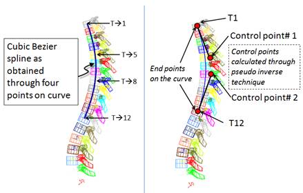
|
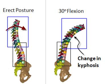
|
|
(a)
Thoracic spinal column repositioning with cubic
Bezier
|
(b)
Magnified view of L5-S1 joint è change in vertebra orientation is shown
|
Repositioning of Ribcage
and Associated Soft Tissues
Post repositioning of the thorax and the lumbar spine
the software automatically repositions the ribcage and associated soft
tissues The output of repositioning is shown in figure below
Ribcage and soft tissues
before and after repositioning
|