Assignment 1
Steps followed for Website Preparation
Pre-Website Preparation
Installation of following Softwares
- Visual Studio- For Editing Html Codes
- GitHub- For uploading files to the main server
- WinScp-For uploading files to the local server
- Adobe Premiere Pro- For Video size reduction and trimming
Video Preparation
So as to not put a load of video on my server I have uploaded that on the Youtube. After uploading the video on youtube I have got the sharing option from which I have got the code which can be added in the HTML code directly.
Image Size Compression
As the capacity of the available server is low so I had reduced the size of the images so as to have faster loading of the website. For Image size compression I have used following link Link- https://compressjpeg.com/
Downloading of Template
After browsing through many templates, I have downloaded the template from the following link as this has a decent design with few amazing Java animations. Link for the template: https://www.free-css.com/free-css-templates/page236/infinity-1.0
Preparation of Text Content
I have prepared the content for the following pages
- About- This page content is an introduction to myself, my experience, education and contact details
- Projects- In this I have prepared a list of projects with their thumbnail images
- Assignments- This page is for the assignments which will be given in the class.
HTML Code Editing
I have understood the code syntax of HTML codes using the attached Cheat Sheets(attached as Appendix 1) before I began editing my template HTML code.

Assignment 2
Project Proposal
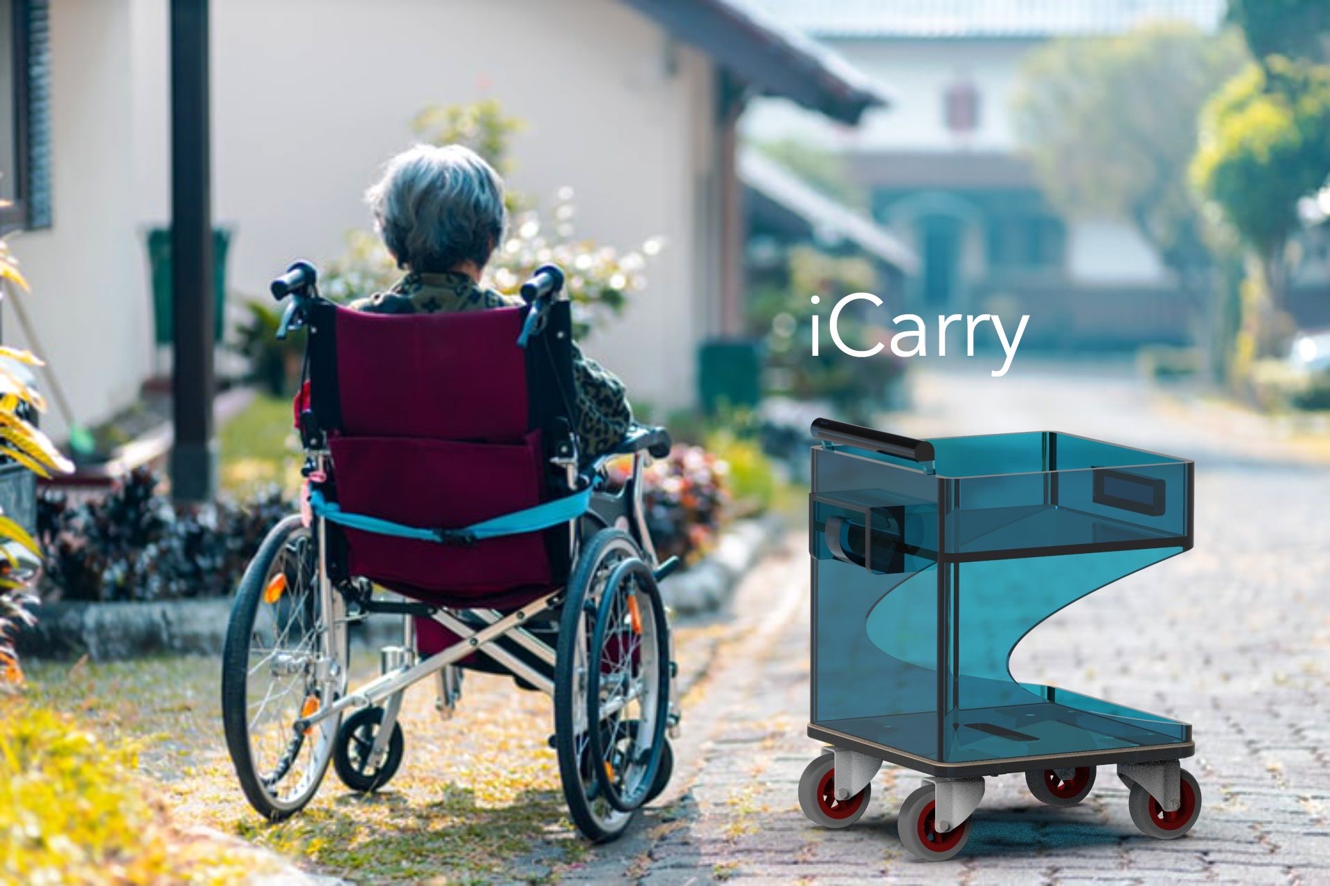
Follower Assistant Cart
Tejas and I teamed up for the project for this semester. After lots of brainstorming, we ended up deciding to build a follower assistant cart as we wanted to learn some skills and also do something innovative for the society.
What is a Follower Assistant Cart?
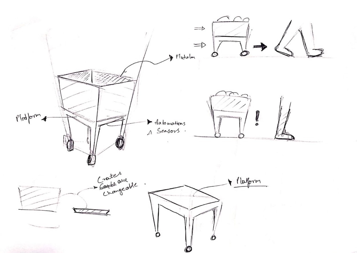
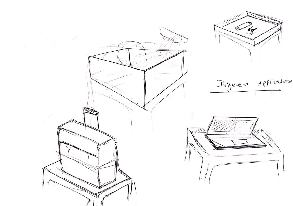
The objective is to build a cart/platform that follows the user. The cart will be capable of holding various items for the user. The platform can be modified according to the requirement of the user. Future possibilities also include Bluetooth connectivity with cellphones.
These are the concepts we have prepared as the initial ideation
Who will get benefit from this product?
We aim to make this useful primarily for elderly people, differently-abled, corporate owners, etc. Anyone who wants someone to carry their items along with them can use our product.
Our approach
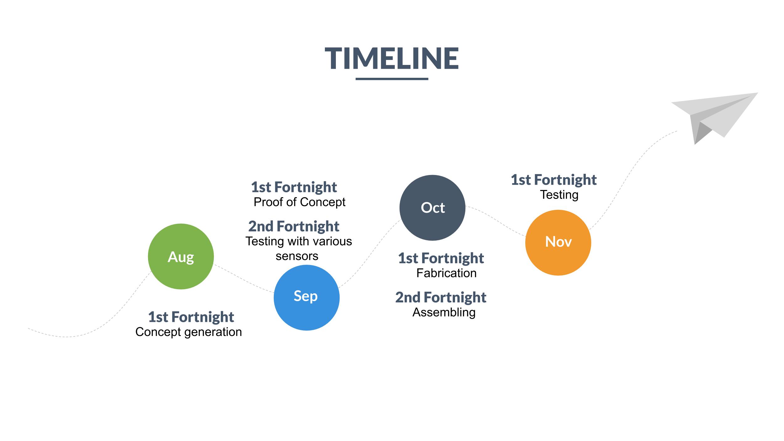
To develop a successful product, we will be starting concept generation, to decide on the form and functionality of the design. Once complete, we will try and generate the Proof of Concept to reinforce that the design is viable and feasible. After completing the Proof of Concept, we would be exploring the addition/ subtraction of functionality based on what could be beneficial by testing various sensors and actuators on the cart, with the help of Arduino microcontrollers and associated coding.
After finalizing the functions, we will be shifting our focus to developing the form. We will be fabricating the components and chassis using 3D printing, CNC milling and/or other fabrication methods.
Next, we will head to the assembly of the mechanical and electrical components and proceed with the testing. Finally, after thorough testing, we plan to present our design in front of the class and our jury by the end of this semester.
To make things easier to understand, we made a timeline to estimate how we would be proceeding with this design.
Estimated Project Timeline
Challenges
The biggest challenges that we foresee would be to complete the project within the given time. We roughly have about 7 fortnights and due to our lack of experience, we aren't sure whether this time is going to be enough or not. However we are quite positive that we'll be able to finish this project.
The availability of the tools and machines could be another minor obstacle that might delay our operations.
Since Tejas is good with concept generation and electronics skills, and I am not, my knowledge needs to be partly up to date with his for a successful completion of the project in time.
Components we would be using
Below is the list of the items/components we'd be using for our project:
- Navigation sensors- Beacons/ GPS module
- Microcontroller- Arduino
- Battery
- Actuators- Servo/DC Motors
- Chassis components
- Motor driver
- Wiring
Skills required
Below is the list of skills required for our project:
1. CAD Skills
2. Sketching skills
3. Arduino Coding skills
4. Fabrication skills
We are happy to have an opportunity to work on such project which will not only enhance our technical skills but will also help us to give exposure of team work. :)
Assignment 3
Basics of Electronics
9 LEDs using Arduino
Task 1)In groups of two, write your first name by switching 9 LEDs on/off and push buttons such that: With press of one push button, the letters of the name blink every 1000 ms 2) With press of another push button, all LEDs blink ON and then OFF with a delay of 1000 ms five times. 3) Extra credit: Also, print the letter typed on the Serial Monitor using the 9 LEDs
Steps which I have followed for programming Arduino
- The output pins representing each 9 LEDs is defined
- Two Input switches were defined so as to input on Arduino
- If statements were formed so as to take input from switch and give various output to the LEDs accordingly
- Different alphabets were defined using different combination of LEDs
- Patterns were also defined using loops
Components needed to build the setup
- Arduino Microcontroller
- 9 Leds
- Jumper Wires
- Resistors with each LED
- 2 Push button swithces
Introduction to the setup
Here in this video I am explaining about the different components of the circuit and how the programming code is controlling each of the components. Please use headphones.
Arduino Code Used
For Adruino Code Please Click here
Letters of name blinking
Here as you can see the albhates of text "Hi Vaibhav" is blinking with delay of 1000ms
Pattern blinking 5 times
All lights are blinking together in a time delay of 1000ms
Thanks for visiting! Hope you enjoyed :)
Assignment 4
Input and output devices
A. What are the different sensors in your phone and what do they do? Conduct an experiment to measure and analyze the data for a sensor in a log and report your findings.
The sensors available in my mobile and their purpose
| S No. | Sensor | Its use |
|---|---|---|
| 1 | Accelometer Sensor | To sense the motion |
| 2 | Lights Sensor | To sense the illmunination |
| 3 | Proximity Sensor | To sense the distance of user's face from device |
| 4 | Gyroscope Sensor | To sense the orientation of device |
| 5 | Magnetic Sensor | To sense the directions |
| 6 | Fingerprint Sensor | To identify biometric |
| 7 | Grip Sensor | To sense the finger position while holding device |
.jpg)
.jpg)
I have got the list of the sensors available in my device by dialling *#0*#.Here is a video I have prepared showing various sensors available in my mobile device. Presently I am focusing mainly on proximity sensor, for this I will be using a small card to create obstacle for the proximity sensor. Whenever it will detect the closeness of the card it will turn the display green and will also vibrate the device.
B. Measure something: add a sensor to a microcontroller board and read it. Document the process. Find an application for it in the real world around you.
For this exercise we have used the temperature/humidity sensor with Arduino microcontroller along with LCD display. The setup is prepared to get the temperature and humidity readings of the surroundings on the LCD display. Here is a video link for the same
Real world application
1. Ultrasonic Sensor: If the car crosses a certain minimum distance at traffic signal it will inform the traffic police
2. Temperature Sensor: If the temperature of refrigerator is more than the desired it will warn the user
C. Add an output device to a microcontroller board and program it to do something
For this we have attached Ultrasonic sensor and LCD display with the Arduino microcontroller and programmed the microcontroller to display the output recieved by the Ultrasonic sensor the LCD display. Here is the video of the same
D. Extra credit: Combine the input and output device to work together.
Here we have combined RGB light with the Ultrasonic Sensor. We have defined if else statement to the Arduino Programming code to decide the color of RGB light according to the distance detected by the ultrasonic sensor.
Here is a link for the Arduino Code
Assignment 5
These are the safety precaution and process that should be followed while using machines and equipments.
Health and safety practices for Makerspace
- Ask for help if needed rather than experimenting by yourself
- Close the entry door properly once you have entered the lab
- Clean the working area once your done with your work
- Do not let other students enter on your biometric
- Wear eye protection glasses whenever there is risk of material cutting.
- Dont immediately touch the workpiece just after performing operation, let it cool for a while.
- Keep all the tools and equipment at the designated place
- Wear proper footwear so as to avoid electric shocks and other accidents
Basic hand tools
Makerspace has these hand tools for minor operation process which need more detailing by hands
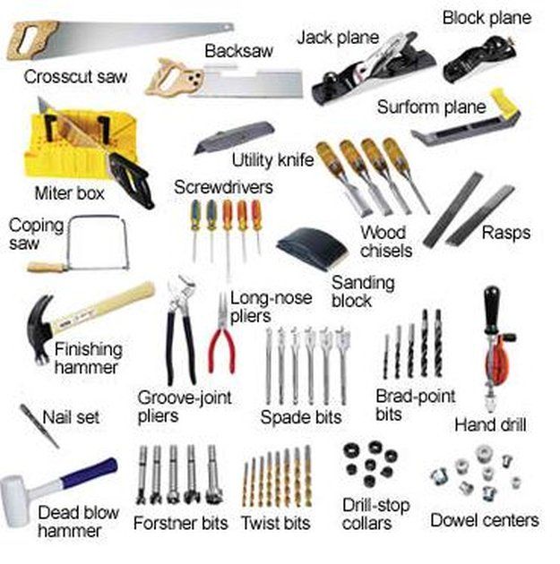 Image source: Link
Hand Drill: A drill is a tool primarily used for making round holes or driving fasteners. It is fitted with a bit, either a drill or driver, depending on application, secured by a chuck.
Power Tools: A power tool is a tool that is actuated by an additional power source and mechanism other than the solely manual labor used with hand tools.For Example - Hand Power Drill, Hand Saw,Scroll Saw, etc.
Carpentry tools
These are some of the instruments available in Makerspace for measuring various part features.
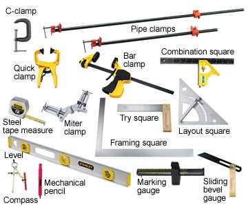 Image Source: Link
Drill Machine
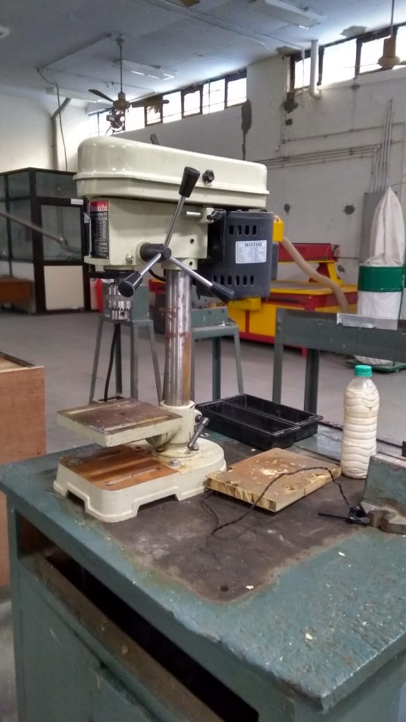 Safety guidelines for operating bench angular machine
- Fix the workpiece properly prior to performing any operation.
- Give enough clearances for the burrs after drilling.
- Decide the type of drilling machine recording to the size of hole required in the workpiece
- Make an indentation before you perform drilling so as to avoid slipping of drill bit over the workpiece
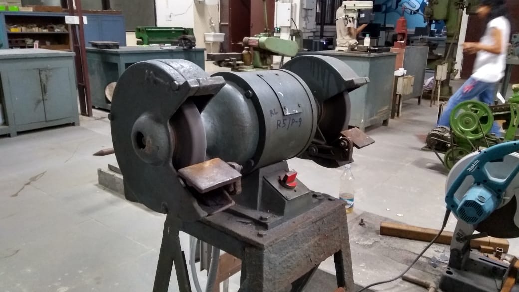
Bench Grinding machine
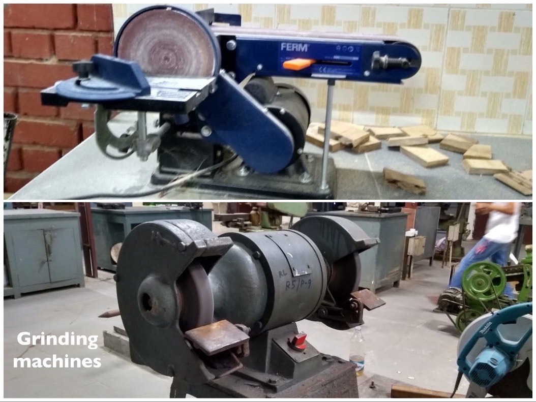 Working on grinding machine
Safety guidelines for operating bench grinder machine
- Properly holding the machine
- Try to use machine in push mode so that if by chance machine falls on ground it will not hurt you.
- Do not touch workpiece just after the operation
- We are proper eye mask before operating
- Do a pilot run of the operation before performing the actual grinding
- Take proper care of the cutting side of the blade
- Check whether the cutting blade has been wear out if yes change it immediately
- Do not work with blunt ages of the blades
- Check for any loose connection of electrical wiring
- Hold the work priest properly using benchwises or other equipments
Angular cutting machine
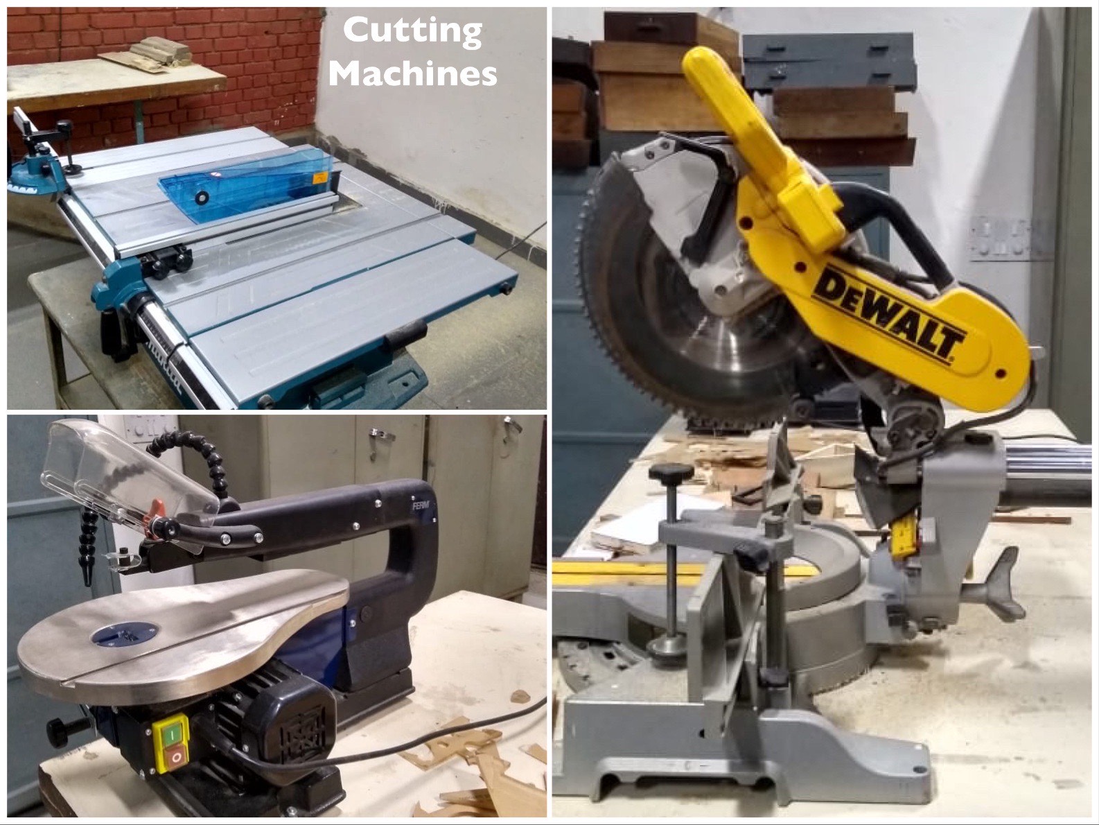 Safety guidelines for operating bench angular machine
- Measure proper angles needed on workpiece and adjust the machine accordingly
- Tight the individual levers properly
- Ensure the outlet of dust pipe goes into dustbin
- Take proper care of fingers and angles while cutting
- Wear proper mask as wood dust may go to your eyes
Working on Angular cutting machine
Bench grinder
 Safety guidelines for operating bench machine
- Give proper tolerances of grinding while designing the workpiece
- Hold the workpiece using proper clamping
- Take proper caution as grinding machine gives a jerk in the starting
Planer machine
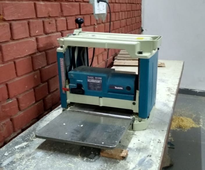 Safety guidelines for operating planar machine
- The linear machine is used to parallel the surfaces
- Proper allowances should be provided for the material removal during planer operation
Choosing the right tools
The selection of proper tool depends on following conditions,
- Speed of operation required
- Type of material of workpiece
- Level of surface finish required
- Size of workpiece
- Precision of operation required
- Size of cutting and drilling required
Some videos of using machines in Makerspace
Working on Sawing machine
Assignment 6
With 2D CAD (Vector, Raster) and 3D CAD Software:
1) Demonstrate and describe processes used in modelling
2) Model parts (preferably related to your project)
Process used for modelling
These are the steps which I have followed for developing 3D model
Step 1: Create a Document
Step 2: Beginning the Sketch
Step 3: Sizing the Sketch
Step 4: Making the Shape
Step 5: Dimensioning of sketch features
Step 6: Extruding the Sketch
Step 7: Application of 3D tools for operation like extrude cut, holes, fillets etc
Step 8: Making assembly file
Step 9: Importing part components to assembly file
Step 10: Mating them together by diving relations among them
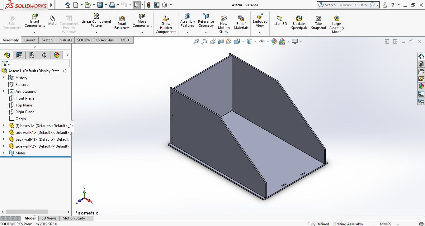
3D Model
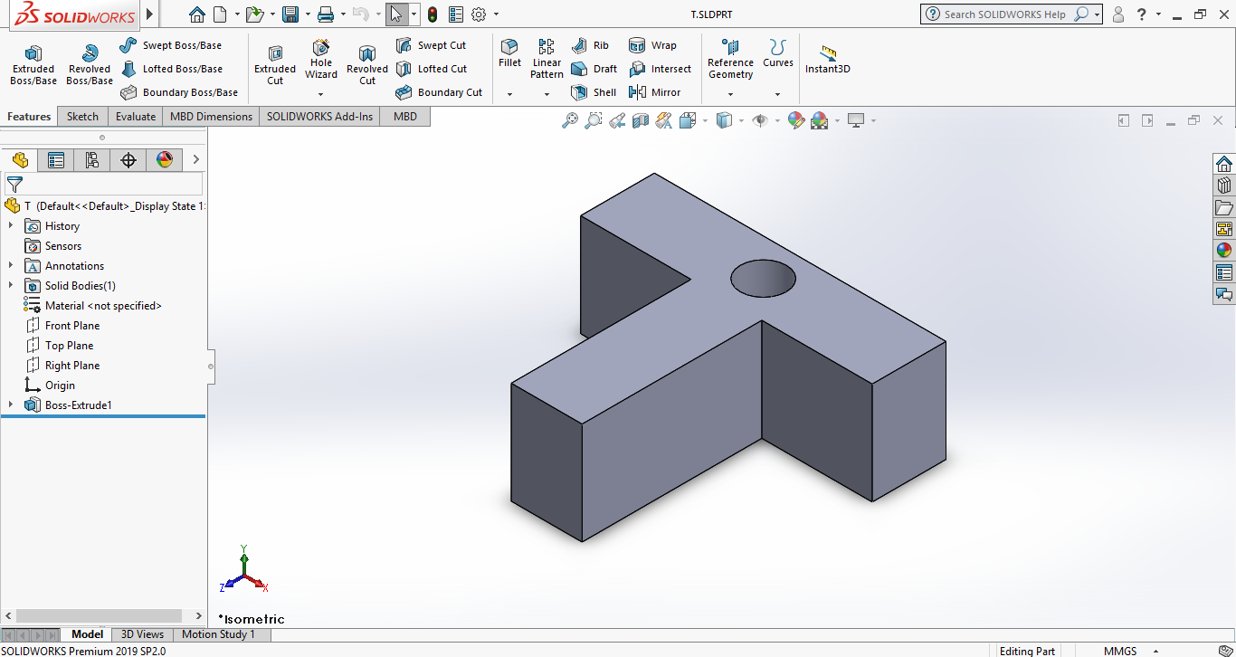
Here is the 3D model I have prepared for Project for this course. Here it represents prototype chassis.
Here is a link for 1. 3D models
Here is a link for 2. 3D models
Raster and Vector Image
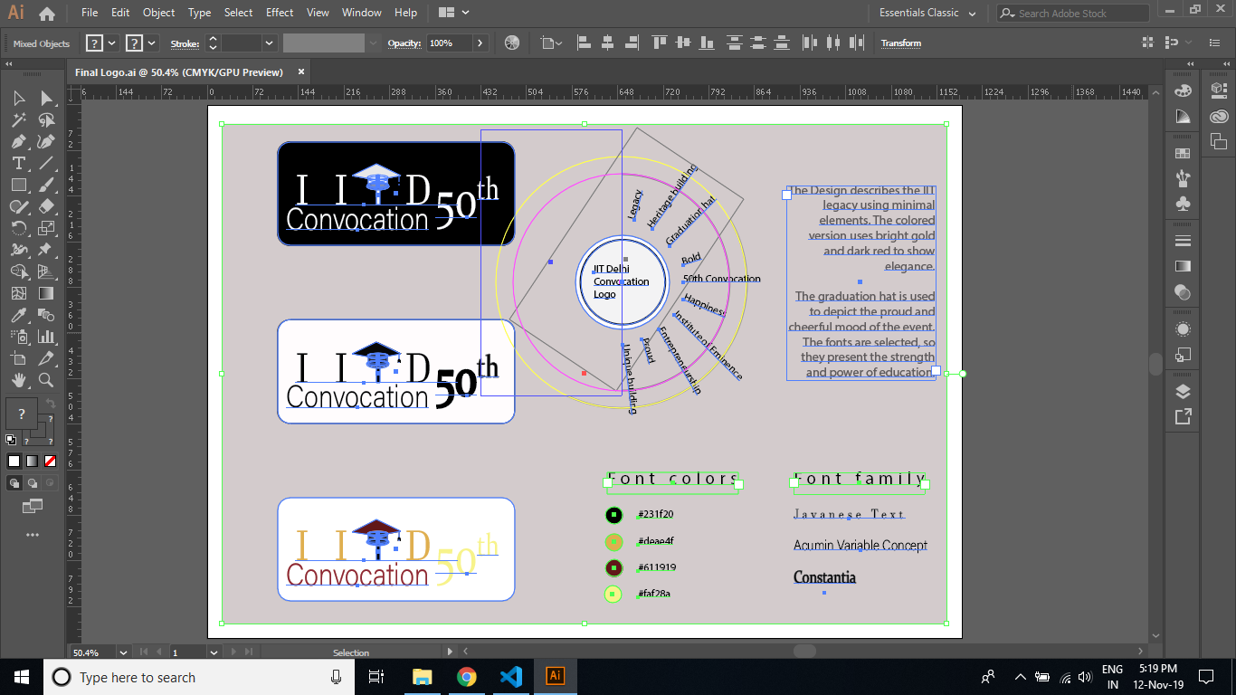
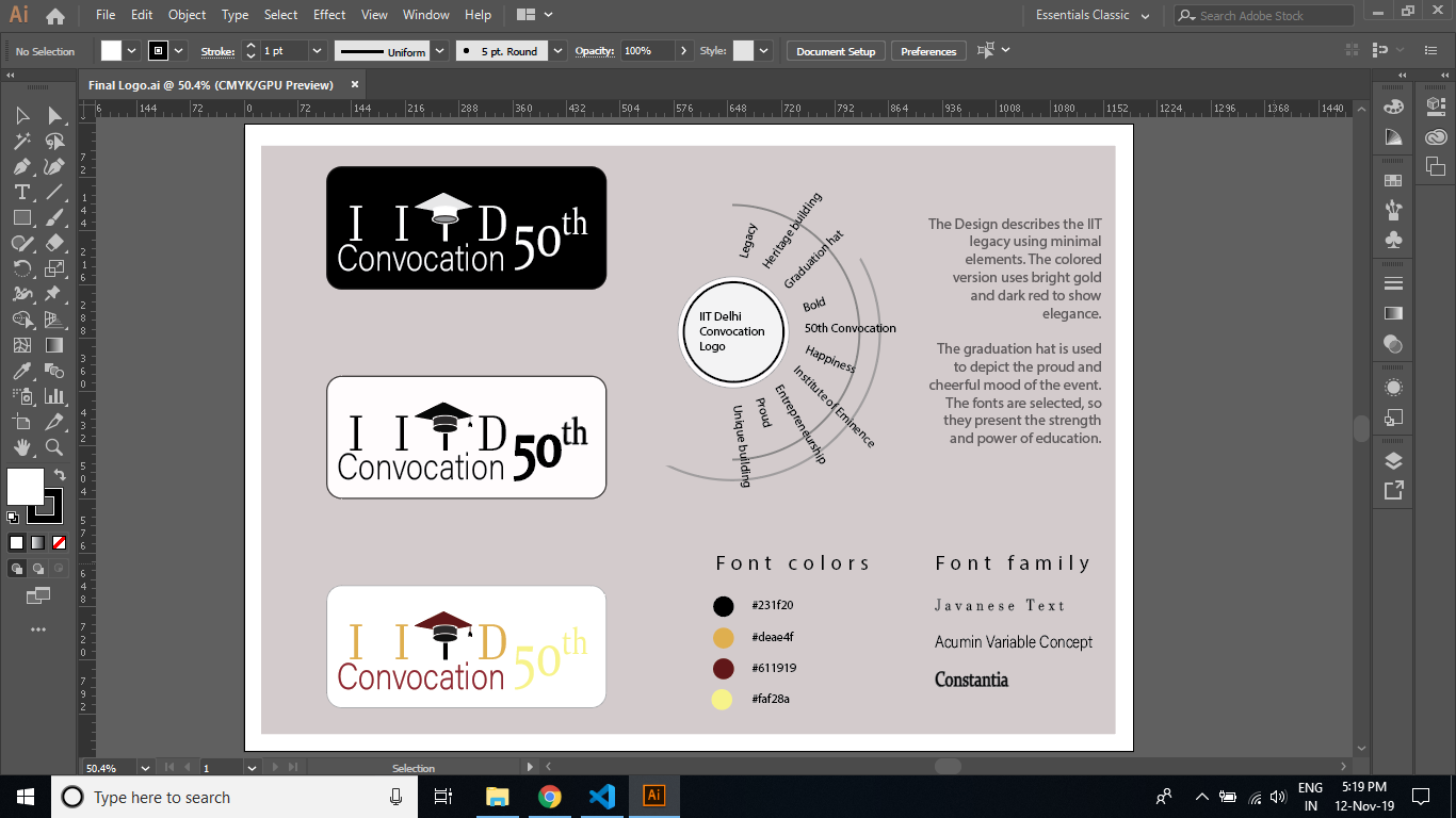
Here is a vector image I have prepared using Adobe Illustrator for course Framework of Desing (DSL 710)

Screenshots of Adobe Illustrator while editing Vector image
Other possibilities with CAD
Here I am presenting part of the project that I have done during my undergratuation.
In this I have used 3D modeling software "SolidWorks" to do the compressive load analysis
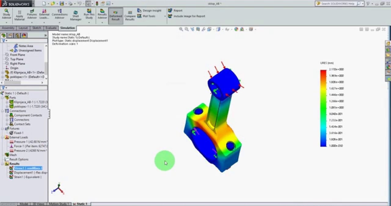
Steps that I followed for Load Analysis
- Importing of Solidworks model
- Generation of Mesh
- Introduction of Rigid supports
- Introduction of applied forces
- Application of constraints
- Getting the final results of simulation
Assignment 7
Documentation of 3D printing
1)Preparation of 3D CAD
2)Preparing files for 3D Printer
3)Adjustments of setting of slicer software
4)Problems that we faced and how we fixed them
Group Member
I did this assignment with Tejas Tilak
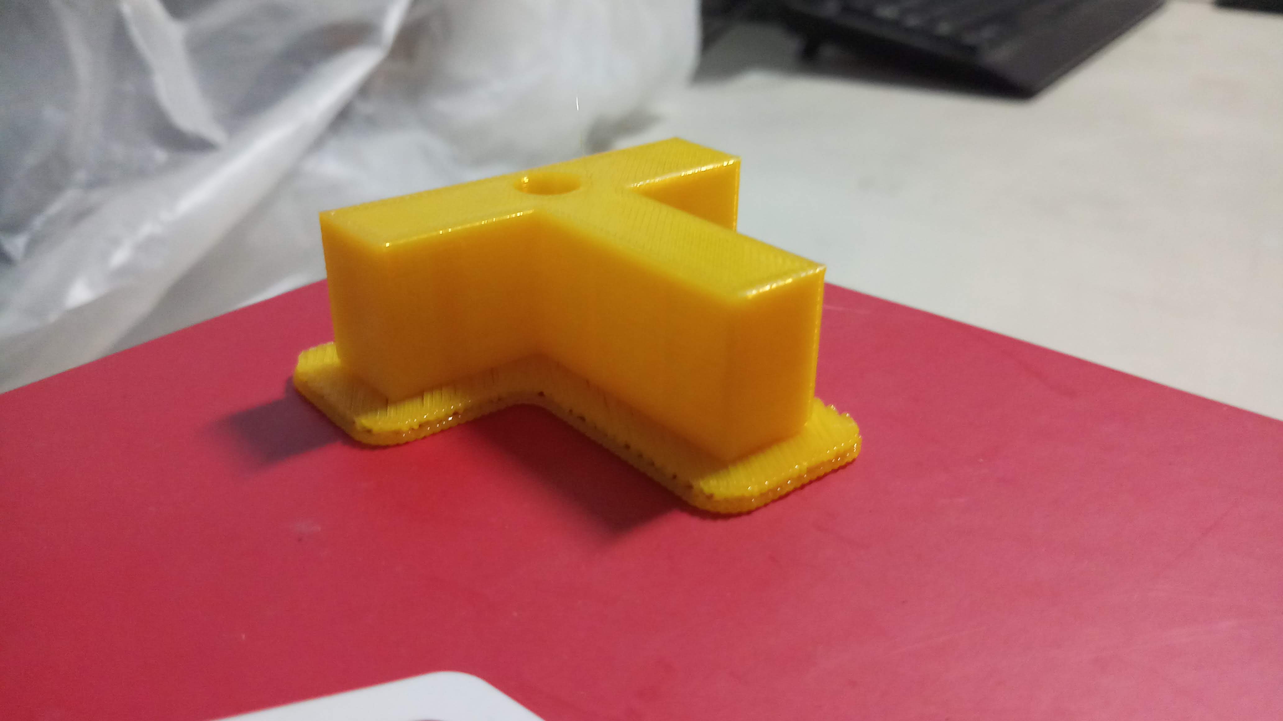
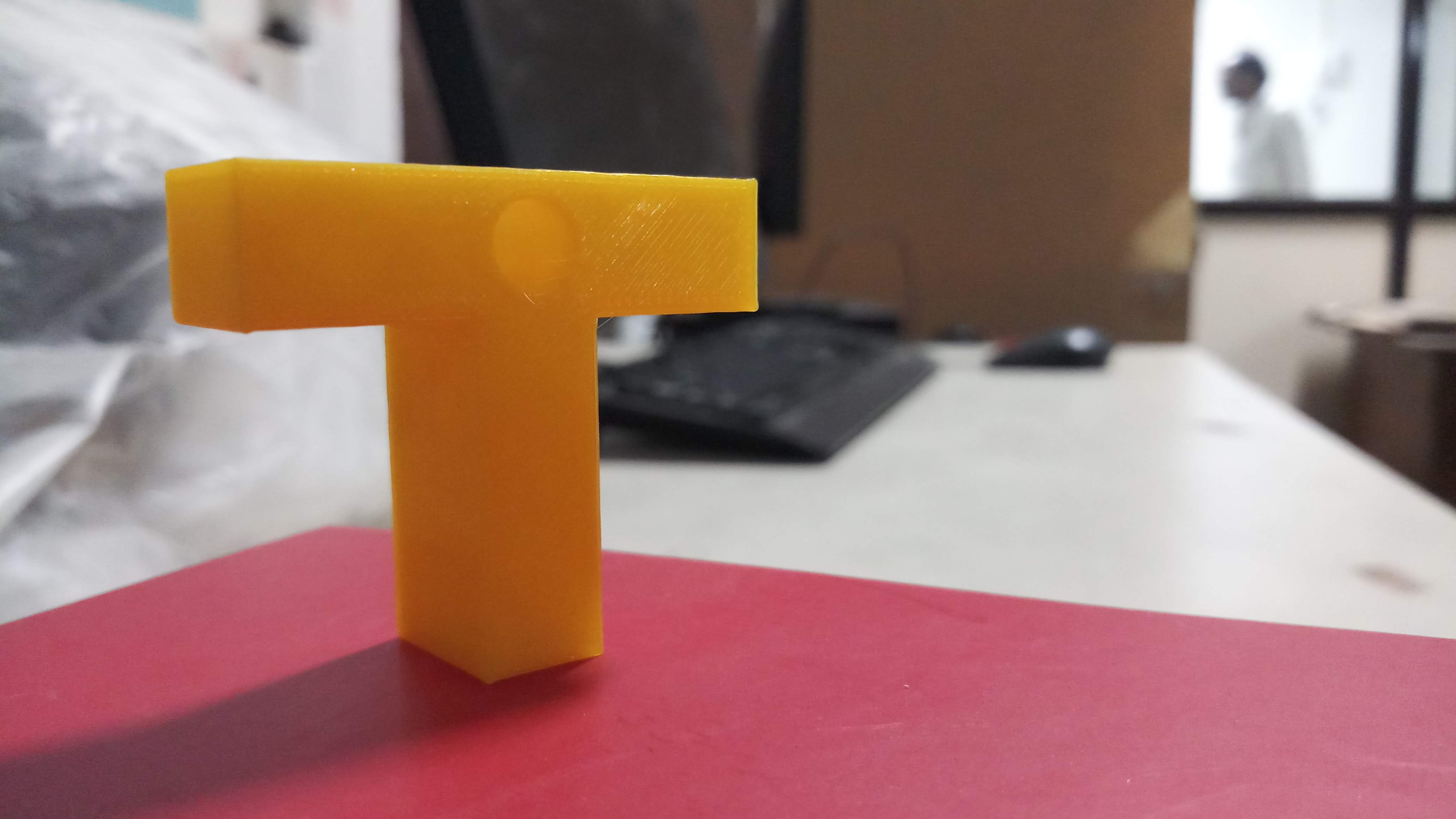
Process used for 3D modelling
This is the 3D model that we have prepared for 3D Printing.
We have intentionally designed our part in a way so that it won't require external supports that will save the processing time.
Preparation of files for 3D printer
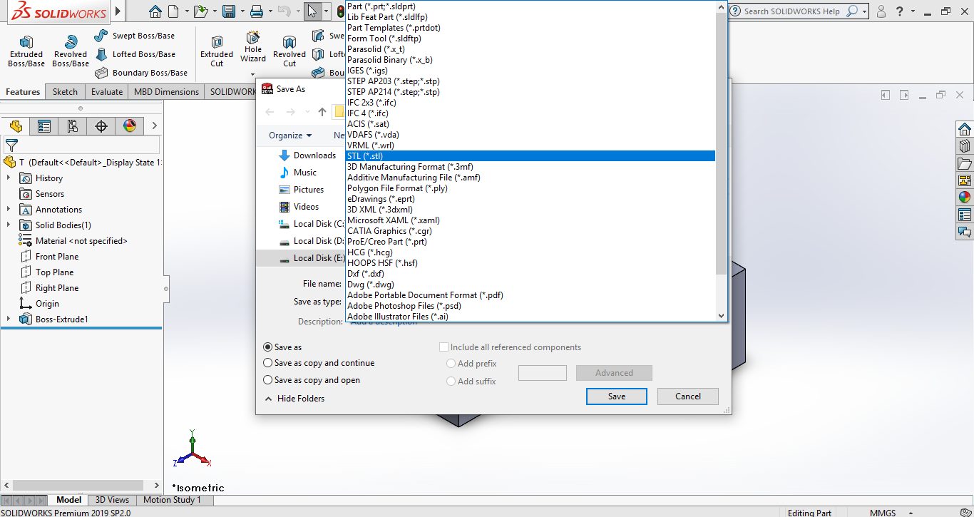
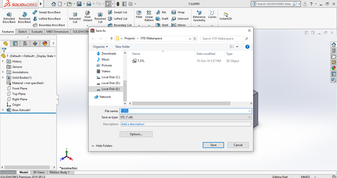
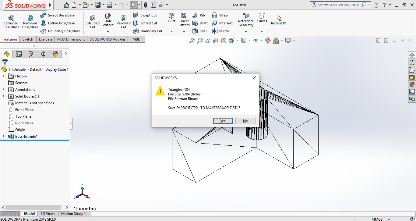
So as to export file from Solidworks to the Ideamaker I have used STL file format.
Here are some screenshots showing the conversion process.
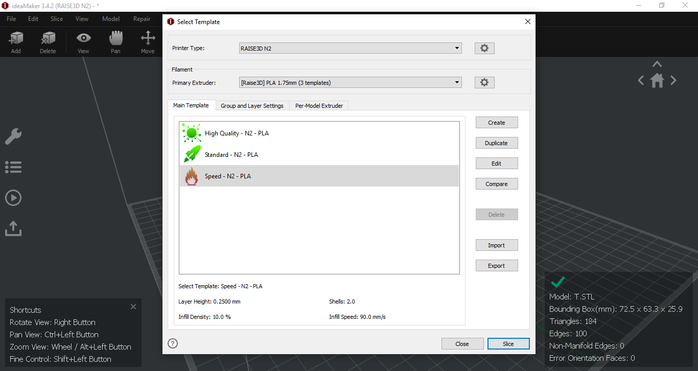
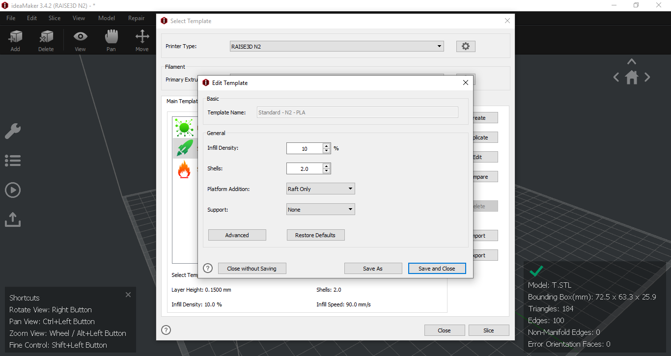
Adjustments of settings of Slicer software
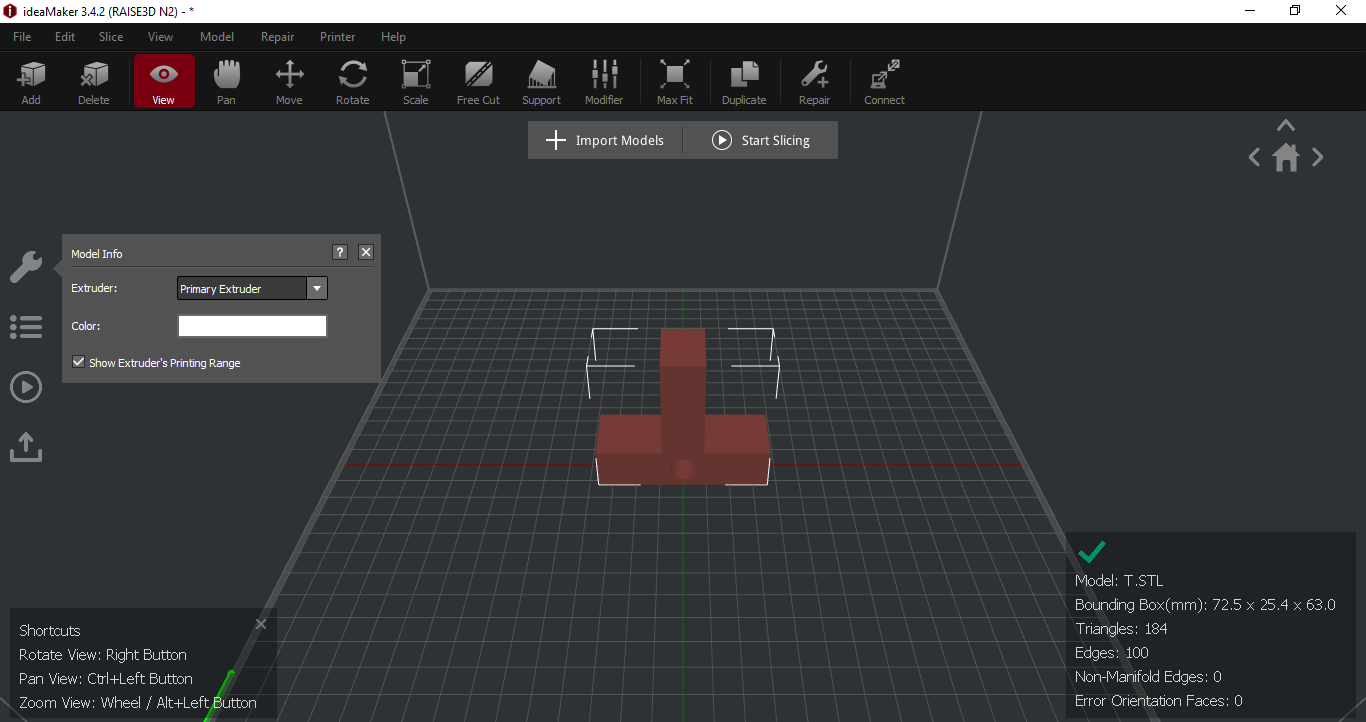
Here are the steps that we have followed in Ideamaker software according to our 3D model
- Importing Solidworks model
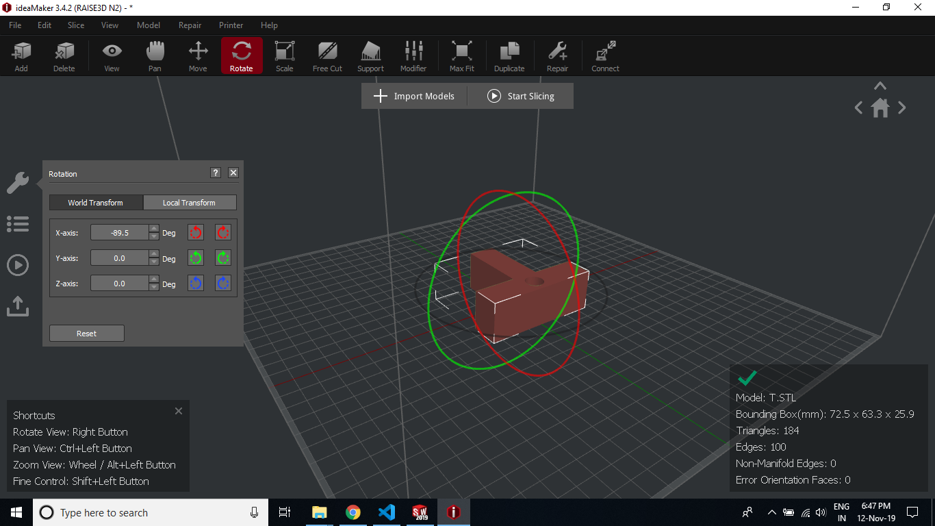
- Performed moving, rotatory, scaling operation on 3D model
- Adjusted model to sit on the machine bed in a way to have minimum supports required
- Adjustment of Bed and nozzle temperature
- Adjustment of Infill density of supports and model
- Addition of the type of support needed for our 3D model structure
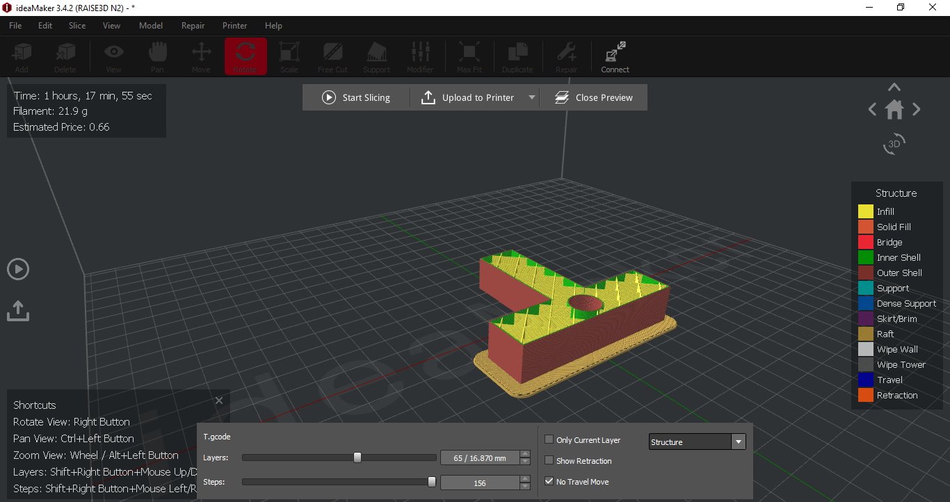
- Gave the slicing command
- Previewed the results in layer-wise view to ensure proper development
- Cleaning of built plate before starting of 3D print
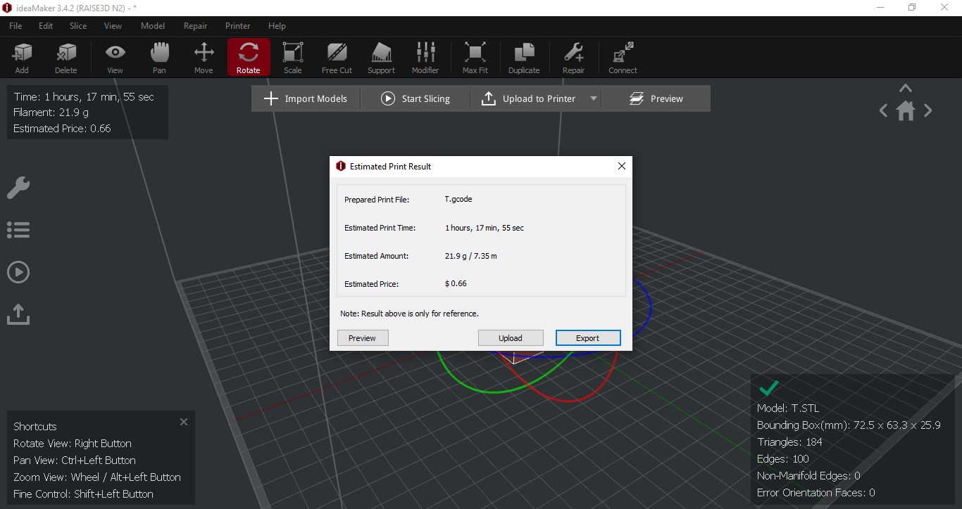
- Obtaining and transferring G-Code file from Ideamaker to 3D Printer
- Removal of model after completion of 3D print
- Cleaned the model as well 3D printer surroundings
Problems we faced and how we fixed them
These are the issues that we faced during 3D Printing.
1.Problem: Filament material was not sticking with the builtplate.
Our Solution: We have then reduced the speed of nozzle and it solved our problem.
2.Problem: It was difficult to remove the model from built plate after completion.
Our Solution: We have heated the builtplate by settings of 3D printer for easy removal of part.
Assignment 8
Documentation of 3D Scanning. This is solo assignment.
1)Setting up background
2)Setting up camera/sensor
3)3D Scan (Output)
4)Problems faced and how I solved them
Setting up background
- Setup of clean background with monochrome color
- Having some small object as reference
- Maintaining space 1-2 feet between surroundings and worktable
- Only camera is needed to rotate not the object
- Lighting of room should be adequate
- Reflective, transparent and untextured model are not good for 3D scanning
- Target object should be stationary
Setting up camera
- First I have installed a 3D scanning app(SCANN3D) on my android phone
- Then I have selected my object (that is having multiple colors)
- Maintaining space 1-2 feet between surroundings and worktable
- Only camera is needed to rotate not the object
- Each segment should be there in atleast 2 photographs
- Distance from too far or near will not work
- Target should not be moved in any case

3D Scan(Output)
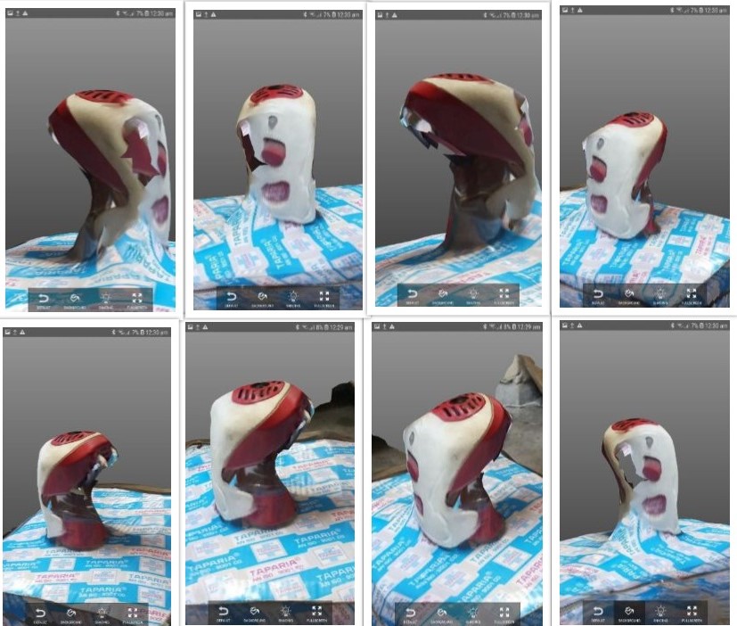
Here is video that shows my 3D model of mosquito repellent that I have scanned using SCANN3D android application.
Here is a collection of some images that SCANN3D has captured.
Problems I faced and how I solved them
Problem: Initially I have tried 3D scanning with object that had monochrome color. But 3D scan application was not able to identify individual features.
Solution: To solve this problem I have tried object with varied color which got easily scanned by scanning application.
Problem: Not able to export file from 3D scanning application.
Solution: I have done screen recording on my mobile to show the 3D model.
Problem: Model is hollow from one side.
Solution: I have tried to scan object for 3 time but still not able to get full model.
Problem: Deleting extra background element is difficult in mobile app case.
Solution: I have zoomed in the 3D model to take screenshots.
Assignment 9
Documentation of Laser cutting process. This assignment I have worked with Tejas Tilak.
1)Process involved in laser cutting and preparation of 2D sketch files.
2)Laser cut parts(Output)
3)Problems I faced and how I solved them
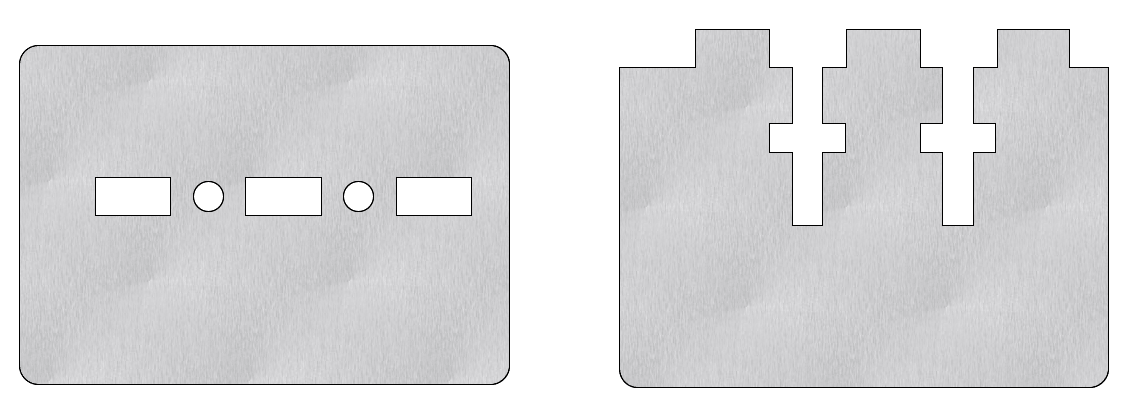
Process involved in laser cutting and preparation of 2D sketch files
- We started with preparing solidworks 3D model
- Here we have used Tab and slot technique to make parts that can be press fit into each other
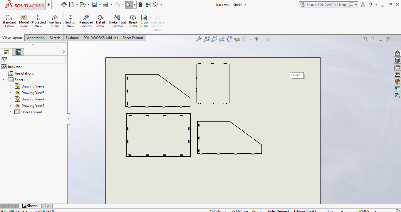
- Then I imported my 3D solidworks files into solidworks drawing file
- Then I exported sketch files as DXF file from SolidWorks
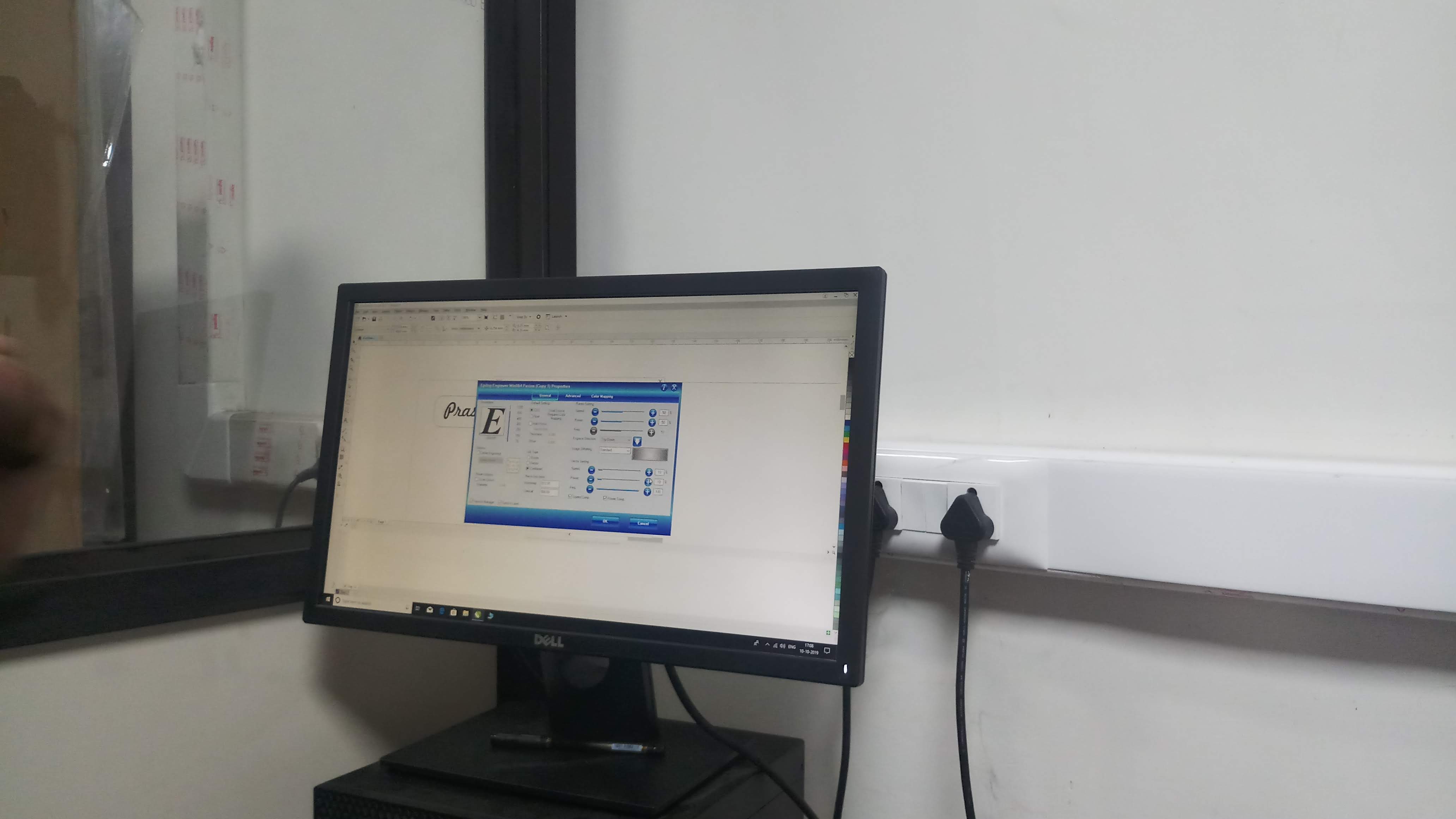
- We imported the DXF file to the system available with Laser cutting machine
- Then we have adjusted the scale of the sketch file according to Corel draw software
- We have aligned the sketch as per the size of the available MDF sheet by selecting the datum point
- Then we have adjusted the Power, speed and Intensity percentages in settings. Also the numbers of prints(cycles) printer should perform.
- Then we calibrated the vertical distance of laser beam mount using the provided tool
Laser cut parts(Output)
Here is video that shows my 3D model of mosquito repellent that I have scanned using SCANN3D android application.
These are the images of the laser cut parts which we have developed for our course project as well test workpiece.
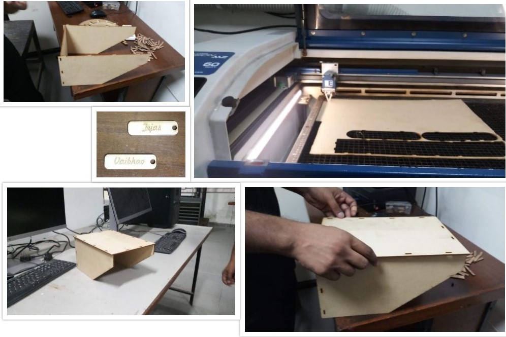
Click on this link for CAD files: Thingiverse
Problems I faced and how I solved them
Problem: At first we had given a tolerance of 0.1mm for press fit but it was loose as we tried assembling parts.
Solution: Then in next iteration we had removed the tolerance, as the cutting kerf was itself is sufficient enough for providing tolerances.
Problem: Not able laser cut part in 1 cycle.
Solution: Next time we have adjusted the value of power(increased) and speed (decreased). We have also given multiple printing copies so as to have good finish laser cut.
Problem: It is difficult to consider turning off/on the exhaust vacuum everytime using machine.
Solution: One of us had decided to make reminders for exhaust vacuum.
Problem: Workpiece got shifted once the laser beam started cutting.
Solution: We have stopped that process and recalibrated the laser beam and started the process all over again.
Assignment 10
Documentation of CNC router. This assignment I have worked with Tejas Tilak.
1)Process involved in big CNC router
2)CNC processed parts(Output)
3)Problems I faced and how I solved them
Process involved in big CNC router
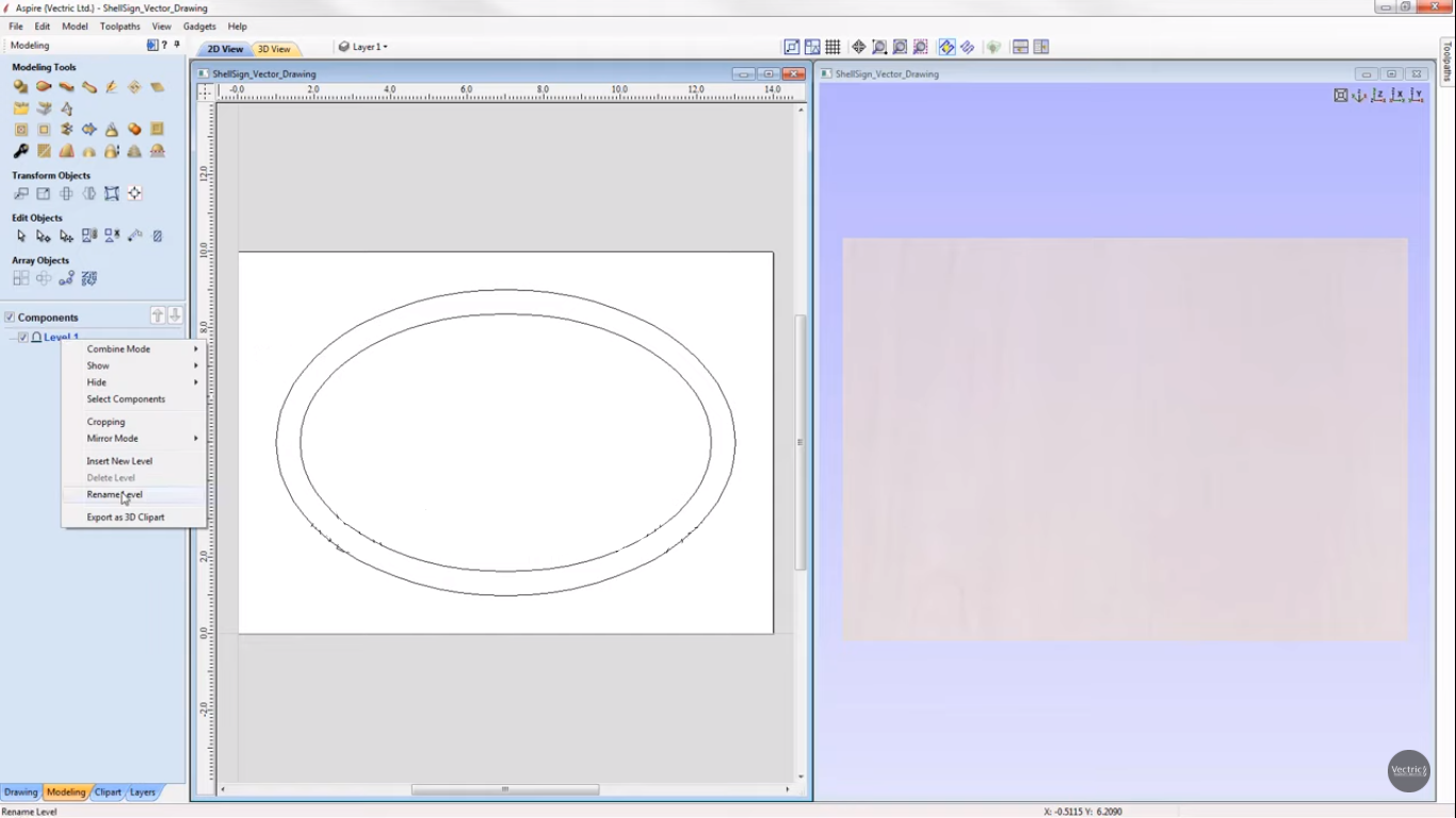
- We started with preparation of sketch on ASPIRE software
- Then we adjusted the sketch according to the space available on the workpiece
- After that we had defined the tool path
- Defined parameters for development of features. Parameter- Material thickness, Cutting depth, cut depth
- Then we selected our tool(6mm) by which we will perform the process
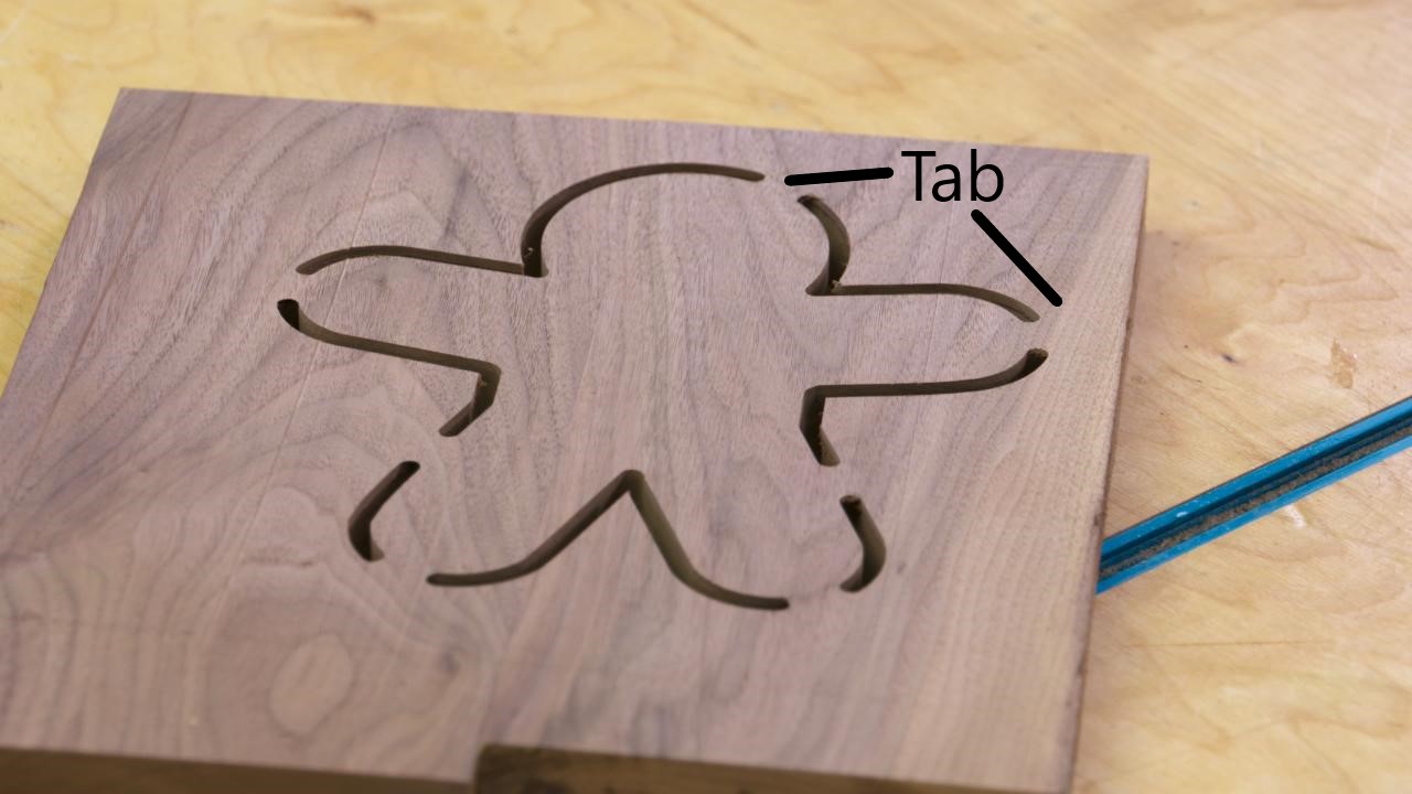
- Then we have added tabs so that workpiece won't move when the tool cuts a whole way through
- After that we saved the file with format as G Code
- We then transferred the G Code to CNC using USB drive
- We then turned on the vacuum cleaner so as to prevent wood dust
- After recieving command machine then started to cut the workpiece

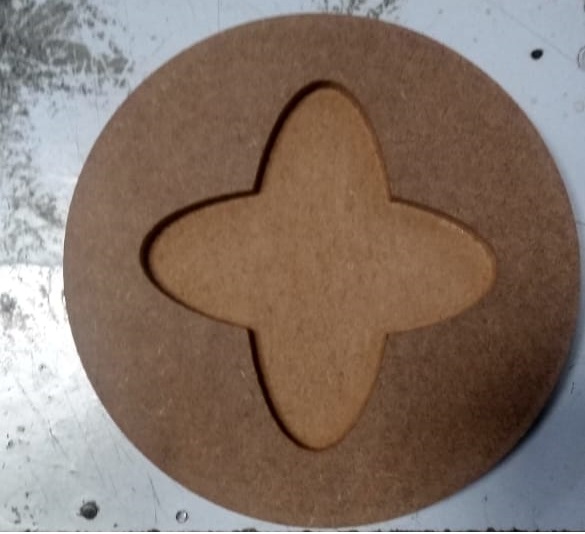
CNC processed parts(Output)
Here, this image is the final output we have got from the big CNC router. The finish of the workpiece is quite good.
Workpiece manufactured by Small CNC
Here, in this video small CNC is working on milling the chess piece "Queen".
Final output by small CNC.
Challenges we faced
1. It is difficult to check whether the tool edge is sharp or blunt.
2. Deciding place and quantity to stick the double sided tape is quite challenging (Small CNC router).
Assignment 11
Documentation of Composite sheet. This assignment I have worked with Tejas Tilak and George.
1)Process for making sheets by composites
2)Composite sheet(Output)
3)Challenges we faced
What are composites?
A composite is made by physically combining two or more materials (components) to produce a combination (blend) of structural properties not present in any individual component. They can, for example, provide greater strength and rigidity than is found in any of the separate components while being as light as possible.
Material required for preparing composite sheets
- Cling wrap
- Newspaper
- Latex Gloves
- Epoxy Resin
- Hardener
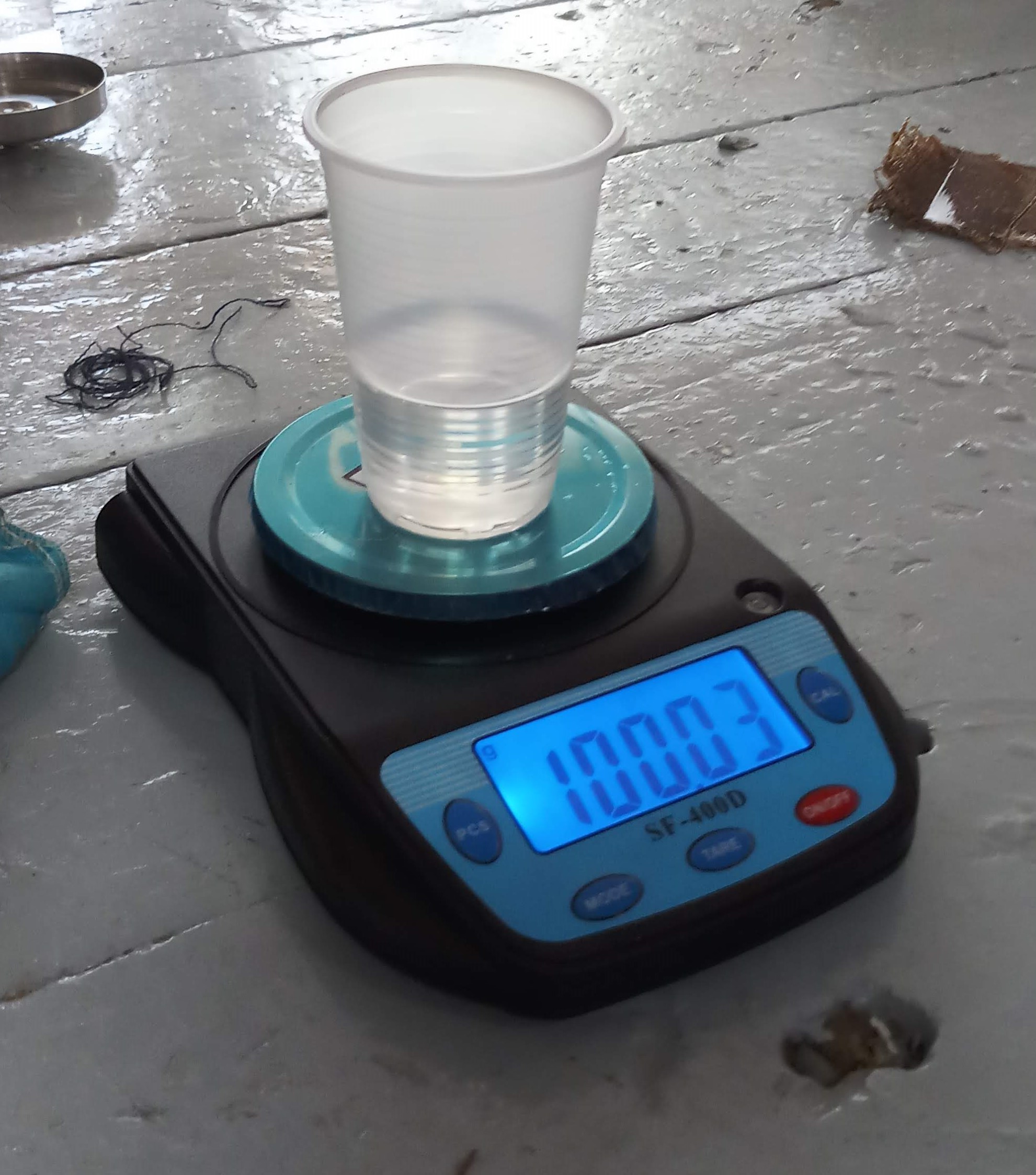
- Weighing Scale
- Mixing Bowl
- Matix material (cloths)
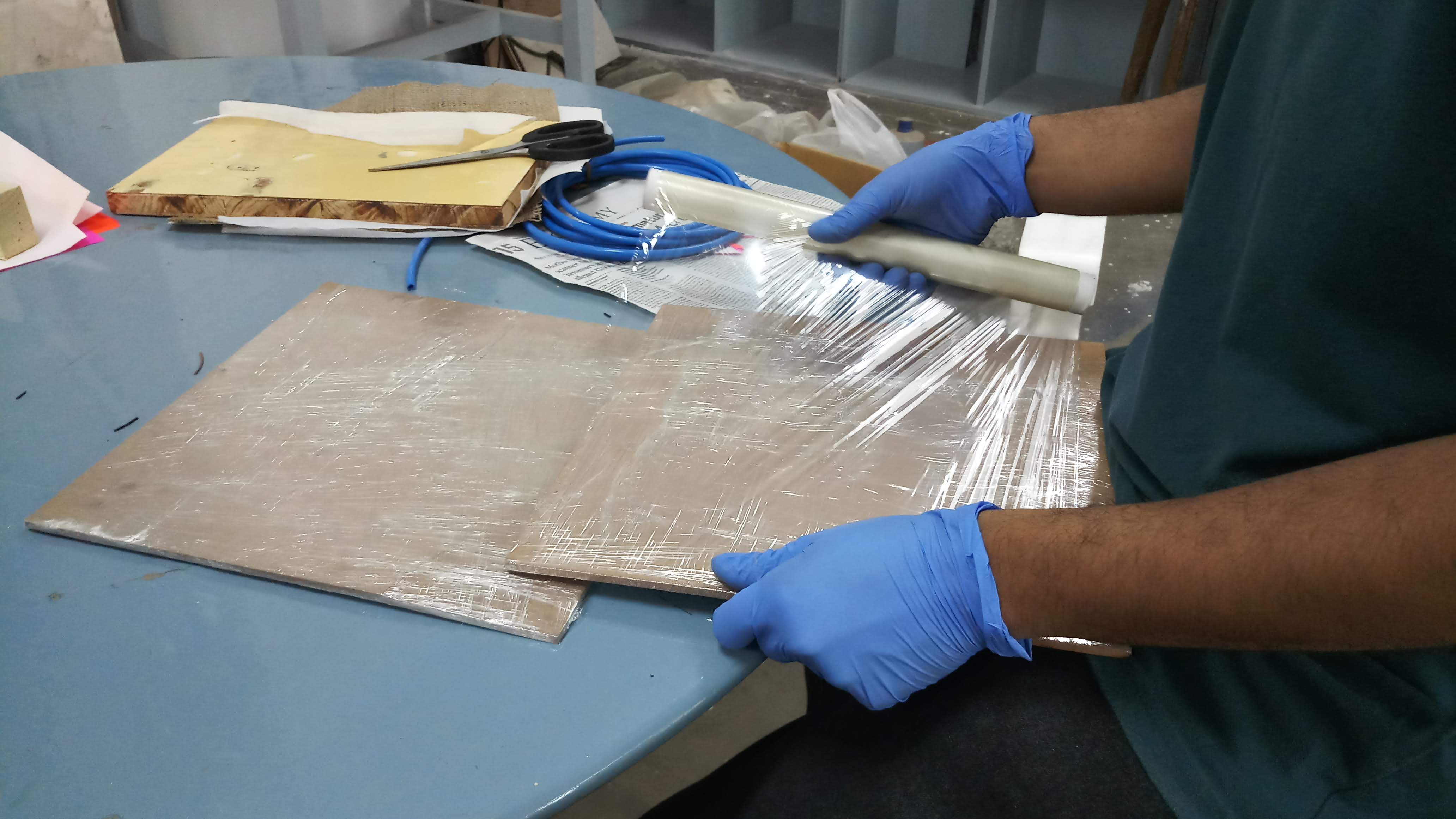
Process for making sheets by composites
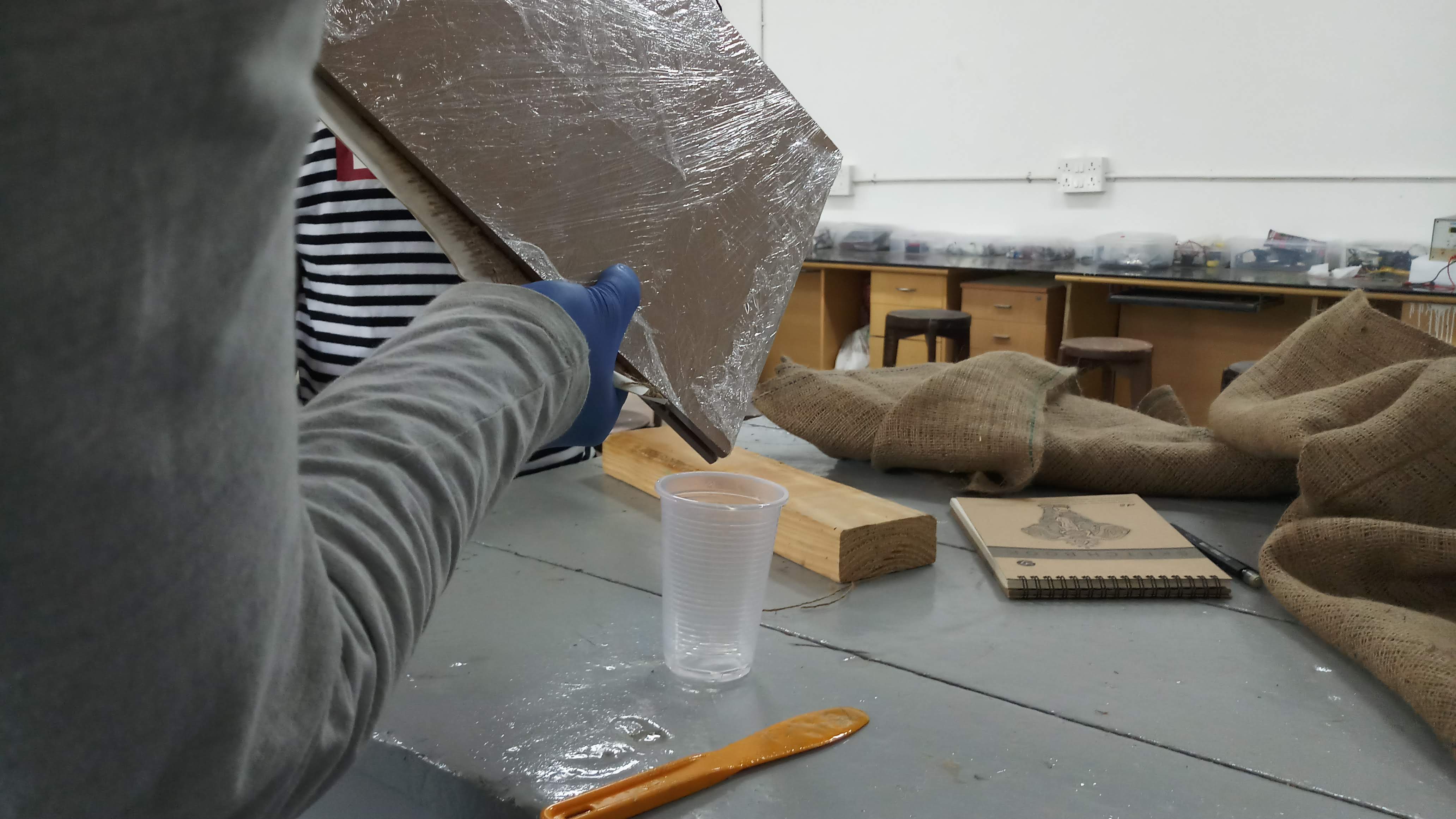
- We started with wood supports for making sandwitch structure with top and bottom layers as wood
- We then wrapped the transparent cling wrap around the wooden piece to make them stay away from liquid epoxy
- We then decided the amount we will be needing for making composite sheet
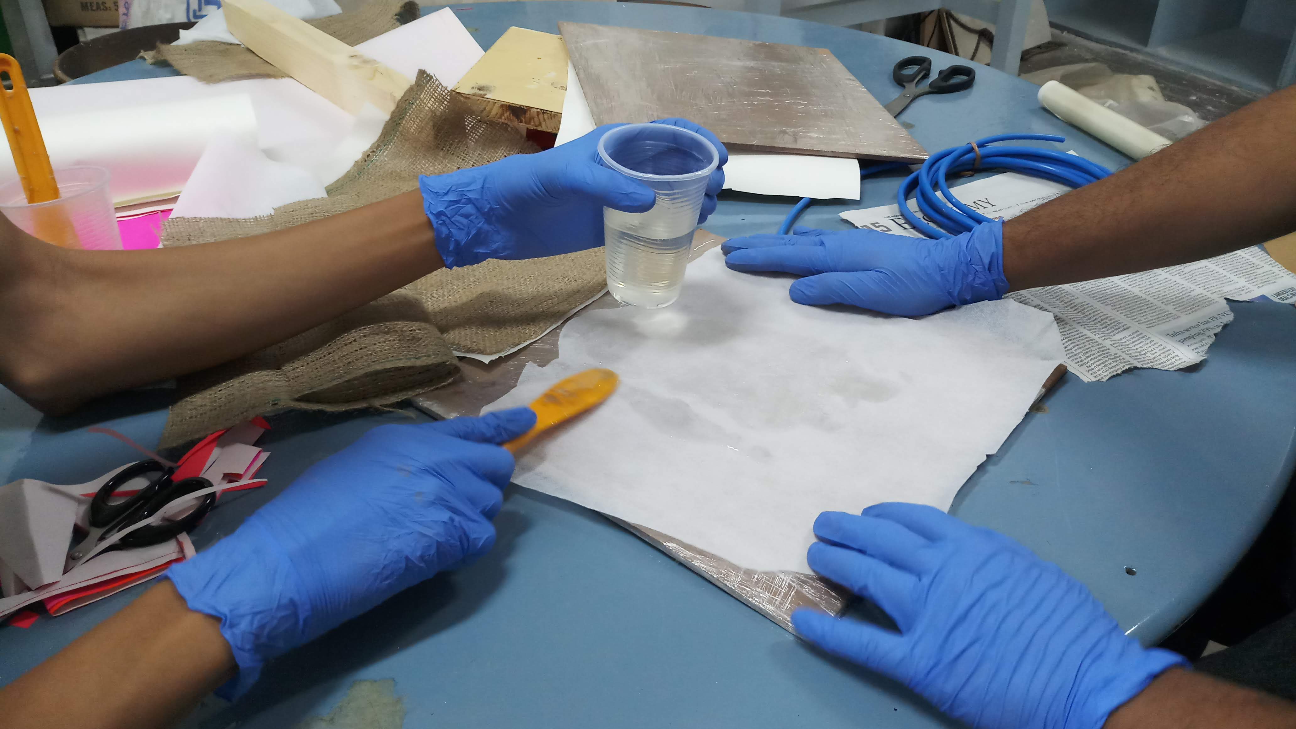
- After that we prepared the mixture of resin and harder in the ratio of 2:1. We took resin as 100g and harder as 50g
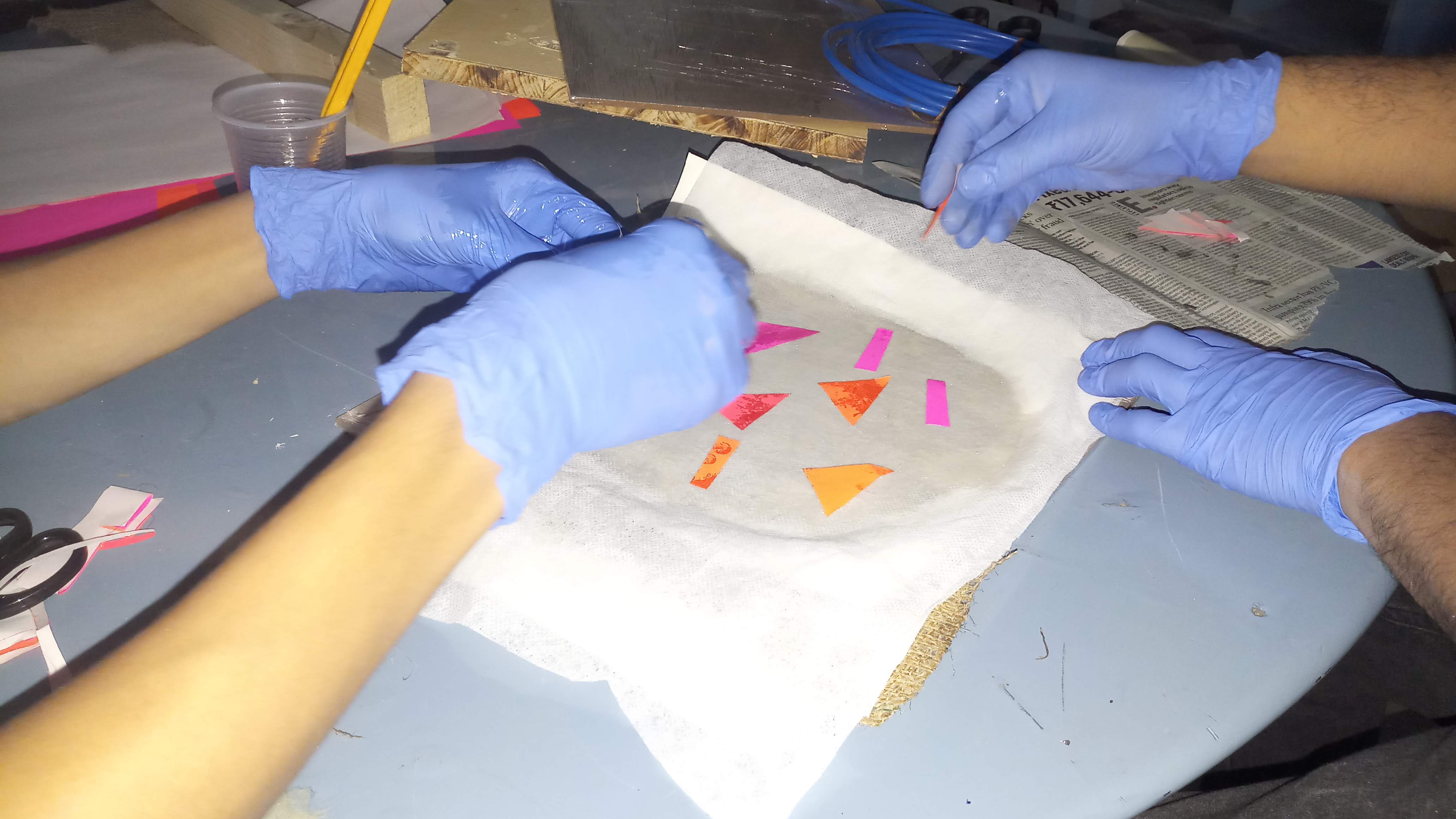
- We then placed Jute, Newspaper and cloth on top of wooden piece. Newspaper was added to ensure uniform spreading and soaking of epoxy over the cloth surface.
- After that we kept on repeating alternate layers with added layers of epoxy mixture
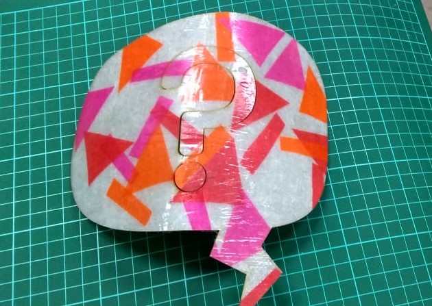
- We have then also added colorful paper piece to add aesthetics to composite sheet
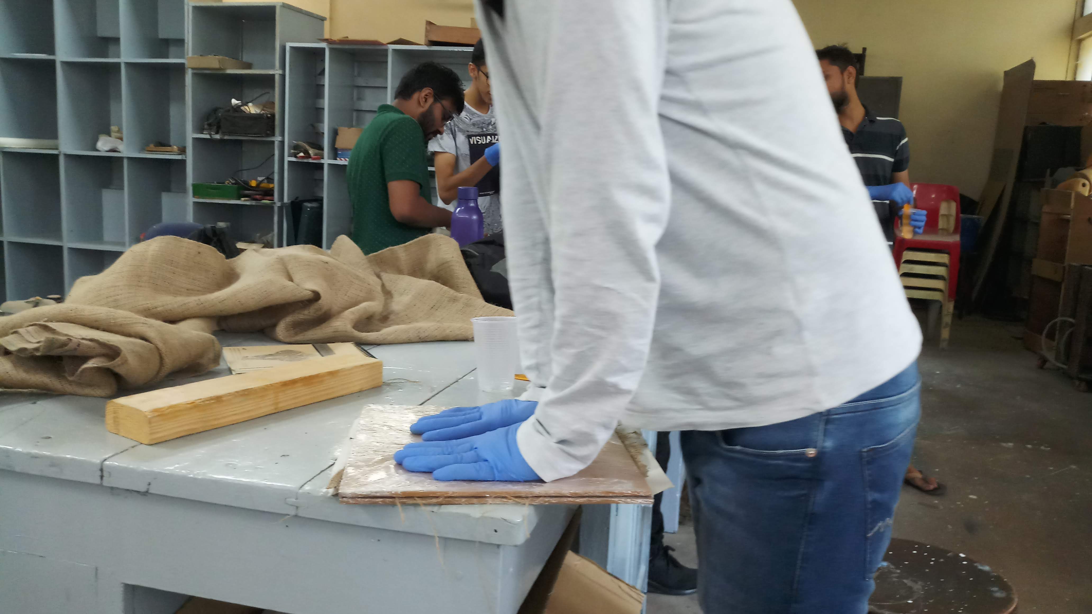
- After making sheet thick as per our needs. We then removed the excess epoxy by squeezing assembly by hands
- After that we have placed this assembly on bench wise providing adequate forces
- We then left the sheet for 24 hrs to dry and settle
- After 24 hrs sheet was felt ductile and it became more rigid after around 36 hrs
- At last we used laser cutting to trim the edges
Composite sheet(Output)
Here, this image presents the final laser cutted composite sheet. Aka "Colorful Speech bubble".
Challenges we faced
1. Difficult to apply contant presure. Especially if the part complexity increases.
2. We find it difficult to make approximation of settling time that sheet will take.